Americas Headquarters Cisco Systems, Inc. 170 West Tasman Drive San Jose, CA 95134-1706 USA http://www.cisco.com Tel: 408 526-4000 800 553-NETS (6387) Fax: 408 527-0883 Cisco PGW 2200 Softswitch Release 9 Billing Interface Guide July 21, 2010 Text Part Number: OL-1089-18

Welcome message from author
This document is posted to help you gain knowledge. Please leave a comment to let me know what you think about it! Share it to your friends and learn new things together.
Transcript
Cisco PGW 2200 Softswitch Release 9 Billing Interface GuideJuly 21, 2010
Americas HeadquartersCisco Systems, Inc.170 West Tasman DriveSan Jose, CA 95134-1706 USAhttp://www.cisco.comTel: 408 526-4000
800 553-NETS (6387)Fax: 408 527-0883
Text Part Number: OL-1089-18

Cisco and the Cisco Logo are trademarks of Cisco Systems, Inc. and/or its affiliates in the U.S. and other countries. A listing of Cisco's trademarks can be found at www.cisco.com/go/trademarks. Third party trademarks mentioned are the property of their respective owners. The use of the word partner does not imply a partnership relationship between Cisco and any other company. (1005R)
Any Internet Protocol (IP) addresses used in this document are not intended to be actual addresses. Any examples, command display output, and figures included in the document are shown for illustrative purposes only. Any use of actual IP addresses in illustrative content is unintentional and coincidental.
Cisco PGW 2200 Softswitch Release 9 Billing Interface Guide Copyright © 2010 Cisco Systems, Inc. All rights reserved.
OL-1089-18
C O N T E N T S
iii
Preface xi
Obtaining Documentation and Submitting a Service Request 1-xii
C H A P T E R 1 Billing Interfaces 1-1
Billing Capabilities Overview 1-1
System Interfaces 1-1
Physical Interface 1-2
RADIUS Interface 1-2
Message Interface 1-2
CDB Message Format 1-2
Tag Values 1-3
Formats and Codes 1-4
CDB Record Types 1-5
Call Data Block Descriptions 1-6
Configuring Call Screening 1-7
Configuring Call Detail Record File Output 1-8
Configuring CDR Message Types 1-8
Enabling Call Screening 1-9
Configuring CDR File Output 1-9
CDE Descriptions 1-10
Cisco PGW 2200 Softswitch Billing Interfaces 1-22
FTP and SFTP Support 1-22
Generic Interface 1-23
Redundant Cisco PGW 2200 Softswitch Configuration 1-23
Cisco PGW 2200 Softswitch Clock Synchronization 1-23
Detailed CDB Descriptions 1-24
Answered CDB Record (Tag: 1010/Release 5 and Later) 1-24
Deselected Outgoing Circuit CDB Record (Tag: 1020/Release 5 and Later) 1-30
Aborted Attempt CDB Record (Tag: 1030/Release 5 and Later) 1-31
Release CDB Record (Tag: 1040/Release 5 and Later) 1-36
Interrupted CDB Record (Tag: 1050/Release 5 and Later) 1-39
On-Going (Call) CDB Record (Tag: 1060/Release 5 and Later) 1-40
Maintenance CDB Record (Tag: 1070/Release 5 and Later) 1-42
iiiCisco PGW 2200 Softswitch Release 9 Billing Interface Guide
Contents
SS7 CIC Audit CDB Record (Tag: 1071/Release 9 and Later) 1-43
External Access CDB (Tag: 1080/Release 7 and Later) 1-45
File Header CDB (Tag: 1090/Release 7 and Later) 1-45
File Footer CDB (Tag: 1100/Release 7 and Later) 1-46
End of the Call CDB (Tag: 1110/Release 7 and Later) 1-46
Slave End-of-Call CDB Record (Tag: 1210/Release 9.6 and Later) 1-53
Slave Long Duration Call CDB Record (Tag: 1260/Release 9.6 and Later) 1-53
CDE Detail Description 1-54
CDEs Encoded in ANSI 1-55
Calling Party Category (Tag: 2000/ANSI) 1-55
User Service Information (Tag: 2001/ANSI) 1-56
Originating Line Information (Tag: 2002/ANSI) 1-57
Calling Number Nature of Address (Tag: 2003/ANSI) 1-57
Charged Number Nature of Address (Tag: 2004/ANSI) 1-58
Dialed Number Nature of Address (Tag: 2005/ANSI) 1-59
LRN Nature of Address (Tag: 2006/ANSI) 1-60
Called Number Nature of Address (Tag: 2007/ANSI) 1-61
Reason Code (Tag: 2008/ANSI) 1-62
Forward Call Indicators Received (Tag: 2009/ANSI) 1-63
Forward Call Indicators Sent (Tag: 2010/ANSI) 1-64
Nature of Connection Indicators Received (Tag: 2011/ANSI) 1-65
Nature of Connection Indicators Sent (Tag: 2012/ANSI) 1-66
Transit Network Selection (Tag: 2013/ANSI) 1-67
Carrier Identification Parameter (Tag: 2014/ANSI) 1-68
Carrier Selection Parameter (Tag: 2015/ANSI) 1-68
Jurisdiction Information Parameter (Tag: 2016/ANSI) 1-69
Redirecting Number Nature of Address (Tag 2017/ANSI) 1-69
Egress Calling Number Nature of Address (Tag 2018/ANSI) 1-70
Egress Redirecting Number Nature of Address (Tag 2019/ANSI) 1-71
Egress Original Called Number Nature of Address (Tag 2020/ANSI) 1-72
CDE Encoded as ITU Recommendation 1-73
Calling Party Category (Tag: 3000/ITU) 1-73
User Service Information (Tag: 3001/ITU) 1-74
Originating Line Information (Tag: 3002/ITU) Retired 1-75
Calling Number Nature of Address (Tag: 3003/ITU) 1-75
Charged Number Nature of Address (Tag: 3004/ITU) Retired 1-76
Dialed Number Nature of Address (Tag: 3005) 1-77
LRN Nature of Address (Tag: 3006/ITU) 1-78
Called Number Nature of Address (Tag: 3007/ITU) 1-79
Reason Code (Tag: 3008/ITU) 1-79
ivCisco PGW 2200 Softswitch Release 9 Billing Interface Guide
OL-1089-18
Contents
Forward Call Indicators Received (Tag: 3009/ITU) 1-92
Forward Call Indicators Sent (Tag: 3010/ITU) 1-94
Nature of Connection Indicators Received (Tag: 3011/ITU) 1-95
Nature of Connection Indicators Sent (Tag: 3012/ITU) 1-96
Transit Network Selection (Tag: 3013/ITU) 1-98
Redirecting Number Nature of Address (Tag 3017/ITU) 1-99
Egress Calling Number Nature of Address (Tag 3018/ITU) 1-100
Egress Redirecting Number Nature of Address (Tag 3019/ITU) 1-101
Egress Original Called Number Nature of Address (Tag 3020/ITU) 1-102
Cisco PGW 2200 Softswitch Generic CDEs 1-102
CDB Version (Tag: 4000) 1-102
CDB Timepoint (Tag: 4001) 1-103
Call Reference ID (Tag: 4002) 1-103
IAM/Setup Timepoint (Tag: 4003) 1-103
ACM/Alert Timepoint (Tag: 4004) 1-104
ANM/Answer Timepoint (Tag: 4005) 1-104
REL/Release Timepoint (Tag: 4006) 1-105
Crash Timepoint (Tag: 4007) 1-105
Originating Trunk Group (Tag: 4008) 1-106
Originating Member (Tag: 4009) 1-106
Calling Number (Tag: 4010) 1-106
Charged Number (Tag: 4011) 1-107
Dialed Number (Tag: 4012) 1-107
LRN Number (Tag: 4013) 1-107
Called Number (Tag: 4014) 1-108
Terminating Trunk Group (Tag: 4015) 1-108
Terminating Member (Tag: 4016) 1-108
Maintenance Trunk Group (Tag: 4017) 1-109
Maintenance Circuit Member (Tag: 4018) 1-109
Glare Encountered (Tag: 4019) 1-109
RLC/RELEASE Complete Timepoint (Tag: 4020) 1-110
Last SAM timepoint (Second) (Tag:4021) 1-110
First Release Source (Tag: 4028) 1-110
LNP Dip (Tag: 4029) 1-111
Total Meter Pulses (Tag: 4030) 1-111
Maintenance Type (Tag: 4032) 1-112
Maintenance Reason (Tag: 4033)—Retired 1-113
Ingress Originating Point Code (Tag: 4034) 1-114
Ingress Destination Point Code (Tag: 4035) 1-114
Egress Originating Point Code (Tag: 4036) 1-115
vCisco PGW 2200 Softswitch Release 9 Billing Interface Guide
OL-1089-18
Contents
Egress Destination Point Code (Tag: 4037) 1-115
Ingress Media Gateway ID (Tag: 4038) 1-116
Egress Media Gateway ID (Tag: 4039) 1-116
TCAP Transaction ID (Tag: 4040) 1-116
Transaction Start Time (Tag: 4041) 1-117
Transaction End Time (Tag: 4042) 1-117
TCAP Database ID (Tag: 4043) 1-117
Announcement ID (Tag: 4044) 1-118
Route Selection Info (Tag: 4045) Retired 1-118
Ingress Gateway Packet Info (Tag: 4046) Restored 1-119
Egress Gateway Packet Info (Tag: 4047) Restored 1-120
Directional Flag (Tag: 4048) 1-121
Service Logic ID (Tag: 4049) 1-121
AMA Line Number (Tag: 4050) 1-122
Inbound Trunk Profile (Tag: 4051) 1-122
Originating Gateway Primary Select (Tag: 4052) 1-123
Terminating Gateway Primary Select (Tag: 4053) 1-123
Egress Domain Profile (Tag: 4054) 1-123
Call Policy (Tag: 4055) 1-124
SIP Terminating Call ID (Tag: 4056) 1-124
Egress Trunk Profile (Tag: 4057) 1-125
Ingress Domain Profile (Tag: 4058) 1-125
Display Name(Tag: 4059) 1-125
Redirecting Number (Tag: 4060) 1-126
Scale Factor (Tag: 4062) 1-126
Test Line Indicator (Tag: 4063) 1-127
Redirection Number (Tag: 4065) 1-127
Ingress SigPath ID (Tag: 4066) 1-127
Ingress Span ID (Tag: 4067) 1-128
Ingress BearChan ID (Tag: 4068) 1-128
Ingress Protocol ID (Tag: 4069) 1-129
Egress SigPath ID (Tag: 4070) 1-129
Egress Span ID (Tag: 4071) 1-130
Egress BearChan ID (Tag: 4072) 1-130
Egress Protocol ID (Tag: 4073) 1-131
Maintenance SigPath ID (Tag: 4074) 1-131
Maintenance Span ID (Tag: 4075) 1-132
Maintenance BearChan ID (Tag: 4076) 1-132
Maintenance Circuits Count (Tag: 4077) 1-132
Charge Band Number (Tag: 4078) 1-133
viCisco PGW 2200 Softswitch Release 9 Billing Interface Guide
OL-1089-18
Contents
Furnish Charging Information (Tag: 4079) 1-133
Original Called Number (Tag: 4080) 1-134
T.38 Fax Call (Tag: 4081) 1-134
Charge Unit Number (Tag: 4082) 1-135
Charge Indicator (Tag: 4083) 1-135
Outgoing Calling Party Number (Tag: 4084) 1-136
MCID Request Indicator (Tag: 4085) 1-136
MCID Response Indicator (Tag: 4086) 1-137
Ingress MGCP DLCX Return Code (Tag: 4087) 1-137
Egress MGCP DLCX Return Code (Tag: 4088) 1-138
Network Translated Address Indicator (Tag: 4089) 1-138
Reservation Request Accepted (Tag: 4090) 1-139
Reservation Request Lost Count (Tag: 4091) 1-139
ATM Ingress Configured Profile (Tag: 4092) 1-140
ATM Egress Configured Profile (Tag: 4093) 1-141
ATM Negotiated Profile (Tag: 4094) 1-142
Route List Name (Tag: 4095) 1-142
Route Name (Tag: 4096) 1-143
MGCP Script Response String (Tag: 4097) 1-143
Originating Leg DSP Statistics (Tag: 4098) 1-144
Terminating Leg DSP Statistics (Tag: 4099) 1-146
Ingress Media Gateway Pool ID (Tag: 4110) 1-147
Egress Media Gateway Pool ID (Tag: 4111) 1-147
Ingress Intergateway Packet Information (Tag: 4112) 1-148
Egress Intergateway Packet Information (Tag: 4113) 1-149
Originating P-Charging-Function-Addresses Header (Tag: 4114) 1-150
Terminating P-Charging-Function-Addresses Header (Tag: 4115) 1-150
Originating P-Charging-Vector orig-IOI (Tag: 4116) 1-150
Originating P-Charging-Vector term-IOI (Tag: 4117) 1-151
Terminating P-Charging-Vector orig-IOI (Tag: 4118) 1-151
Terminating P-Charging-Vector term-IOI (Tag: 4119) 1-151
Originating P-Charging-Vector ICID-value (Tag: 4120) 1-152
Terminating P-Charging-Vector ICID-value (Tag: 4121) 1-152
Ingress Originating P-Access-Network-Info Header (Tag: 4122) 1-152
Egress Originating P-Access-Network-Info Header (Tag: 4123) 1-153
Ingress Terminating P-Access-Network-Info Header (Tag: 4124) 1-153
Egress Terminating P-Access-Network-Info Header (Tag: 4125) 1-153
Originating Remote SIP Host (Tag: 4201) 1-154
Originating Local SIP Host (Tag: 4202) 1-154
SIP Originating Call ID (Tag: 4203) 1-155
viiCisco PGW 2200 Softswitch Release 9 Billing Interface Guide
OL-1089-18
Contents
Source IP Address (Tag: 4204) 1-155
Ingress Media Device Address (Tag: 4205) 1-156
Egress Media Device Address (Tag: 4206) 1-156
Initial Codec (Tag: 4207) 1-157
Final Codec (Tag: 4208) 1-157
Ingress Media Device Port (Tag: 4209) 1-158
Egress Media Device Port (Tag: 4210) 1-158
Originating VPN ID (Tag: 4211) 1-159
Terminating VPN ID (Tag: 4212) 1-159
Meter Pulses Received (Tag: 4213) 1-160
Meter Pulses Sent (Tag: 4214) 1-160
Charge Tariff Info (Tag: 4215) 1-161
Advice of Charge Indicator (Tag: 4216) 1-161
Short Call Indicator (Tag: 4217) 1-162
Charge Limit Exceeded (Tag: 4218) 1-162
Call Recovered Indication (Tag: 4219) 1-163
Partial Calling Line Identity (Tag: 4220) 1-163
Service Activation (Tag: 4221) 1-164
PRI AOC Invoke Type (Tag: 4222) 1-164
PRI AOC – S Charge Information (Tag: 4223) 1-165
PRI AOC – D Charge Information (Tag: 4224) 1-165
PRI AOC – E Charge Information (Tag: 4225) 1-166
PRI AOC Invoke Failure (Tag: 4226) 1-166
Route Optimization/Path Replacement Action (Tag: 4227) 1-167
Route Optimization/Path Replacement Call Reference of Associated Call Instance (Tag: 4228) 1-167
Route Optimization/Path Replacement Trunk Group Info (Tag: 4229) 1-168
Route Optimization/Path Replacement Channel Info (Tag: 4230) 1-168
Route Optimization Switchover Timestamp (Tag: 4231) 1-168
Rejecting Location Label (Tag: 4232) 1-169
Rejecting Location Label Direction (Tag: 4233) 1-169
Total Circuits Count (Tag: 4234) 1-170
Total Circuits Unavailable Count (Tag: 4235) 1-170
H323 Destination (Tag 4236) 1-170
Ingress Redirecting Number (Tag 4237) 1-171
Service Usage Data (Tag 4239) 1-172
CNAM DIP (Tag 4240) 1-173
Calling Party Name (Tag 4241) 1-173
Terminating Remote SIP Host (Tag 4242) 1-174
Terminating Local SIP Host (Tag 4243) 1-174
viiiCisco PGW 2200 Softswitch Release 9 Billing Interface Guide
OL-1089-18

Contents
License Rejecting Reason (Tag 4244) 1-175
License Rejecting Direction (Tag 4245) 1-175
SIP Ingress Transport (Tag: 4246) 1-176
SIP Routing URI Source (Tag 4247) 1-176
SIP Routing URI (Tag: 4248) 1-177
Original Source Header (Tag: 4249) 1-177
Original Source URI (Tag: 4250) 1-178
Final Destination URI (Tag: 4251) 1-178
Non-E.164 Destination Route Select Failure (Tag: 4252) 1-179
Domain Screening Failure URI (Tag: 4253) 1-179
SIP Egress Transport (Tag: 4254) 1-180
SIP Final Source URI (Tag: 4255) 1-180
iTNT Dtmf Digits (Tag: 4256) 1-181
NCT Destinations (Tag: 4257) 1-181
iTNT Destinations (Tag: 4258) 1-182
iTNT MidCall Dial Plan (Tag: 4259) 1-182
Timepoint Millisecond Granularity CDEs 1-183
Last SAM Timepoint (Millisecond) (Tag:4022) 1-183
IAM Timepoint Received_ms (Tag: 4100) 1-183
IAM Timepoint Sent_ms (Tag: 4101) 1-183
ACM Timepoint Received_ms (Tag: 4102) 1-184
ACM Timepoint Sent_ms (Tag: 4103) 1-184
ANM Timepoint Received_ms (Tag: 4104) 1-184
ANM Timepoint Sent_ms (Tag: 4105) 1-185
First REL Timepoint_ms (Tag: 4106) 1-185
Second REL Timepoint _ms (Tag: 4107) 1-185
RLC Timepoint Received_ms (Tag: 4108) 1-186
RLC Timepoint Sent_ms (Tag: 4109) 1-186
Cisco Reserved CDEs 1-187
Unique Call Correlator ID (Tag: 5000) 1-187
Miscellaneous Fields 1-188
MGC ID (Tag: 6000) 1-188
File Start Time (Tag: 6001) 1-188
File End Time (Tag: 6002) 1-188
Total Number of CDB Records (Tag: 6003) 1-189
MGC Version (Tag: 6004) 1-189
Interim CDB (Tag: 6005) 1-189
Protocol-Specific CDEs 1-190
TTC Contract Number (Tag: 6100) 1-190
TTC Contract Number NOA (Tag: 6101) 1-190
ixCisco PGW 2200 Softswitch Release 9 Billing Interface Guide
OL-1089-18

Contents
TTC Charge Info (Tag: 6102) 1-191
TTC Charge Info Type (Tag: 6103) 1-191
TTC Charge Area Info (Tag: 6104) 1-191
C H A P T E R 2 MGC Info Field Reference 2-1
MGC Info Sub-fields 2-1
A P P E N D I X A CDE Listings by Release A-1
CDE Baseline—Release 9.1(5) and Higher A-1
CDE Changes in Release 9.2(2) A-4
CDE Changes in Release 9.3(1) A-5
CDE Changes in Release 9.3(2) A-5
CDE Changes in Release 9.4(1) A-5
CDE Changes in Release 9.5(2) A-6
CDE Changes in Release 9.6(1) A-7
CDE Changes in Release 9.7 A-8
CDE Changes in Release 9.8 A-10
xCisco PGW 2200 Softswitch Release 9 Billing Interface Guide
OL-1089-18

Preface
Revised: July 21, 2010, OL-1089-18
This preface describes the objectives of this document and explains how to find additional information on related products and services. It contains the following sections:
• Document Objective, page xi
• Audience, page xi
• Related Documentation, page xi
• Obtaining Documentation and Submitting a Service Request, page xii
• Document Change History, page xii
Document ObjectiveThis guide provides billing information for the Cisco PGW 2200 Softswitch software Release 9. You should read the system-level documentation supplied with your system before using this guide. A complete list of these documents is included in the Cisco PGW 2200 Softswitch Release 9 Installation and Configuration Guide that ships with your system.
AudienceThe audience for this document is network operators and administrators. This audience is assumed to have experience in telecommunications networks, protocols, and equipment, and a familiarity with data communications networks, protocols, and equipment.
Related DocumentationThis document contains information that is related to Cisco PGW 2200 Softswitch billing parameters. For additional information on the Cisco PGW 2200 Softswitch, see the documents at this URL:
http://www.cisco.com/en/US/products/hw/vcallcon/ps2027/tsd_products_support_series_home.html
You can find the Cisco PGW 2200 Softswitch Documentation Map at the following URL:
http://www.cisco.com/en/US/products/hw/vcallcon/ps2027/products_documentation_roadmaps_list.html
xiCisco PGW 2200 Softswitch Release 9 Billing Interface Guide
OL-1089-18
Obtaining Documentation and Submitting a Service Request
Other useful reference publications include
• Overviews of the related telephony solutions—Describe the Cisco telephony solutions with which the Cisco PGW 2200 Softswitch node is associated
• Provisioning guides for the related telephony solutions—Describe the provisioning steps for the Cisco telephony solutions with which the Cisco PGW 2200 Softswitch node is associated
• Solution gateway installation and configuration guides—Describe the steps for installing and configuring the media gateway for a particular Cisco telephony solution
• Cisco IP Transfer Point - LinkExtender—Describes the Cisco IP Transfer Point - LinkExtender (Cisco IPT-L, formerly known as the Cisco Signaling Link Terminal or Cisco SLT) and provides configuration information
Obtaining Documentation and Submitting a Service RequestFor information on obtaining documentation, submitting a service request, and gathering additional information, see the monthly What’s New in Cisco Product Documentation, which also lists all new and revised Cisco technical documentation, at:
http://www.cisco.com/en/US/docs/general/whatsnew/whatsnew.html
Subscribe to the What’s New in Cisco Product Documentation as a Really Simple Syndication (RSS) feed and set content to be delivered directly to your desktop using a reader application. The RSS feeds are a free service and Cisco currently supports RSS Version 2.0.
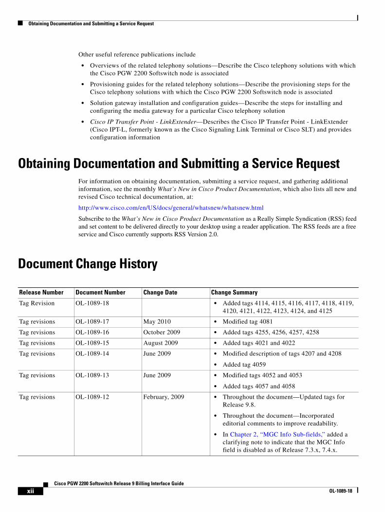
Document Change History
Release Number Document Number Change Date Change Summary
Tag Revision OL-1089-18 • Added tags 4114, 4115, 4116, 4117, 4118, 4119, 4120, 4121, 4122, 4123, 4124, and 4125
Tag revisions OL-1089-17 May 2010 • Modified tag 4081
Tag revisions OL-1089-16 October 2009 • Added tags 4255, 4256, 4257, 4258
Tag revisions OL-1089-15 August 2009 • Added tags 4021 and 4022
Tag revisions OL-1089-14 June 2009 • Modified description of tags 4207 and 4208
• Added tag 4059
Tag revisions OL-1089-13 June 2009 • Modified tags 4052 and 4053
• Added tags 4057 and 4058
Tag revisions OL-1089-12 February, 2009 • Throughout the document—Updated tags for Release 9.8.
• Throughout the document—Incorporated editorial comments to improve readability.
• In Chapter 2, “MGC Info Sub-fields,” added a clarifying note to indicate that the MGC Info field is disabled as of Release 7.3.x, 7.4.x.
xiiCisco PGW 2200 Softswitch Release 9 Billing Interface Guide
OL-1089-18
Obtaining Documentation and Submitting a Service Request
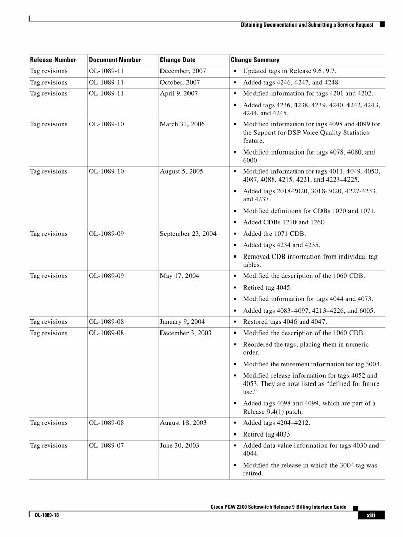
Tag revisions OL-1089-11 December, 2007 • Updated tags in Release 9.6, 9.7.
Tag revisions OL-1089-11 October, 2007 • Added tags 4246, 4247, and 4248
Tag revisions OL-1089-11 April 9, 2007 • Modified information for tags 4201 and 4202.
• Added tags 4236, 4238, 4239, 4240, 4242, 4243, 4244, and 4245.
Tag revisions OL-1089-10 March 31, 2006 • Modified information for tags 4098 and 4099 for the Support for DSP Voice Quality Statistics feature.
• Modified information for tags 4078, 4080, and 6000.
Tag revisions OL-1089-10 August 5, 2005 • Modified information for tags 4011, 4049, 4050, 4087, 4088, 4215, 4221, and 4223–4225.
• Added tags 2018-2020, 3018-3020, 4227-4233, and 4237.
• Modified definitions for CDBs 1070 and 1071.
• Added CDBs 1210 and 1260
Tag revisions OL-1089-09 September 23, 2004 • Added the 1071 CDB.
• Added tags 4234 and 4235.
• Removed CDB information from individual tag tables.
Tag revisions OL-1089-09 May 17, 2004 • Modified the description of the 1060 CDB.
• Retired tag 4045.
• Modified information for tags 4044 and 4073.
• Added tags 4083–4097, 4213–4226, and 6005.
Tag revisions OL-1089-08 January 9, 2004 • Restored tags 4046 and 4047.
Tag revisions OL-1089-08 December 3, 2003 • Modified the description of the 1060 CDB.
• Reordered the tags, placing them in numeric order.
• Modified the retirement information for tag 3004.
• Modified release information for tags 4052 and 4053. They are now listed as “defined for future use.”
• Added tags 4098 and 4099, which are part of a Release 9.4(1) patch.
Tag revisions OL-1089-08 August 18, 2003 • Added tags 4204–4212.
• Retired tag 4033.
Tag revisions OL-1089-07 June 30, 2003 • Added data value information for tags 4030 and 4044.
• Modified the release in which the 3004 tag was retired.
Release Number Document Number Change Date Change Summary
xiiiCisco PGW 2200 Softswitch Release 9 Billing Interface Guide
OL-1089-18
Obtaining Documentation and Submitting a Service Request
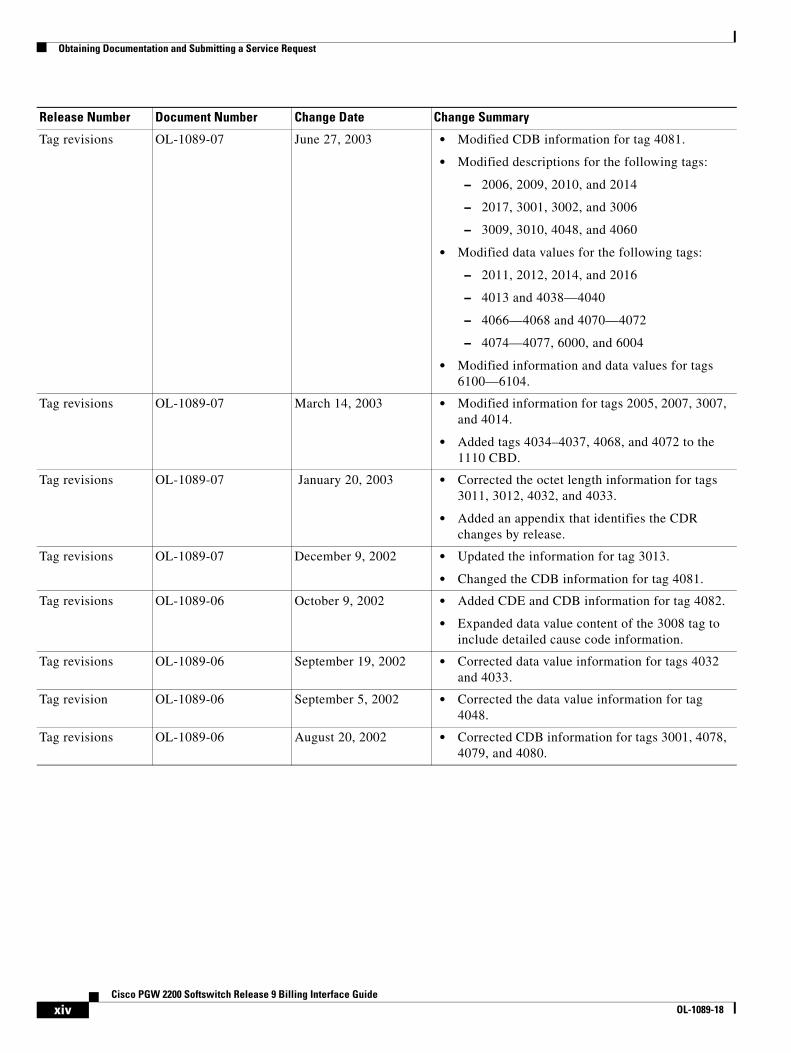
Tag revisions OL-1089-07 June 27, 2003 • Modified CDB information for tag 4081.
• Modified descriptions for the following tags:
– 2006, 2009, 2010, and 2014
– 2017, 3001, 3002, and 3006
– 3009, 3010, 4048, and 4060
• Modified data values for the following tags:
– 2011, 2012, 2014, and 2016
– 4013 and 4038—4040
– 4066—4068 and 4070—4072
– 4074—4077, 6000, and 6004
• Modified information and data values for tags 6100—6104.
Tag revisions OL-1089-07 March 14, 2003 • Modified information for tags 2005, 2007, 3007, and 4014.
• Added tags 4034–4037, 4068, and 4072 to the 1110 CBD.
Tag revisions OL-1089-07 January 20, 2003 • Corrected the octet length information for tags 3011, 3012, 4032, and 4033.
• Added an appendix that identifies the CDR changes by release.
Tag revisions OL-1089-07 December 9, 2002 • Updated the information for tag 3013.
• Changed the CDB information for tag 4081.
Tag revisions OL-1089-06 October 9, 2002 • Added CDE and CDB information for tag 4082.
• Expanded data value content of the 3008 tag to include detailed cause code information.
Tag revisions OL-1089-06 September 19, 2002 • Corrected data value information for tags 4032 and 4033.
Tag revision OL-1089-06 September 5, 2002 • Corrected the data value information for tag 4048.
Tag revisions OL-1089-06 August 20, 2002 • Corrected CDB information for tags 3001, 4078, 4079, and 4080.
Release Number Document Number Change Date Change Summary
xivCisco PGW 2200 Softswitch Release 9 Billing Interface Guide
OL-1089-18

Obtaining Documentation and Submitting a Service Request
Tag revisions OL-1089-06 August 16, 2002 • Added data value information to the 3000 series tags from Q.763.
• Identified tags 3002, 3004, 4046, and 4047 as retired.
• Corrected the CBD information for tags 4052 and 4053.
• Corrected descriptions for tags 4066–4068, 4070–4072, and 4074–4076.
• Modified the data value information for the 4100 series tags to indicate Cisco PGW 2200 Softswitch time.
• Modified the data value information for ANSI Nature of Address tags to indicate that the first value is spare.
• Modified tags to indicate that the maximum ANSI number is 214.
Tag revisions OL-1089-06 July 10, 2002 • Updated CDB values for tags 4078, 4079, and 4081.
• Updated CDB values for tags 4077 and 4080.
New template OL-1089-06 July 1, 2002 • Updated this document with the current user documentation template.
Tag revisions OL-1089-06 July 1, 2002 • Removed Tag 5000 from the listings for CDBs 1090 and 1100.
• Replaced Tag 6001 in CDB 1100 with Tag 6002.
• Added MGCP as a valid interface in Tags 4069 and 4073.
Tag revisions OL-1089-06 May 15, 2002 • Added Tags 4078 through 4081.
Revised Table 1-2 OL-1089-05 April 3, 2002 • Removed references to Tags 4064 and 4065.
Tag revisions OL-1089-04 March 22, 2002 • Revised data value and general information for Tags 4034 through 4037.
Tag revisions OL-1089-03 November 27, 2001 • Revised text for last bullet on page 1-7 and on page 1-8.
• Removed “(retired in Release 9.0(1))” for Tag 2017 and Tag 3017.
• Added Tag 4203.
• Removed Tag 4064 and Tag 4065.
Release Number Document Number Change Date Change Summary
xvCisco PGW 2200 Softswitch Release 9 Billing Interface Guide
OL-1089-18

Obtaining Documentation and Submitting a Service Request
ASCII output OL-1089-02 November 16, 2001 • Removed references to ASCII output on page 1-2 to page 1-4.
• Removed Table 1-1 on page 1-11.
• Removed CdrDmpr.callDetail row in Table 1-6 on page 1-11.
• Removed Trigger Interface section on page 1-18.
— OL-1089-01 October 18, 2001 Initial release
Release Number Document Number Change Date Change Summary
xviCisco PGW 2200 Softswitch Release 9 Billing Interface Guide
OL-1089-18
Cisco PGWOL-1089-18
C H A P T E R 1
Billing InterfacesRevised: July 21, 2010, OL-1089-18
This chapter describes the Cisco PGW 2200 Softswitch billing interface capabilities and its call detail records (CDRs). It contains the following sections:
• Billing Capabilities Overview, page 1-1
• Call Data Block Descriptions, page 1-6
• CDE Descriptions, page 1-10
• Cisco PGW 2200 Softswitch Billing Interfaces, page 1-22
• Redundant Cisco PGW 2200 Softswitch Configuration, page 1-23
• Cisco PGW 2200 Softswitch Clock Synchronization, page 1-23
• Detailed CDB Descriptions, page 1-24
• CDE Detail Description, page 1-54
Billing Capabilities OverviewThe generic interface to the CDR dumper interface carries all the billing information in the form of call detail blocks (CDBs). When the CDR dumper receives the CDB, it writes the record in the CDR file.
CDB generation is based on a point in call (PIC). The Cisco PGW 2200 Softswitch predefines several PICs that can trigger the generation of CDBs. Examples of PICs include Answered, Long Duration, and Released. For example, the Cisco PGW 2200 Softswitch triggers the generation of the Answered CDB when an Answer message (ANM for SS7) is received.
Each CDB has a type associated with it that distinguishes the PIC.
CDB-required events that are triggered are passed to the CDR manager module. When an event is received, the action the CDR manager module takes is determined by its configuration. The CDR manager module either handles or ignores the event.
System InterfacesSystem interfaces vary according to the configuration. The configuration can be either dual Cisco PGW 2200 Softswitch (hot-standby) or standalone. The physical interface is described in the following section.
1-1 2200 Softswitch Release 9 Billing Interface Guide
Chapter 1 Billing InterfacesBilling Capabilities Overview
Physical Interface
The physical interface between the Cisco PGW 2200 Softswitch and the mediation software (for example, Billing and Measurements Server (BAMS)) relies on guaranteed delivery of the CDB information between both Cisco PGW 2200 Softswitches. The interface consists of dual Ethernet links. Each link is physically isolated for redundancy.
RADIUS Interface
The RADIUS Enhancement for Accounting feature provides RADIUS interface support on the PGW 2200 for CDR data. For more information about the feature, including new CDRs, refer to the RADIUS Enhancement for Accounting feature guide.
Message Interface
The CDB message interface is a one-way interface to the CDR dumper. The CDR dumper saves the CDB message into the CDR files without any conversion or data manipulation. The CDR files can be retrieved by a mediation system, for example, a Cisco Billing and Measurements Server (BAMS). The mediation system can convert the CDR data into ASCII files, which can be forwarded to an external billing system for further processing.
For information about the file-transfer process, see the “FTP and SFTP Support” section on page 1-22.
Note Follow your local procedures for managing files created by the Cisco PGW 2200 Softswitch billing process, including archiving and deleting files from your system.
CDB Message FormatThe format of CDB messages being sent to the CDR dumper is based on a binary, tag-length-value (TLV) format. Each field within the CDB message has a tag, length, and value.
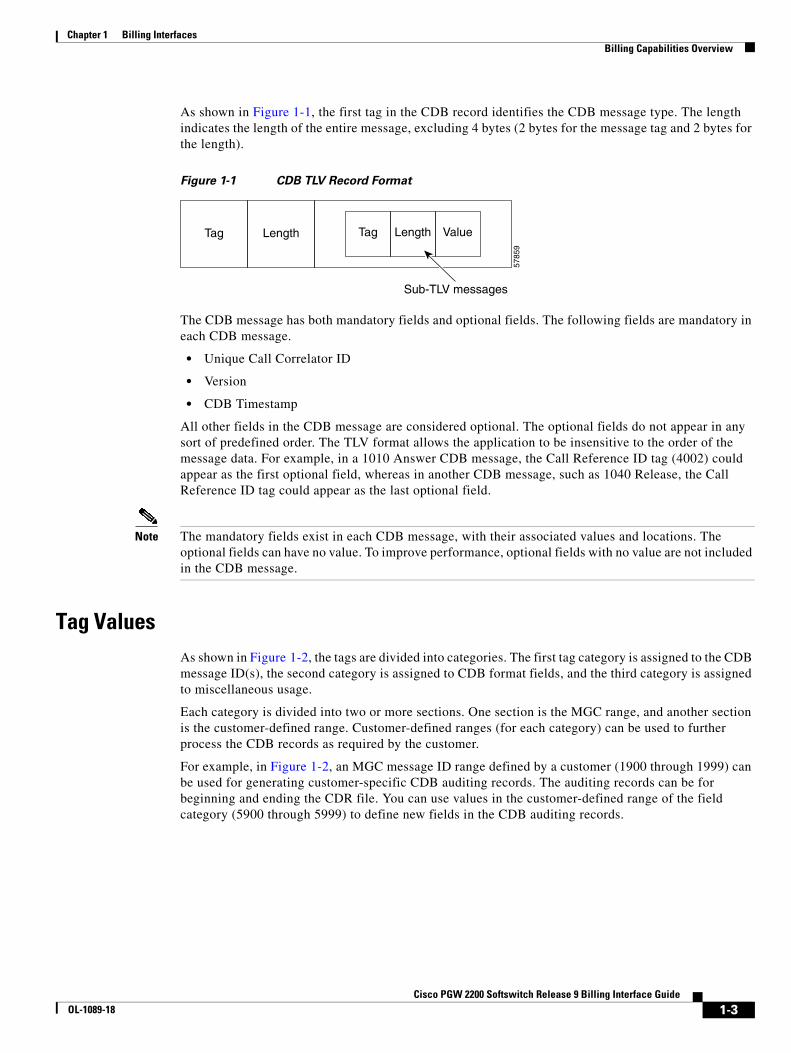
Figure 1-1 shows how the CDB record itself is also in TLV format, with the value part composed of multiple sub-TLVs. For performance reasons, the first few fields (tags) of the value portion of the CDB exist in a fixed order for every message. These fields are the Unique Call Correlator ID (Tag 5000), CDB Version (Tag 4000), and CDB Timepoint (Tag 4001).
Note These three fields are fixed so that the CDR dumper can have direct access to these fields without having to parse or search through all the CDB message TLV fields.
1-2Cisco PGW 2200 Softswitch Release 9 Billing Interface Guide
OL-1089-18
Chapter 1 Billing InterfacesBilling Capabilities Overview
As shown in Figure 1-1, the first tag in the CDB record identifies the CDB message type. The length indicates the length of the entire message, excluding 4 bytes (2 bytes for the message tag and 2 bytes for the length).
Figure 1-1 CDB TLV Record Format
The CDB message has both mandatory fields and optional fields. The following fields are mandatory in each CDB message.
• Unique Call Correlator ID
• Version
• CDB Timestamp
All other fields in the CDB message are considered optional. The optional fields do not appear in any sort of predefined order. The TLV format allows the application to be insensitive to the order of the message data. For example, in a 1010 Answer CDB message, the Call Reference ID tag (4002) could appear as the first optional field, whereas in another CDB message, such as 1040 Release, the Call Reference ID tag could appear as the last optional field.
Note The mandatory fields exist in each CDB message, with their associated values and locations. The optional fields can have no value. To improve performance, optional fields with no value are not included in the CDB message.
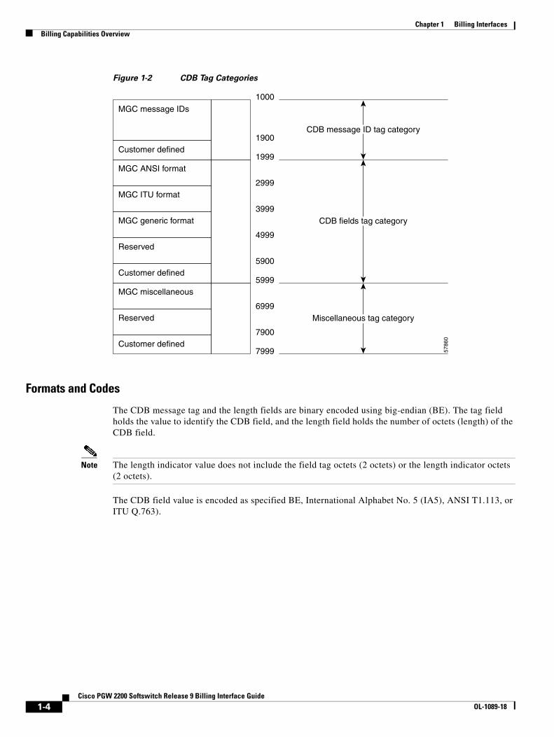
Tag ValuesAs shown in Figure 1-2, the tags are divided into categories. The first tag category is assigned to the CDB message ID(s), the second category is assigned to CDB format fields, and the third category is assigned to miscellaneous usage.
Each category is divided into two or more sections. One section is the MGC range, and another section is the customer-defined range. Customer-defined ranges (for each category) can be used to further process the CDB records as required by the customer.
For example, in Figure 1-2, an MGC message ID range defined by a customer (1900 through 1999) can be used for generating customer-specific CDB auditing records. The auditing records can be for beginning and ending the CDR file. You can use values in the customer-defined range of the field category (5900 through 5999) to define new fields in the CDB auditing records.
Tag Length Tag Length
Sub-TLV messages
Value
5785
9
1-3Cisco PGW 2200 Softswitch Release 9 Billing Interface Guide
OL-1089-18
Chapter 1 Billing InterfacesBilling Capabilities Overview
Figure 1-2 CDB Tag Categories
Formats and Codes
The CDB message tag and the length fields are binary encoded using big-endian (BE). The tag field holds the value to identify the CDB field, and the length field holds the number of octets (length) of the CDB field.
Note The length indicator value does not include the field tag octets (2 octets) or the length indicator octets (2 octets).
The CDB field value is encoded as specified BE, International Alphabet No. 5 (IA5), ANSI T1.113, or ITU Q.763).
MGC message IDs
MGC ANSI format
Customer defined
Customer defined
1000
1999
2999
3999
4999
5900
5999
6999
7900
7999
1900
5786
0
MGC ITU format
MGC generic format
Reserved
Customer defined
MGC miscellaneous
Reserved
CDB message ID tag category
CDB fields tag category
Miscellaneous tag category
1-4Cisco PGW 2200 Softswitch Release 9 Billing Interface Guide
OL-1089-18

Chapter 1 Billing InterfacesBilling Capabilities Overview
CDB Record Types
This section describes different types of CDBs and their relation to PIC events. Creation of the CDB is based on certain PIC events (refer to Table 1-1), and other call events.
Table 1-1 CDB Types
PIC Event DescriptionCDB Tag Value CDB Message Record
Answer call event Call went through and was answered. 1010 Set CDB record
Deselected outgoing circuit event
Circuit cannot be used, passed to another. 1020 Deselected outgoing circuit CDB record
Aborted attempt call event Call did not progress to setup status. 1030 Aborted attempt CDB record
Release call event Released call. 1040 Release CDB record
Interrupted call event Call terminating without release message. 1050 Interrupted CDB record
Ongoing call event Long call. 1060 Ongoing call CDB record
Maintenance CDB record Circuit maintenance. 1070 Maintenance CDB record
SS7 CIC audit This CDB is generated for the following conditions:
• When the MML command sta-aud-cic is used to generate the current CIC availability information on each configured ISUP trunk group or signaling service.
• A provisioning change (add or delete) is made in the number of circuits.
• A CIC service state or block-state change occurs.
1071 SS7 CIC Audit CDB record
External access CDB Call sent a query to a Service Control Point (SCP) (or to another external device or database).
1080 External access CDB record
File header CDB CDR dumper creates the file header CDB at the beginning of each CDR file.
1090 File header CDB record
File footer CDB CDR dumper creates the file footer CDB at the end of each CDR file.
1100 File footer CDB record
End of a call CDB This CDB is generated when the Cisco PGW 2200 Softswitch is configured to have one CDB per call.
The CDB is generated at the end of the call (as in Release CDB) or when the call did not progress to setup status (as in Aborted attempt CDB).
Note If the Cisco PGW 2200 Softswitch is configured for 1110 output, the 1010, 1030, and 1040 CDBs must not be configured for inclusion in the output billing files.
1110 End of a Call CDB
1-5Cisco PGW 2200 Softswitch Release 9 Billing Interface Guide
OL-1089-18
Chapter 1 Billing InterfacesCall Data Block Descriptions
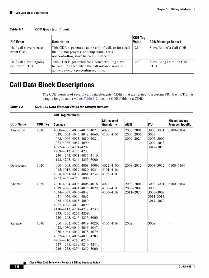
Call Data Block DescriptionsThe CDB consists of several call data elements (CDEs) that are related to a certain PIC. Each CDE has a tag, a length, and a value. Table 1-2 lists the CDE fields in a CDB.
Half call slave release event CDB
This CDB is generated at the end-of-call, or for a call that did not progress to setup status, for a noncontrolling slave half-call instance.
1210 Slave End of a Call CDB
Half call slave ongoing call event CDB
This CDB is generated for a noncontrolling slave half-call instance when the call instance remains active beyond a preconfigured time.
1260 Slave Long Duration Call CDB
Table 1-1 CDB Types (continued)
PIC Event DescriptionCDB Tag Value CDB Message Record
Table 1-2 CDB Call Data Element Fields for Current Release
CDE Tag Numbers
CDB Name CDB Tag Common
Millisecond Granularity
ANSI
ITU
Miscellaneous Protocol Specific
Answered 1010 4000–4005, 4008–4016, 4021, 4029, 4034–4043, 4048, 4060, 4063, 4066–4073, 4080, 4081, 4083–4086, 4089, 4090, 4092–4096, 4201–4207, 4209–4212, 4236, 4237, 4240–4243, 4051–4056, 4110, 4112, 4203, 4246–4255, 5000
4022, 4100–4105
2000, 2001, 2003–2007, 2009–2020
3000, 3001, 3003, 3005–3007, 3009–3013, 3017–3020
6100–6104
Deselected 1020 4000–4003, 4006, 4008, 4009, 4015, 4016, 4019, 4020, 4021, 4028, 4034–4037, 4081, 4232, 4233, 4256–4259, 5000
4022, 4100, 4101, 4106, 4108, 4109
2008–2012 3008–3012 6100–6104
Aborted 1030 4000–4004, 4006, 4008–4016, 4019, 4020, 4021, 4028, 4029, 4034–4039, 4046–4048, 4051–4056, 4060–4062, 4065–4073, 4078–4080, 4082–4096, 4098, 4099, 4110–4113, 4201–4212, 4232, 4233, 4236, 4237, 4239, 4240–4245, 4246–4255, 5000
4022, 4100–4103, 4106–4109,
2000, 2001, 2003–2009, 2011–2020
3000, 3001, 3003, 3005–3009, 3011, 3013, 3017–3020
6100–6104
Release 1040 4000–4002, 4006, 4019, 4020, 4028, 4030, 4044, 4046, 4047, 4056, 4061, 4062, 4078, 4079, 4082–4091, 4095–4099, 4203, 4205–4210, 4213, 4214, 4227–4231, 4239, 4240, 4241, 4246–4253, 4256–4259, 5000
4106–4109, 2008 3008 —
1-6Cisco PGW 2200 Softswitch Release 9 Billing Interface Guide
OL-1089-18
Chapter 1 Billing InterfacesCall Data Block Descriptions
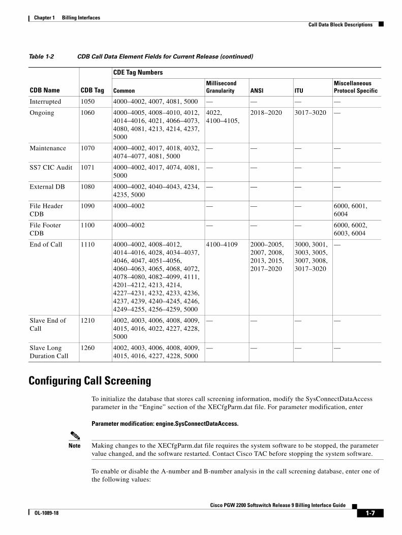
Configuring Call ScreeningTo initialize the database that stores call screening information, modify the SysConnectDataAccess parameter in the “Engine” section of the XECfgParm.dat file. For parameter modification, enter
Parameter modification: engine.SysConnectDataAccess.
Note Making changes to the XECfgParm.dat file requires the system software to be stopped, the parameter value changed, and the software restarted. Contact Cisco TAC before stopping the system software.
To enable or disable the A-number and B-number analysis in the call screening database, enter one of the following values:
Interrupted 1050 4000–4002, 4007, 4081, 5000 — — — —
Ongoing 1060 4000–4005, 4008–4010, 4012, 4014–4016, 4021, 4066–4073, 4080, 4081, 4213, 4214, 4237, 5000
4022, 4100–4105,
2018–2020 3017–3020 —
Maintenance 1070 4000–4002, 4017, 4018, 4032, 4074–4077, 4081, 5000
— — — —
SS7 CIC Audit 1071 4000–4002, 4017, 4074, 4081, 5000
— — — —
External DB 1080 4000–4002, 4040–4043, 4234, 4235, 5000
— — — —
File Header CDB
1090 4000–4002 — — — 6000, 6001, 6004
File Footer CDB
1100 4000–4002 — — — 6000, 6002, 6003, 6004
End of Call 1110 4000–4002, 4008–4012, 4014–4016, 4028, 4034–4037, 4046, 4047, 4051–4056, 4060–4063, 4065, 4068, 4072, 4078–4080, 4082–4099, 4111, 4201–4212, 4213, 4214, 4227–4231, 4232, 4233, 4236, 4237, 4239, 4240–4245, 4246, 4249–4255, 4256–4259, 5000
4100–4109 2000–2005, 2007, 2008, 2013, 2015, 2017–2020
3000, 3001, 3003, 3005, 3007, 3008, 3017–3020
—
Slave End of Call
1210 4002, 4003, 4006, 4008, 4009, 4015, 4016, 4022, 4227, 4228, 5000
— — — —
Slave Long Duration Call
1260 4002, 4003, 4006, 4008, 4009, 4015, 4016, 4227, 4228, 5000
— — — —
Table 1-2 CDB Call Data Element Fields for Current Release (continued)
CDE Tag Numbers
CDB Name CDB Tag Common
Millisecond Granularity
ANSI
ITU
Miscellaneous Protocol Specific
1-7Cisco PGW 2200 Softswitch Release 9 Billing Interface Guide
OL-1089-18
Chapter 1 Billing InterfacesCall Data Block Descriptions
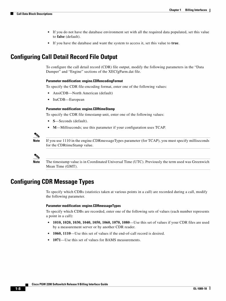
• If you do not have the database environment set with all the required data populated, set this value to false (default).
• If you have the database and want the system to access it, set this value to true.
Configuring Call Detail Record File OutputTo configure the call detail record (CDR) file output, modify the following parameters in the “Data Dumper” and “Engine” sections of the XECfgParm.dat file.
Parameter modification: engine.CDRencodingFormat
To specify the CDR file-encoding format, enter one of the following values:
• AnsiCDB—North American (default)
• ItuCDB—European
Parameter modification: engine.CDRtimeStamp
To specify the CDR file timestamp unit, enter one of the following values:
• S—Seconds (default).
• M—Milliseconds; use this parameter if your configuration uses TCAP.
Note If you use 1110 in the engine.CDRmessageTypes parameter (for TCAP), you must specify milliseconds for the CDRtimeStamp value.
Note The timestamp value is in Coordinated Universal Time (UTC). Previously the term used was Greenwich Mean Time (GMT).
Configuring CDR Message TypesTo specify which CDBs (statistics taken at various points in a call) are recorded during a call, modify the following parameter.
Parameter modification: engine.CDRmessageTypes
To specify which CDBs are recorded, enter one of the following sets of values (each number represents a point in a call):
• 1010, 1020, 1030, 1040, 1050, 1060, 1070, 1080—Use this set of values if your CDR files are used by a measurement server or by another CDR reader.
• 1060, 1110—Use this set of values if the end-of-call record is desired.
• 1071—Use this set of values for BAMS measurements.
1-8Cisco PGW 2200 Softswitch Release 9 Billing Interface Guide
OL-1089-18
Chapter 1 Billing InterfacesCall Data Block Descriptions
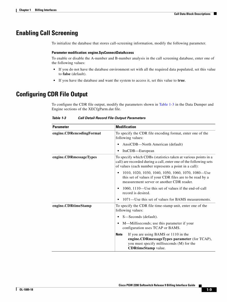
Enabling Call ScreeningTo initialize the database that stores call-screening information, modify the following parameter.
Parameter modification: engine.SysConnectDataAccess
To enable or disable the A-number and B-number analysis in the call screening database, enter one of the following values:
• If you do not have the database environment set with all the required data populated, set this value to false (default).
• If you have the database and want the system to access it, set this value to true.
Configuring CDR File OutputTo configure the CDR file output, modify the parameters shown in Table 1-3 in the Data Dumper and Engine sections of the XECfgParm.dat file.
Table 1-3 Call Detail Record File Output Parameters
Parameter Modification
engine.CDRencodingFormat To specify the CDR file encoding format, enter one of the following values:
• AnsiCDB—North American (default)
• ItuCDB—European
engine.CDRmessageTypes To specify which CDBs (statistics taken at various points in a call) are recorded during a call, enter one of the following sets of values (each number represents a point in a call):
• 1010, 1020, 1030, 1040, 1050, 1060, 1070, 1080—Use this set of values if your CDR files are to be read by a measurement server or another CDR reader.
• 1060, 1110—Use this set of values if the end-of-call record is desired.
• 1071—Use this set of values for BAMS measurements.
engine.CDRtimeStamp To specify the CDR file time-stamp unit, enter one of the following values:
• S—Seconds (default).
• M—Milliseconds; use this parameter if your configuration uses TCAP or BAMS.
Note If you are using BAMS or 1110 in the engine.CDRmessageTypes parameter (for TCAP), you must specify milliseconds (M) for the CDRtimeStamp value.
1-9Cisco PGW 2200 Softswitch Release 9 Billing Interface Guide
OL-1089-18
Chapter 1 Billing InterfacesCDE Descriptions
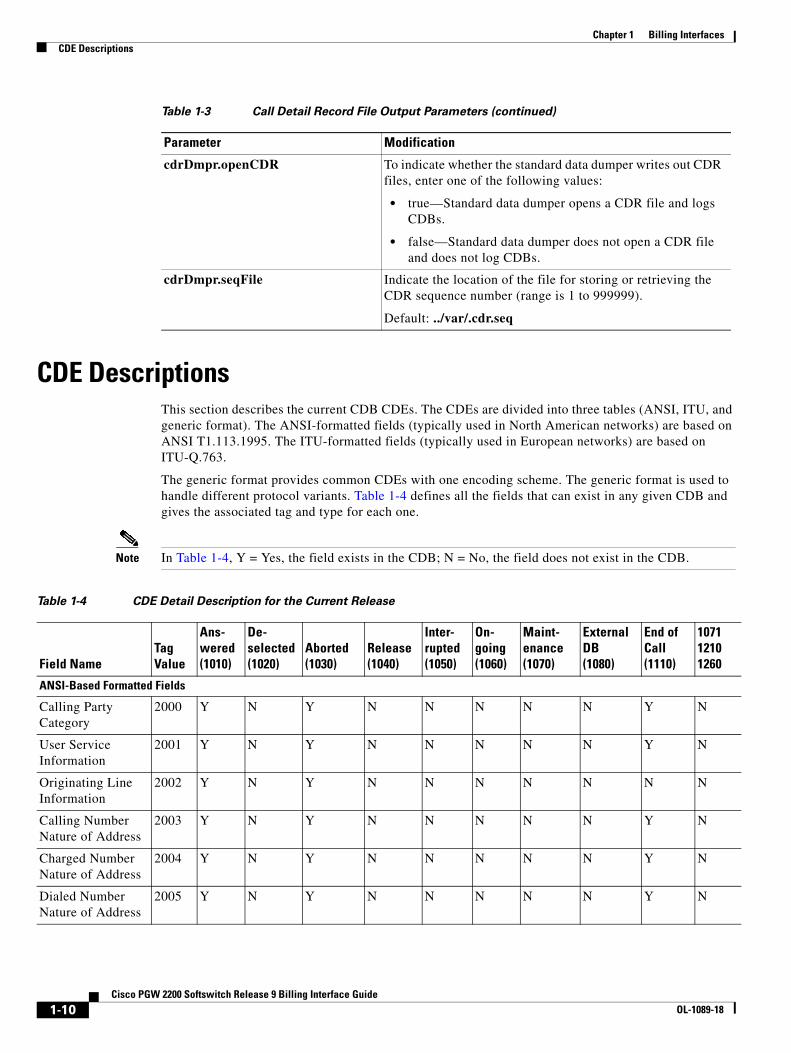
CDE DescriptionsThis section describes the current CDB CDEs. The CDEs are divided into three tables (ANSI, ITU, and generic format). The ANSI-formatted fields (typically used in North American networks) are based on ANSI T1.113.1995. The ITU-formatted fields (typically used in European networks) are based on ITU-Q.763.
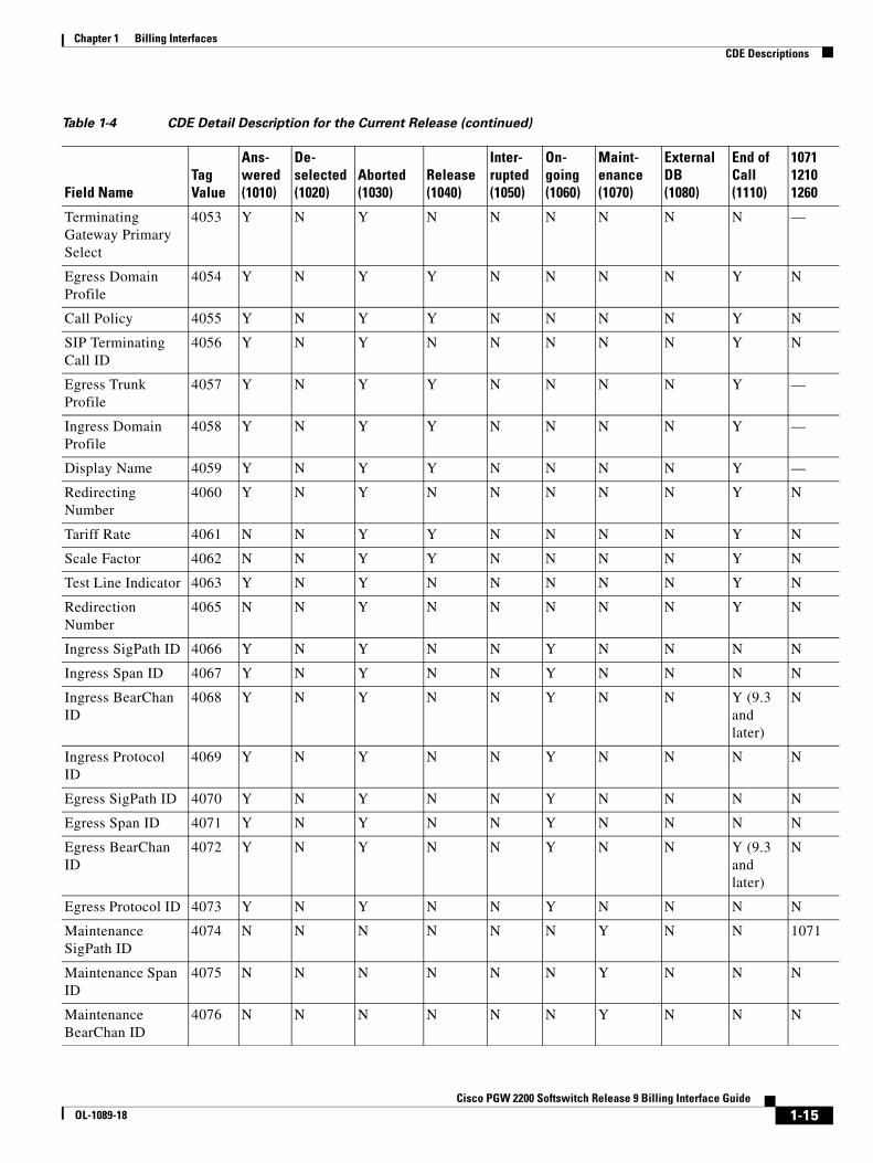
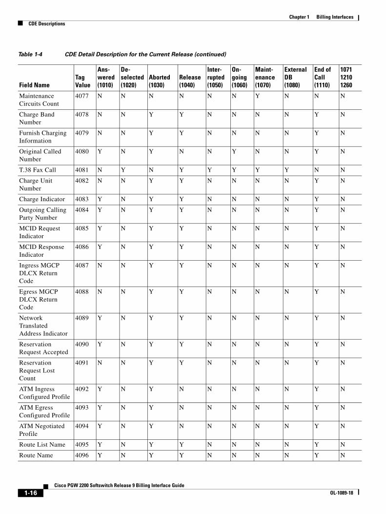
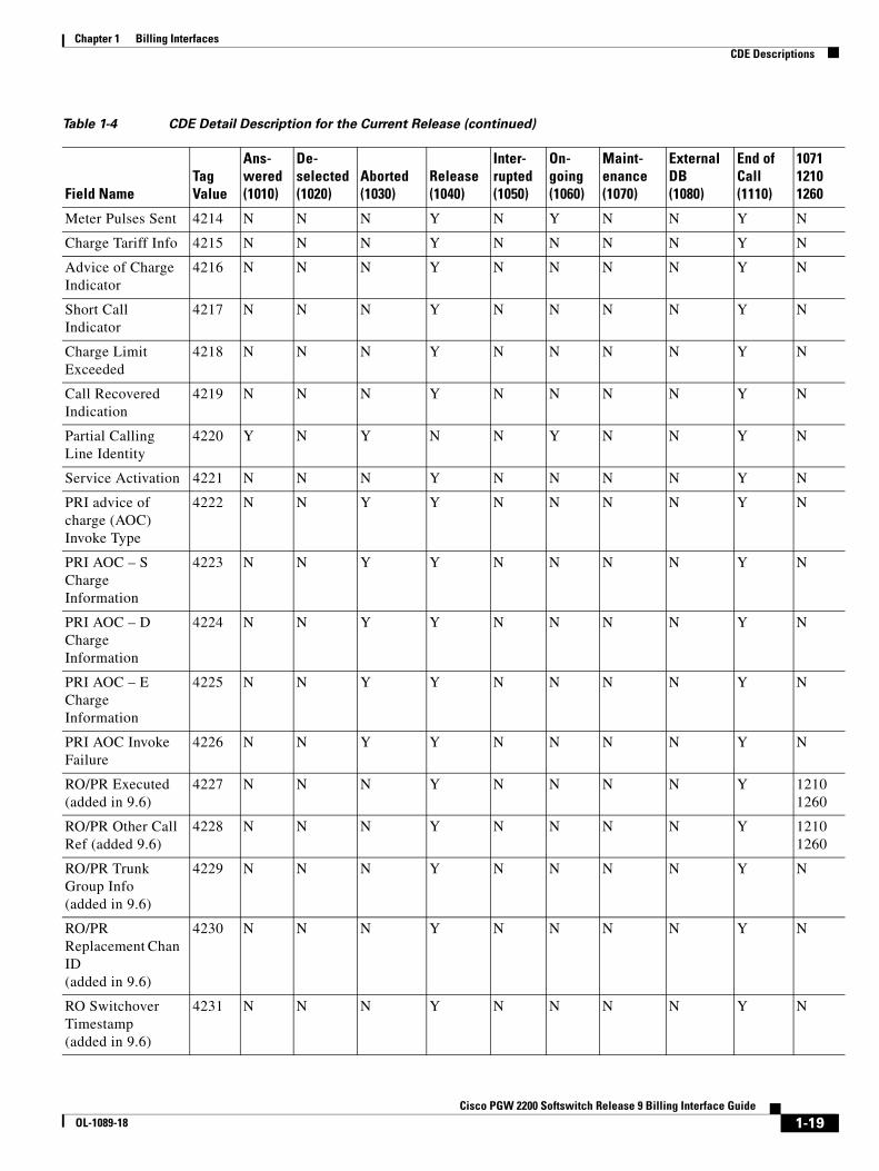
The generic format provides common CDEs with one encoding scheme. The generic format is used to handle different protocol variants. Table 1-4 defines all the fields that can exist in any given CDB and gives the associated tag and type for each one.
Note In Table 1-4, Y = Yes, the field exists in the CDB; N = No, the field does not exist in the CDB.
cdrDmpr.openCDR To indicate whether the standard data dumper writes out CDR files, enter one of the following values:
• true—Standard data dumper opens a CDR file and logs CDBs.
• false—Standard data dumper does not open a CDR file and does not log CDBs.
cdrDmpr.seqFile Indicate the location of the file for storing or retrieving the CDR sequence number (range is 1 to 999999).
Default: ../var/.cdr.seq
Table 1-3 Call Detail Record File Output Parameters (continued)
Parameter Modification
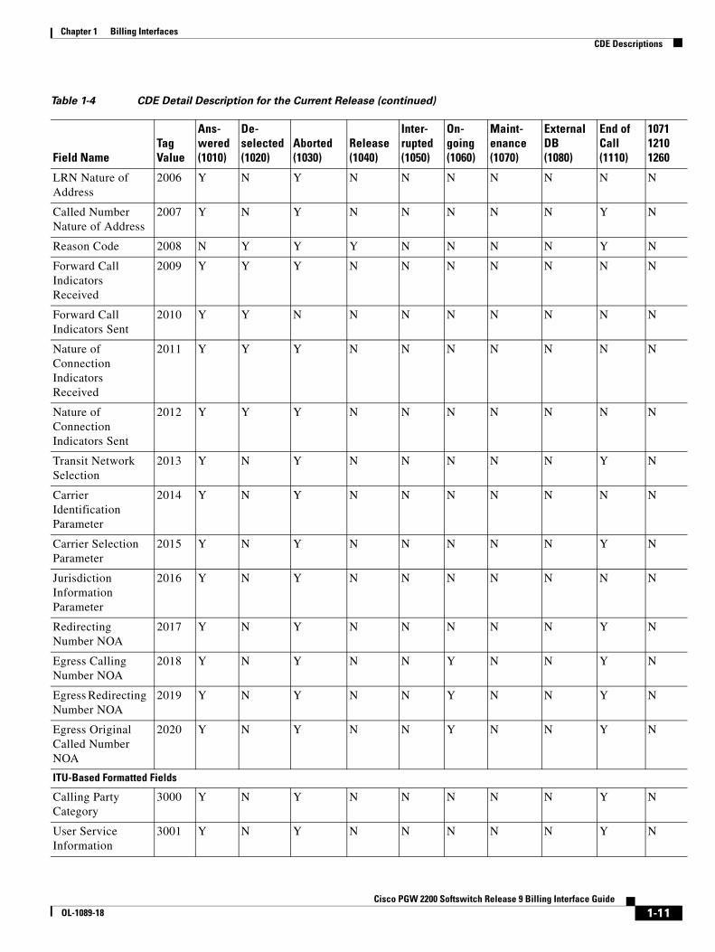
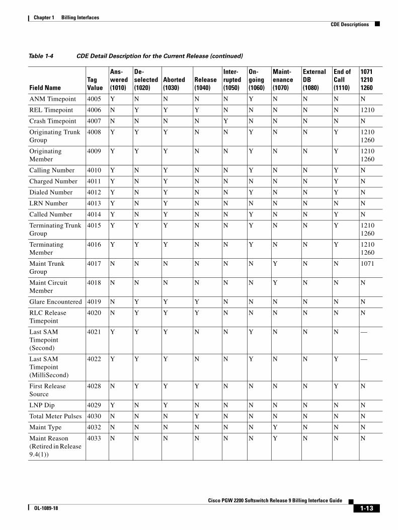
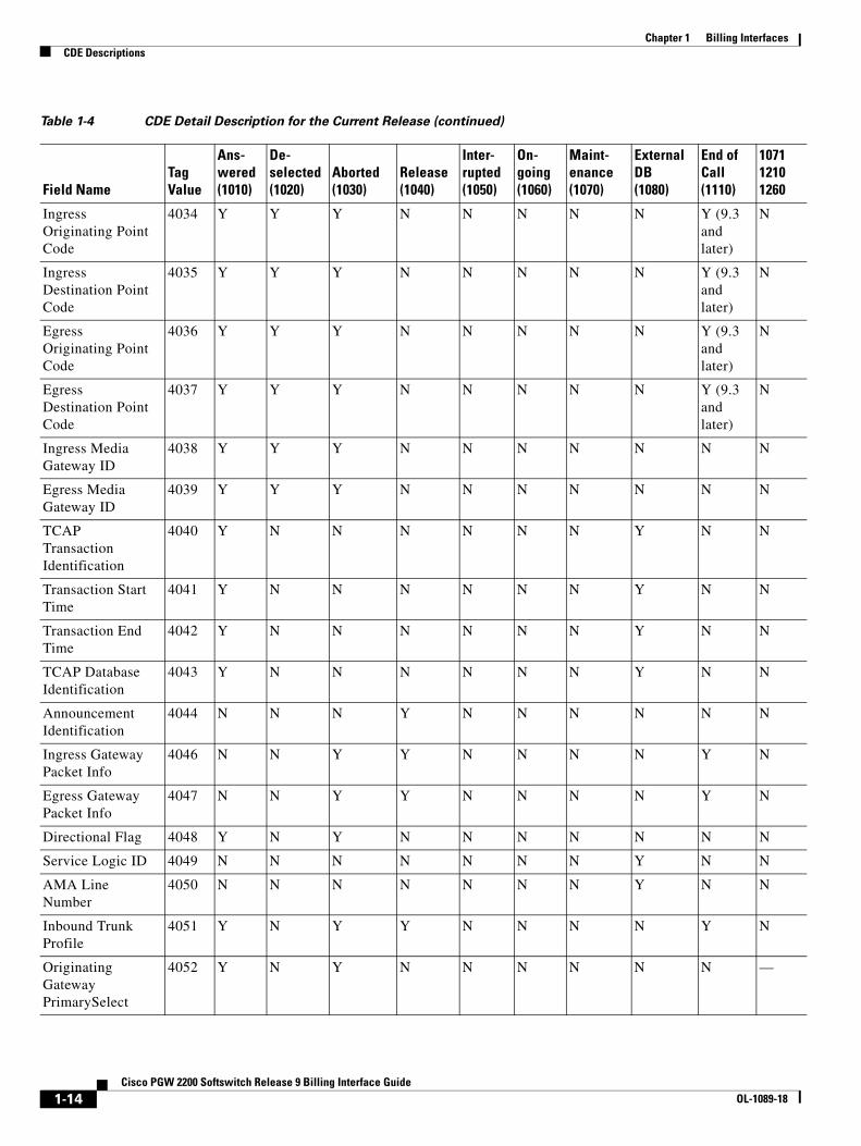
Table 1-4 CDE Detail Description for the Current Release
Field NameTag Value
Ans- wered (1010)
De- selected (1020)
Aborted (1030)
Release (1040)
Inter- rupted (1050)
On- going (1060)
Maint- enance (1070)
External DB (1080)
End of Call (1110)
1071 1210 1260
ANSI-Based Formatted Fields
Calling Party Category
2000 Y N Y N N N N N Y N
User Service Information
2001 Y N Y N N N N N Y N
Originating Line Information
2002 Y N Y N N N N N N N
Calling Number Nature of Address
2003 Y N Y N N N N N Y N
Charged Number Nature of Address
2004 Y N Y N N N N N Y N
Dialed Number Nature of Address
2005 Y N Y N N N N N Y N
1-10Cisco PGW 2200 Softswitch Release 9 Billing Interface Guide
OL-1089-18
Chapter 1 Billing InterfacesCDE Descriptions
LRN Nature of Address
2006 Y N Y N N N N N N N
Called Number Nature of Address
2007 Y N Y N N N N N Y N
Reason Code 2008 N Y Y Y N N N N Y N
Forward Call Indicators Received
2009 Y Y Y N N N N N N N
Forward Call Indicators Sent
2010 Y Y N N N N N N N N
Nature of Connection Indicators Received
2011 Y Y Y N N N N N N N
Nature of Connection Indicators Sent
2012 Y Y Y N N N N N N N
Transit Network Selection
2013 Y N Y N N N N N Y N
Carrier Identification Parameter
2014 Y N Y N N N N N N N
Carrier Selection Parameter
2015 Y N Y N N N N N Y N
Jurisdiction Information Parameter
2016 Y N Y N N N N N N N
Redirecting Number NOA
2017 Y N Y N N N N N Y N
Egress Calling Number NOA
2018 Y N Y N N Y N N Y N
Egress Redirecting Number NOA
2019 Y N Y N N Y N N Y N
Egress Original Called Number NOA
2020 Y N Y N N Y N N Y N
ITU-Based Formatted Fields
Calling Party Category
3000 Y N Y N N N N N Y N
User Service Information
3001 Y N Y N N N N N Y N
Table 1-4 CDE Detail Description for the Current Release (continued)
Field NameTag Value
Ans- wered (1010)
De- selected (1020)
Aborted (1030)
Release (1040)
Inter- rupted (1050)
On- going (1060)
Maint- enance (1070)
External DB (1080)
End of Call (1110)
1071 1210 1260
1-11Cisco PGW 2200 Softswitch Release 9 Billing Interface Guide
OL-1089-18

Chapter 1 Billing InterfacesCDE Descriptions
Calling Number Nature of Address
3003 Y N Y N N N N N Y N
Dialed Number Nature of Address
3005 Y N Y N N N N N Y N
LRN Nature of Address
3006 Y N Y N N N N N N N
Called Number Nature of Address
3007 Y N Y N N N N N Y N
Reason Code 3008 N Y Y Y N N N N Y N
Forward Call Indicators Received
3009 Y Y Y N N N N N N N
Forward Call Indicators Sent
3010 Y Y N N N N N N N N
Nature of Connection Indicators Received
3011 Y Y Y N N N N N N N
Nature of Connection Indicators Sent
3012 Y Y N N N N N N N N
Transit Network Selection
3013 Y N Y N N N N N N N
Redirecting Number NOA
3017 Y N Y N N N N N Y N
Egress Calling Number NOA
3018 Y N Y N N Y N N Y N
Egress Redirecting Number NOA
3019 Y N Y N N Y N N Y N
Egress Original Called Number NOA
3020 Y N Y N N Y N N Y N
Cisco PGW 2200 Softswitch Generic Tags
CDB Version 4000 Y Y Y Y Y Y Y Y Y 1071
CDB Timepoint 4001 Y Y Y Y Y Y Y Y Y 1071
Call Reference ID 4002 Y Y Y Y Y Y Y Y Y 1210 1260
IAM Timepoint 4003 Y Y Y N N Y N N N 1210 1260
ACM Timepoint 4004 Y N Y N N Y N N N N
Table 1-4 CDE Detail Description for the Current Release (continued)
Field NameTag Value
Ans- wered (1010)
De- selected (1020)
Aborted (1030)
Release (1040)
Inter- rupted (1050)
On- going (1060)
Maint- enance (1070)
External DB (1080)
End of Call (1110)
1071 1210 1260
1-12Cisco PGW 2200 Softswitch Release 9 Billing Interface Guide
OL-1089-18
Chapter 1 Billing InterfacesCDE Descriptions
ANM Timepoint 4005 Y N N N N Y N N N N
REL Timepoint 4006 N Y Y Y N N N N N 1210
Crash Timepoint 4007 N N N N Y N N N N N
Originating Trunk Group
4008 Y Y Y N N Y N N Y 1210 1260
Originating Member
4009 Y Y Y N N Y N N Y 1210 1260
Calling Number 4010 Y N Y N N Y N N Y N
Charged Number 4011 Y N Y N N N N N Y N
Dialed Number 4012 Y N Y N N Y N N Y N
LRN Number 4013 Y N Y N N N N N N N
Called Number 4014 Y N Y N N Y N N Y N
Terminating Trunk Group
4015 Y Y Y N N Y N N Y 1210 1260
Terminating Member
4016 Y Y Y N N Y N N Y 1210 1260
Maint Trunk Group
4017 N N N N N N Y N N 1071
Maint Circuit Member
4018 N N N N N N Y N N N
Glare Encountered 4019 N Y Y Y N N N N N N
RLC Release Timepoint
4020 N Y Y Y N N N N N N
Last SAM Timepoint (Second)
4021 Y Y Y N N Y N N N —
Last SAM Timepoint (MilliSecond)
4022 Y Y Y N N Y N N Y —
First Release Source
4028 N Y Y Y N N N N Y N
LNP Dip 4029 Y N Y N N N N N N N
Total Meter Pulses 4030 N N N Y N N N N N N
Maint Type 4032 N N N N N N Y N N N
Maint Reason (Retired in Release 9.4(1))
4033 N N N N N N Y N N N
Table 1-4 CDE Detail Description for the Current Release (continued)
Field NameTag Value
Ans- wered (1010)
De- selected (1020)
Aborted (1030)
Release (1040)
Inter- rupted (1050)
On- going (1060)
Maint- enance (1070)
External DB (1080)
End of Call (1110)
1071 1210 1260
1-13Cisco PGW 2200 Softswitch Release 9 Billing Interface Guide
OL-1089-18
Chapter 1 Billing InterfacesCDE Descriptions
Ingress Originating Point Code
4034 Y Y Y N N N N N Y (9.3 and later)
N
Ingress Destination Point Code
4035 Y Y Y N N N N N Y (9.3 and later)
N
Egress Originating Point Code
4036 Y Y Y N N N N N Y (9.3 and later)
N
Egress Destination Point Code
4037 Y Y Y N N N N N Y (9.3 and later)
N
Ingress Media Gateway ID
4038 Y Y Y N N N N N N N
Egress Media Gateway ID
4039 Y Y Y N N N N N N N
TCAP Transaction Identification
4040 Y N N N N N N Y N N
Transaction Start Time
4041 Y N N N N N N Y N N
Transaction End Time
4042 Y N N N N N N Y N N
TCAP Database Identification
4043 Y N N N N N N Y N N
Announcement Identification
4044 N N N Y N N N N N N
Ingress Gateway Packet Info
4046 N N Y Y N N N N Y N
Egress Gateway Packet Info
4047 N N Y Y N N N N Y N
Directional Flag 4048 Y N Y N N N N N N N
Service Logic ID 4049 N N N N N N N Y N N
AMA Line Number
4050 N N N N N N N Y N N
Inbound Trunk Profile
4051 Y N Y Y N N N N Y N
Originating Gateway PrimarySelect
4052 Y N Y N N N N N N —
Table 1-4 CDE Detail Description for the Current Release (continued)
Field NameTag Value
Ans- wered (1010)
De- selected (1020)
Aborted (1030)
Release (1040)
Inter- rupted (1050)
On- going (1060)
Maint- enance (1070)
External DB (1080)
End of Call (1110)
1071 1210 1260
1-14Cisco PGW 2200 Softswitch Release 9 Billing Interface Guide
OL-1089-18
Chapter 1 Billing InterfacesCDE Descriptions
Terminating Gateway Primary Select
4053 Y N Y N N N N N N —
Egress Domain Profile
4054 Y N Y Y N N N N Y N
Call Policy 4055 Y N Y Y N N N N Y N
SIP Terminating Call ID
4056 Y N Y N N N N N Y N
Egress Trunk Profile
4057 Y N Y Y N N N N Y —
Ingress Domain Profile
4058 Y N Y Y N N N N Y —
Display Name 4059 Y N Y Y N N N N Y —
Redirecting Number
4060 Y N Y N N N N N Y N
Tariff Rate 4061 N N Y Y N N N N Y N
Scale Factor 4062 N N Y Y N N N N Y N
Test Line Indicator 4063 Y N Y N N N N N Y N
Redirection Number
4065 N N Y N N N N N Y N
Ingress SigPath ID 4066 Y N Y N N Y N N N N
Ingress Span ID 4067 Y N Y N N Y N N N N
Ingress BearChan ID
4068 Y N Y N N Y N N Y (9.3 and later)
N
Ingress Protocol ID
4069 Y N Y N N Y N N N N
Egress SigPath ID 4070 Y N Y N N Y N N N N
Egress Span ID 4071 Y N Y N N Y N N N N
Egress BearChan ID
4072 Y N Y N N Y N N Y (9.3 and later)
N
Egress Protocol ID 4073 Y N Y N N Y N N N N
Maintenance SigPath ID
4074 N N N N N N Y N N 1071
Maintenance Span ID
4075 N N N N N N Y N N N
Maintenance BearChan ID
4076 N N N N N N Y N N N
Table 1-4 CDE Detail Description for the Current Release (continued)
Field NameTag Value
Ans- wered (1010)
De- selected (1020)
Aborted (1030)
Release (1040)
Inter- rupted (1050)
On- going (1060)
Maint- enance (1070)
External DB (1080)
End of Call (1110)
1071 1210 1260
1-15Cisco PGW 2200 Softswitch Release 9 Billing Interface Guide
OL-1089-18
Chapter 1 Billing InterfacesCDE Descriptions
Maintenance Circuits Count
4077 N N N N N N Y N N N
Charge Band Number
4078 N N Y Y N N N N Y N
Furnish Charging Information
4079 N N Y Y N N N N Y N
Original Called Number
4080 Y N Y N N Y N N Y N
T.38 Fax Call 4081 N Y N Y Y Y Y Y N N
Charge Unit Number
4082 N N Y Y N N N N Y N
Charge Indicator 4083 Y N Y Y N N N N Y N
Outgoing Calling Party Number
4084 Y N Y Y N N N N Y N
MCID Request Indicator
4085 Y N Y Y N N N N Y N
MCID Response Indicator
4086 Y N Y Y N N N N Y N
Ingress MGCP DLCX Return Code
4087 N N Y Y N N N N Y N
Egress MGCP DLCX Return Code
4088 N N Y Y N N N N Y N
Network Translated Address Indicator
4089 Y N Y Y N N N N Y N
Reservation Request Accepted
4090 Y N Y Y N N N N Y N
Reservation Request Lost Count
4091 N N Y Y N N N N Y N
ATM Ingress Configured Profile
4092 Y N Y N N N N N Y N
ATM Egress Configured Profile
4093 Y N Y N N N N N Y N
ATM Negotiated Profile
4094 Y N Y N N N N N Y N
Route List Name 4095 Y N Y Y N N N N Y N
Route Name 4096 Y N Y Y N N N N Y N
Table 1-4 CDE Detail Description for the Current Release (continued)
Field NameTag Value
Ans- wered (1010)
De- selected (1020)
Aborted (1030)
Release (1040)
Inter- rupted (1050)
On- going (1060)
Maint- enance (1070)
External DB (1080)
End of Call (1110)
1071 1210 1260
1-16Cisco PGW 2200 Softswitch Release 9 Billing Interface Guide
OL-1089-18

Chapter 1 Billing InterfacesCDE Descriptions
MGCP Script Response String
4097 N N N Y N N N N Y N
Originating Leg DSP Statistics (9.4 and later)
4098 N N Y Y N N N N Y N
Terminating Leg DSP Statistics (9.4 and later)
4099 N N Y Y N N N N Y N
Ingress Media Gateway Pool ID
4110 Y N Y N N N N N N N
Egress Media Gateway Pool ID
4111 Y N Y N N N N N N N
Ingress Intergateway Packet Info
4112 N N Y Y N N N N Y N
Egress Intergateway Packet Info
4113 N N Y Y N N N N Y N
Originating P-Charging- Function- Addresses Header
4114 Y Y Y N N N N N Y N
Terminating P-Charging- Function- Addresses Header
4115 Y Y Y N N N N N Y N
Originating P-Charging- Vector orig-IOI
4116 Y Y Y N N N N N Y N
Originating P-Charging- Vector term-IOI
4117 Y Y Y N N N N N Y N
Terminating P-Charging- Vector orig-IOI
4118 Y Y Y N N N N N Y N
Terminating P-Charging- Vector term-IOI
4119 Y Y Y N N N N N Y N
Originating P-Charging- Vector ICID-value
4120 Y Y Y N N N N N Y N
Table 1-4 CDE Detail Description for the Current Release (continued)
Field NameTag Value
Ans- wered (1010)
De- selected (1020)
Aborted (1030)
Release (1040)
Inter- rupted (1050)
On- going (1060)
Maint- enance (1070)
External DB (1080)
End of Call (1110)
1071 1210 1260
1-17Cisco PGW 2200 Softswitch Release 9 Billing Interface Guide
OL-1089-18

Chapter 1 Billing InterfacesCDE Descriptions
Terminating P-Charging- Vector ICID-value
4121 Y Y Y N N N N N Y N
Ingress Originating P-Access-Network-Info Header
4122 Y Y Y N N N N N Y N
Egress Originating P-Access-Network-Info Header
4123 Y Y Y N N N N N Y N
Ingress Terminating P-Access-Network-Info Header
4124 Y Y Y N N N N N Y N
Egress Terminating P-Access-Network-Info Header
4125 Y Y Y N N N N N Y N
Originating Remote SIP Host
4201 Y N Y N N N N N Y N
Originating Local SIP Host
4202 Y N Y N N N N N Y N
SIP Originating Call ID
4203 Y N Y N N N N N Y N
Source IP Address 4204 Y N Y N N N N N Y N
Ingress Media Device Address
4205 Y N Y Y N N N N Y N
Egress Media Device Address
4206 Y N Y Y N N N N Y N
Initial Codec 4207 Y N Y Y N N N N Y N
Final Codec 4208 N N Y Y N N N N Y N
Ingress Media Device Port
4209 Y N Y Y N N N N Y N
Egress Media Device Port
4210 Y N Y Y N N N N Y N
Originating VPN ID
4211 Y N Y N N N N N Y N
Terminating VPN ID
4212 Y N Y N N N N N Y N
Meter Pulses Received
4213 N N N Y N Y N N Y N
Table 1-4 CDE Detail Description for the Current Release (continued)
Field NameTag Value
Ans- wered (1010)
De- selected (1020)
Aborted (1030)
Release (1040)
Inter- rupted (1050)
On- going (1060)
Maint- enance (1070)
External DB (1080)
End of Call (1110)
1071 1210 1260
1-18Cisco PGW 2200 Softswitch Release 9 Billing Interface Guide
OL-1089-18
Chapter 1 Billing InterfacesCDE Descriptions
Meter Pulses Sent 4214 N N N Y N Y N N Y N
Charge Tariff Info 4215 N N N Y N N N N Y N
Advice of Charge Indicator
4216 N N N Y N N N N Y N
Short Call Indicator
4217 N N N Y N N N N Y N
Charge Limit Exceeded
4218 N N N Y N N N N Y N
Call Recovered Indication
4219 N N N Y N N N N Y N
Partial Calling Line Identity
4220 Y N Y N N Y N N Y N
Service Activation 4221 N N N Y N N N N Y N
PRI advice of charge (AOC) Invoke Type
4222 N N Y Y N N N N Y N
PRI AOC – S Charge Information
4223 N N Y Y N N N N Y N
PRI AOC – D Charge Information
4224 N N Y Y N N N N Y N
PRI AOC – E Charge Information
4225 N N Y Y N N N N Y N
PRI AOC Invoke Failure
4226 N N Y Y N N N N Y N
RO/PR Executed (added in 9.6)
4227 N N N Y N N N N Y 1210 1260
RO/PR Other Call Ref (added 9.6)
4228 N N N Y N N N N Y 1210 1260
RO/PR Trunk Group Info (added in 9.6)
4229 N N N Y N N N N Y N
RO/PR Replacement Chan ID (added in 9.6)
4230 N N N Y N N N N Y N
RO Switchover Timestamp (added in 9.6)
4231 N N N Y N N N N Y N
Table 1-4 CDE Detail Description for the Current Release (continued)
Field NameTag Value
Ans- wered (1010)
De- selected (1020)
Aborted (1030)
Release (1040)
Inter- rupted (1050)
On- going (1060)
Maint- enance (1070)
External DB (1080)
End of Call (1110)
1071 1210 1260
1-19Cisco PGW 2200 Softswitch Release 9 Billing Interface Guide
OL-1089-18

Chapter 1 Billing InterfacesCDE Descriptions
Rejecting Location Label (added in 9.6(1))
4232 N Y Y N N N N N Y N
Rejecting Location Label Direction (added in 9.6(1))
4233 N Y Y N N N N N Y N
PRI AOC – E Charge Information
4234 N N N Y N N N N N 1071
PRI AOC Invoke Failure
4235 N N N Y N N N N N 1071
H323 Destination 4236 Y N Y N N N N N Y
Ingress Redirecting Number
4237 Y N Y N N Y N N Y N
Service Usage Data
4239 N N Y Y N N N N Y N
CNAM DIP 4240 Y N Y Y N N N N Y N
Calling Party Name
4241 Y N Y Y N N N N Y N
Terminating Remote SIP Host
4242 Y N Y N N N N N Y N
Terminating Local SIP Host
4243 Y N Y N N N N N Y N
License Rejecting Reason
4244 N N Y N N N N N Y N
License Rejecting Direction
4245 N N Y N N N N N Y N
SIP Ingress Transport
4246 Y N Y N N N N N Y N
SIP Routing URI Source
4247 Y N Y N N N N N Y N
SIP Routing URI 4248 Y N Y N N N N N Y N
Original Source Header
4249 Y N Y Y N N N N Y N
Original Source URI
4250 Y N Y N N N N N Y N
Final Destination URI
4251 Y N Y N N N N N Y N
Table 1-4 CDE Detail Description for the Current Release (continued)
Field NameTag Value
Ans- wered (1010)
De- selected (1020)
Aborted (1030)
Release (1040)
Inter- rupted (1050)
On- going (1060)
Maint- enance (1070)
External DB (1080)
End of Call (1110)
1071 1210 1260
1-20Cisco PGW 2200 Softswitch Release 9 Billing Interface Guide
OL-1089-18

Chapter 1 Billing InterfacesCDE Descriptions
Non-E.164 Destination Route Select Failure
4252 Y N Y N N N N N Y N
Domain Screening Failure URI
4253 Y N Y N N N N N Y N
SIP Egress Transport
4254 Y N Y N N N N N Y N
SIP Final Source URI
4255 Y N Y N N N N N Y N
iTNT Dtmf Digits 4256 N Y N Y N N N N Y —
NCT Destinations 4257 N Y N Y N N N N Y —
iTNT Destinations 4258 N Y N Y N N N N Y —
iTNT MidCall Dial Plan
4259 N Y N Y N N N N Y —
Millisecond Granularity Timepoint Fields
Last SAM Timepoint
(MilliSecond)
4022 Y Y Y N N Y N N Y —
IAM Timepoint Received_ms
4100 Y Y Y N N Y N N Y N
IAM Timepoint Sent_ms
4101 Y Y Y N N Y N N Y N
ACM Timepoint Received_ms
4102 Y N Y N N Y N N Y N
ACM Timepoint Sent_ms
4103 Y N Y N N Y N N Y N
ANM Timepoint Received_ms
4104 Y N N N N Y N N Y N
ANM Timepoint Sent_ms
4105 Y N N N N Y N N Y N
First REL Timepoint_ms
4106 N Y Y Y N N N N Y N
Second REL Timepoint_ms
4107 N N Y Y N N N N Y N
RLC Timepoint Received_ms
4108 N Y Y Y N N N N Y N
RLC Timepoint Sent_ms
4109 N Y Y Y N N N N Y N
Cisco-Reserved Tags
Table 1-4 CDE Detail Description for the Current Release (continued)
Field NameTag Value
Ans- wered (1010)
De- selected (1020)
Aborted (1030)
Release (1040)
Inter- rupted (1050)
On- going (1060)
Maint- enance (1070)
External DB (1080)
End of Call (1110)
1071 1210 1260
1-21Cisco PGW 2200 Softswitch Release 9 Billing Interface Guide
OL-1089-18
Chapter 1 Billing InterfacesCisco PGW 2200 Softswitch Billing Interfaces
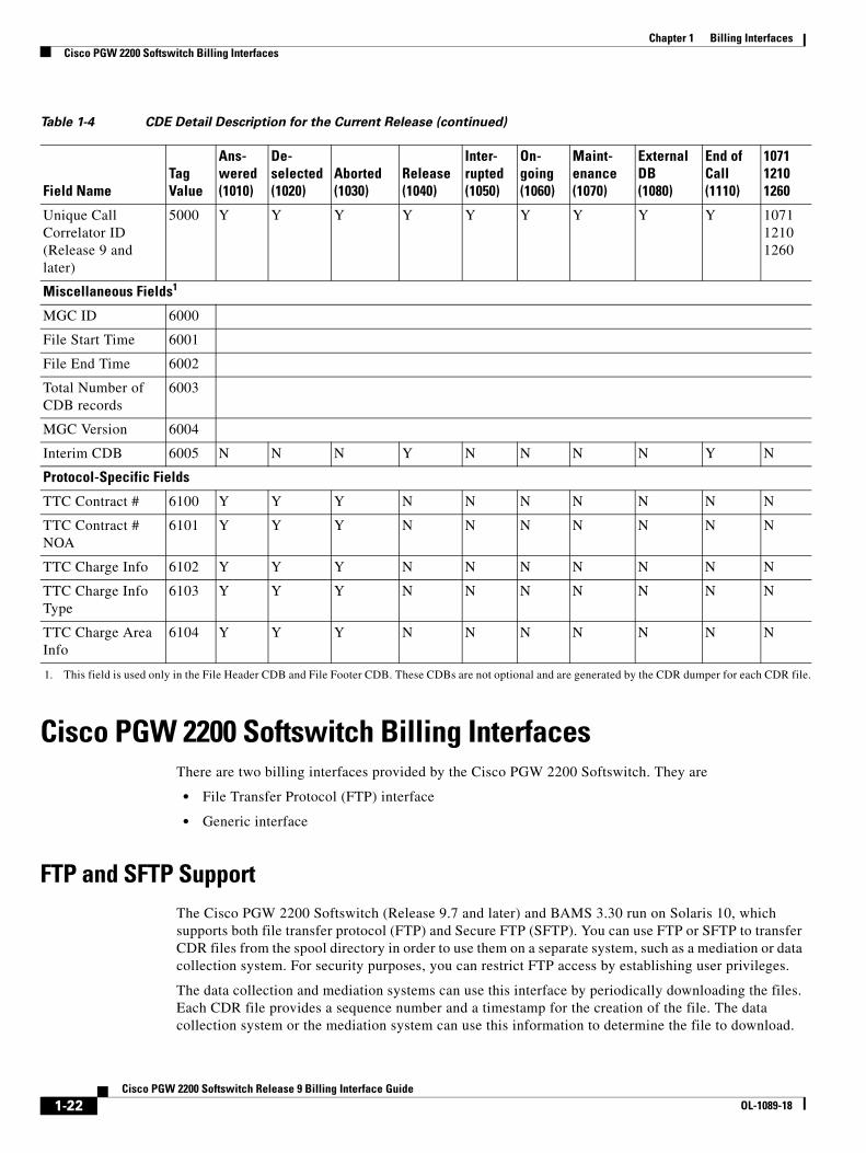
Cisco PGW 2200 Softswitch Billing InterfacesThere are two billing interfaces provided by the Cisco PGW 2200 Softswitch. They are
• File Transfer Protocol (FTP) interface
• Generic interface
FTP and SFTP SupportThe Cisco PGW 2200 Softswitch (Release 9.7 and later) and BAMS 3.30 run on Solaris 10, which supports both file transfer protocol (FTP) and Secure FTP (SFTP). You can use FTP or SFTP to transfer CDR files from the spool directory in order to use them on a separate system, such as a mediation or data collection system. For security purposes, you can restrict FTP access by establishing user privileges.
The data collection and mediation systems can use this interface by periodically downloading the files. Each CDR file provides a sequence number and a timestamp for the creation of the file. The data collection system or the mediation system can use this information to determine the file to download.
Unique Call Correlator ID (Release 9 and later)
5000 Y Y Y Y Y Y Y Y Y 1071 1210 1260
Miscellaneous Fields1
MGC ID 6000
File Start Time 6001
File End Time 6002
Total Number of CDB records
6003
MGC Version 6004
Interim CDB 6005 N N N Y N N N N Y N
Protocol-Specific Fields
TTC Contract # 6100 Y Y Y N N N N N N N
TTC Contract # NOA
6101 Y Y Y N N N N N N N
TTC Charge Info 6102 Y Y Y N N N N N N N
TTC Charge Info Type
6103 Y Y Y N N N N N N N
TTC Charge Area Info
6104 Y Y Y N N N N N N N
1. This field is used only in the File Header CDB and File Footer CDB. These CDBs are not optional and are generated by the CDR dumper for each CDR file.
Table 1-4 CDE Detail Description for the Current Release (continued)
Field NameTag Value
Ans- wered (1010)
De- selected (1020)
Aborted (1030)
Release (1040)
Inter- rupted (1050)
On- going (1060)
Maint- enance (1070)
External DB (1080)
End of Call (1110)
1071 1210 1260
1-22Cisco PGW 2200 Softswitch Release 9 Billing Interface Guide
OL-1089-18
Chapter 1 Billing InterfacesRedundant Cisco PGW 2200 Softswitch Configuration
The Cisco PGW 2200 Softswitch has several configuration parameters to write the CDR file. The following are the configuration parameters:
• The prefix in the file name (CDR_YYYYMMDDHHMMSS_SeqNo), where SeqNo is a sequence number in the format (000001 to 999999)
• Spool directory
• Frequent creation of the file
The purpose of the sequence number is to provide an audit capability to the data collection system or mediation software. The sequence number is unique and ranges from 1 to 999999. If the Cisco PGW 2200 Softswitch fails or restarts, it uses the next sequence number (the last sequence number + 1). When the sequence number reaches 999999, the sequence restarts at 1.
Generic InterfaceThe Cisco PGW 2200 Softswitch defines a generic or flexible billing interface. This is an internal interface between the call processing module and the CDR dumper in the Cisco PGW 2200 Softswitch. You cannot modify this interface.
This interface provides a CDB data stream for the CDR dumper. The generic interface is based on the flexible CDB record layout. The record layout uses a TLV encoding mechanism. The detail messages (that is, CDBs) are explained later in this document.
Redundant Cisco PGW 2200 Softswitch ConfigurationIn a redundant Cisco PGW 2200 Softswitch configuration, the active Cisco PGW 2200 Softswitch creates checkpoint records that synchronize it with the standby Cisco PGW 2200 Softswitch. The standby Cisco PGW 2200 Softswitch creates call objects with appropriate states to allow continued call processing after switchover occurs. When the standby Cisco PGW 2200 Softswitch becomes active, it starts synchronizing with end offices (circuit audit). Each Cisco 2600 buffers messages while failover occurs.
Billing under a redundant configuration is basically limited to the following: The active Cisco PGW 2200 Softswitch generates the CDBs, and the standby Cisco PGW 2200 Softswitch does not. When failover occurs, the now active Cisco PGW 2200 Softswitch generates the CDBs.
If a call was stable during the failover, the newly active Cisco PGW 2200 Softswitch eventually generates an end-of-call CDB (Release CDB or possibly an Interrupted CDB) for each call. The CDBs generated by the previous standby Cisco PGW 2200 Softswitch include the same unique call IDs. The mediation software requires correlating the CDB records from both systems. For both systems to be properly correlated, the two Cisco PGW 2200 Softswitch clocks must be synchronized with each other.
Cisco PGW 2200 Softswitch Clock SynchronizationThe Cisco PGW 2200 Softswitch uses Network Time Protocol (NTP) to synchronize its time to another server or time source. For example, the NTP provides client accuracy that is typically within 1 millisecond on LANs and up to a few tenths of a second on WANs relative to a primary server synchronized to UTC by a Global Positioning System (GPS) receiver. To achieve high accuracy and reliability, typical NTP configurations use multiple redundant servers and diverse network paths. Some configurations include cryptographic authentication to prevent accidents or malicious protocol attacks.
1-23Cisco PGW 2200 Softswitch Release 9 Billing Interface Guide
OL-1089-18
Chapter 1 Billing InterfacesDetailed CDB Descriptions
Note RFC 1305 provides information on the NTP architecture, protocol, and algorithm.
Detailed CDB DescriptionsThis section contains the distinct record layouts for the CDBs. Because each type of CDB is for a different part of a call, the Cisco PGW 2200 Softswitch provides the related CDEs that are needed.
The CDE includes only fields that have values. The layout varies based on the Cisco PGW 2200 Softswitch configuration. For example, if the Cisco PGW 2200 Softswitch is configured with a protocol that does not support a specific CDE, the CDB record does not include that particular CDE.
The following CDB records are listed in this section:
• Answered CDB Record (Tag: 1010/Release 5 and Later), page 1-24
• Deselected Outgoing Circuit CDB Record (Tag: 1020/Release 5 and Later), page 1-30
• Aborted Attempt CDB Record (Tag: 1030/Release 5 and Later), page 1-31
• Release CDB Record (Tag: 1040/Release 5 and Later), page 1-36
• Interrupted CDB Record (Tag: 1050/Release 5 and Later), page 1-39
• On-Going (Call) CDB Record (Tag: 1060/Release 5 and Later), page 1-40
• Maintenance CDB Record (Tag: 1070/Release 5 and Later), page 1-42
• SS7 CIC Audit CDB Record (Tag: 1071/Release 9 and Later), page 1-43
• External Access CDB (Tag: 1080/Release 7 and Later), page 1-45
• File Header CDB (Tag: 1090/Release 7 and Later), page 1-45
• File Footer CDB (Tag: 1100/Release 7 and Later), page 1-46
• End of the Call CDB (Tag: 1110/Release 7 and Later), page 1-46
• Slave End-of-Call CDB Record (Tag: 1210/Release 9.6 and Later), page 1-53
• Slave Long Duration Call CDB Record (Tag: 1260/Release 9.6 and Later), page 1-53
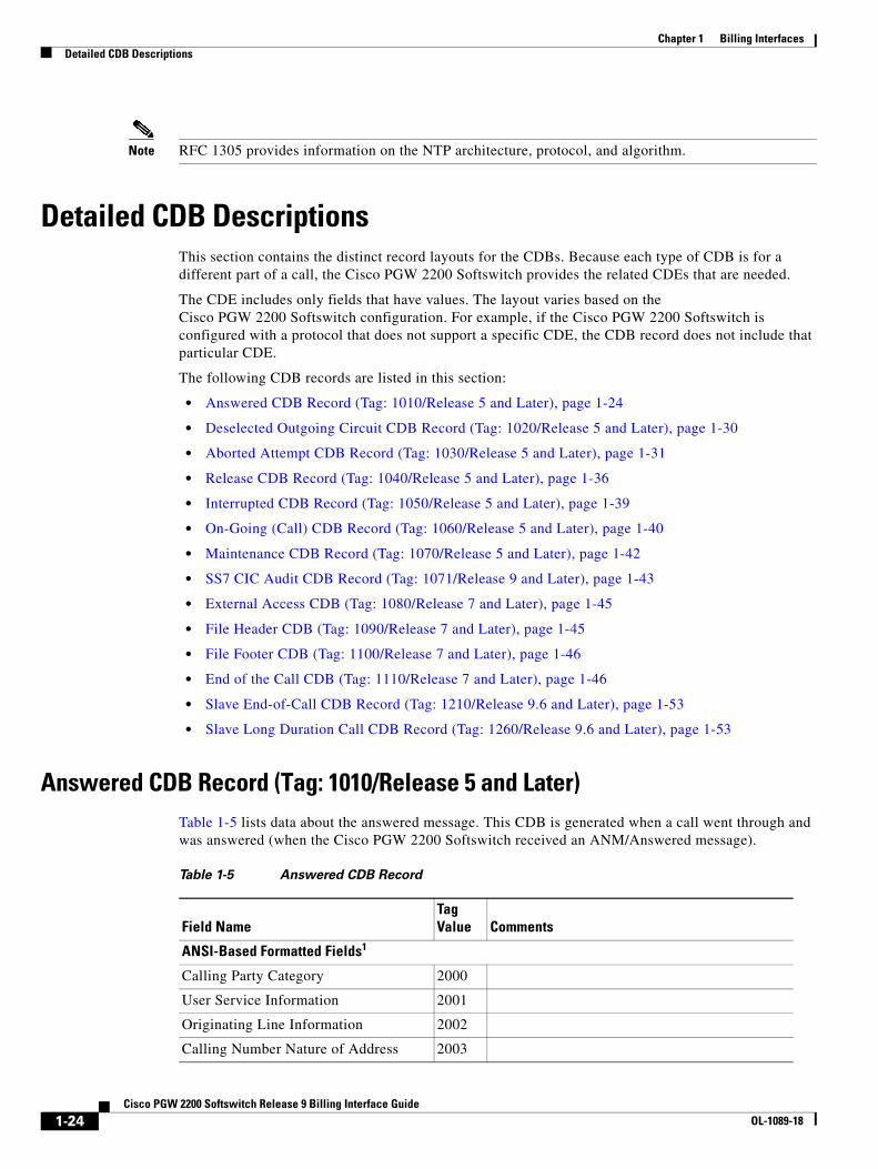
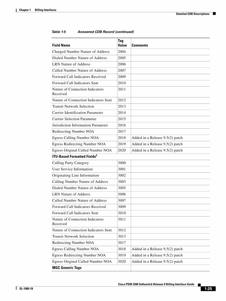
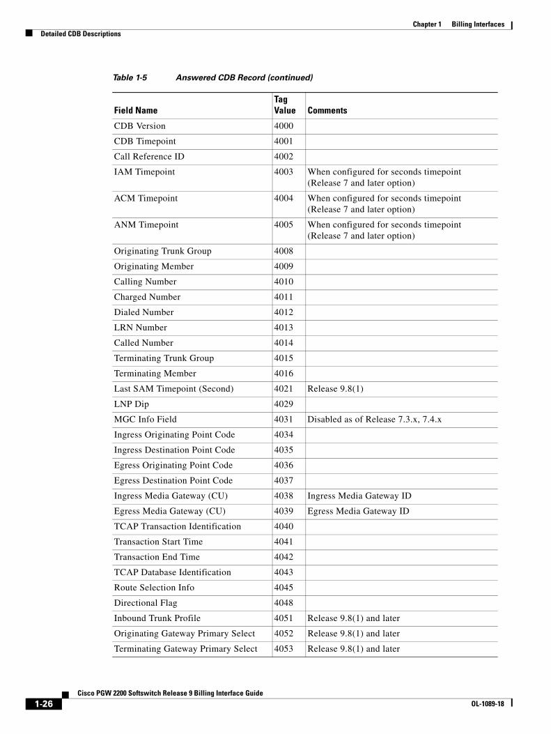
Answered CDB Record (Tag: 1010/Release 5 and Later)Table 1-5 lists data about the answered message. This CDB is generated when a call went through and was answered (when the Cisco PGW 2200 Softswitch received an ANM/Answered message).
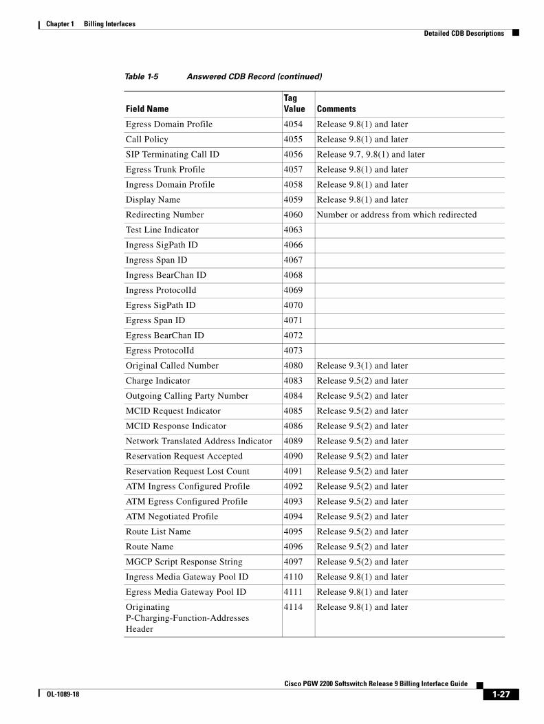
Table 1-5 Answered CDB Record
Field NameTag Value Comments
ANSI-Based Formatted Fields1
Calling Party Category 2000
User Service Information 2001
Originating Line Information 2002
Calling Number Nature of Address 2003
1-24Cisco PGW 2200 Softswitch Release 9 Billing Interface Guide
OL-1089-18
Chapter 1 Billing InterfacesDetailed CDB Descriptions
Charged Number Nature of Address 2004
Dialed Number Nature of Address 2005
LRN Nature of Address 2006
Called Number Nature of Address 2007
Forward Call Indicators Received 2009
Forward Call Indicators Sent 2010
Nature of Connection Indicators Received
2011
Nature of Connection Indicators Sent 2012
Transit Network Selection 2013
Carrier Identification Parameter 2014
Carrier Selection Parameter 2015
Jurisdiction Information Parameter 2016
Redirecting Number NOA 2017
Egress Calling Number NOA 2018 Added in a Release 9.5(2) patch
Egress Redirecting Number NOA 2019 Added in a Release 9.5(2) patch
Egress Original Called Number NOA 2020 Added in a Release 9.5(2) patch
ITU-Based Formatted Fields2
Calling Party Category 3000
User Service Information 3001
Originating Line Information 3002
Calling Number Nature of Address 3003
Dialed Number Nature of Address 3005
LRN Nature of Address 3006
Called Number Nature of Address 3007
Forward Call Indicators Received 3009
Forward Call Indicators Sent 3010
Nature of Connection Indicators Received
3011
Nature of Connection Indicators Sent 3012
Transit Network Selection 3013
Redirecting Number NOA 3017
Egress Calling Number NOA 3018 Added in a Release 9.5(2) patch
Egress Redirecting Number NOA 3019 Added in a Release 9.5(2) patch
Egress Original Called Number NOA 3020 Added in a Release 9.5(2) patch
MGC Generic Tags
Table 1-5 Answered CDB Record (continued)
Field NameTag Value Comments
1-25Cisco PGW 2200 Softswitch Release 9 Billing Interface Guide
OL-1089-18
Chapter 1 Billing InterfacesDetailed CDB Descriptions
CDB Version 4000
CDB Timepoint 4001
Call Reference ID 4002
IAM Timepoint 4003 When configured for seconds timepoint (Release 7 and later option)
ACM Timepoint 4004 When configured for seconds timepoint (Release 7 and later option)
ANM Timepoint 4005 When configured for seconds timepoint (Release 7 and later option)
Originating Trunk Group 4008
Originating Member 4009
Calling Number 4010
Charged Number 4011
Dialed Number 4012
LRN Number 4013
Called Number 4014
Terminating Trunk Group 4015
Terminating Member 4016
Last SAM Timepoint (Second) 4021 Release 9.8(1)
LNP Dip 4029
MGC Info Field 4031 Disabled as of Release 7.3.x, 7.4.x
Ingress Originating Point Code 4034
Ingress Destination Point Code 4035
Egress Originating Point Code 4036
Egress Destination Point Code 4037
Ingress Media Gateway (CU) 4038 Ingress Media Gateway ID
Egress Media Gateway (CU) 4039 Egress Media Gateway ID
TCAP Transaction Identification 4040
Transaction Start Time 4041
Transaction End Time 4042
TCAP Database Identification 4043
Route Selection Info 4045
Directional Flag 4048
Inbound Trunk Profile 4051 Release 9.8(1) and later
Originating Gateway Primary Select 4052 Release 9.8(1) and later
Terminating Gateway Primary Select 4053 Release 9.8(1) and later
Table 1-5 Answered CDB Record (continued)
Field NameTag Value Comments
1-26Cisco PGW 2200 Softswitch Release 9 Billing Interface Guide
OL-1089-18
Chapter 1 Billing InterfacesDetailed CDB Descriptions
Egress Domain Profile 4054 Release 9.8(1) and later
Call Policy 4055 Release 9.8(1) and later
SIP Terminating Call ID 4056 Release 9.7, 9.8(1) and later
Egress Trunk Profile 4057 Release 9.8(1) and later
Ingress Domain Profile 4058 Release 9.8(1) and later
Display Name 4059 Release 9.8(1) and later
Redirecting Number 4060 Number or address from which redirected
Test Line Indicator 4063
Ingress SigPath ID 4066
Ingress Span ID 4067
Ingress BearChan ID 4068
Ingress ProtocolId 4069
Egress SigPath ID 4070
Egress Span ID 4071
Egress BearChan ID 4072
Egress ProtocolId 4073
Original Called Number 4080 Release 9.3(1) and later
Charge Indicator 4083 Release 9.5(2) and later
Outgoing Calling Party Number 4084 Release 9.5(2) and later
MCID Request Indicator 4085 Release 9.5(2) and later
MCID Response Indicator 4086 Release 9.5(2) and later
Network Translated Address Indicator 4089 Release 9.5(2) and later
Reservation Request Accepted 4090 Release 9.5(2) and later
Reservation Request Lost Count 4091 Release 9.5(2) and later
ATM Ingress Configured Profile 4092 Release 9.5(2) and later
ATM Egress Configured Profile 4093 Release 9.5(2) and later
ATM Negotiated Profile 4094 Release 9.5(2) and later
Route List Name 4095 Release 9.5(2) and later
Route Name 4096 Release 9.5(2) and later
MGCP Script Response String 4097 Release 9.5(2) and later
Ingress Media Gateway Pool ID 4110 Release 9.8(1) and later
Egress Media Gateway Pool ID 4111 Release 9.8(1) and later
Originating P-Charging-Function-Addresses Header
4114 Release 9.8(1) and later
Table 1-5 Answered CDB Record (continued)
Field NameTag Value Comments
1-27Cisco PGW 2200 Softswitch Release 9 Billing Interface Guide
OL-1089-18

Chapter 1 Billing InterfacesDetailed CDB Descriptions
Terminating P-Charging-Function-Addresses Header
4115 Release 9.8(1) and later
Originating P-Charging-Vector orig-IOI
4116 Release 9.8(1) and later
Originating P-Charging-Vector term-IOI
4117 Release 9.8(1) and later
Terminating P-Charging-Vector orig-IOI
4118 Release 9.8(1) and later
Terminating P-Charging-Vector term-IOI
4119 Release 9.8(1) and later
Originating P-Charging-Vector ICID-value
4120 Release 9.8(1) and later
Terminating P-Charging-Vector ICID-value
4121 Release 9.8(1) and later
Ingress Originating P-Access-Network-Info Header
4122 Release 9.8(1) and later
Egress Originating P-Access-Network-Info Header
4123 Release 9.8(1) and later
Ingress Terminating P-Access-Network-Info Header
4124 Release 9.8(1) and later
Egress Terminating P-Access-Network-Info Header
4125 Release 9.8(1) and later
Originating Remote SIP Host 4201 Release 9 and later (Named as Ingress SIP URL in versions prior to the Release 9.7(3))
Originating Local SIP Host 4202 Release 9 and later (Named as Egress SIP URL in versions prior to the Release 9.7(3))
SIP Originating Call ID 4203 Release 9 and later.
The name of this CDR was changed from SIP Call ID to SIP Originating Call ID in Release 9.7, 9.8(1) and later.
Source IP Address 4204 Release 9.4(1) and later
Ingress Media Device Address 4205 Release 9.4(1) and later
Egress Media Device Address 4206 Release 9.4(1) and later
Initial Codec 4207 Release 9.4(1) and later
Final Codec 4208 Release 9.4(1) and later
Ingress Media Device Port 4209 Release 9.4(1) and later
Egress Media Device Port 4210 Release 9.4(1) and later
Originating VPN ID 4211 Release 9.4(1) and later
Terminating VPN ID 4212 Release 9.4(1) and later
Table 1-5 Answered CDB Record (continued)
Field NameTag Value Comments
1-28Cisco PGW 2200 Softswitch Release 9 Billing Interface Guide
OL-1089-18
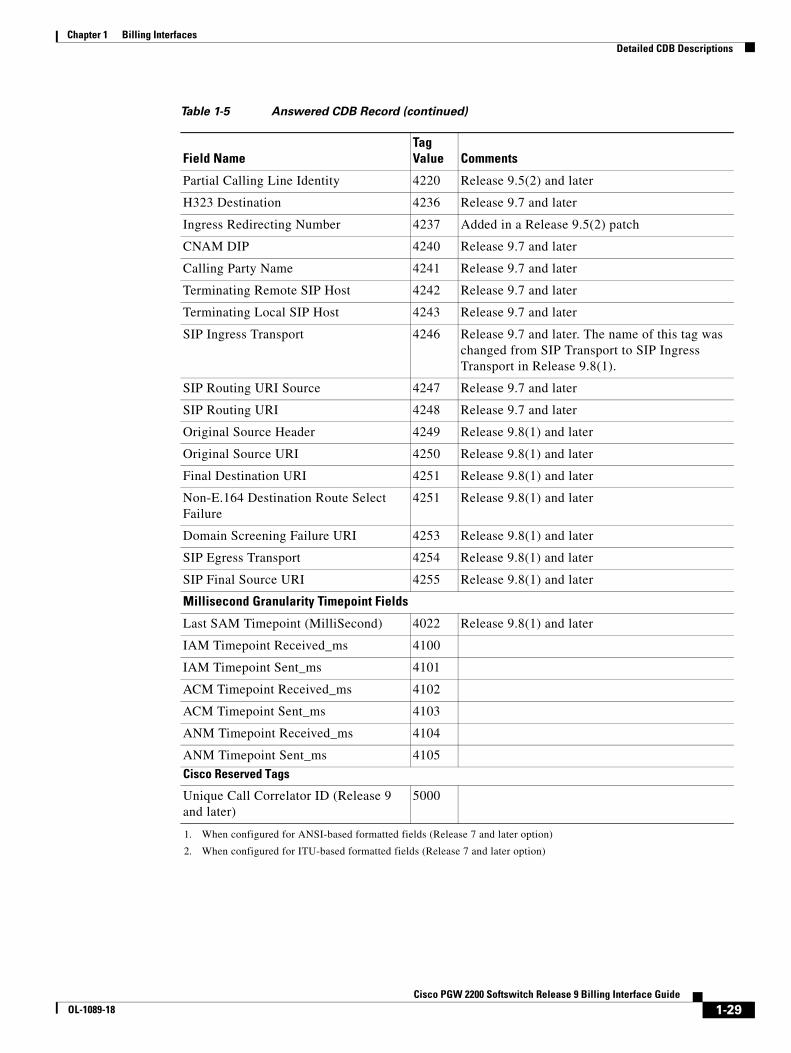
Chapter 1 Billing InterfacesDetailed CDB Descriptions
Partial Calling Line Identity 4220 Release 9.5(2) and later
H323 Destination 4236 Release 9.7 and later
Ingress Redirecting Number 4237 Added in a Release 9.5(2) patch
CNAM DIP 4240 Release 9.7 and later
Calling Party Name 4241 Release 9.7 and later
Terminating Remote SIP Host 4242 Release 9.7 and later
Terminating Local SIP Host 4243 Release 9.7 and later
SIP Ingress Transport 4246 Release 9.7 and later. The name of this tag was changed from SIP Transport to SIP Ingress Transport in Release 9.8(1).
SIP Routing URI Source 4247 Release 9.7 and later
SIP Routing URI 4248 Release 9.7 and later
Original Source Header 4249 Release 9.8(1) and later
Original Source URI 4250 Release 9.8(1) and later
Final Destination URI 4251 Release 9.8(1) and later
Non-E.164 Destination Route Select Failure
4251 Release 9.8(1) and later
Domain Screening Failure URI 4253 Release 9.8(1) and later
SIP Egress Transport 4254 Release 9.8(1) and later
SIP Final Source URI 4255 Release 9.8(1) and later
Millisecond Granularity Timepoint Fields
Last SAM Timepoint (MilliSecond) 4022 Release 9.8(1) and later
IAM Timepoint Received_ms 4100
IAM Timepoint Sent_ms 4101
ACM Timepoint Received_ms 4102
ACM Timepoint Sent_ms 4103
ANM Timepoint Received_ms 4104
ANM Timepoint Sent_ms 4105
Cisco Reserved Tags
Unique Call Correlator ID (Release 9 and later)
5000
1. When configured for ANSI-based formatted fields (Release 7 and later option)
2. When configured for ITU-based formatted fields (Release 7 and later option)
Table 1-5 Answered CDB Record (continued)
Field NameTag Value Comments
1-29Cisco PGW 2200 Softswitch Release 9 Billing Interface Guide
OL-1089-18
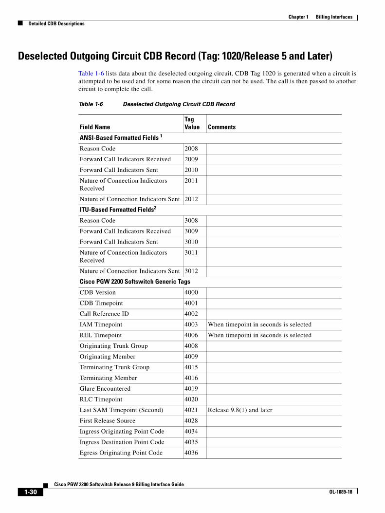
Chapter 1 Billing InterfacesDetailed CDB Descriptions
Deselected Outgoing Circuit CDB Record (Tag: 1020/Release 5 and Later)Table 1-6 lists data about the deselected outgoing circuit. CDB Tag 1020 is generated when a circuit is attempted to be used and for some reason the circuit can not be used. The call is then passed to another circuit to complete the call.
Table 1-6 Deselected Outgoing Circuit CDB Record
Field NameTag Value Comments
ANSI-Based Formatted Fields 1
Reason Code 2008
Forward Call Indicators Received 2009
Forward Call Indicators Sent 2010
Nature of Connection Indicators Received
2011
Nature of Connection Indicators Sent 2012
ITU-Based Formatted Fields2
Reason Code 3008
Forward Call Indicators Received 3009
Forward Call Indicators Sent 3010
Nature of Connection Indicators Received
3011
Nature of Connection Indicators Sent 3012
Cisco PGW 2200 Softswitch Generic Tags
CDB Version 4000
CDB Timepoint 4001
Call Reference ID 4002
IAM Timepoint 4003 When timepoint in seconds is selected
REL Timepoint 4006 When timepoint in seconds is selected
Originating Trunk Group 4008
Originating Member 4009
Terminating Trunk Group 4015
Terminating Member 4016
Glare Encountered 4019
RLC Timepoint 4020
Last SAM Timepoint (Second) 4021 Release 9.8(1) and later
First Release Source 4028
Ingress Originating Point Code 4034
Ingress Destination Point Code 4035
Egress Originating Point Code 4036
1-30Cisco PGW 2200 Softswitch Release 9 Billing Interface Guide
OL-1089-18
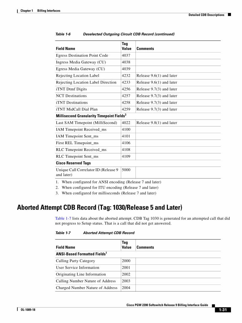
Chapter 1 Billing InterfacesDetailed CDB Descriptions
Aborted Attempt CDB Record (Tag: 1030/Release 5 and Later)Table 1-7 lists data about the aborted attempt. CDB Tag 1030 is generated for an attempted call that did not progress to Setup status. That is a call that did not get answered.
Egress Destination Point Code 4037
Ingress Media Gateway (CU) 4038
Egress Media Gateway (CU) 4039
Rejecting Location Label 4232 Release 9.6(1) and later
Rejecting Location Label Direction 4233 Release 9.6(1) and later
iTNT Dtmf Digits 4256 Release 9.7(3) and later
NCT Destinations 4257 Release 9.7(3) and later
iTNT Destinations 4258 Release 9.7(3) and later
iTNT MidCall Dial Plan 4259 Release 9.7(3) and later
Millisecond Granularity Timepoint Fields3
Last SAM Timepoint (MilliSecond) 4022 Release 9.8(1) and later
IAM Timepoint Received_ms 4100
IAM Timepoint Sent_ms 4101
First REL Timepoint_ms 4106
RLC Timepoint Received_ms 4108
RLC Timepoint Sent_ms 4109
Cisco Reserved Tags
Unique Call Correlator ID (Release 9 and later)
5000
1. When configured for ANSI encoding (Release 7 and later)2. When configured for ITU encoding (Release 7 and later)3. When configured for milliseconds (Release 7 and later)
Table 1-6 Deselected Outgoing Circuit CDB Record (continued)
Field NameTag Value Comments
Table 1-7 Aborted Attempt CDB Record
Field NameTag Value Comments
ANSI-Based Formatted Fields1
Calling Party Category 2000
User Service Information 2001
Originating Line Information 2002
Calling Number Nature of Address 2003
Charged Number Nature of Address 2004
1-31Cisco PGW 2200 Softswitch Release 9 Billing Interface Guide
OL-1089-18
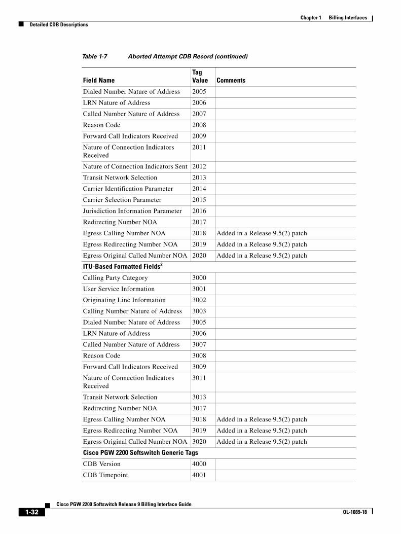
Chapter 1 Billing InterfacesDetailed CDB Descriptions
Dialed Number Nature of Address 2005
LRN Nature of Address 2006
Called Number Nature of Address 2007
Reason Code 2008
Forward Call Indicators Received 2009
Nature of Connection Indicators Received
2011
Nature of Connection Indicators Sent 2012
Transit Network Selection 2013
Carrier Identification Parameter 2014
Carrier Selection Parameter 2015
Jurisdiction Information Parameter 2016
Redirecting Number NOA 2017
Egress Calling Number NOA 2018 Added in a Release 9.5(2) patch
Egress Redirecting Number NOA 2019 Added in a Release 9.5(2) patch
Egress Original Called Number NOA 2020 Added in a Release 9.5(2) patch
ITU-Based Formatted Fields2
Calling Party Category 3000
User Service Information 3001
Originating Line Information 3002
Calling Number Nature of Address 3003
Dialed Number Nature of Address 3005
LRN Nature of Address 3006
Called Number Nature of Address 3007
Reason Code 3008
Forward Call Indicators Received 3009
Nature of Connection Indicators Received
3011
Transit Network Selection 3013
Redirecting Number NOA 3017
Egress Calling Number NOA 3018 Added in a Release 9.5(2) patch
Egress Redirecting Number NOA 3019 Added in a Release 9.5(2) patch
Egress Original Called Number NOA 3020 Added in a Release 9.5(2) patch
Cisco PGW 2200 Softswitch Generic Tags
CDB Version 4000
CDB Timepoint 4001
Table 1-7 Aborted Attempt CDB Record (continued)
Field NameTag Value Comments
1-32Cisco PGW 2200 Softswitch Release 9 Billing Interface Guide
OL-1089-18

Chapter 1 Billing InterfacesDetailed CDB Descriptions
Call Reference ID 4002
IAM Timepoint 4003 When configured for seconds timepoint
ACM Timepoint 4004 When configured for seconds timepoint
REL Timepoint 4006 When configured for seconds timepoint
Originating Trunk Group 4008
Originating Member 4009
Calling Number 4010
Charged Number 4011
Dialed Number 4012
LRN Number 4013
Called Number 4014
Terminating Trunk Group 4015
Terminating Member 4016
Glare Encountered 4019
RLC Timepoint 4020 When timepoint in seconds is selected
Last SAM Timepoint (Second) 4021 Release 9.8(1) and later
First Release Source 4028
LNP Dip 4029
MGC Info Field 4031 Disabled as of Release 7.3.x and 7.4.x
Ingress Originating Point Code 4034
Ingress Destination Point Code 4035
Egress Originating Point Code 4036
Egress Destination Point Code 4037
Ingress Media Gateway (CU) 4038
Egress Media Gateway (CU) 4039
Ingress Gateway Packet Info 4046 Restored as of Release 9.4(1)
Egress Gateway Packet Info 4047 Restored as of Release 9.4(1)
Directional Flag 4048
Inbound Trunk Profile 4051 Release 9.8(1) and later
Originating Gateway Primary Select 4052 Release 9.8(1) and later
Terminating Gateway Primary Select 4053 Release 9.8(1) and later
Egress Domain Profile 4054 Release 9.8(1) and later
Call Policy 4055 Release 9.8(1) and later
SIP Terminating Call ID 4056 Release 9.7, 9.8(1) and later
Egress Trunk Profile 4057 Release 9.8(1) and later
Table 1-7 Aborted Attempt CDB Record (continued)
Field NameTag Value Comments
1-33Cisco PGW 2200 Softswitch Release 9 Billing Interface Guide
OL-1089-18
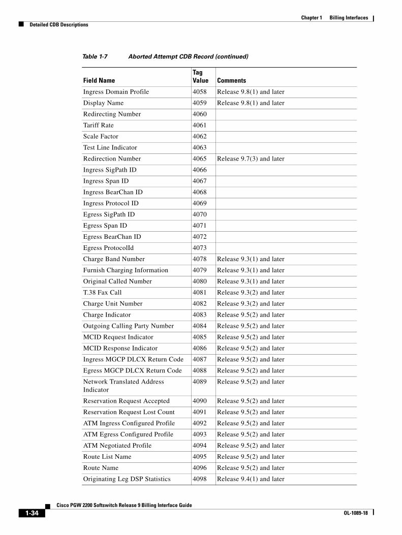
Chapter 1 Billing InterfacesDetailed CDB Descriptions
Ingress Domain Profile 4058 Release 9.8(1) and later
Display Name 4059 Release 9.8(1) and later
Redirecting Number 4060
Tariff Rate 4061
Scale Factor 4062
Test Line Indicator 4063
Redirection Number 4065 Release 9.7(3) and later
Ingress SigPath ID 4066
Ingress Span ID 4067
Ingress BearChan ID 4068
Ingress Protocol ID 4069
Egress SigPath ID 4070
Egress Span ID 4071
Egress BearChan ID 4072
Egress ProtocolId 4073
Charge Band Number 4078 Release 9.3(1) and later
Furnish Charging Information 4079 Release 9.3(1) and later
Original Called Number 4080 Release 9.3(1) and later
T.38 Fax Call 4081 Release 9.3(2) and later
Charge Unit Number 4082 Release 9.3(2) and later
Charge Indicator 4083 Release 9.5(2) and later
Outgoing Calling Party Number 4084 Release 9.5(2) and later
MCID Request Indicator 4085 Release 9.5(2) and later
MCID Response Indicator 4086 Release 9.5(2) and later
Ingress MGCP DLCX Return Code 4087 Release 9.5(2) and later
Egress MGCP DLCX Return Code 4088 Release 9.5(2) and later
Network Translated Address Indicator
4089 Release 9.5(2) and later
Reservation Request Accepted 4090 Release 9.5(2) and later
Reservation Request Lost Count 4091 Release 9.5(2) and later
ATM Ingress Configured Profile 4092 Release 9.5(2) and later
ATM Egress Configured Profile 4093 Release 9.5(2) and later
ATM Negotiated Profile 4094 Release 9.5(2) and later
Route List Name 4095 Release 9.5(2) and later
Route Name 4096 Release 9.5(2) and later
Originating Leg DSP Statistics 4098 Release 9.4(1) and later
Table 1-7 Aborted Attempt CDB Record (continued)
Field NameTag Value Comments
1-34Cisco PGW 2200 Softswitch Release 9 Billing Interface Guide
OL-1089-18
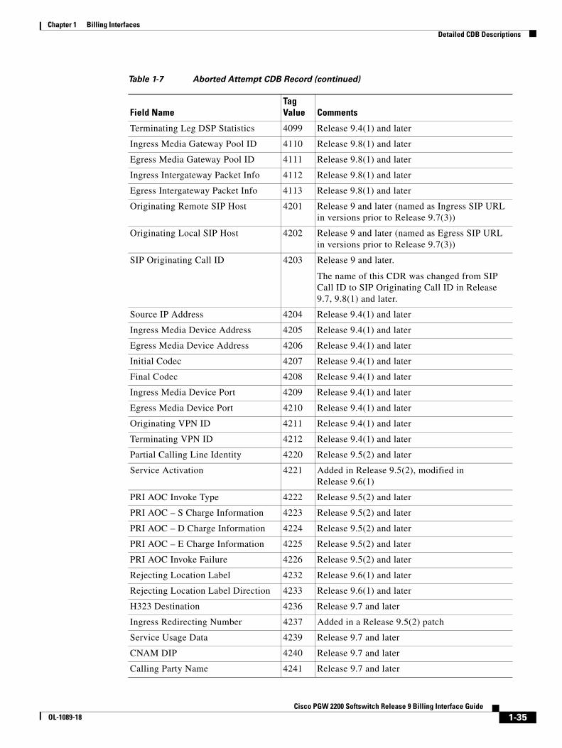
Chapter 1 Billing InterfacesDetailed CDB Descriptions
Terminating Leg DSP Statistics 4099 Release 9.4(1) and later
Ingress Media Gateway Pool ID 4110 Release 9.8(1) and later
Egress Media Gateway Pool ID 4111 Release 9.8(1) and later
Ingress Intergateway Packet Info 4112 Release 9.8(1) and later
Egress Intergateway Packet Info 4113 Release 9.8(1) and later
Originating Remote SIP Host 4201 Release 9 and later (named as Ingress SIP URL in versions prior to Release 9.7(3))
Originating Local SIP Host 4202 Release 9 and later (named as Egress SIP URL in versions prior to Release 9.7(3))
SIP Originating Call ID 4203 Release 9 and later.
The name of this CDR was changed from SIP Call ID to SIP Originating Call ID in Release 9.7, 9.8(1) and later.
Source IP Address 4204 Release 9.4(1) and later
Ingress Media Device Address 4205 Release 9.4(1) and later
Egress Media Device Address 4206 Release 9.4(1) and later
Initial Codec 4207 Release 9.4(1) and later
Final Codec 4208 Release 9.4(1) and later
Ingress Media Device Port 4209 Release 9.4(1) and later
Egress Media Device Port 4210 Release 9.4(1) and later
Originating VPN ID 4211 Release 9.4(1) and later
Terminating VPN ID 4212 Release 9.4(1) and later
Partial Calling Line Identity 4220 Release 9.5(2) and later
Service Activation 4221 Added in Release 9.5(2), modified in Release 9.6(1)
PRI AOC Invoke Type 4222 Release 9.5(2) and later
PRI AOC – S Charge Information 4223 Release 9.5(2) and later
PRI AOC – D Charge Information 4224 Release 9.5(2) and later
PRI AOC – E Charge Information 4225 Release 9.5(2) and later
PRI AOC Invoke Failure 4226 Release 9.5(2) and later
Rejecting Location Label 4232 Release 9.6(1) and later
Rejecting Location Label Direction 4233 Release 9.6(1) and later
H323 Destination 4236 Release 9.7 and later
Ingress Redirecting Number 4237 Added in a Release 9.5(2) patch
Service Usage Data 4239 Release 9.7 and later
CNAM DIP 4240 Release 9.7 and later
Calling Party Name 4241 Release 9.7 and later
Table 1-7 Aborted Attempt CDB Record (continued)
Field NameTag Value Comments
1-35Cisco PGW 2200 Softswitch Release 9 Billing Interface Guide
OL-1089-18

Chapter 1 Billing InterfacesDetailed CDB Descriptions
Release CDB Record (Tag: 1040/Release 5 and Later)Table 1-8 lists data about the release CDB. CDB Tag 1040 is generated when the terminating CDB on a call that went through and was answered and then released.
Terminating Remote SIP Host 4242 Release 9.7 and later
Terminating Local SIP Host 4243 Release 9.7 and later
License Rejecting Reason 4244 Release 9.7 and later
License Rejecting Direction 4245 Release 9.7 and later
SIP Ingress Transport 4246 Release 9.7 and later. The name of this tag was changed from SIP Transport to SIP Ingress Transport in Release 9.8(1).
SIP Routing URI Source 4247 Release 9.7 and later
SIP Routing URI 4248 Release 9.7 and later
Original Source Header 4249 Release 9.8(1) and later
Original Source URI 4250 Release 9.8(1) and later
Final Destination URI 4251 Release 9.8(1) and later
Non-E.164 Destination Route Select Failure
4252 Release 9.8(1) and later
Domain Screening Failure URI 4253 Release 9.8(1) and later
SIP Egress Transport 4254 Release 9.8(1) and later
SIP Final Source URI 4255 Release 9.8(1) and later
Millisecond Granularity Timepoint Fields3
Last SAM Timepoint (MilliSecond) 4022 Release 9.8(1) and later
IAM Timepoint Received_ms 4100
IAM Timepoint Sent_ms 4101
ACM Timepoint Received_ms 4102
ACM Timepoint Sent_ms 4103
First REL Timepoint_ms 4106
Second REL Timepoint_ms 4107
RLC Timepoint Received_ms 4108
RLC Timepoint Sent_ms 4109
Cisco Reserved Tags
Unique Call Correlator ID (Release 9 and later)
5000
1. When configured for ANSI-based encoding (Release 7 and later)
2. When configured for ITU encoding (Release 7 and later)
3. When configured for milliseconds granularity for timepoints fields
Table 1-7 Aborted Attempt CDB Record (continued)
Field NameTag Value Comments
1-36Cisco PGW 2200 Softswitch Release 9 Billing Interface Guide
OL-1089-18

Chapter 1 Billing InterfacesDetailed CDB Descriptions
Table 1-8 Release CDB Record
Field NameTag Value Comments
ANSI-Based Formatted Fields1
Reason Code 2008
ITU-Based Formatted Fields2
Reason Code 3008
Cisco PGW 2200 Softswitch Generic Tags
CDB Version 4000
CDB Timepoint 4001
Call Reference ID 4002
REL Timepoint 4006 When configured for seconds granularity timepoints
Glare Encountered 4019
RLC Timepoint 4020 When configured for seconds granularity timepoints
First Release Source 4028
Total Meter Pulses 4030
Announcement Identification 4044
Ingress Gateway Packet Info 4046 Restored as of Release 9.4(1)
Egress Gateway Packet Info 4047 Restored as of Release 9.4(1)
SIP Terminating Call ID 4056 Release 9.7, 9.8(1) and later
Tariff Rate 4061
Scale Factor 4062
Charge Band Number 4078 Release 9.3(1) and later
Furnish Charging Information 4079 Release 9.3(1) and later
T.38 Fax Call 4081 Release 9.3(2) and later
Charge Unit Number 4082 Release 9.3(2) and later
Charge Indicator 4083 Release 9.5(2) and later
Outgoing Calling Party Number 4084 Release 9.5(2) and later
MCID Request Indicator 4085 Release 9.5(2) and later
MCID Response Indicator 4086 Release 9.5(2) and later
Ingress MGCP DLCX Return Code 4087 Release 9.5(2) and later
Egress MGCP DLCX Return Code 4088 Release 9.5(2) and later
Network Translated Address Indicator
4089 Release 9.5(2) and later
Reservation Request Accepted 4090 Release 9.5(2) and later
Reservation Request Lost Count 4091 Release 9.5(2) and later
Route List Name 4095 Release 9.5(2) and later
1-37Cisco PGW 2200 Softswitch Release 9 Billing Interface Guide
OL-1089-18
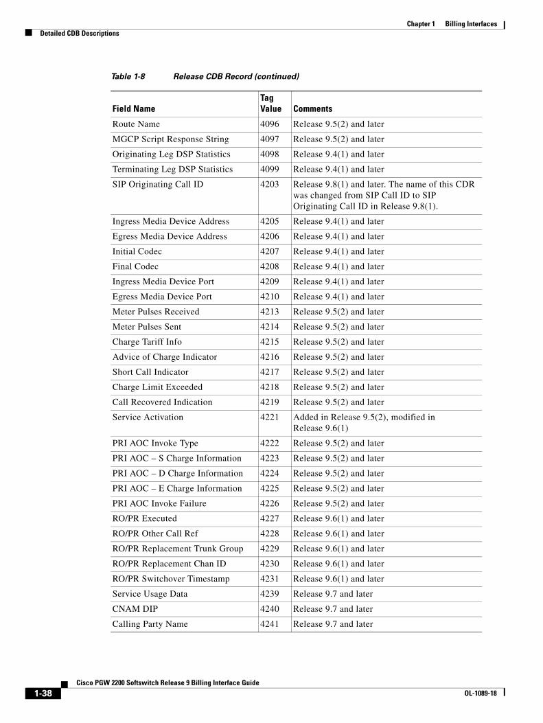
Chapter 1 Billing InterfacesDetailed CDB Descriptions
Route Name 4096 Release 9.5(2) and later
MGCP Script Response String 4097 Release 9.5(2) and later
Originating Leg DSP Statistics 4098 Release 9.4(1) and later
Terminating Leg DSP Statistics 4099 Release 9.4(1) and later
SIP Originating Call ID 4203 Release 9.8(1) and later. The name of this CDR was changed from SIP Call ID to SIP Originating Call ID in Release 9.8(1).
Ingress Media Device Address 4205 Release 9.4(1) and later
Egress Media Device Address 4206 Release 9.4(1) and later
Initial Codec 4207 Release 9.4(1) and later
Final Codec 4208 Release 9.4(1) and later
Ingress Media Device Port 4209 Release 9.4(1) and later
Egress Media Device Port 4210 Release 9.4(1) and later
Meter Pulses Received 4213 Release 9.5(2) and later
Meter Pulses Sent 4214 Release 9.5(2) and later
Charge Tariff Info 4215 Release 9.5(2) and later
Advice of Charge Indicator 4216 Release 9.5(2) and later
Short Call Indicator 4217 Release 9.5(2) and later
Charge Limit Exceeded 4218 Release 9.5(2) and later
Call Recovered Indication 4219 Release 9.5(2) and later
Service Activation 4221 Added in Release 9.5(2), modified in Release 9.6(1)
PRI AOC Invoke Type 4222 Release 9.5(2) and later
PRI AOC – S Charge Information 4223 Release 9.5(2) and later
PRI AOC – D Charge Information 4224 Release 9.5(2) and later
PRI AOC – E Charge Information 4225 Release 9.5(2) and later
PRI AOC Invoke Failure 4226 Release 9.5(2) and later
RO/PR Executed 4227 Release 9.6(1) and later
RO/PR Other Call Ref 4228 Release 9.6(1) and later
RO/PR Replacement Trunk Group 4229 Release 9.6(1) and later
RO/PR Replacement Chan ID 4230 Release 9.6(1) and later
RO/PR Switchover Timestamp 4231 Release 9.6(1) and later
Service Usage Data 4239 Release 9.7 and later
CNAM DIP 4240 Release 9.7 and later
Calling Party Name 4241 Release 9.7 and later
Table 1-8 Release CDB Record (continued)
Field NameTag Value Comments
1-38Cisco PGW 2200 Softswitch Release 9 Billing Interface Guide
OL-1089-18

Chapter 1 Billing InterfacesDetailed CDB Descriptions
Interrupted CDB Record (Tag: 1050/Release 5 and Later)Table 1-9 lists data about the interrupted CDB. CDB Tag 1050 is created when a call is terminated without a Release message. This happens, for example, in hot standby configuration with dual Cisco PGW 2200 Softswitches; when failover occurs and the newly active Cisco PGW 2200 Softswitch discovers that a call is no longer active, it terminates the call without a Release message. (The release message probably arrived and was lost during the failover window.)
SIP Ingress Transport 4246 Release 9.8(1) and later. The name of this tag was changed from SIP Transport to SIP Ingress Transport in Release 9.8(1).
Original Source Header 4249 Release 9.8(1) and later
Original Source URI 4250 Release 9.8(1) and later
Final Destination URI 4251 Release 9.8(1) and later
Non-E.164 Destination Route Select Failure
4252 Release 9.8(1) and later
Domain Screening Failure URI 4253 Release 9.8(1) and later
iTNT Dtmf Digits 4256 Release 9.7(3)and later
NCT Destinations 4257 Release 9.7(3)and later
iTNT Destinations 4258 Release 9.7(3)and later
iTNT MidCall Dial Plan 4259 Release 9.7(3)and later
Millisecond Granularity Timepoint Fields3
First REL Timepoint_ms 4106
Second REL Timepoint_ms 4107
RLC Timepoint Received_ms 4108
RLC Timepoint Sent_ms 4109
Cisco Reserved Tags
Unique Call Correlator ID (Release 9 and later)
5000
1. When configured for ITU encoding (Release 7 and later)
2. When configured for ITU encoding (Release 7 and later)
3. When configured for ITU encoding (Release 7 and later)
Table 1-8 Release CDB Record (continued)
Field NameTag Value Comments
Table 1-9 Interrupt CDB Record
Field NameTag Value Comments
Cisco PGW 2200 Softswitch Generic Tags
CDB Version 4000
CDB Timepoint 4001
1-39Cisco PGW 2200 Softswitch Release 9 Billing Interface Guide
OL-1089-18
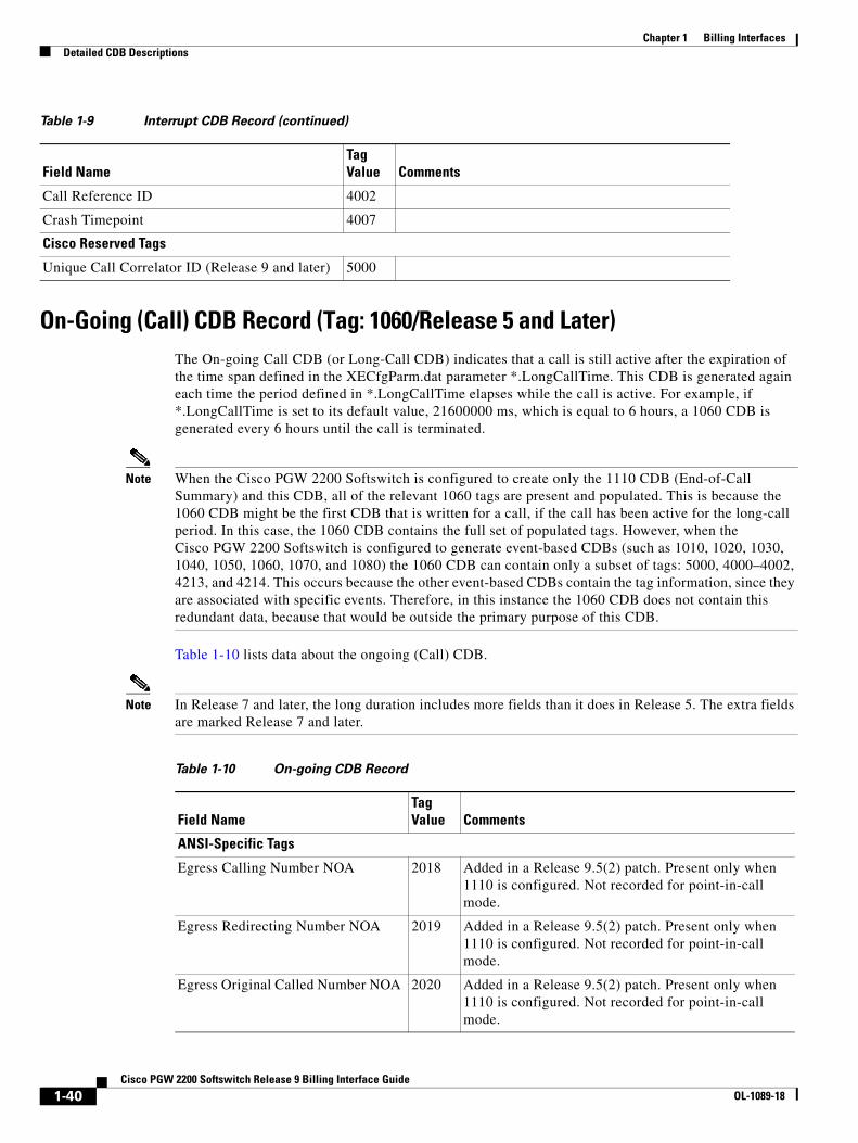
Chapter 1 Billing InterfacesDetailed CDB Descriptions
On-Going (Call) CDB Record (Tag: 1060/Release 5 and Later)The On-going Call CDB (or Long-Call CDB) indicates that a call is still active after the expiration of the time span defined in the XECfgParm.dat parameter *.LongCallTime. This CDB is generated again each time the period defined in *.LongCallTime elapses while the call is active. For example, if *.LongCallTime is set to its default value, 21600000 ms, which is equal to 6 hours, a 1060 CDB is generated every 6 hours until the call is terminated.
Note When the Cisco PGW 2200 Softswitch is configured to create only the 1110 CDB (End-of-Call Summary) and this CDB, all of the relevant 1060 tags are present and populated. This is because the 1060 CDB might be the first CDB that is written for a call, if the call has been active for the long-call period. In this case, the 1060 CDB contains the full set of populated tags. However, when the Cisco PGW 2200 Softswitch is configured to generate event-based CDBs (such as 1010, 1020, 1030, 1040, 1050, 1060, 1070, and 1080) the 1060 CDB can contain only a subset of tags: 5000, 4000–4002, 4213, and 4214. This occurs because the other event-based CDBs contain the tag information, since they are associated with specific events. Therefore, in this instance the 1060 CDB does not contain this redundant data, because that would be outside the primary purpose of this CDB.
Table 1-10 lists data about the ongoing (Call) CDB.
Note In Release 7 and later, the long duration includes more fields than it does in Release 5. The extra fields are marked Release 7 and later.
Call Reference ID 4002
Crash Timepoint 4007
Cisco Reserved Tags
Unique Call Correlator ID (Release 9 and later) 5000
Table 1-9 Interrupt CDB Record (continued)
Field NameTag Value Comments
Table 1-10 On-going CDB Record
Field NameTag Value Comments
ANSI-Specific Tags
Egress Calling Number NOA 2018 Added in a Release 9.5(2) patch. Present only when 1110 is configured. Not recorded for point-in-call mode.
Egress Redirecting Number NOA 2019 Added in a Release 9.5(2) patch. Present only when 1110 is configured. Not recorded for point-in-call mode.
Egress Original Called Number NOA 2020 Added in a Release 9.5(2) patch. Present only when 1110 is configured. Not recorded for point-in-call mode.
1-40Cisco PGW 2200 Softswitch Release 9 Billing Interface Guide
OL-1089-18
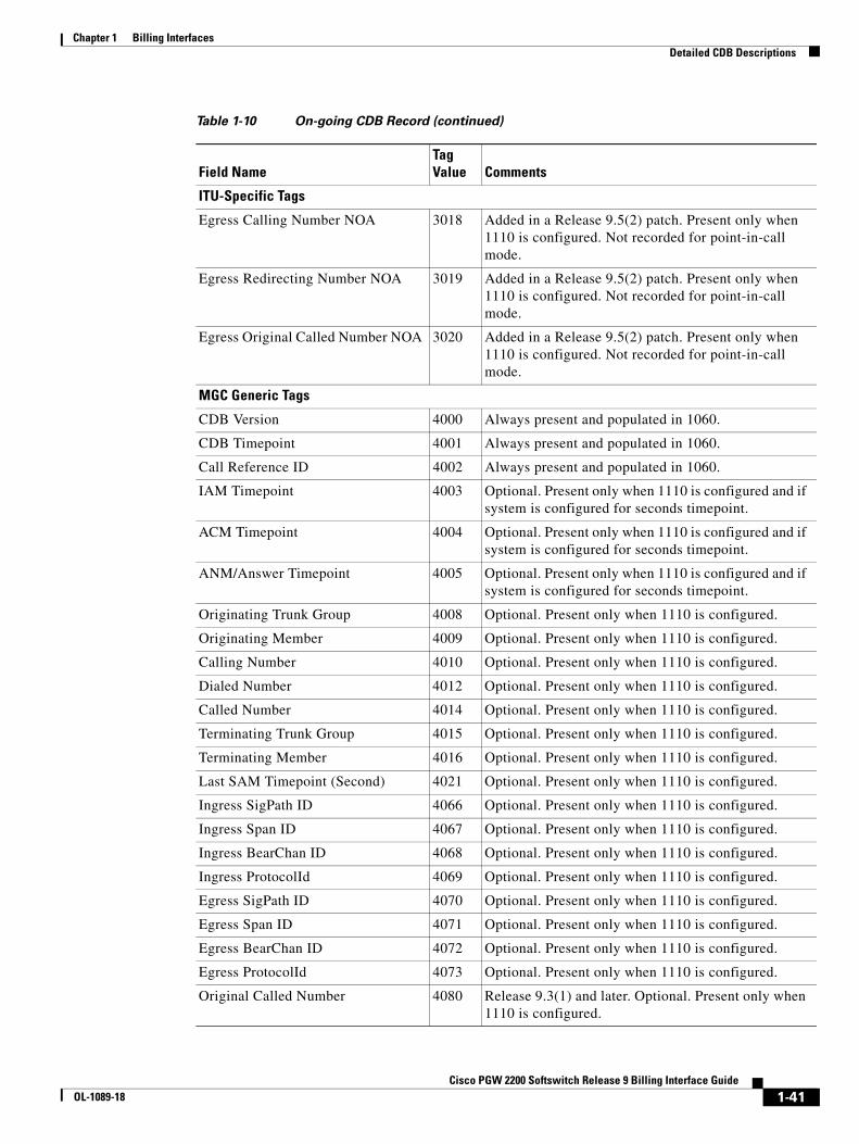
Chapter 1 Billing InterfacesDetailed CDB Descriptions
ITU-Specific Tags
Egress Calling Number NOA 3018 Added in a Release 9.5(2) patch. Present only when 1110 is configured. Not recorded for point-in-call mode.
Egress Redirecting Number NOA 3019 Added in a Release 9.5(2) patch. Present only when 1110 is configured. Not recorded for point-in-call mode.
Egress Original Called Number NOA 3020 Added in a Release 9.5(2) patch. Present only when 1110 is configured. Not recorded for point-in-call mode.
MGC Generic Tags
CDB Version 4000 Always present and populated in 1060.
CDB Timepoint 4001 Always present and populated in 1060.
Call Reference ID 4002 Always present and populated in 1060.
IAM Timepoint 4003 Optional. Present only when 1110 is configured and if system is configured for seconds timepoint.
ACM Timepoint 4004 Optional. Present only when 1110 is configured and if system is configured for seconds timepoint.
ANM/Answer Timepoint 4005 Optional. Present only when 1110 is configured and if system is configured for seconds timepoint.
Originating Trunk Group 4008 Optional. Present only when 1110 is configured.
Originating Member 4009 Optional. Present only when 1110 is configured.
Calling Number 4010 Optional. Present only when 1110 is configured.
Dialed Number 4012 Optional. Present only when 1110 is configured.
Called Number 4014 Optional. Present only when 1110 is configured.
Terminating Trunk Group 4015 Optional. Present only when 1110 is configured.
Terminating Member 4016 Optional. Present only when 1110 is configured.
Last SAM Timepoint (Second) 4021 Optional. Present only when 1110 is configured.
Ingress SigPath ID 4066 Optional. Present only when 1110 is configured.
Ingress Span ID 4067 Optional. Present only when 1110 is configured.
Ingress BearChan ID 4068 Optional. Present only when 1110 is configured.
Ingress ProtocolId 4069 Optional. Present only when 1110 is configured.
Egress SigPath ID 4070 Optional. Present only when 1110 is configured.
Egress Span ID 4071 Optional. Present only when 1110 is configured.
Egress BearChan ID 4072 Optional. Present only when 1110 is configured.
Egress ProtocolId 4073 Optional. Present only when 1110 is configured.
Original Called Number 4080 Release 9.3(1) and later. Optional. Present only when 1110 is configured.
Table 1-10 On-going CDB Record (continued)
Field NameTag Value Comments
1-41Cisco PGW 2200 Softswitch Release 9 Billing Interface Guide
OL-1089-18

Chapter 1 Billing InterfacesDetailed CDB Descriptions
Maintenance CDB Record (Tag: 1070/Release 5 and Later)Table 1-11 lists data about the maintenance record CDB type. CDB Tag 1070 is created for maintenance activity (such as block or unblock) on a circuit.
Meter Pulses Received 4213 Release 9.5(2) and later. Always present and populated in 1060.
Meter Pulses Sent 4214 Release 9.5(2) and later. Always present and populated in 1060.
Partial Calling Line Identity 4220 Release 9.5(2) and later. Optional. Present only when 1110 is configured.
Ingress Redirecting Number 4237 Added in a Release 9.5(2) patch. Present only when 1110 is configured. Not recorded for point-in-call mode.
Millisecond Granularity Timepoint Fields
Last SAM Timepoint (MilliSecond) 4022 Optional. Present only when 1110 is configured.
IAM Timepoint Received _ms 4100 Optional. Present only when 1110 is configured.
IAM Timepoint Sent_ms 4101 Optional. Present only when 1110 is configured.
ACM Timepoint Received_ms 4102 Optional. Present only when 1110 is configured.
ACM Timepoint Sent_ms 4103 Optional. Present only when 1110 is configured.
ANM Timepoint Received_ms 4104 Optional. Present only when 1110 is configured.
ANM Timepoint Sent_ms 4105 Optional. Present only when 1110 is configured.
Cisco Reserved Tags
Unique Call Correlator ID (Release 9 and later)
5000 Always present and populated in 1060.
Table 1-10 On-going CDB Record (continued)
Field NameTag Value Comments
Table 1-11 Maintenance CDB Record
Field Name Tag Value
Cisco PGW 2200 Softswitch Generic Tags
CDB Version 4000
CDB Timepoint 4001
Call Reference ID 4002
Maint Trunk Group 4017
Maint Circuit Member 4018
Maint Type 4032
Maint Reason (retired in Release 9.4(1)) 4033
Maintenance SigPath ID 4074
Maintenance Span ID 4075
1-42Cisco PGW 2200 Softswitch Release 9 Billing Interface Guide
OL-1089-18
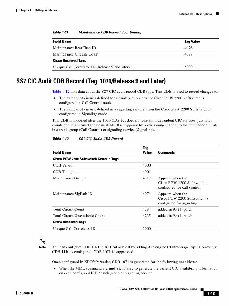
Chapter 1 Billing InterfacesDetailed CDB Descriptions
SS7 CIC Audit CDB Record (Tag: 1071/Release 9 and Later)Table 1-12 lists data about the SS7 CIC audit record CDB type. This CDB is used to record changes to:
• The number of circuits defined for a trunk group when the Cisco PGW 2200 Softswitch is configured in Call Control mode
• The number of circuits defined in a signaling service when the Cisco PGW 2200 Softswitch is configured in Signaling mode
This CDB is modeled after the 1070 CDB but does not contain independent CIC statuses, just total counts of CICs defined and unavailable. It is triggered by provisioning changes to the number of circuits in a trunk group (Call Control) or signaling service (Signaling).
Note You can configure CDB 1071 in XECfgParm.dat by adding it in engine.CDRmessageType. However, if CDB 1110 is configured, CDB 1071 is suppressed.
Once configured in XECfgParm.dat, CDB 1071 is generated for the following conditions:
• When the MML command sta-aud-cic is used to generate the current CIC availability information on each configured ISUP trunk group or signaling service.
Maintenance BearChan ID 4076
Maintenance Circuits Count 4077
Cisco Reserved Tags
Unique Call Correlator ID (Release 9 and later) 5000
Table 1-11 Maintenance CDB Record (continued)
Field Name Tag Value
Table 1-12 SS7 CIC Audio CDB Record
Field NameTag Value Comments
Cisco PGW 2200 Softswitch Generic Tags
CDB Version 4000
CDB Timepoint 4001
Maint Trunk Group 4017 Appears when the Cisco PGW 2200 Softswitch is configured for call control.
Maintenance SigPath ID 4074 Appears when the Cisco PGW 2200 Softswitch is configured for signaling.
Total Circuit Count 4234 added in 9.4(1) patch
Total Circuit Unavailable Count 4235 added in 9.4(1) patch
Cisco Reserved Tags
Unique Call Correlator ID 5000
1-43Cisco PGW 2200 Softswitch Release 9 Billing Interface Guide
OL-1089-18

Chapter 1 Billing InterfacesDetailed CDB Descriptions
• When a provisioning change (add or delete) is made in the number of circuits.
• When a CIC service state or block state change occurs. A circuit that is unavailable is either blocked, OOS, or both. A circuit that is blocked and also OOS is not double-counted as two unavailable circuits. Table 1-13 and Table 1-14 show the action taken when there is a service state or block state change.
A blocked state is one of the following states or a combination of these states:
• Manual local block
• Manual remote block
• Auto remote block (hardware failure)
• Auto local block
• Propagation block (gateway-initiated blocking)
CDB Tag 1071 generation rules:
• If CDB Tag 1071 is generated as the result of the sta-aud-cic MML command, it includes the CIC unavailability information per trunk group for switched configuration, or per signaling service for a nailed-up configuration. For the other two scenarios (a provisioning change to the number of circuits, or a CIC service state or block state change), it generates the information only for the trunk groups that are impacted.
• CDB Tag 1071 is generated only on the active side.
• To generate the CDB Tag 1071 on a trunk group or signaling service level rather than individual CIC level to minimize CPS impact, the Cisco PGW 2200 Softswitch uses an internal 10-second timer. 1071 CDB is generated 10 seconds after the initial CIC state change and/or the initial CIC provision change. This delay prevents the flooding of 1071 CDBs if a large number of CICs have blocks or service state changes almost simultaneously.
• The sta-aud-cic MML command is rejected for the following conditions:
– An attempt is made to run the MML command on the standby side.
– CDB Tag 1071 is not configured in the XECfgParm.dat file.
• A circuit that has COT failure and has COT retest in progress is not counted as unavailable.
Table 1-13 Service State Change
Service State Change Blocked Unblocked
OOS Do nothing Increment total unavailable counters
IS Do nothing Decrement total unavailable counters
Table 1-14 Service Block Change
Service Block Change OOS IS
Block Do nothing Increment total unavailable counters
Unblock Do nothing Decrement total unavailable counters
1-44Cisco PGW 2200 Softswitch Release 9 Billing Interface Guide
OL-1089-18
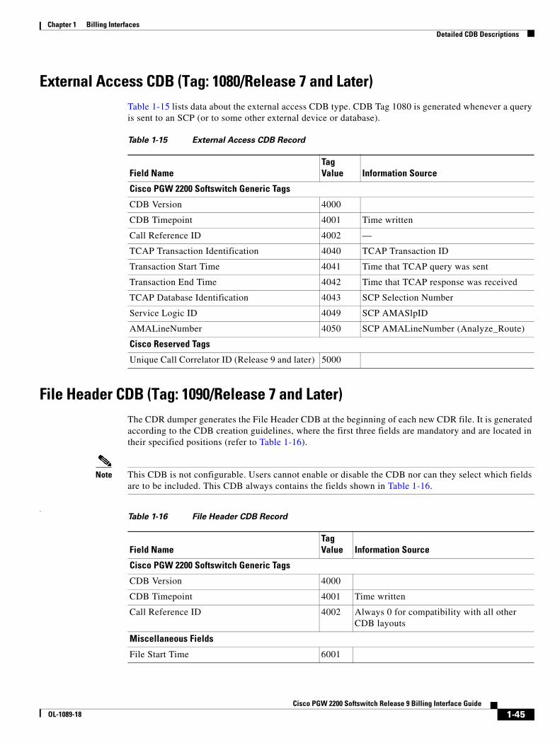
Chapter 1 Billing InterfacesDetailed CDB Descriptions
External Access CDB (Tag: 1080/Release 7 and Later)Table 1-15 lists data about the external access CDB type. CDB Tag 1080 is generated whenever a query is sent to an SCP (or to some other external device or database).
File Header CDB (Tag: 1090/Release 7 and Later)The CDR dumper generates the File Header CDB at the beginning of each new CDR file. It is generated according to the CDB creation guidelines, where the first three fields are mandatory and are located in their specified positions (refer to Table 1-16).
Note This CDB is not configurable. Users cannot enable or disable the CDB nor can they select which fields are to be included. This CDB always contains the fields shown in Table 1-16.
.
Table 1-15 External Access CDB Record
Field NameTag Value Information Source
Cisco PGW 2200 Softswitch Generic Tags
CDB Version 4000
CDB Timepoint 4001 Time written
Call Reference ID 4002 —
TCAP Transaction Identification 4040 TCAP Transaction ID
Transaction Start Time 4041 Time that TCAP query was sent
Transaction End Time 4042 Time that TCAP response was received
TCAP Database Identification 4043 SCP Selection Number
Service Logic ID 4049 SCP AMASlpID
AMALineNumber 4050 SCP AMALineNumber (Analyze_Route)
Cisco Reserved Tags
Unique Call Correlator ID (Release 9 and later) 5000
Table 1-16 File Header CDB Record
Field NameTag Value Information Source
Cisco PGW 2200 Softswitch Generic Tags
CDB Version 4000
CDB Timepoint 4001 Time written
Call Reference ID 4002 Always 0 for compatibility with all other CDB layouts
Miscellaneous Fields
File Start Time 6001
1-45Cisco PGW 2200 Softswitch Release 9 Billing Interface Guide
OL-1089-18
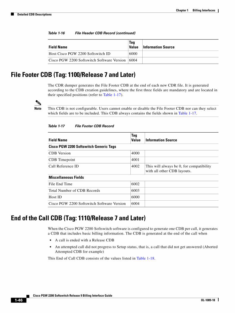
Chapter 1 Billing InterfacesDetailed CDB Descriptions
File Footer CDB (Tag: 1100/Release 7 and Later)The CDR dumper generates the File Footer CDB at the end of each new CDR file. It is generated according to the CDB creation guidelines, where the first three fields are mandatory and are located in their specified positions (refer to Table 1-17).
Note This CDB is not configurable. Users cannot enable or disable the File Footer CDB nor can they select which fields are to be included. This CDB always contains the fields shown in Table 1-17.
End of the Call CDB (Tag: 1110/Release 7 and Later)When the Cisco PGW 2200 Softswitch software is configured to generate one CDB per call, it generates a CDB that includes basic billing information. The CDB is generated at the end of the call when
• A call is ended with a Release CDB
• An attempted call did not progress to Setup status, that is, a call that did not get answered (Aborted Attempted CDB for example)
This End of Call CDB consists of the values listed in Table 1-18.
Host Cisco PGW 2200 Softswitch ID 6000
Cisco PGW 2200 Softswitch Software Version 6004
Table 1-16 File Header CDB Record (continued)
Field NameTag Value Information Source
Table 1-17 File Footer CDB Record
Field NameTag Value Information Source
Cisco PGW 2200 Softswitch Generic Tags
CDB Version 4000
CDB Timepoint 4001
Call Reference ID 4002 This will always be 0, for compatibility with all other CDB layouts.
Miscellaneous Fields
File End Time 6002
Total Number of CDB Records 6003
Host ID 6000
Cisco PGW 2200 Softswitch Software Version 6004
1-46Cisco PGW 2200 Softswitch Release 9 Billing Interface Guide
OL-1089-18
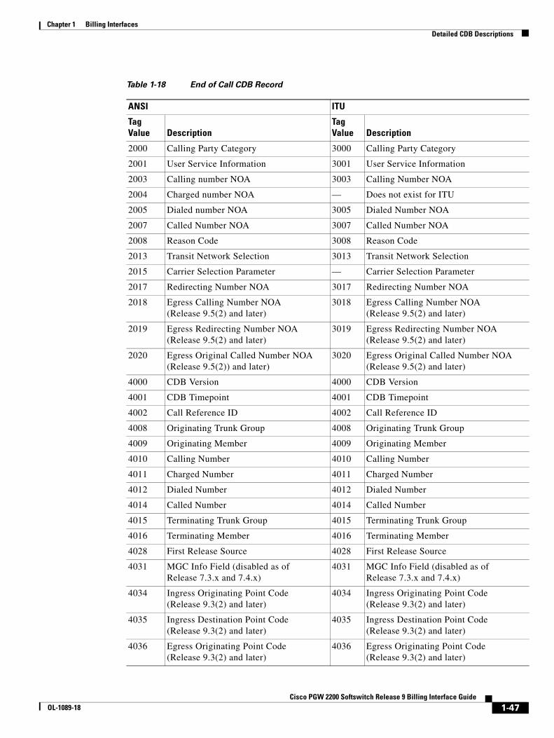
Chapter 1 Billing InterfacesDetailed CDB Descriptions
Table 1-18 End of Call CDB Record
ANSI ITU
Tag Value Description
Tag Value Description
2000 Calling Party Category 3000 Calling Party Category
2001 User Service Information 3001 User Service Information
2003 Calling number NOA 3003 Calling Number NOA
2004 Charged number NOA — Does not exist for ITU
2005 Dialed number NOA 3005 Dialed Number NOA
2007 Called Number NOA 3007 Called Number NOA
2008 Reason Code 3008 Reason Code
2013 Transit Network Selection 3013 Transit Network Selection
2015 Carrier Selection Parameter — Carrier Selection Parameter
2017 Redirecting Number NOA 3017 Redirecting Number NOA
2018 Egress Calling Number NOA (Release 9.5(2) and later)
3018 Egress Calling Number NOA (Release 9.5(2) and later)
2019 Egress Redirecting Number NOA (Release 9.5(2) and later)
3019 Egress Redirecting Number NOA (Release 9.5(2) and later)
2020 Egress Original Called Number NOA (Release 9.5(2)) and later)
3020 Egress Original Called Number NOA (Release 9.5(2) and later)
4000 CDB Version 4000 CDB Version
4001 CDB Timepoint 4001 CDB Timepoint
4002 Call Reference ID 4002 Call Reference ID
4008 Originating Trunk Group 4008 Originating Trunk Group
4009 Originating Member 4009 Originating Member
4010 Calling Number 4010 Calling Number
4011 Charged Number 4011 Charged Number
4012 Dialed Number 4012 Dialed Number
4014 Called Number 4014 Called Number
4015 Terminating Trunk Group 4015 Terminating Trunk Group
4016 Terminating Member 4016 Terminating Member
4028 First Release Source 4028 First Release Source
4031 MGC Info Field (disabled as of Release 7.3.x and 7.4.x)
4031 MGC Info Field (disabled as of Release 7.3.x and 7.4.x)
4034 Ingress Originating Point Code (Release 9.3(2) and later)
4034 Ingress Originating Point Code (Release 9.3(2) and later)
4035 Ingress Destination Point Code (Release 9.3(2) and later)
4035 Ingress Destination Point Code (Release 9.3(2) and later)
4036 Egress Originating Point Code (Release 9.3(2) and later)
4036 Egress Originating Point Code (Release 9.3(2) and later)
1-47Cisco PGW 2200 Softswitch Release 9 Billing Interface Guide
OL-1089-18
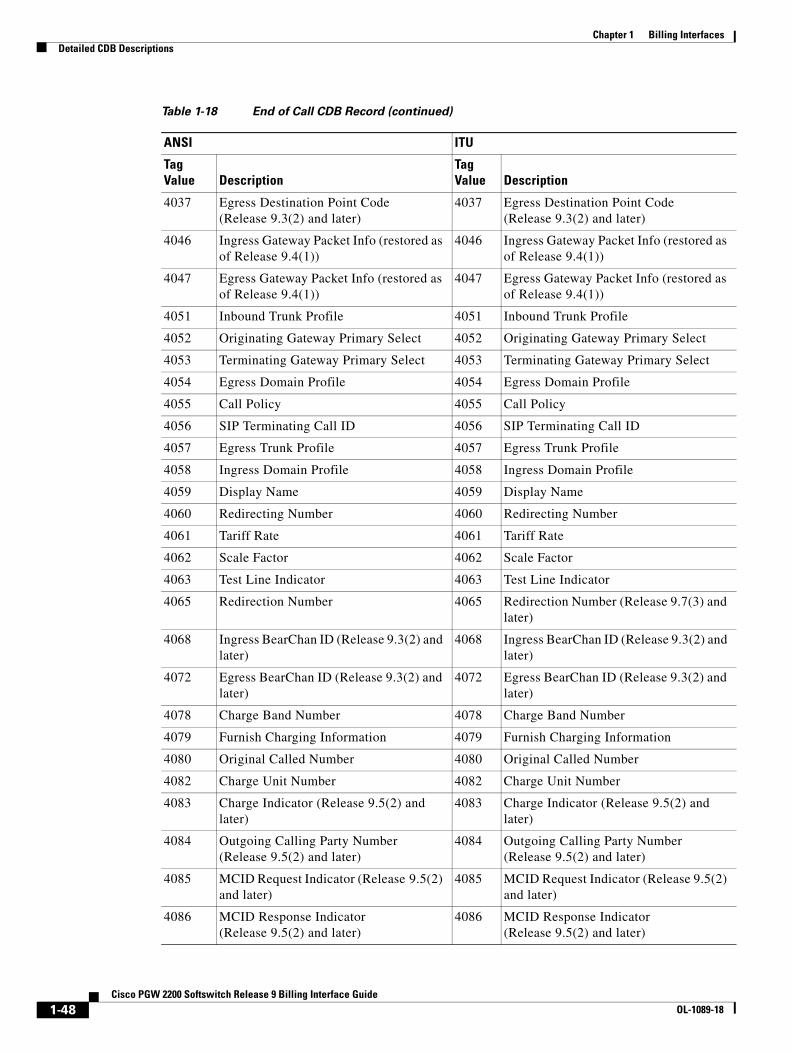
Chapter 1 Billing InterfacesDetailed CDB Descriptions
4037 Egress Destination Point Code (Release 9.3(2) and later)
4037 Egress Destination Point Code (Release 9.3(2) and later)
4046 Ingress Gateway Packet Info (restored as of Release 9.4(1))
4046 Ingress Gateway Packet Info (restored as of Release 9.4(1))
4047 Egress Gateway Packet Info (restored as of Release 9.4(1))
4047 Egress Gateway Packet Info (restored as of Release 9.4(1))
4051 Inbound Trunk Profile 4051 Inbound Trunk Profile
4052 Originating Gateway Primary Select 4052 Originating Gateway Primary Select
4053 Terminating Gateway Primary Select 4053 Terminating Gateway Primary Select
4054 Egress Domain Profile 4054 Egress Domain Profile
4055 Call Policy 4055 Call Policy
4056 SIP Terminating Call ID 4056 SIP Terminating Call ID
4057 Egress Trunk Profile 4057 Egress Trunk Profile
4058 Ingress Domain Profile 4058 Ingress Domain Profile
4059 Display Name 4059 Display Name
4060 Redirecting Number 4060 Redirecting Number
4061 Tariff Rate 4061 Tariff Rate
4062 Scale Factor 4062 Scale Factor
4063 Test Line Indicator 4063 Test Line Indicator
4065 Redirection Number 4065 Redirection Number (Release 9.7(3) and later)
4068 Ingress BearChan ID (Release 9.3(2) and later)
4068 Ingress BearChan ID (Release 9.3(2) and later)
4072 Egress BearChan ID (Release 9.3(2) and later)
4072 Egress BearChan ID (Release 9.3(2) and later)
4078 Charge Band Number 4078 Charge Band Number
4079 Furnish Charging Information 4079 Furnish Charging Information
4080 Original Called Number 4080 Original Called Number
4082 Charge Unit Number 4082 Charge Unit Number
4083 Charge Indicator (Release 9.5(2) and later)
4083 Charge Indicator (Release 9.5(2) and later)
4084 Outgoing Calling Party Number (Release 9.5(2) and later)
4084 Outgoing Calling Party Number (Release 9.5(2) and later)
4085 MCID Request Indicator (Release 9.5(2) and later)
4085 MCID Request Indicator (Release 9.5(2) and later)
4086 MCID Response Indicator (Release 9.5(2) and later)
4086 MCID Response Indicator (Release 9.5(2) and later)
Table 1-18 End of Call CDB Record (continued)
ANSI ITU
Tag Value Description
Tag Value Description
1-48Cisco PGW 2200 Softswitch Release 9 Billing Interface Guide
OL-1089-18

Chapter 1 Billing InterfacesDetailed CDB Descriptions
4087 Ingress MGCP DLCX Return Code (Release 9.5(2) and later)
4087 Ingress MGCP DLCX Return Code (Release 9.5(2) and later)
4088 Egress MGCP DLCX Return Code (Release 9.5(2) and later)
4088 Egress MGCP DLCX Return Code (Release 9.5(2) and later)
4089 Network Translated Address Indicator (Release 9.5(2) and later)
4089 Network Translated Address Indicator (Release 9.5(2) and later)
4090 Reservation Request Accepted (Release 9.5(2) and later)
4090 Reservation Request Accepted (Release 9.5(2) and later)
4091 Reservation Request Lost Count (Release 9.5(2) and later)
4091 Reservation Request Error Count (Release 9.5(2) and later)
4092 ATM Ingress Configured Profile (Release 9.5(2) and later)
4092 ATM Ingress Configured Profile (Release 9.5(2) and later)
4093 ATM Egress Configured Profile (Release 9.5(2) and later)
4093 ATM Egress Configured Profile (Release 9.5(2) and later)
4094 ATM Negotiated Profile (Release 9.5(2) and later)
4094 ATM Negotiated Profile (Release 9.5(2) and later)
4095 Route List Name (Release 9.5(2) and later)
4095 Route List Name (Release 9.5(2) and later)
4096 Route Name (Release 9.5(2) and later) 4096 Route Name (Release 9.5(2) and later)
4097 MGCP Script Response String (Release 9.5(2) and later)
4097 MGCP Script Response String (Release 9.5(2) and later)
4098 Originating Leg DSP Statistics (Release 9.4(1) and later)
4098 Originating Leg DSP Statistics (Release 9.4(1) and later)
4099 Terminating Leg DSP Statistics (Release 9.4(1) and later)
4099 Terminating Leg DSP Statistics (Release 9.4(1) and later)
4100 IAM Timepoint Received_msec 4100 IAM Timepoint Received_msec
4101 IAM Timepoint Sent_msec 4101 IAM Timepoint Sent_msec
4102 ACM Timepoint Received_msec 4102 ACM Timepoint Received_msec
4103 ACM Timepoint Sent_msec 4103 ACM Timepoint Sent_msec
4104 ANM Timepoint Received_msec 4104 ANM Timepoint Received_msec
4105 ANM Timepoint Sent_msec 4105 ANM Timepoint sent_msec
4106 First REL Timepoint_msec 4106 First REL Timepoint_msec
4107 Second REL Timepoint_msec 4107 Second REL Timepoint_msec
4108 RLC Timepoint Received_msec 4108 RLC Timepoint Received_msec
4109 RLC Timepoint Sent_msec 4109 RLC Timepoint Sent_msec
4110 Ingress Media Gateway Pool ID 4110 Ingress Media Gateway Pool ID
4111 Egress Media Gateway Pool ID 4111 Egress Media Gateway Pool ID
Table 1-18 End of Call CDB Record (continued)
ANSI ITU
Tag Value Description
Tag Value Description
1-49Cisco PGW 2200 Softswitch Release 9 Billing Interface Guide
OL-1089-18
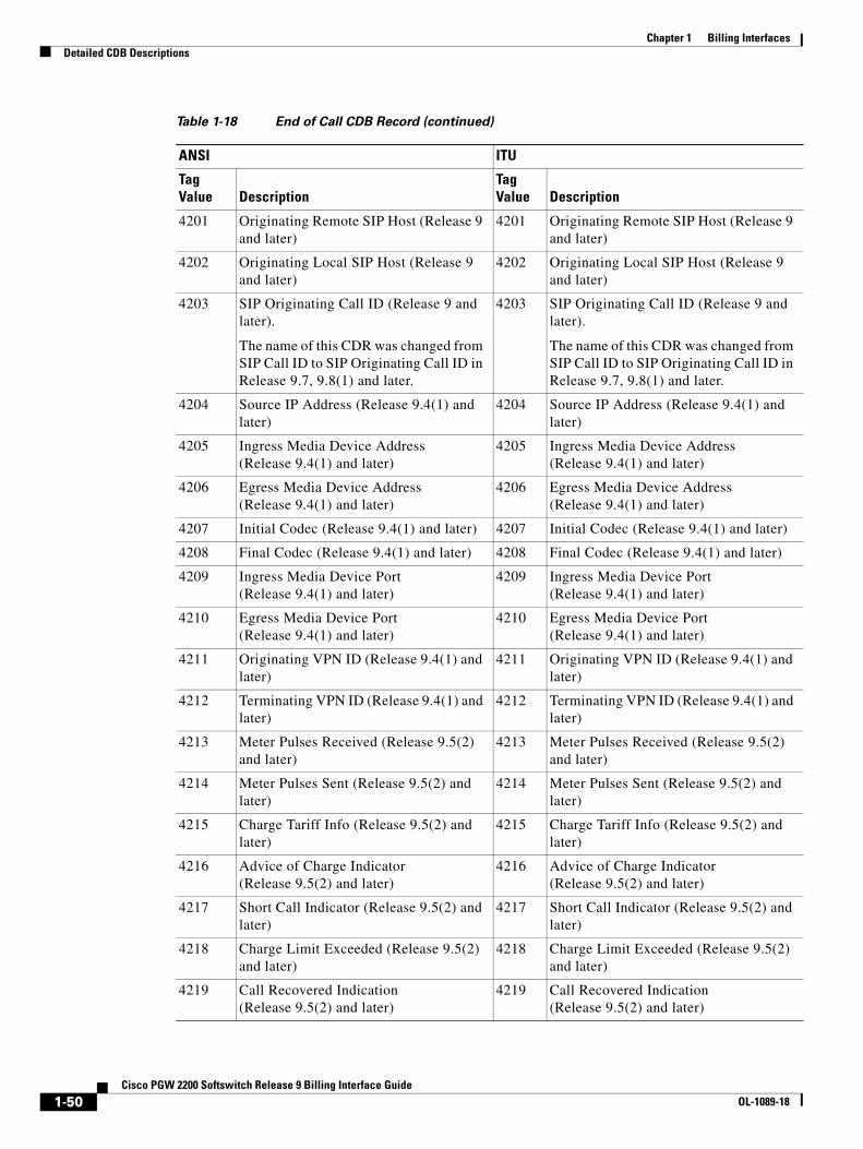
Chapter 1 Billing InterfacesDetailed CDB Descriptions
4201 Originating Remote SIP Host (Release 9 and later)
4201 Originating Remote SIP Host (Release 9 and later)
4202 Originating Local SIP Host (Release 9 and later)
4202 Originating Local SIP Host (Release 9 and later)
4203 SIP Originating Call ID (Release 9 and later).
The name of this CDR was changed from SIP Call ID to SIP Originating Call ID in Release 9.7, 9.8(1) and later.
4203 SIP Originating Call ID (Release 9 and later).
The name of this CDR was changed from SIP Call ID to SIP Originating Call ID in Release 9.7, 9.8(1) and later.
4204 Source IP Address (Release 9.4(1) and later)
4204 Source IP Address (Release 9.4(1) and later)
4205 Ingress Media Device Address (Release 9.4(1) and later)
4205 Ingress Media Device Address (Release 9.4(1) and later)
4206 Egress Media Device Address (Release 9.4(1) and later)
4206 Egress Media Device Address (Release 9.4(1) and later)
4207 Initial Codec (Release 9.4(1) and later) 4207 Initial Codec (Release 9.4(1) and later)
4208 Final Codec (Release 9.4(1) and later) 4208 Final Codec (Release 9.4(1) and later)
4209 Ingress Media Device Port (Release 9.4(1) and later)
4209 Ingress Media Device Port (Release 9.4(1) and later)
4210 Egress Media Device Port (Release 9.4(1) and later)
4210 Egress Media Device Port (Release 9.4(1) and later)
4211 Originating VPN ID (Release 9.4(1) and later)
4211 Originating VPN ID (Release 9.4(1) and later)
4212 Terminating VPN ID (Release 9.4(1) and later)
4212 Terminating VPN ID (Release 9.4(1) and later)
4213 Meter Pulses Received (Release 9.5(2) and later)
4213 Meter Pulses Received (Release 9.5(2) and later)
4214 Meter Pulses Sent (Release 9.5(2) and later)
4214 Meter Pulses Sent (Release 9.5(2) and later)
4215 Charge Tariff Info (Release 9.5(2) and later)
4215 Charge Tariff Info (Release 9.5(2) and later)
4216 Advice of Charge Indicator (Release 9.5(2) and later)
4216 Advice of Charge Indicator (Release 9.5(2) and later)
4217 Short Call Indicator (Release 9.5(2) and later)
4217 Short Call Indicator (Release 9.5(2) and later)
4218 Charge Limit Exceeded (Release 9.5(2) and later)
4218 Charge Limit Exceeded (Release 9.5(2) and later)
4219 Call Recovered Indication (Release 9.5(2) and later)
4219 Call Recovered Indication (Release 9.5(2) and later)
Table 1-18 End of Call CDB Record (continued)
ANSI ITU
Tag Value Description
Tag Value Description
1-50Cisco PGW 2200 Softswitch Release 9 Billing Interface Guide
OL-1089-18

Chapter 1 Billing InterfacesDetailed CDB Descriptions
4220 Partial Calling Line Identity (Release 9.5(2) and later)
4220 Partial Calling Line Identity (Release 9.5(2) and later)
4221 Service Activation (added in Release 9.5(2), modified in Release 9.6(1))
4221 Service Activation (added in Release 9.5(2), modified in Release 9.6(1))
4222 PRI AOC Invoke Type (Release 9.5(2) and later)
4222 PRI AOC Invoke Type (Release 9.5(2) and later)
4223 PRI AOC – S Charge Information (Release 9.5(2) and later)
4223 PRI AOC – S Charge Information (Release 9.5(2) and later)
4224 PRI AOC – D Charge Information (Release 9.5(2) and later)
4224 PRI AOC – D Charge Information (Release 9.5(2) and later)
4225 PRI AOC – E Charge Information (Release 9.5(2) and later)
4225 PRI AOC – E Charge Information (Release 9.5(2) and later)
4226 PRI AOC Invoke Failure (Release 9.5(2) and later)
4226 PRI AOC Invoke Failure (Release 9.5(2) and later)
4227 Route Optimization/Path Replacement Action (Release 9.6(1) and later)
4227 Route Optimization/Path Replacement Action (Release 9.6(1) and later)
4228 Route Optimization/Path Replacement Call Reference of Associated Call Instance (Release 9.6(1) and later)
4228 Route Optimization/Path Replacement Call Reference of Associated Call Instance (Release 9.6(1) and later)
4229 Route Optimization/Path Replacement Trunk Group Info (Release 9.6(1) and later)
4229 Route Optimization/Path Replacement Trunk Group Info (Release 9.6(1) and later)
4230 Route Optimization/Path Replacement Channel Info (Release 9.6(1) and later)
4230 Route Optimization/Path Replacement Channel Info (Release 9.6(1) and later)
4231 Route Optimization Switchover Timestamp (Release 9.6(1) and later)
4231 Route Optimization Switchover Timestamp (Release 9.6(1) and later)
4232 Rejecting Location Label (Release 9.6(1) and later)
4232 Rejecting Location Label (Release 9.6(1) and later)
4233 Rejecting Location Label Direction (Release 9.6(1) and later)
4233 Rejecting Location Label Direction (Release 9.6(1) and later)
4236 H323 Destination (Release 9.7 and later) 4236 H323 Destination (Release 9.7 and later)
4237 Ingress Redirecting Number (Release 9.5(2) and later)
4237 Ingress Redirecting Number (Release 9.5(2) and later)
4239 Service Usage Data (Release 9.7 and later)
4239 Service Usage Data (Release 9.7 and later)
4240 CNAM DIP (Release 9.7 and later) 4240 CNAM DIP (Release 9.7 and later)
4241 Calling Party Name (Release 9.7 and later)
4241 Calling Party Name (Release 9.7 and later)
Table 1-18 End of Call CDB Record (continued)
ANSI ITU
Tag Value Description
Tag Value Description
1-51Cisco PGW 2200 Softswitch Release 9 Billing Interface Guide
OL-1089-18

Chapter 1 Billing InterfacesDetailed CDB Descriptions
4242 Terminating Remote SIP Host (Release 9.7 and later)
4242 Terminating Remote SIP Host (Release 9.7 and later)
4243 Terminating Local SIP Host (Release 9.7 and later)
4243 Terminating Local SIP Host (Release 9.7 and later)
4244 License Rejecting Reason (Release 9.7 and later)
4244 License Rejecting Reason (Release 9.7 and later)
4245 License Rejecting Direction (Release 9.7 and later)
4245 License Rejecting Direction (Release 9.7 and later)
4246 SIP Ingress Transport (Release 9.7 and later). The name of this tag was changed from SIP Transport to SIP Ingress Transport in Release 9.8(1).
4246 SIP Ingress Transport (Release 9.7 and later). The name of this tag was changed from SIP Transport to SIP Ingress Transport in Release 9.8(1).
4247 SIP Routing URI Source 4247 SIP Routing URI Source (Release 9.7 and later)
4248 SIP Routing URI 4248 SIP Routing URI (Release 9.7 and later)
4249 Original Source Header 4249 Original Source Header
4250 Original Source URI 4250 Original Source URI
4251 Final Destination URI 4251 Final Destination URI
4252 Non-E.164 Destination Route Select Failure
4252 Non-E.164 Destination Route Select Failure
4253 Domain Screening Failure URI 4253 Domain Screening Failure URI
4254 SIP Egress Transport 4254 SIP Egress Transport
4255 SIP Final Source URI 4255 SIP Final Source URI
4256 iTNT Dtmf Digits (Release 9.7(3)and later)
iTNT Dtmf Digits (Release 9.7(3)and later)
4257 NCT Destinations (Release 9.7(3)and later)
NCT Destinations (Release 9.7(3)and later)
4258 iTNT Destinations (Release 9.7(3)and later)
iTNT Destinations (Release 9.7(3)and later)
4259 iTNT MidCall Dial Plan (Release 9.7(3)and later)
iTNT MidCall Dial Plan (Release 9.7(3)and later)
5000 Unique Call Correlator ID (Release 9 and later)
5000 Unique Call Correlator ID (Release 9 and later)
6005 Interim CDB (Release 9.5(2) and later) 6005 Interim CDB (Release 9.5(2) and later)
Table 1-18 End of Call CDB Record (continued)
ANSI ITU
Tag Value Description
Tag Value Description
1-52Cisco PGW 2200 Softswitch Release 9 Billing Interface Guide
OL-1089-18

Chapter 1 Billing InterfacesDetailed CDB Descriptions
Slave End-of-Call CDB Record (Tag: 1210/Release 9.6 and Later)Table 1-19 lists data about the Slave End-of-Call CDB type. The Cisco PGW 2200 Softswitch generates this CDB at the end of the call for a noncontrolling half-call instance. Only end-of-call summary style CDBs are issued for slave half-call instances, and the appropriate information is check-pointed to ensure the data is successfully written if a switchover occurs. This CDB is disabled by default on your Cisco PGW 2200.
Note If you do enable this CDB and your network includes a Cisco BAMS, you must provision the Cisco BAMS to ignore this CDB.
Slave Long Duration Call CDB Record (Tag: 1260/Release 9.6 and Later)Table 1-20 lists data about the Slave Long Duration Call CDB type. This CDB is used when the call instance remains active beyond a preconfigured time. The long call duration timer of the slave call is the same as that of “master” call configured in XECfgParm.dat.
Table 1-19 Slave End-of-Call CDB Record
Field Name Tag Value Comments
Cisco PGW 2200 Softswitch Generic Tags
Call Reference ID 4002
IAM Timepoint 4003
REL Timepoint 4006
Originating Trunk Group 4008
Originating Member 4009
Terminating Trunk Group 4015
Terminating Member 4016
Last SAM Timepoint (MilliSecond) 4022 Added in Releae 9.8(1)
RO/PR Executed 4227 Added in Release 9.6(1)
RO/PR Other Call Ref 4228 Added in Release 9.6(1)
Cisco Reserved Tags
Unique Call Correlator ID (Release 9 and later) 5000
Table 1-20 Slave Long Duration Call CDB Record
Field NameTag Value Comments
Cisco PGW 2200 Softswitch Generic Tags
Call Reference ID 4002
IAM Timepoint 4003
Originating Trunk Group 4008
Originating Member 4009
1-53Cisco PGW 2200 Softswitch Release 9 Billing Interface Guide
OL-1089-18

Chapter 1 Billing InterfacesCDE Detail Description
CDE Detail DescriptionA call data element (CDE) is a field within the CDB that contains basic information about a billing record. Examples of CDEs are the calling number and the called number.
The CDEs are described in the CDE description form template as shown in Table 1-21. CDE description forms for each of the CDBs listed near the bottom in Table 1-21 are included in Table 1-22 through Table 1-251.
Terminating Trunk Group 4015
Terminating Member 4016
RO/PR Executed 4227 Added in Release 9.6(1)
RO/PR Other Call Ref 4228 Added in Release 9.6(1)
Cisco Reserved Tags
Unique Call Correlator ID (Release 9 and later) 5000
Table 1-20 Slave Long Duration Call CDB Record (continued)
Field NameTag Value Comments
Table 1-21 CDE Description Form Template
Name: Name of the CDE Tag: The tag value Source: Subsystem that generates the CDE value
Description/Purpose: Brief description of the CDE
Format: The format of the CDE value Length: CDE value length
Data Value: Range of CDE values, or valid values
Extended Data Value: This section includes CDE values that are extended (from the ANSI/ITU standard) by the Cisco PGW 2200 Softswitch.
General Information: General information about the CDE and comments.
Cisco PGW 2200 Softswitch Release: The Cisco PGW 2200 Softswitch release(s) supporting this CDE
1-54Cisco PGW 2200 Softswitch Release 9 Billing Interface Guide
OL-1089-18
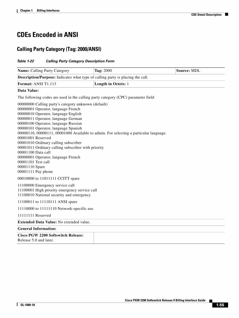
Chapter 1 Billing InterfacesCDE Detail Description
CDEs Encoded in ANSI
Calling Party Category (Tag: 2000/ANSI)
Table 1-22 Calling Party Category Description Form
Name: Calling Party Category Tag: 2000 Source: MDL
Description/Purpose: Indicates what type of calling party is placing the call.
Format: ANSI T1.113 Length in Octets: 1
Data Value:
The following codes are used in the calling party category (CPC) parameter field:
00000000 Calling party's category unknown (default) 00000001 Operator, language French 00000010 Operator, language English 00000011 Operator, language German 00000100 Operator, language Russian 00000101 Operator, language Spanish 00000110, 00000111, 00001000 Available to admin. For selecting a particular language. 00001001 Reserved 00001010 Ordinary calling subscriber 00001011 Ordinary calling subscriber with priority 00001100 Data call 00000001 Operator, language French 00001101 Test call 00001110 Spare 00001111 Pay phone
00010000 to 11011111 CCITT spare
11100000 Emergency service call 11100001 High priority emergency service call 11100010 National security and emergency
11100011 to 11110111 ANSI spare
11110000 to 11111110 Network-specific use
11111111 Reserved
Extended Data Value: No extended value.
General Information:
Cisco PGW 2200 Softswitch Release: Release 5.0 and later.
1-55Cisco PGW 2200 Softswitch Release 9 Billing Interface Guide
OL-1089-18
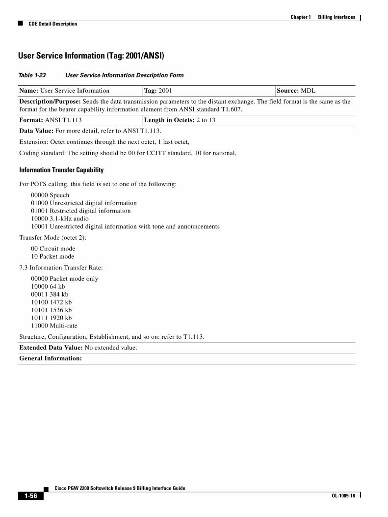
Chapter 1 Billing InterfacesCDE Detail Description
User Service Information (Tag: 2001/ANSI)
Table 1-23 User Service Information Description Form
Name: User Service Information Tag: 2001 Source: MDL
Description/Purpose: Sends the data transmission parameters to the distant exchange. The field format is the same as the format for the bearer capability information element from ANSI standard T1.607.
Format: ANSI T1.113 Length in Octets: 2 to 13
Data Value: For more detail, refer to ANSI T1.113.
Extension: Octet continues through the next octet, 1 last octet,
Coding standard: The setting should be 00 for CCITT standard, 10 for national,
Information Transfer Capability
For POTS calling, this field is set to one of the following:
00000 Speech 01000 Unrestricted digital information 01001 Restricted digital information 10000 3.1-kHz audio 10001 Unrestricted digital information with tone and announcements
Transfer Mode (octet 2):
00 Circuit mode 10 Packet mode
7.3 Information Transfer Rate:
00000 Packet mode only 10000 64 kb 00011 384 kb 10100 1472 kb 10101 1536 kb 10111 1920 kb 11000 Multi-rate
Structure, Configuration, Establishment, and so on: refer to T1.113.
Extended Data Value: No extended value.
General Information:
1-56Cisco PGW 2200 Softswitch Release 9 Billing Interface Guide
OL-1089-18

Chapter 1 Billing InterfacesCDE Detail Description
Originating Line Information (Tag: 2002/ANSI)
Calling Number Nature of Address (Tag: 2003/ANSI)
Table 1-24 Originating Line Information Description Form
Name: Originating Line Information Tag: 2002 Source: MDL
Description/Purpose: Contains information captured from the originating line information parameter.
Format: ANSI T1.113 Length in Octets: 1
Data Value:
00000000 to 01100011 Binary equivalent of the digits
01100100 to 11111111 Reserved
Extended Data Value: No extended value.
General Information:
Cisco PGW 2200 Softswitch Release: Release 5.0 and later.
Table 1-25 Calling Number Nature of Address Description Form
Name: Calling Number Nature of Address Tag: 2003 Source: MDL
Description/Purpose: Indicates the nature of address (NOA) of the calling party. In POTS calling, two values are usually used: unique national number and nonunique national number.
Format: ANSI T1.113 Length in Octets: 1
Data Value:
0000000 Spare 0000001 Unique subscriber number 0000010 Spare (national use) 0000011 Unique national number 0000100 Unique international number
0000101 to 1110000 Spare
1110001 Nonunique subscriber number 1110010 Spare 1110011 Nonunique national number 111010 0 Nonunique international number 1110101 Spare 1110110 Spare 1110111 Test line
1111000 to 1111000 Reserved
1111111 Spare
Extended Data Value: No extended value.
General Information:
Cisco PGW 2200 Softswitch Release: Release 5.0 and later.
1-57Cisco PGW 2200 Softswitch Release 9 Billing Interface Guide
OL-1089-18

Chapter 1 Billing InterfacesCDE Detail Description
Charged Number Nature of Address (Tag: 2004/ANSI)
Table 1-26 Charged Number Nature of Address Description Form
Name: Charged Number Nature of Address Tag: 2004 Source: MDL
Description/Purpose: Indicates to the Cisco PGW 2200 Softswitch how the number was delivered.
Format: ANSI T1.113 Length in Octets: 1
Data Value:
0000000 Spare 0000001 Unique subscriber number 0000010 Spare (national use) 0000011 Unique national number 0000100 Unique international number
0000101 to 1110000 Spare
1110001 Nonunique subscriber number 1110010 Spare 1110011 Nonunique national number 111010 0 Nonunique international number 1110101 Spare 1110110 Spare 1110111 Test line
1111000 to 1111000 Reserved
1111111 Spare
Extended Data Value: No extended value.
General Information:
Cisco PGW 2200 Softswitch Release: Release 5.0 and later.
1-58Cisco PGW 2200 Softswitch Release 9 Billing Interface Guide
OL-1089-18

Chapter 1 Billing InterfacesCDE Detail Description
Dialed Number Nature of Address (Tag: 2005/ANSI)
Table 1-27 Dialed Number Nature of Address Description Form
Name: Dialed Number Nature of Address Tag: 2005 Source: MDL
Description/Purpose: Allows the Call Process to route a call differently based on the Nature of Address (NOA) value provided in the IAM called number parameter. This tag represents the external (for example, line) value of NOA for the called part number.
Format: ANSI T1.113 Length in Octets: 1
Data Value:
0000000 Spare. If the LEC does not know what type of line the calling party is, it sends this value to the Cisco PGW 2200 Softswitch. The Cisco PGW 2200 Softswitch does not alter this value and does not use it for billing.
0000001 Unique subscriber number 0000010 Spare (national use) 0000011 Unique national number 0000100 Unique international number
0000101 to 1110000 Spare
1110001 Nonunique subscriber number 1110010 Spare 1110011 Nonunique national number 111010 0 Nonunique international number 1110101 Spare 1110110 Spare 1110111 Test line
1111000 to 1111000 Reserved
1111111 Spare
Extended Data Value: No extended value.
General Information:
Cisco PGW 2200 Softswitch Release: Release 5.0 and later.
1-59Cisco PGW 2200 Softswitch Release 9 Billing Interface Guide
OL-1089-18
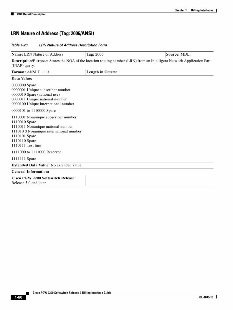
Chapter 1 Billing InterfacesCDE Detail Description
LRN Nature of Address (Tag: 2006/ANSI)
Table 1-28 LRN Nature of Address Description Form
Name: LRN Nature of Address Tag: 2006 Source: MDL
Description/Purpose: Stores the NOA of the location routing number (LRN) from an Intelligent Network Application Part (INAP) query.
Format: ANSI T1.113 Length in Octets: 1
Data Value:
0000000 Spare 0000001 Unique subscriber number 0000010 Spare (national use) 0000011 Unique national number 0000100 Unique international number
0000101 to 1110000 Spare
1110001 Nonunique subscriber number 1110010 Spare 1110011 Nonunique national number 111010 0 Nonunique international number 1110101 Spare 1110110 Spare 1110111 Test line
1111000 to 1111000 Reserved
1111111 Spare
Extended Data Value: No extended value.
General Information:
Cisco PGW 2200 Softswitch Release: Release 5.0 and later.
1-60Cisco PGW 2200 Softswitch Release 9 Billing Interface Guide
OL-1089-18
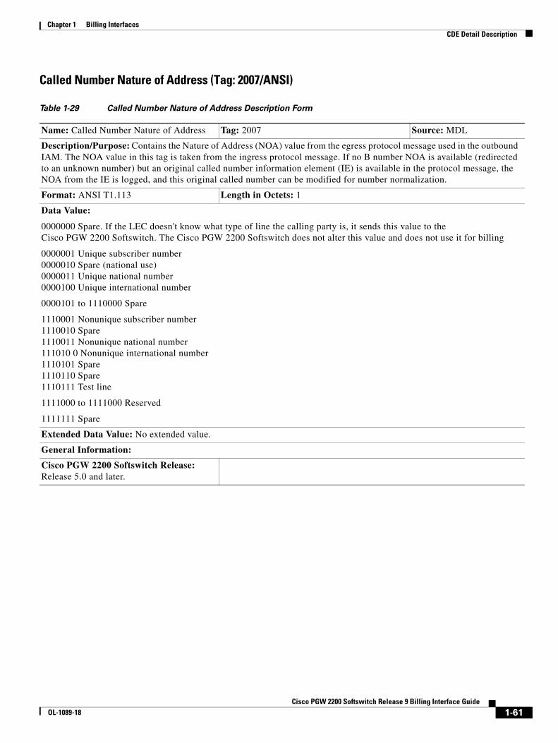
Chapter 1 Billing InterfacesCDE Detail Description
Called Number Nature of Address (Tag: 2007/ANSI)
Table 1-29 Called Number Nature of Address Description Form
Name: Called Number Nature of Address Tag: 2007 Source: MDL
Description/Purpose: Contains the Nature of Address (NOA) value from the egress protocol message used in the outbound IAM. The NOA value in this tag is taken from the ingress protocol message. If no B number NOA is available (redirected to an unknown number) but an original called number information element (IE) is available in the protocol message, the NOA from the IE is logged, and this original called number can be modified for number normalization.
Format: ANSI T1.113 Length in Octets: 1
Data Value:
0000000 Spare. If the LEC doesn't know what type of line the calling party is, it sends this value to the Cisco PGW 2200 Softswitch. The Cisco PGW 2200 Softswitch does not alter this value and does not use it for billing
0000001 Unique subscriber number 0000010 Spare (national use) 0000011 Unique national number 0000100 Unique international number
0000101 to 1110000 Spare
1110001 Nonunique subscriber number 1110010 Spare 1110011 Nonunique national number 111010 0 Nonunique international number 1110101 Spare 1110110 Spare 1110111 Test line
1111000 to 1111000 Reserved
1111111 Spare
Extended Data Value: No extended value.
General Information:
Cisco PGW 2200 Softswitch Release: Release 5.0 and later.
1-61Cisco PGW 2200 Softswitch Release 9 Billing Interface Guide
OL-1089-18
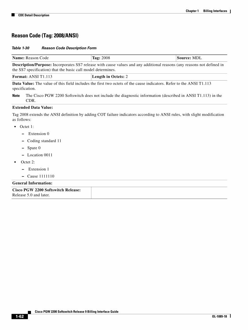
Chapter 1 Billing InterfacesCDE Detail Description
Reason Code (Tag: 2008/ANSI)
Table 1-30 Reason Code Description Form
Name: Reason Code Tag: 2008 Source: MDL
Description/Purpose: Incorporates SS7 release with cause values and any additional reasons (any reasons not defined in the SS7 specification) that the basic call model determines.
Format: ANSI T1.113 Length in Octets: 2
Data Value: The value of this field includes the first two octets of the cause indicators. Refer to the ANSI T1.113 specification.
Note The Cisco PGW 2200 Softswitch does not include the diagnostic information (described in ANSI T1.113) in the CDR.
Extended Data Value:
Tag 2008 extends the ANSI definition by adding COT failure indicators according to ANSI rules, with slight modification as follows:
• Octet 1:
– Extension 0
– Coding standard 11
– Spare 0
– Location 0011
• Octet 2:
– Extension 1
– Cause 1111110
General Information:
Cisco PGW 2200 Softswitch Release: Release 5.0 and later.
1-62Cisco PGW 2200 Softswitch Release 9 Billing Interface Guide
OL-1089-18

Chapter 1 Billing InterfacesCDE Detail Description
Forward Call Indicators Received (Tag: 2009/ANSI)
Table 1-31 Forward Call Indicators Received Description Form
Name: Forward Call Indicators Received Tag: 2009 Source: MDL
Description/Purpose: Contains the received Forward Call Indicator parameter in an ISUP message. It includes the following fields: International Call Ind.; End To End Method Ind.; Interworking Ind.; IAM Segmentation Ind.; ISDN User Part Ind.; ISDN User Part Preference Ind.; ISDN Access Ind.; and SCCP Method Ind.
Format: ANSI T1.113 Length in Octets: 2
Data Value:
National/International call indicator Bit A—For POTS calling, Bit A should be coded as a 0, signifying that this is an incoming national call. A coding of 1 signifies that the call is an incoming international call.
End-to-end method indicator Bits CB:
• 00 No end-to-end method available.
• 01 Pass along method available.
• 10 SCCP method available.
• 11 Both Pass along and SCCP methods available.
Interworking indicator Bit D—This field indicates to the Cisco PGW 2200 Softswitch if any interworking has been encountered in the signaling for this call. No information needs to be acted upon by the Cisco PGW 2200 Softswitch; it passes the information to the destination. “0” means no interworking was encountered (SS7 all the way). “1” means interworking was encountered.
IAM segmentation indicator Bit E—In POTS calling, this segmentation indicator is marked with a 0.
ISDN User Part indicator Bits F, HG, and I: These bits provide ISUP information. In the United States, the ISUP is used exclusively. For POTS national numbers, this field is marked 1 on all ISUP signaling paths. That is, if the Interworking indicator is set at 0 there was no interworking. If the incoming call has a 0 in this field, there was interworking or the incoming international call could have used TUP for signaling before reaching the national network. The Cisco PGW 2200 Softswitch does not deal with this bit, but passes it on to the destination. For more details, refer to the ANSI T1.113 specification.
Extended Data Value:
General Information:
Cisco PGW 2200 Softswitch Release: Release 5.0 and later.
1-63Cisco PGW 2200 Softswitch Release 9 Billing Interface Guide
OL-1089-18

Chapter 1 Billing InterfacesCDE Detail Description
Forward Call Indicators Sent (Tag: 2010/ANSI)
Table 1-32 Forward Call Indicators Sent Description Form
Name: Forward Call Indicators Sent Tag: 2010 Source: MDL
Description/Purpose: Contains the sent Forward Call Indicator parameter in an ISUP message. It includes the following fields: International Call Ind.; End To End Method Ind.; Interworking Ind.; IAM Segmentation Ind.; ISDN User Part Ind.; ISDN User Part Preference Ind.; ISDN Access Ind.; and SCCP Method Ind.
Format: ANSI T1.113 Length in Octets: 2
Data Value: National/International call indicator
Bit A—For POTS calling, Bit A should be coded as a 0, signifying that this is an incoming national call. A coding of 1 signifies that the call is an incoming international call.
Bits CB—End-to-end method indicator:
00 No end-to-end method available. 01 Pass along method available. 10 SCCP method available. 11 Both Pass along and SCCP methods available.
Bit D—Interworking indicator. This field indicates to the Cisco PGW 2200 Softswitch if any interworking has been encountered in the type of signaling for this call. No information needs to be acted upon by the Cisco PGW 2200 Softswitch; it passes the information to the destination. 0 means no interworking encountered (SS7 all the way). “1” means interworking was encountered.
Bit E—IAM segmentation indicator. In POTS calling, this segmentation indicator is marked with a 0.
Bits F, HG, and I—ISDN User Part indicator. These bits provide ISUP information. In the United States, the ISUP is used exclusively. For POTS national numbers, this field is marked 1 on all ISUP signaling paths. That is, if the Interworking indicator is set at 0, there was no interworking. If the incoming call has a 0 in this field, there was interworking or the incoming international call could have used TUP for signaling before reaching the national network. The Cisco PGW 2200 Softswitch does not deal with this bit, but passes it on to the destination. For more details, refer to the ANSI T1.113 specification.
Extended Data Value:
General Information:
Cisco PGW 2200 Softswitch Release: Release 5.0 and later.
1-64Cisco PGW 2200 Softswitch Release 9 Billing Interface Guide
OL-1089-18

Chapter 1 Billing InterfacesCDE Detail Description
Nature of Connection Indicators Received (Tag: 2011/ANSI)
Table 1-33 Nature of Connection Indicators Received Description Form
Name: Nature of Connection Indicators Received
Tag: 2011 Source: MDL
Description/Purpose: Records the Nature of Connection received from the IAM. Three possible indicators can be received: the satellite indicator, the continuity check indicator, and the echo suppressor indicator.
Format: ANSI T1.113 Length in Octets: 1
Data Value:
Assume bit order HGFEDCBA.
Bits BA—Satellite Indicator. This field provides the Cisco PGW 2200 Softswitch with information on how many satellites have been used on this circuit. If the field is set to 00 and the Cisco PGW 2200 Softswitch sends the call message out on a circuit going over a satellite, the field is incremented by 1. The same is true for the other incoming settings (for example, 01 goes to 10 and 10 goes to 11). If the outgoing circuit does not go over a satellite, the field is not incremented.
Bits DC—Continuity check indicator. The Cisco PGW 2200 Softswitch acts upon this field based on what is received. Also depending on mutual agreements with the LECs, each outgoing trunk group sends continuity tones to the terminating LECs with a frequency between 0 and 100 percent of the time. This is configurable on a per trunk group basis. In addition, the Cisco PGW 2200 Softswitch interprets the incoming continuity field and passes the appropriate action to the coding unit.
Bit E—Echo suppressor indicator. If this field is filled, the outgoing half echo control is already set on previous circuits, and there is no need for the terminating Cisco PGW 2200 Softswitch to engage the EC for this call. If the Cisco PGW 2200 Softswitch activates the echo canceller, this field needs to be set for the outgoing IAM message to subsequent switches.
Bits GF: spare
Extended Data Value:
General Information:
Cisco PGW 2200 Softswitch Release: Release 5.0 and later.
1-65Cisco PGW 2200 Softswitch Release 9 Billing Interface Guide
OL-1089-18
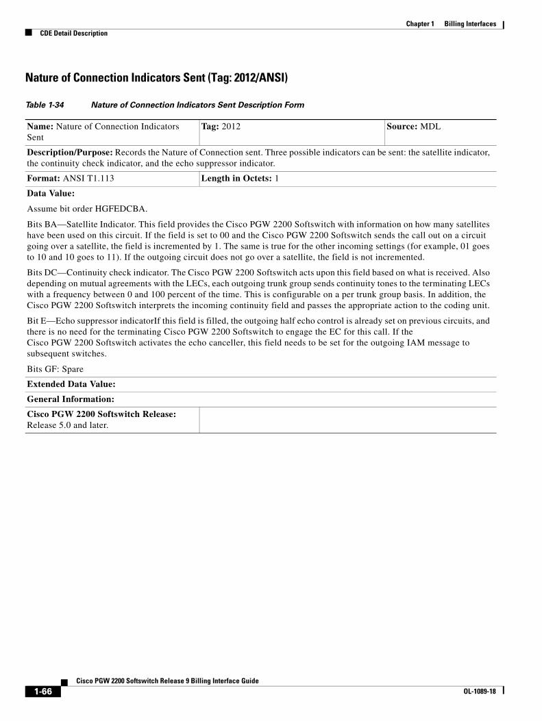
Chapter 1 Billing InterfacesCDE Detail Description
Nature of Connection Indicators Sent (Tag: 2012/ANSI)
Table 1-34 Nature of Connection Indicators Sent Description Form
Name: Nature of Connection Indicators Sent
Tag: 2012 Source: MDL
Description/Purpose: Records the Nature of Connection sent. Three possible indicators can be sent: the satellite indicator, the continuity check indicator, and the echo suppressor indicator.
Format: ANSI T1.113 Length in Octets: 1
Data Value:
Assume bit order HGFEDCBA.
Bits BA—Satellite Indicator. This field provides the Cisco PGW 2200 Softswitch with information on how many satellites have been used on this circuit. If the field is set to 00 and the Cisco PGW 2200 Softswitch sends the call out on a circuit going over a satellite, the field is incremented by 1. The same is true for the other incoming settings (for example, 01 goes to 10 and 10 goes to 11). If the outgoing circuit does not go over a satellite, the field is not incremented.
Bits DC—Continuity check indicator. The Cisco PGW 2200 Softswitch acts upon this field based on what is received. Also depending on mutual agreements with the LECs, each outgoing trunk group sends continuity tones to the terminating LECs with a frequency between 0 and 100 percent of the time. This is configurable on a per trunk group basis. In addition, the Cisco PGW 2200 Softswitch interprets the incoming continuity field and passes the appropriate action to the coding unit.
Bit E—Echo suppressor indicatorIf this field is filled, the outgoing half echo control is already set on previous circuits, and there is no need for the terminating Cisco PGW 2200 Softswitch to engage the EC for this call. If the Cisco PGW 2200 Softswitch activates the echo canceller, this field needs to be set for the outgoing IAM message to subsequent switches.
Bits GF: Spare
Extended Data Value:
General Information:
Cisco PGW 2200 Softswitch Release: Release 5.0 and later.
1-66Cisco PGW 2200 Softswitch Release 9 Billing Interface Guide
OL-1089-18
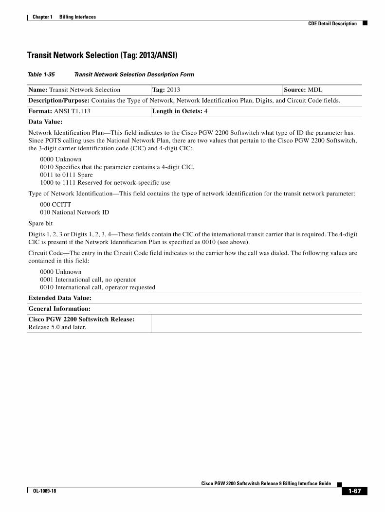
Chapter 1 Billing InterfacesCDE Detail Description
Transit Network Selection (Tag: 2013/ANSI)
Table 1-35 Transit Network Selection Description Form
Name: Transit Network Selection Tag: 2013 Source: MDL
Description/Purpose: Contains the Type of Network, Network Identification Plan, Digits, and Circuit Code fields.
Format: ANSI T1.113 Length in Octets: 4
Data Value:
Network Identification Plan—This field indicates to the Cisco PGW 2200 Softswitch what type of ID the parameter has. Since POTS calling uses the National Network Plan, there are two values that pertain to the Cisco PGW 2200 Softswitch, the 3-digit carrier identification code (CIC) and 4-digit CIC:
0000 Unknown 0010 Specifies that the parameter contains a 4-digit CIC. 0011 to 0111 Spare 1000 to 1111 Reserved for network-specific use
Type of Network Identification—This field contains the type of network identification for the transit network parameter:
000 CCITT 010 National Network ID
Spare bit
Digits 1, 2, 3 or Digits 1, 2, 3, 4—These fields contain the CIC of the international transit carrier that is required. The 4-digit CIC is present if the Network Identification Plan is specified as 0010 (see above).
Circuit Code—The entry in the Circuit Code field indicates to the carrier how the call was dialed. The following values are contained in this field:
0000 Unknown 0001 International call, no operator 0010 International call, operator requested
Extended Data Value:
General Information:
Cisco PGW 2200 Softswitch Release: Release 5.0 and later.
1-67Cisco PGW 2200 Softswitch Release 9 Billing Interface Guide
OL-1089-18

Chapter 1 Billing InterfacesCDE Detail Description
Carrier Identification Parameter (Tag: 2014/ANSI)
Carrier Selection Parameter (Tag: 2015/ANSI)
Table 1-36 Carrier Identification Parameter Description Form
Name: Carrier Identification Parameter Tag: 2014 Source: MDL
Description/Purpose: Contains the Carrier Identification Parameter in the ISUP message. It includes the following fields: Network Identification Plan; Type of Network Identification; Spare; Digit 1; Digit 2; Digit 3; Digit 4 or Null.
Format: ANSI T1.113 Length in Octets: 3 or 4
Data Value:
Network Identification Plan (1st Octet, Bits 4321)—Indicates what type of carrier identification the caller is requesting. The Cisco PGW 2200 Softswitch looks at this field to determine whether the requested CIC is a 3- or 4-digit code and how many digits to expect in the Digits field.
Type of Network Identification (1st Octet, Bits 765)—Gives the identification of the network numbering plan. For POTS calls from the LECs, the value of this field is 010 (National Network ID).
Spare (1st Octet, Bit 8)—Not applicable.
Digits 1, 2, 3 or Digits 1, 2, 3, 4 (remaining two octets, bits 8, 7, 6, and 5 are all zeros if only 3 digits are present)—Requested CIC.
Extended Data Value:
General Information:
Cisco PGW 2200 Softswitch Release: Release 5.0 and later.
Table 1-37 Carrier Selection Parameter Description Form
Name: Carrier Selection Parameter Tag: 2015 Source: MDL
Description/Purpose: Indicates to the Cisco PGW 2200 Softswitch how the carrier access code was dialed. The Cisco PGW 2200 Softswitch uses this information and the Carrier Identification parameter to route the call.
Format: ANSI T1.113 Length in Octets: 1
Data Value:
00000000 No indication 00000001 Selected carrier identification code presubscribed and not input by by the calling party 00000010 Selected carrier identification code presubscribed and input by the calling party 00000011 Selected carrier identification code presubscribed, but there is no indication of whether input by the calling party 00000100 Selected carrier identification code not presubscribed and input by the calling party
00000101 to 11111110 Spare
11111111 Reserved
Extended Data Value:
General Information:
Cisco PGW 2200 Softswitch Release: Release 5.0 and later.
1-68Cisco PGW 2200 Softswitch Release 9 Billing Interface Guide
OL-1089-18
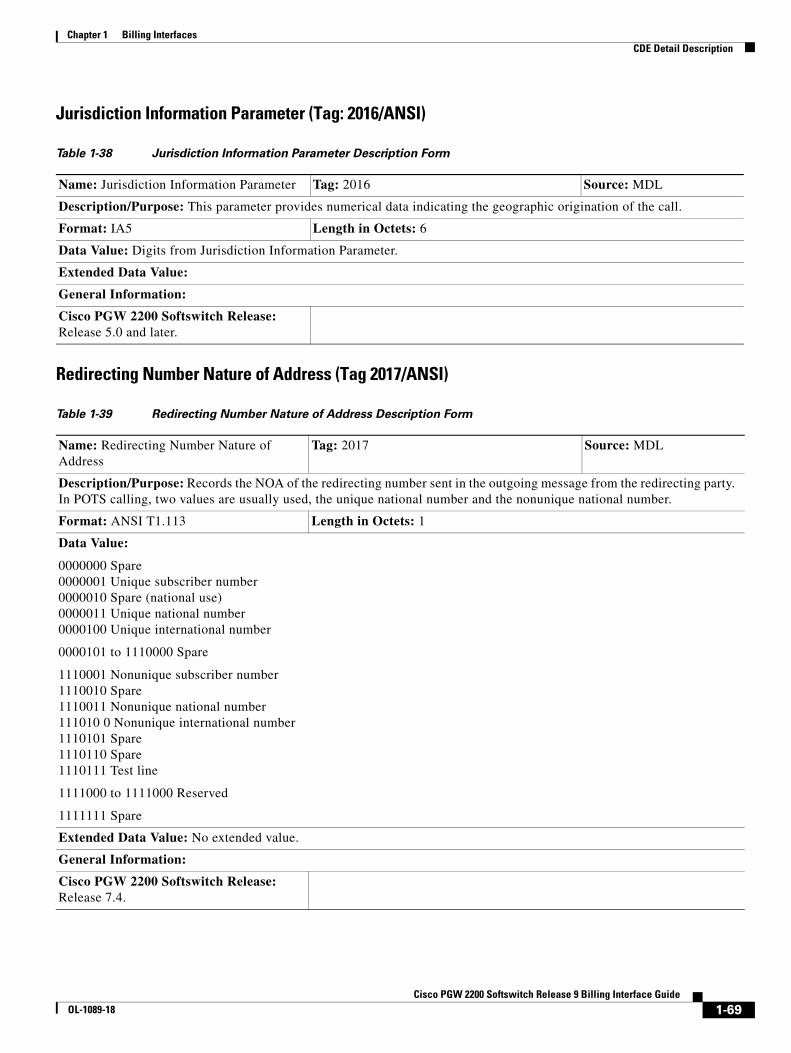
Chapter 1 Billing InterfacesCDE Detail Description
Jurisdiction Information Parameter (Tag: 2016/ANSI)
Redirecting Number Nature of Address (Tag 2017/ANSI)
Table 1-38 Jurisdiction Information Parameter Description Form
Name: Jurisdiction Information Parameter Tag: 2016 Source: MDL
Description/Purpose: This parameter provides numerical data indicating the geographic origination of the call.
Format: IA5 Length in Octets: 6
Data Value: Digits from Jurisdiction Information Parameter.
Extended Data Value:
General Information:
Cisco PGW 2200 Softswitch Release: Release 5.0 and later.
Table 1-39 Redirecting Number Nature of Address Description Form
Name: Redirecting Number Nature of Address
Tag: 2017 Source: MDL
Description/Purpose: Records the NOA of the redirecting number sent in the outgoing message from the redirecting party. In POTS calling, two values are usually used, the unique national number and the nonunique national number.
Format: ANSI T1.113 Length in Octets: 1
Data Value:
0000000 Spare 0000001 Unique subscriber number 0000010 Spare (national use) 0000011 Unique national number 0000100 Unique international number
0000101 to 1110000 Spare
1110001 Nonunique subscriber number 1110010 Spare 1110011 Nonunique national number 111010 0 Nonunique international number 1110101 Spare 1110110 Spare 1110111 Test line
1111000 to 1111000 Reserved
1111111 Spare
Extended Data Value: No extended value.
General Information:
Cisco PGW 2200 Softswitch Release: Release 7.4.
1-69Cisco PGW 2200 Softswitch Release 9 Billing Interface Guide
OL-1089-18

Chapter 1 Billing InterfacesCDE Detail Description
Egress Calling Number Nature of Address (Tag 2018/ANSI)
Table 1-40 Egress Calling Number Nature of Address (ANSI) Description Form
Name: Egress Calling Number NOA Tag: 2018 Source: MDL
Description/Purpose: This CDE records the calling party NOA sent in the outgoing message by the Cisco PGW 2200 Softswitch. This field indicates the address type of the calling party. In POTS calling, two values are usually used, the unique national number and the nonunique national number.
Format: ANSI T1.113 Length in Octets: 1
Data Value:
0000000 Spare 0000001 Unique subscriber number 0000010 Spare (national use) 0000011 Unique national number 0000100 Unique international number
0000101 to 1110000 Spare
1110001 Nonunique subscriber number 1110010 Spare 1110011 Nonunique national number 1110100 Nonunique international number 1110101 Spare 1110110 Spare 1110111 Test line
1111000 to 1111000 Reserved
1111111 Spare
Extended Data Value: No extended value.
General Information:
This CDE is present in the 1060 CDB if the end-of-call CDB (1110) is configured. For point-in-call mode, the 1060 CDB is usually a short one and does not contain this CDE.
Cisco PGW 2200 Softswitch Release: Release 9.5(2).
1-70Cisco PGW 2200 Softswitch Release 9 Billing Interface Guide
OL-1089-18

Chapter 1 Billing InterfacesCDE Detail Description
Egress Redirecting Number Nature of Address (Tag 2019/ANSI)
Table 1-41 Egress Redirecting Number Nature of Address (ANSI) Description Form
Name: Egress Redirecting Number NOA Tag: 2019 Source: MDL
Description/Purpose: Records the redirecting number NOA sent in the outgoing message by the Cisco PGW 2200 Softswitch.
Format: ANSI T1.113 Length in Octets: 1
Data Value:
0000000 Spare 0000001 Unique subscriber number 0000010 Spare (national use) 0000011 Unique national number 0000100 Unique international number
0000101 to 1110000 Spare
1110001 Nonunique subscriber number 1110010 Spare 1110011 Nonunique national number 1110100 Nonunique international number 1110101 Spare 1110110 Spare 1110111 Test line
1111000 to 1111000 Reserved
1111111 Spare
Extended Data Value: No extended value.
General Information:
This CDE is present in the 1060 CDB if the end-of-call CDB (1110) is configured. For point-in-call mode, the 1060 CDB is usually a short one and does not contain this CDE.
Cisco PGW 2200 Softswitch Release: Release 9.5(2).
1-71Cisco PGW 2200 Softswitch Release 9 Billing Interface Guide
OL-1089-18
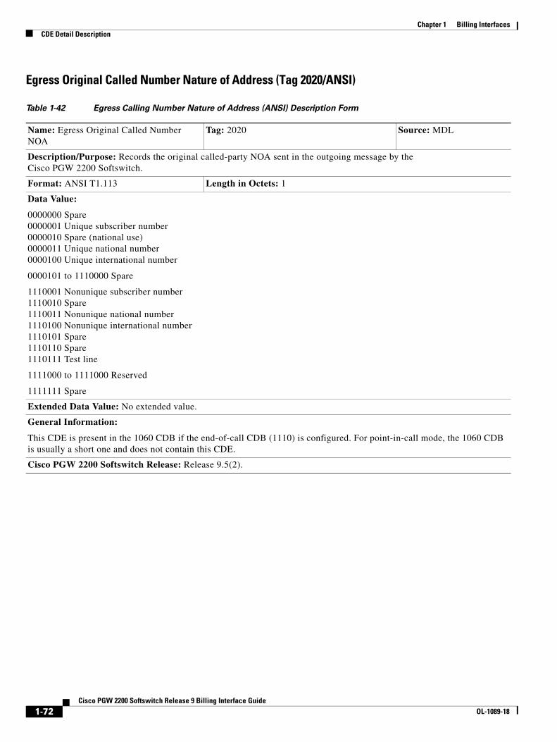
Chapter 1 Billing InterfacesCDE Detail Description
Egress Original Called Number Nature of Address (Tag 2020/ANSI)
Table 1-42 Egress Calling Number Nature of Address (ANSI) Description Form
Name: Egress Original Called Number NOA
Tag: 2020 Source: MDL
Description/Purpose: Records the original called-party NOA sent in the outgoing message by the Cisco PGW 2200 Softswitch.
Format: ANSI T1.113 Length in Octets: 1
Data Value:
0000000 Spare 0000001 Unique subscriber number 0000010 Spare (national use) 0000011 Unique national number 0000100 Unique international number
0000101 to 1110000 Spare
1110001 Nonunique subscriber number 1110010 Spare 1110011 Nonunique national number 1110100 Nonunique international number 1110101 Spare 1110110 Spare 1110111 Test line
1111000 to 1111000 Reserved
1111111 Spare
Extended Data Value: No extended value.
General Information:
This CDE is present in the 1060 CDB if the end-of-call CDB (1110) is configured. For point-in-call mode, the 1060 CDB is usually a short one and does not contain this CDE.
Cisco PGW 2200 Softswitch Release: Release 9.5(2).
1-72Cisco PGW 2200 Softswitch Release 9 Billing Interface Guide
OL-1089-18
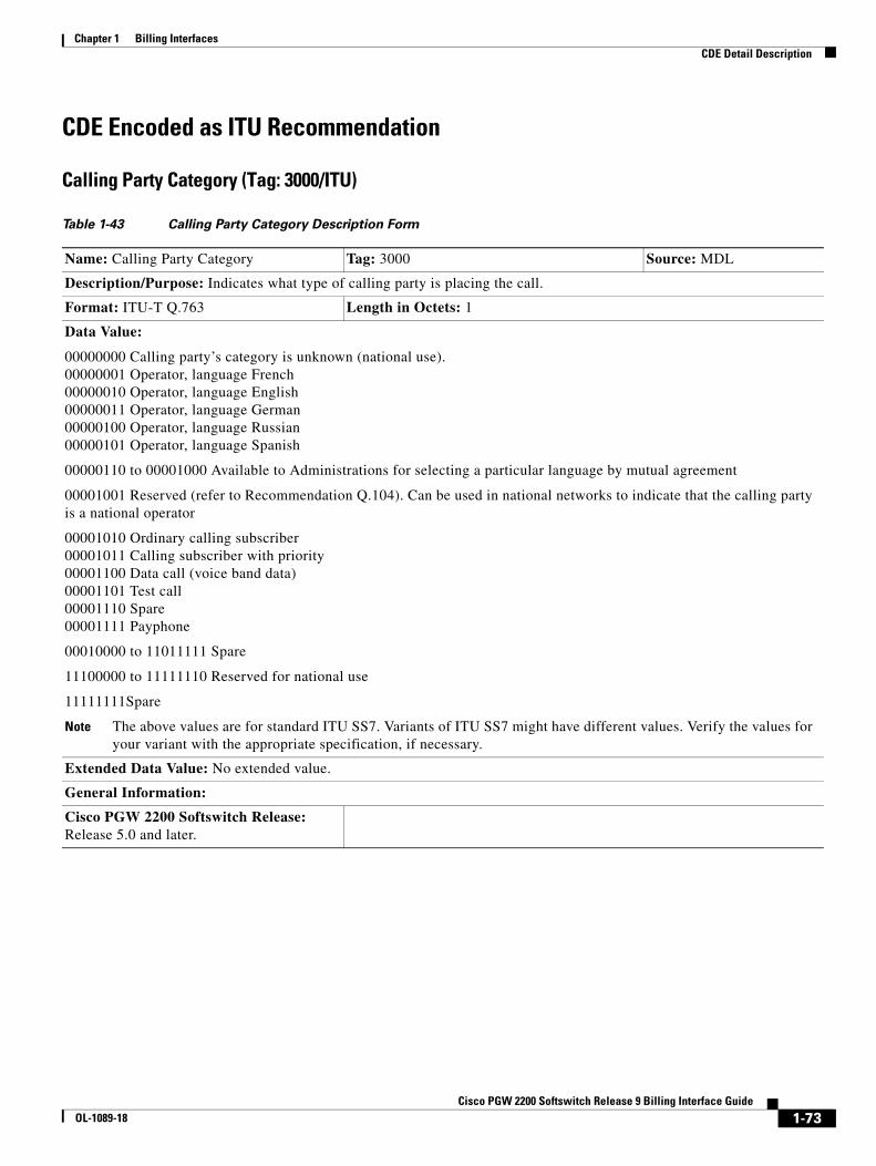
Chapter 1 Billing InterfacesCDE Detail Description
CDE Encoded as ITU Recommendation
Calling Party Category (Tag: 3000/ITU)
Table 1-43 Calling Party Category Description Form
Name: Calling Party Category Tag: 3000 Source: MDL
Description/Purpose: Indicates what type of calling party is placing the call.
Format: ITU-T Q.763 Length in Octets: 1
Data Value:
00000000 Calling party’s category is unknown (national use). 00000001 Operator, language French 00000010 Operator, language English 00000011 Operator, language German 00000100 Operator, language Russian 00000101 Operator, language Spanish
00000110 to 00001000 Available to Administrations for selecting a particular language by mutual agreement
00001001 Reserved (refer to Recommendation Q.104). Can be used in national networks to indicate that the calling party is a national operator
00001010 Ordinary calling subscriber 00001011 Calling subscriber with priority 00001100 Data call (voice band data) 00001101 Test call 00001110 Spare 00001111 Payphone
00010000 to 11011111 Spare
11100000 to 11111110 Reserved for national use
11111111Spare
Note The above values are for standard ITU SS7. Variants of ITU SS7 might have different values. Verify the values for your variant with the appropriate specification, if necessary.
Extended Data Value: No extended value.
General Information:
Cisco PGW 2200 Softswitch Release: Release 5.0 and later.
1-73Cisco PGW 2200 Softswitch Release 9 Billing Interface Guide
OL-1089-18
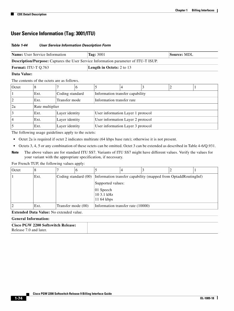
Chapter 1 Billing InterfacesCDE Detail Description
User Service Information (Tag: 3001/ITU)
Table 1-44 User Service Information Description Form
Name: User Service Information Tag: 3001 Source: MDL
Description/Purpose: Captures the User Service Information parameter of ITU-T ISUP.
Format: ITU-T Q.763 Length in Octets: 2 to 13
Data Value:
The contents of the octets are as follows.
Octet 8 7 6 5 4 3 2 1
1 Ext. Coding standard Information transfer capability
2 Ext. Transfer mode Information transfer rate
2a Rate multiplier
3 Ext. Layer identity User information Layer 1 protocol
4 Ext. Layer identity User information Layer 2 protocol
5 Ext. Layer identity User information Layer 3 protocol
The following usage guidelines apply to the octets:
• Octet 2a is required if octet 2 indicates multirate (64 kbps base rate); otherwise it is not present.
• Octets 3, 4, 5 or any combination of these octets can be omitted. Octet 3 can be extended as described in Table 4-6/Q.931.
Note The above values are for standard ITU SS7. Variants of ITU SS7 might have different values. Verify the values for your variant with the appropriate specification, if necessary.
For French TUP, the following values apply:
Octet 8 7 6 5 4 3 2 1
1 Ext. Coding standard (00) Information transfer capability (mapped from OptaddRoutingInf)
Supported values:
01 Speech 10 3.1 kHz 11 64 kbps
2 Ext. Transfer mode (00) Information transfer rate (10000)
Extended Data Value: No extended value.
General Information:
Cisco PGW 2200 Softswitch Release: Release 7.0 and later.
1-74Cisco PGW 2200 Softswitch Release 9 Billing Interface Guide
OL-1089-18
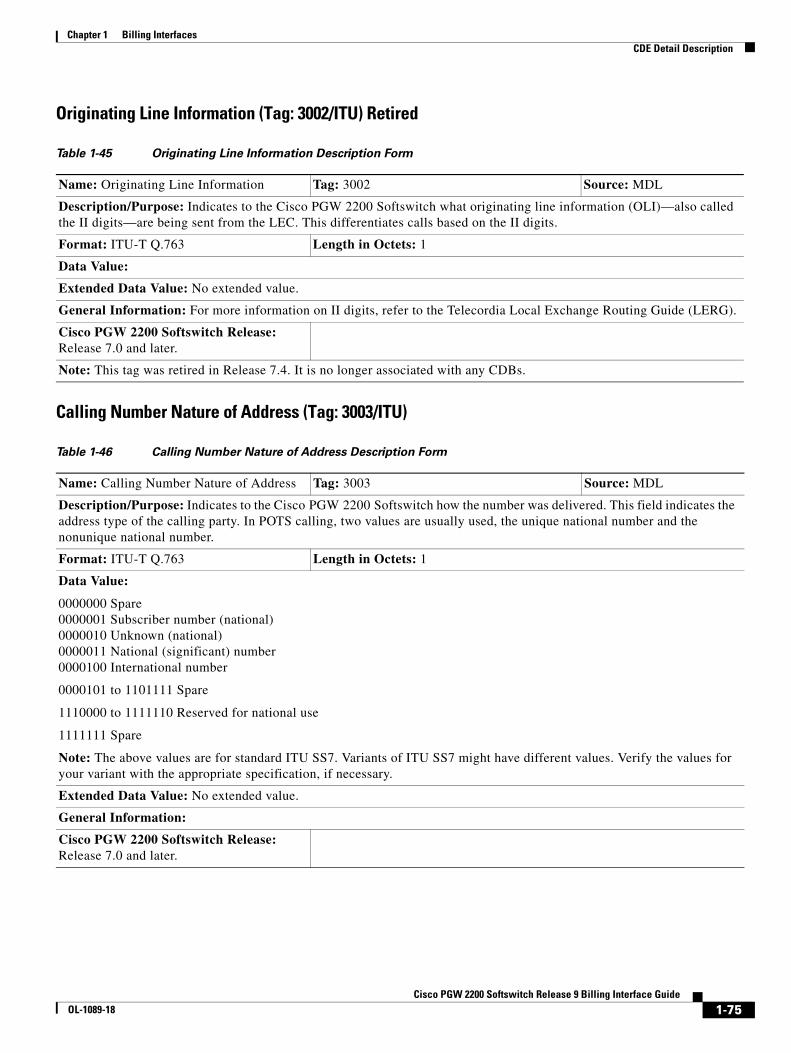
Chapter 1 Billing InterfacesCDE Detail Description
Originating Line Information (Tag: 3002/ITU) Retired
Calling Number Nature of Address (Tag: 3003/ITU)
Table 1-45 Originating Line Information Description Form
Name: Originating Line Information Tag: 3002 Source: MDL
Description/Purpose: Indicates to the Cisco PGW 2200 Softswitch what originating line information (OLI)—also called the II digits—are being sent from the LEC. This differentiates calls based on the II digits.
Format: ITU-T Q.763 Length in Octets: 1
Data Value:
Extended Data Value: No extended value.
General Information: For more information on II digits, refer to the Telecordia Local Exchange Routing Guide (LERG).
Cisco PGW 2200 Softswitch Release: Release 7.0 and later.
Note: This tag was retired in Release 7.4. It is no longer associated with any CDBs.
Table 1-46 Calling Number Nature of Address Description Form
Name: Calling Number Nature of Address Tag: 3003 Source: MDL
Description/Purpose: Indicates to the Cisco PGW 2200 Softswitch how the number was delivered. This field indicates the address type of the calling party. In POTS calling, two values are usually used, the unique national number and the nonunique national number.
Format: ITU-T Q.763 Length in Octets: 1
Data Value:
0000000 Spare 0000001 Subscriber number (national) 0000010 Unknown (national) 0000011 National (significant) number 0000100 International number
0000101 to 1101111 Spare
1110000 to 1111110 Reserved for national use
1111111 Spare
Note: The above values are for standard ITU SS7. Variants of ITU SS7 might have different values. Verify the values for your variant with the appropriate specification, if necessary.
Extended Data Value: No extended value.
General Information:
Cisco PGW 2200 Softswitch Release: Release 7.0 and later.
1-75Cisco PGW 2200 Softswitch Release 9 Billing Interface Guide
OL-1089-18
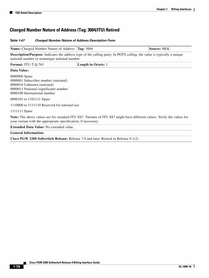
Chapter 1 Billing InterfacesCDE Detail Description
Charged Number Nature of Address (Tag: 3004/ITU) Retired
Table 1-47 Charged Number Nature of Address Description Form
Name: Charged Number Nature of Address Tag: 3004 Source: MDL
Description/Purpose: Indicates the address type of the calling party. In POTS calling, the value is typically a unique national number or nonunique national number
Format: ITU-T Q.763 Length in Octets: 1
Data Value:
0000000 Spare 0000001 Subscriber number (national) 0000010 Unknown (national) 0000011 National (significant) number 0000100 International number
0000101 to 1101111 Spare
1110000 to 1111110 Reserved for national use
1111111 Spare
Note: The above values are for standard ITU SS7. Variants of ITU SS7 might have different values. Verify the values for your variant with the appropriate specification, if necessary.
Extended Data Value: No extended value.
General Information:
Cisco PGW 2200 Softswitch Release: Release 7.0 and later. Retired in Release 9.1(2).
1-76Cisco PGW 2200 Softswitch Release 9 Billing Interface Guide
OL-1089-18
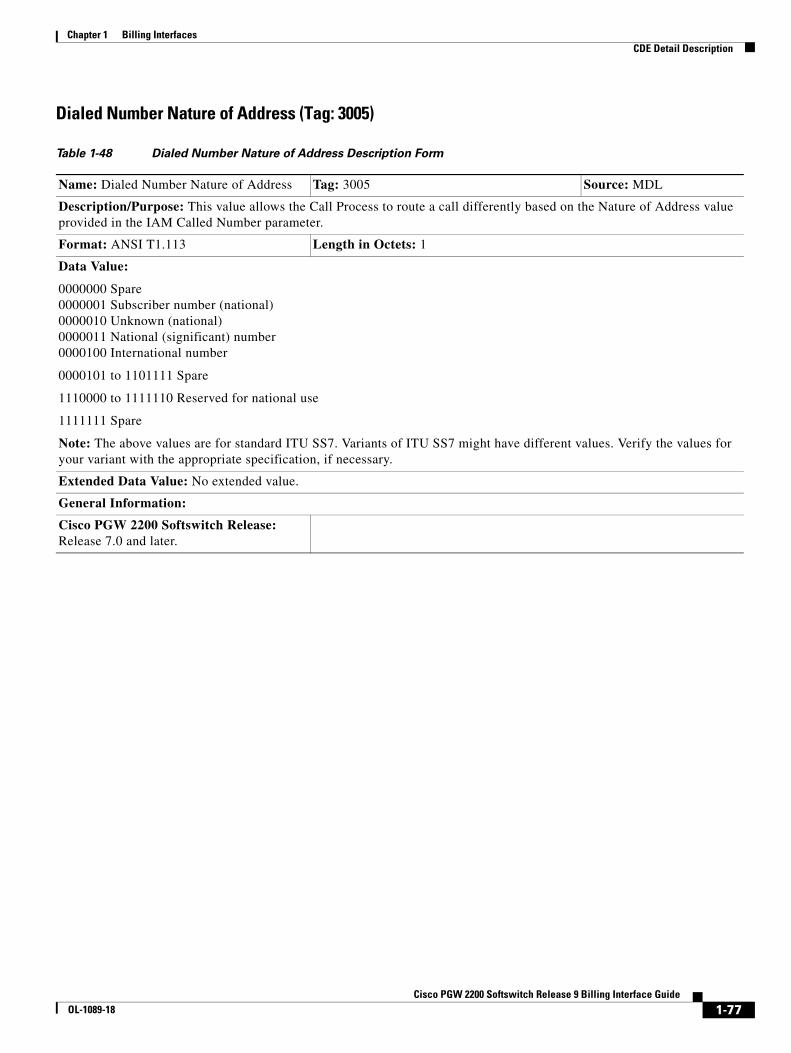
Chapter 1 Billing InterfacesCDE Detail Description
Dialed Number Nature of Address (Tag: 3005)
Table 1-48 Dialed Number Nature of Address Description Form
Name: Dialed Number Nature of Address Tag: 3005 Source: MDL
Description/Purpose: This value allows the Call Process to route a call differently based on the Nature of Address value provided in the IAM Called Number parameter.
Format: ANSI T1.113 Length in Octets: 1
Data Value:
0000000 Spare 0000001 Subscriber number (national) 0000010 Unknown (national) 0000011 National (significant) number 0000100 International number
0000101 to 1101111 Spare
1110000 to 1111110 Reserved for national use
1111111 Spare
Note: The above values are for standard ITU SS7. Variants of ITU SS7 might have different values. Verify the values for your variant with the appropriate specification, if necessary.
Extended Data Value: No extended value.
General Information:
Cisco PGW 2200 Softswitch Release: Release 7.0 and later.
1-77Cisco PGW 2200 Softswitch Release 9 Billing Interface Guide
OL-1089-18
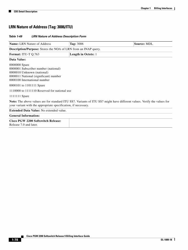
Chapter 1 Billing InterfacesCDE Detail Description
LRN Nature of Address (Tag: 3006/ITU)
Table 1-49 LRN Nature of Address Description Form
Name: LRN Nature of Address Tag: 3006 Source: MDL
Description/Purpose: Stores the NOA of LRN from an INAP query.
Format: ITU-T Q.763 Length in Octets: 1
Data Value:
0000000 Spare 0000001 Subscriber number (national) 0000010 Unknown (national) 0000011 National (significant) number 0000100 International number
0000101 to 1101111 Spare
1110000 to 1111110 Reserved for national use
1111111 Spare
Note: The above values are for standard ITU SS7. Variants of ITU SS7 might have different values. Verify the values for your variant with the appropriate specification, if necessary.
Extended Data Value: No extended value.
General Information:
Cisco PGW 2200 Softswitch Release: Release 7.0 and later.
1-78Cisco PGW 2200 Softswitch Release 9 Billing Interface Guide
OL-1089-18
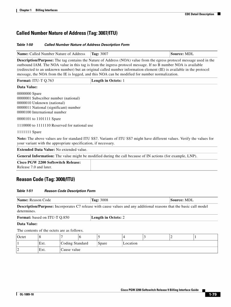
Chapter 1 Billing InterfacesCDE Detail Description
Called Number Nature of Address (Tag: 3007/ITU)
Reason Code (Tag: 3008/ITU)
Table 1-50 Called Number Nature of Address Description Form
Name: Called Number Nature of Address Tag: 3007 Source: MDL
Description/Purpose: The tag contains the Nature of Address (NOA) value from the egress protocol message used in the outbound IAM. The NOA value in this tag is from the ingress protocol message. If no B number NOA is available (redirected to an unknown number) but an original called number information element (IE) is available in the protocol message, the NOA from the IE is logged, and this NOA can be modified for number normalization.
Format: ITU-T Q.763 Length in Octets: 1
Data Value:
0000000 Spare 0000001 Subscriber number (national) 0000010 Unknown (national) 0000011 National (significant) number 0000100 International number
0000101 to 1101111 Spare
1110000 to 1111110 Reserved for national use
1111111 Spare
Note: The above values are for standard ITU SS7. Variants of ITU SS7 might have different values. Verify the values for your variant with the appropriate specification, if necessary.
Extended Data Value: No extended value.
General Information: The value might be modified during the call because of IN actions (for example, LNP).
Cisco PGW 2200 Softswitch Release: Release 7.0 and later.
Table 1-51 Reason Code Description Form
Name: Reason Code Tag: 3008 Source: MDL
Description/Purpose: Incorporates C7 release with cause values and any additional reasons that the basic call model determines.
Format: based on ITU-T Q.850 Length in Octets: 2
Data Value:
The contents of the octets are as follows.
Octet 8 7 6 5 4 3 2 1
1 Ext. Coding Standard Spare Location
2 Ext. Cause value
1-79Cisco PGW 2200 Softswitch Release 9 Billing Interface Guide
OL-1089-18

Chapter 1 Billing InterfacesCDE Detail Description
Note This CDE does not include the Diagnostic and Recommendation octets defined in Q.850. The format of this CDR is the same for both Q.763 and Q.931 signaling.
Extension:
0 Octet continues through the next octet (for example, octet 1 to 1a) 1 Last octet
Coding Standard
00 ITU-T standardized coding 01 ISO/IEC standard 10 National standard 11 Standard specific to identified location
Note The coding standards other than ITU-T should only be used only when the desired cause value cannot be represented with the ITU-T standardized coding.
Location:
0000 User (U) 0001 Private network serving the local user (LPN) 0010 Public network serving the local user (LN) 0011 Transit network (TN) 0100 Public network serving the remote user (RLN) 0101 Private network serving the remote user (RPN) 0111 International network (INTL) 1010 Network beyond interworking point (BI)
1100 to 1111 Reserved for national use
All other values are spare.
Cause value: (only applicable in the context of Recommendations Q.763 and Q.931)
The cause value is divided into two fields, a class (bits 5 through 7) and a value within the class (bits 1 through 4).
The class indicates the general nature of the event. The valid values are as follows:
000 Normal event 001 Normal event 010 Resource unavailable 011 Service or option not available 100 Service or option not implemented 101 Invalid message (for example, parameter out of range) 110 Protocol error (for example, unknown message) 111 Interworking
The valid class values are listed in Table 1-52.
Table 1-51 Reason Code Description Form (continued)
1-80Cisco PGW 2200 Softswitch Release 9 Billing Interface Guide
OL-1089-18
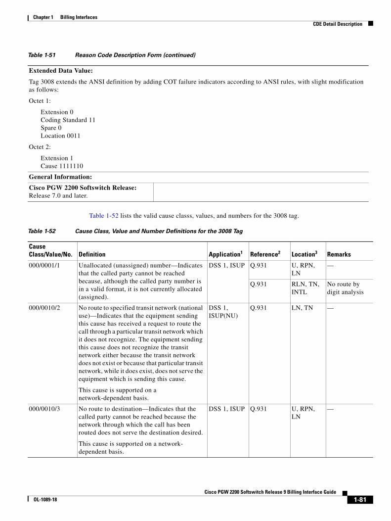
Chapter 1 Billing InterfacesCDE Detail Description
Table 1-52 lists the valid cause classs, values, and numbers for the 3008 tag.
Extended Data Value:
Tag 3008 extends the ANSI definition by adding COT failure indicators according to ANSI rules, with slight modification as follows:
Octet 1:
Extension 0 Coding Standard 11 Spare 0 Location 0011
Octet 2:
Extension 1 Cause 1111110
General Information:
Cisco PGW 2200 Softswitch Release: Release 7.0 and later.
Table 1-51 Reason Code Description Form (continued)
Table 1-52 Cause Class, Value and Number Definitions for the 3008 Tag
Cause Class/Value/No. Definition Application1 Reference2 Location3 Remarks
000/0001/1 Unallocated (unassigned) number—Indicates that the called party cannot be reached because, although the called party number is in a valid format, it is not currently allocated (assigned).
DSS 1, ISUP Q.931 U, RPN, LN
—
Q.931 RLN, TN, INTL
No route by digit analysis
000/0010/2 No route to specified transit network (national use)—Indicates that the equipment sending this cause has received a request to route the call through a particular transit network which it does not recognize. The equipment sending this cause does not recognize the transit network either because the transit network does not exist or because that particular transit network, while it does exist, does not serve the equipment which is sending this cause.
This cause is supported on a network-dependent basis.
DSS 1, ISUP(NU)
Q.931 LN, TN —
000/0010/3 No route to destination—Indicates that the called party cannot be reached because the network through which the call has been routed does not serve the destination desired.
This cause is supported on a network- dependent basis.
DSS 1, ISUP Q.931 U, RPN, LN
—
1-81Cisco PGW 2200 Softswitch Release 9 Billing Interface Guide
OL-1089-18
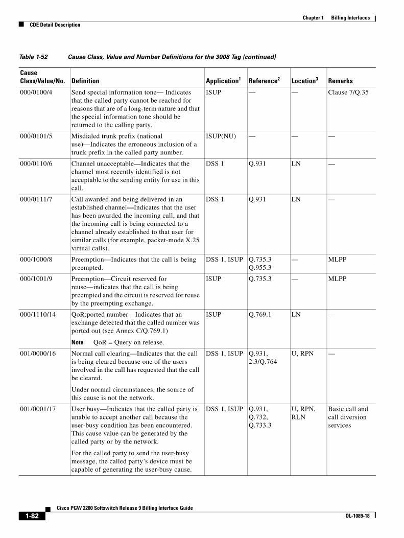
Chapter 1 Billing InterfacesCDE Detail Description
000/0100/4 Send special information tone— Indicates that the called party cannot be reached for reasons that are of a long-term nature and that the special information tone should be returned to the calling party.
ISUP — — Clause 7/Q.35
000/0101/5 Misdialed trunk prefix (national use)—Indicates the erroneous inclusion of a trunk prefix in the called party number.
ISUP(NU) — — —
000/0110/6 Channel unacceptable—Indicates that the channel most recently identified is not acceptable to the sending entity for use in this call.
DSS 1 Q.931 LN —
000/0111/7 Call awarded and being delivered in an established channel—Indicates that the user has been awarded the incoming call, and that the incoming call is being connected to a channel already established to that user for similar calls (for example, packet-mode X.25 virtual calls).
DSS 1 Q.931 LN —
000/1000/8 Preemption—Indicates that the call is being preempted.
DSS 1, ISUP Q.735.3 Q.955.3
— MLPP
000/1001/9 Preemption—Circuit reserved for reuse—indicates that the call is being preempted and the circuit is reserved for reuse by the preempting exchange.
ISUP Q.735.3 — MLPP
000/1110/14 QoR:ported number—Indicates that an exchange detected that the called number was ported out (see Annex C/Q.769.1)
Note QoR = Query on release.
ISUP Q.769.1 LN —
001/0000/16 Normal call clearing—Indicates that the call is being cleared because one of the users involved in the call has requested that the call be cleared.
Under normal circumstances, the source of this cause is not the network.
DSS 1, ISUP Q.931, 2.3/Q.764
U, RPN —
001/0001/17 User busy—Indicates that the called party is unable to accept another call because the user-busy condition has been encountered. This cause value can be generated by the called party or by the network.
For the called party to send the user-busy message, the called party’s device must be capable of generating the user-busy cause.
DSS 1, ISUP Q.931, Q.732, Q.733.3
U, RPN, RLN
Basic call and call diversion services
Table 1-52 Cause Class, Value and Number Definitions for the 3008 Tag (continued)
Cause Class/Value/No. Definition Application1 Reference2 Location3 Remarks
1-82Cisco PGW 2200 Softswitch Release 9 Billing Interface Guide
OL-1089-18
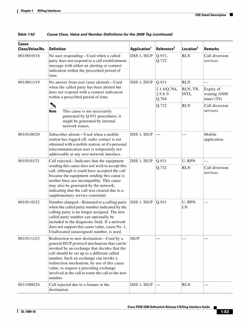
Chapter 1 Billing InterfacesCDE Detail Description
001/0010/18 No user responding—Used when a called party does not respond to a call establishment message with either an alerting or connect indication within the prescribed period of time.
DSS 1, ISUP Q.931, Q.732
RLN Call diversion services
001/0011/19 No answer from user (user alerted)—Used when the called party has been alerted but does not respond with a connect indication within a prescribed period of time.
Note This cause is not necessarily generated by Q.931 procedures; it might be generated by internal network timers.
DSS 1, ISUP Q.931 RLN —
2.1.4/Q.764, 2.9.8.3/ Q.764
RLN, TN, INTL
Expiry of waiting ANM timer (T9)
Q.732 RLN Call diversion services
001/0100/20 Subscriber absent—Used when a mobile station has logged off, radio contact is not obtained with a mobile station, or if a personal telecommunication user is temporarily not addressable at any user-network interface.
DSS 1, ISUP — — Mobile application
001/0101/21 Call rejected—Indicates that the equipment sending this cause does not wish to accept this call, although it could have accepted the call because the equipment sending this cause is neither busy nor incompatible. This cause may also be generated by the network, indicating that the call was cleared due to a supplementary service constraint.
DSS 1, ISUP Q.931 U, RPN —
Q.732 RLN Call diversion services
001/0110/22 Number changed—Returned to a calling party when the called party number indicated by the calling party is no longer assigned. The new called party number can optionally be included in the diagnostic field. If a network does not support this cause value, cause No. 1, Unallocated (unassigned) number, is used.
DSS 1, ISUP Q.931 U, RPN, LN
—
001/0111/23 Redirection to new destination—Used by a general ISUP protocol mechanism that can be invoked by an exchange that decides that the call should be set up to a different called number. Such an exchange can invoke a redirection mechanism, by use of this cause value, to request a preceding exchange involved in the call to route the call to the new number.
ISUP — — —
001/1000/24 Call rejected due to a feature at the destination.
DSS 1, ISUP — RLN —
Table 1-52 Cause Class, Value and Number Definitions for the 3008 Tag (continued)
Cause Class/Value/No. Definition Application1 Reference2 Location3 Remarks
1-83Cisco PGW 2200 Softswitch Release 9 Billing Interface Guide
OL-1089-18

Chapter 1 Billing InterfacesCDE Detail Description
001/1001/25 Exchange—routing error—Indicates that the destination indicated by the user cannot be reached, because an intermediate exchange has released the call due to reaching a limit in executing the hop count procedure. This cause is generated by an intermediate node, which when decrementing the hop counter value, gives the result 0.
ISUP — LN, TN, RLN, ITNL
—
001/1010/26 Non-selected user clearing—Indicates that the user has not been awarded the incoming call.
DSS 1 Q.931 LN —
001/1011/27 Destination out of order—Indicates that the destination indicated by the user cannot be reached because the interface to the destination is not functioning correctly. The phrase "not functioning correctly" indicates that a signaling message could not be delivered to the remote party; this might be due to a failure in a physical layer or data link layer at the remote party, or if the user equipment is off-line.
DSS 1, ISUP Q.931 RLN —
001/1100/28 Invalid number format (address incomplete)—Indicates that the called party cannot be reached because the called party number is not in a valid format or is not complete.
Note This Cisco PGW 2200 Softswitch can determine that a number format is invalid immediately after it receives an end-of-pulsing (ST) signal, or on timeout after the last received digit.
DSS 1, ISUP Q.931 U, RPN, RLN, LN
—
In Q.764, the following sections:
2.1.1, 2.1.2, 2.9.8.3, 2.2.5
TN, INTL The called party number is not in a valid format or is not complete
Annex A/ Q.763
TN, INTL, RLN, RPN
—
001/1101/29 Facility rejected—Returned when a supplementary service requested by the user cannot be provided by the network.
DSS 1, ISUP Q.931 RLN, U, RPN, LN
—
— TN, INTL Inability to provide a request signaling capability
Q.735.1 INTL, RLN
CUG
Q.737.1 INTL, TN, RLN
UUS
Table 1-52 Cause Class, Value and Number Definitions for the 3008 Tag (continued)
Cause Class/Value/No. Definition Application1 Reference2 Location3 Remarks
1-84Cisco PGW 2200 Softswitch Release 9 Billing Interface Guide
OL-1089-18
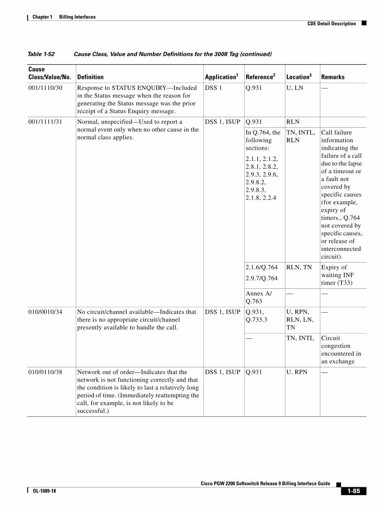
Chapter 1 Billing InterfacesCDE Detail Description
001/1110/30 Response to STATUS ENQUIRY—Included in the Status message when the reason for generating the Status message was the prior receipt of a Status Enquiry message.
DSS 1 Q.931 U, LN —
001/1111/31 Normal, unspecified—Used to report a normal event only when no other cause in the normal class applies.
DSS 1, ISUP Q.931 RLN
In Q.764, the following sections:
2.1.1, 2.1.2, 2.8.1, 2.8.2, 2.9.3, 2.9.6, 2.9.8.2, 2.9.8.3, 2.1.8, 2.2.4
TN, INTL, RLN
Call failure information indicating the failure of a call due to the lapse of a timeout or a fault not covered by specific causes (for example, expiry of timers., Q.764 not covered by specific causes, or release of interconnected circuit).
2.1.6/Q.764
2.9.7/Q.764
RLN, TN Expiry of waiting INF timer (T33)
Annex A/ Q.763
— —
010/0010/34 No circuit/channel available—Indicates that there is no appropriate circuit/channel presently available to handle the call.
DSS 1, ISUP Q.931, Q.733.3
U, RPN, RLN, LN, TN
—
— TN, INTL Circuit congestion encountered in an exchange
010/0110/38 Network out of order—Indicates that the network is not functioning correctly and that the condition is likely to last a relatively long period of time. (Immediately reattempting the call, for example, is not likely to be successful.)
DSS 1, ISUP Q.931 U. RPN —
Table 1-52 Cause Class, Value and Number Definitions for the 3008 Tag (continued)
Cause Class/Value/No. Definition Application1 Reference2 Location3 Remarks
1-85Cisco PGW 2200 Softswitch Release 9 Billing Interface Guide
OL-1089-18
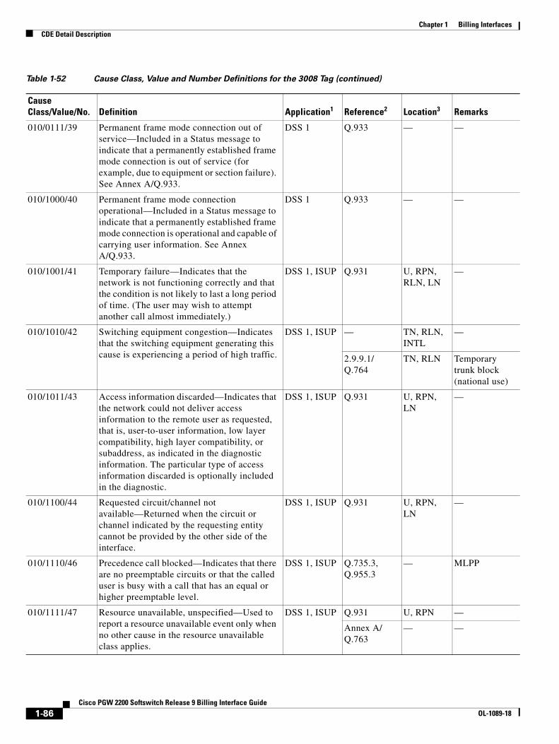
Chapter 1 Billing InterfacesCDE Detail Description
010/0111/39 Permanent frame mode connection out of service—Included in a Status message to indicate that a permanently established frame mode connection is out of service (for example, due to equipment or section failure). See Annex A/Q.933.
DSS 1 Q.933 — —
010/1000/40 Permanent frame mode connection operational—Included in a Status message to indicate that a permanently established frame mode connection is operational and capable of carrying user information. See Annex A/Q.933.
DSS 1 Q.933 — —
010/1001/41 Temporary failure—Indicates that the network is not functioning correctly and that the condition is not likely to last a long period of time. (The user may wish to attempt another call almost immediately.)
DSS 1, ISUP Q.931 U, RPN, RLN, LN
—
010/1010/42 Switching equipment congestion—Indicates that the switching equipment generating this cause is experiencing a period of high traffic.
DSS 1, ISUP — TN, RLN, INTL
—
2.9.9.1/ Q.764
TN, RLN Temporary trunk block (national use)
010/1011/43 Access information discarded—Indicates that the network could not deliver access information to the remote user as requested, that is, user-to-user information, low layer compatibility, high layer compatibility, or subaddress, as indicated in the diagnostic information. The particular type of access information discarded is optionally included in the diagnostic.
DSS 1, ISUP Q.931 U, RPN, LN
—
010/1100/44 Requested circuit/channel not available—Returned when the circuit or channel indicated by the requesting entity cannot be provided by the other side of the interface.
DSS 1, ISUP Q.931 U, RPN, LN
—
010/1110/46 Precedence call blocked—Indicates that there are no preemptable circuits or that the called user is busy with a call that has an equal or higher preemptable level.
DSS 1, ISUP Q.735.3, Q.955.3
— MLPP
010/1111/47 Resource unavailable, unspecified—Used to report a resource unavailable event only when no other cause in the resource unavailable class applies.
DSS 1, ISUP Q.931 U, RPN —
Annex A/ Q.763
— —
Table 1-52 Cause Class, Value and Number Definitions for the 3008 Tag (continued)
Cause Class/Value/No. Definition Application1 Reference2 Location3 Remarks
1-86Cisco PGW 2200 Softswitch Release 9 Billing Interface Guide
OL-1089-18
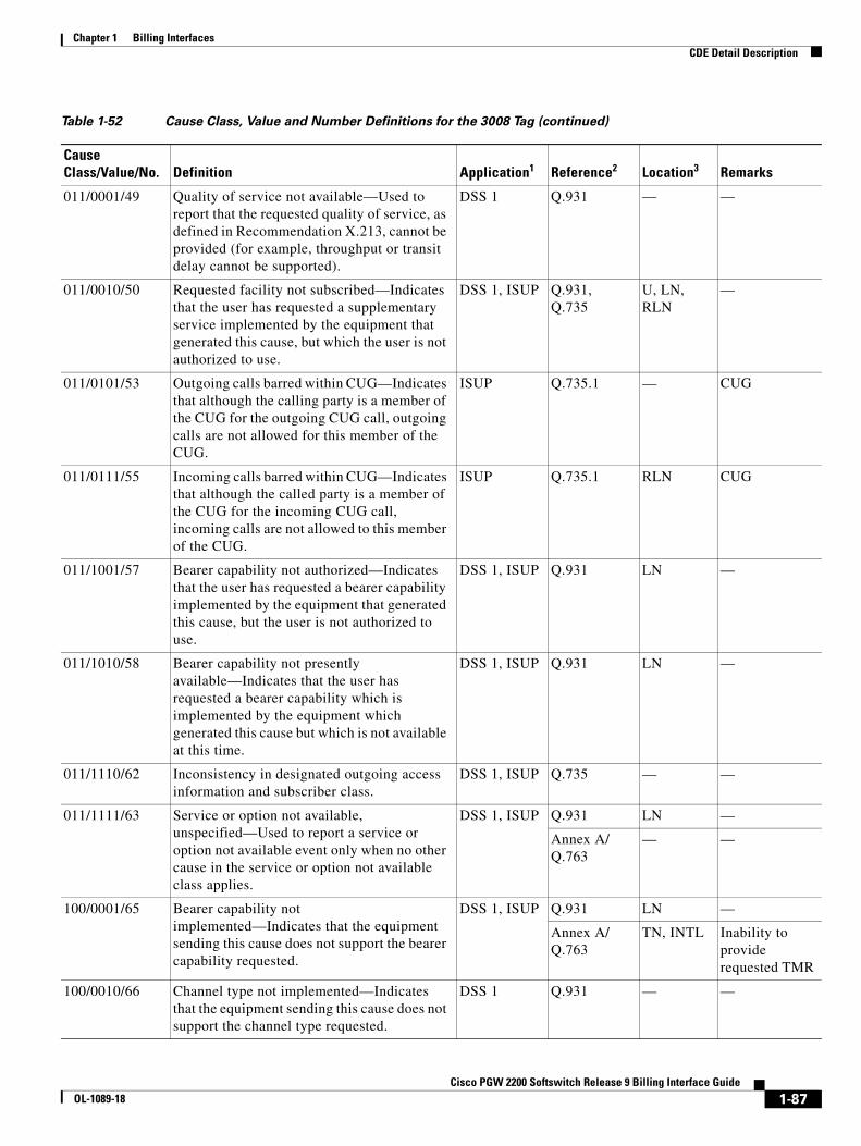
Chapter 1 Billing InterfacesCDE Detail Description
011/0001/49 Quality of service not available—Used to report that the requested quality of service, as defined in Recommendation X.213, cannot be provided (for example, throughput or transit delay cannot be supported).
DSS 1 Q.931 — —
011/0010/50 Requested facility not subscribed—Indicates that the user has requested a supplementary service implemented by the equipment that generated this cause, but which the user is not authorized to use.
DSS 1, ISUP Q.931, Q.735
U, LN, RLN
—
011/0101/53 Outgoing calls barred within CUG—Indicates that although the calling party is a member of the CUG for the outgoing CUG call, outgoing calls are not allowed for this member of the CUG.
ISUP Q.735.1 — CUG
011/0111/55 Incoming calls barred within CUG—Indicates that although the called party is a member of the CUG for the incoming CUG call, incoming calls are not allowed to this member of the CUG.
ISUP Q.735.1 RLN CUG
011/1001/57 Bearer capability not authorized—Indicates that the user has requested a bearer capability implemented by the equipment that generated this cause, but the user is not authorized to use.
DSS 1, ISUP Q.931 LN —
011/1010/58 Bearer capability not presently available—Indicates that the user has requested a bearer capability which is implemented by the equipment which generated this cause but which is not available at this time.
DSS 1, ISUP Q.931 LN —
011/1110/62 Inconsistency in designated outgoing access information and subscriber class.
DSS 1, ISUP Q.735 — —
011/1111/63 Service or option not available, unspecified—Used to report a service or option not available event only when no other cause in the service or option not available class applies.
DSS 1, ISUP Q.931 LN —
Annex A/ Q.763
— —
100/0001/65 Bearer capability not implemented—Indicates that the equipment sending this cause does not support the bearer capability requested.
DSS 1, ISUP Q.931 LN —
Annex A/ Q.763
TN, INTL Inability to provide requested TMR
100/0010/66 Channel type not implemented—Indicates that the equipment sending this cause does not support the channel type requested.
DSS 1 Q.931 — —
Table 1-52 Cause Class, Value and Number Definitions for the 3008 Tag (continued)
Cause Class/Value/No. Definition Application1 Reference2 Location3 Remarks
1-87Cisco PGW 2200 Softswitch Release 9 Billing Interface Guide
OL-1089-18
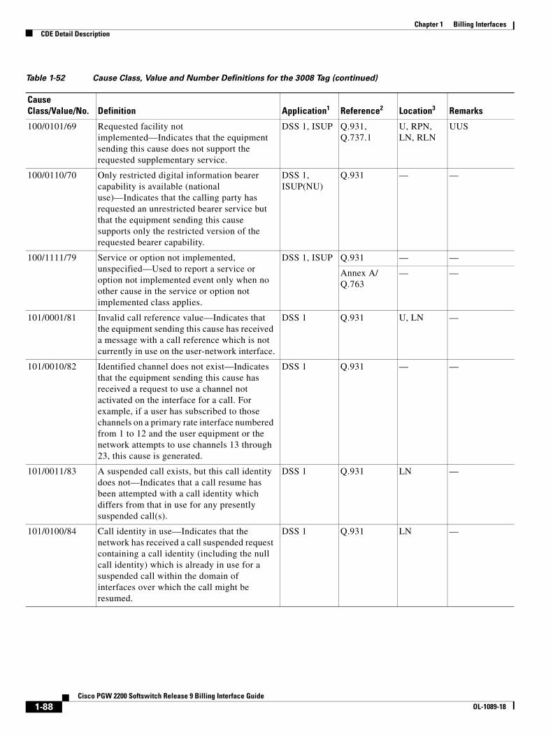
Chapter 1 Billing InterfacesCDE Detail Description
100/0101/69 Requested facility not implemented—Indicates that the equipment sending this cause does not support the requested supplementary service.
DSS 1, ISUP Q.931, Q.737.1
U, RPN, LN, RLN
UUS
100/0110/70 Only restricted digital information bearer capability is available (national use)—Indicates that the calling party has requested an unrestricted bearer service but that the equipment sending this cause supports only the restricted version of the requested bearer capability.
DSS 1, ISUP(NU)
Q.931 — —
100/1111/79 Service or option not implemented, unspecified—Used to report a service or option not implemented event only when no other cause in the service or option not implemented class applies.
DSS 1, ISUP Q.931 — —
Annex A/ Q.763
— —
101/0001/81 Invalid call reference value—Indicates that the equipment sending this cause has received a message with a call reference which is not currently in use on the user-network interface.
DSS 1 Q.931 U, LN —
101/0010/82 Identified channel does not exist—Indicates that the equipment sending this cause has received a request to use a channel not activated on the interface for a call. For example, if a user has subscribed to those channels on a primary rate interface numbered from 1 to 12 and the user equipment or the network attempts to use channels 13 through 23, this cause is generated.
DSS 1 Q.931 — —
101/0011/83 A suspended call exists, but this call identity does not—Indicates that a call resume has been attempted with a call identity which differs from that in use for any presently suspended call(s).
DSS 1 Q.931 LN —
101/0100/84 Call identity in use—Indicates that the network has received a call suspended request containing a call identity (including the null call identity) which is already in use for a suspended call within the domain of interfaces over which the call might be resumed.
DSS 1 Q.931 LN —
Table 1-52 Cause Class, Value and Number Definitions for the 3008 Tag (continued)
Cause Class/Value/No. Definition Application1 Reference2 Location3 Remarks
1-88Cisco PGW 2200 Softswitch Release 9 Billing Interface Guide
OL-1089-18
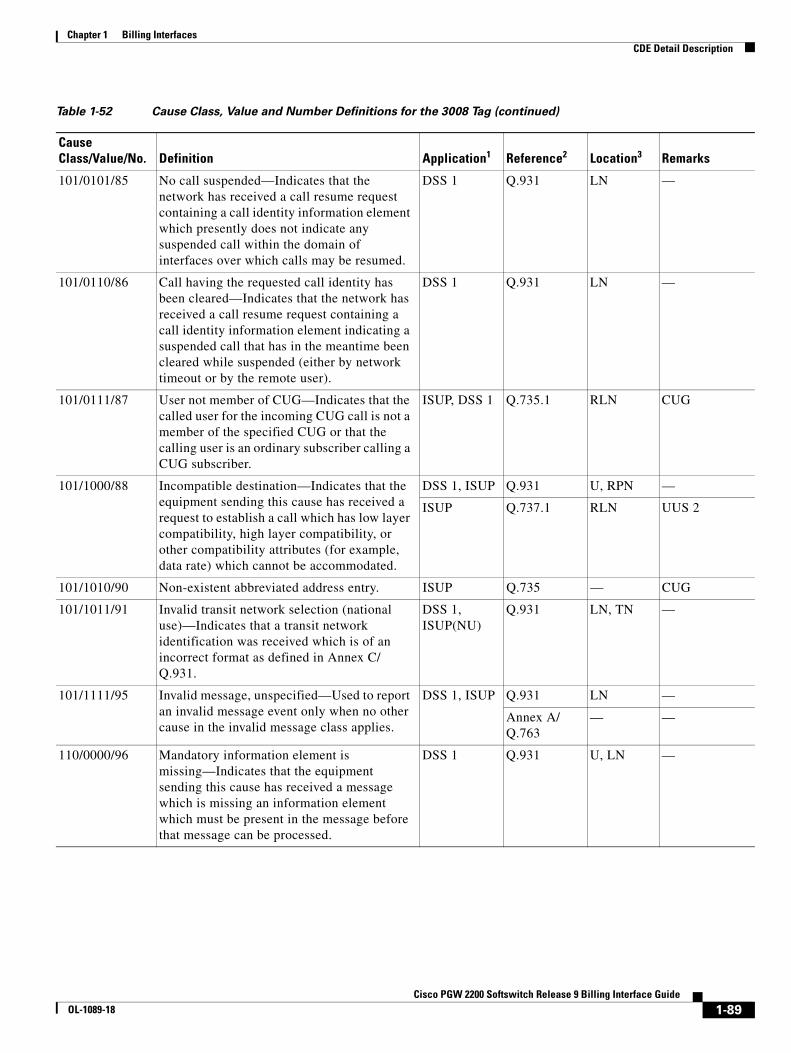
Chapter 1 Billing InterfacesCDE Detail Description
101/0101/85 No call suspended—Indicates that the network has received a call resume request containing a call identity information element which presently does not indicate any suspended call within the domain of interfaces over which calls may be resumed.
DSS 1 Q.931 LN —
101/0110/86 Call having the requested call identity has been cleared—Indicates that the network has received a call resume request containing a call identity information element indicating a suspended call that has in the meantime been cleared while suspended (either by network timeout or by the remote user).
DSS 1 Q.931 LN —
101/0111/87 User not member of CUG—Indicates that the called user for the incoming CUG call is not a member of the specified CUG or that the calling user is an ordinary subscriber calling a CUG subscriber.
ISUP, DSS 1 Q.735.1 RLN CUG
101/1000/88 Incompatible destination—Indicates that the equipment sending this cause has received a request to establish a call which has low layer compatibility, high layer compatibility, or other compatibility attributes (for example, data rate) which cannot be accommodated.
DSS 1, ISUP Q.931 U, RPN —
ISUP Q.737.1 RLN UUS 2
101/1010/90 Non-existent abbreviated address entry. ISUP Q.735 — CUG
101/1011/91 Invalid transit network selection (national use)—Indicates that a transit network identification was received which is of an incorrect format as defined in Annex C/ Q.931.
DSS 1, ISUP(NU)
Q.931 LN, TN —
101/1111/95 Invalid message, unspecified—Used to report an invalid message event only when no other cause in the invalid message class applies.
DSS 1, ISUP Q.931 LN —
Annex A/ Q.763
— —
110/0000/96 Mandatory information element is missing—Indicates that the equipment sending this cause has received a message which is missing an information element which must be present in the message before that message can be processed.
DSS 1 Q.931 U, LN —
Table 1-52 Cause Class, Value and Number Definitions for the 3008 Tag (continued)
Cause Class/Value/No. Definition Application1 Reference2 Location3 Remarks
1-89Cisco PGW 2200 Softswitch Release 9 Billing Interface Guide
OL-1089-18
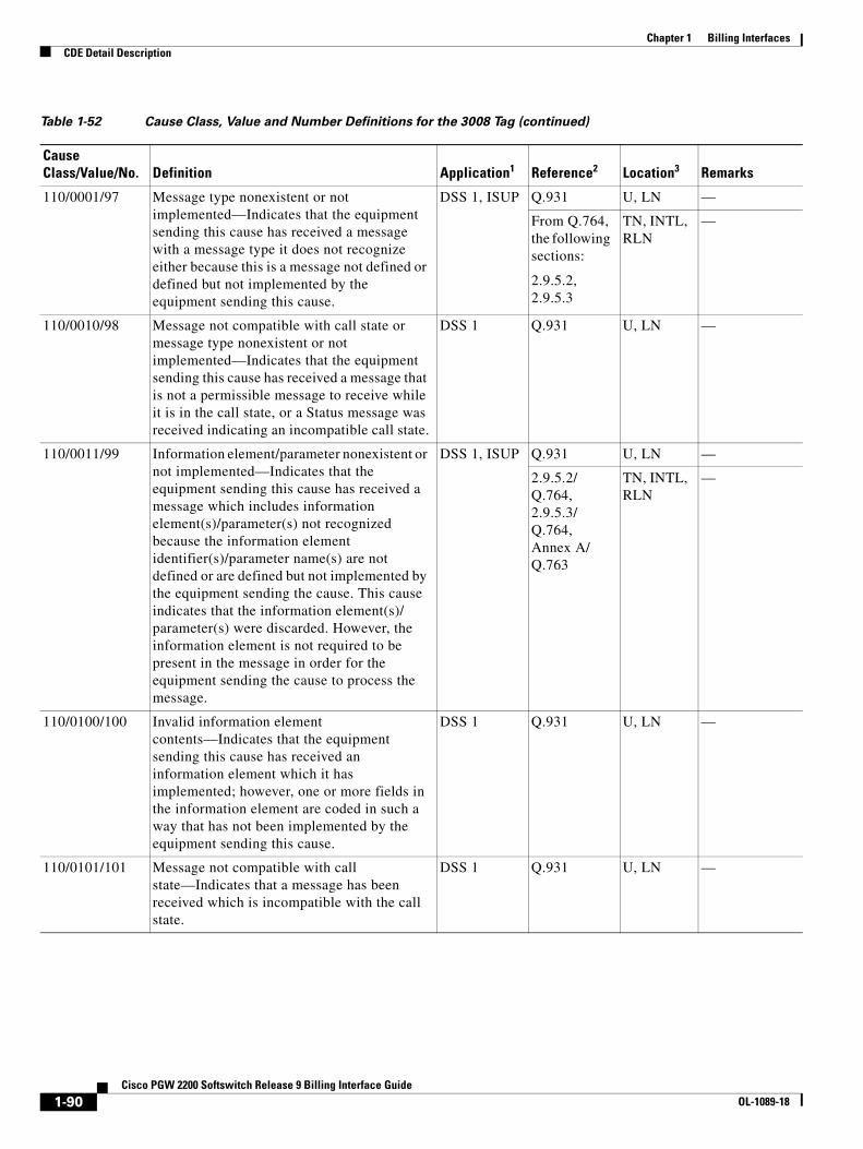
Chapter 1 Billing InterfacesCDE Detail Description
110/0001/97 Message type nonexistent or not implemented—Indicates that the equipment sending this cause has received a message with a message type it does not recognize either because this is a message not defined or defined but not implemented by the equipment sending this cause.
DSS 1, ISUP Q.931 U, LN —
From Q.764, the following sections:
2.9.5.2, 2.9.5.3
TN, INTL, RLN
—
110/0010/98 Message not compatible with call state or message type nonexistent or not implemented—Indicates that the equipment sending this cause has received a message that is not a permissible message to receive while it is in the call state, or a Status message was received indicating an incompatible call state.
DSS 1 Q.931 U, LN —
110/0011/99 Information element/parameter nonexistent or not implemented—Indicates that the equipment sending this cause has received a message which includes information element(s)/parameter(s) not recognized because the information element identifier(s)/parameter name(s) are not defined or are defined but not implemented by the equipment sending the cause. This cause indicates that the information element(s)/ parameter(s) were discarded. However, the information element is not required to be present in the message in order for the equipment sending the cause to process the message.
DSS 1, ISUP Q.931 U, LN —
2.9.5.2/ Q.764, 2.9.5.3/ Q.764, Annex A/ Q.763
TN, INTL, RLN
—
110/0100/100 Invalid information element contents—Indicates that the equipment sending this cause has received an information element which it has implemented; however, one or more fields in the information element are coded in such a way that has not been implemented by the equipment sending this cause.
DSS 1 Q.931 U, LN —
110/0101/101 Message not compatible with call state—Indicates that a message has been received which is incompatible with the call state.
DSS 1 Q.931 U, LN —
Table 1-52 Cause Class, Value and Number Definitions for the 3008 Tag (continued)
Cause Class/Value/No. Definition Application1 Reference2 Location3 Remarks
1-90Cisco PGW 2200 Softswitch Release 9 Billing Interface Guide
OL-1089-18

Chapter 1 Billing InterfacesCDE Detail Description
110/0110/102 Recovery on timer expiry—Indicates that a procedure has been initiated by the expiry of a timer in association with error handling procedures.
DSS 1, ISUP Q.931 — —
Q.733.4 RLN Terminal portability: expiry of waiting RES (user) timer
2.4.3/Q.764 INTL Expiry of waiting RES (network) timer (incoming international exchange)
110/0111/103 Parameter nonexistent or not implemented. Passed on (national use)—Indicates that the equipment sending this cause has received a message which includes parameters not recognized because the parameters are not defined or are defined but not implemented by the equipment sending the cause. The cause indicates that the parameter(s) were ignored. In addition, if the equipment sending this cause is an intermediate point, this cause indicates that the parameter(s) were passed through unchanged.
ISUP(NU) — — —
110/1110/110 Message with unrecognized parameter discarded—Indicates that the equipment sending this cause has discarded a received message which includes a parameter that is not recognized.
ISUP 2.9.5.2/ Q.764, 2.9.5.3/ Q.764
— —
110/1111/111 Protocol error, unspecified—Used to report a protocol error event only when no other cause in the protocol error class applies.
DSS 1, ISUP Q.931 RLN —
Annex A/ Q.763
RLN, TN, INTL
—
Q.735.1 RLN CUG
111/1111/127 Interworking, unspecified—Indicates that there has been interworking with a network which does not provide causes for actions it takes. Thus, the precise cause for a message which is being sent cannot be ascertained.
DSS 1, ISUP Q.931 — —
Annex A/ Q.763
— —
1. Application indicates that the cause value may be carried in DSS 1 and/or ISUP. Causes carried in ISUP which are not marked for national use are the minimum set of cause values that are supported over the international interface.
2. The references included are not exhaustive.
3. These are typical locations generated within the scope of the associated ITU-T Recommendations. Other locations can be used depending upon the network configuration.
Table 1-52 Cause Class, Value and Number Definitions for the 3008 Tag (continued)
Cause Class/Value/No. Definition Application1 Reference2 Location3 Remarks
1-91Cisco PGW 2200 Softswitch Release 9 Billing Interface Guide
OL-1089-18
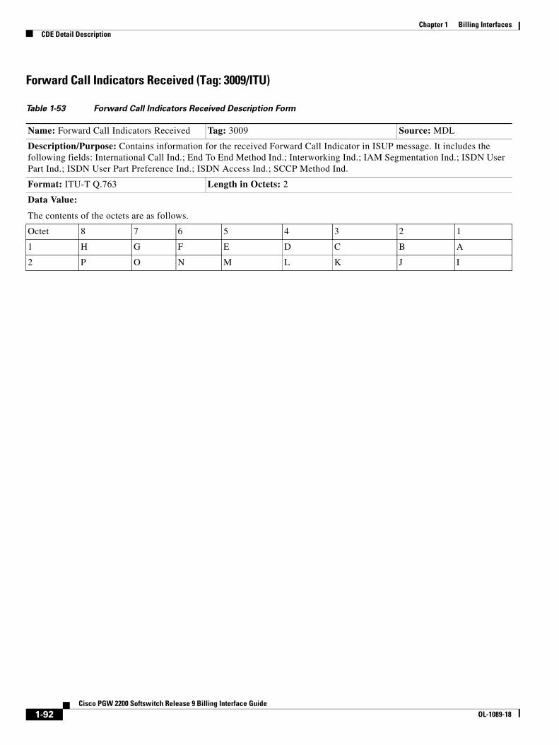
Chapter 1 Billing InterfacesCDE Detail Description
Forward Call Indicators Received (Tag: 3009/ITU)
Table 1-53 Forward Call Indicators Received Description Form
Name: Forward Call Indicators Received Tag: 3009 Source: MDL
Description/Purpose: Contains information for the received Forward Call Indicator in ISUP message. It includes the following fields: International Call Ind.; End To End Method Ind.; Interworking Ind.; IAM Segmentation Ind.; ISDN User Part Ind.; ISDN User Part Preference Ind.; ISDN Access Ind.; SCCP Method Ind.
Format: ITU-T Q.763 Length in Octets: 2
Data Value:
The contents of the octets are as follows.
Octet 8 7 6 5 4 3 2 1
1 H G F E D C B A
2 P O N M L K J I
1-92Cisco PGW 2200 Softswitch Release 9 Billing Interface Guide
OL-1089-18

Chapter 1 Billing InterfacesCDE Detail Description
The following codes are used in the forward call indicators parameter field:
Bit A—National/international call indicator
0 Call to be treated as a national call 1 Call to be treated as an international call
This bit can be set to any value in the country of origin. In the international network this bit is not checked. In the destination country, calls from the international network will have this bit set to 1.
Note Bits B–F and J–K constitute the protocol control indicator.
Bits CB—End-to-end method indicator:
00 No end-to-end method available (only link-by-link method available) 01 Pass along method available 10 SCCP method available 11 Pass along and SCCP methods available
Bit D—Internetworking indicator:
0 No internetworking encountered (SS7 all the way) 1 Internetworking encountered
Bit E—National/international call indictor
0 Call to be treated as a national call 1 Call to be treated as an international call
Bit F—ISDN user part indicator
0 ISDN user part not used all the way 1 ISDN user part used all the way
Bits HG—ISDN user part preference indicator
00 ISDN user part preferred all the way 01 ISDN user part not required all the way 10 ISDN user part required all the way 11 Spare
Bit I—ISDN access indicator
0 Originating access non-ISDN 1 Originating access ISDN
Bits KJ—Signal Control Control Part (SCCP) method indicator
00 No indication 01 Connectionless method available 10 Connection-oriented method available 11 Connectionless and connection-oriented methods available
Bit L—Spare
Bits P–M—Reserved for national use
Note The above values are for standard ITU SS7. Variants of ITU SS7 might have different values. Verify the values for your variant with the appropriate specification, if necessary.
Table 1-53 Forward Call Indicators Received Description Form (continued)
1-93Cisco PGW 2200 Softswitch Release 9 Billing Interface Guide
OL-1089-18
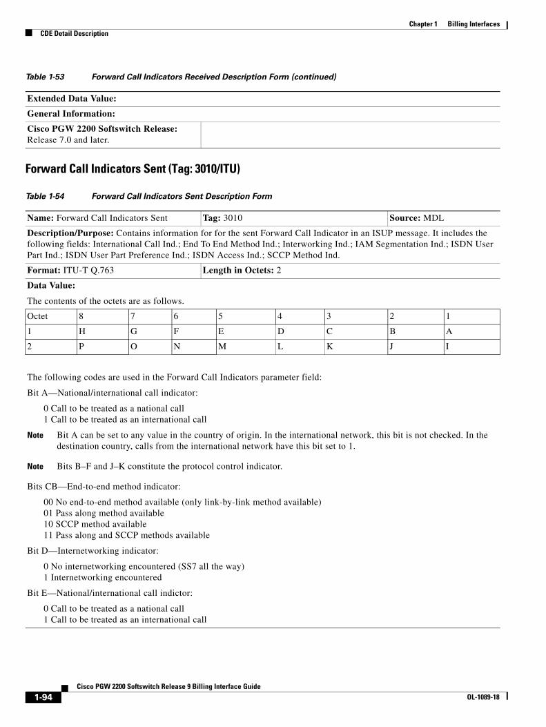
Chapter 1 Billing InterfacesCDE Detail Description
Forward Call Indicators Sent (Tag: 3010/ITU)
Extended Data Value:
General Information:
Cisco PGW 2200 Softswitch Release: Release 7.0 and later.
Table 1-54 Forward Call Indicators Sent Description Form
Name: Forward Call Indicators Sent Tag: 3010 Source: MDL
Description/Purpose: Contains information for for the sent Forward Call Indicator in an ISUP message. It includes the following fields: International Call Ind.; End To End Method Ind.; Interworking Ind.; IAM Segmentation Ind.; ISDN User Part Ind.; ISDN User Part Preference Ind.; ISDN Access Ind.; SCCP Method Ind.
Format: ITU-T Q.763 Length in Octets: 2
Data Value:
The contents of the octets are as follows.
Octet 8 7 6 5 4 3 2 1
1 H G F E D C B A
2 P O N M L K J I
The following codes are used in the Forward Call Indicators parameter field:
Bit A—National/international call indicator:
0 Call to be treated as a national call 1 Call to be treated as an international call
Note Bit A can be set to any value in the country of origin. In the international network, this bit is not checked. In the destination country, calls from the international network have this bit set to 1.
Note Bits B–F and J–K constitute the protocol control indicator.
Bits CB—End-to-end method indicator:
00 No end-to-end method available (only link-by-link method available) 01 Pass along method available 10 SCCP method available 11 Pass along and SCCP methods available
Bit D—Internetworking indicator:
0 No internetworking encountered (SS7 all the way) 1 Internetworking encountered
Bit E—National/international call indictor:
0 Call to be treated as a national call 1 Call to be treated as an international call
Table 1-53 Forward Call Indicators Received Description Form (continued)
1-94Cisco PGW 2200 Softswitch Release 9 Billing Interface Guide
OL-1089-18
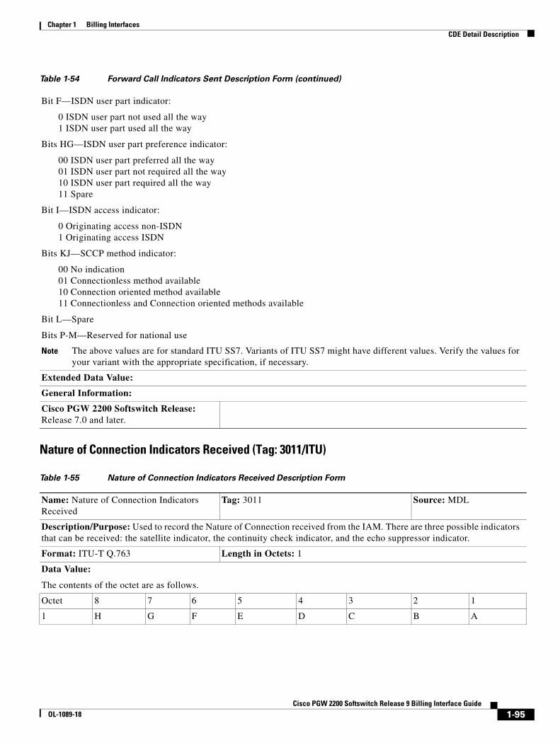
Chapter 1 Billing InterfacesCDE Detail Description
Nature of Connection Indicators Received (Tag: 3011/ITU)
Bit F—ISDN user part indicator:
0 ISDN user part not used all the way 1 ISDN user part used all the way
Bits HG—ISDN user part preference indicator:
00 ISDN user part preferred all the way 01 ISDN user part not required all the way 10 ISDN user part required all the way 11 Spare
Bit I—ISDN access indicator:
0 Originating access non-ISDN 1 Originating access ISDN
Bits KJ—SCCP method indicator:
00 No indication 01 Connectionless method available 10 Connection oriented method available 11 Connectionless and Connection oriented methods available
Bit L—Spare
Bits P-M—Reserved for national use
Note The above values are for standard ITU SS7. Variants of ITU SS7 might have different values. Verify the values for your variant with the appropriate specification, if necessary.
Extended Data Value:
General Information:
Cisco PGW 2200 Softswitch Release: Release 7.0 and later.
Table 1-55 Nature of Connection Indicators Received Description Form
Name: Nature of Connection Indicators Received
Tag: 3011 Source: MDL
Description/Purpose: Used to record the Nature of Connection received from the IAM. There are three possible indicators that can be received: the satellite indicator, the continuity check indicator, and the echo suppressor indicator.
Format: ITU-T Q.763 Length in Octets: 1
Data Value:
The contents of the octet are as follows.
Octet 8 7 6 5 4 3 2 1
1 H G F E D C B A
Table 1-54 Forward Call Indicators Sent Description Form (continued)
1-95Cisco PGW 2200 Softswitch Release 9 Billing Interface Guide
OL-1089-18
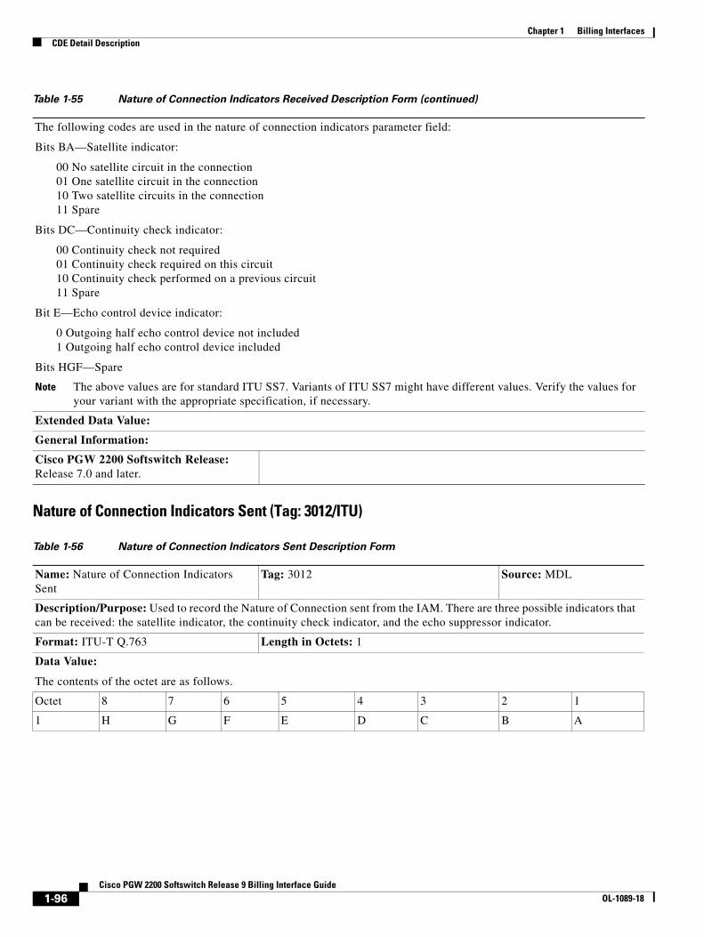
Chapter 1 Billing InterfacesCDE Detail Description
Nature of Connection Indicators Sent (Tag: 3012/ITU)
The following codes are used in the nature of connection indicators parameter field:
Bits BA—Satellite indicator:
00 No satellite circuit in the connection 01 One satellite circuit in the connection 10 Two satellite circuits in the connection 11 Spare
Bits DC—Continuity check indicator:
00 Continuity check not required 01 Continuity check required on this circuit 10 Continuity check performed on a previous circuit 11 Spare
Bit E—Echo control device indicator:
0 Outgoing half echo control device not included 1 Outgoing half echo control device included
Bits HGF—Spare
Note The above values are for standard ITU SS7. Variants of ITU SS7 might have different values. Verify the values for your variant with the appropriate specification, if necessary.
Extended Data Value:
General Information:
Cisco PGW 2200 Softswitch Release: Release 7.0 and later.
Table 1-56 Nature of Connection Indicators Sent Description Form
Name: Nature of Connection Indicators Sent
Tag: 3012 Source: MDL
Description/Purpose: Used to record the Nature of Connection sent from the IAM. There are three possible indicators that can be received: the satellite indicator, the continuity check indicator, and the echo suppressor indicator.
Format: ITU-T Q.763 Length in Octets: 1
Data Value:
The contents of the octet are as follows.
Octet 8 7 6 5 4 3 2 1
1 H G F E D C B A
Table 1-55 Nature of Connection Indicators Received Description Form (continued)
1-96Cisco PGW 2200 Softswitch Release 9 Billing Interface Guide
OL-1089-18
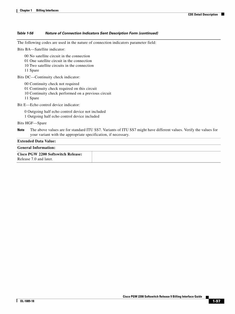
Chapter 1 Billing InterfacesCDE Detail Description
The following codes are used in the nature of connection indicators parameter field:
Bits BA—Satellite indicator:
00 No satellite circuit in the connection 01 One satellite circuit in the connection 10 Two satellite circuits in the connection 11 Spare
Bits DC—Continuity check indicator:
00 Continuity check not required 01 Continuity check required on this circuit 10 Continuity check performed on a previous circuit 11 Spare
Bit E—Echo control device indicator:
0 Outgoing half echo control device not included 1 Outgoing half echo control device included
Bits HGF—Spare
Note The above values are for standard ITU SS7. Variants of ITU SS7 might have different values. Verify the values for your variant with the appropriate specification, if necessary.
Extended Data Value:
General Information:
Cisco PGW 2200 Softswitch Release: Release 7.0 and later.
Table 1-56 Nature of Connection Indicators Sent Description Form (continued)
1-97Cisco PGW 2200 Softswitch Release 9 Billing Interface Guide
OL-1089-18
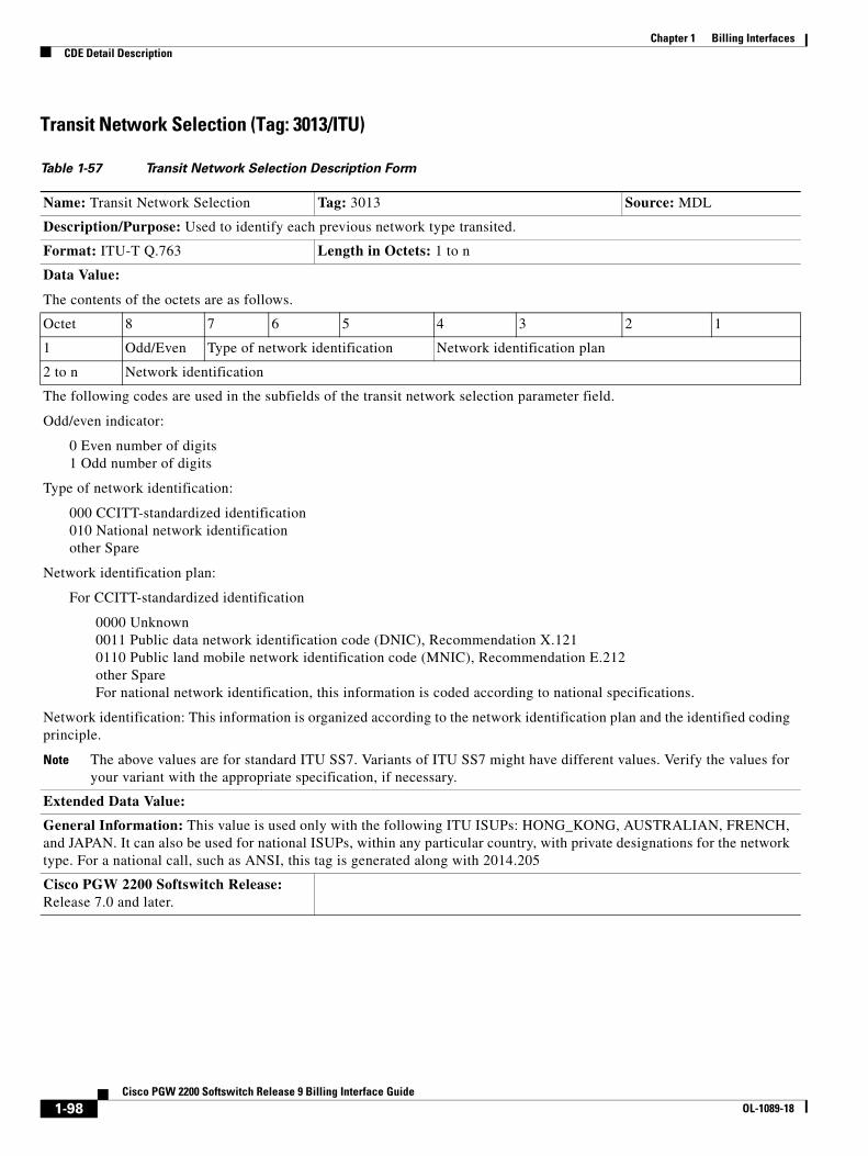
Chapter 1 Billing InterfacesCDE Detail Description
Transit Network Selection (Tag: 3013/ITU)
Table 1-57 Transit Network Selection Description Form
Name: Transit Network Selection Tag: 3013 Source: MDL
Description/Purpose: Used to identify each previous network type transited.
Format: ITU-T Q.763 Length in Octets: 1 to n
Data Value:
The contents of the octets are as follows.
Octet 8 7 6 5 4 3 2 1
1 Odd/Even Type of network identification Network identification plan
2 to n Network identification
The following codes are used in the subfields of the transit network selection parameter field.
Odd/even indicator:
0 Even number of digits 1 Odd number of digits
Type of network identification:
000 CCITT-standardized identification 010 National network identification other Spare
Network identification plan:
For CCITT-standardized identification
0000 Unknown 0011 Public data network identification code (DNIC), Recommendation X.121 0110 Public land mobile network identification code (MNIC), Recommendation E.212 other Spare For national network identification, this information is coded according to national specifications.
Network identification: This information is organized according to the network identification plan and the identified coding principle.
Note The above values are for standard ITU SS7. Variants of ITU SS7 might have different values. Verify the values for your variant with the appropriate specification, if necessary.
Extended Data Value:
General Information: This value is used only with the following ITU ISUPs: HONG_KONG, AUSTRALIAN, FRENCH, and JAPAN. It can also be used for national ISUPs, within any particular country, with private designations for the network type. For a national call, such as ANSI, this tag is generated along with 2014.205
Cisco PGW 2200 Softswitch Release: Release 7.0 and later.
1-98Cisco PGW 2200 Softswitch Release 9 Billing Interface Guide
OL-1089-18
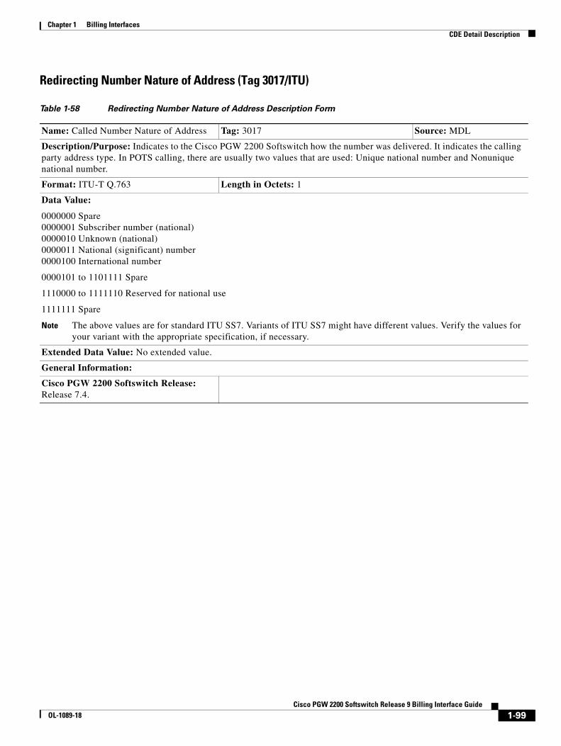
Chapter 1 Billing InterfacesCDE Detail Description
Redirecting Number Nature of Address (Tag 3017/ITU)
Table 1-58 Redirecting Number Nature of Address Description Form
Name: Called Number Nature of Address Tag: 3017 Source: MDL
Description/Purpose: Indicates to the Cisco PGW 2200 Softswitch how the number was delivered. It indicates the calling party address type. In POTS calling, there are usually two values that are used: Unique national number and Nonunique national number.
Format: ITU-T Q.763 Length in Octets: 1
Data Value:
0000000 Spare 0000001 Subscriber number (national) 0000010 Unknown (national) 0000011 National (significant) number 0000100 International number
0000101 to 1101111 Spare
1110000 to 1111110 Reserved for national use
1111111 Spare
Note The above values are for standard ITU SS7. Variants of ITU SS7 might have different values. Verify the values for your variant with the appropriate specification, if necessary.
Extended Data Value: No extended value.
General Information:
Cisco PGW 2200 Softswitch Release: Release 7.4.
1-99Cisco PGW 2200 Softswitch Release 9 Billing Interface Guide
OL-1089-18
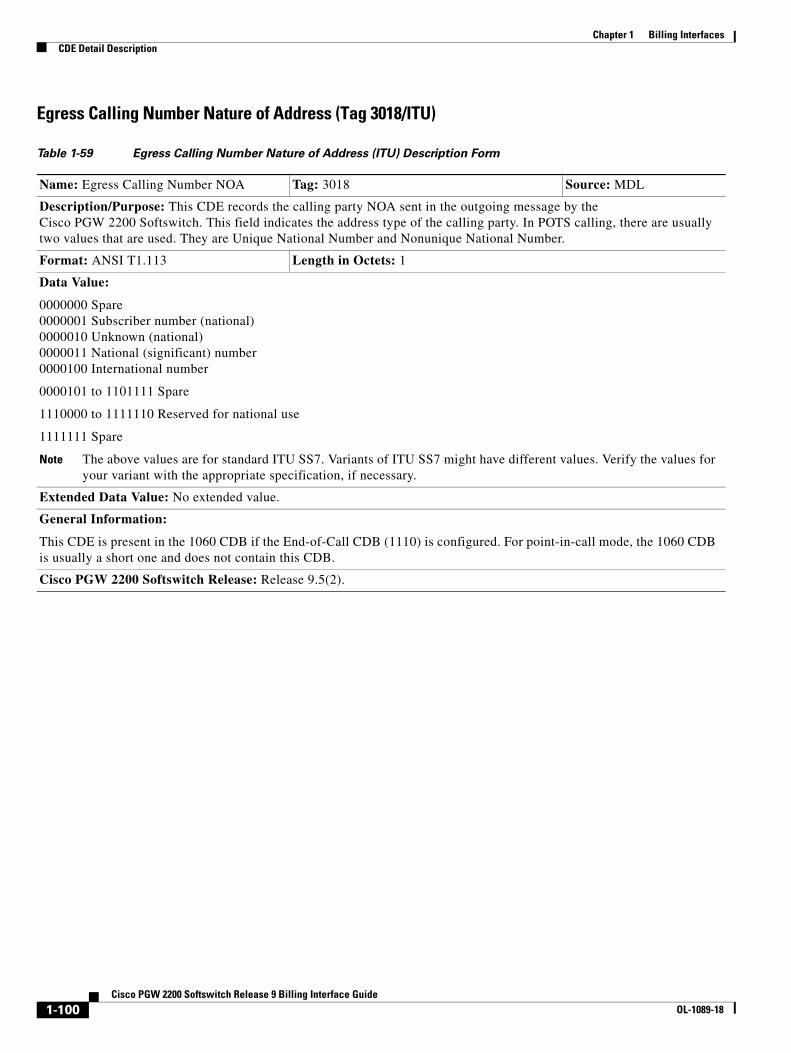
Chapter 1 Billing InterfacesCDE Detail Description
Egress Calling Number Nature of Address (Tag 3018/ITU)
Table 1-59 Egress Calling Number Nature of Address (ITU) Description Form
Name: Egress Calling Number NOA Tag: 3018 Source: MDL
Description/Purpose: This CDE records the calling party NOA sent in the outgoing message by the Cisco PGW 2200 Softswitch. This field indicates the address type of the calling party. In POTS calling, there are usually two values that are used. They are Unique National Number and Nonunique National Number.
Format: ANSI T1.113 Length in Octets: 1
Data Value:
0000000 Spare 0000001 Subscriber number (national) 0000010 Unknown (national) 0000011 National (significant) number 0000100 International number
0000101 to 1101111 Spare
1110000 to 1111110 Reserved for national use
1111111 Spare
Note The above values are for standard ITU SS7. Variants of ITU SS7 might have different values. Verify the values for your variant with the appropriate specification, if necessary.
Extended Data Value: No extended value.
General Information:
This CDE is present in the 1060 CDB if the End-of-Call CDB (1110) is configured. For point-in-call mode, the 1060 CDB is usually a short one and does not contain this CDB.
Cisco PGW 2200 Softswitch Release: Release 9.5(2).
1-100Cisco PGW 2200 Softswitch Release 9 Billing Interface Guide
OL-1089-18

Chapter 1 Billing InterfacesCDE Detail Description
Egress Redirecting Number Nature of Address (Tag 3019/ITU)
Table 1-60 Egress Redirecting Number Nature of Address (ITU) Description Form
Name: Egress Redirecting Number NOA Tag: 3019 Source: MDL
Description/Purpose: This CDE records the redirecting calling number NOA sent in the outgoing message by the Cisco PGW 2200 Softswitch.
Format: ITU-T Q.763 Length in Octets: 1
Data Value:
0000000 Spare 0000001 Subscriber number (national) 0000010 Unknown (national) 0000011 National (significant) number 0000100 International number
0000101 to 1101111 Spare
1110000 to 1111110 Reserved for national use
1111111 Spare
Note The above values are for standard ITU SS7. Variants of ITU SS7 might have different values. Verify the values for your variant with the appropriate specification, if necessary.
Extended Data Value: No extended value.
General Information:
This CDE is present in the 1060 CDB if the end-of-call CDB (1110) is configured. For point-in-call mode, the 1060 CDB is usually a short one and does not contain this CDB.
Cisco PGW 2200 Softswitch Release: Release 9.5(2).
1-101Cisco PGW 2200 Softswitch Release 9 Billing Interface Guide
OL-1089-18

Chapter 1 Billing InterfacesCDE Detail Description
Egress Original Called Number Nature of Address (Tag 3020/ITU)
Cisco PGW 2200 Softswitch Generic CDEs
CDB Version (Tag: 4000)
Table 1-61 Egress Original Called Number Nature of Address (ITU) Description Form
Name: Egress Original Called Number NOA
Tag: 3020 Source: MDL
Description/Purpose: This CDE records the original called party NOA sent in the outgoing message by the Cisco PGW 2200 Softswitch.
Format: ITU-T Q.763 Length in Octets: 1
Data Value:
0000000 Spare 0000001 Subscriber number (national) 0000010 Unknown (national) 0000011 National (significant) number 0000100 International number
0000101 to 1101111 Spare
1110000 to 1111110 Reserved for national use
1111111 Spare
Note The above values are for standard ITU SS7. Variants of ITU SS7 might have different values. Verify the values for your variant with the appropriate specification, if necessary.
Extended Data Value: No extended value.
General Information:
This CDE is present in the 1060 CDB if the End-of-Call CDB (1110) is configured. For point-in-call mode, the 1060 CDB is usually a short one and does not contain this CDB.
Cisco PGW 2200 Softswitch Release: Release 9.5(2).
Table 1-62 CDB Version Description Form
Name: CDB Version Tag: 4000 Source: MDL
Description/Purpose: Holds CDB version number to control raw CDB layout version.
Format: BE Length in Octets: 1
Data Value: 1
Extended Data Value: No extended value.
General Information: This field is required in every CDB.
Cisco PGW 2200 Softswitch Release: Release 5.0 and later.
1-102Cisco PGW 2200 Softswitch Release 9 Billing Interface Guide
OL-1089-18

Chapter 1 Billing InterfacesCDE Detail Description
CDB Timepoint (Tag: 4001)
Call Reference ID (Tag: 4002)
IAM/Setup Timepoint (Tag: 4003)
Table 1-63 CDB Timepoint CDE Description Form
Name: CDB Timepoint Tag: 4001 Source: MDL/Engine
Description/Purpose: Timepoint for creation of the CDB.
Format: BE Length in Octets: 4
Data Value: UNIX time format (number of seconds since January 1, 1970).
Extended Data Value: No extended value.
General Information: This field is required in every CDB.
Cisco PGW 2200 Softswitch Release: Release 5.0 and later.
Table 1-64 Call Reference ID Description Form
Name: Call Reference ID Tag: 4002 Source: MDL/Engine
Description/Purpose: Created by the call processing engine as a unique call ID. This call reference ID provides a traceable link among multiple CDBs that are generated during the call. This field is used by downstream systems (such as mediation devices) to correlate CDBs and create a single CDR record for the call.
Format: BE Length in Octets: 8
Data Value: This consists of a 32-bit time and a 32-bit ascending sequence number.
Extended Data Value: No extended value.
General Information: This field is required in every CDB.
Table 1-65 IAM/Setup Timepoint Description Form
Name: IAM/Setup Timepoint Tag: 4003 Source: MDL/Engine
Description/Purpose: Timepoint for receipt of IAM/Setup (or receipt of CRM if a CRM preceded the IAM).
Format: BE Length in Octets: 4
Data Value: UNIX time format (number of seconds since January 1, 1970).
Extended Data Value: No extended value.
General Information: This message is sent in the forward direction (from the originating exchange to the terminating exchange). It initiates seizure of an outgoing circuit and transmission of the number and other information relating to the routing and handling of a call.
Cisco PGW 2200 Softswitch Release: Release 5.0 and later.
1-103Cisco PGW 2200 Softswitch Release 9 Billing Interface Guide
OL-1089-18

Chapter 1 Billing InterfacesCDE Detail Description
ACM/Alert Timepoint (Tag: 4004)
ANM/Answer Timepoint (Tag: 4005)
Table 1-66 ACM/Alert Timepoint Description Form
Name: ACM/Alert Timepoint Tag: 4004 Source: MDL/Engine
Description/Purpose: Timepoint for receipt of ACM/Alert.
Format: BE Length in Octets: 4
Data Value: UNIX time format (number of seconds since January 1, 1970).
Extended Data Value: No extended value.
General Information: This message is sent in the backward direction (from the terminating exchange to the originating exchange), indicating that all signals required for routing the call to the called party have been received.
Cisco PGW 2200 Softswitch Release: Release 5.0 and later.
Table 1-67 ANM/Answer Timepoint Description Form
Name: ANM/Answer Timepoint Tag: 4005 Source: MDL/Engine
Description/Purpose: Timepoint for receipt of ANM/Answer.
Format: BE Length in Octets: 4
Data Value: UNIX time format (number of seconds since January 1, 1970).
Extended Data Value: No extended value.
General Information: This message is sent in the backward direction (from the terminating exchange to the originating exchange), indicating that the call has been answered.
This message can be used in conjunction with the charging information to start measurement of a call duration.
Cisco PGW 2200 Softswitch Release: Release 5.0 and later.
1-104Cisco PGW 2200 Softswitch Release 9 Billing Interface Guide
OL-1089-18
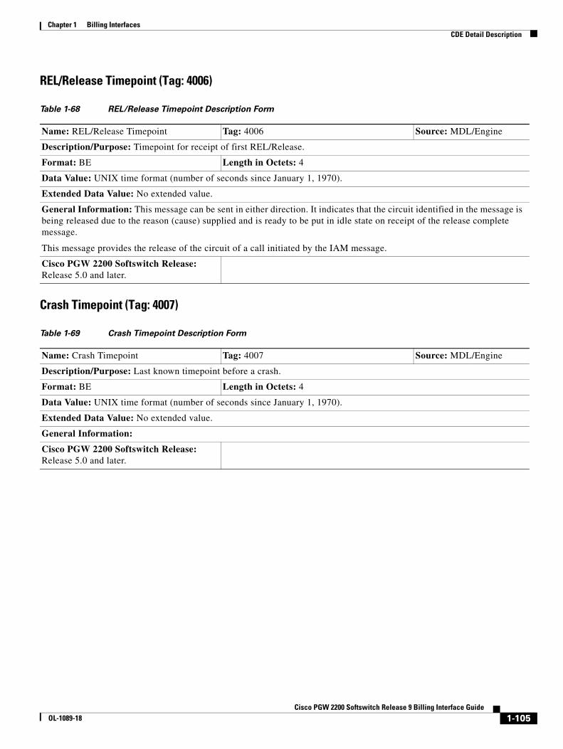
Chapter 1 Billing InterfacesCDE Detail Description
REL/Release Timepoint (Tag: 4006)
Crash Timepoint (Tag: 4007)
Table 1-68 REL/Release Timepoint Description Form
Name: REL/Release Timepoint Tag: 4006 Source: MDL/Engine
Description/Purpose: Timepoint for receipt of first REL/Release.
Format: BE Length in Octets: 4
Data Value: UNIX time format (number of seconds since January 1, 1970).
Extended Data Value: No extended value.
General Information: This message can be sent in either direction. It indicates that the circuit identified in the message is being released due to the reason (cause) supplied and is ready to be put in idle state on receipt of the release complete message.
This message provides the release of the circuit of a call initiated by the IAM message.
Cisco PGW 2200 Softswitch Release: Release 5.0 and later.
Table 1-69 Crash Timepoint Description Form
Name: Crash Timepoint Tag: 4007 Source: MDL/Engine
Description/Purpose: Last known timepoint before a crash.
Format: BE Length in Octets: 4
Data Value: UNIX time format (number of seconds since January 1, 1970).
Extended Data Value: No extended value.
General Information:
Cisco PGW 2200 Softswitch Release: Release 5.0 and later.
1-105Cisco PGW 2200 Softswitch Release 9 Billing Interface Guide
OL-1089-18

Chapter 1 Billing InterfacesCDE Detail Description
Originating Trunk Group (Tag: 4008)
Originating Member (Tag: 4009)
Calling Number (Tag: 4010)
Table 1-70 Originating Trunk Group Description Form
Name: Originating Trunk Group Tag: 4008 Source: MDL/Engine
Description/Purpose: Holds the originating trunk group number.
If you are using the Multiple Incoming IP Trunk Groups feature, this CDR contains the derived incoming trunk group ID.
Format: BE Length in Octets: 2
Data Value: The trunk group number ranges from 1 to 16,384 for ANSI and 1 to 4096 for ITU.
Extended Data Value: No extended value.
General Information: If you are creating Bellcore AMA Format (BAF) records downstream, BAF supports only four digits for the trunk group number. This makes the practical limit 9999.
Cisco PGW 2200 Softswitch Release: Release 5.0 and later.
Table 1-71 Originating Member Description Form
Name: Originating Member Tag: 4009 Source: MDL
Description/Purpose: Contains the originating trunk member number within the originating trunk group. There can be 214 originating members when the Cisco PGW 2200 Softswitch is configured for ANSI, and 212 originating members when it is configured for ITU.
Format: BE Length in Octets: 2
Data Value: Integer—There can be 214 members for ANSI, and 212 for ITU.
Extended Data Value: No extended value.
General Information:
Cisco PGW 2200 Softswitch Release: Release 5.0 and later.
Table 1-72 Calling Number Description Form
Name: Calling Number Tag: 4010 Source: MDL
Description/Purpose: These are the digits of the calling number.
Format: IA5 Length in Octets: 1 to 96
Data Value: Holds the digits of the calling number.
Extended Data Value: No extended value.
General Information: In the SS7/C7 environment, the calling number (Tag 4010) holds only the digits of the calling number; it does not include any NOA or other information. NOA and other information are presented by their own CDE(s).
Cisco PGW 2200 Softswitch Release: Release 5.0 and later.
1-106Cisco PGW 2200 Softswitch Release 9 Billing Interface Guide
OL-1089-18

Chapter 1 Billing InterfacesCDE Detail Description
Charged Number (Tag: 4011)
Dialed Number (Tag: 4012)
LRN Number (Tag: 4013)
Table 1-73 Charged Number Description Form
Name: Charged Number Tag: 4011 Source: MDL
Description/Purpose: If the protocol contains a parameter called charged number, the contents are deposited into this CDE in order to define the unique number of the party to be billed. In this case, it may or may not be the calling number. However, if the charged number parameter does not exist, the calling number is placed by default into this CDE as a billed party.
Format: IA5 Length in Octets: 1 to 96
Data Value: The digits of the number being billed.
Extended Data Value: No extended value.
General Information:
Cisco PGW 2200 Softswitch Release: Release 5.0 and later.
Table 1-74 Dialed Number Description Form
Name: Dialed Number Tag: 4012 Source: MDL
Description/Purpose: These are the digits that were dialed by the calling party.
Format: IA5 Length in Octets: 1 to 96
Data Value: The digits that were dialed by the calling party.
Extended Data Value: No extended value.
General Information:
Cisco PGW 2200 Softswitch Release: Release 5.0 and later.
Table 1-75 LRN Number Description Form
Name: LRN Number Tag: 4013 Source: MDL
Description/Purpose: Location routing number (LRN) used in implementation of local number portability.
Format: IA5 Length in Octets: 1 to 96
Data Value: IA5 digits
Extended Data Value: No extended value.
General Information:
Cisco PGW 2200 Softswitch Release: Release 5.0 and later.
1-107Cisco PGW 2200 Softswitch Release 9 Billing Interface Guide
OL-1089-18
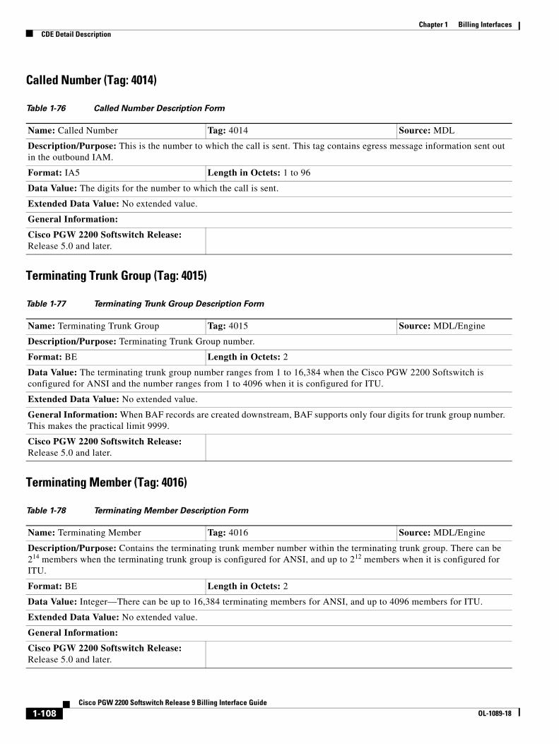
Chapter 1 Billing InterfacesCDE Detail Description
Called Number (Tag: 4014)
Terminating Trunk Group (Tag: 4015)
Terminating Member (Tag: 4016)
Table 1-76 Called Number Description Form
Name: Called Number Tag: 4014 Source: MDL
Description/Purpose: This is the number to which the call is sent. This tag contains egress message information sent out in the outbound IAM.
Format: IA5 Length in Octets: 1 to 96
Data Value: The digits for the number to which the call is sent.
Extended Data Value: No extended value.
General Information:
Cisco PGW 2200 Softswitch Release: Release 5.0 and later.
Table 1-77 Terminating Trunk Group Description Form
Name: Terminating Trunk Group Tag: 4015 Source: MDL/Engine
Description/Purpose: Terminating Trunk Group number.
Format: BE Length in Octets: 2
Data Value: The terminating trunk group number ranges from 1 to 16,384 when the Cisco PGW 2200 Softswitch is configured for ANSI and the number ranges from 1 to 4096 when it is configured for ITU.
Extended Data Value: No extended value.
General Information: When BAF records are created downstream, BAF supports only four digits for trunk group number. This makes the practical limit 9999.
Cisco PGW 2200 Softswitch Release: Release 5.0 and later.
Table 1-78 Terminating Member Description Form
Name: Terminating Member Tag: 4016 Source: MDL/Engine
Description/Purpose: Contains the terminating trunk member number within the terminating trunk group. There can be 214 members when the terminating trunk group is configured for ANSI, and up to 212 members when it is configured for ITU.
Format: BE Length in Octets: 2
Data Value: Integer—There can be up to 16,384 terminating members for ANSI, and up to 4096 members for ITU.
Extended Data Value: No extended value.
General Information:
Cisco PGW 2200 Softswitch Release: Release 5.0 and later.
1-108Cisco PGW 2200 Softswitch Release 9 Billing Interface Guide
OL-1089-18
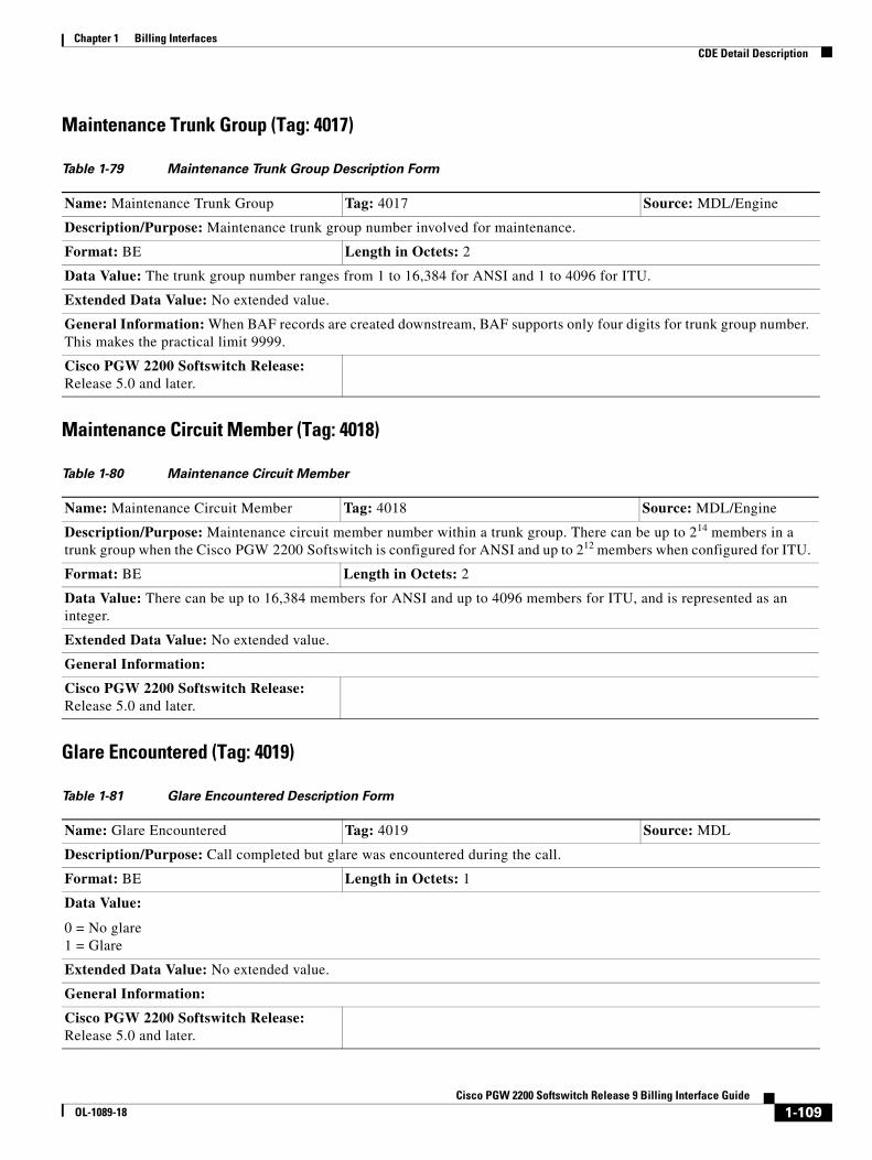
Chapter 1 Billing InterfacesCDE Detail Description
Maintenance Trunk Group (Tag: 4017)
Maintenance Circuit Member (Tag: 4018)
Glare Encountered (Tag: 4019)
Table 1-79 Maintenance Trunk Group Description Form
Name: Maintenance Trunk Group Tag: 4017 Source: MDL/Engine
Description/Purpose: Maintenance trunk group number involved for maintenance.
Format: BE Length in Octets: 2
Data Value: The trunk group number ranges from 1 to 16,384 for ANSI and 1 to 4096 for ITU.
Extended Data Value: No extended value.
General Information: When BAF records are created downstream, BAF supports only four digits for trunk group number. This makes the practical limit 9999.
Cisco PGW 2200 Softswitch Release: Release 5.0 and later.
Table 1-80 Maintenance Circuit Member
Name: Maintenance Circuit Member Tag: 4018 Source: MDL/Engine
Description/Purpose: Maintenance circuit member number within a trunk group. There can be up to 214 members in a trunk group when the Cisco PGW 2200 Softswitch is configured for ANSI and up to 212 members when configured for ITU.
Format: BE Length in Octets: 2
Data Value: There can be up to 16,384 members for ANSI and up to 4096 members for ITU, and is represented as an integer.
Extended Data Value: No extended value.
General Information:
Cisco PGW 2200 Softswitch Release: Release 5.0 and later.
Table 1-81 Glare Encountered Description Form
Name: Glare Encountered Tag: 4019 Source: MDL
Description/Purpose: Call completed but glare was encountered during the call.
Format: BE Length in Octets: 1
Data Value:
0 = No glare 1 = Glare
Extended Data Value: No extended value.
General Information:
Cisco PGW 2200 Softswitch Release: Release 5.0 and later.
1-109Cisco PGW 2200 Softswitch Release 9 Billing Interface Guide
OL-1089-18
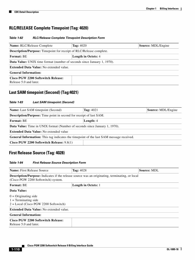
Chapter 1 Billing InterfacesCDE Detail Description
RLC/RELEASE Complete Timepoint (Tag: 4020)
Last SAM timepoint (Second) (Tag:4021)
First Release Source (Tag: 4028)
Table 1-82 RLC/Release Complete Timepoint Description Form
Name: RLC/Release Complete Tag: 4020 Source: MDL/Engine
Description/Purpose: Timepoint for receipt of RLC/Release complete.
Format: BE Length in Octets: 4
Data Value: UNIX time format (number of seconds since January 1, 1970).
Extended Data Value: No extended value.
General Information:
Cisco PGW 2200 Softswitch Release: Release 5.0 and later.
Table 1-83 Last SAM timepoint (Second)
Name: Last SAM timepoint (Second) Tag: 4021 Source: MDL/Engine
Description/Purpose: Time point in second for receipt of last SAM.
Format: BE Length: 4
Data Value: Time in UNIX format (Number of seconds since January 1, 1970).
Extended Data Value: No extended value
General Information: This tag indicates the timepoint of the last SAM message received.
Cisco PGW 2200 Softswitch Release: 9.8(1)
Table 1-84 First Release Source Description Form
Name: First Release Source Tag: 4028 Source: MDL
Description/Purpose: Indicates if the release source was an originating, terminating, or local (Cisco PGW 2200 Softswitch) system.
Format: BE Length in Octets: 1
Data Value:
0 = Originating side 1 = Terminating side 2 = Local (Cisco PGW 2200 Softswitch)
Extended Data Value: No extended value.
General Information:
Cisco PGW 2200 Softswitch Release: Release 5.0 and later.
1-110Cisco PGW 2200 Softswitch Release 9 Billing Interface Guide
OL-1089-18
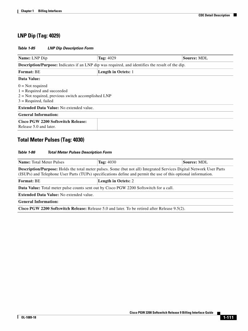
Chapter 1 Billing InterfacesCDE Detail Description
LNP Dip (Tag: 4029)
Total Meter Pulses (Tag: 4030)
Table 1-85 LNP Dip Description Form
Name: LNP Dip Tag: 4029 Source: MDL
Description/Purpose: Indicates if an LNP dip was required, and identifies the result of the dip.
Format: BE Length in Octets: 1
Data Value:
0 = Not required 1 = Required and succeeded 2 = Not required, previous switch accomplished LNP 3 = Required, failed
Extended Data Value: No extended value.
General Information:
Cisco PGW 2200 Softswitch Release: Release 5.0 and later.
Table 1-86 Total Meter Pulses Description Form
Name: Total Meter Pulses Tag: 4030 Source: MDL
Description/Purpose: Holds the total meter pulses. Some (but not all) Integrated Services Digital Network User Parts (ISUPs) and Telephone User Parts (TUPs) specifications define and permit the use of this optional information.
Format: BE Length in Octets: 2
Data Value: Total meter pulse counts sent out by Cisco PGW 2200 Softswitch for a call.
Extended Data Value: No extended value.
General Information:
Cisco PGW 2200 Softswitch Release: Release 5.0 and later. To be retired after Release 9.5(2).
1-111Cisco PGW 2200 Softswitch Release 9 Billing Interface Guide
OL-1089-18
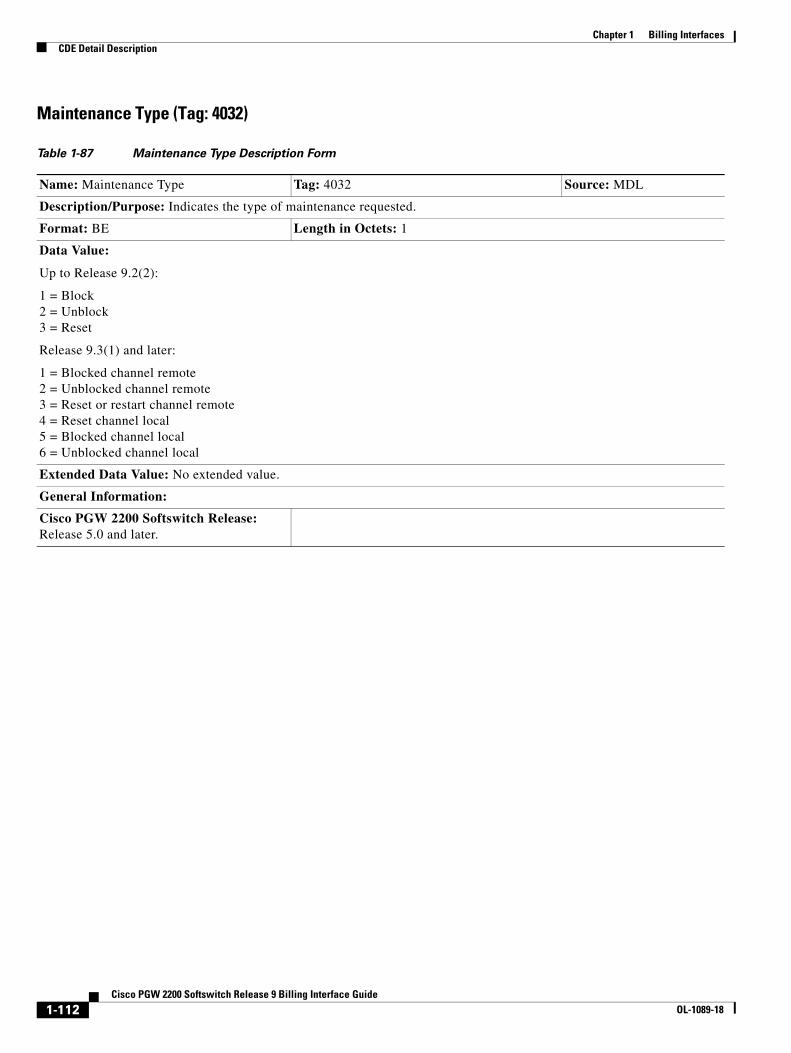
Chapter 1 Billing InterfacesCDE Detail Description
Maintenance Type (Tag: 4032)
Table 1-87 Maintenance Type Description Form
Name: Maintenance Type Tag: 4032 Source: MDL
Description/Purpose: Indicates the type of maintenance requested.
Format: BE Length in Octets: 1
Data Value:
Up to Release 9.2(2):
1 = Block 2 = Unblock 3 = Reset
Release 9.3(1) and later:
1 = Blocked channel remote 2 = Unblocked channel remote 3 = Reset or restart channel remote 4 = Reset channel local 5 = Blocked channel local 6 = Unblocked channel local
Extended Data Value: No extended value.
General Information:
Cisco PGW 2200 Softswitch Release: Release 5.0 and later.
1-112Cisco PGW 2200 Softswitch Release 9 Billing Interface Guide
OL-1089-18

Chapter 1 Billing InterfacesCDE Detail Description
Maintenance Reason (Tag: 4033)—Retired
Note Tag 4033 is retired in Release 9.4(1) of the Cisco PGW 2200 Softswitch software.
Table 1-88 Maintenance Reason Description Form
Name: Maintenance Reason Tag: 4033 Source: MDL
Description/Purpose: Indicates the reason that the maintenance was requested.
Format: BE Length in Octets: 1
Data Value:
Up to Release 9.2(2):
1 = Remote 2 = Local
Release 9.3(1) and later:
1 = Blocked channel remote 2 = Unblocked channel remote 3 = Reset or restart channel remote 4 = Reset channel local 5 = Blocked channel local 6 = Unblocked channel local
Extended Data Value: No extended value.
General Information:
Cisco PGW 2200 Softswitch Release: Release 5.0 and later.
1-113Cisco PGW 2200 Softswitch Release 9 Billing Interface Guide
OL-1089-18
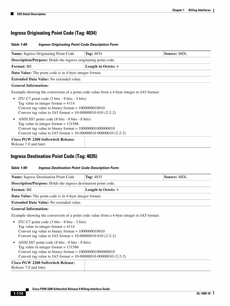
Chapter 1 Billing InterfacesCDE Detail Description
Ingress Originating Point Code (Tag: 4034)
Ingress Destination Point Code (Tag: 4035)
Table 1-89 Ingress Originating Point Code Description Form
Name: Ingress Originating Point Code Tag: 4034 Source: MDL
Description/Purpose: Holds the ingress originating point code.
Format: BE Length in Octets: 4
Data Value: The point code is in 4-byte integer format.
Extended Data Value: No extended value.
General Information:
Example showing the conversion of a point code value from a 4-byte integer to IA5 format:
• ITU C7 point code (3 bits - 8 bits - 3 bits) Tag value in integer format = 4114 Convert tag value to binary format = 1000000010010 Convert tag value to IA5 format = 10-00000010-010 (2-2-2)
• ANSI SS7 point code (8 bits - 8 bits - 8 bits) Tag value in integer format = 131586 Convert tag value to binary format = 100000001000000010 Convert tag value to IA5 format = 10-00000010-00000010 (2-2-2)
Cisco PGW 2200 Softswitch Release: Release 7.0 and later.
Table 1-90 Ingress Destination Point Code Description Form
Name: Ingress Destination Point Code Tag: 4035 Source: MDL
Description/Purpose: Holds the ingress destination point code.
Format: BE Length in Octets: 4
Data Value: The point code is in 4-byte integer format.
Extended Data Value: No extended value.
General Information:
Example showing the conversion of a point code value from a 4-byte integer to IA5 format:
• ITU C7 point code (3 bits - 8 bits - 3 bits) Tag value in integer format = 4114 Convert tag value to binary format = 1000000010010 Convert tag value to IA5 format = 10-00000010-010 (2-2-2)
• ANSI SS7 point code (8 bits - 8 bits - 8 bits) Tag value in integer format = 131586 Convert tag value to binary format = 100000001000000010 Convert tag value to IA5 format = 10-00000010-00000010 (2-2-2)
Cisco PGW 2200 Softswitch Release: Release 7.0 and later.
1-114Cisco PGW 2200 Softswitch Release 9 Billing Interface Guide
OL-1089-18
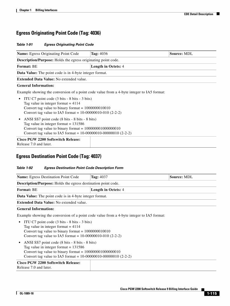
Chapter 1 Billing InterfacesCDE Detail Description
Egress Originating Point Code (Tag: 4036)
Egress Destination Point Code (Tag: 4037)
Table 1-91 Egress Originating Point Code
Name: Egress Originating Point Code Tag: 4036 Source: MDL
Description/Purpose: Holds the egress originating point code.
Format: BE Length in Octets: 4
Data Value: The point code is in 4-byte integer format.
Extended Data Value: No extended value.
General Information:
Example showing the conversion of a point code value from a 4-byte integer to IA5 format:
• ITU C7 point code (3 bits - 8 bits - 3 bits) Tag value in integer format = 4114 Convert tag value to binary format = 1000000010010 Convert tag value to IA5 format = 10-00000010-010 (2-2-2)
• ANSI SS7 point code (8 bits - 8 bits - 8 bits) Tag value in integer format = 131586 Convert tag value to binary format = 100000001000000010 Convert tag value to IA5 format = 10-00000010-00000010 (2-2-2)
Cisco PGW 2200 Softswitch Release: Release 7.0 and later.
Table 1-92 Egress Destination Point Code Description Form
Name: Egress Destination Point Code Tag: 4037 Source: MDL
Description/Purpose: Holds the egress destination point code.
Format: BE Length in Octets: 4
Data Value: The point code is in 4-byte integer format.
Extended Data Value: No extended value.
General Information:
Example showing the conversion of a point code value from a 4-byte integer to IA5 format:
• ITU C7 point code (3 bits - 8 bits - 3 bits) Tag value in integer format = 4114 Convert tag value to binary format = 1000000010010 Convert tag value to IA5 format = 10-00000010-010 (2-2-2)
• ANSI SS7 point code (8 bits - 8 bits - 8 bits) Tag value in integer format = 131586 Convert tag value to binary format = 100000001000000010 Convert tag value to IA5 format = 10-00000010-00000010 (2-2-2)
Cisco PGW 2200 Softswitch Release: Release 7.0 and later.
1-115Cisco PGW 2200 Softswitch Release 9 Billing Interface Guide
OL-1089-18
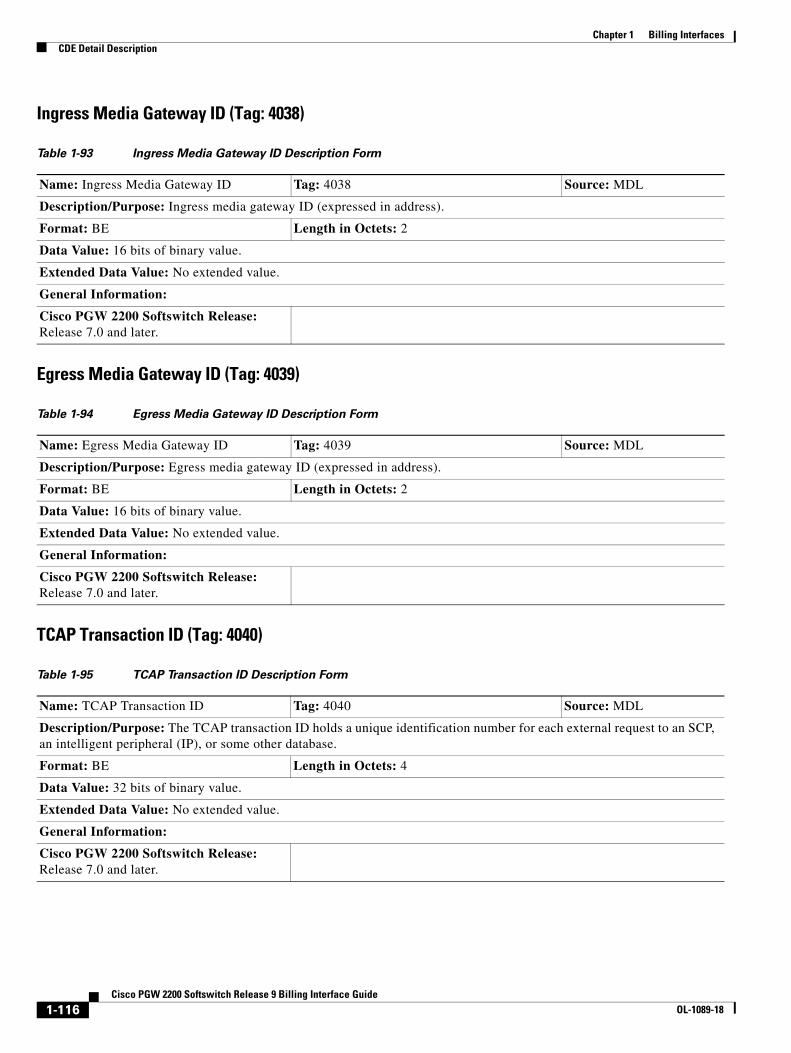
Chapter 1 Billing InterfacesCDE Detail Description
Ingress Media Gateway ID (Tag: 4038)
Egress Media Gateway ID (Tag: 4039)
TCAP Transaction ID (Tag: 4040)
Table 1-93 Ingress Media Gateway ID Description Form
Name: Ingress Media Gateway ID Tag: 4038 Source: MDL
Description/Purpose: Ingress media gateway ID (expressed in address).
Format: BE Length in Octets: 2
Data Value: 16 bits of binary value.
Extended Data Value: No extended value.
General Information:
Cisco PGW 2200 Softswitch Release: Release 7.0 and later.
Table 1-94 Egress Media Gateway ID Description Form
Name: Egress Media Gateway ID Tag: 4039 Source: MDL
Description/Purpose: Egress media gateway ID (expressed in address).
Format: BE Length in Octets: 2
Data Value: 16 bits of binary value.
Extended Data Value: No extended value.
General Information:
Cisco PGW 2200 Softswitch Release: Release 7.0 and later.
Table 1-95 TCAP Transaction ID Description Form
Name: TCAP Transaction ID Tag: 4040 Source: MDL
Description/Purpose: The TCAP transaction ID holds a unique identification number for each external request to an SCP, an intelligent peripheral (IP), or some other database.
Format: BE Length in Octets: 4
Data Value: 32 bits of binary value.
Extended Data Value: No extended value.
General Information:
Cisco PGW 2200 Softswitch Release: Release 7.0 and later.
1-116Cisco PGW 2200 Softswitch Release 9 Billing Interface Guide
OL-1089-18
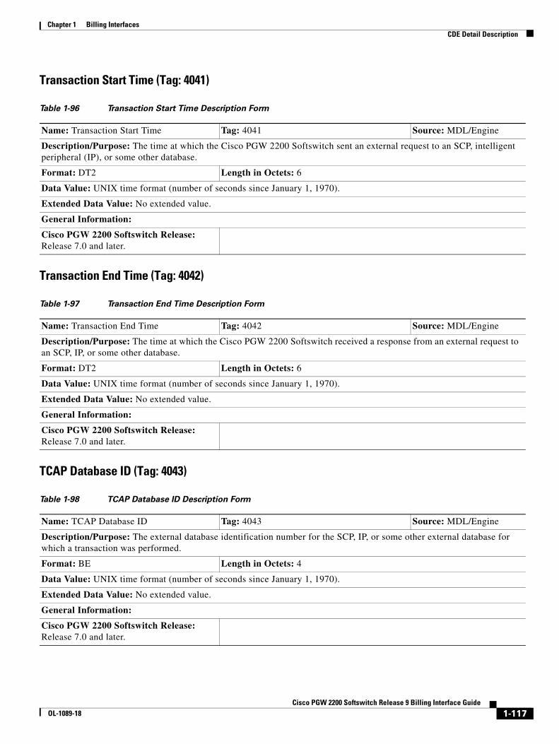
Chapter 1 Billing InterfacesCDE Detail Description
Transaction Start Time (Tag: 4041)
Transaction End Time (Tag: 4042)
TCAP Database ID (Tag: 4043)
Table 1-96 Transaction Start Time Description Form
Name: Transaction Start Time Tag: 4041 Source: MDL/Engine
Description/Purpose: The time at which the Cisco PGW 2200 Softswitch sent an external request to an SCP, intelligent peripheral (IP), or some other database.
Format: DT2 Length in Octets: 6
Data Value: UNIX time format (number of seconds since January 1, 1970).
Extended Data Value: No extended value.
General Information:
Cisco PGW 2200 Softswitch Release: Release 7.0 and later.
Table 1-97 Transaction End Time Description Form
Name: Transaction End Time Tag: 4042 Source: MDL/Engine
Description/Purpose: The time at which the Cisco PGW 2200 Softswitch received a response from an external request to an SCP, IP, or some other database.
Format: DT2 Length in Octets: 6
Data Value: UNIX time format (number of seconds since January 1, 1970).
Extended Data Value: No extended value.
General Information:
Cisco PGW 2200 Softswitch Release: Release 7.0 and later.
Table 1-98 TCAP Database ID Description Form
Name: TCAP Database ID Tag: 4043 Source: MDL/Engine
Description/Purpose: The external database identification number for the SCP, IP, or some other external database for which a transaction was performed.
Format: BE Length in Octets: 4
Data Value: UNIX time format (number of seconds since January 1, 1970).
Extended Data Value: No extended value.
General Information:
Cisco PGW 2200 Softswitch Release: Release 7.0 and later.
1-117Cisco PGW 2200 Softswitch Release 9 Billing Interface Guide
OL-1089-18
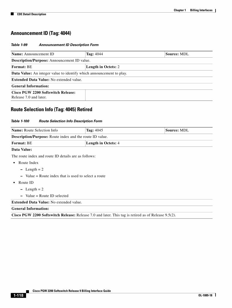
Chapter 1 Billing InterfacesCDE Detail Description
Announcement ID (Tag: 4044)
Route Selection Info (Tag: 4045) Retired
Table 1-99 Announcement ID Description Form
Name: Announcement ID Tag: 4044 Source: MDL
Description/Purpose: Announcement ID value.
Format: BE Length in Octets: 2
Data Value: An integer value to identify which announcement to play.
Extended Data Value: No extended value.
General Information:
Cisco PGW 2200 Softswitch Release: Release 7.0 and later.
Table 1-100 Route Selection Info Description Form
Name: Route Selection Info Tag: 4045 Source: MDL
Description/Purpose: Route index and the route ID value.
Format: BE Length in Octets: 4
Data Value:
The route index and route ID details are as follows:
• Route Index
– Length = 2
– Value = Route index that is used to select a route
• Route ID
– Length = 2
– Value = Route ID selected
Extended Data Value: No extended value.
General Information:
Cisco PGW 2200 Softswitch Release: Release 7.0 and later. This tag is retired as of Release 9.5(2).
1-118Cisco PGW 2200 Softswitch Release 9 Billing Interface Guide
OL-1089-18
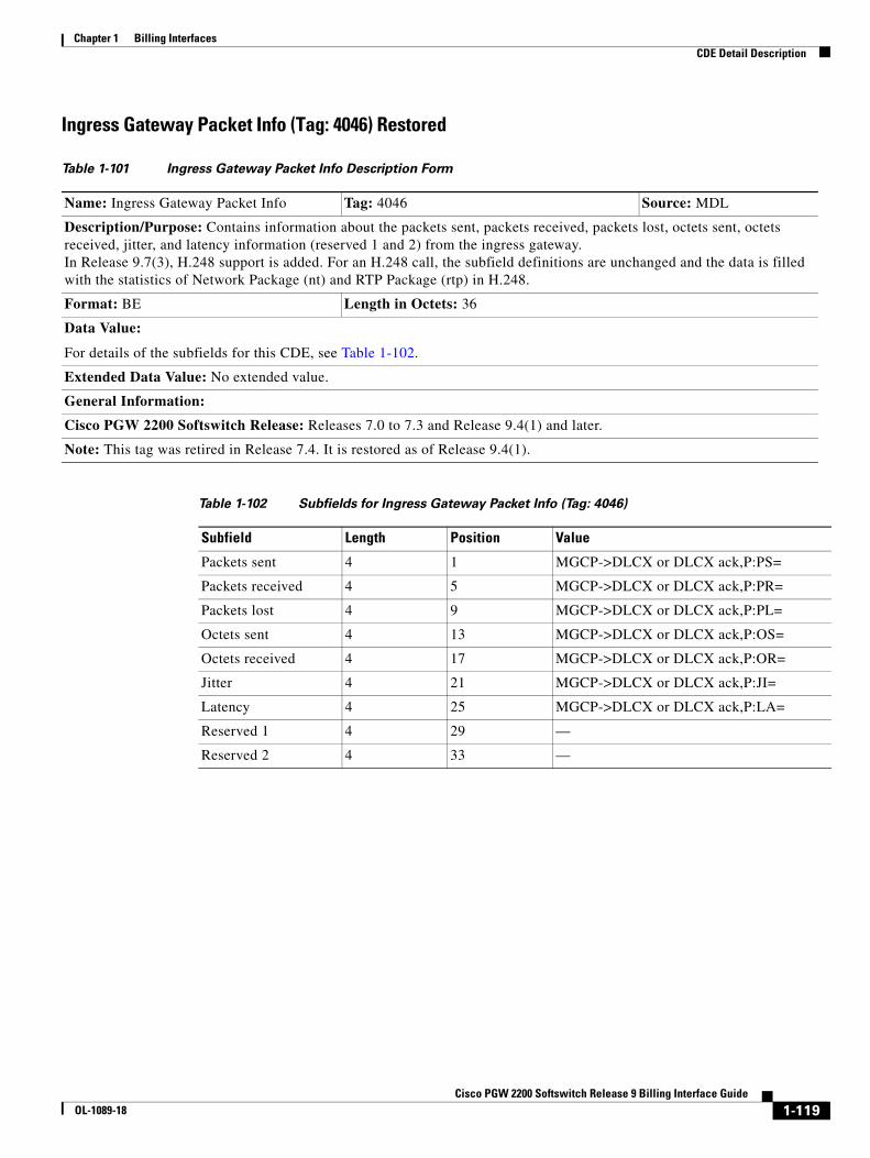
Chapter 1 Billing InterfacesCDE Detail Description
Ingress Gateway Packet Info (Tag: 4046) Restored
Table 1-101 Ingress Gateway Packet Info Description Form
Name: Ingress Gateway Packet Info Tag: 4046 Source: MDL
Description/Purpose: Contains information about the packets sent, packets received, packets lost, octets sent, octets received, jitter, and latency information (reserved 1 and 2) from the ingress gateway. In Release 9.7(3), H.248 support is added. For an H.248 call, the subfield definitions are unchanged and the data is filled with the statistics of Network Package (nt) and RTP Package (rtp) in H.248.
Format: BE Length in Octets: 36
Data Value:
For details of the subfields for this CDE, see Table 1-102.
Extended Data Value: No extended value.
General Information:
Cisco PGW 2200 Softswitch Release: Releases 7.0 to 7.3 and Release 9.4(1) and later.
Note: This tag was retired in Release 7.4. It is restored as of Release 9.4(1).
Table 1-102 Subfields for Ingress Gateway Packet Info (Tag: 4046)
Subfield Length Position Value
Packets sent 4 1 MGCP->DLCX or DLCX ack,P:PS=
Packets received 4 5 MGCP->DLCX or DLCX ack,P:PR=
Packets lost 4 9 MGCP->DLCX or DLCX ack,P:PL=
Octets sent 4 13 MGCP->DLCX or DLCX ack,P:OS=
Octets received 4 17 MGCP->DLCX or DLCX ack,P:OR=
Jitter 4 21 MGCP->DLCX or DLCX ack,P:JI=
Latency 4 25 MGCP->DLCX or DLCX ack,P:LA=
Reserved 1 4 29 —
Reserved 2 4 33 —
1-119Cisco PGW 2200 Softswitch Release 9 Billing Interface Guide
OL-1089-18

Chapter 1 Billing InterfacesCDE Detail Description
Egress Gateway Packet Info (Tag: 4047) Restored
Table 1-103 Egress Gateway Packet Info Description Form
Name: Egress Gateway Packet Info Tag: 4047 Source: MDL
Description/Purpose: Contains information about the packets sent, packets received, packets lost, octets sent, octets received, jitter, and latency information (reserved 1 and 2) from the egress gateway. On Release 9.7(3), H.248 support is added. For an H.248 call, the subfield definitions are unchanged and the data is filled with the statistics of Network Package (nt) and RTP Package (rtp) in H.248.
Format: BE Length in Octets: 36
Data Value:
For details of the subfields for this CDE, see Table 1-104.
Extended Data Value: No extended value.
General Information:
Cisco PGW 2200 Softswitch Release: Releases 7.0 to 7.3, and Release 9.4(1) and later.
Note: This tag was retired in Release 7.4. It is restored as of Release 9.4(1).
Table 1-104 Subfields for Egress Gateway Packet Info (Tag: 4047)
Subfield Length Position Value
Packets sent 4 1 MGCP->DLCX or DLCX ack,P:PS=
Packets received 4 5 MGCP->DLCX or DLCX ack,P:PR=
Packets lost 4 9 MGCP->DLCX or DLCX ack,P:PL=
Octets sent 4 13 MGCP->DLCX or DLCX ack,P:OS=
Octets received 4 17 MGCP->DLCX or DLCX ack,P:OR=
Jitter 4 21 MGCP->DLCX or DLCX ack,P:JI=
Latency 4 25 MGCP->DLCX or DLCX ack,P:LA=
Reserved 1 4 29 —
Reserved 2 4 33 —
1-120Cisco PGW 2200 Softswitch Release 9 Billing Interface Guide
OL-1089-18
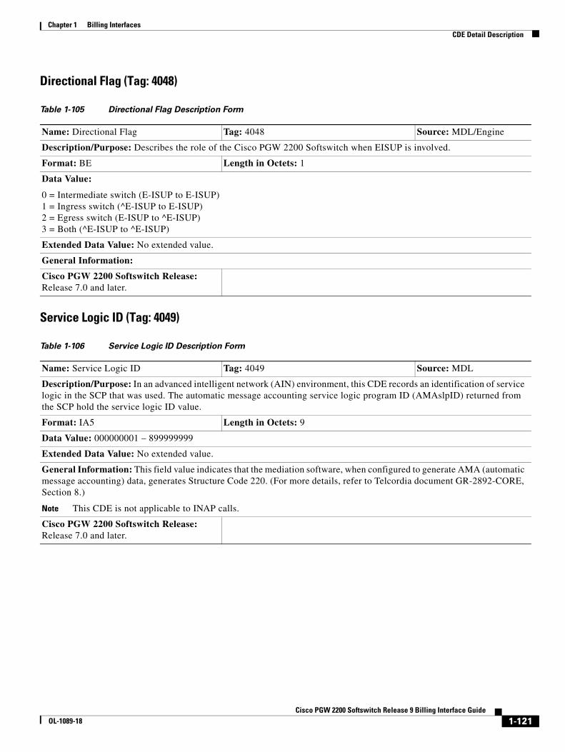
Chapter 1 Billing InterfacesCDE Detail Description
Directional Flag (Tag: 4048)
Service Logic ID (Tag: 4049)
Table 1-105 Directional Flag Description Form
Name: Directional Flag Tag: 4048 Source: MDL/Engine
Description/Purpose: Describes the role of the Cisco PGW 2200 Softswitch when EISUP is involved.
Format: BE Length in Octets: 1
Data Value:
0 = Intermediate switch (E-ISUP to E-ISUP) 1 = Ingress switch (^E-ISUP to E-ISUP) 2 = Egress switch (E-ISUP to ^E-ISUP) 3 = Both (^E-ISUP to ^E-ISUP)
Extended Data Value: No extended value.
General Information:
Cisco PGW 2200 Softswitch Release: Release 7.0 and later.
Table 1-106 Service Logic ID Description Form
Name: Service Logic ID Tag: 4049 Source: MDL
Description/Purpose: In an advanced intelligent network (AIN) environment, this CDE records an identification of service logic in the SCP that was used. The automatic message accounting service logic program ID (AMAslpID) returned from the SCP hold the service logic ID value.
Format: IA5 Length in Octets: 9
Data Value: 000000001 – 899999999
Extended Data Value: No extended value.
General Information: This field value indicates that the mediation software, when configured to generate AMA (automatic message accounting) data, generates Structure Code 220. (For more details, refer to Telcordia document GR-2892-CORE, Section 8.)
Note This CDE is not applicable to INAP calls.
Cisco PGW 2200 Softswitch Release: Release 7.0 and later.
1-121Cisco PGW 2200 Softswitch Release 9 Billing Interface Guide
OL-1089-18
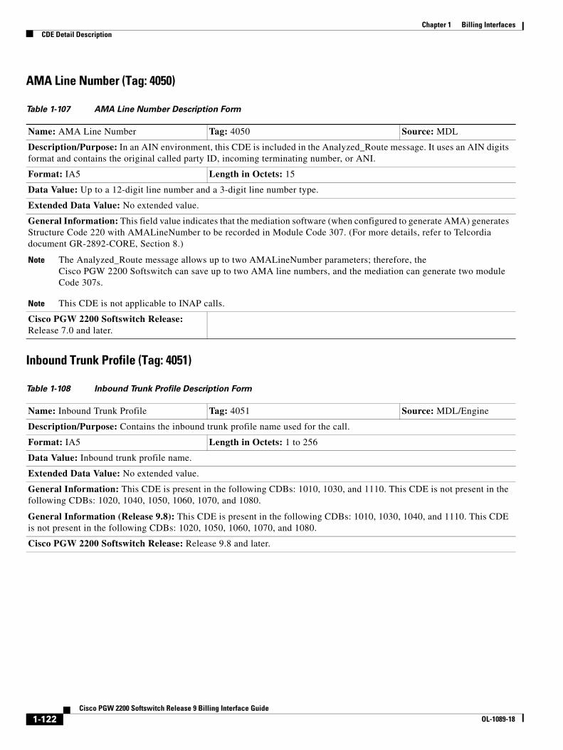
Chapter 1 Billing InterfacesCDE Detail Description
AMA Line Number (Tag: 4050)
Inbound Trunk Profile (Tag: 4051)
Table 1-107 AMA Line Number Description Form
Name: AMA Line Number Tag: 4050 Source: MDL
Description/Purpose: In an AIN environment, this CDE is included in the Analyzed_Route message. It uses an AIN digits format and contains the original called party ID, incoming terminating number, or ANI.
Format: IA5 Length in Octets: 15
Data Value: Up to a 12-digit line number and a 3-digit line number type.
Extended Data Value: No extended value.
General Information: This field value indicates that the mediation software (when configured to generate AMA) generates Structure Code 220 with AMALineNumber to be recorded in Module Code 307. (For more details, refer to Telcordia document GR-2892-CORE, Section 8.)
Note The Analyzed_Route message allows up to two AMALineNumber parameters; therefore, the Cisco PGW 2200 Softswitch can save up to two AMA line numbers, and the mediation can generate two module Code 307s.
Note This CDE is not applicable to INAP calls.
Cisco PGW 2200 Softswitch Release: Release 7.0 and later.
Table 1-108 Inbound Trunk Profile Description Form
Name: Inbound Trunk Profile Tag: 4051 Source: MDL/Engine
Description/Purpose: Contains the inbound trunk profile name used for the call.
Format: IA5 Length in Octets: 1 to 256
Data Value: Inbound trunk profile name.
Extended Data Value: No extended value.
General Information: This CDE is present in the following CDBs: 1010, 1030, and 1110. This CDE is not present in the following CDBs: 1020, 1040, 1050, 1060, 1070, and 1080.
General Information (Release 9.8): This CDE is present in the following CDBs: 1010, 1030, 1040, and 1110. This CDE is not present in the following CDBs: 1020, 1050, 1060, 1070, and 1080.
Cisco PGW 2200 Softswitch Release: Release 9.8 and later.
1-122Cisco PGW 2200 Softswitch Release 9 Billing Interface Guide
OL-1089-18
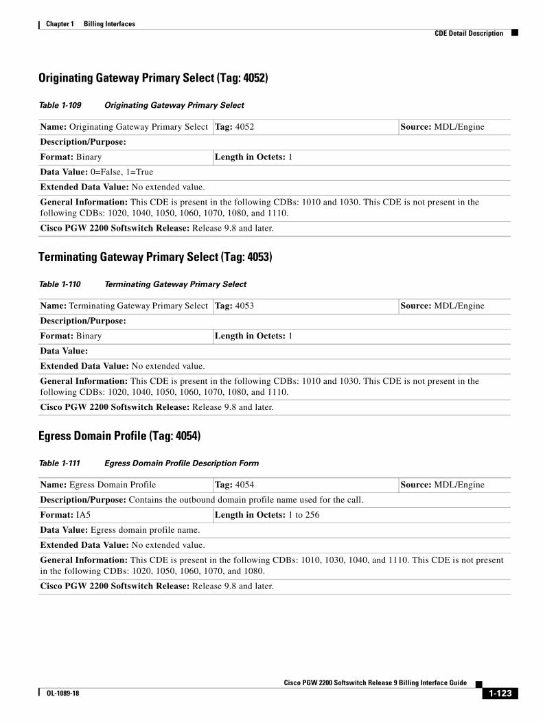
Chapter 1 Billing InterfacesCDE Detail Description
Originating Gateway Primary Select (Tag: 4052)
Terminating Gateway Primary Select (Tag: 4053)
Egress Domain Profile (Tag: 4054)
Table 1-109 Originating Gateway Primary Select
Name: Originating Gateway Primary Select Tag: 4052 Source: MDL/Engine
Description/Purpose:
Format: Binary Length in Octets: 1
Data Value: 0=False, 1=True
Extended Data Value: No extended value.
General Information: This CDE is present in the following CDBs: 1010 and 1030. This CDE is not present in the following CDBs: 1020, 1040, 1050, 1060, 1070, 1080, and 1110.
Cisco PGW 2200 Softswitch Release: Release 9.8 and later.
Table 1-110 Terminating Gateway Primary Select
Name: Terminating Gateway Primary Select Tag: 4053 Source: MDL/Engine
Description/Purpose:
Format: Binary Length in Octets: 1
Data Value:
Extended Data Value: No extended value.
General Information: This CDE is present in the following CDBs: 1010 and 1030. This CDE is not present in the following CDBs: 1020, 1040, 1050, 1060, 1070, 1080, and 1110.
Cisco PGW 2200 Softswitch Release: Release 9.8 and later.
Table 1-111 Egress Domain Profile Description Form
Name: Egress Domain Profile Tag: 4054 Source: MDL/Engine
Description/Purpose: Contains the outbound domain profile name used for the call.
Format: IA5 Length in Octets: 1 to 256
Data Value: Egress domain profile name.
Extended Data Value: No extended value.
General Information: This CDE is present in the following CDBs: 1010, 1030, 1040, and 1110. This CDE is not present in the following CDBs: 1020, 1050, 1060, 1070, and 1080.
Cisco PGW 2200 Softswitch Release: Release 9.8 and later.
1-123Cisco PGW 2200 Softswitch Release 9 Billing Interface Guide
OL-1089-18

Chapter 1 Billing InterfacesCDE Detail Description
Call Policy (Tag: 4055)
SIP Terminating Call ID (Tag: 4056)
Table 1-112 Call Policy Description Form
Name: Call Policy Tag: 4055 Source: MDL
Description/Purpose: Indicates the back-to-back user agent policy applied to the call.
Format: Structured variable Length in Octets: 1
Data Value: Outbound domain profile name.
Octet 1 Transport Protocol
• 0 = Trusted
• 1 = Nontrusted
• 2 = Trusted, topology hiding enabled
• 3 = Nontrusted, topology hiding disabled
Extended Data Value: No extended value.
General Information: This CDE is present in the following CDBs: 1010, 1030, 1040, and 1110. This CDE is not present in the following CDBs: 1020, 1050, 1060, 1070, and 1080.
Cisco PGW 2200 Softswitch Release: Release 9.8 and later.
Table 1-113 SIP Terminating Call ID Description Form
Name: SIP Terminating Call ID Tag: 4056 Source: MDL/Engine
Description/Purpose: Contains the Call ID used by the terminating side of a SIP call.
Format: IA5 Length in Octets: 1 to 256
Data Value: Call ID number.
Extended Data Value: No extended value.
General Information: This CDE is present in the following CDBs: 1010, 1030, and 1110. This CDE is not present in the following CDBs: 1020, 1040, 1050, 1060, 1070, and 1080.
Cisco PGW 2200 Softswitch Release: The name of this CDR was changed from SIP Call ID to SIP Originating Call ID in Release 9.7, 9.8(1) and later.
1-124Cisco PGW 2200 Softswitch Release 9 Billing Interface Guide
OL-1089-18
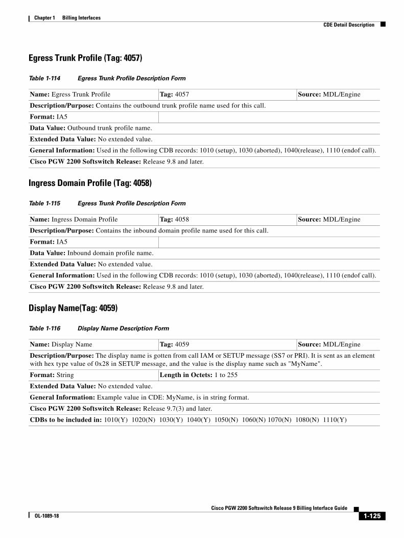
Chapter 1 Billing InterfacesCDE Detail Description
Egress Trunk Profile (Tag: 4057)
Ingress Domain Profile (Tag: 4058)
Display Name(Tag: 4059)
Table 1-114 Egress Trunk Profile Description Form
Name: Egress Trunk Profile Tag: 4057 Source: MDL/Engine
Description/Purpose: Contains the outbound trunk profile name used for this call.
Format: IA5
Data Value: Outbound trunk profile name.
Extended Data Value: No extended value.
General Information: Used in the following CDB records: 1010 (setup), 1030 (aborted), 1040(release), 1110 (endof call).
Cisco PGW 2200 Softswitch Release: Release 9.8 and later.
Table 1-115 Egress Trunk Profile Description Form
Name: Ingress Domain Profile Tag: 4058 Source: MDL/Engine
Description/Purpose: Contains the inbound domain profile name used for this call.
Format: IA5
Data Value: Inbound domain profile name.
Extended Data Value: No extended value.
General Information: Used in the following CDB records: 1010 (setup), 1030 (aborted), 1040(release), 1110 (endof call).
Cisco PGW 2200 Softswitch Release: Release 9.8 and later.
Table 1-116 Display Name Description Form
Name: Display Name Tag: 4059 Source: MDL/Engine
Description/Purpose: The display name is gotten from call IAM or SETUP message (SS7 or PRI). It is sent as an element with hex type value of 0x28 in SETUP message, and the value is the display name such as "MyName".
Format: String Length in Octets: 1 to 255
Extended Data Value: No extended value.
General Information: Example value in CDE: MyName, is in string format.
Cisco PGW 2200 Softswitch Release: Release 9.7(3) and later.
CDBs to be included in: 1010(Y) 1020(N) 1030(Y) 1040(Y) 1050(N) 1060(N) 1070(N) 1080(N) 1110(Y)
1-125Cisco PGW 2200 Softswitch Release 9 Billing Interface Guide
OL-1089-18

Chapter 1 Billing InterfacesCDE Detail Description
Redirecting Number (Tag: 4060)
Scale Factor (Tag: 4062)
Table 1-117 Redirecting Number Description Form
Name: Redirecting Number Tag: 4060 Source: MDL/Engine
Description/Purpose: Stores the digits from the redirecting number.
Format: IA5 Length in Octets: 1 to 96
Data Value: Character string containing the forwarded station’s address or subscriber number.
Extended Data Value: No extended value.
General Information:
Cisco PGW 2200 Softswitch Release: Release 7 and later.
Table 1-118 Scale Factor Description Form
Name: Scale Factor Tag: 4062 Source: MDL/Engine
Description/Purpose: Used for reporting Advice of Charge information.
Format: BE Length in Octets: 4
Data Value: The actual value for the scale factor is given by 10^x, where x is the value of the scale factor. The MML coding of scale factor is as follows; all other values are spare:
0: 10^0 = 1 1: 10^1 = 10 2: 10^2 = 100 3: 10^3 = 1000
4 to 248: Spare
249: 10^–7 = 0.0000001 250) 10^–6 0.000001 251) 10^–5 0.00001 252) 10^–4 0.0001 253) 10^–3 0.001 254) 10^–2 0.01 255) 10^–1 0.1
Extended Data Value: No extended value.
General Information:
Cisco PGW 2200 Softswitch Release: Release 9 and later.
1-126Cisco PGW 2200 Softswitch Release 9 Billing Interface Guide
OL-1089-18
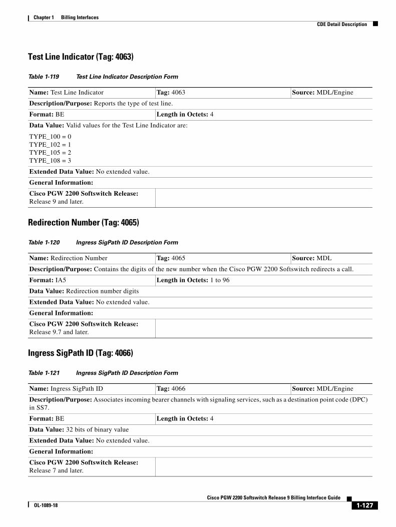
Chapter 1 Billing InterfacesCDE Detail Description
Test Line Indicator (Tag: 4063)
Redirection Number (Tag: 4065)
Ingress SigPath ID (Tag: 4066)
Table 1-119 Test Line Indicator Description Form
Name: Test Line Indicator Tag: 4063 Source: MDL/Engine
Description/Purpose: Reports the type of test line.
Format: BE Length in Octets: 4
Data Value: Valid values for the Test Line Indicator are:
TYPE_100 = 0 TYPE_102 = 1 TYPE_105 = 2 TYPE_108 = 3
Extended Data Value: No extended value.
General Information:
Cisco PGW 2200 Softswitch Release: Release 9 and later.
Table 1-120 Ingress SigPath ID Description Form
Name: Redirection Number Tag: 4065 Source: MDL
Description/Purpose: Contains the digits of the new number when the Cisco PGW 2200 Softswitch redirects a call.
Format: IA5 Length in Octets: 1 to 96
Data Value: Redirection number digits
Extended Data Value: No extended value.
General Information:
Cisco PGW 2200 Softswitch Release: Release 9.7 and later.
Table 1-121 Ingress SigPath ID Description Form
Name: Ingress SigPath ID Tag: 4066 Source: MDL/Engine
Description/Purpose: Associates incoming bearer channels with signaling services, such as a destination point code (DPC) in SS7.
Format: BE Length in Octets: 4
Data Value: 32 bits of binary value
Extended Data Value: No extended value.
General Information:
Cisco PGW 2200 Softswitch Release: Release 7 and later.
1-127Cisco PGW 2200 Softswitch Release 9 Billing Interface Guide
OL-1089-18

Chapter 1 Billing InterfacesCDE Detail Description
Ingress Span ID (Tag: 4067)
Ingress BearChan ID (Tag: 4068)
Table 1-122 Ingress Span ID Description Form
Name: Ingress Span ID Tag: 4067 Source: MDL/Engine
Description/Purpose: Identifies an ingress span, which is a grouping of incoming PRI bearer channels.
Format: BE Length in Octets: 4
Data Value: 32 bits of binary value
Extended Data Value: No extended value.
General Information:
Cisco PGW 2200 Softswitch Release: Release 7 and later.
Table 1-123 Ingress BearChan ID Description Form
Name: Ingress BearChan ID Tag: 4068 Source: MDL/Engine
Description/Purpose: Identifies the incoming bearer channel.
Format: BE Length in Octets: 4
Data Value: 32 bits of binary value
Extended Data Value: No extended value.
General Information:
Cisco PGW 2200 Softswitch Release: Release 7 and later.
1-128Cisco PGW 2200 Softswitch Release 9 Billing Interface Guide
OL-1089-18

Chapter 1 Billing InterfacesCDE Detail Description
Ingress Protocol ID (Tag: 4069)
Egress SigPath ID (Tag: 4070)
Table 1-124 Ingress Protocol ID Description Form
Name: Ingress Protocol ID Tag: 4069 Source: MDL/Engine
Description/Purpose: Determined from MDL and used in measurements and billing. In Release 9.7(3), for the H.248 Protocol feature, a new protocol type 10 = H.248 is added to the definition.
Format: BE Length in Octets: 1
Data Value:
0 = ISDN PRI 1 = C7 2 = DPNSS 3 = CAS 4 = ASN 5 = Unknown 6 = EISUP 7 = H.323 8 = SIP 9 = MGCP 10 = H.248 (Release 9.7(3) and later)
Extended Data Value: No extended value.
General Information:
Cisco PGW 2200 Softswitch Release: Release 7 and later.
Table 1-125 Egress SigPath ID Description Form
Name: Egress SigPath ID Tag: 4070 Source: MDL/Engine
Description/Purpose: Associates outgoing bearer channels with signaling services, such as a destination point code (DPC) in SS7.
Format: BE Length in Octets: 4
Data Value: 32 bits of binary value
Extended Data Value: No extended value.
General Information:
Cisco PGW 2200 Softswitch Release: Release 7 and later.
1-129Cisco PGW 2200 Softswitch Release 9 Billing Interface Guide
OL-1089-18
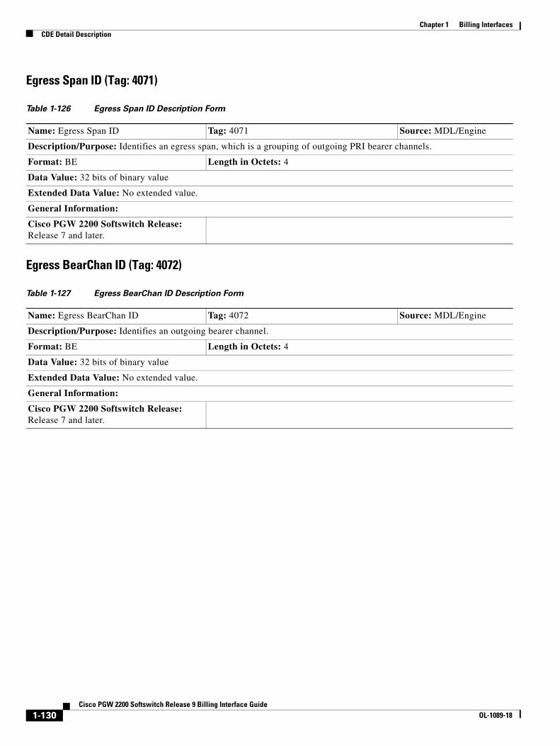
Chapter 1 Billing InterfacesCDE Detail Description
Egress Span ID (Tag: 4071)
Egress BearChan ID (Tag: 4072)
Table 1-126 Egress Span ID Description Form
Name: Egress Span ID Tag: 4071 Source: MDL/Engine
Description/Purpose: Identifies an egress span, which is a grouping of outgoing PRI bearer channels.
Format: BE Length in Octets: 4
Data Value: 32 bits of binary value
Extended Data Value: No extended value.
General Information:
Cisco PGW 2200 Softswitch Release: Release 7 and later.
Table 1-127 Egress BearChan ID Description Form
Name: Egress BearChan ID Tag: 4072 Source: MDL/Engine
Description/Purpose: Identifies an outgoing bearer channel.
Format: BE Length in Octets: 4
Data Value: 32 bits of binary value
Extended Data Value: No extended value.
General Information:
Cisco PGW 2200 Softswitch Release: Release 7 and later.
1-130Cisco PGW 2200 Softswitch Release 9 Billing Interface Guide
OL-1089-18
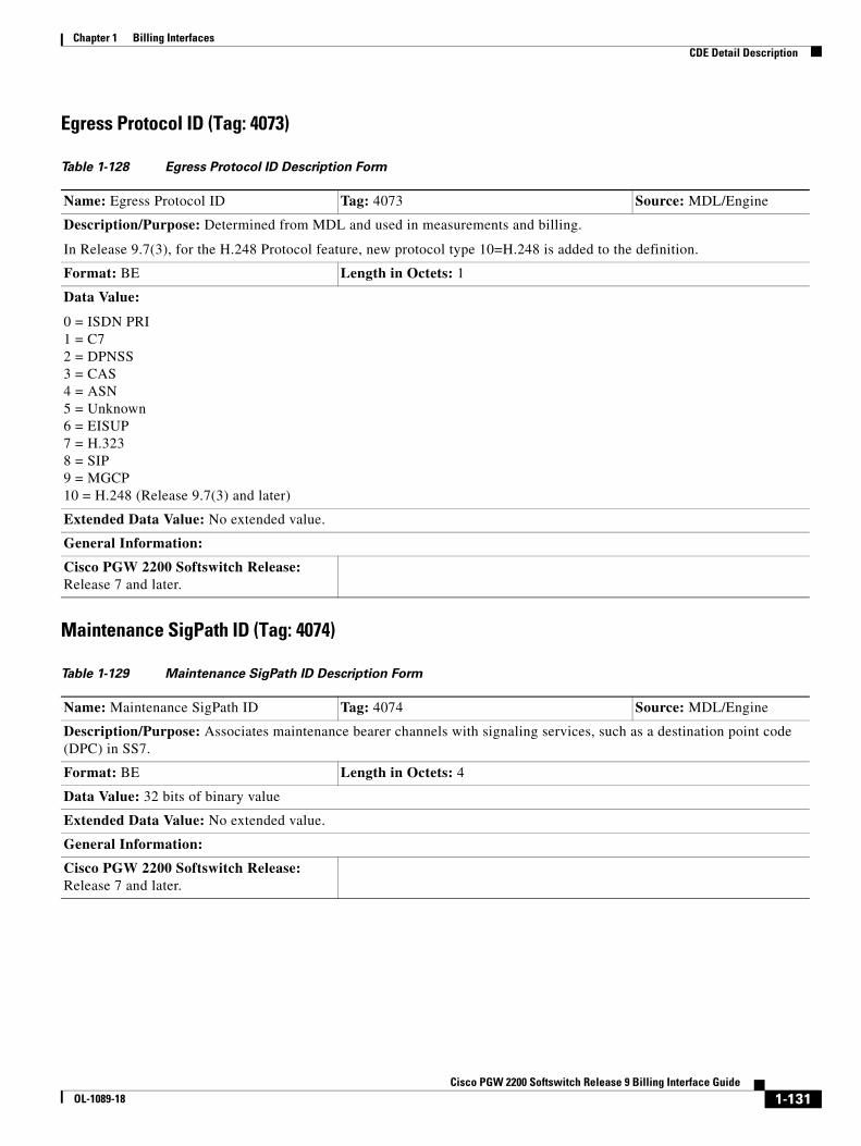
Chapter 1 Billing InterfacesCDE Detail Description
Egress Protocol ID (Tag: 4073)
Maintenance SigPath ID (Tag: 4074)
Table 1-128 Egress Protocol ID Description Form
Name: Egress Protocol ID Tag: 4073 Source: MDL/Engine
Description/Purpose: Determined from MDL and used in measurements and billing.
In Release 9.7(3), for the H.248 Protocol feature, new protocol type 10=H.248 is added to the definition.
Format: BE Length in Octets: 1
Data Value:
0 = ISDN PRI 1 = C7 2 = DPNSS 3 = CAS 4 = ASN 5 = Unknown 6 = EISUP 7 = H.323 8 = SIP 9 = MGCP 10 = H.248 (Release 9.7(3) and later)
Extended Data Value: No extended value.
General Information:
Cisco PGW 2200 Softswitch Release: Release 7 and later.
Table 1-129 Maintenance SigPath ID Description Form
Name: Maintenance SigPath ID Tag: 4074 Source: MDL/Engine
Description/Purpose: Associates maintenance bearer channels with signaling services, such as a destination point code (DPC) in SS7.
Format: BE Length in Octets: 4
Data Value: 32 bits of binary value
Extended Data Value: No extended value.
General Information:
Cisco PGW 2200 Softswitch Release: Release 7 and later.
1-131Cisco PGW 2200 Softswitch Release 9 Billing Interface Guide
OL-1089-18
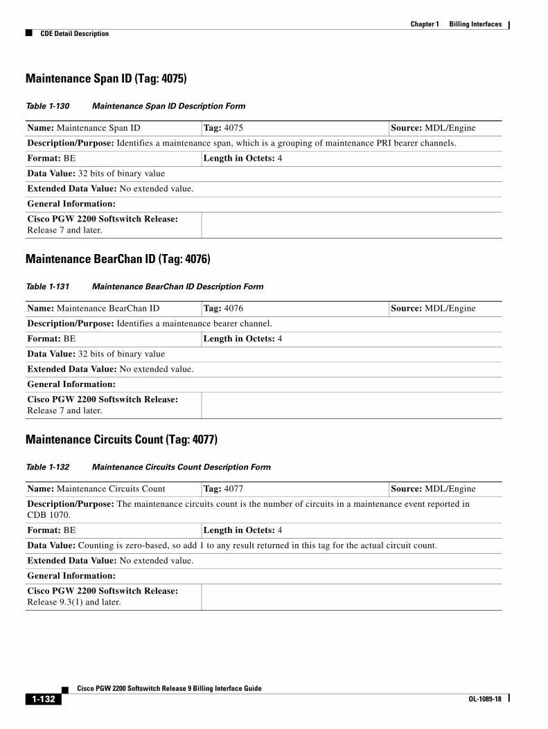
Chapter 1 Billing InterfacesCDE Detail Description
Maintenance Span ID (Tag: 4075)
Maintenance BearChan ID (Tag: 4076)
Maintenance Circuits Count (Tag: 4077)
Table 1-130 Maintenance Span ID Description Form
Name: Maintenance Span ID Tag: 4075 Source: MDL/Engine
Description/Purpose: Identifies a maintenance span, which is a grouping of maintenance PRI bearer channels.
Format: BE Length in Octets: 4
Data Value: 32 bits of binary value
Extended Data Value: No extended value.
General Information:
Cisco PGW 2200 Softswitch Release: Release 7 and later.
Table 1-131 Maintenance BearChan ID Description Form
Name: Maintenance BearChan ID Tag: 4076 Source: MDL/Engine
Description/Purpose: Identifies a maintenance bearer channel.
Format: BE Length in Octets: 4
Data Value: 32 bits of binary value
Extended Data Value: No extended value.
General Information:
Cisco PGW 2200 Softswitch Release: Release 7 and later.
Table 1-132 Maintenance Circuits Count Description Form
Name: Maintenance Circuits Count Tag: 4077 Source: MDL/Engine
Description/Purpose: The maintenance circuits count is the number of circuits in a maintenance event reported in CDB 1070.
Format: BE Length in Octets: 4
Data Value: Counting is zero-based, so add 1 to any result returned in this tag for the actual circuit count.
Extended Data Value: No extended value.
General Information:
Cisco PGW 2200 Softswitch Release: Release 9.3(1) and later.
1-132Cisco PGW 2200 Softswitch Release 9 Billing Interface Guide
OL-1089-18
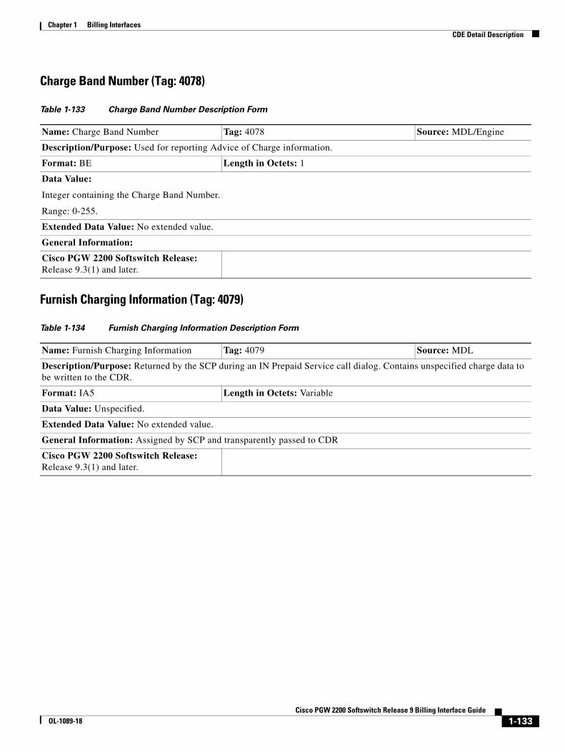
Chapter 1 Billing InterfacesCDE Detail Description
Charge Band Number (Tag: 4078)
Furnish Charging Information (Tag: 4079)
Table 1-133 Charge Band Number Description Form
Name: Charge Band Number Tag: 4078 Source: MDL/Engine
Description/Purpose: Used for reporting Advice of Charge information.
Format: BE Length in Octets: 1
Data Value:
Integer containing the Charge Band Number.
Range: 0-255.
Extended Data Value: No extended value.
General Information:
Cisco PGW 2200 Softswitch Release: Release 9.3(1) and later.
Table 1-134 Furnish Charging Information Description Form
Name: Furnish Charging Information Tag: 4079 Source: MDL
Description/Purpose: Returned by the SCP during an IN Prepaid Service call dialog. Contains unspecified charge data to be written to the CDR.
Format: IA5 Length in Octets: Variable
Data Value: Unspecified.
Extended Data Value: No extended value.
General Information: Assigned by SCP and transparently passed to CDR
Cisco PGW 2200 Softswitch Release: Release 9.3(1) and later.
1-133Cisco PGW 2200 Softswitch Release 9 Billing Interface Guide
OL-1089-18

Chapter 1 Billing InterfacesCDE Detail Description
Original Called Number (Tag: 4080)
T.38 Fax Call (Tag: 4081)
Table 1-135 Original Called Number Description Form
Name: Original Called Number Tag: 4080 Source: MDL
Description/Purpose: Contains the digits from the original called party number.
Format: IA5 Length in Octets: 1 to 96
Data Value: The digits of the original called party number.
Extended Data Value: No extended value.
General Information: The following are conditions that could generate the Original Called Number CDE:
• Original Called Number parameter could be received in the IAM message if the call has been redirected previously (applicable to SS7 calls).
• A distant end TDM switch sends a Release message back to the Cisco PGW 2200 Softswitch over SS7 containing a Cause parameter or Redirection Information parameter, a Redirection Number parameter, and possibly a Redirection Number Restriction parameter.
The actual cause value contained in this CDE indicates that redirection is required, and Cause analysis directs the call. If the call is redirected and there is no original called party number, the called party number is inserted into the original called party number field of the outbound IAM.
Cisco PGW 2200 Softswitch Release: Release 9.3(1) and later.
Table 1-136 T.38 Fax Call Description Form
Name: T.38 Fax Call Tag: 4081 Source: MDL
Description/Purpose: Indicates that the call was a Fax call negotiated using T.38.
Format: IA5 Length in Octets: 1
Data Value:
0 = No fax information available 1 = Call Agent negotiated T.38 Fax call 2 = T.38 fax fail and up-speed CODEC is used for pass-through fax 3 = T.38 fax fail and no up-speed CODEC is used for pass-through fax
Extended Data Value: No extended value.
General Information: The data for this CDR is assigned by SCP and transparently passed to CDR.
Cisco PGW 2200 Softswitch Release: Release 9.3(2) and later. Added data values 2 and 3 in Release 9.5(2).
1-134Cisco PGW 2200 Softswitch Release 9 Billing Interface Guide
OL-1089-18

Chapter 1 Billing InterfacesCDE Detail Description
Charge Unit Number (Tag: 4082)
Charge Indicator (Tag: 4083)
Table 1-137 Charge Unit Number Description Form
Name: Charge Unit Number Tag: 4082 Source: MDL
Description/Purpose: Used for reporting Advice of Charge information.
Format: BE Length in Octets: 1
Data Value:
An integer containing the Charge Unit Number, provisioned as part of the Dial Plan provisioning
ANSI/ITU Variations: None
Valid Range: 0–255
Extended Data Value: No extended value.
General Information: The data for this CDR is assigned by SCP and transparently passed to CDR.
Cisco PGW 2200 Softswitch Release: Release 9.3(2) and later.
Table 1-138 Charge Indicator Description Form
Name: Charge Indicator Tag: 4083 Source: MDL
Description/Purpose: Allows the carrier to determine which calls need to be billed.
Format: BE Length in Octets: 1
Data Value:
Charge Indicator information is 2 bit and is defined as follows:
01 No charge 10 Charge 00 No indication
Extended Data Value: No extended value.
General Information:
Cisco PGW 2200 Softswitch Release: Release 9.5(2) and later.
1-135Cisco PGW 2200 Softswitch Release 9 Billing Interface Guide
OL-1089-18
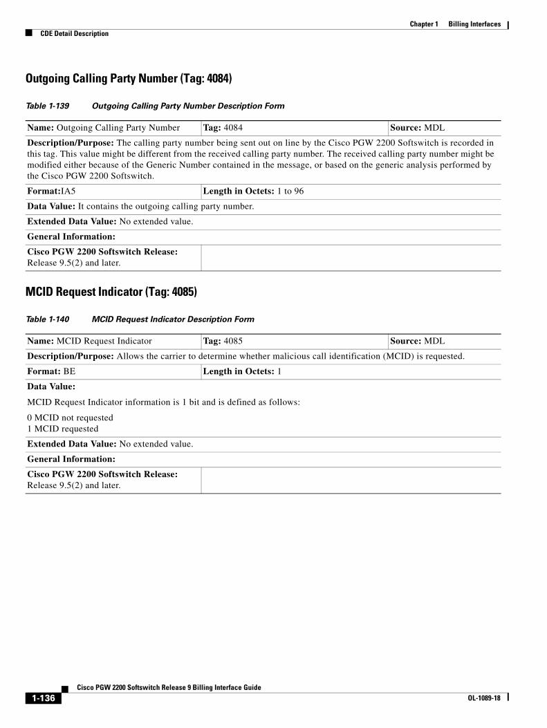
Chapter 1 Billing InterfacesCDE Detail Description
Outgoing Calling Party Number (Tag: 4084)
MCID Request Indicator (Tag: 4085)
Table 1-139 Outgoing Calling Party Number Description Form
Name: Outgoing Calling Party Number Tag: 4084 Source: MDL
Description/Purpose: The calling party number being sent out on line by the Cisco PGW 2200 Softswitch is recorded in this tag. This value might be different from the received calling party number. The received calling party number might be modified either because of the Generic Number contained in the message, or based on the generic analysis performed by the Cisco PGW 2200 Softswitch.
Format:IA5 Length in Octets: 1 to 96
Data Value: It contains the outgoing calling party number.
Extended Data Value: No extended value.
General Information:
Cisco PGW 2200 Softswitch Release: Release 9.5(2) and later.
Table 1-140 MCID Request Indicator Description Form
Name: MCID Request Indicator Tag: 4085 Source: MDL
Description/Purpose: Allows the carrier to determine whether malicious call identification (MCID) is requested.
Format: BE Length in Octets: 1
Data Value:
MCID Request Indicator information is 1 bit and is defined as follows:
0 MCID not requested 1 MCID requested
Extended Data Value: No extended value.
General Information:
Cisco PGW 2200 Softswitch Release: Release 9.5(2) and later.
1-136Cisco PGW 2200 Softswitch Release 9 Billing Interface Guide
OL-1089-18
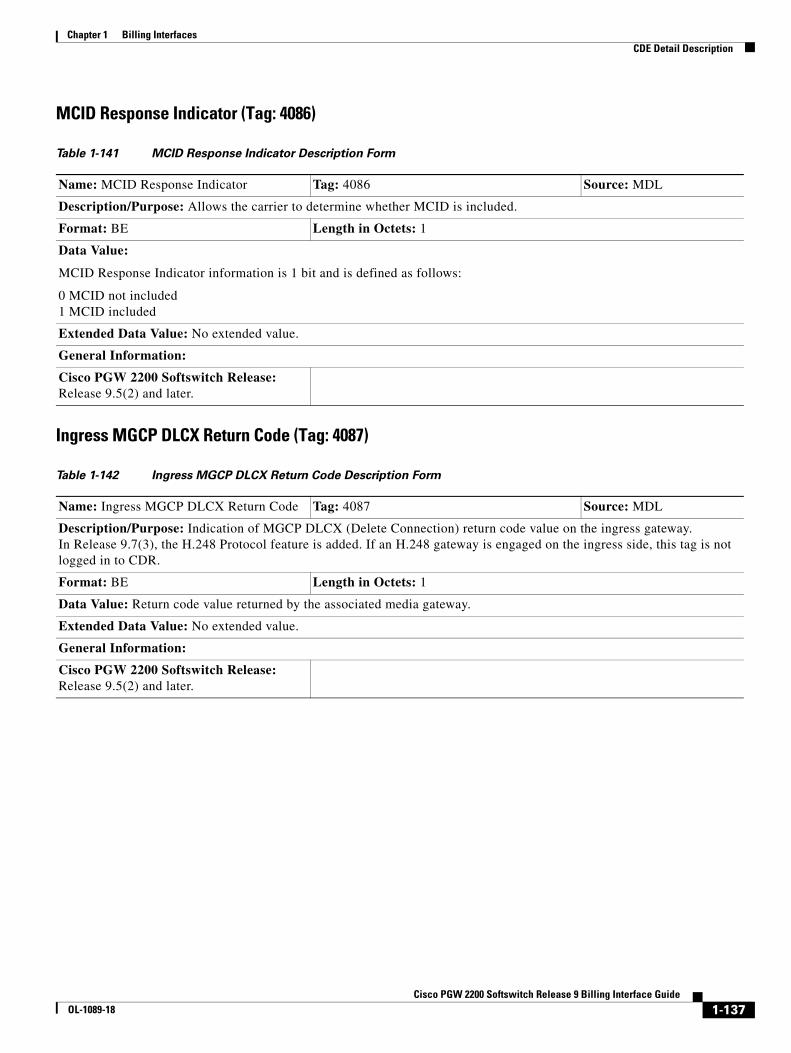
Chapter 1 Billing InterfacesCDE Detail Description
MCID Response Indicator (Tag: 4086)
Ingress MGCP DLCX Return Code (Tag: 4087)
Table 1-141 MCID Response Indicator Description Form
Name: MCID Response Indicator Tag: 4086 Source: MDL
Description/Purpose: Allows the carrier to determine whether MCID is included.
Format: BE Length in Octets: 1
Data Value:
MCID Response Indicator information is 1 bit and is defined as follows:
0 MCID not included 1 MCID included
Extended Data Value: No extended value.
General Information:
Cisco PGW 2200 Softswitch Release: Release 9.5(2) and later.
Table 1-142 Ingress MGCP DLCX Return Code Description Form
Name: Ingress MGCP DLCX Return Code Tag: 4087 Source: MDL
Description/Purpose: Indication of MGCP DLCX (Delete Connection) return code value on the ingress gateway. In Release 9.7(3), the H.248 Protocol feature is added. If an H.248 gateway is engaged on the ingress side, this tag is not logged in to CDR.
Format: BE Length in Octets: 1
Data Value: Return code value returned by the associated media gateway.
Extended Data Value: No extended value.
General Information:
Cisco PGW 2200 Softswitch Release: Release 9.5(2) and later.
1-137Cisco PGW 2200 Softswitch Release 9 Billing Interface Guide
OL-1089-18
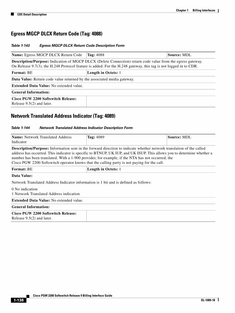
Chapter 1 Billing InterfacesCDE Detail Description
Egress MGCP DLCX Return Code (Tag: 4088)
Network Translated Address Indicator (Tag: 4089)
Table 1-143 Egress MGCP DLCX Return Code Description Form
Name: Egress MGCP DLCX Return Code Tag: 4088 Source: MDL
Description/Purpose: Indication of MGCP DLCX (Delete Connection) return code value from the egress gateway. On Release 9.7(3), the H.248 Protocol feature is added. For the H.248 gateway, this tag is not logged in to CDR.
Format: BE Length in Octets: 1
Data Value: Return code value returned by the associated media gateway.
Extended Data Value: No extended value.
General Information:
Cisco PGW 2200 Softswitch Release: Release 9.5(2) and later.
Table 1-144 Network Translated Address Indicator Description Form
Name: Network Translated Address Indicator
Tag: 4089 Source: MDL
Description/Purpose: Information sent in the forward direction to indicate whether network translation of the called address has occurred. This indicator is specific to BTNUP, UK IUP, and UK ISUP. This allows you to determine whether a number has been translated. With a 1-900 provider, for example, if the NTA has not occurred, the Cisco PGW 2200 Softswitch operator knows that the calling party is not paying for the call.
Format: BE Length in Octets: 1
Data Value:
Network Translated Address Indicator information is 1 bit and is defined as follows:
0 No indication 1 Network Translated Address indication
Extended Data Value: No extended value.
General Information:
Cisco PGW 2200 Softswitch Release: Release 9.5(2) and later.
1-138Cisco PGW 2200 Softswitch Release 9 Billing Interface Guide
OL-1089-18
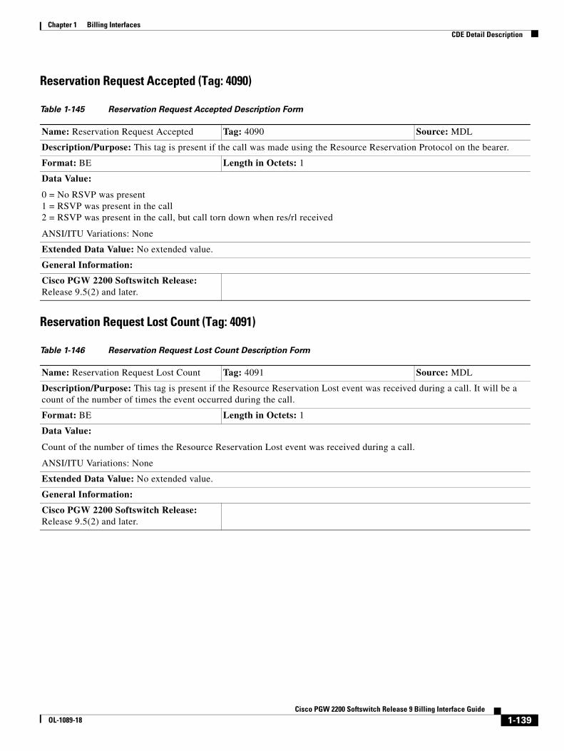
Chapter 1 Billing InterfacesCDE Detail Description
Reservation Request Accepted (Tag: 4090)
Reservation Request Lost Count (Tag: 4091)
Table 1-145 Reservation Request Accepted Description Form
Name: Reservation Request Accepted Tag: 4090 Source: MDL
Description/Purpose: This tag is present if the call was made using the Resource Reservation Protocol on the bearer.
Format: BE Length in Octets: 1
Data Value:
0 = No RSVP was present 1 = RSVP was present in the call 2 = RSVP was present in the call, but call torn down when res/rl received
ANSI/ITU Variations: None
Extended Data Value: No extended value.
General Information:
Cisco PGW 2200 Softswitch Release: Release 9.5(2) and later.
Table 1-146 Reservation Request Lost Count Description Form
Name: Reservation Request Lost Count Tag: 4091 Source: MDL
Description/Purpose: This tag is present if the Resource Reservation Lost event was received during a call. It will be a count of the number of times the event occurred during the call.
Format: BE Length in Octets: 1
Data Value:
Count of the number of times the Resource Reservation Lost event was received during a call.
ANSI/ITU Variations: None
Extended Data Value: No extended value.
General Information:
Cisco PGW 2200 Softswitch Release: Release 9.5(2) and later.
1-139Cisco PGW 2200 Softswitch Release 9 Billing Interface Guide
OL-1089-18
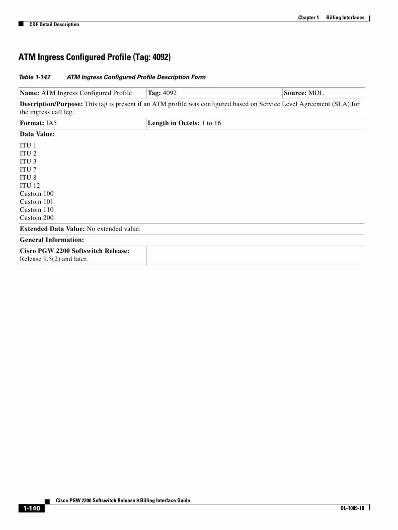
Chapter 1 Billing InterfacesCDE Detail Description
ATM Ingress Configured Profile (Tag: 4092)
Table 1-147 ATM Ingress Configured Profile Description Form
Name: ATM Ingress Configured Profile Tag: 4092 Source: MDL
Description/Purpose: This tag is present if an ATM profile was configured based on Service Level Agreement (SLA) for the ingress call leg.
Format: IA5 Length in Octets: 1 to 16
Data Value:
ITU 1 ITU 2 ITU 3 ITU 7 ITU 8 ITU 12 Custom 100 Custom 101 Custom 110 Custom 200
Extended Data Value: No extended value.
General Information:
Cisco PGW 2200 Softswitch Release: Release 9.5(2) and later.
1-140Cisco PGW 2200 Softswitch Release 9 Billing Interface Guide
OL-1089-18
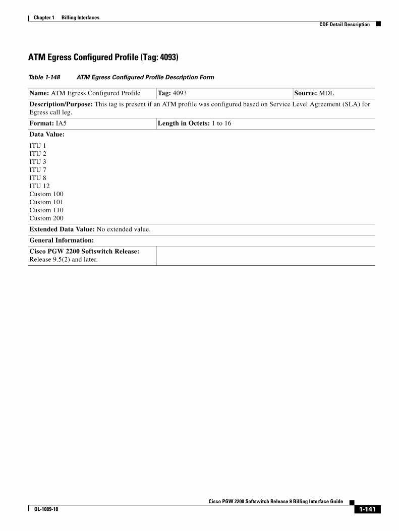
Chapter 1 Billing InterfacesCDE Detail Description
ATM Egress Configured Profile (Tag: 4093)
Table 1-148 ATM Egress Configured Profile Description Form
Name: ATM Egress Configured Profile Tag: 4093 Source: MDL
Description/Purpose: This tag is present if an ATM profile was configured based on Service Level Agreement (SLA) for Egress call leg.
Format: IA5 Length in Octets: 1 to 16
Data Value:
ITU 1 ITU 2 ITU 3 ITU 7 ITU 8 ITU 12 Custom 100 Custom 101 Custom 110 Custom 200
Extended Data Value: No extended value.
General Information:
Cisco PGW 2200 Softswitch Release: Release 9.5(2) and later.
1-141Cisco PGW 2200 Softswitch Release 9 Billing Interface Guide
OL-1089-18
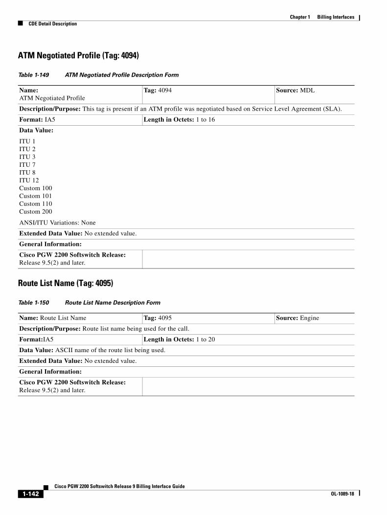
Chapter 1 Billing InterfacesCDE Detail Description
ATM Negotiated Profile (Tag: 4094)
Route List Name (Tag: 4095)
Table 1-149 ATM Negotiated Profile Description Form
Name: ATM Negotiated Profile
Tag: 4094 Source: MDL
Description/Purpose: This tag is present if an ATM profile was negotiated based on Service Level Agreement (SLA).
Format: IA5 Length in Octets: 1 to 16
Data Value:
ITU 1 ITU 2 ITU 3 ITU 7 ITU 8 ITU 12 Custom 100 Custom 101 Custom 110 Custom 200
ANSI/ITU Variations: None
Extended Data Value: No extended value.
General Information:
Cisco PGW 2200 Softswitch Release: Release 9.5(2) and later.
Table 1-150 Route List Name Description Form
Name: Route List Name Tag: 4095 Source: Engine
Description/Purpose: Route list name being used for the call.
Format:IA5 Length in Octets: 1 to 20
Data Value: ASCII name of the route list being used.
Extended Data Value: No extended value.
General Information:
Cisco PGW 2200 Softswitch Release: Release 9.5(2) and later.
1-142Cisco PGW 2200 Softswitch Release 9 Billing Interface Guide
OL-1089-18

Chapter 1 Billing InterfacesCDE Detail Description
Route Name (Tag: 4096)
MGCP Script Response String (Tag: 4097)
Table 1-151 Route Name Description Form
Name: Route Name Tag: 4096 Source: Engine
Description/Purpose: Route Name being used for the call.
Format: IA5 Length in Octets: 1 to 20
Data Value: ASCII name of the route being used.
Extended Data Value: No extended value.
General Information:
Cisco PGW 2200 Softswitch Release: Release 9.5(2) and later.
Table 1-152 MGCP Script Response String Description Form
Name: MGCP Script Response String Tag: 4097 Source: MDL
Description/Purpose: For MGCP Script handoff calls, this tag records the Notification response string, if any, returned in the O: parameter of the MGCP NTFY message. If this call did not receive a MGCP NTFY message, this tag is not logged.
Note In Release 9.7(3), the H.248 Protocol feature is supported. However, MGCP scripting is not implemented by the H.248 protocol, therefore, H.248 calls never generate this CDB.
Format: IA5 Length in Octets: Maximum of 128
Data Value:
Contains the response string obtained from the media gateway, in the MGCP NTFY message, including the event indicator oc or of.
ANSI/ITU variations: None.
Other variations: None.
Values: n/a
Examples of event indicators:
oc(Call completed.) oc(Authentication failed) of() of
Extended Data Value: No extended value.
General Information:
Cisco PGW 2200 Softswitch Release: Release 9.5(2) and later.
1-143Cisco PGW 2200 Softswitch Release 9 Billing Interface Guide
OL-1089-18
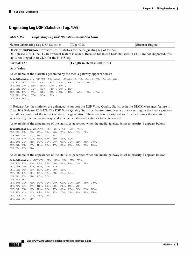
Chapter 1 Billing InterfacesCDE Detail Description
Originating Leg DSP Statistics (Tag: 4098)
Table 1-153 Originating Leg DSP Statistics Description Form
Name: Originating Leg DSP Statistics Tag: 4098 Source: Engine
Description/Purpose: Provides DSP statistics for the originating leg of the call. On Release 9.7(3), the H.248 Protocol feature is added. Because for H.248 DSP statistics in CDR are not supported, this tag is not logged in to CDR for the H.248 leg.
Format: IA5 Length in Octets: 280 to 794
Data Value:
An example of the statistics generated by the media gateway appears below:
OrigDSPstats...: DSP/TX: PK=data1, SG=data2, NS= data3, DU= data4, VO=, DSP/RX: VO= , SG= , CF= , RX= , BS= , BP= , LP= , EP= ,DSP/PD: CU= , MI= , MA= , CO= , IJ= ,DSP/PE: PC= , IC= , SC= , RM= , BO= , EE= ,DSP/LE: TP= , TX= , RP= , RM= , BN= , ER= , AC= , TA= , RA= ,DSP/ER: RD= , TD= , RC= , TC= ,DSP/IC: IC= ,.
In Release 9.6, the statistics are enhanced to support the DSP Voice Quality Statistics in the DLCX Messages feature in Cisco IOS Release 12.4(4)T. The DSP Voice Quality Statistics feature introduces a priority setting on the media gateway that allows control of the impact of statistics generation. There are two priority values: 1, which limits the statistics generated by the media gateway, and 2, which enables all statistics to be generated.
An example of the appearance of the statistics generated when the media gateway is set to priority 1 appears below:
OrigDSPstats…..:DSP/TX: PK=, SG=, NS=, DU=, VO=, DSP/RX: PK=, SG=, CF=, RX=, VO=, BS=, BP=, LP=, EP=, DSP/PD: CU=, MI=, MA=, CO=, IJ=, DSP/LE: TP=, TX=, RP=, RM=, BN=, ER=, AC=, DSP/EC: CI=, FM=, FP=, VS=, GT=, GR=, JD=, JN=, JM=, JX=,DSP/CS: CR=, AV=, MX=, CT=, TT=, OK=, CS=, SC=, TS=, DC=,DSP/DL: RT=, ED=
An example of the appearance of the statistics generated when the media gateway is set to priority 2 appears below:
OrigDSPstats…..:DSP/TX: PK=, SG=, NS=, DU=, VO=, DSP/RX: PK=, SG=, CF=, RX=, VO=, BS=, BP=, LP=, EP=, DSP/PD: CU=, MI=, MA=, CO=, IJ=, DSP/PE: PC=, IC=, SC=, RM=, BO=, EE=, DSP/LE: TP=, TX=, RP=, RM=, BN=, ER=, AC=,DSP/ER: RD=, TD=, RC=, TC=,DSP/IC: IC=, DSP/EC: CI=, FM=, FP=, VS=, GT=, GR=, JD=, JN=, JM=, JX=, DSP/KF: KF=, AV=, MI=, BS=, NB=, FL=, NW=, VR=, DSP/CS: CR=, AV=, MX=, CT=, TT=, OK=, CS=, SC=, TS=, DC=, DSP/RF: ML=, MC=, R1=, R2=, IF=, ID=, IE=, BL=, R0=, VR=, DSP/UC: U1=, U2=, T1=, T2=,DSP/DL: RT=, ED=
1-144Cisco PGW 2200 Softswitch Release 9 Billing Interface Guide
OL-1089-18
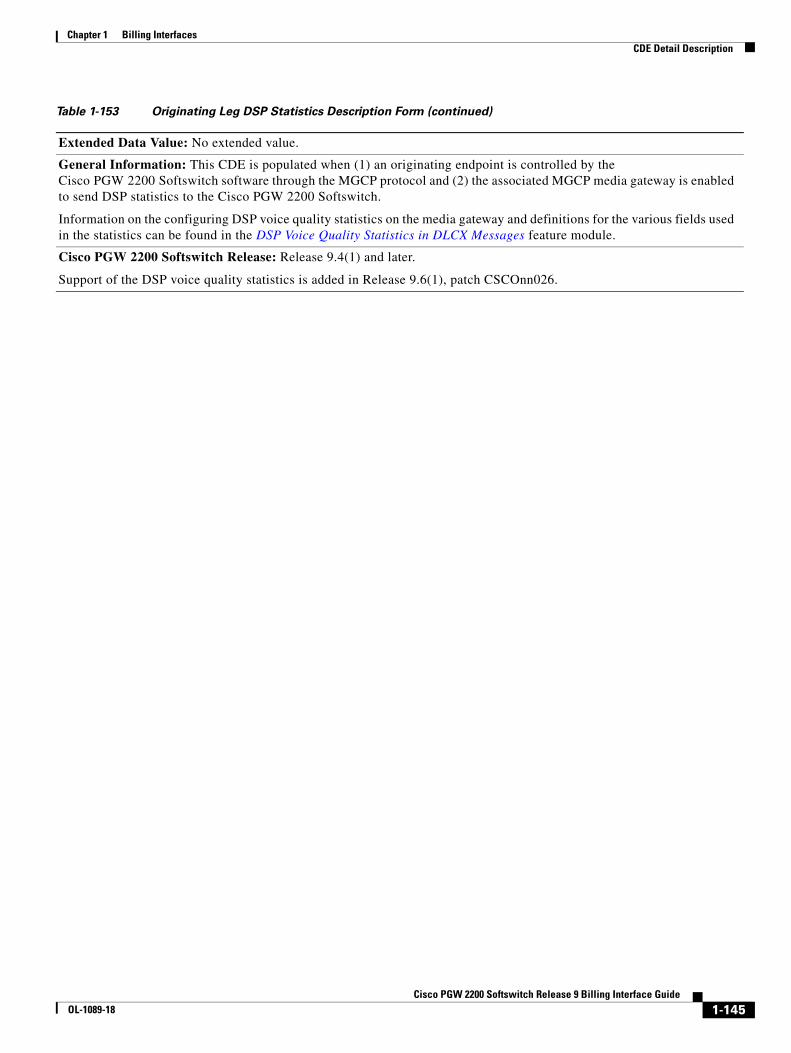
Chapter 1 Billing InterfacesCDE Detail Description
Extended Data Value: No extended value.
General Information: This CDE is populated when (1) an originating endpoint is controlled by the Cisco PGW 2200 Softswitch software through the MGCP protocol and (2) the associated MGCP media gateway is enabled to send DSP statistics to the Cisco PGW 2200 Softswitch.
Information on the configuring DSP voice quality statistics on the media gateway and definitions for the various fields used in the statistics can be found in the DSP Voice Quality Statistics in DLCX Messages feature module.
Cisco PGW 2200 Softswitch Release: Release 9.4(1) and later.
Support of the DSP voice quality statistics is added in Release 9.6(1), patch CSCOnn026.
Table 1-153 Originating Leg DSP Statistics Description Form (continued)
1-145Cisco PGW 2200 Softswitch Release 9 Billing Interface Guide
OL-1089-18
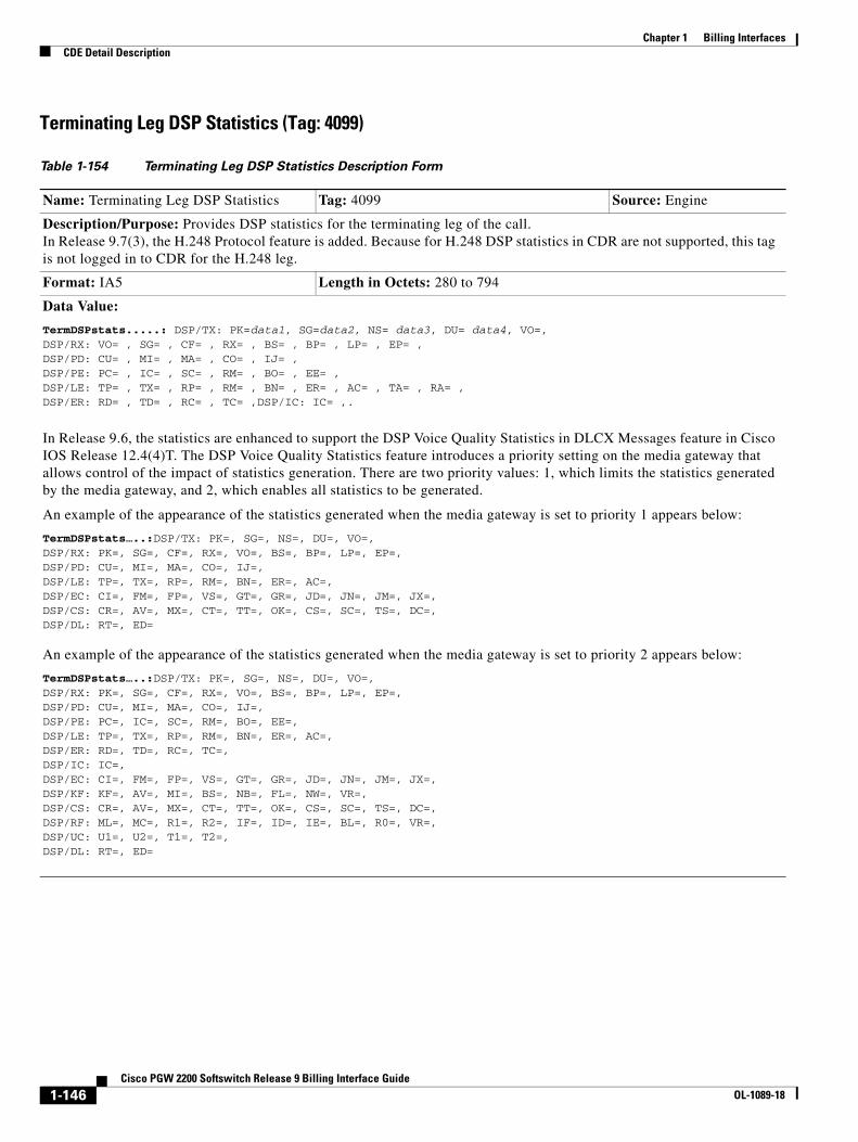
Chapter 1 Billing InterfacesCDE Detail Description
Terminating Leg DSP Statistics (Tag: 4099)
Table 1-154 Terminating Leg DSP Statistics Description Form
Name: Terminating Leg DSP Statistics Tag: 4099 Source: Engine
Description/Purpose: Provides DSP statistics for the terminating leg of the call. In Release 9.7(3), the H.248 Protocol feature is added. Because for H.248 DSP statistics in CDR are not supported, this tag is not logged in to CDR for the H.248 leg.
Format: IA5 Length in Octets: 280 to 794
Data Value:
TermDSPstats.....: DSP/TX: PK=data1, SG=data2, NS= data3, DU= data4, VO=, DSP/RX: VO= , SG= , CF= , RX= , BS= , BP= , LP= , EP= ,DSP/PD: CU= , MI= , MA= , CO= , IJ= ,DSP/PE: PC= , IC= , SC= , RM= , BO= , EE= ,DSP/LE: TP= , TX= , RP= , RM= , BN= , ER= , AC= , TA= , RA= ,DSP/ER: RD= , TD= , RC= , TC= ,DSP/IC: IC= ,.
In Release 9.6, the statistics are enhanced to support the DSP Voice Quality Statistics in DLCX Messages feature in Cisco IOS Release 12.4(4)T. The DSP Voice Quality Statistics feature introduces a priority setting on the media gateway that allows control of the impact of statistics generation. There are two priority values: 1, which limits the statistics generated by the media gateway, and 2, which enables all statistics to be generated.
An example of the appearance of the statistics generated when the media gateway is set to priority 1 appears below:
TermDSPstats…..:DSP/TX: PK=, SG=, NS=, DU=, VO=, DSP/RX: PK=, SG=, CF=, RX=, VO=, BS=, BP=, LP=, EP=, DSP/PD: CU=, MI=, MA=, CO=, IJ=, DSP/LE: TP=, TX=, RP=, RM=, BN=, ER=, AC=, DSP/EC: CI=, FM=, FP=, VS=, GT=, GR=, JD=, JN=, JM=, JX=,DSP/CS: CR=, AV=, MX=, CT=, TT=, OK=, CS=, SC=, TS=, DC=,DSP/DL: RT=, ED=
An example of the appearance of the statistics generated when the media gateway is set to priority 2 appears below:
TermDSPstats…..:DSP/TX: PK=, SG=, NS=, DU=, VO=, DSP/RX: PK=, SG=, CF=, RX=, VO=, BS=, BP=, LP=, EP=, DSP/PD: CU=, MI=, MA=, CO=, IJ=, DSP/PE: PC=, IC=, SC=, RM=, BO=, EE=, DSP/LE: TP=, TX=, RP=, RM=, BN=, ER=, AC=,DSP/ER: RD=, TD=, RC=, TC=,DSP/IC: IC=, DSP/EC: CI=, FM=, FP=, VS=, GT=, GR=, JD=, JN=, JM=, JX=, DSP/KF: KF=, AV=, MI=, BS=, NB=, FL=, NW=, VR=, DSP/CS: CR=, AV=, MX=, CT=, TT=, OK=, CS=, SC=, TS=, DC=, DSP/RF: ML=, MC=, R1=, R2=, IF=, ID=, IE=, BL=, R0=, VR=, DSP/UC: U1=, U2=, T1=, T2=,DSP/DL: RT=, ED=
1-146Cisco PGW 2200 Softswitch Release 9 Billing Interface Guide
OL-1089-18

Chapter 1 Billing InterfacesCDE Detail Description
Ingress Media Gateway Pool ID (Tag: 4110)
Egress Media Gateway Pool ID (Tag: 4111)
Extended Data Value: No extended value.
General Information: This CDE is populated when (1) a terminating endpoint is controlled by the Cisco PGW 2200 Softswitch software through the MGCP protocol and (2) the associated MGCP media gateway is enabled to send DSP statistics to the Cisco PGW 2200 Softswitch.
Information on the configuring DSP voice quality statistics on the media gateway and definitions for the various fields used in the statistics can be found in the DSP Voice Quality Statistics in DLCX Messages feature module.
Cisco PGW 2200 Softswitch Release: Release 9.4(1) and later.
Support of the DSP voice quality statistics is added in Release 9.6(1), patch CSCOnn026.
Table 1-155 Ingress Media Gateway Pool ID Description Form
Name: Ingress Media Gateway Pool ID Tag: 4110 Source: MDL
Description/Purpose: Specifies the ingress media gateway pool ID.
Format: BE Length in Octets: 2
Data Value: An integer value that identifies the ingress media gateway pool.
Extended Data Value: No extended value.
General Information: This CDE is present in the following CDBs: 1010, 1030, and 1110. This CDE is not present in the following CDBs: 1020, 1040, 1050, 1060, 1070, and 1080.
General Information (Release 9.8): This CDE is present in the following CDBs: 1010, and 1030. This CDE is not present in the following CDBs: 1020, 1040, 1050, 1060, 1070, 1080, and 1110.
Cisco PGW 2200 Softswitch Release: Release 9.8 and later.
Table 1-156 Egress Media Gateway Pool ID Description Form
Name: Ingress Media Gateway Pool ID Tag: 4111 Source: MDL
Description/Purpose: Specifies the egress media gateway pool ID.
Format: BE Length in Octets: 2
Data Value: An integer value that identifies the egress media gateway pool.
Extended Data Value: No extended value.
General Information: This CDE is present in the following CDBs: 1010, 1030, and 1110. This CDE is not present in the following CDBs: 1020, 1040, 1050, 1060, 1070, and 1080.
General Information (Release 9.8): This CDE is present in the following CDBs: 1010, and 1030. This CDE is not present in the following CDBs: 1020, 1040, 1050, 1060, 1070, 1080, and 1110.
Cisco PGW 2200 Softswitch Release: Release 9.8 and later.
Table 1-154 Terminating Leg DSP Statistics Description Form (continued)
1-147Cisco PGW 2200 Softswitch Release 9 Billing Interface Guide
OL-1089-18
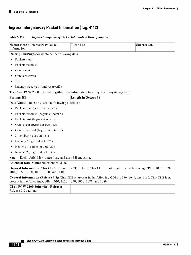
Chapter 1 Billing InterfacesCDE Detail Description
Ingress Intergateway Packet Information (Tag: 4112)
Table 1-157 Ingress Intergateway Packet Information Description Form
Name: Ingress Intergateway Packet Information
Tag: 4112 Source: MDL
Description/Purpose: Contains the following data:
• Packets sent
• Packets received
• Octets sent
• Octets received
• Jitter
• Latency (reserved1 and reserved2)
The Cisco PGW 2200 Softswitch gathers this information from ingress intergateway traffic.
Format: BE Length in Octets: 36
Data Value: This CDR uses the following subfields:
• Packets sent (begins at octet 1)
• Packets received (begins at octet 5)
• Packets lost (begins at octet 9)
• Octets sent (begins at octet 13)
• Octets received (begins at octet 17)
• Jitter (begins at octet 21)
• Latency (begins at octet 25)
• Reservd1 (begins at octet 29)
• Reservd2 (begins at octet 33)
Note Each subfield is 4 octets long and uses BE encoding.
Extended Data Value: No extended value.
General Information: This CDE is present in CDBs 1030. This CDE is not present in the following CDBs: 1010, 1020, 1040, 1050, 1060, 1070, 1080, and 1110.
General Information (Release 9.8): This CDE is present in the following CDBs: 1030, 1040, and 1110. This CDE is not present in the following CDBs: 1010, 1020, 1050, 1060, 1070, and 1080.
Cisco PGW 2200 Softswitch Release: Release 9.8 and later.
1-148Cisco PGW 2200 Softswitch Release 9 Billing Interface Guide
OL-1089-18
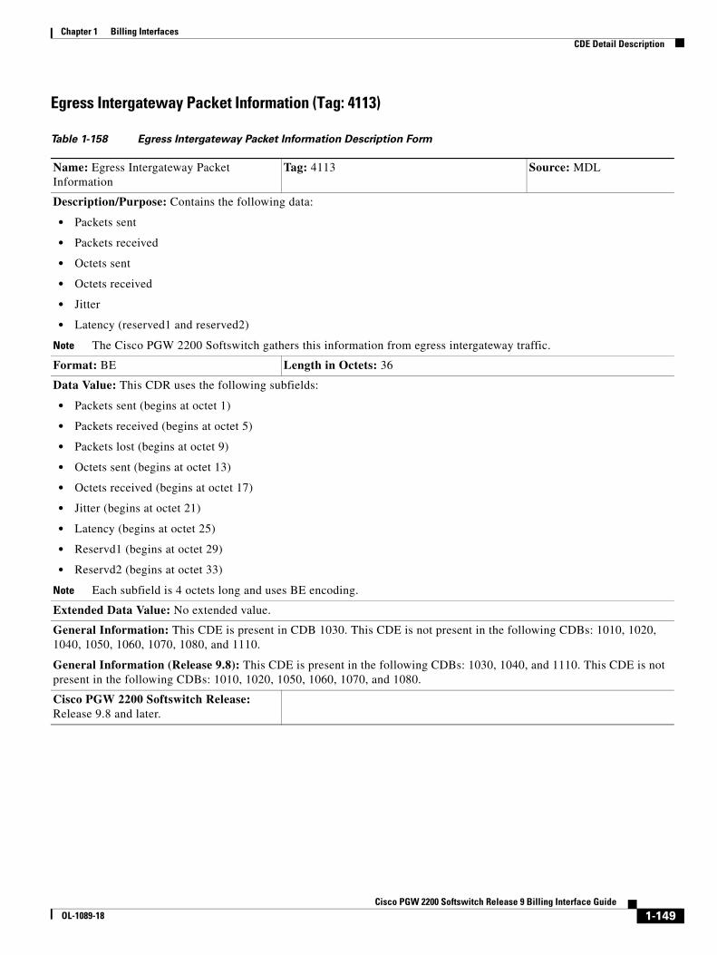
Chapter 1 Billing InterfacesCDE Detail Description
Egress Intergateway Packet Information (Tag: 4113)
Table 1-158 Egress Intergateway Packet Information Description Form
Name: Egress Intergateway Packet Information
Tag: 4113 Source: MDL
Description/Purpose: Contains the following data:
• Packets sent
• Packets received
• Octets sent
• Octets received
• Jitter
• Latency (reserved1 and reserved2)
Note The Cisco PGW 2200 Softswitch gathers this information from egress intergateway traffic.
Format: BE Length in Octets: 36
Data Value: This CDR uses the following subfields:
• Packets sent (begins at octet 1)
• Packets received (begins at octet 5)
• Packets lost (begins at octet 9)
• Octets sent (begins at octet 13)
• Octets received (begins at octet 17)
• Jitter (begins at octet 21)
• Latency (begins at octet 25)
• Reservd1 (begins at octet 29)
• Reservd2 (begins at octet 33)
Note Each subfield is 4 octets long and uses BE encoding.
Extended Data Value: No extended value.
General Information: This CDE is present in CDB 1030. This CDE is not present in the following CDBs: 1010, 1020, 1040, 1050, 1060, 1070, 1080, and 1110.
General Information (Release 9.8): This CDE is present in the following CDBs: 1030, 1040, and 1110. This CDE is not present in the following CDBs: 1010, 1020, 1050, 1060, 1070, and 1080.
Cisco PGW 2200 Softswitch Release: Release 9.8 and later.
1-149Cisco PGW 2200 Softswitch Release 9 Billing Interface Guide
OL-1089-18
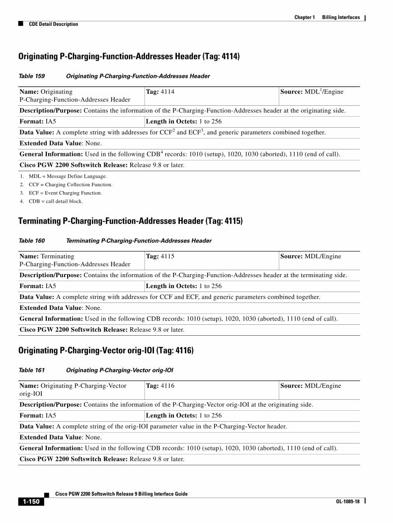
Chapter 1 Billing InterfacesCDE Detail Description
Originating P-Charging-Function-Addresses Header (Tag: 4114)
Terminating P-Charging-Function-Addresses Header (Tag: 4115)
Originating P-Charging-Vector orig-IOI (Tag: 4116)
Table 159 Originating P-Charging-Function-Addresses Header
Name: Originating P-Charging-Function-Addresses Header
Tag: 4114 Source: MDL1/Engine
1. MDL = Message Define Language.
Description/Purpose: Contains the information of the P-Charging-Function-Addresses header at the originating side.
Format: IA5 Length in Octets: 1 to 256
Data Value: A complete string with addresses for CCF2 and ECF3, and generic parameters combined together.
2. CCF = Charging Collection Function.
3. ECF = Event Charging Function.
Extended Data Value: None.
General Information: Used in the following CDB4 records: 1010 (setup), 1020, 1030 (aborted), 1110 (end of call).
4. CDB = call detail block.
Cisco PGW 2200 Softswitch Release: Release 9.8 or later.
Table 160 Terminating P-Charging-Function-Addresses Header
Name: Terminating P-Charging-Function-Addresses Header
Tag: 4115 Source: MDL/Engine
Description/Purpose: Contains the information of the P-Charging-Function-Addresses header at the terminating side.
Format: IA5 Length in Octets: 1 to 256
Data Value: A complete string with addresses for CCF and ECF, and generic parameters combined together.
Extended Data Value: None.
General Information: Used in the following CDB records: 1010 (setup), 1020, 1030 (aborted), 1110 (end of call).
Cisco PGW 2200 Softswitch Release: Release 9.8 or later.
Table 161 Originating P-Charging-Vector orig-IOI
Name: Originating P-Charging-Vector orig-IOI
Tag: 4116 Source: MDL/Engine
Description/Purpose: Contains the information of the P-Charging-Vector orig-IOI at the originating side.
Format: IA5 Length in Octets: 1 to 256
Data Value: A complete string of the orig-IOI parameter value in the P-Charging-Vector header.
Extended Data Value: None.
General Information: Used in the following CDB records: 1010 (setup), 1020, 1030 (aborted), 1110 (end of call).
Cisco PGW 2200 Softswitch Release: Release 9.8 or later.
1-150Cisco PGW 2200 Softswitch Release 9 Billing Interface Guide
OL-1089-18
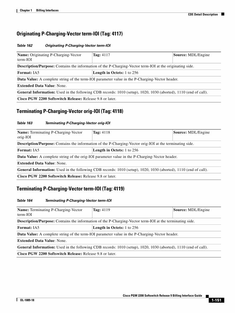
Chapter 1 Billing InterfacesCDE Detail Description
Originating P-Charging-Vector term-IOI (Tag: 4117)
Terminating P-Charging-Vector orig-IOI (Tag: 4118)
Terminating P-Charging-Vector term-IOI (Tag: 4119)
Table 162 Originating P-Charging-Vector term-IOI
Name: Originating P-Charging-Vector term-IOI
Tag: 4117 Source: MDL/Engine
Description/Purpose: Contains the information of the P-Charging-Vector term-IOI at the originating side.
Format: IA5 Length in Octets: 1 to 256
Data Value: A complete string of the term-IOI parameter value in the P-Charging-Vector header.
Extended Data Value: None.
General Information: Used in the following CDB records: 1010 (setup), 1020, 1030 (aborted), 1110 (end of call).
Cisco PGW 2200 Softswitch Release: Release 9.8 or later.
Table 163 Terminating P-Charging-Vector orig-IOI
Name: Terminating P-Charging-Vector orig-IOI
Tag: 4118 Source: MDL/Engine
Description/Purpose: Contains the information of the P-Charging-Vector orig-IOI at the terminating side.
Format: IA5 Length in Octets: 1 to 256
Data Value: A complete string of the orig-IOI parameter value in the P-Charging-Vector header.
Extended Data Value: None.
General Information: Used in the following CDB records: 1010 (setup), 1020, 1030 (aborted), 1110 (end of call).
Cisco PGW 2200 Softswitch Release: Release 9.8 or later.
Table 164 Terminating P-Charging-Vector term-IOI
Name: Terminating P-Charging-Vector term-IOI
Tag: 4119 Source: MDL/Engine
Description/Purpose: Contains the information of the P-Charging-Vector term-IOI at the terminating side.
Format: IA5 Length in Octets: 1 to 256
Data Value: A complete string of the term-IOI parameter value in the P-Charging-Vector header.
Extended Data Value: None.
General Information: Used in the following CDB records: 1010 (setup), 1020, 1030 (aborted), 1110 (end of call).
Cisco PGW 2200 Softswitch Release: Release 9.8 or later.
1-151Cisco PGW 2200 Softswitch Release 9 Billing Interface Guide
OL-1089-18
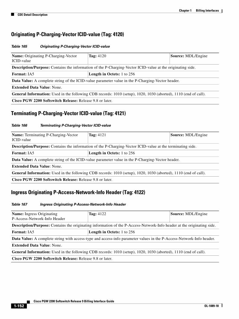
Chapter 1 Billing InterfacesCDE Detail Description
Originating P-Charging-Vector ICID-value (Tag: 4120)
Terminating P-Charging-Vector ICID-value (Tag: 4121)
Ingress Originating P-Access-Network-Info Header (Tag: 4122)
Table 165 Originating P-Charging-Vector ICID-value
Name: Originating P-Charging-Vector ICID-value
Tag: 4120 Source: MDL/Engine
Description/Purpose: Contains the information of the P-Charging-Vector ICID-value at the originating side.
Format: IA5 Length in Octets: 1 to 256
Data Value: A complete string of the ICID-value parameter value in the P-Charging-Vector header.
Extended Data Value: None.
General Information: Used in the following CDB records: 1010 (setup), 1020, 1030 (aborted), 1110 (end of call).
Cisco PGW 2200 Softswitch Release: Release 9.8 or later.
Table 166 Terminating P-Charging-Vector ICID-value
Name: Terminating P-Charging-Vector ICID-value
Tag: 4121 Source: MDL/Engine
Description/Purpose: Contains the information of the P-Charging-Vector ICID-value at the terminating side.
Format: IA5 Length in Octets: 1 to 256
Data Value: A complete string of the ICID-value parameter value in the P-Charging-Vector header.
Extended Data Value: None.
General Information: Used in the following CDB records: 1010 (setup), 1020, 1030 (aborted), 1110 (end of call).
Cisco PGW 2200 Softswitch Release: Release 9.8 or later.
Table 167 Ingress Originating P-Access-Network-Info Header
Name: Ingress Originating P-Access-Network-Info Header
Tag: 4122 Source: MDL/Engine
Description/Purpose: Contains the originating information of the P-Access-Network-Info header at the originating side.
Format: IA5 Length in Octets: 1 to 256
Data Value: A complete string with access-type and access-info parameter values in the P-Access-Network-Info header.
Extended Data Value: None.
General Information: Used in the following CDB records: 1010 (setup), 1020, 1030 (aborted), 1110 (end of call).
Cisco PGW 2200 Softswitch Release: Release 9.8 or later.
1-152Cisco PGW 2200 Softswitch Release 9 Billing Interface Guide
OL-1089-18
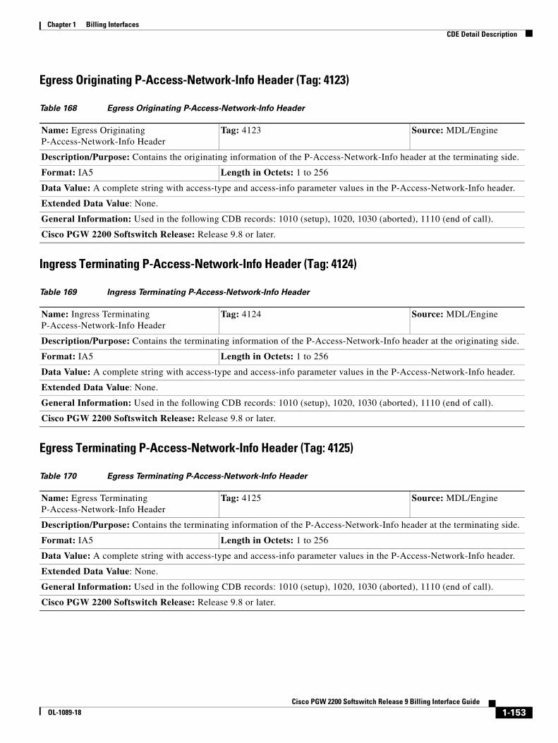
Chapter 1 Billing InterfacesCDE Detail Description
Egress Originating P-Access-Network-Info Header (Tag: 4123)
Ingress Terminating P-Access-Network-Info Header (Tag: 4124)
Egress Terminating P-Access-Network-Info Header (Tag: 4125)
Table 168 Egress Originating P-Access-Network-Info Header
Name: Egress Originating P-Access-Network-Info Header
Tag: 4123 Source: MDL/Engine
Description/Purpose: Contains the originating information of the P-Access-Network-Info header at the terminating side.
Format: IA5 Length in Octets: 1 to 256
Data Value: A complete string with access-type and access-info parameter values in the P-Access-Network-Info header.
Extended Data Value: None.
General Information: Used in the following CDB records: 1010 (setup), 1020, 1030 (aborted), 1110 (end of call).
Cisco PGW 2200 Softswitch Release: Release 9.8 or later.
Table 169 Ingress Terminating P-Access-Network-Info Header
Name: Ingress Terminating P-Access-Network-Info Header
Tag: 4124 Source: MDL/Engine
Description/Purpose: Contains the terminating information of the P-Access-Network-Info header at the originating side.
Format: IA5 Length in Octets: 1 to 256
Data Value: A complete string with access-type and access-info parameter values in the P-Access-Network-Info header.
Extended Data Value: None.
General Information: Used in the following CDB records: 1010 (setup), 1020, 1030 (aborted), 1110 (end of call).
Cisco PGW 2200 Softswitch Release: Release 9.8 or later.
Table 170 Egress Terminating P-Access-Network-Info Header
Name: Egress Terminating P-Access-Network-Info Header
Tag: 4125 Source: MDL/Engine
Description/Purpose: Contains the terminating information of the P-Access-Network-Info header at the terminating side.
Format: IA5 Length in Octets: 1 to 256
Data Value: A complete string with access-type and access-info parameter values in the P-Access-Network-Info header.
Extended Data Value: None.
General Information: Used in the following CDB records: 1010 (setup), 1020, 1030 (aborted), 1110 (end of call).
Cisco PGW 2200 Softswitch Release: Release 9.8 or later.
1-153Cisco PGW 2200 Softswitch Release 9 Billing Interface Guide
OL-1089-18
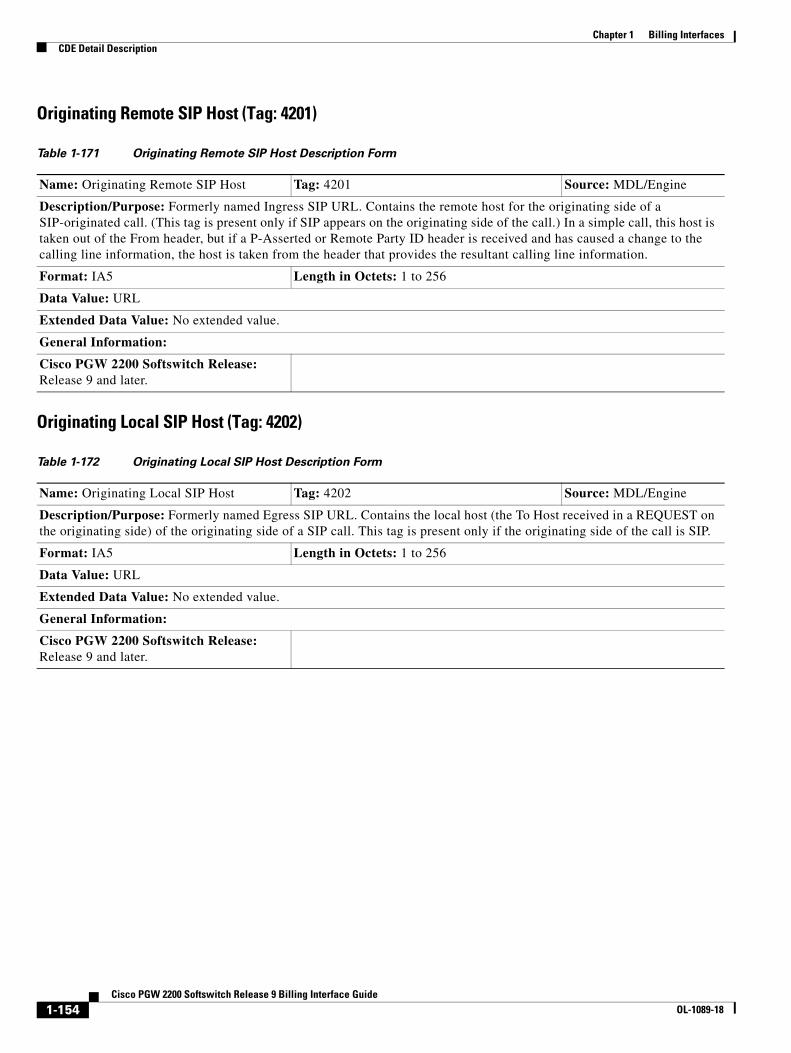
Chapter 1 Billing InterfacesCDE Detail Description
Originating Remote SIP Host (Tag: 4201)
Originating Local SIP Host (Tag: 4202)
Table 1-171 Originating Remote SIP Host Description Form
Name: Originating Remote SIP Host Tag: 4201 Source: MDL/Engine
Description/Purpose: Formerly named Ingress SIP URL. Contains the remote host for the originating side of a SIP-originated call. (This tag is present only if SIP appears on the originating side of the call.) In a simple call, this host is taken out of the From header, but if a P-Asserted or Remote Party ID header is received and has caused a change to the calling line information, the host is taken from the header that provides the resultant calling line information.
Format: IA5 Length in Octets: 1 to 256
Data Value: URL
Extended Data Value: No extended value.
General Information:
Cisco PGW 2200 Softswitch Release: Release 9 and later.
Table 1-172 Originating Local SIP Host Description Form
Name: Originating Local SIP Host Tag: 4202 Source: MDL/Engine
Description/Purpose: Formerly named Egress SIP URL. Contains the local host (the To Host received in a REQUEST on the originating side) of the originating side of a SIP call. This tag is present only if the originating side of the call is SIP.
Format: IA5 Length in Octets: 1 to 256
Data Value: URL
Extended Data Value: No extended value.
General Information:
Cisco PGW 2200 Softswitch Release: Release 9 and later.
1-154Cisco PGW 2200 Softswitch Release 9 Billing Interface Guide
OL-1089-18
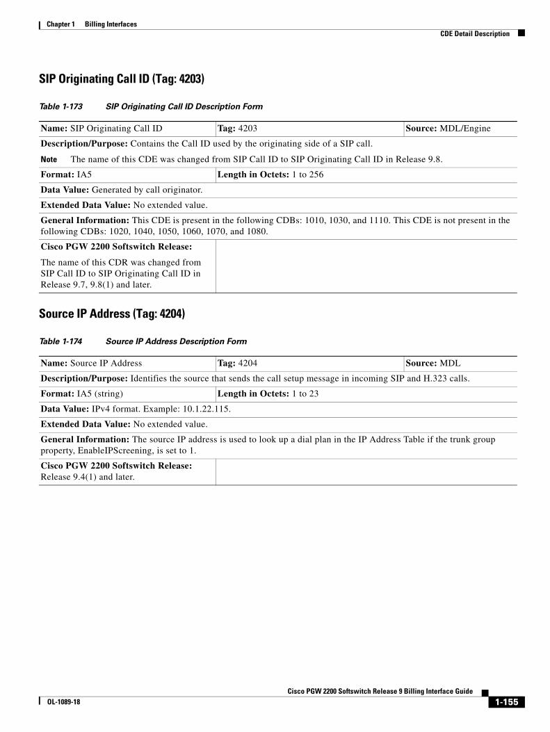
Chapter 1 Billing InterfacesCDE Detail Description
SIP Originating Call ID (Tag: 4203)
Source IP Address (Tag: 4204)
Table 1-173 SIP Originating Call ID Description Form
Name: SIP Originating Call ID Tag: 4203 Source: MDL/Engine
Description/Purpose: Contains the Call ID used by the originating side of a SIP call.
Note The name of this CDE was changed from SIP Call ID to SIP Originating Call ID in Release 9.8.
Format: IA5 Length in Octets: 1 to 256
Data Value: Generated by call originator.
Extended Data Value: No extended value.
General Information: This CDE is present in the following CDBs: 1010, 1030, and 1110. This CDE is not present in the following CDBs: 1020, 1040, 1050, 1060, 1070, and 1080.
Cisco PGW 2200 Softswitch Release:
The name of this CDR was changed from SIP Call ID to SIP Originating Call ID in Release 9.7, 9.8(1) and later.
Table 1-174 Source IP Address Description Form
Name: Source IP Address Tag: 4204 Source: MDL
Description/Purpose: Identifies the source that sends the call setup message in incoming SIP and H.323 calls.
Format: IA5 (string) Length in Octets: 1 to 23
Data Value: IPv4 format. Example: 10.1.22.115.
Extended Data Value: No extended value.
General Information: The source IP address is used to look up a dial plan in the IP Address Table if the trunk group property, EnableIPScreening, is set to 1.
Cisco PGW 2200 Softswitch Release: Release 9.4(1) and later.
1-155Cisco PGW 2200 Softswitch Release 9 Billing Interface Guide
OL-1089-18

Chapter 1 Billing InterfacesCDE Detail Description
Ingress Media Device Address (Tag: 4205)
Egress Media Device Address (Tag: 4206)
Table 1-175 Ingress Media Device Address Description Form
Name: Ingress Media Device Address Tag: 4205 Source: MDL
Description/Purpose: Identifies the IP address of the originating RTP end point. This is parsed from the SDP from SIP, MGCP, or EISUP (HSI).
Format: IA5 (string) Length in Octets: 1 to 256
Data Value: IPv4 format or FQDN. Examples: 10.1.22.115, sp-46-39-gateway.customer.com.
Extended Data Value: No extended value.
General Information: If the ingress media device address is an IP address, it is used to look up a dial plan in the IP Address table if the trunk group properties EnableIPScreening and SipIPSource are set to 1. If the call originates in the H.323 domain as a slow start call, this information is not present in the 1010 CDB. If the call is originated in the H.323 domain as a slow start call and a switchover operation is performed on the Cisco PGW 2200, this information is not captured in any CDB.
Cisco PGW 2200 Softswitch Release: Release 9.4(1) and later.
Table 1-176 Egress Media Device Address Description Form
Name: Egress Media Device Address Tag: 4206 Source: MDL
Description/Purpose: Identifies the IP address of the terminating RTP end point. This is parsed from the SDP from SIP, MGCP, or EISUP (HSI).
Format: IA5 (string) Length in Octets: 1 to 256
Data Value: IPv4 format or FQDN. Examples: 10.1.22.115, sp-46-39-gateway.customer.com.
Extended Data Value: No extended value.
General Information: If the egress media device address is an IP address, it is used to look up a dial plan in the IP Address table if the trunk group properties EnableIPScreening and SipIPSource are set to 1. If the call is terminated in the H.323 domain as a slow start call, this information is not present in the 1010 CDB. If the call is terminated in the H.323 domain as a slow start call and a switchover operation is performed on the Cisco PGW 2200, this information is not captured in any CDB.
Cisco PGW 2200 Softswitch Release: Release 9.4(1) and later.
1-156Cisco PGW 2200 Softswitch Release 9 Billing Interface Guide
OL-1089-18
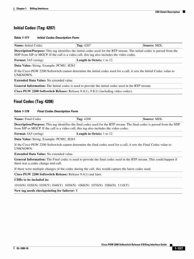
Chapter 1 Billing InterfacesCDE Detail Description
Initial Codec (Tag: 4207)
Final Codec (Tag: 4208)
Table 1-177 Initial Codec Description Form
Name: Initial Codec Tag: 4207 Source: MDL
Description/Purpose: This tag identifies the initial codec used for the RTP stream. The initial codec is parsed from the SDP from SIP or MGCP. If the call is a video call, this tag also includes the video codec.
Format: IA5 (string) Length in Octets: 1 to 12
Data Value: String. Example: PCMU, H263
If the Cisco PGW 2200 Softswitch cannot determine the initial codec used for a call, it sets the Initial Codec value to UNKNOWN.
Extended Data Value: No extended value.
General Information: The Initial codec is used to provide the initial codec used in the RTP stream.
Cisco PGW 2200 Softswitch Release: Release 9.4(1), 9.8(1) (including video codec).
Table 1-178 Final Codec Description Form
Name: Final Codec Tag: 4208 Source: MDL
Description/Purpose: This tag identifies the final codec used for the RTP stream. The final codec is parsed from the SDP from SIP or MGCP. If the call is a video call, this tag also includes the video codec.
Format: IA5 (string) Length in Octets: 1 to 12
Data Value: String. Example: PCMU, H263
If the Cisco PGW 2200 Softswitch cannot determine the final codec used for a call, it sets the Final Codec value to UNKNOWN.
Extended Data Value: No extended value.
General Information: The Final codec is used to provide the final codec used in the RTP stream. This could happen if there was a codec change mid call.
If there were multiple changes of the codec during the call, this would capture the latest codec used.
Cisco PGW 2200 Softswitch Release: Release 9.4(1) and later.
CDBs to be included in:
1010(N) 1020(N) 1030(Y) 1040(Y) 1050(N) 1060(N) 1070(N) 1080(N) 1110(Y)
New tag needs checkpointing for failover: Y
1-157Cisco PGW 2200 Softswitch Release 9 Billing Interface Guide
OL-1089-18
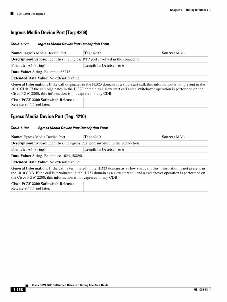
Chapter 1 Billing InterfacesCDE Detail Description
Ingress Media Device Port (Tag: 4209)
Egress Media Device Port (Tag: 4210)
Table 1-179 Ingress Media Device Port Description Form
Name: Ingress Media Device Port Tag: 4209 Source: MDL
Description/Purpose: Identifies the ingress RTP port involved in the connection.
Format: IA5 (string) Length in Octets: 1 to 6
Data Value: String. Example: 66218
Extended Data Value: No extended value.
General Information: If the call originates in the H.323 domain as a slow start call, this information is not present in the 1010 CDB. If the call originates in the H.323 domain as a slow start call and a switchover operation is performed on the Cisco PGW 2200, this information is not captured in any CDB.
Cisco PGW 2200 Softswitch Release: Release 9.4(1) and later.
Table 1-180 Egress Media Device Port Description Form
Name: Egress Media Device Port Tag: 4210 Source: MDL
Description/Purpose: Identifies the egress RTP port involved in the connection.
Format: IA5 (string) Length in Octets: 1 to 6
Data Value: String. Examples: 1024, 58890.
Extended Data Value: No extended value.
General Information: If the call is terminated in the H.323 domain as a slow start call, this information is not present in the 1010 CDB. If the call is terminated in the H.323 domain as a slow start call and a switchover operation is performed on the Cisco PGW 2200, this information is not captured in any CDB.
Cisco PGW 2200 Softswitch Release: Release 9.4(1) and later.
1-158Cisco PGW 2200 Softswitch Release 9 Billing Interface Guide
OL-1089-18

Chapter 1 Billing InterfacesCDE Detail Description
Originating VPN ID (Tag: 4211)
Terminating VPN ID (Tag: 4212)
Table 1-181 Originating VPN ID Description Form
Name: Originating VPN ID Tag: 4211 Source: MDL
Description/Purpose: Identifies the VPN customer ID associated with the incoming trunk group or signaling service. The DPNSS and QSIG access protocols use the Originating VPN ID information to implement the feature transparency feature.
Format: IA5 Length in Octets: 8
Data Value: Alphanumeric string. It is associated with DPNSS and QSIG trunk groups. Example: BTFNET1
Extended Data Value: No extended value.
General Information: This tag is included if there is a VPN ID associated with the incoming trunk group.
Note If the incoming trunk group is EISUP, the VPN ID of the incoming trunk group of the remote Cisco PGW 2200 is used (if a VPN ID is present).
Cisco PGW 2200 Softswitch Release: Release 9.4(1) and later.
Table 1-182 Terminating VPN ID Description Form
Name: Terminating VPN ID Tag: 4212 Source: MDL
Description/Purpose: Identifies the VPN customer ID associated with the outgoing trunk group or signaling service. The DPNSS and QSIG access protocols use the Terminating VPN ID information to implement the feature transparency feature.
Format: IA5 Length in Octets: 8
Data Value: Alphanumeric string. It is associated with DPNSS and QSIG trunk groups. Example: BTFNET1
Extended Data Value: No extended value.
General Information: This tag is included if there is a VPN ID associated with the outgoing trunk group.
Note If the outgoing trunk group is EISUP, the VPN ID of the outgoing trunk group of the remote Cisco PGW 2200 is used (if a VPN ID is present).
Cisco PGW 2200 Softswitch Release: Release 9.4(1) and later.
1-159Cisco PGW 2200 Softswitch Release 9 Billing Interface Guide
OL-1089-18
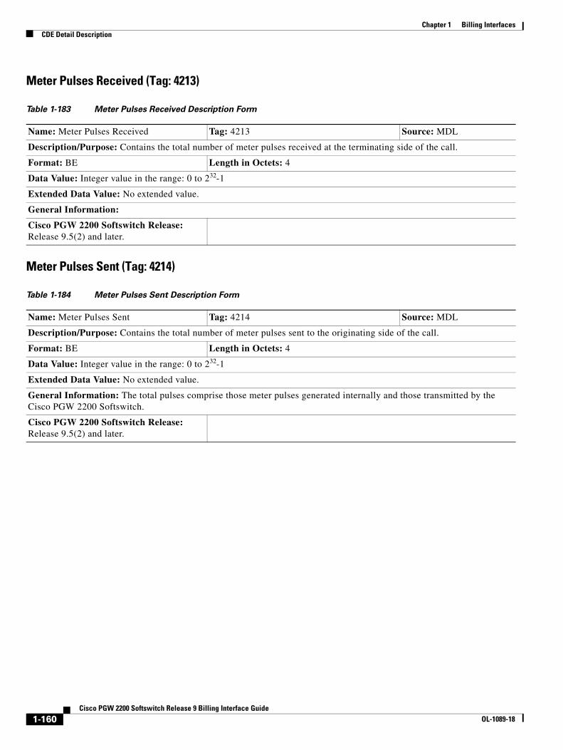
Chapter 1 Billing InterfacesCDE Detail Description
Meter Pulses Received (Tag: 4213)
Meter Pulses Sent (Tag: 4214)
Table 1-183 Meter Pulses Received Description Form
Name: Meter Pulses Received Tag: 4213 Source: MDL
Description/Purpose: Contains the total number of meter pulses received at the terminating side of the call.
Format: BE Length in Octets: 4
Data Value: Integer value in the range: 0 to 232-1
Extended Data Value: No extended value.
General Information:
Cisco PGW 2200 Softswitch Release: Release 9.5(2) and later.
Table 1-184 Meter Pulses Sent Description Form
Name: Meter Pulses Sent Tag: 4214 Source: MDL
Description/Purpose: Contains the total number of meter pulses sent to the originating side of the call.
Format: BE Length in Octets: 4
Data Value: Integer value in the range: 0 to 232-1
Extended Data Value: No extended value.
General Information: The total pulses comprise those meter pulses generated internally and those transmitted by the Cisco PGW 2200 Softswitch.
Cisco PGW 2200 Softswitch Release: Release 9.5(2) and later.
1-160Cisco PGW 2200 Softswitch Release 9 Billing Interface Guide
OL-1089-18
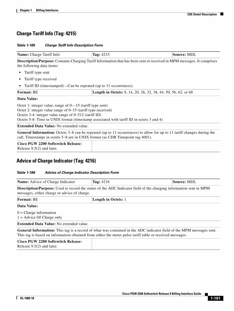
Chapter 1 Billing InterfacesCDE Detail Description
Charge Tariff Info (Tag: 4215)
Advice of Charge Indicator (Tag: 4216)
Table 1-185 Charge Tariff Info Description Form
Name: Charge Tariff Info Tag: 4215 Source: MDL
Description/Purpose: Contains Charging Tariff Information that has been sent or received in MPM messages. It comprises the following data items:
• Tariff type sent
• Tariff type received
• Tariff ID (timestamped)—Can be repeated (up to 11 occurrences).
Format: BE Length in Octets: 8, 14, 20, 26, 32, 38, 44, 50, 56, 62, or 68
Data Value:
Octet 1: integer value, range of 0—15 (tariff type sent) Octet 2: integer value range of 0–15 (tariff type received) Octets 3-4: integer value range of 0–512 (tariff ID) Octets 5-8: Time in UNIX format (timestamp associated with tariff ID in octets 3 and 4)
Extended Data Value: No extended value.
General Information: Octets 3–8 can be repeated (up to 11 occurrences) to allow for up to 11 tariff changes during the call. Timestamps in octets 5–8 are in UNIX format (as CDB Timepoint tag 4001).
Cisco PGW 2200 Softswitch Release: Release 9.5(2) and later.
Table 1-186 Advice of Charge Indicator Description Form
Name: Advice of Charge Indicator Tag: 4216 Source: MDL
Description/Purpose: Used to record the status of the AOC Indicator field of the charging information sent in MPM messages, either charge or advice of charge.
Format: BE Length in Octets: 1
Data Value:
0 = Charge information 1 = Advice Of Charge only
Extended Data Value: No extended value.
General Information: This tag is a record of what was contained in the AOC indicator field of the MPM messages sent. This tag is based on information obtained from either the meter pulse tariff table or received messages.
Cisco PGW 2200 Softswitch Release: Release 9.5(2) and later.
1-161Cisco PGW 2200 Softswitch Release 9 Billing Interface Guide
OL-1089-18

Chapter 1 Billing InterfacesCDE Detail Description
Short Call Indicator (Tag: 4217)
Charge Limit Exceeded (Tag: 4218)
Table 1-187 Short Call Indicator Description Form
Name: Short Call Indicator Tag: 4217 Source: MDL
Description/Purpose: Used to indicate that a call was a short duration call.
Format: BE Length in Octets: 1
Data Value: 1 = Short Call.
Extended Data Value: No extended value.
General Information: The actual period for the timer used to identify short duration calls can be configured for 1 to 30 seconds. This tag is added to the CDB only if the length of the call falls within the defined time frame.
Cisco PGW 2200 Softswitch Release: Release 9.5(2) and later.
Table 1-188 Charge Limit Exceeded Description Form
Name: Charge Limit Exceeded Tag: 4218 Source: MDL
Description/Purpose: Indicates that a call has exceeded the maximum duration permitted and has been cleared.
Format: BE Length in Octets: 1
Data Value: 1 = Charge Limit Exceeded
Extended Data Value: No extended value.
General Information: For calls involving charging there is a maximum call duration timer maintained by the CDR manager. If this timer expires, the call is cleared and Charge Limit Exceeded is recorded in this tag. The value used for the timer is obtained from the tariff table or the ApplyCharging SCP procedure. This tag is added to the CDB only if the charge limit is exceeded.
Cisco PGW 2200 Softswitch Release: Release 9.5(2) and later.
1-162Cisco PGW 2200 Softswitch Release 9 Billing Interface Guide
OL-1089-18
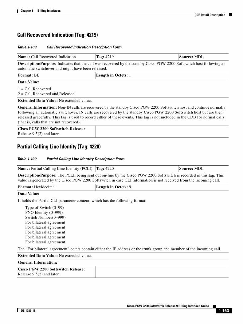
Chapter 1 Billing InterfacesCDE Detail Description
Call Recovered Indication (Tag: 4219)
Partial Calling Line Identity (Tag: 4220)
Table 1-189 Call Recovered Indication Description Form
Name: Call Recovered Indication Tag: 4219 Source: MDL
Description/Purpose: Indicates that the call was recovered by the standby Cisco PGW 2200 Softswitch host following an automatic switchover and might have been released.
Format: BE Length in Octets: 1
Data Value:
1 = Call Recovered 2 = Call Recovered and Released
Extended Data Value: No extended value.
General Information: Non-IN calls are recovered by the standby Cisco PGW 2200 Softswitch host and continue normally following an automatic switchover. IN calls are recovered by the standby Cisco PGW 2200 Softswitch host but are then released gracefully. This tag is used to record either of these events. This tag is not included in the CDB for normal calls (that is, calls that are not recovered).
Cisco PGW 2200 Softswitch Release: Release 9.5(2) and later.
Table 1-190 Partial Calling Line Identity Description Form
Name: Partial Calling Line Identity (PCLI) Tag: 4220 Source: MDL
Description/Purpose: The PCLI, being sent out on-line by the Cisco PGW 2200 Softswitch is recorded in this tag. This value is generated by the Cisco PGW 2200 Softswitch in case CLI information is not received from the incoming call.
Format: Hexidecimal Length in Octets: 9
Data Value:
It holds the Partial CLI parameter content, which has the following format:
Type of Switch (0–99) PNO Identity (0–999) Switch Number(0–999) For bilateral agreement For bilateral agreement For bilateral agreement For bilateral agreement For bilateral agreement
The “For bilateral agreement” octets contain either the IP address or the trunk group and member of the incoming call.
Extended Data Value: No extended value.
General Information:
Cisco PGW 2200 Softswitch Release: Release 9.5(2) and later.
1-163Cisco PGW 2200 Softswitch Release 9 Billing Interface Guide
OL-1089-18
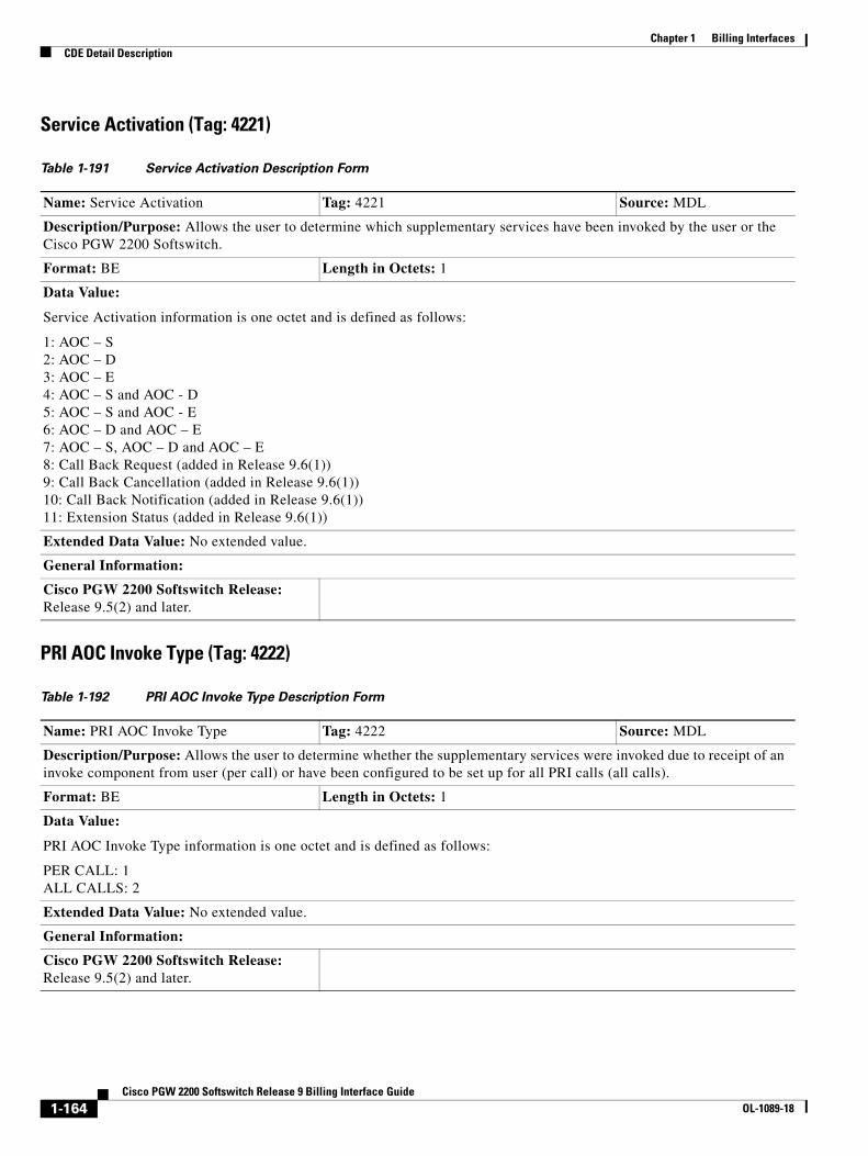
Chapter 1 Billing InterfacesCDE Detail Description
Service Activation (Tag: 4221)
PRI AOC Invoke Type (Tag: 4222)
Table 1-191 Service Activation Description Form
Name: Service Activation Tag: 4221 Source: MDL
Description/Purpose: Allows the user to determine which supplementary services have been invoked by the user or the Cisco PGW 2200 Softswitch.
Format: BE Length in Octets: 1
Data Value:
Service Activation information is one octet and is defined as follows:
1: AOC – S 2: AOC – D 3: AOC – E 4: AOC – S and AOC - D 5: AOC – S and AOC - E 6: AOC – D and AOC – E 7: AOC – S, AOC – D and AOC – E 8: Call Back Request (added in Release 9.6(1)) 9: Call Back Cancellation (added in Release 9.6(1)) 10: Call Back Notification (added in Release 9.6(1)) 11: Extension Status (added in Release 9.6(1))
Extended Data Value: No extended value.
General Information:
Cisco PGW 2200 Softswitch Release: Release 9.5(2) and later.
Table 1-192 PRI AOC Invoke Type Description Form
Name: PRI AOC Invoke Type Tag: 4222 Source: MDL
Description/Purpose: Allows the user to determine whether the supplementary services were invoked due to receipt of an invoke component from user (per call) or have been configured to be set up for all PRI calls (all calls).
Format: BE Length in Octets: 1
Data Value:
PRI AOC Invoke Type information is one octet and is defined as follows:
PER CALL: 1 ALL CALLS: 2
Extended Data Value: No extended value.
General Information:
Cisco PGW 2200 Softswitch Release: Release 9.5(2) and later.
1-164Cisco PGW 2200 Softswitch Release 9 Billing Interface Guide
OL-1089-18
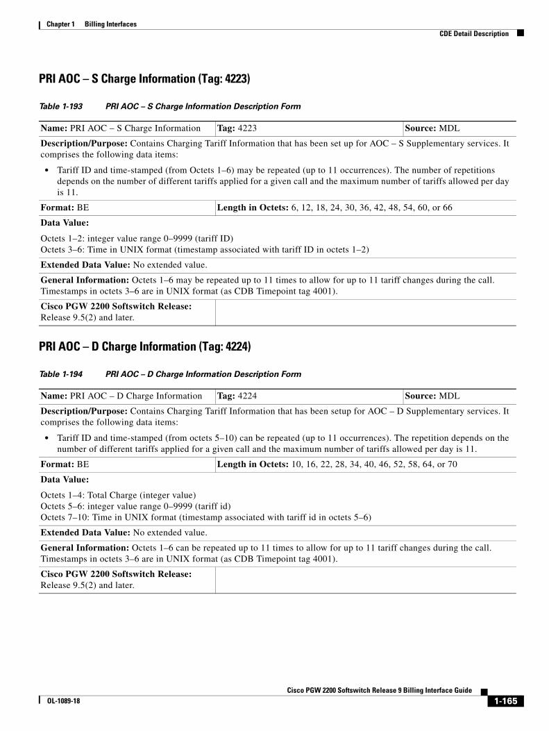
Chapter 1 Billing InterfacesCDE Detail Description
PRI AOC – S Charge Information (Tag: 4223)
PRI AOC – D Charge Information (Tag: 4224)
Table 1-193 PRI AOC – S Charge Information Description Form
Name: PRI AOC – S Charge Information Tag: 4223 Source: MDL
Description/Purpose: Contains Charging Tariff Information that has been set up for AOC – S Supplementary services. It comprises the following data items:
• Tariff ID and time-stamped (from Octets 1–6) may be repeated (up to 11 occurrences). The number of repetitions depends on the number of different tariffs applied for a given call and the maximum number of tariffs allowed per day is 11.
Format: BE Length in Octets: 6, 12, 18, 24, 30, 36, 42, 48, 54, 60, or 66
Data Value:
Octets 1–2: integer value range 0–9999 (tariff ID) Octets 3–6: Time in UNIX format (timestamp associated with tariff ID in octets 1–2)
Extended Data Value: No extended value.
General Information: Octets 1–6 may be repeated up to 11 times to allow for up to 11 tariff changes during the call. Timestamps in octets 3–6 are in UNIX format (as CDB Timepoint tag 4001).
Cisco PGW 2200 Softswitch Release: Release 9.5(2) and later.
Table 1-194 PRI AOC – D Charge Information Description Form
Name: PRI AOC – D Charge Information Tag: 4224 Source: MDL
Description/Purpose: Contains Charging Tariff Information that has been setup for AOC – D Supplementary services. It comprises the following data items:
• Tariff ID and time-stamped (from octets 5–10) can be repeated (up to 11 occurrences). The repetition depends on the number of different tariffs applied for a given call and the maximum number of tariffs allowed per day is 11.
Format: BE Length in Octets: 10, 16, 22, 28, 34, 40, 46, 52, 58, 64, or 70
Data Value:
Octets 1–4: Total Charge (integer value) Octets 5–6: integer value range 0–9999 (tariff id) Octets 7–10: Time in UNIX format (timestamp associated with tariff id in octets 5–6)
Extended Data Value: No extended value.
General Information: Octets 1–6 can be repeated up to 11 times to allow for up to 11 tariff changes during the call. Timestamps in octets 3–6 are in UNIX format (as CDB Timepoint tag 4001).
Cisco PGW 2200 Softswitch Release: Release 9.5(2) and later.
1-165Cisco PGW 2200 Softswitch Release 9 Billing Interface Guide
OL-1089-18
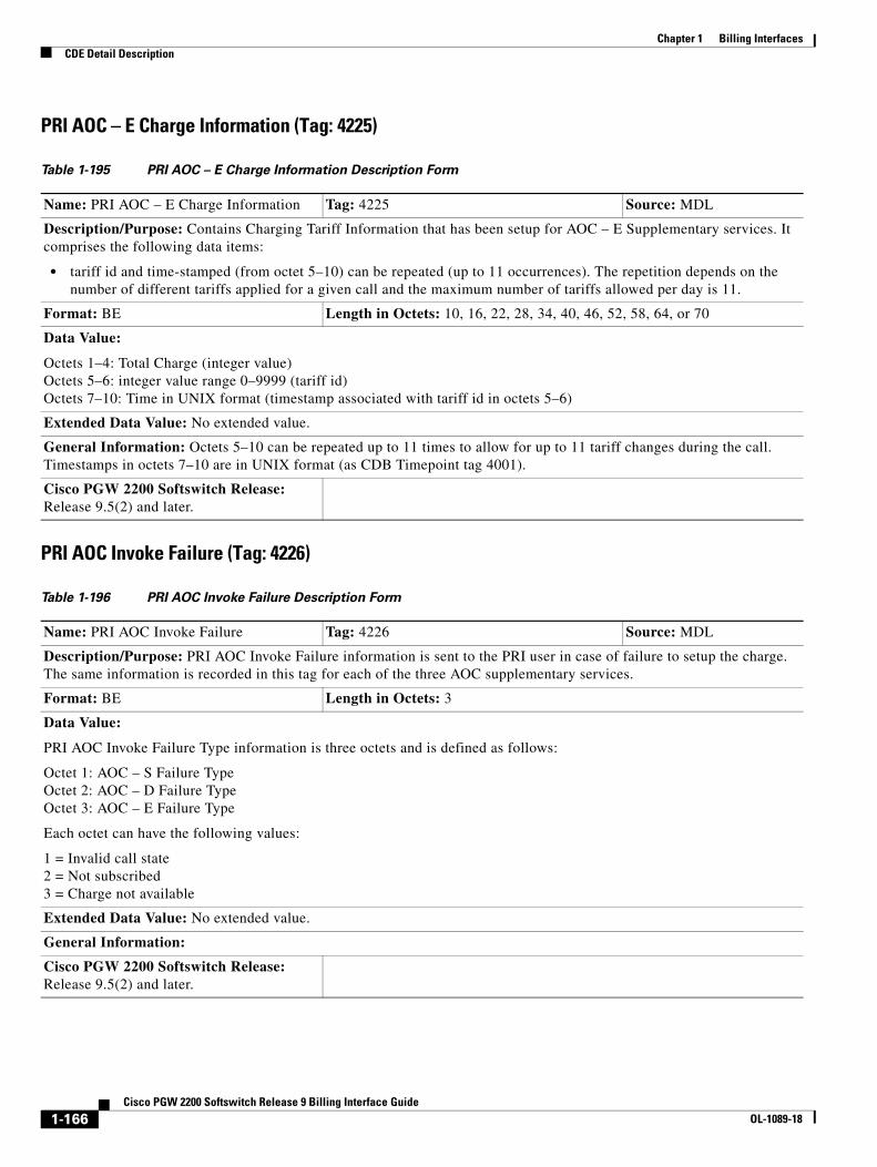
Chapter 1 Billing InterfacesCDE Detail Description
PRI AOC – E Charge Information (Tag: 4225)
PRI AOC Invoke Failure (Tag: 4226)
Table 1-195 PRI AOC – E Charge Information Description Form
Name: PRI AOC – E Charge Information Tag: 4225 Source: MDL
Description/Purpose: Contains Charging Tariff Information that has been setup for AOC – E Supplementary services. It comprises the following data items:
• tariff id and time-stamped (from octet 5–10) can be repeated (up to 11 occurrences). The repetition depends on the number of different tariffs applied for a given call and the maximum number of tariffs allowed per day is 11.
Format: BE Length in Octets: 10, 16, 22, 28, 34, 40, 46, 52, 58, 64, or 70
Data Value:
Octets 1–4: Total Charge (integer value) Octets 5–6: integer value range 0–9999 (tariff id) Octets 7–10: Time in UNIX format (timestamp associated with tariff id in octets 5–6)
Extended Data Value: No extended value.
General Information: Octets 5–10 can be repeated up to 11 times to allow for up to 11 tariff changes during the call. Timestamps in octets 7–10 are in UNIX format (as CDB Timepoint tag 4001).
Cisco PGW 2200 Softswitch Release: Release 9.5(2) and later.
Table 1-196 PRI AOC Invoke Failure Description Form
Name: PRI AOC Invoke Failure Tag: 4226 Source: MDL
Description/Purpose: PRI AOC Invoke Failure information is sent to the PRI user in case of failure to setup the charge. The same information is recorded in this tag for each of the three AOC supplementary services.
Format: BE Length in Octets: 3
Data Value:
PRI AOC Invoke Failure Type information is three octets and is defined as follows:
Octet 1: AOC – S Failure Type Octet 2: AOC – D Failure Type Octet 3: AOC – E Failure Type
Each octet can have the following values:
1 = Invalid call state 2 = Not subscribed 3 = Charge not available
Extended Data Value: No extended value.
General Information:
Cisco PGW 2200 Softswitch Release: Release 9.5(2) and later.
1-166Cisco PGW 2200 Softswitch Release 9 Billing Interface Guide
OL-1089-18
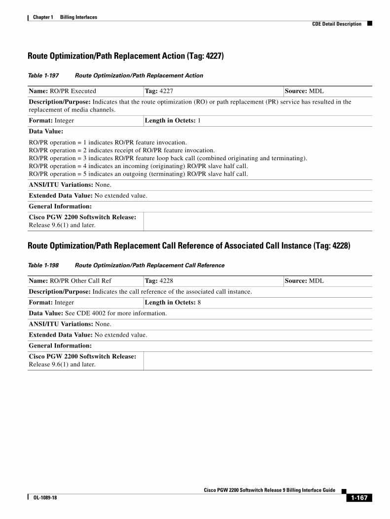
Chapter 1 Billing InterfacesCDE Detail Description
Route Optimization/Path Replacement Action (Tag: 4227)
Route Optimization/Path Replacement Call Reference of Associated Call Instance (Tag: 4228)
Table 1-197 Route Optimization/Path Replacement Action
Name: RO/PR Executed Tag: 4227 Source: MDL
Description/Purpose: Indicates that the route optimization (RO) or path replacement (PR) service has resulted in the replacement of media channels.
Format: Integer Length in Octets: 1
Data Value:
RO/PR operation = 1 indicates RO/PR feature invocation. RO/PR operation = 2 indicates receipt of RO/PR feature invocation. RO/PR operation = 3 indicates RO/PR feature loop back call (combined originating and terminating). RO/PR operation = 4 indicates an incoming (originating) RO/PR slave half call. RO/PR operation = 5 indicates an outgoing (terminating) RO/PR slave half call.
ANSI/ITU Variations: None.
Extended Data Value: No extended value.
General Information:
Cisco PGW 2200 Softswitch Release: Release 9.6(1) and later.
Table 1-198 Route Optimization/Path Replacement Call Reference
Name: RO/PR Other Call Ref Tag: 4228 Source: MDL
Description/Purpose: Indicates the call reference of the associated call instance.
Format: Integer Length in Octets: 8
Data Value: See CDE 4002 for more information.
ANSI/ITU Variations: None.
Extended Data Value: No extended value.
General Information:
Cisco PGW 2200 Softswitch Release: Release 9.6(1) and later.
1-167Cisco PGW 2200 Softswitch Release 9 Billing Interface Guide
OL-1089-18

Chapter 1 Billing InterfacesCDE Detail Description
Route Optimization/Path Replacement Trunk Group Info (Tag: 4229)
Route Optimization/Path Replacement Channel Info (Tag: 4230)
Route Optimization Switchover Timestamp (Tag: 4231)
Table 1-199 Route Optimization/Path Replacement Trunk Group Info
Name: RO/PR Replacement Trk Group Tag: 4229 Source: MDL
Description/Purpose: Indicates the trunk group id of the new replaced media channel associated with the slave call reference.
Format: Integer Length in Octets: 2
Data Value: See CDE 4008 for more information.
ANSI/ITU Variations: None.
Extended Data Value: No extended value.
General Information:
Cisco PGW 2200 Softswitch Release: Release 9.6(1) and later.
Table 1-200 Route Optimization/Path Replacement Channel Info
Name: RO/PR Replacement Chan ID Tag: 4230 Source: MDL
Description/Purpose: Indicates the channel ID of the new media path associated with the slave call reference.
Format: Integer Length in Octets: 2
Data Value: See CDE 4009 for more information.
ANSI/ITU Variations: None.
Extended Data Value: No extended value.
General Information:
Cisco PGW 2200 Softswitch Release: Release 9.6(1) and later.
Table 1-201 Route Optimization Switchover Timestamp
Name: RO/PR Switchover Timestamp Tag: 4231 Source: MDL
Description/Purpose: Indicates the point in time when media replacement occurred.
Format: Integer Length in Octets: 4
Data Value: Time in UNIX format. See CDE 4001.
ANSI/ITU Variations: None.
Extended Data Value: No extended value.
General Information:
Cisco PGW 2200 Softswitch Release: Release 9.6(1) and later.
1-168Cisco PGW 2200 Softswitch Release 9 Billing Interface Guide
OL-1089-18
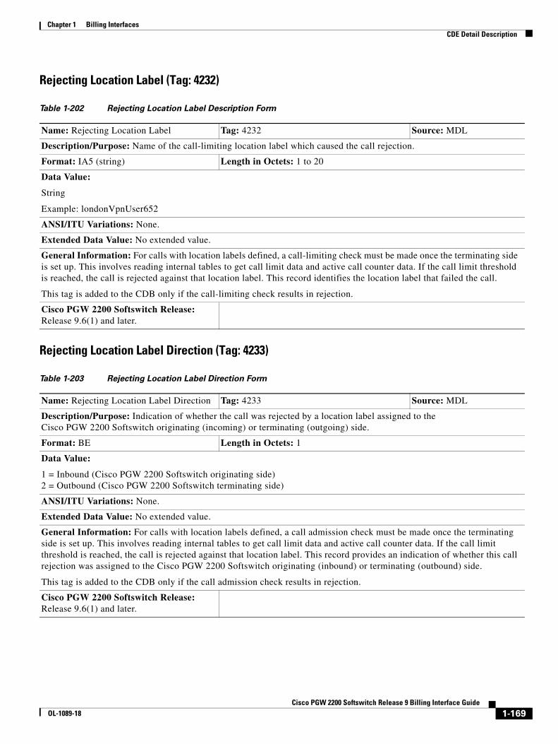
Chapter 1 Billing InterfacesCDE Detail Description
Rejecting Location Label (Tag: 4232)
Rejecting Location Label Direction (Tag: 4233)
Table 1-202 Rejecting Location Label Description Form
Name: Rejecting Location Label Tag: 4232 Source: MDL
Description/Purpose: Name of the call-limiting location label which caused the call rejection.
Format: IA5 (string) Length in Octets: 1 to 20
Data Value:
String
Example: londonVpnUser652
ANSI/ITU Variations: None.
Extended Data Value: No extended value.
General Information: For calls with location labels defined, a call-limiting check must be made once the terminating side is set up. This involves reading internal tables to get call limit data and active call counter data. If the call limit threshold is reached, the call is rejected against that location label. This record identifies the location label that failed the call.
This tag is added to the CDB only if the call-limiting check results in rejection.
Cisco PGW 2200 Softswitch Release: Release 9.6(1) and later.
Table 1-203 Rejecting Location Label Direction Form
Name: Rejecting Location Label Direction Tag: 4233 Source: MDL
Description/Purpose: Indication of whether the call was rejected by a location label assigned to the Cisco PGW 2200 Softswitch originating (incoming) or terminating (outgoing) side.
Format: BE Length in Octets: 1
Data Value:
1 = Inbound (Cisco PGW 2200 Softswitch originating side) 2 = Outbound (Cisco PGW 2200 Softswitch terminating side)
ANSI/ITU Variations: None.
Extended Data Value: No extended value.
General Information: For calls with location labels defined, a call admission check must be made once the terminating side is set up. This involves reading internal tables to get call limit data and active call counter data. If the call limit threshold is reached, the call is rejected against that location label. This record provides an indication of whether this call rejection was assigned to the Cisco PGW 2200 Softswitch originating (inbound) or terminating (outbound) side.
This tag is added to the CDB only if the call admission check results in rejection.
Cisco PGW 2200 Softswitch Release: Release 9.6(1) and later.
1-169Cisco PGW 2200 Softswitch Release 9 Billing Interface Guide
OL-1089-18
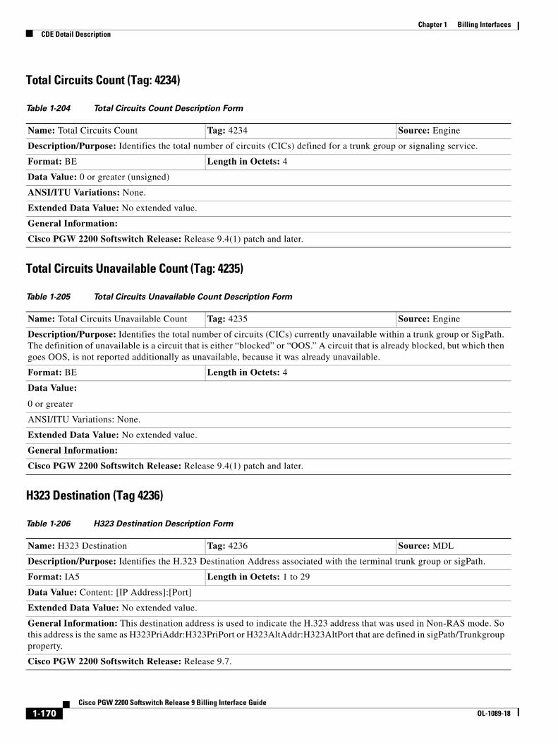
Chapter 1 Billing InterfacesCDE Detail Description
Total Circuits Count (Tag: 4234)
Total Circuits Unavailable Count (Tag: 4235)
H323 Destination (Tag 4236)
Table 1-204 Total Circuits Count Description Form
Name: Total Circuits Count Tag: 4234 Source: Engine
Description/Purpose: Identifies the total number of circuits (CICs) defined for a trunk group or signaling service.
Format: BE Length in Octets: 4
Data Value: 0 or greater (unsigned)
ANSI/ITU Variations: None.
Extended Data Value: No extended value.
General Information:
Cisco PGW 2200 Softswitch Release: Release 9.4(1) patch and later.
Table 1-205 Total Circuits Unavailable Count Description Form
Name: Total Circuits Unavailable Count Tag: 4235 Source: Engine
Description/Purpose: Identifies the total number of circuits (CICs) currently unavailable within a trunk group or SigPath. The definition of unavailable is a circuit that is either “blocked” or “OOS.” A circuit that is already blocked, but which then goes OOS, is not reported additionally as unavailable, because it was already unavailable.
Format: BE Length in Octets: 4
Data Value:
0 or greater
ANSI/ITU Variations: None.
Extended Data Value: No extended value.
General Information:
Cisco PGW 2200 Softswitch Release: Release 9.4(1) patch and later.
Table 1-206 H323 Destination Description Form
Name: H323 Destination Tag: 4236 Source: MDL
Description/Purpose: Identifies the H.323 Destination Address associated with the terminal trunk group or sigPath.
Format: IA5 Length in Octets: 1 to 29
Data Value: Content: [IP Address]:[Port]
Extended Data Value: No extended value.
General Information: This destination address is used to indicate the H.323 address that was used in Non-RAS mode. So this address is the same as H323PriAddr:H323PriPort or H323AltAddr:H323AltPort that are defined in sigPath/Trunkgroup property.
Cisco PGW 2200 Softswitch Release: Release 9.7.
1-170Cisco PGW 2200 Softswitch Release 9 Billing Interface Guide
OL-1089-18
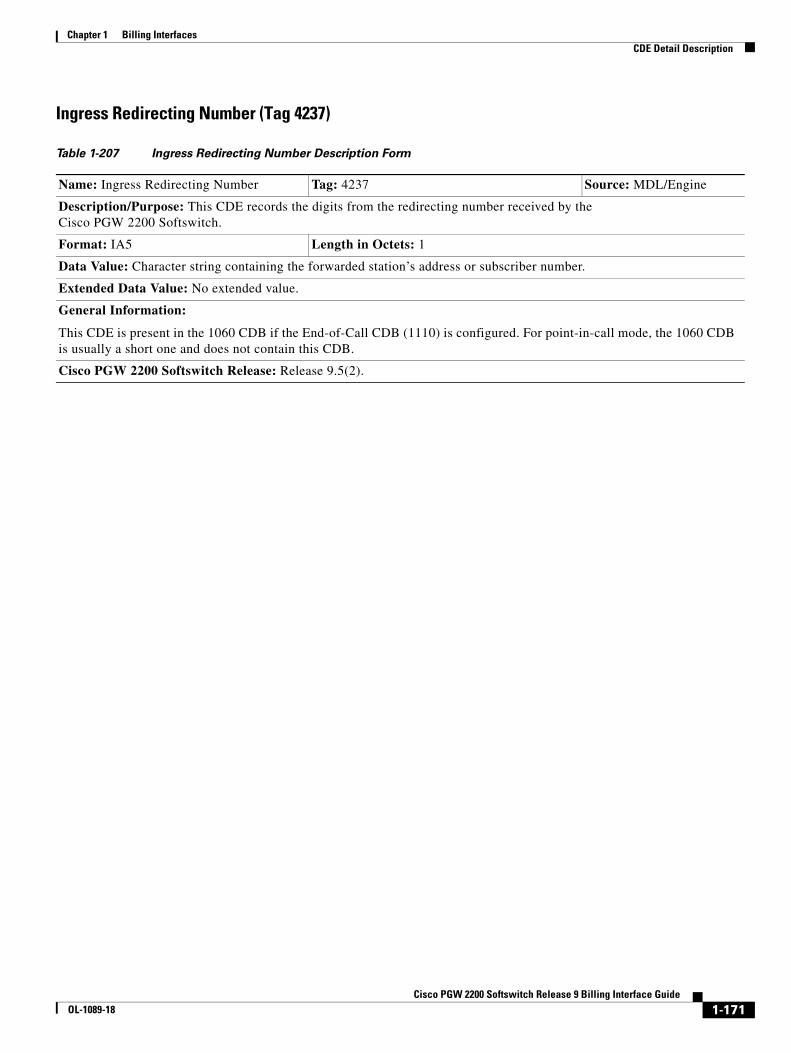
Chapter 1 Billing InterfacesCDE Detail Description
Ingress Redirecting Number (Tag 4237)
Table 1-207 Ingress Redirecting Number Description Form
Name: Ingress Redirecting Number Tag: 4237 Source: MDL/Engine
Description/Purpose: This CDE records the digits from the redirecting number received by the Cisco PGW 2200 Softswitch.
Format: IA5 Length in Octets: 1
Data Value: Character string containing the forwarded station’s address or subscriber number.
Extended Data Value: No extended value.
General Information:
This CDE is present in the 1060 CDB if the End-of-Call CDB (1110) is configured. For point-in-call mode, the 1060 CDB is usually a short one and does not contain this CDB.
Cisco PGW 2200 Softswitch Release: Release 9.5(2).
1-171Cisco PGW 2200 Softswitch Release 9 Billing Interface Guide
OL-1089-18
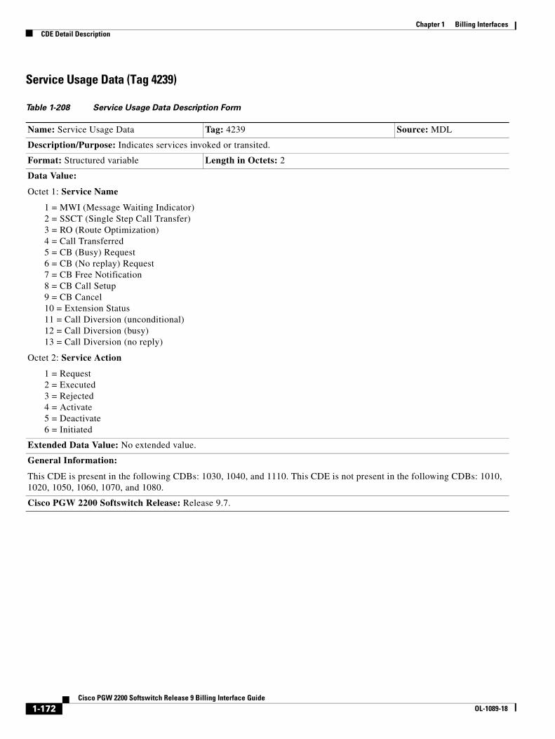
Chapter 1 Billing InterfacesCDE Detail Description
Service Usage Data (Tag 4239)
Table 1-208 Service Usage Data Description Form
Name: Service Usage Data Tag: 4239 Source: MDL
Description/Purpose: Indicates services invoked or transited.
Format: Structured variable Length in Octets: 2
Data Value:
Octet 1: Service Name
1 = MWI (Message Waiting Indicator) 2 = SSCT (Single Step Call Transfer) 3 = RO (Route Optimization) 4 = Call Transferred 5 = CB (Busy) Request 6 = CB (No replay) Request 7 = CB Free Notification 8 = CB Call Setup 9 = CB Cancel 10 = Extension Status 11 = Call Diversion (unconditional) 12 = Call Diversion (busy) 13 = Call Diversion (no reply)
Octet 2: Service Action
1 = Request 2 = Executed 3 = Rejected 4 = Activate 5 = Deactivate 6 = Initiated
Extended Data Value: No extended value.
General Information:
This CDE is present in the following CDBs: 1030, 1040, and 1110. This CDE is not present in the following CDBs: 1010, 1020, 1050, 1060, 1070, and 1080.
Cisco PGW 2200 Softswitch Release: Release 9.7.
1-172Cisco PGW 2200 Softswitch Release 9 Billing Interface Guide
OL-1089-18
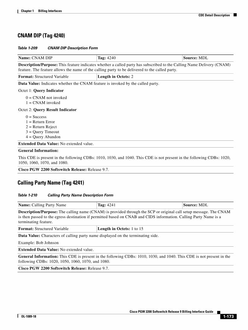
Chapter 1 Billing InterfacesCDE Detail Description
CNAM DIP (Tag 4240)
Calling Party Name (Tag 4241)
Table 1-209 CNAM DIP Description Form
Name: CNAM DIP Tag: 4240 Source: MDL
Description/Purpose: This feature indicates whether a called party has subscribed to the Calling Name Delivery (CNAM) feature. The feature allows the name of the calling party to be delivered to the called party.
Format: Structured Variable Length in Octets: 2
Data Value: Indicates whether the CNAM feature is invoked by the called party.
Octet 1: Query Indicator
0 = CNAM not invoked 1 = CNAM invoked
Octet 2: Query Result Indicator
0 = Success 1 = Return Error 2 = Return Reject 3 = Query Timeout 4 = Query Abandon
Extended Data Value: No extended value.
General Information:
This CDE is present in the following CDBs: 1010, 1030, and 1040. This CDE is not present in the following CDBs: 1020, 1050, 1060, 1070, and 1080.
Cisco PGW 2200 Softswitch Release: Release 9.7.
Table 1-210 Calling Party Name Description Form
Name: Calling Party Name Tag: 4241 Source: MDL
Description/Purpose: The calling name (CNAM) is provided through the SCP or original call setup message. The CNAM is then passed to the egress destination if permitted based on CNAB and CIDS information. Calling Party Name is a terminating feature.
Format: Structured Variable Length in Octets: 1 to 15
Data Value: Characters of calling party name displayed on the terminating side.
Example: Bob Johnson
Extended Data Value: No extended value.
General Information: This CDE is present in the following CDBs: 1010, 1030, and 1040. This CDE is not present in the following CDBs: 1020, 1050, 1060, 1070, and 1080.
Cisco PGW 2200 Softswitch Release: Release 9.7.
1-173Cisco PGW 2200 Softswitch Release 9 Billing Interface Guide
OL-1089-18
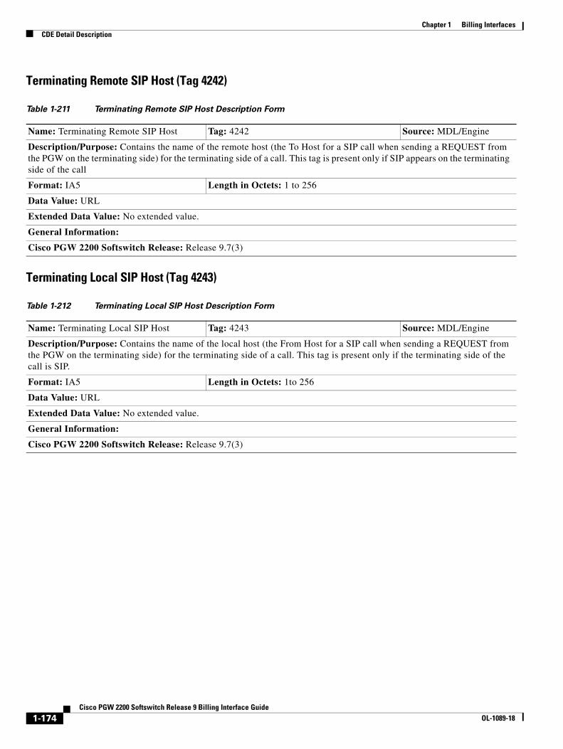
Chapter 1 Billing InterfacesCDE Detail Description
Terminating Remote SIP Host (Tag 4242)
Terminating Local SIP Host (Tag 4243)
Table 1-211 Terminating Remote SIP Host Description Form
Name: Terminating Remote SIP Host Tag: 4242 Source: MDL/Engine
Description/Purpose: Contains the name of the remote host (the To Host for a SIP call when sending a REQUEST from the PGW on the terminating side) for the terminating side of a call. This tag is present only if SIP appears on the terminating side of the call
Format: IA5 Length in Octets: 1 to 256
Data Value: URL
Extended Data Value: No extended value.
General Information:
Cisco PGW 2200 Softswitch Release: Release 9.7(3)
Table 1-212 Terminating Local SIP Host Description Form
Name: Terminating Local SIP Host Tag: 4243 Source: MDL/Engine
Description/Purpose: Contains the name of the local host (the From Host for a SIP call when sending a REQUEST from the PGW on the terminating side) for the terminating side of a call. This tag is present only if the terminating side of the call is SIP.
Format: IA5 Length in Octets: 1to 256
Data Value: URL
Extended Data Value: No extended value.
General Information:
Cisco PGW 2200 Softswitch Release: Release 9.7(3)
1-174Cisco PGW 2200 Softswitch Release 9 Billing Interface Guide
OL-1089-18

Chapter 1 Billing InterfacesCDE Detail Description
License Rejecting Reason (Tag 4244)
License Rejecting Direction (Tag 4245)
Table 1-213 License Rejecting Reason Description Form
Name: License Rejecting Reason Tag: 4244 Source: MDL
Description/Purpose: Indicates that a call was rejected due to a license-control violation, and dentifies the license that the call failed to meet.
Format: IA5(string) Length in Octets: 1 to 20
Data Value: String. Example: “SS7 Interface”
Extended Data Value: No extended value.
General Information:
The PGW performs a license check for calls with License Control. If the license limit threshold is reached or no license exists for the protocol interface, the call is rejected. This record provides the identity of the license that the call failed to meet.
This CDE is present in the following CDBs: 1030, and 1110. This CDE is not present in the following CDBs: 1010, 1020, 1040, 1050, 1060, 1070, and 1080.
Note This tag is added to the CDB only if the call admission check results in rejection.
Cisco PGW 2200 Softswitch Release: Release 9.7(3).
Table 1-214 License Rejecting Direction Description Form
Name: License Rejecting Direction Tag: 4245 Source: MDL
Description/Purpose: Indication of whether the call rejection was due to a license violation from incoming or outgoing traffic on the Cisco PGW 2200 Softswitch.
Format: BE Length in Octets: 1
Data Value:
1 = Inbound (PGW originating side)
2 = Outbound (PGW terminating side)
Extended Data Value: No extended value.
General Information:
The PGW performs a license check for calls with License Control. If the license limit threshold is reached or no license exists for the protocol interface, the call is rejected. This record provides an indication of whether the call rejection was due to a license violation from incoming or outgoing traffic on the Cisco PGW 2200 Softswitch.
This CDE is present in the following CDBs: 1030, 1110. This CDE is not present in the following CDBs: 1010, 1020, 1040, 1050, 1060, 1070, and 1080.
Note This tag is added to the CDB only if the call admission check results in rejection.
Cisco PGW 2200 Softswitch Release: Release 9.7(3).
1-175Cisco PGW 2200 Softswitch Release 9 Billing Interface Guide
OL-1089-18

Chapter 1 Billing InterfacesCDE Detail Description
SIP Ingress Transport (Tag: 4246)
SIP Routing URI Source (Tag 4247)
Table 1-215 SIP Ingress Transport Description Form
Name: SIP Ingress Transport Tag: 4246 Source: MDL
Description/Purpose: Indicates the transport protocol used by the PGW for incoming SIP messages. If the PGW switches between UDP and TCP, this value is the name of the transport protocol used in the last message.
Note The name of this tag was changed from SIP Transport to SIP Ingress Transport in Release 9.8(1).
Format: Structured variable Length in Octets: 1
Data Value:
• 1 = UDP (default)
• 2 = TCP
Extended Data Value: No extended value.
General Information:
This CDE is present in the following CDBs: 1010, 1030, 1110. This CDE is not present in the following CDBs: 1020, 1040, 1050, 1060, 1070, and 1080.
Cisco PGW 2200 Softswitch Release: Release 9.7.
Table 1-216 SIP Routing URI Source Description Form
Name: SIP Routing URI Source Tag: 4247 Source: MDL/Engine
Description/Purpose: Indicates which header or URL was used to make routing decisions.
Format: Integer Length in Octets: 1
Data Value:
1 = Top Route: header
2 = Request URL
3 = To: Header
Extended Data Value: No extended value.
General Information:
This CDE is present in the following CDBs: 1010 and 1030. This CDE is not present in the following CDBs: 1020, 1040, 1050, 1060, 1070, and 1080.
Cisco PGW 2200 Softswitch Release: Release 9.7.
1-176Cisco PGW 2200 Softswitch Release 9 Billing Interface Guide
OL-1089-18

Chapter 1 Billing InterfacesCDE Detail Description
SIP Routing URI (Tag: 4248)
Original Source Header (Tag: 4249)
Table 1-217 SIP Routing URI Description Form
Name: SIP Routing URI Tag: 4248 Source: MDL/Engine
Description/Purpose: Contains the original URI used in the initial routing decisions.
Format: IA5 Length in Octets: 1 to 256
Data Value: URL
Extended Data Value: No extended value.
General Information:
This CDE is present in the following CDBs: 1010, 1030, and 1100. This CDE is not present in the following CDBs: 1020, 1040, 1050, 1060, 1070, and 1080.
Cisco PGW 2200 Softswitch Release: Release 9.7.
Table 1-218 Original Source Header Description Form
Name: Original Source Header Tag: 4249 Source: MDL
Description/Purpose: Indicates which header or URL that the PGW used to obtain the source URI.
Format: Integer Length in Octets: 1
Data Value:
1 = Remote-Party-ID:/P-Asserted-Identity: header
2 = From: header
Extended Data Value: No extended value.
General Information:
This CDE is present in the following CDBs: 1010, 1030, 1040, and 1110. This CDE is not present in the following CDBs: 1020, 1050, 1060, 1070, and 1080.
Cisco PGW 2200 Softswitch Release: Release 9.8(1) and later.
1-177Cisco PGW 2200 Softswitch Release 9 Billing Interface Guide
OL-1089-18

Chapter 1 Billing InterfacesCDE Detail Description
Original Source URI (Tag: 4250)
Final Destination URI (Tag: 4251)
Table 1-219 Original Source URI Description Form
Name: Original Source URI Tag: 4250 Source: MDL
Description/Purpose: This tag contains the original source URI used for analysis.
Format: IA5 String Length in Octets: 1 to 40
Data Value: URI
Example: [email protected]
Extended Data Value: No extended value.
General Information: This CDE is present in the following CDBs: 1010, 1030, and 1110. This CDE is not present in the following CDBs: 1020, 1050, 1060, 1070, and 1080.
General Information (Release 9.8): This CDE is present in the following CDBs: 1010, 1030, and 1110. This CDE is not present in the following CDBs: 1020, 1040, 1050, 1060, 1070, and 1080.
Cisco PGW 2200 Softswitch Release: Release 9.8(1) and later.
Table 1-220 Final Destination URI Description Form
Name: Translated Destination URI Tag: 4251 Source: MDL
Description/Purpose: Contains the post-analysis destination URI that is used to generate outgoing SIP INVITE messages.
Format: IA5 String Length in Octets: 1 to 40
Data Value: URI
Example: [email protected]
Extended Data Value: No extended value.
General Information: This CDE is present in the following CDBs: 1010, 1030, 1040, and 1110. This CDE is not present in the following CDBs: 1020, 1050, 1060, 1070, and 1080.
General Information (Release 9.8): This CDE is present in the following CDBs: 1010, 1030, and 1110. This CDE is not present in the following CDBs: 1020, 1040, 1050, 1060, 1070, and 1080.
Cisco PGW 2200 Softswitch Release: Release 9.8(1) and later.
1-178Cisco PGW 2200 Softswitch Release 9 Billing Interface Guide
OL-1089-18
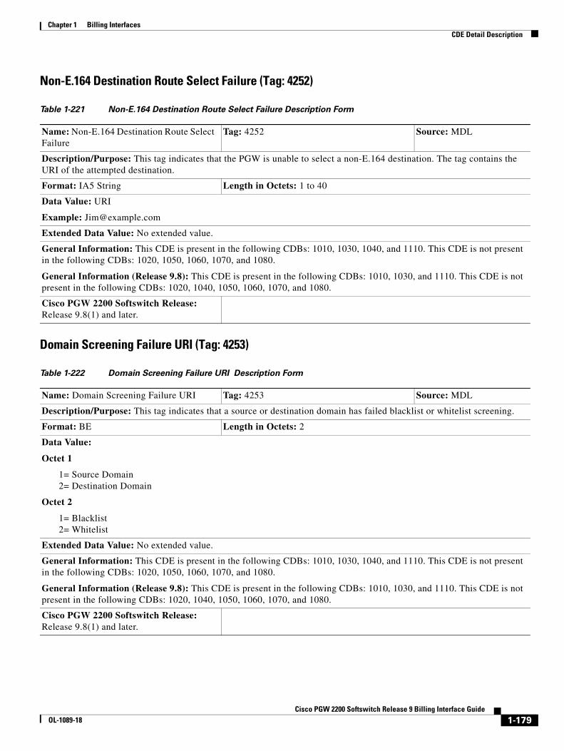
Chapter 1 Billing InterfacesCDE Detail Description
Non-E.164 Destination Route Select Failure (Tag: 4252)
Domain Screening Failure URI (Tag: 4253)
Table 1-221 Non-E.164 Destination Route Select Failure Description Form
Name: Non-E.164 Destination Route Select Failure
Tag: 4252 Source: MDL
Description/Purpose: This tag indicates that the PGW is unable to select a non-E.164 destination. The tag contains the URI of the attempted destination.
Format: IA5 String Length in Octets: 1 to 40
Data Value: URI
Example: [email protected]
Extended Data Value: No extended value.
General Information: This CDE is present in the following CDBs: 1010, 1030, 1040, and 1110. This CDE is not present in the following CDBs: 1020, 1050, 1060, 1070, and 1080.
General Information (Release 9.8): This CDE is present in the following CDBs: 1010, 1030, and 1110. This CDE is not present in the following CDBs: 1020, 1040, 1050, 1060, 1070, and 1080.
Cisco PGW 2200 Softswitch Release: Release 9.8(1) and later.
Table 1-222 Domain Screening Failure URI Description Form
Name: Domain Screening Failure URI Tag: 4253 Source: MDL
Description/Purpose: This tag indicates that a source or destination domain has failed blacklist or whitelist screening.
Format: BE Length in Octets: 2
Data Value:
Octet 1
1= Source Domain 2= Destination Domain
Octet 2
1= Blacklist 2= Whitelist
Extended Data Value: No extended value.
General Information: This CDE is present in the following CDBs: 1010, 1030, 1040, and 1110. This CDE is not present in the following CDBs: 1020, 1050, 1060, 1070, and 1080.
General Information (Release 9.8): This CDE is present in the following CDBs: 1010, 1030, and 1110. This CDE is not present in the following CDBs: 1020, 1040, 1050, 1060, 1070, and 1080.
Cisco PGW 2200 Softswitch Release: Release 9.8(1) and later.
1-179Cisco PGW 2200 Softswitch Release 9 Billing Interface Guide
OL-1089-18
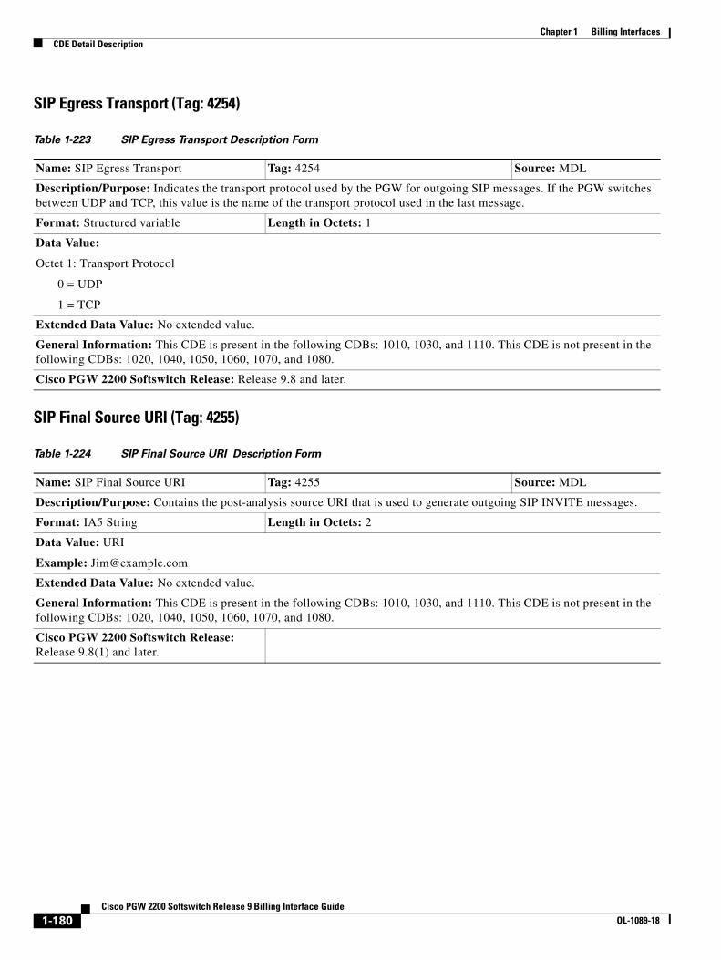
Chapter 1 Billing InterfacesCDE Detail Description
SIP Egress Transport (Tag: 4254)
SIP Final Source URI (Tag: 4255)
Table 1-223 SIP Egress Transport Description Form
Name: SIP Egress Transport Tag: 4254 Source: MDL
Description/Purpose: Indicates the transport protocol used by the PGW for outgoing SIP messages. If the PGW switches between UDP and TCP, this value is the name of the transport protocol used in the last message.
Format: Structured variable Length in Octets: 1
Data Value:
Octet 1: Transport Protocol
0 = UDP
1 = TCP
Extended Data Value: No extended value.
General Information: This CDE is present in the following CDBs: 1010, 1030, and 1110. This CDE is not present in the following CDBs: 1020, 1040, 1050, 1060, 1070, and 1080.
Cisco PGW 2200 Softswitch Release: Release 9.8 and later.
Table 1-224 SIP Final Source URI Description Form
Name: SIP Final Source URI Tag: 4255 Source: MDL
Description/Purpose: Contains the post-analysis source URI that is used to generate outgoing SIP INVITE messages.
Format: IA5 String Length in Octets: 2
Data Value: URI
Example: [email protected]
Extended Data Value: No extended value.
General Information: This CDE is present in the following CDBs: 1010, 1030, and 1110. This CDE is not present in the following CDBs: 1020, 1040, 1050, 1060, 1070, and 1080.
Cisco PGW 2200 Softswitch Release: Release 9.8(1) and later.
1-180Cisco PGW 2200 Softswitch Release 9 Billing Interface Guide
OL-1089-18
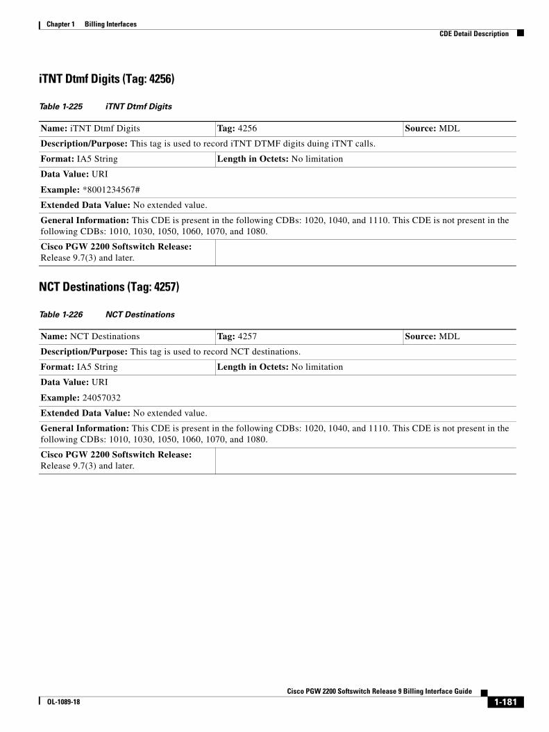
Chapter 1 Billing InterfacesCDE Detail Description
iTNT Dtmf Digits (Tag: 4256)
NCT Destinations (Tag: 4257)
Table 1-225 iTNT Dtmf Digits
Name: iTNT Dtmf Digits Tag: 4256 Source: MDL
Description/Purpose: This tag is used to record iTNT DTMF digits duing iTNT calls.
Format: IA5 String Length in Octets: No limitation
Data Value: URI
Example: *8001234567#
Extended Data Value: No extended value.
General Information: This CDE is present in the following CDBs: 1020, 1040, and 1110. This CDE is not present in the following CDBs: 1010, 1030, 1050, 1060, 1070, and 1080.
Cisco PGW 2200 Softswitch Release: Release 9.7(3) and later.
Table 1-226 NCT Destinations
Name: NCT Destinations Tag: 4257 Source: MDL
Description/Purpose: This tag is used to record NCT destinations.
Format: IA5 String Length in Octets: No limitation
Data Value: URI
Example: 24057032
Extended Data Value: No extended value.
General Information: This CDE is present in the following CDBs: 1020, 1040, and 1110. This CDE is not present in the following CDBs: 1010, 1030, 1050, 1060, 1070, and 1080.
Cisco PGW 2200 Softswitch Release: Release 9.7(3) and later.
1-181Cisco PGW 2200 Softswitch Release 9 Billing Interface Guide
OL-1089-18

Chapter 1 Billing InterfacesCDE Detail Description
iTNT Destinations (Tag: 4258)
iTNT MidCall Dial Plan (Tag: 4259)
Table 1-227 iTNT Destinations
Name: iTNT Destinations Tag: 4258 Source: MDL
Description/Purpose: This tag is used to record iTNT/NBT/Basic TNT destinations.
Format: IA5 String Length in Octets: No limitation
Data Value: URI
Example: 24057032
Extended Data Value: No extended value.
General Information: This CDE is present in the following CDBs: 1020, 1040, and 1110. This CDE is not present in the following CDBs: 1010, 1030, 1050, 1060, 1070, and 1080.
Cisco PGW 2200 Softswitch Release: Release 9.7(3) and later.
Table 1-228 iTNT MidCall Dial Plan
Name: iTNT MidCall Dial Plan Tag: 4259 Source: MDL
Description/Purpose: This tag is used to record the midcall dial plan string used for an iTNT call.
Format: IA5 String Length in Octets: No limitation
Data Value: URI
Example: 2222 , 1111
Extended Data Value: No extended value.
General Information: This CDE is present in the following CDBs: 1020, 1040, and 1110. This CDE is not present in the following CDBs: 1010, 1030, 1050, 1060, 1070, and 1080.
Cisco PGW 2200 Softswitch Release: Release 9.7(3) and later.
1-182Cisco PGW 2200 Softswitch Release 9 Billing Interface Guide
OL-1089-18

Chapter 1 Billing InterfacesCDE Detail Description
Timepoint Millisecond Granularity CDEs
Last SAM Timepoint (Millisecond) (Tag:4022)
IAM Timepoint Received_ms (Tag: 4100)
IAM Timepoint Sent_ms (Tag: 4101)
Table 1-229 Last SAM timepoint (Millisecond)
Name: Last SAM timepoint (Millisecond) Tag: 4022 Source: MDL/Engine
Description/Purpose: Time point in millisecond for receipt of last SAM.
Format: Binary Length: 6
Data Value: Unix Time plus 2 bytes for milliseconds
Extended Data Value: No extended value
General Information: This tag indicates the timepoint of the last SAM message received.
Cisco PGW 2200 Softswitch Release: 9.8(1)
Table 1-230 IAM Timepoint Received_ms Description Form
Name: IAM Timepoint Received_ms Tag: 4100 Source: MDL/Engine
Description/Purpose: The IAM timepoint received is the recorded timepoint when the IAM was received, in milliseconds since January 1, 1970.
Format: Binary Length in Octets: 6
Data Value: Cisco PGW 2200 Softswitch time plus 2 bytes for milliseconds.
Extended Data Value: No extended value.
General Information:
Cisco PGW 2200 Softswitch Release: Release 7.0 and later.
Table 1-231 IAM Timepoint Sent_ms Description Form
Name: IAM Timepoint Sent_ms Tag: 4101 Source: MDL/Engine
Description/Purpose: The IAM timepoint sent is the recorded timepoint when the IAM was sent, in milliseconds since January 1, 1970.
Format: Binary Length in Octets: 6
Data Value: Cisco PGW 2200 Softswitch time plus 2 bytes for milliseconds.
Extended Data Value: No extended value.
General Information:
Cisco PGW 2200 Softswitch Release: Release 7.0 and later.
1-183Cisco PGW 2200 Softswitch Release 9 Billing Interface Guide
OL-1089-18
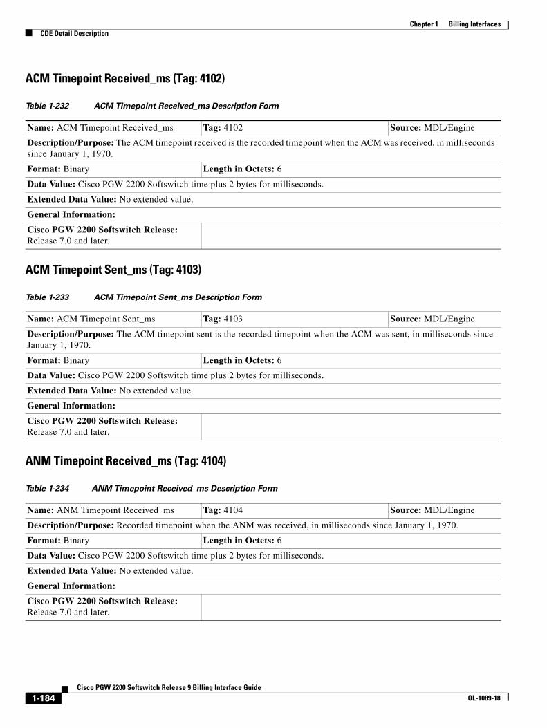
Chapter 1 Billing InterfacesCDE Detail Description
ACM Timepoint Received_ms (Tag: 4102)
ACM Timepoint Sent_ms (Tag: 4103)
ANM Timepoint Received_ms (Tag: 4104)
Table 1-232 ACM Timepoint Received_ms Description Form
Name: ACM Timepoint Received_ms Tag: 4102 Source: MDL/Engine
Description/Purpose: The ACM timepoint received is the recorded timepoint when the ACM was received, in milliseconds since January 1, 1970.
Format: Binary Length in Octets: 6
Data Value: Cisco PGW 2200 Softswitch time plus 2 bytes for milliseconds.
Extended Data Value: No extended value.
General Information:
Cisco PGW 2200 Softswitch Release: Release 7.0 and later.
Table 1-233 ACM Timepoint Sent_ms Description Form
Name: ACM Timepoint Sent_ms Tag: 4103 Source: MDL/Engine
Description/Purpose: The ACM timepoint sent is the recorded timepoint when the ACM was sent, in milliseconds since January 1, 1970.
Format: Binary Length in Octets: 6
Data Value: Cisco PGW 2200 Softswitch time plus 2 bytes for milliseconds.
Extended Data Value: No extended value.
General Information:
Cisco PGW 2200 Softswitch Release: Release 7.0 and later.
Table 1-234 ANM Timepoint Received_ms Description Form
Name: ANM Timepoint Received_ms Tag: 4104 Source: MDL/Engine
Description/Purpose: Recorded timepoint when the ANM was received, in milliseconds since January 1, 1970.
Format: Binary Length in Octets: 6
Data Value: Cisco PGW 2200 Softswitch time plus 2 bytes for milliseconds.
Extended Data Value: No extended value.
General Information:
Cisco PGW 2200 Softswitch Release: Release 7.0 and later.
1-184Cisco PGW 2200 Softswitch Release 9 Billing Interface Guide
OL-1089-18

Chapter 1 Billing InterfacesCDE Detail Description
ANM Timepoint Sent_ms (Tag: 4105)
First REL Timepoint_ms (Tag: 4106)
Second REL Timepoint _ms (Tag: 4107)
Table 1-235 ANM Timepoint Sent_ms Description Form
Name: ANM Timepoint Sent_ms Tag: 4105 Source: MDL/Engine
Description/Purpose: Recorded timepoint when the ANM was sent, in milliseconds since January 1, 1970.
Format: Binary Length in Octets: 6
Data Value: Cisco PGW 2200 Softswitch time plus 2 bytes for milliseconds,
Extended Data Value: No extended value.
General Information:
Cisco PGW 2200 Softswitch Release: Release 7.0 and later.
Table 1-236 First REL Timepoint_ms Description Form
Name: First REL Timepoint_ms Tag: 4106 Source: MDL/Engine
Description/Purpose: Timepoint for receipt of first REL/RELEASE.
Format: Binary Length in Octets: 6
Data Value: Cisco PGW 2200 Softswitch time plus 2 bytes for milliseconds.
Extended Data Value: No extended value.
General Information:
Cisco PGW 2200 Softswitch Release: Release 7.0 and later.
Table 1-237 Second REL Timepoint _ms Description Form
Name: Second REL Timepoint_ms Tag: 4107 Source: MDL/Engine
Description/Purpose: Timepoint for receipt of second REL/RELEASE.
Format: Binary Length in Octets: 6
Data Value: Cisco PGW 2200 Softswitch time plus 2 bytes for milliseconds.
Extended Data Value: No extended value.
General Information:
Cisco PGW 2200 Softswitch Release: Release 7.0 and later.
1-185Cisco PGW 2200 Softswitch Release 9 Billing Interface Guide
OL-1089-18

Chapter 1 Billing InterfacesCDE Detail Description
RLC Timepoint Received_ms (Tag: 4108)
RLC Timepoint Sent_ms (Tag: 4109)
Table 1-238 RLC Timepoint Received_ms Description Form
Name: RLC Timepoint Received_ms Tag: 4108 Source: MDL/Engine
Description/Purpose: Recorded timepoint when the RLC was received, in milliseconds since January 1, 1970.
Format: Binary Length in Octets: 6
Data Value: Cisco PGW 2200 Softswitch time plus 2 bytes for milliseconds.
Extended Data Value: No extended value.
General Information:
Cisco PGW 2200 Softswitch Release: Release 7.0 and later.
Table 1-239 RLC Timepoint Sent_ms Description Form
Name: RLC Timepoint Sent_ms Tag: 4109 Source: MDL/Engine
Description/Purpose: Recorded timepoint when the RLC was sent, in milliseconds since January 1, 1970.
Format: Binary Length in Octets: 6
Data Value: Cisco PGW 2200 Softswitch time plus 2 bytes for milliseconds.
Extended Data Value: No extended value.
General Information:
Cisco PGW 2200 Softswitch Release: Release 7.0 and later.
1-186Cisco PGW 2200 Softswitch Release 9 Billing Interface Guide
OL-1089-18
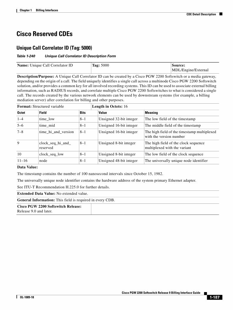
Chapter 1 Billing InterfacesCDE Detail Description
Cisco Reserved CDEs
Unique Call Correlator ID (Tag: 5000)Table 1-240 Unique Call Correlator ID Description Form
Name: Unique Call Correlator ID Tag: 5000 Source: MDL/Engine/External
Description/Purpose: A Unique Call Correlator ID can be created by a Cisco PGW 2200 Softswitch or a media gateway, depending on the origin of a call. The field uniquely identifies a single call across a multinode Cisco PGW 2200 Softswitch solution, and/or provides a common key for all involved recording systems. This ID can be used to associate external billing information, such as RADIUS records, and correlate multiple Cisco PGW 2200 Softswitches to what is considered a single call. The records created by the various network elements can be used by downstream systems (for example, a billing mediation server) after correlation for billing and other purposes.
Format: Structured variable Length in Octets: 16
Octet Field Bits Value Meaning
1–4 time_low 8–1 Unsigned 32-bit integer The low field of the timestamp
5–6 time_mid 8–1 Unsigned 16-bit integer The middle field of the timestamp
7–8 time_hi_and_version 8–1 Unsigned 16-bit integer The high field of the timestamp multiplexed with the version number
9 clock_seq_hi_and_ reserved
8–1 Unsigned 8-bit integer The high field of the clock sequence multiplexed with the variant
10 clock_seq_low 8–1 Unsigned 8-bit integer The low field of the clock sequence
11–16 node 8–1 Unsigned 48-bit integer The universally unique node identifier
Data Value:
The timestamp contains the number of 100 nanosecond intervals since October 15, 1982.
The universally unique node identifier contains the hardware address of the system primary Ethernet adapter.
See ITU-T Recommendation H.225.0 for further details.
Extended Data Value: No extended value.
General Information: This field is required in every CDB.
Cisco PGW 2200 Softswitch Release: Release 9.0 and later.
1-187Cisco PGW 2200 Softswitch Release 9 Billing Interface Guide
OL-1089-18
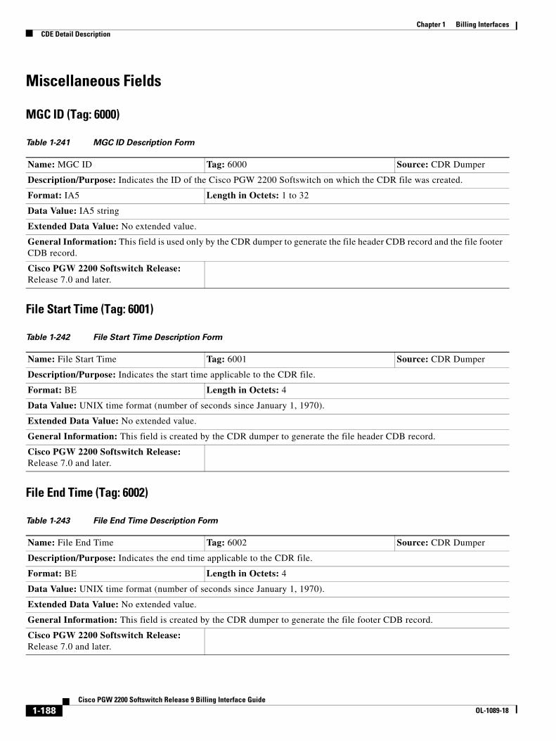
Chapter 1 Billing InterfacesCDE Detail Description
Miscellaneous Fields
MGC ID (Tag: 6000)
File Start Time (Tag: 6001)
File End Time (Tag: 6002)
Table 1-241 MGC ID Description Form
Name: MGC ID Tag: 6000 Source: CDR Dumper
Description/Purpose: Indicates the ID of the Cisco PGW 2200 Softswitch on which the CDR file was created.
Format: IA5 Length in Octets: 1 to 32
Data Value: IA5 string
Extended Data Value: No extended value.
General Information: This field is used only by the CDR dumper to generate the file header CDB record and the file footer CDB record.
Cisco PGW 2200 Softswitch Release: Release 7.0 and later.
Table 1-242 File Start Time Description Form
Name: File Start Time Tag: 6001 Source: CDR Dumper
Description/Purpose: Indicates the start time applicable to the CDR file.
Format: BE Length in Octets: 4
Data Value: UNIX time format (number of seconds since January 1, 1970).
Extended Data Value: No extended value.
General Information: This field is created by the CDR dumper to generate the file header CDB record.
Cisco PGW 2200 Softswitch Release: Release 7.0 and later.
Table 1-243 File End Time Description Form
Name: File End Time Tag: 6002 Source: CDR Dumper
Description/Purpose: Indicates the end time applicable to the CDR file.
Format: BE Length in Octets: 4
Data Value: UNIX time format (number of seconds since January 1, 1970).
Extended Data Value: No extended value.
General Information: This field is created by the CDR dumper to generate the file footer CDB record.
Cisco PGW 2200 Softswitch Release: Release 7.0 and later.
1-188Cisco PGW 2200 Softswitch Release 9 Billing Interface Guide
OL-1089-18
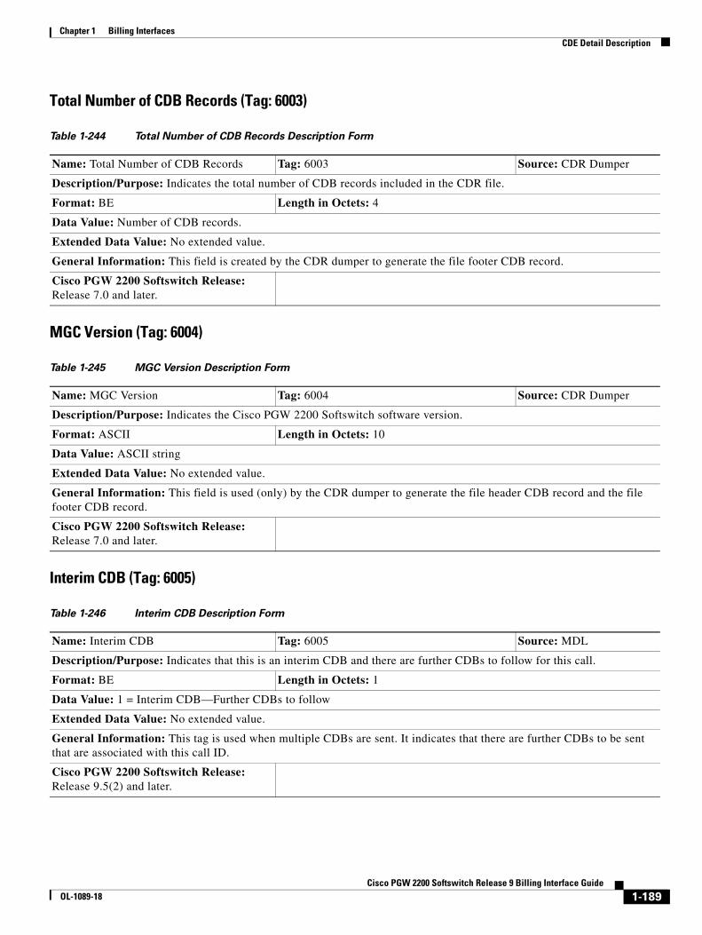
Chapter 1 Billing InterfacesCDE Detail Description
Total Number of CDB Records (Tag: 6003)
MGC Version (Tag: 6004)
Interim CDB (Tag: 6005)
Table 1-244 Total Number of CDB Records Description Form
Name: Total Number of CDB Records Tag: 6003 Source: CDR Dumper
Description/Purpose: Indicates the total number of CDB records included in the CDR file.
Format: BE Length in Octets: 4
Data Value: Number of CDB records.
Extended Data Value: No extended value.
General Information: This field is created by the CDR dumper to generate the file footer CDB record.
Cisco PGW 2200 Softswitch Release: Release 7.0 and later.
Table 1-245 MGC Version Description Form
Name: MGC Version Tag: 6004 Source: CDR Dumper
Description/Purpose: Indicates the Cisco PGW 2200 Softswitch software version.
Format: ASCII Length in Octets: 10
Data Value: ASCII string
Extended Data Value: No extended value.
General Information: This field is used (only) by the CDR dumper to generate the file header CDB record and the file footer CDB record.
Cisco PGW 2200 Softswitch Release: Release 7.0 and later.
Table 1-246 Interim CDB Description Form
Name: Interim CDB Tag: 6005 Source: MDL
Description/Purpose: Indicates that this is an interim CDB and there are further CDBs to follow for this call.
Format: BE Length in Octets: 1
Data Value: 1 = Interim CDB—Further CDBs to follow
Extended Data Value: No extended value.
General Information: This tag is used when multiple CDBs are sent. It indicates that there are further CDBs to be sent that are associated with this call ID.
Cisco PGW 2200 Softswitch Release: Release 9.5(2) and later.
1-189Cisco PGW 2200 Softswitch Release 9 Billing Interface Guide
OL-1089-18

Chapter 1 Billing InterfacesCDE Detail Description
Protocol-Specific CDEs
TTC Contract Number (Tag: 6100)
TTC Contract Number NOA (Tag: 6101)
Table 1-247 TTC Contract Number Description Form
Name: TTC Contract Number Tag: 6100 Source: MDL
Description/Purpose: Digits from the Contract Number Parameter of TTC-Q.763a.
Format: IA5 Length in Octets: 3 to 12
Data Value: Digits
Extended Data Value: No extended value.
General Information: This field is used only when the Cisco PGW 2200 Softswitch is configured with the TTC signaling protocol.
Cisco PGW 2200 Softswitch Release: Release 7.0 and later.
Table 1-248 TTC Contract Number NOA Description Form
Name: TTC Contract Number NOA Tag: 6101 Source: MDL
Description/Purpose: Nature of Address field of Contract Number Parameter from TTC-Q.763a.
Format: IA5 Length in Octets: 1
Data Value: 1 octet
Extended Data Value: No extended value.
General Information: This field is used only when the Cisco PGW 2200 Softswitch is configured with the TTC signaling protocol.
Cisco PGW 2200 Softswitch Release: Release 7.0 and later.
1-190Cisco PGW 2200 Softswitch Release 9 Billing Interface Guide
OL-1089-18

Chapter 1 Billing InterfacesCDE Detail Description
TTC Charge Info (Tag: 6102)
TTC Charge Info Type (Tag: 6103)
TTC Charge Area Info (Tag: 6104)
Table 1-249 TTC Charge Info Description Form
Name: TTC Charge Info Tag: 6102 Source: MDL
Description/Purpose: From TTC-Q.763a Charge Information Parameter.
Format: IA5 Length in Octets: 3 to n, where the field configuration is specified separately for each network
Data Value: Sequence of octets
Extended Data Value: No extended value.
General Information: This field is used only when the Cisco MGC is configured with the TTC signaling protocol.
Cisco PGW 2200 Softswitch Release: Release 7.0 and later.
Table 1-250 TTC Charge Info Type Description Form
Name: TTC Charge Info Type Tag: 6103 Source: MDL
Description/Purpose: This parameter is taken from the TTC-Q.763a Charge Information parameter.
Format: IA5 Length in Octets: 3 to n, where the field configuration is specified separately for each network
Data Value: Sequence of octets
Extended Data Value: No extended value.
General Information: This field is used only when the Cisco PGW 2200 Softswitch is configured with the TTC signaling protocol.
Cisco PGW 2200 Softswitch Release: Release 7.0 and later.
Table 1-251 TTC Charge Area Info Description Form
Name: TTC Charge Area Info Tag: 6104 Source: MDL
Description/Purpose: This parameter is taken from the TTC-Q.763a Charge Originating Info parameter.
Format: IA5 Length in Octets: 3 to 6
Data Value: Sequence of octets
Extended Data Value: No extended value.
General Information: This field is used only when the Cisco PGW 2200 Softswitch is configured with the TTC signaling protocol.
Cisco PGW 2200 Softswitch Release: Release 7.0 and later.
1-191Cisco PGW 2200 Softswitch Release 9 Billing Interface Guide
OL-1089-18
Chapter 1 Billing InterfacesCDE Detail Description
1-192Cisco PGW 2200 Softswitch Release 9 Billing Interface Guide
OL-1089-18
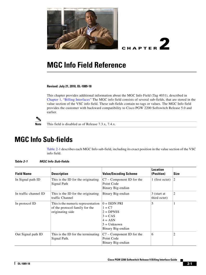
Cisco PGWOL-1089-18
C H A P T E R 2
MGC Info Field ReferenceRevised: July 21, 2010, OL-1089-18
This chapter provides additional information about the MGC Info Field (Tag 4031), described in Chapter 1, “Billing Interfaces” The MGC info field consists of several sub-fields, that are stored in the value section of the VSC info field. These sub-fields contain no tags or values. The MGC Info field provides the customer with backward compatibility to Cisco PGW 2200 Softswitch Release 5.0 and earlier.
Note This field is disabled as of Release 7.3.x, 7.4.x.
MGC Info Sub-fieldsTable 2-1 describes each MGC Info sub-field, including its exact position in the value section of the VSC info field.
Table 2-1 MGC Info Sub-fields
Field Name Description Value/Encoding SchemeLocation(Position) Size
In Signal path ID This is the ID for the originating Signal Path
C7 – Component ID for the Point Code Binary Big-endian
1 (first octet) 2
In traffic channel ID This is the ID for the originating traffic Channel
Binary Big-endian 3 (start at third octet)
2
In protocol ID This is the numeric representation of the protocol family for the originating side
0 = ISDN PRI 1 = C7 2 = DPNSS 3 = CAS 4 = ASN 5 = Unknown Binary Big-endian
5 1
Out Signal path ID This is the ID for the terminating Signal Path.
C7 – Component ID for the Point Code Binary Big-endian
6 2
2-1 2200 Softswitch Release 9 Billing Interface Guide
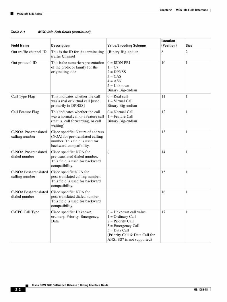
Chapter 2 MGC Info Field ReferenceMGC Info Sub-fields
Out traffic channel ID This is the ID for the terminating traffic Channel
(Binary Big-endian 8 2
Out protocol ID This is the numeric representation of the protocol family for the originating side
0 = ISDN PRI 1 = C7 2 = DPNSS 3 = CAS 4 = ASN 5 = Unknown Binary Big-endian
10 1
Call Type Flag This indicates whether the call was a real or virtual call [used primarily in DPNSS]
0 = Real call 1 = Virtual Call Binary Big-endian
11 1
Call Feature Flag This indicates whether the call was a normal call or a feature call (that is, call forwarding, or call waiting)
0 = Normal Call 1 = Feature Call Binary Big-endian
12 1
C-NOA Pre-translated calling number
Cisco specific: Nature of address (NOA) for pre-translated calling number. This field is used for backward compatibility.
13 1
C-NOA Pre-translated dialed number
Cisco specific: NOA for pre-translated dialed number. This field is used for backward compatibility.
( 14 1
C-NOA Post-translated calling number
Cisco specific:NOA for post-translated calling number. This field is used for backward compatibility.
15 1
C-NOA Post-translated dialed number
Cisco specific: NOA for post-translated dialed number. This field is used for backward compatibility.
16 1
C-CPC Call Type Cisco specific: Unknown, ordinary, Priority, Emergency, Data
0 = Unknown call value 1 = Ordinary Call 2 = Priority Call 3 = Emergency Call 5 = Data Call (Priority Call & Data Call for ANSI SS7 is not supported)
17 1
Table 2-1 MGC Info Sub-fields (continued)
Field Name Description Value/Encoding SchemeLocation(Position) Size
2-2Cisco PGW 2200 Softswitch Release 9 Billing Interface Guide
OL-1089-18
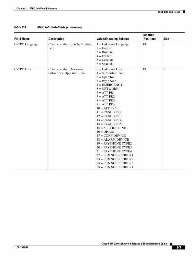
Chapter 2 MGC Info Field ReferenceMGC Info Sub-fields
C-CPC Language Cisco specific: French, English, ..etc
1 = Unknown Language 2 = English 3 = Russian 4 = French 5 = German 6 = Spanish
18 1
C-CPC User Cisco specific: Unknown, Subscriber, Operator,…etc
0 = Unknown User 1 = Subscriber User 2 = Operator 3 = Pay phone 4 = EMERGENCY 5 = NETWORK 6 = ATT PR1 7 = ATT PR2 8 = ATT PR3 9 = ATT PR4 10 = ATT PR5 11 = CGSUB PR2 12 = CGSUB PR3 13 = CGSUB PR4 14 = CGSUB PR5 15 = SERVICE LINE 16 = DPNSS 17 = CONF DEVICE 18 = ALARM DEVICE 19 = PAYPHONE TYPE2 20 = PAYPHONE TYPE3 21 = PAYPHONE TYPE4 22 = PBX SUBSCRIBER1 23 = PBX SUBSCRIBER2 24 = PBX SUBSCRIBER3 25 = PBX SUBSCRIBER4
19 1
Table 2-1 MGC Info Sub-fields (continued)
Field Name Description Value/Encoding SchemeLocation(Position) Size
2-3Cisco PGW 2200 Softswitch Release 9 Billing Interface Guide
OL-1089-18
Chapter 2 MGC Info Field ReferenceMGC Info Sub-fields
2-4Cisco PGW 2200 Softswitch Release 9 Billing Interface Guide
OL-1089-18

Cisco PGW 2200 OL-1089-18
A
P P E N D I X A CDE Listings by ReleaseRevised: July 21, 2010, OL-1089-18
This appendix lists the valid call detail elements (CDEs) on a release-by-release basis. The valid CDEs are listed in the following sections:
• CDE Baseline—Release 9.1(5) and Higher, page A-1
• CDE Changes in Release 9.2(2), page A-4
• CDE Changes in Release 9.3(1), page A-5
• CDE Changes in Release 9.3(2), page A-5
• CDE Changes in Release 9.4(1), page A-5
• CDE Changes in Release 9.5(2), page A-6
• CDE Changes in Release 9.6(1), page A-7
• CDE Changes in Release 9.7, page A-8
• CDE Changes in Release 9.8, page A-10
CDE Baseline—Release 9.1(5) and HigherTable A-1 lists the CDEs that are valid as of Release 9.1(5).
Table A-1 Valid CDEs for Release 9.1(5) and Higher
Tag Value Field Name
2000 Calling Party Category
2001 User Service Information
2002 Originating Line Information
2003 Calling Number Nature of Address
2004 Charged Number Nature of Address
2005 Dialed Number Nature of Address
2006 LRN Nature of Address
2007 Called Number Nature of Address
2008 Reason Code
2009 Forward Call Indicators Received
-1Softswitch Release 9 Billing Interface Guide

Appendix CDE Baseline—Release 9.1(5) and Higher
2010 Forward Call Indicators Sent
2011 Nature of Connection Indicators Received
2012 Nature of Connection Indicators Sent
2013 Transit Network Selection
2014 Carrier Identification Parameter
2015 Carrier Selection Parameter
2016 Jurisdiction Information Parameter
2017 Redirecting Number NOA
3000 Calling Party Category
3001 User Service Information
3003 Calling Number Nature of Address
3005 Dialed Number Nature of Address
3006 LRN Nature of Address
3007 Called Number Nature of Address
3008 Reason Code
3009 Forward Call Indicators Received
3010 Forward Call Indicators Sent
3011 Nature of Connection Indicators Received
3012 Nature of Connection Indicators Sent
3013 Transit Network Selection
3017 Redirecting Number NOA
4000 CDB Version
4001 CDB Timepoint
4002 Call Reference ID
4003 IAM Timepoint
4004 ACM Timepoint
4005 ANM Timepoint
4006 REL Timepoint
4007 Crash Timepoint
4008 Originating Trunk Group
4009 Originating Member
4010 Calling Number
4011 Charged Number
4012 Dialed Number
4013 LRN Number
4014 Called Number
Table A-1 Valid CDEs for Release 9.1(5) and Higher (continued)
Tag Value Field Name
-2Cisco PGW 2200 Softswitch Release 9 Billing Interface Guide
OL-1089-18
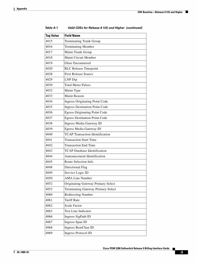
Appendix CDE Baseline—Release 9.1(5) and Higher
4015 Terminating Trunk Group
4016 Terminating Member
4017 Maint Trunk Group
4018 Maint Circuit Member
4019 Glare Encountered
4020 RLC Release Timepoint
4028 First Release Source
4029 LNP Dip
4030 Total Meter Pulses
4032 Maint Type
4033 Maint Reason
4034 Ingress Originating Point Code
4035 Ingress Destination Point Code
4036 Egress Originating Point Code
4037 Egress Destination Point Code
4038 Ingress Media Gateway ID
4039 Egress Media Gateway ID
4040 TCAP Transaction Identification
4041 Transaction Start Time
4042 Transaction End Time
4043 TCAP Database Identification
4044 Announcement Identification
4045 Route Selection Info
4048 Directional Flag
4049 Service Logic ID
4050 AMA Line Number
4052 Originating Gateway Primary Select
4053 Terminating Gateway Primary Select
4060 Redirecting Number
4061 Tariff Rate
4062 Scale Factor
4063 Test Line Indicator
4066 Ingress SigPath ID
4067 Ingress Span ID
4068 Ingress BearChan ID
4069 Ingress Protocol ID
Table A-1 Valid CDEs for Release 9.1(5) and Higher (continued)
Tag Value Field Name
-3Cisco PGW 2200 Softswitch Release 9 Billing Interface Guide
OL-1089-18

Appendix CDE Changes in Release 9.2(2)
CDE Changes in Release 9.2(2)There are no CDE changes in Release 9.2(2).
4070 Egress SigPath ID
4071 Egress Span ID
4072 Egress BearChan ID
4073 Egress Protocol ID
4074 Maintenance SigPath ID
4075 Maintenance Span ID
4076 Maintenance BearChan ID
4077 Maintenance Circuits Count
4100 IAM Timepoint Received_ms
4101 IAM Timepoint Sent_ms
4102 ACM Timepoint Received_ms
4103 ACM Timepoint Sent_ms
4104 ANM Timepoint Received_ms
4105 ANM Timepoint Sent_ms
4106 First REL Timepoint_ms
4107 Second REL Timepoint_ms
4108 RLC Timepoint Received_ms
4109 RLC Timepoint Sent_ms
4201 Ingress SIP URL
4202 Egress SIP URL
4203 SIP Call ID
5000 Unique Call Correlator ID
6000 MGC ID
6001 File Start Time
6002 File End Time
6003 Total Number of CDB records
6004 MGC Version
6100 TTC Contract #
6101 TTC Contract # NOA
6102 TTC Charge Info
6103 TTC Charge Info Type
6104 TTC Charge Area Info
Table A-1 Valid CDEs for Release 9.1(5) and Higher (continued)
Tag Value Field Name
-4Cisco PGW 2200 Softswitch Release 9 Billing Interface Guide
OL-1089-18

Appendix CDE Changes in Release 9.3(1)
CDE Changes in Release 9.3(1)Table A-2 lists the CDEs that are valid as of Release 9.3(1).
CDE Changes in Release 9.3(2)Table A-3 lists the CDEs that are valid as of Release 9.3(2).
CDE Changes in Release 9.4(1)Table A-4 lists the CDE changes for Release 9.4(1).
Table A-2 CDE Changes in Release 9.3(1)
Tag Value Field Name Action
4078 Charge Band Number Added
4079 Furnish Charging Information Added
4080 Original Called Number Added
Table A-3 CDE Changes in Release 9.3(2)
Tag Value Field Name Action
4034 Ingress Originating Point Code Existed, added to the 1110 CDB
4035 Ingress Destination Point Code Existed, added to the 1110 CDB
4036 Egress Originating Point Code Existed, added to the 1110 CDB
4037 Egress Destination Point Code Existed, added to the 1110 CDB
4068 Ingress BearChan ID Existed, added to the 1110 CDB
4072 Egress BearChan ID Existed, added to the 1110 CDB
4081 T.38 Fax Call Added
4082 Charge Unit Number Added
Table A-4 CDE Changes in Release 9.4(1)
Tag Value Field Name Action
1071 SS7 CIC Audit Added
4033 Maint Reason Retired
4046 Ingress Gateway Packet Info Restored
-5Cisco PGW 2200 Softswitch Release 9 Billing Interface Guide
OL-1089-18
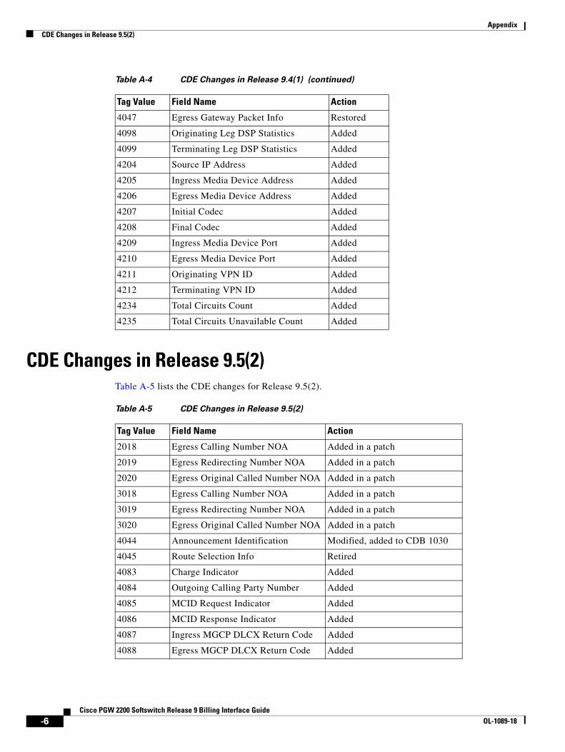
Appendix CDE Changes in Release 9.5(2)
CDE Changes in Release 9.5(2)Table A-5 lists the CDE changes for Release 9.5(2).
4047 Egress Gateway Packet Info Restored
4098 Originating Leg DSP Statistics Added
4099 Terminating Leg DSP Statistics Added
4204 Source IP Address Added
4205 Ingress Media Device Address Added
4206 Egress Media Device Address Added
4207 Initial Codec Added
4208 Final Codec Added
4209 Ingress Media Device Port Added
4210 Egress Media Device Port Added
4211 Originating VPN ID Added
4212 Terminating VPN ID Added
4234 Total Circuits Count Added
4235 Total Circuits Unavailable Count Added
Table A-4 CDE Changes in Release 9.4(1) (continued)
Tag Value Field Name Action
Table A-5 CDE Changes in Release 9.5(2)
Tag Value Field Name Action
2018 Egress Calling Number NOA Added in a patch
2019 Egress Redirecting Number NOA Added in a patch
2020 Egress Original Called Number NOA Added in a patch
3018 Egress Calling Number NOA Added in a patch
3019 Egress Redirecting Number NOA Added in a patch
3020 Egress Original Called Number NOA Added in a patch
4044 Announcement Identification Modified, added to CDB 1030
4045 Route Selection Info Retired
4083 Charge Indicator Added
4084 Outgoing Calling Party Number Added
4085 MCID Request Indicator Added
4086 MCID Response Indicator Added
4087 Ingress MGCP DLCX Return Code Added
4088 Egress MGCP DLCX Return Code Added
-6Cisco PGW 2200 Softswitch Release 9 Billing Interface Guide
OL-1089-18

Appendix CDE Changes in Release 9.6(1)
CDE Changes in Release 9.6(1)Table A-6 lists the CDE changes for Release 9.6(1).
4089 Network Translated Address Indicator
Added
4090 Reservation Request Accepted Added
4091 Reservation Request Error Count Added
4092 ATM Ingress Configured Profile Added
4093 ATM Egress Configured Profile Added
4094 ATM Negotiated Profile Added
4095 Route List Name Added
4096 Route Name Added
4097 MGCP Script Response String Added
4213 Meter Pulses Received Added
4214 Meter Pulses Sent Added
4215 Charge Tariff Info Added
4216 Advice of Charge Indicator Added
4217 Short Call Indicator Added
4218 Charge Limit Exceeded Added
4219 Call Recovered Indication Added
4220 Partial Calling Line Identity Added
4221 Service Activation Added
4222 PRI AOC Invoke Type Added
4223 PRI AOC – S Charge Information Added
4224 PRI AOC – D Charge Information Added
4225 PRI AOC – E Charge Information Added
4226 PRI AOC Invoke Failure Added
4237 Ingress Redirecting Number Added in a patch
6005 Interim CDB Added
Table A-5 CDE Changes in Release 9.5(2) (continued)
Tag Value Field Name Action
Table A-6 CDE Changes in Release 9.6(1)
Tag Value Field Name Action
1210 Slave End-of-Call Added
1260 Slave Long Duration Call Added
4030 Total Meter Pulses Added
-7Cisco PGW 2200 Softswitch Release 9 Billing Interface Guide
OL-1089-18
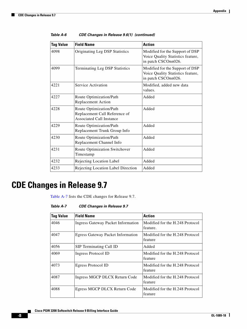
Appendix CDE Changes in Release 9.7
CDE Changes in Release 9.7Table A-7 lists the CDE changes for Release 9.7.
4098 Originating Leg DSP Statistics Modified for the Support of DSP Voice Quality Statistics feature, in patch CSCOnn026.
4099 Terminating Leg DSP Statistics Modified for the Support of DSP Voice Quality Statistics feature, in patch CSCOnn026.
4221 Service Activation Modified, added new data values.
4227 Route Optimization/Path Replacement Action
Added
4228 Route Optimization/Path Replacement Call Reference of Associated Call Instance
Added
4229 Route Optimization/Path Replacement Trunk Group Info
Added
4230 Route Optimization/Path Replacement Channel Info
Added
4231 Route Optimization Switchover Timestamp
Added
4232 Rejecting Location Label Added
4233 Rejecting Location Label Direction Added
Table A-6 CDE Changes in Release 9.6(1) (continued)
Tag Value Field Name Action
Table A-7 CDE Changes in Release 9.7
Tag Value Field Name Action
4046 Ingress Gateway Packet Information Modified for the H.248 Protocol feature.
4047 Egress Gateway Packet Information Modified for the H.248 Protocol feature
4056 SIP Terminating Call ID Added
4069 Ingress Protocol ID Modified for the H.248 Protocol feature
4073 Egress Protocol ID Modified for the H.248 Protocol feature
4087 Ingress MGCP DLCX Return Code Modified for the H.248 Protocol feature
4088 Egress MGCP DLCX Return Code Modified for the H.248 Protocol feature
-8Cisco PGW 2200 Softswitch Release 9 Billing Interface Guide
OL-1089-18
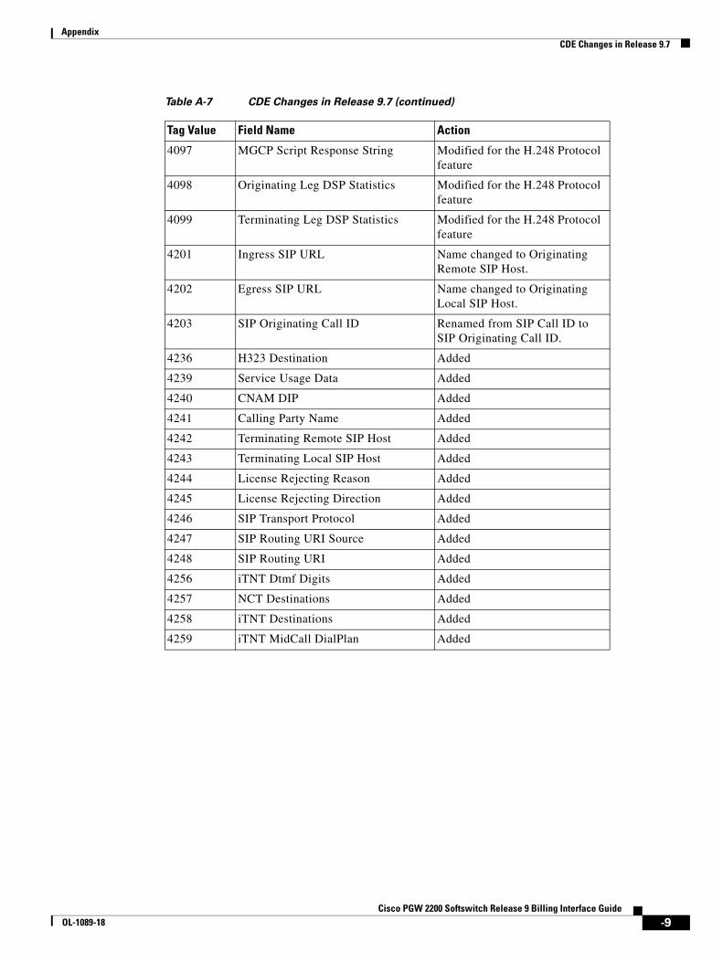
Appendix CDE Changes in Release 9.7
4097 MGCP Script Response String Modified for the H.248 Protocol feature
4098 Originating Leg DSP Statistics Modified for the H.248 Protocol feature
4099 Terminating Leg DSP Statistics Modified for the H.248 Protocol feature
4201 Ingress SIP URL Name changed to Originating Remote SIP Host.
4202 Egress SIP URL Name changed to Originating Local SIP Host.
4203 SIP Originating Call ID Renamed from SIP Call ID to SIP Originating Call ID.
4236 H323 Destination Added
4239 Service Usage Data Added
4240 CNAM DIP Added
4241 Calling Party Name Added
4242 Terminating Remote SIP Host Added
4243 Terminating Local SIP Host Added
4244 License Rejecting Reason Added
4245 License Rejecting Direction Added
4246 SIP Transport Protocol Added
4247 SIP Routing URI Source Added
4248 SIP Routing URI Added
4256 iTNT Dtmf Digits Added
4257 NCT Destinations Added
4258 iTNT Destinations Added
4259 iTNT MidCall DialPlan Added
Table A-7 CDE Changes in Release 9.7 (continued)
Tag Value Field Name Action
-9Cisco PGW 2200 Softswitch Release 9 Billing Interface Guide
OL-1089-18
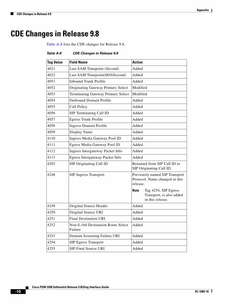
Appendix CDE Changes in Release 9.8
CDE Changes in Release 9.8Table A-8 lists the CDE changes for Release 9.8.
Table A-8 CDE Changes in Release 9.8
Tag Value Field Name Action
4021 Last SAM Timepoint (Second) Added
4022 Last SAM Timepoint(MilliSecond) Added
4051 Inbound Trunk Profile Added
4052 Originating Gateway Primary Select Modified
4053 Terminating Gateway Primary Select Modified
4054 Outbound Domain Profile Added
4055 Call Policy Added
4056 SIP Terminating Call ID Added
4057 Egress Trunk Profile Added
4058 Ingress Domain Profile Added
4059 Display Name Added
4110 Ingress Media Gateway Pool ID Added
4111 Egress Media Gateway Pool ID Added
4112 Ingress Intergateway Packet Info Added
4113 Egress Intergateway Packet Info Added
4203 SIP Originating Call ID Renamed from SIP Call ID to SIP Originating Call ID.
4246 SIP Ingress Transport Previously named SIP Transport Protocol. Name changed in this release.
Note Tag 4254, SIP Egress Transport, is also added in this release.
4249 Original Source Header Added
4250 Original Source URI Added
4251 Final Destination URI Added
4252 Non-E.164 Destination Route Select Failure
Added
4253 Domain Screening Failure URI Added
4254 SIP Egress Transport Added
4255 SIP Final Source URI Added
-10Cisco PGW 2200 Softswitch Release 9 Billing Interface Guide
OL-1089-18
Cisco PGWOL-1089-18
I N D E X
A
ACM Timepoint Sent_ms (Tag: 4103) 1-184
AMA Line Number (Tag: 4050) 1-122
ANM/Answer Timepoint (Tag: 4005) 1-104
ANM Timepoint Received_ms (Tag: 4104) 1-184
ANM Timepoint Sent_ms (Tag: 4105) 1-185
Announcement ID (Tag: 4044) 1-118
B
billing interfaces 1-1
C
call detail record file, configuring 1-9
Called Number (Tag: 4014) 1-108
Called Number Nature of Address (Tag: 2007/ANSI) 1-61
Called Number Nature of Address (Tag: 3007/ITU) 1-79
Call Feature Flag 2-2
Calling Number (Tag: 4010) 1-106
Calling number Nature of Address (Tag: 2003/ANSI) 1-57
Calling Number Nature of Address (Tag: 3003/ITU) 1-75
Calling Party Category (Tag\ 2000/ANSI) 1-55
Calling Party Category Tag: 3000/ITU) 1-73
Call Reference ID (Tag: 4002) 1-103
call screening database
enabling 1-9
Call Type Flag 2-2
Carrier Identification Parameter (Tag: 2014/ANSI) 1-68
Carrier Selection Parameter (Tag: 2015/ANSI) 1-68
C-CPC Call Type 2-2
C-CPC Language 2-3
C-CPC User 2-3
CDB call data element fields 1-6
CDB message type 1-3
CDB Timepoint (Tag: 4001) 1-103
CDB Version (Tag: 4000) 1-102
CDE description form 1-54, 1-110, 1-183
CDR
See call detail record file 1-9
Charged Number (Tag: 4011) 1-107
Charged number Nature of Address (Tag: 2004/ANSI) 1-58
Charged Number Nature of Address Tag: 3004/ITU) 1-76
C-NOA Post-translated calling number 2-2
C-NOA Post-translated dialed number 2-2
C-NOA Pre-translated calling number 2-2
C-NOA Pre-translated dialed number 2-2
configuring
Cisco MGC
call detail record file 1-9
configuring Cisco MGC
enable call screening database 1-9
CRASH Timepoint (Tag: 4007) 1-105
D
Dialed Number (Tag: 4012) 1-107
Dialed number Nature of Address (Tag: 2005/ANSI) 1-59
Dialed Number Nature of Address (Tag: 3005) 1-77
Directional Flag (Tag: 4048) 1-121
IN-1 2200 Softswitch Release 9 Billing Interface Guide

Index
E
Egress destination Point Code (Tag: 4037) 1-115
Egress Media Gateway ID (Tag: 4039) 1-116
Egress originating Point Code (Tag: 4036) 1-115
Egress Packet Info (Tag: 4047) 1-120
F
File End Time (Tag: 6002) 1-188
File Start Time (Tag: 6001) 1-188
First Release Source (Tag: 4028) 1-110
First REL Timepoint_ms (Tag: 4106) 1-185
Forward Call Indicators Received (Tag: 3009/ITU) 1-92
Forward Call Indicators Sent (Tag: 2010/ANSI) 1-64
Forward Call Indicators Sent (Tag: 3010/ITU) 1-94
G
generic interface 1-23
Glare Encountered (Tag: 4019) 1-109
I
IAM/Setup Timepoint (Tag: 4003) 1-103
IAM Timepoint Received_ms (Tag: 4100) 1-183
IAM Timepoint Sent_ms (Tag: 4101) 1-183
Ingress destination Point Code (Tag
\ 4035) 1-114
Ingress Media Gateway ID (Tag: 4038) 1-116
Ingress Originating Point Code (Tag: 4034) 1-114
Ingress Packet Info (Tag: 4046) 1-119, 1-120
In protocol ID 2-1
In Signal path ID 2-1
In traffic channel ID 2-1
IN-2Cisco PGW 2200 Softswitch Release 9 Billing Interface Guide
J
Jurisdiction Information Parameter (Tag: 2016/ANSI) 1-69
L
LNP Dip (Tag: 4029) 1-111
LRN Nature of Address (Tag: 2006/ANSI) 1-60
LRN Nature of Address (Tag: 3006/ITU) 1-78
LRN Number (Tag: 4013) 1-107
M
Maintenance Circuit Member (Tag: 4018) 1-109
Maintenance Reason (Tag: 4033) 1-113
Maintenance Trunk Group (Tag: 4017) 1-109
Maintenance Type (Tag: 4032) 1-112
MGC configuration
redundant 1-23
MGC ID (Tag\ 6000) 1-188
MGC Info Field (Tag: 4031) 1-112
MGC Info Subfields 2-1
MGC Version (Tag: 6004) 1-189
N
Nature of Connection Indicators Received (Tag: 2011/ANSI) 1-65
Nature of Connection Indicators Received (Tag: 3011/ITU) 1-95
Nature of Connection indicators Sent (Tag: 2012/ANSI) 1-66
Nature of Connection indicators Sent (Tag: 3012/ITU) 1-96
NOA value definition 2-3
NTP 1-23
OL-1089-18

Index
O
Originating Gateway Primary Select (Tag: 4052) 1-150
Originating Line Information (Tag
\ 3002/ITU) 1-75
Originating Line Information (Tag: 2002/ANSI) 1-57
Originating Member (Tag: 4009) 1-106
Originating Trunk Group (Tag: 4008) 1-106
Out protocol ID 2-2
Out Signal path ID 2-1
Out traffic channel ID 2-2
R
Reason Code (Tag: 2008/ANSI) 1-62
Reason Code (Tag: 3008/ITU) 1-79
REL/RELEASE timepoint (Tag: 4006) 1-105
RLC/RELEASE Complete Timepoint (Tag: 4020) 1-110
RLC Timepoint Received_ms (Tag: 4108) 1-186
RLC Timepoint Sent_ms (Tag: 4109) 1-186
Route Selection Info (Tag: 4045) 1-118
S
Second REL Timepoint_ms (Tag: 4107) 1-185
Service Logic ID (Tag: 4049) 1-121
T
tag values 1-3
TCAP Database ID (Tag: 4043) 1-117
TCAP transaction ID (Tag: 4040) 1-116
Terminating Member (Tag: 4016) 1-108
Terminating Trunk Group (Tag: 4015) 1-108
Total Meter Pulses (Tag: 4030) 1-111
Total Number of CDB Records (Tag: 6003) 1-189
Transaction End Time (Tag\ 4042) 1-117
Transaction Start Time (Tag: 4041) 1-117
COL-1089-18
Transit Network Selection (Tag
\ 2013/ANSI) 1-67
Transit Network Selection (Tag: 3013/ITU) 1-98
TTC Charge Info (Tag: 6102 1-191
TTC Contract Number (Tag: 6100) 1-190
TTC Contract Number NOA (Tag: 6101) 1-190
U
Unique Call Correlator ID (Tag: 5000) 1-102
User Service Information (Tag: 2001/ANSI) 1-56
User Service Information (Tag: 3001/ITU) 1-74
X
XECfgParm.dat
configuring call detail record file 1-9
enabling call screening database 1-9
IN-3isco PGW 2200 Softswitch Release 9 Billing Interface Guide

Index
IN-4Cisco PGW 2200 Softswitch Release 9 Billing Interface Guide
OL-1089-18
Related Documents