Wide-Area Networking Configuration Guide: Overlay Transport Virtualization, Cisco IOS XE Release 3S Americas Headquarters Cisco Systems, Inc. 170 West Tasman Drive San Jose, CA 95134-1706 USA http://www.cisco.com Tel: 408 526-4000 800 553-NETS (6387) Fax: 408 527-0883

Welcome message from author
This document is posted to help you gain knowledge. Please leave a comment to let me know what you think about it! Share it to your friends and learn new things together.
Transcript
Wide-Area Networking ConfigurationGuide: Overlay Transport Virtualization,Cisco IOS XE Release 3S
Americas HeadquartersCisco Systems, Inc.170 West Tasman DriveSan Jose, CA 95134-1706USAhttp://www.cisco.comTel: 408 526-4000 800 553-NETS (6387)Fax: 408 527-0883

THE SPECIFICATIONS AND INFORMATION REGARDING THE PRODUCTS IN THIS MANUAL ARE SUBJECT TO CHANGE WITHOUT NOTICE. ALL STATEMENTS,INFORMATION, AND RECOMMENDATIONS IN THIS MANUAL ARE BELIEVED TO BE ACCURATE BUT ARE PRESENTED WITHOUT WARRANTY OF ANY KIND,EXPRESS OR IMPLIED. USERS MUST TAKE FULL RESPONSIBILITY FOR THEIR APPLICATION OF ANY PRODUCTS.
THE SOFTWARE LICENSE AND LIMITED WARRANTY FOR THE ACCOMPANYING PRODUCT ARE SET FORTH IN THE INFORMATION PACKET THAT SHIPPEDWITH THE PRODUCT AND ARE INCORPORATED HEREIN BY THIS REFERENCE. IF YOU ARE UNABLE TO LOCATE THE SOFTWARE LICENSE OR LIMITEDWARRANTY, CONTACT YOUR CISCO REPRESENTATIVE FOR A COPY.
The Cisco implementation of TCP header compression is an adaptation of a program developed by the University of California, Berkeley (UCB) as part of UCB’s public domain versionof the UNIX operating system. All rights reserved. Copyright © 1981, Regents of the University of California.
NOTWITHSTANDING ANY OTHER WARRANTY HEREIN, ALL DOCUMENT FILES AND SOFTWARE OF THESE SUPPLIERS ARE PROVIDED “AS IS” WITH ALLFAULTS. CISCO AND THE ABOVE-NAMED SUPPLIERS DISCLAIM ALL WARRANTIES, EXPRESSED OR IMPLIED, INCLUDING, WITHOUT LIMITATION, THOSE OFMERCHANTABILITY, FITNESS FOR A PARTICULAR PURPOSE AND NONINFRINGEMENT OR ARISING FROM A COURSE OF DEALING, USAGE, OR TRADEPRACTICE.
IN NO EVENT SHALL CISCO OR ITS SUPPLIERS BE LIABLE FOR ANY INDIRECT, SPECIAL, CONSEQUENTIAL, OR INCIDENTAL DAMAGES, INCLUDING,WITHOUT LIMITATION, LOST PROFITS OR LOSS OR DAMAGE TO DATA ARISING OUT OF THE USE OR INABILITY TO USE THIS MANUAL, EVEN IF CISCO ORITS SUPPLIERS HAVE BEEN ADVISED OF THE POSSIBILITY OF SUCH DAMAGES.
Cisco and the Cisco logo are trademarks or registered trademarks of Cisco and/or its affiliates in the U.S. and other countries. To view a list of Cisco trademarks, go to this URL: www.cisco.com/go/trademarks. Third-party trademarks mentioned are the property of their respective owners. The use of the word partner does not imply a partnership relationshipbetween Cisco and any other company. (1110R)
Any Internet Protocol (IP) addresses and phone numbers used in this document are not intended to be actual addresses and phone numbers. Any examples, command display output,network topology diagrams, and other figures included in the document are shown for illustrative purposes only. Any use of actual IP addresses or phone numbers in illustrative contentis unintentional and coincidental.
© 2011 Cisco Systems, Inc. All rights reserved.
C O N T E N T S
Configuring Overlay Transport Virtualization 1
Finding Feature Information 1
Prerequisites for OTV 2
Restrictions for OTV 2
Information About OTV 2
Functions of OTV 2
OTV Terms 3
OTV Overlay Network 4
Edge Devices 5
Site-to-Site Connectivity 6
Overlay Networks Mapping to Multicast Groups 6
OTV Packet Flow 6
Mobility 7
Sample OTV Topologies 7
Two-Site Network 8
Multiple Overlay Networks 8
Multihomed Sites and Load Balancing 9
Dual Site Adjacency 9
OTV Features 10
Overlay Interface 10
MAC Address Learning 11
MAC Address Reachability Updates 11
Multicast Group Addresses and IGMP Snooping 11
ARP Cache 11
High Availability 11
Virtualization Support 12
OTV IS-IS 12
OTV IS-IS Instances 12
OTV IS-IS MLRIB Interactions 12
Wide-Area Networking Configuration Guide: Overlay Transport Virtualization, Cisco IOS XE Release 3S iii
How to Configure OTV 13
Creating an Overlay Interface 13
Associating an Overlay Interface with a Physical Interface 15
Configuring a Multicast Group Address 16
Configuring a VLAN over an Overlay Interface 17
Configuring the Site Bridge Domain and the Site Identifier 19
Configuring Authentication for OTV IS-IS Hellos 20
Configuring Authentication for OTV IS-IS PDUs 21
Disabling ARP Caching 23
Tuning OTV 24
Verifying the OTV Configuration 26
Configuration Examples for OTV Features 27
Example: Configuring Overlay Interface and VLANs 27
Additional References 30
Feature Information for OTV 30
Contents
Wide-Area Networking Configuration Guide: Overlay Transport Virtualization, Cisco IOS XE Release 3Siv
Configuring Overlay Transport Virtualization
Overlay Transport Virtualization (OTV) is a MAC-in-IP method that extends Layer 2 connectivity acrossa transport network infrastructure.
OTV application (also known as OTV) is one of the modules of the OTV architecture on Cisco IOSsoftware. OTV interacts with the following other modules of the OTV architecture on Cisco IOS software:
• Layer 2 Intermediate System-to-Intermediate System (IS-IS)• Ethernet infrastructure• IP tunnel infrastructure• Layer 2 Forwarding Information Base (L2FIB)• Multilayer Routing Information Base (MLRIB)• Ethernet Operation, Administration, and Maintenance (OAM)• Internet Group Management Protocol (IGMP)• Address Resolution Protocol (ARP)
OTV provides Layer 2 connectivity between remote network sites by using MAC address-based routingand IP-encapsulated forwarding across a transport network to provide support for applications that requireLayer 2 adjacency, such as clusters and virtualization. You deploy OTV on the edge devices in each site.OTV requires no other changes to the sites or the transport network.
• Finding Feature Information, page 1• Prerequisites for OTV, page 2• Restrictions for OTV, page 2• Information About OTV, page 2• How to Configure OTV, page 13• Verifying the OTV Configuration, page 26• Configuration Examples for OTV Features, page 27• Additional References, page 30• Feature Information for OTV, page 30
Finding Feature InformationYour software release may not support all the features documented in this module. For the latest featureinformation and caveats, see the release notes for your platform and software release. To find informationabout the features documented in this module, and to see a list of the releases in which each feature issupported, see the Feature Information Table at the end of this document.
Use Cisco Feature Navigator to find information about platform support and Cisco software image support.To access Cisco Feature Navigator, go to www.cisco.com/go/cfn. An account on Cisco.com is not required.
Wide-Area Networking Configuration Guide: Overlay Transport Virtualization, Cisco IOS XE Release 3S 1
Prerequisites for OTV• IGMPv3 must be configured on the physical Layer 3 interface that will become the join interface.• Ensure that there is connectivity for VLANs to be extended to the OTV edge device.
Restrictions for OTV• An overlay interface will be in the up state only if the overlay interface configuration is complete and
enabled (no shutdown command). The join interface must also be in the up state.• Configure the join interface and all Layer 3 interfaces that face the IP core between the OTV edge
devices with the highest maximum transmission unit (MTU) size supported by the IP core. OTV setsthe Don’t Fragment (DF) bit in the IP header for all OTV control and data packets so that the corecannot fragment these packets.
• Only one join interface can be configured on the router for all overlays.• The transport network must support Protocol Independent Multicast (PIM) sparse mode (Any Source
Multicast (ASM)) for provider multicast group and Source Specific Multicast (SSM) for deliverygroup.
• Do not enable PIM on the join interface; enable only PIM passive on the join interface. ConfigureSSM for the OTV data group multicast address range by using the ip pim ssm command.
• OTV is compatible with a transport network configured only for IPv4. IPv6 is not supported.• Ensure that the site identifier is configured and is the same for all edge devices on a site. OTV brings
down all overlays when a mismatched site identifier is detected from a neighbor edge device andgenerates a system message.
Information About OTV• Functions of OTV, page 2
• OTV Terms, page 3
• OTV Overlay Network, page 4
• OTV Features, page 10
Functions of OTVOTV performs the following functions:
• Maintains the list of overlays• Maintains overlay configured parameters such as name, multicast address, encapsulation type,
authentication, and OTV feature sets (ARP Suppression)• Maintains the state of the overlay interface• Maintains the OTV VLAN membership from Ethernet infrastructure and authoritative edge device
(AED) state from IS-IS• Maintains a database of overlay adjacencies reported by IS-IS• Maintains IP tunnel information and manages the encapsulation for data sent on the overlay network
Functions of OTV Prerequisites for OTV
Wide-Area Networking Configuration Guide: Overlay Transport Virtualization, Cisco IOS XE Release 3S2
• Manages delivery groups (DGs) for each overlay, snooping multicast traffic and monitoring trafficstreams for active DGs
• Configures, starts, and stops the OTV IS-IS instance• Interfaces with IP multicast to join provider multicast groups for each overlay
OTV TermsTable 1 OTV Terms
Term Description
Edge device An edge device that performs typical Layer 2learning and forwarding on site-facing interfaces(internal interfaces) and IP-based virtualization ontransport-facing interfaces. The edge devicecapability can be colocated in a device thatperforms Layer 2 and Layer 3 functionality. OTVfunctionality occurs only in an edge device. Agiven edge device can have multiple overlayinterfaces. You can also configure multiple edgedevices in a site.
Authoritative edge device (AED) An elected edge device that serves as the forwarder.OTV provides loop-free, multihoming by electingthis designated forwarding device per site for eachVLAN. The edge devices at the site communicatewith each other on the internal interfaces to electthe AED.
Transport network The network that connects OTV sites. This networkcan be customer managed, provided by a serviceprovider, or a mix of both.
Join interface One of the uplink interfaces of the edge device. Thejoin interface is a point-to-point routed interface.The edge device joins an overlay network throughthis interface. The IP address of this interface isused to advertise reachability of a MAC addresspresent in this site.
Internal interface The Layer 2 interface on the edge device thatconnects to the VLANs that are to be extended.These VLANs typically form a Layer 2 domainknown as a site and can contain site-based switchesor site-based routers. The internal interface is aLayer 2 access or a trunk interface regardless ofwhether the internal interface connects to a switchor a router.
OTV TermsInformation About OTV
Wide-Area Networking Configuration Guide: Overlay Transport Virtualization, Cisco IOS XE Release 3S 3
Term Description
MAC routing The type of routing that associates the destinationMAC address of the Layer 2 traffic with an edgedevice IP address. The MAC-to-IP association isadvertised to the edge devices through the OTVcontrol-plane protocol. In MAC routing, MACaddresses are reachable through the IP address of aremote edge device on the overlay network. Layer 2traffic destined to a MAC address is encapsulated inan IP packet based on the MAC-to-IP mapping inthe MAC table.
Overlay interface A logical, multiaccess, multicast-capable interface.The overlay interface encapsulates Layer 2 framesin IP unicast or multicast headers.
Overlay network A logical network that interconnects remote sitesfor MAC routing of Layer 2 traffic. The overlaynetwork comprises multiple edge devices.
Site A Layer 2 network that may be single-homed ormultihomed to the transport network and the OTVoverlay network. Layer 2 connectivity betweensites is provided by edge devices that operate in anoverlay network. Layer 2 sites are physicallyseparated from each other by the transport network.
Site VLAN A dedicated VLAN on which internal adjacency isestablished. OTV sends local hello messages on thesite VLAN to detect other OTV edge devices in thesite and uses the site VLAN to determine the AEDfor the OTV-extended VLANs.
Cisco recommends that you use a dedicated VLANas a site VLAN. You should ensure that the siteVLAN is active on at least one of the edge deviceports and that the site VLAN is not extended acrossthe overlay.
OTV Overlay NetworkAn OTV overlay network provides Layer 2 connectivity between remote sites over a transport network. Anoverlay network consists of one or more edge devices on each site, interconnected with a control-planeprotocol across the transport network.
OTV Overlay Network Information About OTV
Wide-Area Networking Configuration Guide: Overlay Transport Virtualization, Cisco IOS XE Release 3S4
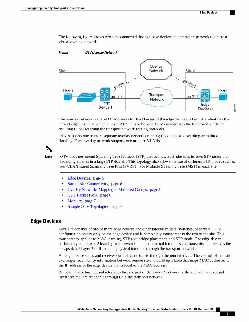
The following figure shows two sites connected through edge devices to a transport network to create avirtual overlay network.
Figure 1 OTV Overlay Network
The overlay network maps MAC addresses to IP addresses of the edge devices. After OTV identifies thecorrect edge device to which a Layer 2 frame is to be sent, OTV encapsulates the frame and sends theresulting IP packet using the transport network routing protocols.
OTV supports one or more separate overlay networks running IPv4 unicast forwarding or multicastflooding. Each overlay network supports one or more VLANs.
Note OTV does not extend Spanning Tree Protocol (STP) across sites. Each site runs its own STP rather thanincluding all sites in a large STP domain. This topology also allows the use of different STP modes such asPer-VLAN Rapid Spanning Tree Plus (PVRST+) or Multiple Spanning Tree (MST) in each site.
• Edge Devices, page 5
• Site-to-Site Connectivity, page 6
• Overlay Networks Mapping to Multicast Groups, page 6
• OTV Packet Flow, page 6
• Mobility, page 7
• Sample OTV Topologies, page 7
Edge DevicesEach site consists of one or more edge devices and other internal routers, switches, or servers. OTVconfiguration occurs only on the edge device and is completely transparent to the rest of the site. Thistransparency applies to MAC learning, STP root bridge placement, and STP mode. The edge deviceperforms typical Layer 2 learning and forwarding on the internal interfaces and transmits and receives theencapsulated Layer 2 traffic on the physical interface through the transport network.
An edge device sends and receives control-plane traffic through the join interface. The control-plane trafficexchanges reachability information between remote sites to build up a table that maps MAC addresses tothe IP address of the edge device that is local to the MAC address.
An edge device has internal interfaces that are part of the Layer 2 network in the site and has externalinterfaces that are reachable through IP in the transport network.
Configuring Overlay Transport VirtualizationEdge Devices
Wide-Area Networking Configuration Guide: Overlay Transport Virtualization, Cisco IOS XE Release 3S 5
Site-to-Site ConnectivityOTV builds Layer 2 reachability information by communicating between edge devices with the overlayprotocol. The overlay protocol forms adjacencies with all edge devices. Once each edge device is adjacentwith all its peers on the overlay, the edge devices share MAC address reachability information with otheredge devices that participate in the same overlay network.
OTV discovers edge devices through dynamic neighbor detection, which leverages the multicast support ofthe core.
Overlay Networks Mapping to Multicast GroupsFor transport networks that support IP multicast, one multicast address (the control-group address) is usedto encapsulate and exchange OTV control-plane protocol updates. Each edge device that participates in theparticular overlay network shares the same control-group address with all the other edge devices. As soonas the control-group address and the join interface are configured, the edge device sends an IGMP reportmessage to join the control group. The edge devices act as hosts in the multicast network and sendmulticast IGMP report messages to the assigned multicast group address.
As in traditional link-state routing protocols, edge devices exchange OTV control-plane hellos to buildadjacencies with other edge devices in the overlay network. Once the adjacencies are established, OTVcontrol-plane link-state packets (LSPs) communicate MAC-to-IP mappings to the adjacent devices. TheseLSPs contain the IP address of the remote edge device, the VLAN IDs, and the learned MAC addresses thatare reachable through that edge device.
Edge devices participate in data-plane learning on internal interfaces to build up the list of MAC addressesthat are reachable within a site. OTV sends these locally learned MAC addresses in the OTV control-planeupdates to remote sites.
OTV Packet FlowWhen an edge device receives a Layer 2 frame on an internal interface, OTV performs the MAC tablelookup based on the destination address of the Layer 2 frame. If the frame is destined to a MAC addressthat is reachable through another internal interface, the frame is forwarded on that internal interface. OTVperforms no other actions and the processing of the frame is complete.
If the frame is destined to a MAC address that was learned over an overlay interface, OTV performs thefollowing tasks:
1 Strips the preamble and frame check sequence (FCS) from the Layer 2 frame.2 Adds an OTV header to the Layer 2 frame and copies the 802.1Q information into the OTV header.3 Adds the IP address to the packet, based on the initial MAC address table lookup. This IP address is
used as a destination address for the IP packet that is sent into the core switch.
OTV traffic appears as IP traffic to the network core.
At the destination site, the edge device performs the reverse operation and presents the original Layer 2frame to the local site. That edge device determines the correct internal interface to forward the frame on,based on the local MAC address table.
Configuring Overlay Transport Virtualization Site-to-Site Connectivity
Wide-Area Networking Configuration Guide: Overlay Transport Virtualization, Cisco IOS XE Release 3S6
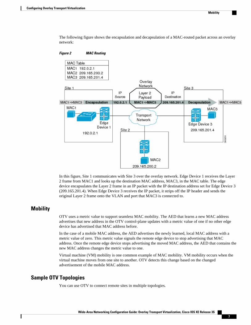
The following figure shows the encapsulation and decapsulation of a MAC-routed packet across an overlaynetwork:
Figure 2 MAC Routing
In this figure, Site 1 communicates with Site 3 over the overlay network. Edge Device 1 receives the Layer2 frame from MAC1 and looks up the destination MAC address, MAC3, in the MAC table. The edgedevice encapsulates the Layer 2 frame in an IP packet with the IP destination address set for Edge Device 3(209.165.201.4). When Edge Device 3 receives the IP packet, it strips off the IP header and sends theoriginal Layer 2 frame onto the VLAN and port that MAC3 is connected to.
MobilityOTV uses a metric value to support seamless MAC mobility. The AED that learns a new MAC addressadvertises that new address in the OTV control-plane updates with a metric value of one if no other edgedevice has advertised that MAC address before.
In the case of a mobile MAC address, the AED advertises the newly learned, local MAC address with ametric value of zero. This metric value signals the remote edge device to stop advertising that MACaddress. Once the remote edge device stops advertising the moved MAC address, the AED that contains thenew MAC address changes the metric value to one.
Virtual machine (VM) mobility is one common example of MAC mobility. VM mobility occurs when thevirtual machine moves from one site to another. OTV detects this change based on the changedadvertisement of the mobile MAC address.
Sample OTV TopologiesYou can use OTV to connect remote sites in multiple topologies.
Configuring Overlay Transport VirtualizationMobility
Wide-Area Networking Configuration Guide: Overlay Transport Virtualization, Cisco IOS XE Release 3S 7
• Two-Site Network, page 8• Multiple Overlay Networks, page 8• Multihomed Sites and Load Balancing, page 9• Dual Site Adjacency, page 9
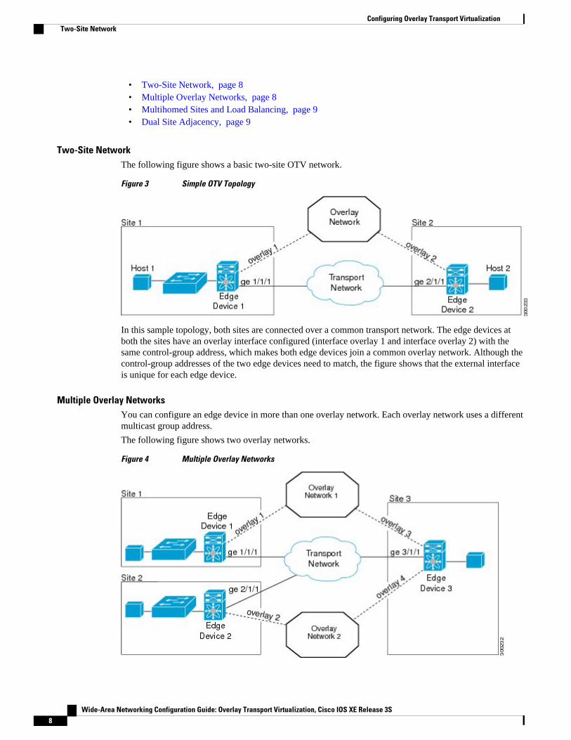
Two-Site NetworkThe following figure shows a basic two-site OTV network.
Figure 3 Simple OTV Topology
In this sample topology, both sites are connected over a common transport network. The edge devices atboth the sites have an overlay interface configured (interface overlay 1 and interface overlay 2) with thesame control-group address, which makes both edge devices join a common overlay network. Although thecontrol-group addresses of the two edge devices need to match, the figure shows that the external interfaceis unique for each edge device.
Multiple Overlay NetworksYou can configure an edge device in more than one overlay network. Each overlay network uses a differentmulticast group address.
The following figure shows two overlay networks.
Figure 4 Multiple Overlay Networks
Configuring Overlay Transport Virtualization Two-Site Network
Wide-Area Networking Configuration Guide: Overlay Transport Virtualization, Cisco IOS XE Release 3S8
In this example, Site 3 connects to Site 1 over Overlay Network 1 through overlay interface 3 on EdgeDevice 3 and connects to Site 2 over Overlay Network 2 through overlay interface 4 on Edge Device 3.Each overlay network has different control group addresses.
Site 3 uses Edge Device 3 to connect to both the overlay networks, 1 and 2. Edge Device 3 associates thesame physical interface for both the overlay networks.
Multihomed Sites and Load Balancing
For resiliency and load balancing, a site can have multiple edge devices.
When more than one edge device is present at a site and both participate in the same overlay network, thesite is considered multihomed. For the VLANs that are extended using OTV, one edge device is elected asthe AED on a per-VLAN basis. OTV leverages a local VLAN to establish an adjacency between edgedevices on their internal interfaces. The local VLAN that is shared by the internal interfaces is the siteVLAN. The adjacency establishment over the site VLAN determines if the other edge device is still presentand which edge device is authoritative for what VLANs.
Load balancing is achieved because each edge device is authoritative for a subset of all VLANs that aretransported over the overlay. Link utilization to and from the transport is optimized.
The following figure shows the AED that is selected for a multihomed site in the OTV network.
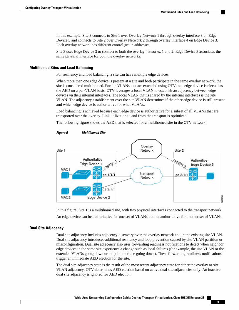
Figure 5 Multihomed Site
In this figure, Site 1 is a multihomed site, with two physical interfaces connected to the transport network.
An edge device can be authoritative for one set of VLANs but not authoritative for another set of VLANs.
Dual Site Adjacency
Dual site adjacency includes adjacency discovery over the overlay network and in the existing site VLAN.Dual site adjacency introduces additional resiliency and loop prevention caused by site VLAN partition ormisconfiguration. Dual site adjacency also uses forwarding readiness notifications to detect when neighboredge devices in the same site experience a change such as local failures (for example, the site VLAN or theextended VLANs going down or the join interface going down). These forwarding readiness notificationstrigger an immediate AED election for the site.
The dual site adjacency state is the result of the most recent adjacency state for either the overlay or siteVLAN adjacency. OTV determines AED election based on active dual site adjacencies only. An inactivedual site adjacency is ignored for AED election.
Configuring Overlay Transport VirtualizationMultihomed Sites and Load Balancing
Wide-Area Networking Configuration Guide: Overlay Transport Virtualization, Cisco IOS XE Release 3S 9
You must configure the same site identifier for all edge devices in a site. OTV advertises this site identifierin the IS-IS hello packets sent over the overlay network and on the local site VLAN. The combination ofthe IS-IS system ID and site identifier uniquely identifies the edge devices on a site.
OTV sends forwarding readiness notifications to all neighbors of an edge device in the following isolationstates:
• Site isolation: All extended VLANs on an edge device go down.• Core isolation: All overlay adjacencies go down.
OTV FeaturesThe OTV control-plane creates adjacencies between remote sites to provide Layer 2 connectivity over atransport network. An OTV network performs the following functions:
• Discovers remote sites and builds a control-protocol adjacency• Shares MAC routing information across the overlay network
The overlay network consists of one or more logical overlay interfaces that are created on the edge devicein each remote site that connects to the physical transport network. You associate the logical overlayinterface with a physical interface that connects to the transport network. The OTV control plane isresponsible for discovering the edge devices in remote sites, creating control-protocol adjacencies to thesesites, and establishing protocol adjacencies among the sites. The OTV control-plane protocol uses the IS-ISprotocol to establish the adjacencies and exchange MAC reachability across the overlay network.
Note You do not need to configure IS-IS to use OTV. IS-IS runs in the background once OTV is enabled.
The OTV control-plane protocol also sends and receives MAC routing updates between remote sites andupdates the Routing Information Base (RIB) with these MAC-to-IP address pairs.
• Overlay Interface, page 10• MAC Address Learning, page 11• MAC Address Reachability Updates, page 11• Multicast Group Addresses and IGMP Snooping, page 11• ARP Cache, page 11• High Availability, page 11• Virtualization Support, page 12• OTV IS-IS, page 12
Overlay InterfaceThe overlay interface is a logical interface that connects to the remote edge devices on the overlay networkthrough an associated physical interface on the transport network. From the perspective of MAC-basedforwarding on the site, the overlay interface is simply another bridged interface. As a bridged interface, theoverlay interface has unicast MAC addresses that are associated with it and is eligible for inclusion in theOutbound Interface List (OIL) for different multicast groups. However, no STP packets are forwarded overthe overlay interface. Unknown unicast packets are also not flooded on the overlay interface. From theperspective of IP transport, the overlay interface is not visible.
OTV encapsulates Layer 2 frames in IP packets and transmits them on the overlay interface.
The following commands must be configured for an overlay to be in the up state:
OTV Features Overlay Interface
Wide-Area Networking Configuration Guide: Overlay Transport Virtualization, Cisco IOS XE Release 3S10
• no shutdown• otv control-group• otv data-group• otv join-interface• otv site bridge-domain
Note The overlay interface does not come up until you configure a multicast group address or if the site VLANdoes not have at least an active port on the device.
MAC Address LearningOTV learns MAC-to-IP address pairs from MAC address learning on internal interfaces, from the OTVcontrol plane updates over the overlay network, and through multicast IGMP snooping.
OTV edge devices snoop IGMP traffic and issue a Group Membership-link-state packet (GM-LSP) toadvertise the presence of receivers to remote edge devices. The remote edge devices include the overlayinterface in the Outbound Interface List (OIL) for the corresponding multicast group. OTV does notprogram multicast MAC addresses in the forwarding tables, but rather updates OIL state as necessary.
All learned MAC addresses are stored in the RIB with the associated remote IP addresses.
MAC Address Reachability UpdatesThe OTV control plane uses IS-IS link-state packets (LSPs) to propagate MAC address to IP addressmappings to all edge devices in the overly network. These address mappings contain the MAC address,VLAN ID, and associated IP address of the edge device that the MAC address is reachable from.
The AED uses IGMP snooping to learn all multicast IP addresses in the local site. OTV includes these IPaddresses in a special GM-LSP that is sent to remote edge devices on the overlay network.
Multicast Group Addresses and IGMP SnoopingOTV uses a multicast group address that is assigned from the transport network to create a unique multicastgroup between remote sites on the overlay network. Each edge device in the overlay network acts as amulticast host and sends an IGMP report message to join the multicast group. OTV sends encapsulatedOTV control-plane hello messages and MAC routing updates across this multicast group.
OTV uses IGMP snooping and group membership advertisements (GM-LSPs) to learn all multicast groupmembers from remote sites. OTV also uses IGMP snooping to detect all multicast groups in the local site.
ARP CacheOTV can suppress unnecessary ARP messages from being sent over the overlay network. OTV builds alocal Layer 3-to-Layer 2 mapping for remote hosts. Any ARP requests from local hosts are served by thisARP cache.
High AvailabilityOTV supports stateful switchovers. A stateful switchover occurs when the active supervisor switches to thestandby supervisor. In Cisco IOS XE Release 3.5S, there may be a few seconds of traffic loss while theOTV tunnel is recreated following a switchover.
Configuring Overlay Transport VirtualizationMAC Address Learning
Wide-Area Networking Configuration Guide: Overlay Transport Virtualization, Cisco IOS XE Release 3S 11
Virtualization SupportOTV supports virtual routing and forwarding (VRF) instances on the physical interface that is associatedwith the overlay interface. By default, the overlay interface is placed in the default VRF unless youspecifically configure another VRF on the interface being used as the OTV join interface.
OTV IS-ISOTV uses the IS-IS protocol for control-plane learning of MAC entries. The OTV IS-IS component isresponsible for transporting MAC information across all VPN sites. It carries unicast and multicast MACinformation encoded in type, length, values (TLVs).
On the site-facing interface, OTV IS-IS is responsible for sending IS-IS hello (IIH) packets on the siteVLAN by using a multicast MAC destination address. Using the multicast MAC address ensures that allLayer 2 switches in the site forward the packet and that it reaches all other OTV edge devices. Each site hasa configured site ID. The site ID is advertised by each edge device on the overlay interface and is used toidentify all edge devices belonging to the same site. IS-IS assigns an AED for each VLAN. The AED for aVLAN is the edge device responsible for announcing local MACs for a given VLAN to remote sites andaccepting packets destined for a given VLAN.
On the overlay interface, OTV IS-IS is responsible for sending out IIH packets with site ID TLV on thespecific multicast group. Using the multicast group ensures that all remote sites participating in the VPNare automatically discovered and adjacency is formed among all the edge devices belonging to the sameVPN. OTV IS-IS also informs OTV whenever a new neighbor is discovered.
OTV IS-IS also handles fast MAC moves between remote sites and local site and guards against fastoscillations in the event of misconfigurations where the same MAC address is used in multiple sites.
• OTV IS-IS Instances, page 12• OTV IS-IS MLRIB Interactions , page 12
OTV IS-IS Instances
The creation of an overlay interface triggers creation of an OTV IS-IS instance. OTV IS-IS supportsmultiple overlays. There is a 1-1 relationship between an OTV IS-IS instance and an overlay. OTV IS-ISdiscovers neighbors, forms adjacencies and exchanges unicast MAC and multicast group information peroverlay. All IS-IS databases such as the adjacency database and the LSP database are maintained peroverlay.
OTV IS-IS forms only level-1 adjacencies. It advertises the primary IP/IPv6 address of the primary externalinterface in its hellos and protocol data units (PDUs). This address along with the system ID of theneighbor is added to OTV, which stores this information in its overlay adjacency database. The IP addressto be used is obtained from OTV based on the configuration.
OTV IS-IS MLRIB Interactions
OTV IS-IS is a client of Multilayer Routing Information Base (MLRIB) for Layer 2. It registers withMLRIB to get notifications for all local Layer 2 unicast and multicast address additions or deletions.Unicast MAC address information is put in OTV IS-IS LSPs, while the multicast address information is putin OTV IS-IS multicast group protocol data units (PDUs) for flooding to all remote sites.
Based on neighbor LSP advertisements, OTV IS-IS adds MAC reachability information for remote unicastand multicast group addresses to MLRIB. When OTV is disabled on a VLAN (the VLAN is removed fromthe list of OTV-advertised VLANs), OTV IS-IS withdraws the remote reachability information fromMLRIB.
Configuring Overlay Transport Virtualization Virtualization Support
Wide-Area Networking Configuration Guide: Overlay Transport Virtualization, Cisco IOS XE Release 3S12
How to Configure OTV• Creating an Overlay Interface, page 13
• Associating an Overlay Interface with a Physical Interface, page 15
• Configuring a Multicast Group Address, page 16
• Configuring a VLAN over an Overlay Interface, page 17
• Configuring the Site Bridge Domain and the Site Identifier, page 19
• Configuring Authentication for OTV IS-IS Hellos, page 20
• Configuring Authentication for OTV IS-IS PDUs, page 21
• Disabling ARP Caching, page 23
• Tuning OTV, page 24
Creating an Overlay InterfaceThe overlay interface is a logical interface that connects to the remote edge devices on the overlay networkthrough an associated physical interface on the transport network. After creating an overlay interface, youmust associate the overlay interface with a physical interface and configure a multicast group address. Formore information, see tasks Associating an Overlay Interface with a Physical Interface, page 15 and Configuring a Multicast Group Address, page 16.
Perform the steps in this task to create an overlay interface.
SUMMARY STEPS
1. enable
2. configure terminal
3. interface overlay interface
4. otv vpn-name name
5. description string
6. end
7. show otv overlay overlay-interface
DETAILED STEPS
Command or Action Purpose
Step 1 enable
Example:Router> enable
Enables privileged EXEC mode.
• Enter your password if prompted.
Step 2 configure terminal
Example:Router# configure terminal
Enters global configuration mode.
Creating an Overlay InterfaceHow to Configure OTV
Wide-Area Networking Configuration Guide: Overlay Transport Virtualization, Cisco IOS XE Release 3S 13
Command or Action Purpose
Step 3 interface overlay interface
Example:Router(config)# interface overlay 1
Creates an OTV overlay interface and enters interface configurationmode.
• The range is from 0 to 512.
Step 4 otv vpn-name name
Example:Router(config-if)# otv vpn-name overlay1
(Optional) Creates an alias for the OTV overlay interface name.
• The alias name is case-sensitive and must be no more than 20alphanumeric characters in length.
Step 5 description string
Example:Router(config-if)# description site4
(Optional) Adds a description for the overlay network.
• The description string can be up to 200 characters in length.
Step 6 end
Example:Router(config-if)# end
Exits interface configuration mode and returns to privileged EXECmode.
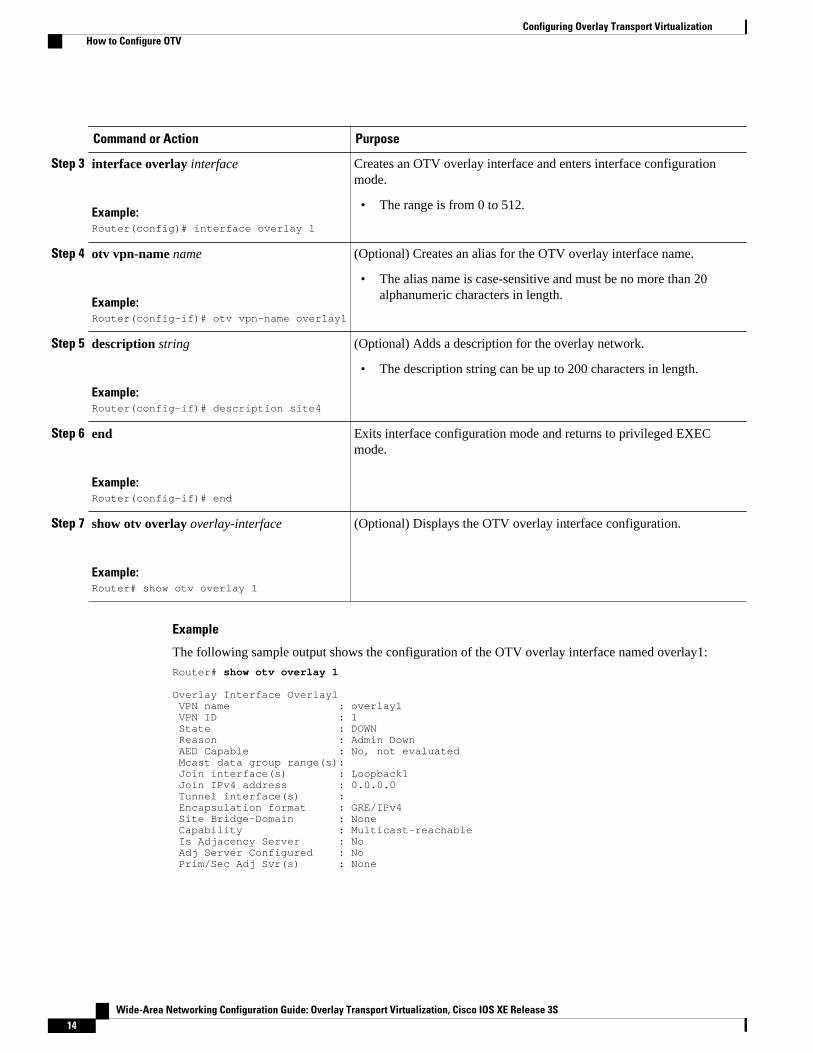
Step 7 show otv overlay overlay-interface
Example:Router# show otv overlay 1
(Optional) Displays the OTV overlay interface configuration.
Example
The following sample output shows the configuration of the OTV overlay interface named overlay1:
Router# show otv overlay 1
Overlay Interface Overlay1 VPN name : overlay1 VPN ID : 1 State : DOWN Reason : Admin Down AED Capable : No, not evaluated Mcast data group range(s): Join interface(s) : Loopback1 Join IPv4 address : 0.0.0.0 Tunnel interface(s) : Encapsulation format : GRE/IPv4 Site Bridge-Domain : None Capability : Multicast-reachable Is Adjacency Server : No Adj Server Configured : No Prim/Sec Adj Svr(s) : None
Configuring Overlay Transport Virtualization How to Configure OTV
Wide-Area Networking Configuration Guide: Overlay Transport Virtualization, Cisco IOS XE Release 3S14
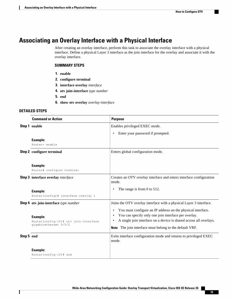
Associating an Overlay Interface with a Physical InterfaceAfter creating an overlay interface, perform this task to associate the overlay interface with a physicalinterface. Define a physical Layer 3 interface as the join interface for the overlay and associate it with theoverlay interface.
SUMMARY STEPS
1. enable
2. configure terminal
3. interface overlay interface
4. otv join-interface type number
5. end
6. show otv overlay overlay-interface
DETAILED STEPS
Command or Action Purpose
Step 1 enable
Example:Router> enable
Enables privileged EXEC mode.
• Enter your password if prompted.
Step 2 configure terminal
Example:Router# configure terminal
Enters global configuration mode.
Step 3 interface overlay interface
Example:Router(config)# interface overlay 1
Creates an OTV overlay interface and enters interface configurationmode.
• The range is from 0 to 512.
Step 4 otv join-interface type number
Example:Router(config-if)# otv join-interface gigabitethernet 0/0/2
Joins the OTV overlay interface with a physical Layer 3 interface.
• You must configure an IP address on the physical interface.• You can specify only one join interface per overlay.• A single join interface on a device is shared across all overlays.
Note The join interface must belong to the default VRF.
Step 5 end
Example:Router(config-if)# end
Exits interface configuration mode and returns to privileged EXECmode.
Associating an Overlay Interface with a Physical InterfaceHow to Configure OTV
Wide-Area Networking Configuration Guide: Overlay Transport Virtualization, Cisco IOS XE Release 3S 15
Command or Action Purpose
Step 6 show otv overlay overlay-interface
Example:Router# show otv overlay 1
(Optional) Displays the OTV overlay interface configuration.
To enable unicast and multicast IP forwarding on a join interface, perform the following tasks after creatingthe join interface:
• Configure the IP address and mask for the join interface by using the ip address command.• Configure the join interface to operate in Protocol Independent Multicast (PIM) passive mode by using
the ip pim passive command.• Configure IGMPv3 on the join interface by using the ip igmp version 3 command.
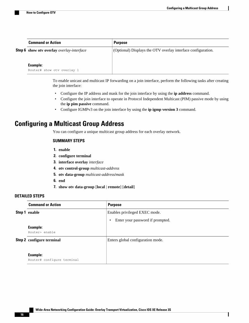
Configuring a Multicast Group AddressYou can configure a unique multicast group address for each overlay network.
SUMMARY STEPS
1. enable
2. configure terminal
3. interface overlay interface
4. otv control-group multicast-address
5. otv data-group multicast-address/mask
6. end
7. show otv data-group [local | remote] [detail]
DETAILED STEPS
Command or Action Purpose
Step 1 enable
Example:Router> enable
Enables privileged EXEC mode.
• Enter your password if prompted.
Step 2 configure terminal
Example:Router# configure terminal
Enters global configuration mode.
Configuring a Multicast Group Address How to Configure OTV
Wide-Area Networking Configuration Guide: Overlay Transport Virtualization, Cisco IOS XE Release 3S16
Command or Action Purpose
Step 3 interface overlay interface
Example:Router(config)# interface overlay 1
Creates an OTV overlay interface and enters interface configurationmode.
• The range is from 0 to 512.
Step 4 otv control-group multicast-address
Example:Router(config-if)# otv control-group 239.1.1.1
Configures the multicast group address used by the OTV control planefor this OTV overlay network.
• The multicast group address is an IPv4 address in dotted decimalnotation.
Step 5 otv data-group multicast-address/mask
Example:Router(config-if)# otv data-group 232.1.1.0/28
Configures one or more ranges of local IPv4 multicast group prefixesused for multicast data traffic.
• Use SSM multicast groups 232.0.0.0/8.• Enable SSM for the groups by using the ip pim ssm command in
global configuration mode.• The multicast group address is an IPv4 address in dotted decimal
notation.• A subnet mask is used to indicate ranges of addresses.• You can define up to 8 data-group ranges.
Step 6 end
Example:Router(config-if)# end
Exits interface configuration mode and returns to privileged EXECmode.
Step 7 show otv data-group [local | remote] [detail]
Example:Router# show otv data-group
(Optional) Displays the advertised multicast groups.
Configuring a VLAN over an Overlay InterfaceEthernet service instances are configured with VLAN encapsulation on an overlay interface to define theVLANs that are part of the overlay network. MAC addresses learned on the service instances’ bridgedomains are advertised to other edge devices on the overlay along with the service instances’ VLAN.
Configuring a VLAN over an Overlay InterfaceHow to Configure OTV
Wide-Area Networking Configuration Guide: Overlay Transport Virtualization, Cisco IOS XE Release 3S 17
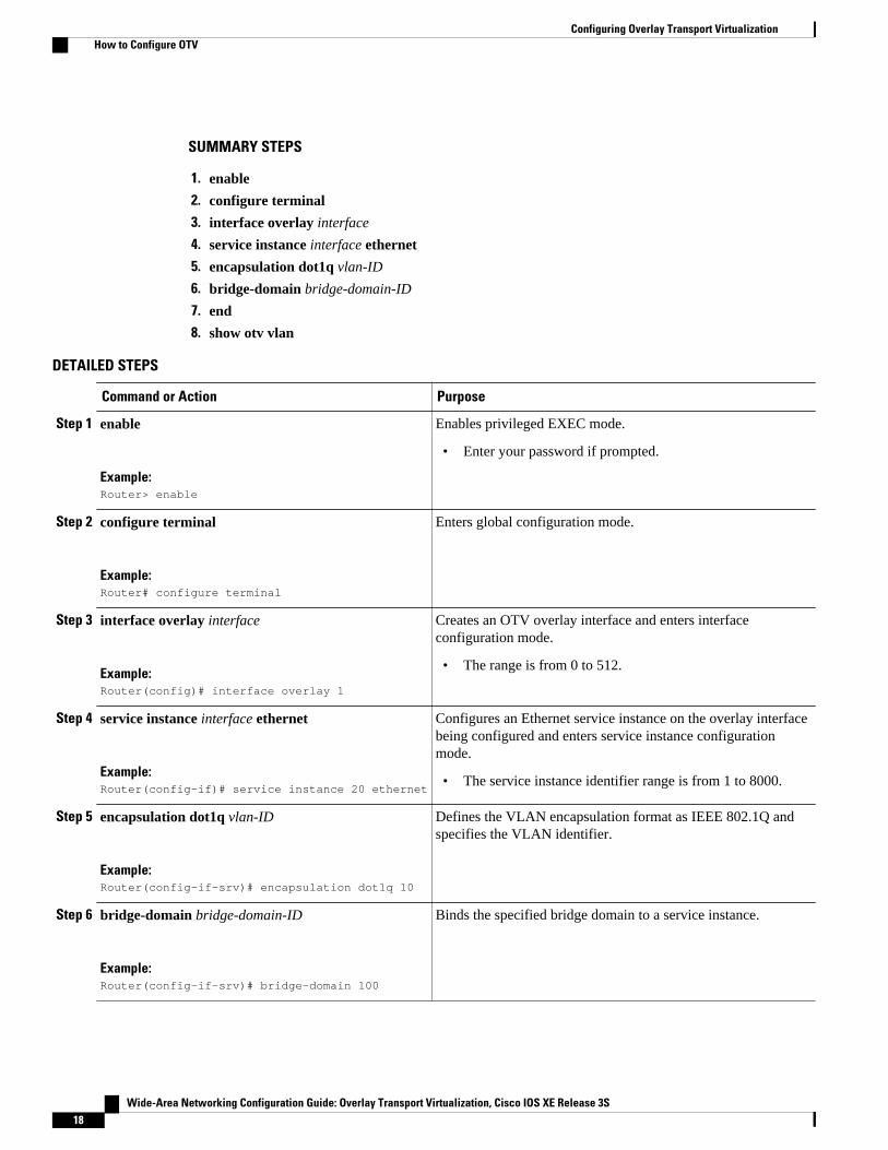
SUMMARY STEPS
1. enable
2. configure terminal
3. interface overlay interface
4. service instance interface ethernet
5. encapsulation dot1q vlan-ID
6. bridge-domain bridge-domain-ID
7. end
8. show otv vlan
DETAILED STEPS
Command or Action Purpose
Step 1 enable
Example:Router> enable
Enables privileged EXEC mode.
• Enter your password if prompted.
Step 2 configure terminal
Example:Router# configure terminal
Enters global configuration mode.
Step 3 interface overlay interface
Example:Router(config)# interface overlay 1
Creates an OTV overlay interface and enters interfaceconfiguration mode.
• The range is from 0 to 512.
Step 4 service instance interface ethernet
Example:Router(config-if)# service instance 20 ethernet
Configures an Ethernet service instance on the overlay interfacebeing configured and enters service instance configurationmode.
• The service instance identifier range is from 1 to 8000.
Step 5 encapsulation dot1q vlan-ID
Example:Router(config-if-srv)# encapsulation dot1q 10
Defines the VLAN encapsulation format as IEEE 802.1Q andspecifies the VLAN identifier.
Step 6 bridge-domain bridge-domain-ID
Example:Router(config-if-srv)# bridge-domain 100
Binds the specified bridge domain to a service instance.
Configuring Overlay Transport Virtualization How to Configure OTV
Wide-Area Networking Configuration Guide: Overlay Transport Virtualization, Cisco IOS XE Release 3S18
Command or Action Purpose
Step 7 end
Example:Router(config-if-srv)# end
Exits service instance configuration mode and returns toprivileged EXEC mode.
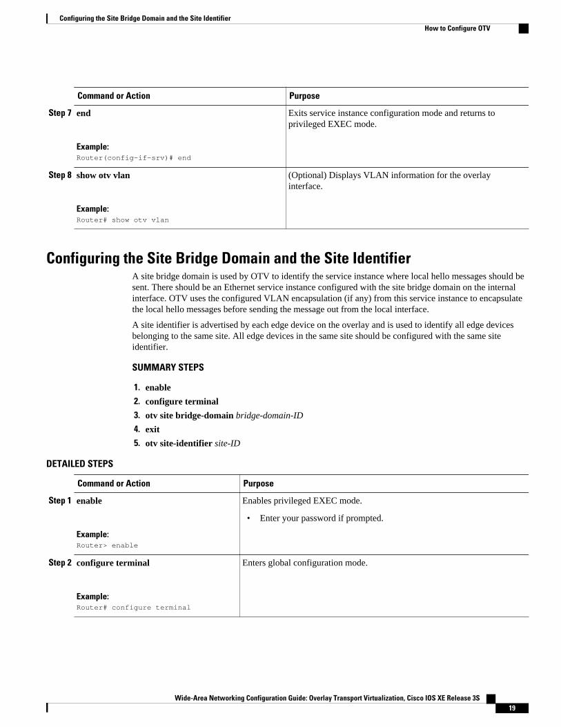
Step 8 show otv vlan
Example:Router# show otv vlan
(Optional) Displays VLAN information for the overlayinterface.
Configuring the Site Bridge Domain and the Site IdentifierA site bridge domain is used by OTV to identify the service instance where local hello messages should besent. There should be an Ethernet service instance configured with the site bridge domain on the internalinterface. OTV uses the configured VLAN encapsulation (if any) from this service instance to encapsulatethe local hello messages before sending the message out from the local interface.
A site identifier is advertised by each edge device on the overlay and is used to identify all edge devicesbelonging to the same site. All edge devices in the same site should be configured with the same siteidentifier.
SUMMARY STEPS
1. enable
2. configure terminal
3. otv site bridge-domain bridge-domain-ID
4. exit
5. otv site-identifier site-ID
DETAILED STEPS
Command or Action Purpose
Step 1 enable
Example:Router> enable
Enables privileged EXEC mode.
• Enter your password if prompted.
Step 2 configure terminal
Example:Router# configure terminal
Enters global configuration mode.
Configuring the Site Bridge Domain and the Site IdentifierHow to Configure OTV
Wide-Area Networking Configuration Guide: Overlay Transport Virtualization, Cisco IOS XE Release 3S 19
Command or Action Purpose
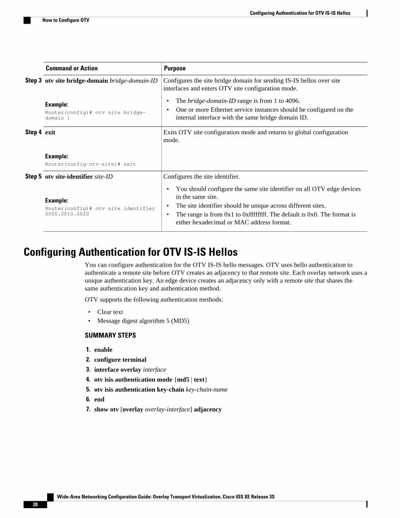
Step 3 otv site bridge-domain bridge-domain-ID
Example:Router(config)# otv site bridge-domain 1
Configures the site bridge domain for sending IS-IS hellos over siteinterfaces and enters OTV site configuration mode.
• The bridge-domain-ID range is from 1 to 4096.• One or more Ethernet service instances should be configured on the
internal interface with the same bridge domain ID.
Step 4 exit
Example:Router(config-otv-site)# exit
Exits OTV site configuration mode and returns to global configurationmode.
Step 5 otv site-identifier site-ID
Example:Router(config)# otv site identifier 0000.0010.0020
Configures the site identifier.
• You should configure the same site identifier on all OTV edge devicesin the same site.
• The site identifier should be unique across different sites.• The range is from 0x1 to 0xffffffff. The default is 0x0. The format is
either hexadecimal or MAC address format.
Configuring Authentication for OTV IS-IS HellosYou can configure authentication for the OTV IS-IS hello messages. OTV uses hello authentication toauthenticate a remote site before OTV creates an adjacency to that remote site. Each overlay network uses aunique authentication key. An edge device creates an adjacency only with a remote site that shares thesame authentication key and authentication method.
OTV supports the following authentication methods:
• Clear text• Message digest algorithm 5 (MD5)
SUMMARY STEPS
1. enable
2. configure terminal
3. interface overlay interface
4. otv isis authentication mode {md5 | text}
5. otv isis authentication key-chain key-chain-name
6. end
7. show otv [overlay overlay-interface] adjacency
Configuring Authentication for OTV IS-IS Hellos How to Configure OTV
Wide-Area Networking Configuration Guide: Overlay Transport Virtualization, Cisco IOS XE Release 3S20
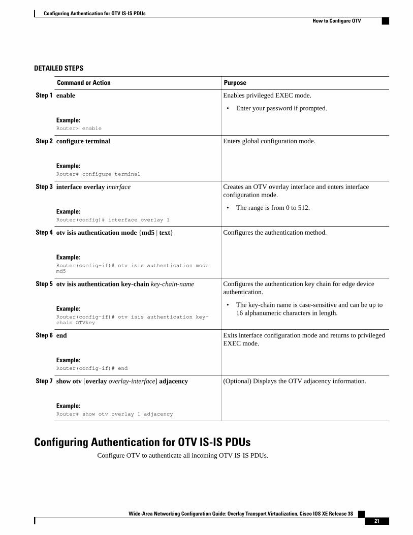
DETAILED STEPS
Command or Action Purpose
Step 1 enable
Example:Router> enable
Enables privileged EXEC mode.
• Enter your password if prompted.
Step 2 configure terminal
Example:Router# configure terminal
Enters global configuration mode.
Step 3 interface overlay interface
Example:Router(config)# interface overlay 1
Creates an OTV overlay interface and enters interfaceconfiguration mode.
• The range is from 0 to 512.
Step 4 otv isis authentication mode {md5 | text}
Example:Router(config-if)# otv isis authentication mode md5
Configures the authentication method.
Step 5 otv isis authentication key-chain key-chain-name
Example:Router(config-if)# otv isis authentication key-chain OTVkey
Configures the authentication key chain for edge deviceauthentication.
• The key-chain name is case-sensitive and can be up to16 alphanumeric characters in length.
Step 6 end
Example:Router(config-if)# end
Exits interface configuration mode and returns to privilegedEXEC mode.
Step 7 show otv [overlay overlay-interface] adjacency
Example:Router# show otv overlay 1 adjacency
(Optional) Displays the OTV adjacency information.
Configuring Authentication for OTV IS-IS PDUsConfigure OTV to authenticate all incoming OTV IS-IS PDUs.
Configuring Authentication for OTV IS-IS PDUsHow to Configure OTV
Wide-Area Networking Configuration Guide: Overlay Transport Virtualization, Cisco IOS XE Release 3S 21
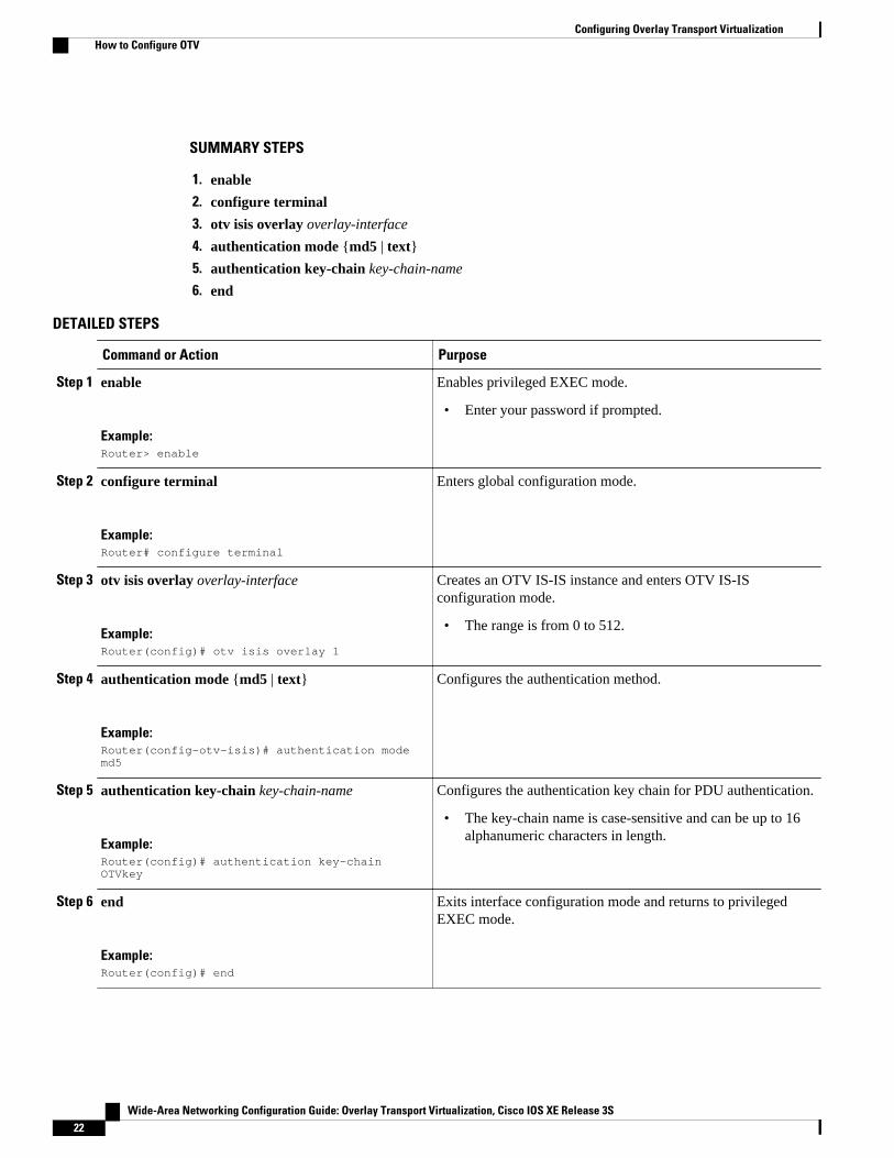
SUMMARY STEPS
1. enable
2. configure terminal
3. otv isis overlay overlay-interface
4. authentication mode {md5 | text}
5. authentication key-chain key-chain-name
6. end
DETAILED STEPS
Command or Action Purpose
Step 1 enable
Example:Router> enable
Enables privileged EXEC mode.
• Enter your password if prompted.
Step 2 configure terminal
Example:Router# configure terminal
Enters global configuration mode.
Step 3 otv isis overlay overlay-interface
Example:Router(config)# otv isis overlay 1
Creates an OTV IS-IS instance and enters OTV IS-ISconfiguration mode.
• The range is from 0 to 512.
Step 4 authentication mode {md5 | text}
Example:Router(config-otv-isis)# authentication mode md5
Configures the authentication method.
Step 5 authentication key-chain key-chain-name
Example:Router(config)# authentication key-chain OTVkey
Configures the authentication key chain for PDU authentication.
• The key-chain name is case-sensitive and can be up to 16alphanumeric characters in length.
Step 6 end
Example:Router(config)# end
Exits interface configuration mode and returns to privilegedEXEC mode.
Configuring Overlay Transport Virtualization How to Configure OTV
Wide-Area Networking Configuration Guide: Overlay Transport Virtualization, Cisco IOS XE Release 3S22
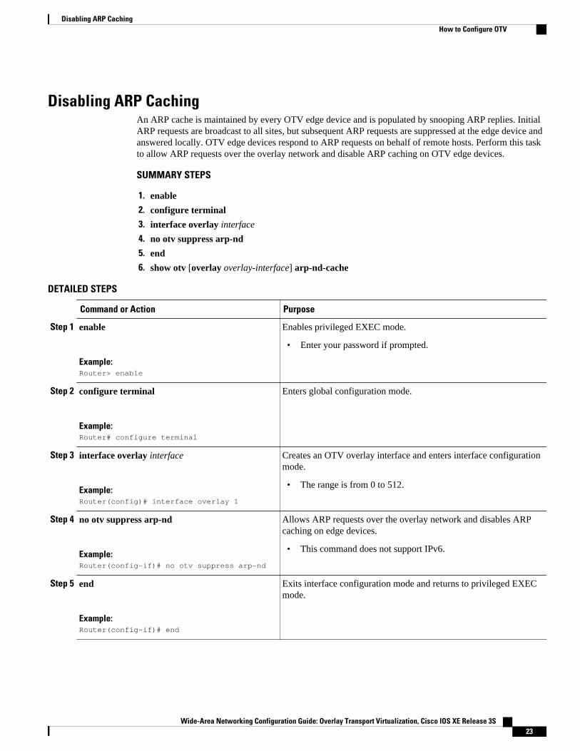
Disabling ARP CachingAn ARP cache is maintained by every OTV edge device and is populated by snooping ARP replies. InitialARP requests are broadcast to all sites, but subsequent ARP requests are suppressed at the edge device andanswered locally. OTV edge devices respond to ARP requests on behalf of remote hosts. Perform this taskto allow ARP requests over the overlay network and disable ARP caching on OTV edge devices.
SUMMARY STEPS
1. enable
2. configure terminal
3. interface overlay interface
4. no otv suppress arp-nd
5. end
6. show otv [overlay overlay-interface] arp-nd-cache
DETAILED STEPS
Command or Action Purpose
Step 1 enable
Example:Router> enable
Enables privileged EXEC mode.
• Enter your password if prompted.
Step 2 configure terminal
Example:Router# configure terminal
Enters global configuration mode.
Step 3 interface overlay interface
Example:Router(config)# interface overlay 1
Creates an OTV overlay interface and enters interface configurationmode.
• The range is from 0 to 512.
Step 4 no otv suppress arp-nd
Example:Router(config-if)# no otv suppress arp-nd
Allows ARP requests over the overlay network and disables ARPcaching on edge devices.
• This command does not support IPv6.
Step 5 end
Example:Router(config-if)# end
Exits interface configuration mode and returns to privileged EXECmode.
Disabling ARP CachingHow to Configure OTV
Wide-Area Networking Configuration Guide: Overlay Transport Virtualization, Cisco IOS XE Release 3S 23
Command or Action Purpose
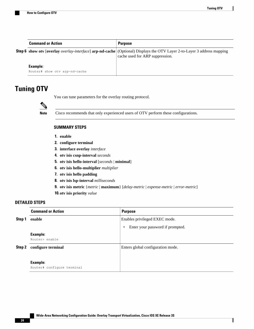
Step 6 show otv [overlay overlay-interface] arp-nd-cache
Example:Router# show otv arp-nd-cache
(Optional) Displays the OTV Layer 2-to-Layer 3 address mappingcache used for ARP suppression.
Tuning OTVYou can tune parameters for the overlay routing protocol.
Note Cisco recommends that only experienced users of OTV perform these configurations.
SUMMARY STEPS
1. enable
2. configure terminal
3. interface overlay interface
4. otv isis csnp-interval seconds
5. otv isis hello-interval [seconds | minimal]
6. otv isis hello-multiplier multiplier
7. otv isis hello padding
8. otv isis lsp-interval milliseconds
9. otv isis metric {metric | maximum} [delay-metric | expense-metric | error-metric]
10. otv isis priority value
DETAILED STEPS
Command or Action Purpose
Step 1 enable
Example:Router> enable
Enables privileged EXEC mode.
• Enter your password if prompted.
Step 2 configure terminal
Example:Router# configure terminal
Enters global configuration mode.
Tuning OTV How to Configure OTV
Wide-Area Networking Configuration Guide: Overlay Transport Virtualization, Cisco IOS XE Release 3S24
Command or Action Purpose
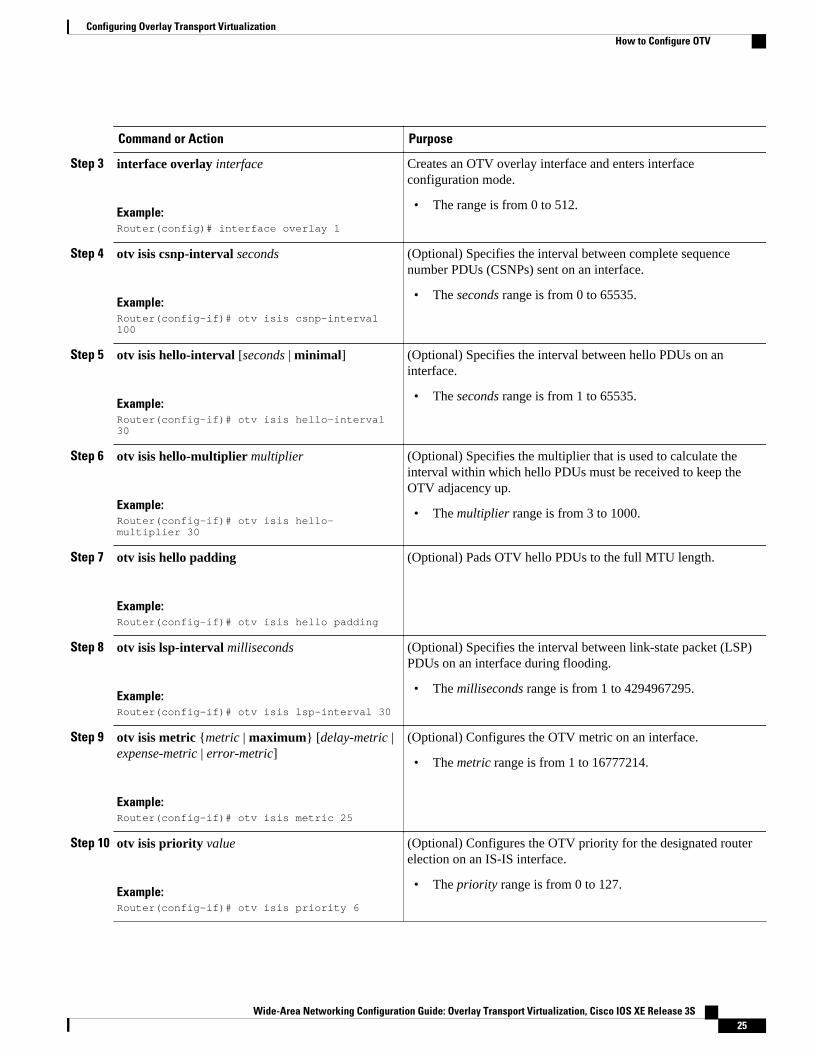
Step 3 interface overlay interface
Example:Router(config)# interface overlay 1
Creates an OTV overlay interface and enters interfaceconfiguration mode.
• The range is from 0 to 512.
Step 4 otv isis csnp-interval seconds
Example:Router(config-if)# otv isis csnp-interval 100
(Optional) Specifies the interval between complete sequencenumber PDUs (CSNPs) sent on an interface.
• The seconds range is from 0 to 65535.
Step 5 otv isis hello-interval [seconds | minimal]
Example:Router(config-if)# otv isis hello-interval 30
(Optional) Specifies the interval between hello PDUs on aninterface.
• The seconds range is from 1 to 65535.
Step 6 otv isis hello-multiplier multiplier
Example:Router(config-if)# otv isis hello-multiplier 30
(Optional) Specifies the multiplier that is used to calculate theinterval within which hello PDUs must be received to keep theOTV adjacency up.
• The multiplier range is from 3 to 1000.
Step 7 otv isis hello padding
Example:Router(config-if)# otv isis hello padding
(Optional) Pads OTV hello PDUs to the full MTU length.
Step 8 otv isis lsp-interval milliseconds
Example:Router(config-if)# otv isis lsp-interval 30
(Optional) Specifies the interval between link-state packet (LSP)PDUs on an interface during flooding.
• The milliseconds range is from 1 to 4294967295.
Step 9 otv isis metric {metric | maximum} [delay-metric |expense-metric | error-metric]
Example:Router(config-if)# otv isis metric 25
(Optional) Configures the OTV metric on an interface.
• The metric range is from 1 to 16777214.
Step 10 otv isis priority value
Example:Router(config-if)# otv isis priority 6
(Optional) Configures the OTV priority for the designated routerelection on an IS-IS interface.
• The priority range is from 0 to 127.
Configuring Overlay Transport VirtualizationHow to Configure OTV
Wide-Area Networking Configuration Guide: Overlay Transport Virtualization, Cisco IOS XE Release 3S 25
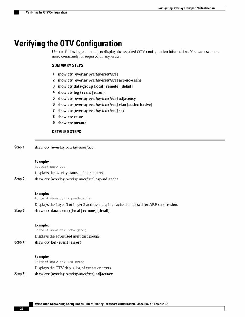
Verifying the OTV ConfigurationUse the following commands to display the required OTV configuration information. You can use one ormore commands, as required, in any order.
SUMMARY STEPS
1. show otv [overlay overlay-interface]
2. show otv [overlay overlay-interface] arp-nd-cache
3. show otv data-group [local | remote] [detail]
4. show otv log {event | error}
5. show otv [overlay overlay-interface] adjacency
6. show otv [overlay overlay-interface] vlan [authoritative]
7. show otv [overlay overlay-interface] site
8. show otv route
9. show otv mroute
DETAILED STEPS
Step 1 show otv [overlay overlay-interface]
Example:Router# show otv
Displays the overlay status and parameters.
Step 2 show otv [overlay overlay-interface] arp-nd-cache
Example:Router# show otv arp-nd-cache
Displays the Layer 3 to Layer 2 address mapping cache that is used for ARP suppression.
Step 3 show otv data-group [local | remote] [detail]
Example:Router# show otv data-group
Displays the advertised multicast groups.
Step 4 show otv log {event | error}
Example:Router# show otv log event
Displays the OTV debug log of events or errors.
Step 5 show otv [overlay overlay-interface] adjacency
Configuring Overlay Transport Virtualization Verifying the OTV Configuration
Wide-Area Networking Configuration Guide: Overlay Transport Virtualization, Cisco IOS XE Release 3S26
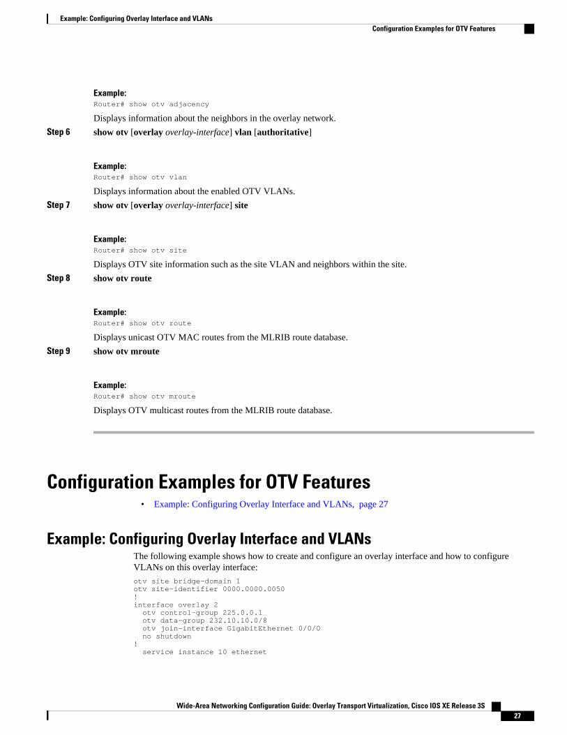
Example:Router# show otv adjacency
Displays information about the neighbors in the overlay network.
Step 6 show otv [overlay overlay-interface] vlan [authoritative]
Example:Router# show otv vlan
Displays information about the enabled OTV VLANs.
Step 7 show otv [overlay overlay-interface] site
Example:Router# show otv site
Displays OTV site information such as the site VLAN and neighbors within the site.
Step 8 show otv route
Example:Router# show otv route
Displays unicast OTV MAC routes from the MLRIB route database.
Step 9 show otv mroute
Example:Router# show otv mroute
Displays OTV multicast routes from the MLRIB route database.
Configuration Examples for OTV Features• Example: Configuring Overlay Interface and VLANs, page 27
Example: Configuring Overlay Interface and VLANsThe following example shows how to create and configure an overlay interface and how to configureVLANs on this overlay interface:
otv site bridge-domain 1otv site-identifier 0000.0000.0050!interface overlay 2 otv control-group 225.0.0.1 otv data-group 232.10.10.0/8 otv join-interface GigabitEthernet 0/0/0 no shutdown! service instance 10 ethernet
Example: Configuring Overlay Interface and VLANsConfiguration Examples for OTV Features
Wide-Area Networking Configuration Guide: Overlay Transport Virtualization, Cisco IOS XE Release 3S 27
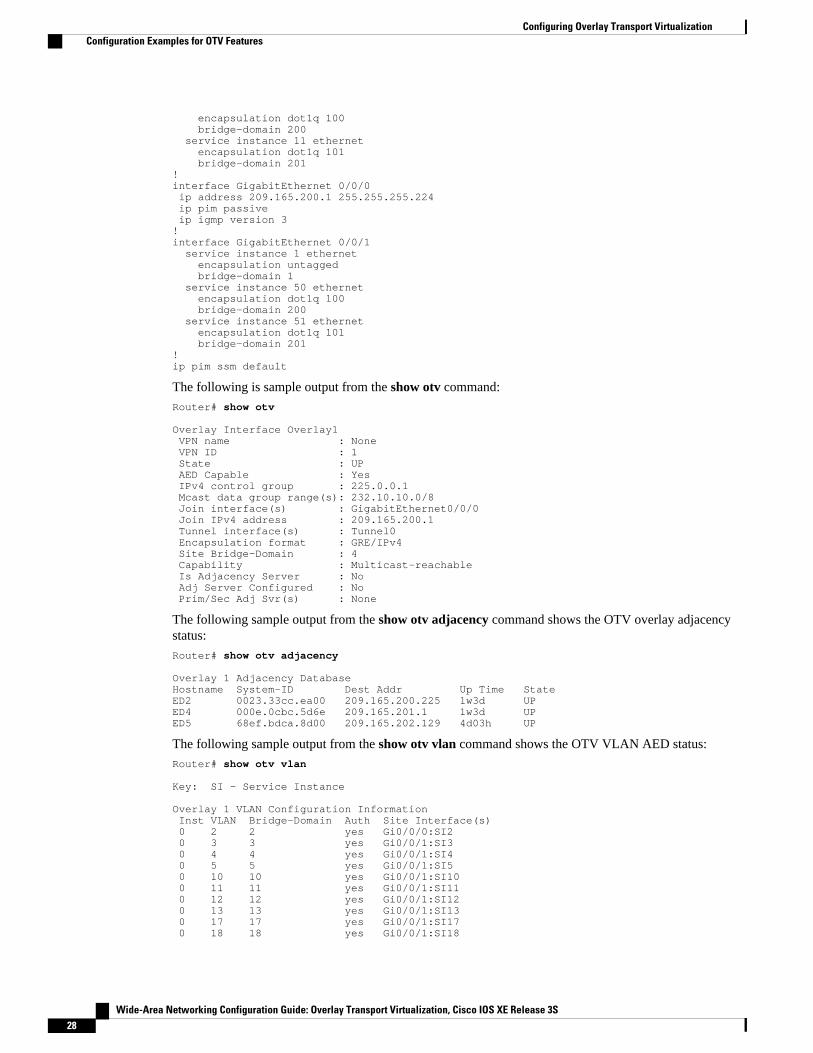
encapsulation dot1q 100 bridge-domain 200 service instance 11 ethernet encapsulation dot1q 101 bridge-domain 201!interface GigabitEthernet 0/0/0 ip address 209.165.200.1 255.255.255.224 ip pim passive ip igmp version 3!interface GigabitEthernet 0/0/1 service instance 1 ethernet encapsulation untagged bridge-domain 1 service instance 50 ethernet encapsulation dot1q 100 bridge-domain 200 service instance 51 ethernet encapsulation dot1q 101 bridge-domain 201!ip pim ssm default
The following is sample output from the show otv command:
Router# show otv
Overlay Interface Overlay1 VPN name : None VPN ID : 1 State : UP AED Capable : Yes IPv4 control group : 225.0.0.1 Mcast data group range(s): 232.10.10.0/8 Join interface(s) : GigabitEthernet0/0/0 Join IPv4 address : 209.165.200.1 Tunnel interface(s) : Tunnel0 Encapsulation format : GRE/IPv4 Site Bridge-Domain : 4 Capability : Multicast-reachable Is Adjacency Server : No Adj Server Configured : No Prim/Sec Adj Svr(s) : None
The following sample output from the show otv adjacency command shows the OTV overlay adjacencystatus:
Router# show otv adjacency
Overlay 1 Adjacency DatabaseHostname System-ID Dest Addr Up Time StateED2 0023.33cc.ea00 209.165.200.225 1w3d UPED4 000e.0cbc.5d6e 209.165.201.1 1w3d UPED5 68ef.bdca.8d00 209.165.202.129 4d03h UP
The following sample output from the show otv vlan command shows the OTV VLAN AED status:
Router# show otv vlan
Key: SI - Service Instance
Overlay 1 VLAN Configuration Information Inst VLAN Bridge-Domain Auth Site Interface(s) 0 2 2 yes Gi0/0/0:SI2 0 3 3 yes Gi0/0/1:SI3 0 4 4 yes Gi0/0/1:SI4 0 5 5 yes Gi0/0/1:SI5 0 10 10 yes Gi0/0/1:SI10 0 11 11 yes Gi0/0/1:SI11 0 12 12 yes Gi0/0/1:SI12 0 13 13 yes Gi0/0/1:SI13 0 17 17 yes Gi0/0/1:SI17 0 18 18 yes Gi0/0/1:SI18
Configuring Overlay Transport Virtualization Configuration Examples for OTV Features
Wide-Area Networking Configuration Guide: Overlay Transport Virtualization, Cisco IOS XE Release 3S28
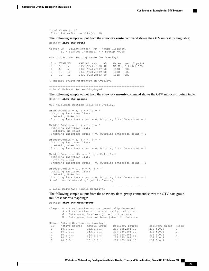
Total VLAN(s): 10 Total Authoritative VLAN(s): 10
The following sample output from the show otv route command shows the OTV unicast routing table:Router# show otv route
Codes: BD - Bridge-Domain, AD - Admin-Distance, SI - Service Instance, * - Backup Route
OTV Unicast MAC Routing Table for Overlay1
Inst VLAN BD MAC Address AD Owner Next Hops(s) 0 5 5 0030.96e6.fc38 40 BD Eng Gi0/0/1:SI5 0 5 5 0030.96e6.fc37 50 ISIS ED3 0 10 10 0030.96e6.fc39 50 ISIS ED3 0 12 12 0030.96e6.fc33 50 ISIS ED3
4 unicast routes displayed in Overlay1
----------------------------------------------------------4 Total Unicast Routes Displayed
The following sample output from the show otv mroute command shows the OTV multicast routing table:Router# show otv mroute
OTV Multicast Routing Table for Overlay1
Bridge-Domain = 2, s = *, g = * Outgoing interface list: Default, NoRedist Incoming interface count = 0, Outgoing interface count = 1
Bridge-Domain = 3, s = *, g = * Outgoing interface list: Default, NoRedist Incoming interface count = 0, Outgoing interface count = 1
Bridge-Domain = 4, s = *, g = * Outgoing interface list: Default, NoRedist Incoming interface count = 0, Outgoing interface count = 1
Bridge-Domain = 10, s = *, g = 224.0.1.40 Outgoing interface list: Overlay1, ED3 Incoming interface count = 0, Outgoing interface count = 1
Bridge-Domain = 11, s = *, g = * Outgoing interface list: Default, NoRedist Incoming interface count = 0, Outgoing interface count = 15 multicast routes displayed in Overlay1
----------------------------------------------------------5 Total Multicast Routes Displayed
The following sample output from the show otv data-group command shows the OTV data groupmulticast address mappings:Router# show otv data-group
Flags: D - Local active source dynamically detected S - Local active source statically configured J - Data group has been joined in the core U - Data group has not been joined in the core
Remote Active Sources for Overlay1 BD Active-Source Active-Group Delivery-Source Delivery-Group Flags 1 10.0.1.1 232.0.0.1 209.165.201.10 232.5.0.0 U 2 10.0.2.1 232.0.0.1 209.165.201.10 232.5.0.1 U 3 10.0.3.1 232.0.0.1 209.165.201.10 232.5.0.2 U 4 10.0.4.1 232.0.0.1 209.165.201.10 232.5.0.3 U 5 10.0.5.1 232.0.0.1 209.165.201.10 232.5.0.4 J
Configuring Overlay Transport VirtualizationConfiguration Examples for OTV Features
Wide-Area Networking Configuration Guide: Overlay Transport Virtualization, Cisco IOS XE Release 3S 29
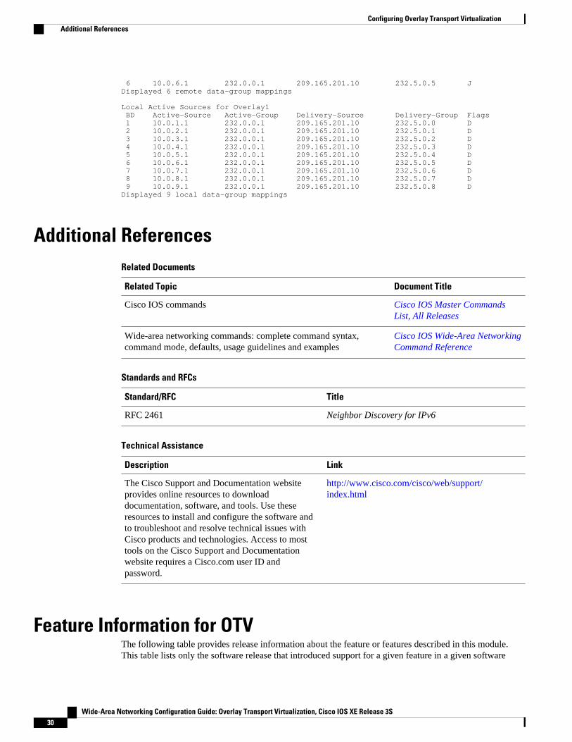
6 10.0.6.1 232.0.0.1 209.165.201.10 232.5.0.5 JDisplayed 6 remote data-group mappings
Local Active Sources for Overlay1 BD Active-Source Active-Group Delivery-Source Delivery-Group Flags 1 10.0.1.1 232.0.0.1 209.165.201.10 232.5.0.0 D 2 10.0.2.1 232.0.0.1 209.165.201.10 232.5.0.1 D 3 10.0.3.1 232.0.0.1 209.165.201.10 232.5.0.2 D 4 10.0.4.1 232.0.0.1 209.165.201.10 232.5.0.3 D 5 10.0.5.1 232.0.0.1 209.165.201.10 232.5.0.4 D 6 10.0.6.1 232.0.0.1 209.165.201.10 232.5.0.5 D 7 10.0.7.1 232.0.0.1 209.165.201.10 232.5.0.6 D 8 10.0.8.1 232.0.0.1 209.165.201.10 232.5.0.7 D 9 10.0.9.1 232.0.0.1 209.165.201.10 232.5.0.8 DDisplayed 9 local data-group mappings
Additional ReferencesRelated Documents
Related Topic Document Title
Cisco IOS commands Cisco IOS Master CommandsList, All Releases
Wide-area networking commands: complete command syntax,command mode, defaults, usage guidelines and examples
Cisco IOS Wide-Area NetworkingCommand Reference
Standards and RFCs
Standard/RFC Title
RFC 2461 Neighbor Discovery for IPv6
Technical Assistance
Description Link
The Cisco Support and Documentation websiteprovides online resources to downloaddocumentation, software, and tools. Use theseresources to install and configure the software andto troubleshoot and resolve technical issues withCisco products and technologies. Access to mosttools on the Cisco Support and Documentationwebsite requires a Cisco.com user ID andpassword.
http://www.cisco.com/cisco/web/support/index.html
Feature Information for OTVThe following table provides release information about the feature or features described in this module.This table lists only the software release that introduced support for a given feature in a given software
Configuring Overlay Transport Virtualization Additional References
Wide-Area Networking Configuration Guide: Overlay Transport Virtualization, Cisco IOS XE Release 3S30

release train. Unless noted otherwise, subsequent releases of that software release train also support thatfeature.
Use Cisco Feature Navigator to find information about platform support and Cisco software image support.To access Cisco Feature Navigator, go to www.cisco.com/go/cfn. An account on Cisco.com is not required.
Configuring Overlay Transport VirtualizationFeature Information for OTV
Wide-Area Networking Configuration Guide: Overlay Transport Virtualization, Cisco IOS XE Release 3S 31
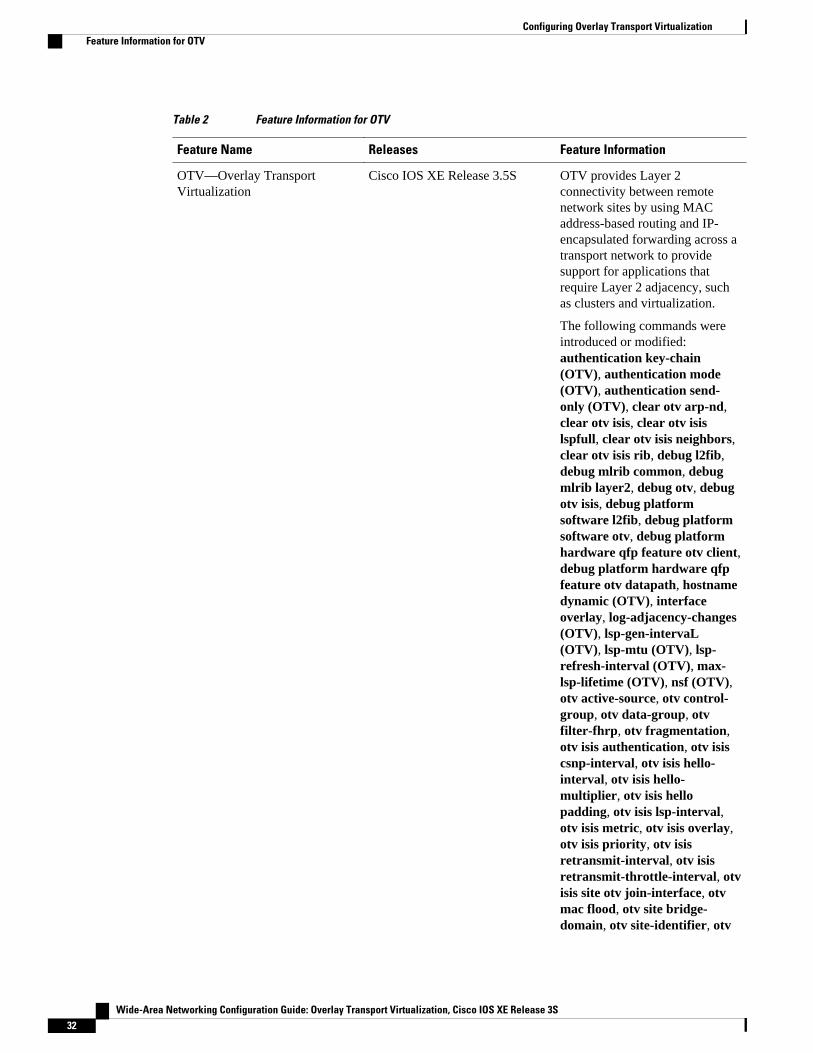
Table 2 Feature Information for OTV
Feature Name Releases Feature Information
OTV—Overlay TransportVirtualization
Cisco IOS XE Release 3.5S OTV provides Layer 2connectivity between remotenetwork sites by using MACaddress-based routing and IP-encapsulated forwarding across atransport network to providesupport for applications thatrequire Layer 2 adjacency, suchas clusters and virtualization.
The following commands wereintroduced or modified:authentication key-chain(OTV), authentication mode(OTV), authentication send-only (OTV), clear otv arp-nd,clear otv isis, clear otv isislspfull, clear otv isis neighbors,clear otv isis rib, debug l2fib,debug mlrib common, debugmlrib layer2, debug otv, debugotv isis, debug platformsoftware l2fib, debug platformsoftware otv, debug platformhardware qfp feature otv client,debug platform hardware qfpfeature otv datapath, hostnamedynamic (OTV), interfaceoverlay, log-adjacency-changes(OTV), lsp-gen-intervaL(OTV), lsp-mtu (OTV), lsp-refresh-interval (OTV), max-lsp-lifetime (OTV), nsf (OTV),otv active-source, otv control-group, otv data-group, otvfilter-fhrp, otv fragmentation,otv isis authentication, otv isiscsnp-interval, otv isis hello-interval, otv isis hello-multiplier, otv isis hellopadding, otv isis lsp-interval,otv isis metric, otv isis overlay,otv isis priority, otv isisretransmit-interval, otv isisretransmit-throttle-interval, otvisis site otv join-interface, otvmac flood, otv site bridge-domain, otv site-identifier, otv
Configuring Overlay Transport Virtualization Feature Information for OTV
Wide-Area Networking Configuration Guide: Overlay Transport Virtualization, Cisco IOS XE Release 3S32
Feature Name Releases Feature Information
suppress arp-nd, otv vpn-name,prc-interval (OTV), show l2fib,show mlrib common log, showmlrib layer2 log, show otv,show otv adjacency, show otvarp-nd-cache, show otv data-group, show otv isis database,show otv isis hostname, showotv isis lsp-log, show otv isisneighbors, show otv isis nsf,show otv isis protocol, show otvisis rib, show otv isis spf-log,show otv isis vlan-database,show otv log, show otv mroute,show otv route, show otv site,show otv statistics, show otvsummary, show otv vlan, showplatform hardware qfp featureotv client interface, showplatform software l2fib fp, showplatform software l2fib rp,show platform software otv fp,skeptical interval (OTV), spf-interval (OTV).
Cisco and the Cisco logo are trademarks or registered trademarks of Cisco and/or its affiliates in the U.S.and other countries. To view a list of Cisco trademarks, go to this URL: www.cisco.com/go/trademarks.Third-party trademarks mentioned are the property of their respective owners. The use of the word partnerdoes not imply a partnership relationship between Cisco and any other company. (1110R)
Any Internet Protocol (IP) addresses and phone numbers used in this document are not intended to beactual addresses and phone numbers. Any examples, command display output, network topology diagrams,and other figures included in the document are shown for illustrative purposes only. Any use of actual IPaddresses or phone numbers in illustrative content is unintentional and coincidental.
Configuring Overlay Transport Virtualization
Wide-Area Networking Configuration Guide: Overlay Transport Virtualization, Cisco IOS XE Release 3S 33

Example: Configuring Overlay Interface and VLANs
Wide-Area Networking Configuration Guide: Overlay Transport Virtualization, Cisco IOS XE Release 3S34
Related Documents


![Network Virtualizationjain/talks/ftp/net_v.pdf · Overlay Transport Virtualization (OTV) Cisco technology for LAN Extension over IP Ref: [Cisco-OTV] Cisco, “Enhance Business Continuance](https://static.cupdf.com/doc/110x72/5f7d939ea0e5f404625bc0af/network-virtualization-jaintalksftpnetvpdf-overlay-transport-virtualization.jpg)