L2TP Over IPsec Between Windows 2000/XP PC and PIX/ASA 7.2 Using Pre-shared Key Configuration Example Document ID: 71028 Introduction Prerequisites Requirements Components Used Related Products Conventions Background Information Configure Network Diagram Configurations Windows L2TP/IPsec Client Configuration L2TP Server in PIX Configuration L2TP using ASDM Configuration Microsoft Windows 2003 Server with IAS Configuration Verify Troubleshoot Troubleshooting Commands Sample debug Output Troubleshoot using ASDM NetPro Discussion Forums - Featured Conversations Related Information Introduction This document describes how to configure Layer 2 Tunneling Protocol (L2TP) over IPsec from remote Microsoft Windows 2000/2003 and XP clients to a PIX Security Appliance corporate office using pre-shared keys with Microsoft Windows 2003 Internet Authentication Service (IAS) RADIUS Server for user authentication. Refer to Microsoft - Checklist: Configuring IAS for dial-up and VPN access for further information on IAS. The primary benefit of configuring L2TP with IPsec in a remote access scenario is that remote users can access a VPN over a public IP network without a gateway or a dedicated line. This enables remote access from virtually any place with POTS. An additional benefit is that the only client requirement for VPN access is the use of Windows 2000 with Microsoft Dial-Up Networking (DUN). No additional client software, such as Cisco VPN Client software, is required. This document also describes how to use the Cisco Adaptive Security Device Manager (ASDM) in order to configure the PIX 500 Series Security Appliance for L2TP over IPsec. Note: Layer 2 Tunneling Protocol (L2TP) over IPsec is supported on Cisco Secure PIX Firewall Software Release 6.x and later. In order to configure L2TP Over IPsec between the PIX 6.x and Windows 2000, refer to Configuring L2TP Over IPsec Between PIX Firewall and Windows 2000 PC Using Certificates.

Welcome message from author
This document is posted to help you gain knowledge. Please leave a comment to let me know what you think about it! Share it to your friends and learn new things together.
Transcript
L2TP Over IPsec Between Windows 2000/XP PCand PIX/ASA 7.2 Using Pre−shared KeyConfiguration Example
Document ID: 71028
IntroductionPrerequisites Requirements Components Used Related Products ConventionsBackground InformationConfigure Network Diagram Configurations Windows L2TP/IPsec Client Configuration L2TP Server in PIX Configuration L2TP using ASDM Configuration Microsoft Windows 2003 Server with IAS ConfigurationVerifyTroubleshoot Troubleshooting Commands Sample debug Output Troubleshoot using ASDMNetPro Discussion Forums − Featured ConversationsRelated Information
Introduction
This document describes how to configure Layer 2 Tunneling Protocol (L2TP) over IPsec from remoteMicrosoft Windows 2000/2003 and XP clients to a PIX Security Appliance corporate office using pre−sharedkeys with Microsoft Windows 2003 Internet Authentication Service (IAS) RADIUS Server for userauthentication. Refer to Microsoft − Checklist: Configuring IAS for dial−up and VPN access for furtherinformation on IAS.
The primary benefit of configuring L2TP with IPsec in a remote access scenario is that remote users canaccess a VPN over a public IP network without a gateway or a dedicated line. This enables remote accessfrom virtually any place with POTS. An additional benefit is that the only client requirement for VPN accessis the use of Windows 2000 with Microsoft Dial−Up Networking (DUN). No additional client software, suchas Cisco VPN Client software, is required.
This document also describes how to use the Cisco Adaptive Security Device Manager (ASDM) in order toconfigure the PIX 500 Series Security Appliance for L2TP over IPsec.
Note: Layer 2 Tunneling Protocol (L2TP) over IPsec is supported on Cisco Secure PIX Firewall SoftwareRelease 6.x and later.
In order to configure L2TP Over IPsec between the PIX 6.x and Windows 2000, refer to Configuring L2TPOver IPsec Between PIX Firewall and Windows 2000 PC Using Certificates.
In order to configure L2TP over IP Security (IPsec) from remote Microsoft Windows 2000 and XP clients to acorporate site using an encrypted method, refer to Configuring L2TP over IPsec from a Windows 2000 or XPClient to a Cisco VPN 3000 Series Concentrator Using Pre−Shared Keys.
Prerequisites
Requirements
Before the secure tunnel establishment, IP connectivity needs to exist between the peers.
Make sure that UDP port 1701 is not blocked anywhere along the path of the connection.
Use only the default tunnel group and default group policy on the Cisco PIX/ASA. User−defined policies andgroups do not work.
Note: The security appliance does not establish an L2TP/IPsec tunnel with Windows 2000 if either CiscoVPN Client 3.x or Cisco VPN 3000 Client 2.5 is installed. Disable the Cisco VPN service for Cisco VPNClient 3.x, or the ANetIKE service for Cisco VPN 3000 Client 2.5 from the Services panel in Windows 2000.In order to do this choose Start > Programs > Administrative Tools > Services, restart the IPsec PolicyAgent Service from the Services panel, and reboot the machine.
Components Used
The information in this document is based on these software and hardware versions:
PIX Security Appliance 515E with software version 7.2(1) or later• Adaptive Security Device Manager 5.2(1) or later• Microsoft Windows 2000 Server• Microsoft Windows XP Professional with SP2• Windows 2003 Server with IAS•
Note: If you upgrade the PIX 6.3 to version 7.x, make sure that you have installed SP2 in Windows XP (L2TPClient).
The information in this document was created from the devices in a specific lab environment. All of thedevices used in this document started with a cleared (default) configuration. If your network is live, make surethat you understand the potential impact of any command.
Related Products
This configuration can also be used with Cisco ASA 5500 Series Security Appliance 7.2(1) or later.
Conventions
Refer to Cisco Technical Tips Conventions for more information on document conventions.
Background Information
Complete these steps in order to configure L2TP over IPsec.
Configure IPsec transport mode in order to enable IPsec with L2TP.1.
Windows 2000 L2TP/IPsec client uses IPsec transport mode�Only the IP payload is encrypted, andthe original IP headers are left intact. The advantages of this mode are that it adds only a few bytes toeach packet and allows devices on the public network to see the final source and destination of thepacket. Therefore, in order for Windows 2000 L2TP/IPsec clients to connect to the security appliance,you must configure IPsec transport mode for a transform (see step 2 in the ASDM configuration).With this capability (transport), you can enable special processing (for example, QoS) on theintermediate network based on the information in the IP header. However, the Layer 4 header isencrypted, which limits the examination of the packet. Unfortunately, the transmission of the IPheader in clear text, transport mode allows an attacker to perform some traffic analysis.Configure L2TP with a virtual private dial−up network (VPDN) group.2.
The configuration of L2TP with IPsec supports certificates that use the pre−shared keys or RSA signaturemethods, and the use of dynamic (as opposed to static) crypto maps. Pre−shared key is used as anauthentication to establish the L2TP over IPsec tunnel.
Configure
In this section, you are presented with the information to configure the features described in this document.
Note: Use the Command Lookup Tool ( registered customers only) to find more information on the commandsused in this document.
Note: The IP addressing schemes used in this configuration are not legally routable on the Internet. They areRFC 1918 addresses which have been used in a lab environment.
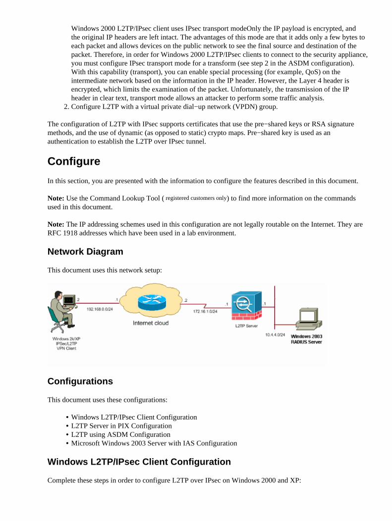
Network Diagram
This document uses this network setup:
Configurations
This document uses these configurations:
Windows L2TP/IPsec Client Configuration• L2TP Server in PIX Configuration• L2TP using ASDM Configuration• Microsoft Windows 2003 Server with IAS Configuration•
Windows L2TP/IPsec Client Configuration
Complete these steps in order to configure L2TP over IPsec on Windows 2000 and XP:
Add this registry value to your Windows 2000 or XP machines:
HKEY_LOCAL_MACHINE\System\CurrentControlSet\Services\Rasman\Parameters
1.
Add this registry value to this key:
Value Name: ProhibitIpSecData Type: REG_DWORDValue: 1
Note: In some cases, the addition of this key (Value: 1) appears to break the connection as it makesthe XP box negotiate L2TP only rather than an L2TP with IPsec connection. It is mandatory to add anIPsec policy in conjunction with that registry key. If you receive an error 800 when you try toestablish a connection, remove the key (Value: 1) in order to get the connection to work.
Note: You must restart Windows 2000/2003 or XP machine in order for the changes to take effect. Bydefault the Windows client attempts to use IPsec with a Certificate Authority (CA). The configurationof this registry key prevents this from occurring. Now you can configure an IPsec policy on theWindows station to match the parameters that you want on the PIX/ASA. Refer to How to Configurea L2TP/IPSec Connection Using Pre−shared Key Authentication (Q240262) for a step−by−stepconfiguration of the Windows IPsec policy.
Refer to Configure a Preshared Key for Use with Layer 2 Tunneling Protocol Connections inWindows XP (Q281555)\ for more information.
2.
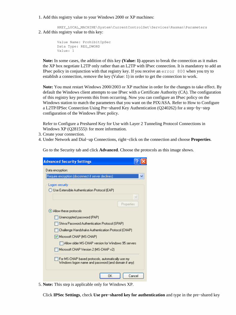
Create your connection.3. Under Network and Dial−up Connections, right−click on the connection and choose Properties.
Go to the Security tab and click Advanced. Choose the protocols as this image shows.
4.
Note: This step is applicable only for Windows XP.
Click IPSec Settings, check Use pre−shared key for authentication and type in the pre−shared key
5.
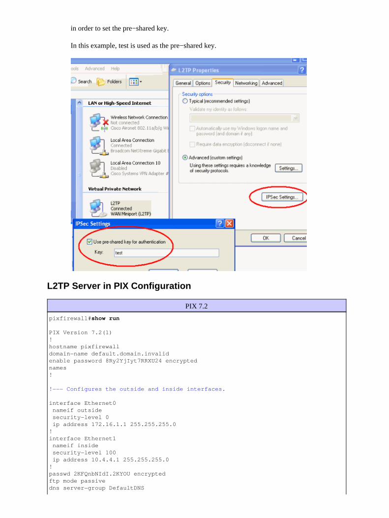
in order to set the pre−shared key.
In this example, test is used as the pre−shared key.
L2TP Server in PIX Configuration
PIX 7.2
pixfirewall#show run
PIX Version 7.2(1)!hostname pixfirewalldomain−name default.domain.invalidenable password 8Ry2YjIyt7RRXU24 encryptednames!
!−−− Configures the outside and inside interfaces.
interface Ethernet0 nameif outside security−level 0 ip address 172.16.1.1 255.255.255.0!interface Ethernet1 nameif inside security−level 100 ip address 10.4.4.1 255.255.255.0!passwd 2KFQnbNIdI.2KYOU encryptedftp mode passivedns server−group DefaultDNS
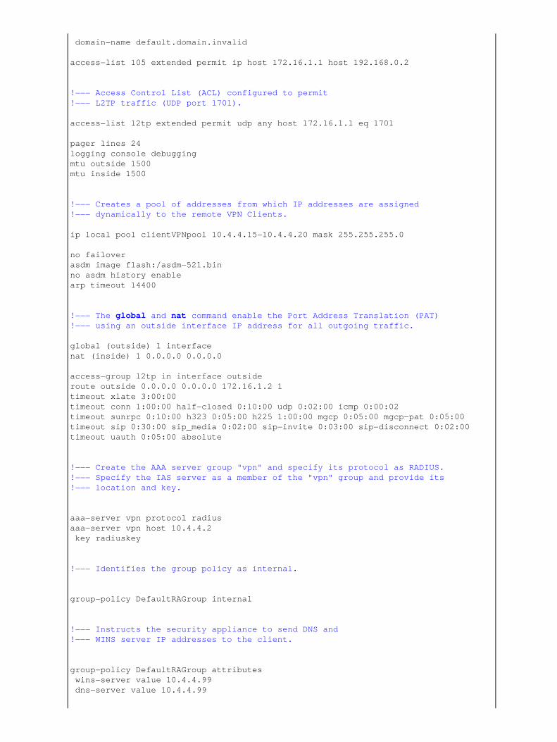
domain−name default.domain.invalid
access−list 105 extended permit ip host 172.16.1.1 host 192.168.0.2
!−−− Access Control List (ACL) configured to permit !−−− L2TP traffic (UDP port 1701).
access−list l2tp extended permit udp any host 172.16.1.1 eq 1701
pager lines 24logging console debuggingmtu outside 1500mtu inside 1500
!−−− Creates a pool of addresses from which IP addresses are assigned !−−− dynamically to the remote VPN Clients.
ip local pool clientVPNpool 10.4.4.15−10.4.4.20 mask 255.255.255.0
no failoverasdm image flash:/asdm−521.binno asdm history enablearp timeout 14400
!−−− The global and nat command enable the Port Address Translation (PAT)!−−− using an outside interface IP address for all outgoing traffic.
global (outside) 1 interfacenat (inside) 1 0.0.0.0 0.0.0.0
access−group l2tp in interface outsideroute outside 0.0.0.0 0.0.0.0 172.16.1.2 1timeout xlate 3:00:00timeout conn 1:00:00 half−closed 0:10:00 udp 0:02:00 icmp 0:00:02timeout sunrpc 0:10:00 h323 0:05:00 h225 1:00:00 mgcp 0:05:00 mgcp−pat 0:05:00timeout sip 0:30:00 sip_media 0:02:00 sip−invite 0:03:00 sip−disconnect 0:02:00timeout uauth 0:05:00 absolute
!−−− Create the AAA server group "vpn" and specify its protocol as RADIUS.!−−− Specify the IAS server as a member of the "vpn" group and provide its!−−− location and key.
aaa−server vpn protocol radiusaaa−server vpn host 10.4.4.2 key radiuskey
!−−− Identifies the group policy as internal.
group−policy DefaultRAGroup internal
!−−− Instructs the security appliance to send DNS and !−−− WINS server IP addresses to the client.
group−policy DefaultRAGroup attributes wins−server value 10.4.4.99 dns−server value 10.4.4.99
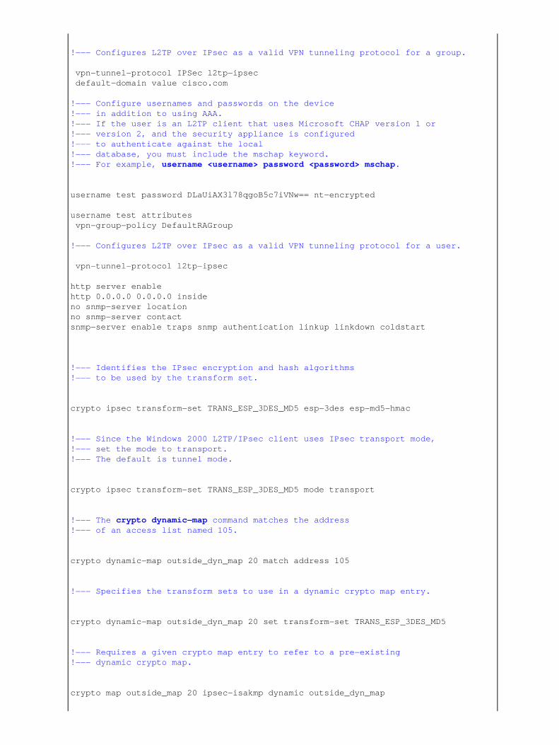
!−−− Configures L2TP over IPsec as a valid VPN tunneling protocol for a group.
vpn−tunnel−protocol IPSec l2tp−ipsec default−domain value cisco.com
!−−− Configure usernames and passwords on the device!−−− in addition to using AAA.!−−− If the user is an L2TP client that uses Microsoft CHAP version 1 or !−−− version 2, and the security appliance is configured !−−− to authenticate against the local !−−− database, you must include the mschap keyword. !−−− For example, username <username> password <password> mschap.
username test password DLaUiAX3l78qgoB5c7iVNw== nt−encrypted
username test attributes vpn−group−policy DefaultRAGroup
!−−− Configures L2TP over IPsec as a valid VPN tunneling protocol for a user.
vpn−tunnel−protocol l2tp−ipsec
http server enablehttp 0.0.0.0 0.0.0.0 insideno snmp−server locationno snmp−server contactsnmp−server enable traps snmp authentication linkup linkdown coldstart
!−−− Identifies the IPsec encryption and hash algorithms !−−− to be used by the transform set.
crypto ipsec transform−set TRANS_ESP_3DES_MD5 esp−3des esp−md5−hmac
!−−− Since the Windows 2000 L2TP/IPsec client uses IPsec transport mode, !−−− set the mode to transport.!−−− The default is tunnel mode.
crypto ipsec transform−set TRANS_ESP_3DES_MD5 mode transport
!−−− The crypto dynamic−map command matches the address !−−− of an access list named 105.
crypto dynamic−map outside_dyn_map 20 match address 105
!−−− Specifies the transform sets to use in a dynamic crypto map entry.
crypto dynamic−map outside_dyn_map 20 set transform−set TRANS_ESP_3DES_MD5
!−−− Requires a given crypto map entry to refer to a pre−existing !−−− dynamic crypto map.
crypto map outside_map 20 ipsec−isakmp dynamic outside_dyn_map
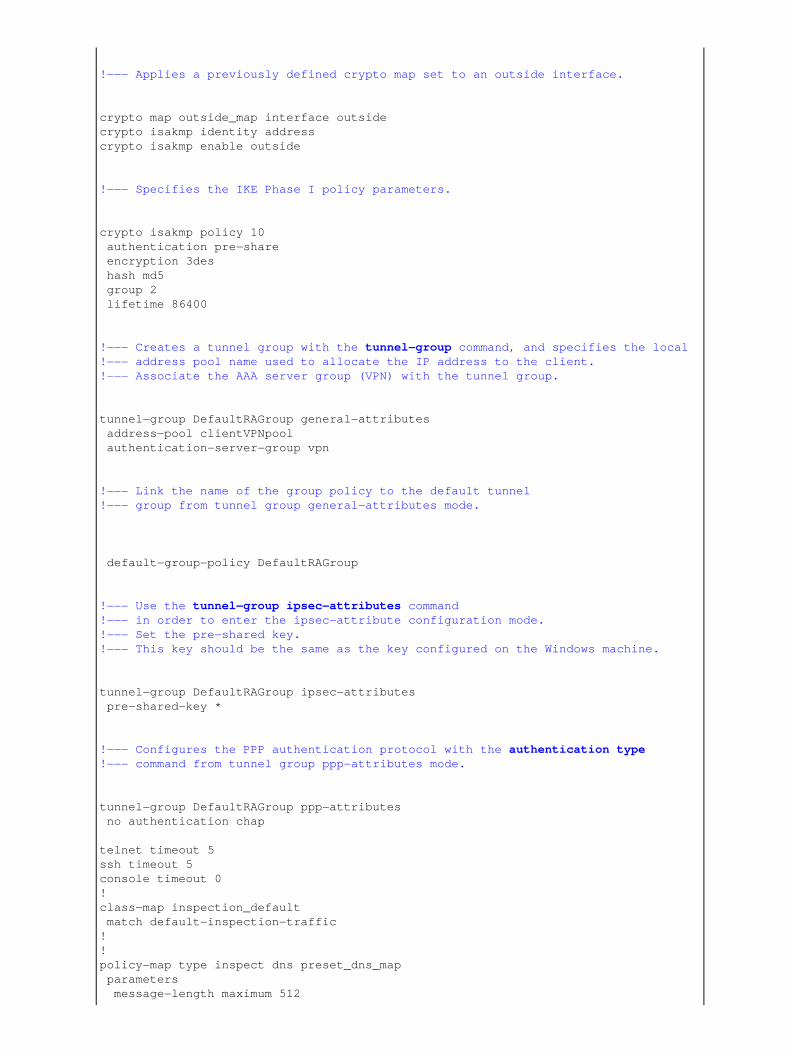
!−−− Applies a previously defined crypto map set to an outside interface.
crypto map outside_map interface outsidecrypto isakmp identity addresscrypto isakmp enable outside
!−−− Specifies the IKE Phase I policy parameters.
crypto isakmp policy 10 authentication pre−share encryption 3des hash md5 group 2 lifetime 86400
!−−− Creates a tunnel group with the tunnel−group command, and specifies the local !−−− address pool name used to allocate the IP address to the client. !−−− Associate the AAA server group (VPN) with the tunnel group.
tunnel−group DefaultRAGroup general−attributes address−pool clientVPNpool authentication−server−group vpn
!−−− Link the name of the group policy to the default tunnel !−−− group from tunnel group general−attributes mode.
default−group−policy DefaultRAGroup
!−−− Use the tunnel−group ipsec−attributes command !−−− in order to enter the ipsec−attribute configuration mode. !−−− Set the pre−shared key. !−−− This key should be the same as the key configured on the Windows machine.
tunnel−group DefaultRAGroup ipsec−attributes pre−shared−key *
!−−− Configures the PPP authentication protocol with the authentication type!−−− command from tunnel group ppp−attributes mode.
tunnel−group DefaultRAGroup ppp−attributes no authentication chap
telnet timeout 5ssh timeout 5console timeout 0!class−map inspection_default match default−inspection−traffic!!policy−map type inspect dns preset_dns_map parameters message−length maximum 512
policy−map global_policy class inspection_default inspect dns preset_dns_map inspect ftp inspect h323 h225 inspect h323 ras inspect netbios inspect rsh inspect rtsp inspect skinny inspect esmtp inspect sqlnet inspect sunrpc inspect tftp inspect sip inspect xdmcp!service−policy global_policy globalprompt hostname contextCryptochecksum:e1e0730fa260244caa2e2784f632accd: end
L2TP using ASDM Configuration
Complete these steps in order to configure the security appliance to accept L2TP over IPsec connections:
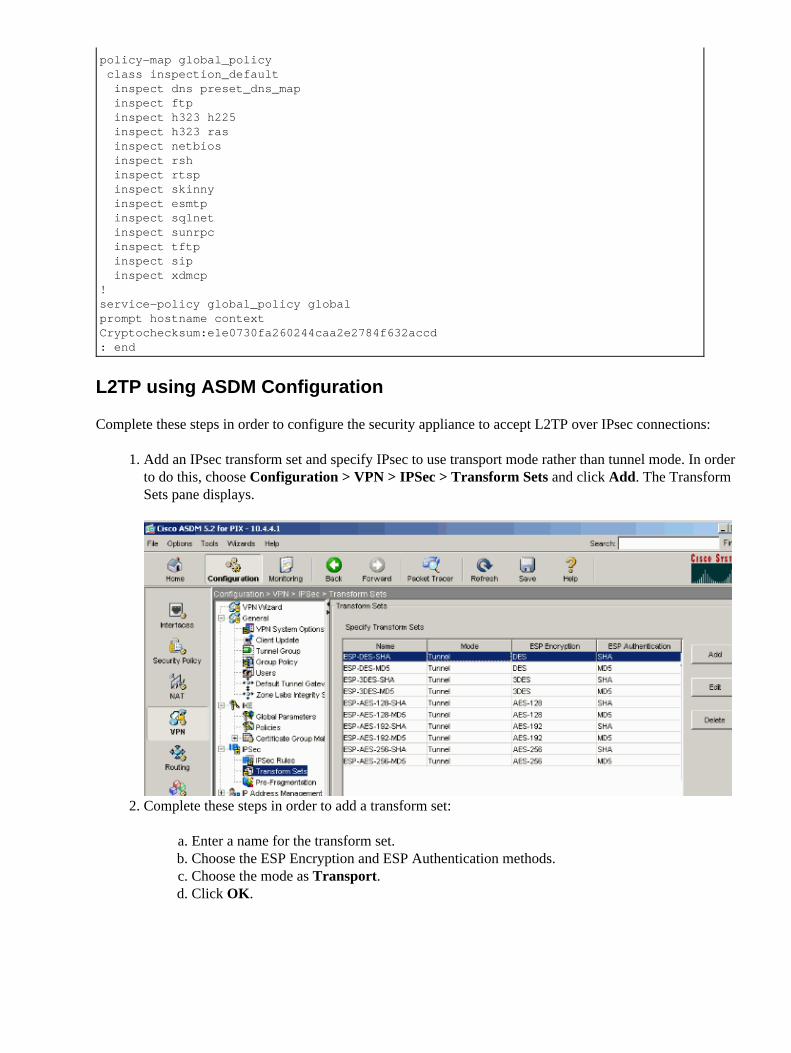
Add an IPsec transform set and specify IPsec to use transport mode rather than tunnel mode. In orderto do this, choose Configuration > VPN > IPSec > Transform Sets and click Add. The TransformSets pane displays.
1.
Complete these steps in order to add a transform set:
Enter a name for the transform set.a. Choose the ESP Encryption and ESP Authentication methods.b. Choose the mode as Transport.c. Click OK.d.
2.
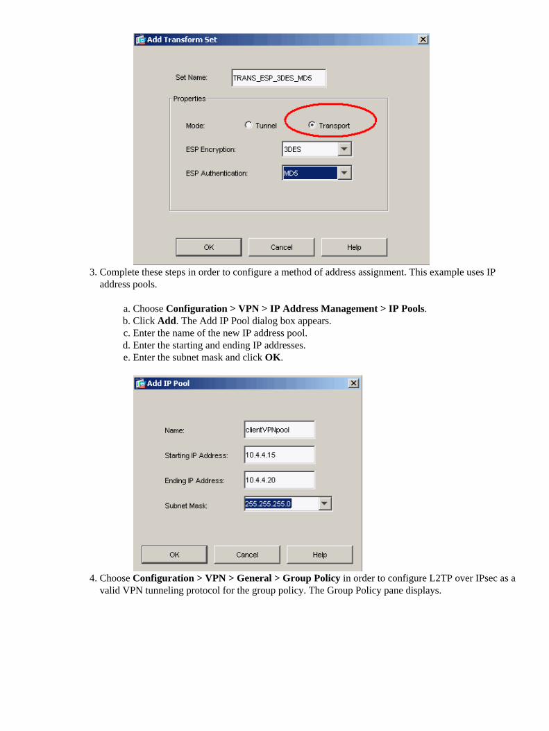
Complete these steps in order to configure a method of address assignment. This example uses IPaddress pools.
Choose Configuration > VPN > IP Address Management > IP Pools.a. Click Add. The Add IP Pool dialog box appears.b. Enter the name of the new IP address pool.c. Enter the starting and ending IP addresses.d. Enter the subnet mask and click OK.e.
3.
Choose Configuration > VPN > General > Group Policy in order to configure L2TP over IPsec as avalid VPN tunneling protocol for the group policy. The Group Policy pane displays.
4.
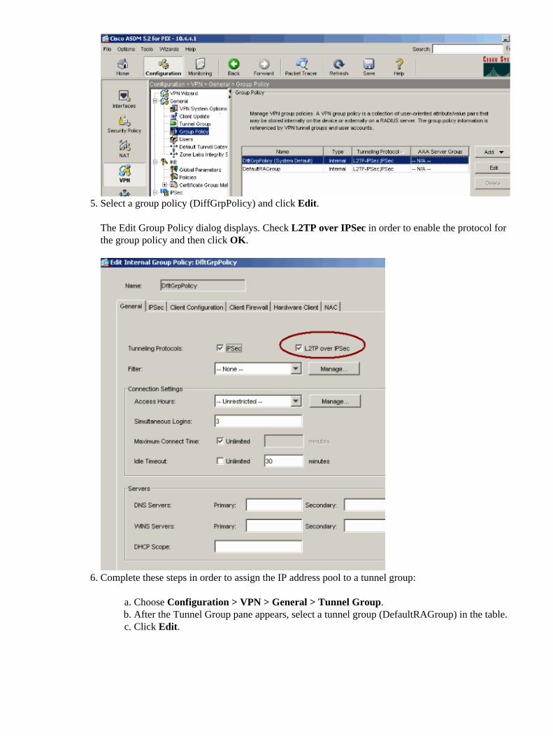
Select a group policy (DiffGrpPolicy) and click Edit.
The Edit Group Policy dialog displays. Check L2TP over IPSec in order to enable the protocol forthe group policy and then click OK.
5.
Complete these steps in order to assign the IP address pool to a tunnel group:
Choose Configuration > VPN > General > Tunnel Group.a. After the Tunnel Group pane appears, select a tunnel group (DefaultRAGroup) in the table.b. Click Edit.c.
6.
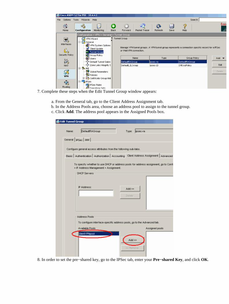
Complete these steps when the Edit Tunnel Group window appears:
From the General tab, go to the Client Address Assignment tab.a. In the Address Pools area, choose an address pool to assign to the tunnel group.b. Click Add. The address pool appears in the Assigned Pools box.c.
7.
In order to set the pre−shared key, go to the IPSec tab, enter your Pre−shared Key, and click OK.8.
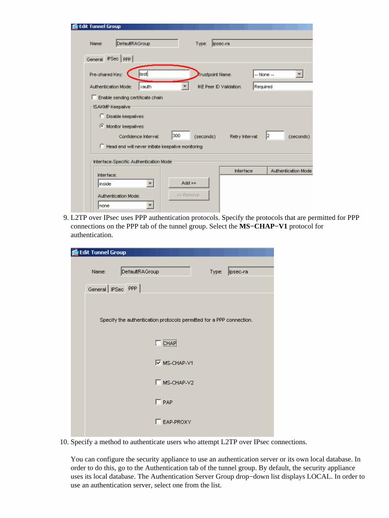
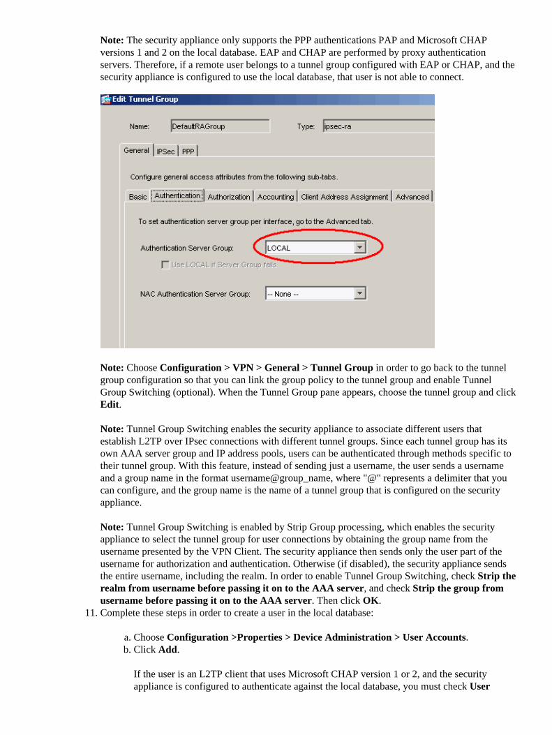
L2TP over IPsec uses PPP authentication protocols. Specify the protocols that are permitted for PPPconnections on the PPP tab of the tunnel group. Select the MS−CHAP−V1 protocol forauthentication.
9.
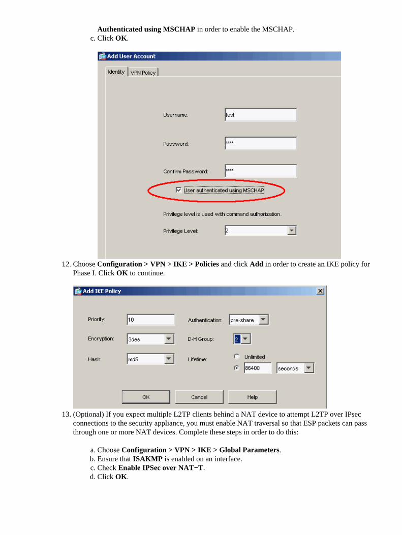
Specify a method to authenticate users who attempt L2TP over IPsec connections.
You can configure the security appliance to use an authentication server or its own local database. Inorder to do this, go to the Authentication tab of the tunnel group. By default, the security applianceuses its local database. The Authentication Server Group drop−down list displays LOCAL. In order touse an authentication server, select one from the list.
10.
Note: The security appliance only supports the PPP authentications PAP and Microsoft CHAPversions 1 and 2 on the local database. EAP and CHAP are performed by proxy authenticationservers. Therefore, if a remote user belongs to a tunnel group configured with EAP or CHAP, and thesecurity appliance is configured to use the local database, that user is not able to connect.
Note: Choose Configuration > VPN > General > Tunnel Group in order to go back to the tunnelgroup configuration so that you can link the group policy to the tunnel group and enable TunnelGroup Switching (optional). When the Tunnel Group pane appears, choose the tunnel group and clickEdit.
Note: Tunnel Group Switching enables the security appliance to associate different users thatestablish L2TP over IPsec connections with different tunnel groups. Since each tunnel group has itsown AAA server group and IP address pools, users can be authenticated through methods specific totheir tunnel group. With this feature, instead of sending just a username, the user sends a usernameand a group name in the format username@group_name, where "@" represents a delimiter that youcan configure, and the group name is the name of a tunnel group that is configured on the securityappliance.
Note: Tunnel Group Switching is enabled by Strip Group processing, which enables the securityappliance to select the tunnel group for user connections by obtaining the group name from theusername presented by the VPN Client. The security appliance then sends only the user part of theusername for authorization and authentication. Otherwise (if disabled), the security appliance sendsthe entire username, including the realm. In order to enable Tunnel Group Switching, check Strip therealm from username before passing it on to the AAA server, and check Strip the group fromusername before passing it on to the AAA server. Then click OK.Complete these steps in order to create a user in the local database:
Choose Configuration >Properties > Device Administration > User Accounts.a. Click Add.
If the user is an L2TP client that uses Microsoft CHAP version 1 or 2, and the securityappliance is configured to authenticate against the local database, you must check User
b.
11.
Authenticated using MSCHAP in order to enable the MSCHAP.Click OK.c.
Choose Configuration > VPN > IKE > Policies and click Add in order to create an IKE policy forPhase I. Click OK to continue.
12.
(Optional) If you expect multiple L2TP clients behind a NAT device to attempt L2TP over IPsecconnections to the security appliance, you must enable NAT traversal so that ESP packets can passthrough one or more NAT devices. Complete these steps in order to do this:
Choose Configuration > VPN > IKE > Global Parameters.a. Ensure that ISAKMP is enabled on an interface.b. Check Enable IPSec over NAT−T.c. Click OK.d.
13.
Microsoft Windows 2003 Server with IAS Configuration
Complete these steps in order to configure the Microsoft Windows 2003 server with IAS.
Note: These steps assume that IAS is already installed on the local machine. If not, add this through ControlPanel > Add/Remove Programs.
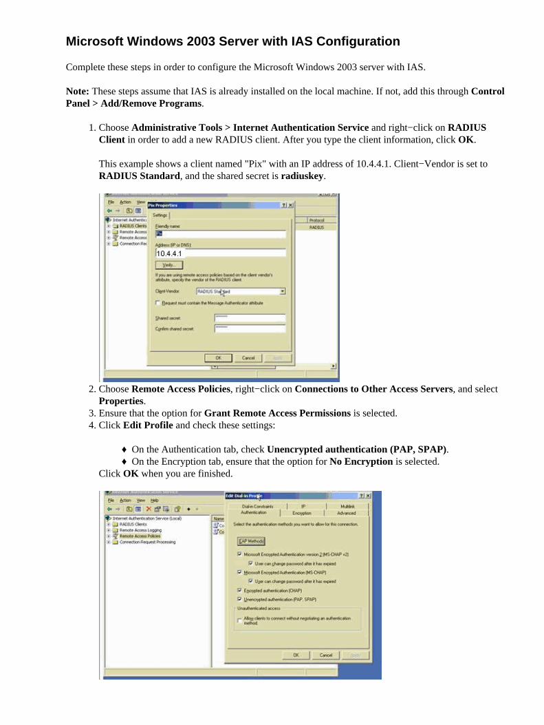
Choose Administrative Tools > Internet Authentication Service and right−click on RADIUSClient in order to add a new RADIUS client. After you type the client information, click OK.
This example shows a client named "Pix" with an IP address of 10.4.4.1. Client−Vendor is set toRADIUS Standard, and the shared secret is radiuskey.
1.
Choose Remote Access Policies, right−click on Connections to Other Access Servers, and selectProperties.
2.
Ensure that the option for Grant Remote Access Permissions is selected.3. Click Edit Profile and check these settings:
On the Authentication tab, check Unencrypted authentication (PAP, SPAP).♦ On the Encryption tab, ensure that the option for No Encryption is selected.♦
Click OK when you are finished.
4.
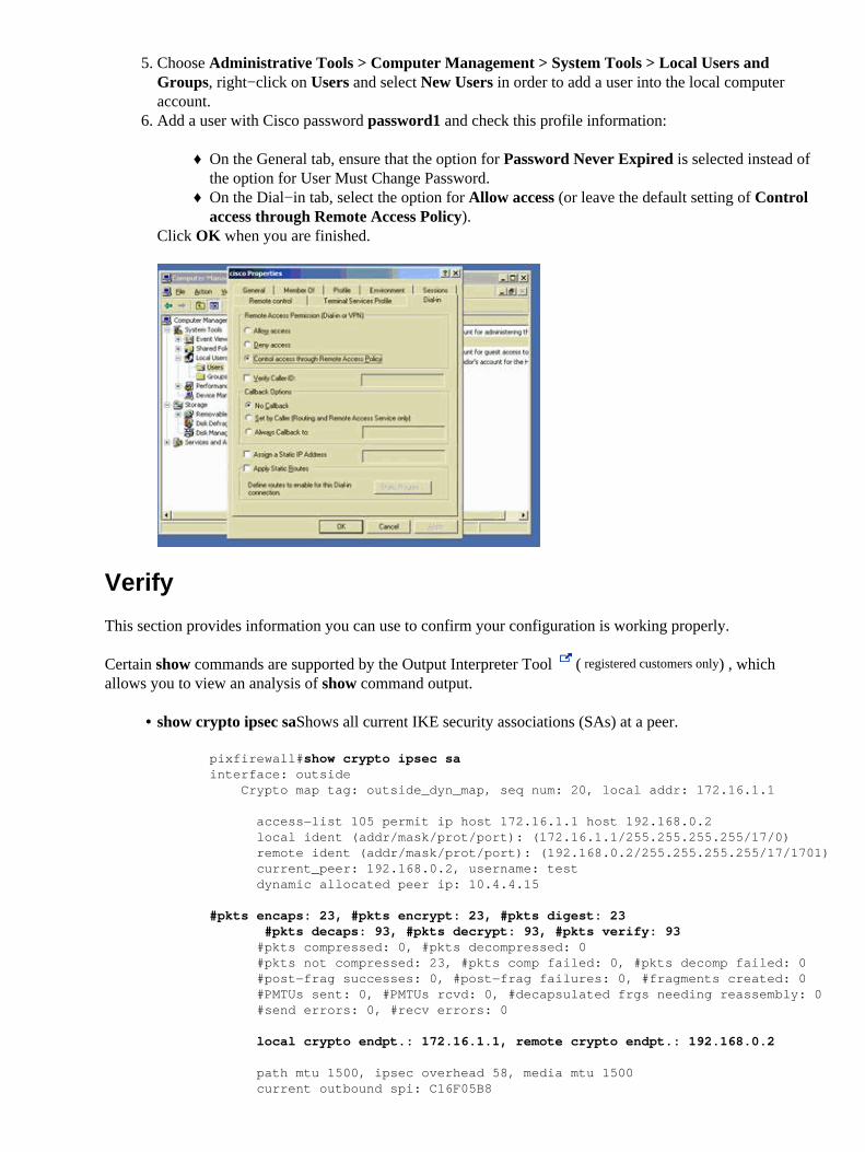
Choose Administrative Tools > Computer Management > System Tools > Local Users andGroups, right−click on Users and select New Users in order to add a user into the local computeraccount.
5.
Add a user with Cisco password password1 and check this profile information:
On the General tab, ensure that the option for Password Never Expired is selected instead ofthe option for User Must Change Password.
♦
On the Dial−in tab, select the option for Allow access (or leave the default setting of Controlaccess through Remote Access Policy).
♦
Click OK when you are finished.
6.
Verify
This section provides information you can use to confirm your configuration is working properly.
Certain show commands are supported by the Output Interpreter Tool ( registered customers only) , whichallows you to view an analysis of show command output.
show crypto ipsec sa�Shows all current IKE security associations (SAs) at a peer.
pixfirewall#show crypto ipsec sainterface: outside Crypto map tag: outside_dyn_map, seq num: 20, local addr: 172.16.1.1
access−list 105 permit ip host 172.16.1.1 host 192.168.0.2 local ident (addr/mask/prot/port): (172.16.1.1/255.255.255.255/17/0) remote ident (addr/mask/prot/port): (192.168.0.2/255.255.255.255/17/1701) current_peer: 192.168.0.2, username: test dynamic allocated peer ip: 10.4.4.15
#pkts encaps: 23, #pkts encrypt: 23, #pkts digest: 23 #pkts decaps: 93, #pkts decrypt: 93, #pkts verify: 93 #pkts compressed: 0, #pkts decompressed: 0 #pkts not compressed: 23, #pkts comp failed: 0, #pkts decomp failed: 0 #post−frag successes: 0, #post−frag failures: 0, #fragments created: 0 #PMTUs sent: 0, #PMTUs rcvd: 0, #decapsulated frgs needing reassembly: 0 #send errors: 0, #recv errors: 0
local crypto endpt.: 172.16.1.1, remote crypto endpt.: 192.168.0.2
path mtu 1500, ipsec overhead 58, media mtu 1500 current outbound spi: C16F05B8
•
inbound esp sas: spi: 0xEC06344D (3959829581) transform: esp−3des esp−md5−hmac in use settings ={RA, Transport, } slot: 0, conn_id: 3, crypto−map: outside_dyn_map sa timing: remaining key lifetime (sec): 3335 IV size: 8 bytes replay detection support: Y
outbound esp sas: spi: 0xC16F05B8 (3245278648) transform: esp−3des esp−md5−hmac in use settings ={RA, Transport, } slot: 0, conn_id: 3, crypto−map: outside_dyn_map sa timing: remaining key lifetime (sec): 3335 IV size: 8 bytes replay detection support: Y
show crypto isakmp sa�Shows all current IKE SAs at a peer.
pixfirewall#show crypto isakmp sa
Active SA: 1 Rekey SA: 0 (A tunnel will report 1 Active and 1 Rekey SA during rekey)Total IKE SA: 1
1 IKE Peer: 192.168.0.2 Type : user Role : responder Rekey : no State : MM_ACTIVE
•
show vpn−sessiondb�Includes protocol filters that you can use in order to view detailed informationabout L2TP over IPsec connections. The full command from global configuration mode is showvpn−sessoindb detailed remote filter protocol l2tpOverIpsec.
This example shows the details of a single L2TP over IPsec connection:
pixfirewall#show vpn−sessiondb detail remote filter protocol L2TPOverIPSec
Session Type: Remote Detailed
Username : testIndex : 1Assigned IP : 10.4.4.15 Public IP : 192.168.0.2Protocol : L2TPOverIPSec Encryption : 3DESHashing : MD5Bytes Tx : 1336 Bytes Rx : 14605Client Type : Client Ver :Group Policy : DefaultRAGroupTunnel Group : DefaultRAGroupLogin Time : 18:06:08 UTC Fri Jan 1 1993Duration : 0h:04m:25sFilter Name :NAC Result : N/APosture Token:
IKE Sessions: 1IPSec Sessions: 1L2TPOverIPSec Sessions: 1
IKE: Session ID : 1 UDP Src Port : 500 UDP Dst Port : 500 IKE Neg Mode : Main Auth Mode : preSharedKeys Encryption : 3DES Hashing : MD5 Rekey Int (T): 28800 Seconds Rekey Left(T): 28536 Seconds
•
D/H Group : 2
IPSec: Session ID : 2 Local Addr : 172.16.1.1/255.255.255.255/17/1701 Remote Addr : 192.168.0.2/255.255.255.255/17/1701 Encryption : 3DES Hashing : MD5 Encapsulation: Transport Rekey Int (T): 3600 Seconds Rekey Left(T): 3333 Seconds Idle Time Out: 30 Minutes Idle TO Left : 30 Minutes Bytes Tx : 1336 Bytes Rx : 14922 Pkts Tx : 25 Pkts Rx : 156
L2TPOverIPSec: Session ID : 3 Username : test Assigned IP : 10.4.4.15 Encryption : none Auth Mode : msCHAPV1 Idle Time Out: 30 Minutes Idle TO Left : 30 Minutes Bytes Tx : 378 Bytes Rx : 13431 Pkts Tx : 16 Pkts Rx : 146
Troubleshoot
This section provides information to troubleshoot your configuration. Sample debug output is also shown.
Troubleshooting Commands
Certain commands are supported by the Output Interpreter Tool ( registered customers only) , which allows youto view an analysis of show command output.
Note: Refer to Important Information on Debug Commands and IP Security Troubleshooting − Understandingand Using debug Commands before you use debug commands.
debug crypto ipsec 7�Displays the IPsec negotiations of Phase 2.• debug crypto isakmp 7�Displays the ISAKMP negotiations of Phase 1.•
Sample debug Output
PIX Firewall
PIX#debug crypto isakmp 7pixfirewall# Jan 02 18:26:44 [IKEv1]: IP = 192.168.0.2, IKE_DECODE RECEIVED Message (msgid=0) with payloads : HDR + SA (1) + VENDOR (13) + VENDOR (13) + VENDOR(13) + NONE (0) total length : 256Jan 02 18:26:44 [IKEv1 DEBUG]: IP = 192.168.0.2, processing SA payloadJan 02 18:26:44 [IKEv1 DEBUG]: IP = 192.168.0.2, Oakley proposal is acceptableJan 02 18:26:44 [IKEv1 DEBUG]: IP = 192.168.0.2, processing VID payloadJan 02 18:26:44 [IKEv1 DEBUG]: IP = 192.168.0.2, processing VID payloadJan 02 18:26:44 [IKEv1 DEBUG]: IP = 192.168.0.2, Received Fragmentation VIDJan 02 18:26:44 [IKEv1 DEBUG]: IP = 192.168.0.2, processing VID payloadJan 02 18:26:44 [IKEv1 DEBUG]: IP = 192.168.0.2, Received NAT−Traversal ver 02 VIDJan 02 18:26:44 [IKEv1 DEBUG]: IP = 192.168.0.2, processing IKE SA payloadJan 02 18:26:44 [IKEv1 DEBUG]: IP = 192.168.0.2, IKE SA Proposal # 1, Transform# 2 acceptable Matches global IKE entry # 2Jan 02 18:26:44 [IKEv1 DEBUG]: IP = 192.168.0.2, constructing ISAKMP SA payloadJan 02 18:26:44 [IKEv1 DEBUG]: IP = 192.168.0.2, constructing Fragmentation VID+ extended capabilities payloadJan 02 18:26:44 [IKEv1]: IP = 192.168.0.2, IKE_DECODE SENDING Message (msgid=0)
with payloads : HDR + SA (1) + VENDOR (13) + NONE (0) total length : 104Jan 02 18:26:44 [IKEv1]: IP = 192.168.0.2, IKE_DECODE RECEIVED Message (msgid=0) with payloads : HDR + KE (4) + NONCE (10) + NONE (0) total length : 184Jan 02 18:26:44 [IKEv1 DEBUG]: IP = 192.168.0.2, processing ke payloadJan 02 18:26:44 [IKEv1 DEBUG]: IP = 192.168.0.2, processing ISA_KE payloadJan 02 18:26:44 [IKEv1 DEBUG]: IP = 192.168.0.2, processing nonce payloadJan 02 18:26:44 [IKEv1 DEBUG]: IP = 192.168.0.2, constructing ke payloadJan 02 18:26:44 [IKEv1 DEBUG]: IP = 192.168.0.2, constructing nonce payloadJan 02 18:26:44 [IKEv1 DEBUG]: IP = 192.168.0.2, constructing Cisco Unity VID payloadJan 02 18:26:44 [IKEv1 DEBUG]: IP = 192.168.0.2, constructing xauth V6 VID payloadJan 02 18:26:44 [IKEv1 DEBUG]: IP = 192.168.0.2, Send IOS VIDJan 02 18:26:44 [IKEv1 DEBUG]: IP = 192.168.0.2, Constructing ASA spoofing IOS Vendor ID payload (version: 1.0.0, capabilities: 20000001)Jan 02 18:26:44 [IKEv1 DEBUG]: IP = 192.168.0.2, constructing VID payloadJan 02 18:26:44 [IKEv1 DEBUG]: IP = 192.168.0.2, Send Altiga/Cisco VPN3000/Cisco ASA GW VIDJan 02 18:26:44 [IKEv1]: IP = 192.168.0.2, Connection landed on tunnel_group DefaultRAGroupJan 02 18:26:44 [IKEv1 DEBUG]: Group = DefaultRAGroup, IP = 192.168.0.2, Generating keys for Responder...Jan 02 18:26:44 [IKEv1]: IP = 192.168.0.2, IKE_DECODE SENDING Message (msgid=0)with payloads : HDR + KE (4) + NONCE (10) + VENDOR (13) + VENDOR (13) + VENDOR (13) + VENDOR (13) + NONE (0) total length : 256Jan 02 18:26:44 [IKEv1]: IP = 192.168.0.2, IKE_DECODE RECEIVED Message (msgid=0) with payloads : HDR + ID (5) + HASH (8) + NONE (0) total length : 60Jan 02 18:26:44 [IKEv1 DEBUG]: Group = DefaultRAGroup, IP = 192.168.0.2, processing ID payloadJan 02 18:26:44 [IKEv1 DEBUG]: Group = DefaultRAGroup, IP = 192.168.0.2, processing hash payloadJan 02 18:26:44 [IKEv1 DEBUG]: Group = DefaultRAGroup, IP = 192.168.0.2, Computing hash for ISAKMPJan 02 18:26:44 [IKEv1]: IP = 192.168.0.2, Connection landed on tunnel_group DefaultRAGroupJan 02 18:26:44 [IKEv1]: Group = DefaultRAGroup, IP = 192.168.0.2, Freeing previously allocated memory for authorization−dn−attributesJan 02 18:26:44 [IKEv1 DEBUG]: Group = DefaultRAGroup, IP = 192.168.0.2, constructing ID payloadJan 02 18:26:44 [IKEv1 DEBUG]: Group = DefaultRAGroup, IP = 192.168.0.2, constructing hash payloadJan 02 18:26:44 [IKEv1 DEBUG]: Group = DefaultRAGroup, IP = 192.168.0.2, Computing hash for ISAKMPJan 02 18:26:44 [IKEv1 DEBUG]: Group = DefaultRAGroup, IP = 192.168.0.2, constructing dpd vid payloadJan 02 18:26:44 [IKEv1]: IP = 192.168.0.2, IKE_DECODE SENDING Message (msgid=0)with payloads : HDR + ID (5) + HASH (8) + VENDOR (13) + NONE (0) total length :80
!−−− Phase 1 completed succesfully.
Jan 02 18:26:44 [IKEv1]: Group = DefaultRAGroup, IP = 192.168.0.2, PHASE 1 COMPLETEDJan 02 18:26:44 [IKEv1]: IP = 192.168.0.2, Keep−alive type for this connection:NoneJan 02 18:26:44 [IKEv1]: IP = 192.168.0.2, Keep−alives configured on but peer does not support keep−alives (type = None)Jan 02 18:26:44 [IKEv1 DEBUG]: Group = DefaultRAGroup, IP = 192.168.0.2, Starting P1 rekey timer: 21600 seconds.Jan 02 18:26:44 [IKEv1]: IP = 192.168.0.2, IKE_DECODE RECEIVED Message (msgid=e1b84b0) with payloads : HDR + HASH (8) + SA (1) + NONCE (10) + ID (5) + ID (5) +NONE (0) total length : 164Jan 02 18:26:44 [IKEv1 DEBUG]: Group = DefaultRAGroup, IP = 192.168.0.2, processing hash payload
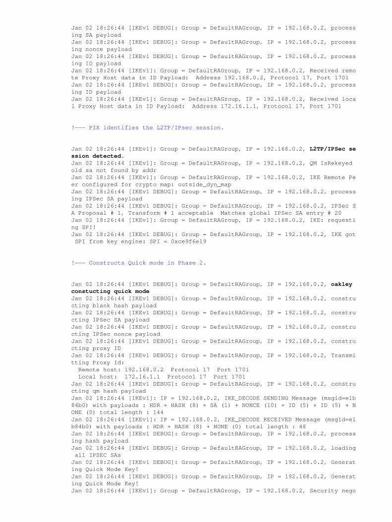
Jan 02 18:26:44 [IKEv1 DEBUG]: Group = DefaultRAGroup, IP = 192.168.0.2, processing SA payloadJan 02 18:26:44 [IKEv1 DEBUG]: Group = DefaultRAGroup, IP = 192.168.0.2, processing nonce payloadJan 02 18:26:44 [IKEv1 DEBUG]: Group = DefaultRAGroup, IP = 192.168.0.2, processing ID payloadJan 02 18:26:44 [IKEv1]: Group = DefaultRAGroup, IP = 192.168.0.2, Received remote Proxy Host data in ID Payload: Address 192.168.0.2, Protocol 17, Port 1701Jan 02 18:26:44 [IKEv1 DEBUG]: Group = DefaultRAGroup, IP = 192.168.0.2, processing ID payloadJan 02 18:26:44 [IKEv1]: Group = DefaultRAGroup, IP = 192.168.0.2, Received local Proxy Host data in ID Payload: Address 172.16.1.1, Protocol 17, Port 1701
!−−− PIX identifies the L2TP/IPsec session.
Jan 02 18:26:44 [IKEv1]: Group = DefaultRAGroup, IP = 192.168.0.2, L2TP/IPSec session detected.Jan 02 18:26:44 [IKEv1]: Group = DefaultRAGroup, IP = 192.168.0.2, QM IsRekeyedold sa not found by addrJan 02 18:26:44 [IKEv1]: Group = DefaultRAGroup, IP = 192.168.0.2, IKE Remote Peer configured for crypto map: outside_dyn_mapJan 02 18:26:44 [IKEv1 DEBUG]: Group = DefaultRAGroup, IP = 192.168.0.2, processing IPSec SA payloadJan 02 18:26:44 [IKEv1 DEBUG]: Group = DefaultRAGroup, IP = 192.168.0.2, IPSec SA Proposal # 1, Transform # 1 acceptable Matches global IPSec SA entry # 20Jan 02 18:26:44 [IKEv1]: Group = DefaultRAGroup, IP = 192.168.0.2, IKE: requesting SPI!Jan 02 18:26:44 [IKEv1 DEBUG]: Group = DefaultRAGroup, IP = 192.168.0.2, IKE got SPI from key engine: SPI = 0xce9f6e19
!−−− Constructs Quick mode in Phase 2.
Jan 02 18:26:44 [IKEv1 DEBUG]: Group = DefaultRAGroup, IP = 192.168.0.2, oakleyconstucting quick modeJan 02 18:26:44 [IKEv1 DEBUG]: Group = DefaultRAGroup, IP = 192.168.0.2, constructing blank hash payloadJan 02 18:26:44 [IKEv1 DEBUG]: Group = DefaultRAGroup, IP = 192.168.0.2, constructing IPSec SA payloadJan 02 18:26:44 [IKEv1 DEBUG]: Group = DefaultRAGroup, IP = 192.168.0.2, constructing IPSec nonce payloadJan 02 18:26:44 [IKEv1 DEBUG]: Group = DefaultRAGroup, IP = 192.168.0.2, constructing proxy IDJan 02 18:26:44 [IKEv1 DEBUG]: Group = DefaultRAGroup, IP = 192.168.0.2, Transmitting Proxy Id: Remote host: 192.168.0.2 Protocol 17 Port 1701 Local host: 172.16.1.1 Protocol 17 Port 1701Jan 02 18:26:44 [IKEv1 DEBUG]: Group = DefaultRAGroup, IP = 192.168.0.2, constructing qm hash payloadJan 02 18:26:44 [IKEv1]: IP = 192.168.0.2, IKE_DECODE SENDING Message (msgid=e1b84b0) with payloads : HDR + HASH (8) + SA (1) + NONCE (10) + ID (5) + ID (5) + NONE (0) total length : 144Jan 02 18:26:44 [IKEv1]: IP = 192.168.0.2, IKE_DECODE RECEIVED Message (msgid=e1b84b0) with payloads : HDR + HASH (8) + NONE (0) total length : 48Jan 02 18:26:44 [IKEv1 DEBUG]: Group = DefaultRAGroup, IP = 192.168.0.2, processing hash payloadJan 02 18:26:44 [IKEv1 DEBUG]: Group = DefaultRAGroup, IP = 192.168.0.2, loading all IPSEC SAsJan 02 18:26:44 [IKEv1 DEBUG]: Group = DefaultRAGroup, IP = 192.168.0.2, Generating Quick Mode Key!Jan 02 18:26:44 [IKEv1 DEBUG]: Group = DefaultRAGroup, IP = 192.168.0.2, Generating Quick Mode Key!Jan 02 18:26:44 [IKEv1]: Group = DefaultRAGroup, IP = 192.168.0.2, Security nego
tiation complete for User () Responder, Inbound SPI = 0xce9f6e19, Outbound SPI= 0xd08f711bJan 02 18:26:44 [IKEv1 DEBUG]: Group = DefaultRAGroup, IP = 192.168.0.2, IKE got a KEY_ADD msg for SA: SPI = 0xd08f711bJan 02 18:26:44 [IKEv1 DEBUG]: Group = DefaultRAGroup, IP = 192.168.0.2, Pitcher: received KEY_UPDATE, spi 0xce9f6e19Jan 02 18:26:44 [IKEv1 DEBUG]: Group = DefaultRAGroup, IP = 192.168.0.2, Starting P2 rekey timer: 3059 seconds.
!−−− Phase 2 completes succesfully.
Jan 02 18:26:44 [IKEv1]: Group = DefaultRAGroup, IP = 192.168.0.2, PHASE 2 COMPLETED (msgid=0e1b84b0)Jan 02 18:26:44 [IKEv1]: IKEQM_Active() Add L2TP classification rules: ip <192.168.0.2> mask <0xFFFFFFFF> port <1701>
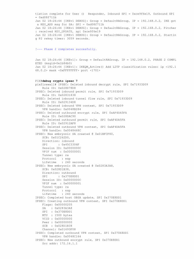
PIX#debug crypto ipsec 7pixfirewall# IPSEC: Deleted inbound decrypt rule, SPI 0x71933D09 Rule ID: 0x028D78D8IPSEC: Deleted inbound permit rule, SPI 0x71933D09 Rule ID: 0x02831838IPSEC: Deleted inbound tunnel flow rule, SPI 0x71933D09 Rule ID: 0x029134D8IPSEC: Deleted inbound VPN context, SPI 0x71933D09 VPN handle: 0x0048B284IPSEC: Deleted outbound encrypt rule, SPI 0xAF4DA5FA Rule ID: 0x028DAC90IPSEC: Deleted outbound permit rule, SPI 0xAF4DA5FA Rule ID: 0x02912AF8IPSEC: Deleted outbound VPN context, SPI 0xAF4DA5FA VPN handle: 0x0048468CIPSEC: New embryonic SA created @ 0x01BFCF80, SCB: 0x01C262D0, Direction: inbound SPI : 0x45C3306F Session ID: 0x0000000C VPIF num : 0x00000001 Tunnel type: ra Protocol : esp Lifetime : 240 secondsIPSEC: New embryonic SA created @ 0x0283A3A8, SCB: 0x028D1B38, Direction: outbound SPI : 0x370E8DD1 Session ID: 0x0000000C VPIF num : 0x00000001 Tunnel type: ra Protocol : esp Lifetime : 240 secondsIPSEC: Completed host OBSA update, SPI 0x370E8DD1IPSEC: Creating outbound VPN context, SPI 0x370E8DD1 Flags: 0x00000205 SA : 0x0283A3A8 SPI : 0x370E8DD1 MTU : 1500 bytes VCID : 0x00000000 Peer : 0x00000000 SCB : 0x028D1B38 Channel: 0x01693F08IPSEC: Completed outbound VPN context, SPI 0x370E8DD1 VPN handle: 0x0048C164IPSEC: New outbound encrypt rule, SPI 0x370E8DD1 Src addr: 172.16.1.1
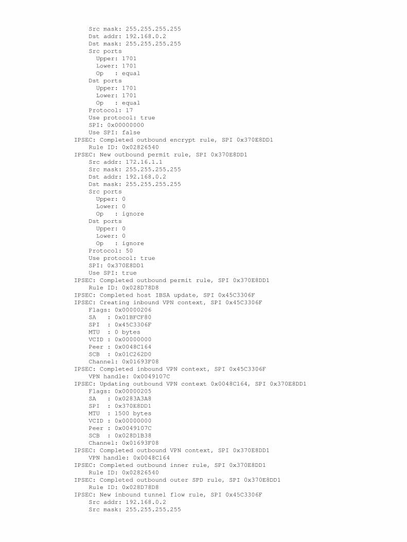
Src mask: 255.255.255.255 Dst addr: 192.168.0.2 Dst mask: 255.255.255.255 Src ports Upper: 1701 Lower: 1701 Op : equal Dst ports Upper: 1701 Lower: 1701 Op : equal Protocol: 17 Use protocol: true SPI: 0x00000000 Use SPI: falseIPSEC: Completed outbound encrypt rule, SPI 0x370E8DD1 Rule ID: 0x02826540IPSEC: New outbound permit rule, SPI 0x370E8DD1 Src addr: 172.16.1.1 Src mask: 255.255.255.255 Dst addr: 192.168.0.2 Dst mask: 255.255.255.255 Src ports Upper: 0 Lower: 0 Op : ignore Dst ports Upper: 0 Lower: 0 Op : ignore Protocol: 50 Use protocol: true SPI: 0x370E8DD1 Use SPI: trueIPSEC: Completed outbound permit rule, SPI 0x370E8DD1 Rule ID: 0x028D78D8IPSEC: Completed host IBSA update, SPI 0x45C3306FIPSEC: Creating inbound VPN context, SPI 0x45C3306F Flags: 0x00000206 SA : 0x01BFCF80 SPI : 0x45C3306F MTU : 0 bytes VCID : 0x00000000 Peer : 0x0048C164 SCB : 0x01C262D0 Channel: 0x01693F08IPSEC: Completed inbound VPN context, SPI 0x45C3306F VPN handle: 0x0049107CIPSEC: Updating outbound VPN context 0x0048C164, SPI 0x370E8DD1 Flags: 0x00000205 SA : 0x0283A3A8 SPI : 0x370E8DD1 MTU : 1500 bytes VCID : 0x00000000 Peer : 0x0049107C SCB : 0x028D1B38 Channel: 0x01693F08IPSEC: Completed outbound VPN context, SPI 0x370E8DD1 VPN handle: 0x0048C164IPSEC: Completed outbound inner rule, SPI 0x370E8DD1 Rule ID: 0x02826540IPSEC: Completed outbound outer SPD rule, SPI 0x370E8DD1 Rule ID: 0x028D78D8IPSEC: New inbound tunnel flow rule, SPI 0x45C3306F Src addr: 192.168.0.2 Src mask: 255.255.255.255
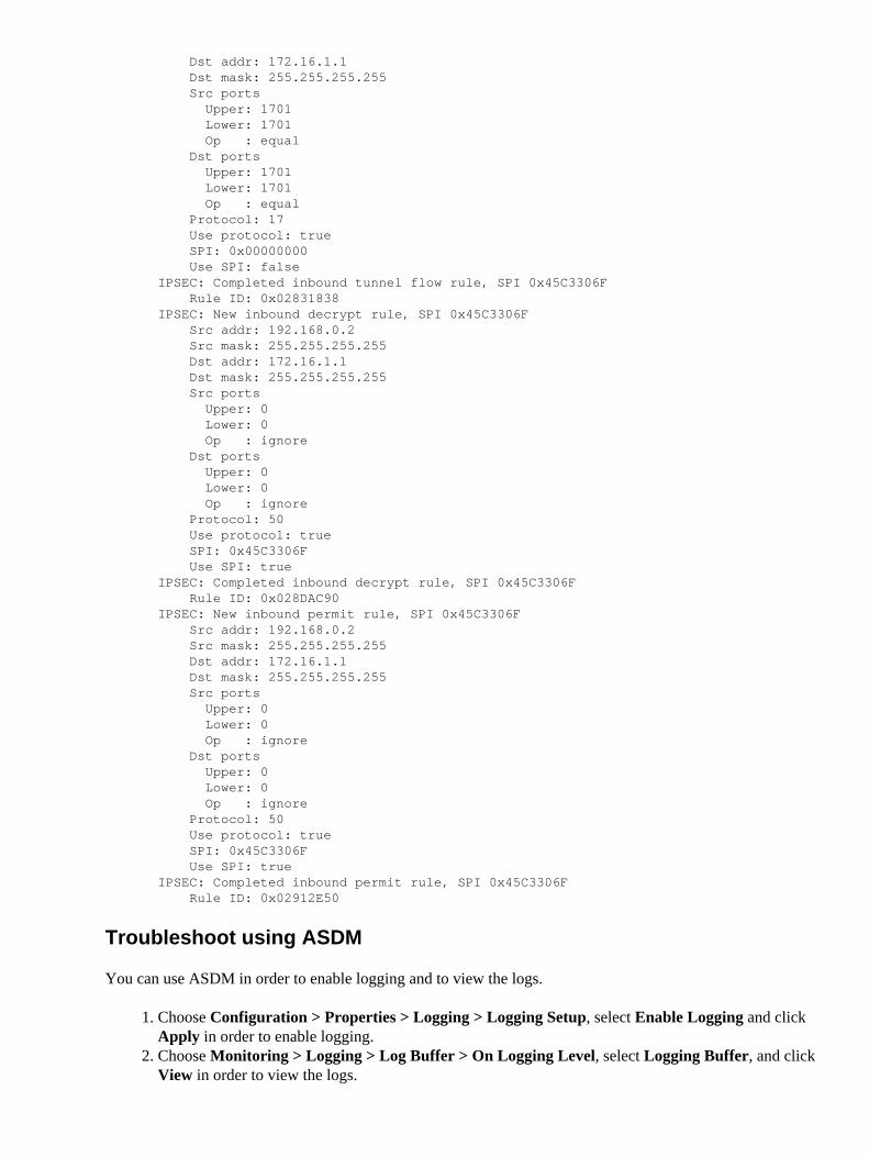
Dst addr: 172.16.1.1 Dst mask: 255.255.255.255 Src ports Upper: 1701 Lower: 1701 Op : equal Dst ports Upper: 1701 Lower: 1701 Op : equal Protocol: 17 Use protocol: true SPI: 0x00000000 Use SPI: falseIPSEC: Completed inbound tunnel flow rule, SPI 0x45C3306F Rule ID: 0x02831838IPSEC: New inbound decrypt rule, SPI 0x45C3306F Src addr: 192.168.0.2 Src mask: 255.255.255.255 Dst addr: 172.16.1.1 Dst mask: 255.255.255.255 Src ports Upper: 0 Lower: 0 Op : ignore Dst ports Upper: 0 Lower: 0 Op : ignore Protocol: 50 Use protocol: true SPI: 0x45C3306F Use SPI: trueIPSEC: Completed inbound decrypt rule, SPI 0x45C3306F Rule ID: 0x028DAC90IPSEC: New inbound permit rule, SPI 0x45C3306F Src addr: 192.168.0.2 Src mask: 255.255.255.255 Dst addr: 172.16.1.1 Dst mask: 255.255.255.255 Src ports Upper: 0 Lower: 0 Op : ignore Dst ports Upper: 0 Lower: 0 Op : ignore Protocol: 50 Use protocol: true SPI: 0x45C3306F Use SPI: trueIPSEC: Completed inbound permit rule, SPI 0x45C3306F Rule ID: 0x02912E50
Troubleshoot using ASDM
You can use ASDM in order to enable logging and to view the logs.
Choose Configuration > Properties > Logging > Logging Setup, select Enable Logging and clickApply in order to enable logging.
1.
Choose Monitoring > Logging > Log Buffer > On Logging Level, select Logging Buffer, and clickView in order to view the logs.
2.
NetPro Discussion Forums − Featured Conversations
Networking Professionals Connection is a forum for networking professionals to share questions, suggestions,and information about networking solutions, products, and technologies. The featured links are some of themost recent conversations available in this technology.
NetPro Discussion Forums − Featured Conversations for VPN
Service Providers: VPN Service Architectures
Service Providers: Network Management
Virtual Private Networks: General
Related Information
Cisco PIX 500 Series Security Appliances• Cisco ASA 5500 Series Adaptive Security Appliances• Documentation for Cisco PIX Security Appliance OS Software• Cisco Secure PIX Firewall Command References• RADIUS Support Page• IPSec Negotiation/IKE Protocols Support Page• Requests for Comments (RFCs)• Layer Two Tunnel Protocol (L2TP)• Technical Support & Documentation − Cisco Systems•
All contents are Copyright © 2006−2007 Cisco Systems, Inc. All rights reserved. Important Notices and Privacy Statement.
Updated: Aug 07, 2007 Document ID: 71028
Related Documents


