All contents are Copyright © 1992–2005 Cisco Systems, Inc. All rights reserved. Important Notices and Privacy Statement. Page 1 of 2 USER GUIDE CISCO IOS IP SERVICE LEVEL AGREEMENTS CISCO IOS IP SERVICE LEVEL AGREEMENTS OVERVIEW Cisco IOS ® IP Service Level Agreements (SLAs) allow users to monitor network performance between Cisco routers or from either a Cisco router to a remote IP device. This user guide focuses on Cisco IOS IP SLAs features, and it covers usage and configuration guidelines, and explains how to retrieve data from Cisco IOS IP SLAs functionality. Configuration examples include both Command Line Interface (CLI) and Simple Network Management Protocol (SNMP). This document is a supplement to Cisco IOS Software technical documentation. Cisco IOS IP SLAs capabilities: • Voice-over-IP (VoIP), video, and VPN network monitoring • SLA monitoring • Network performance monitoring and network performance visibility • IP service network health readiness or assessment • Edge-to-edge network availability monitoring • Troubleshooting of network operation • Multiprotocol Label Switching (MPLS) network monitoring Cisco IOS IP SLAs Benefits • Measure end-to-end IP layer network • Deploy new applications and services with complete confidence • Verify and monitor quality of service (QoS) and differentiated services • Increase end user confidence and satisfaction • Implement SLA measurement metrics • Notify users about network issues proactively • Measure network performance continuously, reliably, and predictably Cisco IOS IP SLAs Feature Overview • Measurement capabilities – User Datagram Protocol (UDP) response time, one-way delay, jitter, and packet loss and connectivity – ICMP response time and connectivity – Hop-by-hop ICMP response time and jitter – Performance metric including DNS lookup, TCP connect, and HTTP transaction time – Packet loss statistics – DHCP response time measurements – Response times from a Cisco network devices to network servers

Cisco IOS IP Service Level Agreements User Guide.pdf
Oct 28, 2015
Welcome message from author
This document is posted to help you gain knowledge. Please leave a comment to let me know what you think about it! Share it to your friends and learn new things together.
Transcript
All contents are Copyright © 1992–2005 Cisco Systems, Inc. All rights reserved. Important Notices and Privacy Statement.
Page 1 of 2
USER GUIDE
CISCO IOS IP SERVICE LEVEL AGREEMENTS
CISCO IOS IP SERVICE LEVEL AGREEMENTS OVERVIEW
Cisco IOS® IP Service Level Agreements (SLAs) allow users to monitor network performance between Cisco routers or from either a Cisco router
to a remote IP device.
This user guide focuses on Cisco IOS IP SLAs features, and it covers usage and configuration guidelines, and explains how to retrieve data from
Cisco IOS IP SLAs functionality. Configuration examples include both Command Line Interface (CLI) and Simple Network Management Protocol
(SNMP). This document is a supplement to Cisco IOS Software technical documentation.
Cisco IOS IP SLAs capabilities:
• Voice-over-IP (VoIP), video, and VPN network monitoring
• SLA monitoring
• Network performance monitoring and network performance visibility
• IP service network health readiness or assessment
• Edge-to-edge network availability monitoring
• Troubleshooting of network operation
• Multiprotocol Label Switching (MPLS) network monitoring
Cisco IOS IP SLAs Benefits • Measure end-to-end IP layer network
• Deploy new applications and services with complete confidence
• Verify and monitor quality of service (QoS) and differentiated services
• Increase end user confidence and satisfaction
• Implement SLA measurement metrics
• Notify users about network issues proactively
• Measure network performance continuously, reliably, and predictably
Cisco IOS IP SLAs Feature Overview • Measurement capabilities
– User Datagram Protocol (UDP) response time, one-way delay, jitter, and packet loss and connectivity
– ICMP response time and connectivity
– Hop-by-hop ICMP response time and jitter
– Performance metric including DNS lookup, TCP connect, and HTTP transaction time
– Packet loss statistics
– DHCP response time measurements
– Response times from a Cisco network devices to network servers

© 2005 Cisco Systems, Inc. All rights reserved.
Important notices, privacy statements, and trademarks of Cisco Systems, Inc. can be found on cisco.com. Page 2 of 57
– MOS/ICPIF Voice Quality scoring and simulation of VoIP codec’s
– DLSw+ peer tunnel performance
• Proactive Notification
– Ability to define rising and falling thresholds to monitor SLAs
– Ability to generate SNMP Traps when a performance threshold is violated
– Ability to trigger another operation for more detailed analysis
• Flexible scheduling
– Measure at any given time, or continuously at any time interval
– Sequential activation for a large number of IP SLAs operations by utilizing multioperation scheduler
References
http://www.cisco.com/go/ipsla/
Figure 1. Cisco IOS IP SLAs Overview
MEASURING THE NETWORK WITH CISCO IOS IP SLAS
Cisco IOS IP SLAs is a network performance measurement and diagnostic tool that uses active monitoring, which includes the generation of
traffic in a continuous, reliable, and predictable manner. Cisco IOS IP SLAs actively sends data across the network to measure performance

© 2005 Cisco Systems, Inc. All rights reserved.
Important notices, privacy statements, and trademarks of Cisco Systems, Inc. can be found on cisco.com. Page 3 of 57
between multiple network locations or across multiple network paths. It uses the timestamp information to calculate performance metrics such
as jitter, latency, network and server response times, packet loss, and MOS voice quality scores. The user defines an IP SLAs operation (probe)
within Cisco IOS Software using the SNMP MIB or CLI. The measurement characteristics include packet size, packet spacing, protocol type, DSCP
marking, and other parameters. The operation is scheduled to generate traffic and retrieve performance measurements. The data from the Cisco IOS
IP SLAs operation is stored within the RTTMON MIB and available within CLI for Network Management System applications to retrieve network
performance statistics. Users can schedule a Cisco IOS IP SLAs operation at any point in time or continuously over any time interval. Cisco IOS IP
SLAs is configured to monitor per-class traffic over the same link by setting the Diff-Serv Code Point (DSCP) bits.
A destination router running Cisco IOS Software is configured as a Cisco IOS IP SLAs Responder, which processes measurement packets and
provides detailed timestamp information. The responder can send information about the destination router’s processing delay back to the source
Cisco router. Uni-direction measurements are also possible using Cisco IOS IP SLAs.
Cisco IOS IP SLAs provides a proactive notification feature with an SNMP trap. Each measurement operation can monitor against a pre-set
performance threshold. Cisco IOS IP SLAs generates an SNMP trap to alert management applications if this threshold is crossed. Several
SNMP traps are available: round trip time, average jitter, one-way latency, jitter, packet loss, MOS, and connectivity tests. Administrators
can also configure Cisco IOS IP SLAs to run a new operation automatically when the threshold is crossed. For instance, when latency exceeds
a threshold this can trigger a secondary operation to measure hop-by-hop latency to isolate the problem area in the network. Examples of
thresholds and triggers are available later in this document.
AN INTRODUCTION TO SLAS MONITORING
Overview
Enterprises are under increasing pressure to offer SLAs to their internal customers or other departments or verify and measure outsourced SLAs.
Service providers have an incentive to offer service level agreements, improve customer satisfaction, and guarantee their customers certain service
levels. Management requires contractual assurance that the network will meet business objectives, while end users want some assurance that their
critical network applications and services will be available as needed. An SLAs or service level verification is often required before a company
will deploy a new technology, business critical applications, or IP service, such as voice over IP (VoIP).
It has become increasingly complicated to deliver SLAs. It can be difficult to determine exactly what to monitor, how to take measurements, and
how frequently to collect data. With the proliferation of heterogeneous and multi-service networks, it is also difficult to monitor the service from
end-to-end. The challenge is compounded by the need to demarcate the timing of problems and to provide customers with reports at the appropriate
level of granularity. Cisco IOS IP SLAs ease the burden of measuring network service levels.
Defining the SLA Requirements
When developing SLAs, it is critical that customers focus on translating business objectives to SLAs, so that tangible service metrics are measured,
reported, and validated. Long, complex, and unrealistic agreements are often to blame when customers fail to manage by service level. They also
have a tendency to fail to monitor the negotiated SLAs parameters.
A clear understanding of the objective is critical to begin monitoring service levels within any network. For example:
• Verify an SLAs that measures Service Provider latency
• Ensure that IP phones in an office are working properly
• Users are getting reasonable response times from an FTP server
While it is important for an end-to-end IP SLAs solution to provide summary information to management, it is also critical that administrators
obtain detailed information about specific problem areas. The ability to demarcate what is causing the IP SLAs not to be met—whether it is a
problem at the client end, at the server end, or in the network—is crucial.
© 2005 Cisco Systems, Inc. All rights reserved.
Important notices, privacy statements, and trademarks of Cisco Systems, Inc. can be found on cisco.com. Page 4 of 57
Examples of Service-Level Contracts and SLAs
An SLAs is a key component of a service-level contract (SLC). The SLC specifies connectivity and performance agreements for an end-user service
from a provider of service. The Service Provider could be within the Enterprise (ie: IS organization could be the Service Provider for internal
departments), or an external company (ie: an ISP providing wide-area or hosted application services).
The SLC typically includes multiple SLAs, so a violation of any particular SLA could create a violation of the overall SLC. The SLC will outline
the minimum level of service and the expected level of service. If the expected level of service is violated multiple times, it can lead to an overall
violation.
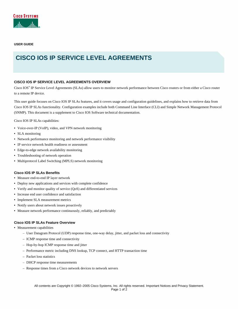
The service-level management solution needs to provide a means to manage collections of agreements that constitute a contract. The solution
should enable the user to monitor multiple SLCs individually, drill down into SLAs details, and monitor the percentage of SLAs conformance for
a given SLC. There is typically an expected service level and a minimum service level. The expected service level is what is contracted and needed
to give good performance, and the minimum service level will certainly give poor service performance. So for instance if service drops below 90%
of the expected service for x number of times over a specified time period this would constitute a violation of the SLA.
Figure 2. SLA Service Level Violation Graph
For example, an SLC for connectivity from several branch sites to the central site may be outlined as “a connection of 64 Kbps with the average
latency of 100ms over 1 month. This average latency would be an expected service level. The minimum service would insure when average
latency was over 500ms for a day.
End-to-end SLCs are usually defined and monitored by performance- and fault management applications. Cisco IOS IP SLAs provides the details
per measured SLAs.
HOW TO MONITOR A NETWORK WITH CISCO IOS IP SLAS
Cisco IOS IP SLAs can be used for network access, troubleshooting, QoS verification, and service level monitoring. Several items need to be
resolved before deciding when to monitor the network performance and service levels.
What is the primary goal of the measurements? Which metrics are important to monitor? In other words, at what days and times are measurements
needed?
© 2005 Cisco Systems, Inc. All rights reserved.
Important notices, privacy statements, and trademarks of Cisco Systems, Inc. can be found on cisco.com. Page 5 of 57
The second step is to make a broad assessment of traffic patterns within the network. When packet samples are distributed and measured more
frequently, network traffic patterns are more reliable. More points mean that information is more accurate. Active measurements should mimic
the type of traffic run on the network; for example, the correct packet size, spacing an interval to mimic a VoIP Codec.
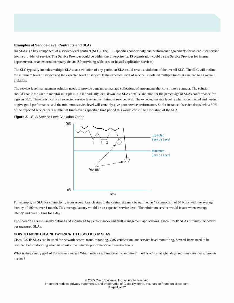
Scenario 1: Measure Data Traffic Performance from the Branch to Central Office
Figure 3. Network for Scenario 1
An Enterprise customer has one central headquarters site along with two branch offices. One of the branch offices is communicating via a
dedicated FR circuit (256 kbps), while the second branch office is accessing the corporate headquarters using a WAN link through the public
Internet via a VPN.
Client stations in both branch offices require access to a central web server at the corporate headquarters. For example, corporate can claim to
provide server 99.95% availability with a response time of no greater than 50ms. For the branch office accessing the servers via the Internet,
corporate headquarters provides a latency SLA of no more than 100ms. Based on this data, the Enterprise must consider how it can measure and
verify that both branch offices are getting their agreed-upon service levels from corporate headquarters. Furthermore, if corporate is not meeting
these service levels, what part or parts of the network are contributing to this degradation (ie: WAN links, client application, web server)?
Selecting the proper operation or measurement
The first step in SLAs deployment involves answering the question of what needs to be monitored. A variety of operation types are supported
by Cisco IOS IP SLAs. The most common operation used is UDP jitter to measure IP performance and UDP performance-sensitive applications.
In this example, the operations outlined are UDP echo, TCP Connect, and HTTP. Later examples will utilize UDP jitter.
UDP Echo Operation
The UDP Echo Operation measures end-to-end response time or connectivity between a Cisco router and IP devices. UDP is a network layer
(Layer 3) Internet protocol that reports errors and provides other information relevant to IP packet processing. Response time is computed by
measuring the time taken between sending the UDP echo request message to the destination and receiving an UDP echo reply. UDP echo accuracy
is enhanced by using the IP SLAs responder at the destination Cisco router. Details about IP SLAs responder will be available later in the document.
TCP Connect Operation
The TCP Connect operation response time is computed by taking the difference between the times taken to request the TCP SYN and ACK replies.
This result will be useful to test the connection to specific ports on headquarters servers from the branch.
© 2005 Cisco Systems, Inc. All rights reserved.
Important notices, privacy statements, and trademarks of Cisco Systems, Inc. can be found on cisco.com. Page 6 of 57
HTTP Operation
The HTTP operation measures the round-trip time (RTT) taken to connect and access data from an HTTP server, which can be specified with a
URL. The HTTP server response-time measurements consist of three types:
• DNS Lookup—RTT taken to perform domain name lookup
• TCP Connect—RTT taken to perform a TCP connect to the HTTP server
• HTTP Transaction Time—RTT taken to send a request and get a response back from the HTTP server for the complete Webpage or the first byte of the Webpage
Selecting the Proper Test Pair(s)
Selecting the proper test pairs can be the most difficult step in defining an appropriate SLA. Certain requirements must be considered before
making this decision.
• The source device must be a Cisco device running Cisco IOS Software Release 12.0(5)T or later. Preferred Cisco IOS Software releases would be Release 12.4 Mainline and later releases.
• When using an IP SLAs operation, the destination device can be any IP device, but if a Cisco router is used, the accuracy can be improved with the Cisco IOS IP SLAs responder.
With these requirements in mind, the Enterprise can then concentrate on selecting device pairs that make sense. In general, the source device
should be the router located at the edge, or the boundary where the Enterprise network meets the service provider’s network. If there are other
routers along the path that are also in the managed domain, then a device pair to source can be configured from these routers as well. Thus, users
can obtain a more granular view of the service levels across the network.
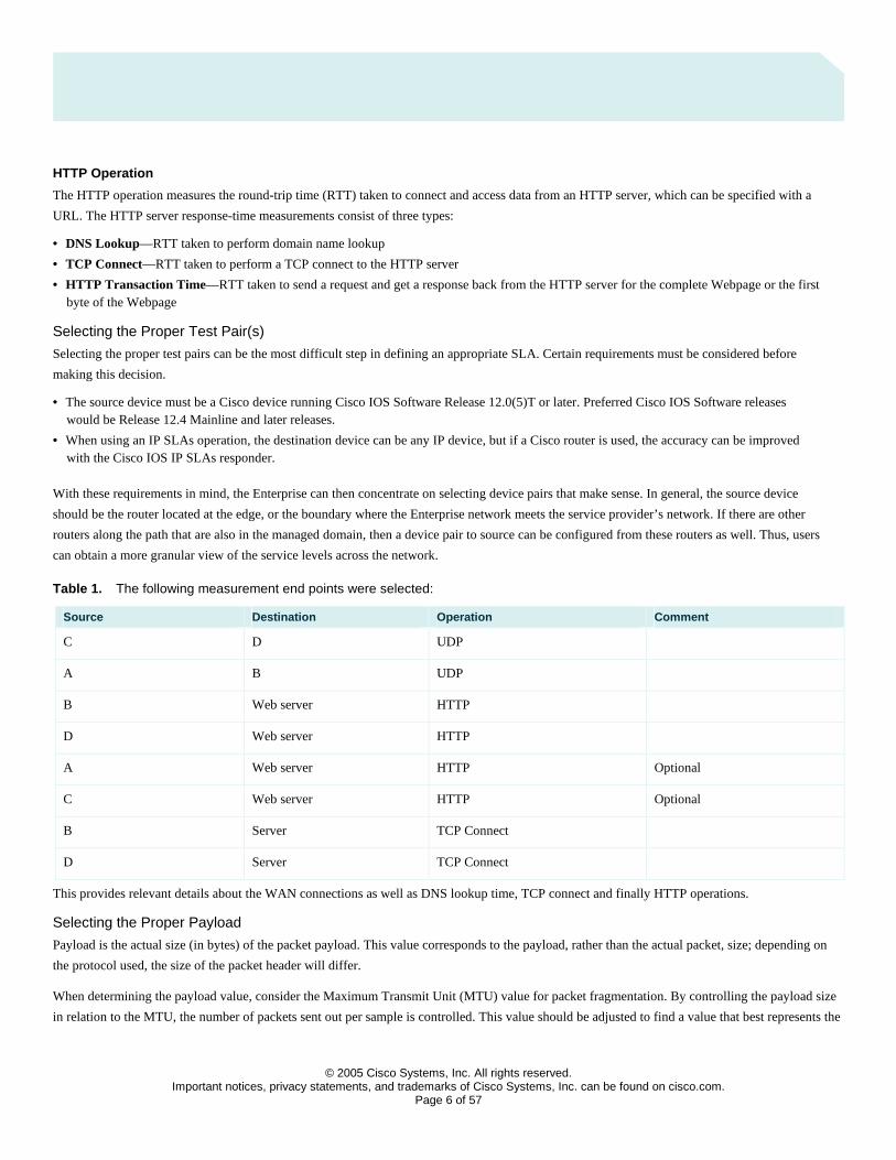
Table 1. The following measurement end points were selected:
Source Destination Operation Comment
C D UDP
A B UDP
B Web server HTTP
D Web server HTTP
A Web server HTTP Optional
C Web server HTTP Optional
B Server TCP Connect
D Server TCP Connect
This provides relevant details about the WAN connections as well as DNS lookup time, TCP connect and finally HTTP operations.
Selecting the Proper Payload
Payload is the actual size (in bytes) of the packet payload. This value corresponds to the payload, rather than the actual packet, size; depending on
the protocol used, the size of the packet header will differ.
When determining the payload value, consider the Maximum Transmit Unit (MTU) value for packet fragmentation. By controlling the payload size
in relation to the MTU, the number of packets sent out per sample is controlled. This value should be adjusted to find a value that best represents the
© 2005 Cisco Systems, Inc. All rights reserved.
Important notices, privacy statements, and trademarks of Cisco Systems, Inc. can be found on cisco.com. Page 7 of 57
actual size and number of typical packets traversing the network. The IP SLAs value to change the payload size is called request-data-size. The
request-data-size changes the size of the payload of the IP packets.
The average packet size on the Internet is 260 bytes; the customer used this packet size.
Selecting the Proper Type of Service (ToS) Bit
As the customer has not yet implemented QoS, this feature was excluded from the described scenario.
Selecting the Proper Sampling Interval
The frequency with which the Cisco IOS IP SLAs send the active monitoring and sample packets configured depending on the needs and
requirements of network bandwidth. Sampling may occur on a frequent basis in order to obtain the most accurate assessment of network service
levels; unfortunately, this is not always feasible. For example, when monitoring across a more expensive WAN connection, the user might not
want to create a large amount of traffic across the link.
It is also important to consider the active monitoring traffic is generated by the IP SLAs on a Cisco IOS Software device. Processing power
might be a concern when a low-end Cisco router is used, or there is a huge amount of traffic passing through the router. In these cases, it would be
necessary to cut down on the frequency of the sampling interval or use a dedicated SLA (aka: shadow) router to perform the IP SLAs operations.
For performance details, please refer to the section later in this document.
In this case the following sampling intervals were chosen:
• UDP: 60 sec
• HTTP: 300 sec
• TCP Connect: 30 sec
Selecting the Proper Thresholds
Service Providers do sometimes predefine performance thresholds. As part of an SLC, ISPs may provide SLAs that specify the amount of latency
or a percentage of availability. If the terms of a particular SLA are more ambiguous, then it falls to the network administrator to decide what type
of thresholds to select. Thresholds and traps can be set for response time, jitter calculations, and packet loss.
Realistic threshold examples:
• One way delay:
– West Europe-US West: 90 ms
– US West-US East: 30 ms
– Within West Europe: 40 ms
– West Europe-Africa: 150 ms
– West Europe-North Asia: 100 ms
As these data consider the carriers backbone only, we have to add the appropriate delay for the access network.
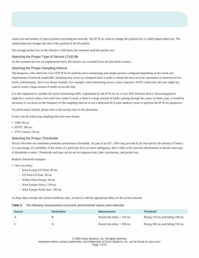
Table 2. The following measurement end points and threshold values were selected:
Source Destination Measurement Threshold
A B Round-trip delay < 150 ms Rising 150 ms and falling 100 ms
C D Round-trip delay < 200 ms Rising 200 ms and falling 150 ms
© 2005 Cisco Systems, Inc. All rights reserved.
Important notices, privacy statements, and trademarks of Cisco Systems, Inc. can be found on cisco.com. Page 8 of 57
A,B,C,D Server TCP Connect < 500 ms Rising 500 ms and falling 200 ms
A,B,C,D Web server HTTP timeout 5 sec Rising 2 s and falling 1 s
Implemented properly, IP SLA provides the required level of details to a network administrator. The upper-layer operations can verify the latency
of the HTTP, DNS or DHCP application.
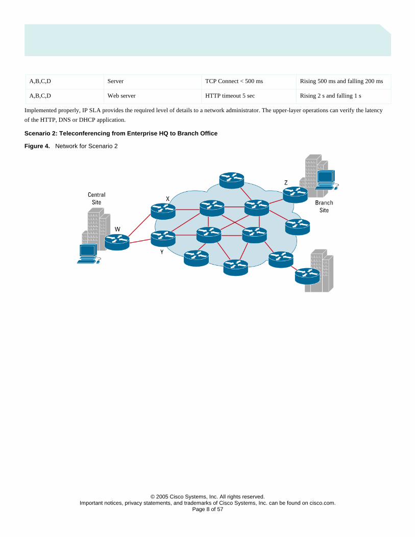
Scenario 2: Teleconferencing from Enterprise HQ to Branch Office
Figure 4. Network for Scenario 2
© 2005 Cisco Systems, Inc. All rights reserved.
Important notices, privacy statements, and trademarks of Cisco Systems, Inc. can be found on cisco.com. Page 9 of 57
Selecting the proper operation
In Scenario 2, a business unit manager needs the ability to run a teleconferencing session across a data link to a branch office. The customer had
already deployed QoS with three different classes. In this situation, the audio and video traveling across the network are extremely sensitive to
inter-packet delay and packet loss; therefore, a jitter operation was selected for the VoIP class and a UDP operation was selected for the Business
class traffic. No operations were defined for the best effort class.
Jitter / Voice over IP
The VoIP Jitter operation measures the variance in inter-packet delay in both directions (source to destination and destination to source). Cisco IOS
IP SLAs will send out a series of packets with a specified interval. The time stamps and sequence numbers of those packets and the responses to
those packets are collected and used to calculate the variance in the packet delay. This measurement is useful in verifying solid VoIP services and
packet loss. Using the jitter operation requires the Cisco IOS IP SLAs responder feature enabled at the target Cisco device.
Jitter operations provide most information compared to other operations, such as:
• Jitter: source to destination, destination to source
• Packet loss: Source to destination, destination to source
• Round trip time
• One way delay if IP SLAs and responder clocks in sync (i.e. NTP is used)
• The jitter operation is the most accurate operation
• An Operation is defined as a sequence of packets (configurable) rather than one packet per polling interval
• Accounts and removes for processing in IP SLAs source and target
• MOS Voice Quality score and codec simulation (Release 12.3(4)T)
• One-way latency, jitter, packet loss and MOS, and Calculated Planning Impairment Factor (ICPIF) traps (Release 12.3(7)T)
Selecting the Proper Test Pair(s) • Relevant routers: W, X, Y
• Branch office router: Z
• Operations: X to Z; Y to Z; W to Z
This enables the operator to monitor the performance of the network services with relevant details.
Selecting the Proper Payload
A packet size of 200 Byte was configured.
Selecting the Proper Type of Service (ToS) Bit
In some cases, different types of traffic may receive different levels of priority when passing through the network. For example, if an organization
deems email traffic more important than Web traffic, it can set the precedence of email traffic to receive a higher priority than Web traffic.
Cisco IOS IP SLAs has the option to configure the ToS bits in the IP header. The ToS bits are four bits located within the ToS byte in the IP header.
The active test traffic that is generated by the Cisco IOS IP SLAs can be subject to queuing or QoS prioritization policies. It is therefore logical that
Cisco IOS IP SLAs can verify that these policies are being enforced if there are QoS policies implemented in the network. The DSCP bits needed to
be converted to TOS bits and input in Cisco IOS IP SLA because the feature does not support DSCP values directly.
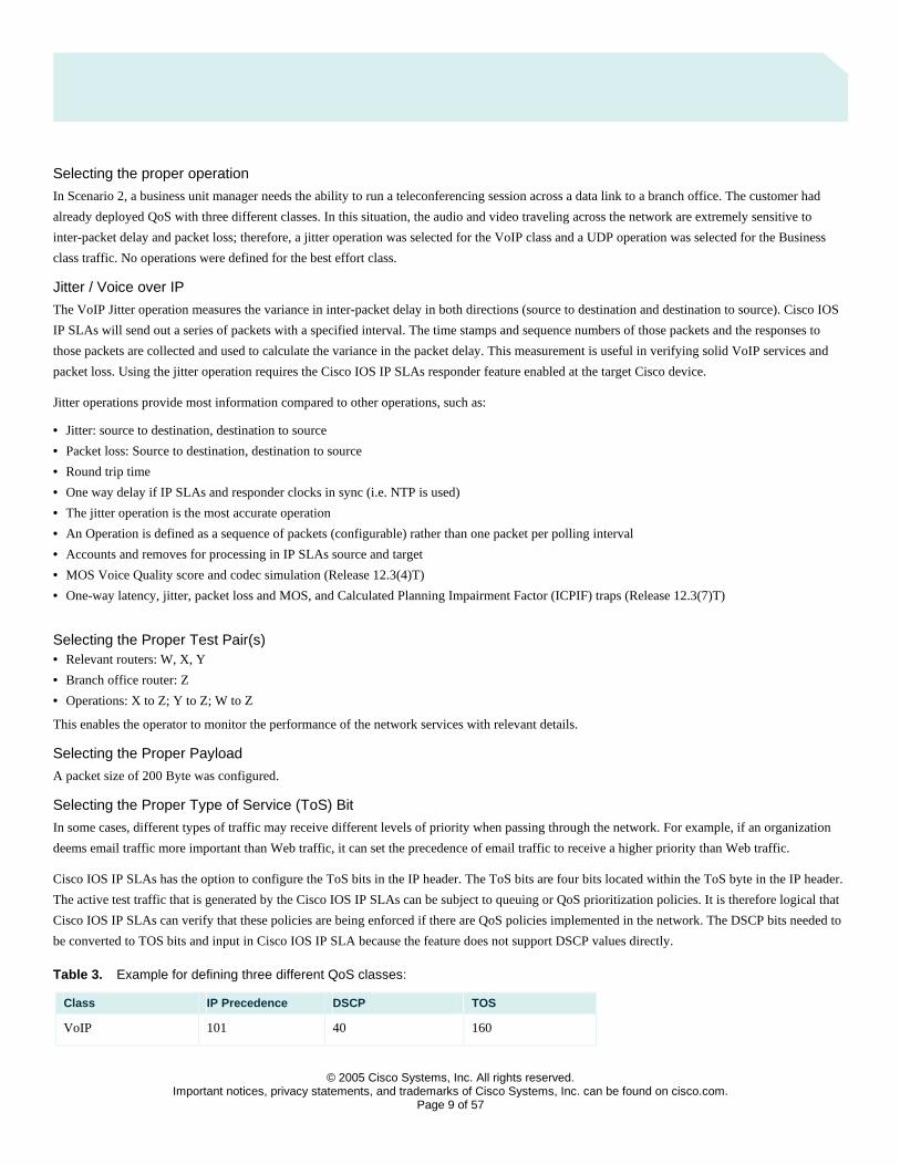
Table 3. Example for defining three different QoS classes:
Class IP Precedence DSCP TOS
VoIP 101 40 160
© 2005 Cisco Systems, Inc. All rights reserved.
Important notices, privacy statements, and trademarks of Cisco Systems, Inc. can be found on cisco.com. Page 10 of 57
Business class 100 32 128
Best Effort 000 00 000
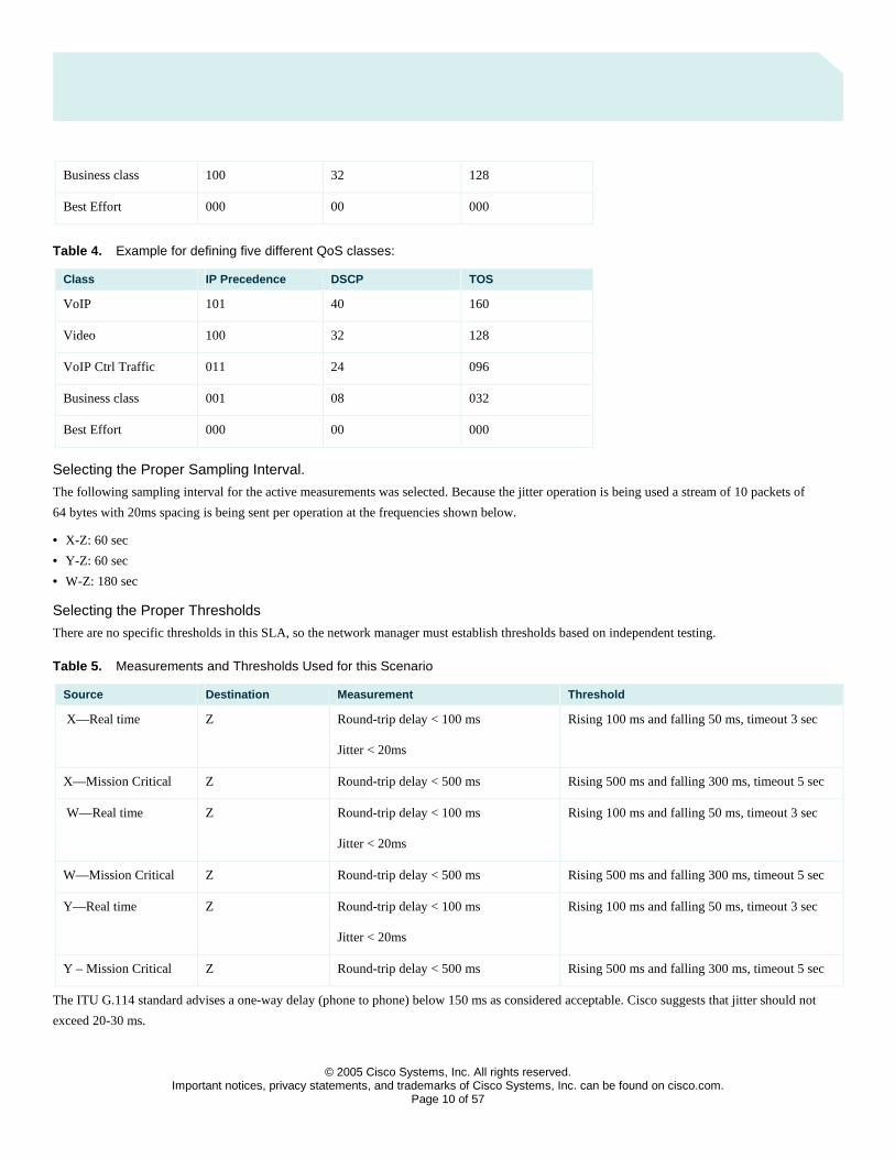
Table 4. Example for defining five different QoS classes:
Class IP Precedence DSCP TOS
VoIP 101 40 160
Video 100 32 128
VoIP Ctrl Traffic 011 24 096
Business class 001 08 032
Best Effort 000 00 000
Selecting the Proper Sampling Interval.
The following sampling interval for the active measurements was selected. Because the jitter operation is being used a stream of 10 packets of
64 bytes with 20ms spacing is being sent per operation at the frequencies shown below.
• X-Z: 60 sec
• Y-Z: 60 sec
• W-Z: 180 sec
Selecting the Proper Thresholds
There are no specific thresholds in this SLA, so the network manager must establish thresholds based on independent testing.
Table 5. Measurements and Thresholds Used for this Scenario
Source Destination Measurement Threshold
X—Real time Z Round-trip delay < 100 ms
Jitter < 20ms
Rising 100 ms and falling 50 ms, timeout 3 sec
X—Mission Critical Z Round-trip delay < 500 ms Rising 500 ms and falling 300 ms, timeout 5 sec
W—Real time Z Round-trip delay < 100 ms
Jitter < 20ms
Rising 100 ms and falling 50 ms, timeout 3 sec
W—Mission Critical Z Round-trip delay < 500 ms Rising 500 ms and falling 300 ms, timeout 5 sec
Y—Real time Z Round-trip delay < 100 ms
Jitter < 20ms
Rising 100 ms and falling 50 ms, timeout 3 sec
Y – Mission Critical Z Round-trip delay < 500 ms Rising 500 ms and falling 300 ms, timeout 5 sec
The ITU G.114 standard advises a one-way delay (phone to phone) below 150 ms as considered acceptable. Cisco suggests that jitter should not
exceed 20-30 ms.

© 2005 Cisco Systems, Inc. All rights reserved.
Important notices, privacy statements, and trademarks of Cisco Systems, Inc. can be found on cisco.com. Page 11 of 57
Scenario 3: Dedicated Router Scenario
Often a dedicated SLA router (or shadow router) can be used as the source of measurements. The dedicated router is used when the number of
operations is extremely high (for example, thousands of measurements). Dedicated routers are often deployed in large hub and spoke networks at the
hub site, and spokes just respond to the measurements. Many dedicated routers are also used in large service provider networks for point-of-presence
(POP)-to-POP measurements or from the POP to the customer premises equipment (CPE) routers. This dedicated router topology allows scalability
with a large number of endpoints. A dedicated router provides the benefit of polling a central source location. The destination access or CPE routers
will only need the responder and will have a decreased load because they are only periodically responding to the source router’s measurement
packets. The responder is available in a wide range of Cisco IOS Software releases and is very backward compatible, allowing measurements for
almost every Cisco IOS Software box in the network.The exception is for IP SLAs that are aware of VPN routing and forwarding (VRF), in which
case the responder must be from Cisco IOS Software Release 12.2(2)T or above. The other exception is new operations that require a responder
upgrades. The jitter, VoIP jitter, UDP echo, and TCP connect measurements any Cisco IOS Software Release supporting a responder can be used.
There are several advantages to using a dedicated router:
• The dedicated router will be a central location to retrieve measurements from the SNMP MIB.
• The dedicated router has no production traffic and therefore will not be affected by any other features or loads imposed on the device.
• The source router can be updated frequently with new measurements without polling or writing to a traffic-forwarding device.
• SNMP write can be set up on the device, and security will not be as much of an issue because the box is not carrying customer traffic.
• Frequent releases of Cisco IOS Software, and therefore the latest feature set and measurements, are possible because the router is not carrying production traffic.
• The dedicated router can act as a very good Network Time Protocol (NTP) synchronization point, especially when it is a Cisco 7200 Series Router, which can have a Global Positioning Systems (GPS) clock connected to the auxiliary port for time synchronization. Time synchronization is needed for one-way measurements.
Scenario 4: Multiprotocol Label Switching VPN Scenario
A unique feature of Cisco IOS IP SLAs is the ability to work within an MPLS network or RFC 2547 MPLS VPN network. IP SLAs have the ability
to specify which VRF routing table is used for forwarding. This feature is used to send IP SLAs packets from a Cisco Router to another vendor’s
equipment supporting RFC 2547 or to send packets between Cisco routers in an MPLS/VPN network. It is possible for IP SLAs dedicated SLA
router to act as a VPNv4 or Internal Border Gateway Protocol (iBGP) neighbor to forward packets to any customer CPE within the VPN network.
Often the responder can be placed on a CPE.
MPLS VPN-aware IP SLAs:
VRF-aware operations support (Releases12.0(26)S, 12.2(25)S, and 12.2(2)T)
• ICMP Echo
• ICMP Path Echo
• UDP Echo
• ICMP Path Jitter
• UDP Jitter
The following architectures might be used within an MPLS/VPN network for monitoring:
1. Provider Edge Router (PE) PE-based VRF-aware IP SLAs operations producing PE-to-PE or PE-CE measurements
2. PE-based IP SLAs operations using the global routing table, which produces PE-to-PE measurements
3. PE-based IP SLAs operations for PE-to-CE measurements within a VRF
© 2005 Cisco Systems, Inc. All rights reserved.
Important notices, privacy statements, and trademarks of Cisco Systems, Inc. can be found on cisco.com. Page 12 of 57
4. A dedicated SLA router used as an IBGP neighbor, allowing the router to participate in VPNs by using a dedicated route target for IP SLAs
traffic and routing to CE routers within customer VPNs
5. A dedicated SLA router using IP SLAs, which utilize logical subinterfaces per VRF connected to a PE to perform PE-to-PE or PE to CE
measurements
6. A dedicated SLA router with multi-VRF CE and multiple subinterfaces from the dedicated SLA router to the PE, producing PE-to-PE or
PE-CE measurements
7. A dedicated SLA router with IP SLAs measurements using the global table for PE-to-PE measurement
8. A dedicated router with a specific VRF for POP-to-POP measurements and one VRF for the dedicated routers to communicate; the dedicated
routers are placed in the POPs, producing PE-to-PE measurement
In general any of the PE-to-PE techniques outlined above may be combined with edge-to-edge (CE-to-CE) measurements. If the VPN topology
is fully meshed and the number of sites is large, then the number of measurements for a full mesh of customer CEs may be prohibitive. Another
method to avoid CE-based measurements is to have a series of measurements and what is called a hierarchical design; CE-to-PE and PE-to-PE
measurements are separated. This obviously eliminates the need for a full mesh of CE-to-CE measurements and increases scalability of the Cisco
IOS IP SLAs deployment. The hierarchical approach allows the PE or dedicated router to be dedicated as the source of IP SLAs traffic, and the CE
device will only respond to the source for the performance measurement. A Cisco CE using an IP SLAs responder will have accurate measurements.
The other advantage with this design is that the CE will only need to have a responder for UDP-based source-dedicated SLA routers, minimizing the
resources consumed by the CE. Potentially round trip times can be summed to give an approximate answer for end-to-end measurement. Jitter
measurements will be more of a problem and may not be accurate if broken into two separate measurements. The service provider SLA or
performance measurements can be set up to accommodate the hierarchical IP SLAs design, simplifying operations for the customer.
© 2005 Cisco Systems, Inc. All rights reserved.
Important notices, privacy statements, and trademarks of Cisco Systems, Inc. can be found on cisco.com. Page 13 of 57
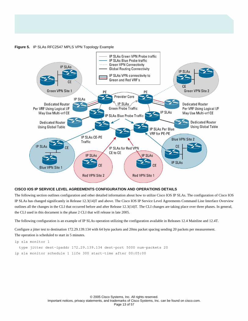
Figure 5. IP SLAs RFC2547 MPLS VPN Topology Example
CISCO IOS IP SERVICE LEVEL AGREEMENTS CONFIGURATION AND OPERATIONS DETAILS
The following section outlines configuration and other detailed information about how to utilize Cisco IOS IP SLAs. The configuration of Cisco IOS
IP SLAs has changed significantly in Release 12.3(14)T and above. The Cisco IOS IP Service Level Agreements Command Line Interface Overview
outlines all the changes in the CLI that occurred before and after Release 12.3(14)T. The CLI changes are taking place over three phases. In general,
the CLI used in this document is the phase 2 CLI that will release in late 2005.
The following configuration is an example of IP SLAs operation utilizing the configuration available in Releases 12.4 Mainline and 12.4T.
Configure a jitter test to destination 172.29.139.134 with 64 byte packets and 20ms packet spacing sending 20 packets per measurement.
The operation is scheduled to start in 5 minutes.
ip sla monitor 1
type jitter dest-ipaddr 172.29.139.134 dest-port 5000 num-packets 20
ip sla monitor schedule 1 life 300 start-time after 00:05:00
© 2005 Cisco Systems, Inc. All rights reserved.
Important notices, privacy statements, and trademarks of Cisco Systems, Inc. can be found on cisco.com. Page 14 of 57
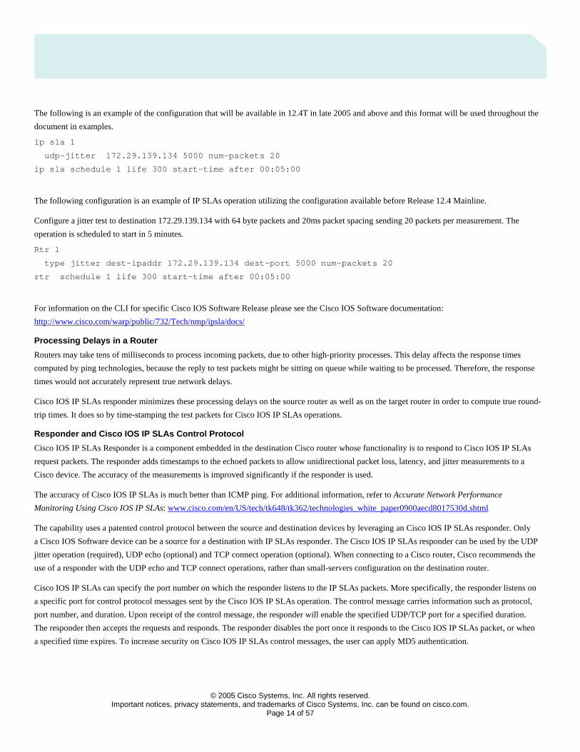
The following is an example of the configuration that will be available in 12.4T in late 2005 and above and this format will be used throughout the
document in examples.
ip sla 1
udp-jitter 172.29.139.134 5000 num-packets 20
ip sla schedule 1 life 300 start-time after 00:05:00
The following configuration is an example of IP SLAs operation utilizing the configuration available before Release 12.4 Mainline.
Configure a jitter test to destination 172.29.139.134 with 64 byte packets and 20ms packet spacing sending 20 packets per measurement. The
operation is scheduled to start in 5 minutes.
Rtr 1
type jitter dest-ipaddr 172.29.139.134 dest-port 5000 num-packets 20
rtr schedule 1 life 300 start-time after 00:05:00
For information on the CLI for specific Cisco IOS Software Release please see the Cisco IOS Software documentation:
http://www.cisco.com/warp/public/732/Tech/nmp/ipsla/docs/
Processing Delays in a Router
Routers may take tens of milliseconds to process incoming packets, due to other high-priority processes. This delay affects the response times
computed by ping technologies, because the reply to test packets might be sitting on queue while waiting to be processed. Therefore, the response
times would not accurately represent true network delays.
Cisco IOS IP SLAs responder minimizes these processing delays on the source router as well as on the target router in order to compute true round-
trip times. It does so by time-stamping the test packets for Cisco IOS IP SLAs operations.
Responder and Cisco IOS IP SLAs Control Protocol
Cisco IOS IP SLAs Responder is a component embedded in the destination Cisco router whose functionality is to respond to Cisco IOS IP SLAs
request packets. The responder adds timestamps to the echoed packets to allow unidirectional packet loss, latency, and jitter measurements to a
Cisco device. The accuracy of the measurements is improved significantly if the responder is used.
The accuracy of Cisco IOS IP SLAs is much better than ICMP ping. For additional information, refer to Accurate Network Performance
Monitoring Using Cisco IOS IP SLAs: www.cisco.com/en/US/tech/tk648/tk362/technologies_white_paper0900aecd8017530d.shtml
The capability uses a patented control protocol between the source and destination devices by leveraging an Cisco IOS IP SLAs responder. Only
a Cisco IOS Software device can be a source for a destination with IP SLAs responder. The Cisco IOS IP SLAs responder can be used by the UDP
jitter operation (required), UDP echo (optional) and TCP connect operation (optional). When connecting to a Cisco router, Cisco recommends the
use of a responder with the UDP echo and TCP connect operations, rather than small-servers configuration on the destination router.
Cisco IOS IP SLAs can specify the port number on which the responder listens to the IP SLAs packets. More specifically, the responder listens on
a specific port for control protocol messages sent by the Cisco IOS IP SLAs operation. The control message carries information such as protocol,
port number, and duration. Upon receipt of the control message, the responder will enable the specified UDP/TCP port for a specified duration.
The responder then accepts the requests and responds. The responder disables the port once it responds to the Cisco IOS IP SLAs packet, or when
a specified time expires. To increase security on Cisco IOS IP SLAs control messages, the user can apply MD5 authentication.
© 2005 Cisco Systems, Inc. All rights reserved.
Important notices, privacy statements, and trademarks of Cisco Systems, Inc. can be found on cisco.com. Page 15 of 57
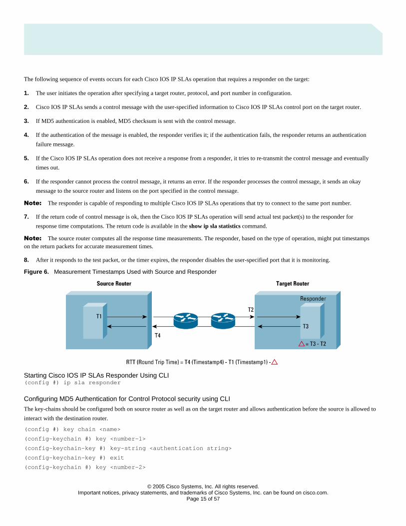
The following sequence of events occurs for each Cisco IOS IP SLAs operation that requires a responder on the target:
1. The user initiates the operation after specifying a target router, protocol, and port number in configuration.
2. Cisco IOS IP SLAs sends a control message with the user-specified information to Cisco IOS IP SLAs control port on the target router.
3. If MD5 authentication is enabled, MD5 checksum is sent with the control message.
4. If the authentication of the message is enabled, the responder verifies it; if the authentication fails, the responder returns an authentication
failure message.
5. If the Cisco IOS IP SLAs operation does not receive a response from a responder, it tries to re-transmit the control message and eventually
times out.
6. If the responder cannot process the control message, it returns an error. If the responder processes the control message, it sends an okay
message to the source router and listens on the port specified in the control message.
Note: The responder is capable of responding to multiple Cisco IOS IP SLAs operations that try to connect to the same port number.
7. If the return code of control message is ok, then the Cisco IOS IP SLAs operation will send actual test packet(s) to the responder for
response time computations. The return code is available in the show ip sla statistics command.
Note: The source router computes all the response time measurements. The responder, based on the type of operation, might put timestamps on the return packets for accurate measurement times.
8. After it responds to the test packet, or the timer expires, the responder disables the user-specified port that it is monitoring.
Figure 6. Measurement Timestamps Used with Source and Responder
Starting Cisco IOS IP SLAs Responder Using CLI (config #) ip sla responder
Configuring MD5 Authentication for Control Protocol security using CLI
The key-chains should be configured both on source router as well as on the target router and allows authentication before the source is allowed to
interact with the destination router.
(config #) key chain <name>
(config-keychain #) key <number-1>
(config-keychain-key #) key-string <authentication string>
(config-keychain-key #) exit
(config-keychain #) key <number-2>
© 2005 Cisco Systems, Inc. All rights reserved.
Important notices, privacy statements, and trademarks of Cisco Systems, Inc. can be found on cisco.com. Page 16 of 57
(config-keychain-key #) key-string <authentication string>
(config-keychain-key #) exit
Multiple authentication strings can be configured for a key-chain. When multiple strings are configured, then MD5 alternates between the
strings during communication.
Once a key-chain is configured, then that key-chain has to be tied to Cisco IOS IP SLAs, so that it could use these authentication strings for
authenticating control messages.
NOTE: The authentication configuration should be the same on both source router and target router, even the order of the authentication strings
(although the key-chain name can be different).
(config #) ip sla key-chain <name>
Accessing Cisco IOS IP Service Level Agreements Data from the Command-Line Interface
Use the following commands to verify that the Cisco IOS IP SLAs feature is configured properly:
show ip sla application
This command shows the types of operations available on the device.
show ip sla configuration
This command shows the details of what was configured in CLI for each or all operations on the device.
Use the following commands to view the results of operations:
show ip sla statistics
show ip sla statistics details
Instantaneous view of the current statistics for the latest measurement
show ip sla statistics aggregated
show ip sla statistics aggregated details
Aggregated view of the statistics over the hour period.
Scalable Deployment of Cisco IOS IP SLAs Operations
In general Cisco IOS IP SLAs operations can be scheduled individually. Each destination to be tested will require the use of the ip sla schedule
command. It has been shown that sequential scheduling of a large number of operations is key to good performance with Cisco IOS IP SLAs. So
for instance if a source has 100 destinations it would be a better deployment design to schedule these 100 operations over one minute instead of
all at the same time. The CPU consumption would decrease significantly if this method is used. The feature multi-operation scheduler available in
Release 12.3(8)T was specifically designed to allow the user sequential operations of a group of destinations. Cisco IOS Software documentation is
available for multi-operation scheduler feature:
http://www.cisco.com/en/US/docs/ios/ipsla/configuration/guide/sla_multi_scheduler_ps10890_TSD_Products_Configuration_Guide_Chapter.html
UDP Echo Operation
The UDP Echo Operation calculates UDP response times between a Cisco router and any IP-enabled device. Response time is computed by
measuring the time taken to send a datagram and receive a response from the destination device.
© 2005 Cisco Systems, Inc. All rights reserved.
Important notices, privacy statements, and trademarks of Cisco Systems, Inc. can be found on cisco.com. Page 17 of 57
If the target is a Cisco router, the user has an option to enable Cisco IOS IP SLAs responder in the target router. The responder would either listen
to the default UDP echo port (port 7), or to the port that the user specifies. Using Cisco IOS IP SLAs responder can increase accuracy as the process
delay in the target router. If the destination is a regular IP host, then the user must use UDP port 7 as the destination port.
Note: Almost all IP devices provide an UDP Echo Service that listens on port number 7 and responds to client requests (echo server). In general the use of UDP Echo Service is not recommended because of router security concerns. Cisco routers also have this service but turned off by default. If the echo server is enabled on the target Cisco Router and if the user tries to start an UDP operation that tries to communicate with responder on port number 7, the responder will fail because of socket bind problem (port number 7 already being used by echo server). If the user intends to use responder, then they should not try to specify a port that might already be in use by other services on the router.
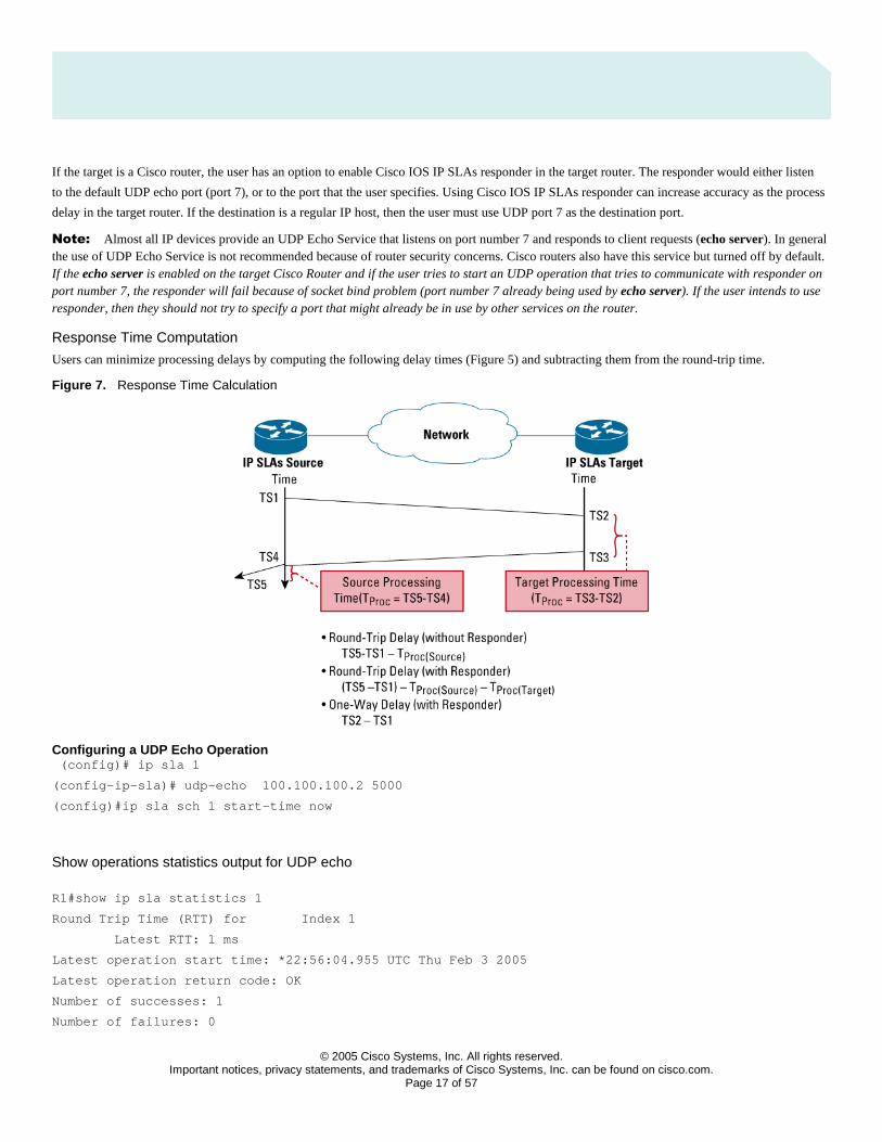
Response Time Computation
Users can minimize processing delays by computing the following delay times (Figure 5) and subtracting them from the round-trip time.
Figure 7. Response Time Calculation
Configuring a UDP Echo Operation (config)# ip sla 1
(config-ip-sla)# udp-echo 100.100.100.2 5000
(config)#ip sla sch 1 start-time now
Show operations statistics output for UDP echo
R1#show ip sla statistics 1
Round Trip Time (RTT) for Index 1
Latest RTT: 1 ms
Latest operation start time: *22:56:04.955 UTC Thu Feb 3 2005
Latest operation return code: OK
Number of successes: 1
Number of failures: 0

© 2005 Cisco Systems, Inc. All rights reserved.
Important notices, privacy statements, and trademarks of Cisco Systems, Inc. can be found on cisco.com. Page 18 of 57
Operation time to live: 3591 sec
R1#show ip sla statistics 1 details
Round Trip Time (RTT) for Index 2020
Latest RTT: 1 ms
Latest operation start time: *22:57:04.954 UTC Thu Feb 3 2005
Latest operation return code: OK
Over thresholds occurred: FALSE
Number of successes: 2
Number of failures: 0
Operation time to live: 3495 sec
Operational state of entry: Active
Last time this entry was reset: Never
Table 6. Description of show operations statistics Output for the UDP Echo Operation
Field Description
Index Cisco IOS IP SLAs operation number
Number of Successes Number of active measurements sent across the network
Number of Failures Number of operations that could not be activated across the network
Operation Time to Live The current time left before the operation stops activating. The life of the operation is a configurable
parameter
Over Thresholds Occurred A threshold was set and exceeded
Latest RTT (Milliseconds) The round trip time last measured for the UDP echo
Latest Operation Start Time Time of the last measurement
Latest Operation Return Code Operation Status
© 2005 Cisco Systems, Inc. All rights reserved.
Important notices, privacy statements, and trademarks of Cisco Systems, Inc. can be found on cisco.com. Page 19 of 57
UDP Jitter Operation
With the addition of real-time traffic (ie: VoIP), the focus shifts not just in the reliability of the network, but also on the delays involved in
transmitting the data. Real-time traffic is delay sensitive. For Voice data, packet loss is manageable to some extent, but frequent losses impair
communication between endpoints. The UDP jitter operation is the most popular operation because the user can obtain packet loss, jitter and
latency from one operation. This also includes unidirectional measurements as well.
The Jitter operation is designed to measure the delay, delay variance and packet loss in IP networks by generating active UDP traffic. It sends N
packets, each of size S, from source router to a target router (which requires Cisco IOS IP SLAs responder enabled) each T milliseconds apart.
All these parameters are user configurable.
The packet’s Cisco IOS IP SLAs jitter operation sends a sequence of packets to measure Jitter carry packet sequence (sending sequence and
receiving sequence) information, as well as sending and receiving timestamps from the source and the responder. Based on this information,
Jitter operation is capable of measuring
• Per-direction inter-packet delay variance (jitter)
• Per-direction packet-loss and
• Average round trip time
• One-way delay (requires Cisco IOS Software Release 12.2(2)T or later)
Jitter Computation
The Cisco IOS source router consecutively sends multiple packets to the destination at ten millisecond intervals; if the network is operating
optimally, the destination should receive them at ten-millisecond intervals. Delays (ie: queueing, or arriving through alternate routes) in the
network can cause inter-packet arrival delay of greater or less than ten milliseconds.
Positive jitter implies that the packets arrived at intervals of more than ten milliseconds. If they arrive twelve milliseconds apart, then
positive jitter is equivalent to two milliseconds. Negative jitter is computed similarly when the interval is smaller than originally encoded.
Greater value for positive jitter is undesirable for voice networks, and a jitter value of zero is ideal for delay-sensitive networks.
One-way Delay computation (Supported in Cisco IOS Software Release 12.2(1)T)
Theoretically, the delay incurred by packets traversing a route from host A to host B is equal in each direction. However, the true delay
in one direction may be much higher than in the other direction.
Consider a busy freeway, on which gridlock may occur in only one direction. The same situation exists within networks. There may also
be asymmetric paths between source and destination. The one-way delay computations provide detailed information to the user about their
network. Users can gain a better understanding of where and in which direction network bottlenecks exist. The UDP Jitter operation provides
these measurements. However, one-way delay measurement requires the clocks on source and target routers very synchronized, e.g., using
GPS-based NTP server The current implementation assumes a NTP accuracy that is 10% of the latency between the end point. If the time is
not synchronized, Cisco IOS IP SLAs ignores the measurement by filling in 0’s. One-way jitter and packet loss measurements do not require
time synchronization. For more information see the section in this document on setting up NTP in the network.
Defining Jitter Operation from CLI (Config)”ip sla 200
(config-ip-sla)#udp-jitter 172.24.132.100 99 num-packets 20 interval 20
© 2005 Cisco Systems, Inc. All rights reserved.
Important notices, privacy statements, and trademarks of Cisco Systems, Inc. can be found on cisco.com. Page 20 of 57
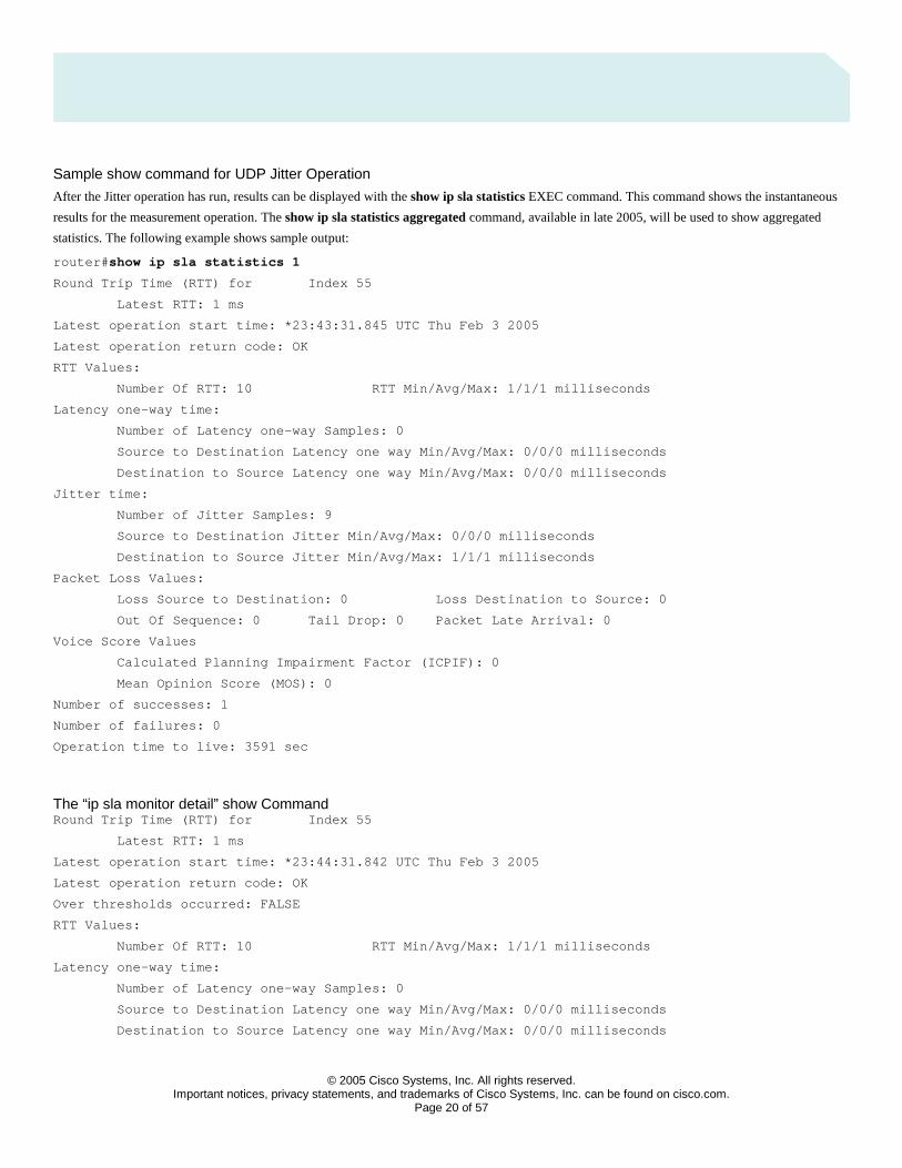
Sample show command for UDP Jitter Operation
After the Jitter operation has run, results can be displayed with the show ip sla statistics EXEC command. This command shows the instantaneous
results for the measurement operation. The show ip sla statistics aggregated command, available in late 2005, will be used to show aggregated
statistics. The following example shows sample output:
router# show ip sla statistics 1
Round Trip Time (RTT) for Index 55
Latest RTT: 1 ms
Latest operation start time: *23:43:31.845 UTC Thu Feb 3 2005
Latest operation return code: OK
RTT Values:
Number Of RTT: 10 RTT Min/Avg/Max: 1/1/1 milliseconds
Latency one-way time:
Number of Latency one-way Samples: 0
Source to Destination Latency one way Min/Avg/Max: 0/0/0 milliseconds
Destination to Source Latency one way Min/Avg/Max: 0/0/0 milliseconds
Jitter time:
Number of Jitter Samples: 9
Source to Destination Jitter Min/Avg/Max: 0/0/0 milliseconds
Destination to Source Jitter Min/Avg/Max: 1/1/1 milliseconds
Packet Loss Values:
Loss Source to Destination: 0 Loss Destination to Source: 0
Out Of Sequence: 0 Tail Drop: 0 Packet Late Arrival: 0
Voice Score Values
Calculated Planning Impairment Factor (ICPIF): 0
Mean Opinion Score (MOS): 0
Number of successes: 1
Number of failures: 0
Operation time to live: 3591 sec
The “ip sla monitor detail” show Command Round Trip Time (RTT) for Index 55
Latest RTT: 1 ms
Latest operation start time: *23:44:31.842 UTC Thu Feb 3 2005
Latest operation return code: OK
Over thresholds occurred: FALSE
RTT Values:
Number Of RTT: 10 RTT Min/Avg/Max: 1/1/1 milliseconds
Latency one-way time:
Number of Latency one-way Samples: 0
Source to Destination Latency one way Min/Avg/Max: 0/0/0 milliseconds
Destination to Source Latency one way Min/Avg/Max: 0/0/0 milliseconds
© 2005 Cisco Systems, Inc. All rights reserved.
Important notices, privacy statements, and trademarks of Cisco Systems, Inc. can be found on cisco.com. Page 21 of 57
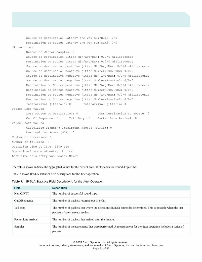
Source to Destination Latency one way Sum/Sum2: 0/0
Destination to Source Latency one way Sum/Sum2: 0/0
Jitter time:
Number of Jitter Samples: 9
Source to Destination Jitter Min/Avg/Max: 0/0/0 milliseconds
Destination to Source Jitter Min/Avg/Max: 0/0/0 milliseconds
Source to destination positive jitter Min/Avg/Max: 0/0/0 milliseconds
Source to destination positive jitter Number/Sum/Sum2: 0/0/0
Source to destination negative jitter Min/Avg/Max: 0/0/0 milliseconds
Source to destination negative jitter Number/Sum/Sum2: 0/0/0
Destination to Source positive jitter Min/Avg/Max: 0/0/0 milliseconds
Destination to Source positive jitter Number/Sum/Sum2: 0/0/0
Destination to Source negative jitter Min/Avg/Max: 0/0/0 milliseconds
Destination to Source negative jitter Number/Sum/Sum2: 0/0/0
Interarrival jitterout: 0 Interarrival jitterin: 0
Packet Loss Values:
Loss Source to Destination: 0 Loss Destination to Source: 0
Out Of Sequence: 0 Tail Drop: 0 Packet Late Arrival: 0
Voice Score Values
Calculated Planning Impairment Factor (ICPIF): 0
Mean Opinion Score (MOS): 0
Number of successes: 2
Number of failures: 0
Operation time to live: 3509 sec
Operational state of entry: Active
Last time this entry was reset: Never
The values shown indicate the aggregated values for the current hour. RTT stands for Round-Trip-Time.
Table 7 shows IP SLA statistics field descriptions for the Jitter operation.
Table 7. IP SLA Statistics Field Descriptions for the Jitter Operation
Field Description
NumOfRTT The number of successful round trips.
OutOfSequence The number of packets returned out of order.
Tail drop The number of packets lost where the direction (SD/DS) cannot be determined. This is possible when the last
packets of a test stream are lost.
Packet Late Arrival The number of packets that arrived after the timeout.
Samples The number of measurements that were performed. A measurement for the jitter operation includes a series of
packets.
© 2005 Cisco Systems, Inc. All rights reserved.
Important notices, privacy statements, and trademarks of Cisco Systems, Inc. can be found on cisco.com. Page 22 of 57
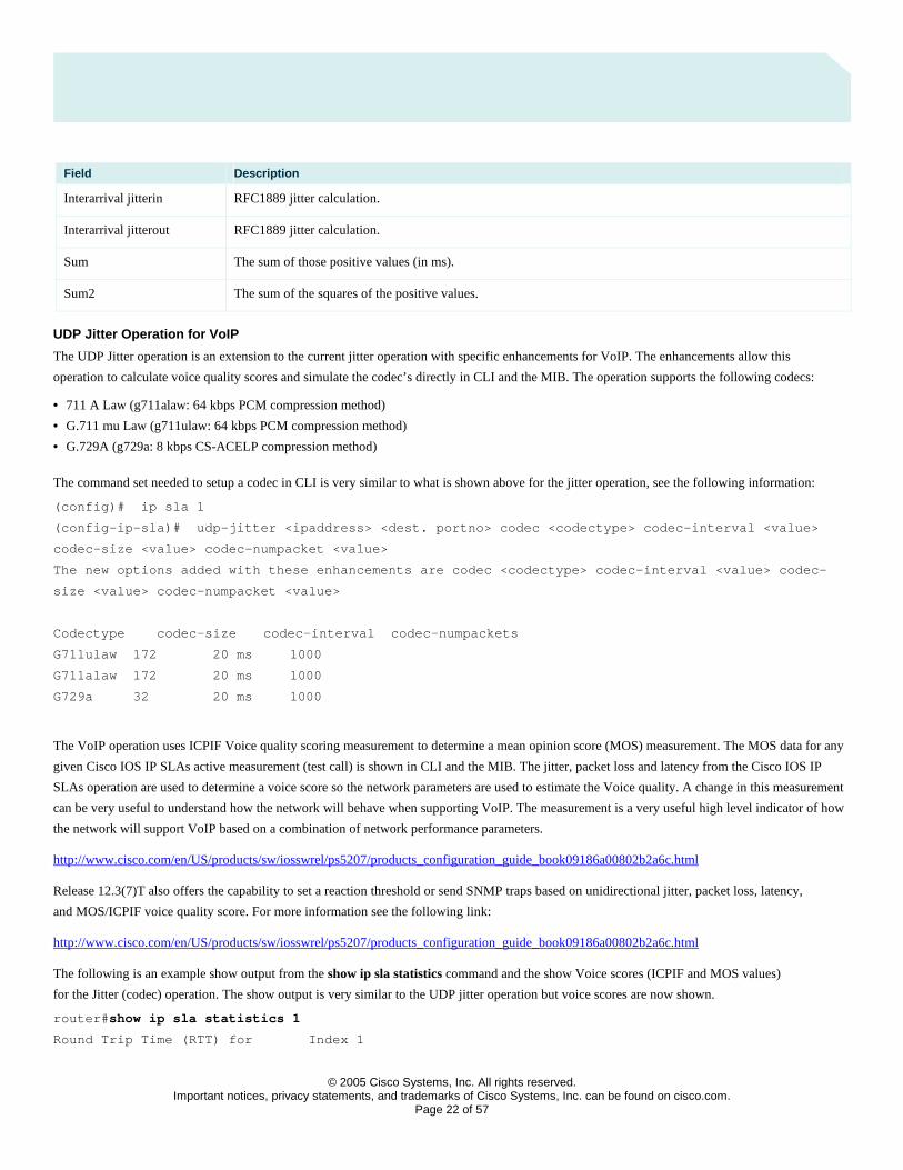
Field Description
Interarrival jitterin RFC1889 jitter calculation.
Interarrival jitterout RFC1889 jitter calculation.
Sum The sum of those positive values (in ms).
Sum2 The sum of the squares of the positive values.
UDP Jitter Operation for VoIP
The UDP Jitter operation is an extension to the current jitter operation with specific enhancements for VoIP. The enhancements allow this
operation to calculate voice quality scores and simulate the codec’s directly in CLI and the MIB. The operation supports the following codecs:
• 711 A Law (g711alaw: 64 kbps PCM compression method)
• G.711 mu Law (g711ulaw: 64 kbps PCM compression method)
• G.729A (g729a: 8 kbps CS-ACELP compression method)
The command set needed to setup a codec in CLI is very similar to what is shown above for the jitter operation, see the following information:
(config)# ip sla 1
(config-ip-sla)# udp-jitter <ipaddress> <dest. portno> codec <codectype> codec-interval <value>
codec-size <value> codec-numpacket <value>
The new options added with these enhancements are codec <codectype> codec-interval <value> codec-
size <value> codec-numpacket <value>
Codectype codec-size codec-interval codec-numpackets
G711ulaw 172 20 ms 1000
G711alaw 172 20 ms 1000
G729a 32 20 ms 1000
The VoIP operation uses ICPIF Voice quality scoring measurement to determine a mean opinion score (MOS) measurement. The MOS data for any
given Cisco IOS IP SLAs active measurement (test call) is shown in CLI and the MIB. The jitter, packet loss and latency from the Cisco IOS IP
SLAs operation are used to determine a voice score so the network parameters are used to estimate the Voice quality. A change in this measurement
can be very useful to understand how the network will behave when supporting VoIP. The measurement is a very useful high level indicator of how
the network will support VoIP based on a combination of network performance parameters.
http://www.cisco.com/en/US/products/sw/iosswrel/ps5207/products_configuration_guide_book09186a00802b2a6c.html
Release 12.3(7)T also offers the capability to set a reaction threshold or send SNMP traps based on unidirectional jitter, packet loss, latency,
and MOS/ICPIF voice quality score. For more information see the following link:
http://www.cisco.com/en/US/products/sw/iosswrel/ps5207/products_configuration_guide_book09186a00802b2a6c.html
The following is an example show output from the show ip sla statistics command and the show Voice scores (ICPIF and MOS values)
for the Jitter (codec) operation. The show output is very similar to the UDP jitter operation but voice scores are now shown.
router# show ip sla statistics 1
Round Trip Time (RTT) for Index 1
© 2005 Cisco Systems, Inc. All rights reserved.
Important notices, privacy statements, and trademarks of Cisco Systems, Inc. can be found on cisco.com. Page 23 of 57
Latest RTT: 1 ms
Latest operation start time: *23:43:31.845 UTC Thu Feb 3 2005
Latest operation return code: OK
RTT Values:
Number Of RTT: 10 RTT Min/Avg/Max: 1/1/1 milliseconds
Latency one-way time:
Number of Latency one-way Samples: 0
Source to Destination Latency one way Min/Avg/Max: 0/0/0 milliseconds
Destination to Source Latency one way Min/Avg/Max: 0/0/0 milliseconds
Jitter time:
Number of Jitter Samples: 9
Source to Destination Jitter Min/Avg/Max: 0/0/0 milliseconds
Destination to Source Jitter Min/Avg/Max: 1/1/1 milliseconds
Packet Loss Values:
Loss Source to Destination: 0 Loss Destination to Source: 0
Out Of Sequence: 0 Tail Drop: 0 Packet Late Arrival: 0
Voice Score Values
Calculated Planning Impairment Factor (ICPIF): 20
Mean Opinion Score (MOS): 3
Number of successes: 1
Number of failures: 0
Operation time to live: 3591 sec
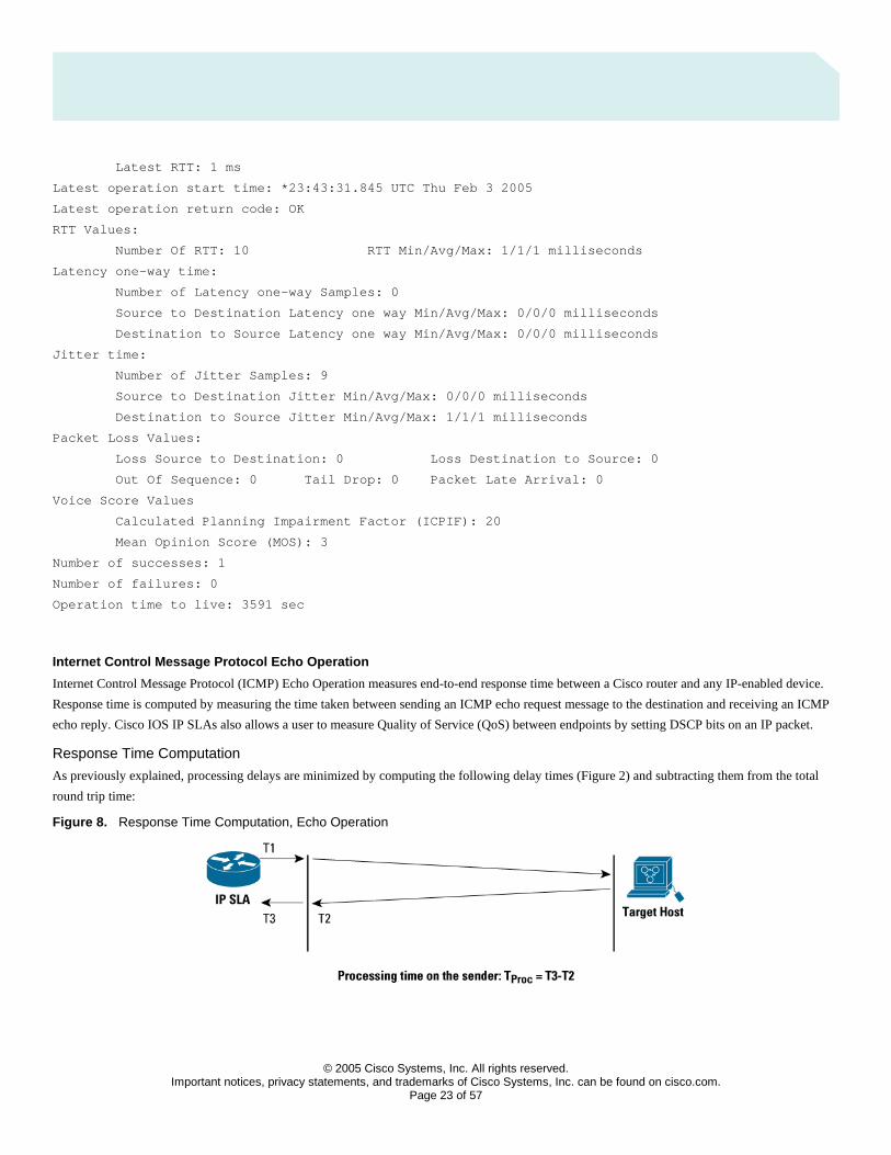
Internet Control Message Protocol Echo Operation
Internet Control Message Protocol (ICMP) Echo Operation measures end-to-end response time between a Cisco router and any IP-enabled device.
Response time is computed by measuring the time taken between sending an ICMP echo request message to the destination and receiving an ICMP
echo reply. Cisco IOS IP SLAs also allows a user to measure Quality of Service (QoS) between endpoints by setting DSCP bits on an IP packet.
Response Time Computation
As previously explained, processing delays are minimized by computing the following delay times (Figure 2) and subtracting them from the total
round trip time:
Figure 8. Response Time Computation, Echo Operation
© 2005 Cisco Systems, Inc. All rights reserved.
Important notices, privacy statements, and trademarks of Cisco Systems, Inc. can be found on cisco.com. Page 24 of 57
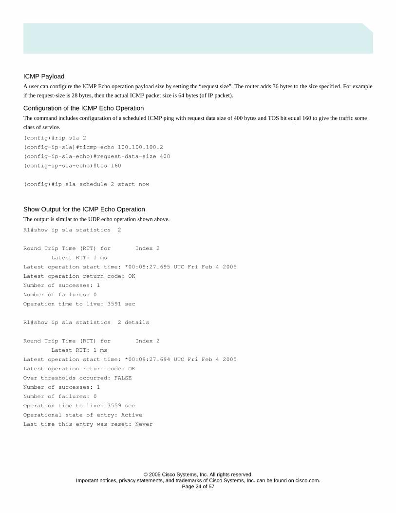
ICMP Payload
A user can configure the ICMP Echo operation payload size by setting the “request size”. The router adds 36 bytes to the size specified. For example
if the request-size is 28 bytes, then the actual ICMP packet size is 64 bytes (of IP packet).
Configuration of the ICMP Echo Operation
The command includes configuration of a scheduled ICMP ping with request data size of 400 bytes and TOS bit equal 160 to give the traffic some
class of service.
(config)#rip sla 2
(config-ip-sla)#ticmp-echo 100.100.100.2
(config-ip-sla-echo)#request-data-size 400
(config-ip-sla-echo)#tos 160
(config)#ip sla schedule 2 start now
Show Output for the ICMP Echo Operation
The output is similar to the UDP echo operation shown above.
R1#show ip sla statistics 2
Round Trip Time (RTT) for Index 2
Latest RTT: 1 ms
Latest operation start time: *00:09:27.695 UTC Fri Feb 4 2005
Latest operation return code: OK
Number of successes: 1
Number of failures: 0
Operation time to live: 3591 sec
R1#show ip sla statistics 2 details
Round Trip Time (RTT) for Index 2
Latest RTT: 1 ms
Latest operation start time: *00:09:27.694 UTC Fri Feb 4 2005
Latest operation return code: OK
Over thresholds occurred: FALSE
Number of successes: 1
Number of failures: 0
Operation time to live: 3559 sec
Operational state of entry: Active
Last time this entry was reset: Never

© 2005 Cisco Systems, Inc. All rights reserved.
Important notices, privacy statements, and trademarks of Cisco Systems, Inc. can be found on cisco.com. Page 25 of 57
ICMP Path Echo Operation
The ICMP Path Echo operation computes hop-by-hop response time between a Cisco router and any IP device on the network.
It discovers the path using traceroute and then measures response time between the source router and each intermittent hop in the path. If there are
multiple equal cost routes between source and destination devices, pathEcho operation has the capability to identify a specific path by using LSR
option (if enabled on intermediate devices). This feature enables Cisco IOS IP SLAs to discover paths more accurately, as compared to a typical
traceroute.
The following is configuration for ICMP Path Echo operation:
Router#
ip sla 3
path-echo <destination ip_address>
frequency 10
ip sla schedule 3 life 25 start-time now
sla7206-2#show ip sla statistics aggregated 55
Note: The show ip sla statistics aggregated keyword requires Cisco IOS Software Release 12.4T, available in late 2005. Before this show ip sla monitor collection-statistics can be used.
Round Trip Time (RTT) for Index 55
Start Time Index: *00:48:06.619 UTC Fri Feb 4 2005
Path Index: 1
Hop in Path Index: 1
Type of operation: path-echo
Number of successes: 1
Number of failures: 0
Target Address 172.29.139.129
Start Time Index: *00:48:06.620 UTC Fri Feb 4 2005
Path Index: 1
Hop in Path Index: 2
Type of operation: path-echo
Number of successes: 1
Number of failures: 0
Target Address 192.168.117.2
Start Time Index: *00:48:06.620 UTC Fri Feb 4 2005
Path Index: 1
Hop in Path Index: 3
Type of operation: path-echo
Number of successes: 1
Number of failures: 0
Target Address 192.168.116.183
© 2005 Cisco Systems, Inc. All rights reserved.
Important notices, privacy statements, and trademarks of Cisco Systems, Inc. can be found on cisco.com. Page 26 of 57
Start Time Index: *00:48:06.620 UTC Fri Feb 4 2005
Path Index: 2
Hop in Path Index: 1
Type of operation: path-echo
Number of successes: 59
Number of failures: 0
Target Address 172.29.139.129
Start Time Index: *00:48:06.620 UTC Fri Feb 4 2005
Path Index: 2
Hop in Path Index: 2
Type of operation: path-echo
Number of successes: 59
Number of failures: 0
Target Address 192.168.116.183
Start Time Index: *01:48:15.608 UTC Fri Feb 4 2005
Path Index: 1
Hop in Path Index: 1
Type of operation: path-echo
Number of successes: 8
Number of failures: 0
Target Address 172.29.139.129
Start Time Index: *01:48:15.609 UTC Fri Feb 4 2005
Path Index: 1
Hop in Path Index: 2
Type of operation: path-echo
Number of successes: 9
Number of failures: 0
Target Address 192.168.116.183
Transmission Control Protocol (TCP) Connect Operation
Transmission Control Protocol (TCP) Connect Operation computes response times by measuring the time taken by the source to perform a
TCP connect operation to the destination device.
If the target is a Cisco router, the user has an option to enable Cisco IOS IP SLA responder in the target router. If the destination is a non-Cisco
IP host, then the user must specify a well-known port number. Some well-known ports are: 21 (ftp), 23 (telnet), 80 (HTTP Server).
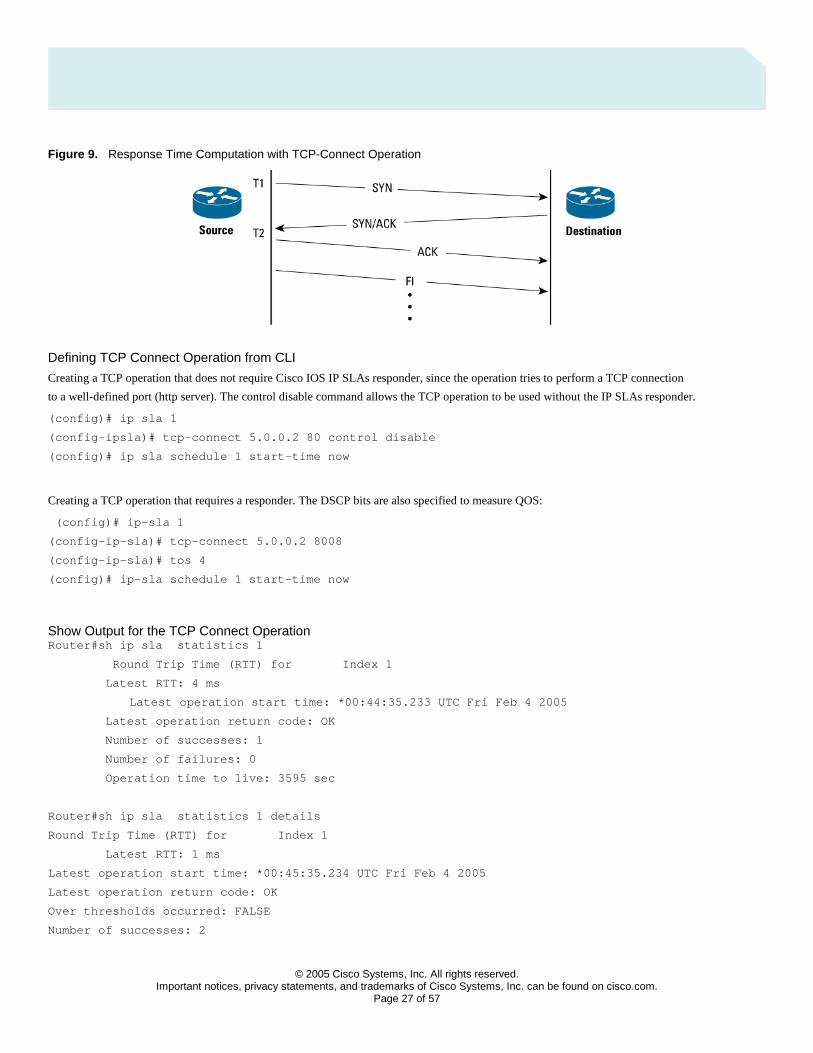
This operation is useful in simulating Telnet or HTTP or server connection times. The measured connection time is the difference between
the time we sent the ACK and we sent the initial SYN, in this case T2-T1 as show in the figure below.
© 2005 Cisco Systems, Inc. All rights reserved.
Important notices, privacy statements, and trademarks of Cisco Systems, Inc. can be found on cisco.com. Page 27 of 57
Figure 9. Response Time Computation with TCP-Connect Operation
Defining TCP Connect Operation from CLI
Creating a TCP operation that does not require Cisco IOS IP SLAs responder, since the operation tries to perform a TCP connection
to a well-defined port (http server). The control disable command allows the TCP operation to be used without the IP SLAs responder.
(config)# ip sla 1
(config-ipsla)# tcp-connect 5.0.0.2 80 control disable
(config)# ip sla schedule 1 start-time now
Creating a TCP operation that requires a responder. The DSCP bits are also specified to measure QOS:
(config)# ip-sla 1
(config-ip-sla)# tcp-connect 5.0.0.2 8008
(config-ip-sla)# tos 4
(config)# ip-sla schedule 1 start-time now
Show Output for the TCP Connect Operation Router#sh ip sla statistics 1
Round Trip Time (RTT) for Index 1
Latest RTT: 4 ms
Latest operation start time: *00:44:35.233 UTC Fri Feb 4 2005
Latest operation return code: OK
Number of successes: 1
Number of failures: 0
Operation time to live: 3595 sec
Router#sh ip sla statistics 1 details
Round Trip Time (RTT) for Index 1
Latest RTT: 1 ms
Latest operation start time: *00:45:35.234 UTC Fri Feb 4 2005
Latest operation return code: OK
Over thresholds occurred: FALSE
Number of successes: 2
© 2005 Cisco Systems, Inc. All rights reserved.
Important notices, privacy statements, and trademarks of Cisco Systems, Inc. can be found on cisco.com. Page 28 of 57
Number of failures: 0
Operation time to live: 3530 sec
Operational state of entry: Active
Last time this entry was reset: Never
Domain Name System (DNS) Operation
Domain Name System (DNS) response time is computed by calculating the difference between the time taken to send a DNS request and the time
a reply is received. The Cisco IOS IP SLAs DNS operation queries for an IP address if the user specifies hostname, or queries for a hostname if the
user specifies an IP address.
Configuration of the DNS operation ip sla 1
dns wow.cisco.com name-server 10.52.128.30
ip sla schedule 1 start-time now
The above configuration will find the response time to resolve the DNS name wow.cisco.com
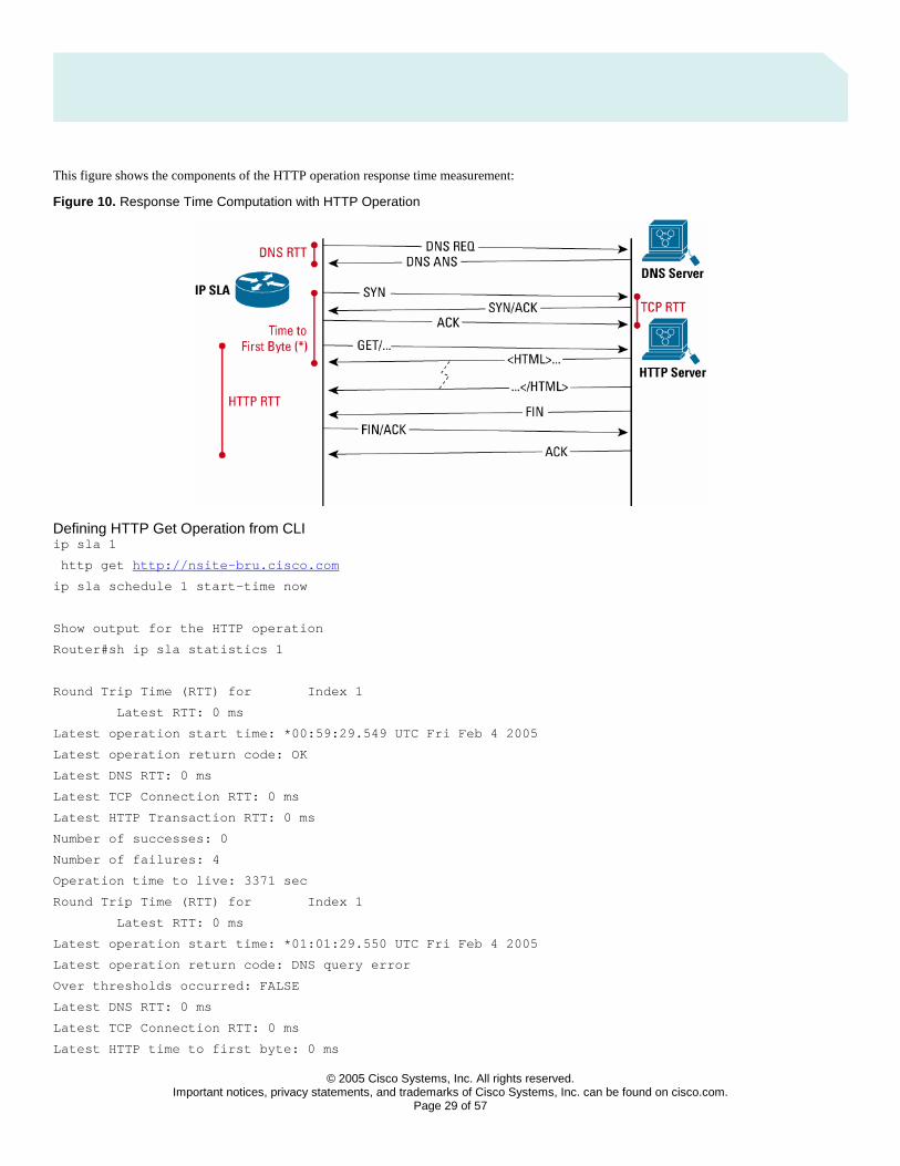
HTTP Operation
The HTTP Operation measures the Round Trip Time (RTT) taken to connect and access data from a HTTP server. The HTTP server response time
measurement is split into three different steps:
• RTT taken to perform domain name lookup
• RTT taken to perform a TCP connect to the HTTP Server
• RTT taken to send a request and get a response back from the HTTP Server (the operation retrieves the object spec¬ified by the URL)
HTTP supports three types of operations: GET and RAW and first byte:
• GET request - Cisco IOS IP SLAs will format the request based on the URL specified
• RAW mode the user controlling this operation is responsible for specifying the entire content of the HTTP request. This gives ultimate flexibility for user to control fields such as authentication. Cisco IOS IP SLAs will send the HTTP request, receive the reply, and report RTT statistics as well as the size of the object returned.
• RTT time to get the first byte of a specified URL
© 2005 Cisco Systems, Inc. All rights reserved.
Important notices, privacy statements, and trademarks of Cisco Systems, Inc. can be found on cisco.com. Page 29 of 57
This figure shows the components of the HTTP operation response time measurement:
Figure 10. Response Time Computation with HTTP Operation
Defining HTTP Get Operation from CLI ip sla 1
http get http://nsite-bru.cisco.com
ip sla schedule 1 start-time now
Show output for the HTTP operation
Router#sh ip sla statistics 1
Round Trip Time (RTT) for Index 1
Latest RTT: 0 ms
Latest operation start time: *00:59:29.549 UTC Fri Feb 4 2005
Latest operation return code: OK
Latest DNS RTT: 0 ms
Latest TCP Connection RTT: 0 ms
Latest HTTP Transaction RTT: 0 ms
Number of successes: 0
Number of failures: 4
Operation time to live: 3371 sec
Round Trip Time (RTT) for Index 1
Latest RTT: 0 ms
Latest operation start time: *01:01:29.550 UTC Fri Feb 4 2005
Latest operation return code: DNS query error
Over thresholds occurred: FALSE
Latest DNS RTT: 0 ms
Latest TCP Connection RTT: 0 ms
Latest HTTP time to first byte: 0 ms
© 2005 Cisco Systems, Inc. All rights reserved.
Important notices, privacy statements, and trademarks of Cisco Systems, Inc. can be found on cisco.com. Page 30 of 57
Latest HTTP Transaction RTT: 0 ms
Latest HTTP Status: 0
Latest HTTP Message Size: 0
Latest HTTP Entity-Body size: 0
Number of successes: 0
Number of failures: 6
Operation time to live: 3265 sec
Operational state of entry: Active
Last time this entry was reset: Never
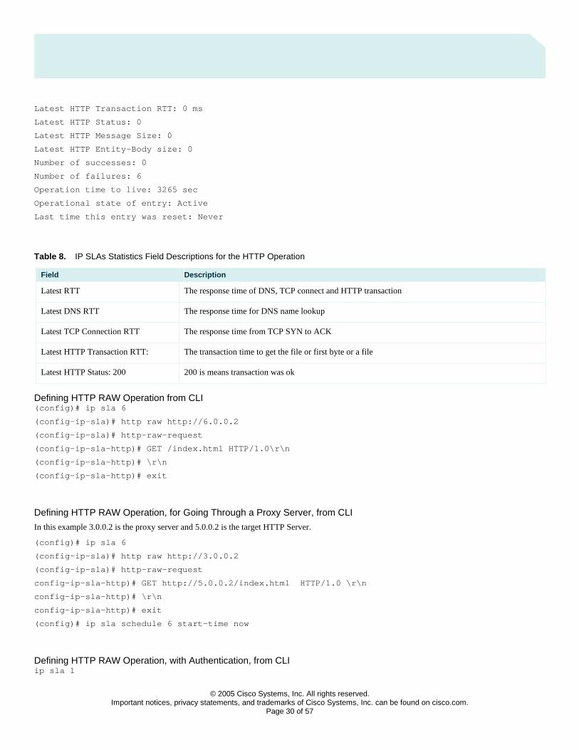
Table 8. IP SLAs Statistics Field Descriptions for the HTTP Operation
Field Description
Latest RTT The response time of DNS, TCP connect and HTTP transaction
Latest DNS RTT The response time for DNS name lookup
Latest TCP Connection RTT The response time from TCP SYN to ACK
Latest HTTP Transaction RTT: The transaction time to get the file or first byte or a file
Latest HTTP Status: 200 200 is means transaction was ok
Defining HTTP RAW Operation from CLI (config)# ip sla 6
(config-ip-sla)# http raw http://6.0.0.2
(config-ip-sla)# http-raw-request
(config-ip-sla-http)# GET /index.html HTTP/1.0\r\n
(config-ip-sla-http)# \r\n
(config-ip-sla-http)# exit
Defining HTTP RAW Operation, for Going Through a Proxy Server, from CLI
In this example 3.0.0.2 is the proxy server and 5.0.0.2 is the target HTTP Server.
(config)# ip sla 6
(config-ip-sla)# http raw http://3.0.0.2
(config-ip-sla)# http-raw-request
config-ip-sla-http)# GET http://5.0.0.2/index.html HTTP/1.0 \r\n
config-ip-sla-http)# \r\n
config-ip-sla-http)# exit
(config)# ip sla schedule 6 start-time now
Defining HTTP RAW Operation, with Authentication, from CLI ip sla 1

© 2005 Cisco Systems, Inc. All rights reserved.
Important notices, privacy statements, and trademarks of Cisco Systems, Inc. can be found on cisco.com. Page 31 of 57
http raw \
http://nsite-bru.cisco.com
http-raw-request
GET /lab/index.html HTTP/1.0\r\n
Authorization: Basic btNpdGT4biNvoZe=\r\n
\r\n
exit
ip sla schedule 1 start-time now
Dynamic Host Configuration Protocol (DHCP) Operation
The Cisco IOS IP SLA Dynamic Host Configuration Protocol (DHCP) operation measures the round trip time taken to discover a DHCP Server and
obtain a lease from it. Cisco IOS IP SLA releases the leased IP address after the operation.
There are two modes for the DHCP Operation. By default, the DHCP operation sends discovery packets on every available IP interface on the router.
However, if a specific server [(config)# ip dhcp-server <server-ip>] is configured on the router, discovery packets are sent only to that DHCP server.
Data Link Switching (DLSw) Operation
Data Link Switching Plus (DLSw+) is the enhanced Cisco version of RFC1795. DLSw+ tunnels Systems Network Architecture (SNA) traffic
over IP backbones via TCP. The routers performing the tunneling of SNA traffic into TCP/IP are referred to as DLSw peers.
The Cisco IOS IP SLA DLSw+ operation measures the DLSw+ protocol stack and network response time between DLSw peers. DLSw peers
normally communicate through TCP port 2065. The endpoint does not have to be a Cisco router if it supports RFC1795.
A prerequisite to successfully running the Cisco IOS IP SLA DLSw+ operation is to have a connected DLSw+ peer between the source and
destination Cisco devices. On the source DLSw+ device, an operation can be defined for a DLSw+ partner peer. The peer (target router) does
not have to run a Cisco IOS IP SLA-capable image.
File Transfer Protocol (FTP) Get Operation (Supported in Cisco IOS Software Release 12.1(1)T)
File Transfer Protocol (FTP) carries a significant amount of traffic. The purpose of FTP throughput operation is to measure the time it takes to
transfer a file from a remote host to the Cisco router. This operation will be very useful in characterizing the capacity of a network. The capability
only works with FTP get to measure response time for the download.
Defining HTTP FTP get operation CLI with absolute path. Get the file /home/user/test.cap ip sla 1
ftp get ftp://user:[email protected]/test.cap
ip sla schedule 1 start-time now
Defining HTTP FTP get operation CLI with relative path. Get the file /test.cap ip sla 1
ftp get ftp://user:[email protected]//test.cap
ip sla schedule 1 start-time now
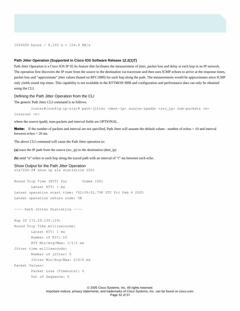
How to Calculate Bandwidth Utilized for FTP Operation
The download bandwidth can be calculated using bytes read and Latest RTT:
© 2005 Cisco Systems, Inc. All rights reserved.
Important notices, privacy statements, and trademarks of Cisco Systems, Inc. can be found on cisco.com. Page 32 of 57
1024000 bytes / 8.193 s = 124.9 KB/s
Path Jitter Operation (Supported in Cisco IOS Software Release 12.2(1)T)
Path Jitter Operation is a Cisco IOS IP SLAs feature that facilitates the measurement of jitter, packet loss and delay at each hop in an IP network.
The operation first discovers the IP route from the source to the destination via traceroute and then uses ICMP echoes to arrive at the response times,
packet loss and “approximate” jitter values (based on RFC1889) for each hop along the path. The measurements would be approximates since ICMP
only yields round trip times. This capability is not available in the RTTMON MIB and configuration and performance data can only be obtained
using the CLI.
Defining the Path Jitter Operation from the CLI
The generic Path Jitter CLI command is as follows:
router#(config-ip-sla)# path-jitter <dest-ip> source-ipaddr <src_ip> num-packets <n>
interval <t>
where the source-ipadd, num-packets and interval fields are OPTIONAL.
Note: If the number of packets and interval are not specified, Path Jitter will assume the default values - number of echos = 10 and interval between echos = 20 ms.
The above CLI command will cause the Path Jitter operation to:
(a) trace the IP path from the source (src_ip) to the destination (dest_ip)
(b) send “n” echos to each hop along the traced path with an interval of “t” ms between each echo.
Show Output for the Path Jitter Operation sla7206-2# show ip sla statistics 1001
Round Trip Time (RTT) for Index 1001
Latest RTT: 1 ms
Latest operation start time: *02:09:52.798 UTC Fri Feb 4 2005
Latest operation return code: OK
---- Path Jitter Statistics ----
Hop IP 172.29.139.129:
Round Trip Time milliseconds:
Latest RTT: 1 ms
Number of RTT: 10
RTT Min/Avg/Max: 1/1/1 ms
Jitter time milliseconds:
Number of jitter: 0
Jitter Min/Avg/Max: 0/0/0 ms
Packet Values:
Packet Loss (Timeouts): 0
Out of Sequence: 0
© 2005 Cisco Systems, Inc. All rights reserved.
Important notices, privacy statements, and trademarks of Cisco Systems, Inc. can be found on cisco.com. Page 33 of 57
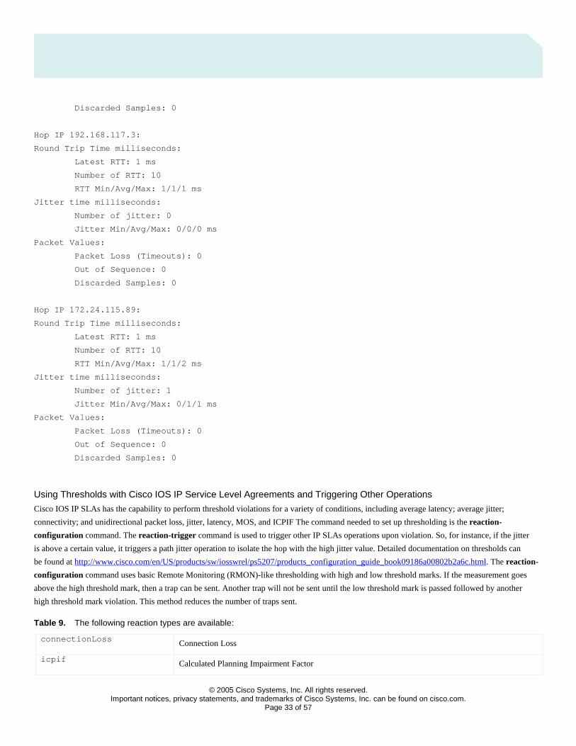
Discarded Samples: 0
Hop IP 192.168.117.3:
Round Trip Time milliseconds:
Latest RTT: 1 ms
Number of RTT: 10
RTT Min/Avg/Max: 1/1/1 ms
Jitter time milliseconds:
Number of jitter: 0
Jitter Min/Avg/Max: 0/0/0 ms
Packet Values:
Packet Loss (Timeouts): 0
Out of Sequence: 0
Discarded Samples: 0
Hop IP 172.24.115.89:
Round Trip Time milliseconds:
Latest RTT: 1 ms
Number of RTT: 10
RTT Min/Avg/Max: 1/1/2 ms
Jitter time milliseconds:
Number of jitter: 1
Jitter Min/Avg/Max: 0/1/1 ms
Packet Values:
Packet Loss (Timeouts): 0
Out of Sequence: 0
Discarded Samples: 0
Using Thresholds with Cisco IOS IP Service Level Agreements and Triggering Other Operations
Cisco IOS IP SLAs has the capability to perform threshold violations for a variety of conditions, including average latency; average jitter;
connectivity; and unidirectional packet loss, jitter, latency, MOS, and ICPIF The command needed to set up thresholding is the reaction-
configuration command. The reaction-trigger command is used to trigger other IP SLAs operations upon violation. So, for instance, if the jitter
is above a certain value, it triggers a path jitter operation to isolate the hop with the high jitter value. Detailed documentation on thresholds can
be found at http://www.cisco.com/en/US/products/sw/iosswrel/ps5207/products_configuration_guide_book09186a00802b2a6c.html. The reaction-
configuration command uses basic Remote Monitoring (RMON)-like thresholding with high and low threshold marks. If the measurement goes
above the high threshold mark, then a trap can be sent. Another trap will not be sent until the low threshold mark is passed followed by another
high threshold mark violation. This method reduces the number of traps sent.
Table 9. The following reaction types are available:
connectionLoss Connection Loss
icpif Calculated Planning Impairment Factor

© 2005 Cisco Systems, Inc. All rights reserved.
Important notices, privacy statements, and trademarks of Cisco Systems, Inc. can be found on cisco.com. Page 34 of 57
jitterAvg Jitter Average in both the directions
jitterDSAvg Jitter Average in the direction from Destination to Source
jitterSDAvg Jitter Average in the direction from Source to Destination
maxOfNegativeDS Maximum negative jitter from Destination to Source
maxOfNegativeSD Maximum negative jitter from Source to Destination
maxOfPositiveDS Maximum positive jitter from Destination to Source
maxOfPositiveSD Maximum positive jitter from Source to Destination
mos MOS Score
packetLateArrival Packets arriving Late
packetLossDS Packet Loss in the direction from Destination to Source
packetLossSD Packet Loss in the direction from Source to Destination
packetMIA Missing In Action
packetOutOfSequence Packets arriving out of sequence
rtt Round Trip Time
timeout timeout
verifyError Verify Error
Table 10. The following actions are possible upon a threshold violation:
None No action
trapAndTrigger Trap and Trigger action
trapOnly Trap Only action
triggerOnly Trigger Only action
Table 11. The following types of threshold violations are available. So, for instance, if N consecutive timeouts occur, Cisco IOS IP SLAs may send a trap.
average Average over N attempts
consecutive Consecutive occurrences
immediate React immediately
never Never react

© 2005 Cisco Systems, Inc. All rights reserved.
Important notices, privacy statements, and trademarks of Cisco Systems, Inc. can be found on cisco.com. Page 35 of 57
xOfy X out of Y occurrences
The following is a basic reaction configuration and trigger CLI example. In this example, upon a connection loss, operation 1 will trap and trigger
operation 2. Operation 1 is a jitter measurement, and operation 2 is an ICMP echo measurement. The ICMP echo lifetime is set to 60 seconds, so
after the connection loss the ICMP will test latency to the endpoint for 60 seconds and stop. The ICMP echo operation will activate every 5 seconds
and trap if there is still no connectivity.
ip sla 1
udp-jitter 1.0.1.2 5555 num-packets 5
ip sla schedule 1 life forever start-time now
ip sla reaction-configuration 1 connection-loss-enable action-type
trapAndTrigger
ip sla reaction-trigger 1 2
ip sla 2
icmp-echo 1.0.1.2
frequency 5
threshold 200
ip sla schedule 2 life 60 start-time pending
ip sla reaction-configuration 2 timeout-enable action-type trapOnly
These are the traps generated:
When there is a failure on jitter (connection loss):
01:55:41: SNMP: V1 Trap, ent rttMonNotificationsPrefix, addr 1.0.1.1,
gentrap 6, spectrap 1
rttMonCtrlAdminTag.1 =
rttMonHistoryCollectionAddress.1 = 01 00 01 02
rttMonCtrlOperConnectionLostOccurred.1 = 1
At this point, you know something might be wrong: jitter operation fails. We send the trap and trigger ICMP.
When ICMP fails:
02:15:18: SNMP: V1 Trap, ent rttMonNotificationsPrefix, addr 1.0.1.1,
gentrap 6, spectrap 2
rttMonCtrlAdminTag.2 =
rttMonHistoryCollectionAddress.2 = 01 00 01 02
rttMonCtrlOperTimeoutOccurred.2 = 1

© 2005 Cisco Systems, Inc. All rights reserved.
Important notices, privacy statements, and trademarks of Cisco Systems, Inc. can be found on cisco.com. Page 36 of 57
At this one, ICMP fails again.
If ICMP is restored in the next 60 seconds, before its expiration:
02:15:58: SNMP: V1 Trap, ent rttMonNotificationsPrefix, addr 1.0.1.1,
gentrap 6, spectrap 2
rttMonCtrlAdminTag.2 =
rttMonHistoryCollectionAddress.2 = 01 00 01 02
rttMonCtrlOperTimeoutOccurred.2 = 2
The ICMP operation will attempt again every 5 seconds during the next 60 seconds. If the network connectivity is restored during that period of
time, IP SLAs will send a trap upon restoration. If not, you will not receive anything because you have already received the previous trap, which
said that timeout happens on ICMP.
When there is service restoration on the jitter operation:
01:56:26: SNMP: V1 Trap, ent rttMonNotificationsPrefix, addr 1.0.1.1,
gentrap 6, spectrap 1
rttMonCtrlAdminTag.1 =
rttMonHistoryCollectionAddress.1 = 01 00 01 02
rttMonCtrlOperConnectionLostOccurred.1 = 2
The following is a CLI example configuration including one-way traps available in Cisco IOS Software Release 12.3(7)T and codec simulation
available in Cisco IOS Software Release 12.3(4)T:
logging on
ip sla 10
udp-jitter 209.165.200.225 16384 codec g711alaw advantage-factor 2
owner admin
tag jitter-with-voice-scores
ip sla schedule 10 start-time now
ip sla reaction-configuration 10 react mos threshold-type immediate threshold-value 490 250
action-type trapOnly
ip sla logging traps
The above example will send a syslog message immediately when the threshold value upper limit of 490 is reached. The lower limit is 250. Mos is
multiplied by 100 in this case, so 490 is really a MOS of 4.9, and 250 is a MOS of 2.5. The reason for the multiplier on MOS is because the MIB
values cannot be decimals. If the MIB is polled, a value of MOS multiplied by 100 is returned. Later in the document is an example of reaction-
trigger when one operation’s threshold violation triggers another.
snmp-server host 10.10.10.10 version 2c public
snmp-server enable traps syslog
The traps in Cisco IOS Software Release 12.3(7)T are actually syslog-to-traps conversion and therefore require the logging CLI. In the
release of Cisco IOS Software Release 12.4T in late spring 2005, pure SNMP traps will be used instead of the syslog-to-trap conversion.
© 2005 Cisco Systems, Inc. All rights reserved.
Important notices, privacy statements, and trademarks of Cisco Systems, Inc. can be found on cisco.com. Page 37 of 57
How to search for IP SLAs features in IOS releases
Use Cisco Feature Navigator to search by full or partial feature name under “IP SLA”: http://tools.cisco.com/ITDIT/CFN/jsp/index.jsp
For more information please refer to specific Cisco IOS Software documentation: http://www.cisco.com/go/ipsla
Platform Support for Cisco IOS IP Service Level Agreements
Cisco IOS IP SLAs are supported in nearly all Cisco IOS Software images, other than IP Lite for the old IOS feature sets. Cisco IOS Packaging,
which is available beginning in Release 12.3, makes Cisco IOS IP SLAs available in all packages other than IP Base. IP Base will contain Cisco
IOS IP SLAs responder and the ICMP operation in Release 12.4T.
With the exception of the Cisco Catalyst 4500 Series, all Cisco hardware that supports Cisco IOS Software supports Cisco IOS IP SLA.
Infrastructure Changes in Cisco IOS IP Service Level Agreements
A new software infrastructure, or architecture, was introduced recently in Cisco IOS IP SLAs. Infrastructure II was introduced into Releases
12.2(15)T2, 12.3(3), and 12.2S(25).
Cisco made significant changes to increase the performance and decrease the memory footprint of Cisco IOS IP SLAs. Other improvements
included accuracy enhancements and NTP based granular timestamps in Release 12.3(7)T2. The accuracy enhancements in Release 12.3(7)T2
were focused on the jitter operation.
Infrastructure II includes the following:
• User can configure an unlimited number of Cisco IOS IP SLAs operations in Releases 12.3(3) and above. The only limitation is CPU and memory. The original infrastructure had a 2000 operation limit after Release 12.2(11)T, while previous Cisco IOS Software releases had a 500 operation limit.
• Memory footprint for Cisco IOS IP SLAs operations was reduced by about fifty percent. A later section in this document discusses memory requirements.
• New architecture uses one Cisco IOS Software process while the original infrastructure used a process per operation configured.
The Cisco IOS IP Service Level Agreements RTTM on MIB
General MIB Information
The Cisco Response Time Monitor MIB (Cisco-RTTMON-MIB.my) is the MIB used for IP SLAs. The only Cisco IOS IP SLAs operations
that are not supported are Frame relay, Path Jitter, and ATM operations.
References:
• Lists of supported MIBs by hardware and Cisco IOS Software release, and MIB modules:
http://www.cisco.com/public/sw-center/netmgmt/cmtk/mibs.shtml
• Cisco IOS MIB Tools: http://tools.cisco.com/ITDIT/MIBS/servlet/index
• SNMP Object Navigator (requires Cisco.com account): http://www.cisco.com/cgi-bin/Support/Mibbrowser/unity.pl
Creating Operations with the RTTMON MIB
There are two ways to create Cisco IOS IP SLAs operations with SNMP: createAndGo operation and createAndWait operation. Each operation
has a specific set of variables that need to be defined before it can be operational. The following variables will be specified in this order:
set rttMonCtrlAdminStatus
set rttMonCtrlAdminRttType
set rttMonEchoAdminProtocol
© 2005 Cisco Systems, Inc. All rights reserved.
Important notices, privacy statements, and trademarks of Cisco Systems, Inc. can be found on cisco.com. Page 38 of 57
set rest of the configuration variables
Additionally each operation requires specific variables to be set before it can be activated. The following is a comprehensive list of variables
based on operation type:
1. For echo, pathEcho and dlsw operations
rttMonEchoAdminTargetAddress
2. For udpEcho, tcpConnect and jitter operations
rttMonEchoAdminTargetAddress
rttMonEchoAdminTargetPort
3. For http operation
rttMonEchoAdminURL
4. For dns operation
rttMonEchoAdminTargetAddressString
rttMonEchoAdminNameServer
5. DHCP operation doesn’t require any additional variables.
Echo Operation Example
An LSR path can be specified to compute the response time for a specific path. The Source Address on the Source Router is also specified,
and the operation is scheduled to run forever.
rttMonCtrlAdminStatus.<index> -Integer 4 \
rttMonCtrlAdminRttType.<index> -Integer 1 \
rttMonEchoAdminProtocol.<index> -Integer 2 \
rttMonEchoAdminTargetAddress.<index> -OctetString “04 00 00 01” \
rttMonEchoAdminSourceAddress.<index> -OctetString “01 00 00 01” \
rttMonEchoPathAdminHopAddress.<index>.1 -OctetString “02 00 00 01” \
rttMonEchoPathAdminHopAddress.<index>.2 -OctetString “03 00 00 01” \
rttMonScheduleAdminRttStartTime.<index> -TimeTicks 1 \
rttMonScheduleAdminRttLife.<index> -Integer 2147483647
Path Echo Operation Example rttMonCtrlAdminStatus.<index> -Integer 4 \
rttMonCtrlAdminRttType.<index> -Integer 2 \
rttMonEchoAdminProtocol.<index> -Integer 2 \
rttMonEchoAdminTargetAddress.<index> -OctetString “05 00 00 02” \
rttMonScheduleAdminRttStartTime.<index> -TimeTicks 1 \
rttMonScheduleAdminConceptRowAgeout.<index> -Integer 0
© 2005 Cisco Systems, Inc. All rights reserved.
Important notices, privacy statements, and trademarks of Cisco Systems, Inc. can be found on cisco.com. Page 39 of 57
UDP Operation Example
The UDP operation computes response time to communicate with a responder running on a Cisco router using port number 4444.
The DSCP bits specify QoS metrics on the network.
rttMonCtrlAdminStatus.<index> -Integer 4 \
rttMonCtrlAdminRttType.<index> -Integer 5 \
rttMonEchoAdminProtocol.<index> -Integer 3 \
rttMonEchoAdminTargetAddress.<index> -OctetString “05 00 00 02” \
rttMonEchoAdminTargetPort.<index> -Integer 4444 \
rttMonEchoAdminTOS.<index> -Integer 5 \
rttMonScheduleAdminRttStartTime.<index> -TimeTicks 1
TCP Operation Example
The TCP operation computes response time to communicate with a host using the well-known HTTP Server port number. Note that the Control
Protocol is disabled, so a well-known port will be used, rather than a responder.
rttMonCtrlAdminStatus.<index> -Integer 4 \
rttMonCtrlAdminRttType.<index> -Integer 6 \
rttMonEchoAdminProtocol.<index> -Integer 24 \
rttMonEchoAdminTargetAddress.<index> -OctetString “05 00 00 02” \
rttMonEchoAdminTargetPort.<index> -Integer 80 \
rttMonEchoAdminControlEnable.<index> -Integer 2 \
rttMonScheduleAdminRttStartTime.<index> -TimeTicks 1
Jitter Operation Example rttMonCtrlAdminStatus.<index> -Integer 4 \
rttMonCtrlAdminRttType.<index> -Integer 9 \
rttMonEchoAdminProtocol.<index> -Integer 27 \
rttMonEchoAdminTargetAddress.<index> -OctetString “05 00 00 02” \
rttMonEchoAdminTargetPort.<index> -Integer 8000 \
rttMonEchoAdminInterval.<index> -Integer 20 \
rttMonEchoAdminNumPackets.<index> -Integer 100 \
rttMonScheduleAdminRttStartTime.<index> -TimeTicks 1
Simple (GET operation) HTTP Operation Example rttMonCtrlAdminStatus.<index> -Integer 4 \
rttMonCtrlAdminRttType.<index> -Integer 7 \
rttMonEchoAdminProtocol.<index> -Integer 25 \
rttMonEchoAdminOperation.<index> -Integer 1 \
rttMonEchoAdminURL.<index> -DisplayString “http://www.cisco.com:80/index.html” \
rttMonEchoAdminHTTPVersion.<index> -DisplayString “1.0” \
rttMonEchoAdminCache.<index> -Integer 2 \
rttMonScheduleAdminRttStartTime.<index> -TimeTicks 1
© 2005 Cisco Systems, Inc. All rights reserved.
Important notices, privacy statements, and trademarks of Cisco Systems, Inc. can be found on cisco.com. Page 40 of 57
Complex (RAW operation) HTTP Operation Example rttMonCtrlAdminStatus.<index> -Integer 4 \
rttMonCtrlAdminRttType.<index> -Integer 7 \
rttMonEchoAdminProtocol.<index> -Integer 25 \
rttMonEchoAdminOperation.<index> -Integer 2 \
rttMonEchoAdminURL.<index> -DisplayString “http://www.cisco.com” \
rttMonEchoAdminString1.<index> -DisplayString “GET /index.html HTTP/1.0\r\n\r\n” \
rttMonEchoAdminNameServer.<index> -OctetString “01 05 07 09” \
rttMonScheduleAdminRttStartTime.<index> -TimeTicks 1
Defining HTTP Operation, for going though a Proxy Server using Authentication example with SNMP rttMonCtrlAdminRttType.1 = 7
rttMonEchoAdminProtocol.1 = 25
rttMonEchoAdminOperation.1 = 2
rttMonScheduleAdminRttStartTime.1 = 1
rttMonEchoAdminURL.1 = http://kick
rttMonEchoAdminString1.1 = GET / HTTP/1.0\r\n
rttMonEchoAdminString2.1 = Authorization: Basic aXBtOmNpc2Nv\r\n
rttMonCtrlAdminStatus.1 = 4
An example using the snmpSet command would be:
snmpset -v2c -c public 10.52.132.69 \
.1.3.6.1.4.1.9.9.42.1.2.1.1.4.1 i 7 \
.1.3.6.1.4.1.9.9.42.1.2.2.1.1.1 i 25 \
.1.3.6.1.4.1.9.9.42.1.2.2.1.13.1 i 2 \
.1.3.6.1.4.1.9.9.42.1.2.5.1.2.1 t 1 \
.1.3.6.1.4.1.9.9.42.1.2.2.1.15.1 s “http://kick” \
.1.3.6.1.4.1.9.9.42.1.2.2.1.20.1 s “GET / HTTP/1.0\r\n” \
.1.3.6.1.4.1.9.9.42.1.2.2.1.21.1 s “Authorization: Basic” \
aXBtOmNpc2Nv\r\n” \
.1.3.6.1.4.1.9.9.42.1.2.1.1.9.1 i 4
DNS Operation Example rttMonCtrlAdminStatus.<index> -Integer 4 \
rttMonCtrlAdminRttType.<index> -Integer 8 \
rttMonEchoAdminProtocol.<index> -Integer 26 \
rttMonEchoAdminTargetAddressString.<index> -DisplayString “www.cisco.com” \
rttMonEchoAdminNameServer.<index> -OctetString “11 05 07 09” \
rttMonScheduleAdminRttStartTime.<index> -TimeTicks 1
19.2.10 DLSw Operation Example
rttMonCtrlAdminStatus.<index> -Integer 4 \
rttMonCtrlAdminRttType.<index> -Integer 10 \
rttMonEchoAdminProtocol.<index> -Integer 28 \

© 2005 Cisco Systems, Inc. All rights reserved.
Important notices, privacy statements, and trademarks of Cisco Systems, Inc. can be found on cisco.com. Page 41 of 57
rttMonEchoAdminTargetAddress.<index> -OctetString “05 00 00 02” \
rttMonScheduleAdminRttStartTime.<index> -TimeTicks 1
DHCP Operation Example rttMonCtrlAdminStatus.<index> -Integer 4 \
rttMonCtrlAdminRttType.<index> -Integer 11 \
rttMonEchoAdminProtocol.<index> -Integer 29
rttMonScheduleAdminRttStartTime.<index> -TimeTicks 1
FTP Operation Example rttMonCtrlAdminStatus.<index> -Integer 4 \
rttMonCtrlAdminRttType.<index> -Integer 12 \
rttMonEchoAdminProtocol.<index> -Integer 30 \
rttMonEchoAdminOperation.<index> -Integer 3 \
rttMonEchoAdminURL.<index> -DisplayString “ftp://anonymous@test:www.cisco.com/temp/temp.txt” \
rttMonScheduleAdminRttStartTime.<index> -TimeTicks 1
Starting Cisco IOS IP Service Level Agreements Responder Using SNMP (Available in Cisco IOS Software Release 12.1(1)T and Above) rttMonApplResponder.0 -Integer 1
Configuring MD5 Authentication for Control Protocol Using SNMP
Currently only one authentication table can be created in Cisco IOS IP SLAs.
rttMonApplAuthStatus.<index> -Integer 4 \
rttMonApplAuthKeyChain.<index> -DisplayString “text” \
rttMonApplAuthKeyString1.<index> -DisplayString “string” \
rttMonApplAuthKeyString2.<index> -DisplayString “string”
The key chain is automatically tied to Cisco IOS IP SLAs once the table is created. Once the table is created, key chain and key strings cannot
be deleted. The complete table has to be deleted.
Modifying Configuration Parameters When an Operation is Running
Operation configuration parameters cannot be changed while the operation is running, because configuration changes affect data storage.
Example: if an operation is configured to poll every sixty seconds, a statsCapture table will store sixty samples in an hour. However, if the
polling interval is changed while the operation is still running, the statsCapture data aggregation becomes corrupted.
Here is how an active operation’s config can be changed using SNMP:
set rttMonCtrlOperState to immediateStop (3)
set rttMonCtrlAdminStatus to notInService (2)
set required variables
set rttMonCtrlAdminStatus to Active (1)
Accessing Cisco IOS IP SLAs Data using SNMP
The results of Cisco IOS IP SLAs operation are stored in different tables. Here is a list of table that the data is stored for each Cisco IOS IP
SLA Operation.
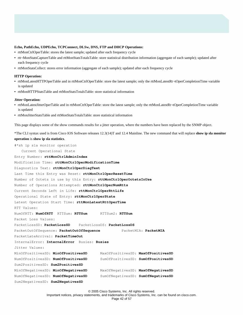
© 2005 Cisco Systems, Inc. All rights reserved.
Important notices, privacy statements, and trademarks of Cisco Systems, Inc. can be found on cisco.com. Page 42 of 57
Echo, PathEcho, UDPEcho, TCPConnect, DLSw, DNS, FTP and DHCP Operations: • rttMonCtrlOperTable: stores the latest sample; updated after each frequency cycle
• rtt¬MonStatsCaptureTable and rttMonStatsTotalsTable: store statistical distribution information (aggregate of each sample); updated after each frequency cycle
• rttMonStatsCollect: stores error information (aggregate of each sample); updated after each frequency cycle
HTTP Operation: • rttMonLatestHTTPOperTable and in rttMonCtrlOperTable: store the latest sample; only the rttMonLatestRt¬tOperCompletionTime variable
is updated
• rttMonHTTPStatsTable and rttMonStatsTotalsTable: store statistical information
Jitter Operation: • rttMonLatestJitterOperTable and in rttMonCtrlOperTable: store the latest sample; only the rttMonLatestRt¬tOperCompletionTime variable
is updated
• rttMonJitterStatsTable and rttMonStatsTotalsTable: store statistical information
This page displays some of the show commands results for a jitter operation, where the numbers have been replaced by the SNMP object.
*The CLI syntax used is from Cisco IOS Software releases 12.3(14)T and 12.4 Mainline. The new command that will replace show ip sla monitor
operation is show ip sla statistics.
#*sh ip sla monitor operation
Current Operational State
Entry Number: rttMonCtrlAdminIndex
Modification Time: rttMonCtrlOperModificationTime
Diagnostics Text: rttMonCtrlOperDiagText
Last Time this Entry was Reset: rttMonCtrlOperResetTime
Number of Octets in use by this Entry: rttMonCtrlOperOctetsInUse
Number of Operations Attempted: rttMonCtrlOperNumRtts
Current Seconds Left in Life: rttMonCtrlOperRttLife
Operational State of Entry: rttMonCtrlOperState
Latest Operation Start Time: rttMonLatestRttOperTime
RTT Values:
NumOfRTT: NumOfRTT RTTSum: RTTSum RTTSum2: RTTSum
Packet Loss Values:
PacketLossSD: PacketLossSD PacketLossDS: PacketLossDS
PacketOutOfSequence: PacketOutOfSequence PacketMIA: PacketMIA
PacketLateArrival: PacketTimeOut
InternalError: InternalError Busies: Busies
Jitter Values:
MinOfPositivesSD: MinOfPositivesSD MaxOfPositivesSD: MaxOfPositivesSD
NumOfPositivesSD: NumOfPositivesSD SumOfPositivesSD: SumOfPositivesSD
Sum2PositivesSD: Sum2PositivesSD
MinOfNegativesSD: MinOfNegativesSD MaxOfNegativesSD: MaxOfNegativesSD
NumOfNegativesSD: NumOfNegativesSD SumOfNegativesSD: SumOfNegativesSD
Sum2NegativesSD: Sum2NegativesSD
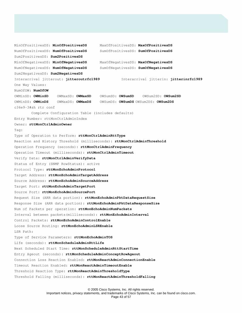
© 2005 Cisco Systems, Inc. All rights reserved.
Important notices, privacy statements, and trademarks of Cisco Systems, Inc. can be found on cisco.com. Page 43 of 57
MinOfPositivesDS: MinOfPositivesDS MaxOfPositivesDS: MaxOfPositivesDS
NumOfPositivesDS: NumOfPositivesDS SumOfPositivesDS: SumOfPositivesDS
Sum2PositivesDS: Sum2PositivesDS
MinOfNegativesDS: MinOfNegativesDS MaxOfNegativesDS: MaxOfNegativesDS
NumOfNegativesDS: NumOfNegativesDS SumOfNegativesDS: SumOfNegativesDS
Sum2NegativesDS: Sum2NegativesDS
Interarrival jitterout: jitteroutrfc1989 Interarrival jitterin: jitterinrfc1989
One Way Values:
NumOfOW: NumOfOW
OWMinSD: OWMinSD OWMaxSD: OWMaxSD OWSumSD: OWSumSD OWSum2SD: OWSum2SD
OWMinDS: OWMinDS OWMaxDS: OWMaxDS OWSumDS: OWSumDS OWSum2DS: OWSum2DS
c36e9-3#sh rtr conf
Complete Configuration Table (includes defaults)
Entry Number: rttMonCtrlAdminIndex
Owner: rttMonCtrlAdminOwner
Tag:
Type of Operation to Perform: rttMonCtrlAdminRttType
Reaction and History Threshold (milliseconds): rttMonCtrlAdminThreshold
Operation Frequency (seconds): rttMonCtrlAdminFrequency
Operation Timeout (milliseconds): rttMonCtrlAdminTimeout
Verify Data: rttMonCtrlAdminVerifyData
Status of Entry (SNMP RowStatus): active
Protocol Type: rttMonEchoAdminProtocol
Target Address: rttMonEchoAdminTargetAddress
Source Address: rttMonEchoAdminSourceAddress
Target Port: rttMonEchoAdminTargetPort
Source Port: rttMonEchoAdminSourcePort
Request Size (ARR data portion): rttMonEchoAdminPktDataRequestSize
Response Size (ARR data portion): rttMonEchoAdminPktDataResponseSize
Num of Packets per operation: rttMonEchoAdminNumPackets
Interval between packets(milliseconds): rttMonEchoAdminInterval
Control Packets: rttMonEchoAdminControlEnable
Loose Source Routing: rttMonEchoAdminLSREnable
LSR Path:
Type of Service Parameters: rttMonEchoAdminTOS
Life (seconds): rttMonScheduleAdminRttLife
Next Scheduled Start Time: rttMonScheduleAdminRttStartTime
Entry Ageout (seconds): rttMonScheduleAdminConceptRowAgeout
Connection Loss Reaction Enabled: rttMonReactAdminConnectionEnable
Timeout Reaction Enabled: rttMonReactAdminTimeoutEnable
Threshold Reaction Type: rttMonReactAdminThresholdType
Threshold Falling (milliseconds): rttMonReactAdminThresholdFalling
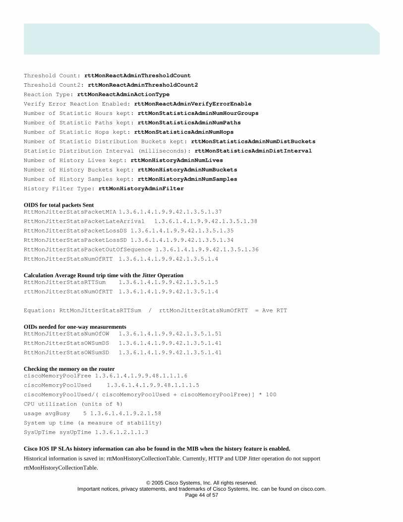
© 2005 Cisco Systems, Inc. All rights reserved.
Important notices, privacy statements, and trademarks of Cisco Systems, Inc. can be found on cisco.com. Page 44 of 57
Threshold Count: rttMonReactAdminThresholdCount
Threshold Count2: rttMonReactAdminThresholdCount2
Reaction Type: rttMonReactAdminActionType
Verify Error Reaction Enabled: rttMonReactAdminVerifyErrorEnable
Number of Statistic Hours kept: rttMonStatisticsAdminNumHourGroups
Number of Statistic Paths kept: rttMonStatisticsAdminNumPaths
Number of Statistic Hops kept: rttMonStatisticsAdminNumHops
Number of Statistic Distribution Buckets kept: rttMonStatisticsAdminNumDistBuckets
Statistic Distribution Interval (milliseconds): rttMonStatisticsAdminDistInterval
Number of History Lives kept: rttMonHistoryAdminNumLives
Number of History Buckets kept: rttMonHistoryAdminNumBuckets
Number of History Samples kept: rttMonHistoryAdminNumSamples
History Filter Type: rttMonHistoryAdminFilter
OIDS for total packets Sent RttMonJitterStatsPacketMIA 1.3.6.1.4.1.9.9.42.1.3.5.1.37
RttMonJitterStatsPacketLateArrival 1.3.6.1.4.1.9.9.42.1.3.5.1.38
RttMonJitterStatsPacketLossDS 1.3.6.1.4.1.9.9.42.1.3.5.1.35
RttMonJitterStatsPacketLossSD 1.3.6.1.4.1.9.9.42.1.3.5.1.34
RttMonJitterStatsPacketOutOfSequence 1.3.6.1.4.1.9.9.42.1.3.5.1.36
RttMonJitterStatsNumOfRTT 1.3.6.1.4.1.9.9.42.1.3.5.1.4
Calculation Average Round trip time with the Jitter Operation RttMonJitterStatsRTTSum 1.3.6.1.4.1.9.9.42.1.3.5.1.5
rttMonJitterStatsNumOfRTT 1.3.6.1.4.1.9.9.42.1.3.5.1.4
Equation: RttMonJitterStatsRTTSum / rttMonJitterStatsNumOfRTT = Ave RTT
OIDs needed for one-way measurements RttMonJitterStatsNumOfOW 1.3.6.1.4.1.9.9.42.1.3.5.1.51
RttMonJitterStatsOWSumDS 1.3.6.1.4.1.9.9.42.1.3.5.1.41
RttMonJitterStatsOWSumSD 1.3.6.1.4.1.9.9.42.1.3.5.1.41
Checking the memory on the router ciscoMemoryPoolFree 1.3.6.1.4.1.9.9.48.1.1.1.6
ciscoMemoryPoolUsed 1.3.6.1.4.1.9.9.48.1.1.1.5
ciscoMemoryPoolUsed/( ciscoMemoryPoolUsed + ciscoMemoryPoolFree)] * 100
CPU utilization (units of %)
usage avgBusy 5 1.3.6.1.4.1.9.2.1.58
System up time (a measure of stability)
SysUpTime sysUpTime 1.3.6.1.2.1.1.3
Cisco IOS IP SLAs history information can also be found in the MIB when the history feature is enabled.
Historical information is saved in: rttMonHistoryCollectionTable. Currently, HTTP and UDP Jitter operation do not support
rttMonHistoryCollectionTable.

© 2005 Cisco Systems, Inc. All rights reserved.
Important notices, privacy statements, and trademarks of Cisco Systems, Inc. can be found on cisco.com. Page 45 of 57
The rttMonAppl table stores all Cisco IOS IP SLAs information, including the number of operations supported by a particular router and the
maximum capacity of that router.
Detailed Calculations Using Cisco IOS IP SLAs CLI and MIB Data
Leveraging the RTTMON-MIB variables and Object Identifiers (OIDs) found in the RTTMON-MIB:
http://www.cisco.com/pcgi-bin/Support/Mibbrowser/mibinfo.pl?mn=CISCO-RTTMON-MIB
The following custom equations can be built:
• Bandwidth
[RttMonEchoAdminNumPackets * (RttMonEchoAdminPktDataRequestSize +12) * 8] / (RttMonCtrlAdminFrequency *1000)
Units – Bits per second (bps)
• Total Packets Sent
[RttMonJitterStatsPacketMIA + RttMonJitterStatsPacketLateArrival + RttMonJitterStatsPacketLossDS + RttMonJitterStatsPacketLossSD +
RttMonJitterStatsPacketOutOfSequence + RttMonJitterStatsNumOfRTT ]
Units – Integer
• Packet Loss Ratio
[(RttMonJitterStatsPacketLossDS + RttMonJitterStatsPacketLossSD + RttMonJitterStatsPacketMIA) * 100 ] / [RttMonJitterStatsPacketLossSD +
RttMonJitterStatsPacketLossDS + RttMonJitterStatsPacketMIA + RttMonJitterStatsPacketLateArrival + RttMonJitterStatsPacketOutOfSequence
+ RttMonJitterStatsNumOfRTT ]
Units – Percentage (%)
• Average Round-Trip Time
RttMonJitterStatsRTTSum / RttMonJitterStatsNumOfRTT
Units – millisecond (ms)
• Average One-Way Delay
Average Delay SD:
RttMonJitterStatsOWSumSD / RttMonJitterStatsNumOfOW

© 2005 Cisco Systems, Inc. All rights reserved.
Important notices, privacy statements, and trademarks of Cisco Systems, Inc. can be found on cisco.com. Page 46 of 57
Average Delay DS:
RttMonJitterStatsOWSumDS / RttMonJitterStatsNumOfOW
Units – millisecond (ms)
• Percentage of Packets that had Positive Jitter
NumOfPositiveSD/NumOfRTT
It estimates how many packets are actually introducing jitter. If a large ratio of the population introduces jitter it might not be a problem as long
as the introduced jitter per packet remains low.
• Average Jitter per Packet that had Positive Jitter
SumOfPositiveSD/NumOfPositiveSD
It gives you an idea on how much jitter is introduced once a positive jitter is experienced. A big jitter increase per packet means a large latency
dynamic in your network which is not good.
• Percentage of Packets that had Negative Jitter
NumOfNegativeSD/NumOfRTT
It is an estimation of how many packets it takes to the network to compensate the jitter. If this is much higher than the percentage of packets that
had positive jitter, it may be a sign that your network is having a hard time to absorb the traffic bursts. Generally speaking they should be within
the same range.
• Average Jitter per Packet that had Negative Jitter
SumOfNegativeSD/NumOfRTT
This values gives an idea on how quick has been the network to compensate a delay increase.
• Average Jitter
DS is destination to source.
SD is source to destination.
jitterSum = sumOfPositiveDS +
sumOfNegativeDS +
sumOfPositiveSD +

© 2005 Cisco Systems, Inc. All rights reserved.
Important notices, privacy statements, and trademarks of Cisco Systems, Inc. can be found on cisco.com. Page 47 of 57
sumOfNegativeSD;
jitterNum =numOfPositiveDS +
numOfNegativeDS +
numOfPositiveSD +
numOfNegativeSD;
avgJitter = jitterSum/jitterNum;
}
Units – millisecond (ms)
• Standard Deviation
The variance is a measure of how spread out a distribution is. It is computed as the average squared deviation of each number from its mean.
The Standard Deviation is calculated as the square root of the variance. If the mean and standard deviation of a normal distribution are known,
it is possible to compute the percentile breakdowns on the spread of data points. In a normal distribution, approximately 68% of the scores are
within one standard deviation of the mean and 95% of the scores are within two standards deviations of the mean.
For RTTMON-MIB when calculating sum of the squares objects then two 32-bit OIDS are required to support the possible generation of large
numbers. If the Object name is “High” then it is a multiple of 2^32.
Round-Trip Time Standard Deviation:
Square Root of [ ((RttMonJitterStatsRTTSum2High * 2^32 + RttMonJitterStatsRTTSum2Low) / RttMonJitterStatsNumOfRTT) –
(RttMonJitterStatsRTTSum / RttMonJitterStatsNumOfRTT)^2 ]
Units – millisecond (ms)
One-Way Delay Source to Destination Standard Deviation:
Square Root of [ ((RttMonJitterStatsOWSum2SDHigh * 2^32 + RttMonJitterStatsOWSum2SDLow) / RttMonJitterStatsNumOfOW) –
(RttMonJitterStatsOWSumSD / RttMonJitterStatsNumOfOW)^2 ]
Units – millisecond (ms)
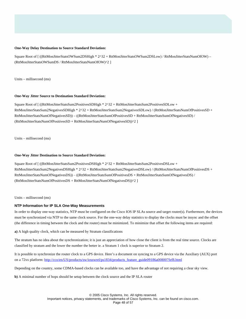
© 2005 Cisco Systems, Inc. All rights reserved.
Important notices, privacy statements, and trademarks of Cisco Systems, Inc. can be found on cisco.com. Page 48 of 57
One-Way Delay Destination to Source Standard Deviation:
Square Root of [ ((RttMonJitterStatsOWSum2DSHigh * 2^32 + RttMonJitterStatsOWSum2DSLow) / RttMonJitterStatsNumOfOW) –
(RttMonJitterStatsOWSumDS / RttMonJitterStatsNumOfOW)^2 ]
Units – millisecond (ms)
One-Way Jitter Source to Destination Standard Deviation:
Square Root of [ ((RttMonJitterStatsSum2PositivesSDHigh * 2^32 + RttMonJitterStatsSum2PositivesSDLow +
RttMonJitterStatsSum2NegativesSDHigh * 2^32 + RttMonJitterStatsSum2NegativesSDLow) / (RttMonJitterStatsNumOfPositivesSD +
RttMonJitterStatsNumOfNegativesSD)) – ((RttMonJitterStatsSumOfPositivesSD + RttMonJitterStatsSumOfNegativesSD) /
(RttMonJitterStatsNumOfPositivesSD + RttMonJitterStatsNumOfNegativesSD))^2 ]
Units – millisecond (ms)
One-Way Jitter Destination to Source Standard Deviation:
Square Root of [ ((RttMonJitterStatsSum2PositivesDSHigh * 2^32 + RttMonJitterStatsSum2PositivesDSLow +
RttMonJitterStatsSum2NegativesDSHigh * 2^32 + RttMonJitterStatsSum2NegativesDSLow) / (RttMonJitterStatsNumOfPositivesDS +
RttMonJitterStatsNumOfNegativesDS)) – ((RttMonJitterStatsSumOfPositivesDS + RttMonJitterStatsSumOfNegativesDS) /
(RttMonJitterStatsNumOfPositivesDS + RttMonJitterStatsNumOfNegativesDS))^2 ]
Units – millisecond (ms)
NTP Information for IP SLA One-Way Measurements
In order to display one-way statistics, NTP must be configured on the Cisco IOS IP SLAs source and target router(s). Furthermore, the devices
must be synchronized via NTP to the same clock source. For the one-way delay statistics to display the clocks must be insync and the offset
(the difference in timing between the clock and the router) must be minimized. To minimize that offset the following items are required:
a) A high quality clock, which can be measured by Stratum classifications
The stratum has no idea about the synchronization; it is just an appreciation of how close the client is from the real time source. Clocks are
classified by stratum and the lower the number the better ie. a Stratum 1 clock is superior to Stratum 2.
It is possible to synchronize the router clock to a GPS device. Here’s a document on syncing to a GPS device via the Auxiliary (AUX) port
on a 72xx platform: http://cco/en/US/products/sw/iosswrel/ps1834/products_feature_guide09186a008007fef8.html
Depending on the country, some CDMA-based clocks can be available too, and have the advantage of not requiring a clear sky view.
b) A minimal number of hops should be setup between the clock source and the IP SLA router
© 2005 Cisco Systems, Inc. All rights reserved.
Important notices, privacy statements, and trademarks of Cisco Systems, Inc. can be found on cisco.com. Page 49 of 57
• If Cisco IOS IP SLAs routers is too many hops away from the NTP server, users can deploy one stratum 1 NTP server at each site, and each Cisco IOS IP SLAs directly synchronizes to its local stratum 1 server.
• If this still is not possible, users can let each Cisco IOS IP SLAs sync to its local stratum 2 server. Because the synchronization of the two Cisco IOS IP SLAs clocks is important, the Cisco IOS IP SLAs 1 can sync to an NTP server and Cisco IOS IP SLAs 2 sync to Cisco IOS IP SLAs 1.
• Two Cisco IOS IP SLAs routers can sync to their NTP server(s) in client/server mode and at the same time two Cisco IOS IP SLAs routers sync to each other in symmetric mode. In client/server mode, client is sync’d to server in one way. In symmetric mode, a peer is willing to synchronize and be synchronized by the peer.
c) A high speed interface(s)/line(s) between the clock source and the IP SLAs router is recommended NTP over a WAN link can gain inaccuracies
of 5 to 250 milliseconds, depending of the network’s characteristics. Therefore, it is critical to reduce the NTP offset between IP SLAs source and
target routers. For example, if the IP SLA source router is 10 milliseconds faster than the NTP server and IP SLAs target router is 10 milliseconds
slower than the NTP server, the offset between IP SLAs source and target is 20 milliseconds. Network jitter is the most significant factor in affecting
clock synchronization and therefore “WAN” refers to a low-speed WAN link, an overloaded WAN link, or simply the Internet. For now, a LAN or
any network having same or better characteristics of a LAN will give users a sub-millisecond accuracy in clock synchronization. This will be the
case if NTP is prioritized on an OC12 link, which is the case on most METRO networks. Cisco recommends that the connection between the NTP
server (the time source) and the source and target routers be as fast as possible and LAN is preferable.
Cisco recommends the following standard NTP configurations for Cisco IOS IP SLAs:
On IP SLAs Source Router ntp server <ntp_server_address>
On IP SLAs Target Router ntp server <ntp_server_address>
After a period of time the routers will sync up and a NTP clock-period command will appear e.g.
Router# show run | include ntp
ntp clock-period 17179759
ntp server 10.100.71.226
Do not change this clock-period value, it is automatically set after the NTP syncs and determines the offset. Also, take care not to accidentally
copy/paste this “ntp clock-period” line from one router into other routers’ configurations.
To cover for a scenario where the primary clock source fails, it’s better to configure multiple “ntp server <reliable_accurate_server>“ statements
for redundancy than use the “ntp master” command. The “prefer” keyword in “ntp server” is used to reduce switching back and forth between
several servers. If multiple servers are configured, then use “prefer” in reference to the best clock source.
Router# show run | include ntp
ntp clock-period 17179759
ntp server 5.1.1.32 prefer
ntp server 10.100.71.226
ntp server 20.200.72.39
If there is only one server configured, it’s not necessary to use the “prefer” keyword.
NTP configuration: http://www.cisco.com/en/US/products/sw/iosswrel/ps5207/products_configuration_guide_book09186a00802b2a6c.html
To determine whether Cisco IOS IP SLA is in sync with the NTP server, use the “show ntp associations” command:

© 2005 Cisco Systems, Inc. All rights reserved.
Important notices, privacy statements, and trademarks of Cisco Systems, Inc. can be found on cisco.com. Page 50 of 57
http://www.cisco.com/en/US/partner/products/sw/iosswrel/ps1818/products_tech_note09186a008015bb3a.shtml
Network Management Applications leveraging IP SLAs
Cisco Internetwork Performance Monitor (IPM)
Several Cisco network management applications use IP SLAs One example is the Cisco Internetwork Performance Monitor (IPM) in
CiscoWorks2000 RWAN bundle. The following operations are supported by IPM.
Table 12. Operations Supported by Cisco IPM
Cisco IOS IP SLA Feature Cisco IPM
ICMP Echo Operation X
ICMP Path Echo Operation X
UDP Echo Operation X
Jitter Operation X
One Way Jitter Operation
HTTP Operation X
TCP Connect Operation X
FTP Operation X
DNS Operation X
DLSW Operation X
DHCP Operation X
SNA LU2 Echo Operation X
Reaction Threshold
Reaction Threshold Trap Collection
Operation History Characteristics
Distributions of Data
SNMP Support X
Scheduling
Frame Relay Operation
Path Jitter Operation
MPLS VPN Aware
Application Performance Monitoring

© 2005 Cisco Systems, Inc. All rights reserved.
Important notices, privacy statements, and trademarks of Cisco Systems, Inc. can be found on cisco.com. Page 51 of 57
Cisco IOS IP SLA Feature Cisco IPM
Tos bit Class of Service Operation X
DSCP bit Class of Service Operation
Low Memory Threshold Setting
MD5 Control messaging
Loose source routing
IPM offers template operations that define IP SLA settings at the device, e.g. the TCP/UDP ports, payload size and packet count to emulate
common applications.
When threshold settings are violated by increasing or decreasing values the source router running the IP SLA will send an SNMP trap to the
trap receivers defined in its running configuration. IPM does not implement a trap receiver, but enables the IP SLA to define thresholds and
configure the use of traps. Some screen captures are provided as a basic overview of the product.
IPM 2.4 Web Page: http://www.cisco.com/en/US/partner/products/sw/cscowork/ps1008/ps5163/index.html
Figure 11. CiscoWorks2000 Main Launch Screen with IPM
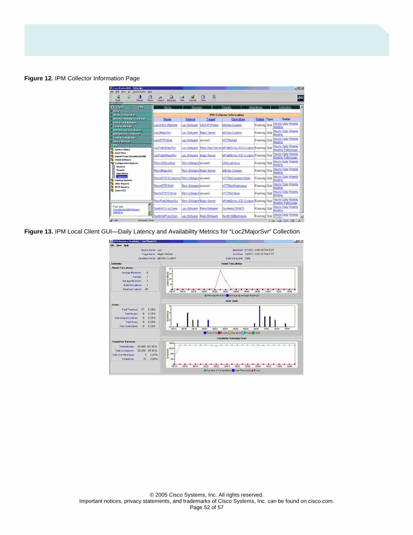
© 2005 Cisco Systems, Inc. All rights reserved.
Important notices, privacy statements, and trademarks of Cisco Systems, Inc. can be found on cisco.com. Page 52 of 57
Figure 12. IPM Collector Information Page
Figure 13. IPM Local Client GUI—Daily Latency and Availability Metrics for “Loc2MajorSvr” Collection

© 2005 Cisco Systems, Inc. All rights reserved.
Important notices, privacy statements, and trademarks of Cisco Systems, Inc. can be found on cisco.com. Page 53 of 57
Figure 14. IPM Web GUI—Hourly Latency and Availability Metrics for “LocPath2MajorSvr” Collection
Figure 15. IPM Web GUI—Path Usage Metrics for “LocPath2MajorSvr” Collection
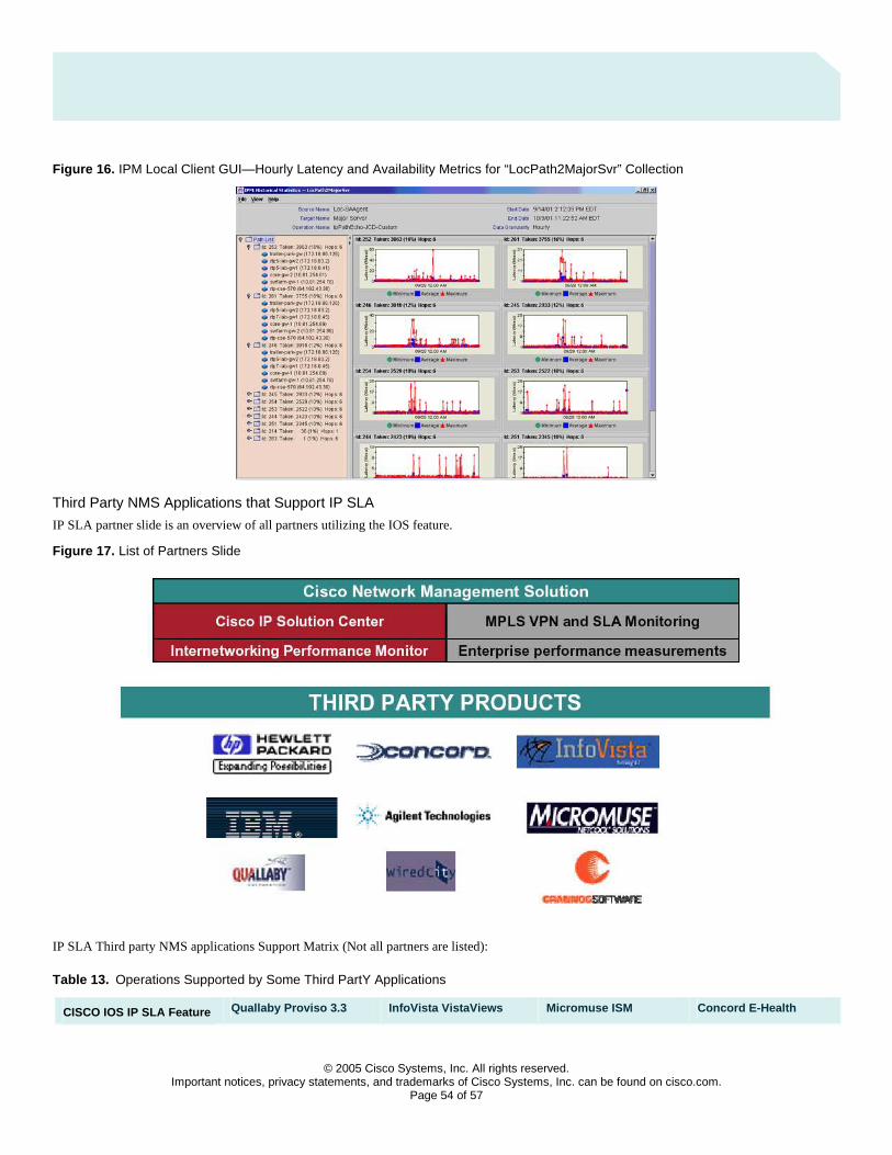
© 2005 Cisco Systems, Inc. All rights reserved.
Important notices, privacy statements, and trademarks of Cisco Systems, Inc. can be found on cisco.com. Page 54 of 57
Figure 16. IPM Local Client GUI—Hourly Latency and Availability Metrics for “LocPath2MajorSvr” Collection
Third Party NMS Applications that Support IP SLA
IP SLA partner slide is an overview of all partners utilizing the IOS feature.
Figure 17. List of Partners Slide
IP SLA Third party NMS applications Support Matrix (Not all partners are listed):
Table 13. Operations Supported by Some Third PartY Applications
CISCO IOS IP SLA Feature Quallaby Proviso 3.3 InfoVista VistaViews Micromuse ISM Concord E-Health

© 2005 Cisco Systems, Inc. All rights reserved.
Important notices, privacy statements, and trademarks of Cisco Systems, Inc. can be found on cisco.com. Page 55 of 57
CISCO IOS IP SLA Feature Quallaby Proviso 3.3 InfoVista VistaViews Micromuse ISM Concord E-Health
ICMP Echo Operation X X X X
ICMP Path Echo Operation X X X
UDP Echo Operation X X X X
Jitter Operation X X X
One Way Jitter Operation X X
HTTP Operation X X X X
TCP Connect Operation X X X X
FTP Operation X X
DNS Operation X X X X
DLSW Operation X X
DHCP Operation X X X
SNA LU2 Echo Operation X X
Reaction Threshold X
Reaction Threshold
Trap Collection
X
Operation History
Characteristics
X
Distributions of Data
SNMP Support X X X X
Scheduling
Path Jitter Operation X X
MPLS VPN Aware X
Application Performance
Monitoring
Tos Bit Class of
Service Operation
X X X X
DSCP Bit Class of
Service Operation
X X X X
Low Memory
Threshold Setting
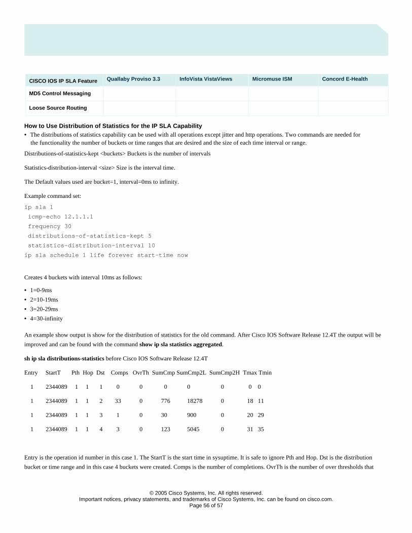
© 2005 Cisco Systems, Inc. All rights reserved.
Important notices, privacy statements, and trademarks of Cisco Systems, Inc. can be found on cisco.com. Page 56 of 57
CISCO IOS IP SLA Feature Quallaby Proviso 3.3 InfoVista VistaViews Micromuse ISM Concord E-Health
MD5 Control Messaging
Loose Source Routing
How to Use Distribution of Statistics for the IP SLA Capability • The distributions of statistics capability can be used with all operations except jitter and http operations. Two commands are needed for
the functionality the number of buckets or time ranges that are desired and the size of each time interval or range.
Distributions-of-statistics-kept <buckets> Buckets is the number of intervals
Statistics-distribution-interval <size> Size is the interval time.
The Default values used are bucket=1, interval=0ms to infinity.
Example command set:
ip sla 1
icmp-echo 12.1.1.1
frequency 30
distributions-of-statistics-kept 5
statistics-distribution-interval 10
ip sla schedule 1 life forever start-time now
Creates 4 buckets with interval 10ms as follows:
• 1=0-9ms
• 2=10-19ms
• 3=20-29ms
• 4=30-infinity
An example show output is show for the distribution of statistics for the old command. After Cisco IOS Software Release 12.4T the output will be
improved and can be found with the command show ip sla statistics aggregated.
sh ip sla distributions-statistics before Cisco IOS Software Release 12.4T
Entry StartT Pth Hop Dst Comps OvrTh SumCmp SumCmp2L SumCmp2H Tmax Tmin
1 2344089 1 1 1 0 0 0 0 0 0 0
1 2344089 1 1 2 33 0 776 18278 0 18 11
1 2344089 1 1 3 1 0 30 900 0 20 29
1 2344089 1 1 4 3 0 123 5045 0 31 35
Entry is the operation id number in this case 1. The StartT is the start time in sysuptime. It is safe to ignore Pth and Hop. Dst is the distribution
bucket or time range and in this case 4 buckets were created. Comps is the number of completions. OvrTh is the number of over thresholds that

© 2005 Cisco Systems, Inc. All rights reserved.
Important notices, privacy statements, and trademarks of Cisco Systems, Inc. can be found on cisco.com. Page 57 of 57
Corporate Headquarters Cisco Systems, Inc. 170 West Tasman Drive San Jose, CA 95134-1706 USA www.cisco.com Tel: 408 526-4000 800 553-NETS (6387) Fax: 408 526-4100
European Headquarters Cisco Systems International BV Haarlerbergpark Haarlerbergweg 13-19 1101 CH Amsterdam The Netherlands www-europe.cisco.com Tel: 31 0 20 357 1000 Fax: 31 0 20 357 1100
Americas Headquarters Cisco Systems, Inc. 170 West Tasman Drive San Jose, CA 95134-1706 USA www.cisco.com Tel: 408 526-7660 Fax: 408 527-0883
Asia Pacific Headquarters Cisco Systems, Inc. 168 Robinson Road #28-01 Capital Tower Singapore 068912 www.cisco.com Tel: +65 6317 7777 Fax: +65 6317 7799
Cisco Systems has more than 200 offices in the following countries and regions. Addresses, phone numbers, and fax numbers are listed on
the Cisco Website at www.cisco.com/go/offices. Argentina • Australia • Austria • Belgium • Brazil • Bulgaria • Canada • Chile • China PRC • Colombia • Costa Rica • Croatia • Cyprus Czech Republic • Denmark • Dubai, UAE • Finland • France • Germany • Greece • Hong Kong SAR • Hungary • India • Indonesia • Ireland • Israel Italy • Japan • Korea • Luxembourg • Malaysia • Mexico • The Netherlands • New Zealand • Norway • Peru • Philippines • Poland • Portugal Puerto Rico • Romania • Russia • Saudi Arabia • Scotland • Singapore • Slovakia • Slovenia • South Africa • Spain • Sweden • Switzerland • Taiwan Thailand • Turkey • Ukraine • United Kingdom • United States • Venezuela • Vietnam • Zimbabwe
Copyright 2005 Cisco Systems, Inc. All rights reserved. CCIP, CCSP, the Cisco Powered Network mark, Cisco Unity, Follow Me Browsing, FormShare, and StackWise are trademarks of Cisco Systems, Inc.; Changing the Way We Work, Live, Play, and Learn, and iQuick Study are service marks of Cisco Systems, Inc.; and Aironet, ASIST, BPX, Catalyst, CCDA, CCDP, CCIE, CCNA, CCNP, Cisco, the Cisco Certified Internetwork Expert logo, Cisco IOS, the Cisco IOS logo, Cisco Press, Cisco Systems, Cisco Systems Capital, the Cisco Systems logo, Empowering the Internet Generation, Enterprise/Solver, EtherChannel, EtherSwitch, Fast Step, GigaStack, Internet Quotient, IOS, IP/TV, iQ Expertise, the iQ logo, iQ Net Readiness Scorecard, LightStream, Linksys, MeetingPlace, MGX, MICA, the Networkers logo, Networking Academy, Network Registrar, Packet, PIX, Post-Routing, Pre-Routing, RateMUX, Registrar, ScriptShare, SlideCast, SMARTnet, StrataView Plus, Stratm, SwitchProbe, TeleRouter, The Fastest Way to Increase Your Internet Quotient, TransPath, and VCO are registered trademarks of Cisco Systems, Inc. and/or its affiliates in the United States and certain other countries. All other trademarks mentioned in this document or Website are the property of their respective owners. The use of the word partner does not imply a partnership relationship between Cisco and any other company. (0501R) C07-624058-00 Printed in the USA
happened if thresholding is setup. SumCmp is the sum of completions for each operation. The SumCmp2L and SumCmp2H is the sum of the
accumulated squares for the H (high) and L (low) 32bits. The sum of squares is used to calculate standard deviation in delay.
Related Documents