Cisco CRS-3 Carrier Routing System 16-Slot Back-to-Back Cabling and Upgrade Guide First Published: 2012-06-04 Last Modified: 2014-07-07 Americas Headquarters Cisco Systems, Inc. 170 West Tasman Drive San Jose, CA 95134-1706 USA http://www.cisco.com Tel: 408 526-4000 800 553-NETS (6387) Fax: 408 527-0883

Welcome message from author
This document is posted to help you gain knowledge. Please leave a comment to let me know what you think about it! Share it to your friends and learn new things together.
Transcript

Cisco CRS-3 Carrier Routing System 16-Slot Back-to-Back Cablingand Upgrade GuideFirst Published: 2012-06-04
Last Modified: 2014-07-07
Americas HeadquartersCisco Systems, Inc.170 West Tasman DriveSan Jose, CA 95134-1706USAhttp://www.cisco.comTel: 408 526-4000 800 553-NETS (6387)Fax: 408 527-0883

THE SPECIFICATIONS AND INFORMATION REGARDING THE PRODUCTS IN THIS MANUAL ARE SUBJECT TO CHANGE WITHOUT NOTICE. ALL STATEMENTS,INFORMATION, AND RECOMMENDATIONS IN THIS MANUAL ARE BELIEVED TO BE ACCURATE BUT ARE PRESENTED WITHOUT WARRANTY OF ANY KIND,EXPRESS OR IMPLIED. USERS MUST TAKE FULL RESPONSIBILITY FOR THEIR APPLICATION OF ANY PRODUCTS.
THE SOFTWARE LICENSE AND LIMITEDWARRANTY FOR THE ACCOMPANYING PRODUCT ARE SET FORTH IN THE INFORMATION PACKET THAT SHIPPED WITHTHE PRODUCT AND ARE INCORPORATED HEREIN BY THIS REFERENCE. IF YOU ARE UNABLE TO LOCATE THE SOFTWARE LICENSE OR LIMITED WARRANTY,CONTACT YOUR CISCO REPRESENTATIVE FOR A COPY.
The Cisco implementation of TCP header compression is an adaptation of a program developed by the University of California, Berkeley (UCB) as part of UCB's public domain versionof the UNIX operating system. All rights reserved. Copyright © 1981, Regents of the University of California.
NOTWITHSTANDINGANYOTHERWARRANTYHEREIN, ALL DOCUMENT FILES AND SOFTWARE OF THESE SUPPLIERS ARE PROVIDED “AS IS"WITH ALL FAULTS.CISCO AND THE ABOVE-NAMED SUPPLIERS DISCLAIM ALL WARRANTIES, EXPRESSED OR IMPLIED, INCLUDING, WITHOUT LIMITATION, THOSE OFMERCHANTABILITY, FITNESS FORA PARTICULAR PURPOSEANDNONINFRINGEMENTORARISING FROMACOURSEOFDEALING, USAGE, OR TRADE PRACTICE.
IN NO EVENT SHALL CISCO OR ITS SUPPLIERS BE LIABLE FOR ANY INDIRECT, SPECIAL, CONSEQUENTIAL, OR INCIDENTAL DAMAGES, INCLUDING, WITHOUTLIMITATION, LOST PROFITS OR LOSS OR DAMAGE TO DATA ARISING OUT OF THE USE OR INABILITY TO USE THIS MANUAL, EVEN IF CISCO OR ITS SUPPLIERSHAVE BEEN ADVISED OF THE POSSIBILITY OF SUCH DAMAGES.
Any Internet Protocol (IP) addresses and phone numbers used in this document are not intended to be actual addresses and phone numbers. Any examples, command display output, networktopology diagrams, and other figures included in the document are shown for illustrative purposes only. Any use of actual IP addresses or phone numbers in illustrative content is unintentionaland coincidental.
Cisco and the Cisco logo are trademarks or registered trademarks of Cisco and/or its affiliates in the U.S. and other countries. To view a list of Cisco trademarks, go to this URL: http://www.cisco.com/go/trademarks. Third-party trademarks mentioned are the property of their respective owners. The use of the word partner does not imply a partnershiprelationship between Cisco and any other company. (1110R)
© 2016 Cisco Systems, Inc. All rights reserved.

C O N T E N T S
P r e f a c e Preface vii
Objective vii
Audience vii
Changes to This Document vii
Document Organization viii
Document Conventions viii
Related Cisco CRS Documentation ix
Obtaining Documentation and Submitting a Service Request x
C H A P T E R 1 Introduction to the CRS Back-to-Back System 1
System Overview 1
Cabling Overview 2
System Management, Alarm, and Network Clock Cabling 3
Fabric Cabling 3
PLIM Port Cabling 3
General Cabling Prerequisites 3
Space and Environmental Considerations 3
Tools and Supplies Required 3
Cables Required 4
Cable Routing Considerations 4
Raised Floor Installations 5
Cable Characteristics 5
Cable Length 5
Cable Bend Radius 5
General Cabling Procedures 6
General Safety Guidelines 7
Cisco CRS-3 Carrier Routing System 16-Slot Back-to-Back Cabling and Upgrade Guide iii

C H A P T E R 2 Cabling for System Management, Alarms, and Network Clocking 9
Console Port Cabling 9
Auxiliary Port Cabling 10
Management Ethernet Port Cabling 10
Alarm Module Alarm-Out Cabling 10
What to Do Next 10
C H A P T E R 3 Cabling the CRS Back-to-Back System 11
About Fabric Cabling 11
About Fabric Planes in the CRS Back-to-Back System 12
Cisco Systems Fabric Cables 15
Planning Fabric Cabling 17
Chassis Cable Routing 17
Planning Cable Labels 21
Label Schema Example 22
Cabling the Fabric 23
Precautions 23
Prerequisites 25
How to Connect the Fabric Cables 25
Attach LCC(s) 25
General Fabric Cabling Procedures 26
Installing Turn Collars 26
Cleaning Cables 28
Verifying the Fabric 28
What to Do Next 34
C H A P T E R 4 Upgrading to a CRS Back-to-Back System Using Cisco IOS-XR 4.3.1 or Earlier 35
Prerequisites for Upgrading to a CRS Back-to-Back System 35
How to Upgrade to a CRS Back-to-Back System 36
Upgrading the Fabric Cards 36
Prerequisites 36
Restrictions 37
Summary Steps 37
Detailed Steps 38
Cisco CRS-3 Carrier Routing System 16-Slot Back-to-Back Cabling and Upgrade Guideiv
Contents
What to Do Next 41
Connecting the Control Network 41
What to Do Next 41
Adding a LCC to a CRS Back-to-Back System 41
Prerequisites 42
Restrictions 42
Summary Steps 42
Detailed Steps 43
Tips and Troubleshooting 46
Technical Assistance 47
C H A P T E R 5 Upgrading to a CRS Back-to-Back System Using Cisco IOS-XR 5.1.1 or Later 49
Prerequisites for Upgrading to a CRS Back-to-Back System 49
Changing the Fabric Addressing Mode 50
Changing the Fabric Addressing Mode 52
How to Upgrade to a CRS Back-to-Back System 54
Upgrading the Fabric Cards 54
Prerequisites 54
Restrictions 55
Summary Steps 55
Detailed Steps 55
What to Do Next 59
Connecting the Control Network 59
What to Do Next 60
Adding an LCC to a CRS Back-to-Back System 60
Prerequisites 60
Restrictions 61
Summary Steps 61
Detailed Steps 62
Tips and Troubleshooting 65
Technical Assistance 65
Cisco CRS-3 Carrier Routing System 16-Slot Back-to-Back Cabling and Upgrade Guide v
Contents

Cisco CRS-3 Carrier Routing System 16-Slot Back-to-Back Cabling and Upgrade Guidevi
Contents

Preface
This preface contains the following sections:
• Objective, page vii
• Audience, page vii
• Changes to This Document, page vii
• Document Organization, page viii
• Document Conventions, page viii
• Related Cisco CRS Documentation, page ix
• Obtaining Documentation and Submitting a Service Request, page x
ObjectiveThis guide describes how to interconnect the two 8-slot chassis that comprise the CRS Back-to-Back System. This guide supplements other chassis documentation, such as site planning and installation documents.
AudienceThis guide is written for hardware installers and system administrators of Cisco routers.
This publication assumes that the user has a substantial background in installing and configuring router andswitch-based hardware. The reader should also be familiar with electronic circuitry and wiring practices, andhave experience as an electronic or electromechanical technician.
Changes to This DocumentThis table lists the technical changes to this document since it was first released.
Cisco CRS-3 Carrier Routing System 16-Slot Back-to-Back Cabling and Upgrade Guide vii
Table 1: Changes to This Document
Change SummaryDate
Added chapter with procedures for upgrading fromCisco IOS-XR release 5.1.1 or later.
January 2014
Initial release of this document.May 2013
Document OrganizationThis guide includes the following sections:
DescriptionTitleSection
Provides an overview of the CRSBack-to-Back System anddescribes what is required tointerconnect system components.
Introduction to the CRSBack-to-Back System, on page 1
1
Provides information about how toprovide cabling for basic systemmanagement.
Cabling for System Management,Alarms, and Network Clocking,on page 9
2
Describes how to physically cablethe fabric planes between chassisin a Back-to-Back system
Cabling the CRS Back-to-BackSystem, on page 11
3
Describes how to upgrade asingle-chassis Cisco CRS-1 orCisco CRS-3 to a CRSBack-to-Back System using CiscoIOS-XR version 4.3.1 or earlier.
Upgrading to a CRSBack-to-BackSystemUsing Cisco IOS-XR 4.3.1or Earlier, on page 35
4
Describes how to upgrade asingle-chassis Cisco CRS-3 to aCRS Back-to-Back System usingCisco IOS-XR version 5.1.1 orlater.
Upgrading to a CRSBack-to-BackSystemUsing Cisco IOS-XR 5.1.1or Later, on page 49
5
Document ConventionsThis document uses the following conventions:
Cisco CRS-3 Carrier Routing System 16-Slot Back-to-Back Cabling and Upgrade Guideviii
PrefaceDocument Organization

Caution: Means be careful. You are capable of doing something that might result in equipment damageor loss of data.
Caution
Note: Means take note . Notes contain helpful suggestions or references to materials not contained in thismanual.
Note
Note: Means the described action saves time . You can save time by performing the action described inthe paragraph.
Tip
This warning symbol means danger. You are in a situation that could cause bodily injury. Before youwork on any equipment, be aware of the hazards involved with electrical circuitry and be familiar withstandard practices for preventing accidents. To see translations of the warnings that appear in thispublication, refer to the Regulatory Compliance and Safety Information document that accompanied thisdevice. Statement 1071.
Warning
Understanding Warning Statement Numbers
Each Warning in this guide contains a Statement Number. For example, the previous warning is Statement1071. The Regulatory Compliance and Safety Information for the Cisco CRS-1 Carrier Routing System bookletcontains translations of every warning that appears in this guide. The compliance and safety booklet shippedwith your chassis. The booklet lists translated warnings in numerical sequence, by statement number.
Related Cisco CRS DocumentationThis section refers you to other documentation that contains complete planning, installation, and configurationinformation.
The documentation listed below is available online.
• Cisco CRS Carrier Routing System 16-Slot Line Card Chassis Site Planning Guide
• Cisco CRS Carrier Routing System 16-Slot Line Card Chassis Installation Guide
• Cisco CRS Carrier Routing System 16-Slot Line Card Chassis Unpacking, Moving, and Securing Guide
• Regulatory Compliance and Safety Information for the Cisco CRS Carrier Routing System
• Cisco CRS Carrier Routing System 16-Slot Line Card Chassis Enhanced Router Site Planning Guide
• Cisco CRS Carrier Routing System 16-Slot Line Card Chassis Enhanced Router Installation Guide
• Cisco CRS Carrier Routing System 16-Slot Line Card Chassis Enhanced Router Unpacking, Moving,and Securing Guide
• Cisco CRS-1 Carrier Routing System Fiber-Optic Cleaning Guide
Cisco CRS-3 Carrier Routing System 16-Slot Back-to-Back Cabling and Upgrade Guide ix
PrefaceRelated Cisco CRS Documentation

Obtaining Documentation and Submitting a Service RequestFor information on obtaining documentation, submitting a service request, and gathering additional information,see the monthlyWhat’s New in Cisco Product Documentation , which also lists all new and revised Ciscotechnical documentation, at:
http://www.cisco.com/en/US/docs/general/whatsnew/whatsnew.html
Subscribe to theWhat’s New in Cisco Product Documentation as a Really Simple Syndication (RSS) feedand set content to be delivered directly to your desktop using a reader application. The RSS feeds are a freeservice and Cisco currently supports RSS Version 2.0.
Cisco CRS-3 Carrier Routing System 16-Slot Back-to-Back Cabling and Upgrade Guidex
PrefaceObtaining Documentation and Submitting a Service Request
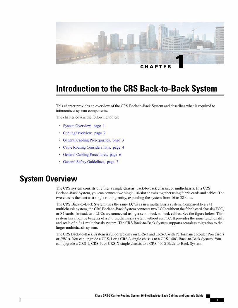
C H A P T E R 1Introduction to the CRS Back-to-Back System
This chapter provides an overview of the CRS Back-to-Back System and describes what is required tointerconnect system components.
The chapter covers the following topics:
• System Overview, page 1
• Cabling Overview, page 2
• General Cabling Prerequisites, page 3
• Cable Routing Considerations, page 4
• General Cabling Procedures, page 6
• General Safety Guidelines, page 7
System OverviewThe CRS system consists of either a single chassis, back-to-back chassis, or multichassis. In a CRSBack-to-Back System, you can connect two single, 16-slot chassis together using fabric cards and cables. Thetwo chassis then act as a single routing entity, expanding the system from 16 to 32 slots.
The CRS Back-to-Back System uses the same LCCs as in a multichassis system. Compared to a 2+1multichassis system, the CRSBack-to-Back System connects two LCCswithout the fabric card chassis (FCC)or S2 cards. Instead, two LCCs are connected using a set of back-to-back cables. See the figure below. Thissystem has all of the benefits of a 2+1 multichassis system without an FCC. It provides the same functionalityand scale of a 2+1 multichassis system. The CRS Back-to-Back System supports seamless migration to thelarger multichassis system.
The CRS Back-to-Back System is supported only on CRS-3 and CRS-X with Performance Router Processorsor PRP s. You can upgrade a CRS-1 or a CRS-3 single chassis to a CRS 140G Back-to-Back System. Youcan upgrade a CRS-1, CRS-3, or CRS-X single chassis to a CRS 400G Back-to-Back System.
Cisco CRS-3 Carrier Routing System 16-Slot Back-to-Back Cabling and Upgrade Guide 1

Throughout this document, the generic term CRS Back-to-Back System refers to the CRS 140GBack-to-Back System and CRS 400G Back-to-Back System unless otherwise specified.
Note
Figure 1: 2+1 Multichassis System Compared to the CRS Back-to-Back System
Cisco CRS Fabric CardChassis
2Cisco CRS 16-Slot LineCard Chassis
1
Cabling OverviewCRS Back-to-Back System cabling can be divided into the following groups:
1 System Management, Alarm, and Network Clock Cabling2 Fabric Cabling3 PLIM Port Cabling
You should cable a CRS Back-to-Back System in this order.
Cisco CRS-3 Carrier Routing System 16-Slot Back-to-Back Cabling and Upgrade Guide2
Introduction to the CRS Back-to-Back SystemCabling Overview
System Management, Alarm, and Network Clock CablingCabling for System Management, Alarms, and Network Clocking, on page 9 describes the cabling forsystem management connections, the optional network clock feature, and the optional external alarm feature.You must cable at least one form of system management connection before system configuration can start.
Fabric CablingChapter 3, “Cabling the CRS Back-to-Back System” describes the cabling between the fabric components inthe two LCCs. The fabric cabling provides the data connection for traffic between two LCCs. You mustcomplete the fabric cabling to enable data communications through the CRS Back-to-Back System. There aretwo types of fabric cables: Trimese and Riser.
PLIM Port CablingAll router data traffic enters the CRS Back-to-Back System through lines connected to the physical layerinterface modules (PLIMs). For information about PLIM cards and connectors, see the PLIM notes andinstallation guides on http://www.cisco.com.
General Cabling PrerequisitesThe prerequisites for cabling a CRS Back-to-Back System include the following:
• Adequate floor space to cable the system
• An environment that meets specifications
• Minimum system components required to create a CRS Back-to-Back System
• Tools required to perform the installation
• Proper cables required to interconnect the chassis to each other and their power sources
These prerequisites are explained in the following sections:
Space and Environmental ConsiderationsSpace, power, and environmental specifications are cited in the Cisco CRS Carrier Routing System 16-SlotLine Card Chassis Site Planning Guide and the Cisco CRS Carrier Routing System 16-Slot Line Card ChassisEnhanced Router Site Planning Guide .
Tools and Supplies RequiredThe following tools and supplies are required to cable the CRS Back-to-Back System:
• ESD (ElectroStatic Discharge) wrist strap (for inserting optical modules)
Cisco CRS-3 Carrier Routing System 16-Slot Back-to-Back Cabling and Upgrade Guide 3
Introduction to the CRS Back-to-Back SystemSystem Management, Alarm, and Network Clock Cabling
• Torx T6 wrench (to screw or unscrew the bolt on the fabric cable connector to the S13 fabric card).
• Medium (number 2) Phillips screwdriver.
• Medium flat-blade screwdriver (1/4 inch [60 - 70 mm]). This screwdriver is optional; it is used foropening the bale latches on small form-factor pluggable [SFP] or Gigabit Interface Converter [GBIC]transceivers.
• Turn collars (to provide support and strain relief for fabric cable connections). The turn collars aresupplied with the cable.
• Supply of Velcro tie wraps (to bundle cables).
• Ladder.
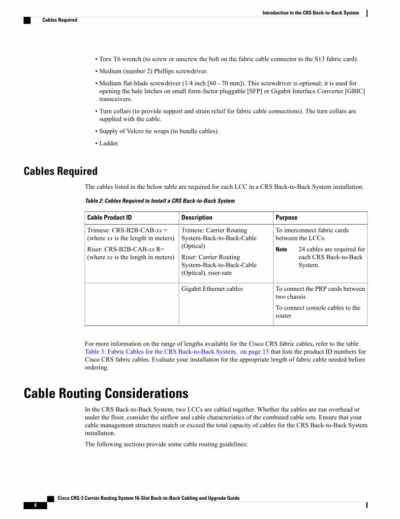
Cables RequiredThe cables listed in the below table are required for each LCC in a CRS Back-to-Back System installation.
Table 2: Cables Required to Install a CRS Back-to-Back System
PurposeDescriptionCable Product ID
To interconnect fabric cardsbetween the LCCs.
24 cables are required foreach CRS Back-to-BackSystem.
Note
Trimese: Carrier RoutingSystem-Back-to-Back-Cable(Optical)
Riser: Carrier RoutingSystem-Back-to-Back-Cable(Optical), riser-rate
Trimese: CRS-B2B-CAB-xx =(where xx is the length in meters)
Riser: CRS-B2B-CAB-xx R=(where xx is the length in meters)
To connect the PRP cards betweentwo chassis
To connect console cables to therouter
Gigabit Ethernet cables
For more information on the range of lengths available for the Cisco CRS fabric cables, refer to the tableTable 3: Fabric Cables for the CRS Back-to-Back System, on page 15 that lists the product ID numbers forCisco CRS fabric cables. Evaluate your installation for the appropriate length of fabric cable needed beforeordering.
Cable Routing ConsiderationsIn the CRS Back-to-Back System, two LCCs are cabled together. Whether the cables are run overhead orunder the floor, consider the airflow and cable characteristics of the combined cable sets. Ensure that yourcable management structures match or exceed the total capacity of cables for the CRS Back-to-Back Systeminstallation.
The following sections provide some cable routing guidelines:
Cisco CRS-3 Carrier Routing System 16-Slot Back-to-Back Cabling and Upgrade Guide4
Introduction to the CRS Back-to-Back SystemCables Required
Raised Floor InstallationsTo plan cable routing in an installation with a raised floor, consider all the characteristics of each cable requiredfor the installation. Allow slack for cabling so that cables can be pooled under the floor for future expansionwithout exceeding bend radius or cable length limitations. Only use Riser cables in an installation with a raisedfloor. Riser cables are not rated for installation in air plenum passages, nor are they designed for use in LSZH(low smoke zero halogen) applications.
Cable CharacteristicsTo plan your cable runs, consider the characteristics of each cable, such as the cable length limitations,combined diameter of bundled cables (such as power cables), weight of the cable groups, and bend radius ofthe cable or cables. Couple these considerations with the cable infrastructure available (or needed) at yourfacility. The infrastructure could include structures like the overhead cabling monorail or J-hook system,sleeve and riser diameters, and distances between floors or elements of the CRS Back-to-Back System.
Analyze the cabling infrastructures, risers, and racking available in your facility to determine if the capacityof the cabling management systems at your facility will accommodate the required capacities of the CRSBack-to-Back System cabling.
Trimese fabric (CRS-B2B-CAB-xx) carries a dual flame rating: general purpose and LSZH (low smokezero halogen). These cables are designed to connect two LCCs in the free air of the room. Route fabriccables within a room. Fabric cables are not rated for installation above ceilings, below floors, or throughwalls.
Riser fabric cables (CRS-B2B-CAB-xxR) meet the OFNR riser cable flame rating. These cables aredesigned to connect two LCCs, either in the free air within a room, or, through a riser access betweenbuilding floors. Riser cables are not rated for installation in air plenum passages, nor are they designedfor use in LSZH (low smoke zero halogen) applications.
Note
Cable LengthThe limit of the cables is 100 m (328 ft). Consider this distance when planning the physical locations of theLCCs. For more information on the range of lengths available for the Cisco CRS fabric cables, refer to thetable Table 3: Fabric Cables for the CRS Back-to-Back System, on page 15 that lists the product ID numbersfor Cisco CRS fabric cables. Evaluate your installation for the appropriate length of fabric cable needed beforeordering.
Cable Bend RadiusExceeding the bend radius allowed for a cable can break the glass in the cable or cause attenuation or loss ofsignal. Do not bend a cable more than the allowable bend radius.
The below figure shows an example of how a bend radius is measured for Trimese cables. In this figure, thecable has a 1 in (2.54 cm) radius. If the cable is specified to wrap around the arc that is formed by the circlewith the 1-inch radius, the cable is said to have a 1-inch bend radius . Note the following:
Cisco CRS-3 Carrier Routing System 16-Slot Back-to-Back Cabling and Upgrade Guide 5
Introduction to the CRS Back-to-Back SystemRaised Floor Installations

• At any time, the bend radius should not be less than 1.25".
• For Trimese and Riser cables, the bend radius should not be less than 2".
• For Riser cables, the bend radius should not exceed the bend that is established by the strain relief collars.
Figure 2: How a Bend Radius Is Specified
General Cabling ProceduresObserve these procedures as you attach every cable:
• Before you start, determine whether you will route the interconnection cables upward or downward fromthe fabric card. The direction determines whether you will install the fabric cable turn collar (see InstallingTurn Collars, on page 26) pointing up or down.
• For cable management, the rear of the line card chassis has a single cable manager located between thetwo shelves. Strap cable bundles to these brackets.
Handle all cables carefully. Fiber-optic cables require special care as follows:
• Do not allow a fiber-optic cable to bend in a radius smaller than the allowable bend radius specified forthat cable type.
• Fiber-optic cables are glass. Do not step on fiber-optic cables or handle them roughly. Do not twist orstretch the cables.
• To keep optical connections clean, do not remove the cable dust cover until immediately before youinstall the cable. See Cisco CRS-1 Carrier Routing System Fiber-Optic Cleaning Guide for details.
• After you install a cable, immediately reserve each dust cover for storage by office personnel in a dust-freestorage area. After all of the cables have been installed ensure that all the reserved dust covers are storedby office personnel in a dust free area for future use.
• Install clean dust covers on every unused connection.
• Consider labeling the chassis interconnection cables or creating a diagram of the cabling to ensure thatthe cables are connected correctly during system installation.
Cisco CRS-3 Carrier Routing System 16-Slot Back-to-Back Cabling and Upgrade Guide6
Introduction to the CRS Back-to-Back SystemGeneral Cabling Procedures
• Consider labeling the chassis. Consider whether each chassis must be physically positioned in sequence.Label each cable with the location of each termination as you install each cable.
General Safety GuidelinesBefore you perform any procedure in this document, review the safety guidelines in this section to avoidinjuring yourself or damaging the equipment.
The following guidelines are for your safety and to protect equipment. The guidelines do not include allhazards. Be alert.
Review the Document Conventions and the Understanding Warning Statement Numbers. In addition,review the safety warnings listed in Regulatory Compliance and Safety Information for the Cisco CRSCarrier Routing System before installing, configuring, or troubleshooting any installed card. This bookletis shipped with your system.
Note
• Never attempt to lift an object that could be too heavy for you to lift by yourself.
• Keep the work area clear and dust free during and after installation. Do not allow dirt or debris to enterinto any laser-based components.
• Keep tools and router components away from walk areas.
• Do not wear loose clothing, jewelry, or other items that could get caught in the router while workingwith cards, modules, and their associated components.
• Cisco equipment operates safely when used in accordance with its specifications and product-usageinstructions.
• Do not work alone if potentially hazardous conditions exist.
• The installation must follow national and local electrical codes: in the United States, National FireProtection Association (NFPA) 70, United States National Electrical Code; in Canada, Canadian ElectricalCode, part I, CSA C22.1; in other countries, International Electrotechnical Commission (IEC) 60364,part 1 through part 7.
Cisco CRS-3 Carrier Routing System 16-Slot Back-to-Back Cabling and Upgrade Guide 7
Introduction to the CRS Back-to-Back SystemGeneral Safety Guidelines

Cisco CRS-3 Carrier Routing System 16-Slot Back-to-Back Cabling and Upgrade Guide8
Introduction to the CRS Back-to-Back SystemGeneral Safety Guidelines

C H A P T E R 2Cabling for System Management, Alarms, andNetwork Clocking
The CRSBack-to-Back System supports several options for systemmanagement connections, and it providesconnections for triggering external alarms and controlling optical cable clocking. A console port connectionmust be established before the system can be configured and become operational. The optional externalalarm and network clocking features can be cabled at any time.
This chapter describes the following cabling options:
• Console Port Cabling, page 9
• Auxiliary Port Cabling, page 10
• Management Ethernet Port Cabling, page 10
• Alarm Module Alarm-Out Cabling, page 10
• What to Do Next, page 10
Console Port CablingThe initial configuration of an PRP takes place through the console port. Although PRPs have Ethernet ports,the Ethernet ports cannot be used until they are configured.
To connect to any of the console ports in the CRS Back-to-Back System, use a rollover cable with an RJ-45connector on the end that connects to the CRS Back-to-Back System component. Typically, the other end ofthe rollover cable also uses an RJ-45 connector. The other end of the rollover cable may connect to a terminal,computer running terminal emulation software, or terminal server. Adapters are available to connect the RJ-45connector on the rollover cable to a variety of serial ports. For more information on rollover cables andconnectors, see the following web page:
http://www.cisco.com/en/US/docs/switches/wan/mgx/mgx_8850/software/mgx_r3/rpm/rpm_r1.5/configuration/guide/rpmappb.html#wp1003614
For information on connecting to the console port on an PRP, see Cisco IOS XR Getting Started Guide .
Cisco CRS-3 Carrier Routing System 16-Slot Back-to-Back Cabling and Upgrade Guide 9

Auxiliary Port CablingAuxiliary ports are provided on the PRP card for remote connections through modems. PRP auxiliary portscan be used to configure the CRS Back-to-Back System.
The typical connection to the auxiliary ports uses a serial cable with RJ-45 connectors at each end. As withthe rollover cable, adapters are available to connect the RJ-45 connector at the other end to a variety of serialport types. Cisco IOS XR Getting Started Guide provides illustrations that show how PRP auxiliary ports areconnected through modems to a remote terminal.
Management Ethernet Port CablingEach PRP provides a Management Ethernet port that can be used to manage the PRP through an Ethernetnetwork. This port can also be used to download software to PRPs in the CRS Back-to-Back System or transferfiles to remote servers for analysis or backup storage.
The typical connection to theManagement Ethernet port uses an Ethernet cable with RJ-45 connectors at eachend. The other end of the cable typically connects to an Ethernet switch, hub, or router that provides connectivitybetween the CRS Back-to-Back System and networks from which system management is desired.
For information on connecting to the Management Ethernet port on an PRP, see Cisco IOS XR Getting StartedGuide .
Alarm Module Alarm-Out CablingEach AC or DC power shelf in LCCs contains an alarm module that monitors the status of the power shelfand provides an external interface for system alarms. The same alarm module is used in all power shelves.For more information on alarm module connections, see Cisco CRS Carrier Routing System 16-Slot LineCard Chassis System Description .
What to Do NextWhen you have completed the cabling connections described in this chapter, document these connections andforward them to the people who will configure the system. For example, if you have cabled the console portto a terminal server so that people can access the console port from a network, they need the IP address of theterminal server and corresponding port number before they can use the console port.
Cisco CRS-3 Carrier Routing System 16-Slot Back-to-Back Cabling and Upgrade Guide10
Cabling for System Management, Alarms, and Network ClockingAuxiliary Port Cabling
C H A P T E R 3Cabling the CRS Back-to-Back System
The cables used to interconnect the CRS Back-to-Back System chassis are optical array cables called fabriccables. This chapter describes how to physically cable the fabric planes between line card chassis (LCCs)in a CRS Back-to-Back System. This chapter is organized into the following sections:
• About Fabric Cabling, page 11
• Planning Fabric Cabling, page 17
• Cabling the Fabric, page 23
• General Fabric Cabling Procedures, page 26
• What to Do Next, page 34
About Fabric CablingEach CRS Back-to-Back System requires 24 fabric cables. This cabling enables interchassis datacommunication, which is accomplished using fiber-optic bundles.
The CRS Back-to-Back System uses a customized cable/connector that visually looks the same as themultichassis cable/connector with a different PIN layout. The way to distinguish the fabric cables for the CRSBack-to-Back System is a label that says Back-to-Back.
This section describes the following topics:
Cisco CRS-3 Carrier Routing System 16-Slot Back-to-Back Cabling and Upgrade Guide 11

About Fabric Planes in the CRS Back-to-Back SystemThe CRS Back-to-Back System has eight fabric planes that support data traffic between the lines connectedto the LCCs. The below figure shows a simplified view of the relationship between the line cards and thefabric.
Figure 3: Relationship of Line Cards and Fabric Cards
In general, CRS fabric planes are divided into three components or stages, which are numbered S1, S2, andS3. Data arrives at the S1 stage then goes through the S2 stage and exits at the S3 stage to the destination linecard. This figure shows a simplified view of the relationship between the line cards and the fabric planes ina general CRS system.
Figure 4: General CRS Fabric Plane Stages
Cisco CRS-3 Carrier Routing System 16-Slot Back-to-Back Cabling and Upgrade Guide12
Cabling the CRS Back-to-Back SystemAbout Fabric Planes in the CRS Back-to-Back System

However, in a CRS Back-to-Back System, fabric planes are divided into two stages: S1 and S3. The S2 stageis no longer needed. The purpose of the S2 stage is to direct traffic to the correct egress LCC when there aremultiple egress LCCs. In the CRS Back-to-Back System, there is only one egress LCC.
Data arrives at the S1 stage in the ingress LCC and then passes over the fabric cables to the S3 stage in theegress LCC. This figure shows a simplified view of the relationship between the line cards and the fabricplanes in a CRS Back-to-Back System.
Figure 5: CRS Back-to Back Fabric Plane Stages
Refer to Figure 7: CRS Back-to-Back System with Fabric Plane Interconnections (Trimese Cable Shown,Riser Cable Available), on page 18 for physical cabling examples.
Note
In each LCC, eight S13 fabric cards provide stages S1 and S3 for each of the eight fabric planes. All ingresstraffic enters through the S1 stage of the ingress S13 card, travels over the fabric cables and exits through theS3 stage on an S13 fabric card. Data traffic can enter through the S1 stage on one card and then exit the S3stage on the same card.
Cisco CRS-3 Carrier Routing System 16-Slot Back-to-Back Cabling and Upgrade Guide 13
Cabling the CRS Back-to-Back SystemAbout Fabric Planes in the CRS Back-to-Back System
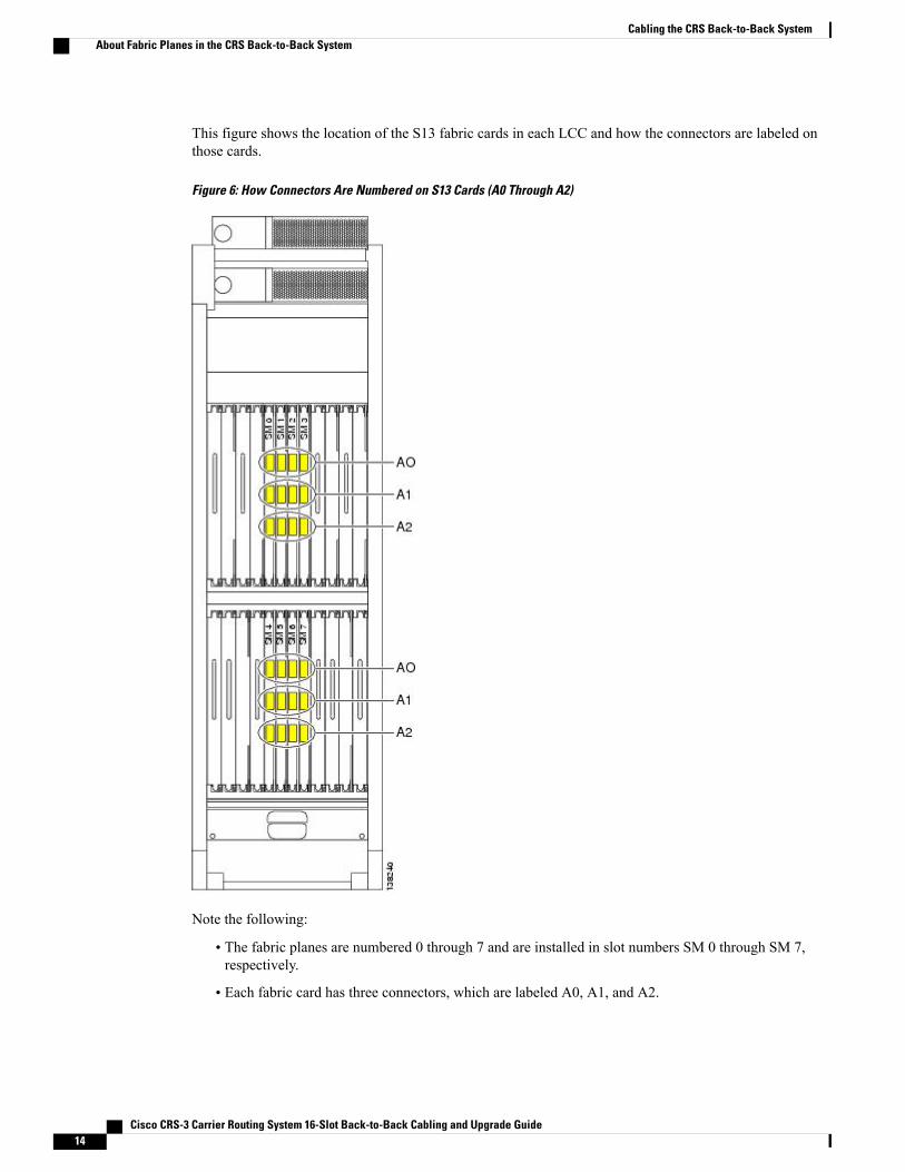
This figure shows the location of the S13 fabric cards in each LCC and how the connectors are labeled onthose cards.
Figure 6: How Connectors Are Numbered on S13 Cards (A0 Through A2)
Note the following:
• The fabric planes are numbered 0 through 7 and are installed in slot numbers SM 0 through SM 7,respectively.
• Each fabric card has three connectors, which are labeled A0, A1, and A2.
Cisco CRS-3 Carrier Routing System 16-Slot Back-to-Back Cabling and Upgrade Guide14
Cabling the CRS Back-to-Back SystemAbout Fabric Planes in the CRS Back-to-Back System

• Each cable on an LCC connects to the same connector on the other LCC. For example, on LCC0, thecard in slot SM0 has a cable coming from the A0 connector. That cable connects to the A0 connectoron the card in slot SM0 on the LCC1.
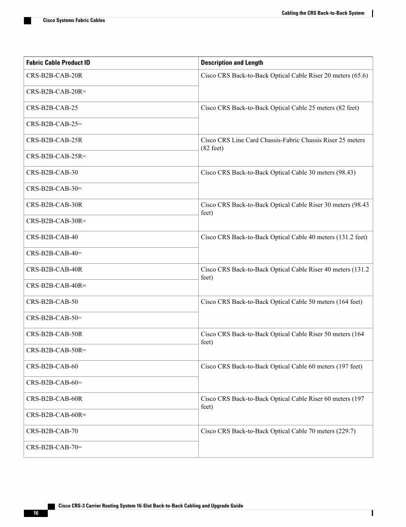
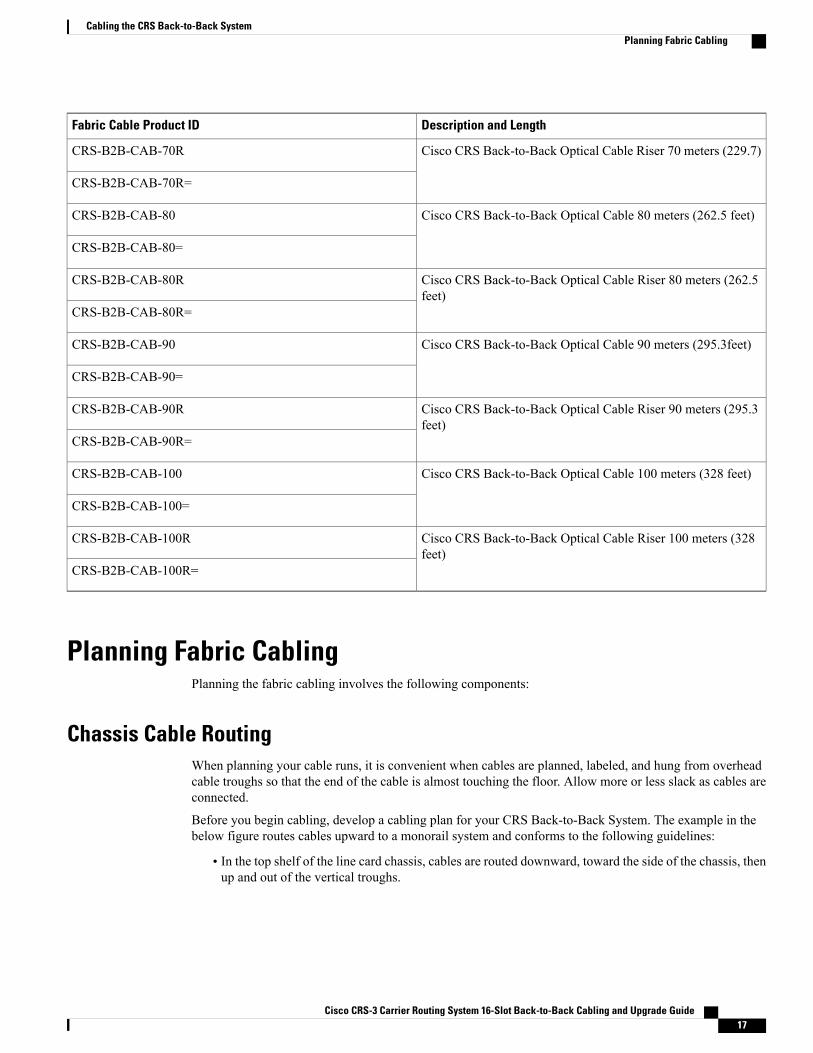
Cisco Systems Fabric CablesTable 3: Fabric Cables for the CRS Back-to-Back System, on page 15 lists the product ID numbers for CiscoCRS fabric cables. The cables listed in Table 3: Fabric Cables for the CRS Back-to-Back System, on page15 can be ordered. The interconnection cables listed are shipped as a set of 24 in the meter length specified.Evaluate your installation for the appropriate length of fabric cable needed before ordering. You should tryto avoid long runs of coiled cables.
In Table 3: Fabric Cables for the CRS Back-to-Back System, on page 15, the cable name CRS-B2B-CAB-XXmeans the following:
• CRS is Carrier Routing System.
• B2B is back-to-back.
• CAB is cable, or optical cable.
• xx is the length of the cable in meters.
The = symbol at the end of a product ID number indicates that the part is a spare , which means that thecable can be ordered as a spare.The R symbol at the end of a product ID number indicates that the part isa Riser cable.
Note
Table 3: Fabric Cables for the CRS Back-to-Back System
Description and LengthFabric Cable Product ID
Cisco CRS Back-to-Back Optical Cable 10 meters (32.8 feet)CRS-B2B-CAB-10
CRS-B2B-CAB-10=
Cisco CRS Back-to-Back Optical Cable Riser 10 meters (32.8feet)
CRS-B2B-CAB-10R
CRS-B2B-CAB-10R=
Cisco CRS Back-to-Back Optical Cable 15 meters (49.2 feet)CRS-B2B-CAB-15
CRS-B2B-CAB-15=
Cisco CRS Back-to-Back Optical Cable Riser 15 meters (49.2feet)
CRS-B2B-CAB-15R
CRS-B2B-CAB-15R=
Cisco CRS Back-to-Back Optical Cable 20 meters (65.6 feet)CRS-B2B-CAB-20
CRS-B2B-CAB-20=
Cisco CRS-3 Carrier Routing System 16-Slot Back-to-Back Cabling and Upgrade Guide 15
Cabling the CRS Back-to-Back SystemCisco Systems Fabric Cables
Description and LengthFabric Cable Product ID
Cisco CRS Back-to-Back Optical Cable Riser 20 meters (65.6)CRS-B2B-CAB-20R
CRS-B2B-CAB-20R=
Cisco CRS Back-to-Back Optical Cable 25 meters (82 feet)CRS-B2B-CAB-25
CRS-B2B-CAB-25=
Cisco CRS Line Card Chassis-Fabric Chassis Riser 25 meters(82 feet)
CRS-B2B-CAB-25R
CRS-B2B-CAB-25R=
Cisco CRS Back-to-Back Optical Cable 30 meters (98.43)CRS-B2B-CAB-30
CRS-B2B-CAB-30=
Cisco CRS Back-to-Back Optical Cable Riser 30 meters (98.43feet)
CRS-B2B-CAB-30R
CRS-B2B-CAB-30R=
Cisco CRS Back-to-Back Optical Cable 40 meters (131.2 feet)CRS-B2B-CAB-40
CRS-B2B-CAB-40=
Cisco CRS Back-to-Back Optical Cable Riser 40 meters (131.2feet)
CRS-B2B-CAB-40R
CRS-B2B-CAB-40R=
Cisco CRS Back-to-Back Optical Cable 50 meters (164 feet)CRS-B2B-CAB-50
CRS-B2B-CAB-50=
Cisco CRS Back-to-Back Optical Cable Riser 50 meters (164feet)
CRS-B2B-CAB-50R
CRS-B2B-CAB-50R=
Cisco CRS Back-to-Back Optical Cable 60 meters (197 feet)CRS-B2B-CAB-60
CRS-B2B-CAB-60=
Cisco CRS Back-to-Back Optical Cable Riser 60 meters (197feet)
CRS-B2B-CAB-60R
CRS-B2B-CAB-60R=
Cisco CRS Back-to-Back Optical Cable 70 meters (229.7)CRS-B2B-CAB-70
CRS-B2B-CAB-70=
Cisco CRS-3 Carrier Routing System 16-Slot Back-to-Back Cabling and Upgrade Guide16
Cabling the CRS Back-to-Back SystemCisco Systems Fabric Cables
Description and LengthFabric Cable Product ID
Cisco CRS Back-to-Back Optical Cable Riser 70 meters (229.7)CRS-B2B-CAB-70R
CRS-B2B-CAB-70R=
Cisco CRS Back-to-Back Optical Cable 80 meters (262.5 feet)CRS-B2B-CAB-80
CRS-B2B-CAB-80=
Cisco CRS Back-to-Back Optical Cable Riser 80 meters (262.5feet)
CRS-B2B-CAB-80R
CRS-B2B-CAB-80R=
Cisco CRS Back-to-Back Optical Cable 90 meters (295.3feet)CRS-B2B-CAB-90
CRS-B2B-CAB-90=
Cisco CRS Back-to-Back Optical Cable Riser 90 meters (295.3feet)
CRS-B2B-CAB-90R
CRS-B2B-CAB-90R=
Cisco CRS Back-to-Back Optical Cable 100 meters (328 feet)CRS-B2B-CAB-100
CRS-B2B-CAB-100=
Cisco CRS Back-to-Back Optical Cable Riser 100 meters (328feet)
CRS-B2B-CAB-100R
CRS-B2B-CAB-100R=
Planning Fabric CablingPlanning the fabric cabling involves the following components:
Chassis Cable RoutingWhen planning your cable runs, it is convenient when cables are planned, labeled, and hung from overheadcable troughs so that the end of the cable is almost touching the floor. Allow more or less slack as cables areconnected.
Before you begin cabling, develop a cabling plan for your CRS Back-to-Back System. The example in thebelow figure routes cables upward to a monorail system and conforms to the following guidelines:
• In the top shelf of the line card chassis, cables are routed downward, toward the side of the chassis, thenup and out of the vertical troughs.
Cisco CRS-3 Carrier Routing System 16-Slot Back-to-Back Cabling and Upgrade Guide 17
Cabling the CRS Back-to-Back SystemPlanning Fabric Cabling
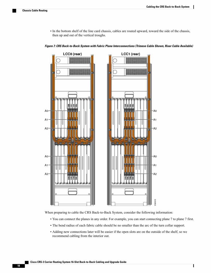
• In the bottom shelf of the line card chassis, cables are routed upward, toward the side of the chassis,then up and out of the vertical troughs.
Figure 7: CRS Back-to-Back System with Fabric Plane Interconnections (Trimese Cable Shown, Riser Cable Available)
When preparing to cable the CRS Back-to-Back System, consider the following information:
• You can connect the planes in any order. For example, you can start connecting plane 7 to plane 7 first.
• The bend radius of each fabric cable should be no smaller than the arc of the turn collar support.
• Adding new connections later will be easier if the open slots are on the outside of the shelf, so werecommend cabling from the interior out.
Cisco CRS-3 Carrier Routing System 16-Slot Back-to-Back Cabling and Upgrade Guide18
Cabling the CRS Back-to-Back SystemChassis Cable Routing

• Always put the turn collar on the fabric cable before inserting the cable connector into the connector,as described in the Installing Turn Collars, on page 26.
•When you install a fabric cable connector into a fabric card connector, hand-tighten the screws. Afteryou have installed all the fabric cable connectors that go on a fabric card, bundle the cables gently, insequence, using the Velcro tie wrap on each turn collar. Use additional Velcro tie wraps as needed toroute the cables around the support brackets and up the vertical troughs, as shown in above figure (CRSBack-to-Back Systemwith Fabric Plane Interconnections (Trimese Cable Shown, Riser Cable Available)).
• Fabric cables have dust covers, held on by two screws. Fabric card connectors have yellow dust coversthat snap on and off. When you take dust covers off, do not put them where they can collect dust. Storeunused dust covers in a clean, dust-free area.
• Velcro tie wraps arrive installed in the vertical troughs. Support brackets have slots that allow Velcrotie wraps to attach the cables to the bracket. The figure Closeup of Riser Cables Attached to Ports A0,A1, and A2 on an S13 Card in a Line Card Chassis below shows the Velcro straps on an S13 card.
Cisco CRS-3 Carrier Routing System 16-Slot Back-to-Back Cabling and Upgrade Guide 19
Cabling the CRS Back-to-Back SystemChassis Cable Routing

These two figures provide a close up view of the cables attached to the fabric card.
Figure 8: Closeup of Trimese Cables Attached to Ports A0, A1, and A2 on an S13 Card in a Line Card Chassis
Figure 9: Closeup of Riser Cables Attached to Ports A0, A1, and A2 on an S13 Card in a Line Card Chassis
Cisco CRS-3 Carrier Routing System 16-Slot Back-to-Back Cabling and Upgrade Guide20
Cabling the CRS Back-to-Back SystemChassis Cable Routing
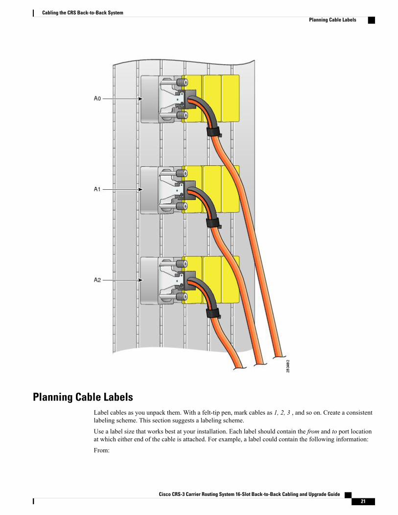
Planning Cable LabelsLabel cables as you unpack them. With a felt-tip pen, mark cables as 1, 2, 3 , and so on. Create a consistentlabeling scheme. This section suggests a labeling scheme.
Use a label size that works best at your installation. Each label should contain the from and to port locationat which either end of the cable is attached. For example, a label could contain the following information:
From:
Cisco CRS-3 Carrier Routing System 16-Slot Back-to-Back Cabling and Upgrade Guide 21
Cabling the CRS Back-to-Back SystemPlanning Cable Labels

LCC #
Slot #/Port #
To:
LCC #
Slot #/Port #
where:
• LCC # is the number for the LCC.
• Slot #/Port # are slot and port numbers (for example, SM3/A0, which means slot SM3, connector A0).To further explain:
◦SM0 through SM7 are slot numbers because there are 8 switch module slots that are numbered 0through 7.
◦A0 through A2 match fabric card port numbers on the S13 card in the line card chassis.
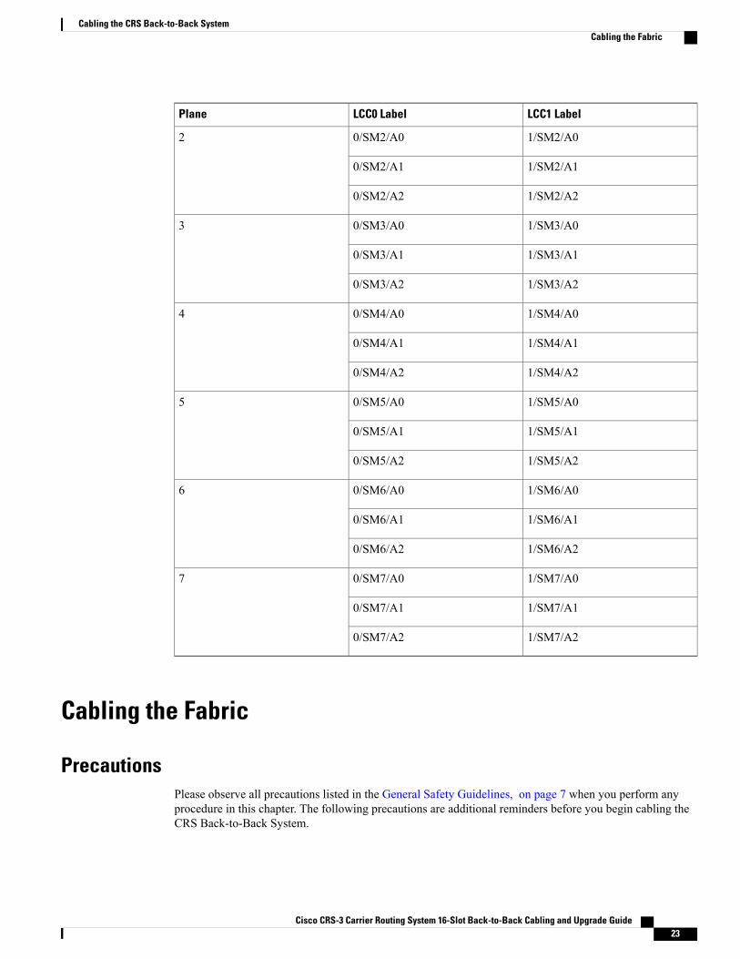
Label Schema ExampleWe suggest that you use a labeling schema, for example, with an Excel spreadsheet. The sample label schemashown in the below table uses the following convention: LCC_number /slot_number /port_number . Note thefollowing:
• Each cable should have a minimum of two labels, one label for each end.
• Do not apply the label within 2.5 inches (6.4 cm) from the point at which the cable meets the connector,or the label will be covered by the turn collar. In addition, if the label is farther than 3.5 inches (8.9 cm)from the point at which the cable meets the connector, it might be obscured by the collar of an adjacentcable when installed. A turn collar is shown in Figure 13: Turn Collar - Riser Cable, on page 28.
Table 4: Sample Labeling Schema for Fabric Cables
LCC1 LabelLCC0 LabelPlane
1/SM0/A00/SM0/A00
1/SM0/A10/SM0/A1
1/SM0/A20/SM0/A2
1/SM1/A00/SM1/A01
1/SM1/A10/SM1/A1
1/SM1/A20/SM1/A2
Cisco CRS-3 Carrier Routing System 16-Slot Back-to-Back Cabling and Upgrade Guide22
Cabling the CRS Back-to-Back SystemPlanning Cable Labels
LCC1 LabelLCC0 LabelPlane
1/SM2/A00/SM2/A02
1/SM2/A10/SM2/A1
1/SM2/A20/SM2/A2
1/SM3/A00/SM3/A03
1/SM3/A10/SM3/A1
1/SM3/A20/SM3/A2
1/SM4/A00/SM4/A04
1/SM4/A10/SM4/A1
1/SM4/A20/SM4/A2
1/SM5/A00/SM5/A05
1/SM5/A10/SM5/A1
1/SM5/A20/SM5/A2
1/SM6/A00/SM6/A06
1/SM6/A10/SM6/A1
1/SM6/A20/SM6/A2
1/SM7/A00/SM7/A07
1/SM7/A10/SM7/A1
1/SM7/A20/SM7/A2
Cabling the Fabric
PrecautionsPlease observe all precautions listed in the General Safety Guidelines, on page 7 when you perform anyprocedure in this chapter. The following precautions are additional reminders before you begin cabling theCRS Back-to-Back System.
Cisco CRS-3 Carrier Routing System 16-Slot Back-to-Back Cabling and Upgrade Guide 23
Cabling the CRS Back-to-Back SystemCabling the Fabric

Because invisible radiation may be emitted from the aperture of the port when no fiber cable is connected,avoid exposure to radiation and do not stare into open apertures. Statement 125
Warning
During this procedure, wear grounding wrist straps to avoid ESD damage to the card. Do not directlytouch the backplane with your hand or any metal tool, or you could shock yourself. Statement 94
Warning
Before working on equipment that is connected to power lines, remove jewelry (including rings, necklaces,and watches). Metal objects will heat up when connected to power and ground and can cause serious burnsor weld the metal object to the terminals. Statement 43
Warning
If a chassis power is on, assume lasers are turned on.
Never look at the ends of the fiber cables unless you are certain the laser is powered off.
The S13 card is Class 1M. Other optical cards are Class 1.
For diverging beams, viewing the laser output with certain optical instruments within a distance of 100MM. may pose an eye hazard. For collimated beams, viewing the laser output with certain opticalinstruments designed for use at a distance may pose an eye hazard. Statement 282
Warning
Laser radiation. Do not view directly with optical instruments. Class 1M laser product. Statement 283Warning
Handle cables carefully, as described in Introduction to the CRS Back-to-Back System, on page 1Caution
Cleanliness is critical to proper switch operation. To keep connections clean, do not remove the yellowdust cover from a port until you are ready to attach a cable. Do not remove the silver dust cover from afabric cable until you are ready to attach the cable to the fabric card connector. Silver dust covers shouldbe screwed on for security. Loosen the screws to remove the dust cover (see the figure below). Store dustcovers in a dust-free location.
Caution
Figure 10: Silver Dust Cover Protecting the Fabric Cable Connector
Cisco CRS-3 Carrier Routing System 16-Slot Back-to-Back Cabling and Upgrade Guide24
Cabling the CRS Back-to-Back SystemPrecautions
PrerequisitesCable connection procedures assume that all LCCs and their cards are installed in accordance with site planningguidelines and that appropriate interconnection cable lengths are ordered and ready to be connected.
All ports should have yellow dust covers on them as you begin this procedure, as shown in Figure 6: HowConnectors Are Numbered on S13 Cards (A0 Through A2), on page 14.
Caution
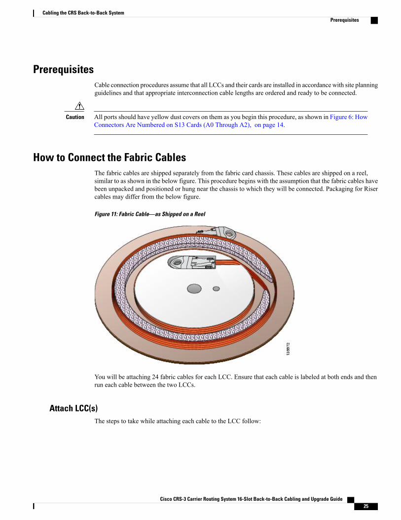
How to Connect the Fabric CablesThe fabric cables are shipped separately from the fabric card chassis. These cables are shipped on a reel,similar to as shown in the below figure. This procedure begins with the assumption that the fabric cables havebeen unpacked and positioned or hung near the chassis to which they will be connected. Packaging for Risercables may differ from the below figure.
Figure 11: Fabric Cable—as Shipped on a Reel
You will be attaching 24 fabric cables for each LCC. Ensure that each cable is labeled at both ends and thenrun each cable between the two LCCs.
Attach LCC(s)The steps to take while attaching each cable to the LCC follow:
Cisco CRS-3 Carrier Routing System 16-Slot Back-to-Back Cabling and Upgrade Guide 25
Cabling the CRS Back-to-Back SystemPrerequisites

Procedure
Step 1 Slide the turn collar support on in the direction shown below:Upper shelf - all turn collars go down. Lowershelf - all turn collars go up.
Step 2 Gently position the connector in the correct orientation (fabric card connectors and fabric cable connectorsare keyed).
Step 3 Hand-tighten the thumbscrews on the connector.Step 4 Repeat Steps 1 through 3 to each cable.Step 5 Fully tighten every connection.Step 6 Gently drape and group cables behind the fabric card. Use Velcro straps to tie the growing bundles together.Step 7 Bundle the cables together and velcro them to the horizontal cable manager and the vertical trough.
General Fabric Cabling ProceduresThe following are general fabric cabling procedures you might want to use when installing or maintainingthe fabric cabling:
Installing Turn CollarsThe turn collar protects the fabric cable bend radius and functions as a strain-relief support. It also has a Velcrostrap attached to it to bundle the cables as the cables are installed.
Here are notes to help you install a turn collar:
• The connector is keyed. One side is flat, and the other side has a diagonal cut from the corners.
• Connectors in S13 cards have the flat side on the right.
• Turn collars can be slipped onto either side of the connector, depending on whether the cable shouldturn up or down for proper routing through the chassis.
To install a turn collar:
Procedure
Step 1 Undo the Velcro strap.Step 2 Slide the cable into the turn collar until the cable is seated and snaps into place.
Add the collar while the cable is hanging. Since the cable is not connected, consider the direction the cableconnector will go when it is connected because all fabric card and fabric cable connectors are keyed.
Cisco CRS-3 Carrier Routing System 16-Slot Back-to-Back Cabling and Upgrade Guide26
Cabling the CRS Back-to-Back SystemGeneral Fabric Cabling Procedures
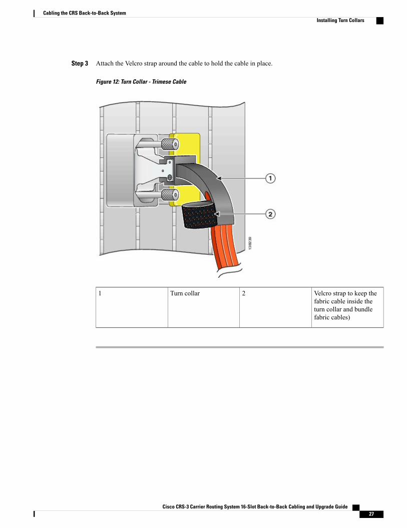
Step 3 Attach the Velcro strap around the cable to hold the cable in place.
Figure 12: Turn Collar - Trimese Cable
Velcro strap to keep thefabric cable inside theturn collar and bundlefabric cables)
2Turn collar1
Cisco CRS-3 Carrier Routing System 16-Slot Back-to-Back Cabling and Upgrade Guide 27
Cabling the CRS Back-to-Back SystemInstalling Turn Collars

What to Do Next
Figure 13: Turn Collar - Riser Cable
Velcro strap (to keep thefabric cable inside theturn collar and bundlefabric cables)
2Turn collar1
Cleaning CablesFor information about cleaning fiber-optic cables, see Cisco CRS-1 Optical Cleaning Guide.
Verifying the FabricThis section describes, in table form, the processes for executing the commands required to verify the fabric.All commands in this mode will be run from admin mode.
Cisco CRS-3 Carrier Routing System 16-Slot Back-to-Back Cabling and Upgrade Guide28
Cabling the CRS Back-to-Back SystemCleaning Cables

Procedure
Step 1 Execute the command: show platform. The command will have output similar to below. Note that there are24 fabric cables (SM0-23) and all are in IOS XR RUN state. Also note the 8 LCC fabric cards.
Example:
RP/0/RP0/CPU0:b2b(admin)#show platform | i SM0/SM0/SP CRS-16-FC-140/M(SP) N/A IOS XR RUN PWR,NSHUT,MON0/SM1/SP CRS-16-FC-140/M(SP) N/A IOS XR RUN PWR,NSHUT,MON0/SM2/SP CRS-16-FC-140/M(SP) N/A IOS XR RUN PWR,NSHUT,MON0/SM3/SP CRS-16-FC-140/M(SP) N/A IOS XR RUN PWR,NSHUT,MON0/SM4/SP CRS-16-FC-140/M(SP) N/A IOS XR RUN PWR,NSHUT,MON0/SM5/SP CRS-16-FC-140/M(SP) N/A IOS XR RUN PWR,NSHUT,MON0/SM7/SP CRS-16-FC-140/M(SP) N/A IOS XR RUN PWR,NSHUT,MON1/SM0/SP CRS-16-FC-140/M(SP) N/A IOS XR RUN PWR,NSHUT,MON1/SM1/SP CRS-16-FC-140/M(SP) N/A IOS XR RUN PWR,NSHUT,MON1/SM2/SP CRS-16-FC-140/M(SP) N/A IOS XR RUN PWR,NSHUT,MON1/SM3/SP CRS-16-FC-140/M(SP) N/A IOS XR RUN PWR,NSHUT,MON1/SM4/SP CRS-16-FC-140/M(SP) N/A IOS XR RUN PWR,NSHUT,MON1/SM5/SP CRS-16-FC-140/M(SP) N/A IOS XR RUN PWR,NSHUT,MON1/SM7/SP CRS-16-FC-140/M(SP) N/A IOS XR RUN PWR,NSHUT,MONRP/0/RP0/CPU0:b2b(admin)#
Step 2 Execute the command: show controllers fabric plane all detail. All planes should be UP/UP and the amountof downed bundles should be 21 on each plane. If there are more than 21 downed bundles, it means that atleast one of the array cables is loose or not connected properly.
Example:
Flags: P - plane admin down, p - plane oper downC - card admin down, c - card oper downL - link port admin down, l - linkport oper downA - asic admin down, a - asic oper downB - bundle port admin Down, b - bundle port oper downI - bundle admin down, i - bundle oper downN - node admin down, n - node downo - other end of link down d - data downf - failed component downstreamm - plane multicast downPlane Admin Oper Down Total DownId State State Flags Bundles Bundles------------------------------------------------------0 UP UP 27 211 UP UP 27 212 UP UP 27 213 UP UP 27 214 UP UP 27 215 UP UP 27 216 UP UP 27 217 UP UP 27 21
Step 3 Execute the command: show controllers fabric connectivity all detail. Each one of your line cards will berepresented in the output. Verify that there is connectivity to all 8 planes. This will be represented by 8 1’s,like below.
Flags: P - plane admin down, p - plane oper downC - card admin down, c - card oper downL - link port admin down, l - linkport oper downA - asic admin down, a - asic oper downB - bundle port admin Down, b - bundle port oper down
Cisco CRS-3 Carrier Routing System 16-Slot Back-to-Back Cabling and Upgrade Guide 29
Cabling the CRS Back-to-Back SystemVerifying the Fabric
Example:
I - bundle admin down, i - bundle oper downN - node admin down, n - node downo - other end of link down d - data downf - failed component downstreamm - plane multicast downCard In Tx Planes Rx Planes Monitored Total PercentR/S/M Use 01234567 01234567 For (s) Uptime (s) Uptime-------------------------------------------------------------------------------0/RP0/CPU0 1 11111111 11111111 12702 12702 100.00000/RP1/CPU0 1 11111111 11111111 12702 12702 100.00001/RP0/CPU0 1 11111111 11111111 50137 50137 100.00001/RP1/CPU0 1 11111111 11111111 50137 50137 100.0000
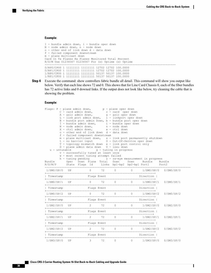
Step 4 Execute the command: show controllers fabric bundle all detail. This command will show you output likebelow. Verify that each line shows 72 and 0. This shows that for Line Card Chassis 0, each of the fiber bundleshas 72 active links and 0 downed links. If the output does not look like below, try cleaning the cable that isshowing the problem.
Example:
Flags: P - plane admin down, p - plane oper downC - card admin down, c - card oper downA - asic admin down, a - asic oper downL - link port admin down, l - linkport oper downB - bundle port admin Down, b - bundle port oper downI - bundle admin down, i - bundle oper downN - node admin down, n - node downX - ctrl admin down, x - ctrl downo - other end of link down d - data downf - failed component downstreamm - plane multicast down, s - link port permanently shutdownt - no barrier input O - Out-Of-Service oper downT - topology mismatch down e - link port control onlyD - plane admin data down U - issu down
u - untunable g - tuning in progressv - successfully tuned at least oncew - most recent tuning attempt failedh - tuning pending z - rx-eye measurement in progress
Bundle Oper Down Plane Total Down Down Bundle BundleR/S/M/P State Flags Id Links bp1-bp2 bp2-bp1 Port1 Port2----------------------------------------------------------------------------------------1/SM0/SP/0 UP 0 72 0 0 1/SM0/SP/0 0/SM0/SP/0+-----------------------------------------------------------------+| Timestamp Flags Event Direction |+-----------------------------------------------------------------+1/SM0/SP/1 UP 0 72 0 0 1/SM0/SP/1 0/SM0/SP/1+-----------------------------------------------------------------+| Timestamp Flags Event Direction |+-----------------------------------------------------------------+1/SM0/SP/2 UP 0 72 0 0 1/SM0/SP/2 0/SM0/SP/2+-----------------------------------------------------------------+| Timestamp Flags Event Direction |+-----------------------------------------------------------------+1/SM2/SP/0 UP 2 72 0 0 1/SM2/SP/0 0/SM2/SP/0+-----------------------------------------------------------------+| Timestamp Flags Event Direction |+----------------------------------------------------------------+1/SM2/SP/1 UP 2 72 0 0 1/SM2/SP/1 0/SM2/SP/1+-----------------------------------------------------------------+| Timestamp Flags Event Direction |+-----------------------------------------------------------------+1/SM2/SP/2 UP 2 72 0 0 1/SM2/SP/2 0/SM2/SP/2+-----------------------------------------------------------------+| Timestamp Flags Event Direction |+-----------------------------------------------------------------+1/SM3/SP/0 UP 3 72 0 0 1/SM3/SP/0 0/SM3/SP/0
Cisco CRS-3 Carrier Routing System 16-Slot Back-to-Back Cabling and Upgrade Guide30
Cabling the CRS Back-to-Back SystemVerifying the Fabric

+-----------------------------------------------------------------+| Timestamp Flags Event Direction |+-----------------------------------------------------------------+1/SM3/SP/1 UP 3 72 0 0 1/SM3/SP/1 0/SM3/SP/1+-----------------------------------------------------------------+| Timestamp Flags Event Direction |+-----------------------------------------------------------------+1/SM3/SP/2 UP 3 72 0 0 1/SM3/SP/2 0/SM3/SP/2+-----------------------------------------------------------------+| Timestamp Flags Event Direction |+-----------------------------------------------------------------+1/SM4/SP/0 UP 4 72 0 0 1/SM4/SP/0 0/SM4/SP/0+-----------------------------------------------------------------+| Timestamp Flags Event Direction |+-----------------------------------------------------------------+1/SM4/SP/1 UP 4 72 0 0 1/SM4/SP/1 0/SM4/SP/1+-----------------------------------------------------------------+| Timestamp Flags Event Direction |+-----------------------------------------------------------------+1/SM4/SP/2 UP 4 72 0 0 1/SM4/SP/2 0/SM4/SP/2+-----------------------------------------------------------------+| Timestamp Flags Event Direction |+-----------------------------------------------------------------+1/SM5/SP/0 UP 5 72 0 0 1/SM5/SP/0 0/SM5/SP/0+-----------------------------------------------------------------+| Timestamp Flags Event Direction |+-----------------------------------------------------------------+1/SM5/SP/1 UP 5 72 0 0 1/SM5/SP/1 0/SM5/SP/1+-----------------------------------------------------------------+| Timestamp Flags Event Direction |+-----------------------------------------------------------------+1/SM5/SP/2 UP 5 72 0 0 1/SM5/SP/2 0/SM5/SP/2+-----------------------------------------------------------------+| Timestamp Flags Event Direction |+-----------------------------------------------------------------+1/SM7/SP/0 UP 7 72 0 0 1/SM7/SP/0 0/SM7/SP/0+-----------------------------------------------------------------+| Timestamp Flags Event Direction |+-----------------------------------------------------------------+1/SM7/SP/1 UP 7 72 0 0 1/SM7/SP/1 0/SM7/SP/1+-----------------------------------------------------------------+| Timestamp Flags Event Direction |+-----------------------------------------------------------------+1/SM7/SP/2 UP 7 72 0 0 1/SM7/SP/2 0/SM7/SP/2+-----------------------------------------------------------------+| Timestamp Flags Event Direction |+-----------------------------------------------------------------+RP/0/RP0/CPU0:b2b(admin)#
Step 5 Execute the command: show controllers fabric plane all statistics. Verify that the output looks similar to below.The actual number of packets does not matter, as long as all fabric planes are showing some packets passedand no increasing errors. It is normal to have a few UCEs across the planes and many CEs on Plane 4.
Step 6 Execute the command: show controllers fabric bundle all brief | i rack/SMslot/. This command will showyou output like below. Verify that the status of all of the bundle members is UP.
Example:
Flags: P - plane admin down, p - plane oper downC - card admin down, c - card oper downA - asic admin down, a - asic oper downL - link port admin down, l - linkport oper downB - bundle port admin Down, b - bundle port oper downI - bundle admin down, i - bundle oper downN - node admin down, n - node downX - ctrl admin down, x - ctrl downo - other end of link down d - data downf - failed component downstreamm - plane multicast down, s - link port permanently shutdownt - no barrier input O - Out-Of-Service oper down
Cisco CRS-3 Carrier Routing System 16-Slot Back-to-Back Cabling and Upgrade Guide 31
Cabling the CRS Back-to-Back SystemVerifying the Fabric
T - topology mismatch down e - link port control onlyD - plane admin data down U - issu downu - untunable g - tuning in progressv - successfully tuned at least oncew - most recent tuning attempt failedh - tuning pending z - rx-eye measurement in progress
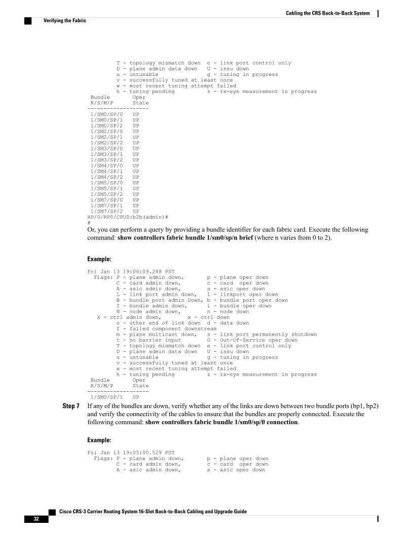
Bundle OperR/S/M/P State-------------------1/SM0/SP/0 UP1/SM0/SP/1 UP1/SM0/SP/2 UP1/SM2/SP/0 UP1/SM2/SP/1 UP1/SM2/SP/2 UP1/SM3/SP/0 UP1/SM3/SP/1 UP1/SM3/SP/2 UP1/SM4/SP/0 UP1/SM4/SP/1 UP1/SM4/SP/2 UP1/SM5/SP/0 UP1/SM5/SP/1 UP1/SM5/SP/2 UP1/SM7/SP/0 UP1/SM7/SP/1 UP1/SM7/SP/2 UPRP/0/RP0/CPU0:b2b(admin)##Or, you can perform a query by providing a bundle identifier for each fabric card. Execute the followingcommand: show controllers fabric bundle 1/sm0/sp/n brief (where n varies from 0 to 2).
Example:
Fri Jan 13 19:06:09.248 PSTFlags: P - plane admin down, p - plane oper down
C - card admin down, c - card oper downA - asic admin down, a - asic oper downL - link port admin down, l - linkport oper downB - bundle port admin Down, b - bundle port oper downI - bundle admin down, i - bundle oper downN - node admin down, n - node down
X - ctrl admin down, x - ctrl downo - other end of link down d - data downf - failed component downstreamm - plane multicast down, s - link port permanently shutdownt - no barrier input O - Out-Of-Service oper downT - topology mismatch down e - link port control onlyD - plane admin data down U - issu downu - untunable g - tuning in progressv - successfully tuned at least oncew - most recent tuning attempt failedh - tuning pending z - rx-eye measurement in progress
Bundle OperR/S/M/P State-------------------1/SM0/SP/1 UP
Step 7 If any of the bundles are down, verify whether any of the links are down between two bundle ports (bp1, bp2)and verify the connectivity of the cables to ensure that the bundles are properly connected. Execute thefollowing command: show controllers fabric bundle 1/sm0/sp/0 connection.
Example:
Fri Jan 13 19:05:00.529 PSTFlags: P - plane admin down, p - plane oper down
C - card admin down, c - card oper downA - asic admin down, a - asic oper down
Cisco CRS-3 Carrier Routing System 16-Slot Back-to-Back Cabling and Upgrade Guide32
Cabling the CRS Back-to-Back SystemVerifying the Fabric
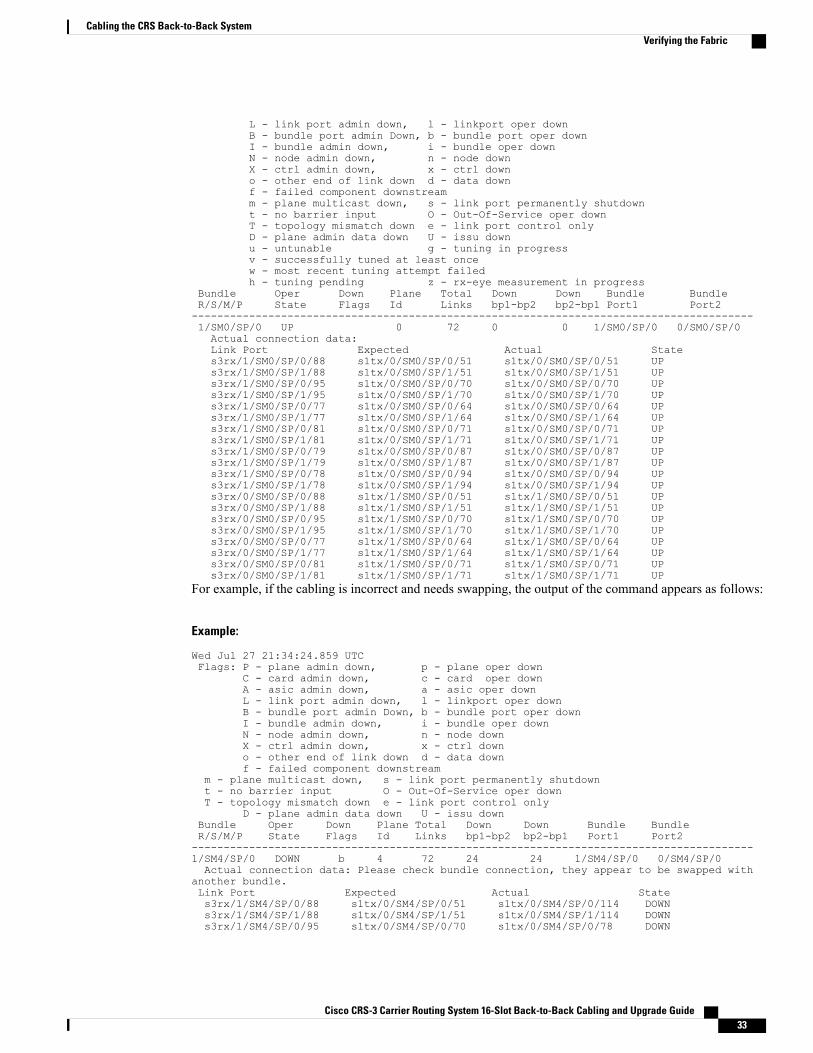
L - link port admin down, l - linkport oper downB - bundle port admin Down, b - bundle port oper downI - bundle admin down, i - bundle oper downN - node admin down, n - node downX - ctrl admin down, x - ctrl downo - other end of link down d - data downf - failed component downstreamm - plane multicast down, s - link port permanently shutdownt - no barrier input O - Out-Of-Service oper downT - topology mismatch down e - link port control onlyD - plane admin data down U - issu downu - untunable g - tuning in progressv - successfully tuned at least oncew - most recent tuning attempt failedh - tuning pending z - rx-eye measurement in progress
Bundle Oper Down Plane Total Down Down Bundle BundleR/S/M/P State Flags Id Links bp1-bp2 bp2-bp1 Port1 Port2----------------------------------------------------------------------------------------1/SM0/SP/0 UP 0 72 0 0 1/SM0/SP/0 0/SM0/SP/0Actual connection data:Link Port Expected Actual States3rx/1/SM0/SP/0/88 s1tx/0/SM0/SP/0/51 s1tx/0/SM0/SP/0/51 UPs3rx/1/SM0/SP/1/88 s1tx/0/SM0/SP/1/51 s1tx/0/SM0/SP/1/51 UPs3rx/1/SM0/SP/0/95 s1tx/0/SM0/SP/0/70 s1tx/0/SM0/SP/0/70 UPs3rx/1/SM0/SP/1/95 s1tx/0/SM0/SP/1/70 s1tx/0/SM0/SP/1/70 UPs3rx/1/SM0/SP/0/77 s1tx/0/SM0/SP/0/64 s1tx/0/SM0/SP/0/64 UPs3rx/1/SM0/SP/1/77 s1tx/0/SM0/SP/1/64 s1tx/0/SM0/SP/1/64 UPs3rx/1/SM0/SP/0/81 s1tx/0/SM0/SP/0/71 s1tx/0/SM0/SP/0/71 UPs3rx/1/SM0/SP/1/81 s1tx/0/SM0/SP/1/71 s1tx/0/SM0/SP/1/71 UPs3rx/1/SM0/SP/0/79 s1tx/0/SM0/SP/0/87 s1tx/0/SM0/SP/0/87 UPs3rx/1/SM0/SP/1/79 s1tx/0/SM0/SP/1/87 s1tx/0/SM0/SP/1/87 UPs3rx/1/SM0/SP/0/78 s1tx/0/SM0/SP/0/94 s1tx/0/SM0/SP/0/94 UPs3rx/1/SM0/SP/1/78 s1tx/0/SM0/SP/1/94 s1tx/0/SM0/SP/1/94 UPs3rx/0/SM0/SP/0/88 s1tx/1/SM0/SP/0/51 s1tx/1/SM0/SP/0/51 UPs3rx/0/SM0/SP/1/88 s1tx/1/SM0/SP/1/51 s1tx/1/SM0/SP/1/51 UPs3rx/0/SM0/SP/0/95 s1tx/1/SM0/SP/0/70 s1tx/1/SM0/SP/0/70 UPs3rx/0/SM0/SP/1/95 s1tx/1/SM0/SP/1/70 s1tx/1/SM0/SP/1/70 UPs3rx/0/SM0/SP/0/77 s1tx/1/SM0/SP/0/64 s1tx/1/SM0/SP/0/64 UPs3rx/0/SM0/SP/1/77 s1tx/1/SM0/SP/1/64 s1tx/1/SM0/SP/1/64 UPs3rx/0/SM0/SP/0/81 s1tx/1/SM0/SP/0/71 s1tx/1/SM0/SP/0/71 UPs3rx/0/SM0/SP/1/81 s1tx/1/SM0/SP/1/71 s1tx/1/SM0/SP/1/71 UP
For example, if the cabling is incorrect and needs swapping, the output of the command appears as follows:
Example:
Wed Jul 27 21:34:24.859 UTCFlags: P - plane admin down, p - plane oper down
C - card admin down, c - card oper downA - asic admin down, a - asic oper downL - link port admin down, l - linkport oper downB - bundle port admin Down, b - bundle port oper downI - bundle admin down, i - bundle oper downN - node admin down, n - node downX - ctrl admin down, x - ctrl downo - other end of link down d - data downf - failed component downstream
m - plane multicast down, s - link port permanently shutdownt - no barrier input O - Out-Of-Service oper downT - topology mismatch down e - link port control only
D - plane admin data down U - issu downBundle Oper Down Plane Total Down Down Bundle BundleR/S/M/P State Flags Id Links bp1-bp2 bp2-bp1 Port1 Port2----------------------------------------------------------------------------------------1/SM4/SP/0 DOWN b 4 72 24 24 1/SM4/SP/0 0/SM4/SP/0Actual connection data: Please check bundle connection, they appear to be swapped with
another bundle.Link Port Expected Actual States3rx/1/SM4/SP/0/88 s1tx/0/SM4/SP/0/51 s1tx/0/SM4/SP/0/114 DOWNs3rx/1/SM4/SP/1/88 s1tx/0/SM4/SP/1/51 s1tx/0/SM4/SP/1/114 DOWNs3rx/1/SM4/SP/0/95 s1tx/0/SM4/SP/0/70 s1tx/0/SM4/SP/0/78 DOWN
Cisco CRS-3 Carrier Routing System 16-Slot Back-to-Back Cabling and Upgrade Guide 33
Cabling the CRS Back-to-Back SystemVerifying the Fabric
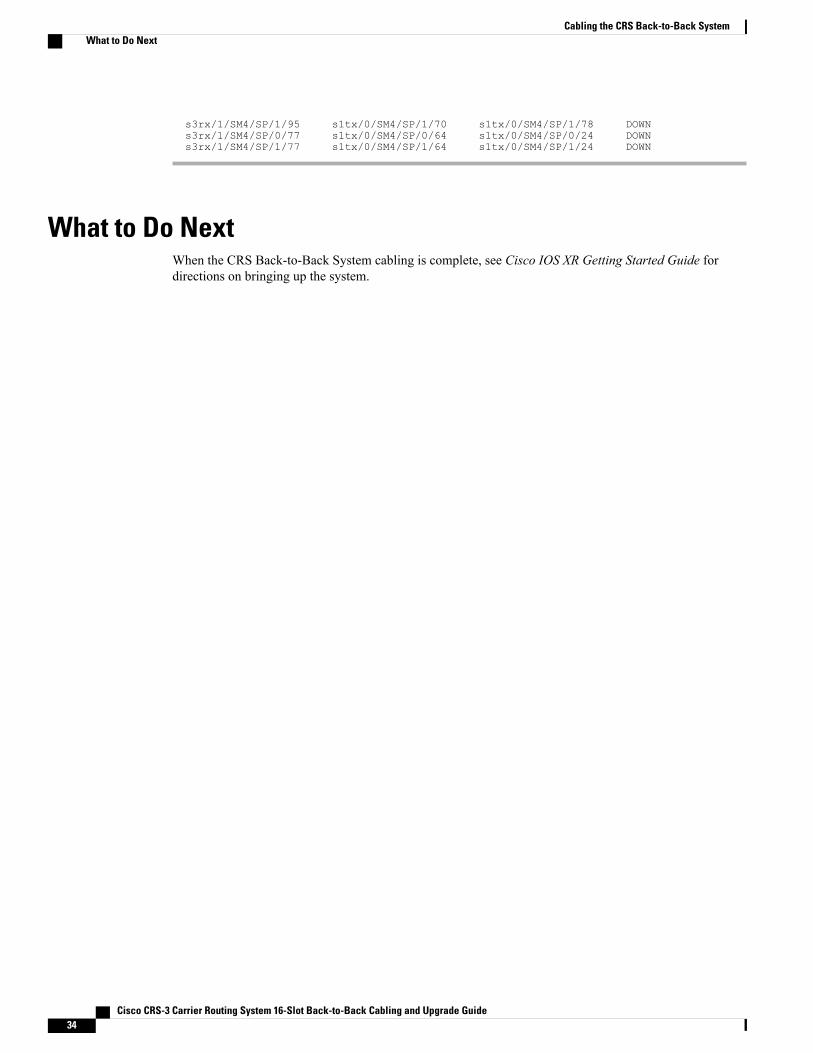
s3rx/1/SM4/SP/1/95 s1tx/0/SM4/SP/1/70 s1tx/0/SM4/SP/1/78 DOWNs3rx/1/SM4/SP/0/77 s1tx/0/SM4/SP/0/64 s1tx/0/SM4/SP/0/24 DOWNs3rx/1/SM4/SP/1/77 s1tx/0/SM4/SP/1/64 s1tx/0/SM4/SP/1/24 DOWN
What to Do NextWhen the CRS Back-to-Back System cabling is complete, see Cisco IOS XR Getting Started Guide fordirections on bringing up the system.
Cisco CRS-3 Carrier Routing System 16-Slot Back-to-Back Cabling and Upgrade Guide34
Cabling the CRS Back-to-Back SystemWhat to Do Next
C H A P T E R 4Upgrading to a CRS Back-to-Back System UsingCisco IOS-XR 4.3.1 or Earlier
This chapter describes how to:
• Upgrade a Cisco CRS-1 or Cisco CRS-3 single-chassis to a CRS 140 G Back-to-Back System whenyou are using Cisco IOS-XR version 4.3.1 or earlier, and
• Upgrade a Cisco CRS-1, Cisco CRS-3, or Cisco CRS-X single-chassis to a CRS 400 G Back-to-BackSystem when you are using Cisco IOS-XR version 4.3.1 or earlier.
The procedures for upgrading to a CRS 140 GBack-to-Back System and a CRS 400 GBack-to-Back Systemare similar.
If you are using Cisco IOS-XR 5.1.1 or later, please see Upgrading to a CRS Back-to-Back System UsingCisco IOS-XR 5.1.1 or Later, on page 49
Note
• Prerequisites for Upgrading to a CRS Back-to-Back System, page 35
• How to Upgrade to a CRS Back-to-Back System, page 36
• Connecting the Control Network, page 41
• Tips and Troubleshooting, page 46
• Technical Assistance, page 47
Prerequisites for Upgrading to a CRS Back-to-Back SystemBefore You Begin
Prior to upgrading, perform the following steps:
Cisco CRS-3 Carrier Routing System 16-Slot Back-to-Back Cabling and Upgrade Guide 35

Procedure
Step 1 Prepare the single-chassis system as follows:a) Obtain the chassis serial number of the current running system which is required for configuration. The
serial number is on a chassis label and can be accessed using the show diag chassis command, as describedin the Cisco IOS XR Getting Started Guide .
b) Upgrade the ROM Monitor software to version 2.06 or later, as described in the Cisco IOS XR ROMMonitor Guide .
Step 2 Prepare the additional LCC as follows:a) Ensure that the power to the new LCC is off.
For more information, see the Cisco CRS Carrier Routing System 16-Slot Line Card Chassis InstallationGuide .
b) It is recommended to get the back-to-back array cables ready and not connected yet.
How to Upgrade to a CRS Back-to-Back SystemTo upgrade a single-chassis system to a CRS Back-to-Back System, you must complete the following tasks:
Upgrading the Fabric CardsThis section describes how to upgrade the fabric cards in a single-chassis system.
Prerequisites
Software Requirements
• Cisco IOS XR Software Release 4.2.1 or later release
• ROMMON 2.06 or later version
The ROMMonitor software must be upgraded to version 2.06 or a later version on all PRPs before a CiscoCRS-3 or CRS-X system is upgraded to Cisco IOSXR Software Release 4.2.1 or later release. If the routeris brought up with an incompatible version of the ROMMonitor software, then the standby PRP may failto boot. For instructions to overcome a boot block in the standby PRP in a single chassis system, see CiscoIOS XR ROM Monitor Guide .
Caution
Hardware Requirements
Conversion kit, which has the following components:
• Eight fabric cards:
Cisco CRS-3 Carrier Routing System 16-Slot Back-to-Back Cabling and Upgrade Guide36
Upgrading to a CRS Back-to-Back System Using Cisco IOS-XR 4.3.1 or EarlierHow to Upgrade to a CRS Back-to-Back System

CRS-16-FC140/M for CRS 140 G Back-to-Back System, or◦
◦CRS-16-FC400/M for CRS 400 G Back-to-Back System
• Rear cable management (CRS-16-REAR-CM)
• PRP route processor (if you are using CRS-16-RP-B on a single chassis)
RestrictionsNone.
Summary StepsOn a single-chassis system, each fabric card represents one fabric plane. To avoid traffic loss during theupgrade, you must upgrade the switch fabric one plane at a time. To do that, you must replace each FC/Sfabric card (CRS-16-FC/S, CRS-16-FC140/S, or CRS-16-FC400/S) with a new FC/M fabric card(CRS-16-FC140/M or CRS-16-FC400/M) and restore service to that fabric plane before upgrading the nextfabric plane.
Here are the basic steps to upgrade fabric cards:
Procedure
Step 1 Use CLI commands to prepare each FC/S fabric card (CRS-16-FC/S, CRS-16-FC140/S, or CRS-16-FC400/S)for replacement with an FC/M fabric card (CRS-16-FC140/M or CRS-16-FC400/M).
Step 2 Before you replace any FC/S cards, shut down the plane on each card using the following command: controllersfabric plane planeNumber shutdown.
Step 3 On the fabric card that you want to replace, disable the power using the following command: hw-modulepower disable location rack /SMslot /SP.
Step 4 Replace each FC/S card (CRS-16-FC/S, CRS-16-FC140/S, or CRS-16-FC400/S) with a FC/M fabric card(CRS-16-FC140/M or CRS-16-FC400/M).
Step 5 Bring up the FC/M card (CRS-16-FC140/M or CRS-16-FC400/M), as follows:a) Power up the card using the following command: no hw-module power disable location rack /SMslot
/SP. Wait for the plates to reach the IOS XR RUN state.b) For the plane to be upgraded, bring up the control plane using the following command: controllers fabric
plane planeNumber shutdown data.c) Verify that the entire card has booted and all asics have initialized prior to restoring the plane for traffic.d) Bring up the data plane using the following command: no controllers fabric plane planeNumber shutdown.
Verify that the plane state is UP/UP.
Step 6 Repeat Step 5 through Step 5 until all planes (0 through 7) are upgraded.
Cisco CRS-3 Carrier Routing System 16-Slot Back-to-Back Cabling and Upgrade Guide 37
Upgrading to a CRS Back-to-Back System Using Cisco IOS-XR 4.3.1 or EarlierUpgrading the Fabric Cards

Detailed Steps
Procedure
PurposeCommand or Action
Places the router in administration EXEC mode.adminStep 1
Example:
RP/0/RP1/CPU0:router# admin
• All commands listed in this procedure should beentered on the pre-existing single-chassis system.
Displays the status of all LCCmodules in the specifiedrack.
show platform rack number/**/*
Example:
RP/0/RP1/CPU0:router(admin)# show platform1/**/*
Step 2
• Replace rack with the rack number of the LCCto examine.
• Repeat this command for all LCCs.
• The state for all modules should be IOS-XRRUN.
• It can take a few minutes for all LCC modulesto start.
The LCC module status appears only whenthe show platform command is executed inadministration EXEC mode.
Note
Places the router in administration configurationmode.configure
Example:
RP/0/RP1/CPU0:router(admin)#configure
Step 3
Displays the administrative and operational status ofall eight fabric planes.
do show controllers fabric plane all
Example:
RP/0/RP1/CPU0:router(admin-config)# do showcontrollers fabric plane all
Step 4
• The do command prefix allows the EXEC modeshow command to execute in administrationconfiguration mode.
To prevent service interruption, do notcontinue until the administrative andoperational status for all eight planes is UP.
Caution
Modifies the target configuration to shut down thespecified plane number.
controllers fabric plane planeNumber shutdown
Example:
RP/0/RP1/CPU0:router(admin-config)#controllers fabric plane 0 shutdown
Step 5
• Replace the planeNumber parameter with thenumber of the plane you want to shut down.
• The admin/operational state will beDOWN/DOWN.
Cisco CRS-3 Carrier Routing System 16-Slot Back-to-Back Cabling and Upgrade Guide38
Upgrading to a CRS Back-to-Back System Using Cisco IOS-XR 4.3.1 or EarlierUpgrading the Fabric Cards

PurposeCommand or Action
Commits the target configuration to the router runningconfiguration.
commit
Example:
RP/0/RP1/CPU0:router(admin-config)# commit
Step 6
• This step shuts down the plane identified in theprevious step.
Disables the power-on feature on a specific fabric card.hw-module power disable location0/smslotNumber /sp
Step 7
Example:
RP/0/RP1/CPU0:router(admin-config)#hw-module power disable location 0/sm0/sp
Commits the target configuration to the router runningconfiguration.
commit
Example:
RP/0/RP1/CPU0:router(admin-config)# commit
Step 8
• This step shuts down the plane identified in theprevious step.
Displays the status of the Rack 0 fabric slot specifiedby slotNumber . Verify that the card is in theUNPOWERED state.
show platform 0/smslotNumber/sp
Example:
RP/0/RP1/CPU0:router(admin)# show platform0/sm0/sp
Step 9
The fabric card status appears only when theshow platform command is executed inadministration EXEC mode.
Note
Creates room for the FC/M fabric card(CRS-16-FC140/M or CRS-16-FC400/M) card that isrequired for CRS Back-to-Back System operation.
In Rack 0, remove the FC/S card (CRS-16-FC/S,CRS-16-FC140/S, or CRS-16-FC400/S) for theplane that was shut down in Step 5.
Step 10
Provides the hardware required for communicationwith the LCC.
In Rack 0, insert the FC/M fabric card(CRS-16-FC140/M or CRS-16-FC400/M) card forthe plane that was shut down in Step 5.
Step 11
Re-enables the power-on feature on a specific fabriccard.
no hw-module power disable location0/smslotNumber /sp
Example:
RP/0/RP1/CPU0:router(admin-config)# nohw-module power disable location 0/sm0/sp
Step 12
Example:
Commits the target configuration to the router runningconfiguration.
commit
Example:
RP/0/RP1/CPU0:router(admin-config)# commit
Step 13
Cisco CRS-3 Carrier Routing System 16-Slot Back-to-Back Cabling and Upgrade Guide 39
Upgrading to a CRS Back-to-Back System Using Cisco IOS-XR 4.3.1 or EarlierUpgrading the Fabric Cards
PurposeCommand or Action
Displays the status of the Rack 0 fabric slot specifiedby slotNumber . Verify that the card is in the IOS XRRUN state.
do show platform 0/smslotNumber/sp
Example:
RP/0/RP1/CPU0:router(admin)# show platform0/sm0/sp
Step 14
The fabric card status appears only when theshow platform command is executed inadministration EXEC mode.
Note
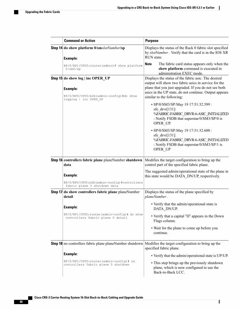
Displays the status of the fabric asic. The desiredoutput will show two fabric asics in service for the
do show log | inc OPER_UP
Example:
RP/0/RP0/CPU0:b2b(admin-config)#do showlogging | inc OPER_UP
Step 15
plane that you just upgraded. If you do not see bothasics in the UP state, do not continue. Output appearssimilar to the following:
• SP/0/SM3/SP:May 19 17:51:32.599 :sfe_drvr[131]:%FABRIC-FABRIC_DRVR-6-ASIC_INITIALIZED: Notify FSDB that superstar/0/SM3/SP/0 isOPER_UP.
• SP/0/SM3/SP:May 19 17:51:32.600 :sfe_drvr[131]:%FABRIC-FABRIC_DRVR-6-ASIC_INITIALIZED: Notify FSDB that superstar/0/SM3/SP/1 isOPER_UP
Modifies the target configuration to bring up thecontrol part of the specified fabric plane.
controllers fabric plane planeNumber shutdowndata
Step 16
Example:
RP/0/RP0/CPU0:b2b(admin-config)#controllersfabric plane 3 shutdown data
The suggested admin/operational state of the plane inthis state would be DATA_DN/UP, respectively.
Displays the status of the plane specified byplaneNumber .
do show controllers fabric plane planeNumberdetail
Step 17
Example:
RP/0/RP1/CPU0:router(admin-config)# do showcontrollers fabric plane 0 detail
• Verify that the admin/operational state isDATA_DN/UP.
• Verify that a capital “D” appears in the DownFlags column.
•Wait for the plane to come up before youcontinue.
Modifies the target configuration to bring up thespecified fabric plane.
no controllers fabric plane planeNumber shutdown
Example:
RP/0/RP1/CPU0:router(admin-config)# nocontrollers fabric plane 0 shutdown
Step 18
• Verify that the admin/operational state is UP/UP.
• This step brings up the previously shutdownplane, which is now configured to use theBack-to-Back LCC.
Cisco CRS-3 Carrier Routing System 16-Slot Back-to-Back Cabling and Upgrade Guide40
Upgrading to a CRS Back-to-Back System Using Cisco IOS-XR 4.3.1 or EarlierUpgrading the Fabric Cards

PurposeCommand or Action
Changes the mode from administration configurationmode to administration EXEC mode.
end
Example:
RP/0/RP1/CPU0:router(admin-config)# end
Step 19
Repeat Step 2 through Step 19 for each fabric plane.Step 20
Displays the administrative and operational status ofall eight fabric planes.
show controllers fabric plane all
Example:
RP/0/RP1/CPU0:router(admin)# showcontrollers fabric plane all
Step 21
• Verify that all fabric planes are operational andthe status is UP/UP.
• The plane you just migrated should show acounter increment of 1 in both the up->dn counterand the up->mcast counter.
What to Do NextOnce the Rack 0 upgrade is completed, the control network must be connected.
Connecting the Control NetworkBefore the additional LCC can be added to the CRS Back-to-Back System, a control network must beestablished. The control network allows two LCCs in the CRS Back-to-Back System to communicate witheach other. The control function is performed by the PRPs.
Figure 14: Connections within a CRS Back-to-Back System, on page 41 shows how the control Ethernetports of PRPs are interconnected.
Figure 14: Connections within a CRS Back-to-Back System
What to Do NextOnce the control network is connected, add the additional LCC to the CRS Back-to-Back System.
Adding a LCC to a CRS Back-to-Back SystemThis section describes how to add a LCC to a CRS Back-to-Back System.
Cisco CRS-3 Carrier Routing System 16-Slot Back-to-Back Cabling and Upgrade Guide 41
Upgrading to a CRS Back-to-Back System Using Cisco IOS-XR 4.3.1 or EarlierConnecting the Control Network

Prerequisites
Software Requirements
• Cisco IOS XR Software Release 4.2.1 or later release
• ROMMON 2.06 or later version
• Serial number of new LCC (can be found on front of chassis)
Hardware Requirements
• The additional LCC.
• The control network must be operational and connected to all chassis.
• The power should be off for the LCC to be added.
• PRP route processor (if you are using CRS-16-RP-B on a single chassis)
RestrictionsNone.
Summary StepsHere are the basic steps to add the additional LCC to the CRS Back-to-Back System:
Procedure
Step 1 Backup the exec and admin configs on LCC0.Step 2 Power ON the LCC (Rack 1) chassis.Step 3 Interrupt the booting into drop the system (Active and Standby PRP) in ROMMON and verify the rack number
(dumpplaneeeprom output ' 0x73rd byte) on the Active PRP.a) Unset the BOOT variable.b) Unset the RACK_NUM variable.c) Also unset the TFTP_FILE and TURBOBOOT variables if they are set.d) Enter the sync command to save the current changes.e) Verify the configuration-register is set to 0x0. The configuration-register setting 0x0 prevents the PRP
from syncing to the dSC by keeping the PRP in the ROMMON state.
Step 4 Configure the Active PRP using the following command, which associates LCC 1 serial numbers with therack number: dsc serial rack serial number rack 1.
Step 5 Configure Rack 1 in fabric rack install-mode using the following command: controllers fabric rack 1install-mode.
Step 6 Connect the B2B fabric cables for all fabric planes.a) Connect 0/SMx/0,1,2 to 1/SMx/0,1,2.
Cisco CRS-3 Carrier Routing System 16-Slot Back-to-Back Cabling and Upgrade Guide42
Upgrading to a CRS Back-to-Back System Using Cisco IOS-XR 4.3.1 or EarlierAdding a LCC to a CRS Back-to-Back System
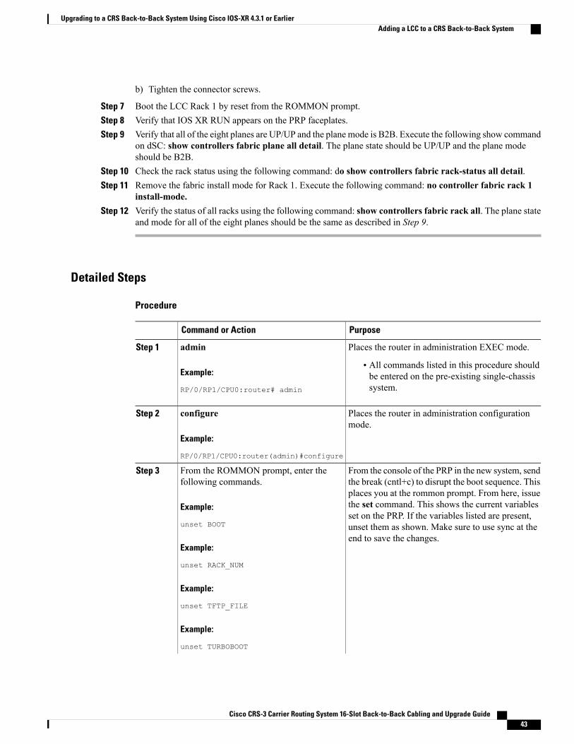
b) Tighten the connector screws.
Step 7 Boot the LCC Rack 1 by reset from the ROMMON prompt.Step 8 Verify that IOS XR RUN appears on the PRP faceplates.Step 9 Verify that all of the eight planes are UP/UP and the plane mode is B2B. Execute the following show command
on dSC: show controllers fabric plane all detail. The plane state should be UP/UP and the plane modeshould be B2B.
Step 10 Check the rack status using the following command: do show controllers fabric rack-status all detail.Step 11 Remove the fabric install mode for Rack 1. Execute the following command: no controller fabric rack 1
install-mode.Step 12 Verify the status of all racks using the following command: show controllers fabric rack all. The plane state
and mode for all of the eight planes should be the same as described in Step 9.
Detailed Steps
Procedure
PurposeCommand or Action
Places the router in administration EXEC mode.adminStep 1
Example:
RP/0/RP1/CPU0:router# admin
• All commands listed in this procedure shouldbe entered on the pre-existing single-chassissystem.
Places the router in administration configurationmode.
configure
Example:
RP/0/RP1/CPU0:router(admin)#configure
Step 2
From the console of the PRP in the new system, sendthe break (cntl+c) to disrupt the boot sequence. This
From the ROMMON prompt, enter thefollowing commands.
Step 3
places you at the rommon prompt. From here, issueExample:
unset BOOT
the set command. This shows the current variablesset on the PRP. If the variables listed are present,unset them as shown. Make sure to use sync at theend to save the changes.
Example:
unset RACK_NUM
Example:
unset TFTP_FILE
Example:
unset TURBOBOOT
Cisco CRS-3 Carrier Routing System 16-Slot Back-to-Back Cabling and Upgrade Guide 43
Upgrading to a CRS Back-to-Back System Using Cisco IOS-XR 4.3.1 or EarlierAdding a LCC to a CRS Back-to-Back System

PurposeCommand or Action
Example:
confreg 0x0
Example:
sync
Example:
reset
Configures the additional LCC as Rack 1 in themultishelf system.
dsc serial serialNumber rack 1
Example:
RP/0/RP1/CPU0:router(admin-config)#dsc serial TBA08440024 rack 1
Step 4
• Replace the serialNumber parameter with theserial number of the additional LCC.
• If you are configuring the system from aremote location, you can use a command todisplay the serial number. For moreinformation, seeCisco IOS XRGetting StartedGuide.
Modifies the target configuration to change the Rack1 configuration to installation mode.
controllers fabric rack 1 install-mode
Example:
RP/0/RP1/CPU0:router(admin-config)#
Step 5
controllers fabric rack 1install-mode
Commits the target configuration to the routerrunning configuration.
commit
Example:
RP/0/RP1/CPU0:router(admin-config)#commit
Step 6
Starts up the second LCC (Rack 1).Apply power to the new LCC (Rack 1).Step 7
Connect all fabric cables that connect the fabricplanes in the new LCC to the additional LCCs.
Interconnects the fabric cards between twoLCCs.
Step 8
Boots the LCCRack 1 by reset from the ROMMONprompt. Sets the config register to 0x2 and enablesboot.
From the ROMMON prompt, enter thefollowing commands.
Example:
confreg 0x2
Step 9
Example:
sync
Cisco CRS-3 Carrier Routing System 16-Slot Back-to-Back Cabling and Upgrade Guide44
Upgrading to a CRS Back-to-Back System Using Cisco IOS-XR 4.3.1 or EarlierAdding a LCC to a CRS Back-to-Back System
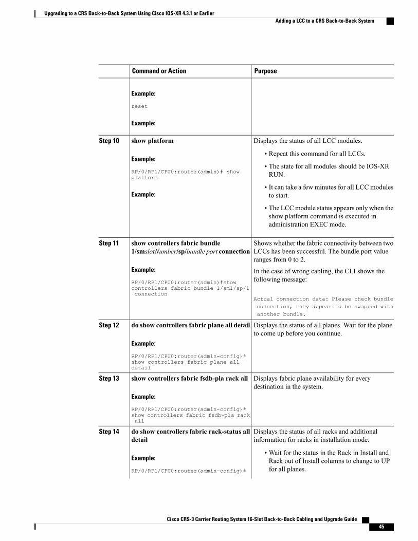
PurposeCommand or Action
Example:
reset
Example:
Displays the status of all LCC modules.show platformStep 10
Example:
RP/0/RP1/CPU0:router(admin)# showplatform
• Repeat this command for all LCCs.
• The state for all modules should be IOS-XRRUN.
Example:• It can take a few minutes for all LCC modulesto start.
• The LCCmodule status appears only when theshow platform command is executed inadministration EXEC mode.
Shows whether the fabric connectivity between twoLCCs has been successful. The bundle port valueranges from 0 to 2.
show controllers fabric bundle1/smslotNumber/sp/bundle port connection
Example:
RP/0/RP1/CPU0:router(admin)#show
Step 11
In the case of wrong cabling, the CLI shows thefollowing message:
Actual connection data: Please check bundle
controllers fabric bundle 1/sm1/sp/1connection
connection, they appear to be swapped withanother bundle.
Displays the status of all planes. Wait for the planeto come up before you continue.
do show controllers fabric plane all detail
Example:
RP/0/RP1/CPU0:router(admin-config)#
Step 12
show controllers fabric plane alldetail
Displays fabric plane availability for everydestination in the system.
show controllers fabric fsdb-pla rack all
Example:
RP/0/RP1/CPU0:router(admin-config)#
Step 13
show controllers fabric fsdb-pla rackall
Displays the status of all racks and additionalinformation for racks in installation mode.
do show controllers fabric rack-status alldetail
Step 14
Example:
RP/0/RP1/CPU0:router(admin-config)#
•Wait for the status in the Rack in Install andRack out of Install columns to change to UPfor all planes.
Cisco CRS-3 Carrier Routing System 16-Slot Back-to-Back Cabling and Upgrade Guide 45
Upgrading to a CRS Back-to-Back System Using Cisco IOS-XR 4.3.1 or EarlierAdding a LCC to a CRS Back-to-Back System

PurposeCommand or Action
do show controllers fabricrack-status all detail
Displays the backpressure status for all racks.do show controllers fabricfabric-backpressure summary
Step 15
• The status for the row labeled “Rack 1: AllGroups Received? :” should be “Yes.”
Example:
RP/0/RP1/CPU0:router(admin-config)#do show controllers fabricfabric-backpressure summary
Modifies the target configuration to change the Rack1 configuration to normal mode.
no controllers fabric rack 1 install-mode
Example:
RP/0/RP1/CPU0:router(admin-config)#
Step 16
no controllers fabric rack 1install-mode
Commits the target configuration to the routerrunning configuration.
commit
Example:
RP/0/RP1/CPU0:router(admin-config)#commit
Step 17
Displays the status of all racks in the system.do show controllers rack-status all detailStep 18
Example:
RP/0/RP1/CPU0:router(admin-config)#
• In a properly operating system, the rack statusfor all racks should be Normal, and the serverstatus should be Present.
do show controllers rack-status alldetail
Displays the status of all planes.do show controllers fabric plane all detailStep 19
Example:
RP/0/RP1/CPU0:router(admin-config)#
• Verify that a capital "D" appears in the DownFlags column.
•Wait for the plane to come up before youcontinue.
do show controllers fabric plane alldetail
Tips and Troubleshooting1 Make sure to use the correct B2B fabric/fiber cables.2 Before the Rack 1 install mode is removed, there will be constant Diag failure because the IngressQ bring
up is halted. Online messages similar to the following may appear:
RP/0/RP1/CPU0:Jan 17 11:38:41.635 : online_diag_rp[338]: %DIAG-XR_DIAG-3-ERROR : (M) FabricPing Failure, 2 of 5 nodes failed(L): 1/RP0/CPU0, 1/RP1/CPU0RP/0/RP1/CPU0:Jan 17 11:38:55.934 : online_diag_rp[338]: %DIAG-XR_DIAG-3-ERROR : (U) FabricPing Failure - destination node (Level 2) in 1/RP0/CPU0
Cisco CRS-3 Carrier Routing System 16-Slot Back-to-Back Cabling and Upgrade Guide46
Upgrading to a CRS Back-to-Back System Using Cisco IOS-XR 4.3.1 or EarlierTips and Troubleshooting

RP/0/RP1/CPU0:Jan 17 11:39:05.498 : online_diag_rp[338]: %DIAG-XR_DIAG-3-ERROR : (UM) FIM:multi-nodes failure detected
Technical AssistanceLinkDescription
http://www.cisco.com/techsupportThe Cisco Technical Support website containsthousands of pages of searchable technical content,including links to products, technologies, solutions,technical tips, and tools. Registered Cisco.com userscan log in from this page to access evenmore content.
Cisco CRS-3 Carrier Routing System 16-Slot Back-to-Back Cabling and Upgrade Guide 47
Upgrading to a CRS Back-to-Back System Using Cisco IOS-XR 4.3.1 or EarlierTechnical Assistance

Cisco CRS-3 Carrier Routing System 16-Slot Back-to-Back Cabling and Upgrade Guide48
Upgrading to a CRS Back-to-Back System Using Cisco IOS-XR 4.3.1 or EarlierTechnical Assistance
C H A P T E R 5Upgrading to a CRS Back-to-Back System UsingCisco IOS-XR 5.1.1 or Later
This chapter describes how to:
• Upgrade a Cisco CRS-3 single-chassis to a CRS 140GBack-to-Back Systemwhen you are using CiscoIOS-XR version 5.1.1 or later, and
• Upgrade a Cisco CRS-3 or Cisco CRS-X single-chassis to a CRS 400 G Back-to-Back System whenyou are using Cisco IOS-XR version 5.1.1 or later.
The procedures for upgrading to a CRS 140 GBack-to-Back System and a CRS 400 GBack-to-Back Systemare similar.
If you are using Cisco IOS-XR 4.3.1 or earlier, please see Upgrading to a CRS Back-to-Back SystemUsing Cisco IOS-XR 4.3.1 or Earlier, on page 35
Note
This chapter contains the following sections:
• Prerequisites for Upgrading to a CRS Back-to-Back System, page 49
Prerequisites for Upgrading to a CRS Back-to-Back SystemBefore You Begin
Prior to upgrading, perform the following steps:
Procedure
Step 1 Prepare the single-chassis system as follows:a) Obtain the chassis serial number of the current running system which is required for configuration. The
serial number is on a chassis label and can be accessed using the show diag chassis command, as describedin the Cisco IOS XR Getting Started Guide .
Cisco CRS-3 Carrier Routing System 16-Slot Back-to-Back Cabling and Upgrade Guide 49
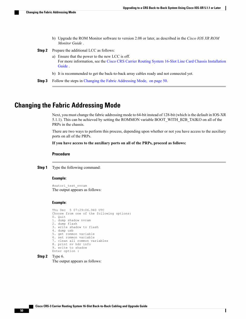
b) Upgrade the ROM Monitor software to version 2.08 or later, as described in the Cisco IOS XR ROMMonitor Guide .
Step 2 Prepare the additional LCC as follows:a) Ensure that the power to the new LCC is off.
For more information, see the Cisco CRS Carrier Routing System 16-Slot Line Card Chassis InstallationGuide .
b) It is recommended to get the back-to-back array cables ready and not connected yet.
Step 3 Follow the steps in Changing the Fabric Addressing Mode, on page 50.
Changing the Fabric Addressing ModeNext, you must change the fabric addressing mode to 64-bit instead of 128-bit (which is the default in IOS-XR5.1.1). This can be achieved by setting the ROMMON variable BOOT_WITH_B2B_TAIKO on all of thePRPs in the chassis.
There are two ways to perform this process, depending upon whether or not you have access to the auxiliaryports on all of the PRPs.
If you have access to the auxiliary ports on all of the PRPs, proceed as follows:
Procedure
Step 1 Type the following command:
Example:
#satori_test_nvramThe output appears as follows:
Example:
Thu Dec 5 07:29:06.940 UTCChoose from one of the following options:0. Quit1. dump shadow nvram2. dump flash3. write shadow to flash4. dump usb5. get rommon variable6. set rommon variable7. clean all rommon variables8. print nv hdr info9. write to shadowEnter option :
Step 2 Type 6.The output appears as follows:
Cisco CRS-3 Carrier Routing System 16-Slot Back-to-Back Cabling and Upgrade Guide50
Upgrading to a CRS Back-to-Back System Using Cisco IOS-XR 5.1.1 or LaterChanging the Fabric Addressing Mode
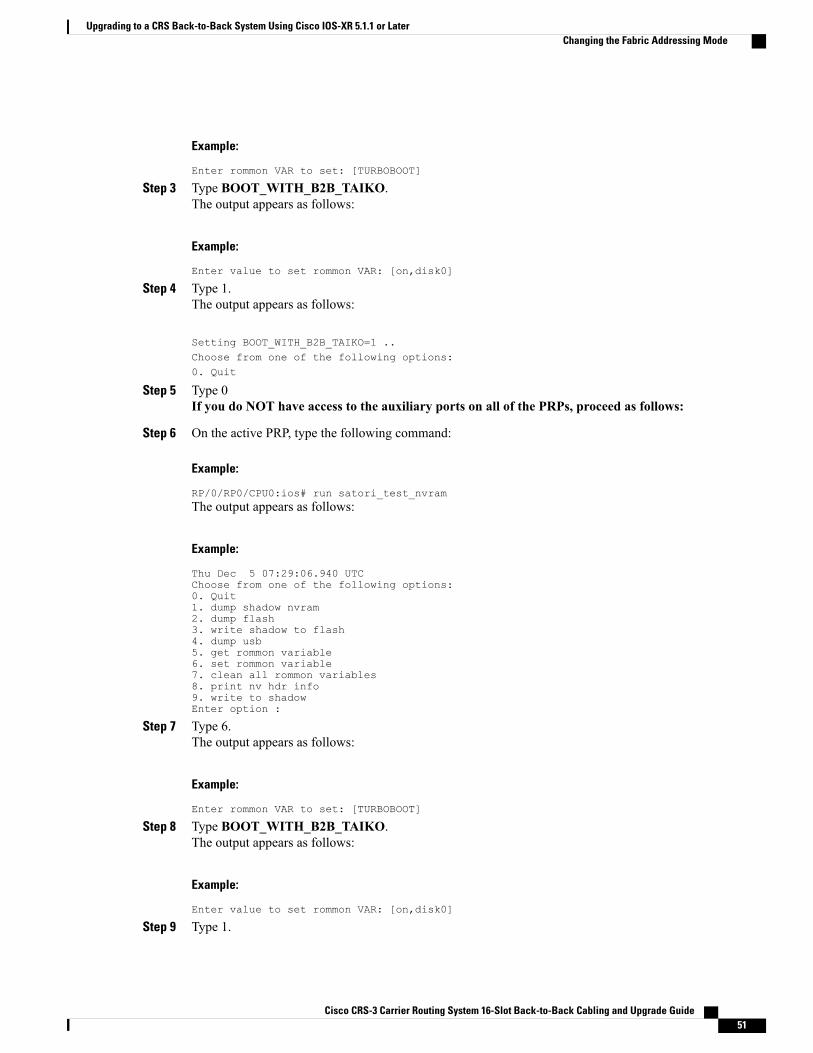
Example:
Enter rommon VAR to set: [TURBOBOOT]
Step 3 Type BOOT_WITH_B2B_TAIKO.The output appears as follows:
Example:
Enter value to set rommon VAR: [on,disk0]
Step 4 Type 1.The output appears as follows:
Setting BOOT_WITH_B2B_TAIKO=1 ..Choose from one of the following options:0. Quit
Step 5 Type 0If you do NOT have access to the auxiliary ports on all of the PRPs, proceed as follows:
Step 6 On the active PRP, type the following command:
Example:
RP/0/RP0/CPU0:ios# run satori_test_nvramThe output appears as follows:
Example:
Thu Dec 5 07:29:06.940 UTCChoose from one of the following options:0. Quit1. dump shadow nvram2. dump flash3. write shadow to flash4. dump usb5. get rommon variable6. set rommon variable7. clean all rommon variables8. print nv hdr info9. write to shadowEnter option :
Step 7 Type 6.The output appears as follows:
Example:
Enter rommon VAR to set: [TURBOBOOT]
Step 8 Type BOOT_WITH_B2B_TAIKO.The output appears as follows:
Example:
Enter value to set rommon VAR: [on,disk0]
Step 9 Type 1.
Cisco CRS-3 Carrier Routing System 16-Slot Back-to-Back Cabling and Upgrade Guide 51
Upgrading to a CRS Back-to-Back System Using Cisco IOS-XR 5.1.1 or LaterChanging the Fabric Addressing Mode
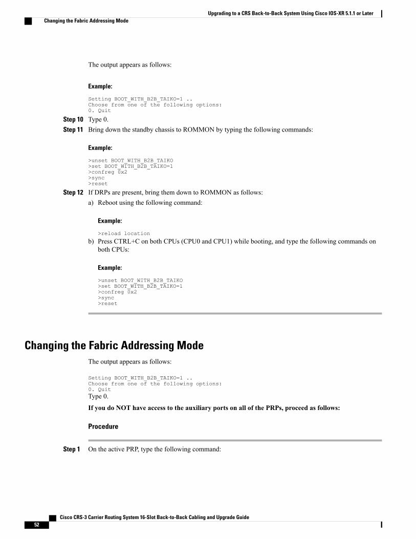
The output appears as follows:
Example:
Setting BOOT_WITH_B2B_TAIKO=1 ..Choose from one of the following options:0. Quit
Step 10 Type 0.Step 11 Bring down the standby chassis to ROMMON by typing the following commands:
Example:
>unset BOOT_WITH_B2B_TAIKO>set BOOT_WITH_B2B_TAIKO=1>confreg 0x2>sync>reset
Step 12 If DRPs are present, bring them down to ROMMON as follows:a) Reboot using the following command:
Example:
>reload location
b) Press CTRL+C on both CPUs (CPU0 and CPU1) while booting, and type the following commands onboth CPUs:
Example:
>unset BOOT_WITH_B2B_TAIKO>set BOOT_WITH_B2B_TAIKO=1>confreg 0x2>sync>reset
Changing the Fabric Addressing ModeThe output appears as follows:
Setting BOOT_WITH_B2B_TAIKO=1 ..Choose from one of the following options:0. QuitType 0.
If you do NOT have access to the auxiliary ports on all of the PRPs, proceed as follows:
Procedure
Step 1 On the active PRP, type the following command:
Cisco CRS-3 Carrier Routing System 16-Slot Back-to-Back Cabling and Upgrade Guide52
Upgrading to a CRS Back-to-Back System Using Cisco IOS-XR 5.1.1 or LaterChanging the Fabric Addressing Mode

Example:
RP/0/RP0/CPU0:ios# run satori_test_nvramThe output appears as follows:
Example:
Thu Dec 5 07:29:06.940 UTCChoose from one of the following options:0. Quit1. dump shadow nvram2. dump flash3. write shadow to flash4. dump usb5. get rommon variable6. set rommon variable7. clean all rommon variables8. print nv hdr info9. write to shadowEnter option :
Step 2 Type 6.The output appears as follows:
Example:
Enter rommon VAR to set: [TURBOBOOT]
Step 3 Type BOOT_WITH_B2B_TAIKO.The output appears as follows:
Example:
Enter value to set rommon VAR: [on,disk0]
Step 4 Type 1.The output appears as follows:
Example:
Setting BOOT_WITH_B2B_TAIKO=1 ..Choose from one of the following options:0. Quit
Step 5 Type 0.Step 6 Bring down the standby chassis to ROMMON by typing the following commands:
Example:
>unset BOOT_WITH_B2B_TAIKO>set BOOT_WITH_B2B_TAIKO=1>confreg 0x2>sync>reset
Step 7 If DRPs are present, bring them down to ROMMON as follows:a) Reboot using the following command:
Cisco CRS-3 Carrier Routing System 16-Slot Back-to-Back Cabling and Upgrade Guide 53
Upgrading to a CRS Back-to-Back System Using Cisco IOS-XR 5.1.1 or LaterChanging the Fabric Addressing Mode
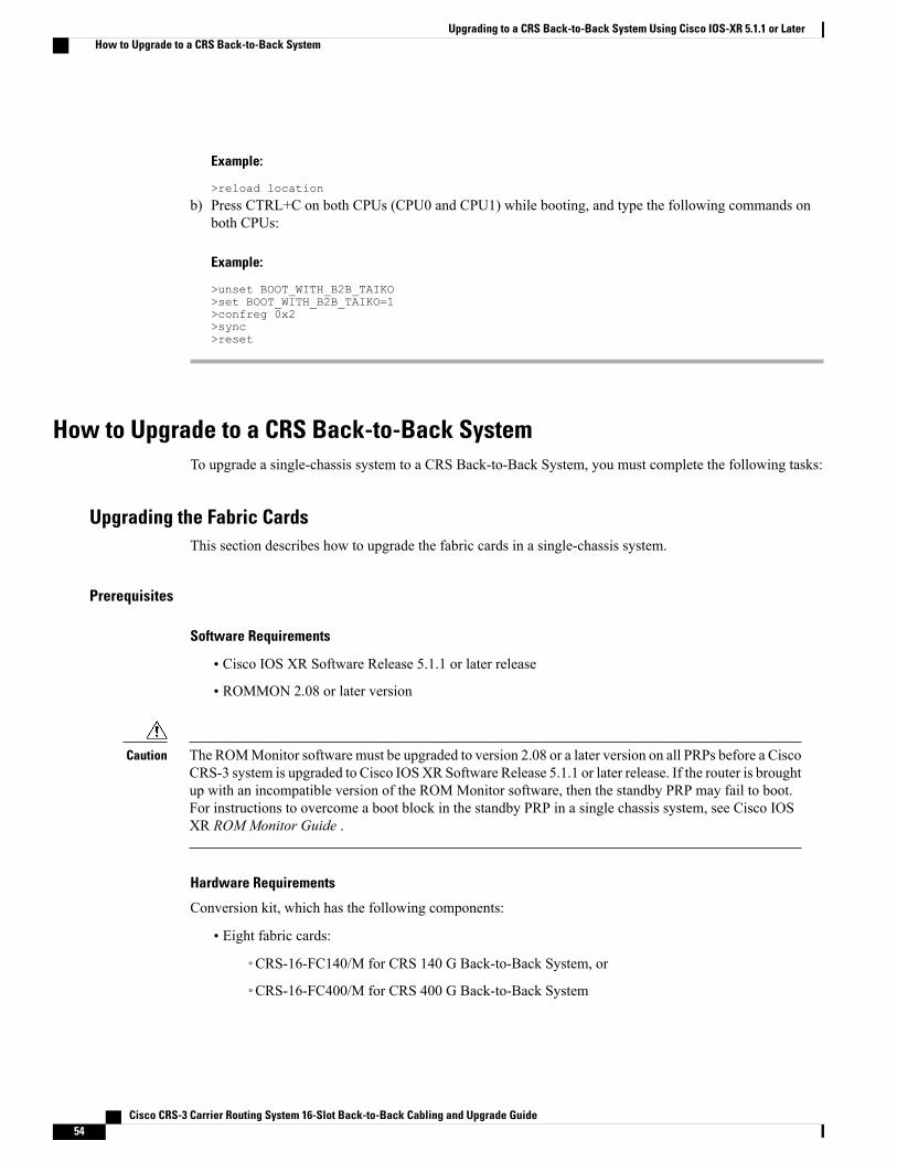
Example:
>reload location
b) Press CTRL+C on both CPUs (CPU0 and CPU1) while booting, and type the following commands onboth CPUs:
Example:
>unset BOOT_WITH_B2B_TAIKO>set BOOT_WITH_B2B_TAIKO=1>confreg 0x2>sync>reset
How to Upgrade to a CRS Back-to-Back SystemTo upgrade a single-chassis system to a CRS Back-to-Back System, you must complete the following tasks:
Upgrading the Fabric CardsThis section describes how to upgrade the fabric cards in a single-chassis system.
Prerequisites
Software Requirements
• Cisco IOS XR Software Release 5.1.1 or later release
• ROMMON 2.08 or later version
The ROMMonitor software must be upgraded to version 2.08 or a later version on all PRPs before a CiscoCRS-3 system is upgraded to Cisco IOSXR Software Release 5.1.1 or later release. If the router is broughtup with an incompatible version of the ROM Monitor software, then the standby PRP may fail to boot.For instructions to overcome a boot block in the standby PRP in a single chassis system, see Cisco IOSXR ROM Monitor Guide .
Caution
Hardware Requirements
Conversion kit, which has the following components:
• Eight fabric cards:
◦CRS-16-FC140/M for CRS 140 G Back-to-Back System, or
◦CRS-16-FC400/M for CRS 400 G Back-to-Back System
Cisco CRS-3 Carrier Routing System 16-Slot Back-to-Back Cabling and Upgrade Guide54
Upgrading to a CRS Back-to-Back System Using Cisco IOS-XR 5.1.1 or LaterHow to Upgrade to a CRS Back-to-Back System
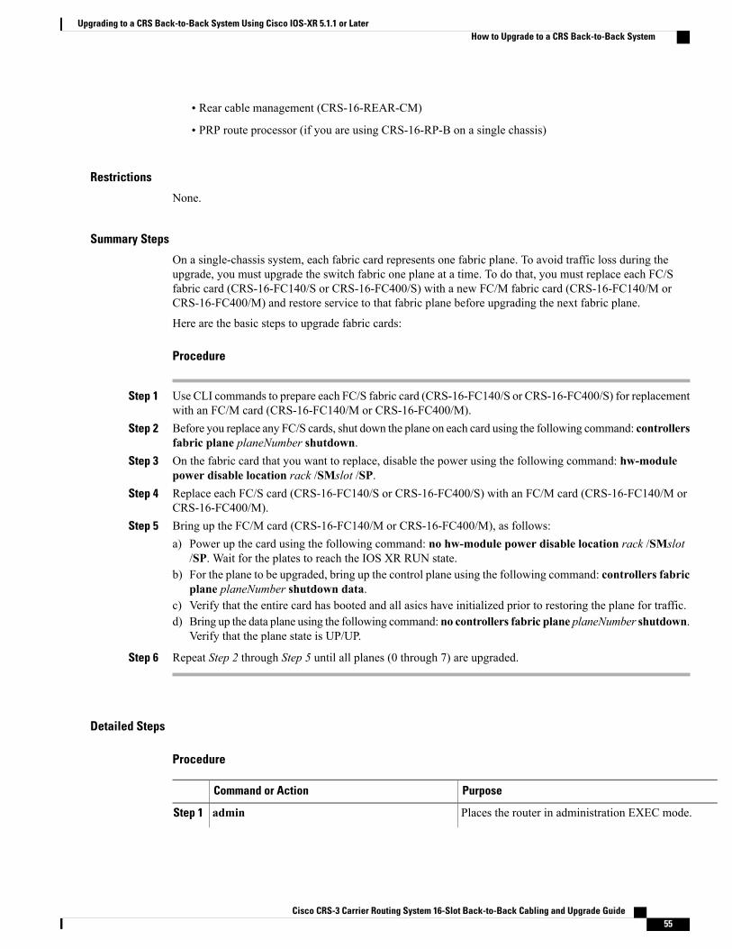
• Rear cable management (CRS-16-REAR-CM)
• PRP route processor (if you are using CRS-16-RP-B on a single chassis)
Restrictions
None.
Summary Steps
On a single-chassis system, each fabric card represents one fabric plane. To avoid traffic loss during theupgrade, you must upgrade the switch fabric one plane at a time. To do that, you must replace each FC/Sfabric card (CRS-16-FC140/S or CRS-16-FC400/S) with a new FC/M fabric card (CRS-16-FC140/M orCRS-16-FC400/M) and restore service to that fabric plane before upgrading the next fabric plane.
Here are the basic steps to upgrade fabric cards:
Procedure
Step 1 Use CLI commands to prepare each FC/S fabric card (CRS-16-FC140/S or CRS-16-FC400/S) for replacementwith an FC/M card (CRS-16-FC140/M or CRS-16-FC400/M).
Step 2 Before you replace any FC/S cards, shut down the plane on each card using the following command: controllersfabric plane planeNumber shutdown.
Step 3 On the fabric card that you want to replace, disable the power using the following command: hw-modulepower disable location rack /SMslot /SP.
Step 4 Replace each FC/S card (CRS-16-FC140/S or CRS-16-FC400/S) with an FC/M card (CRS-16-FC140/M orCRS-16-FC400/M).
Step 5 Bring up the FC/M card (CRS-16-FC140/M or CRS-16-FC400/M), as follows:a) Power up the card using the following command: no hw-module power disable location rack /SMslot
/SP. Wait for the plates to reach the IOS XR RUN state.b) For the plane to be upgraded, bring up the control plane using the following command: controllers fabric
plane planeNumber shutdown data.c) Verify that the entire card has booted and all asics have initialized prior to restoring the plane for traffic.d) Bring up the data plane using the following command: no controllers fabric plane planeNumber shutdown.
Verify that the plane state is UP/UP.
Step 6 Repeat Step 2 through Step 5 until all planes (0 through 7) are upgraded.
Detailed Steps
Procedure
PurposeCommand or Action
Places the router in administration EXEC mode.adminStep 1
Cisco CRS-3 Carrier Routing System 16-Slot Back-to-Back Cabling and Upgrade Guide 55
Upgrading to a CRS Back-to-Back System Using Cisco IOS-XR 5.1.1 or LaterHow to Upgrade to a CRS Back-to-Back System

PurposeCommand or Action
Example:
RP/0/RP1/CPU0:router# admin
• All commands listed in this procedure should beentered on the pre-existing single-chassis system.
Displays the status of all LCCmodules in the specifiedrack.
show platform rack number/**/*
Example:
RP/0/RP1/CPU0:router(admin)# show platform1/**/*
Step 2
• Replace rack with the rack number of the LCCto examine.
• Repeat this command for all LCCs.
• The state for all modules should be IOS-XRRUN.
• It can take a few minutes for all LCC modulesto start.
The LCC module status appears only whenthe show platform command is executed inadministration EXEC mode.
Note
Places the router in administration configurationmode.configure
Example:
RP/0/RP1/CPU0:router(admin)#configure
Step 3
Displays the administrative and operational status ofall eight fabric planes.
do show controllers fabric plane all
Example:
RP/0/RP1/CPU0:router(admin-config)# do showcontrollers fabric plane all
Step 4
• The do command prefix allows the EXEC modeshow command to execute in administrationconfiguration mode.
To prevent service interruption, do notcontinue until the administrative andoperational status for all eight planes is UP.
Caution
Modifies the target configuration to shut down thespecified plane number.
controllers fabric plane planeNumber shutdown
Example:
RP/0/RP1/CPU0:router(admin-config)#controllers fabric plane 0 shutdown
Step 5
• Replace the planeNumber parameter with thenumber of the plane you want to shut down.
• The admin/operational state will beDOWN/DOWN.
Commits the target configuration to the router runningconfiguration.
commit
Example:
RP/0/RP1/CPU0:router(admin-config)# commit
Step 6
• This step shuts down the plane identified in theprevious step.
Cisco CRS-3 Carrier Routing System 16-Slot Back-to-Back Cabling and Upgrade Guide56
Upgrading to a CRS Back-to-Back System Using Cisco IOS-XR 5.1.1 or LaterHow to Upgrade to a CRS Back-to-Back System

PurposeCommand or Action
Disables the power-on feature on a specific fabric card.hw-module power disable location0/smslotNumber /sp
Step 7
Example:
RP/0/RP1/CPU0:router(admin-config)#hw-module power disable location 0/sm0/sp
Commits the target configuration to the router runningconfiguration.
commit
Example:
RP/0/RP1/CPU0:router(admin-config)# commit
Step 8
• This step shuts down the plane identified in theprevious step.
Displays the status of the Rack 0 fabric slot specifiedby slotNumber . Verify that the card is in theUNPOWERED state.
show platform 0/smslotNumber/sp
Example:
RP/0/RP1/CPU0:router(admin)# show platform0/sm0/sp
Step 9
The fabric card status appears only when theshow platform command is executed inadministration EXEC mode.
Note
Creates room for the FC/M card (CRS-16-FC140/Mor CRS-16-FC400/M) that is required for CRSBack-to-Back System operation.
In Rack 0, remove the FC/S card (CRS-16-140FC/Sor CRS-16-FC400/S) for the plane that was shutdown in Step 5 .
Step 10
Provides the hardware required for communicationwith the LCC.
In Rack 0, insert the FC/M card (CRS-16-FC140/Mor CRS-16-FC400/M) for the plane that was shutdown in Step 5 .
Step 11
Re-enables the power-on feature on a specific fabriccard.
no hw-module power disable location0/smslotNumber /sp
Example:
RP/0/RP1/CPU0:router(admin-config)# nohw-module power disable location 0/sm0/sp
Step 12
Example:
Commits the target configuration to the router runningconfiguration.
commit
Example:
RP/0/RP1/CPU0:router(admin-config)# commit
Step 13
Displays the status of the Rack 0 fabric slot specifiedby slotNumber . Verify that the card is in the IOS XRRUN state.
do show platform 0/smslotNumber/sp
Example:
RP/0/RP1/CPU0:router(admin)# show platform0/sm0/sp
Step 14
The fabric card status appears only when theshow platform command is executed inadministration EXEC mode.
Note
Cisco CRS-3 Carrier Routing System 16-Slot Back-to-Back Cabling and Upgrade Guide 57
Upgrading to a CRS Back-to-Back System Using Cisco IOS-XR 5.1.1 or LaterHow to Upgrade to a CRS Back-to-Back System

PurposeCommand or Action
Displays the status of the fabric asic. The desiredoutput will show two fabric asics in service for the
do show log | inc OPER_UP
Example:
RP/0/RP0/CPU0:b2b(admin-config)#do showlogging | inc OPER_UP
Step 15
plane that you just upgraded. If you do not see bothasics in the UP state, do not continue. Output appearssimilar to the following:
• SP/0/SM3/SP:May 19 17:51:32.599 :sfe_drvr[131]:%FABRIC-FABRIC_DRVR-6-ASIC_INITIALIZED: Notify FSDB that superstar/0/SM3/SP/0 isOPER_UP.
• SP/0/SM3/SP:May 19 17:51:32.600 :sfe_drvr[131]:%FABRIC-FABRIC_DRVR-6-ASIC_INITIALIZED: Notify FSDB that superstar/0/SM3/SP/1 isOPER_UP
Modifies the target configuration to bring up thecontrol part of the specified fabric plane.
controllers fabric plane planeNumber shutdowndata
Step 16
Example:
RP/0/RP0/CPU0:b2b(admin-config)#controllersfabric plane 3 shutdown data
The suggested admin/operational state of the plane inthis state would be DATA_DN/UP, respectively.
Displays the status of the plane specified byplaneNumber .
do show controllers fabric plane planeNumberdetail
Step 17
Example:
RP/0/RP1/CPU0:router(admin-config)# do showcontrollers fabric plane 0 detail
• Verify that the admin/operational state isDATA_DN/UP.
• Verify that a capital “D” appears in the DownFlags column.
•Wait for the plane to come up before youcontinue.
Modifies the target configuration to bring up thespecified fabric plane.
no controllers fabric plane planeNumber shutdown
Example:
RP/0/RP1/CPU0:router(admin-config)# nocontrollers fabric plane 0 shutdown
Step 18
• Verify that the admin/operational state is UP/UP.
• This step brings up the previously shutdownplane, which is now configured to use theBack-to-Back LCC.
Changes the mode from administration configurationmode to administration EXEC mode.
end
Example:
RP/0/RP1/CPU0:router(admin-config)# end
Step 19
Cisco CRS-3 Carrier Routing System 16-Slot Back-to-Back Cabling and Upgrade Guide58
Upgrading to a CRS Back-to-Back System Using Cisco IOS-XR 5.1.1 or LaterHow to Upgrade to a CRS Back-to-Back System
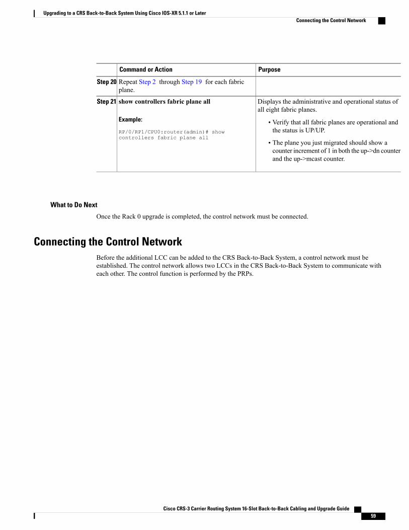
PurposeCommand or Action
Repeat Step 2 through Step 19 for each fabricplane.
Step 20
Displays the administrative and operational status ofall eight fabric planes.
show controllers fabric plane all
Example:
RP/0/RP1/CPU0:router(admin)# showcontrollers fabric plane all
Step 21
• Verify that all fabric planes are operational andthe status is UP/UP.
• The plane you just migrated should show acounter increment of 1 in both the up->dn counterand the up->mcast counter.
What to Do Next
Once the Rack 0 upgrade is completed, the control network must be connected.
Connecting the Control NetworkBefore the additional LCC can be added to the CRS Back-to-Back System, a control network must beestablished. The control network allows two LCCs in the CRS Back-to-Back System to communicate witheach other. The control function is performed by the PRPs.
Cisco CRS-3 Carrier Routing System 16-Slot Back-to-Back Cabling and Upgrade Guide 59
Upgrading to a CRS Back-to-Back System Using Cisco IOS-XR 5.1.1 or LaterConnecting the Control Network
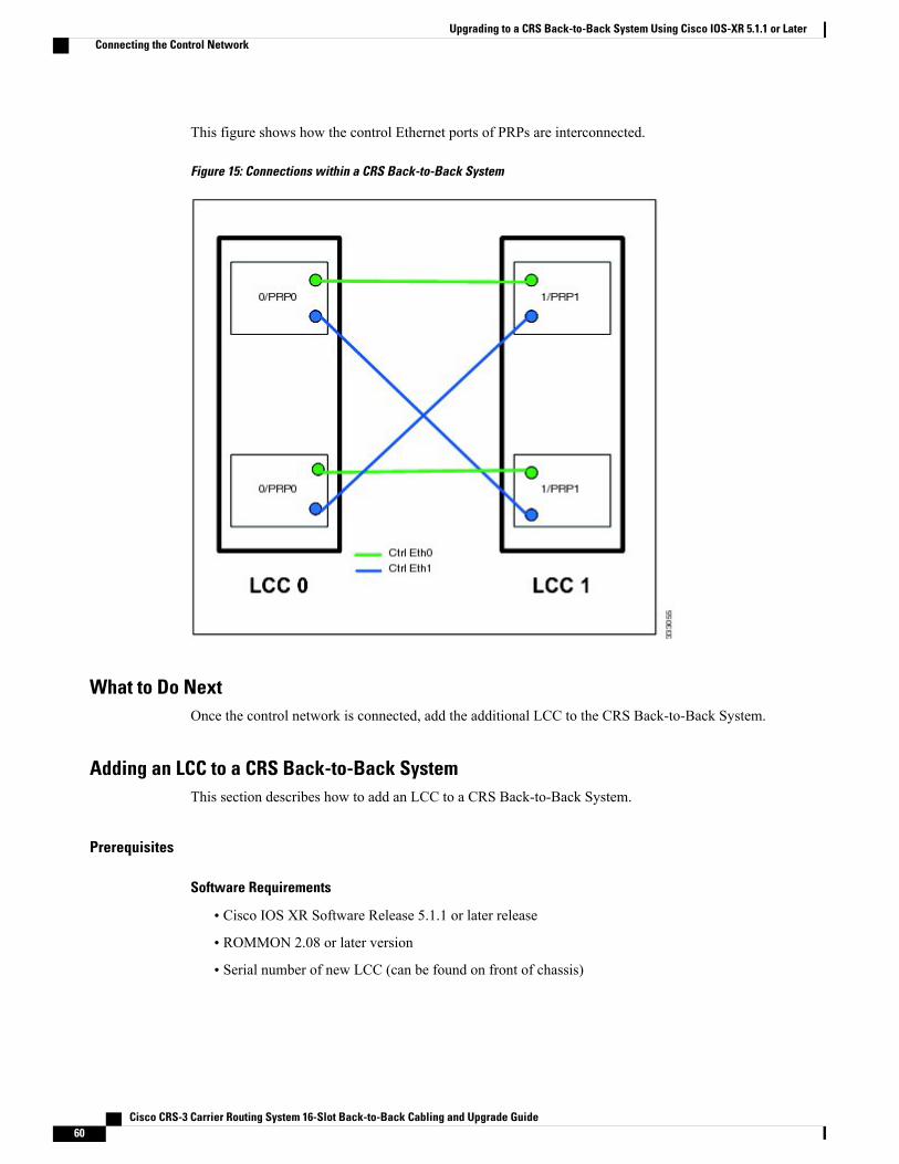
This figure shows how the control Ethernet ports of PRPs are interconnected.
Figure 15: Connections within a CRS Back-to-Back System
What to Do NextOnce the control network is connected, add the additional LCC to the CRS Back-to-Back System.
Adding an LCC to a CRS Back-to-Back SystemThis section describes how to add an LCC to a CRS Back-to-Back System.
Prerequisites
Software Requirements
• Cisco IOS XR Software Release 5.1.1 or later release
• ROMMON 2.08 or later version
• Serial number of new LCC (can be found on front of chassis)
Cisco CRS-3 Carrier Routing System 16-Slot Back-to-Back Cabling and Upgrade Guide60
Upgrading to a CRS Back-to-Back System Using Cisco IOS-XR 5.1.1 or LaterConnecting the Control Network
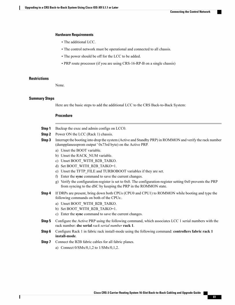
Hardware Requirements
• The additional LCC.
• The control network must be operational and connected to all chassis.
• The power should be off for the LCC to be added.
• PRP route processor (if you are using CRS-16-RP-B on a single chassis)
Restrictions
None.
Summary Steps
Here are the basic steps to add the additional LCC to the CRS Back-to-Back System:
Procedure
Step 1 Backup the exec and admin configs on LCC0.Step 2 Power ON the LCC (Rack 1) chassis.Step 3 Interrupt the booting into drop the system (Active and Standby PRP) in ROMMON and verify the rack number
(dumpplaneeeprom output ' 0x73rd byte) on the Active PRP.a) Unset the BOOT variable.b) Unset the RACK_NUM variable.c) Unset BOOT_WITH_B2B_TAIKO.d) Set BOOT_WITH_B2B_TAIKO=1.e) Unset the TFTP_FILE and TURBOBOOT variables if they are set.f) Enter the sync command to save the current changes.g) Verify the configuration-register is set to 0x0. The configuration-register setting 0x0 prevents the PRP
from syncing to the dSC by keeping the PRP in the ROMMON state.
Step 4 If DRPs are present, bring down both CPUs (CPU0 and CPU1) to ROMMON while booting and type thefollowing commands on both of the CPUs:.a) Unset BOOT_WITH_B2B_TAIKO.b) Set BOOT_WITH_B2B_TAIKO=1.c) Enter the sync command to save the current changes.
Step 5 Configure the Active PRP using the following command, which associates LCC 1 serial numbers with therack number: dsc serial rack serial number rack 1.
Step 6 Configure Rack 1 in fabric rack install-mode using the following command: controllers fabric rack 1install-mode.
Step 7 Connect the B2B fabric cables for all fabric planes.a) Connect 0/SMx/0,1,2 to 1/SMx/0,1,2.
Cisco CRS-3 Carrier Routing System 16-Slot Back-to-Back Cabling and Upgrade Guide 61
Upgrading to a CRS Back-to-Back System Using Cisco IOS-XR 5.1.1 or LaterConnecting the Control Network

b) Tighten the connector screws.
Step 8 Boot the LCC Rack 1 by reset from the ROMMON prompt.Step 9 Verify that IOS XR RUN appears on the PRP faceplates.Step 10 Verify that all of the eight planes are UP/UP and the plane mode is B2B. Execute the following show command
on dSC: show controllers fabric plane all detail. The plane state should be UP/UP and the plane modeshould be B2B.
Step 11 Check the rack status using the following command: do show controllers fabric rack-status all detail.Step 12 Remove the fabric install mode for Rack 1. Execute the following command: no controller fabric rack 1
install-mode.Step 13 Verify the status of all racks using the following command: show controllers fabric rack all. The plane state
and mode for all of the eight planes should be the same as described in Step10.
Detailed Steps
Procedure
PurposeCommand or Action
Places the router in administration EXEC mode.adminStep 1
Example:
RP/0/RP1/CPU0:router# admin
• All commands listed in this procedure shouldbe entered on the pre-existing single-chassissystem.
Places the router in administration configurationmode.
configure
Example:
RP/0/RP1/CPU0:router(admin)#configure
Step 2
From the console of the PRP in the new system, sendthe break (cntl+c) to disrupt the boot sequence. This
From the ROMMON prompt, enter thefollowing commands.
Step 3
places you at the rommon prompt. From here, issueExample:
unset BOOT
the set command. This shows the current variablesset on the PRP. If the variables listed are present,unset them as shown. Make sure to use sync at theend to save the changes.
unset RACK_NUMunset BOOT_WITH_B2B_TAIKOset BOOT_WITH_B2B_TAIKO=1unset TFTP_FILEunset TURBOBOOTconfreg 0x0syncreset
Configures the additional LCC as Rack 1 in themultishelf system.
dsc serial serialNumber rack 1
Example:
RP/0/RP1/CPU0:router(admin-config)#dsc serial TBA08440024 rack 1
Step 4
• Replace the serialNumber parameter with theserial number of the additional LCC.
Cisco CRS-3 Carrier Routing System 16-Slot Back-to-Back Cabling and Upgrade Guide62
Upgrading to a CRS Back-to-Back System Using Cisco IOS-XR 5.1.1 or LaterConnecting the Control Network

PurposeCommand or Action
• If you are configuring the system from aremote location, you can use a command todisplay the serial number. For moreinformation, seeCisco IOS XRGetting StartedGuide.
Modifies the target configuration to change the Rack1 configuration to installation mode.
controllers fabric rack 1 install-mode
Example:
RP/0/RP1/CPU0:router(admin-config)#
Step 5
controllers fabric rack 1install-mode
Commits the target configuration to the routerrunning configuration.
commit
Example:
RP/0/RP1/CPU0:router(admin-config)#commit
Step 6
Starts up the second LCC (Rack 1).Apply power to the new LCC (Rack 1).Step 7
Connect all fabric cables that connect the fabricplanes in the new LCC to the additional LCCs.
Interconnects the fabric cards between twoLCCs.
Step 8
Boots the LCCRack 1 by reset from the ROMMONprompt. Sets the config register to 0x2 and enablesboot.
From the ROMMON prompt, enter thefollowing commands.
Example:
confreg 0x2
Step 9
syncreset
Displays the status of all LCC modules.show platformStep 10
Example:
RP/0/RP1/CPU0:router(admin)# showplatform
• Repeat this command for all LCCs.
• The state for all modules should be IOS-XRRUN.
Example:• It can take a few minutes for all LCC modulesto start.
• The LCCmodule status appears only when theshow platform command is executed inadministration EXEC mode.
Shows whether the fabric connectivity between twoLCCs has been successful. The bundle port valueranges from 0 to 2.
show controllers fabric bundle1/smslotNumber/sp/bundle port connection
Example:
RP/0/RP1/CPU0:router(admin)#show
Step 11
Cisco CRS-3 Carrier Routing System 16-Slot Back-to-Back Cabling and Upgrade Guide 63
Upgrading to a CRS Back-to-Back System Using Cisco IOS-XR 5.1.1 or LaterConnecting the Control Network
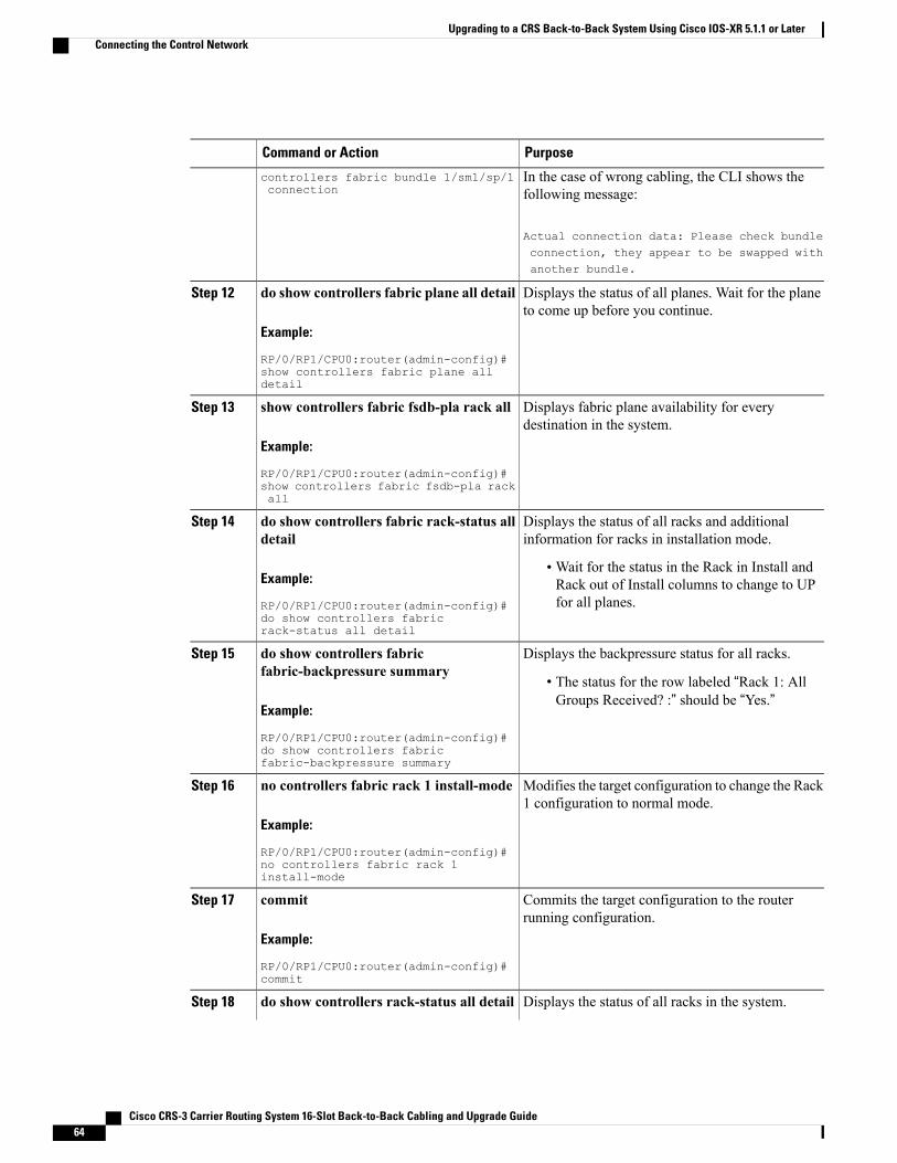
PurposeCommand or Action
In the case of wrong cabling, the CLI shows thefollowing message:
Actual connection data: Please check bundle
controllers fabric bundle 1/sm1/sp/1connection
connection, they appear to be swapped withanother bundle.
Displays the status of all planes. Wait for the planeto come up before you continue.
do show controllers fabric plane all detail
Example:
RP/0/RP1/CPU0:router(admin-config)#
Step 12
show controllers fabric plane alldetail
Displays fabric plane availability for everydestination in the system.
show controllers fabric fsdb-pla rack all
Example:
RP/0/RP1/CPU0:router(admin-config)#
Step 13
show controllers fabric fsdb-pla rackall
Displays the status of all racks and additionalinformation for racks in installation mode.
do show controllers fabric rack-status alldetail
Step 14
Example:
RP/0/RP1/CPU0:router(admin-config)#
•Wait for the status in the Rack in Install andRack out of Install columns to change to UPfor all planes.
do show controllers fabricrack-status all detail
Displays the backpressure status for all racks.do show controllers fabricfabric-backpressure summary
Step 15
• The status for the row labeled “Rack 1: AllGroups Received? :” should be “Yes.”
Example:
RP/0/RP1/CPU0:router(admin-config)#do show controllers fabricfabric-backpressure summary
Modifies the target configuration to change the Rack1 configuration to normal mode.
no controllers fabric rack 1 install-mode
Example:
RP/0/RP1/CPU0:router(admin-config)#
Step 16
no controllers fabric rack 1install-mode
Commits the target configuration to the routerrunning configuration.
commit
Example:
RP/0/RP1/CPU0:router(admin-config)#commit
Step 17
Displays the status of all racks in the system.do show controllers rack-status all detailStep 18
Cisco CRS-3 Carrier Routing System 16-Slot Back-to-Back Cabling and Upgrade Guide64
Upgrading to a CRS Back-to-Back System Using Cisco IOS-XR 5.1.1 or LaterConnecting the Control Network
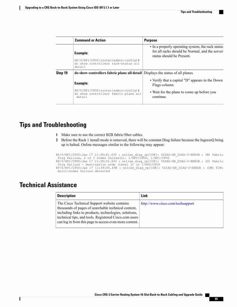
PurposeCommand or Action
Example:
RP/0/RP1/CPU0:router(admin-config)#
• In a properly operating system, the rack statusfor all racks should be Normal, and the serverstatus should be Present.
do show controllers rack-status alldetail
Displays the status of all planes.do show controllers fabric plane all detailStep 19
Example:
RP/0/RP1/CPU0:router(admin-config)#
• Verify that a capital "D" appears in the DownFlags column.
•Wait for the plane to come up before youcontinue.
do show controllers fabric plane alldetail
Tips and Troubleshooting1 Make sure to use the correct B2B fabric/fiber cables.2 Before the Rack 1 install mode is removed, there will be constant Diag failure because the IngressQ bring
up is halted. Online messages similar to the following may appear:
RP/0/RP1/CPU0:Jan 17 11:38:41.635 : online_diag_rp[338]: %DIAG-XR_DIAG-3-ERROR : (M) FabricPing Failure, 2 of 5 nodes failed(L): 1/RP0/CPU0, 1/RP1/CPU0RP/0/RP1/CPU0:Jan 17 11:38:55.934 : online_diag_rp[338]: %DIAG-XR_DIAG-3-ERROR : (U) FabricPing Failure - destination node (Level 2) in 1/RP0/CPU0RP/0/RP1/CPU0:Jan 17 11:39:05.498 : online_diag_rp[338]: %DIAG-XR_DIAG-3-ERROR : (UM) FIM:multi-nodes failure detected
Technical AssistanceLinkDescription
http://www.cisco.com/techsupportThe Cisco Technical Support website containsthousands of pages of searchable technical content,including links to products, technologies, solutions,technical tips, and tools. Registered Cisco.com userscan log in from this page to access evenmore content.
Cisco CRS-3 Carrier Routing System 16-Slot Back-to-Back Cabling and Upgrade Guide 65
Upgrading to a CRS Back-to-Back System Using Cisco IOS-XR 5.1.1 or LaterTips and Troubleshooting

Cisco CRS-3 Carrier Routing System 16-Slot Back-to-Back Cabling and Upgrade Guide66
Upgrading to a CRS Back-to-Back System Using Cisco IOS-XR 5.1.1 or LaterTechnical Assistance
Related Documents