Cisco CPT Command Reference Guide–CTC and Documentation Release 9.5.x and Cisco IOS Release 15.2(01) First Published: July 12, 2012 Americas Headquarters Cisco Systems, Inc. 170 West Tasman Drive San Jose, CA 95134-1706 USA http://www.cisco.com Tel: 408 526-4000 800 553-NETS (6387) Fax: 408 527-0883 Text Part Number: 78-20604-03

Welcome message from author
This document is posted to help you gain knowledge. Please leave a comment to let me know what you think about it! Share it to your friends and learn new things together.
Transcript
Cisco CPT Command Reference Guide–CTC and DocumentationRelease 9.5.x and Cisco IOS Release 15.2(01)First Published: July 12, 2012
Americas HeadquartersCisco Systems, Inc.170 West Tasman DriveSan Jose, CA 95134-1706USAhttp://www.cisco.comTel: 408 526-4000 800 553-NETS (6387)Fax: 408 527-0883
Text Part Number: 78-20604-03

© 2012 Cisco Systems, Inc. All rights reserved.
THE SPECIFICATIONS AND INFORMATION REGARDING THE PRODUCTS IN THIS MANUALARE SUBJECT TO CHANGE WITHOUT NOTICE. ALL STATEMENTS, INFORMATION, ANDRECOMMENDATIONS INTHISMANUALAREBELIEVEDTOBEACCURATEBUTAREPRESENTEDWITHOUT WARRANTY OF ANY KIND, EXPRESS OR IMPLIED. USERS MUST TAKE FULLRESPONSIBILITY FOR THEIR APPLICATION OF ANY PRODUCTS.
THE SOFTWARE LICENSE AND LIMITED WARRANTY FOR THE ACCOMPANYING PRODUCTARE SET FORTH IN THE INFORMATION PACKET THAT SHIPPED WITH THE PRODUCT ANDARE INCORPORATED HEREIN BY THIS REFERENCE. IF YOU ARE UNABLE TO LOCATE THESOFTWARE LICENSE OR LIMITED WARRANTY, CONTACT YOUR CISCO REPRESENTATIVEFOR A COPY.
The following information is for FCC compliance of Class A devices: This equipment has been tested andfound to comply with the limits for a Class A digital device, pursuant to part 15 of the FCC rules. These limitsare designed to provide reasonable protection against harmful interference when the equipment is operatedin a commercial environment. This equipment generates, uses, and can radiate radio-frequency energy and,if not installed and used in accordance with the instruction manual, may cause harmful interference to radiocommunications. Operation of this equipment in a residential area is likely to cause harmful interference, inwhich case users will be required to correct the interference at their own expense.
The following information is for FCC compliance of Class B devices: This equipment has been tested andfound to comply with the limits for a Class B digital device, pursuant to part 15 of the FCC rules. These limitsare designed to provide reasonable protection against harmful interference in a residential installation. Thisequipment generates, uses and can radiate radio frequency energy and, if not installed and used in accordancewith the instructions, may cause harmful interference to radio communications. However, there is no guaranteethat interference will not occur in a particular installation. If the equipment causes interference to radio ortelevision reception, which can be determined by turning the equipment off and on, users are encouraged totry to correct the interference by using one or more of the following measures:
• Reorient or relocate the receiving antenna.
• Increase the separation between the equipment and receiver.
• Connect the equipment into an outlet on a circuit different from that to which the receiver is connected.
• Consult the dealer or an experienced radio/TV technician for help.
Modifications to this product not authorized by Cisco could void the FCC approval and negate your authorityto operate the product
The Cisco implementation of TCP header compression is an adaptation of a program developed by theUniversity of California, Berkeley (UCB) as part of UCB’s public domain version of the UNIX operatingsystem. All rights reserved. Copyright © 1981, Regents of the University of California.
Cisco CPT Command Reference Guide–CTC and Documentation Release 9.5.x and Cisco IOS Release 15.2(01) 78-20604-03 3

NOTWITHSTANDINGANYOTHERWARRANTYHEREIN,ALLDOCUMENTFILESANDSOFTWAREOF THESE SUPPLIERS ARE PROVIDED "AS IS" WITH ALL FAULTS. CISCO AND THEABOVE-NAMEDSUPPLIERSDISCLAIMALLWARRANTIES,EXPRESSEDORIMPLIED, INCLUDING,WITHOUTLIMITATION, THOSEOFMERCHANTABILITY, FITNESS FORAPARTICULARPURPOSEAND NONINFRINGEMENT OR ARISING FROM A COURSE OF DEALING, USAGE, OR TRADEPRACTICE.
IN NO EVENT SHALL CISCO OR ITS SUPPLIERS BE LIABLE FOR ANY INDIRECT, SPECIAL,CONSEQUENTIAL, OR INCIDENTAL DAMAGES, INCLUDING, WITHOUT LIMITATION, LOSTPROFITS OR LOSS OR DAMAGE TO DATA ARISING OUT OF THE USE OR INABILITY TO USETHIS MANUAL, EVEN IF CISCO OR ITS SUPPLIERS HAVE BEEN ADVISED OF THE POSSIBILITYOF SUCH DAMAGES.
Cisco and the Cisco logo are trademarks or registered trademarks of Cisco and/or its affiliates in the U.S. andother countries. To view a list of Cisco trademarks, go to this URL: http://www.cisco.com/go/trademarks.Third-party trademarks mentioned are the property of their respective owners. The use of the word partnerdoes not imply a partnership relationship between Cisco and any other company. (1110R)
Any Internet Protocol (IP) addresses used in this document are not intended to be actual addresses. Anyexamples, command display output, and figures included in the document are shown for illustrative purposesonly. Any use of actual IP addresses in illustrative content is unintentional and coincidental.
Cisco CPT Command Reference Guide–CTC and Documentation Release 9.5.x and Cisco IOS Release 15.2(01)4 78-20604-03
Preface
The terms "Cisco CPT" and "CPT" are used interchangeably.Note
This section explains the objectives, intended audience, and organization of this publication and describesthe conventions that convey instructions and other information.
This section provides the following information:
• Revision History, page v
• Document Objectives, page vi
• Audience, page vi
• Document Organization, page vi
• Document Conventions, page vii
• Related Documentation, page xiv
• Obtaining Optical Networking Information, page xiv
• Obtaining Documentation and Submitting a Service Request, page xv
• Cisco CPT Documentation Roadmap, page xv
Revision HistoryNotesDate
Addedmiscellaneous commands in theMiscellaneousCommand Reference, on page 479 chapter.
October 2012
Cisco CPT Command Reference Guide–CTC and Documentation Release 9.5.x and Cisco IOS Release 15.2(01) 78-20604-03 v
NotesDate
• Added the commands to configure Span in theSpanCommandReference, on page 303 chapter.
• Added the commands to configure the Y.1731feature in the Ethernet OAM, CFM, andY.1731Command Reference, on page 337 chapter.
July 2012
Document ObjectivesThis guide describes the commands available to configure and maintain the Cisco Carrier Packet Transportsystem.
AudienceTo use this publication, you should be familiar with Cisco or equivalent optical transmission hardware andcabling, telecommunications hardware and cabling, electronic circuitry and wiring practices, and preferablyhave experience as a telecommunications technician.
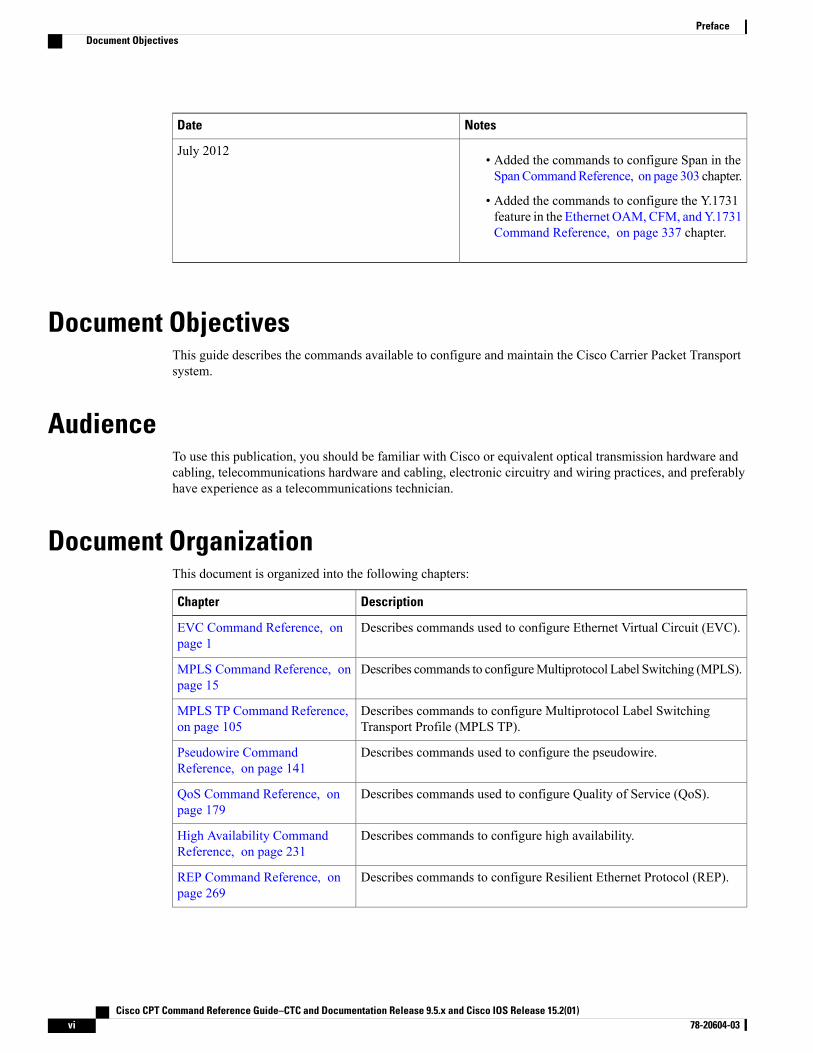
Document OrganizationThis document is organized into the following chapters:
DescriptionChapter
Describes commands used to configure Ethernet Virtual Circuit (EVC).EVC Command Reference, onpage 1
Describes commands to configureMultiprotocol Label Switching (MPLS).MPLS Command Reference, onpage 15
Describes commands to configure Multiprotocol Label SwitchingTransport Profile (MPLS TP).
MPLS TP Command Reference,on page 105
Describes commands used to configure the pseudowire.Pseudowire CommandReference, on page 141
Describes commands used to configure Quality of Service (QoS).QoS Command Reference, onpage 179
Describes commands to configure high availability.High Availability CommandReference, on page 231
Describes commands to configure Resilient Ethernet Protocol (REP).REP Command Reference, onpage 269
Cisco CPT Command Reference Guide–CTC and Documentation Release 9.5.x and Cisco IOS Release 15.2(01)vi 78-20604-03
PrefaceDocument Objectives
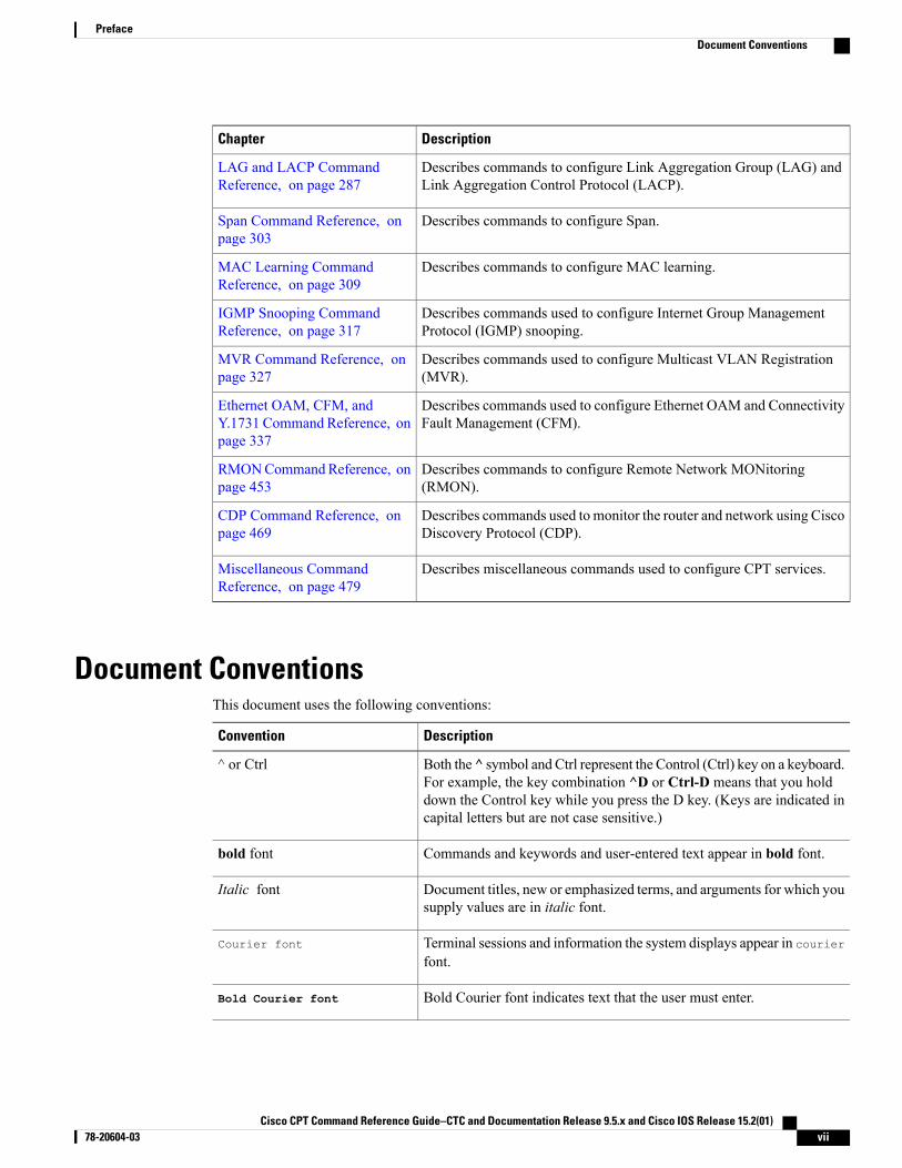
DescriptionChapter
Describes commands to configure Link Aggregation Group (LAG) andLink Aggregation Control Protocol (LACP).
LAG and LACP CommandReference, on page 287
Describes commands to configure Span.Span Command Reference, onpage 303
Describes commands to configure MAC learning.MAC Learning CommandReference, on page 309
Describes commands used to configure Internet Group ManagementProtocol (IGMP) snooping.
IGMP Snooping CommandReference, on page 317
Describes commands used to configure Multicast VLAN Registration(MVR).
MVR Command Reference, onpage 327
Describes commands used to configure Ethernet OAM and ConnectivityFault Management (CFM).
Ethernet OAM, CFM, andY.1731 Command Reference, onpage 337
Describes commands to configure Remote Network MONitoring(RMON).
RMONCommandReference, onpage 453
Describes commands used to monitor the router and network using CiscoDiscovery Protocol (CDP).
CDP Command Reference, onpage 469
Describes miscellaneous commands used to configure CPT services.Miscellaneous CommandReference, on page 479
Document ConventionsThis document uses the following conventions:
DescriptionConvention
Both the ^ symbol and Ctrl represent the Control (Ctrl) key on a keyboard.For example, the key combination ^D or Ctrl-D means that you holddown the Control key while you press the D key. (Keys are indicated incapital letters but are not case sensitive.)
^ or Ctrl
Commands and keywords and user-entered text appear in bold font.bold font
Document titles, new or emphasized terms, and arguments for which yousupply values are in italic font.
Italic font
Terminal sessions and information the system displays appear in courierfont.
Courier font
Bold Courier font indicates text that the user must enter.Bold Courier font
Cisco CPT Command Reference Guide–CTC and Documentation Release 9.5.x and Cisco IOS Release 15.2(01) 78-20604-03 vii
PrefaceDocument Conventions
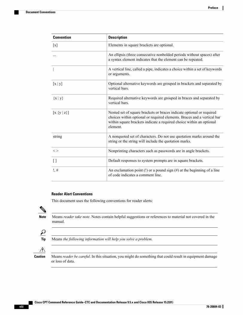
DescriptionConvention
Elements in square brackets are optional.[x]
An ellipsis (three consecutive nonbolded periods without spaces) aftera syntax element indicates that the element can be repeated.
...
A vertical line, called a pipe, indicates a choice within a set of keywordsor arguments.
|
Optional alternative keywords are grouped in brackets and separated byvertical bars.
[x | y]
Required alternative keywords are grouped in braces and separated byvertical bars.
{x | y}
Nested set of square brackets or braces indicate optional or requiredchoices within optional or required elements. Braces and a vertical barwithin square brackets indicate a required choice within an optionalelement.
[x {y | z}]
A nonquoted set of characters. Do not use quotation marks around thestring or the string will include the quotation marks.
string
Nonprinting characters such as passwords are in angle brackets.< >
Default responses to system prompts are in square brackets.[ ]
An exclamation point (!) or a pound sign (#) at the beginning of a lineof code indicates a comment line.
!, #
Reader Alert Conventions
This document uses the following conventions for reader alerts:
Means reader take note. Notes contain helpful suggestions or references to material not covered in themanual.
Note
Means the following information will help you solve a problem.Tip
Means reader be careful. In this situation, you might do something that could result in equipment damageor loss of data.
Caution
Cisco CPT Command Reference Guide–CTC and Documentation Release 9.5.x and Cisco IOS Release 15.2(01)viii 78-20604-03
PrefaceDocument Conventions
Means the described action saves time. You can save time by performing the action described in theparagraph.
Timesaver
Means reader be warned. In this situation, you might perform an action that could result in bodilyinjury.
Warning
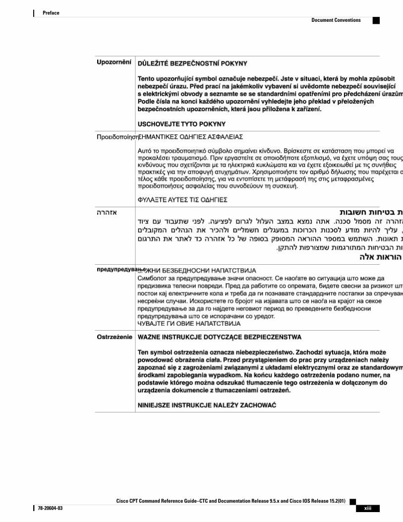
IMPORTANT SAFETY INSTRUCTIONS
This warning symbol means danger. You are in a situation that could cause bodilyinjury. Before you work on any equipment, be aware of the hazards involved withelectrical circuitry and be familiar with standard practices for preventing accidents.Use the statement number provided at the end of each warning to locate its translationin the translated safety warnings that accompanied this device. Statement 1071
SAVE THESE INSTRUCTIONS
Warning
BELANGRIJKE VEILIGHEIDSINSTRUCTIES
Dit waarschuwingssymbool betekent gevaar. U verkeert in een situatie die lichamelijkletsel kan veroorzaken. Voordat u aan enige apparatuur gaat werken, dient u zichbewust te zijn van de bij elektrische schakelingen betrokken risico's en dient u op dehoogte te zijn van de standaard praktijken om ongelukken te voorkomen. Gebruik hetnummer van de verklaring onderaan de waarschuwing als u een vertaling van dewaarschuwing die bij het apparaat wordt geleverd, wilt raadplegen.
BEWAAR DEZE INSTRUCTIES
Waarschuwing
TÄRKEITÄ TURVALLISUUSOHJEITA
Tämä varoitusmerkki merkitsee vaaraa. Tilanne voi aiheuttaa ruumiillisia vammoja.Ennen kuin käsittelet laitteistoa, huomioi sähköpiirien käsittelemiseen liittyvät riskitja tutustu onnettomuuksien yleisiin ehkäisytapoihin. Turvallisuusvaroitusten käännöksetlöytyvät laitteen mukana toimitettujen käännettyjen turvallisuusvaroitusten joukostavaroitusten lopussa näkyvien lausuntonumeroiden avulla.
SÄILYTÄ NÄMÄ OHJEET
Varoitus
IMPORTANTES INFORMATIONS DE SÉCURITÉ
Ce symbole d'avertissement indique un danger. Vous vous trouvez dans une situationpouvant entraîner des blessures ou des dommages corporels. Avant de travailler surun équipement, soyez conscient des dangers liés aux circuits électriques etfamiliarisez-vous avec les procédures couramment utilisées pour éviter les accidents.Pour prendre connaissance des traductions des avertissements figurant dans lesconsignes de sécurité traduites qui accompagnent cet appareil, référez-vous au numérode l'instruction situé à la fin de chaque avertissement.
CONSERVEZ CES INFORMATIONS
Attention
Cisco CPT Command Reference Guide–CTC and Documentation Release 9.5.x and Cisco IOS Release 15.2(01) 78-20604-03 ix
PrefaceDocument Conventions
WICHTIGE SICHERHEITSHINWEISE
Dieses Warnsymbol bedeutet Gefahr. Sie befinden sich in einer Situation, die zuVerletzungen führen kann. Machen Sie sich vor der Arbeit mit Geräten mit denGefahren elektrischer Schaltungen und den üblichen Verfahren zur Vorbeugung vorUnfällen vertraut. Suchen Sie mit der am Ende jeder Warnung angegebenenAnweisungsnummer nach der jeweiligen Übersetzung in den übersetztenSicherheitshinweisen, die zusammen mit diesem Gerät ausgeliefert wurden.
BEWAHREN SIE DIESE HINWEISE GUT AUF.
Warnung
IMPORTANTI ISTRUZIONI SULLA SICUREZZA
Questo simbolo di avvertenza indica un pericolo. La situazione potrebbe causareinfortuni alle persone. Prima di intervenire su qualsiasi apparecchiatura, occorre essereal corrente dei pericoli relativi ai circuiti elettrici e conoscere le procedure standardper la prevenzione di incidenti. Utilizzare il numero di istruzione presente alla fine diciascuna avvertenza per individuare le traduzioni delle avvertenze riportate in questodocumento.
CONSERVARE QUESTE ISTRUZIONI
Avvertenza
VIKTIGE SIKKERHETSINSTRUKSJONER
Dette advarselssymbolet betyr fare. Du er i en situasjon som kan føre til skade påperson. Før du begynner å arbeide med noe av utstyret, må du være oppmerksom påfarene forbundet med elektriske kretser, og kjenne til standardprosedyrer for åforhindre ulykker. Bruk nummeret i slutten av hver advarsel for å finne oversettelseni de oversatte sikkerhetsadvarslene som fulgte med denne enheten.
TA VARE PÅ DISSE INSTRUKSJONENE
Advarsel
INSTRUÇÕES IMPORTANTES DE SEGURANÇA
Este símbolo de aviso significa perigo. Você está em uma situação que poderá sercausadora de lesões corporais. Antes de iniciar a utilização de qualquer equipamento,tenha conhecimento dos perigos envolvidos no manuseio de circuitos elétricos efamiliarize-se com as práticas habituais de prevenção de acidentes. Utilize o númeroda instrução fornecido ao final de cada aviso para localizar sua tradução nos avisos desegurança traduzidos que acompanham este dispositivo.
GUARDE ESTAS INSTRUÇÕES
Aviso
INSTRUCCIONES IMPORTANTES DE SEGURIDAD
Este símbolo de aviso indica peligro. Existe riesgo para su integridad física. Antes demanipular cualquier equipo, considere los riesgos de la corriente eléctrica y familiarícesecon los procedimientos estándar de prevención de accidentes. Al final de cadaadvertencia encontrará el número que le ayudará a encontrar el texto traducido en elapartado de traducciones que acompaña a este dispositivo.
GUARDE ESTAS INSTRUCCIONES
¡Advertencia!
Cisco CPT Command Reference Guide–CTC and Documentation Release 9.5.x and Cisco IOS Release 15.2(01)x 78-20604-03
PrefaceDocument Conventions
VIKTIGA SÄKERHETSANVISNINGAR
Denna varningssignal signalerar fara. Du befinner dig i en situation som kan leda tillpersonskada. Innan du utför arbete på någon utrustning måste du vara medveten omfarorna med elkretsar och känna till vanliga förfaranden för att förebygga olyckor.Använd det nummer som finns i slutet av varje varning för att hitta dess översättningi de översatta säkerhetsvarningar som medföljer denna anordning.
SPARA DESSA ANVISNINGAR
Varning!
Cisco CPT Command Reference Guide–CTC and Documentation Release 9.5.x and Cisco IOS Release 15.2(01) 78-20604-03 xi
PrefaceDocument Conventions
INSTRUÇÕES IMPORTANTES DE SEGURANÇA
Este símbolo de aviso significa perigo. Você se encontra em uma situação em que hárisco de lesões corporais. Antes de trabalhar com qualquer equipamento, esteja cientedos riscos que envolvem os circuitos elétricos e familiarize-se com as práticas padrãode prevenção de acidentes. Use o número da declaração fornecido ao final de cada avisopara localizar sua tradução nos avisos de segurança traduzidos que acompanham odispositivo.
GUARDE ESTAS INSTRUÇÕES
Aviso
VIGTIGE SIKKERHEDSANVISNINGER
Dette advarselssymbol betyder fare. Du befinder dig i en situation med risiko forlegemesbeskadigelse. Før du begynder arbejde på udstyr, skal du være opmærksompå de involverede risici, der er ved elektriske kredsløb, og du skal sætte dig ind istandardprocedurer til undgåelse af ulykker. Brug erklæringsnummeret efter hveradvarsel for at finde oversættelsen i de oversatte advarsler, der fulgte med denne enhed.
GEM DISSE ANVISNINGER
Advarsel
Cisco CPT Command Reference Guide–CTC and Documentation Release 9.5.x and Cisco IOS Release 15.2(01)xii 78-20604-03
PrefaceDocument Conventions
Cisco CPT Command Reference Guide–CTC and Documentation Release 9.5.x and Cisco IOS Release 15.2(01) 78-20604-03 xiii
PrefaceDocument Conventions
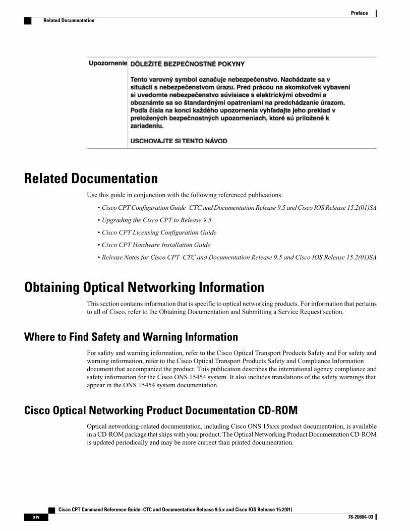
Related DocumentationUse this guide in conjunction with the following referenced publications:
• Cisco CPTConfigurationGuide–CTC andDocumentation Release 9.5 and Cisco IOS Release 15.2(01)SA
• Upgrading the Cisco CPT to Release 9.5
• Cisco CPT Licensing Configuration Guide
• Cisco CPT Hardware Installation Guide
• Release Notes for Cisco CPT–CTC and Documentation Release 9.5 and Cisco IOS Release 15.2(01)SA
Obtaining Optical Networking InformationThis section contains information that is specific to optical networking products. For information that pertainsto all of Cisco, refer to the Obtaining Documentation and Submitting a Service Request section.
Where to Find Safety and Warning InformationFor safety and warning information, refer to the Cisco Optical Transport Products Safety and For safety andwarning information, refer to the Cisco Optical Transport Products Safety and Compliance Informationdocument that accompanied the product. This publication describes the international agency compliance andsafety information for the Cisco ONS 15454 system. It also includes translations of the safety warnings thatappear in the ONS 15454 system documentation.
Cisco Optical Networking Product Documentation CD-ROMOptical networking-related documentation, including Cisco ONS 15xxx product documentation, is availablein a CD-ROMpackage that ships with your product. TheOptical Networking Product Documentation CD-ROMis updated periodically and may be more current than printed documentation.
Cisco CPT Command Reference Guide–CTC and Documentation Release 9.5.x and Cisco IOS Release 15.2(01)xiv 78-20604-03
PrefaceRelated Documentation
Obtaining Documentation and Submitting a Service RequestFor information on obtaining documentation, submitting a service request, and gathering additional information,see the monthlyWhat's New in Cisco Product Documentation, which also lists all new and revised Ciscotechnical documentation, at:
http://www.cisco.com/en/US/docs/general/whatsnew/whatsnew.html
Subscribe to theWhat's New in Cisco Product Documentation as a Really Simple Syndication (RSS) feedand set content to be delivered directly to your desktop using a reader application. The RSS feeds are a freeservice and Cisco currently supports RSS version 2.0.
Cisco CPT Documentation RoadmapTo quickly access publications of Cisco CPT Release 9.5, see the http://www.cisco.com/en/US/docs/optical/cpt/r9_5/doc_roadmap/cptroadmap95.html
Cisco CPT Command Reference Guide–CTC and Documentation Release 9.5.x and Cisco IOS Release 15.2(01) 78-20604-03 xv
PrefaceObtaining Documentation and Submitting a Service Request

Cisco CPT Command Reference Guide–CTC and Documentation Release 9.5.x and Cisco IOS Release 15.2(01)xvi 78-20604-03
PrefaceCisco CPT Documentation Roadmap
EVC Command Reference
This chapter describes commands used to configure an Ethernet Virtual Circuit (EVC).
• bridge-domain, page 2
• clear ethernet service instance, page 3
• encapsulation, page 5
• l2protocol, page 6
• mode, page 7
• rewrite ingress tag, page 9
• service instance ethernet, page 11
• show ethernet service instance, page 13
Cisco CPT Command Reference Guide–CTC and Documentation Release 9.5.x and Cisco IOS Release 15.2(01) 78-20604-03 1
bridge-domainTo bind a service instance to a bridge domain instance, use the bridge-domain command in service instanceconfiguration mode. To unbind a service instance from a bridge domain instance, use the no form of thiscommand.
bridge-domain bridge-id [split-horizon]
no bridge-domain
Syntax Description Numerical ID of the bridge domain instance. The range is from 1 to 16384.bridge-id
(Optional) Configures a port or service instance as a member of asplit-horizon group.
split-horizon
Command Default Service instances are not bound to a bridge domain instance.
Command Modes Service instance configuration (config-if-svc)
Command History ModificationRelease
This command was introduced.9.3.0
Usage Guidelines Use the bridge-domain command to bind a service instance to a bridge domain.
Examples The following example shows how to bind a bridge domain to a service instance using the bridge-domaincommand
Router> enableRouter# configure terminalRouter(config)# interface TenGigabitEthernet 4/1Router(config-if)# service instance 100 ethernetRouter(config-if-srv)# encapsulation dot1q 100Router(config-if-srv)# bridge-domain 200
Related Commands DescriptionCommand
Configures the bridge domain in p2p or p2mp mode.mode p2p
Cisco CPT Command Reference Guide–CTC and Documentation Release 9.5.x and Cisco IOS Release 15.2(01)2 78-20604-03
EVC Command Referencebridge-domain
clear ethernet service instanceTo clear Ethernet service instance attributes such as MAC addresses and statistics or to purge Ethernet serviceinstance errors, use the clear ethernet service instance command in privileged EXEC mode.
clear ethernet service instance {id identifier interface type number {errdisable |mac table [address] |stats} | interface type number stats}
Syntax Description Indicates that a service instance is specified.id identifier
Indicates that a specific interface is specified.interface
Type of interface.type
Number of the interface.number
Indicates that a clear action for an error-disabled state is specified.errdisable
Indicates that a MAC table is specified.mac table
Address in the specified MAC table.address
Indicates that the service instance statistics are specified.stats
Command Modes Privileged EXEC (#)
Command History ModificationRelease
This command was introduced.9.3.0
Usage Guidelines Use the clear ethernet service instance command to clear the service instance attributes that are not neededand to purge service instance errors.
Examples The following example shows how to clear an error-disabled state on service instance 100 on interfaceTenGigabitEthernet 4/1 using the clear ethernet service instance command:
Router# clear ethernet service instance id 100 interface TenGigabitEthernet 4/1 errdisable
Related Commands DescriptionCommand
Displays information about Ethernet service instances.show ethernet service instance
Cisco CPT Command Reference Guide–CTC and Documentation Release 9.5.x and Cisco IOS Release 15.2(01) 78-20604-03 3
EVC Command Referenceclear ethernet service instance

Cisco CPT Command Reference Guide–CTC and Documentation Release 9.5.x and Cisco IOS Release 15.2(01)4 78-20604-03
EVC Command Referenceclear ethernet service instance
encapsulationTo define the matching criteria that maps the ingress dot1q, QinQ, or untagged frames on an interface to theappropriate service instance, use the encapsulation dot1q command in service instance configuration mode.
encapsulation dot1q {any | vlan-id [vlan-id [-vlan-id]]} second-dot1q {any | vlan-id [vlan-id [-vlan-id]]}
Syntax Description Specifies a 802.1Q tag at theingress service instance.
dot1q
Indicates that all VLANs are to beconfigured.
any
Integer in the range 1 to 4094 thatidentifies the VLAN.
vlan-id
Specifies a different 802.1Q tag atthe ingress service instance.
second-dot1q
Command Default Encapsulation is not configured.
Command Modes Service instance configuration mode (config-if-srv)
Command History ModificationRelease
This command was introduced.9.3.0
Examples The following example shows how to configure dot1q encapsulation.
Router> enableRouter# configure terminalRouter(config)# interface TenGigabitEthernet 4/1Router(config-if)# service instance 101 ethernetRouter(config-if-srv)# encapsulation dot1q 100Router(config-if-srv)#
Cisco CPT Command Reference Guide–CTC and Documentation Release 9.5.x and Cisco IOS Release 15.2(01) 78-20604-03 5
EVC Command Referenceencapsulation
l2protocolTo configure Layer 2 protocol tunneling for the interfaces, use the l2protocol command in interfaceconfiguration mode.
l2protocol [drop|forward|peer] [cdp|dot1x|dtp|lacp|pagp|stp|vtp]
Syntax Description This command has no arguments or keywords.
Command Modes Interface configuration (config-if)
Command History ModificationRelease
This command was introduced.9.3.0
Examples The following example shows how to define a Layer 2 protocol tunneling action for an interface.
Router> enableRouter# configure terminalRouter(config)# interface TenGigabitEthernet 4/1Router(config-if)# l2protocol forward cdp
Cisco CPT Command Reference Guide–CTC and Documentation Release 9.5.x and Cisco IOS Release 15.2(01)6 78-20604-03
EVC Command Referencel2protocol
modeTo configure the bridge domain, use themode command in global configuration mode. To remove the bridgedomain from p2p or VPLS mode, use the no form of this command.
mode [p2p | vpls]
Syntax Description (Optional) Configures the bridge domain in point-to-point (p2p) mode.p2p
(Optional) Configures the bridge domain in VPLS mode.vpls
Command Default The default mode of the bridge domain is point-to-multipoint (p2mp).
Command Modes Global configuration (config)
Command History ModificationRelease
This command was introduced.9.3.0
This command was modified to include the vpls parameter.9.5.0
Usage Guidelines The p2p bridge domain can be used for Ethernet Private Line (EPL) and Ethernet Virtual Private Line (EVPL)services. The p2mp bridge domain can be used for Ethernet Private LAN (EPLAN) and Ethernet VirtualPrivate LAN (EVPLAN) services. The VPLS bridge domain can be used for Virtual Private LAN services.
Examples The following example shows how to configure the bridge domain in p2p mode.
Router> enableRouter# configure terminalRouter(config)# bridge-domain 12Router(config)# mode p2p
Examples The following example shows how to configure the bridge domain in VPLS mode.
Router> enableRouter# configure terminalRouter(config)# bridge-domain 12Router(config)# mode vpls
Cisco CPT Command Reference Guide–CTC and Documentation Release 9.5.x and Cisco IOS Release 15.2(01) 78-20604-03 7
EVC Command Referencemode

Related Commands DescriptionCommand
Binds a service instance to a bridge domain instance.bridge-domain
Cisco CPT Command Reference Guide–CTC and Documentation Release 9.5.x and Cisco IOS Release 15.2(01)8 78-20604-03
EVC Command Referencemode
rewrite ingress tagTo specify the rewrite operation to be applied on the frame ingress to the service instance, use the rewriteingress tag command in service instance configuration mode. To remove the rewrite operation, use the noform of this command.
rewrite ingress tag {push {dot1q vlan-id | dot1q vlan-id second-dot1q vlan-id | dot1ad vlan-id dot1qvlan-id} | pop {1 | 2} | translate {1-to-1 {dot1q vlan-id | dot1ad vlan-id}| 2-to-1 dot1q vlan-id | dot1advlan-id}| 1-to-2 {dot1q vlan-id second-dot1q vlan-id | dot1ad vlan-id dot1q vlan-id} | 2-to-2 {dot1q vlan-idsecond-dot1q vlan-id | dot1ad vlan-id dot1q vlan-id}} {symmetric}no rewrite ingress tag
Syntax Description Adds a tag to a packet.push
Specifies an IEEE 802.1Q tag.dot1q
Integer in the range 1 to 4094 that identifies the VLAN.vlan-id
Specifies a different 802.1Q tag at the ingress service instance.second-dot1q
Specifies an IEEE 802.1ad tag.dot1ad
Removes a tag from a packet.pop
Specifies either the outermost tag or the two outermost tags for removal from apacket.
{1 | 2}
Translates, by VLAN ID, a tag or a pair of tags defined in the encapsulationcommand.
translate
Translates a single tag defined by the encapsulation command to a single tagdefined in the rewrite ingress tag command.
1-to-1
Translates a single tag defined by the encapsulation command to a pair of tagsdefined in the rewrite ingress tag command.
1-to-2
Translates, by VLAN ID, a pair of tags defined by the encapsulation commandto a single tag defined in the rewrite ingress tag command.
2-to-1
Translates, by VLAN ID, a pair of tags defined by the encapsulation commandto a pair of tags defined in the rewrite ingress tag command.
2-to-2
(Optional) Indicates a reciprocal adjustment to be done in the egress direction. Forexample, if the ingress pops a tag, the egress pushes a tag and if the ingress pushesa tag, the egress pops a tag.
symmetric
Command Default The frame is left intact on ingress.
Cisco CPT Command Reference Guide–CTC and Documentation Release 9.5.x and Cisco IOS Release 15.2(01) 78-20604-03 9
EVC Command Referencerewrite ingress tag
Command Modes Service instance configuration (config-if-srv)
Command History ModificationRelease
This command was introduced.9.3.0
Usage Guidelines• The EFP point–to–point service does not support the rewrite egress operation. It supports only thesymmetric rewrite operation.
• The EFP multipoint–to–multipoint service supports rewrite ingress with the symmetric option. It doesnot support the rewrite egress operation.
• Rewrite Push 1 tag operation is not supported for encapsulations with double tag.
• Rewrite Push 2 tag operation is not supported for encapsulations with single or double tag.
• Translate rewrite operations are not supported for encapsulations, such as untagged, any, default, andfor encapsulations involving VLAN range and list.
Examples The following example shows how to specify the rewrite operation to be applied on the frame ingress to theservice instance.
Router> enableRouter# configure terminalRouter(config)# interface TenGigabitEthernet 4/1Router(config-if)# service instance 101 ethernetRouter(config-if-srv)# encapsulation dot1q 100Router(config-if-srv)# rewrite ingress tag push dot1q 20 symmetricRouter(config-if-srv)# bridge-domain 12Router(config-if-srv)# exit
Related Commands DescriptionCommand
Sets the encapsulation method used by an interface.encapsulation
Cisco CPT Command Reference Guide–CTC and Documentation Release 9.5.x and Cisco IOS Release 15.2(01)10 78-20604-03
EVC Command Referencerewrite ingress tag
service instance ethernetTo configure an Ethernet service instance on an interface and to enter Ethernet service configuration mode,use the service instance ethernet command in interface configuration mode. To delete a service instance,use the no form of this command.
service instance id ethernet [evc-name]no service instance id
Syntax Description Integer from 1 to 4294967295 that uniquely identifies a service instance on aninterface.
id
(Optional) String of a maximum of 100 bytes that associates an Ethernet virtualconnection (EVC) to the service instance.
evc-name
Command Default No Ethernet service instances are defined.
Command Modes Interface configuration (config-if)
Command History ModificationRelease
This command was introduced.9.3.0
Usage Guidelines A service instance is a configuration object that holds all the management and control-plane attributes andparameters that apply to that service instance on a per-port basis. Different service instances that correspondto the same EVCmust share the same name. Service instances are associated with a global EVC object throughtheir shared name.
Examples The following example shows how to define an Ethernet service instance and enter Ethernet serviceconfiguration mode for an EVC:
Router> enableRouter# configure terminalRouter(config)# interface TenGigabitEthernet 4/1Router(config-if)# service instance 101 ethernetRouter(config-if-srv)#
Related Commands DescriptionCommand
Displays information about configured Ethernetservice instances.
show ethernet service instance
Cisco CPT Command Reference Guide–CTC and Documentation Release 9.5.x and Cisco IOS Release 15.2(01) 78-20604-03 11
EVC Command Referenceservice instance ethernet

Cisco CPT Command Reference Guide–CTC and Documentation Release 9.5.x and Cisco IOS Release 15.2(01)12 78-20604-03
EVC Command Referenceservice instance ethernet
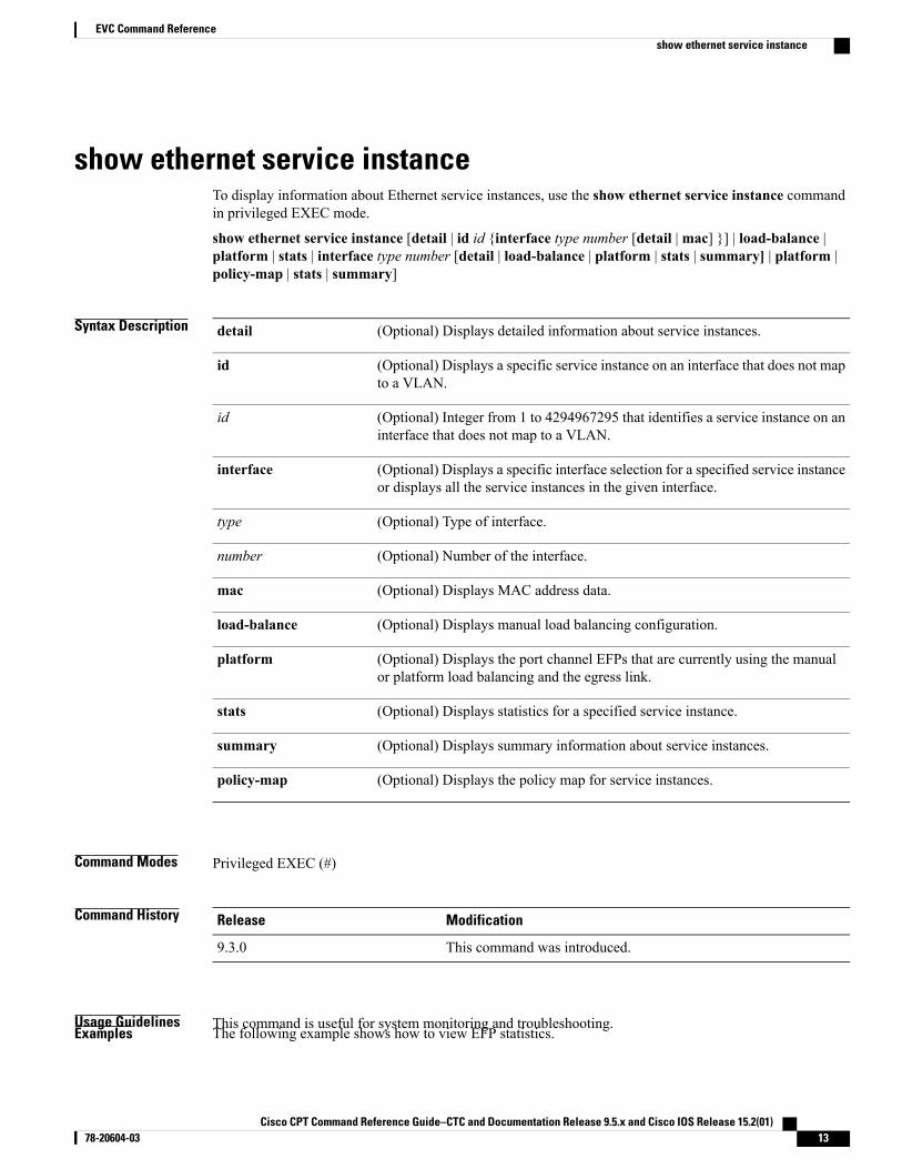
show ethernet service instanceTo display information about Ethernet service instances, use the show ethernet service instance commandin privileged EXEC mode.
show ethernet service instance [detail | id id {interface type number [detail |mac] }] | load-balance |platform | stats | interface type number [detail | load-balance | platform | stats | summary] | platform |policy-map | stats | summary]
Syntax Description (Optional) Displays detailed information about service instances.detail
(Optional) Displays a specific service instance on an interface that does not mapto a VLAN.
id
(Optional) Integer from 1 to 4294967295 that identifies a service instance on aninterface that does not map to a VLAN.
id
(Optional) Displays a specific interface selection for a specified service instanceor displays all the service instances in the given interface.
interface
(Optional) Type of interface.type
(Optional) Number of the interface.number
(Optional) Displays MAC address data.mac
(Optional) Displays manual load balancing configuration.load-balance
(Optional) Displays the port channel EFPs that are currently using the manualor platform load balancing and the egress link.
platform
(Optional) Displays statistics for a specified service instance.stats
(Optional) Displays summary information about service instances.summary
(Optional) Displays the policy map for service instances.policy-map
Command Modes Privileged EXEC (#)
Command History ModificationRelease
This command was introduced.9.3.0
Usage Guidelines This command is useful for system monitoring and troubleshooting.Examples The following example shows how to view EFP statistics.
Cisco CPT Command Reference Guide–CTC and Documentation Release 9.5.x and Cisco IOS Release 15.2(01) 78-20604-03 13
EVC Command Referenceshow ethernet service instance
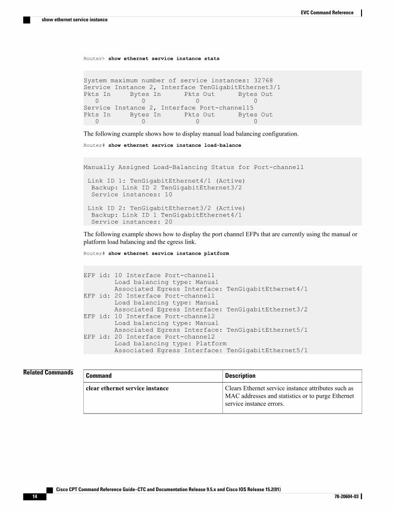
Router> show ethernet service instance stats
System maximum number of service instances: 32768Service Instance 2, Interface TenGigabitEthernet3/1Pkts In Bytes In Pkts Out Bytes Out
0 0 0 0Service Instance 2, Interface Port-channel15Pkts In Bytes In Pkts Out Bytes Out
0 0 0 0
The following example shows how to display manual load balancing configuration.
Router# show ethernet service instance load-balance
Manually Assigned Load-Balancing Status for Port-channel1
Link ID 1: TenGigabitEthernet4/1 (Active)Backup: Link ID 2 TenGigabitEthernet3/2Service instances: 10
Link ID 2: TenGigabitEthernet3/2 (Active)Backup: Link ID 1 TenGigabitEthernet4/1Service instances: 20
The following example shows how to display the port channel EFPs that are currently using the manual orplatform load balancing and the egress link.
Router# show ethernet service instance platform
EFP id: 10 Interface Port-channel1Load balancing type: ManualAssociated Egress Interface: TenGigabitEthernet4/1
EFP id: 20 Interface Port-channel1Load balancing type: ManualAssociated Egress Interface: TenGigabitEthernet3/2
EFP id: 10 Interface Port-channel2Load balancing type: ManualAssociated Egress Interface: TenGigabitEthernet5/1
EFP id: 20 Interface Port-channel2Load balancing type: PlatformAssociated Egress Interface: TenGigabitEthernet5/1
Related Commands DescriptionCommand
Clears Ethernet service instance attributes such asMAC addresses and statistics or to purge Ethernetservice instance errors.
clear ethernet service instance
Cisco CPT Command Reference Guide–CTC and Documentation Release 9.5.x and Cisco IOS Release 15.2(01)14 78-20604-03
EVC Command Referenceshow ethernet service instance
MPLS Command Reference
This chapter describes commands to configure Multiprotocol Label Switching (MPLS).
• affinity, page 17
• auto-bw, page 19
• bandwidth, page 21
• index, page 22
• ip explicit-path, page 23
• ip route, page 24
• ip rsvp bandwidth, page 26
• ip rsvp signalling hello graceful-restart neighbor, page 28
• mpls ip (global configuration), page 29
• mpls ip (interface configuration), page 30
• mpls label protocol ldp (global configuration), page 32
• mpls label protocol ldp (interface configuration), page 33
• mpls ldp autoconfig, page 34
• mpls ldp backoff, page 36
• mpls ldp explicit-null, page 38
• mpls ldp graceful-restart, page 39
• mpls ldp graceful-restart timers forwarding-holding, page 40
• mpls ldp graceful-restart timers max-recovery, page 41
• mpls ldp graceful-restart timers neighbor-liveness, page 42
• mpls ldp igp sync, page 44
• mpls ldp igp sync holddown, page 46
• mpls ldp neighbor targeted, page 47
• mpls ldp router-id, page 49
Cisco CPT Command Reference Guide–CTC and Documentation Release 9.5.x and Cisco IOS Release 15.2(01) 78-20604-03 15
• mpls ldp session protection, page 51
• mpls ldp sync, page 53
• mpls traffic-eng area, page 54
• mpls traffic-eng link-management timers periodic-flooding, page 55
• mpls traffic-eng lsp attributes, page 56
• mpls traffic-eng router-id, page 58
• mpls traffic-eng tunnels (global configuration), page 59
• mpls traffic-eng tunnels (interface configuration), page 60
• mpls traffic-eng path-option list, page 61
• next-address, page 63
• ping mpls, page 65
• priority, page 69
• record-route, page 71
• show ip explicit-paths, page 72
• show ip rsvp sender, page 74
• show mpls ldp backoff, page 75
• show mpls traffic-eng lsp attributes, page 76
• show mpls traffic-eng tunnels, page 78
• show ip ospf mpls ldp interface, page 82
• show mpls interfaces, page 84
• show mpls ldp discovery, page 86
• show mpls ldp igp sync, page 88
• show mpls ldp neighbor, page 90
• trace mpls, page 92
• tunnel mode mpls traffic-eng, page 95
• tunnel mpls traffic-eng path-option, page 97
• tunnel mpls traffic-eng autoroute announce, page 99
• tunnel mpls traffic-eng bandwidth, page 100
• tunnel mpls traffic-eng priority, page 101
• tunnel mpls traffic–eng path–option protect, page 103
Cisco CPT Command Reference Guide–CTC and Documentation Release 9.5.x and Cisco IOS Release 15.2(01)16 78-20604-03
MPLS Command Reference
affinityTo specify affinity and affinity mask values for an LSP in an LSP attribute list, use the affinity command inLSP attributes configuration mode. To remove the specified attribute flags, use the no form of this command.
affinity value [mask value]
no affinity
Syntax Description Attribute flag value required for links that make up an LSP. The attribute flag valuecan be either 0 or 1.
value
(Optional) Indicates which attribute values should be checked. If a bit in the mask is0, an attribute value of the link or that bit is irrelevant. If a bit in the mask is 1, theattribute value of that link and the required affinity of the tunnel for that bit must match.
mask value
Command Default Attribute flag values are not specified.
Command Modes LSP attributes configuration (config-lsp-attr)
Command History ModificationRelease
This command was introduced.9.3.0
Usage Guidelines The affinity value determines the attribute flags for links that make up the LSP, either 0 or 1. The attributemask determines which attribute value the router should check. If a bit in the mask is 0, an attribute value ofa link or that bit is irrelevant. If a bit in the mask is 1, the attribute value of a link and the required affinity ofthe LSP for that bit must match.
An LSP can use a link if the link affinity equals the attribute flag value and the affinity mask value.
Any value set to 1 in the affinity should also be set to 1 in the mask.
To associate the LSP affinity attribute and the LSP attribute list with a path option for an LSP, you mustconfigure the tunnelmpls traffic-eng path option commandwith the attributes string keyword and argument,where string is the identifier of the specific LSP attribute list.
Examples The following example shows how to specify the affinity value and affinity mask values for links comprisingan LSP.Router(config-lsp-attr)# affinity 0 mask 0
Cisco CPT Command Reference Guide–CTC and Documentation Release 9.5.x and Cisco IOS Release 15.2(01) 78-20604-03 17
MPLS Command Referenceaffinity

Related Commands DescriptionCommand
Creates or modifies an LSP attribute list.mpls traffic-eng lsp attributes
Displays global LSP attribute lists.show mpls traffic-eng lsp attributes
Cisco CPT Command Reference Guide–CTC and Documentation Release 9.5.x and Cisco IOS Release 15.2(01)18 78-20604-03
MPLS Command Referenceaffinity
auto-bwTo specify an automatic bandwidth configuration for a LSP in an LSP attribute list, use the auto-bw commandin LSP attributes configuration mode. To remove automatic bandwidth configuration, use the no form of thiscommand.
auto-bw [frequency secs] [max-bw kbps] [min-bw kbps] [collect-bw]
no auto-bw
Syntax Description (Optional) Specifies the interval between bandwidth adjustments. The specifiedinterval ranges from 300 to 604800 seconds.
frequency secs
(Optional) Specifies the maximum automatic bandwidth for the path option. Thevalue ranges from 0 to 4294967295 kbps.
max-bw kbps
(Optional) Specifies the minimum automatic bandwidth for the path option. Thevalue ranges from 0 to 4294967295 kbps.
min-bw kbps
(Optional) Collects bandwidth output rate information for the path option, butdoes not adjust its bandwidth.
collect-bw
Command Default The automatic bandwidth for the LSP is not enabled.
Command Modes LSP attributes configuration (config-lsp-attr)
Command History ModificationRelease
This command was introduced.9.3.0
Usage Guidelines Use this command to set an automatic bandwidth configuration for a LSP in an LSP attributes list.
To sample the bandwidth used by an LSP without automatically adjusting it, specify the collect-bw keywordin the auto-bw command in an LSP attribute list.
If you enter the auto-bw command without the collect-bw keyword, the bandwidth of the LSP is adjusted tothe largest average output rate sampled for the LSP since the last bandwidth adjustment for the LSPwas made.
To constrain the automatic bandwidth adjustment that can be made to an LSP in an LSP attribute list, use themax-bw ormin-bw keyword and specify the permittedmaximum allowable bandwidth or minimum allowablebandwidth, respectively.
The no form of the auto-bw command disables the automatic bandwidth adjustment for the tunnel and restoresthe configured bandwidth for the LSP where configured bandwidth is determined as follows:
Cisco CPT Command Reference Guide–CTC and Documentation Release 9.5.x and Cisco IOS Release 15.2(01) 78-20604-03 19
MPLS Command Referenceauto-bw
• If the LSP bandwidth was explicitly configuredwith thempls traffic-eng lsp attributes lsp-id bandwidthcommand after the running configuration was written to the startup configuration, the configuredbandwidth is the bandwidth specified by that command.
• Otherwise, the configured bandwidth is the bandwidth specified for the tunnel in the startup configuration.
To associate the LSP automatic bandwidth adjustment attribute and the LSP attribute list with a path optionfor an LSP, you must configure the tunnel mpls traffic-eng path option command with the attributes stringkeyword and argument, where string is the identifier of the specific LSP attribute list.
Examples The following example sets the automatic bandwidth configuration for an LSP in an LSP attribute list.Router(config-lsp-attr)# auto-bw
Related Commands DescriptionCommand
Creates or modifies an LSP attribute list.mpls traffic-eng lsp attributes
Displays global LSP attribute lists.show mpls traffic-eng lsp attributes
Cisco CPT Command Reference Guide–CTC and Documentation Release 9.5.x and Cisco IOS Release 15.2(01)20 78-20604-03
MPLS Command Referenceauto-bw
bandwidthTo configure LSP bandwidth in an LSP attribute list, use the bandwidth command in LSP attributesconfiguration mode. To remove the configured bandwidth from the LSP attribute list, use the no form of thiscommand.
bandwidth global kbps
no bandwidth
Syntax Description Indicates a global pool path option.
kbps—Number of kilobits per second set aside for the path option. The range isfrom 1 to 4294967295 kbps.
global kbps
Command Default The LSP bandwidth is not configured in the LSP attribute list.
Command Modes LSP attributes configuration (config-lsp-attr)
Command History ModificationRelease
This command was introduced.9.3.0
Usage Guidelines Use this command to configure the LSP bandwidth in the LSP attribute list. The bandwidth configured canbe associated with both dynamic and explicit path options.
To associate the LSP bandwidth and the LSP attribute list with a path option for an LSP, you must configurethe tunnel mpls traffic-eng path option command with the attributes string keyword and argument, wherestring is the identifier of the specific LSP attribute list.
The bandwidth configured in the LSP attribute list will override the bandwidth configured on the tunnel.
Examples The following example shows how to specify an LSP bandwidth in the LSP attribute list.
Router(config-lsp-attr)# bandwidth global 1000
Related Commands DescriptionCommand
Creates or modifies an LSP attribute list.mpls traffic-eng lsp attributes
Displays global LSP attribute lists.show mpls traffic-eng lsp attributes
Cisco CPT Command Reference Guide–CTC and Documentation Release 9.5.x and Cisco IOS Release 15.2(01) 78-20604-03 21
MPLS Command Referencebandwidth
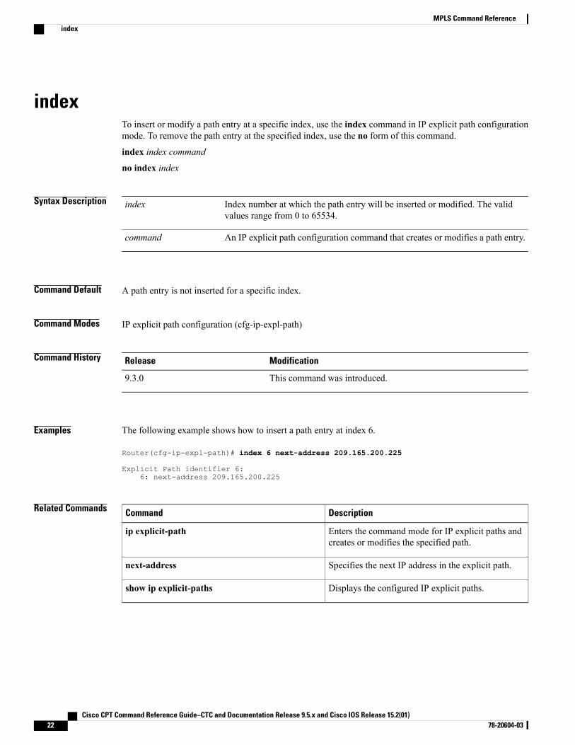
indexTo insert or modify a path entry at a specific index, use the index command in IP explicit path configurationmode. To remove the path entry at the specified index, use the no form of this command.
index index command
no index index
Syntax Description Index number at which the path entry will be inserted or modified. The validvalues range from 0 to 65534.
index
An IP explicit path configuration command that creates or modifies a path entry.command
Command Default A path entry is not inserted for a specific index.
Command Modes IP explicit path configuration (cfg-ip-expl-path)
Command History ModificationRelease
This command was introduced.9.3.0
Examples The following example shows how to insert a path entry at index 6.
Router(cfg-ip-expl-path)# index 6 next-address 209.165.200.225
Explicit Path identifier 6:6: next-address 209.165.200.225
Related Commands DescriptionCommand
Enters the command mode for IP explicit paths andcreates or modifies the specified path.
ip explicit-path
Specifies the next IP address in the explicit path.next-address
Displays the configured IP explicit paths.show ip explicit-paths
Cisco CPT Command Reference Guide–CTC and Documentation Release 9.5.x and Cisco IOS Release 15.2(01)22 78-20604-03
MPLS Command Referenceindex
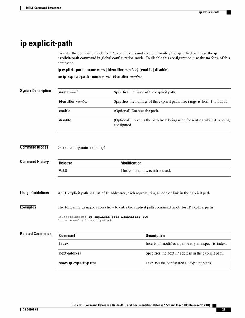
ip explicit-pathTo enter the command mode for IP explicit paths and create or modify the specified path, use the ipexplicit-path command in global configuration mode. To disable this configuration, use the no form of thiscommand.
ip explicit-path {name word | identifier number} [enable | disable]
no ip explicit-path {name word | identifier number}
Syntax Description Specifies the name of the explicit path.name word
Specifies the number of the explicit path. The range is from 1 to 65535.identifier number
(Optional) Enables the path.enable
(Optional) Prevents the path from being used for routing while it is beingconfigured.
disable
Command Modes Global configuration (config)
Command History ModificationRelease
This command was introduced.9.3.0
Usage Guidelines An IP explicit path is a list of IP addresses, each representing a node or link in the explicit path.
Examples The following example shows how to enter the explicit path command mode for IP explicit paths.
Router(config)# ip explicit-path identifier 500Router(config-ip-expl-path)#
Related Commands DescriptionCommand
Inserts or modifies a path entry at a specific index.index
Specifies the next IP address in the explicit path.next-address
Displays the configured IP explicit paths.show ip explicit-paths
Cisco CPT Command Reference Guide–CTC and Documentation Release 9.5.x and Cisco IOS Release 15.2(01) 78-20604-03 23
MPLS Command Referenceip explicit-path
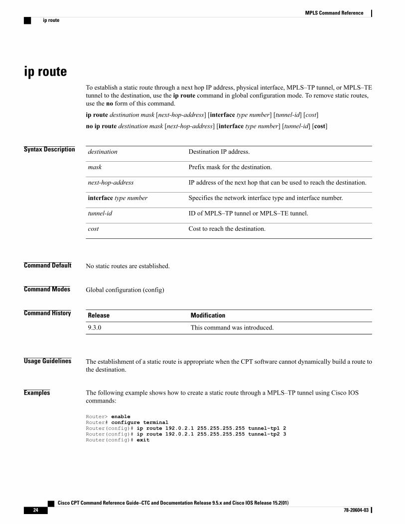
ip routeTo establish a static route through a next hop IP address, physical interface, MPLS–TP tunnel, or MPLS–TEtunnel to the destination, use the ip route command in global configuration mode. To remove static routes,use the no form of this command.
ip route destination mask [next-hop-address] [interface type number] [tunnel-id] [cost]
no ip route destination mask [next-hop-address] [interface type number] [tunnel-id] [cost]
Syntax Description Destination IP address.destination
Prefix mask for the destination.mask
IP address of the next hop that can be used to reach the destination.next-hop-address
Specifies the network interface type and interface number.interface type number
ID of MPLS–TP tunnel or MPLS–TE tunnel.tunnel-id
Cost to reach the destination.cost
Command Default No static routes are established.
Command Modes Global configuration (config)
Command History ModificationRelease
This command was introduced.9.3.0
Usage Guidelines The establishment of a static route is appropriate when the CPT software cannot dynamically build a route tothe destination.
Examples The following example shows how to create a static route through a MPLS–TP tunnel using Cisco IOScommands:
Router> enableRouter# configure terminalRouter(config)# ip route 192.0.2.1 255.255.255.255 tunnel-tp1 2Router(config)# ip route 192.0.2.1 255.255.255.255 tunnel-tp2 3Router(config)# exit
Cisco CPT Command Reference Guide–CTC and Documentation Release 9.5.x and Cisco IOS Release 15.2(01)24 78-20604-03
MPLS Command Referenceip route

The following example shows how to create a static route through a physical interface using Cisco IOScommands:
Router> enableRouter# configure terminalRouter(config)# ip route 192.0.2.1 255.255.255.255 TenGigabitEthernet4/1 5Router(config)# exit
Cisco CPT Command Reference Guide–CTC and Documentation Release 9.5.x and Cisco IOS Release 15.2(01) 78-20604-03 25
MPLS Command Referenceip route
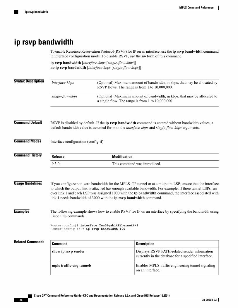
ip rsvp bandwidthTo enable Resource Reservation Protocol (RSVP) for IP on an interface, use the ip rsvp bandwidth commandin interface configuration mode. To disable RSVP, use the no form of this command.
ip rsvp bandwidth [interface-kbps [single-flow-kbps]]no ip rsvp bandwidth [interface-kbps [single-flow-kbps]]
Syntax Description (Optional) Maximum amount of bandwidth, in kbps, that may be allocated byRSVP flows. The range is from 1 to 10,000,000.
interface-kbps
(Optional) Maximum amount of bandwidth, in kbps, that may be allocated toa single flow. The range is from 1 to 10,000,000.
single-flow-kbps
Command Default RSVP is disabled by default. If the ip rsvp bandwidth command is entered without bandwidth values, adefault bandwidth value is assumed for both the interface-kbps and single-flow-kbps arguments.
Command Modes Interface configuration (config-if)
Command History ModificationRelease
This command was introduced.9.3.0
Usage Guidelines If you configure non-zero bandwidth for the MPLS–TP tunnel or at a midpoint LSP, ensure that the interfaceto which the output link is attached has enough available bandwidth. For example, if three tunnel LSPs runover link 1 and each LSP was assigned 1000 with the tp bandwidth command, the interface associated withlink 1 needs bandwidth of 3000 with the ip rsvp bandwidth command.
Examples The following example shows how to enable RSVP for IP on an interface by specifying the bandwidth usingCisco IOS commands.
Router(config)# interface TenGigabitEthernet4/1Router(config-if)# ip rsvp bandwidth 100
Related Commands DescriptionCommand
Displays RSVP PATH-related sender informationcurrently in the database for a specified interface.
show ip rsvp sender
Enables MPLS traffic engineering tunnel signalingon an interface.
mpls traffic-eng tunnels
Cisco CPT Command Reference Guide–CTC and Documentation Release 9.5.x and Cisco IOS Release 15.2(01)26 78-20604-03
MPLS Command Referenceip rsvp bandwidth

DescriptionCommand
Configures the bandwidth required for a MPLS-TEtunnel.
tunnel mpls traffic-eng bandwidth
Configures the bandwidth for the MPLS–TP tunnel.tp bandwidth
Cisco CPT Command Reference Guide–CTC and Documentation Release 9.5.x and Cisco IOS Release 15.2(01) 78-20604-03 27
MPLS Command Referenceip rsvp bandwidth
ip rsvp signalling hello graceful-restart neighborTo enable Resource Reservation Protocol (RSVP) traffic engineering (TE) graceful restart capability on aneighboring router, use the ip rsvp signalling hello graceful-restart neighbor command in interfaceconfiguration mode. To disable RSVP-TE graceful restart capability, use the no form of this command.
ip rsvp signalling hello graceful-restart neighbor ip-address
no ip rsvp signalling hello graceful-restart neighbor ip-address
Syntax Description IP address of a neighbor on a given interface.ip-address
Command Default No neighboring routers have RSVP-TE graceful restart capability enabled.
Command Modes Interface configuration (config-if)
Command History ModificationRelease
This command was introduced.9.3.0
Usage Guidelines Use this command to enable support for graceful restart on routers helping their neighbors recover TE tunnelsfollowing stateful switchover (SSO).
You must issue this command on each interface of the neighboring router that you want to restart.Note
Examples The following example shows how to configure RSVP-TE graceful restart on an interface of a neighboringrouter with the IP address 192.0.2.1.
Router# configure terminalRouter(config)# interface TenGigabitEthernet4/1Router(config-if)# ip rsvp signalling hello graceful-restart neighbor 192.0.2.1
Cisco CPT Command Reference Guide–CTC and Documentation Release 9.5.x and Cisco IOS Release 15.2(01)28 78-20604-03
MPLS Command Referenceip rsvp signalling hello graceful-restart neighbor
mpls ip (global configuration)To configureMPLS hop-by-hop forwarding globally, use thempls ip command in global configuration mode.To disable MPLS hop-by-hop forwarding, use the no form of this command.
mpls ip
no mpls ip
Syntax Description This command has no arguments or keywords.
Command Default Thempls ip command is enabled by default.
Command Modes Global configuration (config)
Command History ModificationRelease
This command was introduced.9.3.0
Usage Guidelines Globally enabling MPLS forwarding does not enable it on the interfaces. You must enable MPLS forwardingon the interfaces separately.
MPLS forwarding of packets along normally routed paths (also called dynamic label switching) is enabledby this command. For a given interface to perform dynamic label switching, this switching function must beenabled.
The no form of this command stops dynamic label switching for all the interfaces regardless of the interfaceconfiguration; it also stops distribution of labels for dynamic label switching. However, the no form of thiscommand does not affect the sending of labeled packets through the LSP tunnels.
Examples The following example shows how to globally configure MPLS hop-by-hop forwarding.
Router> enableRouter# configure terminalRouter(config)# mpls ip
Related Commands DescriptionCommand
Enables MPLS forwarding of IPv4 packets alongnormally routed paths for the associated interface.
mpls ip (interface configuration)
Cisco CPT Command Reference Guide–CTC and Documentation Release 9.5.x and Cisco IOS Release 15.2(01) 78-20604-03 29
MPLS Command Referencempls ip (global configuration)
mpls ip (interface configuration)To configure MPLS hop-by-hop forwarding on a specific interface, use thempls ip command in interfaceconfiguration mode. To disable MPLS hop-by-hop forwarding on a specific interface, use the no form of thiscommand.
mpls ip
no mpls ip
Syntax Description This command has no arguments or keywords.
Command Default Thempls ip command is enabled by default.
Command Modes Interface configuration (config-if)
Command History ModificationRelease
This command was introduced.9.3.0
Usage Guidelines MPLS forwarding of IPv4 packets along normally routed paths is also called dynamic label switching. Ifdynamic label switching has been enabled when this command is issued on an interface, label distribution forthe interface begins with the periodic transmission of neighbor discovery Hello messages on the interface.When the outgoing label for a destination routed through the interface is known, packets for the destinationare labeled with that outgoing label and forwarded through the interface.
The no form of this command causes packets routed out through the interface to be sent unlabeled; this formof the command also terminates label distribution for the interface. However, the no form of the commanddoes not affect the sending of labeled packets through any LSP tunnels that might use the interface.
Examples The following example shows how to configure MPLS hop-by-hop forwarding on the interface.
Router> enableRouter# configure terminalRouter(config)# interface TenGigabitEthernet4/1Router(config-if)# mpls ip
Related Commands DescriptionCommand
Displays information about one or more interfacesthat have been configured for label switching.
show mpls interfaces
Cisco CPT Command Reference Guide–CTC and Documentation Release 9.5.x and Cisco IOS Release 15.2(01)30 78-20604-03
MPLS Command Referencempls ip (interface configuration)

Cisco CPT Command Reference Guide–CTC and Documentation Release 9.5.x and Cisco IOS Release 15.2(01) 78-20604-03 31
MPLS Command Referencempls ip (interface configuration)
mpls label protocol ldp (global configuration)To specify the MPLS Label Distribution Protocol (LDP) on all the interfaces, use thempls label protocolldp command in global configuration mode. To remove the label distribution protocol on all the interfaces,use the no form of this command.
mpls label protocol ldp
no mpls label protocol ldp
Syntax Description This command has no arguments or keywords.
Command Default LDP is the default label distribution protocol.
Command Modes Global configuration (config)
Command History ModificationRelease
This command was introduced.9.3.0
Examples The following command shows how to establish LDP as the label distribution protocol on all the interfaces.Router(config)# mpls label protocol ldp
Related Commands DescriptionCommand
Specifies LDP for an interface.mpls label protocol ldp (interface configuration)
Displays information about one or more or allinterfaces that are configured for label switching.
show mpls interfaces
Cisco CPT Command Reference Guide–CTC and Documentation Release 9.5.x and Cisco IOS Release 15.2(01)32 78-20604-03
MPLS Command Referencempls label protocol ldp (global configuration)
mpls label protocol ldp (interface configuration)To specify the MPLS Label Distribution Protocol (LDP) for an interface, use thempls label protocol ldpcommand in interface configuration mode. To remove the label distribution protocol from the interface, usethe no form of this command.
mpls label protocol ldp
no mpls label protocol ldp
Syntax Description This command has no arguments or keywords.
Command Default If no protocol is explicitly configured for an interface, the label distribution protocol that was globallyconfigured is used. To set the global label distribution protocol, use the globalmpls label protocol command.
Command Modes Interface configuration (config-if)
Command History ModificationRelease
This command was introduced.9.3.0
Usage Guidelines To successfully establish a session for label distribution for a link connecting two label switch routers (LSRs),the link interfaces on the LSRs must be configured to use the same label distribution protocol. If there aremultiple links connecting two LSRs, all of the link interfaces connecting the two LSRs must be configuredto use the same protocol.
Examples The following example shows how to establish LDP as the label distribution protocol for an interface.Router(config-if)# mpls label protocol ldp
Related Commands DescriptionCommand
Specifies the LDP on all the interfaces.mpls label protocol ldp (global configuration)
Displays information about one or more or allinterfaces that are configured for label switching.
show mpls interfaces
Cisco CPT Command Reference Guide–CTC and Documentation Release 9.5.x and Cisco IOS Release 15.2(01) 78-20604-03 33
MPLS Command Referencempls label protocol ldp (interface configuration)
mpls ldp autoconfigTo enable MPLS Label Distribution Protocol (LDP) on interfaces for which an OSPF instance has beendefined, use thempls ldp autoconfig command in router configuration mode. To disable this configuration,use the no form of this command.
mpls ldp autoconfig [area area-id]
no mpls ldp autoconfig [area area-id]
Syntax Description (Optional) Enables LDP on the interfaces belonging to the specified OSPFarea.
area area-id
Command Default LDP is not enabled on the interfaces.
Command Modes Router configuration (config-router)
Command History ModificationRelease
This command was introduced.9.3.0
Usage Guidelines• You can specify this command multiple times to enable LDP on different routing areas with interfacesrunning OSPF.
• If LDP is disabled globally, thempls ldp autoconfig command fails. LDP must be enabled globally bymeans of the globalmpls ip command first.
• If thempls ldp autoconfig command is configured, you cannot issue the global no mpls ip command.If you want to disable LDP, you must issue the no mpls ldp autoconfig command first.
• Thempls ldp autoconfig command is supported only with OSPF interior gateway protocols (IGPs).
• If an OSPF area is not specified, LDP is enabled on all the interfaces belonging to the OSPF process.
Examples The following example shows how to autoconfigure MPLS LDP for OSPF area 5.Router(config-router)# mpls ldp autoconfig area 5
Related Commands DescriptionCommand
Enables LDP globally.mpls ip (global configuration)
Cisco CPT Command Reference Guide–CTC and Documentation Release 9.5.x and Cisco IOS Release 15.2(01)34 78-20604-03
MPLS Command Referencempls ldp autoconfig

DescriptionCommand
Displays information about the interfaces configuredfor LDP.
show mpls interfaces
Displays the status of the LDP discovery process.show mpls ldp discovery
Cisco CPT Command Reference Guide–CTC and Documentation Release 9.5.x and Cisco IOS Release 15.2(01) 78-20604-03 35
MPLS Command Referencempls ldp autoconfig
mpls ldp backoffTo configure parameters for the MPLS label distribution protocol (LDP) backoff mechanism, use themplsldp backoff command in global configuration mode. To disable this configuration, use the no form of thiscommand.
mpls ldp backoff initial-backoff maximum-backoff
no mpls ldp backoff initial-backoff maximum-backoff
Syntax Description Number ranging from 5 to 2147483, inclusive, that defines the initial backoffvalue in seconds. The default is 15 seconds.
initial-backoff
Number ranging from 5 to 2147483, inclusive, that defines the maximumbackoff value in seconds. The default value is 120 seconds.
maximum-backoff
Command Default The LDP backoff mechanism parameters are not configured.
Command Modes Global configuration (config)
Command History ModificationRelease
This command was introduced.9.3.0
Usage Guidelines The LDP backoff mechanism prevents two incompatibly configured label switch routers (LSRs) from engagingin an unthrottled sequence of session setup failures.
If a session setup attempt fails due to an incompatibility, each LSR delays its next attempt (that is, backs off),increasing the delay exponentially with each successive failure until the maximum backoff delay is reached.The default settings correspond to the lowest settings for initial and maximum backoff values defined by theLDP protocol specification. You should change the settings from the default values only if such settings resultin undesirable behavior.
Examples The following example shows how to set the initial backoff delay to 30 seconds and the maximum backoffdelay to 240 seconds.Router(config)# mpls ldp backoff 30 240
Cisco CPT Command Reference Guide–CTC and Documentation Release 9.5.x and Cisco IOS Release 15.2(01)36 78-20604-03
MPLS Command Referencempls ldp backoff

Related Commands DescriptionCommand
Displays information about the configured sessionsetup backoff parameters and any potential LDP peerswith which session setup attempts are being throttled.
show mpls ldp backoff
Cisco CPT Command Reference Guide–CTC and Documentation Release 9.5.x and Cisco IOS Release 15.2(01) 78-20604-03 37
MPLS Command Referencempls ldp backoff
mpls ldp explicit-nullTo enable the router to advertise an MPLS LDP Explicit Null label in situations where it would normallyadvertise an Implicit Null label, use thempls ldp explicit-null command in global configuration mode. Todisable this configuration, use the no form of this command.
mpls ldp explicit-null [for prefix-acl | to peer-acl]
no mpls ldp explicit-null
Syntax Description (Optional) Specifies prefixes for which Explicit Null must be advertised inplace of Implicit Null.
for prefix-acl
(Optional) Specifies LDP peers to which Explicit Null must be advertised inplace of Implicit Null.
to peer-acl
Command Default Explicit Null labels are not advertised.
Command Modes Global configuration (config)
Command History ModificationRelease
This command was introduced.9.3.0
Usage Guidelines Normally, LDP advertises an Implicit Null label for directly connected routes. The Implicit Null label causesthe previous hop (penultimate) router to do penultimate hop popping. In certain cases, it is desirable to preventthe penultimate router from performing penultimate hop popping and to force it to replace the incoming labelwith the Explicit Null label.
When you issue thempls ldp explicit-null command, Explicit Null is advertised in place of Implicit Null fordirectly connected prefixes permitted by the prefix-acl argument to peers permitted by the peer-acl argument.
If you do not specify the prefix-acl argument in the command, Explicit Null is advertised in place of ImplicitNull for all directly connected prefixes.
If you do not specify the peer-acl argument in the command, Explicit Null is advertised in place of ImplicitNull to all the peers.
Examples The following command shows how to enable the Explicit Null label for all directly connected routes to allthe LDP peers.Router(config)# mpls ldp explicit-null
Cisco CPT Command Reference Guide–CTC and Documentation Release 9.5.x and Cisco IOS Release 15.2(01)38 78-20604-03
MPLS Command Referencempls ldp explicit-null
mpls ldp graceful-restartTo enable MPLS LDP graceful restart, use thempls ldp graceful-restart command in global configurationmode. To disable LDP graceful restart, use the no form of this command.
mpls ldp graceful-restart
no mpls ldp graceful-restart
Syntax Description This command has no arguments or keywords.
Command Default MPLS LDP graceful restart is not enabled.
Command Modes Global configuration (config)
Command History ModificationRelease
This command was introduced.9.3.0
Usage Guidelines MPLS LDP graceful restart must be enabled before an LDP session is established. Use the no form of thecommand to disable the graceful restart on all the LDP sessions.
Examples The following example shows how to enable LDP graceful restart.Router(config)# mpls ldp graceful-restart
Related Commands DescriptionCommand
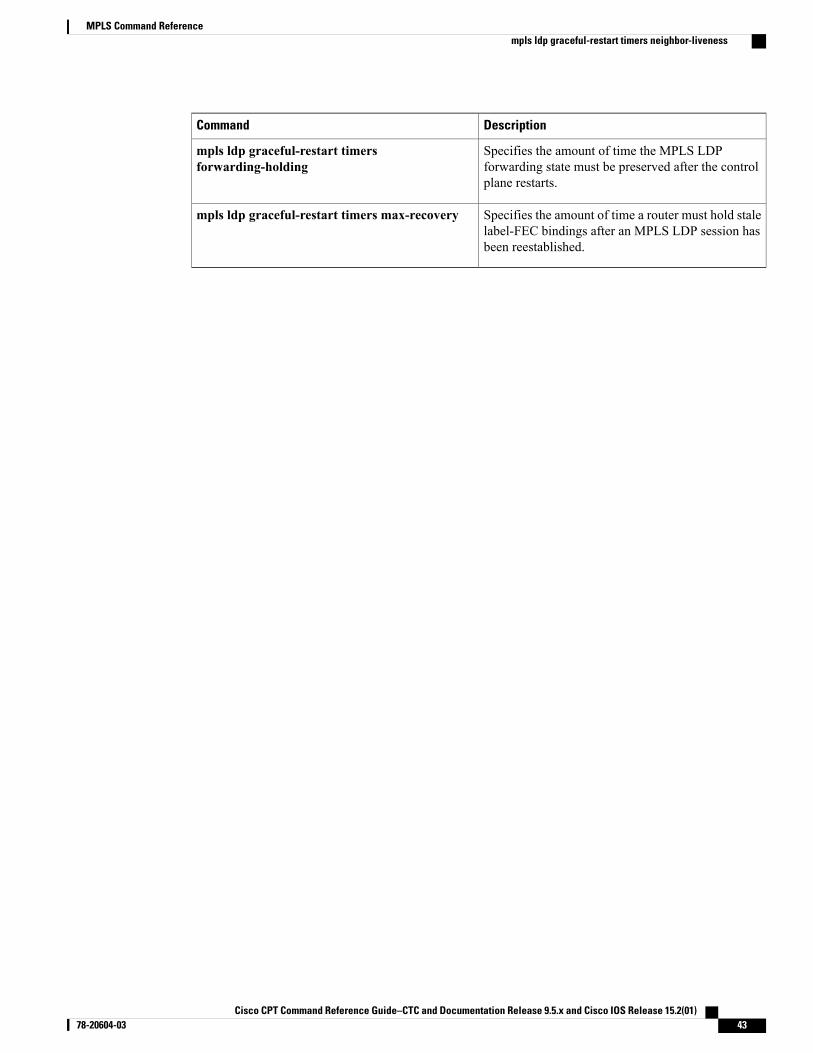
Specifies the amount of time the MPLS LDPforwarding state must be preserved after the controlplane restarts.
mpls ldp graceful-restart timersforwarding-holding
Specifies the amount of time a router should holdstale label-FEC bindings after anMPLS LDP sessionhas been reestablished.
mpls ldp graceful-restart timers max-recovery
Specifies the amount of time a router should wait foran MPLS LDP session to be reestablished.
mpls ldp graceful-restart timers neighbor-liveness
Cisco CPT Command Reference Guide–CTC and Documentation Release 9.5.x and Cisco IOS Release 15.2(01) 78-20604-03 39
MPLS Command Referencempls ldp graceful-restart
mpls ldp graceful-restart timers forwarding-holdingTo specify the amount of time the MPLS forwarding state must be preserved after the control plane restarts,use thempls ldp graceful-restart timers forwarding-holding command in global configuration mode. Torevert to the default timer value, use the no form of this command.
mpls ldp graceful-restart timers forwarding-holding secs
no mpls ldp graceful-restart timers forwarding-holding
Syntax Description Amount of time (in seconds) that the MPLS forwarding state mustbe preserved after the control plane restarts. The default value is 600seconds. The acceptable range of values is 30 to 600 seconds.
secs
Command Default The MPLS forwarding state is preserved for 600 seconds.
Command Modes Global configuration (config)
Command History ModificationRelease
This command was introduced.9.3.0
Usage Guidelines If the timer expires, all the entries that are marked stale are deleted.
Examples The following example shows how to specify the MPLS forwarding state to be preserved for 300 seconds.Router(config)# mpls ldp graceful-restart timers forwarding-holding 300
Related Commands DescriptionCommand
Enables MPLS LDP graceful restart.mpls ldp graceful-restart
Specifies the amount of time a router must hold stalelabel-FEC bindings after an MPLS LDP session hasbeen reestablished.
mpls ldp graceful-restart timers max-recovery
Specifies the amount of time a router must wait foran MPLS LDP session to be reestablished.
mpls ldp graceful-restart timers neighbor-liveness
Cisco CPT Command Reference Guide–CTC and Documentation Release 9.5.x and Cisco IOS Release 15.2(01)40 78-20604-03
MPLS Command Referencempls ldp graceful-restart timers forwarding-holding
mpls ldp graceful-restart timers max-recoveryTo specify the amount of time a router should hold stale label-Forwarding Equivalence Class (FEC) bindingsafter an MPLS LDP session has been reestablished, use thempls ldp graceful-restart timers max-recoverycommand in global configuration mode. To revert to the default timer value, use the no form of this command.
mpls ldp graceful-restart timers max-recovery secs
no mpls ldp graceful-restart timers max-recovery secs
Syntax Description Amount of time (in seconds) that the router should hold stalelabel-FEC bindings after an LDP session has been reestablished. Thedefault value is 120 seconds. The acceptable range of values is 15 to600 seconds.
secs
Command Default Stale label-FEC bindings are held for 120 seconds after an LDP session has been reestablished.
Command Modes Global configuration (config)
Command History ModificationRelease
This command was introduced.9.3.0
Usage Guidelines After the timer expires, all stale label-FEC bindings learned from the associated LDP session are removed,which results in the removal of any forwarding table entries that are based on those bindings.
Examples The following example shows how to specify that the router must hold stale label-FEC bindings after an LDPsession has been reestablished for 180 seconds.Router(config)# mpls ldp graceful-restart timers max-recovery 180
Related Commands DescriptionCommand
Enables MPLS LDP graceful restart.mpls ldp graceful-restart
Specifies the amount of time the MPLS LDPforwarding state should be preserved.
mpls ldp graceful-restart timersforwarding-holding
Specifies the amount of time a router should wait foran MPLS LDP session to be reestablished.
mpls ldp graceful-restart timers neighbor-liveness
Cisco CPT Command Reference Guide–CTC and Documentation Release 9.5.x and Cisco IOS Release 15.2(01) 78-20604-03 41
MPLS Command Referencempls ldp graceful-restart timers max-recovery
mpls ldp graceful-restart timers neighbor-livenessTo specify the upper bound on the amount of time a router must wait for an MPLS LDP session to bereestablished, use thempls ldp graceful-restart timers neighbor-liveness command in global configurationmode. To revert to the default timer value, use the no form of this command.
mpls ldp graceful-restart timers neighbor-liveness secs
no mpls ldp graceful-restart timers neighbor-liveness
Syntax Description Amount of time (in seconds) that the router must wait for an LDPsession to be reestablished. The default value is 120 seconds. Therange is from 5 to 300 seconds.
secs
Command Default The default value is 120 seconds.
Command Modes Global configuration (config)
Command History ModificationRelease
This command was introduced.9.3.0
Usage Guidelines The amount of time a router waits for an LDP session to be reestablished is the lesser of the following values:
• The value of the fault tolerant (FT) type length value (TLV) reconnect timeout of the peer.
• The value of the neighbor liveness timer.
If the router cannot reestablish an MPLS LDP session with the neighbor in the allotted time, the router deletesthe stale label-FEC bindings received from that neighbor.
Examples The following example shows how to set the amount of time that the router must wait for an MPLS LDPsession to be reestablished to 30 seconds.Router(config)# mpls ldp graceful-restart timers neighbor-liveness 30
Related Commands DescriptionCommand
Enables MPLS LDP graceful restart.mpls ldp graceful-restart
Cisco CPT Command Reference Guide–CTC and Documentation Release 9.5.x and Cisco IOS Release 15.2(01)42 78-20604-03
MPLS Command Referencempls ldp graceful-restart timers neighbor-liveness
DescriptionCommand
Specifies the amount of time the MPLS LDPforwarding state must be preserved after the controlplane restarts.
mpls ldp graceful-restart timersforwarding-holding
Specifies the amount of time a router must hold stalelabel-FEC bindings after an MPLS LDP session hasbeen reestablished.
mpls ldp graceful-restart timers max-recovery
Cisco CPT Command Reference Guide–CTC and Documentation Release 9.5.x and Cisco IOS Release 15.2(01) 78-20604-03 43
MPLS Command Referencempls ldp graceful-restart timers neighbor-liveness
mpls ldp igp syncTo enable MPLS LDP-Interior Gateway Protocol (IGP) synchronization on an interface that belongs to anOSPF process, use thempls ldp igp sync command in interface configuration mode. To disable MPLSLDP-IGP synchronization, use the no form of the command.
mpls ldp igp sync [delay seconds]
no mpls ldp igp sync [delay]
Syntax Description (Optional) Sets a delay timer forMPLS LDP-IGP synchronization. The rangeis from 5 to 60 seconds.
delay seconds
Command Default MPLS LDP-IGP synchronization is enabled by default on all the interfaces configured for the process. Adelay timer is not set.
Command Modes Interface configuration (config-if)
Command History ModificationRelease
This command was introduced.9.3.0
Usage Guidelines This command works with thempls ldp sync command, which enables MPLS LDP-IGP synchronization onall the interfaces that belong to an OSPF process. To disable MPLS LDP-IGP synchronization on a selectedinterface, use the no mpls ldp igp sync command in the configuration for that interface.
Use thempls ldp igp sync delay seconds command to configure a delay time for MPLS LDP and IGPsynchronization on an interface-by-interface basis. To remove the delay timer from a specified interface, usethe no mpls ldp igp sync delay command. This command sets the delay time to 0 seconds, but leaves MPLSLDP-IGP synchronization enabled.
When LDP is fully established and synchronized, LDP checks the delay timer:
• If you configured a delay time, LDP starts the timer. When the timer expires, LDP checks thatsynchronization is still valid and notifies the OSPF process.
• If the delay time is not configured, synchronization is disabled or down, or an interface is removed froman IGP process, LDP stops the timer and immediately notifies the OSPF process.
Cisco CPT Command Reference Guide–CTC and Documentation Release 9.5.x and Cisco IOS Release 15.2(01)44 78-20604-03
MPLS Command Referencempls ldp igp sync
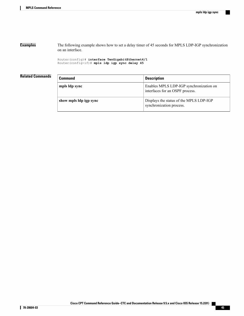
Examples The following example shows how to set a delay timer of 45 seconds for MPLS LDP-IGP synchronizationon an interface.
Router(config)# interface TenGigabitEthernet4/1Router(config-if)# mpls ldp igp sync delay 45
Related Commands DescriptionCommand
Enables MPLS LDP-IGP synchronization oninterfaces for an OSPF process.
mpls ldp sync
Displays the status of the MPLS LDP-IGPsynchronization process.
show mpls ldp igp sync
Cisco CPT Command Reference Guide–CTC and Documentation Release 9.5.x and Cisco IOS Release 15.2(01) 78-20604-03 45
MPLS Command Referencempls ldp igp sync
mpls ldp igp sync holddownTo specify how long an Interior Gateway Protocol (IGP) must wait for an MPLS LDP synchronization to beachieved, use thempls ldp igp sync holddown command in global configuration mode. To disable thehold-down timer, use the no form of this command.
mpls ldp igp sync holddown milliseconds
no mpls ldp igp sync holddown
Syntax Description Number of milliseconds an IGP must wait for an LDP session to be established.The valid range of values is from 1 to 2147483647 milliseconds.
milliseconds
Command Default An IGP will wait indefinitely for LDP synchronization to be achieved.
Command Modes Global configuration (config)
Command History ModificationRelease
This command was introduced.9.3.0
Usage Guidelines This command enables you to limit the amount of time an IGP waits for LDP synchronization to be achieved.
Examples The following example shows how to configure the IGP to wait 10,000 milliseconds (10 seconds) for LDPsynchronization.Router(config)# mpls ldp igp sync holddown 10000
Related Commands DescriptionCommand
Enables MPLS LDP-IGP synchronization oninterfaces for an OSPF process.
mpls ldp sync
Displays the status of the MPLS LDP-IGPsynchronization process.
show mpls ldp igp sync
Cisco CPT Command Reference Guide–CTC and Documentation Release 9.5.x and Cisco IOS Release 15.2(01)46 78-20604-03
MPLS Command Referencempls ldp igp sync holddown
mpls ldp neighbor targetedTo set up a targeted session with a specified MPLS LDP neighbor, use thempls ldp neighbor targetedcommand in global configuration mode. To disable a targeted session, use the no form of this command.
mpls ldp neighbor ip-addr targeted ldp
no mpls ldp neighbor ip-addr targeted ldp
Syntax Description Router ID (IP address) that identifies a neighbor.ip-addr
Specifies Label Distribution Protocol (LDP) as the label protocol for thetargeted session.
targeted ldp
Command Default A targeted session with a specified neighbor is not set up.
Command Modes Global configuration (config)
Command History ModificationRelease
This command was introduced.9.3.0
Usage Guidelines Use thempls ldp neighbor targeted command when you need to set up a targeted session and other meansof establishing targeted sessions do not apply, such as configuringmpls ip on a traffic engineering (TE) tunnel.For example, you would use this command to set up a targeted session between directly connected MPLSlabel switch routers (LSRs) when MPLS label forwarding convergence time is an issue.
Thempls ldp neighbor targeted command can improve label convergence time for directly connectedneighbor LSRs when the links directly connecting them are down.When the links between the neighbor LSRsare up, both the link and targeted Hellos maintain the LDP session. If the links between the neighbor LSRsgo down, the targeted Hellos maintain the session, allowing the LSRs to retain labels learned from each other.When a link directly connecting the LSRs comes back up, the LSRs can immediately reinstall labels forforwarding use without having to reestablish their LDP session and exchange labels.
For the no form of the command, if the targeted keyword is not specified, all the configuration informationfor the specified neighbor reverts to the defaults and the neighbor record is deleted.
Examples The following example shows how to set a targeted session with the neighbor 192.0.2.1.Router(config)# mpls ldp neighbor 192.0.2.1 targeted ldp
Cisco CPT Command Reference Guide–CTC and Documentation Release 9.5.x and Cisco IOS Release 15.2(01) 78-20604-03 47
MPLS Command Referencempls ldp neighbor targeted

Related Commands DescriptionCommand
Displays the status of Label Distribution Protocol(LDP) sessions.
show mpls ldp neighbor
Cisco CPT Command Reference Guide–CTC and Documentation Release 9.5.x and Cisco IOS Release 15.2(01)48 78-20604-03
MPLS Command Referencempls ldp neighbor targeted
mpls ldp router-idTo specify a preferred interface for the Label Distribution Protocol (LDP) router ID, use thempls ldp router-idcommand in global configuration mode. To disable the interface from being used as the LDP router ID, usethe no form of this command.
mpls ldp router-id interface [force]
no mpls ldp router-id interface [force]
Syntax Description Interface specified to be used as theMPLS LDP router ID, provided that the interfaceis operational.
interface
(Optional) Alters the behavior of thempls ldp router-id command, as describedin the “Usage Guidelines” section.
force
Command Default If thempls ldp router-id command is not used, the router examines the IP addresses of all the operationalinterfaces. If these IP addresses include loopback interface addresses, the router selects the largest loopbackaddress as the LDP router ID. Otherwise, the router selects the largest IP address pertaining to an operationalinterface as the LDP router ID.
Command Modes Global configuration (config)
Command History ModificationRelease
This command was introduced.9.3.0
Usage Guidelines The loopback IP address does not become the router ID of the local LDP ID under the following circumstances:
• If the loopback interface has been explicitly shut down.
• If thempls ldp router-id command specifies that a different interface should be used as the LDP routerID.
If you use a loopback interface, ensure that the IP address for the loopback interface is configured with a /32network mask. In addition, ensure that the routing protocol in use is configured to advertise the corresponding/32 network.
Examples The following example shows how to assign interface TenGigabitEthernet4/1 as the LDP router ID:Router> enableRouter# configure terminalRouter(config)# mpls ip
Cisco CPT Command Reference Guide–CTC and Documentation Release 9.5.x and Cisco IOS Release 15.2(01) 78-20604-03 49
MPLS Command Referencempls ldp router-id

Router(config)# mpls label protocol ldpRouter(config)# mpls ldp router-id TenGigabitEthernet4/1
Related Commands DescriptionCommand
Displays the status of the LDP discovery process.show mpls ldp discovery
Cisco CPT Command Reference Guide–CTC and Documentation Release 9.5.x and Cisco IOS Release 15.2(01)50 78-20604-03
MPLS Command Referencempls ldp router-id
mpls ldp session protectionTo enableMPLS LDP autoconfiguration for existing or new LDP sessions, use thempls ldp session protectioncommand in global configuration mode. To disable this configuration, use the no form of this command.
mpls ldp session protection [for acl] [duration {infinite | seconds}]
no mpls ldp session protection [for acl] [duration {infinite | seconds}]
Syntax Description (Optional) Specifies a standard IP access control list that contains the prefixes that areto be protected.
for acl
(Optional) Specifies the time that the LDP targeted hello adjacency must be retainedafter a link is lost.
If you use this keyword, you must select either the infinite keyword or theseconds argument.
Note
duration
Specifies that the LDP targeted hello adjacency must be retained infinitely after a linkis lost.
infinite
Time in seconds that the LDP targeted hello adjacency must be retained after a link islost. The valid range of values is from 30 to 2,147,483 seconds.
seconds
Command Default MPLS LDP session protection is not established.
Command Modes Global configuration (config)
Command History ModificationRelease
This command was introduced.9.3.0
Usage Guidelines If you issue thempls ldp session protection commandwithout the duration keyword, then session protectionis enabled for 86400 seconds (24 hours) meaning that the LDP targeted hello adjacency is retained for 24hours after a link is lost. This is the default timeout.
If you issue thempls ldp session protection duration infinite command, then session protection is enabledinfinitely, which implies that the LDP targeted hello adjacency is retained infinitely after a link is lost.
If you issue thempls ldp session protection duration seconds command, then session protection is enabledfor the number of seconds indicated, which implies that the LDP targeted hello adjacency is retained for thatamount of time. For example, if you issuedmpls ldp session protection duration 100, then the LDP targetedhello adjacency is retained for 100 seconds after a link is lost.
Cisco CPT Command Reference Guide–CTC and Documentation Release 9.5.x and Cisco IOS Release 15.2(01) 78-20604-03 51
MPLS Command Referencempls ldp session protection
Examples The following example shows how to enable MPLS LDP autoconfiguration for LDP sessions for peers whoserouter IDs are listed in access control list rtr4.Router(config)# mpls ldp session protection for rtr4
Related Commands DescriptionCommand
Displays the contents of the LDP.show mpls ldp neighbor
Cisco CPT Command Reference Guide–CTC and Documentation Release 9.5.x and Cisco IOS Release 15.2(01)52 78-20604-03
MPLS Command Referencempls ldp session protection
mpls ldp syncTo enable MPLS LDP-Interior Gateway Protocol (IGP) synchronization on interfaces for an OSPF process,use thempls ldp sync command in router configuration mode. To disable this synchronization, use the noform of this command.
mpls ldp sync
no mpls ldp sync
Syntax Description This command has no arguments or keywords.
Command Default MPLS LDP-IGP synchronization is not enabled on interfaces belonging to the OSPF process.
Command Modes Router configuration (config-router)
Command History ModificationRelease
This command was introduced.9.3.0
Usage Guidelines If thempls ldp sync command is configured, you cannot enter the global no mpls ip command. If you wantto disable LDP synchronization, you must enter the no mpls ldp igp sync command first.
Thempls ldp sync command is supported with OSPF process.
Examples The following example shows how to enable MPLS LDP-IGP synchronization for an OSPF process.Router(config-router)# mpls ldp sync
Related Commands DescriptionCommand
Enables MPLS LDP-IGP synchronization on aninterface that belongs to an OSPF process.
mpls ldp igp sync
Disables MPLS hop-by-hop forwarding.no mpls ip
Displays the status of the MPLS LDP-IGPsynchronization process.
show mpls ldp igp sync
Cisco CPT Command Reference Guide–CTC and Documentation Release 9.5.x and Cisco IOS Release 15.2(01) 78-20604-03 53
MPLS Command Referencempls ldp sync
mpls traffic-eng areaTo configure a router running OSPF MPLS so that it floods traffic engineering for the indicated OSPF area,use thempls traffic-eng area command in router configurationmode. To disable flooding of traffic engineeringfor the indicated OSPF area, use the no form of this command.
mpls traffic-eng area number
no mpls traffic-eng area number
Syntax Description The OSPF area on which MPLS traffic engineering is enabled.number
Command Default Flooding is disabled.
Command Modes Router configuration (config-router)
Command History ModificationRelease
This command was introduced.9.3.0
Usage Guidelines This command is in the routing protocol configuration tree and is supported for OSPF. The command affectsthe operation of MPLS traffic engineering only if MPLS traffic engineering is enabled for that routing protocolinstance.
Examples The following example shows how to configure a router running OSPF MPLS to flood traffic engineeringfor OSPF 0.Router(config-router)# mpls traffic-eng area 0
Related Commands DescriptionCommand
Specifies that the TE router identifier for the node isthe IP address associated with a given interface.
mpls traffic-eng router-id
Configures an OSPF routing process on a router.router ospf
Defines the interfaces on which OSPF runs anddefines the area ID for those interfaces.
network area
Cisco CPT Command Reference Guide–CTC and Documentation Release 9.5.x and Cisco IOS Release 15.2(01)54 78-20604-03
MPLS Command Referencempls traffic-eng area
mpls traffic-eng link-management timers periodic-floodingTo set the length of the interval for periodic flooding, use thempls traffic-eng link-management timersperiodic-flooding command in global configuration mode. To disable the specified interval length for periodicflooding, use the no form of this command.
mpls traffic-eng link-management timers periodic-flooding interval
no mpls traffic-eng link-management timers periodic-flooding
Syntax Description Length of the interval (in seconds) for periodic flooding. Valid valuesare from 0 to 3600. A value of 0 turns off periodic flooding. If youset this value from 1 to 29, it is treated as 30.
interval
Command Default 180 seconds (3 minutes)
Command Modes Global configuration (config)
Command History ModificationRelease
This command was introduced.9.3.0
Usage Guidelines Use this command to advertise link state information changes that do not trigger immediate action. For example,a change to the amount of allocated bandwidth that does not cross a threshold.
Examples The following example shows how to set the interval length for periodic flooding to 120 seconds:Router(config)# mpls traffic-eng link-management timers periodic-flooding 120
Related Commands DescriptionCommand
Enables MPLS TE for the indicated OSPF area.mpls traffic-eng area number
Cisco CPT Command Reference Guide–CTC and Documentation Release 9.5.x and Cisco IOS Release 15.2(01) 78-20604-03 55
MPLS Command Referencempls traffic-eng link-management timers periodic-flooding
mpls traffic-eng lsp attributesTo create or modify a label switched path (LSP) attribute list, use thempls traffic-eng lsp attributes commandin global configuration mode. To remove a specified LSP attribute list from the device configuration, use theno form of this command.
mpls traffic-eng lsp attributes string
no mpls traffic-eng lsp attributes string
Syntax Description Identifies a specific LSP attribute list.string
Command Default An LSP attribute list is not created unless you create one.
Command Modes Global configuration (config)
Command History ModificationRelease
This command was introduced.9.3.0
Usage Guidelines This command sets up an LSP attribute list and enters LSP Attributes configuration mode, in which you canenter LSP attributes.
To associate the LSP attributes and LSP attribute list with a path option for an LSP, you must configure thetunnel mpls traffic-eng path option command with the attributes string keyword and argument, wherestring is the identifier for the specific LSP attribute list.
An LSP attribute referenced by the path option takes precedence over the values configured on the tunnelinterface. If an attribute is not specified in the LSP attribute list, the devices takes the attribute from the tunnelconfiguration. LSP attribute lists do not have default values. If the attribute is not configured on the tunnel,then the device uses tunnel default values.
Once you type thempls traffic-eng lsp attributes command, you enter the LSP Attributes configurationmode where you define the attributes for the LSP attribute list that you are creating.
The mode commands are as follows:
• affinity—Specifies attribute flags for links that make up an LSP.
• auto-bw—Specifies automatic bandwidth configuration.
• bandwidth—Specifies LSP bandwidth.
• lockdown—Disables reoptimization for the LSP.
• priority—Specifies LSP priority.
• protection—Enables failure protection.
Cisco CPT Command Reference Guide–CTC and Documentation Release 9.5.x and Cisco IOS Release 15.2(01)56 78-20604-03
MPLS Command Referencempls traffic-eng lsp attributes
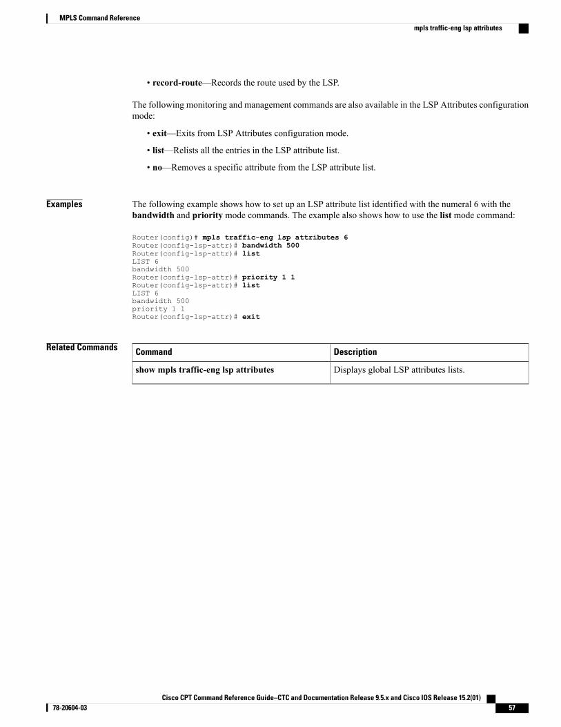
• record-route—Records the route used by the LSP.
The following monitoring and management commands are also available in the LSP Attributes configurationmode:
• exit—Exits from LSP Attributes configuration mode.
• list—Relists all the entries in the LSP attribute list.
• no—Removes a specific attribute from the LSP attribute list.
Examples The following example shows how to set up an LSP attribute list identified with the numeral 6 with thebandwidth and priority mode commands. The example also shows how to use the list mode command:
Router(config)# mpls traffic-eng lsp attributes 6Router(config-lsp-attr)# bandwidth 500Router(config-lsp-attr)# listLIST 6bandwidth 500Router(config-lsp-attr)# priority 1 1Router(config-lsp-attr)# listLIST 6bandwidth 500priority 1 1Router(config-lsp-attr)# exit
Related Commands DescriptionCommand
Displays global LSP attributes lists.show mpls traffic-eng lsp attributes
Cisco CPT Command Reference Guide–CTC and Documentation Release 9.5.x and Cisco IOS Release 15.2(01) 78-20604-03 57
MPLS Command Referencempls traffic-eng lsp attributes
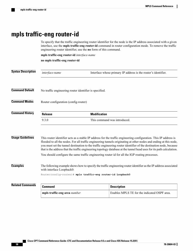
mpls traffic-eng router-idTo specify that the traffic engineering router identifier for the node is the IP address associated with a giveninterface, use thempls traffic-eng router-id command in router configuration mode. To remove the trafficengineering router identifier, use the no form of this command.
mpls traffic-eng router-id interface-name
no mpls traffic-eng router-id
Syntax Description Interface whose primary IP address is the router’s identifier.interface-name
Command Default No traffic engineering router identifier is specified.
Command Modes Router configuration (config-router)
Command History ModificationRelease
This command was introduced.9.3.0
Usage Guidelines This router identifier acts as a stable IP address for the traffic engineering configuration. This IP address isflooded to all the nodes. For all traffic engineering tunnels originating at other nodes and ending at this node,you must set the tunnel destination to the traffic engineering router identifier of the destination node, becausethat is the address that the traffic engineering topology database at the tunnel head uses for its path calculation.
You should configure the same traffic engineering router id for all the IGP routing processes.
Examples The following example shows how to specify the traffic engineering router identifier as the IP address associatedwith interface Loopback0:Router(config-router)# mpls traffic-eng router-id Loopback0
Related Commands DescriptionCommand
Enables MPLS TE for the indicated OSPF area.mpls traffic-eng area number
Cisco CPT Command Reference Guide–CTC and Documentation Release 9.5.x and Cisco IOS Release 15.2(01)58 78-20604-03
MPLS Command Referencempls traffic-eng router-id
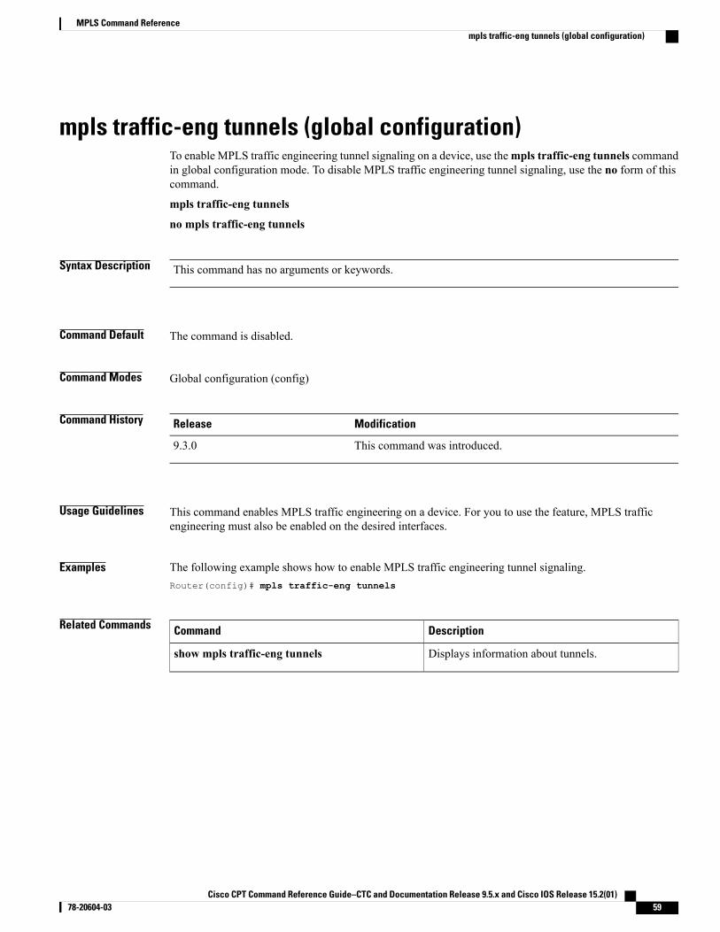
mpls traffic-eng tunnels (global configuration)To enable MPLS traffic engineering tunnel signaling on a device, use thempls traffic-eng tunnels commandin global configuration mode. To disable MPLS traffic engineering tunnel signaling, use the no form of thiscommand.
mpls traffic-eng tunnels
no mpls traffic-eng tunnels
Syntax Description This command has no arguments or keywords.
Command Default The command is disabled.
Command Modes Global configuration (config)
Command History ModificationRelease
This command was introduced.9.3.0
Usage Guidelines This command enables MPLS traffic engineering on a device. For you to use the feature, MPLS trafficengineering must also be enabled on the desired interfaces.
Examples The following example shows how to enable MPLS traffic engineering tunnel signaling.Router(config)# mpls traffic-eng tunnels
Related Commands DescriptionCommand
Displays information about tunnels.show mpls traffic-eng tunnels
Cisco CPT Command Reference Guide–CTC and Documentation Release 9.5.x and Cisco IOS Release 15.2(01) 78-20604-03 59
MPLS Command Referencempls traffic-eng tunnels (global configuration)
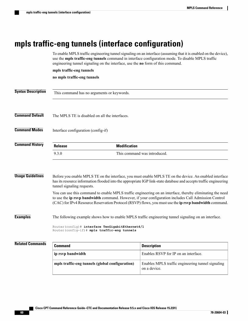
mpls traffic-eng tunnels (interface configuration)To enableMPLS traffic engineering tunnel signaling on an interface (assuming that it is enabled on the device),use thempls traffic-eng tunnels command in interface configuration mode. To disable MPLS trafficengineering tunnel signaling on the interface, use the no form of this command.
mpls traffic-eng tunnels
no mpls traffic-eng tunnels
Syntax Description This command has no arguments or keywords.
Command Default The MPLS TE is disabled on all the interfaces.
Command Modes Interface configuration (config-if)
Command History ModificationRelease
This command was introduced.9.3.0
Usage Guidelines Before you enable MPLS TE on the interface, you must enable MPLS TE on the device. An enabled interfacehas its resource information flooded into the appropriate IGP link-state database and accepts traffic engineeringtunnel signaling requests.
You can use this command to enable MPLS traffic engineering on an interface, thereby eliminating the needto use the ip rsvp bandwidth command. However, if your configuration includes Call Admission Control(CAC) for IPv4 Resource Reservation Protocol (RSVP) flows, youmust use the ip rsvp bandwidth command.
Examples The following example shows how to enable MPLS traffic engineering tunnel signaling on an interface.
Router(config)# interface TenGigabitEthernet4/1Router(config-if)# mpls traffic-eng tunnels
Related Commands DescriptionCommand
Enables RSVP for IP on an interface.ip rsvp bandwidth
Enables MPLS traffic engineering tunnel signalingon a device.
mpls traffic-eng tunnels (global configuration)
Cisco CPT Command Reference Guide–CTC and Documentation Release 9.5.x and Cisco IOS Release 15.2(01)60 78-20604-03
MPLS Command Referencempls traffic-eng tunnels (interface configuration)
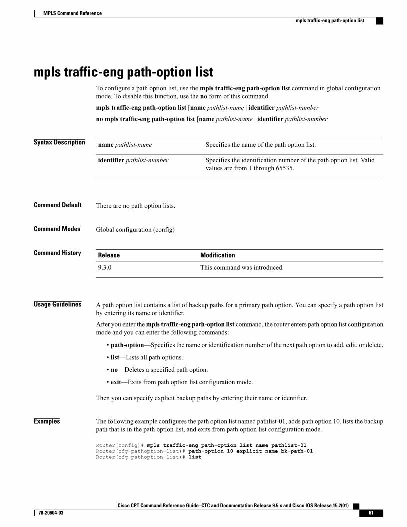
mpls traffic-eng path-option listTo configure a path option list, use thempls traffic-eng path-option list command in global configurationmode. To disable this function, use the no form of this command.
mpls traffic-eng path-option list [name pathlist-name | identifier pathlist-number
no mpls traffic-eng path-option list [name pathlist-name | identifier pathlist-number
Syntax Description Specifies the name of the path option list.name pathlist-name
Specifies the identification number of the path option list. Validvalues are from 1 through 65535.
identifier pathlist-number
Command Default There are no path option lists.
Command Modes Global configuration (config)
Command History ModificationRelease
This command was introduced.9.3.0
Usage Guidelines A path option list contains a list of backup paths for a primary path option. You can specify a path option listby entering its name or identifier.
After you enter thempls traffic-eng path-option list command, the router enters path option list configurationmode and you can enter the following commands:
• path-option—Specifies the name or identification number of the next path option to add, edit, or delete.
• list—Lists all path options.
• no—Deletes a specified path option.
• exit—Exits from path option list configuration mode.
Then you can specify explicit backup paths by entering their name or identifier.
Examples The following example configures the path option list named pathlist-01, adds path option 10, lists the backuppath that is in the path option list, and exits from path option list configuration mode.
Router(config)# mpls traffic-eng path-option list name pathlist-01Router(cfg-pathoption-list)# path-option 10 explicit name bk-path-01Router(cfg-pathoption-list)# list
Cisco CPT Command Reference Guide–CTC and Documentation Release 9.5.x and Cisco IOS Release 15.2(01) 78-20604-03 61
MPLS Command Referencempls traffic-eng path-option list
path-option 10 explicit name bk-path-01Router(cfg-pathoption-list)# exit
Related Commands DescriptionCommand
Configures a path option for an MPLS TE tunnel.tunnel mpls traffic-eng path option
Configures a secondary path option or a path optionlist for an MPLS TE tunnel.
tunnel mpls traffic-eng path-option protect
Cisco CPT Command Reference Guide–CTC and Documentation Release 9.5.x and Cisco IOS Release 15.2(01)62 78-20604-03
MPLS Command Referencempls traffic-eng path-option list
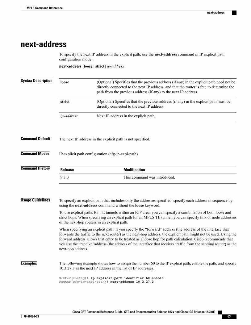
next-addressTo specify the next IP address in the explicit path, use the next-address command in IP explicit pathconfiguration mode.
next-address [loose | strict] ip-address
Syntax Description (Optional) Specifies that the previous address (if any) in the explicit path need not bedirectly connected to the next IP address, and that the router is free to determine thepath from the previous address (if any) to the next IP address.
loose
(Optional) Specifies that the previous address (if any) in the explicit path must bedirectly connected to the next IP address.
strict
Next IP address in the explicit path.ip-address
Command Default The next IP address in the explicit path is not specified.
Command Modes IP explicit path configuration (cfg-ip-expl-path)
Command History ModificationRelease
This command was introduced.9.3.0
Usage Guidelines To specify an explicit path that includes only the addresses specified, specify each address in sequence byusing the next-address command without the loose keyword.
To use explicit paths for TE tunnels within an IGP area, you can specify a combination of both loose andstrict hops. When specifying an explicit path for an MPLS TE tunnel, you can specify link or node addressesof the next-hop routers in an explicit path.
When specifying an explicit path, if you specify the “forward” address (the address of the interface thatforwards the traffic to the next router) as the next-hop address, the explicit path might not be used. Using theforward address allows that entry to be treated as a loose hop for path calculation. Cisco recommends thatyou use the “receive”address (the address of the interface that receives traffic from the sending router) as thenext-hop address.
Examples The following example shows how to assign the number 60 to the IP explicit path, enable the path, and specify10.3.27.3 as the next IP address in the list of IP addresses.
Router(config)# ip explicit-path identifier 60 enableRouter(cfg-ip-expl-path)# next-address 10.3.27.3
Cisco CPT Command Reference Guide–CTC and Documentation Release 9.5.x and Cisco IOS Release 15.2(01) 78-20604-03 63
MPLS Command Referencenext-address
Explicit Path identifier 60:1: next-address 10.3.27.3
Related Commands DescriptionCommand
Inserts or modifies a path entry at a specified index.index
Enters the subcommand mode for IP explicit pathsand creates or modifies the specified path.
ip explicit-path
Displays the configured IP explicit paths.show ip explicit-paths
Cisco CPT Command Reference Guide–CTC and Documentation Release 9.5.x and Cisco IOS Release 15.2(01)64 78-20604-03
MPLS Command Referencenext-address
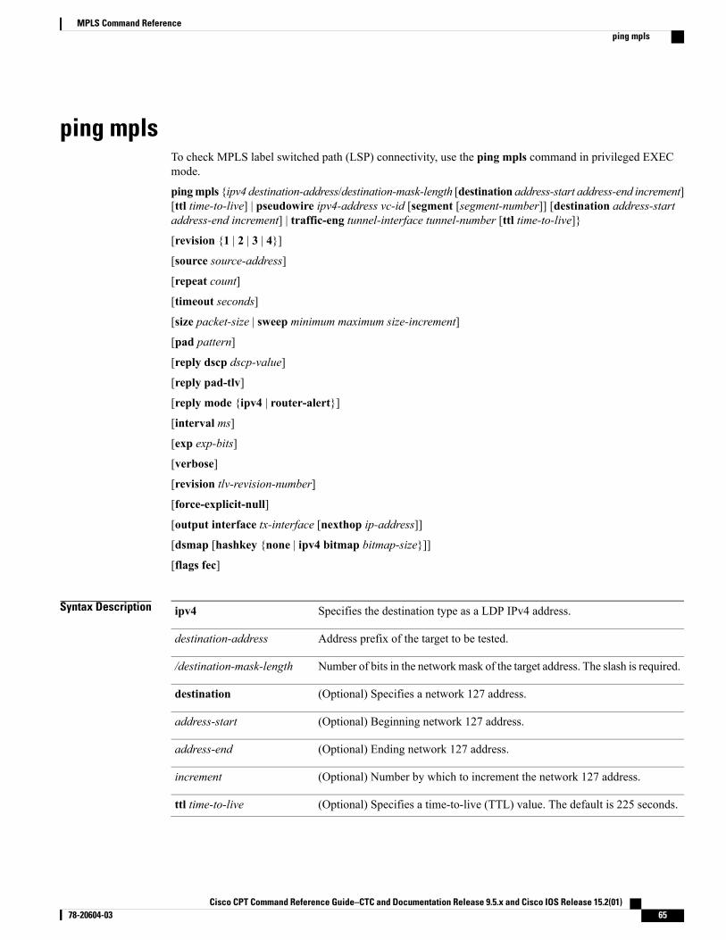
ping mplsTo check MPLS label switched path (LSP) connectivity, use the ping mpls command in privileged EXECmode.
pingmpls {ipv4 destination-address/destination-mask-length [destination address-start address-end increment][ttl time-to-live] | pseudowire ipv4-address vc-id [segment [segment-number]] [destination address-startaddress-end increment] | traffic-eng tunnel-interface tunnel-number [ttl time-to-live]}
[revision {1 | 2 | 3 | 4}]
[source source-address]
[repeat count]
[timeout seconds]
[size packet-size | sweep minimum maximum size-increment]
[pad pattern]
[reply dscp dscp-value]
[reply pad-tlv]
[reply mode {ipv4 | router-alert}]
[interval ms]
[exp exp-bits]
[verbose]
[revision tlv-revision-number]
[force-explicit-null]
[output interface tx-interface [nexthop ip-address]]
[dsmap [hashkey {none | ipv4 bitmap bitmap-size}]]
[flags fec]
Syntax Description Specifies the destination type as a LDP IPv4 address.ipv4
Address prefix of the target to be tested.destination-address
Number of bits in the networkmask of the target address. The slash is required./destination-mask-length
(Optional) Specifies a network 127 address.destination
(Optional) Beginning network 127 address.address-start
(Optional) Ending network 127 address.address-end
(Optional) Number by which to increment the network 127 address.increment
(Optional) Specifies a time-to-live (TTL) value. The default is 225 seconds.ttl time-to-live
Cisco CPT Command Reference Guide–CTC and Documentation Release 9.5.x and Cisco IOS Release 15.2(01) 78-20604-03 65
MPLS Command Referenceping mpls
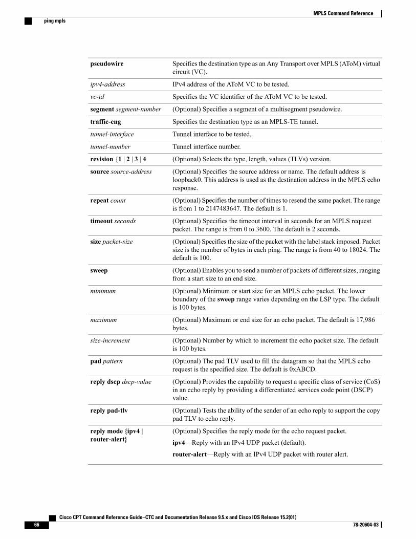
Specifies the destination type as an Any Transport overMPLS (AToM) virtualcircuit (VC).
pseudowire
IPv4 address of the AToM VC to be tested.ipv4-address
Specifies the VC identifier of the AToM VC to be tested.vc-id
(Optional) Specifies a segment of a multisegment pseudowire.segment segment-number
Specifies the destination type as an MPLS-TE tunnel.traffic-eng
Tunnel interface to be tested.tunnel-interface
Tunnel interface number.tunnel-number
(Optional) Selects the type, length, values (TLVs) version.revision {1 | 2 | 3 | 4
(Optional) Specifies the source address or name. The default address isloopback0. This address is used as the destination address in the MPLS echoresponse.
source source-address
(Optional) Specifies the number of times to resend the same packet. The rangeis from 1 to 2147483647. The default is 1.
repeat count
(Optional) Specifies the timeout interval in seconds for an MPLS requestpacket. The range is from 0 to 3600. The default is 2 seconds.
timeout seconds
(Optional) Specifies the size of the packet with the label stack imposed. Packetsize is the number of bytes in each ping. The range is from 40 to 18024. Thedefault is 100.
size packet-size
(Optional) Enables you to send a number of packets of different sizes, rangingfrom a start size to an end size.
sweep
(Optional) Minimum or start size for an MPLS echo packet. The lowerboundary of the sweep range varies depending on the LSP type. The defaultis 100 bytes.
minimum
(Optional) Maximum or end size for an echo packet. The default is 17,986bytes.
maximum
(Optional) Number by which to increment the echo packet size. The defaultis 100 bytes.
size-increment
(Optional) The pad TLV used to fill the datagram so that the MPLS echorequest is the specified size. The default is 0xABCD.
pad pattern
(Optional) Provides the capability to request a specific class of service (CoS)in an echo reply by providing a differentiated services code point (DSCP)value.
reply dscp dscp-value
(Optional) Tests the ability of the sender of an echo reply to support the copypad TLV to echo reply.
reply pad-tlv
(Optional) Specifies the reply mode for the echo request packet.
ipv4—Reply with an IPv4 UDP packet (default).
router-alert—Reply with an IPv4 UDP packet with router alert.
reply mode {ipv4 |router-alert}
Cisco CPT Command Reference Guide–CTC and Documentation Release 9.5.x and Cisco IOS Release 15.2(01)66 78-20604-03
MPLS Command Referenceping mpls
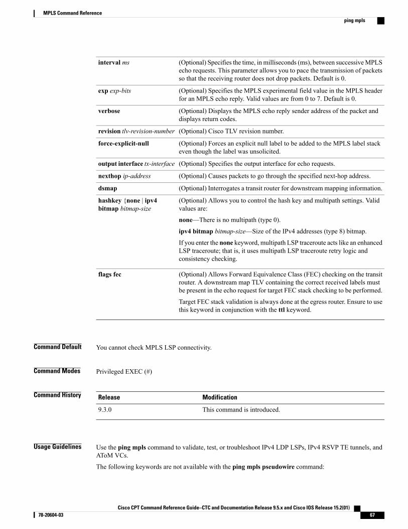
(Optional) Specifies the time, in milliseconds (ms), between successiveMPLSecho requests. This parameter allows you to pace the transmission of packetsso that the receiving router does not drop packets. Default is 0.
interval ms
(Optional) Specifies the MPLS experimental field value in the MPLS headerfor an MPLS echo reply. Valid values are from 0 to 7. Default is 0.
exp exp-bits
(Optional) Displays the MPLS echo reply sender address of the packet anddisplays return codes.
verbose
(Optional) Cisco TLV revision number.revision tlv-revision-number
(Optional) Forces an explicit null label to be added to the MPLS label stackeven though the label was unsolicited.
force-explicit-null
(Optional) Specifies the output interface for echo requests.output interface tx-interface
(Optional) Causes packets to go through the specified next-hop address.nexthop ip-address
(Optional) Interrogates a transit router for downstream mapping information.dsmap
(Optional) Allows you to control the hash key and multipath settings. Validvalues are:
none—There is no multipath (type 0).
ipv4 bitmap bitmap-size—Size of the IPv4 addresses (type 8) bitmap.
If you enter the none keyword, multipath LSP traceroute acts like an enhancedLSP traceroute; that is, it uses multipath LSP traceroute retry logic andconsistency checking.
hashkey {none | ipv4bitmap bitmap-size
(Optional) Allows Forward Equivalence Class (FEC) checking on the transitrouter. A downstream map TLV containing the correct received labels mustbe present in the echo request for target FEC stack checking to be performed.
Target FEC stack validation is always done at the egress router. Ensure to usethis keyword in conjunction with the ttl keyword.
flags fec
Command Default You cannot check MPLS LSP connectivity.
Command Modes Privileged EXEC (#)
Command History ModificationRelease
This command is introduced.9.3.0
Usage Guidelines Use the ping mpls command to validate, test, or troubleshoot IPv4 LDP LSPs, IPv4 RSVP TE tunnels, andAToM VCs.
The following keywords are not available with the ping mpls pseudowire command:
Cisco CPT Command Reference Guide–CTC and Documentation Release 9.5.x and Cisco IOS Release 15.2(01) 78-20604-03 67
MPLS Command Referenceping mpls
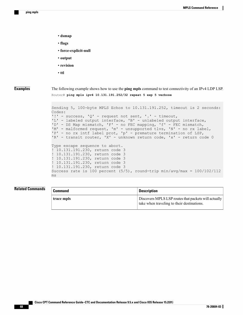
• dsmap
• flags
• force-explicit-null
• output
• revision
• ttl
Examples The following example shows how to use the ping mpls command to test connectivity of an IPv4 LDP LSP.Router# ping mpls ipv4 10.131.191.252/32 repeat 5 exp 5 verbose
Sending 5, 100-byte MPLS Echos to 10.131.191.252, timeout is 2 seconds:Codes:'!' - success, 'Q' - request not sent, '.' - timeout,'L' - labeled output interface, 'B' - unlabeled output interface,'D' - DS Map mismatch, 'F' - no FEC mapping, 'f' - FEC mismatch,'M' - malformed request, 'm' - unsupported tlvs, 'N' - no rx label,'P' - no rx intf label prot, 'p' - premature termination of LSP,'R' - transit router, 'X' - unknown return code, 'x' - return code 0
Type escape sequence to abort.! 10.131.191.230, return code 3! 10.131.191.230, return code 3! 10.131.191.230, return code 3! 10.131.191.230, return code 3! 10.131.191.230, return code 3Success rate is 100 percent (5/5), round-trip min/avg/max = 100/102/112ms
Related Commands DescriptionCommand
DiscoversMPLSLSP routes that packets will actuallytake when traveling to their destinations.
trace mpls
Cisco CPT Command Reference Guide–CTC and Documentation Release 9.5.x and Cisco IOS Release 15.2(01)68 78-20604-03
MPLS Command Referenceping mpls
priorityTo specify the LSP priority in an LSP attribute list, use the priority command in LSP Attributes configurationmode. To remove the specified priority, use the no form of this command.
priority setup-priority [hold-priority]
no priority
Syntax Description Priority used when signaling an LSP to determine which existing LSPs can bepreempted. Valid values are from 0 to 7, where a lower number indicates a higherpriority. Therefore, an LSP with a setup priority of 0 can preempt any LSP with anon-0 priority.
setup-priority
(Optional) Priority associated with an LSP to determine if it should be preempted byother LSPs that are being signaled. Valid values are from 0 to 7, where a lower numberindicates a higher priority.
hold-priority
Command Default No priority is set in the attribute list.
Command Modes LSP Attributes configuration (config-lsp-attr)
Command History ModificationRelease
This command was introduced.9.3.0
Usage Guidelines Use this command to configure setup and hold priority for an LSP in an LSP attribute list. Setup priority andhold priority are typically configured to be equal, and setup priority cannot be better (numerically smaller)than the hold priority.
To associate the LSP priority attribute and the LSP attribute list with a path option for an LSP, you mustconfigure the tunnelmpls traffic-eng path option commandwith the attributes string keyword and argument,where string is the identifier for the specific LSP attribute list.
Examples The following example shows how to set the LSP hold and setup property.Router(config-lsp-attr)# priority 2 2
Related Commands DescriptionCommand
Creates or modifies an LSP attribute list.mpls traffic-eng lsp attributes
Cisco CPT Command Reference Guide–CTC and Documentation Release 9.5.x and Cisco IOS Release 15.2(01) 78-20604-03 69
MPLS Command Referencepriority

DescriptionCommand
Displays global LSP attribute lists.show mpls traffic-eng lsp attributes
Cisco CPT Command Reference Guide–CTC and Documentation Release 9.5.x and Cisco IOS Release 15.2(01)70 78-20604-03
MPLS Command Referencepriority
record-routeTo record the route used by the LSP, use the record-route command in LSP Attributes configuration mode.To stop the recording the route used by the LSP, use the no form of this command.
record-route
no record-route
Syntax Description This command has no arguments or keywords.
Command Default The LSP route is not recorded.
Command Modes LSP Attributes configuration (config-lsp-attr)
Command History ModificationRelease
This command was introduced.9.3.0
Usage Guidelines Use this command to set up the recording of the route taken by the LSP in an LSP attribute list.
To associate the LSP record-route attribute and the LSP attribute list with a path option for an LSP, you mustconfigure the tunnelmpls traffic-eng path option commandwith the attributes string keyword and argument,where string is the identifier for the specific LSP attribute list.
Examples The following example shows how to set up LSP route recording in an LSP attribute list.Router(config-lsp-attr)# record-route
Related Commands DescriptionCommand
Creates or modifies an LSP attribute list.mpls traffic-eng lsp attributes
Displays global LSP attribute lists.show mpls traffic-eng lsp attributes
Cisco CPT Command Reference Guide–CTC and Documentation Release 9.5.x and Cisco IOS Release 15.2(01) 78-20604-03 71
MPLS Command Referencerecord-route
show ip explicit-pathsTo display the configured IP explicit paths, use the show ip explicit-paths command in user EXEC orprivileged EXEC mode.
show ip explicit-paths [name pathname | identifier number] [detail]
Syntax Description (Optional) Displays the pathname of the explicit path.name pathname
(Optional) Displays the number of the explicit path. Valid values are from1 to 65535.
identifier number
(Optional) Displays, in the long form, information about the configured IPexplicit paths.
detail
Command Default If you enter the commandwithout entering an optional keyword, all configured IP explicit paths are displayed.
Command Modes User EXEC (>) and Privileged EXEC (#)
Command History ModificationRelease
This command was introduced.9.3.0
Usage Guidelines An IP explicit path is a list of IP addresses, each representing a node or link in the explicit path.
Examples The following is sample output from the show ip explicit-paths command.Router# show ip explicit-paths
PATH 200 (strict source route, path complete, generation 6)1: next-address 10.3.28.32: next-address 10.3.27.3
Related Commands DescriptionCommand
Inserts or modifies a path entry at a specific index.index
Enters the subcommand mode for IP explicit pathsso that you can create or modify the named path.
ip explicit-path
Cisco CPT Command Reference Guide–CTC and Documentation Release 9.5.x and Cisco IOS Release 15.2(01)72 78-20604-03
MPLS Command Referenceshow ip explicit-paths

DescriptionCommand
Specifies the next IP address in the explicit path.next-address
Cisco CPT Command Reference Guide–CTC and Documentation Release 9.5.x and Cisco IOS Release 15.2(01) 78-20604-03 73
MPLS Command Referenceshow ip explicit-paths
show ip rsvp senderTo display Resource Reservation Protocol (RSVP) PATH-related sender information currently in the database,use the show ip rsvp sender command in user EXEC or privileged EXEC mode.
show ip rsvp sender [detail] [filter [session-type all]]
Syntax Description (Optional) Specifies additional sender information.detail
(Optional) Specifies a subset of the senders to display.filter
(Optional) Specifies the type of RSVP sessions to display.session-type
(Optional) Specifies all the types of RSVP sessions.all
Command Modes User EXEC (>) and Privileged EXEC (#)
Command History ModificationRelease
This command was introduced.9.3.0
Usage Guidelines Use the show ip rsvp sender command to display the RSVP sender (PATH) information currently in thedatabase for a specified interface or for all the interfaces.
Examples The following is sample output from the show ip rsvp sender command.Router# show ip rsvp sender
To From Pro DPort Sport Prev Hop I/F BPS172.16.1.49 172.16.4.53 1 0 0 172.16.3.53 TenGEthernet4/1 80K172.16.2.51 172.16.5.54 1 0 0 172.16.3.54 TenGEthernet4/2 80K
Cisco CPT Command Reference Guide–CTC and Documentation Release 9.5.x and Cisco IOS Release 15.2(01)74 78-20604-03
MPLS Command Referenceshow ip rsvp sender
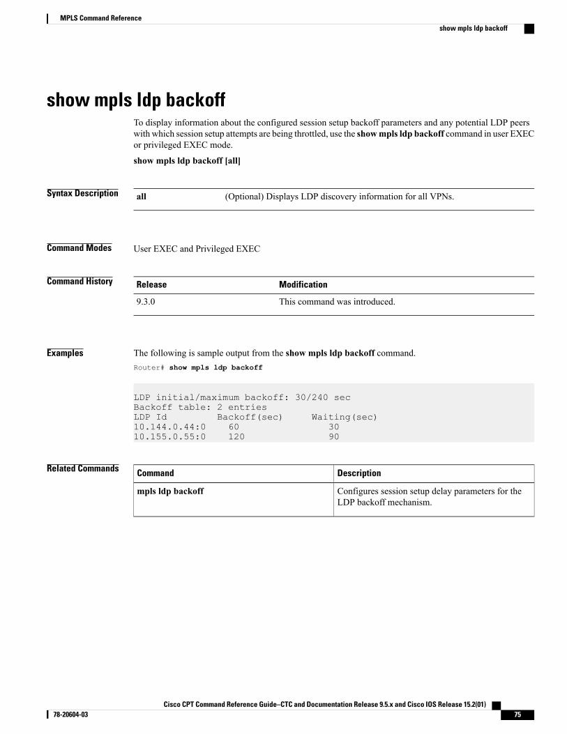
show mpls ldp backoffTo display information about the configured session setup backoff parameters and any potential LDP peerswith which session setup attempts are being throttled, use the showmpls ldp backoff command in user EXECor privileged EXEC mode.
show mpls ldp backoff [all]
Syntax Description (Optional) Displays LDP discovery information for all VPNs.all
Command Modes User EXEC and Privileged EXEC
Command History ModificationRelease
This command was introduced.9.3.0
Examples The following is sample output from the show mpls ldp backoff command.Router# show mpls ldp backoff
LDP initial/maximum backoff: 30/240 secBackoff table: 2 entriesLDP Id Backoff(sec) Waiting(sec)10.144.0.44:0 60 3010.155.0.55:0 120 90
Related Commands DescriptionCommand
Configures session setup delay parameters for theLDP backoff mechanism.
mpls ldp backoff
Cisco CPT Command Reference Guide–CTC and Documentation Release 9.5.x and Cisco IOS Release 15.2(01) 78-20604-03 75
MPLS Command Referenceshow mpls ldp backoff
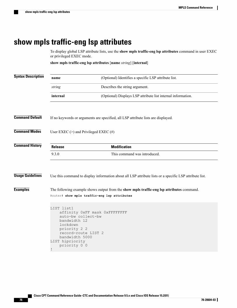
show mpls traffic-eng lsp attributesTo display global LSP attribute lists, use the show mpls traffic-eng lsp attributes command in user EXECor privileged EXEC mode.
show mpls traffic-eng lsp attributes [name string] [internal]
Syntax Description (Optional) Identifies a specific LSP attribute list.name
Describes the string argument.string
(Optional) Displays LSP attribute list internal information.internal
Command Default If no keywords or arguments are specified, all LSP attribute lists are displayed.
Command Modes User EXEC (>) and Privileged EXEC (#)
Command History ModificationRelease
This command was introduced.9.3.0
Usage Guidelines Use this command to display information about all LSP attribute lists or a specific LSP attribute list.
Examples The following example shows output from the show mpls traffic-eng lsp attributes command.Router# show mpls traffic-eng lsp attributes
LIST list1affinity 0xFF mask 0xFFFFFFFFauto-bw collect-bwbandwidth 12lockdownpriority 2 2record-route LIST 2bandwidth 5000
LIST hiprioritypriority 0 0
!
Cisco CPT Command Reference Guide–CTC and Documentation Release 9.5.x and Cisco IOS Release 15.2(01)76 78-20604-03
MPLS Command Referenceshow mpls traffic-eng lsp attributes

Related Commands DescriptionCommand
Creates or modifies a LSP attribute list.mpls traffic-eng lsp attributes
Cisco CPT Command Reference Guide–CTC and Documentation Release 9.5.x and Cisco IOS Release 15.2(01) 78-20604-03 77
MPLS Command Referenceshow mpls traffic-eng lsp attributes
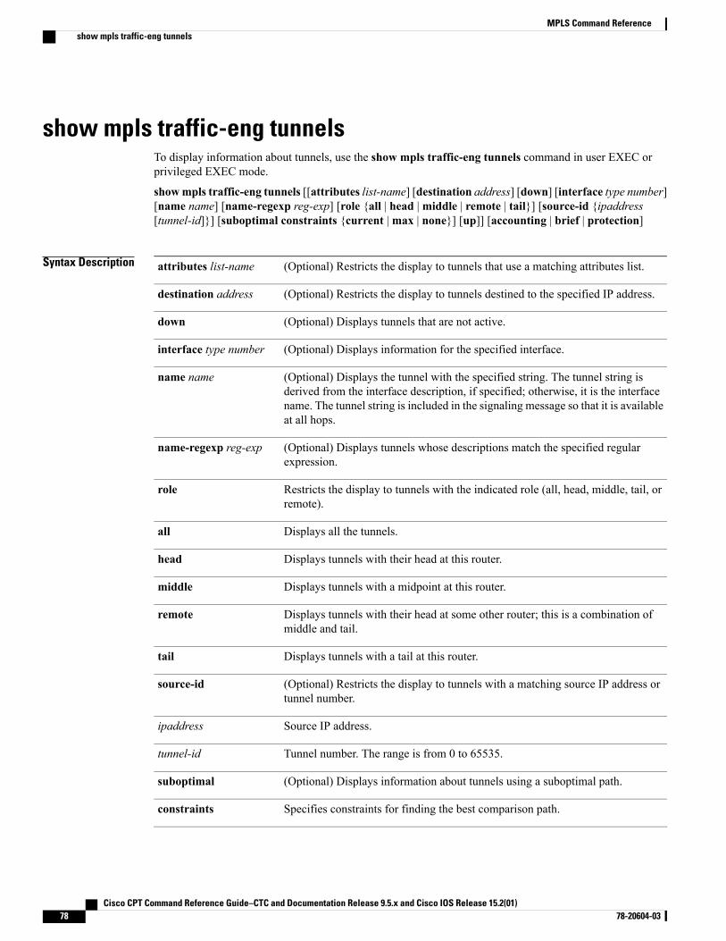
show mpls traffic-eng tunnelsTo display information about tunnels, use the show mpls traffic-eng tunnels command in user EXEC orprivileged EXEC mode.
showmpls traffic-eng tunnels [[attributes list-name] [destination address] [down] [interface type number][name name] [name-regexp reg-exp] [role {all | head |middle | remote | tail}] [source-id {ipaddress[tunnel-id]}] [suboptimal constraints {current |max | none}] [up]] [accounting | brief | protection]
Syntax Description (Optional) Restricts the display to tunnels that use a matching attributes list.attributes list-name
(Optional) Restricts the display to tunnels destined to the specified IP address.destination address
(Optional) Displays tunnels that are not active.down
(Optional) Displays information for the specified interface.interface type number
(Optional) Displays the tunnel with the specified string. The tunnel string isderived from the interface description, if specified; otherwise, it is the interfacename. The tunnel string is included in the signaling message so that it is availableat all hops.
name name
(Optional) Displays tunnels whose descriptions match the specified regularexpression.
name-regexp reg-exp
Restricts the display to tunnels with the indicated role (all, head, middle, tail, orremote).
role
Displays all the tunnels.all
Displays tunnels with their head at this router.head
Displays tunnels with a midpoint at this router.middle
Displays tunnels with their head at some other router; this is a combination ofmiddle and tail.
remote
Displays tunnels with a tail at this router.tail
(Optional) Restricts the display to tunnels with a matching source IP address ortunnel number.
source-id
Source IP address.ipaddress
Tunnel number. The range is from 0 to 65535.tunnel-id
(Optional) Displays information about tunnels using a suboptimal path.suboptimal
Specifies constraints for finding the best comparison path.constraints
Cisco CPT Command Reference Guide–CTC and Documentation Release 9.5.x and Cisco IOS Release 15.2(01)78 78-20604-03
MPLS Command Referenceshow mpls traffic-eng tunnels
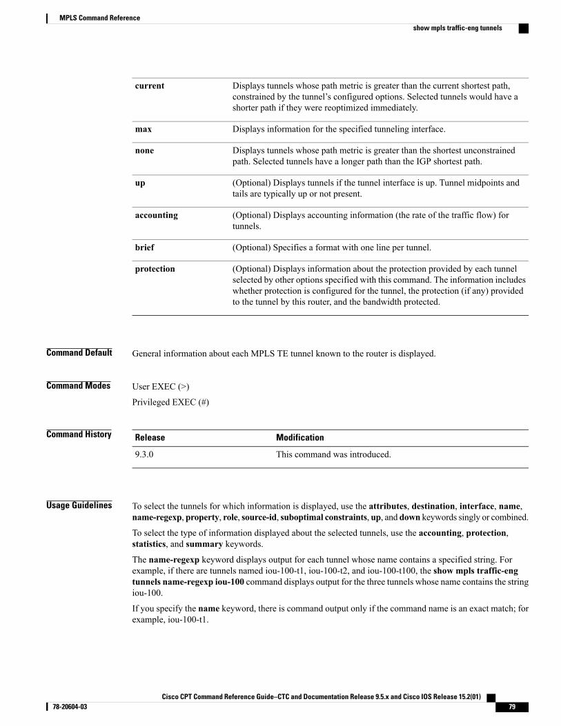
Displays tunnels whose path metric is greater than the current shortest path,constrained by the tunnel’s configured options. Selected tunnels would have ashorter path if they were reoptimized immediately.
current
Displays information for the specified tunneling interface.max
Displays tunnels whose path metric is greater than the shortest unconstrainedpath. Selected tunnels have a longer path than the IGP shortest path.
none
(Optional) Displays tunnels if the tunnel interface is up. Tunnel midpoints andtails are typically up or not present.
up
(Optional) Displays accounting information (the rate of the traffic flow) fortunnels.
accounting
(Optional) Specifies a format with one line per tunnel.brief
(Optional) Displays information about the protection provided by each tunnelselected by other options specified with this command. The information includeswhether protection is configured for the tunnel, the protection (if any) providedto the tunnel by this router, and the bandwidth protected.
protection
Command Default General information about each MPLS TE tunnel known to the router is displayed.
Command Modes User EXEC (>)
Privileged EXEC (#)
Command History ModificationRelease
This command was introduced.9.3.0
Usage Guidelines To select the tunnels for which information is displayed, use the attributes, destination, interface, name,name-regexp, property, role, source-id, suboptimal constraints, up, and down keywords singly or combined.
To select the type of information displayed about the selected tunnels, use the accounting, protection,statistics, and summary keywords.
The name-regexp keyword displays output for each tunnel whose name contains a specified string. Forexample, if there are tunnels named iou-100-t1, iou-100-t2, and iou-100-t100, the show mpls traffic-engtunnels name-regexp iou-100 command displays output for the three tunnels whose name contains the stringiou-100.
If you specify the name keyword, there is command output only if the command name is an exact match; forexample, iou-100-t1.
Cisco CPT Command Reference Guide–CTC and Documentation Release 9.5.x and Cisco IOS Release 15.2(01) 78-20604-03 79
MPLS Command Referenceshow mpls traffic-eng tunnels
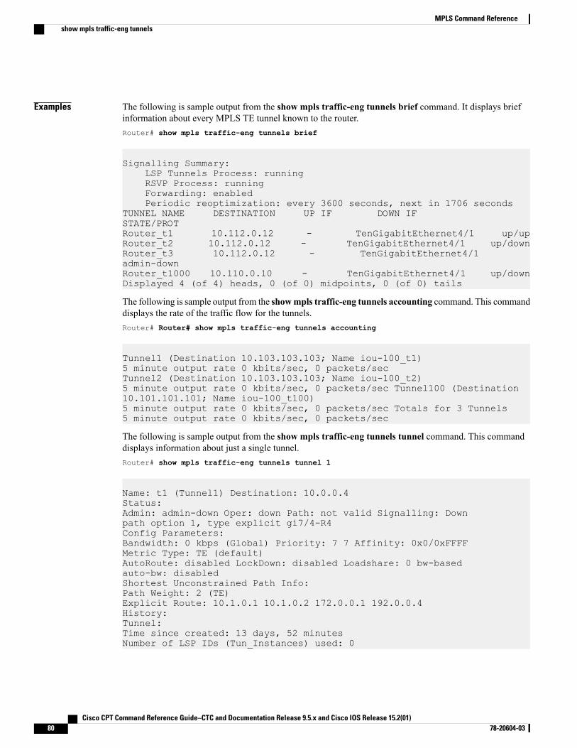
Examples The following is sample output from the show mpls traffic-eng tunnels brief command. It displays briefinformation about every MPLS TE tunnel known to the router.Router# show mpls traffic-eng tunnels brief
Signalling Summary:LSP Tunnels Process: runningRSVP Process: runningForwarding: enabledPeriodic reoptimization: every 3600 seconds, next in 1706 seconds
TUNNEL NAME DESTINATION UP IF DOWN IFSTATE/PROTRouter_t1 10.112.0.12 - TenGigabitEthernet4/1 up/upRouter_t2 10.112.0.12 - TenGigabitEthernet4/1 up/downRouter_t3 10.112.0.12 - TenGigabitEthernet4/1admin-downRouter_t1000 10.110.0.10 - TenGigabitEthernet4/1 up/downDisplayed 4 (of 4) heads, 0 (of 0) midpoints, 0 (of 0) tails
The following is sample output from the showmpls traffic-eng tunnels accounting command. This commanddisplays the rate of the traffic flow for the tunnels.Router# Router# show mpls traffic-eng tunnels accounting
Tunnel1 (Destination 10.103.103.103; Name iou-100_t1)5 minute output rate 0 kbits/sec, 0 packets/secTunnel2 (Destination 10.103.103.103; Name iou-100_t2)5 minute output rate 0 kbits/sec, 0 packets/sec Tunnel100 (Destination10.101.101.101; Name iou-100_t100)5 minute output rate 0 kbits/sec, 0 packets/sec Totals for 3 Tunnels5 minute output rate 0 kbits/sec, 0 packets/sec
The following is sample output from the show mpls traffic-eng tunnels tunnel command. This commanddisplays information about just a single tunnel.Router# show mpls traffic-eng tunnels tunnel 1
Name: t1 (Tunnel1) Destination: 10.0.0.4Status:Admin: admin-down Oper: down Path: not valid Signalling: Downpath option 1, type explicit gi7/4-R4Config Parameters:Bandwidth: 0 kbps (Global) Priority: 7 7 Affinity: 0x0/0xFFFFMetric Type: TE (default)AutoRoute: disabled LockDown: disabled Loadshare: 0 bw-basedauto-bw: disabledShortest Unconstrained Path Info:Path Weight: 2 (TE)Explicit Route: 10.1.0.1 10.1.0.2 172.0.0.1 192.0.0.4History:Tunnel:Time since created: 13 days, 52 minutesNumber of LSP IDs (Tun_Instances) used: 0
Cisco CPT Command Reference Guide–CTC and Documentation Release 9.5.x and Cisco IOS Release 15.2(01)80 78-20604-03
MPLS Command Referenceshow mpls traffic-eng tunnels

Related Commands DescriptionCommand
Enables MPLS traffic engineering tunnel signalingon a device.
mpls traffic-eng tunnels
Cisco CPT Command Reference Guide–CTC and Documentation Release 9.5.x and Cisco IOS Release 15.2(01) 78-20604-03 81
MPLS Command Referenceshow mpls traffic-eng tunnels
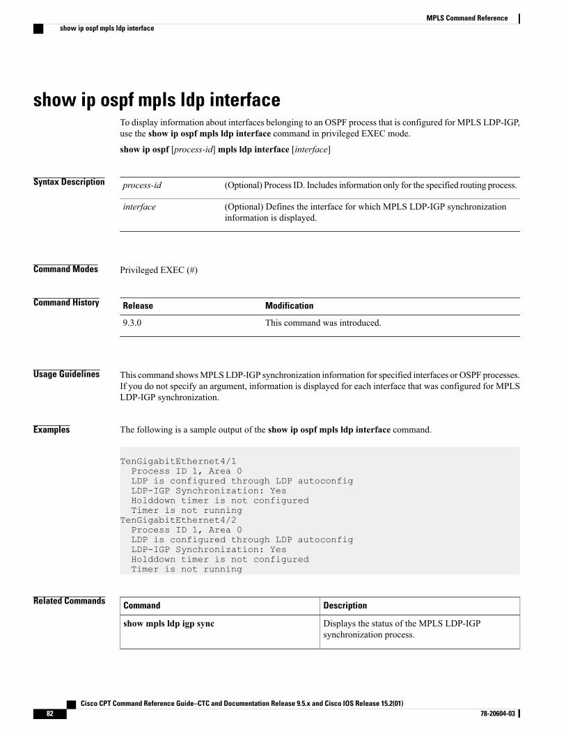
show ip ospf mpls ldp interfaceTo display information about interfaces belonging to an OSPF process that is configured for MPLS LDP-IGP,use the show ip ospf mpls ldp interface command in privileged EXEC mode.
show ip ospf [process-id] mpls ldp interface [interface]
Syntax Description (Optional) Process ID. Includes information only for the specified routing process.process-id
(Optional) Defines the interface for which MPLS LDP-IGP synchronizationinformation is displayed.
interface
Command Modes Privileged EXEC (#)
Command History ModificationRelease
This command was introduced.9.3.0
Usage Guidelines This command showsMPLSLDP-IGP synchronization information for specified interfaces or OSPF processes.If you do not specify an argument, information is displayed for each interface that was configured for MPLSLDP-IGP synchronization.
Examples The following is a sample output of the show ip ospf mpls ldp interface command.
TenGigabitEthernet4/1Process ID 1, Area 0LDP is configured through LDP autoconfigLDP-IGP Synchronization: YesHolddown timer is not configuredTimer is not running
TenGigabitEthernet4/2Process ID 1, Area 0LDP is configured through LDP autoconfigLDP-IGP Synchronization: YesHolddown timer is not configuredTimer is not running
Related Commands DescriptionCommand
Displays the status of the MPLS LDP-IGPsynchronization process.
show mpls ldp igp sync
Cisco CPT Command Reference Guide–CTC and Documentation Release 9.5.x and Cisco IOS Release 15.2(01)82 78-20604-03
MPLS Command Referenceshow ip ospf mpls ldp interface

Cisco CPT Command Reference Guide–CTC and Documentation Release 9.5.x and Cisco IOS Release 15.2(01) 78-20604-03 83
MPLS Command Referenceshow ip ospf mpls ldp interface
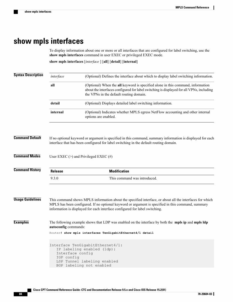
show mpls interfacesTo display information about one or more or all interfaces that are configured for label switching, use theshow mpls interfaces command in user EXEC or privileged EXEC mode.
show mpls interfaces [interface ] [all] [detail] [internal]
Syntax Description (Optional) Defines the interface about which to display label switching information.interface
(Optional) When the all keyword is specified alone in this command, informationabout the interfaces configured for label switching is displayed for all VPNs, includingthe VPNs in the default routing domain.
all
(Optional) Displays detailed label switching information.detail
(Optional) Indicates whether MPLS egress NetFlow accounting and other internaloptions are enabled.
internal
Command Default If no optional keyword or argument is specified in this command, summary information is displayed for eachinterface that has been configured for label switching in the default routing domain.
Command Modes User EXEC (>) and Privileged EXEC (#)
Command History ModificationRelease
This command was introduced.9.3.0
Usage Guidelines This command shows MPLS information about the specified interface, or about all the interfaces for whichMPLS has been configured. If no optional keyword or argument is specified in this command, summaryinformation is displayed for each interface configured for label switching.
Examples The following example shows that LDP was enabled on the interface by both the mpls ip andmpls ldpautoconfig commands:Router# show mpls interfaces TenGigabitEthernet4/1 detail
Interface TenGigabitEthernet4/1:IP labeling enabled (ldp):Interface configIGP configLSP Tunnel labeling enabledBGP labeling not enabled
Cisco CPT Command Reference Guide–CTC and Documentation Release 9.5.x and Cisco IOS Release 15.2(01)84 78-20604-03
MPLS Command Referenceshow mpls interfaces
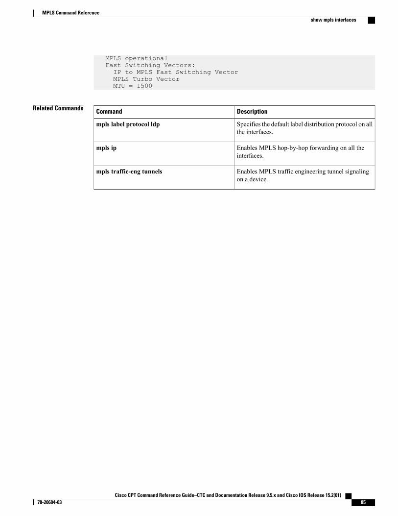
MPLS operationalFast Switching Vectors:IP to MPLS Fast Switching VectorMPLS Turbo VectorMTU = 1500
Related Commands DescriptionCommand
Specifies the default label distribution protocol on allthe interfaces.
mpls label protocol ldp
Enables MPLS hop-by-hop forwarding on all theinterfaces.
mpls ip
Enables MPLS traffic engineering tunnel signalingon a device.
mpls traffic-eng tunnels
Cisco CPT Command Reference Guide–CTC and Documentation Release 9.5.x and Cisco IOS Release 15.2(01) 78-20604-03 85
MPLS Command Referenceshow mpls interfaces
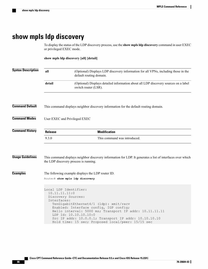
show mpls ldp discoveryTo display the status of the LDP discovery process, use the showmpls ldp discovery command in user EXECor privileged EXEC mode.
show mpls ldp discovery [all] [detail]
Syntax Description (Optional) Displays LDP discovery information for all VPNs, including those in thedefault routing domain.
all
(Optional) Displays detailed information about all LDP discovery sources on a labelswitch router (LSR).
detail
Command Default This command displays neighbor discovery information for the default routing domain.
Command Modes User EXEC and Privileged EXEC
Command History ModificationRelease
This command was introduced.9.3.0
Usage Guidelines This command displays neighbor discovery information for LDP. It generates a list of interfaces over whichthe LDP discovery process is running.
Examples The following example displays the LDP router ID.Router# show mpls ldp discovery
Local LDP Identifier:10.11.11.11:0Discovery Sources:Interfaces:TenGigabitEthernet4/1 (ldp): xmit/recvEnabled: Interface config, IGP config;Hello interval: 5000 ms; Transport IP addr: 10.11.11.11LDP Id: 10.10.10.10:0Src IP addr: 10.0.0.1; Transport IP addr: 10.10.10.10Hold time: 15 sec; Proposed local/peer: 15/15 sec
Cisco CPT Command Reference Guide–CTC and Documentation Release 9.5.x and Cisco IOS Release 15.2(01)86 78-20604-03
MPLS Command Referenceshow mpls ldp discovery
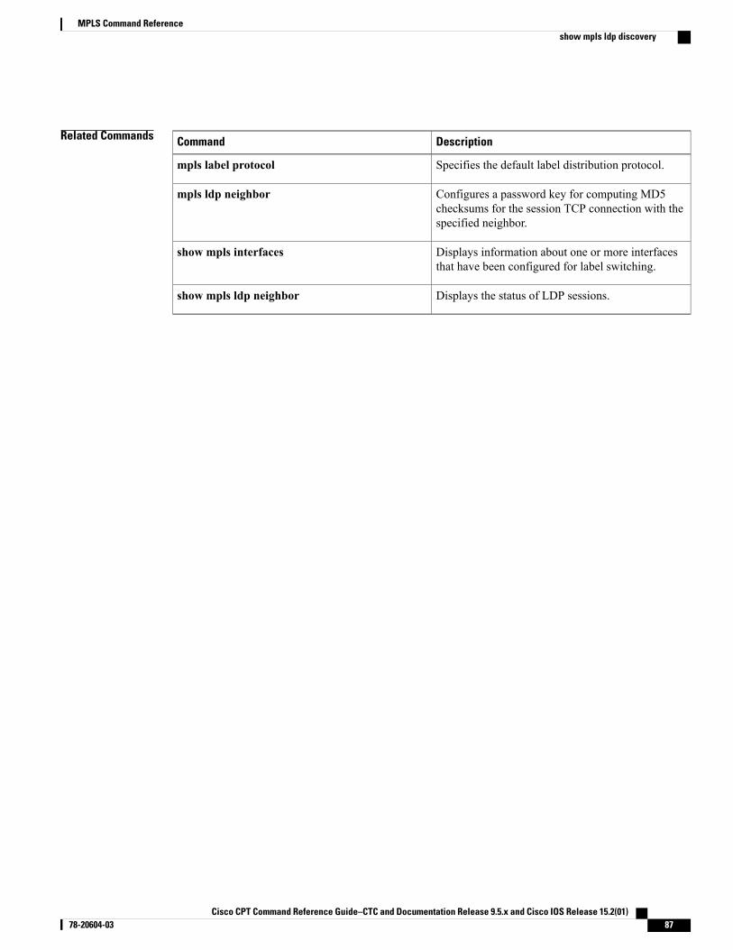
Related Commands DescriptionCommand
Specifies the default label distribution protocol.mpls label protocol
Configures a password key for computing MD5checksums for the session TCP connection with thespecified neighbor.
mpls ldp neighbor
Displays information about one or more interfacesthat have been configured for label switching.
show mpls interfaces
Displays the status of LDP sessions.show mpls ldp neighbor
Cisco CPT Command Reference Guide–CTC and Documentation Release 9.5.x and Cisco IOS Release 15.2(01) 78-20604-03 87
MPLS Command Referenceshow mpls ldp discovery
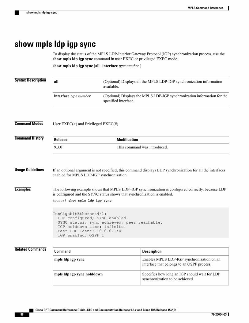
show mpls ldp igp syncTo display the status of the MPLS LDP-Interior Gateway Protocol (IGP) synchronization process, use theshow mpls ldp igp sync command in user EXEC or privileged EXEC mode.
show mpls ldp igp sync [all | interface type number ]
Syntax Description (Optional) Displays all the MPLS LDP-IGP synchronization informationavailable.
all
(Optional) Displays the MPLS LDP-IGP synchronization information for thespecified interface.
interface type number
Command Modes User EXEC(>) and Privileged EXEC(#)
Command History ModificationRelease
This command was introduced.9.3.0
Usage Guidelines If an optional argument is not specified, this command displays LDP synchronization for all the interfacesenabled for MPLS LDP-IGP synchronization.
Examples The following example shows that MPLS LDP–IGP synchronization is configured correctly, because LDPis configured and the SYNC status shows that synchronization is enabled.Router# show mpls ldp igp sync
TenGigabitEthernet4/1:LDP configured; SYNC enabled.SYNC status: sync achieved; peer reachable.IGP holddown time: infinite.Peer LDP Ident: 10.0.0.1:0IGP enabled: OSPF 1
Related Commands DescriptionCommand
Enables MPLS LDP-IGP synchronization on aninterface that belongs to an OSPF process.
mpls ldp igp sync
Specifies how long an IGP should wait for LDPsynchronization to be achieved.
mpls ldp igp sync holddown
Cisco CPT Command Reference Guide–CTC and Documentation Release 9.5.x and Cisco IOS Release 15.2(01)88 78-20604-03
MPLS Command Referenceshow mpls ldp igp sync

DescriptionCommand
Enables MPLS LDP-IGP synchronization oninterfaces for an OSPF process.
mpls ldp sync
Cisco CPT Command Reference Guide–CTC and Documentation Release 9.5.x and Cisco IOS Release 15.2(01) 78-20604-03 89
MPLS Command Referenceshow mpls ldp igp sync
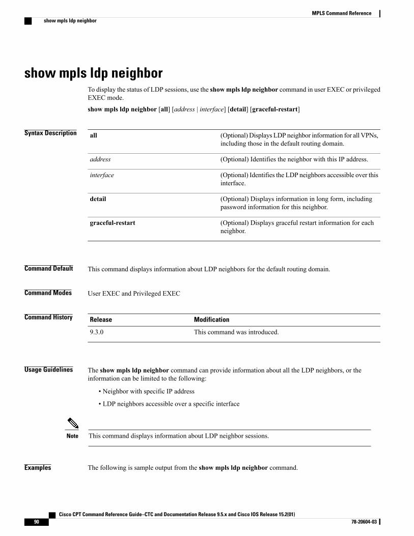
show mpls ldp neighborTo display the status of LDP sessions, use the showmpls ldp neighbor command in user EXEC or privilegedEXEC mode.
show mpls ldp neighbor [all] [address | interface] [detail] [graceful-restart]
Syntax Description (Optional) Displays LDP neighbor information for all VPNs,including those in the default routing domain.
all
(Optional) Identifies the neighbor with this IP address.address
(Optional) Identifies the LDP neighbors accessible over thisinterface.
interface
(Optional) Displays information in long form, includingpassword information for this neighbor.
detail
(Optional) Displays graceful restart information for eachneighbor.
graceful-restart
Command Default This command displays information about LDP neighbors for the default routing domain.
Command Modes User EXEC and Privileged EXEC
Command History ModificationRelease
This command was introduced.9.3.0
Usage Guidelines The show mpls ldp neighbor command can provide information about all the LDP neighbors, or theinformation can be limited to the following:
• Neighbor with specific IP address
• LDP neighbors accessible over a specific interface
This command displays information about LDP neighbor sessions.Note
Examples The following is sample output from the show mpls ldp neighbor command.
Cisco CPT Command Reference Guide–CTC and Documentation Release 9.5.x and Cisco IOS Release 15.2(01)90 78-20604-03
MPLS Command Referenceshow mpls ldp neighbor
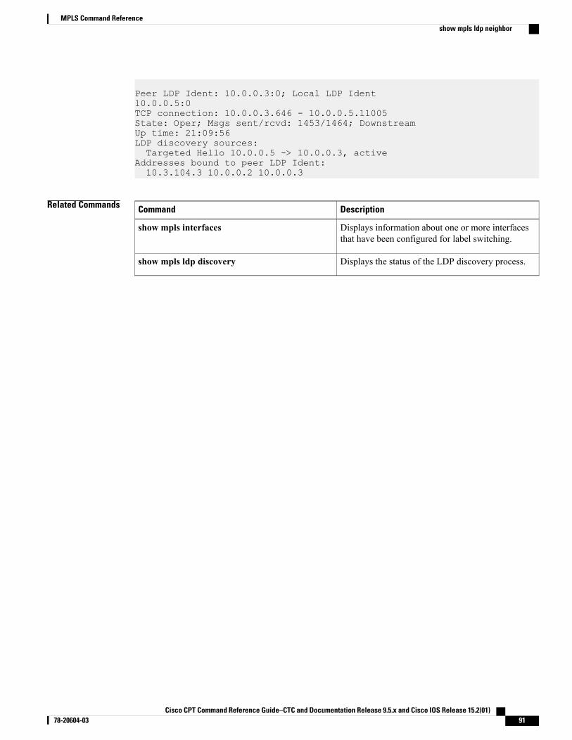
Peer LDP Ident: 10.0.0.3:0; Local LDP Ident10.0.0.5:0TCP connection: 10.0.0.3.646 - 10.0.0.5.11005State: Oper; Msgs sent/rcvd: 1453/1464; DownstreamUp time: 21:09:56LDP discovery sources:Targeted Hello 10.0.0.5 -> 10.0.0.3, active
Addresses bound to peer LDP Ident:10.3.104.3 10.0.0.2 10.0.0.3
Related Commands DescriptionCommand
Displays information about one or more interfacesthat have been configured for label switching.
show mpls interfaces
Displays the status of the LDP discovery process.show mpls ldp discovery
Cisco CPT Command Reference Guide–CTC and Documentation Release 9.5.x and Cisco IOS Release 15.2(01) 78-20604-03 91
MPLS Command Referenceshow mpls ldp neighbor
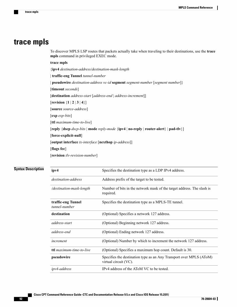
trace mplsTo discover MPLS LSP routes that packets actually take when traveling to their destinations, use the tracempls command in privileged EXEC mode.
trace mpls
{ipv4 destination-address/destination-mask-length
| traffic-eng Tunnel tunnel-number
| pseudowire destination-address vc-id segment segment-number [segment number]}
[timeout seconds]
[destination address-start [address-end | address-increment]]
[revision {1 | 2 | 3 | 4}]
[source source-address]
[exp exp-bits]
[ttl maximum-time-to-live]
[reply {dscp dscp-bits |mode reply-mode {ipv4 | no-reply | router-alert} | pad-tlv}]
[force-explicit-null]
[output interface tx-interface [nexthop ip-address]]
[flags fec]
[revision tlv-revision-number]
Syntax Description Specifies the destination type as a LDP IPv4 address.ipv4
Address prefix of the target to be tested.destination-address
Number of bits in the network mask of the target address. The slash isrequired.
/destination-mask-length
Specifies the destination type as a MPLS-TE tunnel.traffic-eng Tunneltunnel-number
(Optional) Specifies a network 127 address.destination
(Optional) Beginning network 127 address.address-start
(Optional) Ending network 127 address.address-end
(Optional) Number by which to increment the network 127 address.increment
(Optional) Specifies a maximum hop count. Default is 30.ttl maximum-time-to-live
Specifies the destination type as an Any Transport over MPLS (AToM)virtual circuit (VC).
pseudowire
IPv4 address of the AToM VC to be tested.ipv4-address
Cisco CPT Command Reference Guide–CTC and Documentation Release 9.5.x and Cisco IOS Release 15.2(01)92 78-20604-03
MPLS Command Referencetrace mpls
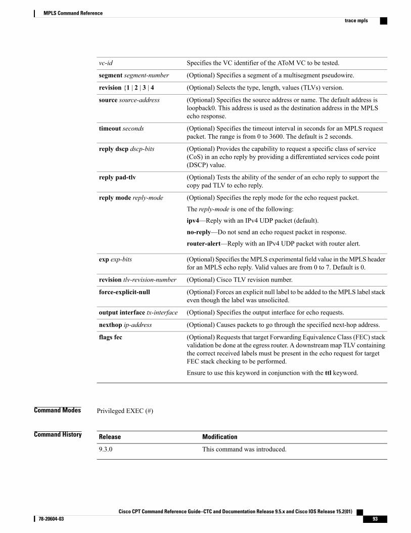
Specifies the VC identifier of the AToM VC to be tested.vc-id
(Optional) Specifies a segment of a multisegment pseudowire.segment segment-number
(Optional) Selects the type, length, values (TLVs) version.revision {1 | 2 | 3 | 4
(Optional) Specifies the source address or name. The default address isloopback0. This address is used as the destination address in the MPLSecho response.
source source-address
(Optional) Specifies the timeout interval in seconds for an MPLS requestpacket. The range is from 0 to 3600. The default is 2 seconds.
timeout seconds
(Optional) Provides the capability to request a specific class of service(CoS) in an echo reply by providing a differentiated services code point(DSCP) value.
reply dscp dscp-bits
(Optional) Tests the ability of the sender of an echo reply to support thecopy pad TLV to echo reply.
reply pad-tlv
(Optional) Specifies the reply mode for the echo request packet.
The reply-mode is one of the following:
ipv4—Reply with an IPv4 UDP packet (default).
no-reply—Do not send an echo request packet in response.
router-alert—Reply with an IPv4 UDP packet with router alert.
reply mode reply-mode
(Optional) Specifies theMPLS experimental field value in theMPLS headerfor an MPLS echo reply. Valid values are from 0 to 7. Default is 0.
exp exp-bits
(Optional) Cisco TLV revision number.revision tlv-revision-number
(Optional) Forces an explicit null label to be added to theMPLS label stackeven though the label was unsolicited.
force-explicit-null
(Optional) Specifies the output interface for echo requests.output interface tx-interface
(Optional) Causes packets to go through the specified next-hop address.nexthop ip-address
(Optional) Requests that target Forwarding Equivalence Class (FEC) stackvalidation be done at the egress router. A downstreammap TLV containingthe correct received labels must be present in the echo request for targetFEC stack checking to be performed.
Ensure to use this keyword in conjunction with the ttl keyword.
flags fec
Command Modes Privileged EXEC (#)
Command History ModificationRelease
This command was introduced.9.3.0
Cisco CPT Command Reference Guide–CTC and Documentation Release 9.5.x and Cisco IOS Release 15.2(01) 78-20604-03 93
MPLS Command Referencetrace mpls
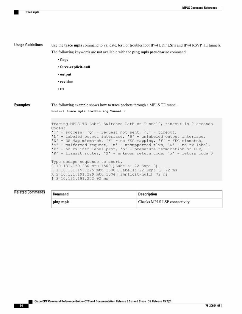
Usage Guidelines Use the trace mpls command to validate, test, or troubleshoot IPv4 LDP LSPs and IPv4 RSVP TE tunnels.
The following keywords are not available with the ping mpls pseudowire command:
• flags
• force-explicit-null
• output
• revision
• ttl
Examples The following example shows how to trace packets through a MPLS TE tunnel.Router# trace mpls traffic-eng Tunnel 0
Tracing MPLS TE Label Switched Path on Tunnel0, timeout is 2 secondsCodes:'!' - success, 'Q' - request not sent, '.' - timeout,'L' - labeled output interface, 'B' - unlabeled output interface,'D' - DS Map mismatch, 'F' - no FEC mapping, 'f' - FEC mismatch,'M' - malformed request, 'm' - unsupported tlvs, 'N' - no rx label,'P' - no rx intf label prot, 'p' - premature termination of LSP,'R' - transit router, 'X' - unknown return code, 'x' - return code 0
Type escape sequence to abort.0 10.131.159.230 mtu 1500 [Labels: 22 Exp: 0]R 1 10.131.159.225 mtu 1500 [Labels: 22 Exp: 6] 72 msR 2 10.131.191.229 mtu 1504 [implicit-null] 72 ms! 3 10.131.191.252 92 ms
Related Commands DescriptionCommand
Checks MPLS LSP connectivity.ping mpls
Cisco CPT Command Reference Guide–CTC and Documentation Release 9.5.x and Cisco IOS Release 15.2(01)94 78-20604-03
MPLS Command Referencetrace mpls
tunnel mode mpls traffic-engTo set the mode of a tunnel to MPLS for traffic engineering, use the tunnel mode mpls traffic-eng commandin interface configuration mode. To disable this feature, use the no form of this command.
tunnel mode mpls traffic-eng
no tunnel mode mpls traffic-eng
Syntax Description This command has no arguments or keywords.
Command Default Disabled.
Command Modes Interface configuration (config-if)
Command History ModificationRelease
This command was introduced.9.3.0
Usage Guidelines This command specifies that the tunnel interface is for an MPLS traffic engineering tunnel and enables thevarious tunnel MPLS configuration options.
Examples The following example shows how to set the mode of the tunnel to MPLS traffic engineering.Router(config-if)# tunnel mode mpls traffic-eng
Related Commands DescriptionCommand
Configures an affinity for aMPLS traffic engineeringtunnel.
tunnel mpls traffic-eng affinity
Instructs the IGP to use the tunnel in its enhancedSPF algorithm calculation (if the tunnel is up).
tunnel mpls traffic-eng autoroute announce
Configures the bandwidth required for aMPLS trafficengineering tunnel.
tunnel mpls traffic-eng bandwidth
Configures a path option.tunnel mpls traffic-eng path-option
Configures setup and reservation priority for aMPLStraffic engineering tunnel.
tunnel mpls traffic-eng priority
Cisco CPT Command Reference Guide–CTC and Documentation Release 9.5.x and Cisco IOS Release 15.2(01) 78-20604-03 95
MPLS Command Referencetunnel mode mpls traffic-eng

Cisco CPT Command Reference Guide–CTC and Documentation Release 9.5.x and Cisco IOS Release 15.2(01)96 78-20604-03
MPLS Command Referencetunnel mode mpls traffic-eng
tunnel mpls traffic-eng path-optionTo configure a path option for a MPLS–TE tunnel, use the tunnel mpls traffic-eng path-option commandin interface configuration mode. To disable this function, use the no form of this command.
tunnel mpls traffic-eng path-option {number {dynamic [attributes lsp-attributes | bandwidth kbps][lockdown] | lockdown [bandwidth kbps] | explicit {identifier path-number | name path-name} [attributeslsp-attributes [verbatim]] | bandwidth kbps [lockdown] [verbatim]] | lockdown bandwidth kbps [verbatim]| verbatim bandwidth kbps [lockdown]}}
no tunnel mpls traffic-eng path-option number
Syntax Description Preference for this path option. When you configure multiple path options,lower numbered options are preferred. Valid values are from 1 to 1000.
number
Dynamically calculates the path of the LSP.dynamic
(Optional) Identifies an LSP attribute list. The attribute list used must be thesame as the primary path option being configured.
attributes lsp-attributes
(Optional) Overrides the bandwidth configured on the tunnel or the attributelist. The kbps is the number of kilobits per second set aside for the path option.The range is from 1 to 4294967295. The bandwidth value must be the same asthe primary path option being configured.
bandwidth kbps
(Optional) Indicates that the LSP cannot be reoptimized.lockdown
(Optional) Bypasses the topology database verification process.verbatim
Specifies that the path of the LSP is an IP explicit path.explicit
Specifies the path name of the IP explicit path that the tunnel uses with thisoption.
name path–name
Specifies the path number of the IP explicit path that the tunnel uses with thisoption. The range is from 1 to 65535.
identifier path–number
Command Default No path option for an MPLS TE tunnel is configured.
Command Modes Interface configuration (config-if)
Command History ModificationRelease
This command was introduced.9.3.0
Cisco CPT Command Reference Guide–CTC and Documentation Release 9.5.x and Cisco IOS Release 15.2(01) 78-20604-03 97
MPLS Command Referencetunnel mpls traffic-eng path-option
Usage Guidelines You can configure multiple path options for a single tunnel. For example, there can be several explicit pathoptions and a dynamic option for one tunnel. Path setup preference is for lower (not higher) numbers, sooption 1 is preferred.
If you specify the dynamic keyword, the software checks both the physical bandwidth of the interface andthe available TE bandwidth to be sure that the requested amount of bandwidth does not exceed the physicalbandwidth of any link. To oversubscribe links, you must specify the explicit keyword. If you use the explicitkeyword, the software only checks how much bandwidth is available on the link for TE; the amount ofbandwidth you configure is not limited to how much physical bandwidth is available on the link.
Examples The following example shows how to configure the tunnel to use a named IP explicit path.Router(config-if)# tunnel mpls traffic-eng path-option 1 explicit name test
Related Commands DescriptionCommand
Enters the command mode for IP explicit paths andcreates or modifies the specified path.
ip explicit-path
Creates or modifies an LSP attribute list.mpls traffic-eng lsp attributes
Displays the configured IP explicit paths.show ip explicit-paths
Configures a secondary path option for a MPLS TEtunnel.
tunnel mpls traffic-eng path-option protect
Cisco CPT Command Reference Guide–CTC and Documentation Release 9.5.x and Cisco IOS Release 15.2(01)98 78-20604-03
MPLS Command Referencetunnel mpls traffic-eng path-option
tunnel mpls traffic-eng autoroute announceTo specify that the IGPmust use the tunnel in its enhanced shortest path first (SPF) calculation, use the tunnelmpls traffic-eng autoroute announce command in interface configuration mode. To disable this feature,use the no form of this command.
tunnel mpls traffic-eng autoroute announce
no tunnel mpls traffic-eng autoroute announce
Syntax Description This command has no arguments or keywords.
Command Default The IGP does not use the tunnel in its enhanced SPF calculation.
Command Modes Interface configuration (config-if)
Command History ModificationRelease
This command was introduced.9.3.0
Usage Guidelines The only way to forward traffic onto a tunnel is by enabling this command or by explicitly configuringforwarding (for example, with an interface static route).
Examples The following example shows how to specify that the IGP must use the tunnel in its enhanced SPF calculationif the tunnel is up.Router(config-if)# tunnel mpls traffic-eng autoroute announce
Related Commands DescriptionCommand
Sets the mode of a tunnel to MPLS for trafficengineering.
tunnel mode mpls traffic-eng
Cisco CPT Command Reference Guide–CTC and Documentation Release 9.5.x and Cisco IOS Release 15.2(01) 78-20604-03 99
MPLS Command Referencetunnel mpls traffic-eng autoroute announce
tunnel mpls traffic-eng bandwidthTo configure the bandwidth required for a MPLS-TE tunnel, use the tunnel mpls traffic-eng bandwidthcommand in interface configuration mode. To disable this bandwidth configuration, use the no form of thiscommand.
tunnel mpls traffic-eng bandwidth kbps
no tunnel mpls traffic-eng bandwidth
Syntax Description The bandwidth, in kilobits per second, set aside for the MPLS TE tunnel. The range isfrom 1 to 4294967295. The default value is 0.
kbps
Command Default The default tunnel is a global pool tunnel.
Command Modes Interface configuration (config-if)
Command History ModificationRelease
This command was introduced.9.3.0
Usage Guidelines If automatic bandwidth is configured for the tunnel, the tunnel mpls traffic-eng bandwidth commandconfigures the initial tunnel bandwidth, which will be adjusted by the autobandwidth mechanism.
Examples The following example shows how to configure 100 kbps of bandwidth for the MPLS traffic engineeringtunnel.Router(config-if)# tunnel mpls traffic-eng bandwidth 100
Related Commands DescriptionCommand
Enables RSVP for IP on an interface.ip rsvp bandwidth
Displays information about tunnels.show mpls traffic-eng tunnel
Cisco CPT Command Reference Guide–CTC and Documentation Release 9.5.x and Cisco IOS Release 15.2(01)100 78-20604-03
MPLS Command Referencetunnel mpls traffic-eng bandwidth
tunnel mpls traffic-eng priorityTo configure the setup and reservation priority for MPLS-TE tunnel, use the tunnel mpls traffic-eng prioritycommand in interface configuration mode. To remove the specified setup and reservation priority, use the noform of this command.
tunnel mpls traffic-eng priority setup-priority [hold-priority]
no tunnel mpls traffic-eng priority setup-priority [hold-priority]
Syntax Description The priority used when signaling a LSP for this tunnel to determine which existingtunnels can be preempted. Valid values are from 0 to 7, where a lower number indicatesa higher priority. Therefore, an LSP with a setup priority of 0 can preempt any LSPwith a non-0 priority.
setup-priority
(Optional) The priority associated with an LSP for this tunnel to determine if it shouldbe preempted by other LSPs that are being signaled. Valid values are from 0 to 7,where a lower number indicates a higher priority.
hold-priority
Command Default By default, the setup priority is 7. The value of hold priority is the same as the value of setup priority.
Command Modes Interface configuration (config-if)
Command History ModificationRelease
This command was introduced.9.3.0
Usage Guidelines When an LSP is being signaled and an interface does not currently have enough bandwidth available for thatLSP, the lower-priority LSPs are pre-empted so that the new LSP can be admitted.
The new LSP’s priority is its setup priority and the existing LSP’s priority is its hold priority. The two prioritiesenables the signaling of an LSP with a low setup priority (so that the LSP does not preempt other LSPs onsetup) but a high hold priority (so that the LSP is not preempted after it is established).
Setup priority and hold priority are typically configured to be equal, and setup priority cannot be better(numerically smaller) than the hold priority.
Examples The following example shows how to configure a tunnel with a setup and hold priority of 1.Router(config-if)# tunnel mpls traffic-eng priority 1 1
Cisco CPT Command Reference Guide–CTC and Documentation Release 9.5.x and Cisco IOS Release 15.2(01) 78-20604-03 101
MPLS Command Referencetunnel mpls traffic-eng priority

Related Commands DescriptionCommand
Sets the mode of a tunnel to MPLS for trafficengineering.
tunnel mode mpls traffic-eng
Cisco CPT Command Reference Guide–CTC and Documentation Release 9.5.x and Cisco IOS Release 15.2(01)102 78-20604-03
MPLS Command Referencetunnel mpls traffic-eng priority
tunnel mpls traffic–eng path–option protectTo configure a secondary path option for a MPLS–TE tunnel, use the tunnel mpls traffic-eng path-optionprotect command in interface configuration mode. To disable this function, use the no form of this command.
tunnel mpls traffic-eng path-option protect {number {dynamic [attributes lsp-attributes | bandwidthkbps] [lockdown] | lockdown [bandwidth kbps] | explicit {identifier path-number | name path-name}[attributes lsp-attributes [verbatim]] | bandwidth kbps [lockdown] [verbatim]] | lockdown bandwidthkbps [lockdown] [verbatim] | verbatim [lockdown]]}
no tunnel mpls traffic-eng path-option protect number
Syntax Description The primary path option being protected. Valid values are from 1 to 1000.number
Dynamically calculates the path of the LSP.dynamic
(Optional) Identifies an LSP attribute list. The attribute list used must be thesame as the primary path option being protected.
attributes lsp-attributes
(Optional) Overrides the bandwidth configured on the tunnel or the attributelist. The kbps value is the number of kilobits per second set aside for the pathoption. The range is from 1 to 4294967295. The bandwidth value must be thesame as the primary path option being configured.
bandwidth kbps
(Optional) Indicates that the LSP cannot be reoptimized.lockdown
(Optional) Bypasses the topology database verification process.verbatim
Specifies that the path of the LSP is an IP explicit path.explicit
Specifies the path name of the IP explicit path that the tunnel uses with thisoption.
name path–name
Specifies the path number of the IP explicit path that the tunnel uses with thisoption. The range is from 1 to 65535.
identifier path–number
Command Default The MPLS TE tunnel does not have a secondary path option.
Command Modes Interface configuration (config-if)
Command History ModificationRelease
This command was introduced.9.3.0
Cisco CPT Command Reference Guide–CTC and Documentation Release 9.5.x and Cisco IOS Release 15.2(01) 78-20604-03 103
MPLS Command Referencetunnel mpls traffic–eng path–option protect
Usage Guidelines Cisco recommends that the primary path options being protected use explicit paths.
Calculation of a dynamic path for the path protected LSP is not available. When configuring the IP explicitpath for the path protected LSP, choose hops that minimize the number of links and nodes shared with theprimary path option that is being protected.
If the path option being protected uses an attribute list, configure path protection to use the same attribute list.
If the path option being protected uses bandwidth override, configure path protection to use bandwidth overridewith the same values.
Examples The following example shows how to configure the tunnel to use a named IP explicit path.Router(config-if)# tunnel mpls traffic-eng path-option protect 1 explicit name testThe following example shows how to configure path option 1 to use an LSP attribute list identified with thenumeral 1.Router(config-if)# tunnel mpls traffic-eng path-option protect 1 explicit name test attributes1The following example shows how to configure bandwidth for a path option to override the bandwidthconfigured on the tunnel.Router(config-if)# tunnel mpls traffic-eng path-option protect 3 explicit name test bandwidth0
Related Commands DescriptionCommand
Enters the command mode for IP explicit paths andcreates or modifies the specified path.
ip explicit-path
Creates or modifies an LSP attribute list.mpls traffic-eng lsp attributes
Displays the configured IP explicit paths.show ip explicit-paths
Configures a primary path for an MPLS TE tunnel.tunnel mpls traffic-eng path-option
Cisco CPT Command Reference Guide–CTC and Documentation Release 9.5.x and Cisco IOS Release 15.2(01)104 78-20604-03
MPLS Command Referencetunnel mpls traffic–eng path–option protect
MPLS TP Command Reference
This chapter describes commands to configureMultiprotocol Label Switching Transport Profile (MPLS TP).
• bfd-template, page 106
• debug mpls tp, page 107
• interface tunnel-tp, page 109
• interval (mpls–tp), page 115
• local interface, page 117
• medium p2p, page 119
• mpls tp, page 120
• mpls tp link, page 123
• mpls tp lsp, page 125
• ping mpls tp, page 128
• pseudowire-static-oam class, page 132
• pseudowire-tlv template, page 133
• show mpls tp, page 134
• status protocol notification static, page 136
• tlv template, page 137
• trace mpls tp, page 138
Cisco CPT Command Reference Guide–CTC and Documentation Release 9.5.x and Cisco IOS Release 15.2(01) 78-20604-03 105
bfd-templateTo create a Bidirectional Forwarding Detection (BFD) template and to enter BFD configuration mode, usethe bfd-template command in global configuration mode. To disable a BFD template, use the no form of thiscommand.
bfd-template single-hop template-name
no bfd-template single-hop template-name
Syntax Description Specifies a single-hop BFD template.single-hop
Name of the template.template-name
Command Default The BFD template does not exist.
Command Modes Global configuration (config)
Command History ModificationRelease
This command was introduced.9.3.0
Usage Guidelines The bfd-template command enables you to create a BFD template and enter BFD configuration mode. Thetemplate can be used to specify a set of BFD interval values. The BFD interval values specified as part of theBFD template are not specific to a single interface.
Examples The following example shows how to create a BFD template and specify BFD interval values.
Router(config)# bfd-template single-hop node1Router(config-bfd)# interval min-tx 120 min-rx 100 multiplier 3
Related Commands DescriptionCommand
Configures the transmit and receive intervals betweenBFD packets.
interval (MPLS–TP)
Cisco CPT Command Reference Guide–CTC and Documentation Release 9.5.x and Cisco IOS Release 15.2(01)106 78-20604-03
MPLS TP Command Referencebfd-template
debug mpls tpTo display Multiprotocol Label Switching (MPLS) Transport Profile (TP) error messages, use the debugmpls tp command in privileged EXEC mode. To disable the display of the messages, use the no form of thiscommand.
debug mpls tp [all | cli | error | event | fault-oam | ha | init | link-num | lsp-db | lsp-ep | lsp-mp |mem |tun-db | tunnel ]
no debug mpls tp
Syntax Description Displays all debug messages.all
Displays MPLS-TP CLI debug messages.cli
Displays MPLS-TP error debug messages.error
Displays MPLS-TP event debug messages.event
Displays MPLS-TP fault OAM debug messages.fault-oam
Displays MPLS-TP high availability (HA) debug messages.ha
Displays MPLS-TP initialization debug messages.init
Displays MPLS-TP link management debug messages.link-num
Displays MPLS-TP midpoint label switched path (LSP) database debugmessages.
lsp-db
Displays MPLS-TP endpoint (EP) LSP configuration and operation debugmessages.
lsp-ep
Displays MPLS-TP midpoint (MP) LSP configuration and operation debugmessages.
lsp-mp
Displays MPLS-TP memory allocation and usage debug messages.mem
Displays MPLS-TP tunnel database debug messages.tun-db
Displays MPLS-TP tunnel configuration and operation debug messages.tunnel
Command Default Debug messages are not enabled.
Command Modes Privileged EXEC (#)
Cisco CPT Command Reference Guide–CTC and Documentation Release 9.5.x and Cisco IOS Release 15.2(01) 78-20604-03 107
MPLS TP Command Referencedebug mpls tp
Command History ModificationRelease
This command was introduced.9.3.0
Examples The following example displays the MPLS–TP endpoint LSP configuration and operation debug messages.
Router# debug mpls tp lsp-ep
Related Commands DescriptionCommand
Displays information about the MPLS TP tunnels.show mpls tp
Cisco CPT Command Reference Guide–CTC and Documentation Release 9.5.x and Cisco IOS Release 15.2(01)108 78-20604-03
MPLS TP Command Referencedebug mpls tp
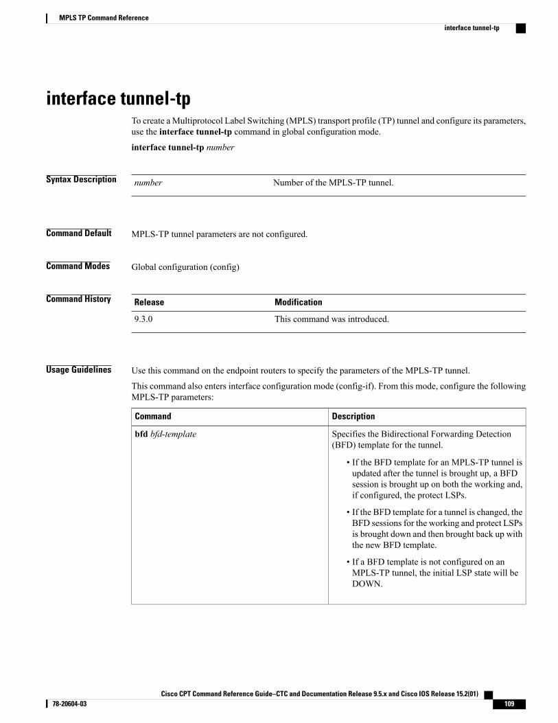
interface tunnel-tpTo create a Multiprotocol Label Switching (MPLS) transport profile (TP) tunnel and configure its parameters,use the interface tunnel-tp command in global configuration mode.
interface tunnel-tp number
Syntax Description Number of the MPLS-TP tunnel.number
Command Default MPLS-TP tunnel parameters are not configured.
Command Modes Global configuration (config)
Command History ModificationRelease
This command was introduced.9.3.0
Usage Guidelines Use this command on the endpoint routers to specify the parameters of the MPLS-TP tunnel.
This command also enters interface configuration mode (config-if). From this mode, configure the followingMPLS-TP parameters:
DescriptionCommand
Specifies the Bidirectional Forwarding Detection(BFD) template for the tunnel.
• If the BFD template for an MPLS-TP tunnel isupdated after the tunnel is brought up, a BFDsession is brought up on both the working and,if configured, the protect LSPs.
• If the BFD template for a tunnel is changed, theBFD sessions for the working and protect LSPsis brought down and then brought back up withthe new BFD template.
• If a BFD template is not configured on anMPLS-TP tunnel, the initial LSP state will beDOWN.
bfd bfd-template
Cisco CPT Command Reference Guide–CTC and Documentation Release 9.5.x and Cisco IOS Release 15.2(01) 78-20604-03 109
MPLS TP Command Referenceinterface tunnel-tp
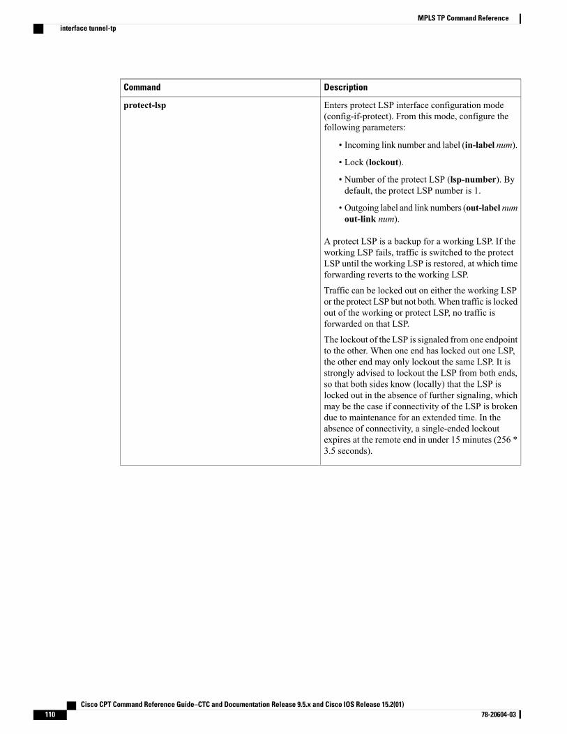
DescriptionCommand
Enters protect LSP interface configuration mode(config-if-protect). From this mode, configure thefollowing parameters:
• Incoming link number and label (in-label num).
• Lock (lockout).
• Number of the protect LSP (lsp-number). Bydefault, the protect LSP number is 1.
• Outgoing label and link numbers (out-label numout-link num).
A protect LSP is a backup for a working LSP. If theworking LSP fails, traffic is switched to the protectLSP until the working LSP is restored, at which timeforwarding reverts to the working LSP.
Traffic can be locked out on either the working LSPor the protect LSP but not both.When traffic is lockedout of the working or protect LSP, no traffic isforwarded on that LSP.
The lockout of the LSP is signaled from one endpointto the other. When one end has locked out one LSP,the other end may only lockout the same LSP. It isstrongly advised to lockout the LSP from both ends,so that both sides know (locally) that the LSP islocked out in the absence of further signaling, whichmay be the case if connectivity of the LSP is brokendue to maintenance for an extended time. In theabsence of connectivity, a single-ended lockoutexpires at the remote end in under 15 minutes (256 *3.5 seconds).
protect-lsp
Cisco CPT Command Reference Guide–CTC and Documentation Release 9.5.x and Cisco IOS Release 15.2(01)110 78-20604-03
MPLS TP Command Referenceinterface tunnel-tp
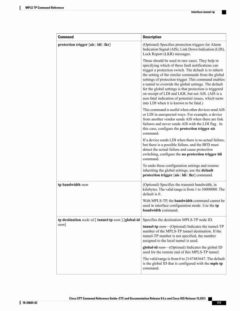
DescriptionCommand
(Optional) Specifies protection triggers for AlarmIndication Signal (AIS), Link Down Indication (LDI),Lock Report (LKR) messages.
These should be used in rare cases. They help inspecifying which of these fault notifications cantrigger a protection switch. The default is to inheritthe setting of the similar commands from the globalsettings of protection trigger. This command enablesa tunnel to override the global settings. The defaultfor the global settings is that protection is triggeredon receipt of LDI and LKR, but not AIS. (AIS is anon-fatal indication of potential issues, which turnsinto LDI when it is known to be fatal.)
This command is useful when other devices send AISor LDI in unexpected ways. For example, a devicefrom another vendor sends AIS when there are linkfailures and never sends AIS with the LDI flag . Inthis case, configure the protection trigger aiscommand.
If a device sends LDI when there is no actual failure,but there is a possible failure, and the BFD mustdetect the actual failure and cause protectionswitching, configure the no protection trigger ldicommand.
To undo these configuration settings and resumeinheriting the global settings, use the defaultprotection trigger [ais | ldi | lkr] command.
protection trigger [ais | ldi | lkr]
(Optional) Specifies the transmit bandwidth, inkilobytes. The valid range is from 1 to 10000000. Thedefault is 0.
With MPLS-TP, the bandwidth command cannot beused in interface configuration mode. Use the tpbandwidth command.
tp bandwidth num
Specifies the destination MPLS-TP node ID.
tunnel-tp num—(Optional) Indicates the tunnel-TPnumber of the MPLS-TP tunnel destination. If thetunnel-TP number is not specified, the numberassigned to the local tunnel is used.
global-id num—(Optional) Indicates the global IDused for the remote end of this MPLS-TP tunnel.
The valid range is from 0 to 2147483647. The defaultis the global ID that is configured with thempls tpcommand.
tp destination node-id [ tunnel-tp num ] [global-idnum]
Cisco CPT Command Reference Guide–CTC and Documentation Release 9.5.x and Cisco IOS Release 15.2(01) 78-20604-03 111
MPLS TP Command Referenceinterface tunnel-tp
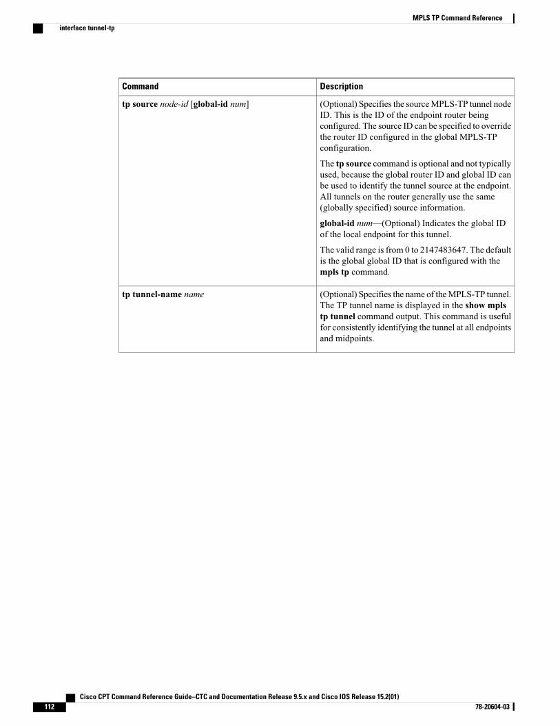
DescriptionCommand
(Optional) Specifies the sourceMPLS-TP tunnel nodeID. This is the ID of the endpoint router beingconfigured. The source ID can be specified to overridethe router ID configured in the global MPLS-TPconfiguration.
The tp source command is optional and not typicallyused, because the global router ID and global ID canbe used to identify the tunnel source at the endpoint.All tunnels on the router generally use the same(globally specified) source information.
global-id num—(Optional) Indicates the global IDof the local endpoint for this tunnel.
The valid range is from 0 to 2147483647. The defaultis the global global ID that is configured with thempls tp command.
tp source node-id [global-id num]
(Optional) Specifies the name of theMPLS-TP tunnel.The TP tunnel name is displayed in the show mplstp tunnel command output. This command is usefulfor consistently identifying the tunnel at all endpointsand midpoints.
tp tunnel-name name
Cisco CPT Command Reference Guide–CTC and Documentation Release 9.5.x and Cisco IOS Release 15.2(01)112 78-20604-03
MPLS TP Command Referenceinterface tunnel-tp
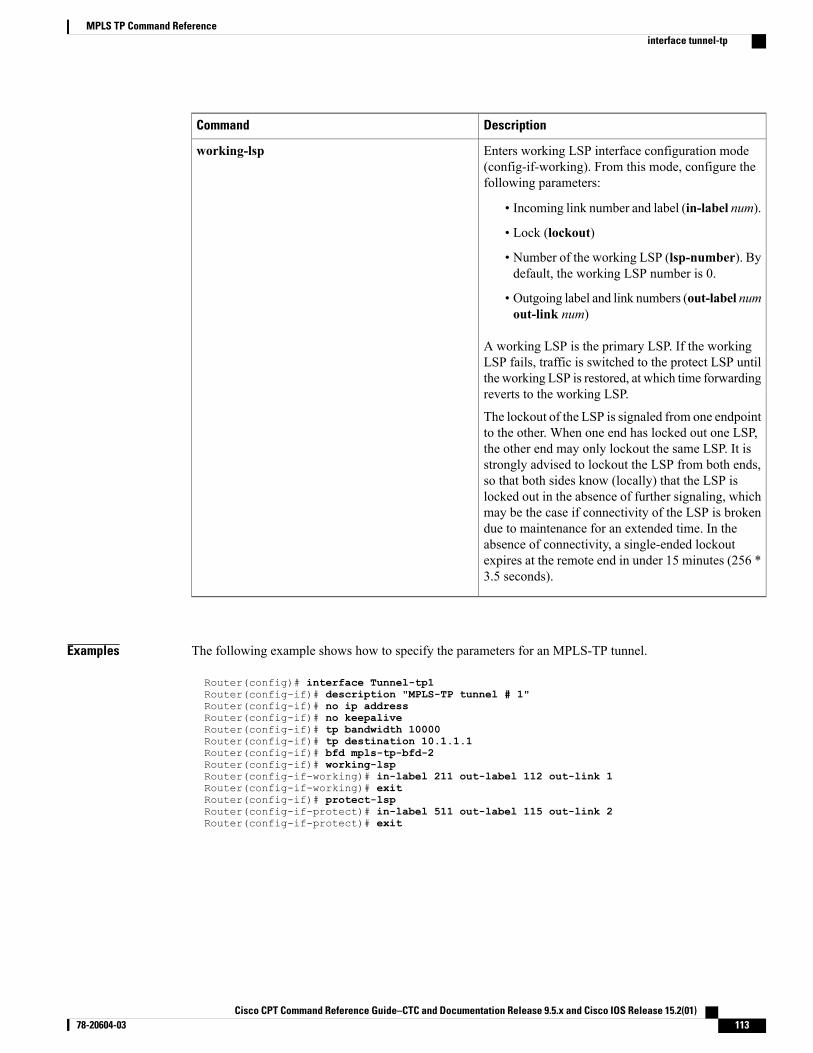
DescriptionCommand
Enters working LSP interface configuration mode(config-if-working). From this mode, configure thefollowing parameters:
• Incoming link number and label (in-label num).
• Lock (lockout)
• Number of the working LSP (lsp-number). Bydefault, the working LSP number is 0.
• Outgoing label and link numbers (out-label numout-link num)
A working LSP is the primary LSP. If the workingLSP fails, traffic is switched to the protect LSP untilthe working LSP is restored, at which time forwardingreverts to the working LSP.
The lockout of the LSP is signaled from one endpointto the other. When one end has locked out one LSP,the other end may only lockout the same LSP. It isstrongly advised to lockout the LSP from both ends,so that both sides know (locally) that the LSP islocked out in the absence of further signaling, whichmay be the case if connectivity of the LSP is brokendue to maintenance for an extended time. In theabsence of connectivity, a single-ended lockoutexpires at the remote end in under 15 minutes (256 *3.5 seconds).
working-lsp
Examples The following example shows how to specify the parameters for an MPLS-TP tunnel.
Router(config)# interface Tunnel-tp1Router(config–if)# description "MPLS-TP tunnel # 1"Router(config-if)# no ip addressRouter(config-if)# no keepaliveRouter(config-if)# tp bandwidth 10000Router(config-if)# tp destination 10.1.1.1Router(config-if)# bfd mpls-tp-bfd-2Router(config-if)# working-lspRouter(config-if-working)# in-label 211 out-label 112 out-link 1Router(config-if-working)# exitRouter(config-if)# protect-lspRouter(config-if-protect)# in-label 511 out-label 115 out-link 2Router(config-if-protect)# exit
Cisco CPT Command Reference Guide–CTC and Documentation Release 9.5.x and Cisco IOS Release 15.2(01) 78-20604-03 113
MPLS TP Command Referenceinterface tunnel-tp

Related Commands DescriptionCommand
Specifies global values used across the MPLS TPimplementation and applies to all the tunnels andmidpoint LSPs.
mpls tp
Cisco CPT Command Reference Guide–CTC and Documentation Release 9.5.x and Cisco IOS Release 15.2(01)114 78-20604-03
MPLS TP Command Referenceinterface tunnel-tp
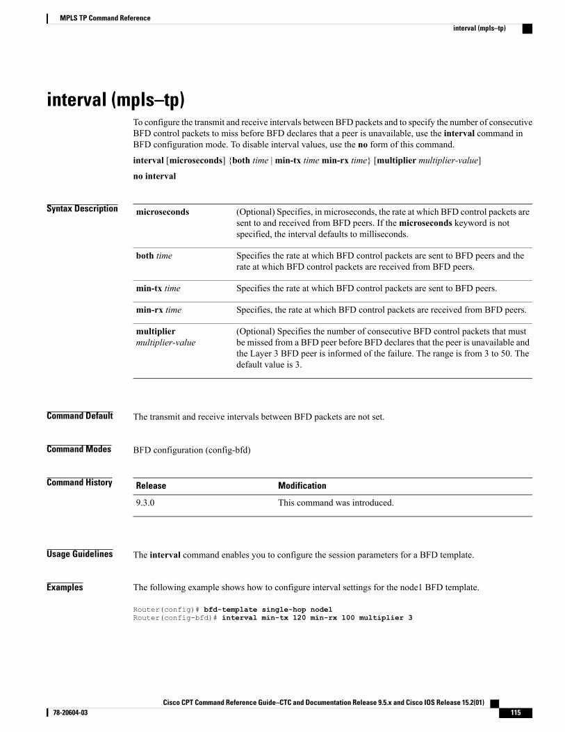
interval (mpls–tp)To configure the transmit and receive intervals between BFD packets and to specify the number of consecutiveBFD control packets to miss before BFD declares that a peer is unavailable, use the interval command inBFD configuration mode. To disable interval values, use the no form of this command.
interval [microseconds] {both time |min-tx timemin-rx time} [multiplier multiplier-value]
no interval
Syntax Description (Optional) Specifies, in microseconds, the rate at which BFD control packets aresent to and received from BFD peers. If themicroseconds keyword is notspecified, the interval defaults to milliseconds.
microseconds
Specifies the rate at which BFD control packets are sent to BFD peers and therate at which BFD control packets are received from BFD peers.
both time
Specifies the rate at which BFD control packets are sent to BFD peers.min-tx time
Specifies, the rate at which BFD control packets are received from BFD peers.min-rx time
(Optional) Specifies the number of consecutive BFD control packets that mustbe missed from a BFD peer before BFD declares that the peer is unavailable andthe Layer 3 BFD peer is informed of the failure. The range is from 3 to 50. Thedefault value is 3.
multipliermultiplier-value
Command Default The transmit and receive intervals between BFD packets are not set.
Command Modes BFD configuration (config-bfd)
Command History ModificationRelease
This command was introduced.9.3.0
Usage Guidelines The interval command enables you to configure the session parameters for a BFD template.
Examples The following example shows how to configure interval settings for the node1 BFD template.
Router(config)# bfd-template single-hop node1Router(config-bfd)# interval min-tx 120 min-rx 100 multiplier 3
Cisco CPT Command Reference Guide–CTC and Documentation Release 9.5.x and Cisco IOS Release 15.2(01) 78-20604-03 115
MPLS TP Command Referenceinterval (mpls–tp)

Related Commands DescriptionCommand
Creates a BFD template and enters BFD configurationmode.
bfd-template
Cisco CPT Command Reference Guide–CTC and Documentation Release 9.5.x and Cisco IOS Release 15.2(01)116 78-20604-03
MPLS TP Command Referenceinterval (mpls–tp)
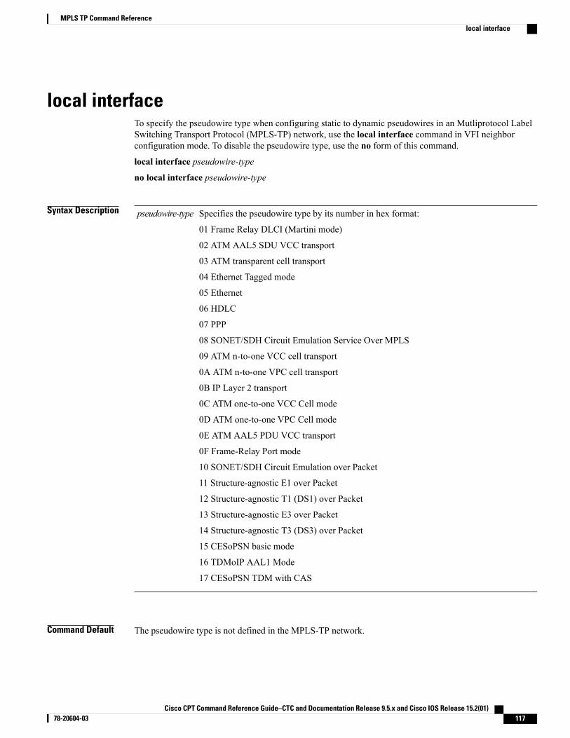
local interfaceTo specify the pseudowire type when configuring static to dynamic pseudowires in an Mutliprotocol LabelSwitching Transport Protocol (MPLS-TP) network, use the local interface command in VFI neighborconfiguration mode. To disable the pseudowire type, use the no form of this command.
local interface pseudowire-type
no local interface pseudowire-type
Syntax Description Specifies the pseudowire type by its number in hex format:
01 Frame Relay DLCI (Martini mode)
02 ATM AAL5 SDU VCC transport
03 ATM transparent cell transport
04 Ethernet Tagged mode
05 Ethernet
06 HDLC
07 PPP
08 SONET/SDH Circuit Emulation Service Over MPLS
09 ATM n-to-one VCC cell transport
0A ATM n-to-one VPC cell transport
0B IP Layer 2 transport
0C ATM one-to-one VCC Cell mode
0D ATM one-to-one VPC Cell mode
0E ATM AAL5 PDU VCC transport
0F Frame-Relay Port mode
10 SONET/SDH Circuit Emulation over Packet
11 Structure-agnostic E1 over Packet
12 Structure-agnostic T1 (DS1) over Packet
13 Structure-agnostic E3 over Packet
14 Structure-agnostic T3 (DS3) over Packet
15 CESoPSN basic mode
16 TDMoIP AAL1 Mode
17 CESoPSN TDM with CAS
pseudowire-type
Command Default The pseudowire type is not defined in the MPLS-TP network.
Cisco CPT Command Reference Guide–CTC and Documentation Release 9.5.x and Cisco IOS Release 15.2(01) 78-20604-03 117
MPLS TP Command Referencelocal interface
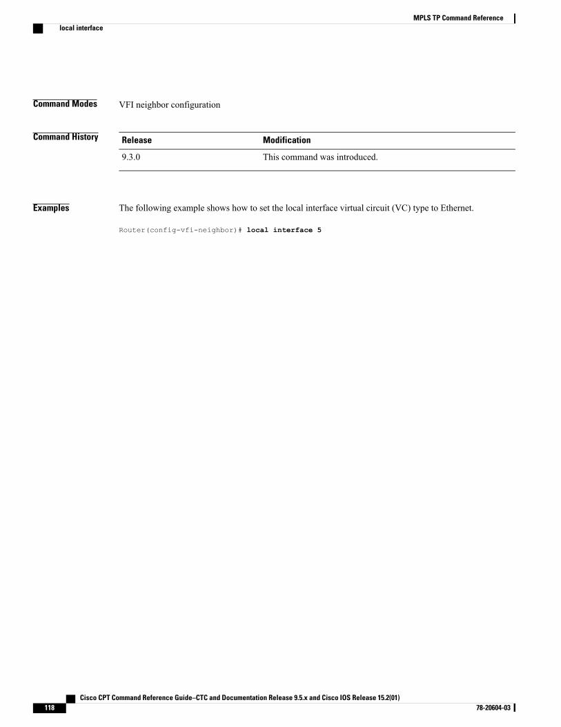
Command Modes VFI neighbor configuration
Command History ModificationRelease
This command was introduced.9.3.0
Examples The following example shows how to set the local interface virtual circuit (VC) type to Ethernet.
Router(config-vfi-neighbor)# local interface 5
Cisco CPT Command Reference Guide–CTC and Documentation Release 9.5.x and Cisco IOS Release 15.2(01)118 78-20604-03
MPLS TP Command Referencelocal interface
medium p2pTo configure the interface as point-to-point, use themedium p2p command in interface configuration mode.To return the interface to its normal mode, use the no form of this command.
medium p2p
no medium p2p
Syntax Description This command has no arguments or keywords.
Command Default Interfaces are configured to connect to multiple devices.
Command Modes Interface configuration (config-if)
Command History ModificationRelease
This command was introduced.9.3.0
Usage Guidelines This command enables the router to send and receive all MPLS-TP packets using a common multicast MACaddress knowing that it is communicating with only one other device.
Examples The following example shows how to configure the interface as point-to-point:
Router(config)# interface TenGigabitEthernet4/1Router(config-if)# medium p2p
Related Commands DescriptionCommand
Configures MPLS–TP link parameters.mpls tp link
Cisco CPT Command Reference Guide–CTC and Documentation Release 9.5.x and Cisco IOS Release 15.2(01) 78-20604-03 119
MPLS TP Command Referencemedium p2p
mpls tpTo configure Multiprotocol Label Switching (MPLS) transport profile (TP) parameters and enter MPLS-TPconfiguration mode, use thempls tp command in global configuration mode. To remove all MPLS-TPparameters, use the no form of this command.
mpls tpno mpls tp
Syntax Description This command has no arguments or keywords.
Command Default MPLS-TP parameters are not configured.
Command Modes Global configuration (config)
Command History ModificationRelease
This command was introduced.9.3.0
Usage Guidelines Use this command to enterMPLS-TP configurationmode. From this mode, configure the following parameters:
DescriptionCommand
(Optional) Specifies the maximum time betweensuccessive fault Operations, Administration, andMaintenance (OAM) messages specified in seconds.
The range is from 1 to20. The default value is 20.
fault-oam refresh-timer secs
(Optional) Specifies the default global ID used for allendpoints and midpoints.
The range is from 0 to 2147483647. The default valueis 0.
This command makes the router-id globally uniquein a multiprovider tunnel. Otherwise, the router-id isonly locally meaningful. The global-id is anautonomous system number, which is a controllednumber space by which providers can identify eachother.
global-id num
Cisco CPT Command Reference Guide–CTC and Documentation Release 9.5.x and Cisco IOS Release 15.2(01)120 78-20604-03
MPLS TP Command Referencempls tp
DescriptionCommand
(Optional) Specifies protection triggers for AlarmIndication Signal (AIS), Link Down Indication (LDI),Lock Report (LKR) messages.
These should be used in rare cases. They help inchanging the default protection-switching behaviorfor fault notifications on all tunnels. The default forthese global settings is to trigger protection on receiptof LDI and LKR, but not AIS. (AIS is a non-fatalindication of potential issues, which turns into LDIwhen it is known to be fatal.)
This command is useful when other devices send AISor LDI in unexpected ways. For example, configurethe protection trigger ais command to interoperatewith another vendor whose devices send AIS whenthere are link failures and never send AIS with theLDI flag.
Another example is if a device sends LDI when thereis no actual failure, but there is a possible failure, andthe BFD must detect the actual failure and causeprotection switching, configure the no protectiontrigger ldi command.
To undo these configuration settings and revert to thedefault settings, use the no protection trigger [ais |ldi | lkr] command.
protection trigger [ais | ldi | lkr]
(Required) Specifies the defaultMPLS-TP router ID,which is used as the source node ID for all MPLS-TPtunnels configured on the router. This is required forMPLS-TP forwarding.
This router-id is used in fault OAM messaging toidentify the source of a fault on a midpoint router.
router-id router-id
Specifies the wait-to-restore (WTR) timer. This timercontrols the length of time to wait before reversionfollowing the repair of a fault on the original workingpath.
wtr-timer
Examples The following example shows how to enter MPLS-TP configuration mode.
Router(config)# mpls tpRouter(config-mpls-tp)#
The following example shows how to set the default router ID from MPLS-TP configuration mode.Router(config-mpls-tp)# router-id 10.10.10.10
Cisco CPT Command Reference Guide–CTC and Documentation Release 9.5.x and Cisco IOS Release 15.2(01) 78-20604-03 121
MPLS TP Command Referencempls tp
Related Commands DescriptionCommand
Specifies the parameters for two ends of theMPLS-TP tunnel from the tunnel midpoint.
mpls tp lsp
Specifies the parameters for the MPLS tunnel.interface tunnel-tp
Cisco CPT Command Reference Guide–CTC and Documentation Release 9.5.x and Cisco IOS Release 15.2(01)122 78-20604-03
MPLS TP Command Referencempls tp
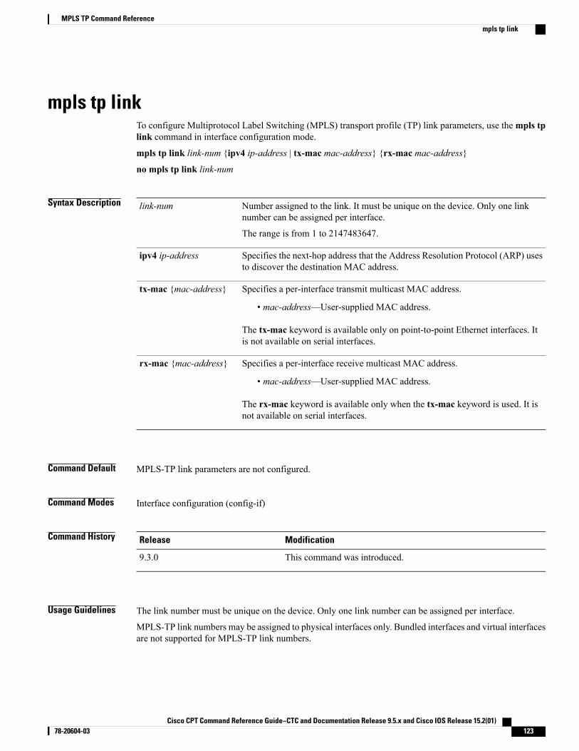
mpls tp linkTo configure Multiprotocol Label Switching (MPLS) transport profile (TP) link parameters, use thempls tplink command in interface configuration mode.
mpls tp link link-num {ipv4 ip-address | tx-mac mac-address} {rx-mac mac-address}
no mpls tp link link-num
Syntax Description Number assigned to the link. It must be unique on the device. Only one linknumber can be assigned per interface.
The range is from 1 to 2147483647.
link-num
Specifies the next-hop address that the Address Resolution Protocol (ARP) usesto discover the destination MAC address.
ipv4 ip-address
Specifies a per-interface transmit multicast MAC address.
• mac-address—User-supplied MAC address.
The tx-mac keyword is available only on point-to-point Ethernet interfaces. Itis not available on serial interfaces.
tx-mac {mac-address}
Specifies a per-interface receive multicast MAC address.
• mac-address—User-supplied MAC address.
The rx-mac keyword is available only when the tx-mac keyword is used. It isnot available on serial interfaces.
rx-mac {mac-address}
Command Default MPLS-TP link parameters are not configured.
Command Modes Interface configuration (config-if)
Command History ModificationRelease
This command was introduced.9.3.0
Usage Guidelines The link number must be unique on the device. Only one link number can be assigned per interface.
MPLS-TP link numbers may be assigned to physical interfaces only. Bundled interfaces and virtual interfacesare not supported for MPLS-TP link numbers.
Cisco CPT Command Reference Guide–CTC and Documentation Release 9.5.x and Cisco IOS Release 15.2(01) 78-20604-03 123
MPLS TP Command Referencempls tp link
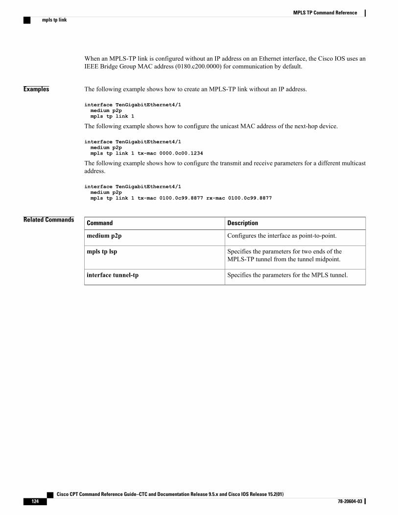
When an MPLS-TP link is configured without an IP address on an Ethernet interface, the Cisco IOS uses anIEEE Bridge Group MAC address (0180.c200.0000) for communication by default.
Examples The following example shows how to create an MPLS-TP link without an IP address.
interface TenGigabitEthernet4/1medium p2pmpls tp link 1
The following example shows how to configure the unicast MAC address of the next-hop device.
interface TenGigabitEthernet4/1medium p2pmpls tp link 1 tx-mac 0000.0c00.1234
The following example shows how to configure the transmit and receive parameters for a different multicastaddress.
interface TenGigabitEthernet4/1medium p2pmpls tp link 1 tx-mac 0100.0c99.8877 rx-mac 0100.0c99.8877
Related Commands DescriptionCommand
Configures the interface as point-to-point.medium p2p
Specifies the parameters for two ends of theMPLS-TP tunnel from the tunnel midpoint.
mpls tp lsp
Specifies the parameters for the MPLS tunnel.interface tunnel-tp
Cisco CPT Command Reference Guide–CTC and Documentation Release 9.5.x and Cisco IOS Release 15.2(01)124 78-20604-03
MPLS TP Command Referencempls tp link
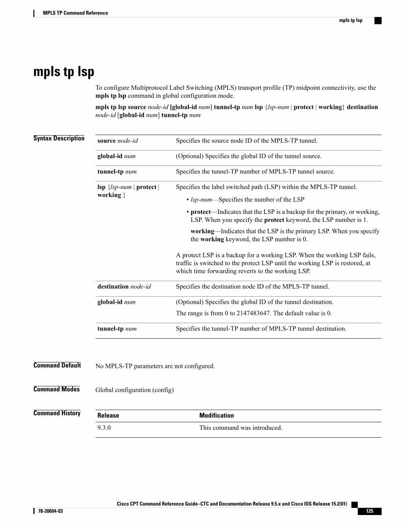
mpls tp lspTo configure Multiprotocol Label Switching (MPLS) transport profile (TP) midpoint connectivity, use thempls tp lsp command in global configuration mode.
mpls tp lsp source node-id [global-id num] tunnel-tp num lsp {lsp-num | protect | working} destinationnode-id [global-id num] tunnel-tp num
Syntax Description Specifies the source node ID of the MPLS-TP tunnel.source node-id
(Optional) Specifies the global ID of the tunnel source.global-id num
Specifies the tunnel-TP number of MPLS-TP tunnel source.tunnel-tp num
Specifies the label switched path (LSP) within the MPLS-TP tunnel.
• lsp-num—Specifies the number of the LSP
• protect—Indicates that the LSP is a backup for the primary, or working,LSP. When you specify the protect keyword, the LSP number is 1.
working—Indicates that the LSP is the primary LSP. When you specifythe working keyword, the LSP number is 0.
A protect LSP is a backup for a working LSP. When the working LSP fails,traffic is switched to the protect LSP until the working LSP is restored, atwhich time forwarding reverts to the working LSP.
lsp {lsp-num | protect |working }
Specifies the destination node ID of the MPLS-TP tunnel.destination node-id
(Optional) Specifies the global ID of the tunnel destination.
The range is from 0 to 2147483647. The default value is 0.
global-id num
Specifies the tunnel-TP number of MPLS-TP tunnel destination.tunnel-tp num
Command Default No MPLS-TP parameters are not configured.
Command Modes Global configuration (config)
Command History ModificationRelease
This command was introduced.9.3.0
Cisco CPT Command Reference Guide–CTC and Documentation Release 9.5.x and Cisco IOS Release 15.2(01) 78-20604-03 125
MPLS TP Command Referencempls tp lsp
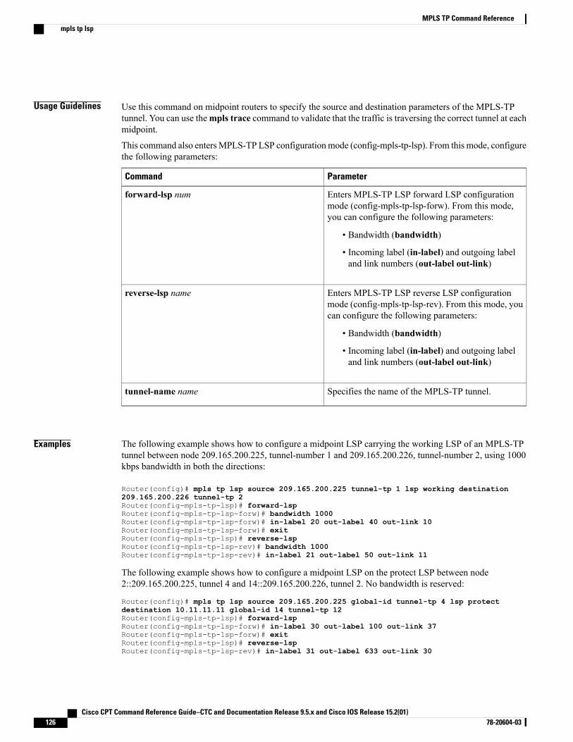
Usage Guidelines Use this command on midpoint routers to specify the source and destination parameters of the MPLS-TPtunnel. You can use thempls trace command to validate that the traffic is traversing the correct tunnel at eachmidpoint.
This command also entersMPLS-TP LSP configurationmode (config-mpls-tp-lsp). From this mode, configurethe following parameters:
ParameterCommand
Enters MPLS-TP LSP forward LSP configurationmode (config-mpls-tp-lsp-forw). From this mode,you can configure the following parameters:
• Bandwidth (bandwidth)
• Incoming label (in-label) and outgoing labeland link numbers (out-label out-link)
forward-lsp num
Enters MPLS-TP LSP reverse LSP configurationmode (config-mpls-tp-lsp-rev). From this mode, youcan configure the following parameters:
• Bandwidth (bandwidth)
• Incoming label (in-label) and outgoing labeland link numbers (out-label out-link)
reverse-lsp name
Specifies the name of the MPLS-TP tunnel.tunnel-name name
Examples The following example shows how to configure a midpoint LSP carrying the working LSP of an MPLS-TPtunnel between node 209.165.200.225, tunnel-number 1 and 209.165.200.226, tunnel-number 2, using 1000kbps bandwidth in both the directions:
Router(config)# mpls tp lsp source 209.165.200.225 tunnel-tp 1 lsp working destination209.165.200.226 tunnel-tp 2Router(config-mpls-tp-lsp)# forward-lspRouter(config-mpls-tp-lsp-forw)# bandwidth 1000Router(config-mpls-tp-lsp-forw)# in-label 20 out-label 40 out-link 10Router(config-mpls-tp-lsp-forw)# exitRouter(config-mpls-tp-lsp)# reverse-lspRouter(config-mpls-tp-lsp-rev)# bandwidth 1000Router(config-mpls-tp-lsp-rev)# in-label 21 out-label 50 out-link 11
The following example shows how to configure a midpoint LSP on the protect LSP between node2::209.165.200.225, tunnel 4 and 14::209.165.200.226, tunnel 2. No bandwidth is reserved:
Router(config)# mpls tp lsp source 209.165.200.225 global-id tunnel-tp 4 lsp protectdestination 10.11.11.11 global-id 14 tunnel-tp 12Router(config-mpls-tp-lsp)# forward-lspRouter(config-mpls-tp-lsp-forw)# in-label 30 out-label 100 out-link 37Router(config-mpls-tp-lsp-forw)# exitRouter(config-mpls-tp-lsp)# reverse-lspRouter(config-mpls-tp-lsp-rev)# in-label 31 out-label 633 out-link 30
Cisco CPT Command Reference Guide–CTC and Documentation Release 9.5.x and Cisco IOS Release 15.2(01)126 78-20604-03
MPLS TP Command Referencempls tp lsp
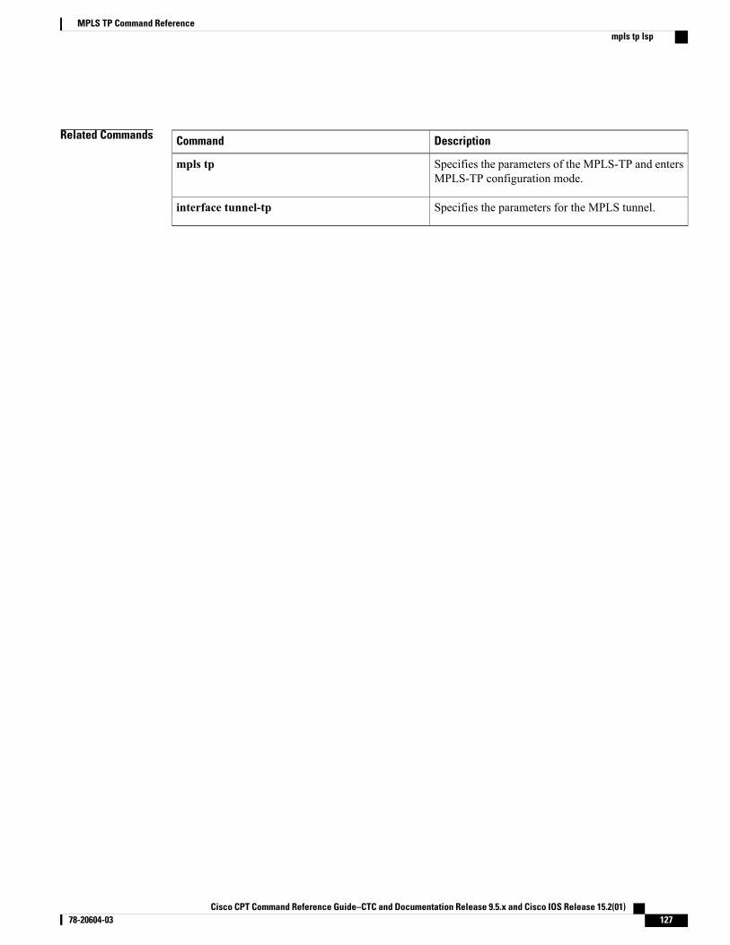
Related Commands DescriptionCommand
Specifies the parameters of the MPLS-TP and entersMPLS-TP configuration mode.
mpls tp
Specifies the parameters for the MPLS tunnel.interface tunnel-tp
Cisco CPT Command Reference Guide–CTC and Documentation Release 9.5.x and Cisco IOS Release 15.2(01) 78-20604-03 127
MPLS TP Command Referencempls tp lsp
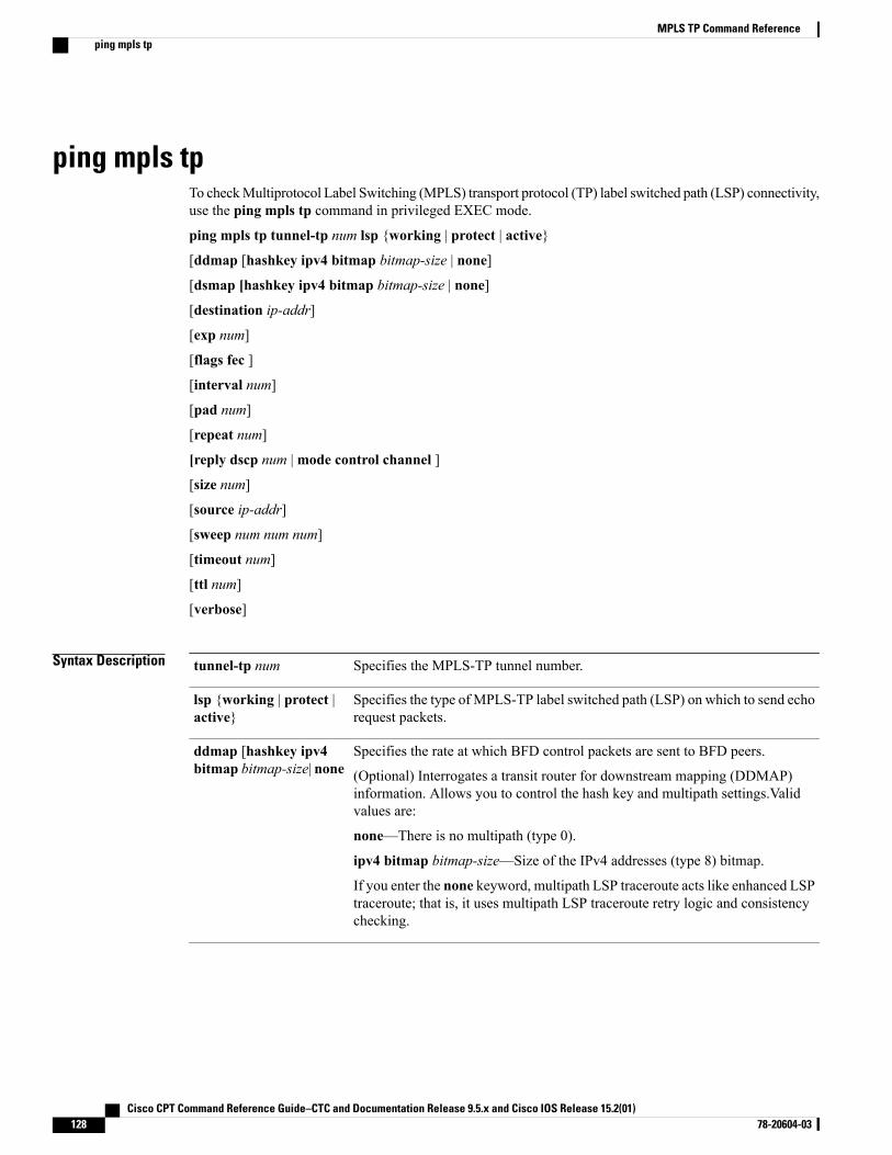
ping mpls tpTo checkMultiprotocol Label Switching (MPLS) transport protocol (TP) label switched path (LSP) connectivity,use the ping mpls tp command in privileged EXEC mode.
ping mpls tp tunnel-tp num lsp {working | protect | active}
[ddmap [hashkey ipv4 bitmap bitmap-size | none]
[dsmap [hashkey ipv4 bitmap bitmap-size | none]
[destination ip-addr]
[exp num]
[flags fec ]
[interval num]
[pad num]
[repeat num]
[reply dscp num |mode control channel ]
[size num]
[source ip-addr]
[sweep num num num]
[timeout num]
[ttl num]
[verbose]
Syntax Description Specifies the MPLS-TP tunnel number.tunnel-tp num
Specifies the type of MPLS-TP label switched path (LSP) on which to send echorequest packets.
lsp {working | protect |active}
Specifies the rate at which BFD control packets are sent to BFD peers.
(Optional) Interrogates a transit router for downstream mapping (DDMAP)information. Allows you to control the hash key and multipath settings.Validvalues are:
none—There is no multipath (type 0).
ipv4 bitmap bitmap-size—Size of the IPv4 addresses (type 8) bitmap.
If you enter the none keyword, multipath LSP traceroute acts like enhanced LSPtraceroute; that is, it uses multipath LSP traceroute retry logic and consistencychecking.
ddmap [hashkey ipv4bitmap bitmap-size| none
Cisco CPT Command Reference Guide–CTC and Documentation Release 9.5.x and Cisco IOS Release 15.2(01)128 78-20604-03
MPLS TP Command Referenceping mpls tp
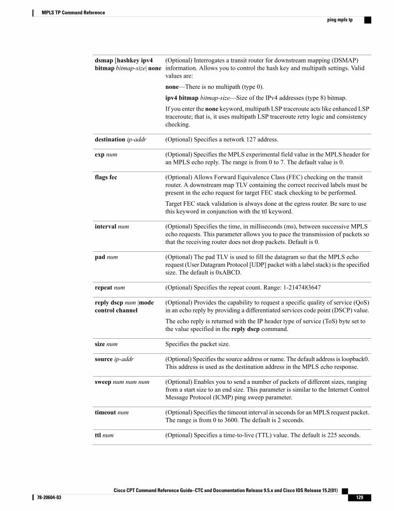
(Optional) Interrogates a transit router for downstream mapping (DSMAP)information. Allows you to control the hash key and multipath settings. Validvalues are:
none—There is no multipath (type 0).
ipv4 bitmap bitmap-size—Size of the IPv4 addresses (type 8) bitmap.
If you enter the none keyword, multipath LSP traceroute acts like enhanced LSPtraceroute; that is, it uses multipath LSP traceroute retry logic and consistencychecking.
dsmap [hashkey ipv4bitmap bitmap-size| none
(Optional) Specifies a network 127 address.destination ip-addr
(Optional) Specifies the MPLS experimental field value in the MPLS header foran MPLS echo reply. The range is from 0 to 7. The default value is 0.
exp num
(Optional) Allows Forward Equivalence Class (FEC) checking on the transitrouter. A downstream map TLV containing the correct received labels must bepresent in the echo request for target FEC stack checking to be performed.
Target FEC stack validation is always done at the egress router. Be sure to usethis keyword in conjunction with the ttl keyword.
flags fec
(Optional) Specifies the time, in milliseconds (ms), between successive MPLSecho requests. This parameter allows you to pace the transmission of packets sothat the receiving router does not drop packets. Default is 0.
interval num
(Optional) The pad TLV is used to fill the datagram so that the MPLS echorequest (User Datagram Protocol [UDP] packet with a label stack) is the specifiedsize. The default is 0xABCD.
pad num
(Optional) Specifies the repeat count. Range: 1-2147483647repeat num
(Optional) Provides the capability to request a specific quality of service (QoS)in an echo reply by providing a differentiated services code point (DSCP) value.
The echo reply is returned with the IP header type of service (ToS) byte set tothe value specified in the reply dscp command.
reply dscp num |modecontrol channel
Specifies the packet size.size num
(Optional) Specifies the source address or name. The default address is loopback0.This address is used as the destination address in the MPLS echo response.
source ip-addr
(Optional) Enables you to send a number of packets of different sizes, rangingfrom a start size to an end size. This parameter is similar to the Internet ControlMessage Protocol (ICMP) ping sweep parameter.
sweep num num num
(Optional) Specifies the timeout interval in seconds for anMPLS request packet.The range is from 0 to 3600. The default is 2 seconds.
timeout num
(Optional) Specifies a time-to-live (TTL) value. The default is 225 seconds.ttl num
Cisco CPT Command Reference Guide–CTC and Documentation Release 9.5.x and Cisco IOS Release 15.2(01) 78-20604-03 129
MPLS TP Command Referenceping mpls tp
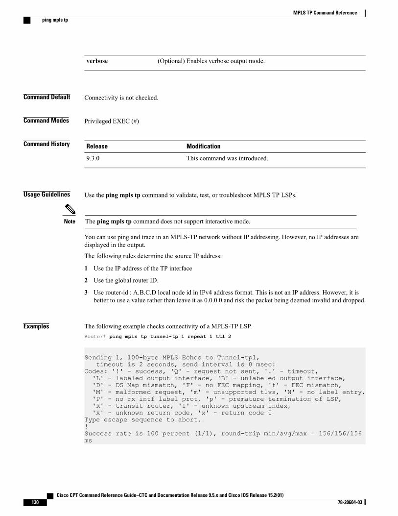
(Optional) Enables verbose output mode.verbose
Command Default Connectivity is not checked.
Command Modes Privileged EXEC (#)
Command History ModificationRelease
This command was introduced.9.3.0
Usage Guidelines Use the ping mpls tp command to validate, test, or troubleshoot MPLS TP LSPs.
The ping mpls tp command does not support interactive mode.Note
You can use ping and trace in an MPLS-TP network without IP addressing. However, no IP addresses aredisplayed in the output.
The following rules determine the source IP address:
1 Use the IP address of the TP interface
2 Use the global router ID.
3 Use router-id : A.B.C.D local node id in IPv4 address format. This is not an IP address. However, it isbetter to use a value rather than leave it as 0.0.0.0 and risk the packet being deemed invalid and dropped.
Examples The following example checks connectivity of a MPLS-TP LSP.Router# ping mpls tp tunnel-tp 1 repeat 1 ttl 2
Sending 1, 100-byte MPLS Echos to Tunnel-tp1,timeout is 2 seconds, send interval is 0 msec:
Codes: '!' - success, 'Q' - request not sent, '.' - timeout,'L' - labeled output interface, 'B' - unlabeled output interface,'D' - DS Map mismatch, 'F' - no FEC mapping, 'f' - FEC mismatch,'M' - malformed request, 'm' - unsupported tlvs, 'N' - no label entry,'P' - no rx intf label prot, 'p' - premature termination of LSP,'R' - transit router, 'I' - unknown upstream index,'X' - unknown return code, 'x' - return code 0
Type escape sequence to abort.!Success rate is 100 percent (1/1), round-trip min/avg/max = 156/156/156ms
Cisco CPT Command Reference Guide–CTC and Documentation Release 9.5.x and Cisco IOS Release 15.2(01)130 78-20604-03
MPLS TP Command Referenceping mpls tp

Related Commands DescriptionCommand
Displays the MPLS LSP routes that packets take totheir destinations.
trace mpls tp
Cisco CPT Command Reference Guide–CTC and Documentation Release 9.5.x and Cisco IOS Release 15.2(01) 78-20604-03 131
MPLS TP Command Referenceping mpls tp
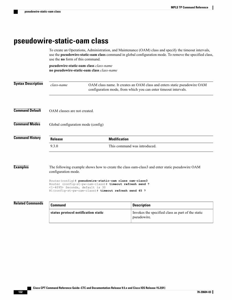
pseudowire-static-oam classTo create an Operations, Administration, and Maintenance (OAM) class and specify the timeout intervals,use the pseudowire-static-oam class command in global configuration mode. To remove the specified class,use the no form of this command.
pseudowire-static-oam class class-nameno pseudowire-static-oam class class-name
Syntax Description OAM class name. It creates an OAM class and enters static pseudowire OAMconfiguration mode, from which you can enter timeout intervals.
class-name
Command Default OAM classes are not created.
Command Modes Global configuration mode (config)
Command History ModificationRelease
This command was introduced.9.3.0
Examples The following example shows how to create the class oam-class3 and enter static pseudowire OAMconfiguration mode.
Router(config)# pseudowire-static-oam class oam-class3Router (config-st-pw-oam-class)# timeout refresh send ?<1-4095> Seconds, default is 30R1(config-st-pw-oam-class)# timeout refresh send 45 ?
Related Commands DescriptionCommand
Invokes the specified class as part of the staticpseudowire.
status protocol notification static
Cisco CPT Command Reference Guide–CTC and Documentation Release 9.5.x and Cisco IOS Release 15.2(01)132 78-20604-03
MPLS TP Command Referencepseudowire-static-oam class
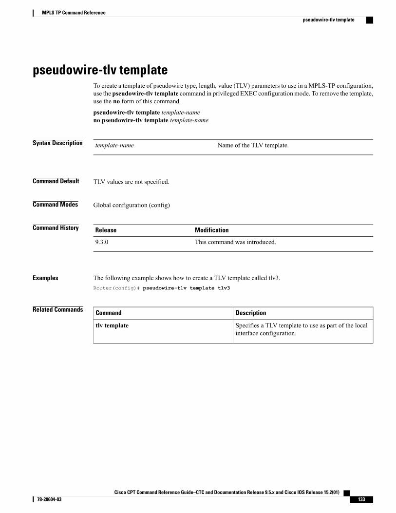
pseudowire-tlv templateTo create a template of pseudowire type, length, value (TLV) parameters to use in a MPLS-TP configuration,use the pseudowire-tlv template command in privileged EXEC configurationmode. To remove the template,use the no form of this command.
pseudowire-tlv template template-nameno pseudowire-tlv template template-name
Syntax Description Name of the TLV template.template-name
Command Default TLV values are not specified.
Command Modes Global configuration (config)
Command History ModificationRelease
This command was introduced.9.3.0
Examples The following example shows how to create a TLV template called tlv3.Router(config)# pseudowire-tlv template tlv3
Related Commands DescriptionCommand
Specifies a TLV template to use as part of the localinterface configuration.
tlv template
Cisco CPT Command Reference Guide–CTC and Documentation Release 9.5.x and Cisco IOS Release 15.2(01) 78-20604-03 133
MPLS TP Command Referencepseudowire-tlv template
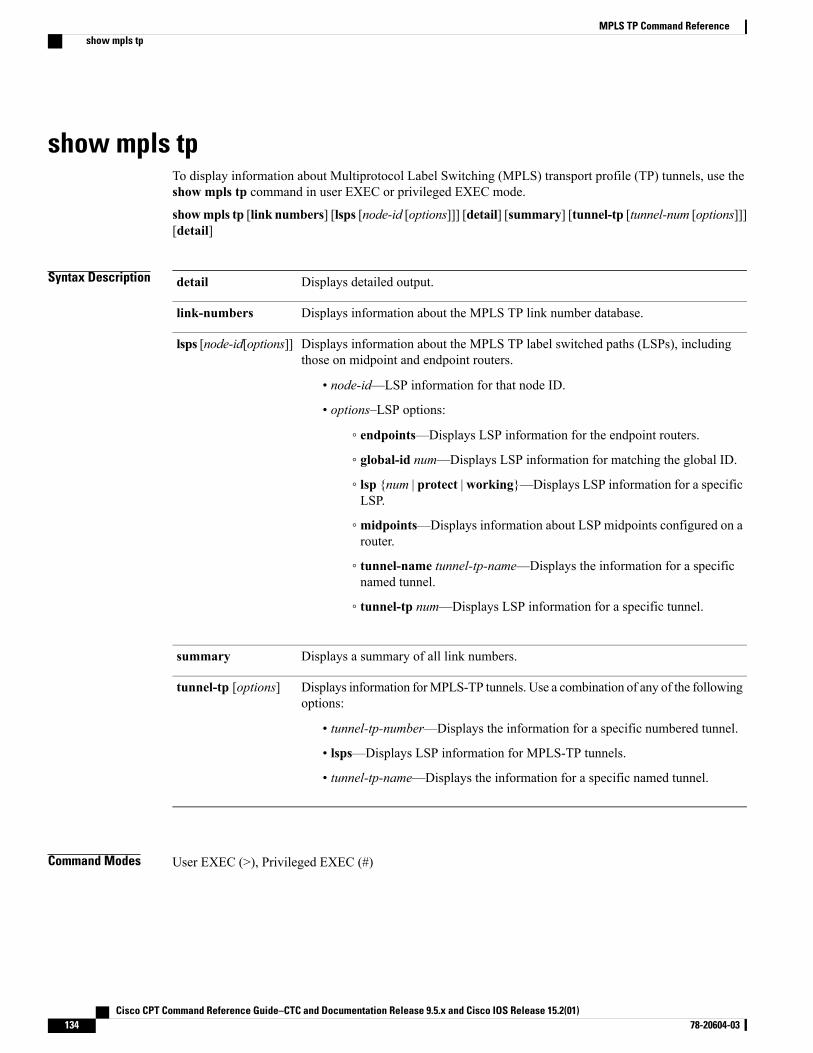
show mpls tpTo display information about Multiprotocol Label Switching (MPLS) transport profile (TP) tunnels, use theshow mpls tp command in user EXEC or privileged EXEC mode.
showmpls tp [link numbers] [lsps [node-id [options]]] [detail] [summary] [tunnel-tp [tunnel-num [options]]][detail]
Syntax Description Displays detailed output.detail
Displays information about the MPLS TP link number database.link-numbers
Displays information about the MPLS TP label switched paths (LSPs), includingthose on midpoint and endpoint routers.
• node-id—LSP information for that node ID.
• options–LSP options:
◦ endpoints—Displays LSP information for the endpoint routers.
◦ global-id num—Displays LSP information for matching the global ID.
◦ lsp {num | protect | working}—Displays LSP information for a specificLSP.
◦ midpoints—Displays information about LSP midpoints configured on arouter.
◦ tunnel-name tunnel-tp-name—Displays the information for a specificnamed tunnel.
◦ tunnel-tp num—Displays LSP information for a specific tunnel.
lsps [node-id[options]]
Displays a summary of all link numbers.summary
Displays information forMPLS-TP tunnels. Use a combination of any of the followingoptions:
• tunnel-tp-number—Displays the information for a specific numbered tunnel.
• lsps—Displays LSP information for MPLS-TP tunnels.
• tunnel-tp-name—Displays the information for a specific named tunnel.
tunnel-tp [options]
Command Modes User EXEC (>), Privileged EXEC (#)
Cisco CPT Command Reference Guide–CTC and Documentation Release 9.5.x and Cisco IOS Release 15.2(01)134 78-20604-03
MPLS TP Command Referenceshow mpls tp
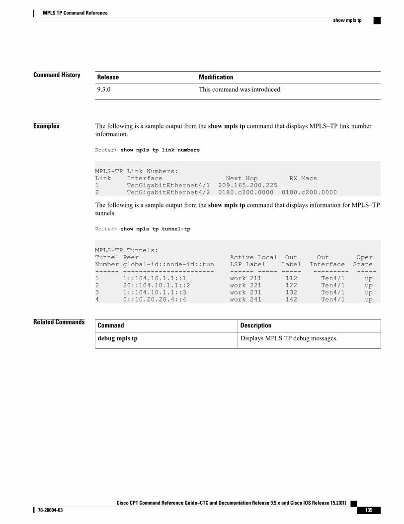
Command History ModificationRelease
This command was introduced.9.3.0
Examples The following is a sample output from the show mpls tp command that displays MPLS–TP link numberinformation.
Router> show mpls tp link-numbers
MPLS-TP Link Numbers:Link Interface Next Hop RX Macs1 TenGigabitEthernet4/1 209.165.200.2252 TenGigabitEthernet4/2 0180.c200.0000 0180.c200.0000
The following is a sample output from the show mpls tp command that displays information for MPLS–TPtunnels.
Router> show mpls tp tunnel-tp
MPLS-TP Tunnels:Tunnel Peer Active Local Out Out OperNumber global-id::node-id::tun LSP Label Label Interface State------ ----------------------- ------ ----- ----- --------- -----1 1::104.10.1.1::1 work 211 112 Ten4/1 up2 20::104.10.1.1::2 work 221 122 Ten4/1 up3 1::104.10.1.1::3 work 231 132 Ten4/1 up4 0::10.20.20.4::4 work 241 142 Ten4/1 up
Related Commands DescriptionCommand
Displays MPLS TP debug messages.debug mpls tp
Cisco CPT Command Reference Guide–CTC and Documentation Release 9.5.x and Cisco IOS Release 15.2(01) 78-20604-03 135
MPLS TP Command Referenceshow mpls tp
status protocol notification staticTo enable the timers set in the specified class name, use the status protocol notification static command inpseudowire-class configuration mode. To disable the use of the specified class, use the no form of thiscommand.
status protocol notification static class-nameno status protocol notification static class-name
Syntax Description OAMclass that was createdwith the pseudowire-static-oam-class command.class-name
Command Default OAM classes are not specified.
Command Modes Pseudowire-class (config-pw-class)
Command History ModificationRelease
This command was introduced.9.3.0
Examples The following example shows how to enable the timers in class oam-class3.Router(config-pw-class)# status protocol notification static oam-class3
Related Commands DescriptionCommand
Creates a class that defines the OAM parameters forthe pseudowire.
pseudowire-static-oam class
Cisco CPT Command Reference Guide–CTC and Documentation Release 9.5.x and Cisco IOS Release 15.2(01)136 78-20604-03
MPLS TP Command Referencestatus protocol notification static
tlv templateTo use the pseudowire type, length, value (TLV) parameters created with the pseudowire-tlv templatecommand, use the tlv template command in VFI neighbor interface configuration mode. To remove the TLVtemplate, use the no form of this command.
tlv template template-nameno tlv template template-name
Syntax Description Name of the TLV template that was created with the pseudowire-tlvtemplate command.
template-name
Command Default No TLV template is used.
Command Modes VFI neighbor interface configuration mode (config-vfi-neighbor-interface)
Command History ModificationRelease
This command was introduced.9.3.0
Usage Guidelines Ensure that you create the template with the pseudowire-tlv template command before specifying the templateas part of the local interface configuration.
Examples The following example shows how to use a TLV template called net.Router(config-vfi-neighbor-interface)# tlv template net
Related Commands DescriptionCommand
Creates a template of TLV parameters to use in anMPLS-TP configuration.
pseudowire-tlv template
Cisco CPT Command Reference Guide–CTC and Documentation Release 9.5.x and Cisco IOS Release 15.2(01) 78-20604-03 137
MPLS TP Command Referencetlv template
trace mpls tpTo display the Multiprotocol Label Switching (MPLS) transport protocol (TP) label switched path (LSP)routes that packets take to their destinations, use the trace mpls tp command in privileged EXEC mode.
trace mpls tp tunnel-tp num lsp {working | protect | active}
[destination ip-addr]
[exp num]
[flags fec ]
[reply dscp num |mode control channel ]
[source ip-addr]
[timeout num]
[ttl num]
[verbose]
Syntax Description Specifies the MPLS-TP tunnel number.tunnel-tp num
Specifies the type of MPLS-TP label switched path (LSP) on which to sendecho request packets.
lsp {working | protect |active}
(Optional) Specifies a network 127 address.destination ip-addr
(Optional) Specifies the MPLS experimental field value in the MPLS headerfor an MPLS echo reply. Valid values are from 0 to 7. Default is 0.
exp num
(Optional) Allows Forward Equivalence Class (FEC) checking on the transitrouter. A downstream map TLV containing the correct received labels mustbe present in the echo request for target FEC stack checking to be performed.
Target FEC stack validation is always done at the egress router. Be sure to usethis keyword in conjunction with the ttl keyword.
flags fec
(Optional) Provides the capability to request a specific quality of service (QoS)in an echo reply by providing a differentiated services code point (DSCP) value.
The echo reply is returned with the IP header type of service (ToS) byte set tothe value specified in the reply dscp command.
reply dscp num |modecontrol channel
Specifies the packet size.size num
(Optional) Specifies the source address or name. The default address isloopback0. This address is used as the destination address in the MPLS echoresponse.
source ip-addr
(Optional) Specifies the timeout interval in seconds for anMPLS request packet.The range is from 0 to 3600. The default is 2 seconds.
timeout num
Cisco CPT Command Reference Guide–CTC and Documentation Release 9.5.x and Cisco IOS Release 15.2(01)138 78-20604-03
MPLS TP Command Referencetrace mpls tp
(Optional) Specifies a time-to-live (TTL) value. The default is 225 seconds.ttl num
(Optional) Enables verbose output mode.verbose
Command Default Connectivity is not checked.
Command Modes Privileged EXEC (#)
Command History ModificationRelease
This command was introduced.9.3.0
Usage Guidelines Use the trace mpls tp command to validate, test, or troubleshoot MPLS TP LSPs.
The trace mpls tp command does not support interactive mode.Note
You can use ping and trace in an MPLS-TP network without IP addressing. However, no IP addresses aredisplayed in the output.
The following rules determine the source IP address:
1 Use the IP address of the TP interface
2 Use the global router ID.
3 Use router-id : A.B.C.D local node id in IPv4 address format. This is not an IP address. However, it isbetter to use a value rather than leave it as 0.0.0.0 and risk the packet being deemed invalid and dropped.
Examples The following example checks connectivity of an MPLS-TP LSP:Router# trace mpls tp tunnel-tp 1 lsp working verbose
Tracing MPLS TP Label Switched Path on Tunnel-tp1, timeout is 2 seconds
Codes: '!' - success, 'Q' - request not sent, '.' - timeout,'L' - labeled output interface, 'B' - unlabeled output interface,'D' - DS Map mismatch, 'F' - no FEC mapping, 'f' - FEC mismatch,'M' - malformed request, 'm' - unsupported tlvs, 'N' - no label entry,'P' - no rx intf label prot, 'p' - premature termination of LSP,'R' - transit router, 'I' - unknown upstream index,'l' - Label switched with FEC change, 'd' - see DDMAP for return code,'X' - unknown return code, 'x' - return code 0
Type escape sequence to abort.0 1.1.1.5 127.0.0.1 MRU 1500 [Labels: 444 Exp: 0]
Cisco CPT Command Reference Guide–CTC and Documentation Release 9.5.x and Cisco IOS Release 15.2(01) 78-20604-03 139
MPLS TP Command Referencetrace mpls tp
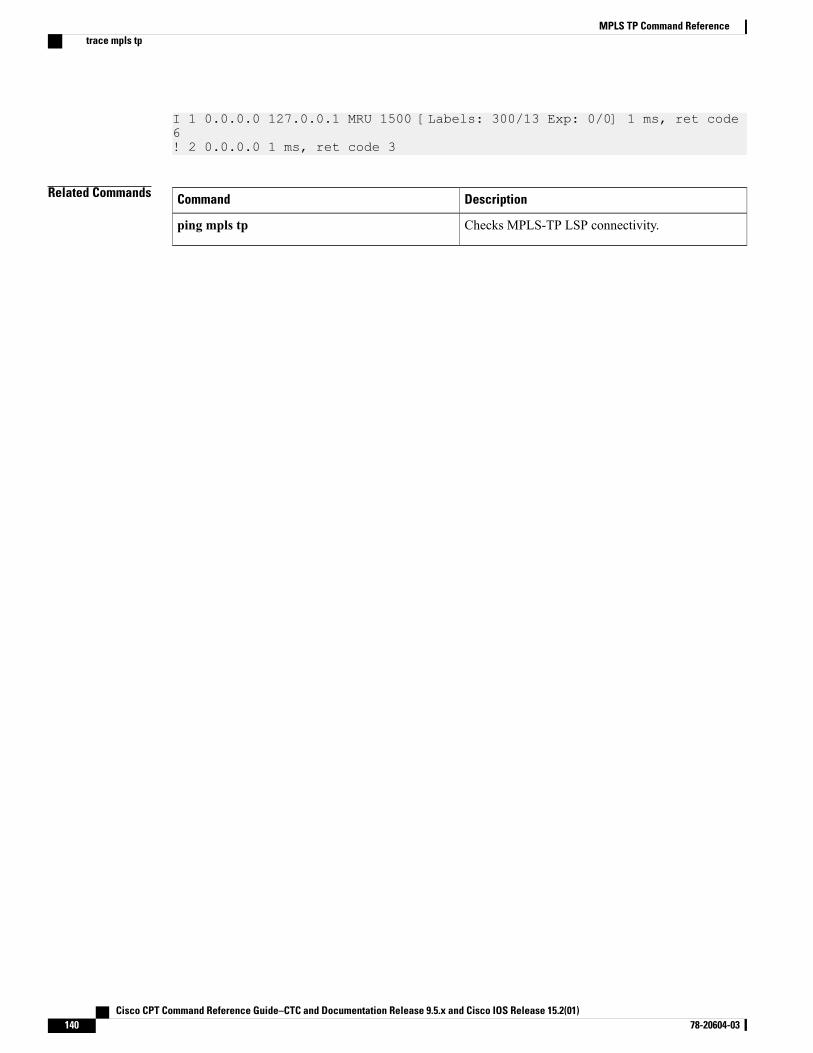
I 1 0.0.0.0 127.0.0.1 MRU 1500 [Labels: 300/13 Exp: 0/0] 1 ms, ret code6! 2 0.0.0.0 1 ms, ret code 3
Related Commands DescriptionCommand
Checks MPLS-TP LSP connectivity.ping mpls tp
Cisco CPT Command Reference Guide–CTC and Documentation Release 9.5.x and Cisco IOS Release 15.2(01)140 78-20604-03
MPLS TP Command Referencetrace mpls tp
Pseudowire Command Reference
This chapter describes commands used to configure the pseudowire.
• backup delay, page 142
• backup peer, page 143
• encapsulation (pseudowire), page 145
• interworking, page 146
• l2 vfi point-to-point, page 147
• local link notification, page 148
• mpls control-word, page 149
• mpls label, page 151
• mtu, page 153
• neighbor (L2VPN Pseudowire Stitching), page 154
• preferred-path, page 155
• pseudowire-class, page 157
• pseudowire, page 159
• remote link failure notification, page 161
• show mpls l2transport binding, page 162
• show mpls l2transport vc, page 163
• status redundancy, page 166
• status (pseudowire class), page 167
• switching tlv, page 168
• vccv, page 170
• vccv bfd status signaling, page 172
• vccv bfd template, page 174
• xconnect, page 176
Cisco CPT Command Reference Guide–CTC and Documentation Release 9.5.x and Cisco IOS Release 15.2(01) 78-20604-03 141
backup delayTo specify how long a backup pseudowire virtual circuit (VC) must wait before resuming operation after theprimary pseudowire VC goes down, use the backup delay command in xconnect configuration mode.
backup delay enable-delay {disable-delay | never}
Syntax Description Number of seconds that elapse after the primary pseudowire VC goes down before thesecondary pseudowire VC is activated. The range is 0 to 180 seconds. The defaultvalue is 0 seconds.
enable-delay
Number of seconds that elapse after the primary pseudowire VC comes up before thesecondary pseudowire VC is deactivated. The range is 0 to 180 seconds. The defaultvalue is 0 seconds.
disable-delay
Indicates that the secondary pseudowire VCwill not fall back to the primary pseudowireVC if the primary pseudowire VC becomes available again unless the secondarypseudowire VC fails.
never
Command Modes Xconnect configuration (config-if-xconn)
Command History ModificationRelease
This command was introduced.9.3.0
Examples The following example shows how to create a xconnect with one redundant peer. After a switchover to thesecondary VC occurs, there will be no fallback to the primary VC unless the secondary VC fails.
Router(config)# pseudowire-class mplsRouter(config-pw-class)# encapsulation mplsRouter(config-if)# xconnect 10.0.0.1 50 pw-class mplsRouter(config-if-xconn)# backup peer 10.0.0.2 50Router(config-if-xconn)# backup delay 0 never
Related Commands DescriptionCommand
Configures a redundant peer for a pseudowire VC.backup peer
Cisco CPT Command Reference Guide–CTC and Documentation Release 9.5.x and Cisco IOS Release 15.2(01)142 78-20604-03
Pseudowire Command Referencebackup delay
backup peerTo specify a redundant peer for a pseudowire virtual circuit (VC), use the backup peer command in xconnectconfiguration mode. To remove the redundant peer, use the no form of this command.
backup peer peer-router-ip-addr vcid [pw-class pw-class-name]
no backup peer peer-router-ip-addr vcid
Syntax Description IP address of the remote peer.peer-router-ip-addr
32-bit identifier of the virtual circuit between the routers at each end ofthe layer control channel.
vcid
(Optional) Specifies the pseudowire class.pw-class
(Optional) Name of the pseudowire class.pw-class-name
Command Default A redundant peer is not established.
Command Modes Xconnect configuration (config-if-xconn)
Command History ModificationRelease
This command was introduced.9.3.0
Usage Guidelines The combination of the peer-router-ip-addr and vcid arguments must be unique on the router.
Examples The following example shows how to create an MPLS xconnect with one redundant peer.
Router(config)# pseudowire-class mplsRouter(config-pw-class)# encapsulation mpls
Router(config)# interface TenGigabitEthernet4/1Router(config-if)# xconnect 10.0.0.1 100 pw-class mplsRouter(config-if-xconn)# backup peer 10.0.0.2 200
Related Commands DescriptionCommand
Specifies how long the backup pseudowire VC mustwait before resuming operation after the primarypseudowire VC goes down.
backup delay
Cisco CPT Command Reference Guide–CTC and Documentation Release 9.5.x and Cisco IOS Release 15.2(01) 78-20604-03 143
Pseudowire Command Referencebackup peer

Cisco CPT Command Reference Guide–CTC and Documentation Release 9.5.x and Cisco IOS Release 15.2(01)144 78-20604-03
Pseudowire Command Referencebackup peer
encapsulation (pseudowire)To specify an encapsulation type for tunneling Layer 2 traffic over a pseudowire, use the encapsulationcommand in pseudowire class configuration mode.
encapsulation mpls
Syntax Description Specifies that MPLS is used as the data encapsulation method.mpls
Command Default Encapsulation type for tunneling Layer 2 traffic is not configured.
Command Modes Pseudowire-class configuration (config-pw-class)
Command History ModificationRelease
This command was introduced.9.3.0
Examples The following example shows how to configure MPLS as the data encapsulation method for the pseudowireclass ether-pw.
Router(config)# pseudowire-class ether-pwRouter(config-pw-class)# encapsulation mpls
Related Commands DescriptionCommand
Binds an attachment circuit to a pseudowire forxconnect service and enters xconnect configurationmode.
xconnect
Specifies the name of a pseudowire class and enterspseudowire class configuration mode.
pseudowire-class
Cisco CPT Command Reference Guide–CTC and Documentation Release 9.5.x and Cisco IOS Release 15.2(01) 78-20604-03 145
Pseudowire Command Referenceencapsulation (pseudowire)
interworkingTo enable the L2VPN Interworking feature, use the interworking command in pseudowire class configurationmode. To disable the L2VPN Interworking feature, use the no form of this command.
interworking {ethernet | vlan}
no interworking {ethernet | vlan}
Syntax Description Enables Ethernet frames to be extracted from the attachment circuit and sent over thepseudowire. Ethernet end-to-end transmission is assumed. Attachment circuit frames thatdo not contain Ethernet frames are dropped. In the case of VLAN, the VLAN tag is removed,which leaves a pure Ethernet frame.
ethernet
Enables Ethernet frames and the VLAN tag to be sent over the pseudowire. Ethernetend-to-end transmission is assumed. Attachment circuit frames that do not contain Ethernetframes are dropped.
vlan
Command Default L2VPN interworking is not enabled.
Command Modes Pseudowire class configuration (config-pw)
Command History ModificationRelease
This command was introduced.9.3.0
Examples The following example shows how to create a pseudowire class configuration that enables the L2VPNInterworking feature.
Router(config)# pseudowire-class ip-interworkingRouter(config-pw)# encapsulation mplsRouter(config-pw)# interworking ethernet
Related Commands DescriptionCommand
Specifies that MPLS is used as the data encapsulationmethod for tunneling Layer 2 traffic over thepseudowire.
encapsulation mpls
Cisco CPT Command Reference Guide–CTC and Documentation Release 9.5.x and Cisco IOS Release 15.2(01)146 78-20604-03
Pseudowire Command Referenceinterworking
l2 vfi point-to-pointTo establish a point-to-point Layer 2 virtual forwarding interface (VFI) between two separate networks, usethe l2 vfi point-to-point command in global configuration mode. To disable the connection, use the no formof this command.
l2 vfi name point-to-point
no l2 vfi name point-to-point
Syntax Description Name of the connection between the two networks.name
Command Default Point-to-point Layer 2 virtual forwarding interfaces are not created.
Command Modes Global configuration (config)
Command History ModificationRelease
This command was introduced.9.3.0
Usage Guidelines If you disable L2VPN Pseudowire Stitching with the no l2 vfi point-to-point command, the virtual circuits(VCs) are deleted.
Examples The following example shows how to establish a point-to-point Layer 2 VFI.
Router(config)# l2 vfi atomvfi point-to-point
Related Commands DescriptionCommand
Establishes the two routers with which to form aconnection.
neighbor (L2VPN Pseudowire Stitching)
Cisco CPT Command Reference Guide–CTC and Documentation Release 9.5.x and Cisco IOS Release 15.2(01) 78-20604-03 147
Pseudowire Command Referencel2 vfi point-to-point
local link notificationTo specify the soak time for an interface, use the local link notification command in interface configurationmode.
local link notification soak-duration duration
Syntax Description Specifies the soak time for an interface in seconds. The validvalues range from 0 to 300. The default is 10.
soak-duration duration
Command Modes Interface configuration (config-if)
Command History ModificationRelease
This command was introduced.9.5.0
Usage Guidelines The soak time can be configured even if the Remote Ethernet Port Shutdown feature is disabled. However,the soak time is effective only when the Remote Ethernet Port Shutdown feature is enabled.
The soak time applies only to the individual ports. It does not apply to the ports of a channel group if thechannel group is configured as an attachment circuit.
Examples The following example shows how to specify the soak time for an interface:
Router> enableRouter# configure terminalRouter(config)# interface TenGigabitEthernet4/1Router(config-if)# local link notification soak-duration 30Router(config-if)# exit
Related Commands DescriptionCommand
Enables the Remote Ethernet Port Shutdown featureon an interface.
remote link failure notification
Cisco CPT Command Reference Guide–CTC and Documentation Release 9.5.x and Cisco IOS Release 15.2(01)148 78-20604-03
Pseudowire Command Referencelocal link notification
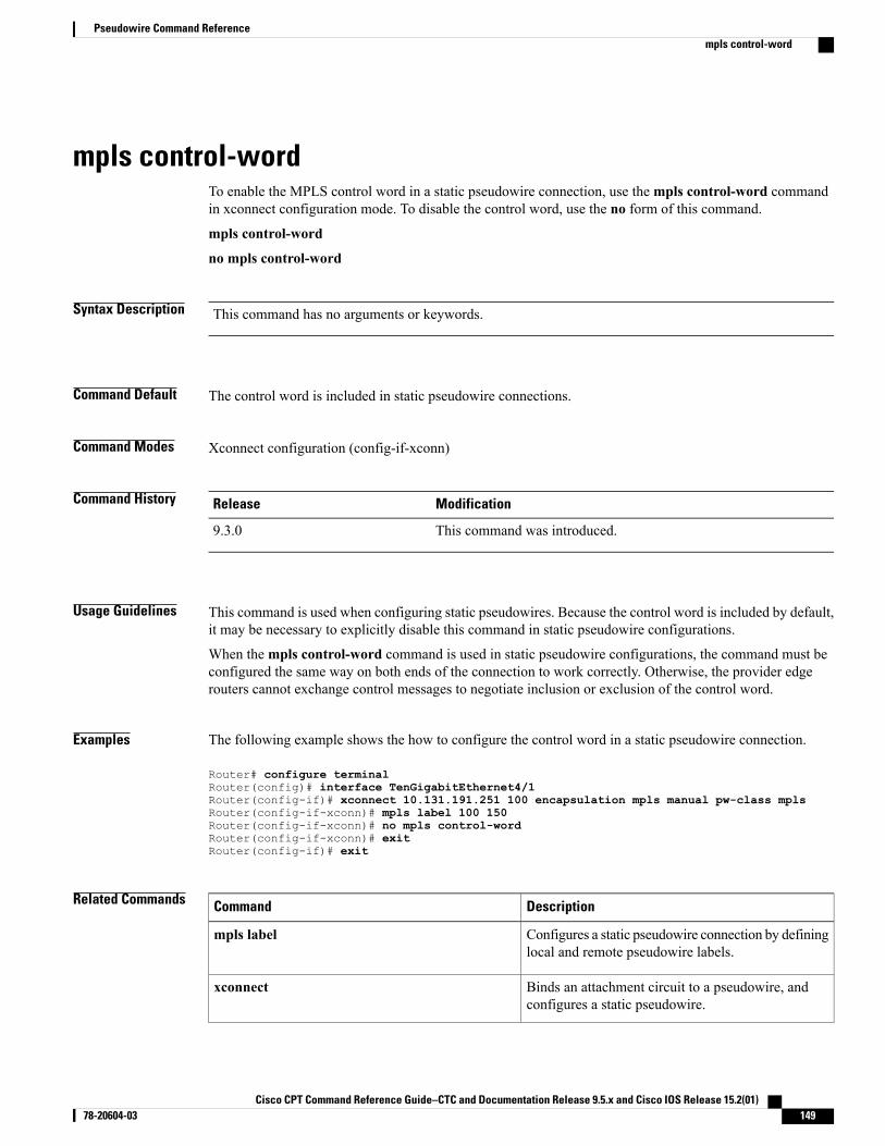
mpls control-wordTo enable the MPLS control word in a static pseudowire connection, use thempls control-word commandin xconnect configuration mode. To disable the control word, use the no form of this command.
mpls control-word
no mpls control-word
Syntax Description This command has no arguments or keywords.
Command Default The control word is included in static pseudowire connections.
Command Modes Xconnect configuration (config-if-xconn)
Command History ModificationRelease
This command was introduced.9.3.0
Usage Guidelines This command is used when configuring static pseudowires. Because the control word is included by default,it may be necessary to explicitly disable this command in static pseudowire configurations.
When thempls control-word command is used in static pseudowire configurations, the command must beconfigured the same way on both ends of the connection to work correctly. Otherwise, the provider edgerouters cannot exchange control messages to negotiate inclusion or exclusion of the control word.
Examples The following example shows the how to configure the control word in a static pseudowire connection.
Router# configure terminalRouter(config)# interface TenGigabitEthernet4/1Router(config-if)# xconnect 10.131.191.251 100 encapsulation mpls manual pw-class mplsRouter(config-if-xconn)# mpls label 100 150Router(config-if-xconn)# no mpls control-wordRouter(config-if-xconn)# exitRouter(config-if)# exit
Related Commands DescriptionCommand
Configures a static pseudowire connection by defininglocal and remote pseudowire labels.
mpls label
Binds an attachment circuit to a pseudowire, andconfigures a static pseudowire.
xconnect
Cisco CPT Command Reference Guide–CTC and Documentation Release 9.5.x and Cisco IOS Release 15.2(01) 78-20604-03 149
Pseudowire Command Referencempls control-word

DescriptionCommand
Displays information about virtual circuits and staticpseudowires that are enabled to route Layer 2 packetson a router.
show mpls l2transport vc
Cisco CPT Command Reference Guide–CTC and Documentation Release 9.5.x and Cisco IOS Release 15.2(01)150 78-20604-03
Pseudowire Command Referencempls control-word
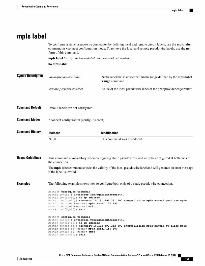
mpls labelTo configure a static pseudowire connection by defining local and remote circuit labels, use thempls labelcommand in xconnect configuration mode. To remove the local and remote pseudowire labels, use the noform of this command.
mpls label local-pseudowire-label remote-pseudowire-label
no mpls label
Syntax Description Static label that is unused within the range defined by thempls labelrange command.
local-pseudowire-label
Value of the local pseudowire label of the peer provider edge router.remote-pseudowire-label
Command Default Default labels are not configured.
Command Modes Xconnect configuration (config-if-xconn)
Command History ModificationRelease
This command was introduced.9.3.0
Usage Guidelines This command is mandatory when configuring static pseudowires, and must be configured at both ends ofthe connection.
Thempls label command checks the validity of the local pseudowire label and will generate an error messageif the label is invalid.
Examples The following example shows how to configure both ends of a static pseudowire connection.
Router# configure terminalRouter(config)# interface TenGigabitEthernet4/1Router(config-if)# no ip addressRouter(config-if)# xconnect 10.131.191.251 100 encapsulation mpls manual pw-class mplsRouter(config-if-xconn)# mpls label 100 150Router(config-if-xconn)# exitRouter(config-if)# exit
Router# configure terminalRouter(config)# interface TenGigabitEthernet4/1Router(config-if)# no ip addressRouter(config-if)# xconnect 10.132.192.252 100 encapsulation mpls manual pw-class mplsRouter(config-if-xconn)# mpls label 150 100Router(config-if-xconn)# exitRouter(config-if)# exit
Cisco CPT Command Reference Guide–CTC and Documentation Release 9.5.x and Cisco IOS Release 15.2(01) 78-20604-03 151
Pseudowire Command Referencempls label
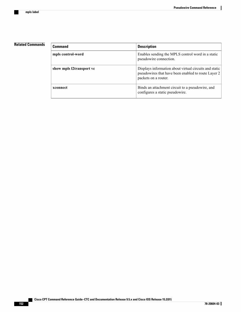
Related Commands DescriptionCommand
Enables sending the MPLS control word in a staticpseudowire connection.
mpls control-word
Displays information about virtual circuits and staticpseudowires that have been enabled to route Layer 2packets on a router.
show mpls l2transport vc
Binds an attachment circuit to a pseudowire, andconfigures a static pseudowire.
xconnect
Cisco CPT Command Reference Guide–CTC and Documentation Release 9.5.x and Cisco IOS Release 15.2(01)152 78-20604-03
Pseudowire Command Referencempls label
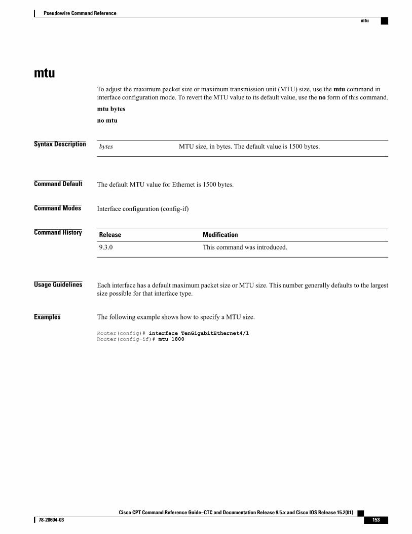
mtuTo adjust the maximum packet size or maximum transmission unit (MTU) size, use themtu command ininterface configuration mode. To revert the MTU value to its default value, use the no form of this command.
mtu bytes
no mtu
Syntax Description MTU size, in bytes. The default value is 1500 bytes.bytes
Command Default The default MTU value for Ethernet is 1500 bytes.
Command Modes Interface configuration (config-if)
Command History ModificationRelease
This command was introduced.9.3.0
Usage Guidelines Each interface has a default maximum packet size or MTU size. This number generally defaults to the largestsize possible for that interface type.
Examples The following example shows how to specify a MTU size.
Router(config)# interface TenGigabitEthernet4/1Router(config-if)# mtu 1800
Cisco CPT Command Reference Guide–CTC and Documentation Release 9.5.x and Cisco IOS Release 15.2(01) 78-20604-03 153
Pseudowire Command Referencemtu
neighbor (L2VPN Pseudowire Stitching)To specify the routers that must form a point-to-point Layer 2 virtual forwarding interface (VFI) connection,use the neighbor command in L2 VFI point-to-point configuration mode. To disconnect the routers, use theno form of this command.
neighbor ip-address vcid {encapsulation mpls | pw-class pw-class-name}
no neighbor ip-address vcid {encapsulation mpls | pw-class pw-class-name}
Syntax Description IP address of the VFI neighbor.ip-address
Virtual circuit (VC) identifier.vc-id
Specifies the encapsulation type.encapsulation mpls
Specifies the pseudowire type.pw-class
Name of the pseudowire you created when you established thepseudowire class.
pw-class-name
Command Default Routers do not form a point-to-point Layer 2 VFI connection.
Command Modes L2 VFI point-to-point configuration (config-vfi)
Command History ModificationRelease
This command was introduced.9.3.0
Usage Guidelines A maximum of two neighbor commands are allowed when you issue the l2 vfi point-to-point command.
Examples The following example shows how to configure a Layer 2 VFI connection.
Router(config)# l2 vfi atom point-to-pointRouter(config-vfi)# neighbor 10.10.10.10 1 encapsulation mpls
Related Commands DescriptionCommand
Establishes a point-to-point Layer 2 VFI between twoseparate networks.
l2 vfi point-to-point
Cisco CPT Command Reference Guide–CTC and Documentation Release 9.5.x and Cisco IOS Release 15.2(01)154 78-20604-03
Pseudowire Command Referenceneighbor (L2VPN Pseudowire Stitching)
preferred-pathTo specify the Multiprotocol Label Switching Transport Profile (MPLS-TP) or MPLS Traffic Engineering(MPLS-TE) tunnel path that the traffic uses, use the preferred-path command in pseudowire configurationmode. To disable the tunnel path selection, use the no form of this command.
preferred-path {interface tunnel tunnel-number | peer {ip-address | host-name}} [disable- fallback]
no preferred-path {interface tunnel tunnel-number | peer {ip-address | host-name}} [disable- fallback]
Syntax Description Specifies a MPLS–TE or MPLS–TP tunnel interface.interface tunnel tunnel-number
Specifies an IP address or DNS name configured on the peer provideredge (PE) router, which is reachable through a label switched path(LSP).
peer ip-address | host-name
(Optional) Disables the router from using the default path when thepreferred path is unreachable.
disable-fallback
Command Default The tunnel path selection is not enabled.
Command Modes Pseudowire configuration (config-pw)
Command History ModificationRelease
This command was introduced.9.3.0
Usage Guidelines The following guidelines provide more information about using this command:
• This command is available only if the pseudowire encapsulation type is MPLS.
• Tunnel selection is enabled when you exit from pseudowire configuration mode.
• The selected path must be an LSP destined to the peer PE router.
• The selected tunnel must be either an MPLS–TE or MPLS–TP tunnel.
• If you select a tunnel, the tunnel tail-end must be on the remote PE router.
• If you specify an IP address, that address must be the IP address of the loopback interface on the remotePE. The address must have a /32 mask.
Cisco CPT Command Reference Guide–CTC and Documentation Release 9.5.x and Cisco IOS Release 15.2(01) 78-20604-03 155
Pseudowire Command Referencepreferred-path
Examples The following example shows how to create a pseudowire class and specifies tunnel 1 as the preferred path.
Router(config)# pseudowire-class pw1Router(config-pw)# encapsulation mplsRouter(config-pw)# preferred-path interface tunnel 1 disable-fallback
Related Commands DescriptionCommand
Displays information about the virtual circuits thathave been enabled to route Layer 2 packets on arouter.
show mpls l2transport vc
Cisco CPT Command Reference Guide–CTC and Documentation Release 9.5.x and Cisco IOS Release 15.2(01)156 78-20604-03
Pseudowire Command Referencepreferred-path
pseudowire-classTo specify the name of a Layer 2 pseudowire class and enter pseudowire class configuration mode, use thepseudowire-class command in global configuration mode. To remove a pseudowire class configuration, usethe no form of this command.
pseudowire-class [pw-class-name]
no pseudowire-class [pw-class-name]
Syntax Description (Optional) Name of a Layer 2 pseudowire class. If you want to configure morethan one pseudowire class, youmust enter a value for the pw-class-name argument.
pw-class-name
Command Default Pseudowire classes are not defined.
Command Modes Global configuration (config)
Command History ModificationRelease
This command was introduced.9.3.0
Usage Guidelines The pseudowire-class command enables you to configure a pseudowire class template that consists ofconfiguration settings used by all the attachment circuits bound to the class. A pseudowire class includes thefollowing configuration settings:
• Data encapsulation type
• Control protocol
• Sequencing
• IP address of the local Layer 2 interface
After you enter the pseudowire-class command, the router switches to pseudowire class configuration mode,where pseudowire settings can be configured.
Examples The following example shows how to enter pseudowire class configuration mode to configure a pseudowireconfiguration template named class1.
Router(config)# pseudowire-class class1Router(config-pw)#
Cisco CPT Command Reference Guide–CTC and Documentation Release 9.5.x and Cisco IOS Release 15.2(01) 78-20604-03 157
Pseudowire Command Referencepseudowire-class
Related Commands DescriptionCommand
Binds an attachment circuit to a Layer 2 pseudowirefor xconnect service.
pseudowire
Binds an attachment circuit to a pseudowire forxconnect service and enters xconnect configurationmode.
xconnect
Cisco CPT Command Reference Guide–CTC and Documentation Release 9.5.x and Cisco IOS Release 15.2(01)158 78-20604-03
Pseudowire Command Referencepseudowire-class
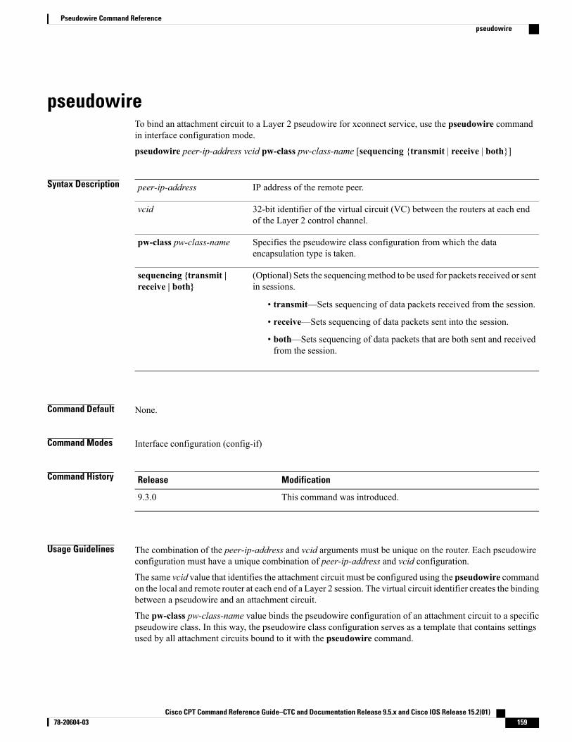
pseudowireTo bind an attachment circuit to a Layer 2 pseudowire for xconnect service, use the pseudowire commandin interface configuration mode.
pseudowire peer-ip-address vcid pw-class pw-class-name [sequencing {transmit | receive | both}]
Syntax Description IP address of the remote peer.peer-ip-address
32-bit identifier of the virtual circuit (VC) between the routers at each endof the Layer 2 control channel.
vcid
Specifies the pseudowire class configuration from which the dataencapsulation type is taken.
pw-class pw-class-name
(Optional) Sets the sequencingmethod to be used for packets received or sentin sessions.
• transmit—Sets sequencing of data packets received from the session.
• receive—Sets sequencing of data packets sent into the session.
• both—Sets sequencing of data packets that are both sent and receivedfrom the session.
sequencing {transmit |receive | both}
Command Default None.
Command Modes Interface configuration (config-if)
Command History ModificationRelease
This command was introduced.9.3.0
Usage Guidelines The combination of the peer-ip-address and vcid arguments must be unique on the router. Each pseudowireconfiguration must have a unique combination of peer-ip-address and vcid configuration.
The same vcid value that identifies the attachment circuit must be configured using the pseudowire commandon the local and remote router at each end of a Layer 2 session. The virtual circuit identifier creates the bindingbetween a pseudowire and an attachment circuit.
The pw-class pw-class-name value binds the pseudowire configuration of an attachment circuit to a specificpseudowire class. In this way, the pseudowire class configuration serves as a template that contains settingsused by all attachment circuits bound to it with the pseudowire command.
Cisco CPT Command Reference Guide–CTC and Documentation Release 9.5.x and Cisco IOS Release 15.2(01) 78-20604-03 159
Pseudowire Command Referencepseudowire
Examples The following example shows how to bind the attachment circuit to a Layer 2 pseudowire for a xconnectservice for the pseudowire class named pwclass1.
Router(config-if)# pseudowire 172.24.13.196 10 pw-class pwclass1
Related Commands DescriptionCommand
Specifies the name of a pseudowire class and enterspseudowire class configuration mode.
pseudowire-class
Cisco CPT Command Reference Guide–CTC and Documentation Release 9.5.x and Cisco IOS Release 15.2(01)160 78-20604-03
Pseudowire Command Referencepseudowire
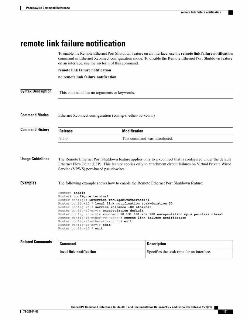
remote link failure notificationTo enable the Remote Ethernet Port Shutdown feature on an interface, use the remote link failure notificationcommand in Ethernet Xconnect configuration mode. To disable the Remote Ethernet Port Shutdown featureon an interface, use the no form of this command.
remote link failure notification
no remote link failure notification
Syntax Description This command has no arguments or keywords.
Command Modes Ethernet Xconnect configuration (config-if-ether-vc-xconn)
Command History ModificationRelease
This command was introduced.9.5.0
Usage Guidelines The Remote Ethernet Port Shutdown feature applies only to a xconnect that is configured under the defaultEthernet Flow Point (EFP). This feature applies only to attachment circuit failures on Virtual Private WiredService (VPWS) port-based pseudowires.
Examples The following example shows how to enable the Remote Ethernet Port Shutdown feature:
Router> enableRouter# configure terminalRouter(config)# interface TenGigabitEthernet4/1Router(config-if)# local link notification soak-duration 30Router(config-if)# service instance 100 ethernetRouter(config-if-srv)# encapsulation defaultRouter(config-if-srv)# xconnect 10.131.191.252 100 encapsulation mpls pw-class class1Router(config-if-ether-vc-xconn)# remote link failure notificationRouter(config-if-ether-vc-xconn)# exitRouter(config-if-srv)# exitRouter(config-if)# exit
Related Commands DescriptionCommand
Specifies the soak time for an interface.local link notification
Cisco CPT Command Reference Guide–CTC and Documentation Release 9.5.x and Cisco IOS Release 15.2(01) 78-20604-03 161
Pseudowire Command Referenceremote link failure notification
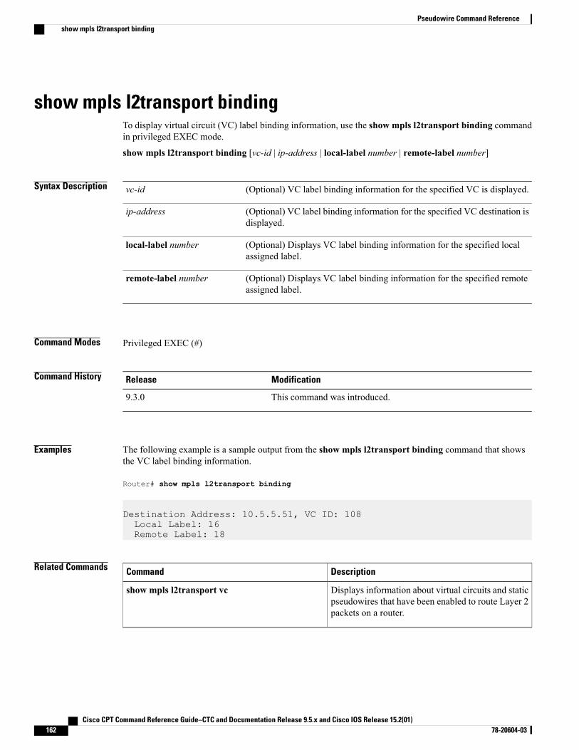
show mpls l2transport bindingTo display virtual circuit (VC) label binding information, use the show mpls l2transport binding commandin privileged EXEC mode.
show mpls l2transport binding [vc-id | ip-address | local-label number | remote-label number]
Syntax Description (Optional) VC label binding information for the specified VC is displayed.vc-id
(Optional) VC label binding information for the specified VC destination isdisplayed.
ip-address
(Optional) Displays VC label binding information for the specified localassigned label.
local-label number
(Optional) Displays VC label binding information for the specified remoteassigned label.
remote-label number
Command Modes Privileged EXEC (#)
Command History ModificationRelease
This command was introduced.9.3.0
Examples The following example is a sample output from the show mpls l2transport binding command that showsthe VC label binding information.
Router# show mpls l2transport binding
Destination Address: 10.5.5.51, VC ID: 108Local Label: 16Remote Label: 18
Related Commands DescriptionCommand
Displays information about virtual circuits and staticpseudowires that have been enabled to route Layer 2packets on a router.
show mpls l2transport vc
Cisco CPT Command Reference Guide–CTC and Documentation Release 9.5.x and Cisco IOS Release 15.2(01)162 78-20604-03
Pseudowire Command Referenceshow mpls l2transport binding
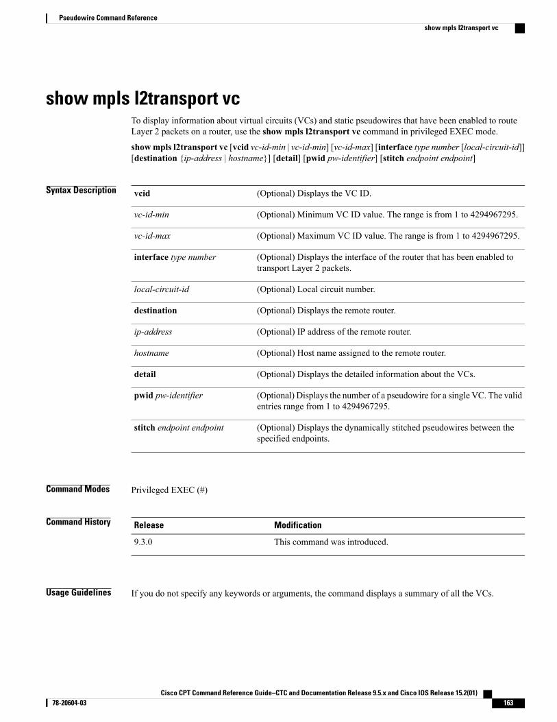
show mpls l2transport vcTo display information about virtual circuits (VCs) and static pseudowires that have been enabled to routeLayer 2 packets on a router, use the show mpls l2transport vc command in privileged EXEC mode.
showmpls l2transport vc [vcid vc-id-min | vc-id-min] [vc-id-max] [interface type number [local-circuit-id]][destination {ip-address | hostname}] [detail] [pwid pw-identifier] [stitch endpoint endpoint]
Syntax Description (Optional) Displays the VC ID.vcid
(Optional) Minimum VC ID value. The range is from 1 to 4294967295.vc-id-min
(Optional) Maximum VC ID value. The range is from 1 to 4294967295.vc-id-max
(Optional) Displays the interface of the router that has been enabled totransport Layer 2 packets.
interface type number
(Optional) Local circuit number.local-circuit-id
(Optional) Displays the remote router.destination
(Optional) IP address of the remote router.ip-address
(Optional) Host name assigned to the remote router.hostname
(Optional) Displays the detailed information about the VCs.detail
(Optional) Displays the number of a pseudowire for a single VC. The validentries range from 1 to 4294967295.
pwid pw-identifier
(Optional) Displays the dynamically stitched pseudowires between thespecified endpoints.
stitch endpoint endpoint
Command Modes Privileged EXEC (#)
Command History ModificationRelease
This command was introduced.9.3.0
Usage Guidelines If you do not specify any keywords or arguments, the command displays a summary of all the VCs.
Cisco CPT Command Reference Guide–CTC and Documentation Release 9.5.x and Cisco IOS Release 15.2(01) 78-20604-03 163
Pseudowire Command Referenceshow mpls l2transport vc
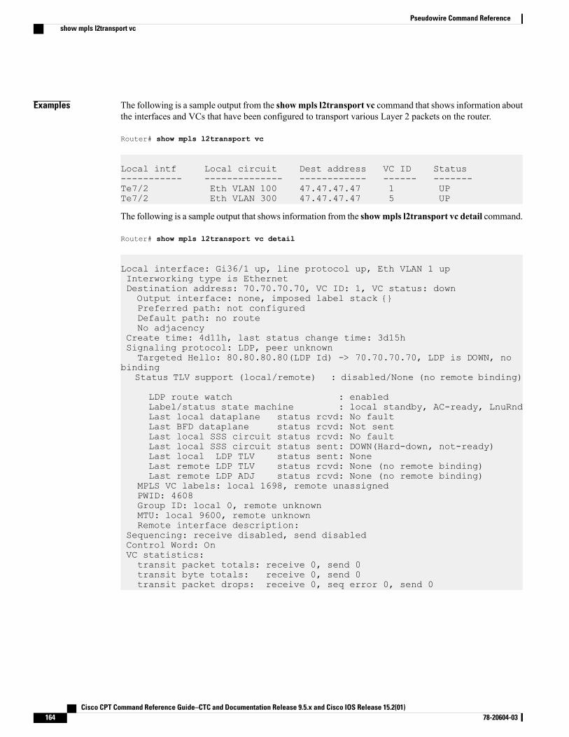
Examples The following is a sample output from the showmpls l2transport vc command that shows information aboutthe interfaces and VCs that have been configured to transport various Layer 2 packets on the router.
Router# show mpls l2transport vc
Local intf Local circuit Dest address VC ID Status----------- -------------- ------------ ------ -------Te7/2 Eth VLAN 100 47.47.47.47 1 UPTe7/2 Eth VLAN 300 47.47.47.47 5 UP
The following is a sample output that shows information from the showmpls l2transport vc detail command.
Router# show mpls l2transport vc detail
Local interface: Gi36/1 up, line protocol up, Eth VLAN 1 upInterworking type is EthernetDestination address: 70.70.70.70, VC ID: 1, VC status: downOutput interface: none, imposed label stack {}Preferred path: not configuredDefault path: no routeNo adjacency
Create time: 4d11h, last status change time: 3d15hSignaling protocol: LDP, peer unknownTargeted Hello: 80.80.80.80(LDP Id) -> 70.70.70.70, LDP is DOWN, no
bindingStatus TLV support (local/remote) : disabled/None (no remote binding)
LDP route watch : enabledLabel/status state machine : local standby, AC-ready, LnuRndLast local dataplane status rcvd: No faultLast BFD dataplane status rcvd: Not sentLast local SSS circuit status rcvd: No faultLast local SSS circuit status sent: DOWN(Hard-down, not-ready)Last local LDP TLV status sent: NoneLast remote LDP TLV status rcvd: None (no remote binding)Last remote LDP ADJ status rcvd: None (no remote binding)
MPLS VC labels: local 1698, remote unassignedPWID: 4608Group ID: local 0, remote unknownMTU: local 9600, remote unknownRemote interface description:
Sequencing: receive disabled, send disabledControl Word: OnVC statistics:transit packet totals: receive 0, send 0transit byte totals: receive 0, send 0transit packet drops: receive 0, seq error 0, send 0
Cisco CPT Command Reference Guide–CTC and Documentation Release 9.5.x and Cisco IOS Release 15.2(01)164 78-20604-03
Pseudowire Command Referenceshow mpls l2transport vc

Related Commands DescriptionCommand
Displays virtual circuit (VC) label bindinginformation.
show mpls l2transport binding
Cisco CPT Command Reference Guide–CTC and Documentation Release 9.5.x and Cisco IOS Release 15.2(01) 78-20604-03 165
Pseudowire Command Referenceshow mpls l2transport vc
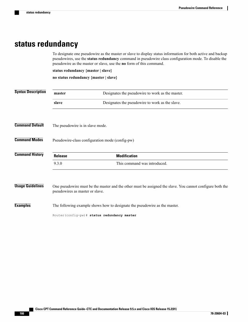
status redundancyTo designate one pseudowire as the master or slave to display status information for both active and backuppseudowires, use the status redundancy command in pseudowire class configuration mode. To disable thepseudowire as the master or slave, use the no form of this command.
status redundancy {master | slave}
no status redundancy {master | slave}
Syntax Description Designates the pseudowire to work as the master.master
Designates the pseudowire to work as the slave.slave
Command Default The pseudowire is in slave mode.
Command Modes Pseudowire-class configuration mode (config-pw)
Command History ModificationRelease
This command was introduced.9.3.0
Usage Guidelines One pseudowire must be the master and the other must be assigned the slave. You cannot configure both thepseudowires as master or slave.
Examples The following example shows how to designate the pseudowire as the master.
Router(config-pw)# status redundancy master
Cisco CPT Command Reference Guide–CTC and Documentation Release 9.5.x and Cisco IOS Release 15.2(01)166 78-20604-03
Pseudowire Command Referencestatus redundancy
status (pseudowire class)To enable the router to send pseudowire status messages to a peer router, even when the attachment circuit isdown, use the status command in pseudowire class configuration mode. To disable the pseudowire statusmessages, use the no form of this command.
status
no status
Syntax Description This command has no arguments or keywords.
Command Default Pseudowire status messages are sent and received if both routers support the messages.
Command Modes Pseudowire class configuration (config-pw)
Command History ModificationRelease
This command was introduced.9.3.0
Usage Guidelines Both the peer routers must support the ability to send and receive pseudowire status messages in labeladvertisement and label notification messages. If both peer routers do not support pseudowire status messages,it is recommended that you disable the messages with the no status command.
Examples The following example shows how to enable the router to send pseudowire status messages to a peer router.
Router> enableRouter# configure terminalRouter(config)# pseudowire-class test1Router(config-pw)# statusRouter(config-pw)# encapsulation mpls
Related Commands DescriptionCommand
Displays information about virtual circuits (VCs) andstatic pseudowires that have been enabled to routeLayer 2 packets on a router.
show mpls l2transport vc
Cisco CPT Command Reference Guide–CTC and Documentation Release 9.5.x and Cisco IOS Release 15.2(01) 78-20604-03 167
Pseudowire Command Referencestatus (pseudowire class)
switching tlvTo advertise the stitching point type, length, variable (TLV) in the label binding, use the switching tlv commandin pseudowire class configuration mode. To disable the stitching point TLV, use the no form of this command.
switching tlv
no switching tlv
Syntax Description This command has no arguments or keywords.
Command Default Stitching point TLV data is advertised to peers.
Command Modes Pseudowire class configuration (config-pw-class)
Command History ModificationRelease
This command was introduced.9.3.0
Usage Guidelines The pseudowire stitching point TLV information includes the following information:
• Pseudowire ID of the last pseudowire segment traversed
• Pseudowire stitching point description
• Local IP address of the pseudowire stitching point
• Remote IP address of the last pseudowire stitching point that was crossed or the T-PE router
By default, stitching point TLV data is advertised to peers.
Examples The following example shows how to enable the display of the pseudowire stitching TLV.
Router(config)# pseudowire-class class1Router(config-pw-class)# switching tlv
Related Commands DescriptionCommand
Displays stitching point TLV information.show mpls l2transport binding
Displays information about virtual circuits (VCs) andstatic pseudowires that have been enabled to routeLayer 2 packets on a router.
show mpls l2transport vc
Cisco CPT Command Reference Guide–CTC and Documentation Release 9.5.x and Cisco IOS Release 15.2(01)168 78-20604-03
Pseudowire Command Referenceswitching tlv

Cisco CPT Command Reference Guide–CTC and Documentation Release 9.5.x and Cisco IOS Release 15.2(01) 78-20604-03 169
Pseudowire Command Referenceswitching tlv
vccvTo configure the pseudowire Virtual Circuit Connection Verification (VCCV) control channel (CC) type forpseudowires, use the vccv command in pseudowire class configuration mode. To disable a pseudowire VCCVCC type, use the no form of this command.
vccv {control-word | router-alert | ttl}
no vccv {control-word | router-alert | ttl}
Syntax Description Specifies the CC Type 1: control word.control-word
Specifies the CC Type 2: MPLS router alert label.router-alert
Specifies the CC Type 3:MPLS pseudowire label with Time to Live (TTL).ttl
Command Default The pseudowire VCCV CC type is set to Type 1 (control word).
Command Modes Pseudowire-class configuration (config-pw-class)
Command History ModificationRelease
This command was introduced.9.3.0
Usage Guidelines When an initiating provider edge (PE) device sends a setup request message to a remote PE device, the messageincludes VCCV capability information. This capability information is a combination of the CC type and thecontrol verification (CV) type. Use the vccv command to configure the CC type capabilities of the MPLSpseudowire.
If the CV type for the MPLS pseudowire is set to a type that does not use IP/UDP headers, then you must setthe CC type to the CC Type 1: control word.
Examples The following example shows how to configure the MPLS pseudowire class to use CC Type 1.
Router(config)# pseudowire-class bfdclassRouter(config-pw-class)# encapsulation mplsRouter(config-pw-class)# protocol noneRouter(config-pw-class)# vccv control-word
Cisco CPT Command Reference Guide–CTC and Documentation Release 9.5.x and Cisco IOS Release 15.2(01)170 78-20604-03
Pseudowire Command Referencevccv
Related Commands DescriptionCommand
Creates a BFD template and enters BFD configurationmode.
bfd-template
Specifies the name of the pseudowire class and enterspseudowire class configuration mode.
pseudowire-class
Enables status signaling for VCCV BFD.vccv bfd status signaling
Enables VCCV BFD for a pseudowire class.vccv bfd template
Cisco CPT Command Reference Guide–CTC and Documentation Release 9.5.x and Cisco IOS Release 15.2(01) 78-20604-03 171
Pseudowire Command Referencevccv
vccv bfd status signalingTo enable status signaling for Bidirectional Forwarding Detection (BFD) over Virtual Circuit ConnectionVerification (VCCV), use the vccv bfd status signaling command in pseudowire class configuration mode.To disable status signaling, use the no form of this command.
vccv bfd status signaling
no vccv bfd status signaling
Syntax Description This command has no arguments or keywords.
Command Default VCCV BFD status signaling is disabled.
Command Modes Pseudowire-class configuration (config-pw-class)
Command History ModificationRelease
This command was introduced.9.3.0
Usage Guidelines Use this command to allow BFD to provide status signaling functionality that indicates the fault status of anattachment circuit (AC).
Examples The following example shows how to enable VCCV BFD status signaling for a pseudowire class.
Router(config)# pseudowire-class bfdclassRouter(config-pw-class)# encapsulation mplsRouter(config-pw-class)# protocol noneRouter(config-pw-class)# vccv control-wordRouter(config-pw-class)# vccv bfd template bfdtemplate raw-bfdRouter(config-pw-class)# vccv bfd status signaling
Related Commands DescriptionCommand
Creates a BFD template and enters BFD configurationmode.
bfd-template
Specifies the name of the pseudowire class and enterspseudowire class configuration mode.
pseudowire-class
Configures the pseudowire VCCVCC type forMPLSpseudowires.
vccv
Cisco CPT Command Reference Guide–CTC and Documentation Release 9.5.x and Cisco IOS Release 15.2(01)172 78-20604-03
Pseudowire Command Referencevccv bfd status signaling

DescriptionCommand
Enables VCCV BFD for a pseudowire class.vccv bfd template
Cisco CPT Command Reference Guide–CTC and Documentation Release 9.5.x and Cisco IOS Release 15.2(01) 78-20604-03 173
Pseudowire Command Referencevccv bfd status signaling
vccv bfd templateTo enable BFD over VCCV for a pseudowire class, use the vccv bfd template command in pseudowire classconfiguration mode. To disable VCCV BFD, use the no form of this command.
vccv bfd template name {udp | raw-bfd}
no vccv bfd template name {udp | raw-bfd}
Syntax Description Name of the BFD template to use.name
(Optional) Enables support for BFD with IP or User Datagram Protocol (UDP)header encapsulation.
udp
(Optional) Enables support for BFD without IP/UDP header encapsulation.raw-bfd
Command Default VCCV BFD is not enabled for a pseudowire class.
Command Modes Pseudowire-class configuration (config-pw-class)
Command History ModificationRelease
This command was introduced.9.3.0
Usage Guidelines The BFD template specified by the name argument is created using the bfd-template command, and containssettings for the BFD interval values.
VCCV defines two types encapsulation for VCCV messages to differentiate them from data packets: BFDwith IP/UDP headers and BFD without IP/UDP headers. Support for BFD without IP/UDP headers can beenabled only for pseudowires that use a control word.
If the VCCV carries raw BFD, the control word must be set to BFD without IP/UDP headers. BFD withoutIP/UDP headers enables the system to identify the BFD packet when demultiplexing the control channel.
Examples The following example shows how to enable the BFD template without support for IP/UDP headerencapsulation.
Router(config)# pseudowire-class bfdclassRouter(config-pw-class)# encapsulation mplsRouter(config-pw-class)# protocol noneRouter(config-pw-class)# vccv control-wordRouter(config-pw-class)# vccv bfd template bfdtemplate raw-bfdRouter(config-pw-class)# vccv bfd status signaling
Cisco CPT Command Reference Guide–CTC and Documentation Release 9.5.x and Cisco IOS Release 15.2(01)174 78-20604-03
Pseudowire Command Referencevccv bfd template
Related Commands DescriptionCommand
Creates a BFD template and enters BFD configurationmode.
bfd-template
Specifies the name of the pseudowire class and enterspseudowire class configuration mode.
pseudowire-class
Configures the pseudowire VCCV CC type forpseudowires.
vccv
Enables status signaling for VCCV BFD.vccv bfd status signaling
Cisco CPT Command Reference Guide–CTC and Documentation Release 9.5.x and Cisco IOS Release 15.2(01) 78-20604-03 175
Pseudowire Command Referencevccv bfd template
xconnectTo bind an attachment circuit to a pseudowire, and to configure a static pseudowire, use the xconnect commandin one of the supported configuration modes. To restore the default values, use the no form of this command.
xconnect peer-ip-address vcid {encapsulation {mpls [manual]} | pw-class pw-class-name}[pw-classpw-class-name] [sequencing {transmit | receive | both}]
no xconnect
Syntax Description IP address of the remote provider edge (PE) peer. The remote router ID canbe any IP address, as long as it is reachable.
peer-ip-address
32-bit identifier of the virtual circuit (VC) between the PE routers.vcid
Specifies MPLS as the tunneling method to encapsulate the data in thepseudowire.
encapsulation mpls
(Optional) Specifies the pseudowire class for advanced configuration.pw-class pw-class-name
(Optional) Sets the sequencing method to be used for packets received or sent.sequencing
(Optional) Sequences data packets received from the attachment circuit.transmit
(Optional) Sequences data packets sent into the attachment circuit.receive
(Optional) Sequences data packets that are both sent and received from theattachment circuit.
both
Command Default The attachment circuit is not bound to the pseudowire.
Command Modes Xconnect configuration(config-if-xconn)
Interface configuration (config-if)
Command History ModificationRelease
This command was introduced.9.3.0
Usage Guidelines The combination of the peer-ip-address and vcid arguments must be unique on the router. Each xconnectconfiguration must have a unique combination of peer-ip-address and vcid configuration.
Cisco CPT Command Reference Guide–CTC and Documentation Release 9.5.x and Cisco IOS Release 15.2(01)176 78-20604-03
Pseudowire Command Referencexconnect
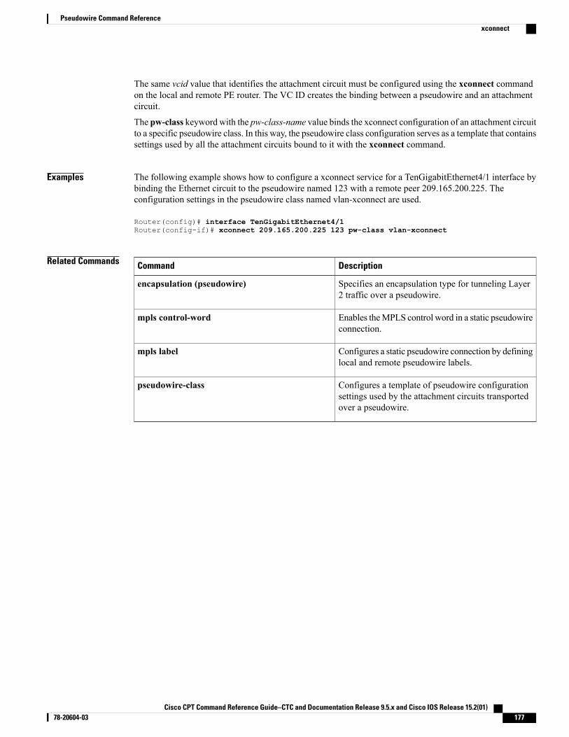
The same vcid value that identifies the attachment circuit must be configured using the xconnect commandon the local and remote PE router. The VC ID creates the binding between a pseudowire and an attachmentcircuit.
The pw-class keyword with the pw-class-name value binds the xconnect configuration of an attachment circuitto a specific pseudowire class. In this way, the pseudowire class configuration serves as a template that containssettings used by all the attachment circuits bound to it with the xconnect command.
Examples The following example shows how to configure a xconnect service for a TenGigabitEthernet4/1 interface bybinding the Ethernet circuit to the pseudowire named 123 with a remote peer 209.165.200.225. Theconfiguration settings in the pseudowire class named vlan-xconnect are used.
Router(config)# interface TenGigabitEthernet4/1Router(config-if)# xconnect 209.165.200.225 123 pw-class vlan-xconnect
Related Commands DescriptionCommand
Specifies an encapsulation type for tunneling Layer2 traffic over a pseudowire.
encapsulation (pseudowire)
Enables theMPLS control word in a static pseudowireconnection.
mpls control-word
Configures a static pseudowire connection by defininglocal and remote pseudowire labels.
mpls label
Configures a template of pseudowire configurationsettings used by the attachment circuits transportedover a pseudowire.
pseudowire-class
Cisco CPT Command Reference Guide–CTC and Documentation Release 9.5.x and Cisco IOS Release 15.2(01) 78-20604-03 177
Pseudowire Command Referencexconnect

Cisco CPT Command Reference Guide–CTC and Documentation Release 9.5.x and Cisco IOS Release 15.2(01)178 78-20604-03
Pseudowire Command Referencexconnect
QoS Command Reference
This chapter describes commands used to configure Quality of Service (QoS).
• bandwidth, page 181
• class , page 184
• class-map, page 186
• match ip precedence, page 189
• match cos, page 191
• match ip dscp, page 193
• match mpls experimental topmost, page 195
• match qos-group, page 196
• platform, page 198
• police (policy map), page 200
• policy-map, page 204
• priority, page 206
• service-policy, page 208
• set cos, page 210
• set discard-class, page 212
• set ip dscp, page 214
• set ip precedence, page 216
• set qos-group, page 218
• shape, page 220
• show class-map, page 222
• show policy-map, page 223
• show policy-map class, page 225
• show policy-map interface, page 227
Cisco CPT Command Reference Guide–CTC and Documentation Release 9.5.x and Cisco IOS Release 15.2(01) 78-20604-03 179

• table-map (value mapping), page 229
Cisco CPT Command Reference Guide–CTC and Documentation Release 9.5.x and Cisco IOS Release 15.2(01)180 78-20604-03
QoS Command Reference
bandwidthTo specify or modify the bandwidth allocated for a class belonging to a policy map, use the bandwidthcommand in policy-map class configuration mode. To remove the bandwidth specified for a class, use the noform of this command.
bandwidth {bandwidth-value | percent x% | remaining percent x% | remaining ratio ratio}
no bandwidth {bandwidth-value | percent x% | remaining percent x% | remaining ratio ratio}
Syntax Description Specifies the amount of bandwidth in kbps to be assignedto the class. Implies that the class where this is applied isgiven a minimum bandwidth guarantee of bandwidth-valuekbps. The amount of bandwidth configured should be largeenough to also accommodate Layer 2 overhead.
bandwidth value
Specifies the amount of bandwidth, in percentage from theavailable bandwidth, to be assigned to the class. The valueranges from 1 to 100 percent.
percent x%
Specifies that the class where the command is specifiedshould be given x% of the excess bandwidth, where excessbandwidth is the bandwidth in excess of all the minimumbandwidth guarantees of all the classes at the same level.The value ranges from 1 to 100 percent.
remaining percent x%
Specifies a bandwidth-remaining ratio for class-level orsubinterface-level queues to be used during congestion todetermine the amount of excess bandwidth (unused bypriority traffic) to allocate to non priority queues. The valueshould be between 1 to 127.
remaining ratio ratio
Command Default Bandwidth is not specified.
Command Modes Policy-map class configuration (config-pmap-c)
Command History ModificationRelease
This command was introduced.9.3.0
Usage Guidelines The restrictions and usage guidelines to configure quality of service (QoS) egress bandwidth on a CPT systemare as follows:
Cisco CPT Command Reference Guide–CTC and Documentation Release 9.5.x and Cisco IOS Release 15.2(01) 78-20604-03 181
QoS Command Referencebandwidth
• Bandwidth action is not supported on classes with match criteria as qos-group 3 or 7, or multicast-priorityclass.
• The bandwidth command cannot be used in combination with Bandwidth Remaining Ratio (BRR) orBandwidth Remaining Percentage (BRP) in a class-map or a policy-map.
• The system does not validate for the total CIR configured on all the targets under the various congestionpoints. Therefore, ensure that the total committed information rate (CIR) configured does not exceedthe total bandwidth available:
• Total CIR configured under a 1 Gbps interface shall not exceed 1 Gbps; this includes CIR in policyapplied on interface as well as services on that interface.
• Total CIR configured under a 10 Gbps interface shall not exceed 10 Gbps; this includes CIR inpolicy applied on interface as well as services on that interface.
• Total CIR on all targets on a CPT 50 shelf shall not exceed 9.882 Gbps; this is the least bandwidthfor a CPT 50 shelf in a scenario where only one of the interconnects for a CPT50 shelf is functional.
• Total CIR on all the unicast targets on two SFP+ interfaces on a fabric card shall not exceed 13Gbps. The same is applicable if two CPT 50 shelves are connected to the two SFP+ interfaces ofthe same fabric card.
The restrictions and usage guidelines to configure QoS egress bandwidth remaining ratio or bandwidthremaining percent on a CPT system are as follows:
• The bandwidth remaining ratio and bandwidth remaining percent command is not supported incombination with bandwidth action in a class-map or a policy-map.
• The bandwidth remaining ratio and bandwidth remaining percent command is not supported onclasses with match criteria as qos-group 3 or 7 or multicast-priority class
BRR is implemented on logical interfaces using hierarchical policy-maps.
Examples The following example shows how to configure bandwidth remaining ratio at the egress:
Router(config)# policy-map BRRRouter(config-pmap)# class Test1Router(config-pmap-c)# bandwidth remaining ratio 10Router(config-pmap-c)# exitRouter(config-pmap)# class Test2Router(config-pmap-c)# bandwidth remaining ratio 20Router(config-pmap-c)# exitRouter(config-pmap)# class Test3Router(config-pmap-c)# bandwidth remaining ratio 30Router(config-pmap-c)# exitRouter(config-pmap)# class class-defaultRouter(config-pmap-c)#bandwidth remaining ratio 40
This example shows how to configure minimum bandwidth guarantee at the egress:
Router# config terminalRouter(config)# policy-map TestRouter(config-pmap)# class class-defaultRouter(config-pmap-c)# bandwidth 10000Router(config-pmap-c)# exit
Cisco CPT Command Reference Guide–CTC and Documentation Release 9.5.x and Cisco IOS Release 15.2(01)182 78-20604-03
QoS Command Referencebandwidth
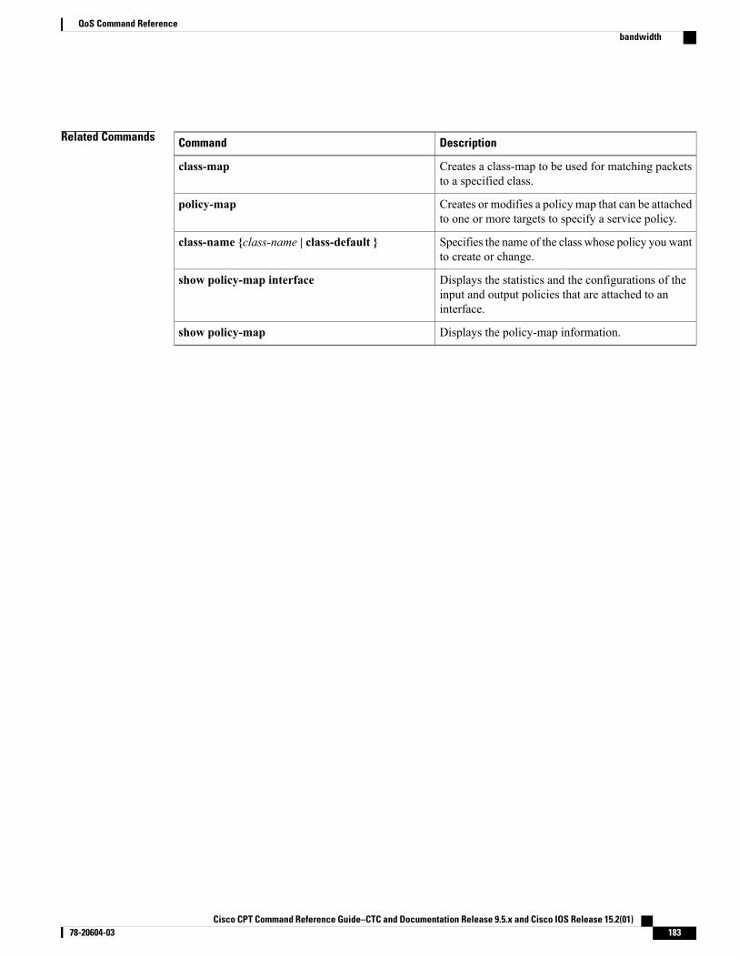
Related Commands DescriptionCommand
Creates a class-map to be used for matching packetsto a specified class.
class-map
Creates or modifies a policy map that can be attachedto one or more targets to specify a service policy.
policy-map
Specifies the name of the class whose policy you wantto create or change.
class-name {class-name | class-default }
Displays the statistics and the configurations of theinput and output policies that are attached to aninterface.
show policy-map interface
Displays the policy-map information.show policy-map
Cisco CPT Command Reference Guide–CTC and Documentation Release 9.5.x and Cisco IOS Release 15.2(01) 78-20604-03 183
QoS Command Referencebandwidth
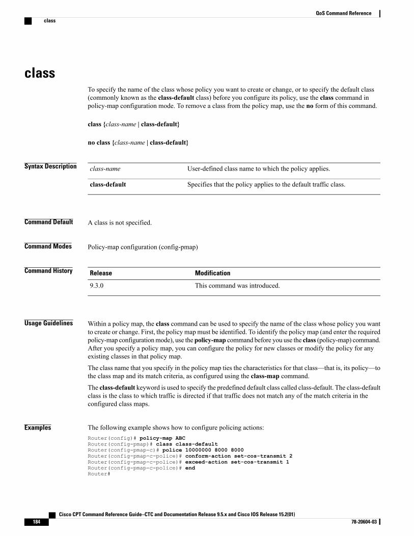
classTo specify the name of the class whose policy you want to create or change, or to specify the default class(commonly known as the class-default class) before you configure its policy, use the class command inpolicy-map configuration mode. To remove a class from the policy map, use the no form of this command.
class {class-name | class-default}
no class {class-name | class-default}
Syntax Description User-defined class name to which the policy applies.class-name
Specifies that the policy applies to the default traffic class.class-default
Command Default A class is not specified.
Command Modes Policy-map configuration (config-pmap)
Command History ModificationRelease
This command was introduced.9.3.0
Usage Guidelines Within a policy map, the class command can be used to specify the name of the class whose policy you wantto create or change. First, the policy map must be identified. To identify the policy map (and enter the requiredpolicy-map configurationmode), use the policy-map command before you use the class (policy-map) command.After you specify a policy map, you can configure the policy for new classes or modify the policy for anyexisting classes in that policy map.
The class name that you specify in the policy map ties the characteristics for that class—that is, its policy—tothe class map and its match criteria, as configured using the class-map command.
The class-default keyword is used to specify the predefined default class called class-default. The class-defaultclass is the class to which traffic is directed if that traffic does not match any of the match criteria in theconfigured class maps.
Examples The following example shows how to configure policing actions:Router(config)# policy-map ABCRouter(config-pmap)# class class-defaultRouter(config-pmap-c)# police 10000000 8000 8000Router(config-pmap-c-police)# conform-action set-cos-transmit 2Router(config-pmap-c-police)# exceed-action set-cos-transmit 1Router(config-pmap-c-police)# endRouter#
Cisco CPT Command Reference Guide–CTC and Documentation Release 9.5.x and Cisco IOS Release 15.2(01)184 78-20604-03
QoS Command Referenceclass
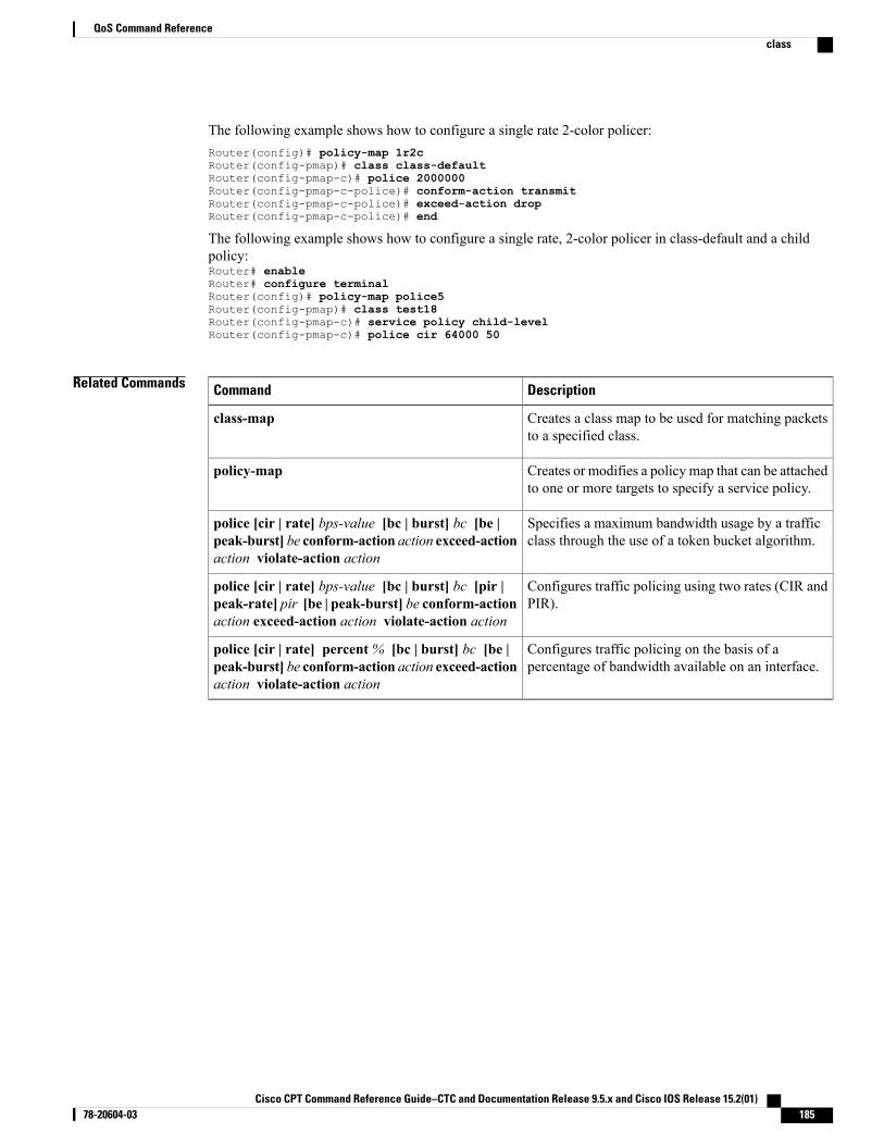
The following example shows how to configure a single rate 2-color policer:Router(config)# policy-map 1r2cRouter(config-pmap)# class class-defaultRouter(config-pmap-c)# police 2000000Router(config-pmap-c-police)# conform-action transmitRouter(config-pmap-c-police)# exceed-action dropRouter(config-pmap-c-police)# end
The following example shows how to configure a single rate, 2-color policer in class-default and a childpolicy:Router# enableRouter# configure terminalRouter(config)# policy-map police5Router(config-pmap)# class test18Router(config-pmap-c)# service policy child-levelRouter(config-pmap-c)# police cir 64000 50
Related Commands DescriptionCommand
Creates a class map to be used for matching packetsto a specified class.
class-map
Creates or modifies a policy map that can be attachedto one or more targets to specify a service policy.
policy-map
Specifies a maximum bandwidth usage by a trafficclass through the use of a token bucket algorithm.
police [cir | rate] bps-value [bc | burst] bc [be |peak-burst] be conform-action action exceed-actionaction violate-action action
Configures traffic policing using two rates (CIR andPIR).
police [cir | rate] bps-value [bc | burst] bc [pir |peak-rate] pir [be | peak-burst] be conform-actionaction exceed-action action violate-action action
Configures traffic policing on the basis of apercentage of bandwidth available on an interface.
police [cir | rate] percent% [bc | burst] bc [be |peak-burst] be conform-action action exceed-actionaction violate-action action
Cisco CPT Command Reference Guide–CTC and Documentation Release 9.5.x and Cisco IOS Release 15.2(01) 78-20604-03 185
QoS Command Referenceclass
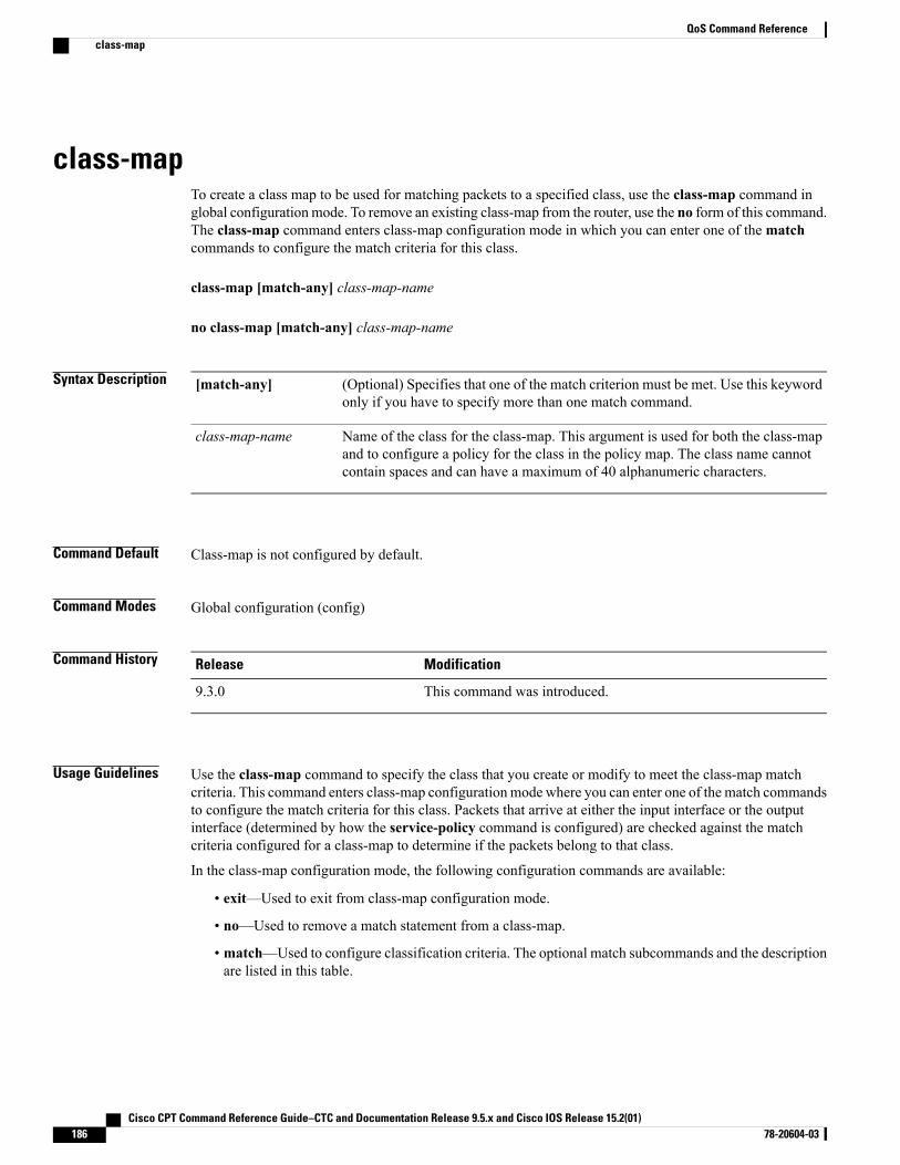
class-mapTo create a class map to be used for matching packets to a specified class, use the class-map command inglobal configuration mode. To remove an existing class-map from the router, use the no form of this command.The class-map command enters class-map configuration mode in which you can enter one of thematchcommands to configure the match criteria for this class.
class-map [match-any] class-map-name
no class-map [match-any] class-map-name
Syntax Description (Optional) Specifies that one of the match criterion must be met. Use this keywordonly if you have to specify more than one match command.
[match-any]
Name of the class for the class-map. This argument is used for both the class-mapand to configure a policy for the class in the policy map. The class name cannotcontain spaces and can have a maximum of 40 alphanumeric characters.
class-map-name
Command Default Class-map is not configured by default.
Command Modes Global configuration (config)
Command History ModificationRelease
This command was introduced.9.3.0
Usage Guidelines Use the class-map command to specify the class that you create or modify to meet the class-map matchcriteria. This command enters class-map configuration mode where you can enter one of the match commandsto configure the match criteria for this class. Packets that arrive at either the input interface or the outputinterface (determined by how the service-policy command is configured) are checked against the matchcriteria configured for a class-map to determine if the packets belong to that class.
In the class-map configuration mode, the following configuration commands are available:
• exit—Used to exit from class-map configuration mode.
• no—Used to remove a match statement from a class-map.
• match—Used to configure classification criteria. The optional match subcommands and the descriptionare listed in this table.
Cisco CPT Command Reference Guide–CTC and Documentation Release 9.5.x and Cisco IOS Release 15.2(01)186 78-20604-03
QoS Command Referenceclass-map
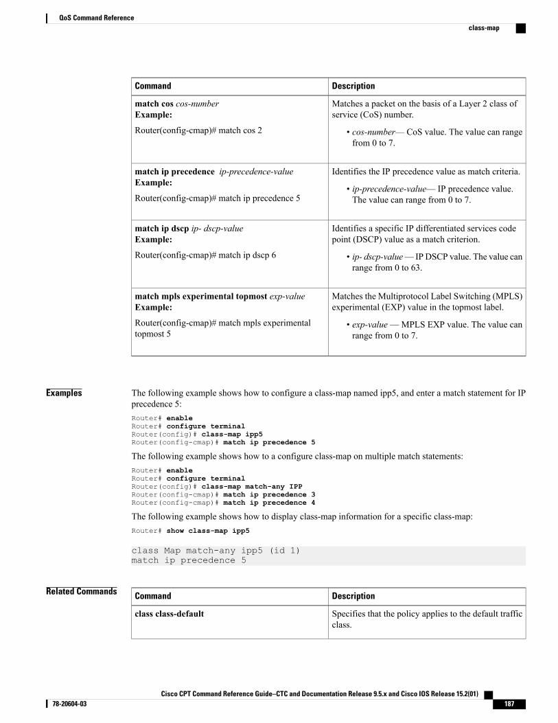
DescriptionCommand
Matches a packet on the basis of a Layer 2 class ofservice (CoS) number.
• cos-number—CoS value. The value can rangefrom 0 to 7.
match cos cos-numberExample:
Router(config-cmap)# match cos 2
Identifies the IP precedence value as match criteria.
• ip-precedence-value— IP precedence value.The value can range from 0 to 7.
match ip precedence ip-precedence-valueExample:
Router(config-cmap)# match ip precedence 5
Identifies a specific IP differentiated services codepoint (DSCP) value as a match criterion.
• ip- dscp-value—IPDSCP value. The value canrange from 0 to 63.
match ip dscp ip- dscp-valueExample:
Router(config-cmap)# match ip dscp 6
Matches the Multiprotocol Label Switching (MPLS)experimental (EXP) value in the topmost label.
• exp-value—MPLS EXP value. The value canrange from 0 to 7.
match mpls experimental topmost exp-valueExample:
Router(config-cmap)# match mpls experimentaltopmost 5
Examples The following example shows how to configure a class-map named ipp5, and enter a match statement for IPprecedence 5:Router# enableRouter# configure terminalRouter(config)# class-map ipp5Router(config-cmap)# match ip precedence 5
The following example shows how to a configure class-map on multiple match statements:Router# enableRouter# configure terminalRouter(config)# class-map match-any IPPRouter(config-cmap)# match ip precedence 3Router(config-cmap)# match ip precedence 4
The following example shows how to display class-map information for a specific class-map:Router# show class-map ipp5
class Map match-any ipp5 (id 1)match ip precedence 5
Related Commands DescriptionCommand
Specifies that the policy applies to the default trafficclass.
class class-default
Cisco CPT Command Reference Guide–CTC and Documentation Release 9.5.x and Cisco IOS Release 15.2(01) 78-20604-03 187
QoS Command Referenceclass-map
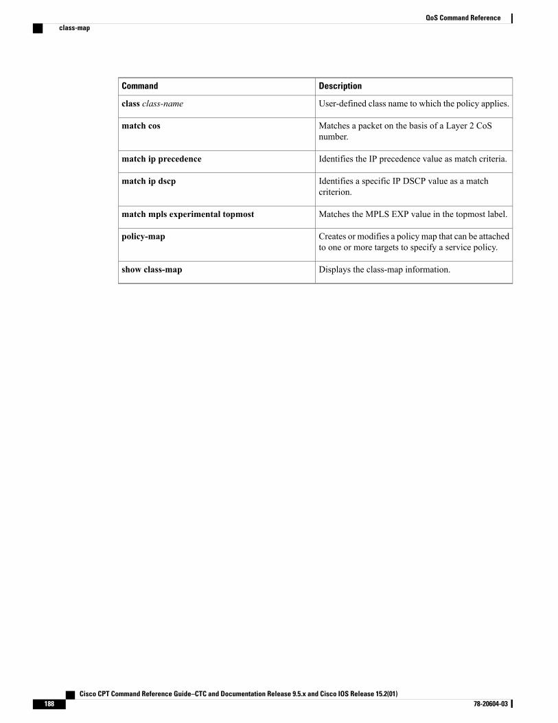
DescriptionCommand
User-defined class name to which the policy applies.class class-name
Matches a packet on the basis of a Layer 2 CoSnumber.
match cos
Identifies the IP precedence value as match criteria.match ip precedence
Identifies a specific IP DSCP value as a matchcriterion.
match ip dscp
Matches the MPLS EXP value in the topmost label.match mpls experimental topmost
Creates or modifies a policy map that can be attachedto one or more targets to specify a service policy.
policy-map
Displays the class-map information.show class-map
Cisco CPT Command Reference Guide–CTC and Documentation Release 9.5.x and Cisco IOS Release 15.2(01)188 78-20604-03
QoS Command Referenceclass-map
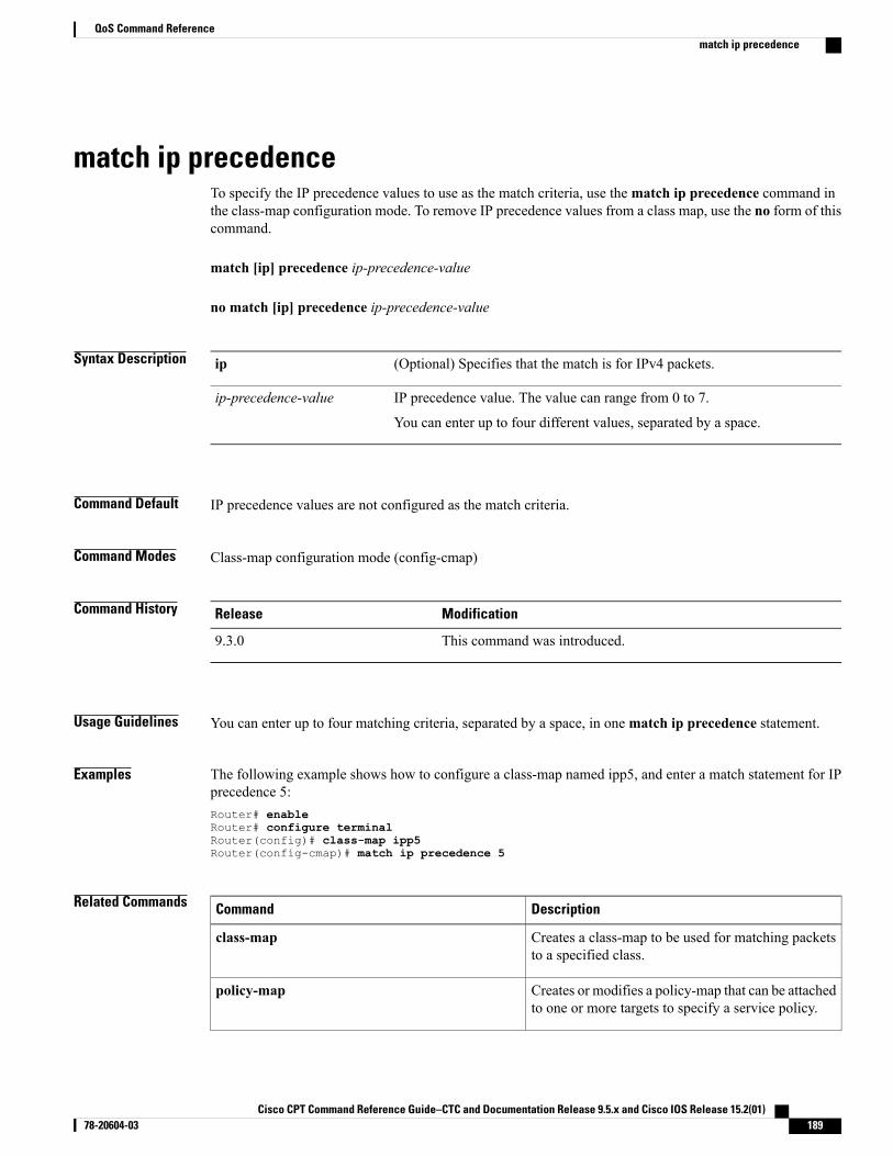
match ip precedenceTo specify the IP precedence values to use as the match criteria, use thematch ip precedence command inthe class-map configuration mode. To remove IP precedence values from a class map, use the no form of thiscommand.
match [ip] precedence ip-precedence-value
no match [ip] precedence ip-precedence-value
Syntax Description (Optional) Specifies that the match is for IPv4 packets.ip
IP precedence value. The value can range from 0 to 7.
You can enter up to four different values, separated by a space.
ip-precedence-value
Command Default IP precedence values are not configured as the match criteria.
Command Modes Class-map configuration mode (config-cmap)
Command History ModificationRelease
This command was introduced.9.3.0
Usage Guidelines You can enter up to four matching criteria, separated by a space, in onematch ip precedence statement.
Examples The following example shows how to configure a class-map named ipp5, and enter a match statement for IPprecedence 5:Router# enableRouter# configure terminalRouter(config)# class-map ipp5Router(config-cmap)# match ip precedence 5
Related Commands DescriptionCommand
Creates a class-map to be used for matching packetsto a specified class.
class-map
Creates or modifies a policy-map that can be attachedto one or more targets to specify a service policy.
policy-map
Cisco CPT Command Reference Guide–CTC and Documentation Release 9.5.x and Cisco IOS Release 15.2(01) 78-20604-03 189
QoS Command Referencematch ip precedence

DescriptionCommand
Attaches a policy-map to an input or an output target.service-policy (service configuration)
Displays all class-maps and their matching criteria.show class-map
Marks the precedence value in the IP header with avalue between 0 to 7.
set ip precedence
Cisco CPT Command Reference Guide–CTC and Documentation Release 9.5.x and Cisco IOS Release 15.2(01)190 78-20604-03
QoS Command Referencematch ip precedence
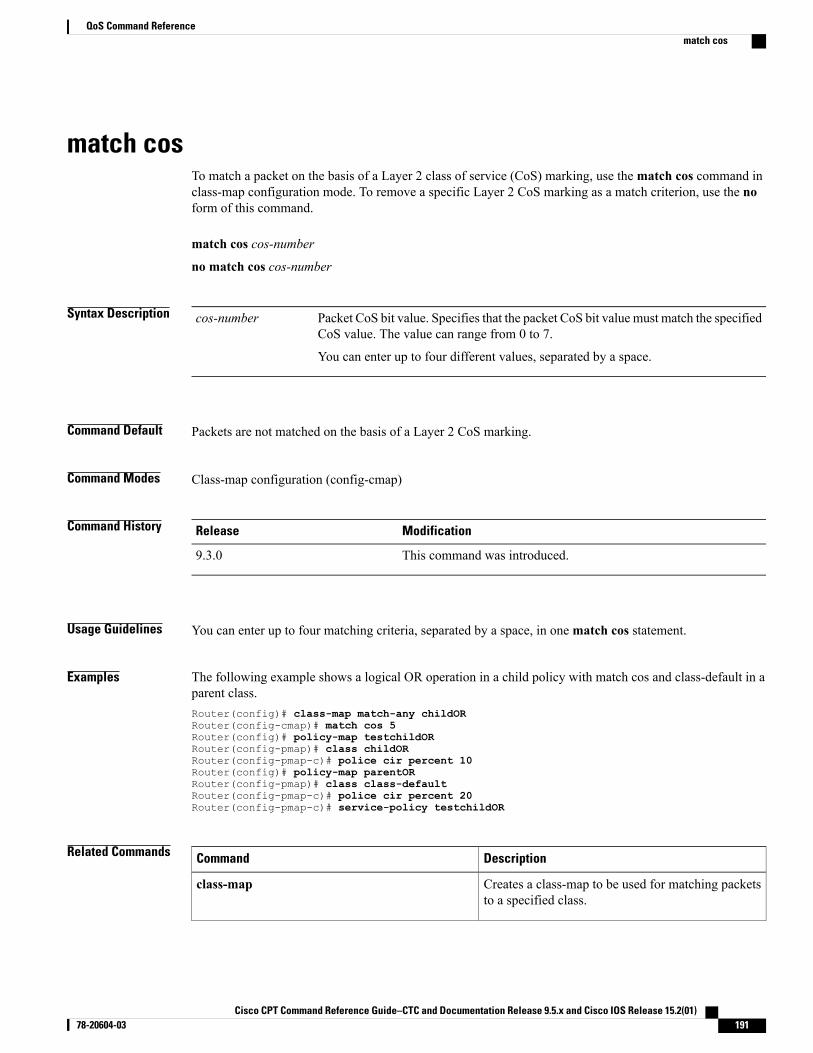
match cosTo match a packet on the basis of a Layer 2 class of service (CoS) marking, use thematch cos command inclass-map configuration mode. To remove a specific Layer 2 CoS marking as a match criterion, use the noform of this command.
match cos cos-number
no match cos cos-number
Syntax Description Packet CoS bit value. Specifies that the packet CoS bit value must match the specifiedCoS value. The value can range from 0 to 7.
You can enter up to four different values, separated by a space.
cos-number
Command Default Packets are not matched on the basis of a Layer 2 CoS marking.
Command Modes Class-map configuration (config-cmap)
Command History ModificationRelease
This command was introduced.9.3.0
Usage Guidelines You can enter up to four matching criteria, separated by a space, in onematch cos statement.
Examples The following example shows a logical OR operation in a child policy with match cos and class-default in aparent class.Router(config)# class-map match-any childORRouter(config-cmap)# match cos 5Router(config)# policy-map testchildORRouter(config-pmap)# class childORRouter(config-pmap-c)# police cir percent 10Router(config)# policy-map parentORRouter(config-pmap)# class class-defaultRouter(config-pmap-c)# police cir percent 20Router(config-pmap-c)# service-policy testchildOR
Related Commands DescriptionCommand
Creates a class-map to be used for matching packetsto a specified class.
class-map
Cisco CPT Command Reference Guide–CTC and Documentation Release 9.5.x and Cisco IOS Release 15.2(01) 78-20604-03 191
QoS Command Referencematch cos
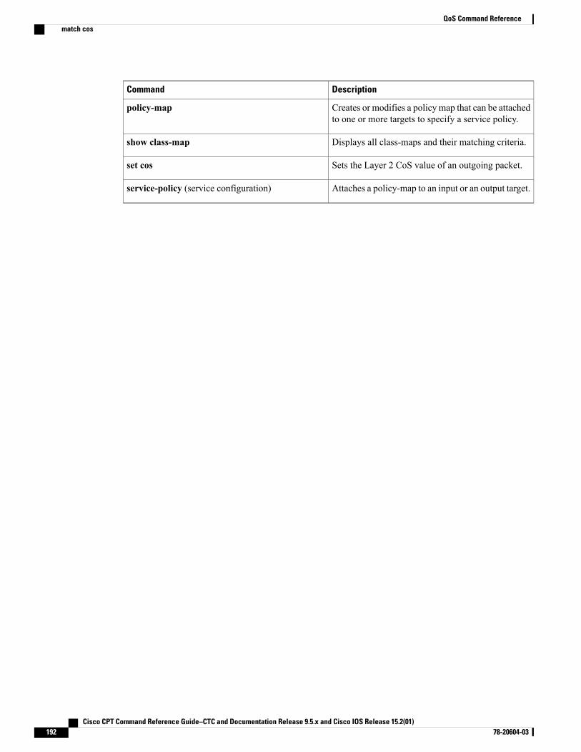
DescriptionCommand
Creates or modifies a policy map that can be attachedto one or more targets to specify a service policy.
policy-map
Displays all class-maps and their matching criteria.show class-map
Sets the Layer 2 CoS value of an outgoing packet.set cos
Attaches a policy-map to an input or an output target.service-policy (service configuration)
Cisco CPT Command Reference Guide–CTC and Documentation Release 9.5.x and Cisco IOS Release 15.2(01)192 78-20604-03
QoS Command Referencematch cos
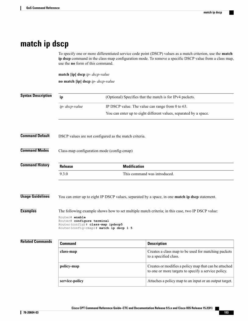
match ip dscpTo specify one or more differentiated service code point (DSCP) values as a match criterion, use thematchip dscp command in the class-map configuration mode. To remove a specific DSCP value from a class map,use the no form of this command.
match [ip] dscp ip- dscp-value
no match [ip] dscp ip- dscp-value
Syntax Description (Optional) Specifies that the match is for IPv4 packets.ip
IP DSCP value. The value can range from 0 to 63.
You can enter up to eight different values, separated by a space.
ip- dscp-value
Command Default DSCP values are not configured as the match criteria.
Command Modes Class-map configuration mode (config-cmap)
Command History ModificationRelease
This command was introduced.9.3.0
Usage Guidelines You can enter up to eight IP DSCP values, separated by a space, in onematch ip dscp statement.
Examples The following example shows how to set multiple match criteria; in this case, two IP DSCP value:Router# enableRouter# configure terminalRouter(config)# class-map ipdscp5Router(config-cmap)# match ip dscp 1 5
Related Commands DescriptionCommand
Creates a class map to be used for matching packetsto a specified class.
class-map
Creates or modifies a policy map that can be attachedto one or more targets to specify a service policy.
policy-map
Attaches a policy map to an input or an output target.service-policy
Cisco CPT Command Reference Guide–CTC and Documentation Release 9.5.x and Cisco IOS Release 15.2(01) 78-20604-03 193
QoS Command Referencematch ip dscp

DescriptionCommand
Displays all class-maps and their matching criteria.show class-map
Marks the precedence value in the IP header with avalue between 0 to 63.
set ip dscp
Cisco CPT Command Reference Guide–CTC and Documentation Release 9.5.x and Cisco IOS Release 15.2(01)194 78-20604-03
QoS Command Referencematch ip dscp
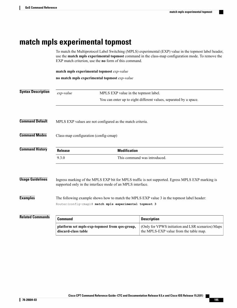
match mpls experimental topmostTo match the Multiprotocol Label Switching (MPLS) experimental (EXP) value in the topmost label header,use thematch mpls experimental topmost command in the class-map configuration mode. To remove theEXP match criterion, use the no form of this command.
match mpls experimental topmost exp-value
no match mpls experimental topmost exp-value
Syntax Description MPLS EXP value in the topmost label.
You can enter up to eight different values, separated by a space.
exp-value
Command Default MPLS EXP values are not configured as the match criteria.
Command Modes Class-map configuration (config-cmap)
Command History ModificationRelease
This command was introduced.9.3.0
Usage Guidelines Ingress marking of the MPLS EXP bit for MPLS traffic is not supported. Egress MPLS EXP marking issupported only in the interface mode of an MPLS interface.
Examples The following example shows how to match the MPLS EXP value 3 in the topmost label header:Router(config-cmap)# match mpls experimental topmost 3
Related Commands DescriptionCommand
(Only for VPWS initiation and LSR scenarios) Mapsthe MPLS-EXP value from the table map.
platform set mpls-exp-topmost from qos-group,discard-class table
Cisco CPT Command Reference Guide–CTC and Documentation Release 9.5.x and Cisco IOS Release 15.2(01) 78-20604-03 195
QoS Command Referencematch mpls experimental topmost
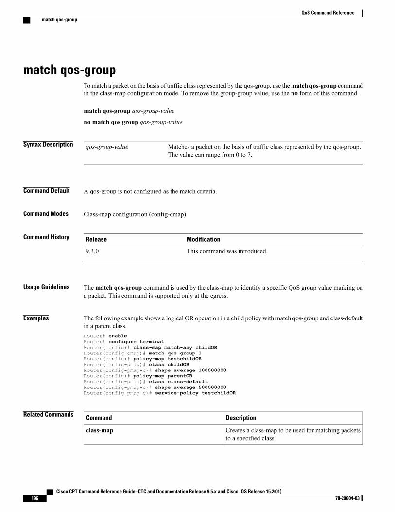
match qos-groupTomatch a packet on the basis of traffic class represented by the qos-group, use thematch qos-group commandin the class-map configuration mode. To remove the group-group value, use the no form of this command.
match qos-group qos-group-value
no match qos group qos-group-value
Syntax Description Matches a packet on the basis of traffic class represented by the qos-group.The value can range from 0 to 7.
qos-group-value
Command Default A qos-group is not configured as the match criteria.
Command Modes Class-map configuration (config-cmap)
Command History ModificationRelease
This command was introduced.9.3.0
Usage Guidelines Thematch qos-group command is used by the class-map to identify a specific QoS group value marking ona packet. This command is supported only at the egress.
Examples The following example shows a logical OR operation in a child policy with match qos-group and class-defaultin a parent class.Router# enableRouter# configure terminalRouter(config)# class-map match-any childORRouter(config-cmap)# match qos-group 1Router(config)# policy-map testchildORRouter(config-pmap)# class childORRouter(config-pmap-c)# shape average 100000000Router(config)# policy-map parentORRouter(config-pmap)# class class-defaultRouter(config-pmap-c)# shape average 500000000Router(config-pmap-c)# service-policy testchildOR
Related Commands DescriptionCommand
Creates a class-map to be used for matching packetsto a specified class.
class-map
Cisco CPT Command Reference Guide–CTC and Documentation Release 9.5.x and Cisco IOS Release 15.2(01)196 78-20604-03
QoS Command Referencematch qos-group

DescriptionCommand
Specifies the name of the class whose policy you wantto create or change
class-name {class-name | class-default }
Creates or modifies a policy-map that can be attachedto one or more targets to specify a service policy.
policy-map
Cisco CPT Command Reference Guide–CTC and Documentation Release 9.5.x and Cisco IOS Release 15.2(01) 78-20604-03 197
QoS Command Referencematch qos-group
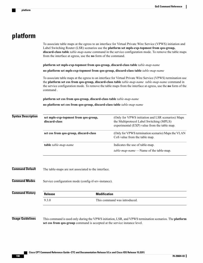
platformTo associate table maps at the egress to an interface for Virtual Private Wire Service (VPWS) initiation andLabel Switching Router (LSR) scenarios use the platform set mpls-exp-topmost from qos-group,discard-class table table-map-name command in the service configuration mode. To remove the table mapsfrom the interface at egress, use the no form of the command.
platform set mpls-exp-topmost from qos-group, discard-class table table-map-name
no platform set mpls-exp-topmost from qos-group, discard-class table table-map-name
To associate table maps at the egress to an interface for Virtual Private Wire Service (VPWS) termination usethe platform set cos from qos-group, discard-class table table-map-name table-map-name command inthe service configuration mode. To remove the table maps from the interface at egress, use the no form of thecommand .
platform set cos from qos-group, discard-class table table-map-name
no platform set cos from qos-group, discard-class table table-map-name
Syntax Description (Only for VPWS initiation and LSR scenarios) Mapsthe Multiprotocol Label Switching (MPLS)experimental (EXP) value from the table map.
set mpls-exp-topmost from qos-group,discard-class
(Only for VPWS termination scenario)Maps theVLANCoS value from the table map.
set cos from qos-group, discard-class
Indicates the use of table-map.
table-map-name—Name of the table-map.
table table-map-name
Command Default The table-maps are not associated to the interface.
Command Modes Service configuration mode (config-if-srv-instance).
Command History ModificationRelease
This command was introduced.9.3.0
Usage Guidelines This command is used only during the VPWS initiation, LSR, and VPWS termination scenarios. The platformset cos from qos-group command is accepted at the service instance level.
Cisco CPT Command Reference Guide–CTC and Documentation Release 9.5.x and Cisco IOS Release 15.2(01)198 78-20604-03
QoS Command Referenceplatform
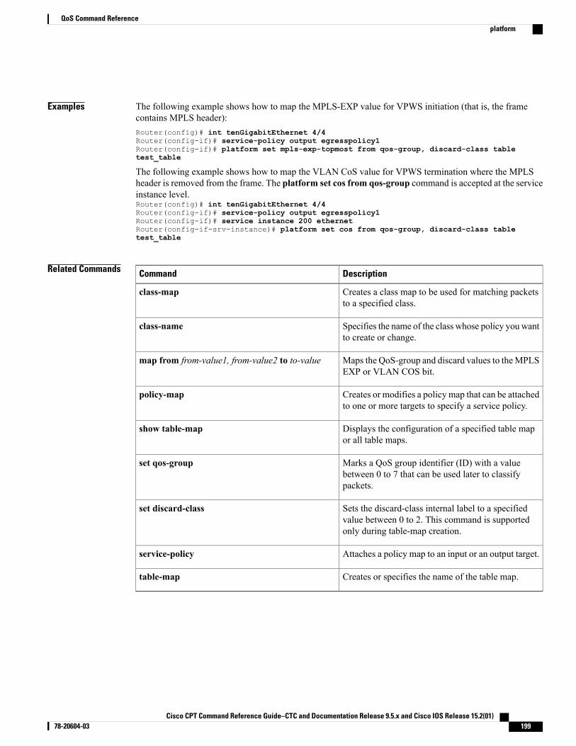
Examples The following example shows how to map the MPLS-EXP value for VPWS initiation (that is, the framecontains MPLS header):Router(config)# int tenGigabitEthernet 4/4Router(config-if)# service-policy output egresspolicy1Router(config-if)# platform set mpls-exp-topmost from qos-group, discard-class tabletest_table
The following example shows how to map the VLAN CoS value for VPWS termination where the MPLSheader is removed from the frame. The platform set cos from qos-group command is accepted at the serviceinstance level.Router(config)# int tenGigabitEthernet 4/4Router(config-if)# service-policy output egresspolicy1Router(config-if)# service instance 200 ethernetRouter(config-if-srv-instance)# platform set cos from qos-group, discard-class tabletest_table
Related Commands DescriptionCommand
Creates a class map to be used for matching packetsto a specified class.
class-map
Specifies the name of the class whose policy you wantto create or change.
class-name
Maps the QoS-group and discard values to theMPLSEXP or VLAN COS bit.
map from from-value1, from-value2 to to-value
Creates or modifies a policy map that can be attachedto one or more targets to specify a service policy.
policy-map
Displays the configuration of a specified table mapor all table maps.
show table-map
Marks a QoS group identifier (ID) with a valuebetween 0 to 7 that can be used later to classifypackets.
set qos-group
Sets the discard-class internal label to a specifiedvalue between 0 to 2. This command is supportedonly during table-map creation.
set discard-class
Attaches a policy map to an input or an output target.service-policy
Creates or specifies the name of the table map.table-map
Cisco CPT Command Reference Guide–CTC and Documentation Release 9.5.x and Cisco IOS Release 15.2(01) 78-20604-03 199
QoS Command Referenceplatform
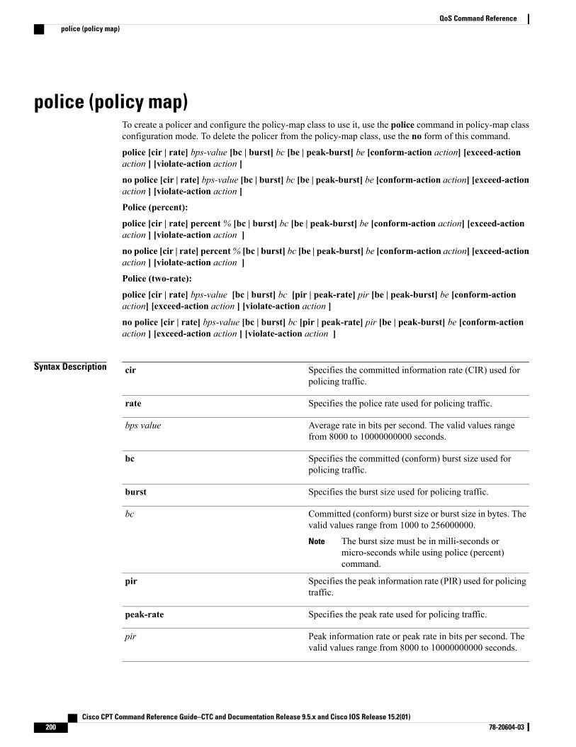
police (policy map)To create a policer and configure the policy-map class to use it, use the police command in policy-map classconfiguration mode. To delete the policer from the policy-map class, use the no form of this command.
police [cir | rate] bps-value [bc | burst] bc [be | peak-burst] be [conform-action action] [exceed-actionaction ] [violate-action action ]
no police [cir | rate] bps-value [bc | burst] bc [be | peak-burst] be [conform-action action] [exceed-actionaction ] [violate-action action ]
Police (percent):
police [cir | rate] percent% [bc | burst] bc [be | peak-burst] be [conform-action action] [exceed-actionaction ] [violate-action action ]
no police [cir | rate] percent% [bc | burst] bc [be | peak-burst] be [conform-action action] [exceed-actionaction ] [violate-action action ]
Police (two-rate):
police [cir | rate] bps-value [bc | burst] bc [pir | peak-rate] pir [be | peak-burst] be [conform-actionaction] [exceed-action action ] [violate-action action ]
no police [cir | rate] bps-value [bc | burst] bc [pir | peak-rate] pir [be | peak-burst] be [conform-actionaction ] [exceed-action action ] [violate-action action ]
Syntax Description Specifies the committed information rate (CIR) used forpolicing traffic.
cir
Specifies the police rate used for policing traffic.rate
Average rate in bits per second. The valid values rangefrom 8000 to 10000000000 seconds.
bps value
Specifies the committed (conform) burst size used forpolicing traffic.
bc
Specifies the burst size used for policing traffic.burst
Committed (conform) burst size or burst size in bytes. Thevalid values range from 1000 to 256000000.
The burst size must be in milli-seconds ormicro-seconds while using police (percent)command.
Note
bc
Specifies the peak information rate (PIR) used for policingtraffic.
pir
Specifies the peak rate used for policing traffic.peak-rate
Peak information rate or peak rate in bits per second. Thevalid values range from 8000 to 10000000000 seconds.
pir
Cisco CPT Command Reference Guide–CTC and Documentation Release 9.5.x and Cisco IOS Release 15.2(01)200 78-20604-03
QoS Command Referencepolice (policy map)
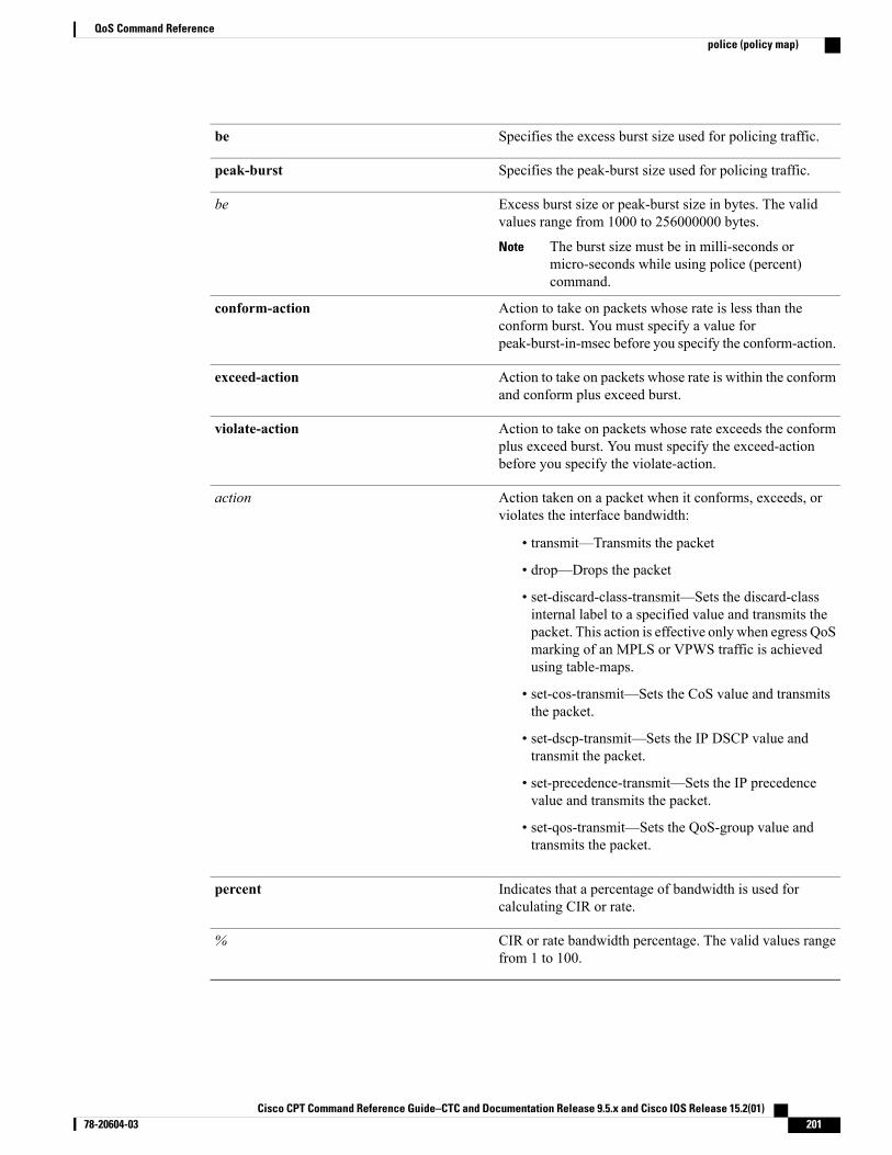
Specifies the excess burst size used for policing traffic.be
Specifies the peak-burst size used for policing traffic.peak-burst
Excess burst size or peak-burst size in bytes. The validvalues range from 1000 to 256000000 bytes.
The burst size must be in milli-seconds ormicro-seconds while using police (percent)command.
Note
be
Action to take on packets whose rate is less than theconform burst. You must specify a value forpeak-burst-in-msec before you specify the conform-action.
conform-action
Action to take on packets whose rate is within the conformand conform plus exceed burst.
exceed-action
Action to take on packets whose rate exceeds the conformplus exceed burst. You must specify the exceed-actionbefore you specify the violate-action.
violate-action
Action taken on a packet when it conforms, exceeds, orviolates the interface bandwidth:
• transmit—Transmits the packet
• drop—Drops the packet
• set-discard-class-transmit—Sets the discard-classinternal label to a specified value and transmits thepacket. This action is effective only when egress QoSmarking of an MPLS or VPWS traffic is achievedusing table-maps.
• set-cos-transmit—Sets the CoS value and transmitsthe packet.
• set-dscp-transmit—Sets the IP DSCP value andtransmit the packet.
• set-precedence-transmit—Sets the IP precedencevalue and transmits the packet.
• set-qos-transmit—Sets the QoS-group value andtransmits the packet.
action
Indicates that a percentage of bandwidth is used forcalculating CIR or rate.
percent
CIR or rate bandwidth percentage. The valid values rangefrom 1 to 100.
%
Cisco CPT Command Reference Guide–CTC and Documentation Release 9.5.x and Cisco IOS Release 15.2(01) 78-20604-03 201
QoS Command Referencepolice (policy map)
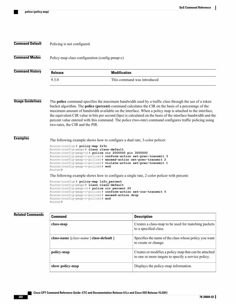
Command Default Policing is not configured.
Command Modes Policy-map class configuration (config-pmap-c)
Command History ModificationRelease
This command was introduced9.3.0
Usage Guidelines The police command specifies the maximum bandwidth used by a traffic class through the use of a tokenbucket algorithm. The police (percent) command calculates the CIR on the basis of a percentage of themaximum amount of bandwidth available on the interface. When a policy map is attached to the interface,the equivalent CIR value in bits per second (bps) is calculated on the basis of the interface bandwidth and thepercent value entered with this command. The police (two-rate) command configures traffic policing usingtwo-rates, the CIR and the PIR.
Examples The following example shows how to configure a dual rate, 3-color policer:Router(config)# policy-map 2r3cRouter(config-pmap)# class class-defaultRouter(config-pmap-c)# police cir 2000000 pir 3000000Router(config-pmap-c-police)# conform-action set-prec-transmit 3Router(config-pmap-c-police)# exceed-action set-prec-transmit 2Router(config-pmap-c-police)# violate-action set-prec-transmit 1Router(config-pmap-c-police)# endRouter#
The following example shows how to configure a single rate, 2-color policer with percent:Router(config)# policy-map 1r2c_percentRouter(config-pmap)# class class-defaultRouter(config-pmap-c)# police cir percent 20Router(config-pmap-c-police)# conform-action set-cos-transmit 0Router(config-pmap-c-police)# exceed-action dropRouter(config-pmap-c-police)# endRouter#
Related Commands DescriptionCommand
Creates a class-map to be used for matching packetsto a specified class.
class-map
Specifies the name of the class whose policy you wantto create or change.
class-name {class-name | class-default }
Creates or modifies a policy map that can be attachedto one or more targets to specify a service policy.
policy-map
Displays the policy-map information.show policy-map
Cisco CPT Command Reference Guide–CTC and Documentation Release 9.5.x and Cisco IOS Release 15.2(01)202 78-20604-03
QoS Command Referencepolice (policy map)

Cisco CPT Command Reference Guide–CTC and Documentation Release 9.5.x and Cisco IOS Release 15.2(01) 78-20604-03 203
QoS Command Referencepolice (policy map)
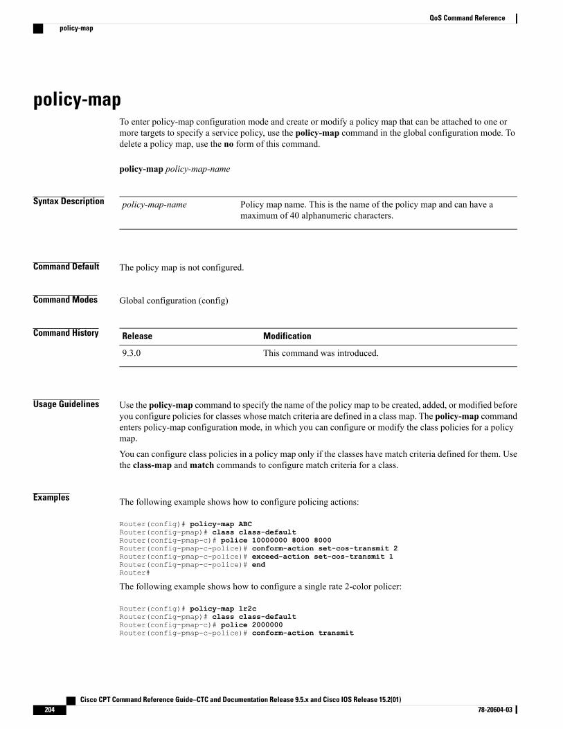
policy-mapTo enter policy-map configuration mode and create or modify a policy map that can be attached to one ormore targets to specify a service policy, use the policy-map command in the global configuration mode. Todelete a policy map, use the no form of this command.
policy-map policy-map-name
Syntax Description Policy map name. This is the name of the policy map and can have amaximum of 40 alphanumeric characters.
policy-map-name
Command Default The policy map is not configured.
Command Modes Global configuration (config)
Command History ModificationRelease
This command was introduced.9.3.0
Usage Guidelines Use the policy-map command to specify the name of the policy map to be created, added, or modified beforeyou configure policies for classes whose match criteria are defined in a class map. The policy-map commandenters policy-map configuration mode, in which you can configure or modify the class policies for a policymap.
You can configure class policies in a policy map only if the classes have match criteria defined for them. Usethe class-map andmatch commands to configure match criteria for a class.
Examples The following example shows how to configure policing actions:
Router(config)# policy-map ABCRouter(config-pmap)# class class-defaultRouter(config-pmap-c)# police 10000000 8000 8000Router(config-pmap-c-police)# conform-action set-cos-transmit 2Router(config-pmap-c-police)# exceed-action set-cos-transmit 1Router(config-pmap-c-police)# endRouter#
The following example shows how to configure a single rate 2-color policer:
Router(config)# policy-map 1r2cRouter(config-pmap)# class class-defaultRouter(config-pmap-c)# police 2000000Router(config-pmap-c-police)# conform-action transmit
Cisco CPT Command Reference Guide–CTC and Documentation Release 9.5.x and Cisco IOS Release 15.2(01)204 78-20604-03
QoS Command Referencepolicy-map
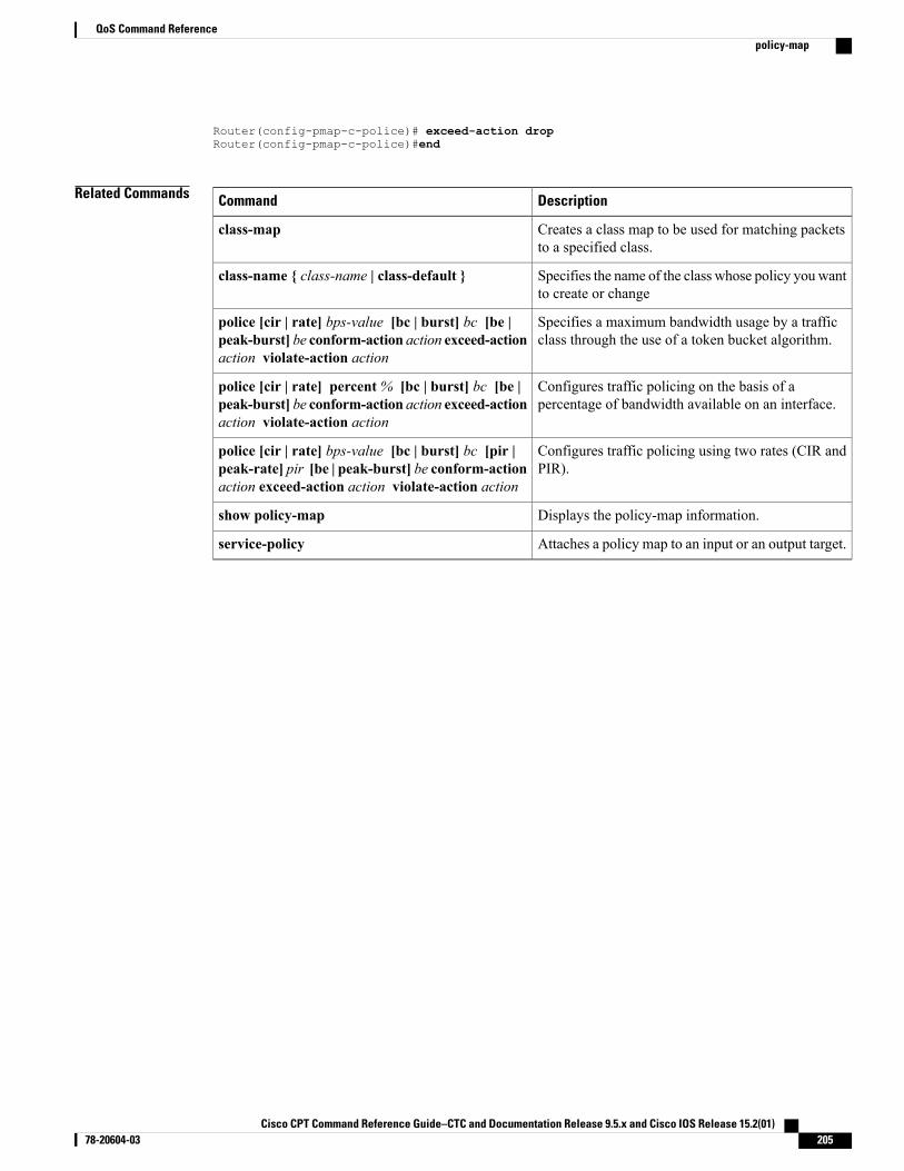
Router(config-pmap-c-police)# exceed-action dropRouter(config-pmap-c-police)#end
Related Commands DescriptionCommand
Creates a class map to be used for matching packetsto a specified class.
class-map
Specifies the name of the class whose policy you wantto create or change
class-name { class-name | class-default }
Specifies a maximum bandwidth usage by a trafficclass through the use of a token bucket algorithm.
police [cir | rate] bps-value [bc | burst] bc [be |peak-burst] be conform-action action exceed-actionaction violate-action action
Configures traffic policing on the basis of apercentage of bandwidth available on an interface.
police [cir | rate] percent% [bc | burst] bc [be |peak-burst] be conform-action action exceed-actionaction violate-action action
Configures traffic policing using two rates (CIR andPIR).
police [cir | rate] bps-value [bc | burst] bc [pir |peak-rate] pir [be | peak-burst] be conform-actionaction exceed-action action violate-action action
Displays the policy-map information.show policy-map
Attaches a policy map to an input or an output target.service-policy
Cisco CPT Command Reference Guide–CTC and Documentation Release 9.5.x and Cisco IOS Release 15.2(01) 78-20604-03 205
QoS Command Referencepolicy-map
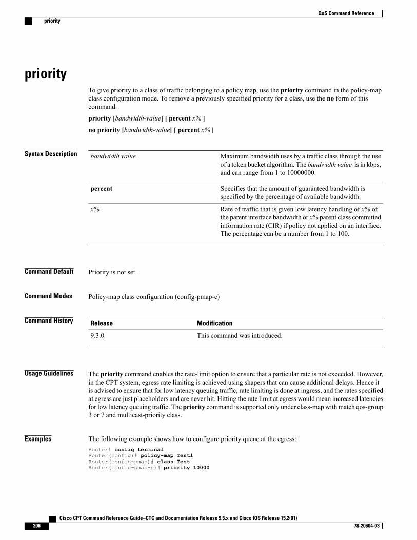
priorityTo give priority to a class of traffic belonging to a policy map, use the priority command in the policy-mapclass configuration mode. To remove a previously specified priority for a class, use the no form of thiscommand.
priority [bandwidth-value] [ percent x% ]
no priority [bandwidth-value] [ percent x% ]
Syntax Description Maximum bandwidth uses by a traffic class through the useof a token bucket algorithm. The bandwidth value is in kbps,and can range from 1 to 10000000.
bandwidth value
Specifies that the amount of guaranteed bandwidth isspecified by the percentage of available bandwidth.
percent
Rate of traffic that is given low latency handling of x% ofthe parent interface bandwidth or x% parent class committedinformation rate (CIR) if policy not applied on an interface.The percentage can be a number from 1 to 100.
x%
Command Default Priority is not set.
Command Modes Policy-map class configuration (config-pmap-c)
Command History ModificationRelease
This command was introduced.9.3.0
Usage Guidelines The priority command enables the rate-limit option to ensure that a particular rate is not exceeded. However,in the CPT system, egress rate limiting is achieved using shapers that can cause additional delays. Hence itis advised to ensure that for low latency queuing traffic, rate limiting is done at ingress, and the rates specifiedat egress are just placeholders and are never hit. Hitting the rate limit at egress would mean increased latenciesfor low latency queuing traffic. The priority command is supported only under class-mapwithmatch qos-group3 or 7 and multicast-priority class.
Examples The following example shows how to configure priority queue at the egress:Router# config terminalRouter(config)# policy-map Test1Router(config-pmap)# class TestRouter(config-pmap-c)# priority 10000
Cisco CPT Command Reference Guide–CTC and Documentation Release 9.5.x and Cisco IOS Release 15.2(01)206 78-20604-03
QoS Command Referencepriority
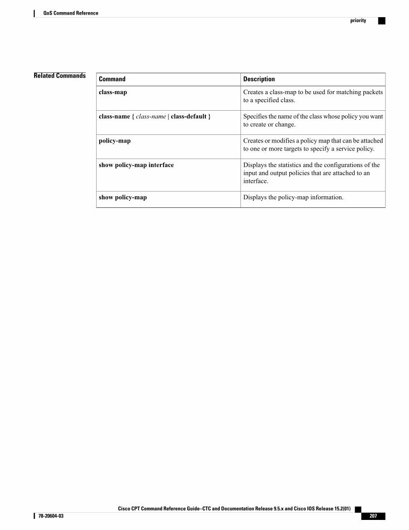
Related Commands DescriptionCommand
Creates a class-map to be used for matching packetsto a specified class.
class-map
Specifies the name of the class whose policy you wantto create or change.
class-name { class-name | class-default }
Creates or modifies a policy map that can be attachedto one or more targets to specify a service policy.
policy-map
Displays the statistics and the configurations of theinput and output policies that are attached to aninterface.
show policy-map interface
Displays the policy-map information.show policy-map
Cisco CPT Command Reference Guide–CTC and Documentation Release 9.5.x and Cisco IOS Release 15.2(01) 78-20604-03 207
QoS Command Referencepriority
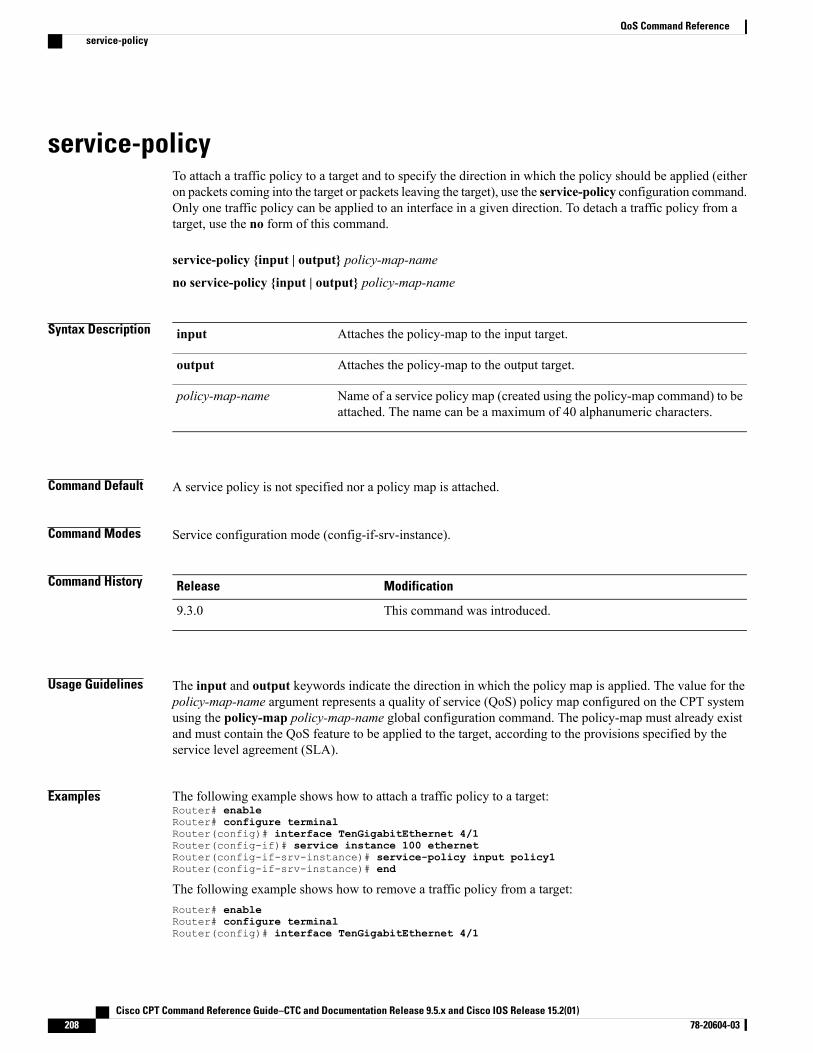
service-policyTo attach a traffic policy to a target and to specify the direction in which the policy should be applied (eitheron packets coming into the target or packets leaving the target), use the service-policy configuration command.Only one traffic policy can be applied to an interface in a given direction. To detach a traffic policy from atarget, use the no form of this command.
service-policy {input | output} policy-map-name
no service-policy {input | output} policy-map-name
Syntax Description Attaches the policy-map to the input target.input
Attaches the policy-map to the output target.output
Name of a service policy map (created using the policy-map command) to beattached. The name can be a maximum of 40 alphanumeric characters.
policy-map-name
Command Default A service policy is not specified nor a policy map is attached.
Command Modes Service configuration mode (config-if-srv-instance).
Command History ModificationRelease
This command was introduced.9.3.0
Usage Guidelines The input and output keywords indicate the direction in which the policy map is applied. The value for thepolicy-map-name argument represents a quality of service (QoS) policy map configured on the CPT systemusing the policy-map policy-map-name global configuration command. The policy-map must already existand must contain the QoS feature to be applied to the target, according to the provisions specified by theservice level agreement (SLA).
Examples The following example shows how to attach a traffic policy to a target:Router# enableRouter# configure terminalRouter(config)# interface TenGigabitEthernet 4/1Router(config-if)# service instance 100 ethernetRouter(config-if-srv-instance)# service-policy input policy1Router(config-if-srv-instance)# end
The following example shows how to remove a traffic policy from a target:Router# enableRouter# configure terminalRouter(config)# interface TenGigabitEthernet 4/1
Cisco CPT Command Reference Guide–CTC and Documentation Release 9.5.x and Cisco IOS Release 15.2(01)208 78-20604-03
QoS Command Referenceservice-policy
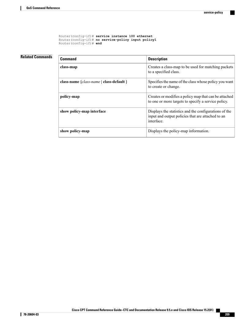
Router(config-if)# service instance 100 ethernetRouter(config-if)# no service-policy input policy1Router(config-if)# end
Related Commands DescriptionCommand
Creates a class-map to be used for matching packetsto a specified class.
class-map
Specifies the name of the class whose policy you wantto create or change.
class-name {class-name | class-default }
Creates or modifies a policy map that can be attachedto one or more targets to specify a service policy.
policy-map
Displays the statistics and the configurations of theinput and output policies that are attached to aninterface.
show policy-map interface
Displays the policy-map information.show policy-map
Cisco CPT Command Reference Guide–CTC and Documentation Release 9.5.x and Cisco IOS Release 15.2(01) 78-20604-03 209
QoS Command Referenceservice-policy
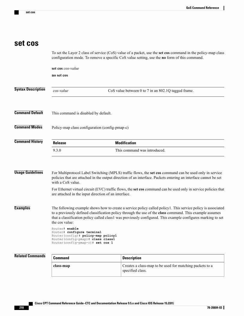
set cosTo set the Layer 2 class of service (CoS) value of a packet, use the set cos command in the policy-map classconfiguration mode. To remove a specific CoS value setting, use the no form of this command.
set cos cos-value
no set cos
Syntax Description CoS value between 0 to 7 in an 802.1Q tagged frame.cos-value
Command Default This command is disabled by default.
Command Modes Policy-map class configuration (config-pmap-c)
Command History ModificationRelease
This command was introduced.9.3.0
Usage Guidelines For Multiprotocol Label Switching (MPLS) traffic flows, the set cos command can be used only in servicepolicies that are attached in the output direction of an interface. Packets entering an interface cannot be setwith a CoS value.
For Ethernet virtual circuit (EVC) traffic flows, the set cos command can be used only in service policies thatare attached in the input direction of an interface.
Examples The following example shows how to create a service policy called policy1. This service policy is associatedto a previously defined classification policy through the use of the class command. This example assumesthat a classification policy called class1 was previously configured. This example configures marking to setthe cos value:Router# enableRouter# configure terminalRouter(config)# policy-map policy1Router(config-pmap)# class class1Router(config-pmap-c)# set cos 1
Related Commands DescriptionCommand
Creates a class-map to be used for matching packets to aspecified class.
class-map
Cisco CPT Command Reference Guide–CTC and Documentation Release 9.5.x and Cisco IOS Release 15.2(01)210 78-20604-03
QoS Command Referenceset cos
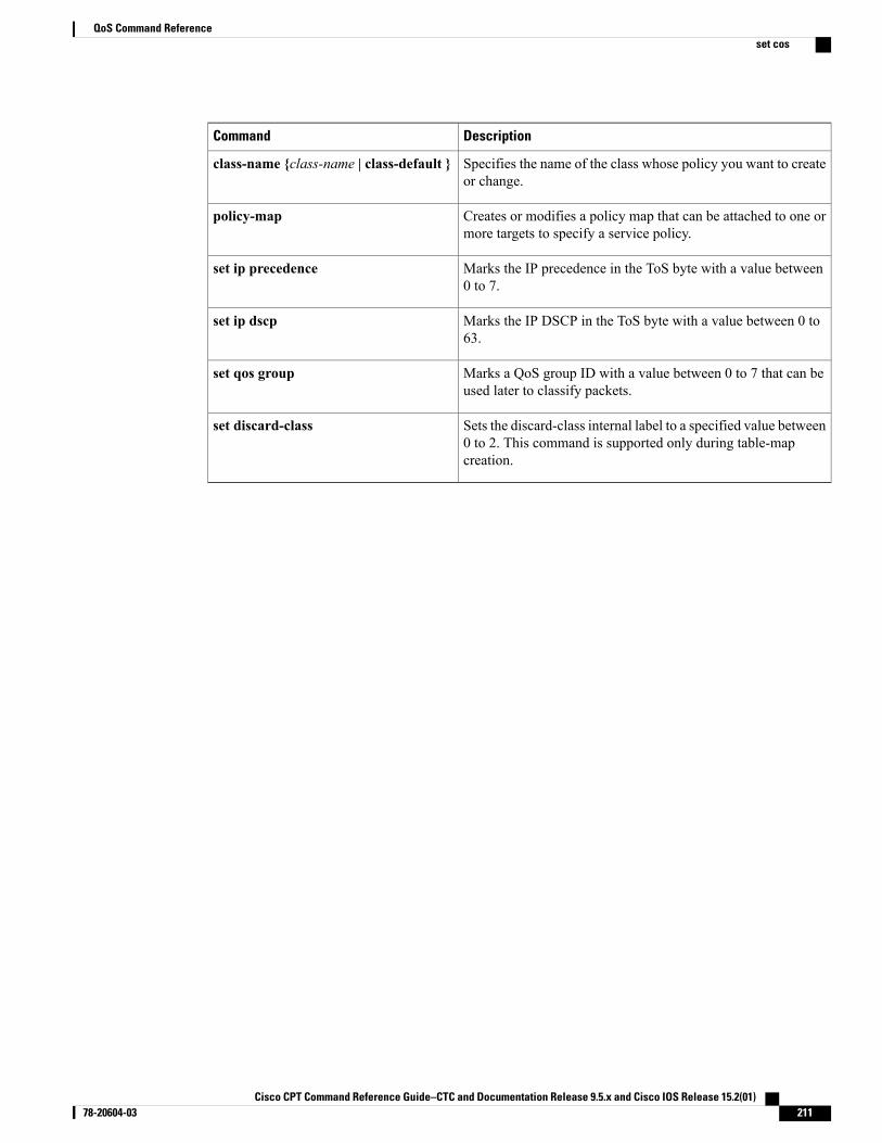
DescriptionCommand
Specifies the name of the class whose policy you want to createor change.
class-name {class-name | class-default }
Creates or modifies a policy map that can be attached to one ormore targets to specify a service policy.
policy-map
Marks the IP precedence in the ToS byte with a value between0 to 7.
set ip precedence
Marks the IP DSCP in the ToS byte with a value between 0 to63.
set ip dscp
Marks a QoS group ID with a value between 0 to 7 that can beused later to classify packets.
set qos group
Sets the discard-class internal label to a specified value between0 to 2. This command is supported only during table-mapcreation.
set discard-class
Cisco CPT Command Reference Guide–CTC and Documentation Release 9.5.x and Cisco IOS Release 15.2(01) 78-20604-03 211
QoS Command Referenceset cos
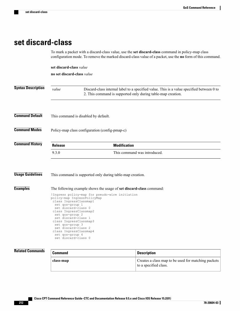
set discard-classTo mark a packet with a discard-class value, use the set discard-class command in policy-map classconfiguration mode. To remove the marked discard-class value of a packet, use the no form of this command.
set discard-class value
no set discard-class value
Syntax Description Discard-class internal label to a specified value. This is a value specified between 0 to2. This command is supported only during table-map creation.
value
Command Default This command is disabled by default.
Command Modes Policy-map class configuration (config-pmap-c)
Command History ModificationRelease
This command was introduced.9.3.0
Usage Guidelines This command is supported only during table-map creation.
Examples The following example shows the usage of set discard-class command:!Ingress policy-map for pseudo-wire initiationpolicy-map IngressPolicyMapclass IngressClassmap1set qos-group 1set discard-class 0class IngressClassmap2set qos-group 2set discard-class 1class IngressClassmap3set qos-group 3set discard-class 2class IngressClassmap4set qos-group 4set discard-class 0
Related Commands DescriptionCommand
Creates a class map to be used for matching packetsto a specified class.
class-map
Cisco CPT Command Reference Guide–CTC and Documentation Release 9.5.x and Cisco IOS Release 15.2(01)212 78-20604-03
QoS Command Referenceset discard-class
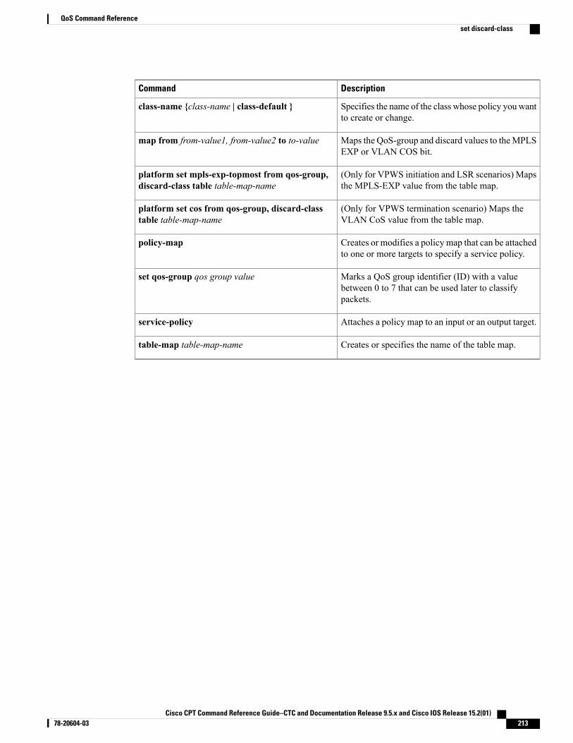
DescriptionCommand
Specifies the name of the class whose policy you wantto create or change.
class-name {class-name | class-default }
Maps the QoS-group and discard values to theMPLSEXP or VLAN COS bit.
map from from-value1, from-value2 to to-value
(Only for VPWS initiation and LSR scenarios) Mapsthe MPLS-EXP value from the table map.
platform set mpls-exp-topmost from qos-group,discard-class table table-map-name
(Only for VPWS termination scenario) Maps theVLAN CoS value from the table map.
platform set cos from qos-group, discard-classtable table-map-name
Creates or modifies a policy map that can be attachedto one or more targets to specify a service policy.
policy-map
Marks a QoS group identifier (ID) with a valuebetween 0 to 7 that can be used later to classifypackets.
set qos-group qos group value
Attaches a policy map to an input or an output target.service-policy
Creates or specifies the name of the table map.table-map table-map-name
Cisco CPT Command Reference Guide–CTC and Documentation Release 9.5.x and Cisco IOS Release 15.2(01) 78-20604-03 213
QoS Command Referenceset discard-class
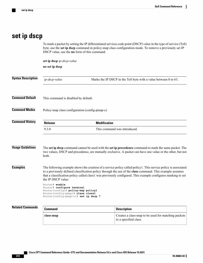
set ip dscpTo mark a packet by setting the IP differentiated services code point (DSCP) value in the type of service (ToS)byte, use the set ip dscp command in policy-map class configuration mode. To remove a previously set IPDSCP value, use the no form of this command.
set ip dscp ip-dscp-value
no set ip dscp
Syntax Description Marks the IP DSCP in the ToS byte with a value between 0 to 63.ip-dscp-value
Command Default This command is disabled by default.
Command Modes Policy-map class configuration (config-pmap-c)
Command History ModificationRelease
This command was introduced.9.3.0
Usage Guidelines The set ip dscp command cannot be used with the set ip precedence command to mark the same packet. Thetwo values, DSCP and precedence, are mutually exclusive. A packet can have one value or the other, but notboth.
Examples The following example shows the creation of a service policy called policy1. This service policy is associatedto a previously defined classification policy through the use of the class command. This example assumesthat a classification policy called class1 was previously configured. This example configures marking to setthe IP DSCP value:Router# enableRouter# configure terminalRouter(config)# policy-map policy1Router(config-pmap)# class class1Router(config-pmap-c)# set ip dscp 7
Related Commands DescriptionCommand
Creates a class-map to be used for matching packetsto a specified class.
class-map
Cisco CPT Command Reference Guide–CTC and Documentation Release 9.5.x and Cisco IOS Release 15.2(01)214 78-20604-03
QoS Command Referenceset ip dscp
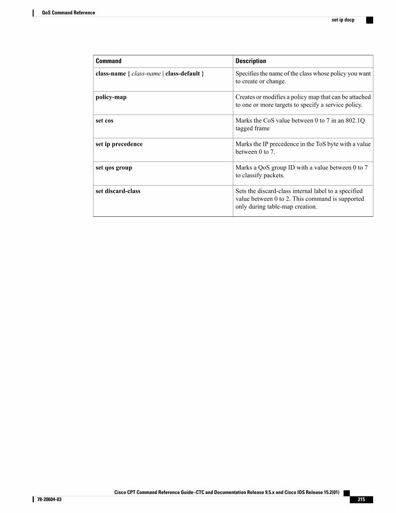
DescriptionCommand
Specifies the name of the class whose policy you wantto create or change.
class-name { class-name | class-default }
Creates or modifies a policy map that can be attachedto one or more targets to specify a service policy.
policy-map
Marks the CoS value between 0 to 7 in an 802.1Qtagged frame
set cos
Marks the IP precedence in the ToS byte with a valuebetween 0 to 7.
set ip precedence
Marks a QoS group ID with a value between 0 to 7to classify packets.
set qos group
Sets the discard-class internal label to a specifiedvalue between 0 to 2. This command is supportedonly during table-map creation.
set discard-class
Cisco CPT Command Reference Guide–CTC and Documentation Release 9.5.x and Cisco IOS Release 15.2(01) 78-20604-03 215
QoS Command Referenceset ip dscp
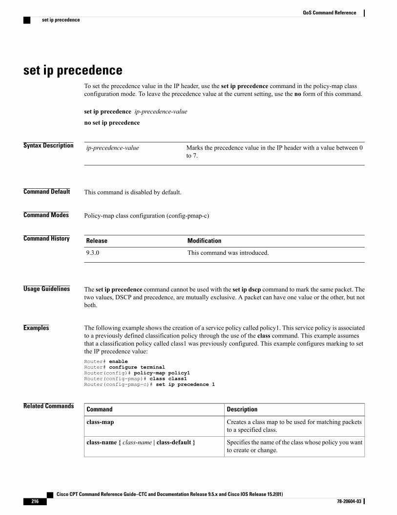
set ip precedenceTo set the precedence value in the IP header, use the set ip precedence command in the policy-map classconfiguration mode. To leave the precedence value at the current setting, use the no form of this command.
set ip precedence ip-precedence-value
no set ip precedence
Syntax Description Marks the precedence value in the IP header with a value between 0to 7.
ip-precedence-value
Command Default This command is disabled by default.
Command Modes Policy-map class configuration (config-pmap-c)
Command History ModificationRelease
This command was introduced.9.3.0
Usage Guidelines The set ip precedence command cannot be used with the set ip dscp command to mark the same packet. Thetwo values, DSCP and precedence, are mutually exclusive. A packet can have one value or the other, but notboth.
Examples The following example shows the creation of a service policy called policy1. This service policy is associatedto a previously defined classification policy through the use of the class command. This example assumesthat a classification policy called class1 was previously configured. This example configures marking to setthe IP precedence value:Router# enableRouter# configure terminalRouter(config)# policy-map policy1Router(config-pmap)# class class1Router(config-pmap-c)# set ip precedence 1
Related Commands DescriptionCommand
Creates a class map to be used for matching packetsto a specified class.
class-map
Specifies the name of the class whose policy you wantto create or change.
class-name { class-name | class-default }
Cisco CPT Command Reference Guide–CTC and Documentation Release 9.5.x and Cisco IOS Release 15.2(01)216 78-20604-03
QoS Command Referenceset ip precedence
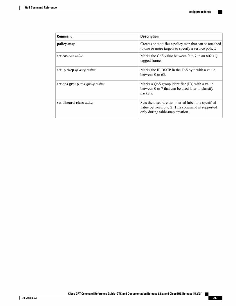
DescriptionCommand
Creates or modifies a policy map that can be attachedto one or more targets to specify a service policy.
policy-map
Marks the CoS value between 0 to 7 in an 802.1Qtagged frame.
set cos cos value
Marks the IP DSCP in the ToS byte with a valuebetween 0 to 63.
set ip dscp ip dscp value
Marks a QoS group identifier (ID) with a valuebetween 0 to 7 that can be used later to classifypackets.
set qos group qos group value
Sets the discard-class internal label to a specifiedvalue between 0 to 2. This command is supportedonly during table-map creation.
set discard-class value
Cisco CPT Command Reference Guide–CTC and Documentation Release 9.5.x and Cisco IOS Release 15.2(01) 78-20604-03 217
QoS Command Referenceset ip precedence
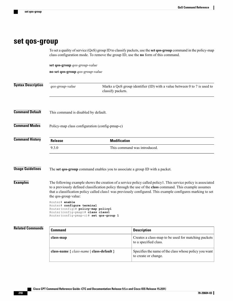
set qos-groupTo set a quality of service (QoS) group ID to classify packets, use the set qos-group command in the policy-mapclass configuration mode. To remove the group ID, use the no form of this command.
set qos-group qos-group-value
no set qos-group qos-group-value
Syntax Description Marks a QoS group identifier (ID) with a value between 0 to 7 is used toclassify packets.
qos-group-value
Command Default This command is disabled by default.
Command Modes Policy-map class configuration (config-pmap-c)
Command History ModificationRelease
This command was introduced.9.3.0
Usage Guidelines The set qos-group command enables you to associate a group ID with a packet.
Examples The following example shows the creation of a service policy called policy1. This service policy is associatedto a previously defined classification policy through the use of the class command. This example assumesthat a classification policy called class1 was previously configured. This example configures marking to setthe qos-group value:Router# enableRouter# configure terminalRouter(config)# policy-map policy1Router(config-pmap)# class class1Router(config-pmap-c)# set qos-group 1
Related Commands DescriptionCommand
Creates a class-map to be used for matching packetsto a specified class.
class-map
Specifies the name of the class whose policy you wantto create or change.
class-name { class-name | class-default }
Cisco CPT Command Reference Guide–CTC and Documentation Release 9.5.x and Cisco IOS Release 15.2(01)218 78-20604-03
QoS Command Referenceset qos-group
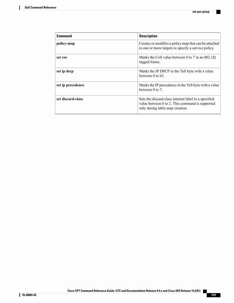
DescriptionCommand
Creates or modifies a policy map that can be attachedto one or more targets to specify a service policy.
policy-map
Marks the CoS value between 0 to 7 in an 802.1Qtagged frame.
set cos
Marks the IP DSCP in the ToS byte with a valuebetween 0 to 63.
set ip dscp
Marks the IP precedence in the ToS byte with a valuebetween 0 to 7.
set ip precedence
Sets the discard-class internal label to a specifiedvalue between 0 to 2. This command is supportedonly during table-map creation.
set discard-class
Cisco CPT Command Reference Guide–CTC and Documentation Release 9.5.x and Cisco IOS Release 15.2(01) 78-20604-03 219
QoS Command Referenceset qos-group
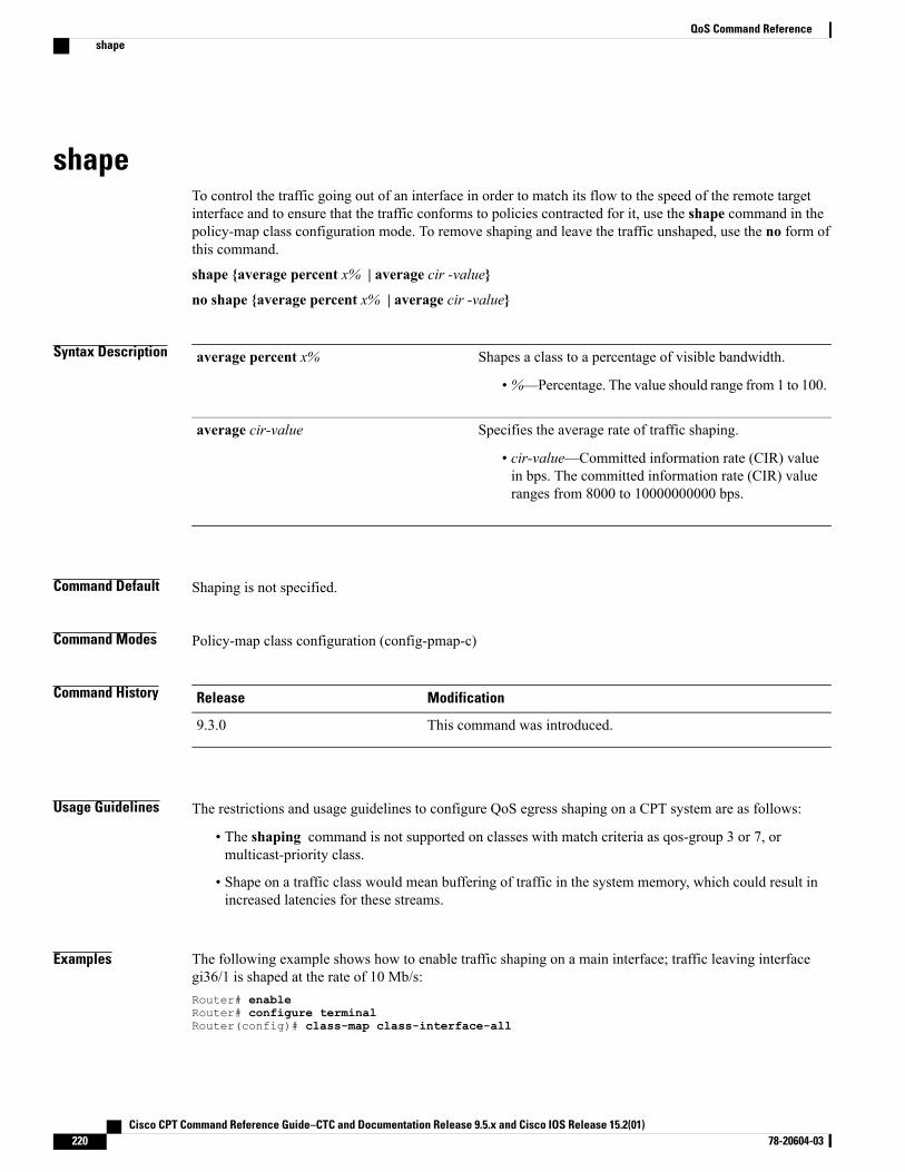
shapeTo control the traffic going out of an interface in order to match its flow to the speed of the remote targetinterface and to ensure that the traffic conforms to policies contracted for it, use the shape command in thepolicy-map class configuration mode. To remove shaping and leave the traffic unshaped, use the no form ofthis command.
shape {average percent x% | average cir -value}
no shape {average percent x% | average cir -value}
Syntax Description Shapes a class to a percentage of visible bandwidth.
• %—Percentage. The value should range from 1 to 100.
average percent x%
Specifies the average rate of traffic shaping.
• cir-value—Committed information rate (CIR) valuein bps. The committed information rate (CIR) valueranges from 8000 to 10000000000 bps.
average cir-value
Command Default Shaping is not specified.
Command Modes Policy-map class configuration (config-pmap-c)
Command History ModificationRelease
This command was introduced.9.3.0
Usage Guidelines The restrictions and usage guidelines to configure QoS egress shaping on a CPT system are as follows:
• The shaping command is not supported on classes with match criteria as qos-group 3 or 7, ormulticast-priority class.
• Shape on a traffic class would mean buffering of traffic in the system memory, which could result inincreased latencies for these streams.
Examples The following example shows how to enable traffic shaping on a main interface; traffic leaving interfacegi36/1 is shaped at the rate of 10 Mb/s:Router# enableRouter# configure terminalRouter(config)# class-map class-interface-all
Cisco CPT Command Reference Guide–CTC and Documentation Release 9.5.x and Cisco IOS Release 15.2(01)220 78-20604-03
QoS Command Referenceshape
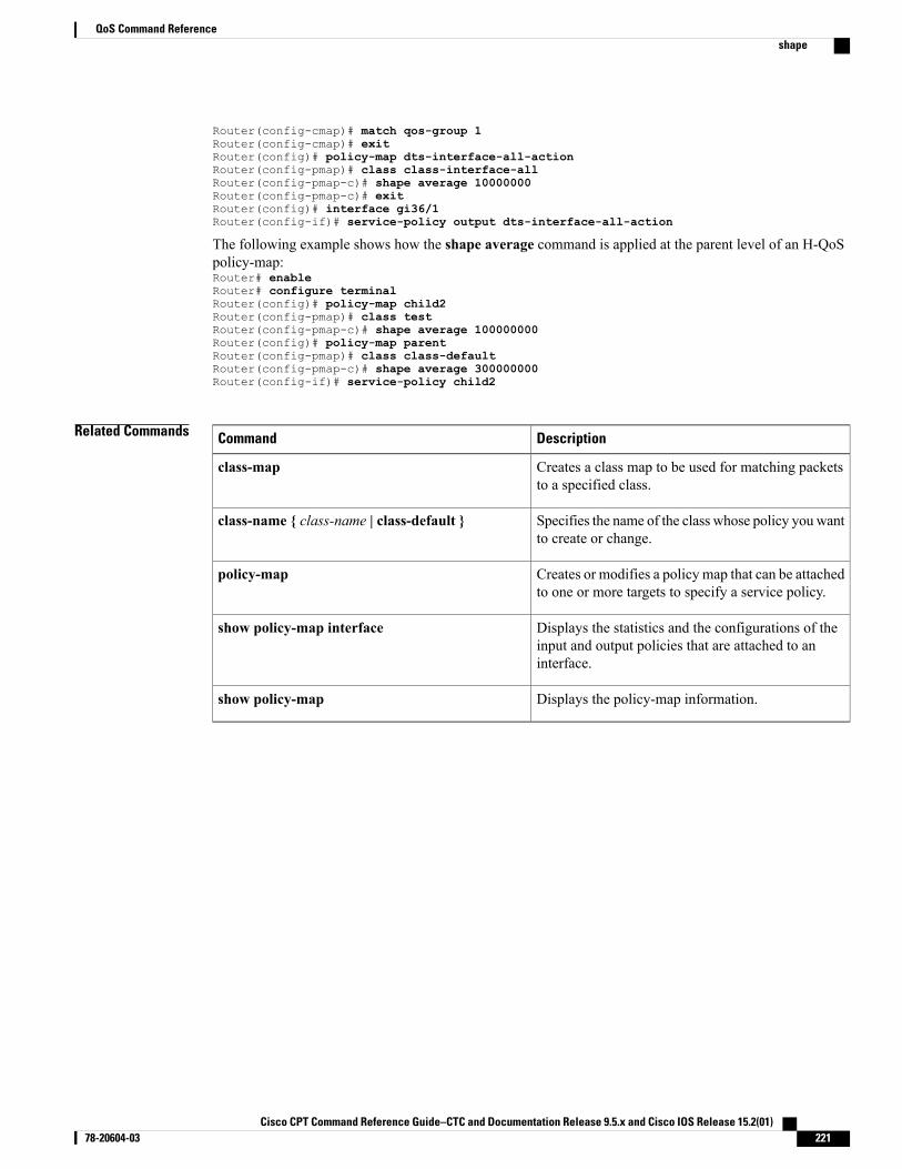
Router(config-cmap)# match qos-group 1Router(config-cmap)# exitRouter(config)# policy-map dts-interface-all-actionRouter(config-pmap)# class class-interface-allRouter(config-pmap-c)# shape average 10000000Router(config-pmap-c)# exitRouter(config)# interface gi36/1Router(config-if)# service-policy output dts-interface-all-action
The following example shows how the shape average command is applied at the parent level of an H-QoSpolicy-map:Router# enableRouter# configure terminalRouter(config)# policy-map child2Router(config-pmap)# class testRouter(config-pmap-c)# shape average 100000000Router(config)# policy-map parentRouter(config-pmap)# class class-defaultRouter(config-pmap-c)# shape average 300000000Router(config-if)# service-policy child2
Related Commands DescriptionCommand
Creates a class map to be used for matching packetsto a specified class.
class-map
Specifies the name of the class whose policy you wantto create or change.
class-name { class-name | class-default }
Creates or modifies a policy map that can be attachedto one or more targets to specify a service policy.
policy-map
Displays the statistics and the configurations of theinput and output policies that are attached to aninterface.
show policy-map interface
Displays the policy-map information.show policy-map
Cisco CPT Command Reference Guide–CTC and Documentation Release 9.5.x and Cisco IOS Release 15.2(01) 78-20604-03 221
QoS Command Referenceshape
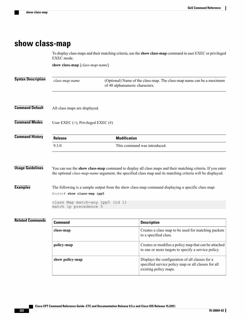
show class-mapTo display class maps and their matching criteria, use the show class-map command in user EXEC or privilegedEXEC mode.
show class-map [class-map-name]
Syntax Description (Optional) Name of the class-map. The class-map name can be a maximumof 40 alphanumeric characters.
class-map-name
Command Default All class maps are displayed.
Command Modes User EXEC (>), Privileged EXEC (#)
Command History ModificationRelease
This command was introduced.9.3.0
Usage Guidelines You can use the show class-map command to display all class maps and their matching criteria. If you enterthe optional class-map-name argument, the specified class map and its matching criteria will be displayed.
Examples The following is a sample output from the show class-map command displaying a specific class map:Router# show class-map ipp5
class Map match-any ipp5 (id 1)match ip precedence 5
Related Commands DescriptionCommand
Creates a class map to be used for matching packetsto a specified class.
class-map
Creates or modifies a policy map that can be attachedto one or more targets to specify a service policy.
policy-map
Displays the configuration of all classes for aspecified service policy map or all classes for allexisting policy maps.
show policy-map
Cisco CPT Command Reference Guide–CTC and Documentation Release 9.5.x and Cisco IOS Release 15.2(01)222 78-20604-03
QoS Command Referenceshow class-map
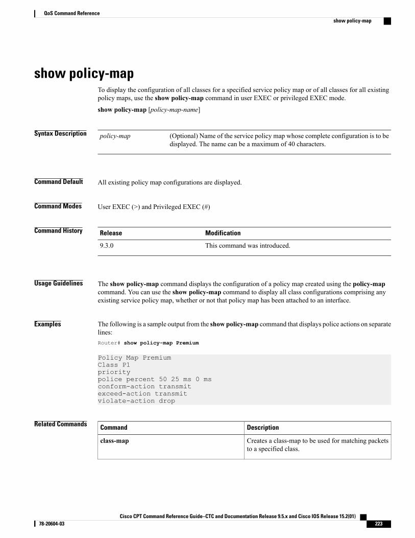
show policy-mapTo display the configuration of all classes for a specified service policy map or of all classes for all existingpolicy maps, use the show policy-map command in user EXEC or privileged EXEC mode.
show policy-map [policy-map-name]
Syntax Description (Optional) Name of the service policy map whose complete configuration is to bedisplayed. The name can be a maximum of 40 characters.
policy-map
Command Default All existing policy map configurations are displayed.
Command Modes User EXEC (>) and Privileged EXEC (#)
Command History ModificationRelease
This command was introduced.9.3.0
Usage Guidelines The show policy-map command displays the configuration of a policy map created using the policy-mapcommand. You can use the show policy-map command to display all class configurations comprising anyexisting service policy map, whether or not that policy map has been attached to an interface.
Examples The following is a sample output from the show policy-map command that displays police actions on separatelines:Router# show policy-map Premium
Policy Map PremiumClass P1prioritypolice percent 50 25 ms 0 msconform-action transmitexceed-action transmitviolate-action drop
Related Commands DescriptionCommand
Creates a class-map to be used for matching packetsto a specified class.
class-map
Cisco CPT Command Reference Guide–CTC and Documentation Release 9.5.x and Cisco IOS Release 15.2(01) 78-20604-03 223
QoS Command Referenceshow policy-map

DescriptionCommand
Creates or modifies a policy map that can be attachedto one or more targets to specify a service policy.
policy-map
Cisco CPT Command Reference Guide–CTC and Documentation Release 9.5.x and Cisco IOS Release 15.2(01)224 78-20604-03
QoS Command Referenceshow policy-map
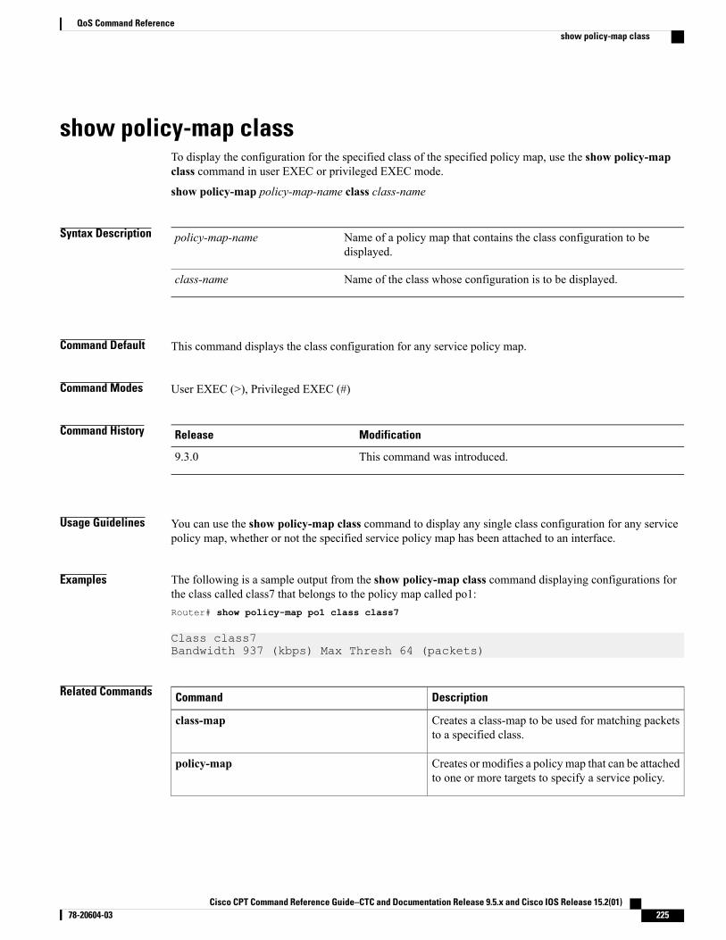
show policy-map classTo display the configuration for the specified class of the specified policy map, use the show policy-mapclass command in user EXEC or privileged EXEC mode.
show policy-map policy-map-name class class-name
Syntax Description Name of a policy map that contains the class configuration to bedisplayed.
policy-map-name
Name of the class whose configuration is to be displayed.class-name
Command Default This command displays the class configuration for any service policy map.
Command Modes User EXEC (>), Privileged EXEC (#)
Command History ModificationRelease
This command was introduced.9.3.0
Usage Guidelines You can use the show policy-map class command to display any single class configuration for any servicepolicy map, whether or not the specified service policy map has been attached to an interface.
Examples The following is a sample output from the show policy-map class command displaying configurations forthe class called class7 that belongs to the policy map called po1:Router# show policy-map po1 class class7
Class class7Bandwidth 937 (kbps) Max Thresh 64 (packets)
Related Commands DescriptionCommand
Creates a class-map to be used for matching packetsto a specified class.
class-map
Creates or modifies a policy map that can be attachedto one or more targets to specify a service policy.
policy-map
Cisco CPT Command Reference Guide–CTC and Documentation Release 9.5.x and Cisco IOS Release 15.2(01) 78-20604-03 225
QoS Command Referenceshow policy-map class

DescriptionCommand
Displays the configuration of all classes for aspecified service policy map or all classes for allexisting policy maps.
show policy-map
Cisco CPT Command Reference Guide–CTC and Documentation Release 9.5.x and Cisco IOS Release 15.2(01)226 78-20604-03
QoS Command Referenceshow policy-map class
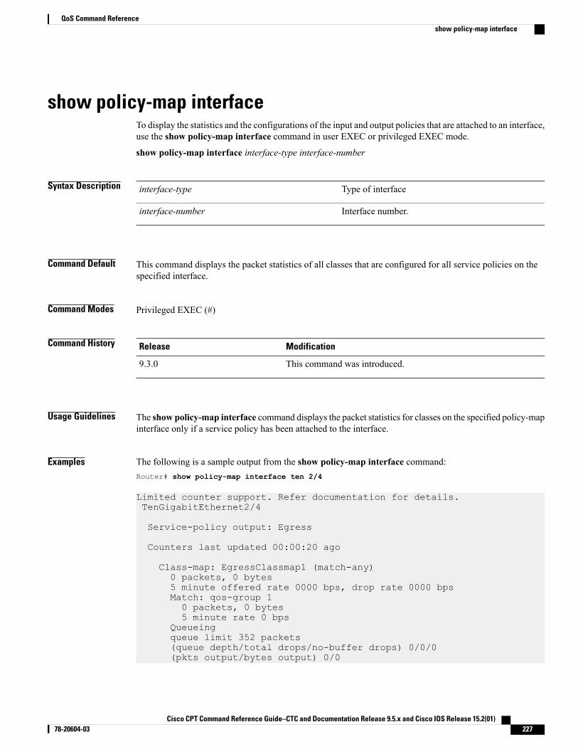
show policy-map interfaceTo display the statistics and the configurations of the input and output policies that are attached to an interface,use the show policy-map interface command in user EXEC or privileged EXEC mode.
show policy-map interface interface-type interface-number
Syntax Description Type of interfaceinterface-type
Interface number.interface-number
Command Default This command displays the packet statistics of all classes that are configured for all service policies on thespecified interface.
Command Modes Privileged EXEC (#)
Command History ModificationRelease
This command was introduced.9.3.0
Usage Guidelines The show policy-map interface command displays the packet statistics for classes on the specified policy-mapinterface only if a service policy has been attached to the interface.
Examples The following is a sample output from the show policy-map interface command:Router# show policy-map interface ten 2/4
Limited counter support. Refer documentation for details.TenGigabitEthernet2/4
Service-policy output: Egress
Counters last updated 00:00:20 ago
Class-map: EgressClassmap1 (match-any)0 packets, 0 bytes5 minute offered rate 0000 bps, drop rate 0000 bpsMatch: qos-group 10 packets, 0 bytes5 minute rate 0 bps
Queueingqueue limit 352 packets(queue depth/total drops/no-buffer drops) 0/0/0(pkts output/bytes output) 0/0
Cisco CPT Command Reference Guide–CTC and Documentation Release 9.5.x and Cisco IOS Release 15.2(01) 78-20604-03 227
QoS Command Referenceshow policy-map interface
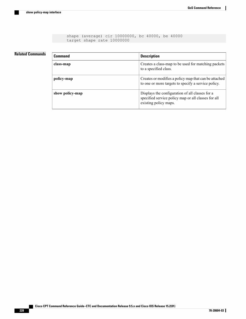
shape (average) cir 10000000, bc 40000, be 40000target shape rate 10000000
Related Commands DescriptionCommand
Creates a class-map to be used for matching packetsto a specified class.
class-map
Creates or modifies a policy map that can be attachedto one or more targets to specify a service policy.
policy-map
Displays the configuration of all classes for aspecified service policy map or all classes for allexisting policy maps.
show policy-map
Cisco CPT Command Reference Guide–CTC and Documentation Release 9.5.x and Cisco IOS Release 15.2(01)228 78-20604-03
QoS Command Referenceshow policy-map interface
table-map (value mapping)To create a table-map that is used for mapping the values from qos-group and discard-class to theMultiprotocolLabel Switching (MPLS) experimental (EXP) or Ethernet class of service (CoS) bit at egress use the table-map(value mapping) command in the global configuration mode. To disable the use of this table map, use the noform of this command. .
table-map table-map-namemap from from-value1, from-value2 to to-value
no table-map table-map-namemap from from-value1, from-value2 to to-value
Syntax Description Name of the table-map. This can have a maximum of 40 alphanumericcharacters.
table-map-name
Indicates that a “map from” value is used. Maps the qos-group and discardvalues to the MPLS EXP or VLAN CoS bit.
map from
Value of the qos-group, which can range from 0 to 7.from-value1
Value of the discard class, which can range from 0 to 2.from-value2
Indicates that a “map to” value is used. Maps the QoS-group and discard valuesto the MPLS EXP or VLAN CoS bit.
to
Value of the MPLS EXP or VLAN CoS bits, which can range from 0 to 7.to-value
Command Default Table-map is not configured.
Command Modes Global configuration (config)
Command History ModificationRelease
This command was introduced.9.3.0
Usage Guidelines If a table-map is not attached, the MPLS EXP or the VLAN COS bit is set to zero. Also, the system defaultsetting is zero.
Examples The following example shows how to create a table map that contains multiple entries.Router# enableRouter# configure terminalRouter(config)# table-map test_tableRouter(config-tablemap)# map from 0,2 to 2Router(config-tablemap)# map from 0,0 to 0
Cisco CPT Command Reference Guide–CTC and Documentation Release 9.5.x and Cisco IOS Release 15.2(01) 78-20604-03 229
QoS Command Referencetable-map (value mapping)

Related Commands DescriptionCommand
Creates a class map to be used for matching packetsto a specified class.
class-map
Specifies the name of the class whose policy you wantto create or change.
class-name {class-name | class-default }
Creates or modifies a policy map that can be attachedto one or more targets to specify a service policy.
policy-map
(Only for VPWS initiation and LSR scenarios) Mapsthe MPLS-EXP value from the table map.
platform set mpls-exp-topmost from qos-group,discard-class table
(Only for VPWS termination scenario) Maps theVLAN CoS value from the table map.
platform set cos from qos-group, discard-classtable
Displays the configuration of a specified table mapor all table maps.
show table-map
Marks a QoS group ID with a value between 0 to 7that can be used later to classify packets.
set qos-group
Sets the discard-class internal label to a specifiedvalue between 0 to 2. This command is supportedonly during table-map creation.
set discard-class
Cisco CPT Command Reference Guide–CTC and Documentation Release 9.5.x and Cisco IOS Release 15.2(01)230 78-20604-03
QoS Command Referencetable-map (value mapping)

High Availability Command Reference
This chapter describes commands to configure high availability.
• crashdump-timeout, page 232
• network area, page 233
• nsf cisco, page 235
• nsf ietf, page 237
• router ospf, page 239
• show cef nsf, page 240
• show cef state, page 241
• show ip ospf, page 243
• show ip ospf neighbor, page 244
• show ip ospf nsf, page 246
• show issu capability, page 248
• show issu clients, page 250
• show issu comp-matrix, page 252
• show issu endpoints, page 254
• show issu entities, page 256
• show issu fsm, page 258
• show issu message, page 260
• show issu negotiated, page 262
• show issu sessions, page 264
• show redundancy, page 266
Cisco CPT Command Reference Guide–CTC and Documentation Release 9.5.x and Cisco IOS Release 15.2(01) 78-20604-03 231
crashdump-timeoutTo set the longest time that the newly active fabric card waits before reloading the previously active fabriccard, use the crashdump-timeout command in redundancy mode. To reset the default time that the newlyactive fabric card waits before reloading the previously active fabric card, use the no form of this command.
crashdump-timeout [mm | hh:mm]
Syntax Description (Optional) Time, in minutes, that the newly active fabric card waits before reloading thepreviously active fabric card. The range is from 5 to 1080 minutes.
mm
(Optional) Time, in hours and minutes, that the newly active fabric card waits beforereloading the previously active fabric card. The range is from 5 minutes to 18 hours.
hh:mm
Command Default The default timeout for this command is 5 minutes.
Command Modes Redundancy mode (config-red)
Command History ModificationRelease
This command was introduced.9.3.0
Usage Guidelines Use this command to specify the length of time that the newly active fabric card waits before reloading thepreviously active fabric card.
Examples The following example shows how to set the time before the previously active fabric card is reloaded.Router(config-red)# crashdump-timeout 10
Cisco CPT Command Reference Guide–CTC and Documentation Release 9.5.x and Cisco IOS Release 15.2(01)232 78-20604-03
High Availability Command Referencecrashdump-timeout
network areaTo define the interfaces on which Open Shortest Path First (OSPF) protocol runs and to define the area IDfor those interfaces, use the network area command in router configuration mode. To disable OSPF routingfor the interfaces, use the no form of this command.
network ip-address wildcard-mask area area-idno network ip-address wildcard-mask area area-id
Syntax Description IP address.ip-address
Wild card mask address.wildcard-mask
Area that is to be associated with the OSPF address range. It can be specifiedas either a decimal value or as an IP address. To associate areas with IPsubnets, specify a subnet address as the value of the area-id argument.
area-id
Command Default This command is disabled by default.
Command Modes Router configuration (config-router)
Command History ModificationRelease
This command was introduced.9.3.0
Usage Guidelines The ip-address and wildcard-mask arguments together enable one or multiple interfaces to be associated witha specific OSPF area using a single command. To associate areas with IP subnets, specify a subnet addressas the value of the area-id argument.
Examples The following example shows how to initialize OSPF routing process 109, and defines four OSPF areas.
Router(config)# interface TenGigabitEthernet4/1Router(config-if)# ip address 209.165.200.225 255.255.255.0Router(config)# router ospf 109Router(config-router)# network 209.165.200.226 0.0.0.255 area 10.9.50.0Router(config-router)# network 209.165.200.227 0.0.255.255 area 2Router(config-router)# network 209.165.200.228 0.0.0.255 area 3Router(config-router)# network 0.0.0.0 255.255.255.255 area 0
Related Commands DescriptionCommand
Configures an OSPF routing process.router ospf
Cisco CPT Command Reference Guide–CTC and Documentation Release 9.5.x and Cisco IOS Release 15.2(01) 78-20604-03 233
High Availability Command Referencenetwork area

Cisco CPT Command Reference Guide–CTC and Documentation Release 9.5.x and Cisco IOS Release 15.2(01)234 78-20604-03
High Availability Command Referencenetwork area
nsf ciscoTo enable Cisco Nonstop Forwarding (NSF) operations on a router that is running the Open Shortest PathFirst (OSPF) protocol, use the nsf cisco command in router configuration mode. To return to the default, usethe no form of this command.
nsf cisco [enforce global | helper [disable]]no nsf cisco [enforce global | helper [disable]]
Syntax Description (Optional) Cancels Cisco NSF restart on all the interfaces when neighboringnetworking devices that are not NSF-aware are detected on any interface duringthe restart process.
enforce global
(Optional) Configures Cisco NSF helper mode.helper
(Optional) Disables Cisco NSF helper mode.disable
Command Default Cisco NSF restarting mode is disabled but helper mode is enabled.
Command Modes Router configuration (config-router)
Command History ModificationRelease
This command was introduced.9.3.0
Usage Guidelines This command enables Cisco NSF on an OSPF router. When the Cisco NSF is enabled on a router, the routeris Cisco NSF capable and will operate in restarting mode.
By default, neighboring Cisco NSF-aware routers operate in NSF helper mode during a graceful restart. Todisable Cisco NSF helper mode on a Cisco NSF-aware router, use this command with the disable keyword.To reenable helper mode after explicitly disabling helper mode on a Cisco NSF-aware router, use the no nsfcisco helper disable command.
If neighbors that are not Cisco NSF-aware are detected on a network interface during a Cisco NSF gracefulrestart, restart is aborted only on that interface and continues on other interfaces. To cancel restart for theentire OSPF process when neighbors that are not Cisco NSF-aware are detected during restart, configure thiscommand with the enforce global keywords.
Cisco CPT Command Reference Guide–CTC and Documentation Release 9.5.x and Cisco IOS Release 15.2(01) 78-20604-03 235
High Availability Command Referencensf cisco
Examples The following example shows how to enable Cisco NSF restarting mode on a router. This example causesthe Cisco NSF restart to be canceled for the entire OSPF process if neighbors that are not Cisco NSF-awareare detected on any network interface during the restart.
Router(config)# router ospf 24Router(config-router)# nsf cisco enforce global
Related Commands DescriptionCommand
Enables IETF NSF.nsf ietf
Cisco CPT Command Reference Guide–CTC and Documentation Release 9.5.x and Cisco IOS Release 15.2(01)236 78-20604-03
High Availability Command Referencensf cisco
nsf ietfTo configure Internet Engineering Task Force (IETF) Nonstop Forwarding (NSF) operations on a router thatis running Open Shortest Path First (OSPF), use the nsf ietf command in router configuration mode. To returnto the default, use the no form of this command.
nsf ietf [restart-interval seconds | helper [disable | strict-lsa-checking]]no nsf ietf [restart-interval | helper [disable | strict-lsa-checking]]
Syntax Description (Optional) Specifies length of the graceful restart interval, in seconds. Therange is from 1 to 1800. The default value is 120 seconds.
restart-interval seconds
(Optional) Configures IETF NSF helper mode.helper
(Optional) Disables helper mode on an IETF NSF-aware router.disable
(Optional) Enables strict link-state advertisement (LSA) checking forhelper mode.
strict-lsa-checking
Command Default IETF NSF graceful restart mode is disabled but the helper mode is enabled.
Command Modes Router configuration (config-router)
Command History ModificationRelease
This command was introduced.9.3.0
Usage Guidelines This command enables IETF NSF on an OSPF router. When IETF NSF is enabled on a Cisco router, therouter is IETF NSF-capable and will operate in restarting mode.
By default, neighboring IETF NSF-aware routers operate in IETF NSF helper mode during a graceful restart.To disable IETFNSF helper mode on an IETFNSF-aware router, use this command with the disable keyword.To reenable helper mode after explicitly disabling helper mode on an IETF NSF-aware router, use the no nsfietf helper disable command.
Strict LSA checking enables a router in IETF NSF helper mode to terminate the graceful restart process if itdetects a changed LSA that would cause flooding during the graceful restart process. Configure strict LSAchecking on IETF NSF-aware and IETF NSF-capable routers but it is effective only when the router is inhelper mode.
Cisco CPT Command Reference Guide–CTC and Documentation Release 9.5.x and Cisco IOS Release 15.2(01) 78-20604-03 237
High Availability Command Referencensf ietf
Examples The following example shows how to enable IETF NSF restarting mode on a router and changes the gracefulrestart interval from default (120 seconds) to 200 seconds:
Router(config)# router ospf 24Router(config-router)# nsf ietf restart-interval 200
Related Commands DescriptionCommand
Enables Cisco NSF.nsf cisco
Cisco CPT Command Reference Guide–CTC and Documentation Release 9.5.x and Cisco IOS Release 15.2(01)238 78-20604-03
High Availability Command Referencensf ietf
router ospfTo configure an Open Shortest Path First (OSPF) routing process, use the router ospf command in globalconfiguration mode. To terminate an OSPF routing process, use the no form of this command.
router ospf process-idno router ospf process-id
Syntax Description Identification parameter internally used for an OSPF routing process. It is locallyassigned and can be any positive integer. A unique value is assigned for each OSPFrouting process.
process-id
Command Default OSPF routing process is not defined.
Command Modes Global configuration (config)
Command History ModificationRelease
This command was introduced.9.3.0
Usage Guidelines You can specify multiple OSPF routing processes in each router.
Examples The following example shows how to configure an OSPF routing process and assign a process number of109.Router(config)# router ospf 109
Related Commands DescriptionCommand
Defines the interfaces on which OSPF runs anddefines the area ID for those interfaces.
network area
Cisco CPT Command Reference Guide–CTC and Documentation Release 9.5.x and Cisco IOS Release 15.2(01) 78-20604-03 239
High Availability Command Referencerouter ospf
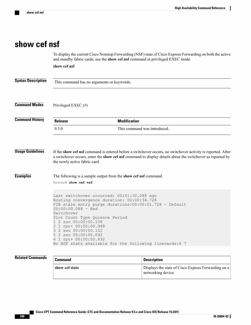
show cef nsfTo display the current Cisco Nonstop Forwarding (NSF) state of Cisco Express Forwarding on both the activeand standby fabric cards, use the show cef nsf command in privileged EXEC mode.
show cef nsf
Syntax Description This command has no arguments or keywords.
Command Modes Privileged EXEC (#)
Command History ModificationRelease
This command was introduced.9.3.0
Usage Guidelines If the show cef nsf command is entered before a switchover occurs, no switchover activity is reported. Aftera switchover occurs, enter the show cef nsf command to display details about the switchover as reported bythe newly active fabric card.
Examples The following is a sample output from the show cef nsf command.Router# show cef nsf
Last switchover occurred: 00:01:30.088 agoRouting convergence duration: 00:00:34.728FIB stale entry purge durations:00:00:01.728 - Default00:00:00.088 - RedSwitchoverSlot Count Type Quiesce Period1 2 sso 00:00:00.1082 1 rpr+ 00:00:00.9483 2 sso 00:00:00.1525 2 sso 00:00:00.0926 1 rpr+ 00:00:00.632No NSF stats available for the following linecards:4 7
Related Commands DescriptionCommand
Displays the state of Cisco Express Forwarding on anetworking device.
show cef state
Cisco CPT Command Reference Guide–CTC and Documentation Release 9.5.x and Cisco IOS Release 15.2(01)240 78-20604-03
High Availability Command Referenceshow cef nsf
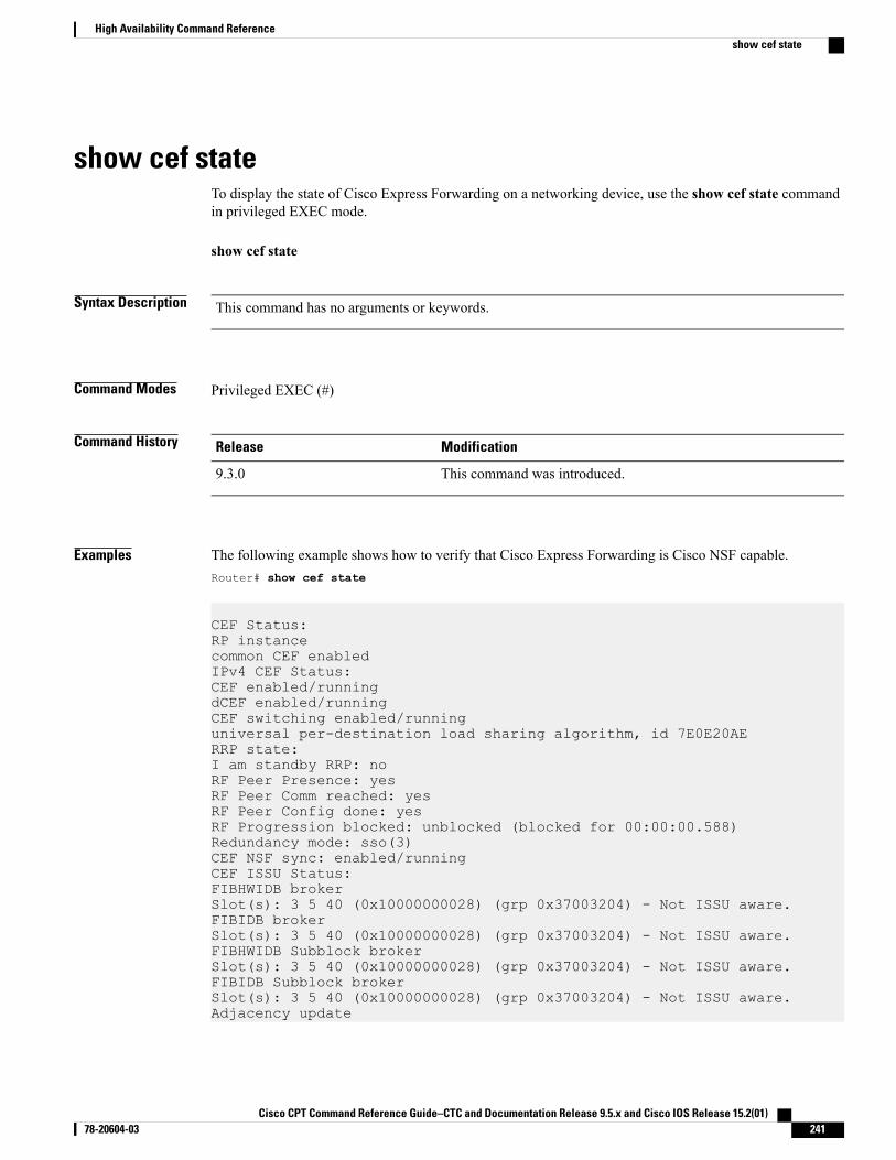
show cef stateTo display the state of Cisco Express Forwarding on a networking device, use the show cef state commandin privileged EXEC mode.
show cef state
Syntax Description This command has no arguments or keywords.
Command Modes Privileged EXEC (#)
Command History ModificationRelease
This command was introduced.9.3.0
Examples The following example shows how to verify that Cisco Express Forwarding is Cisco NSF capable.Router# show cef state
CEF Status:RP instancecommon CEF enabledIPv4 CEF Status:CEF enabled/runningdCEF enabled/runningCEF switching enabled/runninguniversal per-destination load sharing algorithm, id 7E0E20AERRP state:I am standby RRP: noRF Peer Presence: yesRF Peer Comm reached: yesRF Peer Config done: yesRF Progression blocked: unblocked (blocked for 00:00:00.588)Redundancy mode: sso(3)CEF NSF sync: enabled/runningCEF ISSU Status:FIBHWIDB brokerSlot(s): 3 5 40 (0x10000000028) (grp 0x37003204) - Not ISSU aware.FIBIDB brokerSlot(s): 3 5 40 (0x10000000028) (grp 0x37003204) - Not ISSU aware.FIBHWIDB Subblock brokerSlot(s): 3 5 40 (0x10000000028) (grp 0x37003204) - Not ISSU aware.FIBIDB Subblock brokerSlot(s): 3 5 40 (0x10000000028) (grp 0x37003204) - Not ISSU aware.Adjacency update
Cisco CPT Command Reference Guide–CTC and Documentation Release 9.5.x and Cisco IOS Release 15.2(01) 78-20604-03 241
High Availability Command Referenceshow cef state
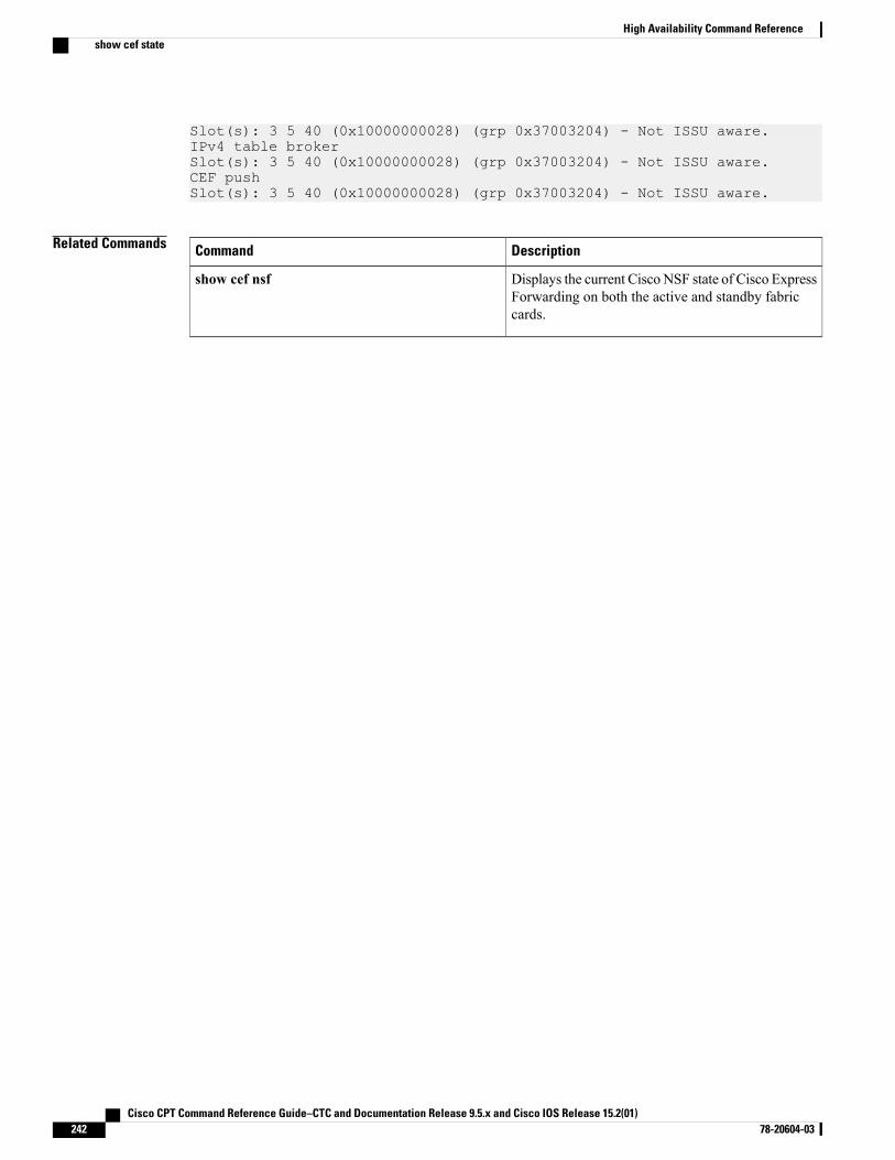
Slot(s): 3 5 40 (0x10000000028) (grp 0x37003204) - Not ISSU aware.IPv4 table brokerSlot(s): 3 5 40 (0x10000000028) (grp 0x37003204) - Not ISSU aware.CEF pushSlot(s): 3 5 40 (0x10000000028) (grp 0x37003204) - Not ISSU aware.
Related Commands DescriptionCommand
Displays the current Cisco NSF state of Cisco ExpressForwarding on both the active and standby fabriccards.
show cef nsf
Cisco CPT Command Reference Guide–CTC and Documentation Release 9.5.x and Cisco IOS Release 15.2(01)242 78-20604-03
High Availability Command Referenceshow cef state
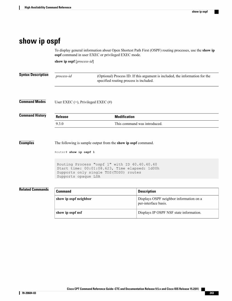
show ip ospfTo display general information about Open Shortest Path First (OSPF) routing processes, use the show ipospf command in user EXEC or privileged EXEC mode.
show ip ospf [process-id]
Syntax Description (Optional) Process ID. If this argument is included, the information for thespecified routing process is included.
process-id
Command Modes User EXEC (>), Privileged EXEC (#)
Command History ModificationRelease
This command was introduced.9.3.0
Examples The following is sample output from the show ip ospf command.
Router# show ip ospf 1
Routing Process "ospf 1" with ID 40.40.40.40Start time: 00:01:08.623, Time elapsed: 1d00hSupports only single TOS(TOS0) routesSupports opaque LSA
Related Commands DescriptionCommand
Displays OSPF neighbor information on aper-interface basis.
show ip ospf neighbor
Displays IP OSPF NSF state information.show ip ospf nsf
Cisco CPT Command Reference Guide–CTC and Documentation Release 9.5.x and Cisco IOS Release 15.2(01) 78-20604-03 243
High Availability Command Referenceshow ip ospf
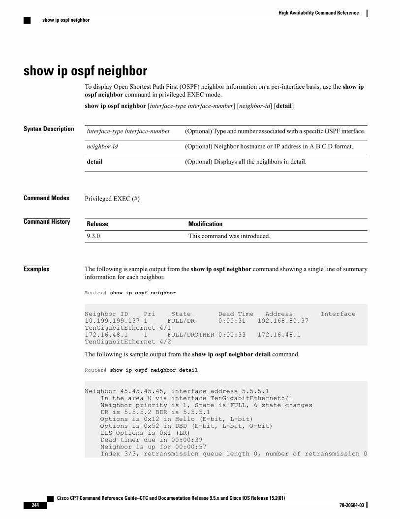
show ip ospf neighborTo display Open Shortest Path First (OSPF) neighbor information on a per-interface basis, use the show ipospf neighbor command in privileged EXEC mode.
show ip ospf neighbor [interface-type interface-number] [neighbor-id] [detail]
Syntax Description (Optional) Type and number associated with a specific OSPF interface.interface-type interface-number
(Optional) Neighbor hostname or IP address in A.B.C.D format.neighbor-id
(Optional) Displays all the neighbors in detail.detail
Command Modes Privileged EXEC (#)
Command History ModificationRelease
This command was introduced.9.3.0
Examples The following is sample output from the show ip ospf neighbor command showing a single line of summaryinformation for each neighbor.
Router# show ip ospf neighbor
Neighbor ID Pri State Dead Time Address Interface10.199.199.137 1 FULL/DR 0:00:31 192.168.80.37TenGigabitEthernet 4/1172.16.48.1 1 FULL/DROTHER 0:00:33 172.16.48.1TenGigabitEthernet 4/2
The following is sample output from the show ip ospf neighbor detail command.
Router# show ip ospf neighbor detail
Neighbor 45.45.45.45, interface address 5.5.5.1In the area 0 via interface TenGigabitEthernet5/1Neighbor priority is 1, State is FULL, 6 state changesDR is 5.5.5.2 BDR is 5.5.5.1Options is 0x12 in Hello (E-bit, L-bit)Options is 0x52 in DBD (E-bit, L-bit, O-bit)LLS Options is 0x1 (LR)Dead timer due in 00:00:39Neighbor is up for 00:00:57Index 3/3, retransmission queue length 0, number of retransmission 0
Cisco CPT Command Reference Guide–CTC and Documentation Release 9.5.x and Cisco IOS Release 15.2(01)244 78-20604-03
High Availability Command Referenceshow ip ospf neighbor
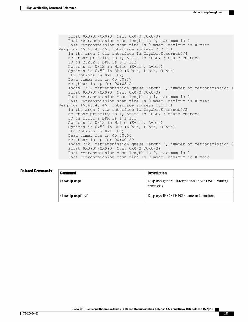
First 0x0(0)/0x0(0) Next 0x0(0)/0x0(0)Last retransmission scan length is 0, maximum is 0Last retransmission scan time is 0 msec, maximum is 0 msec
Neighbor 45.45.45.45, interface address 2.2.2.1In the area 0 via interface TenGigabitEthernet4/4Neighbor priority is 1, State is FULL, 6 state changesDR is 2.2.2.1 BDR is 2.2.2.2Options is 0x12 in Hello (E-bit, L-bit)Options is 0x52 in DBD (E-bit, L-bit, O-bit)LLS Options is 0x1 (LR)Dead timer due in 00:00:37Neighbor is up for 00:03:54Index 1/1, retransmission queue length 0, number of retransmission 1First 0x0(0)/0x0(0) Next 0x0(0)/0x0(0)Last retransmission scan length is 1, maximum is 1Last retransmission scan time is 0 msec, maximum is 0 msec
Neighbor 45.45.45.45, interface address 1.1.1.1In the area 0 via interface TenGigabitEthernet5/3Neighbor priority is 1, State is FULL, 6 state changesDR is 1.1.1.2 BDR is 1.1.1.1Options is 0x12 in Hello (E-bit, L-bit)Options is 0x52 in DBD (E-bit, L-bit, O-bit)LLS Options is 0x1 (LR)Dead timer due in 00:00:38Neighbor is up for 00:00:59Index 2/2, retransmission queue length 0, number of retransmission 0First 0x0(0)/0x0(0) Next 0x0(0)/0x0(0)Last retransmission scan length is 0, maximum is 0Last retransmission scan time is 0 msec, maximum is 0 msec
Related Commands DescriptionCommand
Displays general information about OSPF routingprocesses.
show ip ospf
Displays IP OSPF NSF state information.show ip ospf nsf
Cisco CPT Command Reference Guide–CTC and Documentation Release 9.5.x and Cisco IOS Release 15.2(01) 78-20604-03 245
High Availability Command Referenceshow ip ospf neighbor
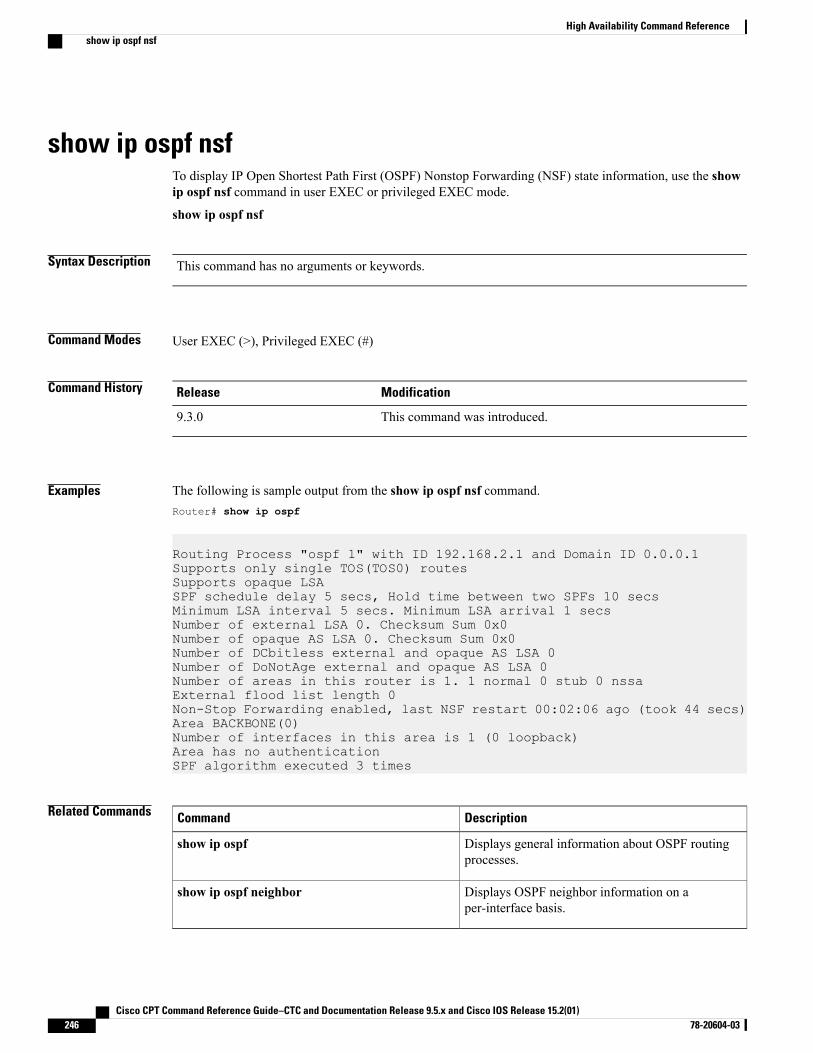
show ip ospf nsfTo display IP Open Shortest Path First (OSPF) Nonstop Forwarding (NSF) state information, use the showip ospf nsf command in user EXEC or privileged EXEC mode.
show ip ospf nsf
Syntax Description This command has no arguments or keywords.
Command Modes User EXEC (>), Privileged EXEC (#)
Command History ModificationRelease
This command was introduced.9.3.0
Examples The following is sample output from the show ip ospf nsf command.Router# show ip ospf
Routing Process "ospf 1" with ID 192.168.2.1 and Domain ID 0.0.0.1Supports only single TOS(TOS0) routesSupports opaque LSASPF schedule delay 5 secs, Hold time between two SPFs 10 secsMinimum LSA interval 5 secs. Minimum LSA arrival 1 secsNumber of external LSA 0. Checksum Sum 0x0Number of opaque AS LSA 0. Checksum Sum 0x0Number of DCbitless external and opaque AS LSA 0Number of DoNotAge external and opaque AS LSA 0Number of areas in this router is 1. 1 normal 0 stub 0 nssaExternal flood list length 0Non-Stop Forwarding enabled, last NSF restart 00:02:06 ago (took 44 secs)Area BACKBONE(0)Number of interfaces in this area is 1 (0 loopback)Area has no authenticationSPF algorithm executed 3 times
Related Commands DescriptionCommand
Displays general information about OSPF routingprocesses.
show ip ospf
Displays OSPF neighbor information on aper-interface basis.
show ip ospf neighbor
Cisco CPT Command Reference Guide–CTC and Documentation Release 9.5.x and Cisco IOS Release 15.2(01)246 78-20604-03
High Availability Command Referenceshow ip ospf nsf

Cisco CPT Command Reference Guide–CTC and Documentation Release 9.5.x and Cisco IOS Release 15.2(01) 78-20604-03 247
High Availability Command Referenceshow ip ospf nsf
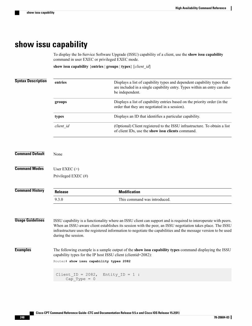
show issu capabilityTo display the In-Service Software Upgrade (ISSU) capability of a client, use the show issu capabilitycommand in user EXEC or privileged EXEC mode.
show issu capability {entries | groups | types} [client_id]
Syntax Description Displays a list of capability types and dependent capability types thatare included in a single capability entry. Types within an entry can alsobe independent.
entries
Displays a list of capability entries based on the priority order (in theorder that they are negotiated in a session).
groups
Displays an ID that identifies a particular capability.types
(Optional) Client registered to the ISSU infrastructure. To obtain a listof client IDs, use the show issu clients command.
client_id
Command Default None
Command Modes User EXEC (>)
Privileged EXEC (#)
Command History ModificationRelease
This command was introduced.9.3.0
Usage Guidelines ISSU capability is a functionality where an ISSU client can support and is required to interoperate with peers.When an ISSU-aware client establishes its session with the peer, an ISSU negotiation takes place. The ISSUinfrastructure uses the registered information to negotiate the capabilities and the message version to be usedduring the session.
Examples The following example is a sample output of the show issu capability types command displaying the ISSUcapability types for the IP host ISSU client (clientid=2082):Router# show issu capability types 2082
Client_ID = 2082, Entity_ID = 1 :Cap_Type = 0
Cisco CPT Command Reference Guide–CTC and Documentation Release 9.5.x and Cisco IOS Release 15.2(01)248 78-20604-03
High Availability Command Referenceshow issu capability
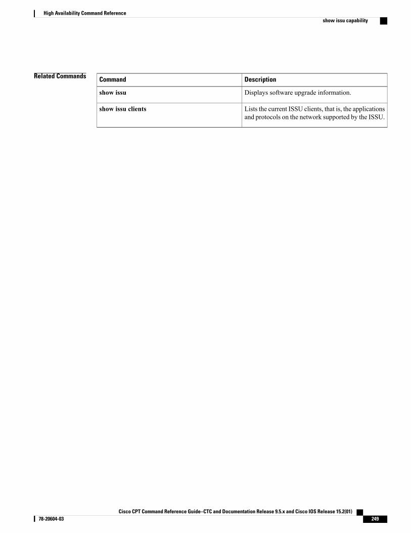
Related Commands DescriptionCommand
Displays software upgrade information.show issu
Lists the current ISSU clients, that is, the applicationsand protocols on the network supported by the ISSU.
show issu clients
Cisco CPT Command Reference Guide–CTC and Documentation Release 9.5.x and Cisco IOS Release 15.2(01) 78-20604-03 249
High Availability Command Referenceshow issu capability
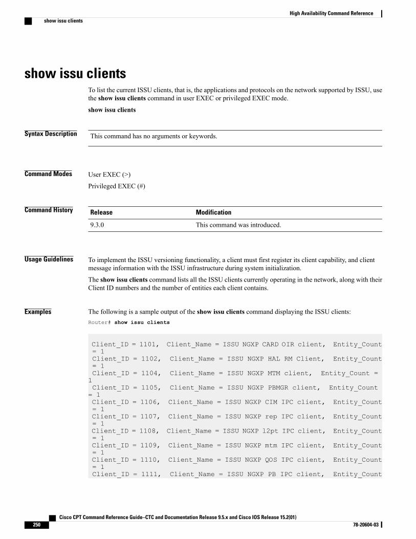
show issu clientsTo list the current ISSU clients, that is, the applications and protocols on the network supported by ISSU, usethe show issu clients command in user EXEC or privileged EXEC mode.
show issu clients
Syntax Description This command has no arguments or keywords.
Command Modes User EXEC (>)
Privileged EXEC (#)
Command History ModificationRelease
This command was introduced.9.3.0
Usage Guidelines To implement the ISSU versioning functionality, a client must first register its client capability, and clientmessage information with the ISSU infrastructure during system initialization.
The show issu clients command lists all the ISSU clients currently operating in the network, along with theirClient ID numbers and the number of entities each client contains.
Examples The following is a sample output of the show issu clients command displaying the ISSU clients:Router# show issu clients
Client_ID = 1101, Client_Name = ISSU NGXP CARD OIR client, Entity_Count= 1Client_ID = 1102, Client_Name = ISSU NGXP HAL RM Client, Entity_Count= 1Client_ID = 1104, Client_Name = ISSU NGXP MTM client, Entity_Count =1Client_ID = 1105, Client_Name = ISSU NGXP PBMGR client, Entity_Count= 1Client_ID = 1106, Client_Name = ISSU NGXP CIM IPC client, Entity_Count= 1Client_ID = 1107, Client_Name = ISSU NGXP rep IPC client, Entity_Count= 1Client_ID = 1108, Client_Name = ISSU NGXP l2pt IPC client, Entity_Count= 1Client_ID = 1109, Client_Name = ISSU NGXP mtm IPC client, Entity_Count= 1Client_ID = 1110, Client_Name = ISSU NGXP QOS IPC client, Entity_Count= 1Client_ID = 1111, Client_Name = ISSU NGXP PB IPC client, Entity_Count
Cisco CPT Command Reference Guide–CTC and Documentation Release 9.5.x and Cisco IOS Release 15.2(01)250 78-20604-03
High Availability Command Referenceshow issu clients
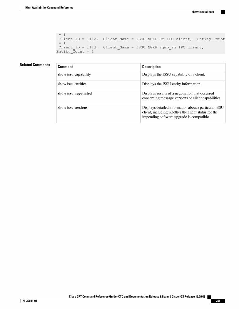
= 1Client_ID = 1112, Client_Name = ISSU NGXP RM IPC client, Entity_Count= 1Client_ID = 1113, Client_Name = ISSU NGXP igmp_sn IPC client,Entity_Count = 1
Related Commands DescriptionCommand
Displays the ISSU capability of a client.show issu capability
Displays the ISSU entity information.show issu entities
Displays results of a negotiation that occurredconcerning message versions or client capabilities.
show issu negotiated
Displays detailed information about a particular ISSUclient, including whether the client status for theimpending software upgrade is compatible.
show issu sessions
Cisco CPT Command Reference Guide–CTC and Documentation Release 9.5.x and Cisco IOS Release 15.2(01) 78-20604-03 251
High Availability Command Referenceshow issu clients
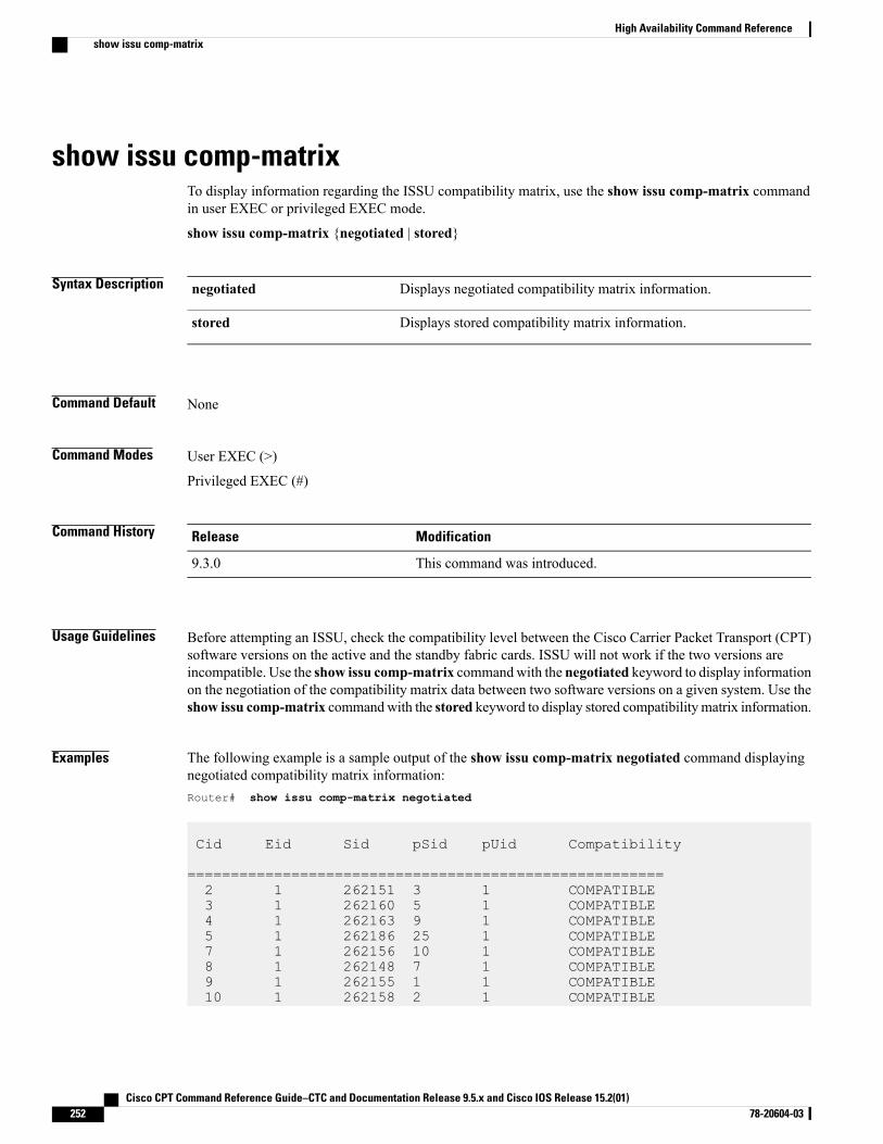
show issu comp-matrixTo display information regarding the ISSU compatibility matrix, use the show issu comp-matrix commandin user EXEC or privileged EXEC mode.
show issu comp-matrix {negotiated | stored}
Syntax Description Displays negotiated compatibility matrix information.negotiated
Displays stored compatibility matrix information.stored
Command Default None
Command Modes User EXEC (>)
Privileged EXEC (#)
Command History ModificationRelease
This command was introduced.9.3.0
Usage Guidelines Before attempting an ISSU, check the compatibility level between the Cisco Carrier Packet Transport (CPT)software versions on the active and the standby fabric cards. ISSU will not work if the two versions areincompatible. Use the show issu comp-matrix commandwith the negotiated keyword to display informationon the negotiation of the compatibility matrix data between two software versions on a given system. Use theshow issu comp-matrix commandwith the stored keyword to display stored compatibilitymatrix information.
Examples The following example is a sample output of the show issu comp-matrix negotiated command displayingnegotiated compatibility matrix information:Router# show issu comp-matrix negotiated
Cid Eid Sid pSid pUid Compatibility
=======================================================2 1 262151 3 1 COMPATIBLE3 1 262160 5 1 COMPATIBLE4 1 262163 9 1 COMPATIBLE5 1 262186 25 1 COMPATIBLE7 1 262156 10 1 COMPATIBLE8 1 262148 7 1 COMPATIBLE9 1 262155 1 1 COMPATIBLE10 1 262158 2 1 COMPATIBLE
Cisco CPT Command Reference Guide–CTC and Documentation Release 9.5.x and Cisco IOS Release 15.2(01)252 78-20604-03
High Availability Command Referenceshow issu comp-matrix
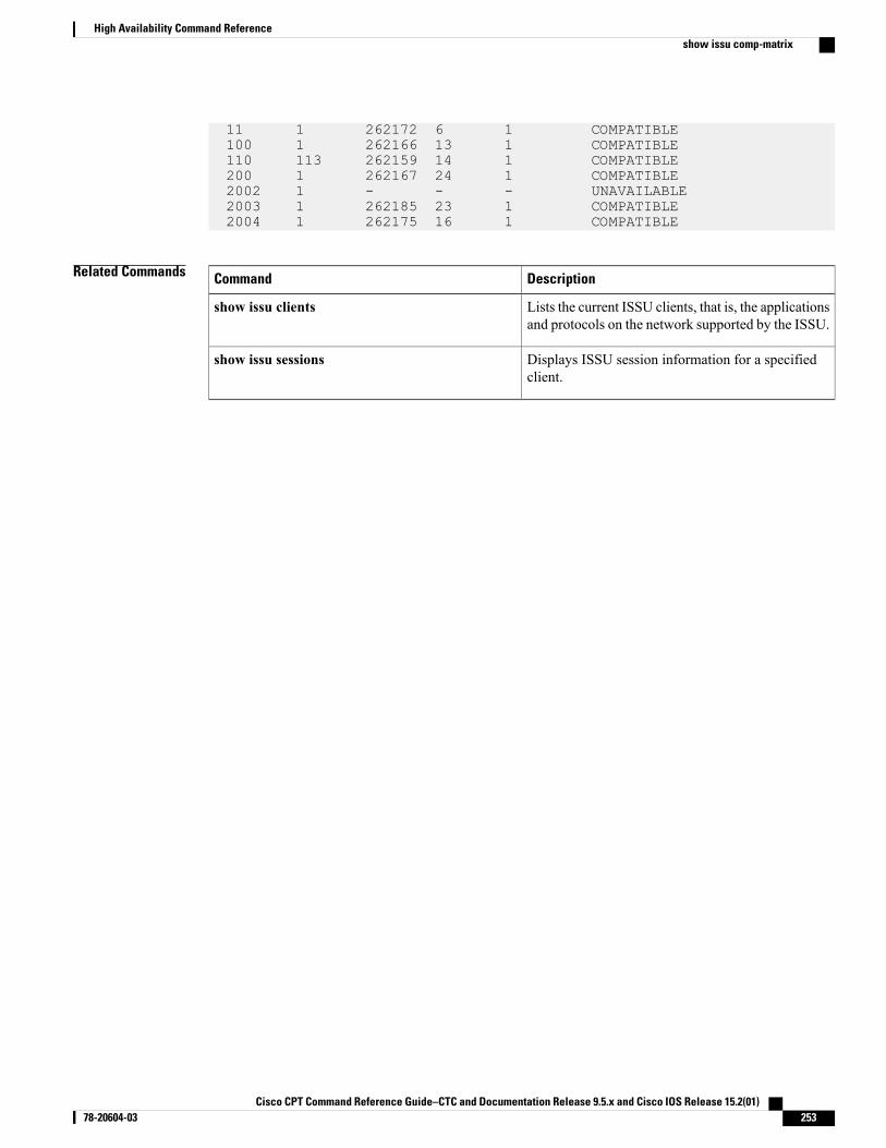
11 1 262172 6 1 COMPATIBLE100 1 262166 13 1 COMPATIBLE110 113 262159 14 1 COMPATIBLE200 1 262167 24 1 COMPATIBLE2002 1 - - - UNAVAILABLE2003 1 262185 23 1 COMPATIBLE2004 1 262175 16 1 COMPATIBLE
Related Commands DescriptionCommand
Lists the current ISSU clients, that is, the applicationsand protocols on the network supported by the ISSU.
show issu clients
Displays ISSU session information for a specifiedclient.
show issu sessions
Cisco CPT Command Reference Guide–CTC and Documentation Release 9.5.x and Cisco IOS Release 15.2(01) 78-20604-03 253
High Availability Command Referenceshow issu comp-matrix
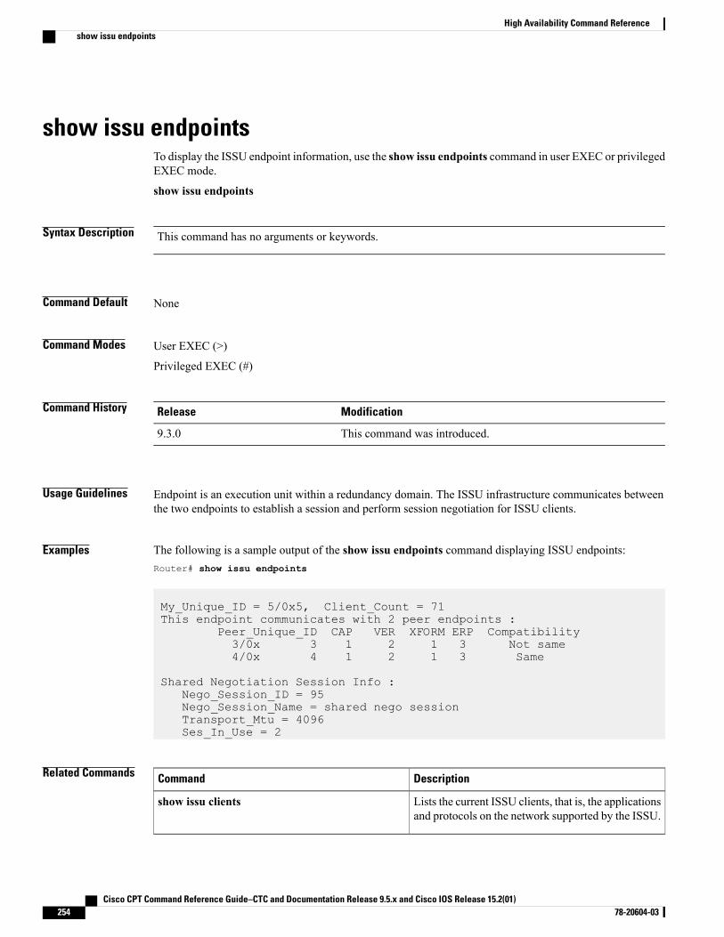
show issu endpointsTo display the ISSU endpoint information, use the show issu endpoints command in user EXEC or privilegedEXEC mode.
show issu endpoints
Syntax Description This command has no arguments or keywords.
Command Default None
Command Modes User EXEC (>)
Privileged EXEC (#)
Command History ModificationRelease
This command was introduced.9.3.0
Usage Guidelines Endpoint is an execution unit within a redundancy domain. The ISSU infrastructure communicates betweenthe two endpoints to establish a session and perform session negotiation for ISSU clients.
Examples The following is a sample output of the show issu endpoints command displaying ISSU endpoints:Router# show issu endpoints
My_Unique_ID = 5/0x5, Client_Count = 71This endpoint communicates with 2 peer endpoints :
Peer_Unique_ID CAP VER XFORM ERP Compatibility3/0x 3 1 2 1 3 Not same4/0x 4 1 2 1 3 Same
Shared Negotiation Session Info :Nego_Session_ID = 95Nego_Session_Name = shared nego sessionTransport_Mtu = 4096Ses_In_Use = 2
Related Commands DescriptionCommand
Lists the current ISSU clients, that is, the applicationsand protocols on the network supported by the ISSU.
show issu clients
Cisco CPT Command Reference Guide–CTC and Documentation Release 9.5.x and Cisco IOS Release 15.2(01)254 78-20604-03
High Availability Command Referenceshow issu endpoints

Cisco CPT Command Reference Guide–CTC and Documentation Release 9.5.x and Cisco IOS Release 15.2(01) 78-20604-03 255
High Availability Command Referenceshow issu endpoints
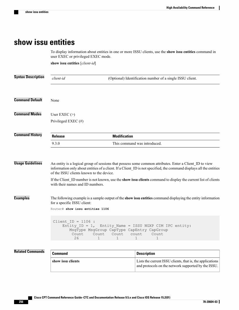
show issu entitiesTo display information about entities in one or more ISSU clients, use the show issu entities command inuser EXEC or privileged EXEC mode.
show issu entities [client-id]
Syntax Description (Optional) Identification number of a single ISSU client.client-id
Command Default None
Command Modes User EXEC (>)
Privileged EXEC (#)
Command History ModificationRelease
This command was introduced.9.3.0
Usage Guidelines An entity is a logical group of sessions that possess some common attributes. Enter a Client_ID to viewinformation only about entities of a client. If a Client_ID is not specified, the command displays all the entitiesof the ISSU clients known to the device.
If the Client_ID number is not known, use the show issu clients command to display the current list of clientswith their names and ID numbers.
Examples The following example is a sample output of the show issu entities command displaying the entity informationfor a specific ISSU client:Router# show issu entities 1106
Client_ID = 1106 :Entity_ID = 1, Entity_Name = ISSU NGXP CIM IPC entity:
MsgType MsgGroup CapType CapEntry CapGroupCount Count Count count Count26 1 1 1 1
Related Commands DescriptionCommand
Lists the current ISSU clients, that is, the applicationsand protocols on the network supported by the ISSU.
show issu clients
Cisco CPT Command Reference Guide–CTC and Documentation Release 9.5.x and Cisco IOS Release 15.2(01)256 78-20604-03
High Availability Command Referenceshow issu entities

DescriptionCommand
Displays detailed information about a particular ISSUclient, including whether the client status for theimpending software upgrade is compatible.
show issu sessions
Cisco CPT Command Reference Guide–CTC and Documentation Release 9.5.x and Cisco IOS Release 15.2(01) 78-20604-03 257
High Availability Command Referenceshow issu entities
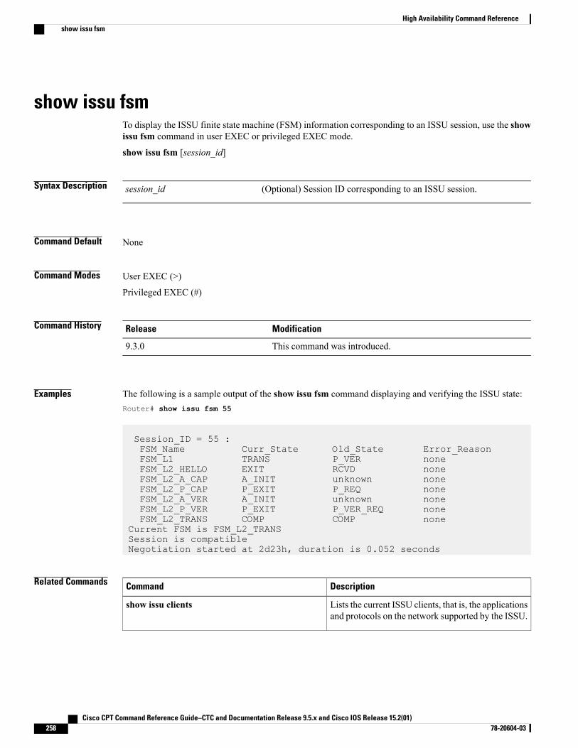
show issu fsmTo display the ISSU finite state machine (FSM) information corresponding to an ISSU session, use the showissu fsm command in user EXEC or privileged EXEC mode.
show issu fsm [session_id]
Syntax Description (Optional) Session ID corresponding to an ISSU session.session_id
Command Default None
Command Modes User EXEC (>)
Privileged EXEC (#)
Command History ModificationRelease
This command was introduced.9.3.0
Examples The following is a sample output of the show issu fsm command displaying and verifying the ISSU state:Router# show issu fsm 55
Session_ID = 55 :FSM_Name Curr_State Old_State Error_ReasonFSM_L1 TRANS P_VER noneFSM_L2_HELLO EXIT RCVD noneFSM_L2_A_CAP A_INIT unknown noneFSM_L2_P_CAP P_EXIT P_REQ noneFSM_L2_A_VER A_INIT unknown noneFSM_L2_P_VER P_EXIT P_VER_REQ noneFSM_L2_TRANS COMP COMP none
Current FSM is FSM_L2_TRANSSession is compatibleNegotiation started at 2d23h, duration is 0.052 seconds
Related Commands DescriptionCommand
Lists the current ISSU clients, that is, the applicationsand protocols on the network supported by the ISSU.
show issu clients
Cisco CPT Command Reference Guide–CTC and Documentation Release 9.5.x and Cisco IOS Release 15.2(01)258 78-20604-03
High Availability Command Referenceshow issu fsm

DescriptionCommand
Displays detailed information about a particular ISSUclient, including whether the client status for theimpending software upgrade is compatible.
show issu sessions
Cisco CPT Command Reference Guide–CTC and Documentation Release 9.5.x and Cisco IOS Release 15.2(01) 78-20604-03 259
High Availability Command Referenceshow issu fsm
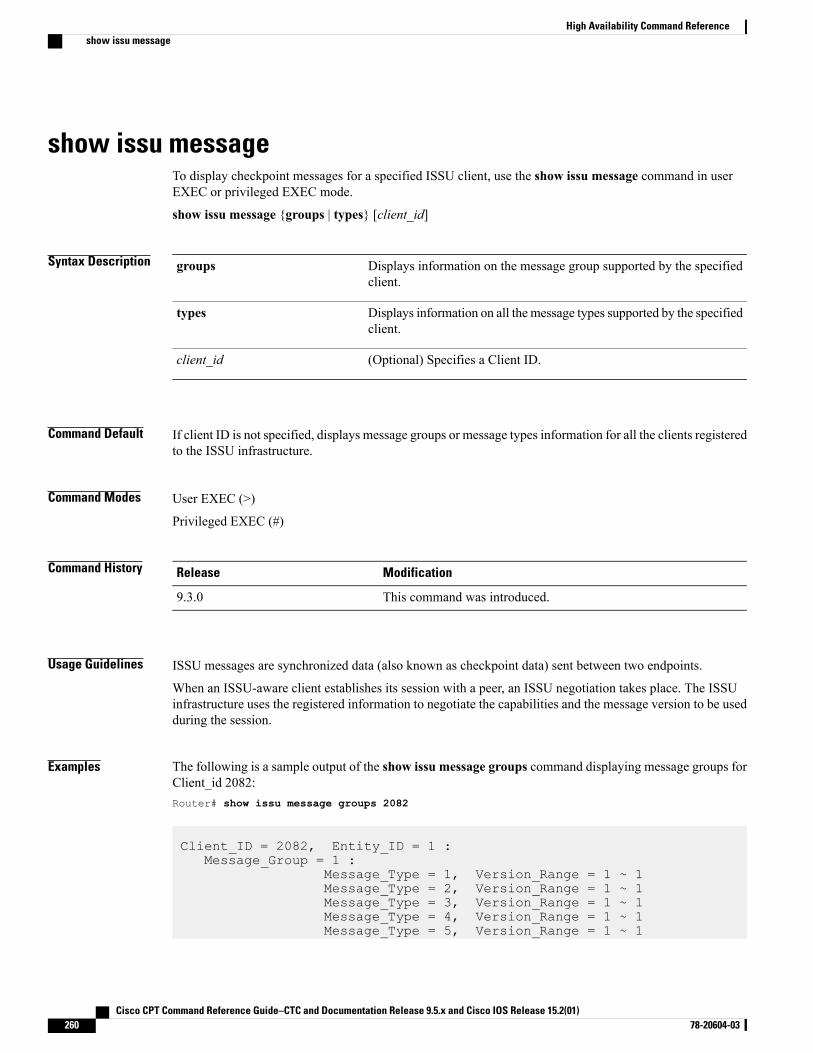
show issu messageTo display checkpoint messages for a specified ISSU client, use the show issu message command in userEXEC or privileged EXEC mode.
show issu message {groups | types} [client_id]
Syntax Description Displays information on the message group supported by the specifiedclient.
groups
Displays information on all the message types supported by the specifiedclient.
types
(Optional) Specifies a Client ID.client_id
Command Default If client ID is not specified, displays message groups or message types information for all the clients registeredto the ISSU infrastructure.
Command Modes User EXEC (>)
Privileged EXEC (#)
Command History ModificationRelease
This command was introduced.9.3.0
Usage Guidelines ISSU messages are synchronized data (also known as checkpoint data) sent between two endpoints.
When an ISSU-aware client establishes its session with a peer, an ISSU negotiation takes place. The ISSUinfrastructure uses the registered information to negotiate the capabilities and the message version to be usedduring the session.
Examples The following is a sample output of the show issu message groups command displaying message groups forClient_id 2082:Router# show issu message groups 2082
Client_ID = 2082, Entity_ID = 1 :Message_Group = 1 :
Message_Type = 1, Version_Range = 1 ~ 1Message_Type = 2, Version_Range = 1 ~ 1Message_Type = 3, Version_Range = 1 ~ 1Message_Type = 4, Version_Range = 1 ~ 1Message_Type = 5, Version_Range = 1 ~ 1
Cisco CPT Command Reference Guide–CTC and Documentation Release 9.5.x and Cisco IOS Release 15.2(01)260 78-20604-03
High Availability Command Referenceshow issu message
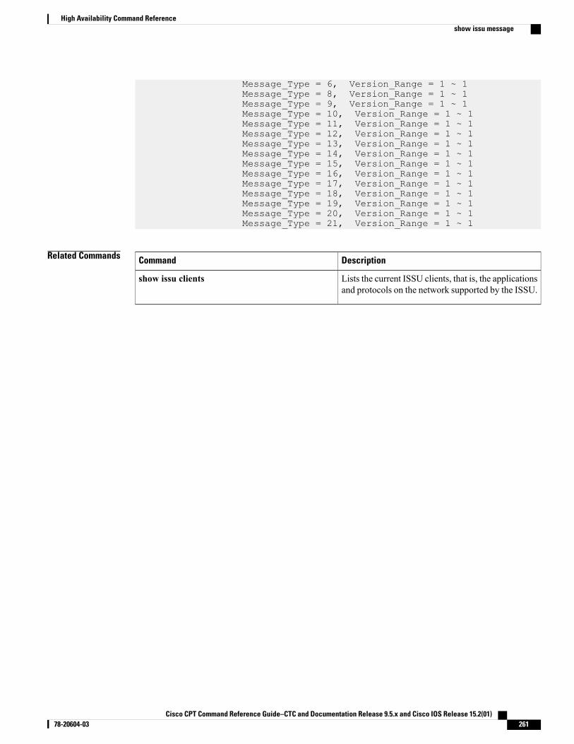
Message_Type = 6, Version_Range = 1 ~ 1Message_Type = 8, Version_Range = 1 ~ 1Message_Type = 9, Version_Range = 1 ~ 1Message_Type = 10, Version_Range = 1 ~ 1Message_Type = 11, Version_Range = 1 ~ 1Message_Type = 12, Version_Range = 1 ~ 1Message_Type = 13, Version_Range = 1 ~ 1Message_Type = 14, Version_Range = 1 ~ 1Message_Type = 15, Version_Range = 1 ~ 1Message_Type = 16, Version_Range = 1 ~ 1Message_Type = 17, Version_Range = 1 ~ 1Message_Type = 18, Version_Range = 1 ~ 1Message_Type = 19, Version_Range = 1 ~ 1Message_Type = 20, Version_Range = 1 ~ 1Message_Type = 21, Version_Range = 1 ~ 1
Related Commands DescriptionCommand
Lists the current ISSU clients, that is, the applicationsand protocols on the network supported by the ISSU.
show issu clients
Cisco CPT Command Reference Guide–CTC and Documentation Release 9.5.x and Cisco IOS Release 15.2(01) 78-20604-03 261
High Availability Command Referenceshow issu message
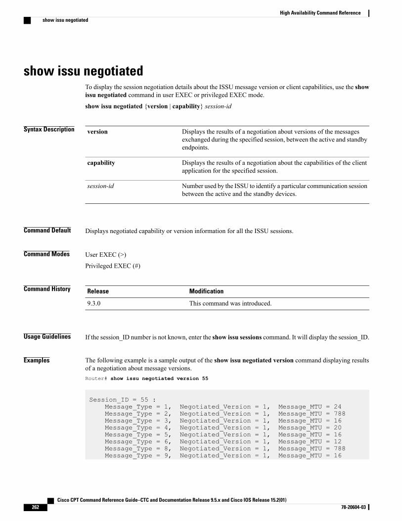
show issu negotiatedTo display the session negotiation details about the ISSU message version or client capabilities, use the showissu negotiated command in user EXEC or privileged EXEC mode.
show issu negotiated {version | capability} session-id
Syntax Description Displays the results of a negotiation about versions of the messagesexchanged during the specified session, between the active and standbyendpoints.
version
Displays the results of a negotiation about the capabilities of the clientapplication for the specified session.
capability
Number used by the ISSU to identify a particular communication sessionbetween the active and the standby devices.
session-id
Command Default Displays negotiated capability or version information for all the ISSU sessions.
Command Modes User EXEC (>)
Privileged EXEC (#)
Command History ModificationRelease
This command was introduced.9.3.0
Usage Guidelines If the session_ID number is not known, enter the show issu sessions command. It will display the session_ID.
Examples The following example is a sample output of the show issu negotiated version command displaying resultsof a negotiation about message versions.Router# show issu negotiated version 55
Session_ID = 55 :Message_Type = 1, Negotiated_Version = 1, Message_MTU = 24Message_Type = 2, Negotiated_Version = 1, Message_MTU = 788Message_Type = 3, Negotiated_Version = 1, Message_MTU = 16Message_Type = 4, Negotiated_Version = 1, Message_MTU = 20Message_Type = 5, Negotiated_Version = 1, Message_MTU = 16Message_Type = 6, Negotiated_Version = 1, Message_MTU = 12Message_Type = 8, Negotiated_Version = 1, Message_MTU = 788Message_Type = 9, Negotiated_Version = 1, Message_MTU = 16
Cisco CPT Command Reference Guide–CTC and Documentation Release 9.5.x and Cisco IOS Release 15.2(01)262 78-20604-03
High Availability Command Referenceshow issu negotiated
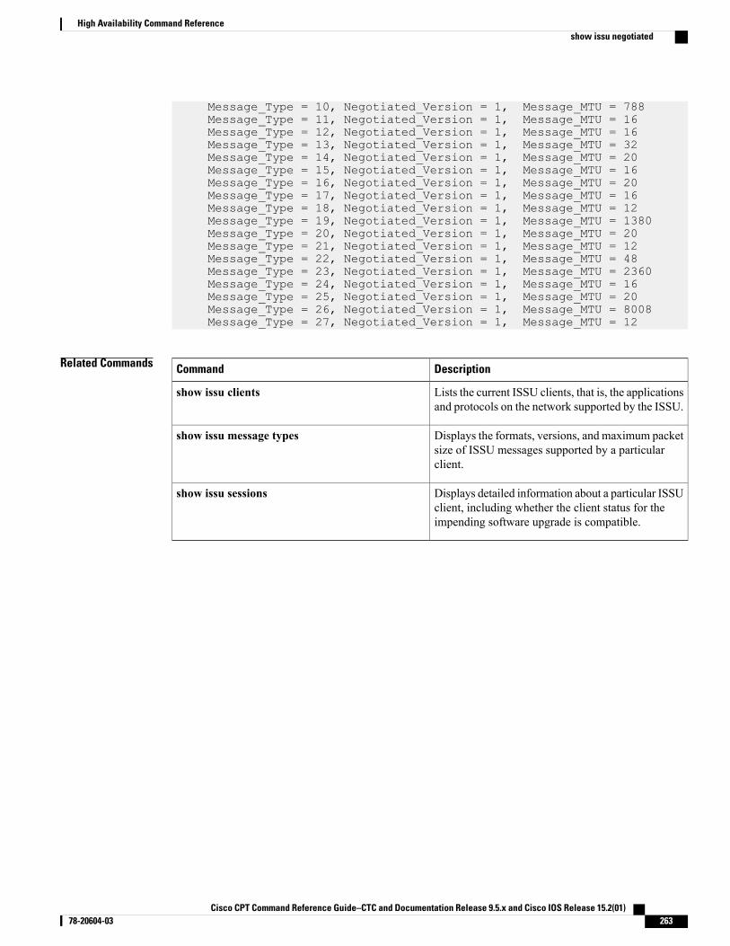
Message_Type = 10, Negotiated_Version = 1, Message_MTU = 788Message_Type = 11, Negotiated_Version = 1, Message_MTU = 16Message_Type = 12, Negotiated_Version = 1, Message_MTU = 16Message_Type = 13, Negotiated_Version = 1, Message_MTU = 32Message_Type = 14, Negotiated_Version = 1, Message_MTU = 20Message_Type = 15, Negotiated_Version = 1, Message_MTU = 16Message_Type = 16, Negotiated_Version = 1, Message_MTU = 20Message_Type = 17, Negotiated_Version = 1, Message_MTU = 16Message_Type = 18, Negotiated_Version = 1, Message_MTU = 12Message_Type = 19, Negotiated_Version = 1, Message_MTU = 1380Message_Type = 20, Negotiated_Version = 1, Message_MTU = 20Message_Type = 21, Negotiated_Version = 1, Message_MTU = 12Message_Type = 22, Negotiated_Version = 1, Message_MTU = 48Message_Type = 23, Negotiated_Version = 1, Message_MTU = 2360Message_Type = 24, Negotiated_Version = 1, Message_MTU = 16Message_Type = 25, Negotiated_Version = 1, Message_MTU = 20Message_Type = 26, Negotiated_Version = 1, Message_MTU = 8008Message_Type = 27, Negotiated_Version = 1, Message_MTU = 12
Related Commands DescriptionCommand
Lists the current ISSU clients, that is, the applicationsand protocols on the network supported by the ISSU.
show issu clients
Displays the formats, versions, and maximum packetsize of ISSU messages supported by a particularclient.
show issu message types
Displays detailed information about a particular ISSUclient, including whether the client status for theimpending software upgrade is compatible.
show issu sessions
Cisco CPT Command Reference Guide–CTC and Documentation Release 9.5.x and Cisco IOS Release 15.2(01) 78-20604-03 263
High Availability Command Referenceshow issu negotiated
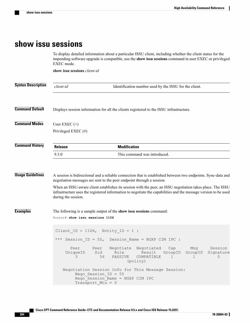
show issu sessionsTo display detailed information about a particular ISSU client, including whether the client status for theimpending software upgrade is compatible, use the show issu sessions command in user EXEC or privilegedEXEC mode.
show issu sessions client-id
Syntax Description Identification number used by the ISSU for the client.client-id
Command Default Displays session information for all the clients registered to the ISSU infrastructure.
Command Modes User EXEC (>)
Privileged EXEC (#)
Command History ModificationRelease
This command was introduced.9.3.0
Usage Guidelines A session is bidirectional and a reliable connection that is established between two endpoints. Sync-data andnegotiation messages are sent to the peer endpoint through a session.
When an ISSU-aware client establishes its session with the peer, an ISSU negotiation takes place. The ISSUinfrastructure uses the registered information to negotiate the capabilities and the message version to be usedduring the session.
Examples The following is a sample output of the show issu sessions command:Router# show issu sessions 1106
Client_ID = 1106, Entity_ID = 1 :
*** Session_ID = 55, Session_Name = NGXP CIM IPC :
Peer Peer Negotiate Negotiated Cap Msg SessionUniqueID Sid Role Result GroupID GroupID Signature
3 56 PASSIVE COMPATIBLE 1 1 0(policy)
Negotiation Session Info for This Message Session:Nego_Session_ID = 55Nego_Session_Name = NGXP CIM IPCTransport_Mtu = 0
Cisco CPT Command Reference Guide–CTC and Documentation Release 9.5.x and Cisco IOS Release 15.2(01)264 78-20604-03
High Availability Command Referenceshow issu sessions
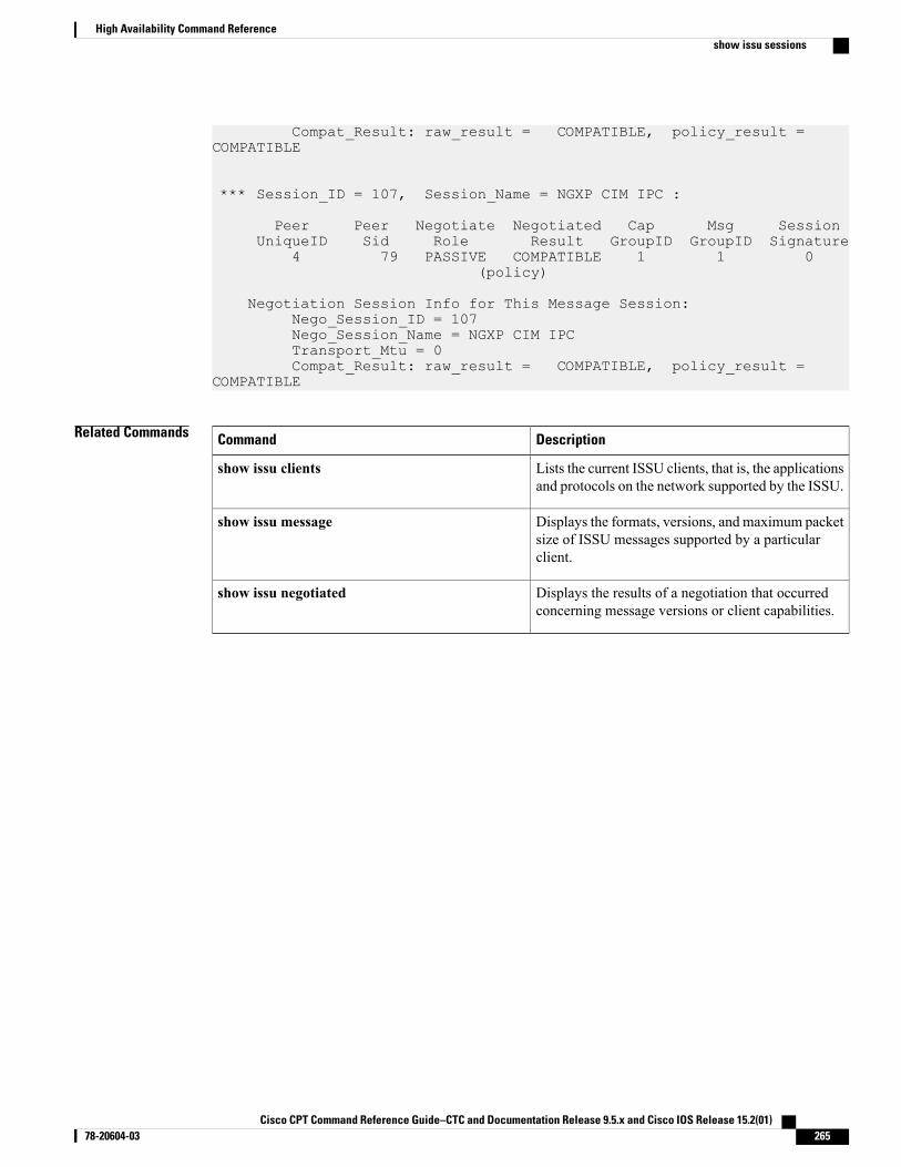
Compat_Result: raw_result = COMPATIBLE, policy_result =COMPATIBLE
*** Session_ID = 107, Session_Name = NGXP CIM IPC :
Peer Peer Negotiate Negotiated Cap Msg SessionUniqueID Sid Role Result GroupID GroupID Signature
4 79 PASSIVE COMPATIBLE 1 1 0(policy)
Negotiation Session Info for This Message Session:Nego_Session_ID = 107Nego_Session_Name = NGXP CIM IPCTransport_Mtu = 0Compat_Result: raw_result = COMPATIBLE, policy_result =
COMPATIBLE
Related Commands DescriptionCommand
Lists the current ISSU clients, that is, the applicationsand protocols on the network supported by the ISSU.
show issu clients
Displays the formats, versions, and maximum packetsize of ISSU messages supported by a particularclient.
show issu message
Displays the results of a negotiation that occurredconcerning message versions or client capabilities.
show issu negotiated
Cisco CPT Command Reference Guide–CTC and Documentation Release 9.5.x and Cisco IOS Release 15.2(01) 78-20604-03 265
High Availability Command Referenceshow issu sessions
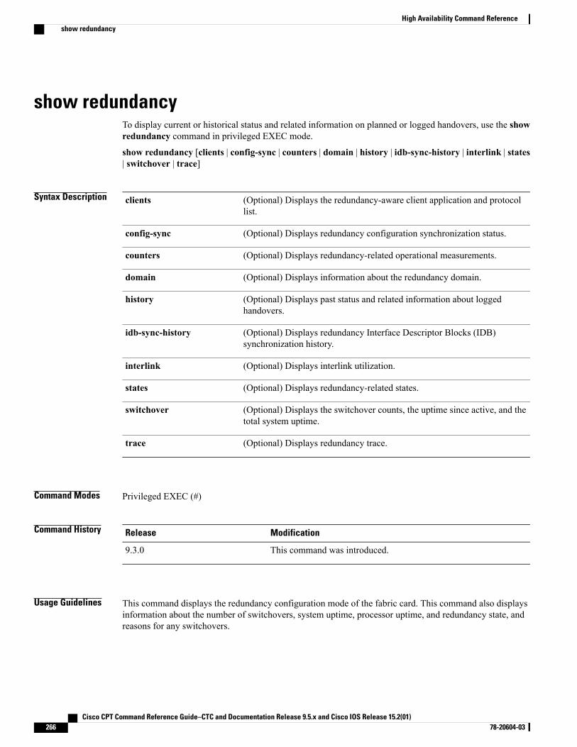
show redundancyTo display current or historical status and related information on planned or logged handovers, use the showredundancy command in privileged EXEC mode.
show redundancy [clients | config-sync | counters | domain | history | idb-sync-history | interlink | states| switchover | trace]
Syntax Description (Optional) Displays the redundancy-aware client application and protocollist.
clients
(Optional) Displays redundancy configuration synchronization status.config-sync
(Optional) Displays redundancy-related operational measurements.counters
(Optional) Displays information about the redundancy domain.domain
(Optional) Displays past status and related information about loggedhandovers.
history
(Optional) Displays redundancy Interface Descriptor Blocks (IDB)synchronization history.
idb-sync-history
(Optional) Displays interlink utilization.interlink
(Optional) Displays redundancy-related states.states
(Optional) Displays the switchover counts, the uptime since active, and thetotal system uptime.
switchover
(Optional) Displays redundancy trace.trace
Command Modes Privileged EXEC (#)
Command History ModificationRelease
This command was introduced.9.3.0
Usage Guidelines This command displays the redundancy configuration mode of the fabric card. This command also displaysinformation about the number of switchovers, system uptime, processor uptime, and redundancy state, andreasons for any switchovers.
Cisco CPT Command Reference Guide–CTC and Documentation Release 9.5.x and Cisco IOS Release 15.2(01)266 78-20604-03
High Availability Command Referenceshow redundancy
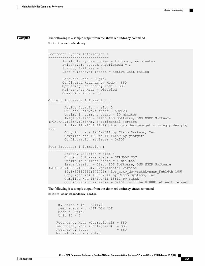
Examples The following is a sample output from the show redundancy command.Router# show redundancy
Redundant System Information :------------------------------
Available system uptime = 18 hours, 44 minutesSwitchovers system experienced = 1Standby failures = 0Last switchover reason = active unit failed
Hardware Mode = DuplexConfigured Redundancy Mode = SSOOperating Redundancy Mode = SSOMaintenance Mode = DisabledCommunications = Up
Current Processor Information :-------------------------------
Active Location = slot 5Current Software state = ACTIVEUptime in current state = 10 minutesImage Version = Cisco IOS Software, ONS NGXP Software
(NGXP-ADVIPSERVICES-M), Experimental Version15.1(20110216:101154) [ios_ngxp_dev-georgeti-ios_ngxp_dev.pkg
100]Copyright (c) 1986-2011 by Cisco Systems, Inc.Compiled Wed 16-Feb-11 16:59 by georgetiConfiguration register = 0x101
Peer Processor Information :----------------------------
Standby Location = slot 4Current Software state = STANDBY HOTUptime in current state = 8 minutesImage Version = Cisco IOS Software, ONS NGXP Software
(NGXP-ADVIPSERVICES-M), Experimental Version15.1(20110215:170703) [ios_ngxp_dev-sathk-ngxp_Feb16th 109]Copyright (c) 1986-2011 by Cisco Systems, Inc.Compiled Wed 16-Feb-11 15:12 by sathkConfiguration register = 0x101 (will be 0x8001 at next reload)
The following is a sample output from the show redundancy states command.Router# show redundancy states
my state = 13 -ACTIVEpeer state = 8 -STANDBY HOTMode = DuplexUnit ID = 4
Redundancy Mode (Operational) = SSORedundancy Mode (Configured) = SSORedundancy State = SSOManual Swact = enabled
Cisco CPT Command Reference Guide–CTC and Documentation Release 9.5.x and Cisco IOS Release 15.2(01) 78-20604-03 267
High Availability Command Referenceshow redundancy
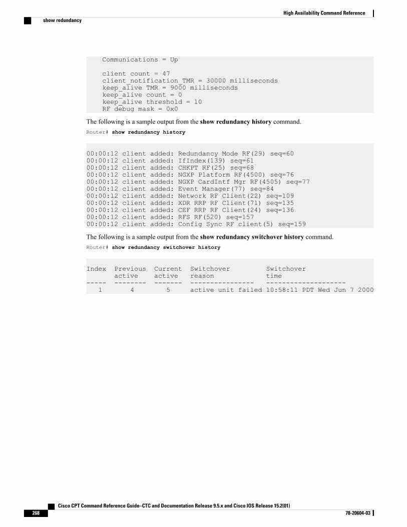
Communications = Up
client count = 47client_notification_TMR = 30000 millisecondskeep_alive TMR = 9000 millisecondskeep_alive count = 0keep_alive threshold = 10RF debug mask = 0x0
The following is a sample output from the show redundancy history command.Router# show redundancy history
00:00:12 client added: Redundancy Mode RF(29) seq=6000:00:12 client added: IfIndex(139) seq=6100:00:12 client added: CHKPT RF(25) seq=6800:00:12 client added: NGXP Platform RF(4500) seq=7600:00:12 client added: NGXP CardIntf Mgr RF(4505) seq=7700:00:12 client added: Event Manager(77) seq=8400:00:12 client added: Network RF Client(22) seq=10900:00:12 client added: XDR RRP RF Client(71) seq=13500:00:12 client added: CEF RRP RF Client(24) seq=13600:00:12 client added: RFS RF(520) seq=15700:00:12 client added: Config Sync RF client(5) seq=159
The following is a sample output from the show redundancy switchover history command.Router# show redundancy switchover history
Index Previous Current Switchover Switchoveractive active reason time
----- -------- ------- ---------------- --------------------1 4 5 active unit failed 10:58:11 PDT Wed Jun 7 2000
Cisco CPT Command Reference Guide–CTC and Documentation Release 9.5.x and Cisco IOS Release 15.2(01)268 78-20604-03
High Availability Command Referenceshow redundancy
REP Command Reference
This chapter describes commands to configure Resilient Ethernet Protocol (REP).
• rep admin vlan, page 270
• rep block port, page 271
• rep lsl-age-timer, page 273
• rep lsl-retries, page 274
• rep preempt delay, page 275
• rep preempt segment, page 277
• rep segment, page 279
• rep stcn, page 281
• show interfaces rep detail, page 282
• show rep topology, page 284
Cisco CPT Command Reference Guide–CTC and Documentation Release 9.5.x and Cisco IOS Release 15.2(01) 78-20604-03 269
rep admin vlanTo configure a Resilient Ethernet Protocol (REP) administrative VLAN for REP to transmit hardware floodlayer (HFL) messages, use the rep admin vlan command in global configuration mode. To return to thedefault configuration with VLAN 1 as the administrative VLAN, use the no form of this command.
rep admin vlan vlan-id
no rep admin vlan
Syntax Description The 48-bit static MAC address.vlan-id
Command Default The default value of the administrative VLAN is VLAN 1.
Command Modes Global configuration (config)
Command History ModificationRelease
This command was introduced.9.3.0
Usage Guidelines The range of the REP administrative VLAN is from 2 to 4094.
If you do not configure an administrative VLAN, the default VLAN is VLAN 1. The default VLAN 1 isalways configured. There can be only one administrative VLAN on a router and on a segment.
You can verify your settings by entering the show interfaces rep detail privileged EXEC command.
Examples The following example shows how to configure VLAN 100 as the REP administrative VLAN:
Router(config)# rep admin vlan 100
Related Commands DescriptionCommand
Displays detailed REP configuration and status forall interfaces or the specified interface, including theadministrative VLAN.
show interfaces rep detail
Cisco CPT Command Reference Guide–CTC and Documentation Release 9.5.x and Cisco IOS Release 15.2(01)270 78-20604-03
REP Command Referencerep admin vlan
rep block portTo configure a REP VLAN load balancing on the REP primary edge port, use the rep block port commandin interface configuration mode. To return to the default configuration, use the no form of this command.
rep block port {id port-id | neighbor-offset | preferred} vlan {vlan-list | all}no rep block port {id port-id | neighbor-offset | preferred}
Syntax Description Specifies the VLAN blocking alternate port by entering the unique port ID, whichis automatically generated when REP is enabled. The REP port ID is a 16-characterhexadecimal value. You can display the port ID for an interface by entering the showinterface interface-id rep detail command in privileged EXEC mode.
id port-id
Identifies the VLAN blocking alternate port by entering the offset number of aneighbor. The range is from –256 to +256; a value of 0 is invalid.
neighbor-offset
Selects the regular segment port previously identified as the preferred alternate portfor VLAN load balancing.
preferred
Identifies the VLANs to be blocked.vlan
VLAN ID or range of VLAN IDs to be displayed. Enter a VLAN ID from 1 to 4094or a range or sequence of VLANs (such as 1-3, 22, 41-44) to be blocked.
vlan-list
Blocks all the VLANs.all
Command Default The default behavior after you enter the rep preempt segment command in privileged EXEC (for manualpreemption) is to block all VLANs at the primary edge port. This behavior remains until you configure therep block port command.
If the primary edge port cannot determine which port is to be the alternate port, the default action is nopreemption and no VLAN load balancing.
Command Modes Interface configuration (config-if)
Command History ModificationRelease
This command was introduced.9.3.0
Usage Guidelines You must enter this command on the REP primary edge port.
When you select an alternate port by entering an offset number, this number identifies the downstream neighborport of an edge port. The primary edge port has an offset number of 1; positive numbers above 1 identifydownstream neighbors of the primary edge port. Negative numbers identify the secondary edge port (offset
Cisco CPT Command Reference Guide–CTC and Documentation Release 9.5.x and Cisco IOS Release 15.2(01) 78-20604-03 271
REP Command Referencerep block port
number –1) and its downstream neighbors. Do not enter an offset value of 1 because that is the offset numberof the primary edge port itself.
If you have configured a preempt delay time by entering the rep preempt delay seconds command in interfaceconfiguration mode and a link failure and recovery occurs, VLAN load balancing begins after the configuredpreemption time period elapses without another link failure. The alternate port specified in the load-balancingconfiguration blocks the configured VLANs and unblocks all other segment ports. If the primary edge portcannot determine the alternate port for VLAN balancing, the default action is no preemption.
Each port in a segment has a unique port ID. To determine the port ID of a port, enter the show interfacesinterface-id rep detail command in privileged EXEC mode.
Examples The following example shows how to configure REP VLAN load balancing.
Router# configure terminalRouter(config)# interface TenGigabitEthernet 4/1Router(config-if)# rep block port id 0009001818D68700 vlan 1-100Router(config-if)# end
Related Commands DescriptionCommand
Configures a waiting period after a segment portfailure and recovery before REP VLAN loadbalancing is triggered.
rep preempt delay
Manually starts REP VLAN load balancing on asegment.
rep preempt segment
Displays REP detailed configuration and status forall the interfaces or the specified interface, includingthe administrative VLAN.
show interfaces rep detail
Cisco CPT Command Reference Guide–CTC and Documentation Release 9.5.x and Cisco IOS Release 15.2(01)272 78-20604-03
REP Command Referencerep block port
rep lsl-age-timerTo configure the REP link status layer (LSL) age-out timer value, use the rep lsl-age-timer command ininterface configuration mode. To restore the default age-out timer value, use the no form of this command.
rep lsl-age-timer milliseconds
no rep lsl-age-timer milliseconds
Syntax Description REP LSL age-out timer value in milliseconds (ms). The range is from 120 msto 10000 ms in multiples of 40 ms.
milliseconds
Command Default The default LSL age-out timer value is 5 ms.
Command Modes Interface configuration (config-if)
Command History ModificationRelease
This command was introduced.9.3.0
Usage Guidelines The rep lsl-age-timer command is used to configure the REP LSL age-out timer value. While configuringREP configurable timers, we recommend that you configure the REP LSL number of retries first and thenconfigure the REP LSL age-out timer value.
Examples The following example shows how to configure REP LSL age-out timer value.
Router# enableRouter# configure terminalRouter(config)# interface TenGigabitEthernet4/1Router(config-if)# rep segment 1 edge primaryRouter(config-if)# rep lsl-age-timer 2000Router(config-if)# end
Related Commands DescriptionCommand
Configures the number of retries before the REP linkis disabled.
rep lsl-retries
Cisco CPT Command Reference Guide–CTC and Documentation Release 9.5.x and Cisco IOS Release 15.2(01) 78-20604-03 273
REP Command Referencerep lsl-age-timer
rep lsl-retriesTo configure the REP link status layer (LSL) number of retries, use the rep lsl-retries command in interfaceconfiguration mode. To restore the default number of retries, use the no form of this command.
rep lsl-retries number-of-retries
no rep lsl-retries number-of-retries
Syntax Description Number of LSL retries. The range of retries is from 3 to 10.number-of-retries
Command Default The default number of LSL retries is 5.
Command Modes Interface configuration (config-if)
Command History ModificationRelease
This command was introduced.9.3.0
Usage Guidelines The rep lsl-retries command is used to configure the number of retries before the REP link is disabled. Whileconfiguring REP configurable timers, we recommend that you configure the REP LSL number of retries firstand then configure the REP LSL age-out timer value.
Examples The following example shows how to configure REP LSL retries.
Router# enableRouter# configure terminalRouter(config)# interface TenGigabitEthernet4/1Router(config-if)# rep segment 2 edge primaryRouter(config-if)# rep lsl-retries 4Router(config-if)# end
Related Commands DescriptionCommand
Configures the REP link status layer age-out timervalue.
rep lsl-age-timer
Cisco CPT Command Reference Guide–CTC and Documentation Release 9.5.x and Cisco IOS Release 15.2(01)274 78-20604-03
REP Command Referencerep lsl-retries
rep preempt delayTo configure a waiting period after a segment port failure and recovery before REP VLAN load balancing istriggered, use the rep preempt delay command in interface configuration mode. To remove the configureddelay, use the no form of this command.
rep preempt delay seconds
no rep preempt delay
Syntax Description Number of seconds to delay REP preemption. The range is from 15 to 300 seconds.The default is manual preemption without delay.
seconds
Command Default REP preemption delay is not set. The default is manual preemption without delay.
Command Modes Interface configuration (config-if)
Command History ModificationRelease
This command was introduced.9.3.0
Usage Guidelines You must enter this command on the REP primary edge port.
You must enter this command and configure a preempt time delay if you want VLAN load balancing toautomatically trigger after a link failure and recovery.
If VLAN load balancing is configured, after a segment port failure and recovery, the REP primary edge portstarts a delay timer before VLAN load balancing occurs. Note that the timer restarts after each link failure.When the timer expires, the REP primary edge alerts the alternate port to perform VLAN load balancing(configured by using the rep block port interface configuration command) and prepares the segment for thenew topology. The configured VLAN list is blocked at the alternate port, and all other VLANs are blockedat the primary edge port.
You can verify your settings by entering the show interfaces rep privileged EXEC command.
Examples The following example shows how to configure a REP preemption time delay of 100 seconds on the primaryedge port.
Router(config)# interface TenGigabitEthernet 4/1Router(config-if)# rep preempt delay 100Router(config-if)# exit
Cisco CPT Command Reference Guide–CTC and Documentation Release 9.5.x and Cisco IOS Release 15.2(01) 78-20604-03 275
REP Command Referencerep preempt delay
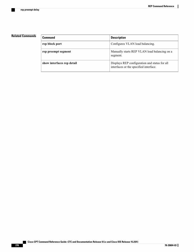
Related Commands DescriptionCommand
Configures VLAN load balancing.rep block port
Manually starts REP VLAN load balancing on asegment.
rep preempt segment
Displays REP configuration and status for allinterfaces or the specified interface.
show interfaces rep detail
Cisco CPT Command Reference Guide–CTC and Documentation Release 9.5.x and Cisco IOS Release 15.2(01)276 78-20604-03
REP Command Referencerep preempt delay
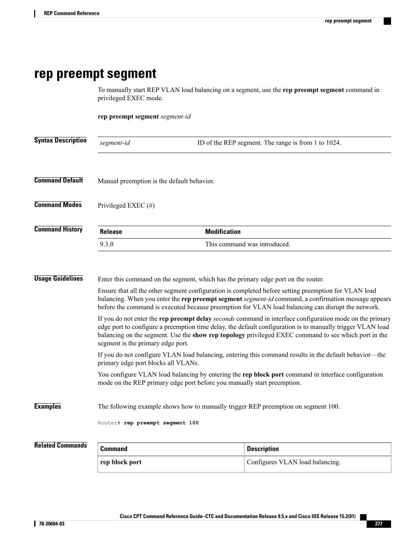
rep preempt segmentTo manually start REP VLAN load balancing on a segment, use the rep preempt segment command inprivileged EXEC mode.
rep preempt segment segment-id
Syntax Description ID of the REP segment. The range is from 1 to 1024.segment-id
Command Default Manual preemption is the default behavior.
Command Modes Privileged EXEC (#)
Command History ModificationRelease
This command was introduced.9.3.0
Usage Guidelines Enter this command on the segment, which has the primary edge port on the router.
Ensure that all the other segment configuration is completed before setting preemption for VLAN loadbalancing. When you enter the rep preempt segment segment-id command, a confirmation message appearsbefore the command is executed because preemption for VLAN load balancing can disrupt the network.
If you do not enter the rep preempt delay seconds command in interface configuration mode on the primaryedge port to configure a preemption time delay, the default configuration is to manually trigger VLAN loadbalancing on the segment. Use the show rep topology privileged EXEC command to see which port in thesegment is the primary edge port.
If you do not configure VLAN load balancing, entering this command results in the default behavior—theprimary edge port blocks all VLANs.
You configure VLAN load balancing by entering the rep block port command in interface configurationmode on the REP primary edge port before you manually start preemption.
Examples The following example shows how to manually trigger REP preemption on segment 100.
Router# rep preempt segment 100
Related Commands DescriptionCommand
Configures VLAN load balancing.rep block port
Cisco CPT Command Reference Guide–CTC and Documentation Release 9.5.x and Cisco IOS Release 15.2(01) 78-20604-03 277
REP Command Referencerep preempt segment
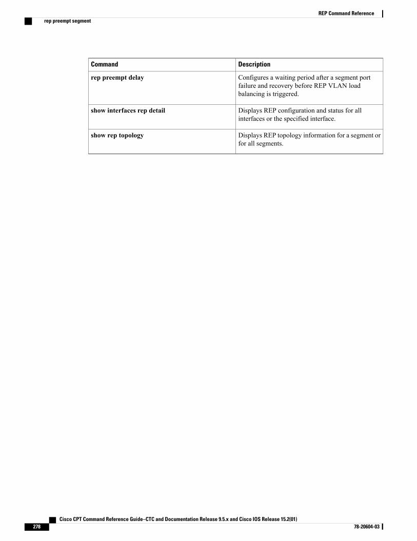
DescriptionCommand
Configures a waiting period after a segment portfailure and recovery before REP VLAN loadbalancing is triggered.
rep preempt delay
Displays REP configuration and status for allinterfaces or the specified interface.
show interfaces rep detail
Displays REP topology information for a segment orfor all segments.
show rep topology
Cisco CPT Command Reference Guide–CTC and Documentation Release 9.5.x and Cisco IOS Release 15.2(01)278 78-20604-03
REP Command Referencerep preempt segment
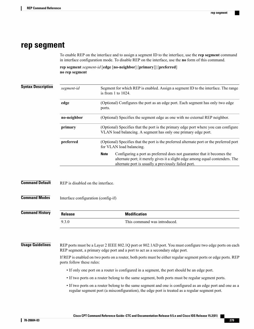
rep segmentTo enable REP on the interface and to assign a segment ID to the interface, use the rep segment commandin interface configuration mode. To disable REP on the interface, use the no form of this command.
rep segment segment-id [edge [no-neighbor] [primary]] [preferred]no rep segment
Syntax Description Segment for which REP is enabled. Assign a segment ID to the interface. The rangeis from 1 to 1024.
segment-id
(Optional) Configures the port as an edge port. Each segment has only two edgeports.
edge
(Optional) Specifies the segment edge as one with no external REP neighbor.no-neighbor
(Optional) Specifies that the port is the primary edge port where you can configureVLAN load balancing. A segment has only one primary edge port.
primary
(Optional) Specifies that the port is the preferred alternate port or the preferred portfor VLAN load balancing.
Configuring a port as preferred does not guarantee that it becomes thealternate port; it merely gives it a slight edge among equal contenders. Thealternate port is usually a previously failed port.
Note
preferred
Command Default REP is disabled on the interface.
Command Modes Interface configuration (config-if)
Command History ModificationRelease
This command was introduced.9.3.0
Usage Guidelines REP ports must be a Layer 2 IEEE 802.1Q port or 802.1AD port. You must configure two edge ports on eachREP segment, a primary edge port and a port to act as a secondary edge port.
If REP is enabled on two ports on a router, both ports must be either regular segment ports or edge ports. REPports follow these rules:
• If only one port on a router is configured in a segment, the port should be an edge port.
• If two ports on a router belong to the same segment, both ports must be regular segment ports.
• If two ports on a router belong to the same segment and one is configured as an edge port and one as aregular segment port (a misconfiguration), the edge port is treated as a regular segment port.
Cisco CPT Command Reference Guide–CTC and Documentation Release 9.5.x and Cisco IOS Release 15.2(01) 78-20604-03 279
REP Command Referencerep segment
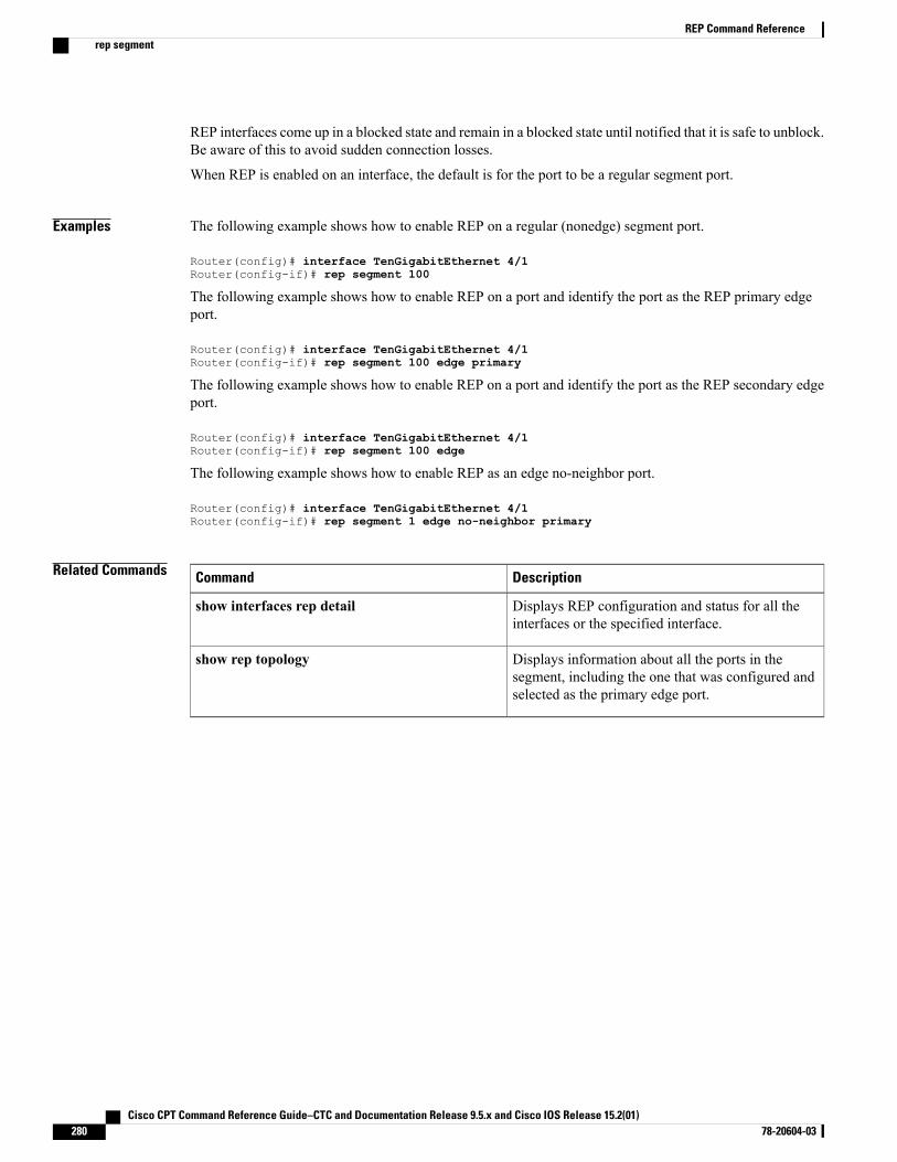
REP interfaces come up in a blocked state and remain in a blocked state until notified that it is safe to unblock.Be aware of this to avoid sudden connection losses.
When REP is enabled on an interface, the default is for the port to be a regular segment port.
Examples The following example shows how to enable REP on a regular (nonedge) segment port.
Router(config)# interface TenGigabitEthernet 4/1Router(config-if)# rep segment 100
The following example shows how to enable REP on a port and identify the port as the REP primary edgeport.
Router(config)# interface TenGigabitEthernet 4/1Router(config-if)# rep segment 100 edge primary
The following example shows how to enable REP on a port and identify the port as the REP secondary edgeport.
Router(config)# interface TenGigabitEthernet 4/1Router(config-if)# rep segment 100 edge
The following example shows how to enable REP as an edge no-neighbor port.
Router(config)# interface TenGigabitEthernet 4/1Router(config-if)# rep segment 1 edge no-neighbor primary
Related Commands DescriptionCommand
Displays REP configuration and status for all theinterfaces or the specified interface.
show interfaces rep detail
Displays information about all the ports in thesegment, including the one that was configured andselected as the primary edge port.
show rep topology
Cisco CPT Command Reference Guide–CTC and Documentation Release 9.5.x and Cisco IOS Release 15.2(01)280 78-20604-03
REP Command Referencerep segment
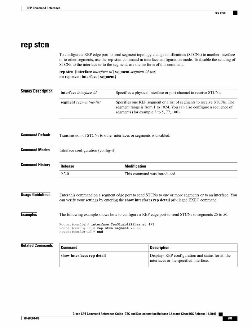
rep stcnTo configure a REP edge port to send segment topology change notifications (STCNs) to another interfaceor to other segments, use the rep stcn command in interface configuration mode. To disable the sending ofSTCNs to the interface or to the segment, use the no form of this command.
rep stcn {interface interface-id | segment segment-id-list}no rep stcn {interface | segment}
Syntax Description Specifies a physical interface or port channel to receive STCNs.interface interface-id
Specifies one REP segment or a list of segments to receive STCNs. Thesegment range is from 1 to 1024. You can also configure a sequence ofsegments (for example 3 to 5, 77, 100).
segment segment-id-list
Command Default Transmission of STCNs to other interfaces or segments is disabled.
Command Modes Interface configuration (config-if)
Command History ModificationRelease
This command was introduced.9.3.0
Usage Guidelines Enter this command on a segment edge port to send STCNs to one or more segments or to an interface. Youcan verify your settings by entering the show interfaces rep detail privileged EXEC command.
Examples The following example shows how to configure a REP edge port to send STCNs to segments 25 to 50.
Router(config)# interface TenGigabitEthernet 4/1Router(config-if)# rep stcn segment 25-50Router(config-if)# end
Related Commands DescriptionCommand
Displays REP configuration and status for all theinterfaces or the specified interface.
show interfaces rep detail
Cisco CPT Command Reference Guide–CTC and Documentation Release 9.5.x and Cisco IOS Release 15.2(01) 78-20604-03 281
REP Command Referencerep stcn
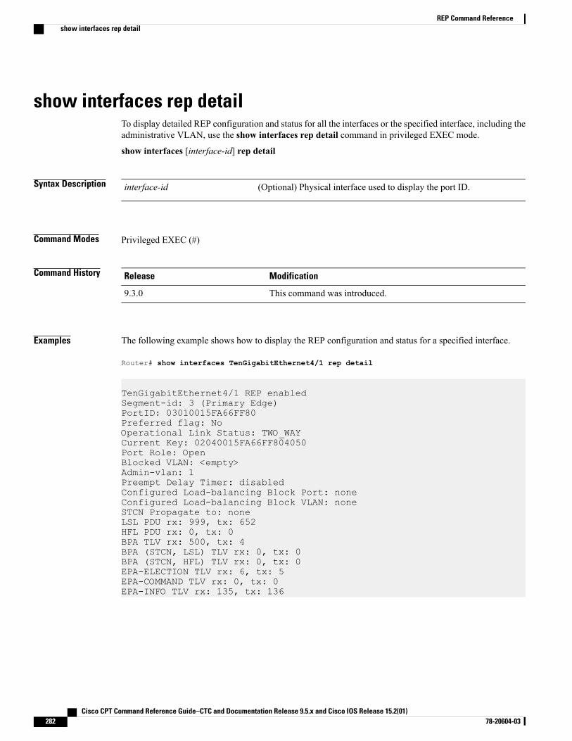
show interfaces rep detailTo display detailed REP configuration and status for all the interfaces or the specified interface, including theadministrative VLAN, use the show interfaces rep detail command in privileged EXEC mode.
show interfaces [interface-id] rep detail
Syntax Description (Optional) Physical interface used to display the port ID.interface-id
Command Modes Privileged EXEC (#)
Command History ModificationRelease
This command was introduced.9.3.0
Examples The following example shows how to display the REP configuration and status for a specified interface.
Router# show interfaces TenGigabitEthernet4/1 rep detail
TenGigabitEthernet4/1 REP enabledSegment-id: 3 (Primary Edge)PortID: 03010015FA66FF80Preferred flag: NoOperational Link Status: TWO_WAYCurrent Key: 02040015FA66FF804050Port Role: OpenBlocked VLAN: <empty>Admin-vlan: 1Preempt Delay Timer: disabledConfigured Load-balancing Block Port: noneConfigured Load-balancing Block VLAN: noneSTCN Propagate to: noneLSL PDU rx: 999, tx: 652HFL PDU rx: 0, tx: 0BPA TLV rx: 500, tx: 4BPA (STCN, LSL) TLV rx: 0, tx: 0BPA (STCN, HFL) TLV rx: 0, tx: 0EPA-ELECTION TLV rx: 6, tx: 5EPA-COMMAND TLV rx: 0, tx: 0EPA-INFO TLV rx: 135, tx: 136
Cisco CPT Command Reference Guide–CTC and Documentation Release 9.5.x and Cisco IOS Release 15.2(01)282 78-20604-03
REP Command Referenceshow interfaces rep detail
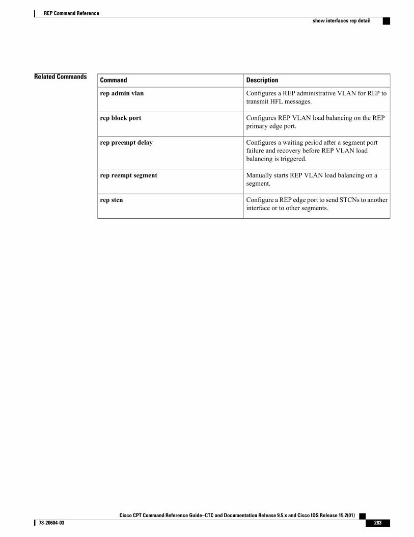
Related Commands DescriptionCommand
Configures a REP administrative VLAN for REP totransmit HFL messages.
rep admin vlan
Configures REP VLAN load balancing on the REPprimary edge port.
rep block port
Configures a waiting period after a segment portfailure and recovery before REP VLAN loadbalancing is triggered.
rep preempt delay
Manually starts REP VLAN load balancing on asegment.
rep reempt segment
Configure a REP edge port to send STCNs to anotherinterface or to other segments.
rep stcn
Cisco CPT Command Reference Guide–CTC and Documentation Release 9.5.x and Cisco IOS Release 15.2(01) 78-20604-03 283
REP Command Referenceshow interfaces rep detail
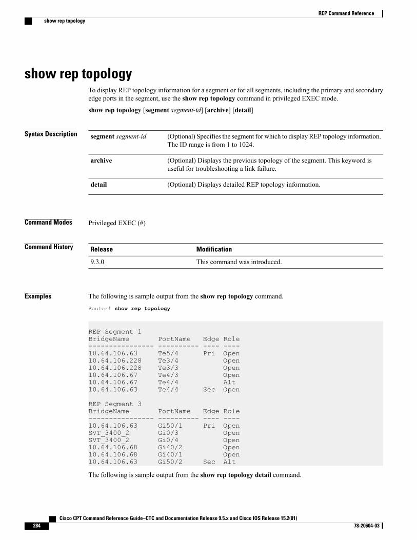
show rep topologyTo display REP topology information for a segment or for all segments, including the primary and secondaryedge ports in the segment, use the show rep topology command in privileged EXEC mode.
show rep topology [segment segment-id] [archive] [detail]
Syntax Description (Optional) Specifies the segment for which to display REP topology information.The ID range is from 1 to 1024.
segment segment-id
(Optional) Displays the previous topology of the segment. This keyword isuseful for troubleshooting a link failure.
archive
(Optional) Displays detailed REP topology information.detail
Command Modes Privileged EXEC (#)
Command History ModificationRelease
This command was introduced.9.3.0
Examples The following is sample output from the show rep topology command.
Router# show rep topology
REP Segment 1BridgeName PortName Edge Role---------------- ---------- ---- ----10.64.106.63 Te5/4 Pri Open10.64.106.228 Te3/4 Open10.64.106.228 Te3/3 Open10.64.106.67 Te4/3 Open10.64.106.67 Te4/4 Alt10.64.106.63 Te4/4 Sec Open
REP Segment 3BridgeName PortName Edge Role---------------- ---------- ---- ----10.64.106.63 Gi50/1 Pri OpenSVT_3400_2 Gi0/3 OpenSVT_3400_2 Gi0/4 Open10.64.106.68 Gi40/2 Open10.64.106.68 Gi40/1 Open10.64.106.63 Gi50/2 Sec Alt
The following is sample output from the show rep topology detail command.
Cisco CPT Command Reference Guide–CTC and Documentation Release 9.5.x and Cisco IOS Release 15.2(01)284 78-20604-03
REP Command Referenceshow rep topology
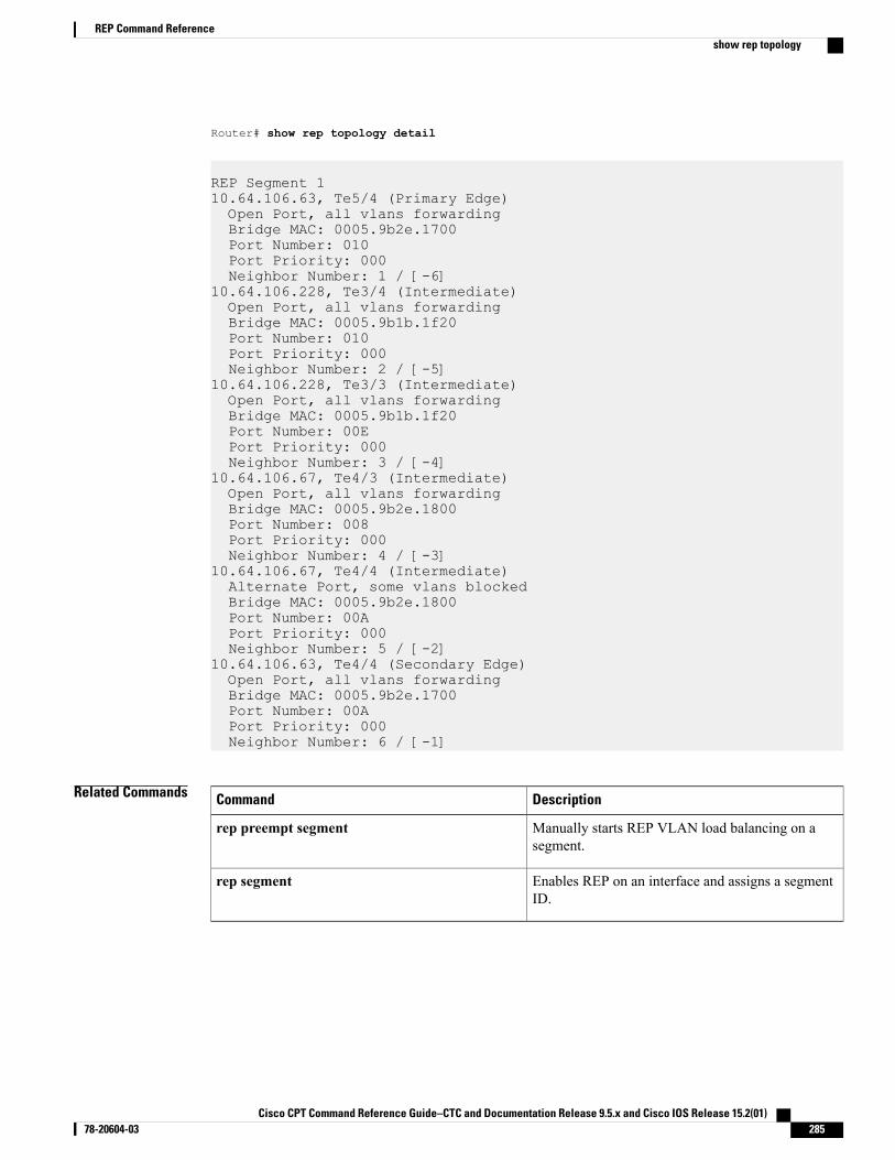
Router# show rep topology detail
REP Segment 110.64.106.63, Te5/4 (Primary Edge)Open Port, all vlans forwardingBridge MAC: 0005.9b2e.1700Port Number: 010Port Priority: 000Neighbor Number: 1 / [-6]
10.64.106.228, Te3/4 (Intermediate)Open Port, all vlans forwardingBridge MAC: 0005.9b1b.1f20Port Number: 010Port Priority: 000Neighbor Number: 2 / [-5]
10.64.106.228, Te3/3 (Intermediate)Open Port, all vlans forwardingBridge MAC: 0005.9b1b.1f20Port Number: 00EPort Priority: 000Neighbor Number: 3 / [-4]
10.64.106.67, Te4/3 (Intermediate)Open Port, all vlans forwardingBridge MAC: 0005.9b2e.1800Port Number: 008Port Priority: 000Neighbor Number: 4 / [-3]
10.64.106.67, Te4/4 (Intermediate)Alternate Port, some vlans blockedBridge MAC: 0005.9b2e.1800Port Number: 00APort Priority: 000Neighbor Number: 5 / [-2]
10.64.106.63, Te4/4 (Secondary Edge)Open Port, all vlans forwardingBridge MAC: 0005.9b2e.1700Port Number: 00APort Priority: 000Neighbor Number: 6 / [-1]
Related Commands DescriptionCommand
Manually starts REP VLAN load balancing on asegment.
rep preempt segment
Enables REP on an interface and assigns a segmentID.
rep segment
Cisco CPT Command Reference Guide–CTC and Documentation Release 9.5.x and Cisco IOS Release 15.2(01) 78-20604-03 285
REP Command Referenceshow rep topology

Cisco CPT Command Reference Guide–CTC and Documentation Release 9.5.x and Cisco IOS Release 15.2(01)286 78-20604-03
REP Command Referenceshow rep topology
LAG and LACP Command Reference
This chapter describes commands to configure Link Aggregation Group (LAG) and Link Aggregation ControlProtocol (LACP).
• channel-group, page 288
• interface port-channel, page 290
• lacp fast-switchover, page 291
• lacp max-bundle, page 292
• lacp min-bundle, page 293
• lacp port-priority, page 294
• lacp system-priority, page 296
• port-channel load-balance, page 298
• show interfaces port-channel, page 299
• show lacp, page 301
Cisco CPT Command Reference Guide–CTC and Documentation Release 9.5.x and Cisco IOS Release 15.2(01) 78-20604-03 287
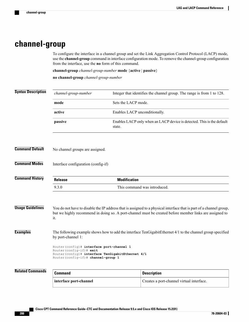
channel-groupTo configure the interface in a channel group and set the Link Aggregation Control Protocol (LACP) mode,use the channel-group command in interface configuration mode. To remove the channel-group configurationfrom the interface, use the no form of this command.
channel-group channel-group-numbermode {active | passive}
no channel-group channel-group-number
Syntax Description Integer that identifies the channel group. The range is from 1 to 128.channel-group-number
Sets the LACP mode.mode
Enables LACP unconditionally.active
Enables LACP only when an LACP device is detected. This is the defaultstate.
passive
Command Default No channel groups are assigned.
Command Modes Interface configuration (config-if)
Command History ModificationRelease
This command was introduced.9.3.0
Usage Guidelines You do not have to disable the IP address that is assigned to a physical interface that is part of a channel group,but we highly recommend in doing so. A port-channel must be created before member links are assigned toit.
Examples The following example shows how to add the interface TenGigabitEthernet 4/1 to the channel group specifiedby port-channel 1:
Router(config)# interface port-channel 1Router(config-if)# exitRouter(config)# interface TenGigabitEthernet 4/1Router(config-if)# channel-group 1
Related Commands DescriptionCommand
Creates a port-channel virtual interface.interface port-channel
Cisco CPT Command Reference Guide–CTC and Documentation Release 9.5.x and Cisco IOS Release 15.2(01)288 78-20604-03
LAG and LACP Command Referencechannel-group

DescriptionCommand
Sets the LACP priority for a physical interface.lacp port-priority
Sets the LACP priority for a system.lacp system-priority
Displays traffic that is seen by a specific port channel.show interfaces port-channel
Cisco CPT Command Reference Guide–CTC and Documentation Release 9.5.x and Cisco IOS Release 15.2(01) 78-20604-03 289
LAG and LACP Command Referencechannel-group
interface port-channelTo create a port-channel virtual interface, use the interface port-channel command in global configurationmode.
interface port-channel channel-number
Syntax Description Channel number assigned to this port-channel interface.channel-number
Command Default The port-channel virtual interface is not created.
Command Modes Global configuration (config)
Command History ModificationRelease
This command was introduced.9.3.0
Examples The following example shows how to create a port-channel interface.
Router(config)# interface port-channel 2
Related Commands DescriptionCommand
Configures the interface in a channel group.channel-group
Creates a port-channel virtual interface.interface port-channel
Defines the minimum number of active bundledLACP ports allowed in a port channel.
lacp min-bundle
Defines the maximum number of active bundledLACP ports allowed in a port channel.
lacp max-bundle
Displays traffic that is seen by a specific port channel.show interfaces port-channel
Cisco CPT Command Reference Guide–CTC and Documentation Release 9.5.x and Cisco IOS Release 15.2(01)290 78-20604-03
LAG and LACP Command Referenceinterface port-channel
lacp fast-switchoverTo enable LACP 1:1 link redundancy, use the lacp fast-switchover command in interface configuration mode.To disable LACP 1:1 link redundancy, use the no form of this command.
lacp fast-switchover
no lacp fast-switchover
Syntax Description This command has no arguments or keywords.
Command Default LACP 1:1 link redundancy is disabled by default.
Command Modes Interface configuration (config-if)
Command History ModificationRelease
This command was introduced.9.3.0
Usage Guidelines Before entering the lacp fast-switchover command, ensure the following:
• The port channel protocol type is LACP.
• The lacp max-bundle command has been entered on the port channel. The lacp fast-switchovercommand does not affect the lacp max-bundle command.
When you enable LACP 1:1 link redundancy, based on the system priority and port priority, the port with thehigher system priority chooses the link as the active link and the other link as the standby link. When theactive link fails, the standby link is selected as the new active link without taking down the port channel.When the original active link recovers, it reverts to its active link status. During this switch over, the portchannel is also up.
Examples The following example shows how to enable LACP 1:1 link redundancy:
Router(config-if)# lacp fast-switchover
Related Commands DescriptionCommand
Defines the maximum number of active bundledLACP ports allowed in a port channel.
lacp max-bundle
Cisco CPT Command Reference Guide–CTC and Documentation Release 9.5.x and Cisco IOS Release 15.2(01) 78-20604-03 291
LAG and LACP Command Referencelacp fast-switchover
lacp max-bundleTo define the maximum number of active bundled LACP ports allowed in a port channel, use the lacpmax-bundle command in interface configuration mode. To return to the default settings, use the no form ofthis command.
lacp max-bundle max-bundle-number
no lacp max-bundle
Syntax Description Maximum threshold of active member links allowed in the LACP bundle. Therange from is 1 to 8. The maximum threshold value must be greater than or equalto the minimum threshold value.
max-bundle-number
Command Default A maximum number of active bundled LACP ports is not configured.
Command Modes Interface configuration (config-if)
Command History ModificationRelease
This command was introduced.9.3.0
Usage Guidelines The value specified in themax-bundle-number argument determines the number of active links that are bundledin the port channel. The remaining links are in hot-standby mode.
Examples The following example shows how to set three ports to bundle in port channel 2:
Router(config)# interface port-channel 2Router(config-if)# lacp max-bundle 3
Related Commands DescriptionCommand
Creates a port-channel virtual interface.interface port-channel
Enables LACP 1:1 link redundancy.lacp fast-switchover
Sets the LACP priority for a physical interface.lacp port-priority
Displays traffic that is seen by a specific port channel.show interfaces port-channel
Cisco CPT Command Reference Guide–CTC and Documentation Release 9.5.x and Cisco IOS Release 15.2(01)292 78-20604-03
LAG and LACP Command Referencelacp max-bundle
lacp min-bundleTo define the minimum number of active bundled LACP ports allowed in a port channel, use the lacpmin-bundle command in interface configuration mode. To return to the default settings, use the no form ofthis command.
lacp min-bundle min-bundle-number
no lacp min-bundle
Syntax Description Minimum threshold of active member links allowed in the LACP bundle.The range is from 1 to 8. The default is 1.
min-bundle-number
Command Default A minimum number of active bundled LACP ports is not configured.
Command Modes Interface configuration (config-if)
Command History ModificationRelease
This command was introduced.9.3.0
Usage Guidelines Use this command to configure the minimum number of active links allowed in an LACP bundle. When thenumber of active links falls below this minimum threshold, the port channel shuts down.
Examples The following example shows how to set the minimum number of active links to five ports:
Router(config)# interface port-channel 2Router(config-if)# lacp min-bundle 5
Related Commands DescriptionCommand
Creates a port-channel virtual interface.interface port-channel
Displays traffic that is seen by a specific port channel.show interfaces port-channel
Cisco CPT Command Reference Guide–CTC and Documentation Release 9.5.x and Cisco IOS Release 15.2(01) 78-20604-03 293
LAG and LACP Command Referencelacp min-bundle
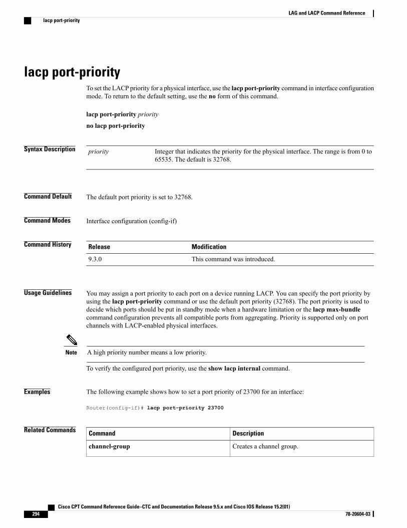
lacp port-priorityTo set the LACP priority for a physical interface, use the lacp port-priority command in interface configurationmode. To return to the default setting, use the no form of this command.
lacp port-priority priority
no lacp port-priority
Syntax Description Integer that indicates the priority for the physical interface. The range is from 0 to65535. The default is 32768.
priority
Command Default The default port priority is set to 32768.
Command Modes Interface configuration (config-if)
Command History ModificationRelease
This command was introduced.9.3.0
Usage Guidelines You may assign a port priority to each port on a device running LACP. You can specify the port priority byusing the lacp port-priority command or use the default port priority (32768). The port priority is used todecide which ports should be put in standby mode when a hardware limitation or the lacp max-bundlecommand configuration prevents all compatible ports from aggregating. Priority is supported only on portchannels with LACP-enabled physical interfaces.
A high priority number means a low priority.Note
To verify the configured port priority, use the show lacp internal command.
Examples The following example shows how to set a port priority of 23700 for an interface:
Router(config-if)# lacp port-priority 23700
Related Commands DescriptionCommand
Creates a channel group.channel-group
Cisco CPT Command Reference Guide–CTC and Documentation Release 9.5.x and Cisco IOS Release 15.2(01)294 78-20604-03
LAG and LACP Command Referencelacp port-priority
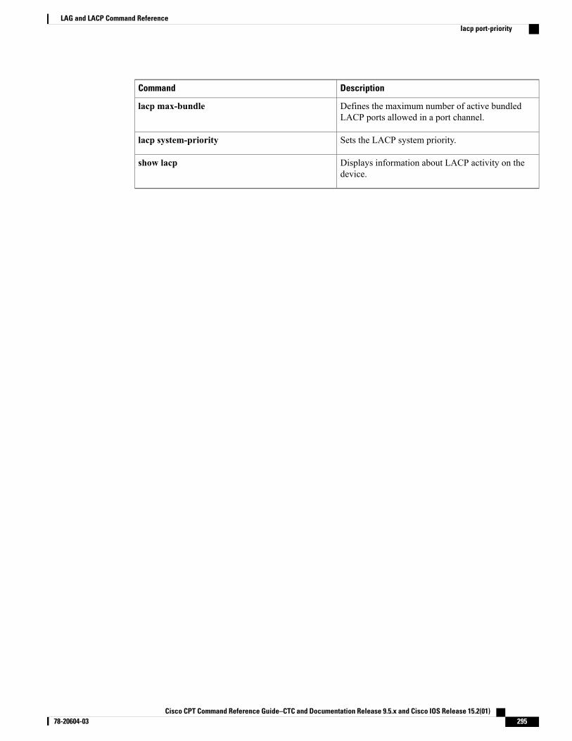
DescriptionCommand
Defines the maximum number of active bundledLACP ports allowed in a port channel.
lacp max-bundle
Sets the LACP system priority.lacp system-priority
Displays information about LACP activity on thedevice.
show lacp
Cisco CPT Command Reference Guide–CTC and Documentation Release 9.5.x and Cisco IOS Release 15.2(01) 78-20604-03 295
LAG and LACP Command Referencelacp port-priority
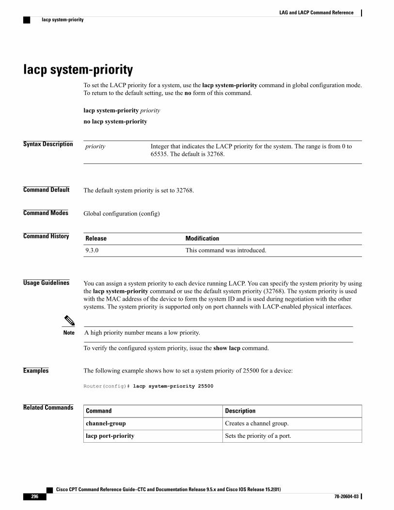
lacp system-priorityTo set the LACP priority for a system, use the lacp system-priority command in global configuration mode.To return to the default setting, use the no form of this command.
lacp system-priority priority
no lacp system-priority
Syntax Description Integer that indicates the LACP priority for the system. The range is from 0 to65535. The default is 32768.
priority
Command Default The default system priority is set to 32768.
Command Modes Global configuration (config)
Command History ModificationRelease
This command was introduced.9.3.0
Usage Guidelines You can assign a system priority to each device running LACP. You can specify the system priority by usingthe lacp system-priority command or use the default system priority (32768). The system priority is usedwith the MAC address of the device to form the system ID and is used during negotiation with the othersystems. The system priority is supported only on port channels with LACP-enabled physical interfaces.
A high priority number means a low priority.Note
To verify the configured system priority, issue the show lacp command.
Examples The following example shows how to set a system priority of 25500 for a device:
Router(config)# lacp system-priority 25500
Related Commands DescriptionCommand
Creates a channel group.channel-group
Sets the priority of a port.lacp port-priority
Cisco CPT Command Reference Guide–CTC and Documentation Release 9.5.x and Cisco IOS Release 15.2(01)296 78-20604-03
LAG and LACP Command Referencelacp system-priority

DescriptionCommand
Displays information about LACP activity on thedevice.
show lacp
Cisco CPT Command Reference Guide–CTC and Documentation Release 9.5.x and Cisco IOS Release 15.2(01) 78-20604-03 297
LAG and LACP Command Referencelacp system-priority
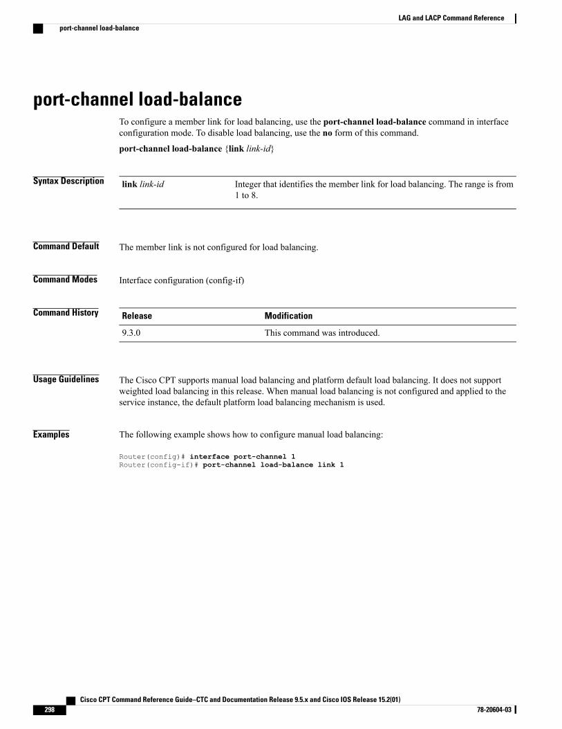
port-channel load-balanceTo configure a member link for load balancing, use the port-channel load-balance command in interfaceconfiguration mode. To disable load balancing, use the no form of this command.
port-channel load-balance {link link-id}
Syntax Description Integer that identifies the member link for load balancing. The range is from1 to 8.
link link-id
Command Default The member link is not configured for load balancing.
Command Modes Interface configuration (config-if)
Command History ModificationRelease
This command was introduced.9.3.0
Usage Guidelines The Cisco CPT supports manual load balancing and platform default load balancing. It does not supportweighted load balancing in this release. When manual load balancing is not configured and applied to theservice instance, the default platform load balancing mechanism is used.
Examples The following example shows how to configure manual load balancing:
Router(config)# interface port-channel 1Router(config-if)# port-channel load-balance link 1
Cisco CPT Command Reference Guide–CTC and Documentation Release 9.5.x and Cisco IOS Release 15.2(01)298 78-20604-03
LAG and LACP Command Referenceport-channel load-balance
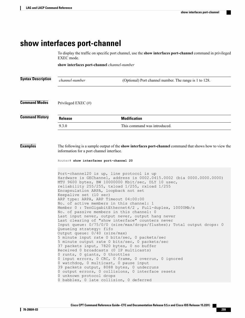
show interfaces port-channelTo display the traffic on specific port channel, use the show interfaces port-channel command in privilegedEXEC mode.
show interfaces port-channel channel-number
Syntax Description (Optional) Port channel number. The range is 1 to 128.channel-number
Command Modes Privileged EXEC (#)
Command History ModificationRelease
This command was introduced.9.3.0
Examples The following is a sample output of the show interfaces port-channel command that shows how to view theinformation for a port channel interface.
Router# show interfaces port-channel 20
Port-channel20 is up, line protocol is upHardware is GEChannel, address is 0002.0415.0002 (bia 0000.0000.0000)MTU 9600 bytes, BW 10000000 Kbit/sec, DLY 10 usec,reliability 255/255, txload 1/255, rxload 1/255Encapsulation ARPA, loopback not setKeepalive set (10 sec)ARP type: ARPA, ARP Timeout 04:00:00No. of active members in this channel: 1Member 0 : TenGigabitEthernet4/2 , Full-duplex, 10000Mb/sNo. of passive members in this channel: 0Last input never, output never, output hang neverLast clearing of "show interface" counters neverInput queue: 0/75/0/0 (size/max/drops/flushes); Total output drops: 0Queueing strategy: fifoOutput queue: 0/40 (size/max)5 minute input rate 0 bits/sec, 0 packets/sec5 minute output rate 0 bits/sec, 0 packets/sec37 packets input, 7820 bytes, 0 no bufferReceived 0 broadcasts (0 IP multicasts)0 runts, 0 giants, 0 throttles0 input errors, 0 CRC, 0 frame, 0 overrun, 0 ignored0 watchdog, 0 multicast, 0 pause input39 packets output, 8088 bytes, 0 underruns0 output errors, 0 collisions, 0 interface resets0 unknown protocol drops0 babbles, 0 late collision, 0 deferred
Cisco CPT Command Reference Guide–CTC and Documentation Release 9.5.x and Cisco IOS Release 15.2(01) 78-20604-03 299
LAG and LACP Command Referenceshow interfaces port-channel
0 lost carrier, 0 no carrier, 0 pause output0 output buffer failures, 0 output buffers swapped out
Related Commands DescriptionCommand
Configures the interface in a channel group and setsthe LACP mode.
channel-group
Creates a port-channel virtual interface.interface port-channel
Defines the maximum number of active bundledLACP ports allowed in a port channel.
lacp max-bundle
Defines the minimum number of active bundledLACP ports allowed in a port channel.
lacp min-bundle
Cisco CPT Command Reference Guide–CTC and Documentation Release 9.5.x and Cisco IOS Release 15.2(01)300 78-20604-03
LAG and LACP Command Referenceshow interfaces port-channel
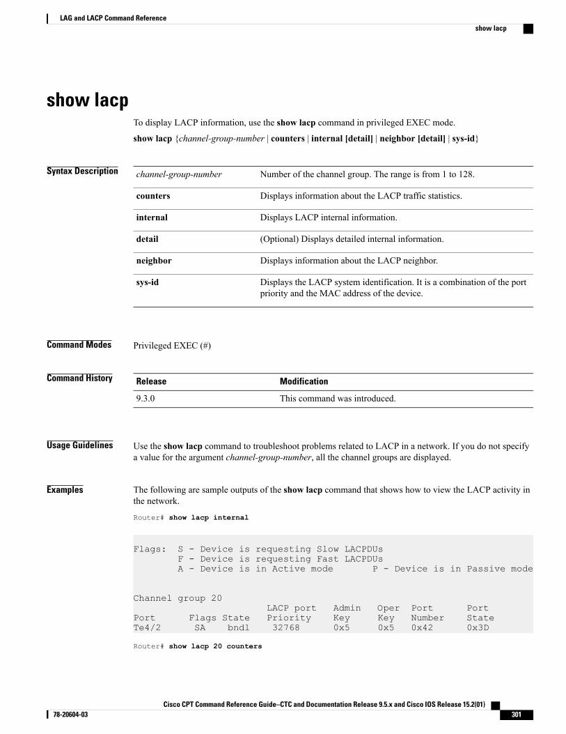
show lacpTo display LACP information, use the show lacp command in privileged EXEC mode.
show lacp {channel-group-number | counters | internal [detail] | neighbor [detail] | sys-id}
Syntax Description Number of the channel group. The range is from 1 to 128.channel-group-number
Displays information about the LACP traffic statistics.counters
Displays LACP internal information.internal
(Optional) Displays detailed internal information.detail
Displays information about the LACP neighbor.neighbor
Displays the LACP system identification. It is a combination of the portpriority and the MAC address of the device.
sys-id
Command Modes Privileged EXEC (#)
Command History ModificationRelease
This command was introduced.9.3.0
Usage Guidelines Use the show lacp command to troubleshoot problems related to LACP in a network. If you do not specifya value for the argument channel-group-number, all the channel groups are displayed.
Examples The following are sample outputs of the show lacp command that shows how to view the LACP activity inthe network.
Router# show lacp internal
Flags: S - Device is requesting Slow LACPDUsF - Device is requesting Fast LACPDUsA - Device is in Active mode P - Device is in Passive mode
Channel group 20LACP port Admin Oper Port Port
Port Flags State Priority Key Key Number StateTe4/2 SA bndl 32768 0x5 0x5 0x42 0x3D
Router# show lacp 20 counters
Cisco CPT Command Reference Guide–CTC and Documentation Release 9.5.x and Cisco IOS Release 15.2(01) 78-20604-03 301
LAG and LACP Command Referenceshow lacp
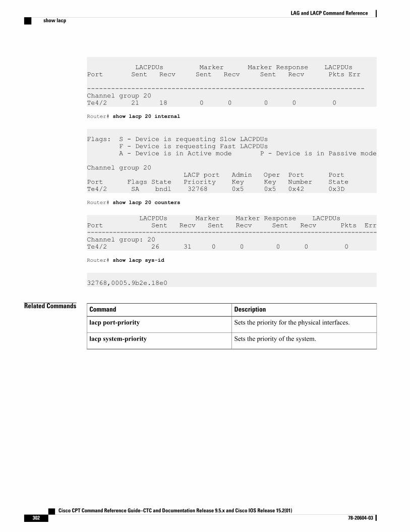
LACPDUs Marker Marker Response LACPDUsPort Sent Recv Sent Recv Sent Recv Pkts Err
---------------------------------------------------------------------Channel group 20Te4/2 21 18 0 0 0 0 0
Router# show lacp 20 internal
Flags: S - Device is requesting Slow LACPDUsF - Device is requesting Fast LACPDUsA - Device is in Active mode P - Device is in Passive mode
Channel group 20LACP port Admin Oper Port Port
Port Flags State Priority Key Key Number StateTe4/2 SA bndl 32768 0x5 0x5 0x42 0x3D
Router# show lacp 20 counters
LACPDUs Marker Marker Response LACPDUsPort Sent Recv Sent Recv Sent Recv Pkts Err-------------------------------------------------------------------------------Channel group: 20Te4/2 26 31 0 0 0 0 0
Router# show lacp sys-id
32768,0005.9b2e.18e0
Related Commands DescriptionCommand
Sets the priority for the physical interfaces.lacp port-priority
Sets the priority of the system.lacp system-priority
Cisco CPT Command Reference Guide–CTC and Documentation Release 9.5.x and Cisco IOS Release 15.2(01)302 78-20604-03
LAG and LACP Command Referenceshow lacp
Span Command Reference
This chapter describes commands to configure Span.
• monitor permit-list, page 304
• monitor session, page 305
• show monitor permit-list, page 307
• show monitor session, page 308
Cisco CPT Command Reference Guide–CTC and Documentation Release 9.5.x and Cisco IOS Release 15.2(01) 78-20604-03 303
monitor permit-listTo restrict the destination ports that can be used for a SPAN session, use themonitor permit-list commandin the global configuration mode.
monitor permit-list destination interface type number
Syntax Description Type of interface; valid values are gigabitethernet or tengigabitethernet.type
Number of interface.number
Command Default Disabled
Command Modes Global Configuration (config)
Command History ModificationRelease
This command was introduced.9.5.1
Usage Guidelines To prevent accidental configuration of ports as destinations, you can create a permit list of the ports that arevalid for use as destinations. With a destination port permit list configured, you can only configure the portsin the permit list as destinations.
When you enter multiple instances of interface interface-typeslot/port-last-port, you must enter a space beforeand after the comma. For example, interface interface-typeslot/port-last-port, interface-typeslot/port-last-port,interface-typeslot/port-last-port.
Examples The following example shows how to configure a destination port permit list that includes Gigabit Ethernetports 5/1 through 5/4, and activate monitoring.Router(config)# monitor permit-list destination interface gigabitethernet 5/1-4
Related Commands DescriptionCommand
Displays the permit-list state and interfacesconfigured.
show monitor permit-list
Cisco CPT Command Reference Guide–CTC and Documentation Release 9.5.x and Cisco IOS Release 15.2(01)304 78-20604-03
Span Command Referencemonitor permit-list
monitor sessionTo start a new SPAN session, add or delete interfaces from an existing SPAN session, or delete a SPANsession, use themonitor session command in global configuration mode. To remove one or more sourceinterfaces or destination interfaces from the SPAN session, use the no form of this command.
monitor session session_number type span-type
monitor session local_span_session_number source interface type number direction
monitor session local_span_session_number source service instance EFP_number type number direction
monitor session local_span_session_number destination interface type number
Syntax Description Number of the local SPAN session; valid value is from 1 to 50.session_number
Type of span; only local span type is supported.span type
Specifies the port SPAN source.source interface
Specifies the EFP SPAN source.source service instance
Specifies the SPAN destination interface.destination interface
Specifies the interface type and number; valid values are gigabitethernet(1 to 9) and port-channel.
interface type number
Traffic direction. The direction argument accepts the following values:
• both-monitors received and transmitted traffic (both ingress andegress).
• rx-monitors received traffic (ingress).
• tx-monitors transmitted traffic (egress).
direction
Command Default This command has no default settings.
Command Modes Global Configuration (config)
Command History ModificationRelease
This command was introduced.9.5.1
Cisco CPT Command Reference Guide–CTC and Documentation Release 9.5.x and Cisco IOS Release 15.2(01) 78-20604-03 305
Span Command Referencemonitor session
Usage Guidelines Only one SPAN destination for a SPAN session is supported. If you attempt to add another destination interfaceto a session that already has a destination interface configured, you will get an error. You must first removea SPAN destination interface before changing the SPAN destination to a different interface.
Examples The following example shows how to start a third local monitor session.Router(config)# monitor session 3 type local
Examples The following example shows how to configure a port span for the TenGigabitEthernet 4/1 port and monitorthe received traffic (ingress).Router(config-mon-local)# source interface TenGigabitEthernet 4/1 rx
Examples The following example shows how to configure a monitoring port for a traffic mirroring session.Router(config-mon-local)# destination interface TenGigabitEthernet 5/1
Related Commands DescriptionCommand
Displays SPAN session number.show monitor
Cisco CPT Command Reference Guide–CTC and Documentation Release 9.5.x and Cisco IOS Release 15.2(01)306 78-20604-03
Span Command Referencemonitor session
show monitor permit-listTo display the destination ports that can be used for a SPAN session, use the show monitorpermit-listcommand in either user or privileged EXEC mode.
show monitor permit-list
Command Default This command has no default settings.
Command Modes User EXEC (>)
Privileged EXEC (#)
Command History ModificationRelease
This command was introduced.9.5.1
Examples The following example shows how to display the permit-list state and interfaces configured.Router# show monitor permit-list
Related Commands DescriptionCommand
Configures a destination port permit list or adds to anexisting destination port permit list.
monitor permit-list
Cisco CPT Command Reference Guide–CTC and Documentation Release 9.5.x and Cisco IOS Release 15.2(01) 78-20604-03 307
Span Command Referenceshow monitor permit-list
show monitor sessionTo display information about the SPAN sessions, use the show monitor session command in the user EXECmode.
show monitor session all
Syntax Description (Optional) Displays all sessions.all
Command Default This command has no default settings.
Command Modes User EXEC (>)
Command History ModificationRelease
This command was introduced.9.5.1
Usage Guidelines If you enter the showmonitor session command without specifying a session, the information for all sessionsis displayed.
Examples The following example shows how to display the configuration of all the SPAN sessions.Router# show monitor session all
Related Commands DescriptionCommand
Starts a new SPAN session.monitor session
Cisco CPT Command Reference Guide–CTC and Documentation Release 9.5.x and Cisco IOS Release 15.2(01)308 78-20604-03
Span Command Referenceshow monitor session
MAC Learning Command Reference
This chapter describes commands to configure MAC learning.
• clear mac-address-table, page 310
• mac learning, page 311
• mac limit maximum addresses, page 313
• mac static address, page 314
• show mac-address-table, page 315
Cisco CPT Command Reference Guide–CTC and Documentation Release 9.5.x and Cisco IOS Release 15.2(01) 78-20604-03 309
clear mac-address-tableTo remove a specified address (or set of addresses) from the MAC address table, use the clearmac-address-table command in privileged EXEC mode.
clear mac-address-table [address mac-addr] [bridge-domain bridgedomain-id] [interface type number]
Syntax Description (Optional) Specifies the MAC address to clear.address mac-addr
(Optional) Clears the MAC address from the specified bridgedomain.
bridge-domain bridgedomain-id
(Optional) Clears the MAC address from the specified interface.interface type number
Command Default When no options are specified, all the dynamically added MAC addresses are cleared.
Command Modes Privileged EXEC (#)
Command History ModificationRelease
This command was introduced.9.3.0
Usage Guidelines If the clear mac-address-table command is used without options, all the MAC addresses are removed. Ifyou specify an address but do not specify an interface, the address is deleted from all the interfaces. If youspecify an interface but do not specify an address, all the addresses on the specified interface are removed.
Examples The following example shows how to remove aMAC address from theMAC address table on a bridge domain:
Router# clear mac-address-table address0000.bbbb.cccc interface TenGigabitEthernet 4/1 bridge-domain 100
The following example shows how to remove a MAC address from the MAC address table on all the bridgedomains:
Router# clear mac-address-table address 0000.bbbb.cccc
Related Commands DescriptionCommand
Displays information about the MAC address table.show mac-address-table
Cisco CPT Command Reference Guide–CTC and Documentation Release 9.5.x and Cisco IOS Release 15.2(01)310 78-20604-03
MAC Learning Command Referenceclear mac-address-table
mac learningTo reenable MAC learning on the bridge domain, use themac learning command in bridge domainconfiguration mode. To disable MAC learning, use the no form of this command.
mac learning
no mac learning
Syntax Description This command has no arguments or keywords.
Command Default MAC learning is enabled on the bridge domains by default.
Command Modes Bridge domain configuration (config-bdomain)
Command History ModificationRelease
This command was introduced.9.3.0
Usage Guidelines MAC address learning is enabled by default only for point–to–multipoint bridge domains and can also bedisabled.
Examples The following example shows how to reenable MAC learning on a bridge domain:
Router> enableRouter# configure terminalRouter(config)# bridge-domain 100Router(config-bdomain)# mac learningRouter(config-bdomain)# end
The following example shows how to disable MAC learning on a bridge domain:
Router> enableRouter# configure terminalRouter(config)# bridge-domain 100Router(config-bdomain)# no mac learningRouter(config-bdomain)# end
Related Commands DescriptionCommand
Configures a static MAC address on a serviceinstance.
mac static address
Cisco CPT Command Reference Guide–CTC and Documentation Release 9.5.x and Cisco IOS Release 15.2(01) 78-20604-03 311
MAC Learning Command Referencemac learning

DescriptionCommand
Configures the maximum number of MAC addressesallowed on a bridge domain.
mac limit maximum addresses
Cisco CPT Command Reference Guide–CTC and Documentation Release 9.5.x and Cisco IOS Release 15.2(01)312 78-20604-03
MAC Learning Command Referencemac learning
mac limit maximum addressesTo configure the maximum number of MAC addresses allowed on a bridge domain, use themac limitmaximum addresses command in bridge domain configuration mode. To return to the default state, use theno form of this command.
mac limit maximum addresses maximum-addresses
no mac limit maximum addresses maximum-addresses
Syntax Description Integer that specifies the maximum number of MAC addresses allowed ona bridge domain. The range is from 1 to 128000.
maximum-addresses
Command Default Maximum number of MAC addresses are allowed on the bridge domain.
Command Modes Bridge domain configuration (config-bdomain)
Command History ModificationRelease
This command was introduced.9.3.0
Examples The following example shows how to set the maximum number ofMAC addresses on a specific bridge domainto 1000:
Router> enableRouter# configure terminalRouter(config)# bridge-domain 100Router(config-bdomain)# mac limit maximum addresses 1000Router(config-bdomain)# end
Related Commands DescriptionCommand
Enables MAC learning on a bridge domain.mac learning
Cisco CPT Command Reference Guide–CTC and Documentation Release 9.5.x and Cisco IOS Release 15.2(01) 78-20604-03 313
MAC Learning Command Referencemac limit maximum addresses
mac static addressTo configure a static MAC address on a service instance, use themac static address command in serviceinstance configuration mode. To remove a static MAC address, use the no form of this command.
mac static address mac-addr
no mac static address mac-addr
Syntax Description The 48-bit static MAC address.mac-addr
Command Default MAC static addresses are not configured.
Command Modes Service instance configuration (config-if-srv)
Command History ModificationRelease
This command was introduced.9.3.0
Usage Guidelines StaticMAC address configuration is supported only on Ethernet virtual circuit (EVC) bridge domain interfaces.The static MAC address configuration does not apply to the Multicast VLAN Registration (MVR) bridgedomain.
Examples The following example shows how to configure aMAC static address in service instance configuration mode:
Router> enableRouter# configure terminalRouter(config)# interface TenGigabitEthernet 4/1Router(config-if)# service instance 1 ethernetRouter(config-if-srv)# encapsulation dot1q 100Router(config-if-srv)# bridge-domain 100Router(config-if-srv)# mac static address 0000.bbbb.ccccRouter(config-if-srv)# exitRouter(config-if)# end
Related Commands DescriptionCommand
Enables MAC learning on a bridge domain.mac learning
Cisco CPT Command Reference Guide–CTC and Documentation Release 9.5.x and Cisco IOS Release 15.2(01)314 78-20604-03
MAC Learning Command Referencemac static address
show mac-address-tableTo display information about theMAC address table, use the showmac-address-table command in privilegedEXEC mode.
show mac-address-table [address mac-addr] [bridge-domain bridgedomain-id] [interface type number][count]
Syntax Description (Optional) Displays information about the MAC address table for aspecific MAC address.
address mac-addr
(Optional) Displays information about the MAC address table for aspecific bridge domain.
bridge-domain bridgedomain-id
(Optional) Displays information about the MAC address table for aspecific interface.
interface type number
(Optional) Displays the number of entries that are currently in the MACaddress table.
count
Command Default When no options are specified, the command displays the entire MAC address table.
Command Modes Privileged EXEC (#)
Command History ModificationRelease
This command was introduced.9.3.0
Usage Guidelines The mac-addr is a 48–bit MAC address and the valid format is H.H.H. The bridgedomain-id is the bridgedomain number.
Examples The following example shows how to display theMAC address table information for a specificMAC address:
Router# show mac-address-table address 0000.1000.0001
BD Index MAC Address Type Ports--------------------------------------------2 0000.1000.0001 dynamic Te4/2
The following example shows how to display theMAC address table information for a specific bridge domain:
Router# show mac-address-table bridge-domain 2
Cisco CPT Command Reference Guide–CTC and Documentation Release 9.5.x and Cisco IOS Release 15.2(01) 78-20604-03 315
MAC Learning Command Referenceshow mac-address-table
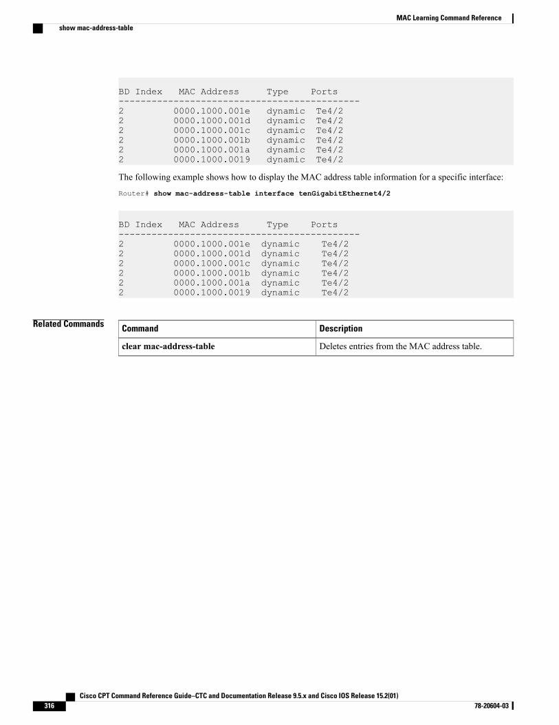
BD Index MAC Address Type Ports--------------------------------------------2 0000.1000.001e dynamic Te4/22 0000.1000.001d dynamic Te4/22 0000.1000.001c dynamic Te4/22 0000.1000.001b dynamic Te4/22 0000.1000.001a dynamic Te4/22 0000.1000.0019 dynamic Te4/2
The following example shows how to display the MAC address table information for a specific interface:
Router# show mac-address-table interface tenGigabitEthernet4/2
BD Index MAC Address Type Ports--------------------------------------------2 0000.1000.001e dynamic Te4/22 0000.1000.001d dynamic Te4/22 0000.1000.001c dynamic Te4/22 0000.1000.001b dynamic Te4/22 0000.1000.001a dynamic Te4/22 0000.1000.0019 dynamic Te4/2
Related Commands DescriptionCommand
Deletes entries from the MAC address table.clear mac-address-table
Cisco CPT Command Reference Guide–CTC and Documentation Release 9.5.x and Cisco IOS Release 15.2(01)316 78-20604-03
MAC Learning Command Referenceshow mac-address-table
IGMP Snooping Command Reference
This chapter describes commands used to configure Internet GroupManagement Protocol (IGMP) snooping.
• ip igmp snooping, page 318
• ip igmp snooping immediate-leave, page 319
• ip igmp snooping mrouter, page 320
• ip igmp snooping report-suppression, page 321
• show ip igmp snooping, page 322
• show ip igmp snooping querier, page 325
Cisco CPT Command Reference Guide–CTC and Documentation Release 9.5.x and Cisco IOS Release 15.2(01) 78-20604-03 317
ip igmp snoopingTo enable Internet Group Management Protocol (IGMP) snooping, use the ip igmp snooping command inthe bridge domain configuration mode. To disable IGMP snooping, use the no form of this command.
ip igmp snooping
no ip igmp snooping
Syntax Description This command has no arguments or keywords.
Command Default IGMP snooping is not enabled.
Command Modes Bridge domain configuration (config-bdomain)
Command History ModificationRelease
This command was introduced.9.3.0
Usage Guidelines On a CPT system, IGMP snooping can be configured at the bridge domain level.
Following configuration restrictions are applicable while configuring the IGMP snooping on the CPT system:
• For a single tagged packet, the tag is removed using the rewrite ingress tag pop 1 symmetric commandat the EFP level.
• For a double tagged packet, the tag is removed using the rewrite ingress tag pop 2 symmetric commandat the EFP level.
• For an untagged packet, a rewrite operation is not required.
Examples The following example shows how to enable IGMP snooping on a bridge domain:Router(config)# bridge-domain 30Router(config-bdomain)# ip igmp snooping
Related Commands DescriptionCommand
Displays the IGMP snooping configuration.show ip igmp snooping
Cisco CPT Command Reference Guide–CTC and Documentation Release 9.5.x and Cisco IOS Release 15.2(01)318 78-20604-03
IGMP Snooping Command Referenceip igmp snooping
ip igmp snooping immediate-leaveTo enable Internet Group Management Protocol (IGMP) Immediate-Leave processing on a bridge-domain,use the ip igmp snooping immediate-leave command in global configuration mode. To disableImmediate-Leave processing on the bridge domain, use the no form of this command.
ip igmp snooping immediate-leave
no ip igmp snooping immediate-leave
Syntax Description This command has no arguments or keywords.
Command Default By default, IGMP Immediate-Leave processing is disabled.
Command Modes Bridge domain configuration (config-bdomain)
Command History ModificationRelease
This command was introduced.9.3.0
Usage Guidelines The Immediate Leave feature is supported only on IGMP version 2 hosts.
Examples The following example shows how to enable IGMP Immediate Leave feature for bridge-domain130:
Router# configure terminalRouter(config)# bridge-domain 130Router(config-bdomain)# ip igmp snooping immediate-leaveRouter(config-bdomain)# end
Related Commands DescriptionCommand
Enables IGMP snooping on the bridge domain.ip igmp snooping
Configures a multicast router port.ip igmp snooping mrouter
Cisco CPT Command Reference Guide–CTC and Documentation Release 9.5.x and Cisco IOS Release 15.2(01) 78-20604-03 319
IGMP Snooping Command Referenceip igmp snooping immediate-leave
ip igmp snooping mrouterTo configure a port as a multicast router port, use the ip igmp snooping mrouter command in theservice-instance configuration mode. To remove the configuration, use the no form of this command.
ip igmp snooping mrouter
no ip igmp snooping mrouter
Syntax Description This command has no arguments or keywords.
Command Default Disabled
Command Modes Service-instance configuration (config-if-srv)
Command History ModificationRelease
This command was introduced.9.3.0
Usage Guidelines Static connections to multicast routers are supported only at the EFP.
Examples The following example shows how to enable a static connection to a multicast router:Router(config)# interface TenGigabitEthernet4/2Router(config-if)# service instance 20 ethernetRouter(config-if-srv)# encapsulation dot1q 10Router(config-if-srv)# rewrite ingress tag pop 1 symmetricRouter(config-if-srv)# bridge-domain 20Router(config-if-srv)# ip igmp snooping mrouter
The following example shows how to disable a static connection to a multicast router:Router(config)# interface TenGigabitEthernet4/2Router(config-if)# service instance 20 ethernetRouter(config-if-srv)# no ip igmp snooping mrouter
Related Commands DescriptionCommand
Enables IGMP snooping on the bridge domain.ip igmp snooping
Displays the information about the dynamically learned andmanually configured multicast router interfaces.
show ip igmp snooping mrouter
Cisco CPT Command Reference Guide–CTC and Documentation Release 9.5.x and Cisco IOS Release 15.2(01)320 78-20604-03
IGMP Snooping Command Referenceip igmp snooping mrouter
ip igmp snooping report-suppressionTo turn on IP IGMP snooping report suppression, use the ip igmp snooping report-suppression commandin the bridge domain configuration mode. To turn off report suppression, use the no form of this command.
ip igmp snooping report-suppression
no ip igmp snooping report-suppression
Syntax Description This command has no arguments or keywords.
Command Default Disabled
Command Modes Bridge domain configuration (config-bdomain)
Command History ModificationRelease
This command was introduced.9.3.0
Usage Guidelines IGMP report suppression is supported only when the multicast query has IGMPv1 and IGMPv2 reports. Thisfeature is not supported when the query includes IGMPv3 reports.
Examples The following example shows how to re-enable IGMP report suppression for bridge-domain 130:
Router# configure terminalRouter(config-bdomain)# bridge-domain 130Router(config-bdomain)# ip igmp snooping report-suppressionRouter(config-bdomain)# end
Related Commands DescriptionCommand
Displays the IGMP snooping configuration.show ip igmp snooping
Cisco CPT Command Reference Guide–CTC and Documentation Release 9.5.x and Cisco IOS Release 15.2(01) 78-20604-03 321
IGMP Snooping Command Referenceip igmp snooping report-suppression
show ip igmp snoopingTo display the Internet Group Management Protocol (IGMP) snooping configuration of a device, use theshow ip igmp snooping command in the privileged EXEC mode.
show ip igmp snooping [groups [count | vlan bridge-domain ID [ ip-address | count |dynamic [count] |user [count] ]]] | mrouter [vlan bridge-domain ID] querier | vlan bridge-domain ID]
Syntax Description (Optional) Displays group information.groups
(Optional) Displays the number of multicast groups learned by IGMP snooping.count
(Optional) Specifies a bridge domain.
bridge-domain ID—Bridge domain ID. Valid values are from 1 to 16384.
vlan bridge-domain ID
(Optional) Displays information about the specified group.ip-address
(Optional) Displays the group count inside a bridge domain.count
(Optional) Displays dynamic entries learned through IGMP snooping.dynamic
(Optional) Displays the number of dynamic entries.count
(Optional) Displays only the user-configured multicast entries.user
(Optional) Displays the number of user-configured multicast entries.count
(Optional) Displays information about dynamically learned and manuallyconfigured multicast router ports.
mrouter
(Optional) Displays IGMP querier information.querier
Command Default This command has no default settings.
Command Modes Privileged EXEC (#)
Command History ModificationRelease
This command was introduced.9.3.0
Examples The following example displays the output of the show ip igmp snooping [vlan bridge-domain ID ] command.Router# show ip igmp sn vlan 2
Cisco CPT Command Reference Guide–CTC and Documentation Release 9.5.x and Cisco IOS Release 15.2(01)322 78-20604-03
IGMP Snooping Command Referenceshow ip igmp snooping
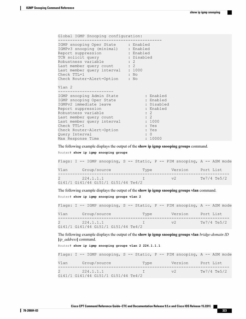
Global IGMP Snooping configuration:-------------------------------------------IGMP snooping Oper State : EnabledIGMPv3 snooping (minimal) : EnabledReport suppression : EnabledTCN solicit query : DisabledRobustness variable : 2Last member query count : 2Last member query interval : 1000Check TTL=1 : NoCheck Router-Alert-Option : No
Vlan 2-----------------------IGMP snooping Admin State : EnabledIGMP snooping Oper State : EnabledIGMPv2 immediate leave : DisabledReport suppression : EnabledRobustness variable : 2Last member query count : 2Last member query interval : 1000Check TTL=1 : YesCheck Router-Alert-Option : YesQuery Interval : 0Max Response Time : 10000
The following example displays the output of the show ip igmp snooping groups command.Router# show ip igmp snooping groups
Flags: I -- IGMP snooping, S -- Static, P -- PIM snooping, A -- ASM mode
Vlan Group/source Type Version Port List-----------------------------------------------------------------------2 224.1.1.1 I v2 Te7/4 Te5/2Gi41/1 Gi41/44 Gi51/1 Gi51/44 Te4/2
The following example displays the output of the show ip igmp snooping groups vlan command.Router# show ip igmp snooping groups vlan 2
Flags: I -- IGMP snooping, S -- Static, P -- PIM snooping, A -- ASM mode
Vlan Group/source Type Version Port List-----------------------------------------------------------------------2 224.1.1.1 I v2 Te7/4 Te5/2Gi41/1 Gi41/44 Gi51/1 Gi51/44 Te4/2
The following example displays the output of the show ip igmp snooping groups vlan bridge-domain ID[ip_address] command.Router# show ip igmp snooping groups vlan 2 224.1.1.1
Flags: I -- IGMP snooping, S -- Static, P -- PIM snooping, A -- ASM mode
Vlan Group/source Type Version Port List-----------------------------------------------------------------------2 224.1.1.1 I v2 Te7/4 Te5/2Gi41/1 Gi41/44 Gi51/1 Gi51/44 Te4/2
Cisco CPT Command Reference Guide–CTC and Documentation Release 9.5.x and Cisco IOS Release 15.2(01) 78-20604-03 323
IGMP Snooping Command Referenceshow ip igmp snooping
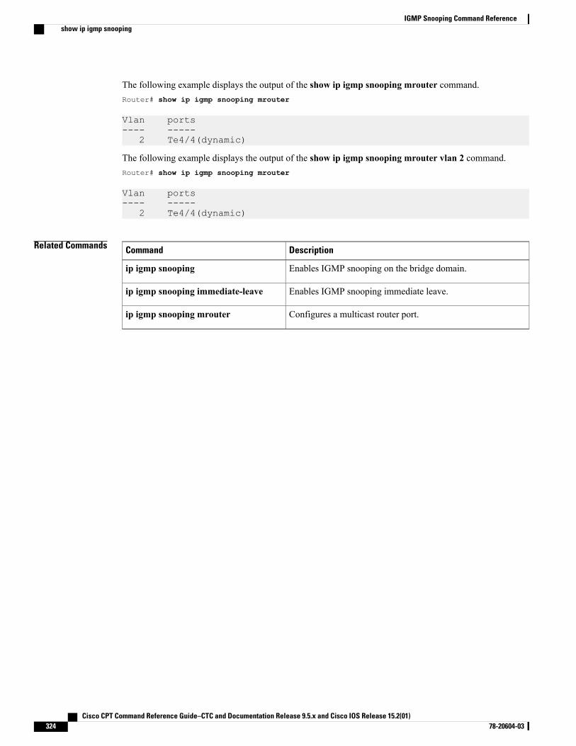
The following example displays the output of the show ip igmp snooping mrouter command.Router# show ip igmp snooping mrouter
Vlan ports---- -----
2 Te4/4(dynamic)
The following example displays the output of the show ip igmp snooping mrouter vlan 2 command.Router# show ip igmp snooping mrouter
Vlan ports---- -----
2 Te4/4(dynamic)
Related Commands DescriptionCommand
Enables IGMP snooping on the bridge domain.ip igmp snooping
Enables IGMP snooping immediate leave.ip igmp snooping immediate-leave
Configures a multicast router port.ip igmp snooping mrouter
Cisco CPT Command Reference Guide–CTC and Documentation Release 9.5.x and Cisco IOS Release 15.2(01)324 78-20604-03
IGMP Snooping Command Referenceshow ip igmp snooping
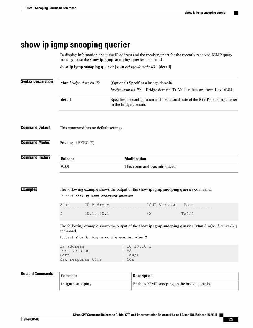
show ip igmp snooping querierTo display information about the IP address and the receiving port for the recently received IGMP querymessages, use the show ip igmp snooping querier command.
show ip igmp snooping querier [vlan bridge-domain ID ] [detail]
Syntax Description (Optional) Specifies a bridge domain.
bridge-domain ID—Bridge domain ID. Valid values are from 1 to 16384.
vlan bridge-domain ID
Specifies the configuration and operational state of the IGMP snooping querierin the bridge domain.
detail
Command Default This command has no default settings.
Command Modes Privileged EXEC (#)
Command History ModificationRelease
This command was introduced.9.3.0
Examples The following example shows the output of the show ip igmp snooping querier command.Router# show ip igmp snooping querier
Vlan IP Address IGMP Version Port-------------------------------------------------------------2 10.10.10.1 v2 Te4/4
The following example shows the output of the show ip igmp snooping querier [vlan bridge-domain ID ]command.Router# show ip igmp snooping querier vlan 2
IP address : 10.10.10.1IGMP version : v2Port : Te4/4Max response time : 10s
Related Commands DescriptionCommand
Enables IGMP snooping on the bridge domain.ip igmp snooping
Cisco CPT Command Reference Guide–CTC and Documentation Release 9.5.x and Cisco IOS Release 15.2(01) 78-20604-03 325
IGMP Snooping Command Referenceshow ip igmp snooping querier

DescriptionCommand
Configures a multicast router port.ip igmp snooping mrouter
Cisco CPT Command Reference Guide–CTC and Documentation Release 9.5.x and Cisco IOS Release 15.2(01)326 78-20604-03
IGMP Snooping Command Referenceshow ip igmp snooping querier
MVR Command Reference
This chapter describes commands used to configure Multicast VLAN Registration (MVR).
• mvr, page 328
• mvr group, page 329
• mvr type, page 331
• show mvr, page 333
Cisco CPT Command Reference Guide–CTC and Documentation Release 9.5.x and Cisco IOS Release 15.2(01) 78-20604-03 327
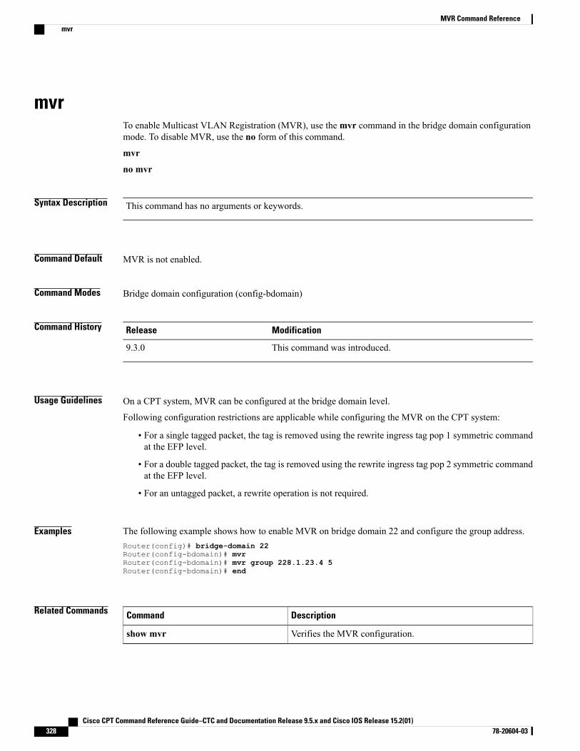
mvrTo enable Multicast VLAN Registration (MVR), use themvr command in the bridge domain configurationmode. To disable MVR, use the no form of this command.
mvr
no mvr
Syntax Description This command has no arguments or keywords.
Command Default MVR is not enabled.
Command Modes Bridge domain configuration (config-bdomain)
Command History ModificationRelease
This command was introduced.9.3.0
Usage Guidelines On a CPT system, MVR can be configured at the bridge domain level.
Following configuration restrictions are applicable while configuring the MVR on the CPT system:
• For a single tagged packet, the tag is removed using the rewrite ingress tag pop 1 symmetric commandat the EFP level.
• For a double tagged packet, the tag is removed using the rewrite ingress tag pop 2 symmetric commandat the EFP level.
• For an untagged packet, a rewrite operation is not required.
Examples The following example shows how to enable MVR on bridge domain 22 and configure the group address.Router(config)# bridge-domain 22Router(config-bdomain)# mvrRouter(config-bdomain)# mvr group 228.1.23.4 5Router(config-bdomain)# end
Related Commands DescriptionCommand
Verifies the MVR configuration.show mvr
Cisco CPT Command Reference Guide–CTC and Documentation Release 9.5.x and Cisco IOS Release 15.2(01)328 78-20604-03
MVR Command Referencemvr
mvr groupTo define a global range of IP multicast groups on whichMVRmust be enabled, use themvr group commandin the bridge domain configuration mode. To remove the IP multicast address groups, use the no form of thiscommand.
mvr group ip-address [count]
no mvr group ip-address [count]
Syntax Description Group IP address.ip-address
Group count inside the bridge domain.count
Command Default The IP multicast address on which the MVR feature must be enabled is not defined.
Command Modes Bridge domain configuration (config-bdomain)
Command History ModificationRelease
This command was introduced.9.3.0
Usage Guidelines On a CPT system, MVR can be configured at the bridge domain level.
Following configuration restrictions are applicable while configuring the MVR on the CPT system:
• For a single tagged packet, the tag is removed using the rewrite ingress tag pop 1 symmetric commandat the EFP level.
• For a double tagged packet, the tag is removed using the rewrite ingress tag pop 2 symmetric commandat the EFP level.
• For an untagged packet, a rewrite operation is not required.
Themvr group ip-address [count] command configures an IP multicast address on the CPT system. Theoptional count parameter is used to configure a contiguous series of MVR group addresses (the range forcount is from 1 to 2000; the default is 1). Any multicast data sent to the IP address mentioned in the commandis sent to all source EFPs on the CPT system and all receiver EFPs that have elected to receive data on thatmulticast address. The no form of the deletes the multicast IP address configuration.
Examples The following example shows how to enable MVR on bridge domain 22 and configure the group address.Router(config)# bridge-domain 22Router(config-bdomain)# mvr
Cisco CPT Command Reference Guide–CTC and Documentation Release 9.5.x and Cisco IOS Release 15.2(01) 78-20604-03 329
MVR Command Referencemvr group

Router(config-bdomain)# mvr group 228.1.23.4 5Router(config-bdomain)# end
Related Commands DescriptionCommand
Displays the MVR configuration.show mvr
Displays the group MVR configuration.show mvr groups
Cisco CPT Command Reference Guide–CTC and Documentation Release 9.5.x and Cisco IOS Release 15.2(01)330 78-20604-03
MVR Command Referencemvr group
mvr typeTo configure an EFP as theMVR enabled source or receiver, use themvr type command in the service-instancemode. To remove the source or receiver port configuration, use the no form of this command.
mvr type {source | receiver bridge-domain id [vlan id] [immediate]}
no mvr type {source | receiver bridge-domain id [vlan id] [immediate]}
Syntax Description Configures an MVR EFP as the source.source
Configures an MVR EFP as the receiver.
id—Bridge domain ID.
receiver bridge-domain id
(Optional) Specifies the VLAN ID to be used when the VLAN range ismentioned. This option is used only on the receiver EFP.
id—VLAN ID.
vlan id
(Optional) Enables the Immediate-Leave feature on the receiver EFP.immediate
Command Default There is no default setting for this command.
Command Modes Service instance mode (config-if-srv)
Command History ModificationRelease
This command was introduced.9.3.0
Usage Guidelines Users must configure an MVR bridge domain before configuring the MVR source and receiver EFPs.
An MVR enabled EFP (subscriber port) is configured as the receiver to receive only multicast data. It doesnot receive data unless it becomes a member of the multicast group, either statically or by using IGMP leaveand join messages. Receiver EFPs cannot belong to the multicast bridge-domain.
Themvr type {source | receiver bridge-domain id [vlan id] [immediate]} command is used to configurethe EFPs, where bridge-domain id [vlan id] [immediate] is only applicable to the receiver EFPs.
Examples This example shows how to enableMVR on the bridge domains and configure sourceMVREFPs and receiverMVR EFPs.
! Enabling MVR on the bridge domain 22 and bridge domain 30.Router(config)# bridge-domain 22Router(config-bdomain)# mvrRouter(config-bdomain)# mvr group 225.0.0.1 5
Cisco CPT Command Reference Guide–CTC and Documentation Release 9.5.x and Cisco IOS Release 15.2(01) 78-20604-03 331
MVR Command Referencemvr type
Router(config-bdomain)# end
Router(config)# bridge-domain 30Router(config-bdomain)# mvrRouter(config-bdomain)# mvr group 226.0.0.1 5
! Configuring source EFP on the bridge domain 22.Router(config)# TengigabitEthernet 6/3Router(config-if)# service instance 100 ethernetRouter(config-if-srv)# encapsulation dot1q 12Router(config-if-srv)# rewrite ingress tag pop 1 symmetricRouter(config-if-srv)# bridge-domain 22Router(config-if-srv)# mvr type source
! Configuring receiver EFP on the bridge domain 50.Router(config)# interface TengigabitEthernet 5/3Router(config-if)# service instance 100 ethernetRouter(config-if-srv)# encapsulation dot1q 10Router(config-if-srv)# rewrite ingress tag pop 1 symmetricRouter(config-if-srv)# bridge-domain 50Router(config-if-srv)# mvr type receiver bridge-domain 22 immediate
! Configuring source EFP on the bridge domain 30.Router(config)# TengigabitEthernet 4/3Router(config-if)# service instance 100 ethernetRouter(config-if-srv)# encapsulation dot1q 12Router(config-if-srv)# rewrite ingress tag pop 1 symmetricRouter(config-if-srv)# bridge-domain 30Router(config-if-srv)# mvr type source
! Configuring receiver EFP on the bridge domain 60.Router(config)# interface TengigabitEthernet 2/3Router(config-if)# service instance 100 ethernetRouter(config-if-srv)# encapsulation dot1q 10Router(config-if-srv)# rewrite ingress tag pop 1 symmetricRouter(config-if-srv)# bridge-domain 60Router(config-if-srv)# mvr type receiver bridge-domain 30 immediate
! Configuring receiver EFP on the bridge domain 60 encapsulation range.Router(config)# interface TengigabitEthernet 2/4Router(config-if)# service instance 200 ethernetRouter(config-if-srv)# encapsulation dot1q 10-1000Router(config-if-srv)# bridge-domain 60Router(config-if-srv)# mvr type receiver bridge-domain 30 immediate vlan 20
Related Commands DescriptionCommand
Displays MVR status and values for all the bridge-domainswhere MVR is enabled. It provides the number of groupsconfigured per bridge domain and displays all receiver andsource EFPs.
showmvr [source-ports] [receiver-ports][groups]
Cisco CPT Command Reference Guide–CTC and Documentation Release 9.5.x and Cisco IOS Release 15.2(01)332 78-20604-03
MVR Command Referencemvr type
show mvrTo display the MVR information use the show mvr command in the privileged EXEC mode.
show mvr [source-ports] [receiver-ports] [groups]
Syntax Description Displays the details of the MVR enabled source ports.source-ports
Displays the details of the MVR enabled receiver ports.receiver-ports
Displays the details of the MVR enabled groups.groups
Command Default This command has no default settings.
Command Modes Privileged EXEC (#)
Command History ModificationRelease
This command was introduced.9.3.0
Usage Guidelines This command displays the MVR status and values for all the bridge-domains where MVR is enabled. Itprovides the number of groups configured per bridge domain and displays all receiver and source EFPs.
Examples This example shows how to view MVR receiver port configuration.Router# show mvr receiver-ports
Joins: v1,v2,v3 counter shows total IGMP joinsv3 counter shows IGMP joins received with both MVR and non-MVR
groupsPort VLAN Status Immediate Joins
Leave (v1,v2,v3) (v3)--------- ---- ------------- ---------- ---------- ----------Po10 100 ACTIVE /UP DISABLED 0 0Gi40/2 100 ACTIVE /UP DISABLED 0 0Po10 200 ACTIVE /UP DISABLED 0 0Gi40/2 101 ACTIVE /UP DISABLED 0 0
This example shows how to view MVR source port configuration.Router# show mvr source-ports
Cisco CPT Command Reference Guide–CTC and Documentation Release 9.5.x and Cisco IOS Release 15.2(01) 78-20604-03 333
MVR Command Referenceshow mvr
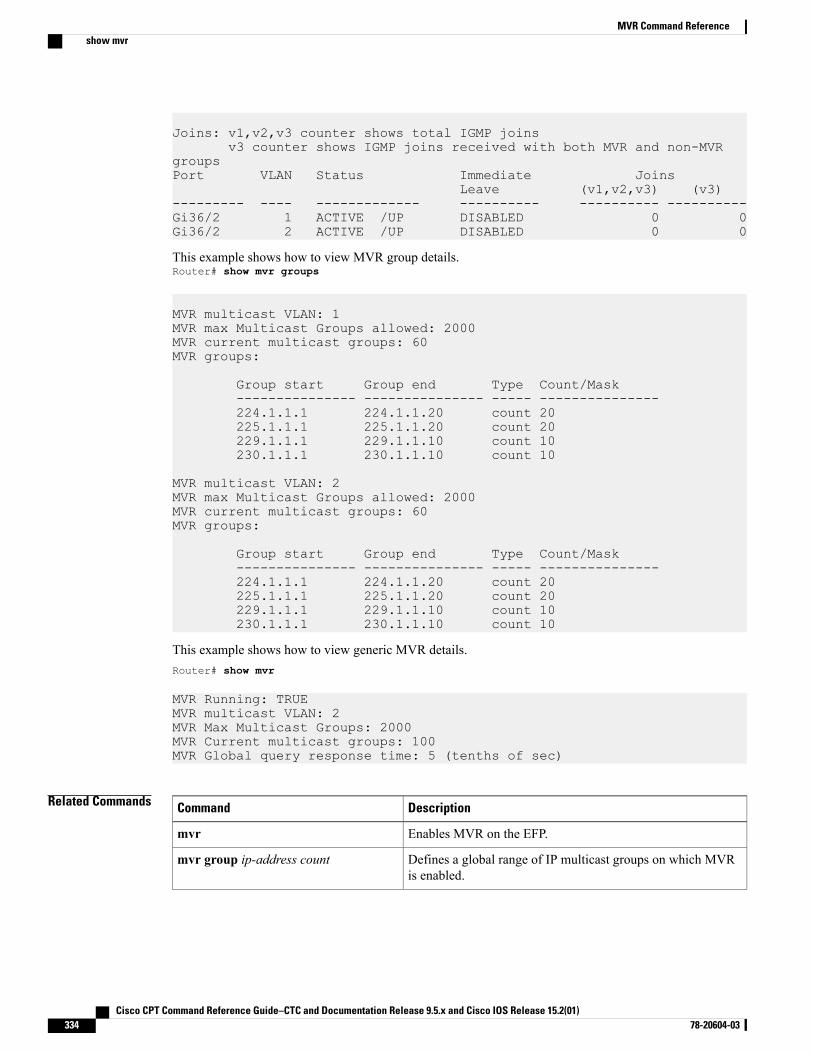
Joins: v1,v2,v3 counter shows total IGMP joinsv3 counter shows IGMP joins received with both MVR and non-MVR
groupsPort VLAN Status Immediate Joins
Leave (v1,v2,v3) (v3)--------- ---- ------------- ---------- ---------- ----------Gi36/2 1 ACTIVE /UP DISABLED 0 0Gi36/2 2 ACTIVE /UP DISABLED 0 0
This example shows how to view MVR group details.Router# show mvr groups
MVR multicast VLAN: 1MVR max Multicast Groups allowed: 2000MVR current multicast groups: 60MVR groups:
Group start Group end Type Count/Mask--------------- --------------- ----- ---------------224.1.1.1 224.1.1.20 count 20225.1.1.1 225.1.1.20 count 20229.1.1.1 229.1.1.10 count 10230.1.1.1 230.1.1.10 count 10
MVR multicast VLAN: 2MVR max Multicast Groups allowed: 2000MVR current multicast groups: 60MVR groups:
Group start Group end Type Count/Mask--------------- --------------- ----- ---------------224.1.1.1 224.1.1.20 count 20225.1.1.1 225.1.1.20 count 20229.1.1.1 229.1.1.10 count 10230.1.1.1 230.1.1.10 count 10
This example shows how to view generic MVR details.Router# show mvr
MVR Running: TRUEMVR multicast VLAN: 2MVR Max Multicast Groups: 2000MVR Current multicast groups: 100MVR Global query response time: 5 (tenths of sec)
Related Commands DescriptionCommand
Enables MVR on the EFP.mvr
Defines a global range of IP multicast groups on which MVRis enabled.
mvr group ip-address count
Cisco CPT Command Reference Guide–CTC and Documentation Release 9.5.x and Cisco IOS Release 15.2(01)334 78-20604-03
MVR Command Referenceshow mvr

DescriptionCommand
Configures an EFP as the MVR enabled source or receiver.mvr type {source | receiverbridge-domain id [vlan vlan-id][immediate]}
Cisco CPT Command Reference Guide–CTC and Documentation Release 9.5.x and Cisco IOS Release 15.2(01) 78-20604-03 335
MVR Command Referenceshow mvr

Cisco CPT Command Reference Guide–CTC and Documentation Release 9.5.x and Cisco IOS Release 15.2(01)336 78-20604-03
MVR Command Referenceshow mvr
Ethernet OAM, CFM, and Y.1731 CommandReference
This chapter describes commands to configure Ethernet OAM, Connectivity Fault Management (CFM), andY.1731.
• aggregate interval, page 340
• ais, page 342
• cfm encapsulation, page 344
• cfm mep domain, page 346
• clear ethernet cfm ais, page 348
• clear ethernet cfm error, page 350
• continuity-check, page 352
• cos (CFM), page 354
• distribution, page 355
• ethernet cfm ais link-status, page 357
• ethernet cfm ais link-status global, page 358
• ethernet cfm domain level, page 359
• ethernet cfm global, page 361
• ethernet cfm interface, page 362
• ethernet cfm lck link-status, page 363
• ethernet cfm lck link-status global, page 364
• ethernet cfm lck start interface, page 365
• ethernet cfm lck start mpid, page 366
• ethernet cfm mep crosscheck, page 367
• ethernet cfm mep crosscheck start-delay, page 369
• ethernet cfm mep domain mpid, page 370
Cisco CPT Command Reference Guide–CTC and Documentation Release 9.5.x and Cisco IOS Release 15.2(01) 78-20604-03 337
• ethernet cfm mip, page 371
• ethernet cfm mip level, page 373
• ethernet cfm traceroute cache, page 375
• ethernet cfm traceroute cache hold-time, page 376
• ethernet cfm traceroute cache size, page 378
• ethernet oam, page 380
• ethernet oam link-monitor frame, page 382
• ethernet oam link-monitor frame-period, page 384
• ethernet oam link-monitor frame-seconds, page 386
• ethernet oam link-monitor high-threshold action, page 388
• ethernet oam link-monitor on, page 390
• ethernet oam link-monitor receive-crc, page 391
• ethernet oam link-monitor supported, page 393
• ethernet oam link-monitor symbol-period, page 395
• ethernet oam link-monitor transmit-crc, page 397
• ethernet oam remote-failure action, page 399
• ethernet oam remote-loopback, page 400
• ethernet oam remote-loopback (interface), page 401
• ethernet y1731 delay dmm domain, page 402
• frame, page 404
• history interval, page 406
• id (CFM), page 408
• ip sla, page 409
• ip sla reset, page 411
• ip sla restart, page 412
• ip sla schedule, page 413
• lck, page 416
• maximum meps, page 417
• mep archive-hold-time, page 418
• mep mpid, page 419
• mip auto-create, page 420
• mip auto-create (cfm-srv), page 421
• ping ethernet, page 423
Cisco CPT Command Reference Guide–CTC and Documentation Release 9.5.x and Cisco IOS Release 15.2(01)338 78-20604-03
Ethernet OAM, CFM, and Y.1731 Command Reference
• service (CFM-srv), page 425
• show ethernet cfm domain, page 426
• show ethernet cfm errors, page 428
• show ethernet cfm maintenance-points local, page 430
• show ethernet cfm maintenance-points remote, page 432
• show ethernet cfm maintenance-points remote crosscheck, page 434
• show ethernet cfm maintenance-points remote detail, page 436
• show ethernet cfm mpdb, page 438
• show ethernet cfm smep, page 440
• show ethernet cfm statistics, page 442
• show ethernet cfm traceroute-cache, page 444
• show ip sla configuration, page 445
• show ip sla statistics, page 447
• show ip sla statistics aggregated, page 449
• traceroute ethernet, page 451
Cisco CPT Command Reference Guide–CTC and Documentation Release 9.5.x and Cisco IOS Release 15.2(01) 78-20604-03 339
Ethernet OAM, CFM, and Y.1731 Command Reference
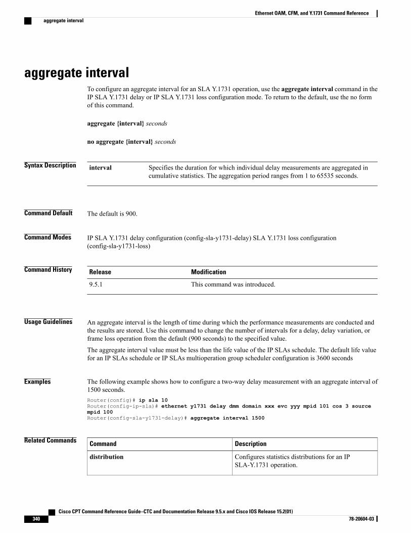
aggregate intervalTo configure an aggregate interval for an SLA Y.1731 operation, use the aggregate interval command in theIP SLA Y.1731 delay or IP SLA Y.1731 loss configuration mode. To return to the default, use the no formof this command.
aggregate {interval} seconds
no aggregate {interval} seconds
Syntax Description Specifies the duration for which individual delay measurements are aggregated incumulative statistics. The aggregation period ranges from 1 to 65535 seconds.
interval
Command Default The default is 900.
Command Modes IP SLA Y.1731 delay configuration (config-sla-y1731-delay) SLA Y.1731 loss configuration(config-sla-y1731-loss)
Command History ModificationRelease
This command was introduced.9.5.1
Usage Guidelines An aggregate interval is the length of time during which the performance measurements are conducted andthe results are stored. Use this command to change the number of intervals for a delay, delay variation, orframe loss operation from the default (900 seconds) to the specified value.
The aggregate interval value must be less than the life value of the IP SLAs schedule. The default life valuefor an IP SLAs schedule or IP SLAs multioperation group scheduler configuration is 3600 seconds
Examples The following example shows how to configure a two-way delay measurement with an aggregate interval of1500 seconds.Router(config)# ip sla 10Router(config-ip-sla)# ethernet y1731 delay dmm domain xxx evc yyy mpid 101 cos 3 sourcempid 100Router(config-sla-y1731-delay)# aggregate interval 1500
Related Commands DescriptionCommand
Configures statistics distributions for an IPSLA-Y.1731 operation.
distribution
Cisco CPT Command Reference Guide–CTC and Documentation Release 9.5.x and Cisco IOS Release 15.2(01)340 78-20604-03
Ethernet OAM, CFM, and Y.1731 Command Referenceaggregate interval
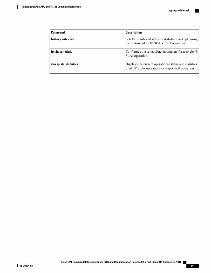
DescriptionCommand
Sets the number of statistics distributions kept duringthe lifetime of an IP SLA Y.1731 operation.
history interval
Configures the scheduling parameters for a single IPSLAs operation.
ip sla schedule
Displays the current operational status and statisticsof all IP SLAs operations or a specified operation.
sho ip sla statistics
Cisco CPT Command Reference Guide–CTC and Documentation Release 9.5.x and Cisco IOS Release 15.2(01) 78-20604-03 341
Ethernet OAM, CFM, and Y.1731 Command Referenceaggregate interval
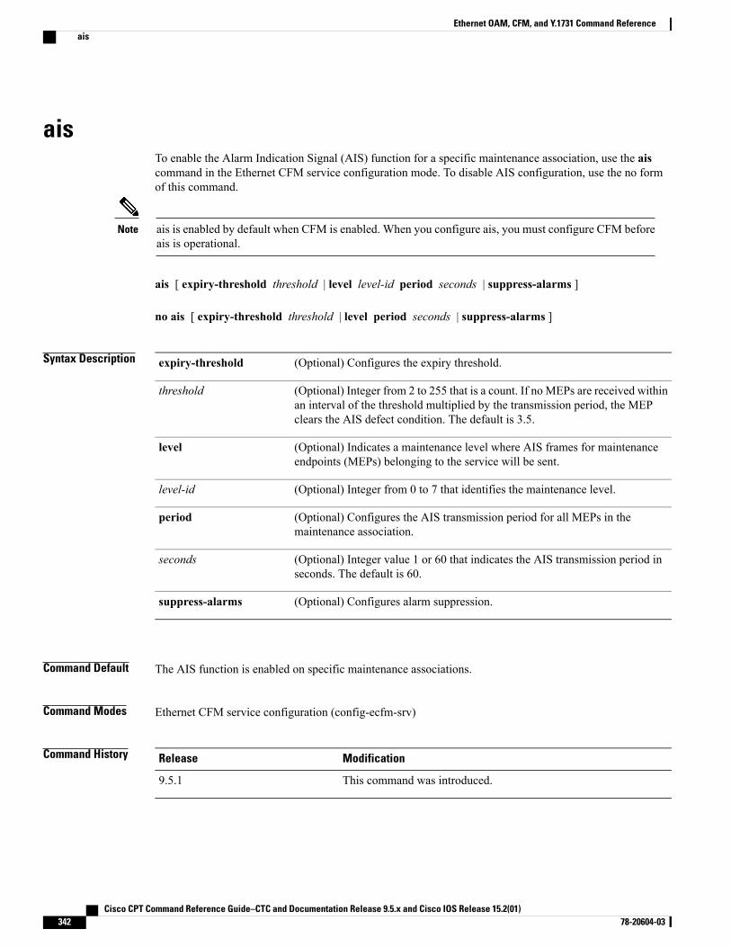
aisTo enable the Alarm Indication Signal (AIS) function for a specific maintenance association, use the aiscommand in the Ethernet CFM service configuration mode. To disable AIS configuration, use the no formof this command.
ais is enabled by default when CFM is enabled. When you configure ais, you must configure CFM beforeais is operational.
Note
ais [ expiry-threshold threshold | level level-id period seconds | suppress-alarms ]
no ais [ expiry-threshold threshold | level period seconds | suppress-alarms ]
Syntax Description (Optional) Configures the expiry threshold.expiry-threshold
(Optional) Integer from 2 to 255 that is a count. If no MEPs are received withinan interval of the threshold multiplied by the transmission period, the MEPclears the AIS defect condition. The default is 3.5.
threshold
(Optional) Indicates a maintenance level where AIS frames for maintenanceendpoints (MEPs) belonging to the service will be sent.
level
(Optional) Integer from 0 to 7 that identifies the maintenance level.level-id
(Optional) Configures the AIS transmission period for all MEPs in themaintenance association.
period
(Optional) Integer value 1 or 60 that indicates the AIS transmission period inseconds. The default is 60.
seconds
(Optional) Configures alarm suppression.suppress-alarms
Command Default The AIS function is enabled on specific maintenance associations.
Command Modes Ethernet CFM service configuration (config-ecfm-srv)
Command History ModificationRelease
This command was introduced.9.5.1
Cisco CPT Command Reference Guide–CTC and Documentation Release 9.5.x and Cisco IOS Release 15.2(01)342 78-20604-03
Ethernet OAM, CFM, and Y.1731 Command Referenceais
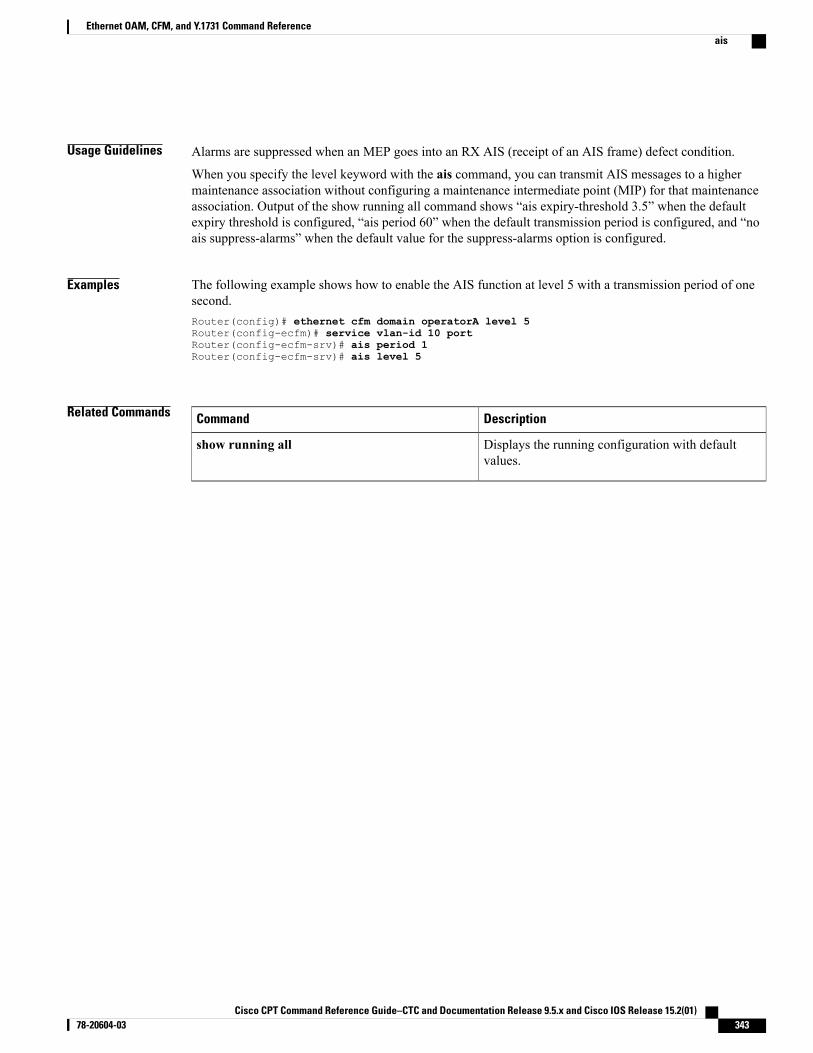
Usage Guidelines Alarms are suppressed when an MEP goes into an RX AIS (receipt of an AIS frame) defect condition.
When you specify the level keyword with the ais command, you can transmit AIS messages to a highermaintenance association without configuring a maintenance intermediate point (MIP) for that maintenanceassociation. Output of the show running all command shows “ais expiry-threshold 3.5” when the defaultexpiry threshold is configured, “ais period 60” when the default transmission period is configured, and “noais suppress-alarms” when the default value for the suppress-alarms option is configured.
Examples The following example shows how to enable the AIS function at level 5 with a transmission period of onesecond.Router(config)# ethernet cfm domain operatorA level 5Router(config-ecfm)# service vlan-id 10 portRouter(config-ecfm-srv)# ais period 1Router(config-ecfm-srv)# ais level 5
Related Commands DescriptionCommand
Displays the running configuration with defaultvalues.
show running all
Cisco CPT Command Reference Guide–CTC and Documentation Release 9.5.x and Cisco IOS Release 15.2(01) 78-20604-03 343
Ethernet OAM, CFM, and Y.1731 Command Referenceais
cfm encapsulationTo configure Connectivity FaultManagement (CFM) Ethernet frame encapsulation, use the cfm encapsulationcommand in service instance configuration mode. To remove the encapsulation, use the no form of thiscommand.
cfm encapsulation {dot1ad vlan-id | dot1q vlan-id} [dot1q vlan-id | second-dot1q vlan-id]
no cfm encapsulation {dot1ad vlan-id | dot1q vlan-id} [dot1q vlan-id | second-dot1q vlan-id]
Syntax Description Indicates the IEEE 802.1ad encapsulation type.dot1ad
VLAN on which the CFM frames are sent out. The valid values rangefrom 1 to 4094.
vlan-id
Supports the IEEE 802.1q standard for encapsulation of traffic, andspecifies the outer dot1q encapsulation tag.
dot1q
(Optional) Specifies the inner dot1q encapsulation tag. This option isvalid only when the outer dot1q encapsulation tag is selected. Whenthe dot1ad encapsulation type is selected first, dot1q is a valid option.
second-dot1q
Command Default CFM Ethernet frame encapsulation is not configured.
Command Modes Service instance configuration (config-if-srv)
Command History ModificationRelease
This command was introduced.9.5.0
Usage Guidelines To use the cfm encapsulation command, you must first configure a bridge-domain in the Ethernet serviceconfiguration mode using the bridge-domain command. The cfm encapsulation command does not supportuntagged service instances.
Examples The following example shows how to configure the cfm encapsulation command:
Router> enableRouter# configure terminalRouter(config)# interface TenGigabitEthernet 4/1Router(config-if)# service instance 101 ethernetRouter(config-if-srv)# encapsulation dot1q 100-110 second dot1q 200Router(config-if-srv)# bridge-domain 12Router(config-if-srv)# cfm encapsulation dot1q 105 second dot1q 200Router(config-if-srv)# exitRouter(config-if)# exit
Cisco CPT Command Reference Guide–CTC and Documentation Release 9.5.x and Cisco IOS Release 15.2(01)344 78-20604-03
Ethernet OAM, CFM, and Y.1731 Command Referencecfm encapsulation
Related Commands DescriptionCommand
Binds the service instance to a bridge domaininstance.
bridge-domain
Configures an Ethernet service instance on aninterface and enters service instance configurationmode.
service instance ethernet
Cisco CPT Command Reference Guide–CTC and Documentation Release 9.5.x and Cisco IOS Release 15.2(01) 78-20604-03 345
Ethernet OAM, CFM, and Y.1731 Command Referencecfm encapsulation
cfm mep domainTo create an MEP for a Ethernet Flow Point (EFP), use the cfm mep domain command in service instanceconfiguration mode. To remove the MEP, use the no form of this command.
cfm mep domain domain-namempid mpid-value
no cfm mep domain domain-namempid mpid-value
Syntax Description Domain name. The name can be up to 154 characters.domain-name
Indicates the maintenance point ID (MPID).mpid
Maintenance point identifier value. The valid values range from 1 to8191.
mpid-value
Command Default MEPs are not created if this command is not issued.
Command Modes Service instance configuration (config-if-srv)
Command History ModificationRelease
This command was introduced.9.5.0
Usage Guidelines To use the cfm mep domain command, you must first configure a bridge domain in the service instanceconfiguration mode by issuing the bridge-domain command.
Examples The following example shows how to create an MEP for an EFP:
Router> enableRouter# configure terminalRouter(config)# interface TenGigabitEthernet 4/1Router(config-if)# service instance 101 ethernetRouter(config-if-srv)# encapsulation dot1q 100Router(config-if-srv)# bridge-domain 12Router(config-if-srv)# cfm mep domain CustomerB mpid 5Router(config-if-srv)# exit
Related Commands DescriptionCommand
Binds the service instance to a bridge domaininstance.
bridge-domain
Cisco CPT Command Reference Guide–CTC and Documentation Release 9.5.x and Cisco IOS Release 15.2(01)346 78-20604-03
Ethernet OAM, CFM, and Y.1731 Command Referencecfm mep domain

DescriptionCommand
Configures an Ethernet service instance on aninterface and enters service instance configurationmode.
service instance ethernet
Cisco CPT Command Reference Guide–CTC and Documentation Release 9.5.x and Cisco IOS Release 15.2(01) 78-20604-03 347
Ethernet OAM, CFM, and Y.1731 Command Referencecfm mep domain
clear ethernet cfm aisTo clear an MEP or SMEP out of the AIS defect condition, use the clear ethernet cfm ais command in theprivileged EXEC mode.
clear ethernet cfm ais {domain domain-namempid mpid-id evc evc name | link-status interface interfacename}
Syntax Description Indicates that a maintenance domain is specified.domain
String of a maximum of 154 characters that identifies the domain.domain-name
Indicates that a maintenance point ID (MPID) is specified.mpid
An integer in the range of 1 to 8191 that identifies the MPID.mpid-id
Indicates that an Ethernet virtual circuit (EVC) is specified.evc
String identifying the EVC name.evc name
Indicates either a SMEP or a link up/link down condition.link-status
Indicates that an interface is specified.interface name
Command Default This command has no defaults.
Command Modes Privileged EXEC (#)
Command History ModificationRelease
This command was introduced.9.5.1
Usage Guidelines If anMEP does not exit the AIS state when all the errors are resolved, use the clear ethernet cfm ais commandwith the domain and mpid keywords to clear the AIS defect condition. If an SMEP does not exit the AIS statewhen all errors are resolved, use the clear ethernet cfm ais command with the link-status and interfacekeywords to clear the AIS defect condition.
Examples The following example shows how to clear an SMEP of an AIS defect condition.Router# clear ethernet cfm ais link-status interface TenGigabitEthernet 2/3
Cisco CPT Command Reference Guide–CTC and Documentation Release 9.5.x and Cisco IOS Release 15.2(01)348 78-20604-03
Ethernet OAM, CFM, and Y.1731 Command Referenceclear ethernet cfm ais
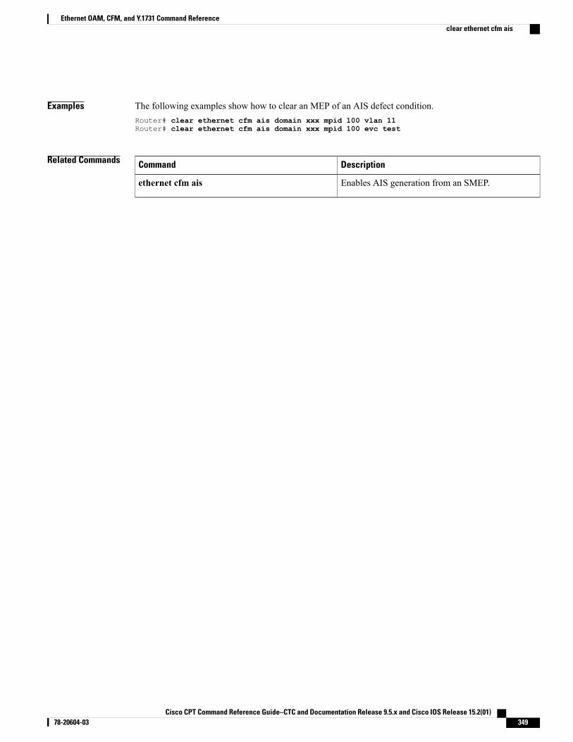
Examples The following examples show how to clear an MEP of an AIS defect condition.Router# clear ethernet cfm ais domain xxx mpid 100 vlan 11Router# clear ethernet cfm ais domain xxx mpid 100 evc test
Related Commands DescriptionCommand
Enables AIS generation from an SMEP.ethernet cfm ais
Cisco CPT Command Reference Guide–CTC and Documentation Release 9.5.x and Cisco IOS Release 15.2(01) 78-20604-03 349
Ethernet OAM, CFM, and Y.1731 Command Referenceclear ethernet cfm ais
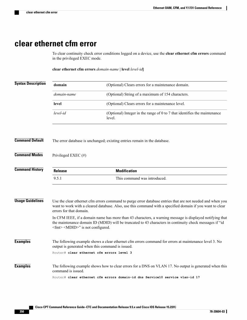
clear ethernet cfm errorTo clear continuity check error conditions logged on a device, use the clear ethernet cfm errors commandin the privileged EXEC mode.
clear ethernet cfm errors domain-name | level level-id]
Syntax Description (Optional) Clears errors for a maintenance domain.domain
(Optional) String of a maximum of 154 characters.domain-name
(Optional) Clears errors for a maintenance level.level
(Optional) Integer in the range of 0 to 7 that identifies the maintenancelevel.
level-id
Command Default The error database is unchanged; existing entries remain in the database.
Command Modes Privileged EXEC (#)
Command History ModificationRelease
This command was introduced.9.5.1
Usage Guidelines Use the clear ethernet cfm errors command to purge error database entries that are not needed and when youwant to work with a cleared database. Also, use this command with a specified domain if you want to clearerrors for that domain.
In CFM IEEE, if a domain name has more than 43 characters, a warning message is displayed notifying thatthe maintenance domain ID (MDID) will be truncated to 43 characters in continuity check messages if “id<fmt> <MDID>” is not configured.
Examples The following example shows a clear ethernet cfm errors command for errors at maintenance level 3. Nooutput is generated when this command is issued.Router# clear ethernet cfm errors level 3
Examples The following example shows how to clear errors for a DNS on VLAN 17. No output is generated when thiscommand is issued.Router# clear ethernet cfm errors domain-id dns Service10 service vlan-id 17
Cisco CPT Command Reference Guide–CTC and Documentation Release 9.5.x and Cisco IOS Release 15.2(01)350 78-20604-03
Ethernet OAM, CFM, and Y.1731 Command Referenceclear ethernet cfm error

Related Commands DescriptionCommand
Displays CFM continuity check error conditionslogged on a device since it was last reset or since thelog was last cleared.
show ethernet cfm errors
Cisco CPT Command Reference Guide–CTC and Documentation Release 9.5.x and Cisco IOS Release 15.2(01) 78-20604-03 351
Ethernet OAM, CFM, and Y.1731 Command Referenceclear ethernet cfm error
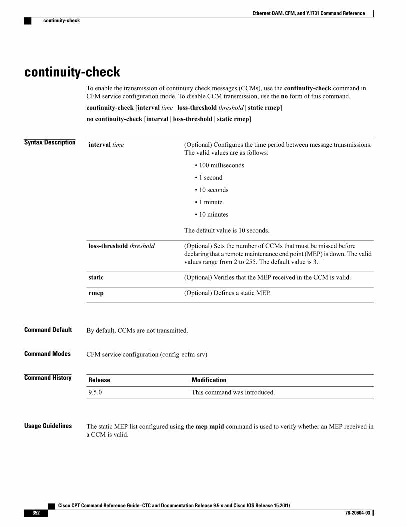
continuity-checkTo enable the transmission of continuity check messages (CCMs), use the continuity-check command inCFM service configuration mode. To disable CCM transmission, use the no form of this command.
continuity-check [interval time | loss-threshold threshold | static rmep]
no continuity-check [interval | loss-threshold | static rmep]
Syntax Description (Optional) Configures the time period between message transmissions.The valid values are as follows:
• 100 milliseconds
• 1 second
• 10 seconds
• 1 minute
• 10 minutes
The default value is 10 seconds.
interval time
(Optional) Sets the number of CCMs that must be missed beforedeclaring that a remote maintenance end point (MEP) is down. The validvalues range from 2 to 255. The default value is 3.
loss-threshold threshold
(Optional) Verifies that the MEP received in the CCM is valid.static
(Optional) Defines a static MEP.rmep
Command Default By default, CCMs are not transmitted.
Command Modes CFM service configuration (config-ecfm-srv)
Command History ModificationRelease
This command was introduced.9.5.0
Usage Guidelines The static MEP list configured using themep mpid command is used to verify whether an MEP received ina CCM is valid.
Cisco CPT Command Reference Guide–CTC and Documentation Release 9.5.x and Cisco IOS Release 15.2(01)352 78-20604-03
Ethernet OAM, CFM, and Y.1731 Command Referencecontinuity-check
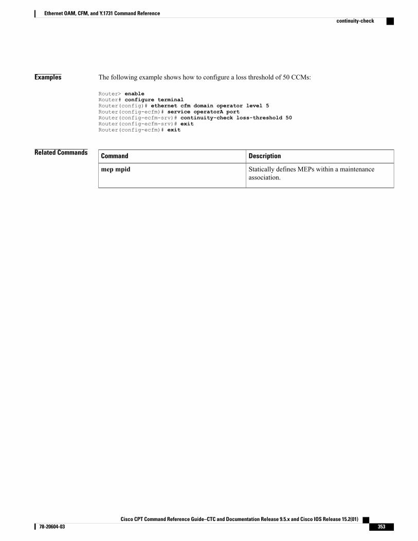
Examples The following example shows how to configure a loss threshold of 50 CCMs:
Router> enableRouter# configure terminalRouter(config)# ethernet cfm domain operator level 5Router(config-ecfm)# service operatorA portRouter(config-ecfm-srv)# continuity-check loss-threshold 50Router(config-ecfm-srv)# exitRouter(config-ecfm)# exit
Related Commands DescriptionCommand
Statically defines MEPs within a maintenanceassociation.
mep mpid
Cisco CPT Command Reference Guide–CTC and Documentation Release 9.5.x and Cisco IOS Release 15.2(01) 78-20604-03 353
Ethernet OAM, CFM, and Y.1731 Command Referencecontinuity-check
cos (CFM)To set the class of service (CoS) for a maintenance end point (MEP) that is sent in IEEE Connectivity FaultManagement (CFM) messages, use the cos command in CFM interface configuration mode. To set the CoSto the highest priority allowed on the interface, use the no form of this command.
cos cos-value
no cos
Syntax Description CoS value. The valid values range from 0 to 7. The default value is 7.cos-value
Command Default If this command is not configured, the default CoS value is used. The default value is 7. If no cos commandis used, the default value is 0.
Command Modes CFM interface configuration (config-if-ecfm-mep)
Command History ModificationRelease
This command was introduced.9.5.0
Usage Guidelines The cos command is used to set the priority of messages.
Examples The following example shows how to set the CoS to 5:
Router> enableRouter# configure terminalRouter(config)# interface TenGigabitEthernet 4/1Router(config-if)# ethernet cfm mep domain test mpid 701 portRouter(config-if-ecfm-mep)# cos 5Router(config-if-ecfm-mep)# exitRouter(config-if)# exit
Cisco CPT Command Reference Guide–CTC and Documentation Release 9.5.x and Cisco IOS Release 15.2(01)354 78-20604-03
Ethernet OAM, CFM, and Y.1731 Command Referencecos (CFM)
distributionTo configure statistics distributions for an IP SLA-Y.1731 operation, use the distribution command in theIP SLA Y.1731 delay or IP SLA Y.1731 loss configuration mode. To return to the default, use the no formof this command.
distribution {delay | delay-variation} two-way number-of-bins comma separated values
Syntax Description Specifies that the performance measurement type is delay.delay
Specifies that the performance measurement type is delay variation. Thisis the default value, along with delay.
delay-variation
Specifies two-way measurement values. This is the default for asingle-ended operation.
two-way
Number of bins kept during an aggregate interval.number-of-bins
Comma separated list of upper boundaries of bins (in microseconds).comma separated values
Command Default This command has no defaults.
Command Modes IP SLA Y.1731 delay configuration (config-sla-y1731-delay)
Command History ModificationRelease
This command was introduced.9.5.1
Usage Guidelines Configure this command on theMEP that performs the performancemeasurement calculation. For dual-endedoperations, calculations are performed at the receiverMEP on the responder. Statistics distributions are definedby number of bins per interval. A bin is a counter that counts the number of measurements initiated andcompleted during a specified length of time for each operation. The results of performance measurementsfalling within a specified range are stored in each bin. When the number of distributions reaches the numberand range specified, no further distribution-based information is stored.
Examples The following example shows how to configure statistics distributions for an IP SLA-Y.1731 operation.Router(config)# ip sla 10Router(config-ip-sla)# ethernet y1731 delay dmm domain xxx evc yyy mpid 101 cos 3 sourcempid 100Router(config-sla-y1731-delay)# distribution delay one-way 5 10,30,500,700,1000
Cisco CPT Command Reference Guide–CTC and Documentation Release 9.5.x and Cisco IOS Release 15.2(01) 78-20604-03 355
Ethernet OAM, CFM, and Y.1731 Command Referencedistribution
Related Commands DescriptionCommand
Configures the aggregate interval.aggregate interval
Sets the number of statistics distributions kept duringthe lifetime of an IP SLAsMetro Ethernet 3.0 (ITU-TY.1731) operation.
history interval
Cisco CPT Command Reference Guide–CTC and Documentation Release 9.5.x and Cisco IOS Release 15.2(01)356 78-20604-03
Ethernet OAM, CFM, and Y.1731 Command Referencedistribution
ethernet cfm ais link-statusTo enable AIS generation from a server maintenance endpoint (SMEP), use the ethernet cfm ais link-statuscommand in the interface configuration mode. To disable AIS generation, use the no form of this command.
ethernet cfm ais link-status [level level-id | period seconds]
no ethernet cfm ais link-status [level | period]
Syntax Description (Optional) Indicates a maintenance domain level where the AIS will be sent.level
(Optional) Integer from 0 to 7 that identifies the maintenance level.level-id
(Optional) Configures the AIS transmission period generated by the SMEP onthe interface.
period
(Optional) Integer value 1 or 60 that indicates the AIS transmission period inseconds. The default is 60.
seconds
Command Default AIS frames are not generated.
Command Modes Interface configuration (config-if)
Command History ModificationRelease
This command was introduced.9.5.1
Usage Guidelines This command has precedence over the ethernet cfm ais link-status global command issued in globalconfiguration mode.
Examples The following example shows how to configure AIS generation with a transmission period of 60 seconds.Router(config-if)# ethernet cfm ais link-status period 60
Related Commands DescriptionCommand
Globally enables AIS generation and places the CLIin CFM SMEP AIS configuration mode.
ethernet cfm ais link-status global
Cisco CPT Command Reference Guide–CTC and Documentation Release 9.5.x and Cisco IOS Release 15.2(01) 78-20604-03 357
Ethernet OAM, CFM, and Y.1731 Command Referenceethernet cfm ais link-status
ethernet cfm ais link-status globalTo globally enable AIS generation and place the command-line interface (CLI) in the CFM SMEP AISconfiguration mode (config-ais-link-cfm) to configure AIS commands for an SMEP, use the ethernet cfmais link-status global command in the global configuration mode. To remove the global AIS configuration,use the no form of this command.
ethernet cfm ais link-status global {level level-id | period seconds}
no ethernet cfm ais link-status global {level level-id | period seconds}
Syntax Description Indicates a maintenance level where AIS frames forMEPs belonging to the servicewill be sent.
level
Integer from 0 to 7 that identifies the maintenance level.level-id
Configures the AIS transmission period for all MEPs in the maintenanceassociation.
period
Integer value 1 or 60 that indicates the AIS transmission period in seconds. Thedefault is 60.
value
Command Default AIS generation is enabled.
Command Modes Global configuration (config)
Command History ModificationRelease
This command was introduced.9.5.1
Usage Guidelines The ethernet cfm ais link-status global command changes configuration modes to allow you to configureAIS commands for an SMEP.
Examples The following example shows how to configure AIS commands for an SMEP.Router(config)# ethernet cfm ais link-status globalRouter(config-ais-link-cfm)# level 3Router(config-ais-link-cfm)# period 1
Cisco CPT Command Reference Guide–CTC and Documentation Release 9.5.x and Cisco IOS Release 15.2(01)358 78-20604-03
Ethernet OAM, CFM, and Y.1731 Command Referenceethernet cfm ais link-status global
ethernet cfm domain levelTo create a IEEE Connectivity Fault Management (CFM)maintenance domain at a specific maintenance leveland enter CFM configuration mode, use the ethernet cfm domain level command in global configurationmode. To remove the CFM domain at the specified maintenance level, use the no form of this command.
ethernet cfm domain domain-name level level-id
no ethernet cfm domain domain-name level level-id
Syntax Description Domain name. The name can be up to 154 characters.domain-name
Maintenance level ID. The valid values range from 0 to 7.level level-id
Command Default Maintenance domains are not assigned to maintenance levels.
Command Modes Global configuration (config)
Command History ModificationRelease
This command was introduced.9.5.0
Usage Guidelines When a router is in CFM configurationmode, parameters specific to a maintenance domain can be set. Severaldomains with different names can be configured at the same maintenance level; however, a single domaincannot be associated with multiple maintenance levels.
In CFM IEEE, if a domain name has more than 43 characters, a warning message is displayed notifying thatthe maintenance domain ID (MDID) will be truncated to 43 characters in the continuity check messages.
Examples The following example shows how to create a maintenance domain named domain1 at maintenance level 6and enter CFM configuration mode:
Router> enableRouter# configure terminalRouter(config)# ethernet cfm domain domain1 level 6Router(config-ecfm)#
Related Commands DescriptionCommand
Displays information about the CFM maintenancedomain.
show ethernet cfm domain
Cisco CPT Command Reference Guide–CTC and Documentation Release 9.5.x and Cisco IOS Release 15.2(01) 78-20604-03 359
Ethernet OAM, CFM, and Y.1731 Command Referenceethernet cfm domain level

DescriptionCommand
Displays information about CFMmaintenance pointsconfigured on a device.
show ethernet cfm maintenance-points local
Cisco CPT Command Reference Guide–CTC and Documentation Release 9.5.x and Cisco IOS Release 15.2(01)360 78-20604-03
Ethernet OAM, CFM, and Y.1731 Command Referenceethernet cfm domain level
ethernet cfm globalTo enable IEEE Connectivity Fault Management (CFM) globally on a device, use the ethernet cfm globalcommand in global configuration mode. To disable IEEE CFM globally on a device, use the no form of thiscommand.
ethernet cfm global
no ethernet cfm global
Syntax Description This command has no arguments or keywords.
Command Default IEEE CFM is disabled on a device.
Command Modes Global configuration (config)
Command History ModificationRelease
This command was introduced.9.5.0
Usage Guidelines IEEE CFM is disabled by default and must be enabled explicitly. This command is supported only in theEthernet CFM IEEE 802.1ag standard implementation.
Examples The following example shows how to enable CFM globally on a device:
Router> enableRouter# configure terminalRouter(config)# ethernet cfm global
Related Commands DescriptionCommand
Enables IEEE CFM on an interface.ethernet cfm interface
Cisco CPT Command Reference Guide–CTC and Documentation Release 9.5.x and Cisco IOS Release 15.2(01) 78-20604-03 361
Ethernet OAM, CFM, and Y.1731 Command Referenceethernet cfm global
ethernet cfm interfaceTo enable IEEE Connectivity Fault Management (CFM) on an interface, use the ethernet cfm interfacecommand in interface configuration mode. To disable CFM on an interface, use the no form of this command.
ethernet cfm interface
no ethernet cfm interface
Syntax Description This command has no arguments or keywords.
Command Default IEEE CFM is enabled on an interface.
Command Modes Interface configuration (config-if)
Command History ModificationRelease
This command was introduced.9.5.0
Usage Guidelines IEEE CFM is enabled by default on an interface and must be explicitly disabled. An interface must be enabledbefore any MEPs or MIPs can be configured. Similarly, maintenance points must be unconfigured before aninterface configured with MIPs or MEPs can be disabled.
When IEEE CFM processing is disabled on an interface, all the CFM frames that arrive on that interface aredropped and are not processed by the CPU.
Examples The following example shows how to configure an interface for IEEE CFM processing:
Router> enableRouter# configure terminalRouter(config)# interface TenGigabitEthernet 4/1Router(config-if)# ethernet cfm interface
Related Commands DescriptionCommand
Enables IEEE CFM globally on a device.ethernet cfm global
Cisco CPT Command Reference Guide–CTC and Documentation Release 9.5.x and Cisco IOS Release 15.2(01)362 78-20604-03
Ethernet OAM, CFM, and Y.1731 Command Referenceethernet cfm interface
ethernet cfm lck link-statusTo enable LCK generation from an SMEP, use the ethernet cfm lck link-status command in the interfaceconfiguration mode. To disable LCK generation, use the no form of this command.
ethernet cfm lck link-status [level level-id | period seconds]
no ethernet cfm lck link-status [level | period]
Syntax Description (Optional) Indicates a maintenance domain level where the LCK will be sent.level
(Optional) Integer from 0 to 7 that identifies the maintenance level.level-id
(Optional) Configures the LCK transmission period generated by the SMEP onthe interface.
period
(Optional) Integer value 1 or 60 that indicates the LCK transmission period inseconds. The default is 60.
seconds
Command Default LCK frames are not generated.
Command Modes Interface configuration (config-if)
Command History ModificationRelease
This command was introduced.9.5.1
Usage Guidelines This command has precedence over the ethernet cfm lck link-status global command issued in globalconfiguration mode.
Examples The following example shows how to configure LCK generation with a transmission period of 60 seconds.Router(config-if)# ethernet cfm lck link-status period 60
Related Commands DescriptionCommand
Globally enables LCK generation and places the CLIin CFM SMEP LCK configuration mode.
ethernet cfm lck link-status global
Cisco CPT Command Reference Guide–CTC and Documentation Release 9.5.x and Cisco IOS Release 15.2(01) 78-20604-03 363
Ethernet OAM, CFM, and Y.1731 Command Referenceethernet cfm lck link-status
ethernet cfm lck link-status globalTo globally enable LCK generation and place the CLI in the CFM SMEP LCK configuration mode(config-lck-link-cfm) to configure LCK commands for an SMEP, use the ethernet cfm lck link-status globalcommand in the global configuration mode. To remove the global LCK configuration, use the no form of thiscommand.
ethernet cfm lck link-status global{level level-id | period seconds}
no ethernet cfm lck link-status global{level level-id | period seconds}
Syntax Description Indicates the maintenance level for sending LCK frames transmitted by theSMEP.
level
Integer from 0 to 7 that identifies the maintenance level.level-id
Configures the LCK frame transmission period interval.period
Integer value 1 or 60 that indicates the frame transmission period in seconds.seconds
Command Default LCK generation is enabled.
Command Modes Privileged EXEC (#)
Command History ModificationRelease
This command was introduced.9.5.1
Usage Guidelines The ethernet cfm lck link-status global command changes configuration modes to allow you to configureLCK commands for an SMEP.
Examples The following example shows how to configure LCK commands for an SMEP.Router(config)# ethernet cfm lck link-status global
Cisco CPT Command Reference Guide–CTC and Documentation Release 9.5.x and Cisco IOS Release 15.2(01)364 78-20604-03
Ethernet OAM, CFM, and Y.1731 Command Referenceethernet cfm lck link-status global
ethernet cfm lck start interfaceTo put an interface in the ETH-LCK condition, enter the ethernet cfm lck start interface command in theprivileged EXEC mode.
ethernet cfm lck start interface type number direction {up | down} [dropl2-bpdu]
Syntax Description Specify the interface to be put in LCK condition.interface type number
The LCK is in the direction toward the relay; that is, within the switch.direction up
The LCK is in the direction of the wire.direction down
(Optional) Specifies that all Layer 2 BPDUs except CFM frames, all dataframes, and all Layer 3 control traffic are dropped for that MEP. If notentered, only data frames and Layer 3 control frames are dropped.
dropl2-bpdu
Command Default This command has no defaults.
Command Modes Privileged EXEC (#)
Command History ModificationRelease
This command was introduced.9.5.1
Examples The following example shows how to put an interface in the ETH-LCK condition.Router# ethernet cfm lck start interface TenGigabitEthernet 4/1 direction down
Related Commands DescriptionCommand
Places an interface out of the ETH-LCK condition.ethernet cfm lck stop interface
Places an MEP in the ETH-LCK condition.ethernet cfm lck start mpid
Displays CFM information for the source MEP.show ethernet cfm smep
Cisco CPT Command Reference Guide–CTC and Documentation Release 9.5.x and Cisco IOS Release 15.2(01) 78-20604-03 365
Ethernet OAM, CFM, and Y.1731 Command Referenceethernet cfm lck start interface
ethernet cfm lck start mpidPlaces an MEP in ETH-LCK condition. To put an MEP out of the ETH-LCK condition, enter the ethernetcfm lck stop mpid command in the privileged EXEC command.
ethernet cfm lck start mpid local-mpid domain domain-name evc evc name [dropl2-bpdu]
Syntax Description Identifies the MEP.mpid local-mpid domaindomain-name evc evc name
Specifies that the switch should drop all data frames, all Layer 3control traffic, and all Layer 2 BPDUs except CFM frames for thatMEP. If not entered, the switch drops only data frames and Layer 3control frames.
dropl2-bpdu
Command Default This command has no defaults.
Command Modes Privileged EXEC (#)
Command History ModificationRelease
This command was introduced.9.5.1
Examples The following example shows how to place an MEP in ETH-LCK condition.Router# ethernet cfm lck start mpid 2 domain customer evc evc1
Related Commands DescriptionCommand
Places an interface in ETH-LCK condition.ethernet cfmlck start interface
To put a MEP out of ETH-LCK condition.ethernet cfm lck stop mpid
Displays CFM information for the source MEP.show ethernet cfm smep
Cisco CPT Command Reference Guide–CTC and Documentation Release 9.5.x and Cisco IOS Release 15.2(01)366 78-20604-03
Ethernet OAM, CFM, and Y.1731 Command Referenceethernet cfm lck start mpid
ethernet cfm mep crosscheckTo enable cross-checking between the list of configured remote IEEE CFM maintenance end points (MEPs)of a domain and MEPs learned through continuity check messages (CCMs), use the ethernet cfm mepcrosscheck command in privileged EXEC mode. To disable cross-checking, use the ethernet cfm mepcrosscheck disable command.
ethernet cfm mep crosscheck {enable | disable} domain domain-name {port | evc evc-name}
Syntax Description Enables cross-checking.enable
Disables cross-checking.disable
Domain name. The name can be up to 154 characters.domain
String of a maximum of 154 characters that identifies the maintenancedomain.
domain-name
Specifies that the MEP is a port MEP.port
Specifies an MEP for an EVC.evc
Identifier of the EVC.evc-name
Command Default Cross-checking is not enabled.
Command Modes Privileged EXEC (#)
Command History ModificationRelease
This command was introduced.9.5.0
Usage Guidelines To enable cross-checking after a device has booted up, you must issue the ethernet cfm mep crosscheckenable command. A no form of this command does not exist. Cross-checking is disabled when you issue thecommand with the disable keyword.
If a domain name has more than 43 characters, a warning message is displayed notifying that the maintenancedomain ID (MDID) will be truncated to 43 characters in the continuity check messages.
To view the results of a cross-check operation, use the show ethernet cfm maintenance-points remotecrosscheck command. To view errors in the cross-check operation, use the show ethernet cfm errorscommand. Both commands are used in privileged EXEC mode.
Cisco CPT Command Reference Guide–CTC and Documentation Release 9.5.x and Cisco IOS Release 15.2(01) 78-20604-03 367
Ethernet OAM, CFM, and Y.1731 Command Referenceethernet cfm mep crosscheck
Examples The following example shows how to enable IEEE CFM MEP cross-check on a port MEP:
Router> enableRouter# ethernet cfm mep crosscheck enable domain customerA port
Related Commands DescriptionCommand
Configures themaximum amount of time that a devicewaits for remote IEEECFMMEPs to come up beforethe cross-check operation is started.
ethernet cfm mep crosscheck start-delay
Displays IEEECFMcontinuity check error conditionslogged on a device since it was last reset or since thelog was last cleared.
show ethernet cfm errors
Displays detailed information about remote IEEECFMMEPs in the cross-check list that were staticallyconfigured.
show ethernet cfm maintenance-points remotecrosscheck
Cisco CPT Command Reference Guide–CTC and Documentation Release 9.5.x and Cisco IOS Release 15.2(01)368 78-20604-03
Ethernet OAM, CFM, and Y.1731 Command Referenceethernet cfm mep crosscheck
ethernet cfm mep crosscheck start-delayTo configure themaximum amount of time that a device waits for the remote IEEECFMmaintenance endpoints(MEPs) to come up before the cross-check operation is started, use the ethernet cfm mep crosscheckstart-delay command in global configuration mode. To restore the default number of seconds a device waits,use the no form of this command.
ethernet cfm mep crosscheck start-delay delay
no ethernet cfm mep crosscheck start-delay delay
Syntax Description Number of seconds a device waits for the remote IEEE CFM MEPs to come up beforethe cross-check is started. The valid values range from 1 to 65535. The default value is30.
delay
Command Default The start delay interval is enabled with a default of 30 seconds.
Command Modes Global configuration (config)
Command History ModificationRelease
This command was introduced.9.5.0
Usage Guidelines If the continuity check intervals in your network are greater than 30 seconds (the delay default), you mustconfigure the start-delay to match the greatest interval to avoid unnecessary traps.
Examples The following example shows how to set the maximum number of seconds that a device waits for the remoteIEEE CFM MEPs to come up before the cross-check operation is started:
Router> enableRouter# configure terminalRouter(config)# ethernet cfm mep crosscheck start-delay 700
Related Commands DescriptionCommand
Enables cross-checking between the list of configuredremote IEEE CFM MEPs of a domain and MEPslearned through continuity check messages.
ethernet cfm mep crosscheck
Cisco CPT Command Reference Guide–CTC and Documentation Release 9.5.x and Cisco IOS Release 15.2(01) 78-20604-03 369
Ethernet OAM, CFM, and Y.1731 Command Referenceethernet cfm mep crosscheck start-delay
ethernet cfm mep domain mpidTo set a port as internal to a maintenance domain and create a port maintenance end point (MEP), use theethernet cfmmep domainmpid command in interface configurationmode. To restore the default configurationof the port, use the no form of this command.
ethernet cfm mep domain domain-namempid mpid {port}
no ethernet cfm mep domain domain-namempid mpid {port}
Syntax Description Domain name. The name can be up to 154 characters.domain-name
MP ID. The valid values range from 1 to 8191.mpid mp-id
Specifies that the MEP is a port MEP.port
Command Default This command is disabled.
Command Modes Interface configuration (config-if)
Command History ModificationRelease
This command was introduced.9.5.0
Usage Guidelines A single port may belong to multiple domains, meaning that you can issue multiple instances of the ethernetcfm mep domain mpid command for different domains. A port MEP can be created only on a physical portor on a port of a channel group.
Examples The following example shows how to set a port as internal to a maintenance domain and create a port MEP:
Router> enableRouter# configure terminalRouter(config)# interface TenGigabitEthernet 4/1Router(config-if)# ethernet cfm mep domain CustomerB mpid 5 port
Cisco CPT Command Reference Guide–CTC and Documentation Release 9.5.x and Cisco IOS Release 15.2(01)370 78-20604-03
Ethernet OAM, CFM, and Y.1731 Command Referenceethernet cfm mep domain mpid
ethernet cfm mipTo dynamically create a IEEE maintenance intermediate point (MIP) and provision it globally at a specifiedmaintenance level and to enable level filtering, use the ethernet cfm mip command in global configurationmode. To remove a IEEE MIP, use the no form of this command.
ethernet cfm mip {auto-create level level-id [lower-mep-only] [sender-id chassis] | filter}
no ethernet cfm mip {auto-create level level-id [lower-mep-only] [sender-id chassis] | filter}
Syntax Description Dynamically creates an IEEE CFM MIP.auto-create
Specifies a maintenance domain level.level
Maintenance level ID. The valid values range from 0 to 7.level-id
(Optional) Creates an MIP only if a maintenance end point (MEP) is configuredat the next lower maintenance domain level on the port.
lower-mep-only
(Optional) Configures the Sender ID option to send VLAN IDs that are notassociated with maintenance associations.
If the sender-id option is not configured, the Sender ID TLV is not included inthe messages.
sender-id
(Optional) Sends the chassis ID.chassis
Configures IEEE CFM MIP filter that drops all CFM frames at a lower levelindependent of whether they come from the wire or relay function side. The levelfiltering is disabled by default.
filter
Command Default IEEE CFM MIPs are not provisioned.
Command Modes Global configuration (config)
Command History ModificationRelease
This command was introduced.9.5.0
Usage Guidelines IEEE CFM MIPs will be provisioned only if all the policies have been met.
The ethernet cfmmip command has lower precedence than the manualMIP ethernet cfmmip level (interfaceconfiguration mode) configuration command. For example, if you manually configure anMIP for a particularMA, that configuration overrides the MIP created by the global ethernet cfm mip command for that MA.
Cisco CPT Command Reference Guide–CTC and Documentation Release 9.5.x and Cisco IOS Release 15.2(01) 78-20604-03 371
Ethernet OAM, CFM, and Y.1731 Command Referenceethernet cfm mip
Examples The following example shows how to dynamically create a IEEE CFM MIP at maintenance level 6:
Router> enableRouter# configure terminalRouter(config)# ethernet cfm mip auto-create level 6
Related Commands DescriptionCommand
Creates an MIP manually at a specified maintenancelevel on an interface.
ethernet cfm mip level
Cisco CPT Command Reference Guide–CTC and Documentation Release 9.5.x and Cisco IOS Release 15.2(01)372 78-20604-03
Ethernet OAM, CFM, and Y.1731 Command Referenceethernet cfm mip
ethernet cfm mip levelTo provision a IEEE Connectivity Fault Management (CFM)maintenance intermediate point (MIP) manuallyat a specified maintenance level on an EFP service, use the ethernet cfm mip level command in interfaceconfiguration mode. To restore the default configuration, use the no form of this command.
ethernet cfm mip level level-id
no ethernet cfm mip level level-id
Syntax Description Maintenance level ID. The valid values range from 0 to 7.level-id
Command Default IEEE CFM MIPs are not configured.
Command Modes Interface configuration (config-if)
Command History ModificationRelease
This command was introduced.9.5.0
Usage Guidelines You cannot configure a IEEE CFM MIP at a level lower than the level of already configured MEPs on anEFP service.
Configuring a IEEE CFM MIP using this command is known as a manual MIP and has precedence over theethernet cfm mip command.
Examples The following example shows how to provision a IEEE CFM MIP manually at maintenance level 5:
Router> enableRouter# configure terminalRouter(config)# interface TenGigabitEthernet 4/1Router(config-if)# ethernet cfm mip level 5Router(config-if)# exit
Related Commands DescriptionCommand
Defines a IEEE CFM domain.ethernet cfm domain
Enables the automatic creation of a IEEE CFM MIPat a maintenance domain level.
ethernet cfm mip
Displays information about maintenance pointsconfigured on a device.
show ethernet cfm maintenance-points local
Cisco CPT Command Reference Guide–CTC and Documentation Release 9.5.x and Cisco IOS Release 15.2(01) 78-20604-03 373
Ethernet OAM, CFM, and Y.1731 Command Referenceethernet cfm mip level

Cisco CPT Command Reference Guide–CTC and Documentation Release 9.5.x and Cisco IOS Release 15.2(01)374 78-20604-03
Ethernet OAM, CFM, and Y.1731 Command Referenceethernet cfm mip level
ethernet cfm traceroute cacheTo enable caching of IEEE CFM data learned through traceroute messages, use the ethernet cfm traceroutecache command in global configuration mode. To disable caching, use the no form of this command.
ethernet cfm traceroute cache
no ethernet cfm traceroute cache
Syntax Description This command has no arguments or keywords.
Command Default Caching is disabled.
Command Modes Global configuration (config)
Command History ModificationRelease
This command was introduced.9.5.0
Usage Guidelines Setting a traceroute cache allows you to store the results of traceroute operations initiated on the device.
Examples The following example shows how to enable IEEE CFM traceroute cache:
Router> enableRouter# configure terminalRouter(config)# ethernet cfm traceroute cache
Related Commands DescriptionCommand
Sets the maximum time that IEEE CFM traceroutecache entries are retained.
ethernet cfm traceroute cache hold-time
Sets the maximum number for entries in IEEE CFMtraceroute cache table.
ethernet cfm traceroute cache size
Cisco CPT Command Reference Guide–CTC and Documentation Release 9.5.x and Cisco IOS Release 15.2(01) 78-20604-03 375
Ethernet OAM, CFM, and Y.1731 Command Referenceethernet cfm traceroute cache
ethernet cfm traceroute cache hold-timeTo set the time when IEEE Connectivity Fault Management (CFM) traceroute cache entries are retained, usethe ethernet cfm traceroute cache hold-time command in global configuration mode. To remove theconfigured time, use the no form of this command.
ethernet cfm traceroute cache hold-time minutes
no ethernet cfm traceroute cache hold-time
Syntax Description Number of minutes that cache entries are retained. The valid valuesrange from 1 to 65535. The default is 100.
minutes
Command Default Traceroute cache entries are retained.
Command Modes Global configuration (config)
Command History ModificationRelease
This command was introduced.9.5.0
Usage Guidelines Before you can issue this command, you must have enabled traceroute caching using the ethernet cfmtraceroute cache command.
If the traceroute cache is enabled and not empty and you change the hold time to less than the currentlyconfigured time, the change is rejected. You are prompted to clean up the table before the new hold time canbe accepted. For example:Router(config)# ethernet cfm traceroute cache hold-time 5
Please clean up the cache before setting smaller hold-timecurrent hold time = 100 Command Aborted.
Examples The following example shows how to set the retention time for entries in the IEEE CFM traceroute cachetable to 5 minutes:
Router> enableRouter# configure terminalRouter(config)# ethernet cfm traceroute cache hold-time 5
Cisco CPT Command Reference Guide–CTC and Documentation Release 9.5.x and Cisco IOS Release 15.2(01)376 78-20604-03
Ethernet OAM, CFM, and Y.1731 Command Referenceethernet cfm traceroute cache hold-time
Related Commands DescriptionCommand
Enables caching of IEEE CFM data learned fromtraceroute messages.
ethernet cfm traceroute cache
Sets a maximum number for entries in IEEE CFMtraceroute cache table.
ethernet cfm traceroute cache size
Cisco CPT Command Reference Guide–CTC and Documentation Release 9.5.x and Cisco IOS Release 15.2(01) 78-20604-03 377
Ethernet OAM, CFM, and Y.1731 Command Referenceethernet cfm traceroute cache hold-time
ethernet cfm traceroute cache sizeTo set a maximum size of the IEEE Connectivity Fault Management (CFM) traceroute cache table, use theethernet cfm traceroute cache size command in global configuration mode. To remove the configured size,use the no form of this command.
ethernet cfm traceroute cache size entries
no ethernet cfm traceroute cache size
Syntax Description Number of entries in the traceroute cache table. The valid values rangefrom 1 to 4095. The default is 100.
entries
Command Default The traceroute cache is disabled.
Command Modes Global configuration (config)
Command History ModificationRelease
This command was introduced.9.5.0
Usage Guidelines If traceroute cache is enabled, traceroute replies are cached up to a maximum of 100 entries. If traceroutecache is disabled, traceroute replies are not cached; the default size is 0.
Before you can issue this command, you must have enabled traceroute caching using the ethernet cfmtraceroute cache command.
In the CFM IEEE 802.1ag standard, when the maximum cache size is reached, the oldest traceroute operationis removed to make room for a new traceroute operation.
Setting the number of traceroute cache entries lower than the number of entries currently cached causes thiscommand to be rejected, and you are prompted to clear the traceroute cache.
Examples The following example shows how to set the maximum number of entries in the IEEE CFM traceroute cachetable to 2500:
Router> enableRouter# configure terminalRouter(config)# ethernet cfm traceroute cache size 2500
Related Commands DescriptionCommand
Enables caching of IEEE CFM data learned fromtraceroute messages.
ethernet cfm traceroute cache
Cisco CPT Command Reference Guide–CTC and Documentation Release 9.5.x and Cisco IOS Release 15.2(01)378 78-20604-03
Ethernet OAM, CFM, and Y.1731 Command Referenceethernet cfm traceroute cache size

DescriptionCommand
Sets the maximum time that IEEE CFM traceroutecache entries are retained.
ethernet cfm traceroute cache hold-time
Cisco CPT Command Reference Guide–CTC and Documentation Release 9.5.x and Cisco IOS Release 15.2(01) 78-20604-03 379
Ethernet OAM, CFM, and Y.1731 Command Referenceethernet cfm traceroute cache size
ethernet oamTo enable Ethernet link Operations, Administration, andMaintenance (OAM) on an interface, use the ethernetoam command in interface configuration mode. To disable Ethernet OAM on an interface, use the no formof this command.
ethernet oam [max-rate oampdus |min-rate num-seconds |mode {active | passive} | timeout seconds]
no ethernet oam [max-rate oampdus |min-rate num-seconds |mode {active | passive} | timeout seconds]
Syntax Description (Optional) Sets the maximum rate at which OAM protocol data units(PDUs) can be transmitted per second. The valid values range from 1to 10. The default is 10.
max-rate oampdus
(Optional) Sets the minimum rate at which OAMPDUs are transmitted,in seconds. The valid values range from 1 to 10.
min-rate num-seconds
(Optional) Sets the OAM client mode.mode
Sets the OAM client mode to active after the interface was previouslyplaced in passive mode. Active is the default.
active
Sets the OAM client mode to passive. In passive mode, a device cannotinitiate discovery, inquire about variables, or set the loopback mode.
passive
(Optional) Specifies the amount of time, in seconds, after which a devicedeclares its OAMpeer to be nonoperational and resets its state machine.The valid values range from 2 to 30. The default is 5.
timeout seconds
Command Default Ethernet link OAM is disabled.
Command Modes Interface configuration (config-if)
Command History ModificationRelease
This command was introduced.9.5.0
Usage Guidelines When the Ethernet link OAM is configured on an interface, the default mode of the OAM client is active.When Ethernet link OAM mode is enabled on two interfaces passing traffic, both the interfaces cannot be inpassive mode. Both interfaces can be in active mode, and one can be in active mode and the other in passivemode. Toggling between the Ethernet link OAM modes does not disable OAM.
Themin-rate num-seconds keyword and argument pair controls the minimum rate at which OAM PDUs canbe sent on an interface, in seconds. A value of n, where 1 is less than or equal to n and n is less than or equalto 10, indicates that an OAM PDU must be sent at least once per n seconds. If no other OAM PDU is to besent within an n-second window, an information OAM PDU must be sent.
Cisco CPT Command Reference Guide–CTC and Documentation Release 9.5.x and Cisco IOS Release 15.2(01)380 78-20604-03
Ethernet OAM, CFM, and Y.1731 Command Referenceethernet oam
Examples The following example shows how to activate an Ethernet link OAM interface that was previously configuredto be in passive mode:
Router> enableRouter# configure terminalRouter(config)# interface TenGigabitEthernet4/1Router(config-if)# ethernet oam mode active
The following example shows how to set the maximum transmission rate of OAM PDUs on theTenGigabitEthernet4/1 interface to 5 transmissions per second:
Router> enableRouter# configure terminalRouter(config)# interface TenGigabitEthernet4/1Router(config-if)# ethernet oam max-rate 5
The following example shows how to set the timeout period to 25 seconds on the TenGigabitEthernet4/1interface:
Router> enableRouter# configure terminalRouter(config)# interface TenGigabitEthernet4/1Router(config-if)# ethernet oam timeout 25
Cisco CPT Command Reference Guide–CTC and Documentation Release 9.5.x and Cisco IOS Release 15.2(01) 78-20604-03 381
Ethernet OAM, CFM, and Y.1731 Command Referenceethernet oam
ethernet oam link-monitor frameTo configure an error link–monitor frame threshold or window on an Ethernet OAM interface, use the ethernetoam link-monitor frame command in interface configuration mode. To remove the error link–monitorthreshold or window, use the no form of this command.
ethernet oam link-monitor frame {threshold {high {none | high-frames} | low low-frames} | windowmilliseconds}
no ethernet oam link-monitor frame {threshold {high {none | high-frames} | low low-frames} | windowmilliseconds}
Syntax Description Sets a number of error frames at, above, or below which an action istriggered. The high keyword sets a high error frame threshold, in numberof frames. The none keyword disables a high error frame threshold. Thevalid values of high-frames range from 1 to 65535.
threshold high none high-frames
Sets a low error frame threshold, in number of frames. The valid valuesrange from 0 to 65535. The default value is 1.
low low-frames
Sets the period of time during which error frames are counted. Numberof milliseconds in multiples of 100. The valid values range from 10 to600. The default value is 100.
window milliseconds
Command Default The error link–monitor frame threshold or window command is not configured on the Ethernet OAM interface.
Command Modes Interface configuration (config-if)
Command History ModificationRelease
This command was introduced.9.5.0
Usage Guidelines The ethernet oam link-monitor frame command configures a number of error frames that trigger an actionor a period of time during which error frames are counted.
Examples The following example shows how to configure an error frame threshold or window on an Ethernet OAMinterface of 3000 milliseconds:
Router> enableRouter# configure terminalRouter(config)# interface TenGigabitEthernet4/1Router(config-if)# ethernet oamRouter(config-if)# ethernet oam link-monitor frame window 300
Cisco CPT Command Reference Guide–CTC and Documentation Release 9.5.x and Cisco IOS Release 15.2(01)382 78-20604-03
Ethernet OAM, CFM, and Y.1731 Command Referenceethernet oam link-monitor frame
Related Commands DescriptionCommand
Configures an error frame period on an Ethernet OAMinterface.
ethernet oam link-monitor frame-period
Configures the frame-seconds period on an EthernetOAM interface.
ethernet oam link-monitor frame-seconds
Configures a specific action to trigger when the highthreshold error exceeds on an Ethernet OAMinterface.
ethernet oam link-monitor high-threshold action
Configures an Ethernet OAM interface to monitorframes received with cyclic redundancy code (CRC)errors for a period of time.
ethernet oam link-monitor receive-crc
Configures an error symbol period on an EthernetOAM interface.
ethernet oam link-monitor symbol-period
Configures an Ethernet OAM interface to monitorframes transmitted with CRC errors for a period oftime.
ethernet oam link-monitor transmit-crc
Cisco CPT Command Reference Guide–CTC and Documentation Release 9.5.x and Cisco IOS Release 15.2(01) 78-20604-03 383
Ethernet OAM, CFM, and Y.1731 Command Referenceethernet oam link-monitor frame
ethernet oam link-monitor frame-periodTo configure an error frame period on an Ethernet OAM interface, use the ethernet oam link-monitorframe-period command in interface configuration mode. To remove the error frame period, use the no formof this command.
ethernet oam link-monitor frame-period {threshold {high {none | high-frames} | low low-frames} |window frames}
no ethernet oam link-monitor frame-period {threshold {high | low} | window}
Syntax Description Sets a number of error frames at, above, or below which an action istriggered.
threshold
Sets a high threshold for the error frame period, in number of frames.The valid values range from 1 to 65535. There is no default. The highthreshold must be configured. The none keyword disables the highthreshold for the error frame period.
high none high-frames
Sets a low threshold for the error frame period, in number of frames.The valid values range from 0 to 65535. The default is 1.
low low-frames
Sets a polling window and window size of the error frame period innumber of frames. The valid values range from 1 to 65535. Each valueis a multiple of 10000. The default value is 1000.
window frames
Command Default The error frame period is not configured on an Ethernet frame interface.
Command Modes Interface configuration (config-if)
Command History ModificationRelease
This command was introduced.9.5.0
Usage Guidelines The ethernet oam link-monitor frame-period command configures an error frame period in number offrames. When a high threshold is configured, it must be at least as great as the low threshold for frame errors.
Examples The following example shows how to configure an Ethernet OAM link-monitor frame-period window of20000 frames:
Router> enableRouter# configure terminalRouter(config)# interface TenGigabitEthernet4/1Router(config-if)# ethernet oamRouter(config-if)# ethernet oam link-monitor frame-period window 2
Cisco CPT Command Reference Guide–CTC and Documentation Release 9.5.x and Cisco IOS Release 15.2(01)384 78-20604-03
Ethernet OAM, CFM, and Y.1731 Command Referenceethernet oam link-monitor frame-period
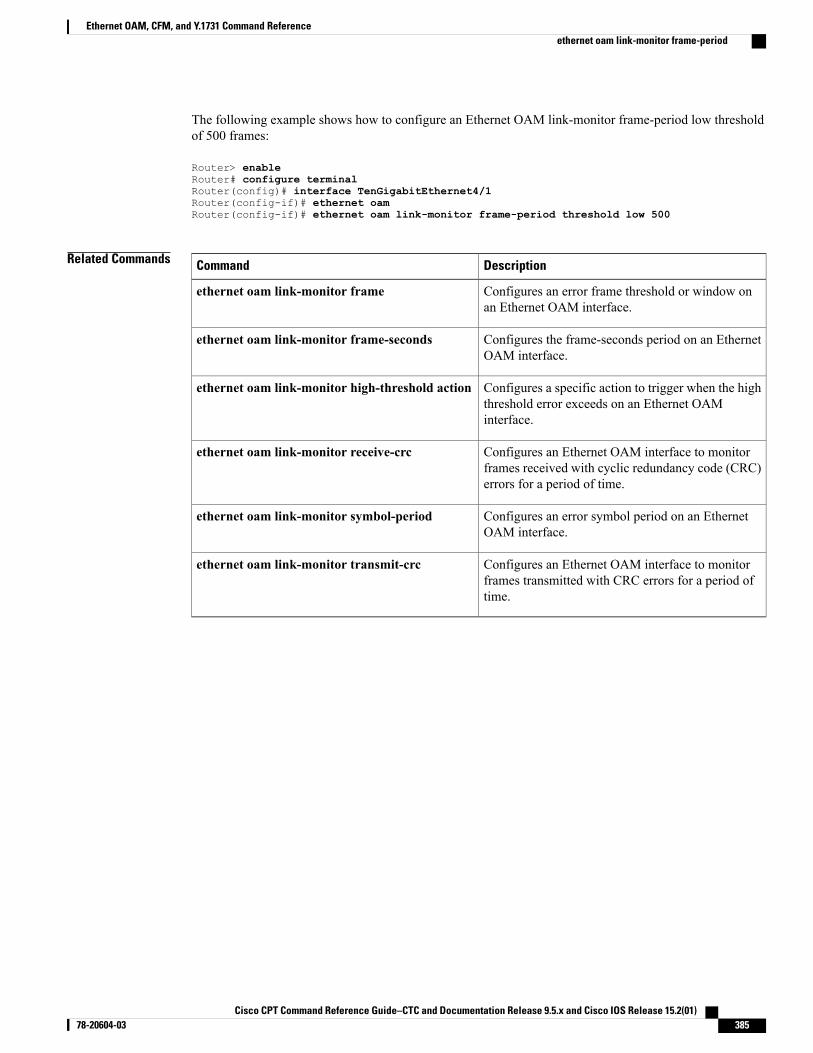
The following example shows how to configure an Ethernet OAM link-monitor frame-period low thresholdof 500 frames:
Router> enableRouter# configure terminalRouter(config)# interface TenGigabitEthernet4/1Router(config-if)# ethernet oamRouter(config-if)# ethernet oam link-monitor frame-period threshold low 500
Related Commands DescriptionCommand
Configures an error frame threshold or window onan Ethernet OAM interface.
ethernet oam link-monitor frame
Configures the frame-seconds period on an EthernetOAM interface.
ethernet oam link-monitor frame-seconds
Configures a specific action to trigger when the highthreshold error exceeds on an Ethernet OAMinterface.
ethernet oam link-monitor high-threshold action
Configures an Ethernet OAM interface to monitorframes received with cyclic redundancy code (CRC)errors for a period of time.
ethernet oam link-monitor receive-crc
Configures an error symbol period on an EthernetOAM interface.
ethernet oam link-monitor symbol-period
Configures an Ethernet OAM interface to monitorframes transmitted with CRC errors for a period oftime.
ethernet oam link-monitor transmit-crc
Cisco CPT Command Reference Guide–CTC and Documentation Release 9.5.x and Cisco IOS Release 15.2(01) 78-20604-03 385
Ethernet OAM, CFM, and Y.1731 Command Referenceethernet oam link-monitor frame-period
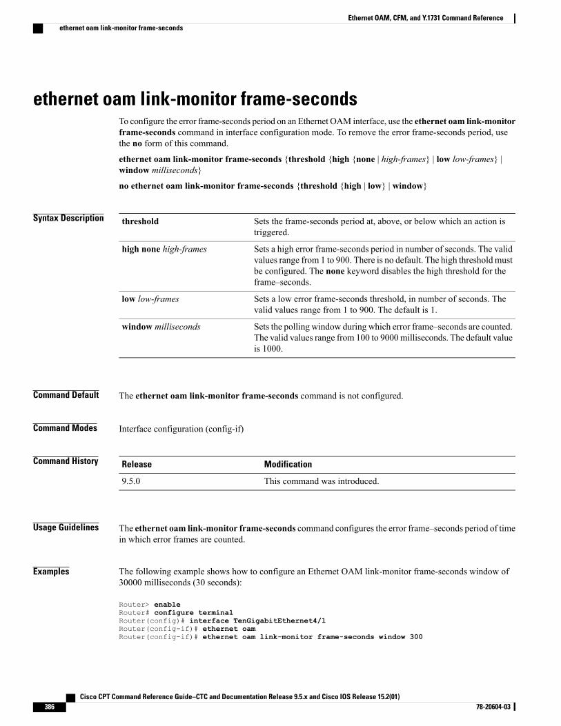
ethernet oam link-monitor frame-secondsTo configure the error frame-seconds period on an Ethernet OAM interface, use the ethernet oam link-monitorframe-seconds command in interface configuration mode. To remove the error frame-seconds period, usethe no form of this command.
ethernet oam link-monitor frame-seconds {threshold {high {none | high-frames} | low low-frames} |window milliseconds}
no ethernet oam link-monitor frame-seconds {threshold {high | low} | window}
Syntax Description Sets the frame-seconds period at, above, or below which an action istriggered.
threshold
Sets a high error frame-seconds period in number of seconds. The validvalues range from 1 to 900. There is no default. The high threshold mustbe configured. The none keyword disables the high threshold for theframe–seconds.
high none high-frames
Sets a low error frame-seconds threshold, in number of seconds. Thevalid values range from 1 to 900. The default is 1.
low low-frames
Sets the polling window during which error frame–seconds are counted.The valid values range from 100 to 9000milliseconds. The default valueis 1000.
window milliseconds
Command Default The ethernet oam link-monitor frame-seconds command is not configured.
Command Modes Interface configuration (config-if)
Command History ModificationRelease
This command was introduced.9.5.0
Usage Guidelines The ethernet oam link-monitor frame-seconds command configures the error frame–seconds period of timein which error frames are counted.
Examples The following example shows how to configure an Ethernet OAM link-monitor frame-seconds window of30000 milliseconds (30 seconds):
Router> enableRouter# configure terminalRouter(config)# interface TenGigabitEthernet4/1Router(config-if)# ethernet oamRouter(config-if)# ethernet oam link-monitor frame-seconds window 300
Cisco CPT Command Reference Guide–CTC and Documentation Release 9.5.x and Cisco IOS Release 15.2(01)386 78-20604-03
Ethernet OAM, CFM, and Y.1731 Command Referenceethernet oam link-monitor frame-seconds
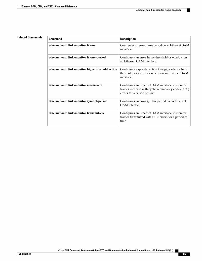
Related Commands DescriptionCommand
Configures an error frame period on an Ethernet OAMinterface.
ethernet oam link-monitor frame
Configures an error frame threshold or window onan Ethernet OAM interface.
ethernet oam link-monitor frame-period
Configures a specific action to trigger when a highthreshold for an error exceeds on an Ethernet OAMinterface.
ethernet oam link-monitor high-threshold action
Configures an Ethernet OAM interface to monitorframes received with cyclic redundancy code (CRC)errors for a period of time.
ethernet oam link-monitor receive-crc
Configures an error symbol period on an EthernetOAM interface.
ethernet oam link-monitor symbol-period
Configures an Ethernet OAM interface to monitorframes transmitted with CRC errors for a period oftime.
ethernet oam link-monitor transmit-crc
Cisco CPT Command Reference Guide–CTC and Documentation Release 9.5.x and Cisco IOS Release 15.2(01) 78-20604-03 387
Ethernet OAM, CFM, and Y.1731 Command Referenceethernet oam link-monitor frame-seconds
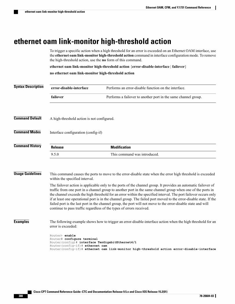
ethernet oam link-monitor high-threshold actionTo trigger a specific action when a high threshold for an error is exceeded on an Ethernet OAM interface, usethe ethernet oam link-monitor high-threshold action command in interface configurationmode. To removethe high-threshold action, use the no form of this command.
ethernet oam link-monitor high-threshold action {error-disable-interface | failover}
no ethernet oam link-monitor high-threshold action
Syntax Description Performs an error-disable function on the interface.error-disable-interface
Performs a failover to another port in the same channel group.failover
Command Default A high-threshold action is not configured.
Command Modes Interface configuration (config-if)
Command History ModificationRelease
This command was introduced.9.5.0
Usage Guidelines This command causes the ports to move to the error-disable state when the error high threshold is exceededwithin the specified interval.
The failover action is applicable only to the ports of the channel group. It provides an automatic failover oftraffic from one port in a channel group to another port in the same channel group when one of the ports inthe channel exceeds the high threshold for an error within the specified interval. The port failover occurs onlyif at least one operational port is in the channel group. The failed port moved to the error-disable state. If thefailed port is the last port in the channel group, the port will not move to the error-disable state and willcontinue to pass traffic regardless of the types of errors received.
Examples The following example shows how to trigger an error-disable-interface action when the high threshold for anerror is exceeded:
Router> enableRouter# configure terminalRouter(config)# interface TenGigabitEthernet4/1Router(config-if)# ethernet oamRouter(config-if)# ethernet oam link-monitor high-threshold action error-disable-interface
Cisco CPT Command Reference Guide–CTC and Documentation Release 9.5.x and Cisco IOS Release 15.2(01)388 78-20604-03
Ethernet OAM, CFM, and Y.1731 Command Referenceethernet oam link-monitor high-threshold action
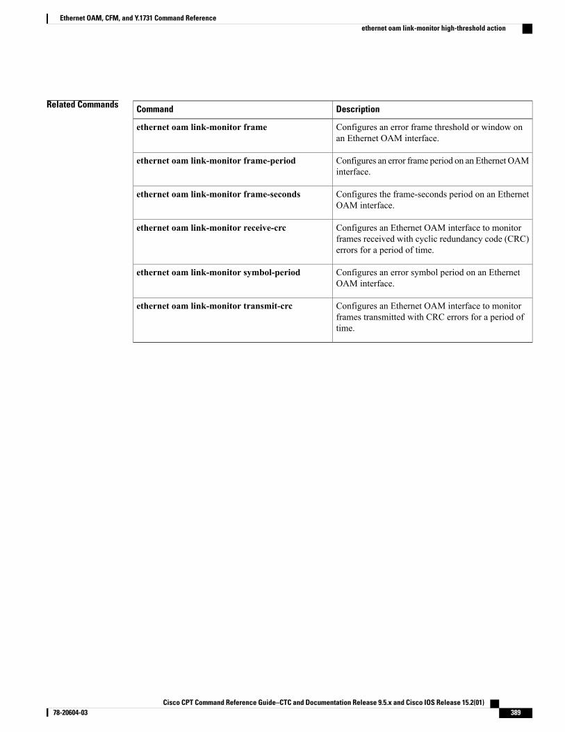
Related Commands DescriptionCommand
Configures an error frame threshold or window onan Ethernet OAM interface.
ethernet oam link-monitor frame
Configures an error frame period on an Ethernet OAMinterface.
ethernet oam link-monitor frame-period
Configures the frame-seconds period on an EthernetOAM interface.
ethernet oam link-monitor frame-seconds
Configures an Ethernet OAM interface to monitorframes received with cyclic redundancy code (CRC)errors for a period of time.
ethernet oam link-monitor receive-crc
Configures an error symbol period on an EthernetOAM interface.
ethernet oam link-monitor symbol-period
Configures an Ethernet OAM interface to monitorframes transmitted with CRC errors for a period oftime.
ethernet oam link-monitor transmit-crc
Cisco CPT Command Reference Guide–CTC and Documentation Release 9.5.x and Cisco IOS Release 15.2(01) 78-20604-03 389
Ethernet OAM, CFM, and Y.1731 Command Referenceethernet oam link-monitor high-threshold action
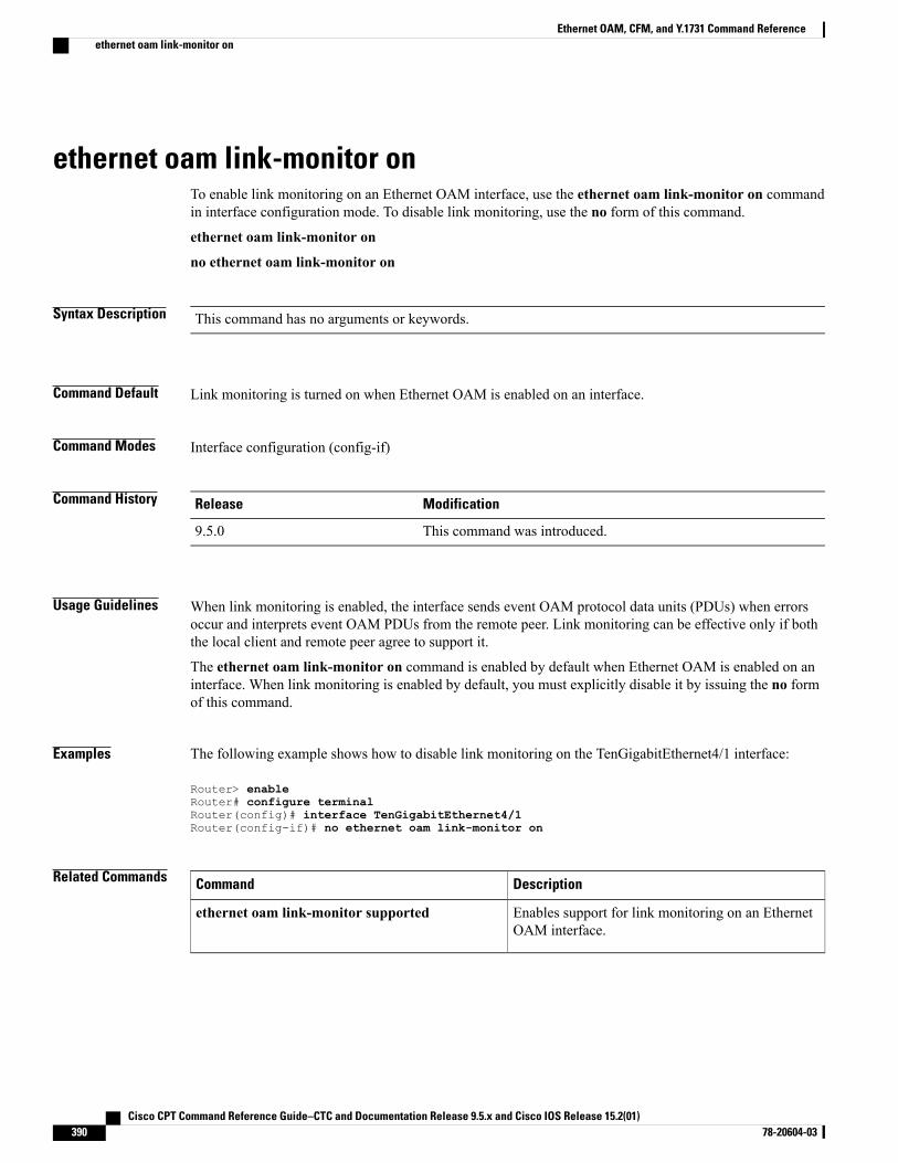
ethernet oam link-monitor onTo enable link monitoring on an Ethernet OAM interface, use the ethernet oam link-monitor on commandin interface configuration mode. To disable link monitoring, use the no form of this command.
ethernet oam link-monitor on
no ethernet oam link-monitor on
Syntax Description This command has no arguments or keywords.
Command Default Link monitoring is turned on when Ethernet OAM is enabled on an interface.
Command Modes Interface configuration (config-if)
Command History ModificationRelease
This command was introduced.9.5.0
Usage Guidelines When link monitoring is enabled, the interface sends event OAM protocol data units (PDUs) when errorsoccur and interprets event OAM PDUs from the remote peer. Link monitoring can be effective only if boththe local client and remote peer agree to support it.
The ethernet oam link-monitor on command is enabled by default when Ethernet OAM is enabled on aninterface. When link monitoring is enabled by default, you must explicitly disable it by issuing the no formof this command.
Examples The following example shows how to disable link monitoring on the TenGigabitEthernet4/1 interface:
Router> enableRouter# configure terminalRouter(config)# interface TenGigabitEthernet4/1Router(config-if)# no ethernet oam link-monitor on
Related Commands DescriptionCommand
Enables support for link monitoring on an EthernetOAM interface.
ethernet oam link-monitor supported
Cisco CPT Command Reference Guide–CTC and Documentation Release 9.5.x and Cisco IOS Release 15.2(01)390 78-20604-03
Ethernet OAM, CFM, and Y.1731 Command Referenceethernet oam link-monitor on
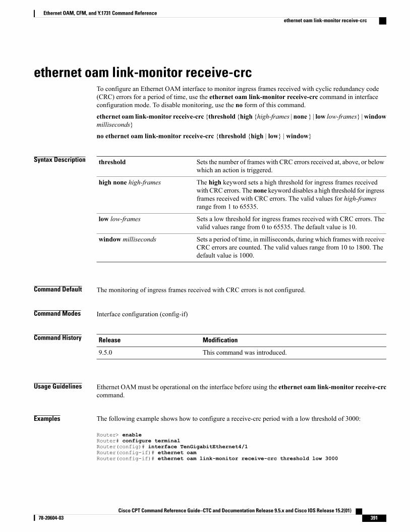
ethernet oam link-monitor receive-crcTo configure an Ethernet OAM interface to monitor ingress frames received with cyclic redundancy code(CRC) errors for a period of time, use the ethernet oam link-monitor receive-crc command in interfaceconfiguration mode. To disable monitoring, use the no form of this command.
ethernet oam link-monitor receive-crc {threshold {high {high-frames | none } | low low-frames} |windowmilliseconds}
no ethernet oam link-monitor receive-crc {threshold {high | low} | window}
Syntax Description Sets the number of frames with CRC errors received at, above, or belowwhich an action is triggered.
threshold
The high keyword sets a high threshold for ingress frames receivedwith CRC errors. The none keyword disables a high threshold for ingressframes received with CRC errors. The valid values for high-framesrange from 1 to 65535.
high none high-frames
Sets a low threshold for ingress frames received with CRC errors. Thevalid values range from 0 to 65535. The default value is 10.
low low-frames
Sets a period of time, in milliseconds, during which frames with receiveCRC errors are counted. The valid values range from 10 to 1800. Thedefault value is 1000.
window milliseconds
Command Default The monitoring of ingress frames received with CRC errors is not configured.
Command Modes Interface configuration (config-if)
Command History ModificationRelease
This command was introduced.9.5.0
Usage Guidelines Ethernet OAMmust be operational on the interface before using the ethernet oam link-monitor receive-crccommand.
Examples The following example shows how to configure a receive-crc period with a low threshold of 3000:
Router> enableRouter# configure terminalRouter(config)# interface TenGigabitEthernet4/1Router(config-if)# ethernet oamRouter(config-if)# ethernet oam link-monitor receive-crc threshold low 3000
Cisco CPT Command Reference Guide–CTC and Documentation Release 9.5.x and Cisco IOS Release 15.2(01) 78-20604-03 391
Ethernet OAM, CFM, and Y.1731 Command Referenceethernet oam link-monitor receive-crc
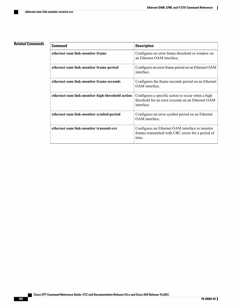
Related Commands DescriptionCommand
Configures an error frame threshold or window onan Ethernet OAM interface.
ethernet oam link-monitor frame
Configures an error frame period on an Ethernet OAMinterface.
ethernet oam link-monitor frame-period
Configures the frame-seconds period on an EthernetOAM interface.
ethernet oam link-monitor frame-seconds
Configures a specific action to occur when a highthreshold for an error exceeds on an Ethernet OAMinterface.
ethernet oam link-monitor high-threshold action
Configures an error symbol period on an EthernetOAM interface.
ethernet oam link-monitor symbol-period
Configures an Ethernet OAM interface to monitorframes transmitted with CRC errors for a period oftime.
ethernet oam link-monitor transmit-crc
Cisco CPT Command Reference Guide–CTC and Documentation Release 9.5.x and Cisco IOS Release 15.2(01)392 78-20604-03
Ethernet OAM, CFM, and Y.1731 Command Referenceethernet oam link-monitor receive-crc
ethernet oam link-monitor supportedTo enable support for link monitoring on an Ethernet OAM interface, use the ethernet oam link-monitorsupported command in interface configuration mode. To disable link monitoring support, use the no formof this command.
ethernet oam link-monitor supported
no ethernet oam link-monitor supported
Syntax Description This command has no arguments or keywords.
Command Default Link monitoring is supported only when Ethernet OAM is enabled.
Command Modes Interface configuration (config-if)
Command History ModificationRelease
This command was introduced.9.5.0
Usage Guidelines Use this command to help establish an OAM session for performing OAM functions, such as remote loopback.For example, if a device is connected to a third-party device that does not support link monitoring, linkmonitoring support must be disabled on this device to establish an OAM session with the third-party device.
When the ethernet oam link-monitor supported command is used, remote loopback will not function evenwhen the interface has been configured to support it.
When support for link monitoring is enabled by default, you must explicitly disable it by issuing the no formof this command.
Examples The following example shows how to disable support for link monitoring on the TenGigabitEthernet4/1 OAMinterface:
Router> enableRouter# configure terminalRouter(config)# interface TenGigabitEthernet4/1Router(config-if)# no ethernet oam link-monitor supported
The following example shows how to reenable support for link monitoring on the TenGigabitEthernet4/1OAM interface after support has been disabled:
Router> enableRouter# configure terminalRouter(config)# interface TenGigabitEthernet4/1Router(config-if)# ethernet oam link-monitor supported
Cisco CPT Command Reference Guide–CTC and Documentation Release 9.5.x and Cisco IOS Release 15.2(01) 78-20604-03 393
Ethernet OAM, CFM, and Y.1731 Command Referenceethernet oam link-monitor supported

Related Commands DescriptionCommand
Enables link monitoring on an Ethernet OAMinterface.
ethernet oam link-monitor on
Cisco CPT Command Reference Guide–CTC and Documentation Release 9.5.x and Cisco IOS Release 15.2(01)394 78-20604-03
Ethernet OAM, CFM, and Y.1731 Command Referenceethernet oam link-monitor supported
ethernet oam link-monitor symbol-periodTo configure an error symbol–period on an Ethernet OAM interface, use the ethernet oam link-monitorsymbol-period command in interface configuration mode. To remove the symbol–period, use the no formof this command.
ethernet oam link-monitor symbol-period {threshold {high {none | high-symbols} | low low-symbols} |window symbols}
no ethernet oam link-monitor symbol-period {threshold {high | low} | window}
Syntax Description Sets the number of error symbols at, above, or below which an actionis triggered.
threshold
Sets a high threshold for the error symbol–period in number of errorsymbols. The valid values range from 1 to 65535. There is no default.The high threshold must be configured.
high high-symbols
Disables the high threshold for the error symbol–period.none
Sets a low threshold for the error symbol–period in number of errorsymbols. The valid values range from 0 to 65535.
low low-symbols
Sets a window and window size in number of symbols. The valid valuesrange from 1 to 65535. Each value represents one million.
window symbols
Command Default The error symbol–period is not configured.
Command Modes Interface configuration (config-if)
Command History ModificationRelease
This command was introduced.9.5.0
Usage Guidelines The ethernet oam link-monitor symbol-period command configures an error symbol–period in number ofsymbols. When a high threshold is configured, it must be at least as great as the low threshold for symbolerrors.
Examples The following example shows how to configure an error symbol-period window of 500million error symbols:
Router> enableRouter# configure terminalRouter(config)# interface TenGigabitEthernet4/1Router(config-if)# ethernet oamRouter(config-if)# ethernet oam link-monitor symbol-period window 500
Cisco CPT Command Reference Guide–CTC and Documentation Release 9.5.x and Cisco IOS Release 15.2(01) 78-20604-03 395
Ethernet OAM, CFM, and Y.1731 Command Referenceethernet oam link-monitor symbol-period
The following example shows how to configure an error symbol-period low threshold of 500 error symbols:
Router> enableRouter# configure terminalRouter(config)# interface TenGigabitEthernet4/1Router(config-if)# ethernet oamRouter(config-if)# ethernet oam link-monitor symbol-period threshold low 500
Related Commands DescriptionCommand
Configures an error frame threshold or window onan Ethernet OAM interface.
ethernet oam link-monitor frame
Configures an error frame period on an Ethernet OAMinterface.
ethernet oam link-monitor frame-period
Configures the frame-seconds period on an EthernetOAM interface.
ethernet oam link-monitor frame-seconds
Configures a specific action to occur when a highthreshold for an error exceeds on an Ethernet OAMinterface.
ethernet oam link-monitor high-threshold action
Configures an Ethernet OAM interface to monitorframes received with cyclic redundancy code (CRC)errors for a period of time.
ethernet oam link-monitor receive-crc
Configures an Ethernet OAM interface to monitorframes transmitted with CRC errors for a period oftime.
ethernet oam link-monitor transmit-crc
Cisco CPT Command Reference Guide–CTC and Documentation Release 9.5.x and Cisco IOS Release 15.2(01)396 78-20604-03
Ethernet OAM, CFM, and Y.1731 Command Referenceethernet oam link-monitor symbol-period

ethernet oam link-monitor transmit-crcTo configure an Ethernet OAM interface to monitor egress frames transmitted with cyclic redundancy code(CRC) errors for a period of time, use the ethernet oam link-monitor transmit-crc command in interfaceconfiguration mode. To disable monitoring, use the no form of this command.
ethernet oam link-monitor transmit-crc {threshold {high {high-frames | none } | low low-frames} |windowmilliseconds}
no ethernet oam link-monitor transmit-crc {threshold {high | low} | window}
Syntax Description Sets the number of frames with CRC errors transmitted at, above, orbelow which an action is triggered.
threshold
The high keyword sets a high threshold for egress frames transmittedwith CRC errors. The none keyword disables a high threshold for egressframes transmitted with CRC errors. The valid values for high-framesrange from 1 to 65535.
high none high-frames
Sets a low threshold for ingress frames transmitted with CRC errors.The valid values range from 0 to 65535. The default value is 10.
low low-frames
Sets a period of time, in milliseconds, during which frames with transmitCRC errors are counted. The valid values range from 10 to 1800. Thedefault value is 100.
window milliseconds
Command Default The monitoring of egress frames transmitted with CRC errors is not configured.
Command Modes Interface configuration (config-if)
Command History ModificationRelease
This command was introduced.9.5.0
Usage Guidelines Ethernet OAMmust be operational on the interface before using the ethernet oam link-monitor transmit-crccommand
Examples The following example shows how to configure a transmit CRC window of 2500 milliseconds:
Router> enableRouter# configure terminalRouter(config)# interface TenGigabitEthernet4/1Router(config-if)# ethernet oamRouter(config-if)# ethernet oam link-monitor transmit-crc window 25
Cisco CPT Command Reference Guide–CTC and Documentation Release 9.5.x and Cisco IOS Release 15.2(01) 78-20604-03 397
Ethernet OAM, CFM, and Y.1731 Command Referenceethernet oam link-monitor transmit-crc
Related Commands DescriptionCommand
Configures an error frame threshold or window onan Ethernet OAM interface.
ethernet oam link-monitor frame
Configures an error frame period on an Ethernet OAMinterface.
ethernet oam link-monitor frame-period
Configures the frame-seconds period on an EthernetOAM interface.
ethernet oam link-monitor frame-seconds
Configures a specific action to occur when a highthreshold for an error exceeds on an Ethernet OAMinterface.
ethernet oam link-monitor high-threshold action
Configures an Ethernet OAM interface to monitoringress frames received with CRC errors.
ethernet oam link-monitor receive-crc
Configures an error symbol period on an EthernetOAM interface.
ethernet oam link-monitor symbol-period
Cisco CPT Command Reference Guide–CTC and Documentation Release 9.5.x and Cisco IOS Release 15.2(01)398 78-20604-03
Ethernet OAM, CFM, and Y.1731 Command Referenceethernet oam link-monitor transmit-crc
ethernet oam remote-failure actionTo enable Ethernet OAM remote–failure actions, use the ethernet oam remote-failure action command ininterface configuration mode. To turn off remote failure actions, use the no form of this command.
ethernet oam remote-failure {critical-event | dying-gasp | link-fault} action {error-block-interface |error-disable-interface}
no ethernet oam remote-failure {critical-event | dying-gasp | link-fault} action
Syntax Description Acts on remote critical event failures.critical-event
Acts on remote dying-gasp failures.dying-gasp
Acts on remote link-fault failures.link-fault
Sets the interface to the blocking state when an error occurs.error-block-interface
Disables the interface when an error occurs.error-disable-interface
Command Default Actions in response to Ethernet OAM remote failures do not occur.
Command Modes Interface configuration (config-if)
Command History ModificationRelease
This command was introduced.9.5.0
Usage Guidelines Use this command to configure an interface to take specific actions when Ethernet OAM remote-failure eventsoccur.
Examples The following example shows how to configure the action to be taken when a critical event occurs on theTenGigabitEthernet4/11 interface:
Router> enableRouter# configure terminalRouter(config)# interface TenGigabitEthernet4/11Router(config-if)# ethernet oam remote-failure critical-event action error-disable-interface
Cisco CPT Command Reference Guide–CTC and Documentation Release 9.5.x and Cisco IOS Release 15.2(01) 78-20604-03 399
Ethernet OAM, CFM, and Y.1731 Command Referenceethernet oam remote-failure action
ethernet oam remote-loopbackTo enable or disable Ethernet OAM remote loopback functionality on an interface, use the ethernet oamremote-loopback command in privileged EXEC mode.
ethernet oam remote-loopback {start | stop} {interface type number}
Syntax Description Starts the remote loopback operation.start
Stops the remote loopback operation.stop
Specifies an interface, interface type, and number.interface type number
Command Default Remote loopback functionality is disabled.
Command Modes Privileged EXEC (#)
Command History ModificationRelease
This command was introduced.9.5.0
Usage Guidelines When the Ethernet OAM remote loopback functionality is enabled on an interface, traffic sent out on thisinterface is discarded or sent back (and dropped locally) by the remote interface.
When the no ethernet oam link-monitor supported command is used, remote loopback will not functioneven when the interface has been configured to support it.
Examples The following example shows how to start a remote loopback session on the TenGigabitEthernet4/1 interface:
Router> enableRouter# ethernet oam remote-loopback start interface TenGigabitEthernet4/1
Related Commands DescriptionCommand
Enables the support of the Ethernet OAM remoteloopback operation on an interface or sets a remoteloopback timeout period.
ethernet oam remote-loopback (interface)
Cisco CPT Command Reference Guide–CTC and Documentation Release 9.5.x and Cisco IOS Release 15.2(01)400 78-20604-03
Ethernet OAM, CFM, and Y.1731 Command Referenceethernet oam remote-loopback
ethernet oam remote-loopback (interface)To enable the support of Ethernet OAM remote loopback operations on an interface or set a remote loopbacktimeout period, use the ethernet oam remote-loopback (interface) command in interface configurationmode. To disable support of the remote loopback operations or remove the timeout setting, use the no formof this command.
ethernet oam remote-loopback {supported | timeout seconds}
no ethernet oam remote-loopback {supported | timeout}
Syntax Description Enables the remote loopback functionality.supported
Sets a master loopback timeout setting. The valid values of the timeoutperiod range from 1 to 10.
timeout seconds
Command Default Ethernet OAM remote loopback is not enabled.
Command Modes Interface configuration (config-if)
Command History ModificationRelease
This command was introduced.9.5.0
Usage Guidelines This command enables the support of OAM remote loopback on an interface. Only after this functionality isenabled, the local OAM client can initiate the OAM remote loopback operations to exchange configurationinformation with its remote peer.
Examples The following example shows how to enable remote loopback support on the TenGigabitEthernet4/1 interface:
Router> enableRouter# configure terminalRouter(config)# interface TenGigabitEthernet 4/1Router(config-if)# ethernet oam remote-loopback supported
Related Commands DescriptionCommand
Enables or disables the remote loopback functionality.ethernet oam remote-loopback
Cisco CPT Command Reference Guide–CTC and Documentation Release 9.5.x and Cisco IOS Release 15.2(01) 78-20604-03 401
Ethernet OAM, CFM, and Y.1731 Command Referenceethernet oam remote-loopback (interface)
ethernet y1731 delay dmm domainTo configure a sender MEP for an IP SLA-Y.1731 delay or delay variation operation, use the ethernet y1731delay command in the IP SLA configuration mode.
ethernet y1731 delay DMM domain domain {{vlan | evc} value}{mpid |mac-address} value cos valuesource {mpid | mac-address} value
Syntax Description Specifies the ethernet virtual circuit identifier.evc
Specifies the VLAN.vlan
Specifies the class of service. The values ranges between 0 and 7.cos
Specifies the destination MP ID. The values ranges between 1 and 8191.mpid
Specifies the destination mac-address.mac-address
Specifies the source MP ID or mac-address.source
Command Default A sender MEP is not configured for the IP SLA Y.1731 operation.
Command Modes IP SLA configuration (config-ip-sla)
Command History ModificationRelease
This command was introduced.9.5.1
Usage Guidelines This command begins configuring a two-way delaymeasurement and enters IP SLAY.1731 delay configurationmode.
Delay Measurement Message (DMM) frames are sent during single-ended operations. A receiver MEP onthe responder device is required for dual-ended operations. To change the operation type of an existing IPSLAs operation, you must first use the no ip sla command to delete the IP SLAs operation and then reconfigurethe operation with the new operation type.
Examples The follwoing example shows how to sender MEP for an IP SLA-Y.1731 delay or delay variation operation.Router(config-term)# ip sla 500Router(config-ip-sla)# ethernet y7131 delay DMM domain xxx evc yyy mpid 101 cos 3 sourcempid 100
Cisco CPT Command Reference Guide–CTC and Documentation Release 9.5.x and Cisco IOS Release 15.2(01)402 78-20604-03
Ethernet OAM, CFM, and Y.1731 Command Referenceethernet y1731 delay dmm domain
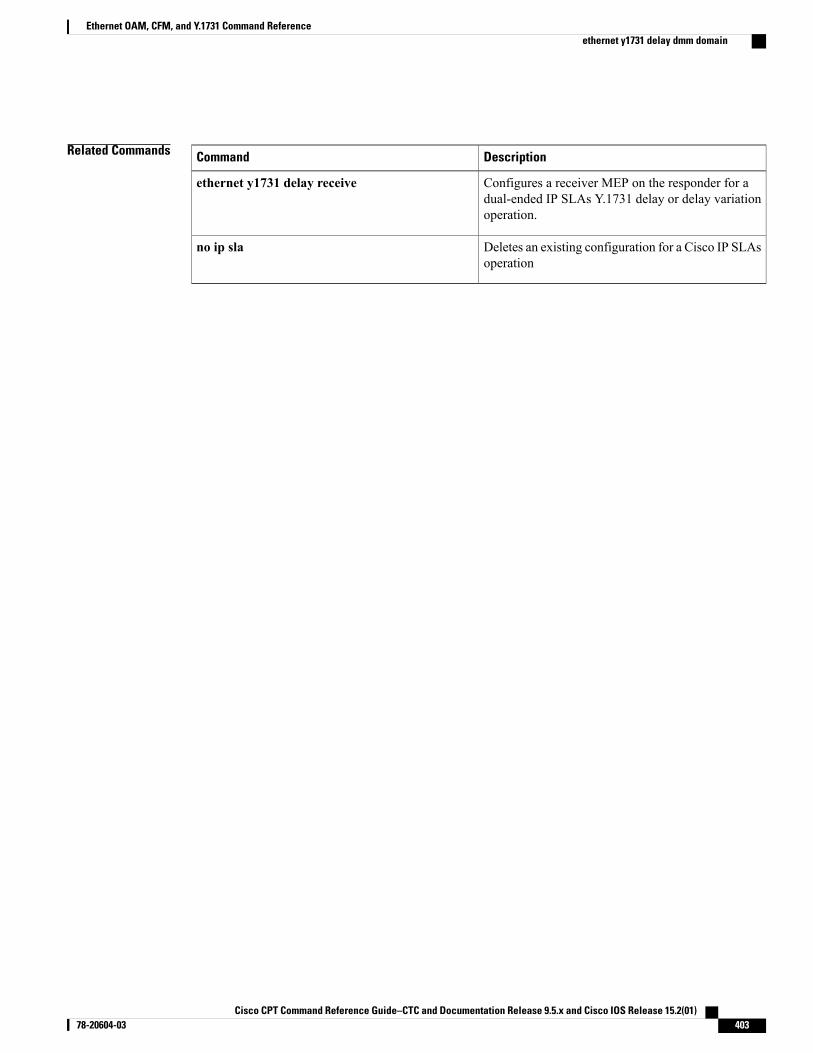
Related Commands DescriptionCommand
Configures a receiver MEP on the responder for adual-ended IP SLAs Y.1731 delay or delay variationoperation.
ethernet y1731 delay receive
Deletes an existing configuration for a Cisco IP SLAsoperation
no ip sla
Cisco CPT Command Reference Guide–CTC and Documentation Release 9.5.x and Cisco IOS Release 15.2(01) 78-20604-03 403
Ethernet OAM, CFM, and Y.1731 Command Referenceethernet y1731 delay dmm domain
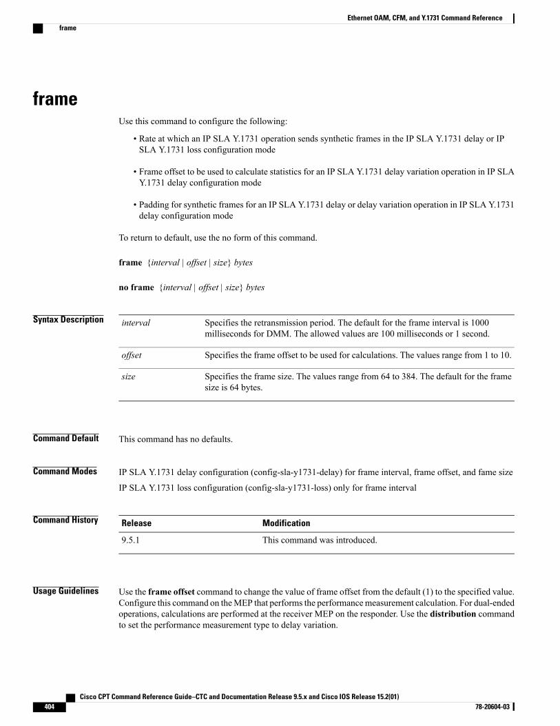
frameUse this command to configure the following:
• Rate at which an IP SLA Y.1731 operation sends synthetic frames in the IP SLA Y.1731 delay or IPSLA Y.1731 loss configuration mode
• Frame offset to be used to calculate statistics for an IP SLA Y.1731 delay variation operation in IP SLAY.1731 delay configuration mode
• Padding for synthetic frames for an IP SLA Y.1731 delay or delay variation operation in IP SLA Y.1731delay configuration mode
To return to default, use the no form of this command.
frame {interval | offset | size} bytes
no frame {interval | offset | size} bytes
Syntax Description Specifies the retransmission period. The default for the frame interval is 1000milliseconds for DMM. The allowed values are 100 milliseconds or 1 second.
interval
Specifies the frame offset to be used for calculations. The values range from 1 to 10.offset
Specifies the frame size. The values range from 64 to 384. The default for the framesize is 64 bytes.
size
Command Default This command has no defaults.
Command Modes IP SLA Y.1731 delay configuration (config-sla-y1731-delay) for frame interval, frame offset, and fame size
IP SLA Y.1731 loss configuration (config-sla-y1731-loss) only for frame interval
Command History ModificationRelease
This command was introduced.9.5.1
Usage Guidelines Use the frame offset command to change the value of frame offset from the default (1) to the specified value.Configure this command on theMEP that performs the performancemeasurement calculation. For dual-endedoperations, calculations are performed at the receiver MEP on the responder. Use the distribution commandto set the performance measurement type to delay variation.
Cisco CPT Command Reference Guide–CTC and Documentation Release 9.5.x and Cisco IOS Release 15.2(01)404 78-20604-03
Ethernet OAM, CFM, and Y.1731 Command Referenceframe
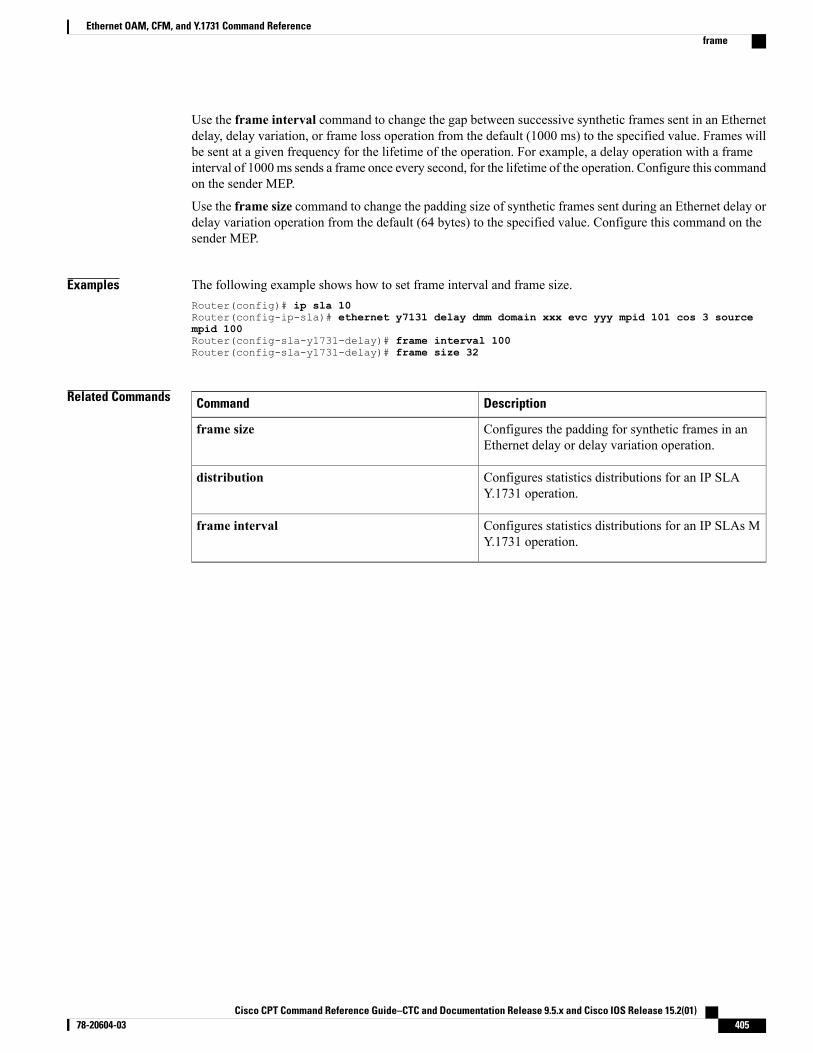
Use the frame interval command to change the gap between successive synthetic frames sent in an Ethernetdelay, delay variation, or frame loss operation from the default (1000 ms) to the specified value. Frames willbe sent at a given frequency for the lifetime of the operation. For example, a delay operation with a frameinterval of 1000ms sends a frame once every second, for the lifetime of the operation. Configure this commandon the sender MEP.
Use the frame size command to change the padding size of synthetic frames sent during an Ethernet delay ordelay variation operation from the default (64 bytes) to the specified value. Configure this command on thesender MEP.
Examples The following example shows how to set frame interval and frame size.Router(config)# ip sla 10Router(config-ip-sla)# ethernet y7131 delay dmm domain xxx evc yyy mpid 101 cos 3 sourcempid 100Router(config-sla-y1731-delay)# frame interval 100Router(config-sla-y1731-delay)# frame size 32
Related Commands DescriptionCommand
Configures the padding for synthetic frames in anEthernet delay or delay variation operation.
frame size
Configures statistics distributions for an IP SLAY.1731 operation.
distribution
Configures statistics distributions for an IP SLAs MY.1731 operation.
frame interval
Cisco CPT Command Reference Guide–CTC and Documentation Release 9.5.x and Cisco IOS Release 15.2(01) 78-20604-03 405
Ethernet OAM, CFM, and Y.1731 Command Referenceframe
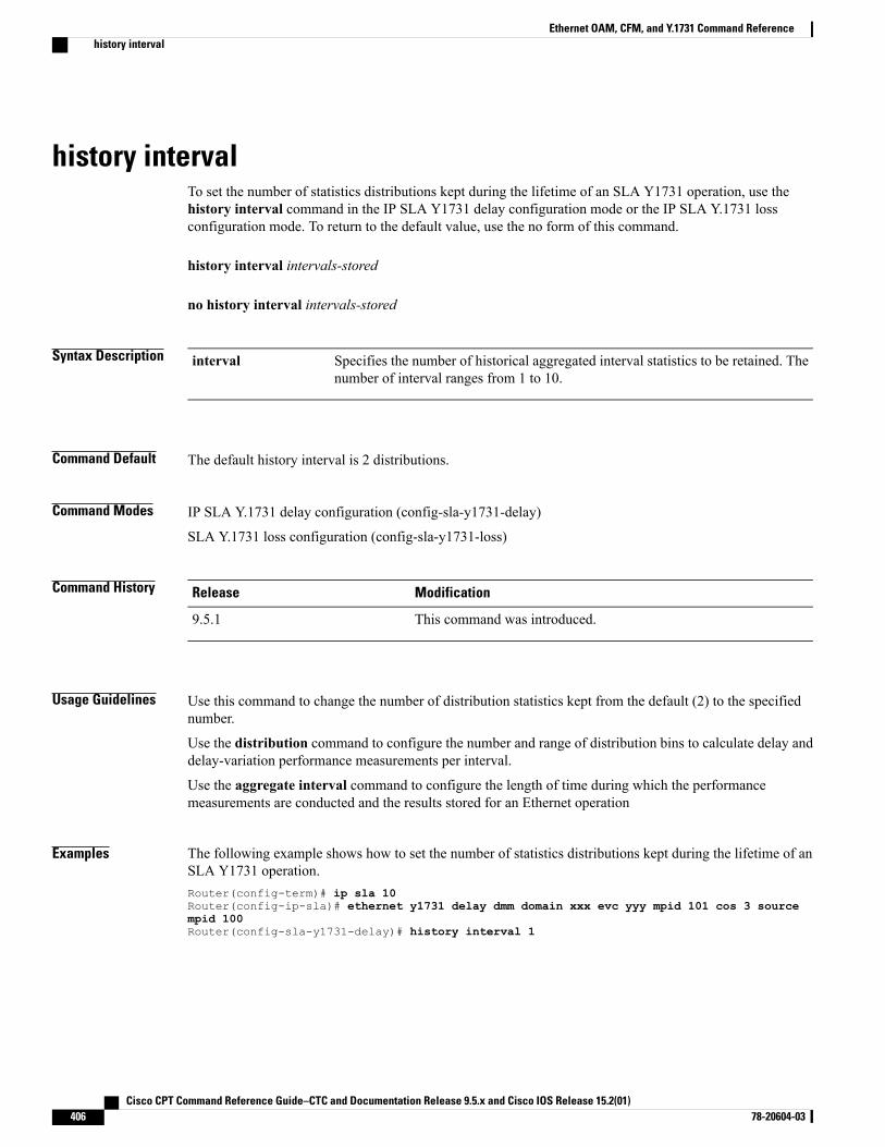
history intervalTo set the number of statistics distributions kept during the lifetime of an SLA Y1731 operation, use thehistory interval command in the IP SLA Y1731 delay configuration mode or the IP SLA Y.1731 lossconfiguration mode. To return to the default value, use the no form of this command.
history interval intervals-stored
no history interval intervals-stored
Syntax Description Specifies the number of historical aggregated interval statistics to be retained. Thenumber of interval ranges from 1 to 10.
interval
Command Default The default history interval is 2 distributions.
Command Modes IP SLA Y.1731 delay configuration (config-sla-y1731-delay)
SLA Y.1731 loss configuration (config-sla-y1731-loss)
Command History ModificationRelease
This command was introduced.9.5.1
Usage Guidelines Use this command to change the number of distribution statistics kept from the default (2) to the specifiednumber.
Use the distribution command to configure the number and range of distribution bins to calculate delay anddelay-variation performance measurements per interval.
Use the aggregate interval command to configure the length of time during which the performancemeasurements are conducted and the results stored for an Ethernet operation
Examples The following example shows how to set the number of statistics distributions kept during the lifetime of anSLA Y1731 operation.Router(config-term)# ip sla 10Router(config-ip-sla)# ethernet y1731 delay dmm domain xxx evc yyy mpid 101 cos 3 sourcempid 100Router(config-sla-y1731-delay)# history interval 1
Cisco CPT Command Reference Guide–CTC and Documentation Release 9.5.x and Cisco IOS Release 15.2(01)406 78-20604-03
Ethernet OAM, CFM, and Y.1731 Command Referencehistory interval
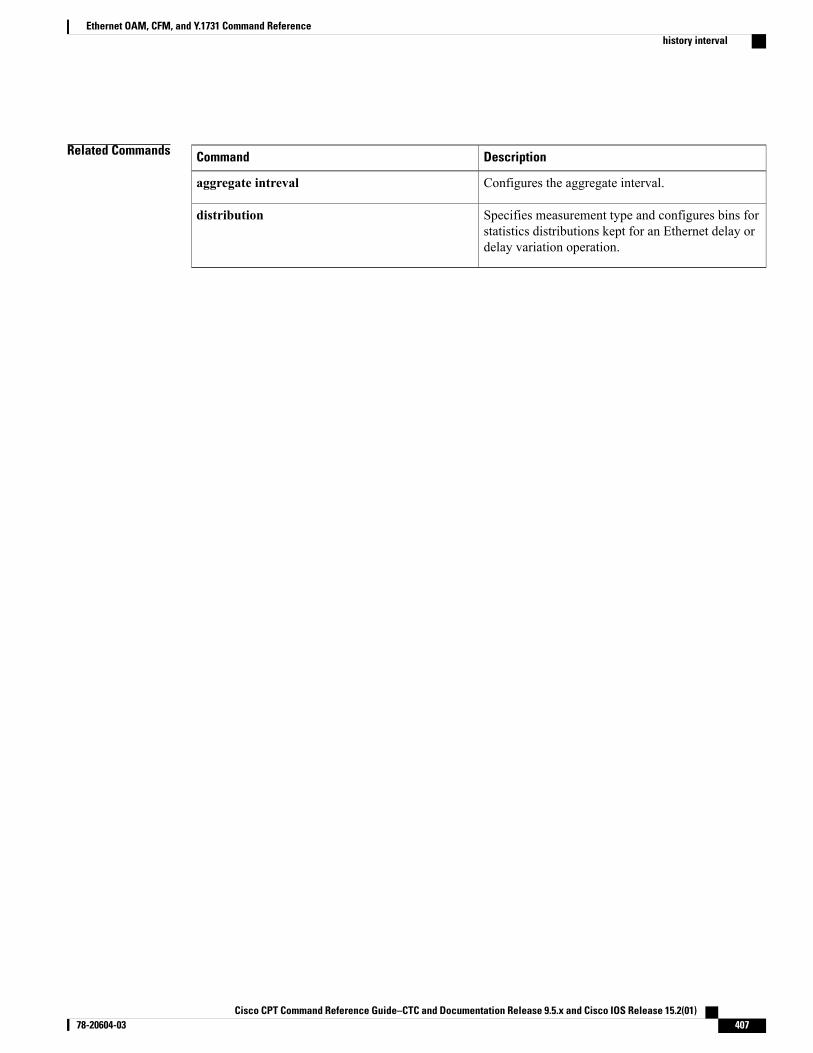
Related Commands DescriptionCommand
Configures the aggregate interval.aggregate intreval
Specifies measurement type and configures bins forstatistics distributions kept for an Ethernet delay ordelay variation operation.
distribution
Cisco CPT Command Reference Guide–CTC and Documentation Release 9.5.x and Cisco IOS Release 15.2(01) 78-20604-03 407
Ethernet OAM, CFM, and Y.1731 Command Referencehistory interval
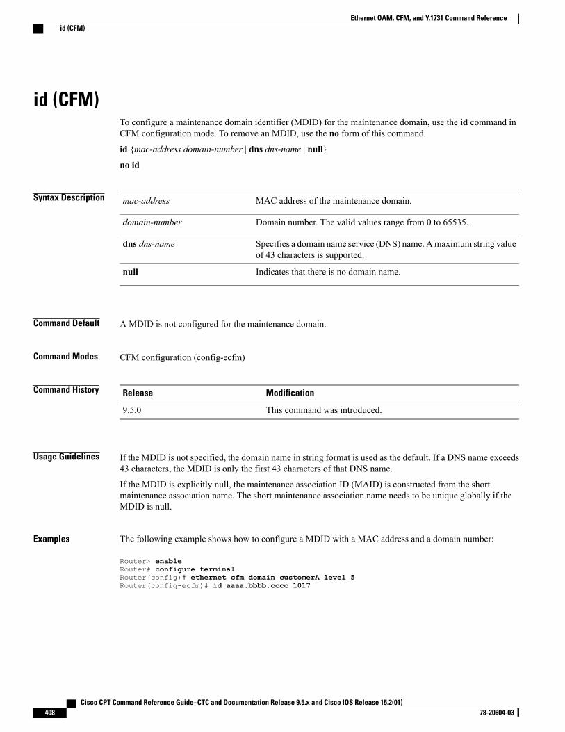
id (CFM)To configure a maintenance domain identifier (MDID) for the maintenance domain, use the id command inCFM configuration mode. To remove an MDID, use the no form of this command.
id {mac-address domain-number | dns dns-name | null}
no id
Syntax Description MAC address of the maintenance domain.mac-address
Domain number. The valid values range from 0 to 65535.domain-number
Specifies a domain name service (DNS) name. Amaximum string valueof 43 characters is supported.
dns dns-name
Indicates that there is no domain name.null
Command Default A MDID is not configured for the maintenance domain.
Command Modes CFM configuration (config-ecfm)
Command History ModificationRelease
This command was introduced.9.5.0
Usage Guidelines If the MDID is not specified, the domain name in string format is used as the default. If a DNS name exceeds43 characters, the MDID is only the first 43 characters of that DNS name.
If the MDID is explicitly null, the maintenance association ID (MAID) is constructed from the shortmaintenance association name. The short maintenance association name needs to be unique globally if theMDID is null.
Examples The following example shows how to configure a MDID with a MAC address and a domain number:
Router> enableRouter# configure terminalRouter(config)# ethernet cfm domain customerA level 5Router(config-ecfm)# id aaaa.bbbb.cccc 1017
Cisco CPT Command Reference Guide–CTC and Documentation Release 9.5.x and Cisco IOS Release 15.2(01)408 78-20604-03
Ethernet OAM, CFM, and Y.1731 Command Referenceid (CFM)
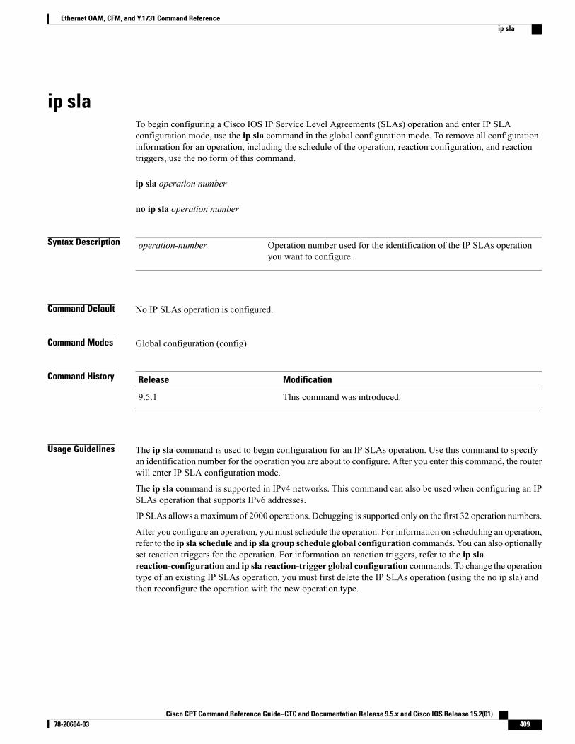
ip slaTo begin configuring a Cisco IOS IP Service Level Agreements (SLAs) operation and enter IP SLAconfiguration mode, use the ip sla command in the global configuration mode. To remove all configurationinformation for an operation, including the schedule of the operation, reaction configuration, and reactiontriggers, use the no form of this command.
ip sla operation number
no ip sla operation number
Syntax Description Operation number used for the identification of the IP SLAs operationyou want to configure.
operation-number
Command Default No IP SLAs operation is configured.
Command Modes Global configuration (config)
Command History ModificationRelease
This command was introduced.9.5.1
Usage Guidelines The ip sla command is used to begin configuration for an IP SLAs operation. Use this command to specifyan identification number for the operation you are about to configure. After you enter this command, the routerwill enter IP SLA configuration mode.
The ip sla command is supported in IPv4 networks. This command can also be used when configuring an IPSLAs operation that supports IPv6 addresses.
IP SLAs allows amaximum of 2000 operations. Debugging is supported only on the first 32 operation numbers.
After you configure an operation, youmust schedule the operation. For information on scheduling an operation,refer to the ip sla schedule and ip sla group schedule global configuration commands. You can also optionallyset reaction triggers for the operation. For information on reaction triggers, refer to the ip slareaction-configuration and ip sla reaction-trigger global configuration commands. To change the operationtype of an existing IP SLAs operation, you must first delete the IP SLAs operation (using the no ip sla) andthen reconfigure the operation with the new operation type.
Cisco CPT Command Reference Guide–CTC and Documentation Release 9.5.x and Cisco IOS Release 15.2(01) 78-20604-03 409
Ethernet OAM, CFM, and Y.1731 Command Referenceip sla
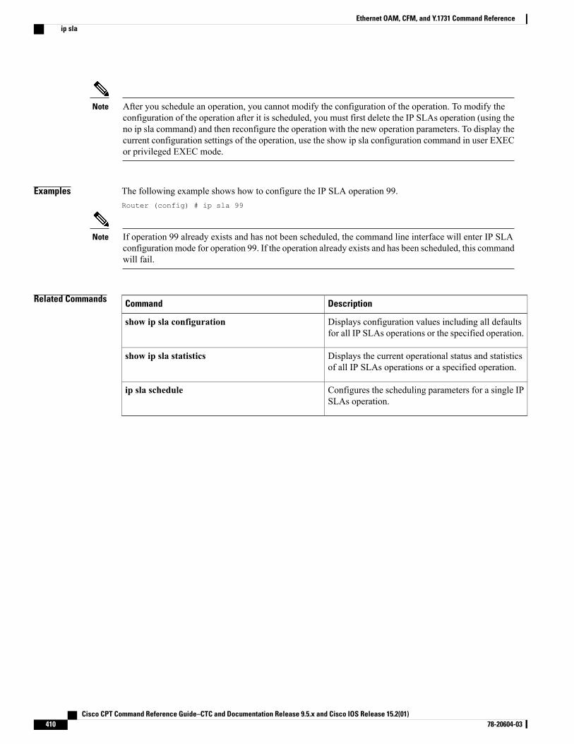
After you schedule an operation, you cannot modify the configuration of the operation. To modify theconfiguration of the operation after it is scheduled, you must first delete the IP SLAs operation (using theno ip sla command) and then reconfigure the operation with the new operation parameters. To display thecurrent configuration settings of the operation, use the show ip sla configuration command in user EXECor privileged EXEC mode.
Note
Examples The following example shows how to configure the IP SLA operation 99.Router (config) # ip sla 99
If operation 99 already exists and has not been scheduled, the command line interface will enter IP SLAconfiguration mode for operation 99. If the operation already exists and has been scheduled, this commandwill fail.
Note
Related Commands DescriptionCommand
Displays configuration values including all defaultsfor all IP SLAs operations or the specified operation.
show ip sla configuration
Displays the current operational status and statisticsof all IP SLAs operations or a specified operation.
show ip sla statistics
Configures the scheduling parameters for a single IPSLAs operation.
ip sla schedule
Cisco CPT Command Reference Guide–CTC and Documentation Release 9.5.x and Cisco IOS Release 15.2(01)410 78-20604-03
Ethernet OAM, CFM, and Y.1731 Command Referenceip sla
ip sla resetTo perform a shutdown and restart of the Cisco IOS IP SLAs engine, use the ip sla reset command in theglobal configuration mode.
ip sla reset
Command Default This command has no defaults.
Command Modes Global configuration (config)
Command History ModificationRelease
This command was introduced.9.5.1
Usage Guidelines The ip sla reset command stops all IP SLAs operations, clears IP SLAs configuration information, and returnsthe IP SLAs feature to the startup condition. This command does not reread the IP SLAs configuration storedin the startup configuration in NVRAM. You must retype the configuration or load a previously savedconfiguration file.
The ip sla reset command does not remove IP SLAs label switched path (LSP) Health Monitorconfigurations from the running configuration. Use the auto ip sla mpls-lsp-monitor reset command toremove LSP Health Monitor configurations from the running configuration.
Note
Use the ip sla reset command only in extreme situations such as the incorrect configuration of a numberof operations.
Note
Examples The following example shows how to reset the Cisco IOS IP SLAs engine, clearing all stored IP SLAsinformation and configuration.Router (config) # ip sla reset
Related Commands DescriptionCommand
Restarts a stopped IP SLAs operation.ip sla restart
Cisco CPT Command Reference Guide–CTC and Documentation Release 9.5.x and Cisco IOS Release 15.2(01) 78-20604-03 411
Ethernet OAM, CFM, and Y.1731 Command Referenceip sla reset
ip sla restartTo restart a Cisco IOS IP SLAs operation, use the ip sla restart command in the global configuration mode.
ip sla restart operation-number
Syntax Description Number of the IP SLAs operation to restart. IP SLAs allows a maximumof 2000 operations.
operation-number
Command Default This command has no defaults.
Command Modes Global configuration (config)
Command History ModificationRelease
This command was introduced.9.5.1
Usage Guidelines To restart an operation, the operation should be in an active state.
IP SLAs allows a maximum of 2000 operations. This command does not have a no form.
Examples The following example shows how to restart operation 12.Router (config) # ip sla restart 12
Related Commands DescriptionCommand
Clears all current IP SLAs statistics and configurationinformation from the router and resets the IP SLAsengine.
ip sla reset
Cisco CPT Command Reference Guide–CTC and Documentation Release 9.5.x and Cisco IOS Release 15.2(01)412 78-20604-03
Ethernet OAM, CFM, and Y.1731 Command Referenceip sla restart
ip sla scheduleTo configure the scheduling parameters for a single Cisco IOS IP SLAs operation, use the ip sla schedulecommand in the global configuration mode. To stop the operation and place it in the default state (pending),use the no form of this command.
ip sla schedule operation-number [life {forever | seconds}] [start-time {hh:mm [:ss] [month day | day month]|pending | now | after hh:mm:ss}] [ageout seconds] [recurring]
no ip sla schedule operation-number
Syntax Description Number of the IP SLAs operation to schedule.operation-number
(Optional) Schedules the operation to run indefinitely.life forever
(Optional) Number of seconds the operation actively collects information. Thedefault is 3600 seconds (one hour).
life seconds
(Optional) Time when the operation starts.start-time
Specifies an absolute start time using hour, minute, and (optionally) second. Usethe 24-hour clock notation. For example, start-time 01:02 means “start at 1:02a.m.,” and start-time 13:01:30 means “start at 1:01 p.m. and 30 seconds.” Thecurrent day is implied unless you specify a month and day.
hh:mm[:ss]
(Optional) Name of the month to start the operation in. If month is not specified,the current month is used. Use of this argument requires that a day be specified.You can specify the month by using either the full English name or the first threeletters of the month.
month
(Optional) Number of the day (in the range 1 to 31) to start the operation on. If aday is not specified, the current day is used. Use of this argument requires that amonth be specified.
day
(Optional) No information is collected. This is the default value.pending
(Optional) Indicates that the operation should start immediately.now
(Optional) Indicates that the operation should start hh hours, mm minutes, and ssseconds after this command was entered.
after hh:mm:ss
(Optional) Number of seconds to keep the operation in memory when it is notactively collecting information. The default is 0 seconds (never ages out).
ageout seconds
(Optional) Indicates that the operation will start automatically at the specified timeand for the specified duration every day.
recurring
Cisco CPT Command Reference Guide–CTC and Documentation Release 9.5.x and Cisco IOS Release 15.2(01) 78-20604-03 413
Ethernet OAM, CFM, and Y.1731 Command Referenceip sla schedule
Command Default The operation is placed in a pending state (that is, the operation is enabled but not actively collectinginformation).
Command Modes Global configuration (config)
Command History ModificationRelease
This command was introduced.9.5.1
Usage Guidelines After you schedule the operation with the ip sla schedule command, you cannot change the configuration ofthe operation. To change the configuration of the operation, use the no form of the ip sla global configurationcommand and reenter the configuration information.
If the operation is in a pending state, you can define the conditions under which the operation makes thetransition from pending to active with the ip sla reaction-trigger and ip sla reaction-configuration globalconfiguration commands.When the operation is in an active state, it immediately begins collecting information.
The following time line shows the age-out process of the operation:W----------------------X----------------------Y----------------------Zwhere:
• W is the time the operation was configured with the ip sla global configuration command.
• X is the start time or start of life of the operation (that is, when the operation became “active”).
• Y is the end of life as configured with the ip sla schedule global configuration command (life secondshave counted down to zero).
• Z is the age out of the operation.
Age out starts counting down at W and Y, is suspended between X and Y, and is reset to its configured sizeat Y.
The operation to can age out before it executes (that is, Z can occur before X). To ensure that this does nothappen, configure the difference between the operation’s configuration time and start time (X and W) to beless than the age-out seconds.
The total RAM required to hold the history and statistics tables is allocated at the time of scheduling theIP SLAs operation. This prevents router memory problems when the router gets heavily loaded and lowersthe amount of overhead an IP SLAs operation causes on a router when it is active.
Note
The recurring keyword is supported only for scheduling single IP SLAs operations. You cannot schedulemultiple IP SLAs operations using the ip sla schedule command. The life value for a recurring IP SLAsoperation should be less than one day. The ageout value for a recurring operation must be “never” (which isspecified with the value 0), or the sum of the life and ageout values must be more than one day. If the recurringoption is not specified, the operations are started in the existing normal scheduling mode.
Cisco CPT Command Reference Guide–CTC and Documentation Release 9.5.x and Cisco IOS Release 15.2(01)414 78-20604-03
Ethernet OAM, CFM, and Y.1731 Command Referenceip sla schedule
The ip sla schedule command is supported in IPv4 networks. This command can also be used when configuringan IP SLAs operation that supports IPv6 addresses.
Examples In the following example, operation 25 begins actively collecting data at 3:00 p.m. on April 5. This operationwill age out after 12 hours of inactivity, which can be before it starts or after it has finished with its life. Whenthis operation ages out, all configuration information for the operation is removed (that is, the configurationinformation is no longer in the running configuration in RAM).ip sla schedule 25 life 43200 start-time 15:00 apr 5 ageout 43200In the following example, operation 1 begins collecting data after a 5-minute delay:ip sla schedule 1 start-time after 00:05:00
In the following example, operation 3 begins collecting data immediately and is scheduled to run indefinitely:ip sla schedule 3 start-time now life forever
In the following example, operation 15 begins automatically collecting data every day at 1:30 a.m.:ip sla schedule 15 start-time 01:30:00 recurring
Related Commands DescriptionCommand
Begins configuration for an IP SLAs operation andenters IP SLA configuration mode.
ip sla
Performs group scheduling for IP SLAs operations.ip sla group schedule
Configures certain actions to occur based on eventsunder the control of the IP SLA.
ip sla reaction-configuration
Defines a second IP SLAs operation to make thetransition from a pending state to an active state whenone of the trigger action-type options is defined withthe ip sla reaction-configuration global configurationcommand.
ip sla reaction-trigger
Displays the configuration details of the IP SLAsoperation.
show ip sla configuration
Cisco CPT Command Reference Guide–CTC and Documentation Release 9.5.x and Cisco IOS Release 15.2(01) 78-20604-03 415
Ethernet OAM, CFM, and Y.1731 Command Referenceip sla schedule
lckTo enable the Locked Signal function (LCK) for a specific maintenance association, use the lck command inthe Ethernet CFM service configurationmode. To disable LCK configuration, use the no form of this command.
lck is enabled by default when CFM is enabled. When you configure lck, you must configure CFM beforelck is operational.
Note
lck [ level level-id | period seconds | expiry threshold value ]
no lck [ level level-id | period seconds | expiry threshold value ]
Syntax Description Configures the maintenance level for sending ETH-LCK frames transmittedby the MEP. The range is from 0 to 7.
level level-id
Configure the MEP ETH-LCK frame transmission period interval. Theallowable values are 1 second or 60 seconds.
lck period value
Sets the expiry threshold for the maintenance association. The range is from2 to 255. The default value is 3.5.
lck expiry-threshold value
Command Default The LCK function is enabled on specific maintenance associations.
Command Modes Ethernet CFM service configuration (config-ecfm-srv)
Command History ModificationRelease
This command was introduced.9.5.1
Examples The following example shows how to enable the LCK function at level 7.Router(config)# ethernet cfm domain operatorA level 7Router(config-ecfm)# service Customer1 portRouter(config-ecfm-srv)# lck level 3Router(config-ecfm-srv)# lck period 60Router(config-ecfm-srv)# lck expiry-threshold 20
Cisco CPT Command Reference Guide–CTC and Documentation Release 9.5.x and Cisco IOS Release 15.2(01)416 78-20604-03
Ethernet OAM, CFM, and Y.1731 Command Referencelck
maximum mepsTo specify the number of maintenance end points (MEPs) across the network in a maintenance association,use themaximum meps command in IEEE Connectivity Fault Management (CFM) service configurationmode. To restore the default value, use the no form of this command.
maximum meps max-num
no maximum meps
Syntax Description Maximum number of MEPS that can be defined in the network. The valid valuesrange from 1 to 65535. The default is 100.
max-num
Command Default A maximum number of MEPs is not configured.
Command Modes IEEE CFM service configuration (config-ecfm-srv)
Command History ModificationRelease
This command was introduced.9.5.0
Usage Guidelines When the configured maximumMEP value is reached, continuity check messages (CCMs) from other remoteMEPs are ignored and a warning message is displayed.
Examples The following example shows how to configure a maximum of 50 MEPs:
Router> enableRouter# configure terminalRouter(config)# ethernet cfm domain operator level 5Router(config-ecfm)# service operatorA portRouter(config-ecfm-srv)# maximum meps 50Router(config-ecfm-srv)# exitRouter(config-ecfm)# exit
Cisco CPT Command Reference Guide–CTC and Documentation Release 9.5.x and Cisco IOS Release 15.2(01) 78-20604-03 417
Ethernet OAM, CFM, and Y.1731 Command Referencemaximum meps
mep archive-hold-timeTo set the amount of time (in minutes), that data from a missing maintenance end point (MEP) is kept in thecontinuity check database or that entries are held in the error database before they are purged, use themeparchive-hold-time command in CFM configuration mode. To restore the default number of minutes, use theno form of this command.
mep archive-hold-time minutes
no mep archive-hold-time
Syntax Description Number of minutes that data from a missing MEP is kept before it ispurged. The valid values range from 1 to 65535. The default value is100.
minutes
Command Default The command is enabled, and the archive-hold-time is set to 100 minutes.
Command Modes Ethernet CFM configuration (config-ecfm)
Command History ModificationRelease
This command was introduced.9.5.0
Usage Guidelines When you reset the archive-hold-time, the new hold-time applies only to entries in the database that occurafter the reset. Entries made before the hold-time was reset are not affected by the change. Different archivehold-times can be set for MEPs in different domains.
Examples The following example shows how to set an archive-hold-time of 1000 minutes:
Router> enableRouter# configure terminalRouter(config)# ethernet cfm domain operator level 5Router(config-ecfm)# mep archive-hold-time 1000
Cisco CPT Command Reference Guide–CTC and Documentation Release 9.5.x and Cisco IOS Release 15.2(01)418 78-20604-03
Ethernet OAM, CFM, and Y.1731 Command Referencemep archive-hold-time
mep mpidTo statically define maintenance end points (MEPs) within a maintenance association, use themep mpidcommand in CFM service configuration mode. To removeMEP definitions, use the no form of this command.
mep mpid mpid
no mep mpid
Syntax Description MEP ID that identifies the MEP. The valid values range from 1 to 8191.mpid
Command Default MEPs are not statically defined.
Command Modes CFM service configuration (config-ecfm-srv)
Command History ModificationRelease
This command was introduced.9.5.0
Usage Guidelines Use this command to manually configure a list of MEPs in a maintenance association. The device logs awarning when a discovered MPID is not on the list of configured MPIDs.
Examples The following example shows how to configure an MEP with an ID of 25:
Router> enableRouter# configure terminalRouter(config)# ethernet cfm domain operator level 5Router(config-ecfm)# service operatorA portRouter(config-ecfm-srv)# mep mpid 25Router(config-ecfm-srv)# exitRouter(config-ecfm)# exit
Cisco CPT Command Reference Guide–CTC and Documentation Release 9.5.x and Cisco IOS Release 15.2(01) 78-20604-03 419
Ethernet OAM, CFM, and Y.1731 Command Referencemep mpid
mip auto-createTo enable the automatic creation of a maintenance intermediate point (MIP) at a maintenance domain level,use themip auto-create command in IEEE CFM configuration mode. To disable the automatic creation ofan MIP, use the no form of this command.
mip auto-create [lower-mep-only]
no mip auto-create [lower-mep-only]
Syntax Description (Optional) Creates an MIP only if there is a maintenance end point(MEP) for the service in another domain at the next lower activemaintenance domain level.
lower-mep-only
Command Default MIPs are not created automatically.
Command Modes Ethernet CFM configuration (config-ecfm)
Command History ModificationRelease
This command was introduced.9.5.0
Usage Guidelines This command configures the MIP creation policy for members of a maintenance domain to apply forautomatically creating an MIP at the domain maintenance level.
If youmanually configure anMIP for the maintenance association using the ethernet cfmmip level command,it will override themip auto-create command for the MIP created for that maintenance association. Themipauto-create command also has lower precedence than theMIP creation policy at the maintenance association.
Examples The following example shows how to enable the automatic creation of an MIP in the customerA domain atmaintenance level 5:
Router> enableRouter# configure terminalRouter(config)# ethernet cfm domain customerA level 5Router(config-ecfm)# mip auto-create
Related Commands DescriptionCommand
Provisions an MIP manually at a specifiedmaintenance level on an interface.
ethernet cfm mip level
Cisco CPT Command Reference Guide–CTC and Documentation Release 9.5.x and Cisco IOS Release 15.2(01)420 78-20604-03
Ethernet OAM, CFM, and Y.1731 Command Referencemip auto-create
mip auto-create (cfm-srv)To configure the policy for a maintenance association to dynamically create maintenance intermediate points(MIPs) at the maintenance domain level, use themip auto-create command in CFM service configurationmode. To disable the dynamic creation of an MIP, use the no form of this command.
mip auto-create [lower-mep-only | none]
no mip auto-create [lower-mep-only | none]
Syntax Description (Optional) Creates an MIP only if there is a maintenance end point(MEP) for the service in another domain at the next lower activemaintenance domain level.
lower-mep-only
(Optional) Indicates that MIPs should not be dynamically created.none
Command Default The default behavior is the MIP configuration policy of the enclosing maintenance domain.
Command Modes CFM service configuration (config-ecfm-srv)
Command History ModificationRelease
This command was introduced.9.5.0
Usage Guidelines If the lower-mep-only or none options are not configured, an MIP is created at the maintenance association.
This command has lower precedence than the manual configuration of an MIP for a maintenance association.For example, if you manually configure an MIP for a maintenance association using the ethernet cfm miplevel command, that manual configuration overrides the dynamic configuration from thismip auto-createcommand.
Examples The following example shows how to configure the policy for a maintenance association to dynamically createMIPs at the enclosing maintenance domain level:
Router> enableRouter# configure terminalRouter(config)# ethernet cfm domain operator level 5Router(config-ecfm)# service operatorA portRouter(config-ecfm-srv)# mip auto-create
Cisco CPT Command Reference Guide–CTC and Documentation Release 9.5.x and Cisco IOS Release 15.2(01) 78-20604-03 421
Ethernet OAM, CFM, and Y.1731 Command Referencemip auto-create (cfm-srv)

Related Commands DescriptionCommand
Provisions an MIP manually at a specifiedmaintenance level on an interface.
ethernet cfm mip level
Cisco CPT Command Reference Guide–CTC and Documentation Release 9.5.x and Cisco IOS Release 15.2(01)422 78-20604-03
Ethernet OAM, CFM, and Y.1731 Command Referencemip auto-create (cfm-srv)
ping ethernetTo send Connectivity Fault Management (CFM) loopback messages through a MAC address or MPID to adestination maintenance end point (MEP) and maintenance intermediate point (MIP), use the ping ethernetcommand in privileged EXEC mode.
ping ethernet {mpid mpid | mac-address} {domain domain-name} {port | evc evc-name} [sourcesource-mpid] [cos cos-value]
Syntax Description Specifies a maintenance point identifier. The valid values range from 1to 8191.
mpid mpid
MAC address of the destination MEP in the format abcd.abcd.abcd.mac-address
Specifies the domain where the destination MEP resides. The domainname can be up to 154 characters.
domain domain-name
Specifies a port MEP.port
Specifies an MEP for an Ethernet Virtual Circuit (EVC).evc evc-name
(Optional) Specifies a source maintenance point identifier. The validvalues range from 1 to 8191.
source source-mpid
(Optional) Specifies a class of service (CoS) for an MEP that will besent in the IEEE CFM messages. The valid values range from 0 to 7.
cos cos-value
Command Default A CFM ping operation to the specified MEP and MIP is performed.
Command Modes Privileged EXEC (#)
Command History ModificationRelease
This command was introduced.9.5.0
Usage Guidelines Use the ping ethernet command to test connectivity between MEPs and MIPs.
If a domain name has more than 154 characters, a warning message is displayed notifying you that themaintenance domain ID (MDID) will be truncated to 43 characters in the continuity check messages (CCMs).
This command can be issued by specifying keywords and arguments as one command or as an extendedcommand where you specify options line by line.
The CFM ping (loopback) supports up to 1488 bytes.
Cisco CPT Command Reference Guide–CTC and Documentation Release 9.5.x and Cisco IOS Release 15.2(01) 78-20604-03 423
Ethernet OAM, CFM, and Y.1731 Command Referenceping ethernet
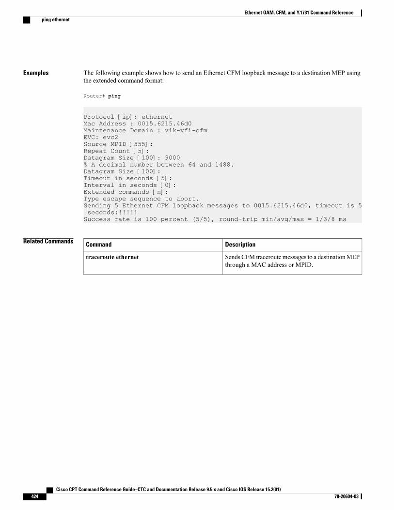
Examples The following example shows how to send an Ethernet CFM loopback message to a destination MEP usingthe extended command format:
Router# ping
Protocol [ip]: ethernetMac Address : 0015.6215.46d0Maintenance Domain : vik-vfi-ofmEVC: evc2Source MPID [555]:Repeat Count [5]:Datagram Size [100]: 9000% A decimal number between 64 and 1488.Datagram Size [100]:Timeout in seconds [5]:Interval in seconds [0]:Extended commands [n]:Type escape sequence to abort.Sending 5 Ethernet CFM loopback messages to 0015.6215.46d0, timeout is 5seconds:!!!!!Success rate is 100 percent (5/5), round-trip min/avg/max = 1/3/8 ms
Related Commands DescriptionCommand
Sends CFM traceroutemessages to a destinationMEPthrough a MAC address or MPID.
traceroute ethernet
Cisco CPT Command Reference Guide–CTC and Documentation Release 9.5.x and Cisco IOS Release 15.2(01)424 78-20604-03
Ethernet OAM, CFM, and Y.1731 Command Referenceping ethernet
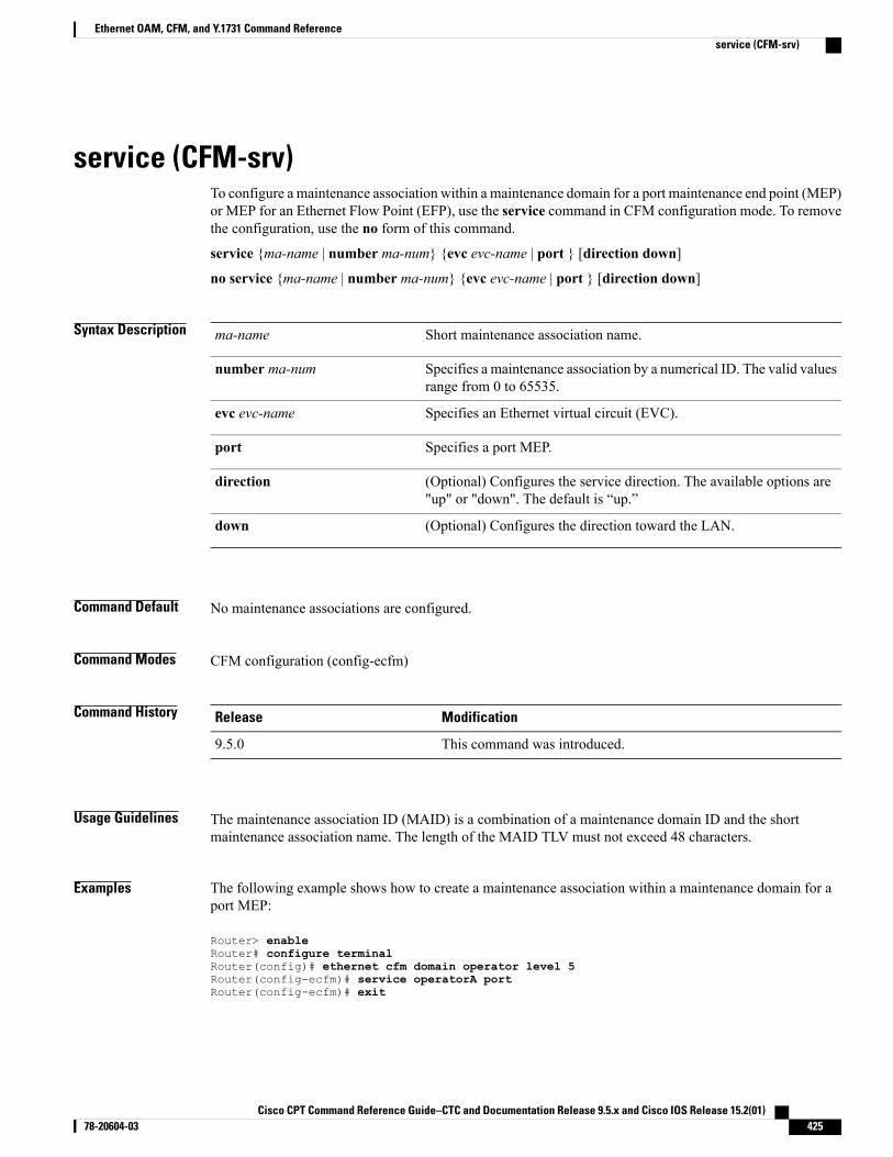
service (CFM-srv)To configure a maintenance association within a maintenance domain for a port maintenance end point (MEP)or MEP for an Ethernet Flow Point (EFP), use the service command in CFM configuration mode. To removethe configuration, use the no form of this command.
service {ma-name | number ma-num} {evc evc-name | port } [direction down]
no service {ma-name | number ma-num} {evc evc-name | port } [direction down]
Syntax Description Short maintenance association name.ma-name
Specifies a maintenance association by a numerical ID. The valid valuesrange from 0 to 65535.
number ma-num
Specifies an Ethernet virtual circuit (EVC).evc evc-name
Specifies a port MEP.port
(Optional) Configures the service direction. The available options are"up" or "down". The default is “up.”
direction
(Optional) Configures the direction toward the LAN.down
Command Default No maintenance associations are configured.
Command Modes CFM configuration (config-ecfm)
Command History ModificationRelease
This command was introduced.9.5.0
Usage Guidelines The maintenance association ID (MAID) is a combination of a maintenance domain ID and the shortmaintenance association name. The length of the MAID TLV must not exceed 48 characters.
Examples The following example shows how to create a maintenance association within a maintenance domain for aport MEP:
Router> enableRouter# configure terminalRouter(config)# ethernet cfm domain operator level 5Router(config-ecfm)# service operatorA portRouter(config-ecfm)# exit
Cisco CPT Command Reference Guide–CTC and Documentation Release 9.5.x and Cisco IOS Release 15.2(01) 78-20604-03 425
Ethernet OAM, CFM, and Y.1731 Command Referenceservice (CFM-srv)
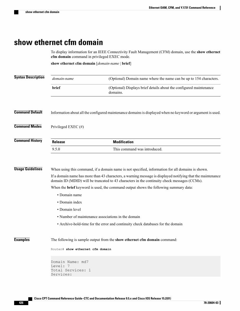
show ethernet cfm domainTo display information for an IEEE Connectivity Fault Management (CFM) domain, use the show ethernetcfm domain command in privileged EXEC mode.
show ethernet cfm domain [domain-name | brief]
Syntax Description (Optional) Domain name where the name can be up to 154 characters.domain-name
(Optional) Displays brief details about the configured maintenancedomains.
brief
Command Default Information about all the configuredmaintenance domains is displayedwhen no keyword or argument is used.
Command Modes Privileged EXEC (#)
Command History ModificationRelease
This command was introduced.9.5.0
Usage Guidelines When using this command, if a domain name is not specified, information for all domains is shown.
If a domain name has more than 43 characters, a warning message is displayed notifying that the maintenancedomain ID (MDID) will be truncated to 43 characters in the continuity check messages (CCMs).
When the brief keyword is used, the command output shows the following summary data:
• Domain name
• Domain index
• Domain level
• Number of maintenance associations in the domain
• Archive-hold-time for the error and continuity check databases for the domain
Examples The following is sample output from the show ethernet cfm domain command:
Router# show ethernet cfm domain
Domain Name: md7Level: 7Total Services: 1Services:
Cisco CPT Command Reference Guide–CTC and Documentation Release 9.5.x and Cisco IOS Release 15.2(01)426 78-20604-03
Ethernet OAM, CFM, and Y.1731 Command Referenceshow ethernet cfm domain
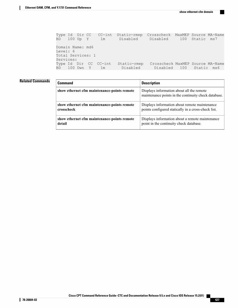
Type Id Dir CC CC-int Static-rmep Crosscheck MaxMEP Source MA-NameBD 100 Up Y 1m Disabled Disabled 100 Static ms7
Domain Name: md6Level: 6Total Services: 1Services:Type Id Dir CC CC-int Static-rmep Crosscheck MaxMEP Source MA-NameBD 100 Dwn Y 1m Disabled Disabled 100 Static ms6
Related Commands DescriptionCommand
Displays information about all the remotemaintenance points in the continuity check database.
show ethernet cfm maintenance-points remote
Displays information about remote maintenancepoints configured statically in a cross-check list.
show ethernet cfm maintenance-points remotecrosscheck
Displays information about a remote maintenancepoint in the continuity check database.
show ethernet cfm maintenance-points remotedetail
Cisco CPT Command Reference Guide–CTC and Documentation Release 9.5.x and Cisco IOS Release 15.2(01) 78-20604-03 427
Ethernet OAM, CFM, and Y.1731 Command Referenceshow ethernet cfm domain
show ethernet cfm errorsTo display IEEEConnectivity Fault Management (CFM) continuity check error conditions logged on a devicesince it was last reset or since the log was last cleared, use the show ethernet cfm errors command in privilegedEXEC mode.
show ethernet cfm errors [configuration | domain-id domain-name [service {ma-name | numberma-num}]]
Syntax Description (Optional) Displays the configuration error list information; for example,port and error condition.
configuration
(Optional) Displays the domain ID. The domain name can be up to 154characters.
domain-id domain-name
(Optional) Displays a maintenance association within the domain.service
(Optional) Short maintenance association name.ma-name
(Optional) Specifies a maintenance association by a numerical ID. Thevalid values range from 0 to 65535.
number ma-num
Command Default When no maintenance domain is specified, errors for all domains are displayed.
Command Modes Privileged EXEC (#)
Command History ModificationRelease
This command was introduced.9.5.0
Usage Guidelines Errors that are logged on a device while using the show ethernet cfm errors command include the following:
• MEP–Down—Maintenance end point (MEP) timed out or is advertising a 0 lifetime.
• Configuration Error—A continuity check message (CCM) is received that has an maintenance point ID(MPID) matching the local device, but the source MAC address is different.
• Forwarding Loop—A CCM is received, that has the same MPID and same MAC address as the localdevice.
• Cross–connected—A CCM is received and the service ID does not match the service ID configured onthe device.
• Cross–check Missing MEP—The cross-checking delay timer has expired, and the configured remoteMEP did not come up.
• Cross–check Unknown MEP—An unexpected remote MEP came up.
Cisco CPT Command Reference Guide–CTC and Documentation Release 9.5.x and Cisco IOS Release 15.2(01)428 78-20604-03
Ethernet OAM, CFM, and Y.1731 Command Referenceshow ethernet cfm errors
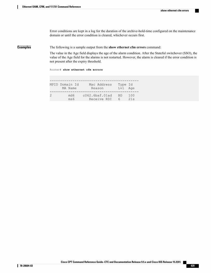
Error conditions are kept in a log for the duration of the archive-hold-time configured on the maintenancedomain or until the error condition is cleared, whichever occurs first.
Examples The following is a sample output from the show ethernet cfm errors command:
The value in the Age field displays the age of the alarm condition. After the Stateful switchover (SSO), thevalue of the Age field for the alarms is not restarted. However, the alarm is cleared if the error condition isnot present after the expiry threshold.
Router# show ethernet cfm errors
-------------------------------------------MPID Domain Id Mac Address Type Id
MA Name Reason Lvl Age-------------------------------------------2 md6 c062.6baf.01ad BD 100
ms6 Receive RDI 6 21s
Cisco CPT Command Reference Guide–CTC and Documentation Release 9.5.x and Cisco IOS Release 15.2(01) 78-20604-03 429
Ethernet OAM, CFM, and Y.1731 Command Referenceshow ethernet cfm errors
show ethernet cfm maintenance-points localTo display information about IEEE Connectivity Fault Management (CFM) maintenance points configuredon a device, use the show ethernet cfm maintenance-points local command in privileged EXEC mode.
show ethernet cfm maintenance-points local [detail] [mep |mip] [domain domain-name | interface typenumber | level level-id | evc evc-name]
Syntax Description (Optional) Displays a detailed output.detail
(Optional) Displays a maintenance end point (MEP).mep
(Optional) Displays a maintenance intermediate point (MIP).mip
(Optional) Displays a maintenance domain. The domain name can beup to 154 characters.
domain domain-name
(Optional) Displays an interface type and number.interface type number
(Optional) Displays a maintenance level. The valid values range from0 to 7.
level level-id
(Optional) Displays an Ethernet virtual circuit (EVC).evc evc-name
Command Default When none of the optional keywords and arguments is specified, information about all the maintenance pointson the device is shown.
Command Modes Privileged EXEC (#)
Command History ModificationRelease
This command was introduced.9.5.0
Usage Guidelines The show ethernet cfm maintenance-points local command allows you to filter output. You can displayinformation about maintenance points as follows:
• Independent of domain or interface
• On a particular interface independent of domain
• On a particular interface belonging to a given domain
• Belonging to a given domain independent of interface
The display may also be restricted to either MEPs or MIPs.
Cisco CPT Command Reference Guide–CTC and Documentation Release 9.5.x and Cisco IOS Release 15.2(01)430 78-20604-03
Ethernet OAM, CFM, and Y.1731 Command Referenceshow ethernet cfm maintenance-points local
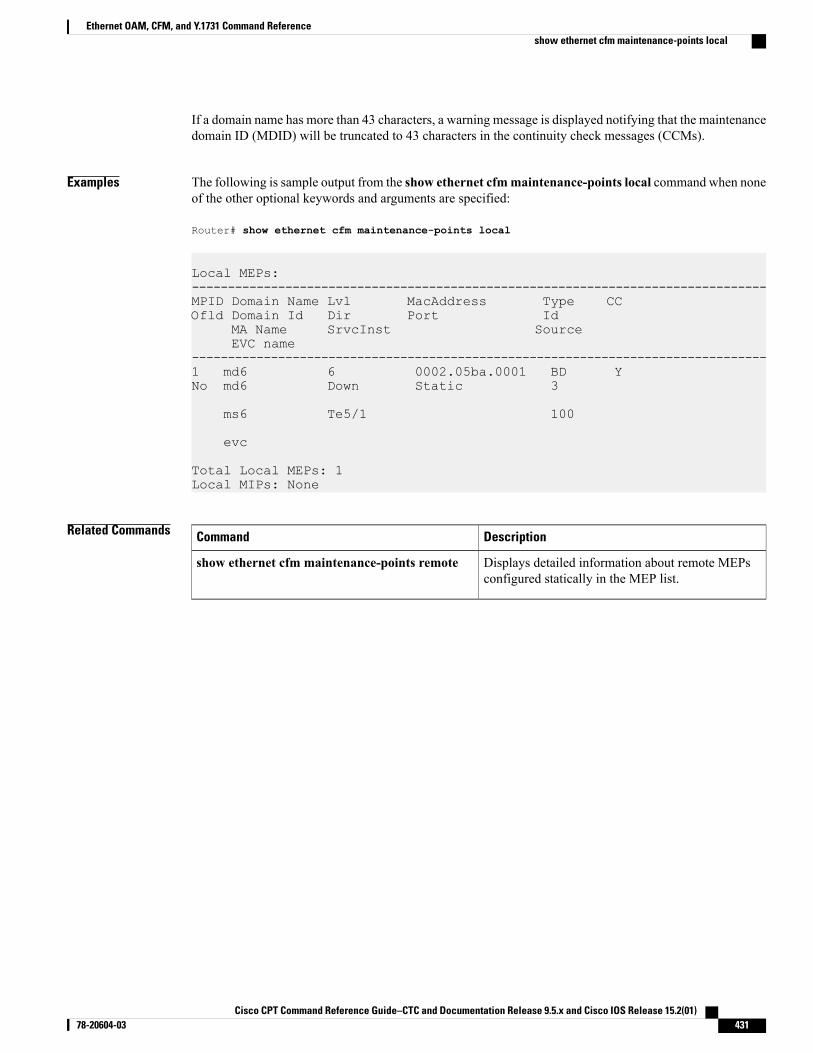
If a domain name has more than 43 characters, a warning message is displayed notifying that the maintenancedomain ID (MDID) will be truncated to 43 characters in the continuity check messages (CCMs).
Examples The following is sample output from the show ethernet cfmmaintenance-points local command when noneof the other optional keywords and arguments are specified:
Router# show ethernet cfm maintenance-points local
Local MEPs:--------------------------------------------------------------------------------MPID Domain Name Lvl MacAddress Type CCOfld Domain Id Dir Port Id
MA Name SrvcInst SourceEVC name
--------------------------------------------------------------------------------1 md6 6 0002.05ba.0001 BD YNo md6 Down Static 3
ms6 Te5/1 100
evc
Total Local MEPs: 1Local MIPs: None
Related Commands DescriptionCommand
Displays detailed information about remote MEPsconfigured statically in the MEP list.
show ethernet cfm maintenance-points remote
Cisco CPT Command Reference Guide–CTC and Documentation Release 9.5.x and Cisco IOS Release 15.2(01) 78-20604-03 431
Ethernet OAM, CFM, and Y.1731 Command Referenceshow ethernet cfm maintenance-points local
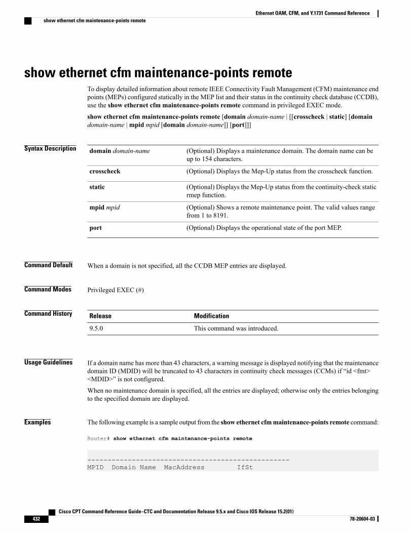
show ethernet cfm maintenance-points remoteTo display detailed information about remote IEEE Connectivity Fault Management (CFM) maintenance endpoints (MEPs) configured statically in the MEP list and their status in the continuity check database (CCDB),use the show ethernet cfm maintenance-points remote command in privileged EXEC mode.
show ethernet cfm maintenance-points remote [domain domain-name | [[crosscheck | static] [domaindomain-name |mpid mpid [domain domain-name]] [port]]]
Syntax Description (Optional) Displays a maintenance domain. The domain name can beup to 154 characters.
domain domain-name
(Optional) Displays the Mep-Up status from the crosscheck function.crosscheck
(Optional) Displays the Mep-Up status from the continuity-check staticrmep function.
static
(Optional) Shows a remote maintenance point. The valid values rangefrom 1 to 8191.
mpid mpid
(Optional) Displays the operational state of the port MEP.port
Command Default When a domain is not specified, all the CCDB MEP entries are displayed.
Command Modes Privileged EXEC (#)
Command History ModificationRelease
This command was introduced.9.5.0
Usage Guidelines If a domain name has more than 43 characters, a warning message is displayed notifying that the maintenancedomain ID (MDID) will be truncated to 43 characters in continuity check messages (CCMs) if “id <fmt><MDID>” is not configured.
When no maintenance domain is specified, all the entries are displayed; otherwise only the entries belongingto the specified domain are displayed.
Examples The following example is a sample output from the show ethernet cfmmaintenance-points remote command:
Router# show ethernet cfm maintenance-points remote
--------------------------------------------------MPID Domain Name MacAddress IfSt
Cisco CPT Command Reference Guide–CTC and Documentation Release 9.5.x and Cisco IOS Release 15.2(01)432 78-20604-03
Ethernet OAM, CFM, and Y.1731 Command Referenceshow ethernet cfm maintenance-points remote
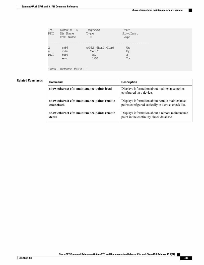
Lvl Domain ID Ingress PtStRDI MA Name Type SrvcInst
EVC Name ID Age
--------------------------------------------------2 md6 c062.6baf.01ad Up6 md6 Te5/1 UpRDI ms6 BD 3
evc 100 2s
Total Remote MEPs: 1
Related Commands DescriptionCommand
Displays information about maintenance pointsconfigured on a device.
show ethernet cfm maintenance-points local
Displays information about remote maintenancepoints configured statically in a cross-check list.
show ethernet cfm maintenance-points remotecrosscheck
Displays information about a remote maintenancepoint in the continuity check database.
show ethernet cfm maintenance-points remotedetail
Cisco CPT Command Reference Guide–CTC and Documentation Release 9.5.x and Cisco IOS Release 15.2(01) 78-20604-03 433
Ethernet OAM, CFM, and Y.1731 Command Referenceshow ethernet cfm maintenance-points remote
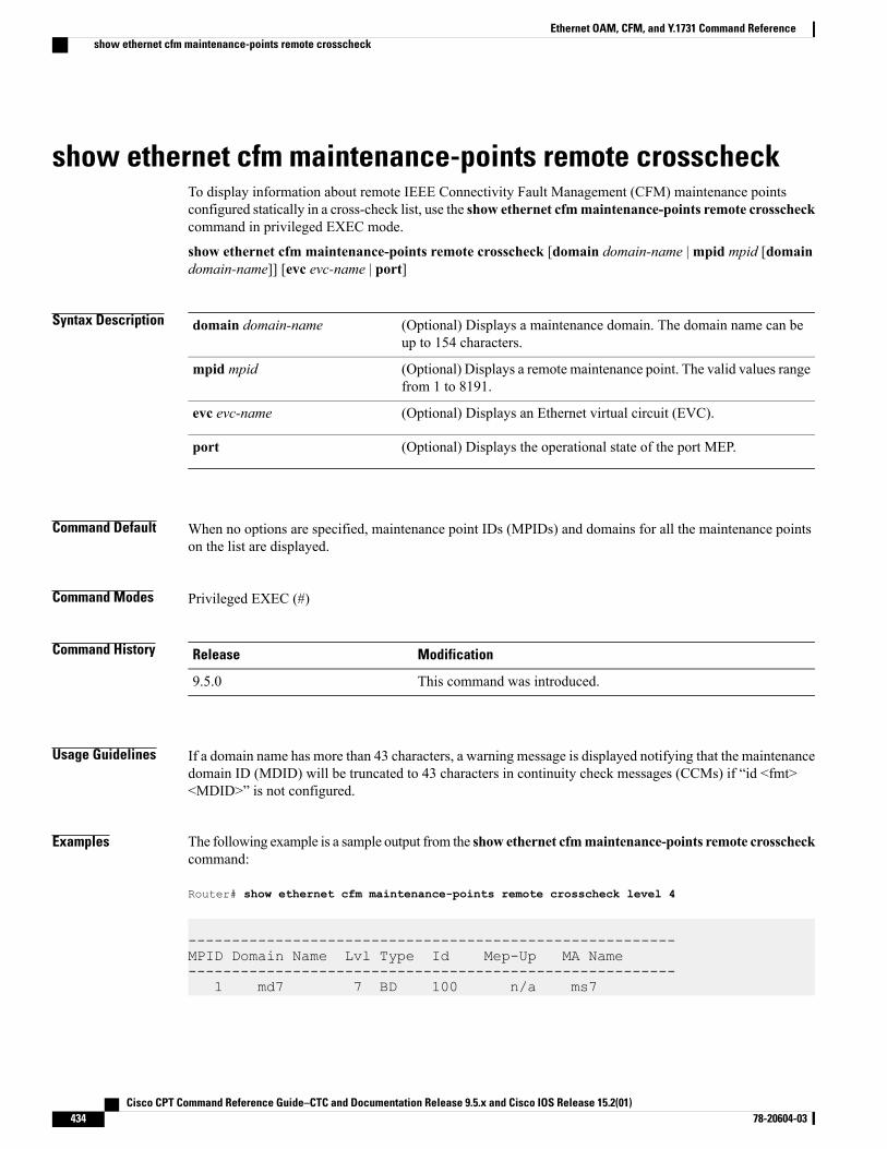
show ethernet cfm maintenance-points remote crosscheckTo display information about remote IEEE Connectivity Fault Management (CFM) maintenance pointsconfigured statically in a cross-check list, use the show ethernet cfmmaintenance-points remote crosscheckcommand in privileged EXEC mode.
show ethernet cfm maintenance-points remote crosscheck [domain domain-name |mpid mpid [domaindomain-name]] [evc evc-name | port]
Syntax Description (Optional) Displays a maintenance domain. The domain name can beup to 154 characters.
domain domain-name
(Optional) Displays a remote maintenance point. The valid values rangefrom 1 to 8191.
mpid mpid
(Optional) Displays an Ethernet virtual circuit (EVC).evc evc-name
(Optional) Displays the operational state of the port MEP.port
Command Default When no options are specified, maintenance point IDs (MPIDs) and domains for all the maintenance pointson the list are displayed.
Command Modes Privileged EXEC (#)
Command History ModificationRelease
This command was introduced.9.5.0
Usage Guidelines If a domain name has more than 43 characters, a warning message is displayed notifying that the maintenancedomain ID (MDID) will be truncated to 43 characters in continuity check messages (CCMs) if “id <fmt><MDID>” is not configured.
Examples The following example is a sample output from the show ethernet cfmmaintenance-points remote crosscheckcommand:
Router# show ethernet cfm maintenance-points remote crosscheck level 4
--------------------------------------------------------MPID Domain Name Lvl Type Id Mep-Up MA Name--------------------------------------------------------
1 md7 7 BD 100 n/a ms7
Cisco CPT Command Reference Guide–CTC and Documentation Release 9.5.x and Cisco IOS Release 15.2(01)434 78-20604-03
Ethernet OAM, CFM, and Y.1731 Command Referenceshow ethernet cfm maintenance-points remote crosscheck
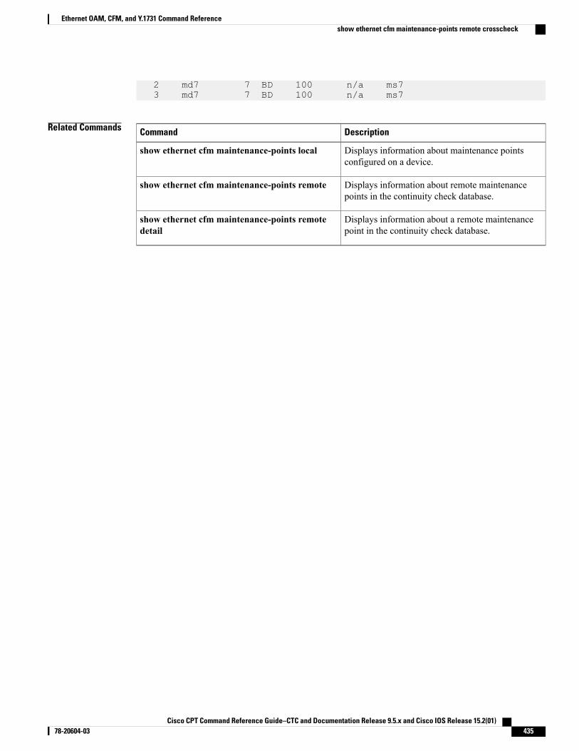
2 md7 7 BD 100 n/a ms73 md7 7 BD 100 n/a ms7
Related Commands DescriptionCommand
Displays information about maintenance pointsconfigured on a device.
show ethernet cfm maintenance-points local
Displays information about remote maintenancepoints in the continuity check database.
show ethernet cfm maintenance-points remote
Displays information about a remote maintenancepoint in the continuity check database.
show ethernet cfm maintenance-points remotedetail
Cisco CPT Command Reference Guide–CTC and Documentation Release 9.5.x and Cisco IOS Release 15.2(01) 78-20604-03 435
Ethernet OAM, CFM, and Y.1731 Command Referenceshow ethernet cfm maintenance-points remote crosscheck
show ethernet cfm maintenance-points remote detailTo display information about a remote IEEE Connectivity Fault Management (CFM) maintenance point inthe continuity check database, use the show ethernet cfm maintenance-points remote detail command inprivileged EXEC mode.
show ethernet cfm maintenance-points remote detail {mac mac-address |mpid mpid} [domaindomain-name | evc evc-name | port]]
Syntax Description Displays a remote MAC address.mac
MAC address of the remote maintenance point, in the formatabcd.abcd.abcd.
mac-address
Displays a remote maintenance point. The valid values range from 1 to8191.
mpid mpid
(Optional) Displays a specific maintenance domain. The domain namecan be up to 154 characters.
domain domain-name
(Optional) Displays an Ethernet virtual circuit (EVC).evc evc-name
(Optional) Displays the operational state of the port MEP.port
Command Default When no options are specified, all the remote MEPs matching the specified MAC address or maintenancepoint ID (MPID) are displayed.
Command Modes Privileged EXEC (#)
Command History ModificationRelease
This command was introduced.9.5.0
Usage Guidelines Use the show ethernet cfm maintenance-points remote detail command to obtain information about aspecific maintenance point by specifying its MPID or to obtain information about all maintenance points thathave a particular MAC address.
Examples The following example is a sample output from the show ethernet cfm maintenance-points remote detailcommand:
Router# show ethernet cfm maintenance-points remote detail mpid 2
Cisco CPT Command Reference Guide–CTC and Documentation Release 9.5.x and Cisco IOS Release 15.2(01)436 78-20604-03
Ethernet OAM, CFM, and Y.1731 Command Referenceshow ethernet cfm maintenance-points remote detail
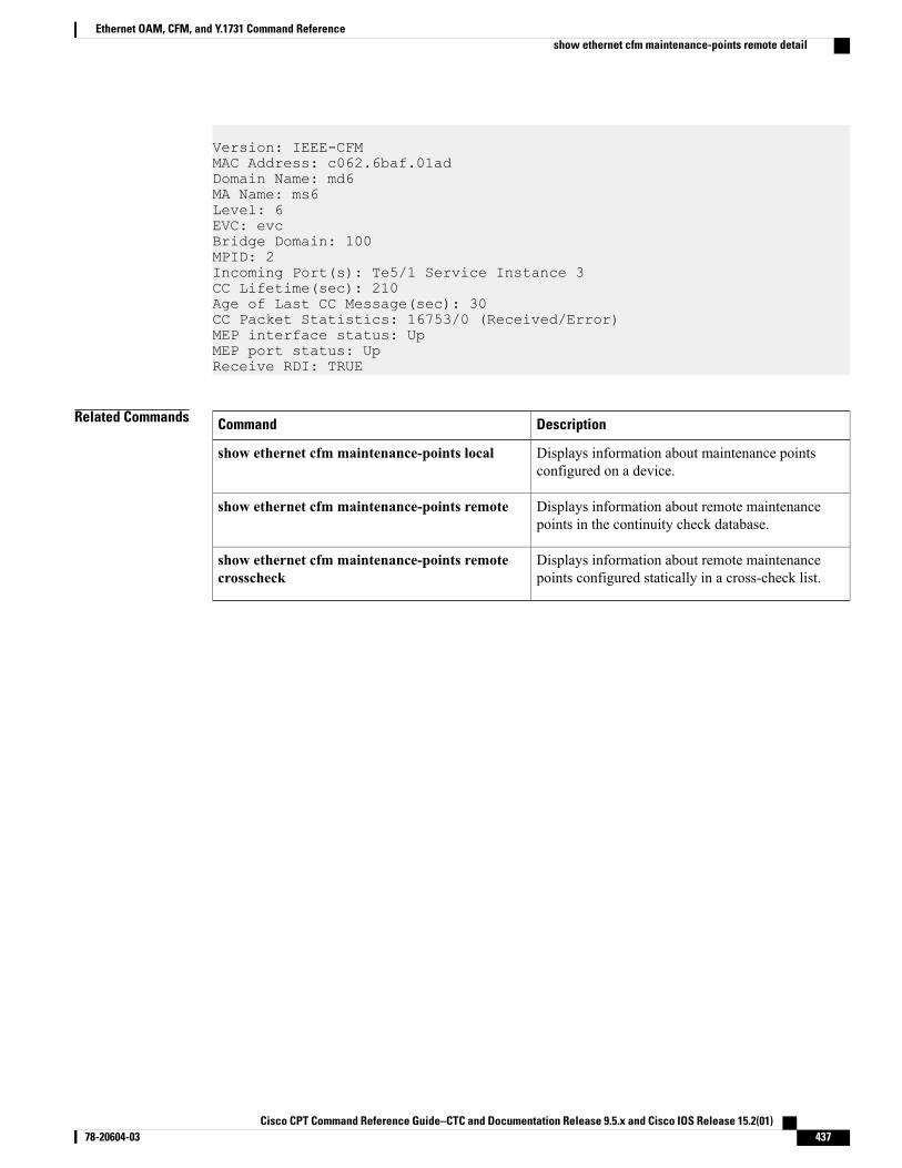
Version: IEEE-CFMMAC Address: c062.6baf.01adDomain Name: md6MA Name: ms6Level: 6EVC: evcBridge Domain: 100MPID: 2Incoming Port(s): Te5/1 Service Instance 3CC Lifetime(sec): 210Age of Last CC Message(sec): 30CC Packet Statistics: 16753/0 (Received/Error)MEP interface status: UpMEP port status: UpReceive RDI: TRUE
Related Commands DescriptionCommand
Displays information about maintenance pointsconfigured on a device.
show ethernet cfm maintenance-points local
Displays information about remote maintenancepoints in the continuity check database.
show ethernet cfm maintenance-points remote
Displays information about remote maintenancepoints configured statically in a cross-check list.
show ethernet cfm maintenance-points remotecrosscheck
Cisco CPT Command Reference Guide–CTC and Documentation Release 9.5.x and Cisco IOS Release 15.2(01) 78-20604-03 437
Ethernet OAM, CFM, and Y.1731 Command Referenceshow ethernet cfm maintenance-points remote detail
show ethernet cfm mpdbTo display the contents of a maintenance intermediate point (MIP) continuity check database, use the showethernet cfm mpdb command in privileged EXEC mode.
show ethernet cfm mpdb [domain-id {domain-name} [service {ma-name | number ma-num}]]
Syntax Description (Optional) Displays the domain ID. The domain name can be up to 43characters.
domain-id domain-name
(Optional) Displays a maintenance association within the domain.service
(Optional) Short maintenance association name.ma-name
(Optional) Displays a maintenance association by a numerical ID. Thevalid values range from 0 to 65535.
number ma-num
Command Default When no maintenance domain is specified, all the entries are displayed.
Command Modes Privileged EXEC (#)
Command History ModificationRelease
This command was introduced.9.5.0
Usage Guidelines Use this command to display information received from MEPs.
Examples The following example is a sample output from the show ethernet cfm mpdb command:
Router# show ethernet cfm mpdb
* = Can Ping/Traceroute to MEP---------------------------------------------------------------MPID Domain Name MacAddress Version SrvcInstLvl Domain ID Ingress Type AgeExpd MA Name ID
EVC Name
---------------------------------------------------------------2 * md6 c062.6baf.01ad IEEE-CFM 36 md6 Te5/1 BD 13s- ms6 100
Cisco CPT Command Reference Guide–CTC and Documentation Release 9.5.x and Cisco IOS Release 15.2(01)438 78-20604-03
Ethernet OAM, CFM, and Y.1731 Command Referenceshow ethernet cfm mpdb

evc
Total Remote MEPs: 1
Cisco CPT Command Reference Guide–CTC and Documentation Release 9.5.x and Cisco IOS Release 15.2(01) 78-20604-03 439
Ethernet OAM, CFM, and Y.1731 Command Referenceshow ethernet cfm mpdb
show ethernet cfm smepTo display CFM SMEP settings on a device, use the show ethernet cfm smep command in the privilegedEXEC mode.
show ethernet cfm smep [inteface number]
Syntax Description (Optional) Displays information about an interface.interface
(Optional)
• Integer from 1 to 6 that identifies a Gigabit Ethernet interface.
• Integer from 1 to 564 that identifies a port channel.
number
Command Default This command has no defaults.
Command Modes Privileged EXEC (#)
Command History ModificationRelease
This command was introduced.9.5.1
Usage Guidelines This command allows filtering on a per-interface basis.
AIS messages are sent by default at the configured maintenance intermediate point (MIP) level if an AIS levelis not configured.
Examples The following example shows sample output from the show ethernet cfm smep command.Router# show ethernet cfm smep
Interface: TenGigabitEthernet2/2LCK-Status: EnabledLCK Period: 60000 (ms)Level to transmit LCK: DefaultAIS-Status: EnabledAIS Period: 60000 (ms)Level to transmit AIS: DefaultDefect Condition: No Defect10.64.107.172#AAA^ZTranslating "AAA"...domain server (255.255.255.255)
Cisco CPT Command Reference Guide–CTC and Documentation Release 9.5.x and Cisco IOS Release 15.2(01)440 78-20604-03
Ethernet OAM, CFM, and Y.1731 Command Referenceshow ethernet cfm smep
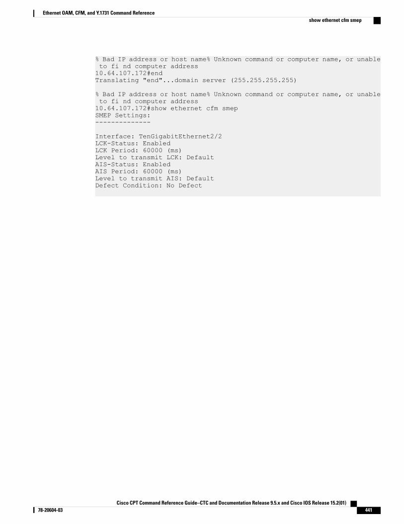
% Bad IP address or host name% Unknown command or computer name, or unableto fi nd computer address10.64.107.172#endTranslating "end"...domain server (255.255.255.255)
% Bad IP address or host name% Unknown command or computer name, or unableto fi nd computer address10.64.107.172#show ethernet cfm smepSMEP Settings:--------------
Interface: TenGigabitEthernet2/2LCK-Status: EnabledLCK Period: 60000 (ms)Level to transmit LCK: DefaultAIS-Status: EnabledAIS Period: 60000 (ms)Level to transmit AIS: DefaultDefect Condition: No Defect
Cisco CPT Command Reference Guide–CTC and Documentation Release 9.5.x and Cisco IOS Release 15.2(01) 78-20604-03 441
Ethernet OAM, CFM, and Y.1731 Command Referenceshow ethernet cfm smep
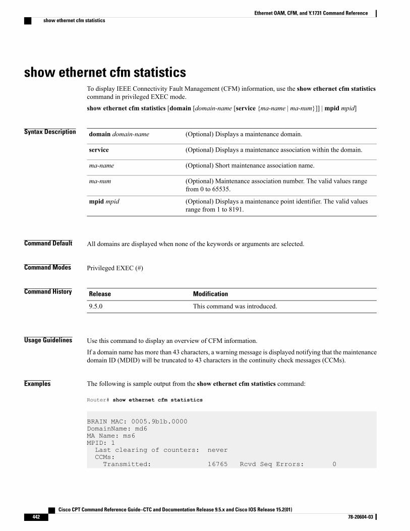
show ethernet cfm statisticsTo display IEEE Connectivity Fault Management (CFM) information, use the show ethernet cfm statisticscommand in privileged EXEC mode.
show ethernet cfm statistics [domain [domain-name [service {ma-name | ma-num}]] |mpid mpid]
Syntax Description (Optional) Displays a maintenance domain.domain domain-name
(Optional) Displays a maintenance association within the domain.service
(Optional) Short maintenance association name.ma-name
(Optional) Maintenance association number. The valid values rangefrom 0 to 65535.
ma-num
(Optional) Displays a maintenance point identifier. The valid valuesrange from 1 to 8191.
mpid mpid
Command Default All domains are displayed when none of the keywords or arguments are selected.
Command Modes Privileged EXEC (#)
Command History ModificationRelease
This command was introduced.9.5.0
Usage Guidelines Use this command to display an overview of CFM information.
If a domain name has more than 43 characters, a warning message is displayed notifying that the maintenancedomain ID (MDID) will be truncated to 43 characters in the continuity check messages (CCMs).
Examples The following is sample output from the show ethernet cfm statistics command:
Router# show ethernet cfm statistics
BRAIN MAC: 0005.9b1b.0000DomainName: md6MA Name: ms6MPID: 1Last clearing of counters: neverCCMs:Transmitted: 16765 Rcvd Seq Errors: 0
Cisco CPT Command Reference Guide–CTC and Documentation Release 9.5.x and Cisco IOS Release 15.2(01)442 78-20604-03
Ethernet OAM, CFM, and Y.1731 Command Referenceshow ethernet cfm statistics

LTRs:Unexpected Rcvd: 0
LBRs:Transmitted: 0 Rcvd Seq Errors: 0Rcvd in order: 0 Rcvd Bad MSDU: 0
Cisco CPT Command Reference Guide–CTC and Documentation Release 9.5.x and Cisco IOS Release 15.2(01) 78-20604-03 443
Ethernet OAM, CFM, and Y.1731 Command Referenceshow ethernet cfm statistics
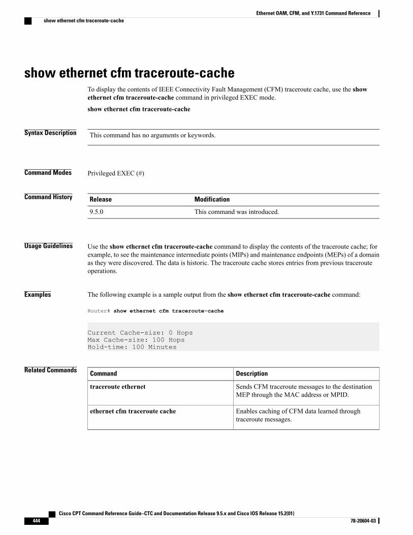
show ethernet cfm traceroute-cacheTo display the contents of IEEE Connectivity Fault Management (CFM) traceroute cache, use the showethernet cfm traceroute-cache command in privileged EXEC mode.
show ethernet cfm traceroute-cache
Syntax Description This command has no arguments or keywords.
Command Modes Privileged EXEC (#)
Command History ModificationRelease
This command was introduced.9.5.0
Usage Guidelines Use the show ethernet cfm traceroute-cache command to display the contents of the traceroute cache; forexample, to see the maintenance intermediate points (MIPs) and maintenance endpoints (MEPs) of a domainas they were discovered. The data is historic. The traceroute cache stores entries from previous tracerouteoperations.
Examples The following example is a sample output from the show ethernet cfm traceroute-cache command:
Router# show ethernet cfm traceroute-cache
Current Cache-size: 0 HopsMax Cache-size: 100 HopsHold-time: 100 Minutes
Related Commands DescriptionCommand
Sends CFM traceroute messages to the destinationMEP through the MAC address or MPID.
traceroute ethernet
Enables caching of CFM data learned throughtraceroute messages.
ethernet cfm traceroute cache
Cisco CPT Command Reference Guide–CTC and Documentation Release 9.5.x and Cisco IOS Release 15.2(01)444 78-20604-03
Ethernet OAM, CFM, and Y.1731 Command Referenceshow ethernet cfm traceroute-cache
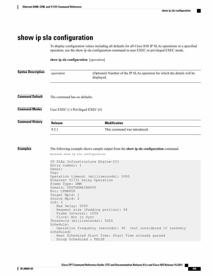
show ip sla configurationTo display configuration values including all defaults for all Cisco IOS IP SLAs operations or a specifiedoperation, use the show ip sla configuration command in user EXEC or privileged EXEC mode.
show ip sla configuration [operation]
Syntax Description (Optional) Number of the IP SLAs operation for which the details will bedisplayed.
operation
Command Default The command has no defaults.
Command Modes User EXEC (>) Privileged EXEC (#)
Command History ModificationRelease
This command was introduced.9.5.1
Examples The following example shows sample output from the show ip sla configuration command.Router# show ip sla configuration
IP SLAs Infrastructure Engine-IIIEntry number: 1Owner:Tag:Operation timeout (milliseconds): 5000Ethernet Y1731 Delay OperationFrame Type: DMMDomain: TESTDOMAINRPUPEvc: CFMRPUPTarget Mpid: 1Source Mpid: 2CoS: 2
Max Delay: 5000Request size (Padding portion): 64Frame Interval: 1000Clock: Not In Sync
Threshold (milliseconds): 5000Schedule:
Operation frequency (seconds): 90 (not considered if randomlyscheduled)
Next Scheduled Start Time: Start Time already passedGroup Scheduled : FALSE
Cisco CPT Command Reference Guide–CTC and Documentation Release 9.5.x and Cisco IOS Release 15.2(01) 78-20604-03 445
Ethernet OAM, CFM, and Y.1731 Command Referenceshow ip sla configuration
Randomly Scheduled : FALSELife (seconds): Forever
Related Commands DescriptionCommand
Begins configuration for an IP SLAs operation andenters IP SLA configuration mode.
ip sla
Cisco CPT Command Reference Guide–CTC and Documentation Release 9.5.x and Cisco IOS Release 15.2(01)446 78-20604-03
Ethernet OAM, CFM, and Y.1731 Command Referenceshow ip sla configuration
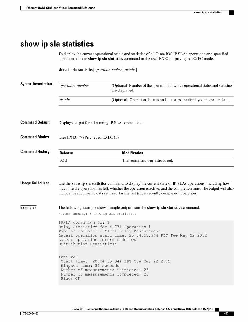
show ip sla statisticsTo display the current operational status and statistics of all Cisco IOS IP SLAs operations or a specifiedoperation, use the show ip sla statistics command in the user EXEC or privileged EXEC mode.
show ip sla statistics[operation-umber][details]
Syntax Description (Optional) Number of the operation for which operational status and statisticsare displayed.
operation-number
(Optional) Operational status and statistics are displayed in greater detail.details
Command Default Displays output for all running IP SLAs operations.
Command Modes User EXEC (>) Privileged EXEC (#)
Command History ModificationRelease
This command was introduced.9.5.1
Usage Guidelines Use the show ip sla statistics command to display the current state of IP SLAs operations, including howmuch life the operation has left, whether the operation is active, and the completion time. The output will alsoinclude the monitoring data returned for the last (most recently completed) operation.
Examples The following example shows sample output from the show ip sla statistics command.Router (config) # show ip sla statistics
IPSLA operation id: 1Delay Statistics for Y1731 Operation 1Type of operation: Y1731 Delay MeasurementLatest operation start time: 20:34:55.944 PDT Tue May 22 2012Latest operation return code: OKDistribution Statistics:
IntervalStart time: 20:34:55.944 PDT Tue May 22 2012Elapsed time: 31 secondsNumber of measurements initiated: 23Number of measurements completed: 23Flag: OK
Cisco CPT Command Reference Guide–CTC and Documentation Release 9.5.x and Cisco IOS Release 15.2(01) 78-20604-03 447
Ethernet OAM, CFM, and Y.1731 Command Referenceshow ip sla statistics
IPSLA operation id: 10
Related Commands DescriptionCommand
Displays configuration values including all defaultsfor all IP SLAs operations or the specified operation.
show ip sla configuration
Cisco CPT Command Reference Guide–CTC and Documentation Release 9.5.x and Cisco IOS Release 15.2(01)448 78-20604-03
Ethernet OAM, CFM, and Y.1731 Command Referenceshow ip sla statistics
show ip sla statistics aggregatedTo display the aggregated statistical errors and distribution information for all Cisco IOS IP SLAs operationsor a specified operation, use the show ip sla statistics aggregated command in the user EXEC or privilegedEXEC mode.
show ip sla statistics aggregated [operation-number][detaills]
Syntax Description (Optional) Number of the IP SLAs operation to display.operation-number
(Optional) Aggregated statistical information is displayed in greater detail.Distribution information is included when this keyword is specified.
details
Command Default This command has no defaults.
Command Modes User EXEC (>) Privileged EXEC (#)
Command History ModificationRelease
This command was introduced.9.5.1
Usage Guidelines Use this command to display information such as the number of failed operations and the failure reason. Thedistributions statistics consist of the following:
• The sum of completion times (used to calculate the mean)
• The sum of the completions times squared (used to calculate standard deviation)
• The maximum and minimum completion time
• The number of completed attempts
This command shows information collected over the past two hours, unless you specify a different amountof time using the history hours-of-statistics-kept command.
This command does not support the IP SLAs ICMP path jitter operation.Note
Examples The following example shows sample output from the show ip sla statistics aggregated command.Router (config) # show ip sla statistics aggregated
Cisco CPT Command Reference Guide–CTC and Documentation Release 9.5.x and Cisco IOS Release 15.2(01) 78-20604-03 449
Ethernet OAM, CFM, and Y.1731 Command Referenceshow ip sla statistics aggregated
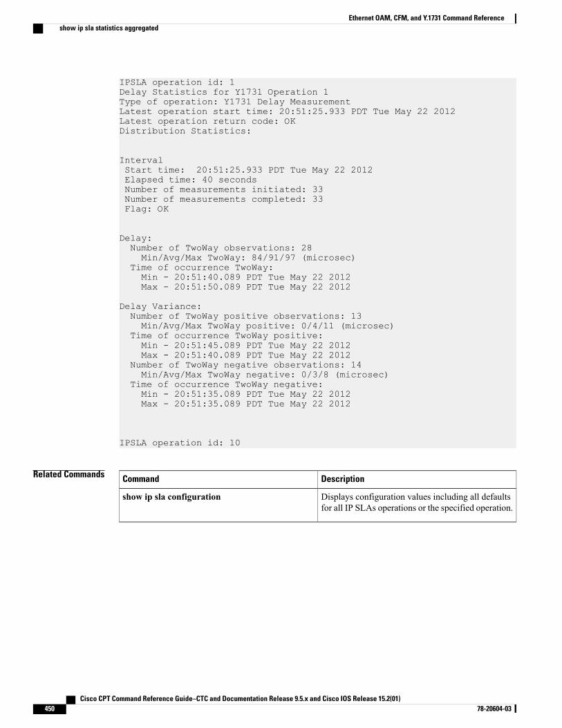
IPSLA operation id: 1Delay Statistics for Y1731 Operation 1Type of operation: Y1731 Delay MeasurementLatest operation start time: 20:51:25.933 PDT Tue May 22 2012Latest operation return code: OKDistribution Statistics:
IntervalStart time: 20:51:25.933 PDT Tue May 22 2012Elapsed time: 40 secondsNumber of measurements initiated: 33Number of measurements completed: 33Flag: OK
Delay:Number of TwoWay observations: 28Min/Avg/Max TwoWay: 84/91/97 (microsec)
Time of occurrence TwoWay:Min - 20:51:40.089 PDT Tue May 22 2012Max - 20:51:50.089 PDT Tue May 22 2012
Delay Variance:Number of TwoWay positive observations: 13Min/Avg/Max TwoWay positive: 0/4/11 (microsec)
Time of occurrence TwoWay positive:Min - 20:51:45.089 PDT Tue May 22 2012Max - 20:51:40.089 PDT Tue May 22 2012
Number of TwoWay negative observations: 14Min/Avg/Max TwoWay negative: 0/3/8 (microsec)
Time of occurrence TwoWay negative:Min - 20:51:35.089 PDT Tue May 22 2012Max - 20:51:35.089 PDT Tue May 22 2012
IPSLA operation id: 10
Related Commands DescriptionCommand
Displays configuration values including all defaultsfor all IP SLAs operations or the specified operation.
show ip sla configuration
Cisco CPT Command Reference Guide–CTC and Documentation Release 9.5.x and Cisco IOS Release 15.2(01)450 78-20604-03
Ethernet OAM, CFM, and Y.1731 Command Referenceshow ip sla statistics aggregated
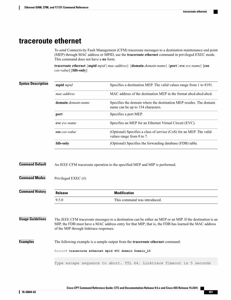
traceroute ethernetTo send Connectivity Fault Management (CFM) traceroute messages to a destination maintenance end point(MEP) through MAC address or MPID, use the traceroute ethernet command in privileged EXEC mode.This command does not have a no form.
traceroute ethernet {mpid mpid | mac-address} {domain domain-name} {port | evc evc-name} [coscos-value] [fdb-only]
Syntax Description Specifies a destination MEP. The valid values range from 1 to 8191.mpid mpid
MAC address of the destination MEP in the format abcd.abcd.abcd.mac-address
Specifies the domain where the destination MEP resides. The domainname can be up to 154 characters.
domain domain-name
Specifies a port MEP.port
Specifies an MEP for an Ethernet Virtual Circuit (EVC).evc evc-name
(Optional) Specifies a class of service (CoS) for an MEP. The validvalues range from 0 to 7.
cos cos-value
(Optional) Specifies the forwarding database (FDB) table.fdb-only
Command Default An IEEE CFM traceroute operation to the specified MEP and MIP is performed.
Command Modes Privileged EXEC (#)
Command History ModificationRelease
This command was introduced.9.5.0
Usage Guidelines The IEEE CFM traceroute messages to a destination can be either an MEP or an MIP. If the destination is anMIP, the FDB must have a MAC address entry for that MIP; that is, the FDB has learned the MAC addressof the MIP through linktrace responses.
Examples The following example is a sample output from the traceroute ethernet command:
Router# traceroute ethernet mpid 401 domain Domain_L5
Type escape sequence to abort. TTL 64. Linktrace Timeout is 5 seconds
Cisco CPT Command Reference Guide–CTC and Documentation Release 9.5.x and Cisco IOS Release 15.2(01) 78-20604-03 451
Ethernet OAM, CFM, and Y.1731 Command Referencetraceroute ethernet
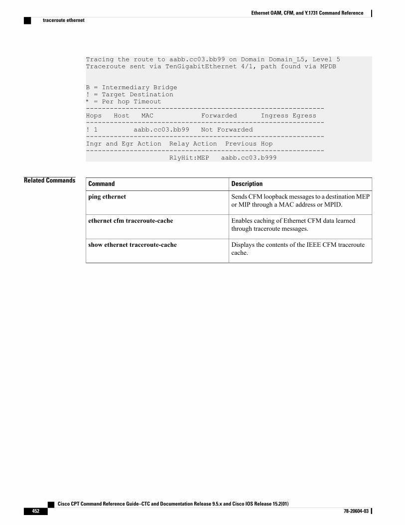
Tracing the route to aabb.cc03.bb99 on Domain Domain_L5, Level 5Traceroute sent via TenGigabitEthernet 4/1, path found via MPDB
B = Intermediary Bridge! = Target Destination* = Per hop Timeout------------------------------------------------------------Hops Host MAC Forwarded Ingress Egress------------------------------------------------------------! 1 aabb.cc03.bb99 Not Forwarded------------------------------------------------------------Ingr and Egr Action Relay Action Previous Hop------------------------------------------------------------
RlyHit:MEP aabb.cc03.b999
Related Commands DescriptionCommand
Sends CFM loopbackmessages to a destinationMEPor MIP through a MAC address or MPID.
ping ethernet
Enables caching of Ethernet CFM data learnedthrough traceroute messages.
ethernet cfm traceroute-cache
Displays the contents of the IEEE CFM traceroutecache.
show ethernet traceroute-cache
Cisco CPT Command Reference Guide–CTC and Documentation Release 9.5.x and Cisco IOS Release 15.2(01)452 78-20604-03
Ethernet OAM, CFM, and Y.1731 Command Referencetraceroute ethernet
RMON Command Reference
This chapter describes commands to configure Remote Monitoring (RMON).
• rmon, page 454
• rmon alarm, page 456
• rmon collection history, page 458
• rmon collection host, page 460
• rmon event, page 461
• show controllers, page 463
• show rmon, page 464
Cisco CPT Command Reference Guide–CTC and Documentation Release 9.5.x and Cisco IOS Release 15.2(01) 78-20604-03 453
rmonTo enable Remote Monitoring (RMON) on an Ethernet interface, use the rmon command in interfaceconfiguration mode. To disable RMON on the interface, use the no form of this command.
rmon {native | promiscuous}
Syntax Description Enables RMON on the Ethernet interface. In native mode, the router processesonly packets destined for this interface.
native
Enables RMON on the Ethernet interface. In promiscuous mode, the routerexamines each packet.
promiscuous
Command Default RMON is disabled on the interface.
Command Modes Interface configuration (config-if)
Command History ModificationRelease
This command was introduced.9.3.0
Usage Guidelines This command enables RMON on Ethernet interfaces. A generic RMON console application is recommendedin order to use the RMON network management capabilities. Simple NetworkManagement Protocol (SNMP)must also be configured. RMON provides visibility of individual nodal activity and monitors all nodes andtheir interaction on a LAN segment. When the rmon command is used, the router automatically installs anEthernet statistics study for the associated interface.
RMON can be very data and processor intensive. Measure usage effects to ensure that router performance isnot degraded and to minimize excessive management traffic overhead. Native mode is less intensive thanpromiscuous mode.
Examples The following example enables RMON on an interface and allows the router to examine only packets destinedfor the interface.
Router(config)# interface TenGigabitEthernet4/1Router(config-if)# rmon native
Related Commands DescriptionCommand
Sets an alarm on any MIB object.rmon alarm
Cisco CPT Command Reference Guide–CTC and Documentation Release 9.5.x and Cisco IOS Release 15.2(01)454 78-20604-03
RMON Command Referencermon

DescriptionCommand
Adds or removes an event in the RMON event tablethat is associated with an RMON event number.
rmon event
Displays the current RMON agent status on the router.show rmon
Cisco CPT Command Reference Guide–CTC and Documentation Release 9.5.x and Cisco IOS Release 15.2(01) 78-20604-03 455
RMON Command Referencermon
rmon alarmTo set a RMON alarm on a MIB object, use the rmon alarm command in global configuration mode. Todisable the alarm, use the no form of this command.
rmon alarm number variable interval {delta | absolute} rising-threshold value [event-number]falling-threshold value [event-number] [owner string]
no rmon alarm number
Syntax Description Alarm number, which is identical to the alarmIndex in the alarmTable in theRMON MIB.
number
MIB object to monitor, which translates into the alarmVariable used in thealarmTable of the RMON MIB.
variable
Time in seconds. The alarm monitors the MIB variable, which is identical to thealarmInterval used in the alarmTable of the RMON MIB.
interval
Tests the change between MIB variables, which affects the alarmSampleTypein the alarmTable of the RMON MIB.
delta
Tests each MIB variable directly, which affects the alarmSampleType in thealarmTable of the RMON MIB.
absolute
Specifies the value at which the alarm is triggered.rising-threshold value
(Optional) Event number to trigger when the rising or falling threshold exceedsits limit. This value is identical to the alarmRisingEventIndex or thealarmFallingEventIndex in the alarmTable of the RMON MIB.
event-number
Specifies the value at which the alarm is reset.falling-threshold value
(Optional) Specifies an owner for the alarm, which is identical to the alarmOwnerin the alarmTable of the RMON MIB.
owner string
Command Default No RMON alarms are configured.
Command Modes Global configuration (config)
Command History ModificationRelease
This command was introduced.9.3.0
Cisco CPT Command Reference Guide–CTC and Documentation Release 9.5.x and Cisco IOS Release 15.2(01)456 78-20604-03
RMON Command Referencermon alarm
Usage Guidelines TheMIB object must be specified as a dotted decimal value after the entry sequence (for example, ifEntry.10.1).You cannot specify the variable name and the instance (for example, ifInOctets.1) or the entire dotted decimalnotation. The variable must be of the form entry.integer.instance.
To disable the RMON alarms, you must use the no form of the command on each configured alarm. Forexample, enter no rmon alarm 1, where 1 identifies the alarm to be removed.
Examples The following example shows how to configure an RMON alarm using the rmon alarm command:
rmon alarm 10 ifEntry.20.1 20 delta rising-threshold 15 1 falling-threshold 0 owner user1
This example configures RMON alarm number 10. The alarm monitors the MIB variable ifEntry.20.1 onceevery 20 seconds until the alarm is disabled, and checks the change in the rise or fall of the variable. If theifEntry.20.1 value shows a MIB counter increase of 15 or more, such as from 100000 to 100015, the alarmis triggered. The alarm in turn triggers event number 1, which is configured with the rmon event command.The possible events include a log entry or an SNMP trap. If the ifEntry.20.1 value changes by 0, the alarm isreset and can be triggered again.
Related Commands DescriptionCommand
Enables RMON on an Ethernet interface.rmon
Adds or removes an event in the RMON event tablethat is associated with an RMON event number.
rmon event
Displays the current RMON agent status on the router.show rmon
Cisco CPT Command Reference Guide–CTC and Documentation Release 9.5.x and Cisco IOS Release 15.2(01) 78-20604-03 457
RMON Command Referencermon alarm
rmon collection historyTo enable RMON history gathering on an interface, use the rmon collection history command in interfaceconfiguration mode. To disable the history gathering on an interface, use the no form of this command.
rmon collection history controlEntry integer [buckets bucket-number] [interval seconds] [owner ownername]
no rmon collection history controlEntry integer [buckets bucket-number] [interval seconds] [ownerownername]
Syntax Description Specifies the RMON group of statistics using a value.controlEntry
Integer that identifies the RMON group of statistics and matches the indexvalue returned for SNMP requests. The range is from 1 to 65535.
integer
(Optional) Specifies the name of the owner of the RMON group of statistics.owner
(Optional) Name of the owner of the RMON group of statistics.ownername
(Optional) Specifies the maximum number of buckets desired for the RMONcollection history group of statistics.
buckets bucket-number
(Optional) Specifies the interval, in seconds, when history should be gatheredin a single bucket. When the interval ends, history is collected into a newbucket.
interval seconds
Command Default The RMON history gathering is disabled.
Command Modes Interface configuration (config-if)
Command History ModificationRelease
This command was introduced.9.3.0
Usage Guidelines Use the show rmon capture and show rmon matrix commands to display RMON statistics.
Examples The following example enables RMON history collection with an ID number of 5 and an owner named user1.Router(config-if)# rmon collection history controlEntry 5 buckets 5 interval 10 owner user1
Cisco CPT Command Reference Guide–CTC and Documentation Release 9.5.x and Cisco IOS Release 15.2(01)458 78-20604-03
RMON Command Referencermon collection history
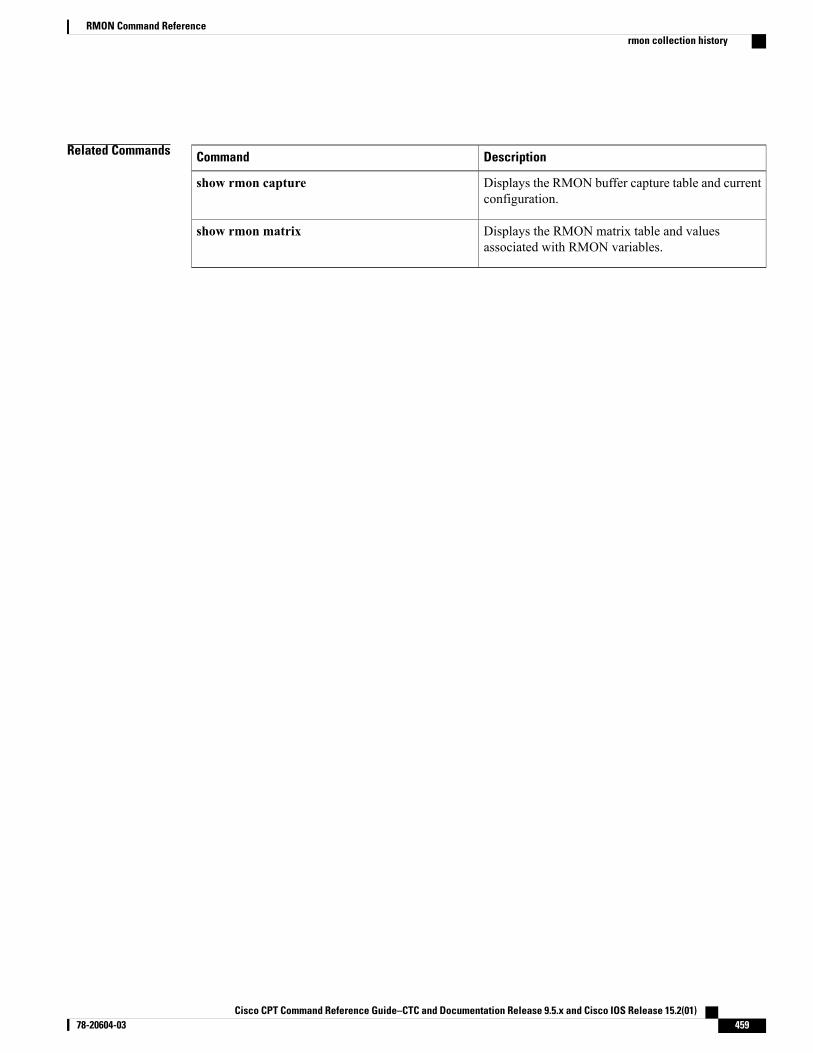
Related Commands DescriptionCommand
Displays the RMON buffer capture table and currentconfiguration.
show rmon capture
Displays the RMON matrix table and valuesassociated with RMON variables.
show rmon matrix
Cisco CPT Command Reference Guide–CTC and Documentation Release 9.5.x and Cisco IOS Release 15.2(01) 78-20604-03 459
RMON Command Referencermon collection history
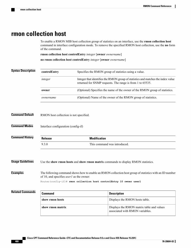
rmon collection hostTo enable a RMON MIB host collection group of statistics on an interface, use the rmon collection hostcommand in interface configuration mode. To remove the specified RMON host collection, use the no formof the command.
rmon collection host controlEntry integer [owner ownername]
no rmon collection host controlEntry integer [owner ownername]
Syntax Description Specifies the RMON group of statistics using a value.controlEntry
Integer that identifies the RMON group of statistics andmatches the index valuereturned for SNMP requests. The range is from 1 to 65535.
integer
(Optional) Specifies the name of the owner of the RMON group of statistics.owner
(Optional) Name of the owner of the RMON group of statistics.ownername
Command Default RMON host collection is not specified.
Command Modes Interface configuration (config-if)
Command History ModificationRelease
This command was introduced.9.3.0
Usage Guidelines Use the show rmon hosts and show rmon matrix commands to display RMON statistics.
Examples The following command shows how to enable an RMON collection host group of statistics with an ID numberof 10, and specifies user1 as the owner:Router(config-if)# rmon collection host controlEntry 10 owner user1
Related Commands DescriptionCommand
Displays the RMON hosts table.show rmon hosts
Displays the RMON matrix table and valuesassociated with RMON variables.
show rmon matrix
Cisco CPT Command Reference Guide–CTC and Documentation Release 9.5.x and Cisco IOS Release 15.2(01)460 78-20604-03
RMON Command Referencermon collection host
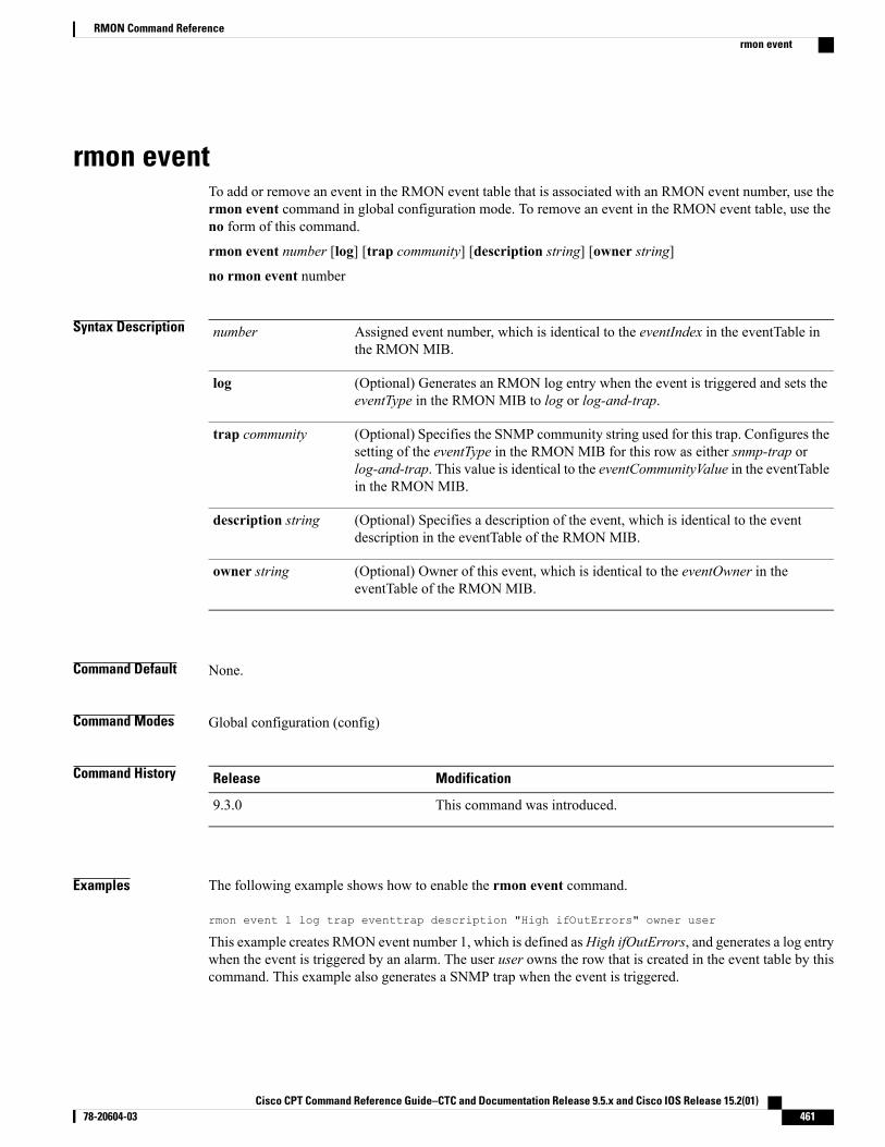
rmon eventTo add or remove an event in the RMON event table that is associated with an RMON event number, use thermon event command in global configuration mode. To remove an event in the RMON event table, use theno form of this command.
rmon event number [log] [trap community] [description string] [owner string]
no rmon event number
Syntax Description Assigned event number, which is identical to the eventIndex in the eventTable inthe RMON MIB.
number
(Optional) Generates an RMON log entry when the event is triggered and sets theeventType in the RMON MIB to log or log-and-trap.
log
(Optional) Specifies the SNMP community string used for this trap. Configures thesetting of the eventType in the RMON MIB for this row as either snmp-trap orlog-and-trap. This value is identical to the eventCommunityValue in the eventTablein the RMON MIB.
trap community
(Optional) Specifies a description of the event, which is identical to the eventdescription in the eventTable of the RMON MIB.
description string
(Optional) Owner of this event, which is identical to the eventOwner in theeventTable of the RMON MIB.
owner string
Command Default None.
Command Modes Global configuration (config)
Command History ModificationRelease
This command was introduced.9.3.0
Examples The following example shows how to enable the rmon event command.
rmon event 1 log trap eventtrap description "High ifOutErrors" owner user
This example creates RMON event number 1, which is defined asHigh ifOutErrors, and generates a log entrywhen the event is triggered by an alarm. The user user owns the row that is created in the event table by thiscommand. This example also generates a SNMP trap when the event is triggered.
Cisco CPT Command Reference Guide–CTC and Documentation Release 9.5.x and Cisco IOS Release 15.2(01) 78-20604-03 461
RMON Command Referencermon event
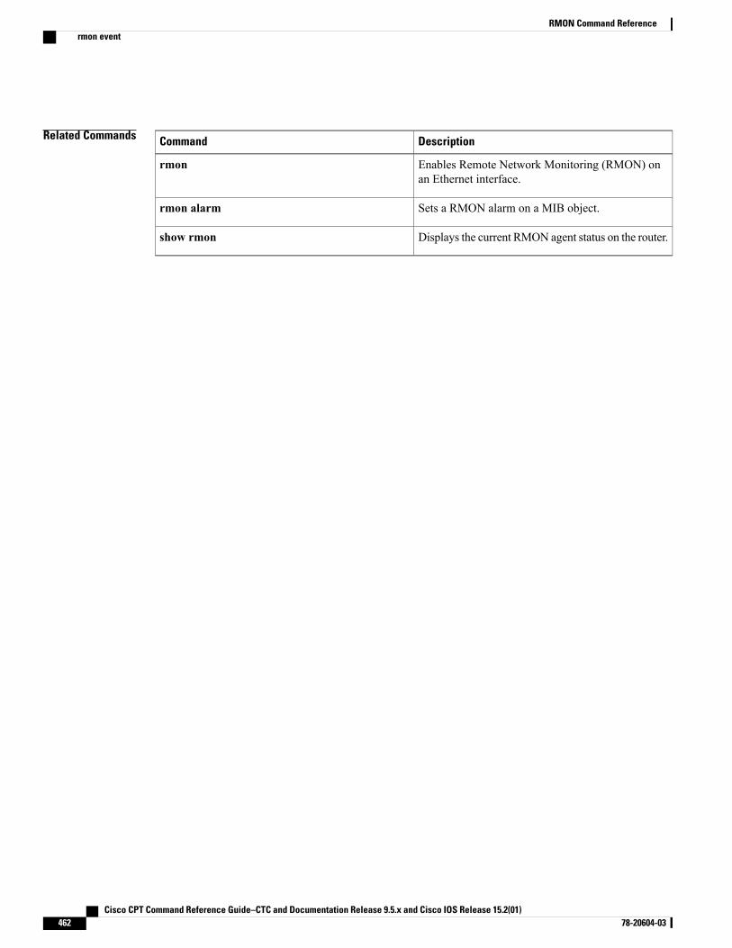
Related Commands DescriptionCommand
Enables Remote Network Monitoring (RMON) onan Ethernet interface.
rmon
Sets a RMON alarm on a MIB object.rmon alarm
Displays the current RMON agent status on the router.show rmon
Cisco CPT Command Reference Guide–CTC and Documentation Release 9.5.x and Cisco IOS Release 15.2(01)462 78-20604-03
RMON Command Referencermon event
show controllersTo display the RMON performance parameters for 15 minute or 1 day intervals, use the show controllerscommand in privileged EXEC mode.
show controllers dwdm slot/port pm interval {15-min | 24-hour}
Syntax Description Slot and port.slot/port
Specifies the interval for performance monitoring.pm interval
Displays the performance parameters for a 15-minute interval.15-min
Displays the performance parameters for 1 day interval.24-hour
Command Modes Privileged EXEC (#)
Command History ModificationRelease
This command was introduced.9.3.0
Examples The following example shows how to display the RMON performance parameters for a 15-minute interval.Router# show controllers dwdm 4/3 pm interval 15-min
Cisco CPT Command Reference Guide–CTC and Documentation Release 9.5.x and Cisco IOS Release 15.2(01) 78-20604-03 463
RMON Command Referenceshow controllers
show rmonTo display the current RMON agent status on the router, use the show rmon command in privileged EXECmode.
show rmon [task | alarms | capture | events | filter | history | hosts |matrix | statistics | topn]
Syntax Description Displays general RMON statistics.task
Displays the RMON alarm table.alarms
Displays the RMON buffer capture table and current configuration.capture
Displays the RMON event table.events
Displays the RMON filter table.filter
Displays the RMON history table.history
Displays the RMON hosts table.hosts
Displays the RMONmatrix table and values associatedwith RMONvariables.matrix
Displays the RMON statistics tablestatistics
Displays the RMON top-n hosts tabletopn
Command Default The task option is displayed.
Command Modes Privileged Exec (#)
Command History ModificationRelease
This command was introduced.9.3.0
Examples The following example shows how to display general RMON statistics.
Router# show rmon
145678 packets input (34562 promiscuous), 0 drops145678 packets processed, 0 on queue, queue utilization 15/64
The following example shows how to display the contents of the RMON alarm table.
Cisco CPT Command Reference Guide–CTC and Documentation Release 9.5.x and Cisco IOS Release 15.2(01)464 78-20604-03
RMON Command Referenceshow rmon
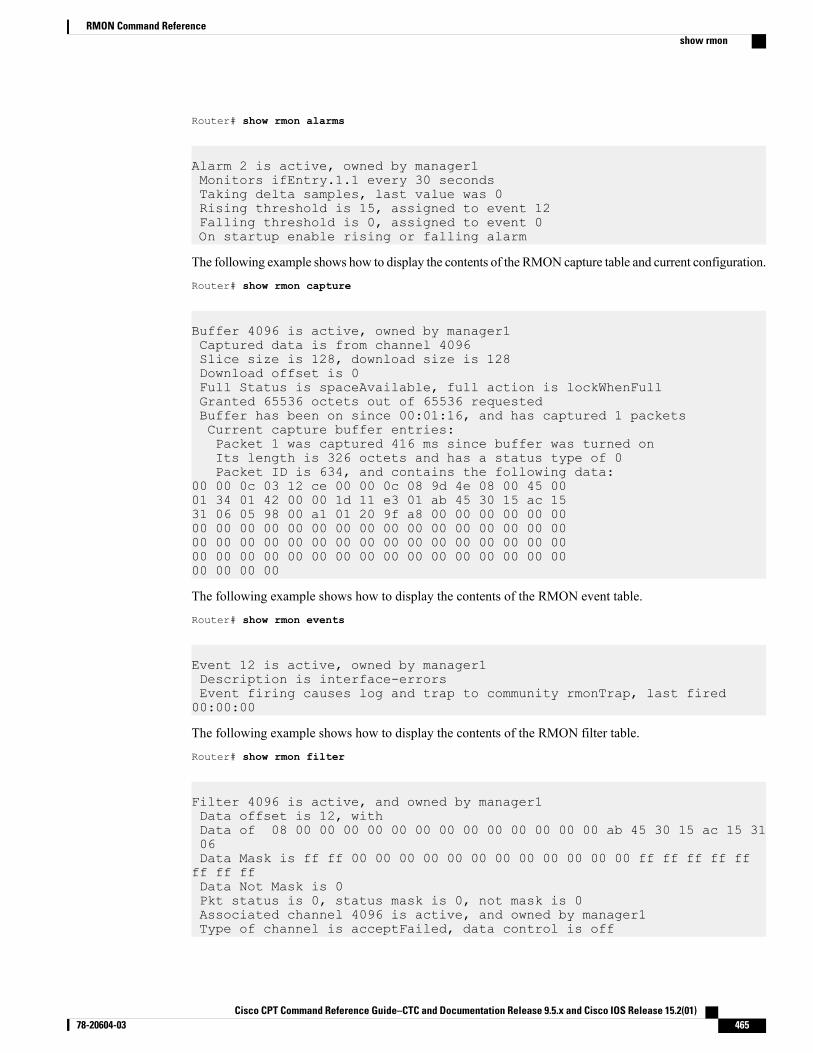
Router# show rmon alarms
Alarm 2 is active, owned by manager1Monitors ifEntry.1.1 every 30 secondsTaking delta samples, last value was 0Rising threshold is 15, assigned to event 12Falling threshold is 0, assigned to event 0On startup enable rising or falling alarm
The following example shows how to display the contents of the RMON capture table and current configuration.
Router# show rmon capture
Buffer 4096 is active, owned by manager1Captured data is from channel 4096Slice size is 128, download size is 128Download offset is 0Full Status is spaceAvailable, full action is lockWhenFullGranted 65536 octets out of 65536 requestedBuffer has been on since 00:01:16, and has captured 1 packetsCurrent capture buffer entries:Packet 1 was captured 416 ms since buffer was turned onIts length is 326 octets and has a status type of 0Packet ID is 634, and contains the following data:
00 00 0c 03 12 ce 00 00 0c 08 9d 4e 08 00 45 0001 34 01 42 00 00 1d 11 e3 01 ab 45 30 15 ac 1531 06 05 98 00 a1 01 20 9f a8 00 00 00 00 00 0000 00 00 00 00 00 00 00 00 00 00 00 00 00 00 0000 00 00 00 00 00 00 00 00 00 00 00 00 00 00 0000 00 00 00 00 00 00 00 00 00 00 00 00 00 00 0000 00 00 00
The following example shows how to display the contents of the RMON event table.
Router# show rmon events
Event 12 is active, owned by manager1Description is interface-errorsEvent firing causes log and trap to community rmonTrap, last fired00:00:00
The following example shows how to display the contents of the RMON filter table.
Router# show rmon filter
Filter 4096 is active, and owned by manager1Data offset is 12, withData of 08 00 00 00 00 00 00 00 00 00 00 00 00 00 ab 45 30 15 ac 15 3106Data Mask is ff ff 00 00 00 00 00 00 00 00 00 00 00 00 ff ff ff ff ffff ff ffData Not Mask is 0Pkt status is 0, status mask is 0, not mask is 0Associated channel 4096 is active, and owned by manager1Type of channel is acceptFailed, data control is off
Cisco CPT Command Reference Guide–CTC and Documentation Release 9.5.x and Cisco IOS Release 15.2(01) 78-20604-03 465
RMON Command Referenceshow rmon
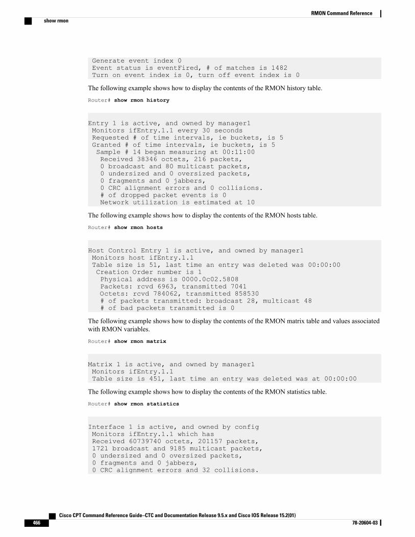
Generate event index 0Event status is eventFired, # of matches is 1482Turn on event index is 0, turn off event index is 0
The following example shows how to display the contents of the RMON history table.
Router# show rmon history
Entry 1 is active, and owned by manager1Monitors ifEntry.1.1 every 30 secondsRequested # of time intervals, ie buckets, is 5Granted # of time intervals, ie buckets, is 5Sample # 14 began measuring at 00:11:00Received 38346 octets, 216 packets,0 broadcast and 80 multicast packets,0 undersized and 0 oversized packets,0 fragments and 0 jabbers,0 CRC alignment errors and 0 collisions.# of dropped packet events is 0Network utilization is estimated at 10
The following example shows how to display the contents of the RMON hosts table.
Router# show rmon hosts
Host Control Entry 1 is active, and owned by manager1Monitors host ifEntry.1.1Table size is 51, last time an entry was deleted was 00:00:00Creation Order number is 1Physical address is 0000.0c02.5808Packets: rcvd 6963, transmitted 7041Octets: rcvd 784062, transmitted 858530# of packets transmitted: broadcast 28, multicast 48# of bad packets transmitted is 0
The following example shows how to display the contents of the RMON matrix table and values associatedwith RMON variables.
Router# show rmon matrix
Matrix 1 is active, and owned by manager1Monitors ifEntry.1.1Table size is 451, last time an entry was deleted was at 00:00:00
The following example shows how to display the contents of the RMON statistics table.
Router# show rmon statistics
Interface 1 is active, and owned by configMonitors ifEntry.1.1 which hasReceived 60739740 octets, 201157 packets,1721 broadcast and 9185 multicast packets,0 undersized and 0 oversized packets,0 fragments and 0 jabbers,0 CRC alignment errors and 32 collisions.
Cisco CPT Command Reference Guide–CTC and Documentation Release 9.5.x and Cisco IOS Release 15.2(01)466 78-20604-03
RMON Command Referenceshow rmon
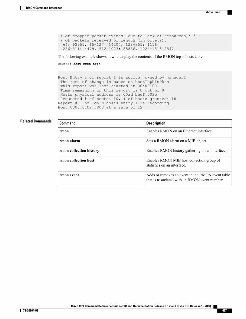
# of dropped packet events (due to lack of resources): 511# of packets received of length (in octets):64: 92955, 65-127: 14204, 128-255: 1116,256-511: 4479, 512-1023: 85856, 1024-1518:2547
The following example shows how to display the contents of the RMON top-n hosts table.
Router# show rmon topn
Host Entry 1 of report 1 is active, owned by manager1The rate of change is based on hostTopNInPktsThis report was last started at 00:00:00Time remaining in this report is 0 out of 0Hosts physical address is 00ad.beef.002bRequested # of hosts: 10, # of hosts granted: 10Report # 1 of Top N hosts entry 1 is recordingHost 0000.0c02.5808 at a rate of 12
Related Commands DescriptionCommand
Enables RMON on an Ethernet interface.rmon
Sets a RMON alarm on a MIB object.rmon alarm
Enables RMON history gathering on an interface.rmon collection history
Enables RMON MIB host collection group ofstatistics on an interface.
rmon collection host
Adds or removes an event in the RMON event tablethat is associated with an RMON event number.
rmon event
Cisco CPT Command Reference Guide–CTC and Documentation Release 9.5.x and Cisco IOS Release 15.2(01) 78-20604-03 467
RMON Command Referenceshow rmon

Cisco CPT Command Reference Guide–CTC and Documentation Release 9.5.x and Cisco IOS Release 15.2(01)468 78-20604-03
RMON Command Referenceshow rmon

CDP Command Reference
This chapter describes commands used to monitor the router and network using Cisco Discovery Protocol(CDP).
• cdp enable, page 470
• cdp run, page 471
• show cdp, page 472
• show cdp entry, page 473
• show cdp interface, page 475
• show cdp neighbors, page 476
• show cdp traffic, page 478
Cisco CPT Command Reference Guide–CTC and Documentation Release 9.5.x and Cisco IOS Release 15.2(01) 78-20604-03 469
cdp enableTo enable Cisco Discovery Protocol (CDP) on an interface, use the cdp enable command in interfaceconfiguration mode. To disable CDP on an interface, use the no form of this command.
cdp enable
no cdp enable
Syntax Description This command has no arguments or keywords.
Command Default Enabled at the global level and on all the supported interfaces.
Command Modes Interface configuration (config-if)
Command History ModificationRelease
This command was introduced.9.3.0
Usage Guidelines CDP is enabled by default at the global level and on each supported interface to send or receive CDPinformation.
Examples The following example shows how to disable CDP only on the TenGigabitEthernet4/1 interface.
Router# config terminalRouter(config)# interface TenGigabitEthernet4/1Router(config-if)# no cdp enable
Related Commands DescriptionCommand
Reenables CDP on a Cisco device.cdp run
Cisco CPT Command Reference Guide–CTC and Documentation Release 9.5.x and Cisco IOS Release 15.2(01)470 78-20604-03
CDP Command Referencecdp enable
cdp runTo enable the CDP, use the cdp run command in global configuration mode. To disable CDP, use the noform of this command.
cdp run
no cdp run
Syntax Description This command has no arguments or keywords.
Command Default Enabled at the global level and on all the supported interfaces.
Command Modes Global configuration (config)
Command History ModificationRelease
This command was introduced.9.3.0
Usage Guidelines CDP is enabled by default at the global level and on each supported interface to send or receive CDPinformation.
If CDP is disabled globally, you cannot enable it on each interface using the cdp enable interface configurationmode command.
Examples The following example shows how to enable CDP on the TenGigabitEthernet4/1 interface, when CDP isdisabled globally.
Router(config)# no cdp runRouter(config)# endRouter# show cdp% CDP is not enabledRouter# configure terminalEnter configuration commands, one per line. End with CNTL/Z.Router(config)# interface TenGigabitEthernet4/1Router(config-if)# cdp enable% Cannot enable CDP on this interface, since CDP is not runningRouter(config-if)#
Related Commands DescriptionCommand
Enables CDP on a supported interface.cdp enable
Cisco CPT Command Reference Guide–CTC and Documentation Release 9.5.x and Cisco IOS Release 15.2(01) 78-20604-03 471
CDP Command Referencecdp run
show cdpTo display global CDP information, including timer and hold-time information, use the show cdp commandin privileged EXEC mode.
show cdp
Syntax Description This command has no arguments or keywords.
Command Modes Privileged EXEC (#)
Command History ModificationRelease
This command was introduced.9.3.0
Examples The following is a sample output from the show cdp command that shows that the current router is transmittingCDP advertisements every one minute (the default setting for cdp timer). Also shown is that the current routerdirects its neighbors to hold its CDP advertisements for 3 minutes (the default for cdp holdtime), and thatthe router is enabled to transmit CDP version 2 advertisements.
Router# show cdp
Global CDP information:Sending CDP packets every 60 secondsSending a holdtime value of 180 secondsSending CDPv2 advertisements is enabled
Related Commands DescriptionCommand
Displays information about a specific neighbor devicelisted in the CDP table.
show cdp entry
Displays information about the interfaces on whichCDP is enabled.
show cdp interface
Displays detailed information about neighboringdevices discovered using CDP.
show cdp neighbors
Displays traffic information from the CDP table.show cdp traffic
Cisco CPT Command Reference Guide–CTC and Documentation Release 9.5.x and Cisco IOS Release 15.2(01)472 78-20604-03
CDP Command Referenceshow cdp
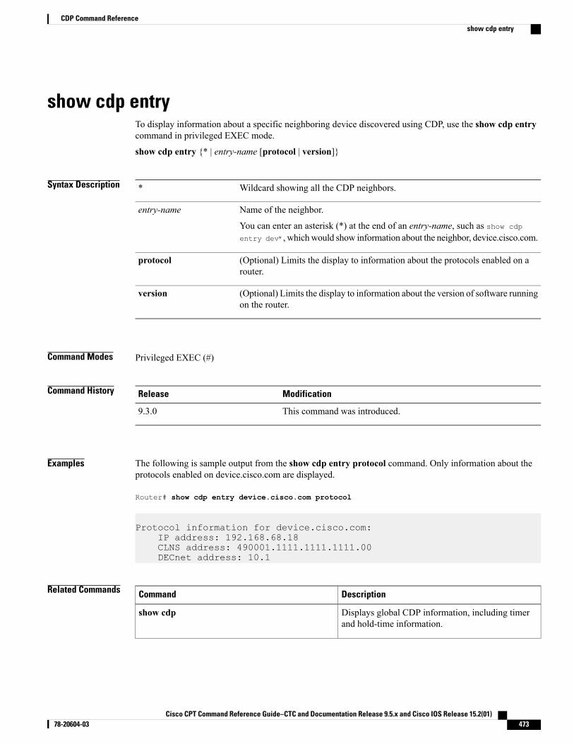
show cdp entryTo display information about a specific neighboring device discovered using CDP, use the show cdp entrycommand in privileged EXEC mode.
show cdp entry {* | entry-name [protocol | version]}
Syntax Description Wildcard showing all the CDP neighbors.*
Name of the neighbor.
You can enter an asterisk (*) at the end of an entry-name, such as show cdp
entry dev*, whichwould show information about the neighbor, device.cisco.com.
entry-name
(Optional) Limits the display to information about the protocols enabled on arouter.
protocol
(Optional) Limits the display to information about the version of software runningon the router.
version
Command Modes Privileged EXEC (#)
Command History ModificationRelease
This command was introduced.9.3.0
Examples The following is sample output from the show cdp entry protocol command. Only information about theprotocols enabled on device.cisco.com are displayed.
Router# show cdp entry device.cisco.com protocol
Protocol information for device.cisco.com:IP address: 192.168.68.18CLNS address: 490001.1111.1111.1111.00DECnet address: 10.1
Related Commands DescriptionCommand
Displays global CDP information, including timerand hold-time information.
show cdp
Cisco CPT Command Reference Guide–CTC and Documentation Release 9.5.x and Cisco IOS Release 15.2(01) 78-20604-03 473
CDP Command Referenceshow cdp entry
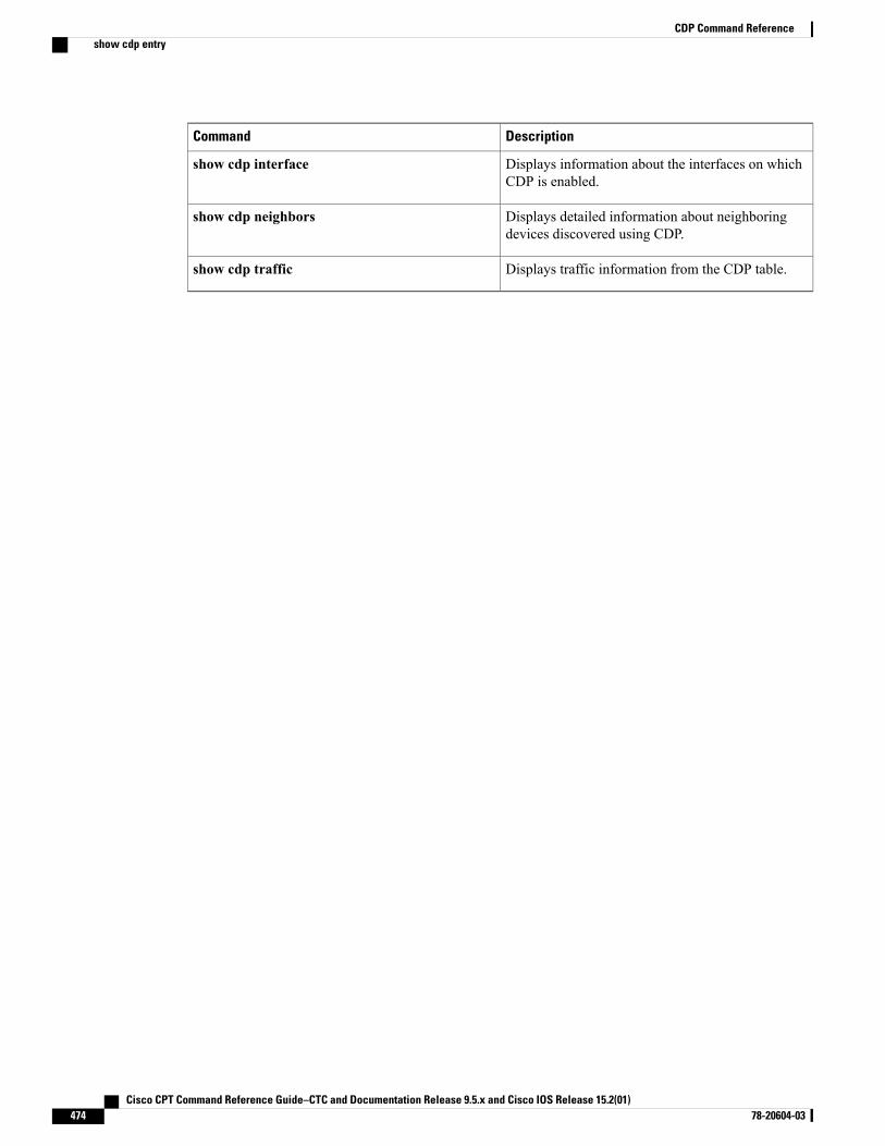
DescriptionCommand
Displays information about the interfaces on whichCDP is enabled.
show cdp interface
Displays detailed information about neighboringdevices discovered using CDP.
show cdp neighbors
Displays traffic information from the CDP table.show cdp traffic
Cisco CPT Command Reference Guide–CTC and Documentation Release 9.5.x and Cisco IOS Release 15.2(01)474 78-20604-03
CDP Command Referenceshow cdp entry
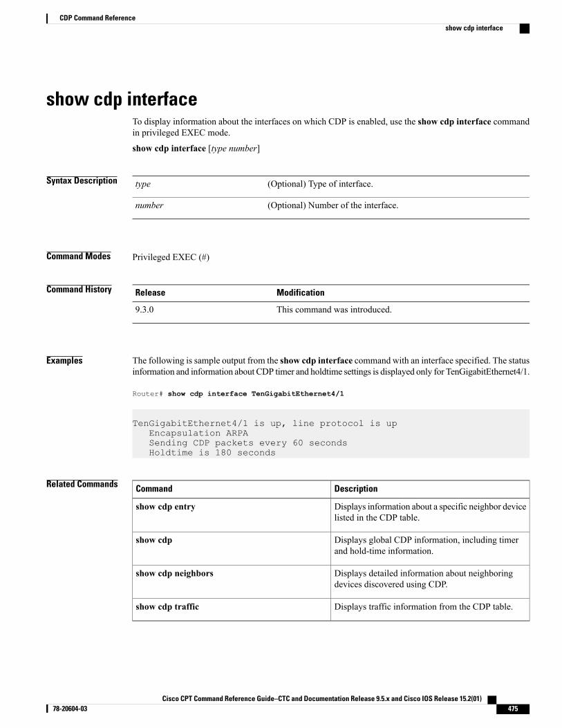
show cdp interfaceTo display information about the interfaces on which CDP is enabled, use the show cdp interface commandin privileged EXEC mode.
show cdp interface [type number]
Syntax Description (Optional) Type of interface.type
(Optional) Number of the interface.number
Command Modes Privileged EXEC (#)
Command History ModificationRelease
This command was introduced.9.3.0
Examples The following is sample output from the show cdp interface command with an interface specified. The statusinformation and information about CDP timer and holdtime settings is displayed only for TenGigabitEthernet4/1.
Router# show cdp interface TenGigabitEthernet4/1
TenGigabitEthernet4/1 is up, line protocol is upEncapsulation ARPASending CDP packets every 60 secondsHoldtime is 180 seconds
Related Commands DescriptionCommand
Displays information about a specific neighbor devicelisted in the CDP table.
show cdp entry
Displays global CDP information, including timerand hold-time information.
show cdp
Displays detailed information about neighboringdevices discovered using CDP.
show cdp neighbors
Displays traffic information from the CDP table.show cdp traffic
Cisco CPT Command Reference Guide–CTC and Documentation Release 9.5.x and Cisco IOS Release 15.2(01) 78-20604-03 475
CDP Command Referenceshow cdp interface
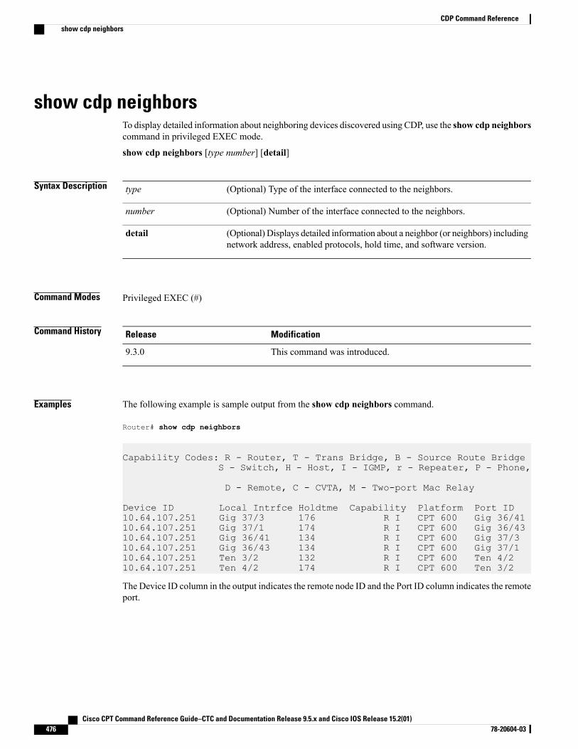
show cdp neighborsTo display detailed information about neighboring devices discovered using CDP, use the show cdp neighborscommand in privileged EXEC mode.
show cdp neighbors [type number] [detail]
Syntax Description (Optional) Type of the interface connected to the neighbors.type
(Optional) Number of the interface connected to the neighbors.number
(Optional) Displays detailed information about a neighbor (or neighbors) includingnetwork address, enabled protocols, hold time, and software version.
detail
Command Modes Privileged EXEC (#)
Command History ModificationRelease
This command was introduced.9.3.0
Examples The following example is sample output from the show cdp neighbors command.
Router# show cdp neighbors
Capability Codes: R - Router, T - Trans Bridge, B - Source Route BridgeS - Switch, H - Host, I - IGMP, r - Repeater, P - Phone,
D - Remote, C - CVTA, M - Two-port Mac Relay
Device ID Local Intrfce Holdtme Capability Platform Port ID10.64.107.251 Gig 37/3 176 R I CPT 600 Gig 36/4110.64.107.251 Gig 37/1 174 R I CPT 600 Gig 36/4310.64.107.251 Gig 36/41 134 R I CPT 600 Gig 37/310.64.107.251 Gig 36/43 134 R I CPT 600 Gig 37/110.64.107.251 Ten 3/2 132 R I CPT 600 Ten 4/210.64.107.251 Ten 4/2 174 R I CPT 600 Ten 3/2
The Device ID column in the output indicates the remote node ID and the Port ID column indicates the remoteport.
Cisco CPT Command Reference Guide–CTC and Documentation Release 9.5.x and Cisco IOS Release 15.2(01)476 78-20604-03
CDP Command Referenceshow cdp neighbors
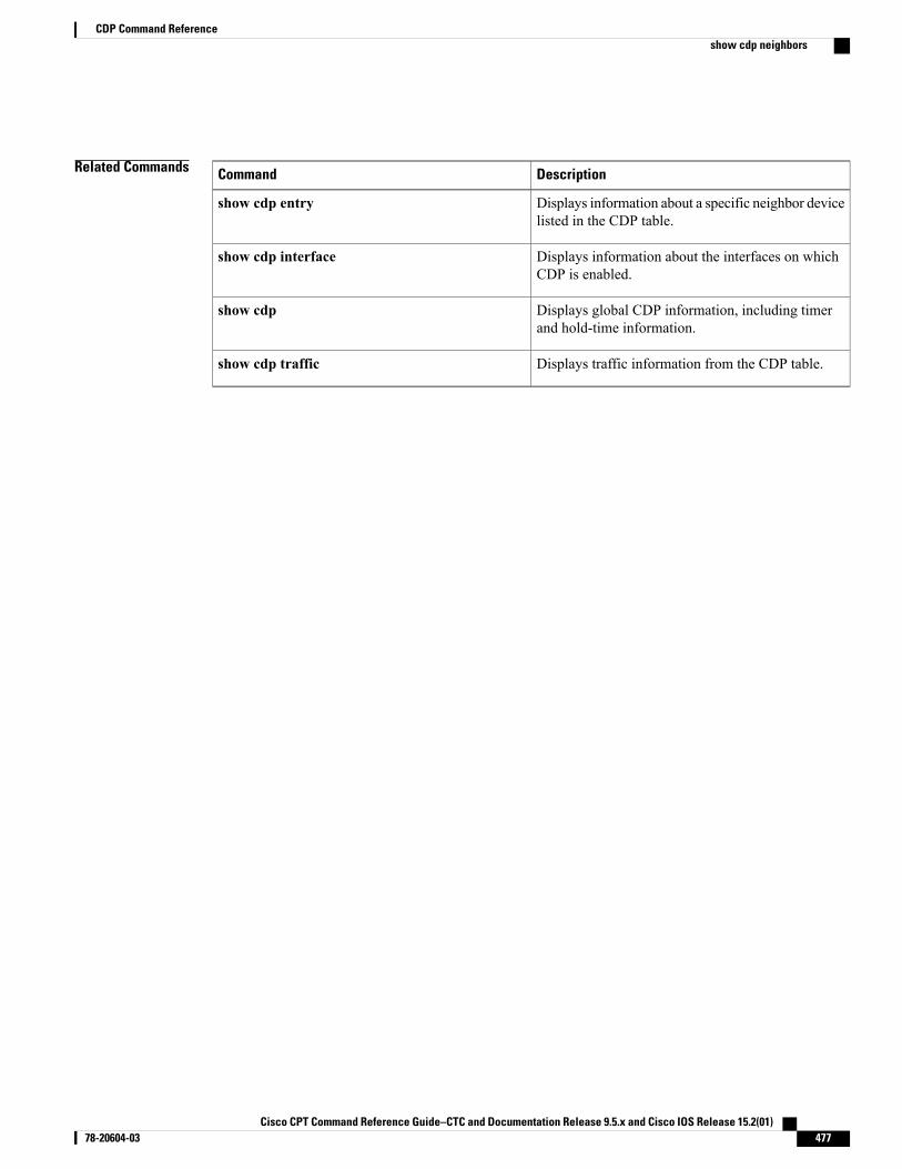
Related Commands DescriptionCommand
Displays information about a specific neighbor devicelisted in the CDP table.
show cdp entry
Displays information about the interfaces on whichCDP is enabled.
show cdp interface
Displays global CDP information, including timerand hold-time information.
show cdp
Displays traffic information from the CDP table.show cdp traffic
Cisco CPT Command Reference Guide–CTC and Documentation Release 9.5.x and Cisco IOS Release 15.2(01) 78-20604-03 477
CDP Command Referenceshow cdp neighbors
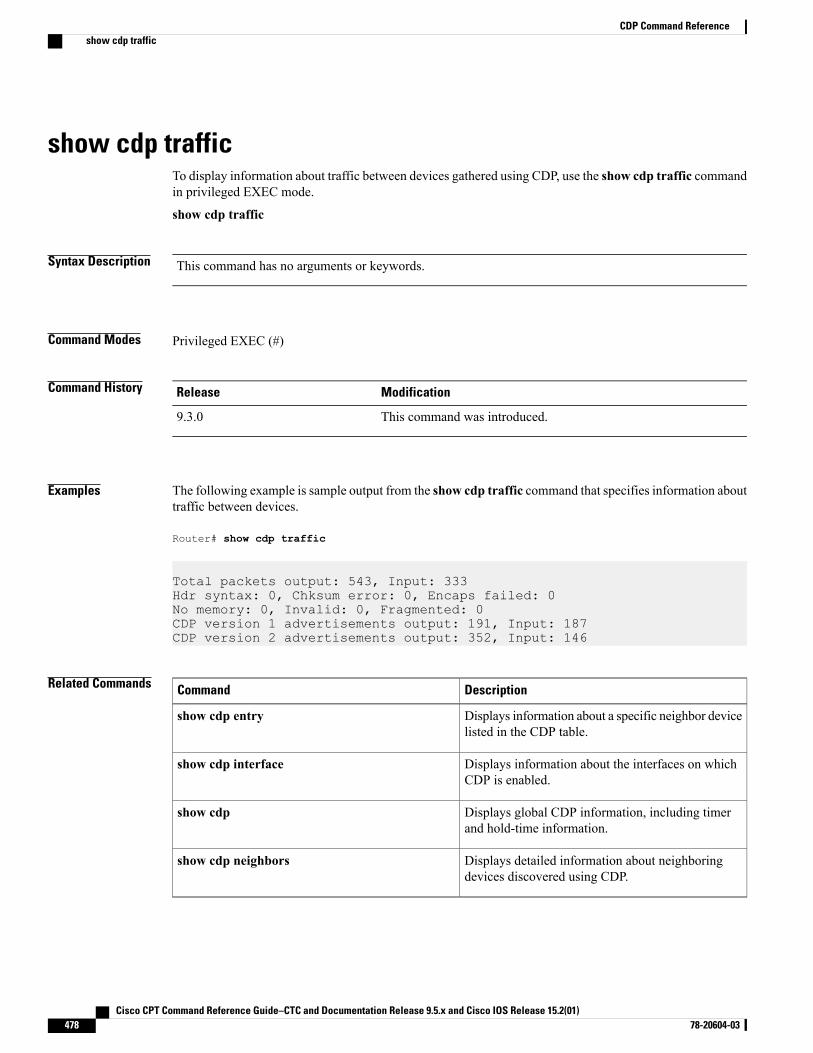
show cdp trafficTo display information about traffic between devices gathered using CDP, use the show cdp traffic commandin privileged EXEC mode.
show cdp traffic
Syntax Description This command has no arguments or keywords.
Command Modes Privileged EXEC (#)
Command History ModificationRelease
This command was introduced.9.3.0
Examples The following example is sample output from the show cdp traffic command that specifies information abouttraffic between devices.
Router# show cdp traffic
Total packets output: 543, Input: 333Hdr syntax: 0, Chksum error: 0, Encaps failed: 0No memory: 0, Invalid: 0, Fragmented: 0CDP version 1 advertisements output: 191, Input: 187CDP version 2 advertisements output: 352, Input: 146
Related Commands DescriptionCommand
Displays information about a specific neighbor devicelisted in the CDP table.
show cdp entry
Displays information about the interfaces on whichCDP is enabled.
show cdp interface
Displays global CDP information, including timerand hold-time information.
show cdp
Displays detailed information about neighboringdevices discovered using CDP.
show cdp neighbors
Cisco CPT Command Reference Guide–CTC and Documentation Release 9.5.x and Cisco IOS Release 15.2(01)478 78-20604-03
CDP Command Referenceshow cdp traffic

Miscellaneous Command Reference
This chapter describes miscellaneous commands to configure CPT services.
• show ip interface brief, page 480
Cisco CPT Command Reference Guide–CTC and Documentation Release 9.5.x and Cisco IOS Release 15.2(01) 78-20604-03 479
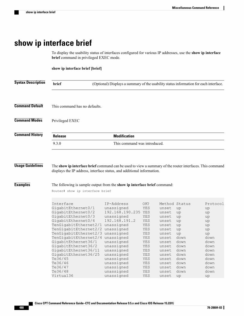
show ip interface briefTo display the usability status of interfaces configured for various IP addresses, use the show ip interfacebrief command in privileged EXEC mode.
show ip interface brief [brief]
Syntax Description (Optional) Displays a summary of the usability status information for each interface.brief
Command Default This command has no defaults.
Command Modes Privileged EXEC
Command History ModificationRelease
This command was introduced.9.3.0
Usage Guidelines The show ip interface brief command can be used to view a summary of the router interfaces. This commanddisplays the IP address, interface status, and additional information.
Examples The following is sample output from the show ip interface brief command:Router# show ip interface brief
Interface IP-Address OK? Method Status ProtocolGigabitEthernet0/1 unassigned YES unset up upGigabitEthernet0/2 192.168.190.235 YES unset up upGigabitEthernet0/3 unassigned YES unset up upGigabitEthernet0/4 192.168.191.2 YES unset up upTenGigabitEthernet2/1 unassigned YES unset up upTenGigabitEthernet2/2 unassigned YES unset up upTenGigabitEthernet2/3 unassigned YES unset up upTenGigabitEthernet2/4 unassigned YES unset down downGigabitEthernet36/1 unassigned YES unset down downGigabitEthernet36/2 unassigned YES unset down downGigabitEthernet36/11 unassigned YES unset down downGigabitEthernet36/25 unassigned YES unset down downTe36/45 unassigned YES unset down downTe36/46 unassigned YES unset down downTe36/47 unassigned YES unset down downTe36/48 unassigned YES unset down downVirtual36 unassigned YES unset up up
Cisco CPT Command Reference Guide–CTC and Documentation Release 9.5.x and Cisco IOS Release 15.2(01)480 78-20604-03
Miscellaneous Command Referenceshow ip interface brief
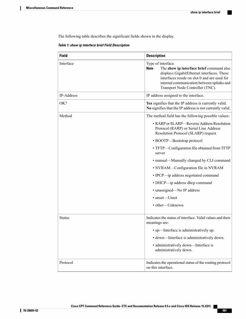
The following table describes the significant fields shown in the display.
Table 1: show ip interface brief Field Description
DescriptionField
Type of interface.The show ip interface brief command alsodisplays GigabitEthernet interfaces. Theseinterfaces reside on slot 0 and are used forinternal communication between uplinks andTransport Node Controller (TNC).
NoteInterface
IP address assigned to the interface.IP-Address
Yes signifies that the IP address is currently valid.No signifies that the IP address is not currently valid.
OK?
The method field has the following possible values:
• RARPor SLARP—ReverseAddress ResolutionProtocol (RARP) or Serial Line AddressResolution Protocol (SLARP) request
• BOOTP—Bootstrap protocol
• TFTP—Configuration file obtained from TFTPserver
• manual—Manually changed by CLI command
• NVRAM—Configuration file in NVRAM
• IPCP—ip address negotiated command
• DHCP—ip address dhcp command
• unassigned—No IP address
• unset—Unset
• other—Unknown
Method
Indicates the status of interface. Valid values and theirmeanings are:
• up—Interface is administratively up.
• down—Interface is administratively down.
• administratively down—Interface isadministratively down.
Status
Indicates the operational status of the routing protocolon this interface.
Protocol
Cisco CPT Command Reference Guide–CTC and Documentation Release 9.5.x and Cisco IOS Release 15.2(01) 78-20604-03 481
Miscellaneous Command Referenceshow ip interface brief

Cisco CPT Command Reference Guide–CTC and Documentation Release 9.5.x and Cisco IOS Release 15.2(01)482 78-20604-03
Miscellaneous Command Referenceshow ip interface brief

I N D E X
A
affinity 17auto-bw 19
B
backup delay 142backup peer 143bandwidth 21, 181bfd-template 106bridge-domain 2
C
cdp enable 470cdp run 471cfm encapsulation 344cfm mep domain 346channel-group 288class 184class-map 186clear ethernet service instance 3clear mac-address-table 310continuity-check 352cos (CFM) 354crashdump-timeout 232
D
debug-mpls tp 107
E
encapsulation 5, 145ethernet cfm domain level 359ethernet cfm global 361
ethernet cfm interface 362ethernet cfm mep crosscheck 367ethernet cfm mep crosscheck start-delay 369ethernet cfm mep domain mpid 370ethernet cfm mip 371ethernet cfm mip level 373ethernet cfm traceroute cache 375ethernet cfm traceroute cache hold-time 376ethernet cfm traceroute cache size 378ethernet oam 380ethernet oam link-monitor frame 382ethernet oam link-monitor frame-period 384ethernet oam link-monitor frame-seconds 386ethernet oam link-monitor high-threshold action 388ethernet oam link-monitor on 390ethernet oam link-monitor receive-crc 391ethernet oam link-monitor supported 393ethernet oam link-monitor symbol-period 395ethernet oam link-monitor transmit-crc 397ethernet oam remote-failure action 399ethernet oam remote-loopback 400ethernet oam remote-loopback (interface) 401
I
id (CFM) 408index 22interface port-channel 290interface tunnel-tp 109interval 115interworking 146ip explicit-path 23ip igmp snooping 318ip igmp snooping immediate-leave 319ip igmp snooping report-suppression 321ip route 24ip rsvp bandwidth 26ip rsvp signalling hello graceful-restart neighbor 28
Cisco CPT Command Reference Guide–CTC and Documentation Release 9.5.x and Cisco IOS Release 15.2(01) 78-20604-03 IN-1
L
l2 vfi point-to-point 147l2protocol 6lacp fast-switchover 291lacp max-bundle 292lacp min-bundle 293lacp port-priority 294lacp system-priority 296local interface 117local link notification 148
M
mac learning 311mac limit maximum addresses 313mac static address 314match cos 191match ip dscp 193match ip precedence 189match mpls experimental topmost 195match qos-group 196maximum meps 417medium p2p 119mep archive-hold-time 418mep mpid 419mip auto-create 420mip auto-create (cfm-srv) 421mode 7mpls control-word 149mpls ip 29, 30mpls label 151mpls label protocol ldp 32, 33mpls ldp autoconfig 34mpls ldp backoff 36mpls ldp explicit-null 38mpls ldp graceful-restart 39mpls ldp graceful-restart timers forwarding-holding 40mpls ldp graceful-restart timers max-recovery 41mpls ldp graceful-restart timers neighbor-liveness 42mpls ldp igp sync 44mpls ldp igp sync holddown 46mpls ldp neighbor targeted 47mpls ldp router-id 49mpls ldp session protection 51mpls ldp sync 53mpls tp 120mpls tp link 123mpls tp lsp 125mpls traffic-eng area 54mpls traffic-eng link-management timers periodic-flooding 55mpls traffic-eng lsp attributes 56mpls traffic-eng path-option list 61
mpls traffic-eng router-id 58mpls traffic-eng tunnels 59, 60mvr 328mvr group 329mvr type 331
N
neighbor 154network area 233next-address 63nsf cisco 235nsf ietf 237
P
ping ethernet 423ping mpls 65ping mpls tp 128platform 198police (policy map) 200policy-map 204port-channel load-balance 298preferred-path 155priority 69, 206pseudowire 159pseudowire-class 153, 157pseudowire-static-oam class 132pseudowire-tlv template 133
R
record-route 71remote link failure notification 161rep admin vlan 270rep block port 271rep lsl-age-timer 273rep lsl-retries 274rep preempt delay 275rep preempt segment 277rep segment 279rep stcn 281rmon 454rmon alarm 456rmon collection history 458rmon collection host 460rmon event 461router ospf 239
Cisco CPT Command Reference Guide–CTC and Documentation Release 9.5.x and Cisco IOS Release 15.2(01)IN-2 78-20604-03
Index
S
service (CFM-srv) 425service instance ethernet 11service-policy 208set cos 210set discard-class 212set ip dscp 214set ip precedence 216set qos-group 218shape 220show cdp 472show cdp entry 473show cdp interface 475show cdp neighbors 476show cdp traffic 478show cef nsf 240show cef state 241show class-map 222show controllers 463show ethernet cfm domain 426show ethernet cfm errors 428show ethernet cfm maintenance-points local 430show ethernet cfm maintenance-points remote 432show ethernet cfm maintenance-points remote crosscheck 434show ethernet cfm maintenance-points remote detail 436show ethernet cfm mpdb 438show ethernet cfm statistics 442show ethernet cfm traceroute-cache 444show ethernet service instance 13show interfaces port-channel 299show interfaces rep detail 282show ip explicit-paths 72show ip ospf 243show ip ospf mpls ldp interface 82show ip ospf neighbor 244show ip ospf nsf 246show ip rsvp sender 74show issu capability 248show issu clients 250show issu comp-matrix 252show issu endpoints 254show issu entities 256show issu fsm 258show issu message 260show issu negotiated 262show issu sessions 264show lacp 301show mac-address-table 315
show mpls interfaces 84show mpls l2transport binding 162show mpls l2transport vc 163show mpls ldp backoff 75show mpls ldp discovery 86show mpls ldp igp sync 88show mpls ldp neighbor 90show mpls tp 134show mpls traffic-eng lsp attributes 76show mpls traffic-eng tunnels 78show mvr 333show policy-map 223show policy-map class 225show policy-map interface 227show redundancy 266show rep topology 284show rmon 464status 167status protocol notification static 136status redundancy 166stitching tlv 168
T
table-map 229tlv template 137trace mpls 92trace mpls tp 138traceroute ethernet 451tunnel mode mpls traffic-eng 95tunnel mpls traffic-eng autoroute announce 99tunnel mpls traffic-eng bandwidth 100tunnel mpls traffic-eng path-option 97tunnel mpls traffic-eng priority 101tunnel mpls traffic–eng path–option protect 103
V
vccv 170, 172vccv bfd template 174
X
xconnect 176
Cisco CPT Command Reference Guide–CTC and Documentation Release 9.5.x and Cisco IOS Release 15.2(01) 78-20604-03 IN-3
Index

Cisco CPT Command Reference Guide–CTC and Documentation Release 9.5.x and Cisco IOS Release 15.2(01)IN-4 78-20604-03
Index
Related Documents