Cisco ASR 5500 System Administration Guide Version 15.0 Last Updated October 31, 2014 Americas Headquarters Cisco Systems, Inc. 170 West Tasman Drive San Jose, CA 95134-1706 USA http://www.cisco.com Tel: 408 526-4000 800 553-NETS (6387) Fax: 408 527-0883

Welcome message from author
This document is posted to help you gain knowledge. Please leave a comment to let me know what you think about it! Share it to your friends and learn new things together.
Transcript

Cisco ASR 5500 System Administration Guide
Version 15.0
Last Updated October 31, 2014
Americas Headquarters Cisco Systems, Inc. 170 West Tasman Drive San Jose, CA 95134-1706 USA http://www.cisco.com Tel: 408 526-4000 800 553-NETS (6387) Fax: 408 527-0883

THE SPECIFICATIONS AND INFORMATION REGARDING THE PRODUCTS IN THIS MANUAL ARE SUBJECT TO CHANGE WITHOUT NOTICE. ALL
STATEMENTS, INFORMATION, AND RECOMMENDATIONS IN THIS MANUAL ARE BELIEVED TO BE ACCURATE BUT ARE PRESENTED WITHOUT
WARRANTY OF ANY KIND, EXPRESS OR IMPLIED. USERS MUST TAKE FULL RESPONSIBILITY FOR THEIR APPLICATION OF ANY PRODUCTS.
THE SOFTWARE LICENSE AND LIMITED WARRANTY FOR THE ACCOMPANYING PRODUCT ARE SET FORTH IN THE INFORMATION PACKET THAT SHIPPED
WITH THE PRODUCT AND ARE INCORPORATED HEREIN BY THIS REFERENCE. IF YOU ARE UNABLE TO LOCATE THE SOFTWARE LICENSE OR LIMITED
WARRANTY, CONTACT YOUR CISCO REPRESENTATIVE FOR A COPY.
The Cisco implementation of TCP header compression is an adaptation of a program developed by the University of California, Berkeley (UCB) as part of UCB’s public domain
version of the UNIX operating system. All rights reserved. Copyright © 1981, Regents of the University of California.
NOTWITHSTANDING ANY OTHER WARRANTY HEREIN, ALL DOCUMENT FILES AND SOFTWARE OF THESE SUPPLIERS ARE PROVIDED “AS IS” WITH ALL
FAULTS. CISCO AND THE ABOVE-NAMED SUPPLIERS DISCLAIM ALL WARRANTIES, EXPRESSED OR IMPLIED, INCLUDING, WITHOUT LIMITATION, THOSE
OF MERCHANTABILITY, FITNESS FOR A PARTICULAR PURPOSE AND NONINFRINGEMENT OR ARISING FROM A COURSE OF DEALING, USAGE, OR TRADE
PRACTICE.
IN NO EVENT SHALL CISCO OR ITS SUPPLIERS BE LIABLE FOR ANY INDIRECT, SPECIAL, CONSEQUENTIAL, OR INCIDENTAL DAMAGES, INCLUDING,
WITHOUT LIMITATION, LOST PROFITS OR LOSS OR DAMAGE TO DATA ARISING OUT OF THE USE OR INABILITY TO USE THIS MANUAL, EVEN IF CISCO OR
ITS SUPPLIERS HAVE BEEN ADVISED OF THE POSSIBILITY OF SUCH DAMAGES.
Cisco and the Cisco Logo are trademarks of Cisco Systems, Inc. and/or its affiliates in the U.S. and other countries. A listing of Cisco's trademarks can be found at
www.cisco.com/go/trademarks. Third party trademarks mentioned are the property of their respective owners. The use of the word partner does not imply a partnership relationship
between Cisco and any other company.
Any Internet Protocol (IP) addresses and phone numbers used in this document are not intended to be actual addresses and phon e numbers. Any examples, command display
output, network topology diagrams, and other figures included in the document are shown for illustrative purposes only. Any use of actual IP addresses or phone numbers in
illustrative content is unintentional and coincidental.
Cisco ASR 5500 System Administration Guide
© 2014 Cisco Systems, Inc. All rights reserved.
Cisco ASR 5500 System Administration Guide ▄ iii
CONTENTS
About this Guide .............................................................................................. xiii Conventions Used .................................................................................................................................. xiv Supported Documents and Resources ...................................................................................................xv
Related Documentation ...................................................................................................................... xv Contacting Customer Support .................................................................................................................xv
System Operation and Configuration ............................................................. 17 Terminology ............................................................................................................................................ 18
Contexts ............................................................................................................................................. 18 Ports ................................................................................................................................................... 18 Logical Interface ................................................................................................................................. 18 Management Interface ....................................................................................................................... 19 Bindings .............................................................................................................................................. 19 Services .............................................................................................................................................. 19 AAA Servers ....................................................................................................................................... 20 Subscribers ........................................................................................................................................ 20
How the System Selects Contexts ......................................................................................................... 21 Context Selection for Context-level Administrative User Sessions .................................................... 21 Context Selection for Subscriber Sessions ........................................................................................ 23
Understanding the ASR 5500 Boot Process .......................................................................................... 24 Understanding Configuration Files ......................................................................................................... 26 IP Address Notation ................................................................................................................................ 28
IPv4 Dotted-Decimal Notation ............................................................................................................ 28 IPv6 Colon-Separated-Hexadecimal Notation ................................................................................... 28 CIDR Notation .................................................................................................................................... 28
Alphanumeric Strings ............................................................................................................................. 30 Character Set ..................................................................................................................................... 30 Quoted Strings ................................................................................................................................... 31
Getting Started .................................................................................................. 33 ASR 5500 Configuration ......................................................................................................................... 34 Using the ASR 5500 Quick Setup Wizard .............................................................................................. 34 Using the CLI for Initial Configuration ..................................................................................................... 40 Configuring the System for Remote Access........................................................................................... 42 Configuring the Management Interface with a Second IP Address........................................................ 44
System Settings ................................................................................................ 45 Configuring a Second Management Interface ........................................................................................ 46 Verifying and Saving Your Interface and Port Configuration .................................................................. 47 Configuring System Timing .................................................................................................................... 48
Setting the System Clock and Time Zone .......................................................................................... 48 Verifying and Saving Your Clock and Time Zone Configuration ........................................................ 48 Configuring Network Time Protocol Support ...................................................................................... 49 Configuring NTP Servers with Local Sources .................................................................................... 50 Using a Load Balancer ....................................................................................................................... 50 Verifying the NTP Configuration ......................................................................................................... 50
Enabling CLI Timestamping ................................................................................................................... 52 Configuring System Administrative Users .............................................................................................. 52

▀ Contents
▄ Cisco ASR 5500 System Administration Guide
iv
Configuring Context-level Administrative Users ................................................................................. 52 Configuring Context-level Security Administrators......................................................................... 52 Configuring Context-level Administrators ....................................................................................... 53 Configuring Context-level Operators .............................................................................................. 53 Configuring Context-level Inspectors ............................................................................................. 54 Verifying Context-level Administrative User Configuration ............................................................ 54
Configuring Local-User Administrative Users..................................................................................... 55 Verifying Local-User Configuration ..................................................................................................... 55 Updating Local User Database .......................................................................................................... 55
Configuring TACACS+ for System Administrative Users ....................................................................... 56 Operation ............................................................................................................................................ 56 User Account Requirements .............................................................................................................. 56
TACACS+ User Account Requirements ........................................................................................ 56 User Account Requirements .......................................................................................................... 57
Configuring TACACS+ AAA Services ................................................................................................ 58 Verifying the TACACS+ Configuration ............................................................................................... 59
Configuring a Chassis Key ..................................................................................................................... 60 Configuring MIO/UMIO Port Redundancy .............................................................................................. 61
Configuring MIO/UMIO Port Redundancy Auto-Recovery ................................................................. 63 Verifying Port Redundancy Auto-Recovery ................................................................................... 64
Configuring Data Processing Card (DPC) Availability ............................................................................ 65 Verifying Card Configurations ............................................................................................................ 65
Configuring ASR 5500 Link Aggregation ................................................................................................ 66 LAG and Master Port .......................................................................................................................... 66 LAG and Port Redundancy ................................................................................................................ 66 LAG and Multiple Switches ................................................................................................................ 66
Multiple Switches with L2 Redundancy .......................................................................................... 67 Port States for Auto-Switch ............................................................................................................ 67 Hold Time ....................................................................................................................................... 68 Preferred Slot ................................................................................................................................. 68 Auto-Switch Criteria ....................................................................................................................... 68
Link Aggregation Control .................................................................................................................... 69 Redundancy Options .......................................................................................................................... 70 Horizontal Link Aggregation with Two Ethernet Switches .................................................................. 70 Link Aggregation Status ..................................................................................................................... 71
Configuring a Demux Card ..................................................................................................................... 72 Overview ............................................................................................................................................. 72 MIO/UMIO Demux Restrictions .......................................................................................................... 72 Configuration ...................................................................................................................................... 73
Management Settings ....................................................................................... 75 ORBEM and the Web Element Manager ................................................................................................ 76
Configuring ORBEM Client and Port Parameters .............................................................................. 76 Configuring IIOP Transport Parameters ............................................................................................. 77 Verifying ORBEM Parameters ............................................................................................................ 77
SNMP Support ........................................................................................................................................ 79 Configuring SNMP and Alarm Server Parameters ............................................................................. 79 Verifying SNMP Parameters .............................................................................................................. 80 Controlling SNMP Trap Generation .................................................................................................... 81
Verifying and Saving Your Configuration ...................................................... 83 Verifying the Configuration ..................................................................................................................... 84
Feature Configuration ......................................................................................................................... 84 Service Configuration ......................................................................................................................... 84 Context Configuration ......................................................................................................................... 85
Contents ▀
Cisco ASR 5500 System Administration Guide ▄ v
System Configuration ......................................................................................................................... 85 Finding Configuration Errors .............................................................................................................. 85
Saving the Configuration ........................................................................................................................ 86
System Interfaces and Ports............................................................................ 87 Contexts.................................................................................................................................................. 88
Creating Contexts ............................................................................................................................... 88 Viewing and Verifying Contexts ......................................................................................................... 88
Ethernet Interfaces and Ports ................................................................................................................. 89 Creating an Interface .......................................................................................................................... 89 Configuring a Port and Binding It to an Interface ............................................................................... 90 Configuring a Static Route for an Interface ........................................................................................ 90 Viewing and Verifying Port Configuration .......................................................................................... 91
System Security ................................................................................................ 93 Per-Chassis Key Identifier ...................................................................................................................... 94
MIO/UMIO Synchronization ............................................................................................................... 95 Protection of Passwords .................................................................................................................... 95 Secure Configuration Password Encryption ...................................................................................... 95 Support for Non-Current Encryptions and Decryptions ...................................................................... 95 Selectable Password/Secrets Encryption Algorithm .......................................................................... 95 Support for ICSR Configurations ........................................................................................................ 96
Encrypted SNMP Community Strings .................................................................................................... 97 Lawful Intercept Restrictions .................................................................................................................. 97
LI Server Addresses ........................................................................................................................... 97 Modifying Intercepts ........................................................................................................................... 97
Adding, Modifying and Removing Users ................................................................................................ 98 Notification of Users Being Added or Deleted .................................................................................... 98 Notification of Changes in Privilege Levels ........................................................................................ 98 User Access to Operating System Shell ............................................................................................ 98
Hidden Commands ................................................................................................................................. 99 Enabling cli test-commands Mode ..................................................................................................... 99 Enabling Password for Access to CLI-test commands ...................................................................... 99 Exec Mode cli test-commands ......................................................................................................... 100 Configuration mode cli test-commands ............................................................................................ 100
Software Management Operations ................................................................ 101 Understanding the Local File System ................................................................................................... 102
File Types Used by the Local File System ....................................................................................... 102 Understanding the boot.sys File ....................................................................................................... 102
Maintaining the Local File System ........................................................................................................ 104 File System Management Commands ............................................................................................. 104
Synchronizing the File System .................................................................................................... 104 Creating Directories ..................................................................................................................... 104 Renaming Files and Directories ................................................................................................... 105 Copying Files on the ASR 5500 Chassis ..................................................................................... 105 Deleting Files ............................................................................................................................... 106 Removing Directories ................................................................................................................... 106 Formatting Local Devices ............................................................................................................ 106
Applying Pre-existing CLI Configuration Files .................................................................................. 107 Viewing Files on the Local File System ............................................................................................ 107
Viewing the Contents of a Local Device ...................................................................................... 107 Viewing CLI Configuration and boot.sys Files ............................................................................. 107 Validating an Operating System File ........................................................................................... 108
Configuring the Boot Stack ................................................................................................................... 109
▀ Contents
▄ Cisco ASR 5500 System Administration Guide
vi
System Boot Methods ...................................................................................................................... 109 Viewing the Current Boot Stack ....................................................................................................... 109 Adding a New Boot Stack Entry ....................................................................................................... 111 Deleting a Boot Stack Entry ............................................................................................................. 111 Network Booting Configuration Requirements ................................................................................. 112
Configuring the Boot Interface ..................................................................................................... 112 Configuring the Boot Network ...................................................................................................... 112 Configuring Boot Network Delay Time ......................................................................................... 113 Configuring a Boot Nameserver ................................................................................................... 114
Upgrading the Operating System Software .......................................................................................... 115 Identifying OS Release Version and Build Number ......................................................................... 115 Verify Free Space on the /flash Device ............................................................................................ 115 Download the Software Image from the Support Site ...................................................................... 116 Transfer StarOS Image to /flash on the Chassis .............................................................................. 116 Saving a Copy of the Current Configuration File .............................................................................. 116 Downgrading from Release 15.0 to 14.0 .......................................................................................... 117 Off-line Software Upgrade ................................................................................................................ 117
Configure a Newcall Policy .......................................................................................................... 117 Configure a Message of the Day Banner ..................................................................................... 118 Back up the Current CLI Configuration File ................................................................................. 118 Create a New Boot Stack Entry ................................................................................................... 118 Synchronize File Systems ............................................................................................................ 119 Reboot the Chassis ...................................................................................................................... 119
Verify the Running Software Version ............................................................................................... 119 Restoring the Previous Software Image ........................................................................................... 120 Upgrading ICSR Chassis.................................................................................................................. 120
Performing Dynamic Software Updates ............................................................................................... 120 Managing License Keys ........................................................................................................................ 121
New System License Keys ............................................................................................................... 121 Session Use and Feature Use Licenses .......................................................................................... 121 Installing New License Keys ............................................................................................................. 122
Cutting and Pasting the Key......................................................................................................... 122 Adding License Keys to Configuration Files ................................................................................ 123
License Expiration Behavior ............................................................................................................. 123 Requesting License Keys ................................................................................................................. 123 Viewing License Information ............................................................................................................ 124 Deleting a License Key ..................................................................................................................... 124 Management Card Replacement and License Keys ........................................................................ 124
Managing Local-User Administrative Accounts .................................................................................... 125 Configuring Local-User Password Properties .................................................................................. 125 Configuring Local-User Account Management Properties ............................................................... 125
Local-User Account Lockouts ...................................................................................................... 125 Local-User Account Suspensions ................................................................................................ 126
Changing Local-User Passwords ..................................................................................................... 126
Monitoring the System ................................................................................... 127 SNMP Notifications ............................................................................................................................... 128 Monitoring System Status and Performance ........................................................................................ 128 Clearing Statistics and Counters .......................................................................................................... 129 Monitoring ASR 5500 Hardware Status ................................................................................................ 130
Bulk Statistics ................................................................................................. 133 Configuring Communication with the Collection Server ....................................................................... 134
Configuring Standard Settings ......................................................................................................... 134 Configuring Optional Settings ........................................................................................................... 134
Contents ▀
Cisco ASR 5500 System Administration Guide ▄ vii
Configuring Bulk Statistic Schemas ................................................................................................. 135 Verifying Your Configuration ............................................................................................................ 135 Saving Your Configuration ............................................................................................................... 136
Viewing Collected Bulk Statistics Data ................................................................................................. 137 Manually Gathering and Transferring Bulk Statistics ........................................................................... 138 Clearing Bulk Statistics Counters and Information ............................................................................... 138 Bulk Statistics Event Log Messages .................................................................................................... 138
System Logs .................................................................................................... 139 System Log Types ................................................................................................................................ 140 Configuring Event Logging Parameters ............................................................................................... 141
Configuring Event Log Filters ........................................................................................................... 141 Configuring syslog Servers .............................................................................................................. 142
Configuring Active Logs ........................................................................................................................ 143 Specifying Facilities .............................................................................................................................. 144 Configuring Trace Logging ................................................................................................................... 152 Configuring Monitor Logs ..................................................................................................................... 153
Enabling Monitor Logs...................................................................................................................... 153 Disabling Monitor Logs ..................................................................................................................... 153
Viewing Logging Configuration and Statistics ...................................................................................... 154 Viewing Event Logs Using the CLI ....................................................................................................... 155 Configuring and Viewing Crash Logs ................................................................................................... 156
Crash Logging Architecture .............................................................................................................. 156 Configuring Software Crash Log Destinations ................................................................................. 157 Viewing Abridged Crash Log Information Using the CLI .................................................................. 158
Saving Log Files ................................................................................................................................... 159 Event ID Overview ................................................................................................................................ 160
Event Severities ............................................................................................................................... 168 Understanding Event ID Information in Logged Output ................................................................... 169
Troubleshooting .............................................................................................. 171 Detecting Faulty Hardware ................................................................................................................... 172
Licensing Issues ............................................................................................................................... 172 Using the CLI to View Status LEDs .................................................................................................. 172 Checking the LEDs on the PFU ....................................................................................................... 173 Checking the LEDs on the MIO and UMIO ...................................................................................... 174
MIO/UMIO Run/Fail LED States .................................................................................................. 174 MIO/UMIO Active LED States ...................................................................................................... 175 MIO/UMIO Redundancy LED States ........................................................................................... 176 MIO/UMIO Master LED States .................................................................................................... 176 MIO/UMIO Busy LED States ....................................................................................................... 177 MIO/UMIO – Interface Link LED States ....................................................................................... 177 MIO/UMIO – Interface Activity LED States .................................................................................. 178
Checking the LEDs on the DPC and UDPC..................................................................................... 178 DPC/UDPC Run/Fail LED States ................................................................................................ 179 DPC/UDPC Active LED States .................................................................................................... 179 DPC/UDPC Redundancy LED States .......................................................................................... 180
Checking the LEDs on the FSC ....................................................................................................... 181 FSC Run/Fail LED States ............................................................................................................ 181 FSC Active LED States ................................................................................................................ 182 FSC Redundancy LED States ..................................................................................................... 183 FSC Drive n Activity LED States .................................................................................................. 183
Checking the LEDs on the SSC ....................................................................................................... 184 SSC Run/Fail LED States ............................................................................................................ 184 SSC Active LED States ................................................................................................................ 185
▀ Contents
▄ Cisco ASR 5500 System Administration Guide
viii
SSC Redundancy LED States ..................................................................................................... 186 SSC System Status LED States .................................................................................................. 186 SSC System Service LED States ................................................................................................ 187
Testing System Alarm Outputs ......................................................................................................... 187 Taking Corrective Action ....................................................................................................................... 188
Switching MIO/UMIOs ...................................................................................................................... 188 Busying Out a DPC/UDPC ............................................................................................................... 188 Migrating a DPC/UDPC .................................................................................................................... 189 Halting Cards .................................................................................................................................... 189
Initiate a Card Halt ....................................................................................................................... 190 Restore a Previously Halted Card ................................................................................................ 190
Verifying Network Connectivity ............................................................................................................. 191 Using the ping or ping6 Command ................................................................................................... 191
Syntax .......................................................................................................................................... 191 Troubleshooting ........................................................................................................................... 192
Using the traceroute or traceroute6 Command ................................................................................ 192 traceroute – IPv4 .......................................................................................................................... 192 traceroute6 – IPv6 ........................................................................................................................ 192
Viewing IP Routes ............................................................................................................................ 193 Viewing the Address Resolution Protocol Table .............................................................................. 193
Using the System Diagnostic Utilities ................................................................................................... 195 Using the Monitor Utility.................................................................................................................... 195 Using the Protocol Monitor ............................................................................................................... 195
Using the Protocol Monitor for a Specific Subscriber .................................................................. 196 Using the DHCP Testing Tool .......................................................................................................... 198
System Recovery ............................................................................................ 199 Prerequisites ......................................................................................................................................... 200
Console Access ................................................................................................................................ 200 Boot Image ....................................................................................................................................... 200
Accessing the boot CLI ......................................................................................................................... 201 Initiate a Reboot ............................................................................................................................... 201 Interrupt the Boot Sequence ............................................................................................................ 201 Enter CLI Mode ................................................................................................................................ 201 boot Command Syntax ..................................................................................................................... 202
Booting from a Selected Image ............................................................................................................ 203 Boot Using No Configuration FIle ..................................................................................................... 203 Boot Using A Specified Configuration File ....................................................................................... 203
Access Control Lists ...................................................................................... 205 Overview ............................................................................................................................................... 206 Understanding ACLs ............................................................................................................................. 207
Rule(s) .............................................................................................................................................. 207 Actions .......................................................................................................................................... 207 Criteria .......................................................................................................................................... 207
Rule Order ........................................................................................................................................ 208 Configuring ACLs on the System ......................................................................................................... 209
Creating ACLs .................................................................................................................................. 209 Configuring Action and Criteria for Subscriber Traffic ...................................................................... 210 Configuring an Undefined ACL ......................................................................................................... 210 Verifying the ACL Configuration ....................................................................................................... 211
Applying IP ACLs .................................................................................................................................. 212 Applying an ACL to an Individual Interface ...................................................................................... 214 Applying the ACL to an Interface ...................................................................................................... 214 Verifying the ACL Configuration on an Interface .............................................................................. 215
Contents ▀
Cisco ASR 5500 System Administration Guide ▄ ix
Applying an ACL to All Traffic Within a Context ............................................................................... 215 Applying the ACL to a Context ......................................................................................................... 216 Verifying the ACL Configuration in a Context .................................................................................. 216 Applying an ACL to a RADIUS-based Subscriber ........................................................................... 217 Applying an ACL to an Individual Subscriber ................................................................................... 217 Verifying the ACL Configuration to an Individual Subscriber ........................................................... 218 Applying a Single ACL to Multiple Subscribers ................................................................................ 219
Applying an ACL to the Subscriber Named default ..................................................................... 219 Applying an ACL to Service-specified Default Subscriber ........................................................... 221
Congestion Control......................................................................................... 225 Overview ............................................................................................................................................... 226 Configuring Congestion Control ........................................................................................................... 227
Configuring the Congestion Control Threshold ................................................................................ 227 Configuring Service Congestion Policies ......................................................................................... 228 Configuring Overload Reporting on the MME .................................................................................. 228 Enabling Congestion Control Redirect Overload Policy ................................................................... 229
Verify the Service Overload Policies ............................................................................................ 229 Verify the Congestion Control Configuration ............................................................................... 229 Verify MME Congestion Action Profiles ....................................................................................... 232 Disconnecting Subscribers Based on Call or Inactivity Time ...................................................... 232
Routing ............................................................................................................. 233 Routing Policies .................................................................................................................................... 234
Creating IP Prefix Lists ..................................................................................................................... 234 Creating Route Access Lists ............................................................................................................ 235 Creating AS Path Access Lists ........................................................................................................ 235 Creating Route Maps ....................................................................................................................... 235 Sample Configuration ....................................................................................................................... 236
Static Routing ....................................................................................................................................... 237 Adding Static Routes to a Context ................................................................................................... 237 Deleting Static Routes From a Context ............................................................................................ 238
OSPF Routing ...................................................................................................................................... 239 OSPF Version 2 Overview ............................................................................................................... 239 Basic OSPFv2 Configuration ........................................................................................................... 240
Enabling OSPF Routing For a Specific Context .......................................................................... 240 Enabling OSPF Over a Specific Interface .................................................................................... 240 Redistributing Routes Into OSPF (Optional) ................................................................................ 240 Confirming OSPF Configuration Parameters............................................................................... 241
OSPFv3 Routing ................................................................................................................................... 242 OSPFv3 Overview ............................................................................................................................ 242 Basic OSPFv3 Configuration ........................................................................................................... 242
Enabling OSPFv3 Routing For a Specific Context ...................................................................... 242 Enabling OSPFv6 Over a Specific Interface ................................................................................ 242 Redistributing Routes Into OSPFv3 (Optional) ............................................................................ 243
Confirming OSPFv3 Configuration Parameters ............................................................................... 243 Equal Cost Multiple Path (ECMP) ........................................................................................................ 243 BGP-4 Routing ..................................................................................................................................... 244
Overview of BGP Support ................................................................................................................ 244 Configuring BGP .............................................................................................................................. 245 Redistributing Routes Into BGP (Optional) ...................................................................................... 245 ICSR and SRP Groups..................................................................................................................... 245
Bidirectional Forwarding Detection ....................................................................................................... 246 Overview of BFD Support ................................................................................................................ 246 Configuring BFD ............................................................................................................................... 246

▀ Contents
▄ Cisco ASR 5500 System Administration Guide
x
Configuring a BFD Context .......................................................................................................... 247 Configuring IPv4 BFD for Static Routes ....................................................................................... 247 Configuring IPv6 BFD for Static Routes ....................................................................................... 248 Configuring BFD for Single Hop ................................................................................................... 248 Configuring Multihop BFD ............................................................................................................ 249 Scaling of BFD ............................................................................................................................. 249 Associating BGP Neighbors with the Context .............................................................................. 250 Associating OSPF Neighbors with the Context............................................................................ 250 Associating BFD Neighbor Groups with the BFD Protocol .......................................................... 250 Enabling BFD on OSPF Interfaces .............................................................................................. 251 Saving the Configuration .............................................................................................................. 251
Viewing Routing Information ................................................................................................................. 252
VLANs ............................................................................................................... 253 Overview ............................................................................................................................................... 254
Overlapping IP Address Pool Support – GGSN ............................................................................... 254 RADIUS VLAN Support – Enhanced Charging Services ................................................................. 254 APN Support – PDN Gateway (P-GW) ............................................................................................ 255
Creating VLAN Tags ............................................................................................................................. 255 Verifying the Port Configuration ............................................................................................................ 256 Configuring Subscriber VLAN Associations ......................................................................................... 257
RADIUS Attributes Used .................................................................................................................. 257 Configuring Local Subscriber Profiles .............................................................................................. 257 Verify the Subscriber Profile Configuration ...................................................................................... 257
VLAN-Related CLI Commands ............................................................................................................. 258
BGP MPLS VPNs ............................................................................................. 261 Introduction ........................................................................................................................................... 262 MPLS-CE Connected to PE.................................................................................................................. 262 ASR 5x00 as a PE ................................................................................................................................ 263
Overview ........................................................................................................................................... 263 Sample Configuration ....................................................................................................................... 263
IPv6 Support for BGP MPLS VPNs ...................................................................................................... 266 Overview ........................................................................................................................................... 266 Sample Configuration ....................................................................................................................... 267
VPN-Related CLI Commands ............................................................................................................... 270
Content Service Steering ............................................................................... 275 Overview ............................................................................................................................................... 276 Configuring Internal Content Service Steering ..................................................................................... 277
Defining IP Access Lists for Internal CSS ........................................................................................ 277 Applying an ACL to an Individual Subscriber (Optional) .................................................................. 278 Applying an ACL to Multiple Subscribers (Optional) ........................................................................ 278
Applying an ACL to the Subscriber Named default (Optional) ..................................................... 278 Applying an ACL to Service-specified Default Subscribers (Optional) ........................................ 278
Applying an ACL to Multiple Subscribers via APNs (Optional) ........................................................ 278
Session Recovery ........................................................................................... 279 How Session Recovery Works ............................................................................................................. 280 Additional ASR 5x00 Hardware Requirements..................................................................................... 282 Configuring the System to Support Session Recovery ........................................................................ 283
Enabling Session Recovery ............................................................................................................. 283 Enabling Session Recovery on an Out-of-Service System .......................................................... 283 Enabling Session Recovery on an In-Service System ................................................................. 284
Disabling the Session Recovery Feature ......................................................................................... 285 Viewing Session Recovery Status .................................................................................................... 285
Contents ▀
Cisco ASR 5500 System Administration Guide ▄ xi
Viewing Recovered Session Information ......................................................................................... 286
Interchassis Session Recovery ..................................................................... 289 Overview ............................................................................................................................................... 290
Interchassis Communication ............................................................................................................ 291 Checkpoint Messages ...................................................................................................................... 291 AAA Monitor ..................................................................................................................................... 291 BGP Interaction ................................................................................................................................ 291 Requirements ................................................................................................................................... 292
ICSR Operation .................................................................................................................................... 293 Chassis Initialization ......................................................................................................................... 296 Chassis Operation ............................................................................................................................ 296
Chassis Communication .............................................................................................................. 296 Chassis Switchover ...................................................................................................................... 296
Configuring Interchassis Session Recovery (ICSR) ............................................................................. 297 Configuring the Service Redundancy Protocol (SRP) Context ........................................................ 298
Creating and Binding the SRP Context ....................................................................................... 298 Configuring the SRP Context Parameters ................................................................................... 299 Configuring the SRP Context Interface Parameters .................................................................... 300 Verifying SRP Configuration ........................................................................................................ 300
Modifying the Source Context for ICSR ........................................................................................... 301 Configuring BGP Router and Gateway Address ......................................................................... 301 Configuring the SRP Context for BGP ......................................................................................... 302 Verifying BGP Configuration ........................................................................................................ 302
Modifying the Destination Context for ICSR .................................................................................... 302 Configuring BGP Router and Gateway Address in Destination Context ..................................... 303 Configuring SRP Context for BGP for Destination Context ......................................................... 303 Setting Subscriber to Default Mode ............................................................................................. 303 Verifying BGP Configuration in Destination Context ................................................................... 304
Disabling Bulk Statistics Collection on a Standby System ............................................................... 304 Verifying the Primary and Backup Chassis Configuration ............................................................... 304 Configuring Subscriber State Management Audit Process .............................................................. 305
Updating the Operating System ........................................................................................................... 306 Both ICSR Chassis ........................................................................................................................... 311
Downloading and Transferring the StarOS Build ......................................................................... 311 Standby Backup Chassis ................................................................................................................. 312
Performing Health Checks ........................................................................................................... 312 Performing SRP Checks .............................................................................................................. 312 Performing BGP Checks .............................................................................................................. 312 Updating the Boot Record............................................................................................................ 312 Synchronizing File Systems ......................................................................................................... 313 Reloading the Chassis ................................................................................................................. 313 Updating the Configuration File ................................................................................................... 313 Verifying the Software Version .................................................................................................... 313 Saving the Configuration File ....................................................................................................... 313 Completing the Update Process .................................................................................................. 314 Waiting for Session Synchronization ........................................................................................... 314
Primary Chassis ............................................................................................................................... 315 Initiating an SRP Switchover........................................................................................................ 315 Checking AAA Monitor Status on the Newly Active Chassis ....................................................... 315 Completing the Software Update ................................................................................................. 315 Initiating an SRP Switchover........................................................................................................ 316 Checking AAA Monitor Status ..................................................................................................... 316 Making Test Calls ........................................................................................................................ 316
Fallback Procedure .......................................................................................................................... 316

▀ Contents
▄ Cisco ASR 5500 System Administration Guide
xii
Support Data Collector ................................................................................... 317 Overview ............................................................................................................................................... 318 Configuring SDR Collection .................................................................................................................. 319 Displaying the SDR Collection Configuration ....................................................................................... 319 Collecting and Storing the SDR Information ......................................................................................... 319 Managing Record Collection................................................................................................................. 320 Using SDRs to Diagnose Problems ...................................................................................................... 321 SDR CLI Commands ............................................................................................................................ 322
Configuration Commands (Global Configuration Mode) .................................................................. 322 support record .............................................................................................................................. 322 support collection ......................................................................................................................... 323
Exec Mode Commands .................................................................................................................... 323 show support record ..................................................................................................................... 323 delete support record ................................................................................................................... 324 show support collection ................................................................................................................ 324
Engineering Rules........................................................................................... 325 CLI Session Rules ................................................................................................................................ 326 ASR 5500 Interface and Port Rules ..................................................................................................... 326
Packet Data Network (PDN) Interface Rules ................................................................................... 326 Context Rules ....................................................................................................................................... 327 Subscriber Rules .................................................................................................................................. 329 Service Rules ........................................................................................................................................ 329 Access Control List (ACL) Engineering Rules ...................................................................................... 330
ASR 5500 SDR CLI Command Strings .......................................................... 331

Cisco ASR 5500 System Administration Guide ▄ xiii
About this Guide
This preface describes the System Administration Guide, how it is organized and its document conventions.
The System Administration Guide describes how to generally configure and maintain StarOS running on an ASR 5500
platform. It also includes information on monitoring system performance and troubleshooting.

About this Guide
▀ Conventions Used
▄ Cisco ASR 5500 System Administration Guide
xiv
Conventions Used The following tables describe the conventions used throughout this documentation.
Icon Notice Type Description
Information Note Provides information about important features or instructions.
Caution Alerts you of potential damage to a program, device, or system.
Warning Alerts you of potential personal injury or fatality. May also alert you of potential electrical
hazards.
Typeface Conventions Description
Text represented as a screen display This typeface represents displays that appear on your terminal screen, for
example:
Login:
Text represented as commands This typeface represents commands that you enter, for example:
show ip access-list
This document always gives the full form of a command in lowercase letters.
Commands are not case sensitive.
Text represented as a command variable This typeface represents a variable that is part of a command, for example:
show card slot_number
slot_number is a variable representing the desired chassis slot number.
Text represented as menu or sub-menu names This typeface represents menus and sub-menus that you access within a
software application, for example:
Click the File menu, then click New
About this Guide
Supported Documents and Resources ▀
Cisco ASR 5500 System Administration Guide ▄ xv
Supported Documents and Resources
Related Documentation
The most up-to-date information for this product is available in the product Release Notes provided with each software
release.
The following user documents are available on www.cisco.com:
ASR 5500 Installation Guide
AAA Interface Administration and Reference
Command Line Interface Reference
GTPP Interface Administration and Reference
Release Change Reference
SNMP MIB Reference
Statistics and Counters Reference
Thresholding Configuration Guide
Cisco Web Element Manager Installation and Administration Guide
Cisco StarOS IP Security (IPSec) Reference
Product-specific and feature-specific Administration guides
Contacting Customer Support Use the information in this section to contact customer support.
Refer to the support area of http://www.cisco.com for up-to-date product documentation or to submit a service request.
A valid username and password are required to access this site. Please contact your Cisco sales or service representative
for additional information.

Cisco ASR 5500 System Administration Guide ▄ 17
Chapter 1 System Operation and Configuration
The ASR 5500 is designed to provide subscriber management services for high-capacity 4G wireless networks.
Before you connect to the command line interface (CLI) and begin system configuration, you must understand how the
system supports these services. This chapter provides terminology and background information to consider before you
configure the system. The following sections are included:
Terminology
How the System Selects Contexts
Understanding the ASR 5500 Boot Process
Understanding Configuration Files
IP Address Notation
Alphanumeric Strings
System Operation and Configuration
▀ Terminology
▄ Cisco ASR 5500 System Administration Guide
18
Terminology This section defines important terms used throughout this guide.
Contexts
A context is a logical grouping or mapping of configuration parameters that pertain to various physical ports, logical IP
interfaces, and services. A context can be thought of as a virtual private network (VPN).
The system supports the configuration of multiple contexts. Each context is configured and operates independently of
the others. Once a context has been created, administrative users can configure services, logical IP interfaces, and
subscribers for that context and then bind the logical interfaces to physical ports.
You can also assign a domain alias to a context; if a subscriber’s domain name matches one of the configured alias
names for a context, that context is used.
Ports
Ports are the physical connectors on line cards that support remote access and subscriber traffic. Port configuration
includes traffic profiles, data encapsulation methods, media type, and other information for physical connectivity
between the system and the rest of the network.
Ports are identified by the chassis slot number for the Management Input/Output (MIO) or Management I/O Universal
Card (UMIO) card, followed by the physical connector number. For example, Port 5/10 identifies connector number 10
on the MIO/UMIO card in slot 5.
Associate ports with contexts through bindings. For additional information on bindings, refer to the Bindings section
below. You can configure each physical port to support multiple logical IP interfaces, each with up to 17 IP addresses
(one primary and up to 16 secondaries).
For complete information on line cards and port assignments, refer to the ASR 5500 Installation Guide.
Important: UMIO cards and UDPCs are direct replacements for MIO cards and DPCs. However, a special
Universal PID license must be purchased and installed on the chassis for each installed UMIO and UDPC. Contact your
Cisco account representative for additional licensing information.
Important: Throughout this guide, any reference to an MIO card or DPC is assumed to also refer to the UMIO
and UDPC respectively.
Logical Interface
You must associate a port with a virtual circuit or tunnel called a logical interface before the port can allow the flow of
user data. A logical interface within the system is the assignment of a virtual router instance that provides higher-layer
protocol transport, such as Layer 3 IP addressing. Interfaces are configured as part of the VPN context and are
independent from the physical port that will be used to bridge the virtual interfaces to the network.
There are several types of logical interfaces to configure to support Simple and Mobile IP data applications.
System Operation and Configuration
Terminology ▀
Cisco ASR 5500 System Administration Guide ▄ 19
Management Interface
This interface provides the point of attachment to the management network. The interface supports remote access to the
command line interface (CLI). It also supports Common Object Request Broker Architecture (CORBA)-based
management via the Web Element Manager application, and event notification via the Simple Network Management
Protocol (SNMP).
Define management interfaces in the local context and bind them to the ports on the Management Input/Output (MIO)
cards.
Bindings
A binding is an association between elements within the system. There are two types of bindings: static and dynamic.
Static binding is accomplished through system configuration. Static bindings associate:
A specific logical interface (configured within a particular context) to a physical port. Once the interface is
bound, traffic can flow through the context as if it were any physically-defined circuit. Static bindings support
any encapsulation method over any interface and port type.
A service to an IP address assigned to a logical interface within the same context. This allows the interface to
take on the characteristics (that is, support the protocols) required by the service.
Dynamic binding associates a subscriber to a specific egress context based on the configuration of their profile or
system parameters. This provides a higher degree of deployment flexibility, as it allows a wireless carrier to support
multiple services and facilitates seamless connections to multiple networks.
Management ports can only be bound in the local context. Traffic or subscriber ports can only be bound in a non-local
context.
Services
Configure services within a context to enable certain functionality. The following are examples of services you can
configure on the system, subject to licensing availability and platform type:
Gateway GPRS Support Node (GGSN) services
Serving GPRS Support Node (SGSN) Services
Packet Data Serving Node (PDSN) services
Home Agent (HA) services
Layer 2 Tunneling Protocol Access Concentrator (LAC) services
Dynamic Host Control Protocol (DHCP) services
PDN Gateway (P-GW) Services
Serving Gateway (S-GW) Services
Intelligent Policy Control Function (IPCF) Services (PCC-Service, PCC-Policy, PCC-AF)
System Operation and Configuration
▀ Terminology
▄ Cisco ASR 5500 System Administration Guide
20
AAA Servers
Authentication, Authorization and Accounting (AAA) servers store profiles, perform authentication, and maintain
accounting records for each mobile data subscriber. The AAA servers communicate with the system over an AAA
interface. The system supports the configuration of up to 128 interfaces to AAA servers.
It is important to note that for Mobile IP, there can be Foreign AAA (FAAA) and Home AAA (HAAA) servers. FAAA
servers typically reside in the carrier’s network. HAAA servers could be owned and controlled by either the carrier or
the home network. If the HAAA server is owned and controlled by the home network, accounting data is transferred to
the carrier via an AAA proxy server.
Important: Mobile IP support depends on the availability and purchase of a standalone license or a license
bundle that includes Home Agent (HA).
Subscribers
Subscribers are the end-users of the service; they gain access to the Internet, their home network, or a public network
through the system.
There are three primary types of subscribers:
RADIUS-based Subscribers: The most common type of subscriber, these users are identified by their
International Mobile Subscriber Identity (IMSI) number, an Electronic Serial Number (ESN), or by their
domain name or user name. They are configured on and authenticated by a RADIUS AAA server.
Upon successful authentication, various attributes that are contained in the subscriber profile are returned. The
attributes dictate such things as session parameter settings (for example, protocol settings and IP address
assignment method), and what privileges the subscriber has.
Important: Attribute settings received by the system from a RADIUS AAA server take precedence over
local-subscriber attributes and parameters configured on the system.
Local Subscribers: These are subscribers, primarily used for testing purposes, that are configured and
authenticated within a specific context. Unlike RADIUS-based subscribers, the local subscriber’s user profile
(containing attributes like those used by RADIUS-based subscribers) is configured within the context where
they are created.
When local subscriber profiles are first created, attributes for that subscriber are set to the system’s default
settings. The same default settings are applied to all subscriber profiles, including the subscriber named default
which is created automatically by the system for each system context. When configuring local profile
attributes, the changes are made on a subscriber-by-subscriber basis.
Important: Attributes configured for local subscribers take precedence over context-level parameters.
However, they could be over-ridden by attributes returned from a RADIUS AAA server.
Management Subscribers: A management user is an authorized user who can monitor, control, and configure
the system through the CLI or Web Element Manager application. Management is performed either locally,
through the system Console port, or remotely through the use of the Telnet or secure shell (SSH) protocols.
Management users are typically configured as a local subscriber within the Local context, which is used
exclusively for system management and administration. As with a local subscriber, a management subscriber’s
System Operation and Configuration
How the System Selects Contexts ▀
Cisco ASR 5500 System Administration Guide ▄ 21
user profile is configured within the context where the subscriber was created (in this case, the Local context).
However, management subscribers may also be authenticated remotely via RADIUS, if an AAA configuration
exists within the local context, or TACACS+.
How the System Selects Contexts This section describes the process that determines which context to use for context-level administrative users or
subscriber sessions. Understanding this process allows you to better plan your configuration in terms of how many
contexts and interfaces you need to configure.
Context Selection for Context-level Administrative User Sessions
The system comes configured with a context called local that you use specifically for management purposes. The
context selection process for context-level administrative users (those configured within a context) is simplified because
the management ports on the MIO are associated only with the Local context. Therefore, the source and destination
contexts for a context-level administrative user responsible for managing the entire system should always be the local
context.
A context-level administrative user can also connect through other interfaces on the system and still have full system
management privileges.
A context-level administrative user can be created in a non-local context. These management accounts have privileges
only in the context in which they are created. This type of management account can connect directly to a port in the
context in which they belong, if local connectivity is enabled (SSHD, for example) in that context.
For all FTP or SFTP connections, you must connect through an MIO management interface. If you SFTP or FTP as a
non-local context account, you must use the username syntax of username@contextname.
The context selection process becomes more involved if you are configuring the system to provide local authentication
or work with a AAA server to authenticate the context-level administrative user.
The system gives you the flexibility to configure context-level administrative users locally (meaning that their profile
will be configured and stored in its own memory), or remotely on an AAA server. If a locally-configured user attempts
to log onto the system, the system performs the authentication. If you have configured the user profile on an AAA
server, the system must determine how to contact the AAA server to perform authentication. It does this by determining
the AAA context for the session.
The following table and flowchart describe the process that the system uses to select an AAA context for a context-level
administrative user. Items in the table correspond to the circled numbers in the flowchart.
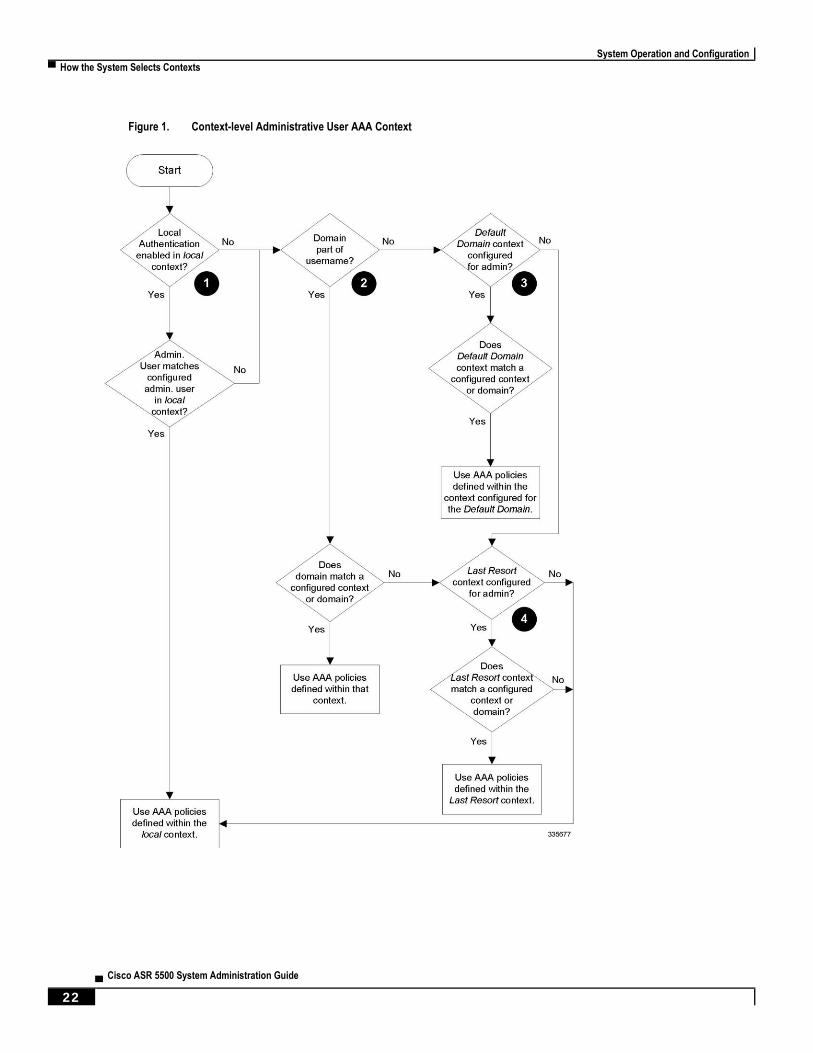
System Operation and Configuration
▀ How the System Selects Contexts
▄ Cisco ASR 5500 System Administration Guide
22
Figure 1. Context-level Administrative User AAA Context
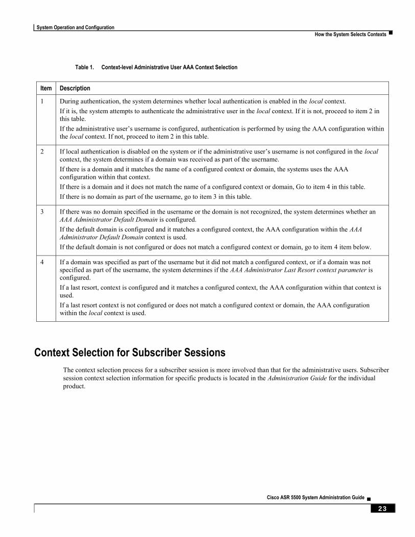
System Operation and Configuration
How the System Selects Contexts ▀
Cisco ASR 5500 System Administration Guide ▄ 23
Table 1. Context-level Administrative User AAA Context Selection
Item Description
1 During authentication, the system determines whether local authentication is enabled in the local context.
If it is, the system attempts to authenticate the administrative user in the local context. If it is not, proceed to item 2 in
this table.
If the administrative user’s username is configured, authentication is performed by using the AAA configuration within
the local context. If not, proceed to item 2 in this table.
2 If local authentication is disabled on the system or if the administrative user’s username is not configured in the local
context, the system determines if a domain was received as part of the username.
If there is a domain and it matches the name of a configured context or domain, the systems uses the AAA
configuration within that context.
If there is a domain and it does not match the name of a configured context or domain, Go to item 4 in this table.
If there is no domain as part of the username, go to item 3 in this table.
3 If there was no domain specified in the username or the domain is not recognized, the system determines whether an
AAA Administrator Default Domain is configured.
If the default domain is configured and it matches a configured context, the AAA configuration within the AAA
Administrator Default Domain context is used.
If the default domain is not configured or does not match a configured context or domain, go to item 4 item below.
4 If a domain was specified as part of the username but it did not match a configured context, or if a domain was not
specified as part of the username, the system determines if the AAA Administrator Last Resort context parameter is
configured.
If a last resort, context is configured and it matches a configured context, the AAA configuration within that context is
used.
If a last resort context is not configured or does not match a configured context or domain, the AAA configuration
within the local context is used.
Context Selection for Subscriber Sessions
The context selection process for a subscriber session is more involved than that for the administrative users. Subscriber
session context selection information for specific products is located in the Administration Guide for the individual
product.

System Operation and Configuration
▀ Understanding the ASR 5500 Boot Process
▄ Cisco ASR 5500 System Administration Guide
24
Understanding the ASR 5500 Boot Process Part of the configuration process requires that you allocate hardware resources for processing and redundancy.
Therefore, before you configure the system, it is important to understand the boot process which determines how the
hardware components are brought on line.
The following flowchart shows each step in the startup process. For additional information about system configuration
files, refer to the Understanding Configuration Files section.
Figure 2. ASR 5500 Process Flowchart
The following steps describe the system’s boot process:
Step 1 When power is first applied to the chassis, or after a reboot, only the MIO/UMIOs in slot 5 and slot 6 receive power.
Step 2 During the startup process, the MIO/UMIO performs a series of power-on self tests (POSTs) to ensure that its hardware
is operational.
Step 3 If the MIO/UMIO in slot 5 successfully executes all POSTs, it becomes the active MIO. The MIO in slot 6 becomes the
standby card. If there is a problem with the MIO in slot 5, the MIO in slot 6 becomes the active MIO.
System Operation and Configuration
Understanding the ASR 5500 Boot Process ▀
Cisco ASR 5500 System Administration Guide ▄ 25
Step 4 The active MIO/UMIO begins loading the operating system software image designated in the boot stack. The boot stack
entries are contained in the boot.sys file that resides on flash memory on the MIO/UMIO. The standby MIO/UMIO
observes the active card startup. If the file on the active MIO/UMIO is loads normally, the standby MIO/UMIO boots
from the active card image. If the active MIO/UMIO experiences problems during this phase, the standby MIO/UMIO
loads its software image designated by its own boot stack entry in its boot.sys file and takes over control of the system
as the active MIO/UMIO.
Step 5 After the software image is loaded into its memory, the active MIO/UMIO determines whether other cards are installed
in the chassis by applying power to the other chassis slots and signalling them. If the chassis slot contains a card, power
is left On to that slot. All empty slots are powered off.
Important: If no MIOs are installed or if both fail to boot successfully, no other card installed in the system will
boot.
Step 6 When power is applied to the DPC/UDPCs installed in the system, they each perform their own series of POSTs.
Step 7 After successful POST, each DPC/UDPC enters standby mode.
Step 8 After entering the standby mode, each of the control processors (CPs) on the DPC/UDPC communicate with the active
MIO/UMIO to receive the appropriate code.
Step 9 Upon successful loading of the software image, the system loads a configuration file designated in the boot stack
(boot.sys file). If this is the first time the system is powered on and there is no configuration file, the active MIO/UMIO
invokes the system’s Quick Setup wizard. Use the Quick Setup wizard to configure basic system parameters for
communication across the management network.
The wizard creates a configuration file (system.cfg) that you can use as a starting point for subsequent configurations.
This allows you to configure the system automatically by applying the configuration file during any subsequent boot.
For additional information about system configuration files, refer to the Understanding Configuration Files section.
System Operation and Configuration
▀ Understanding Configuration Files
▄ Cisco ASR 5500 System Administration Guide
26
Understanding Configuration Files The system supports the use of a file or script to modify configurable parameters. Using a file for offline system
configuration reduces the time it takes to configure parameters on multiple systems.
A system configuration file is an ASCII text file that contains commands and configuration parameters. When you apply
the configuration file, the system parses through the file line-by-line, testing the syntax and executing the command. If
the syntax is incorrect, a message is displayed to the CLI and the system proceeds to the next command. Lines that
begin with # are considered remarks and are ignored.
Important: Pipes ( | ), used with the grep and more keywords, can potentially cause errors in configuration file
processing. Therefore, the system automatically ignores keywords with pipes during processing.
Important: Always save configuration files in UNIX format. Failure to do so can result in errors that prevent
configuration file processing.
The commands and configuration data within the file are organized and formatted just as they would be if they were
being entered at the CLI prompt. For example, if you wanted to create a context called source in the CLI, you would
enter the following commands at their respective prompts:
[local]host_name# config
[local]host_name(config)# context source
[source]host_name(config-ctx)# end
To create a context called source using a configuration file, you would use a text editor to create a new file that consists
of the following:
config
context source
end
There are several important things to consider when using configuration files:
The system automatically applies a configuration file at the end of the boot process. After the system boots up
for the first time, a configuration file that you have created and that is tailored to your network needs, can be
applied. To make the system use your configuration file, modify the system’s boot parameters according to the
instructions located in Software Management Operations.
In addition to being applied during the boot process, you can also apply configuration files manually at any time
by executing the appropriate commands at the CLI prompt. Refer to the instructions in Software Management
Operations.
Important: When you apply a configuration file after the boot process, the file does not delete the
configuration loaded as part of the boot process. Only those commands that are duplicated are overwritten.
System Operation and Configuration
Understanding Configuration Files ▀
Cisco ASR 5500 System Administration Guide ▄ 27
Configuration files can be stored in any of the following locations:
USB Memory Stick: Supported via a USB port on the active MIO (/usb1).
Network Server: Any workstation or server on the network that the system can access using the Secure
File Transfer Protocol (SFTP). This is recommended for large network deployments in which multiple
systems require the same configuration.
/flash: a solid-state device with limited storage.
/hd-raid: internal RAID storage.
Each time you save configuration changes you made during a CLI session, you can save those settings to a file
which you can use as a configuration file.
System Operation and Configuration
▀ IP Address Notation
▄ Cisco ASR 5500 System Administration Guide
28
IP Address Notation When configuring a port interface via the CLI you must enter an IP address. The CLI always accepts an IPv4 address,
and in some cases accepts an IPv6 address as an alternative.
For some configuration commands, the CLI also accepts CIDR notation. Always view the online Help for the CLI
command to verify acceptable forms of IP address notation.
IPv4 Dotted-Decimal Notation
An Internet Protocol Version 4 (IPv4) address consists of 32 bits divided into four octets. These four octets are written
in decimal numbers, ranging from 0 to 255, and are concatenated as a character string with full stop delimiters (dots)
between each number.
For example, the address of the loopback interface, usually assigned the host name localhost, is 127.0.0.1. It consists of
the four binary octets 01111111, 00000000, 00000000, and 00000001, forming the full 32-bit address.
IPv4 allows 32 bits for an Internet Protocol address and can, therefore, support 2^32 (4,294,967,296) addresses
IPv6 Colon-Separated-Hexadecimal Notation
An Internet Protocol Version 6 (IPv6) address has two logical parts: a 64-bit network prefix, and a 64-bit host address
part. An IPv6 address is represented by eight groups of 16-bit hexadecimal values separated by colons (:).
A typical example of a full IPv6 address is 2001:0db8:85a3:0000:0000:8a2e:0370:7334
The hexadecimal digits are case-insensitive.
The 128-bit IPv6 address can be abbreviated with the following rules:
Leading zeroes within a 16-bit value may be omitted. For example, the address
fe80:0000:0000:0000:0202:b3ff:fe1e:8329 may be written as fe80:0:0:0:202:b3ff:fe1e:8329
One group of consecutive zeroes within an address may be replaced by a double colon. For example,
fe80:0:0:0:202:b3ff:fe1e:8329 becomes fe80::202:b3ff:fe1e:8329
IPv6 allows 128 bits for an Internet Protocol address and can support 2^128
(340,282,366,920,938,000,000,000,000,000,000,000,000) internet addresses.
CIDR Notation
Classless Inter-Domain Routing (CIDR) notation is a compact specification of an Internet Protocol address and its
associated routing prefix. It is used for both IPv4 and IPv6 addressing in networking architectures.
CIDR is a bitwise, prefix-based standard for the interpretation of IP addresses. It facilitates routing by allowing blocks
of addresses to be grouped into single routing table entries. These groups (CIDR blocks) share an initial sequence of bits
in the binary representation of their IP addresses.
CIDR notation is constructed from the IP address and the prefix size, the latter being the number of leading 1 bits of the
routing prefix. The IP address is expressed according to the standards of IPv4 or IPv6. It is followed by a separator
character, the slash (/) character, and the prefix size expressed as a decimal number.
System Operation and Configuration
IP Address Notation ▀
Cisco ASR 5500 System Administration Guide ▄ 29
The address may denote a single, distinct, interface address or the beginning address of an entire network. In the latter
case the CIDR notation specifies the address block allocation of the network. The maximum size of the network is given
by the number of addresses that are possible with the remaining, least-significant bits below the prefix. This is often
called the host identifier.
For example:
the address specification 192.168.100.1/24 represents the given IPv4 address and its associated routing prefix
192.168.100.0, or equivalently, its subnet mask 255.255.255.0.
the IPv4 block 192.168.0.0/22 represents the 1024 IPv4 addresses from 192.168.0.0 to 192.168.3.255.
the IPv6 block 2001:DB8::/48 represents the IPv6 addresses from 2001:DB8:0:0:0:0:0:0 to
2001:DB8:0:FFFF:FFFF:FFFF:FFFF:FFFF.
::1/128 represents the IPv6 loopback address. Its prefix size is 128, the size of the address itself, indicating that
this facility consists of only this one address.
The number of addresses of a subnet defined by the mask or prefix can be calculated as 2, in which the address size for
IPv4 is 32 and for IPv6 is 128. For example, in IPv4, a mask of /29 gives 8 addresses.
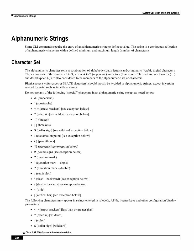
System Operation and Configuration
▀ Alphanumeric Strings
▄ Cisco ASR 5500 System Administration Guide
30
Alphanumeric Strings Some CLI commands require the entry of an alphanumeric string to define a value. The string is a contiguous collection
of alphanumeric characters with a defined minimum and maximum length (number of characters).
Character Set
The alphanumeric character set is a combination of alphabetic (Latin letters) and/or numeric (Arabic digits) characters.
The set consists of the numbers 0 to 9, letters A to Z (uppercase) and a to z (lowercase). The underscore character ( _ )
and dash/hyphen (-) are also considered to be members of the alphanumeric set of characters.
Blank spaces (whitespaces or SPACE characters) should mostly be avoided in alphanumeric strings, except in certain
ruledef formats, such as time/date stamps.
Do not use any of the following “special” characters in an alphanumeric string except as noted below:
& (ampersand)
‘ (apostrophe)
< > (arrow brackets) [see exception below]
* (asterisk) [see wildcard exception below]
{ } (braces)
[ ] (brackets)
$ (dollar sign) [see wildcard exception below]
! (exclamation point) [see exception below]
( ) [parentheses]
% (percent) [see exception below]
# (pound sign) [see exception below]
? (question mark)
' (quotation mark – single)
" (quotation mark – double)
; (semicolon)
\ (slash – backward) [see exception below]
/ (slash – forward) [see exception below]
~ (tilde)
| (vertical bar) [see exception below]
The following characters may appear in strings entered in ruledefs, APNs, license keys and other configuration/display
parameters:
< > (arrow brackets) [less than or greater than]
* (asterisk) [wildcard]
: (colon)
$ (dollar sign) [wildcard]
System Operation and Configuration
Alphanumeric Strings ▀
Cisco ASR 5500 System Administration Guide ▄ 31
. (dot)
= (equals sign)
! (exclamation point)
% (percent)
/ (slash – forward)
| (vertical bar)
The following characters may be used to delimit the domain from the user name for global AAA functions:
@ (at sign)
- (dash or hyphen)
# (hash or pound sign)
% [percent]
\ (slash – backward) [must be entered as double slash “\\”]
/ (slash – forward)
Quoted Strings
If descriptive text requires the use of spaces between words, the string must be entered within double quotation marks
(“ “). For example:
interface “Rack 3 Chassis 1 port 5/2”

Cisco ASR 5500 System Administration Guide ▄ 33
Chapter 2 Getting Started
Following sucessful installation of the system hardware, you must configure a set of software parameters. You then save
these settings in a system configuration file that is launched whenever the system is reloaded.
This segment provides instructions for connecting to the console port and creating the initial local context management
configuration. It includes the following sections:
ASR 5500 Configuration
Using the ASR 5500 Quick Setup Wizard
Using the CLI for Initial Configuration
Configuring the System for Remote Access
Configuring the Management Interface with a Second IP Address
Getting Started
▀ ASR 5500 Configuration
▄ Cisco ASR 5500 System Administration Guide
34
ASR 5500 Configuration The first time power is applied to the system, the active Management Input/Output (MIO) card (typically the one
installed in chassis slot 5) automatically launches a Quick Setup Wizard on its console port. This wizard guides you
through the initial configuration of the system.
The serial console port (logical port 3) is located on the front panel of the MIO card.
You can choose not to use the wizard and perform the initial configuration by issuing commands via the command line
interface (CLI). You can manually launch the wizard by running the setup command in the Exec mode. Refer to the
Command Line Interface Reference for details.
The following sections describe how to configure the system.
Using the ASR 5500 Quick Setup Wizard The Quick Setup Wizard consists of three parts:
Configuring a context-level security administrator and hostname
Configuring the Ethernet interface for out-of-band (OOB) management
Configuring the system for remote CLI access via Telnet, Secure Shell (SSH), or File Transfer Protocol (FTP)
The following figure and table provides a flow diagram that shows the run logic of the wizard along with additional
information and notes.
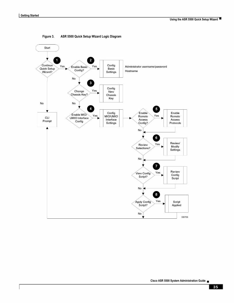
Getting Started
Using the ASR 5500 Quick Setup Wizard ▀
Cisco ASR 5500 System Administration Guide ▄ 35
Figure 3. ASR 5500 Quick Setup Wizard Logic Diagram

Getting Started
▀ Using the ASR 5500 Quick Setup Wizard
▄ Cisco ASR 5500 System Administration Guide
36
Table 2. Quick Setup Wizard Logic Diagram Callout Descriptions
Item Task Description/Notes
1 Enter or exit the wizard. Enter no at the prompt to automatically be directed to the command line
interface (CLI). Proceed to Using the CLI for Initial Configuration for
instructions on performing an initial system configuration with the CLI.
Enter setup at the command prompt to re-invoke the wizard.
2 Configure an administrative
username/password and the a hostname
for the system.
The name of the default administrative user configured through the wizard
is admin.
Administrative user name is an alphanumeric string of 1 through 32
characters that is case sensitive.
Administrative user password is an alphanumeric string of 1 through 63
characters that is case sensitive.
Configure a valid, non-null hostname. The hostname is an alphanumeric
string of 1 through 63 characters that is case sensitive.
3 Change chassis key value. A unique chassis key is configured at the factory for each system. This key
is used to decrypt encrypted passwords found in generated configuration
files. The system administrator can create a unique chassis key that will be
used to encrypt passwords stored in configuration files.
Enter yes to set a new chassis key. Refer to the instructions in System
Settings. Additional information can be found in System Security.
4 Configure a single Management
Input/Output (MIO) out-of-band
management interface for out-of-band
system management.
Traffic on the management LAN is not transferred over the same media as
user data and control signaling.
For security reasons, it is recommended that management functions be
maintained on a separate network from user data and control signaling.
MIO port 1 (mio1) is the 1000Base-T default management port.
MIO port 2 (mio2) is available as a secondary management port.
Use the RJ-45 interfaces to connect the system to the management network
with CAT5 Ethernet cable.
Configure an IP address, subnet mask, and gateway for the interface.
Instructions for configuring the second management interface on the MIO
can be found in System Settings.
5 Enable various remote access protocols
for accessing the system.
Secure Shell (SSH) uses TCP port number 22 by default, if enabled.
SSH V1 and/or V2 are supported.
If SSH is enabled, you can also enable SSH File Transfer Protocol (SFTP)
server functionality.
Telnet uses TCP port number 23 by default, if enabled.
The File Transfer Protocol (FTP) uses TCP port number 21 by default, if
enabled.
For maximum security, use only SSH v2.

Getting Started
Using the ASR 5500 Quick Setup Wizard ▀
Cisco ASR 5500 System Administration Guide ▄ 37
Item Task Description/Notes
6 Review and/or modify the configuration
of previous prompts. 1. Enter the number of the prompt to be modified.
2. Configure the parameter.
3. Optional. Repeat step 1 and step 2 to modify additional settings.
4. Enter “done” when you have completed all changes.
7 Review the configure script created by
the wizard based on your inputs.
An example of a created script is displayed in the example below.
Variables are displayed in italics (variable).
8 Apply the configuration file to the
system.
Once applied, the parameter configuration is automatically saved to the
system.cfg file stored in MIO flash memory.

Getting Started
▀ Using the ASR 5500 Quick Setup Wizard
▄ Cisco ASR 5500 System Administration Guide
38
Figure 4. MIO Interfaces
1 Console port 2 USB port
3 10 GbE ports, DC-1 4 10 GbE ports, DC-2
5 1 GbE ports (1000Base-T)
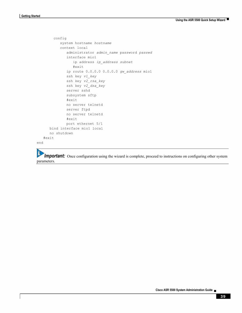
Getting Started
Using the ASR 5500 Quick Setup Wizard ▀
Cisco ASR 5500 System Administration Guide ▄ 39
config
system hostname hostname
context local
administrator admin_name password passwd
interface mio1
ip address ip_address subnet
#exit
ip route 0.0.0.0 0.0.0.0 gw_address mio1
ssh key v1_key
ssh key v2_rsa_key
ssh key v2_dsa_key
server sshd
subsystem sftp
#exit
no server telnetd
server ftpd
no server telnetd
#exit
port ethernet 5/1
bind interface mio1 local
no shutdown
#exit
end
Important: Once configuration using the wizard is complete, proceed to instructions on configuring other system
parameters.
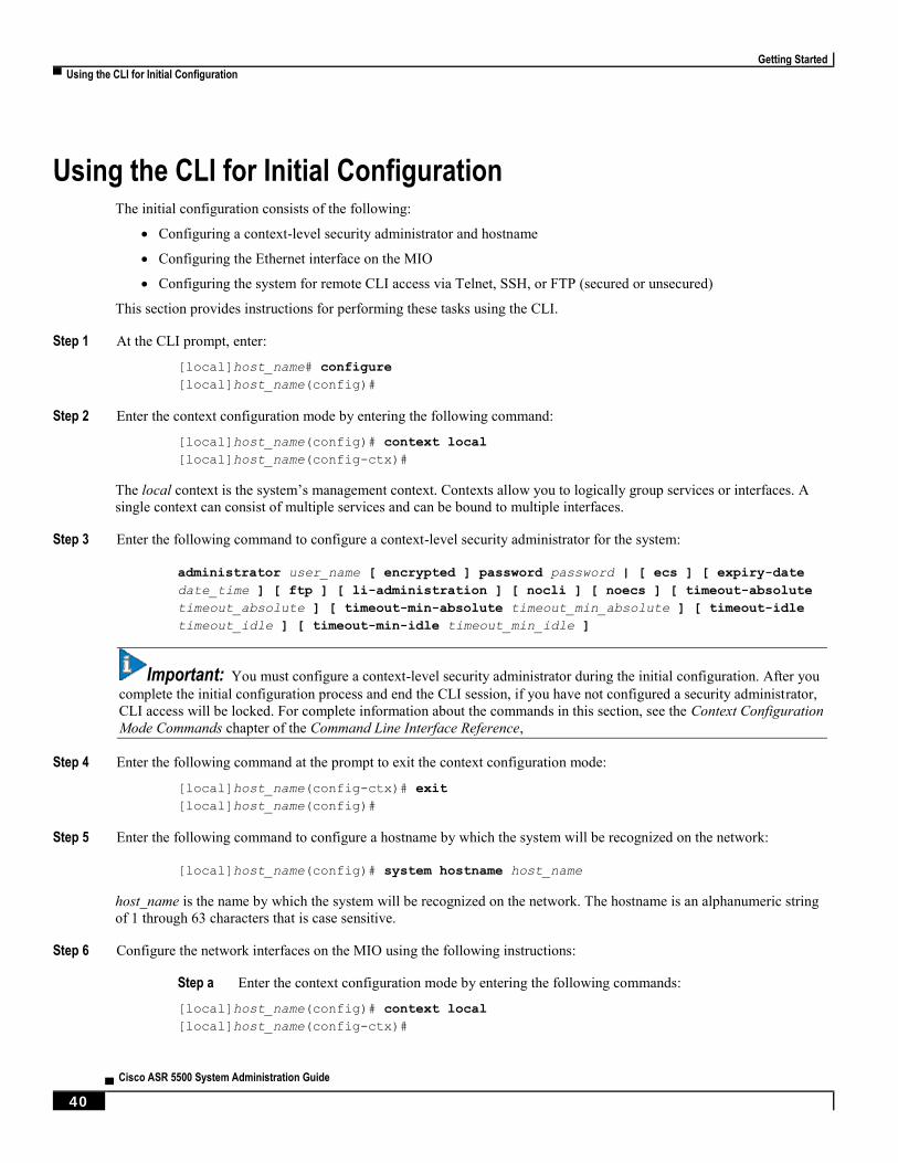
Getting Started
▀ Using the CLI for Initial Configuration
▄ Cisco ASR 5500 System Administration Guide
40
Using the CLI for Initial Configuration The initial configuration consists of the following:
Configuring a context-level security administrator and hostname
Configuring the Ethernet interface on the MIO
Configuring the system for remote CLI access via Telnet, SSH, or FTP (secured or unsecured)
This section provides instructions for performing these tasks using the CLI.
Step 1 At the CLI prompt, enter:
[local]host_name# configure
[local]host_name(config)#
Step 2 Enter the context configuration mode by entering the following command:
[local]host_name(config)# context local
[local]host_name(config-ctx)#
The local context is the system’s management context. Contexts allow you to logically group services or interfaces. A
single context can consist of multiple services and can be bound to multiple interfaces.
Step 3 Enter the following command to configure a context-level security administrator for the system:
administrator user_name [ encrypted ] password password | [ ecs ] [ expiry-date
date_time ] [ ftp ] [ li-administration ] [ nocli ] [ noecs ] [ timeout-absolute
timeout_absolute ] [ timeout-min-absolute timeout_min_absolute ] [ timeout-idle
timeout_idle ] [ timeout-min-idle timeout_min_idle ]
Important: You must configure a context-level security administrator during the initial configuration. After you
complete the initial configuration process and end the CLI session, if you have not configured a security administrator,
CLI access will be locked. For complete information about the commands in this section, see the Context Configuration
Mode Commands chapter of the Command Line Interface Reference,
Step 4 Enter the following command at the prompt to exit the context configuration mode:
[local]host_name(config-ctx)# exit
[local]host_name(config)#
Step 5 Enter the following command to configure a hostname by which the system will be recognized on the network:
[local]host_name(config)# system hostname host_name
host_name is the name by which the system will be recognized on the network. The hostname is an alphanumeric string
of 1 through 63 characters that is case sensitive.
Step 6 Configure the network interfaces on the MIO using the following instructions:
Step a Enter the context configuration mode by entering the following commands:
[local]host_name(config)# context local
[local]host_name(config-ctx)#
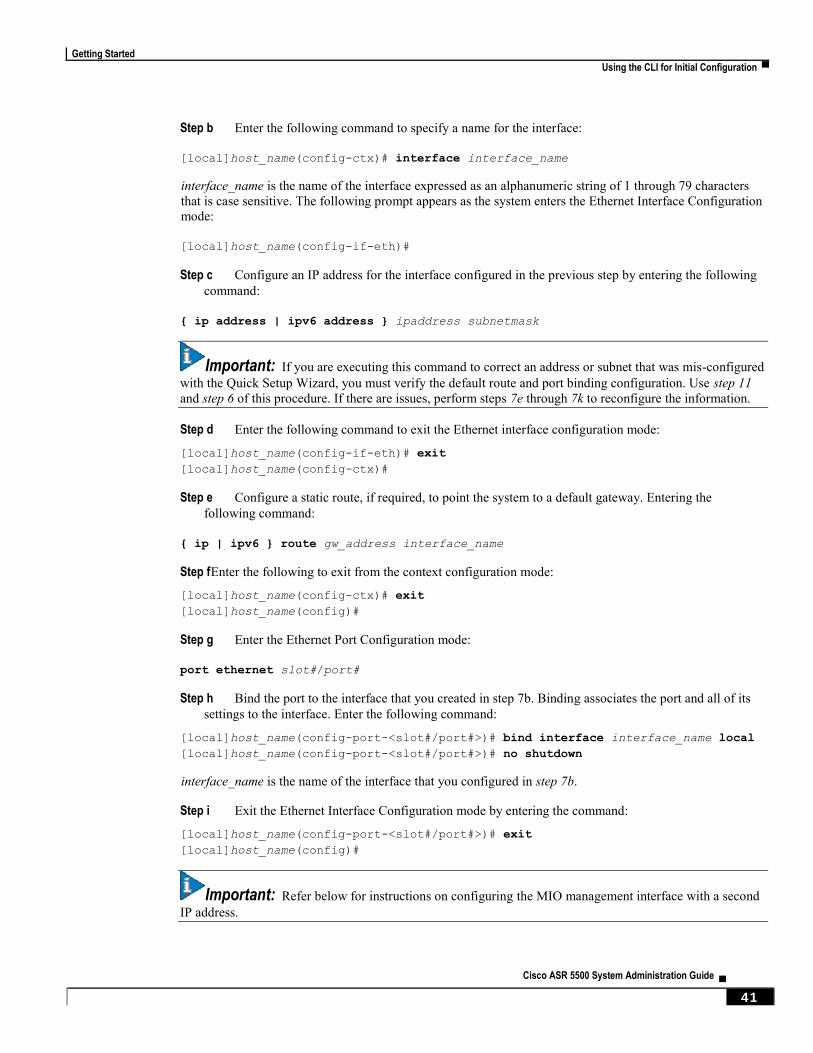
Getting Started
Using the CLI for Initial Configuration ▀
Cisco ASR 5500 System Administration Guide ▄ 41
Step b Enter the following command to specify a name for the interface:
[local]host_name(config-ctx)# interface interface_name
interface_name is the name of the interface expressed as an alphanumeric string of 1 through 79 characters
that is case sensitive. The following prompt appears as the system enters the Ethernet Interface Configuration
mode:
[local]host_name(config-if-eth)#
Step c Configure an IP address for the interface configured in the previous step by entering the following
command:
{ ip address | ipv6 address } ipaddress subnetmask
Important: If you are executing this command to correct an address or subnet that was mis-configured
with the Quick Setup Wizard, you must verify the default route and port binding configuration. Use step 11
and step 6 of this procedure. If there are issues, perform steps 7e through 7k to reconfigure the information.
Step d Enter the following command to exit the Ethernet interface configuration mode:
[local]host_name(config-if-eth)# exit
[local]host_name(config-ctx)#
Step e Configure a static route, if required, to point the system to a default gateway. Entering the
following command:
{ ip | ipv6 } route gw_address interface_name
Step f Enter the following to exit from the context configuration mode:
[local]host_name(config-ctx)# exit
[local]host_name(config)#
Step g Enter the Ethernet Port Configuration mode:
port ethernet slot#/port#
Step h Bind the port to the interface that you created in step 7b. Binding associates the port and all of its
settings to the interface. Enter the following command:
[local]host_name(config-port-<slot#/port#>)# bind interface interface_name local
[local]host_name(config-port-<slot#/port#>)# no shutdown
interface_name is the name of the interface that you configured in step 7b.
Step i Exit the Ethernet Interface Configuration mode by entering the command:
[local]host_name(config-port-<slot#/port#>)# exit
[local]host_name(config)#
Important: Refer below for instructions on configuring the MIO management interface with a second
IP address.
Getting Started
▀ Configuring the System for Remote Access
▄ Cisco ASR 5500 System Administration Guide
42
Configuring the System for Remote Access Configure the system for remote access. An administrative user may access the system from a remote location over a
local area network (LAN) or wide area network (WAN):
Telnet
Secure Shell (SSH)
File Transfer Protocol (FTP) (secured or unsecured)
Trivial File Transfer Protocol (TFTP)
Important: If there are two simultaneous telnet sessions, and one administrator deletes the context into which the
other administrator is logged, the administrator in the deleted context will not be automatically kicked into the local
context. Although the deleted context will still appear in the CLI prompt, context specific commands will generate
errors.
Important: For maximum security, use SSH v2.
Step 1 Enter the context configuration mode by entering the following command:
[local]host_name(config)# context local
[local]host_name(config-ctx)#
Step 2 Configure the system to allow Telnet access, if desired:
[local]host_name(config-ctx)# server telnetd
Step 3 Configure the system to allow SSH access, if desired:
[local]host_name(config-ctx)# ssh generate key [ type { v1-rsa | v2-rsa | v2-dsa
} ]
Important: v2-rsa is the recommended key type.
[local]host_name(config-ctx)# server sshd
[local]host_name(config-sshd)# subsystem sftp
[local]host_name(config-sshd)# exit
Step 4 Configure the system to allow FTP access, if desired, by entering the following command:
[local]host_name(config-ctx)# server ftpd
Step 5 Exit the configuration mode by entering the following command:
[local]host_name(config-ctx)# end
[local]host_name#
Step 6 Verify the configuration by entering the following command:
[local]host_name# show configuration
Getting Started
Configuring the System for Remote Access ▀
Cisco ASR 5500 System Administration Guide ▄ 43
The CLI output should be similar to the sample output: context local
interface interface_name
ip address ipaddress subnetmask
exit
subscriber default
exit
administrator admin_name password admin_password
server telnetd
server ftpd
ssh generate key
server sshd
subsystem sftp
exit
port ethernet 5/1
bind interface interface_name local
exit
port ethernet 5/1
no shutdown
exit
snmp engine-id local 800007e580ed826c191ded2d3d
end
Step 7 Verify the configuration of the IP routes by entering the following command:
[local]host_name# show ip route
The CLI output should be similar to the sample output: "*" indicates the Best or Used route.
Destination Nexthop Protocol Prec Cost Interface
*0.0.0.0/0 ipaddress static 1 0 mio1
*network 0.0.0.0 connected 0 0 mio1
Step 8 Verify the interface binding by entering the following command:
[local]host_name# show ip interface name interface_name
interface_name> is the name of the interface that was configured in step 7b.The CLI output should be similar to the
sample output:
Intf Name: mio1Intf Type: Broadcast
Description:
IP State: UP (Bound to 5/1 untagged, ifIndex 83951617)
IP Address: ipaddress Subnet Mask: subnetmask
Bcast Address: bcastaddress MTU: 1500
Resoln Type: ARP ARP timeout: 3600 secs
Number of Secondary Addresses: 0
Step 9 Save your configuration as described in Verifying and Saving Your Configuration.
Getting Started
▀ Configuring the Management Interface with a Second IP Address
▄ Cisco ASR 5500 System Administration Guide
44
Configuring the Management Interface with a Second IP Address
If necessary, you can configure a second IP address on the MIO management interface.
Step 1 Enter the configuration mode by entering the following command at the prompt:
[local]host_name# configure
[local]host_name(config)#
Step 2 Enter the following to enter the context configuration mode:
[local]host_name(config)# context local
[local]host-name(config-ctx)#
Step 3 Enter the interface slot number and port number by entering the following command:
[local]host_name(config-ctx)# 5/1
[local]host_name(config-if-eth)#
Step 4 Enter the secondary IP address and subnet mask by entering the following command:
[local]host_name(config-if-eth)# { ip | ipv } address ipaddress subnet_mask
secondary
Step 5 Exit the configuration mode by entering the following command:
[local]host_name(config-if-eth)# end
Step 6 Confirm the interface ip addresses by entering the following command:
[local]host_name# show config context local
The CLI output should look similar to this example:
config
context local
interface interface_name
ip address ipaddress subnetmask
ip address ipaddress subnetmask secondary
#exit
Step 7 Save your configuration as described in Verifying and Saving Your Configuration.
Cisco ASR 5500 System Administration Guide ▄ 45
Chapter 3 System Settings
This chapter provides instructions for configuring the following system options:
Configuring a Second Management Interface
Configuring System Timing
Verifying and Saving Your Interface and Port Configuration
Enabling CLI Timestamping
Configuring System Administrative Users
Configuring TACACS+ for System Administrative Users
Configuring a Chassis Key
Configuring MIO/UMIO Port Redundancy
Configuring Data Processing Card (DPC) Availability
Configuring ASR 5500 Link Aggregation
Configuring a Demux Card
It is assumed that the procedures to initially configure the system as described in Getting Started have been completed.
Important: The commands used in the configuration examples in this section are the most likely-used commands
and/or keyword options. In many cases, other optional commands and/or keyword options are available. Refer to the
Command Line Interface Reference for complete information.

System Settings
▀ Configuring a Second Management Interface
▄ Cisco ASR 5500 System Administration Guide
46
Configuring a Second Management Interface Refer to Getting Started for instructions on configuring a system management interface on the Management
Input/Output (MIO) or Management Input/Output Universal (UMIO) card. This section provides described how to
configure a second management interface.
Use the following example to configure a second management interface:
configure
context local
interface interface_name
ip address ipaddress subnetmask
exit
ip route 0.0.0.0 0.0.0.0 gw_address interface_name
exit
port ethernet slot#/port#
bind interface interface_name local
no shutdown
media [ rj45 | sfp ]
end
Notes:
For port ethernet slot#, use the actual chassis slot in which the active MIO/UMIO is installed (slot number 5 or
6).
Enter IP addresses using IPv4 dotted-decimal or IPv6 colon-separated-hexadecimal notation.
For port ethernet port#, use the physical port on the MIO/UMIO card that will be used. This is either port 1 or
2. Port 1 represents the top-most port (either RJ-45 or SFP).
The MIO/UMIO is equipped with RJ-45 (1000Base-T copper) interfaces. The RJ-45 interfaces connect the
system to the management network with CAT3 or CAT5 Ethernet cable.
Option: In the Ethernet Port configuration mode, configure the port speed, if needed, by entering the medium
command. Refer to the Command Line Interface Reference for a complete explanation of this command.
In the { ip | ipv6 } route command, other keyword options, instead of the gateway IP address, are available and
include: next-hop IP address, point-to-point, and tunnel.

System Settings
Verifying and Saving Your Interface and Port Configuration ▀
Cisco ASR 5500 System Administration Guide ▄ 47
Verifying and Saving Your Interface and Port Configuration Verify that your interface configuration settings are correct by entering the following command:
show ip interface
The output from this command should be similar to that shown below. In this example an interface named mgmt2 was
configured in the local context.
Intf Name: mgmt2
Intf Type: Broadcast
Description: management2
VRF: None
IP State: UP (Bound to 5/2)
IP Address: 192.168.100.3 Subnet Mask: 255.255.255.0
Bcast Address: 192.168.100.255 MTU: 1500
Resoln Type: ARP ARP timeout: 60 secs
L3 monitor LC-port switchover: Disabled
Number of Secondary Addresses: 0
Verify that the port configuration settings are correct by entering the following command:
show configuration port slot#/port#
slot# is the chassis slot number of the line card where the physical port resides. slot# is either 5 or 6. port# is the
number of the port (either 1 or 2).
This following command produces an output similar to the one shown below. It displays the configuration of port 2 of
the MIO/UMIO installed in chassis slot 5. In this example, the port is bound to an interface called mgmt2.
config
port ethernet 5/2
description management2
no shutdown
bind interface mgmt2 local
end
Save your configuration as described in the Verifying and Saving Your Configuration chapter.

System Settings
▀ Configuring System Timing
▄ Cisco ASR 5500 System Administration Guide
48
Configuring System Timing The system is equipped with a clock that supplies the timestamp for statistical counters, accounting records, logging,
and event notification. After the initial configuration of the system clock, you can configure the system to communicate
with one or more Network Time Protocol (NTP) server(s) to ensure that the clock is always accurate.
In the event of a power outage, the clock is maintained with an accuracy of +/- one minute per month for up to 10 years.
This ensures that when power is restored, the system is ready to process sessions and generate accounting, log, and
event data with accurate timestamps.
In addition to configuring the timing source, you must configure the system’s time zone.
Setting the System Clock and Time Zone
Use the following command example to configure the system clock and time zone:
clock set date:time
configure
clock timezone timezone [ local ]
end
Notes:
Enter the date and time in the format YYYY:MM:DD:HH:mm or YYYY:MM:DD:HH:mm:ss.
Refer to the online Help for the clock timezone command for a complete list of supported time zones.
The optional local keyword indicates that the time zone specified is the local timezone.
Daylight Savings Time is automatically adjusted for time zones supporting it.
Save your configuration as described in the Verifying and Saving Your Configuration chapter.
Verifying and Saving Your Clock and Time Zone Configuration
Enter the following command to verify that you configured the time and time zone correctly:
show clock
The output displays the date, time, and time zone that you configured.

System Settings
Configuring System Timing ▀
Cisco ASR 5500 System Administration Guide ▄ 49
Configuring Network Time Protocol Support
This section provides information and instructions for configuring the system to enable the use of the Network Time
Protocol (NTP).
Important: Configure the system clock and time zone prior to implementing NTP support. This greatly reduces
the time period that must be corrected by the NTP server.
Many of the services offered by the ASR 5x00 platform require accurate timekeeping derived through NTP. If the time
reference(s) used by StarOS are not accurate, the services may be unreliable. For this reason it should be assumed that
normal system operation requires that NTP be configured.
The system uses NTP to synchronize internal clocks on the chassis to external time sources (typically GPS NTP sources,
or other Stratum 2 or 3 servers, switches or routers).
By default, NTP is not enabled externally and should be configured when the system is initially installed. When
enabled, the active MIO/UMIO will synchronize with external sources. If not enabled, the active MIO/UMIO will use
its local clock as a time source. In the event of an NTP server or network outage, an already running MIO/UMIO will
continue to use NTP to maintain time accuracy, but in a holdover mode.
All cards with CPUs synchronize to the active MIO/UMIO internally. This occurs even if an external NTP server is not
configured. In the event of a MIO/UMIO switchover, all other cards will start synchronizing with the newly active
MIO/UMIO automatically.
The system should have:
NTP enabled.
NTP configured for use in the local context only. Use of other contexts (which can be specified in the enable
configurable) will cause issues.
NTP configured for at least three external NTP servers. With three or more servers, outlyers and broken or
misconfigured servers can be detected and excluded. Generally, the more servers the better (within reason).
Important: Do not configure any external NTP servers using the prefer keyword. The NTP clock selection
algorithms already have the built-in ability to pick the best server. Use of prefer usually results in a poorer choice than
NTP can determine for itself.
Important: Do not change the maxpoll, minpoll, or version keyword settings unless instructed to do so by
Cisco TAC.
Use the following example to configure the necessary NTP association parameters:
configure
ntp
enable
server ip_address1
server ip_address2

System Settings
▀ Configuring System Timing
▄ Cisco ASR 5500 System Administration Guide
50
server ip_address3
end
Notes:
By default context_name is set to local. This is the recommended configuration.
A number of options exist for the server command. Refer to theNTP Configuration Mode Commands chapter in
the Command Line Interface Reference for more information.
Enter the IP address of NTP servers using IPv4 dotted-decimal or IPv6 colon-separated-hexadecimal notation.
Important: Configure the system with at least three (preferably four) NTP servers.
Save the configuration as described in the Verifying and Saving Your Configuration chapter.
Configuring NTP Servers with Local Sources
NTP can use network peers, local external clocks (such as GPS devices), or a local clock with no external source.
A local clock with no external source is usually a last-resort clock when no better clock is available. It is typically
configured on a site's intermediate NTP server so that when a WAN network outage occurs, hosts within the site can
continue to synchronize amongst themselves.
You can configure this in ntpd or on many commercially available NTP devices. This local clock should always have a
high stratum number (8+) so that under normal conditions (when real sources are available) this local clock will not be
used.
Using a Load Balancer
The NTP daemon and protocol assume that each configured server is running NTP. If a NTP client is configured to
synchronize to a load balancer that relays and distributes packets to a set of real NTP servers, the load balancer may
distribute those packets dynamically and confuse the NTP client. NTP packets are latency and jitter sensitive. Relaying
them through a load balancer can confuse the NTP client and is not a supported practice.
Verifying the NTP Configuration
Verify the NTP configuration is correct. Enter the following command at the Exec mode prompt:
show ntp associations
The output displays information about all NTP servers. See the output below for an example deploying two NTP
servers.
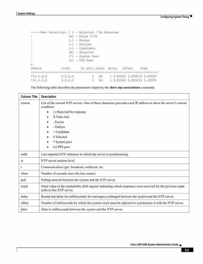
System Settings
Configuring System Timing ▀
Cisco ASR 5500 System Administration Guide ▄ 51
+----Peer Selection: ( ) - Rejected / No Response
| (x) - False Tick
| (.) - Excess
| (-) - Outlyer
| (+) - Candidate
| (#) - Selected
| (*) - System Peer
| (o) - PPS Peer
v
remote local st poll reach delay offset disp
=======================================================================
*10.0.4.5 0.0.0.0 3 64 1 0.00060 0.000019 0.00029
*10.0.4.5 0.0.0.0 3 64 1 0.00060 0.000019 0.00029
The following table describes the parameters output by the show ntp associations command.
Column Title Description
remote List of the current NTP servers. One of these characters precedes each IP address to show the server’s current
condition:
( ) Rejected/No response
X False tick
. Excess
- Outlyer
+ Candidate
# Selected
* System peer
(o) PPS peer
refid Last reported NTP reference to which the server is synchronizing.
st NTP server stratum level.
t Communication type: broadcast, multicast, etc.
when Number of seconds since the last contact.
poll Polling interval between the system and the NTP server.
reach Octal value of the reachability shift register indicating which responses were received for the previous eight
polls to this NTP server.
delay Round-trip delay (in milliseconds) for messages exchanged between the system and the NTP server.
offset Number of milliseconds by which the system clock must be adjusted to synchronize it with the NTP server.
jitter Jitter in milliseconds between the system and the NTP server.
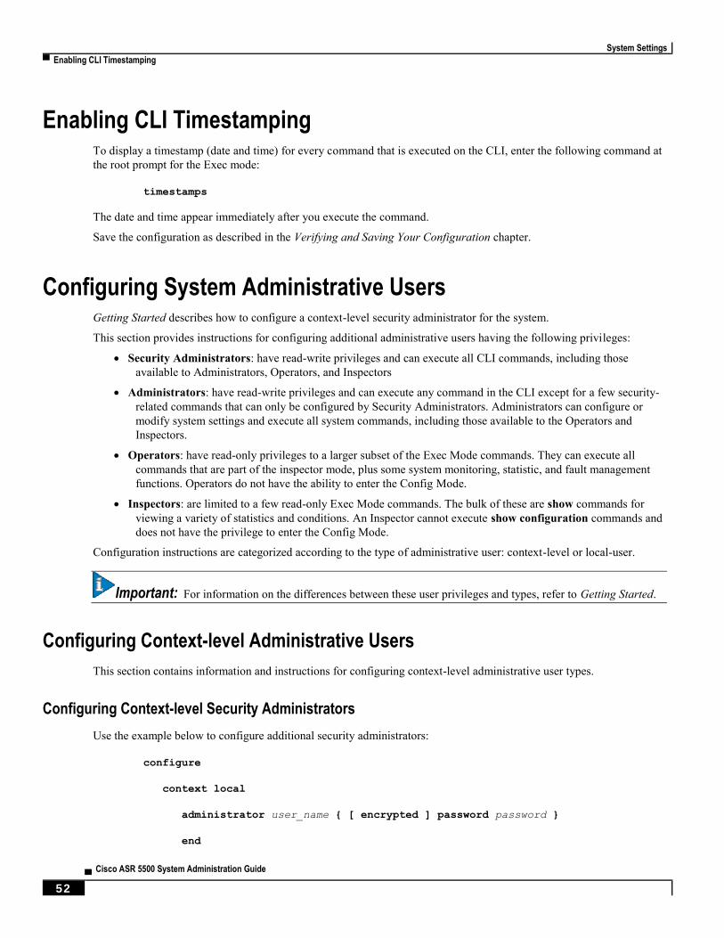
System Settings
▀ Enabling CLI Timestamping
▄ Cisco ASR 5500 System Administration Guide
52
Enabling CLI Timestamping To display a timestamp (date and time) for every command that is executed on the CLI, enter the following command at
the root prompt for the Exec mode:
timestamps
The date and time appear immediately after you execute the command.
Save the configuration as described in the Verifying and Saving Your Configuration chapter.
Configuring System Administrative Users Getting Started describes how to configure a context-level security administrator for the system.
This section provides instructions for configuring additional administrative users having the following privileges:
Security Administrators: have read-write privileges and can execute all CLI commands, including those
available to Administrators, Operators, and Inspectors
Administrators: have read-write privileges and can execute any command in the CLI except for a few security-
related commands that can only be configured by Security Administrators. Administrators can configure or
modify system settings and execute all system commands, including those available to the Operators and
Inspectors.
Operators: have read-only privileges to a larger subset of the Exec Mode commands. They can execute all
commands that are part of the inspector mode, plus some system monitoring, statistic, and fault management
functions. Operators do not have the ability to enter the Config Mode.
Inspectors: are limited to a few read-only Exec Mode commands. The bulk of these are show commands for
viewing a variety of statistics and conditions. An Inspector cannot execute show configuration commands and
does not have the privilege to enter the Config Mode.
Configuration instructions are categorized according to the type of administrative user: context-level or local-user.
Important: For information on the differences between these user privileges and types, refer to Getting Started.
Configuring Context-level Administrative Users
This section contains information and instructions for configuring context-level administrative user types.
Configuring Context-level Security Administrators
Use the example below to configure additional security administrators:
configure
context local
administrator user_name { [ encrypted ] password password }
end
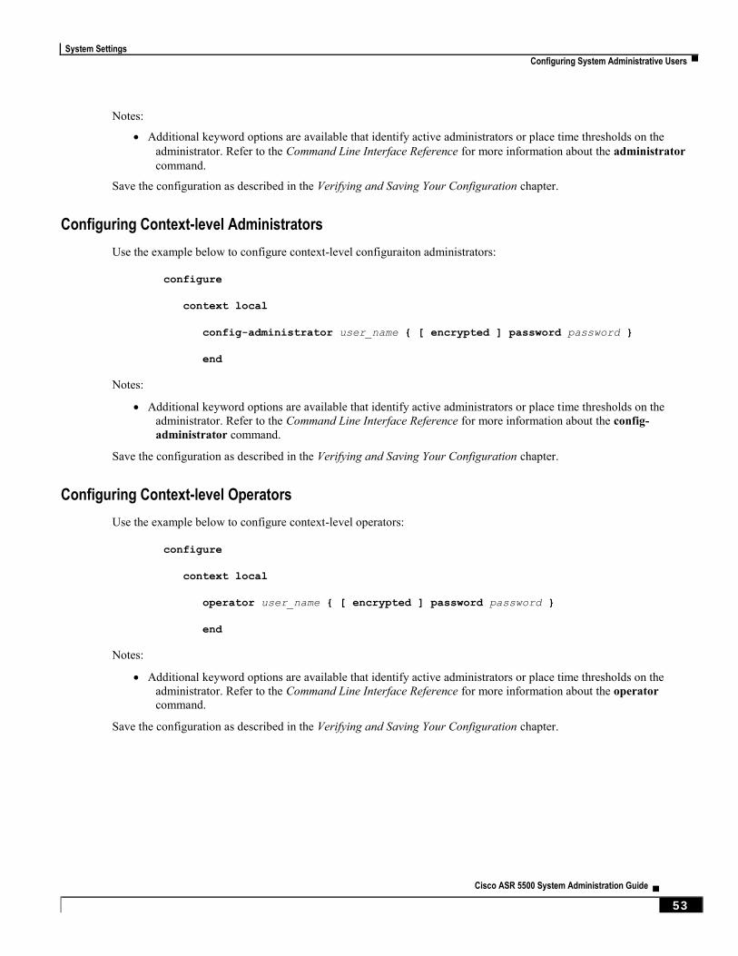
System Settings
Configuring System Administrative Users ▀
Cisco ASR 5500 System Administration Guide ▄ 53
Notes:
Additional keyword options are available that identify active administrators or place time thresholds on the
administrator. Refer to the Command Line Interface Reference for more information about the administrator
command.
Save the configuration as described in the Verifying and Saving Your Configuration chapter.
Configuring Context-level Administrators
Use the example below to configure context-level configuraiton administrators:
configure
context local
config-administrator user_name { [ encrypted ] password password }
end
Notes:
Additional keyword options are available that identify active administrators or place time thresholds on the
administrator. Refer to the Command Line Interface Reference for more information about the config-
administrator command.
Save the configuration as described in the Verifying and Saving Your Configuration chapter.
Configuring Context-level Operators
Use the example below to configure context-level operators:
configure
context local
operator user_name { [ encrypted ] password password }
end
Notes:
Additional keyword options are available that identify active administrators or place time thresholds on the
administrator. Refer to the Command Line Interface Reference for more information about the operator
command.
Save the configuration as described in the Verifying and Saving Your Configuration chapter.

System Settings
▀ Configuring System Administrative Users
▄ Cisco ASR 5500 System Administration Guide
54
Configuring Context-level Inspectors
Use the example below to configure context-level inspectors:
configure
context local
inspector user_name { [ encrypted ] password password }
end
Notes:
Additional keyword options are available that identify active administrators or place time thresholds on the
administrator. Refer to the Command Line Interface Reference for more information about the inspector
command.
Save the configuration as described in the Verifying and Saving Your Configuration chapter.
Verifying Context-level Administrative User Configuration
Verify that the configuration was successful by entering the following command:
show configuration context local
This command displays all of the configuration parameters you modified within the Local context during this session.
The following displays sample output for this command. In this example, a security administrator named testadmin was
configured.
config
context local
interface mgmt1
ip address 192.168.1.10 255.255.255.0
#exit
subscriber default
#exit
administrator testadmin encrypted password fd01268373c5da85
inspector testinspector encrypted password 148661a0bb12cd59
exit
port ethernet 5/1
bind interface mgmt1 local
#exit

System Settings
Configuring System Administrative Users ▀
Cisco ASR 5500 System Administration Guide ▄ 55
Configuring Local-User Administrative Users
Use the example below to configure local-user administrative users:
configure
local-user username name
end
Notes:
Additional keyword options are available identify active administrators or place time thresholds on the
administrator. Refer to the Command Line Interface Reference for more information about the local-user
username command.
Save the configuration as described in theVerifying and Saving Your Configuration chapter.
Verifying Local-User Configuration
Verify that the configuration was successful by entering the following command:
show local-user verbose
This command displays information on configured local-user administrative users. A sample output for this command
appears below. In this example, a local-user named SAUser was configured.
Username: SAUser
Auth Level: secadmin
Last Login: Never
Login Failures: 0
Password Expired: Yes
Locked: No
Suspended: No
Lockout on Pw Aging: Yes
Lockout on Login Fail: Yes
Updating Local User Database
Update the local user (administrative) configuration by running the following Exec mode command. This command
should be run immediately after creating, removing or editing administrative users.
update local-user database
System Settings
▀ Configuring TACACS+ for System Administrative Users
▄ Cisco ASR 5500 System Administration Guide
56
Configuring TACACS+ for System Administrative Users This section describes TACACS+ (Terminal Access Controller Access Control System+) AAA (Authentication
Authorization and Accounting) service functionality and configuration on the ASR 5x00.
Operation
TACACS+ is a secure, encrypted protocol. By remotely accessing TACACS+ servers that are provisioned with the
administrative user account database, the ASR 5x00 can provide TACACS+ AAA services for system administrative
users. TACACS+ is an enhanced version of the TACACS protocol that uses TCP instead of UDP.
The ASR 5x00 system serves as the TACACS+ Network Access Server (NAS). As the NAS the system requests
TACACS+ AAA services on behalf of authorized system administrative users. For the authentication to succeed, the
TACACS+ server must be in the same local context and network accessed by the system.
The system supports TACACS+ multiple-connection mode. In multiple-connection mode, a separate and private TCP
connection to the TACACS+ server is opened and maintained for each session. When the TACACS+ session ends, the
connection to the server is terminated.
TACACS+ is a system-wide function on the ASR 5x00. TACACS+ AAA service configuration is performed in
TACACS Configuration Mode. Enabling the TACACS+ function is performed in the Global Configuration Mode. The
system supports the configuration of up to three TACACS+ servers.
Once configured and enabled on the system, TACACS+ authentication is attempted first. By default, if TACACS+
authentication fails, the system then attempts to authenticate the user using non-TACACS+ AAA services, such as
RADIUS.
User Account Requirements
Before configuring TACACS+ AAA services on the ASR 5x00, note the following TACACS+ server and system user
account provisioning requirements.
TACACS+ User Account Requirements
The TACACS+ server must be provisioned with the following TACACS+ user account information:
A list of known administrative users.
The plain-text or encrypted password for each user.
The name of the group to which each user belongs.
A list of user groups.
TACACS+ privilege levels and commands that are allowed/denied for each group.
Important: TACACS+ privilege levels are stored as Attribute Value Pairs (AVPs) in the network’s TACACS+
server database. Users are restricted to the set of commands associated with their privilege level. A mapping of
TACACS+ privilege levels to ASR 5x00 CLI administrative roles and responsibilities is provided in the table below.
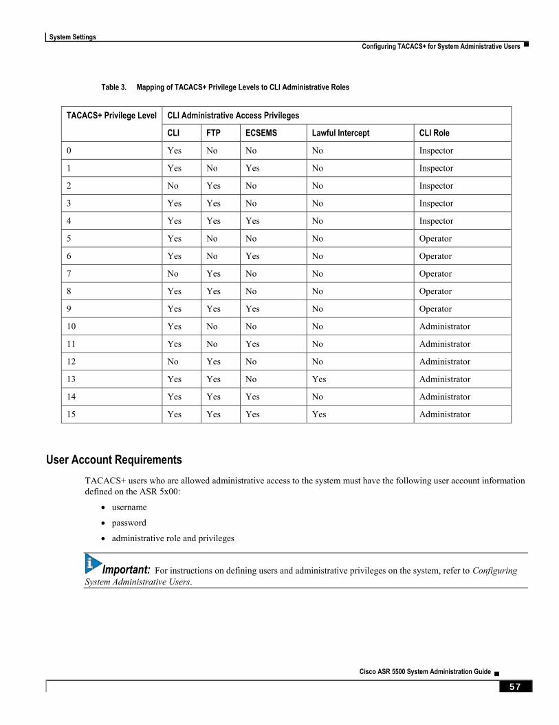
System Settings
Configuring TACACS+ for System Administrative Users ▀
Cisco ASR 5500 System Administration Guide ▄ 57
Table 3. Mapping of TACACS+ Privilege Levels to CLI Administrative Roles
TACACS+ Privilege Level CLI Administrative Access Privileges
CLI FTP ECSEMS Lawful Intercept CLI Role
0 Yes No No No Inspector
1 Yes No Yes No Inspector
2 No Yes No No Inspector
3 Yes Yes No No Inspector
4 Yes Yes Yes No Inspector
5 Yes No No No Operator
6 Yes No Yes No Operator
7 No Yes No No Operator
8 Yes Yes No No Operator
9 Yes Yes Yes No Operator
10 Yes No No No Administrator
11 Yes No Yes No Administrator
12 No Yes No No Administrator
13 Yes Yes No Yes Administrator
14 Yes Yes Yes No Administrator
15 Yes Yes Yes Yes Administrator
User Account Requirements
TACACS+ users who are allowed administrative access to the system must have the following user account information
defined on the ASR 5x00:
username
password
administrative role and privileges
Important: For instructions on defining users and administrative privileges on the system, refer to Configuring
System Administrative Users.
System Settings
▀ Configuring TACACS+ for System Administrative Users
▄ Cisco ASR 5500 System Administration Guide
58
Configuring TACACS+ AAA Services
This section provides an example of how to configure TACACS+ AAA services for administrative users on the system.
Caution: When configuring TACACS+ AAA services for the first time, the administrative user must use non-
TACACS+ services to log into the ASR 5x00. Failure to do so will result in the TACACS+ user being denied access to
the system.
Log in to the system using non-TACACS+ services.
Use the example below to configure TACACS+ AAA services on the system:
configure
tacacs mode
server priority priority_number ip-address tacacs+srvr_ip_address
end
Note:
server priority priority_number: Must be a number from 1 to 3, that specifies the order in which this
TACACS+ server will be tried for TACACS+ authentication. 1 is the highest priority, and 3 is the lowest.
ip-address: Must be the IPv4 address of a valid TACACS+ server that will be used for authenticating
administrative users accessing this system via TACACS+ AAA services.
By default, the TACACS+ configuration will provide authentication, authorization, and accounting services.
Enable TACACS+ on the ASR 5x00:
configure
aaa tacacs+
end
Save the configuration as described in the Verifying and Saving Your Configuration chapter.
Important: For complete information on all TACACS+ Configuration Mode commands and options, refer to the
TACACS Configuration Mode Commands chapter in the Command Line Reference.
System Settings
Configuring TACACS+ for System Administrative Users ▀
Cisco ASR 5500 System Administration Guide ▄ 59
Verifying the TACACS+ Configuration
This section describes how to verify the TACACS+ configuration.
Log out of the system CLI, then log back in using TACACS+ services.
Important: Once TACACS+ AAA services are configured and enabled on the ASR 5x00, the system first will
try to authenticate the administrative user via TACACS+ AAA services. By default, if TACACS+ authentication fails,
the system then continues with authentication using non-TACACS+ AAA services.
At the Exec Mode prompt, enter the following command:
show tacacs
The command output provides summary information for each active TACACS+ session such as username, login time,
login status, current session state and privilege level.
An example of this command’s output is provided below. In this example, a system administrative user named asradmin
has successfully logged in to the system via TACACS+ AAA services.
active session #1:
login username : asradmin
login tty : /dev/pts/1
time of login : Fri Oct 22 13:19:11 2011
login server priority : 1
current login status : pass
current session state : user login complete
current privilege level : 15
remote client application : ssh
remote client ip address : 111.11.11.11
last server reply status : -1
total TACACS+ sessions : 1
Important: For details on all TACACS+ maintenance commands, refer to the Command Line Interface
Reference.
System Settings
▀ Configuring a Chassis Key
▄ Cisco ASR 5500 System Administration Guide
60
Configuring a Chassis Key A unique chassis key is configured at the factory for each system. This key is used to decrypt encrypted passwords
found in generated configuration files. The system administrator can create a unique chassis key that will be used to
encrypt passwords stored in configuration files.
Important: The Quick Setup Wizard also prompts the user to enter a chassis key value.
The Exec mode chassis key value key_string command identifies the chassis which can encrypt and decrypt encrypted
passwords in the configuration file. If two or more chassis are configured with the same chassis key value, the encrypted
passwords can be decrypted by any of the chassis sharing the same chassis key value. As a corollary to this, a given
chassis key value will not be able to decrypt passwords that were encrypted with a different chassis key value.
The key_string is an alphanumeric string of 1 through 16 characters. The chassis key is stored as a one-way encrypted
value, much like a password. For this reason, the chassis key value is never displayed in plain-text form.
The Exec mode chassis keycheck key_string command generates a one-way encrypted key value based on the entered
key_string. The generated encrypted key value is compared against the encrypted key value of the previously entered
chassis key value. If the encrypted values match, the command succeeds and keycheck passes. If the comparison fails, a
message is displayed indicating that the key check has failed. If the default chassis key (no chassis key) is currently
being used, this key check will always fail since there will be no chassis key value to compare against.
Use the chassis keycheck command to verify whether multiple chassis share the same chassis key value.
Important: Only a user with Security Administrator or Administrator privilege can execute the chassis key
value and chassis keycheck commands.
For additional information, refer to the Exec Mode Commands chapter in the Command Line Interface Reference.
Beginning with Release 15.0, the chassis ID will be generated from an input chassis key using the SHA2-256 algorithm
followed by base36 encoding. The resulting 44-character chassis ID will be stored in the same chassisid file in flash.
Release 14 and Release 15 chassis IDs will be in different formats. Release 15 will recognize a Release 14 chassis ID
and consider it as valid. Upgrading from 14.x to 15.0 will not require changing the chassis ID or configuration file.
However, if the chassis key is reset in Release 15 through the setup wizard or chassis-key CLI command, a new chassis
ID will be generated in Release 15 format (44 instead of 16 characters). Release14 builds will not recognize the 44-
character chassis ID. If the chassis is subsequently downgraded to Release 14, a new 16-character chassis ID will be
generated. To accommodate the old key format, you must save the configuration file in pre-v12.2 format before the
downgrade. If you attempt to load a v15 configuration file on the downgraded chassis, StarOS will not be able to
decrypt the password/secrets stored in the configuration file.
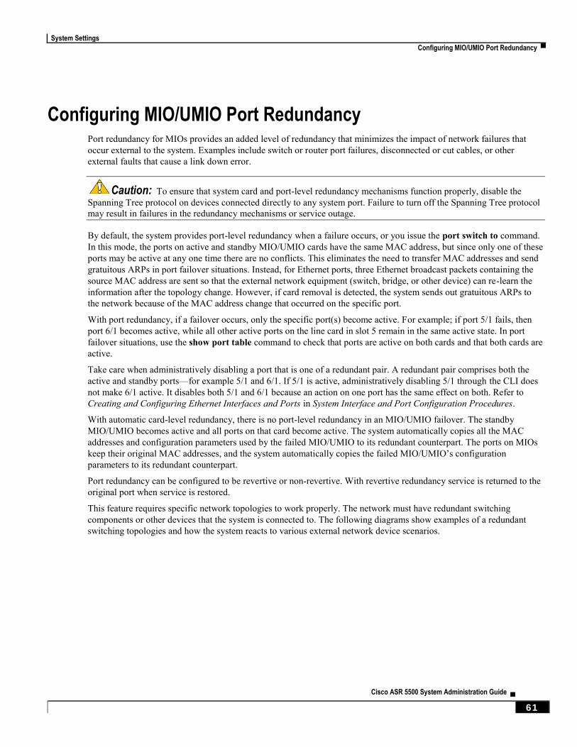
System Settings
Configuring MIO/UMIO Port Redundancy ▀
Cisco ASR 5500 System Administration Guide ▄ 61
Configuring MIO/UMIO Port Redundancy Port redundancy for MIOs provides an added level of redundancy that minimizes the impact of network failures that
occur external to the system. Examples include switch or router port failures, disconnected or cut cables, or other
external faults that cause a link down error.
Caution: To ensure that system card and port-level redundancy mechanisms function properly, disable the
Spanning Tree protocol on devices connected directly to any system port. Failure to turn off the Spanning Tree protocol
may result in failures in the redundancy mechanisms or service outage.
By default, the system provides port-level redundancy when a failure occurs, or you issue the port switch to command.
In this mode, the ports on active and standby MIO/UMIO cards have the same MAC address, but since only one of these
ports may be active at any one time there are no conflicts. This eliminates the need to transfer MAC addresses and send
gratuitous ARPs in port failover situations. Instead, for Ethernet ports, three Ethernet broadcast packets containing the
source MAC address are sent so that the external network equipment (switch, bridge, or other device) can re-learn the
information after the topology change. However, if card removal is detected, the system sends out gratuitous ARPs to
the network because of the MAC address change that occurred on the specific port.
With port redundancy, if a failover occurs, only the specific port(s) become active. For example; if port 5/1 fails, then
port 6/1 becomes active, while all other active ports on the line card in slot 5 remain in the same active state. In port
failover situations, use the show port table command to check that ports are active on both cards and that both cards are
active.
Take care when administratively disabling a port that is one of a redundant pair. A redundant pair comprises both the
active and standby ports—for example 5/1 and 6/1. If 5/1 is active, administratively disabling 5/1 through the CLI does
not make 6/1 active. It disables both 5/1 and 6/1 because an action on one port has the same effect on both. Refer to
Creating and Configuring Ethernet Interfaces and Ports in System Interface and Port Configuration Procedures.
With automatic card-level redundancy, there is no port-level redundancy in an MIO/UMIO failover. The standby
MIO/UMIO becomes active and all ports on that card become active. The system automatically copies all the MAC
addresses and configuration parameters used by the failed MIO/UMIO to its redundant counterpart. The ports on MIOs
keep their original MAC addresses, and the system automatically copies the failed MIO/UMIO’s configuration
parameters to its redundant counterpart.
Port redundancy can be configured to be revertive or non-revertive. With revertive redundancy service is returned to the
original port when service is restored.
This feature requires specific network topologies to work properly. The network must have redundant switching
components or other devices that the system is connected to. The following diagrams show examples of a redundant
switching topologies and how the system reacts to various external network device scenarios.
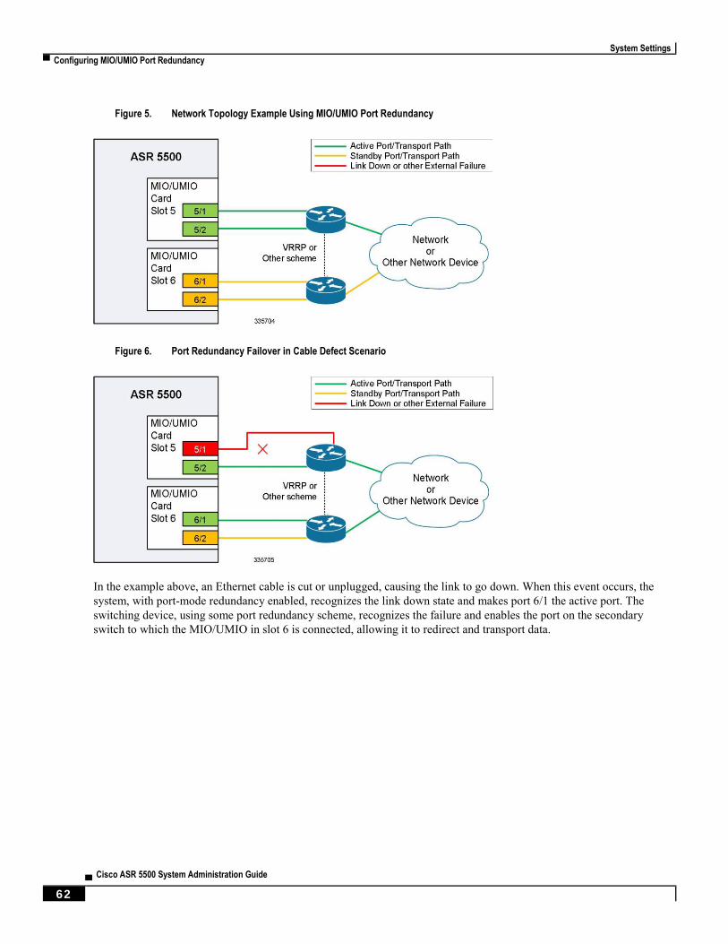
System Settings
▀ Configuring MIO/UMIO Port Redundancy
▄ Cisco ASR 5500 System Administration Guide
62
Figure 5. Network Topology Example Using MIO/UMIO Port Redundancy
Figure 6. Port Redundancy Failover in Cable Defect Scenario
In the example above, an Ethernet cable is cut or unplugged, causing the link to go down. When this event occurs, the
system, with port-mode redundancy enabled, recognizes the link down state and makes port 6/1 the active port. The
switching device, using some port redundancy scheme, recognizes the failure and enables the port on the secondary
switch to which the MIO/UMIO in slot 6 is connected, allowing it to redirect and transport data.
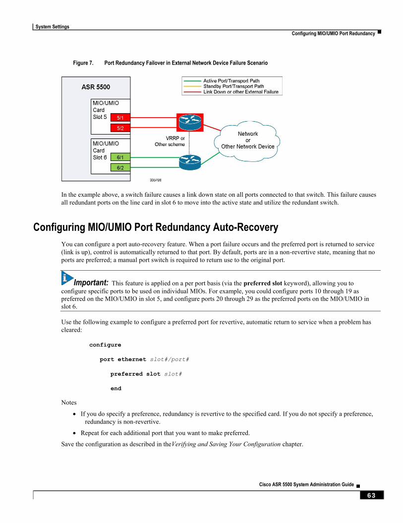
System Settings
Configuring MIO/UMIO Port Redundancy ▀
Cisco ASR 5500 System Administration Guide ▄ 63
Figure 7. Port Redundancy Failover in External Network Device Failure Scenario
In the example above, a switch failure causes a link down state on all ports connected to that switch. This failure causes
all redundant ports on the line card in slot 6 to move into the active state and utilize the redundant switch.
Configuring MIO/UMIO Port Redundancy Auto-Recovery
You can configure a port auto-recovery feature. When a port failure occurs and the preferred port is returned to service
(link is up), control is automatically returned to that port. By default, ports are in a non-revertive state, meaning that no
ports are preferred; a manual port switch is required to return use to the original port.
Important: This feature is applied on a per port basis (via the preferred slot keyword), allowing you to
configure specific ports to be used on individual MIOs. For example, you could configure ports 10 through 19 as
preferred on the MIO/UMIO in slot 5, and configure ports 20 through 29 as the preferred ports on the MIO/UMIO in
slot 6.
Use the following example to configure a preferred port for revertive, automatic return to service when a problem has
cleared:
configure
port ethernet slot#/port#
preferred slot slot#
end
Notes
If you do specify a preference, redundancy is revertive to the specified card. If you do not specify a preference,
redundancy is non-revertive.
Repeat for each additional port that you want to make preferred.
Save the configuration as described in theVerifying and Saving Your Configuration chapter.
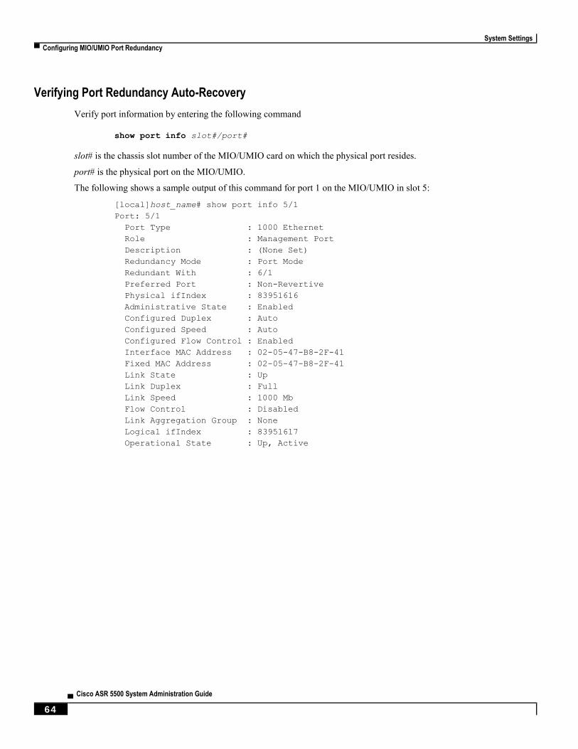
System Settings
▀ Configuring MIO/UMIO Port Redundancy
▄ Cisco ASR 5500 System Administration Guide
64
Verifying Port Redundancy Auto-Recovery
Verify port information by entering the following command
show port info slot#/port#
slot# is the chassis slot number of the MIO/UMIO card on which the physical port resides.
port# is the physical port on the MIO/UMIO.
The following shows a sample output of this command for port 1 on the MIO/UMIO in slot 5:
[local]host_name# show port info 5/1
Port: 5/1
Port Type : 1000 Ethernet
Role : Management Port
Description : (None Set)
Redundancy Mode : Port Mode
Redundant With : 6/1
Preferred Port : Non-Revertive
Physical ifIndex : 83951616
Administrative State : Enabled
Configured Duplex : Auto
Configured Speed : Auto
Configured Flow Control : Enabled
Interface MAC Address : 02-05-47-B8-2F-41
Fixed MAC Address : 02-05-47-B8-2F-41
Link State : Up
Link Duplex : Full
Link Speed : 1000 Mb
Flow Control : Disabled
Link Aggregation Group : None
Logical ifIndex : 83951617
Operational State : Up, Active

System Settings
Configuring Data Processing Card (DPC) Availability ▀
Cisco ASR 5500 System Administration Guide ▄ 65
Configuring Data Processing Card (DPC) Availability As discussed in the Understanding the System Boot Process section of Understanding System Operation and
Configuration, when the system initially boots up, all installed DPCs and or UDPCs are placed into standby mode. You
must activate some of these cards in order to configure and use them for session processing. One DPC/UDPC may
remain in standby mode for redundancy.
This section describes how to activate DPCs and specify their redundancy.
Important: Refer to the ASR 5500 Installation Guide for information about system hardware configurations and
redundancy.
Enter the following command to check the operational status of all DPCs:
show card table
This command lists the DPCs installed in the system by their slot number, their operational status, and whether or not
the card is a single point of failure (SPOF).
Use the following example to configure DPC/UDPC availability:
configure
card slot#
mode { active | standby }
end
Notes:
When activating cards, remember to keep at least one DPC/UDPC in standby mode for redundancy.
Repeat for every other DPC/UDPC in the chassis that you wish to activate.
Save the configuration as described in the Verifying and Saving Your Configuration chapter.
Verifying Card Configurations
Verify that the configuration was successful. Enter the following command:
show card table
Any DPC/UDPC that you made active should now have an operational status of Active.
System Settings
▀ Configuring ASR 5500 Link Aggregation
▄ Cisco ASR 5500 System Administration Guide
66
Configuring ASR 5500 Link Aggregation A Link Aggregation Group (LAG) works by exchanging control packets via Link Aggregation Control Protocol (LACP)
over configured physical ports with peers to reach agreement on an aggregation of links as defined in IEEE 802.3ad.
The LAG sends and receives the control packets directly on physical ports.
Link aggregation (also called trunking or bonding) provides higher total bandwidth, auto-negotiation, and recovery by
combining parallel network links between devices as a single link. A large file is guaranteed to be sent over one of the
links, which removes the need to address out-of-order packets.
LAG and Master Port
Logical port configurations (VLAN and binding) are defined in the master port of the LAG. If the master port is
removed because of a card removal/failure, another member port becomes the master port (resulting in VPN binding
change and outage), unless there is a redundant master port available.
Important: The master port on which VLAN can be created for VPN binding must always be configured on the
active/master MIO/UMIO. The redundancy between MIO/UMIO 5 and MIO/UMIO 6 automatically causes both ports
to be the master with the same VLANs configured and active.
LAG and Port Redundancy
ASR 5500 LAG implementation assumes that:
LAG ports on MIO/UMIO 5 and MIO/UMIO 6 are connected to two Ethernet switches.
LAG ports on MIO/UMIO 5 and MIO/UMIO 6 are both active at the same time.
Ports on MIO/UMIO 5 and MIO/UMIO 6 are redundant with each other.
All ports in a LAG can be auto-switched to another MIO/UMIO when certain active port counts or bandwidth
thresholds are crossed.
LAG and Multiple Switches
This feature connects subscriber traffic ports on MIOs to ports on Ethernet switches. A port failure/switch forces all
ports in a LAG to switch to the other MIO/UMIO when a specified threshold is crossed. This works in a way similar to
the auto-switch feature for port redundancy. LACP runs between the ASR 5500 and the Ethernet switch, exchanging
relevant pieces on information, such as health status.
The following table summarizes typical LAG functionality on an MIO/UMIO card.
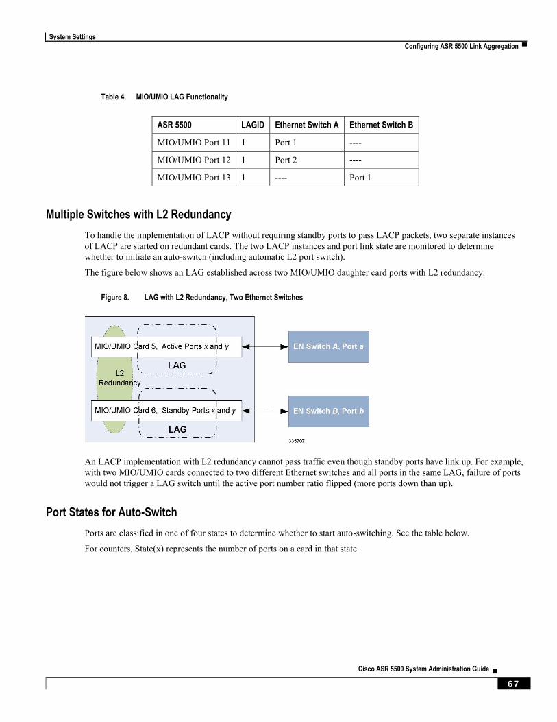
System Settings
Configuring ASR 5500 Link Aggregation ▀
Cisco ASR 5500 System Administration Guide ▄ 67
Table 4. MIO/UMIO LAG Functionality
ASR 5500 LAGID Ethernet Switch A Ethernet Switch B
MIO/UMIO Port 11 1 Port 1 ----
MIO/UMIO Port 12 1 Port 2 ----
MIO/UMIO Port 13 1 ---- Port 1
Multiple Switches with L2 Redundancy
To handle the implementation of LACP without requiring standby ports to pass LACP packets, two separate instances
of LACP are started on redundant cards. The two LACP instances and port link state are monitored to determine
whether to initiate an auto-switch (including automatic L2 port switch).
The figure below shows an LAG established across two MIO/UMIO daughter card ports with L2 redundancy.
Figure 8. LAG with L2 Redundancy, Two Ethernet Switches
An LACP implementation with L2 redundancy cannot pass traffic even though standby ports have link up. For example,
with two MIO/UMIO cards connected to two different Ethernet switches and all ports in the same LAG, failure of ports
would not trigger a LAG switch until the active port number ratio flipped (more ports down than up).
Port States for Auto-Switch
Ports are classified in one of four states to determine whether to start auto-switching. See the table below.
For counters, State(x) represents the number of ports on a card in that state.
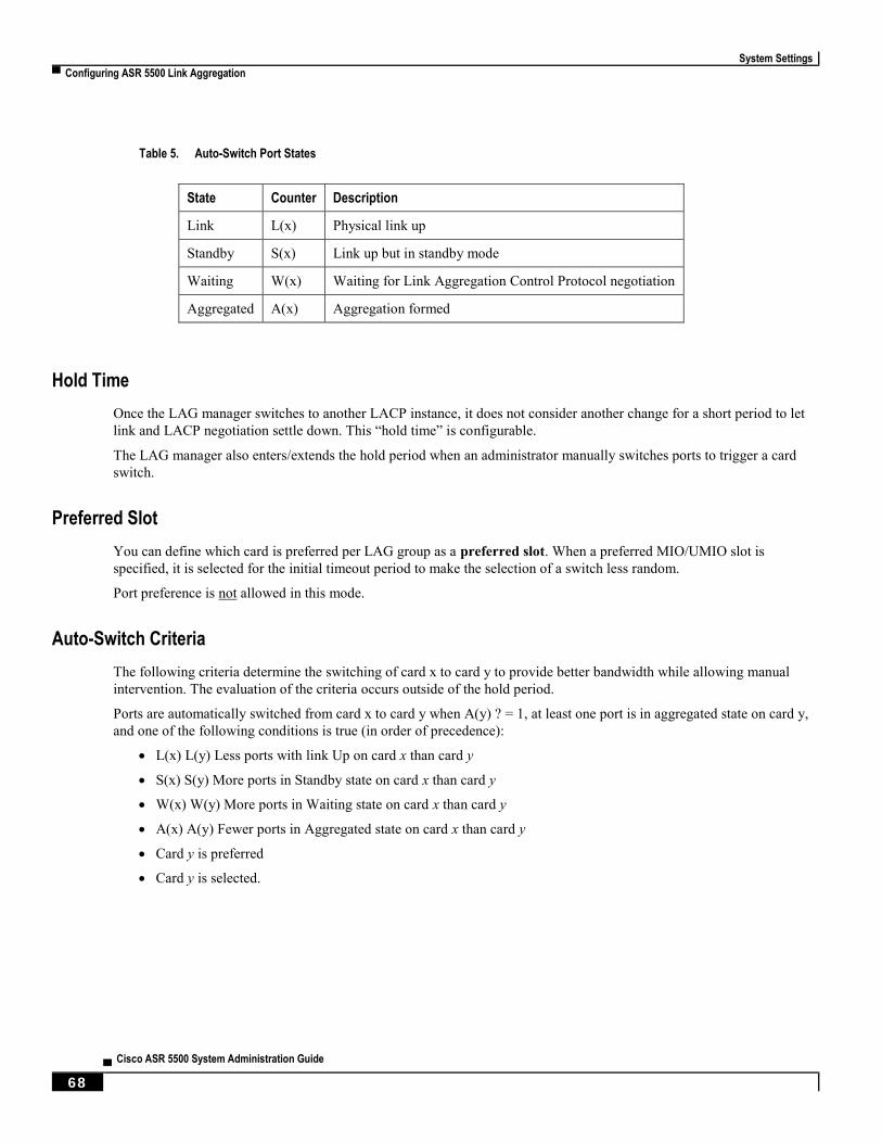
System Settings
▀ Configuring ASR 5500 Link Aggregation
▄ Cisco ASR 5500 System Administration Guide
68
Table 5. Auto-Switch Port States
State Counter Description
Link L(x) Physical link up
Standby S(x) Link up but in standby mode
Waiting W(x) Waiting for Link Aggregation Control Protocol negotiation
Aggregated A(x) Aggregation formed
Hold Time
Once the LAG manager switches to another LACP instance, it does not consider another change for a short period to let
link and LACP negotiation settle down. This “hold time” is configurable.
The LAG manager also enters/extends the hold period when an administrator manually switches ports to trigger a card
switch.
Preferred Slot
You can define which card is preferred per LAG group as a preferred slot. When a preferred MIO/UMIO slot is
specified, it is selected for the initial timeout period to make the selection of a switch less random.
Port preference is not allowed in this mode.
Auto-Switch Criteria
The following criteria determine the switching of card x to card y to provide better bandwidth while allowing manual
intervention. The evaluation of the criteria occurs outside of the hold period.
Ports are automatically switched from card x to card y when A(y) ? = 1, at least one port is in aggregated state on card y,
and one of the following conditions is true (in order of precedence):
L(x) L(y) Less ports with link Up on card x than card y
S(x) S(y) More ports in Standby state on card x than card y
W(x) W(y) More ports in Waiting state on card x than card y
A(x) A(y) Fewer ports in Aggregated state on card x than card y
Card y is preferred
Card y is selected.

System Settings
Configuring ASR 5500 Link Aggregation ▀
Cisco ASR 5500 System Administration Guide ▄ 69
Link Aggregation Control
One port in an aggregation group is configured as a master so that all traffic (except control traffic) in the aggregation
group logically passes through this port. It is recommended that you configure link-aggregation on the master port first
when enabling LAG, and unconfigure the master port last when disabling LAG.
The following command creates link aggregation group N with port slot#/port# as master. Only one master port is
allowed for a group. N must be in the range of [1...255].
configure
port ethernet slot#/port#
link-aggregation master group N
exit
Important: Link Aggregation Control Protocol (LACP) starts running only when the master port is enabled.
Use the following command to add a port as member of link aggregation group number N only if the master port is
assigned. Otherwise, it is added to the group when the master port is assigned:
port ethernet slot#/port#
link-aggregation member group N
exit
Important: The VPN can only bind the master port, and a VLAN can only be created on the master port. A
failure message is generated if you attempt to bind to a link aggregation member port.
Each system that participates in link aggregation has a unique system ID that consists of a two-byte priority (where the
lowest number [0] has the highest priority) and a six-byte MAC address derived from the first port’s MAC address. The
following command sets the system priority used to form the system ID. P is a hex in the range [0x0000..0xFFFF]. The
default is 0x8000.
card slot#
link-aggregation system-priority P
Ports in a system are assigned keys. The group number maps directly to the key, whereupon only ports with the same
key can be aggregated. Ports on each side of the link use a different aggregation key.
The system ID, port key and port ID of two peers form the Link Aggregation Group Identifier (LAGID). You can
aggregate links having the same LAGID. Systems are often configured initially with each port in its own aggregation
(requiring a separate key per port), or with all ports in the same aggregation (a single key for all ports). Negotiation via
LACP would qualify the actual aggregation.
Systems exchange information about system ID, port key and port ID with peers across the physical links using LACP.
LACP packets are defined with the Slow Protocol format. Each system sends out its own (“actor”) information and its
last received information about its peer (“partner”) over the physical link.
System Settings
▀ Configuring ASR 5500 Link Aggregation
▄ Cisco ASR 5500 System Administration Guide
70
Use the following commands to set the LACP parameters. LACP can run in active mode to send LACP packets
periodically, or in passive mode, in which it only responds to LACP packets it receives.
LACP can send packets at either a auto (30s) or fast (1s) rate. The defaults for this release are Active and Auto; see the
sample configuration below:
config
port ethernet slot#/port#
link-aggregation lacp { active | passive } [ rate { auto | fast } |
timeout { long | short } ]
Peers send out LACP packets when the state changes or if a difference is found from a received LACP packet about its
own state.
Corresponding ports on an MIO/UMIO redundant pair cannot be active at the same time. Redundant ports share the
same MAC address, so after a failover is resolved, the original port rejoins the link aggregation group.
Redundancy Options
For L2 redundancy set the following option on the master port for use with the whole group:
link-aggregation redundancy standard [hold-time sec ] [preferred slot { card_number |
none }
Standard redundancy treats all cards in the group as one group.
Horizontal Link Aggregation with Two Ethernet Switches
When a LAG contains two sets of ports each connecting to a different switch, the operator has the ability to specify the
slot/port (connected to the destination switch) when switching ports.
The Exec mode link-aggregation port switch to slot/port command configures this option. The slot/port is any valid
port connected to the destination switch. The following criteria apply to the setting of this option:
slot/port must support LAG.
slot/port must be configured with LAG.
slot/port must not be already actively distributing
slot/port must have negotiated a link aggregation partner in standard mode.
slot/port's partner must have an equal or higher in standard mode.
slot/port's partner bundle must have equal or higher bandwidth in standard mode.
Switching to slot/port must not violate preference within hold-time in standard mode.
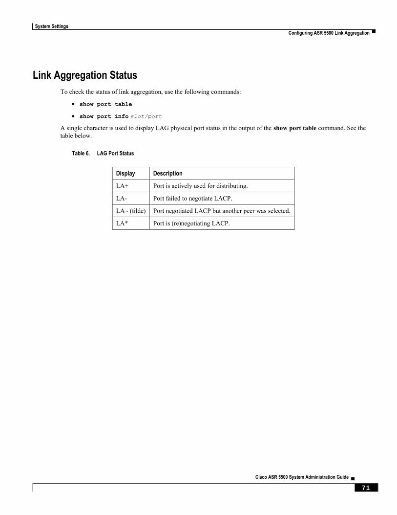
System Settings
Configuring ASR 5500 Link Aggregation ▀
Cisco ASR 5500 System Administration Guide ▄ 71
Link Aggregation Status
To check the status of link aggregation, use the following commands:
show port table
show port info slot/port
A single character is used to display LAG physical port status in the output of the show port table command. See the
table below.
Table 6. LAG Port Status
Display Description
LA+ Port is actively used for distributing.
LA- Port failed to negotiate LACP.
LA~ (tilde) Port negotiated LACP but another peer was selected.
LA* Port is (re)negotiating LACP.

System Settings
▀ Configuring a Demux Card
▄ Cisco ASR 5500 System Administration Guide
72
Configuring a Demux Card You can dedicate a DPC/UDPC or MIO/UMIO to function as a demux card. Demux is a generic term for signal
demultiplexing tasks. These are the tasks are responsible for parsing call setup (signaling packets) and distributing the
calls internally. For this reason there almost as many tasks running on a demux card as there are services.
The vpnmgr tasks responsible for each context also run on the demux card. The number of vpnmgr tasks correspond to
the number of contexts. A vpnmgr is responsible for IP address assignment to mobile equipment, IP routing (such as
BGP, OSPF), as well as a variety of associated tasks.
Overview
Designating a DPC/UDPC or MIO/UMIO as a demux card frees up resources for session handling, which has the
potential to increase system throughput. However, there is no increased support in total subscriber capacity due to other
system resource restrictions.
This feature is disabled by default and can be enabled via the Global Configuration mode require demux command. It
is only supported for a limited number of products. Refer to the product Administration Guide for additional
information.
To support this feature session recovery must also be enabled via the Global Configuration mode require session
recovery command.
Important: After enabling demux card and session recovery, you must save the configuration and reboot the
ASR 5500 to enable this feature.
Caution: Enabling the Demux on MIO/UMIO feature changes resource allocations within the system. This
directly impacts an upgrade or downgrade between StarOS versions in ICSR configurations. Contact Cisco TAC for
procedural assistance prior to upgrading or downgrading your ICSR deployment.
MIO/UMIO Demux Restrictions
The following restrictions apply when enabling an MIO/UMIO as a demux card:
The require demux management-card command must be configured before any service or contexts have been
created on the system. The command will not execute after a mode of operation has been selected for the
chassis.
Only the following services currently support the designation of an MIO/UMIO card for demux functions:
GGSN, SGW, PGW, HA, SAE-GW and L2TP LNS. These services are supported only when they are deployed
as consumer gateways.
SGSN, MME, HNBGW, HeNBGW, SaMOG, PDG, PDIF, ePDG, IPSG, PDSN, HSGW, L2TP LAC, NEMO,
CSCF, FA, and WSG are not supported. Enterprise or corporate gateways (GGSN, HA, PGW, etc.) are also not
supported.
You should not enable demux functionality on MIO for configurations that require a large number of tunnels.

System Settings
Configuring a Demux Card ▀
Cisco ASR 5500 System Administration Guide ▄ 73
After the ASR 5500 has booted with demux functions running on an MIO/UMIO, you cannot configure non-
supported services. A maximum of eight Demux Managers are supported. Any attempt to add more than eight
Demux Managers will be blocked.
Service/products requiring a large number of VPN Managers, VRFs and/or Demux Managers must not enable
demux functions on an MIO.
With demux functions running on an MIO, the ASR 5500 supports a maximum of 10 contexts, 64 interfaces per
context, and 250 VRFs per system.
ICSR upgrades require compatible configurations and Methods of Procedure (MOPs).
Implementation of this feature assumes that CEPS (Call Events Per Second) and the number of subscribers will remain
constant, and only the data rate will increase. This ensures that the CPU demand will not increase on the MIO/UMIO.
Important: Contact Cisco TAC for additional assistance when assessing the impact to system configurations
when enabling the Demux on MIO/UMIO feature.
Configuration
For releases prior to 15.0, to configure a DPC/UDPC as a demux card enter the following CLI commands:
configue
require demux card
end
For release 15.0+, to configure a DPC/UDPC as a demux card enter the following CLI commands:
configue
require demux processing-card
end
To configure an MIO/UMIO as a demux card enter the following CLI commands:
configue
require demux management-card
end

Cisco ASR 5500 System Administration Guide ▄ 75
Chapter 4 Management Settings
This chapter provides instructions for configuring Object Request Broker Element Management (ORBEM) and Simple
Network Management Protocol (SNMP) options.
This chapter includes the following sections:
ORBEM and the Web Element Manager
SNMP Support
Management Settings
▀ ORBEM and the Web Element Manager
▄ Cisco ASR 5500 System Administration Guide
76
ORBEM and the Web Element Manager The system can be managed by a Common Object Broker Request Architecture (CORBA)-based, element management
system application called the Cisco® Web Element Manager (WEM).
You must configure the ORBEM settings on the ASR 5x00 that allow the system to communicate with the server
running the WEM application.
Important: Commands used in the configuration samples in this section provide base functionality. The most
common commands and keyword options are presented. In many cases, other optional commands and keyword options
are available. Refer to the Command Line Interface Reference for detailed information about all commands.
To configure the system to communicate with the Web Element Manager:
Step 1 Set client ID parameters and configure the STOP/TCP port settings by applying the example configuration in
Configuring Client and Port Parameters.
Step 2 Configure Internet Inter-ORB Protocol (IIOP) transport parameters by applying the example configuration in
Configuring Internet Inter-ORB Protocol (IIOP) Transport Parameters.
Step 3 View your new ORBEM configuration by following the steps in Verifying ORBEM Parameters.
Step 4 Save the configuration as described in Verifying and Saving Your Configuration.
Configuring ORBEM Client and Port Parameters
Use the following example to set client ID parameters and configure the SIOP/TCP port settings:
configure
orbem
client id encrypted password password
max-attempt number
session-timeout time
siop-port port_number
event-notif-siop-port siop_notif_port
event-notif-service
end
Notes:
You can issue the client id command multiple times to configure multiple clients.
If a client ID is de-activated due to reaching the configured maximum number of attempts, use the activate
client id command to reactivate it.

Management Settings
ORBEM and the Web Element Manager ▀
Cisco ASR 5500 System Administration Guide ▄ 77
If a firewall exists between the system and the Web Element Manager, open the SIOP port number and the TCP
port number 15011.
If the ORB Notification Service is enabled via the event-notif-service command, you can set filters to determine
which events are to be sent. By default, the Service sends all error and higher level events, “info” level events
for the ORBS facility, CLI command logs, and license change logs. Optionally, configure a filter by including
the event-notif-service filter command. Enter this command for each filter you need to configure.
Configuring IIOP Transport Parameters
Use the following example to configure Internet Inter-ORB Protocol (IIOP) transport parameters that enable ORB-based
management to be performed over the network:
configure
orbem
iiop-transport
iiop-port iiop_port_number
event-notif-iiop-port iiop_notif_port
end
Notes:
If you are using the Secure Sockets Layer (SSL) option, do not enable the IIOP transport parameter. The WEM
default process enforces SSL.
You configure the ORBEM interface to use SSL by specifying a certificate and private key.
Verifying ORBEM Parameters
Step 1 Run the show orbem client table command to verify that the client was configured properly. This command lists the
configured ORBEM clients and displays their state and privileges.
Step 2 Run the show orbem status command to verify the ORBEM parameter configuration. The following displays a sample
of this command’s output.
Service State : On
Management Functions : FCAPS
IOP Address : 192.168.1.150
SSL Port : 14131
TCP Port : 14132
Notification SSL Port : 7777
Notification TCP Port : 7778
Session Timeout : 86400 secs
Max Login Attempts : 5
IIOP Transport : On
Notification : On
Debug Level : Off
IDL Version Check : On

Management Settings
▀ ORBEM and the Web Element Manager
▄ Cisco ASR 5500 System Administration Guide
78
Number of Current Sessions : 1
Number of Event Channels Open : 0
Number of Operations Completed : 2895
Number of Events Processed : 0
Avg Operation Processing time : 87214 usecs
(last 1000) : 87950 usecs
Management Settings
SNMP Support ▀
Cisco ASR 5500 System Administration Guide ▄ 79
SNMP Support The system uses the SNMP to send traps or events to the Web Element Manager server or an alarm server on the
network. You must configure SNMP settings to communicate with those devices.
Important: Commands used in the configuration samples in this section provide base functionality. The most
common commands and keyword options are presented. In many cases, other optional commands and keyword options
are available. Refer to the Command Line Interface Reference for complete information.
The SNMP MIB Reference describes the MIBs and SNMP traps supported by the ASR 5x00 platform.
To configure the system to communicate with the WEM server or an alarm server:
Step 1 Set SNMP parameters such as UDP port, and alarm server target by applying the example configuration in Configuring
SNMP and Alarm Server Parameters.
Step 2 To view your new SNMP configuration, follow the steps in Verifying SNMP Parameters.
Step 3 Save the configuration as described in Verifying and Saving Your Configuration.
Configuring SNMP and Alarm Server Parameters
Use the following example to set SNMP and alarm server parameters:
configure
system contact contact_name
system location location_name
snmp authentication-failure-trap
snmp community community_string
snmp server port port_number
snmp target name ip_address
snmp engine-id local id_string
snmp notif-threshold value low low_value period time_period
snmp user user_name
snmp mib mib_name
end
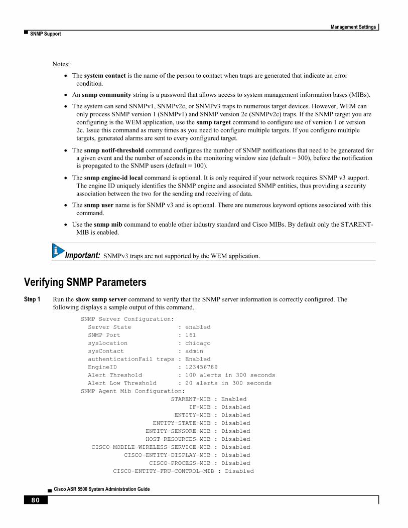
Management Settings
▀ SNMP Support
▄ Cisco ASR 5500 System Administration Guide
80
Notes:
The system contact is the name of the person to contact when traps are generated that indicate an error
condition.
An snmp community string is a password that allows access to system management information bases (MIBs).
The system can send SNMPv1, SNMPv2c, or SNMPv3 traps to numerous target devices. However, WEM can
only process SNMP version 1 (SNMPv1) and SNMP version 2c (SNMPv2c) traps. If the SNMP target you are
configuring is the WEM application, use the snmp target command to configure use of version 1 or version
2c. Issue this command as many times as you need to configure multiple targets. If you configure multiple
targets, generated alarms are sent to every configured target.
The snmp notif-threshold command configures the number of SNMP notifications that need to be generated for
a given event and the number of seconds in the monitoring window size (default = 300), before the notification
is propagated to the SNMP users (default = 100).
The snmp engine-id local command is optional. It is only required if your network requires SNMP v3 support.
The engine ID uniquely identifies the SNMP engine and associated SNMP entities, thus providing a security
association between the two for the sending and receiving of data.
The snmp user name is for SNMP v3 and is optional. There are numerous keyword options associated with this
command.
Use the snmp mib command to enable other industry standard and Cisco MIBs. By default only the STARENT-
MIB is enabled.
Important: SNMPv3 traps are not supported by the WEM application.
Verifying SNMP Parameters
Step 1 Run the show snmp server command to verify that the SNMP server information is correctly configured. The
following displays a sample output of this command.
SNMP Server Configuration:
Server State : enabled
SNMP Port : 161
sysLocation : chicago
sysContact : admin
authenticationFail traps : Enabled
EngineID : 123456789
Alert Threshold : 100 alerts in 300 seconds
Alert Low Threshold : 20 alerts in 300 seconds
SNMP Agent Mib Configuration:
STARENT-MIB : Enabled
IF-MIB : Disabled
ENTITY-MIB : Disabled
ENTITY-STATE-MIB : Disabled
ENTITY-SENSORE-MIB : Disabled
HOST-RESOURCES-MIB : Disabled
CISCO-MOBILE-WIRELESS-SERVICE-MIB : Disabled
CISCO-ENTITY-DISPLAY-MIB : Disabled
CISCO-PROCESS-MIB : Disabled
CISCO-ENTITY-FRU-CONTROL-MIB : Disabled

Management Settings
SNMP Support ▀
Cisco ASR 5500 System Administration Guide ▄ 81
Step 2 Verify that the SNMP community(ies) were configured properly by entering the following command:
show snmp communities
The output of this command lists the configured SNMP communities and their corresponding access levels.
Step 3 Verify that the SNMP transports are configured properly by entering the following command:
show snmp transports
The following displays a sample output:
Target Name: rms1
IP Address: 192.168.1.200
Port: 162
Default: Default
Security Name: public
Version: 1
Security:
View:
Notif Type: traps
Controlling SNMP Trap Generation
The system uses SNMP traps (notifications) to indicate that certain events have occurred. By default, the system enables
the generation of all traps. However, you can disable individual traps to allow only traps of a certain type or alarm level
to be generated. This section provides instructions for disabling/enabling SNMP traps.
Important: Commands used in the configuration samples in this section provide base functionality. The most
common commands and keyword options are presented. In many cases, other optional commands and keyword options
are available. Refer to the Command Line Interface Reference for complete information regarding all commands.
To configure SNMP trap generation:
Step 1 Set parameters by applying the following example configuration:
configure
snmp trap suppress
snmp trap suppress trap_name1 trap_name2 ... trap_nameN
Important: If at a later time you wish to re-enable a trap that was previously suppressed, use the snmp trap
enable command.
snmp trap enable trap_name1 trap_name2 ... trap_nameN target target-name
Step 2 Save the configuration as described in Verifying and Saving Your Configuration.


Cisco ASR 5500 System Administration Guide ▄ 83
Chapter 5 Verifying and Saving Your Configuration
This chapter describes how to save your system configuration and includes the following sections:
Verifying the Configuration
Saving the Configuration
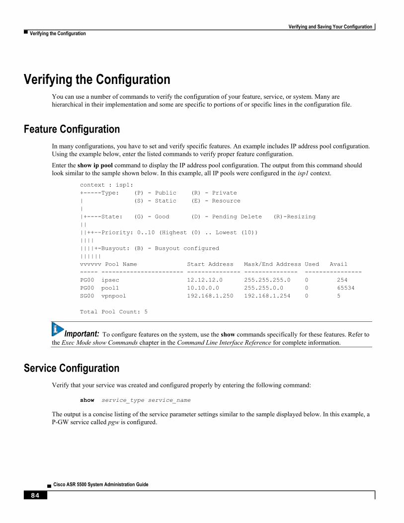
Verifying and Saving Your Configuration
▀ Verifying the Configuration
▄ Cisco ASR 5500 System Administration Guide
84
Verifying the Configuration You can use a number of commands to verify the configuration of your feature, service, or system. Many are
hierarchical in their implementation and some are specific to portions of or specific lines in the configuration file.
Feature Configuration
In many configurations, you have to set and verify specific features. An example includes IP address pool configuration.
Using the example below, enter the listed commands to verify proper feature configuration.
Enter the show ip pool command to display the IP address pool configuration. The output from this command should
look similar to the sample shown below. In this example, all IP pools were configured in the isp1 context.
context : isp1:
+-----Type: (P) - Public (R) - Private
| (S) - Static (E) - Resource
|
|+----State: (G) - Good (D) - Pending Delete (R)-Resizing
||
||++--Priority: 0..10 (Highest (0) .. Lowest (10))
||||
||||+-Busyout: (B) - Busyout configured
||||||
vvvvvv Pool Name Start Address Mask/End Address Used Avail
----- ----------------------- --------------- --------------- ----------------
PG00 ipsec 12.12.12.0 255.255.255.0 0 254
PG00 pool1 10.10.0.0 255.255.0.0 0 65534
SG00 vpnpool 192.168.1.250 192.168.1.254 0 5
Total Pool Count: 5
Important: To configure features on the system, use the show commands specifically for these features. Refer to
the Exec Mode show Commands chapter in the Command Line Interface Reference for complete information.
Service Configuration
Verify that your service was created and configured properly by entering the following command:
show service_type service_name
The output is a concise listing of the service parameter settings similar to the sample displayed below. In this example, a
P-GW service called pgw is configured.
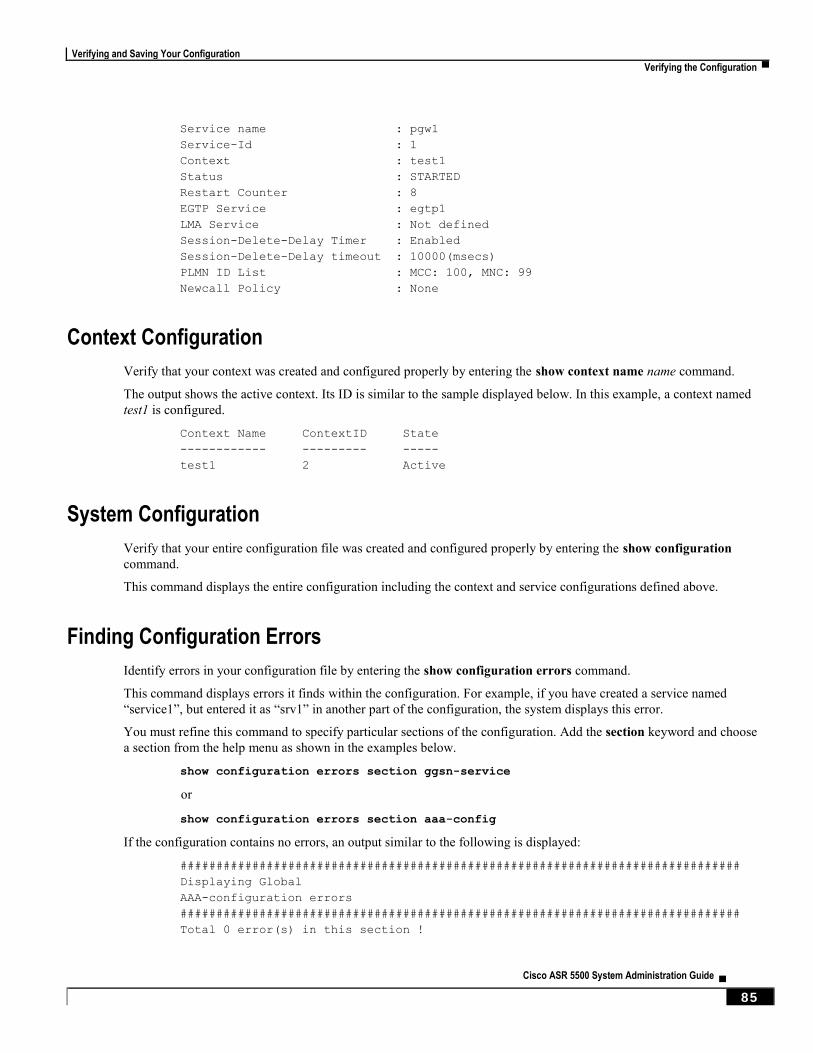
Verifying and Saving Your Configuration
Verifying the Configuration ▀
Cisco ASR 5500 System Administration Guide ▄ 85
Service name : pgw1
Service-Id : 1
Context : test1
Status : STARTED
Restart Counter : 8
EGTP Service : egtp1
LMA Service : Not defined
Session-Delete-Delay Timer : Enabled
Session-Delete-Delay timeout : 10000(msecs)
PLMN ID List : MCC: 100, MNC: 99
Newcall Policy : None
Context Configuration
Verify that your context was created and configured properly by entering the show context name name command.
The output shows the active context. Its ID is similar to the sample displayed below. In this example, a context named
test1 is configured.
Context Name ContextID State
------------ --------- -----
test1 2 Active
System Configuration
Verify that your entire configuration file was created and configured properly by entering the show configuration
command.
This command displays the entire configuration including the context and service configurations defined above.
Finding Configuration Errors
Identify errors in your configuration file by entering the show configuration errors command.
This command displays errors it finds within the configuration. For example, if you have created a service named
“service1”, but entered it as “srv1” in another part of the configuration, the system displays this error.
You must refine this command to specify particular sections of the configuration. Add the section keyword and choose
a section from the help menu as shown in the examples below.
show configuration errors section ggsn-service
or
show configuration errors section aaa-config
If the configuration contains no errors, an output similar to the following is displayed:
##############################################################################
Displaying Global
AAA-configuration errors
##############################################################################
Total 0 error(s) in this section !
Verifying and Saving Your Configuration
▀ Saving the Configuration
▄ Cisco ASR 5500 System Administration Guide
86
Saving the Configuration These instructions assume that you are at the root prompt for the Exec mode:
[local]host_name#
To save your current configuration, enter the following command:
save configuration url [ obsolete-encryption | showsecrets | verbose ] [ -
redundant ] [ -noconfirm ]
url specifies the location in which to store the configuration file. It may refer to a local or a remote file.
For complete information about the above command, see the Exec Mode Commands chapter of the Command Line
Interface Reference.
Important: Do not use the “/” (forward slash), “:” (colon) or “@” (at sign) characters when entering a string for
the following URL fields: directory, filename, username, password, host or port#.
To save a configuration file called system.cfg to a directory that was previously created called cfgfiles to the flash
memory on the active MIO/UMIO, enter the following command:
save configuration /flash/cfgfiles/system.cfg
To save a configuration file called simple_ip.cfg to a directory called host_name_configs, using an FTP server with an
IP address of 192.168.34.156, on which you have an account with a username of administrator and a password of
secure, use the following command:
save configuration sftp://administrator:[email protected]/host_name_configs/
simple_ip.cfg
To save a configuration file called init_config.cfg to the root directory of a TFTP server with a hostname of
config_server, enter the following command:
save configuration tftp://config_server/init_config.cfg

Cisco ASR 5500 System Administration Guide ▄ 87
Chapter 6 System Interfaces and Ports
This chapter describes how to create a context and configure system interfaces and ports within the context. Before
beginning these procedures, refer to your product-specific administration guide for configuration information for your
product.
This chapter includes the following:
Contexts
Ethernet Interfaces and Ports
Important: Make sure at least one Data Processing Card (DPC) or Data Processing Card Universal (UDPC) is
active before you configure system interfaces and ports. Refer to System Settings in this guide for information and
instructions on activating DPCs.
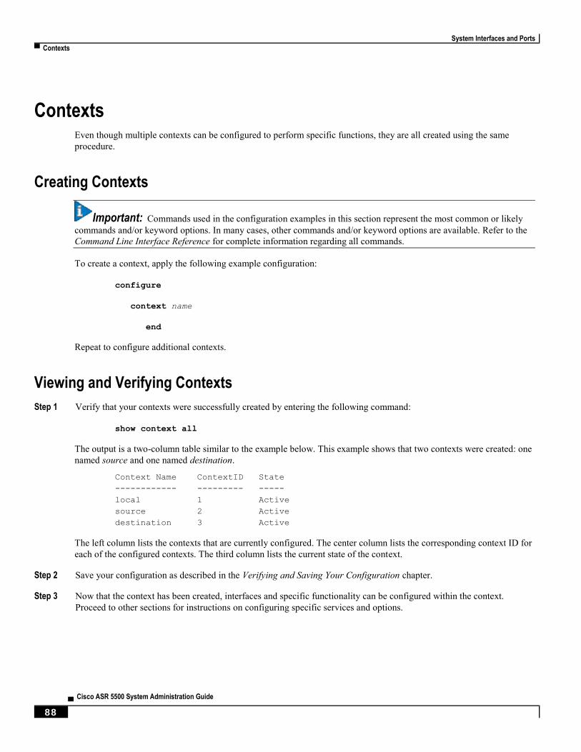
System Interfaces and Ports
▀ Contexts
▄ Cisco ASR 5500 System Administration Guide
88
Contexts Even though multiple contexts can be configured to perform specific functions, they are all created using the same
procedure.
Creating Contexts
Important: Commands used in the configuration examples in this section represent the most common or likely
commands and/or keyword options. In many cases, other commands and/or keyword options are available. Refer to the
Command Line Interface Reference for complete information regarding all commands.
To create a context, apply the following example configuration:
configure
context name
end
Repeat to configure additional contexts.
Viewing and Verifying Contexts
Step 1 Verify that your contexts were successfully created by entering the following command:
show context all
The output is a two-column table similar to the example below. This example shows that two contexts were created: one
named source and one named destination.
Context Name ContextID State
------------ --------- -----
local 1 Active
source 2 Active
destination 3 Active
The left column lists the contexts that are currently configured. The center column lists the corresponding context ID for
each of the configured contexts. The third column lists the current state of the context.
Step 2 Save your configuration as described in the Verifying and Saving Your Configuration chapter.
Step 3 Now that the context has been created, interfaces and specific functionality can be configured within the context.
Proceed to other sections for instructions on configuring specific services and options.
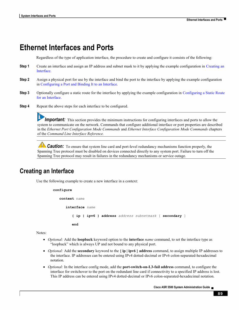
System Interfaces and Ports
Ethernet Interfaces and Ports ▀
Cisco ASR 5500 System Administration Guide ▄ 89
Ethernet Interfaces and Ports Regardless of the type of application interface, the procedure to create and configure it consists of the following:
Step 1 Create an interface and assign an IP address and subnet mask to it by applying the example configuration in Creating an
Interface.
Step 2 Assign a physical port for use by the interface and bind the port to the interface by applying the example configuration
in Configuring a Port and Binding It to an Interface.
Step 3 Optionally configure a static route for the interface by applying the example configuration in Configuring a Static Route
for an Interface.
Step 4 Repeat the above steps for each interface to be configured.
Important: This section provides the minimum instructions for configuring interfaces and ports to allow the
system to communicate on the network. Commands that configure additional interface or port properties are described
in the Ethernet Port Configuration Mode Commands and Ethernet Interface Configuration Mode Commands chapters
of the Command Line Interface Reference.
Caution: To ensure that system line card and port-level redundancy mechanisms function properly, the
Spanning Tree protocol must be disabled on devices connected directly to any system port. Failure to turn off the
Spanning Tree protocol may result in failures in the redundancy mechanisms or service outage.
Creating an Interface
Use the following example to create a new interface in a context:
configure
context name
interface name
{ ip | ipv6 } address address subnetmask [ secondary ]
end
Notes:
Optional: Add the loopback keyword option to the interface name command, to set the interface type as
“loopback” which is always UP and not bound to any physical port.
Optional: Add the secondary keyword to the { ip | ipv6 } address command, to assign multiple IP addresses to
the interface. IP addresses can be entered using IPv4 dotted-decimal or IPv6 colon-separated-hexadecimal
notation.
Optional: In the interface config mode, add the port-switch-on-L3-fail address command, to configure the
interface for switchover to the port on the redundant line card if connectivity to a specified IP address is lost.
This IP address can be entered using IPv4 dotted-decimal or IPv6 colon-separated-hexadecimal notation.
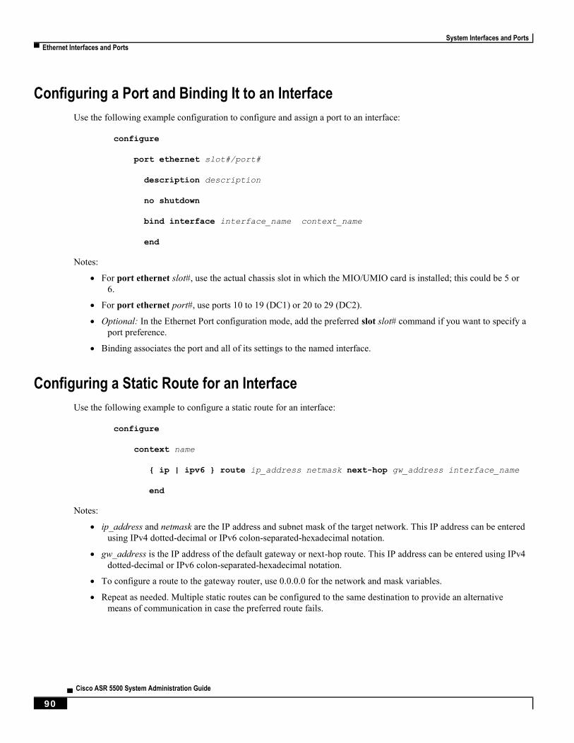
System Interfaces and Ports
▀ Ethernet Interfaces and Ports
▄ Cisco ASR 5500 System Administration Guide
90
Configuring a Port and Binding It to an Interface
Use the following example configuration to configure and assign a port to an interface:
configure
port ethernet slot#/port#
description description
no shutdown
bind interface interface_name context_name
end
Notes:
For port ethernet slot#, use the actual chassis slot in which the MIO/UMIO card is installed; this could be 5 or
6.
For port ethernet port#, use ports 10 to 19 (DC1) or 20 to 29 (DC2).
Optional: In the Ethernet Port configuration mode, add the preferred slot slot# command if you want to specify a
port preference.
Binding associates the port and all of its settings to the named interface.
Configuring a Static Route for an Interface
Use the following example to configure a static route for an interface:
configure
context name
{ ip | ipv6 } route ip_address netmask next-hop gw_address interface_name
end
Notes:
ip_address and netmask are the IP address and subnet mask of the target network. This IP address can be entered
using IPv4 dotted-decimal or IPv6 colon-separated-hexadecimal notation.
gw_address is the IP address of the default gateway or next-hop route. This IP address can be entered using IPv4
dotted-decimal or IPv6 colon-separated-hexadecimal notation.
To configure a route to the gateway router, use 0.0.0.0 for the network and mask variables.
Repeat as needed. Multiple static routes can be configured to the same destination to provide an alternative
means of communication in case the preferred route fails.
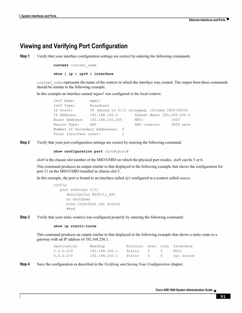
System Interfaces and Ports
Ethernet Interfaces and Ports ▀
Cisco ASR 5500 System Administration Guide ▄ 91
Viewing and Verifying Port Configuration
Step 1 Verify that your interface configuration settings are correct by entering the following commands:
context context_name
show { ip | ipv6 } interface
context_name represents the name of the context in which the interface was created. The output from these commands
should be similar to the following example.
In this example an interface named mgmt1 was configured in the local context.
Intf Name: mgmt1
Intf Type: Broadcast
IP State: UP (Bound to 5/11 untagged, ifIndex 285278209)
IP Address: 192.168.100.3 Subnet Mask: 255.255.255.0
Bcast Address: 192.168.100.255 MTU: 1500
Resoln Type: ARP ARP timeout: 3600 secs
Number of Secondary Addresses: 0
Total interface count: 1
Step 2 Verify that your port configuration settings are correct by entering the following command:
show configuration port slot#/port#
slot# is the chassis slot number of the MIO/UMIO on which the physical port resides. slot# can be 5 or 6.
This command produces an output similar to that displayed in the following example that shows the configuration for
port 11 on the MIO/UMIO installed in chassis slot 5.
In this example, the port is bound to an interface called rp1 configured in a context called source.
config
port ethernet 5/11
description MIO5/11_RP1
no shutdown
bind interface rp1 source
#end
Step 3 Verify that your static route(s) was configured properly by entering the following command:
show ip static-route
This command produces an output similar to that displayed in the following example that shows a static route to a
gateway with an IP address of 192.168.250.1.
Destination Nexthop Protocol Prec Cost Interface
0.0.0.0/0 192.168.250.1 Static 0 0 MIO1
0.0.0.0/0 192.168.250.1 Static 0 0 rp1 source
Step 4 Save the configuration as described in the Verifying and Saving Your Configuration chapter.

Cisco ASR 5500 System Administration Guide ▄ 93
Chapter 7 System Security
This chapter describes the security features supported on the ASR 5500 platform.
This chapter explores the following topics:
Per-Chassis Key Identifier
Encrypted SNMP Community Strings
Lawful Intercept Restrictions
Adding, Modifying and Removing Users
Hidden Commands
System Security
▀ Per-Chassis Key Identifier
▄ Cisco ASR 5500 System Administration Guide
94
Per-Chassis Key Identifier A user can set a unique chassis key which will work only for a chassis or for any set of chassis that will share the same
configuration information.
The chassis key consists of 1 to 16 alphanumeric ASCII characters. The chassis key plain-text value is never displayed
to the user; it is entered interactively and not echoed to the user.
On the ASR5500 the encrypted chassis key is stored in the midplane EEPROM and shared by both MIO/UMIOs.
If the chassis key identifier stored in the header comment line of the configuration file does not match the chassis key,
an error message is displayed to the user. The user can change the chassis key value simply by entering the chassis key
again. The previous chassis key is replaced by a new chassis key. The user is not required to enter a chassis key.
If the user does not configure a chassis key, the system generates a unique value for that chassis.
Important: Changing a chassis key may invalidate previously generated configurations. This is because any
secret portions of the earlier generated configuration will have used a different encryption key. For this reason the
configuration needs to be recreated and restored.
Important: To make password configuration easier for administrators, the chassis key should be set during the
initial chassis set-up.
The configuration file contains a one-way encrypted value of the chassis key (the chassis key identifier) and the version
number in a comment header line. These two pieces of data determine if the encrypted passwords stored within the
configuration will be properly decrypted.
While a configuration file is being loaded, the chassis key used to generate the configuration is compared with the
stored chassis key. If they do not match the configuration is not loaded.
The user can remove the chassis key identifier value and the version number header from the configuration file. Also,
the user may elect to create a configuration file manually. In both of these cases, the system will assume that the same
chassis key will be used to encrypt the encrypted passwords. If this is not the case, the passwords will not be decrypted
due to resulting non-printable characters or memory size checks. This situation is only recoverable by setting the chassis
key back to the previous value, editing the configuration to have the encrypted values which match the current chassis
key, or by moving the configuration header line lower in the configuration file.
Beginning with Release 15.0, the chassis ID will be generated from an input chassis key using the SHA2-256 algorithm
followed by base36 encoding. The resulting 44-character chassis ID will be stored in the same chassisid file in flash.
Release 14 and Release 15 chassis IDs will be in different formats. Release 15 will recognize a Release 14 chassis ID
and consider it as valid. Upgrading from 14.x to 15.0 will not require changing the chassis ID or configuration file
However, if the chassis-key is reset in Release 15 through the setup wizard or chassis-key CLI command, a new chassis
ID will be generated in Release 15 format (44 instead of 16 characters). Release14 builds will not recognize the 44-
character chassis ID. If the chassis is subsequently downgraded to Release 14, a new 16-character chassis ID will be
generated. To accommodate the old key format, you must save the configuration file in pre-v12.2 format before the
downgrade. If you attempt to load a v15 configuration file on the downgraded chassis, StarOS will not be able to
decrypt the password/secrets stored in the configuration file.
System Security
Per-Chassis Key Identifier ▀
Cisco ASR 5500 System Administration Guide ▄ 95
MIO/UMIO Synchronization
On boot up both MIO/UMIOs automatically read the chassis key configured on the ASR 5500 midplane.
Protection of Passwords
Users with privilege levels of Inspector and Operator cannot display decrypted passwords in the configuration file via
the ASR 5500 command line interface (CLI).
Secure Configuration Password Encryption
The system encrypts passwords using an MD5-based cipher. These passwords also have a random 64-bit (8-byte) salt
added to the password. The chassis key is used as the encryption key.
Using the chassis key allows for an encryption method where the decryption requires the knowledge of a “shared
secret”. Only a chassis with knowledge of this shared secret can access the passwords. To decipher passwords, a hacker
who knew the chassis key would still need to identify the location of the 64-bit random salt value within the encryption.
The encrypted password is displayed with a prefixed of “+A” in the configuration file to identify the methodology used
for encrypting.
Support for Non-Current Encryptions and Decryptions
The system supports previously formatted encrypted passwords. The syntax of the encrypted passwords indicates to the
ASR 5500 which methodology was used for encryption. If the system does not see a prefix before the encrypted
password, the earlier encryption method using a fixed key will be used. If the encrypted password includes the “+A”
prefix, the decryption method uses the chassis key and random salt.
If the user saves a new configuration, the generated file will always contain passwords encrypted by the most recent
method. The user cannot generate the earlier DES-based encryption values. However, all future StarOS releases will
continue to support plain-text password entry for all two-way encryptable passwords
The recommended process for changing the chassis key without causing a “lock-out” state is as follows:
Load the configuration file of the last good configuration using the previous chassis key.
Change the chassis key to the new desired value.
Save the configuration with this new chassis key.
Refer to Configuring a Chassis Key in System Settings for additional information.
Selectable Password/Secrets Encryption Algorithm
An administrator can specify the type of encryption algorithm to be used for passwords and secrets. The default
algorithm will be the MD5-based cipher (algorithm “A”) described above. Another option specifies the use of AES-
CBC-128 for encryption and HMAC-SHA1 for authentication (algorithm “B”).
Use the Global Configuration mode cli-encrypt-algorithm command to specify the desired encryption algorithm – A
(default) or B. For additional information, refer to the Command Line Interface Reference.
System Security
▀ Per-Chassis Key Identifier
▄ Cisco ASR 5500 System Administration Guide
96
Support for ICSR Configurations
Inter-Chassis Session Recovery (ICSR) is a redundancy configuration that employs two identically configured ASR
5500 chassis as a redundant pair.
ICSR chassis share the same chassis key. If the ISCR detects that the two chassis have incompatible chassis keys, an
error message is logged but the ICSR system will continue to run. Without the matching chassis key, the standby ICSR
chassis can recover services if the active chassis goes out of service; the standby chassis will still have access to the
passwords in their decrypted form.
ICSR chassis use Service Redundancy Protocol (SRP) to periodically check to see if the redundancy configuration
matches with either decrypted passwords or DES-based two-way encryption strings. Since the configuration is
generated internally to the software, users are not able to access the configuration used to check ICSR compatibility.
System Security
Encrypted SNMP Community Strings ▀
Cisco ASR 5500 System Administration Guide ▄ 97
Encrypted SNMP Community Strings Simple Network Management Protocol (SNMP) uses community strings as passwords for network elements. Although
these community strings are sent in clear-text in the SNMP PDUs, the values can be encrypted in the configuration file.
The snmp community encrypted name command enables the encryption of SNMP community strings. For additional
information, see the Global Configuration Mode Commands chapter in the Command Line Interface Reference.
Lawful Intercept Restrictions This section describes some of the security features associated with the provisioning of Lawful Intercept (LI). For
additional information, refer to the Lawful Intercept Configuration Guide.
LI Server Addresses
An external authenticating agent (such as RADIUS or Diameter) sends a list of LI server addresses as part of access-
accept. For any intercept that was already installed or will be installed for that subscriber, a security check is performed
to match the LI server address with any of the LI-addresses that were received from the authenticating agent. Only those
addresses that pass this criteria will get the intercepted information for that subscriber.
While configuring a campon trigger, the user will not be required to enter the destination LI server addresses. When a
matching call for that campon trigger is detected, a security check is done with the list received from the authentication
agent. The LI-related information is only forwarded if a matching address is found.
When an active-only intercept is configured, if a matching call is found, a security check is made for the LI address
received from the authentication agent and the intercept configuration will be rejected.
If no information related to LI server addresses is received for that subscriber, LI server addresses will not be restricted.
Important: A maximum of five LI server addresses are supported via an authenticating agent.
Modifying Intercepts
One LI administrator can access and/or modify the intercepts created by another LI administrator. Whenever an
intercept is added, removed or modified, an event log is displayed across LI administrators about the change. An SNMP
trap is also generated.

System Security
▀ Adding, Modifying and Removing Users
▄ Cisco ASR 5500 System Administration Guide
98
Adding, Modifying and Removing Users It is considered uncommon for a user to be added or removed from the ASR 5500. Likewise, it is considered uncommon
for a user's privileges to modified. However, if the system is compromised, it is common for attackers to add or remove
a privileged user, raise their privileges or lower the privileges of others.
As a general rule, lower privileged users should not be allowed to increase their privileges or gain access to sensitive
data, such as passwords, which were entered by higher privileged users.
Important: The ASR 5500 can only detect changes in users and user attributes, such as privilege level, when
these users are configured through the ASR 5500.
Notification of Users Being Added or Deleted
Users with low level authorization should not be able to create users with high level authorization. However, if a
malicious actor were to be able to create a high level authorized user, they could then delete the other high level
authorized users, thereby locking them out of the system.
The following SNMP traps notify an administrator when users are added or removed:
starLocalUserAdded – indicates that a new local user account has been added to the system.
starLocalUserRemoved – indicates that a local user account has been removed from the system.
Notification of Changes in Privilege Levels
Whenever a user's privilege level is increased or decreased, an SNMP notification will be sent out. A malicious actor
may gain access to more privileged commands by somehow promoting” their privileges. Once this is done, they could
then “demote” the privileges of all the other users, thereby locking the proper administrators out of the system.
The starLocalUserPrivilegeChanged trap indicates that a local user's privilege level has been changed.
User Access to Operating System Shell
The starOsShellAccessed trap indicates that a user has accessed the operating system shell.
System Security
Hidden Commands ▀
Cisco ASR 5500 System Administration Guide ▄ 99
Hidden Commands Users with Security Administrator privilege can enable the display of previously hidden commands. The CLI test-
commands mode displays new command keywords for existing commands, as well as new commands.
Caution: CLI test-commands are intended for diagnostic use only. Access to these commands is not required
during normal system operation. These commands are intended for use by Cisco TAC personnel only. Some of these
commands can slow system performance, drop subscribers, and/or render the system inoperable.
Enabling cli test-commands Mode
To display hidden commands, the user must log into the CLI as a Security Administrator and go to the Global
Configuration mode.
Enter cli hidden to enable the use of hidden commands.
This command sequence is shown below.
[local]asr5500# config
[local]asr5500(config)# cli hidden
[local]asr5500(config)#
Important: Low-level diagnostic and test commands/keywords will now be visible to a user with Administrator
or higher privilege. There is no visual indication on the CLI that the test-commands mode has been enabled.
Enabling Password for Access to CLI-test commands
A Security Administrator can set a plain-text or encrypted password for access to CLI test commands. The password
value is stored in /flash along with the boot configuration information. The show configuration and save configuration
commands will never output this value.
The Global Configuration mode command tech-support test-commands [encrypted] password password sets an
encrypted or plain-text password for access to CLI test-commands.
This command sequence is shown below.
[local]asr5500# config
[local]asr5500(config)# tech-support test-commands password password
[local]asr5500(config)#
When a test-commands password is enabled, the Global Configuration mode command cli test-commands [encrypted]
password password requires the entry of the password keyword. If the encrypted keyword is specified, the password
argument is interpreted as an encrypted string containing the password value. If the encrypted keyword is not specified,
the password argument is interpreted as the actual plain text value
Important: If tech-support test-commands password is never configured, cli-test commands will always
fail. If the password keyword is not entered for cli test-commands, the user is prompted (no-echo) to enter the
password. Also, cli hidden must be enabled by a Security Administrator to access the CLI test-commands.
System Security
▀ Hidden Commands
▄ Cisco ASR 5500 System Administration Guide
100
Exec Mode cli test-commands
Exec mode commands are available to a privileged user who enters the command cli test-commands from Exec mode.
[local]asr5500# cli test-commands [encrypted] password password
Warning: Test commands enables internal testing and debugging commands
USE OF THIS MODE MAY CAUSE SIGNIFICANT SERVICE INTERRUPTION
Important: An SNMP trap (starTestModeEntered) is generated whenever a user enters CLI test-commands
mode.
Configuration mode cli test-commands
Configuration commands which provided access to low-level software parameters are accessible only after a privileged
user enters the command cli test-commands from Global Configuration mode.
[local]asr5500# config
[local]asr5500(config)# cli test-commands [encrypted] password password
Warning: Test commands enables internal testing and debugging commands
USE OF THIS MODE MAY CAUSE SIGNIFICANT SERVICE INTERRUPTION
Important: An SNMP trap (starTestModeEntered) is generated whenever a user enters CLI test-commands
mode.

Cisco ASR 5500 System Administration Guide ▄ 101
Chapter 8 Software Management Operations
This chapter provides information about software management operations on the system. Software management sections
include:
Understanding the Local File System
Maintaining the Local File System
Configuring the Boot Stack
Upgrading the Operating System Software
Performing Dynamic Software Updates
Managing License Keys
Managing Local-User Administrative Accounts
Software Management Operations
▀ Understanding the Local File System
▄ Cisco ASR 5500 System Administration Guide
102
Understanding the Local File System The Management Input/Output (MIO) or Management Input/Output Universal (UMIO) card provides control and
management for the system.
The local file system is made up of files that are stored on one or more of the following:
/flash - Flash memory located on the circuit board of the MIO/UMIO, is the default storage media for the
operating system software image, CLI configuration, and crash log files used by the system.
/usb1 - This device is available when a USB memory stick is inserted on the front panel of the active
MIO/UMIO.
/hd-raid - This is the solid state hard disk array supported by the Fabric and Storage Cards (FSCs) and accessed
via the active MIO/UMIO.
File Types Used by the Local File System
The following file types can be located in the local file system:
Operating System Software Image File: This binary file type is identified by its .bin extension. The file is the
operating system that is loaded by the system upon startup or reloading. This is an executable, read-only file
that cannot be modified by end users.
CLI Configuration File: This file type is identified by its .cfg extension. These are text files that contain CLI
commands that work in conjunction with the operating system software image. These files determine services
to be provided, hardware and software configurations, and other functions performed by the system. The files
are typically created by the end user. You can modify the files both on and off-line and use descriptive long
filenames.
System File: Only one file identified by a .sys extension is used by the system. The boot.sys file contains
system-specific information, which describes how the system locates, and in what priority it loads, file groups
(paired .bin and .cfg files) from its boot stack.
Abridged Crash Log: The abridged crash log, identified by its crashlog filename, contains summary
information about software or hardware failures that occur on the system. This file is located in the
/flash/crsh2/ directory on the device. You can view the contents of this file through the CLI, but you cannot
modify the file.
Understanding the boot.sys File
The system uses the boot.sys file to store the prioritized boot stack parameters and file groups the system uses during
startup. Modify this file only through system CLI commands and not through external means. Boot parameters contain
information the system needs to locate the operating system image file, including:
bootmode: This setting is typically configured to normal, and identifies how the system starts.
network interface configuration: Use these optional boot method settings when you configure the system to
obtain its operating system image from an external network server that is using one of the management LAN
interfaces on the MIO/UMIO card.
boot stack information: The boot stack is made up of prioritized file group entries that designate the operating
system image file and the CLI configuration file to load.

Software Management Operations
Understanding the Local File System ▀
Cisco ASR 5500 System Administration Guide ▄ 103
When a system is unpacked and started for the first time, the boot.sys file is configured to use the normal boot mode and
load the operating system software image from the /flash directory.
There is no CLI configuration file contained on the local file system. This causes the system to automatically start its
CLI-based Quick Setup Wizard upon the first successful boot. Refer to Getting Started for more information on using
the Quick Setup Wizard.
Software Management Operations
▀ Maintaining the Local File System
▄ Cisco ASR 5500 System Administration Guide
104
Maintaining the Local File System Use CLI commands to manage and maintain the devices that make up the local file system. Execute all the commands
described in this section in the Exec Mode. Unless otherwise specified, you must have security administrator or
administrator privileges to execute these commands.
File System Management Commands
Use the commands in this section to manage and organize the local file system.
Important: For complete information on the commands listed below, see the Exec Mode Commands chapter of
the Command Line Interface Reference
Synchronizing the File System
Commands are supported for mirroring the local file systems from the active MIO/UMIO to the standby MIO/UMIO in
systems containing two cards. Use these commands to synchronize any or all of the local devices.
Important: Crash log files are not synchronized when these commands are executed.
The following Exec mode command synchronizes the file systems between two MIO/UMIOs:
filesystem synchronize [ /flash | /usb1 | all ] [ checkonly ] [ from card_num |
to card_num ] [-noconfirm]
Only filesystems on matching local devices are synchronized. For example, if the active MIO/UMIO contains two local
devices (/flash and /usb1) and the standby MIO/UMIO contains only one local device (/flash), then synchronization only
occurs on the matching local device (/flash).
The following command synchronizes the file systems on two MIO/UMIO /flash devices.
filsystem synchronize /flash
Creating Directories
Use the mkdir command to create a new directory on the specific local device. This directory can then be incorporated
as part of the path name for any file located in the local file system.
mkdir { /flash | /usb1 | /hd-raid } /dir_name
Use the following command to create a directory named configs:
mkdir /flash/configs

Software Management Operations
Maintaining the Local File System ▀
Cisco ASR 5500 System Administration Guide ▄ 105
Renaming Files and Directories
Use the rename command to change the name of a file from its original name to a different name. Remember to use the
same file extension, if applicable, to ensure that the file type remains unchanged.
rename { /flash | /usb1 | /hd-raid } /src_filename { /flash | /usb1 | /hd-raid }
/dst_filename [-noconfirm]]
Use the following command to rename a file named iot_test.cfg to iot_accept.cfg on the /flash local device.
rename /flash/iot_test.cfg /flash/iot_accept.cfg -noconfirm
Important: Use the rename command only within the same local device. You cannot rename a file and place it
onto another local device at the same time. To move a renamed file, you must use the copy command.
Copying Files on the ASR 5500 Chassis
These instructions assume that you are at the root prompt for the Exec mode:
[local]host_name#
To save your current configuration, enter the following command:
copy from_url to_url [-noconfirm]
To copy a configuration file called system.cfg from a directory that was called cfgfiles to a directory named configs_old
on the flash memory in the MIO/UMIO, enter the following command:
copy /flash/cfgfiles/system.cfg /flash/configs_old/system_2011.cfg
To copy a configuration file called simple_ip.cfg from a directory called host_name_configs to an FTP server with an IP
address of 192.168.34.156, on which you have an account with a username of administrator and a password of secure,
use the following command:
copy /flash/host_name_configs/simple_ip.cfg
ftp://administrator:[email protected]/host_name_configs/ simple_ip.cfg
To copy a configuration file called init_config.cfg to the root directory of a TFTP server with a hostname of
config_server, enter the following command:
copy /flash/cfgfiles/init_confg.cfg tftp://config_server/init_config.cfg
Software Management Operations
▀ Maintaining the Local File System
▄ Cisco ASR 5500 System Administration Guide
106
Deleting Files
The delete command removes a designated file from its specified location on the local file system.
Important: This command does not support wildcard entries; each filename must be specified in its entirety.
Caution: Do not delete the boot.sys file. If deleted, the system will not reboot on command and will be
rendered inoperable.
delete { /flash | /usb1 | /hd-raid }/filename [-noconfirm]
The following command deletes a file named test.cfg from the /flash directory.
delete /flash/test.cfg
Removing Directories
The rmdir command deletes a current directory on the specific local device. This directory can then be incorporated as
part of the path name for any file located in the local file system.
Important: The directory you want to remove (delete) must be empty before executing the rmdir command. If
the directory is not empty, the CLI displays a “Directory not empty” message and will not execute.
rmdir url /dir_name
The following command deletes an empty directory named configs in the /flash directory.
rmdir /flash/configs
Formatting Local Devices
The format command performs a low-level format of a local device. This operation formats the device to use the
FAT16 formatting method, which is required for proper read/write functionality with the operating system.
Important: Local devices that have been formatted using other methods such as NTFS or FAT32 may be used to
store various operating system, CLI configuration, and crash log files. However, when placing a new local device into
the MIO/UMIO for regular use, you should format the device via the system prior to use. This ensures that the proper
file allocation table format is used, preventing any possible discrepancies between other formats used with other
operating systems.
Caution: The format command removes all files and information stored on the device.
To format a local device for use by the local file system, enter the following command:
format { /flash | /usb1 | /hd-raid }

Software Management Operations
Maintaining the Local File System ▀
Cisco ASR 5500 System Administration Guide ▄ 107
Applying Pre-existing CLI Configuration Files
A pre-existing CLI configuration file is any .cfg file created to provide utility functions (such as clearing all statistics
during testing) or created off-line using a text editor. There may be pre-existing configuration files stored on the local
file system that can be applied to a running system at any time.
Caution: If a configuration file is applied to a system currently running another CLI configuration, any like
contexts, services, logical interfaces, physical ports, IP address pools, or other configured items will be overwritten if
the same command exists in the configuration file being applied. Take caution to ensure that you are knowledgeable of
the contents of the file being applied and understand what the service ramifications are if a currently running command
is overwritten. Also note that changes will not be saved automatically.
A CLI configuration file, or script containing CLI commands, can be applied to a running system by entering the
following command at the Exec mode prompt:
configure url [ verbose ]
url specifies the location of the CLI configuration file to be applied. It may refer to a local or a remote file.
The following command applies a pre-existing CLI configuration file named clearcmds.cfg in the /flash directory.
configure /flash/clearcmds.cfg
Viewing Files on the Local File System
This section describes how to view a variety of files.
Viewing the Contents of a Local Device
The contents, usage information, and file system directory structure of any local device can be viewed by entering the
following command at the Exec mode prompt:
directory { /flash | /usb1 | /hd-raid }
Viewing CLI Configuration and boot.sys Files
The contents of CLI configuration and boot.sys files, contained on the local file system, can be viewed off-line (without
loading them into the OS) by entering the following command at the Exec mode prompt:
show file url { /flash | /usb1 | /hd-raid } /filename
Where: url is the path name for the location of the file and filename is the name of the file, including any extension.
Important: Operator and inspector-level users can execute the show file command but cannot execute the
directory command.
Software Management Operations
▀ Maintaining the Local File System
▄ Cisco ASR 5500 System Administration Guide
108
Validating an Operating System File
The operating system software image file, identified by its .bin extension, is a non-readable, non-editable file that
executes on the system, creating its runtime operating system (OS).
It is important to verify a new operating system image file before attempting to load it. To accomplish this, a proprietary
checksum algorithm is used to create checksum values for each portion of the application stored within the .bin file
during program compilation.
This information can be used to validate the actual file against the checksum values stored within the file during its
compilation. If any portion of the image file has become corrupted (for example, the file was truncated or was
transferred using ASCII mode instead of binary mode), then this information is reported and the file is deemed
unusable.
To validate an operating system software image file, enter the following command at the Exec mode prompt:
show version { /flash | /usb1 | /hd-raid } /[directory]/filename [all]
The output of this command displays the following information:
Version number
Description
Date
Boot Image
Size
Flags
Platform – ASR5500
If an invalid file is found, the system displays a failure message similar to these:
Failure: Image /flash/image_version.bin CRC check failed!
Failure: /flash/image_version.bin, has a bad magic number

Software Management Operations
Configuring the Boot Stack ▀
Cisco ASR 5500 System Administration Guide ▄ 109
Configuring the Boot Stack The boot stack consists of a prioritized listing of operating system software image-to-CLI configuration file
associations. These associations determine the software image and configuration file that gets loaded during system
startup or upon a reload/reboot. Though multiple associations can be configured, the system uses the association with
the highest priority. In the event that there is an error processing this association (for example, one of the files cannot be
located), the system attempts to use the association with the next highest priority. Priorities range from 1 to 100, with 1
being the highest priority. The maximum number of boot stack entries that may be configured in the boot.sys file is 10.
Boot stack information is contained in the boot.sys file, described in Understanding the boot.sys File. In addition to boot
stack entries, the boot.sys file contains any configuration commands required to define the system boot method as
explained in the section that follows.
System Boot Methods
The local-boot method uses software image and configuration files stored locally on the system. Upon system startup or
reboot, the system looks on one of its local devices or /hd-raid located on the active MIO/UMIO for the specific
software image and accompanying configuration text file. When using the local-booting method, you only need to
configure boot stack parameters.
The system can also be configured to obtain its software image from a specific external network server while it is paired
with a configuration text file that resides on the system. When using network booting, you need to configure the
following:
Boot stack parameters, which define the files to use and in what priority to use them
Boot interface and network parameters defining the MIO/UMIO remote management LAN interface and the
methods to use to reach the external network server
Network booting delay time and optional name server parameters defining the delay period (in seconds) to allow
for network communications to be established, and the IP address of any Domain Name Service (DNS) name
server that may be used
Detailed information on how to configure the system to use the network booting method appears in Network Booting
Configuration Requirements.
Viewing the Current Boot Stack
To view the boot stack entries contained in the boot.sys file run the Exec mode show boot command.
Important: Operator and inspector-level users can execute the show boot command.
The examples below shows the command output for a local booting configuration. Notice that in these examples both
the image file (operating system software) and configuration file (CLI commands) are located on the /flash device.
Important: The StarOS image filename scheme changed with release 16.1. Pre-16.1, format =
“production.image.bin”. For 16.1 onwards, format = “asr5500-image_number.bin”. This change is reflected in the
examples provided below.
Software Management Operations
▀ Configuring the Boot Stack
▄ Cisco ASR 5500 System Administration Guide
110
Example 1 – StarOS releases prior to 16.1:
boot system priority 18 \
image /flash/15-0-builds/production.45666.bin \
config /flash/general_config.cfg
boot system priority 19 \
image /flash/15-0-builds/production.45717.bin \
config /flash/general_config_3819.cfg
boot system priority 20 \
image /flash/15-0-builds/production.45069.bin \
config /flash/general_config_3665.cfg
Example 2 – StarOS release 16.1 onwards:
boot system priority 18 \
image /flash/16-1-builds/asr5500-16.1.3.bin \
config /flash/general_config.cfg
boot system priority 19 \
image /flash/16-1-builds/asr5500-16.1.1.bin \
config /flash/general_config_3819.cfg
boot system priority 20 \
image /flash/16-1-builds/asr5500-16.1.0.bin \
config /flash/general_config_3665.cfg
The example below shows the output for a combination network booting and local booting configuration. Notice in this
example that the first two boot stack entries (Priorities 18 and 19) load the image file (operating system software) from
an external network server using the Trivial File Transfer Protocol (TFTP), while all configuration files are located on
the /flash device.
Also notice the boot network interface and boot network configuration commands located at the top of the boot stack.
These commands define what MIO/UMIO remote management LAN interface(s) to use and information about
communicating with the external network server that hosts the operating system software image file.
boot networkconfig static ip address mio1 192.168.1.150 netmask 255.255.255.0
boot delay 15
boot system priority 18 image tftp://192.168.1.161/tftpboot/image_version.bin
\config /flash/general_config.cfg
boot system priority 19 image tftp://192.168.1.161/tftpboot/image_version.bin
\config /flash/general_config.cfg
boot system priority 20 image /flash/image_version.bin \config
/flash/general_config.cfg
To identify the boot image priority that was loaded at the initial boot time enter:
show boot initial-config

Software Management Operations
Configuring the Boot Stack ▀
Cisco ASR 5500 System Administration Guide ▄ 111
The example below displays the output:
[local]host# show boot initial-config
Initial (boot time) configuration:
image tftp://192.168.1.161/tftpboot/image_version.bin \
config /flash/config_name.cfg
priority 1
Adding a New Boot Stack Entry
Important: Before performing this procedure, verify that there are less than 10 entries in the boot.sys file and
that a higher priority entry is available (i.e. that minimally there is no priority 1 entry in the boot stack). Refer to
Viewing the Current Boot Stack for more information.
If priority 1 is in use, then you must renumber the existing entry(ies) to ensure that at least that priority is available. The
maximum number of boot stack entries that can be contained in the boot.sys file is 10. If there are already 10 entries in
the boot stack, you must delete at least one of these entries (typically, the lowest priority) and, if necessary, renumber
some or all of the other entries before proceeding. Refer to Deleting a Boot Stack Entry for more information.
This procedure details how to add new boot stack entries to the boot.sys file. Make sure you are at the Exec mode
prompt and enter the following commands:
configure
boot system priority number image image_url config cfg_url
The following command creates a new boot stack entry, using a boot priority of 3.
boot system priority 3 image /flash/image_filename.bin config
/flash/config_name.cfg
Important: Boot stack changes saved to the boot.sys file are not executed until the system is rebooted.
Synchronize the local file systems on the MIO/UMIOs with the following command:
fielsystem synchronize all
Deleting a Boot Stack Entry
This procedure details how to remove an individual boot stack entry from the boot.sys file. Make sure you are at the
Exec mode prompt and enter the following commands:
configure
no boot system priority number
Where number specifies the boot priority used for the boot stack entry. This command removes that specific entry from
the boot stack, causing the boot.sys file to be overwritten.

Software Management Operations
▀ Configuring the Boot Stack
▄ Cisco ASR 5500 System Administration Guide
112
Network Booting Configuration Requirements
Configuring the Boot Interface
Boot interface parameters define the MIO/UMIO management LAN interface that the system will use to communicate
with the management network when using the network booting method.
This procedure details how to configure the boot interface for reliable communications with your network server. Make
sure you are at the Exec mode prompt:
[local]host_name#
Step 1 Enter the Global Configuration mode by entering the following command:
configure
The following prompt appears:
[local]host_name(config)#
Step 2 Enter the following command:
boot interface { local-eth1 | local-eth2 } medium { auto | speed { 10 | 100 |
1000 } duplex { full | half } } media { rj45 | sfp }
Important: For complete information about the above command, see the Global Configuration Mode
Commands chapter in the Command Line Interface Reference.
Use port 1 for network booting.
If the speed is manually configured, you must also configure the duplex mode. In addition, you must ensure that the
network server configuration supports the speed and duplex configuration.
Network speed for MIO/UMIO is fixed at 1000.
Ethernet networking rules dictate that if a device’s interface is configured for auto-negotiation is communicating with a
device that is manually configured to support full duplex, the first device will negotiate to the manually configured
speed of the second device, but will only communicate in half duplex mode.
The media for MIO/UMIO port 1 is fixed at rj45.
Step 3 Save the configuration as described in the Verifying and Saving Your Configuration chapter.
Configuring the Boot Network
Boot network parameters define the protocols and IP address information for MIO/UMIO interfaces used to reach the
external network server that hosts the operating system software image file. To configure boot network parameters,
make sure you are at the Exec mode prompt:
[local]host_name#

Software Management Operations
Configuring the Boot Stack ▀
Cisco ASR 5500 System Administration Guide ▄ 113
Step 1 Enter the Global Configuration mode by entering the following command:
configure
The following prompt appears:
[local]host_name(config)#
Step 2 Enter the following command:
boot networkconfig { dhcp | { { dhcp-static-fallback|static } ip address mio5
ip_address5 [ mio6 ip_address6 ] netmask subnet_mask [ gateway gw_ip_address ] } }
Important: For complete information about the above command, see the Global Configuration Mode
Commands chapter in the Command Line Interface Reference.
The following command configures the boot network to communicate using DHCP, with a static-fallback IP address for
MIO/UMIO in slot 5 of 192.168.206.101 and a Class C netmask.
boot networkconfig dhcp-static-fallback ip address mio5 192.168.206.101 netmask
255.255.255.0
The next example uses static IP addresses for MIO/UMIO in slot 5, which can access the external network server
through a gateway whose IP address is 135.212.10.2.
boot networkconfig static ip address mio5 192.168.206.101 netmask 255.255.255.0
gateway 135.212.10.2
Step 3 Save the configuration as described in the Verifying and Saving Your Configuration chapter.
Configuring Boot Network Delay Time
An optional delay period, in seconds, can be configured for systems booting from a network. The purpose of this
parameter is to allow time for external devices, such as switches, that use the Spanning Tree Protocol (STP) to
determine the network route to a specified IP address.
To configure a boot network delay, enter the following command from the Global Configuration mode prompt.
boot delay time
Where time is an integer from 1 to 300 seconds before attempting to contact the external network server. If your
network uses STP, a typical delay time of 30 seconds should suffice.
Important: Save your configuration as described in the Verifying and Saving Your Configuration chapter.
Software Management Operations
▀ Configuring the Boot Stack
▄ Cisco ASR 5500 System Administration Guide
114
Configuring a Boot Nameserver
To enter the hostname of the network server that hosts the operating system software image, first configure the IP
address of the Domain Name Service (DNS) server, referred to as a name server, that can resolve the host name for the
machine.
To configure a boot nameserver address, enter the following command from the Global Configuration mode prompt.
boot nameserver ip_address
Where ip_address is the IP address of the DNS server entered in IPv4 dotted-decimal notation.
Important: Save the configuration as described in the Verifying and Saving Your Configuration chapter.
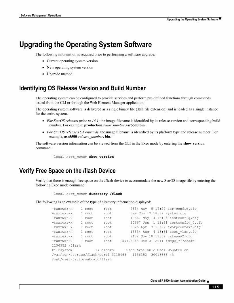
Software Management Operations
Upgrading the Operating System Software ▀
Cisco ASR 5500 System Administration Guide ▄ 115
Upgrading the Operating System Software The following information is required prior to performing a software upgrade:
Current operating system version
New operating system version
Upgrade method
Identifying OS Release Version and Build Number
The operating system can be configured to provide services and perform pre-defined functions through commands
issued from the CLI or through the Web Element Manager application.
The operating system software is delivered as a single binary file (.bin file extension) and is loaded as a single instance
for the entire system.
For StarOS releases prior to 16.1, the image filename is identified by its release version and corresponding build
number. For example: production.build_number.asr5500.bin.
For StarOS release 16.1 onwards, the image filename is identified by its platform type and release number. For
example, asr5500-release_number. bin.
The software version information can be viewed from the CLI in the Exec mode by entering the show version
command.
[local]host_name# show version
Verify Free Space on the /flash Device
Verify that there is enough free space on the /flash device to accommodate the new StarOS image file by entering the
following Exec mode command:
[local]host_name# directory /flash
The following is an example of the type of directory information displayed:
-rwxrwxr-x 1 root root 7334 May 5 17:29 asr-config.cfg
-rwxrwxr-x 1 root root 399 Jun 7 18:32 system.cfg
-rwxrwxr-x 1 root root 10667 May 14 16:24 testconfig.cfg
-rwxrwxr-x 1 root root 10667 Jun 1 11:21 testconfig_4.cfg
-rwxrwxr-x 1 root root 5926 Apr 7 16:27 tworpcontext.cfg
-rwxrwxr-x 1 root root 15534 Aug 4 13:31 test_vlan.cfg
-rwxrwxr-x 1 root root 2482 Nov 18 11:09 gateway2.cfg
-rwxrwxr-x 1 root root 159106048 Dec 31 2011 image_filename
1136352 /flash
Filesystem 1k-blocks Used Available Use% Mounted on
/var/run/storage/flash/part1 3115468 1136352 30018336 4%
/mnt/user/.auto/onboard/flash

Software Management Operations
▀ Upgrading the Operating System Software
▄ Cisco ASR 5500 System Administration Guide
116
Note the “Available” blocks in the last line of the display. After displaying the directory information, the CLI returns to
root and the following prompt appears:
[local]host_name#
Download the Software Image from the Support Site
Access to the Cisco support site and download facility is username and password controlled. You must have an active
customer account to access the site and download the StarOS image.
Download the software image to a network location or physical device (USB stick) from which it can be uploaded to the
/flash device.
Contact your Cisco representative or Cisco TAC for additional information.
Transfer StarOS Image to /flash on the Chassis
Transfer the new operating system image file to the /flash device on the MIO/UMIO using one of the following
methods:
Copy the file from a network location or local device plugged in into the MIO/UMIO by entering the following
command:
[local]host_name# copy from_url to_url [-noconfirm]
Transfer the file to the /flash device using an FTP client with access to the system.
Important: Whenever transferring a operating system software image file using the file transfer protocol
(FTP), the FTP client must be configured to transfer the file using binary mode. Failure to use binary transfer
mode will make the transferred operating system image file unusable.
Transfer the file to the /flash device using an SFTP client with access to the system.
Verify that the image file was successfully transferred to the /flash device by running the following Exec mode
command:
[local]host_name# directory /flash
The image filename should appear in the displayed output.
Run the show version /flash/image_filename command to verify the build information.
[local]host_name# show version /flash/image_filename.bin
Saving a Copy of the Current Configuration File
Prior to upgrading to a new software release, you should copy and rename the current configuration file to the /flash
device and to an off-chassis location (external memory device or network URL). This renamed copy assures that you
will have a fallback, loadable configuration file should a problem be encountered during the upgrade.
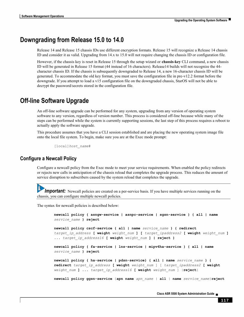
Software Management Operations
Upgrading the Operating System Software ▀
Cisco ASR 5500 System Administration Guide ▄ 117
Downgrading from Release 15.0 to 14.0
Release 14 and Release 15 chassis IDs use different encryption formats. Release 15 will recognize a Release 14 chassis
ID and consider it as valid. Upgrading from 14.x to 15.0 will not require changing the chassis ID or configuration file.
However, if the chassis key is reset in Release 15 through the setup wizard or chassis-key CLI command, a new chassis
ID will be generated in Release 15 format (44 instead of 16 characters). Release14 builds will not recognize the 44-
character chassis ID. If the chassis is subsequently downgraded to Release 14, a new 16-character chassis ID will be
generated. To accommodate the old key format, you must save the configuration file in pre-v12.2 format before the
downgrade. If you attempt to load a v15 configuration file on the downgraded chassis, StarOS will not be able to
decrypt the password/secrets stored in the configuration file.
Off-line Software Upgrade
An off-line software upgrade can be performed for any system, upgrading from any version of operating system
software to any version, regardless of version number. This process is considered off-line because while many of the
steps can be performed while the system is currently supporting sessions, the last step of this process requires a reboot to
actually apply the software upgrade.
This procedure assumes that you have a CLI session established and are placing the new operating system image file
onto the local file system. To begin, make sure you are at the Exec mode prompt:
[local]host_name#
Configure a Newcall Policy
Configure a newcall policy from the Exec mode to meet your service requirements. When enabled the policy redirects
or rejects new calls in anticipation of the chassis reload that completes the upgrade process. This reduces the amount of
service disruption to subscribers caused by the system reload that completes the upgrade.
Important: Newcall policies are created on a per-service basis. If you have multiple services running on the
chassis, you can configure multiple newcall policies.
The syntax for newcall policies is described below:
newcall policy { asngw-service | asnpc-service | sgsn-service } { all | name
service_name } reject
newcall policy cscf-service { all | name service_name } { redirect
target_ip_address [ weight weight_num ] [ target_ipaddress2 [ weight weight_num ]
... target_ip_address16 [ weight weight_num ] | reject }
newcall policy { fa-service | lns-service | mipv6ha-service } { all | name
service_name } reject
newcall policy { ha-service | pdsn-service} { all | name service_name } {
redirect target_ip_address [ weight weight_num ] [ target_ipaddress2 [ weight
weight_num ] ... target_ip_address16 [ weight weight_num ] |reject}
newcall policy ggsn-service {apn name apn_name | all | name service_name}reject

Software Management Operations
▀ Upgrading the Operating System Software
▄ Cisco ASR 5500 System Administration Guide
118
newcall policy hnbgw-service {all | name service_name}reject
newcall policy {pcc-af-service | pcc-policy-service} {all | name
service_name}reject
newcall policy {pcc-af-service | pcc-policy-service} {all | name
service_name}reject
newcall policy mme-service {all | name service_name } reject
For complete information about the above commands, see the Exec Mode Commands chapter of the Command Line
Interface Reference.
Configure a Message of the Day Banner
Optional: Configure a “Message of the Day” banner informing other management users that the system will be rebooted
by entering the following command from the Global Configuration mode prompt.
banner motd “banner_text”
banner_text is the message that you would like to be displayed and can be up to 2048 alphanumeric characters. Note
that banner_text must begin with and end in quotation marks (“ “). For more information in entering CLI banner
information, see the CLI Reference. The banner is displayed when an administrative user logs onto the CLI.
Back up the Current CLI Configuration File
Back up the current CLI configuration file by entering the following command:
[local]host_name# copy from_url to_url [-noconfirm]
This creates a mirror-image of the CLI configuration file linked to the operating system defined in the current boot stack
entry.
The following command example creates a backup copy of a file called general.cfg located on the /flash device to a
file called general_3652.cfg:
[local]host_name# copy /flash/general.cfg /flash/general_3652.cfg
Create a New Boot Stack Entry
Create a new boot stack entry for the new file group, consisting of the new operating system image file and the currently
used CLI configuration file by entering the following Global Configuration command:
[local]host_name(config)# boot system priority number image image_url /flash
filename config cfg_url /flash/filename
Assign the next highest priority to this entry, by using the <N-1> method, wherein you assign a priority number that is
one number less than your current highest priority.
Important: Run the Exec mode show boot command to verify that there are less than 10 entries in the boot.sys
file and that a higher priority entry is available (minimally there is no priority 1 entry in the boot stack).
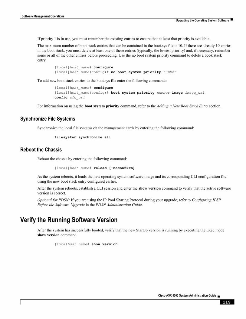
Software Management Operations
Upgrading the Operating System Software ▀
Cisco ASR 5500 System Administration Guide ▄ 119
If priority 1 is in use, you must renumber the existing entries to ensure that at least that priority is available.
The maximum number of boot stack entries that can be contained in the boot.sys file is 10. If there are already 10 entries
in the boot stack, you must delete at least one of these entries (typically, the lowest priority) and, if necessary, renumber
some or all of the other entries before proceeding. Use the no boot system priority command to delete a book stack
entry.
[local]host_name# configure
[local]host_name(config)# no boot system priority number
To add new boot stack entries to the boot.sys file enter the following commands:
[local]host_name# configure
[local]host_name(config)# boot system priority number image image_url
config cfg_url
For information on using the boot system priority command, refer to the Adding a New Boot Stack Entry section.
Synchronize File Systems
Synchronize the local file systems on the management cards by entering the following command:
filesystem synchronize all
Reboot the Chassis
Reboot the chassis by entering the following command:
[local]host_name# reload [-noconfirm]
As the system reboots, it loads the new operating system software image and its corresponding CLI configuration file
using the new boot stack entry configured earlier.
After the system reboots, establish a CLI session and enter the show version command to verify that the active software
version is correct.
Optional for PDSN: If you are using the IP Pool Sharing Protocol during your upgrade, refer to Configuring IPSP
Before the Software Upgrade in the PDSN Administration Guide.
Verify the Running Software Version
After the system has successfully booted, verify that the new StarOS version is running by executing the Exec mode
show version command.
[localhost_name# show version

Software Management Operations
▀ Performing Dynamic Software Updates
▄ Cisco ASR 5500 System Administration Guide
120
Restoring the Previous Software Image
If for some reason you need to undo the upgrade, perform the upgrade again except:
Specify the locations of the upgrade software image and configuration files.
then
Specify the locations of the original software image and configuration files.
Upgrading ICSR Chassis
The procedure for upgrading primary and backup ICSR chassis is described in Interchassis Session Recovery.
Essentially the procedure requires upgrading the primary and standby chassis using the off-line method while each is in
standby mode.
Performing Dynamic Software Updates StarOS allows the runtime loading of plugins. All StarOS builds include a “default” baseline plugin.
This feature is currently used to dynamically update the detection logic used to filter P2P applications via the
Application Detection and Control (ADC) feature.
Patching is the process used to install a plugin as an incremental update to a StarOS release. One plugin can be provided
to multiple, compatible, concurrent product releases. A plugin is distributed in the form of a compressed distribution kit
via the internet or by other means (USB stick, CD, etc.).
A plugin is a functional software entity that provides incremental updates to a pre-existing StarOS software component.
Plugins have the characteristic of being dynamically loadable at runtime and do not require a system restart. A plugin
has a name and one or more versions. All plugin names are known to the system at product release.
For complete information on the Dynamic Software Update process, refer to the ADC Administration Guide.
Software Management Operations
Managing License Keys ▀
Cisco ASR 5500 System Administration Guide ▄ 121
Managing License Keys License keys define capacity limits (number of allowed subscriber sessions) and available features on your system.
Adding new license keys allows you to increase capacity and add new features as your subscriber base grows.
New System License Keys
New systems are delivered with no license keys installed. In most cases, you receive the license key in electronic format
(usually through e-mail).
When a system boots with no license key installed a default set of restricted session use and feature licenses is installed.
The following Exec Mode command lists the license information:
show license information
Important: With no license key installed, the session use licenses for PDSN, HA, GGSN, and L2TP LNS are
limited to 10,000 sessions.
The license keys on the ASR 5500 are stored in EEPROM on the chassis midplane. Both MIO/UMIOs access this
EEPROM when booting.
Session Use and Feature Use Licenses
Session use and feature use licenses are software mechanisms that provide session limit controls and enable special
features within the system. These electronic licenses are stored in the system's configuration file that is loaded as part of
the system software each time the system is powered on or restarted.
Session use licenses limit the number of concurrent sessions that a system is capable of supporting per service
type and are acquired on an as-needed basis. This allows carriers to pay only for what they are using and easily
increase capacity as their subscriber base grows.
Feature use licenses enable specific features/functionality within the system and are distributed based on the total
number of sessions supported by the system.
Software Management Operations
▀ Managing License Keys
▄ Cisco ASR 5500 System Administration Guide
122
Installing New License Keys
Use the instructions below to install a new license key.
Cutting and Pasting the Key
If you have a copy of the license, use the following configuration to cut and paste just the license key part:
Step 1 From the Exec mode, enter the following:
configure
license key license
exit
license is the license key string. The license can be an alphanumeric string of 1 through 1023 characters that is case
sensitive. Copy the license key as shown in the example below, including the “\ (double-quote slash). Please note: this is
not a functional license.
"\
VER=1|C1M=000-0000-00|C1S=03290231803|C2M=11-1111-11-
1|C2S=\STCB21M82003R80411A4|DOI=0000000000|DOE=00000000|ISS=1|NUM=13459|000000000
0000|LSP=000000|LSH=000000|LSG=500000|LSL=500000\|FIS=Y|FR4=Y|FPP=Y|FCS=Y|FTC=Y|F
MG=Y|FCR=Y|FSR=Y|FPM=Y|FID=Y|SIG=MCwCF\Esnq6Bs/XdmyfLe7rHcD4sVP2bzAhQ3IeHDoyyd638
8jHsHD99sg36SG267gshssja77
end
Step 2 Verify that the license key just entered was accepted by entering the following command at the Exec mode prompt:
show license key
The new license key should be displayed. If it is not, return to the Global configuration mode and re-enter the key using
the license key command.
Step 3 Verify that the license key enabled the correct functionality by entering the following command:
show license information
All license keys and the new session capacity or functionality enabled should be listed. If the functionality or session
capacity enabled by the new key is incorrect, please contact your service representative.
Step 4 Save your configuration as described in the Verifying and Saving Your Configuration chapter.
Caution: Failure to save the new license key configuration in the current CLI configuration file will result in
the loss of any of the new features enabled by the license key once the system is reloaded.
Software Management Operations
Managing License Keys ▀
Cisco ASR 5500 System Administration Guide ▄ 123
Adding License Keys to Configuration Files
License keys can be added to a new or existing configuration file.
Important: License key information is maintained as part of the CLI configuration. Each time a key is installed
or updated, you must re-save the configuration file.
Step 1 Open the configuration file to which the new license key commands are to be copied.
Step 2 Copy the license as shown in the example, including the “\ (double-quote slash). Please note: this is not a functional
license.
"\
VER=1|C1M=000-0000-00|C1S=03290231803|C2M=11-1111-11-
1|C2S=\STCB21M82003R80411A4|DOI=0000000000|DOE=00000000|ISS=1|NUM=13459|000000000
0000|LSP=000000|LSH=000000|LSG=500000|LSL=500000\|FIS=Y|FR4=Y|FPP=Y|FCS=Y|FTC=Y|F
MG=Y|FCR=Y|FSR=Y|FPM=Y|FID=Y|SIG=MCwCF\Esnq6Bs/XdmyfLe7rHcD4sVP2bzAhQ3IeHDoyyd638
8jHsHD99sg36SG267gshssja77
end
Step 3 Paste the license key into the configuration
Important: Paste the license key information at the beginning of the configuration file to ensure the system has
the expected capacity and features before it configures contexts.
Step 4 Save your configuration as described in the Verifying and Saving Your Configuration chapter.
License Expiration Behavior
When a license expires, there is a built-in grace period of 30 days that allows normal use of the licensed session use and
feature use licenses. This allows you to obtain a new license without any interruption of service.
The following Exec mode command lists the license information including the date the grace period is set to expire:
show license information
Requesting License Keys
License keys for the system can be obtained through your Cisco account representative. Specific information is required
before a license key may be generated:
Sales Order or Purchase Order information
Desired session capacity
Desired functionality
Midplane (chassis) serial number
To obtain the ASR 5500 chassis serial number, at the Exec mode prompt enter the show card hardware 5
command. Look under the “MEC” heading for the “UDI Serial Number” as shown in the example below:
Software Management Operations
▀ Managing License Keys
▄ Cisco ASR 5500 System Administration Guide
124
MEC:
Description : MEC
Cisco Part Number : 73-14501-01 A0
UDI Serial Number : FLM154300D8
UDI Product ID : ASR55-MEC
UDI Version ID : V01
Viewing License Information
To see the license detail, enter the following command from the Exec mode:
show license information [ full | key [ full ] ]
Deleting a License Key
Use the procedure below to delete the session and feature use license key from a configuration. You must be a security
administrator or administrator.
configure
no license key
exit
show license key
The output of this command should display: “No license key installed”.
Management Card Replacement and License Keys
License keys are stored on a midplane EEPROM in the ASR 5500 chassis. The MIO/UMIOs share these license keys.
There is no need to swap memory cards into replacement MIO/UMIOs.

Software Management Operations
Managing Local-User Administrative Accounts ▀
Cisco ASR 5500 System Administration Guide ▄ 125
Managing Local-User Administrative Accounts Unlike context-level administrative accounts which are configured via a configuration file, information for local-user
administrative accounts is maintained in a separate file in flash memory and managed through the software’s Shared
Configuration Task (SCT). Because local-user accounts were designed to be compliant with ANSI T1.276-2003, the
system provides a number of mechanisms for managing these types of administrative user accounts.
Configuring Local-User Password Properties
Local-user account password properties are configured globally and apply to all local-user accounts. The system
supports the configuration of the following password properties:
Complexity: Password complexity can be forced to be compliant with ANSI T1.276-2003.
History length: How many previous password versions should be tracked by the system.
Maximum age: How long a user can use the same password.
Minimum number of characters to change: How many characters must be changed in the password during a
reset.
Minimum change interval: How often a user can change their password.
Minimum length: The minimum number of characters a valid password must contain.
Refer to the local-user password command in the Global Configuration Mode Commands chapter of the Command
Line Interface Reference for details on each of the above parameters.
Configuring Local-User Account Management Properties
Local-user account management includes configuring account lockouts and user suspensions.
Local-User Account Lockouts
Local-user accounts can be administratively locked for the following reasons:
Login failures: The configured maximum login failure threshold has been reached. Refer to the local-user max-
failed-logins command in the Global Configuration Mode Commands chapter of the Command Line Interface
Reference for details
Password Aging: The configured maximum password age has been reached. Refer to the local-user password
command in the Global Configuration Mode Commands chapter of the Command Line Interface Reference for
details.
Accounts that are locked out are inaccessible to the user until either the configured lockout time is reached (refer to the
local-user lockout-time command in the Global Configuration Mode Commands chapter of the Command Line
Interface Reference) or a security administrator clears the lockout (refer to the clear local-user command in the Exec
Mode Commands chapter of the Command Line Interface Reference).
Important: Local-user administrative user accounts could be configured to enforce or reject lockouts. Refer to
the local-user username command in the Global Configuration Mode Commands chapter of the Command Line
Interface Reference for details.
Software Management Operations
▀ Managing Local-User Administrative Accounts
▄ Cisco ASR 5500 System Administration Guide
126
Local-User Account Suspensions
Local-user accounts can be suspended as follows:
configure
suspend local-user name
A suspension can be removed by entering:
configure
no suspend local-user name
Changing Local-User Passwords
Local-user administrative users can change their passwords using the password change command in the Exec mode.
Users are prompted to enter their current and new passwords.
Security administrators can reset passwords for local-users by entering the following command from the root prompt in
the Exec mode:
password change username name
name is the name of the local-user account for which the password is to be changed. When a security administrator
resets a local-user’s password, the system prompts the user to change their password the next time they login.
All new passwords must adhere to the password properties configured for the system.

Cisco ASR 5500 System Administration Guide ▄ 127
Chapter 9 Monitoring the System
This chapter provides information for monitoring system status and performance using the show commands found in the
Command Line Interface (CLI). These command have many related keywords that allow them to provide useful
information on all aspects of the system ranging from current software configuration through call activity and status.
The selection of keywords described in this chapter is intended to provide the most useful and in-depth information for
monitoring the system. For additional information on these and other show command keywords, refer to the Exec Mode
show Commands chapter of the Command Line Interface Reference.
This chapter includes the following sections:
SNMP Notifications
Monitoring System Status and Performance
Clearing Statistics and Counters
Monitoring ASR 5500 Hardware Status
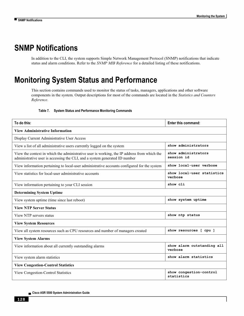
Monitoring the System
▀ SNMP Notifications
▄ Cisco ASR 5500 System Administration Guide
128
SNMP Notifications In addition to the CLI, the system supports Simple Network Management Protocol (SNMP) notifications that indicate
status and alarm conditions. Refer to the SNMP MIB Reference for a detailed listing of these notifications.
Monitoring System Status and Performance This section contains commands used to monitor the status of tasks, managers, applications and other software
components in the system. Output descriptions for most of the commands are located in the Statistics and Counters
Reference.
Table 7. System Status and Performance Monitoring Commands
To do this: Enter this command:
View Administrative Information
Display Current Administrative User Access
View a list of all administrative users currently logged on the system show administrators
View the context in which the administrative user is working, the IP address from which the
administrative user is accessing the CLI, and a system generated ID number show administrators
session id
View information pertaining to local-user administrative accounts configured for the system show local-user verbose
View statistics for local-user administrative accounts show local-user statistics
verbose
View information pertaining to your CLI session show cli
Determining System Uptime
View system uptime (time since last reboot) show system uptime
View NTP Server Status
View NTP servers status show ntp status
View System Resources
View all system resources such as CPU resources and number of managers created show resources [ cpu ]
View System Alarms
View information about all currently outstanding alarms show alarm outstanding all
verbose
View system alarm statistics show alarm statistics
View Congestion-Control Statistics
View Congestion-Control Statistics show congestion-control
statistics

Monitoring the System
Clearing Statistics and Counters ▀
Cisco ASR 5500 System Administration Guide ▄ 129
To do this: Enter this command:
View Remote Management Statistics
Display SNMP Notification Statistics
View SNMP notification statistics show snmp notifies
Display SNMP Access Statistics
View SNMP access statistics show snmp accesses
Display SNMP Trap History
View SNMP trap history show snmp trap history
Display SNMP Trap Statistics
View SNMP Trap Statistics show snmp trap statistics
Display ORBEM Information
View ORBEM client status show orbem client id
View ORBEM session information show orbem session table
View individual ORBEM sessions show orbem session id
orbem
View ORBEM status information show orbem status
View Port Counters
Display Port Datalink Counters
View datalink counters for a specific port show port datalink
counters slot#/port#
Display Port Network Processor Unit (NPU) Counters
View NPU counters for a specific port show port npu counters slot#/port#
Important: The commands or keywords/variables that are available are dependent on platform type, product
version, and installed license(s).
Important: Some commands have different outputs depending on the platform type.
Clearing Statistics and Counters It may be necessary to periodically clear statistics and counters in order to gather new information. The system provides
the ability to clear statistics and counters based on their grouping (PPP, MIPHA, MIPFA, etc.).
Statistics and counters can be cleared using the CLI clear command. Refer to the Exec Mode Commands chapter of the
Command Line Interface Reference for detailed information on using this command.
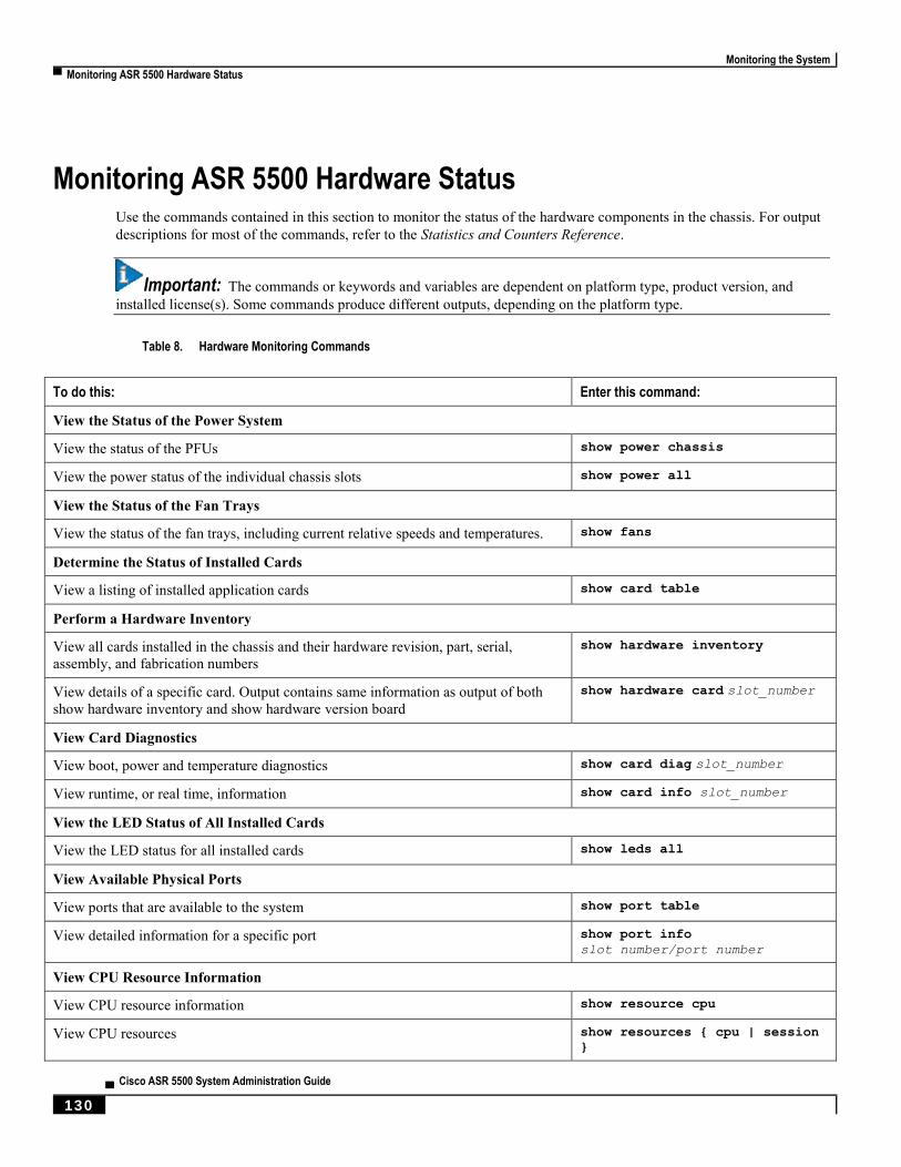
Monitoring the System
▀ Monitoring ASR 5500 Hardware Status
▄ Cisco ASR 5500 System Administration Guide
130
Monitoring ASR 5500 Hardware Status Use the commands contained in this section to monitor the status of the hardware components in the chassis. For output
descriptions for most of the commands, refer to the Statistics and Counters Reference.
Important: The commands or keywords and variables are dependent on platform type, product version, and
installed license(s). Some commands produce different outputs, depending on the platform type.
Table 8. Hardware Monitoring Commands
To do this: Enter this command:
View the Status of the Power System
View the status of the PFUs show power chassis
View the power status of the individual chassis slots show power all
View the Status of the Fan Trays
View the status of the fan trays, including current relative speeds and temperatures. show fans
Determine the Status of Installed Cards
View a listing of installed application cards show card table
Perform a Hardware Inventory
View all cards installed in the chassis and their hardware revision, part, serial,
assembly, and fabrication numbers show hardware inventory
View details of a specific card. Output contains same information as output of both
show hardware inventory and show hardware version board show hardware card slot_number
View Card Diagnostics
View boot, power and temperature diagnostics show card diag slot_number
View runtime, or real time, information show card info slot_number
View the LED Status of All Installed Cards
View the LED status for all installed cards show leds all
View Available Physical Ports
View ports that are available to the system show port table
View detailed information for a specific port show port info slot_number/port_number
View CPU Resource Information
View CPU resource information show resource cpu
View CPU resources show resources { cpu | session
}

Monitoring the System
Monitoring ASR 5500 Hardware Status ▀
Cisco ASR 5500 System Administration Guide ▄ 131
To do this: Enter this command:
View CPU usage information show cpu table; show cpu info
View Component Temperature Information
View current component temperatures show temperature
View maximum temperatures reached since last timestamp. show maximum-temperatures


Cisco ASR 5500 System Administration Guide ▄ 133
Chapter 10 Bulk Statistics
This chapter provides configuration information for:
Configuring Communication with the Collection Server
Viewing Collected Bulk Statistics Data
Manually Gathering and Transferring Bulk Statistics
Clearing Bulk Statistics Counters and Information
Bulk Statistics Event Log Messages

Bulk Statistics
▀ Configuring Communication with the Collection Server
▄ Cisco ASR 5500 System Administration Guide
134
Configuring Communication with the Collection Server Two configuration methods are available for defining how bulk statistics are collected and managed. A “standard”
configuration allows the system to automatically assign a number to the bulk statistics file. Optionally, a number can be
specified by an administrator in the optional configuration method. Command details and descriptions of keywords and
variables for commands in this chapter are located in the Bulk Statistics Configuration Mode Commands and Bulk
Statistics File Configuration Mode Commands chapters in the Command Line Interface Reference.
Configuring Standard Settings
The configuration example in this section defines basic operation of the bulk statistics feature. Use the following
example configuration to set up the system to communicate with the statistic collection server:
configure
bulkstats mode
schema name format format_string
sample-interval time_interval
transfer-interval xmit_time_interval
limit mem_limit
exit
bulkstats collection
end
Configuring Optional Settings
This section describes optional commands that can be used within the Bulk Statistics Configuration mode. Specifically,
bulk statistic “files” under which to group the bulk statistic configuration are configured using commands in this
section. “Files” are used to group bulk statistic schema, delivery options, and receiver configuration. Because multiple
“files” can be configured, this functionality provides greater flexibility in that it allows you to configure different
schemas to go to different receivers.
configure
bulkstats mode
file number
receiver ip_address { primary | secondary } [ mechanism { { { ftp | sftp
} login user_name [ encrypted ] password pwd } | tftp } } ] }
receiver mode { redundant | secondary-on-failure }
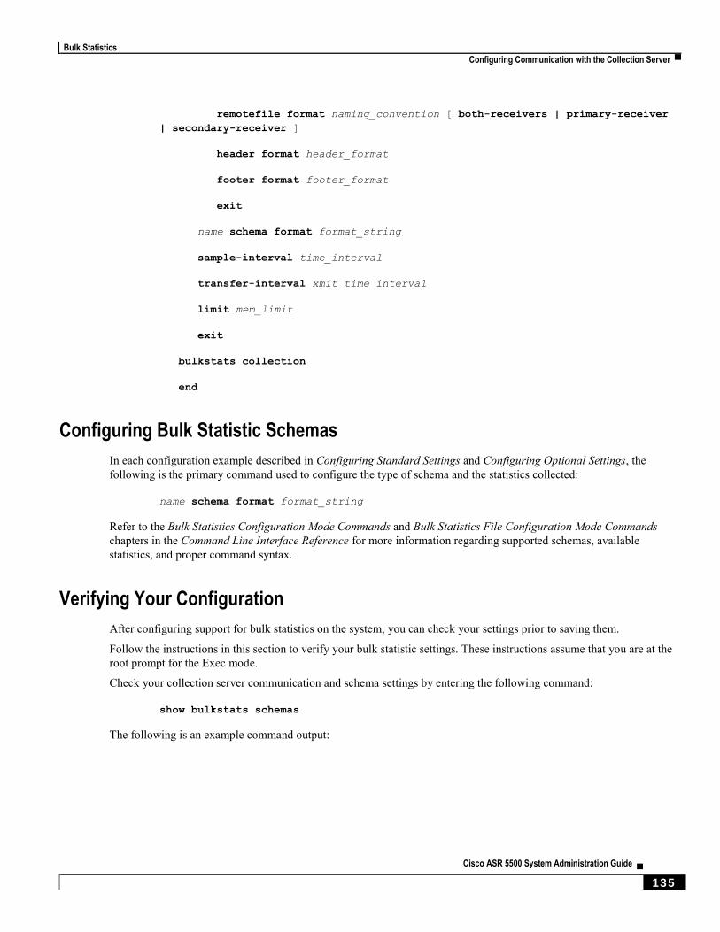
Bulk Statistics
Configuring Communication with the Collection Server ▀
Cisco ASR 5500 System Administration Guide ▄ 135
remotefile format naming_convention [ both-receivers | primary-receiver
| secondary-receiver ]
header format header_format
footer format footer_format
exit
name schema format format_string
sample-interval time_interval
transfer-interval xmit_time_interval
limit mem_limit
exit
bulkstats collection
end
Configuring Bulk Statistic Schemas
In each configuration example described in Configuring Standard Settings and Configuring Optional Settings, the
following is the primary command used to configure the type of schema and the statistics collected:
name schema format format_string
Refer to the Bulk Statistics Configuration Mode Commands and Bulk Statistics File Configuration Mode Commands
chapters in the Command Line Interface Reference for more information regarding supported schemas, available
statistics, and proper command syntax.
Verifying Your Configuration
After configuring support for bulk statistics on the system, you can check your settings prior to saving them.
Follow the instructions in this section to verify your bulk statistic settings. These instructions assume that you are at the
root prompt for the Exec mode.
Check your collection server communication and schema settings by entering the following command:
show bulkstats schemas
The following is an example command output:

Bulk Statistics
▀ Configuring Communication with the Collection Server
▄ Cisco ASR 5500 System Administration Guide
136
Bulk Statistics Server Configuration:
Server State: Enabled
File Limit: 6000 KB
Sample Interval: 15 minutes (0D 0H 15M)
Transfer Interval: 480 minutes (0D 0H 15M)
Collection Mode: Cumulative
Receiver Mode: Secondary-on-failure
Local File Storage: None
Bulk Statistics Server Statistics:
Records awaiting transmission: 114
Bytes awaiting transmission: 8092
Total records collected: 59926
Total bytes collected: 4190178
Total records transmitted: 59812
Total bytes transmitted: 4188512
Total records discarded: 0
Total bytes discarded: 0
Last collection time required: 2 second(s)
Last transfer time required: 0 second(s)
Last successful transfer: Wednesday December 7 12:14:30 EDT 2011
Last successful tx recs: 190
Last successful tx bytes: 13507
Last attempted transfer: Wednesday December 7 12:14:30 EDT 2011
File 1
Remote File Format: /users/ems/server/data/chicago/bulkstat%date%%time%.txt
File Header: "CHI_test %time%"
File Footer: ""
Bulkstats Receivers:
Primary: 192.168.0.100 using FTP with username administrator
Records awaiting transmission: 0
Bytes awaiting transmission: 0
Total records collected: 0
Total bytes collected: 0
Total records transmitted: 0
Total bytes transmitted: 0
Total records discarded: 0
Total bytes discarded: 0
Last transfer time required: 0 second(s)
No successful data transfers
No attempted data transfe
File 2 not configured
File 3 not configured
File 4 not configured
Saving Your Configuration
Save the configuration as described in the Verifying and Saving Your Configuration chapter.
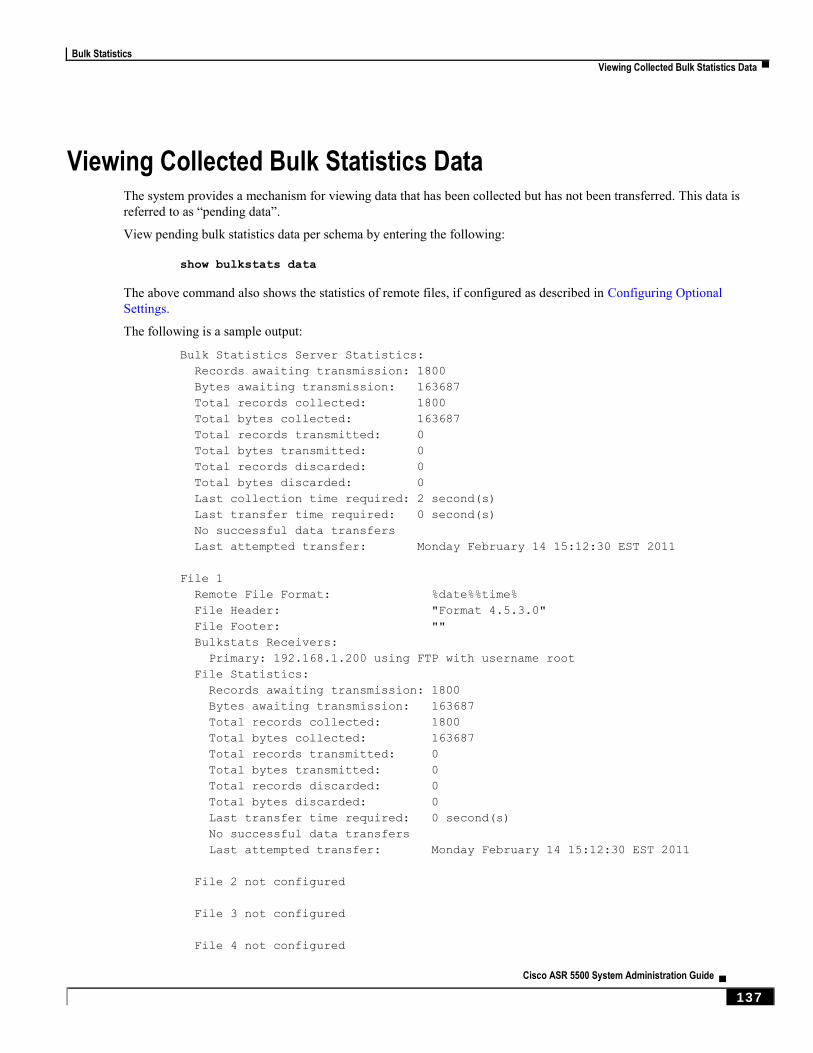
Bulk Statistics
Viewing Collected Bulk Statistics Data ▀
Cisco ASR 5500 System Administration Guide ▄ 137
Viewing Collected Bulk Statistics Data The system provides a mechanism for viewing data that has been collected but has not been transferred. This data is
referred to as “pending data”.
View pending bulk statistics data per schema by entering the following:
show bulkstats data
The above command also shows the statistics of remote files, if configured as described in Configuring Optional
Settings.
The following is a sample output:
Bulk Statistics Server Statistics:
Records awaiting transmission: 1800
Bytes awaiting transmission: 163687
Total records collected: 1800
Total bytes collected: 163687
Total records transmitted: 0
Total bytes transmitted: 0
Total records discarded: 0
Total bytes discarded: 0
Last collection time required: 2 second(s)
Last transfer time required: 0 second(s)
No successful data transfers
Last attempted transfer: Monday February 14 15:12:30 EST 2011
File 1
Remote File Format: %date%%time%
File Header: "Format 4.5.3.0"
File Footer: ""
Bulkstats Receivers:
Primary: 192.168.1.200 using FTP with username root
File Statistics:
Records awaiting transmission: 1800
Bytes awaiting transmission: 163687
Total records collected: 1800
Total bytes collected: 163687
Total records transmitted: 0
Total bytes transmitted: 0
Total records discarded: 0
Total bytes discarded: 0
Last transfer time required: 0 second(s)
No successful data transfers
Last attempted transfer: Monday February 14 15:12:30 EST 2011
File 2 not configured
File 3 not configured
File 4 not configured
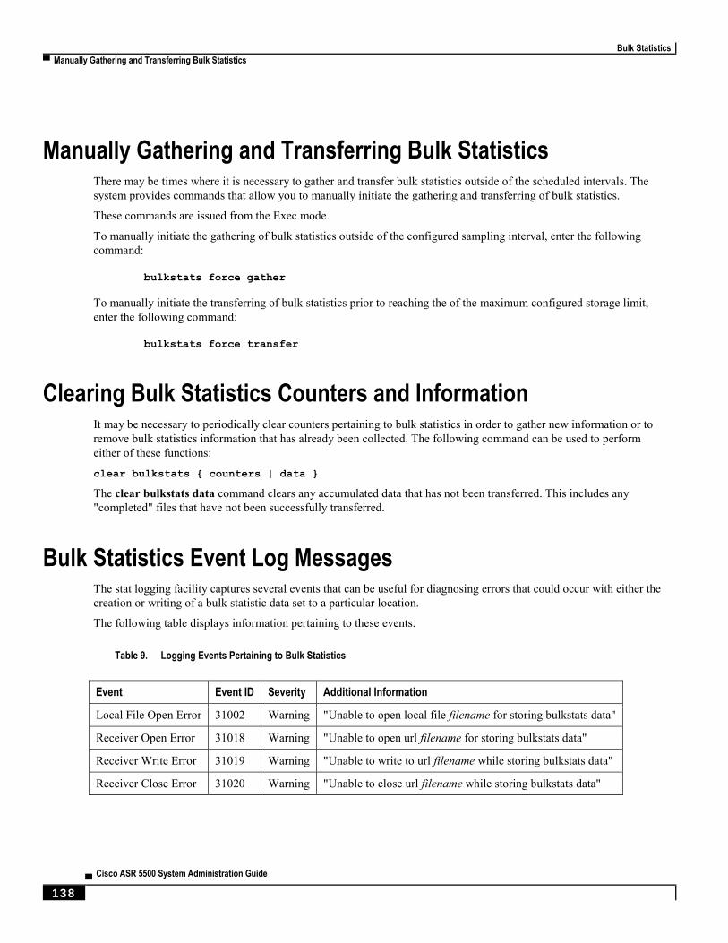
Bulk Statistics
▀ Manually Gathering and Transferring Bulk Statistics
▄ Cisco ASR 5500 System Administration Guide
138
Manually Gathering and Transferring Bulk Statistics There may be times where it is necessary to gather and transfer bulk statistics outside of the scheduled intervals. The
system provides commands that allow you to manually initiate the gathering and transferring of bulk statistics.
These commands are issued from the Exec mode.
To manually initiate the gathering of bulk statistics outside of the configured sampling interval, enter the following
command:
bulkstats force gather
To manually initiate the transferring of bulk statistics prior to reaching the of the maximum configured storage limit,
enter the following command:
bulkstats force transfer
Clearing Bulk Statistics Counters and Information It may be necessary to periodically clear counters pertaining to bulk statistics in order to gather new information or to
remove bulk statistics information that has already been collected. The following command can be used to perform
either of these functions:
clear bulkstats { counters | data }
The clear bulkstats data command clears any accumulated data that has not been transferred. This includes any
"completed" files that have not been successfully transferred.
Bulk Statistics Event Log Messages The stat logging facility captures several events that can be useful for diagnosing errors that could occur with either the
creation or writing of a bulk statistic data set to a particular location.
The following table displays information pertaining to these events.
Table 9. Logging Events Pertaining to Bulk Statistics
Event Event ID Severity Additional Information
Local File Open Error 31002 Warning "Unable to open local file filename for storing bulkstats data"
Receiver Open Error 31018 Warning "Unable to open url filename for storing bulkstats data"
Receiver Write Error 31019 Warning "Unable to write to url filename while storing bulkstats data"
Receiver Close Error 31020 Warning "Unable to close url filename while storing bulkstats data"
Cisco ASR 5500 System Administration Guide ▄ 139
Chapter 11 System Logs
This chapter describes how to configure parameters related to the various types of logging and how to viewing their
content. It includes the following sections:
Configuring Event Logging Parameters
Configuring Active Logs
Specifying Facilities
Configuring Trace Logging
Configuring Monitor Logs
Viewing Logging Configuration and Statistics
Viewing Event Logs Using the CLI
Configuring and Viewing Crash Logs
Saving Log Files
Event ID Overview
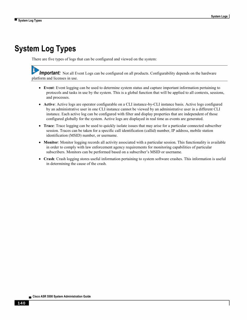
System Logs
▀ System Log Types
▄ Cisco ASR 5500 System Administration Guide
140
System Log Types There are five types of logs that can be configured and viewed on the system:
Important: Not all Event Logs can be configured on all products. Configurability depends on the hardware
platform and licenses in use.
Event: Event logging can be used to determine system status and capture important information pertaining to
protocols and tasks in use by the system. This is a global function that will be applied to all contexts, sessions,
and processes.
Active: Active logs are operator configurable on a CLI instance-by-CLI instance basis. Active logs configured
by an administrative user in one CLI instance cannot be viewed by an administrative user in a different CLI
instance. Each active log can be configured with filter and display properties that are independent of those
configured globally for the system. Active logs are displayed in real time as events are generated.
Trace: Trace logging can be used to quickly isolate issues that may arise for a particular connected subscriber
session. Traces can be taken for a specific call identification (callid) number, IP address, mobile station
identification (MSID) number, or username.
Monitor: Monitor logging records all activity associated with a particular session. This functionality is available
in order to comply with law enforcement agency requirements for monitoring capabilities of particular
subscribers. Monitors can be performed based on a subscriber’s MSID or username.
Crash: Crash logging stores useful information pertaining to system software crashes. This information is useful
in determining the cause of the crash.
System Logs
Configuring Event Logging Parameters ▀
Cisco ASR 5500 System Administration Guide ▄ 141
Configuring Event Logging Parameters The system can be configured to generate logs based on user-defined filters. The filters specify the facilities (system
tasks or protocols) that the system is to monitor and severity levels at which to trigger the generation of the event
entries.
Event logs are stored in system memory and can be viewed via the CLI. There are two memory buffers that store event
logging information. The first buffer stores the active log information. The second buffer stores inactive logging
information. The inactive buffer is used as a temporary repository to allow you to view logs without having data be
overwritten. Logs are copied to the inactive buffer only through manual intervention.
Each buffer can store up to 50,000 events. Once these buffers reach their capacity, the oldest information is removed to
make room for the newest.
To prevent the loss of log data, the system can be configured to transmit logs to a syslog server over a network interface.
Configuring Event Log Filters
Follow the example below to configure run time event logging parameters for the system:
configure
logging filter runtime facility facility level report_level
logging display { event-verbosity | pdu-data | pdu-verbosity }
end
Notes:
Configure the logging filter that determines which system facilities should be logged and at what levels. For
detailed information, see Specifying Facilities and Event Severities.
Repeat for every facility that you would like to log.
Optional: Configure event ID restrictions by adding the logging disable eventid command. The system provides
the ability to restrict the sending of a specific event ID or a range of event IDs to minimize the amount of data
logged to that which is most useful. Repeat to disable logging for additional event IDs or event ID ranges.
Save the configuration as described in the Verifying and Saving Your Configuration chapter.
System Logs
▀ Configuring Event Logging Parameters
▄ Cisco ASR 5500 System Administration Guide
142
Configuring syslog Servers
Information generated by the run time event logging filters can be transmitted to a syslog server for permanent storage.
Important: The data transmitted to the syslog server is meant to be used for informational purposes. Functions
such as billing and performance monitoring should not be based on syslogs.
Important: Although the system provides the flexibility to configure syslog servers on a context-by-context
basis, it is recommended that all servers be configured in the local context in order to isolate the log traffic from the
network traffic.
Use the following example to configure syslog servers:
configure
context local
logging syslog ip_address
end
Notes:
ip_address specifies the IP address of a system log server on the network in IPv4 dotted-decimal or IPv6 colon-
separated-hexadecimal notation.
A number of keyword options/variables are available for the logging syslog command. Refer to the Context
Configuration Mode Commands chapter in the Command Line Interface Reference for more information.
Repeat as needed to configure additional syslog servers. There is no limit to the number of syslog servers that
can be configured.
Save the configuration as described in the Verifying and Saving Your Configuration chapter.

System Logs
Configuring Active Logs ▀
Cisco ASR 5500 System Administration Guide ▄ 143
Configuring Active Logs Active logs are event logs that are operator configurable on a CLI instance-by-CLI instance basis. Active logs
configured by an administrative user in one CLI instance are not displayed to an administrative user in a different CLI
instance. Each active log can be configured with filter and display properties that are independent of those configured
globally for the system. Active logs are displayed in real time as they are generated.
Active logs are not written to the active memory buffer by default. To write active logs to the active memory buffer
execute the following command in the Global Configuration mode:
[local]host_name(config)# logging runtime buffer store all-events
When active logs are written to the active memory buffer, they are available to all users in all CLI instances.
Use the following example to configure active logging in Global Configuration mode:
[local]host_name(config)# logging filter runtime facility facility
level report_level
Notes:
Configure the logging filter that determines which system facilities should be logged and at what levels. For
detailed information, see Specifying Facilities and Event Severities.
Repeat for every facility that you would like to log.
Optional: Configure event ID restrictions by adding the logging disable eventid command. The system provides
the ability to restrict the sending of a specific event ID or a range of event IDs to minimize the amount of data
logged to that which is most useful. Repeat to disable logging for additional event IDs or event ID ranges.
A number of keyword options/variables are available for the Exec mode logging active command. Refer to the
Exec Mode Commands chapter in the Command Line Interface Reference for more information.
Once all of the necessary information has been gathered, the Active log display can be stopped by entering the
following command in the Exec mode:
no logging active

System Logs
▀ Specifying Facilities
▄ Cisco ASR 5500 System Administration Guide
144
Specifying Facilities
Important: The actual facilities available for logging vary by platform type, StarOS version and installed product
licenses.
The following facilities can be configured for logging event data:
a10: A10 interface facility
a11: A11 interface facility
a11mgr: A11 Manager facility
aaa-client: Authentication, Authorization and Accounting (AAA) client facility
aaamgr: AAA manager logging facility
aaaproxy: AAA Proxy facility
aal2: ATM Adaptation Layer 2 (AAL2) protocol logging facility
acl-log: Access Control List (ACL) logging facility
acsctrl: Active Charging Service (ACS) Controller facility
acsmgr: ACS Manager facility
afctrl: Fabric Controller facility [ASR 5500 only]
afmgr: Fabric Manager logging facility [ASR 5500 only]
alarmctrl: Alarm Controller facility
alcap: Access Link Control Application Part (ALCAP) protocol logging facility
alcapmgr: ALCAP manager logging facility
all: All facilities
asngwmgr: Access Service Network (ASN) Gateway Manager facility
asnpcmgr: ASN Paging Controller Manager facility
bfd: Bidirectional Forwarding Detection (BFD) protocol logging facility
bgp: Border Gateway Protocol (BGP) facility
bindmux: IPCF BindMux-Demux Manager logging facility
bngmgr: Broadband Network Gateway (BNG) Demux Manager logging facility
bssap+: Base Station Sub-system Application Part+ protocol facility for the login interface between the SGSN
and the MSC/VLR (2.5G and 3G)
bssgp: Base Station Sub-system GPRS Protocol logging facility handles exchange information between the
SGSN and the BSS (2.5G only)
callhome: Call Home application logging facility
cap: CAMEL Application Part (CAP) logging facility for protocol used in prepaid applications (2.5G and 3G)
cbsmgr: Cell Broadcasting Service (CBS) logging facility [HNBGW]
cdf: Charging Data Function (CDF) logging facility
cgw: Converged Access Gateway (CGW) logging facility

System Logs
Specifying Facilities ▀
Cisco ASR 5500 System Administration Guide ▄ 145
cli: Command Line Interface (CLI) logging facility
cmp: Certificate Management Protocol (IPSec) logging facility
connectedapps: SecGW ASR 9000 oneP communication procotol
connproxy: Controller Proxy logging facility
credit-control: Credit Control (CC) facility
cscf: IMS/MMD Call Session Control Function (CSCF)
cscfcpmgr: CSCFCPMGR logging facility
cscfmgr: SIP CSCF Manager facility
cscfnpdb: CSCF Number Portability Database (NPDB) logging facility
cscfrtcp: IMS/MMD CSCF RTCP log facility
cscfrtp: IMS/MMD CSCF RTP log facility
cscfttmgr: SIP CSCF Tunnel and Transport Manager facility
csp: Card/Slot/Port controller facility
css: Content Service Selection (CSS) facility
css-sig: CSS RADIUS Signaling facility
cx-diameter: Cx Diameter Messages facility
dcardctrl: IPSec Daughter Card Controller logging facility
dcardmgr: IPSec Daughter Card Manager logging facility
demuxmgr: Demux Manager API facility
dgmbmgr: Diameter Gmb Application Manager logging facility
dhcp: Dynamic Host Configuration Protocol (DHCP) logging facility
dhcpv6: DHCPv6
dhost: Distributed Host logging facility
diabase: Diabase messages facility
diameter: Diameter endpoint logging facility
diameter-acct: Diameter Accounting
diameter-auth: Diameter Authentication
diameter-dns: Diameter DNS subsystem
diameter-ecs: ACS Diameter signaling facility
diameter-hdd: Diameter Horizontal Directional Drilling (HDD) Interface facility
diameter-svc: Diameter Service
diamproxy: DiamProxy logging facility
dpath: IPSec Data Path facility
drvctrl: Driver Controller facility
doulosuemgr: Doulos (IMS-IPSec-Tool) user equipment manager
eap-diameter: Extensible Authentication Protocol (EAP) IP Sec urity facility
eap-ipsec: Extensible Authentication Protocol (EAP) IPSec facility

System Logs
▀ Specifying Facilities
▄ Cisco ASR 5500 System Administration Guide
146
eap-sta-s6a-s13-s6b-diameter: EAP/STA/S6A/S13/S6B Diameter messages facility
ecs-css: ACSMGR <-> Session Manager Signalling Interface facility
egtpc: eGTP-C logging facility
egtpmgr: enhanced GPRS Tunneling Protocol (eGTP) manager logging facility
egtpu: eGTP-U logging facility
epdg: evolved Packet Data (ePDG) gateway logging facility
event-notif: Event Notification Interface logging facility
evlog: Event log facility
famgr: Foreign Agent manager logging facility
firewall: Firewall logging facility
fng: Femto Network Gateway (FNG) logging facility
gbmgr: SGSN Gb Interface Manager facility
gmm:
For 2.5G: Logs the GPRS Mobility Management (GMM) layer (above LLC layer)
For 3G: Logs the access application layer (above the RANAP layer)
gprs-app: GPRS Application logging facility
gprs-ns: GPRS Network Service Protocol (layer between SGSN and the BSS) logging facility
gq-rx-tx-diameter: Gq/Rx/Tx Diameter messages facility
gss-gcdr: GTPP Storage Server GCDR facility
gtpc: GTP-C protocol logging facility
gtpcmgr: GTP-C protocol manager logging facility
gtpp: GTP-prime protocol logging facility
gtpu: GTP-U protocol logging facility
gtpumgr: GTP-U Demux manager
gx-ty-diameter: Gx/Ty Diameter messages facility
gy-diameter: Gy Diameter messages facility
h248prt: H.248 port manager facility
hamgr: Home Agent manager logging facility
hat: High Availability Task (HAT) process facility
hdctrl: HD Controller logging facility
henbapp: Home Evolved NodeB (HENB) App facility
henbgw: HENB-Gateway facility
henbgw-sctp-acs: HENBGW access Stream Control Transmission Protocol (SCTP) facility
henbgw-sctp-nw: HENBGW network SCTP facility
henbgwdemux: HENB-GW Demux facility
henbgwmgr: HENB-GW Manager facility
hnb-gw: HNB-GW (3G Femto GW) logging facility
System Logs
Specifying Facilities ▀
Cisco ASR 5500 System Administration Guide ▄ 147
hnbmgr: HNB-GW Demux Manager logging facility
hss-peer-service: Home Subscriber Server (HSS) Peer Service facility
igmp: Internet Group Management Protocol (IGMP)
ikev2: Internet Key Exchange version 2 (IKEv2)
ims-authorizatn: IP Multimedia Subsystem (IMS) Authorization Service facility
ims-sh: HSS Diameter Sh Interface Service facility
imsimgr: SGSN IMSI Manager facility
imsue: IMS User Equipment (IMSUE) facility
ip-arp: IP Address Resolution Protocol facility
ip-interface: IP interface facility
ip-route: IP route facility
ipms: Intelligent Packet Monitoring System (IPMS) logging facility
ipne: IP Network Enabler (IPNE) facility
ipsec: IP Security logging facility
ipsg: IP Service Gateway interface logging facility
ipsgmgr: IP Services Gateway facility
ipsp: IP Pool Sharing Protocol logging facility
kvstore: Key/Value Store (KVSTORE) Store facility
l2tp-control: Layer 2 Tunneling Precool (L2TP) control logging facility
l2tp-data: L2TP data logging facility
l2tpdemux: L2TP Demux Manager logging facility
l2tpmgr: L2TP Manager logging facility
lagmgr: Link Aggregation Group (LAG) manager logging facility
lcs: Location Services (LCS) logging facility
ldap: Lightweight Directory Access Protocol (LDAP) messages logging facility
li: Refer to the Lawful Intercept Interface Reference for a description of this command.
linkmgr: SGSN/BSS SS7 Link Manager logging facility (2.5G only)
llc: Logical Link Control (LLC) Protocol logging facility; for SGSN: logs the LLC layer between the GMM and
the BSSGP layers for logical links between the MS and the SGSN
local-policy: Local Policy Service facility
location-service: Location Services facility
m3ua: M3UA Protocol logging facility
magmgr: Mobile Access Gateway manager logging facility
map: Mobile Application Part (MAP) protocol logging facility
megadiammgr: MegaDiameter Manager (SLF Service) logging facility
mme-app: Mobility Management Entity (MME) Application logging facility
mme-misc: MME miscellaneous logging facility
System Logs
▀ Specifying Facilities
▄ Cisco ASR 5500 System Administration Guide
148
mmedemux: MME Demux Manager logging facility
mmemgr: MME Manager facility
mmgr: Master Manager logging facility
mobile-ip: Mobile IP processes
mobile-ip-data: Mobile IP data facility
mobile-ipv6: Mobile IPv6 logging facility
mpls: Multiprotocol Label Switching (MPLS) protocol logging facility
mrme: Multi Radio Mobility Entity (MRME) logging facility
mseg-app: Mobile Services Edge Gateway (MSEG) application logging facility (This option is not supported in
this release.)
mseg-gtpc: MSEG GTP-C application logging facility (This option is not supported in this release.)
mseg-gtpu: MSEG GTP-U application logging facility (This option is not supported in this release.)
msegmgr: MSEG Demux Manager logging facility (This option is not supported in this release.)
mtp2: Message Transfer Part 2 (MTP2) Service logging facility
mtp3: Message Transfer Part 3 (MTP3) Protocol logging facility
multicast-proxy: Multicast Proxy logging facility
nas: Non-Access Stratum (NAS) protocol logging facility [MME 4G]
netwstrg: Network Storage facility
npuctrl: Network Processor Unit Control facility
npudrv: Network Processor Unit Driver facility [ASR 5500 only]
npumgr: Network Processor Unit Manager facility
npumgr-acl: NPUMGR ACL logging facility
npumgr-drv: NPUMGR DRV logging facility
npumgr-flow: NPUMGR FLOW logging facility
npumgr-fwd: NPUMGR FWD logging facility
npumgr-init: NPUMGR INIT logging facility
npumgr-lc: NPUMGR LC logging facility
npumgr-port: NPUMGR PORT logging facility
npumgr-recovery: NPUMGR RECOVERY logging facility
npumgr-rri: NPUMGR RRI (Reverse Route Injection) logging facility
npumgr-vpn: NPUMGR VPN logging facility
npusim: NPUSIM logging facility [ASR 5500 only]
ntfy-intf: Notification Interface logging facility [Release 12.0 and earlier versions only]
ocsp: Online Certificate Status Protocol logging facility.
orbs: Object Request Broker System logging facility
ospf: OSPF protocol logging facility
ospfv3: OSPFv3 protocol logging facility

System Logs
Specifying Facilities ▀
Cisco ASR 5500 System Administration Guide ▄ 149
p2p: Peer-to-Peer Detection logging facility
pagingmgr: PAGINGMGR logging facility
pccmgr: Intelligent Policy Control Function (IPCF) Policy Charging and Control (PCC) Manager library
pdg: Packet Data Gateway (PDG) logging facility
pdgdmgr: PDG Demux Manager logging facility
pdif: Packet Data Interworking Function (PDIF) logging facility
pgw: Packet Data Network Gateway (PGW) logging facility
phs: Payload Header Suppression (PHS)
phs-control: PHS X1/X5 and X2/X6 Interface logging facility
phs-data: PHS Data logging facility
phs-eapol: PHS EAP over LAN (EAPOL) logging facility
phsgwmgr: PHS Gateway Manager facility
phspcmgr: PHS Paging Controller Manager facility
pmm-app: Packet Mobility Management (PMM) application logging facility
ppp: Point-To-Point Protocol (PPP) link and packet facilities
pppoe: PPP over Ethernet logging facility
push: VPNMGR CDR push logging facility
radius-acct: RADIUS accounting logging facility
radius-auth: RADIUS authentication logging facility
radius-coa: RADIUS change of authorization and radius disconnect
ranap: Radio Access Network Application Part (RANAP) Protocol facility logging info flow between SGSN
and RNS (3G)
rct: Recovery Control Task logging facility
rdt: Redirect Task logging facility
resmgr: Resource Manager logging facility
rf-diameter: Diameter Rf interface messages facility
rip: Routing Information Protocol (RIP) logging facility [RIP is not supported at this time.]
rlf: Rate Limiting Function (RLF) logging facility
rohc: Robust Header Compression (RoHC) facility
rsvp: Reservation Protocol logging facility
rua: RANAP User Adaptation (RUA) [3G Femto GW - RUA messages] logging facility
s1ap: S1 Application Protocol (S1AP) Protocol logging facility
sabp: Service Area Broadcast Protocol (SABP) logging facility
saegw: System Architecture Evolution (SAE) Gateway facility
sccp: Signalling Connection Control Part (SCCP) Protocol logging (connection-oriented messages between
RANAP and TCAP layers).
sct: Shared Configuration Task logging facility
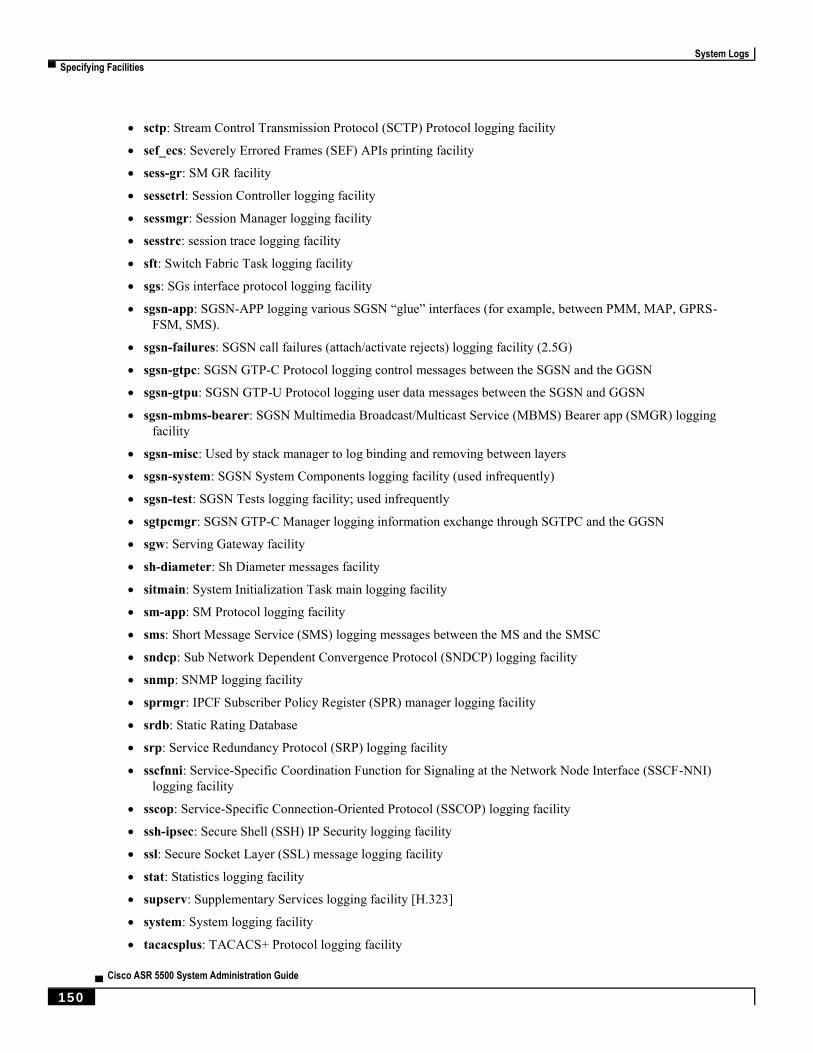
System Logs
▀ Specifying Facilities
▄ Cisco ASR 5500 System Administration Guide
150
sctp: Stream Control Transmission Protocol (SCTP) Protocol logging facility
sef_ecs: Severely Errored Frames (SEF) APIs printing facility
sess-gr: SM GR facility
sessctrl: Session Controller logging facility
sessmgr: Session Manager logging facility
sesstrc: session trace logging facility
sft: Switch Fabric Task logging facility
sgs: SGs interface protocol logging facility
sgsn-app: SGSN-APP logging various SGSN “glue” interfaces (for example, between PMM, MAP, GPRS-
FSM, SMS).
sgsn-failures: SGSN call failures (attach/activate rejects) logging facility (2.5G)
sgsn-gtpc: SGSN GTP-C Protocol logging control messages between the SGSN and the GGSN
sgsn-gtpu: SGSN GTP-U Protocol logging user data messages between the SGSN and GGSN
sgsn-mbms-bearer: SGSN Multimedia Broadcast/Multicast Service (MBMS) Bearer app (SMGR) logging
facility
sgsn-misc: Used by stack manager to log binding and removing between layers
sgsn-system: SGSN System Components logging facility (used infrequently)
sgsn-test: SGSN Tests logging facility; used infrequently
sgtpcmgr: SGSN GTP-C Manager logging information exchange through SGTPC and the GGSN
sgw: Serving Gateway facility
sh-diameter: Sh Diameter messages facility
sitmain: System Initialization Task main logging facility
sm-app: SM Protocol logging facility
sms: Short Message Service (SMS) logging messages between the MS and the SMSC
sndcp: Sub Network Dependent Convergence Protocol (SNDCP) logging facility
snmp: SNMP logging facility
sprmgr: IPCF Subscriber Policy Register (SPR) manager logging facility
srdb: Static Rating Database
srp: Service Redundancy Protocol (SRP) logging facility
sscfnni: Service-Specific Coordination Function for Signaling at the Network Node Interface (SSCF-NNI)
logging facility
sscop: Service-Specific Connection-Oriented Protocol (SSCOP) logging facility
ssh-ipsec: Secure Shell (SSH) IP Security logging facility
ssl: Secure Socket Layer (SSL) message logging facility
stat: Statistics logging facility
supserv: Supplementary Services logging facility [H.323]
system: System logging facility
tacacsplus: TACACS+ Protocol logging facility
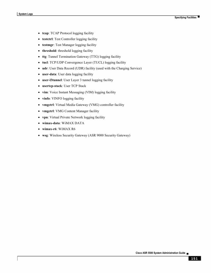
System Logs
Specifying Facilities ▀
Cisco ASR 5500 System Administration Guide ▄ 151
tcap: TCAP Protocol logging facility
testctrl: Test Controller logging facility
testmgr: Test Manager logging facility
threshold: threshold logging facility
ttg: Tunnel Termination Gateway (TTG) logging facility
tucl: TCP/UDP Convergence Layer (TUCL) logging facility
udr: User Data Record (UDR) facility (used with the Charging Service)
user-data: User data logging facility
user-l3tunnel: User Layer 3 tunnel logging facility
usertcp-stack: User TCP Stack
vim: Voice Instant Messaging (VIM) logging facility
vinfo: VINFO logging facility
vmgctrl: Virtual Media Gateway (VMG) controller facility
vmgctrl: VMG Content Manager facility
vpn: Virtual Private Network logging facility
wimax-data: WiMAX DATA
wimax-r6: WiMAX R6
wsg: Wireless Security Gateway (ASR 9000 Security Gateway)
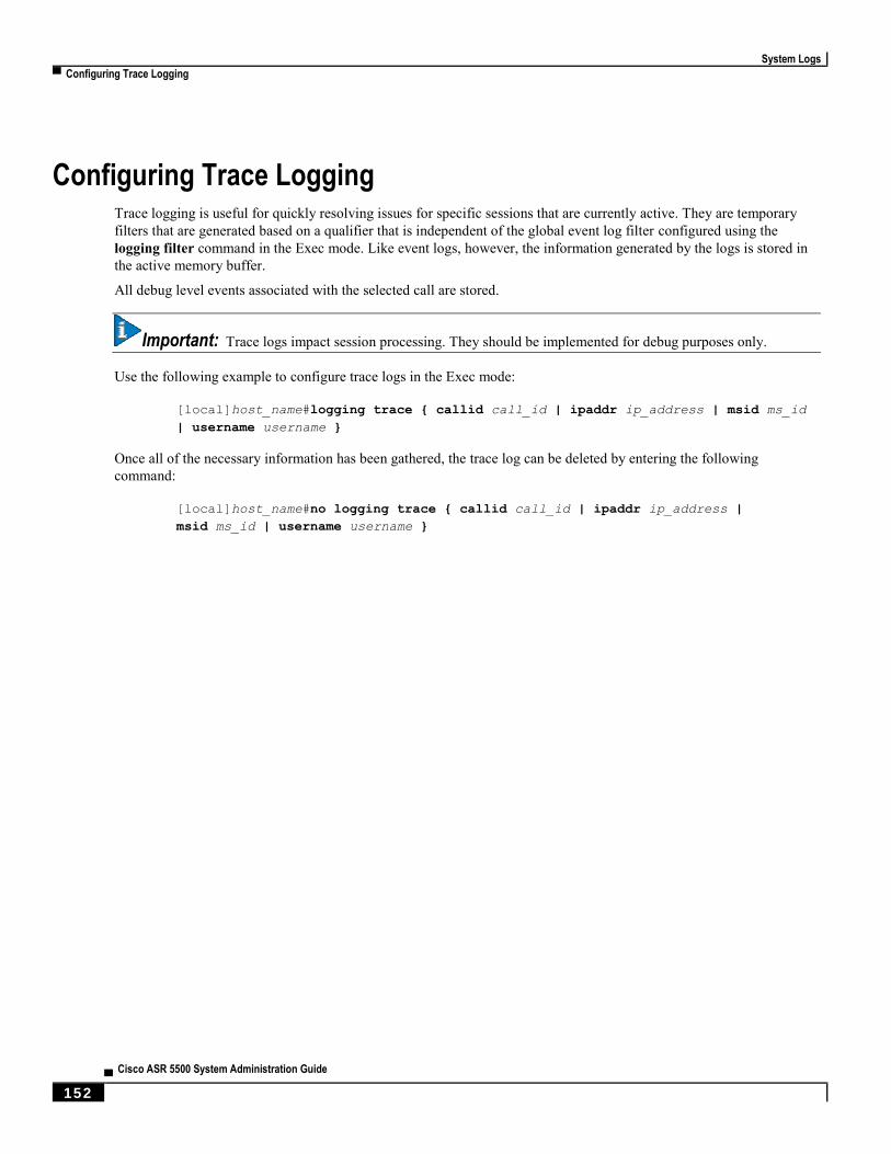
System Logs
▀ Configuring Trace Logging
▄ Cisco ASR 5500 System Administration Guide
152
Configuring Trace Logging Trace logging is useful for quickly resolving issues for specific sessions that are currently active. They are temporary
filters that are generated based on a qualifier that is independent of the global event log filter configured using the
logging filter command in the Exec mode. Like event logs, however, the information generated by the logs is stored in
the active memory buffer.
All debug level events associated with the selected call are stored.
Important: Trace logs impact session processing. They should be implemented for debug purposes only.
Use the following example to configure trace logs in the Exec mode:
[local]host_name#logging trace { callid call_id | ipaddr ip_address | msid ms_id
| username username }
Once all of the necessary information has been gathered, the trace log can be deleted by entering the following
command:
[local]host_name#no logging trace { callid call_id | ipaddr ip_address |
msid ms_id | username username }

System Logs
Configuring Monitor Logs ▀
Cisco ASR 5500 System Administration Guide ▄ 153
Configuring Monitor Logs Monitor logging records all activity associated with all of a particular subscriber’s sessions. This functionality is
available in compliance with law enforcement agency requirements for monitoring capabilities of particular subscribers.
Monitors can be performed based on a subscriber’s MSID or username, and are only intended to be used for finite
periods of time as dictated by the law enforcement agency. Therefore, they should be terminated immediately after the
required monitoring period.
This section provides instructions for enabling and disabling monitor logs.
Enabling Monitor Logs
Use the following example to configure monitor log targets:
configure
logging monitor { ip_addr | IPv6_addr | msid id | username name }
end
Repeat to configure additional monitor log targets.
Disabling Monitor Logs
Use the following example to disable monitor logs:
configure
no logging monitor { ip_addr | IPv6_addr | msid id | username name }
end
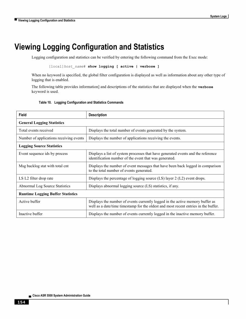
System Logs
▀ Viewing Logging Configuration and Statistics
▄ Cisco ASR 5500 System Administration Guide
154
Viewing Logging Configuration and Statistics Logging configuration and statistics can be verified by entering the following command from the Exec mode:
[local]host_name# show logging [ active | verbose ]
When no keyword is specified, the global filter configuration is displayed as well as information about any other type of
logging that is enabled.
The following table provides information] and descriptions of the statistics that are displayed when the verbose
keyword is used.
Table 10. Logging Configuration and Statistics Commands
Field Description
General Logging Statistics
Total events received Displays the total number of events generated by the system.
Number of applications receiving events Displays the number of applications receiving the events.
Logging Source Statistics
Event sequence ids by process Displays a list of system processes that have generated events and the reference
identification number of the event that was generated.
Msg backlog stat with total cnt Displays the number of event messages that have been back logged in comparison
to the total number of events generated.
LS L2 filter drop rate Displays the percentage of logging source (LS) layer 2 (L2) event drops.
Abnormal Log Source Statistics Displays abnormal logging source (LS) statistics, if any.
Runtime Logging Buffer Statistics
Active buffer Displays the number of events currently logged in the active memory buffer as
well as a date/time timestamp for the oldest and most recent entries in the buffer.
Inactive buffer Displays the number of events currently logged in the inactive memory buffer.
System Logs
Viewing Event Logs Using the CLI ▀
Cisco ASR 5500 System Administration Guide ▄ 155
Viewing Event Logs Using the CLI Event logs generated by the system can be viewed in one of the following ways:
From the syslog server: If the system is configured to send logs to a syslog server, the logs can be viewed
directly on the syslog server.
From the system CLI: Logs stored in the system memory buffers can be viewed directly from the CLI.
From the console port: By default, the system automatically displays events over the console interface to a
terminal provided that there is no CLI session active.
This section provides instructions for viewing event logs using the CLI. These instructions assume that you are at the
root prompt for the Exec mode.
Step 1 Copy the active log memory buffer to the inactive log memory buffer.
When the active log memory buffer is copied to the inactive log memory buffer existing information in the inactive log
memory buffer is deleted.
Both active and inactive event log memory buffers can be viewed using the CLI in Exec mode. However, it is preferable
to view the inactive log in order to prevent any data from being over-written. The information from the active log buffer
can be copied to the inactive log buffer by entering the following command:
[local]host_name# logs checkpoint
Step 2 View the logs by entering the following command:
[local]host_name# show logs
Important: A number of optional keywords/variables are available for the show logs command. Refer to the
Exec Mode Show Commands chapter in the Command Line Interface Reference for more information.
System Logs
▀ Configuring and Viewing Crash Logs
▄ Cisco ASR 5500 System Administration Guide
156
Configuring and Viewing Crash Logs In the unlikely even of a software crash, the system stores information that could be useful in determining the reason for
the crash. This information can be maintained in system memory or it can be transferred and stored on a network server.
The system supports the generation of the following two types of logs:
Crash log: Crash logs record all possible information pertaining to a software crash (full core dump). Due to
their size, they can not be stored in system memory. Therefore, these logs are only generated if the system is
configured with a Universal Resource Locator (URL) pointing to a local device or a network server where the
log can be stored.
Abridged crash log: Crash event records are automatically generated when a software crash occurs and are
stored in flash memory on management cards. The abridged crash log contains a list crash event records along
with associated dump files. This log allows you to view event records and dump files via CLI commands.
Crash Logging Architecture
The crash log is a persistent repository of crash event information. Each event is numbered and contains text associated
with a CPU (minicore), NPU or kernel crash. The logged events are recorded into fixed length records and stored in
/flash/crashlog2.
Whenever a crash occurs, the following crash information is stored:
1. The event record is stored in /flash/crashlog2 file (the crash log).
2. The associated minicore, NPU or kernel dump file is stored in the /flash/crsh2 directory.
3. A full core dump is stored in a user configured directory.
Important: The crashlog2 file along with associated minicore, NPU and kernel dumps are automatically
synchronized across redundant management cards (SMC, MIO/UMIO). Full core dumps are not synchronized across
management cards.
The following behaviors apply to the crash logging process.
When a crash event arrives on an active management card, the event record is stored in its crashlog2 file along
with the minicore, NPU, or kernel dump file in /flash/crsh2. The crash event and dump file are also
automatically stored in the same locations on the standby management card.
When a crash log entry is deleted via CLI command, it is deleted on both the active and standby management
cards.
When a management card is added or replaced, active and standby cards will automatically synchronize crash
logs and dump files.
When a crash event is received and the crash log file is full, the oldest entry in the crash log and its related dump
file will be replaced with the latest arrived event and dump file on both management cards. Information for a
maximum of 120 crash events can be stored on management cards.
Duplicate crash events bump the count of hits in the existing record and update the new record with the old crash
record. Additions to the count use the timestamp for the first time the event happened.

System Logs
Configuring and Viewing Crash Logs ▀
Cisco ASR 5500 System Administration Guide ▄ 157
Configuring Software Crash Log Destinations
The system can be configured to store software crash log information to any of the following locations:
On the ASR 5000:
CompactFlash™: Installed on the SMC [abridged crash log and associated dump files only]
PCMCIA Flash Card: Installed in the PCMCIA1 slot on the SMC
On the ASR 5500:
Flash memory: Installed on the active MIO/UMIO [abridged crash log and associated dump files only]
USB memory stick: Installed in the USB slot on the active MIO/UMIO
On QvPC
Flash memory: Accessible by the virtual machine
USB memory stick: Installed in the USB slot of the platform (USB slot has been enabled via the
hypervisor)
Network Server: Any workstation or server on the network that the system can access using the Trivial File
Transfer Protocol (TFTP), the File Transfer Protocol (FTP), the Secure File Transfer Protocol (SFTP), or the
Hyper-Text Transfer Protocol (HTTP); this is recommended for large network deployments in which multiple
systems require the same configuration
Crash log files (full core dumps) are written with unique names as they occur to the specified location. The name format
is crash-card-cpu-time-core. Where card is the card slot, cpu is the number of the CPU on the card, and time is the
Portable Operating System Interface (POSIX) timestamp in hexadecimal notation.
Use the following example to configure a software crash log destination in the Global Configuration mode:
configure
crash enable [ encrypted ] url crash_url
end
Notes:
Refer to the Global Configuration Mode Commands chapter in the Command Line Interface Reference for more
information on this command.
Repeat to configure additional software crash log destinations. There is no limit to the number of destinations
that can be configured.
Save the configuration as described in the Verifying and Saving Your Configuration chapter.
System Logs
▀ Configuring and Viewing Crash Logs
▄ Cisco ASR 5500 System Administration Guide
158
Viewing Abridged Crash Log Information Using the CLI
You can view abridged crash information that is stored as a set of event records in flash memory on management cards
(/flash/crashlog2). Each crash event record has an associated dump file (minicore, NPU or kernel) that can also be
displayed (/flash/crsh2)
Follow the instructions in this section to view software crash events that have occurred on the system. These instructions
assume that you are at the root prompt for the Exec mode.
Step 1 View a list of software crash events by entering the following Exec mode command:
[local]host_name# show crash { all | list | number crash_num }
Notes:
Run show crash list to obtain the number for a specific crash event.
Run show crash number crash_num to display the output for the target crash event.
Important: Information about similar crash events is suppressed in the output of this command.
Step 2 View the dump file associated with a specific crash event.
The information contained in the dump file helps identify and diagnose any internal or external factors causing the
software to crash.
Crash # – unique number assigned by StarOS when logging the crash event
SW Version – StarOS build release in format: RR.n(bbbbb)
Similar Crash Count – number of similar crashes
Time of first crash – timestamp when first crash occurred in format: YYYY-MMM-DD+hh:mm:ss
Failure message – text of event message
Function – code identifier
Process – where the crash occurred (Card, CPU, PID, etc.)
Crash time – timestamp for when the crash occurred in the format: YYYY-MMM-DD+hh:mm:ss time zone
Recent errno – text of most recent error number.
Stack – memory stack information
Last Bounce – information about the messaging received prior to the crash
Registers – memory register contents
Current inbound message – hexadecimal information for the current inbound message
Address Map
Recent heap activity (oldest first)
Recent events (oldest first)
Profile depth

System Logs
Saving Log Files ▀
Cisco ASR 5500 System Administration Guide ▄ 159
Important: The informational content of each crash log entry varies based on the type of crash and the StarOS
release.
Saving Log Files Log files can be saved to a file in a local or remote location specified by a URL. Use the following Exec mode
command to save log files:
save logs { url } [active] ] [inactive] [callid call_id] [event-verbosity
evt_verboseness] [facility facility] [level severity_level] [pdu-data pdu_format]
[pdu-verbosity pdu_verboseness] [since from_date_time[until to_date_time] ] [
| { grep grep_options | more } ]
For detailed information on the save logs command, see the Exec Mode Commands chapter in the Command Line
Interface Reference.
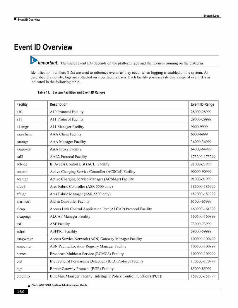
System Logs
▀ Event ID Overview
▄ Cisco ASR 5500 System Administration Guide
160
Event ID Overview
Important: The use of event IDs depends on the platform type and the licenses running on the platform.
Identification numbers (IDs) are used to reference events as they occur when logging is enabled on the system. As
described previously, logs are collected on a per facility basis. Each facility possesses its own range of event IDs as
indicated in the following table.
Table 11. System Facilities and Event ID Ranges
Facility Description Event ID Range
a10 A10 Protocol Facility 28000-28999
a11 A11 Protocol Facility 29000-29999
a11mgr A11 Manager Facility 9000-9999
aaa-client AAA Client Facility 6000-6999
aaamgr AAA Manager Facility 36000-36999
aaaproxy AAA Proxy Facility 64000-64999
aal2 AAL2 Protocol Facility 173200-173299
acl-log IP Access Control List (ACL) Facility 21000-21999
acsctrl Active Charging Service Controller (ACSCtrl) Facility 90000-90999
acsmgr Active Charging Service Manager (ACSMgr) Facility 91000-91999
afctrl Ares Fabric Controller (ASR 5500 only) 186000-186999
afmgr Ares Fabric Manager (ASR 5500 only) 187000-187999
alarmctrl Alarm Controller Facility 65000-65999
alcap Access Link Control Application Part (ALCAP) Protocol Facility 160900-161399
alcapmgr ALCAP Manager Facility 160500-160899
asf ASF Facility 73000-73999
asfprt ASFPRT Facility 59000-59999
asngwmgr Access Service Network (ASN) Gateway Manager Facility 100000-100499
asnpcmgr ASN Paging/Location-Registry Manager Facility 100500-100999
bcmcs Broadcast/Multicast Service (BCMCS) Facility 109000-109999
bfd Bidirectional Forwarding Detection (BFD) Protocol Facility 170500-170999
bgp Border Gateway Protocol (BGP) Facility 85000-85999
bindmux BindMux Manager Facility [Intelligent Policy Control Function (IPCF)] 158200-158999

System Logs
Event ID Overview ▀
Cisco ASR 5500 System Administration Guide ▄ 161
Facility Description Event ID Range
bngmgr Broadband Network Gateway (BNG) Manager Facility 182000-182999
bssap Base Station System Application Part+ (BSSAP+) Service Facilities 131000-131199
bssgp Base Station System GPRS Protocol (BSSGP) Facility 115050-115099
callhome Call Home Facility 173600-173999
cap CAMEL Application Part (CAP) Facility 87900-88099
chatconf CHATCONF Facility 74000-74999
cli Command Line Interface (CLI) Facility 30000-30999
connproxy Connection Proxy Facility 190000-190999
crdt-ctl Credit Control Facility 127000-127999
cscf Call Session Control Function (CSCF) Facility 105000-108924
cscfcpmgr CSCF CP Manager Facility 197000-197999
cscfmgr CSCF FM Manager Facility 101000-101999
cscfnpdb CSCF NPDB Facility 108925-108949
cscfrtcp CSCF RTCP Facility 108976-108999
cscfrtp CSCF RTP Facility 108950-108975
cscfttmgr CSCF TT Manager Facility 163000-163499
csg Closed Subscriber Groups (CSG) Facility 188000-188999
csg-acl CSG Access Control List (ACL) Facility 189000-189999
csp Card/Slot/Port (CSP) Facility 7000-7999
css Content Steering Service (CSS) Facility [ESC] 77000-77499
css-sig Content Service Selection (CSS) RADIUS Signaling Facility 77500-77599
cx-diameter Cx Diameter Message Facility 92840-92849
dcardctrl Daughter Card Controller Facility 62000-62999
dcardmgr Daughter Card Manager Facility 57000-57999
demuxmgr Demux Manager Facility 110000-110999
dgmbmgr Diameter Gmb (DGMB) Application Manager Facility 126000-126999
dhcp DHCP Facility 53000-53999
dhcpv6 DHCPv6 Protocol Facility 123000-123999
dhost Distributed Host Manager Facility 83000-83999
diameter Diameter Endpoint Facility 92000-92599
diabase Diabase Message Facility 92800-92809
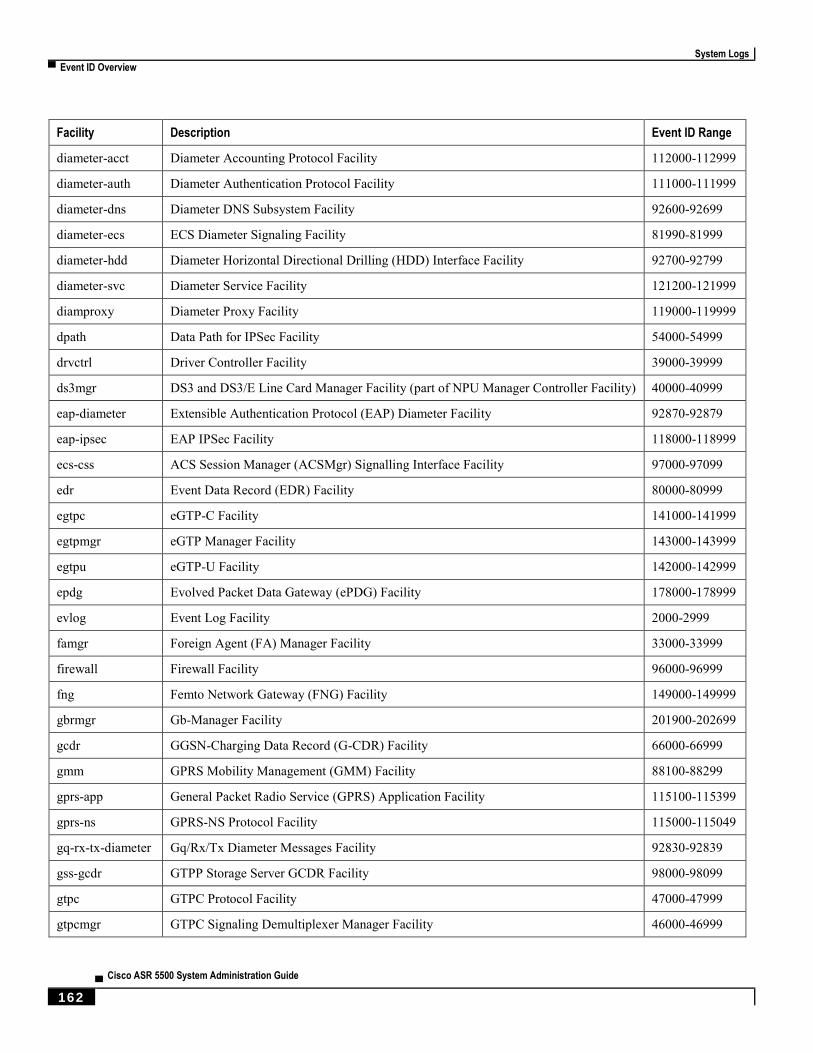
System Logs
▀ Event ID Overview
▄ Cisco ASR 5500 System Administration Guide
162
Facility Description Event ID Range
diameter-acct Diameter Accounting Protocol Facility 112000-112999
diameter-auth Diameter Authentication Protocol Facility 111000-111999
diameter-dns Diameter DNS Subsystem Facility 92600-92699
diameter-ecs ECS Diameter Signaling Facility 81990-81999
diameter-hdd Diameter Horizontal Directional Drilling (HDD) Interface Facility 92700-92799
diameter-svc Diameter Service Facility 121200-121999
diamproxy Diameter Proxy Facility 119000-119999
dpath Data Path for IPSec Facility 54000-54999
drvctrl Driver Controller Facility 39000-39999
ds3mgr DS3 and DS3/E Line Card Manager Facility (part of NPU Manager Controller Facility) 40000-40999
eap-diameter Extensible Authentication Protocol (EAP) Diameter Facility 92870-92879
eap-ipsec EAP IPSec Facility 118000-118999
ecs-css ACS Session Manager (ACSMgr) Signalling Interface Facility 97000-97099
edr Event Data Record (EDR) Facility 80000-80999
egtpc eGTP-C Facility 141000-141999
egtpmgr eGTP Manager Facility 143000-143999
egtpu eGTP-U Facility 142000-142999
epdg Evolved Packet Data Gateway (ePDG) Facility 178000-178999
evlog Event Log Facility 2000-2999
famgr Foreign Agent (FA) Manager Facility 33000-33999
firewall Firewall Facility 96000-96999
fng Femto Network Gateway (FNG) Facility 149000-149999
gbrmgr Gb-Manager Facility 201900-202699
gcdr GGSN-Charging Data Record (G-CDR) Facility 66000-66999
gmm GPRS Mobility Management (GMM) Facility 88100-88299
gprs-app General Packet Radio Service (GPRS) Application Facility 115100-115399
gprs-ns GPRS-NS Protocol Facility 115000-115049
gq-rx-tx-diameter Gq/Rx/Tx Diameter Messages Facility 92830-92839
gss-gcdr GTPP Storage Server GCDR Facility 98000-98099
gtpc GTPC Protocol Facility 47000-47999
gtpcmgr GTPC Signaling Demultiplexer Manager Facility 46000-46999
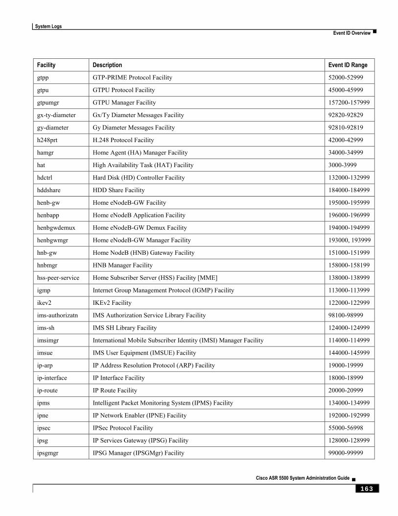
System Logs
Event ID Overview ▀
Cisco ASR 5500 System Administration Guide ▄ 163
Facility Description Event ID Range
gtpp GTP-PRIME Protocol Facility 52000-52999
gtpu GTPU Protocol Facility 45000-45999
gtpumgr GTPU Manager Facility 157200-157999
gx-ty-diameter Gx/Ty Diameter Messages Facility 92820-92829
gy-diameter Gy Diameter Messages Facility 92810-92819
h248prt H.248 Protocol Facility 42000-42999
hamgr Home Agent (HA) Manager Facility 34000-34999
hat High Availability Task (HAT) Facility 3000-3999
hdctrl Hard Disk (HD) Controller Facility 132000-132999
hddshare HDD Share Facility 184000-184999
henb-gw Home eNodeB-GW Facility 195000-195999
henbapp Home eNodeB Application Facility 196000-196999
henbgwdemux Home eNodeB-GW Demux Facility 194000-194999
henbgwmgr Home eNodeB-GW Manager Facility 193000, 193999
hnb-gw Home NodeB (HNB) Gateway Facility 151000-151999
hnbmgr HNB Manager Facility 158000-158199
hss-peer-service Home Subscriber Server (HSS) Facility [MME] 138000-138999
igmp Internet Group Management Protocol (IGMP) Facility 113000-113999
ikev2 IKEv2 Facility 122000-122999
ims-authorizatn IMS Authorization Service Library Facility 98100-98999
ims-sh IMS SH Library Facility 124000-124999
imsimgr International Mobile Subscriber Identity (IMSI) Manager Facility 114000-114999
imsue IMS User Equipment (IMSUE) Facility 144000-145999
ip-arp IP Address Resolution Protocol (ARP) Facility 19000-19999
ip-interface IP Interface Facility 18000-18999
ip-route IP Route Facility 20000-20999
ipms Intelligent Packet Monitoring System (IPMS) Facility 134000-134999
ipne IP Network Enabler (IPNE) Facility 192000-192999
ipsec IPSec Protocol Facility 55000-56998
ipsg IP Services Gateway (IPSG) Facility 128000-128999
ipsgmgr IPSG Manager (IPSGMgr) Facility 99000-99999
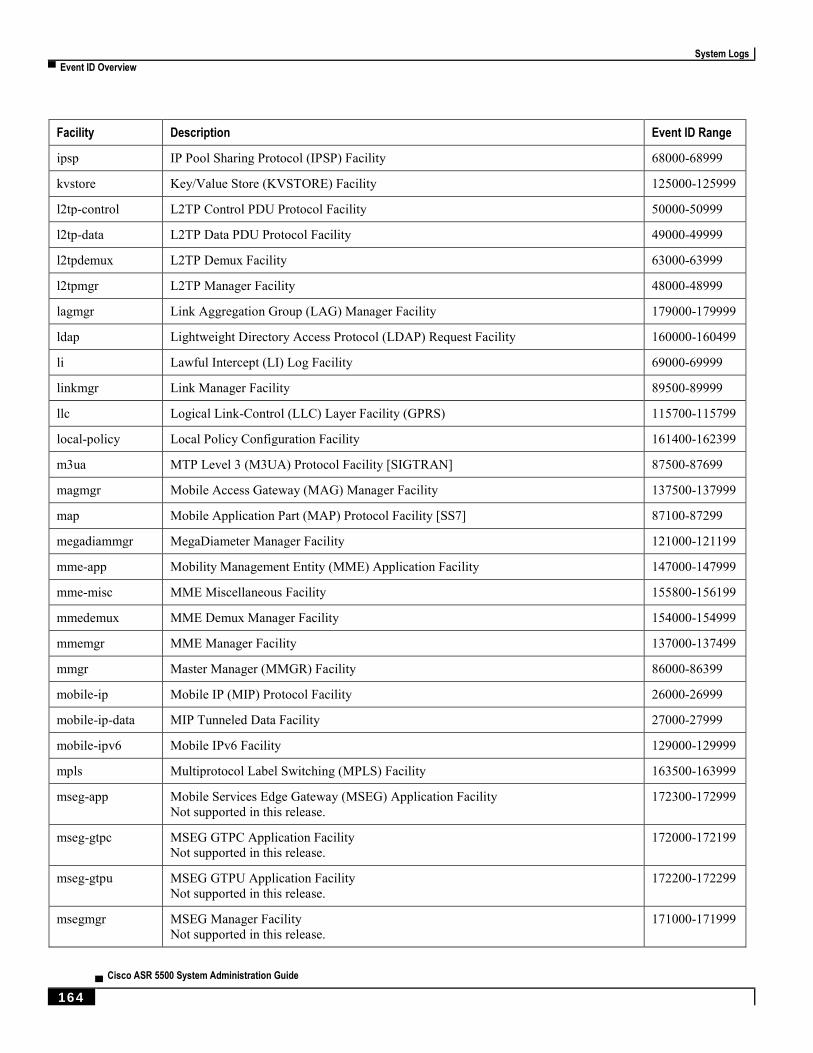
System Logs
▀ Event ID Overview
▄ Cisco ASR 5500 System Administration Guide
164
Facility Description Event ID Range
ipsp IP Pool Sharing Protocol (IPSP) Facility 68000-68999
kvstore Key/Value Store (KVSTORE) Facility 125000-125999
l2tp-control L2TP Control PDU Protocol Facility 50000-50999
l2tp-data L2TP Data PDU Protocol Facility 49000-49999
l2tpdemux L2TP Demux Facility 63000-63999
l2tpmgr L2TP Manager Facility 48000-48999
lagmgr Link Aggregation Group (LAG) Manager Facility 179000-179999
ldap Lightweight Directory Access Protocol (LDAP) Request Facility 160000-160499
li Lawful Intercept (LI) Log Facility 69000-69999
linkmgr Link Manager Facility 89500-89999
llc Logical Link-Control (LLC) Layer Facility (GPRS) 115700-115799
local-policy Local Policy Configuration Facility 161400-162399
m3ua MTP Level 3 (M3UA) Protocol Facility [SIGTRAN] 87500-87699
magmgr Mobile Access Gateway (MAG) Manager Facility 137500-137999
map Mobile Application Part (MAP) Protocol Facility [SS7] 87100-87299
megadiammgr MegaDiameter Manager Facility 121000-121199
mme-app Mobility Management Entity (MME) Application Facility 147000-147999
mme-misc MME Miscellaneous Facility 155800-156199
mmedemux MME Demux Manager Facility 154000-154999
mmemgr MME Manager Facility 137000-137499
mmgr Master Manager (MMGR) Facility 86000-86399
mobile-ip Mobile IP (MIP) Protocol Facility 26000-26999
mobile-ip-data MIP Tunneled Data Facility 27000-27999
mobile-ipv6 Mobile IPv6 Facility 129000-129999
mpls Multiprotocol Label Switching (MPLS) Facility 163500-163999
mseg-app Mobile Services Edge Gateway (MSEG) Application Facility
Not supported in this release.
172300-172999
mseg-gtpc MSEG GTPC Application Facility
Not supported in this release.
172000-172199
mseg-gtpu MSEG GTPU Application Facility
Not supported in this release.
172200-172299
msegmgr MSEG Manager Facility
Not supported in this release.
171000-171999

System Logs
Event ID Overview ▀
Cisco ASR 5500 System Administration Guide ▄ 165
Facility Description Event ID Range
mtp2 Message Transfer Part 2 (MTP2) Service Facility [SS7] 116900-116999
mtp3 Message Transfer Part 3 (MTP3) Service Facility [SS7] 115600-115699
multicast-proxy Multicast Proxy Facility 94000-94999
nas Network Access Signaling (NAS) Facility 153000-153999
netwstrg Network Storage Facility 78000-78999
npuctrl Network Processing Unit (NPU) Control Facility 16000-16999
npudrv NPU Driver Facility 191000-191999
npumgr NPU Manager (NPUMGR) Facility 17000-17999
npumgr-acl NPUMGR ACL Facility 169000-169999
npumgr-drv NPUMGR Driver Facility 185000-185999
npumgr-flow NPUMGR Flow Facility 167000-167999
npumgr-fwd NPUMGR Forwarding Facility 168000-168999
npumgr-init NPUMGR Initialization Facility 164000-164999
npumgr-lc NPUMGR LC Facility 180000-180999
npumgr-port NPUMGR Port Facility 166000-166999
npumgr-recovery NPUMGR Recovery Facility 165000-165999
npumgr-vpn NPUMGR VPN Facility 181000-181999
npusim NPUSIM Facility 176000-176999
ntfy-intf Event Notification Interface Facility 170000-170499
orbs Object Request Broker (ORB) System Facility 15000-15999
ospf Open Shortest Path First (OSPF) Protocol Facility 38000-38999
ospfv3 OSPFv3 Protocol Facility [IPv6] 150000-150999
p2p Peer-to-Peer (P2P) Facility 146000-146999
pccmgr Policy Charging and Control (PCC) Manager Facility 159000-159499
pdg Packet Data Gateway (PDG) Facility 152010-152999
pdgdmgr PDG TCP Demux Manager (pdgdmgr) Facility (this is a customer-specific facility) 162400-162999
pdif Packet Data Interworking Function (PDIF) Facility 120000-120999
pgw Packet Data Network Gateway (PGW) Facility 139000-139999
phs Payload Header Suppression (PHS) Facility 177000-177999
phs-control PHS X1/X5 and X2/X6 Interface Facility 136000-136899
phs-data PHS Data Facility 136900-136979
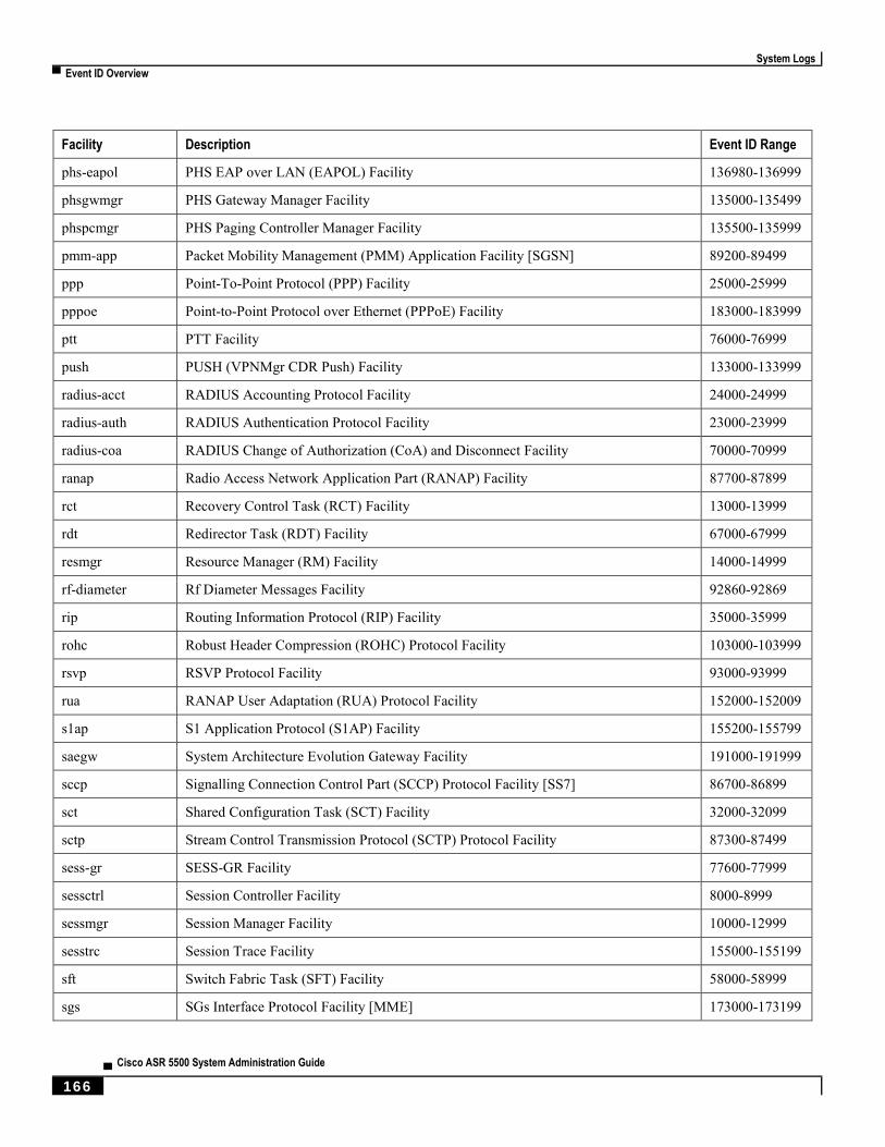
System Logs
▀ Event ID Overview
▄ Cisco ASR 5500 System Administration Guide
166
Facility Description Event ID Range
phs-eapol PHS EAP over LAN (EAPOL) Facility 136980-136999
phsgwmgr PHS Gateway Manager Facility 135000-135499
phspcmgr PHS Paging Controller Manager Facility 135500-135999
pmm-app Packet Mobility Management (PMM) Application Facility [SGSN] 89200-89499
ppp Point-To-Point Protocol (PPP) Facility 25000-25999
pppoe Point-to-Point Protocol over Ethernet (PPPoE) Facility 183000-183999
ptt PTT Facility 76000-76999
push PUSH (VPNMgr CDR Push) Facility 133000-133999
radius-acct RADIUS Accounting Protocol Facility 24000-24999
radius-auth RADIUS Authentication Protocol Facility 23000-23999
radius-coa RADIUS Change of Authorization (CoA) and Disconnect Facility 70000-70999
ranap Radio Access Network Application Part (RANAP) Facility 87700-87899
rct Recovery Control Task (RCT) Facility 13000-13999
rdt Redirector Task (RDT) Facility 67000-67999
resmgr Resource Manager (RM) Facility 14000-14999
rf-diameter Rf Diameter Messages Facility 92860-92869
rip Routing Information Protocol (RIP) Facility 35000-35999
rohc Robust Header Compression (ROHC) Protocol Facility 103000-103999
rsvp RSVP Protocol Facility 93000-93999
rua RANAP User Adaptation (RUA) Protocol Facility 152000-152009
s1ap S1 Application Protocol (S1AP) Facility 155200-155799
saegw System Architecture Evolution Gateway Facility 191000-191999
sccp Signalling Connection Control Part (SCCP) Protocol Facility [SS7] 86700-86899
sct Shared Configuration Task (SCT) Facility 32000-32099
sctp Stream Control Transmission Protocol (SCTP) Protocol Facility 87300-87499
sess-gr SESS-GR Facility 77600-77999
sessctrl Session Controller Facility 8000-8999
sessmgr Session Manager Facility 10000-12999
sesstrc Session Trace Facility 155000-155199
sft Switch Fabric Task (SFT) Facility 58000-58999
sgs SGs Interface Protocol Facility [MME] 173000-173199

System Logs
Event ID Overview ▀
Cisco ASR 5500 System Administration Guide ▄ 167
Facility Description Event ID Range
sgsn-app SGSN Application Interface Facility 115900-115999
sgsn-failures SGSN Call Failures Facility 89100-89199
sgsn-gtpc SGSN GTP-C Protocol Facility 116000-116599
sgsn-gtpu SGSN GTP-U Protocol Facility 86900-87099
sgsn-mbms-bearer SGSN MBMS Bearer Application (SMGR) Facility 116600-116799
sgsn-misc SGSN Miscellaneous Facility 88800-89099
sgsn-system SGSN System Components Facility 86400-86499
sgsn-test SGSN Tests Facility 88700-88799
sgsn2 SGSN2 Facility 114000-117999
sgtpcmgr SGSN GTP-C (SGTPC) Manager Facility 117000-117999
sgw Serving Gateway (SGW) Facility 140000-140999
sh-diameter Sh Diameter Messages Facility 92850-92859
sipcdprt SIPCDPRT Facility 95000-95999
sitmain System Initiation Task (SIT) Main Facility 4000-4999
sm-app Short Message Service (SMS) Facility 88300-88499
sms SMS Service Facility 116800-116899
sndcp Sub Network Dependent Convergence Protocol (SNDCP) Facility 115800-115899
snmp Simple Network Management Protocol (SNMP) Facility 22000-22999
sprmgr Subscriber Policy Register (SPR) Manager Facility 159500-159999
srdb Static Rating Database Facility 102000-102999
srp Service Redundancy Protocol (SRP) Facility 84000-84999
sscfnni SSCFNNI Protocol Facility [ATM] 115500-115599
sscop SSCOP Protocol Facility [ATM] 115400-115499
ssh-ipsec SSH IP Security Facility 56999-56999
ssl SSL Facility (this is a customer-specific facility) 156200-157199
stat Statistics Facility 31000-31999
system System Facility 1000-1999
tacacs+ TACACS+ Protocol Facility 37000-37999
taclcp TACLCP Facility 44000-44999
tcap Transaction Capabilities Application Part (TCAP) Protocol Logging Facility [SS7] 86500-86699
testctrl Test Controller Facility 174000-174999
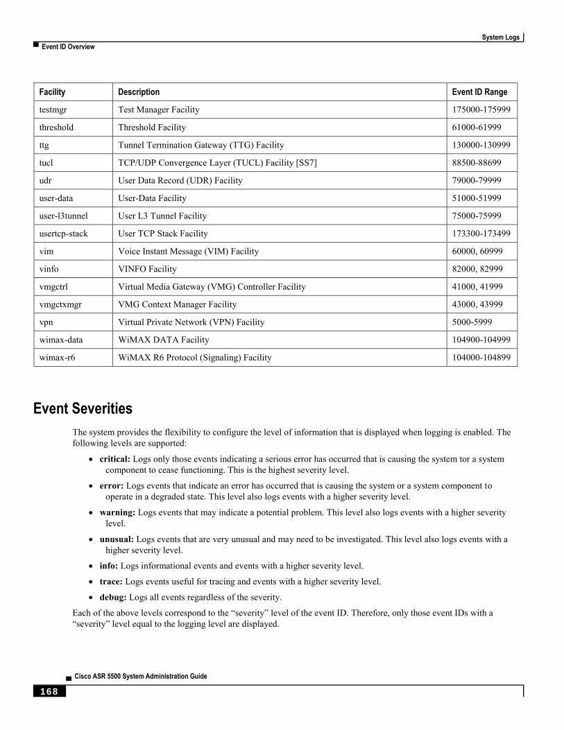
System Logs
▀ Event ID Overview
▄ Cisco ASR 5500 System Administration Guide
168
Facility Description Event ID Range
testmgr Test Manager Facility 175000-175999
threshold Threshold Facility 61000-61999
ttg Tunnel Termination Gateway (TTG) Facility 130000-130999
tucl TCP/UDP Convergence Layer (TUCL) Facility [SS7] 88500-88699
udr User Data Record (UDR) Facility 79000-79999
user-data User-Data Facility 51000-51999
user-l3tunnel User L3 Tunnel Facility 75000-75999
usertcp-stack User TCP Stack Facility 173300-173499
vim Voice Instant Message (VIM) Facility 60000, 60999
vinfo VINFO Facility 82000, 82999
vmgctrl Virtual Media Gateway (VMG) Controller Facility 41000, 41999
vmgctxmgr VMG Context Manager Facility 43000, 43999
vpn Virtual Private Network (VPN) Facility 5000-5999
wimax-data WiMAX DATA Facility 104900-104999
wimax-r6 WiMAX R6 Protocol (Signaling) Facility 104000-104899
Event Severities
The system provides the flexibility to configure the level of information that is displayed when logging is enabled. The
following levels are supported:
critical: Logs only those events indicating a serious error has occurred that is causing the system tor a system
component to cease functioning. This is the highest severity level.
error: Logs events that indicate an error has occurred that is causing the system or a system component to
operate in a degraded state. This level also logs events with a higher severity level.
warning: Logs events that may indicate a potential problem. This level also logs events with a higher severity
level.
unusual: Logs events that are very unusual and may need to be investigated. This level also logs events with a
higher severity level.
info: Logs informational events and events with a higher severity level.
trace: Logs events useful for tracing and events with a higher severity level.
debug: Logs all events regardless of the severity.
Each of the above levels correspond to the “severity” level of the event ID. Therefore, only those event IDs with a
“severity” level equal to the logging level are displayed.
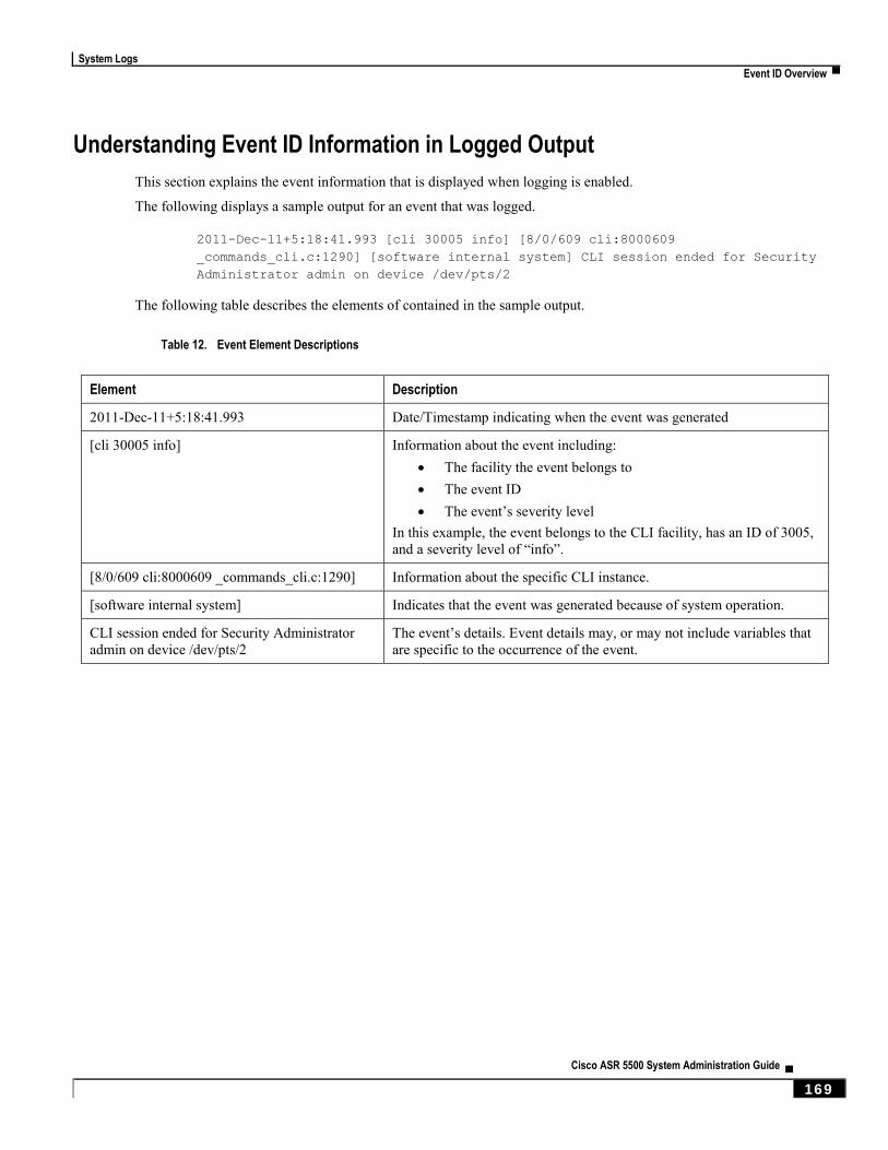
System Logs
Event ID Overview ▀
Cisco ASR 5500 System Administration Guide ▄ 169
Understanding Event ID Information in Logged Output
This section explains the event information that is displayed when logging is enabled.
The following displays a sample output for an event that was logged.
2011-Dec-11+5:18:41.993 [cli 30005 info] [8/0/609 cli:8000609
_commands_cli.c:1290] [software internal system] CLI session ended for Security
Administrator admin on device /dev/pts/2
The following table describes the elements of contained in the sample output.
Table 12. Event Element Descriptions
Element Description
2011-Dec-11+5:18:41.993 Date/Timestamp indicating when the event was generated
[cli 30005 info] Information about the event including:
The facility the event belongs to
The event ID
The event’s severity level
In this example, the event belongs to the CLI facility, has an ID of 3005,
and a severity level of “info”.
[8/0/609 cli:8000609 _commands_cli.c:1290] Information about the specific CLI instance.
[software internal system] Indicates that the event was generated because of system operation.
CLI session ended for Security Administrator
admin on device /dev/pts/2 The event’s details. Event details may, or may not include variables that
are specific to the occurrence of the event.

Cisco ASR 5500 System Administration Guide ▄ 171
Chapter 12 Troubleshooting
This chapter provides information and instructions for using the system command line interface (CLI) for
troubleshooting any issues that may arise during system operation.
Refer to the ASR 5500 Installation Guide for comprehensive descriptions of the hardware components addressed by
these troubleshooting procedures.
The following topics are included:
Detecting Faulty Hardware
Taking Corrective Action
Verifying Network Connectivity
Using the System Diagnostic Utilities
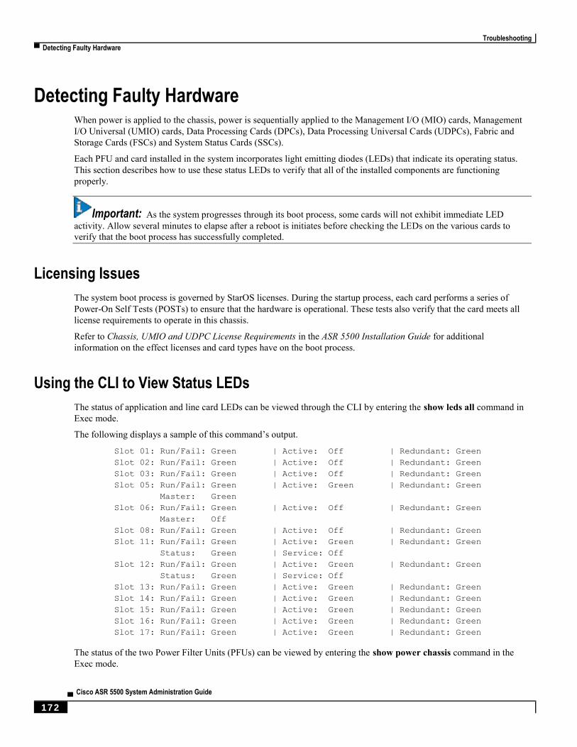
Troubleshooting
▀ Detecting Faulty Hardware
▄ Cisco ASR 5500 System Administration Guide
172
Detecting Faulty Hardware When power is applied to the chassis, power is sequentially applied to the Management I/O (MIO) cards, Management
I/O Universal (UMIO) cards, Data Processing Cards (DPCs), Data Processing Universal Cards (UDPCs), Fabric and
Storage Cards (FSCs) and System Status Cards (SSCs).
Each PFU and card installed in the system incorporates light emitting diodes (LEDs) that indicate its operating status.
This section describes how to use these status LEDs to verify that all of the installed components are functioning
properly.
Important: As the system progresses through its boot process, some cards will not exhibit immediate LED
activity. Allow several minutes to elapse after a reboot is initiates before checking the LEDs on the various cards to
verify that the boot process has successfully completed.
Licensing Issues
The system boot process is governed by StarOS licenses. During the startup process, each card performs a series of
Power-On Self Tests (POSTs) to ensure that the hardware is operational. These tests also verify that the card meets all
license requirements to operate in this chassis.
Refer to Chassis, UMIO and UDPC License Requirements in the ASR 5500 Installation Guide for additional
information on the effect licenses and card types have on the boot process.
Using the CLI to View Status LEDs
The status of application and line card LEDs can be viewed through the CLI by entering the show leds all command in
Exec mode.
The following displays a sample of this command’s output.
Slot 01: Run/Fail: Green | Active: Off | Redundant: Green
Slot 02: Run/Fail: Green | Active: Off | Redundant: Green
Slot 03: Run/Fail: Green | Active: Off | Redundant: Green
Slot 05: Run/Fail: Green | Active: Green | Redundant: Green
Master: Green
Slot 06: Run/Fail: Green | Active: Off | Redundant: Green
Master: Off
Slot 08: Run/Fail: Green | Active: Off | Redundant: Green
Slot 11: Run/Fail: Green | Active: Green | Redundant: Green
Status: Green | Service: Off
Slot 12: Run/Fail: Green | Active: Green | Redundant: Green
Status: Green | Service: Off
Slot 13: Run/Fail: Green | Active: Green | Redundant: Green
Slot 14: Run/Fail: Green | Active: Green | Redundant: Green
Slot 15: Run/Fail: Green | Active: Green | Redundant: Green
Slot 16: Run/Fail: Green | Active: Green | Redundant: Green
Slot 17: Run/Fail: Green | Active: Green | Redundant: Green
The status of the two Power Filter Units (PFUs) can be viewed by entering the show power chassis command in the
Exec mode.
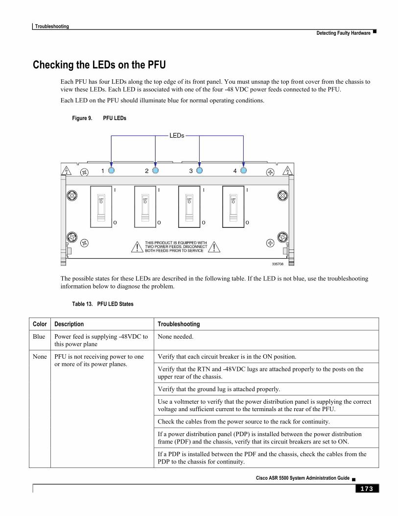
Troubleshooting
Detecting Faulty Hardware ▀
Cisco ASR 5500 System Administration Guide ▄ 173
Checking the LEDs on the PFU
Each PFU has four LEDs along the top edge of its front panel. You must unsnap the top front cover from the chassis to
view these LEDs. Each LED is associated with one of the four -48 VDC power feeds connected to the PFU.
Each LED on the PFU should illuminate blue for normal operating conditions.
Figure 9. PFU LEDs
The possible states for these LEDs are described in the following table. If the LED is not blue, use the troubleshooting
information below to diagnose the problem.
Table 13. PFU LED States
Color Description Troubleshooting
Blue Power feed is supplying -48VDC to
this power plane None needed.
None PFU is not receiving power to one
or more of its power planes. Verify that each circuit breaker is in the ON position.
Verify that the RTN and -48VDC lugs are attached properly to the posts on the
upper rear of the chassis.
Verify that the ground lug is attached properly.
Use a voltmeter to verify that the power distribution panel is supplying the correct
voltage and sufficient current to the terminals at the rear of the PFU.
Check the cables from the power source to the rack for continuity.
If a power distribution panel (PDP) is installed between the power distribution
frame (PDF) and the chassis, verify that its circuit breakers are set to ON.
If a PDP is installed between the PDF and the chassis, check the cables from the
PDP to the chassis for continuity.
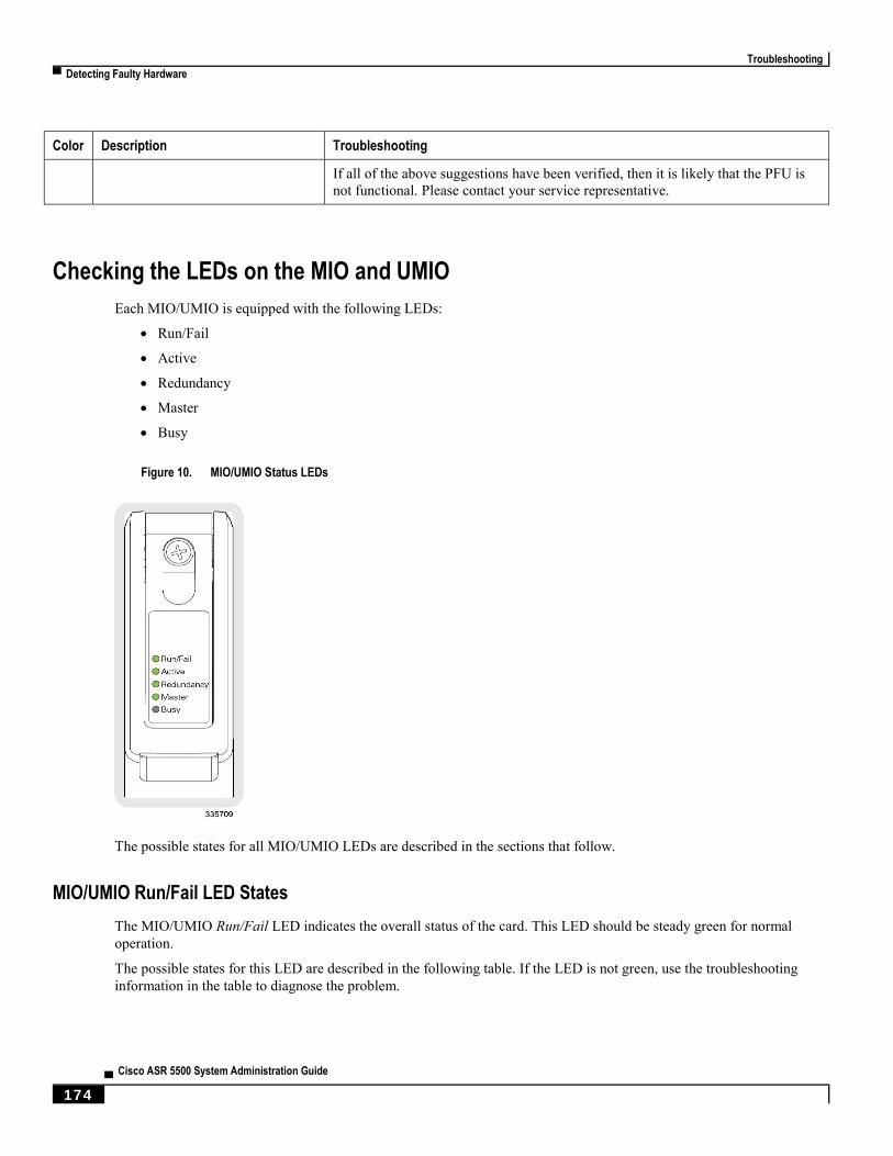
Troubleshooting
▀ Detecting Faulty Hardware
▄ Cisco ASR 5500 System Administration Guide
174
Color Description Troubleshooting
If all of the above suggestions have been verified, then it is likely that the PFU is
not functional. Please contact your service representative.
Checking the LEDs on the MIO and UMIO
Each MIO/UMIO is equipped with the following LEDs:
Run/Fail
Active
Redundancy
Master
Busy
Figure 10. MIO/UMIO Status LEDs
The possible states for all MIO/UMIO LEDs are described in the sections that follow.
MIO/UMIO Run/Fail LED States
The MIO/UMIO Run/Fail LED indicates the overall status of the card. This LED should be steady green for normal
operation.
The possible states for this LED are described in the following table. If the LED is not green, use the troubleshooting
information in the table to diagnose the problem.
Troubleshooting
Detecting Faulty Hardware ▀
Cisco ASR 5500 System Administration Guide ▄ 175
Table 14. MIO/UMIO Run/Fail LED States
Color Description Troubleshooting
Green Card powered with no
errors detected None needed.
Blinking
Green Card is initializing and/or
loading software This is normal operation during boot-up.
Red Card powered with error(s)
detected Errors were detected during the Power On Self Tests (POSTs). It is likely that the
errors were logged to the system's command line interface during boot.
None Card is not receiving
power Verify that the LEDs on the PFUs are blue. If they are not, refer to Checking the
LEDs on the PFU for troubleshooting information.
Verify that the power source is supplying ample voltage and current to the chassis.
Verify that the card is properly installed per the instructions in the ASR 5500
Installation Guide.
If all of the above suggestions have been verified, it is possible that the MIO is not
functional. Please contact your service representative.
MIO/UMIO Active LED States
The Active LED on the MIO/UMIO indicates that the software is loaded on the card and it is ready for operation. For the
MIO installed in chassis slot 5, this LED should be green for normal operation. For the MIO installed in slot 6, this LED
should be off for normal operation.
The possible states for this LED are described in the following table. If the LED is not green, use the troubleshooting
information in the table to diagnose the problem.
Table 15. Active LED States
Color Description Troubleshooting
Green Card is active None needed for the MIO/UMIO in slot 5. If green for the MIO/UMIO in slot 6,
verify that the MIO/UMIO in slot 5 is installed and licensed properly according
to the instructions in the ASR 5500 Installation Guide.
Blinking
Green Tasks or processes being
migrated from the active MIO to
the standby MIO.
Refer to Monitoring the System for information on determining the status of the
MIO/UMIO and system software processes.
None Card is not receiving power.
OR Card has failed.
Verify that the Run/Fail LED is green. If so, the card is receiving power and
POST test results are positive. If it is off, refer to MIO/UMIO RunFail LED
States for troubleshooting information.

Troubleshooting
▀ Detecting Faulty Hardware
▄ Cisco ASR 5500 System Administration Guide
176
MIO/UMIO Redundancy LED States
The Redundancy LED on the MIO/UMIO indicates that software is loaded on the card, but it is serving as a redundant
component. For the MIO/UMIO installed in slot 6, this LED should be green for normal operation. For the MIO/UMIO
installed in slot 8, this LED should be off for normal operation.
The possible states for this LED are described in the following table. If the LED is not green, use the troubleshooting
information in the table to diagnose the problem.
Table 16. MIO/UMIO Redundancy LED States
Color Description Troubleshooting
Green Card is in redundant mode None needed. If green for the MIO/UMIOs in slot 5 and slot 6, the cards and
ports are fully backed up.
Amber Card or port on this card is not
backed up by other MIO. Check the status of the other MIO/UMIO. If it has failed or one or more of its
ports are no longer active, the system can continue to function but redundancy
is compromised.
Refer to Monitoring the System for information on determining the status of the
MIO/UMIO and system software processes.
Blinking
Amber Tasks or processes being
migrated from the active MIO to
the standby MIO.
Refer to Monitoring the System for information on determining the status of the
MIO/UMIO and system software processes.
None Card is not receiving power.
OR Card has failed.
Verify that the Run/Fail LED is green. If so, the card is receiving power and
POST test results are positive. If it is off, refer to MIO/UMIO RunFail LED
States for troubleshooting information on.
MIO/UMIO Master LED States
The Master LED on the MIO/UMIO indicates whether the card is in Active or Standby mode.
The possible states for this LED are described in the following table. If the LED is not green, use the troubleshooting
information also provided to diagnose the problem.
Table 17. MIO/UMIO Master LED States
Color Description Troubleshooting
Green This card is the Active MIO. None needed.
Blinking
Green Tasks or processes being migrated
from the active MIO to the
standby MIO.
Refer to Monitoring the System for information on determining the status of the
MIO/UMIO and system software processes.
None This card is the Standby MIO.
OR
Verify that the Run/Fail LED is green. If so, the card is receiving power and
POST test results are positive. If it is off, refer to MIO/UMIO RunFail LED
States for troubleshooting information.

Troubleshooting
Detecting Faulty Hardware ▀
Cisco ASR 5500 System Administration Guide ▄ 177
Color Description Troubleshooting
Card has failed. Refer to Monitoring the System for information on determining the status of he
MIO/UMIO and system software processes.
MIO/UMIO Busy LED States
The Busy LED on the MIO/UMIO indicates that the card is accessing the RAID solid state drives on the FSCs.
This LED is off when no file storage activity is occurring.
The possible states for this LED are described in the following table. If the LED is not green, use the troubleshooting
information in the table to diagnose the problem.
Table 18. MIO/UMIO Busy LED States
Color Description Troubleshooting
Green Files are being transferred to or accessed from the RAID configuration on the FSCs. None required.
None No RAID activity.
OR RAID configuration is unavailable.
Checking the LEDs on the FSC
MIO/UMIO – Interface Link LED States
The Link LED associated with a 1000Base-T (management) or 10 Gigabit Ethernet port on an MIO/UMIO daughter
card (subscriber traffic) indicates the status of the network link. This LED should be green for normal operation.
The possible states for this LED are described in the following table. If the LED is not green, use the troubleshooting
information in the table to diagnose the problem.
Table 19. MIO/UMIO – Interface Link LED States
Color Description Troubleshooting
Green Link is up None needed.
NOTE: This LED will not indicate the presence of a network link until the interface parameters are set
during the software configuration process.
None No power to
card.
OR Link is down.
Verify that the Run/Fail LED is green. If so, the card is receiving power. If it is off, refer to
MIO/UMIO Run/Fail LED States for troubleshooting information.
Verify that the interface is cabled properly.
Verify that the device on which the interface is located is cabled and powered properly.

Troubleshooting
▀ Detecting Faulty Hardware
▄ Cisco ASR 5500 System Administration Guide
178
MIO/UMIO – Interface Activity LED States
The Activity LED associated with a 1000Base-T (management) or 10 Gigabit Ethernet port on an MIO/UMIO daughter
card (subscriber traffic) indicates the presence of traffic on the network link. This LED should be green when data is
being transmitted or received over the interface.
The possible states for this LED are described in the following table. If the LED is not green, use the troubleshooting
information in the table to diagnose the problem.
Table 20. MIO/UMIO – Interface Activity LED States
Color Description Troubleshooting
Flashing
Green Traffic is present on the
link None needed.
None No traffic is present on the
link None needed if there is no activity on the link. Prior to interface configuration, this
is normal operation.
Checking the LEDs on the DPC and UDPC
Each DPC/UDPC is equipped with status LEDs as listed below:
Run/Fail
Active
Redundancy
Figure 11. DPC/UDPC Status LEDs
Troubleshooting
Detecting Faulty Hardware ▀
Cisco ASR 5500 System Administration Guide ▄ 179
The possible states for all of the DPC/UDPC LEDs are described in the sections that follow.
DPC/UDPC Run/Fail LED States
The DPC/UDPC Run/Fail LED indicates the overall status of the card. This LED should be green for normal operation.
The possible states for this LED are described in the following table. If the LED is not green, use the troubleshooting
information in the table to diagnose the problem.
Table 21. DPC/UDPC Run/Fail LED States
Color Description Troubleshooting
Green Card powered up with no
errors detected. None needed.
Blinking
Green Card is initializing and/or
loading software. This is normal operation during boot-up.
Red Card powered up with
error(s) detected. Errors were detected during the Power On Self Tests (POSTs). It is likely that the
errors were logged to the system's command line interface during boot.
None Card is not receiving
power. Verify that the LEDs on the PFUs are blue. If they are not, refer to Checking the
LEDs on the PFU for troubleshooting information.
Verify that the power source is supplying ample voltage and current to the chassis.
Verify that the card is properly installed and licensed per the instructions in the
ASR 5500 Installation Guide.
If all of the above suggestions have been verified, it is possible that the DPC/UDPC
is not functional. Please contact your service representative.
DPC/UDPC Active LED States
The Active LED on the DDPC/UDPCPC indicates that the software is loaded on the card and that the card is ready for
operation. When the system first boots up, all installed DPC/UDPCs are booted into standby mode. The system must
then be configured as to which DPC/UDPCs should serve as redundant components (remain in standby mode) and
which should function as active components.
The possible states for this LED are described in the following table. If the LED is not green, use the troubleshooting
information in the table to diagnose the problem.
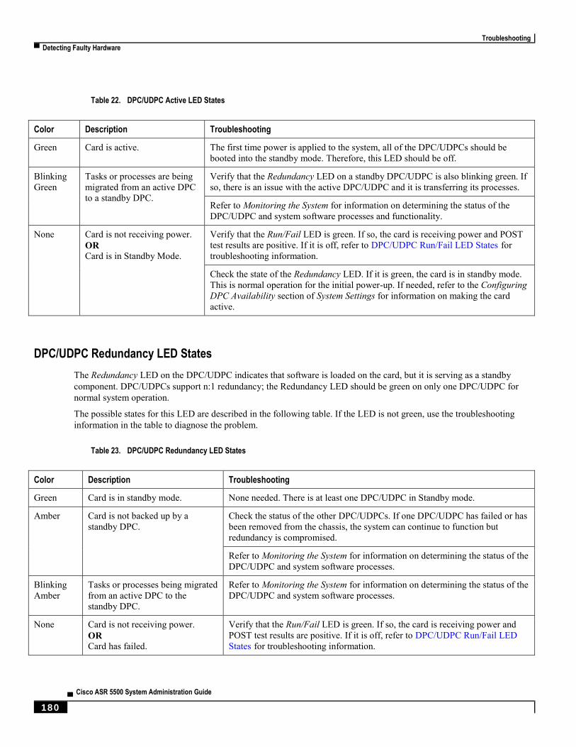
Troubleshooting
▀ Detecting Faulty Hardware
▄ Cisco ASR 5500 System Administration Guide
180
Table 22. DPC/UDPC Active LED States
Color Description Troubleshooting
Green Card is active. The first time power is applied to the system, all of the DPC/UDPCs should be
booted into the standby mode. Therefore, this LED should be off.
Blinking
Green Tasks or processes are being
migrated from an active DPC
to a standby DPC.
Verify that the Redundancy LED on a standby DPC/UDPC is also blinking green. If
so, there is an issue with the active DPC/UDPC and it is transferring its processes.
Refer to Monitoring the System for information on determining the status of the
DPC/UDPC and system software processes and functionality.
None Card is not receiving power.
OR Card is in Standby Mode.
Verify that the Run/Fail LED is green. If so, the card is receiving power and POST
test results are positive. If it is off, refer to DPC/UDPC Run/Fail LED States for
troubleshooting information.
Check the state of the Redundancy LED. If it is green, the card is in standby mode.
This is normal operation for the initial power-up. If needed, refer to the Configuring
DPC Availability section of System Settings for information on making the card
active.
DPC/UDPC Redundancy LED States
The Redundancy LED on the DPC/UDPC indicates that software is loaded on the card, but it is serving as a standby
component. DPC/UDPCs support n:1 redundancy; the Redundancy LED should be green on only one DPC/UDPC for
normal system operation.
The possible states for this LED are described in the following table. If the LED is not green, use the troubleshooting
information in the table to diagnose the problem.
Table 23. DPC/UDPC Redundancy LED States
Color Description Troubleshooting
Green Card is in standby mode. None needed. There is at least one DPC/UDPC in Standby mode.
Amber Card is not backed up by a
standby DPC. Check the status of the other DPC/UDPCs. If one DPC/UDPC has failed or has
been removed from the chassis, the system can continue to function but
redundancy is compromised.
Refer to Monitoring the System for information on determining the status of the
DPC/UDPC and system software processes.
Blinking
Amber Tasks or processes being migrated
from an active DPC to the
standby DPC.
Refer to Monitoring the System for information on determining the status of the
DPC/UDPC and system software processes.
None Card is not receiving power.
OR Card has failed.
Verify that the Run/Fail LED is green. If so, the card is receiving power and
POST test results are positive. If it is off, refer to DPC/UDPC Run/Fail LED
States for troubleshooting information.
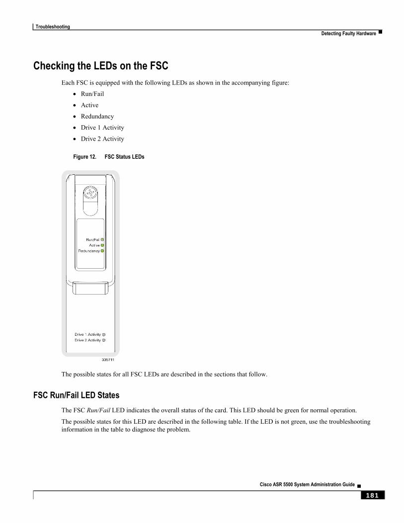
Troubleshooting
Detecting Faulty Hardware ▀
Cisco ASR 5500 System Administration Guide ▄ 181
Checking the LEDs on the FSC
Each FSC is equipped with the following LEDs as shown in the accompanying figure:
Run/Fail
Active
Redundancy
Drive 1 Activity
Drive 2 Activity
Figure 12. FSC Status LEDs
The possible states for all FSC LEDs are described in the sections that follow.
FSC Run/Fail LED States
The FSC Run/Fail LED indicates the overall status of the card. This LED should be green for normal operation.
The possible states for this LED are described in the following table. If the LED is not green, use the troubleshooting
information in the table to diagnose the problem.

Troubleshooting
▀ Detecting Faulty Hardware
▄ Cisco ASR 5500 System Administration Guide
182
Table 24. FSC Run/Fail LED States
Color Description Troubleshooting
Green Card powered with no
errors detected None needed.
Blinking
Green Card is initializing and/or
loading software This is normal operation during boot-up.
Red Card powered with error(s)
detected Errors were detected during the Power On Self Tests (POSTs). It is likely that the
errors were logged to the system's command line interface during boot.
None Card is not receiving
power Verify that the LEDs on the PFUs are blue. If they are not, refer to Checking the
LEDs on the PFU for troubleshooting information.
Verify that the power source is supplying ample voltage and current to the chassis.
Verify that the card is properly installed per the instructions in the ASR 5500
Installation Guide.
If all of the above suggestions have been verified, it is possible that the FSC is not
functional. Please contact your service representative.
FSC Active LED States
The Active LED on the FSC indicates that the software is loaded on the card and that the card is ready for operation.
When the system first boots up, all installed FSCs are booted into ready mode.
The possible states for this LED are described in the following table. If the LED is not green, use the troubleshooting
information in the table to diagnose the problem.
Table 25. FSC Active LED States
Color Description Troubleshooting
Green Card is active. The first time power is applied to the system, all of the FSCs should be booted
into the ready mode. Therefore, this LED should be on.
Blinking
Green Tasks or processes being migrated
from an active FSC to a standby
FSC.
Verify that the Redundancy LED on a standby FSC is also blinking green. If so,
there is an issue with the active FSC and it is transferring its processes.
Refer to Monitoring the System for information on determining the status of the
FSC and system software processes and functionality.
None Card is not receiving power.
OR Card is in Standby Mode.
Verify that the Run/Fail LED is green. If so, the card is receiving power and
POST test results are positive. If it is off, refer to FSC Run/Fail LED States for
troubleshooting information.
Check the state of the Redundancy LED. If it is green, the card is in standby
mode.
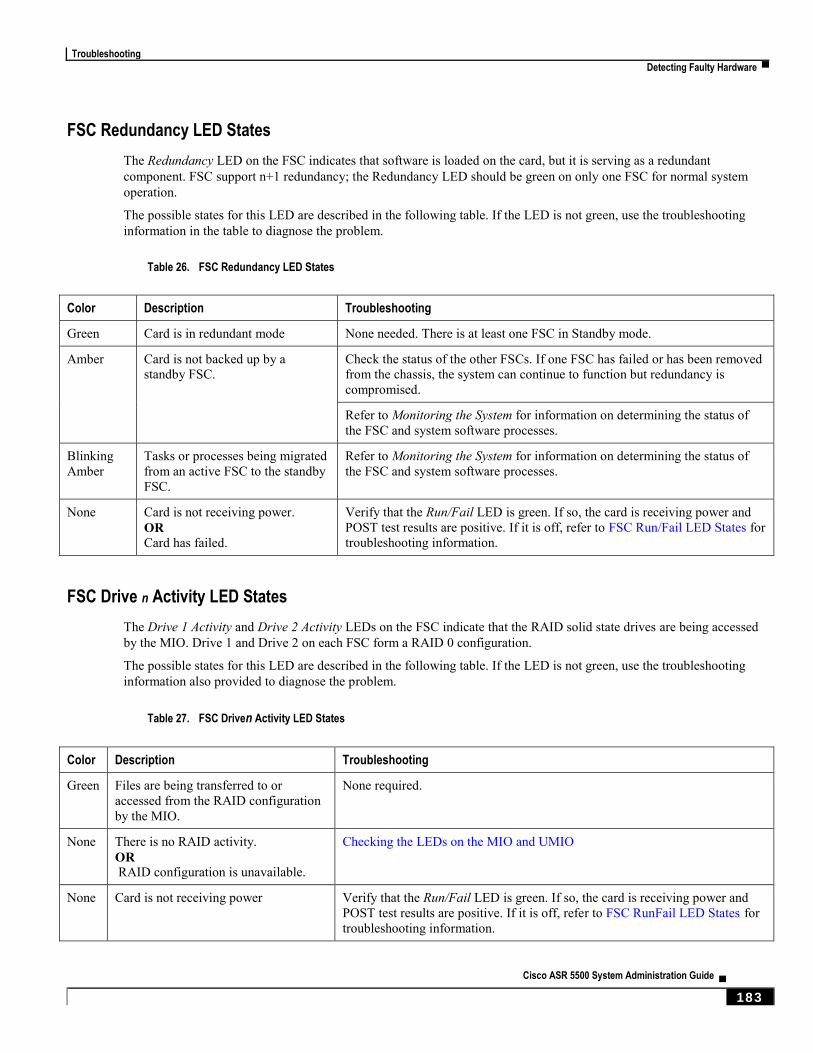
Troubleshooting
Detecting Faulty Hardware ▀
Cisco ASR 5500 System Administration Guide ▄ 183
FSC Redundancy LED States
The Redundancy LED on the FSC indicates that software is loaded on the card, but it is serving as a redundant
component. FSC support n+1 redundancy; the Redundancy LED should be green on only one FSC for normal system
operation.
The possible states for this LED are described in the following table. If the LED is not green, use the troubleshooting
information in the table to diagnose the problem.
Table 26. FSC Redundancy LED States
Color Description Troubleshooting
Green Card is in redundant mode None needed. There is at least one FSC in Standby mode.
Amber Card is not backed up by a
standby FSC. Check the status of the other FSCs. If one FSC has failed or has been removed
from the chassis, the system can continue to function but redundancy is
compromised.
Refer to Monitoring the System for information on determining the status of
the FSC and system software processes.
Blinking
Amber Tasks or processes being migrated
from an active FSC to the standby
FSC.
Refer to Monitoring the System for information on determining the status of
the FSC and system software processes.
None Card is not receiving power.
OR Card has failed.
Verify that the Run/Fail LED is green. If so, the card is receiving power and
POST test results are positive. If it is off, refer to FSC Run/Fail LED States for
troubleshooting information.
FSC Drive n Activity LED States
The Drive 1 Activity and Drive 2 Activity LEDs on the FSC indicate that the RAID solid state drives are being accessed
by the MIO. Drive 1 and Drive 2 on each FSC form a RAID 0 configuration.
The possible states for this LED are described in the following table. If the LED is not green, use the troubleshooting
information also provided to diagnose the problem.
Table 27. FSC Driven Activity LED States
Color Description Troubleshooting
Green Files are being transferred to or
accessed from the RAID configuration
by the MIO.
None required.
None There is no RAID activity.
OR RAID configuration is unavailable.
Checking the LEDs on the MIO and UMIO
None Card is not receiving power Verify that the Run/Fail LED is green. If so, the card is receiving power and
POST test results are positive. If it is off, refer to FSC RunFail LED States for
troubleshooting information.
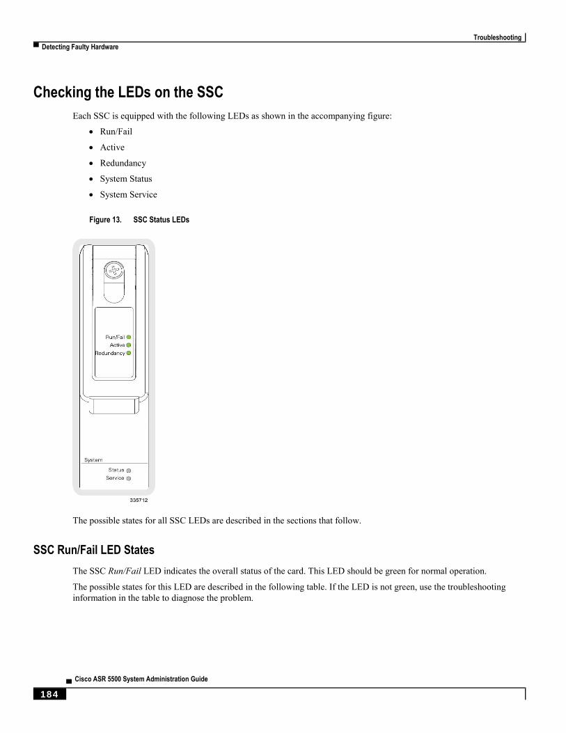
Troubleshooting
▀ Detecting Faulty Hardware
▄ Cisco ASR 5500 System Administration Guide
184
Checking the LEDs on the SSC
Each SSC is equipped with the following LEDs as shown in the accompanying figure:
Run/Fail
Active
Redundancy
System Status
System Service
Figure 13. SSC Status LEDs
The possible states for all SSC LEDs are described in the sections that follow.
SSC Run/Fail LED States
The SSC Run/Fail LED indicates the overall status of the card. This LED should be green for normal operation.
The possible states for this LED are described in the following table. If the LED is not green, use the troubleshooting
information in the table to diagnose the problem.
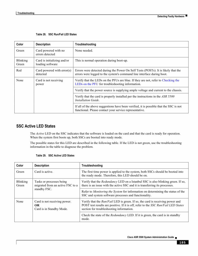
Troubleshooting
Detecting Faulty Hardware ▀
Cisco ASR 5500 System Administration Guide ▄ 185
Table 28. SSC Run/Fail LED States
Color Description Troubleshooting
Green Card powered with no
errors detected None needed.
Blinking
Green Card is initializing and/or
loading software This is normal operation during boot-up.
Red Card powered with error(s)
detected Errors were detected during the Power On Self Tests (POSTs). It is likely that the
errors were logged to the system's command line interface during boot.
None Card is not receiving
power Verify that the LEDs on the PFUs are blue. If they are not, refer to Checking the
LEDs on the PFU for troubleshooting information.
Verify that the power source is supplying ample voltage and current to the chassis.
Verify that the card is properly installed per the instructions in the ASR 5500
Installation Guide.
If all of the above suggestions have been verified, it is possible that the SSC is not
functional. Please contact your service representative.
SSC Active LED States
The Active LED on the SSC indicates that the software is loaded on the card and that the card is ready for operation.
When the system first boots up, both SSCs are booted into ready mode.
The possible states for this LED are described in the following table. If the LED is not green, use the troubleshooting
information in the table to diagnose the problem.
Table 29. SSC Active LED States
Color Description Troubleshooting
Green Card is active. The first time power is applied to the system, both SSCs should be booted into
the ready mode. Therefore, this LED should be on.
Blinking
Green Tasks or processes being
migrated from an active FSC to a
standby FSC.
Verify that the Redundancy LED on a Istanbul SSC is also blinking green. If so,
there is an issue with the active SSC and it is transferring its processes.
Refer to Monitoring the System for information on determining the status of the
SSC and system software processes and functionality.
None Card is not receiving power.
OR Card is in Standby Mode.
Verify that the Run/Fail LED is green. If so, the card is receiving power and
POST test results are positive. If it is off, refer to the SSC Run/Fail LED States
section for troubleshooting information.
Check the state of the Redundancy LED. If it is green, the card is in standby
mode.
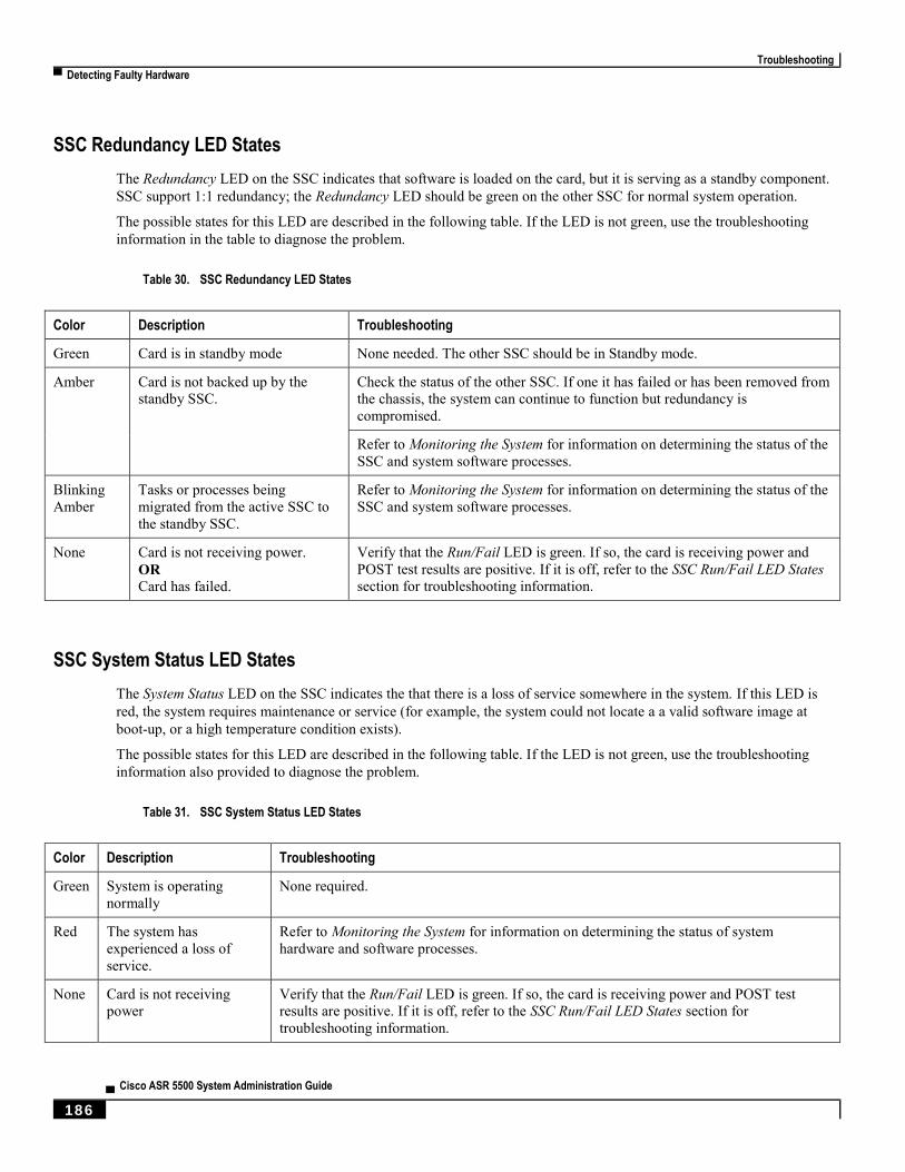
Troubleshooting
▀ Detecting Faulty Hardware
▄ Cisco ASR 5500 System Administration Guide
186
SSC Redundancy LED States
The Redundancy LED on the SSC indicates that software is loaded on the card, but it is serving as a standby component.
SSC support 1:1 redundancy; the Redundancy LED should be green on the other SSC for normal system operation.
The possible states for this LED are described in the following table. If the LED is not green, use the troubleshooting
information in the table to diagnose the problem.
Table 30. SSC Redundancy LED States
Color Description Troubleshooting
Green Card is in standby mode None needed. The other SSC should be in Standby mode.
Amber Card is not backed up by the
standby SSC. Check the status of the other SSC. If one it has failed or has been removed from
the chassis, the system can continue to function but redundancy is
compromised.
Refer to Monitoring the System for information on determining the status of the
SSC and system software processes.
Blinking
Amber Tasks or processes being
migrated from the active SSC to
the standby SSC.
Refer to Monitoring the System for information on determining the status of the
SSC and system software processes.
None Card is not receiving power.
OR Card has failed.
Verify that the Run/Fail LED is green. If so, the card is receiving power and
POST test results are positive. If it is off, refer to the SSC Run/Fail LED States
section for troubleshooting information.
SSC System Status LED States
The System Status LED on the SSC indicates the that there is a loss of service somewhere in the system. If this LED is
red, the system requires maintenance or service (for example, the system could not locate a a valid software image at
boot-up, or a high temperature condition exists).
The possible states for this LED are described in the following table. If the LED is not green, use the troubleshooting
information also provided to diagnose the problem.
Table 31. SSC System Status LED States
Color Description Troubleshooting
Green System is operating
normally None required.
Red The system has
experienced a loss of
service.
Refer to Monitoring the System for information on determining the status of system
hardware and software processes.
None Card is not receiving
power Verify that the Run/Fail LED is green. If so, the card is receiving power and POST test
results are positive. If it is off, refer to the SSC Run/Fail LED States section for
troubleshooting information.
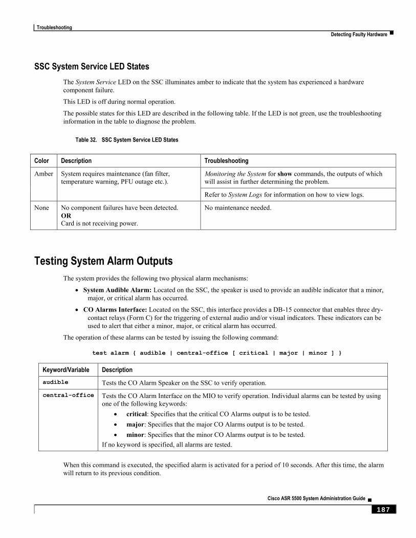
Troubleshooting
Detecting Faulty Hardware ▀
Cisco ASR 5500 System Administration Guide ▄ 187
SSC System Service LED States
The System Service LED on the SSC illuminates amber to indicate that the system has experienced a hardware
component failure.
This LED is off during normal operation.
The possible states for this LED are described in the following table. If the LED is not green, use the troubleshooting
information in the table to diagnose the problem.
Table 32. SSC System Service LED States
Color Description Troubleshooting
Amber System requires maintenance (fan filter,
temperature warning, PFU outage etc.). Monitoring the System for show commands, the outputs of which
will assist in further determining the problem.
Refer to System Logs for information on how to view logs.
None No component failures have been detected.
OR Card is not receiving power.
No maintenance needed.
Testing System Alarm Outputs
The system provides the following two physical alarm mechanisms:
System Audible Alarm: Located on the SSC, the speaker is used to provide an audible indicator that a minor,
major, or critical alarm has occurred.
CO Alarms Interface: Located on the SSC, this interface provides a DB-15 connector that enables three dry-
contact relays (Form C) for the triggering of external audio and/or visual indicators. These indicators can be
used to alert that either a minor, major, or critical alarm has occurred.
The operation of these alarms can be tested by issuing the following command:
test alarm { audible | central-office [ critical | major | minor ] }
Keyword/Variable Description
audible Tests the CO Alarm Speaker on the SSC to verify operation.
central-office Tests the CO Alarm Interface on the MIO to verify operation. Individual alarms can be tested by using
one of the following keywords:
critical: Specifies that the critical CO Alarms output is to be tested.
major: Specifies that the major CO Alarms output is to be tested.
minor: Specifies that the minor CO Alarms output is to be tested.
If no keyword is specified, all alarms are tested.
When this command is executed, the specified alarm is activated for a period of 10 seconds. After this time, the alarm
will return to its previous condition.
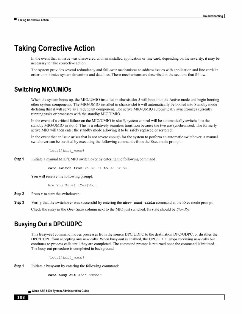
Troubleshooting
▀ Taking Corrective Action
▄ Cisco ASR 5500 System Administration Guide
188
Taking Corrective Action In the event that an issue was discovered with an installed application or line card, depending on the severity, it may be
necessary to take corrective action.
The system provides several redundancy and fail-over mechanisms to address issues with application and line cards in
order to minimize system downtime and data loss. These mechanisms are described in the sections that follow.
Switching MIO/UMIOs
When the system boots up, the MIO/UMIO installed in chassis slot 5 will boot into the Active mode and begin booting
other system components. The MIO/UMIO installed in chassis slot 6 will automatically be booted into Standby mode
dictating that it will serve as a redundant component. The active MIO/UMIO automatically synchronizes currently
running tasks or processes with the standby MIO/UMIO.
In the event of a critical failure on the MIO/UMIO in slot 5, system control will be automatically switched to the
standby MIO/UMIO in slot 6. This is a relatively seamless transition because the two are synchronized. The formerly
active MIO will then enter the standby mode allowing it to be safely replaced or restored.
In the event that an issue arises that is not severe enough for the system to perform an automatic switchover, a manual
switchover can be invoked by executing the following commands from the Exec mode prompt:
[local]host_name#
Step 1 Initiate a manual MIO/UMIO switch over by entering the following command:
card switch from <5 or 6> to <6 or 5>
You will receive the following prompt:
Are You Sure? [Yes|No]:
Step 2 Press Y to start the switchover.
Step 3 Verify that the switchover was successful by entering the show card table command at the Exec mode prompt:
Check the entry in the Oper State column next to the MIO just switched. Its state should be Standby.
Busying Out a DPC/UDPC
This busy-out command moves processes from the source DPC/UDPC to the destination DPC/UDPC, or disables the
DPC/UDPC from accepting any new calls. When busy-out is enabled, the DPC/UDPC stops receiving new calls but
continues to process calls until they are completed. The command prompt is returned once the command is initiated.
The busy-out procedure is completed in background.
[local]host_name#
Step 1 Initiate a busy-out by entering the following command:
card busy-out slot_number

Troubleshooting
Taking Corrective Action ▀
Cisco ASR 5500 System Administration Guide ▄ 189
You will receive the following prompt:
Are You Sure? [Yes|No]:
Step 2 Press Y to start the switchover.
Step 3 Verify that the busy-out was successful by entering the show card table command at the Exec mode prompt:
Check the entry in the Oper State column next to the DPC/UDPC just busied-out. Its state should be Standby.
Migrating a DPC/UDPC
When the system boots up, all DPC/UDPCs enter the “standby” mode. The standby mode indicates that the card is
available for use but is not configured for operation. Installed components can be made active through the software
configuration process. Cards that are not configured to enter the “active” mode will remain in standby mode for use as
redundant components.
In the event of the critical failure of a DPC/UDPC, tasks will be automatically be migrated from the active card to a
redundant card in standby mode.
In the event that an issue arises that is not severe enough for the system to perform an automatic migration, a manual
migration can be initiated. Follow the instructions below to manually initiate a DPC/UDPC migration. These
instructions assume you are at the root prompt for the Exec mode:
[local]host_name#
Step 1 Initiate a DPC/UDPC migration by entering the following command:
card migration from original_slot# to final_slot#
You will receive the following prompt:
Are You Sure? [Yes|No]:
Step 2 Press Y to start the migration.
Step 3 Verify that the migration was successful by entering the show card table command at the Exec mode prompt.
Check the entry in the Oper State column next to the packet processing card that was just migrated from. Its state should
be Standby. The state of the packet processing card migrated to should be Active.
Halting Cards
Cards other than MIO/UMIOs that are in either the Active or Standby modes can be halted. Halting these cards places
them into the “offline” mode. In this mode, the card is unusable for session processing as either an active or redundant
component.
If a card in the active mode is halted, its tasks, processes, or network connections will be migrated or switched to a
redundant component prior to entering the offline mode.
This section describes how to initiate a card halt and restore halted components.
Troubleshooting
▀ Taking Corrective Action
▄ Cisco ASR 5500 System Administration Guide
190
Initiate a Card Halt
Important: Do not initiate a card halt for an active FSC if there are less than two active FSCs in the system. The
system returns an error message if there are less than two active FSCs. There are similar restrictions when executing the
card reboot or card upgrade commands on active FSCs. Refer to the Command Line Interface Reference for detailed
information.
Follow the instructions below to manually initiate a card halt. These instructions assume you are at the root prompt for
the Exec mode:
[local]host_name#
Step 1 Initiate a manual card migration by entering the following command:
card halt slot#
slot# is the chassis slot number in which the card to be halted is installed. It can be any integer from 1 through 4, and 7
through 18. You will receive the following prompt:
Are You Sure? [Yes|No]:
Step 2 Press Y to initiate the halt operation.
Step 3 Verify that the migration was successful by entering the show card table command at the Exec mode prompt.
Check the entry in the Oper State column next to the card that was just halted. Its state should be Offline. If the card was
in active mode prior to the execution of this command, the state of the redundant component associated with it should
now be Active.
Restore a Previously Halted Card
Follow the instructions below to restore a card that was previously halted. These instructions assume you are at the root
prompt for the Exec mode:
[local]host_name#
Step 1 Reboot the card to be restored by entering the following command.
card reboot slot# -force
You will receive the following prompt:
Are You Sure? [Yes|No]:
Step 2 Press Y to start the reboot of the card.
Step 3 Verify that the migration was successful by entering the show card table command at the prompt.
Check the entry in the Oper State column next to the card that was just restored. Its state should be the state of that it
was in before it was halted.
Troubleshooting
Verifying Network Connectivity ▀
Cisco ASR 5500 System Administration Guide ▄ 191
Verifying Network Connectivity There are multiple commands supported by the system to verify and/or troubleshoot network connectivity. Note that
network connectivity can only be tested once system interfaces and ports have been configured and bound.
The commands specified in this section should be issued on a context-by-context basis. Contexts act like virtual private
networks (VPNs) that operate independently of other contexts. Ports, interfaces, and routes configured in one context
cannot be tested from another context without additional configuration.
To switch between contexts enter the following command at the root prompt for the Exec mode:
context context_name
context_name is the name of the context to which you wish to switch. The following prompt appears:
[context_name]host_name#
Using the ping or ping6 Command
The ping or ping6 command verifies the system’s ability to communicate with a remote node in the network by passing
data packets between and measuring the response. This command is useful in verifying network routing and if a remote
node is able to respond at the IP layer.
Syntax
The ping command has the following syntax:
ping host_ipv4_address [ count num_packets ] [ flood ] [ pattern packet_pattern ]
[ size octet_count ] [ src { src_host_name | src_host_ipv4_address } ]
[ vrf vrf_nam ]
ping6 host_ipv6_address [ count num_packets ] [ flood ][ pattern packet_pattern ]
[ size octet_count ] [ src { src_host_name | src_host_ipv6_address } ]
[ vrf vrf_nam ]
For complete information on the above commands, see the Exec Mode Commands chapter of the Command Line
Interface Reference.
The following displays a sample of a successful ping (IPV4) response.
PING 192.168.250.1 (192.168.250.1): 56 data bytes
64 bytes from 192.168.250.1: icmp_seq=0 ttl=255 time=0.4 ms
64 bytes from 192.168.250.1: icmp_seq=1 ttl=255 time=0.2 ms
64 bytes from 192.168.250.1: icmp_seq=2 ttl=255 time=0.2 ms
64 bytes from 192.168.250.1: icmp_seq=3 ttl=255 time=0.2 ms
64 bytes from 192.168.250.1: icmp_seq=4 ttl=255 time=0.2 ms
--- 192.168.250.1 ping statistics ---
5 packets transmitted, 5 packets received, 0% packet loss
round-trip min/avg/max = 0.2/0.2/0.4 ms
Troubleshooting
▀ Verifying Network Connectivity
▄ Cisco ASR 5500 System Administration Guide
192
Troubleshooting
If no response is received from the target follow these troubleshooting procedures:
Verify that the correct IP address was entered.
Attempt to ping a different device on the same network. If the ping was successful then it is likely that your
system configuration is correct. Verify that the device you are attempting to ping is powered and functioning
properly.
Verify the port is operational.
Verify that the configuration of the ports and interfaces within the context are correct.
If the configuration is correct and you have access to the device that you’re attempting to ping, ping the system
from that device.
If there is still no response, it is likely that the packets are getting discarded by a network device. Use the
traceroute or traceroute6 and show ip static-route commands discussed in this chapter to further
troubleshoot the issue.
Using the traceroute or traceroute6 Command
The traceroute or traceroute6 command collects information on the route data will take to a specified host. This is a
useful troubleshooting command that can be used to identify the source of significant packet delays or packet loss on the
network. This command can also be used to identify bottle necks in the routing of data over the network.
traceroute – IPv4
The traceroute command has the following syntax:
traceroute { host_name | host_ipv4_address } [ count packets ] [ df ]
[ maxttl max_ttl ] [ minttl min_ttl ] [ port port_number ] [ size octet_count ]
[ src { src_host_name | src_host_ipv4_address } ] [ timeout seconds ]
[ vrf vrf_nam ]
For complete information on the above command, see the Exec Mode Commands chapter of the Command Line
Interface Reference.
The following displays a sample output.
traceroute to 192.168.250.1 (192.168.250.1), 30 hops max, 40 byte packets
1 192.168.250.1 (192.168.250.1) 0.446 ms 0.235 ms 0.178 ms
traceroute6 – IPv6
The traceroute6 command has the following syntax:
traceroute6 { host_name | host_ipv6_address } [ count packets ] [ maxttl max_ttl ]
[ port port_number ] [ size octet_count ] [ src { src_host_name |
src_host_ipv6_address } ] [ timeout seconds ] [ vrf vrf_nam ]
For complete information on the above commands, see the Exec Mode Commands chapter of the Command Line
Interface Reference.

Troubleshooting
Verifying Network Connectivity ▀
Cisco ASR 5500 System Administration Guide ▄ 193
The following displays a sample output.
traceroute6 to 2001:4A2B::1f3F (2001:4A2B::1f3F), 30 hops max, 40 byte packets
1 2001:4A2B::1f3F (2001:4A2B::1f3F) 0.446 ms 0.235 ms 0.178 ms
Viewing IP Routes
The system provides a mechanism for viewing route information to a specific node or for an entire context. This
information can be used to verify network connectivity and to ensure the efficiency of the network connection. The
command has the following syntax:
show ip route [ route_ip_address ]
show ipv6 route [ route_ipv6_address ] ]
For complete information on the above commands, see the Exec Mode show Commands chapter of the Command Line
Interface Reference.
If no keywords are specified, all IP routes within the context’s routing table are displayed.
The following displays a sample of this command’s output showing a context IPv4 routing table.
"*" indicates the Best or Used route.
Destination Nexthop Protocol Prec Cost Interface
*0.0.0.0/0 10.0.4.1 static 0 0 SPIO1
*10.0.4.0/24 0.0.0.0 kernel 0 0 SPIO1
*10.0.4.0/32 0.0.0.0 kernel 0 0 SPIO1
*10.0.4.3/32 0.0.0.0 kernel 0 0 SPIO1
*10.0.4.255/32 0.0.0.0 kernel 0 0 SPIO1
Viewing the Address Resolution Protocol Table
The system provides a mechanism for viewing Address Resolution Protocol (ARP) table information to a specific node
or for an entire context. This information can be used to verify that when the system sends an ARP packet, it receives
valid responses from other network nodes. The command has the following syntax:
show ip arp [ arp_ip_address ]
arp_ip_address specifies a specific network node for which to display ARP information. The address can be entered in
IPv4 dotted-decimal or IPv6 colon-separated-hexadecimal notation. If this keyword is not specified, all entries within
the context’s ARP table are displayed.
Important: Restarting the VPN Manager removes all interfaces from the kernel which in turn removes all ARP
entries. However, the NPU still retains all of the ARP entries so that there is no traffic disruption. From a user point of
view, show ip arp is broken since this command gathers information from the kernel and not the NPU.

Troubleshooting
▀ Verifying Network Connectivity
▄ Cisco ASR 5500 System Administration Guide
194
The following displays a sample of this command’s output showing a context’s ARP table.
Flags codes:
C - Completed, M - Permanent, P - Published, ! - Not answered
T - has requested trailers
Address Link Type Link Address Flags Mask Interface
10.0.4.240 ether 00:05:47:02:20:20 C MIO1
10.0.4.7 ether 00:05:47:02:03:36 C MIO1
10.0.4.1 ether 00:01:30:F2:7F:00 C MIO1
Troubleshooting
Using the System Diagnostic Utilities ▀
Cisco ASR 5500 System Administration Guide ▄ 195
Using the System Diagnostic Utilities The system provides protocol monitor and test utilities that are useful when troubleshooting or verifying configurations.
The information generated by these utilities can help identify the root cause of a software or network configuration
issue.
This section describes how to use these utilities.
Important: Only an administrator with Operator or higher privilege can run the diagnostic utilities described in
this section.
Using the Monitor Utility
For troubleshooting purposes, the system provides a protocol monitoring utility. This tool displays protocol information
for a particular subscriber session or for every session being processed.
Caution: The monitor tool may cause session processing delays and/or data loss. Therefore, it should be used
only when troubleshooting.
Using the Protocol Monitor
The protocol monitor displays information for every session that is currently being processed. Depending on the number
of protocols monitored, and the number of sessions in progress, a significant amount of data is generated. It is highly
recommended that logging be enabled on your terminal client in order to capture all of the information that is generated.
Follow the instructions below83 to invoke and configure the protocol monitoring tool.
Step 1 Invoke the protocol monitor from the Exec mode by entering the monitor protocol command.
An output listing all the currently available protocols, each with an assigned number, is displayed.
Step 2 Choose the protocol that you wish to monitor by entering the associated number at the Select: prompt. A right arrow ( >
) appears next to the protocol you selected.
Step 3 Repeat step 2 as needed to choose multiple protocols.
Step 4 Press B to begin the protocol monitor.
WARNING!!! You have selected options that can DISRUPT USER SERVICE
Existing CALLS MAY BE DROPPED and/or new CALLS MAY FAIL!!!
(Under heavy call load, some debugging output may not be displayed)
Proceed? - Select (Y)es or (N)o
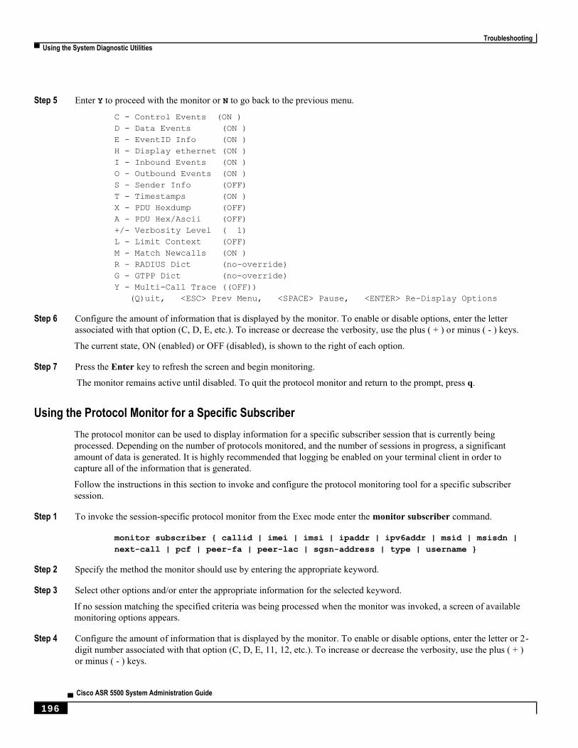
Troubleshooting
▀ Using the System Diagnostic Utilities
▄ Cisco ASR 5500 System Administration Guide
196
Step 5 Enter Y to proceed with the monitor or N to go back to the previous menu.
C - Control Events (ON )
D - Data Events (ON )
E - EventID Info (ON )
H - Display ethernet (ON )
I - Inbound Events (ON )
O - Outbound Events (ON )
S - Sender Info (OFF)
T - Timestamps (ON )
X - PDU Hexdump (OFF)
A - PDU Hex/Ascii (OFF)
+/- Verbosity Level ( 1)
L - Limit Context (OFF)
M - Match Newcalls (ON )
R - RADIUS Dict (no-override)
G - GTPP Dict (no-override)
Y - Multi-Call Trace ((OFF))
(Q)uit, <ESC> Prev Menu, <SPACE> Pause, <ENTER> Re-Display Options
Step 6 Configure the amount of information that is displayed by the monitor. To enable or disable options, enter the letter
associated with that option (C, D, E, etc.). To increase or decrease the verbosity, use the plus ( + ) or minus ( - ) keys.
The current state, ON (enabled) or OFF (disabled), is shown to the right of each option.
Step 7 Press the Enter key to refresh the screen and begin monitoring.
The monitor remains active until disabled. To quit the protocol monitor and return to the prompt, press q.
Using the Protocol Monitor for a Specific Subscriber
The protocol monitor can be used to display information for a specific subscriber session that is currently being
processed. Depending on the number of protocols monitored, and the number of sessions in progress, a significant
amount of data is generated. It is highly recommended that logging be enabled on your terminal client in order to
capture all of the information that is generated.
Follow the instructions in this section to invoke and configure the protocol monitoring tool for a specific subscriber
session.
Step 1 To invoke the session-specific protocol monitor from the Exec mode enter the monitor subscriber command.
monitor subscriber { callid | imei | imsi | ipaddr | ipv6addr | msid | msisdn |
next-call | pcf | peer-fa | peer-lac | sgsn-address | type | username }
Step 2 Specify the method the monitor should use by entering the appropriate keyword.
Step 3 Select other options and/or enter the appropriate information for the selected keyword.
If no session matching the specified criteria was being processed when the monitor was invoked, a screen of available
monitoring options appears.
Step 4 Configure the amount of information that is displayed by the monitor. To enable or disable options, enter the letter or 2-
digit number associated with that option (C, D, E, 11, 12, etc.). To increase or decrease the verbosity, use the plus ( + )
or minus ( - ) keys.

Troubleshooting
Using the System Diagnostic Utilities ▀
Cisco ASR 5500 System Administration Guide ▄ 197
The current state, ON (enabled) or OFF (disabled), is shown to the right of each option.
Important: Option Y for performing multi-call traces is only supported for use with the GGSN.
Step 5 Repeat step 6 as needed to enable or disable multiple protocols.
Step 6 Press Enter to refresh the screen and begin monitoring.
The following displays a portion of a sample of the monitor’s output for a subscriber named user2@aaa. The default
protocols were monitored.
---------------------------------------------------------------------------
Incoming Call:
---------------------------------------------------------------------------
MSID: 0000012345 Callid: 002dc6c2
Username: user2@aaa SessionType: unknown
Status: Active Service Name: xxx1
Src Context: source Dest Context:
---------------------------------------------------------------------------
<<<<OUTBOUND 10:02:35:415 Eventid:25001(0)
PPP Tx PDU (9)
PAP 9: Auth-Ack(1), Msg=
<<<<OUTBOUND 10:02:35:416 Eventid:25001(0)
PPP Tx PDU (14)
IPCP 14: Conf-Req(1), IP-Addr=192.168.250.70
<<<<OUTBOUND 10:02:35:416 Eventid:25001(0)
PPP Tx PDU (27)
CCP 27: Conf-Req(1), MPPC, Stac-LZS, Deflate, MVRCA
INBOUND>>>>> 10:02:35:517 Eventid:25000(0)
PPP Rx PDU (30)
IPCP 30: Conf-Req(1), IP-Comp VJ-Comp, IP-Addr=0.0.0.0, Pri-DNS=0.0.0.0,
Sec-DNS=0.0.0.0
<<<<OUTBOUND 10:02:35:517 Eventid:25001(0)
PPP Tx PDU (26)
IPCP 26: Conf-Rej(1), IP-Comp VJ-Comp, Pri-DNS=0.0.0.0, Sec-DNS=0.0.0.0
INBOUND>>>>> 10:02:35:517 Eventid:25000(0)
PPP Rx PDU (12)
IPCP 12: Conf-Ack(1), IP-Addr=192.168.250.70
INBOUND>>>>> 10:02:35:518 Eventid:25000(0)
PPP Rx PDU (31)
LCP 31: Prot-Rej(1), Rejected-Protocol=CCP (0x80fd)
INBOUND>>>>> 10:02:35:518 Eventid:25000(0)
PPP Rx PDU (12)
IPCP 12: Conf-Req(2), IP-Addr=0.0.0.0

Troubleshooting
▀ Using the System Diagnostic Utilities
▄ Cisco ASR 5500 System Administration Guide
198
<<<<OUTBOUND 10:02:35:518 Eventid:25001(0)
PPP Tx PDU (14)
IPCP 14: Conf-Nak(2), IP-Addr=192.168.250.87
INBOUND>>>>> 10:02:35:519 Eventid:25000(0)
PPP Rx PDU (12)
IPCP 12: Conf-Req(3), IP-Addr=192.168.250.87
The monitor remains active until disabled. To quit the protocol monitor and return to the prompt, press q.
Using the DHCP Testing Tool
The CLI provides a mechanism for testing network connectivity with and configuration of DHCP servers. This
functionality can help determine the accuracy of the system’s DHCP configuration and the server’s response time.
This tool provides a mechanism for obtaining an IP address for one or more DHCP servers with which the system
communicates.
Important: This tool must be executed from the context in which the DHCP server(s) are configured.
To execute the DHCP test tool enter the following command within the appropriate context:
dhcp test dhcp-service { service_name } [ all | server ip_addr ]
For complete information on the above command, see the Exec Mode Commands chapter of the Command Line
Interface Reference.

Cisco ASR 5500 System Administration Guide ▄ 199
Chapter 13 System Recovery
This chapter describes how to recover a system after it has failed to complete a reboot following a power off cycle or
interruption of the normal boot sequence following a reload command.
This chapter includes the following sections:
Prerequisites
Accessing the boot CLI
Booting from a Selected Image
Caution: This system recovery process interrupts subscriber service by dropping any existing flows and
preventing traffic from being processed during the boot interval. It should only be initiated as an emergency measure.

System Recovery
▀ Prerequisites
▄ Cisco ASR 5500 System Administration Guide
200
Prerequisites Successful recovery from a failed reboot requires that you have access to the system via a console port, and have an
uncorrupted copy of the StarOS boot image file stored in flash memory on the management card, or accessible from an
external memory device.
Console Access
The boot recovery sequence can only be executed via a terminal connected to the serial console port on the active
management card. This connection can be through a terminal server that is accessible via a LAN interface.
The boot recovery sequence can only be viewed via the Console port.
Boot Image
The boot recovery command line interface allows you to specify from which boot image you would like to boot the
system. If the system failed to reload following a software update, you can initiate a boot from a previously stored
image.
The system recovery procedure will prompt you to enter the path name for the location of the StarOS boot image from
which the system will boot. By default the boot command will timeout and attempt to reload the highest priority image
from flash memory using the default configuration file.
The operating system software is delivered as a single binary file (.bin file extension) and is loaded as a single instance
for the entire system.
For StarOS releases prior to 16.1, the image filename is identified by its release version and corresponding build
number. Format = production.build_number.platform.bin.
For StarOS release 16.1 onwards, the image filename is identified by its platform type and release number.
Format = platform-release_number.bin.
Refer to the Configuring the Boot Stack section in the Software Management Operations chapter for additional
information on boot stack entries and prioritization.
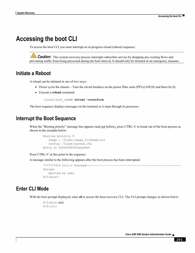
System Recovery
Accessing the boot CLI ▀
Cisco ASR 5500 System Administration Guide ▄ 201
Accessing the boot CLI To access the boot CLI you must interrupt an in-progress reload (reboot) sequence.
Caution: This system recovery process interrupts subscriber service by dropping any existing flows and
preventing traffic from being processed during the boot interval. It should only be initiated as an emergency measure.
Initiate a Reboot
A reload can be initiated in one of two ways:
Power cycle the chassis – Turn the circuit breakers on the power filter units (PFUs) Off (0) and then On (I).
Execute a reload command
[local]host_name# reload -noconfirm
The boot sequence displays messages on the terminal as it steps through its processes.
Interrupt the Boot Sequence
When the “Booting priority” message line appears (and not before), press CTRL+C to break out of the boot process as
shown in the example below:
Booting priority 8
image : /flash/image_filename.bin
config: /flash/system.cfg
Entry at 0x000000000cba45e0
Press CTRL+C at this point in the sequence.
A message similar to the following appears after the boot process has been interrupted:
*******9/0 Ctrl-C Pressed-------------------------------------------------------
Failed.
aborted by user
8/0:boot>
Enter CLI Mode
With the boot prompt displayed, enter cli to access the boot recovery CLI. The CLI prompt changes as shown below:
8/0:boot>cli
8/0:cli>
System Recovery
▀ Accessing the boot CLI
▄ Cisco ASR 5500 System Administration Guide
202
boot Command Syntax
The boot recovery command has the following syntax:
boot [ -show | -priority=* | -config=* | -noconfig ] { bootfile_URL }
The options for this command include:
-show: displays the current boot configuration
-priority=*: selects the desired boot stack priority (*)
-config=*: enters the desired configuration filename (*), if not the default file
-noconfig: boots using no configuration file
bootfile_URL is the URL for the location of the StarOS boot image file. It specifies the path and file name of the
StarOS .bin file from which the system will be booted.
The URL may refer to a local file (flash) or an external file on a memory device attached to the management card. The
URL must be entered in the following format:
{ /flash | /pcmcia1 or usb1 / filename
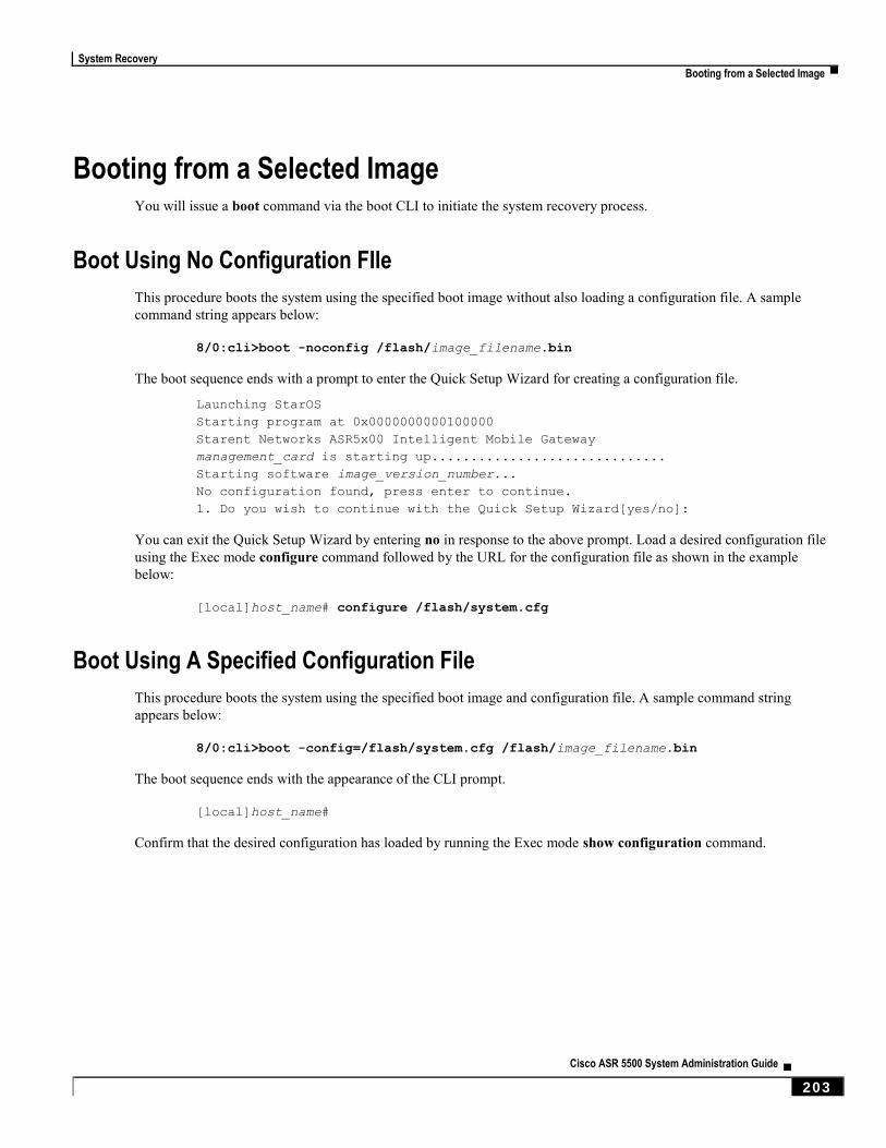
System Recovery
Booting from a Selected Image ▀
Cisco ASR 5500 System Administration Guide ▄ 203
Booting from a Selected Image You will issue a boot command via the boot CLI to initiate the system recovery process.
Boot Using No Configuration FIle
This procedure boots the system using the specified boot image without also loading a configuration file. A sample
command string appears below:
8/0:cli>boot -noconfig /flash/image_filename.bin
The boot sequence ends with a prompt to enter the Quick Setup Wizard for creating a configuration file.
Launching StarOS
Starting program at 0x0000000000100000
Starent Networks ASR5x00 Intelligent Mobile Gateway
management_card is starting up..............................
Starting software image_version_number...
No configuration found, press enter to continue.
1. Do you wish to continue with the Quick Setup Wizard[yes/no]:
You can exit the Quick Setup Wizard by entering no in response to the above prompt. Load a desired configuration file
using the Exec mode configure command followed by the URL for the configuration file as shown in the example
below:
[local]host_name# configure /flash/system.cfg
Boot Using A Specified Configuration File
This procedure boots the system using the specified boot image and configuration file. A sample command string
appears below:
8/0:cli>boot -config=/flash/system.cfg /flash/image_filename.bin
The boot sequence ends with the appearance of the CLI prompt.
[local]host_name#
Confirm that the desired configuration has loaded by running the Exec mode show configuration command.

Cisco ASR 5500 System Administration Guide ▄ 205
Chapter 14 Access Control Lists
This chapter describes system support for access control lists and explains how they are configured. The product
administration guides provide examples and procedures for configuration of basic services on the system. You should
select the configuration example that best meets your service model before using the procedures described below.
Important: You do not require a license to configure ACLs. However, the number of ACLs configured may
impact performance significantly.
This chapter contains the following sections:
Understanding ACLs
Configuring ACLs on the System
Applying IP ACLs
Important: Not all commands and keywords/variables may be available. Availability depends on the platform
type.
Access Control Lists
▀ Overview
▄ Cisco ASR 5500 System Administration Guide
206
Overview IP access lists, commonly known as access control lists (ACLs), control the flow of packets into and out of the system.
They are configured on a per-context basis and consist of “rules” (ACL rules) or filters that control the action taken on
packets that match the filter criteria. Once configured, an ACL can be applied to any of the following:
An individual interface
All traffic facilitated by a context (known as a policy ACL)
An individual subscriber
All subscriber sessions facilitated by a specific context
Separate ACLs may be created for IPv4 and IPv6 access routes.
Access Control Lists
Understanding ACLs ▀
Cisco ASR 5500 System Administration Guide ▄ 207
Understanding ACLs This section discusses the two main aspects to ACLs on the system:
Rule(s)
Rule Order
Important: Refer to ACL Configuration Mode Commands and the IPv6 ACL Configuration Mode Commands
chapter in the Command Line Interface Reference for the full command syntax.
Rule(s)
A single ACL consists of one or more ACL rules. Each rule is a filter configured to take a specific action when packets
matching specific criteria. Up to 128 rules can be configured per ACL.
Important: Configured ACLs consisting of no rules imply a “deny any” rule. The deny action and any criteria
are discussed later in this section. This is the default behavior for an empty ACL.
Each rule specifies the action to take when a packet matches the specifies criteria. This section discusses the rule actions
and criteria supported by the system.
Actions
ACLs specify that one of the following actions can be taken on a packet that matches the specified criteria:
Permit: The packet is accepted and processed.
Deny: The packet is rejected.
Redirect: The packet is forwarded to the specified next-hop address through a specific system interface or to the
specified context for processing.
Important: Redirect rules are ignored for ACLs applied to specific subscribers or all subscribers
facilitated by a specific context, or APN for UMTS subscribers.
Criteria
Each ACL consists of one or more rules specifying the criteria that packets will be compared against.
The following criteria are supported:
Any: Filters all packets
Host: Filters packets based on the source host IP address
ICMP: Filters Internet Control Message Protocol (ICMP) packets
IP: Filters Internet Protocol (IP) packets
Source IP Address: Filter packets based on one or more source IP addresses
Access Control Lists
▀ Understanding ACLs
▄ Cisco ASR 5500 System Administration Guide
208
TCP: Filters Transport Control Protocol (TCP) packets
UDP: Filters User Datagram Protocol (UDP) packets
Each of the above criteria are described in detail in the sections that follow.
Important: The following sections contain basic ACL rule syntax information. Refer to the ACL Configuration
Mode Commands and IPv6 ACL Configuration Mode Commands chapters in the Command Line Interface Reference for
the full command syntax.
Any: The rule applies to all packets.
Host: The rule applies to a specific host as determined by its IP address.
ICMP: The rule applies to specific Internet Control Message Protocol (ICMP) packets, Types, or Codes. ICMP
type and code definitions can be found at www.iana.org (RFC 3232).
IP: The rule applies to specific Internet Protocol (IP) packets or fragments.
IP Packet Size Identification Algorithm: The rule applies to specific Internet Protocol (IP) packets
identification for fragmentation during forwarding.
This configuration is related to the “IP Identification field” assignment algorithm used by the system, when
subscriber packets are being encapsulated (such as Mobile IP and other tunneling encapsulation). Within the
system, subscriber packet encapsulation is done in a distributed way and a 16-bit IP identification space is
divided and distributed to each entity which does the encapsulation, so that unique IP identification value can
be assigned for IP headers during encapsulation.
Since this distributed IP Identification space is small, a non-zero unique identification will be assigned only for
those packets which may potentially be fragmented during forwarding (since the IP identification field is only
used for reassembly of the fragmented packet). The total size of the IP packet is used to determine the
possibility of that packet getting fragmented.
Source IP Address: The rule applies to specific packets originating from a specific source address or a group of
source addresses.
TCP: The rule applies to any Transport Control Protocol (TCP) traffic and could be filtered on any combination
of source/destination IP addresses, a specific port number, or a group of port numbers. TCP port numbers
definitions can be found at www.iana.org
UDP: The rule applies to any User Datagram Protocol (UDP) traffic and could be filtered on any combination of
source/destination IP addresses, a specific port number, or a group of port numbers. UDP port numbers
definitions can be found at www.iana.org.
Rule Order
A single ACL can consist of multiple rules. Each packet is compared against each of the ACL rules, in the order in
which they were entered, until a match is found. Once a match is identified, all subsequent rules are ignored.
Additional rules can be added to an existing ACL and properly ordered using either of the following options:
Before
After
Using these placement options requires the specification of an existing rule in the ACL and the configuration of the new
rule as demonstrated by the following flow:
[ before | after ] { existing_rule }
Access Control Lists
Configuring ACLs on the System ▀
Cisco ASR 5500 System Administration Guide ▄ 209
Configuring ACLs on the System This section describes how to configure ACLs.
Important: This section provides the minimum instruction set for configuring access control list on the system.
For more information on commands that configure additional parameters and options, refer to the ACL Configuration
Mode Commands and IPv6 ACL Configuration Mode Commands chapters in the Command Line Interface Reference.
To configure the system to provide an access control list facility to subscribers:
Step 1 Create the access control list by following the example configuration in Creating ACLs.
Step 2 Specify the rules and criteria for action in the ACL list by following the example configuration in Configuring Action
and Criteria for Subscriber Traffic.
Step 3 Optional. The system provides an “undefined” ACL that acts as a default filter for all packets into the context. The
default action is to “permit all”. Modify the default configuration for “unidentified” ACLs for by following the example
configuration in Configuring an Undefined ACL.
Step 4 Verify your ACL configuration by following the steps in Verifying the ACL Configuration.
Step 5 Save your configuration to flash memory, an external memory device, and/or a network location using the Exec mode
save configuration command. For additional information refer to the Verifying and Saving Your Configuration chapter.
Creating ACLs
To create an ACL, enter the following command sequence from the Exec mode of the system CLI:
configure
context acl_ctxt_name [ -noconfirm ]
( ip | ipv6 } access-list acl_list_name
end
Notes:
The maximum number of ACLs that can be configured per context is limited by the amount of available memory
in the VPN Manager software task. Typically, the maximum is less than 200.

Access Control Lists
▀ Configuring ACLs on the System
▄ Cisco ASR 5500 System Administration Guide
210
Configuring Action and Criteria for Subscriber Traffic
To create rules to deny/permit the subscriber traffic and apply the rules after or before action, enter the following
command sequence from the Exec mode of the system CLI:
configure
context acl_ctxt_name [ -noconfirm ]
( ip | ipv6 } access-list acl_list_name
deny { ip_address | any | host | icmp | ip | log | tcp | udp }
permit { ip_address | any | host | icmp | ip | log | tcp | udp }
after { deny | permit | readdress | redirect }
before { deny | permit | readdress | redirect }
end
Notes:
Caution: The system does not apply a “deny any” rule, unless it is specified in the ACL. This behavior can be
changed by adding a “deny any” rule at the end of the ACL.
The maximum number of rules that can be configured per ACL varies depending on how the ACL is to be used.
For more information, refer to the Engineering Rules chapter.
Use the information provided in Actions and Criteria to configure the rules that comprise the ACL. For more
information, refer to the ACL Configuration Mode Commands and IPv6 ACL Configuration Mode Commands
chapters in the Command Line Interface Reference.
Configuring an Undefined ACL
As discussed previously the system uses an “undefined” ACL mechanism for filtering the packet(s) in the event that an
ACL that has been applied is not present. This scenario is likely the result of a mis-configuration such as the ACL name
being mis-typed during the configuration process.
For these scenarios, the system provides an “undefined” ACL that acts as a default filter for all packets into the context.
The default action is to “permit all”.
To modify the default behavior for unidentified ACLs, use the following configuration:
configure
context acl_ctxt_name [-noconfirm]
access-list undefined { deny-all | permit-all }
end

Access Control Lists
Configuring ACLs on the System ▀
Cisco ASR 5500 System Administration Guide ▄ 211
Notes:
Context name is the name of the context containing the “undefined” ACL to be modified. For more information,
refer to the Context Configuration Mode Commands chapter in the Command Line Interface Reference.
Verifying the ACL Configuration
To verify the ACL configuration, enter the Exec mode show { ip | ipv6 } access-list command.
The following is a sample output of this command. In this example, an ACL named acl_1 was configured.
ip access list acl_1
deny host 10.2.3.4
deny ip any host 10.2.3.4
permit any 10.2.4.4
1 ip access-lists are configured.
Access Control Lists
▀ Applying IP ACLs
▄ Cisco ASR 5500 System Administration Guide
212
Applying IP ACLs Once an ACL is configured, it must be applied to take effect.
Important: All ACLs should be configured and verified according to the instructions in the Configuring ACLs
on the System prior to beginning these procedures. The procedures described below also assume that the subscribers
have been previously configured.
As discussed earlier, you can apply an ACL to any of the following:
Applying an ACL to an Individual Interface
Applying an ACL to All Traffic Within a Context (known as a policy ACL)
Applying an ACL to an Individual Subscriber
Applying a Single ACL to Multiple Subscribers
Applying a Single ACL to Multiple Subscribers via APNs (for 3GPP subscribers only)
Important: ACLs must be configured in the same context in which the subscribers and/or interfaces to which
they are to be applied. Similarly, ACLs to be applied to a context must be configured in that context.
If ACLs are applied at multiple levels within a single context (such as an ACL is applied to an interface within the
context and another ACL is applied to the entire context), they will be processed as shown in the following figure and
table.
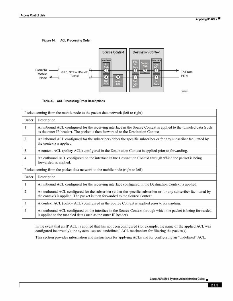
Access Control Lists
Applying IP ACLs ▀
Cisco ASR 5500 System Administration Guide ▄ 213
Figure 14. ACL Processing Order
Table 33. ACL Processing Order Descriptions
Packet coming from the mobile node to the packet data network (left to right)
Order Description
1 An inbound ACL configured for the receiving interface in the Source Context is applied to the tunneled data (such
as the outer IP header). The packet is then forwarded to the Destination Context.
2 An inbound ACL configured for the subscriber (either the specific subscriber or for any subscriber facilitated by
the context) is applied.
3 A context ACL (policy ACL) configured in the Destination Context is applied prior to forwarding.
4 An outbound ACL configured on the interface in the Destination Context through which the packet is being
forwarded, is applied.
Packet coming from the packet data network to the mobile node (right to left)
Order Description
1 An inbound ACL configured for the receiving interface configured in the Destination Context is applied.
2 An outbound ACL configured for the subscriber (either the specific subscriber or for any subscriber facilitated by
the context) is applied. The packet is then forwarded to the Source Context.
3 A context ACL (policy ACL) configured in the Source Context is applied prior to forwarding.
4 An outbound ACL configured on the interface in the Source Context through which the packet is being forwarded,
is applied to the tunneled data (such as the outer IP header).
In the event that an IP ACL is applied that has not been configured (for example, the name of the applied ACL was
configured incorrectly), the system uses an “undefined” ACL mechanism for filtering the packet(s).
This section provides information and instructions for applying ACLs and for configuring an “undefined” ACL.

Access Control Lists
▀ Applying IP ACLs
▄ Cisco ASR 5500 System Administration Guide
214
Applying an ACL to an Individual Interface
This section provides information and instructions for applying one or more ACLs to an individual interface configured
on the system.
Important: This section provides the minimum instruction set for applying the ACL list to an interface on the
system. For more information on commands that configure additional parameters and options, refer to the Ethernet
Interface Configuration Mode Commands chapter in the Command Line Interface Reference.
To configure the system to provide ACL facility to subscribers:
Step 1 Apply the configured access control list by following the example configuration in Applying the ACL to an Interface.
Step 2 Verify that ACL is applied properly on interface by following the steps in Verifying the ACL Configuration on an
Interface.
Step 3 Save your configuration to flash memory, an external memory device, and/or a network location using the Exec mode
save configuration command. For additional information refer to the Verifying and Saving Your Configuration chapter.
Applying the ACL to an Interface
To apply the ACL to an interface, use the following configuration:
configure
context acl_ctxt_name [ -noconfirm ]
interface interface_name
{ ip | ipv6 } access-group acl_list_name { in | out } [ preference ]
end
Notes:
The context name is the name of the ACL context containing the interface to which the ACL is to be applied.
The ACL to be applied must be configured in the context specified by this command.
Up to eight ACLs can be applied to a group provided that the number of rules configured within the ACL(s) does
not exceed the 128-rule limit for the interface.
Access Control Lists
Applying IP ACLs ▀
Cisco ASR 5500 System Administration Guide ▄ 215
Verifying the ACL Configuration on an Interface
This section describes how to verify the ACL configuration.
Step 1 In the Exec Mode, enter the following command:
show configuration context context_name
context_name is the name of the context containing the interface to which the ACL(s) was/were applied.
The output of this command displays the configuration of the entire context. Examine the output for the commands
pertaining to interface configuration. The commands display the ACL(s) applied using this procedure.
configure
context context_name
ip access-list acl_name
deny host ip_address
deny ip any host ip_address
exit
ip access-group access_group_name
service-redundancy-protocol
exit
interface interface_name
ip address ip_address/mask
exit
subscriber default
exit
aaa group default
exit
gtpp group default
end
Applying an ACL to All Traffic Within a Context
This section provides information and instructions for applying one or more ACLs to a context configured within a
specific context on the system. The applied ACLs, known as policy ACLs, contain rules that apply to all traffic
facilitated by the context.
Important: This section provides the minimum instruction set for applying the ACL list to all traffic within a
context. For more information on commands that configure additional parameters and options, refer to the Context
Configuration Mode Commands chapter in the Command Line Interface Reference.
To configure the system to provide access control list facility to subscribers:
Step 1 Apply the configured ACL as described in Applying the ACL to a Context.
Step 2 Verify that ACL is applied properly on interface as described in Verifying the ACL Configuration in a Context.
Step 3 Save your configuration to flash memory, an external memory device, and/or a network location using the Exec mode
save configuration command. For additional information refer to the Verifying and Saving Your Configuration chapter.
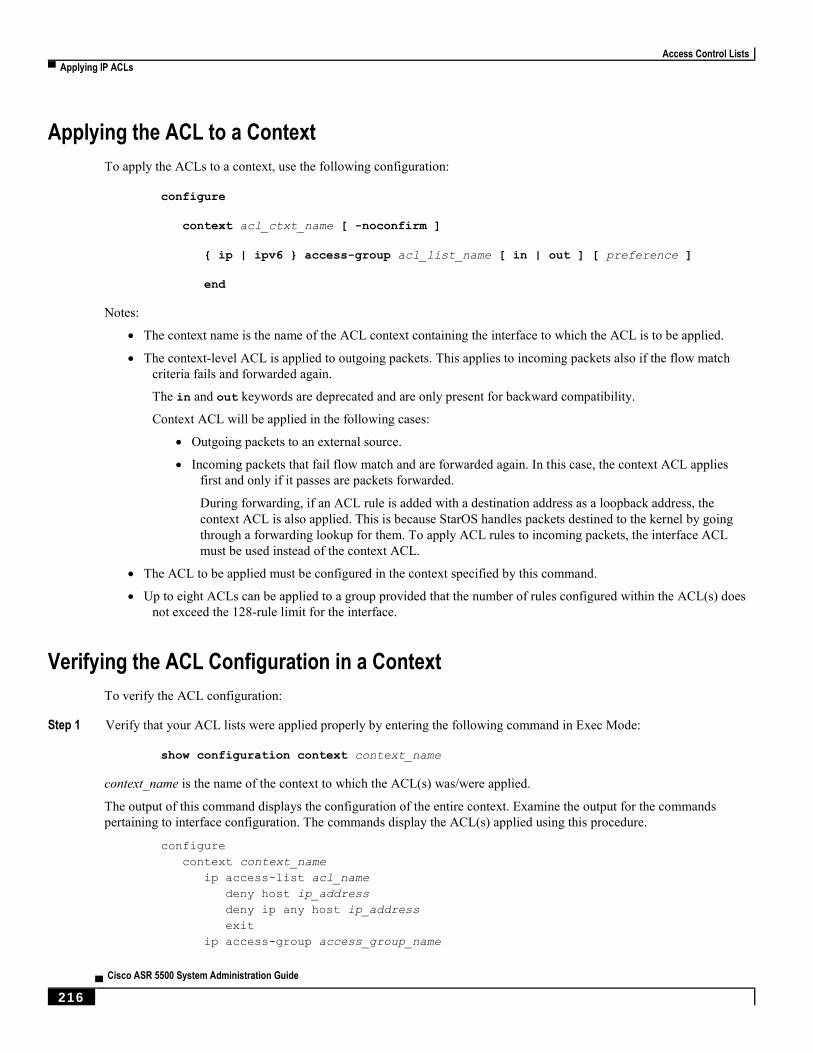
Access Control Lists
▀ Applying IP ACLs
▄ Cisco ASR 5500 System Administration Guide
216
Applying the ACL to a Context
To apply the ACLs to a context, use the following configuration:
configure
context acl_ctxt_name [ -noconfirm ]
{ ip | ipv6 } access-group acl_list_name [ in | out ] [ preference ]
end
Notes:
The context name is the name of the ACL context containing the interface to which the ACL is to be applied.
The context-level ACL is applied to outgoing packets. This applies to incoming packets also if the flow match
criteria fails and forwarded again.
The in and out keywords are deprecated and are only present for backward compatibility.
Context ACL will be applied in the following cases:
Outgoing packets to an external source.
Incoming packets that fail flow match and are forwarded again. In this case, the context ACL applies
first and only if it passes are packets forwarded.
During forwarding, if an ACL rule is added with a destination address as a loopback address, the
context ACL is also applied. This is because StarOS handles packets destined to the kernel by going
through a forwarding lookup for them. To apply ACL rules to incoming packets, the interface ACL
must be used instead of the context ACL.
The ACL to be applied must be configured in the context specified by this command.
Up to eight ACLs can be applied to a group provided that the number of rules configured within the ACL(s) does
not exceed the 128-rule limit for the interface.
Verifying the ACL Configuration in a Context
To verify the ACL configuration:
Step 1 Verify that your ACL lists were applied properly by entering the following command in Exec Mode:
show configuration context context_name
context_name is the name of the context to which the ACL(s) was/were applied.
The output of this command displays the configuration of the entire context. Examine the output for the commands
pertaining to interface configuration. The commands display the ACL(s) applied using this procedure.
configure
context context_name
ip access-list acl_name
deny host ip_address
deny ip any host ip_address
exit
ip access-group access_group_name
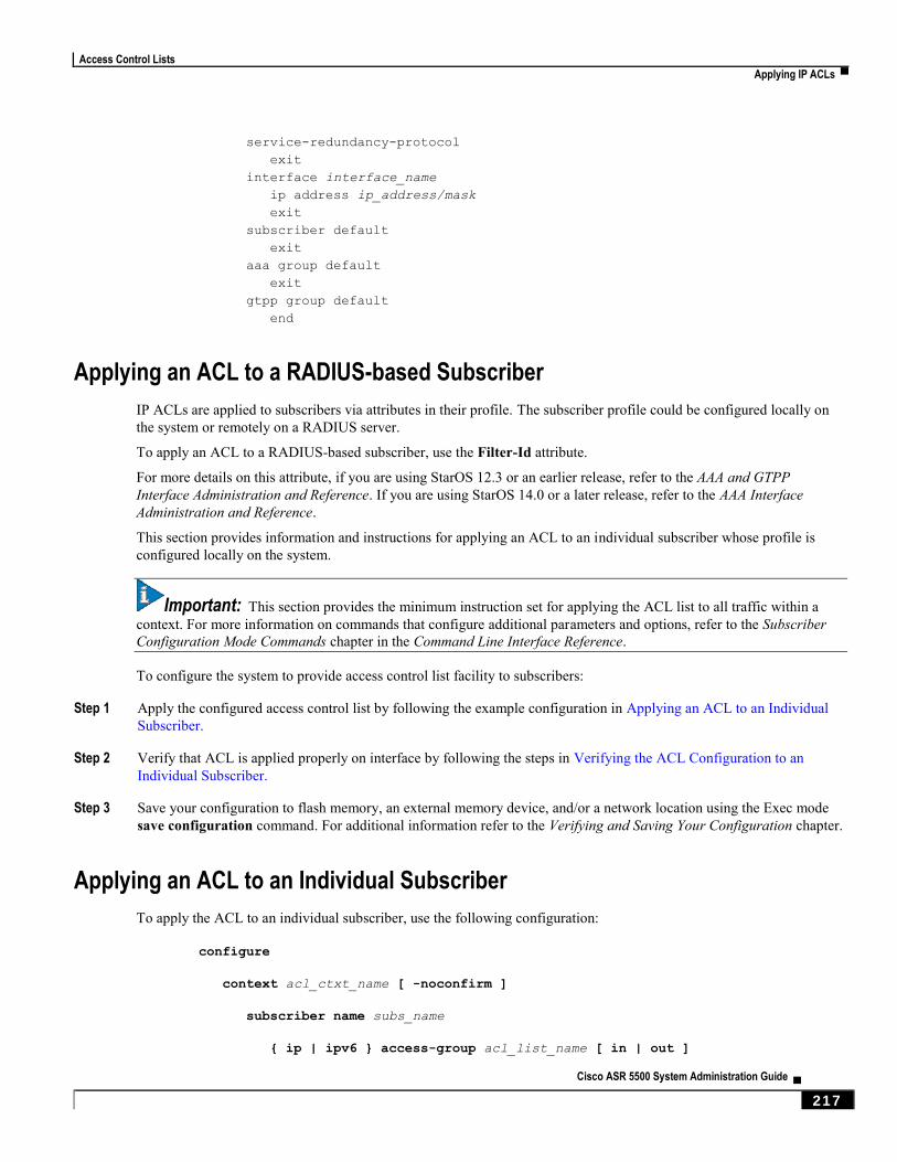
Access Control Lists
Applying IP ACLs ▀
Cisco ASR 5500 System Administration Guide ▄ 217
service-redundancy-protocol
exit
interface interface_name
ip address ip_address/mask
exit
subscriber default
exit
aaa group default
exit
gtpp group default
end
Applying an ACL to a RADIUS-based Subscriber
IP ACLs are applied to subscribers via attributes in their profile. The subscriber profile could be configured locally on
the system or remotely on a RADIUS server.
To apply an ACL to a RADIUS-based subscriber, use the Filter-Id attribute.
For more details on this attribute, if you are using StarOS 12.3 or an earlier release, refer to the AAA and GTPP
Interface Administration and Reference. If you are using StarOS 14.0 or a later release, refer to the AAA Interface
Administration and Reference.
This section provides information and instructions for applying an ACL to an individual subscriber whose profile is
configured locally on the system.
Important: This section provides the minimum instruction set for applying the ACL list to all traffic within a
context. For more information on commands that configure additional parameters and options, refer to the Subscriber
Configuration Mode Commands chapter in the Command Line Interface Reference.
To configure the system to provide access control list facility to subscribers:
Step 1 Apply the configured access control list by following the example configuration in Applying an ACL to an Individual
Subscriber.
Step 2 Verify that ACL is applied properly on interface by following the steps in Verifying the ACL Configuration to an
Individual Subscriber.
Step 3 Save your configuration to flash memory, an external memory device, and/or a network location using the Exec mode
save configuration command. For additional information refer to the Verifying and Saving Your Configuration chapter.
Applying an ACL to an Individual Subscriber
To apply the ACL to an individual subscriber, use the following configuration:
configure
context acl_ctxt_name [ -noconfirm ]
subscriber name subs_name
{ ip | ipv6 } access-group acl_list_name [ in | out ]
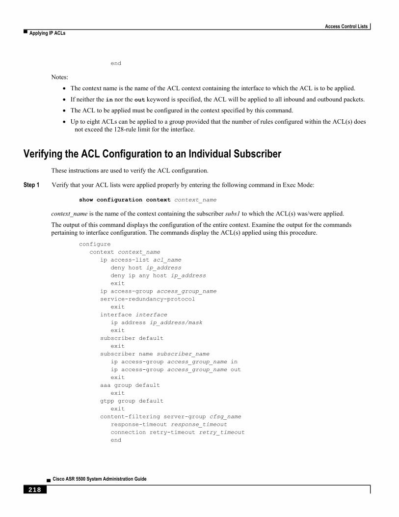
Access Control Lists
▀ Applying IP ACLs
▄ Cisco ASR 5500 System Administration Guide
218
end
Notes:
The context name is the name of the ACL context containing the interface to which the ACL is to be applied.
If neither the in nor the out keyword is specified, the ACL will be applied to all inbound and outbound packets.
The ACL to be applied must be configured in the context specified by this command.
Up to eight ACLs can be applied to a group provided that the number of rules configured within the ACL(s) does
not exceed the 128-rule limit for the interface.
Verifying the ACL Configuration to an Individual Subscriber
These instructions are used to verify the ACL configuration.
Step 1 Verify that your ACL lists were applied properly by entering the following command in Exec Mode:
show configuration context context_name
context_name is the name of the context containing the subscriber subs1 to which the ACL(s) was/were applied.
The output of this command displays the configuration of the entire context. Examine the output for the commands
pertaining to interface configuration. The commands display the ACL(s) applied using this procedure.
configure
context context_name
ip access-list acl_name
deny host ip_address
deny ip any host ip_address
exit
ip access-group access_group_name
service-redundancy-protocol
exit
interface interface
ip address ip_address/mask
exit
subscriber default
exit
subscriber name subscriber_name
ip access-group access_group_name in
ip access-group access_group_name out
exit
aaa group default
exit
gtpp group default
exit
content-filtering server-group cfsg_name
response-timeout response_timeout
connection retry-timeout retry_timeout
end
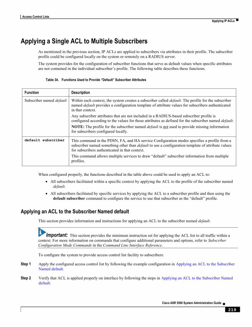
Access Control Lists
Applying IP ACLs ▀
Cisco ASR 5500 System Administration Guide ▄ 219
Applying a Single ACL to Multiple Subscribers
As mentioned in the previous section, IP ACLs are applied to subscribers via attributes in their profile. The subscriber
profile could be configured locally on the system or remotely on a RADIUS server.
The system provides for the configuration of subscriber functions that serve as default values when specific attributes
are not contained in the individual subscriber’s profile. The following table describes these functions.
Table 34. Functions Used to Provide “Default” Subscriber Attributes
Function Description
Subscriber named default Within each context, the system creates a subscriber called default. The profile for the subscriber
named default provides a configuration template of attribute values for subscribers authenticated
in that context.
Any subscriber attributes that are not included in a RADIUS-based subscriber profile is
configured according to the values for those attributes as defined for the subscriber named default.
NOTE: The profile for the subscriber named default is not used to provide missing information
for subscribers configured locally.
default subscriber This command in the PDSN, FA, and HA service Configuration modes specifies a profile from a
subscriber named something other than default to use a configuration template of attribute values
for subscribers authenticated in that context.
This command allows multiple services to draw “default” subscriber information from multiple
profiles.
When configured properly, the functions described in the table above could be used to apply an ACL to:
All subscribers facilitated within a specific context by applying the ACL to the profile of the subscriber named
default.
All subscribers facilitated by specific services by applying the ACL to a subscriber profile and then using the
default subscriber command to configure the service to use that subscriber as the “default” profile.
Applying an ACL to the Subscriber Named default
This section provides information and instructions for applying an ACL to the subscriber named default.
Important: This section provides the minimum instruction set for applying the ACL list to all traffic within a
context. For more information on commands that configure additional parameters and options, refer to Subscriber
Configuration Mode Commands in the Command Line Interface Reference.
To configure the system to provide access control list facility to subscribers:
Step 1 Apply the configured access control list by following the example configuration in Applying an ACL to the Subscriber
Named default.
Step 2 Verify that ACL is applied properly on interface by following the steps in Applying an ACL to the Subscriber Named
default.

Access Control Lists
▀ Applying IP ACLs
▄ Cisco ASR 5500 System Administration Guide
220
Step 3 Save your configuration to flash memory, an external memory device, and/or a network location using the Exec mode
save configuration command. For additional information refer to the Verifying and Saving Your Configuration chapter.
Applying an ACL to the Subscriber Named default
To apply the ACL to the subscriber named default, use the following configuration:
configure
context acl_ctxt_name [ -noconfirm ]
subscriber name subs_name
{ ip | ipv6 } access-group acl_list_name [ in | out ]
end
Notes:
The context name is the name of the ACL context containing the interface to which the ACL is to be applied.
If neither the in nor the out keyword is specified, the ACL will be applied to all inbound and outbound packets.
The ACL to be applied must be configured in the context specified by this command.
Up to eight ACLs can be applied to a group provided that the number of rules configured within the ACL(s) does
not exceed the 128-rule limit for the interface.
Verifying the ACL Configuration to the Subscriber Named default
These instructions are used to verify the ACL configuration.
Step 1 Verify that your ACL lists were applied properly by entering the following command in Exec Mode:
show configuration context context_name
context_name is the name of the context containing the subscriber default to which the ACL(s) was/were applied.
The output of this command displays the configuration of the entire context. Examine the output for the commands
pertaining to interface configuration. The commands display the ACL(s) applied using this procedure.
configure
context context_name
ip access-list acl_name
deny host ip_address
deny ip any host ip_address
exit
ip access-group access_group_name
service-redundancy-protocol
exit
interface interface
ip address ip_address/mask
exit
subscriber name default
ip access-group access_group_name in
ip access-group access_group_name out
exit
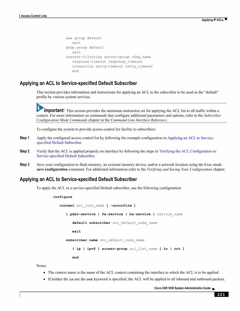
Access Control Lists
Applying IP ACLs ▀
Cisco ASR 5500 System Administration Guide ▄ 221
aaa group default
exit
gtpp group default
exit
content-filtering server-group cfsg_name
response-timeout response_timeout
connection retry-timeout retry_timeout
end
Applying an ACL to Service-specified Default Subscriber
This section provides information and instructions for applying an ACL to the subscriber to be used as the “default”
profile by various system services.
Important: This section provides the minimum instruction set for applying the ACL list to all traffic within a
context. For more information on commands that configure additional parameters and options, refer to the Subscriber
Configuration Mode Commands chapter in the Command Line Interface Reference.
To configure the system to provide access control list facility to subscribers:
Step 1 Apply the configured access control list by following the example configuration in Applying an ACL to Service-
specified Default Subscriber.
Step 2 Verify that the ACL is applied properly on interface by following the steps in Verifying the ACL Configuration to
Service-specified Default Subscriber.
Step 3 Save your configuration to flash memory, an external memory device, and/or a network location using the Exec mode
save configuration command. For additional information refer to the Verifying and Saving Your Configuration chapter.
Applying an ACL to Service-specified Default Subscriber
To apply the ACL to a service-specified Default subscriber, use the following configuration:
configure
context acl_ctxt_name [ -noconfirm ]
{ pdsn-service | fa-service | ha-service } service_name
default subscriber svc_default_subs_name
exit
subscriber name svc_default_subs_name
{ ip | ipv6 } access-group acl_list_name [ in | out ]
end
Notes:
The context name is the name of the ACL context containing the interface to which the ACL is to be applied.
If neither the in nor the out keyword is specified, the ACL will be applied to all inbound and outbound packets.
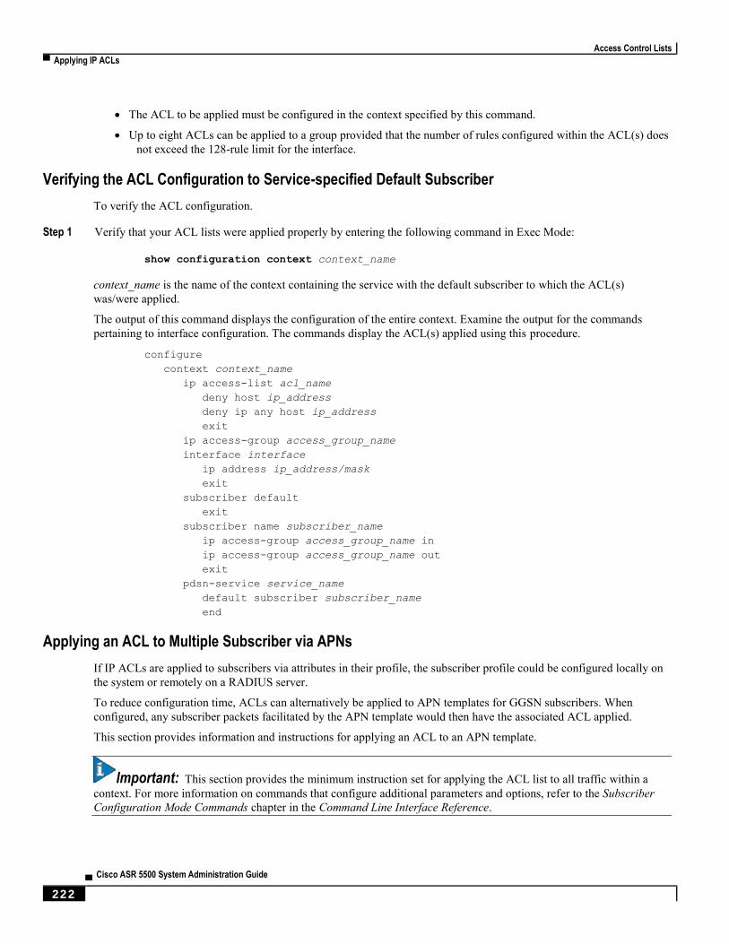
Access Control Lists
▀ Applying IP ACLs
▄ Cisco ASR 5500 System Administration Guide
222
The ACL to be applied must be configured in the context specified by this command.
Up to eight ACLs can be applied to a group provided that the number of rules configured within the ACL(s) does
not exceed the 128-rule limit for the interface.
Verifying the ACL Configuration to Service-specified Default Subscriber
To verify the ACL configuration.
Step 1 Verify that your ACL lists were applied properly by entering the following command in Exec Mode:
show configuration context context_name
context_name is the name of the context containing the service with the default subscriber to which the ACL(s)
was/were applied.
The output of this command displays the configuration of the entire context. Examine the output for the commands
pertaining to interface configuration. The commands display the ACL(s) applied using this procedure.
configure
context context_name
ip access-list acl_name
deny host ip_address
deny ip any host ip_address
exit
ip access-group access_group_name
interface interface
ip address ip_address/mask
exit
subscriber default
exit
subscriber name subscriber_name
ip access-group access_group_name in
ip access-group access_group_name out
exit
pdsn-service service_name
default subscriber subscriber_name
end
Applying an ACL to Multiple Subscriber via APNs
If IP ACLs are applied to subscribers via attributes in their profile, the subscriber profile could be configured locally on
the system or remotely on a RADIUS server.
To reduce configuration time, ACLs can alternatively be applied to APN templates for GGSN subscribers. When
configured, any subscriber packets facilitated by the APN template would then have the associated ACL applied.
This section provides information and instructions for applying an ACL to an APN template.
Important: This section provides the minimum instruction set for applying the ACL list to all traffic within a
context. For more information on commands that configure additional parameters and options, refer to the Subscriber
Configuration Mode Commands chapter in the Command Line Interface Reference.
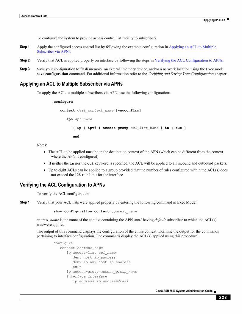
Access Control Lists
Applying IP ACLs ▀
Cisco ASR 5500 System Administration Guide ▄ 223
To configure the system to provide access control list facility to subscribers:
Step 1 Apply the configured access control list by following the example configuration in Applying an ACL to Multiple
Subscriber via APNs.
Step 2 Verify that ACL is applied properly on interface by following the steps in Verifying the ACL Configuration to APNs.
Step 3 Save your configuration to flash memory, an external memory device, and/or a network location using the Exec mode
save configuration command. For additional information refer to the Verifying and Saving Your Configuration chapter.
Applying an ACL to Multiple Subscriber via APNs
To apply the ACL to multiple subscribers via APN, use the following configuration:
configure
context dest_context_name [-noconfirm]
apn apn_name
{ ip | ipv6 } access-group acl_list_name [ in | out ]
end
Notes:
The ACL to be applied must be in the destination context of the APN (which can be different from the context
where the APN is configured).
If neither the in nor the out keyword is specified, the ACL will be applied to all inbound and outbound packets.
Up to eight ACLs can be applied to a group provided that the number of rules configured within the ACL(s) does
not exceed the 128-rule limit for the interface.
Verifying the ACL Configuration to APNs
To verify the ACL configuration:
Step 1 Verify that your ACL lists were applied properly by entering the following command in Exec Mode:
show configuration context context_name
context_name is the name of the context containing the APN apn1 having default subscriber to which the ACL(s)
was/were applied.
The output of this command displays the configuration of the entire context. Examine the output for the commands
pertaining to interface configuration. The commands display the ACL(s) applied using this procedure.
configure
context context_name
ip access-list acl_name
deny host ip_address
deny ip any host ip_address
exit
ip access-group access_group_name
interface interface
ip address ip_address/mask

Access Control Lists
▀ Applying IP ACLs
▄ Cisco ASR 5500 System Administration Guide
224
exit
subscriber default
exit
apn apn_name
ip access-group access_group_name in
ip access-group access_group_name out
end
Cisco ASR 5500 System Administration Guide ▄ 225
Chapter 15 Congestion Control
This chapter describes the Congestion Control feature. It covers the following topics:
Overview
Configuring Congestion Control
Congestion Control
▀ Overview
▄ Cisco ASR 5500 System Administration Guide
226
Overview Congestion Control monitors the system for conditions that could potentially degrade performance when the system is
under heavy load. Typically, these conditions are temporary (for example, high CPU or memory utilization) and are
quickly resolved. However, continuous or large numbers of these conditions within a specific time interval may impact
the system’s ability to service subscriber sessions. Congestion control helps identify such conditions and invokes
policies for addressing the situation.
Congestion control operation is based on configuring the following:
Congestion Condition Thresholds: Thresholds dictate the conditions for which congestion control is enabled
and establishes limits for defining the state of the system (congested or clear). These thresholds function in a
way similar to operation thresholds that are configured for the system as described in the Thresholding
Configuration Guide. The primary difference is that when congestion thresholds are reached, a service
congestion policy and an SNMP trap (starCongestion) are generated.
A threshold tolerance dictates the percentage under the configured threshold that must be reached in order for
the condition to be cleared. An SNMP trap, starCongestionClear, is then triggered.
Port Utilization Thresholds: If you set a port utilization threshold, when the average utilization of all
ports in the system reaches the specified threshold, congestion control is enabled.
Port-specific Thresholds: If you set port-specific thresholds, when any individual port-specific
threshold is reached, congestion control is enabled system-wide.
Service Congestion Policies: Congestion policies are configurable for each service. These policies dictate how
services respond when the system detects that a congestion condition threshold has been crossed.
Important: This section provides the minimum instruction set for configuring congestion control. Commands
that configure additional interface or port properties are provided in Subscriber Configuration Mode in the Command
Line Interface Reference. Always refer to the Administration Guides for all of the licensed products running on this
platform for additional configuration information with respect to congestion control. Congesiton control functionality
varies based on product and StarOS version.
For the MME three levels of congestion control thresholds are supported – critical, major and minor. By default only the
critical threshold is supported for other products. SNMP traps also support major and minor congestion control
thresholds. A set of congestion-action-profile commands allows an operator to establish additional actions to be taken
for specific thresholds and threshold levels.
Congestion Control
Configuring Congestion Control ▀
Cisco ASR 5500 System Administration Guide ▄ 227
Configuring Congestion Control To configure Congestion Control functionality:
Step 1 Configure congestion control thresholds as described in Configuring the Congestion Control Threshold.
Step 2 Configure service congestion policies as described in Configuring Service Congestion Policies.
Step 3 Enable redirect overload policies as described in Enabling Congestion Control Redirect Overload Policy.
Step 4 Configure disconnecting subscribers based on call or inactivity time as described in Disconnecting Subscribers Based
on Call or Inactivity Time.
Step 5 Save your configuration as described in the Verifying and Saving Your Configuration chapter.
Configuring the Congestion Control Threshold
To configure congestion control threshold, apply the following example configuration in the Global Configuration mode
of the CLI:
configure
congestion-control threshold max-sessions-per-service-utilization percent
congestion-control threshold tolerance percent
end
Notes:
There are numerous threshold parameters. See Global Configuration Mode Commands in the Command Line
Interface Reference for more information.
The tolerance is the percentage under a configured threshold that dictates the point at which the condition is
cleared.
Multiple levels of congestion thresholds – critical, major and minor – a re supported for various types of
congestion control thresholds. If a threshold level is not specified, the default is critical. Currently, major and
minor thresholds are only supported for the MME. The congestion-action-profile command under lte-policy
defines the action to be taken when thresholds are exceeded. See Global Configuration Mode Commands, LTE
Policy Configuration Mode Commands and Congestion Action Profile Configuration Mode Commands in the
Command Line Interface Reference for more information.
Repeat this configuration as needed for additional thresholds.
Congestion Control
▀ Configuring Congestion Control
▄ Cisco ASR 5500 System Administration Guide
228
Configuring Service Congestion Policies
To create a congestion control policy, apply the following example configuration in the Global Configuration mode of
the CLI:
configure
congestion-control policy service action { drop | none | redirect | reject }
end
Notes:
When the redirect action occurs for PDSN services, the PDSN responds to the PCF with a reply code of 136,
“unknown PDSN address” along with the IP address of an alternate PDSN.
redirect is not available for PDIF. The default action for PDIF is “none.”
When the redirect action occurs for HA services, the system responds to the FA with a reply code of 136,
“unknown home agent address”.
redirect cannot be used in conjunction with GGSN services.
redirect is not available for the Local Mobility Anchor (LMA) service.
When setting the action to reject, the reply code is 130, “insufficient resources”.
For the GGSN, the reply code is 199, “no resources available”.
For the MME, redirect is not available.
For the MME, create action profiles for optional major and minor thresholds using the congestion-action-profile
command under lte-policy in the Global Configuration mode.
For the MME, you can specify service as critical, major or minor to set a policy and associate an action-
profile for the respective threshold. See Global Configuration Mode Commands in the Command Line
Interface Reference for more information.
Configuring Overload Reporting on the MME
When an overload condition is detected on an MME and the report-overload keyword is enabled in the congestion-
control policy command, the system reports the condition to a specified percentage of eNodeBs and proceeds to take
the configured action on incoming sessions. To create a congestion control policy with overload reporting, apply the
following example configuration:
configure
congestion-control policy mme-service action report-overload reject-new-
sessions enodeb-percentage percentage
end
Notes:
Other overload actions include permit-emergency-sessions and reject-non-emergency-sessions.

Congestion Control
Configuring Congestion Control ▀
Cisco ASR 5500 System Administration Guide ▄ 229
Enabling Congestion Control Redirect Overload Policy
To create a congestion control policy and configure a redirect overload policy for the service, apply the following
example configuration:
Important: Redirect is not available on PDIF or MME for this release.
configure
congestion-control
context context_name
{service_configuration_mode}
policy overload redirect address
end
Notes:
Optional: If the congestion control policy action was configured to redirect, then a redirect overload policy must
be configured for the service(s) that are affected.
There are several service configuration modes that you can configure. See the Command Line Interface
Reference for a complete list of modes.
You can set various options for redirection. See the Command Line Interface Reference for more information.
Repeat this configuration example to configure overload policies for additional services configured in the same
context.
Verify the Service Overload Policies
To verify that the service overload policies were properly configured enter the following command in the Exec Mode:
show service_type name service_name
This command lists the entire service configuration. Verify that the information displayed for the “Overload Policy” is
accurate.
Repeat this configuration example to configure additional services in other contexts.
Verify the Congestion Control Configuration
To verify Congestion Control Configuration enter the show congestion-control configuration command in the Exec
Mode.
The following output is a concise listing of all threshold and policy configurations showing multi-level Critical, Major
and Minor threshold parameters:

Congestion Control
▀ Configuring Congestion Control
▄ Cisco ASR 5500 System Administration Guide
230
Congestion-control: enabled
Congestion-control Critical threshold parameters
system cpu utilization: 80%
service control cpu utilization: 80%
system memory utilization: 80%
message queue utilization: 80%
message queue wait time: 10 seconds
port rx utilization: 80%
port tx utilization: 80%
license utilization: 100%
max-session-per-service utilization: 100%
tolerence limit: 10%
Congestion-control Major threshold parameters
system cpu utilization: 0%
service control cpu utilization: 0%
system memory utilization: 0%
message queue utilization: 0%
message queue wait time: 0 seconds
port rx utilization: 0%
port tx utilization: 0%
license utilization: 0%
max-session-per-service utilization: 0%
tolerence limit: 0%
Congestion-control Minor threshold parameters
system cpu utilization: 0%
service control cpu utilization: 0%
system memory utilization: 0%
message queue utilization: 0%
message queue wait time: 0 seconds
port rx utilization: 0%
port tx utilization: 0%
license utilization: 0%
max-session-per-service utilization: 0%
tolerence limit: 0%
Overload-disconnect: disabled
Overload-disconnect threshold parameters
license utilization: 80%
max-session-per-service utilization: 80%
tolerance: 10%
session disconnect percent: 5%

Congestion Control
Configuring Congestion Control ▀
Cisco ASR 5500 System Administration Guide ▄ 231
iterations-per-stage: 8
Congestion-control Policy
pdsn-service: none
hsgw-service: none
ha-service: none
ggsn-service: none
closedrp-service: none
lns-service: none
cscf-service: reject
pdif-service: none
wsg-service: none
pdg-service: none
fng-service: none
sgsn-service: none
mme-service: drop
henbgw-network-service: none
asngw-service: none
asnpc-service: none
phsgw-service: none
phspc-service: none
mipv6ha-service: none
lma-service: none
saegw-service: none
sgw-service: none
pgw-service: none
hnbgw-service: none
pcc-policy-service: none
pcc-quota-service: none
pcc-af-service: none
ipsg-service: none
samog-service: none
The primary threshold to observe is license utilization. This threshold is defaulted to 80%. Overload controls on the
system enables the Congestion-control Policy when the system has only 80% of the licenses used. The overload
condition will not clear until the utilization drops below the tolerance limit setting. The tolerance limit is defaulted to
10%. If the system goes into overload due to license utilization (threshold at 80%), the overload condition will not clear
until the license utilization reaches 70%.
The system may go into overload if threshold settings are set too low and congestion control is enabled. You will need
to review all threshold values and become familiar with the settings.
Since the recommendation for license utilization overload threshold is 100%, you should enable a license threshold
alarm at 80%. An alarm is then triggered when the license utilization hits 80%. When the congestion-control policy
setting is set to drop, the system drops incoming packets containing new session requests.
Important: For additional information on configuring the alarm threshold, refer to the Threshold Configuration
Guide.

Congestion Control
▀ Configuring Congestion Control
▄ Cisco ASR 5500 System Administration Guide
232
Verify MME Congestion Action Profiles
To verify MME multilevel congestion action profiles, run the following Exec mode command:
show lte-policy congestion-action-profile { name profile_name | summary }
Disconnecting Subscribers Based on Call or Inactivity Time
During periods of heavy system load, it may be necessary to disconnect subscribers in order to maintain an acceptable
level of system performance. You can establish thresholds to select subscribers to disconnect based on the length of time
that a call has been connected or inactive.
To enable overload disconnect for the currently selected subscriber, use the following configuration example:
configure
context context_name
subscriber name subscriber_name
default overload-disconnect threshold inactivity-time dur_thresh
default overload-disconnect threshold connect-time dur_thresh
end
To disable the overload disconnect feature for this subscriber, use the following configuration example:
configure
context context_name
subscriber subscriber_name
no overload-disconnect {[threshold inactivity-time] | [threshold connect-
time]}
end
Notes:
overload-disconnect is not supported for the Call Session Control Function (CSCF) service.
Cisco ASR 5500 System Administration Guide ▄ 233
Chapter 16 Routing
This chapter provides information on configuring an enhanced, or extended, service. The product administration guides
provide examples and procedures for configuring basic services on the system. You should select the configuration
example that best meets your service model, and configure the required elements for that model before using the
procedures described below.
This chapter includes the following sections:
Routing Policies
Static Routing
OSPF Routing
OSPFv3 Routing
Equal Cost Multiple Path (ECMP)
BGP-4 Routing
Bidirectional Forwarding Detection
Viewing Routing Information

Routing
▀ Routing Policies
▄ Cisco ASR 5500 System Administration Guide
234
Routing Policies This section describes how to configure the elements needed to define routing policies. Routing policies modify and
redirect routes to and from the system to satisfy specific network deployment requirements.
Use the following building blocks to configure routing policies:
Route Access Lists – The basic building block of a routing policy. Route access lists filter routes based on a
range of IP addresses.
IP Prefix Lists – A more advanced element of a routing policy. An IP Prefix list filters routes based on IP
prefixes.
AS Path Access Lists – A basic building block used for Border Gateway Protocol (BGP) routing. These lists
filter Autonomous System (AS) paths.
Route Maps – Route-maps provide detailed control over routes during route selection or route advertisement by
a routing protocol, and in route redistribution between routing protocols. For this level of control you use IP
Prefix Lists, Route Access Lists and AS Path Access Lists to specify IP addresses, address ranges, and
Autonomous System paths.
Creating IP Prefix Lists
Use the following configuration example to create IP Prefix Lists:
config
context context_name
ip prefix-list name list_name { deny | permit } network_address/net_mask
Notes:
Set the IP prefix list to deny, permit or match any prefix.
IPv4 dotted-decimal and IPv6 colon-separated-hexadecimal addresses are supported.
Save your configuration as described in the Verifying and Saving Your Configuration chapter.
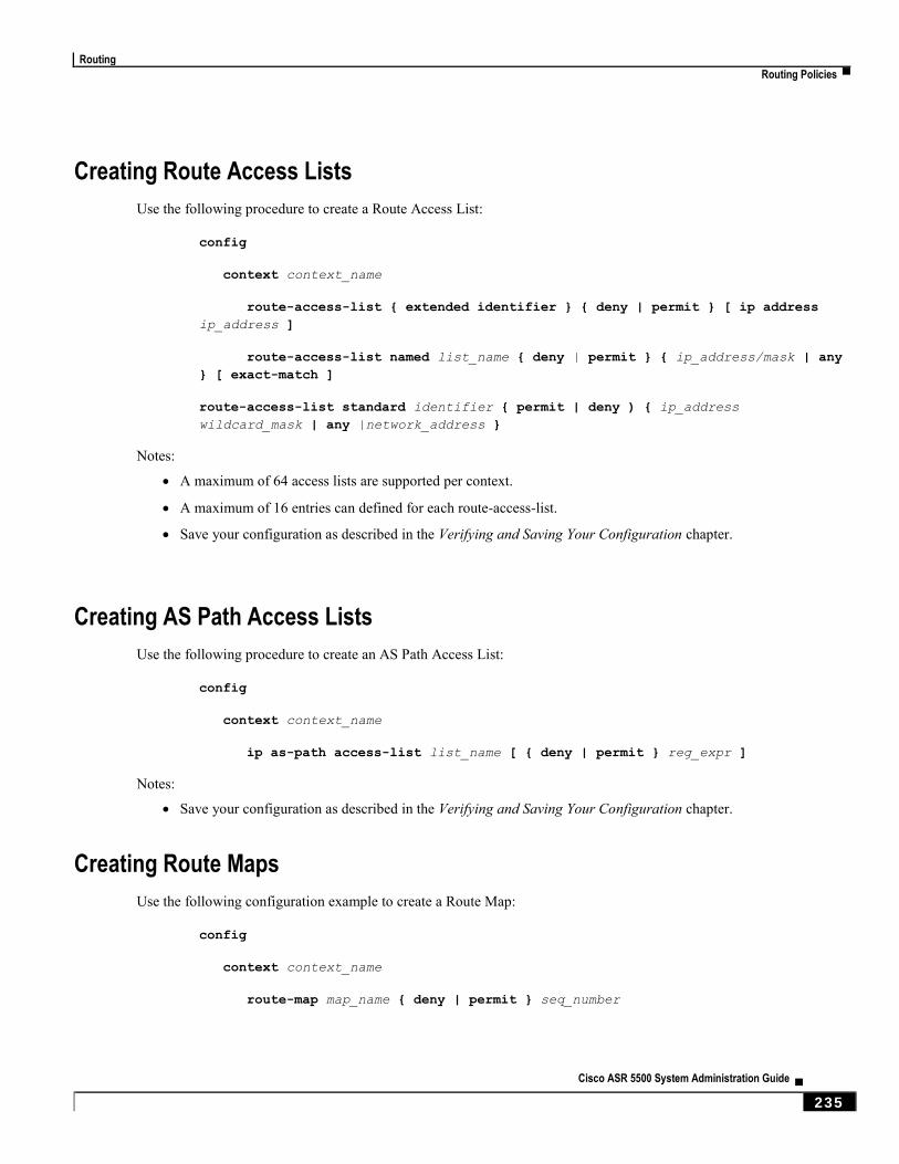
Routing
Routing Policies ▀
Cisco ASR 5500 System Administration Guide ▄ 235
Creating Route Access Lists
Use the following procedure to create a Route Access List:
config
context context_name
route-access-list { extended identifier } { deny | permit } [ ip address
ip_address ]
route-access-list named list_name { deny | permit } { ip_address/mask | any
} [ exact-match ]
route-access-list standard identifier { permit | deny ) { ip_address
wildcard_mask | any |network_address }
Notes:
A maximum of 64 access lists are supported per context.
A maximum of 16 entries can defined for each route-access-list.
Save your configuration as described in the Verifying and Saving Your Configuration chapter.
Creating AS Path Access Lists
Use the following procedure to create an AS Path Access List:
config
context context_name
ip as-path access-list list_name [ { deny | permit } reg_expr ]
Notes:
Save your configuration as described in the Verifying and Saving Your Configuration chapter.
Creating Route Maps
Use the following configuration example to create a Route Map:
config
context context_name
route-map map_name { deny | permit } seq_number
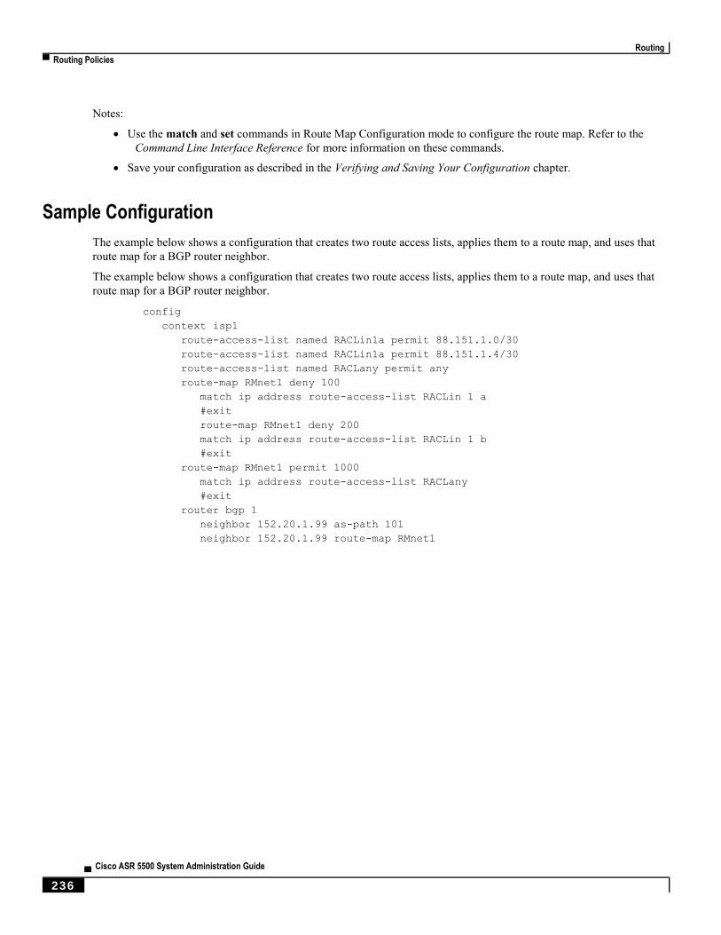
Routing
▀ Routing Policies
▄ Cisco ASR 5500 System Administration Guide
236
Notes:
Use the match and set commands in Route Map Configuration mode to configure the route map. Refer to the
Command Line Interface Reference for more information on these commands.
Save your configuration as described in the Verifying and Saving Your Configuration chapter.
Sample Configuration
The example below shows a configuration that creates two route access lists, applies them to a route map, and uses that
route map for a BGP router neighbor.
The example below shows a configuration that creates two route access lists, applies them to a route map, and uses that
route map for a BGP router neighbor.
config
context isp1
route-access-list named RACLin1a permit 88.151.1.0/30
route-access-list named RACLin1a permit 88.151.1.4/30
route-access-list named RACLany permit any
route-map RMnet1 deny 100
match ip address route-access-list RACLin 1 a
#exit
route-map RMnet1 deny 200
match ip address route-access-list RACLin 1 b
#exit
route-map RMnet1 permit 1000
match ip address route-access-list RACLany
#exit
router bgp 1
neighbor 152.20.1.99 as-path 101
neighbor 152.20.1.99 route-map RMnet1
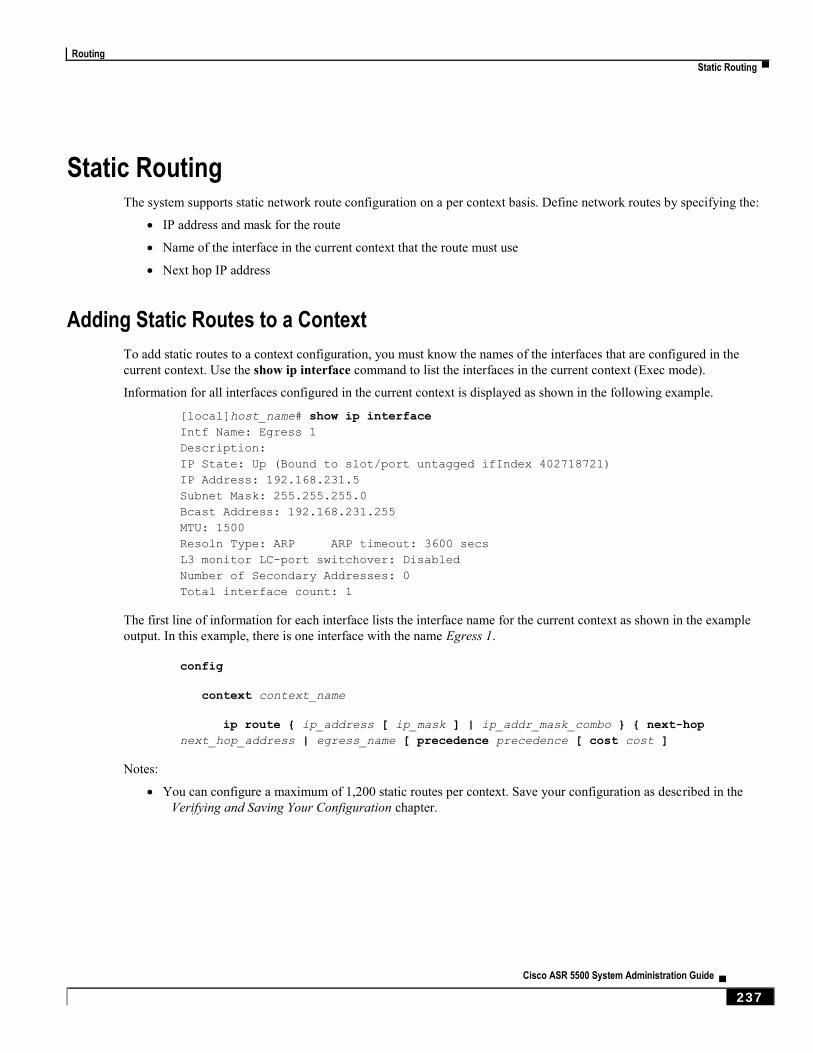
Routing
Static Routing ▀
Cisco ASR 5500 System Administration Guide ▄ 237
Static Routing The system supports static network route configuration on a per context basis. Define network routes by specifying the:
IP address and mask for the route
Name of the interface in the current context that the route must use
Next hop IP address
Adding Static Routes to a Context
To add static routes to a context configuration, you must know the names of the interfaces that are configured in the
current context. Use the show ip interface command to list the interfaces in the current context (Exec mode).
Information for all interfaces configured in the current context is displayed as shown in the following example.
[local]host_name# show ip interface
Intf Name: Egress 1
Description:
IP State: Up (Bound to slot/port untagged ifIndex 402718721)
IP Address: 192.168.231.5
Subnet Mask: 255.255.255.0
Bcast Address: 192.168.231.255
MTU: 1500
Resoln Type: ARP ARP timeout: 3600 secs
L3 monitor LC-port switchover: Disabled
Number of Secondary Addresses: 0
Total interface count: 1
The first line of information for each interface lists the interface name for the current context as shown in the example
output. In this example, there is one interface with the name Egress 1.
config
context context_name
ip route { ip_address [ ip_mask ] | ip_addr_mask_combo } { next-hop
next_hop_address | egress_name [ precedence precedence [ cost cost ]
Notes:
You can configure a maximum of 1,200 static routes per context. Save your configuration as described in the
Verifying and Saving Your Configuration chapter.
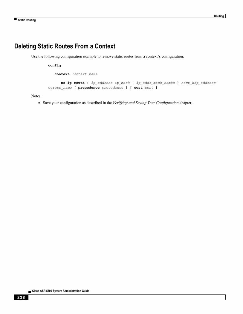
Routing
▀ Static Routing
▄ Cisco ASR 5500 System Administration Guide
238
Deleting Static Routes From a Context
Use the following configuration example to remove static routes from a context’s configuration:
config
context context_name
no ip route { ip_address ip_mask | ip_addr_mask_combo } next_hop_address
egress_name [ precedence precedence ] [ cost cost ]
Notes:
Save your configuration as described in the Verifying and Saving Your Configuration chapter.

Routing
OSPF Routing ▀
Cisco ASR 5500 System Administration Guide ▄ 239
OSPF Routing This section gives an overview of Open Shortest Path First (OPSF) routing and its implementation in the system. It also
describes how to enable the base OSPF functionality and lists the commands that are available for more complex
configurations.
You must purchase and install a license key before you can use this feature. Contact your Cisco account representative
for more information on licenses.
Important: During system task recovery, it is possible for a dynamically-learned forwarding entry to incorrectly
remain in the system forwarding table if that forwarding entry has been removed from the dynamic routing protocol
during the recovery.
OSPF Version 2 Overview
OSPF is a link-state routing protocol that employs an interior gateway protocol (IGP) to route IP packets using the
shortest path first based solely on the destination IP address in the IP packet header. OSPF routed IP packets are not
encapsulated in any additional protocol headers as they transit the network.
An Autonomous System (AS), or Domain, is defined as a group of networks within a common routing infrastructure.
OSPF is a dynamic routing protocol that quickly detects topological changes in the AS (such as router interface failures)
and calculates new loop-free routes after a period of convergence. This period of convergence is short and involves a
minimum of routing traffic.
In a link-state routing protocol, each router maintains a database, referred to as the link-state database, that describes the
Autonomous System's topology. Each participating router has an identical database. Each entry in this database is a
particular router's local state (for example, the router's usable interfaces and reachable neighbors). The router distributes
its local state throughout the AS by flooding.
All routers run the same algorithm in parallel. From the link-state database, each router constructs a tree of shortest
paths with itself as root to each destination in the AS. Externally derived routing information appears on the tree as
leaves. The cost of a route is described by a single dimensionless metric.
OSPF allows sets of networks to be grouped together. Such a grouping is called an area. The topology of this area is
hidden from the rest of the AS, which enables a significant reduction in routing traffic. Also, routing within the area is
determined only by the area’s own topology, lending the area protection from bad routing data. An area is a
generalization of an IP subnetted network.
OSPF enables the flexible configuration of IP subnets so that each route distributed by OSPF has a destination and
mask. Two different subnets of the same IP network number may have different sizes (that is, different masks). This is
commonly referred to as variable-length subnetting. A packet is routed to the best (longest or most specific) match. Host
routes are considered to be subnets whose masks are “all ones” (0xffffffff).
OSPF traffic can be authenticated or non-authenticated, or can use no authentication, simple/clear text passwords, or
MD5-based passwords. This means that only trusted routers can participate in the AS routing. You can specify a variety
of authentication schemes and, in fact, you can configure separate authentication schemes for each IP subnet.
Externally derived routing data (for example, routes learned from an exterior protocol such as BGP) is advertised
throughout the AS. This externally derived data is kept separate from the OSPF ink state data.
Each external route can also be tagged by the advertising router, enabling the passing of additional information between
routers on the boundary of the AS.
OSPF uses a link-state algorithm to build and calculate the shortest path to all known destinations.

Routing
▀ OSPF Routing
▄ Cisco ASR 5500 System Administration Guide
240
Basic OSPFv2 Configuration
This section describes how to implement basic OSPF routing.
Enabling OSPF Routing For a Specific Context
Use the following configuration example to enable OSPF Routing for a specific context:
config
context context_name
router ospf
end
Notes:
Save your configuration as described in the Verifying and Saving Your Configuration chapter.
Enabling OSPF Over a Specific Interface
After you enable OSPF, specify the networks on which it will run. Use the following command to enable OSPF:
network network_ip_address/network_mask area { area_id | area_ip_address }
Important: The default cost for OSPF on the system is 10. To change the cost, refer to the ip ospf cost command
in the Ethernet Interface Configuration Mode Commands chapter of the Command Line Interface Reference.
Notes:
Save your configuration as described in the Verifying and Saving Your Configuration chapter.
Redistributing Routes Into OSPF (Optional)
Redistributing routes into OSPF means any routes from another protocol that meet specified a specified criterion, such
as route type, metric, or rule within a route-map, are redistributed using the OSPFv2 protocol to all OSPF areas. This is
an optional configuration.
config
context context_name
router ospf
redistribute { connected | static }
end
Notes:
Save your configuration as described in the Verifying and Saving Your Configuration chapter.

Routing
OSPF Routing ▀
Cisco ASR 5500 System Administration Guide ▄ 241
Confirming OSPF Configuration Parameters
To confirm the OSPF router configuration, use the following command and look for the section labeled router ospf in
the screen output:
show config context ctxt_name [ verbose ]
Routing
▀ OSPFv3 Routing
▄ Cisco ASR 5500 System Administration Guide
242
OSPFv3 Routing This section gives an overview of Open Shortest Path First Version 3 (OPSFv3) routing and its implementation in the
system. It also describes how to enable the base OSPFv3 functionality and lists the commands that are available for
more complex configurations.
OSPFv3 Overview
Much of OSPF version 3 is the same as OSPF version 2. OSPFv3 expands on OSPF version 2 to provide support for
IPv6 routing prefixes and the larger size of IPv6 addresses. OSPFv3 dynamically learns and advertises (redistributes)
IPv6 routes within an OSPFv3 routing domain
In OSPFv3, a routing process does not need to be explicitly created. Enabling OSPFv3 on an interface will cause a
routing process and its associated configuration to be created.
Basic OSPFv3 Configuration
This section describes how to implement basic OSPF routing.
Enabling OSPFv3 Routing For a Specific Context
Use the following configuration example to enable OSPF Routing for a specific context:
config
context context_name
router ospfv3
end
Notes:
Save your configuration as described in the Verifying and Saving Your Configuration chapter.
Enabling OSPFv6 Over a Specific Interface
After you enable OSPFv3 specify the area in which it will run. Use the following command to enable OSPFv3:
area { area_id | area_ip_address } [ default-cost dflt-cost ] [ stub stub-area ]
[ virtual-link vl-neighbor-ipv4address ]
Important: The default cost for OSPFv3 on the system is 10. To change the cost, refer to the ipv6 ospf cost
command in the Ethernet Interface Configuration Mode Commands chapter of the Command Line Interface Reference.
Notes:
Save your configuration as described in the Verifying and Saving Your Configuration chapter.
Routing
Equal Cost Multiple Path (ECMP) ▀
Cisco ASR 5500 System Administration Guide ▄ 243
Redistributing Routes Into OSPFv3 (Optional)
Redistributing routes into OSPFv3 means any routes from another protocol that meet specified a specified criterion,
such as route type, metric, or rule within a route-map, are redistributed using the OSPFv3 protocol to all OSPF areas.
This is an optional configuration.
config
context context_name
router ospf3
redistribute { connected | static }
end
Notes:
Save your configuration as described in the Verifying and Saving Your Configuration chapter.
Confirming OSPFv3 Configuration Parameters
To confirm the OSPF router configuration, use the following command and look for the section labeled router ipv6
ospf in the screen output:
show config context ctxt_name [ verbose ]
Equal Cost Multiple Path (ECMP) The system supports ECMP for routing protocols. ECMP distributes traffic across multiple routes that have the same
cost to lessen the burden on any one route.
The following command configures the maximum number of equal cost paths that can be submitted by a routing
protocol:
config
context context_name
ip routing maximum-paths [ max_num ]
Notes:
max_num is an integer from 1 through 10.
Save your configuration as described in the Verifying and Saving Your Configuration chapter.

Routing
▀ BGP-4 Routing
▄ Cisco ASR 5500 System Administration Guide
244
BGP-4 Routing The Border Gateway Protocol 4 (BGP-4) routing protocol is supported through a BGP router process that is
implemented at the context level.
The Border Gateway Protocol (BGP) is an inter-AS routing protocol. An Autonomous System (AS) is a set of routers
under a single technical administration that use an interior gateway protocol and common metrics to route packets
within the AS. The set of routers uses an exterior gateway protocol to route packets to other autonomous systems.
BGP runs over TCP. This eliminates the need for the BGP protocol to implement explicit update fragmentation,
retransmission, acknowledgement, and sequencing information. Any authentication scheme used by TCP may be used
in addition to BGP’s own authentication mechanisms.
BGP routers exchange network reachability information with other BGP routers. This information builds a picture of AS
connectivity from which routes are filtered and AS-level policy decisions are enforced.
BGP-4 provides classless inter-domain routing. This includes support for advertising an IP prefix and eliminates the
concept of network class within BGP. BGP-4 also allows the aggregation of routes, including the aggregation of AS
paths.
Overview of BGP Support
Mobile devices communicate to the Internet through Home Agents (HAs). HAs assign IP addresses to the mobile node
from a configured pool of addresses. These addresses are also advertised to Internet routers through an IP routing
protocol to ensure dynamic routing. The BGP-4 protocol is used as a monitoring mechanism between an HA and
Internet router with routing to support Interchassis Session Recovery (ICSR). (Refer to Interchassis Session Recovery
for more information.)
The objective of BGP-4 protocol support is to satisfy routing requirements and monitor communications with Internet
routers. BGP-4 may trigger an active to standby switchover to keep subscriber services from being interrupted.
The following BGP-4 features are supported:
Exterior Border Gateway Protocol (EBGP) multi-hop
Route Filtering for inbound and outbound routes
Route redistribution and route-maps
IP pool routes and loopback routes are advertised in the BGP domain in the following ways:
Through BGP Configuration Mode redistribution commands, all or some of the connected routes are
redistributed into the BGP domain. (IP pool and loopback routes are present in the IP routing table as
connected routes.) The network routemap command provides the flexibility to change many BGP attributes.
Through the BGP Configuration Mode network commands, connected routes are explicitly configured for
advertisement into the BGP domain. The network routemap command provides the flexibility to change
many BGP attributes. Refer to the Border Gateway Protocol Configuration Mode Commands chapter of the
Command Line Interface Reference for details on these commands.
Important: If a BGP task restarts because of a processing card failure, a migration, a crash, or the removal of a
processing card, all peering session and route information is lost.
Routing
BGP-4 Routing ▀
Cisco ASR 5500 System Administration Guide ▄ 245
Configuring BGP
This section describes how to configure and enable basic BGP routing support in the system.
config
context context_name
router bgp AS_number
neighbor ip_address remote-as AS_num
Notes:
A maximum of 64 BGP peers are supported per context.
Save your configuration as described in the Verifying and Saving Your Configuration chapter.
Redistributing Routes Into BGP (Optional)
Redistributing routes into BGP simply means that any routes from another protocol that meet a specified criterion, such
as a route type, or a rule within a route-map, are redistributed through the BGP protocol to all BGP areas. This is an
optional configuration.
config
context context_name
router bgp as_number
redistribute bgp { bgp | connected | static } [ metric metric_value ]
[ metric-type { 1 | 2 } ] [ route-map route_map_name ]
Notes:
The redistribution options are connected, ospf, rip, or static. Refer to the Border Gateway Protocol
Configuration Mode Commands chapter of the Command Line Interface Reference for details on the
redistribute command.
A maximum of 64 route-maps are supported per context.
Save your configuration as described in the Verifying and Saving Your Configuration chapter.
ICSR and SRP Groups
BGP is employed with Interchassis Session Recovery (ICSR) configurations linked via Service Redundancy Protocol
(SRP). By default an ICSR failover is triggered when all BGP peers within a context are down.
Optionally, you can configure SRP peer groups within a context. ICSR failover would then occur if all peers within a
group fail. This option is useful in deployments in which a combination of IPv4 and IPv6 peers are spread across
multiple paired VLANs, and IPv4 or IPv6 connectivity is lost by all members of a peer group.
For additional information refer to Interchassis Session Recovery in this guide and the description of the monitor bgp,
monitor diameter and monitor authentication-probe commands in the Service Redundancy Protocol Configuration
Mode Commands chapter of the Command Line Interface Reference.

Routing
▀ Bidirectional Forwarding Detection
▄ Cisco ASR 5500 System Administration Guide
246
Bidirectional Forwarding Detection Bidirectional Forwarding Detection (BFD) is a network protocol used to detect faults between two forwarding engines
connected by a link. BFD establishes a session between two endpoints over a particular link. If more than one link exists
between two systems, multiple BFD sessions may be established to monitor each one of them. The session is established
with a three-way handshake, and is torn down the same way. Authentication may be enabled on the session. A choice of
simple password, MD5 or SHA1 authentication is available.
Overview of BFD Support
BFD does not have a discovery mechanism; sessions must be explicitly configured between endpoints. BFD may be
used on many different underlying transport mechanisms and layers, and operates independently of all of these.
Therefore, it needs to be encapsulated by whatever transport it uses.
Protocols that support some form of adjacency setup, such as OSPF or IS-IS, may also be used to bootstrap a BFD
session. These protocols may then use BFD to receive faster notification of failing links than would normally be
possible using the protocol's own keepalive mechanism.
In asynchronous mode, both endpoints periodically send Hello packets to each other. If a number of those packets are
not received, the session is considered down.
When Echo is active, a stream of Echo packets is sent to the other endpoint which then forwards these back to the
sender. Echo can be globally enabled via the bfd-protocol command, and/or individually enabled/disabled per interface.
This function is used to test the forwarding path on the remote system.
The system supports BFD in asynchronous mode with optional Echo capability via static or BGP routing.
Configuring BFD
This section describes how to configure and enable basic BFD routing protocol support in the system.
There are several factors affecting the configuration of BFD protocol:
Configuring a BFD Context
Configuring IPv4 BFD for Static Routes
Configuring IPv6 BFD for Static Routes
Configuring BFD for Single Hop
Configuring Multihop BFD
Scaling of BFD
Associating BGP Neighbors with the Context
Associating OSPF Neighbors with the Context
Associating BFD Neighbor Groups with the BFD Protocol
Enabling BFD on OSPF Interfaces

Routing
Bidirectional Forwarding Detection ▀
Cisco ASR 5500 System Administration Guide ▄ 247
Configuring a BFD Context
config
context context_name
bfd-protocol
[ [no] bfd echo ]
exit
Notes:
Echo function can be optionally enabled for all interfaces in this context.
16 BFD sessions per context and 64 per chassis.
Configuring IPv4 BFD for Static Routes
Enable BFD on an interface.
config
context bfd_context_name
interface if_name
ip address ipv4_address ipv4_mask
bfd interval interval_value min_rx rx_value multiplier multiplier_value
[ [no] bfd echo ]
exit
Configure BFD static route.
ip route static bfd if_name ipv4_gw_address
Add static routes.
ip route ipv4_address ipv4_mask
ip route ipv4_address ipv4_mask
Routing
▀ Bidirectional Forwarding Detection
▄ Cisco ASR 5500 System Administration Guide
248
Configuring IPv6 BFD for Static Routes
Enable BFD on an Interface
config
context bfd_context_name
interface if_name
ipv6 address ipv6_address ipv6_mask
bfd interval interval_value min_rx rx_value multiplier multiplier_value
[ [no] bfd echo ]
exit
Configure BFD static route.
ipv6 route static bfd if_name ipv6_gw_address
Add static routes.
ipv6 route ipv6_address ipv6_mask
ipv6 route ipv6_address ipv6_mask
Configuring BFD for Single Hop
Enable BFD on an interface.
config
context bfd_context_name
interface if_name
ip address ipv4_address ipv4_mask
ipv6 address ipv6_address ipv6_mask
bfd interval interval_value min_rx rx_value multiplier multiplier_value
[ [no] bfd echo ]
exit
Enable BFD on a BGP Neighbor. For additional information, see Associating BGP Neighbors with the Context.
Enable BFD on an OSPF Neighbor. For additional information, see Associating OSPF Neighbors with the Context.
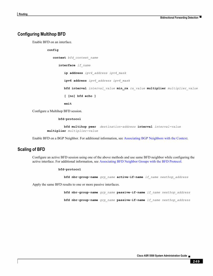
Routing
Bidirectional Forwarding Detection ▀
Cisco ASR 5500 System Administration Guide ▄ 249
Configuring Multihop BFD
Enable BFD on an interface.
config
context bfd_context_name
interface if_name
ip address ipv4_address ipv4_mask
ipv6 address ipv6_address ipv6_mask
bfd interval interval_value min_rx rx_value multiplier multiplier_value
[ [no] bfd echo ]
exit
Configure a Multihop BFD session.
bfd-protocol
bfd multihop peer destination-address interval interval-value
multiplier multiplier-value
Enable BFD on a BGP Neighbor. For additional information, see Associating BGP Neighbors with the Context.
Scaling of BFD
Configure an active BFD session using one of the above methods and use same BFD neighbor while configuring the
active interface. For additional information, see Associating BFD Neighbor Groups with the BFD Protocol.
bfd-protocol
bfd nbr-group-name grp_name active-if-name if_name nexthop_address
Apply the same BFD results to one or more passive interfaces.
bfd nbr-group-name grp_name passive-if-name if_name nexthop_address
bfd nbr-group-name grp_name passive-if-name if_name nexthop_address

Routing
▀ Bidirectional Forwarding Detection
▄ Cisco ASR 5500 System Administration Guide
250
Associating BGP Neighbors with the Context
config
context context_name
router bgp AS_number
neighbor neighbor_ip-address remote-as rem_AS_number
neighbor neighbor_ip-address ebgp-multihop max-hop max_hops
neighbor neighbor_ip-address update-source update-src_ip-address
neighbor neighbor_ip-address failover bfd [ multihop ]
Notes:
Repeat the sequence to add neighbors.
Associating OSPF Neighbors with the Context
config
context context_name
router ospf
neighbor neighbor_ip-address
Notes:
Repeat the sequence to add neighbors.
Associating BFD Neighbor Groups with the BFD Protocol
config
context context_name
bfd-protocol
bfd nbr-group-name grp_name active-if-name if_name nexthop_address
bfd nbr-group-name grp_name passive-if-name if_name nexthop_address

Routing
Bidirectional Forwarding Detection ▀
Cisco ASR 5500 System Administration Guide ▄ 251
Enabling BFD on OSPF Interfaces
All OSPF Interfaces
config
context context_name
router ospf
bfd-all-interfaces
Specific OSPF Interface
config
context context_name
interface interface_name
broadcast
ip ospf bfd
Saving the Configuration
Save your configuration as described in the Verifying and Saving Your Configuration chapter.
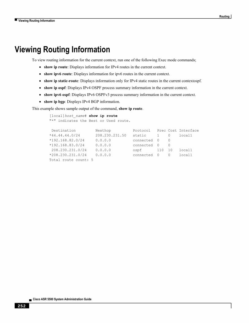
Routing
▀ Viewing Routing Information
▄ Cisco ASR 5500 System Administration Guide
252
Viewing Routing Information To view routing information for the current context, run one of the following Exec mode commands;
show ip route: Displays information for IPv4 routes in the current context.
show ipv6 route: Displays information for ipv6 routes in the current context.
show ip static-route: Displays information only for IPv4 static routes in the current contextospf.
show ip ospf: Displays IPv4 OSPF process summary information in the current context.
show ipv6 ospf: Displays IPv6 OSPFv3 process summary information in the current context.
show ip bgp: Displays IPv4 BGP information.
This example shows sample output of the command, show ip route.
[local]host_name# show ip route
"*" indicates the Best or Used route.
Destination Nexthop Protocol Prec Cost Interface
*44.44.44.0/24 208.230.231.50 static 1 0 local1
*192.168.82.0/24 0.0.0.0 connected 0 0
*192.168.83.0/24 0.0.0.0 connected 0 0
208.230.231.0/24 0.0.0.0 ospf 110 10 local1
*208.230.231.0/24 0.0.0.0 connected 0 0 local1
Total route count: 5

Cisco ASR 5500 System Administration Guide ▄ 253
Chapter 17 VLANs
This chapter provides information on configuring virtual local area networks (VLANs) in support of enhanced or
extended services. The product administration guides provide examples and procedures for configuration of services on
the system that may utilize VLANs. You should select the configuration example that best meets your service model
before using the procedures described below.
This chapter includes the following sections:
Overview
Creating VLAN Tags
Verifying the Port Configuration
Configuring Subscriber VLAN Associations
VLAN-Related CLI Commands
Important: VLAN – Layer 2 Traffic Management is a Cisco feature that requires a separate license. Contact
your Cisco account representative for detailed information on specific licensing requirements. For information on
installing and verifying licenses, refer to the Managing License Keys section of Software Management Operations.
VLANs
▀ Overview
▄ Cisco ASR 5500 System Administration Guide
254
Overview Virtual LANs (VLANs) provide greater flexibility in the configuration and use of contexts and services.
They are configured as “tags” on a per-port basis and allow more complex configurations to be implemented. The
VLAN tag allows a single physical port to be bound to multiple logical interfaces that can be configured in different
contexts. Therefore, each Ethernet port can be viewed as containing many logical ports when VLAN tags are employed.
Important: VLANs are supported in conjunction with subscriber traffic ports on Management I/O (MIO/UMIO)
cards. The system supports the configuration limits for VLANs as described in Engineering Rules.
Overlapping IP Address Pool Support – GGSN
Overlapping IP Address pools provides allow operators to more flexibly support multiple corporate VPN customers
with the same private IP address space without expensive investments in physically separate routers or virtual routers.
The system supports two types of overlapping pools – resource and overlap. Resource pools are designed for dynamic
assignment only, and use a VPN tunnel (such as a GRE tunnel) to forward and receive the private IP addresses to and
from the VPN. Overlapping type pools can be used for both dynamic and static addressing, and use VLANs and a next
hop forwarding address to connect to the VPN customer
To forward downstream traffic to the correct PDP context, the GGSN uses either the GRE tunnel ID or the VLAN ID to
match the packet. When forwarding traffic upstream, the GGSN uses the tunnel and forwarding information in the IP
pool configuration; overlapping pools must be configured in the APN in such instances.
When a PDP context is created, the IP address is assigned from the IP pool. In this case the forwarding rules are also
configured into the GGSN. If the address is assigned statically, when the GGSN confirms the IP address from the pool
configured in the APN, the forwarding rules are also applied.
The GGSN can scale to as many actual overlapping pools as there are VLAN interfaces per context, and there can be
multiple contexts per GGSN. The limit is the number of IP pools. This scalability allows operators who wish to provide
VPN services to customers using the customer's private IP address space, not to be concerned about escalating hardware
costs or complex configurations.
RADIUS VLAN Support – Enhanced Charging Services
VPN customers often use private address space which can easily overlap with other customers. The subscriber addresses
are supported with overlapping pools which can be configured in the same virtual routing context.
RADIUS Server and NAS IP addresses do not need to be in separate contexts, thereby simplifying APN and RADIUS
configuration and network design. This feature allows the following scenarios to be defined in the same context:
Overlapping RADIUS NAS-IP addresses for various RADIUS server groups representing different APNs.
Overlapping RADIUS server IP addresses for various RADIUS servers groups.
Every overlapping NAS-IP address is given a unique next-hop address which is then bound to an interface that is bound
to a unique VLAN, thereby allowing the configuration to exist within the same context.
The system forwards RADIUS access requests and accounting messages to the next hop defined for that NAS-IP; the
connected routers forward the messages to the RADIUS server. The next hop address determines the interface and
VLAN to use. Traffic from the server is identified as belonging to a certain NAS-IP by the port/VLAN combination.

VLANs
Creating VLAN Tags ▀
Cisco ASR 5500 System Administration Guide ▄ 255
The number of RADIUS NAS-IP addresses that can be configured is limited by the number of loopback addresses that
can be configured.
APN Support – PDN Gateway (P-GW)
P-GW Access Point Name (APN) supports extensive parameter configuration flexibility for the APN. VLAN tagging
may be selected by the APN, but are configured in the P-GW independently from the APN.
Creating VLAN Tags Use the following example to create VLANs on a port and bind them to pre-existing interfaces. For information on
creating interfaces, refer to System Interfaces and Ports.
config
port ethernet slot/port
no shutdown
vlan vlan_tag_ID
no shutdown
bind interface interface_name context_name
end
Notes:
Optional: Configure VLAN-subscriber associations. Refer to Configuring Subscriber VLAN Associations for
more information.
Repeat this procedure as needed to configure additional VLANs for the port.
Refer to VLAN-Related CLI Commands and the Command Line Interface Reference for additional information.
Save your configuration as described in the Verifying and Saving Your Configuration chapter.
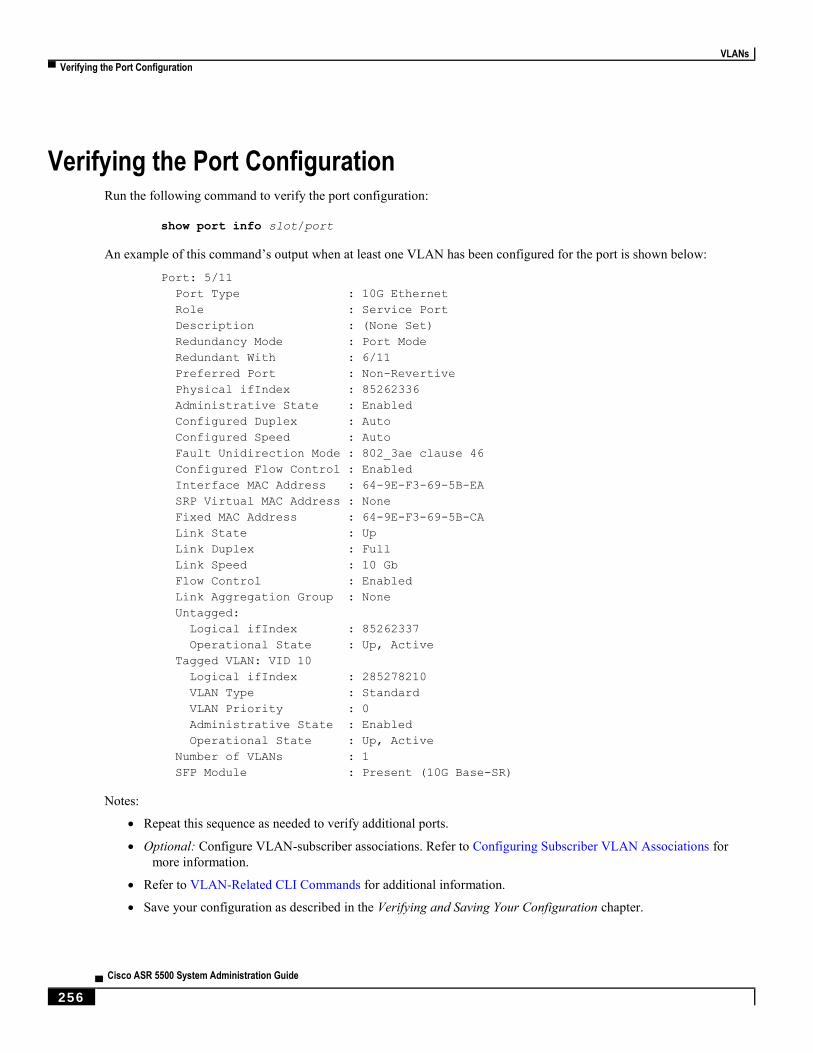
VLANs
▀ Verifying the Port Configuration
▄ Cisco ASR 5500 System Administration Guide
256
Verifying the Port Configuration Run the following command to verify the port configuration:
show port info slot/port
An example of this command’s output when at least one VLAN has been configured for the port is shown below:
Port: 5/11
Port Type : 10G Ethernet
Role : Service Port
Description : (None Set)
Redundancy Mode : Port Mode
Redundant With : 6/11
Preferred Port : Non-Revertive
Physical ifIndex : 85262336
Administrative State : Enabled
Configured Duplex : Auto
Configured Speed : Auto
Fault Unidirection Mode : 802_3ae clause 46
Configured Flow Control : Enabled
Interface MAC Address : 64-9E-F3-69-5B-EA
SRP Virtual MAC Address : None
Fixed MAC Address : 64-9E-F3-69-5B-CA
Link State : Up
Link Duplex : Full
Link Speed : 10 Gb
Flow Control : Enabled
Link Aggregation Group : None
Untagged:
Logical ifIndex : 85262337
Operational State : Up, Active
Tagged VLAN: VID 10
Logical ifIndex : 285278210
VLAN Type : Standard
VLAN Priority : 0
Administrative State : Enabled
Operational State : Up, Active
Number of VLANs : 1
SFP Module : Present (10G Base-SR)
Notes:
Repeat this sequence as needed to verify additional ports.
Optional: Configure VLAN-subscriber associations. Refer to Configuring Subscriber VLAN Associations for
more information.
Refer to VLAN-Related CLI Commands for additional information.
Save your configuration as described in the Verifying and Saving Your Configuration chapter.
VLANs
Configuring Subscriber VLAN Associations ▀
Cisco ASR 5500 System Administration Guide ▄ 257
Configuring Subscriber VLAN Associations Subscriber traffic can be routed to specific VLANs based on the configuration of their user profile. This functionality
provides a mechanism for routing all traffic from a subscriber over the specified VLAN. All packets destined for the
subscriber must also be sent using only IP addresses valid on the VLAN or they will be dropped.
RADIUS Attributes Used
The following RADIUS attributes can be configured within subscriber profiles on the RADIUS server to allow the
association of a specific VLAN to the subscriber:
SN-Assigned-VLAN-ID: In the Starent VSA dictionary
SN1-Assigned-VLAN-ID: In the Starent VSA1 dictionary
Important: Since the instructions for configuring subscriber profiles differ between RADIUS server applications,
this section only describes the individual attributes that can be added to the subscriber profile. Please refer to the
documentation that shipped with your RADIUS server for instructions on configuring subscribers.
Configuring Local Subscriber Profiles
Use the configuration example below to configure VLAN associations within local subscriber profiles on the system.
Important: These instructions assume that you have already configured subscriber-type VLAN tags according to
the instructions provided in Creating VLAN Tags .
config
context context_name
subscriber name user_name
ip vlan vlan_id
end
Verify the Subscriber Profile Configuration
Use the following command to view the configuration for a subscriber profile:
show subscriber configuration username user_name
Notes:
Repeat this command for each subscriber.
Save your configuration as described in the Verifying and Saving Your Configuration chapter.
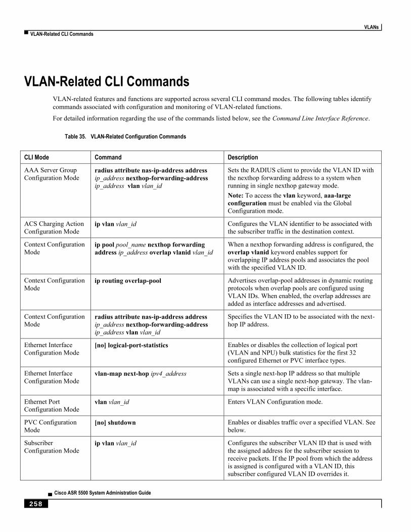
VLANs
▀ VLAN-Related CLI Commands
▄ Cisco ASR 5500 System Administration Guide
258
VLAN-Related CLI Commands VLAN-related features and functions are supported across several CLI command modes. The following tables identify
commands associated with configuration and monitoring of VLAN-related functions.
For detailed information regarding the use of the commands listed below, see the Command Line Interface Reference.
Table 35. VLAN-Related Configuration Commands
CLI Mode Command Description
AAA Server Group
Configuration Mode radius attribute nas-ip-address address
ip_address nexthop-forwarding-address
ip_address vlan vlan_id
Sets the RADIUS client to provide the VLAN ID with
the nexthop forwarding address to a system when
running in single nexthop gateway mode.
Note: To access the vlan keyword, aaa-large
configuration must be enabled via the Global
Configuration mode.
ACS Charging Action
Configuration Mode ip vlan vlan_id Configures the VLAN identifier to be associated with
the subscriber traffic in the destination context.
Context Configuration
Mode ip pool pool_name nexthop forwarding
address ip_address overlap vlanid vlan_id When a nexthop forwarding address is configured, the
overlap vlanid keyword enables support for
overlapping IP address pools and associates the pool
with the specified VLAN ID.
Context Configuration
Mode ip routing overlap-pool Advertises overlap-pool addresses in dynamic routing
protocols when overlap pools are configured using
VLAN IDs. When enabled, the overlap addresses are
added as interface addresses and advertised.
Context Configuration
Mode radius attribute nas-ip-address address
ip_address nexthop-forwarding-address
ip_address vlan vlan_id
Specifies the VLAN ID to be associated with the next-
hop IP address.
Ethernet Interface
Configuration Mode [no] logical-port-statistics Enables or disables the collection of logical port
(VLAN and NPU) bulk statistics for the first 32
configured Ethernet or PVC interface types.
Ethernet Interface
Configuration Mode vlan-map next-hop ipv4_address Sets a single next-hop IP address so that multiple
VLANs can use a single next-hop gateway. The vlan-
map is associated with a specific interface.
Ethernet Port
Configuration Mode vlan vlan_id Enters VLAN Configuration mode.
PVC Configuration
Mode [no] shutdown Enables or disables traffic over a specified VLAN. See
below.
Subscriber
Configuration Mode ip vlan vlan_id Configures the subscriber VLAN ID that is used with
the assigned address for the subscriber session to
receive packets. If the IP pool from which the address
is assigned is configured with a VLAN ID, this
subscriber configured VLAN ID overrides it.
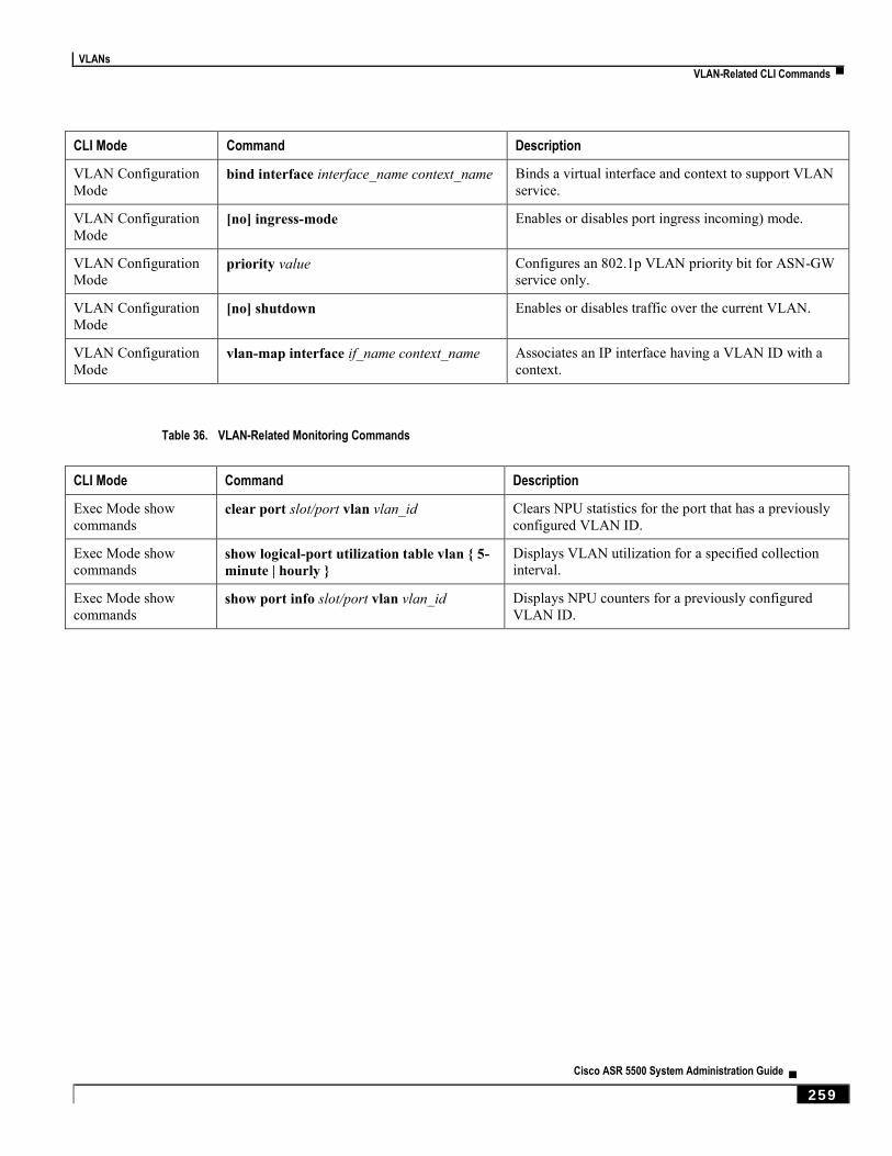
VLANs
VLAN-Related CLI Commands ▀
Cisco ASR 5500 System Administration Guide ▄ 259
CLI Mode Command Description
VLAN Configuration
Mode bind interface interface_name context_name Binds a virtual interface and context to support VLAN
service.
VLAN Configuration
Mode [no] ingress-mode Enables or disables port ingress incoming) mode.
VLAN Configuration
Mode priority value Configures an 802.1p VLAN priority bit for ASN-GW
service only.
VLAN Configuration
Mode [no] shutdown Enables or disables traffic over the current VLAN.
VLAN Configuration
Mode vlan-map interface if_name context_name Associates an IP interface having a VLAN ID with a
context.
Table 36. VLAN-Related Monitoring Commands
CLI Mode Command Description
Exec Mode show
commands clear port slot/port vlan vlan_id Clears NPU statistics for the port that has a previously
configured VLAN ID.
Exec Mode show
commands show logical-port utilization table vlan { 5-
minute | hourly } Displays VLAN utilization for a specified collection
interval.
Exec Mode show
commands show port info slot/port vlan vlan_id Displays NPU counters for a previously configured
VLAN ID.


Cisco ASR 5500 System Administration Guide ▄ 261
Chapter 18 BGP MPLS VPNs
This chapter describes services that are supported by the ASR 5x00 for Border Gateway Protocol (BGP) Multi-Protocol
Label Switching (MPLS) Virtual Private Networks (VPNs).
Important: MPLS is a licensed Cisco feature that requires a separate license. Contact your Cisco account
representative for detailed information on specific licensing requirements. For information on installing and verifying
licenses, refer to the Managing License Keys section of Software Management Operations.
It includes the following topics:
Introduction
MPLS-CE Connected to PE
ASR 5x00 as a PE
IPv6 Support for BGP MPLS VPNs
VPN-Related CLI Commands
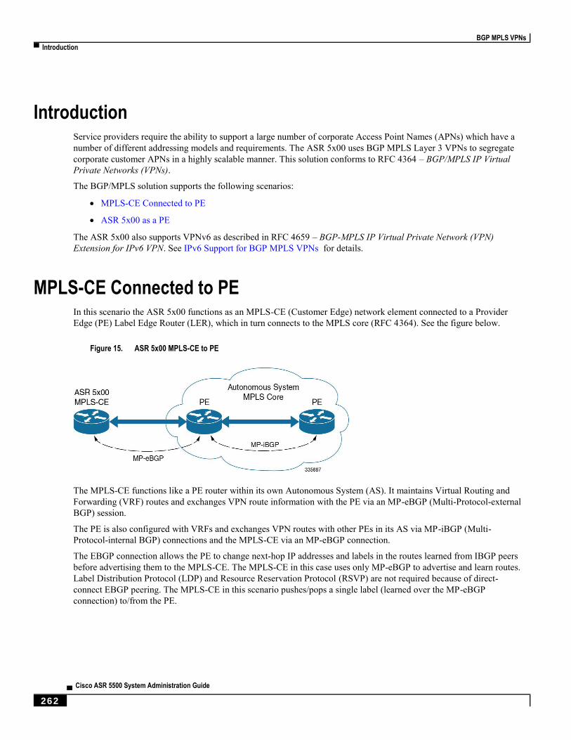
BGP MPLS VPNs
▀ Introduction
▄ Cisco ASR 5500 System Administration Guide
262
Introduction Service providers require the ability to support a large number of corporate Access Point Names (APNs) which have a
number of different addressing models and requirements. The ASR 5x00 uses BGP MPLS Layer 3 VPNs to segregate
corporate customer APNs in a highly scalable manner. This solution conforms to RFC 4364 – BGP/MPLS IP Virtual
Private Networks (VPNs).
The BGP/MPLS solution supports the following scenarios:
MPLS-CE Connected to PE
ASR 5x00 as a PE
The ASR 5x00 also supports VPNv6 as described in RFC 4659 – BGP-MPLS IP Virtual Private Network (VPN)
Extension for IPv6 VPN. See IPv6 Support for BGP MPLS VPNs for details.
MPLS-CE Connected to PE In this scenario the ASR 5x00 functions as an MPLS-CE (Customer Edge) network element connected to a Provider
Edge (PE) Label Edge Router (LER), which in turn connects to the MPLS core (RFC 4364). See the figure below.
Figure 15. ASR 5x00 MPLS-CE to PE
The MPLS-CE functions like a PE router within its own Autonomous System (AS). It maintains Virtual Routing and
Forwarding (VRF) routes and exchanges VPN route information with the PE via an MP-eBGP (Multi-Protocol-external
BGP) session.
The PE is also configured with VRFs and exchanges VPN routes with other PEs in its AS via MP-iBGP (Multi-
Protocol-internal BGP) connections and the MPLS-CE via an MP-eBGP connection.
The EBGP connection allows the PE to change next-hop IP addresses and labels in the routes learned from IBGP peers
before advertising them to the MPLS-CE. The MPLS-CE in this case uses only MP-eBGP to advertise and learn routes.
Label Distribution Protocol (LDP) and Resource Reservation Protocol (RSVP) are not required because of direct-
connect EBGP peering. The MPLS-CE in this scenario pushes/pops a single label (learned over the MP-eBGP
connection) to/from the PE.
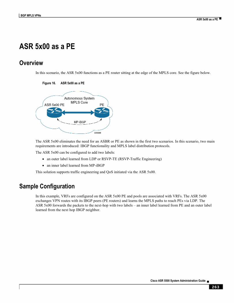
BGP MPLS VPNs
ASR 5x00 as a PE ▀
Cisco ASR 5500 System Administration Guide ▄ 263
ASR 5x00 as a PE
Overview
In this scenario, the ASR 5x00 functions as a PE router sitting at the edge of the MPLS core. See the figure below.
Figure 16. ASR 5x00 as a PE
The ASR 5x00 eliminates the need for an ASBR or PE as shown in the first two scenarios. In this scenario, two main
requirements are introduced: IBGP functionality and MPLS label distribution protocols.
The ASR 5x00 can be configured to add two labels:
an outer label learned from LDP or RSVP-TE (RSVP-Traffic Engineering)
an inner label learned from MP-iBGP
This solution supports traffic engineering and QoS initiated via the ASR 5x00.
Sample Configuration
In this example, VRFs are configured on the ASR 5x00 PE and pools are associated with VRFs. The ASR 5x00
exchanges VPN routes with its IBGP peers (PE routers) and learns the MPLS paths to reach PEs via LDP. The
ASR 5x00 forwards the packets to the next-hop with two labels – an inner label learned from PE and an outer label
learned from the next hop IBGP neighbor.
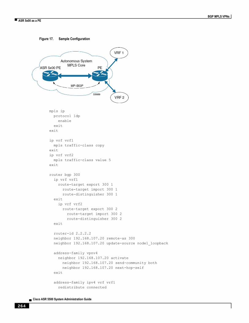
BGP MPLS VPNs
▀ ASR 5x00 as a PE
▄ Cisco ASR 5500 System Administration Guide
264
Figure 17. Sample Configuration
mpls ip
protocol ldp
enable
exit
exit
ip vrf vrf1
mpls traffic-class copy
exit
ip vrf vrf2
mpls traffic-class value 5
exit
router bgp 300
ip vrf vrf1
route-target export 300 1
route-target import 300 1
route-distinguisher 300 1
exit
ip vrf vrf2
route-target export 300 2
route-target import 300 2
route-distinguisher 300 2
exit
router-id 2.2.2.2
neighbor 192.168.107.20 remote-as 300
neighbor 192.168.107.20 update-source node1_loopback
address-family vpnv4
neighbor 192.168.107.20 activate
neighbor 192.168.107.20 send-community both
neighbor 192.168.107.20 next-hop-self
exit
address-family ipv4 vrf vrf1
redistribute connected

BGP MPLS VPNs
ASR 5x00 as a PE ▀
Cisco ASR 5500 System Administration Guide ▄ 265
exit
address-family ipv4 vrf vrf2
redistribute connected
exit
interface interface_to_internet
ip address 192.168.109.65/24
mpls ip
exit
router ospf
network 192.168.109.0/24 area 0.0.0.0
exit
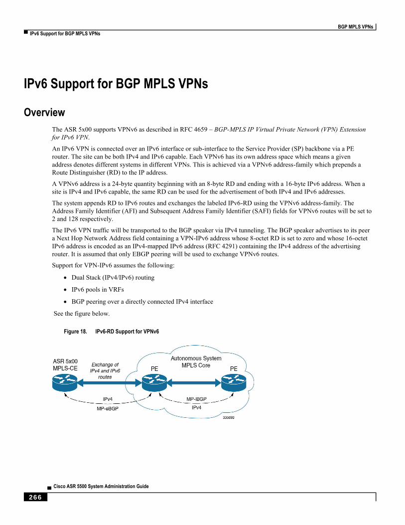
BGP MPLS VPNs
▀ IPv6 Support for BGP MPLS VPNs
▄ Cisco ASR 5500 System Administration Guide
266
IPv6 Support for BGP MPLS VPNs
Overview
The ASR 5x00 supports VPNv6 as described in RFC 4659 – BGP-MPLS IP Virtual Private Network (VPN) Extension
for IPv6 VPN.
An IPv6 VPN is connected over an IPv6 interface or sub-interface to the Service Provider (SP) backbone via a PE
router. The site can be both IPv4 and IPv6 capable. Each VPNv6 has its own address space which means a given
address denotes different systems in different VPNs. This is achieved via a VPNv6 address-family which prepends a
Route Distinguisher (RD) to the IP address.
A VPNv6 address is a 24-byte quantity beginning with an 8-byte RD and ending with a 16-byte IPv6 address. When a
site is IPv4 and IPv6 capable, the same RD can be used for the advertisement of both IPv4 and IPv6 addresses.
The system appends RD to IPv6 routes and exchanges the labeled IPv6-RD using the VPNv6 address-family. The
Address Family Identifier (AFI) and Subsequent Address Family Identifier (SAFI) fields for VPNv6 routes will be set to
2 and 128 respectively.
The IPv6 VPN traffic will be transported to the BGP speaker via IPv4 tunneling. The BGP speaker advertises to its peer
a Next Hop Network Address field containing a VPN-IPv6 address whose 8-octet RD is set to zero and whose 16-octet
IPv6 address is encoded as an IPv4-mapped IPv6 address (RFC 4291) containing the IPv4 address of the advertising
router. It is assumed that only EBGP peering will be used to exchange VPNv6 routes.
Support for VPN-IPv6 assumes the following:
Dual Stack (IPv4/IPv6) routing
IPv6 pools in VRFs
BGP peering over a directly connected IPv4 interface
See the figure below.
Figure 18. IPv6-RD Support for VPNv6

BGP MPLS VPNs
IPv6 Support for BGP MPLS VPNs ▀
Cisco ASR 5500 System Administration Guide ▄ 267
Sample Configuration
This example assumes three VRFs. VRF 1 has only IPv4 routes, VRF f2 has both IPv4 and IPv6 routes, and VRF 3 has
only IPv6 routes.
Figure 19. VPNv6 Sample Configuration
Configure VRFs.
ip vrf vrf1
exit
ip vrf vrf2
exit
ip vrf vrf3
exit
Enable MPLS BGP forwarding.
mpls bgp forwarding
Configure pools.
ip pool vrf1-pool 51.52.53.0 255.255.255.0 private 0 vrf vrf1
exit
ip pool vrf2-pool 51.52.53.0 255.255.255.0 private 0 vrf vrf2
exit
ipv6 pool vrf2-v6pool prefix 2005:0101::/32 private 0 vrf vrf2
exit
ipv6 pool vrf3-v6pool prefix 2005:0101::/32 private 0 vrf vrf3
exit
Configure interfaces.
interface ce_interface_to_rtr
ip address 192.168.110.90 255.255.255.0
exit
interface ce_v6_interface
ip address 2009:0101:0101:0101::1/96
exit
interface ce_loopback loopback

BGP MPLS VPNs
▀ IPv6 Support for BGP MPLS VPNs
▄ Cisco ASR 5500 System Administration Guide
268
ip address 52.1.2.3 255.255.255.255
exit
interface vrf1-loop loopback
ip vrf forwarding vrf1
ip address 1.52.53.54 255.255.255.255
exit
interface vrf2-loop loopback
ip vrf forwarding vrf2
ip address 2.52.53.54 255.255.255.255
exit
interface vrf2-v6loop loopback
ip vrf forwarding vrf2
ip address 2005:0202:0101::1/128
exit
interface vrf3-v6loop loopback
ip vrf forwarding vrf3
ip address 2005:0303:0101::1/128
exit
Configure BGP along with address families and redistribution rules.
router bgp 800
router-id 1.1.1.1
neighbor 192.168.110.20 remote-as 1003
neighbor 192.168.110.20 activate
address-family vpnv4
neighbor 192.168.110.20 activate
neighbor 192.168.110.20 send-community both
exit
address-family vpnv6
neighbor 192.168.110.20 activate
neighbor 192.168.110.20 send-community both
exit
ip vrf vrf1
route-distinguisher 800 1
route-target export 800 1
route-target import 800 1
exit
address-family ipv4 vrf vrf1
redistribute connected
redistribute static
exit
ip vrf vrf2
route-distinguisher 800 2
route-target export 800 2
route-target import 800 2
exit
address-family ipv4 vrf vrf2
redistribute connected
redistribute static
exit
address-family ipv6 vrf vrf2
redistribute connected

BGP MPLS VPNs
IPv6 Support for BGP MPLS VPNs ▀
Cisco ASR 5500 System Administration Guide ▄ 269
redistribute static
exit
ip vrf vrf3
route-distinguisher 800 3
route-target export 800 3
route-target import 800 3
exit
address-family ipv6 vrf vrf3
redistribute connected
redistribute static
exit
Configure APNs.
apn walmart51.com
selection-mode sent-by-ms
accounting-mode none
aaa group walmart-group
authentication pap 1 chap 2 allow-noauth
ip context-name Gi_ce
ip address pool name vrf1-pool
exit
apn amazon51.com
selection-mode sent-by-ms
accounting-mode none
aaa group amazon-group
authentication pap 1 chap 2 allow-noauth
ip context-name Gi_ce
ip address pool name vrf2-pool
ipv6 address prefix-pool vrf2-v6pool
exit
apn apple51.com
selection-mode sent-by-ms
accounting-mode none
aaa group apple-group
authentication pap 1 chap 2 allow-noauthip context-name Gi_ce
ipv6 address prefix-pool vrf3-v6pool
exit
aaa-group amazon-group
radius ip vrf vrf2
aaa group default
exit
gtpp group default
exit
ip igmp profile default
exit
Bind physical interfaces with the port.

BGP MPLS VPNs
▀ VPN-Related CLI Commands
▄ Cisco ASR 5500 System Administration Guide
270
VPN-Related CLI Commands VPN-related features and functions are supported across several CLI command modes. The following tables identify
commands associated with configuration and monitoring of VPN-related functions.
For detailed information regarding the use of the commands listed below, see the Command Line Interface Reference.
Table 37. VPN-Related Configuration Commands
CLI Mode Command Description
BGP Address-
Family (IPv4/IPv6)
Configuration Mode
neighbor ip_address activate Enables the exchange of routing information with a peer router.
BGP Address-
Family (IPv4/IPv6)
Configuration Mode
neighbor ip_address send
community { both | extended |
standard }
Sends the community attributes to a peer router (neighbor).
BGP Address-
Family (IPv4/IPv6)
Configuration Mode
redistribute connected Redistributes routes into BGP from another protocol as BGP
neighbors.
BGP Address-
Family (VPNv4)
Configuration Mode
neighbor ip_address activate Enables the exchange of routing information with a peer router.
BGP Address-
Family (VPNv4)
Configuration Mode
neighbor ip_address send
community { both | extended |
standard }
Sends the extended-community attribute to a peer router. In VPN,
route-distinguisher and route-target are encoded in the BGP
extended-community. This command enables sending of BGP
routes with extended community to a neighbor.
BGP Address-
Family (VRF)
Configuration Mode
neighbor ip_address activate Enables the exchange of routing information with a peer router.
BGP Address-
Family (VRF)
Configuration Mode
neighbor ip_address send
community { both | extended |
standard }
Sends the extended-community attribute to a peer router. In VPN,
route-distinguisher and route-target are encoded in the BGP
extended-community. This command enables sending of BGP
routes with extended community to a neighbor.
BGP Address-
Family (VRF)
Configuration Mode
redistribute connected Redistributes routes into BGP from another protocol as BGP
neighbors.
BGP Configuration
Mode address-family { ipv4 vrf
vrf_name | vpnv4 } Enables the exchange of IPv4 VRF routing information. There is a
different mode for each address-family.
BGP Configuration
Mode address-family { ipv6 vrf vrf_name | vpnv6 }
Configures a VPNv6 address family and IPv6 VRF routing in BGP.
BGP Configuration
Mode ip vrf vrf_name Adds a VRF to BGP and switches to the VRF Configuration mode
to allow configuration of BGP attributes for the VRF.
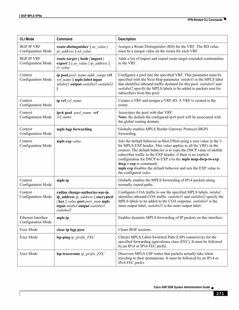
BGP MPLS VPNs
VPN-Related CLI Commands ▀
Cisco ASR 5500 System Administration Guide ▄ 271
CLI Mode Command Description
BGP IP VRF
Configuration Mode route-distinguisher { as_value |
ip_address } rd_value Assigns a Route Distinguisher (RD) for the VRF. The RD value
must be a unique value on the router for each VRF.
BGP IP VRF
Configuration Mode route-target { both | import |
export } { as_value | ip_address } rt_value
Adds a list of import and export route-target extended communities
to the VRF.
Context
Configuration Mode ip pool pool_name addr_range vrf
vrf_name [ mpls-label input
inlabel1 output outlabel1 outlabel2
]
Configures a pool into the specified VRF. This parameter must be
specified with the Next-Hop parameter. inlabel1 is the MPLS label
that identifies inbound traffic destined for this pool. outlabel1 and
outlabel2 specify the MPLS labels to be added to packets sent for
subscribers from this pool.
Context
Configuration Mode ip vrf vrf_name Creates a VRF and assigns a VRF-ID. A VRF is created in the
router.
Context
Configuration Mode ipv6 pool pool_name vrf vrf_name
Associates the pool with that VRF.
Note: By default the configured ipv6 pool will be associated with
the global routing domain.
Context
Configuration Mode mpls bgp forwarding Globally enables MPLS Border Gateway Protocol (BGP)
forwarding.
Context
Configuration Mode mpls exp value Sets the default behavior as Best Effort using a zero value in the 3-
bit MPLS EXP header. This value applies to all the VRFs in the
context. The default behavior is to copy the DSCP value of mobile
subscriber traffic to the EXP header, if there is no explicit
configuration for DSCP to EXP (via the mpls map-dscp-to-exp
dscp n exp m command).
mpls exp disables the default behavior and sets the EXP value to
the configured value.
Context
Configuration Mode mpls ip Globally enables the MPLS forwarding of IPv4 packets along
normally routed paths.
Context
Configuration Mode radius change-authorize-nas-ip
ip_address ip_address { encrypted
| key } value port port_num mpls
input inlabel output outlabel1 outlabel2
Configures COA traffic to use the specified MPLS labels. inlabel
identifies inbound COA traffic. outlabel1 and outlabel2 specify the
MPLS labels to be added to the COA response. outlabel1 is the
inner output label; outlabel2 is the outer output label.
Ethernet Interface
Configuration Mode mpls ip Enables dynamic MPLS forwarding of IP packets on this interface.
Exec Mode clear ip bgp peer Clears BGP sessions.
Exec Mode lsp-ping ip_prefix_FEC Checks MPLS Label-Switched Path (LSP) connectivity for the
specified forwarding equivalence class (FEC). It must be followed
by an IPv4 or IPv6 FEC prefix.
Exec Mode lsp-traceroute ip_prefix_FEC Discovers MPLS LSP routes that packets actually take when
traveling to their destinations. It must be followed by an IPv4 or
IPv6 FEC prefix.
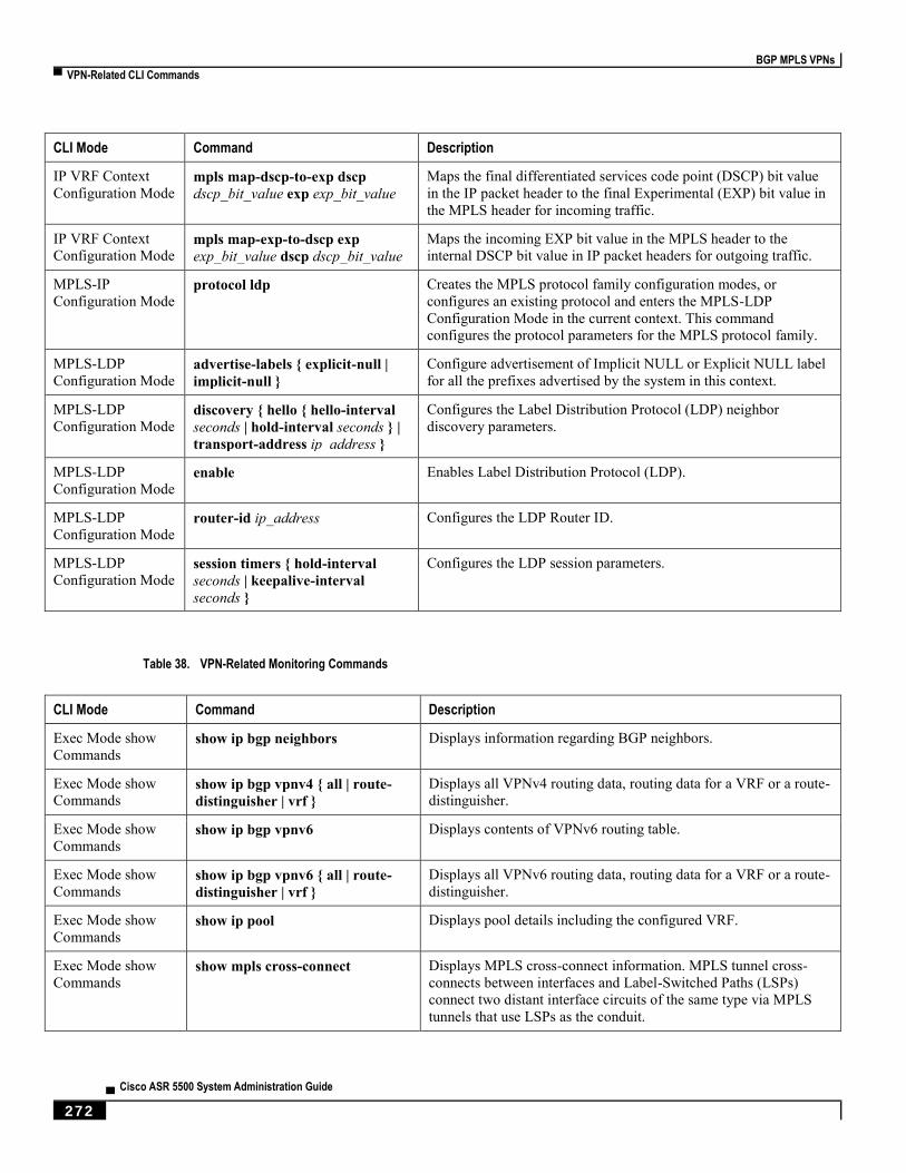
BGP MPLS VPNs
▀ VPN-Related CLI Commands
▄ Cisco ASR 5500 System Administration Guide
272
CLI Mode Command Description
IP VRF Context
Configuration Mode mpls map-dscp-to-exp dscp
dscp_bit_value exp exp_bit_value Maps the final differentiated services code point (DSCP) bit value
in the IP packet header to the final Experimental (EXP) bit value in
the MPLS header for incoming traffic.
IP VRF Context
Configuration Mode mpls map-exp-to-dscp exp
exp_bit_value dscp dscp_bit_value Maps the incoming EXP bit value in the MPLS header to the
internal DSCP bit value in IP packet headers for outgoing traffic.
MPLS-IP
Configuration Mode protocol ldp Creates the MPLS protocol family configuration modes, or
configures an existing protocol and enters the MPLS-LDP
Configuration Mode in the current context. This command
configures the protocol parameters for the MPLS protocol family.
MPLS-LDP
Configuration Mode advertise-labels { explicit-null |
implicit-null } Configure advertisement of Implicit NULL or Explicit NULL label
for all the prefixes advertised by the system in this context.
MPLS-LDP
Configuration Mode discovery { hello { hello-interval
seconds | hold-interval seconds } |
transport-address ip_address }
Configures the Label Distribution Protocol (LDP) neighbor
discovery parameters.
MPLS-LDP
Configuration Mode enable Enables Label Distribution Protocol (LDP).
MPLS-LDP
Configuration Mode router-id ip_address Configures the LDP Router ID.
MPLS-LDP
Configuration Mode session timers { hold-interval
seconds | keepalive-interval
seconds }
Configures the LDP session parameters.
Table 38. VPN-Related Monitoring Commands
CLI Mode Command Description
Exec Mode show
Commands show ip bgp neighbors Displays information regarding BGP neighbors.
Exec Mode show
Commands show ip bgp vpnv4 { all | route-
distinguisher | vrf } Displays all VPNv4 routing data, routing data for a VRF or a route-
distinguisher.
Exec Mode show
Commands show ip bgp vpnv6 Displays contents of VPNv6 routing table.
Exec Mode show
Commands show ip bgp vpnv6 { all | route-
distinguisher | vrf } Displays all VPNv6 routing data, routing data for a VRF or a route-
distinguisher.
Exec Mode show
Commands show ip pool Displays pool details including the configured VRF.
Exec Mode show
Commands show mpls cross-connect Displays MPLS cross-connect information. MPLS tunnel cross-
connects between interfaces and Label-Switched Paths (LSPs)
connect two distant interface circuits of the same type via MPLS
tunnels that use LSPs as the conduit.

BGP MPLS VPNs
VPN-Related CLI Commands ▀
Cisco ASR 5500 System Administration Guide ▄ 273
CLI Mode Command Description
Exec Mode show
Commands show mpls ftn [ vrf vrf_name Displays MPLS FEC-to-NHLFE (FTN) table information.
Exec Mode show
Commands show mpls ftn [ vrf vrf_name ] Displays contents of the MPLS FTN table for a specified VRF.
Exec Mode show
Commands show mpls ilm Displays MPLS Incoming Label Map (ILM) table information.
Exec Mode show
Commands show mpls ldp Displays the MPLS LDP information.
Exec Mode show
Commands show mpls nexthop-label-
forwarding-entry Displays MPLS Next-Hop Label Forwarding Entry (NHLFE) table
information.

Cisco ASR 5500 System Administration Guide ▄ 275
Chapter 19 Content Service Steering
This chapter provides information on configuring Content Service Steering (CSS). The product administration guides
provide examples and procedures for configuration of basic services on the system. You should select the configuration
example that best meets your service model, and configure the required elements for that model as described in the
respective product administration guide, before using the procedures described below.
Important: Internal CSS is a generic feature, if an ECSv2 license is installed on your system, internal CSS can
be enabled. A separate license is not required to enable internal CSS. Contact your local Cisco account representative
for information on how to obtain a license.
This chapter contains the following topics:
Overview
Configuring Internal Content Service Steering
Content Service Steering
▀ Overview
▄ Cisco ASR 5500 System Administration Guide
276
Overview Content Service Steering (CSS) selectively directs subscriber traffic to In-line services internal to the system based on
data content presented by mobile subscribers. CSS is a broad term that includes features such as NAT, HTTP
redirection, and DNS redirection.
CSS uses Access Control Lists (ACLs) to redirect subscriber traffic flows. ACLs control the flow of packets into and
out of the system. ACLs consist of “rules” (ACL rules) or filters that control the action taken on packets matching the
filter criteria.
ACLs are configurable on a per-context basis and applies to a subscriber through either a subscriber profile (or an APN
profile in the destination context. For additional information, refer to the Access Control Lists chapter.
Content Service Steering
Configuring Internal Content Service Steering ▀
Cisco ASR 5500 System Administration Guide ▄ 277
Configuring Internal Content Service Steering To configure and activate a single CSS service for redirecting all of a subscriber’s IP traffic to an internal in-line
service:
Step 1 Define an IP ACL as described in Defining IP Access Lists for Internal CSS.
Step 2 Optional: Apply an ACL to an individual subscriber as described in Applying an ACL to an Individual Subscriber
(Optional).
Step 3 Optional: Apply a single ACL to multiple subscribers as described in Applying an ACL to Multiple Subscribers
(Optional).
Step 4 Optional: Apply an ACL to multiple subscribers via APNs as described in Applying an ACL to Multiple Subscribers
via APNs (Optional).
Step 5 Save your configuration to flash memory, an external memory device, and/or a network location using the Exec mode
command save configuration. For additional information on how to verify and save configuration files, refer to the
System Administration Guide and the Command Line Interface Reference.
Important: Commands used in the configuration examples in this section provide base functionality to the
extent that the most common or likely commands and/or keyword options are presented. In many cases, other optional
commands and/or keyword options are available. Refer to the Command Line Interface Reference for complete
information regarding all commands. Not all commands or keywords/variables may be supported or available.
Availability varies on the platform type and installed license(s).
Defining IP Access Lists for Internal CSS
IP ACLs specify what type of subscriber traffic and which direction (uplink, downlink, or both) traffic is redirected. The
IP ACL must be specified in the context in which subscriber authentication is performed.
Caution: To minimize the risk of data loss, do not make configuration changes to ACLs while the system is
facilitating subscriber sessions.
Use the following configuration example to define an IP ACL for internal CSS; start in the Exec mode of the CLI:
configure
context context_name
ip access-list acl_name
redirect css service service_name keywords options
end
Notes:
service_name must be an ACL service name.
Content Service Steering
▀ Configuring Internal Content Service Steering
▄ Cisco ASR 5500 System Administration Guide
278
For information on the keywords and options available with the redirect css service command, see the ACL
Configuration Mode Commands chapter in the Command Line Interface Reference.
For IPv6 ACLs, the same configurations must be done in the IPv6 ACL Configuration Mode. See the IPv6 ACL
Configuration Mode Commands chapter in the Command Line Interface Reference.
Applying an ACL to an Individual Subscriber (Optional)
For information on how to apply an ACL to an individual subscriber, refer to the Applying an ACL to an Individual
Subscriber section of the Access Control Lists chapter.
Applying an ACL to Multiple Subscribers (Optional)
IP ACLs are applied to subscribers via attributes in their profiles. The subscriber profile can be configured locally on the
system or remotely on a RADIUS server.
The system provides for the configuration of subscriber functions that serve as default values when specific attributes
are not contained in the individual subscriber’s profile. When configured properly, the functions can be used to apply an
ACL to:
All subscribers facilitated within a specific context by applying the ACL to the profile of the subscriber named
default.
All subscribers facilitated by specific services by applying the ACL to a subscriber profile and then using the
default subscriber command to configure the service to use that subscriber as the “default” profile.
Applying an ACL to the Subscriber Named default (Optional)
For information on how to apply an ACL to the default subscriber, refer to the Applying an ACL to the Subscriber
Named default section in the Access Control Lists chapter.
Applying an ACL to Service-specified Default Subscribers (Optional)
For information on how to apply an ACL to the subscriber to be used as the “default” profile by various system services,
refer to the Applying an ACL to Service-specified Default Subscribers section in the Access Control Lists chapter.
Applying an ACL to Multiple Subscribers via APNs (Optional)
IP ACLs are applied to subscribers via attributes in their profiles. The subscriber profile can be configured locally on the
system or remotely on a RADIUS server.
To reduce configuration time, ACLs can alternatively be applied to APN templates. When configured, any subscriber
packets facilitated by the APN template would then have the associated ACL applied.
For information on how to apply an ACL to multiple subscribers via APNs, refer to the Applying a Single ACL to
Multiple Subscribers via APNs section in the Access Control Lists chapter.
Cisco ASR 5500 System Administration Guide ▄ 279
Chapter 20 Session Recovery
With robust hardware failover and redundancy protection, any card-level hardware failures on the system can quickly be
corrected. However, software failures can occur for numerous reasons, often without prior indication.
This chapter describes the Session Recovery feature that provides seamless failover and reconstruction of subscriber
session information in the event of a hardware or software fault.
Important: Session Recovery is a licensed Cisco feature. A separate feature license may be required. Contact
your Cisco account representative for detailed information on specific licensing requirements. For information on
installing and verifying licenses, refer to the Managing License Keys section of Software Management Operations.
This chapter includes the following sections:
How Session Recovery Works
Additional ASR 5x00 Hardware Requirements
Configuring the System to Support Session Recovery

Session Recovery
▀ How Session Recovery Works
▄ Cisco ASR 5500 System Administration Guide
280
How Session Recovery Works This section provides an overview of how this feature is implemented and the recovery process.
The Session Recovery feature provides seamless failover and reconstruction of subscriber session information in the
event of a hardware or software fault within the system preventing a fully connected user session from being
disconnected.
Session recovery is performed by mirroring key software processes (for example, session manager and AAA manager)
within the system. These mirrored processes remain in an idle state (standby-mode) wherein they perform no
processing, until they may be needed in the event of a software failure (for example, a session manager task aborts).
The system spawns new instances of “standby mode” session and AAA managers for each active control processor (CP)
being used. These mirrored processes require both memory and processing resources, which means that additional
hardware may be required to enable this feature (see Additional Hardware Requirements).
Other key system-level software tasks, such as VPN manager, are performed on a physically separate packet processing
card to ensure that a double software fault (for example, session manager and VPN manager fails at same time on same
card) cannot occur. The packet processing card that hosts the VPN manager process is in active mode and reserved by
the operating system for this sole use when session recovery is enabled.
There are two modes of session recovery.
Task recovery mode: Wherein one or more session manager failures occur and are recovered without the need
to use resources on a standby packet processing card. In this mode, recovery is performed by using the
mirrored “standby-mode” session manager task(s) running on active packet processing cards. The “standby-
mode” task is renamed, made active, and is then populated using information from other tasks such as AAA
manager. In case of Task failure, limited subscribers will be affected and will suffer outage only until the task
starts back up.
Full packet processing card recovery mode: Used when a packet processing card hardware failure occurs, or
when a planned packet processing card migration fails. In this mode, the standby packet processing card is
made active and the “standby-mode” session manager and AAA manager tasks on the newly activated packet
processing card perform session recovery.
Session/Call state information is saved in the peer AAA manager task because each AAA manager and session manager
task is paired together. These pairs are started on physically different packet processing cards to ensure task recovery.
There are some situations wherein session recovery may not operate properly. These include:
Additional software or hardware failures occur during the session recovery operation. For example, an AAA
manager fails while the state information it contained was being used to populate the newly activated session
manager task.
A lack of hardware resources (packet processing card memory and control processors) to support session
recovery.
Important: After a session recovery operation, some statistics, such as those collected and maintained on a per
manager basis (AAA Manager, Session Manager, etc.) are in general not recovered, only accounting and billing related
information is checkpointed and recovered.
Session Recovery is available for the following functions:
Any session needing L2TP LAC support (excluding regenerated PPP on top of an HA or GGSN session)
ASR 5000 only – Closed RP PDSN services supporting simple IP, Mobile IP, and Proxy Mobile IP
Session Recovery
How Session Recovery Works ▀
Cisco ASR 5500 System Administration Guide ▄ 281
CSCF sessions
ASR 5000 only – eHRPD service (evolved High Rate Packet Data)
ASR 5000 only – ePDG service (evolved Packet Data Gateway)
ASR 5000 only – eWAG service (enhanced Wireless Access Gateway)
GGSN services for IPv4 and PPP PDP contexts
HA services supporting Mobile IP and/or Proxy Mobile IP session types with or without per-user Layer 3 tunnels
ASR 5000 only – HNB-GW: HNB Session over IuH
ASR 5000 only – HNB-GW: HNB-CN Session over IuPS and IuCS
ASR 5000 only – HNB-GW: SeGW Session IPSec Tunnel
ASR 5000 only – HSGW services for IPv4
IPCF (Intelligent Policy Control Function)
ASR 5000 only – IPSG-only systems (IP Services Gateway)
LNS session types (L2TP Network Server)
MME (Mobility Management Entity)
ASR 5000 only – NEMO (Network Mobility )
P-GW services for IPv4
ASR 5000 only – PDG/TTG (Packet Data Gateway/Tunnel Termination Gateway)
ASR 5000 only – PDIF (Packet Data Interworking Function)
PDSN services supporting simple IP, Mobile IP, and Proxy Mobile IP
S-GW (Serving Gateway)
SAE-GW (System Architecture Evolution Gateway)
SCM (Service Control Manager)
ASR 5000 only – SGSN services (3G and 2.5G services) for IPv4 and PPP PDP contexts
Session recovery is not supported for the following functions:
Destination-based accounting recovery
GGSN network initiated connections
GGSN session using more than 1 service instance
MIP/L2TP with IPSec integration
MIP session with multiple concurrent bindings
Mobile IP sessions with L2TP
Multiple MIP sessions
Important: Always refer to the Administration Guides for individual products for other possible session
recovery and Interchassis Session Recovery (ICSR) support limitations.
When session recovery occurs, the system reconstructs the following subscriber information:
Data and control state information required to maintain correct call behavior.
A minimal set of subscriber data statistics; required to ensure that accounting information is maintained.

Session Recovery
▀ Additional ASR 5x00 Hardware Requirements
▄ Cisco ASR 5500 System Administration Guide
282
A best-effort attempt to recover various timer values such as call duration, absolute time, and others.
The idle time timer is reset to zero and the re-registration timer is reset to its maximum value for HA sessions to
provide a more conservative approach to session recovery.
Important: Any partially connected calls (for example, a session where HA authentication was pending but has
not yet been acknowledged by the AAA server) are not recovered when a failure occurs.
Additional ASR 5x00 Hardware Requirements Because session recovery requires numerous hardware resources, such as memory, control processors, NPU processing
capacity, some additional hardware may be required to ensure that enough resources are available to fully support this
feature.
Important: A minimum of four packet processing cards (three active and one standby) per individual chassis is
required to use this feature.
To allow for complete session recovery in the event of a hardware failure during a packet processing card migration, a
minimum of three active packet processing cards and two standby packet processing cards should be deployed.
To assist you in your network design and capacity planning, consider the following factors:
Subscriber capacity is decreased depending on the hardware configuration. A fully configured chassis would
experience a smaller decrease in subscriber capacity versus a minimally configured chassis.
The amount by which control transaction processing capacity is reduced.
The reduction in subscriber data throughput.
The recovery time for a failed software task.
The recovery time for a failed packet processing card.
A packet processing card migration may temporarily impact session recovery as hardware resources (memory,
processors, etc.) that may be needed are not available during the migration. To avoid this condition, a minimum of two
standby packet processing cards should be configured.
Session Recovery
Configuring the System to Support Session Recovery ▀
Cisco ASR 5500 System Administration Guide ▄ 283
Configuring the System to Support Session Recovery The following procedures allow you to configure the session recovery feature for either an operational system that is
currently in-service (able to accept incoming calls) or a system that is out-of-service (not part of your production
network and, therefore, not processing any live subscriber/customer data).
Important: The session recovery feature, even when the feature use key is present, is disabled by default on the
system.
Enabling Session Recovery
As noted earlier, session recovery can be enabled on a system that is out-of-service (OOS) and does not yet have any
contexts configured, or on an in-service system that is currently capable of processing calls. However, if the system is
in-service, it must be restarted before the session recovery feature takes effect.
Enabling Session Recovery on an Out-of-Service System
The following procedure is for a system that does not have any contexts configured.
To enable the session recovery feature on an out-of-service system, follow the procedure below. This procedure
assumes that you begin at the Exec mode prompt.
Step 1 At the Exec mode prompt, verify that the session recovery feature is enabled via the session and feature use licenses on
the system by running the show license info command.
Important: If the current status of the Session Recovery feature is Disabled, you cannot enable this feature until
a license key is installed in the system.
Step 2 Use the following configuration example to enable session recovery.
configure
require session recovery
end
Step 3 Save your configuration as described in Verifying and Saving Your Configuration.
The system, when started, enables session recovery, creates all mirrored “standby-mode” tasks, and performs packet
processing card reservations and other operations automatically.
Step 4 After the system has been configured and placed in-service, you should verify the preparedness of the system to support
this feature as described in Viewing Session Recovery Status.

Session Recovery
▀ Configuring the System to Support Session Recovery
▄ Cisco ASR 5500 System Administration Guide
284
Enabling Session Recovery on an In-Service System
When enabling session recovery on a system that already has a saved configuration, the session recovery commands are
automatically placed before any service configuration commands in the configuration file.
To enable the session recovery feature on an in-service system, follow the procedure below. This procedure assumes
that you begin at the Exec mode prompt.
Step 1 At the Exec mode prompt, verify that the session recovery feature is enabled via the session and feature use licenses on
the system by running the show license info command:
Important: If the current status of the Session Recovery feature is Disabled, You cannot enable this feature until
a license key is installed in the system.
Step 2 Use the following configuration example to enable session recovery.
configure
require session recovery
end
Important: This feature does not take effect until after the system has been restarted.
Step 3 Save your configuration as described in Verifying and Saving Your Configuration.
Step 4 Perform a system restart by entering the reload command:
The following prompt appears:
Are you sure? [Yes|No]:
Confirm your desire to perform a system restart by entering yes.
The system, when restarted, enables session recovery and creates all mirrored “standby-mode” tasks, performs packet
processing card reservations, and other operations automatically.
Step 5 After the system has been restarted, you should verify the preparedness of the system to support this feature as
described in Viewing Session Recovery Status.
Important: More advanced users may opt to simply insert the require session recovery command syntax into
an existing configuration file using a text editor or other means, and then applying the configuration file manually.
Exercise caution when doing this to ensure that this command is placed among the first few lines of any existing
configuration file; it must appear before the creation of any non-local context.

Session Recovery
Configuring the System to Support Session Recovery ▀
Cisco ASR 5500 System Administration Guide ▄ 285
Disabling the Session Recovery Feature
To disable the session recovery feature on a system, enter the no require session recovery command from the Global
Configuration mode prompt.
Important: If this command is issued on an in-service system, then the system must be restarted by issuing the
reload command.
Viewing Session Recovery Status
To determine if the system is capable of performing session recovery, when enabled, enter the show session recovery
status verbose command from the Exec mode prompt.
The output of this command should be similar to the examples shown below.
[local]host_name# show session recovery status
Session Recovery Status:
Overall Status : SESSMGR Not Ready For Recovery
Last Status Update : 1 second ago
[local]host_name# show session recovery status
Session Recovery Status:
Overall Status : Ready For Recovery
Last Status Update : 8 seconds ago
[local]host_name# show session recovery status verbose
Session Recovery Status:
Overall Status : Ready For Recovery
Last Status Update : 2 seconds ago
----sessmgr--- ----aaamgr---- demux
cpu state active standby active standby active status
---- ------- ------ ------- ------ ------- ------ ------------
1/1 Active 2 1 1 1 0 Good
1/2 Active 1 1 0 0 0 Good
1/3 Active 1 1 3 1 0 Good
2/1 Active 1 1 1 1 0 Good
2/2 Active 1 1 0 0 0 Good
2/3 Active 2 1 3 1 0 Good
3/0 Active 0 0 0 0 1 Good (Demux)
3/2 Active 0 0 0 0 1 Good (Demux)
4/1 Standby 0 2 0 1 0 Good
4/2 Standby 0 1 0 0 0 Good
4/3 Standby 0 2 0 3 0 Good
[local]host_name#

Session Recovery
▀ Configuring the System to Support Session Recovery
▄ Cisco ASR 5500 System Administration Guide
286
Viewing Recovered Session Information
To view session state information and any session recovery status, enter the following command:
show subscriber debug-info { callid id | msid id | username name }
Keyword/Variable Description
callid id Displays subscriber information for the call specified by id. The call ID is an 8-byte hexadecimal number.
msid id Displays information for the mobile user identified by an MSID from 7 to 16 digits specified as an IMSI,
MIN, or RMI. Wildcard characters $ and * are allowed. The * wildcard matches multiple characters and
the $ wildcard matches a single character. If you do not want the wildcard characters interpreted as a
wildcard enclose them in single quotes ( ‘ ). For example; ‘$’.
username name Displays information for connections for the subscriber identified by a previously configured username.
name is a sequence of alphanumeric characters and/or wildcard characters ('$' and '*') from 1 to 127
characters in length. The * wildcard matches multiple characters and the $ wildcard matches a single
character. If you do not want the wildcard characters interpreted as wildcard enclose them in single
quotes ( ‘). For example; ‘$’.
The following example shows the output of this command both before and after a session recovery operation has been
performed. The “Redundancy Status” fields in this example have been bold-faced for clarity.
username: user1 callid: 01ca11b1 msid: 0000100003
Card/Cpu: 4/2
Sessmgr Instance: 7
Primary callline:
Redundancy Status: Original Session
Checkpoints Attempts Success Last-Attempt Last-Success
Full: 69 68 29800ms 29800ms
Micro: 206 206 20100ms 20100ms
Current state: SMGR_STATE_CONNECTED
FSM Event trace:
State Event
SMGR_STATE_OPEN SMGR_EVT_NEWCALL
SMGR_STATE_NEWCALL_ARRIVED SMGR_EVT_ANSWER_CALL
SMGR_STATE_NEWCALL_ANSWERED SMGR_EVT_LINE_CONNECTED
SMGR_STATE_LINE_CONNECTED SMGR_EVT_LINK_CONTROL_UP
SMGR_STATE_LINE_CONNECTED SMGR_EVT_AUTH_REQ
SMGR_STATE_LINE_CONNECTED SMGR_EVT_IPADDR_ALLOC_SUCCESS
SMGR_STATE_LINE_CONNECTED SMGR_EVT_AUTH_SUCCESS
SMGR_STATE_LINE_CONNECTED SMGR_EVT_UPDATE_SESS_CONFIG
SMGR_STATE_LINE_CONNECTED SMGR_EVT_LOWER_LAYER_UP
Data Reorder statistics
Total timer expiry: 0 Total flush (tmr expiry): 0
Total no buffers: 0 Total flush (no buffers): 0
Total flush (queue full): 0 Total flush (out of range): 0
Total flush (svc change): 0 Total out-of-seq pkt drop: 0
Total out-of-seq arrived: 0
IPv4 Reassembly Statistics:
Success: 0 In Progress: 0
Failure (timeout): 0 Failure (no buffers): 0
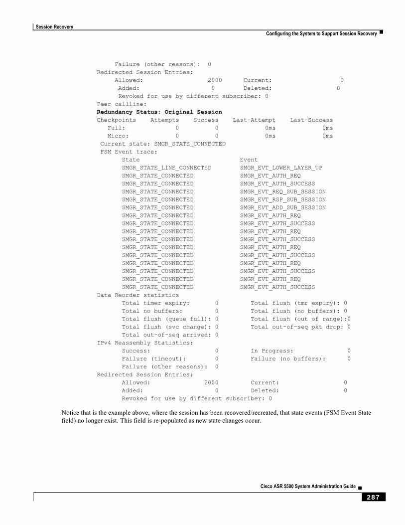
Session Recovery
Configuring the System to Support Session Recovery ▀
Cisco ASR 5500 System Administration Guide ▄ 287
Failure (other reasons): 0
Redirected Session Entries:
Allowed: 2000 Current: 0
Added: 0 Deleted: 0
Revoked for use by different subscriber: 0
Peer callline:
Redundancy Status: Original Session
Checkpoints Attempts Success Last-Attempt Last-Success
Full: 0 0 0ms 0ms
Micro: 0 0 0ms 0ms
Current state: SMGR_STATE_CONNECTED
FSM Event trace:
State Event
SMGR_STATE_LINE_CONNECTED SMGR_EVT_LOWER_LAYER_UP
SMGR_STATE_CONNECTED SMGR_EVT_AUTH_REQ
SMGR_STATE_CONNECTED SMGR_EVT_AUTH_SUCCESS
SMGR_STATE_CONNECTED SMGR_EVT_REQ_SUB_SESSION
SMGR_STATE_CONNECTED SMGR_EVT_RSP_SUB_SESSION
SMGR_STATE_CONNECTED SMGR_EVT_ADD_SUB_SESSION
SMGR_STATE_CONNECTED SMGR_EVT_AUTH_REQ
SMGR_STATE_CONNECTED SMGR_EVT_AUTH_SUCCESS
SMGR_STATE_CONNECTED SMGR_EVT_AUTH_REQ
SMGR_STATE_CONNECTED SMGR_EVT_AUTH_SUCCESS
SMGR_STATE_CONNECTED SMGR_EVT_AUTH_REQ
SMGR_STATE_CONNECTED SMGR_EVT_AUTH_SUCCESS
SMGR_STATE_CONNECTED SMGR_EVT_AUTH_REQ
SMGR_STATE_CONNECTED SMGR_EVT_AUTH_SUCCESS
SMGR_STATE_CONNECTED SMGR_EVT_AUTH_REQ
SMGR_STATE_CONNECTED SMGR_EVT_AUTH_SUCCESS
Data Reorder statistics
Total timer expiry: 0 Total flush (tmr expiry): 0
Total no buffers: 0 Total flush (no buffers): 0
Total flush (queue full): 0 Total flush (out of range):0
Total flush (svc change): 0 Total out-of-seq pkt drop: 0
Total out-of-seq arrived: 0
IPv4 Reassembly Statistics:
Success: 0 In Progress: 0
Failure (timeout): 0 Failure (no buffers): 0
Failure (other reasons): 0
Redirected Session Entries:
Allowed: 2000 Current: 0
Added: 0 Deleted: 0
Revoked for use by different subscriber: 0
Notice that is the example above, where the session has been recovered/recreated, that state events (FSM Event State
field) no longer exist. This field is re-populated as new state changes occur.


Cisco ASR 5500 System Administration Guide ▄ 289
Chapter 21 Interchassis Session Recovery
This chapter describes how to configure Interchassis Session Recovery (ICSR). The product Administration Guides
provide examples and procedures for configuration of basic services on the system. You should select the configuration
example that best meets your service model, and configure the required elements for that model as described in the
respective product Administration Guide, before using the procedures described below.
Important: ICSR is a licensed Cisco feature that requires a separate license. Contact your Cisco account
representative for detailed information on specific licensing requirements. For information on installing and verifying
licenses, refer to the Managing License Keys section of Software Management Operations.
This chapter discusses the following:
Overview
ICSR Operation
Configuring Interchassis Session Recovery (ICSR)
Updating the Operating System
Interchassis Session Recovery
▀ Overview
▄ Cisco ASR 5500 System Administration Guide
290
Overview The ICSR feature provides the highest possible availability for continuous call processing without interrupting
subscriber services. ICSR allows the operator to configure geographically distant gateways for redundancy purposes. In
the event of a node or gateway failure, ICSR allows sessions to be transparently routed around the failure, thus
maintaining the user experience. ICSR also preserves session information and state.
ICSR is implemented through the use of redundant chassis. The chassis are configured as primary and backup, with one
being active and one standby. Both chassis are connected to the same AAA server. A checkpoint duration timer controls
when subscriber data is sent from the active chassis to the standby chassis. If the active chassis handling the call traffic
goes out of service, the standby chassis transitions to the active state and continues processing the call traffic without
interrupting the subscriber session.
The chassis determine which is active through a proprietary TCP-based connection known as the Service Redundancy
Protocol (SRP) link. The SRP link is used to exchange Hello messages between the primary and backup chassis and
must be maintained for proper system operation.
ICSR licenses are currently supported for the following services:
eHRPD – Evolved High Rate Packet Data
ePDG – Evolved Packet Data Gateway
GGSN – Gateway GPRS Support Node
HA – Home Agent
IPSG – IP Services Gateway
MME – Mobility Management Entity
P-GW – Packet Data Network Gateway
PDSN – Packet Data Serving Node
S-GW – Serving Gateway
SAEGW – System Architecture Evolution Gateway
Important: For releases prior to 17.0, ICSR should not be configured on chassis supporting L2TP calls.
Important: Contact your Cisco account representative to verify whether a specific service supports ICSR as an
option.

Interchassis Session Recovery
Overview ▀
Cisco ASR 5500 System Administration Guide ▄ 291
Interchassis Communication
Chassis configured to support ICSR communicate using periodic Hello messages. These messages are sent by each
chassis to notify the peer of its current state. The Hello message contains information about the chassis such as its
configuration and priority. A dead interval is used to set a time limit for a Hello message to be received from the
chassis’ peer. If the standby chassis does not receive an Hello message from the active chassis within the dead interval,
the standby chassis transitions to the active state. In situations where the SRP link goes out of service, a priority scheme
is used to determine which chassis processes the session. The following priority scheme is used:
route modifier
chassis priority
MIO/UMIO MAC address
Checkpoint Messages
Checkpoint messages are sent from the active chassis to the standby chassis. These messages are sent at specific
intervals and contain all the information needed to recreate the sessions on the standby chassis, if that chassis were to
become active. Once a session exceeds the checkpoint duration, checkpoint data is collected on the session.
AAA Monitor
AAA servers are monitored using the authentication probe mechanism. AAA servers are considered Up if the
authentication-probe receives a valid response. AAA servers are considered Down when the max-retries count
specified in the configuration of the AAA server has been reached. SRP initiates a switchover when none of the
configured AAA servers responds to an authentication probe. AAA probing is only performed on the active chassis.
Important: A switchover event caused by an AAA monitoring failure is non-revertible.
If the newly active chassis fails to monitor the configured AAA servers, it remains as the active chassis until one of the
following occurs:
a manual switchover
another non-AAA failure event causes the system to switchover
a CLI command is used to clear the AAA failure flag and allow the chassis to switch to standby
BGP Interaction
The Service Redundancy Protocol implements revertible switchover behavior via a mechanism that adjusts the route
modifier value for the advertised loopback/IP Pool routes. The initial value of the route modifier value is determined by
the chassis’ configured role and is initialized to a value that is higher than a normal operational value. This ensures that
in the event of an SRP link failure and an SRP task failure, the correct chassis is still preferred in the routing domain.
The Active and Standby chassis share current route modifier values. When BGP advertises the loopback and IP pool
routes, it converts the route modifier into an autonomous systems (AS) path prepend count. The Active chassis always
has a lower route modifier, and thus prepends less to the AS-path attribute. This causes the route to be preferred in the
routing domain.

Interchassis Session Recovery
▀ Overview
▄ Cisco ASR 5500 System Administration Guide
292
If communication on the SRP link is lost, and both chassis in the redundant pair are claiming to be Active, the
previously Active chassis is still preferred since it is advertising a smaller AS-path into the BGP routing domain. The
route modifier is incremented as switchover events occur. A threshold determines when the route modifier should be
reset to its initial value to avoid rollover.
Requirements
ICSR configurations require the following:
Two chassis configured for the same service types. The services must be bound on an SRP-activated loopback
interface.
Both chassis must have identical hardware.
Three contexts:
Redundancy – to configure the primary and backup chassis redundancy.
Source – AAA configuration of the specified nas-ip-address must be the IP address of an interface
bound to an HA, or any core network service configured within the same context.
Destination – to configure monitoring and routing to the PDN.
AAA RADIUS server
Border Gateway Protocol (BGP) – ICSR uses the route modifier to determine the chassis priority.
Important: ICSR is a licensed Cisco feature. Verify that each chassis has the appropriate license before using
these procedures. To do this, log in to both chassis and execute a show license information command. Look for “Inter-
Chassis Session Recovery”. If the chassis is not licensed, please contact your Cisco account representative.
The following figure shows an ICSR network.
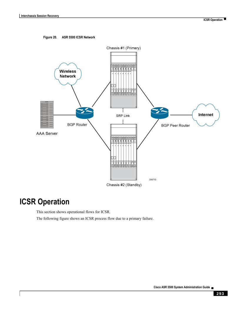
Interchassis Session Recovery
ICSR Operation ▀
Cisco ASR 5500 System Administration Guide ▄ 293
Figure 20. ASR 5500 ICSR Network
ICSR Operation This section shows operational flows for ICSR.
The following figure shows an ICSR process flow due to a primary failure.
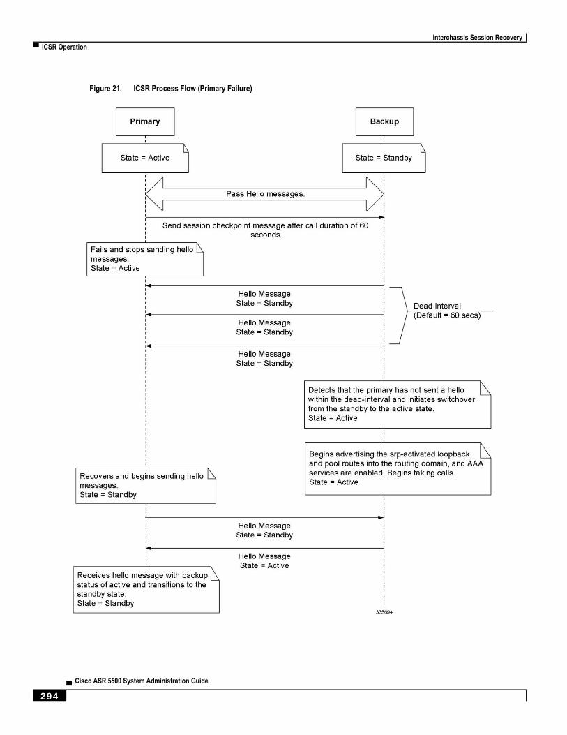
Interchassis Session Recovery
▀ ICSR Operation
▄ Cisco ASR 5500 System Administration Guide
294
Figure 21. ICSR Process Flow (Primary Failure)
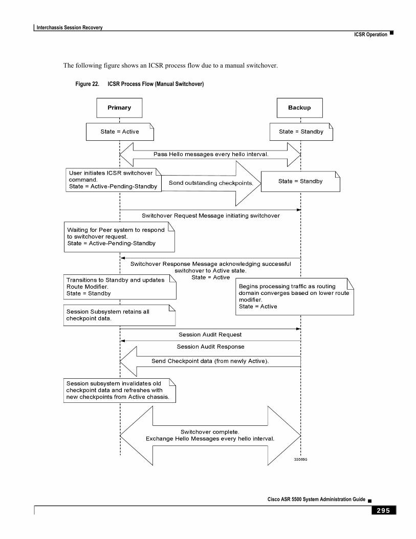
Interchassis Session Recovery
ICSR Operation ▀
Cisco ASR 5500 System Administration Guide ▄ 295
The following figure shows an ICSR process flow due to a manual switchover.
Figure 22. ICSR Process Flow (Manual Switchover)
Interchassis Session Recovery
▀ ICSR Operation
▄ Cisco ASR 5500 System Administration Guide
296
Chassis Initialization
When the chassis are simultaneously initialized, they send Hello messages to their configured peer. The peer sends a
response, establishes communication between the chassis, and messages are sent that contain configuration information.
During initialization, if both chassis are misconfigured in the same mode - both active (primary) or both standby
(backup), the chassis with the highest priority (lowest number set with the ICSR priority command) becomes active and
the other chassis becomes the standby.
If the chassis priorities are the same, the system compares the two MAC addresses and the chassis with the higher
MIO/UMIO MAC address becomes active. For example, if the chassis have MAC addresses of 00-02-43-03-1C-2B and
00-02-43-03-01-3B, the last 3 sets of octets (the first 3 sets are the vendor code) are compared. In this example, the
03-1C-2B and 03-01-3B are compared from left to right. The first pair of octets in both MAC addresses are the same, so
the next pairs are compared. Since the 01 is lower than the 1C, the chassis with the MIO/UMIO MAC address of
00-02-43-03-1C-2B becomes active and the other chassis the standby.
Chassis Operation
This section describes how the chassis communicate, maintain subscriber sessions, and perform chassis switchover.
Chassis Communication
If one chassis in the active state and one in the standby state, they both send Hello messages at each hello interval.
Subscriber sessions that exceed the checkpoint session duration are included in checkpoint messages that are sent to the
standby chassis. The checkpoint message contains subscriber session information so if the active chassis goes out of
service, the backup chassis becomes active and is able to continue processing the subscriber sessions. Additional
checkpoint messages occur at various intervals whenever subscriber session information is updated on the standby
chassis.
Chassis Switchover
If the active chassis goes out of service, the standby chassis continues to send Hello messages. If the standby chassis
does not receive a response to the Hello messages within the dead interval, the standby chassis initiates a switchover.
During the switchover, the standby chassis begins advertising its srp-activated loopback and pool routes into the routing
domain. Once the chassis becomes active, it continues to process existing AAA services and subscriber sessions that had
checkpoint information, and is also able to establish new subscriber sessions.
When the primary chassis is back in service, it sends Hello messages to the configured peer. The peer sends a response,
establishes communication between the chassis, and sends Hello messages that contain configuration information. The
primary chassis receives an Hello message that shows the backup chassis state as active and then transitions to standby.
The Hello messages continue to be sent to each peer, and checkpoint information is now sent from the active chassis to
the standby chassis at regular intervals.
When chassis switchover occurs, the session timers are recovered. The access gateway session recovery is recreated
with the full lifetime to avoid potential loss of the session and the possibility that a renewal update was lost in the
transitional checkpoint update process.
Interchassis Session Recovery
Configuring Interchassis Session Recovery (ICSR) ▀
Cisco ASR 5500 System Administration Guide ▄ 297
Configuring Interchassis Session Recovery (ICSR)
Important: The ICSR configuration must be the same on the primary and backup chassis. If each chassis has a
different Service Redundancy Protocol (SRP) configuration, the session recovery feature does not function and sessions
cannot be recovered when the active chassis goes out of service.
This section describes how to configure basic ICSR on each chassis. For information on commands that configure
additional parameters and options, refer to the Command Line Interface Reference.
Caution: ICSR should not be configured for chassis supporting L2TP calls.
The procedures described below assume the following:
The chassis have been installed and configured with core network services.
For more configuration information and instructions on configuring services, refer to the respective product
Administration Guide.
In addition, the IP address pools must be srp activated.
AAA server is installed, configured and accessible by both chassis.
For more information on configuring the AAA server, refer to the AAA Interface Administration and
Reference.
BGP router installed and configured. See Routing for more information on configuring BGP services.
To configure the ICSR on a primary and/or backup chassis:
Step 1 Configure the SRP context by applying the example configuration in Configuring the Service Redundancy Protocol
(SRP) Context.
Step 2 Modify the source context of the core network service by applying the example configuration in Modifying the Source
Context for ICSR.
Step 3 Modify the destination context of core network service by applying the example configuration in Modifying the
Destination Context for ICSR.
Step 4 Optional: Disable bulk statistics collection on the standby system by applying the example configuration in Disabling
Bulk Statistics Collection on a Standby System.
Step 5 Verify your primary and backup chassis configuration by following the steps in Verifying the Primary and Backup
Chassis Configuration.
Step 6 Save your configuration as described in Verifying and Saving Your Configuration.

Interchassis Session Recovery
▀ Configuring Interchassis Session Recovery (ICSR)
▄ Cisco ASR 5500 System Administration Guide
298
Configuring the Service Redundancy Protocol (SRP) Context
To configure the system to work with ICSR:
Step 1 Create the chassis redundancy context and bind it to the IP address of the primary chassis by applying the example
configuration in Creating and Binding the SRP Context.
Step 2 Configure the chassis redundancy context with priority, chassis mode, hello interval, dead-interval and peer IP address
by applying the example configuration in Configuring the SRP Context Parameters.
Step 3 Configure the SRP context with interface parameters (including interface name, IP address and port number) for
interchassis communication by applying the example configuration in Configuring the SRP Context Interface
Parameters.
Step 4 Verify your SRP context configuration by following the steps in Verifying SRP Configuration.
Step 5 Save your configuration as described in Verifying and Saving Your Configuration.
Creating and Binding the SRP Context
Use the example below to create the SRP context and bind it to primary chassis IP address:
Important: ICSR is configured using two systems. Be sure to create the redundancy context on both systems.
CLI commands must be executed on both systems. Log onto both chassis before continuing. Always make configuration
changes on the primary chassis first. Before starting this configuration, identify which chassis to configure as the
primary and use that login session.
configure
context srp_ctxt_name [-noconfirm]
service-redundancy-protocol
bind address ip_address
end
Notes:
ICSR should be configured and maintained in a separate context.
Be sure to bind the local IP address to the primary chassis. When configuring the backup chassis, be sure to bind
the local IP address to the backup chassis.

Interchassis Session Recovery
Configuring Interchassis Session Recovery (ICSR) ▀
Cisco ASR 5500 System Administration Guide ▄ 299
Configuring the SRP Context Parameters
This configuration assigns a chassis mode and priority, and also configures the redundancy link between the primary
and backup chassis:
Important: CLI commands must be executed on both chassis. Log onto both chassis before continuing. Always
make configuration changes on the primary chassis first.
configure
context srp_ctxt_name
service-redundancy-protocol
chassis-mode { primary | backup }
priority priority
peer-ip-address ip_address
hello-interval dur_sec
dead-interval dead_dur_sec
end
Notes:
ICSR should be configured and maintained in a separate context.
When assigning the chassis mode on the backup chassis be sure to enter the backup keyword.
The priority determines which chassis becomes active in the event that both chassis are misconfigured with the
same chassis mode; see Chassis Initialization. The higher priority chassis has the lower number. Be sure to
assign different priorities to each chassis.
Enter the IP chassis of the backup chassis as the peer-ip-address to the primary chassis. Assign the IP address of
the primary chassis as the peer-ip-address to the backup chassis.
The dead-interval must be at least three times greater than the hello-interval. For example, if the hello interval
is 10, the dead interval should be at least 30. System performance is severely impacted if the hello interval and
dead interval are not set properly.
Interchassis Session Recovery
▀ Configuring Interchassis Session Recovery (ICSR)
▄ Cisco ASR 5500 System Administration Guide
300
Configuring the SRP Context Interface Parameters
This procedure configures the communication interface with the IP address and port number within the SRP context.
This interface supports interchassis communication.
Important: CLI commands must be executed on both chassis. Log onto both chassis before continuing. Always
make configuration changes on the primary chassis first.
configure
context vpn_ctxt_name [-noconfirm]
interface srp_if_name
ip-address { ip_address | ip_address/mask }
exit
exit
port ethernet slot_num/port_num
description des_string
medium { auto | speed { 10 | 100 | 1000 } duplex { full | half } }
no shutdown
bind interface srp_if_name srp_ctxt_name
end
Verifying SRP Configuration
Step 1 Verify that your SRP contexts were created and configured properly by entering the show srp info command (Exec
Mode).
Sample output for this command as shown. In this example, an SRP context called srp1 was configured with default
parameters.
Service Redundancy Protocol:
----------------------------------------------------------------------
Context: srp1
Local Address: 0.0.0.0
Chassis State: Init
Chassis Mode: Backup
Chassis Priority: 125
Local Tiebreaker: 00-00-00-00-00-00
Route-Modifier: 34
Peer Remote Address: 0.0.0.0
Peer State: Init
Peer Mode: Init

Interchassis Session Recovery
Configuring Interchassis Session Recovery (ICSR) ▀
Cisco ASR 5500 System Administration Guide ▄ 301
Peer Priority: 0
Peer Tiebreaker: 00-00-00-00-00-00
Peer Route-Modifier: 0
Last Hello Message received: -
Peer Configuration Validation: Initial
Last Peer Configuration Error: None
Last Peer Configuration Event: -
Connection State: None
Modifying the Source Context for ICSR
To modify the source context of core service:
Step 1 Add the Border Gateway Protocol (BGP) router AS-path and configure the gateway IP address, neighbor IP address,
remote IP address in the source context where the core network service is configured, by applying the example
configuration in Configuring BGP Router and Gateway Address.
Step 2 Configure the service redundancy context with the BGP neighbor context and IP address to monitor the BGP link
activity by applying the example configuration in Configuring the SRP Context for BGP.
Step 3 Verify your BGP context configuration by following the steps in Verifying BGP Configuration.
Step 4 Save your configuration as described in Verifying and Saving Your Configuration.
Configuring BGP Router and Gateway Address
Use the following example to create the BGP context and network addresses.
configure
context source_ctxt_name
router bgp AS_num
network gw_ip_address
neighbor neighbor_ip_address remote-as AS_num
end
Notes:
source_ctxt_name is the context where the core network service is configured.

Interchassis Session Recovery
▀ Configuring Interchassis Session Recovery (ICSR)
▄ Cisco ASR 5500 System Administration Guide
302
Configuring the SRP Context for BGP
Use the following example to configure the BGP context and IP addresses in the SRP context.
configure
context srp_ctxt_name
service-redundancy-protocol
monitor bgp context source_ctxt_name neighbor_ip_address
end
neighbor_ip_address can be entered in IPv4 dotted-decimal or IPv6 colon-separated-hexadecimal notation. Multiple IP
addresses can be added per context as IPv4 and/or IPv6 IP addresses.
An ICSR failover is triggered when all BGP peers within a context are down.
Optionally, you can configure SRP peer groups within a context. ICSR failover would then occur if all peers within a
group fail. This option is useful in deployments in which a combination of IPv4 and IPv6 peers are spread across
multiple paired VLANs, and IPv4 or IPv6 connectivity is lost by all members of a peer group.
A sample configuration for SRP peer groups within a context (“PGWin”) appears below.
monitor bgp context PGWin 10.1.1.16 group 1
monitor bgp context PGWin 10.1.1.17 group 1
monitor bgp context PGWin 69.2.215.0 group 2
monitor bgp context PGWin 69.2.215.1 group 2
monitor bgp context PGWin 2001:4333:201:1102:103:2a1:: group 3
monitor bgp context PGWin 2001:4333:201:1102:103:2a1:0:1 group 3
In the above sample configuration, ICSR failover would occur if both addresses in group 1, 2 or 3 lost connectivity.
For additional information refer to the description of the monitor bgp, monitor diameter and monitor authentication-
probe commands in the Service Redundancy Protocol Configuration Mode Commands chapter of the Command Line
Interface Reference.
Verifying BGP Configuration
Verify your BGP configuration by entering the show srp monitor bgp command (Exec Mode).
Modifying the Destination Context for ICSR
To modify the destination context of core service:
Step 1 Add the BGP router and configure the gateway IP address, neighbor IP address, remote IP address in the destination
context where the core network service is configured, by applying the example configuration in Configuring BGP
Router and Gateway Address in Destination Context.
Step 2 Configure the service redundancy context with BGP neighbor context and IP address to monitor the BGP link activity
by applying the example configuration in Configuring SRP Context for BGP for Destination Context.
Step 3 Set the subscriber mode to default by following the steps in Setting Subscriber to Default Mode.
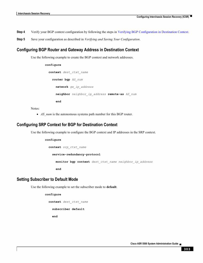
Interchassis Session Recovery
Configuring Interchassis Session Recovery (ICSR) ▀
Cisco ASR 5500 System Administration Guide ▄ 303
Step 4 Verify your BGP context configuration by following the steps in Verifying BGP Configuration in Destination Context.
Step 5 Save your configuration as described in Verifying and Saving Your Configuration.
Configuring BGP Router and Gateway Address in Destination Context
Use the following example to create the BGP context and network addresses.
configure
context dest_ctxt_name
router bgp AS_num
network gw_ip_address
neighbor neighbor_ip_address remote-as AS_num
end
Notes:
AS_num is the autonomous systems path number for this BGP router.
Configuring SRP Context for BGP for Destination Context
Use the following example to configure the BGP context and IP addresses in the SRP context.
configure
context srp_ctxt_name
service-redundancy-protocol
monitor bgp context dest_ctxt_name neighbor_ip_address
end
Setting Subscriber to Default Mode
Use the following example to set the subscriber mode to default.
configure
context dest_ctxt_name
subscriber default
end

Interchassis Session Recovery
▀ Configuring Interchassis Session Recovery (ICSR)
▄ Cisco ASR 5500 System Administration Guide
304
Verifying BGP Configuration in Destination Context
Verify your BGP configuration by entering the show srp monitor bgp command (Exec Mode).
Disabling Bulk Statistics Collection on a Standby System
You can disable the collection of bulk statistics from a system when it is in the standby mode of operation.
Important: When this feature is enabled and a system transitions to standby state, any pending accumulated
statistical data is transferred at the first opportunity. After that no additional statistics gathering takes place until the
system comes out of standby state.
Use the following example to disable the bulk statistics collection on a standby system.
configure
bulkstat mode
no gather-on-standby
end
Repeat this procedure for both systems.
Verifying the Primary and Backup Chassis Configuration
This section describes how to compare the ICSR configuration on both chassis.
Step 1 Enter the show configuration srp command on both chassis (Exec mode).
Verify that both chassis have the same SRP configuration information. The output looks similar to following:
config
context source
interface haservice loopback
ip address 172.17.1.1 255.255.255.255 srp-activate
#exit
radius attribute nas-ip-address address 172.17.1.1
radius server 192.168.83.2 encrypted key 01abd002c82b4a2c port 1812
radius accounting server 192.168.83.2 encrypted key 01abd002c82b4a2c port
1813
ha-service ha-pdsn
mn-ha-spi spi-number 256 encrypted secret 6c93f7960b726b6f6c93f7960b726b6f
hash-algorithm md5
fa-ha-spi remote-address 192.168.82.0/24 spi-number 256 encrypted secret
1088bdd6817f64df
bind address 172.17.1.1
#exit
#exit
context destination
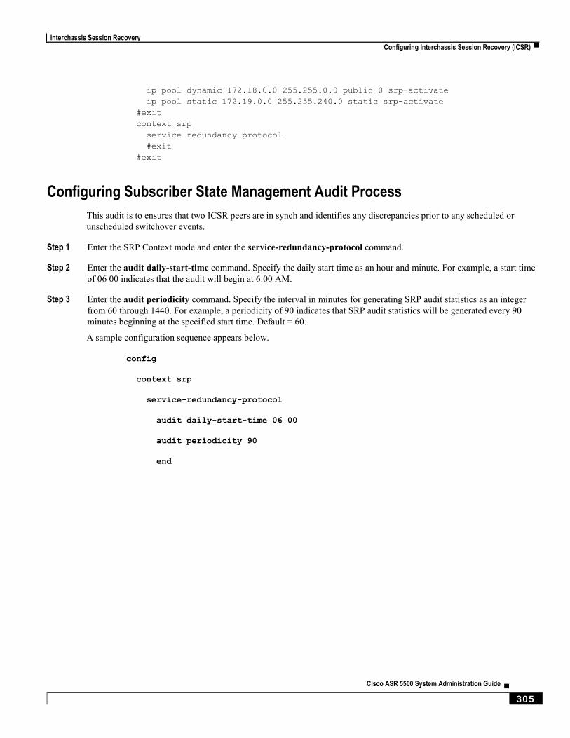
Interchassis Session Recovery
Configuring Interchassis Session Recovery (ICSR) ▀
Cisco ASR 5500 System Administration Guide ▄ 305
ip pool dynamic 172.18.0.0 255.255.0.0 public 0 srp-activate
ip pool static 172.19.0.0 255.255.240.0 static srp-activate
#exit
context srp
service-redundancy-protocol
#exit
#exit
Configuring Subscriber State Management Audit Process
This audit is to ensures that two ICSR peers are in synch and identifies any discrepancies prior to any scheduled or
unscheduled switchover events.
Step 1 Enter the SRP Context mode and enter the service-redundancy-protocol command.
Step 2 Enter the audit daily-start-time command. Specify the daily start time as an hour and minute. For example, a start time
of 06 00 indicates that the audit will begin at 6:00 AM.
Step 3 Enter the audit periodicity command. Specify the interval in minutes for generating SRP audit statistics as an integer
from 60 through 1440. For example, a periodicity of 90 indicates that SRP audit statistics will be generated every 90
minutes beginning at the specified start time. Default = 60.
A sample configuration sequence appears below.
config
context srp
service-redundancy-protocol
audit daily-start-time 06 00
audit periodicity 90
end
Interchassis Session Recovery
▀ Updating the Operating System
▄ Cisco ASR 5500 System Administration Guide
306
Updating the Operating System Updating the operating system (StarOS™) on ICSR chassis requires performing an Off-line update of each chassis
while it is standby mode. Traffic disruption is minimal since an active chassis will be handling call sessions while the
standby chassis is being updated.
The general upgrade sequence is as follows:
Download the StarOS software image and copy/transfer it to both chassis.
Save the currently running configurations on both chassis.
Update the standby backup chassis first.
Initiate an SRP switchover from the active primary chassis to make the standby backup chassis active.
Update the standby primary chassis.
Initiate an SRP switchover from the active backup chassis to make the standby primary chassis active.
The four-part flowchart below shows a more complete view of all the procedures required to complete the StarOS
upgrade process.
Caution: Enabling the Demux on MIO/UMIO feature changes resource allocations within the system. This
directly impacts an upgrade or downgrade between StarOS versions in ICSR configurations. Contact Cisco TAC for
procedural assistance prior to upgrading or downgrading your ICSR deployment.
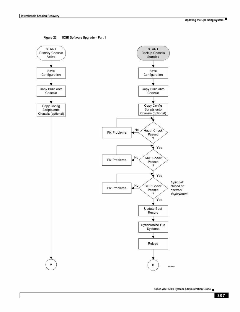
Interchassis Session Recovery
Updating the Operating System ▀
Cisco ASR 5500 System Administration Guide ▄ 307
Figure 23. ICSR Software Upgrade – Part 1
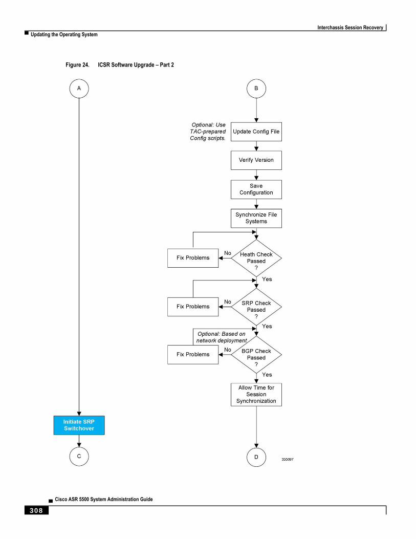
Interchassis Session Recovery
▀ Updating the Operating System
▄ Cisco ASR 5500 System Administration Guide
308
Figure 24. ICSR Software Upgrade – Part 2

Interchassis Session Recovery
Updating the Operating System ▀
Cisco ASR 5500 System Administration Guide ▄ 309
Figure 25. ICSR Software Upgrade – Part 3
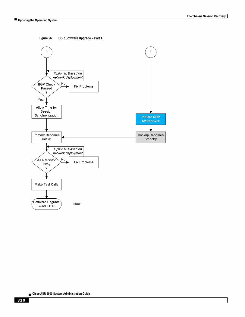
Interchassis Session Recovery
▀ Updating the Operating System
▄ Cisco ASR 5500 System Administration Guide
310
Figure 26. ICSR Software Upgrade – Part 4
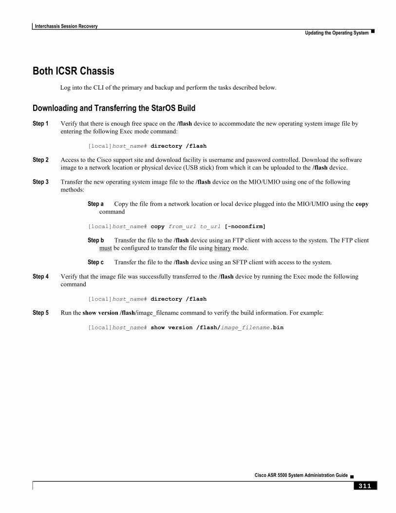
Interchassis Session Recovery
Updating the Operating System ▀
Cisco ASR 5500 System Administration Guide ▄ 311
Both ICSR Chassis
Log into the CLI of the primary and backup and perform the tasks described below.
Downloading and Transferring the StarOS Build
Step 1 Verify that there is enough free space on the /flash device to accommodate the new operating system image file by
entering the following Exec mode command:
[local]host_name# directory /flash
Step 2 Access to the Cisco support site and download facility is username and password controlled. Download the software
image to a network location or physical device (USB stick) from which it can be uploaded to the /flash device.
Step 3 Transfer the new operating system image file to the /flash device on the MIO/UMIO using one of the following
methods:
Step a Copy the file from a network location or local device plugged into the MIO/UMIO using the copy
command
[local]host_name# copy from_url to_url [-noconfirm]
Step b Transfer the file to the /flash device using an FTP client with access to the system. The FTP client
must be configured to transfer the file using binary mode.
Step c Transfer the file to the /flash device using an SFTP client with access to the system.
Step 4 Verify that the image file was successfully transferred to the /flash device by running the Exec mode the following
command
[local]host_name# directory /flash
Step 5 Run the show version /flash/image_filename command to verify the build information. For example:
[local]host_name# show version /flash/image_filename.bin

Interchassis Session Recovery
▀ Updating the Operating System
▄ Cisco ASR 5500 System Administration Guide
312
Standby Backup Chassis
Log into the backup standby chassis and perform the tasks described below.
Performing Health Checks
Health checks are a series of Exec mode show commands to determine the readiness of the system to handle a software
update.
Step 1 Run show card table all |grep unknown. No output should be displayed.
Step 2 Run show card table |grep offline. No output should be displayed.
Step 3 Run show resources |grep Status. The output should display “Within acceptable limits”.
Step 4 Run show alarm outstanding. Review the output for any issues that may preclude performing the software update.
Performing SRP Checks
Service Redundancy Protocol (SRP) checks verify that the mechanism for monitoring ICSR system status is operational.
Step 1 Run show srp monitor all.
Step 2 Review the output for any issues that may preclude performing the software update.
Performing BGP Checks
Border Gateway Protocol (BGP) checks are only required when BGP is used to support redundant interchassis
communication. These checks are run per context and per service type.
Step 1 For each BGP-enabled context, run show ip bgp summary. Verify that the BGP peers are connected and IPv4 and IPv6
peers are up. Repeat for all BGP-enable contexts.
Step 2 Run show service_name all |grep "Service Status:". The service should be “Started”. Repeat for all services running
on the chassis.
Updating the Boot Record
You must add a new boot stack entry for the recently downloaded software image (.bin) file.
Step 1 Run the Exec mode show boot command to verify that there are less than 10 entries in the boot.sys file and that a higher
priority entry is available (minimally there is no priority 1 entry in the boot stack).
Step 2 Create a new boot stack entry for the new file group, consisting of the new operating system image file and the currently
used CLI configuration file by entering the following Global Configuration command:
[local]host_name(config)# boot system priority number image image_url
/flash/filename config cfg_url /flash/filename
Interchassis Session Recovery
Updating the Operating System ▀
Cisco ASR 5500 System Administration Guide ▄ 313
Step 3 Assign the next highest priority to this entry, by using the <N-1> method, wherein you assign a priority number that is
one number less than your current highest priority.
If priority 1 is in use, you must renumber the existing entries to ensure that at least that priority is available.
The maximum number of boot stack entries that can be contained in the boot.sys file is 10. If there are already 10 entries
in the boot stack, you must delete at least one of these entries (typically, the lowest priority) and, if necessary, renumber
some or all of the other entries before proceeding. Use the no boot system priority command to delete a book stack
entry.
For information on using the boot system priority command, refer to the Adding a New Boot Stack Entry section in this
guide
Synchronizing File Systems
Synchronize the local file systems by entering the following Exec mode command:
[local]host_name# filesystem synchronize all
Reloading the Chassis
Reboot the chassis by entering the following command:
[local]host_name# reload [-noconfirm]
As the system reboots, it loads the new operating system software image and its corresponding CLI configuration file
using the new boot stack entry configured earlier.
After the system reboots, establish a CLI session and enter the show version command to verify that the active software
version is correct.
Optional for PDSN: If you are using the IP Pool Sharing Protocol during your upgrade, refer to Configuring IPSP
Before the Software Upgrade in the PDSN Administration Guide.
Updating the Configuration File
Features in the new operating system may require changes tot he configuration file. These changes can be done
manually or facilitated by custom scripts prepared by Cisco TAC. Make whatever changes are necessary prior to saving
the updated configuration file.
Verifying the Software Version
After the system has successfully booted, verify that the new StarOS version is running by executing the Exec mode
show version command.
Saving the Configuration File
Use the Exec mode save configuration command to save the currently running configuration to the /flash device and to
an off-chassis location (external memory device or network URL). The off-chassis copy assures that you will have a
fallback, loadable configuration file should a problem be encountered.
Interchassis Session Recovery
▀ Updating the Operating System
▄ Cisco ASR 5500 System Administration Guide
314
Completing the Update Process
Repeat the following tasks to complete the upgrade process on the standby secondary chassis:
Synchronizing File Systems
Performing Health Checks
Performing SRP Checks
Performing BGP Checks
Waiting for Session Synchronization
Allow time for session synchronization to occur between the ICSR chassis before preceding to the next steps.
Step 1 Run the show session recovery status verbose command on both chassis. Proceed to the next steps only when no
errors are seen in the output of this command.
Step 2 On the standby chassis, run show srp checkpoint statistics |more.
Step 3 On active chassis, run show subs summary |grep Total.
Step 4 Compare the number of subscribers on the active chassis and the number of Current pre-allocated calls: on the standby
chassis. They should be similar (within 5%). Allow a few minutes for systems to complete synchronization.
Interchassis Session Recovery
Updating the Operating System ▀
Cisco ASR 5500 System Administration Guide ▄ 315
Primary Chassis
Log into the active primary chassis and complete the tasks described below.
Initiating an SRP Switchover
An SRP switchover places the primary chassis in standby mode and makes the backup chassis active. The secondary
chassis is now processing sessions with the upgraded software.
Step 1 On the primary chassis run the srp initiate-switchover command. All existing sessions will be migrated to the backup
chassis and it begins servicing new session requests. Allow the switchover process to complete.
Step 2 On the primary chassis, run the show srp info command. Chassis State should indicate Standby when switchover is
complete.
Step 3 On the backup chassis, confirm the switchover is complete by running the show srp info command. Chassis State
should indicate Active when switchover is complete.
Checking AAA Monitor Status on the Newly Active Chassis
If your network deployment requires communication with AAA servers, log into the newly active chassis and perform
an AAA monitor check. You will be checking for the existence of any SNMP traps that indicate the chassis cannot
communicate with AAA servers (starSRPAAAUnreachable).
Step 1 Run the Exec mode command show snmp trap history |grep starSRPAAAUnreachable.
Step 2 There should be no output for this command, or no very recent SNMP trap notifications (based on the event timestamp).
Step 3 If the active chassis cannot communicate with one or more AAA servers, refer to Checking AAA Monitor Status for
additional information on how to proceed.
Completing the Software Update
Log into the standby chassis and repeat the following tasks to complete the upgrade process on the standby primary
chassis:
Updating the Boot Record
Reloading the Chassis
Updating the Configuration File
Verifying the Software Version
Saving the Configuration File
Synchronizing File Systems
Performing Health Checks
Performing SRP Checks
Performing BGP Checks
Waiting for Session Synchronization
Interchassis Session Recovery
▀ Updating the Operating System
▄ Cisco ASR 5500 System Administration Guide
316
Initiating an SRP Switchover
An SRP switchover places the primary chassis in active mode and makes the backup chassis active. The primary chassis
is now processing sessions with the upgraded software.
Step 1 On the backup chassis run the srp initiate-switchover command. All existing sessions will be migrated to the primary
chassis and it begins servicing new session requests. Allow the switchover process to complete.
Step 2 On the backup chassis, run the show srp info command. Chassis State should indicate Standby when switchover is
complete.
Step 3 On the primary chassis, confirm the switchover is complete by running the show srp info command. Chassis State
should indicate Active when switchover is complete.
Checking AAA Monitor Status
If your network deployment requires communication with AAA servers, check the status of communication with AAA
servers as described in Checking AAA Monitor Status on the Newly Active Chassis.
Making Test Calls
Once the chassis state is verified and subscribers are migrated, perform new call testing to make sure calls are
successful.
Fallback Procedure
To revert to the previous configuration and software build, perform the following steps as a user with administrative
privileges.
Step 1 Run the Exec mode show boot command. The topmost lowest numbered entry of the displayed output should be the
new configuration with the new software build. The second topmost entry should be the backup configuration.
Step 2 Remove the topmost boot entry n, and synchronize the configuration across the management cards.
[local]host_name# config
[local]host_name(config)# no boot system priority n
[local]host_name(config)# end
[local]host_name# filesystem synchronize all
Step 3 Reboot the system to load its previous configuration.
[local]host_name# reload
Step 4 Perform health checks as described in Performing Health Checks.
Cisco ASR 5500 System Administration Guide ▄ 317
Chapter 22 Support Data Collector
The Support Data Collector (SDC) is a system feature that allows scheduled collection of process state, counter, event
and attribute data that may be useful when troubleshooting problems at an installation site.
This chapter includes the following sections:
Overview
Configuring SDR Collection
Displaying the SDR Collection Configuration
Collecting and Storing the SDR Information
Managing Record Collection
Using SDRs to Diagnose Problems
SDR CLI Commands
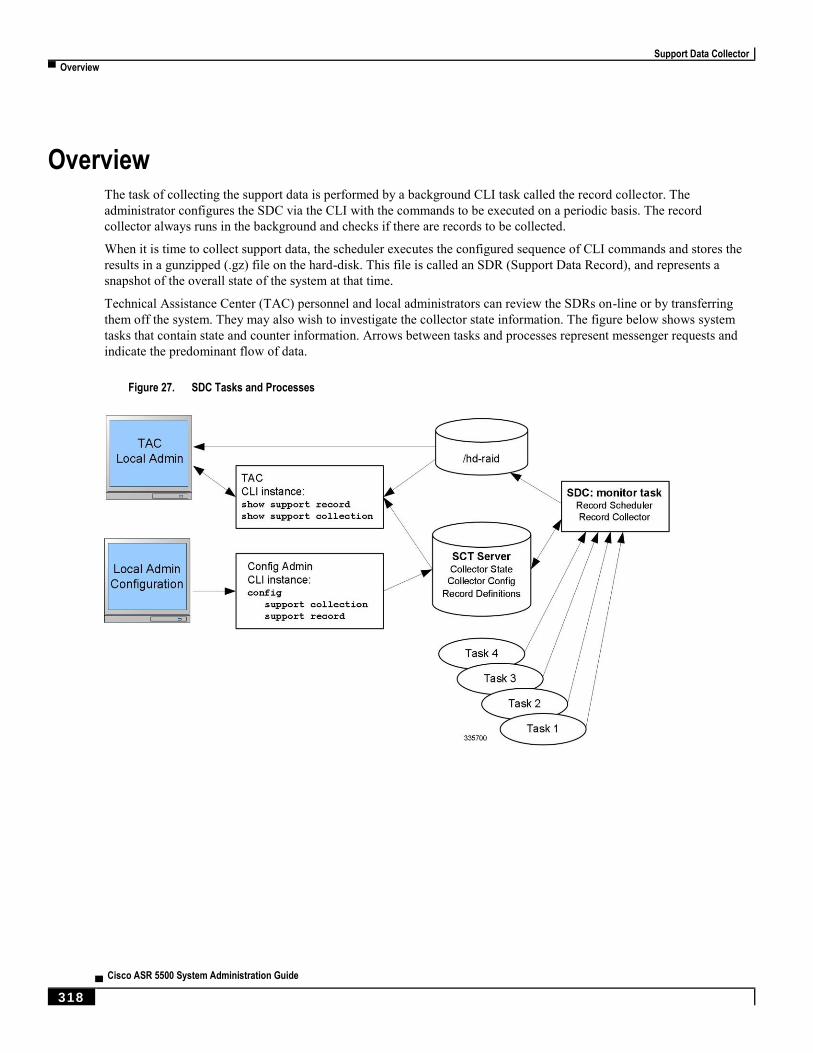
Support Data Collector
▀ Overview
▄ Cisco ASR 5500 System Administration Guide
318
Overview The task of collecting the support data is performed by a background CLI task called the record collector. The
administrator configures the SDC via the CLI with the commands to be executed on a periodic basis. The record
collector always runs in the background and checks if there are records to be collected.
When it is time to collect support data, the scheduler executes the configured sequence of CLI commands and stores the
results in a gunzipped (.gz) file on the hard-disk. This file is called an SDR (Support Data Record), and represents a
snapshot of the overall state of the system at that time.
Technical Assistance Center (TAC) personnel and local administrators can review the SDRs on-line or by transferring
them off the system. They may also wish to investigate the collector state information. The figure below shows system
tasks that contain state and counter information. Arrows between tasks and processes represent messenger requests and
indicate the predominant flow of data.
Figure 27. SDC Tasks and Processes
Support Data Collector
Configuring SDR Collection ▀
Cisco ASR 5500 System Administration Guide ▄ 319
Configuring SDR Collection The Support Data Record (SDR) is an ordered set of the CLI support commands' display output that is stored in a stand-
alone compressed file. Each CLI support command output is stored in its own record section. The record section is
identified by a record section name and its ASCII command syntax. For example, the record section show_version
would have a CLI command string of “show version”.
The order in which the record section commands appear in the configuration is significant. All of the support record
section commands must be configured together as an ordered set. In other words, just specifying one command by itself
will result in just that one command output constituting the contents of the entire SDR.
The user may configure a specific set of record sections for the SDR which may or may not include some or all of the
default SDR record sections. This configuration is stored in the Global Configuration section of the configuration file.
Refer to Configuration Commands (Global Configuration Mode) for more detail on the support record section
command.
Displaying the SDR Collection Configuration The show configuration verbose command displays the default support record sections, if the user has not specified
any support record sections. If the user has configured support record sections, then the show configuration command
displays user-configured support record sections. The support collection schedule configuration also appears in the
show configuration output under the Global Configuration section.
Collecting and Storing the SDR Information At the scheduled time, the Support Data Collector (SDC), if active, runs in the background to collect all the record
section commands that have been specified. This information is concatenated as one contiguous output. The output is
compressed and stored as a file on disk in the /hd-raid/support/record/ directory.
The periodicity of the SDC is configured by the support collection schedule command under Global Configuration
Mode. Once the SDR is stored, the SDC waits the sleep-duration interval specified via the support collection command
before collecting another SDR.
Important: The period between SDRs is equal to the configured sleep-duration interval + the time taken to
collect the previous record.

Support Data Collector
▀ Managing Record Collection
▄ Cisco ASR 5500 System Administration Guide
320
Managing Record Collection The SDRs are stored together in a self-relative set. This self-relative set is called a Support Record Collection. Each
individual SDR is identified with a record-id. The record-id of the most recent SDR is always 0 (zero). The next older
SDR is record-id 1, and so on, for the number of records in the stored collection. For example, if there are five SDRs,
they are identified as SDR-0 through SDR-4.
Figure 28. Support Data Collection Hierarchy
When a new SDR is created, the numbers all increment by one and the newest SDR is given the value of 0. If the total
number of records exceeds a configured maximum, then the oldest SDR is deleted.
Using the example above, when the maximum SDR count of 5 is reached, the SDRs continue to be SDR-0 through
SDR-4, with the file timestamps indicating that the files are changing over time.
Support Data Collector
Using SDRs to Diagnose Problems ▀
Cisco ASR 5500 System Administration Guide ▄ 321
The time interval between collections may vary by several minutes in relation to the specified sleep-duration. This is
because the interval specifies the idle time between scheduled collection runs. Since the actual overhead of the
collecting process is not included in the scheduled intervals, the time differences between collections includes this non-
deterministic amount of time.
Important: Using a shorter interval to compensate for this behavior is not recommended, since it will only add to
the overhead incurred by the collection process and will ultimately impact the overall system performance. The sleep-
duration (idle-time) between scheduled collections is an important component of the “self-throttling” mechanism that
should not be circumvented by the user.
The Exec Mode show support collection command displays useful information about the Support Data Collector. The
output includes information about when the collector last ran, how long it took to run, when it is scheduled to run again,
as well as the number of SDRs currently stored, where they are stored, and how much storage space is being used. Refer
to show Commands (Exec Mode) for more detail about this command.
Using SDRs to Diagnose Problems The user can compare the SDRs by examining two or more in sequence. These SDRs are dumped out in their CLI-
formatted output display. Comparing the display outputs reveals trends and performance or configuration differences
that indicate problem areas.
Once specific record sections have been identified as having problematic characteristics, only the CLI show commands
associated with those sections need be monitored and compared to further isolate the problem areas. In addition,
individual SDRs may be transferred via system-supported protocols to remote system, or the current collection may be
transferred as a set for later analysis.
Support Data Collector
▀ SDR CLI Commands
▄ Cisco ASR 5500 System Administration Guide
322
SDR CLI Commands You may use the collected support data records to view support data chronologically. If the default list and sequence of
sections is inadequate for system monitoring, you can configure your own set of record section commands that make up
a particular support record.
Important: Refer to the SDR CLI Command Strings appendix for a listing of supported CLI strings (show
commands) for record sections. The listing also identifies the CLI strings supported as default record sections. You can
obtain the same listing by running the show support collection definitions command.
Important: You may enter up to 200 SDR CLI strings in a single record section command. If you attempt to add
more than 200 CLI strings, an error message appears. You may also receive an error message if the system is unable to
parse all of the requested CLI strings because they are too complicated to parse.
After configuring the SDR you then configure the sleep-duration interval between record collections and the number of
historical records to be retained before being overwritten. By default, configuring this collection information makes the
collector mechanism active (if not already active).
After one or more collection intervals have passed, the SDR data becomes available for analysis. The administrator can
then use CLI commands to examine the SDR information to perform root cause analysis and trend analysis based on
how the data has changed over time. The administrator may decide to transfer the SDRs off the system to be analyzed
remotely, for example, by Cisco TAC.
For complete descriptions of the CLI commands discussed below, refer to the Command Line Interface Reference.
Configuration Commands (Global Configuration Mode)
support record
support record section section-name command “command-string” [ section section-
name command “command-string” ] ...
no support record [ all | section section_name ]
default support record [ all | section section_name ]
The support record section command configures a specific record section or set of record sections for a support
information output command. The order in which record sections are saved is fixed, regardless of the sequence in which
the CLI commands were entered.
For example:
[local]host_name(config)# support record section show_context command "show
context”
If the support record section command is not explicitly configured by the user, a default set of record section
commands are used. These default record section commands are displayed when you run the show configuration
verbose command. If support record section commands are explicitly configured, they replace the default commands.
Support Data Collector
SDR CLI Commands ▀
Cisco ASR 5500 System Administration Guide ▄ 323
Important: Refer to the SDR CLI Command Strings appendix for a listing of supported CLI strings (show
commands) for record sections. The listing also identifies the CLI strings included in default record sections.
The no support record command removes either a specific section of the record definition or all of the sections. If you
specify the default support record command, the default record section definition of that specified record section is
used. If neither the keyword all or section is specified, all the record section definitions are removed.
support collection
support collection [ sleep-duration [ hours h | minutes m ] ] [ max-records n ]
no support collection
default support collection
The support collection command modifies and/or enables the support collection process. If support collection has been
previously disabled, this command enables the collection activity. If the support collection is currently enabled, this
command may be used to modify the sleep-duration interval and/or the maximum number of SDRs that can be collected
and stored.
The sleep duration keyword specifies the time interval between the collection of support data. It can be specified in
hours or minutes with a default of one hour (60 minutes).
The max-records keyword specifies the number of SDRs to store as an integer from 1 to 65535. When this value is
exceeded, the new SDR overwrites the oldest SDR. The default value is 168.
Important: SDR files will be stored in the /hd-raid/support/records/ directory.
For example:
[local]host_name(config)# support collection sleep-duration minute 30
max-records 50
Use the no support collection command to explicitly disable the collection of the SDRs. If no record section commands
are defined, the support data collector mechanism is also effectively disabled.
Use the default support collection command to enable the support data collector using the default record sections.
Exec Mode Commands
show support record
show support record record-id [ to record-id ] [ section section_name ]
The show support record command displays a collection of SDRs. The SDRs are displayed in order from lowest
record-id to highest record-id.
Each SDR is identified by a time index called the record-id. For example, the most recent record is always record-id 0
(filename = sdr.0.gz). The next older record is record-id 1 (filename = sdr.1.gz), and so on.
Support Data Collector
▀ SDR CLI Commands
▄ Cisco ASR 5500 System Administration Guide
324
When a new record is collected it is given a record-id of 0. The previously most recent record is renamed to record-id 1,
and so on. The display includes the record-id along with the collection time-stamp.
The record-id variable identifies a single SDR. The to keyword specifies the endpoint record-id when displaying a
range of SDRs.
The section keyword displays a particular section of the record.
delete support record
delete support record record-id [ to record-id ]
The delete support records command removes an SDR with a specified record-id or all SDRs in the specified range of
record-ids.
show support collection
show support collection [ definitions ]
The show support collection command displays information on SDC activity. It display informations such as the start
time of the last scheduled collection, the duration of the last scheduled collection, whether the collection is still in
progress, etc. In addition this command lists the currently stored set of SDR record-ids, their respective timestamps, and
size of each SDR.
[local]host_name# show support collection
Record Collection Enabled : yes
Last Collection Start Time : Monday October 21 06:29:05 PDT 2013
Last Collection End Time : Monday October 21 06:29:09 PDT 2013
Est. Collection Next Start : Monday October 21 07:29:13 PDT 2013 (40 minutes)
Support Data Records at /var/tmp/support-records/
ID Name Size Date/Time
167 sdr.167.gz 42863 Monday October 21 04:40:00 PDT 2013
166 sdr.166.gz 170425 Monday October 21 05:40:08 PDT 2013
total SDRs 2, total bytes 2132880, time span is last 1 day(s) 1 hour(s)
The optional definitions keyword displays the list of default support record section definitions. This is the list of all
valid record section definitions. The display also indicates whether the record section is enabled or disabled by default.
[local]host_name# show support collection definitions
The output of this command reflects the sequence in which record sections will be output, regardless of the sequence in
which they may have been entered by the user. Refer to the SDR CLI Command Strings appendix for additional
information.

Cisco ASR 5500 System Administration Guide ▄ 325
Appendix A Engineering Rules
This appendix provides engineering guidelines for configuring the system to meet network deployment requirements.
This appendix consists of the following topics:
CLI Session Rules
ASR 5500 Interface and Port Rules
Context Rules
Subscriber Rules
Service Rules
Access Control List (ACL) Engineering Rules
Engineering Rules
▀ CLI Session Rules
▄ Cisco ASR 5500 System Administration Guide
326
CLI Session Rules Multiple CLI session support is based on the amount of available memory. The Resource Manager reserves enough
resources to support a minimum of six CLI sessions at all times. One of the six sessions is further reserved for use
exclusively by a CLI session on an MIO/UMIO serial interface.
Additional CLI sessions beyond the pre-reserved limit are permitted if sufficient MIO/UMIO resources are available. If
the Resource Manager is unable to reserve resources for a CLI session beyond those that are pre-reserved, users with
administrator-privileges are prompted to create the new CLI session, even without reserved resources.
ASR 5500 Interface and Port Rules The rules discussed in this section pertain to the Ethernet ports used for subscriber traffic on the MIO/UMIO card (ports
10 through 29).
Give all logical interfaces a unique name to identify the interface from others in the same context. Logical
interfaces in different contexts may have the same name.
A single physical port can support multiple logical interfaces when you configure VLAN tags for that physical
port. You can use VLAN tagging to bind a single physical port to multiple logical interfaces that reside in
different contexts.
Assign all logical interfaces a valid IP address and subnet.
Give each logical interface within a context a unique IP address(es). Logical interfaces in different
contexts can have the same IP address(es).
If multi-homing is supported on the network, you can assign all logical interfaces a single primary IP
address and up to 16 secondary IP addresses.
You can configure a logical interface in only one context, but you can configure multiple interfaces (up to 512)
in a single context.
You can apply a maximum of 256 access control list (ACL) rules to a single logical interface.
All ports are identified by their <slot#>/<port#>.
Each physical port for subscriber traffic on an MIO/UMIO card may contain up to a maximum of 1,024 VLAN
tags.
A logical interface is limited to using a single VLAN on a single physical port, identified by its
<card#/slot#/port#>.
Packet Data Network (PDN) Interface Rules
The following engineering rules apply to the interface to the packet data network (PDN):
Configure the logical interfaces used to facilitate the PDN interface within the egress context.
The default is to use a single interface within the egress context to facilitate the PDN interface.
You can configure multiple interfaces in the egress context by using static routes or dynamic routing protocols.
You may also configure next-hop default gateways.
Engineering Rules
Context Rules ▀
Cisco ASR 5500 System Administration Guide ▄ 327
Context Rules A maximum of 63 contexts may be configured per chassis.Enabling demux functions on an MIO card reduces
the maxium number of contexts to 10.
Interfaces per Context
Prior to Release 15.0: Up to 16 interfaces can be configured within a single context.
For Release 15.0 and higher: With the Demux MIO/UMIO feature enabled, up to 64 interfaces can be
configured within a single context.
512 Ethernet+PPP+tunnel interfaces
32 ipv6ip tunnel interfaces
511 GRE tunnels (2,048 GRE tunnels per chassis)
256 loopback interfaces
IP Addresses and IP Address Pools
Up to 2,000 IPv4 address pools can be configured within a single context (regardless of the number of
packet processing cards) with a total system limit of 5,000 IPv4 address pools for all contexts.
Prior to Release 15.0: Up to 32 IPv6 pools can be configured within a single context.
For Release 15.0 and higher: Up to 256 IPv6 pools can be configured within a single context.
There is also a limit of 4,000,000 pool addresses and 32,000,000 static addresses that can be configured
per context. Therefore, the number of pools depends on how many addresses are being used and how
they are subnetted.
Each context supports up to 32,000,000 static IP pool addresses. You can configure a maximum total of
96,000,000 static IP pool addresses per chassis. Each static IP pool can contain up to 500,000
addresses.
Each context supports up to 16,000,000 dynamic IP pool addresses. You can configure a maximum
total of 32,000,000 dynamic IP pool addresses per chassis. Each dynamic IP pool can contain up to
500,000 addresses.
Important: Each address in the pool requires approximately 60 bytes of memory. The amount of
memory required, however, depends on a number of factors such as the pool type, and hold-timer
usage. Therefore, in order to conserve available memory, you may need to limit the number of pools
depending on the number of addresses to be configured and the number of installed application cards.
The maximum number of simultaneous subscriber sessions is controlled by the installed capacity license for the
service(s) supported.
The maximum number of static address resolution protocol (ARP) entries per context is 128.
The maximum number of domains per context is 2,048.
ASN-GW services configured within the same context cannot communicate with each other.
Routes
Up to 1,200 static routes per context (48,000 per chassis).
6,000 pool routes per context (6,000 per chassis)
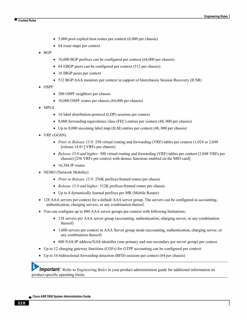
Engineering Rules
▀ Context Rules
▄ Cisco ASR 5500 System Administration Guide
328
5,000 pool explicit host routes per context (6,000 per chassis)
64 route maps per context
BGP
16,000 BGP prefixes can be configured per context (64,000 per chassis)
64 EBGP peers can be configured per context (512 per chassis)
16 IBGP peers per context
512 BGP/AAA monitors per context in support of Interchassis Session Recovery (ICSR)
OSPF
200 OSPF neighbors per chassis
10,000 OSPF routes per chassis (64,000 per chassis)
MPLS
16 label distribution protocol (LDP) sessions per context
8,000 forwarding equivalence class (FEC) entries per context (48, 000 per chassis)
Up to 8,000 incoming label map (ILM) entries per context (48, 000 per chassis)
VRF (GGSN)
Prior to Release 15.0: 250 virtual routing and forwarding (VRF) tables per context (1,024 or 2,048
[release 14.0+] VRFs per chassis)
Release 15.0 and higher: 300 virtual routing and forwarding (VRF) tables per context (2,048 VRFs per
chassis) [256 VRFs per context with demux functions enabled on the MIO card]
16,384 IP routes
NEMO (Network Mobility)
Prior to Release 15.0: 256K prefixes/framed routes per chassis
Release 15.0 and higher: 512K prefixes/framed routes per chassis
Up to 8 dynamically learned prefixes per MR (Mobile Router)
128 AAA servers per context for a default AAA server group. The servers can be configured as accounting,
authentication, charging servers, or any combination thereof.
You can configure up to 800 AAA server groups per context with following limitations:
128 servers per AAA server group (accounting, authentication, charging server, or any combination
thereof)
1,600 servers per context in AAA Server group mode (accounting, authentication, charging server, or
any combination thereof)
800 NAS-IP address/NAS identifier (one primary and one secondary per server group) per context
Up to 12 charging gateway functions (CGFs) for GTPP accounting can be configured per context.
Up to 16 bidirectional forwarding detection (BFD) sessions per context (64 per chassis)
Important: Refer to Engineering Rules in your product administration guide for additional information on
product-specific operating limits.
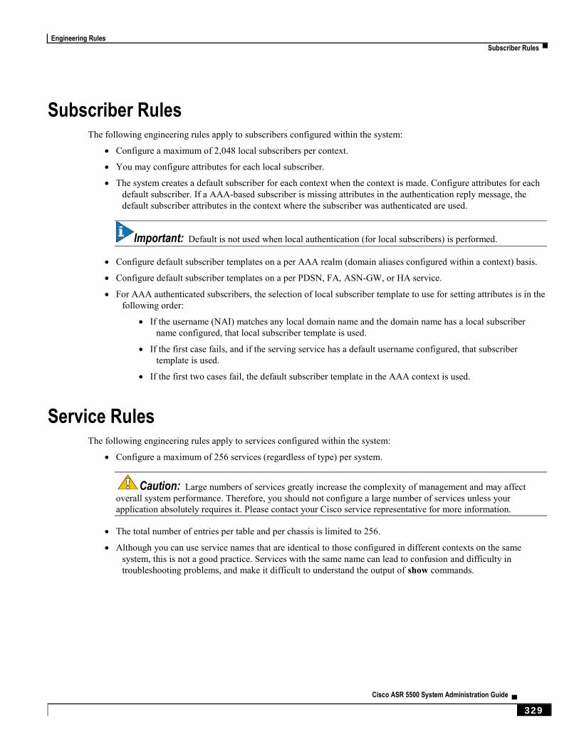
Engineering Rules
Subscriber Rules ▀
Cisco ASR 5500 System Administration Guide ▄ 329
Subscriber Rules The following engineering rules apply to subscribers configured within the system:
Configure a maximum of 2,048 local subscribers per context.
You may configure attributes for each local subscriber.
The system creates a default subscriber for each context when the context is made. Configure attributes for each
default subscriber. If a AAA-based subscriber is missing attributes in the authentication reply message, the
default subscriber attributes in the context where the subscriber was authenticated are used.
Important: Default is not used when local authentication (for local subscribers) is performed.
Configure default subscriber templates on a per AAA realm (domain aliases configured within a context) basis.
Configure default subscriber templates on a per PDSN, FA, ASN-GW, or HA service.
For AAA authenticated subscribers, the selection of local subscriber template to use for setting attributes is in the
following order:
If the username (NAI) matches any local domain name and the domain name has a local subscriber
name configured, that local subscriber template is used.
If the first case fails, and if the serving service has a default username configured, that subscriber
template is used.
If the first two cases fail, the default subscriber template in the AAA context is used.
Service Rules The following engineering rules apply to services configured within the system:
Configure a maximum of 256 services (regardless of type) per system.
Caution: Large numbers of services greatly increase the complexity of management and may affect
overall system performance. Therefore, you should not configure a large number of services unless your
application absolutely requires it. Please contact your Cisco service representative for more information.
The total number of entries per table and per chassis is limited to 256.
Although you can use service names that are identical to those configured in different contexts on the same
system, this is not a good practice. Services with the same name can lead to confusion and difficulty in
troubleshooting problems, and make it difficult to understand the output of show commands.
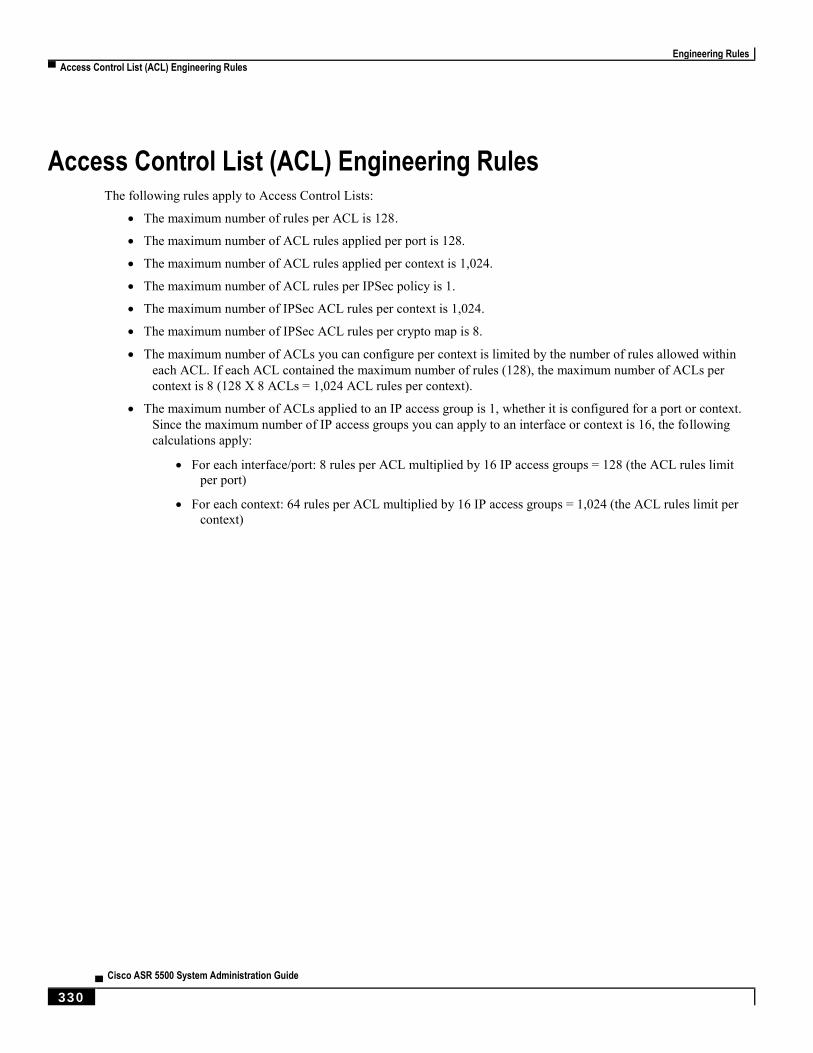
Engineering Rules
▀ Access Control List (ACL) Engineering Rules
▄ Cisco ASR 5500 System Administration Guide
330
Access Control List (ACL) Engineering Rules The following rules apply to Access Control Lists:
The maximum number of rules per ACL is 128.
The maximum number of ACL rules applied per port is 128.
The maximum number of ACL rules applied per context is 1,024.
The maximum number of ACL rules per IPSec policy is 1.
The maximum number of IPSec ACL rules per context is 1,024.
The maximum number of IPSec ACL rules per crypto map is 8.
The maximum number of ACLs you can configure per context is limited by the number of rules allowed within
each ACL. If each ACL contained the maximum number of rules (128), the maximum number of ACLs per
context is 8 (128 X 8 ACLs = 1,024 ACL rules per context).
The maximum number of ACLs applied to an IP access group is 1, whether it is configured for a port or context.
Since the maximum number of IP access groups you can apply to an interface or context is 16, the following
calculations apply:
For each interface/port: 8 rules per ACL multiplied by 16 IP access groups = 128 (the ACL rules limit
per port)
For each context: 64 rules per ACL multiplied by 16 IP access groups = 1,024 (the ACL rules limit per
context)
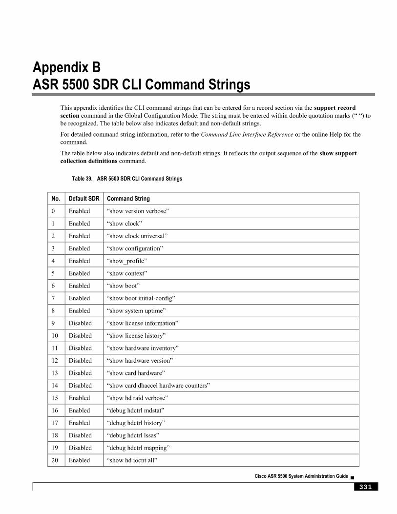
Cisco ASR 5500 System Administration Guide ▄ 331
Appendix B ASR 5500 SDR CLI Command Strings
This appendix identifies the CLI command strings that can be entered for a record section via the support record
section command in the Global Configuration Mode. The string must be entered within double quotation marks (“ “) to
be recognized. The table below also indicates default and non-default strings.
For detailed command string information, refer to the Command Line Interface Reference or the online Help for the
command.
The table below also indicates default and non-default strings. It reflects the output sequence of the show support
collection definitions command.
Table 39. ASR 5500 SDR CLI Command Strings
No. Default SDR Command String
0 Enabled “show version verbose”
1 Enabled “show clock”
2 Enabled “show clock universal”
3 Enabled “show configuration”
4 Enabled “show_profile”
5 Enabled “show context”
6 Enabled “show boot”
7 Enabled “show boot initial-config”
8 Enabled “show system uptime”
9 Disabled “show license information”
10 Disabled “show license history”
11 Disabled “show hardware inventory”
12 Disabled “show hardware version”
13 Disabled “show card hardware”
14 Disabled “show card dhaccel hardware counters”
15 Enabled “show hd raid verbose”
16 Enabled “debug hdctrl mdstat”
17 Enabled “debug hdctrl history”
18 Disabled “debug hdctrl lssas”
19 Disabled “debug hdctrl mapping”
20 Enabled “show hd iocnt all”
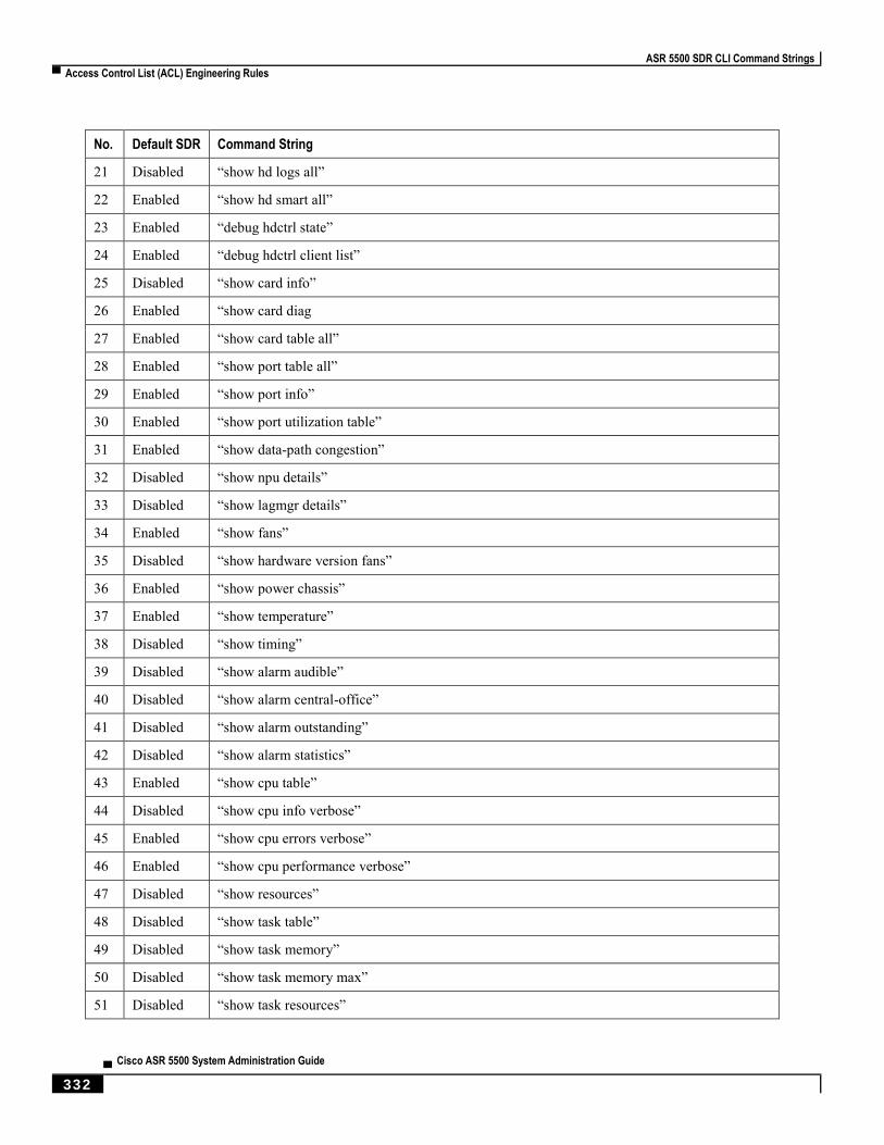
ASR 5500 SDR CLI Command Strings
▀ Access Control List (ACL) Engineering Rules
▄ Cisco ASR 5500 System Administration Guide
332
No. Default SDR Command String
21 Disabled “show hd logs all”
22 Enabled “show hd smart all”
23 Enabled “debug hdctrl state”
24 Enabled “debug hdctrl client list”
25 Disabled “show card info”
26 Enabled “show card diag
27 Enabled “show card table all”
28 Enabled “show port table all”
29 Enabled “show port info”
30 Enabled “show port utilization table”
31 Enabled “show data-path congestion”
32 Disabled “show npu details”
33 Disabled “show lagmgr details”
34 Enabled “show fans”
35 Disabled “show hardware version fans”
36 Enabled “show power chassis”
37 Enabled “show temperature”
38 Disabled “show timing”
39 Disabled “show alarm audible”
40 Disabled “show alarm central-office”
41 Disabled “show alarm outstanding”
42 Disabled “show alarm statistics”
43 Enabled “show cpu table”
44 Disabled “show cpu info verbose”
45 Enabled “show cpu errors verbose”
46 Enabled “show cpu performance verbose”
47 Disabled “show resources”
48 Disabled “show task table”
49 Disabled “show task memory”
50 Disabled “show task memory max”
51 Disabled “show task resources”
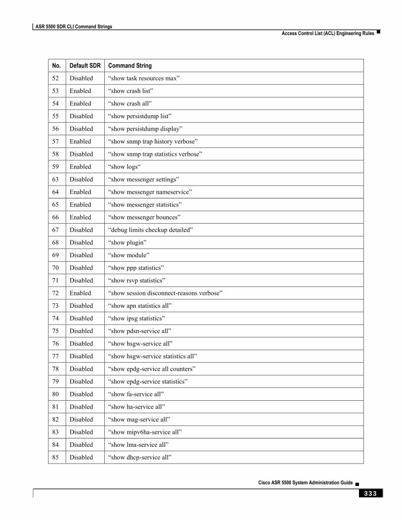
ASR 5500 SDR CLI Command Strings
Access Control List (ACL) Engineering Rules ▀
Cisco ASR 5500 System Administration Guide ▄ 333
No. Default SDR Command String
52 Disabled “show task resources max”
53 Enabled “show crash list”
54 Enabled “show crash all”
55 Disabled “show persistdump list”
56 Disabled “show persistdump display”
57 Enabled “show snmp trap history verbose”
58 Disabled “show snmp trap statistics verbose”
59 Enabled “show logs“
63 Disabled “show messenger settings”
64 Enabled “show messenger nameservice”
65 Enabled “show messenger statistics”
66 Enabled “show messenger bounces”
67 Disabled “debug limits checkup detailed”
68 Disabled “show plugin”
69 Disabled “show module”
70 Disabled “show ppp statistics”
71 Disabled “show rsvp statistics”
72 Enabled “show session disconnect-reasons verbose”
73 Disabled “show apn statistics all”
74 Disabled “show ipsg statistics”
75 Disabled “show pdsn-service all”
76 Disabled “show hsgw-service all”
77 Disabled “show hsgw-service statistics all”
78 Disabled “show epdg-service all counters”
79 Disabled “show epdg-service statistics”
80 Disabled “show fa-service all”
81 Disabled “show ha-service all”
82 Disabled “show mag-service all”
83 Disabled “show mipv6ha-service all”
84 Disabled “show lma-service all”
85 Disabled “show dhcp-service all”

ASR 5500 SDR CLI Command Strings
▀ Access Control List (ACL) Engineering Rules
▄ Cisco ASR 5500 System Administration Guide
334
No. Default SDR Command String
86 Disabled “show sgsn-service all”
87 Disabled “show sgsn sessmgr all memory statistics”
88 Disabled “show operator-policy all”
89 Disabled “show call-control-profile all”
90 Disabled “show apn-profile all”
91 Disabled “show imei-profile all”
92 Disabled “show gprs-service all”
93 Disabled “show iups-service all”
94 Disabled “show sgtp-service all”
95 Disabled “show map-service all”
96 Disabled “show gs-service all”
97 Disabled “show ggsn-service all”
98 Disabled “show ggsn-service sgsn-table”
99 Disabled “show cscf service all”
100 Disabled “show cscf service diameter policy-control statistics”
101 Disabled “show cscf service diameter location-info statistics”
102 Disabled “show cscf service li-packet-cable statistics”
103 Disabled “show cscf peer-servers full”
104 Disabled “show demux-mgr statistics cscfmgr all”
105 Disabled “show lac-service all”
106 Disabled “show lns-service all”
107 Disabled “show pdsnclosedrp-service all”
108 Enabled “show subscriber summary”
109 Enabled “show connproxy sockets all”
110 Disabled “show session progress”
111 Disabled “show session subsystem data-info verbose”
112 Disabled “show session subsystem full data-info”
113 Disabled “show session subsystem facility sessmgr all debug-info”
114 Disabled “show sessctrl config-reconciliation statistics”
115 Disabled “show rp statistics”
116 Disabled “show mipfa statistics”
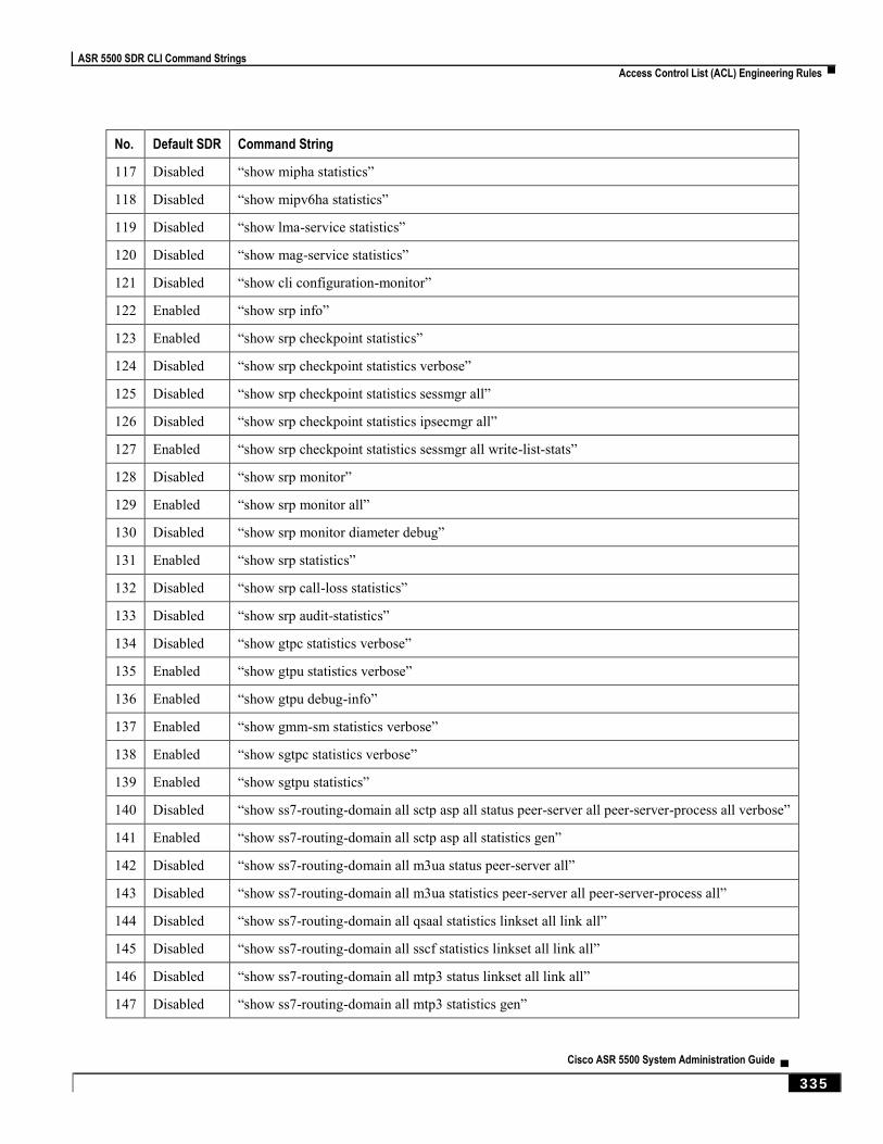
ASR 5500 SDR CLI Command Strings
Access Control List (ACL) Engineering Rules ▀
Cisco ASR 5500 System Administration Guide ▄ 335
No. Default SDR Command String
117 Disabled “show mipha statistics”
118 Disabled “show mipv6ha statistics”
119 Disabled “show lma-service statistics”
120 Disabled “show mag-service statistics”
121 Disabled “show cli configuration-monitor”
122 Enabled “show srp info”
123 Enabled “show srp checkpoint statistics”
124 Disabled “show srp checkpoint statistics verbose”
125 Disabled “show srp checkpoint statistics sessmgr all”
126 Disabled “show srp checkpoint statistics ipsecmgr all”
127 Enabled “show srp checkpoint statistics sessmgr all write-list-stats”
128 Disabled “show srp monitor”
129 Enabled “show srp monitor all”
130 Disabled “show srp monitor diameter debug”
131 Enabled “show srp statistics”
132 Disabled “show srp call-loss statistics”
133 Disabled “show srp audit-statistics”
134 Disabled “show gtpc statistics verbose”
135 Enabled “show gtpu statistics verbose”
136 Enabled “show gtpu debug-info”
137 Enabled “show gmm-sm statistics verbose”
138 Enabled “show sgtpc statistics verbose”
139 Enabled “show sgtpu statistics”
140 Disabled “show ss7-routing-domain all sctp asp all status peer-server all peer-server-process all verbose”
141 Enabled “show ss7-routing-domain all sctp asp all statistics gen”
142 Disabled “show ss7-routing-domain all m3ua status peer-server all”
143 Disabled “show ss7-routing-domain all m3ua statistics peer-server all peer-server-process all”
144 Disabled “show ss7-routing-domain all qsaal statistics linkset all link all”
145 Disabled “show ss7-routing-domain all sscf statistics linkset all link all”
146 Disabled “show ss7-routing-domain all mtp3 status linkset all link all”
147 Disabled “show ss7-routing-domain all mtp3 statistics gen”
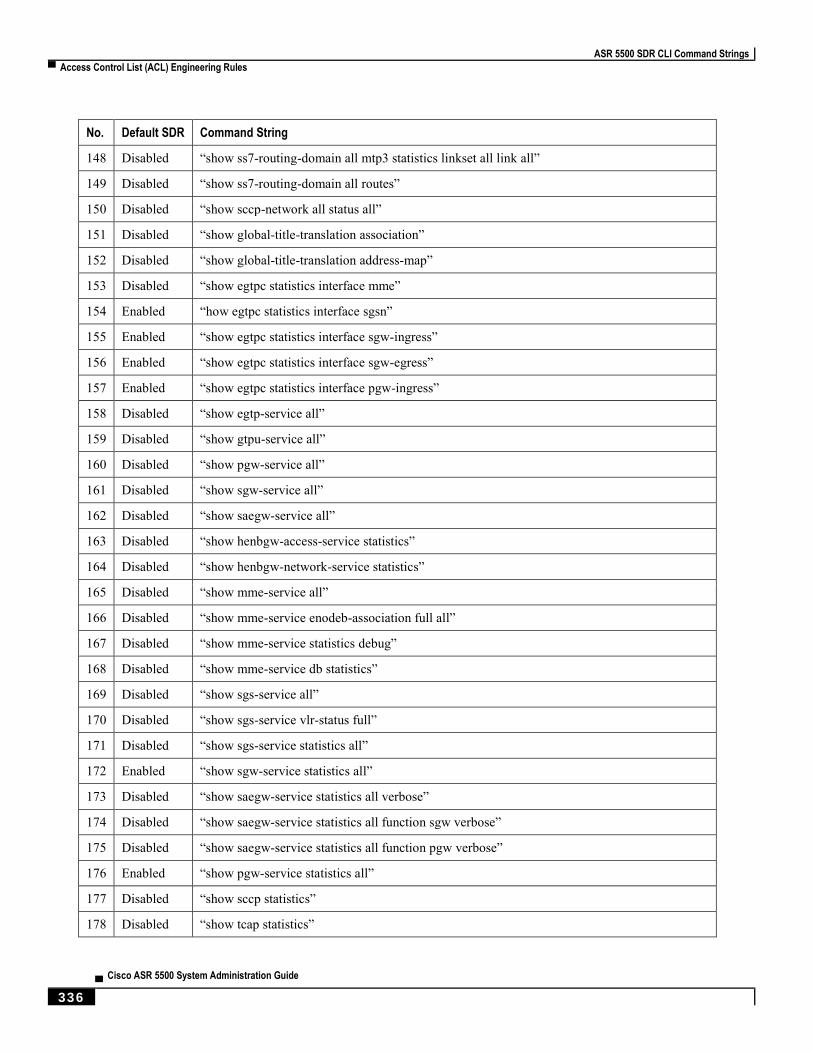
ASR 5500 SDR CLI Command Strings
▀ Access Control List (ACL) Engineering Rules
▄ Cisco ASR 5500 System Administration Guide
336
No. Default SDR Command String
148 Disabled “show ss7-routing-domain all mtp3 statistics linkset all link all”
149 Disabled “show ss7-routing-domain all routes”
150 Disabled “show sccp-network all status all”
151 Disabled “show global-title-translation association”
152 Disabled “show global-title-translation address-map”
153 Disabled “show egtpc statistics interface mme”
154 Enabled “how egtpc statistics interface sgsn”
155 Enabled “show egtpc statistics interface sgw-ingress”
156 Enabled “show egtpc statistics interface sgw-egress”
157 Enabled “show egtpc statistics interface pgw-ingress”
158 Disabled “show egtp-service all”
159 Disabled “show gtpu-service all”
160 Disabled “show pgw-service all”
161 Disabled “show sgw-service all”
162 Disabled “show saegw-service all”
163 Disabled “show henbgw-access-service statistics”
164 Disabled “show henbgw-network-service statistics”
165 Disabled “show mme-service all”
166 Disabled “show mme-service enodeb-association full all”
167 Disabled “show mme-service statistics debug”
168 Disabled “show mme-service db statistics”
169 Disabled “show sgs-service all”
170 Disabled “show sgs-service vlr-status full”
171 Disabled “show sgs-service statistics all”
172 Enabled “show sgw-service statistics all”
173 Disabled “show saegw-service statistics all verbose”
174 Disabled “show saegw-service statistics all function sgw verbose”
175 Disabled “show saegw-service statistics all function pgw verbose”
176 Enabled “show pgw-service statistics all”
177 Disabled “show sccp statistics”
178 Disabled “show tcap statistics”

ASR 5500 SDR CLI Command Strings
Access Control List (ACL) Engineering Rules ▀
Cisco ASR 5500 System Administration Guide ▄ 337
No. Default SDR Command String
179 Disabled “show map statistics”
180 Disabled “show sms statistics”
181 Disabled “show pdg-service statistics”
182 Disabled “show hnbgw sessmgr all memory statistics”
183 Disabled “show hnbgw sessmgr all internal statistics”
184 Disabled “show hnbgw disconnect-reasons”
185 Disabled “show cs-network statistics”
186 Disabled “show ps-network statistics”
187 Disabled “show hnbgw statistics”
188 Disabled “show hnbgw counters”
189 Disabled “show demux-mgr statistics hnbmgr full”
190 Disabled “show demuxmgr statistics bngmgr all”
191 Disabled “show alcap statistics”
192 Disabled “show pdg-service statistics micro-tunnel”
193 Disabled “show pdg-service statistics transport”
194 Disabled “show demuxmgr statistics a11mgr all”
195 Disabled “show demuxmgr statistics famgr all”
196 Disabled “show demuxmgr statistics hamgr all”
197 Disabled “show demuxmgr statistics l2tpmgr all”
198 Disabled “show demuxmgr statistics ipsgmgr all”
199 Enabled “show demuxmgr statistics sgtpcmgr all”
200 Disabled “show demuxmgr statistics imsimgr all”
201 Enabled “show demuxmgr statistics gtpcmgr all”
202 Enabled “show demuxmgr statistics egtpmgr all”
203 Disabled “show demuxmgr statistics egtpegmgr all”
204 Disabled “show demuxmgr statistics pdgdmgr all”
205 Enabled “show demuxmgr statistics gtpumgr all”
206 Disabled “show bcmcs statistics all”
207 Enabled “show linkmgr all parser statistics all”
208 Disabled “show gtpp accounting servers”
209 Disabled “show gtpp statistics verbose”
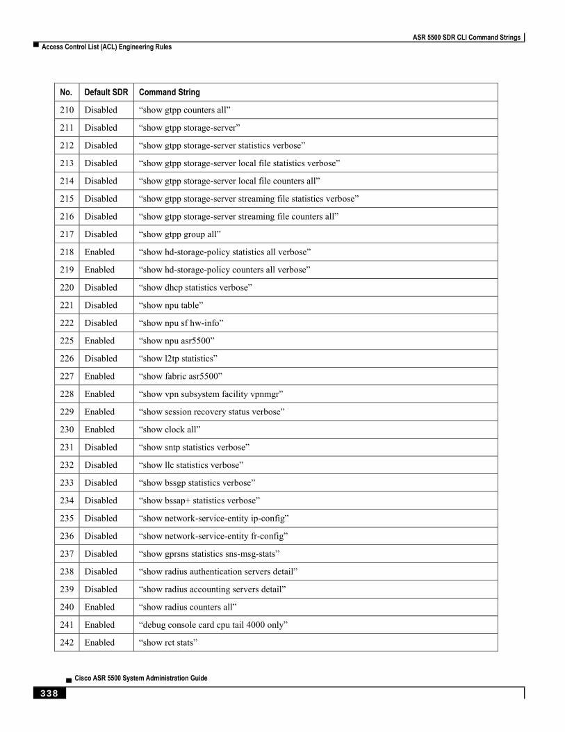
ASR 5500 SDR CLI Command Strings
▀ Access Control List (ACL) Engineering Rules
▄ Cisco ASR 5500 System Administration Guide
338
No. Default SDR Command String
210 Disabled “show gtpp counters all”
211 Disabled “show gtpp storage-server”
212 Disabled “show gtpp storage-server statistics verbose”
213 Disabled “show gtpp storage-server local file statistics verbose”
214 Disabled “show gtpp storage-server local file counters all”
215 Disabled “show gtpp storage-server streaming file statistics verbose”
216 Disabled “show gtpp storage-server streaming file counters all”
217 Disabled “show gtpp group all”
218 Enabled “show hd-storage-policy statistics all verbose”
219 Enabled “show hd-storage-policy counters all verbose”
220 Disabled “show dhcp statistics verbose”
221 Disabled “show npu table”
222 Disabled “show npu sf hw-info”
225 Enabled “show npu asr5500”
226 Disabled “show l2tp statistics”
227 Enabled “show fabric asr5500”
228 Enabled “show vpn subsystem facility vpnmgr”
229 Enabled “show session recovery status verbose”
230 Enabled “show clock all”
231 Disabled “show sntp statistics verbose”
232 Disabled “show llc statistics verbose”
233 Disabled “show bssgp statistics verbose”
234 Disabled “show bssap+ statistics verbose”
235 Disabled “show network-service-entity ip-config”
236 Disabled “show network-service-entity fr-config”
237 Disabled “show gprsns statistics sns-msg-stats”
238 Disabled “show radius authentication servers detail”
239 Disabled “show radius accounting servers detail”
240 Enabled “show radius counters all”
241 Enabled “debug console card cpu tail 4000 only”
242 Enabled “show rct stats”
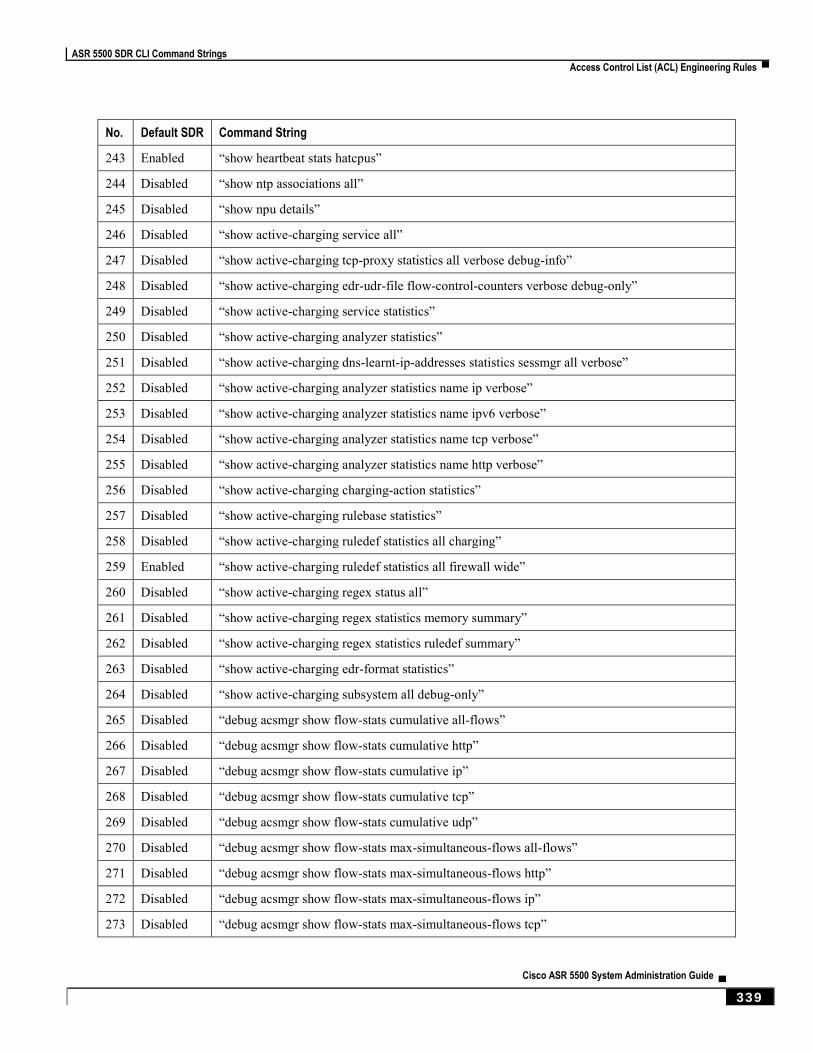
ASR 5500 SDR CLI Command Strings
Access Control List (ACL) Engineering Rules ▀
Cisco ASR 5500 System Administration Guide ▄ 339
No. Default SDR Command String
243 Enabled “show heartbeat stats hatcpus”
244 Disabled “show ntp associations all”
245 Disabled “show npu details”
246 Disabled “show active-charging service all”
247 Disabled “show active-charging tcp-proxy statistics all verbose debug-info”
248 Disabled “show active-charging edr-udr-file flow-control-counters verbose debug-only”
249 Disabled “show active-charging service statistics”
250 Disabled “show active-charging analyzer statistics”
251 Disabled “show active-charging dns-learnt-ip-addresses statistics sessmgr all verbose”
252 Disabled “show active-charging analyzer statistics name ip verbose”
253 Disabled “show active-charging analyzer statistics name ipv6 verbose”
254 Disabled “show active-charging analyzer statistics name tcp verbose”
255 Disabled “show active-charging analyzer statistics name http verbose”
256 Disabled “show active-charging charging-action statistics”
257 Disabled “show active-charging rulebase statistics”
258 Disabled “show active-charging ruledef statistics all charging”
259 Enabled “show active-charging ruledef statistics all firewall wide”
260 Disabled “show active-charging regex status all”
261 Disabled “show active-charging regex statistics memory summary”
262 Disabled “show active-charging regex statistics ruledef summary”
263 Disabled “show active-charging edr-format statistics”
264 Disabled “show active-charging subsystem all debug-only”
265 Disabled “debug acsmgr show flow-stats cumulative all-flows”
266 Disabled “debug acsmgr show flow-stats cumulative http”
267 Disabled “debug acsmgr show flow-stats cumulative ip”
268 Disabled “debug acsmgr show flow-stats cumulative tcp”
269 Disabled “debug acsmgr show flow-stats cumulative udp”
270 Disabled “debug acsmgr show flow-stats max-simultaneous-flows all-flows”
271 Disabled “debug acsmgr show flow-stats max-simultaneous-flows http”
272 Disabled “debug acsmgr show flow-stats max-simultaneous-flows ip”
273 Disabled “debug acsmgr show flow-stats max-simultaneous-flows tcp”
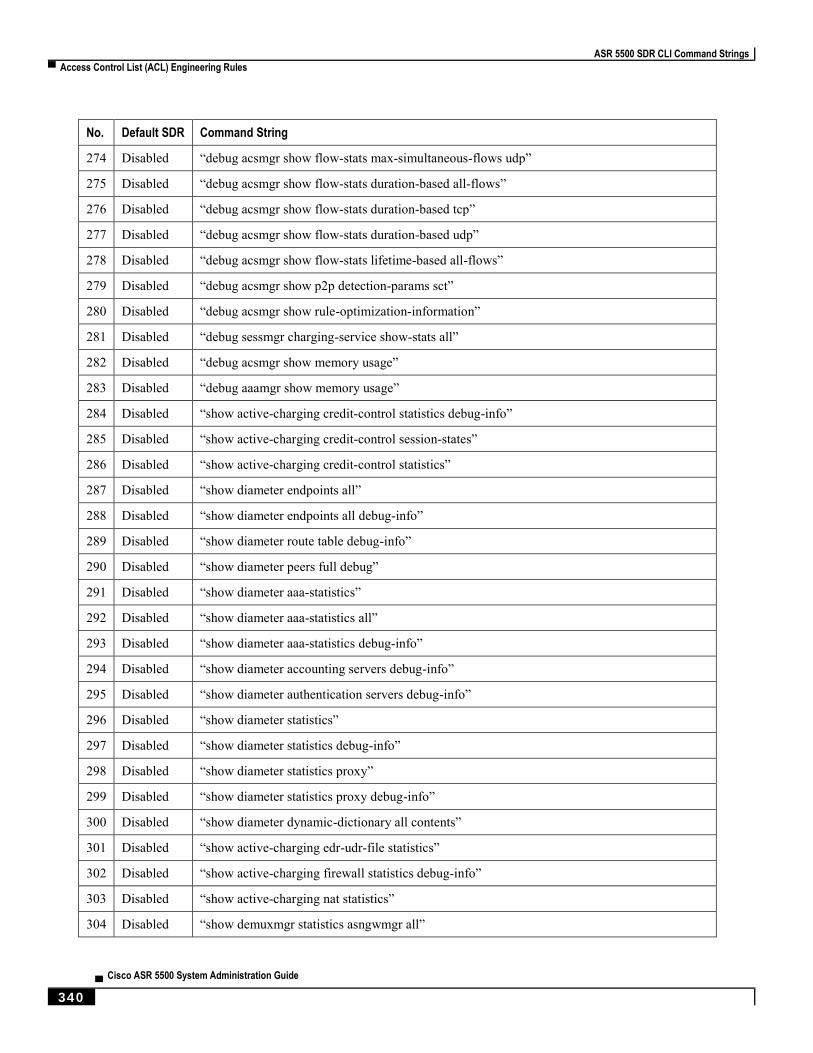
ASR 5500 SDR CLI Command Strings
▀ Access Control List (ACL) Engineering Rules
▄ Cisco ASR 5500 System Administration Guide
340
No. Default SDR Command String
274 Disabled “debug acsmgr show flow-stats max-simultaneous-flows udp”
275 Disabled “debug acsmgr show flow-stats duration-based all-flows”
276 Disabled “debug acsmgr show flow-stats duration-based tcp”
277 Disabled “debug acsmgr show flow-stats duration-based udp”
278 Disabled “debug acsmgr show flow-stats lifetime-based all-flows”
279 Disabled “debug acsmgr show p2p detection-params sct”
280 Disabled “debug acsmgr show rule-optimization-information”
281 Disabled “debug sessmgr charging-service show-stats all”
282 Disabled “debug acsmgr show memory usage”
283 Disabled “debug aaamgr show memory usage”
284 Disabled “show active-charging credit-control statistics debug-info”
285 Disabled “show active-charging credit-control session-states”
286 Disabled “show active-charging credit-control statistics”
287 Disabled “show diameter endpoints all”
288 Disabled “show diameter endpoints all debug-info”
289 Disabled “show diameter route table debug-info”
290 Disabled “show diameter peers full debug”
291 Disabled “show diameter aaa-statistics”
292 Disabled “show diameter aaa-statistics all”
293 Disabled “show diameter aaa-statistics debug-info”
294 Disabled “show diameter accounting servers debug-info”
295 Disabled “show diameter authentication servers debug-info”
296 Disabled “show diameter statistics”
297 Disabled “show diameter statistics debug-info”
298 Disabled “show diameter statistics proxy”
299 Disabled “show diameter statistics proxy debug-info”
300 Disabled “show diameter dynamic-dictionary all contents”
301 Disabled “show active-charging edr-udr-file statistics”
302 Disabled “show active-charging firewall statistics debug-info”
303 Disabled “show active-charging nat statistics”
304 Disabled “show demuxmgr statistics asngwmgr all”

ASR 5500 SDR CLI Command Strings
Access Control List (ACL) Engineering Rules ▀
Cisco ASR 5500 System Administration Guide ▄ 341
No. Default SDR Command String
305 Disabled “show asngw-service all”
306 Disabled “show asngw-service statistics verbose”
307 Disabled “show demuxmgr statistics asnpcmgr all”
308 Disabled “show asnpc-service all”
309 Disabled “show asnpc-service statistics verbose”
310 Disabled “show demuxmgr statistics phsgwmgr all”
311 Disabled “show phsgw-service all”
312 Disabled “show phsgw-service statistics verbose”
313 Disabled “show demuxmgr statistics phspcmgr all”
314 Disabled “show phspc-service all”
315 Disabled “show phspc-service statistics verbose”
316 Disabled “show demuxmgr statistics magmgr all”
317 Disabled “show active-charging content-filtering category policy-id all”
318 Disabled “show content-filtering category database all verbose”
319 Disabled “show content-filtering category database facility srdbmgr all verbose”
320 Disabled “show content-filtering category statistics”
321 Disabled “show content-filtering category statistics facility srdbmgr all”
322 Disabled “show active-charging content-filtering category statistics”
323 Disabled “show active-charging content-filtering server-group statistics verbose”
324 Disabled “show active-charging url-blacklisting statistics”
325 Disabled “show url-blacklisting database all”
326 Disabled “show url-blacklisting database facility acsmgr all”
327 Disabled “show active-charging tethering-detection database”
328 Disabled “show active-charging tethering-detection database sessmgr all”
329 Disabled “show active-charging tethering-detection statistics”
330 Disabled “show ims-authorization service statistics”
331 Disabled “show ims-authorization policy-control statistics”
332 Disabled “show ims-authorization policy-control statistics debug-info”
333 Disabled “show local-policy statistics summary”
334 Disabled “show rohc statistics”
335 Disabled “show dns client statistics”

ASR 5500 SDR CLI Command Strings
▀ Access Control List (ACL) Engineering Rules
▄ Cisco ASR 5500 System Administration Guide
342
No. Default SDR Command String
336 Disabled “show hss-peer-service service all”
337 Disabled “show ipms status all”
338 Disabled “show ipms status debug-info”
339 Disabled “show kvstore”
340 Disabled “show kvstore verbose”
341 Disabled “show kvstore kvclient”
342 Disabled “show kvstore kvmgr”
343 Disabled “show pcc-service all”
344 Disabled “show pcc-service statistics all”
345 Disabled “show pcc-policy service all”
346 Disabled “show pcc-policy service statistics all”
347 Disabled “show pcc-quota service all”
348 Disabled “show pcc-quota service statistics all”
349 Disabled “show pcc-af service all”
350 Disabled “show pcc-af service statistics all”
351 Disabled “show pcc-sp-endpoint all”
352 Disabled “show pcc-sp-endpoint statistics all”
353 Disabled “show event-notif server all”
354 Disabled “show event-notif statistics”
355 Disabled “show demux-mgr statistics bindmux all”
356 Disabled “show congestion-control configuration”
357 Disabled “show congestion-control statistics mme full”
358 Disabled “show congestion-control statistics imsimgr all full”
359 Enabled “show ge-switch counters (second sample)”
360 Enabled “ethtool -S cpeth”
361 Enabled “Standby SMC Ophir Mac counters (second sample)” [ASR 5000 only]
362 Disabled “show cli history”
363 Disabled “card-cpu boxer summary”
Notes:
Enabled = Included in default record section
Disabled = Not included in default record section
Related Documents