Cisco ACI Virtualization Guide, Release 3.1(1) and 3.1(2) First Published: 2017-12-22 Last Modified: 2019-02-04 Americas Headquarters Cisco Systems, Inc. 170 West Tasman Drive San Jose, CA 95134-1706 USA http://www.cisco.com Tel: 408 526-4000 800 553-NETS (6387) Fax: 408 527-0883

Welcome message from author
This document is posted to help you gain knowledge. Please leave a comment to let me know what you think about it! Share it to your friends and learn new things together.
Transcript
Cisco ACI Virtualization Guide, Release 3.1(1) and 3.1(2)First Published: 2017-12-22
Last Modified: 2019-02-04
Americas HeadquartersCisco Systems, Inc.170 West Tasman DriveSan Jose, CA 95134-1706USAhttp://www.cisco.comTel: 408 526-4000
800 553-NETS (6387)Fax: 408 527-0883

THE SPECIFICATIONS AND INFORMATION REGARDING THE PRODUCTS IN THIS MANUAL ARE SUBJECT TO CHANGE WITHOUT NOTICE. ALL STATEMENTS,INFORMATION, AND RECOMMENDATIONS IN THIS MANUAL ARE BELIEVED TO BE ACCURATE BUT ARE PRESENTED WITHOUT WARRANTY OF ANY KIND,EXPRESS OR IMPLIED. USERS MUST TAKE FULL RESPONSIBILITY FOR THEIR APPLICATION OF ANY PRODUCTS.
THE SOFTWARE LICENSE AND LIMITED WARRANTY FOR THE ACCOMPANYING PRODUCT ARE SET FORTH IN THE INFORMATION PACKET THAT SHIPPED WITHTHE PRODUCT AND ARE INCORPORATED HEREIN BY THIS REFERENCE. IF YOU ARE UNABLE TO LOCATE THE SOFTWARE LICENSE OR LIMITED WARRANTY,CONTACT YOUR CISCO REPRESENTATIVE FOR A COPY.
The Cisco implementation of TCP header compression is an adaptation of a program developed by the University of California, Berkeley (UCB) as part of UCB's public domain version ofthe UNIX operating system. All rights reserved. Copyright © 1981, Regents of the University of California.
NOTWITHSTANDING ANY OTHERWARRANTY HEREIN, ALL DOCUMENT FILES AND SOFTWARE OF THESE SUPPLIERS ARE PROVIDED “AS IS" WITH ALL FAULTS.CISCO AND THE ABOVE-NAMED SUPPLIERS DISCLAIM ALL WARRANTIES, EXPRESSED OR IMPLIED, INCLUDING, WITHOUT LIMITATION, THOSE OFMERCHANTABILITY, FITNESS FOR A PARTICULAR PURPOSE AND NONINFRINGEMENT OR ARISING FROM A COURSE OF DEALING, USAGE, OR TRADE PRACTICE.
IN NO EVENT SHALL CISCO OR ITS SUPPLIERS BE LIABLE FOR ANY INDIRECT, SPECIAL, CONSEQUENTIAL, OR INCIDENTAL DAMAGES, INCLUDING, WITHOUTLIMITATION, LOST PROFITS OR LOSS OR DAMAGE TO DATA ARISING OUT OF THE USE OR INABILITY TO USE THIS MANUAL, EVEN IF CISCO OR ITS SUPPLIERSHAVE BEEN ADVISED OF THE POSSIBILITY OF SUCH DAMAGES.
Any Internet Protocol (IP) addresses and phone numbers used in this document are not intended to be actual addresses and phone numbers. Any examples, command display output, networktopology diagrams, and other figures included in the document are shown for illustrative purposes only. Any use of actual IP addresses or phone numbers in illustrative content is unintentionaland coincidental.
Cisco and the Cisco logo are trademarks or registered trademarks of Cisco and/or its affiliates in the U.S. and other countries. To view a list of Cisco trademarks, go to this URL: www.cisco.comgo trademarks. Third-party trademarks mentioned are the property of their respective owners. The use of the word partner does not imply a partnership relationship between Cisco and anyother company. (1721R)
© 2017-2019 Cisco Systems, Inc. All rights reserved.
C O N T E N T S
Preface xviiP R E F A C E
Audience xvii
Document Conventions xvii
Related Documentation xix
Documentation Feedback xx
Obtaining Documentation and Submitting a Service Request xx
New and Changed Information 1C H A P T E R 1
New and Changed Information 1
Cisco ACI Virtual Machine Networking 3C H A P T E R 2
Cisco ACI VM Networking Support for Virtual Machine Managers 3
Virtual Machine Manager Domain Main Components 4
Virtual Machine Manager Domains 5
VMM Domain VLAN Pool Association 6
VMM Domain EPG Association 7
About Trunk Port Group 9
Attachable Entity Profile 10
EPG Policy Resolution and Deployment Immediacy 11
Guidelines for Deleting VMM Domains 13
NetFlow with Virtual Machine Networking 13
About NetFlow with Virtual Machine Networking 13
About NetFlow Exporter Policies with Virtual Machine Networking 14
NetFlow Support with VMware vSphere Distributed Switch 14
NetFlow Support with Cisco Application Virtual Switch 14
Configuring a NetFlow Exporter Policy for VM Networking Using the GUI 14
Cisco ACI Virtualization Guide, Release 3.1(1) and 3.1(2)iii
Consuming a NetFlow Exporter Policy Under a VMM Domain Using the GUI 15
Enabling NetFlow on an Endpoint Group to VMM Domain Association Using the GUI 15
Configuring a NetFlow Exporter Policy for Virtual Machine Networking Using the NX-OS-StyleCLI 16
Consuming a NetFlow Exporter Policy Under a VMM Domain Using the NX-OS-Style CLI forVMware VDS 17
Consuming a NetFlow Exporter Policy Under a VMM Domain Using the NX-OS-Style CLI forCisco AVS 17
Enabling or Disabling NetFlow on an Endpoint Group Using the NX-OS-Style CLI for VMwareVDS 18
Enabling or Disabling NetFlow on an Endpoint Group Using the NX-OS-Style CLI for Cisco AVS18
Configuring a NetFlow Exporter Policy for VM Networking Using the REST API 19
Consuming a NetFlow Exporter Policy Under a VMM Domain Using the REST API for VMwareVDS 19
Consuming a NetFlow Exporter Policy Under a VMMDomain Using the RESTAPI for Cisco AVS19
Enabling NetFlow on an Endpoint Group for VMM Domain Association for VMware VDS 20
Enabling NetFlow on an Endpoint Group for VMM Domain Association for Cisco AVS 20
Troubleshooting VMM Connectivity 21
Cisco ACI with VMware VDS Integration 23C H A P T E R 3
Configuring Virtual Machine Networking Policies 23
APIC Supported VMware VDS Versions 23
Guidelines for Upgrading VMware DVS from 5.x to 6.x and VMM Integration 24
Mapping ACI and VMware Constructs 24
VMware VDS Parameters Managed By APIC 25
VDS Parameters Managed by APIC 25
VDS Port Group Parameters Managed by APIC 25
Creating a VMM Domain Profile 26
GUI Tasks 26
Prerequisites for Creating a VMM Domain Profile 26
vCenter Domain Operational Workflow 27
Creating a vCenter Domain Profile Using the GUI 28
Creating a Read-Only VMM Domain 30
Cisco ACI Virtualization Guide, Release 3.1(1) and 3.1(2)iv
Contents
Creating a Read-Only VMM Domain Using the Cisco APIC GUI 30
Endpoint Retention Configuration 31
Configuring Endpoint Retention Using the GUI 31
Configuring Endpoint Retention Using the NX-OS Style CLI 32
Creating VDS Uplink Port Groups 32
Creating a Trunk Port Group 33
Creating a Trunk Port Group Using the GUI 33
Creating a Trunk Port Group Using the NX-OS Style CLI 33
Creating a Trunk Port Group Using the REST API 36
Working with Blade Servers 36
Guidelines for Cisco UCS B-Series Servers 36
Setting up an Access Policy for a Blade Server Using the GUI 37
Troubleshooting the Cisco ACI and VMware VMM System Integration 39
Additional Reference Sections 39
Custom User Account with Minimum VMware vCenter Privileges 39
Quarantine Port Groups 40
On-Demand VMM Inventory Refresh 40
Guidelines for Migrating a vCenter Hypervisor VMK0 to an ACI Inband VLAN 40
Create the Necessary Management EPG Policies in APIC 41
Migrate the VMK0 to the Inband ACI VLAN 41
REST API Tasks 41
Creating a vCenter Domain Profile Using the REST API 41
Creating a Read-Only VMM Domain Using the REST API 44
Configuring Endpoint Retention Using the REST API 47
Setting Up an Access Policy for a Blade Server Using the REST API 47
NX-OS Style CLI Tasks 48
Creating a vCenter Domain Profile Using the NX-OS Style CLI 48
Creating a Read-Only VMM Domain Using the NX-OS Style CLI 50
Microsegmentation with Cisco ACI 53C H A P T E R 4
Microsegmentation with Cisco ACI 53
Benefits of Microsegmentation with Cisco ACI 54
How Microsegmentation Using Cisco ACI Works 54
Attributes for Microsegmentation with Cisco ACI 55
Cisco ACI Virtualization Guide, Release 3.1(1) and 3.1(2)v
Contents
Methods of Filtering VMs for uSeg EPGs 57
VM Filtering when Matching Any Attribute 58
VM Filtering when Matching All Attributes 59
VM Filtering when Using Simple or Block Statements 60
VM Filtering when Using EPG Match Precedence 60
Precedence of Operators 61
Scenarios for Using Microsegmentation with Cisco ACI 62
Using Microsegmentation with Cisco ACI with VMs Within a Single Application EPG 62
Using Microsegmentation with Cisco ACI with VMs in Different Application EPGs 63
Using Microsegmentation with Network-based Attributes 64
Configuring Microsegmentation with Cisco ACI 64
Prerequisites for Configuring Microsegmentation with Cisco ACI 65
Workflow for Configuring Microsegmentation with Cisco ACI 66
Configuring Microsegmentation with Cisco ACI Using the GUI 67
Configuring Microsegmentation with Cisco ACI Using the NX-OS-Style CLI 70
Configuring Microsegmentation with Cisco ACI Using the REST API 72
Intra-EPG Isolation Enforcement and Cisco ACI 75C H A P T E R 5
Intra-EPG Isolation for VMware VDS or Microsoft vSwitch 75
Configuring Intra-EPG Isolation for VMware VDS or Microsoft vSwitch using the GUI 77
Configuring Intra-EPG Isolation for VMware VDS or Microsoft vSwitch using the NX-OS StyleCLI 77
Configuring Intra-EPG Isolation for VMware VDS or Microsoft vSwitch using the REST API 79
Intra-EPG Isolation Enforcement for Cisco AVS 80
Configuring Intra-EPG Isolation for Cisco AVS Using the GUI 80
Configuring Intra-EPG Isolation for Cisco AVS Using the NX-OS Style CLI 81
Configuring Intra-EPG Isolation for Cisco AVS Using the REST API 82
Choosing Statistics to View for Isolated Endpoints on Cisco AVS 83
Viewing Statistics for Isolated Endpoints on Cisco AVS 83
Intra-EPG Isolation Enforcement for Cisco ACI Virtual Edge 84
Configure Intra-EPG Isolation for Cisco ACI Virtual Edge Using the GUI 84
Configure Intra-EPG Isolation for Cisco ACI Virtual Edge Using the NX-OS Style CLI 85
Configure Intra-EPG Isolation for Cisco ACI Virtual Edge Using the REST API 86
Choose Statistics for Isolated Endpoints on Cisco ACI Virtual Edge Under the Tenants Tab 87
Cisco ACI Virtualization Guide, Release 3.1(1) and 3.1(2)vi
Contents
Choose Statistics for Isolated Endpoints on Cisco ACI Virtual Edge Under the Virtual NetworkingTab 87
View Statistics for Isolated Endpoints on Cisco ACI Virtual Edge Under the Tenants Tab 88
View Statistics for Isolated Endpoints on Cisco ACI Virtual Edge Under the Virtual NetworkingTab 88
Cisco ACI with Cisco AVS 91C H A P T E R 6
Cisco AVS Overview 91
About the Cisco AVS and the VMware vCenter 93
Cisco AVS in a Multipod Environment 94
Required Software 95
Cisco AVS Documentation 95
Cisco AVS Installation 96
Workflow for Installing the Cisco AVS 96
Creating Interface, Switch, and vCenter Domain Profiles 97
Interface and Switch Profile Guidelines and Prerequisites 97
vCenter Domain Profile Guidelines and Prerequisites 98
Creating Interface and Switch Profiles and a vCenter Domain Profile Using the GUI 99
Configuring vSwitch Override Policies on the VMM Domain Using the GUI 102
Pre-Cisco AVS Installation Configuration Using the NX-OS Style CLI 103
Prerequisites for Installing Cisco AVS 106
Installing Cisco AVS Using the VMware vCenter Plug-in 107
Installing the Cisco AVS Using Cisco VSUM 109
Installing Cisco VSUM 109
About the Virtual Switch Image File Upload Utility 118
Uploading the Cisco AVS Image File 118
Installing Cisco AVS Using VSUM 121
Installing the Cisco AVS Software Using the ESXi CLI 126
Verifying the Cisco AVS Installation 128
Verifying the Virtual Switch Status 128
Verifying the vNIC Status 128
Adding Cisco AVS Hosts to the DVS 129
Uninstalling Cisco AVS 129
Uninstalling Cisco AVS Using the VMware vCenter Plug-in 130
Cisco ACI Virtualization Guide, Release 3.1(1) and 3.1(2)vii
Contents
Key Post-Installation Configuration Tasks for the Cisco AVS 131
Prerequisites for Configuring the Cisco AVS 131
Workflow for Key Post-Installation Configuration Tasks for the Cisco AVS 132
Deploying an Application Profile for Cisco AVS Using the GUI 134
Creating a Tenant, VRF, and Bridge Domain Using the GUI 134
Creating an Application Profile Using the GUI 135
Creating EPGs Using the GUI 135
Creating VLAN Pools with Encapsulation Blocks Using the GUI 136
Assigning Port Groups to the VM in vCenter 137
Creating a Filter Using the GUI 137
Creating a Contract Using the GUI 138
Deploying an Application Profile for Cisco AVS Using the NX-OS CLI 139
Creating a Tenant, VRF, and Bridge Domain Using the NX-OS Style CLI 139
Creating an Application Profile and EPG Using the NX-OS Style CLI 140
Creating VLAN Pools with Encapsulation Blocks Using the NX-OS Style CLI 141
Deploying an Application Policy Using the NX-OS Style CLI 142
Verifying the Application Profile 145
Verifying the Application Profile and EPGs in the GUI 145
Verifying the EPGs in vCenter 145
Verifying that VMs can Communicate 145
Configuring an IP Address for VMs Connected to Cisco AVS 146
Assigning an IP Address to the Cisco AVS VM Network Adapter 146
Assigning a Gateway Address for the VMs Connected to Cisco AVS Using the GUI 147
Guidelines for Using vMotion with Cisco AVS 148
Distributed Firewall 149
Benefits of Distributed Firewall 150
Configuring Distributed Firewall 151
Workflow for Configuring Distributed Firewall 152
Configuring a Stateful Policy for Distributed Firewall Using the GUI 152
Configuring a Stateful Policy for Distributed Firewall Using the NX-OS Style CLI 153
Creating a Distributed Firewall Policy or Changing its Mode Using the GUI 153
Enabling Distributed Firewall After Installation or Upgrade 155
Configuring Distributed Firewall Using the NX-OS Style CLl 156
Distributed Firewall Flow Logging 156
Cisco ACI Virtualization Guide, Release 3.1(1) and 3.1(2)viii
Contents
Configuring Parameters for Distributed Firewall Flow Information 156
Distributed Firewall Flow Counts 163
Choosing Statistics to View for Distributed Firewall 164
Viewing Statistics for Distributed Firewall 164
Microsegmentation with Cisco ACI for Cisco AVS 165
Configuring Layer 4 to Layer 7 Services 165
Migrating Your Network from DVS to AVS 165
REST API Tasks for Cisco AVS 166
Creating a Tenant, VRF, and Bridge Domain Using the REST API 166
Deploying an Application Profile Using the REST API 167
Configuring a Stateful Policy for Distributed Firewall Using the REST API 169
Changing the Distributed Firewall Mode Using the REST API 170
Configuring Parameters for Distributed Firewall Flow Information in the REST API 171
Cisco ACI with VMware vRealize 173C H A P T E R 7
About Cisco ACI with VMware vRealize 173
Cisco ACI with VMware vRealize Solution Overview 173
Physical and Logical Topology 174
About the Mapping of ACI Constructs in VMware vRealize 176
Event Broker VM Customization 177
Getting Started with Cisco ACI with VMware vRealize 178
Prerequisites for Getting Started with Cisco ACI with VMware vRealize 178
Setting Up an IaaS Handle in vRealize Orchestrator 179
Cisco ACI with VMware vRealize Installation Workflow 180
Installing the APIC Plug-in on the vRealize Orchestrator 180
Setting Up the VMware vRealize Automation Appliance for ACI 181
Day-0 Operations of ACI 183
Associating AEP with VMware VMM Domain 184
Cisco ACI with VMware vRealize Upgrade Workflow 184
Upgrading the APIC Plug-in on the vRealize Orchestrator 185
Verifying the Connection Between APIC and vRealize 185
Cisco ACI with VMware vRealize Downgrade Workflow 186
Deleting Package and Workflows 186
Use Case Scenarios for the Administrator and Tenant Experience 187
Cisco ACI Virtualization Guide, Release 3.1(1) and 3.1(2)ix
Contents
Overview of Tier Application Deployment 187
Deploying a Single-Tier Application Using Property Groups 187
Deploying a 3-Tier Application Using a Multi-Machine Blueprint 189
About Plan Types 193
About vRealize Service Categories and Catalog Items 194
Mapping of the ACI Plan Types to vRealize Service Categories 194
ACI Administrator Services in vRealize 196
List of Admin Services Catalog Items for ACI Administrator Services 196
ACI Tenant Services in vRealize 199
List of Network Security Catalog Items for ACI Tenant Services 199
List of Tenant Network Services Catalog Items for ACI Tenant Services 200
List of Tenant Shared Plan Catalog Items for ACI Tenant Services 200
List of Tenant VPC Plan Catalog Items for ACI Tenant Services 201
List of VM Services Catalog Items for ACI Tenant Services 202
Entitlements for ACI catalog-items in vRealize 203
List of Entitlements for ACI Catalog Items 203
ACI Plug-in in vRealize Orchestrator 204
APIC Workflows 204
APIC Inventory View 204
About Load Balancing and Firewall Services 205
Prerequisites for Enabling Services 206
Configuring the Services on APIC Using XML POST 207
Deleting the Services Configuration 209
About L3 External Connectivity 210
Prerequisites for Configuring L3 External Connectivity for vRealize 210
Administrator Experiences 210
Cisco ACI with Cisco AVS or Cisco ACI Virtual Edge 210
Cisco AVS or Cisco ACI Virtual Edge VMM Domain Creation 211
Update of Cisco AVS or Cisco ACI Virtual Edge VMM Domain Encapsulation Pools 213
Deletion of Cisco AVS or Cisco ACI Virtual Edge and the VMM Domain 214
Cisco AVS or Cisco ACI Virtual Edge VMM Domain Security Domain Mapping 216
Distributed Firewall Policy 217
Tenant Experiences in a Shared or Virtual Private Cloud Plan 221
Creating Networks in a Shared Plan 221
Cisco ACI Virtualization Guide, Release 3.1(1) and 3.1(2)x
Contents
Verifying the Newly Created Network on VMware vRealize and APIC 222
Creating a Bridge Domain in a VPC Plan 223
Creating a Network and Associating to a Bridge Domain in a VPC Plan 223
Creating a Security Policy Within the Tenant 225
Consuming a Shared Service in the Common Tenant 227
Updating Security Policies (Access Control Lists) 229
Deleting Security Policies (Access Control Lists) 230
Creating the Network in the VPC Plan 231
Updating a Tenant Network Association with the VMM Domain 232
Microsegmentation 233
Creating the VMs and Attaching to Networks Without Using the Machine Blueprints 243
About Adding the Load Balancer to the Tenant Network 244
Configuring the Firewall 248
Configuring the Firewall and Load Balancer 249
Configuring the Inter-EPG Firewall 251
Attaching an External L3 Network Internet Access 253
Application Deployment Scenarios 255
About Property Groups 256
About Service Blueprints 256
Integration with vRealize Network Profiles (IPAM) 257
Documentation of APIC Workflows in vRealize Orchestrator 257
List of Methods in ApicConfigHelper Class 258
Writing Custom Workflows Using the APIC Plug-in Method 263
Multi-Tenancy and Role based Access Control Using Security Domains 265
Adding the Tenant 265
Deleting the Tenant 265
APIC Credentials for Workflows 265
Adding APIC with Admin Credentials 266
Adding APIC with Tenant Credentials 266
Troubleshooting 266
Collecting the Logs to Report 266
Installing the ACI Helper Scripts 267
Removing the APIC Plug-in 268
Plug-in Overview 268
Cisco ACI Virtualization Guide, Release 3.1(1) and 3.1(2)xi
Contents
Configuring a vRA Host for the Tenant in the vRealize Orchestrator 269
Configuring an IaaS Host in the vRealize Orchestrator 270
Cisco ACI vCenter Plug-in 271C H A P T E R 8
About Cisco ACI with VMware vSphere Web Client 271
Cisco ACI vCenter Plug-in Overview 271
Getting Started with Cisco ACI vCenter Plug-in 272
Cisco ACI vCenter Plug-in Software Requirements 272
Required APIC Configuration 273
Installing the Cisco ACI vCenter Plug-in 273
Connecting vCenter Plug-in to your ACI Fabric 274
Connecting vCenter Plug-in to the Cisco ACI Fabric Using Credentials 274
Connecting vCenter Plug-in to your ACI Fabric Using an Existing Certificate 275
Connecting vCenter Plug-in to your ACI Fabric by Creating a New Certificate 276
Cisco ACI vCenter Plug-in Features and Limitations 277
Role-based Access Control for Cisco ACI vCenter Plug-in 282
Recommended RBAC Configuration for Cisco ACI vCenter Plug-in 284
Upgrading VMware vCenter when Using the Cisco ACI vCenter Plug-in 285
Cisco ACI vCenter Plug-in GUI 285
Cisco ACI vCenter Plug-in GUI Architecture Overview 285
Cisco ACI vCenter Plug-in Overview 287
GUI Tips 292
Performing ACI Object Configurations 292
Creating a New Tenant 292
Creating a New Application Profile 293
Creating an EPG Using the Drag and Drop Method 293
Creating a New uSeg EPG Using the Drag and Drop Method 294
Creating a Contract Between Two EPGs Using the Drag and Drop Method 295
Adding an EPG to an Existing Contract Using Drag and Drop Method 296
Adding an EPG to an Existing Contract using the Security Tab 297
Setting up L3 External Network 297
Setting up L2 External Network 298
Creating a VRF Using the Drag and Drop Method 299
Creating a Bridge Domain 300
Cisco ACI Virtualization Guide, Release 3.1(1) and 3.1(2)xii
Contents
Start a New Troubleshooting Session Between Endpoints 300
Start an Exisiting Troubleshooting Session Between Endpoints 301
Uninstalling the Cisco ACI vCenter Plug-in 302
Upgrading the Cisco ACI vCenter Plug-in 302
Troubleshooting the Cisco ACI vCenter Plug-in Installation 302
Reference Information 304
Alternative Installation of the Cisco ACI vCenter Plug-in 304
Cisco ACI with Microsoft SCVMM 307C H A P T E R 9
About Cisco ACI with Microsoft SCVMM 307
Cisco ACI with Microsoft SCVMM Solution Overview 308
Physical and Logical Topology of SCVMM 308
About the Mapping of ACI Constructs in SCVMM 308
SCVMM Fabric Cloud and Tenant Clouds 309
Getting Started with Cisco ACI with Microsoft SCVMM 310
Prerequisites for Getting Started with Cisco ACI with Microsoft SCVMM 310
Installing, Setting Up, and Verifying the Cisco ACI with Microsoft SCVMM Components 311
Installing the APIC SCVMM Agent on SCVMM 313
Installing the APIC SCVMM Agent on a Highly Available SCVMM 313
Generating APIC OpFlex Certificate 314
Adding the OpFlex Certificate Policy to APIC 315
Installing the OpflexAgent Certificate 316
Configuring APIC IP Settings with OpflexAgent Certificate on the SCVMM Agent 318
Configuring APIC IP Settings with OpflexAgent Certificate on the SCVMM Agent on a HighlyAvailable SCVMM 320
Installing the APIC Hyper-V Agent on the Hyper-V Server 321
Verifying the Installation of Cisco ACI with Microsoft SCVMM 323
Setting Up ACI Policies 326
Upgrading the Cisco ACI with Microsoft SCVMM Components 330
Upgrading the ACI Microsoft SCVMM Components Workflow 331
Upgrading the APIC SCVMM Agent on SCVMM 331
Upgrading the APIC SCVMM Agent on a High Available SCVMM 332
Upgrading the APIC Hyper-V Agent 332
Deploying Tenant Policies 333
Cisco ACI Virtualization Guide, Release 3.1(1) and 3.1(2)xiii
Contents
Deployment Tenant Policies Prerequisites 333
Creating a Tenant 334
Creating an EPG 334
Associating the Microsoft VMM Domain with an EPG 334
Verifying the EPG is Associated with the VMM Domain on APIC 335
Verifying the EPG is Associated with the VMM Domain on SCVMM 335
Creating a Static IP Address Pool 336
Creating a Static IP Address Pool Using the NX-OS Style CLI 337
Connecting and Powering on the Virtual Machine 338
Verifying the Association on APIC 338
Viewing EPGs on APIC 339
Troubleshooting the Cisco ACI with Microsoft SCVMM 339
Troubleshooting APIC to SCVMM Connectivity 339
Troubleshooting Leaf to Hyper-V Host Connectivity 339
Responding to Traffic Failure after Leaf Switch Replacement 340
Troubleshooting the EPG Configuration Issue 340
REST API References 341
Creating a SCVMM Domain Profile Using the REST API 341
Reference Information 344
Installing the APIC Agent on SCVMM Using the Windows Command Prompt 344
Installing the APIC Hyper-V Agent on the Hyper-V Server Using the Windows Command Prompt345
Creating a SCVMM Domain Profile Using the NX-OS Style CLI 346
Programmability References 347
ACI SCVMM PowerShell Cmdlets 347
Configuration References 348
MAC Address Configuration Recommendations 348
Uninstalling the Cisco ACI with Microsoft SCVMM Components 349
Uninstalling the APIC SCVMM Agent 350
Uninstalling the APIC SCVMM Agent on a Highly Available SCVMM 350
Downgrading the APIC Controller and the Switch Software with Cisco ACI with Microsoft SCVMMComponents 351
Exporting APIC OpFlex Certificate 351
Cisco ACI Virtualization Guide, Release 3.1(1) and 3.1(2)xiv
Contents
Cisco ACI with Microsoft Windows Azure Pack 353C H A P T E R 1 0
About Cisco ACI with Microsoft Windows Azure Pack 353
Cisco ACI with Microsoft Windows Azure Pack Solution Overview 354
Physical and Logical Topology 355
About the Mapping of ACI Constructs in Microsoft Windows Azure Pack 356
Getting Started with Cisco ACI with Microsoft Windows Azure Pack 357
Prerequisites for Getting Started with Cisco ACI with Microsoft Windows Azure Pack 357
Installing, Setting Up, and Verifying the Cisco ACI with Microsoft Windows Azure PackComponents 358
Installing ACI Azure Pack Resource Provider 359
Installing the OpflexAgent Certificate 359
Configuring ACI Azure Pack Resource Provider Site 361
Installing ACI Azure Pack Admin Site Extension 362
Installing ACI Azure Pack Tenant Site Extension 362
Setting Up ACI 362
Verifying the Windows Azure Pack Resource Provider 363
Upgrading the Cisco ACI with Microsoft Windows Azure Pack Components 363
Upgrading the ACI Windows Azure Pack Workflow 364
Upgrading the ACI Windows Azure Pack Resource Provider 365
Upgrading the ACI Azure Pack Admin Site Extension 365
Upgrading the ACI Azure Pack Tenant Site Extension 366
Use Case Scenarios for the Administrator and Tenant Experience 366
Admin Tasks 369
About Plan Types 369
About Plan Options 370
Creating a Plan 371
Creating a Tenant 372
Allowing Tenants to Provide Shared Services 372
Allowing Tenants to Consume Shared Service 373
Allowing Tenants to Consume NAT Firewall and ADC Load Balancer Services 373
Viewing the Shared Service Providers and Consumers 374
Managing Shared Services 374
About Load Balancing 375
Cisco ACI Virtualization Guide, Release 3.1(1) and 3.1(2)xv
Contents
About L3 External Connectivity 383
Tenant Tasks 385
Shared or Virtual Private Cloud Plan Experience 385
Troubleshooting Cisco ACI with Microsoft Windows Azure Pack 398
Troubleshooting as an Admin 398
Troubleshooting as a Tenant 398
Troubleshooting the EPG Configuration Issue 398
Programmability References 398
ACI Windows Azure Pack PowerShell Cmdlets 398
Uninstalling the Cisco ACI with Microsoft Windows Azure Pack Components 400
Uninstalling the APIC Windows Azure Pack Resource Provider 400
Uninstalling the ACI Azure Pack Resource Provider 401
Uninstalling the ACI Azure Pack Admin Site Extension 401
Uninstalling the ACI Azure Pack Tenant Site Extension 401
Uninstalling the APIC Hyper-V Agent 402
Downgrading Cisco APIC and the Switch Software with Cisco ACI and Microsoft Windows AzurePack Components 402
Cisco ACI Virtualization Guide, Release 3.1(1) and 3.1(2)xvi
Contents
Preface
This preface includes the following sections:
• Audience, on page xvii• Document Conventions, on page xvii• Related Documentation, on page xix• Documentation Feedback, on page xx• Obtaining Documentation and Submitting a Service Request, on page xx
AudienceThis guide is intended primarily for data center administrators with responsibilities and expertise in one ormore of the following:
• Virtual machine installation and administration
• Server administration
• Switch and network administration
Document ConventionsCommand descriptions use the following conventions:
DescriptionConventionBold text indicates the commands and keywords that you enter literallyas shown.
bold
Italic text indicates arguments for which the user supplies the values.Italic
Square brackets enclose an optional element (keyword or argument).[x]
Square brackets enclosing keywords or arguments separated by a verticalbar indicate an optional choice.
[x | y]
Braces enclosing keywords or arguments separated by a vertical barindicate a required choice.
{x | y}
Cisco ACI Virtualization Guide, Release 3.1(1) and 3.1(2)xvii
DescriptionConvention
Nested set of square brackets or braces indicate optional or requiredchoices within optional or required elements. Braces and a vertical barwithin square brackets indicate a required choice within an optionalelement.
[x {y | z}]
Indicates a variable for which you supply values, in context where italicscannot be used.
variable
A nonquoted set of characters. Do not use quotation marks around thestring or the string will include the quotation marks.
string
Examples use the following conventions:
DescriptionConventionTerminal sessions and information the switch displays are in screen font.screen font
Information you must enter is in boldface screen font.boldface screen font
Arguments for which you supply values are in italic screen font.italic screen font
Nonprinting characters, such as passwords, are in angle brackets.< >
Default responses to system prompts are in square brackets.[ ]
An exclamation point (!) or a pound sign (#) at the beginning of a lineof code indicates a comment line.
!, #
This document uses the following conventions:
Means reader take note. Notes contain helpful suggestions or references to material not covered in the manual.Note
Means reader be careful. In this situation, you might do something that could result in equipment damage orloss of data.
Caution
IMPORTANT SAFETY INSTRUCTIONS
This warning symbol means danger. You are in a situation that could cause bodily injury. Before you workon any equipment, be aware of the hazards involved with electrical circuitry and be familiar with standardpractices for preventing accidents. Use the statement number provided at the end of each warning to locateits translation in the translated safety warnings that accompanied this device.
SAVE THESE INSTRUCTIONS
Warning
Cisco ACI Virtualization Guide, Release 3.1(1) and 3.1(2)xviii
PrefacePreface
Related DocumentationApplication Policy Infrastructure Controller (APIC) Documentation
The following companion guides provide documentation for APIC:
• Cisco APIC Getting Started Guide
• Cisco APIC Basic Configuration Guide
• Cisco ACI Fundamentals
• Cisco APIC Layer 2 Networking Configuration Guide
• Cisco APIC Layer 3 Networking Configuration Guide
• Cisco APIC NX-OS Style Command-Line Interface Configuration Guide
• Cisco APIC REST API Configuration Guide
• Cisco APIC Layer 4 to Layer 7 Services Deployment Guide
• Cisco ACI Virtualization Guide
• Cisco Application Centric Infrastructure Best Practices Guide
All these documents are available at the following URL: http://www.cisco.com/c/en/us/support/cloud-systems-management/application-policy-infrastructure-controller-apic/tsd-products-support-series-home.html
Cisco Application Centric Infrastructure (ACI) Documentation
The broader ACI documentation is available at the following URL: http://www.cisco.com/c/en/us/support/cloud-systems-management/application-policy-infrastructure-controller-apic/tsd-products-support-series-home.html.
Cisco Application Centric Infrastructure (ACI) Simulator Documentation
The Cisco ACI Simulator documentation is available at http://www.cisco.com/c/en/us/support/cloud-systems-management/application-centric-infrastructure-simulator/tsd-products-support-series-home.html.
Cisco Nexus 9000 Series Switches Documentation
The Cisco Nexus 9000 Series Switches documentation is available at http://www.cisco.com/c/en/us/support/switches/nexus-9000-series-switches/tsd-products-support-series-home.html.
Cisco Application Virtual Switch Documentation
The Cisco Application Virtual Switch (AVS) documentation is available at http://www.cisco.com/c/en/us/support/switches/application-virtual-switch/tsd-products-support-series-home.html.
Cisco ACI Virtualization Guide, Release 3.1(1) and 3.1(2)xix
PrefaceRelated Documentation
Cisco Application Centric Infrastructure (ACI) Integration with OpenStack Documentation
Cisco ACI integration with OpenStack documentation is available at http://www.cisco.com/c/en/us/support/cloud-systems-management/application-policy-infrastructure-controller-apic/tsd-products-support-series-home.html.
Documentation FeedbackTo provide technical feedback on this document, or to report an error or omission, please send your commentsto [email protected]. We appreciate your feedback.
Obtaining Documentation and Submitting a Service RequestFor information on obtaining documentation, using the Cisco Bug Search Tool (BST), submitting a servicerequest, and gathering additional information, seeWhat's New in Cisco Product Documentation at:http://www.cisco.com/c/en/us/td/docs/general/whatsnew/whatsnew.html
Subscribe toWhat’s New in Cisco Product Documentation, which lists all new and revised Cisco technicaldocumentation as an RSS feed and delivers content directly to your desktop using a reader application. TheRSS feeds are a free service.
Cisco ACI Virtualization Guide, Release 3.1(1) and 3.1(2)xx
PrefaceDocumentation Feedback
C H A P T E R 1New and Changed Information
This chapter contains the following sections:
• New and Changed Information, on page 1
New and Changed InformationThe following table provides an overview of the significant changes to this guide up to this current release.The table does not provide an exhaustive list of all changes made to the guide or of the new features up tothis release.
Table 1: New Features and Changed Behavior in the Cisco ACI Virtualization Guide
Where DocumentedDescriptionFeatureCisco APIC ReleaseVersion
Cisco ACI VMNetworking Support forVirtual MachineManagers, on page 3 inthis guide and Cisco ACIVirtual Edgedocumentation onCisco.com
Cisco ACI Virtual Edgeis the next generation ofthe Application VirtualSwitch (AVS) for CiscoACI environments.CiscoACI Virtual Edge is ahypervisor-independentdistributed service VMthat leverages the nativedistributed virtual switchthat belongs to thehypervisor. Cisco ACIVirtual Edge runs in theuser space, operates as avirtual leaf, and ismanaged by the CiscoApplication PolicyInfrastructure Controller(APIC).
Cisco ACI Virtual Edge3.1(1)
Cisco ACI Virtualization Guide, Release 3.1(1) and 3.1(2)1
Where DocumentedDescriptionFeatureCisco APIC ReleaseVersion
Cisco ACI VMNetworking Support forVirtual MachineManagers, on page 3and the knowledge basearticle "Cisco ACI andRed Hat Virtualization"on Cisco.com
Cisco APIC integrateswith Red HatVirtualization (formerlyRed Hat EnterpriseVirtualization) andenhances the networkmanagement capabilitiesof the platform.
Cisco ACI with Red HatVirtualization
3.1(1)
Role-based AccessControl for Cisco ACIvCenter Plug-in, on page282 and RecommendedRBAC Configuration forCisco ACI vCenterPlug-in, on page 284 inthis guide
The Cisco ACI vCenterplug-in supports enhancedrole-based access control(RBAC) based on CiscoAPIC user roles andsecurity domains.
Role-based access controlfor Cisco ACI vCenterplug-in
3.1(1)
Requesting AdditionalNAT Firewall Public IPAddresses for a VRF, onpage 396
You can allocate extrapublic IP addresses to usewith NAT rules withMicrosoft WAP. You canrequest this public IPaddress from any EPGwhere NAT is enabled.
Extra NAT firewall publicIP addresses forMicrosoftWindows Azure Pack(WAP)
3.1(1)
Creating a Read-OnlyVMM Domain, on page30 in this guide.
You can create aread-only mode VMMdomain for VMwareVDS. This enables you toview information about aDVS in VMware vCenterthat is not managed byCisco APIC. You create aread-only VMM domainby setting the accessmodewhen you create thedomain.
Read-only mode VMMdomain (VMware VDS)
3.1(1)
Cisco ACI with VMwarevRealize, on page 173 inthis guide.
Beginning with CiscoAPIC Release 3.1(1),vRA and vRO supportCisco ACI Virtual Edge.
vRealize support for CiscoApplication CentricInfrastructure VirtualEdge (Cisco ACI VirtualEdge).
3.1(1)
The content in this document for Cisco APIC Release 3.1(1) and Cisco APICRelease 3.1(2) is the same.
3.1(2)
Cisco ACI Virtualization Guide, Release 3.1(1) and 3.1(2)2
New and Changed InformationNew and Changed Information
C H A P T E R 2Cisco ACI Virtual Machine Networking
This chapter contains the following sections:
• Cisco ACI VM Networking Support for Virtual Machine Managers, on page 3• Virtual Machine Manager Domain Main Components , on page 4• Virtual Machine Manager Domains, on page 5• VMM Domain VLAN Pool Association, on page 6• VMM Domain EPG Association, on page 7• About Trunk Port Group, on page 9• Attachable Entity Profile, on page 10• EPG Policy Resolution and Deployment Immediacy, on page 11• Guidelines for Deleting VMM Domains, on page 13• NetFlow with Virtual Machine Networking, on page 13• Troubleshooting VMM Connectivity, on page 21
Cisco ACI VM Networking Support for Virtual MachineManagers
Benefits of ACI VM Networking
Cisco ACI virtual machine (VM) networking supports hypervisors from multiple vendors. It provides thehypervisors programmable and automated access to high-performance scalable virtualized data centerinfrastructure.
Programmability and automation are critical features of scalable data center virtualization infrastructure. TheCiscoACI open RESTAPI enables virtual machine integrationwith and orchestration of the policymodel-basedCisco ACI fabric. Cisco ACI VM networking enables consistent enforcement of policies across both virtualand physical workloads managed by hypervisors from multiple vendors.
Attachable entity profiles easily enable VMmobility and placement of workloads anywhere in the Cisco ACIfabric. The Cisco Application Policy Infrastructure Controller (APIC) provides centralized troubleshooting,application health score, and virtualization monitoring. Cisco ACI multi-hypervisor VM automation reducesor eliminates manual configuration and manual errors. This enables virtualized data centers to support largenumbers of VMs reliably and cost effectively.
Cisco ACI Virtualization Guide, Release 3.1(1) and 3.1(2)3
Supported Vendors
Cisco ACI supports virtual machine managers (VMMs) from the following products and vendors:
• Cisco Application Centric Infrastructure Virtual Edge
For information, see the Cisco ACI Virtual Edge documentation on Cisco.com.
• Cisco Application Virtual Switch (AVS)
For information, see the chapter "Cisco ACI with Cisco AVS" in the Cisco ACI Virtualization Guideand Cisco AVS documentation on Cisco.com.
• Cloud Foundry
Cloud Foundry integration with Cisco ACI is supported beginning with Cisco APIC Release 3.1(2). Forinformation, see the knowledge base article, Cisco ACI and Cloud Foundry Integration on Cisco.com.
• Kubernetes
For information, see the knowledge base article, Cisco ACI and Kubernetes Integration on Cisco.com.
• Microsoft System Center Virtual Machine Manager (SCVMM)
For information, see the chapters "Cisco ACI with Microsoft SCVMM" and "Cisco ACI with MicrosoftWindows Azure Pack in the Cisco ACI Virtualization Guide.
• OpenShift
For information, see the OpenShift documentation on Cisco.com.
• OpenStack
For information, see the OpenStack documentation on Cisco.com.
• Red Hat Virtualization (RHV)
For information, see the knowledge base article, Cisco ACI and Red Hat Integration on Cisco.com.
• VMware Virtual Distributed Switch (VDS)
For information, see the chapter "Cisco "ACI with VMware VDS Integration" in the Cisco ACIVirtualization Guide.
See the Cisco ACI Virtualization Compatibility Matrix for the most current list of verified interoperableproducts.
Virtual Machine Manager Domain Main ComponentsACI fabric virtual machine manager (VMM) domains enable an administrator to configure connectivitypolicies for virtual machine controllers. The essential components of an ACI VMM domain policy includethe following:
• Virtual Machine Manager Domain Profile—Groups VM controllers with similar networking policyrequirements. For example, VM controllers can share VLAN pools and application endpoint groups(EPGs). The APIC communicates with the controller to publish network configurations such as portgroups that are then applied to the virtual workloads. The VMM domain profile includes the followingessential components:
Cisco ACI Virtualization Guide, Release 3.1(1) and 3.1(2)4
Cisco ACI Virtual Machine NetworkingVirtual Machine Manager Domain Main Components
• Credential—Associates a valid VM controller user credential with an APIC VMM domain.
• Controller—Specifes how to connect to a VM controller that is part of a policy enforcement domain.For example, the controller specifies the connection to a VMware vCenter that is part a VMMdomain.
A single VMM domain can contain multiple instances of VM controllers, buttheymust be from the same vendor (for example, fromVMware or fromMicrosoft.
Note
• EPGAssociation—Endpoint groups regulate connectivity and visibility among the endpoints within thescope of the VMM domain policy. VMM domain EPGs behave as follows:
• The APIC pushes these EPGs as port groups into the VM controller.
• An EPG can span multiple VMM domains, and a VMM domain can contain multiple EPGs.
• Attachable Entity Profile Association—Associates a VMM domain with the physical networkinfrastructure. An attachable entity profile (AEP) is a network interface template that enables deployingVM controller policies on a large set of leaf switch ports. An AEP specifies which switches and portsare available, and how they are configured.
• VLANPool Association—AVLANpool specifies theVLAN IDs or ranges used for VLAN encapsulationthat the VMM domain consumes.
Virtual Machine Manager DomainsAn APIC VMM domain profile is a policy that defines a VMM domain. The VMM domain policy is createdin APIC and pushed into the leaf switches.
Cisco ACI Virtualization Guide, Release 3.1(1) and 3.1(2)5
Cisco ACI Virtual Machine NetworkingVirtual Machine Manager Domains
Figure 1: ACI VMM Domain VM Controller Integration
VMM domains provide the following:
• A common layer in the ACI fabric that enables scalable fault-tolerant support for multiple VM controllerplatforms.
• VMM support for multiple tenants within the ACI fabric.
VMM domains contain VM controllers such as VMware vCenter or Microsoft SCVMMManager and thecredential(s) required for the ACI API to interact with the VM controller. A VMM domain enables VMmobility within the domain but not across domains. A single VMM domain can contain multiple instances ofVM controllers but they must be the same kind. For example, a VMM domain can contain many VMwarevCenters managing multiple controllers each running multiple VMs but it may not also contain SCVMMManagers. A VMM domain inventories controller elements (such as pNICs, vNICs, VM names, and so forth)and pushes policies into the controller(s), creating port groups, and other necessary elements. The ACI VMMdomain listens for controller events such as VM mobility and responds accordingly.
VMM Domain VLAN Pool AssociationVLAN pools represent blocks of traffic VLAN identifiers. A VLAN pool is a shared resource and can beconsumed by multiple domains such as VMM domains and Layer 4 to Layer 7 services.
Each pool has an allocation type (static or dynamic), defined at the time of its creation. The allocation typedetermines whether the identifiers contained in it will be used for automatic assignment by the APIC (dynamic)or set explicitly by the administrator (static). By default, all blocks contained within a VLAN pool have thesame allocation type as the pool but users can change the allocation type for encapsulation blocks containedin dynamic pools to static. Doing so excludes them from dynamic allocation.
A VMM domain can associate with only one dynamic VLAN pool. By default, the assignment of VLANidentifiers to EPGs that are associated with VMM domains is done dynamically by the APIC. While dynamicallocation is the default and preferred configuration, an administrator can statically assign a VLAN identifier
Cisco ACI Virtualization Guide, Release 3.1(1) and 3.1(2)6
Cisco ACI Virtual Machine NetworkingVMM Domain VLAN Pool Association
to an EPG instead. In that case, the identifiers used must be selected from encapsulation blocks in the VLANpool associated with the VMM domain, and their allocation type must be changed to static.
The APIC provisions VMM domain VLAN on leaf ports based on EPG events, either statically binding onleaf ports or based on VM events from controllers such as VMware vCenter or Microsoft SCVMM.
VMM Domain EPG AssociationThe ACI fabric associates tenant application profile EPGs to VMM domains, either automatically by anorchestration component such as Microsoft Azure, or by an APIC administrator creating such configurations.An EPG can span multiple VMM domains and a VMM domain can contain multiple EPGs.Figure 2: VMM Domain EPG Association
In the illustration above, end points (EP) of the same color are part of the same end point group. For example,all the green EPs are in the same EPG even though they are in two different VMM domains.
Refer to the latest Verified Scalability Guide for Cisco ACI document for virtual network and VMM domainEPG capacity information.
Cisco ACI Virtualization Guide, Release 3.1(1) and 3.1(2)7
Cisco ACI Virtual Machine NetworkingVMM Domain EPG Association
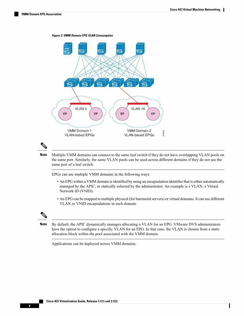
Figure 3: VMM Domain EPG VLAN Consumption
Multiple VMM domains can connect to the same leaf switch if they do not have overlapping VLAN pools onthe same port. Similarly, the same VLAN pools can be used across different domains if they do not use thesame port of a leaf switch.
Note
EPGs can use multiple VMM domains in the following ways:
• An EPGwithin a VMMdomain is identified by using an encapsulation identifier that is either automaticallymanaged by the APIC, or statically selected by the administrator. An example is a VLAN, a VirtualNetwork ID (VNID).
• An EPG can be mapped to multiple physical (for baremetal servers) or virtual domains. It can use differentVLAN or VNID encapsulations in each domain.
By default, the APIC dynamically manages allocating a VLAN for an EPG. VMware DVS administratorshave the option to configure a specific VLAN for an EPG. In that case, the VLAN is chosen from a staticallocation block within the pool associated with the VMM domain.
Note
Applications can be deployed across VMM domains.
Cisco ACI Virtualization Guide, Release 3.1(1) and 3.1(2)8
Cisco ACI Virtual Machine NetworkingVMM Domain EPG Association
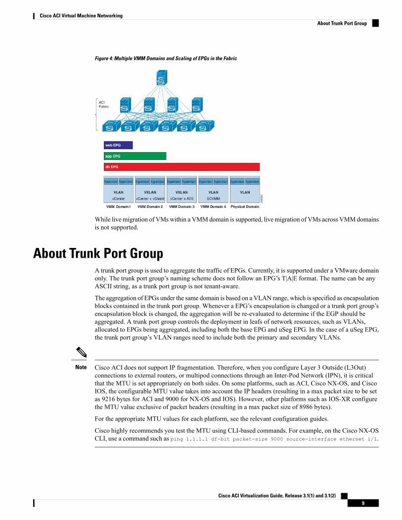
Figure 4: Multiple VMM Domains and Scaling of EPGs in the Fabric
While livemigration of VMswithin a VMMdomain is supported, livemigration of VMs across VMMdomainsis not supported.
About Trunk Port GroupA trunk port group is used to aggregate the traffic of EPGs. Currently, it is supported under a VMware domainonly. The trunk port group’s naming scheme does not follow an EPG’s T|A|E format. The name can be anyASCII string, as a trunk port group is not tenant-aware.
The aggregation of EPGs under the same domain is based on a VLAN range, which is specified as encapsulationblocks contained in the trunk port group. Whenever a EPG’s encapsulation is changed or a trunk port group’sencapsulation block is changed, the aggregation will be re-evaluated to determine if the EGP should beaggregated. A trunk port group controls the deployment in leafs of network resources, such as VLANs,allocated to EPGs being aggregated, including both the base EPG and uSeg EPG. In the case of a uSeg EPG,the trunk port group’s VLAN ranges need to include both the primary and secondary VLANs.
Cisco ACI does not support IP fragmentation. Therefore, when you configure Layer 3 Outside (L3Out)connections to external routers, or multipod connections through an Inter-Pod Network (IPN), it is criticalthat the MTU is set appropriately on both sides. On some platforms, such as ACI, Cisco NX-OS, and CiscoIOS, the configurable MTU value takes into account the IP headers (resulting in a max packet size to be setas 9216 bytes for ACI and 9000 for NX-OS and IOS). However, other platforms such as IOS-XR configurethe MTU value exclusive of packet headers (resulting in a max packet size of 8986 bytes).
For the appropriate MTU values for each platform, see the relevant configuration guides.
Cisco highly recommends you test the MTU using CLI-based commands. For example, on the Cisco NX-OSCLI, use a command such as ping 1.1.1.1 df-bit packet-size 9000 source-interface ethernet 1/1.
Note
Cisco ACI Virtualization Guide, Release 3.1(1) and 3.1(2)9
Cisco ACI Virtual Machine NetworkingAbout Trunk Port Group
If you install 1 Gigabit Ethernet (GE) or 10GE links between the leaf and spine switches in the fabric, thereis risk of packets being dropped instead of forwarded, because of inadequate bandwidth. To avoid the risk,use 40GE or 100GE links between the leaf and spine switches.
Caution
Multiple Spanning Tree (MST) is not supported on interfaces configured with the Per Port VLAN feature(configuring multiple EPGs on a leaf switch using the same VLAN ID with localPort scope).
Note
If you are using Cisco ACI Multi-Site with this Cisco APIC cluster/fabric, look for a cloud icon on the objectnames in the navigation bar. This indicates that the information is derived fromMulti-Site. It is recommendedto only make changes from the Multi-Site GUI. Please review the Multi-Site documentation before makingchanges here.
Note
For a Cisco APIC REST API query of event records, the APIC system limits the response to a maximum of500,000 event records. If the response is more than 500,000 events, it returns an error. Use filters to refineyour queries. For more information, see Composing Query Filter Expressions.
Note
For more information, see
• Creating a Trunk Port Group Using the GUI, on page 33
• Creating a Trunk Port Group Using the NX-OS Style CLI, on page 33
• Creating a Trunk Port Group Using the REST API, on page 36
Attachable Entity ProfileThe ACI fabric provides multiple attachment points that connect through leaf ports to various external entitiessuch as bare metal servers, virtual machine hypervisors, Layer 2 switches (for example, the Cisco UCS fabricinterconnect), or Layer 3 routers (for example Cisco Nexus 7000 Series switches). These attachment pointscan be physical ports, FEX ports, port channels, or a virtual port channel (vPC) on leaf switches.
Cisco ACI Virtualization Guide, Release 3.1(1) and 3.1(2)10
Cisco ACI Virtual Machine NetworkingAttachable Entity Profile
When creating a VPC domain between two leaf switches, both switches must be in the same switch generation,one of the following:
• Generation 1 - Cisco Nexus N9K switches without “EX” or "FX" on the end of the switch name; forexample, N9K-9312TX
• Generation 2 – Cisco Nexus N9K switches with “EX” or "FX" on the end of the switch model name; forexample, N9K-93108TC-EX
Switches such as these two are not compatible VPC peers. Instead, use switches of the same generation.
Note
An Attachable Entity Profile (AEP) represents a group of external entities with similar infrastructure policyrequirements. The infrastructure policies consist of physical interface policies that configure various protocoloptions, such as Cisco Discovery Protocol (CDP), Link Layer Discovery Protocol (LLDP), or Link AggregationControl Protocol (LACP).
An AEP is required to deploy VLAN pools on leaf switches. Encapsulation blocks (and associated VLANs)are reusable across leaf switches. An AEP implicitly provides the scope of the VLAN pool to the physicalinfrastructure.
The following AEP requirements and dependencies must be accounted for in various configuration scenarios,including network connectivity, VMM domains, and multipod configuration:
• The AEP defines the range of allowed VLANS but it does not provision them. No traffic flows unlessan EPG is deployed on the port. Without defining a VLAN pool in an AEP, a VLAN is not enabled onthe leaf port even if an EPG is provisioned.
• A particular VLAN is provisioned or enabled on the leaf port that is based on EPG events either staticallybinding on a leaf port or based on VM events from external controllers such as VMware vCenter orMicrosoft Azure Service Center Virtual Machine Manager (SCVMM).
• Attached entity profiles can be associated directly with application EPGs, which deploy the associatedapplication EPGs to all those ports associated with the attached entity profile. The AEP has a configurablegeneric function (infraGeneric), which contains a relation to an EPG (infraRsFuncToEpg) that is deployedon all interfaces that are part of the selectors that are associated with the attachable entity profile.
A virtual machine manager (VMM) domain automatically derives physical interface policies from the interfacepolicy groups of an AEP.
An override policy at the AEP can be used to specify a different physical interface policy for a VMM domain.This policy is useful in scenarios where a VM controller is connected to the leaf switch through an intermediateLayer 2 node, and a different policy is desired at the leaf switch and VM controller physical ports. For example,you can configure LACP between a leaf switch and a Layer 2 node. At the same time, you can disable LACPbetween the VM controller and the Layer 2 switch by disabling LACP under the AEP override policy.
EPG Policy Resolution and Deployment ImmediacyWhenever an EPG associates to a VMM domain, the administrator can choose the resolution and deploymentpreferences to specify when a policy should be pushed into leaf switches.
Cisco ACI Virtualization Guide, Release 3.1(1) and 3.1(2)11
Cisco ACI Virtual Machine NetworkingEPG Policy Resolution and Deployment Immediacy
Resolution Immediacy
• Pre-provision—Specifies that a policy (for example, VLAN, VXLAN binding, contracts, or filters) isdownloaded to a leaf switch even before a VM controller is attached to the virtual switch (for example,VMware VDS). This pre-provisions the configuration on the switch.
This helps the situation where management traffic for hypervisors/VM controllers are also using thevirtual switch associated to APIC VMM domain (VMM switch).
Deploying a VMM policy such as VLAN on ACI leaf switch requires APIC to collect CDP/LLDPinformation from both hypervisors via VM controller and ACI leaf switch. However if VM Controlleris supposed to use the same VMM policy (VMM switch) to communicate with its hypervisors or evenAPIC, the CDP/LLDP information for hypervisors can never be collected because the policy requiredfor VM controller/hypervisor management traffic is not deployed yet.
When using pre-provision immediacy, policy is downloaded to ACI leaf switch regardless of CDP/LLDPneighborship. Even without a hypervisor host connected to the VMM switch.
• Immediate—Specifies that EPG policies (including contracts and filters) are downloaded to the associatedleaf switch software upon ESXi host attachment to a DVS. LLDP or OpFlex permissions are used toresolve the VM controller to leaf node attachments.
The policy will be downloaded to leaf when you add host to the VMM switch. CDP/LLDP neighborshipfrom host to leaf is required.
• On Demand—Specifies that a policy (for example, VLAN, VXLAN bindings, contracts, or filters) ispushed to the leaf node only when an ESXi host is attached to a DVS and a VM is placed in the portgroup (EPG).
The policy will be downloaded to leaf when host is added to VMM switch and virtual machine needs tobe placed into port group (EPG). CDP/LLDP neighborship from host to leaf is required.
With both immediate and on demand, if host and leaf lose LLDP/CDP neighborship the policies areremoved.
Deployment Immediacy
Once the policies are downloaded to the leaf software, deployment immediacy can specify when the policyis pushed into the hardware policy content-addressable memory (CAM).
• Immediate—Specifies that the policy is programmed in the hardware policy CAM as soon as the policyis downloaded in the leaf software.
• On demand—Specifies that the policy is programmed in the hardware policy CAM only when the firstpacket is received through the data path. This process helps to optimize the hardware space.
When you use on demand deployment immediacy withMAC-pinned VPCs, the EPG contracts are not pushedto the leaf ternary content-addressble memory (TCAM) until the first endpoint is learned in the EPG on eachleaf. This can cause uneven TCAM utilization across VPC peers. (Normally, the contract would be pushedto both peers.)
Note
Cisco ACI Virtualization Guide, Release 3.1(1) and 3.1(2)12
Cisco ACI Virtual Machine NetworkingEPG Policy Resolution and Deployment Immediacy
Guidelines for Deleting VMM DomainsFollow the sequence below to assure that the APIC request to delete a VMM domain automatically triggersthe associated VM controller (for example VMware vCenter or Microsoft SCVMM) to complete the processnormally, and that no orphan EPGs are stranded in the ACI fabric.
1. The VM administrator must detach all the VMs from the port groups (in the case of VMware vCenter) orVM networks (in the case of SCVMM), created by the APIC.
In the case of Cisco AVS, the VM admin also needs to delete vmk interfaces associated with the CiscoAVS.
2. The ACI administrator deletes the VMM domain in the APIC. The APIC triggers deletion of VMwareVDS or Cisco AVS or SCVMM logical switch and associated objects.
The VM administrator should not delete the virtual switch or associated objects (such as port groups or VMnetworks); allow the APIC to trigger the virtual switch deletion upon completion of step 2 above. EPGs couldbe orphaned in the APIC if the VM administrator deletes the virtual switch from the VM controller beforethe VMM domain is deleted in the APIC.
Note
If this sequence is not followed, the VM controller does delete the virtual switch associated with the APICVMM domain. In this scenario, the VM administrator must manually remove the VM and vtep associationsfrom the VM controller, then delete the virtual switch(es) previously associated with the APIC VMMdomain.
NetFlow with Virtual Machine Networking
About NetFlow with Virtual Machine NetworkingThe NetFlow technology provides the metering base for a key set of applications, including network trafficaccounting, usage-based network billing, network planning, as well as denial of services monitoring, networkmonitoring, outbound marketing, and data mining for both service providers and enterprise customers. Ciscoprovides a set of NetFlow applications to collect NetFlow export data, perform data volume reduction, performpost-processing, and provide end-user applications with easy access to NetFlow data. If you have enabledNetFlow monitoring of the traffic flowing through your datacenters, this feature enables you to perform thesame level of monitoring of the traffic flowing through the Cisco Application Centric Infrastructure (CiscoACI) fabric.
Instead of hardware directly exporting the records to a collector, the records are processed in the supervisorengine and are exported to standard NetFlow collectors in the required format.
For more information about NetFlow, see the Cisco APIC and NetFlow knowledge base article.
Cisco ACI Virtualization Guide, Release 3.1(1) and 3.1(2)13
Cisco ACI Virtual Machine NetworkingGuidelines for Deleting VMM Domains
About NetFlow Exporter Policies with Virtual Machine NetworkingA virtual machine manager exporter policy (netflowVmmExporterPol) describes information about the datacollected for a flow that is sent to the reporting server or NetFlow collector. A NetFlow collector is an externalentity that supports the standard NetFlow protocol and accepts packets marked with valid NetFlow headers.
An exporter policy has the following properties:
• VmmExporterPol.dstAddr—This mandatory property specifies the IPv4 or IPv6 address of the NetFlowcollector that accepts the NetFlow flow packets. This must be in the host format (that is, "/32" or "/128").An IPv6 address is supported in vSphere Distributed Switch (vDS) version 6.0 and later.
• VmmExporterPol.dstPort—This mandatory property specifies the port on which the NetFlow collectorapplication is listening on, which enables the collector to accept incoming connections.
• VmmExporterPol.srcAddr—This optional property specifies the IPv4 address that is used as the sourceaddress in the exported NetFlow flow packets.
NetFlow Support with VMware vSphere Distributed SwitchThe VMware vSphere Distributed Switch (VDS) supports NetFlow with the following caveats:
• The external collector must be reachable through the ESX. ESX does not support virtual routing andforwardings (VRFs).
• A port group can enable or disable NetFlow.
• VDS does not support flow-level filtering.
Configure the following VDS parameters in VMware vCenter:
• Collector IP address and port. IPv6 is supported on VDS version 6.0 or later. These are mandatory.
• Source IP address. This is optional.
• Active flow timeout, idle flow timeout, and sampling rate. These are optional.
NetFlow Support with Cisco Application Virtual SwitchThe Cisco Application Virtual Switch (AVS) supports NetFlow with the following caveats:
• The external collector must be reachable through the ESX. ESX does not support virtual routing andforwardings (VRFs).
• A port group can enable or disable NetFlow and specify the direction of the traffic to be collected.
• Cisco AVS does not support flow-level filtering.
Configuring a NetFlow Exporter Policy for VM Networking Using the GUIThe following procedure configures a NetFlow exporter policy for VM networking.
Cisco ACI Virtualization Guide, Release 3.1(1) and 3.1(2)14
Cisco ACI Virtual Machine NetworkingAbout NetFlow Exporter Policies with Virtual Machine Networking
Procedure
Step 1 On the menu bar, choose Fabric > Access Policies.Step 2 In the Navigation pane, expand Interface Policies > Policies > NetFlow.Step 3 Right-click NetFlow Exporters for VM Networking and choose Create NetFlow Exporter for VM
Networking.Step 4 In the Create NetFlow Exporter for VM Networking dialog box, fill in the fields as required.Step 5 Click Submit.
Consuming a NetFlow Exporter Policy Under a VMM Domain Using the GUIThe following procedure consumes a NetFlow exporter policy under a VMM domain using the GUI.
Procedure
Step 1 On the menu bar, choose Virtual Networking > Inventory.Step 2 In theNavigation pane, expand theVMMDomainsfolder, right-clickVMware, and chooseCreate vCenter
Domain.Step 3 In the Create vCenter Domain dialog box, fill in the fields as required, except as specified:
a) In the NetFlow Exporter Policy drop-down list, choose the desired exporter policy or create a new one.b) In the Active Flow Timeout field, enter the desired active flow timeout, in seconds.
The Active Flow Timeout parameter specifies the delay that NetFlow waits after the active flow isinitiated, after which NetFlow sends the collected data. The range is from 60 to 3600. The default valueis 60.
c) In the Idle Flow Timeout field, enter the desired idle flow timeout, in seconds.
The Idle Flow Timeout parameter specifies the delay that NetFlow waits after the idle flow is initiated,after which NetFlow sends the collected data. The range is from 10 to 300. The default value is 15.
d) (VDS only) In the Sampling Rate field, enter the desired sampling rate.
The Sampling Rate parameter specifies how many packets that NetFlow will drop after every collectedpacket. If you specify a value of 0, then NetFlow does not drop any packets. The range is from 0 to 1000.The default value is 0.
Step 4 Click Submit.
Enabling NetFlow on an Endpoint Group to VMM Domain Association Usingthe GUI
The following procedure enables NetFlow on an endpoint group to VMM domain association.
Cisco ACI Virtualization Guide, Release 3.1(1) and 3.1(2)15
Cisco ACI Virtual Machine NetworkingConsuming a NetFlow Exporter Policy Under a VMM Domain Using the GUI
Before you begin
You must have configured the following:
• An application profile
• An application endpoint group
Procedure
Step 1 On the menu bar, choose Tenants > All Tenants.Step 2 In theWork pane, double-click the tenant's name.Step 3 In the left navigation pane, expand tenant_name > Application Profiles > application_profile_name >
Application EPGs > application_EPG_nameStep 4 Right-click Domains (VMs and Bare-Metals) and choose Add VMM Domain Association.Step 5 In the Add VMM Domain Association dialog box, fill in the fields as required, except as specified below:
a) In the NetFlow are, choose Enable.b) (Cisco AVS only) Click NetFlow Direction and choose ingress, egress, or both for the flows that need
to be monitored and collected.
Step 6 Click Submit.
Configuring a NetFlow Exporter Policy for Virtual Machine Networking Usingthe NX-OS-Style CLI
The following example procedure uses the NX-OS-style CLI to configure a NetFlow exporter policy forvirtual machine networking.
Procedure
Step 1 Enter the configuration mode.
Example:apic1# config
Step 2 Configure the exporter policy.
Example:apic1(config)# flow vm-exporter vmExporter1 destination address 2.2.2.2 transport udp 1234apic1(config-flow-vm-exporter)# source address 4.4.4.4apic1(config-flow-vm-exporter)# exitapic1(config)# exit
Cisco ACI Virtualization Guide, Release 3.1(1) and 3.1(2)16
Cisco ACI Virtual Machine NetworkingConfiguring a NetFlow Exporter Policy for Virtual Machine Networking Using the NX-OS-Style CLI
Consuming a NetFlow Exporter Policy Under a VMM Domain Using theNX-OS-Style CLI for VMware VDS
The following procedure uses the NX-OS-style CLI to consume a NetFlow exporter policy under a VMMdomain.
Procedure
Step 1 Enter the configuration mode.
Example:apic1# config
Step 2 Consume the NetFlow exporter policy.
Example:apic1(config)# vmware-domain mininetapic1(config-vmware)# configure-dvsapic1(config-vmware-dvs)# flow exporter vmExporter1apic1(config-vmware-dvs-flow-exporter)# active-flow-timeout 62apic1(config-vmware-dvs-flow-exporter)# idle-flow-timeout 16apic1(config-vmware-dvs-flow-exporter)# sampling-rate 1apic1(config-vmware-dvs-flow-exporter)# exitapic1(config-vmware-dvs)# exitapic1(config-vmware)# exitapic1(config)# exit
Consuming a NetFlow Exporter Policy Under a VMM Domain Using theNX-OS-Style CLI for Cisco AVS
The following procedure uses the NX-OS-style CLI to consume a NetFlow exporter policy under a VMMdomain.
Procedure
Step 1 Enter the configuration mode.
Example:apic1# config
Step 2 Consume the NetFlow exporter policy.
Example:apic1(config)# vmware-domain mininetapic1(config-vmware)# configure-avsapic1(config-vmware-dvs)# flow exporter vmExporter1apic1(config-vmware-dvs-flow-exporter)# active-flow-timeout 62apic1(config-vmware-dvs-flow-exporter)# idle-flow-timeout 16apic1(config-vmware-dvs-flow-exporter)# exit
Cisco ACI Virtualization Guide, Release 3.1(1) and 3.1(2)17
Cisco ACI Virtual Machine NetworkingConsuming a NetFlow Exporter Policy Under a VMM Domain Using the NX-OS-Style CLI for VMware VDS
apic1(config-vmware-dvs)# exitapic1(config-vmware)# exitapic1(config)# exit
Enabling or Disabling NetFlow on an Endpoint Group Using the NX-OS-StyleCLI for VMware VDS
The following procedure enables or disables NetFlow on an endpoint group using the NX-OS-style CLI.
Procedure
Step 1 Enable NetFlow:
Example:apic1# configapic1(config)# tenant tn1apic1(config-tenant)# application app1apic1(config-tenant-app)# epg epg1apic1(config-tenant-app-epg)# vmware-domain member mininetapic1(config-tenant-app-epg-domain)# flow monitor enableapic1(config-tenant-app-epg-domain)# exitapic1(config-tenant-app-epg)# exitapic1(config-tenant-app)# exitapic1(config-tenant)# exitapic1(config)# exit
Step 2 (Optional) If you no longer want to use NetFlow, disable the feature:
Example:apic1(config-tenant-app-epg-domain)# no flow monitor enable
Enabling or Disabling NetFlow on an Endpoint Group Using the NX-OS-StyleCLI for Cisco AVS
The following procedure enables or disables NetFlow on an endpoint group using the NX-OS-style CLI.
Procedure
Step 1 Enable NetFlow:
Example:apic1# configapic1(config)# tenant tn1apic1(config-tenant)# application app1apic1(config-tenant-app)# epg epg1apic1(config-tenant-app-epg)# vmware-domain member mininetapic1(config-tenant-app-epg-domain)# flow monitor enable
Cisco ACI Virtualization Guide, Release 3.1(1) and 3.1(2)18
Cisco ACI Virtual Machine NetworkingEnabling or Disabling NetFlow on an Endpoint Group Using the NX-OS-Style CLI for VMware VDS
apic1(config-tenant-app-epg-domain)#flow direction {ingress | egress | both}apic1(config-tenant-app-epg-domain)# exitapic1(config-tenant-app-epg)# exitapic1(config-tenant-app)# exitapic1(config-tenant)# exitapic1(config)# exit
Step 2 (Optional) If you no longer want to use NetFlow, disable the feature:
Example:apic1(config-tenant-app-epg-domain)# no flow monitor enable
Configuring a NetFlow Exporter Policy for VM Networking Using the RESTAPI
The following example XML shows how to configure a NetFlow exporter policy for VM networking usingthe REST API:<polUni>
<infraInfra><netflowVmmExporterPol name=“vmExporter1” dstAddr=“2.2.2.2” dstPort=“1234”
srcAddr=“4.4.4.4”/></infraInfra>
</polUni>
Consuming a NetFlow Exporter Policy Under a VMM Domain Using the RESTAPI for VMware VDS
The following example XML shows how to consume a NetFlow exporter policy under a VMM domain usingthe REST API:<polUni>
<vmmProvP vendor=“VMware”><vmmDomP name=“mininet”>
<vmmVSwitchPolicyCont><vmmRsVswitchExporterPol tDn=“uni/infra/vmmexporterpol-vmExporter1”
activeFlowTimeOut=“62” idleFlowTimeOut=“16” samplingRate=“1”/></vmmVSwitchPolicyCont>
</vmmDomP></vmmProvP>
</polUni>
Consuming a NetFlow Exporter Policy Under a VMM Domain Using the RESTAPI for Cisco AVS
Procedure
To consume a NetFlow exporter policy under a VMM domain, send a POST message like the followingexample:
Cisco ACI Virtualization Guide, Release 3.1(1) and 3.1(2)19
Cisco ACI Virtual Machine NetworkingConfiguring a NetFlow Exporter Policy for VM Networking Using the REST API
Example:<polUni>
<vmmProvP vendor=“VMware”><vmmDomP name=“mininet”>
<vmmVSwitchPolicyCont><vmmRsVswitchExporterPol tDn=“uni/infra/vmmexporterpol-vmExporter1”
activeFlowTimeOut=“62” idleFlowTimeOut=“16”/></vmmVSwitchPolicyCont>
</vmmDomP></vmmProvP>
</polUni>
Enabling NetFlow on an Endpoint Group for VMM Domain Association forVMware VDS
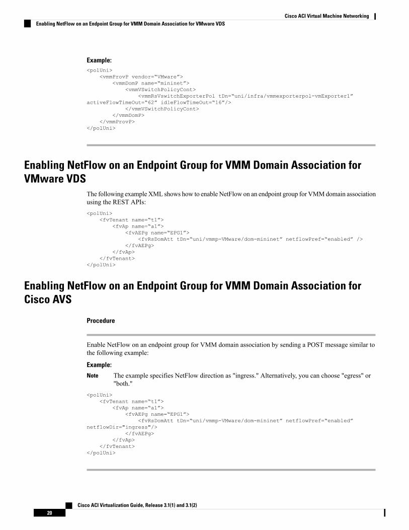
The following exampleXML shows how to enable NetFlow on an endpoint group for VMMdomain associationusing the REST APIs:<polUni>
<fvTenant name=“t1”><fvAp name=“a1”>
<fvAEPg name=“EPG1”><fvRsDomAtt tDn=“uni/vmmp-VMware/dom-mininet” netflowPref=“enabled” />
</fvAEPg></fvAp>
</fvTenant></polUni>
Enabling NetFlow on an Endpoint Group for VMM Domain Association forCisco AVS
Procedure
Enable NetFlow on an endpoint group for VMM domain association by sending a POST message similar tothe following example:
Example:
The example specifies NetFlow direction as "ingress." Alternatively, you can choose "egress" or"both."
Note
<polUni><fvTenant name=“t1”>
<fvAp name=“a1”><fvAEPg name=“EPG1”>
<fvRsDomAtt tDn=“uni/vmmp-VMware/dom-mininet” netflowPref=“enabled”netflowDir="ingress"/>
</fvAEPg></fvAp>
</fvTenant></polUni>
Cisco ACI Virtualization Guide, Release 3.1(1) and 3.1(2)20
Cisco ACI Virtual Machine NetworkingEnabling NetFlow on an Endpoint Group for VMM Domain Association for VMware VDS
Troubleshooting VMM ConnectivityThe following procedure resolves VMM connectivity issues:
Procedure
Step 1 Trigger inventory resync on the Application Policy Infrastructure Controller (APIC).
For more information about how to trigger an inventory resync on APIC, see the following knowledge basearticle:
http://www.cisco.com/c/en/us/td/docs/switches/datacenter/aci/apic/sw/kb/b_KB_VMM_OnDemand_Inventory_in_APIC.html
Step 2 If step 1 does not fix the issue, for the impacted EPGs, set the resolution immediacy to use preprovisioningin the VMM domain.
"Pre-Provision” removes the need for neighbor adjacencies or OpFlex permissions and subsequently thedynamic nature of VMM Domain VLAN Programming. For more information about Resolution Immediacytypes, see the following EPG Policy Resolution and Deployment Immediacy section:
http://www.cisco.com/c/en/us/td/docs/switches/datacenter/aci/apic/sw/1-x/aci-fundamentals/b_ACI-Fundamentals/b_ACI-Fundamentals_chapter_01011.html#concept_EF87ADDAD4EF47BDA741EC6EFDAECBBD
Step 3 If steps 1 and 2 do not fix the issue and you see the issue on all of the VMs, then delete the VM controllerpolicy and readd the policy.
Deleting the controller policy impacts traffic for all VMs that are on that controller.Note
Cisco ACI Virtualization Guide, Release 3.1(1) and 3.1(2)21
Cisco ACI Virtual Machine NetworkingTroubleshooting VMM Connectivity

Cisco ACI Virtualization Guide, Release 3.1(1) and 3.1(2)22
Cisco ACI Virtual Machine NetworkingTroubleshooting VMM Connectivity
C H A P T E R 3Cisco ACI with VMware VDS Integration
This chapter contains the following sections:
• Configuring Virtual Machine Networking Policies, on page 23• Creating a VMM Domain Profile, on page 26• Creating VDS Uplink Port Groups, on page 32• Creating a Trunk Port Group, on page 33• Creating a Trunk Port Group Using the GUI, on page 33• Creating a Trunk Port Group Using the NX-OS Style CLI, on page 33• Creating a Trunk Port Group Using the REST API, on page 36• Working with Blade Servers, on page 36• Troubleshooting the Cisco ACI and VMware VMM System Integration, on page 39• Additional Reference Sections, on page 39
Configuring Virtual Machine Networking PoliciesCisco APIC integrates with third-party VM managers (VMMs) (for example, VMware vCenter) to extendthe benefits of Cisco ACI to the virtualized infrastructure. Cisco APIC enables Cisco ACI policies inside theVMM system to be used by its administrator.
The following modes of Cisco ACI and VMware VMM integration are supported:
• VMware VDS—When integrated with Cisco ACI, the VMware vSphere Distributed Switch (VDS)enables you to configure VM networking in the ACI fabric.
• Cisco ACI Virtual Edge—For information about how to install and configure Cisco ACI Virtual Edge,see the Cisco ACI Virtual Edge Installation Guide and the Cisco ACI Virtual Edge Configuration Guideon Cisco.com .
• Cisco Application Virtual Switch (AVS)—For information about how to install and configure CiscoAVS with Cisco ACI, see Cisco AVS documentation on Cisco.com.
APIC Supported VMware VDS VersionsRelease 6.5Release 6.0Release 5.5Release 5.1Version
SupportedSupportedSupportedSupportedVMware VDS
Cisco ACI Virtualization Guide, Release 3.1(1) and 3.1(2)23
Release 6.5Release 6.0Release 5.5Release 5.1Version
SupportedSupportedSupportedSupportedVMware vCenter
When adding additional VMware ESXi hosts to the VMM domain with VMware vSphere Distributed Switch(VDS), ensure that the version of ESXi host is compatible with the Distributed Virtual Switch (DVS) versionalready deployed in the vCenter. For more information about VMware VDS compatibility requirements forESXi hosts, see the VMware documentation.
If the ESXi host version is not compatible with the existing DVS version, vCenter will not be able to add theESXi host to the DVS, and an incompatibility error will occur. Modification of the existing DVS versionsetting from the Cisco APIC is not possible. To lower the DVS version in the vCenter, you need to removeand reapply the VMM domain configuration with a lower setting.
Note
If you have ESXi 6.5 hosts running UCS B-Series or C-Series server with VIC cards, some of the vmnicsmay go down on a port state event, such as a link flap or a TOR reload. To prevent this problem, do not usethe default eNIC driver but install it from the VMware website: https://my.vmware.com/web/vmware/details?downloadGroup=DT-ESXI65-CISCO-NENIC-1020&productId=614.
Important
Guidelines for Upgrading VMware DVS from 5.x to 6.x and VMM IntegrationThis section describes the guidelines for upgrading VMware Distributed Virtual Switch (DVS) from 5.x to6.x and VMM integration.
• DVS versioning is only applicable to the VMware DVS and not the Cisco Application Virtual Switch(AVS). DVS upgrades are initiated from VMware vCenter, or the relevant orchestration tool and notACI. The Upgrade Version option appears grayed out for AVS switches within vCenter.
• If you are upgrading the DVS from 5.x to 6.x, you must upgrade the vCenter Server to version 6.0 andall hosts connected to the distributed switch to ESXi 6.0. For full details on upgrading your vCenter andHypervisor hosts, see VMware's upgrade documentation. To upgrade the DVS go to the Web Client:Home > Networking > DatacenterX > DVS-X > Actions Menu > Upgrade Distributed Switch.
• There is no functional impact on the DVS features, capability, performance and scale if the DVS versionshown in vCenter does not match the VMM domain DVS version configured on the APIC. The APICand VMM Domain DVS Version is only used for initial deployment.
Mapping ACI and VMware ConstructsTable 2: Mapping of ACI and VMware Constructs
VMware TermsCisco APIC Terms
vCenter (Datacenter)VM controller
vSphere Distributed Switch (VDS)Virtual Machine Manager (VMM) Domain
Cisco ACI Virtualization Guide, Release 3.1(1) and 3.1(2)24
Cisco ACI with VMware VDS IntegrationGuidelines for Upgrading VMware DVS from 5.x to 6.x and VMM Integration
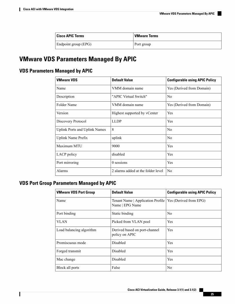
VMware TermsCisco APIC Terms
Port groupEndpoint group (EPG)
VMware VDS Parameters Managed By APIC
VDS Parameters Managed by APIC
Configurable using APIC PolicyDefault ValueVMware VDS
Yes (Derived from Domain)VMM domain nameName
No"APIC Virtual Switch"Description
Yes (Derived from Domain)VMM domain nameFolder Name
YesHighest supported by vCenterVersion
YesLLDPDiscovery Protocol
No8Uplink Ports and Uplink Names
NouplinkUplink Name Prefix
Yes9000Maximum MTU
YesdisabledLACP policy
Yes0 sessionsPort mirroring
No2 alarms added at the folder levelAlarms
VDS Port Group Parameters Managed by APIC
Configurable using APIC PolicyDefault ValueVMware VDS Port Group
Yes (Derived from EPG)Tenant Name | Application ProfileName | EPG Name
Name
NoStatic bindingPort binding
YesPicked from VLAN poolVLAN
YesDerived based on port-channelpolicy on APIC
Load balancing algorithm
YesDisabledPromiscuous mode
YesDisabledForged transmit
YesDisabledMac change
NoFalseBlock all ports
Cisco ACI Virtualization Guide, Release 3.1(1) and 3.1(2)25
Cisco ACI with VMware VDS IntegrationVMware VDS Parameters Managed By APIC
Creating a VMM Domain ProfileVMM domain profiles specify connectivity policies that enable virtual machine controllers to connect to theCisco ACI fabric. They group VM controllers with similar networking policy requirements. For example,VM controllers can share VLANpools and application endpoint groups (EPGs). The CiscoAPIC communicateswith the controller to publish network configurations such as port groups that are then applied to the virtualworkloads. For details, see the Cisco Application Centric Infrastructure Fundamentals on Cisco.com.
Beginning with Cisco APIC Release 3.1(1), you also can create a read-only VMMdomain. A read-only VMMdomain enables you to view inventory information for a VDS in the VMware vCenter that Cisco APIC doesnot manage. Procedures to configure a read-only VMM domain differ slightly from procedures to create otherVMM domains. However, the same workflow and prerequisites apply.
In this section, examples of a VMM domain are vCenter domain.Note
GUI TasksThis section shows how to perform tasks using GUI.
• For references to REST API tasks, refer to REST API Tasks, on page 41.
• For references to NX-OS Style CLI tasks, refer to NX-OS Style CLI Tasks, on page 48.
Prerequisites for Creating a VMM Domain ProfileTo configure a VMM domain profile, you must meet the following prerequisites:
• All fabric nodes are discovered and configured.
• Inband (inb) or out-of-band (oob) management has been configured on the APIC.
• A Virtual Machine Manager (VMM) is installed, configured, and reachable through the inb/oobmanagement network (for example, a vCenter).
Cisco ACI Virtualization Guide, Release 3.1(1) and 3.1(2)26
Cisco ACI with VMware VDS IntegrationCreating a VMM Domain Profile
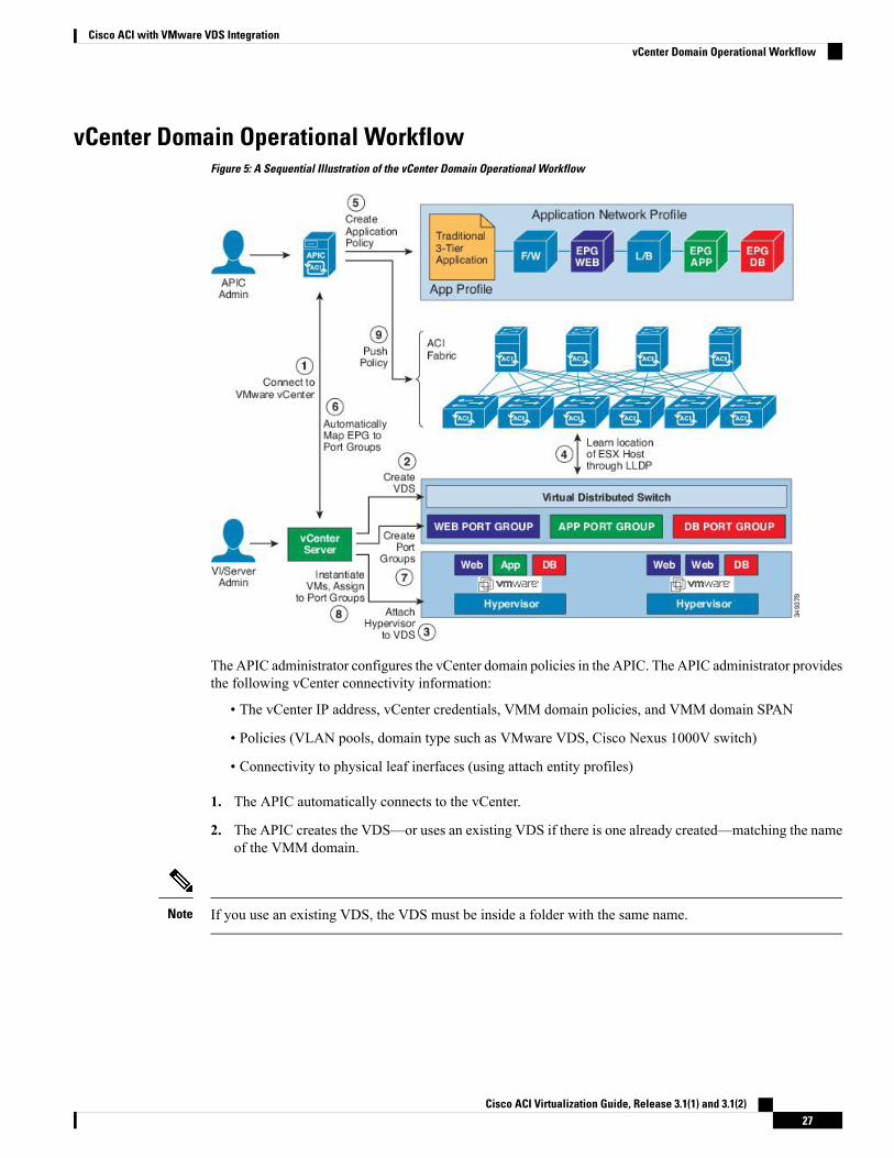
vCenter Domain Operational WorkflowFigure 5: A Sequential Illustration of the vCenter Domain Operational Workflow
The APIC administrator configures the vCenter domain policies in the APIC. The APIC administrator providesthe following vCenter connectivity information:
• The vCenter IP address, vCenter credentials, VMM domain policies, and VMM domain SPAN
• Policies (VLAN pools, domain type such as VMware VDS, Cisco Nexus 1000V switch)
• Connectivity to physical leaf inerfaces (using attach entity profiles)
1. The APIC automatically connects to the vCenter.
2. The APIC creates the VDS—or uses an existing VDS if there is one already created—matching the nameof the VMM domain.
If you use an existing VDS, the VDS must be inside a folder with the same name.Note
Cisco ACI Virtualization Guide, Release 3.1(1) and 3.1(2)27
Cisco ACI with VMware VDS IntegrationvCenter Domain Operational Workflow
If you want to see an existing VDS from the vCenter, you can do so by specifying the Read Only Mode inthe Access Mode area when you create a VMM domain with the same name as the VDS in vCenter using theCisco APIC. This VMM in Read Only Mode is not managed by APIC. You may not be able to modify anyproperties of this VMM domain except vCenter user credentials and vCenter IP address.
Note
3. The vCenter administrator or the compute management tool adds the ESX host or hypervisor to the APICVDS and assigns the ESX host hypervisor ports as uplinks on the APIC VDS. These uplinks must connectto the ACI leaf switches.
4. TheAPIC learns the location of the hypervisor host to the leaf connectivity using LLDP or CDP informationof the hypervisors.
5. The APIC administrator creates and associates application EPG policies.
6. The APIC administrator associates EPG policies to VMM domains.
7. TheAPIC automatically creates port groups in the VMware vCenter under the VDS. This process provisionsthe network policy in the VMware vCenter.
• The port group name is a concatenation of the tenant name, the application profile name, and the EPGname.
• The port group is created under the VDS, and it was created earlier by the APIC.
Note
8. The vCenter administrator or the compute management tool instantiates and assigns VMs to the portgroups.
9. The APIC learns about the VM placements based on the vCenter events. The APIC automatically pushesthe application EPG and its associated policy (for example, contracts and filters) to the ACI fabric.
Creating a vCenter Domain Profile Using the GUIAn overview of the tasks performed in the creation of a vCenter Domain are as follows (details are in thesteps that follow):
• Create/select a switch profile
• Create/select an interface profile
• Create/select an interface policy group
• Create/select VLAN pool
• Create vCenter domain
• Create vCenter credentials
Cisco ACI Virtualization Guide, Release 3.1(1) and 3.1(2)28
Cisco ACI with VMware VDS IntegrationCreating a vCenter Domain Profile Using the GUI
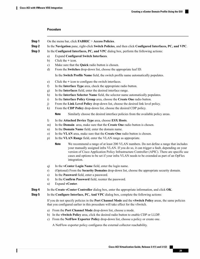
Procedure
Step 1 On the menu bar, click FABRIC > Access Policies.Step 2 In the Navigation pane, right-click Switch Policies, and then click Configured Interfaces, PC, and VPC.Step 3 In the Configured Interfaces, PC, and VPC dialog box, perform the following actions:
a) Expand Configured Switch Interfaces.b) Click the + icon.c) Make sure that the Quick radio button is chosen.d) From the Switches drop-down list, choose the appropriate leaf ID.
In the Switch Profile Name field, the switch profile name automatically populates.
e) Click the + icon to configure the switch interfaces.f) In the Interface Type area, check the appropriate radio button.g) In the Interfaces field, enter the desired interface range.h) In the Interface Selector Name field, the selector name automatically populates.i) In the Interface Policy Group area, choose the Create One radio button.j) From the Link Level Policy drop-down list, choose the desired link level policy.k) From the CDP Policy drop-down list, choose the desired CDP policy.
Similarly choose the desired interface policies from the available policy areas.Note
l) In the Attached Device Type area, choose ESX Hosts.m) In the Domain area, make sure that the Create One radio button is chosen.n) In the Domain Name field, enter the domain name.o) In the VLAN area, make sure that the Create One radio button is chosen.p) In the VLAN Range field, enter the VLAN range as appropriate.
We recommend a range of at least 200 VLAN numbers. Do not define a range that includesyour manually assigned infra VLAN. If you do so, it can trigger a fault, depending on yourversion of Cisco Application Policy Infrastructure Controller (APIC). There are specific usecases and options to be set if your infra VLAN needs to be extended as part of an OpFlexintegration.
Note
q) In the vCenter Login Name field, enter the login name.r) (Optional) From the Security Domains drop-down list, choose the appropriate security domain.s) In the Password field, enter a password.t) In the Confirm Password field, reenter the password.u) Expand vCenter.
Step 4 In the Create vCenter Controller dialog box, enter the appropriate information, and click OK.Step 5 In the Configure Interface, PC, And VPC dialog box, complete the following actions:
If you do not specify policies in the Port Channel Mode and the vSwitch Policy areas, the same policiesthat you configured earlier in this procedure will take effect for the vSwitch.
a) From the Port Channel Mode drop-down list, choose a mode.b) In the vSwitch Policy area, click the desired radio button to enable CDP or LLDP.c) From the NetFlow Exporter Policy drop-down list, choose a policy or create one.
A NetFlow exporter policy configures the external collector reachability.
Cisco ACI Virtualization Guide, Release 3.1(1) and 3.1(2)29
Cisco ACI with VMware VDS IntegrationCreating a vCenter Domain Profile Using the GUI
d) Choose values from theActive Flow Time0ut, Idle Flow Timeout, and Sampling Rate drop-down lists.e) Click SAVE twice and then click SUBMIT.
Step 6 Verify the new domain and profiles, by performing the following actions:a) On the menu bar, choose Virtual Networking > Inventory.b) In the Navigation pane, expand VMM Domains > VMware > Domain_name > vCenter_name.In theWork pane, under Properties, view the VMM domain name to verify that the controller is online. IntheWork pane, the vCenter properties are displayed including the operational status. The displayed informationconfirms that connection from the APIC controller to the vCenter server is established, and the inventory isavailable.
Creating a Read-Only VMM DomainBeginning in Cisco APIC Release 3.1(1), you can create a read-only VMM domain. Doing so enables you toview inventory information for a VDS in the VMware vCenter that Cisco APIC does not manage.
After you create the read-only VMMdomain, you can view hypervisors, VMs, NIC status, and other inventoryinformation, as with regular VMM domains. You can associate an EPG to the VMM domain and configurepolicies for it. However, policies are not pushed from the read-only VMM domain to the VDS. Also, no faultsare raised for a read-only VMM domain.
You can create a read-only VMM domain using the Cisco APIC GUI, the NX-OS style CLI, or REST API.See the following sections in this guide for instructions:
• Creating a Read-Only VMM Domain Using the Cisco APIC GUI, on page 30
• Creating a Read-Only VMM Domain Using the REST API, on page 44
• Creating a Read-Only VMM Domain Using the NX-OS Style CLI, on page 50
Creating a Read-Only VMM Domain Using the Cisco APIC GUIIn order to create a read-only VMM domain, you create the domain in the Create vCenter Domain dialogbox under theVirtual Networking tab. Do not follow the procedure in the section Creating a vCenter DomainProfile Using the GUI, on page 28 to create the domain. That procedure does not enable you to set an accessmode for the VMM domain.
You cannot change the access mode of the VMM domain after creating it. If you try to do so, you see an errormessage.
Before you begin
• Fulfill the prerequisites in the section Prerequisites for Creating a VMM Domain Profile, on page 26.
• In the VMware vCenter, ensure that under the Networking tab, the VDS is contained by a folder.
Also ensure that the folder and the VDS have the exact same name of the read-only VMM domain thatyou plan to create.
Cisco ACI Virtualization Guide, Release 3.1(1) and 3.1(2)30
Cisco ACI with VMware VDS IntegrationCreating a Read-Only VMM Domain
Procedure
Step 1 Log in to Cisco APIC.Step 2 Choose Virtual Networking > Inventory and then expand the VMM Domains folder.Step 3 Right-click the VMM Domains folder and choose Create vCenter Domain.Step 4 In the Create vCenter Domain dialog box, complete the following steps:
a) In the Virtual Switch Name field, enter a name for the domain.
The name of the read-only domain must be the same as the name of the VDS and the folder thatcontains in the VMware vCenter.
Note
b) In the Virtual Switch area, choose VMware vSphere Distributed Switch.c) In the Access Mode area, choose Read Only Mode.d) In the vCenter Credentials area, click the + (plus) icon, and then create the VMware vCenter credentials
for the domain.e) In the vCenter area, click the + (plus) icon, and then add a vCenter controller for the domain.f) Click Submit.
What to do next
You can attach an EPG to the read-only VMM domain and configure policies for it. However, those policiesare not pushed to the VDS in the VMware vCenter.
Endpoint Retention ConfigurationAfter you create a vCenter domain, you can configure endpoint retention. This feature enables you to delaythe deletion of an endpoint, reducing the chances of dropped traffic.
You configure endpoint retention in the APIC GUI or with the NX-OS style CLI or the REST API. Forinformation, see the following sections in this guide:
• Configuring Endpoint Retention Using the GUI, on page 31
• Configuring Endpoint Retention Using the NX-OS Style CLI, on page 32
• Configuring Endpoint Retention Using the REST API, on page 47
Configuring Endpoint Retention Using the GUI
Before you begin
You must have created a vCenter domain.
Procedure
Step 1 Log in to Cisco APIC.Step 2 Choose VM Networking > Inventory.
Cisco ACI Virtualization Guide, Release 3.1(1) and 3.1(2)31
Cisco ACI with VMware VDS IntegrationEndpoint Retention Configuration
Step 3 In the left navigation pane, expand the VMware folder and then click the vCenter domain that you createdearlier.
Step 4 In the central Domain work pane, make sure that the Policy and General tabs are selected.Step 5 In theEnd Point Retention Time (seconds) counter, choose the number of seconds to retain endpoints before
they are detached.
You can choose between 0 and 600 seconds. The default is 0.
Step 6 Click Submit.
Configuring Endpoint Retention Using the NX-OS Style CLI
Before you begin
You must have created a vCenter domain.
Procedure
Step 1 In the CLI, enter configuration mode:
Example:apic1# configureapic1(config)#
Step 2 Configure a retention time for detached endpoints:
You can choose a delay of between 0 and 600 seconds. The default is 0.
Example:apic1(config)# vmware-domain <domainName>
apic1(config-vmware)# ep-retention-time <value>
Creating VDS Uplink Port GroupsEach VMM domain appears in the vCenter as a vSphere Distributed Switch (VDS). The virtualizationadministrator associates hosts to the VDS created by the APIC and selects which vmnics to use for the specificVDS. The configuration of the VDS uplinks are performed from the APIC controller by changing the vSwitchconfiguration from the Attach Entity Profile (AEP) that is associated with the VMM domain. You can findthe AEP in the APIC GUI in the Fabric Access Policies configuration area.
Whenworking with ACI and vSphere VMM integration, Link Aggregation Groups (LAGs) are not a supportedmethod of creating interface teams on distributed switches created by the APIC. The APIC pushes the necessaryinterface teaming configuration based on the settings in the Interface Policy Group and/or AEP vSwitch policy.It is not supported or required to manually create interface teams in vCenter.
Note
Cisco ACI Virtualization Guide, Release 3.1(1) and 3.1(2)32
Cisco ACI with VMware VDS IntegrationConfiguring Endpoint Retention Using the NX-OS Style CLI
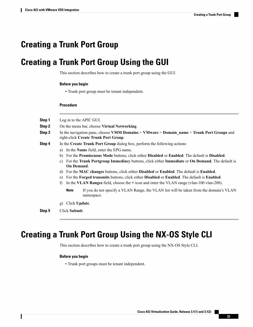
Creating a Trunk Port Group
Creating a Trunk Port Group Using the GUIThis section describes how to create a trunk port group using the GUI.
Before you begin
• Trunk port group must be tenant independent.
Procedure
Step 1 Log in to the APIC GUI.Step 2 On the menu bar, choose Virtual Networking.Step 3 In the navigation pane, choose VMM Domains > VMware > Domain_name > Trunk Port Groups and
right-click Create Trunk Port Group.Step 4 In the Create Trunk Port Group dialog box, perform the following actions:
a) In the Name field, enter the EPG name.b) For the Promiscuous Mode buttons, click either Disabled or Enabled. The default is Disabled.c) For the Trunk Portgroup Immediacy buttons, click either Immediate or On Demand. The default is
On Demand.d) For theMAC changes buttons, click either Disabled or Enabled. The default is Enabled.e) For the Forged transmits buttons, click either Disabled or Enabled. The default is Enabled.f) In the VLAN Ranges field, choose the + icon and enter the VLAN range (vlan-100 vlan-200).
If you do not specify a VLAN Range, the VLAN list will be taken from the domain’s VLANnamespace.
Note
g) Click Update.
Step 5 Click Submit.
Creating a Trunk Port Group Using the NX-OS Style CLIThis section describes how to create a trunk port group using the NX-OS Style CLI.
Before you begin
• Trunk port groups must be tenant independent.
Cisco ACI Virtualization Guide, Release 3.1(1) and 3.1(2)33
Cisco ACI with VMware VDS IntegrationCreating a Trunk Port Group
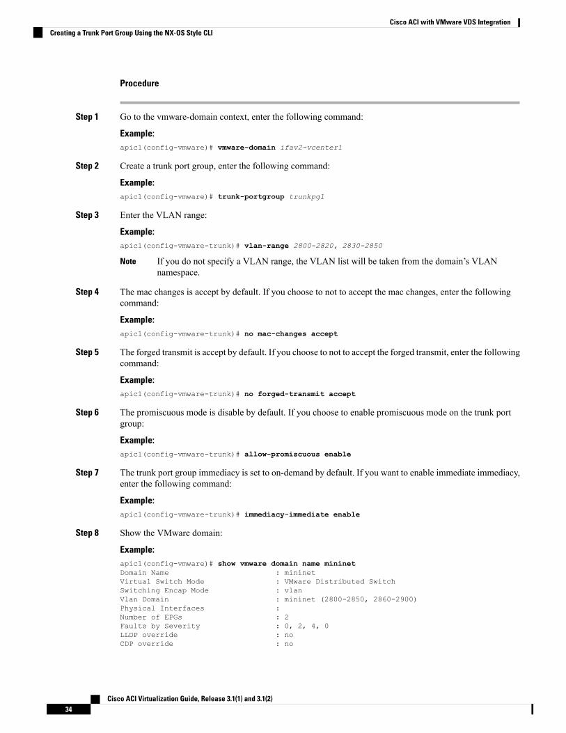
Procedure
Step 1 Go to the vmware-domain context, enter the following command:
Example:apic1(config-vmware)# vmware-domain ifav2-vcenter1
Step 2 Create a trunk port group, enter the following command:
Example:apic1(config-vmware)# trunk-portgroup trunkpg1
Step 3 Enter the VLAN range:
Example:apic1(config-vmware-trunk)# vlan-range 2800-2820, 2830-2850
If you do not specify a VLAN range, the VLAN list will be taken from the domain’s VLANnamespace.
Note
Step 4 The mac changes is accept by default. If you choose to not to accept the mac changes, enter the followingcommand:
Example:apic1(config-vmware-trunk)# no mac-changes accept
Step 5 The forged transmit is accept by default. If you choose to not to accept the forged transmit, enter the followingcommand:
Example:apic1(config-vmware-trunk)# no forged-transmit accept
Step 6 The promiscuous mode is disable by default. If you choose to enable promiscuous mode on the trunk portgroup:
Example:apic1(config-vmware-trunk)# allow-promiscuous enable
Step 7 The trunk port group immediacy is set to on-demand by default. If you want to enable immediate immediacy,enter the following command:
Example:apic1(config-vmware-trunk)# immediacy-immediate enable
Step 8 Show the VMware domain:
Example:apic1(config-vmware)# show vmware domain name mininetDomain Name : mininetVirtual Switch Mode : VMware Distributed SwitchSwitching Encap Mode : vlanVlan Domain : mininet (2800-2850, 2860-2900)Physical Interfaces :Number of EPGs : 2Faults by Severity : 0, 2, 4, 0LLDP override : noCDP override : no
Cisco ACI Virtualization Guide, Release 3.1(1) and 3.1(2)34
Cisco ACI with VMware VDS IntegrationCreating a Trunk Port Group Using the NX-OS Style CLI
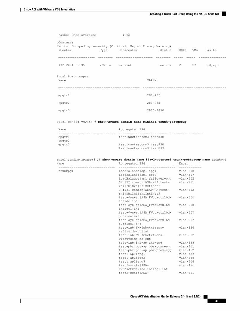
Channel Mode override : no
vCenters:Faults: Grouped by severity (Critical, Major, Minor, Warning)vCenter Type Datacenter Status ESXs VMs Faults
-------------------- -------- -------------------- -------- ----- ----- ---------------
172.22.136.195 vCenter mininet online 2 57 0,0,4,0
Trunk Portgroups:Name VLANs
--------------------------------------------- ----------------------------------------------
epgtr1 280-285
epgtr2 280-285
epgtr3 2800-2850
apic1(config-vmware)# show vmware domain name mininet trunk-portgroup
Name Aggregated EPG------------------------------ ----------------------------------------------epgtr1 test|wwwtestcom3|test830epgtr2epgtr3 test|wwwtestcom3|test830
test|wwwtestcom3|test833
apic1(config-vmware)# )# show vmware domain name ifav2-vcenter1 trunk-portgroup name trunkpg1Name Aggregated EPG Encap------------------------------ ------------------------------ ------------trunkpg1 LoadBalance|ap1|epg1 vlan-318
LoadBalance|ap1|epg2 vlan-317LoadBalance|ap1|failover-epg vlan-362SH:l3I:common:ASAv-HA:test- vlan-711rhi|rhiExt|rhiExtInstPSH:l3I:common:ASAv-HA:test- vlan-712rhi|rhiInt|rhiIntInstPtest-dyn-ep|ASA_FWctxctx1bd- vlan-366inside|inttest-dyn-ep|ASA_FWctxctx1bd- vlan-888inside1|inttest-dyn-ep|ASA_FWctxctx1bd- vlan-365outside|exttest-dyn-ep|ASA_FWctxctx1bd- vlan-887outside1|exttest-inb|FW-Inbctxtrans- vlan-886vrfinside-bd|inttest-inb|FW-Inbctxtrans- vlan-882vrfoutside-bd|exttest-inb|inb-ap|inb-epg vlan-883test-pbr|pbr-ap|pbr-cons-epg vlan-451test-pbr|pbr-ap|pbr-prov-epg vlan-452test1|ap1|epg1 vlan-453test1|ap1|epg2 vlan-485test1|ap1|epg3 vlan-454test2-scale|ASA- vlan-496Trunkctxctx1bd-inside1|inttest2-scale|ASA- vlan-811
Cisco ACI Virtualization Guide, Release 3.1(1) and 3.1(2)35
Cisco ACI with VMware VDS IntegrationCreating a Trunk Port Group Using the NX-OS Style CLI
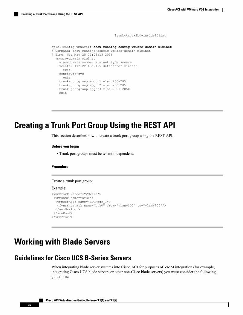
Trunkctxctx1bd-inside10|int
apic1(config-vmware)# show running-config vmware-domain mininet# Command: show running-config vmware-domain mininet# Time: Wed May 25 21:09:13 2016vmware-domain mininetvlan-domain member mininet type vmwarevcenter 172.22.136.195 datacenter mininetexit
configure-dvsexit
trunk-portgroup epgtr1 vlan 280-285trunk-portgroup epgtr2 vlan 280-285trunk-portgroup epgtr3 vlan 2800-2850exit
Creating a Trunk Port Group Using the REST APIThis section describes how to create a trunk port group using the REST API.
Before you begin
• Trunk port groups must be tenant independent.
Procedure
Create a trunk port group:
Example:<vmmProvP vendor="VMware"><vmmDomP name=”DVS1"><vmmUsrAggr name="EPGAggr_1"><fvnsEncapBlk name="blk0" from="vlan-100” to="vlan-200"/></vmmUsrAggr></vmmDomP></vmmProvP>
Working with Blade Servers
Guidelines for Cisco UCS B-Series ServersWhen integrating blade server systems into Cisco ACI for purposes of VMM integration (for example,integrating Cisco UCS blade servers or other non-Cisco blade servers) you must consider the followingguidelines:
Cisco ACI Virtualization Guide, Release 3.1(1) and 3.1(2)36
Cisco ACI with VMware VDS IntegrationCreating a Trunk Port Group Using the REST API
This example shows how to configure a port channel access policy for integrating Cisco UCS blade servers.You can use similar steps to set up a virtual port channel or individual link access policies depending uponhow your Cisco UCS blade server uplinks are connected to the fabric. If no port channel is explicitly configuredon the APIC for the UCS blade server uplinks, the default behavior will be mac-pinning.
Note
• The VM endpoint learning relies on either the CDP or LLDP protocol. If supported, CDPmust be enabledall the way from the leaf switch port through any blade switches and to the blade adapters.
• Ensure the management address type, length, and value (TLV) is enabled on the blade switch (CDP orLLDP protocol) and advertised towards servers and fabric switches. Configuration of management TLVaddress must be consistent across CDP and LLDP protocols on the blade switch.
• The APIC does not manage fabric interconnects and the blade server, so any UCS specific policies suchas CDP or port channel policies must be configured from the UCS Manager.
• VLANs defined in the VLAN pool used by the attachable access entity profile on the APIC, must alsobe manually created on the UCS and allowed on the appropriate uplinks connecting to the fabric. Thismust include the infrastructure VLAN if applicable. For details, see the Cisco UCS Manager GUIConfiguration Guide.
• When you are working with the Cisco UCS B-series server and using an APIC policy, Link LayerDiscovery Protocol (LLDP) is not supported.
• Cisco Discovery Protocol (CDP) is disabled by default in Cisco UCS Manager. In Cisco UCS Manager,you must enable CDP by creating a Network Control Policy.
• Do not enable fabric failover on the adapters in the UCS server service profiles. Cisco recommends thatyou allow the hypervisor to handle failover at the virtual switch layer so that load balancing of traffic isappropriately performed.
Symptom: The change of management IP of the unmanaged node such as blade switch or fabric interconnectgets updated in the VMware vCenter, but the VMware vCenter does not send any events to APIC.
Condition: This causes the APIC to be out of sync with VMware vCenter.
Workaround: You need to trigger an inventory pull for the VMware vCenter controller that manages ESXservers behind the unmanaged node.
Note
Setting up an Access Policy for a Blade Server Using the GUI
Before you begin
To operate with the Cisco APIC, the Cisco UCS Fabric Interconnect must be at least a version 2.2(1c). Allcomponents, such as the BIOS, CIMC, and the adapter must be a version 2.2(1c) or later. For further details,see the Cisco UCS Manager CLI Configuration Guide.
Cisco ACI Virtualization Guide, Release 3.1(1) and 3.1(2)37
Cisco ACI with VMware VDS IntegrationSetting up an Access Policy for a Blade Server Using the GUI
Procedure
Step 1 On the menu bar, choose FABRIC > Access Policies.Step 2 In theWork pane, click Configure Interface, PC, and vPC.Step 3 In the Configure Interface, PC, and vPC dialog box, click the + icon to select switches.Step 4 In the Switches field, from the drop-down list, choose the desired switch IDs.Step 5 Click the + icon to configure the switch interfaces.Step 6 In the Interface Type field, click the VPC radio button.Step 7 In the Interfaces field, enter the appropriate interface or interface range that is connected to the blade server.Step 8 In the Interface Selector Name field, enter a name.Step 9 From the CDP Policy drop-down list, choose default
The default CDP policy is set to disabled. (Between the leaf switch and the blade server, CDPmust be disabled.)
Step 10 From the LLDP Policy drop-down list, choose default.
The default LLDP policy is set to enabled for the receive and transmit states. (Between the leaf switch andthe blade server, LLDP must be enabled.)
Step 11 From the LACP Policy drop-down list, choose Create LACP Policy.
Between the leaf switch and the blade server, the LACP policy must be set to active.
Step 12 In the Create LACP Policy dialog box, perform the following actions:a) In the Name field, enter a name for the policy.b) In theMode field, the Active radio button is checked.c) Keep the remaining default values and click Submit.
Step 13 From the Attached Device Type field drop-down list, choose ESX Hosts.Step 14 In the Domain Name field, enter a name as appropriate.Step 15 In the VLAN Range field, enter the range.Step 16 In the vCenter Login Name field, enter the login name.Step 17 In the Password field, and the Confirm Password field, enter the password.Step 18 Expand the vCenter field, and in the Create vCenter Controller dialog box, enter the desired content and
click OK.Step 19 In the vSwitch Policy field, perform the following actions:
Between the blade server and the ESX hypervisor, CDP must be enabled, LLDP must be disabled, and LACPmust be disabled so Mac Pinning must be set.
a) Check theMAC Pinning check box.b) Check the CDP check box.c) Leave the LLDP check box unchecked because LLDP must remain disabled.
Step 20 Click Save, and click Save again. Click Submit.The access policy is set.
Cisco ACI Virtualization Guide, Release 3.1(1) and 3.1(2)38
Cisco ACI with VMware VDS IntegrationSetting up an Access Policy for a Blade Server Using the GUI
Troubleshooting the Cisco ACI and VMware VMM SystemIntegration
For troubleshooting information, see the following links:
• Cisco APIC Troubleshooting Guide
• ACI Troubleshooting Book
Additional Reference Sections
Custom User Account with Minimum VMware vCenter PrivilegesThis allows the APIC to send VMware API commands to vCenter to allow the creation of the DVS/AVS,creation of the VMK interface (AVS), publish port groups and relay all necessary alerts.
To configure the vCenter from Cisco APIC, your credentials must allow the following minimum set ofprivileges within the vCenter:
• Alarms
APIC creates two alarms on the folder. One for DVS and another for port-group. The alarm is raisedwhen the EPG or Domain policy is deleted on APIC, but for port-group or DVS it cannot be deleted dueto the VMs are attached.
• Distributed Switch
• dvPort Group
• Folder
• Network
APICmanages the network settings such as add or delete port-groups, setting host/DVSMTU, LLDP/CDP,LACP etc.
• Host
If you use AVS in addition to above, you need the Host privilege on the data center where APIC willcreate DVS.
• Host.Configuration.Advanced settings
• Host.Local operations.Reconfigure virtual machine
• Host.Configuration.Network configuration
This is needed for AVS and the auto-placement feature for virtual Layer 4 to Layer 7 Service VMs.For AVS, APIC creates VMK interface and places it in ‘vtep’ port-group which is used for OpFlex.
• Virtual machine
Cisco ACI Virtualization Guide, Release 3.1(1) and 3.1(2)39
Cisco ACI with VMware VDS IntegrationTroubleshooting the Cisco ACI and VMware VMM System Integration
If you use Service Graph in addition to above, you need the Virtual machine privilege for the virtualappliances which will be used for Service Graph.
• Virtual machine.Configuration.Modify device settings
• Virtual machine.Configuration.Settings
Quarantine Port GroupsThe quarantine port group feature provides a method to clear port group assignments under certaincircumstances. In the VMware vCenter, when a VMware vSphere Distributed Switch (VDS) is created, aquarantine port group is created in the VDS by default. The quarantine port group default policy is to blockall ports.
As part of integration with Layer 4 to Layer 7 virtual service appliances, such as a load balancer or firewall,the Application Policy Infrastructure Controller (APIC) creates service port groups in vCenter for servicestitching and orchestrates placement of virtual appliances, such as service virtual machines (VMs), in theseservice port groups as part of the service graph rendering mechanism. When the service graph is deleted, theservice VMs are automatically moved to the quarantine port group. This auto-move to a quarantine port groupon delete is only done for service VMs, which are orchestrated by the APIC.
You can take further action with the port in quarantine port group as desired. For example, you can migrateall of the ports from the quarantine port group to another port group, such as a VM network.
The quarantine port group mechanism is not applicable to regular tenant endpoint groups (EPGs) and theirassociated port groups and tenant VMs. Therefore, if the tenant EPG is deleted, any tenant VMs present inthe associated port group remains intact and they will not be moved to the quarantine port group. The placementof tenant VMs into the tenant port group is outside the realm of the APIC.
On-Demand VMM Inventory RefreshTriggered Inventory provides a manual trigger option to pull and resynchronize inventory between a virtualmachine manager (VMM) controller and the APIC. Triggered inventory provides instant recovery fromout-of-sync scenarios. Triggered inventory is applicable to vCenter VMM controllers only. It is not requiredin normal scenarios and should be used with discretion since inventory sync is a burdensome operation forthe VMM controllers.
The APIC initiates vCenter inventory pull. Hosts, VMs, DVS, uplink port groups, NICs, and so on are retrievedas part of the initial VMM Controller creation. Further changes in vCenter are learned through the eventsubscription mechanism. This enables the APIC VMM manager to send endpoint attach/detach updates tothe APIC policy manager which downloads updated policies to leaf switches accordingly.
When there is a process restart, leadership change, or background periodic 24 hour inventory audit, the APICdoes inventory pull to keep VMM inventory synchronized between VMM controllers and the APIC. Whenheavily loaded, the vCenter fails to provide the APIC an appropriate inventory event notification. In this case,triggered inventory helps to keep the APIC in synchronization with the vCenter.
Guidelines for Migrating a vCenter Hypervisor VMK0 to an ACI Inband VLANFollow the guidelines below to migrate the default vCenter hypervisor VMK0 out of bound connectivity toACI inband ports. AnACI fabric infrastructure administrator configures the APICwith the necessary policies,then the vCenter administrator migrates the VMK0 to the appropriate ACI port group.
Cisco ACI Virtualization Guide, Release 3.1(1) and 3.1(2)40
Cisco ACI with VMware VDS IntegrationQuarantine Port Groups
Create the Necessary Management EPG Policies in APICAs an ACI fabric infrastructure administrator, use the following guidelines when creating the managementtenant and VMM domain policies:
• Choose a VLAN to use for ESX management.
• Add the VLAN chosen for ESX management to a range (or Encap Block) in the VLAN pool associatedwith the target VMM domain. The range where this VLAN is added must have allocation mode set tostatic allocation.
• Create a management EPG in the ACI management tenant (mgmt).
• Verify that the bridge domain associated with the management EPG is also associated with the privatenetwork (inb).
• Associate the management EPG with the target VMM domain as follows:
• Use resolution immediacy as pre-provision.
• Specify the management VLAN in the Port Encap field of the VM domain profile association.
As a result, APIC creates the port group under vCenter with VLAN specified by the user. APIC alsoautomatically pushes the policies on the leaf switches associated with the VMM domain and AttachEntity Profile (AEP).
Migrate the VMK0 to the Inband ACI VLANBy default vCenter configures the default VMK0 on the hypervisor management interface. The ACI policescreated above enable the vCenter administrator to migrate the default VMK0 to the port group that is createdby APIC. Doing so frees up the hypervisor management port.
REST API TasksThis section shows how to perform tasks using REST API.
• For references to GUI tasks, refer to sections, Creating a VMM Domain Profile, on page 26 and Settingup an Access Policy for a Blade Server Using the GUI, on page 37.
• For references to NX-OS Style CLI tasks, refer to NX-OS Style CLI Tasks, on page 48.
Creating a vCenter Domain Profile Using the REST API
Procedure
Step 1 Configure a VMM domain name, a controller, and user credentials.
Example:POST URL: https://<api-ip>/api/node/mo/.xml
<polUni><vmmProvP vendor="VMware"><!-- VMM Domain --><vmmDomP name="productionDC">
Cisco ACI Virtualization Guide, Release 3.1(1) and 3.1(2)41
Cisco ACI with VMware VDS IntegrationCreate the Necessary Management EPG Policies in APIC
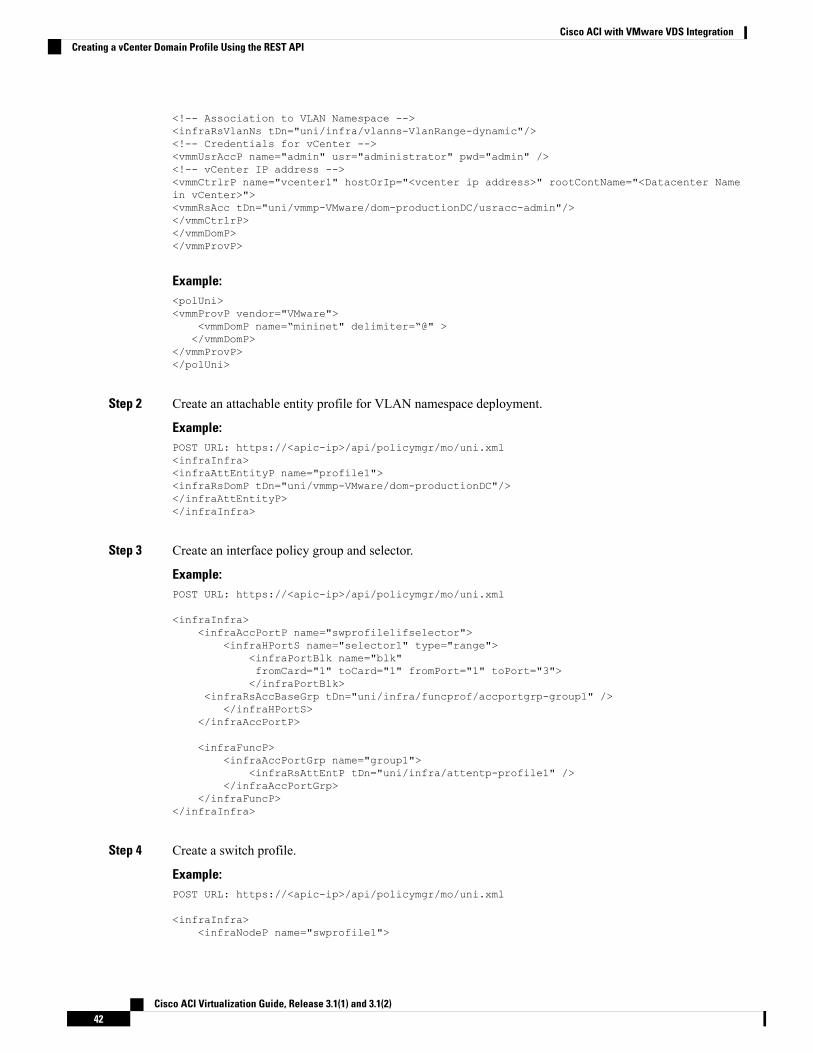
<!-- Association to VLAN Namespace --><infraRsVlanNs tDn="uni/infra/vlanns-VlanRange-dynamic"/><!-- Credentials for vCenter --><vmmUsrAccP name="admin" usr="administrator" pwd="admin" /><!-- vCenter IP address --><vmmCtrlrP name="vcenter1" hostOrIp="<vcenter ip address>" rootContName="<Datacenter Namein vCenter>"><vmmRsAcc tDn="uni/vmmp-VMware/dom-productionDC/usracc-admin"/></vmmCtrlrP></vmmDomP></vmmProvP>
Example:<polUni><vmmProvP vendor="VMware">
<vmmDomP name=“mininet" delimiter=“@" ></vmmDomP>
</vmmProvP></polUni>
Step 2 Create an attachable entity profile for VLAN namespace deployment.
Example:POST URL: https://<apic-ip>/api/policymgr/mo/uni.xml<infraInfra><infraAttEntityP name="profile1"><infraRsDomP tDn="uni/vmmp-VMware/dom-productionDC"/></infraAttEntityP></infraInfra>
Step 3 Create an interface policy group and selector.
Example:POST URL: https://<apic-ip>/api/policymgr/mo/uni.xml
<infraInfra><infraAccPortP name="swprofile1ifselector">
<infraHPortS name="selector1" type="range"><infraPortBlk name="blk"fromCard="1" toCard="1" fromPort="1" toPort="3"></infraPortBlk>
<infraRsAccBaseGrp tDn="uni/infra/funcprof/accportgrp-group1" /></infraHPortS>
</infraAccPortP>
<infraFuncP><infraAccPortGrp name="group1">
<infraRsAttEntP tDn="uni/infra/attentp-profile1" /></infraAccPortGrp>
</infraFuncP></infraInfra>
Step 4 Create a switch profile.
Example:POST URL: https://<apic-ip>/api/policymgr/mo/uni.xml
<infraInfra><infraNodeP name="swprofile1">
Cisco ACI Virtualization Guide, Release 3.1(1) and 3.1(2)42
Cisco ACI with VMware VDS IntegrationCreating a vCenter Domain Profile Using the REST API
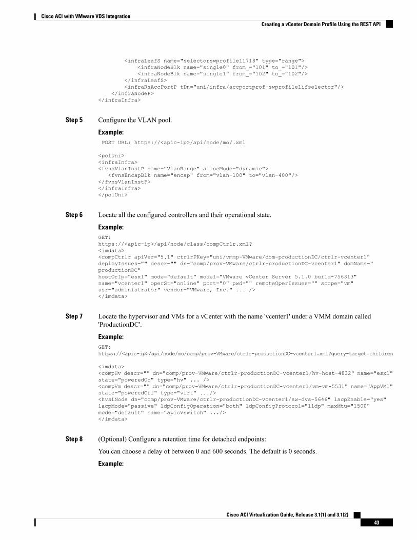
<infraLeafS name="selectorswprofile11718" type="range"><infraNodeBlk name="single0" from_="101" to_="101"/><infraNodeBlk name="single1" from_="102" to_="102"/>
</infraLeafS><infraRsAccPortP tDn="uni/infra/accportprof-swprofile1ifselector"/>
</infraNodeP></infraInfra>
Step 5 Configure the VLAN pool.
Example:POST URL: https://<apic-ip>/api/node/mo/.xml
<polUni><infraInfra><fvnsVlanInstP name="VlanRange" allocMode="dynamic">
<fvnsEncapBlk name="encap" from="vlan-100" to="vlan-400"/></fvnsVlanInstP></infraInfra></polUni>
Step 6 Locate all the configured controllers and their operational state.
Example:GET:https://<apic-ip>/api/node/class/compCtrlr.xml?<imdata><compCtrlr apiVer="5.1" ctrlrPKey="uni/vmmp-VMware/dom-productionDC/ctrlr-vcenter1"deployIssues="" descr="" dn="comp/prov-VMware/ctrlr-productionDC-vcenter1" domName="productionDC"hostOrIp="esx1" mode="default" model="VMware vCenter Server 5.1.0 build-756313"name="vcenter1" operSt="online" port="0" pwd="" remoteOperIssues="" scope="vm"usr="administrator" vendor="VMware, Inc." ... /></imdata>
Step 7 Locate the hypervisor and VMs for a vCenter with the name 'vcenter1' under a VMM domain called'ProductionDC'.
Example:GET:https://<apic-ip>/api/node/mo/comp/prov-VMware/ctrlr-productionDC-vcenter1.xml?query-target=children
<imdata><compHv descr="" dn="comp/prov-VMware/ctrlr-productionDC-vcenter1/hv-host-4832" name="esx1"state="poweredOn" type="hv" ... /><compVm descr="" dn="comp/prov-VMware/ctrlr-productionDC-vcenter1/vm-vm-5531" name="AppVM1"state="poweredOff" type="virt" .../><hvsLNode dn="comp/prov-VMware/ctrlr-productionDC-vcenter1/sw-dvs-5646" lacpEnable="yes"lacpMode="passive" ldpConfigOperation="both" ldpConfigProtocol="lldp" maxMtu="1500"mode="default" name="apicVswitch" .../></imdata>
Step 8 (Optional) Configure a retention time for detached endpoints:
You can choose a delay of between 0 and 600 seconds. The default is 0 seconds.
Example:
Cisco ACI Virtualization Guide, Release 3.1(1) and 3.1(2)43
Cisco ACI with VMware VDS IntegrationCreating a vCenter Domain Profile Using the REST API
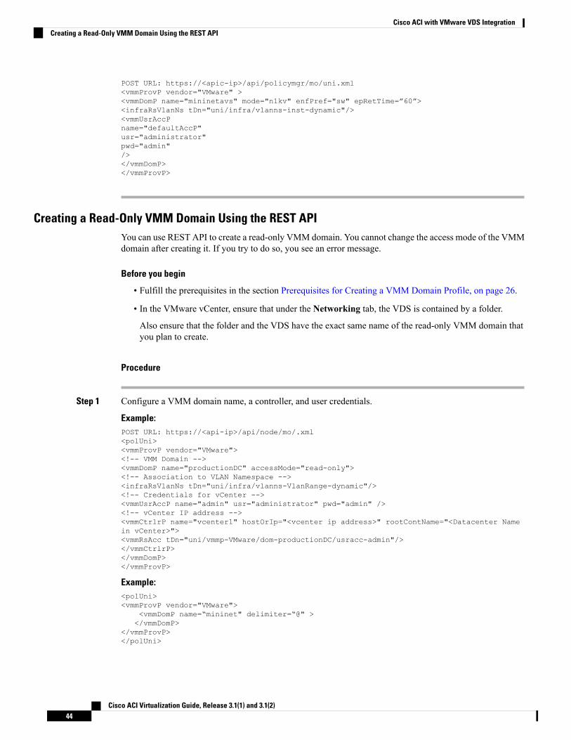
POST URL: https://<apic-ip>/api/policymgr/mo/uni.xml<vmmProvP vendor="VMware" ><vmmDomP name="mininetavs" mode="n1kv" enfPref="sw" epRetTime=”60”><infraRsVlanNs tDn="uni/infra/vlanns-inst-dynamic"/><vmmUsrAccPname="defaultAccP"usr="administrator"pwd="admin"/></vmmDomP></vmmProvP>
Creating a Read-Only VMM Domain Using the REST APIYou can use REST API to create a read-only VMM domain. You cannot change the access mode of the VMMdomain after creating it. If you try to do so, you see an error message.
Before you begin
• Fulfill the prerequisites in the section Prerequisites for Creating a VMM Domain Profile, on page 26.
• In the VMware vCenter, ensure that under the Networking tab, the VDS is contained by a folder.
Also ensure that the folder and the VDS have the exact same name of the read-only VMM domain thatyou plan to create.
Procedure
Step 1 Configure a VMM domain name, a controller, and user credentials.
Example:POST URL: https://<api-ip>/api/node/mo/.xml<polUni><vmmProvP vendor="VMware"><!-- VMM Domain --><vmmDomP name="productionDC" accessMode="read-only"><!-- Association to VLAN Namespace --><infraRsVlanNs tDn="uni/infra/vlanns-VlanRange-dynamic"/><!-- Credentials for vCenter --><vmmUsrAccP name="admin" usr="administrator" pwd="admin" /><!-- vCenter IP address --><vmmCtrlrP name="vcenter1" hostOrIp="<vcenter ip address>" rootContName="<Datacenter Namein vCenter>"><vmmRsAcc tDn="uni/vmmp-VMware/dom-productionDC/usracc-admin"/></vmmCtrlrP></vmmDomP></vmmProvP>
Example:<polUni><vmmProvP vendor="VMware">
<vmmDomP name=“mininet" delimiter=“@" ></vmmDomP>
</vmmProvP></polUni>
Cisco ACI Virtualization Guide, Release 3.1(1) and 3.1(2)44
Cisco ACI with VMware VDS IntegrationCreating a Read-Only VMM Domain Using the REST API
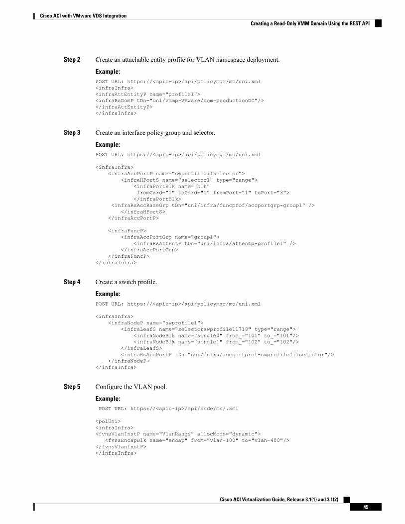
Step 2 Create an attachable entity profile for VLAN namespace deployment.
Example:POST URL: https://<apic-ip>/api/policymgr/mo/uni.xml<infraInfra><infraAttEntityP name="profile1"><infraRsDomP tDn="uni/vmmp-VMware/dom-productionDC"/></infraAttEntityP></infraInfra>
Step 3 Create an interface policy group and selector.
Example:POST URL: https://<apic-ip>/api/policymgr/mo/uni.xml
<infraInfra><infraAccPortP name="swprofile1ifselector">
<infraHPortS name="selector1" type="range"><infraPortBlk name="blk"fromCard="1" toCard="1" fromPort="1" toPort="3"></infraPortBlk>
<infraRsAccBaseGrp tDn="uni/infra/funcprof/accportgrp-group1" /></infraHPortS>
</infraAccPortP>
<infraFuncP><infraAccPortGrp name="group1">
<infraRsAttEntP tDn="uni/infra/attentp-profile1" /></infraAccPortGrp>
</infraFuncP></infraInfra>
Step 4 Create a switch profile.
Example:POST URL: https://<apic-ip>/api/policymgr/mo/uni.xml
<infraInfra><infraNodeP name="swprofile1">
<infraLeafS name="selectorswprofile11718" type="range"><infraNodeBlk name="single0" from_="101" to_="101"/><infraNodeBlk name="single1" from_="102" to_="102"/>
</infraLeafS><infraRsAccPortP tDn="uni/infra/accportprof-swprofile1ifselector"/>
</infraNodeP></infraInfra>
Step 5 Configure the VLAN pool.
Example:POST URL: https://<apic-ip>/api/node/mo/.xml
<polUni><infraInfra><fvnsVlanInstP name="VlanRange" allocMode="dynamic">
<fvnsEncapBlk name="encap" from="vlan-100" to="vlan-400"/></fvnsVlanInstP></infraInfra>
Cisco ACI Virtualization Guide, Release 3.1(1) and 3.1(2)45
Cisco ACI with VMware VDS IntegrationCreating a Read-Only VMM Domain Using the REST API
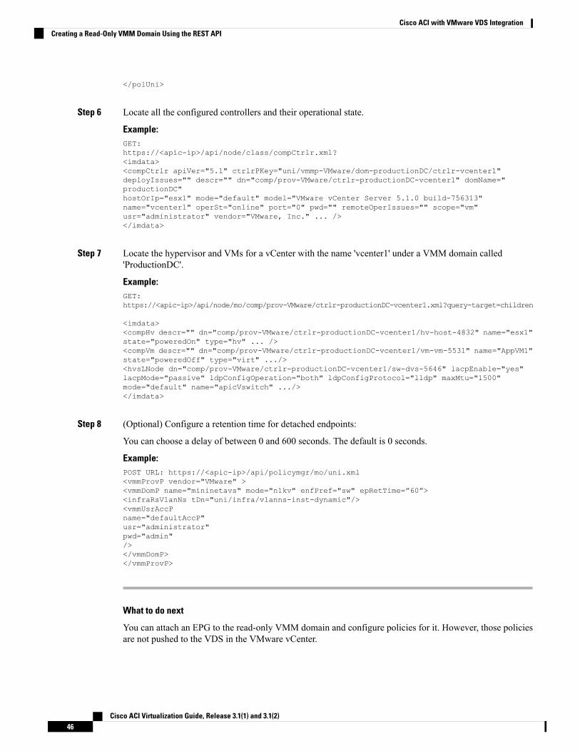
</polUni>
Step 6 Locate all the configured controllers and their operational state.
Example:GET:https://<apic-ip>/api/node/class/compCtrlr.xml?<imdata><compCtrlr apiVer="5.1" ctrlrPKey="uni/vmmp-VMware/dom-productionDC/ctrlr-vcenter1"deployIssues="" descr="" dn="comp/prov-VMware/ctrlr-productionDC-vcenter1" domName="productionDC"hostOrIp="esx1" mode="default" model="VMware vCenter Server 5.1.0 build-756313"name="vcenter1" operSt="online" port="0" pwd="" remoteOperIssues="" scope="vm"usr="administrator" vendor="VMware, Inc." ... /></imdata>
Step 7 Locate the hypervisor and VMs for a vCenter with the name 'vcenter1' under a VMM domain called'ProductionDC'.
Example:GET:https://<apic-ip>/api/node/mo/comp/prov-VMware/ctrlr-productionDC-vcenter1.xml?query-target=children
<imdata><compHv descr="" dn="comp/prov-VMware/ctrlr-productionDC-vcenter1/hv-host-4832" name="esx1"state="poweredOn" type="hv" ... /><compVm descr="" dn="comp/prov-VMware/ctrlr-productionDC-vcenter1/vm-vm-5531" name="AppVM1"state="poweredOff" type="virt" .../><hvsLNode dn="comp/prov-VMware/ctrlr-productionDC-vcenter1/sw-dvs-5646" lacpEnable="yes"lacpMode="passive" ldpConfigOperation="both" ldpConfigProtocol="lldp" maxMtu="1500"mode="default" name="apicVswitch" .../></imdata>
Step 8 (Optional) Configure a retention time for detached endpoints:
You can choose a delay of between 0 and 600 seconds. The default is 0 seconds.
Example:POST URL: https://<apic-ip>/api/policymgr/mo/uni.xml<vmmProvP vendor="VMware" ><vmmDomP name="mininetavs" mode="n1kv" enfPref="sw" epRetTime=”60”><infraRsVlanNs tDn="uni/infra/vlanns-inst-dynamic"/><vmmUsrAccPname="defaultAccP"usr="administrator"pwd="admin"/></vmmDomP></vmmProvP>
What to do next
You can attach an EPG to the read-only VMM domain and configure policies for it. However, those policiesare not pushed to the VDS in the VMware vCenter.
Cisco ACI Virtualization Guide, Release 3.1(1) and 3.1(2)46
Cisco ACI with VMware VDS IntegrationCreating a Read-Only VMM Domain Using the REST API
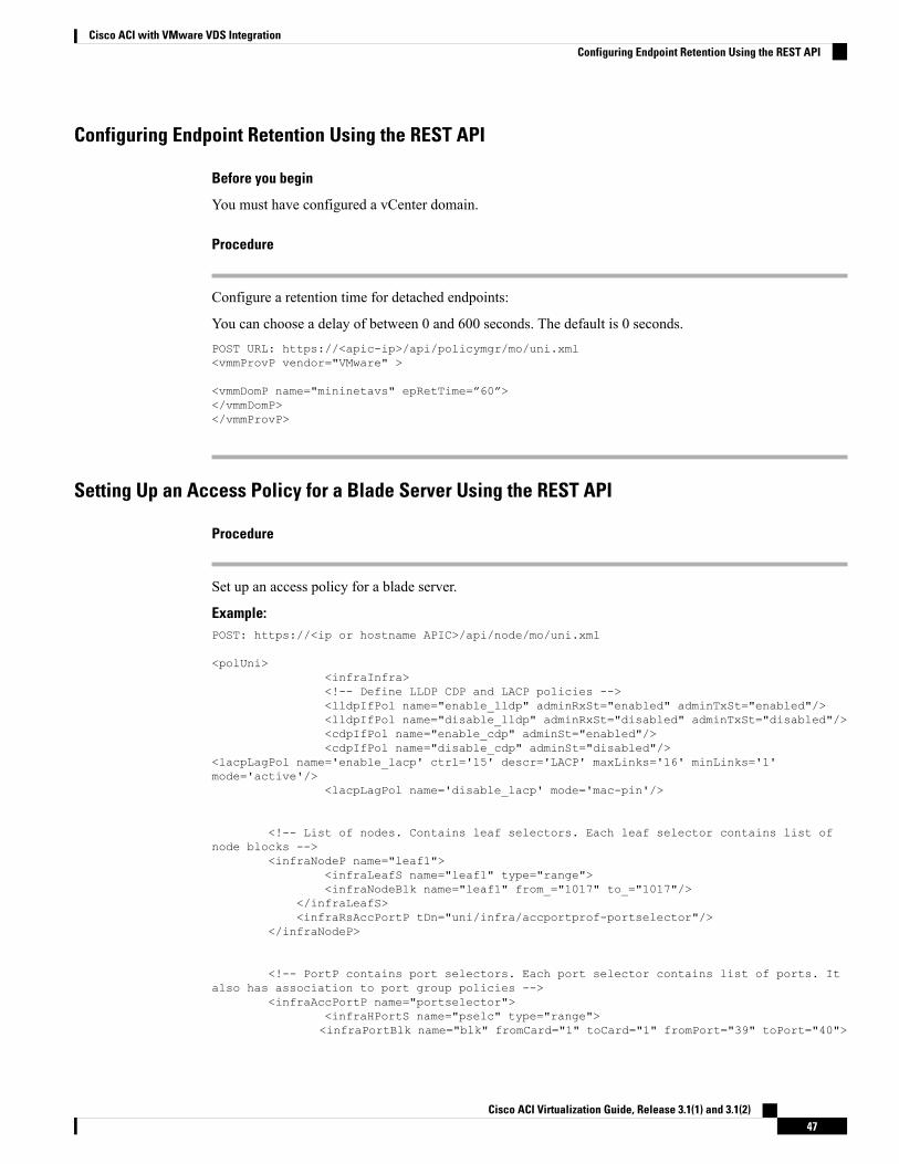
Configuring Endpoint Retention Using the REST API
Before you begin
You must have configured a vCenter domain.
Procedure
Configure a retention time for detached endpoints:
You can choose a delay of between 0 and 600 seconds. The default is 0 seconds.POST URL: https://<apic-ip>/api/policymgr/mo/uni.xml<vmmProvP vendor="VMware" >
<vmmDomP name="mininetavs" epRetTime=”60”></vmmDomP></vmmProvP>
Setting Up an Access Policy for a Blade Server Using the REST API
Procedure
Set up an access policy for a blade server.
Example:POST: https://<ip or hostname APIC>/api/node/mo/uni.xml
<polUni><infraInfra><!-- Define LLDP CDP and LACP policies --><lldpIfPol name="enable_lldp" adminRxSt="enabled" adminTxSt="enabled"/><lldpIfPol name="disable_lldp" adminRxSt="disabled" adminTxSt="disabled"/><cdpIfPol name="enable_cdp" adminSt="enabled"/><cdpIfPol name="disable_cdp" adminSt="disabled"/>
<lacpLagPol name='enable_lacp' ctrl='15' descr='LACP' maxLinks='16' minLinks='1'mode='active'/>
<lacpLagPol name='disable_lacp' mode='mac-pin'/>
<!-- List of nodes. Contains leaf selectors. Each leaf selector contains list ofnode blocks -->
<infraNodeP name="leaf1"><infraLeafS name="leaf1" type="range"><infraNodeBlk name="leaf1" from_="1017" to_="1017"/>
</infraLeafS><infraRsAccPortP tDn="uni/infra/accportprof-portselector"/>
</infraNodeP>
<!-- PortP contains port selectors. Each port selector contains list of ports. Italso has association to port group policies -->
<infraAccPortP name="portselector"><infraHPortS name="pselc" type="range"><infraPortBlk name="blk" fromCard="1" toCard="1" fromPort="39" toPort="40">
Cisco ACI Virtualization Guide, Release 3.1(1) and 3.1(2)47
Cisco ACI with VMware VDS IntegrationConfiguring Endpoint Retention Using the REST API
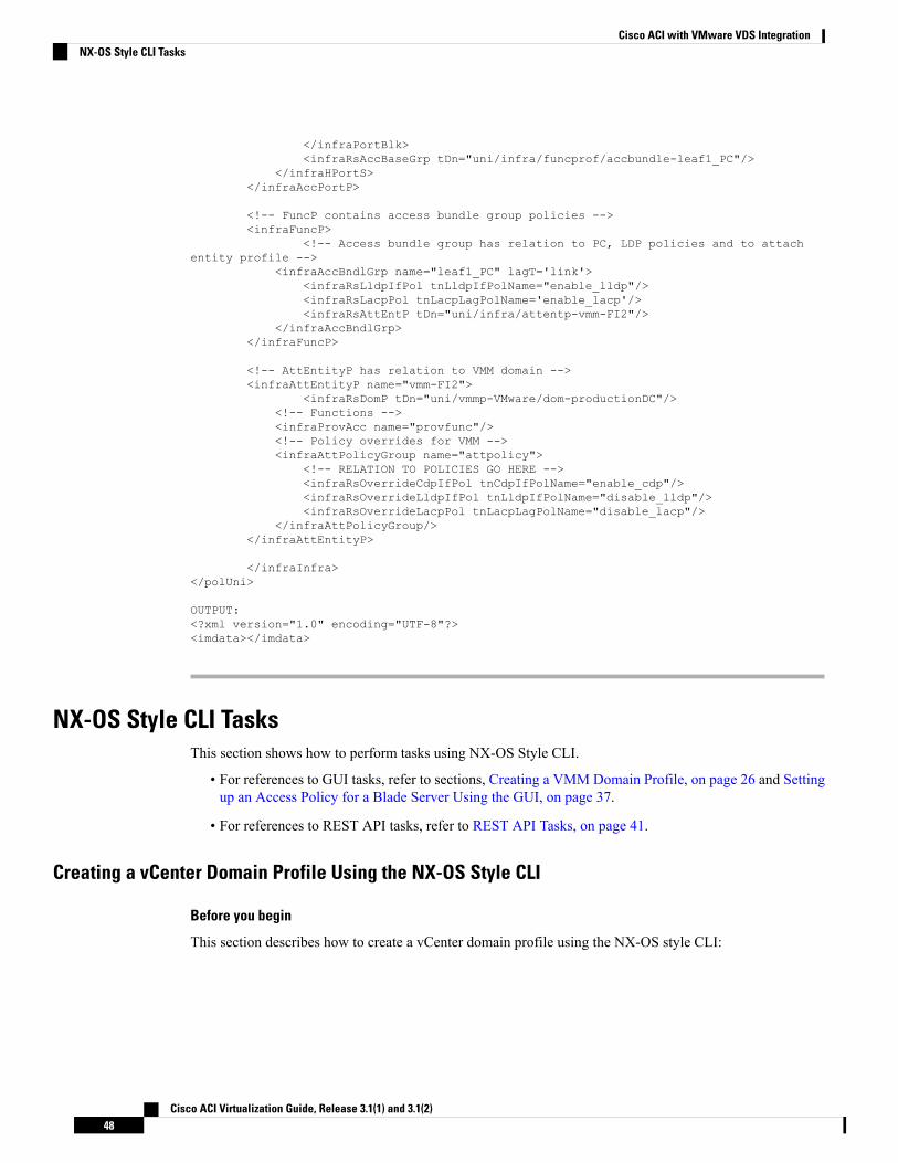
</infraPortBlk><infraRsAccBaseGrp tDn="uni/infra/funcprof/accbundle-leaf1_PC"/>
</infraHPortS></infraAccPortP>
<!-- FuncP contains access bundle group policies --><infraFuncP>
<!-- Access bundle group has relation to PC, LDP policies and to attachentity profile -->
<infraAccBndlGrp name="leaf1_PC" lagT='link'><infraRsLldpIfPol tnLldpIfPolName="enable_lldp"/><infraRsLacpPol tnLacpLagPolName='enable_lacp'/><infraRsAttEntP tDn="uni/infra/attentp-vmm-FI2"/>
</infraAccBndlGrp></infraFuncP>
<!-- AttEntityP has relation to VMM domain --><infraAttEntityP name="vmm-FI2">
<infraRsDomP tDn="uni/vmmp-VMware/dom-productionDC"/><!-- Functions --><infraProvAcc name="provfunc"/><!-- Policy overrides for VMM --><infraAttPolicyGroup name="attpolicy">
<!-- RELATION TO POLICIES GO HERE --><infraRsOverrideCdpIfPol tnCdpIfPolName="enable_cdp"/><infraRsOverrideLldpIfPol tnLldpIfPolName="disable_lldp"/><infraRsOverrideLacpPol tnLacpLagPolName="disable_lacp"/>
</infraAttPolicyGroup/></infraAttEntityP>
</infraInfra></polUni>
OUTPUT:<?xml version="1.0" encoding="UTF-8"?><imdata></imdata>
NX-OS Style CLI TasksThis section shows how to perform tasks using NX-OS Style CLI.
• For references to GUI tasks, refer to sections, Creating a VMM Domain Profile, on page 26 and Settingup an Access Policy for a Blade Server Using the GUI, on page 37.
• For references to REST API tasks, refer to REST API Tasks, on page 41.
Creating a vCenter Domain Profile Using the NX-OS Style CLI
Before you begin
This section describes how to create a vCenter domain profile using the NX-OS style CLI:
Cisco ACI Virtualization Guide, Release 3.1(1) and 3.1(2)48
Cisco ACI with VMware VDS IntegrationNX-OS Style CLI Tasks
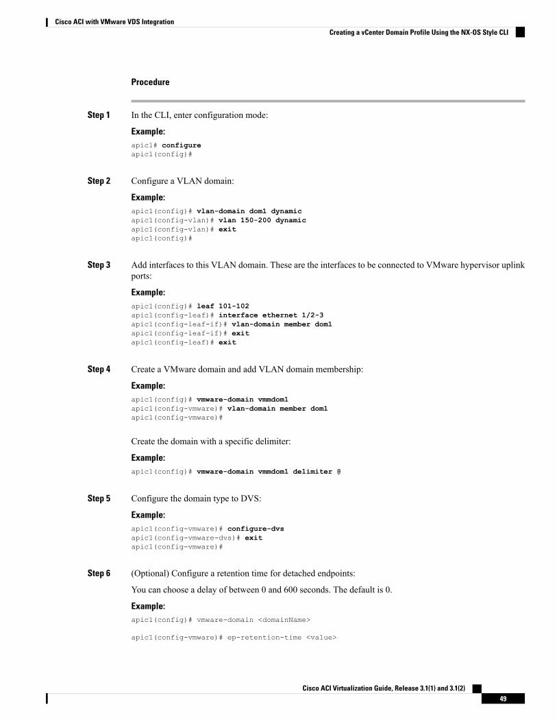
Procedure
Step 1 In the CLI, enter configuration mode:
Example:apic1# configureapic1(config)#
Step 2 Configure a VLAN domain:
Example:apic1(config)# vlan-domain dom1 dynamicapic1(config-vlan)# vlan 150-200 dynamicapic1(config-vlan)# exitapic1(config)#
Step 3 Add interfaces to this VLAN domain. These are the interfaces to be connected to VMware hypervisor uplinkports:
Example:apic1(config)# leaf 101-102apic1(config-leaf)# interface ethernet 1/2-3apic1(config-leaf-if)# vlan-domain member dom1apic1(config-leaf-if)# exitapic1(config-leaf)# exit
Step 4 Create a VMware domain and add VLAN domain membership:
Example:apic1(config)# vmware-domain vmmdom1apic1(config-vmware)# vlan-domain member dom1apic1(config-vmware)#
Create the domain with a specific delimiter:
Example:apic1(config)# vmware-domain vmmdom1 delimiter @
Step 5 Configure the domain type to DVS:
Example:apic1(config-vmware)# configure-dvsapic1(config-vmware-dvs)# exitapic1(config-vmware)#
Step 6 (Optional) Configure a retention time for detached endpoints:
You can choose a delay of between 0 and 600 seconds. The default is 0.
Example:apic1(config)# vmware-domain <domainName>
apic1(config-vmware)# ep-retention-time <value>
Cisco ACI Virtualization Guide, Release 3.1(1) and 3.1(2)49
Cisco ACI with VMware VDS IntegrationCreating a vCenter Domain Profile Using the NX-OS Style CLI
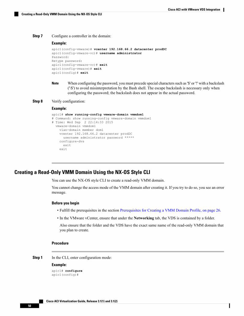
Step 7 Configure a controller in the domain:
Example:apic1(config-vmware)# vcenter 192.168.66.2 datacenter prodDCapic1(config-vmware-vc)# username administratorPassword:Retype password:apic1(config-vmware-vc)# exitapic1(config-vmware)# exitapic1(config)# exit
When configuring the password, youmust precede special characters such as '$' or '!' with a backslash('\$') to avoid misinterpretation by the Bash shell. The escape backslash is necessary only whenconfiguring the password; the backslash does not appear in the actual password.
Note
Step 8 Verify configuration:
Example:apic1# show running-config vmware-domain vmmdom1# Command: show running-config vmware-domain vmmdom1# Time: Wed Sep 2 22:14:33 2015vmware-domain vmmdom1vlan-domain member dom1vcenter 192.168.66.2 datacenter prodDCusername administrator password *****
configure-dvsexit
exit
Creating a Read-Only VMM Domain Using the NX-OS Style CLIYou can use the NX-OS style CLI to create a read-only VMM domain.
You cannot change the access mode of the VMM domain after creating it. If you try to do so, you see an errormessage.
Before you begin
• Fulfill the prerequisites in the section Prerequisites for Creating a VMM Domain Profile, on page 26.
• In the VMware vCenter, ensure that under the Networking tab, the VDS is contained by a folder.
Also ensure that the folder and the VDS have the exact same name of the read-only VMM domain thatyou plan to create.
Procedure
Step 1 In the CLI, enter configuration mode:
Example:apic1# configureapic1(config)#
Cisco ACI Virtualization Guide, Release 3.1(1) and 3.1(2)50
Cisco ACI with VMware VDS IntegrationCreating a Read-Only VMM Domain Using the NX-OS Style CLI
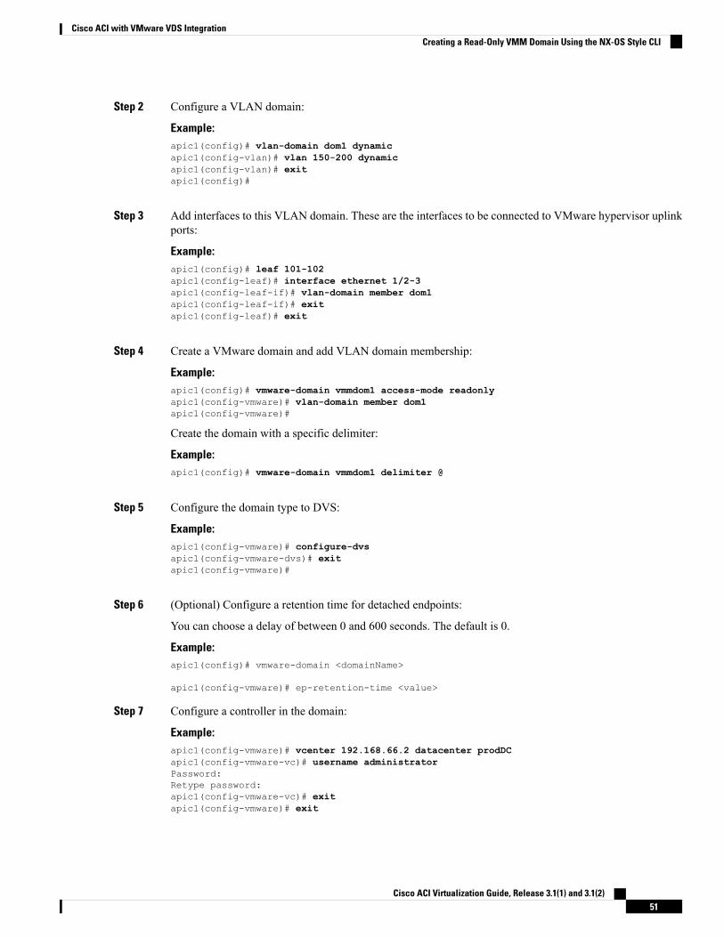
Step 2 Configure a VLAN domain:
Example:apic1(config)# vlan-domain dom1 dynamicapic1(config-vlan)# vlan 150-200 dynamicapic1(config-vlan)# exitapic1(config)#
Step 3 Add interfaces to this VLAN domain. These are the interfaces to be connected to VMware hypervisor uplinkports:
Example:apic1(config)# leaf 101-102apic1(config-leaf)# interface ethernet 1/2-3apic1(config-leaf-if)# vlan-domain member dom1apic1(config-leaf-if)# exitapic1(config-leaf)# exit
Step 4 Create a VMware domain and add VLAN domain membership:
Example:apic1(config)# vmware-domain vmmdom1 access-mode readonlyapic1(config-vmware)# vlan-domain member dom1apic1(config-vmware)#
Create the domain with a specific delimiter:
Example:apic1(config)# vmware-domain vmmdom1 delimiter @
Step 5 Configure the domain type to DVS:
Example:apic1(config-vmware)# configure-dvsapic1(config-vmware-dvs)# exitapic1(config-vmware)#
Step 6 (Optional) Configure a retention time for detached endpoints:
You can choose a delay of between 0 and 600 seconds. The default is 0.
Example:apic1(config)# vmware-domain <domainName>
apic1(config-vmware)# ep-retention-time <value>
Step 7 Configure a controller in the domain:
Example:apic1(config-vmware)# vcenter 192.168.66.2 datacenter prodDCapic1(config-vmware-vc)# username administratorPassword:Retype password:apic1(config-vmware-vc)# exitapic1(config-vmware)# exit
Cisco ACI Virtualization Guide, Release 3.1(1) and 3.1(2)51
Cisco ACI with VMware VDS IntegrationCreating a Read-Only VMM Domain Using the NX-OS Style CLI
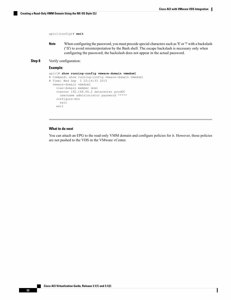
apic1(config)# exit
When configuring the password, youmust precede special characters such as '$' or '!' with a backslash('\$') to avoid misinterpretation by the Bash shell. The escape backslash is necessary only whenconfiguring the password; the backslash does not appear in the actual password.
Note
Step 8 Verify configuration:
Example:apic1# show running-config vmware-domain vmmdom1# Command: show running-config vmware-domain vmmdom1# Time: Wed Sep 2 22:14:33 2015vmware-domain vmmdom1vlan-domain member dom1vcenter 192.168.66.2 datacenter prodDCusername administrator password *****
configure-dvsexit
exit
What to do next
You can attach an EPG to the read-only VMM domain and configure policies for it. However, those policiesare not pushed to the VDS in the VMware vCenter.
Cisco ACI Virtualization Guide, Release 3.1(1) and 3.1(2)52
Cisco ACI with VMware VDS IntegrationCreating a Read-Only VMM Domain Using the NX-OS Style CLI
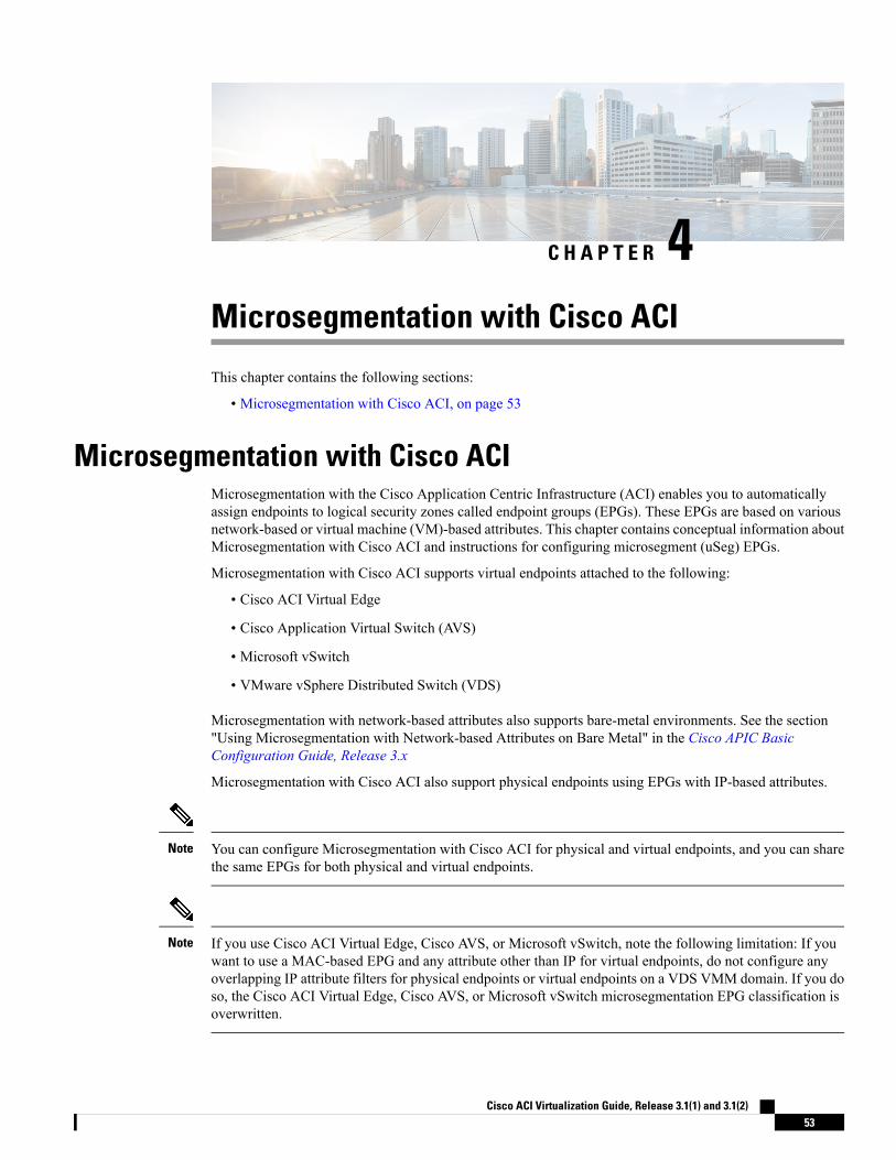
C H A P T E R 4Microsegmentation with Cisco ACI
This chapter contains the following sections:
• Microsegmentation with Cisco ACI, on page 53
Microsegmentation with Cisco ACIMicrosegmentation with the Cisco Application Centric Infrastructure (ACI) enables you to automaticallyassign endpoints to logical security zones called endpoint groups (EPGs). These EPGs are based on variousnetwork-based or virtual machine (VM)-based attributes. This chapter contains conceptual information aboutMicrosegmentation with Cisco ACI and instructions for configuring microsegment (uSeg) EPGs.
Microsegmentation with Cisco ACI supports virtual endpoints attached to the following:
• Cisco ACI Virtual Edge
• Cisco Application Virtual Switch (AVS)
• Microsoft vSwitch
• VMware vSphere Distributed Switch (VDS)
Microsegmentation with network-based attributes also supports bare-metal environments. See the section"Using Microsegmentation with Network-based Attributes on Bare Metal" in the Cisco APIC BasicConfiguration Guide, Release 3.x
Microsegmentation with Cisco ACI also support physical endpoints using EPGs with IP-based attributes.
You can configure Microsegmentation with Cisco ACI for physical and virtual endpoints, and you can sharethe same EPGs for both physical and virtual endpoints.
Note
If you use Cisco ACI Virtual Edge, Cisco AVS, or Microsoft vSwitch, note the following limitation: If youwant to use a MAC-based EPG and any attribute other than IP for virtual endpoints, do not configure anyoverlapping IP attribute filters for physical endpoints or virtual endpoints on a VDS VMM domain. If you doso, the Cisco ACI Virtual Edge, Cisco AVS, or Microsoft vSwitch microsegmentation EPG classification isoverwritten.
Note
Cisco ACI Virtualization Guide, Release 3.1(1) and 3.1(2)53
The Cisco Application Policy Infrastructure Controller (APIC) manages microsegmentation polices used bythe Cisco ACI Virtual Edge, Cisco AVS, VMware VDS, and Microsoft vSwitch. The fabric enforces thepolicies. This section assumes that you are familiar with EPGs, tenants, contracts, and other key conceptsrelating to Cisco ACI policies. For more information, see Cisco Application Centric InfrastructureFundamentals.
Benefits of Microsegmentation with Cisco ACIEndpoint groups (EPGs) are used to group virtual machines (VMs) within a tenant and apply filtering andforwarding policies to them.Microsegmentation with Cisco ACI adds the ability to group endpoints in existingapplication EPGs into new microsegment (uSeg) EPGs and configure network or VM-based attributes forthose uSeg EPGs. This enables you to filter with those attributes and apply more dynamic policies.Microsegmentation with Cisco ACI also allows you to apply policies to any endpoints within the tenant.
Example: Microsegmentation with Cisco ACI Within a Single EPG or Multiple EPGs in the Same Tenant
You might assign web servers to an EPG so that you can apply the similar policies. By default, all endpointswithin an EPG can freely communicate with each other. However, if this web EPG contains a mix of productionand development web servers, you might not want to allow communication between these different types ofweb servers. Microsegmentation with Cisco ACI allows you to create a new EPG and autoassign endpointsbased on their VM name attribute, such as "Prod-xxxx" or "Dev-xxx".
Example: Microsegmentation for Endpoint Quarantine
You might have separate EPGs for web servers and database servers, and each one contains both Windowsand Linux VMs. If a virus affecting only Windows threatens your network, you can isolate Windows VMsacross all EPGs by creating a newEPG called, for example, "Windows-Quarantine" and applying the VM-basedoperating systems attribute to filter out all Windows-based endpoints. This quarantined EPG could have morerestrictive communication policies, such as limiting allowed protocols or preventing communication to anyother EPGs by not having any contract. A microsegment EPG can have a contract or not have a contract.
How Microsegmentation Using Cisco ACI WorksMicrosegmentation using Cisco ACI involves the Cisco APIC, vCenter or Microsoft System Center VirtualMachine Manager (SCVMM), and leaf switches. This section describes the workflow for microsegmentationusing Cisco ACI Virtual Edge, Cisco AVS, VMware VDS, or Microsoft vSwitch.
Cisco APIC
1. The user configures a VMMdomain for Cisco ACI Virtual Edge, Cisco AVS, VMware VDS, orMicrosoftvSwitch in the Cisco APIC.
2. The Cisco APIC connects to vCenter or SCVMM and does the following:
1. Creates an instance of Cisco ACI Virtual Edge, Cisco AVS, VMware VDS, or Microsoft vSwitch.
2. Pulls VM and hypervisor inventory information from the associated VMware vCenter or MicrosoftSCVMM.
3. The user creates an application EPG and associates it with a vCenter/SCVMM domain. In eachvCenter/SCVMM domain, a new encapsulation is allocated for this application EPG. The applicationEPG does not have any attributes.
Cisco ACI Virtualization Guide, Release 3.1(1) and 3.1(2)54
Microsegmentation with Cisco ACIBenefits of Microsegmentation with Cisco ACI
The vCenter/SCVMM administrator assigns virtual endpoints to this application EPG—not to anymicrosegment (uSeg) EPGs. It is the application EPG that appears in vCenter/SCVMM as a port group.
4. The user creates an uSeg EPG and associates it with the VMM domain.
The uSeg EPG does not appear in vCenter/SCVMM as a port group; it has a special function: The uSegEPG has VM-based attributes to match filter criteria. If a match occurs between the uSeg EPG VMattributes and VMs, the Cisco APIC dynamically assigns the VMs to the uSeg EPG.
The endpoints are transferred from the application EPG to the uSeg EPG. If the uSeg EPG is deleted, theendpoints are assigned back to the application EPG.
The uSeg EPG must be assigned to a VMM domain in order for it to take effect. When you associate anuSeg EPG to a VMM domain, its criteria will be applied for that VMM domain only. If you have VMwareVDS, you also must assign the uSeg EPG to the same bridge domain as the application EPG.
In the case of VMware VDS, its criteria will be applied for that VMM domain and bridge domain.
Leaf Switch and Cisco ACI Virtual Edge, Cisco AVS, or Microsoft vSwitch
1. The physical leaf switch pulls the attribute policies from the Cisco APIC.
2. The Cisco ACI Virtual Edge, Cisco AVS, orMicrosoft vSwitch sends a VM attachmessage to the physicalleaf switch using the OpFlex protocol when a VM attaches to Cisco ACI Virtual Edge, Cisco AVS, orMicrosoft vSwitch.
3. The physical leaf switch matches the VM against the configured attribute policies for the tenant.
4. If the VM matches the configured VM attributes, the physical leaf switch pushes the uSeg EPG—alongwith the corresponding encapsulation— to the Cisco ACI Virtual Edge, Cisco AVS, orMicrosoft vSwitch.
Note that this action does not change the original port-group assignment for the VM in vCenter/SCVMM.
Packet Forwarding for Cisco ACI Virtual Edge, Cisco AVS, or Microsoft vSwitch
1. When the VM sends the data packets, Cisco ACI Virtual Edge, Cisco AVS, or Microsoft vSwitch tagsthe packets using encapsulation corresponding to the uSeg EPG, not the application EPG.
2. The physical leaf hardware sees an attribute-based encapsulated VM packet and matches it with theconfigured policy.
The VM is dynamically assigned to an uSeg EPG, and the packet is forwarded based on the policy definedfor that particular uSeg EPG.
Attributes for Microsegmentation with Cisco ACIApplying attributes to uSeg EPGs enables you to apply forwarding and security policies with greater granularitythan you can to EPGs without attributes. Attributes are unique within the tenant.
There are two types of attributes that you can apply to uSeg EPGs: network-based attributes and VM-basedattributes.
Cisco ACI Virtualization Guide, Release 3.1(1) and 3.1(2)55
Microsegmentation with Cisco ACIAttributes for Microsegmentation with Cisco ACI
Network-Based Attributes
The network-based attributes are IP (IP address filter) and MAC (MAC Address Filter). You can apply oneor more MAC or IP addresses to a uSeg EPG.
For IP addresses, you simply specify the address or the subnet; for MAC addresses, you simply specify theaddress.
If you want to use a network-based attribute and classify IP addresses in the same subnet, you must use theMAC-based network attribute. IP-based microsegmented EPGs do not support classification for IP addressesin the same subnet. IP-based microsegmented EPGs are supported only when traffic requires Layer 3 routing.If the traffic is bridged, the microsegmentation policy cannot be enforced.
Note
VM-Based Attributes
You can apply multiple VM-based attributes to an uSeg EPG. The VM-based attributes are VMM Domain,Operating System, Hypervisor Identifier, Datacenter, VM Identifier, VM Name, VNic Dn (vNIC domainname), Custom Attribute, and Tag.
The attribute Datacenter corresponds to Cloud for Microsoft vSwitch.Note
When you create any VM-based attribute, in addition to naming the attribute, you must do the following:
1. Specify the attribute type, such as VM Name or Hypervisor Identifier.
2. Specify the operator, such as Equals, or Starts With.
3. Specify the value, such as a particular vNIC or name of the operating system.
Custom Attribute and Tag Attribute
The Custom Attribute and the Tag attribute allow you to define an attribute based on criteria not used in otherattributes. For example, you might want to define a Custom Attribute called "Security Zone" in vCenter andthen associate this attribute to one or more VMswith such values as "DMZ" or "Edge." The APIC administratorcan then create an uSeg EPG based on that VM Custom Attribute.
The Custom Attribute and the Tag attribute appear in the APIC GUI as VM attributes that are configured onvCenter. They are available for Cisco AVS and VMware VDS only.
If you want to use a Custom Attribute or a Tag attribute, you also need to add it in VMware vSphere WebClient. We recommend doing so before configuring the uSeg EPG so you can choose the Custom Attributeor Tag attribute in the drop-down list while configuring microsegmentation policy in Cisco APIC. You canadd the Custom Attribute or Tag attribute in vSphere Web Client after you configure the uSeg EPG in CiscoAPIC; however, you won't see the Custom Attribute or Tag attribute in the drop-down list in Cisco APIC,although you can type the name in the text box.
See VMware vSphere ESXi and vCenter Server documentation for instructions for adding a CustomAttributeor Tag attribute in vSphere Web Client.
Although similar to the Custom Attribute, the Tag attribute differs from in it several ways:
Cisco ACI Virtualization Guide, Release 3.1(1) and 3.1(2)56
Microsegmentation with Cisco ACIAttributes for Microsegmentation with Cisco ACI
• The Tag attribute can be applied to any object in vCenter, such as a host or datacenter; the CustomAttribute can be applied only to VMs and ESXi hosts. However, only the Tag attribute for VMs is relevantto microsegmentation.
• The Tag attribute does not have a name and value like the Custom Attribute. Tags are simply labels thatget applied or not to objects.
• To configure a Custom Attribute, you provide details about the controller and VM as well as an operatorand a value; to configure the Tag attribute, you provide the attribute type, category, operator, and tagname.
The Tag attribute can be defined for a uSeg EPG only when the vCenter is running vSphere 6 .0 or later.Note
Uniqueness of Attributes Within a Tenant
Attributes must be unique within a tenant. Uniqueness depends on the value of the attribute.
For example, for a network-based attribute, you can use the attribute IP Address Filter multiple times withina tenant provided that the attribute has a different value for the IP address each time it is used. So you cannotuse the IP Address Filter attribute with the address 192.168.33.77 more than once; however, you can use theIP Address Filter attribute a second time, provided that the IP address is different, for example 192.168.33.78.
Methods of Filtering VMs for uSeg EPGsYou can configure uSeg EPGs with multiple attributes. However, VMs can become part of only one uSegEPG. When a VM has attributes matching more than one uSeg EPG in the tenant, Cisco APIC puts the VMinto a uSeg EPG based on filtering rules.
Depending on how you define the attributes, you can use different filtering rules:
• Matching any attribute—You canmatch any attribute, and Cisco APIC follows a the default precedenceamong attributes in deciding which uSeg EPG that a VM will join.
For more information, see the section VM Filtering when Matching Any Attribute, on page 58in thisguide.
• Matching all attributes—You can match all of the VM-based attributes defined for the uSeg EPG. Youcannot match all for multiple network-based attributes.
For more information, see the section VM Filtering when Matching All Attributes, on page 59 in thisguide.
• Using simple or block statements—You can create multiple statements to filter for multiple attributes,or you can create block, or nested, statements to create precise filtering rules.
For more information, see the section VM Filtering when Using Simple or Block Statements, on page60 in this guide.
• Overriding existing rules—When you create a uSeg EPG, you can set its precedence, overriding otherrules. You can set the precedence when you match any attribute or match all attributes. You need to setmatch precedence to break ties across EPGs in the tenant. You can match all attributes and not set matchprecedence; however, in such cases, if you have multiple uSeg EPGs with similar attributes, the VM canget matched to any of the uSeg EPGs arbitrarily.
Cisco ACI Virtualization Guide, Release 3.1(1) and 3.1(2)57
Microsegmentation with Cisco ACIMethods of Filtering VMs for uSeg EPGs
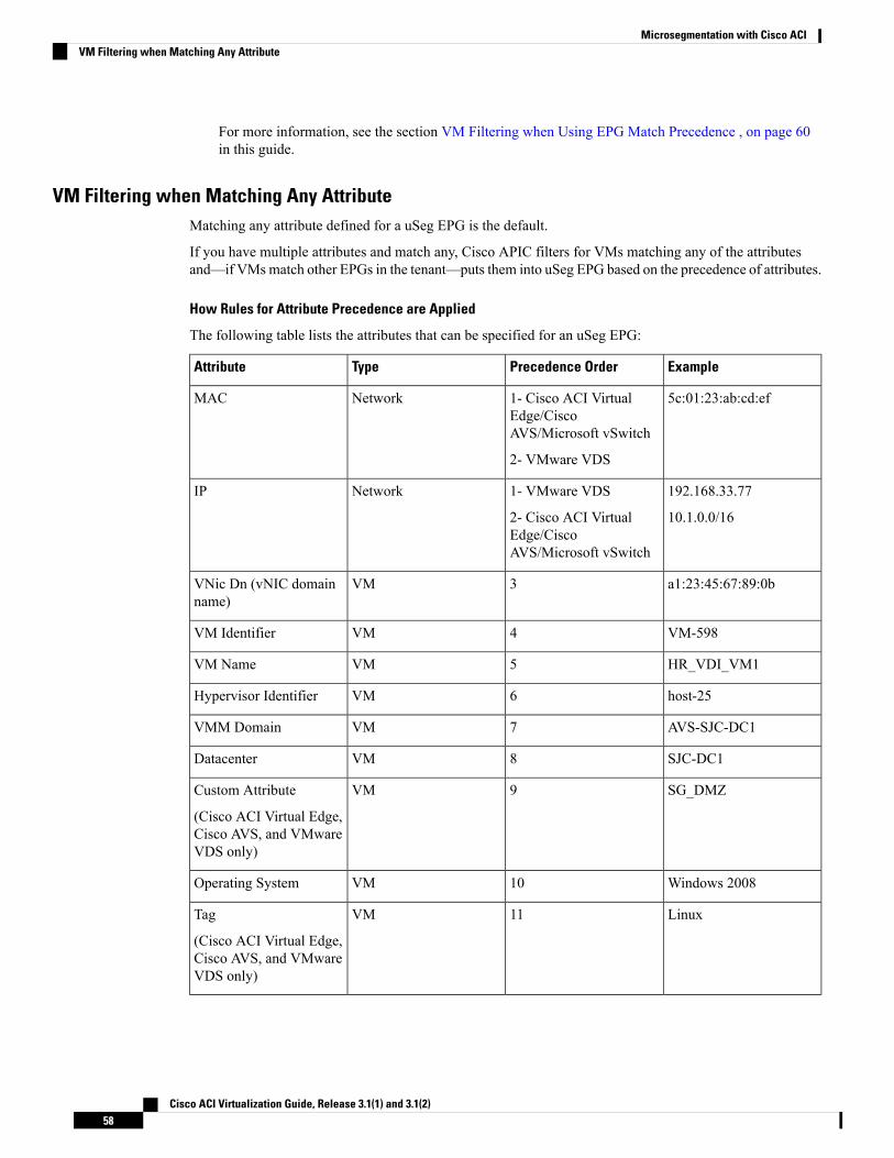
For more information, see the section VM Filtering when Using EPG Match Precedence , on page 60in this guide.
VM Filtering when Matching Any AttributeMatching any attribute defined for a uSeg EPG is the default.
If you have multiple attributes and match any, Cisco APIC filters for VMs matching any of the attributesand—if VMsmatch other EPGs in the tenant—puts them into uSeg EPG based on the precedence of attributes.
How Rules for Attribute Precedence are Applied
The following table lists the attributes that can be specified for an uSeg EPG:
ExamplePrecedence OrderTypeAttribute
5c:01:23:ab:cd:ef1- Cisco ACI VirtualEdge/CiscoAVS/Microsoft vSwitch
2- VMware VDS
NetworkMAC
192.168.33.77
10.1.0.0/16
1- VMware VDS
2- Cisco ACI VirtualEdge/CiscoAVS/Microsoft vSwitch
NetworkIP
a1:23:45:67:89:0b3VMVNic Dn (vNIC domainname)
VM-5984VMVM Identifier
HR_VDI_VM15VMVM Name
host-256VMHypervisor Identifier
AVS-SJC-DC17VMVMM Domain
SJC-DC18VMDatacenter
SG_DMZ9VMCustom Attribute
(Cisco ACI Virtual Edge,Cisco AVS, and VMwareVDS only)
Windows 200810VMOperating System
Linux11VMTag
(Cisco ACI Virtual Edge,Cisco AVS, and VMwareVDS only)
Cisco ACI Virtualization Guide, Release 3.1(1) and 3.1(2)58
Microsegmentation with Cisco ACIVM Filtering when Matching Any Attribute
Precedence ofMAC-based and IP-based attributes differ for VMware VDS and Cisco ACI Virtual Edge/CiscoAVS/Microsoft vSwitch.
Note
Examples of how Rules for Precedence are Applied
You might have four uSeg EPGs containing attributes that match the same VM, and each uSeg EPG has adifferent network or VM attribute: Operating System, Hypervisor Identifier, IP; and another has MAC.
Rules for Cisco AVS and Microsoft vSwitch are applied in this order: MAC, IP, Hypervisor Identifier, andOperating System. The rule is applied to MAC, and the subsequent rules are skipped. However, if the uSegEPG with the MAC attribute is deleted, the rule is applied to IP Address Filter, and the subsequent rules areskipped—and so on with the other attributes.
Rules for VMware VDS are applied in this order: IP Address Filter, MACAddress Filter, Hypervisor Identifier,and Operating System. The rule is applied to IP, and the subsequent rules are skipped. However, if the uSegEPG with the IP attribute is deleted, the rule is applied to MAC and the subsequent rules are skipped—andso on with the other attributes.
In another case, you might have uSeg EPGs containing the same VM, and each uSeg EPG has a different VMattribute: VMM Domain, Datacenter, Custom Attribute, and VNic Dn. The rule is applied to VNic Dn, andthe subsequent rules as skipped. However, if the uSeg EPG with the VNic Dn attribute is deleted, the rule isapplied to VMM Domain, and the subsequent rules are skipped–and so on with the other attributes.
VM Filtering when Matching All AttributesYou can filter by matching all VM-based attributes defined for a uSeg EPG. You do so by choosingMatchAll from a drop-down list in the APIC GUI or specify matching in the NX-OS CLI or REST API.
If you match all attributes, Cisco APIC does not put any VM into the uSeg EPG unless it matches all theattributes defined for the uSeg EPG.
For example, you have a uSeg EPG with the following attributes: Hypervisor Identifier where the hypervisoris host-25, VM Name that contains "vm," and Operating System of Linux. Cisco APIC puts into the uSegEPG only those VMs that have the hypervisor host-25, a VM Name containing "vm," and have the operatingsystem Linux. It would not put into the uSeg EPG a VM that matches the first two attributes but has theoperating system Microsoft.
Matching all attributes is supported for VM-based attributes only. You cannot choose Match All fornetwork-based attributes.
Note
If you want to match all VM-based attributes, you might want to set the EPG match precedence when youcreate the uSeg EPG. Doing so allows you to decide which uSeg EPG should override other uSeg EPGs.However, you can set EPG match precedence whether you match any attribute or all attributes. For moreinformation, see the section VM Filtering when Using EPG Match Precedence , on page 60 in this guide.
If you use Microsoft vSwitch and want to downgrade to APIC Release 2.3(1) from a later release, you firstneed to delete any uSegs configured with the Match All filter. The Match All filter is supported for Microsoftbeginning with APIC Release 3.0(1).
Note
Cisco ACI Virtualization Guide, Release 3.1(1) and 3.1(2)59
Microsegmentation with Cisco ACIVM Filtering when Matching All Attributes
VM Filtering when Using Simple or Block StatementsWhen you define attributes for a uSeg EPG, you can define multiple attributes in simple statements or in blockstatements. You can combine simple and block statements to create complex filters for attributes.
Simple statements contain a single attribute. You can have as many simple statements as you want for eachuSeg EPG. You can match any of the attributes or all of the attributes.
Block statements contain multiple attributes at different levels in a hierarchy. You can have only two sublevelswithin a block statement. You can match any of the attributes or all of the attributes for each level of the blockstatement.
You cannot put network-based attributes into sublevels of block statements. However, you can create sublevelsfor network-based attributes if the network-based attribute is at the top level of a block statement.
Note
When you have block statements, Cisco APIC first filters for attributes defined on the top level. It then filterson the next-highest level, and then the next-highest level.
You can create simple and block statements in the APIC GUI, the NX-OS CLI, and the REST API.
Example of Using Block Statements
You want to put some VMs into a uSeg EPG so you can update Linux on them. The VMs are within a singledata center, but you want to limit the update to VMs within two VMM domains. You can use block statementsto set up filtering for those VMs.
Because you are filtering for VMs that run Linux and are in a single data center, you create two simplestatements: one for the Operating System attribute with the value Linux and one for the attribute Datacenterwith the value of datacenter3. For these statements you choose Match All because you want to capture allVMs in the tenant that run Linux and belong to datacenter 3.
However, among VMs that run Linux and belong to datacenter3, you now want to capture VMs that belongonly to the VMM domains mininet2 or mininet4. You create a block statement as a sublevel of the two simplestatements. The blocks statement contains two attributes: one for the attribute VMM domain with the valueof mininet 2 and one for the attribute VMM domain with the value of mininet 4. You choose match any forthe block statement because you want to capture VMs that are in either VMM domain.
Once you define the attributes, Cisco APIC first filters for VMs that run Linux and also are in datacenter3. Itthen searches among those VMs for the ones that belong to either mininet2 or mininet4.
VM Filtering when Using EPG Match PrecedenceEPG Match Precedence enables you to override default precedence rules for uSeg EPGs when filtering forVM-based attributes. You configure it when you create the uSeg EPG in the GUI, NX-OS CLI, or REST API.
EPG Match Precedence is optional when matching any attribute or matching all attributes. However, whenyou match all attributes—filtering on multiple attributes—setting precedence enables Cisco APIC to breakties between uSeg EPGs.
You cannot use EPG Match Precedence when filtering network-based attributes. If you try to do so, you seean error message.
Note
Cisco ACI Virtualization Guide, Release 3.1(1) and 3.1(2)60
Microsegmentation with Cisco ACIVM Filtering when Using Simple or Block Statements
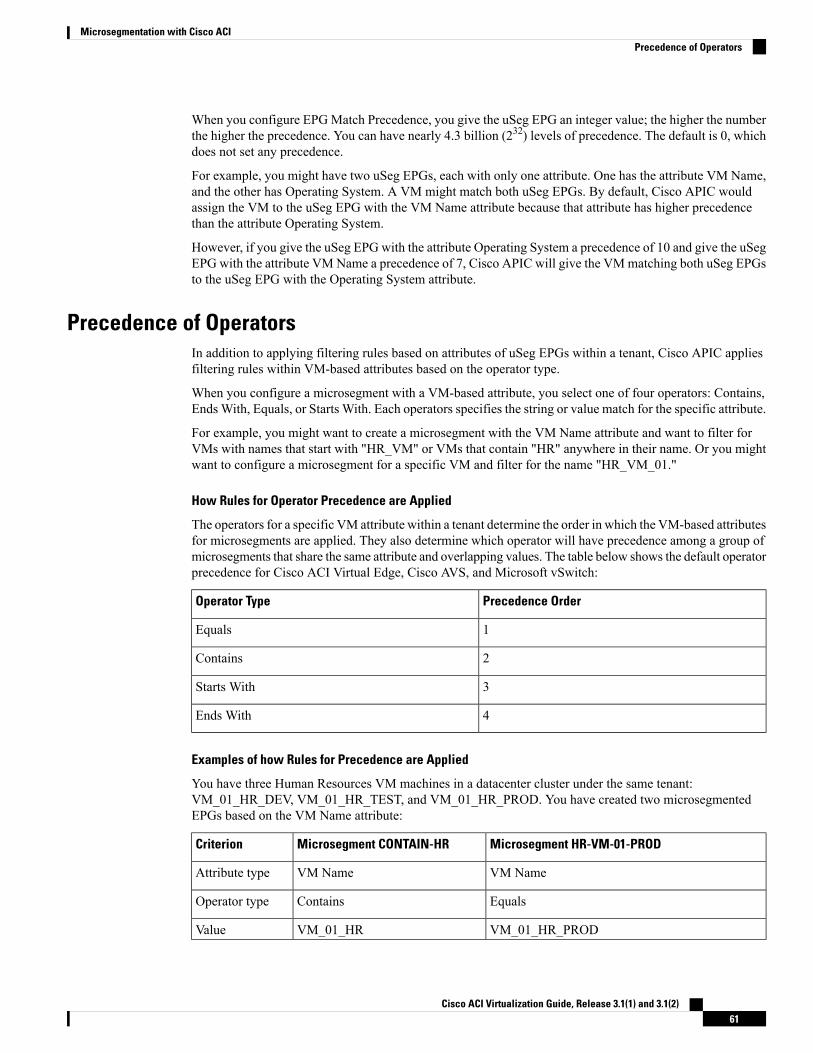
When you configure EPGMatch Precedence, you give the uSeg EPG an integer value; the higher the numberthe higher the precedence. You can have nearly 4.3 billion (232) levels of precedence. The default is 0, whichdoes not set any precedence.
For example, you might have two uSeg EPGs, each with only one attribute. One has the attribute VM Name,and the other has Operating System. A VM might match both uSeg EPGs. By default, Cisco APIC wouldassign the VM to the uSeg EPG with the VM Name attribute because that attribute has higher precedencethan the attribute Operating System.
However, if you give the uSeg EPG with the attribute Operating System a precedence of 10 and give the uSegEPG with the attribute VMName a precedence of 7, Cisco APIC will give the VMmatching both uSeg EPGsto the uSeg EPG with the Operating System attribute.
Precedence of OperatorsIn addition to applying filtering rules based on attributes of uSeg EPGs within a tenant, Cisco APIC appliesfiltering rules within VM-based attributes based on the operator type.
When you configure a microsegment with a VM-based attribute, you select one of four operators: Contains,EndsWith, Equals, or Starts With. Each operators specifies the string or value match for the specific attribute.
For example, you might want to create a microsegment with the VM Name attribute and want to filter forVMs with names that start with "HR_VM" or VMs that contain "HR" anywhere in their name. Or you mightwant to configure a microsegment for a specific VM and filter for the name "HR_VM_01."
How Rules for Operator Precedence are Applied
The operators for a specific VM attribute within a tenant determine the order in which the VM-based attributesfor microsegments are applied. They also determine which operator will have precedence among a group ofmicrosegments that share the same attribute and overlapping values. The table below shows the default operatorprecedence for Cisco ACI Virtual Edge, Cisco AVS, and Microsoft vSwitch:
Precedence OrderOperator Type
1Equals
2Contains
3Starts With
4Ends With
Examples of how Rules for Precedence are Applied
You have three Human Resources VM machines in a datacenter cluster under the same tenant:VM_01_HR_DEV, VM_01_HR_TEST, and VM_01_HR_PROD. You have created two microsegmentedEPGs based on the VM Name attribute:
Microsegment HR-VM-01-PRODMicrosegment CONTAIN-HRCriterion
VM NameVM NameAttribute type
EqualsContainsOperator type
VM_01_HR_PRODVM_01_HRValue
Cisco ACI Virtualization Guide, Release 3.1(1) and 3.1(2)61
Microsegmentation with Cisco ACIPrecedence of Operators
Because the operator type Equals has precedence over the operator type Contains, the valueVM_01_HR_PRODismatched before the value VM_01_HR. So the VMnamedVM_01_HR_PRODwill be put intomicrosegmentHR-VM-01-PROD because it is an exact criterion match and because the operator Equals has precedenceover the operator Contains, even though the VM name matches both microsegments. The other two VMs willbe put in the Microsegment CONTAIN-HR.
Scenarios for Using Microsegmentation with Cisco ACIThis section contains examples of circumstances in which you might find Microsegmentation useful in yournetwork.
Using Microsegmentation with Cisco ACI with VMs Within a Single Application EPGYou can use Microsegmentation with Cisco ACI to create new, uSeg EPGs to contain VMs from a singleapplication EPG. By default, VMs within an application EPG can communicate with each other; however,you might want to prevent communication between groups of VMs, if VRF is in enforced mode and there isno contract between uSeg EPGs.
For more information about Intra-EPG Isolation knob, that controls communication between VMs within theEPG, see Intra-EPG Isolation for VMware VDS or Microsoft vSwitch, on page 75.
Example: Putting VMs from the Same Application EPG into a Microsegmented EPG
Your company deploys a virtual desktop infrastructure (VDI) for its Human Resources, Finance, and Operationsdepartments. The VDI virtual desktop VMs are part of a single application EPG called EPG_VDI with identicalaccess requirements to the rest of the application EPGs.
Service contracts are built in such a way such that the EPG-VDI has access to Internet resources and internalresources. But at the same time, the company must ensure that each of the VM groups—Human Resources,Finance, and Operations—cannot access the others even though they belong to the same application EPG,EPG_VDI.
To meet this requirement, you can create filters in the Cisco APIC that would check the names of the VMsin the application EPG, EPG_VDI. If you create a filter with the value "HR_VM," Cisco APIC creates a uSegEPG—amicrosegment—for all Human Resource VMs. Cisco APIC looks for matching values in all the EPGsin a tenant even though you want to group the matching VMs within one EPG. So when you create VMs, werecommend that you choose names unique within the tenant.
Similarly, you can create filters with the keyword "FIN_VMs" for Finance virtual desktops and "OPS_VMs"for Operations virtual desktops. These uSeg EPGs are represented as new EPGs within the Cisco APIC policymodel. You can then apply contracts and filters to control access between the VM groups even though theybelong to the same application EPG.
Cisco ACI Virtualization Guide, Release 3.1(1) and 3.1(2)62
Microsegmentation with Cisco ACIScenarios for Using Microsegmentation with Cisco ACI
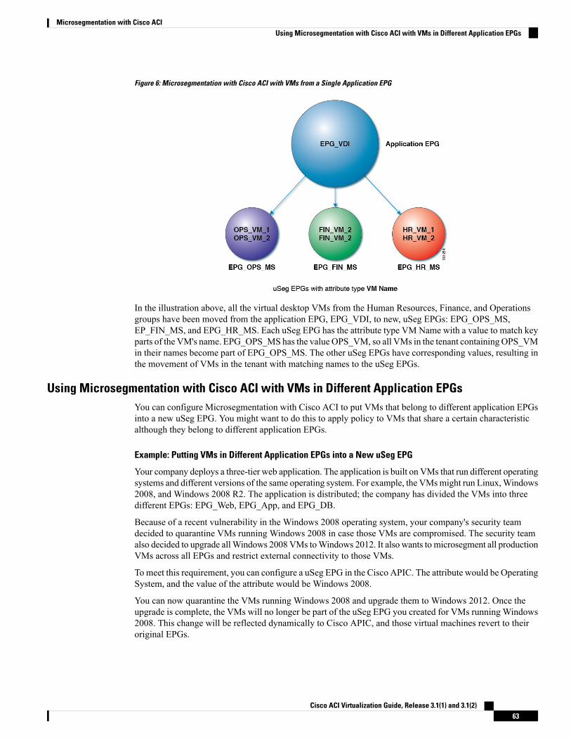
Figure 6: Microsegmentation with Cisco ACI with VMs from a Single Application EPG
In the illustration above, all the virtual desktop VMs from the Human Resources, Finance, and Operationsgroups have been moved from the application EPG, EPG_VDI, to new, uSeg EPGs: EPG_OPS_MS,EP_FIN_MS, and EPG_HR_MS. Each uSeg EPG has the attribute type VM Name with a value to match keyparts of the VM's name. EPG_OPS_MS has the value OPS_VM, so all VMs in the tenant containingOPS_VMin their names become part of EPG_OPS_MS. The other uSeg EPGs have corresponding values, resulting inthe movement of VMs in the tenant with matching names to the uSeg EPGs.
Using Microsegmentation with Cisco ACI with VMs in Different Application EPGsYou can configure Microsegmentation with Cisco ACI to put VMs that belong to different application EPGsinto a new uSeg EPG. You might want to do this to apply policy to VMs that share a certain characteristicalthough they belong to different application EPGs.
Example: Putting VMs in Different Application EPGs into a New uSeg EPG
Your company deploys a three-tier web application. The application is built on VMs that run different operatingsystems and different versions of the same operating system. For example, the VMsmight run Linux,Windows2008, and Windows 2008 R2. The application is distributed; the company has divided the VMs into threedifferent EPGs: EPG_Web, EPG_App, and EPG_DB.
Because of a recent vulnerability in the Windows 2008 operating system, your company's security teamdecided to quarantine VMs running Windows 2008 in case those VMs are compromised. The security teamalso decided to upgrade allWindows 2008 VMs toWindows 2012. It also wants to microsegment all productionVMs across all EPGs and restrict external connectivity to those VMs.
To meet this requirement, you can configure a uSeg EPG in the Cisco APIC. The attribute would be OperatingSystem, and the value of the attribute would be Windows 2008.
You can now quarantine the VMs running Windows 2008 and upgrade them to Windows 2012. Once theupgrade is complete, the VMs will no longer be part of the uSeg EPG you created for VMs running Windows2008. This change will be reflected dynamically to Cisco APIC, and those virtual machines revert to theiroriginal EPGs.
Cisco ACI Virtualization Guide, Release 3.1(1) and 3.1(2)63
Microsegmentation with Cisco ACIUsing Microsegmentation with Cisco ACI with VMs in Different Application EPGs
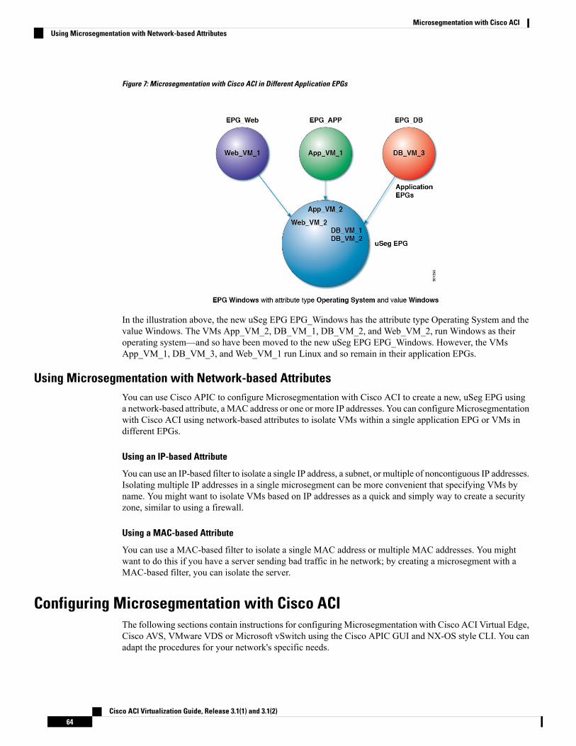
Figure 7: Microsegmentation with Cisco ACI in Different Application EPGs
In the illustration above, the new uSeg EPG EPG_Windows has the attribute type Operating System and thevalue Windows. The VMs App_VM_2, DB_VM_1, DB_VM_2, and Web_VM_2, run Windows as theiroperating system—and so have been moved to the new uSeg EPG EPG_Windows. However, the VMsApp_VM_1, DB_VM_3, and Web_VM_1 run Linux and so remain in their application EPGs.
Using Microsegmentation with Network-based AttributesYou can use Cisco APIC to configure Microsegmentation with Cisco ACI to create a new, uSeg EPG usinga network-based attribute, aMAC address or one or more IP addresses. You can configureMicrosegmentationwith Cisco ACI using network-based attributes to isolate VMs within a single application EPG or VMs indifferent EPGs.
Using an IP-based Attribute
You can use an IP-based filter to isolate a single IP address, a subnet, or multiple of noncontiguous IP addresses.Isolating multiple IP addresses in a single microsegment can be more convenient that specifying VMs byname. You might want to isolate VMs based on IP addresses as a quick and simply way to create a securityzone, similar to using a firewall.
Using a MAC-based Attribute
You can use a MAC-based filter to isolate a single MAC address or multiple MAC addresses. You mightwant to do this if you have a server sending bad traffic in he network; by creating a microsegment with aMAC-based filter, you can isolate the server.
Configuring Microsegmentation with Cisco ACIThe following sections contain instructions for configuring Microsegmentation with Cisco ACI Virtual Edge,Cisco AVS, VMware VDS or Microsoft vSwitch using the Cisco APIC GUI and NX-OS style CLI. You canadapt the procedures for your network's specific needs.
Cisco ACI Virtualization Guide, Release 3.1(1) and 3.1(2)64
Microsegmentation with Cisco ACIUsing Microsegmentation with Network-based Attributes
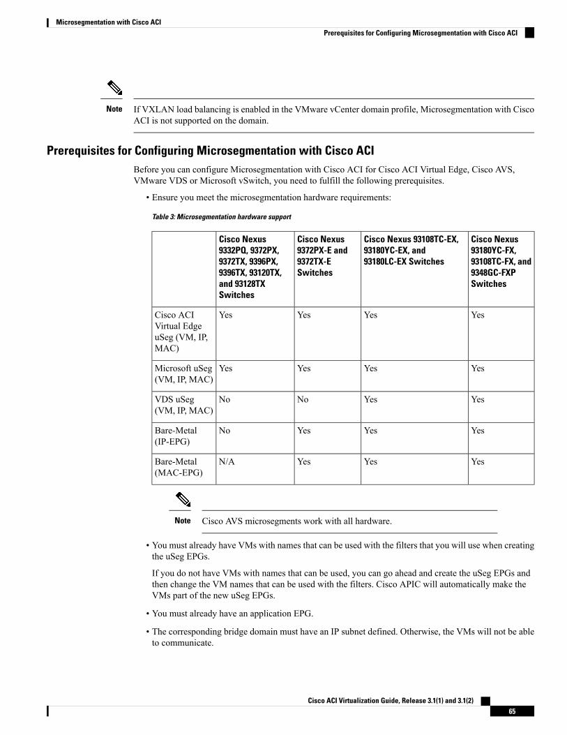
If VXLAN load balancing is enabled in the VMware vCenter domain profile, Microsegmentation with CiscoACI is not supported on the domain.
Note
Prerequisites for Configuring Microsegmentation with Cisco ACIBefore you can configure Microsegmentation with Cisco ACI for Cisco ACI Virtual Edge, Cisco AVS,VMware VDS or Microsoft vSwitch, you need to fulfill the following prerequisites.
• Ensure you meet the microsegmentation hardware requirements:
Table 3: Microsegmentation hardware support
Cisco Nexus93180YC-FX,93108TC-FX, and9348GC-FXPSwitches
Cisco Nexus 93108TC-EX,93180YC-EX, and93180LC-EX Switches
Cisco Nexus9372PX-E and9372TX-ESwitches
Cisco Nexus9332PQ, 9372PX,9372TX, 9396PX,9396TX, 93120TX,and 93128TXSwitches
YesYesYesYesCisco ACIVirtual EdgeuSeg (VM, IP,MAC)
YesYesYesYesMicrosoft uSeg(VM, IP, MAC)
YesYesNoNoVDS uSeg(VM, IP, MAC)
YesYesYesNoBare-Metal(IP-EPG)
YesYesYesN/ABare-Metal(MAC-EPG)
Cisco AVS microsegments work with all hardware.Note
• You must already have VMs with names that can be used with the filters that you will use when creatingthe uSeg EPGs.
If you do not have VMs with names that can be used, you can go ahead and create the uSeg EPGs andthen change the VM names that can be used with the filters. Cisco APIC will automatically make theVMs part of the new uSeg EPGs.
• You must already have an application EPG.
• The corresponding bridge domain must have an IP subnet defined. Otherwise, the VMs will not be ableto communicate.
Cisco ACI Virtualization Guide, Release 3.1(1) and 3.1(2)65
Microsegmentation with Cisco ACIPrerequisites for Configuring Microsegmentation with Cisco ACI
• You must have chosen your own attributes, names, and values.
Attributes, names, and values used in the preceding scenarios were provided as examples.
• You must create a contract before creating a microsegment with one or more attributes if you want toassociate the EPG with a contract.
• If you have a Cisco ACI Virtual Edge, Cisco AVS or VMware VDS and want to use a VM CustomAttribute, you also need to add it in VMware vSphere Web Client. We recommend doing so beforeconfiguringMicrosegmentation in Cisco APIC so you can choose the CustomAttribute in the drop-downlist while configuring the microsegment in he Cisco APIC GUI.
See VMware vSphere ESXi and vCenter Server documentation for instructions for adding a CustomAttribute in vSphere Web Client.
• For Microsoft vSwitch based microsegmentation, one of the following is required:
• SCVMM 2012 R2 Build 3.2.8145.0 or newer
• SCVMM 2016 Build 4.0.1662.0 or newer
These builds include a feature called "Enable Dynamic VLAN on the vNIC of a virtual machine," whichwill be automatically enabled by the Cisco SCVMM Agent to allow live migration of virtual machinesthat use Microsegmentation with ACI. For more information, see Microsoft's documentation:https://support.microsoft.com.
• If you have VMware VDS or a bare-metal server, make sure to set the VRF policy-enforcement directionto "ingress." Otherwise, there will be a fault.
• If you have VMware VDS, make sure the PVLANs are set up on the blade switch. Also make sure thatstatic VLANs are deployed so that VLAN usage is consistent.
Workflow for Configuring Microsegmentation with Cisco ACIThis section provides a high-level description of the tasks that you need to perform in order to configureMicrosegmentation with Cisco ACI.
Create the uSeg EPG: Specify a name and bridge domain for the new uSeg EPG and choose anetwork-based or VM-based attribute for the EPG.
For VMware VDS, you need to choose the same bridge domain for the new uSeg EPGthat is use by the application EPG. Otherwise, the VDS uSeg will not match VMattributes or place the VM into the uSeg EPG.
Note
1
Associate the new uSeg EPG with a VMM domain profile; you need to associate it with the sameVMM domain profile used by the application EPG.
2
Configure attributes for the uSeg EPG.3
Verify that the end points have moved from the application EPG to the uSeg EPG.4
Follow the instructions for these steps in the Configuring Microsegmentation with Cisco ACI, on page 64section in this guide.
Cisco ACI Virtualization Guide, Release 3.1(1) and 3.1(2)66
Microsegmentation with Cisco ACIWorkflow for Configuring Microsegmentation with Cisco ACI
Configuring Microsegmentation with Cisco ACI Using the GUIYou can use Cisco APIC to configure Microsegmentation with Cisco ACI to put VMs that belong to differentapplication EPGs or the same EPG into a new uSeg EPG. The task is essentially the same for Cisco ACIVirtual Edge, Cisco AVS, VMware VDS, and Microsoft vSwitch; the slight differences are noted in theprocedure.
Cisco APIC Basic mode is deprecated after the Cisco APIC Release 3.0(1). Cisco does not recommend usingBasic mode for configuration. However, if you want to use Basic mode, use the following URL: APICURL/indexSimple.html.
Caution: Cisco recommends that you do not mix configuration modes (Advanced or Basic). When you makea configuration in either mode and change the configuration using the other mode, unintended changes canoccur. For example, if you apply an interface policy to two ports using Advanced mode and then change thesettings of one port using Basic mode, your changes might be applied to both ports.
Procedure
Step 1 Log into the Cisco APIC.Step 2 Choose Tenants and then choose the tenant where you want to create a microsegment.Step 3 In the tenant navigation pane, expand the tenant folder, theApplication Profiles folder and the profile folder.Step 4 Complete one of the following actions:
• If you are using VMware VDS, complete the following substeps.• If you are using Cisco ACI Virtual Edge, Cisco AVS, or Microsoft vSwitch, skip the following substepsand continue with Step 5.
a) Expand the Application EPGs folder and the folder for the application EPG.b) Right-click on the folder Domains (VMs and Bare-Metals).c) In the Add VMM Domain Association dialog box, check the Allow Micro-Segmentation check box.
If you are using VMware VDS, you also need to configure all the required parameters.
d) Click Submit.
Step 5 In the tenant navigation pane, right-click the uSeg EPGs folder, and then choose Create Useg EPG.Step 6 In the Create USeg EPG Step 1 > Identity dialog box, complete the following steps to begin creation of an
uSeg EPG for a group of VMs:a) In the Name field, enter a name.
We recommend that you choose a name that indicates that the new uSeg EPG is a microsegment.
b) In the intra-EPG isolation field, select enforced or unenforced.
If you select enforced, Cisco ACI prevents all communication between the endpoint devices within thisuSeg EPG.
c) In the Bridge Domain area, choose a bridge domain from the drop-down list.
For VMware VDS, you must choose the same bridge domain that is used for the applicationEPG. Otherwise, the VDS uSeg will not match VM attributes and will not place the VM into auSeg EPG.
Note
Cisco ACI Virtualization Guide, Release 3.1(1) and 3.1(2)67
Microsegmentation with Cisco ACIConfiguring Microsegmentation with Cisco ACI Using the GUI
d) (Optional) In the EpgMatch Precedence field, choose an integer to set the precedence for the uSeg EPGamong other VM-based attribute uSeg EPGs, overriding default rules.
The larger the integer, the higher the precedence.
e) Click Next.
Step 7 In the Create USeg EPG Step 2 > Domains, complete the following steps to associate the uSeg EPG with aVMM domain.a) Click the + (plus) icon at the right of the dialog box.b) From the Domain Profile drop-down list, choose a profile.
If you have a Cisco ACI Virtual Edge, Cisco AVS, or a VMware VDS, choose a VMware domain; if youhave a Microsoft vSwitch, choose a Microsoft domain.
You must choose the same domain that is used by the application EPG.Note
c) From the Deploy Immediacy drop-down list, accept the default On Demand if you have Cisco ACIVirtual Edge, Cisco AVS, or Microsoft vSwitch; choose Immediate if you have VMware VDS.
d) From the Resolution Immediacy drop-down list, accept the default Immediate.e) In the Encap Mode drop down list, accept the default Auto.f) In the Port Encap (or Secondary VLAN for Micro-Seg) field, accept the default value.g) If you have Cisco ACI Virtual Edge, from the Switching Mode drop-down list, choose a mode.
Choose AVE to switch the uSeg EPG through Cisco ACI Virtual Edge; choose native to switch the uSegEPG through the VMware VDS.
h) Click Update and then click Finish.
Step 8 In the navigation page for the tenant, open the folder for the uSeg EPG that you just created.Step 9 Click the uSeg Attributes folder.
The uSeg Attributes work pane appears, where you configure attributes to filter for VMs that you want to putinto the uSeg EPG.
Step 10 (Optional) If you will filter using VM-based attributes, in the uSeg Attributes work pane, from the matchdrop-down list, chooseMatch Any orMatch All.
The match feature enables you to use multiple attributes to filter VMs for the uSeg EPG. The default isMatchAny. The match all feature is supported for VM-based attributes only. See the sections "VM Filtering whenMatching Any Attribute" and "VMFiltering whenMatching All Attributes" in the microsegmentation chapterof the Cisco ACI Virtualization Guide.
Step 11 Click the + or the +( icon to add a filtering statement.
The + icon allows you to create a simple statement, one that creates a filter for a single attribute. You can addmultiple simple statements to filter for multiple attributes. The +( icon allows you to create a block, or nested,statement, which allows you to set attributes in a hierarchy, which filters for the highest-level attribute firstand then filters for lower-level attributes. See the section VMFiltering when Using Simple or Block Statements,on page 60 in this guide for more information.
Step 12 Complete one of the following series of steps to configure the filter.Then...If you want to use...
An IP-based attribute 1. From the Select a type... drop-down list, choose IP.
2. From the Use EPG Subnet? drop-down list, choose Yes or No.
Cisco ACI Virtualization Guide, Release 3.1(1) and 3.1(2)68
Microsegmentation with Cisco ACIConfiguring Microsegmentation with Cisco ACI Using the GUI
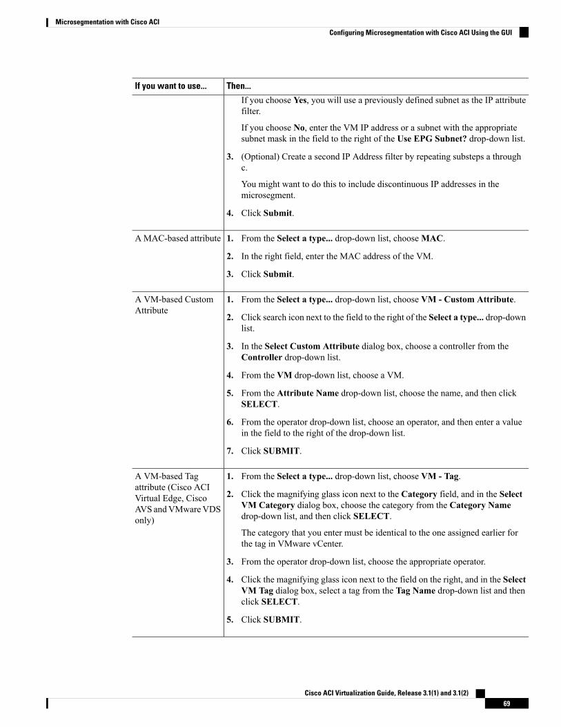
Then...If you want to use...
If you choose Yes, you will use a previously defined subnet as the IP attributefilter.
If you choose No, enter the VM IP address or a subnet with the appropriatesubnet mask in the field to the right of the Use EPG Subnet? drop-down list.
3. (Optional) Create a second IP Address filter by repeating substeps a throughc.
You might want to do this to include discontinuous IP addresses in themicrosegment.
4. Click Submit.
A MAC-based attribute 1. From the Select a type... drop-down list, chooseMAC.
2. In the right field, enter the MAC address of the VM.
3. Click Submit.
A VM-based CustomAttribute
1. From the Select a type... drop-down list, choose VM - Custom Attribute.
2. Click search icon next to the field to the right of the Select a type... drop-downlist.
3. In the Select Custom Attribute dialog box, choose a controller from theController drop-down list.
4. From the VM drop-down list, choose a VM.
5. From the Attribute Name drop-down list, choose the name, and then clickSELECT.
6. From the operator drop-down list, choose an operator, and then enter a valuein the field to the right of the drop-down list.
7. Click SUBMIT.
A VM-based Tagattribute (Cisco ACI
1. From the Select a type... drop-down list, choose VM - Tag.
2. Click the magnifying glass icon next to the Category field, and in the SelectVM Category dialog box, choose the category from the Category Namedrop-down list, and then click SELECT.
Virtual Edge, CiscoAVS andVMwareVDSonly)
The category that you enter must be identical to the one assigned earlier forthe tag in VMware vCenter.
3. From the operator drop-down list, choose the appropriate operator.
4. Click the magnifying glass icon next to the field on the right, and in the SelectVM Tag dialog box, select a tag from the Tag Name drop-down list and thenclick SELECT.
5. Click SUBMIT.
Cisco ACI Virtualization Guide, Release 3.1(1) and 3.1(2)69
Microsegmentation with Cisco ACIConfiguring Microsegmentation with Cisco ACI Using the GUI
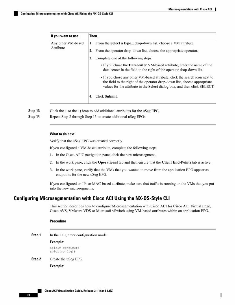
Then...If you want to use...
Any other VM-basedAttribute
1. From the Select a type... drop-down list, choose a VM attribute.
2. From the operator drop-down list, choose the appropriate operator.
3. Complete one of the following steps:
• If you chose the Datacenter VM-based attribute, enter the name of thedata center in the field to the right of the operator drop-down list.
• If you chose any other VM-based attribute, click the search icon next tothe field to the right of the operator drop-down list, choose appropriatevalues for the attribute in the Select dialog box, and then click SELECT.
4. Click Submit.
Step 13 Click the + or the +( icon to add additional attributes for the uSeg EPG.Step 14 Repeat Step 2 through Step 13 to create additional uSeg EPGs.
What to do next
Verify that the uSeg EPG was created correctly.
If you configured a VM-based attribute, complete the following steps:
1. In the Cisco APIC navigation pane, click the new microsegment.
2. In the work pane, click the Operational tab and then ensure that the Client End-Points tab is active.
3. In the work pane, verify that the VMs that you wanted to move from the application EPG appear asendpoints for the new uSeg EPG.
If you configured an IP- or MAC-based attribute, make sure that traffic is running on the VMs that you putinto the new microsegments.
Configuring Microsegmentation with Cisco ACI Using the NX-OS-Style CLIThis section describes how to configure Microsegmentation with Cisco ACI for Cisco ACI Virtual Edge,Cisco AVS, VMware VDS or Microsoft vSwitch using VM-based attributes within an application EPG.
Procedure
Step 1 In the CLI, enter configuration mode:
Example:apic1# configureapic1(config)#
Step 2 Create the uSeg EPG:
Example:
Cisco ACI Virtualization Guide, Release 3.1(1) and 3.1(2)70
Microsegmentation with Cisco ACIConfiguring Microsegmentation with Cisco ACI Using the NX-OS-Style CLI
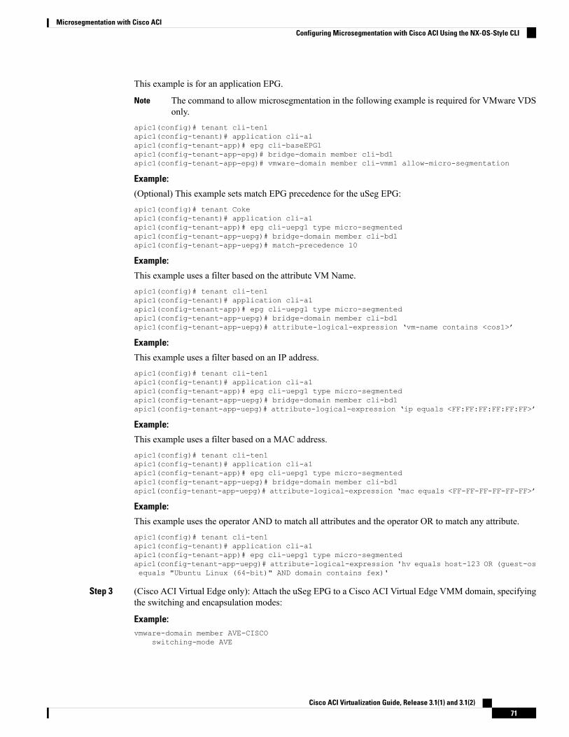
This example is for an application EPG.
The command to allow microsegmentation in the following example is required for VMware VDSonly.
Note
apic1(config)# tenant cli-ten1apic1(config-tenant)# application cli-a1apic1(config-tenant-app)# epg cli-baseEPG1apic1(config-tenant-app-epg)# bridge-domain member cli-bd1apic1(config-tenant-app-epg)# vmware-domain member cli-vmm1 allow-micro-segmentation
Example:
(Optional) This example sets match EPG precedence for the uSeg EPG:apic1(config)# tenant Cokeapic1(config-tenant)# application cli-a1apic1(config-tenant-app)# epg cli-uepg1 type micro-segmentedapic1(config-tenant-app-uepg)# bridge-domain member cli-bd1apic1(config-tenant-app-uepg)# match-precedence 10
Example:
This example uses a filter based on the attribute VM Name.apic1(config)# tenant cli-ten1apic1(config-tenant)# application cli-a1apic1(config-tenant-app)# epg cli-uepg1 type micro-segmentedapic1(config-tenant-app-uepg)# bridge-domain member cli-bd1apic1(config-tenant-app-uepg)# attribute-logical-expression ‘vm-name contains <cos1>’
Example:
This example uses a filter based on an IP address.apic1(config)# tenant cli-ten1apic1(config-tenant)# application cli-a1apic1(config-tenant-app)# epg cli-uepg1 type micro-segmentedapic1(config-tenant-app-uepg)# bridge-domain member cli-bd1apic1(config-tenant-app-uepg)# attribute-logical-expression ‘ip equals <FF:FF:FF:FF:FF:FF>’
Example:
This example uses a filter based on a MAC address.apic1(config)# tenant cli-ten1apic1(config-tenant)# application cli-a1apic1(config-tenant-app)# epg cli-uepg1 type micro-segmentedapic1(config-tenant-app-uepg)# bridge-domain member cli-bd1apic1(config-tenant-app-uepg)# attribute-logical-expression ‘mac equals <FF-FF-FF-FF-FF-FF>’
Example:
This example uses the operator AND to match all attributes and the operator OR to match any attribute.apic1(config)# tenant cli-ten1apic1(config-tenant)# application cli-a1apic1(config-tenant-app)# epg cli-uepg1 type micro-segmentedapic1(config-tenant-app-uepg)# attribute-logical-expression 'hv equals host-123 OR (guest-osequals "Ubuntu Linux (64-bit)" AND domain contains fex)'
Step 3 (Cisco ACI Virtual Edge only): Attach the uSeg EPG to a Cisco ACI Virtual Edge VMM domain, specifyingthe switching and encapsulation modes:
Example:vmware-domain member AVE-CISCO
switching-mode AVE
Cisco ACI Virtualization Guide, Release 3.1(1) and 3.1(2)71
Microsegmentation with Cisco ACIConfiguring Microsegmentation with Cisco ACI Using the NX-OS-Style CLI
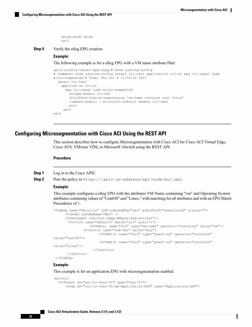
encap-mode vxlanexit
Step 4 Verify the uSeg EPG creation:
Example:
The following example is for a uSeg EPG with a VM name attribute filterapic1(config-tenant-app-uepg)# show running-config# Command: show running-config tenant cli-ten1 application cli-a1 epg cli-uepg1 typemicro-segmented # Time: Thu Oct 8 11:54:32 2015tenant cli-ten1application cli-a1epg cli-uepg1 type micro-segmentedbridge-domain cli-bd1attribute-logical-expression ‘vm-name contains cos1 force’{vmware-domain | microsoft-domain} member cli-vmm1exit
exitexit
Configuring Microsegmentation with Cisco ACI Using the REST APIThis section describes how to configure Microsegmentation with Cisco ACI for Cisco ACI Virtual Edge,Cisco AVS, VMware VDS, or Microsoft vSwitch using the REST API.
Procedure
Step 1 Log in to the Cisco APIC.Step 2 Post the policy to https://apic-ip-address/api/node/mo/.xml.
Example:
This example configures a uSeg EPG with the attributes VM Name containing "vm" and Operating Systemattributes containing values of "CentOS" and "Linux," with matching for all attributes and with an EPGMatchPrecedence of 1.<fvAEPg name="Security" isAttrBasedEPg="yes" pcEnfPref="unenforced" status="">
<fvRsBd tnFvBDName="BD1" /><fvRsDomAtt tDn="uni/vmmp-VMware/dom-mininet”/><fvCrtrn name="default" match=“all” prec=“1”>
<fvVmAttr name="foo" type="vm-name" operator="contains" value="vm"/><fvSCrtrn name="sub-def" match=“any”>
<fvVmAttr name="foo1" type="guest-os" operator="contains"value="CentOS"/>
<fvVmAttr name="foo2" type="guest-os" operator="contains"value="Linux"/>
</fvSCrtrn></fvCrtrn>
</fvAEPg>
Example:
This example is for an application EPG with microsegmentation enabled.<polUni><fvTenant dn="uni/tn-User-T1" name="User-T1">
<fvAp dn="uni/tn-User-T1/ap-Application-EPG" name="Application-EPG">
Cisco ACI Virtualization Guide, Release 3.1(1) and 3.1(2)72
Microsegmentation with Cisco ACIConfiguring Microsegmentation with Cisco ACI Using the REST API
<fvAEPg dn="uni/tn-User-T1/ap-Application-EPG/applicationEPG” name=“applicationEPG”pcEnfPref="enforced” >
<fvRsBd tnFvBDName="BD1" /><fvRsDomAtt tDn="uni/vmmp-VMware/dom-cli-vmm1" classPref=“useg”/>
</fvAEPg></fvAp>
</fvTenant></polUni>
In the example above, the string <fvRsDomAtt tDn="uni/vmmp-VMware/dom-cli-vmm1"classPref=“useg”/> is relevant only for VMware VDS and not for Cisco ACI Virtual Edge, CiscoAVS, or Microsoft vSwitch.
Example:
This example attaches a uSeg EPG to a Cisco ACI Virtual Edge VMM domain to add the switching mode.<fvRsDomAtt resImedcy="immediate" instrImedcy="immediate" switchingMode="AVE" encapMode="auto"tDn="uni/vmmp-VMware/dom-AVE-CISCO" primaryEncapInner="" secondaryEncapInner=""/>
Cisco ACI Virtualization Guide, Release 3.1(1) and 3.1(2)73
Microsegmentation with Cisco ACIConfiguring Microsegmentation with Cisco ACI Using the REST API

Cisco ACI Virtualization Guide, Release 3.1(1) and 3.1(2)74
Microsegmentation with Cisco ACIConfiguring Microsegmentation with Cisco ACI Using the REST API
C H A P T E R 5Intra-EPG Isolation Enforcement and Cisco ACI
This chapter contains the following sections:
• Intra-EPG Isolation for VMware VDS or Microsoft vSwitch, on page 75• Intra-EPG Isolation Enforcement for Cisco AVS, on page 80• Intra-EPG Isolation Enforcement for Cisco ACI Virtual Edge, on page 84
Intra-EPG Isolation for VMware VDS or Microsoft vSwitchIntra-EPG Isolation is an option to prevent physical or virtual endpoint devices that are in the same base EPGor uSeg EPG from communicating with each other. By default, endpoint devices included in the same EPGare allowed to communicate with one another. However, conditions exist in which total isolation of the endpointdevices from on another within an EPG is desirable. For example, you may want to enforce intra-EPG isolationif the endpoint VMs in the same EPG belong to multiple tenants, or to prevent the possible spread of a virus.
A Cisco ACI virtual machine manager (VMM) domain creates an isolated PVLAN port group at the VMwareVDS orMicrosoft vSwitch for each EPG that has intra-EPG isolation enabled. A fabric administrator specifiesprimary encapsulation or the fabric dynamically specifies primary encapsulation at the time of EPG-to-VMMdomain association. When the fabric administrator selects the VLAN-pri and VLAN-sec values statically, theVMM domain validates that the VLAN-pri and VLAN-sec are part of a static block in the domain pool.
When intra-EPG isolation is not enforced, the VLAN-pri value is ignored even if it is specified in theconfiguration.
Note
VLAN-pri/VLAN-sec pairs for the VMware VDS orMicrosoft vSwitch are selected per VMMdomain duringthe EPG-to-domain association. The port group created for the intra-EPG isolation EPGs uses the VLAN-sectagged with type set to PVLAN. The VMware VDS or the Microsoft vSwitch and fabric swap theVLAN-pri/VLAN-sec encapsulation:
• Communication from the Cisco ACI fabric to the VMware VDS or Microsoft vSwitch uses VLAN-pri.
• Communication from the VMware VDS or Microsoft vSwitch to the Cisco ACI fabric uses VLAN-sec.
Cisco ACI Virtualization Guide, Release 3.1(1) and 3.1(2)75
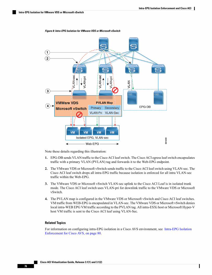
Figure 8: Intra-EPG Isolation for VMware VDS or Microsoft vSwitch
Note these details regarding this illustration:
1. EPG-DB sends VLAN traffic to the Cisco ACI leaf switch. The Cisco ACI egress leaf switch encapsulatestraffic with a primary VLAN (PVLAN) tag and forwards it to the Web-EPG endpoint.
2. The VMware VDS or Microsoft vSwitch sends traffic to the Cisco ACI leaf switch using VLAN-sec. TheCisco ACI leaf switch drops all intra-EPG traffic because isolation is enforced for all intra VLAN-sectraffic within the Web-EPG.
3. The VMware VDS or Microsoft vSwitch VLAN-sec uplink to the Cisco ACI Leaf is in isolated trunkmode. The Cisco ACI leaf switch uses VLAN-pri for downlink traffic to the VMware VDS or MicrosoftvSwitch.
4. The PVLAN map is configured in the VMware VDS or Microsoft vSwitch and Cisco ACI leaf switches.VM traffic fromWEB-EPG is encapsulated in VLAN-sec. The VMware VDS orMicrosoft vSwitch denieslocal intra-WEB EPGVM traffic according to the PVLAN tag. All intra-ESXi host or Microsoft Hyper-Vhost VM traffic is sent to the Cisco ACI leaf using VLAN-Sec.
Related Topics
For information on configuring intra-EPG isolation in a Cisco AVS environment, see Intra-EPG IsolationEnforcement for Cisco AVS, on page 80.
Cisco ACI Virtualization Guide, Release 3.1(1) and 3.1(2)76
Intra-EPG Isolation Enforcement and Cisco ACIIntra-EPG Isolation for VMware VDS or Microsoft vSwitch
Configuring Intra-EPG Isolation for VMware VDS or Microsoft vSwitch usingthe GUI
Procedure
Step 1 Log into Cisco APIC.Step 2 Choose Tenants > tenant.Step 3 In the left navigation pane expand the Application Profiles folder and appropriate application profile.Step 4 Right-click the Application EPGs folder and then choose Create Application EPG.Step 5 In the Create Application EPG dialog box, complete the following steps:
a) In the Name field, add the EPG name.b) In the Intra EPG Isolation area, click Enforced.c) In the Bridge Domain field, choose the bridge domain from the drop-down list.d) Associate the EPG with a bare metal/physical domain interface or with a VM Domain.
• For the VM Domain case, check the Associate to VM Domain Profiles check box.
• For the bare metal case, check the Statically Link with Leaves/Paths check box.
e) Click Next.f) In the Associated VM Domain Profiles area, click the + icon.g) From the Domain Profile drop-down list, choose the desired VMM domain.
For the static case, in the Port Encap (or Secondary VLAN for Micro-Seg) field, specify the secondaryVLAN, and in the Primary VLAN for Micro-Seg field, specify the primary VLAN. If the Encap fieldsare left blank, values will be allocated dynamically.
For the static case, a static VLAN must be available in the VLAN pool.Note
Step 6 Click Update and click Finish.
Configuring Intra-EPG Isolation for VMware VDS or Microsoft vSwitch usingthe NX-OS Style CLI
Procedure
Step 1 In the CLI, create an intra-EPG isolation EPG:
Example:
The following example is for VMware VDS:apic1(config)# tenant Test_Isolationapic1(config-tenant)# application PVLANapic1(config-tenant-app)# epg EPG1apic1(config-tenant-app-epg)# show running-config# Command: show running-config tenant Tenant_VMM application Web epg intraEPGDeny
Cisco ACI Virtualization Guide, Release 3.1(1) and 3.1(2)77
Intra-EPG Isolation Enforcement and Cisco ACIConfiguring Intra-EPG Isolation for VMware VDS or Microsoft vSwitch using the GUI
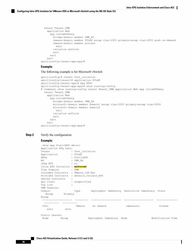
tenant Tenant_VMMapplication Webepg intraEPGDenybridge-domain member VMM_BDvmware-domain member PVLAN encap vlan-2001 primary-encap vlan-2002 push on-demandvmware-domain member mininetexit
isolation enforceexit
exitexit
apic1(config-tenant-app-epg)#
Example:
The following example is for Microsoft vSwitch:apic1(config)# tenant Test_Isolationapic1(config-tenant)# application PVLANapic1(config-tenant-app)# epg EPG1apic1(config-tenant-app-epg)# show running-config# Command: show running-config tenant Tenant_VMM application Web epg intraEPGDenytenant Tenant_VMMapplication Webepg intraEPGDenybridge-domain member VMM_BDmicrosoft-domain member domain1 encap vlan-2003 primary-encap vlan-2004microsoft-domain member domain2exit
isolation enforceexit
exitexit
apic1(config-tenant-app-epg)#
Step 2 Verify the configuration:
Example:show epg StaticEPG detailApplication EPg Data:Tenant : Test_IsolationApplication : PVLANAEPg : StaticEPGBD : VMM_BDuSeg EPG : noIntra EPG Isolation : enforcedVlan Domains : VMMConsumed Contracts : VMware_vDS-ExtProvided Contracts : default,Isolate_EPGDenied Contracts :Qos Class : unspecifiedTag List :VMM Domains:Domain Type Deployment Immediacy Resolution Immediacy State
Encap PrimaryEncap-------------------- --------- -------------------- -------------------- ------------------------ ----------DVS1 VMware On Demand immediate formed
auto auto
Static Leaves:Node Encap Deployment Immediacy Mode Modification Time
Cisco ACI Virtualization Guide, Release 3.1(1) and 3.1(2)78
Intra-EPG Isolation Enforcement and Cisco ACIConfiguring Intra-EPG Isolation for VMware VDS or Microsoft vSwitch using the NX-OS Style CLI
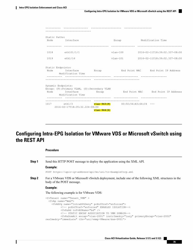
---------- ---------------- -------------------- ------------------------------------------------
Static Paths:Node Interface Encap Modification Time
---------- ------------------------------ ---------------- ------------------------------
1018 eth101/1/1 vlan-100 2016-02-11T18:39:02.337-08:00
1019 eth1/16 vlan-101 2016-02-11T18:39:02.337-08:00
Static Endpoints:Node Interface Encap End Point MAC End Point IP Address
Modification Time---------- ------------------------------ ---------------- ----------------------------------------------- ------------------------------
Dynamic Endpoints:Encap: (P):Primary VLAN, (S):Secondary VLANNode Interface Encap End Point MAC End Point IP Address
Modification Time---------- ------------------------------ ---------------- ----------------------------------------------- ------------------------------1017 eth1/3 vlan-943(P) 00:50:56:B3:64:C4 ---
2016-02-17T18:35:32.224-08:00vlan-944(S)
Configuring Intra-EPG Isolation for VMware VDS or Microsoft vSwitch usingthe REST API
Procedure
Step 1 Send this HTTP POST message to deploy the application using the XML API.
Example:POST https://apic-ip-address/api/mo/uni/tn-ExampleCorp.xml
Step 2 For a VMware VDS or Microsoft vSwitch deployment, include one of the following XML structures in thebody of the POST message.
Example:
The following example is for VMware VDS:<fvTenant name="Tenant_VMM" ><fvAp name="Web"><fvAEPg name="IntraEPGDeny" pcEnfPref="enforced">
<!-- pcEnfPref="enforced" ENABLES ISOLATION--><fvRsBd tnFvBDName="bd" /><!-- STATIC ENCAP ASSOCIATION TO VMM DOMAIN--><fvRsDomAtt encap="vlan-2001" instrImedcy="lazy" primaryEncap="vlan-2002"
resImedcy="immediate" tDn="uni/vmmp-VMware/dom-DVS1”>
Cisco ACI Virtualization Guide, Release 3.1(1) and 3.1(2)79
Intra-EPG Isolation Enforcement and Cisco ACIConfiguring Intra-EPG Isolation for VMware VDS or Microsoft vSwitch using the REST API
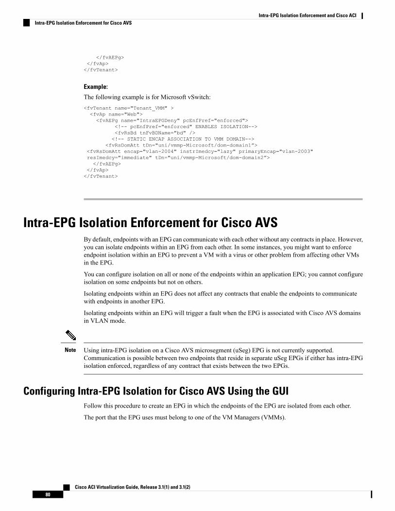
</fvAEPg></fvAp></fvTenant>
Example:
The following example is for Microsoft vSwitch:<fvTenant name="Tenant_VMM" ><fvAp name="Web"><fvAEPg name="IntraEPGDeny" pcEnfPref="enforced">
<!-- pcEnfPref="enforced" ENABLES ISOLATION--><fvRsBd tnFvBDName="bd" /><!-- STATIC ENCAP ASSOCIATION TO VMM DOMAIN-->
<fvRsDomAtt tDn="uni/vmmp-Microsoft/dom-domain1”><fvRsDomAtt encap="vlan-2004" instrImedcy="lazy" primaryEncap="vlan-2003"resImedcy="immediate" tDn="uni/vmmp-Microsoft/dom-domain2”></fvAEPg>
</fvAp></fvTenant>
Intra-EPG Isolation Enforcement for Cisco AVSBy default, endpoints with an EPG can communicate with each other without any contracts in place. However,you can isolate endpoints within an EPG from each other. In some instances, you might want to enforceendpoint isolation within an EPG to prevent a VM with a virus or other problem from affecting other VMsin the EPG.
You can configure isolation on all or none of the endpoints within an application EPG; you cannot configureisolation on some endpoints but not on others.
Isolating endpoints within an EPG does not affect any contracts that enable the endpoints to communicatewith endpoints in another EPG.
Isolating endpoints within an EPG will trigger a fault when the EPG is associated with Cisco AVS domainsin VLAN mode.
Using intra-EPG isolation on a Cisco AVS microsegment (uSeg) EPG is not currently supported.Communication is possible between two endpoints that reside in separate uSeg EPGs if either has intra-EPGisolation enforced, regardless of any contract that exists between the two EPGs.
Note
Configuring Intra-EPG Isolation for Cisco AVS Using the GUIFollow this procedure to create an EPG in which the endpoints of the EPG are isolated from each other.
The port that the EPG uses must belong to one of the VM Managers (VMMs).
Cisco ACI Virtualization Guide, Release 3.1(1) and 3.1(2)80
Intra-EPG Isolation Enforcement and Cisco ACIIntra-EPG Isolation Enforcement for Cisco AVS
This procedure assumes that you want to isolate endpoints within an EPG when you create the EPG. If youwant to isolate endpoints within an existing EPG, select the EPG in Cisco APIC, and in the Properties pane,in the Intra EPG Isolation area, choose Enforced, and then click SUBMIT.
Note
Before you begin
Make sure that Cisco AVS is in VXLAN mode.
Procedure
Step 1 Log in to Cisco APIC.Step 2 Choose Tenants, expand the folder for the tenant, and then expand the Application Profiles folder.Step 3 Right-click an application profile, and choose Create Application EPG.Step 4 In the Create Application EPG dialog box, complete the following actions:
a) In the Name field, enter the EPG name.b) In the Intra EPG Isolation area, click Enforced.c) From the Bridge Domain drop-down list, choose the bridge domain.d) Check the Associate to VM Domain Profiles check box.e) Click Next.f) In theAssociate VMDomain Profiles area, click the plus icon, and from theDomain Profile drop-down
list, choose the desired VMM domain.g) Click Update and click FINISH.
What to do next
You can select statistics and view them to help diagnose problems involving the endpoint. See the sectionsChoosing Statistics to View for Isolated Endpoints on Cisco AVS and Viewing Statistics for Isolated Endpointson Cisco AVS in this guide.
Configuring Intra-EPG Isolation for Cisco AVS Using the NX-OS Style CLI
Before you begin
Make sure that Cisco AVS is in VXLAN mode.
Procedure
In the CLI, create an intra-EPG isolation EPG:
Example:# Command: show running-configtenant TENANT1application APP1
Cisco ACI Virtualization Guide, Release 3.1(1) and 3.1(2)81
Intra-EPG Isolation Enforcement and Cisco ACIConfiguring Intra-EPG Isolation for Cisco AVS Using the NX-OS Style CLI
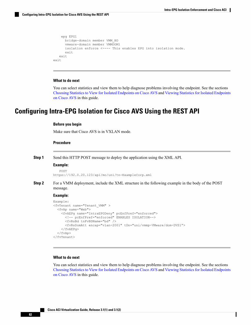
epg EPG1bridge-domain member VMM_BDvmware-domain member VMMDOM1isolation enforce <---- This enables EPG into isolation mode.exit
exitexit
What to do next
You can select statistics and view them to help diagnose problems involving the endpoint. See the sectionsChoosing Statistics to View for Isolated Endpoints on Cisco AVS and Viewing Statistics for Isolated Endpointson Cisco AVS in this guide.
Configuring Intra-EPG Isolation for Cisco AVS Using the REST API
Before you begin
Make sure that Cisco AVS is in VXLAN mode.
Procedure
Step 1 Send this HTTP POST message to deploy the application using the XML API.
Example:POST
https://192.0.20.123/api/mo/uni/tn-ExampleCorp.xml
Step 2 For a VMM deployment, include the XML structure in the following example in the body of the POSTmessage.
Example:Example:<fvTenant name="Tenant_VMM" ><fvAp name="Web"><fvAEPg name="IntraEPGDeny" pcEnfPref="enforced"><!-- pcEnfPref="enforced" ENABLES ISOLATION--><fvRsBd tnFvBDName="bd" /><fvRsDomAtt encap="vlan-2001" tDn="uni/vmmp-VMware/dom-DVS1”>
</fvAEPg></fvAp>
</fvTenant>
What to do next
You can select statistics and view them to help diagnose problems involving the endpoint. See the sectionsChoosing Statistics to View for Isolated Endpoints on Cisco AVS and Viewing Statistics for Isolated Endpointson Cisco AVS in this guide.
Cisco ACI Virtualization Guide, Release 3.1(1) and 3.1(2)82
Intra-EPG Isolation Enforcement and Cisco ACIConfiguring Intra-EPG Isolation for Cisco AVS Using the REST API
Choosing Statistics to View for Isolated Endpoints on Cisco AVSIf you configured intra-EPG isolation on a Cisco AVS, you need to choose statistics—such as deniedconnections, received packets, or transmitted multicast packets—for the endpoints before you can view them.
Procedure
Step 1 Log into Cisco APIC.Step 2 Choose Tenants > tenant.Step 3 In the tenant navigation pane, choose Application Profiles > profile > Application EPGs, and then choose
the EPG containing the endpoint the statistics for which you want to view.Step 4 In the EPG Properties work pane, click the Operational tab to display the endpoints in the EPG.Step 5 Double-click the endpoint.Step 6 In the Properties dialog box for the endpoint, click the Stats tab and then click the check icon.Step 7 In the Select Stats dialog box, in the Available pane, choose the statistics that you want to view for the
endpoint and then use the right-pointing arrow to move them into the Selected pane.Step 8 Click SUBMIT.
Viewing Statistics for Isolated Endpoints on Cisco AVSIf you configured intra-EPG isolation on a Cisco AVS, once you have chosen statistics for the endpoints, youcan view them.
Before you begin
You must have chosen statistics to view for isolated endpoints. See "Choosing Statistics to View for IsolatedEndpoints for Cisco AVS" in this guide for instructions.
Procedure
Step 1 Log into Cisco APIC.Step 2 Choose Tenants > tenant.Step 3 In the tenant navigation pane, choose Application Profiles > profile > Application EPGs, and then choose
the EPG containing the endpoint the statistics for which you want to view.Step 4 In the EPG Properties work pane, click the Stats tab to display the statistics for the EPG.
The central pane displays the statistics that you chose earlier. You can change the view by clicking the tableview or chart view icon on the upper right side of the work pane.
Cisco ACI Virtualization Guide, Release 3.1(1) and 3.1(2)83
Intra-EPG Isolation Enforcement and Cisco ACIChoosing Statistics to View for Isolated Endpoints on Cisco AVS
Intra-EPG Isolation Enforcement for Cisco ACI Virtual EdgeBy default, endpoints with an EPG can communicate with each other without any contracts in place. However,you can isolate endpoints within an EPG from each other. For example, you may want to enforce endpointisolation within an EPG to prevent a VM with a virus or other problem from affecting other VMs in the EPG.
You can configure isolation on all or none of the endpoints within an application EPG; you cannot configureisolation on some endpoints but not on others.
Isolating endpoints within an EPG does not affect any contracts that enable the endpoints to communicatewith endpoints in another EPG.
Enforcing intra-EPG Isolation is not supported for the EPG that is associated with Cisco ACI Virtual Edgedomains in VLAN mode. If you try to enforce intra-EPG isolation with such an EPG, a fault is triggered.
Note
Using intra-EPG isolation on a Cisco ACI Virtual Edge microsegment (uSeg) EPG is not currently supported.Note
Proxy ARP is not supported for Cisco ACI Virtual Edge EPGs using VXLAN encapsulation and on whichintra-EPG Isolation is enforced. Therefore, intra-subnet communication is not possible between intra-EPGisolated EPGs even though contracts are in place between those Cisco ACI Virtual Edge EPGs. (VXLAN).
Note
Configure Intra-EPG Isolation for Cisco ACI Virtual Edge Using the GUIFollow this procedure to create an EPG in which the endpoints of the EPG are isolated from each other.
The port that the EPG uses must belong to one of the VM Managers (VMMs).
This procedure assumes that you want to isolate endpoints within an EPG when you create the EPG. If youwant to isolate endpoints within an existing EPG, select the EPG in Cisco APIC, and in the Properties pane,in the Intra EPG Isolation area, choose Enforced, and then click SUBMIT.
Note
Before you begin
Make sure that VXLAN-related configuration is present on the Cisco ACI Virtual Edge VMM domain,particularly a Cisco ACI Virtual Edge fabric-wide multicast address and pool of multicast addresses (one perEPG).
Procedure
Step 1 Log in to Cisco APIC.
Cisco ACI Virtualization Guide, Release 3.1(1) and 3.1(2)84
Intra-EPG Isolation Enforcement and Cisco ACIIntra-EPG Isolation Enforcement for Cisco ACI Virtual Edge
Step 2 Choose Tenants, expand the folder for the tenant, and then expand the Application Profiles folder.Step 3 Right-click an application profile, and choose Create Application EPG.Step 4 In the Create Application EPG dialog box, complete the following steps:
a) In the Name field, enter the EPG name.b) In the Intra EPG Isolation area, click Enforced.c) From the Bridge Domain drop-down list, choose the bridge domain.d) Check the Associate to VM Domain Profiles check box.e) Click Next.f) In the Associate VM Domain Profiles area, complete the following steps:
• Click the + (plus) icon, and from the Domain Profile drop-down list, choose the desired Cisco ACIVirtual Edge VMM domain.
• From the Switching Mode drop-down list, choose AVE.
• From the Encap Mode drop-down list, choose VXLAN or Auto.
If you chooseAuto, make sure that encapsulationmode of the Cisco ACI Virtual Edge VMMdomainis VXLAN.
• (Optional) Choose other configuration options appropriate to your setup.
g) Click Update and click Finish.
What to do next
You can select statistics and view them to help diagnose problems involving the endpoint. See the sectionsChoose Statistics for Isolated Endpoints on Cisco ACI Virtual Edge Under the Tenants Tab, on page 87 andView Statistics for Isolated Endpoints on Cisco ACI Virtual Edge Under the Tenants Tab, on page 88 in thisguide.
Configure Intra-EPG Isolation for Cisco ACI Virtual Edge Using the NX-OS StyleCLI
Before you begin
Make sure that VXLAN-related configuration is present on the Cisco ACI Virtual Edge VMM domain,particularly a Cisco ACI Virtual Edge fabric-wide multicast address and pool of multicast addresses (one perEPG).
Procedure
In the CLI, create an intra-EPG isolation EPG:
Example:# Command: show running-config tenant Tenant2 application AP-1 epg EPG-61tenant Tenant2application AP-1epg EPG-61
Cisco ACI Virtualization Guide, Release 3.1(1) and 3.1(2)85
Intra-EPG Isolation Enforcement and Cisco ACIConfigure Intra-EPG Isolation for Cisco ACI Virtual Edge Using the NX-OS Style CLI
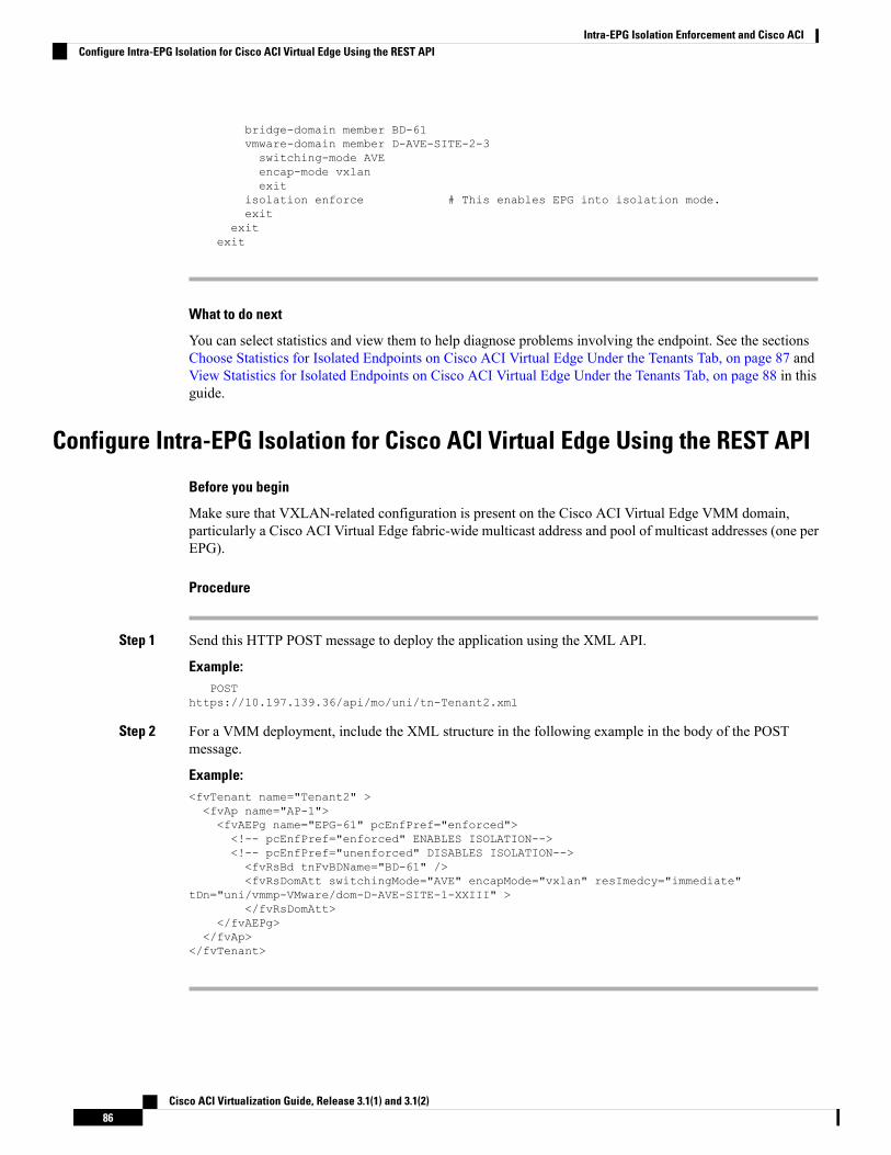
bridge-domain member BD-61vmware-domain member D-AVE-SITE-2-3switching-mode AVEencap-mode vxlanexit
isolation enforce # This enables EPG into isolation mode.exit
exitexit
What to do next
You can select statistics and view them to help diagnose problems involving the endpoint. See the sectionsChoose Statistics for Isolated Endpoints on Cisco ACI Virtual Edge Under the Tenants Tab, on page 87 andView Statistics for Isolated Endpoints on Cisco ACI Virtual Edge Under the Tenants Tab, on page 88 in thisguide.
Configure Intra-EPG Isolation for Cisco ACI Virtual Edge Using the REST API
Before you begin
Make sure that VXLAN-related configuration is present on the Cisco ACI Virtual Edge VMM domain,particularly a Cisco ACI Virtual Edge fabric-wide multicast address and pool of multicast addresses (one perEPG).
Procedure
Step 1 Send this HTTP POST message to deploy the application using the XML API.
Example:POST
https://10.197.139.36/api/mo/uni/tn-Tenant2.xml
Step 2 For a VMM deployment, include the XML structure in the following example in the body of the POSTmessage.
Example:<fvTenant name="Tenant2" ><fvAp name="AP-1"><fvAEPg name="EPG-61" pcEnfPref="enforced"><!-- pcEnfPref="enforced" ENABLES ISOLATION--><!-- pcEnfPref="unenforced" DISABLES ISOLATION--><fvRsBd tnFvBDName="BD-61" /><fvRsDomAtt switchingMode="AVE" encapMode="vxlan" resImedcy="immediate"
tDn="uni/vmmp-VMware/dom-D-AVE-SITE-1-XXIII" ></fvRsDomAtt>
</fvAEPg></fvAp>
</fvTenant>
Cisco ACI Virtualization Guide, Release 3.1(1) and 3.1(2)86
Intra-EPG Isolation Enforcement and Cisco ACIConfigure Intra-EPG Isolation for Cisco ACI Virtual Edge Using the REST API
What to do next
You can select statistics and view them to help diagnose problems involving the endpoint. See the sectionsChoose Statistics for Isolated Endpoints on Cisco ACI Virtual Edge Under the Tenants Tab, on page 87 andView Statistics for Isolated Endpoints on Cisco ACI Virtual Edge Under the Tenants Tab, on page 88 in thisguide.
Choose Statistics for Isolated Endpoints on Cisco ACI Virtual Edge Under theTenants Tab
If you configured intra-EPG isolation on a Cisco ACI Virtual Edge, choose statistics—such as deniedconnections, received packets, or transmitted multicast packets—for the endpoints. You can then view thestatistics.
Procedure
Step 1 Log in to Cisco APIC.Step 2 Choose Tenants > tenant.Step 3 In the tenant navigation pane, expand the Application Profiles, profile, and Application EPGs folders, and
then choose the EPG containing the endpoint the statistics for which you want to view.Step 4 In the EPG Properties work pane, click the Operational tab to display the endpoints in the EPG.Step 5 Double-click the endpoint.Step 6 In the Properties dialog box for the endpoint, click the Stats tab and then click the check icon.Step 7 In the Select Stats dialog box, in the Available pane, choose the statistics that you want to view for the
endpoint, and then use the right-pointing arrow to move them into the Selected pane.Step 8 Click Submit.
Choose Statistics for Isolated Endpoints on Cisco ACI Virtual Edge Under theVirtual Networking Tab
If you configured intra-EPG isolation on a Cisco ACI Virtual Edge, choose statistics—such as deniedconnections, received packets, or transmitted multicast packets—for the endpoints. You can then view thestatistics.
Procedure
Step 1 Log in to Cisco APIC.Step 2 Choose Virtual Networking > Inventory > VMM Domains > VMware > VMM domain > Controllers >
controller instance name > DVS-VMM name > Portgroups > EPG name > Learned Point MAC address(node) > .
Step 3 Click the Stats tab.Step 4 Click the tab with the check mark.
Cisco ACI Virtualization Guide, Release 3.1(1) and 3.1(2)87
Intra-EPG Isolation Enforcement and Cisco ACIChoose Statistics for Isolated Endpoints on Cisco ACI Virtual Edge Under the Tenants Tab
Step 5 In the Select Stats dialog box, click the statistics that you want to view in the Available pane, and then clickthe arrow pointing right to put them in the Selected pane.
Step 6 (Optional) Choose a sampling interval.Step 7 Click Submit.
View Statistics for Isolated Endpoints on Cisco ACI Virtual Edge Under theTenants Tab
If you configured intra-EPG isolation on a Cisco ACI Virtual Edge, once you have chosen statistics for theendpoints, you can view them.
Before you begin
You must have chosen statistics to view for isolated endpoints. See Choose Statistics for Isolated Endpointson Cisco ACI Virtual Edge Under the Tenants Tab, on page 87 in this guide for instructions.
Procedure
Step 1 Log in to Cisco APIC.Step 2 Choose Tenants > tenant.Step 3 In the tenant navigation pane, expand the Application Profiles, profile, and Application EPGs folders, and
then choose the EPG containing the endpoint with statistics that you want to view.Step 4 In the EPG Properties work pane, click the Operational tab to display the endpoints in the EPG.Step 5 Double-click the endpoint with statistics that you want to view.Step 6 In the Properties work pane for the endpoint, click the Stats tab.
The work pane displays the statistics that you chose earlier. You can change the view by clicking the tableview or chart view icon on the upper left side of the work pane.
View Statistics for Isolated Endpoints on Cisco ACI Virtual Edge Under theVirtual Networking Tab
If you configured intra-EPG isolation on a Cisco ACI Virtual Edge, once you have chosen statistics for theendpoints, you can view them.
Before you begin
You must have chosen statistics to view for isolated endpoints. See Choose Statistics for Isolated Endpointson Cisco ACI Virtual Edge Under the Tenants Tab, on page 87 in this guide for instructions.
Cisco ACI Virtualization Guide, Release 3.1(1) and 3.1(2)88
Intra-EPG Isolation Enforcement and Cisco ACIView Statistics for Isolated Endpoints on Cisco ACI Virtual Edge Under the Tenants Tab
Procedure
Step 1 Log in to Cisco APIC.Step 2 Choose Virtual Networking > Inventory > VMM Domains > VMware > VMM name > Controllers >
controller instance name > DVS-VMM name > Portgroups > EPG name > Learned Point MAC address(node)
Step 3 Click the Stats tab.The central pane displays the statistics that you chose earlier. You can change the view by clicking the tableview or chart view icon on the upper left side of the work pane.
Cisco ACI Virtualization Guide, Release 3.1(1) and 3.1(2)89
Intra-EPG Isolation Enforcement and Cisco ACIView Statistics for Isolated Endpoints on Cisco ACI Virtual Edge Under the Virtual Networking Tab

Cisco ACI Virtualization Guide, Release 3.1(1) and 3.1(2)90
Intra-EPG Isolation Enforcement and Cisco ACIView Statistics for Isolated Endpoints on Cisco ACI Virtual Edge Under the Virtual Networking Tab
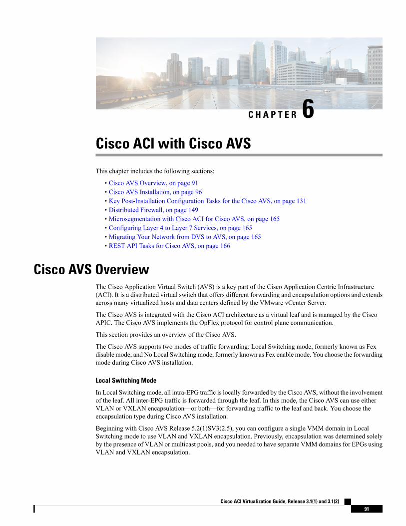
C H A P T E R 6Cisco ACI with Cisco AVS
This chapter includes the following sections:
• Cisco AVS Overview, on page 91• Cisco AVS Installation, on page 96• Key Post-Installation Configuration Tasks for the Cisco AVS, on page 131• Distributed Firewall, on page 149• Microsegmentation with Cisco ACI for Cisco AVS, on page 165• Configuring Layer 4 to Layer 7 Services, on page 165• Migrating Your Network from DVS to AVS, on page 165• REST API Tasks for Cisco AVS, on page 166
Cisco AVS OverviewThe Cisco Application Virtual Switch (AVS) is a key part of the Cisco Application Centric Infrastructure(ACI). It is a distributed virtual switch that offers different forwarding and encapsulation options and extendsacross many virtualized hosts and data centers defined by the VMware vCenter Server.
The Cisco AVS is integrated with the Cisco ACI architecture as a virtual leaf and is managed by the CiscoAPIC. The Cisco AVS implements the OpFlex protocol for control plane communication.
This section provides an overview of the Cisco AVS.
The Cisco AVS supports two modes of traffic forwarding: Local Switching mode, formerly known as Fexdisable mode; and No Local Switchingmode, formerly known as Fex enable mode. You choose the forwardingmode during Cisco AVS installation.
Local Switching Mode
In Local Switching mode, all intra-EPG traffic is locally forwarded by the Cisco AVS, without the involvementof the leaf. All inter-EPG traffic is forwarded through the leaf. In this mode, the Cisco AVS can use eitherVLAN or VXLAN encapsulation—or both—for forwarding traffic to the leaf and back. You choose theencapsulation type during Cisco AVS installation.
Beginning with Cisco AVS Release 5.2(1)SV3(2.5), you can configure a single VMM domain in LocalSwitching mode to use VLAN and VXLAN encapsulation. Previously, encapsulation was determined solelyby the presence of VLAN or multicast pools, and you needed to have separate VMM domains for EPGs usingVLAN and VXLAN encapsulation.
Cisco ACI Virtualization Guide, Release 3.1(1) and 3.1(2)91
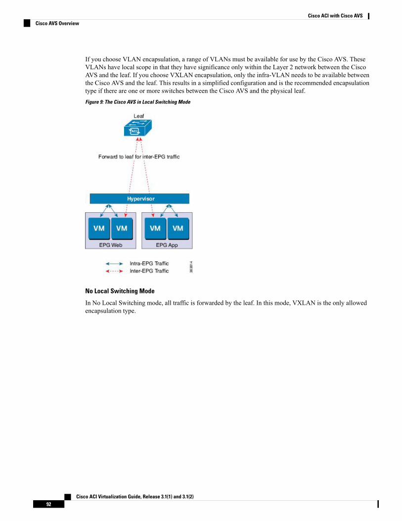
If you choose VLAN encapsulation, a range of VLANs must be available for use by the Cisco AVS. TheseVLANs have local scope in that they have significance only within the Layer 2 network between the CiscoAVS and the leaf. If you choose VXLAN encapsulation, only the infra-VLAN needs to be available betweenthe Cisco AVS and the leaf. This results in a simplified configuration and is the recommended encapsulationtype if there are one or more switches between the Cisco AVS and the physical leaf.Figure 9: The Cisco AVS in Local Switching Mode
No Local Switching Mode
In No Local Switching mode, all traffic is forwarded by the leaf. In this mode, VXLAN is the only allowedencapsulation type.
Cisco ACI Virtualization Guide, Release 3.1(1) and 3.1(2)92
Cisco ACI with Cisco AVSCisco AVS Overview
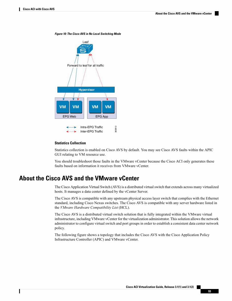
Figure 10: The Cisco AVS in No Local Switching Mode
Statistics Collection
Statistics collection is enabled on Cisco AVS by default. You may see Cisco AVS faults within the APICGUI relating to VM resource use.
You should troubleshoot those faults in the VMware vCenter because the Cisco ACI only generates thesefaults based on information it receives from VMware vCenter.
About the Cisco AVS and the VMware vCenterThe Cisco Application Virtual Switch (AVS) is a distributed virtual switch that extends across many virtualizedhosts. It manages a data center defined by the vCenter Server.
The Cisco AVS is compatible with any upstream physical access layer switch that complies with the Ethernetstandard, including Cisco Nexus switches. The Cisco AVS is compatible with any server hardware listed inthe VMware Hardware Compatibility List (HCL).
The Cisco AVS is a distributed virtual switch solution that is fully integrated within the VMware virtualinfrastructure, including VMware vCenter for the virtualization administrator. This solution allows the networkadministrator to configure virtual switch and port groups in order to establish a consistent data center networkpolicy.
The following figure shows a topology that includes the Cisco AVS with the Cisco Application PolicyInfrastructure Controller (APIC) and VMware vCenter.
Cisco ACI Virtualization Guide, Release 3.1(1) and 3.1(2)93
Cisco ACI with Cisco AVSAbout the Cisco AVS and the VMware vCenter
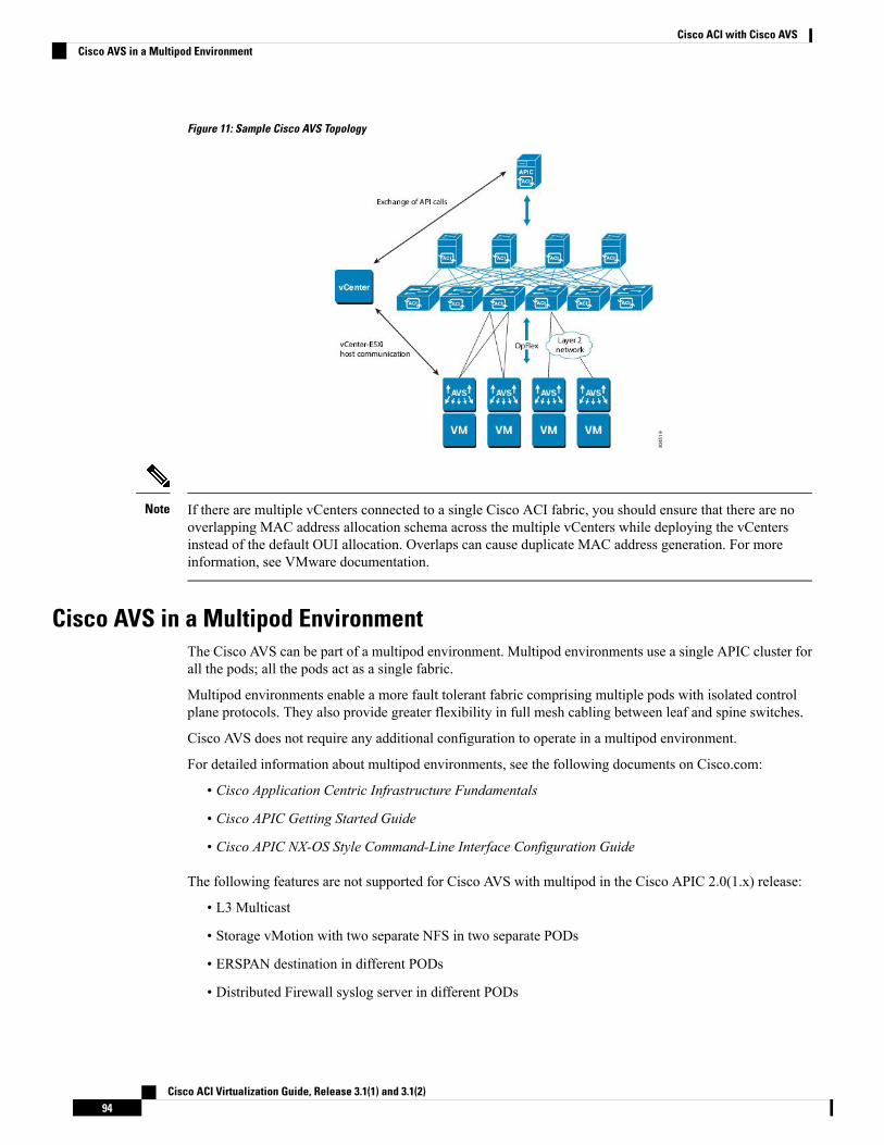
Figure 11: Sample Cisco AVS Topology
If there are multiple vCenters connected to a single Cisco ACI fabric, you should ensure that there are nooverlapping MAC address allocation schema across the multiple vCenters while deploying the vCentersinstead of the default OUI allocation. Overlaps can cause duplicate MAC address generation. For moreinformation, see VMware documentation.
Note
Cisco AVS in a Multipod EnvironmentThe Cisco AVS can be part of a multipod environment. Multipod environments use a single APIC cluster forall the pods; all the pods act as a single fabric.
Multipod environments enable a more fault tolerant fabric comprising multiple pods with isolated controlplane protocols. They also provide greater flexibility in full mesh cabling between leaf and spine switches.
Cisco AVS does not require any additional configuration to operate in a multipod environment.
For detailed information about multipod environments, see the following documents on Cisco.com:
• Cisco Application Centric Infrastructure Fundamentals
• Cisco APIC Getting Started Guide
• Cisco APIC NX-OS Style Command-Line Interface Configuration Guide
The following features are not supported for Cisco AVS with multipod in the Cisco APIC 2.0(1.x) release:
• L3 Multicast
• Storage vMotion with two separate NFS in two separate PODs
• ERSPAN destination in different PODs
• Distributed Firewall syslog server in different PODs
Cisco ACI Virtualization Guide, Release 3.1(1) and 3.1(2)94
Cisco ACI with Cisco AVSCisco AVS in a Multipod Environment
Required SoftwareThe following table shows the versions of software you need to install for Cisco Application Virtual Switch(AVS) to work with the Cisco Application Policy Infrastructure Controller (APIC), VMware vCenter, andVMware ESXi hypervisor:
DescriptionComponent
Cisco AVS is supported in Release 4.2(1)SV2(2.3) and later releases.However, Release 5.2(1)SV3(1.5) or later is required if you want touse Distributed Firewall and Microsegmentation with Cisco AVS.
Cisco AVS software
See the Cisco AVS Release Notes for compatibility information.However, version 1.1(1j) or later is required with Cisco AVS5.2(1)SV3(1.5) or later if you want to use Distributed Firewall andMicrosegmentation with Cisco AVS.
Cisco APIC
Cisco AVS is compatible with release 5.5, 6.0, or 6.5 of VMwarevCenter Server.
VMware vCenter
Cisco AVS is supported as a vLeaf for the Cisco APIC with release 5.5and later releases of the VMware ESXi hypervisor.
When you choose a Cisco AVS VIB, you need to choosethe one compatible with the version of VMware ESXihypervisor that you use. ESXi 5.5 uses xxix.3.2.1.vib, ESXi6.0 uses xxxx.6.0.1.vib, and ESXi 6.5 uses xxxx.6.5.1.vib.
Note
VMware vSphere bare metal
Cisco AVS is supported in VSUM Release 1.0 and later releases.Cisco Virtual Switch UpdateManager (VSUM)
Cisco AVS DocumentationYou can find documentation on the Cisco Application Virtual Switch page on Cisco.com.
Documentation for Cisco Application Virtual Switch (AVS) includes:
• Cisco Application Virtual Switch Release Notes
• Cisco Application Virtual Switch Documentation Overview
• Cisco Application Virtual Switch Installation Guide
• Cisco Application Virtual Switch Download Instructions for VMware ESXi Deployments
• Cisco Application Virtual Switch Configuration Guide
• Cisco Application Virtual Switch Verified Scalability Guide
• Cisco Application Virtual Switch Solution Guide
• Cisco Application Virtual Switch Troubleshooting Guide
• Cisco Virtual Switch Update Manager Getting Started Guide
• Cisco Virtual Switch Update Manager Release Notes
Cisco ACI Virtualization Guide, Release 3.1(1) and 3.1(2)95
Cisco ACI with Cisco AVSRequired Software
• Cisco Virtual Switch Update Manager Troubleshooting Guide
Cisco AVS InstallationInstalling the Cisco Application Virtual Switch (AVS) consists of two separate sets of tasks: configuring theCisco Application Policy Infrastructure Controller (APIC) and then installing Cisco AVS using the CiscoVirtual Switch Update Manager (VSUM), the ESXi CLI, or the VMware Virtual Update Manager (VUM).You also must verify the installation.
This section provides the instructions for each set of tasks that you need to perform to install Cisco AVS touse within the Cisco Application Centric Infrastructure (ACI) fabric.
Workflow for Installing the Cisco AVSThis section provides a high-level description of the tasks that you need to perform in order to install the CiscoAVS.
1. Create interface and switch policies and a VMware vCenter domain profile for the Cisco AVS in theunified configuration wizard in the Cisco Application Policy Infrastructure Controller (APIC) GUI.
An interface policy configures the type of interface—port channel (PC) or virtual PC (VPC)—for thevSphere hosts and a link aggregation control protocol (LACP), or MAC pinning. See the appendix"Recommended Topologies" in the Cisco Application Virtual Switch Installation Guide for supportedtopologies.
A switch policy configures the connection between the Cisco AVS (the vLeaf) and the ESXi hypervisorby specifying a physical port on the leaf switch and by specifying Cisco AVS trunk settings. These includeVLANs or VXLANs.
A VMware vCenter domain groups virtual machine (VM) controllers with similar networking policyrequirements. For example, VM controllers can share VLAN or Virtual Extensible Local Area Network(VXLAN) space and application endpoint groups (EPGs). The Cisco APIC communicates with thecontroller to publish network configurations such as port groups that are then applied to the virtualworkloads.
See the section Creating Interface and Switch Profiles and a vCenter Domain Profile Using the GUI inthis guide for instructions.
2. Install the Cisco AVS and add the ESXi host to the Cisco AVS.
You can connect a single ESX or ESXi host to only one Cisco AVS at a time. You cannot add multiple CiscoAVS to a single ESX or ESXi host.
Note
Using Cisco VSUM is the recommended method for installing the Cisco AVS. Using Cisco VSUMvalidates the version and compatibility for the ESXi host, and in one procedure enables you to install theCisco AVS onto the ESXi host and add the ESXi host to the Cisco AVS distributed virtual switch (DVS).
See the section Installing the Cisco AVS Using Cisco VSUM in this guide for instructions for installingthe Cisco AVS using VSUM.
Cisco ACI Virtualization Guide, Release 3.1(1) and 3.1(2)96
Cisco ACI with Cisco AVSCisco AVS Installation
However, you can install Cisco AVS using the VMware vCenter plug-in. You should use the vCenterplug-in to install Cisco AVS only if you are already using it to perform other tasks or if you plan to doso. See Installing Cisco AVS Using the VMware vCenter Plug-in, on page 107 in this guide.
You also can install Cisco AVS using the ESXi CLI or VMware Virtual Update Manager (VUM). Youmight want to do so if you have one or few Cisco AVS. See Installing the Cisco AVS Software Using theESXi CLI, on page 126 in this guide or "Installing the Cisco AVS Software Using VMware VUM" in theCisco Application Virtual Switch Installation Guide for instructions.
3. Verify the Cisco AVS Installation.
You need to verify that the Cisco AVS has been installed on the VMware ESXi hypervisor by verifyingthe virtual switch status and the virtual NIC status. You also need to verify that the vmknic is created,that OpFlex is online, and that the ports are in a forwarding state.
See the section Verifying the Cisco AVS Installation in this guide for instructions.
4. Add hosts to the Cisco AVS.
Once you have installed the Cisco AVS, you can add hosts, one at a time, to it.
See the section Adding Cisco AVS Hosts to the DVS, on page 129 in this guide for instructions.
Creating Interface, Switch, and vCenter Domain ProfilesBefore you can install the Cisco AVS, you need to create interface, switch, and vCenter domain profiles. Asof Cisco APIC 1.1.x, we recommend that you perform these tasks in the united configuration wizard in theCisco APIC. This is the procedure Creating Interface and Switch Profiles and a vCenter Domain Profile Usingthe GUI in this guide.
You should understand and follow the guidelines in this section before proceeding with the tasks.
Alternate Procedures
If you need to configure a FEX profile or detailed interface, switch, or vCenter domain profiles, you can findinstructions in Appendix C, "Procedures for Creating Interface, Switch, and vCenter Domain Profiles" in theCisco Application Virtual Switch Installation Guide.
Firewall Considerations
If you use the recommended united configuration wizard, the Cisco APIC automatically creates a firewallpolicy, which can be modified later. If you instead use the alternate procedures to create interface, switch, orvCenter domain profiles, you will need to create a firewall policy manually. Follow the instructions in theDistributed Firewall section of this guide.
Interface and Switch Profile Guidelines and PrerequisitesFollow these guidelines and fulfil the prerequisites when creating interface and switch profiles for your CiscoAVS.
Guidelines for Creating Interface and Switch Profiles
The Cisco AVS supports PC, VPC, MAC Pinning, and FEX interface policies. It does not support individualinterface policies. See the Cisco Application Virtual Switch Installation Guide for information about FEXpolicies.
Cisco ACI Virtualization Guide, Release 3.1(1) and 3.1(2)97
Cisco ACI with Cisco AVSCreating Interface, Switch, and vCenter Domain Profiles
• If there is a Layer 2 network between the leaf switch and the Cisco AVS vSphere host, configure theinterface policy on the interfaces that are connected to the Layer 2 network.
• The number of links and leafs that you use determine whether you need to configure a PC or a VPCpolicy for the Cisco AVS:
• If you are using a single link between a leaf and an ESXi host, you need to configure a PC policy.
• If you are using multiple links between one leaf and an ESXi host, you must configure a PC policy.
• If you are using multiple links between multiple leafs and an ESXi host, you must configure a VPCpolicy.
• Follow these guidelines for choosing a LACP policy:
• Choose LACP (Active or Passive) if the uplinks from the Cisco AVS (vSphere host) are directlyconnected to the leaf switches and you want to use or turn on the LACP channeling protocol.
• Choose Static Channel - Mode On if the uplinks form the Cisco AVS are directly connected to theleaf switches but you do not want to use the LACP channeling protocol, for example, static portchannel.
• Choose MAC Pinning if the uplinks from the Cisco AVS should not be channeled together and willoperate as separate links.
Prerequisites for Creating Interface and Switch Profiles
You should verify that the leaf switch interfaces are physically connected to the ESXi hypervisor or, if youare using a Layer 2 device, verify that the leaf is physically connected to the Layer 2 device.
vCenter Domain Profile Guidelines and PrerequisitesYou must create a new vCenter domain profile; you cannot convert an existing one. For information aboutdeleting an existing VMware vCenter domain profile, see the section "Guidelines for Deleting VMMDomains"in Cisco Application Centric Infrastructure Fundamentals.
Guidelines for Creating a VMware vCenter Domain Profile
You can create multiple data centers and DVS entries under a single domain. However, you can have onlyone Cisco AVS assigned to each data center.
If you choose VXLAN encapsulation and MAC pinning link aggregation, we recommend that you enableVXLAN load balancing. See the section “Enabling VXLAN load balancing” in the Cisco Application VirtualSwitch Configuration Guide.
VXLAN load balancing is enabled by default. However, to use it effectively, you need to configure additionalVMK NICs to match the number of PNICs.
Note
Beginning with Cisco AVS Release 5.2(1)SV3(1.15), you can use IPv6 when creating a VMM domain,provided that the vCenter and ESXi host management are IPv6-enabled.
Cisco ACI Virtualization Guide, Release 3.1(1) and 3.1(2)98
Cisco ACI with Cisco AVSvCenter Domain Profile Guidelines and Prerequisites
Prerequisites for Creating a VMware vCenter Domain Profile
Make sure that the multicast IP address pool has enough multicast IP addresses to accommodate the numberof EPGs that will be published to the VMware vCenter domain. You can add more IP addresses to a multicastaddress pool that is already associated with a VMware vCenter domain at any time.
Make sure that you have a sufficient number of VLAN IDs. If you do not, ports on endpoint groups (EPGs)might report that no encapsulation is available.
If you want to change the switch mode on a Cisco AVS, you first must remove the existing DVS and thenadd the VMware vCenter domain with the desired switching mode. For instructions on removing the existingDVS, see Cisco Application Virtual Switch Configuration Guide.
vCenter must be installed, configured, and reachable through the in-band/out-of-band management network.
You must have the administrator/root credentials to the vCenter.
If you prefer not to use the vCenter administrator/root credentials, you can create a custom user account withminimum required permissions. See Custom User Account with Minimum VMware vCenter Privileges, onpage 39 for a list of the required user privileges.
Note
Creating Interface and Switch Profiles and a vCenter Domain Profile Using the GUIBasic mode is deprecated after Cisco APIC Release 3.0(1). Cisco does not recommend using Basic mode forconfiguration. However, if you want to use Basic mode, use the following URL: APICURL/indexSimple.html
Caution: Cisco recommends that you do not mix configuration modes (Advanced or Basic). When you makea configuration in either mode and change the configuration using the other mode, unintended changes canoccur. For example, if you apply an interface policy to two ports using Advanced mode and then change thesettings of one port using Basic mode, your changes might be applied to both ports.
If you want to choose a delimiter for the VMware PortGroup name when you create a vCenter domain, youcannot do so in this procedure, which uses the configuration wizard. Instead, you must create the vCenterdomain separately; the delimiter option appears in theCreate vCenter Domain dialog box. See the procedure"Creating a VMware vCenter Domain Profile" in the Cisco Application Virtual Switch Installation Guide.
Note
Before you begin
Before you create a vCenter domain profile, you must establish connectivity to external network using in-bandmanagement network on the Cisco APIC.
Procedure
Step 1 Log into the Cisco APIC.Step 2 On the menu bar, click Fabric > Access Policies.Step 3 In the Policies Navigation pane, right-click Switch Policies, and then click Configure Interfaces, PC, and
VPC.
Cisco ACI Virtualization Guide, Release 3.1(1) and 3.1(2)99
Cisco ACI with Cisco AVSCreating Interface and Switch Profiles and a vCenter Domain Profile Using the GUI
Step 4 In the Configure Interfaces, PC, and VPC dialog box, expand Configured Switch Interfaces, click thegreen + icon, and then perform the following steps:a) In the Select Switches to Configure Interfaces area, make sure that the Quick radio button is selected.b) From the Switches drop-down list, choose the appropriate leaf ID.
In the Switch Profile Name field, the switch profile name automatically appears.
c) Click the green + icon again.
The Configure Interfaces, PC, and VPC dialog box displays a wizard that enables you to configureinterface, switch, and vCenter domain profiles.
Step 5 In the wizard, perform the following actions:a) In the Interface Type area, choose the appropriate radio button.
PC or VPC are the only valid options for Cisco AVS deployment. See the section Interface and SwitchProfile Guidelines and Prerequisites in this guide.
b) In the Interfaces field, enter the interface or interface range for your vSphere hosts.
Once you enter the interface or interface range, the wizard enters a name in the Interface SelectorName field.
c) In the Interface Policy Group area, choose the Create One radio button.
This procedure assumes that you are creating interface and switch policies and creating avCenter domain from scratch. If you choose the Choose One radio button, you will not beable to do so in the wizard.
Note
d) From the CDP Policy or the LLDP Policy drop-down list, create a policy.
If you use a Cisco Unified Computing System (UCS) server, create a policy to enable a CiscoDiscovery Protocol (CDP) policy and a policy to disable Link Layer Discovery Protocol(LLDP).
Note
Beginning with Cisco AVS Release 5.2(1)SV3(1.15), CDP and LLDP policies are disabledby default. You must enable them in the configuration wizard. Enable CDP or LLDP policiesin the Interface Policy Group area to enable them on Cisco AVS and other switches in thefabric. If you want to enable CDP or LLDP only on Cisco AVS, enable them in the vSwitchPolicy area of the configuration wizard.
Note
e) From the Link Level Policy drop-down list, choose the desired link level policy or create one.The link level policy specifies the speed of the physical interface. If you do not choose a link levelpolicy, the speed will default to 10 Gbps.
f) In the Port Channel Policy drop-down list, choose Create Port Channel Policy.
You need to choose the same policy that is on the ESXi server. For example, if the server does notsupport LACP, you can choose Static Channel - Mode On orMAC Pinning.
g) In the Attached Device Type area, choose AVS VLAN Hosts or AVS VXLAN Hosts.
If the hypervisors are directly connected to leaf switches, you can use either VLAN or VXLAN.(Cisco UCS blade servers, where Fabric Interconnects are connected to the fabric, areconsidered to be directly connected.) However, if the hypervisors are not directly connectedto leaf switches, you must use VXLAN. For more information, see the Cisco AVS Overviewsection.
Note
Cisco ACI Virtualization Guide, Release 3.1(1) and 3.1(2)100
Cisco ACI with Cisco AVSCreating Interface and Switch Profiles and a vCenter Domain Profile Using the GUI
h) In the Domain area, make sure that the Create One radio button is chosen.
The Create One option is used when creating a new VMM domain for an interface or switch profile,as you do in this procedure. TheChoose One button is used when creating an interface or switch profilefor a new host that you want to make part of an existing VMM domain.
i) In the Domain Name field, enter the domain name.
When you create the VMMdomain, you choose VLAN or VXLAN encapsulation, dependingon the attached device type you chose in Step 5g. However, beginning with Cisco AVSRelease5.2(1)SV3(2.5), you can configure a single VMM domain to use VLAN and VXLANencapsulation. After you finish installing the Cisco AVS, you can enable mixed encapsulationmode. See the section "Mixed-Mode Encapsulation Configuration" in the Cisco ApplicationVirtual Switch Configuration Guide.
Note
j) If you chose AVS VLAN Hosts in Step 5 g, in the VLAN Range field, enter the VLAN range asappropriate.
Do not define a range that includes the reserved VLAN ID for infrastructure network becausethat VLAN is for internal use.
Note
k) If you chose AVS VXLAN Hosts in Step 5 g, in the Fabric Multicast Address field, enter an address,such as 225.1.1.1.
l) If you chose AVS VXLAN Hosts in Step 5 g, in the Pool of Multicast Address Ranges field, createa new multicast pool or choose an existing one.
The multicast address configured in Step 5 l must not overlap with the ranges configured inStep 5 m.
Note
m) If you chose AVS VXLAN Hosts in Step 5 g, in the Local Switching area, choose True or False.With local switching, traffic within an endpoint group (EPG) does not go to the leaf, so if you chooselocal switching, you might not see some traffic counters. If you want to see all intra-EPG traffic, youshould choose False. See the section Cisco AVS Overview for additional information about LocalSwitching and No Local Switching modes.
n) (Optional) From the Security Domains drop-down list, choose or create a security domain.o) In the vCenter Login Name field, enter the vCenter Administrator/root username.p) In the Password field, enter the vCenter Administrator/root password.q) In the Confirm Password field, reenter the password.
Step 6 Click the + icon to expand vCenter, and in theCreate vCenter Controller dialog box, perform the followingactions:a) In the Name field, enter a name to refer to the vCenter domain.
The name does not need to be the same as the vCenter domain name; you can use the vCenter host name.
b) In the Host Name (or IP Address) field, enter the host name or IP address.
If you use the host name, you must already have configured a DNS policy on Cisco APIC. If you do nothave a DNS policy configured, enter the IP address of the vCenter server.
c) From the DVS Version drop-down list, choose a DVS version.
The DVS version that you choose represents the minimum ESXi version of the host that can be added tothe virtual switch. So if you choose DVS version 5.5, you can add or manage hosts of ESXI version 5.5and later.
d) In the Datacenter field, enter the data center name.
Cisco ACI Virtualization Guide, Release 3.1(1) and 3.1(2)101
Cisco ACI with Cisco AVSCreating Interface and Switch Profiles and a vCenter Domain Profile Using the GUI
The name that you enter for Datacenter must match exactly the name in vCenter. The name iscase sensitive.
Note
e) Click OK.
For the following three steps, if you do not specify port channel, vSwitch, or interface controlpolicies, the same interface policy that you configured earlier in this procedure will take effectfor the vSwitch.
Note
f) From the Port Channel Mode drop-down list, choose a mode.
ChooseMACPinning if you have a Unified Computing System (UCS) Fabric Interconnect (FI) betweenthe top-of-rack switch and the Cisco AVS.
g) In the vSwitch Policy area, choose a policy.h) In the Interface Controls area, choose BPDU Guard, BPDU Filter, or both.i) From the Firewall drop-down list, choose Learning, Enabled or Disabled mode.
Learning mode, the default, should be used only when upgrading from a version of Cisco AVS that doesnot support Distributed Firewall to a version that does. Otherwise, Distributed Firewall should be inEnabled mode.You can change the Distributed Firewall mode later. See the section Creating a DistributedFirewall Policy or Changing its Mode Using the GUI in this guide for instructions.
Step 7 In the Configure Interface, PC, And VPC dialog box, click SAVE, click SAVE again, and then clickSUBMIT.
Step 8 Verify the new domain and profiles, by performing the following actions:a) On the menu bar, choose Virtual Networking > Inventory.b) In the navigation pane, expand VMM Domains > VMware > Domain_name > Controllers, and then
choose the vCenter.In the work pane, under Properties, view the virtual machine manager (VMM) domain name to verify thatthe controller is online. In the work pane, the vCenter properties are displayed including the operational status.The displayed information confirms that connection from the APIC controller to the vCenter server isestablished, and the inventory is available.
Configuring vSwitch Override Policies on the VMM Domain Using the GUIBefore installing Cisco AVS, you can use the configuration wizard to create a VMware vCenter profile andcreate interface policy group policies for Cisco AVS. You also can create vSwitch policies that override theinterface policy group policies and apply a different policy for the leaf.
However, if you did not use the configuration wizard—or if you used the configuration wizard but did notconfigure a vSwitch override policy—you can configure a vSwitch override policy by following the procedurein this section.
In Cisco AVS 5.2(1)SV3(1.10), you cannot create a Distributed Firewall policy on the vSwitch using theconfiguration wizard. See the section Configuring Distributed Firewall in this guide for instructions forconfiguring a Distributed Firewall policy and associating it to the VMM domain.
Note
Cisco ACI Virtualization Guide, Release 3.1(1) and 3.1(2)102
Cisco ACI with Cisco AVSConfiguring vSwitch Override Policies on the VMM Domain Using the GUI
Previously, you could configure a vSwitch override policy through the Fabric tab as well as the VirtualNetworking tab. Override policies configured through theVirtual Networking tab took precedence. However,any override policy configured through the Fabric tab stands until it is reconfigured through the VirtualNetworking tab.
Note
Before you begin
We recommend that you already have created access policies and an attachable access entity profile for CiscoAVS.
Procedure
Step 1 Log in to the Cisco APIC.Step 2 Go to Virtual Networking > Inventory > VMM Domains > VMware.Step 3 In the navigation pane, choose the relevant VMM domain.Step 4 In the VMM domain work pane, scroll to theVSwitch Policies area, and from the appropriate vSwitch policy
drop-down list, choose the policy that you want to apply as an override policy.Step 5 Click Submit.
What to do next
Verify that the policies are in effect on Cisco AVS.
Pre-Cisco AVS Installation Configuration Using the NX-OS Style CLIYou can perform some pre-Cisco AVS installation configuration tasks using the NX-OS style CLI.
Creating a VLAN Domain Using the NX-OS Style CLI
Procedure
Create a VLAN domain.
Example:
Configuring a VLAN domain with static allocation:apic1# configureapic1(config)# vlan-domain cli-vdom1apic1(config-vlan)# vlan 101-200
apic1(config-vlan)# show running-config# Command: show running-config vlan-domain cli-vdom1# Time: Thu Oct 1 10:12:21 2015vlan-domain cli-vdom1vlan 101-200exit
Cisco ACI Virtualization Guide, Release 3.1(1) and 3.1(2)103
Cisco ACI with Cisco AVSPre-Cisco AVS Installation Configuration Using the NX-OS Style CLI
Example:
Configuring a VLAN domain with dynamic allocation:apic1# configureapic1(config)# vlan-domain cli-vdom1 dynamicapic1(config-vlan)# vlan 101-200 dynamic
apic1(config-vlan)# show running-config# Command: show running-config vlan-domain cli-vdom1 dynamic# Time: Thu Oct 1 10:12:21 2015vlan-domain cli-vdom1 dynamicvlan 101-200 dynamicexit
Configuring a Port Channel Using the NX-OS Style CLI
Procedure
Create a port channel.
Example:
apic1# configapic1(config)# template port-channel cli-pc1apic1(config-if)# channel-mode activeapic1(config-if)# vlan-domain member cli-vdom1
apic1(config-if)# show running-config# Command: show running-config interface port-channel cli-pc1# Time: Thu Oct 1 10:38:30 2015interface port-channel cli-pc1vlan-domain member cli-vdom1channel-mode activeexit
Configuring a VPC Using the NX-OS Style CLI
Configuring a Virtual Port Channel (VPC) using the NX-OS style CLI consists of two tasks: configuring aVPC domain and then configuring the VPC on the switch interfaces.
Configuring a VPC Domain Using the NX-OS Style CLI
Procedure
Configure a VPC domain.
Example:
apic1# configapic1(config)# vpc domain explicit 10 leaf 101 102
Cisco ACI Virtualization Guide, Release 3.1(1) and 3.1(2)104
Cisco ACI with Cisco AVSConfiguring a Port Channel Using the NX-OS Style CLI
apic1(config-vpc)# show running-config# Command: show running-config vpc domain explicit 10 leaf 101 102# Time: Thu Oct 1 10:39:26 2015vpc domain explicit 10 leaf 101 102exit
Configuring a VPC on Switch Interfaces Using NX-OS Style CLI
Procedure
Configuring a VPC on switch interfaces
Example:
apic1# configapic1(config)# leaf 101 – 102apic1(config-leaf)# interface ethernet 1/3apic1(config-leaf-if)# channel-group cli-pc1 vpc
apic1(config-leaf-if)# show running-config# Command: show running-config leaf 101 - 102 interface ethernet 1/3# Time: Thu Oct 1 10:41:15 2015leaf 101interface ethernet 1/3channel-group cli-pc1 vpcexit
exitleaf 102interface ethernet 1/3channel-group cli-pc1 vpcexit
exit
Creating a VMM Domain with Local Switching or No Local Switching Using the NX-OS Style CLI
Procedure
Create a VMM domain with local switching or no local switching.
Example:apic1(config)# vmware-domain cli-vmm1 delimiter=@apic1(config-vmware)# vlan-domain member cli-vdom1apic1(config-vmware)# vcenter 10.193.218.223 datacenter dc1 dvs-version 5.5apic1(config-vmware-vc)# username rootPassword:Retype password:apic1(config-vmware-vc)#apic1(config-vmware)# configure-avsapic1(config-vmware-avs)# switching mode vlan<or>apic1(config-vmware-avs)# switching mode vxlan-nsapic1(config-vmware-avs)# multicast-address 226.0.0.1apic1(config-vmware-avs)# vxlan multicast-pool 226.0.0.11-226.0.0.20
Cisco ACI Virtualization Guide, Release 3.1(1) and 3.1(2)105
Cisco ACI with Cisco AVSConfiguring a VPC on Switch Interfaces Using NX-OS Style CLI
apic1(config-vmware-vc)# show running-config# Command: show running-config vmware-domain cli-vmm1 vcenter 10.193.218.223 datacenter dc1dvs-version 5.5# Time: Thu Oct 1 10:51:45 2015vmware-domain cli-vmm1 delimiter=@vcenter 10.193.218.223 datacenter dc1 dvs-version 5.5username rootexit
exit
apic1(config-vmware-avs)# show running-config# Command: show running-config vmware-domain cli-vmm1 configure-avs# Time: Thu Oct 1 10:53:28 2015vmware-domain cli-vmm1 delimiter=@configure-avsswitching mode vlan | vxlan | vxlan-nsexit
exit
In the initial string vmware-domain cli-vmm1 delimiter=@, delimiter=@ is optional. If youdo not enter a delimiter, the system will use the default | delimiter.
For switching mode, mode might be vxlan or vxlan-ns. The string vxlan-ns is VXLAN encapsulationwith no local switching.
Beginning in Cisco AVS Release 5.2(1)SV3(2.5), you can configure a single VMM domain to useVLAN and VXLAN encapsulation. You can do so after creating the VMMdomain in this procedureby following the procedure "Checking or Changing the VMMDomain Encapsulation Mode" in theCisco Application Virtual Switch Configuration Guide.
Note
Prerequisites for Installing Cisco AVSInstalling Cisco AVS has the following prerequisites:
• You must set up the Cisco APIC before you can set up the Cisco AVS. See the Cisco APIC GettingStarted Guide for instructions on how to configure the Cisco APIC for the first time.
• You must make sure that all switches are registered and that the Cisco ACI fabric is up to date. See CiscoApplication Centric Infrastructure Fundamentals and the Cisco APIC Getting Started Guide.
• The Cisco AVS configuration in the Cisco APIC must be completed manually. See the section CreatingInterface, Switch, and vCenter Domain Profiles in this guide or the Cisco Application Virtual SwitchInstallation Guide for detailed information about configuring the Cisco APIC before Cisco AVSinstallation.
• If you want to use Cisco VSUM to install the Cisco AVS, you first must install Cisco VSUM. See thesection Installing Cisco VSUM, on page 109 in this guide.
• If you want to use Cisco VSUM to install the Cisco AVS, you must have downloaded the appropriateCisco AVS image file from Cisco.com and uploaded it to the Cisco VSUM repository. See the sectionsAbout the Virtual Switch Image File Upload Utility, on page 118 and Uploading the Cisco AVS ImageFile, on page 118 in this guide.
• You have created a tenant configuration that contains the required bridge domain, application profile,endpoint groups, and contracts. See the Cisco APIC Getting Started Guide for more information.
Cisco ACI Virtualization Guide, Release 3.1(1) and 3.1(2)106
Cisco ACI with Cisco AVSPrerequisites for Installing Cisco AVS
• The host has one or more unclaimed physical NICs.
• You have administrative privileges for the vCenter Server.
• When connecting the Cisco AVS using VXLAN encapsulation, set the maximum transmission unit(MTU) value equal to or greater than 1600 on all intermediate devices on the path between the CiscoACI fabric and the Cisco AVS. These include FI switches and UCS-B. However, to optimize performance,the MTU should be set to the maximum supported size that all intermediate devices on the path betweenthe Cisco ACI fabric and the Cisco AVS support.
• When adding additional VMware ESXi hosts to the VMM domain for the Cisco AVS, ensure that theversion of the ESXi host is compatible with the Distributed Virtual Switch (DVS) version already deployedin the vCenter. For more information about Cisco AVS compatibility for ESXi hosts, see the Cisco AVSRelease Notes for your Cisco AVS release.
If the ESXi host version is not compatible with the existing DVS version, vCenter will not be able toadd the ESXi host to the DVS, and an incompatibility error will occur. Modification of the existing DVSVersion setting from the Cisco APIC is not possible. To lower the DVS Version in the vCenter, you needto remove and reapply the VMM domain configuration with a lower setting.
If you have ESXi 6.5 hosts running UCS B-Series or C-Series server with VIC cards, some of the vmnicsmay go down on a port state event, such as a link flap or a TOR reload. To prevent this problem, do not usethe default eNIC driver but install it from the VMware website: https://my.vmware.com/web/vmware/details?downloadGroup=DT-ESXI65-CISCO-NENIC-1020&productId=614.
Important
Installing Cisco AVS Using the VMware vCenter Plug-inYou can install Cisco AVS using the Cisco AVS plug-in in VMware vCenter, avoiding the need to install theswitch software with Cisco VSUM, VUM, or the CLI.
You should use the vCenter plug-in to install Cisco AVS if you are already using it to perform other tasks orif you plan to do so. We do not recommend using the vCenter plug-in to install Cisco AVS unless you planto use it for other tasks. For information about the vCenter plug-in, see the chapter Cisco ACI vCenter Plug-in,on page 271 in this guide.
This procedure does the following:
1. Places the host into maintenance mode.
If the host cannot be put into maintenance mode, the installation will not start.
2. Uploads the appropriate VIB file to the host data store.
The plug-in chooses the appropriate VIB file for east host, based on the version of ESXi host and versionof Cisco AVS that you choose.
3. Installs Cisco AVS software.
4. Deletes the VIB file from the host data store.
5. Takes the host out of maintenance mode.
Cisco ACI Virtualization Guide, Release 3.1(1) and 3.1(2)107
Cisco ACI with Cisco AVSInstalling Cisco AVS Using the VMware vCenter Plug-in
Before you begin
• You must have downloaded the .zip folder with the VIB file from Cisco.com to your local computer.
• You must have made sure that it is compatible with the version of Cisco APIC; check the Cisco AVSRelease Notes on Cisco.com for compatibility.
• You must have already created a VMM domain on Cisco APIC.
• You must have already registered the ACI fabric inside the vCenter plug-in.
For instructions, see Connecting vCenter Plug-in to your ACI Fabric , on page 274 in this guide.
• You also must have fulfilled the other prerequisites for installing Cisco AVS documented earlier in thisguide.
You cannot use the vCenter plug-in to migrate hosts.Note
Procedure
Step 1 Log in to VMware vSphere Web Client.Step 2 ChooseCisco ACI Fabric > Cisco AVS.Step 3 At the top of the central work pane, from the Select an ACI domain drop-down list, choose a domain.
When you choose a domain, the work pane displays the host or hosts in the vCenter related to the VMMdomain. The central pane displays the following columns:
• Name—Name of the host
• ESX Version—The ESX or ESXi version on the host
• Added to Domain—Whether the host is connected to the Cisco AVS associated with the selected domain
• OpFlex State—Whether the OpFlex agent on the host is online
• AVS Version—The version of Cisco AVS, if any, installed on the host
Step 4 Choose a one or more hosts by clicking the appropriate check box or check boxes.Step 5 In the Actions area of the work pane, perform one of the following actions from the AVS version drop-down
list:
• Choose the version of Cisco AVS to be installed on the selected hosts; you see versions in the drop-downlist if you previously uploaded a Cisco AVS version to vCenter.
• Choose Upload a new AVS version to open a dialog box enabling you to upload a new Cisco AVSpackage from the VIB file on your local computer to vCenter.
Step 6 In theConcurrent Tasks drop-down, if you chose multiple hosts in Step 4, choose how many hosts on whichto install Cisco AVS at the same time.
You can choose up to 10 hosts on which to install Cisco AVS at the same time. If you choose multiple hostsbut do not choose a number from the Concurrent Tasks drop-down list, the default value of 2 will apply.
Step 7 Choose Install/Upgrade AVS.
Cisco ACI Virtualization Guide, Release 3.1(1) and 3.1(2)108
Cisco ACI with Cisco AVSInstalling Cisco AVS Using the VMware vCenter Plug-in
Step 8 In the Install AVS dialog box, click Yes to put the hosts into maintenance mode.In the central work pane, the AVS version for the host displays installation progress. You also can viewprogress of the individual installation tasks in the Recent Tasks area.
What to do next
Verify the Cisco AVS installation. See Verifying the Cisco AVS Installation in this guide for instructions.
The procedure installs the VIB on the host; however, the host still needs to be manually connected to theswitch.
Note
Installing the Cisco AVS Using Cisco VSUMOnce you have finished configuring the Cisco AVS in the Cisco APIC, you complete the installation of theCisco AVS in the Cisco VSUM. You do so by installing the Cisco AVS and adding the ESXi host to the CiscoAVS.
Installing Cisco VSUMYou can install the Cisco VSUM OVA using the following steps.
Before you begin
• Ensure that the Cisco VSUM OVA image is available in the file system.
• Ensure that you have the IP address, subnet mask, gateway IP address, domain name, DNS server, andvCenter IP address and credentials for deploying the OVA.
When you install Cisco VSUM, you must use the same credentials that you useto install the thick client.
Note
Procedure
Step 1 Log in to the VMware vSphere Web Client.
Cisco ACI Virtualization Guide, Release 3.1(1) and 3.1(2)109
Cisco ACI with Cisco AVSInstalling the Cisco AVS Using Cisco VSUM
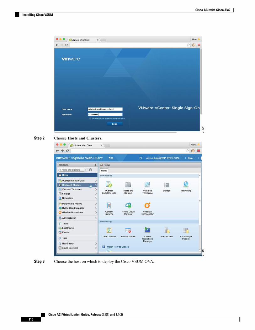
Step 2 Choose Hosts and Clusters.
Step 3 Choose the host on which to deploy the Cisco VSUM OVA.
Cisco ACI Virtualization Guide, Release 3.1(1) and 3.1(2)110
Cisco ACI with Cisco AVSInstalling Cisco VSUM
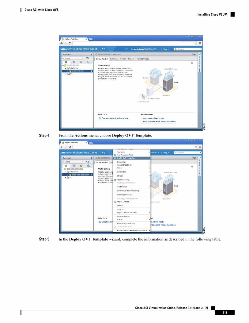
Step 4 From the Actions menu, choose Deploy OVF Template.
Step 5 In the Deploy OVF Template wizard, complete the information as described in the following table.
Cisco ACI Virtualization Guide, Release 3.1(1) and 3.1(2)111
Cisco ACI with Cisco AVSInstalling Cisco VSUM
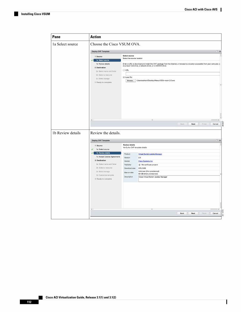
ActionPane
Choose the Cisco VSUM OVA.1a Select source
Review the details.1b Review details
Cisco ACI Virtualization Guide, Release 3.1(1) and 3.1(2)112
Cisco ACI with Cisco AVSInstalling Cisco VSUM
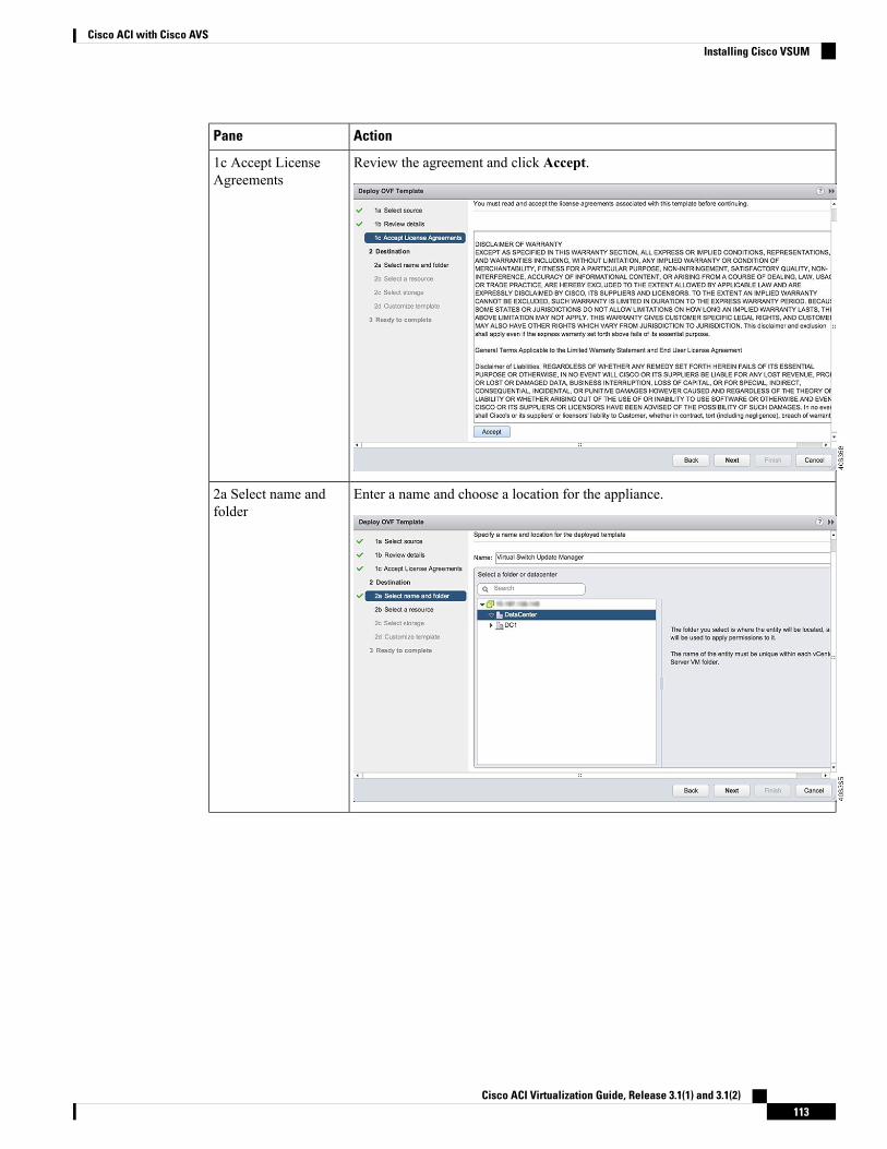
ActionPane
Review the agreement and click Accept.1c Accept LicenseAgreements
Enter a name and choose a location for the appliance.2a Select name andfolder
Cisco ACI Virtualization Guide, Release 3.1(1) and 3.1(2)113
Cisco ACI with Cisco AVSInstalling Cisco VSUM
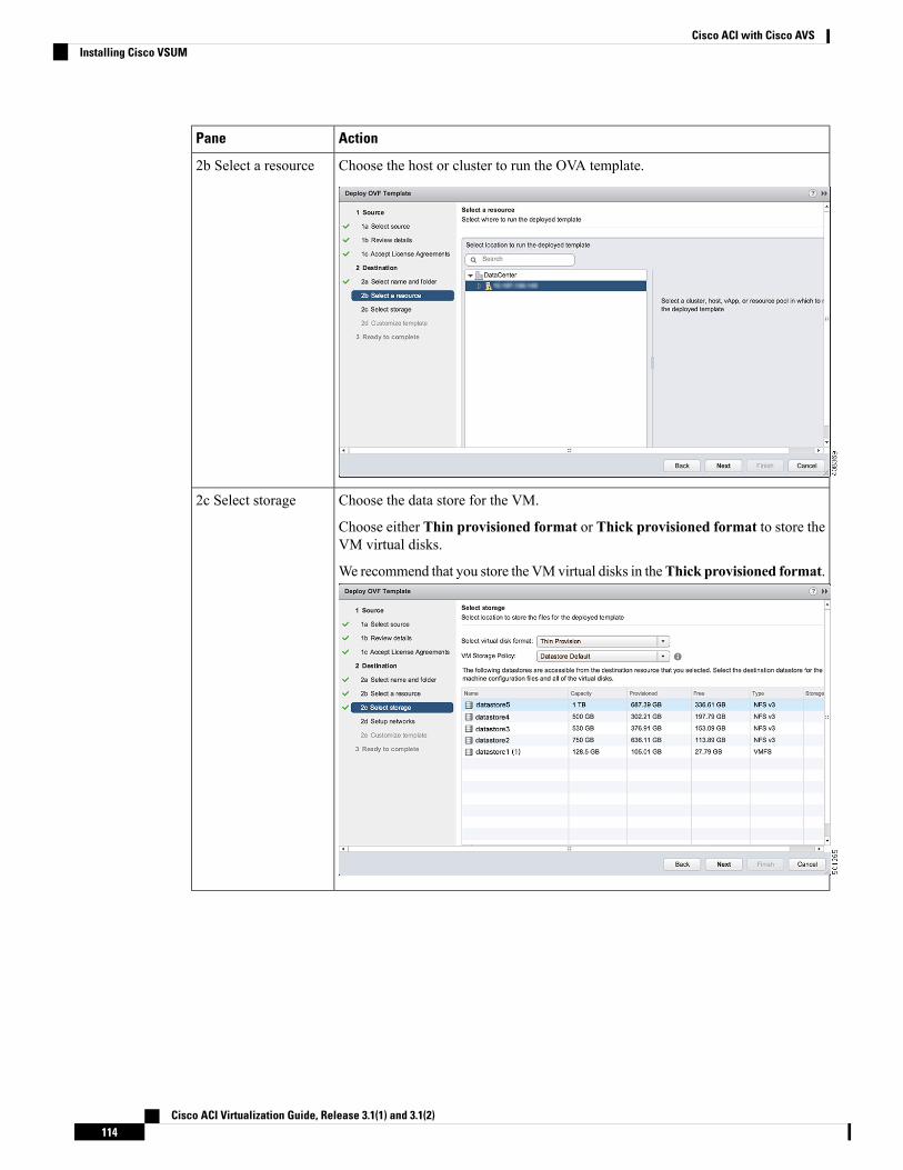
ActionPane
Choose the host or cluster to run the OVA template.2b Select a resource
Choose the data store for the VM.
Choose either Thin provisioned format or Thick provisioned format to store theVM virtual disks.
We recommend that you store the VMvirtual disks in theThick provisioned format.
2c Select storage
Cisco ACI Virtualization Guide, Release 3.1(1) and 3.1(2)114
Cisco ACI with Cisco AVSInstalling Cisco VSUM
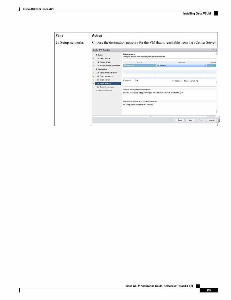
ActionPane
Choose the destination network for the VM that is reachable from the vCenter Server.2d Setup networks
Cisco ACI Virtualization Guide, Release 3.1(1) and 3.1(2)115
Cisco ACI with Cisco AVSInstalling Cisco VSUM
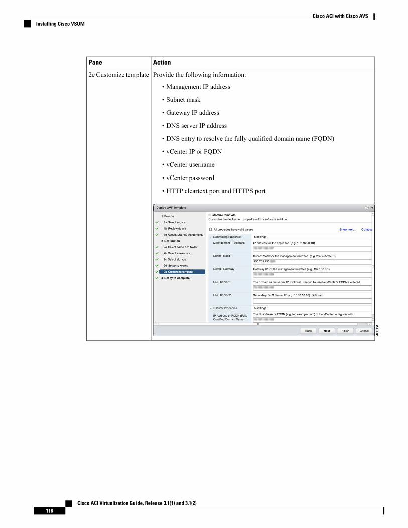
ActionPane
Provide the following information:
• Management IP address
• Subnet mask
• Gateway IP address
• DNS server IP address
• DNS entry to resolve the fully qualified domain name (FQDN)
• vCenter IP or FQDN
• vCenter username
• vCenter password
• HTTP cleartext port and HTTPS port
2e Customize template
Cisco ACI Virtualization Guide, Release 3.1(1) and 3.1(2)116
Cisco ACI with Cisco AVSInstalling Cisco VSUM
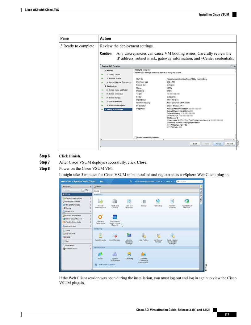
ActionPane
Review the deployment settings.
Any discrepancies can cause VM booting issues. Carefully review theIP address, subnet mask, gateway information, and vCenter credentials.
Caution
3 Ready to complete
Step 6 Click Finish.Step 7 After Cisco VSUM deploys successfully, click Close.Step 8 Power on the Cisco VSUM VM.
It might take 5 minutes for Cisco VSUM to be installed and registered as a vSphere Web Client plug-in.
If theWeb Client session was open during the installation, you must log out and log in again to view the CiscoVSUM plug-in.
Cisco ACI Virtualization Guide, Release 3.1(1) and 3.1(2)117
Cisco ACI with Cisco AVSInstalling Cisco VSUM
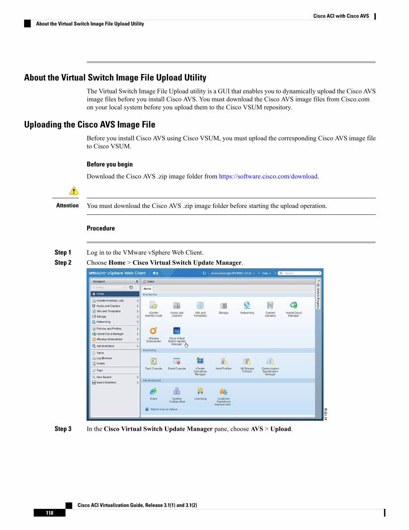
About the Virtual Switch Image File Upload UtilityThe Virtual Switch Image File Upload utility is a GUI that enables you to dynamically upload the Cisco AVSimage files before you install Cisco AVS. You must download the Cisco AVS image files from Cisco.comon your local system before you upload them to the Cisco VSUM repository.
Uploading the Cisco AVS Image FileBefore you install Cisco AVS using Cisco VSUM, you must upload the corresponding Cisco AVS image fileto Cisco VSUM.
Before you begin
Download the Cisco AVS .zip image folder from https://software.cisco.com/download.
You must download the Cisco AVS .zip image folder before starting the upload operation.Attention
Procedure
Step 1 Log in to the VMware vSphere Web Client.Step 2 Choose Home > Cisco Virtual Switch Update Manager.
Step 3 In the Cisco Virtual Switch Update Manager pane, choose AVS > Upload.
Cisco ACI Virtualization Guide, Release 3.1(1) and 3.1(2)118
Cisco ACI with Cisco AVSAbout the Virtual Switch Image File Upload Utility
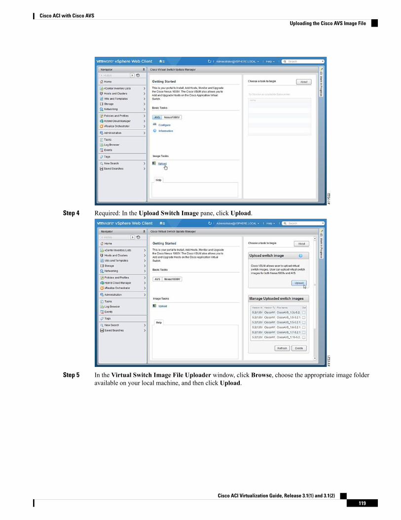
Step 4 Required: In the Upload Switch Image pane, click Upload.
Step 5 In the Virtual Switch Image File Uploader window, click Browse, choose the appropriate image folderavailable on your local machine, and then click Upload.
Cisco ACI Virtualization Guide, Release 3.1(1) and 3.1(2)119
Cisco ACI with Cisco AVSUploading the Cisco AVS Image File
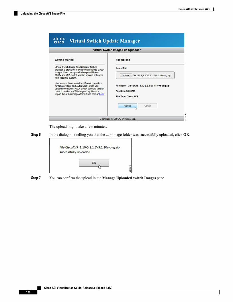
The upload might take a few minutes.
Step 6 In the dialog box telling you that the .zip image folder was successfully uploaded, click OK.
Step 7 You can confirm the upload in theManage Uploaded switch Images pane.
Cisco ACI Virtualization Guide, Release 3.1(1) and 3.1(2)120
Cisco ACI with Cisco AVSUploading the Cisco AVS Image File
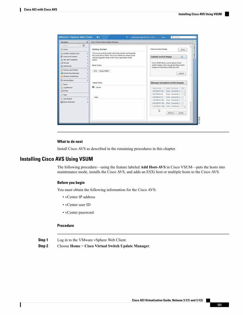
What to do next
Install Cisco AVS as described in the remaining procedures in this chapter.
Installing Cisco AVS Using VSUMThe following procedure—using the feature labeled Add Host-AVS in Cisco VSUM—puts the hosts intomaintenance mode, installs the Cisco AVS, and adds an ESXi host or multiple hosts to the Cisco AVS.
Before you begin
You must obtain the following information for the Cisco AVS:
• vCenter IP address
• vCenter user ID
• vCenter password
Procedure
Step 1 Log in to the VMware vSphere Web Client.Step 2 Choose Home > Cisco Virtual Switch Update Manager.
Cisco ACI Virtualization Guide, Release 3.1(1) and 3.1(2)121
Cisco ACI with Cisco AVSInstalling Cisco AVS Using VSUM
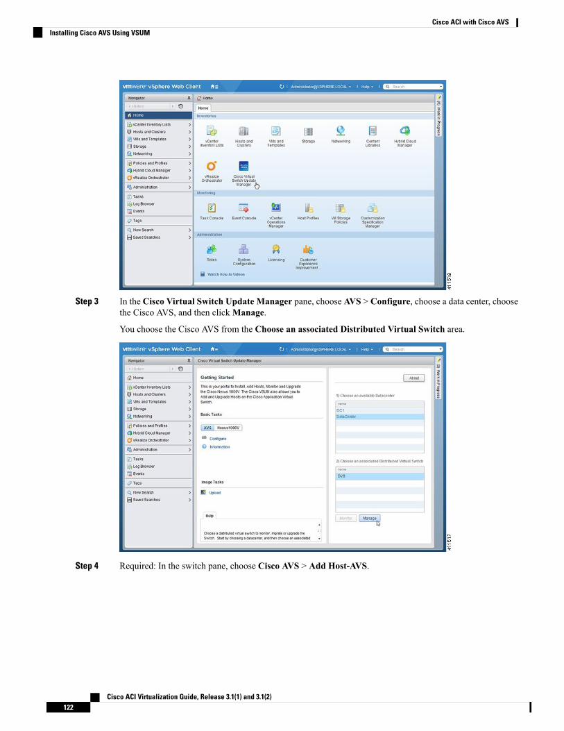
Step 3 In the Cisco Virtual Switch Update Manager pane, choose AVS > Configure, choose a data center, choosethe Cisco AVS, and then clickManage.
You choose the Cisco AVS from the Choose an associated Distributed Virtual Switch area.
Step 4 Required: In the switch pane, choose Cisco AVS > Add Host-AVS.
Cisco ACI Virtualization Guide, Release 3.1(1) and 3.1(2)122
Cisco ACI with Cisco AVSInstalling Cisco AVS Using VSUM
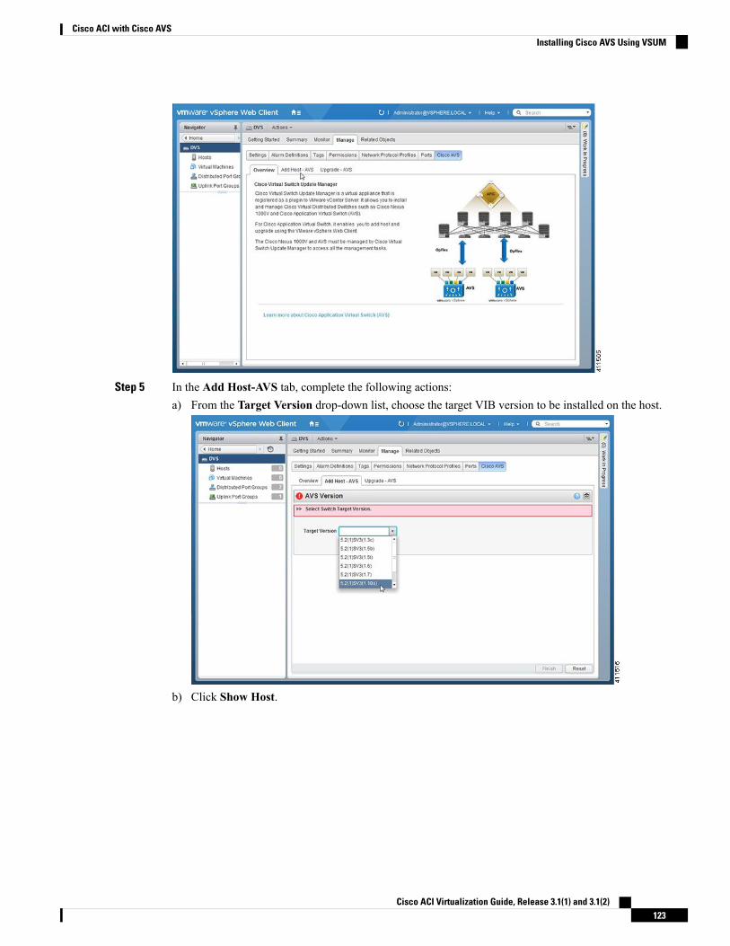
Step 5 In the Add Host-AVS tab, complete the following actions:a) From the Target Version drop-down list, choose the target VIB version to be installed on the host.
b) Click Show Host.
Cisco ACI Virtualization Guide, Release 3.1(1) and 3.1(2)123
Cisco ACI with Cisco AVSInstalling Cisco AVS Using VSUM
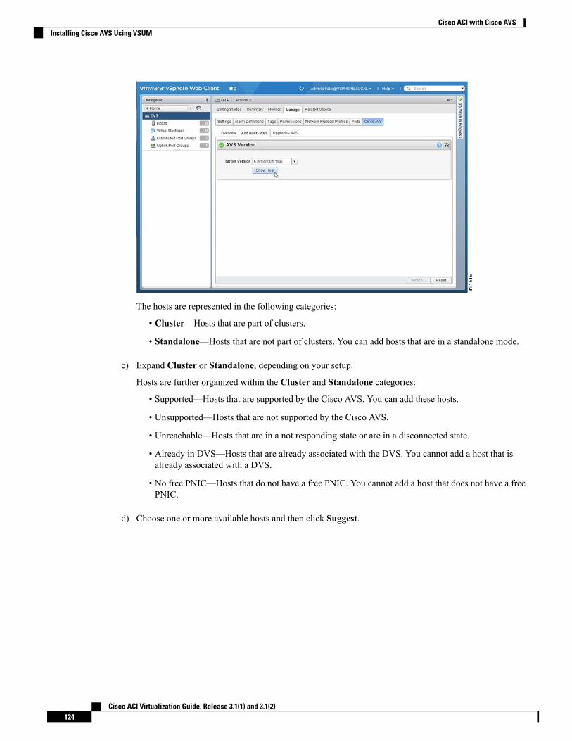
The hosts are represented in the following categories:
• Cluster—Hosts that are part of clusters.
• Standalone—Hosts that are not part of clusters. You can add hosts that are in a standalone mode.
c) Expand Cluster or Standalone, depending on your setup.
Hosts are further organized within the Cluster and Standalone categories:
• Supported—Hosts that are supported by the Cisco AVS. You can add these hosts.
• Unsupported—Hosts that are not supported by the Cisco AVS.
• Unreachable—Hosts that are in a not responding state or are in a disconnected state.
• Already in DVS—Hosts that are already associated with the DVS. You cannot add a host that isalready associated with a DVS.
• No free PNIC—Hosts that do not have a free PNIC. You cannot add a host that does not have a freePNIC.
d) Choose one or more available hosts and then click Suggest.
Cisco ACI Virtualization Guide, Release 3.1(1) and 3.1(2)124
Cisco ACI with Cisco AVSInstalling Cisco AVS Using VSUM
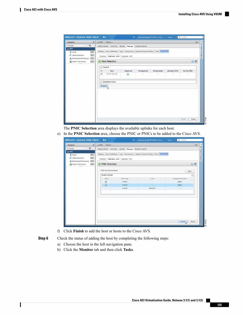
The PNIC Selection area displays the available uplinks for each host.e) In the PNIC Selection area, choose the PNIC or PNICs to be added to the Cisco AVS.
f) Click Finish to add the host or hosts to the Cisco AVS.
Step 6 Check the status of adding the host by completing the following steps:a) Choose the host in the left navigation pane.b) Click theMonitor tab and then click Tasks.
Cisco ACI Virtualization Guide, Release 3.1(1) and 3.1(2)125
Cisco ACI with Cisco AVSInstalling Cisco AVS Using VSUM
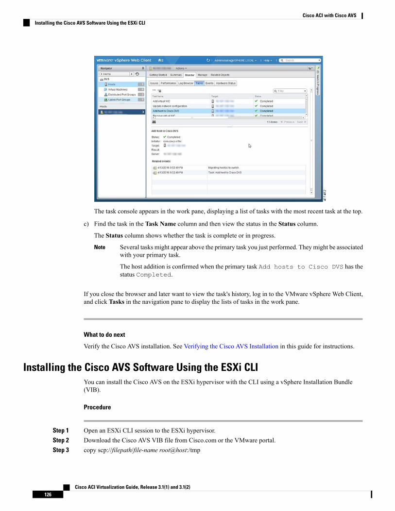
The task console appears in the work pane, displaying a list of tasks with the most recent task at the top.
c) Find the task in the Task Name column and then view the status in the Status column.
The Status column shows whether the task is complete or in progress.
Several tasks might appear above the primary task you just performed. They might be associatedwith your primary task.
The host addition is confirmed when the primary task Add hosts to Cisco DVS has thestatus Completed.
Note
If you close the browser and later want to view the task's history, log in to the VMware vSphere Web Client,and click Tasks in the navigation pane to display the lists of tasks in the work pane.
What to do next
Verify the Cisco AVS installation. See Verifying the Cisco AVS Installation in this guide for instructions.
Installing the Cisco AVS Software Using the ESXi CLIYou can install the Cisco AVS on the ESXi hypervisor with the CLI using a vSphere Installation Bundle(VIB).
Procedure
Step 1 Open an ESXi CLI session to the ESXi hypervisor.Step 2 Download the Cisco AVS VIB file from Cisco.com or the VMware portal.Step 3 copy scp://filepath/file-name root@host:/tmp
Cisco ACI Virtualization Guide, Release 3.1(1) and 3.1(2)126
Cisco ACI with Cisco AVSInstalling the Cisco AVS Software Using the ESXi CLI
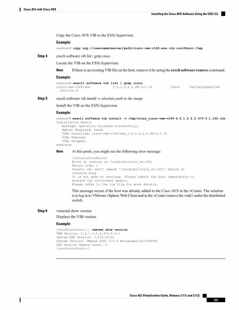
Copy the Cisco AVS VIB to the ESXi hypervisor.
Example:esxhost# copy scp://username@server/path/cisco-vem-v165-esx.vib root@host:/tmp
Step 4 esxcli software vib list | grep cisco
Locate the VIB on the ESXi hypervisor.
If there is an existing VIB file on the host, remove it by using the esxcli software remove command.Note
Example:esxhost# esxcli software vib list | grep ciscocisco-vem-v164-esx 5.2.1.2.2.0.88-3.1.74 Cisco PartnerSupported2014-03-31
Step 5 esxcli software vib install -v absolute path to the image
Install the VIB on the ESXi hypervisor.
Example:esxhost# esxcli software vib install -v /tmp/cross_cisco-vem-v165-4.2.1.2.2.2.473-3.1.165.vibInstallation Result
Message: Operation finished successfully.Reboot Required: falseVIBs Installed: cisco-vem-v164-esx_5.2.1.2.2.0.88-3.1.74VIBs Removed:VIBs Skipped:
esxhost#
At this point, you might see the following error message:[InstallationError]Error in running rm /tardisks/cisco_ve.v00:Return code: 1Output: rm: can't remove '/tardisks/cisco_ve.v00': Device orresource busyIt is not safe to continue. Please reboot the host immediately todiscard the unfinished update.Please refer to the log file for more details.
This message occurs if the host was already added to the Cisco AVS in the vCenter. The solutionis to log in to VMware vSphereWeb Client and in the vCenter remove the vmk1 under the distributedswitch.
Note
Step 6 vemcmd show versionDisplays the VIB version.
Example:[root@localhost:~] vemcmd show versionVEM Version: 5.2.1.3.3.9.972-6.0.1OpFlex SDK Version: 3.0(0.257a)System Version: VMware ESXi 6.0.0 Releasebuild-2494585ESX Version Update Level: 0[root@localhost:~]
Cisco ACI Virtualization Guide, Release 3.1(1) and 3.1(2)127
Cisco ACI with Cisco AVSInstalling the Cisco AVS Software Using the ESXi CLI
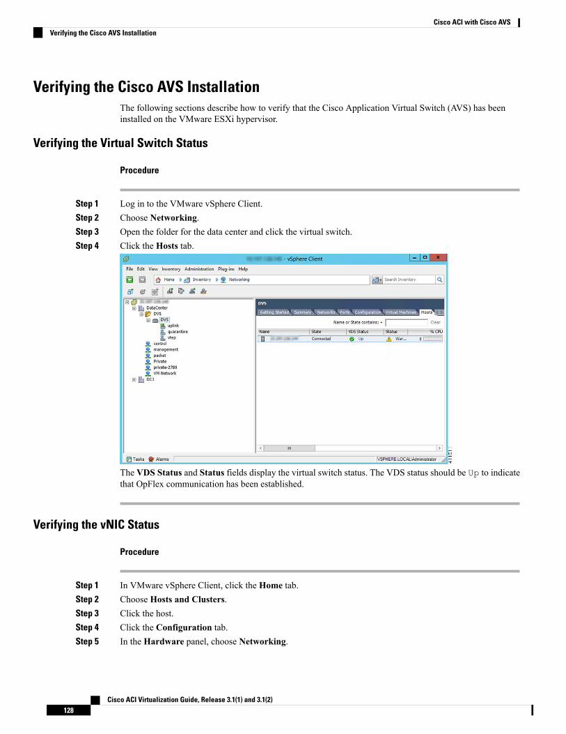
Verifying the Cisco AVS InstallationThe following sections describe how to verify that the Cisco Application Virtual Switch (AVS) has beeninstalled on the VMware ESXi hypervisor.
Verifying the Virtual Switch Status
Procedure
Step 1 Log in to the VMware vSphere Client.Step 2 Choose Networking.Step 3 Open the folder for the data center and click the virtual switch.Step 4 Click the Hosts tab.
The VDS Status and Status fields display the virtual switch status. The VDS status should be Up to indicatethat OpFlex communication has been established.
Verifying the vNIC Status
Procedure
Step 1 In VMware vSphere Client, click the Home tab.Step 2 Choose Hosts and Clusters.Step 3 Click the host.Step 4 Click the Configuration tab.Step 5 In the Hardware panel, choose Networking.
Cisco ACI Virtualization Guide, Release 3.1(1) and 3.1(2)128
Cisco ACI with Cisco AVSVerifying the Cisco AVS Installation
Step 6 In the View field, click the vSphere Distributed Switch button.Step 7 ClickManage Virtual Adapters. The vmk1 displays as a virtual adapter and lists an IP address.Step 8 Click the newly created vmk interface to display the vmknic status.
Allow approximately 20 seconds for the vmk to receive an IP address through DHCP.Note
Adding Cisco AVS Hosts to the DVSYou can add only one host at a time. You need to perform this procedure once for every host that you wantto add.
If you installed the Cisco AVS by using the Cisco VSUM, you do not need to perform this procedure; VSUMadds hosts to the DVS at the same time that it installs the Cisco AVS. However, you do need to perform thisprocedure if you upgraded Cisco AVS by using the CLI or the VMware VUM.
Note
Before you begin
Before you add vLeafs to the DVS, ensure that you have created a tenant configuration that contains therequired bridge domain, application profiles, endpoint groups, and contracts. For more information, see theCisco APIC Getting Started Guide.
Procedure
Step 1 In vSphere Web Client, choose Home >Inventories > Networking.Step 2 In the left navigation pane, choose AVS Distributed Switch, and then click the Hosts tab.Step 3 Right-click anywhere within the work pane and choose Add Host to vSphere Distributed Switch.Step 4 In the Add Host to vSphere Distributed Switch dialog box, choose the virtual NIC ports that are connected
to the leaf switch (vmnic2, vmnic3).Step 5 Click Next.Step 6 In the Network Connectivity dialog box, click Next.Step 7 In the Virtual Machine Networking dialog box, click Next.Step 8 In the Ready to Complete dialog box, click Finish.Step 9 Repeat Step 1 through Step 8 for each additional host.
Uninstalling Cisco AVSYou might need to remove Cisco AVS for testing or if you need to remove all configuration from the CiscoACI fabric, resetting the fabric to its initial state. Follow the high-level steps in this procedure to remove theCisco AVS.
Cisco ACI Virtualization Guide, Release 3.1(1) and 3.1(2)129
Cisco ACI with Cisco AVSAdding Cisco AVS Hosts to the DVS
Procedure
Step 1 Complete the following steps in the VMware vSphere Client:a) Remove all VMs from EPG port groups.b) Remove all Virtual Tunnel Endpoint (VTEP) VMware kernels (VMKs) from the Cisco AVS hosts.c) Remove all hosts from the Cisco AVS.
See the VMware documentation for instructions.
Step 2 Complete the following steps in the Cisco APIC:a) Remove all virtual machine management (VMM) domain associations to EPGs to delete port groups.
This step is optional if you are removing all configuration from the Cisco ACI fabric.
b) Remove the Cisco AVS VMM domain.
What to do next
If you are uninstalling the Cisco AVS but not removing all configuration from the Cisco ACI fabric, you canremove the VIB software from each host where it was installed. You can do so by completing one of thefollowing tasks:
• Enter the following vSphere CLI command to remove the VIB software from a host: esxcli softwarevib remove -n installed_vem_version
• Complete the procedure in the section "Uninstalling Cisco AVS Using the VMware vCenter Plug-in" inthis guide.
Uninstalling Cisco AVS Using the VMware vCenter Plug-inThis procedure removes the Cisco AVS VIB file from the host.
You should use the vCenter plug-in to uninstall Cisco AVS if you are already using it to perform other tasksor if you plan to do so. We do not recommend using the vCenter plug-in to uninstall Cisco AVS unless youplan to use it for other tasks. For information about the vCenter plug-in, see the chapter "Cisco ACI vCenterPlug-in" in the Cisco ACI Virtualization Guide on Cisco.com.
Before you begin
• You must perform the all steps in the procedure "Uninstalling Cisco AVS" except for the task in the"What to do next" section.
• You must disconnect Cisco AVS from the VMM domain.
Procedure
Step 1 Log in to VMware vSphere Web Client.Step 2 ChooseCisco ACI Fabric > Cisco AVS.
Cisco ACI Virtualization Guide, Release 3.1(1) and 3.1(2)130
Cisco ACI with Cisco AVSUninstalling Cisco AVS Using the VMware vCenter Plug-in
Step 3 At the top of the central work pane, from the Select an ACI domain drop-down list, choose a domain.When you choose a domain, the work pane displays the host or hosts in the vCenter related to the VMMdomain. The central pane displays the following columns:
• Name—Name of the host
• ESX Version—The ESX or ESXi version on the host
• Added to Domain—Whether the host is connected to the Cisco AVS associated with the selected domain
• OpFlex State—Whether the OpFlex agent on the host is online
• AVS Version—The version of Cisco AVS, if any, installed on the host
Step 4 Choose a one or more hosts by clicking the appropriate check box or check boxes.Step 5 In theConcurrent Tasks drop-down, if you chose multiple hosts in Step 4, choose how many hosts on which
to uninstall Cisco AVS at the same time.
You can choose up to 10 hosts on which to uninstall Cisco AVS at the same time. If you choose multiplehosts but do not choose a number from the Concurrent Tasks drop-down list, Cisco AVS will be uninstalledon the hosts one after another.
Step 6 Click Uninstall AVS.Step 7 In the Uninstall AVS dialog box, click Yes to put the hosts into maintenance mode.
In the central work pane, the AVS version for the host displays uninstallation progress. You also can viewprogress of the individual uninstallation tasks in the Recent Tasks area. When the uninstallation is complete,"Not installed" will appear for the host in the central work pane AVS Version column.
What to do next
Take the following optional steps to remove from vCenter the version of Cisco AVS you just uninstalled:
1. Click Remove uploaded versions.
2. In the Select the AVS versions you wish to remove from vCenter dialog box, click the appropriatecheck box and then click OK.
Key Post-Installation Configuration Tasks for the Cisco AVSAfter you install the Cisco Application Virtual Switch (AVS), you need to perform some configuration tasksin the Cisco Application Policy Infrastructure Controller (APIC).
Prerequisites for Configuring the Cisco AVSBefore you configure the Cisco Application Virtual Switch (AVS), you need to perform the following tasks:
1. Install the Cisco AVS as described in the previous sections of this guide.
2. Understand the concepts presented in the ACI Fundamentals Guide and the APIC Getting Started Guide.
Cisco ACI Virtualization Guide, Release 3.1(1) and 3.1(2)131
Cisco ACI with Cisco AVSKey Post-Installation Configuration Tasks for the Cisco AVS
Workflow for Key Post-Installation Configuration Tasks for the Cisco AVSThis section provides a high-level description of the tasks that you need to perform in the correct sequencein order to configure Cisco AVS.
1. Deploy an application profile.
1. Create a tenant.
A tenant is a logical container for application policies that enable an administrator to exercisedomain-based access control. Tenants can represent a customer in a service provider setting, anorganization or domain in an enterprise setting, or just a convenient grouping of policies.
The fabric can containmultiple tenants. Tenants can be isolated from one another or can share resources.The primary elements that the tenant contains are filters, contracts, outside networks, bridge domains,contexts, and application profiles that contain endpoint groups (EPGs). Entities in the tenant inheritits policies.
You must configure a tenant before you can deploy any Layer 4 to Layer 7 services.
See the section Creating a Tenant, VRF, and Bridge Domain Using the GUI in this guide for instructionsfor creating tenants.
2. Create an application profile.
An application profile models application requirements. An application profile is a convenient logicalcontainer for grouping EPGs.
Modern applications contain multiple components. For example, an e-commerce application couldrequire a web server, a database server, data located in a storage area network, and access to outsideresources that enable financial transactions. The application profile contains as many (or as few) EPGsas necessary that are logically related to providing the capabilities of an application.
See the section Creating an Application Profile Using the GUI in this guide for instructions for creatingan application profile.
3. Create an endpoint group (EPG)
Endpoints are devices that are connected to the network directly or indirectly. They have an address(identity), a location, attributes (such as version or patch level), and can be physical or virtual. Endpointexamples include servers, virtual machines, network-attached storage, or clients on the Internet.
An EPG is a named logical entity that contains a collection of endpoints that have common policyrequirements such as security, virtual machine mobility, QoS, or Layer 4 to Layer 7 services. EPGsenable you to manage endpoints as a group rather than having to configure and manage themindividually; endpoints in an EPG have the same configuration and changes to EPG configuration arepropagated automatically to all the endpoints assigned to it. In vCenter Server, an EPG is representedas a port group.
See the section Creating EPGs Using the GUI in this guide for instructions for creating EPGs.
4. Assign port groups to virtual machines (VMs) in vCenter.
In vCenter Server, an EPG is represented as a port group. The virtual Ethernet (vEth) interfaces areassigned in vCenter Server to an EPG in order to do the following:
• Define the port configuration by the policy.
• Apply a single policy across a large number of ports.
Cisco ACI Virtualization Guide, Release 3.1(1) and 3.1(2)132
Cisco ACI with Cisco AVSWorkflow for Key Post-Installation Configuration Tasks for the Cisco AVS
EPGs that are configured as uplinks can be assigned by the server administrator to physical ports(which can be vmnics or PNICs). EPGs that are not configured as uplinks can be assigned to a VMvirtual port.
See the section Assigning Port Groups to the VM in vCenter in this guide for instructions.
5. Create filters.
A filter is a managed object that helps enable mixing and matching among EPGs and contracts so asto satisfy various applications or service delivery requirements. It specifies the data protocols to beallowed or denied by a contract—rules for communications between EPGs—that contains the filter.
See the section Creating a Filter Using the GUI in this guide for instructions.
6. Create contracts.
Contracts are policies that enable communications between EPGs. An administrator uses a contractto select the type(s) of traffic that can pass between EPGs, including the protocols and ports allowed.If there is no contract, inter-EPG communication is disabled by default. No contract is required forcommunication within an EPG; communication within an EPG is always implicitly allowed.
Contracts govern the communication between EPGs that are labeled providers, consumers, or both.An EPG can both provide and consume the same contract. An EPG can also provide and consumemultiple contracts simultaneously.
See the section Creating a Contract Using the GUI in this guide for instructions.
2. Verify the application profile.
You need to perform the following tasks to verify that the application profile has been created.
1. Verify the application profile on the Cisco APIC.
2. Verify that the EPGs appear in the vCenter.
3. Ensure that the VMs can communicate.
See the section Verifying the Application Profile and EPGs in the GUI in this guide for instructions.
3. Configure an IPv4 or IPv6 address
To configure an IP address for VMs connected to Cisco AVS, you assign an IPv4 or IPv6 address—orboth an IPV4 and IPv6 address—for the VM and then assign a gateway address.
See the section Configuring an IP Address for VMs Connected to Cisco AVS in this guide for instructions.
4. Configure an IGMP querier under the infra BD subnet.
In order for Cisco AVS to forward multi-destination traffic—especially when traffic goes through a bladeswitch—you should configure an IGMP querier under the infra BD subnet. This enables devices to buildtheir Layer 2 multicast tree.
See the section "Configuring IGMP Querier and Snooping" in the Cisco AVS Configuration Guide forinstructions.
5. (Optional but recommended) Enable Distributed Firewall.
After you install or upgrade to Cisco AVSRelease 5.2(1)SV3(1.5), you need to enable Distributed Firewallif you want to use the feature. Distributed Firewall is in Learning mode by default. Follow the instructions
Cisco ACI Virtualization Guide, Release 3.1(1) and 3.1(2)133
Cisco ACI with Cisco AVSWorkflow for Key Post-Installation Configuration Tasks for the Cisco AVS
in Creating a Distributed Firewall Policy or Changing its Mode Using the GUI in this guide to enableDistributed Firewall.
Deploying an Application Profile for Cisco AVS Using the GUIBasic mode is deprecated after Cisco APIC Release 3.0(1). Cisco does not recommend using Basic mode forconfiguration. However, if you want to use Basic mode, use the following URL: APICURL/index.Simple.html
Caution: Cisco recommends that you do not mix configuration modes (Advanced or Basic). When you makea configuration in either mode and change the configuration using the other mode, unintended changes canoccur. For example, if you apply an interface policy to two ports using Advanced mode and then change thesettings of one port using Basic mode, your changes might be applied to both ports.
Creating a Tenant, VRF, and Bridge Domain Using the GUIIf you have a public subnet when you configure the routed outside, you must associate the bridge domainwith the outside configuration.
Procedure
Step 1 On the menu bar, choose Tenants > Add Tenant.Step 2 In the Create Tenant dialog box, perform the following tasks:
a) In the Name field, enter a name.b) Click the Security Domains + icon to open the Create Security Domain dialog box.c) In the Name field, enter a name for the security domain. Click Submit.d) In the Create Tenant dialog box, check the check box for the security domain that you created, and click
Submit.
Step 3 In the Navigation pane, expand Tenant-name > Networking, and in theWork pane, drag the VRF icon tothe canvas to open the Create VRF dialog box, and perform the following tasks:a) In the Name field, enter a name.b) Click Submit to complete the VRF configuration.
Step 4 In the Networking pane, drag the BD icon to the canvas while connecting it to the VRF icon. In the CreateBridge Domain dialog box that displays, perform the following tasks:a) In the Name field, enter a name.b) Click the L3 Configurations tab.c) Expand Subnets to open the Create Subnet dialog box, enter the subnet mask in the Gateway IP field
and click OK.d) Click Submit to complete bridge domain configuration.
Step 5 In theNetworks pane, drag theL3 icon down to the canvas while connecting it to theVRF icon. In theCreateRouted Outside dialog box that displays, perform the following tasks:a) In the Name field, enter a name.b) Expand Nodes And Interfaces Protocol Profiles to open the Create Node Profile dialog box.c) In the Name field, enter a name.d) Expand Nodes to open the Select Node dialog box.
Cisco ACI Virtualization Guide, Release 3.1(1) and 3.1(2)134
Cisco ACI with Cisco AVSDeploying an Application Profile for Cisco AVS Using the GUI
e) In the Node ID field, choose a node from the drop-down list.f) In the Router ID field, enter the router ID.g) Expand Static Routes to open the Create Static Route dialog box.h) In the Prefix field, enter the IPv4 or IPv6 address.i) Expand Next Hop Addresses and in the Next Hop IP field, enter the IPv4 or IPv6 address.j) In the Preference field, enter a number, then click UPDATE and then OK.k) In the Select Node dialog box, click OK.l) In the Create Node Profile dialog box, click OK.m) Check the BGP,OSPF, or EIGRP check boxes if desired, and clickNEXT. ClickOK to complete the
Layer 3 configuration.To confirm L3 configuration, in the Navigation pane, expand Networking > VRFs.
Creating an Application Profile Using the GUI
Procedure
Step 1 On the menu bar, choose TENANTS. In the Navigation pane, expand the tenant, right-click ApplicationProfiles, and click Create Application Profile.
Step 2 In theCreate Application Profile dialog box, in theName field, add the application profile name (OnlineStore).
Creating EPGs Using the GUIThe port the EPG uses must belong to one of the VMManagers (VMM) or physical domains associated withthe EPG.
Procedure
Step 1 On the menu bar, choose Tenants and the tenant where you want to create an EPG.Step 2 In the navigation pane, expand the folder for the tenant, the Application Profiles folder, and the folder for
the application profile.Step 3 Right-click theApplication EPG folder, and in theCreate Application EPG dialog box, perform the following
actions:a) In the Name field, add the EPG name (db).b) In the Bridge Domain field, choose the bridge domain from the drop-down list (bd1).c) Check the Associate to VM Domain Profiles check box. Click Next.d) In the STEP 2 > Domains area, expand Associate VM Domain Profiles and from the drop-down list,
choose the desired VMM domain.e) From the Deployment Immediacy drop-down list, accept the default or choose when policies are
deployed from Cisco APIC to the physical leaf switch.f) From theResolution Immediacy drop-down list, choose when policies are deployed from the physical
leaf switch to the virtual leaf.
Cisco ACI Virtualization Guide, Release 3.1(1) and 3.1(2)135
Cisco ACI with Cisco AVSCreating an Application Profile Using the GUI
If you have Cisco AVS, choose Immediate or On Demand; if you have Cisco ACI Virtual Edge orVMware VDS, choose Immediate, On Demand, or Pre-provision.
g) (Optional) In the Delimiter field, enter one of the following symbols: |, ~, !, @, ^, +, or =.
If you do not enter a symbol, the system uses the default | delimiter in the VMware portgroup name.
h) If you have Cisco ACI Virtual Edge or Cisco AVS, from the Encap Mode drop-down list, choose anencapsulation mode.
You can choose one of the following encap modes:
• VXLAN—This overrides the domain's VLAN configuration, and the EPG uses VXLANencapsulation. However, a fault is for the EPG if a multicast pool is not configured on the domain.
• VLAN—This overrides the domain's VXLAN configuration, and the EPG uses VLANencapsulation. However, a fault is triggered for the EPG if a VLAN pool is not configured on thedomain.
• Auto—This causes the EPG to use the same encapsulation mode as the VMM domain. This is thedefault configuration.
i) If you have Cisco ACI Virtual Edge, from the Switching Mode drop-down list, choose native or AVE.
If you choose native, the EPG is switched through the VMware VDS; if you choose AVE, the EPG isswitched through the Cisco ACI Virtual Edge. The default is native.
j) Click Update and then click Finish.
Step 4 In the Create Application Profile dialog box, create two more EPGs. Create the three EPGs—db, app, andweb—in the same bridge domain and data center.
Creating VLAN Pools with Encapsulation Blocks Using the GUIYou can create VLAN pools to associate with a VMM domain or with EPGs, either application EPGs ormicrosegments.
Procedure
Step 1 Log in to Cisco APIC.
Step 2 Go to Fabric > Access Policies.Step 3 In the Policies navigation pane, expand the Pools folder.Step 4 Right-click the VLAN folder and then choose Create VLAN Pool.Step 5 In the Create VLAN Pool dialog box, in the Name field, give the VLAN pool a name.Step 6 In the Allocation Mode area, choose Dynamic Allocation or Static Allocation mode.
If you want to associate the VLAN pool to a VMM domain, you must choose dynamic allocation.If you define static allocation for a VLAN pool, then try to create a VMM domain, the VLAN poolwith static allocation will not be available.
Note
Step 7 In the Encap Blocks area, click the + icon.
Cisco ACI Virtualization Guide, Release 3.1(1) and 3.1(2)136
Cisco ACI with Cisco AVSCreating VLAN Pools with Encapsulation Blocks Using the GUI
Step 8 In theCreate Ranges dialog box, in theRange area, type the numbers of the appropriate VLANs in the Fromand To fields.
Step 9 In the Allocation Mode area, choose Dynamic Allocation, Inherit allocMode from parent or StaticAllocation.
VLAN pools can contain encapsulation blocks with different allocation modes. For example, a VLAN poolwith dynamic allocation can contain encapsulation blocks with dynamic or static allocation.
You must configure an encapsulation block with static allocation if you want to configure an EPGwith static VLAN port encapsulation. You can use any one of the VLANS in the encapsulationblock with static allocation.
Note
Step 10 Click OK.The VLAN range and allocation mode appear in the Encap Blocks area of the Create VLAN Pool dialogbox.
Step 11 In the Create VLAN Pool dialog box, click SUBMIT.
Assigning Port Groups to the VM in vCenter
Procedure
Step 1 Log in to the vCenter.Step 2 Navigate to the virtual machine (VM) in the navigation pane.Step 3 Right-click the VM in the navigation pane.Step 4 In the Edit Settings dialog box for the VM, complete the following actions:
a) From the Network Adapter 1 drop-down menu, choose the appropriate combined value for tenant,application profile, and endpoint group (EPG).
For example, youmight see an option similar to T2|ap4|EPG1 followed by the values that were configuredin Cisco APIC.
b) Repeat Step 4 a for any other network adapters you have and want to configure.
You must configure one network adapter; configuring others is optional.
c) Click OK.
Creating a Filter Using the GUICreate a filter using the following steps. This task shows how to create an HTTP filter.
Before you begin
Verify that the tenant, network, and bridge domain have been created.
Cisco ACI Virtualization Guide, Release 3.1(1) and 3.1(2)137
Cisco ACI with Cisco AVSAssigning Port Groups to the VM in vCenter
Procedure
Step 1 On the menu bar, choose TENANTS. In the Navigation pane, expand the tenant > Security Policies,right-click Filters, and click Create Filter.
In the Navigation pane, you expand the tenant where you want to add filters.Note
Step 2 In the Create Filter dialog box, perform the following actions:a) In the Name field, enter the filter name (http).b) Expand Entries, and in the Name field, enter the name (Dport-80).c) From the EtherType drop-down list, choose the EtherType (IP).d) From the IP Protocol drop-down list, choose the protocol (tcp).e) From the Destination Port/Range drop-down lists, choose http in the From and To fields. (http)f) Click Update, and click Submit.
The newly added filter appears in the Navigation pane and in theWork pane.
Step 3 Expand Entries in the Name field. Follow the same process to add another entry with HTTPS as theDestination port, and click Update.This new filter rule is added.
Creating a Contract Using the GUICreate a contract using the following steps.
Procedure
Step 1 On the menu bar, choose TENANTS and the tenant name on which you want to operate. In the Navigationpane, expand the tenant > Security Policies.
Step 2 Right-click Contracts > Create Contract.Step 3 In the Create Contract dialog box, perform the following tasks:
a) In the Name field, enter the contract name (web).b) Click the + sign next to Subjects to add a new subject.c) In the Create Contract Subject dialog box, enter a subject name in the Name field. (web)d) Note This step associates the filters created that were earlier with the contract subject.
In the Filter Chain area, click the + sign next to Filters.e) In the dialog box, from the drop-down menu, choose the filter name (http), and click Update.
Step 4 In the Create Contract Subject dialog box, click OK.
Cisco ACI Virtualization Guide, Release 3.1(1) and 3.1(2)138
Cisco ACI with Cisco AVSCreating a Contract Using the GUI
Deploying an Application Profile for Cisco AVS Using the NX-OS CLI
Creating a Tenant, VRF, and Bridge Domain Using the NX-OS Style CLIThis section provides information on how to create tenants, VRFs, and bridge domains.
Before creating the tenant configuration, you must create a VLAN domain using the vlan-domain commandand assign the ports to it.
Note
Procedure
Step 1 Create a VLAN domain (which contains a set of VLANs that are allowable in a set of ports) and allocateVLAN inputs, as follows:
Example:
In the following example ("exampleCorp"), note that VLANs 50 - 500 are allocated.apic1# configureapic1(config)# vlan-domain dom_exampleCorpapic1(config-vlan)# vlan 50-500apic1(config-vlan)# exit
Step 2 Once the VLANs have been allocated, specify the leaf (switch) and interface for which these VLANs can beused. Then, enter "vlan-domain member" and then the name of the domain you just created.
Example:
In the following example, these VLANs (50 - 500) have been enabled on leaf 101 on interface ethernet 1/2-4(three ports including 1/2, 1/3, and 1/4). This means that if you are using this interface, you can use VLANS50-500 on this port for any application that the VLAN can be used for.apic1(config-vlan)# leaf 101apic1(config-vlan)# interface ethernet 1/2-4apic1(config-leaf-if)# vlan-domain member dom_exampleCorpapic1(config-leaf-if)# exitapic1(config-leaf)# exit
Step 3 Create a tenant in global configuration mode, as shown in the following example:
Example:
apic1(config)# tenant exampleCorp
Step 4 Create a private network (also called VRF) in tenant configuration mode as shown in the following example:
Example:
apic1(config)# tenant exampleCorpapic1(config-tenant)# vrf context exampleCorp_v1apic1(config-tenant-vrf)# exit
Step 5 Create a bridge domain (BD) under the tenant, as shown in the following example:
Example:
Cisco ACI Virtualization Guide, Release 3.1(1) and 3.1(2)139
Cisco ACI with Cisco AVSDeploying an Application Profile for Cisco AVS Using the NX-OS CLI
apic1(config-tenant)# bridge-domain exampleCorp_b1apic1(config-tenant-bd)# vrf member exampleCorp_v1apic1(config-tenant-bd)# exit
In this case, the VRF is "exampleCorp_v1".Note
Step 6 Allocate IP addresses for the BD (ip and ipv6), as shown in the following example.
Example:apic1(config-tenant)# interface bridge-domain exampleCorp_b1apic1(config-tenant-interface)# ip address 172.1.1.1/24apic1(config-tenant-interface)# ipv6 address 2001:1:1::1/64apic1(config-tenant-interface)# exit
What to do next
The next section describes how to add an application profile, create an application endpoint group (EPG), andassociate the EPG to the bridge domain.
Related TopicsConfiguring a VLAN Domain Using the NX-OS Style CLI
Creating an Application Profile and EPG Using the NX-OS Style CLI
Before you begin
Before you can create an application profile and an application endpoint group (EPG), you must create aVLAN domain, tenant, VRF, and BD (as described in the previous section).
Procedure
Step 1 Create an application profile, as shown in the following example ("exampleCorp_web1"):
Example:
apic1(config)# tenant exampleCorpapic1(config-tenant)# application exampleCorp_web1
Step 2 Create an EPG under the application, as shown in the following example ("exampleCorp_webepg1"):
Example:
apic1(config-tenant-app)# epg exampleCorp_webepg1
Step 3 Associate the EPG to the bridge domain, shown as follows:
Example:apic1(config-tenant-app-epg)# bridge-domain member exampleCorp_b1apic1(config-tenant-app-epg)# exitapic1(config-tenant-app)# exitapic1(config-tenant)# exit
Cisco ACI Virtualization Guide, Release 3.1(1) and 3.1(2)140
Cisco ACI with Cisco AVSCreating an Application Profile and EPG Using the NX-OS Style CLI
Every EPG belongs to a BD. An EPG can belong to a BD from the same tenant (or) from tenantCommon. If you look at the chain, the lowest end is the EPG, and above that is the BD. The BDbelongs to a VRF, and the VRF belongs to the tenant.
Note
What to do next
These examples have shown how to configure an application EPG on a tenant. The next section discusseshow to map a VLAN on a port to the EPG.
Creating VLAN Pools with Encapsulation Blocks Using the NX-OS Style CLI
Procedure
Step 1 Create a dynamic or static VLAN pool.
Example:apic1# configapic1(config)# vlan-domain AVS-DOM2 dynamic
orapic1# configapic1(config)# vlan-domain AVS-DOM2
Static VLAN pool is the default; you must add the keyword dynamic to the command if you want to create adynamic VLAN pool.
Step 2 Define a dynamic or static allocation block.
Example:apic1(config-vlan)# vlan 1071-1075 dynamic
orapic1(config-vlan)# vlan 1071-1075
Static allocation is the default; you must add the keyword dynamic to the command if you want to create adynamic allocation block.
Step 3 Allocate dynamic or static encapsulation blocks.
Example:apic1(config-vlan)# vlan 1076-1080,1091 dynamicscale-apic1(config-vlan)#apic1(config-vlan)# exit
orapic1(config-vlan)# vlan 1076-1080,1091scale-apic1(config-vlan)#apic1(config-vlan)# exit
Allocation is static by default; to allocate dynamic encapsulation, you need to add the keyword dynamic tothe command.
Cisco ACI Virtualization Guide, Release 3.1(1) and 3.1(2)141
Cisco ACI with Cisco AVSCreating VLAN Pools with Encapsulation Blocks Using the NX-OS Style CLI
Static VLAN pools cannot contain dynamic encapsulation blocks; however, dynamic VLAN poolscan contain static and dynamic encapsulation blocks.
Note
Step 4 Associate the VLAN pool to the VMM domain.
Example:apic1(config)# vmware-domain AVS-DOM2apic1(config-vmware)# vlan-domain member AVS-DOM2apic1(config-vmware)# exitapic1(config)# exitapic1#apic1# show vlan-domain
Deploying an Application Policy Using the NX-OS Style CLIThe port the EPG uses must belong to one of the VMManagers (VMM) or physical domains associated withthe EPG.
Procedure
Step 1 To get into the configuration mode using the NX-OS CLI, enter the following:
Example:
apic1#configureapic1(config)#
Step 2 Create an application network profile for the tenant.The application network profile in this example is OnlineStore.
Example:
apic1(config)# tenant exampleCorpapic1(config-tenant)# application OnlineStoreapic1(config-tenant-app)#
Step 3 Create application web, db, and app EPGs for this application network profile of the tenant.
Example:
apic1(config-tenant-app)# epg webapic1(config-tenant-app-epg)# exitapic1(config-tenant-app)# epg dbapic1(config-tenant-app-epg)# exitapic1(config-tenant-app)# epg appapic1(config-tenant-app-epg)# exit
Step 4 Get back into the tenant mode to create an access list (filter) for different traffic types between these EPGs.
Example:
apic1(config-tenant-app)# exit
Step 5 Create an access list (filter) for the http and https traffic.
Cisco ACI Virtualization Guide, Release 3.1(1) and 3.1(2)142
Cisco ACI with Cisco AVSDeploying an Application Policy Using the NX-OS Style CLI
Example:
apic1(config-tenant)# access-list httpapic1(config-tenant-acl)# match tcp dest 80apic1(config-tenant-acl)# match tcp dest 443apic1(config-tenant-acl)# exit
Step 6 Create an access list (filter) for Remote Method Invocation (RMI) traffic.
Example:
apic1(config-tenant)# access-list rmiapic1(config-tenant-acl)# match tcp dest 1099apic1(config-tenant-acl)# exit
Step 7 Create an access list (filter) for the SQL/database traffic.
Example:
apic1(config-tenant)# access-list sqlapic1(config-tenant-acl)# match tcp dest 1521apic1(config-tenant)# exit
Step 8 Create the contracts and assign an access group (filters) for RMI traffic between EPGs.
Example:
apic1(config)# tenant exampleCorpapic1(config-tenant)# contract rmiapic1(config-tenant-contract)# subject rmiapic1(config-tenant-contract-subj)# access-group rmi bothapic1(config-tenant-contract-subj)# exitapic1(config-tenant-contract)# exit
Step 9 Create the contracts and assign an access group (filters) for web traffic between EPGs.
Example:
apic1(config-tenant)# contract webapic1(config-tenant-contract)# subject webapic1(config-tenant-contract-subj)# access-group http bothapic1(config-tenant-contract-subj)# exit
Step 10 Create the contracts and assign an access group (filters) for SQL traffic between EPGs.
Example:
apic1(config-tenant)# contract sqlapic1(config-tenant-contract)# subject sqlapic1(config-tenant-contract-subj)# access-group sql bothapic1(config-tenant-contract-subj)# exitapic1(config-tenant-contract)# exit
Step 11 Attach the bridge domain and contracts to the web EPG.
Example:
apic1(config-tenant)# application OnlineStoreapic1(config-tenant-app)# epg web
Cisco ACI Virtualization Guide, Release 3.1(1) and 3.1(2)143
Cisco ACI with Cisco AVSDeploying an Application Policy Using the NX-OS Style CLI
apic1(config-tenant-app-epg)# bridge-domain member exampleCorp_b1apic1(config-tenant-app-epg)# contract consumer rmiapic1(config-tenant-app-epg)# contract provider webapic1(config-tenant-app-epg)# exit
Step 12 Attach the bridge domain and contracts to the db EPG.
Example:
apic1(config-tenant-app)# epg dbapic1(config-tenant-app-epg)# bridge-domain member exampleCorp_b1apic1(config-tenant-app-epg)# contract provider sqlapic1(config-tenant-app-epg)# exit
Step 13 Attach the bridge domain and contracts to the application EPG.
Example:
apic1(config-tenant-app)# epg appapic1(config-tenant-app-epg)# bridge-domain member exampleCorp_b1
Step 14 Associate the provider contracts to the application EPGs.
Example:
apic1(config-tenant-app-epg)# contract provider rm1apic1(config-tenant-app-epg)# contract consumer sqlapic1(config-tenant-app-epg)# exitapic1(config-tenant-app)# exitapic1(config-tenant)# exit
Step 15 Associate the ports and VLANs to the EPGs app, db, and web.
Example:
apic1(config)# leaf 103apic1(config-leaf)# interface ethernet 1/2-4apic1(config-leaf-if)# vlan-domain member exampleCorpapic1(config-leaf)# exitapic1(config)# leaf 103apic1(config-leaf)# interface ethernet 1/2apic1(config-leaf-if)# switchportaccess trunk vlanapic1(config-leaf-if)# switchport trunk allowed vlan 100 tenant exampleCorp applicationOnlineStore epg appapic1(config-leaf-if)# exitapic1(config-leaf)# interface ethernet 1/3apic1(config-leaf-if)# switchport trunk allowed vlan 101 tenant exampleCorp applicationOnlineStore epg dbapic1(config-leaf-if)# exitapic1(config-leaf)# interface ethernet 1/4apic1(config-leaf-if)# switchport trunk allowed vlan 102 tenant exampleCorp applicationOnlineStore epg webapic1(config-leaf-if)# exit
Cisco ACI Virtualization Guide, Release 3.1(1) and 3.1(2)144
Cisco ACI with Cisco AVSDeploying an Application Policy Using the NX-OS Style CLI
Verifying the Application Profile
Verifying the Application Profile and EPGs in the GUIAfter you create an application profile and EPGs, you should verify that they appear in the Cisco APIC.
Basic mode is deprecated after Cisco APIC Release 3.0(1). Cisco does not recommend using Basic mode forconfiguration. However, if you want to use Basic mode, use the following URL: APICURL/indexSimple.html
Caution: Cisco recommends that you do not mix configuration modes (Advanced or Basic). When you makea configuration in either mode and change the configuration using the other mode, unintended changes canoccur. For example, if you apply an interface policy to two ports using Advanced mode and then change thesettings of one port using Basic mode, your changes might be applied to both ports.
Procedure
Step 1 Log in to the Cisco APIC.Step 2 On the menu bar, choose TENANTS and the tenant in which you created the application profile and EPGs.Step 3 In the navigation pane, expand the tenant folder and then expand the Application Profiles folder.Step 4 Verify that the application profile that you created appears.Step 5 Open the application profile folder and then click the Application EPGs folder.Step 6 In the work pane, verify that the EPGs that you created appear and then click each EPG to view its properties.
Verifying the EPGs in vCenterYou need to verify that the EPGs that you created have been propagated to the vCenter.
Procedure
Step 1 Log in to the vCenter.Step 2 Navigate to the Cisco AVS.Step 3 Verify that the EPGs that you created appear among the port groups for the Cisco AVS.
Verifying that VMs can CommunicateYou need to verify that VMs can communicate with each other.
Procedure
Step 1 Log in to the vCenter.Step 2 Navigate to one of the virtual machines VMs that you want to test.Step 3 Click the console tab for the VM.
Cisco ACI Virtualization Guide, Release 3.1(1) and 3.1(2)145
Cisco ACI with Cisco AVSVerifying the Application Profile
Step 4 Log in to the VM.Step 5 Access the command prompt and enter the following command:ping Second IP address
Step 6 View the results to ensure that the two VMs can communicate.Step 7 Repeat Step 2 through Step 6 as needed.
Configuring an IP Address for VMs Connected to Cisco AVSTo configure an IP address for VMs connected to Cisco AVS, you assign an IPv4 or IPv6 address—or bothan IPV4 and IPv6 address—to the VM and then assign a gateway address.
Assigning an IP Address to the Cisco AVS VM Network AdapterYou can assign either an IPv4 address or an IPv6 address to a Cisco AVS virtual machine network adapter.You first associate a port group with the VM network adapter in the VMware vSphere Client, check whetherany IP addresses have already been assigned to the adapter on the VM console, and then assign a new IPv4or IPV6 address, using the procedure appropriate for your Linux or Windows environment.
This procedure assumes that you have created a VM or VMs.Note
Before you begin
You must have an IPv4 or IPv6 address to assign to the Cisco AVS VM network adapter.
Procedure
Step 1 Log in to the VMware vSphere Client.Step 2 Choose Home > Inventory > Hosts and Clusters.Step 3 In the navigation pane, click the server with the VM and then click the VM.Step 4 In the central pane, click Edit virtual machine settings.Step 5 In the Virtual Machine Properties dialog box, make sure that the Hardware tab is chosen.Step 6 In the navigation pane, click the network adapter.Step 7 In the Network Label area, choose a port group and then click OK.
The port group is associated with the network adapter.Step 8 Log into the VM.
You can log into the VM by right-clicking on the VM and choosing Open Console or by establishing aSSH/Telnet session on the VM's management port if SSH/Telnet is already enabled.
Step 9 Use the command appropriate for your environment (such as ifconfig for Linux and ipconfig for Windows)to list the IP addresses assigned to the network adapter.
Step 10 Use the configuration procedure relevant to your version of Linux or Windows to assign a new persistent(static or dynamic) IPv4 or IPv6 address within the desired subnet of the EPG or bridge domain.
Cisco ACI Virtualization Guide, Release 3.1(1) and 3.1(2)146
Cisco ACI with Cisco AVSConfiguring an IP Address for VMs Connected to Cisco AVS
Step 11 Log out of the VM.
What to do next
If you wish, you can configure a gateway address using the Cisco APIC.
Assigning a Gateway Address for the VMs Connected to Cisco AVS Using the GUIYou can configure the gateway address either under a bridge domain or under an EPG in that bridge domainbut not under both.
Basic mode is deprecated after Cisco APIC Release 3.0(1). Cisco does not recommend using Basic mode forconfiguration. However, if you want to use Basic mode, use the following URL: APICURL/indexSimple.html
Caution: Cisco recommends that you do not mix configuration modes (Advanced or Basic). When you makea configuration in either mode and change the configuration using the other mode, unintended changes canoccur. For example, if you apply an interface policy to two ports using Advanced mode and then change thesettings of one port using Basic mode, your changes might be applied to both ports.
Procedure
Step 1 Log in to Cisco APIC.Step 2 Complete one of the following sets of steps:
• If you are configuring a gateway under the bridge domain subnets, complete Step 3 through Step 7 andskip Step 8 through 12.
• If you are configuring a gateway under the EPG subnets, skip Step 3 through Step 7 and complete Step8 through Step 12.
Step 3 Choose Tenants > tenant_name > Networking > Bridge Domains > bridge_domain_name > Subnets.Step 4 On the right side of the work pane, click the + icon.Step 5 In the Create Subnet dialog box, in the Gateway IP field, enter the gateway IPv4 or IPv6 address.Step 6 Accept the default values in the dialog box.
In the Scope area, Private to VRF is chosen by default. In the Subnet Control area,NDRAPrefix is chosenby default.
Step 7 Click SUBMIT.Step 8 Choose Tenant > tenant_name > Application Profiles > application_profile_name > Application EPGs >
epg_name > Subnets.Step 9 On the right side of the work pane, click the ACTIONS down arrow and choose Create EPG Subnet.Step 10 In the Create EPG Subnet dialog box, in the Default Gateway IP field, enter the gateway IPv4 or IPv6
address.Step 11 Accept the default values in the dialog box.
In the Scope area, Private to VRF is chosen by default. In the Subnet Control area,NDRAPrefix is chosenby default.
Cisco ACI Virtualization Guide, Release 3.1(1) and 3.1(2)147
Cisco ACI with Cisco AVSAssigning a Gateway Address for the VMs Connected to Cisco AVS Using the GUI
Step 12 Click SUBMIT.
Guidelines for Using vMotion with Cisco AVSFollow the guidelines in this section for using vMotion with Cisco AVS.
vMotion Configuration
• We recommend that you configure vMotion on a separate VMkernel NIC with a separate EPG. Do notconfigure vMotion on the VMkernel NIC created for the OpFlex channel.
• We recommend that you do not delete or change any parameters for the VMkernel NIC created for theOpFlex channel.
• Ensure that OpFlex is up on the destination host. Otherwise the EPG will not be available on the host.
If you delete the VMkernel NIC created for the OpFlex channel bymistake, recreate it with the attach port-groupvtep, and configure it with a dynamic IP address. You should never configure a static IP address for an OpFlexVMkernel NIC.
Note
vMotion with Cisco AVS when Using VXLAN Encapsulation
When using vMotion with Cisco AVS and using virtual extensible LAN (VXLAN) encapsulation, you musttake into account the following when setting the maximum transmission unit (MTU).
• Using the default value of 1500 MTU will cause a timeout during vMotion migration to Cisco AVS. Sowe recommend an MTU greater than or equal to 1600. However, in order to optimize performance, theMTU should be set to the maximum allowed value of 8950.
• Cisco AVS will enforce the physical NIC (PNIC) MTU by fragmenting or segmenting the inner packet.Any switch in the path, such as Fabric Interconnect, must have an MTU value greater than or equal tothe Cisco AVS PNIC MTU.
• The path MTU between the Virtual Tunnel Endpoint (VTEP) and the fabric must be greater than CiscoAVS PNIC MTU because reassembly of VXLAN packets is not supported.
• Total overhead when using VXLAN is at least 50 bytes:
• Outer Ethernet—14 bytes
• IP Header—20 bytes
• UDP header—8 bytes
• VXLAN Header—8 bytes
Cross-vCenter vMotion Support
Cisco AVS supports cross-vCenter vMotion beginning in Release 5.2(1)SV3(1.15).
Cisco ACI Virtualization Guide, Release 3.1(1) and 3.1(2)148
Cisco ACI with Cisco AVSGuidelines for Using vMotion with Cisco AVS
Microsegmentation with Cisco ACI for Cisco AVS is not supported for cross-vCenter and cross-vDS vMotion.Note
When you do a cross-vCenter vMotion of endpoints, you might experience a few seconds of traffic loss.Note
Guidelines for Using Cross-vCenter and Cross-vDS vMotion
• The source and destination VMware vCenter Server instances and ESXi hosts must be running version6.0 or later.
• The source and destination vSphere Distributed Switch (vDS) version must be same.
• Refer to VMware documentation for prerequisites for cross-vDS and Cross-VCenter vMotion.
Distributed FirewallTheDistributed Firewall is a hardware-assisted firewall that supplements—but does not replace—other securityfeatures in the Cisco Application Centric Infrastructure (ACI) fabric such as Cisco Adaptive Security VirtualAppliance (ASAv) or secure zones created by Microsegmentation with the Cisco Application Virtual Switch(AVS). Distributed Firewall was a new feature in Cisco AVS in Release 5.2(1)SV3(1.5).
Part of Cisco AVS, the Distributed Firewall resides in the ESXi (hypervisor) kernel and is in learning modeby default. No additional software is required for the Distributed Firewall to work. However, you mustconfigure policies in the Cisco Application Policy Infrastructure Controller (APIC) to work with the DistributedFirewall.
The Distributed Firewall is supported on all Virtual Ethernet (vEth) ports but is disabled for all system ports(Virtual Extensible LAN (VXLAN] tunnel endpoint [VTEP]) and all vmkernel ports) and for all uplink ports.
Distributed Firewall flows are limited to 10,000 per endpoint and 250,000 per Cisco AVS host.
Key Features of the Distributed Firewall
DescriptionFeature
Tracks the state of TCP and FTP connections andblocks packets unless they match a known activeconnection. Traffic from the Internet and internalnetwork is filtered based on policies that you configurein the APIC GUI.
Provides dynamic packet filtering (also known asstateful inspection)
Tracks connections even if virtual machines (VMs)are relocated by vMotion to other servers.
Is distributed
When the provider VM initiates SYN-ACK packets,the Distributed Firewall on the provider Cisco AVSdrops these packets because no corresponding flow(connection) is created.
Prevents SYN-ACK attacks
Cisco ACI Virtualization Guide, Release 3.1(1) and 3.1(2)149
Cisco ACI with Cisco AVSDistributed Firewall
DescriptionFeature
Connections in ESTABLISHED state are maintainedfor 2 hours unless the per-port limit reaches the 75%threshold. Once that threshold is reached, any newconnection can potentially replace the old connection(which has been inactive for at least 5 minutes).
Connections in non-ESTABLISHED TCP state areretained for 5 minutes of idle/inactive time.
Supports TCP flow aging
Enables a flow between VMs over the TCPconnection, eliminating the need to establish a TCP/IPconnection for each packet.
Is implemented at the flow level
Works with either Local Switching and No LocalSwitchingmodes andwith either VLAN andVXLAN.
Not dependent on any particular topology orconfiguration
In the ACI fabric, Cisco Nexus 9000 leaf switchesstore the policies, avoiding impact on performance.
Is hardware-assisted
Uses the source and destination IP addresses, thesource and destination ports, and the protocol inimplementing policies.
Bases implementation on 5-tuple values
Facilitates upgrades; Distributed Firewall must be inlearning mode when you upgrade from an earlierrelease of Cisco AVS to Release 5.2(1)SV3(1.5) orlater releases that support Distributed Firewall.
Is in learning mode by default
Benefits of Distributed FirewallThis section provides examples of how Distributed Firewall works with hardware in the Cisco ACI fabric toprovide security.
Enhanced Security For Reflexive ACLs
An administrator creates a contract using subjects and filters in the Cisco APIC between consumer and providerEPGs to allow web traffic. The administrator creates a policy in Cisco APIC to allow traffic from any sourceport to destination port 80.
As soon as the policy is configured in Cisco APIC, a reflexive access control list (ACL) entry from the providerto the consumer is automatically programmed in the ACI hardware. This reflexive ACL is created to allowthe reverse traffic for the time when a connection remains established. This reflexive ACL entry is necessaryto allow the reverse traffic to flow.
Because of the automatic reflexive ACL creation, the leaf switch allows the provider to connect to any clientport when the connection is in the established state. But this might not be desirable for some data centers.That is because an endpoint in a provider EPG might initiate a SYN attack or a port-scan to the endpoints inthe consumer EPGs using its source port 80.
Cisco ACI Virtualization Guide, Release 3.1(1) and 3.1(2)150
Cisco ACI with Cisco AVSBenefits of Distributed Firewall
However, the Distributed Firewall, with the help of the physical hardware, will not allow such attack. Thephysical leaf hardware evaluates the packet it receives from the hypervisor against the policy ternary contentaddressable memory (TCAM) entry.
Protecting Data when VMs are Moved with vMotion
Distributed Firewall is present in the hypervisor kernel. Every packet sent or received follows the flow-basedentry in the Cisco AVS Distributed Firewall in the hypervisor kernel as well as in the physical leaf. Since theflows are directly attached to a virtual machine (VM) virtual Ethernet (vEth) interface, even when VMs aremoved by vMotion to a different hypervisor host, the flows and table entries move with it to the new hypervisor.
This movement also is reported back to physical leaf. The physical leaf allows the legitimate flow to continueand will prevent attacks if they occur. So even when the VM is moved to the new hosts, VM is stillcommunicating without losing protection.
Seamless FTP Traffic Handling
The behavior and interworking of the FTP protocol is different than other TCP-based protocols. For thisreason, it requires special treatment in the Distributed Firewall. FTP Server (Provider) listens on the Controlport (TCP port 21) and a Data port (TCP port 20).When communication begins between FTP client (Consumer)and server (Provider), the control connection is set up initially between the FTP client and server. The dataconnection is set up on demand (only when there is data to be exchanged) and torn down immediately afterthe data transfer.
Distributed Firewall supports only Active-FTP mode handling. The data connections are not tracked for thePassive-FTP mode.
Distributed Firewall will allow the FTP data connection only if it matches the FTP Client IP and Portinformation that was received during the control connection handshake. Distributed Firewall will block theFTP data connections if there is no corresponding control connection; this is what prevents FTP attacks.
Configuring Distributed FirewallYou configure Distributed Firewall by setting it to one of its three modes:
• Enabled—Enforces the Distributed Firewall.
• Disabled—Does not enforce Distributed Firewall. This mode should be used only if you do not want touse the Distributed Firewall. Disabling Distributed Firewall removes all flow information on the CiscoAVS.
• Learning—Cisco AVS monitors all TCP communication and creates flows in a flow table but does notenforce the firewall. Learning is the default firewall mode in Cisco AVS Release 5.2(1)SV3(1.5) andRelease 5.2(1)SV3(1.10). Learning mode provides a way to enable the firewall without losing traffic.
You need to create policies in Cisco APIC to work with Distributed Firewall.
We recommend that you use vmxnet3 adapters for the VMs when using Distributed Firewall.Note
Cisco ACI Virtualization Guide, Release 3.1(1) and 3.1(2)151
Cisco ACI with Cisco AVSConfiguring Distributed Firewall
Workflow for Configuring Distributed FirewallThis section provides a high-level description of the tasks that you need to perform in order to change theDistributed Firewall mode and create policies.
1. Create an interface policy group to enable the firewall policy in the Cisco APIC, or, if you already havean interface policy group, make sure that it contains a firewall policy.
If you followed instructions in the section Creating Interface and Switch Profiles and a vCenter DomainProfile Using the GUI in this guide, using the configuration wizard, you created an interface policy groupwith a firewall policy.
2. Configure a stateful policy for Distributed Firewall.
Follow instructions in the section Configuring a Stateful Policy for Distributed Firewall Using the GUIin this guide.
3. Change the Distributed Firewall mode if necessary.
Distributed Firewall is in learningmode by default. If you have not previously enabled Distributed Firewall,follow the instructions in the section Creating a Distributed Firewall Policy or Changing its Mode Usingthe GUI in this guide to make sure that the feature is enabled.
4. Configure Distributed Firewall flow logging.
Cisco AVS reports the flows that are denied by Distributed Firewall to the system log (syslog) server.You can configure parameters for the flows and view the denied flows on the syslog server. See theinstructions in the section Distributed Firewall Flow Logging in this guide.
5. Choose which Distributed Firewall flow count statistics that you want to view.
Cisco AVS collects Distributed Firewall flow information, but you must choose which statistics you wantto know about before you can view the. See the instructions in the section Distributed Firewall FlowCounts in this guide.
Configuring a Stateful Policy for Distributed Firewall Using the GUIYou need to configure a stateful policy in the Cisco APIC.
You also can perform the procedure with the REST API or the NX-OS style CLI. See the section Configuringa Stateful Policy for Distributed Firewall Using the REST API or the section Configuring a Stateful Policyfor Distributed Firewall Using the NX-OS Style CLI in this guide for instructions.
Procedure
Step 1 Log in to the Cisco APIC.Step 2 Choose Tenants.Step 3 In the navigation pane, expand the folder for the tenant for which you want to configure the policy and then
expand the Security Policies folder.Step 4 Right-click the Contracts folder and then choose Create Contract.Step 5 In the Create Contract dialog box, in the Name field, type a name for the contract.Step 6 In the Subjects area, click the + icon.Step 7 In the Create Contract Subject dialog box, in the Name field, type a name for the subject.
Cisco ACI Virtualization Guide, Release 3.1(1) and 3.1(2)152
Cisco ACI with Cisco AVSWorkflow for Configuring Distributed Firewall
Step 8 In the Filters area, click the + icon next to FILTERS.Step 9 Click the down arrow to display the Name drop-down filter list, and then click the + icon at the top of the
Name list.Step 10 In the Create Filter dialog box, complete the following actions:
a) In the Name field, type a name for the filter.b) In the Entries area, click the + icon to display additional fields below.c) In the Name field, type a name to further describe the filter, if necessary.d) From the Ether Type drop-down menu, choose IP.e) From the IP Protocol field, choose tcp.f) Check the Stateful check box.g) (Optional) In the Source Port / Range field, from the To and the From drop-down menus, choose
Unspecified, the default.h) In the Destination Port / Range field, from the To and the From drop-down menus, choose http.i) Click UPDATE and then click SUBMIT.
Step 11 In the Create Contract Subject dialog box, in the Filters area, click UPDATE and then click OK.Step 12 In the Create Contract dialog box, click SUBMIT.
Configuring a Stateful Policy for Distributed Firewall Using the NX-OS Style CLI
Procedure
Configure a stateful policy in the Cisco APIC.
Example:apic1(config)# tenant Tenant1apic1(config-tenant)# access-list TCP-511 apic1apic1 (config-tenant-acl)# match icmpapic1 (config-tenant-acl)# match raw TCP-511 dFromPort 443 dToPort 443 etherT ip prot 6stateful yesapic1 (config-tenant-acl)# match raw tcp etherT ip prot 6 sFromPort 443 sToPort 443 statefulyesapic1 (config-tenant-acl)# match raw tcp-22out dFromPort 22 dToPort 22 etherT ip prot 6stateful yes apic1(config-tenant-acl)# match raw tcp-all etherT ip prot 6 stateful yesapic1(config-tenant-acl)# match raw tcp22-from etherT ip prot 6 sFromPort 22 sToPort 22stateful yes apic1(config-tenant-acl)# exit apic1(config-tenant)# contract TCP511apic1(config-tenant-contract)# subject TCP-ICMPapic1(config-tenant-contract-subj)# access-group TCP-511 bothapic1(config-tenant-contract-subj)# access-group arp bothapic1(config-tenant-contract-subj)#
Creating a Distributed Firewall Policy or Changing its Mode Using the GUIIf you use the unified configuration wizard in the section Creating Interface and Switch Profiles and a vCenterDomain Profile Using the GUI, Cisco APIC applies the firewall policy in the mode you chose: Learning,Enabled, or Disabled. If you do not use the unified configuration wizard, Cisco APIC applies the defaultpolicy, which is Learning mode. If you are upgrading from a version of Cisco AVS before Release
Cisco ACI Virtualization Guide, Release 3.1(1) and 3.1(2)153
Cisco ACI with Cisco AVSConfiguring a Stateful Policy for Distributed Firewall Using the NX-OS Style CLI
5.2(1)SV3(1.5)—versions that did not support Distributed Firewall—the default policy, which is Learningmode, also is applied. However, you can edit the policy or create a new one.
You can create a Distributed Firewall policy or change its mode in the Cisco APIC GUI.
Procedure
Step 1 Log in to the Cisco APIC.Step 2 Go to Fabric > Access Policies.Step 3 Perform one of the following sets of actions:
Then...If you want to ...
Create a newDistributed Firewallpolicy
1. In the Policies navigation pane, expand the Interface Policies and Policiesfolders.
2. Right-click the Firewall folder and choose Create Firewall Policy.
3. In the Create Firewall Policy dialog box, in the Name field, type a name forthe policy.
4. In theMode area, choose a mode, and then click SUBMIT.
The default mode is Learning. However, learning mode is used only whenupgrading from a version of CiscoAVS that does not support Distributed Firewallto a version that does. Otherwise, Distributed Firewall should be in Enabledmode.
Do not change the mode from Disabled directly to Enabled. Doingso will lead to traffic loss. Instead, from Disabled mode, change themode to Learning, wait 5 minutes, and then change the mode toEnabled.
Note
TheCreate Firewall Policy dialog box includes a Syslog area whereyou can configure the source for Distributed Firewall flow informationthat is sent to the syslog server. See the section Distributed FirewallFlow Logging in this guide for information about configuring thesource and destination.
Note
5. Associate the new policy with the VMM domain by completing the followingsteps:
1. Go to Virtual Networking > Inventory.
2. In the Inventory navigation pane, expand the VMM Domainsfolder andthe VMware folder, and then choose the relevant VMM domain.
3. In the VMM domain work pane, scroll to the VSwitch Policies area, andfrom the Firewall Policy drop-down list, choose the firewall policy that youjust created.
4. Click SUBMIT.
Cisco ACI Virtualization Guide, Release 3.1(1) and 3.1(2)154
Cisco ACI with Cisco AVSCreating a Distributed Firewall Policy or Changing its Mode Using the GUI
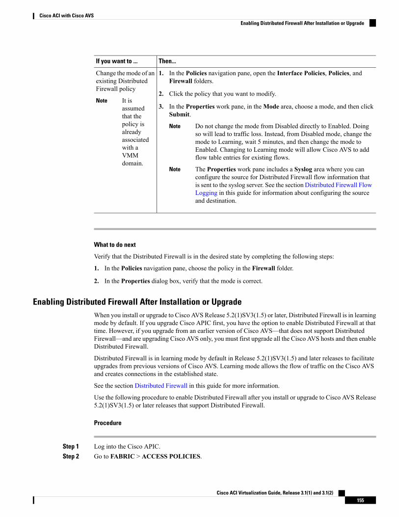
Then...If you want to ...
Change themode of anexisting DistributedFirewall policy
1. In the Policies navigation pane, open the Interface Policies, Policies, andFirewall folders.
2. Click the policy that you want to modify.It isassumedthat thepolicy isalreadyassociatedwith aVMMdomain.
Note3. In the Properties work pane, in theMode area, choose a mode, and then click
Submit.
Do not change the mode from Disabled directly to Enabled. Doingso will lead to traffic loss. Instead, from Disabled mode, change themode to Learning, wait 5 minutes, and then change the mode toEnabled. Changing to Learning mode will allow Cisco AVS to addflow table entries for existing flows.
Note
The Properties work pane includes a Syslog area where you canconfigure the source for Distributed Firewall flow information thatis sent to the syslog server. See the section Distributed Firewall FlowLogging in this guide for information about configuring the sourceand destination.
Note
What to do next
Verify that the Distributed Firewall is in the desired state by completing the following steps:
1. In the Policies navigation pane, choose the policy in the Firewall folder.
2. In the Properties dialog box, verify that the mode is correct.
Enabling Distributed Firewall After Installation or UpgradeWhen you install or upgrade to Cisco AVS Release 5.2(1)SV3(1.5) or later, Distributed Firewall is in learningmode by default. If you upgrade Cisco APIC first, you have the option to enable Distributed Firewall at thattime. However, if you upgrade from an earlier version of Cisco AVS—that does not support DistributedFirewall—and are upgrading Cisco AVS only, you must first upgrade all the Cisco AVS hosts and then enableDistributed Firewall.
Distributed Firewall is in learning mode by default in Release 5.2(1)SV3(1.5) and later releases to facilitateupgrades from previous versions of Cisco AVS. Learning mode allows the flow of traffic on the Cisco AVSand creates connections in the established state.
See the section Distributed Firewall in this guide for more information.
Use the following procedure to enable Distributed Firewall after you install or upgrade to Cisco AVS Release5.2(1)SV3(1.5) or later releases that support Distributed Firewall.
Procedure
Step 1 Log into the Cisco APIC.Step 2 Go to FABRIC > ACCESS POLICIES.
Cisco ACI Virtualization Guide, Release 3.1(1) and 3.1(2)155
Cisco ACI with Cisco AVSEnabling Distributed Firewall After Installation or Upgrade
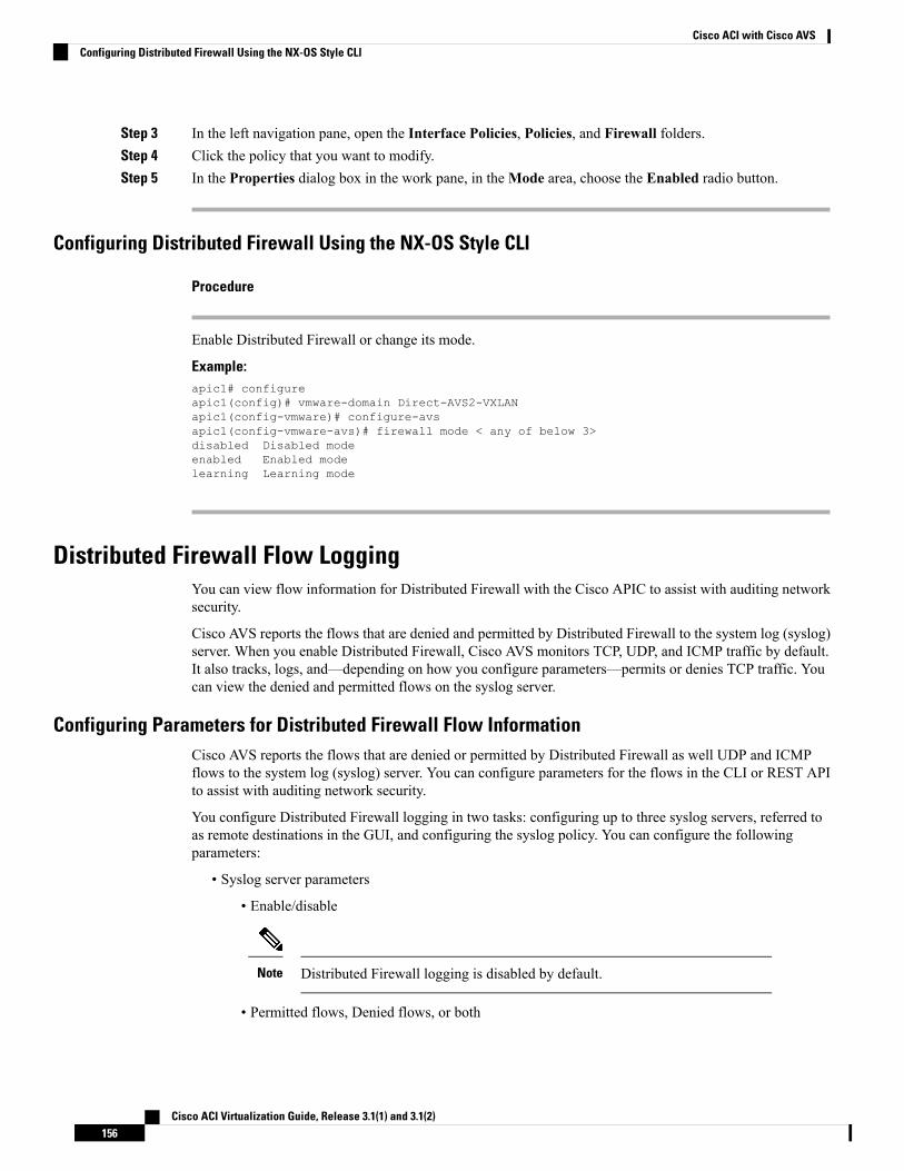
Step 3 In the left navigation pane, open the Interface Policies, Policies, and Firewall folders.Step 4 Click the policy that you want to modify.Step 5 In the Properties dialog box in the work pane, in theMode area, choose the Enabled radio button.
Configuring Distributed Firewall Using the NX-OS Style CLl
Procedure
Enable Distributed Firewall or change its mode.
Example:apic1# configureapic1(config)# vmware-domain Direct-AVS2-VXLANapic1(config-vmware)# configure-avsapic1(config-vmware-avs)# firewall mode < any of below 3>disabled Disabled modeenabled Enabled modelearning Learning mode
Distributed Firewall Flow LoggingYou can view flow information for Distributed Firewall with the Cisco APIC to assist with auditing networksecurity.
Cisco AVS reports the flows that are denied and permitted by Distributed Firewall to the system log (syslog)server. When you enable Distributed Firewall, Cisco AVS monitors TCP, UDP, and ICMP traffic by default.It also tracks, logs, and—depending on how you configure parameters—permits or denies TCP traffic. Youcan view the denied and permitted flows on the syslog server.
Configuring Parameters for Distributed Firewall Flow InformationCisco AVS reports the flows that are denied or permitted by Distributed Firewall as well UDP and ICMPflows to the system log (syslog) server. You can configure parameters for the flows in the CLI or REST APIto assist with auditing network security.
You configure Distributed Firewall logging in two tasks: configuring up to three syslog servers, referred toas remote destinations in the GUI, and configuring the syslog policy. You can configure the followingparameters:
• Syslog server parameters
• Enable/disable
Distributed Firewall logging is disabled by default.Note
• Permitted flows, Denied flows, or both
Cisco ACI Virtualization Guide, Release 3.1(1) and 3.1(2)156
Cisco ACI with Cisco AVSConfiguring Distributed Firewall Using the NX-OS Style CLl
• Polling interval
You can set the interval for exporting the flows from 60 seconds to 24 hours.
A polling interval of 125 seconds is required to send data at maximum scale. Werecommend that you configure the syslog timer with a polling interval of at least150 seconds.
Note
• Log severity
You can set the severity level from 0-7.
• Syslog policy parameters
• IP address
• Port
• Log severity
You can set the severity level from 0-7.
• Log facility
Cisco AVS reports up to 250,000 denied or permitted flows to the syslog server for each polling interval. Ifyou choose to log denied and permitted flows, Cisco AVS will report up to 500,000 flows. Cisco AVS alsoreports up to 100,000 short-lived flows—flows that are shorter than the polling interval.
Syslog messages are sent only if the syslog destination log severity is at or below the same log severity forthe syslog policy. Severity levels for the syslog server and syslog policy are as follows:
• 0: Emergency
• 1: Alert
• 2: Critical
• 3: Error
• 4: Warning
• 5: Notification
• 6: Information
• 7: Debug
Guidelines for Configuring the Syslog Server
Follow the guidelines in this section when configuring the syslog server for Cisco AVS.
• The syslog server should always be reachable from the Cisco AVS host management network or CiscoAVS overlay-1 network (infraVRF [virtual routing and forwarding]).
If the syslog server is behind the Cisco AVS, bring up the VM VNIC in the VTEP port group.
• The syslog server should always be on a different host from Cisco AVS.
Cisco ACI Virtualization Guide, Release 3.1(1) and 3.1(2)157
Cisco ACI with Cisco AVSGuidelines for Configuring the Syslog Server
Sending log messages from a Cisco AVS to a syslog server hosted behind the same Cisco AVS is notsupported.
• If the syslog server destination is a VM, make sure that vMotion is disabled on it. If the syslog serverdestination VM is moved to another host for any reason, make sure that the static client end point (CEP)is configured accordingly. See the section Configuring a Static End Point Using the GUI
The IP for the syslog server can be obtained using DHCP (Option 61 is needed during DHCP) or staticconfiguration. Make sure that the IP address is in the same subnet as the other VTEPs in overlay-1(infraVRF).
Distributed Firewall Flow Syslog Messages
This section provides the formats and examples of syslog messages for distributed Firewall flows
• Denied flows
• Format<Syslog Server timestamp> < PRI = Facility*8 + Severity > <syslog version> <Hosttimestamp> <Host IP> <Application name (avs-dfwlog)> - AVS IP: <AVSIP>DFWLOG-DENY_FLOW - <Deny Reason> AVS UUID: <UUID>, Source IP: <Source IP address>,Destination IP: <Destination IP address> , Source Port: <Port number>, DestinationPort: <Port Number>, Source Interface: <Interface name>, Protocol: "TCP"(6),Hit-Count = <Number of Occurrences>, EPG Name: <EPG Name>
• ExampleThu Apr 21 14:36:45 2016 10.197.138.90 <62>1 2016-04-22T11:34:49.198 10.197.138.90avs-dfwlog - AVS IP: 10.197.138.90 DFWLOG-DENY_FLOW - ACK scan ingress AVS UUID:4c4c4544-0047-3510-8048-c2c04f443032, Source IP: 192.168.5.1, Destination IP:192.168.5.2, Source Port: 60957, Destination Port: 21, Source Interface:UB4_sid.eth0, Protocol: "TCP"(6), Hit-Count = 1, EPG Name:uni/epp/fv-[uni/tn-TEMP_CLIENT/ap-APP_PROF/epg-EPG-1]
• Permitted flows
• Format<Syslog server timestamp> < PRI = Facility*8 + Severity> <syslog version> <Hosttimestamp> <Host IP> <Application name (avs-dfwlog)> - AVS IP: <AVSIP>DFWLOG-PERMIT_FLOW - AVS UUID: <UUID>, Source IP: <Source IP address>, DestinationIP: <Destination IP address>, Source Port: <Port Number>, Destination Port: <PortNumber>, Source Interface: <Interface name>, Protocol: "TCP"(6), Age = <Age inseconds>, EPG Name: <Full EPG Name>
• ExampleTue Apr 19 19:31:21 2016 10.197.138.90 <62>1 2016-04-20T16:30:03.418 10.197.138.90avs-dfwlog - AVS IP: 10.197.138.90 DFWLOG-PERMIT_FLOW - ESTABLISHED AVS UUID:4c4c4544-0047-3510-8048-c2c04f443032, Source IP: 192.168.5.1, Destination IP:192.168.5.2, Source Port: 59418, Destination Port: 5001, Source Interface:UB4_sid.eth0, Protocol: "TCP"(6), Age = 0, EPG Name:uni/epp/fv-[uni/tn-TEMP_CLIENT/ap-APP_PROF/epg-EPG-1]
• Short-lived permitted flows
• Format<Syslog Server timestamp> < PRI = Facility*8 + Severity > <syslog version> <Hosttimestamp> <Host IP> <Application name (avs-dfwlog)> - AVS IP: <AVSIP>DFWLOG-PERMIT_SHORT_LIVED - <State of flow> AVS UUID: <UUID>, Source IP: <SourceIP address>, Destination IP: <Destination IP address>, Source Port: <Port Number>,
Cisco ACI Virtualization Guide, Release 3.1(1) and 3.1(2)158
Cisco ACI with Cisco AVSDistributed Firewall Flow Syslog Messages
Destination Port: <Port Number>, Source Interface: <Interface Name>, Protocol:"TCP"(6), Timestamp = <Host Timestamp>, EPG Name: <EPG Name>
• ExampleThu Apr 21 14:46:38 2016 10.197.138.88 <62>1 2016-04-22T06:26:37.610 10.197.138.88avs-dfwlog - AVS IP: 10.197.138.88 DFWLOG-PERMIT_SHORT_LIVED - CLOSED AVS UUID:4c4c4544-0037-5810-8047-b7c04f443032, Source IP: 192.168.5.2, Destination IP:192.168.5.1, Source Port: 5001, Destination Port: 59508, Source Interface:UB3_sid.eth0, Protocol: "TCP"(6), Timestamp = 2016-04-22T06:26:37.610, EPG Name:uni/epp/fv-[uni/tn-TEMP_CLIENT/ap-APP_PROF/epg-EPG-1]
• ICMP monitored flows
• Format<Syslog server timestamp> < PRI = Facility*8 + Severity> <syslog version> <Hosttimestamp> <Host IP> <Application name (avs-dfwlog)> - AVS IP: <AVSIP>DFWLOG-PERMIT_FLOW_ICMP - AVS UUID: <UUID>, Source IP: <Source IP address>,Destination IP: <Destination IP address>, Type:<ICMP type field>, Source Interface:<Interface name>, Protocol: "ICMP"(1), Timestamp= <Host time stamp>, Direction:<Egress/Ingress>, EPG Name:<Full EPG Name>
• Example2016-11-28 11:02:43 News.Info 10.197.138.88 1 2016-11-28T19:01:34.221 10.197.138.88avs-dfwlog - AVS IP: 10.197.138.88 DFWLOG-ICMP_TRACKING AVS UUID:4c4c4544-0037-5810-8047-b7c04f443032, Source IP: 192.168.5.1, Destination IP:192.168.5.2, Icmp type and code: Echo request (8,0) Source Interface: UB4_sid.eth0,Protocol: "ICMP"(1), Timestamp = 2016-11-28T19:01:34.221, Direction: Ingress, EpPDN: uni/epp/fv-[uni/tn-TEST_TENT/ap-Temp1/epg-tempEPG]
• UDP monitored flows
• FormatUDP:<Syslog server timestamp> < PRI = Facility*8 + Severity> <syslog version> <Hosttimestamp> <Host IP> <Application name (avs-dfwlog)> - AVS IP: <AVSIP>DFWLOG-PERMIT_FLOW_UDP - AVS UUID: <UUID>, Source IP: <Source IP address>,Destination IP: <Destination IP address>, Source Port: <Port Number>, DestinationPort: <Port Number>, Source Interface: <Interface name>, Protocol: "UDP"(17),Timestamp=<Host timestamp>, Direction: <Egress/Ingress>, EPG Name: <Full EPG Name>
• Example2016-11-28 11:00:23 News.Info 10.197.138.88 1 2016-11-28T19:00:14.252 10.197.138.88avs-dfwlog - AVS IP: 10.197.138.88 DFWLOG-UDP_TRACKING AVS UUID:4c4c4544-0037-5810-8047-b7c04f443032, Source IP: 169.254.170.192, Destination IP:169.254.255.255, Source Port: 138, Destination Port: 138, Source Interface:win_sys.eth1, Protocol: "UDP"(17), Timestamp = 2016-11-28T19:00:14.252, Direction:Ingress, EpP DN: uni/epp/fv-[uni/tn-t0/ap-a0/epg-e0]
Configuring a Static End Point Using the GUI
Procedure
Step 1 Log into Cisco APIC.
Cisco ACI Virtualization Guide, Release 3.1(1) and 3.1(2)159
Cisco ACI with Cisco AVSConfiguring a Static End Point Using the GUI
Step 2 In theTenant infra navigation pane, open the following folders:Application Profiles > access >ApplicationEPGs > EPG default.
Step 3 Right-click the Static Endpoint folder and then choose Create Static EndPoint.Step 4 In the Create Static Endpoint dialog box, complete the following steps:
a) In theMAC field, enter the syslog server destination's MAC address.b) In the Type area, choose tep.c) In the Path Type area, choose the appropriate path type.
The path type determines how the leaf is connected to the syslog server destination. The leaf can beconnected by port, direct port channel, or virtual port channel.
d) In the Path field, enter the appropriate path.
The path determines the policy group where the syslog server destination is attached.
e) In the IP Address field, enter the syslog server destination IP address.f) In the Encap field, enter the overlay-1 VLAN (vlan-xxix).g) Click SUBMIT.
Step 5 From the syslog server destination, ping any overlay-IP address—for example, 10.0.0.30.
This step ensures that the fabric learns the Syslog server destination IP address.
Configuring Parameters for Distributed Firewall Flow Information
To configure parameters, you first configure the parameters for the syslog server or servers and then configurethe parameters for the syslog policy. The syslog server is referred to as the Remote Destination in the GUI.
Before you begin
Youmust have Distributed Firewall enabled. See the Distributed Firewall section of the "Cisco ACI and CiscoAVS" chapter in this guide information about configuring Distributed Firewall.
Procedure
Step 1 Log into Cisco APIC.Step 2 Go to Admin > External Data Collectors.Step 3 In the External Data Collectors navigation pane, expand theMonitoring Destinations folder and then
choose the Syslog folder.Step 4 In the Syslog work pane, click the ACTIONS down arrow and then choose Create Syslog Monitoring
Destination Group.Step 5 In the Create Syslog Monitoring Destination Group STEP 1 > Profile dialog box, complete the following
steps:a) In the Define Group Name and Profile area, enter a name in the Name field.b) In the Admin State area, make sure that enabled is chosen from the drop-down list.c) Accept the defaults in the rest of the dialog box and click NEXT.
Step 6 In the Create Syslog Monitoring Destination Group STEP 2 > Remote Destinations dialog box, click the+ icon.
Cisco ACI Virtualization Guide, Release 3.1(1) and 3.1(2)160
Cisco ACI with Cisco AVSConfiguring Parameters for Distributed Firewall Flow Information
Step 7 In the Create Syslog Remote Destination dialog box, complete the following steps:a) In the Host field, enter the host IP address.b) In the Name field, enter the host name.c) In the Admin State area, make sure that enabled is chosen.d) In the Format area, make sure that aci is chosen.e) From the Severity drop-down list, choose a severity.f) From the Port drop-down list, accept the standard port unless you are using another port.g) From the Forwarding Facility drop-down list, choose a facility.h) Ignore theManagement EPG drop-down list and click OK.
Step 8 (Optional) In the Create Syslog Monitoring Destination Group STEP 2 > Remote Destinations dialogbox, create up to two additional remote destinations.
Step 9 In the Create Syslog Monitoring Destination Group STEP 2 > Remote Destinations dialog box, clickFINISH.The newly created destination appears in the Syslog folder in the External Data Collectors navigation pane.
Step 10 Choose Fabric > Access Policies.Step 11 In the Policies navigation pane, open the Interface Polices and Policies folders.Step 12 Complete one of the following sets of steps:
Then...If you want to...
Configure a syslogpolicy with a new
1. Right-click the Firewall folder and choose Create Firewall Policy.
2. In the Create Firewall Policy dialog box, in the Specify the Firewall PolicyProperties area, type a name for the policy in the Name field.
Distributed Firewallpolicy
3. In theMode area, choose a mode.
Learning mode is used only when upgrading from a version of Cisco AVS thatdoes not support Distributed Firewall to a version that does. Otherwise,Distributed Firewall should be in Enabled mode.
4. In the Syslog area, make sure that enabled is chosen from the AdministrativeState drop-down list.
5. From the Included Flows area, choose Permitted flows,Denied flows, or both.
6. In the Polling Interval (seconds) area, choosing an interval from 60 seconds to24 hours.
7. From the Log Level drop-down list, choose a severity level.
The logging severity level should be greater than or equal to severity level definedfor the syslog server. See the section Configuring Parameters for DistributedFirewall Flow Information in this guide for information about severity.
8. From the Destination Group drop-down list, choose the destination group thatyou just created.
9. Click SUBMIT.
10. Go to the section "What To Do Next" and associate the newDistributed Firewallpolicy with a VMM domain.
Cisco ACI Virtualization Guide, Release 3.1(1) and 3.1(2)161
Cisco ACI with Cisco AVSConfiguring Parameters for Distributed Firewall Flow Information
Then...If you want to...
Configure a syslogpolicy with an
1. Expand the Firewall folder and choose the Distributed Firewall policy that youwant to modify.
existing DistributedFirewall policy 2. In the policy work pane, change theMode if desired.
Learning mode is used only when upgrading from a version of Cisco AVS thatdoes not support Distributed Firewall to a version that does. Otherwise, DistributedFirewall should be in Enabled mode.
3. In the Syslog area, make sure that enabled is chosen from the AdministrativeState drop-down list.
4. From the Included Flows area, choose Permitted flows, Denied flows, or both.
5. In the Polling Interval (seconds) area, choosing an interval from 60 seconds to24 hours.
6. From the Log Level drop-down list, choose a severity level.
The logging severity level should be greater than or equal to severity level definedfor the syslog server. See the section Configuring Parameters for DistributedFirewall Flow Information in this guide for information about severity.
7. From the Destination Group drop-down list, choose the destination group thatyou just created.
8. Click SUBMIT.
9. If you see the Policy Usage Warning dialog box, click SUBMIT CHANGES.
What to do next
If you configured a syslog policy with a new Distributed Firewall policy, you must associate the DistributedFirewall policy with a VMM domain.
1. In Cisco APIC, choose Virtual Networking > Inventory.
2. In the navigation pane, expand the VMM Domains folder and the VMware folder, and then choose therelevant VMM domain.
3. In the work pane, click the ACTIONS down arrow and then choose Create VSwitch Policies.
4. In the Create VSwitch Policy Container dialog box, click Yes.
5. In the work pane, scroll to theVSwitch Policies area, and from the Firewall Policy drop-down list, choosethe policy.
6. Click SUBMIT.
7. If you see the Policy Usage Warning dialog box, click SUBMIT CHANGES.
Cisco ACI Virtualization Guide, Release 3.1(1) and 3.1(2)162
Cisco ACI with Cisco AVSConfiguring Parameters for Distributed Firewall Flow Information
Configuring Parameters for Distributed Firewall Flow Information in the NX-OS Style CLI
Before you begin
You must have Distributed Firewall enabled. See the "Distributed Firewall" section of the "Cisco ACI andCisco AVS" chapter in the Cisco ACI Virtualization Guide for information about configuring DistributedFirewall.
Procedure
Step 1 Configure the parameters for the syslog server or servers.
Example:
apic1# configureapic1(config)# logging server-group group name
apic1(config-logging)# server IP address severity severity level facility facilityname
You can repeat the last command for additional syslog servers; you can configure up to three syslog servers.
Step 2 Configure the parameters for the syslog source.
Example:
apic1# configureapic1(config)# vmware-domain Direct-AVSapic1(config)# configure-avsapic1(config-avs)# firewall mode enabledapic1(config-avs)# firewall-logging server-group group name action-type permit,deny
You must enter the firewall mode enabled command before you enter the firewall-loggingcommand.
Note
For the firewall-logging command, you can enter either permit or deny. You can also enter both,separated by a comma.
Note
Distributed Firewall Flow CountsYou can view Distributed Firewall flow counts with the Cisco APIC.
Cisco AVS collects Distributed Firewall flow information, but you must choose which statistics you want toknow about before you can view them. You can choose a sampling interval with choices ranging from 10seconds to 1 year; however, the default is 5 minutes.
You can choose statistics and view them from two different places in Cisco APIC: one beginning withVirtualNetworking and one beginning with Tenants. However, the steps for choosing and viewing statistics are thesame.
When you choose statistics in Cisco APIC, you see a list of different kinds of statistics, but only nine arerelevant to Distributed Firewall:
• aged connections (connections)
Cisco ACI Virtualization Guide, Release 3.1(1) and 3.1(2)163
Cisco ACI with Cisco AVSConfiguring Parameters for Distributed Firewall Flow Information in the NX-OS Style CLI
• created connections (connections)
• destroyed connections (connections)
• denied global input connections (connections)
• denied per port limit connections (connections)
• invalid SYN ACK packets (packets)
• invalid SYN packets (packets)
• invalid connection packets (packets)
• invalid ftp SYN packets (packets)
Choosing Statistics to View for Distributed Firewall
Before you begin
You must have Distributed Firewall enabled. See the "Distributed Firewall" section of the "Cisco ACI andCisco AVS" chapter in the Cisco ACI Virtualization Guide for information about configuring DistributedFirewall.
Procedure
Step 1 Choose Virtual Networking > Inventory > VMM Domains > VMware > VMM_name > Controllers >data center_name >DVS-VMMname > Portgroups > EPG_name > Learned PointMAC address (Node).
Step 2 Click the Stats tab.Step 3 Click the tab with the check mark.Step 4 In the Select Stats dialog box, click the statistics that you want to view in the Available pane and then click
the arrow pointing right to put them in the Selected pane.Step 5 (Optional) Choose a sampling interval different from the default of 5 minutes.Step 6 Click SUBMIT.
Viewing Statistics for Distributed FirewallOnce you have chosen statistics for Distributed Firewall, you can view them.
Before you begin
Youmust have chosen statistics to view for Distributed Firewall. See Choosing Statistics to View for DistributedFirewall for instructions.
Procedure
Step 1 Choose Virtual Networking > Inventory > VMM Domains > VMware > VMM_name > Controllers >data center_name > DVS-VMM name > Portgroups > EPG_name > Learned PointMAC address (Node)
Cisco ACI Virtualization Guide, Release 3.1(1) and 3.1(2)164
Cisco ACI with Cisco AVSChoosing Statistics to View for Distributed Firewall
Step 2 Click the Stats tab.
The central pane displays the statistics that you chose earlier. You can change the view by clicking the tableview or chart view icon on the upper left side of the work pane.
Microsegmentation with Cisco ACI for Cisco AVSMicrosegmentation with the Cisco ACI enables you to automatically assign endpoints to logical security zonescalled EPGs based on various attributes. Microsegmentation with Cisco ACI is available in Cisco AVSRelease5.2(1)SV3(1.5) and later releases.
For detailed conceptual information about Microsegmentation with Cisco ACI—including how it works,attributes, and precedence—and instructions for configuring it, see the chapterMicrosegmentation with CiscoACI in this guide.
Configuring Layer 4 to Layer 7 ServicesFor information about configuring Layer 4 to Layer 7 services on the Cisco AVS, see the Cisco APIC Layer4 to Layer 7 Services Deployment Guide.
When you follow instructions in the Cisco APIC Layer 4 to Layer 7 Services Deployment Guide, instead ofconfiguring services on the VMware Distributed Virtual Switch (DVS), configure the services on the CiscoAVS.
You must install Cisco AVS before you can configure Layer 4 to Layer 7 services.Note
Beginning with Cisco AVS Release 5.2(1)SV3(1.10), Layer 4 to Layer 7 service graphs are supported forCisco AVS. Layer 4 to Layer 7 service graphs for Cisco AVS can be configured for VMs only and in VLANmode only. Layer 4 to Layer 7 service integration is not supported when the service VMs are deployed on ahost with VXLAN encapsulation.
However, beginning with Cisco AVS Release 5.2(1)SV3(2.14), Layer 4 to Layer 7 service integration issupported when the service VMs are deployed on hosts with VXLAN encapsulation. This is achieved byadding both service VM hosts and Compute VM hosts to a single VMM domain that is in mixed mode. BothVLAN and multicast pools can be configured in mixed mode. Service VM EPGs will use VLAN from thedefined pool, and all other EPGs can use either VXLAN or VLAN encapsulation. Both VXLAN endpointsand VLAN service VMs can now be part of same host in a mixed-mode VMM configuration.
Migrating Your Network from DVS to AVSComplete the following steps in VMware vSphere Web Client to migrate your network from VMware DVSto Cisco AVS.
Cisco ACI Virtualization Guide, Release 3.1(1) and 3.1(2)165
Cisco ACI with Cisco AVSMicrosegmentation with Cisco ACI for Cisco AVS
Before you begin
You must remove the configuration that you made in Cisco APIC for the VMware DVS.
Procedure
Step 1 Put the ESXi host in maintenance mode.Step 2 Remove from the VMware DVS the uplinks that you plan to use for Cisco AVS.
Do not delete the VMware DVS at this point.
Step 3 Remove the configuration from ports in the Cisco ACI fabric that correspond to the host VMware DVS.Step 4 Install Cisco AVS and verify its operational state, following the procedures in the Cisco AVS Installation
Guide or the Cisco AVS chapter in the Cisco ACI Virtualization Guide.Step 5 Once Cisco AVS is operational, associate all the EPGs that were used by the VMware DVS to the Cisco AVS
VMM domain.
Associating the EPGs to the Cisco AVS VMM domain should lead to the creation of port groups for CiscoAVS.
Step 6 Remove the host frommaintenancemode andmigrate the VMs that you removed from the host earlier—beforeyou entered maintenance mode—back to the host.
Step 7 In VM network settings, change the port group from VMware DVS to the same port group for Cisco AVS.Step 8 (Optional but recommended) Remove the VMware DVS from the host.
What to do next
Repeat Step 1 through Step 7 for each remaining host.
REST API Tasks for Cisco AVSThis section contains the REST API versions of tasks documented in the Cisco APIC GUI in this chapter.
Creating a Tenant, VRF, and Bridge Domain Using the REST API
Procedure
Step 1 Create a tenant.
Example:POST https://apic-ip-address/api/mo/uni.xml<fvTenant name="ExampleCorp"/>
When the POST succeeds, you see the object that you created in the output.Step 2 Create a VRF and bridge domain.
Cisco ACI Virtualization Guide, Release 3.1(1) and 3.1(2)166
Cisco ACI with Cisco AVSREST API Tasks for Cisco AVS
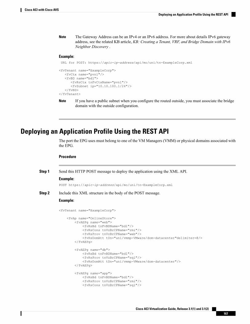
The Gateway Address can be an IPv4 or an IPv6 address. For more about details IPv6 gatewayaddress, see the related KB article, KB: Creating a Tenant, VRF, and Bridge Domain with IPv6Neighbor Discovery .
Note
Example:URL for POST: https://apic-ip-address/api/mo/uni/tn-ExampleCorp.xml
<fvTenant name="ExampleCorp"><fvCtx name="pvn1"/><fvBD name="bd1">
<fvRsCtx tnFvCtxName="pvn1"/><fvSubnet ip="10.10.100.1/24"/>
</fvBD></fvTenant>
If you have a public subnet when you configure the routed outside, you must associate the bridgedomain with the outside configuration.
Note
Deploying an Application Profile Using the REST APIThe port the EPG uses must belong to one of the VMManagers (VMM) or physical domains associated withthe EPG.
Procedure
Step 1 Send this HTTP POST message to deploy the application using the XML API.
Example:POST https://apic-ip-address/api/mo/uni/tn-ExampleCorp.xml
Step 2 Include this XML structure in the body of the POST message.
Example:
<fvTenant name="ExampleCorp">
<fvAp name="OnlineStore"><fvAEPg name="web">
<fvRsBd tnFvBDName="bd1"/><fvRsCons tnVzBrCPName="rmi"/><fvRsProv tnVzBrCPName="web"/><fvRsDomAtt tDn="uni/vmmp-VMware/dom-datacenter"delimiter=@/>
</fvAEPg>
<fvAEPg name="db"><fvRsBd tnFvBDName="bd1"/><fvRsProv tnVzBrCPName="sql"/><fvRsDomAtt tDn="uni/vmmp-VMware/dom-datacenter"/>
</fvAEPg>
<fvAEPg name="app"><fvRsBd tnFvBDName="bd1"/><fvRsProv tnVzBrCPName="rmi"/><fvRsCons tnVzBrCPName="sql"/>
Cisco ACI Virtualization Guide, Release 3.1(1) and 3.1(2)167
Cisco ACI with Cisco AVSDeploying an Application Profile Using the REST API
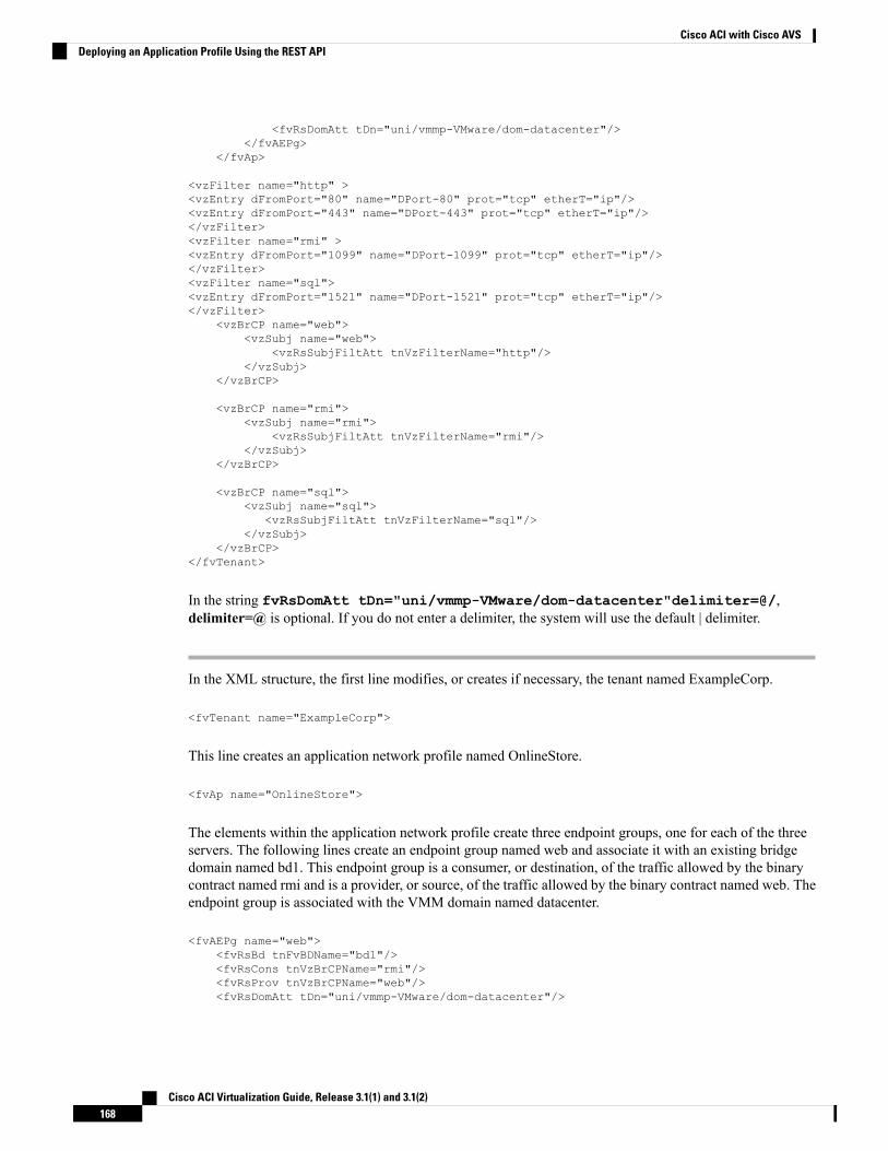
<fvRsDomAtt tDn="uni/vmmp-VMware/dom-datacenter"/></fvAEPg>
</fvAp>
<vzFilter name="http" ><vzEntry dFromPort="80" name="DPort-80" prot="tcp" etherT="ip"/><vzEntry dFromPort="443" name="DPort-443" prot="tcp" etherT="ip"/></vzFilter><vzFilter name="rmi" ><vzEntry dFromPort="1099" name="DPort-1099" prot="tcp" etherT="ip"/></vzFilter><vzFilter name="sql"><vzEntry dFromPort="1521" name="DPort-1521" prot="tcp" etherT="ip"/></vzFilter>
<vzBrCP name="web"><vzSubj name="web">
<vzRsSubjFiltAtt tnVzFilterName="http"/></vzSubj>
</vzBrCP>
<vzBrCP name="rmi"><vzSubj name="rmi">
<vzRsSubjFiltAtt tnVzFilterName="rmi"/></vzSubj>
</vzBrCP>
<vzBrCP name="sql"><vzSubj name="sql">
<vzRsSubjFiltAtt tnVzFilterName="sql"/></vzSubj>
</vzBrCP></fvTenant>
In the string fvRsDomAtt tDn="uni/vmmp-VMware/dom-datacenter"delimiter=@/,delimiter=@ is optional. If you do not enter a delimiter, the system will use the default | delimiter.
In the XML structure, the first line modifies, or creates if necessary, the tenant named ExampleCorp.
<fvTenant name="ExampleCorp">
This line creates an application network profile named OnlineStore.
<fvAp name="OnlineStore">
The elements within the application network profile create three endpoint groups, one for each of the threeservers. The following lines create an endpoint group named web and associate it with an existing bridgedomain named bd1. This endpoint group is a consumer, or destination, of the traffic allowed by the binarycontract named rmi and is a provider, or source, of the traffic allowed by the binary contract named web. Theendpoint group is associated with the VMM domain named datacenter.
<fvAEPg name="web"><fvRsBd tnFvBDName="bd1"/><fvRsCons tnVzBrCPName="rmi"/><fvRsProv tnVzBrCPName="web"/><fvRsDomAtt tDn="uni/vmmp-VMware/dom-datacenter"/>
Cisco ACI Virtualization Guide, Release 3.1(1) and 3.1(2)168
Cisco ACI with Cisco AVSDeploying an Application Profile Using the REST API
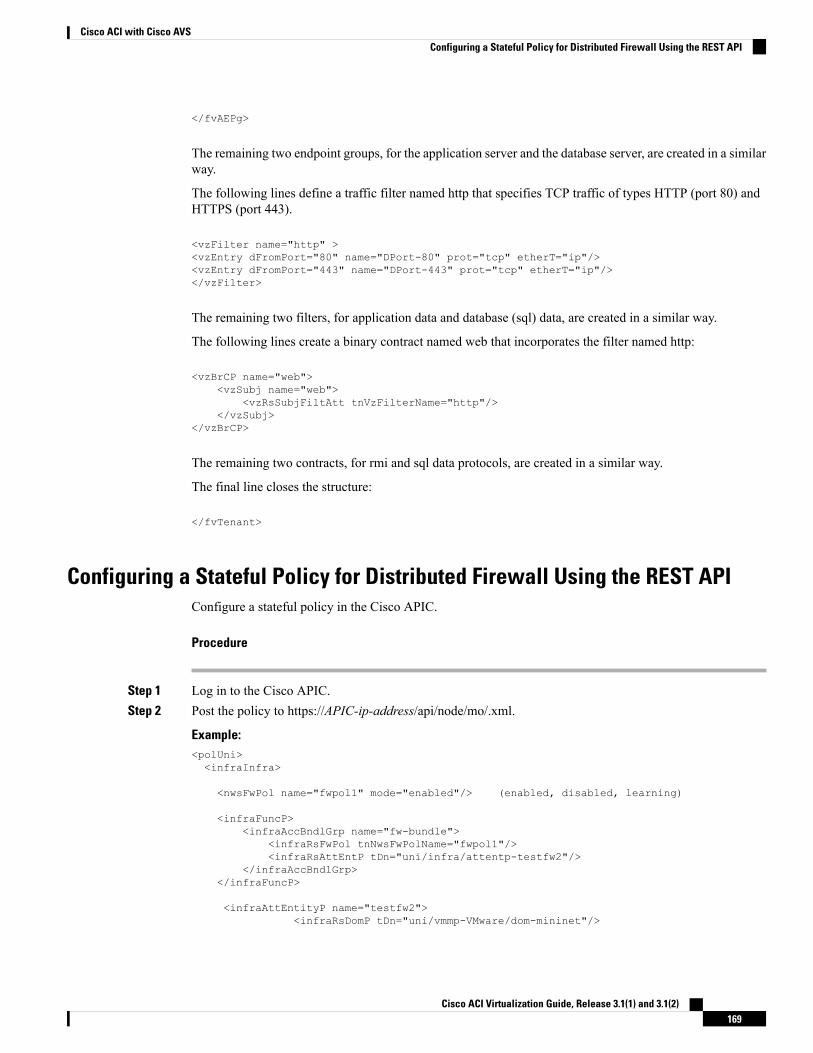
</fvAEPg>
The remaining two endpoint groups, for the application server and the database server, are created in a similarway.
The following lines define a traffic filter named http that specifies TCP traffic of types HTTP (port 80) andHTTPS (port 443).
<vzFilter name="http" ><vzEntry dFromPort="80" name="DPort-80" prot="tcp" etherT="ip"/><vzEntry dFromPort="443" name="DPort-443" prot="tcp" etherT="ip"/></vzFilter>
The remaining two filters, for application data and database (sql) data, are created in a similar way.
The following lines create a binary contract named web that incorporates the filter named http:
<vzBrCP name="web"><vzSubj name="web">
<vzRsSubjFiltAtt tnVzFilterName="http"/></vzSubj>
</vzBrCP>
The remaining two contracts, for rmi and sql data protocols, are created in a similar way.
The final line closes the structure:
</fvTenant>
Configuring a Stateful Policy for Distributed Firewall Using the REST APIConfigure a stateful policy in the Cisco APIC.
Procedure
Step 1 Log in to the Cisco APIC.Step 2 Post the policy to https://APIC-ip-address/api/node/mo/.xml.
Example:<polUni><infraInfra>
<nwsFwPol name="fwpol1" mode="enabled"/> (enabled, disabled, learning)
<infraFuncP><infraAccBndlGrp name="fw-bundle">
<infraRsFwPol tnNwsFwPolName="fwpol1"/><infraRsAttEntP tDn="uni/infra/attentp-testfw2"/>
</infraAccBndlGrp></infraFuncP>
<infraAttEntityP name="testfw2"><infraRsDomP tDn="uni/vmmp-VMware/dom-mininet"/>
Cisco ACI Virtualization Guide, Release 3.1(1) and 3.1(2)169
Cisco ACI with Cisco AVSConfiguring a Stateful Policy for Distributed Firewall Using the REST API
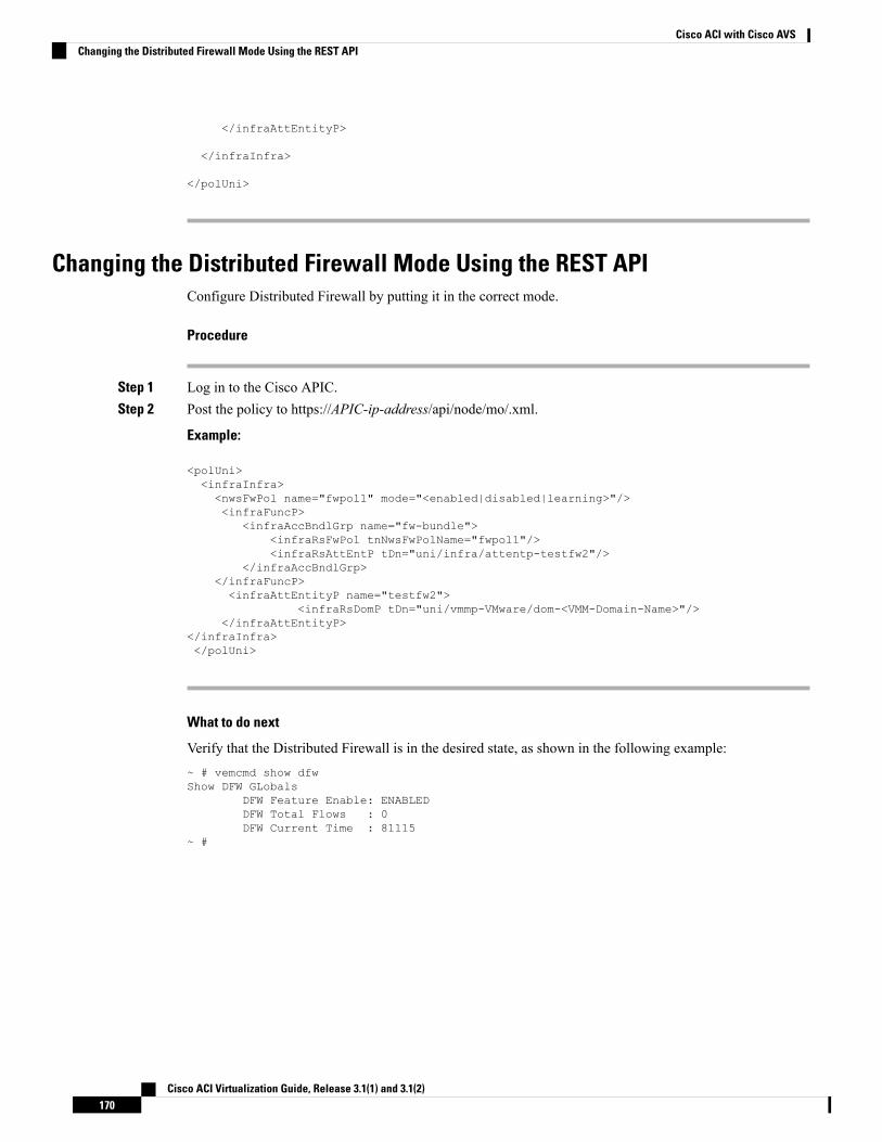
</infraAttEntityP>
</infraInfra>
</polUni>
Changing the Distributed Firewall Mode Using the REST APIConfigure Distributed Firewall by putting it in the correct mode.
Procedure
Step 1 Log in to the Cisco APIC.Step 2 Post the policy to https://APIC-ip-address/api/node/mo/.xml.
Example:
<polUni><infraInfra><nwsFwPol name="fwpol1" mode="<enabled|disabled|learning>"/><infraFuncP>
<infraAccBndlGrp name="fw-bundle"><infraRsFwPol tnNwsFwPolName="fwpol1"/><infraRsAttEntP tDn="uni/infra/attentp-testfw2"/>
</infraAccBndlGrp></infraFuncP><infraAttEntityP name="testfw2">
<infraRsDomP tDn="uni/vmmp-VMware/dom-<VMM-Domain-Name>"/></infraAttEntityP>
</infraInfra></polUni>
What to do next
Verify that the Distributed Firewall is in the desired state, as shown in the following example:~ # vemcmd show dfwShow DFW GLobals
DFW Feature Enable: ENABLEDDFW Total Flows : 0DFW Current Time : 81115
~ #
Cisco ACI Virtualization Guide, Release 3.1(1) and 3.1(2)170
Cisco ACI with Cisco AVSChanging the Distributed Firewall Mode Using the REST API
Configuring Parameters for Distributed Firewall Flow Information in the RESTAPI
Procedure
Step 1 Configure the Distributed Firewall logging parameters for the source.
Example:<infraInfra>
<nwsFwPol name="__ui_vmm_pol_PARAM-AVS" mode="enabled"><nwsSyslogSrc adminState="enabled" name="PARAM-AVS" inclAction="deny" logLevel="4"
pollingInterval="120"><nwsRsNwsSyslogSrcToDestGroup tDn="uni/fabric/slgroup-syslog-servers"/>
</nwsSyslogSrc></nwsFwPol>
</infraInfra>
Step 2 Identify the syslog server or servers that will receive the Distributed Firewall flows.
Example:<syslogGroup name="syslog-servers" >
<syslogRemoteDest host="1.1.1.1" /><syslogRemoteDest host="2.2.2.2" /><syslogRemoteDest host="3.3.3.3" />
</syslogGroup>
The name of the syslog group must be the same in both REST API commands, as it does in the precedingexamples.
Cisco ACI Virtualization Guide, Release 3.1(1) and 3.1(2)171
Cisco ACI with Cisco AVSConfiguring Parameters for Distributed Firewall Flow Information in the REST API

Cisco ACI Virtualization Guide, Release 3.1(1) and 3.1(2)172
Cisco ACI with Cisco AVSConfiguring Parameters for Distributed Firewall Flow Information in the REST API
C H A P T E R 7Cisco ACI with VMware vRealize
This chapter contains the following sections:
• About Cisco ACI with VMware vRealize, on page 173• Getting Started with Cisco ACI with VMware vRealize, on page 178• Cisco ACI with VMware vRealize Upgrade Workflow, on page 184• Cisco ACI with VMware vRealize Downgrade Workflow, on page 186• Use Case Scenarios for the Administrator and Tenant Experience, on page 187• Troubleshooting, on page 266• Removing the APIC Plug-in, on page 268• Plug-in Overview, on page 268• Configuring a vRA Host for the Tenant in the vRealize Orchestrator, on page 269• Configuring an IaaS Host in the vRealize Orchestrator, on page 270
About Cisco ACI with VMware vRealizeCisco Application Centric Infrastructure (ACI), in addition to integrating with VMware vCenter, integrateswith VMware's products vRealize Automation (vRA) and vRealize Orchestrator (vRO). vRA and vRO areparts of the VMware vRealize Suite for building and managing multivendor hybrid cloud environments.
Beginning with Cisco Application Policy Infrastructure Controller (APIC) Release 2.0(1), vRA and vROsupport Cisco AVS in addition to VMware DVS. Beginning with Cisco APIC Release 3.1(1), vRA and vROsupport Cisco Application Centric Infrastructure Virtual Edge (Cisco ACI Virtual Edge).
In the Cisco APIC GUI, Cisco ACI Virtual Edge is indicated with the term AVE.Note
Cisco ACI with VMware vRealize Solution OverviewvRA integration is delivered through a set of service blueprints imported into vRA. The service blueprintsleverage the vRO Application Policy Infrastructure Controller (APIC) workflows, providing a set of catalogitems in a self-service portal that allows Tenants to build, manage, and remove networking components.Multi-machine with ACI workflows achieve following functionalities:
• Auto-create Tenant Endpoint Groups (EPGs)
Cisco ACI Virtualization Guide, Release 3.1(1) and 3.1(2)173
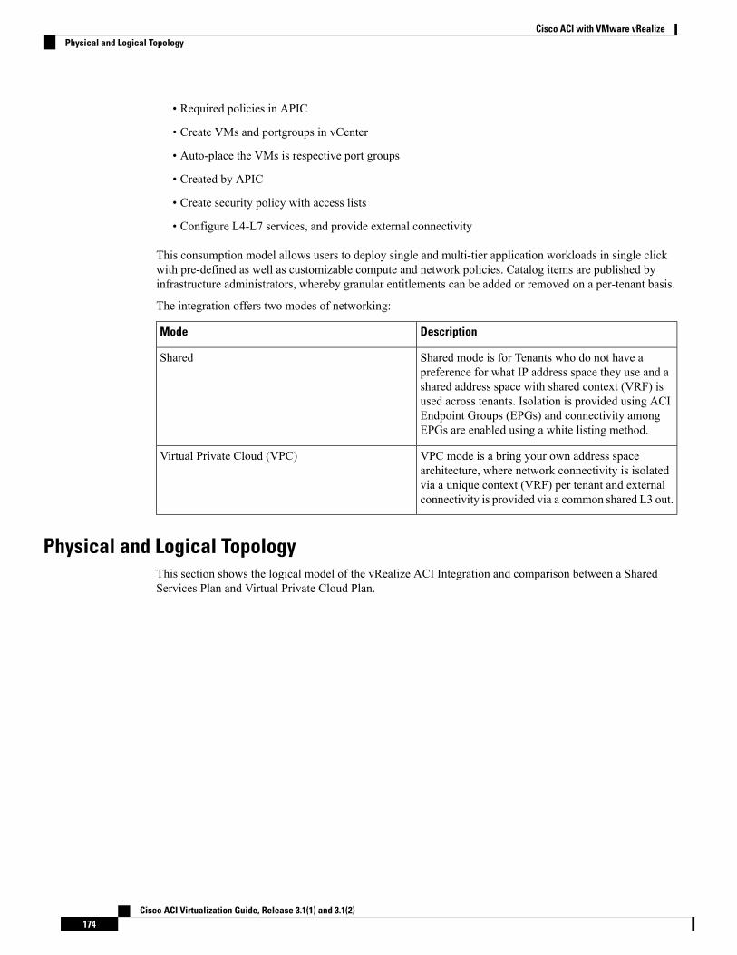
• Required policies in APIC
• Create VMs and portgroups in vCenter
• Auto-place the VMs is respective port groups
• Created by APIC
• Create security policy with access lists
• Configure L4-L7 services, and provide external connectivity
This consumption model allows users to deploy single and multi-tier application workloads in single clickwith pre-defined as well as customizable compute and network policies. Catalog items are published byinfrastructure administrators, whereby granular entitlements can be added or removed on a per-tenant basis.
The integration offers two modes of networking:
DescriptionMode
Shared mode is for Tenants who do not have apreference for what IP address space they use and ashared address space with shared context (VRF) isused across tenants. Isolation is provided using ACIEndpoint Groups (EPGs) and connectivity amongEPGs are enabled using a white listing method.
Shared
VPC mode is a bring your own address spacearchitecture, where network connectivity is isolatedvia a unique context (VRF) per tenant and externalconnectivity is provided via a common shared L3 out.
Virtual Private Cloud (VPC)
Physical and Logical TopologyThis section shows the logical model of the vRealize ACI Integration and comparison between a SharedServices Plan and Virtual Private Cloud Plan.
Cisco ACI Virtualization Guide, Release 3.1(1) and 3.1(2)174
Cisco ACI with VMware vRealizePhysical and Logical Topology

Figure 12: This figure shows a logical model of the vRealize ACI Integration.
Cisco ACI Virtualization Guide, Release 3.1(1) and 3.1(2)175
Cisco ACI with VMware vRealizePhysical and Logical Topology
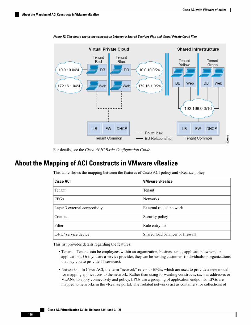
Figure 13: This figure shows the comparison between a Shared Services Plan and Virtual Private Cloud Plan.
For details, see the Cisco APIC Basic Configuration Guide.
About the Mapping of ACI Constructs in VMware vRealizeThis table shows the mapping between the features of Cisco ACI policy and vRealize policy
VMware vRealizeCisco ACI
TenantTenant
NetworksEPGs
External routed networkLayer 3 external connectivity
Security policyContract
Rule entry listFilter
Shared load balancer or firewallL4-L7 service device
This list provides details regarding the features:
• Tenant—Tenants can be employees within an organization, business units, application owners, orapplications. Or if you are a service provider, they can be hosting customers (individuals or organizationsthat pay you to provide IT services).
• Networks—In Cisco ACI, the term “network” refers to EPGs, which are used to provide a new modelfor mapping applications to the network. Rather than using forwarding constructs, such as addresses orVLANs, to apply connectivity and policy, EPGs use a grouping of application endpoints. EPGs aremapped to networks in the vRealize portal. The isolated networks act as containers for collections of
Cisco ACI Virtualization Guide, Release 3.1(1) and 3.1(2)176
Cisco ACI with VMware vRealizeAbout the Mapping of ACI Constructs in VMware vRealize
applications, or of application components and tiers, that can be used to apply forwarding and policylogic. They allow the separation of network policy, security, and forwarding from addressing and insteadapply these to logical application boundaries. When a network is created in vRealize, in the back end itis created as a port group in vCenter. A vRealize tenant can use vCenter to manage the computingresources and can attach the virtual machine to the appropriate network.
• Layer 3 external connectivity—The Cisco ACI fabric connects to the outside through Layer 3 externalnetworks. These constructs are also available for vRealize tenants to access other services within thedata center, across the data center, or on the internet.
• Security policy—Cisco ACI is built on a highly secure model, in which traffic between EPGs (isolatednetworks) is denied, unless explicitly allowed by policy contracts. A Cisco ACI contract is mapped to asecurity policy in the vRealize portal. The security policy describes which networks (EPGs) will provideand consume a service. The security policy contains one or more rule entry lists (filters), stateless firewallrules that describe a set of Layer 4 TCP or User Datagram Protocol (UDP) port numbers that define thecommunication between the various applications.
• Shared load balancer and firewall—Cisco ACI treats services as an integral part of an application. Anyservices that are required are managed as a service graph that is instantiated on the Application PolicyInfrastructure Controller (APIC) . Users define the service for the application, and service graphs identifythe set of network and service functions that are needed by the application. Cisco ACI has an openecosystem of L4-7 service vendors whose services integrate natively with Cisco ACI. This integrationis achieved through device packages written and owned by the vendors. The APIC manages the networkservices and inserts the services according to the Cisco ACI policy model. For vRealize, Cisco ACI offersF5 and Citrix load balancers and Cisco ASA firewalls, both in virtual and physical form factors, whichare connected to the Cisco ACI fabric and shared across the various vRealize tenants. After the devicehas been integrated into Cisco ACI, the vRealize administrator can choose to add the device as a premiumservice and upsell the plan. The vRealize administrator manages the virtual IP address range for theshared device, to simplify the vRealize tenant’s workflow.
• VPC plan—In a VPC plan, vRealize tenants can define their own address spaces, bring a DHCP server,and map their address spaces to networks. A VPC tenant can also be offered services, such as loadbalancing, from the shared service plan. In this scenario, a device would have multiple virtual NICs(vNICs). One vNIC would connect to the private address space, and another would connect to the sharedservice infrastructure. The vNIC that connects to the shared service infrastructure would have an addressassigned by the infrastructure and would also consume a shared load balancer owned by the infrastructure.
Event Broker VM CustomizationvRealize Automation Event Broker is a workflow subscription service for vRealize Automation to callworkflows from the vRealize Orchestrator under predefined conditions the user sets. It is supported beginningwith Cisco APIC 3.0(1).
A deployment of a single or multitier application is automatically subscribed to the Event Broker. Machineoperations such as creation or deletion on any machine, configured by the vRA, trigger the Event Broker.This invokes the preconfigured operations to the Cisco APIC defined by the Property Groups associated to asingle or multitier application.
To add the Cisco APIC workflow subscription, follow the instructions at Setting Up the VMware vRealizeAutomation Appliance for ACI, on page 181. The workflow subscription then will be added automatically.
Cisco ACI Virtualization Guide, Release 3.1(1) and 3.1(2)177
Cisco ACI with VMware vRealizeEvent Broker VM Customization
Getting Started with Cisco ACI with VMware vRealizeThis section describes how to get started with Cisco ACI with VMware vRealize.
Youmust download and unzip the Cisco ACI and VMware vRealize file for the 2.2(1) release before installingCisco ACI with VMware vRealize.
Procedure
Step 1 Go to Cisco's Application Policy Infrastructure Controller (APIC) Website:
http://www.cisco.com/c/en/us/support/cloud-systems-management/application-policy-infrastructure-controller-apic/tsd-products-support-series-home.html
Step 2 Choose All Downloads for this Product.Step 3 Choose the release version and the apic-vrealize-2.2.1x.tgz file.Step 4 Click Download.Step 5 Unzip the apic-vrealize-2.2.1x.tgz file.
Cisco ACI with VMware vRealize only supports ASCII characters. Non-ASCII characters are notsupported.
Note
Prerequisites for Getting Started with Cisco ACI with VMware vRealizeBefore you get started, ensure that you have verified that your vRealize computing environment meets thefollowing prerequisites:
• vRealize Automation Release 7.0-7.3 must be installed.
See VMware's vRealize documentation.
• The vRealize ACI plug-in version and the Cisco APIC version must match.
• A tenant is configured in vRealize automation and associated with identity store. The tenant must haveone or more users configured with "Infra Admin", "Tenant Admin", and "Tenant user" roles.
See VMware's vRealize documentation.
• The tenant must have one more "Business group" configured.
See VMware's vRealize documentation.
• Configure vRealize Orchestrator as an end-point.
See VMware's vRealize documentation.
• Configure vCenter as an endpoint.
See VMware's vRealize documentation.
• Configure "Reservations" using the vCenter compute resources.
Cisco ACI Virtualization Guide, Release 3.1(1) and 3.1(2)178
Cisco ACI with VMware vRealizeGetting Started with Cisco ACI with VMware vRealize
See VMware's vRealize documentation.
• Set up the vRealize Appliance.
See VMware's vRealize documentation.
• If Layer 3 (L3) Out policies are to be consumed by a tenant, you must configure a BGP route reflector.
See the Cisco APIC Basic Configuration Guide about Configuring an MP-BGP Route Reflector Usingthe Basic GUI or Configuring an MP-BGP Route Reflector.
• Setup a vRA handle in vRO.
This is used for Installing the ACI service catalog workflow.
• Setup a IAAS handle in vRO.
This is used for Installing the ACI service catalog workflow.
See Setting Up an IaaS Handle in vRealize Orchestrator, on page 179.
• Install the vCAC/vRA Custom Property Toolkit for vCO/vRO. You can download the package from thefollowing URL:
https://communities.vmware.com/docs/DOC-26693
• The embedded vRO in vRA has the vCAC vRO plug-in that is installed by default. If you are using astandalone vRO, the vCAC vRO plug-in must be installed. You can download the plug-in from thefollowing URL:
https://solutionexchange.vmware.com/store/products/vmware-vrealize-orchestrator-plug-in-for-vra-6-2-0
Setting Up an IaaS Handle in vRealize OrchestratorThis section describes how to set up an Infrastructure as a Service (IaaS) handle in the vRealize Orchestrator(vRO).
Procedure
Step 1 Log in to the VMware vRealize Orchestrator as administrator.Step 2 Once the VMware vRealize Ochestrator GUI appears, from the drop-down list, choose Run from the menu
bar.Step 3 In the navigation pane, choose theWorkflows icon.Step 4 Choose Adminstrator@vra_name > Library > vRealize Automation > Configuration > Add the IaaS
host of a vRA host.Step 5 Right-click Add the IaaS host of a vRA host and choose Start Workflow.Step 6 In the Start Workflow: Add the IaaS host of a vRA host dialog box, perform the following actions:
a) In the vRA host field, enter your vRealize Handle.b) Click Next.
Step 7 In the next screen, perform the following actions:a) In the Host Name field, enter a name.b) In the Host URL field, enter the URL of your IaaS host.c) Use the default values for the remaining fields.
Cisco ACI Virtualization Guide, Release 3.1(1) and 3.1(2)179
Cisco ACI with VMware vRealizeSetting Up an IaaS Handle in vRealize Orchestrator
d) Click Next.
Step 8 In the next screen, perform the following actions:a) In the Session mode drop-down list, choose Shared Session.b) In the Authentication user name field, enter the authentication user name.c) In the Authentication password field, enter the password.d) Click Next.
Step 9 In the next screen, perform the following actions:a) In theWorkstation for NTLM authentication field, enter the name of the workstation that you will use
for NTLM authentication.b) In the Domain for NTLM authentication field, enter the domain that is used in the IaaS host URL.c) Click Submit.
Cisco ACI with VMware vRealize Installation WorkflowThis section describes the Cisco ACI with VMware vRealize installation workflow.
Procedure
Step 1 Install the APIC plug-in on the vRealize Orchestrator (vRO).
For more information, see Installing the APIC Plug-in on the vRealize Orchestrator, on page 180.
Step 2 Set up the VMware vRealize Automation Appliance for ACI.
For more information, see Setting Up the VMware vRealize Automation Appliance for ACI, on page 181.
Installing the APIC Plug-in on the vRealize OrchestratorThis section describes how to install APIC plug-in on the vRealize Orchestrator.
Procedure
Step 1 Once you have unzipped the package, save the aci-vra-plugin-3.0.1000.N.dar file in a known directory.Step 2 Log in to the vRA appliance as root using SSH, enter:
$ ssh root@<vra_ip>
Step 3 Start the configurator to enable the configurator services web interface, enter the following commands:# service vco-configurator start...Tomcat started.
Cisco ACI Virtualization Guide, Release 3.1(1) and 3.1(2)180
Cisco ACI with VMware vRealizeCisco ACI with VMware vRealize Installation Workflow
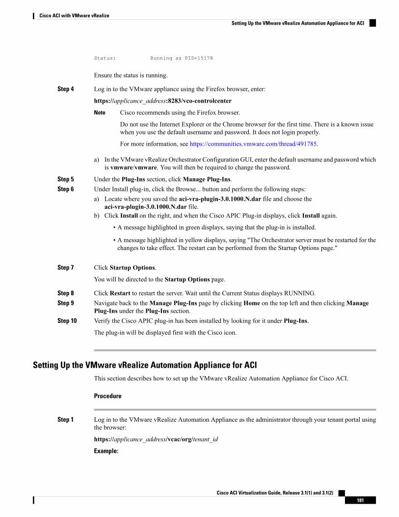
Status: Running as PID=15178
Ensure the status is running.
Step 4 Log in to the VMware appliance using the Firefox browser, enter:
https://applicance_address:8283/vco-controlcenter
Cisco recommends using the Firefox browser.
Do not use the Internet Explorer or the Chrome browser for the first time. There is a known issuewhen you use the default username and password. It does not login properly.
For more information, see https://communities.vmware.com/thread/491785.
Note
a) In the VMware vRealize Orchestrator Configuration GUI, enter the default username and password whichis vmware/vmware. You will then be required to change the password.
Step 5 Under the Plug-Ins section, clickManage Plug-Ins.Step 6 Under Install plug-in, click the Browse... button and perform the following steps:
a) Locate where you saved the aci-vra-plugin-3.0.1000.N.dar file and choose theaci-vra-plugin-3.0.1000.N.dar file.
b) Click Install on the right, and when the Cisco APIC Plug-in displays, click Install again.
• A message highlighted in green displays, saying that the plug-in is installed.
• A message highlighted in yellow displays, saying "The Orchestrator server must be restarted for thechanges to take effect. The restart can be performed from the Startup Options page."
Step 7 Click Startup Options.
You will be directed to the Startup Options page.
Step 8 Click Restart to restart the server. Wait until the Current Status displays RUNNING.Step 9 Navigate back to theManage Plug-Ins page by clicking Home on the top left and then clickingManage
Plug-Ins under the Plug-Ins section.Step 10 Verify the Cisco APIC plug-in has been installed by looking for it under Plug-Ins.
The plug-in will be displayed first with the Cisco icon.
Setting Up the VMware vRealize Automation Appliance for ACIThis section describes how to set up the VMware vRealize Automation Appliance for Cisco ACI.
Procedure
Step 1 Log in to the VMware vRealize Automation Appliance as the administrator through your tenant portal usingthe browser:
https://applicance_address/vcac/org/tenant_id
Example:
Cisco ACI Virtualization Guide, Release 3.1(1) and 3.1(2)181
Cisco ACI with VMware vRealizeSetting Up the VMware vRealize Automation Appliance for ACI
https://192.168.0.10/vcac/org/tenant1
Enter the admin username and password.
Step 2 In the VMware vRealize Automation Appliance GUI, perform the following actions:a) Choose Administration > Users & Groups > Custom Groupsb) In the Custom Group pane, click Add to add a custom group.c) Enter the name of the custom group. (Service Architect)d) In the Roles to this group field, select the custom group you created in the previous step. (Service
Architect)e) Choose theMember pane, enter and select the user name(s).f) Click Add.
This creates a custom group with members.g) In the Custom Group pane, choose the custom group you created. (Service Architect)h) In the Edit Group pane, you can verify the members in theMembers pane.
Step 3 In the browser, enter the vRealize Automation Appliance.
https://applicance_address
For example:
https://vra3-app.ascisco.net
a) Choose the vRealize Orchestrator Client to download the client.jnlp file.b) The Downloads dialog box will appear, launch the client.jnlp file.
Step 4 Log in to the VMware vRealize Orchestrator as administrator.Step 5 Once the VMware vRealize Orchestrator GUI appears, from the drop-down list, choose Run from the menu
bar.Step 6 In the Navigation pane, choose theWorkflows icon.Step 7 Choose [email protected] > Cisco APIC Workflows > Utils > Install ACI Service
Catalog.Step 8 Right-click Install ACI Service Catalog and choose Start Workflow.Step 9 In the Start Workflow - Install ACI Service Catalog dialog box, perform the following actions:
a) In the APIC Hostname/IP Address field, enter the APIC hostname or IP address.b) In the APIC Admin Password field, enter the APIC admin password.c) In the vRealize Automation IP Address field, provide the IP address for the vRA.d) In the vRealize Automation handle field, click Not set, navigate and choose the vRealize automation
handle for this appliance.e) In the Business group field, click Not set to choose business group.
If running vRealize 7.0, you need to select the Business Group from Business Group(Deprecated).
Note
Usernames need to include the domain name. For example: [email protected]
f) In the Admin User field, enter the tenant admin user.g) In the vRealize Automation Admin Password field, enter the admin password for the vRA.h) In the End users field, click Not set and enter the user names to enable privilege for.
Do not copy and paste the end user names, you should type the user names.Note
Cisco ACI Virtualization Guide, Release 3.1(1) and 3.1(2)182
Cisco ACI with VMware vRealizeSetting Up the VMware vRealize Automation Appliance for ACI
i) In the JSON File containing vRealize Properties field, click Not set, navigate and choose the JSONfile containing the vRealize properties. (aci-vra-properties-3.0.1000.x.json)
Usernames need to include the domain name. For example: [email protected]
j) In the Zip file containing the service blueprints field, click Not set, navigate and choose the zip filecontaining the service blueprints. (aci-vra-asd-3.0.1000.x.zip)
k) Click Submit.
Step 10 In the Navigation pane, you will see a green check mark next to the Install ACI Service Catalog, if theinstallation was successful.
Step 11 In the Navigation pane, choose theWorkflows icon.Step 12 Right-click Install ACI Property Definitions and choose Start Workflow.Step 13 In the Start Workflow - Install ACI Property Definitions dialog box, click Net set, navigate and choose
the IaaS host.a) Click Submit.
In the Navigation pane, you will see a green checkmark next to the Install ACI Property Definitions, ifthe installation was successful.
Step 14 To verify as a tenant, log in to the vRealize Automation Appliance as tenant, choose Catalog and you willsee the services.
Step 15 To verify as an administrator, log in to the vRealize Automation Appliance as administrator, choose Catalogand you will see the services.a) Choose Infrastructure > Blueprints > Property Definitions and you will see the properties.
Day-0 Operations of ACIThis section describes day-0 operations of ACI.
Before you begin
• Fabric bring-up
Bring up the fabric and all topologies are supported.
• Access policies
• Attach Entity Policy (AEP)
• Configure access policies between the leaf switches and ESXi hosts to ensure CDP and LLDP isenabled between the leaf and host.
• Layer 3 (L3) Out configuration
• Create any L3 Out configurations in the common tenant that you wish to be consumed user tenants.
• You can choose any name for the L3 policy.
• External EPG must be named "[L3OutName|InstP]".
• Create two policies.
For shared plan, specify "default" and for VPC plan, specify "vpcDefault".
Cisco ACI Virtualization Guide, Release 3.1(1) and 3.1(2)183
Cisco ACI with VMware vRealizeDay-0 Operations of ACI
For more information, see About L3 External Connectivity, on page 210.
• Service graph templates and devices
Create any service graph devices in the common tenant.
For more information, see Configuring the Services on APIC Using XML POST, on page 207.
• Security domains and tenant user
• vRealize plug-in requires two user accounts.
The first account needs administrator privileges. This account allows you to create, read, update,and destroy objects in the tenant common, access policies, and VMM domains.
The second account needs restricted tenant privileges. This account allows you to only read commontenant and VMM domains, but you can create, read, update, and destroy objects in their own tenant.
• Role-based access control (RBAC) rules are enforced through the APIC not the plug-in.
Procedure
See the Cisco APIC Basic Configuration Guide for more information.
Associating AEP with VMware VMM DomainThis section describes how to associate attachable entity profile (AEP) with VMware VMM domain.
You do not need to perform this procedure if the domain type is Cisco AVS.Note
Procedure
Step 1 Log in to the APIC GUI, choose FABRIC > ACCESS POLICIES.Step 2 In theNavigation pane, expandGlobal Policies >Attachable Access Entity Policies >AEP_profile_name.Step 3 In the PROPERTIES pane, perform the following actions:
a) In the Domains (VMM, Physical or External) Associated to Interfaces field, click on the + to expand.b) In the Unformed field, choose a VMM domain and click UPDATE.
Cisco ACI with VMware vRealize Upgrade WorkflowThis section describes the Cisco ACI with VMware vRealize upgrade workflow.
Cisco ACI Virtualization Guide, Release 3.1(1) and 3.1(2)184
Cisco ACI with VMware vRealizeAssociating AEP with VMware VMM Domain
Procedure
Step 1 Upgrade the APIC image.Step 2 Upgrade the APIC plug-in on the vRealize Orchestrator (vRO).
For more information, see Upgrading the APIC Plug-in on the vRealize Orchestrator, on page 185.
Step 3 Set Up the VMware vRealize Automation Appliance for ACI.
For more information, see Setting Up the VMware vRealize Automation Appliance for ACI, on page 181.
Step 4 Verify the connection between APIC and vRealize.
For more information, see Verifying the Connection Between APIC and vRealize, on page 185.
Upgrading the APIC Plug-in on the vRealize OrchestratorThis section describes how to upgrade the APIC plug-in certificate on the vRealize Orchestrator.
Procedure
Step 1 To upgrade, first follow the directions in Installing the APIC Plug-in on the vRealize Orchestrator, on page180.
Step 2 Upgrade your service blueprints, service categories, and entitlements, see Setting Up the VMware vRealizeAutomation Appliance for ACI, on page 181.
Verifying the Connection Between APIC and vRealizeAfter you have upgraded the Application Policy Infrastructure Controller (APIC) controller and the switchsoftware, you must verify the connection from the vRealize Orchestrator to APIC.
Before you begin
• Ensure the APIC controller and the switch software is upgraded.
For more information, see the Cisco ACI Firmware Management Guide.
Procedure
Step 1 Log in to the vRealize Orchestrator as administrator.Step 2 In the navigation pane, choose the Inventory icon.Step 3 Expand the Cisco APIC Plugin, choose the APIC and check the following:
a) In the General pane, check if the controllers are showing in the Name field.
Cisco ACI Virtualization Guide, Release 3.1(1) and 3.1(2)185
Cisco ACI with VMware vRealizeUpgrading the APIC Plug-in on the vRealize Orchestrator
b) Check if you can maneuver through the nested hierarchy below the APIC. This ensures you arecommunicating with APIC.
If the connection from vRO to APIC is not established, then next to the APIC name the string down willbe present, indicating that the connection is down.
Cisco ACI with VMware vRealize Downgrade WorkflowThis section describes the Cisco ACI with VMware vRealize downgrade workflow.
Procedure
Step 1 Downgrade the APIC image.Step 2 Delete the APIC plug-in package and all the APIC workflows.
For more information, see Deleting Package and Workflows , on page 186.
Step 3 Install the APIC plug-in on the vRealize Orchestrator (vRO).
For more information, see Upgrading the APIC Plug-in on the vRealize Orchestrator, on page 185.
Step 4 Set up the VMware vRealize Automation Appliance for ACI.
For more information, see Setting Up the VMware vRealize Automation Appliance for ACI, on page 181.
Step 5 Verify the connection between APIC and vRealize.
For more information, see Verifying the Connection Between APIC and vRealize, on page 185.
Deleting Package and WorkflowsThis section describes how to delete the package and workflows.
Procedure
Step 1 Log in to the vRO client as administrator.Step 2 Choose the Design role.Step 3 Choose the Packages tab.Step 4 Right-click on the com.cisco.apic.package and choose Delete element with content.Step 5 Choose Keep Shared in the pop-up window.Step 6 Choose theWorkflows tab.Step 7 Ensure that all workflows in the "Cisco APIC workflows" folder and subfolders are deleted.
Cisco ACI Virtualization Guide, Release 3.1(1) and 3.1(2)186
Cisco ACI with VMware vRealizeCisco ACI with VMware vRealize Downgrade Workflow
To delete the workflow: Select the workflow, right-click and choose Delete.
Use Case Scenarios for the Administrator and TenantExperience
This section describes use case scenarios for the administrator and tenant experience.
Overview of Tier Application DeploymentThis section describes the overview of 3-tier application deployment.
See Deploying a Single-Tier Application UsingProperty Groups, on page 187.
Deployment of a single-tier application using propertygroups
See Deploying a 3-Tier Application Using aMulti-Machine Blueprint, on page 189.
Deployment of a 3-tier application using amulti-machine blueprint
Deploying a Single-Tier Application Using Property GroupsThis section describes how to deploy a single-tier application using property groups.
Procedure
Step 1 Connect to the vRealize Automation appliance by pointing your browser to the following URL:https://appliance_address/vcac/org/tenant_id
Step 2 Enter the tenant administrator username and password.Step 3 Choose Catalog.Step 4 Click Configure Property Groups.
You will configure the database tier.
Step 5 Click Request.Step 6 In the Request Information tab, enter a description of the request.Step 7 Click Next.Step 8 In the Common tab, perform the following actions:
a) In the IaaS Host for vRealize field, click Add.b) Put a check in the box next to the desired IaaS host.c) Click Submit.d) In the APIC Tenant field, click Add.e) Expand apic_name > Tenants.f) Put a check in the box next to the desired tenant's name.
Example:
Cisco ACI Virtualization Guide, Release 3.1(1) and 3.1(2)187
Cisco ACI with VMware vRealizeUse Case Scenarios for the Administrator and Tenant Experience
green
g) Click Submit.h) In the Property Group Name field, enter a name for the property group.
Example:green-app-bp
i) In the Plan Type (Shared or VPC) field, click Shared.j) In the VMM Domain/DVS field, click Add.k) Expand apic_name > Vcenters > vcenter_namel) Put a check in the box next to the desired vCenter's name.
Example:green
m) Click Submit.
Step 9 Click Next.Step 10 In the VM Networking tab, leave all of the fields at their default values.Step 11 Click Next.Step 12 In the Security tab, perform the following actions:
a) In the Configure Security Policy drop-down list, choose No.
Step 13 In the Load Balancer tab, from the drop-down list, choose No.Step 14 In the Firewall tab, from the drop-down list, choose No.Step 15 Click Submit.Step 16 Click OK.Step 17 To verify your request, choose the Requests tab.
a) Choose the request you submitted and click view details. Ensure the status is Succesful.
Step 18 (Optional) To edit a blueprint in the property group, choose Infrastructure >Blueprints > Property Groups.a) In the Property Group pane, choose the property group you created (green-app-bp) and click edit.b) In the Edit Property Group pane, choose the property group you want to edit and click on the pencil
icon to edit a certain blueprint.c) Once you have completed your edits, click OK.
Step 19 Attach the property group to the VMs, choose Infrastructure > Blueprints.Step 20 In the Blueprints pane, clickNew Blueprint, from the drop-down list, chooseVirtual > vSphere (vCenter).Step 21 In the New Blueprint vSphere (vCenter)pane, perform the following actions:
a) In the Blueprint Information tab, enter the information to create your blueprint and click OK. SeeVMware's documentation for details on how to create your machine blueprint.
b) In the Build Information tab, enter the information to create your property group and click OK. SeeVMware's documentation for details on how to create your machine blueprint.
Step 22 In the Properties tab, perform the following actions:a) In the Property Groups field, choose your property group that you created (green-app-bp) and clickOK.b) Click on the magnifying glass icon for the newly created property group (green-app-bp).c) In the Property Group Custom Properties dialog box, ensure that the properties match your property
group and this makes a connection with the VM and the ACI networking.d) In the New Blueprint vSphere (vCenter)pane, click OK.
Cisco ACI Virtualization Guide, Release 3.1(1) and 3.1(2)188
Cisco ACI with VMware vRealizeDeploying a Single-Tier Application Using Property Groups
Step 23 In the Blueprints pane, perform the following actions:a) Choose your property group that you created (green-app-bp), hover and choose Publish.b) Click OK.c) Choose Aministration > Catalog Management > Catalog Items.
Step 24 In the Catalog Items pane, perform the following actions.a) Find and choose the blueprint that you created (Green App Tier).
Step 25 In the Configure Catalog Item pane, perform the following actions.a) In the Details tab, in the Service field, choose VM Services.b) Check the check box for New and noteworthy.c) Click Update.You now have deployed a single-tier application using property groups.
Step 26 To verify the deployment of the single-tier application, log out of the administrator session and log back inas the tenant.a) Click the Catalog tab.b) In the navigation pane, choose VM Services.c) In theWork pane, choose the blueprint you created.d) In the Catalog Item Details pane, verify the properties of the blueprint and click Request.e) In the New Request pane, click Submit and then OK.This provisions a new virtual machine, ACI networking, and connects the two together.
Deploying a 3-Tier Application Using a Multi-Machine BlueprintVMware vRealize multi-machine blueprints are groupings of one or more machine blueprints to be deployedsimultaneously. A common use case is a three-tier web application, where the web, app, and database tiersare deployed together. From a networking perspective, you must push the application policy into CiscoApplication Centric Infrastructure (ACI) to enable secure communication between tiers that need tocommunicate. This is achieved by creating a security policy and associating the relevant machines dynamicallyat deployment time.
When configuring a blueprint that will be used in a multi-machine blueprint, a security policy must be created.During the creation process, the consumer and provider must be provided. The provider is always the machinethat you are building, and the consumer can be any other machine or network.
As an example, say that you have a MySQL database machine blueprint that provides a service on port 3306.The application tier machines need to access this database, but the web tier machines do not. Under theSecurity Policy section of the Configure Property Group workflow, you create a policy with the "app" tieras the consumer, listing port 3306 as permissible (everything else is denied by default) and the blueprint willautomatically place the "db" tier as the provider.
The "app" tier also must provide a service; in this example a server is listening on port 8000. The web tierwill then consume this service. The security policy must be specified in the "app" tier property group.
Cisco ACI Virtualization Guide, Release 3.1(1) and 3.1(2)189
Cisco ACI with VMware vRealizeDeploying a 3-Tier Application Using a Multi-Machine Blueprint
Machine prefixes generate a unique name for each virtual machine that is deployed. An example prefix for atenant named "Green" could be "green-web-", plus three unique digits for each machine. The sequence wouldbe: "green-web-001", "green-web-002", "green-web-003", and so on. It is important that you follow a similarscheme with your machine prefixes so that the Application Policy Infrastructure Controller (APIC) plug-incan accurately predict the name of the consumer endpoint group. Additionally, every machine must be on thesame prefix number. For example, the names for a 3-tier app must be: green-db-001, green-app-001, andgreen-web-001. If any tier were not aligned, the security policy would fail to form a correct relationship. Thisis a requirement because vRealize does not provide the name of the sibling tiers, so the plug-in must infer thesiblings' names based on its own name.
When configuring a security policy under a property group, the consumer name should be the second wordof the machine prefix. For the example prefix "green-web-", the consumer name would be "web".
Note
This section describes how to deploy a 3-tier application using a multi-machine blueprint.
Procedure
Step 1 Connect to the vRealize Automation appliance by pointing your browser to the following URL:https://appliance_address/vcac/org/tenant_id
Step 2 Enter the tenant administrator username and password.Step 3 Choose Catalog.Step 4 Click Configure Property Group.
You will configure the database tier.
Step 5 Click Request.Step 6 In the Request Information tab, enter a description of the request.Step 7 Click Next.Step 8 In the Common tab, perform the following actions:
a) In the IaaS Host for vRealize field, click Add.b) Put a check in the box next to the desired IaaS host.c) Click Submit.d) In the APIC Tenant field, click Add.e) Expand apic_name > Tenants.f) Put a check in the box next to the desired tenant's name.
Example:green
g) Click Submit.h) In the Property Group Name field, enter a name for the property group.
Example:green-db-mm
i) In the VMM Domain/DVS field, click Add.j) Expand apic_name > Vcenters > vcenter_name
Cisco ACI Virtualization Guide, Release 3.1(1) and 3.1(2)190
Cisco ACI with VMware vRealizeDeploying a 3-Tier Application Using a Multi-Machine Blueprint
k) Put a check in the box next to the desired vCenter's name.
Example:green
l) Click Submit.
Step 9 Click Next.Step 10 In the VM Networking tab, leave all of the fields at their default values.Step 11 Click Next.Step 12 In the Security tab, perform the following actions:
a) In the Configure Security Policy drop-down list, choose Yes.b) In theConsumer Network/EPGName of Security Policy field, enter the name of the consumer network,
without the full machine prefix.
Example:app
The database tier must have the application tier as the consumer.
c) In the Starting Port Number in Security Policy field, enter the starting port number.
Example:3306
d) In the Ending Port Number in Security Policy field, enter the ending port number.
Example:3306
e) For the other fields, leave their values at the defaults.
Step 13 Click Next.Step 14 In the Load Balancer tab, leave the field at its default value.Step 15 Click Next.Step 16 In the Firewall tab, leave the field at its default value.Step 17 Click Submit.Step 18 Click OK.Step 19 Click Configure Property Group.
This time, you will configure the application tier.
Step 20 Click Request.Step 21 In the Request Information tab, enter a description of the request.Step 22 Click Next.Step 23 In the Common tab, perform the following actions:
a) In the IaaS Host for vRealize field, click Add.b) Put a check in the box next to the desired IaaS host.c) Click Submit.d) In the APIC Tenant field, click Add.e) Expand apic_name > Tenants.
Cisco ACI Virtualization Guide, Release 3.1(1) and 3.1(2)191
Cisco ACI with VMware vRealizeDeploying a 3-Tier Application Using a Multi-Machine Blueprint
f) Put a check in the box next to the desired tenant's name.
Example:green
g) Click Submit.h) In the Property Group Name field, enter a name for the property group.
Example:green-app-mm
i) In the VMM Domain/DVS field, click Add.j) Expand apic_name > Vcenters > vcenter_namek) Put a check in the box next to the desired vCenter's name.
Example:green
l) Click Submit.
Step 24 Click Next.Step 25 In the VM Networking tab, leave all of the fields at their default values.Step 26 Click Next.Step 27 In the Security tab, perform the following actions:
a) In the Configure Security Policy drop-down list, choose Yes.b) In theConsumer Network/EPGName of Security Policy field, enter the name of the consumer network,
without the full machine prefix.
Example:web
The application tier must have the web tier as the consumer.
c) In the Starting Port Number in Security Policy field, enter the starting port number.
Example:8000
d) In the Ending Port Number in Security Policy field, enter the ending port number.
Example:8000
e) For the other fields, leave their values at the defaults.
Step 28 Click Next.Step 29 In the Load Balancer tab, leave the field at its default value.Step 30 Click Next.Step 31 In the Firewall tab, leave the field at its default value.Step 32 Click Submit.Step 33 Click OK.Step 34 Click Configure Property Group.
You will configure the web tier.
Cisco ACI Virtualization Guide, Release 3.1(1) and 3.1(2)192
Cisco ACI with VMware vRealizeDeploying a 3-Tier Application Using a Multi-Machine Blueprint
Step 35 Click Request.Step 36 In the Request Information tab, enter a description of the request.Step 37 Click Next.Step 38 In the Common tab, perform the following actions:
a) In the IaaS Host for vRealize field, click Add.b) Put a check in the box next to the desired IaaS host.c) Click Submit.d) In the APIC Tenant field, click Add.e) Expand apic_name > Tenants.f) Put a check in the box next to the desired tenant's name.
Example:green
g) Click Submit.h) In the Property Group Name field, enter a name for the property group.
Example:green-web-mm
i) In the VMM Domain/DVS field, click Add.j) Expand apic_name > Vcenters > vcenter_namek) Put a check in the box next to the desired vCenter's name.
Example:green
l) Click Submit.
Step 39 Click Next.Step 40 In the VM Networking tab, leave all of the fields at their default values.Step 41 Click Next.Step 42 In the Security tab, leave the field at its default value.
Because this is a consumer policy, you do not need to configure the security policy.
Step 43 Click Next.Step 44 In the Load Balancer tab, leave the field at its default value.Step 45 Click Next.Step 46 In the Firewall tab, leave the field at its default value.Step 47 Click Submit.Step 48 Click OK.
About Plan TypesThe administrator creates the plan with their own values. The plan types are as follows:
Cisco ACI Virtualization Guide, Release 3.1(1) and 3.1(2)193
Cisco ACI with VMware vRealizeAbout Plan Types
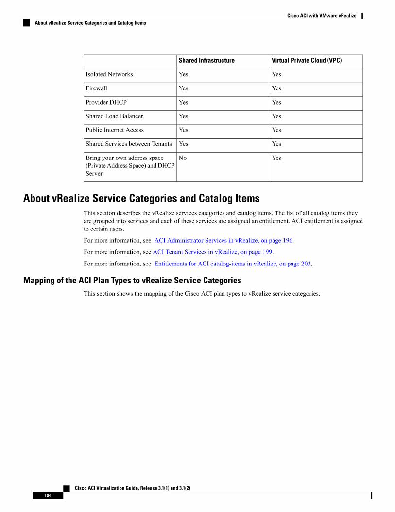
Virtual Private Cloud (VPC)Shared Infrastructure
YesYesIsolated Networks
YesYesFirewall
YesYesProvider DHCP
YesYesShared Load Balancer
YesYesPublic Internet Access
YesYesShared Services between Tenants
YesNoBring your own address space(Private Address Space) andDHCPServer
About vRealize Service Categories and Catalog ItemsThis section describes the vRealize services categories and catalog items. The list of all catalog items theyare grouped into services and each of these services are assigned an entitlement. ACI entitlement is assignedto certain users.
For more information, see ACI Administrator Services in vRealize, on page 196.
For more information, see ACI Tenant Services in vRealize, on page 199.
For more information, see Entitlements for ACI catalog-items in vRealize, on page 203.
Mapping of the ACI Plan Types to vRealize Service CategoriesThis section shows the mapping of the Cisco ACI plan types to vRealize service categories.
Cisco ACI Virtualization Guide, Release 3.1(1) and 3.1(2)194
Cisco ACI with VMware vRealizeAbout vRealize Service Categories and Catalog Items
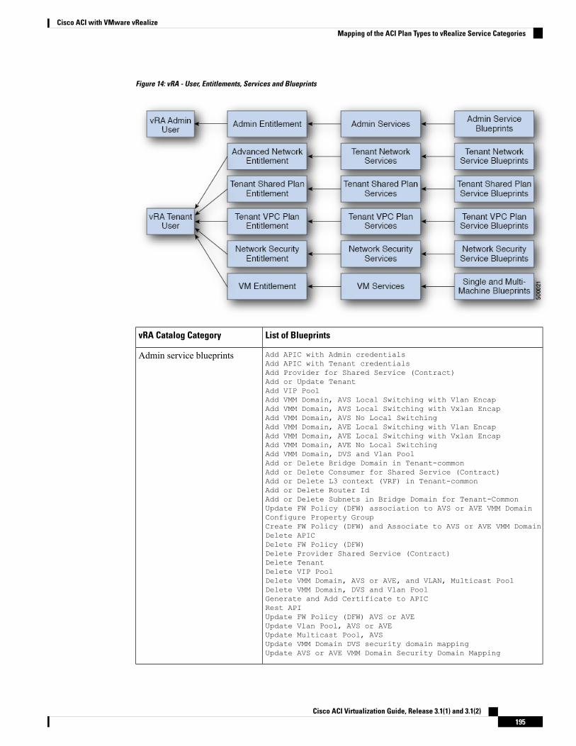
Figure 14: vRA - User, Entitlements, Services and Blueprints
List of BlueprintsvRA Catalog Category
Add APIC with Admin credentialsAdd APIC with Tenant credentialsAdd Provider for Shared Service (Contract)Add or Update TenantAdd VIP PoolAdd VMM Domain, AVS Local Switching with Vlan EncapAdd VMM Domain, AVS Local Switching with Vxlan EncapAdd VMM Domain, AVS No Local SwitchingAdd VMM Domain, AVE Local Switching with Vlan EncapAdd VMM Domain, AVE Local Switching with Vxlan EncapAdd VMM Domain, AVE No Local SwitchingAdd VMM Domain, DVS and Vlan PoolAdd or Delete Bridge Domain in Tenant-commonAdd or Delete Consumer for Shared Service (Contract)Add or Delete L3 context (VRF) in Tenant-commonAdd or Delete Router IdAdd or Delete Subnets in Bridge Domain for Tenant-CommonUpdate FW Policy (DFW) association to AVS or AVE VMM DomainConfigure Property GroupCreate FW Policy (DFW) and Associate to AVS or AVE VMM DomainDelete APICDelete FW Policy (DFW)Delete Provider Shared Service (Contract)Delete TenantDelete VIP PoolDelete VMM Domain, AVS or AVE, and VLAN, Multicast PoolDelete VMM Domain, DVS and Vlan PoolGenerate and Add Certificate to APICRest APIUpdate FW Policy (DFW) AVS or AVEUpdate Vlan Pool, AVS or AVEUpdate Multicast Pool, AVSUpdate VMM Domain DVS security domain mappingUpdate AVS or AVE VMM Domain Security Domain Mapping
Admin service blueprints
Cisco ACI Virtualization Guide, Release 3.1(1) and 3.1(2)195
Cisco ACI with VMware vRealizeMapping of the ACI Plan Types to vRealize Service Categories
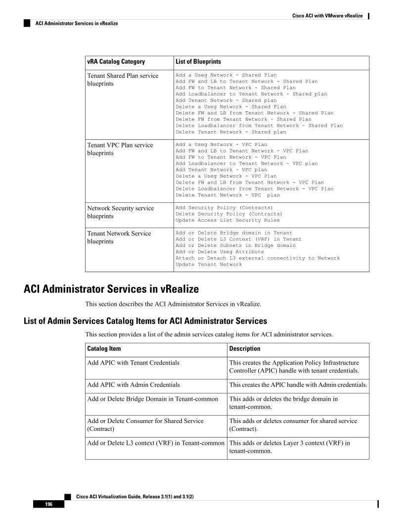
List of BlueprintsvRA Catalog Category
Add a Useg Network - Shared PlanAdd FW and LB to Tenant Network - Shared PlanAdd FW to Tenant Network - Shared PlanAdd Loadbalancer to Tenant Network - Shared planAdd Tenant Network - Shared planDelete a Useg Network - Shared PlanDelete FW and LB from Tenant Network - Shared PlanDelete FW from Tenant Network - Shared PlanDelete Loadbalancer from Tenant Network - Shared PlanDelete Tenant Network - Shared plan
Tenant Shared Plan serviceblueprints
Add a Useg Network - VPC PlanAdd FW and LB to Tenant Network - VPC PlanAdd FW to Tenant Network - VPC PlanAdd Loadbalancer to Tenant Network - VPC planAdd Tenant Network - VPC planDelete a Useg Network - VPC PlanDelete FW and LB from Tenant Network - VPC PlanDelete Loadbalancer from Tenant Network - VPC PlanDelete Tenant Network - VPC plan
Tenant VPC Plan serviceblueprints
Add Security Policy (Contracts)Delete Security Policy (Contracts)Update Access List Security Rules
Network Security serviceblueprints
Add or Delete Bridge domain in TenantAdd or Delete L3 Context (VRF) in TenantAdd or Delete Subnets in Bridge domainAdd or Delete Useg AttributeAttach or Detach L3 external connectivity to NetworkUpdate Tenant Network
Tenant Network Serviceblueprints
ACI Administrator Services in vRealizeThis section describes the ACI Administrator Services in vRealize.
List of Admin Services Catalog Items for ACI Administrator ServicesThis section provides a list of the admin services catalog items for ACI administrator services.
DescriptionCatalog Item
This creates the Application Policy InfrastructureController (APIC) handle with tenant credentials.
Add APIC with Tenant Credentials
This creates the APIC handle with Admin credentials.Add APIC with Admin Credentials
This adds or deletes the bridge domain intenant-common.
Add or Delete Bridge Domain in Tenant-common
This adds or deletes consumer for shared service(Contract).
Add or Delete Consumer for Shared Service(Contract)
This adds or deletes Layer 3 context (VRF) intenant-common.
Add or Delete L3 context (VRF) in Tenant-common
Cisco ACI Virtualization Guide, Release 3.1(1) and 3.1(2)196
Cisco ACI with VMware vRealizeACI Administrator Services in vRealize
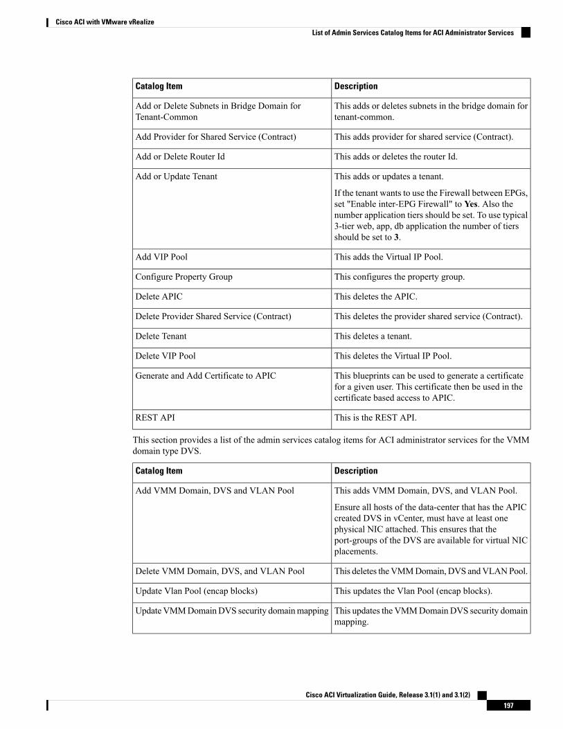
DescriptionCatalog Item
This adds or deletes subnets in the bridge domain fortenant-common.
Add or Delete Subnets in Bridge Domain forTenant-Common
This adds provider for shared service (Contract).Add Provider for Shared Service (Contract)
This adds or deletes the router Id.Add or Delete Router Id
This adds or updates a tenant.
If the tenant wants to use the Firewall between EPGs,set "Enable inter-EPG Firewall" to Yes. Also thenumber application tiers should be set. To use typical3-tier web, app, db application the number of tiersshould be set to 3.
Add or Update Tenant
This adds the Virtual IP Pool.Add VIP Pool
This configures the property group.Configure Property Group
This deletes the APIC.Delete APIC
This deletes the provider shared service (Contract).Delete Provider Shared Service (Contract)
This deletes a tenant.Delete Tenant
This deletes the Virtual IP Pool.Delete VIP Pool
This blueprints can be used to generate a certificatefor a given user. This certificate then be used in thecertificate based access to APIC.
Generate and Add Certificate to APIC
This is the REST API.REST API
This section provides a list of the admin services catalog items for ACI administrator services for the VMMdomain type DVS.
DescriptionCatalog Item
This adds VMM Domain, DVS, and VLAN Pool.
Ensure all hosts of the data-center that has the APICcreated DVS in vCenter, must have at least onephysical NIC attached. This ensures that theport-groups of the DVS are available for virtual NICplacements.
Add VMM Domain, DVS and VLAN Pool
This deletes theVMMDomain, DVS andVLANPool.Delete VMM Domain, DVS, and VLAN Pool
This updates the Vlan Pool (encap blocks).Update Vlan Pool (encap blocks)
This updates the VMMDomain DVS security domainmapping.
UpdateVMMDomainDVS security domainmapping
Cisco ACI Virtualization Guide, Release 3.1(1) and 3.1(2)197
Cisco ACI with VMware vRealizeList of Admin Services Catalog Items for ACI Administrator Services
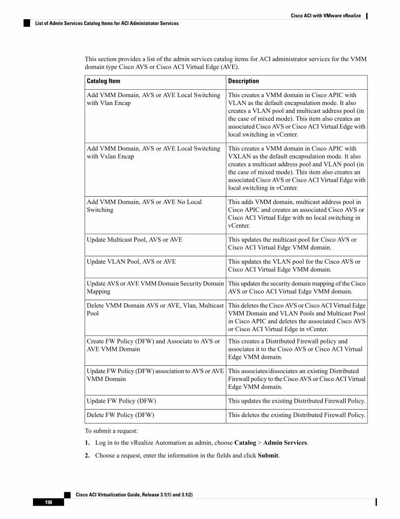
This section provides a list of the admin services catalog items for ACI administrator services for the VMMdomain type Cisco AVS or Cisco ACI Virtual Edge (AVE).
DescriptionCatalog Item
This creates a VMM domain in Cisco APIC withVLAN as the default encapsulation mode. It alsocreates a VLAN pool and multicast address pool (inthe case of mixed mode). This item also creates anassociated Cisco AVS or Cisco ACI Virtual Edge withlocal switching in vCenter.
Add VMM Domain, AVS or AVE Local Switchingwith Vlan Encap
This creates a VMM domain in Cisco APIC withVXLAN as the default encapsulation mode. It alsocreates a multicast address pool and VLAN pool (inthe case of mixed mode). This item also creates anassociated Cisco AVS or Cisco ACI Virtual Edge withlocal switching in vCenter.
Add VMM Domain, AVS or AVE Local Switchingwith Vxlan Encap
This adds VMM domain, multicast address pool inCisco APIC and creates an associated Cisco AVS orCisco ACI Virtual Edge with no local switching invCenter.
Add VMM Domain, AVS or AVE No LocalSwitching
This updates the multicast pool for Cisco AVS orCisco ACI Virtual Edge VMM domain.
Update Multicast Pool, AVS or AVE
This updates the VLAN pool for the Cisco AVS orCisco ACI Virtual Edge VMM domain.
Update VLAN Pool, AVS or AVE
This updates the security domainmapping of the CiscoAVS or Cisco ACI Virtual Edge VMM domain.
UpdateAVS orAVEVMMDomain SecurityDomainMapping
This deletes the Cisco AVS or Cisco ACI Virtual EdgeVMM Domain and VLAN Pools and Multicast Poolin Cisco APIC and deletes the associated Cisco AVSor Cisco ACI Virtual Edge in vCenter.
Delete VMM Domain AVS or AVE, Vlan, MulticastPool
This creates a Distributed Firewall policy andassociates it to the Cisco AVS or Cisco ACI VirtualEdge VMM domain.
Create FW Policy (DFW) and Associate to AVS orAVE VMM Domain
This associates/dissociates an existing DistributedFirewall policy to the Cisco AVS or Cisco ACI VirtualEdge VMM domain.
Update FWPolicy (DFW) association to AVS or AVEVMM Domain
This updates the existing Distributed Firewall Policy.Update FW Policy (DFW)
This deletes the existing Distributed Firewall Policy.Delete FW Policy (DFW)
To submit a request:
1. Log in to the vRealize Automation as admin, choose Catalog > Admin Services.
2. Choose a request, enter the information in the fields and click Submit.
Cisco ACI Virtualization Guide, Release 3.1(1) and 3.1(2)198
Cisco ACI with VMware vRealizeList of Admin Services Catalog Items for ACI Administrator Services
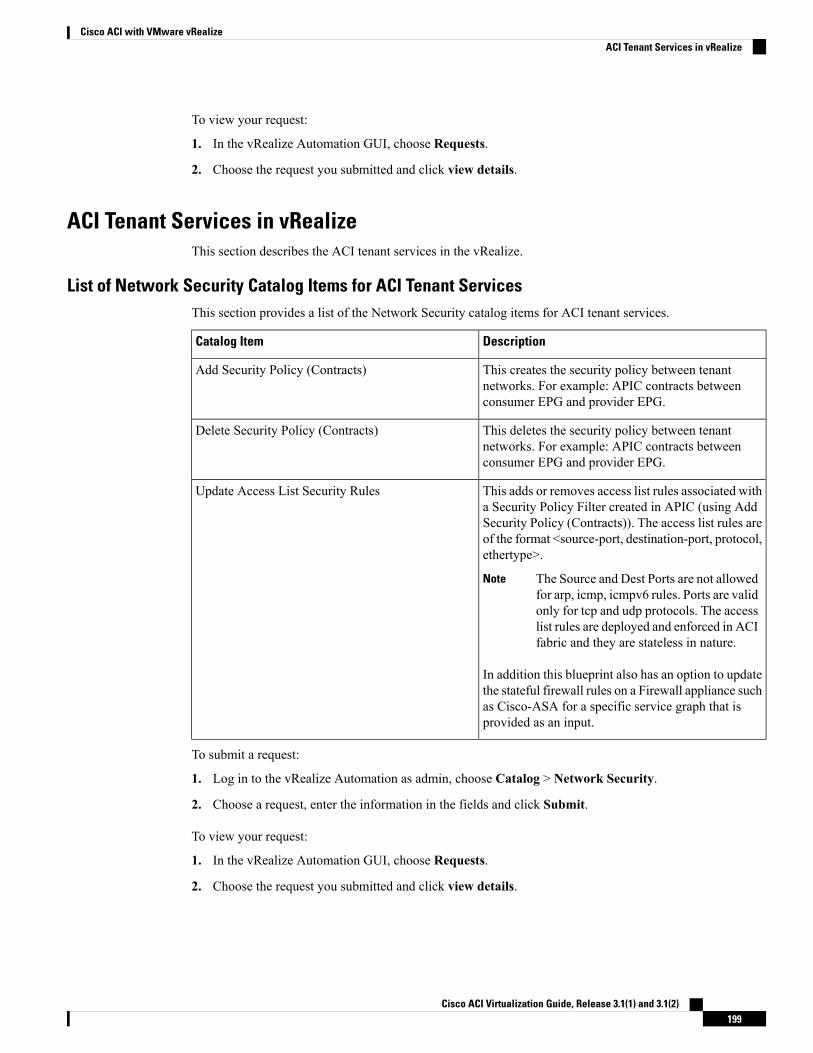
To view your request:
1. In the vRealize Automation GUI, choose Requests.
2. Choose the request you submitted and click view details.
ACI Tenant Services in vRealizeThis section describes the ACI tenant services in the vRealize.
List of Network Security Catalog Items for ACI Tenant ServicesThis section provides a list of the Network Security catalog items for ACI tenant services.
DescriptionCatalog Item
This creates the security policy between tenantnetworks. For example: APIC contracts betweenconsumer EPG and provider EPG.
Add Security Policy (Contracts)
This deletes the security policy between tenantnetworks. For example: APIC contracts betweenconsumer EPG and provider EPG.
Delete Security Policy (Contracts)
This adds or removes access list rules associated witha Security Policy Filter created in APIC (using AddSecurity Policy (Contracts)). The access list rules areof the format <source-port, destination-port, protocol,ethertype>.
The Source and Dest Ports are not allowedfor arp, icmp, icmpv6 rules. Ports are validonly for tcp and udp protocols. The accesslist rules are deployed and enforced in ACIfabric and they are stateless in nature.
Note
In addition this blueprint also has an option to updatethe stateful firewall rules on a Firewall appliance suchas Cisco-ASA for a specific service graph that isprovided as an input.
Update Access List Security Rules
To submit a request:
1. Log in to the vRealize Automation as admin, choose Catalog > Network Security.
2. Choose a request, enter the information in the fields and click Submit.
To view your request:
1. In the vRealize Automation GUI, choose Requests.
2. Choose the request you submitted and click view details.
Cisco ACI Virtualization Guide, Release 3.1(1) and 3.1(2)199
Cisco ACI with VMware vRealizeACI Tenant Services in vRealize
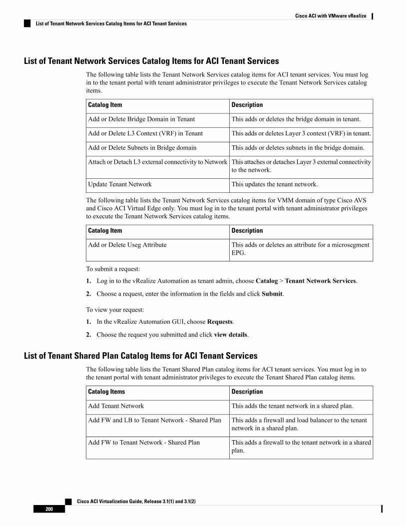
List of Tenant Network Services Catalog Items for ACI Tenant ServicesThe following table lists the Tenant Network Services catalog items for ACI tenant services. You must login to the tenant portal with tenant administrator privileges to execute the Tenant Network Services catalogitems.
DescriptionCatalog Item
This adds or deletes the bridge domain in tenant.Add or Delete Bridge Domain in Tenant
This adds or deletes Layer 3 context (VRF) in tenant.Add or Delete L3 Context (VRF) in Tenant
This adds or deletes subnets in the bridge domain.Add or Delete Subnets in Bridge domain
This attaches or detaches Layer 3 external connectivityto the network.
Attach or Detach L3 external connectivity to Network
This updates the tenant network.Update Tenant Network
The following table lists the Tenant Network Services catalog items for VMM domain of type Cisco AVSand Cisco ACI Virtual Edge only. You must log in to the tenant portal with tenant administrator privilegesto execute the Tenant Network Services catalog items.
DescriptionCatalog Item
This adds or deletes an attribute for a microsegmentEPG.
Add or Delete Useg Attribute
To submit a request:
1. Log in to the vRealize Automation as tenant admin, choose Catalog > Tenant Network Services.
2. Choose a request, enter the information in the fields and click Submit.
To view your request:
1. In the vRealize Automation GUI, choose Requests.
2. Choose the request you submitted and click view details.
List of Tenant Shared Plan Catalog Items for ACI Tenant ServicesThe following table lists the Tenant Shared Plan catalog items for ACI tenant services. You must log in tothe tenant portal with tenant administrator privileges to execute the Tenant Shared Plan catalog items.
DescriptionCatalog Items
This adds the tenant network in a shared plan.Add Tenant Network
This adds a firewall and load balancer to the tenantnetwork in a shared plan.
Add FW and LB to Tenant Network - Shared Plan
This adds a firewall to the tenant network in a sharedplan.
Add FW to Tenant Network - Shared Plan
Cisco ACI Virtualization Guide, Release 3.1(1) and 3.1(2)200
Cisco ACI with VMware vRealizeList of Tenant Network Services Catalog Items for ACI Tenant Services
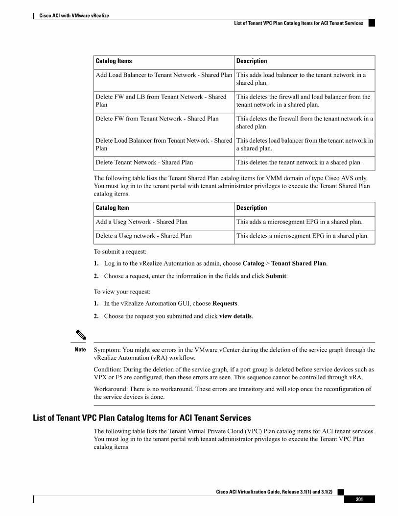
DescriptionCatalog Items
This adds load balancer to the tenant network in ashared plan.
Add Load Balancer to Tenant Network - Shared Plan
This deletes the firewall and load balancer from thetenant network in a shared plan.
Delete FW and LB from Tenant Network - SharedPlan
This deletes the firewall from the tenant network in ashared plan.
Delete FW from Tenant Network - Shared Plan
This deletes load balancer from the tenant network ina shared plan.
Delete Load Balancer from Tenant Network - SharedPlan
This deletes the tenant network in a shared plan.Delete Tenant Network - Shared Plan
The following table lists the Tenant Shared Plan catalog items for VMM domain of type Cisco AVS only.You must log in to the tenant portal with tenant administrator privileges to execute the Tenant Shared Plancatalog items.
DescriptionCatalog Item
This adds a microsegment EPG in a shared plan.Add a Useg Network - Shared Plan
This deletes a microsegment EPG in a shared plan.Delete a Useg network - Shared Plan
To submit a request:
1. Log in to the vRealize Automation as admin, choose Catalog > Tenant Shared Plan.
2. Choose a request, enter the information in the fields and click Submit.
To view your request:
1. In the vRealize Automation GUI, choose Requests.
2. Choose the request you submitted and click view details.
Symptom: You might see errors in the VMware vCenter during the deletion of the service graph through thevRealize Automation (vRA) workflow.
Condition: During the deletion of the service graph, if a port group is deleted before service devices such asVPX or F5 are configured, then these errors are seen. This sequence cannot be controlled through vRA.
Workaround: There is no workaround. These errors are transitory and will stop once the reconfiguration ofthe service devices is done.
Note
List of Tenant VPC Plan Catalog Items for ACI Tenant ServicesThe following table lists the Tenant Virtual Private Cloud (VPC) Plan catalog items for ACI tenant services.You must log in to the tenant portal with tenant administrator privileges to execute the Tenant VPC Plancatalog items
Cisco ACI Virtualization Guide, Release 3.1(1) and 3.1(2)201
Cisco ACI with VMware vRealizeList of Tenant VPC Plan Catalog Items for ACI Tenant Services
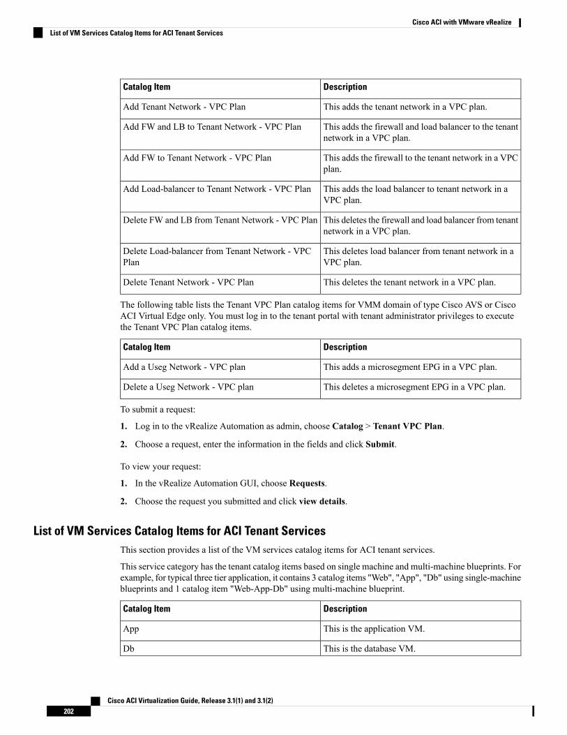
DescriptionCatalog Item
This adds the tenant network in a VPC plan.Add Tenant Network - VPC Plan
This adds the firewall and load balancer to the tenantnetwork in a VPC plan.
Add FW and LB to Tenant Network - VPC Plan
This adds the firewall to the tenant network in a VPCplan.
Add FW to Tenant Network - VPC Plan
This adds the load balancer to tenant network in aVPC plan.
Add Load-balancer to Tenant Network - VPC Plan
This deletes the firewall and load balancer from tenantnetwork in a VPC plan.
Delete FW and LB from Tenant Network - VPC Plan
This deletes load balancer from tenant network in aVPC plan.
Delete Load-balancer from Tenant Network - VPCPlan
This deletes the tenant network in a VPC plan.Delete Tenant Network - VPC Plan
The following table lists the Tenant VPC Plan catalog items for VMM domain of type Cisco AVS or CiscoACI Virtual Edge only. You must log in to the tenant portal with tenant administrator privileges to executethe Tenant VPC Plan catalog items.
DescriptionCatalog Item
This adds a microsegment EPG in a VPC plan.Add a Useg Network - VPC plan
This deletes a microsegment EPG in a VPC plan.Delete a Useg Network - VPC plan
To submit a request:
1. Log in to the vRealize Automation as admin, choose Catalog > Tenant VPC Plan.
2. Choose a request, enter the information in the fields and click Submit.
To view your request:
1. In the vRealize Automation GUI, choose Requests.
2. Choose the request you submitted and click view details.
List of VM Services Catalog Items for ACI Tenant ServicesThis section provides a list of the VM services catalog items for ACI tenant services.
This service category has the tenant catalog items based on single machine and multi-machine blueprints. Forexample, for typical three tier application, it contains 3 catalog items "Web", "App", "Db" using single-machineblueprints and 1 catalog item "Web-App-Db" using multi-machine blueprint.
DescriptionCatalog Item
This is the application VM.App
This is the database VM.Db
Cisco ACI Virtualization Guide, Release 3.1(1) and 3.1(2)202
Cisco ACI with VMware vRealizeList of VM Services Catalog Items for ACI Tenant Services
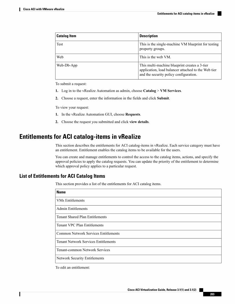
DescriptionCatalog Item
This is the single-machine VM blueprint for testingproperty groups.
Test
This is the web VM.Web
This multi-machine blueprint creates a 3-tierapplication, load balancer attached to the Web tierand the security policy configuration.
Web-Db-App
To submit a request:
1. Log in to the vRealize Automation as admin, choose Catalog > VM Services.
2. Choose a request, enter the information in the fields and click Submit.
To view your request:
1. In the vRealize Automation GUI, choose Requests.
2. Choose the request you submitted and click view details.
Entitlements for ACI catalog-items in vRealizeThis section describes the entitlements for ACI catalog-items in vRealize. Each service category must havean entitlement. Entitlement enables the catalog items to be available for the users.
You can create and manage entitlements to control the access to the catalog items, actions, and specify theapproval policies to apply the catalog requests. You can update the priority of the entitlement to determinewhich approval policy applies to a particular request.
List of Entitlements for ACI Catalog ItemsThis section provides a list of the entitlements for ACI catalog items.
Name
VMs Entitlements
Admin Entitlements
Tenant Shared Plan Entitlements
Tenant VPC Plan Entitlements
Common Network Services Entitlements
Tenant Network Services Entitlements
Tenant-common Network Services
Network Security Entitlements
To edit an entitlement:
Cisco ACI Virtualization Guide, Release 3.1(1) and 3.1(2)203
Cisco ACI with VMware vRealizeEntitlements for ACI catalog-items in vRealize
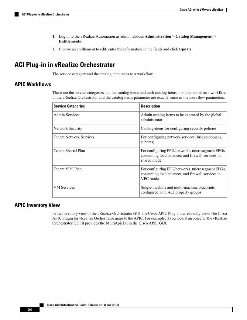
1. Log in to the vRealize Automation as admin, choose Administration > Catalog Management >Entitlements.
2. Choose an entitlement to edit, enter the information in the fields and click Update.
ACI Plug-in in vRealize OrchestratorThe service category and the catalog item maps to a workflow.
APIC WorkflowsThese are the service categories and the catalog items and each catalog items is implemented as a workflowin the vRealize Orchestrator and the catalog items parameter are exactly same as the workflow parameters.
DescriptionService Categories
Admin catalog-items to be executed by the globaladministrator
Admin Services
Catalog-items for configuring security policiesNetwork Security
For configuring network services (bridge-domain,subnets)
Tenant Network Services
For configuring EPG/networks, microsegment EPGs,consuming load balancer, and firewall services inshared mode
Tenant Shared Plan
For configuring EPG/networks, microsegment EPGs,consuming load balancer, and firewall services inVPC mode
Tenant VPC Plan
Single-machine and multi-machine blueprintsconfigured with ACI property groups
VM Services
APIC Inventory ViewIn the Inventory view of the vRealize Orchestrator GUI, the Cisco APIC Plugin is a read only view. The CiscoAPIC Plugin for vRealize Orchestrator maps to the APIC. For example, if you look at an object in the vRealizeOrchestrator GUI it provides the MultiApicDn in the Cisco APIC GUI.
Cisco ACI Virtualization Guide, Release 3.1(1) and 3.1(2)204
Cisco ACI with VMware vRealizeACI Plug-in in vRealize Orchestrator
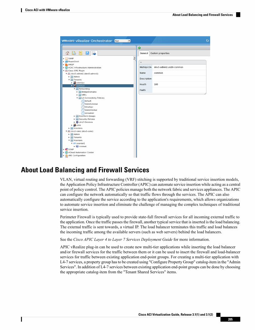
About Load Balancing and Firewall ServicesVLAN, virtual routing and forwarding (VRF) stitching is supported by traditional service insertion models,the Application Policy Infrastructure Controller (APIC) can automate service insertion while acting as a centralpoint of policy control. The APIC policies manage both the network fabric and services appliances. The APICcan configure the network automatically so that traffic flows through the services. The APIC can alsoautomatically configure the service according to the application's requirements, which allows organizationsto automate service insertion and eliminate the challenge of managing the complex techniques of traditionalservice insertion.
Perimeter Firewall is typically used to provide state-full firewall services for all incoming external traffic tothe application. Once the traffic passes the firewall, another typical service that is inserted is the load balancing.The external traffic is sent towards, a virtual IP. The load balancer terminates this traffic and load balancesthe incoming traffic among the available servers (such as web servers) behind the load balancers.
See the Cisco APIC Layer 4 to Layer 7 Services Deployment Guide for more information.
APIC vRealize plug-in can be used to create new multi-tier applications while inserting the load balancerand/or firewall services for the traffic between them or it can be used to insert the firewall and load-balancerservices for traffic between existing application end-point groups. For creating a multi-tier application withL4-7 services, a property group has to be created using "Configure Property Group" catalog-item in the "AdminServices". In addition of L4-7 services between existing application end-point groups can be done by choosingthe appropriate catalog-item from the "Tenant Shared Services" items.
Cisco ACI Virtualization Guide, Release 3.1(1) and 3.1(2)205
Cisco ACI with VMware vRealizeAbout Load Balancing and Firewall Services
In this release, only support for Shared-Plan is supported for Load balancer and Firewall services.Note
Prerequisites for Enabling ServicesThis section describes the prerequisites for enabling services.
You must perform the following tasks to deploy Layer 4 to Layer 7 services using the APIC vRealize plug-in:
• Device package for load balancer needs to be uploaded by APIC admin.
Use the link to download the required Citrix, F5, and Cisco ASA device packages:
http://www.cisco.com/c/en/us/solutions/collateral/data-center-virtualization/application-centric-infrastructure/solution-overview-c22-734587.html
Ensure the device package version is certified for the APIC release that you are using.
• Device cluster for load balancer, firewall needs to be created in tenant "common" by APIC-admin. Citrixand F5 are the supported vendors for load balancers. Cisco ASA is the supported vendor for firewall.
• For stand-alone firewall or load balancer service, a service graph template with single node must beconfigured. For the firewall and load balancer service, a service graph template with two nodes must beconfigured.
• For the abstract service graph, the firewall node (vnsAbsNode) must be named FW, and the load balancernode must be named SLB.
• For the load balancer only abstract service graph name (vnsAbsGraph) should be same as the load balancerdevice cluster (vnsLdevVip).
• For the load balancer only service, the consumer L3 connectivity policy must be configured in the"default" VRF of the tenant common.
• For the firewall, the consumer L3 connectivity policy must be configured in the separate VRF ("outside")of the tenant common.
• The firewall device needs to be deployed in the routed mode. For firewall device connectivity, twoadditional L3 connectivity policy must be configured. One must be configured in the "outside" VRF,and is used as the external connection to the firewall device. The other must be configured in the "default"VRF and is used as the internal connection to the firewall device. These two L3 connectivity policies,attached to the firewall enables the firewall to do the VRF stitching and re-direct the traffic appropriatelybetween the VRFs. The administrator has to ensure that appropriate prefixes with the correct import andexport flags are configured under the L3 external connectivity policies.
• The following convention should be used when configuring the L3 connectivity policies. For the L3connectivity policy should be named as L3ExtName, the child L3 instance should be named asL3ExtNameInst.
• The interface IP addresses that are used on the firewall and load balancer devices need to be configuredin the abstract graph.
• For the 2-node abstract graph, an access list to permit all traffic needs to be configured for the firewallnode.
Cisco ACI Virtualization Guide, Release 3.1(1) and 3.1(2)206
Cisco ACI with VMware vRealizePrerequisites for Enabling Services
Configuring the Services on APIC Using XML POSTOnly the administrator can configure and post the XML POST. The template POSTs are located in theapic-vrealize package under the services directory.
Before you begin
• The device package file should be uploaded on the Application Policy Infrastructure Controller (APIC).
See the Cisco APIC Layer 4 to Layer 7 Device Package Development Guide for more information.
• The tenant common should have the two bridge domains named "default" and "vpcDefault". Ensure thatthe subnets being used by the tenant who is consuming the load balancer are added to these bridgedomains. Typically you would have created these bridge domains and subnets while setting up the DHCPinfrastructure for vRealize tenants.
• For a non-Virtual Private Cloud (VPC) plan, the backend interface of the load balancer should be placedin the default EPG under the tenant common that was created above. For a VPC plan, the EPG shouldbe "vpcDefault".
• Ensure that the VIP subnet is linked with L3. One VIP per EPG will be allocated from the VIP poolassociated with the tenant.
• Prerequisites for the service scripts:
• Python 2.7
• Python libraries:
• jinja2
• yaml
• glob
• json
• requests
• xml
• re
Procedure
Step 1 Use the following link to download the required device packages Citrix, F5, and ASA. Ensure that the devicepackage version is certified for the APIC release that you are using. Store the device package zip files in thisdirectory:
http://www.cisco.com/c/en/us/solutions/collateral/data-center-virtualization/application-centric-infrastructure/solution-overview-c22-734587.html
Step 2 Replace the VENDOR-DEVICE-PACKAGE.zip entries in the shared.cfg or vpc.cfg file with thecorrect device package files.
Step 3 Edit the setup.yaml file and change the variables to according to your setup.
Cisco ACI Virtualization Guide, Release 3.1(1) and 3.1(2)207
Cisco ACI with VMware vRealizeConfiguring the Services on APIC Using XML POST
The template variables in the setup.yaml file are:TEMPLATE_VARS:
VCENTER: "vcenter1"ASA_IP: "1.1.1.1"ASA_CLUSTER: "AsaCluster1"ASA_VM: "asav-service5"OUTSIDE_CTX: "outside"INSIDE_CTX: "default"FW_GRAPH: "FWOnlyGraph"FW_SLB_GRAPH: "FWAndSLBGraph"BD_WEB: "default"CITRIX_MGMT_IP: "1.1.1.1"FW_NODE: "FW"SLB_NODE: "SLB"CITRIX_GRAPH: "CitrixCluster1_L3"CITRIX_CLUSTER: "CitrixCluster1_L3"CITRIX_GRAPH: "CitrixCluster1_L3"CITRIX_VM: "NS-service4"F5_BD: "F5Cluster1_L3"F5_EPG: "F5Cluster1_L3"F5_CLUSTER: "F5Cluster1_L3"F5_MGMT_IP: "1.1.1.1"F5_GRAPH: "F5Cluster1_L3"F5_ABS_NODE: "SLB"# Use deleted to generate the "deleted" version of the posts# STATUS: "deleted"STATUS: ""
Step 4 Enter the following commands:
For Shared Plan:
Example:../jinja.py setup.yaml tn-common-template.xml > tn-common.xml../jinja.py setup.yaml Shared-Plan-Citrix-graph-template.xml > Shared-Plan-Citrix-graph.xml../jinja.py setup.yaml Shared-Plan-F5-graph-template.xml > Shared-Plan-F5-graph.xml
For VPC Plan:
Example:../jinja.py setup.yaml VPC-tn-common-template.xml > VPC-tn-common.xml../jinja.py setup.yaml VPC-Plan-Citrix-LB-graph-template.xml > VPC-Plan-Citrix-LB-graph.xml../jinja.py setup.yaml VPC-Plan-F5-LB-graph-template.xml > VPC-Plan-F5-LB-graph.xml
If you see python errors, ensure that the prerequisite python libraries are installed in the system.
Step 5 Edit theshared.cfg orvpc.cfg file and set the values forhosts: <YOUR_APIC_IP> andpasswd:<YOUR_APIC_ADMIN_PASSWD>.
Sample of the shared.cfg file:
Example:host: <YOUR_APIC_IP>:443name: adminpasswd: <YOUR_APIC_ADMIN_PASSWD>tests:
- type: filepath: /ppi/node/mo/.xml
# file: asa-device-pkg-1.2.2.1.zip
Cisco ACI Virtualization Guide, Release 3.1(1) and 3.1(2)208
Cisco ACI with VMware vRealizeConfiguring the Services on APIC Using XML POST
# Replace actual ASA Device package file in the line belowfile: ASA-DEVICE-PACKAGE.zipwait: 2
- type: filepath: /ppi/node/mo/.xml
# file: CitrixNetscalerPackage.zip# Replace actual Citrix Device package file in the line below
file: CITRIX-DEVICE-PACKAGE.zipwait: 2
- type: filepath: /ppi/node/mo/.xml
# file: CitrixNetscalerPackage.zip# Replace actual F5 Device package file in the line below
file: F5-DEVICE-PACKAGE.zipwait: 2
- type: xmlpath: /api/node/mo/.xmlfile: tn-common.xmlwait: 0
- type: xmlpath: /api/node/mo/.xmlfile: Shared-Plan-Citrix-graph.xmlwait: 0
- type: xmlpath: /api/node/mo/.xmlfile: Shared-Plan-F5-graph.xmlwait: 0
Step 6 Post the templates.
For Shared Plan, enter the following command:
Example:../request.py shared.cfg
For VPC Plan, enter the following command:
Example:../request.py vpc.cfg
Deleting the Services ConfigurationThis section describes how to delete the services configuration. Only the administrator can configure and postthe XML POST. The template POSTs are located in the apic-vrealize package under the servicesdirectory.
Procedure
Step 1 Edit the shared.cfg file and set the values for hosts: <YOUR_APIC_IP> and passwd:<YOUR_APIC_ADMIN_PASSWD>.
Step 2 Edit the setup.yaml file and set the STATUS variable to deleted to generate the deleted version of theposts.
Step 3 Run the following commands:
Cisco ACI Virtualization Guide, Release 3.1(1) and 3.1(2)209
Cisco ACI with VMware vRealizeDeleting the Services Configuration
./jinja.py setup.yaml tn-common-template.xml > tn-common-del.xml
./jinja.py setup.yaml Shared-Plan-Citrix-graph-template.xml > Shared-Plan-Citrix-graph-del.xml
./jinja.py setup.yaml Shared-Plan-F5-graph-template.xml > Shared-Plan-F5-graph-del.xml
Step 4 Post the templates:./request.py shared_del.cfg
About L3 External ConnectivityLayer 3 (L3) external connectivity is an Cisco Application Centric Infrastructure (ACI) feature to connectACI fabric to an external network by L3 routing protocols, including static routing, OSPF, EIGRP, and BGP.By setting up L3 external connectivity for vRealize, it allows a tenant network to initiate outgoing trafficdestined outside the fabric and to attract traffic from outside. The assumption of this feature is the tenantvirtual machine IP addresses are visible outside the fabric without NAT, ACI L3 external connectivity doesnot include NAT.
Prerequisites for Configuring L3 External Connectivity for vRealizeTo configure Layer 3 (L3) external connectivity for vRealize, you must meet the following prerequisites:
• Ensure you have logged in to the Application Policy Infrastructure Controller (APIC) GUI, on the menubar, choose TENANT > common.
• Create a l3ExtOut called “default”, refer to BD “default”.
• Create l3extInstP name="defaultInstP" under the l3ExtOut. This is to be used by shared servicetenants.
See Cisco APIC Basic Configuration Guide for L3 external connectivity configuration.
• Ensure you have logged in to the APIC GUI, on the menu bar, choose TENANT > common.
• Create a l3ExtOut called "vpcDefault", refer to BD "vpcDefault".
• Create l3extInstP name="vpcDefaultInstP" under this l3ExtOut.
This is to be used by VPC tenants.
See Cisco APIC Basic Configuration Guide for configuring external connectivity for tenants.
vRealize leverages the common l3ExtOut configuration with no special requirement other than the namingconvention highlighted above
Administrator Experiences
Cisco ACI with Cisco AVS or Cisco ACI Virtual EdgeSee the following documentation for general information about Cisco Application Virtual Switch (AVS) orCisco ACI Virtual Edge:
• Cisco AVS—See the chapter "Cisco ACI with Cisco AVS" in the latest version of the Cisco ACIVirtualization Guide or the Cisco AVS guides on Cisco.com
Cisco ACI Virtualization Guide, Release 3.1(1) and 3.1(2)210
Cisco ACI with VMware vRealizeAbout L3 External Connectivity
• Cisco ACI Virtual Edge—See the Cisco ACI Virtual Edge documentation on Cisco.com.
Cisco AVS or Cisco ACI Virtual Edge VMM Domain CreationYou can create VMM domains for Cisco AVS or Cisco ACI Virtual Edge using VLAN or VXLANencapsulation or with no local switching.
Beginning with Cisco APIC Release 2.1(1), you can mix encapsulation modes. That is, you can configure aVMM domain to use VLAN or VXLAN and later add EPGs that override the domain's default encapsulation.For details, see the section "Mixed-Mode Encapsulation Configuration" in the Cisco Application VirtualSwitch Configuration Guide or the chapter "Mixed-Mode Encapsulation" in the Cisco ACI Virtual EdgeConfiguration Guide.
You also can create a Cisco AVS or Cisco ACI Virtual Edge VMM domain with no local switching. In localswitching mode, the leaf forwards all traffic, and VXLAN is the only allowed encapsulation type. See theCisco Application Virtual Switch Installation Guide or the Cisco ACI Virtual Edge Installation Guide.
After you create a Cisco AVS or Cisco ACI Virtual Edge VMM domain, you can update the domain'sencapsulation pools and delete the Cisco AVS or Cisco ACI Virtual Edge and the VMM domain.
Creating a Cisco AVS or Cisco ACI Virtual Edge VMM Domain
This section shows how to create a Cisco AVS or a Cisco ACI Virtual Edge VMM Domain supporting noencapsulation, VLAN, or VXLAN encapsulation. When you choose the virtual switch (Cisco AVS or CiscoAVE) and the switching preference (Local Switching or No Local Switching), the vRealize GUI shows orhides mandatory or optional field inputs.
Before you begin
We recommend that you created an attachable access entity profile (AAEP) as part of day-0 operation ofCisco ACI.
Procedure
Step 1 Log in to vRealize Automation as the administrator and then choose Catalog.Step 2 Choose Add VMM Domain and AVS or AVE.Step 3 In the New Request dialog box, complete the following steps:
a) View the Service Blueprint Information for the input fields and then click Request.b) In the Request Information pane, add a description and then click Next.c) In the Domain name field, enter the VMM domain name.d) For the Virtual Switch selector, choose Cisco AVS or Cisco AVE.e) For the Switching Preference selector, choose Lo Local Switching or Local Switching.f) If you chose Local Switching, for the Encap mode selector choose VLAN or VXLAN.
Encap mode is applicable only for Local Switching.g) In the AAEP Name field, enter an attachable access entity profile (AAEP) name to associate it to the
VMM domain.
If the AAEP that you enter doesn’t exist, it is created.
h) For the VLAN Ranges to be allocated, click Not set and then add values to create VLANs.
Cisco ACI Virtualization Guide, Release 3.1(1) and 3.1(2)211
Cisco ACI with VMware vRealizeCisco AVS or Cisco ACI Virtual Edge VMM Domain Creation
For Encap_Block_Role, specify external or internal.
i) (Optional) In the AVS Fabric-wide Multicast Address or AVE Fabric-wide Multicast Addressfield,enter a valid multicast address between 224.0.0.0 and 239.255.255.255, inclusive, for the multicastaddress block range.
j) (Optional) In theMulticast Address Start field, enter the starting multicast address between 224.0.0.0and 239.255.255.255, inclusive, for the multicast address block range.
k) Optional) In theMulticast Address End field, between 224.0.0.0 and 239.255.255.255, inclusive, forthe multicast address block range.
l) In the AAA Domain area, click the green cross, choose a security domain, and then click Next.m) In the Vcenter IP (or Hostname) field, enter the host name or IP address.
If you use the host name, you already must have configured a DNS policy on Cisco APIC. If you donot have a DNS policy configured, enter the IP address of the vCenter server.
n) From the DVS Version drop-down list, choose the DVS version.o) In the Username field, enter the user name for logging in to the vCenter.p) In the Password field, enter the password for logging into the vCenter.q) In the vCenter Datacenter field, enter the data center name.
The name that you enter for the data center must match exactly the name in vCenter. Thename is case-sensitive.
Note
Verifying Cisco AVS or Cisco ACI Virtual Edge Creation in vCenter
Procedure
Step 1 Open a vSphere Client connection to a vCenter server.Step 2 In vCenter, choose Home > Inventory > Networkingview.Step 3 Choose the data center.Step 4 Under the data center, ensure that the Cisco AVS or the Cisco ACI Virtual Edge and its folder are created.
Verifying Creation of the Cisco AVS or Cisco ACI Virtual Edge VMM Domain on Cisco APIC
Procedure
Step 1 Log in to Cisco APIC as the administrator.Step 2 Choose Virtual Networking > Inventory.Step 3 In the Inventory navigation pane, choose VMM Domains > VMware.Step 4 In the work pane, under Properties, in the vCenter Domains field, ensure that the newly created VMM
domain is listed.
Cisco ACI Virtualization Guide, Release 3.1(1) and 3.1(2)212
Cisco ACI with VMware vRealizeVerifying Cisco AVS or Cisco ACI Virtual Edge Creation in vCenter
Update of Cisco AVS or Cisco ACI Virtual Edge VMM Domain Encapsulation PoolsAfter you create a Cisco AVS VMM or Cisco ACI Virtual Edge domain, you can update VLAN or multicastaddress pools. You should then verify the update.
Updating the VLAN Pool of a Cisco AVS or Cisco ACI Virtual Edge VMM Domain
Procedure
Step 1 Log in to the vRealize Automation as the administrator and then choose Catalog.Step 2 Choose Update Vlan Pool, AVS or Update Vlan Pool, AVE.
This update operation is only supported for dynamic VLAN pools. Static VLAN pools are notsupported.
Note
Step 3 View the Service Blueprint Information for the input fields and then click Request.Step 4 In the New Request dialog box, complete the following steps:
a) Add the description and then click Next.b) In the Vlan Pool Name field, enter the name of the existing VLAN pool.c) In the List of encap blocks area, click the green cross next to New.d) For each Encap block, in the VlanStart column, enter the starting VLAN.e) In the VlanEnd column, enter the ending VLAN.f) For encapRole, specify external or internal.g) Tick the check box in IsAddoperation to add encap blocks to the VLAN pool.
Leave the check box unchecked to remove an entered encap block from a VLAN pool.
h) Click Submit.
What to do next
Complete the procedure Verifying the Update of the VLAN Pool of a Cisco AVS or Cisco ACI Virtual EdgeVMM Domain in Cisco APIC, on page 213.
Verifying the Update of the VLAN Pool of a Cisco AVS or Cisco ACI Virtual Edge VMM Domain in Cisco APIC
Procedure
Step 1 Log in to Cisco APIC as the administrator.Step 2 Choose Fabric > Access Policies.Step 3 In the Policies navigation pane, expand the Pools folder.Step 4 Expand the VLAN folder.Step 5 Choose the VLAN pool.Step 6 In the work pane, under Pools - VLAN, ensure that the VLAN pool is updated.
Cisco ACI Virtualization Guide, Release 3.1(1) and 3.1(2)213
Cisco ACI with VMware vRealizeUpdate of Cisco AVS or Cisco ACI Virtual Edge VMM Domain Encapsulation Pools
Updating the Multicast Address Pool of a Cisco AVS or Cisco ACI Virtual Edge VMM Domain
Procedure
Step 1 Log in to vRealize Automation as the administrator and then choose Catalog.Step 2 Choose Update Multicast Pool, AVS or AVE.Step 3 View the Service Blueprint Information for the input fields and then click Request.Step 4 In the New Request dialog box, complete the following steps:
a) In theMulticast Pool Name field, enter the name of the existing multicast address pool.b) In the List of Multicast Address Range area, click the green cross next to New.c) For each multicast address block, enter the starting multicast address between 224.0.0.0 and
239.255.255.255, inclusive, in theMulticastAddressStart column.d) In theMulticastAddressEnd column, enter the ending multicast address between 224.0.0.0 and
239.255.255.255, inclusive.e) Check the check box in the column IsAddOperation to add multicast address blocks to the multicast
address pool.
Leave the check box unchecked to remove an entered multicast address block from the multicast addresspool.
f) Click Submit.
What to do next
Complete the procedure Verifying the Update of a Multicast Address Pool on Cisco APIC , on page 214.
Verifying the Update of a Multicast Address Pool on Cisco APIC
Procedure
Step 1 Log in to Cisco APIC as the administrator.Step 2 Choose Fabric > Access Policies.Step 3 in the Policies navigation pane, expand the Pools folder.Step 4 Expand theMulticast Address folder.Step 5 Choose the multicast address pool.Step 6 In the work pane, under Pools - Multicast Address, ensure that the multicast address pool is updated.
Deletion of Cisco AVS or Cisco ACI Virtual Edge and the VMM DomainYou can delete the Cisco AVS or Cisco ACI Virtual Edge and the VMM domain. After you do so, you shouldverify the deletion.
Cisco ACI Virtualization Guide, Release 3.1(1) and 3.1(2)214
Cisco ACI with VMware vRealizeUpdating the Multicast Address Pool of a Cisco AVS or Cisco ACI Virtual Edge VMM Domain
Deleting the Cisco AVS or Cisco ACI Virtual Edge and the VMM Domain
Procedure
Step 1 Log in to vRealize Automation as the administrator and then choose Catalog.Step 2 Choose Delete VMM Domain, AVS or AVE.Step 3 View the Service Blueprint Information for the input fields and then click Request.Step 4 In the New Request dialog box, complete the following steps:
a) Add a description and then click Next.b) In the Domain name field, enter the name of the VMM domain that you want to delete.
If the VMM domain has an associated multicast address pool (Domain/AVS or AVEname_mcastpool) or a VLAN pool (Domain/AVS or AVE name_vlanpool), it also will be deleted.
Note
c) Click Submit.
What to do next
Complete the following procedures:
• Verifying Cisco AVS or Cisco ACI Virtual Edge Deletion in vCenter, on page 215
• Verifying VMM Domain Deletion on Cisco APIC, on page 215
• Verifying VLAN Pool Deletion on Cisco APIC, on page 216
• Verifying Multicast Address Pool Deletion on Cisco APIC, on page 216
Verifying Cisco AVS or Cisco ACI Virtual Edge Deletion in vCenter
Procedure
Step 1 Open a vSphere Client connection to a vCenter server.Step 2 In vCenter, choose Home > Inventory > Networking view.Step 3 Choose the data center.Step 4 Under the data center, ensure that the Cisco AVS or Cisco ACI Virtual Edge and its folder are deleted.
Verifying VMM Domain Deletion on Cisco APIC
Procedure
Step 1 Log in to Cisco APIC as the administrator.Step 2 Choose Virtual Networking > Inventory.Step 3 In the Inventory navigation pane, expand the VMM Domains folder and the VMware folder.
Cisco ACI Virtualization Guide, Release 3.1(1) and 3.1(2)215
Cisco ACI with VMware vRealizeDeleting the Cisco AVS or Cisco ACI Virtual Edge and the VMM Domain
Step 4 Under VMware, ensure that the deleted VMM domain is not present.
Verifying VLAN Pool Deletion on Cisco APIC
Procedure
Step 1 Log in to Cisco APIC as the administrator.Step 2 Choose Fabric > Access PoliciesStep 3 In the Policies navigation pane, expand the Pools folder.Step 4 Choose the VLAN folder.Step 5 In the work pane, under Pools - VLAN, ensure that the VLAN pool (Domain/AVS name_vlanpool) is
deleted.
Verifying Multicast Address Pool Deletion on Cisco APIC
Procedure
Step 1 Log in to Cisco APIC as the administrator.Step 2 Choose Fabric > Access Policies.Step 3 In the Policies navigation pane, expand the Pools folder.Step 4 Choose theMulticast Address folder.Step 5 In the work pane, under Pools - Multicast Address, ensure that the multicast address pool (Domain/AVS
or AVE name_mcastpool) is deleted.
Cisco AVS or Cisco ACI Virtual Edge VMM Domain Security Domain MappingYou can update the security domain mapping for the Cisco AVS or Cisco ACI Virtual Edge VMM domain.
Updating the Security Domain Mapping of the Cisco AVS or Cisco ACI Virtual Edge VMM Domain
Procedure
Step 1 Log in to vRealize Automation as the administrator and then choose Catalog.Step 2 ChooseUpdate AVS or AVE VMMDomain Security DomainMapping and complete the following steps:
a) View the Service Blueprint Information for the input fields and then click Request.b) In the Request Information pane, add a description and then click Next.c) In the AVS/VMM-domain name field, enter the VMM domain name.d) In the AAA Domain list table, click New and enter the AAA domain name.
Cisco ACI Virtualization Guide, Release 3.1(1) and 3.1(2)216
Cisco ACI with VMware vRealizeVerifying VLAN Pool Deletion on Cisco APIC
For each entry, specify the existing security domain in the aaaDomainName column. Check the checkbox in the IsAddOperation column to add the AVS or AVE VMM domain to the AAA domain. Ifunchecked, the AVS or AVE VMM domain is removed from the AAA domain.
e) Click Submit.
What to do next
Complete the procedure Verifying the Security Domain Mapping of the Cisco AVS or Cisco ACI VirtualEdge VMM Domain, on page 217.
Verifying the Security Domain Mapping of the Cisco AVS or Cisco ACI Virtual Edge VMM Domain
Procedure
Step 1 Log in to Cisco APIC as the administrator.Step 2 Choose Virtual Networking > Inventory > VMM Domains > VMware.Step 3 Choose the VMM domain.Step 4 In the work pane, under Properties, ensure that the Security Domains field has been updated.
Distributed Firewall PolicyYou can create, update, and delete a Distributed Firewall (DFW) policy and update the DFW policy associationwith the Cisco AVS or Cisco ACI Virtual Edge VMM domain.
For detailed information about Distributed Firewall, see the one of the following:
• The section Distributed Firewall, on page 149 in the chapter "Cisco ACI with Cisco AVS" in this guide
• The chapter "Distributed Firewall" in the Cisco ACI Virtual Edge Configuration Guide
Creating a Distributed Firewall Policy
This section describes how to create a DFW policy and associate it with a Cisco AVS or Cisco ACI VirtualEdge VMM domain.
Procedure
Step 1 Log in to vRealize Automation as the administrator and then choose Catalog.Step 2 ChooseCreate FWPolicy (DFW) andAssociate to AVS or AVEVMMDomain and complete the following
steps:a) View the Service Blueprint Information for the input fields and then click Request.b) In the Request Information pane, add the description and click Next.c) In the FW Policy Name field, enter a name for the policy.d) From theMode drop-down list, choose Learning, Enabled, or Disabled.
Cisco ACI Virtualization Guide, Release 3.1(1) and 3.1(2)217
Cisco ACI with VMware vRealizeVerifying the Security Domain Mapping of the Cisco AVS or Cisco ACI Virtual Edge VMM Domain
• Learning—Cisco AVS or Cisco ACI Virtual Edge monitors all TCP communication and createsflows in a flow table but does not enforce the firewall. Learning mode lets you enable the firewallwithout losing traffic.
• Enabled—Enforces the Distributed Firewall. If you upgrade from an earlier version of CiscoAVS—one that does not support Distributed Firewall—and are upgrading Cisco AVS only, youmust first upgrade all the Cisco AVS hosts in that VMM domain and then enable DistributedFirewall.
• Disabled—Does not enforce the Distributed Firewall and removes all flow information from theCisco AVS or Cisco ACI Virtual Edge. Choose this mode only if you do not want to use theDistributed Firewall.
e) In the VMM Name field, enter the name of the existing Cisco AVS or Cisco ACI Virtual Edge VMMdomain to which you want to associate the DFW policy and then click Next.
f) In the Syslog Form page, chooseDisabled or Enabled from theAdministrative State drop-down list.g) Cisco AVS or Cisco ACI Virtual Edge reports the flows that are permitted or denied by the Distributed
Firewall to the system log (syslog) server. Do the following:
• From the Permitted flows drop-down list, choose yes if you want Cisco AVS or Cisco ACI VirtualEdge to report permitted flows to the syslog server. Choose no if you do not want Cisco AVS orCisco ACI Virtual Edge to report permitted flows to the syslog server.
• From the Denied flows drop-down list, choose yes if you want Cisco AVS or Cisco ACI VirtualEdge to report denied flows to the syslog server. Choose no if you do not want Cisco AVS or CiscoACI Virtual Edge to report denied flows to the syslog server.
h) In the Polling Interval (seconds) area, enter an interval from 60 to 86,400 seconds.i) From the Log Level drop-down list, choose a logging severity level that is greater than or equal to the
severity level defined for the syslog server.j) In the Dest Group area, enter an existing syslog monitoring destination group.k) Click Submit.
What to do next
Complete the procedure Verifying Distributed Firewall Policy Creation on APIC, on page 218.
Verifying Distributed Firewall Policy Creation on APIC
This section describes how to verify the creation of a distributed firewall policy on Application PolicyInfrastructure Controller.
Procedure
Step 1 Log in to APIC as the administrator.Step 2 Choose Fabric > Access Policies.Step 3 In the Policies navigation pane, choose Interface Policies > Policies > Firewall.Step 4 In theWork pane, under Policies - Firewall, confirm that the corresponding firewall policy is created.Step 5 To view the distributed firewall policy association with a VMM domain, do the following:
Cisco ACI Virtualization Guide, Release 3.1(1) and 3.1(2)218
Cisco ACI with VMware vRealizeVerifying Distributed Firewall Policy Creation on APIC
a) Choose Virtual Networking > Inventory > VMM Domains > VMware.b) Click the corresponding VMM domain.c) In theWork pane, under Properties, confirm that the created distributed firewall policy is present in the
Firewall Policy field for vSwitch Policies.
Updating a Distributed Firewall Policy
This section describes how to update an existing DFW policy.
Procedure
Step 1 Log in to vRealize Automation as the administrator and then choose Catalog.Step 2 Choose Update FW Policy (DFW) and complete the following steps:
In the service blueprint, some drop-down lists have a <NO CHANGE> option that you can choose if you donot want to change the configured value.a) View the Service Blueprint Information for the input fields and then click Request.b) In the Request Information pane, add the description and click Next.c) In the FW Policy Name field, enter an updated name for the policy.d) From theMode drop-down list, choose Learning, Enabled, Disabled, or <NO CHANGE>. Click
Next.e) In the Syslog Form page, choose Disabled, Enabled, or <NO CHANGE> from the Administrative
State drop-down list.f) From the Permitted flows drop-down list, choose yes, no, or <NO CHANGE>.g) From the Denied flows drop-down list, choose yes, no, or <NO CHANGE>.h) In the Polling Interval (seconds) area, update the interval to a value from 60 to 86,400 seconds.
If you do not specify an interval, no update occurs.Note
i) From the Log Level drop-down list, choose a logging severity level that is greater than or equal to theseverity level defined for the syslog server. Choose <NO CHANGE> if you do not want to change thelog level.
j) In the Dest Group area, enter a new or existing syslog monitoring destination group.
If you do not enter a new or existing syslog monitoring destination group, no update occurs.Note
k) Click Submit.
Verifying a Distributed Firewall Policy Update on APIC
This section describes how to verify an update to a distributed firewall policy on Application PolicyInfrastructure Controller.
Procedure
Step 1 Log in to Cisco APIC as the administrator.
Cisco ACI Virtualization Guide, Release 3.1(1) and 3.1(2)219
Cisco ACI with VMware vRealizeUpdating a Distributed Firewall Policy
Step 2 Choose Fabric > Access Policies.Step 3 In the Policies navigation pane, choose Interface Policies > Policies > Firewall.Step 4 In the work pane, under Policies - Firewall, double-click the required firewall policy and confirm that it is
updated.
Deleting a Distributed Firewall Policy
This section describes how to delete a DFW policy.
Procedure
Step 1 Log in to vRealize Automation as the administrator and then choose Catalog.Step 2 Choose Delete FW Policy (DFW) and complete the following steps:
a) View the Service Blueprint Information for the input fields and then click Request.b) In the Request Information pane, add the description and click Next.c) In the FW Policy Name field, enter the name of the DFW policy that you want to delete.d) Click Submit.
Verifying a Distributed Firewall Policy Deletion on APIC
This section describes how to verify the deletion of a distributed firewall policy on Application PolicyInfrastructure Controller.
Procedure
Step 1 Log in to Cisco APIC.Step 2 Choose Fabric > Access Policies.Step 3 In the Policies navigation pane, choose Interface Policies > Policies > Firewall.Step 4 In theWork pane, under Policies - Firewall, confirm that the deleted firewall policy is not present.
Updating a Distributed Firewall Policy Association with the Cisco AVS or Cisco ACI Virtual Edge VMM Domain
This section describes how to update a DFW policy that is associated with a Cisco AVS or Cisco ACI VirtualEdge VMM domain.
Procedure
Step 1 Log in to vRealize Automation as the administrator and then choose Catalog.Step 2 Choose Update FW Policy (DFW) association to AVS or AVE VMMDomain and complete the following
steps:a) View the Service Blueprint Information for the input fields and then click Request.
Cisco ACI Virtualization Guide, Release 3.1(1) and 3.1(2)220
Cisco ACI with VMware vRealizeDeleting a Distributed Firewall Policy
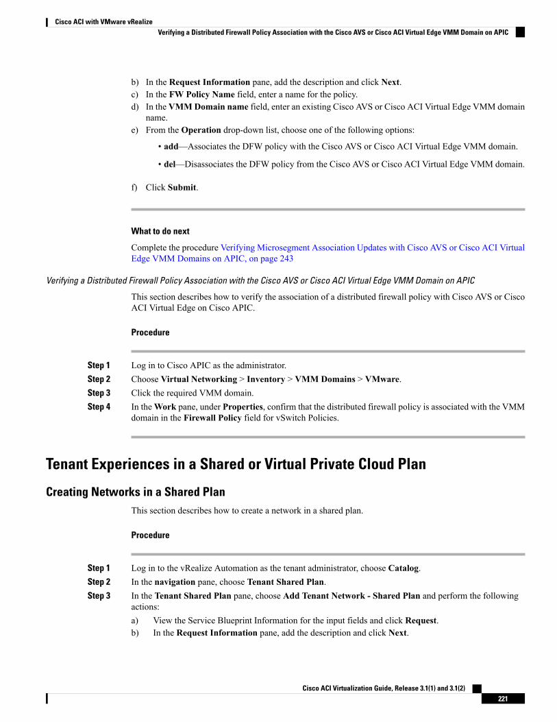
b) In the Request Information pane, add the description and click Next.c) In the FW Policy Name field, enter a name for the policy.d) In the VMMDomain name field, enter an existing Cisco AVS or Cisco ACI Virtual Edge VMM domain
name.e) From the Operation drop-down list, choose one of the following options:
• add—Associates the DFW policy with the Cisco AVS or Cisco ACI Virtual Edge VMM domain.
• del—Disassociates the DFW policy from the Cisco AVS or Cisco ACI Virtual Edge VMM domain.
f) Click Submit.
What to do next
Complete the procedure Verifying Microsegment Association Updates with Cisco AVS or Cisco ACI VirtualEdge VMM Domains on APIC, on page 243
Verifying a Distributed Firewall Policy Association with the Cisco AVS or Cisco ACI Virtual Edge VMM Domain on APIC
This section describes how to verify the association of a distributed firewall policy with Cisco AVS or CiscoACI Virtual Edge on Cisco APIC.
Procedure
Step 1 Log in to Cisco APIC as the administrator.Step 2 Choose Virtual Networking > Inventory > VMM Domains > VMware.Step 3 Click the required VMM domain.Step 4 In theWork pane, under Properties, confirm that the distributed firewall policy is associated with the VMM
domain in the Firewall Policy field for vSwitch Policies.
Tenant Experiences in a Shared or Virtual Private Cloud Plan
Creating Networks in a Shared PlanThis section describes how to create a network in a shared plan.
Procedure
Step 1 Log in to the vRealize Automation as the tenant administrator, choose Catalog.Step 2 In the navigation pane, choose Tenant Shared Plan.Step 3 In the Tenant Shared Plan pane, choose Add Tenant Network - Shared Plan and perform the following
actions:a) View the Service Blueprint Information for the input fields and click Request.b) In the Request Information pane, add the description and click Next.
Cisco ACI Virtualization Guide, Release 3.1(1) and 3.1(2)221
Cisco ACI with VMware vRealizeVerifying a Distributed Firewall Policy Association with the Cisco AVS or Cisco ACI Virtual Edge VMM Domain on APIC
c) In the Step pane, perform the following actions:d) In the NetworkEPG name field, enter the name of the new shared network (new-shared-network).e) In the Domain/DVS field, click Add, expand your_apic > vCenters > your_vcenter, and then select
the DVS.f) From the encapMode drop-down list, choose either Auto, VLAN, or VXLAN for the encapsulation
mode.
The encapMode field is applicable only if the VMM domain type is Cisco AVS or CiscoACI Virtual Edge (Local Switching). Selecting VLAN or VXLAN for VDS VMM Domain,may lead into unpredictable results.
Note
g) In the Application Tier Number field, enter a numeric value from 1 to 10.h) In the Intra EPG Deny field, select a value either Yes or No.i) In the Allow Microsegmentation field, select a value, either Yes or No.
The Allow Microsegmentation field is applicable only if the VMM domain type is VDSVMM Domain.
Note
j) In the Use Default BD? field, select a value either Yes or No.
If you selected No, choose a custom bridge domain by clicking on Add.
• Expand your_apic_user > Tenants > your_tenant > Networking > BridgeDomains >your_bridgedomain and select this bridge domain.
k) In the Switching Mode selector, choose native or AVE.
The native option is default switching; AVE is for Cisco ACI Virtual Edge switching.
l) Click Submit.
Verifying the Newly Created Network on VMware vRealize and APICThis section describes how to verify the newly created network on VMware vRealize and Application PolicyInfrastructure Controller (APIC) .
Procedure
Step 1 Log in to the vRealize Automation as the tenant administrator, chooseRequest and ensure your request statusis successful.
Step 2 Log into the APIC GUI as the Tenant, choose Tenants.Step 3 In the navigation pane, expand the Tenant name > Application Profiles > default > Application EPGs >
EPG new-shared-network.Step 4 In the Properties pane, ensure the Received Bridge Domain field is common/default.Step 5 In the navigation pane, choose Domains (VMs and Bare-Metals), ensure it is bound to
VMware/your_vmm_domain.
Cisco ACI Virtualization Guide, Release 3.1(1) and 3.1(2)222
Cisco ACI with VMware vRealizeVerifying the Newly Created Network on VMware vRealize and APIC
Creating a Bridge Domain in a VPC PlanThis section describes how to create a bridge domain in a VPC plan.
Procedure
Step 1 Log in to the vRealize Automation as the tenant administrator, choose Catalog.Step 2 In the navigation pane, choose Tenant Network Services.Step 3 In the Tenant Network Services pane, choose Add or Delete Bridge domain in Tenant and perform the
following actions:a) View the Service Blueprint Information for the input fields and click Request.b) In the Request Information pane, add the description and click Next.c) In the Step pane, perform the following actions:d) In the Add a bridge domain field, choose Yes.e) In the Bridge Domain name field, enter the bridge domain name (new-bd).f) In the Enable ARP Flooding field, choose No.g) In the Enable flooding for L2 Unknown Unicast field, choose hardware-proxy.h) In the Enable flooding for L3 Unknown Multicast field, choose flood.i) In theL3 context (VRF) field, clickAdd, expand your_apic >Tenants > your_tenant >Networking >
VRFs and select the VRF (ctx1).j) Click Submit.k) In the Operation field, choose Add.l) Click Submit.
Verifying the Newly Created Bridge Domain on APIC
This section describes how to verify the newly created bridge domain on Application Policy InfrastructureController (APIC).
Procedure
Step 1 Log into the APIC GUI as the tenant, choose Tenants.Step 2 In the navigation pane, expand theTenant name >Networking >Bridge Domain > your_newly_created_bd.Step 3 In the Properties pane, ensure the fields are the same as in the VMware vRealize GUI.
Creating a Network and Associating to a Bridge Domain in a VPC PlanThis section describes how to create a network and associating to a bridge domain in a VPC Plan.
Procedure
Step 1 Log in to the vRealize Automation as the tenant administrator, choose Catalog.
Cisco ACI Virtualization Guide, Release 3.1(1) and 3.1(2)223
Cisco ACI with VMware vRealizeCreating a Bridge Domain in a VPC Plan
Step 2 In the navigation pane, choose Tenant VPC Plan.Step 3 In the Tenant VPC Plan pane, chooseAdd Tenant Network - VPC Plan and perform the following actions:
a) View the Service Blueprint Information for the input fields and click Request.b) In the Request Information pane, add the description and click Next.c) In the Step pane, perform the following actions:d) In the NetworkEPG name field, enter the name of the new shared network (new-vpc-network).e) In the Domain/DVS field, click Add, expand your_apic > vCenters > your_vcenter and select the
DVS.f) From the encapMode drop-down list, choose either Auto, VLAN, or VXLAN for the encapsulation
mode.
The encapMode field is applicable only if the VMMdomain type is Cisco AVS or Cisco ACIVirtual Edge (Local Switching). Selecting VLAN or VXLAN for VDS VMM Domain, maylead into unpredictable results.
Note
g) In the Application Tier Number field, enter a numeric value from 1-10.h) In the Intra EPG Deny field, select a value either Yes or No.i) In the Allow Microsegmentation field, select a value either Yes or No.
The Allow Microsegmentation field is applicable only if the VMMdomain type is VDSVMM Domain.
Note
j) In the Use Default BD? field, select a value either Yes or No.
If you selected No, choose a custom bridge domain by clicking on Add.
• Expand your_apic_user > Tenants > your_tenant > Networking > BridgeDomains >your_bridgedomain and select this bridge domain.
k) In the Subnet Prefix field, enter the gateway IP address and the subnet mask (10.1.1.1/24).l) Click Submit.
Verifying the Network and Association to the Bridge Domain in a VPC Plan on APIC
This section describes how to verify the newly created bridge domain on APIC.
Procedure
Step 1 Log into the APIC GUI as the Tenant, choose Tenants.Step 2 In the navigation pane, expand the Tenant name > Application Profiles > default > Application EPGs >
EPG new-vpc-network.Step 3 In the Properties pane, ensure the Bridge Domain is your_tenant/bd1.Step 4 In the navigation pane, choose Domains (VMs and Bare-Metals), ensure it is bound to
VMware/your_vmm_domain.Step 5 In the navigation pane, expand the Tenant name > Networking > Bridge Domain > bd1 > Subnets.Step 6 In the Subnets pane, ensure the gateway IP address and subnet mask that you enter when creating a network
and associating to a bridge domain in a VPC plan (10.1.1.1/24) and the scope is Private to VRF.Step 7 On the menu bar, choose Virtual Networking.
Cisco ACI Virtualization Guide, Release 3.1(1) and 3.1(2)224
Cisco ACI with VMware vRealizeVerifying the Network and Association to the Bridge Domain in a VPC Plan on APIC
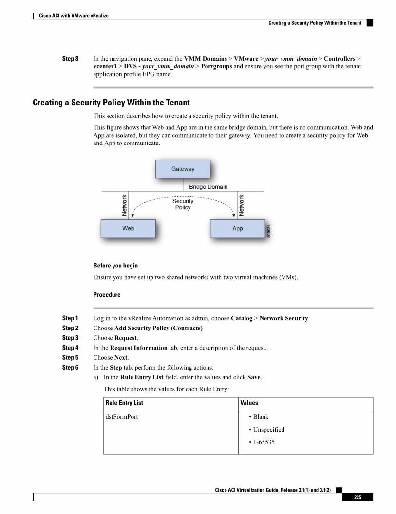
Step 8 In the navigation pane, expand the VMM Domains > VMware > your_vmm_domain > Controllers >vcenter1 > DVS - your_vmm_domain > Portgroups and ensure you see the port group with the tenantapplication profile EPG name.
Creating a Security Policy Within the TenantThis section describes how to create a security policy within the tenant.
This figure shows that Web and App are in the same bridge domain, but there is no communication. Web andApp are isolated, but they can communicate to their gateway. You need to create a security policy for Weband App to communicate.
Before you begin
Ensure you have set up two shared networks with two virtual machines (VMs).
Procedure
Step 1 Log in to the vRealize Automation as admin, choose Catalog > Network Security.Step 2 Choose Add Security Policy (Contracts)Step 3 Choose Request.Step 4 In the Request Information tab, enter a description of the request.Step 5 Choose Next.Step 6 In the Step tab, perform the following actions:
a) In the Rule Entry List field, enter the values and click Save.
This table shows the values for each Rule Entry:
ValuesRule Entry List
• Blank
• Unspecified
• 1-65535
dstFormPort
Cisco ACI Virtualization Guide, Release 3.1(1) and 3.1(2)225
Cisco ACI with VMware vRealizeCreating a Security Policy Within the Tenant
ValuesRule Entry List
• Blank
• Unspecified
• 1-65535
dstToPort
• icmp
• icmpv6
• tcp
• udp
• Blank
protocol
• IP
• ARP
etherType
b) In theConsumer Network/EPG name field, clickAdd to locate and choose the consumer network/EPG.(web-host)
c) Click Submit.d) In the Provider Network/EPG name field, click Add to locate and choose the provider network/EPG.
(app-host)e) Click Submit.
Step 7 Click Submit.Step 8 Click OK.
Verifying the Security Policy Within the Tenant on APIC
This section describes how to verify the security policy within the tenant on APIC.
Procedure
Step 1 Log in to Cisco APIC and then choose TENANTS.Step 2 In the navigation pane, expand Tenant your_tenant > Networking > Security Policies > Contracts.
a) Ensure the name nested underContracts is the provider and consumer name. (app-host_ctrct_web-hosts)
Step 3 In the navigation pane, expand Tenant your_tenant > Networking > Security Policies > Filters.a) Ensure the name nested under Filters is the provider and consumer name. (app-host_flt_web-hosts)
Step 4 In the navigation pane, expand Tenant your_tenant > Networking > Application Profiles > default >Application EPGs > EPG web-hosts > Contracts.a) In the work pane, ensure the consumer is Comsumed.
Step 5 In the navigation pane, expand Tenant your_tenant > Networking > Application Profiles > default >Application EPGs > EPG app-hosts > Contracts.
Cisco ACI Virtualization Guide, Release 3.1(1) and 3.1(2)226
Cisco ACI with VMware vRealizeVerifying the Security Policy Within the Tenant on APIC
a) In the work pane, ensure the provider is Provided.
Verifying the Connectivity of the Security Policy within the Tenant
This section describes how to verify the connectivity of the security policy within the tenant.
Procedure
Step 1 Log in to the virtual machine (web-host), from the command line, ping the other VM (app-host).Step 2 Log in to the virtual machine (app-host), from the command line, ping the other VM (web-host).
This ensure the VMs are communicating with each other.
Consuming a Shared Service in the Common TenantThis section describes consuming a shared service in the common tenant.
Before you begin
You must have an EPG in the common tenant that has a bridge domain relationship to "common/default".
Procedure
Step 1 Log in to the vRealize Automation as tenant, choose Catalog > Network Security.Step 2 Choose Add Security Policy (Contracts)Step 3 Choose Request.Step 4 In the Request Information tab, enter a description of the request.Step 5 Choose Next.Step 6 In the Step tab, perform the following actions:
a) In the Rule Entry List field, enter the values and click Save.
This table shows the values for each Rule Entry:
ValuesRule Entry List
• Blank
• Unspecified
• 1-65535
dstFormPort
• Blank
• Unspecified
• 1-65535
dstToPort
Cisco ACI Virtualization Guide, Release 3.1(1) and 3.1(2)227
Cisco ACI with VMware vRealizeVerifying the Connectivity of the Security Policy within the Tenant
ValuesRule Entry List
• icmp
• icmpv6
• tcp
• udp
• Blank
protocol
• IP
• ARP
etherType
b) In theConsumer Network/EPG name field, clickAdd to locate and choose the consumer network/EPG.(web-host)
c) Click Submit.d) In the Provider Network/EPG name field, click Add to locate and choose the provider network/EPG.
(SYSLOG-EPG)e) Click Submit.
Step 7 Click Submit.Step 8 Click OK.
Verifying the Security Policy in the Tenant Common on APIC
This section describes how to verify the security policy in the tenant common on APIC.
Procedure
Step 1 Log in to Cisco APIC as the tenant, and then choose TENANTS.Step 2 In the navigation pane, expand Tenant your_tenant > Networking > Security Policies > Contracts.
a) Ensure the name nested under Contracts is the provider and consumer name.(SYSLOG-EPG_ctrct_web-hosts)
Step 3 In the navigation pane, expand Tenant your_tenant > Networking > Security Policies > Filters.a) Ensure the name nested under Filters is the provider and consumer name. (SYSLOG-EPG_flt_web-hosts)
Step 4 In the navigation pane, expand Tenant your_tenant > Networking > Application Profiles > default >Application EPGs > EPG web-hosts > Contracts.a) In the work pane, ensure the consumer is Comsumed.
Step 5 In the navigation pane, expand Tenant your_tenant > Networking > Application Profiles > default >Application EPGs > EPG SYSLOG-EPG-hosts > Contracts.a) In the work pane, ensure the provider is Provided.
Cisco ACI Virtualization Guide, Release 3.1(1) and 3.1(2)228
Cisco ACI with VMware vRealizeVerifying the Security Policy in the Tenant Common on APIC
Verifying the Connectivity of the Security Policy in the Tenant Common
This section describes how to verify the connectivity of the security policy in the tenant common.
Procedure
Step 1 Log in to the virtual machine (web-host), from the command line, ping the other VM (SYSLOG-EPG).Step 2 Log in to the virtual machine (SYSLOG-EPG), from the command line, ping the other VM (web-host).
This ensure the VMs are communicating with each other.
Updating Security Policies (Access Control Lists)This section describes how to update security policies (access control lists).
Procedure
Step 1 Log in to the vRealize Automation as tenant, choose Catalog > Network Security.Step 2 Choose Update Security policies (Access Control Lists)Step 3 Choose Request.Step 4 In the Request Information tab, enter a description of the request.Step 5 Choose Next.Step 6 In the Step tab, perform the following actions:
a) In the apic security filter name field, clickAdd to locate and choose a filter that been pushed by vRealize.b) In the Rule Entry List field, enter the values and click Save. You must recreate the rule entry list.
This updating security policies access control lists will push new rules in including over writingexisting rule of the same name.
Note
This table shows the values for each Rule Entry:
ValuesRule Entry List
• Blank
• Unspecified
• 1-65535
dstFormPort
• Blank
• Unspecified
• 1-65535
dstToPort
Cisco ACI Virtualization Guide, Release 3.1(1) and 3.1(2)229
Cisco ACI with VMware vRealizeVerifying the Connectivity of the Security Policy in the Tenant Common
ValuesRule Entry List
• icmp
• icmpv6
• tcp
• udp
• Blank
protocol
• IP
• ARP
etherType
c) In the Update firewall access-list field, if the access-list being use by a firewall, click Yes otherwiseclick No.
d) Click Submit.
Step 7 Click OK.Step 8 To verify your request, choose the Requests tab.
a) Choose the request you submitted and click view details. Ensure the status is Succesful.
Deleting Security Policies (Access Control Lists)This section describes how to delete security policies (access control lists).
Procedure
Step 1 Log in to the vRealize Automation as tenant, choose Catalog > Network Security.Step 2 Choose Delete Security policies (Access Control Lists)Step 3 Choose Request.Step 4 In the Request Information tab, enter a description of the request.Step 5 Choose Next.Step 6 In the Step tab, perform the following actions:
a) In the Comsume Network/EPG name field, click Add to locate and choose the provider network/EPG.(web-host)
b) In the Provider Network/EPG name field, click Add to locate and choose the provider network/EPG.(app-host)
c) Click Submit.
Step 7 Click OK.Step 8 To verify your request, choose the Requests tab.
a) Choose the request you submitted and click view details. Ensure the status is Succesful.
Cisco ACI Virtualization Guide, Release 3.1(1) and 3.1(2)230
Cisco ACI with VMware vRealizeDeleting Security Policies (Access Control Lists)
Creating the Network in the VPC PlanThis section describes how to create the network in the VPC plan.
Procedure
Step 1 Log in to the vRealize Automation Appliance as the tenant, choose Catalog > Tenant VPC Plan > AddTenant Network - VPC plan and click Request.
Step 2 In the Request Information pane, perform the following actions:a) In the Description field, enter the description.b) Click Next.
Step 3 In the Step pane, perform the following actions:a) In the Network/EPG name field, enter the Network/EPG name. (web-hosts-vpc)b) In the Domain Type field, from the drop-down list, choose either VmmDomain (Dynamic Binding)
for connecting to virtual machines or PhysDomain (Static Binding) for connecting to physicalinfrastructure. Cisco recommends choosing VmmDomain (Dynamic Binding) to use the full featuresof the vRealize plug-in.
c) In the Domain/DVS field, click Add, expand your_apic > vCenters > your_vcenter, and then selectthe DVS.
d) From the encapMode drop-down list, choose either Auto, VLAN, or VXLAN for the encapsulationmode.
The encapMode field is applicable only if the VMM domain type is Cisco AVS or CiscoACI Virtual Edge (Local Switching). Selecting VLAN or VXLAN for VDS VMM Domain,may lead into unpredictable results.
Note
e) In the Application Tier Number field, enter a numeric value from 1 to 10.f) In the Intra EPG Deny field, select a value either Yes or No.g) In the Allow Microsegmentation field, select a value either Yes or No.
The Allow Microsegmentation field is applicable only if the VMM domain type is VDSVMM Domain.
Note
h) In the Use Default BD? field, select a value either Yes or No.
If you selected No, choose a custom bridge domain by clicking on Add.
• Expand your_apic_user > Tenants > your_tenant > Networking > BridgeDomains >your_bridgedomain and select this bridge domain.
i) In the Subnet prefix field, enter the gateway IP address and the subnet mask. (192.168.1.1/24)
The subnet prefix is the subnet that this VPC will have available to any hosts.
j) Click Submit.k) Click OK.
Step 4 Choose Requests.Step 5 Choose the request you submitted and click view details.Step 6 Ensure that your request status is Successful.
Cisco ACI Virtualization Guide, Release 3.1(1) and 3.1(2)231
Cisco ACI with VMware vRealizeCreating the Network in the VPC Plan
Verifying the Network in the VPC Plan on APIC
This section describes how to verify the network in the VPC plan on APIC.
Procedure
Step 1 Log in to Cisco APIC as the tenant, and then choose Tenants > your_tenant.Step 2 In the navigation pane, choose Tenant your_tenant >Application Profiles > default >Application EPGs >
EPG web-hosts-vpcStep 3 In the properties pane, in the Bridge Domain field, verify your tenant name and bd1 is present. (green/bd1)Step 4 In the navigation pane, choose Tenant your_tenant >Application Profiles > default >Application EPGs >
EPG web-hosts-vpc > Domains (VMs and Bare-Metals).Step 5 Ensure the state is formed and the domain profile is VMware/vmmdomain_you_specified.Step 6 In the navigation pane, choose Tenant your_tenant > Networking > Bridge Domains > bd1 > Subnets.Step 7 Under Subnets, ensure the subnet prefix that you specified is present.
Verifying the Network in the VPC Plan on vCenter
This section describes how to verify the network in the VPC plan on vCenter.
Procedure
Step 1 Log in to vSphere Web Client GUI, choose the Networking icon.Step 2 In the navigation pane, choose vCenter_IP/Host > Datacenter > green > distributed_virtual_switch >
port_group and ensure it is present.
The port_group name is in the following format: Tenant Name|Application Profile Name|Application EPGName.
Updating a Tenant Network Association with the VMM DomainThis section describes how to update a tenant network association with the VMM domain.
Procedure
Step 1 Log in to vRealize Automation as the tenant administrator and choose Catalog.Step 2 In the navigation pane, choose Tenant Network services.Step 3 Choose Update Tenant Network and perform the following actions:
a) View the Service Blueprint Information for the input fields and click Request.b) In the Request Information pane, add the description and click Next.c) In the Tenant name field, input the name of corresponding tenant.d) In theNetwork/EPG field, clickAdd, expand your_apic >Tenants > your_tenant>End-Point-Groups,
and then select the EPG.
Cisco ACI Virtualization Guide, Release 3.1(1) and 3.1(2)232
Cisco ACI with VMware vRealizeVerifying the Network in the VPC Plan on APIC
e) From the Domain Type drop-down list, choose the domain type. The domain type is VmmDomain(Dynamic Binding) for VMware VDS or Cisco AVS or Cisco ACI Virtual Edge.
f) In the Domain/DVS field, click Add, expand your_apic > vCenters > your_vcenter, and then selectthe DVS to associate the tenant network (EPG) to the VMM domain.
g) From the encapMode drop-down list, choose Auto, VLAN, or VXLAN for the encapsulation mode.
The encapMode field is applicable only when associating an EPG to a VMM domain of theCisco AVS or Cisco ACI Virtual Edge (Local Switching) type. That association is performedin the following step.
Note
h) From theOperation drop-down list, choose add to associate the tenant network with the VMM domainor choose delete to disassociate the tenant network from the VMM domain.
i) In the Switching Mode selector, choose native or AVE.
The native option is default switching, and AVE is for Cisco ACI Virtual Edge.
j) Click Submit.
Verifying Tenant Network Association with VMM Domains on APIC
This section describes how to verify a tenant Network association with VMM domains on APIC.
Procedure
Step 1 Log in to Cisco APIC as the tenant, and then choose Tenants > your_tenant.Step 2 In the navigation pane, chooseTenant your_tenant >Application Profiles > default >Application EPGs >
your_tenant_network > Domains (VMs and Bare-Metals).Step 3 Confirm that any associations with VMM domains are correct.
MicrosegmentationThis section describes microsegmentation in shared and VPC plans and explains the usage-related serviceblueprints.
Startingwith the CiscoAPIC vRealize Plug-In 2.0(1) release, the service blueprints related tomicrosegmentationare supported only for Cisco AVS VMM domains.
Note
Microsegmentation with Cisco ACI
Microsegmentation with the Cisco ACI provides the ability to automatically assign endpoints to logical securityzones called endpoint groups (EPGs) based on various attributes.
For detailed information about Microsegmentation, see the chapter "Microsegmentation with Cisco ACI" inthe Cisco ACI Virtualization Guide.
Cisco ACI Virtualization Guide, Release 3.1(1) and 3.1(2)233
Cisco ACI with VMware vRealizeVerifying Tenant Network Association with VMM Domains on APIC
Microsegmentation in a Shared Plan
You can create, update, and delete a microsegment in a shared plan.
Creating a Microsegment in a Shared Plan
This section describes how to create a microsegment in a shared plan.
Procedure
Step 1 Log in to vRealize Automation as the tenant administrator and then choose Catalog.Step 2 In the navigation pane, choose Tenant Shared Plan.Step 3 Choose Add a Useg Network - Shared Plan and complete the following steps:
a) View the Service Blueprint Information for the input fields and then click Request.b) In the Request Information pane, add a description and then click Next.c) In the Tenant name field, enter the name of the corresponding tenant.d) In the Network/EPG name field, enter the name of the microsegment (uSeg) that you want to create.e) From the Domain Type drop-down list, choose the domain type. For the Cisco AVS or Cisco ACI
Virtual Edge VMM domain, the domain type is VmmDomain (Dynamic Binding).f) In the Domain/DVS field, click Add, expand your_apic > vCenters > your_vcenter, and then and
select the DVS (Cisco AVS or Cisco ACI Virtual Edge VMM domain) to associate the uSeg to theVMM domain.
g) From the encapMode drop-down list, choose Auto, VLAN, or VXLAN for the encapsulation mode.
The encapMode field is applicable only if the VMMdomain type is Cisco AVS or CiscoACI Virtual Edge (Local Switching).
Note
h) In the Application Tier Number field, enter the number of the tier to which the uSeg belongs. Thedefault tier number is 1. The tier number that you enter must be less than or equal to the number ofapplication tiers that were created as part of the tenant creation via the service blueprintAdd or UpdateTenant option.
For example, if you enter tier number 2, the uSeg will be placed in BD (common/cmnbd2), which ispart of VRF (common/default). See the following table for reference.
VRFBDTier Number
common/defaultcommon/default1
common/defaultcommon/cmnbd22
common/defaultcommon/cmnbd33
i) From the Intra EPG Deny drop-down list, choose Yes to enforce intra-EPG isolation. Choose No ifyou do not want to enforce intra-EPG isolation.
Intra-EPG isolation is not supported in AVS or Cisco ACI Virtual Edge VLAN mode, DVS-VXLANmode, or for Microsoft VMM domains. If you enforce intra-EPG isolation for those modes or domains,ports might go into blocked state.
j) In the Ip Criteria table, click New and enter the IP criteria (or IP attribute). The following columnsapply to each entry:
Cisco ACI Virtualization Guide, Release 3.1(1) and 3.1(2)234
Cisco ACI with VMware vRealizeMicrosegmentation in a Shared Plan
• Name—Name of the IP criteria (or IP attribute).
• Description—Description of the IP criteria.
• IP—For IP addresses, specify the address or the subnet (for example, 1.1.1.1 or 1.1.1.0/30).
k) In theMac Criteria table, click New and enter the MAC criteria (or MAC attribute). The followingcolumns apply to each entry:
• Name—Name of the MAC criteria (or MAC attribute).
• Description—Description of the MAC criteria.
• MAC—For MAC addresses, specify the address (for example, 00:50:56:44:44:5D).
l) In theVMCriteria table, clickNew and enter the VM criteria (or VM attribute). The following columnsapply to each entry:
• Name—Name of the VM criteria (or VM attribute).
• Type—The following table lists the supported attribute types, their mapping in APIC, and examples.(The MAC attribute and IP attribute have precedence 1 and 2, respectively.)
ExamplesPrecedenceType in APIC (Mapping)Type in vRealize
00:50:56:44:44:5D3VNic Dnvnic
vm-8214VM Identifiervm
HR_VDI_VM15VM NamevmName
host-436Hypervisor Identifierhv
AVS-SJC-DC17VMM Domaindomain
DCI8Datacenterdatacenter
SG_DMZ9Custom AttributecustomLabel
Windows 200810Operating SystemguestOS
• Operator—The following table lists the supported operators and their mapping in APIC.
Operator in APIC (Mapping)Operator in vRealize
Equalsequals
Containscontains
Starts WithstartsWith
Ends WithendsWith
• AttributeName—Enter an attribute name. In the VM Criteria table, the AttributeName appliesonly to the customLabel attribute type.
Cisco ACI Virtualization Guide, Release 3.1(1) and 3.1(2)235
Cisco ACI with VMware vRealizeCreating a Microsegment in a Shared Plan
• VmmDomain_vC_VmName—In the VM Criteria table, it is applicable only for the type vnic,operator equals. The format to input is <VmmDomain>/<vC>/<VmName>,where <VmmDomain>(AVS VMM domain) and <vC> (vCenter) belong to a controller instance. For example:vmmdomain1/vcenter1/VM1.
• Value—Enter the attribute type value. Examples of each attribute type are listed in the precedingType table.
m) Click Submit.
What to do next
Complete the procedure Verifying Microsegmentation Creation in a Shared Plan on APIC, on page 236.
Verifying Microsegmentation Creation in a Shared Plan on APIC
This section describes how to verify that microsegmentation creation in a shared plan has been successful onApplication Policy Infrastructure Controller.
Procedure
Step 1 Log in to Cisco APIC as the tenant, and then choose Tenants > your_tenant.Step 2 In the navigation pane, choose Tenant your_tenant > Application Profiles > default > uSeg EPGs.Step 3 In the uSeg EPGs pane, double-click the required uSeg to view its properties.Step 4 In the Properties pane, confirm that the configuration is correct.Step 5 In the navigation pane, choose Tenant your_tenant > Application Profiles > default > uSeg EPGs >
your_useg > Domains (VMs and Bare-Metals).Step 6 Confirm that the state is formed and that the domain profile is VMware/vmmdomain_you_specified.
Deleting a Microsegment in a Shared Plan
This section describes how to delete a microsegment.
Procedure
Step 1 Log in to vRealize Automation as the tenant administrator and then choose Catalog.Step 2 In the navigation pane, choose Tenant Shared Plan.Step 3 Choose Delete a Useg Network - Shared Plan and then complete the following steps:
a) View the Service Blueprint Information for the input fields and then click Request.b) In the Request Information pane, add a description and then click Next.c) In the Tenant name field, confirm that the tenant name is hard coded to the corresponding tenant.d) In the Network/EPG field, click Add, expand priapic > Tenants > appurtenant >
Useg-End-Point-Groups, and then select the microsegment EPG.
Cisco ACI Virtualization Guide, Release 3.1(1) and 3.1(2)236
Cisco ACI with VMware vRealizeVerifying Microsegmentation Creation in a Shared Plan on APIC
e) Click Submit.
What to do next
Complete the procedure Verifying Microsegmentation Deletion on APIC, on page 237.
Verifying Microsegmentation Deletion on APIC
This section describes how to verifymicrosegmentation deletion onApplication Policy Infrastructure Controller.
Procedure
Step 1 Log in to Cisco APIC as the tenant, and then choose Tenants > your_tenant.Step 2 In the navigation pane, choose Tenant your_tenant > Application Profiles > default > uSeg EPGs.Step 3 In the uSeg EPGs pane, confirm that the deleted uSeg is not present.
Microsegmentation in a VPC Plan
You can create, update, and delete a microsegment in a VPC plan.
Creating a Microsegment in a VPC Plan
This section describes how to create a microsegment in a VPC plan.
Procedure
Step 1 Log in to vRealize Automation as the tenant administrator and then choose Catalog.Step 2 In the navigation pane, choose Tenant VPC Plan.Step 3 Choose Add a Useg Network - VPC Plan and complete the following steps:
a) View the Service Blueprint Information for the input fields and then click Request.b) In the Request Information pane, add a description and then click Next.c) In the Tenant name field, enter the name of the corresponding tenant.d) In the Network/EPG name field, enter the name of the microsegment (uSeg) that you want to create.e) From the Domain Type drop-down list, choose the domain type.f) In the Domain/DVS field, click Add, expand your_apic > vCenters > your_vcenter, and then select
the DVS (Cisco AVS or Cisco ACI Virtual Edge VMM domain) to associate the uSeg to the VMMdomain.
g) From the encapMode drop-down list, choose Auto, VLAN, or VXLAN for the encapsulation mode.
The encapMode field is applicable only if the VMM domain type is Cisco AVS or CiscoACI Virtual Edge (Local Switching).
Note
h) In the Subnet field, enter the gateway IP address and the subnet mask (1.1.1.1/24).i) In the Application Tier Number field, enter the number of the tier to which the uSeg belongs. The
default tier number is 1. The tier number that you enter must be less than or equal to the number of
Cisco ACI Virtualization Guide, Release 3.1(1) and 3.1(2)237
Cisco ACI with VMware vRealizeVerifying Microsegmentation Deletion on APIC
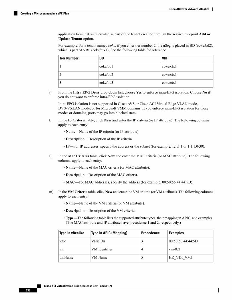
application tiers that were created as part of the tenant creation through the service blueprint Add orUpdate Tenant option.
For example, for a tenant named coke, if you enter tier number 2, the uSeg is placed in BD (coke/bd2),which is part of VRF (coke/ctx1). See the following table for reference.
VRFBDTier Number
coke/ctx1coke/bd11
coke/ctx1coke/bd22
coke/ctx1coke/bd33
j) From the Intra EPG Deny drop-down list, choose Yes to enforce intra-EPG isolation. Choose No ifyou do not want to enforce intra-EPG isolation.
Intra-EPG isolation is not supported in Cisco AVS or Cisco ACI Virtual Edge VLAN mode,DVS-VXLAN mode, or for Microsoft VMM domains. If you enforce intra-EPG isolation for thosemodes or domains, ports may go into blocked state.
k) In the Ip Criteria table, click New and enter the IP criteria (or IP attribute). The following columnsapply to each entry:
• Name—Name of the IP criteria (or IP attribute).
• Description—Description of the IP criteria.
• IP—For IP addresses, specify the address or the subnet (for example, 1.1.1.1 or 1.1.1.0/30).
l) In theMac Criteria table, click New and enter the MAC criteria (or MAC attribute). The followingcolumns apply to each entry:
• Name—Name of the MAC criteria (or MAC attribute).
• Description—Description of the MAC criteria.
• MAC—For MAC addresses, specify the address (for example, 00:50:56:44:44:5D).
m) In theVMCriteria table, clickNew and enter the VM criteria (or VM attribute). The following columnsapply to each entry:
• Name—Name of the VM criteria (or VM attribute).
• Description—Description of the VM criteria.
• Type—The following table lists the supported attribute types, their mapping in APIC, and examples.(The MAC attribute and IP attribute have precedence 1 and 2, respectively.)
ExamplesPrecedenceType in APIC (Mapping)Type in vRealize
00:50:56:44:44:5D3VNic Dnvnic
vm-8214VM Identifiervm
HR_VDI_VM15VM NamevmName
Cisco ACI Virtualization Guide, Release 3.1(1) and 3.1(2)238
Cisco ACI with VMware vRealizeCreating a Microsegment in a VPC Plan
ExamplesPrecedenceType in APIC (Mapping)Type in vRealize
host-436Hypervisor Identifierhv
AVS-SJC-DC17VMM Domaindomain
DCI8Datacenterdatacenter
SG_DMZ9Custom AttributecustomLabel
Windows 200810Operating SystemguestOS
• Operator—The following table lists the supported operators and their mapping in APIC.
Operator in APIC (Mapping)Operator in vRealize
Equalsequals
Containscontains
Starts WithstartsWith
Ends WithendsWith
• AttributeName—Enter an attribute name. In the VM Criteria table, the AttributeName appliesonly to the customLabel attribute type.
• VmmDomain_vC_VmName—In the VM Criteria table, it is applicable only for the type vnic,operator equals. The format to input is <VmmDomain>/<vC>/<VmName>where <VmmDomain>(AVS VMM domain) and <vC> (vCenter) belong to a controller instance. For example:vmmdomain1/vcenter1/VM1.
• Value—Enter the attribute type value. Examples of each attribute type are listed in the precedingType table.
n) Click Submit.
What to do next
Complete the procedure Verifying Microsegmentation Creation in a VPC Plan on APIC, on page 239.
Verifying Microsegmentation Creation in a VPC Plan on APIC
This section describes how to verify microsegmentation creation in a VPC plan on Application PolicyInfrastructure Controller.
Procedure
Step 1 Log in to Cisco APIC as the tenant, and then choose Tenants > your_tenant.Step 2 In the navigation pane, choose Tenant your_tenant > Application Profiles > default > uSeg EPGs.
Cisco ACI Virtualization Guide, Release 3.1(1) and 3.1(2)239
Cisco ACI with VMware vRealizeVerifying Microsegmentation Creation in a VPC Plan on APIC
Step 3 In the uSeg EPGs pane, double-click the required uSeg to view its properties.Step 4 In the Properties pane, confirm that the configuration is correct.Step 5 In the navigation pane, choose Tenant your_tenant > Application Profiles > default > uSeg EPGs >
your_useg > Domains (VMs and Bare-Metals).Step 6 Confirm that the state is formed and that the domain profile is VMware/vmmdomain_you_specified.Step 7 In the navigation pane, chooseTenant your_tenant >Networking >Bridge Domains > corresponding_bd >
Subnets.Step 8 Under Subnets, confirm that the subnet prefix that you specified is present.
Deleting a Microsegment in a VPC Plan
This section describes how to delete a microsegment.
Procedure
Step 1 Log in to vRealize Automation as the tenant administrator and then choose Catalog.Step 2 In the navigation pane, choose Tenant VPC Plan.Step 3 Choose Delete a Useg Network - VPC Plan and then complete the following steps:
a) View the Service Blueprint Information for the input fields and then click Request.b) In the Request Information pane, add a description and then click Next.c) In the Tenant name field, confirm that the tenant name is hard coded to the corresponding tenant.d) In the Network/EPG field, click Add, expand your_apic > Tenants > your_tenant >
Useg-End-Point-Groups and select the uSeg EPG.e) Click Submit.
What to do next
Complete the procedure Verifying Microsegmentation Deletion on APIC, on page 237.
Updating Microsegment Attributes
This section describes how to update an existing microsegment.
Procedure
Step 1 Log in to vRealize Automation as the tenant administrator and then choose Catalog.Step 2 In the navigation pane, choose Tenant Network services.Step 3 Choose Add or Delete Useg Attribute and complete the following steps:
a) View the Service Blueprint Information for the input fields and then click Request.b) In the Request Information pane, add a description and then click Next.c) In the Network/EPG field, click Add, expand your_apic > Tenants > your_tenant >
Useg-End-Point-Groups and select the uSeg EPG.d) In the Tenant name field, enter the name of the corresponding tenant.
Cisco ACI Virtualization Guide, Release 3.1(1) and 3.1(2)240
Cisco ACI with VMware vRealizeDeleting a Microsegment in a VPC Plan
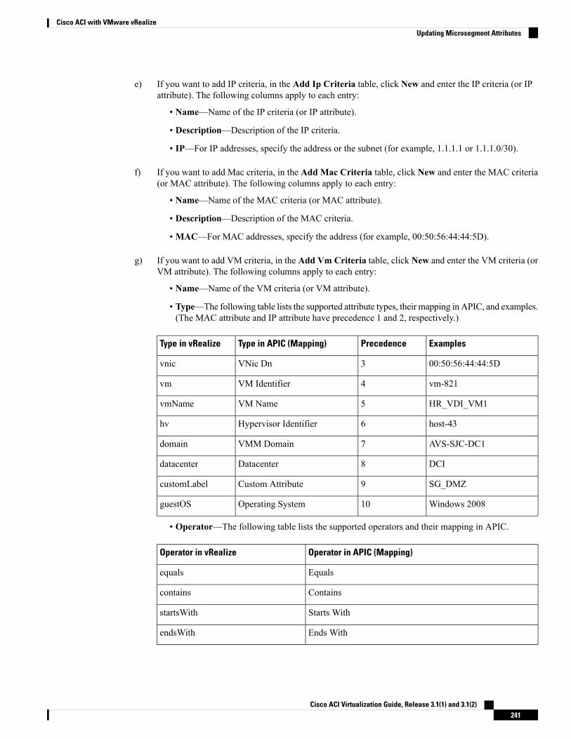
e) If you want to add IP criteria, in the Add Ip Criteria table, click New and enter the IP criteria (or IPattribute). The following columns apply to each entry:
• Name—Name of the IP criteria (or IP attribute).
• Description—Description of the IP criteria.
• IP—For IP addresses, specify the address or the subnet (for example, 1.1.1.1 or 1.1.1.0/30).
f) If you want to add Mac criteria, in the Add Mac Criteria table, click New and enter the MAC criteria(or MAC attribute). The following columns apply to each entry:
• Name—Name of the MAC criteria (or MAC attribute).
• Description—Description of the MAC criteria.
• MAC—For MAC addresses, specify the address (for example, 00:50:56:44:44:5D).
g) If you want to add VM criteria, in the Add Vm Criteria table, click New and enter the VM criteria (orVM attribute). The following columns apply to each entry:
• Name—Name of the VM criteria (or VM attribute).
• Type—The following table lists the supported attribute types, their mapping in APIC, and examples.(The MAC attribute and IP attribute have precedence 1 and 2, respectively.)
ExamplesPrecedenceType in APIC (Mapping)Type in vRealize
00:50:56:44:44:5D3VNic Dnvnic
vm-8214VM Identifiervm
HR_VDI_VM15VM NamevmName
host-436Hypervisor Identifierhv
AVS-SJC-DC17VMM Domaindomain
DCI8Datacenterdatacenter
SG_DMZ9Custom AttributecustomLabel
Windows 200810Operating SystemguestOS
• Operator—The following table lists the supported operators and their mapping in APIC.
Operator in APIC (Mapping)Operator in vRealize
Equalsequals
Containscontains
Starts WithstartsWith
Ends WithendsWith
Cisco ACI Virtualization Guide, Release 3.1(1) and 3.1(2)241
Cisco ACI with VMware vRealizeUpdating Microsegment Attributes
• AttributeName—Enter an attribute name. In the VM Criteria table, the AttributeName appliesonly to the customLabel attribute type.
• Value—Enter the attribute type value. Examples of each attribute type are listed in the precedingType table.
• VmmDomain_vC_VmName—In the VM Criteria table, it is applicable only for the type vnic,operator equals. The format to input is <VmmDomain>/<vC>/<VmName>,where <VmmDomain>(AVS VMM domain) and <vC> (vCenter) belong to a controller instance. For example:vmmdomain1/vcenter1/VM1.
h) If you want to delete existing IP criteria, in the Delete IP Criteria table, click New and enter the nameof the IP criteria (or IP attribute) to delete.
i) If you want to delete existing Mac criteria, in the Delete Mac Criteria table, click New and enter thename of the MAC criteria (or MAC attribute) to delete.
j) If you want to delete existing VM criteria, in the Delete Vm Criteria table, click New and enter thename of the VM criteria (or VM attribute) to delete.
k) Click Submit.
What to do next
Complete the procedure Verifying a Microsegmentation Attributes Update on APIC, on page 242.
Verifying a Microsegmentation Attributes Update on APIC
This section describes how to verify that microsegmentation attributes have been updated on ApplicationPolicy Infrastructure Controller.
Procedure
Step 1 Log in to Cisco APIC as the tenant, and then choose Tenants > your_tenant.Step 2 In the navigation pane, choose Tenant your_tenant > Application Profiles > default > uSeg EPGs.Step 3 In the uSeg EPGs pane, double-click the required uSeg to view its properties.Step 4 In the Properties pane, confirm that the attributes in the uSeg Attributes field have been updated.
Updating a Microsegment Association with the Cisco AVS or Cisco ACI Virtual Edge VMM Domain
This section describes how to update a microsegment that is associated with a Cisco AVS or Cisco ACI VirtualEdge VMM domain.
Procedure
Step 1 Log in to vRealize Automation as the tenant administrator and then choose Catalog.Step 2 In the navigation pane, choose Tenant Network services.Step 3 Choose Update Tenant Network and complete the following steps:
Cisco ACI Virtualization Guide, Release 3.1(1) and 3.1(2)242
Cisco ACI with VMware vRealizeVerifying a Microsegmentation Attributes Update on APIC
a) View the Service Blueprint Information for the input fields and then click Request.b) In the Request Information pane, add the description and click Next.c) In the Tenant name field, enter the name of the corresponding tenant.d) In the Network/EPG field, click Add, expand your_apic > Tenants > your_tenant >
Useg-End-Point-Groups and select the uSeg EPG.e) From theDomain Type drop-down list, choose the domain type. For the Cisco AVS or Cisco ACI Virtual
Edge VMM domain, the domain type is VmmDomain (Dynamic Binding).f) In the Domain/DVS field, click Add, expand your_apic > vCenters > your_vcenter and then select the
DVS (Cisco AVS or Cisco ACI Virtual Edge VMM domain) to associate the uSeg to the VMM domain.g) From the encapMode drop-down list, choose Auto, VLAN, or VXLAN for the encapsulation mode.
The encapMode field is applicable only when associating an EPG to a VMM domain of theCisco AVS or Cisco ACI Virtual Edge (Local Switching) type. That association is performedin the following step.
Note
h) From the Operation drop-down list, choose add to associate the microsegment with the Cisco AVS orCisco ACI Virtual Edge domain. Choose delete to disassociate the microsegment from the Cisco AVSor Cisco ACI Virtual Edge VMM domain.
i) Click Submit.
What to do next
Complete the procedure Verifying Microsegment Association Updates with Cisco AVS or Cisco ACI VirtualEdge VMM Domains on APIC, on page 243.
Verifying Microsegment Association Updates with Cisco AVS or Cisco ACI Virtual Edge VMM Domains on APIC
This section describes how to verify updates to microsegment associations with Cisco AVS or Cisco ACIVirtual Edge VMM domains on Cisco APIC.
Procedure
Step 1 Log in to Cisco APIC as the tenant, and then choose Tenants > your_tenant.Step 2 In the navigation pane, choose Tenant your_tenant > Application Profiles > default > uSeg EPGs >
your_useg > Domains (VMs and Bare-Metals).Step 3 Confirm that any associations with VMM domains are correct.
Creating the VMs and Attaching to Networks Without Using the Machine BlueprintsThis section describes how to verify the creating machines (VMs) and attaching to networks without usingthe machine blueprints.
Procedure
Step 1 Log in to vSphere Web Client GUI, choose the Networking icon.
Cisco ACI Virtualization Guide, Release 3.1(1) and 3.1(2)243
Cisco ACI with VMware vRealizeVerifying Microsegment Association Updates with Cisco AVS or Cisco ACI Virtual Edge VMM Domains on APIC
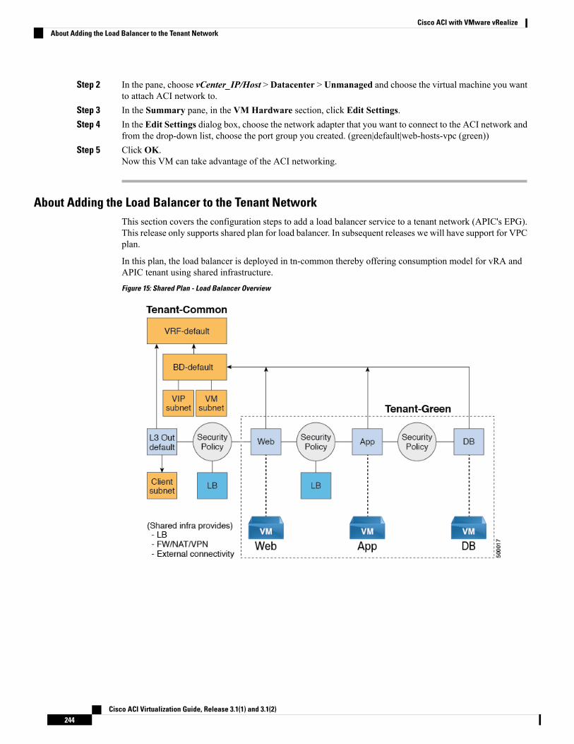
Step 2 In the pane, choose vCenter_IP/Host > Datacenter > Unmanaged and choose the virtual machine you wantto attach ACI network to.
Step 3 In the Summary pane, in the VM Hardware section, click Edit Settings.Step 4 In the Edit Settings dialog box, choose the network adapter that you want to connect to the ACI network and
from the drop-down list, choose the port group you created. (green|default|web-hosts-vpc (green))Step 5 Click OK.
Now this VM can take advantage of the ACI networking.
About Adding the Load Balancer to the Tenant NetworkThis section covers the configuration steps to add a load balancer service to a tenant network (APIC's EPG).This release only supports shared plan for load balancer. In subsequent releases we will have support for VPCplan.
In this plan, the load balancer is deployed in tn-common thereby offering consumption model for vRA andAPIC tenant using shared infrastructure.Figure 15: Shared Plan - Load Balancer Overview
Cisco ACI Virtualization Guide, Release 3.1(1) and 3.1(2)244
Cisco ACI with VMware vRealizeAbout Adding the Load Balancer to the Tenant Network
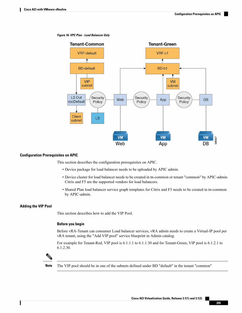
Figure 16: VPC Plan - Load Balancer Only
Configuration Prerequisites on APIC
This section describes the configuration prerequisites on APIC.
• Device package for load balancer needs to be uploaded by APIC admin.
• Device cluster for load balancer needs to be created in tn-common or tenant "common" by APIC-admin.Citrix and F5 are the supported vendors for load balancers.
• Shared Plan load balancer service graph templates for Citrix and F5 needs to be created in tn-commonby APIC-admin.
Adding the VIP Pool
This section describes how to add the VIP Pool.
Before you begin
Before vRA-Tenant can consumer Load balancer services, vRA admin needs to create a Virtual-IP pool pervRA tenant, using the "Add VIP pool" service blueprint in Admin catalog.
For example for Tenant-Red, VIP pool is 6.1.1.1 to 6.1.1.30 and for Tenant-Green, VIP pool is 6.1.2.1 to6.1.2.30.
The VIP pool should be in one of the subnets defined under BD "default" in the tenant "common"Note
Cisco ACI Virtualization Guide, Release 3.1(1) and 3.1(2)245
Cisco ACI with VMware vRealizeConfiguration Prerequisites on APIC
Procedure
Step 1 Log in to the vRealize Automation as admin, choose Catalog > Admin Services.Step 2 Choose Add VIP Pool and perform the following actions:
a) In the Tenant field, enter the Tenant name.b) In the VIP address start field, enter the VIP address start.c) In the VIP Address End field, enter the VIP address end.d) In the Internal VIP for Inter-EPG in VPC plan field, select Yes or No.e) Click Submit.
Deleting the VIP Pool
This section describes how to delete the VIP Pool.
This blueprint is to do necessary cleanup of VIP pool, once all the load balancer services consumed in thetenant are deleted.
Procedure
Step 1 Log in to the vRealize Automation as admin, choose Catalog > Admin Services.Step 2 Choose Delete VIP Pool, perform the following action items.
a) In the Tenant field, click Add, expand your_apic > Tenants and select the tenant.b) In the VIP address start field, enter the VIP address start.c) In the VIP Address End field, enter the VIP address end.d) In the Internal VIP for Inter-EPG in VPC plan field, select Yes or No.e) Click Submit.
Adding the Load Balancer to the Tenant-Network in a Shared Plan
vRA-Tenant can add a load balancer (LB) to Tenant-Network. The required parameters are Network-Name,LB device cluster, LB-endpoint (protocol, port), Vendor Type, and Consumer EPG or L3out. As part of thisworkflow, all the required service graph instance and contract (security policy) with chosen Tenant-Networkas Provider-EPG is created. The consumer of this load balanced endpoint could be L3out in tenant common,or it could be another Tenant-Network belonging to the tenant.
Procedure
Step 1 Log in to the vRealize Automation as admin, choose Catalog > Tenant Shared Plan.Step 2 Choose Add Load Balancer to Tenant Network - Shared Plan, click Request.Step 3 Enter the requested information in the fields.Step 4 Click Submit.
Cisco ACI Virtualization Guide, Release 3.1(1) and 3.1(2)246
Cisco ACI with VMware vRealizeDeleting the VIP Pool
Adding the Load Balancer to the Tenant-Network in a VPC Plan
This section describes how to add the load balancer to the tenant-network in a VPC Plan.
In a VPC plan, the Inter-EPG load balancer is not supported. Only the load balancer between L3out andFirst-Tier (Web) is supported in release 1.2(2x).
Note
Procedure
Step 1 Log in to the vRealize Automation as admin, choose Catalog > Tenant VPC Plan.Step 2 Choose Add Load Balancer to Tenant Network - VPC Plan, click Request.Step 3 Enter the requested information in the fields.Step 4 Click Submit.
Deleting the Load Balancer from the Tenant-Network in a Shared Plan
You can delete the load balancer service (lb-port, lb-protocol) from an existing tenant network or endpointgroup.
Procedure
Step 1 Log in to the vRealize Automation as admin, choose Catalog > Tenant Shared Plan.Step 2 Choose Delete Load Balancer to Tenant Network - Shared Plan and click Request.Step 3 Enter the requested information in the fields.Step 4 Click Submit.
Deleting the Load Balancer from the Tenant-Network in a VPC Plan
You can delete the load balancer service (lb-port, lb-protocol) from an existing tenant network or endpointgroup.
Procedure
Step 1 Log in to the vRealize Automation as admin, choose Catalog > Tenant VPC Plan.Step 2 Choose Delete Load Balancer to Tenant Network - VPC Plan and click Request.Step 3 Enter the requested information in the fields.Step 4 Click Submit.
Cisco ACI Virtualization Guide, Release 3.1(1) and 3.1(2)247
Cisco ACI with VMware vRealizeAdding the Load Balancer to the Tenant-Network in a VPC Plan
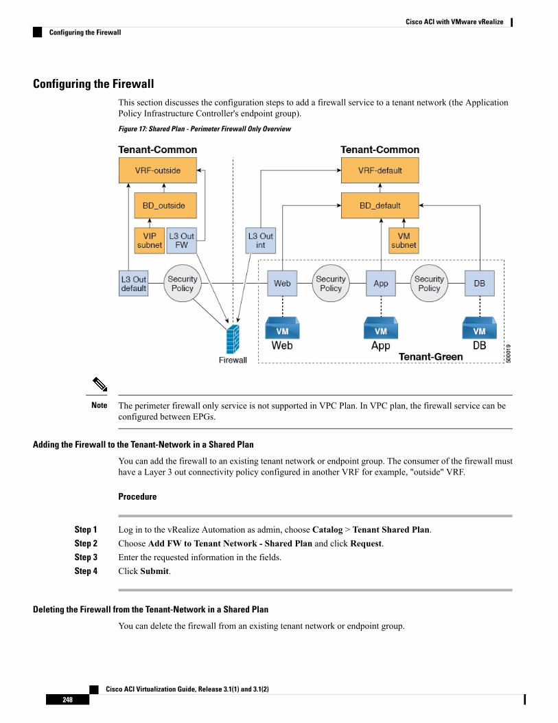
Configuring the FirewallThis section discusses the configuration steps to add a firewall service to a tenant network (the ApplicationPolicy Infrastructure Controller's endpoint group).Figure 17: Shared Plan - Perimeter Firewall Only Overview
The perimeter firewall only service is not supported in VPC Plan. In VPC plan, the firewall service can beconfigured between EPGs.
Note
Adding the Firewall to the Tenant-Network in a Shared Plan
You can add the firewall to an existing tenant network or endpoint group. The consumer of the firewall musthave a Layer 3 out connectivity policy configured in another VRF for example, "outside" VRF.
Procedure
Step 1 Log in to the vRealize Automation as admin, choose Catalog > Tenant Shared Plan.Step 2 Choose Add FW to Tenant Network - Shared Plan and click Request.Step 3 Enter the requested information in the fields.Step 4 Click Submit.
Deleting the Firewall from the Tenant-Network in a Shared Plan
You can delete the firewall from an existing tenant network or endpoint group.
Cisco ACI Virtualization Guide, Release 3.1(1) and 3.1(2)248
Cisco ACI with VMware vRealizeConfiguring the Firewall
Procedure
Step 1 Log in to the vRealize Automation as admin, choose Catalog > Tenant Shared Plan.Step 2 Choose Delete FW from Tenant Network - Shared Plan and click Request.Step 3 Enter the requested information in the fields.Step 4 Click Submit.
Configuring the Firewall and Load BalancerThis section covers the configuration steps to add a firewall and load balancer service to a tenant network (theApplication Policy Infrastructure Controller's endpoint group).
In this plan, the firewall and load balancer devices are deployed in the "common" tenant, there by offeringconsumption model for vRealize Automation (vRA) and the APIC tenant using the shared infrastructure.Figure 18: Shared Plan - Firewall and Load Balancer Overview
Cisco ACI Virtualization Guide, Release 3.1(1) and 3.1(2)249
Cisco ACI with VMware vRealizeConfiguring the Firewall and Load Balancer
Figure 19: VPC Plan - Perimeter Firewall and Load Balancer
Adding the Firewall and Load Balancer to the Tenant-Network in a Shared Plan
The virtual IP address pool must be added to the tenant before using the firewall and load balancer service.
See Adding the VIP Pool, on page 245.
The firewall and load balancer can be added to an existing tenant network or endpoint group. The consumerof the firewall must have a Layer 3 out connectivity policy configured in the "outside" VRF.
Before you begin
For both Firewall and Load-Balancer only services have to be met before a firewall and load balancer servicecan be deployed.
Procedure
Step 1 Log in to the vRealize Automation as admin, choose Catalog > Tenant Shared Plan.Step 2 Choose Add FW and LB to Tenant Network - Shared Plan and click Request.Step 3 Enter the requested information in the fields.Step 4 Click Submit.
Adding the Firewall and Load Balancer to the Tenant-Network in a VPC Plan
This section describes how to add the firewall and load balancer to the Tenant-Network in a VPC Plan.
Cisco ACI Virtualization Guide, Release 3.1(1) and 3.1(2)250
Cisco ACI with VMware vRealizeAdding the Firewall and Load Balancer to the Tenant-Network in a Shared Plan
Whenever a firewall and load balancer (LB) workflow is executed then external leg of LB is pointing to"default" Bridge Domain (BD). Customers should always deploy internal leg of firewall in "default" BD undertn-common. This ensures that both the firewall and load balancer point to same BD and traffic flows in anuninterrupted way.
Note
Procedure
Step 1 Log in to the vRealize Automation as admin, choose Catalog > Tenant VPC Plan.Step 2 Choose Add FW and LB to Tenant Network - VPC Plan and click Request.Step 3 Enter the requested information in the fields.Step 4 Click Submit.
Deleting the Firewall and Load Balancer from the Tenant-Network in a Shared Plan
Procedure
Step 1 Log in to the vRealize Automation as admin, choose Catalog > Tenant Shared Plan.Step 2 Choose Delete FW and LB from Tenant Network - Shared Plan and click Request.Step 3 Enter the requested information in the fields.Step 4 Click Submit.
Deleting the Firewall and Load Balancer from the Tenant-Network in a VPC Plan
Procedure
Step 1 Log in to the vRealize Automation as admin, choose Catalog > Tenant VPC Plan.Step 2 Choose Delete FW and LB from Tenant Network - VPC Plan and click Request.Step 3 Enter the requested information in the fields.Step 4 Click Submit.
Configuring the Inter-EPG FirewallThis section describes how to configure the inter-EPG firewall service to a tenant network (the ApplicationPolicy Infrastructure Controller's endpoint group).
Cisco ACI Virtualization Guide, Release 3.1(1) and 3.1(2)251
Cisco ACI with VMware vRealizeDeleting the Firewall and Load Balancer from the Tenant-Network in a Shared Plan
Figure 20: VPC Plan - Inter EPG FW
Adding the Firewall to the Tenant-Network in a VPC Plan
This section describes how to add the firewall to an existing tenant network or endpoint group (EPG). Whenadding the tenant, "Enable Inter-EPG Firewall" should be set to "yes" and the number of tiers used in theapplication should be configured. When configuring the network (EPG) tier number should be set. In thisscenario, the firewall is configured between a provider EPG and consumer EPG.
Procedure
Step 1 Log into the vRealize Automation as admin, choose Catalog > Tenant VPC Plan.Step 2 Choose Add FW to Tenant Network - VPC Plan and click Request.Step 3 Enter the requested information in the fields.Step 4 Click Submit.
Deleting the Firewall from the Tenant-Network in a VPC Plan
This section describes how to delete the firewall from an existing tenant network or endpoint group (EPG).
Procedure
Step 1 Log into the vRealize Automation as admin, choose Catalog > Tenant VPC Plan.Step 2 Choose Delete FW from Tenant Network - VPC Plan and click Request.Step 3 Enter the requested information in the fields.
Cisco ACI Virtualization Guide, Release 3.1(1) and 3.1(2)252
Cisco ACI with VMware vRealizeAdding the Firewall to the Tenant-Network in a VPC Plan
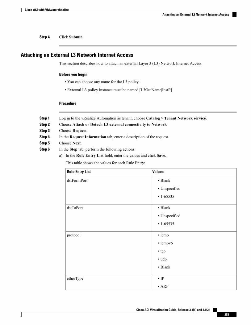
Step 4 Click Submit.
Attaching an External L3 Network Internet AccessThis section describes how to attach an external Layer 3 (L3) Network Internet Access.
Before you begin
• You can choose any name for the L3 policy.
• External L3 policy instance must be named [L3OutName|InstP].
Procedure
Step 1 Log in to the vRealize Automation as tenant, choose Catalog > Tenant Network service.Step 2 Choose Attach or Detach L3 external connectivity to NetworkStep 3 Choose Request.Step 4 In the Request Information tab, enter a description of the request.Step 5 Choose Next.Step 6 In the Step tab, perform the following actions:
a) In the Rule Entry List field, enter the values and click Save.
This table shows the values for each Rule Entry:
ValuesRule Entry List
• Blank
• Unspecified
• 1-65535
dstFormPort
• Blank
• Unspecified
• 1-65535
dstToPort
• icmp
• icmpv6
• tcp
• udp
• Blank
protocol
• IP
• ARP
etherType
Cisco ACI Virtualization Guide, Release 3.1(1) and 3.1(2)253
Cisco ACI with VMware vRealizeAttaching an External L3 Network Internet Access
b) In theL3out Policy field, clickAdd to locate and choose the L3 connectivity policy in the common tenant.(default)
c) In theNetwork/EPG name field, clickAdd to locate and choose the network/EPG in the common tenant.(web-host)
d) In the EPG/Network plan type field, click Add to locate and choose the network/EPG in the commontenant. (web-host)
e) In the Operation field, click Add to add a Layer3 Out.
Step 7 To verify your request, choose the Requests tab.a) Choose the request you submitted and click view details. Ensure the status is Succesful.
Verify the Security and L3 Policy on the APIC
This section describes how to verifying the security and Layer 3 (L3) policy on APIC.
Procedure
Step 1 Log in to Cisco APIC as the tenant, and then choose TENANTS > common.Step 2 In the navigation pane, expand Tenant Common > Networking > Security Policies > Contracts.
a) Nested under Contracts there should be a new contract with the end_user_tenantname-L3ext_ctrct_network_name that you connected to. (green-L3ext_ctrct_web-hosts)
b) Expand the end_user_tenant name-L3ext_ctrct_network_name. (green-L3ext_ctrct_web-hosts)c) Choose the end_user_tenant name-L3ext_ctrct_network_name. (green-L3ext_ctrct_web-hosts)d) In the Property pane, in the Filter field, click the filter. (green-L3ext_filt_web-hosts)e) In the Properties pane, you can see the filter is mapped to vRealize.
Step 3 In the navigation pane, expand Tenant Common > Networking > External Routed Networks > default >Networks > defaultInstP.a) In the Properties pane, in the Provided Contracts field, you should see the end_user_tenant
name-L3ext_ctrct_network_name. (green-L3ext_filt_web-hosts)b) In the Consumed Contracts field, you should see the end_user_tenant
name-L3ext_ctrct_network/EPG_name. (green-L3ext_filt_web-hosts)
Step 4 On the menu bar choose TENANTS > your_tenant.Step 5 In the navigation pane, expand Tenant your_tenant >Application Profile > default >Application EPGs >
EPG web-hosts > Contracts.a) In the Contracts pane, you can verify the contract and consumes a contract is present.
Verifying the Network Connectivity
This section describes how to verify the network connectivity.
Cisco ACI Virtualization Guide, Release 3.1(1) and 3.1(2)254
Cisco ACI with VMware vRealizeVerify the Security and L3 Policy on the APIC
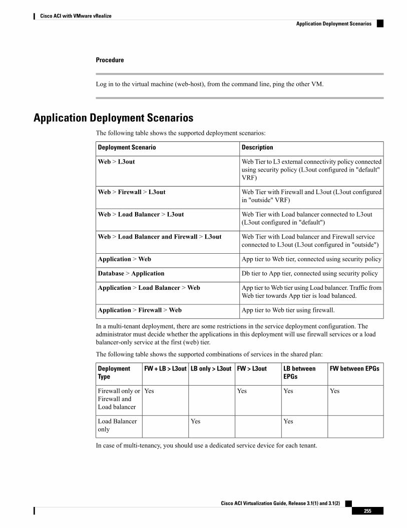
Procedure
Log in to the virtual machine (web-host), from the command line, ping the other VM.
Application Deployment ScenariosThe following table shows the supported deployment scenarios:
DescriptionDeployment Scenario
Web Tier to L3 external connectivity policy connectedusing security policy (L3out configured in "default"VRF)
Web > L3out
Web Tier with Firewall and L3out (L3out configuredin "outside" VRF)
Web > Firewall > L3out
Web Tier with Load balancer connected to L3out(L3out configured in "default")
Web > Load Balancer > L3out
Web Tier with Load balancer and Firewall serviceconnected to L3out (L3out configured in "outside")
Web > Load Balancer and Firewall > L3out
App tier to Web tier, connected using security policyApplication >Web
Db tier to App tier, connected using security policyDatabase > Application
App tier toWeb tier using Load balancer. Traffic fromWeb tier towards App tier is load balanced.
Application > Load Balancer >Web
App tier to Web tier using firewall.Application > Firewall >Web
In a multi-tenant deployment, there are some restrictions in the service deployment configuration. Theadministrator must decide whether the applications in this deployment will use firewall services or a loadbalancer-only service at the first (web) tier.
The following table shows the supported combinations of services in the shared plan:
FW between EPGsLB betweenEPGs
FW > L3outLB only > L3outFW + LB > L3outDeploymentType
YesYesYesYesFirewall only orFirewall andLoad balancer
YesYesLoad Balanceronly
In case of multi-tenancy, you should use a dedicated service device for each tenant.
Cisco ACI Virtualization Guide, Release 3.1(1) and 3.1(2)255
Cisco ACI with VMware vRealizeApplication Deployment Scenarios
About Property GroupsProperty groups are a vRealize Automation (vRA) construct that provide virtual machine customization. Usingproperty groups, vRA can invokeworkflows in vRealize Orchestration (vRO) at given stage of virtual machine'slife cycle. This virtual machine extension capability is used by Application Policy Infrastructure Controller(APIC) vRealize to invoke APIC vRA workflows and configure APIC policies.
APIC vRealize supports a number of application deployment scenarios. In a multi-tier application, the APICsecurity policy or the load balancing or firewall services can be inserted between tiers. This is achieved bythe following steps:
1. Execute theConfigure Property Group catalog-item in theAdmin Services catalog to create a propertygroup.
2. Use the Security Policy, Load Balancer, and Firewall tabs to customize the property group.
3. Enable the property group in the single-machine blueprint at the Infrastructure > Blueprints > SingleMachine Blueprint level in vRealize.
About Service BlueprintsThis section describes the service blueprints.
In vRealize there are two sets of blueprints one is a machine blueprints that is for compute for installing,setting up VMs, and spinning VMs. There is a single- and a multi-machine blueprint for launching single-tierapplication workload or multi-tier application workload that is called machine blueprint for networkingworkflows.
Admin workflow:
• Create APIC handles
• Create VMM domains
• Create Tenants
• Create subnets in common
• Create Layer 4-7 devices
Tenant workflow:
• Create EPGs
• Create contracts
• Provide contracts
• Consume contracts
• Consume L3Outs
• Consume Layer 4-7 devices
Cisco ACI Virtualization Guide, Release 3.1(1) and 3.1(2)256
Cisco ACI with VMware vRealizeAbout Property Groups
Integration with vRealize Network Profiles (IPAM)vRealize IP address management (IPAM) uses the network profiles concept to assign a pool of addresses toone or more networks. You can assign network profiles to ACI backed networks in the same fashion as aregular vRealize network.
To integrate with the vRealize IPAM:
Procedure
Step 1 Ensure the subnet exists to the bridge domain.
See Add or Delete Subnets in Bridge Domain for Tenant-Common.
Step 2 Create a network profile.
See VMware's documentation for creating a network profile.
Step 3 This depends on if your blueprint generates a new network or not:
If you use the same network for each machine blueprint:
Under your vCenter reservation find the EPG (Network Path) and assign the network profile to it.
a) In the vCenter, navigate to Infrastructure > Reservations.b) Find "Your Reservation", hover and click Edit.c) Navigate toNetwork > Find desired Network Path (EPG), from the drop-down list, choose the Network
Profile and click Ok.
If you generate a network per VM:
Add a property to your property group with the network profile as the value.
a) In the vCenter, navigate to Infrastructure > Blueprints > Property Groups.b) Find "Your Blueprint", hover and click Edit.c) Click + New Property.d) Set the Name to "VirtualMachine.NetworkX.NetworkProfileName".
where X is the VM NIC number (in the range [0-9]).
e) Set the Value to the name of the Network Profile you created.f) Click the green tick icon to confirm and click Ok.
New applications will be assigned an address from this pool.
Step 4 Use guest customizations to assign the IP address to the server.
See VMware's documentation for guest customizations.
Documentation of APIC Workflows in vRealize OrchestratorTo get documentation on the APIC methods and types, the vRO API search can be used.
1. Log in to the vRO GUI, choose Tools > API Search
Cisco ACI Virtualization Guide, Release 3.1(1) and 3.1(2)257
Cisco ACI with VMware vRealizeIntegration with vRealize Network Profiles (IPAM)
2. Enter APIC.
This shows the list of all APIC methods and types.
List of Methods in ApicConfigHelper ClassThis section provides a list of methods in ApicConfigHelper class.
• This adds an APIC host to the repository and does a login to the APIC:ApicHandle addHost(String hostName,
String hostIp0,String hostIp1,String hostIp2,String userName,String pwd,int port,boolean noSsl,String role,String tenantName)
• This gets the APIC handle give the APIC name:ApicHandle getApicHandle(String hostName)
• This gets the list of APIC handles for a given <role, username>:List<ApicHandle> getApicHandleByRole(String role, String userName)
• This removes an APIC host from the repository:boolean removeHost(String inApicName)
• This creates Tenant endpoint group and association to vmmDomain in APIC:ApicResponse addNetwork(ApicHandle handle,
String tenantName,String apName,String epgName,String bdName,String ctxName,String subnet,String domName,boolean vmm,boolean vpc,boolean intraEpgDeny,boolean allowUseg,String encapMode)
• This updates the domain of the endpoint group by adding or deleting:ApicResponse updateNetwork(ApicHandle handle,
String tenantName,String apName,String epgName,String domName,boolean vmm,boolean add,String encapMode)
• This adds or deletes subnets to the bridge domain in the virtual private cloud (VPC) tenant:ApicResponse updateSubnets(ApicHandle handle,
String tenantName,String bdName,
Cisco ACI Virtualization Guide, Release 3.1(1) and 3.1(2)258
Cisco ACI with VMware vRealizeList of Methods in ApicConfigHelper Class
fvSubnet subnetList[],boolean add)
• This adds or deletes the bridge domain to or from the tenant:ApicResponse updateBD(ApicHandle handle,
String tenantName,String bdName,String ctxName,boolean arpFlooding,String l2UnknownUnicast,String l3UnknownMulticast,boolean add)
• This adds or deletes the context (Ctx) to or from the tenant:ApicResponse updateCtx(ApicHandle handle,
String tenantName,String ctxName,boolean add)
• This adds or deletes the following based on add or delete:ApicResponse addOrDeleteLBToNetwork(ApicHandle handle,
String tenantName,String apName,String epgName,String bdName,String ctxName,boolean vpc,String planName,String lbVendor,String ldevName,String graphName,boolean sharedLb,String protocol,String port,String consumerDn,String snipIntAddress,String snipIntNetMask,String snipExtAddress,String snipExtNetMask,String snipNextHopGW,boolean addOperation)
• This opens a connection to the URL, sends the postBody string to the URL location, and returns result:ApicResponse addOrDelFWReq(ApicHandle handle,
String tenantName,String apName,String epgName,String ctrctName,String graphName,vzEntry entryList[],String consumerDn,boolean addOp,boolean updateOp)
• This adds the firewall service to an endpoint group in the shared and VPC plan:ApicResponse addFWToNetwork(ApicHandle handle,
String tenantName,String apName,String epgName,boolean vpc,String fwVendor,
Cisco ACI Virtualization Guide, Release 3.1(1) and 3.1(2)259
Cisco ACI with VMware vRealizeList of Methods in ApicConfigHelper Class
String ldevName,String graphName,vzEntry entryList[],String fwL3extExternal,String fwL3extInternal,boolean skipFWReq,String consumerDn)
• This deletes the firewall from the endpoint group in the shared and VPC Plan:ApicResponse deleteFWFromNetwork(ApicHandle handle,
String tenantName,String apName,String epgName,boolean vpc,String graphName,String ctrctName,String protocol,String startPort,boolean skipFWReq,String consumerDn)
• This implements the REST API to APIC:String apicRestApi(ApicHandle handle,
String apiUrl,String method,String postBody)
• This adds or deletes the router ID in a tenant:ApicResponse addOrDelRouterId(ApicHandle handle,
String rtrId,boolean addOp)
• This deletes the tenant endpoint group and the association:ApicResponse deleteNetwork(ApicHandle handle,
String tenantName,String apName,String epgName)
• This creates the tenant, bridge domain and the context (Ctx) in APIC:ApicResponse addTenant(ApicHandle handle,
String tenantName,String bdName,String ctxName,String aaaDomain)
• This deletes the tenant in APIC:ApicResponse deleteTenant(ApicHandle handle,
String tenantName)
• This adds VlaNS, vmmDomP, vmmCtrlP, vmmUsrAccp and required relation objects to the APIC:ApicResponse addVmmDomain(ApicHandle handle,
String dvsName,String vcenterIP,String userName,String passwd,String datacenter,String vlanPoolName,int vlanStart,
Cisco ACI Virtualization Guide, Release 3.1(1) and 3.1(2)260
Cisco ACI with VMware vRealizeList of Methods in ApicConfigHelper Class
int vlanEnd,String aaaDomain)
• This deletes VlanNS and vmmDomP objects from the APIC:ApicResponse deleteVmmDomain(ApicHandle handle,
String domName,String vlanPoolName)
• This adds or deletes encap blocks in the VLAN pool:ApicResponse updateVlanPool(ApicHandle handle,
String vlanPoolName,fvnsEncapBlk encapList[])
• This adds the security policy (contract entry):ApicResponse addSecurityPolicySet(ApicHandle handle,
String tenant,String ap,String srcEpg,String dstEpg,vzEntry entryList[],boolean createFlg)
• This updates the security policy (contract entry):ApicResponse updateSecurityFilters(ApicHandle handle,
String tenant,String filterName,vzEntry entryList[])
• This adds or removes the consumer contract interface:ApicResponse updateSharedSvcConsumer(ApicHandle handle,
String tenant,String ap,String consumerEpg,vzBrCP contract,boolean add)
• This updates the security policy (contract entry):ApicResponse updateL3outPolicy(ApicHandle handle,
String tenant,String ap,String dstEpg,vzEntry entryList[],l3extOut l3out,boolean vpc,boolean add)
• This deletes all the security policy (contracts):ApicResponse deleteSecurityPolicy(ApicHandle handle,
String tenant,String ap,String srcEpg,String dstEpg)
• This creates VIP address block in the tn-common:
Cisco ACI Virtualization Guide, Release 3.1(1) and 3.1(2)261
Cisco ACI with VMware vRealizeList of Methods in ApicConfigHelper Class
ApicResponse addVipPool(ApicHandle handle,String planName,String addrStart,String addrEnd)
• This deletes VIP address block in the tn-common:ApicResponse deleteVipPool(ApicHandle handle,
String planName,String addrStart,String addrEnd)
• This adds or deletes the security domain associations:ApicResponse updateVmmDomain(ApicHandle handle,
String domName,aaaDomainRef aaaList[])
• This deletes a shared service provider (endpoint group) from a contract:ApicResponse deleteSharedServiceProvider(ApicHandle handle,
String tenant,String ap,String srcEpg,String dstEpg,vzBrCP contract)
• This creates a Cisco AVS VMM domain and adds related objects to the APIC:ApicResponse addAvsVmmDomain(ApicHandle handle,
String dvsName,String aepName,String vcenterIP,String userName,String passwd,String dvsVersion,String datacenter,String mcastIP,String poolName,String rangeStart,String rangeEnd,String aaaDomain,int domType,String secondRangeStart,String secondRangeEnd,String secondPoolName)
• This updates the pools (VLAN, Multicast Address) relevant to a Cisco AVS VMM domain:ApicResponse updateAvsVlanMcastPool(ApicHandle handle,
String poolName,fvnsEncapBlk encapList[],int poolType)
• This deletes a Cisco AVS VMM domain:ApicResponse deleteAvsVmmDomain(ApicHandle handle,
String domName,String poolName,int poolType)
• This deletes a Cisco AVS VMM domain which is in mixed mode:ApicResponse deleteAvsVmmDomainMixedmode(ApicHandle handle,
String domName )
• This creates Distributed Firewall for a Cisco AVS VMM domain:
Cisco ACI Virtualization Guide, Release 3.1(1) and 3.1(2)262
Cisco ACI with VMware vRealizeList of Methods in ApicConfigHelper Class
ApicResponse createFWPol(ApicHandle handle,String polName,String vmmName,String polMode,String pInterval,String logLevel,String adminState,String destGrpName,String inclAction,int caseVal)
• This updates Distributed Firewall association with a Cisco AVS VMM domain:ApicResponse updateFWPolMapping(ApicHandle handle,
String polName,String vmmName,Boolean opValue)
• This deletes Distributed Firewall:ApicResponse deleteFWPol(ApicHandle handle,
String polName)
• This adds or deletes attribute(s) for a Microsegment EPG:ApicResponse addOrDelUsegAttr(ApicHandle handle,
String tenantName,String apName,String epgName,String criteriaName,fvVmAttrV addFvVmAttrList[],fvMacAttr addFvMacAttrList[],fvIpAttr addFvIpAttrList[],fvVmAttr delFvVmAttrList[],fvMacAttr delFvMacAttrList[],fvIpAttr delFvIpAttrList[])
• This adds a microsegment EPG:ApicResponse addUsegEpg(ApicHandle handle,
String tenantName,String apName,String epgName,String bdName,String ctxName,String subnet,String domName,String criteriaName,boolean vmm,boolean vpc,boolean intraEpgDeny,fvVmAttrV fvVmAttrList[],fvMacAttr fvMacAttrList[],fvIpAttr fvIpAttrList[],String encapMode)
Writing Custom Workflows Using the APIC Plug-in MethodThis section describes how to write custom workflows using the Application Policy Infrastructure Controller(APIC) plug-in method. Tenants might have unique requirements for their logical network topology that arenot covered by the out-of-box designs. Existing Cisco APIC workflows can be combined together into acustom workflow that enables limitless network designs.
Cisco ACI Virtualization Guide, Release 3.1(1) and 3.1(2)263
Cisco ACI with VMware vRealizeWriting Custom Workflows Using the APIC Plug-in Method
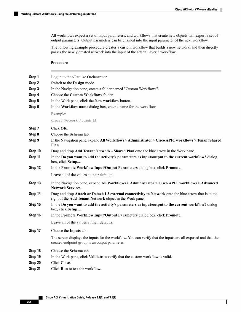
All workflows expect a set of input parameters, and workflows that create new objects will export a set ofoutput parameters. Output parameters can be chained into the input parameter of the next workflow.
The following example procedure creates a custom workflow that builds a new network, and then directlypasses the newly created network into the input of the attach Layer 3 workflow.
Procedure
Step 1 Log in to the vRealize Orchestrator.Step 2 Switch to the Design mode.Step 3 In the Navigation pane, create a folder named "Custom Workflows".Step 4 Choose the Custom Workflows folder.Step 5 In the Work pane, click the New workflow button.Step 6 In theWorkflow name dialog box, enter a name for the workflow.
Example:Create_Network_Attach_L3
Step 7 Click OK.Step 8 Choose the Schema tab.Step 9 In the Navigation pane, expandAllWorkflows >Administrator >CiscoAPICworkflows >Tenant Shared
PlanStep 10 Drag and drop Add Tenant Network - Shared Plan onto the blue arrow in the Work pane.Step 11 In the Do you want to add the activity's parameters as input/output to the current workflow? dialog
box, click Setup....Step 12 In the Promote Workflow Input/Output Parameters dialog box, click Promote.
Leave all of the values at their defaults.
Step 13 In the Navigation pane, expand All Workflows > Administrator > Cisco APIC workflows > AdvancedNetwork Services.
Step 14 Drag and drop Attach or Detach L3 external connectivity to Network onto the blue arrow that is to theright of the Add Tenant Network object in the Work pane.
Step 15 In the Do you want to add the activity's parameters as input/output to the current workflow? dialogbox, click Setup....
Step 16 In the Promote Workflow Input/Output Parameters dialog box, click Promote.
Leave all of the values at their defaults.
Step 17 Choose the Inputs tab.
The screen displays the inputs for the workflow. You can verify that the inputs are all exposed and that thecreated endpoint group is an output parameter.
Step 18 Choose the Schema tab.Step 19 In the Work pane, click Validate to verify that the custom workflow is valid.Step 20 Click Close.Step 21 Click Run to test the workflow.
Cisco ACI Virtualization Guide, Release 3.1(1) and 3.1(2)264
Cisco ACI with VMware vRealizeWriting Custom Workflows Using the APIC Plug-in Method
Step 22 In the Start Workflow dialog box, click Submit to start the workflow.
Multi-Tenancy and Role based Access Control Using Security DomainsAPIC and vRA both supports multi-tenancy natively. vRA tenant user is mapped one-to-one with a APICtenant user and thus Tenant names need to match exactly on both systems.
For every vRA tenant, APIC admin needs to ensure that an user account and required security domains androles are created in APIC as part of Day-0 operation.
As a next step, vRA-Admin would execute Add Tenant service blueprint (part of Admin catalog), tocreate/update Tenant in APIC and associate it with the right security Domain. For eg: Tenant-Green on vRAis mapped to Tenant-Green in APIC with association to Security Domain "Domain-Green" enabled for"User-Green".
By associating tenant to right security domains, Role based access control is enforced and it allows for granularas well stricter Tenant policy enforcement.
Adding the TenantThis section describes how to add the tenant.
In this blueprint, a tenant identified by input parameter "Tenant" is created in APIC with association thesecurity domain that is provided as second input.
Procedure
Step 1 Log in to the vRealize Automation as admin, choose Catalog > Admin Services.Step 2 Choose Add Tenant, enter the information in the fields and click Submit.
Deleting the TenantThis section describes how to delete the tenant from APIC.
Procedure
Step 1 Log in to the vRealize Automation as admin, choose Catalog > Admin Services.Step 2 Choose Delete Tenant, enter the information in the fields and click Submit.
APIC Credentials for WorkflowsAs part of ACI-integration with vRA, this release supports pairing up vRA with a ACI fabric managed by aAPIC-cluster.
Cisco ACI Virtualization Guide, Release 3.1(1) and 3.1(2)265
Cisco ACI with VMware vRealizeMulti-Tenancy and Role based Access Control Using Security Domains
The network service blueprints are categorized into Admin and Tenant workflows and accordingly vRA adminhas to setup APIC connection handles for APIC-Admin credential as well as APIC-Tenant credential for everyvRA-Tenant.
As part of plug-in, the right handles (Admin vs Tenant) are auto-selected implicitly based on the workflowcontext and the privileges needs to create and managed objects in APIC. This provides stronger access controland isolation among tenants.
Adding APIC with Admin CredentialsThis section describes how to add APIC with admin credentials.
All the blueprints and workflows that are part of catalog items in Admin portal are performed using theAdmin-credential.
Procedure
Step 1 Log in to the vRealize Automation as admin, choose Catalog > Network Security.Step 2 Choose Add APIC with Admin Credentials, enter the information in the fields and click Submit.Step 3 To access APIC using certificates, set the "Use certificate authentication" to yes and enter the Certificate
Name and Private Key parameters.
Adding APIC with Tenant CredentialsThis section describes how to using tenant admin credentials (security domain).
Procedure
Step 1 Log in to the vRealize Automation as admin, choose Catalog > Admin Services.Step 2 Choose Add APIC with Tenant credentials, enter the information in the fields and click Submit.Step 3 To access APIC using certificates, set the "Use certificate authentication" to yes and enter the Certificate
Name and Private Key parameters.
TroubleshootingThis section describes the troubleshooting techniques.
Collecting the Logs to ReportThis section describes how to collect the log files from the vRealize Appliance to report.
Cisco ACI Virtualization Guide, Release 3.1(1) and 3.1(2)266
Cisco ACI with VMware vRealizeAdding APIC with Admin Credentials
Procedure
To collect the log files, enter the following commands:tar xvfz apic-vrealize-1.2.1x.tgzcd apic-vrealize-1.2.1xcd scripts/./get_logs.shUsage: get_logs.sh [-u] [-p <password>] [-s <vra_setup>]
-p password (can be skipped for default passwd)-s vra_setup-u un-compress (ie., don't create .tar.gz file)
Example:./get_logs.sh –p ***** -s vra-app…VMware vRealize Automation ApplianceCompressing Logslogs/logs/app-server/logs/app-server/catalina.outlogs/app-server/server.loglogs/configuration/logs/configuration/catalina.outLogs saved in vra_logs_201511251716.tar.gz
Installing the ACI Helper ScriptsThis section describes how to install the helper scripts. The ACI helper scripts provide the following:
• Restarts the vco-server and vco-configurator
• Uninstalls the APIC plug-in
Procedure
To install the helper scripts, enter the following commands:cd scripts./install_apic_scripts.shUsage: install_apic_scripts.sh [-p <password>] [-s <vra_setup>]
-p password-s vra_setup
Example:./install_apic_scripts.sh -p ***** -s vra-appCopying APIC scripts 'rmapic', 'restart' to vra: vra-app
Cisco ACI Virtualization Guide, Release 3.1(1) and 3.1(2)267
Cisco ACI with VMware vRealizeInstalling the ACI Helper Scripts
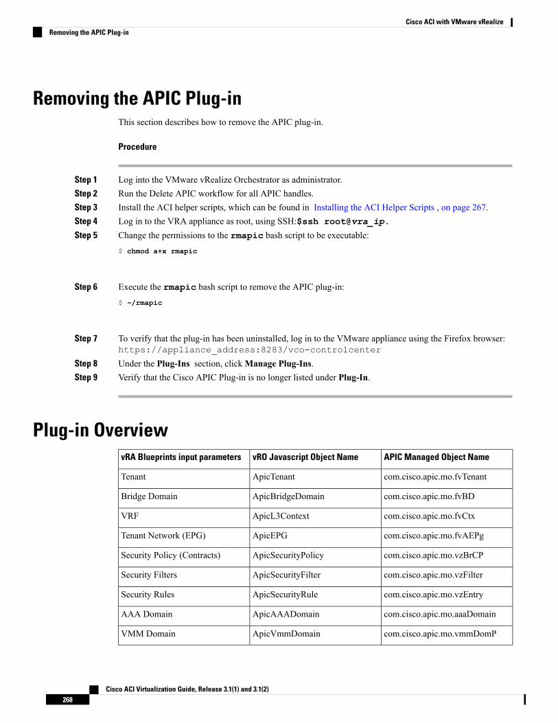
Removing the APIC Plug-inThis section describes how to remove the APIC plug-in.
Procedure
Step 1 Log into the VMware vRealize Orchestrator as administrator.Step 2 Run the Delete APIC workflow for all APIC handles.Step 3 Install the ACI helper scripts, which can be found in Installing the ACI Helper Scripts , on page 267.Step 4 Log in to the VRA appliance as root, using SSH:$ssh root@vra_ip.
Step 5 Change the permissions to the rmapic bash script to be executable:$ chmod a+x rmapic
Step 6 Execute the rmapic bash script to remove the APIC plug-in:$ ~/rmapic
Step 7 To verify that the plug-in has been uninstalled, log in to the VMware appliance using the Firefox browser:https://appliance_address:8283/vco-controlcenter
Step 8 Under the Plug-Ins section, clickManage Plug-Ins.Step 9 Verify that the Cisco APIC Plug-in is no longer listed under Plug-In.
Plug-in OverviewAPIC Managed Object NamevRO Javascript Object NamevRA Blueprints input parameters
com.cisco.apic.mo.fvTenantApicTenantTenant
com.cisco.apic.mo.fvBDApicBridgeDomainBridge Domain
com.cisco.apic.mo.fvCtxApicL3ContextVRF
com.cisco.apic.mo.fvAEPgApicEPGTenant Network (EPG)
com.cisco.apic.mo.vzBrCPApicSecurityPolicySecurity Policy (Contracts)
com.cisco.apic.mo.vzFilterApicSecurityFilterSecurity Filters
com.cisco.apic.mo.vzEntryApicSecurityRuleSecurity Rules
com.cisco.apic.mo.aaaDomainApicAAADomainAAA Domain
com.cisco.apic.mo.vmmDomPApicVmmDomainVMM Domain
Cisco ACI Virtualization Guide, Release 3.1(1) and 3.1(2)268
Cisco ACI with VMware vRealizeRemoving the APIC Plug-in
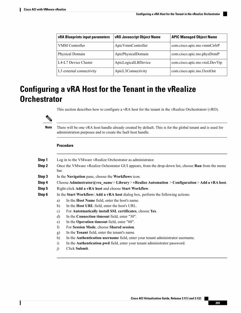
APIC Managed Object NamevRO Javascript Object NamevRA Blueprints input parameters
com.cisco.apic.mo.vmmCtrlrPApicVmmControllerVMM Controller
com.cisco.apic.mo.physDomPApicPhysicalDomainPhysical Domain
com.cisco.apic.mo.vnsLDevVipApicLogicalLBDeviceL4-L7 Device Cluster
com.cisco.apic.mo.l3extOutApicL3ConnectivityL3 external connectivity
Configuring a vRA Host for the Tenant in the vRealizeOrchestrator
This section describes how to configure a vRA host for the tenant in the vRealize Orchestratorr (vRO).
There will be one vRA host handle already created by default. This is for the global tenant and is used foradministration purposes and to create the IaaS host handle.
Note
Procedure
Step 1 Log in to the VMware vRealize Orchestrator as administrator.Step 2 Once the VMware vRealize Ochestrator GUI appears, from the drop-down list, choose Run from the menu
bar.Step 3 In the Navigation pane, choose theWorkflows icon.Step 4 ChooseAdminstrator@vra_name >Library > vRealize Automation >Configuration >Add a vRAhost.Step 5 Right-click Add a vRA host and choose Start Workflow.Step 6 In the Start Workflow: Add a vRA host dialog box, perform the following actions:
a) In the Host Name field, enter the host's name.b) In the Host URL field, enter the host's URL.c) For Autotmatically install SSL certificates, choose Yes.d) In the Connection timeout field, enter "30".e) In the Operation timeout field, enter "60".f) For Session Mode, choose Shared session.g) In the Tenant field, enter the tenant's name.h) In the Authentication username field, enter your tenant administrator username.i) In the Authentication pwd field, enter your tenant administrator password.j) Click Submit.
Cisco ACI Virtualization Guide, Release 3.1(1) and 3.1(2)269
Cisco ACI with VMware vRealizeConfiguring a vRA Host for the Tenant in the vRealize Orchestrator
Configuring an IaaS Host in the vRealize OrchestratorThis section describes how to configure an IaaS host in the vRealize Orchestratorr (vRO).
Procedure
Step 1 Log in to the VMware vRealize Orchestrator as administrator.Step 2 Once the VMware vRealize Ochestrator GUI appears, from the drop-down list, choose Run from the menu
bar.Step 3 In the Navigation pane, choose theWorkflows icon.Step 4 Choose Adminstrator@vra_name > Library > vRealize Automation > Configuration > Add the Iaas
host of a vRA host.Step 5 Right-click Add the Iaas host of a vRA host and choose Start Workflow.Step 6 In the Start Workflow: Add the Iaas host of a vRA host dialog box, perform the following actions:
a) In the vRA Host drop-down list, choose the default vRA host that was created by the system. Do notchoose the tenant handle.
b) In the Host Name field, leave the auto-filled name as is.c) In the Host URL field, enter the vRA host's URL.d) In the Connection timeout field, enter "30".e) In the Operation timeout field, enter "60".f) For Session Mode, choose Shared session.g) In the Authentication username field, enter your IaaS administrator username.h) In the Authentication pwd field, enter your IaaS administrator password.i) In theWorkstation for NTLM authentication field, enter your IaaS host name.j) In the Domain for NTLM authentication field, enter your IaaS domain name.k) Click Submit.
Cisco ACI Virtualization Guide, Release 3.1(1) and 3.1(2)270
Cisco ACI with VMware vRealizeConfiguring an IaaS Host in the vRealize Orchestrator
C H A P T E R 8Cisco ACI vCenter Plug-in
This chapter contains the following sections:
• About Cisco ACI with VMware vSphere Web Client, on page 271• Getting Started with Cisco ACI vCenter Plug-in, on page 272• Cisco ACI vCenter Plug-in Features and Limitations, on page 277• Upgrading VMware vCenter when Using the Cisco ACI vCenter Plug-in, on page 285• Cisco ACI vCenter Plug-in GUI, on page 285• Performing ACI Object Configurations, on page 292• Uninstalling the Cisco ACI vCenter Plug-in, on page 302• Upgrading the Cisco ACI vCenter Plug-in, on page 302• Troubleshooting the Cisco ACI vCenter Plug-in Installation, on page 302• Reference Information, on page 304
About Cisco ACI with VMware vSphere Web ClientThe Cisco ACI vCenter plug-in is a user interface that allows you to manage the ACI fabric from within thevSphere Web client.
This allows the VMware vSphere Web Client to become a single pane of glass to configure both VMwarevCenter and the ACI fabric.
The Cisco ACI vCenter plug-in empowers virtualization administrators to define network connectivityindependently of the networking team while sharing the same infrastructure.
No configuration of in-depth networking is done through the Cisco ACI vCenter plug-in. Only the elementsthat are relevant to virtualization administrators are exposed.
Cisco ACI vCenter Plug-in OverviewThe Cisco Application Centric Infrastructure (ACI) vCenter plug-in for the VMware vSphere Web Client,adds a new view to the GUI called Cisco ACI Fabric.
The Cisco Application Centric Infrastructure (ACI) vCenter plug-in does not change existing integration ofACI with vCenter, it allows you to configure an EPG, uSeg EPG, contract, tenant, VRF, and bridge domainfrom the VMware vSphere Web Client.
Cisco ACI Virtualization Guide, Release 3.1(1) and 3.1(2)271
Cisco Application Centric Infrastructure (ACI) vCenter plug-in is stateless, fetches everything fromApplicationPolicy Infrastructure Controller (APIC) and does not store any information.
The following is a brief overview of the features provided by Cisco ACI vCenter plug-in:
For more detailed information, see Cisco ACI vCenter Plug-in Features and Limitations, on page 277.
The Cisco ACI vCenter plug-in provides the possibility to create, read, update and delete (CRUD) the followingobject on the ACI Fabric:
• Tenant
• Application Profile
• EPG / uSeg EPG
• Contract
• VRF
• Bridge Domain
The Cisco ACI vCenter plug-in also provides a more limited operation regarding the usage of L2 and L3 Out,where all of the advanced configuration needs to be done in APIC beforehand.
• Preconfigured L2 and L3 Out can be used as providers or consumers of a contract.
• Cannot be created, edited or deleted.
The Cisco ACI vCenter plug-in also allows to consume preconfigured L4-L7 Services, by applying existinggraph template to a Contract.
• Can use existing graph templates, not create them.
• Only empty mandatory parameter of the function profile will be displayed and configurable.
The Cisco ACI vCenter plug-in also has troubleshooting capabilities:
• Endpoint to endpoint sessions (Faults, Audits, Events, Stats, Contract, Traceroute )
Getting Started with Cisco ACI vCenter Plug-in
Cisco ACI vCenter Plug-in Software RequirementsThe Cisco ACI vCenter plug-in Software Requirements:
Cisco ACI Virtualization Guide, Release 3.1(1) and 3.1(2)272
Cisco ACI vCenter Plug-inGetting Started with Cisco ACI vCenter Plug-in
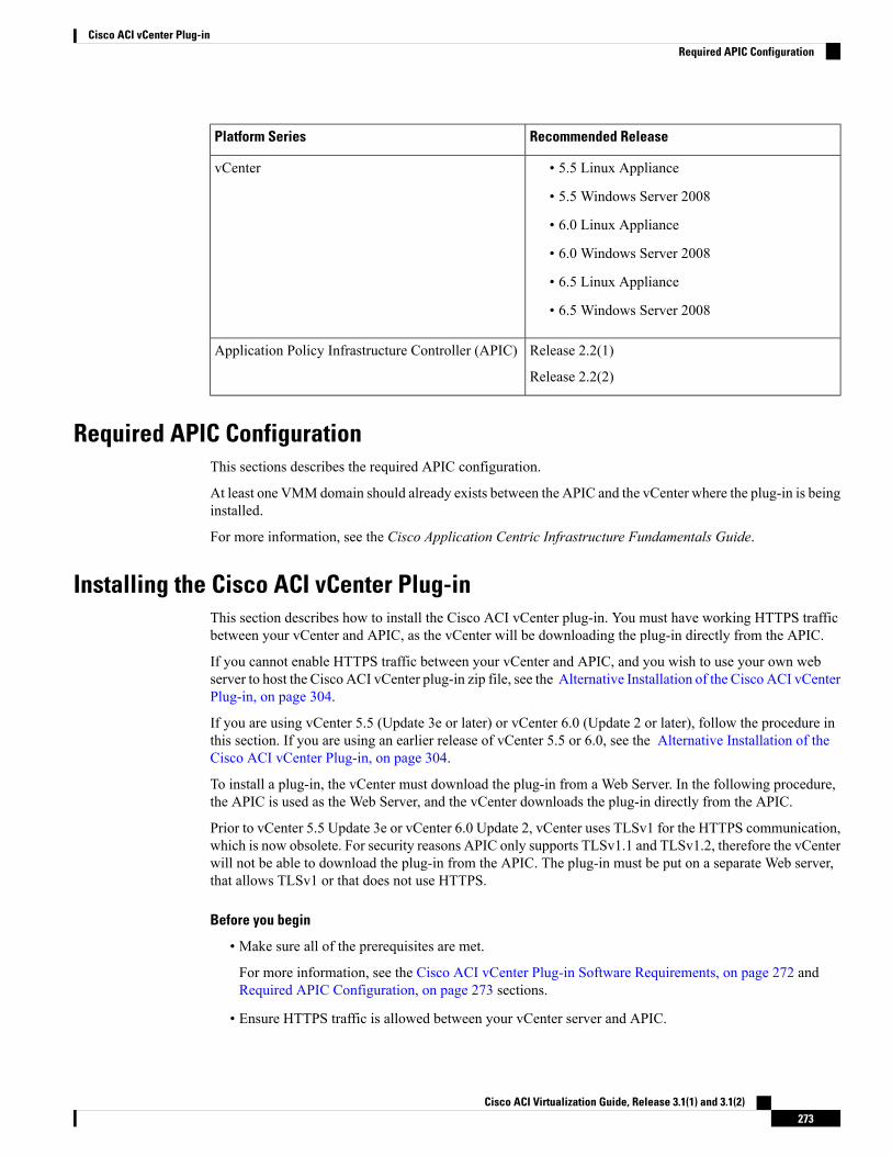
Recommended ReleasePlatform Series
• 5.5 Linux Appliance
• 5.5 Windows Server 2008
• 6.0 Linux Appliance
• 6.0 Windows Server 2008
• 6.5 Linux Appliance
• 6.5 Windows Server 2008
vCenter
Release 2.2(1)
Release 2.2(2)
Application Policy Infrastructure Controller (APIC)
Required APIC ConfigurationThis sections describes the required APIC configuration.
At least one VMMdomain should already exists between the APIC and the vCenter where the plug-in is beinginstalled.
For more information, see the Cisco Application Centric Infrastructure Fundamentals Guide.
Installing the Cisco ACI vCenter Plug-inThis section describes how to install the Cisco ACI vCenter plug-in. You must have working HTTPS trafficbetween your vCenter and APIC, as the vCenter will be downloading the plug-in directly from the APIC.
If you cannot enable HTTPS traffic between your vCenter and APIC, and you wish to use your own webserver to host the Cisco ACI vCenter plug-in zip file, see the Alternative Installation of the Cisco ACI vCenterPlug-in, on page 304.
If you are using vCenter 5.5 (Update 3e or later) or vCenter 6.0 (Update 2 or later), follow the procedure inthis section. If you are using an earlier release of vCenter 5.5 or 6.0, see the Alternative Installation of theCisco ACI vCenter Plug-in, on page 304.
To install a plug-in, the vCenter must download the plug-in from a Web Server. In the following procedure,the APIC is used as the Web Server, and the vCenter downloads the plug-in directly from the APIC.
Prior to vCenter 5.5 Update 3e or vCenter 6.0 Update 2, vCenter uses TLSv1 for the HTTPS communication,which is now obsolete. For security reasons APIC only supports TLSv1.1 and TLSv1.2, therefore the vCenterwill not be able to download the plug-in from the APIC. The plug-in must be put on a separate Web server,that allows TLSv1 or that does not use HTTPS.
Before you begin
• Make sure all of the prerequisites are met.
For more information, see the Cisco ACI vCenter Plug-in Software Requirements, on page 272 andRequired APIC Configuration, on page 273 sections.
• Ensure HTTPS traffic is allowed between your vCenter server and APIC.
Cisco ACI Virtualization Guide, Release 3.1(1) and 3.1(2)273
Cisco ACI vCenter Plug-inRequired APIC Configuration
Procedure
Step 1 Go to the following URL:
Example:https://<APIC>/vcplugin
Step 2 Follow the instructions on that web page.
Connecting vCenter Plug-in to your ACI FabricThis section describes how to connect the vCenter plug-in to your ACI fabric.
• The registration is vCenter wide and it does not take into account the user that performs it. It is aconfiguration for the whole vCenter, not just for the logged in user that performs it.
• Role Based Access Control (RBAC) is based on the credentials used upon registration. Permission ofthe APIC account used for the registration defines configuration restriction on the vCenter plug-in.
Note
You can connect the vCenter plug-in to your ACI fabric, using one of the following ways:
For more information, see Connecting vCenterPlug-in to the Cisco ACI Fabric Using Credentials,on page 274.
Connect the vCenter plug-in to your ACI fabric usingcredentials.
For more information, see Connecting vCenter Plug-into your ACI Fabric Using an Existing Certificate, onpage 275.
Connect the vCenter plug-in to your ACI fabric usingan existing certificate.
Formore information, see Connecting vCenter Plug-into your ACI Fabric by Creating a New Certificate, onpage 276.
Connect the vCenter plug-in to your ACI fabric bycreating a new certificate.
Connecting vCenter Plug-in to the Cisco ACI Fabric Using CredentialsThis section describes how to connect the Cisco Application Centric Infrastructure (ACI) vCenter plug-in toyour Cisco ACI fabric using credentials.
Before you begin
Ensure the Cisco ACI vCenter plug-in is installed. For more information, see Installing the Cisco ACI vCenterPlug-in, on page 273.
Cisco ACI Virtualization Guide, Release 3.1(1) and 3.1(2)274
Cisco ACI vCenter Plug-inConnecting vCenter Plug-in to your ACI Fabric
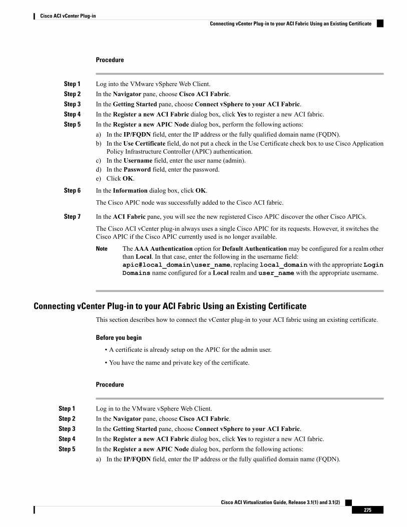
Procedure
Step 1 Log into the VMware vSphere Web Client.Step 2 In the Navigator pane, choose Cisco ACI Fabric.Step 3 In the Getting Started pane, choose Connect vSphere to your ACI Fabric.Step 4 In the Register a new ACI Fabric dialog box, click Yes to register a new ACI fabric.Step 5 In the Register a new APIC Node dialog box, perform the following actions:
a) In the IP/FQDN field, enter the IP address or the fully qualified domain name (FQDN).b) In the Use Certificate field, do not put a check in the Use Certificate check box to use Cisco Application
Policy Infrastructure Controller (APIC) authentication.c) In the Username field, enter the user name (admin).d) In the Password field, enter the password.e) Click OK.
Step 6 In the Information dialog box, click OK.
The Cisco APIC node was successfully added to the Cisco ACI fabric.
Step 7 In the ACI Fabric pane, you will see the new registered Cisco APIC discover the other Cisco APICs.
The Cisco ACI vCenter plug-in always uses a single Cisco APIC for its requests. However, it switches theCisco APIC if the Cisco APIC currently used is no longer available.
The AAA Authentication option for Default Authenticationmay be configured for a realm otherthan Local. In that case, enter the following in the username field:apic#local_domain\user_name, replacing local_domainwith the appropriate LoginDomains name configured for a Local realm and user_name with the appropriate username.
Note
Connecting vCenter Plug-in to your ACI Fabric Using an Existing CertificateThis section describes how to connect the vCenter plug-in to your ACI fabric using an existing certificate.
Before you begin
• A certificate is already setup on the APIC for the admin user.
• You have the name and private key of the certificate.
Procedure
Step 1 Log in to the VMware vSphere Web Client.Step 2 In the Navigator pane, choose Cisco ACI Fabric.Step 3 In the Getting Started pane, choose Connect vSphere to your ACI Fabric.Step 4 In the Register a new ACI Fabric dialog box, click Yes to register a new ACI fabric.Step 5 In the Register a new APIC Node dialog box, perform the following actions:
a) In the IP/FQDN field, enter the IP address or the fully qualified domain name (FQDN).
Cisco ACI Virtualization Guide, Release 3.1(1) and 3.1(2)275
Cisco ACI vCenter Plug-inConnecting vCenter Plug-in to your ACI Fabric Using an Existing Certificate
b) In the Use Certificate field, check the Use Certificate check box.
Step 6 In the Action section, choose Use an existing certificate.Step 7 In the Name field, enter the certificate name.Step 8 In the Private Key section, paste the private key of the certificate.Step 9 Click Check Certificate.
The status switches to Connection Success.
If connection failure is displayed, check that the certificate name and private key are correct, andtry again.
Note
Step 10 Click OK.Step 11 In the Information dialog box, click OK .
The APIC node was successfully added to the ACI fabric.Step 12 In the ACI Fabric pane the newly registered APIC discovers the other APICs.
The Cisco ACI vCenter plug-in always uses a single APIC for its requests. If the currently used APIC is nolonger available, the Cisco ACI vCenter plug-in switches APICs.
Connecting vCenter Plug-in to your ACI Fabric by Creating a New CertificateThis section describes how to connect the vCenter plug-in to your ACI fabric by creating a new certificate.
Before you begin
• Ensure the plug-in is installed.
• You have access to the APIC admin credentials.
Procedure
Step 1 Log into the VMware vSphere Web Client.Step 2 In the Navigator pane, choose Cisco ACI Fabric.Step 3 In the Getting Started pane, choose Connect vSphere to your ACI Fabric.Step 4 In the Register a new ACI Fabric dialog box, click Yes to register a new ACI fabric.Step 5 In the Register a new APIC Node dialog box, perform the following actions:
a) In the IP/FQDN field, enter the IP address or the fully qualified domain name (FQDN).b) In the Use Certificate field, check the Use Certificate check box.
Step 6 In the Action field, choose Generate a new certificate.Step 7 In the Name field, enter the new certificate name.Step 8 Click the Generate certificate button.Step 9 Copy the displayed certificate.
From -----BEGIN CERTIFICATE----- included, to -----END CERTIFICATE----- included.
Step 10 Add this certificate to the admin user in APIC. Make sure to use the same certificate name.
Cisco ACI Virtualization Guide, Release 3.1(1) and 3.1(2)276
Cisco ACI vCenter Plug-inConnecting vCenter Plug-in to your ACI Fabric by Creating a New Certificate
a) Log into the APIC GUI as admin.b) On the menu bar, choose Admin.c) In the Navigation pane, expand Security Management > Local Users > admin.d) In theWork pane, in the User Certificate section, click the plus icon to add the certificate.e) In the Name field, enter the certificate name.f) In the Data field, paste the certificate content that you copied in step 8.g) Click Submit.
Step 11 In the vCenter plug-in, click Check Certificate.
The status changes to Connection Success.
If a Connection Failure message displays, check that the certificate is correctly added on the APICand that the certificate names are the same.
Note
Step 12 Click OK.Step 13 In the Information dialog box, click OK.
The APIC node is successfully added to the ACI fabric.Step 14 In the ACI Fabric pane, the newly registered APIC discovers the other APICs.
The Cisco ACI vCenter plug-in always uses a single APIC for its requests. If the currently used APIC is nolonger available, the Cisco ACI vCenter plug-in switches APICs.
Cisco ACI vCenter Plug-in Features and LimitationsThis section describes the possible operations provided by the Cisco ACI vCenter plug-in, for all object typesit manages. It also goes over intentional configuration limitations.
For more information about the objects, see theCisco Application Centric Infrastructure Fundamentals Guide.
Tenants
The Cisco ACI vCenter plug-in allows CRUD operations on the Tenant object. The following attributes areexposed in the plug-in:
• Name: The name of the tenant.
• Description (Optional): The description of the tenant.
When a tenant is created by the plug-in, a VRF <tenant_name>_default and a Bridge Domain<tenant_name>_default connected to that VRF are automatically created inside. An Application Profile<tenant_name>_default is also created inside it.
The infrastructure Tenant (infra) and the management Tenant (mgmt) are not exposed in the plug-in.
The tenants visible in the plug-in will also depends on the permissions associated with the account used whileregistering the ACI fabric into the plug-in.
Note
Cisco ACI Virtualization Guide, Release 3.1(1) and 3.1(2)277
Cisco ACI vCenter Plug-inCisco ACI vCenter Plug-in Features and Limitations
Application Profiles
The Cisco ACI vCenter plug-in allows CRUD operations on the Application Profile objects. The followingattributes are exposed in the plug-in:
• Name: The name of the Application Profile.
• Description (Optional): The description of the Application Profile.
Endpoint Groups
The Cisco ACI vCenter plug-in allows CRUD operations on the Endpoint Group objects. The followingattributes are exposed in the plug-in:
• Name: The name of the Endpoint Group.
• Description (Optional): The description of the Endpoint Group
• Bridge Domain: The Bridge Domain associated with this Endpoint Group.
• Intra-EPG Isolation: This allows to deny all traffic between the virtual machines that are connected toan EPG. By default, all virtual machines in the same EPG can talk to each other.
• Distributed Switch: The DVS/Cisco AVS where the EPG is deployed. This correspond to the associationwith a VMM domain in ACI
By default, all EPGs created with the plug-in are associated with the VMM Domain pointing to thevCenter where the plug-in is used. If there are multiple VMM Domains pointing to the same vCenter,you must choose at least one, in the form of selected on which DVS to deploy the EPG.
Allow microsegmentation (only for DVS, not Cisco AVS): This allows you to create a “Base EPG” . All thevirtual machines connected to this EPG are candidates to apply microsegmentation rules of a uSeg EPG.Microsegmented EPG rules only applies to virtual machine that are connected to a “Base EPG” .
All EPGs are considered as base EPGs if the distributed switch is Cisco AVS.Note
An EPG linked to a VMM domain pointing to the vCenter where the plug-in is being used is displayed as"Virtual." Other EPGs are displayed as "Physical."
Update and Delete actions are only authorized for EPGs linked to a VMM domain that is pointing to thevCenter (Virtual). Others EPGs (Physical) are read-only. Updates are still authorized to make EPGs consumeor provide contracts, regardless of their VMM domain.
uSeg EPGs
The Cisco ACI vCenter plug-in allows CRUD operations on the mircosegemented EPG objects. The followingattributes are exposed in the plug-in:
• Name: The name of the microsegmented EPG.
• Description (Optional): The description of the microsegmented EPG.
• Bridge Domain: The Bridge Domain associated with this microsegmented EPG.
Cisco ACI Virtualization Guide, Release 3.1(1) and 3.1(2)278
Cisco ACI vCenter Plug-inCisco ACI vCenter Plug-in Features and Limitations
• Intra-EPG Isolation: This allows to deny all traffic between the virtual machines that are connected toan EPG. By default, all virtual machines in the same EPG can talk to each other.
• Distributed Switch: The DVS/Cisco AVS where the EPG is deployed. This correspond to the associationwith a VMM domain in ACI
By default, all EPGs created with the plug-in are associated with the VMM Domain pointing to thevCenter where the plug-in is used. If there are multiple VMM Domains pointing to the same vCenter,you must choose at least one, in the form of selected on which DVS to deploy the EPG.
• Miro-segmentation attributes: List of rules that decide which VM belongs to this microsegmented EPG.Rules options include: IP, MAC, VM name, OS, Host, VM id, VNic, Domain, Data Center, CustomAttribute.
Domain attributes (VMM Domain) only allow you to select VMM domains to the local vCenter. You choosea domain by selecting the corresponding DVS/Cisco AVS.
Custom attributes can only be chosen. They cannot be set by the plug-in. They must be set by the VMwarevSphere Client. To create custom labels, see: https://kb.vmware.com/selfservice/microsites/search.do?language=en_US&cmd=displayKC&externalId=1005720
Note
L2 and L3 External Networks
Layer 2 and Layer 3 External Networks must be created and configured on the APIC by the networkadministrator. They are read-only on the vCenter plug-in.
The only plug-in operations permitted on these objects are to make them consume or provide contracts.
The visible information for an L3 External Network is:
• Name: The name of the L3 External Network
• Subnets: External subnets represented by this L3 external network
• VRF: The VRF this L3 External Network belongs to
• Connected Bridge Domains: The Bridge Domains connected to this L3 External Network
The visible information for an L2 External Network is:
• Name: The name of the L2 External Network
• Bridge Domain: The bridge domain associated with this Bridge Domain
• VLAN ID: The VLAN ID associated with this L2 External Network
VRF
The Cisco ACI vCenter plug-in allows CRUD operations on the VRF objects. The following attributes areexposed in the plug-in:
• Name: The name of the VRF
• Description (Optional): The description of the VRF
Cisco ACI Virtualization Guide, Release 3.1(1) and 3.1(2)279
Cisco ACI vCenter Plug-inCisco ACI vCenter Plug-in Features and Limitations
• Enforce policies: Determine if the contracts need to be enforced for the EPG in this VRF.
Bridge Domains
The Cisco ACI vCenter plug-in allows CRUD operations on the Bridge Domain objects. The followingattributes are exposed in the plug-in:
• Name: The name of the Bridge Domain
• Description (Optional): The description of the Bridge Domain
• Private Subnets: List of gateways for this Bridge Domain.
• Shared and advertised subnets are read only. They cannot be configured by the plug-in. Only the privatesubnets can be added or deleted.
• If the Bridge Domain has been connected to an L3/L2 Out by the APIC, it cannot be deleted.
Note
Contracts
The Cisco ACI vCenter plug-in allows CRUD operations on the Contract objects. The following attributesare exposed in the plug-in:
• Name: The name of the contract
• Description (Optional): The description of the contract.
• Consumers: The consumers for the contract (EPG, uSeg EPGs, L2/L3 External Networks)
• Providers: The providers for the contract (EPG, uSeg EPGs, L2/L3 External Networks)
• Filters: List of filters associated with the contract
• Apply both direction: Indicate if the specified Filters are applying only from consumers to providers oralso from providers to consumers.
• L4-L7 Graph Template: It is possible to associate existing graph template to a Contract. See L4-L7Service section below.
• Subject is not exposed. The plug-in only manages contracts with a single subject. Contracts with multiplesubjects are seen, but not editable.
• If the consumer and the contract are not in the same tenant, a contract interface is automatically created(named to_Tenant-name_contract-name).
Note
Filters
The Cisco ACI vCenter plug-in allows CRUD operations on the Filter objects. All parameters from the APICare exposed.
Cisco ACI Virtualization Guide, Release 3.1(1) and 3.1(2)280
Cisco ACI vCenter Plug-inCisco ACI vCenter Plug-in Features and Limitations
L4-L7 Services
• L4-L7 services can only be added on contracts that have a single provider.
• The graph template cannot be created by the plug-in (only consume existing graph templates)
• The graph template must be configured so that it contains:
• Association with devices
• Association with a function profile
• Only support graph templates with a maximum of two nodes
• The Function Profile folders naming and hierarchy must be valid as the plug-in does not allow foldermanipulation.
• Only empty mandatory parameters of the function profile are editable by the plug-in.
• Graph connectors can be configured.
• All parameters from the APIC are exposed
• You can only consume redirect policies, if needed, not create them
Troubleshooting
• Only endpoint to endpoint troubleshooting sessions are supported.
• You can choose an existing session or create a new one
• The physical topology (spine / leaf) is not displayed.
• The topology display is VM-centric, focusing on Host, VM, vNIC, and the EPG the vNICs connectto
• Available information in a session:
• Faults
• Contracts: A table listing all the Contract/Filters/Entries between the two EPGs (hit counts are notdisplayed)
• Drop/Stats
• Audits/Events
• Traceroute
• Atomic Counter and SPAN are not available
• A more basic troubleshooting tool is available between objects that are not endpoints (VM, EPG, L3Out), that only display configured contracts between two selected objects.
• A view of VMs and their connection to EPGs is available.
• For a given VM, it is possible to view the EPGs to which its VNICs are connected.
Cisco ACI Virtualization Guide, Release 3.1(1) and 3.1(2)281
Cisco ACI vCenter Plug-inCisco ACI vCenter Plug-in Features and Limitations
• If a L4-L7 connecter is used as source or destination of a troubleshooting session, then it is expected toget the following error on the Contract section of the troubleshooting wizard:
The feature required the source and destination endpoint to both be part on an EPG.
You can safely ignore the error message.
Cisco AVS Installation and Upgrade
The Cisco ACI vCenter plug-in enables you to install, uninstall, upgrade, or downgrade Cisco AVS from thevSphere Web Client:
• Once the vCenter plug-in is connected to the ACI fabric, it allows you to see all the Cisco AVS domainspresent on Cisco APIC, and to install, uninstall, upgrade, or downgrade Cisco AVS for some or all ofthe hosts in the data center associated with the Cisco AVS domains.
• New versions of Cisco AVS that have been downloaded from Cisco.com can be uploaded to the vCenterusing the GUI. These versions can then be installed on the hosts in a given domain.
• You can see all hosts if they are connected to a given Cisco AVS domain. You also can see the hosts'OpFlex Agent status and the current version of Cisco AVS, if installed.
When installing or upgrading Cisco AVS, the vCenter plug-in automatically performs the following steps ona ESXi host:
1. Places the host into maintenance mode.
2. Uploads the appropriate VIB file to the host data store.
3. Installs or reinstalls Cisco AVS software.
4. Deletes the VIB file from the host data store.
5. Takes the host out of maintenance mode.
• The vCenter plug-in only installs or uninstalls Cisco AVS VIBs on the hosts; you need to manuallyconnect or disconnect the host to the Cisco AVS switch.
• If the host is part of an HA/DRS cluster, when the host is placed in maintenance mode, the VMs will bemigrated automatically. If the VMs can’t be migrated automatically, you need to migrate them or turnoff all the VMs on the host for the installation or upgrade to succeed.
Note
For more information see, Installing Cisco AVSUsing the VMware vCenter Plug-in, on page 107 in this guideor "Upgrading Cisco AVS Using the VMware vCenter Plug-in," "Uninstalling Cisco AVS using the VMwarevCenter Plug-in," or "Downgrading Cisco AVS using the VMware vCenter Plug-in" in the Cisco AVSInstallation Guide.
Role-based Access Control for Cisco ACI vCenter Plug-inStarting with Cisco APIC Release 3.1(1), the Cisco ACI vCenter plug-in supports enhanced role-based accesscontrol (RBAC) based on Cisco APIC user roles and security domains.
Cisco ACI Virtualization Guide, Release 3.1(1) and 3.1(2)282
Cisco ACI vCenter Plug-inRole-based Access Control for Cisco ACI vCenter Plug-in
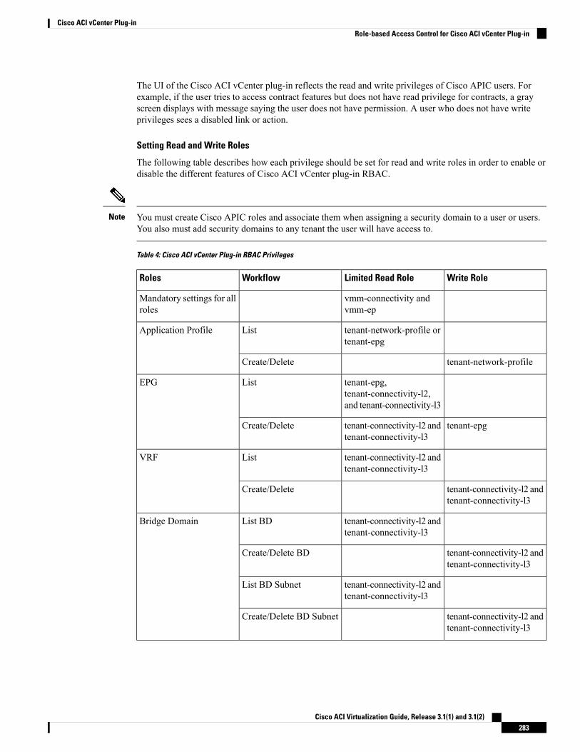
The UI of the Cisco ACI vCenter plug-in reflects the read and write privileges of Cisco APIC users. Forexample, if the user tries to access contract features but does not have read privilege for contracts, a grayscreen displays with message saying the user does not have permission. A user who does not have writeprivileges sees a disabled link or action.
Setting Read and Write Roles
The following table describes how each privilege should be set for read and write roles in order to enable ordisable the different features of Cisco ACI vCenter plug-in RBAC.
You must create Cisco APIC roles and associate them when assigning a security domain to a user or users.You also must add security domains to any tenant the user will have access to.
Note
Table 4: Cisco ACI vCenter Plug-in RBAC Privileges
Write RoleLimited Read RoleWorkflowRoles
vmm-connectivity andvmm-ep
Mandatory settings for allroles
tenant-network-profile ortenant-epg
ListApplication Profile
tenant-network-profileCreate/Delete
tenant-epg,tenant-connectivity-l2,and tenant-connectivity-l3
ListEPG
tenant-epgtenant-connectivity-l2 andtenant-connectivity-l3
Create/Delete
tenant-connectivity-l2 andtenant-connectivity-l3
ListVRF
tenant-connectivity-l2 andtenant-connectivity-l3
Create/Delete
tenant-connectivity-l2 andtenant-connectivity-l3
List BDBridge Domain
tenant-connectivity-l2 andtenant-connectivity-l3
Create/Delete BD
tenant-connectivity-l2 andtenant-connectivity-l3
List BD Subnet
tenant-connectivity-l2 andtenant-connectivity-l3
Create/Delete BD Subnet
Cisco ACI Virtualization Guide, Release 3.1(1) and 3.1(2)283
Cisco ACI vCenter Plug-inRole-based Access Control for Cisco ACI vCenter Plug-in
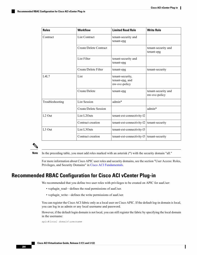
Write RoleLimited Read RoleWorkflowRoles
tenant-security andtenant-epg
List ContractContract
tenant-security andtenant-epg
Create/Delete Contract
tenant-security andtenant-epg
List Filter
tenant-securitytenant-epgCreate/Delete Filter
tenant-security,tenant-epg, andnw-svc-policy
ListL4L7
tenant-security andnw-svc-policy
tenant-epgCreate/Delete
admin*List SessionTroubleshooting
admin*Create/Delete Session
tenant-ext-connectivity-l2List L2OutsL2 Out
tenant-securitytenant-ext-connectivity-l2Contract creation
tenant-ext-connectivity-l3List L3OutsL3 Out
tenant-securitytenant-ext-connectivity-l3Contract creation
In the preceding table, you must add roles marked with an asterisk (*) with the security domain "all."Note
For more information about Cisco APIC user roles and security domains, see the section "User Access: Roles,Privileges, and Security Domains" in Cisco ACI Fundamentals.
Recommended RBAC Configuration for Cisco ACI vCenter Plug-inWe recommended that you define two user roles with privileges to be created on APIC for aaaUser:
• vcplugin_read—defines the read permissions of aaaUser.
• vcplugin_write—defines the write permissions of aaaUser.
You can register the Cisco ACI fabric only as a local user on Cisco APIC. If the default log-in domain is local,you can log in as admin or any local username and password.
However, if the default login domain is not local, you can still register the fabric by specifying the local domainin the username:apic#local domain\username
Cisco ACI Virtualization Guide, Release 3.1(1) and 3.1(2)284
Cisco ACI vCenter Plug-inRecommended RBAC Configuration for Cisco ACI vCenter Plug-in
The local domain name must exist on Cisco APIC before you enter the local domain and username.
Any RBAC configuration requires that you assign the security domain or domains of aaaUser to the VMMdomain between Cisco APIC and VMware vCenter.
Note
The Cisco ACI vCenter plug-in adapts to any combination of user roles that follow the permissions describedin the RBAC privileges table in Role-based Access Control for Cisco ACI vCenter Plug-in, on page 282 inthis guide.
Note
Upgrading VMware vCenter when Using the Cisco ACI vCenterPlug-in
If you are upgrading VMware vCenter from version 6.0 to version 6.5, and you are using the Cisco ACIvCenter plug-in, you need to take an additional step before you proceed with the upgrade.
Procedure
Delete the folder C:\ProgramData\cisco_aci_plugin\ on the vCenter.
If you do not delete the folder, and you try to register a fabric again after the upgrade, you see the followingerror message: "Error while saving setting in C:\ProgramData\cisco_aci_plugin\user_domain.properties"where the user is the user currently logged in to the vSphere Web Client, and the domain is the domain towhich it belongs.
Although you can still register a fabric, you do not have rights to override settings that were created in theold vCenter. You need to enter any changes in APIC configuration again after restarting vCenter.
Cisco ACI vCenter Plug-in GUI
Cisco ACI vCenter Plug-in GUI Architecture OverviewThis section describes the Cisco ACI vCenter plug-in GUI architecture Overview.
Cisco ACI Virtualization Guide, Release 3.1(1) and 3.1(2)285
Cisco ACI vCenter Plug-inUpgrading VMware vCenter when Using the Cisco ACI vCenter Plug-in
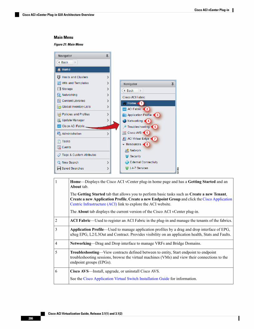
Main Menu
Figure 21: Main Menu
Home—Displays the Cisco ACI vCenter plug-in home page and has a Getting Started and anAbout tab.
The Getting Started tab that allows you to perform basic tasks such as Create a new Tenant,Create a newApplication Profile,Create a newEndpoint Group and click the Cisco ApplicationCentric Infrastructure (ACI) link to explore the ACI website.
The About tab displays the current version of the Cisco ACI vCenter plug-in.
1
ACI Fabric—Used to register an ACI Fabric in the plug-in and manage the tenants of the fabrics.2
Application Profile—Used to manage application profiles by a drag and drop interface of EPG,uSeg EPG, L2/L3Out and Contract. Provides visibility on an application health, Stats and Faults.
3
Networking—Drag and Drop interface to manage VRFs and Bridge Domains.4
Troubleshooting—View contracts defined between to entity, Start endpoint to endpointtroubleshooting sessions, browse the virtual machines (VMs) and view their connections to theendpoint groups (EPGs).
5
Cisco AVS—Install, upgrade, or uninstall Cisco AVS.
See the Cisco Application Virtual Switch Installation Guide for information.
6
Cisco ACI Virtualization Guide, Release 3.1(1) and 3.1(2)286
Cisco ACI vCenter Plug-inCisco ACI vCenter Plug-in GUI Architecture Overview
Cisco ACI Virtual Edge—Install or uninstall Cisco ACI Virtual Edge, or migrate from Cisco AVSor VMware VDS to ACI Virtual Edge.
See the Cisco ACI Virtual Edge Installation Guide for information.
7
Resources—Allows you to browse in a hierarchical view of all objects managed by the plug-in.8
While navigating through Application Profile, Networking and Resources sections, a selection bar at thetop of each screen allows you to select an active tenant. Content displayed for each section is specific to thetenant selected in that bar.
Note
Cisco ACI vCenter Plug-in OverviewThis section describes the Cisco ACI vCenter plug-in GUI overview.
All of the times for faults, stats, event and audits are shown in the local timezone of the browser. If the CiscoAPIC time zone does not match the time zone of your system, the time stamp can have a different time zone.
Note
Home
In the VMware vSphere Web Client, in the Navigator pane, choose Home. In theWork pane displays thefollowing tabs:
• Getting Started tab
The bottom of the Getting Started pane enables you to do the following things:
• Click Create a new Tenant to create a new tenant.
• Click Create a new Application Profile to create a new application profile.
• Click Create a new Endpoint Group to create a new endpoint group.
• Click the Cisco Application Centric Infrastructure (ACI) link to explore the ACI website.
• About tab
The About pane displays the Cisco ACI vCenter plug-in version.
ACI Fabric
In the VMware vSphere Web Client, in the Navigator pane, choose Cisco ACI Fabric. In theWork panedisplays the following tabs:
• ACI Fabric tab
The ACI Fabric pane enables you to do the following things:
• Click Register a new ACI Fabric / ACI Node to register a new ACI fabric or ACI node.
• View information about the current Cisco APIC states of the fabric.
Cisco ACI Virtualization Guide, Release 3.1(1) and 3.1(2)287
Cisco ACI vCenter Plug-inCisco ACI vCenter Plug-in Overview
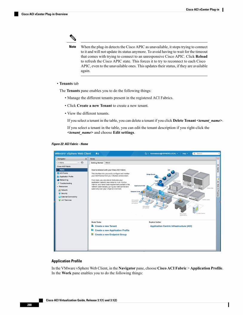
When the plug-in detects the Cisco APIC as unavailable, it stops trying to connectto it and will not update its status anymore. To avoid having to wait for the timeoutthat comes with trying to connect to an unresponsive Cisco APIC. Click Reloadto refresh the Cisco APIC state. This forces it to try to reconnect to each CiscoAPIC, even to the unavailable ones. This updates their status, if they are availableagain.
Note
• Tenants tab
The Tenants pane enables you to do the following things:
• Manage the different tenants present in the registered ACI Fabrics.
• Click Create a new Tenant to create a new tenant.
• View the different tenants.
If you select a tenant in the table, you can delete a tenant if you clickDelete Tenant <tenant_name>.
If you select a tenant in the table, you can edit the tenant description if you right-click the<tenant_name> and choose Edit settings.
Figure 22: ACI Fabric - Home
Application Profile
In the VMware vSphereWeb Client, in theNavigator pane, chooseCisco ACI Fabric >Application Profile.In theWork pane enables you to do the following things:
Cisco ACI Virtualization Guide, Release 3.1(1) and 3.1(2)288
Cisco ACI vCenter Plug-inCisco ACI vCenter Plug-in Overview
• Choose an active tenant and the application profile.
• Click Create a new Application Profile to create a new application profile.
• Use the Drag and drop to configure section to drag and drop the different elements to configure yourApplication Profiles fully. The elements are:
• Endpoint Group
• uSeg
• L3 External Network
• L2 External Network
• Contract
• View the Policy, Traffic Stats, Health, Faults, Audit Logs, and Events by using the tabs.
In the Policy tab, you can switch back to Consumer and Provider view or traffic view.
Networking
In the VMware vSphere Web Client, in the Navigator pane, choose Cisco ACI Fabric > Networking. In theWork pane enables you to do the following things:
• Set up your own addressing for all endpoint groups by creating isolated VRFs that are populated withbridge domains. An endpoint group will be associated with one bridge domain.
• Choose an active tenant.
• Use the Drag and drop to configure section to drag and drop the following elements:
• VRF
• Bridge Domain
The available Layer 3 and Layer 2 endpoint groups are displayed here, but arenot configurable.
Note
Troubleshooting
In the VMware vSphere Web Client, in the Navigator pane, choose Cisco ACI Fabric > Troubleshooting.In theWork pane displays the following tabs:
• Policy Checker tab
The Policy Checker tab enables you to select two entities (Virtual Machine, endpoint group, Layer 3external network or endpoint), and view all of the contracts and Layer 4 to Layer 7 services that areenforced between those 2 entities.
You can also start a troubleshooting session between two endpoints:
• Choose the time frame of the session in the From, To and fixed time check box.
• You can configure the time frame by putting a check in the Fix Time check box.
Cisco ACI Virtualization Guide, Release 3.1(1) and 3.1(2)289
Cisco ACI vCenter Plug-inCisco ACI vCenter Plug-in Overview
• In the Source Destination section, you can choose the source and destination endpoints. Click onStart Troubleshooting session to start a new troubleshooting session.
• In the Troubleshooting Session, you can inspect faults, configured contracts, event, audits, andtraffic stats.
• You can start a trace route between the two endpoints if you click Traceroute.
• You can click the icon next to an elements to get details that correspond to the category that youchose in the left pane.
• You can get a topology that represents, for each endpoint, the corresponding vNIC, VM, and host,and the EPG to which the vNIC is connected.
• Virtual Machines tab
This view is to visualize if the network interface cards of your virtual machine are connected to anyendpoint groups.
• You can restrict the list by using the search field.
• You view each of the VMs if the vNICs are connected to an EPG.
• You can quickly view if the associated EPG has good health or any faults, and view the tenant andapplication profile to which it belongs.
Resources
• Network
In the VMware vSphere Web Client, in the Navigator pane, choose Cisco ACI Fabric > Resources >Network. In theWork pane displays the following tabs:
• Endpoint Groups tab
Configure the network infrastructure by creating endpoint groups. Each endpoint group has acorresponding VMware Distributed Port Group where you can connect your virtual machines. Youcan organize your different endpoint groups into application profiles.
• Choose an active tenant.
• Click Create a new Application Profile to create a new application profile.
• Choose an application in the table and click Create a new Endpoint Group to create a newendpoint group.
• View the table to see the application profiles and endpoint groups of an active tenant.
• Choose an endpoint group to view all of the VMs that are connected to it.
• VRFs tab
For all endpoint groups, you can setup your own addressing by creating isolated VRFs that arepopulated with bridge domains. An endpoint group will be associated with one bridge domain.
• Choose an active tenant.
• Click Create a new VRF to create a new VRF.
Cisco ACI Virtualization Guide, Release 3.1(1) and 3.1(2)290
Cisco ACI vCenter Plug-inCisco ACI vCenter Plug-in Overview
• Click Create a new Bridge Domain to create a new bridge domain.
• View the table to see the VRFs.
• Security
In the VMware vSphere Web Client, in the Navigator pane, choose Cisco ACI Fabric > Resources >Security. In theWork pane displays the following tabs:
• Contracts tab
Contracts allows you to define security policies between different endpoint groups and securitypolicies between endpoint groups and Layer 3 and Layer 2 external networks.
• Choose an active tenant.
• Click Create a new Contract to create a new contract.
• View the table to see the contracts.
• Filters tab
Filters are entities that matches a given type of traffic (based on protocol, port, etc.). They are usedby contracts to define the authorized services between endpoint groups and Layer 3 external networks.
• Choose an active tenant.
• Click Create a new Filter to create a new filter.
• View the table to see the filters.
• External Connectivity
In the VMware vSphere Web Client, in the Navigator pane, choose Cisco ACI Fabric > Resources >External Connectivity. In theWork pane displays the following tabs:
• L3 External Networks tab
Layer 3 external networks are defined by the Cisco APIC administrator. You have the possibilityto consume the defined networks in your contracts and Layer 4 to Layer 7 services, in order to bringexternal connectivity to your infrastructure.
• Choose an active tenant.
• View the table to see the Layer 3 external networks.
• L2 External Networks tab
Layer 2 external networks are defined by the Cisco APIC administrator. You have the possibilityto consume the defined networks in your Contracts and Layer 4 to Layer 7 services, in order to bringexternal connectivity to your infrastructure.
• Choose an active tenant.
• View the table to see the Layer 2 external networks.
• L4-7 Services
Cisco ACI Virtualization Guide, Release 3.1(1) and 3.1(2)291
Cisco ACI vCenter Plug-inCisco ACI vCenter Plug-in Overview
In the VMware vSphere Web Client, in the Navigator pane, choose Cisco ACI Fabric > Resources >External Connectivity. In theWork pane displays the following:
• Layer 4 to Layer 7 services enables you to add pre-provisoned firewalls and load balancers betweenyour endpoint groups and Layer 3 external networks.
• Choose an active tenant.
• View the table to see the Layer 4 to Layer 7 graph instances currently deployed inside the tenant.
GUI TipsThis section provides GUI tips.
• You can right-click on ACI object displayed in tables or in graph, to get associated actions.
• When a Virtual Machine object is displayed inside a table in the vCenter plug-in, you can double-clickon it to navigate to that Virtual Machine in the vSphere Web Client.
Performing ACI Object Configurations
Creating a New TenantThis section describes how to create a new tenant.
Before you begin
Ensure that an ACI fabric is registered. For more information, see Connecting vCenter Plug-in to the CiscoACI Fabric Using Credentials, on page 274.
Procedure
Step 1 Log into the VMware vSphere Web Client.Step 2 In theWork pane, choose Cisco ACI Fabric.Step 3 In the Navigator pane, choose ACI Fabric.Step 4 In the ACI Fabric pane, choose the Tenants tab.Step 5 In the Tenants pane, click Create a new Tenant.Step 6 In the New Tenant dialog box, perform the following actions:
a) In the Enter a name for the Tenant field, enter the tenant name.b) (Optional) In the Enter a description for the Tenant field, enter the description for the tenant.c) Click OK.
Cisco ACI Virtualization Guide, Release 3.1(1) and 3.1(2)292
Cisco ACI vCenter Plug-inGUI Tips
Creating a New Application ProfileThis section describes how to create a new application profile.
Before you begin
• Ensure that a tenant has been created.
For more information, see Creating a New Tenant, on page 292.
Procedure
Step 1 Log into the VMware vSphere Web Client.Step 2 In theWork pane, choose Cisco ACI Fabric.Step 3 In the Navigator pane, choose Resources > Network.Step 4 In the Network pane, under the Endpoint Groups tab, perform the following actions:
a) From the Tenant drop-down list, choose the tenant name.b) Click Create a new Application Profile.
Step 5 In the New Application Profile dialog box, perform the following actions:a) In the Name field, the application profile name.b) (Optional) In the Description field, enter the description of the application profile name.c) Click OK.
Creating an EPG Using the Drag and Drop MethodThis section describes how to create an endpoint group (EPG) using the drag and drop method.
Before you begin
• Ensure that a tenant has been created.
For more information, see Creating a New Tenant, on page 292.
• Ensure that an application profile has been created.
For more information, see Creating a New Application Profile, on page 293.
Procedure
Step 1 Log into the VMware vSphere Web Client.Step 2 In the Navigator pane, choose Application Profile.Step 3 In the Application Profile pane, perform the following actions:
a) In the Tenant field, from the drop-down list, choose a tenant.b) In the Application Profile field, from the drop-down list, choose an application profile.
Cisco ACI Virtualization Guide, Release 3.1(1) and 3.1(2)293
Cisco ACI vCenter Plug-inCreating a New Application Profile
c) In the Drag and drop to configure element area, drag and drop Endpoint Group.
Step 4 In the New Endpoint Group dialog box, perform the following actions:a) In the Name field, enter the name of the endpoint group.b) (Optional) In the Description field, enter the description of the EPG.c) In the Bridge Domain field, choose any bridge domain from common or from the tenant where the EPG
is created. The default bridge domain is common/default. Click the pen icon to choose another bridgedomain.
Step 5 In the Distributed Switch field, perform the following actions:a) Put a check in at least one distributed switch check box to connect the EPG to the chosen distributed
switches.b) Put a check in the Allow micro-segmentation check box to allow micro-segmentation.
TheAllowmicro-segmentation check box only shows if the distributed switch is DVS. If the distributedswitch is AVS, then the GUI does not show the Allow micro-segmentation check box. All EPGs areconsidered to be base EPGs if the distributed switch is AVS.
This allows you to create a base EPG. All of the virtual machines that are connected to this EPG arecandidates to apply the micro-segmentation rules of a uSeg EPG. Micro-segmented EPG rules only applyto virtual machines that are connected to a base EPG.
c) Put a check in the Intra EPG isolation check box to isolate the EPG.
This allows you to deny all traffic between the virtual machines that are connected to this EPG. This rulealso applies to machines that are seen under a microsegmented EPG. By default, all virtual machines inthe same EPG can talk to each other.
Step 6 Click OK to push the new EPG on APIC.
You will see the new EPG that you created in the topology.
Creating a New uSeg EPG Using the Drag and Drop MethodThis section describes how to create a new uSeg EPG using the drag and drop method.
Before you begin
• Ensure that a tenant has been created
For more information, see Create a New Tenant.
• Ensure that an application profile has been created.
For more information, see Creating a New Application Profile, on page 293.
• (DVS only, not Cisco AVS) Ensure you have created a base EPG, and connected all the VMs that needsto participate in micro-segmentation to that base EPG. For more information, see Creating a new EndpointGroup.
Cisco ACI Virtualization Guide, Release 3.1(1) and 3.1(2)294
Cisco ACI vCenter Plug-inCreating a New uSeg EPG Using the Drag and Drop Method
Procedure
Step 1 Log in to the VMware vSphere Web Client.Step 2 In the Navigator pane, choose Application Profile.Step 3 In the Application Profile pane, perform the following actions:
a) From the Tenant drop-down list, choose a tenant.b) From the Application Profile drop-down list, choose an application profile.c) In the Drag and drop to configure element area, drag and drop the uSeg into the topology.
Step 4 In the New Endpoint Group dialog box, perform the following actions:a) In the Name field, enter the name of the EPG.b) In the Description field, enter the description of the EPG.
Step 5 In the Distributed Switch field, choose which distributed switch needs to be associated with that uSeg EPG.
If there is only one DVS, no check box is displayed as it is chosen by default.Note
Step 6 In theBridge Domain field, choose any bridge domain from common or from the tenant where the uSeg EPGis created. The default bridge domain is common/default. Click the pen icon to select another bridge domain.
Step 7 Put a check in the Intra EPG isolation check box to isolate the EPG.Step 8 In theMicrosegmentation section, click the + icon.Step 9 In the New micro-segmentation Attribute dialog box, perform the following actions:
a) In the Name field, enter the name of the new attribute.b) (Optional) In the Description field, enter the description of the new attribute.c) In the Type section, choose the type on which to filter.d) In the Operator section, choose Contains the operator you wish to use.e) If available, click the Browse button to choose a specific object, instead of manually entering a value.f) Click OK to add the new attribute to the uSeg EPG.
Step 10 Repeat Step 7 and Step 8 to add other attributes to the uSeg EPG.Step 11 Click OK.
Creating a Contract Between Two EPGs Using the Drag and Drop MethodThis section describes how to create a contract between two endpoint groups (EPGs) using the drag and dropmethod.
Before you begin
• Ensure that two EPGs have been created.
For more information, see Creating an EPG Using the Drag and Drop Method, on page 293.
Procedure
Step 1 Log into the VMware vSphere Web Client.
Cisco ACI Virtualization Guide, Release 3.1(1) and 3.1(2)295
Cisco ACI vCenter Plug-inCreating a Contract Between Two EPGs Using the Drag and Drop Method
Step 2 In theWork pane, choose Cisco ACI Fabric.Step 3 In the Navigator pane, choose Application Profile.Step 4 In the Application Profile pane, perform the following actions:
a) From the Tenant drop-down list, choose a tenant.b) From the Application Profile drop-down list, choose an application profile.
Step 5 In the Drag and drop to configure element area, drag and drop the contract on the source EPG.Step 6 Click on the destination EPG. An arrow will display, going from the source EPG to the destination EPG.Step 7 In the New Contract dialog box, perform the following actions:
a) In the Consumers field, verify that it displays the correct EPG.b) In the Providers field, verify that it displays the correct EPG.c) In the Name field, enter the name of the contract.d) (Optional) In the Description field, enter the description of the contract.e) In the Filters field, click the + icon to add filters to the contract.f) In the new dialog box, drag and drop all the filters you wish to add to the Contract from the list on the
left to the list on the right and click OK.g) (Optional) Check the Configure L4-7 service check box to configure Layer 4 to Layer 7 services.h) Click OK to create the contract.
Adding an EPG to an Existing Contract Using Drag and Drop MethodThis section describes how to add an EPG to an existing contract using the drag and drop method.
Before you begin
• Ensure that a contract has been created.
• Ensure that an EPG has been created.
For more information, see Creating an EPG Using the Drag and Drop Method, on page 293.
• Ensure that the contract is visible on the Application Profile pane. For example, if another EPG of theApplication Profile is already using the contract. If this is not the case, follow the steps of Adding anEPG to an Existing Contract using the Security Tab.
Procedure
Step 1 Log into the VMware vSphere Web Client. In the Navigator pane, choose Application Profile .Step 2 In the Navigator pane, choose Application Profile .Step 3 In the Application Profile pane, perform the following actions:
a) From the Tenant drop-down list, choose a tenant.b) From the Application Profile drop-down list, choose an application profile.
Step 4 In the Drag and drop to configure element area, drag and drop the contract, and do one of the following:
• To have the EPG consume the contract:
Cisco ACI Virtualization Guide, Release 3.1(1) and 3.1(2)296
Cisco ACI vCenter Plug-inAdding an EPG to an Existing Contract Using Drag and Drop Method
1. Drag and drop the Contract on the EPG that needs to consume the contract.
2. Choose the relevant contract (an arrow is displayed going from the EPG to the contract), and clickthe contract to make the EPG consume the contract.
• To have the EPG provide the contract:
1. Drag and drop the Contract on the contract that the EPG needs to provide.
2. Choose the relevant contract (an arrow is displayed going from the contract to the EPG), and clickthe Contract to make the EPG provide that contact.
Adding an EPG to an Existing Contract using the Security Tab
Before you begin
• Ensure that a contract has been created.
• Ensure that an EPG has been created.
For more information, see Creating an EPG Using the Drag and Drop Method, on page 293.
Procedure
Step 1 Log into the VMware vSphere Web Client.Step 2 In the Navigator pane, choose Resources > Security.Step 3 From the Tenant drop-down list, choose a tenant.Step 4 Click on the contract where the EPG needs to be added in the list of contract.Step 5 Click on the + icon of either the Consumers or Providers columns (to respectively have the EPG consume
or provide the contract).Step 6 From the menu that opens, choose Add Endpoint Groups.Step 7 In the dialog box, perform the following actions:
a) Expand the tenant where the EPG is located.b) Expand the Application Profile where the EPG is located.c) Drag and drop the EPG from the list on the left to the list on the right.d) Click OK.
Setting up L3 External NetworkThis section describes how to connect an a Layer 3 external network.
Cisco ACI Virtualization Guide, Release 3.1(1) and 3.1(2)297
Cisco ACI vCenter Plug-inAdding an EPG to an Existing Contract using the Security Tab
You cannot do any configuration with a Layer 3 external network. You can only set up a Layer 3 externalnetwork that exists in APIC.
Note
Before you begin
• Ensure that a Layer 3 (L3) external network on APIC is configured. For more information, see the ACIBasic Configuration Guide.
• Ensure that an EPG has been created. For more information, see Creating an EPG Using the Drag andDrop Method, on page 293.
Procedure
Step 1 Log in to the VMware vSphere Web Client.Step 2 In the Navigator pane, choose Application Profile.Step 3 In the Application Profile pane, perform the following actions:
a) From the Tenant drop-down list, choose a tenant.b) From the Application Profile drop-down list, choose an application profile (app).c) In the Drag and drop to configure element area, drag and drop the L3 External Network into the
topology.
Step 4 In the Select an object dialog box, expand Tenant <tenant_name> (tenant1), choose the Layer 3 externalnetwork and click OK.
Step 5 In the Drag and drop to configure element area, drag and drop the Contract on top of the Layer 3 externalnetwork and drag to connect the EPG (WEB).
Step 6 In the New Contract dialog box, perform the following actions:a) In the Consumers field, verify that it displays the correct Layer 3 external network (L3ext).b) In the Providers field, verify that it displays the correct EPG (WEB).c) In the Name field, enter the name of the contract (L3ext-to-WEB).d) (Optional) In the Description field, enter the description of the contract.e) In the Filters field, you can add traffic filters by clicking the + icon.f) In the new dialog box, drag and drop all the filters you wish to add to the contract from the list on the left
to the list on the right and click OK.g) (Optional) Check the Configure L4-7 service check box to configure Layer 4 to Layer 7 services.h) Click OK to create the contract.
The contract is connected to the Layer 3 external network in the topology.
Setting up L2 External NetworkThis section describes how to connect Layer 2 (L2) External Network.
Cisco ACI Virtualization Guide, Release 3.1(1) and 3.1(2)298
Cisco ACI vCenter Plug-inSetting up L2 External Network
You cannot do any configuration with an L2 External Network. You can only set up an L2 External Networkthat exists in the APIC.
Note
Before you begin
• Ensure that a L2 external network on APIC is configured. For more information, see the ACI BasicConfiguration Guide
• Ensure that a EPG exists.
Procedure
Step 1 Log in to the VMware vSphere Web Client.Step 2 In the Navigator pane, choose Application Profile.Step 3 In the Application Profile pane, perform the following actions:
a) From the Tenant drop-down list, choose a tenant (tenant1).b) From the Application Profile drop-down list, choose Expenses.c) In the Drag and drop to configure element area, drag and drop the L2 External Network into the
topology.d) In the Drag and drop to configure element area, drag and drop the Contract on top of the L2 external
network, and then drag to connect the EPG (WEB).
Step 4 In the New Contract dialog box, perform the following actions:a) In the Consumers field, verify that it displays the correct L2 External Network (L2ext).b) In the Providers field, verify that it displays the correct EPG (WEB).c) In the Name field, enter the name of the contract (L2ext-to-WEB).d) In the Description field, enter the description of the contract.e) In the Filters field, you can add traffic filters by clicking the + icon.f) In the new dialog box, drag and drop all the filters you wish to add to the contract from the list on the left
to the list on the right and click OK.g) (Optional) Check the Configure L4-7 service check box to configure Layer 4 to Layer 7 services.h) Click OK.
The contract is connected to the L2 external network in the topology.
Creating a VRF Using the Drag and Drop MethodThis sections describes how to create a VRF using the drag and drop method.
Procedure
Step 1 Log into the VMware vSphere Web Client.
Cisco ACI Virtualization Guide, Release 3.1(1) and 3.1(2)299
Cisco ACI vCenter Plug-inCreating a VRF Using the Drag and Drop Method
Step 2 In theWork pane, choose Networking.Step 3 In the Networking pane, perform the following actions:
a) From the Tenant drop-down list, choose a tenantb) In the Drag and drop to configure element area, drag and drop the VRF into the pane.
Step 4 In the New VRF dialog box, perform the following actions:a) In the Name field, enter the name of the VRF.b) (Optional) In the Description field, enter the description of the VRF.c) In the Security section, check theEnforce Policies check box. Enforce Policies determines if the security
rules (Contracts) should be enforced or not for that VRF.d) Click OK.
Creating a Bridge DomainThis section describes how to create a bridge domain.
Before you begin
• Ensure that a VRF (Private Network) exists.
Procedure
Step 1 Log in to the VMware vSphere Web Client.Step 2 In the Navigator pane, choose Networking.Step 3 In the Networking pane, perform the following actions:
a) From the Tenant drop-down list, choose a tenant (tenant1).b) In the Drag and drop to configure element area, drag and drop the Bridge Domain on top of the VRF
in the topology.
Step 4 In the New Bridge Domain dialog box, perform the following actions:a) In the Name field, enter the name of the bridge domain (BD2).b) (Optional) In the Description field, enter the description of the bridge domain.c) In the Private Subnets section, enter the private subnets (2.2.2.2/24) and click the + icon to add the subnet
to the bridge domain.d) (Optional) Repeat substeps c and d to add the desired number of subnets to the bridge domain.e) Click OK.
The bridge domain connects to the VRF in the topology.
Start a New Troubleshooting Session Between EndpointsThis section describes how to start a new troubleshooting session between endpoints.
Cisco ACI Virtualization Guide, Release 3.1(1) and 3.1(2)300
Cisco ACI vCenter Plug-inCreating a Bridge Domain
Procedure
Step 1 Log into the VMware vSphere Web Client.Step 2 In theWork pane, choose Cisco ACI Fabric.Step 3 In the Navigator pane, choose Troubleshooting.Step 4 In the Policy Checker tab, in the Session name section, enter the new session name.Step 5 In the Source and Destination section, click Select source.Step 6 From the Menu that opens, click on Select Endpoint.Step 7 In the new dialog box that opens, select the endpoint to use as source and click OK.Step 8 In the Source and Destination section, click Select destination.Step 9 From the Menu that opens, click on Select Endpoint.Step 10 In the new dialog box that opens, select the endpoint to use as destination and click OKStep 11 Click Start Troubleshooting Session.Step 12 In the Troubleshooting pane, you can inspect the faults, configured contracts, event, audits and traffic stats.
A topology displays your configuration for each endpoint, the corresponding vNIC, VM, host, and the EPGto which the vNIC is connected. You can click the icon next to an elements to get details, corresponding tothe category selected in the left pane.
Step 13 In the Navigation pane, click Traceroute to start a trace route between the two endpoints.
Start an Exisiting Troubleshooting Session Between EndpointsThis section describes how to start an existing troubleshooting session between endpoints.
Before you begin
Procedure
Step 1 Log into the VMware vSphere Web Client, in theWork pane, choose Cisco ACI Fabric.Step 2 In the Navigator pane, choose Troubleshooting.Step 3 In the Policy Checker tab, in the Session name section, click Select an existing session.
a) In the Select a section dialog box, choose a troubleshooting session.b) Click OK.
You can only do endpoint to endpoint troubleshooting.
Step 4 Click Start Troubleshooting Session.Step 5 In the Troubleshooting pane, you can inspect the faults, configured contracts, event, audits and traffic stats.
A topology displays your configuration for each endpoint, the corresponding vNIC, VM, host, and the EPGto which the vNIC is connected. You can click the icon next to an elements to get details, corresponding tothe category selected in the left pane.
Cisco ACI Virtualization Guide, Release 3.1(1) and 3.1(2)301
Cisco ACI vCenter Plug-inStart an Exisiting Troubleshooting Session Between Endpoints
Step 6 In the Navigation pane, click Traceroute to start a trace route between the two endpoints.
Uninstalling the Cisco ACI vCenter Plug-inThis section describes how to uninstall the VMware vCenter Plug-in.
Before you begin
• You must have a PowerCLI console available.
• You must have the ACIPlugin-Uninstall.ps1 script available.
You can find the script inside the plug-in archive, or you can download it from:https://APIC_IP/vcplugin/ACIPlugin-Uninstall.ps1.
Procedure
Step 1 Open a PowerCLI console.Step 2 Run the ACIPlugin-Uninstall.ps1 script.Step 3 When prompted, in the vCenter IP / FQDN field, enter the vCenter where the plug-in needs to be uninstalled.Step 4 In the dialog box that appears, enter the root privilege credentials of the vCenter.
you should see the following message in the console if the uninstallation was successful:
[x] Uninstalled ACI vCenter Plugin
Upgrading the Cisco ACI vCenter Plug-inThis section describes how to upgrade the Cisco ACI vCenter Plug-in.
Procedure
To upgrade the Cisco ACI vCenter Plug-in, you must follow the installation procedure.
For more information, see Installing the Cisco ACI vCenter Plug-in, on page 273.
Troubleshooting the Cisco ACI vCenter Plug-in InstallationThis section describes how to troubleshoot the Cisco ACI vCenter plug-in installation.
Cisco ACI Virtualization Guide, Release 3.1(1) and 3.1(2)302
Cisco ACI vCenter Plug-inUninstalling the Cisco ACI vCenter Plug-in
If the Cisco ACI vCenter plug-in is not seen the VMware vSphere Web Client GUI, perform the followingactions:
• Make sure the .zip file can be downloaded from the vCenter by ensuring that HTTPS/HTTP traffic isworking between the vCenter and web server where the .zip is hosted.
• Ensure that you have enabled HTTP download if your using a HTTP web server.
• Ensure that the Thumbprint used is correct if you are using HTTPS.
• Check if the registration has happened by going to the following URL:
https://<VCENTER_IP>/mob/?moid=ExtensionManager&doPath=extensionList%5b"com%2ecisco%2eaciPlugin"%5d
You should see the Cisco ACI vCenter plug-in details.
If you do not and the page is blank, this indicates that the registration did not succeed. This means anerror occurred while executing the registration script. To resolve this, you must perform the installationprocedure again and note if an error is displayed by the registration scripts.
• Check the vSphere Web Client logs.
• Linux Appliance:/var/log/vmware/vsphere-client/logs/vsphere_client_virgo.log
• 5.5 Windows 2008: C:\ProgramData\VMware\vSphere WebClient\serviceability\logs\vsphere_client_virgo.log
• 6.0 Windows 2008:%ALLUSERSPROFILE%\VMWare\vCenterServer\logs\vsphere-client\logs\vsphere_client_virgo.log
• Searching for ‘vcenter-plugin’ or ‘com.cisco.aciPlugin’ in the log displays relevant informationabout the install/upgrade.
An Example of a successful upgrade:[2016-05-31T19:32:56.780Z] [INFO ] -extensionmanager-pool-11139 70002693 100019200004 com.vmware.vise.vim.extension.VcExtensionManagerDownloading plugin package from https://172.23.137.72/vcenter-plugin-2.0.343.6.zip(no proxy defined)[2016-05-31T19:32:56.872Z] [INFO ] m-catalog-manager-pool-11128 70002693 100019 200004
com.vmware.vise.vim.cm.CmCatalogManagerDetected service providers (ms):206[2016-05-31T19:32:56.872Z] [INFO ] m-catalog-manager-pool-11128 70002693 100019 200004
com.vmware.vise.vim.cm.CmCatalogManagerNo new locales or service infos to download.[2016-05-31T19:32:57.678Z] [INFO ] -extensionmanager-pool-11139 70002693 100019 200004
com.vmware.vise.vim.extension.VcExtensionManagerDone downloading plugin package from https://172.23.137.72/vcenter-plugin-2.0.343.6.zip
[2016-05-31T19:32:58.438Z] [INFO ] -extensionmanager-pool-11139 70002693 100019 200004
com.vmware.vise.vim.extension.VcExtensionManagerDone expanding plugin package to /etc/vmware/vsphere-client/vc-packages/vsphere-client-serenity/com.cisco.aciPlugin-2.0.343.6[2016-05-31T19:32:58.440Z] [INFO ] -extensionmanager-pool-11139 70002693 100019 200004
com.vmware.vise.extensionfw.ExtensionManagerUndeploying plugin package 'com.cisco.aciPlugin:2.0.343.5’.
Cisco ACI Virtualization Guide, Release 3.1(1) and 3.1(2)303
Cisco ACI vCenter Plug-inTroubleshooting the Cisco ACI vCenter Plug-in Installation
Reference Information
Alternative Installation of the Cisco ACI vCenter Plug-inThis section describes how to install the Cisco ACI vCenter plug-in. If you cannot enable HTTPS trafficbetween your vCenter and APIC and you wish to use your own web server to host the Cisco ACI vCenterplug-in zip file, follow this procedure.
Before you begin
• Make sure that all the prerequisites are met.
For more information, see Cisco ACI vCenter Plug-in Software Requirements, on page 272.
For more information, see Required APIC Configuration, on page 273.
• Have a PowerCLI console available.
For more information, see VMware documentation.
Procedure
Step 1 Make the .zip file available on a Web server.a) If the Web server is not HTTPS: By default, vCenter will only allow a download from HTTPS sources.
To allow from HTTP, open and edit the following configuration file for your vCenter version:
• vCenter 5.5 Linux Appliance: /var/lib/vmware/vsphere-client/webclient.properties
• vCenter 6.0 Linux Appliance: /etc/vmware/vsphere-client/webclient.properties
• vCenter 5.5 Windows 2008:%ALLUSERSPROFILE%\VMware\vSphere WebClient\webclient.properties
• vCenter 6.0 Windows 2008:C:\ProgramData\VMware\vCenterServer\cfg\vsphere-client\webclient.properties
b) Add allowHttp=true at the end of the file.c) If theWeb server is not HTTPS, restart the vSphereWeb Client service using the '/etc/init.d/vsphere-client
restart' command.
Step 2 Run the script using the PowerCLI console or Python:DescriptionOption
To use thePowerCLIconsole
1. Open a PowerCLI console.
2. Run the ACIPlugin-Install.ps1 script.
When prompted, enter the following information:
• In the vCenter IP / FQDN field, enter the vCenter where the plug-in needs to beinstalled.
Cisco ACI Virtualization Guide, Release 3.1(1) and 3.1(2)304
Cisco ACI vCenter Plug-inReference Information
DescriptionOption
• In the Plugin .zip file URL field, enter the URL where the vCenter will be able todownload the plug-in.
Ensure you have not renamed the .zip file.Note
• If you are using HTTP, leave the SHA1 thumbprint field empty. If you are usingHTTPS, enter the SHA1 thumbprint of the Web server used, using one of thefollowing formats:
• Separated by colons:xx:xx:xx:xx:xx:xx:xx:xx:xx:xx:xx
• Separated by spaces:xx xx xx xx xx xx xx xx xx xx xx
Some browsers onWindowsmight display the certificate thumbprint as a singlenon-delimited string (for example, xxxxxxxxxxxxxxxxxx), which theinstallation script does not process correctly. Make sure that the SHA1thumbprint of the Web server uses one of the correct formats. Otherwise, theCisco ACI vCenter plug-in appears to fail.
Note
3. In the dialog box, enter the root privilege credentials of the vCenter.
To usePython
You must use Python 2.7.9 or higher and have the pyvmomi package installed inthe Python environment.
Note
Run the Python script: python deployPlugin.py
When prompted, enter the following information:
• In the vCenter IP field, enter the vCenter where the plug-in needs to be installed.
• In the vCenter Username & Password field, enter the root privilege credentials of thevCenter.
• In the Plugin .zip file URL field, enter the URL where the vCenter will be able todownload the plug-in.
Ensure you have not renamed the .zip file.
• In the Https server thumbprint field, Leave this empty, if you are using HTTP.Otherwise, enter the SHA1 thumbprint of the Web server used. The fields are separatedwith colons. For example:D7:9F:07:61:10:B3:92:93:E3:49:AC:89:84:5B:03:80:C1:9E:2F:8B
There is also a deploy.cfg file available, where you can pre-enter yourinformation. You can then run the script with the file as argument. For example:$ python deployPlugin.py deploy.cfg
Note
Step 3 Log into the vSphere Web Client once the registration is completed.
Cisco ACI Virtualization Guide, Release 3.1(1) and 3.1(2)305
Cisco ACI vCenter Plug-inAlternative Installation of the Cisco ACI vCenter Plug-in

First login may take longer, as the vCenter will be downloading and deploying the plug-in from theWeb server.
Note
Once the VMware vSphereWeb Client loads, you will see theCisco ACI Fabric in theNavigator pane. Thisallows you to manage your ACI fabric.
After you register the plug-in, when you launch the web client for the first time, an error messagemight display asking to reload the web client. ClickReload to refresh the page and the error messagewill not appear again.
Note
Cisco ACI Virtualization Guide, Release 3.1(1) and 3.1(2)306
Cisco ACI vCenter Plug-inAlternative Installation of the Cisco ACI vCenter Plug-in
C H A P T E R 9Cisco ACI with Microsoft SCVMM
This chapter contains the following sections:
• About Cisco ACI with Microsoft SCVMM, on page 307• Getting Started with Cisco ACI with Microsoft SCVMM, on page 310• Upgrading the Cisco ACI with Microsoft SCVMM Components, on page 330• Deploying Tenant Policies, on page 333• Troubleshooting the Cisco ACI with Microsoft SCVMM, on page 339• REST API References, on page 341• Reference Information, on page 344• Programmability References, on page 347• Configuration References, on page 348• Uninstalling the Cisco ACI with Microsoft SCVMM Components, on page 349• Downgrading the APIC Controller and the Switch Software with Cisco ACI with Microsoft SCVMMComponents, on page 351
• Exporting APIC OpFlex Certificate, on page 351
About Cisco ACI with Microsoft SCVMMThe Application Policy Infrastructure Controller (APIC) integrates with Microsoft VMmanagement systemsand enhances the networkmanagement capabilities of the platform. The CiscoApplication Centric Infrastructure(ACI) integrates at the following levels of the Microsoft VM Management systems:
• Cisco ACI with Microsoft System Center Virtual Machine Manager (SCVMM)—When integrated withCisco ACI, SCVMM enables communication between ACI and SCVMM for network management.
Migrating from SCVMM to SCVMM HA is not supported by Microsoft.Note
• Cisco ACI and Microsoft Windows Azure Pack—For information about how to set up Cisco ACI andMicrosoftWindows Azure Pack, see Cisco ACI withMicrosoftWindows Azure Pack Solution Overview,on page 354.
Cisco ACI Virtualization Guide, Release 3.1(1) and 3.1(2)307
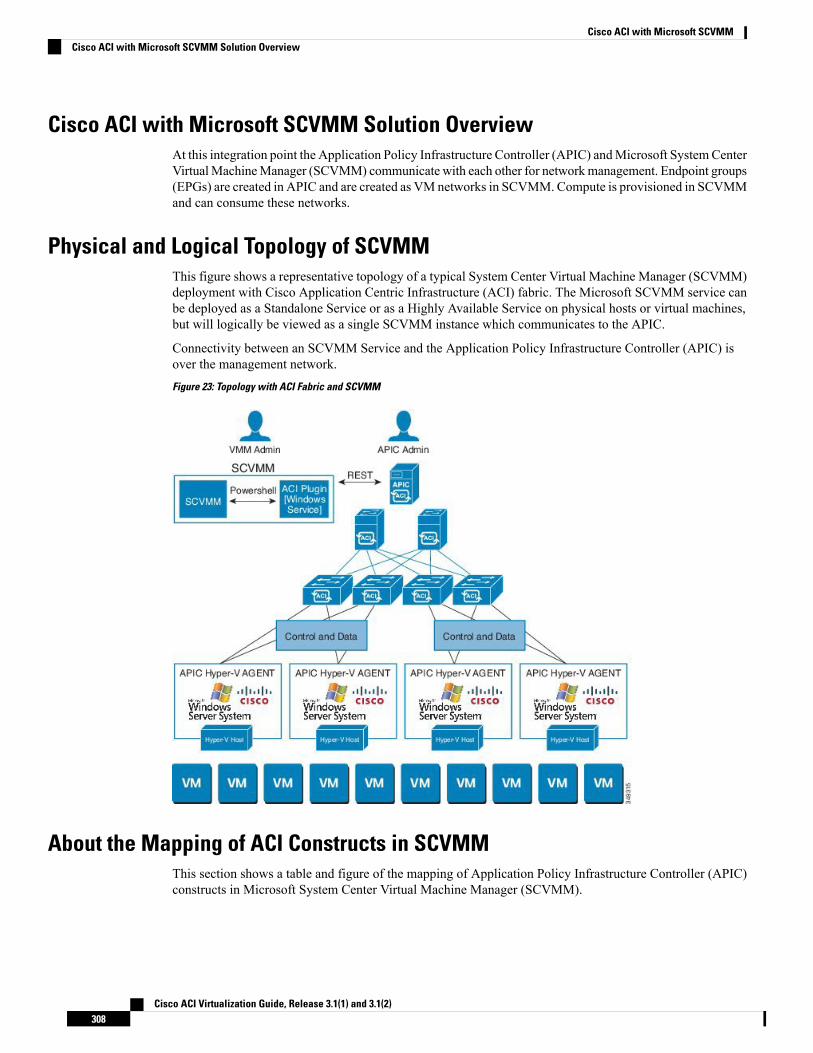
Cisco ACI with Microsoft SCVMM Solution OverviewAt this integration point the Application Policy Infrastructure Controller (APIC) andMicrosoft SystemCenterVirtualMachineManager (SCVMM) communicate with each other for networkmanagement. Endpoint groups(EPGs) are created in APIC and are created as VM networks in SCVMM. Compute is provisioned in SCVMMand can consume these networks.
Physical and Logical Topology of SCVMMThis figure shows a representative topology of a typical System Center Virtual Machine Manager (SCVMM)deployment with Cisco Application Centric Infrastructure (ACI) fabric. The Microsoft SCVMM service canbe deployed as a Standalone Service or as a Highly Available Service on physical hosts or virtual machines,but will logically be viewed as a single SCVMM instance which communicates to the APIC.
Connectivity between an SCVMM Service and the Application Policy Infrastructure Controller (APIC) isover the management network.Figure 23: Topology with ACI Fabric and SCVMM
About the Mapping of ACI Constructs in SCVMMThis section shows a table and figure of the mapping of Application Policy Infrastructure Controller (APIC)constructs in Microsoft System Center Virtual Machine Manager (SCVMM).
Cisco ACI Virtualization Guide, Release 3.1(1) and 3.1(2)308
Cisco ACI with Microsoft SCVMMCisco ACI with Microsoft SCVMM Solution Overview
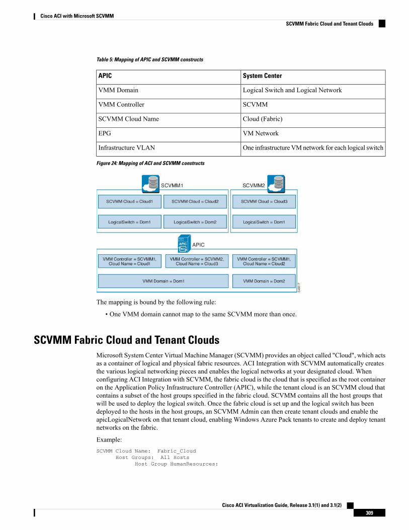
Table 5: Mapping of APIC and SCVMM constructs
System CenterAPIC
Logical Switch and Logical NetworkVMM Domain
SCVMMVMM Controller
Cloud (Fabric)SCVMM Cloud Name
VM NetworkEPG
One infrastructureVMnetwork for each logical switchInfrastructure VLAN
Figure 24: Mapping of ACI and SCVMM constructs
The mapping is bound by the following rule:
• One VMM domain cannot map to the same SCVMM more than once.
SCVMM Fabric Cloud and Tenant CloudsMicrosoft System Center Virtual Machine Manager (SCVMM) provides an object called "Cloud", which actsas a container of logical and physical fabric resources. ACI Integration with SCVMM automatically createsthe various logical networking pieces and enables the logical networks at your designated cloud. Whenconfiguring ACI Integration with SCVMM, the fabric cloud is the cloud that is specified as the root containeron the Application Policy Infrastructure Controller (APIC), while the tenant cloud is an SCVMM cloud thatcontains a subset of the host groups specified in the fabric cloud. SCVMM contains all the host groups thatwill be used to deploy the logical switch. Once the fabric cloud is set up and the logical switch has beendeployed to the hosts in the host groups, an SCVMM Admin can then create tenant clouds and enable theapicLogicalNetwork on that tenant cloud, enabling Windows Azure Pack tenants to create and deploy tenantnetworks on the fabric.
Example:SCVMM Cloud Name: Fabric_Cloud
Host Groups: All HostsHost Group HumanResources:
Cisco ACI Virtualization Guide, Release 3.1(1) and 3.1(2)309
Cisco ACI with Microsoft SCVMMSCVMM Fabric Cloud and Tenant Clouds
HyperV Node: Node-2-24Host Group Engineering:
HyperV Node: Node-2-25
SCVMM Cloud Name: HR_CloudHost Groups: HumanResources
SCVMM Cloud Name: Engineering_CloudHost Groups: Engineering
Getting Started with Cisco ACI with Microsoft SCVMMThis section describes how to get started with Cisco Application Centric Infrastructure (ACI) with MicrosoftSystem Center Virtual Machine Manager (SCVMM).
You must download and unzip the Cisco ACI and Microsoft Integration file for the 2.2(1) release beforeinstalling Cisco ACI with Microsoft Windows Azure Pack.
1. Go to Cisco's Application Policy Infrastructure Controller (APIC) Website:
http://www.cisco.com/c/en/us/support/cloud-systems-management/application-policy-infrastructure-controller-apic/tsd-products-support-series-home.html
2. Choose All Downloads for this Product.
3. Choose the release version and the aci-msft-pkg-2.2.1x.zip file.
4. Click Download.
5. Unzip the aci-msft-pkg-2.2.1x.zip file.
CiscoACIwithMicrosoft SystemCenter VirtualMachineManager (SCVMM) only supports ASCII characters.Non-ASCII characters are not supported.
Ensure that English is set in the System Locale settings for Windows, otherwise ACI with SCVMM will notinstall. In addition, if the System Locale is later modified to a non-English Locale after the installation, theintegration components may fail when communicating with the APIC and the ACI fabric.
Note
Prerequisites for Getting Started with Cisco ACI with Microsoft SCVMMBefore you get started, ensure that you have verified that your computing environment meets the followingprerequisites:
• Ensure that one of the followingMicrosoft SystemCenter Virtual MachineManager (SCVMM) versionswith the Administrator Console Builds are met:
• 2016 RTM (Build 4.0.1662.0) or newer
• 2012 R2 with Update Rollup 9 (Build 3.2.8145.0) or newer
• Ensure Windows Server 2016 or 2012 R2 is installed on the Hyper-V server with the Hyper-V roleenabled.
Cisco ACI Virtualization Guide, Release 3.1(1) and 3.1(2)310
Cisco ACI with Microsoft SCVMMGetting Started with Cisco ACI with Microsoft SCVMM
See Microsoft's documentation.
• Ensure the cloud is configured in SCVMM and appropriate hosts added to that cloud.
See Microsoft's documentation.
• Ensure "default" AEP exists with infrastructure VLAN enabled.
• Ensure you have the Cisco MSI files for APIC SCVMM and the Host Agent.
See Getting Started with Cisco ACI with Microsoft SCVMM, on page 310.
• Ensure that you scheduled a maintenance window for the SCVMM Installation. The Cisco ACI SCVMMInstallation process with automatically restart the current running SCVMM service instance.
If the VMs in SCVMM are configured with Dynamic MAC, then it takes timefor the APIC to update the VM Inventory as the SCVMM takes time to learn ordiscover these MAC addresses.
Note
• Ensure the Hyper-VManagement Tools is installed on the Hyper-V hosts as well as the SCVMM server.
To install the Hyper-V Management Tools feature:
1. In theRemote Server Administration Tools,AddRoles and Features > Feature >Remote ServerAdministration Tools > Role Administration Tools > Hyper-V Management Tools and finishthe wizard to install the feature.
2. Repeat for each Hyper-V and the SCVMM server.
This installs the Hyper-V PowerShell cmdlets needed for the APIC SCVMM and host agent.
Installing, Setting Up, and Verifying the Cisco ACI with Microsoft SCVMMComponents
This section describes how to install, set up, and verify the Cisco Application Centric Infrastructure (ACI)with Microsoft System Center Virtual Machine Manager (SCVMM) components.
TaskComponent
See Installing the APIC SCVMMAgent on SCVMM,on page 313.
See Installing the APIC SCVMMAgent on a HighlyAvailable SCVMM, on page 313
For the Windows Command Prompt method, seeInstalling the APIC Agent on SCVMM Using theWindows Command Prompt, on page 344.
Install the APIC SCVMM Agent on SCVMM or ona Highly Available SCVMM
SeeGeneratingAPICOpFlex Certificate, on page 314.Generate the OpflexAgent certificate
See Adding the OpFlex Certificate Policy to APIC,on page 315.
Add the OpFlex certificate policy to APIC
Cisco ACI Virtualization Guide, Release 3.1(1) and 3.1(2)311
Cisco ACI with Microsoft SCVMMInstalling, Setting Up, and Verifying the Cisco ACI with Microsoft SCVMM Components
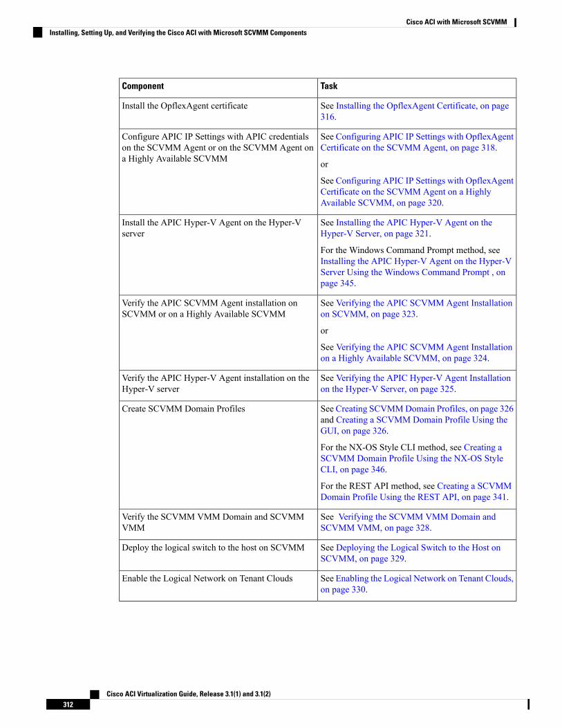
TaskComponent
See Installing the OpflexAgent Certificate, on page316.
Install the OpflexAgent certificate
See Configuring APIC IP Settings with OpflexAgentCertificate on the SCVMM Agent, on page 318.
or
See Configuring APIC IP Settings with OpflexAgentCertificate on the SCVMM Agent on a HighlyAvailable SCVMM, on page 320.
Configure APIC IP Settings with APIC credentialson the SCVMM Agent or on the SCVMM Agent ona Highly Available SCVMM
See Installing the APIC Hyper-V Agent on theHyper-V Server, on page 321.
For the Windows Command Prompt method, seeInstalling the APIC Hyper-V Agent on the Hyper-VServer Using the Windows Command Prompt , onpage 345.
Install the APIC Hyper-V Agent on the Hyper-Vserver
See Verifying the APIC SCVMM Agent Installationon SCVMM, on page 323.
or
See Verifying the APIC SCVMM Agent Installationon a Highly Available SCVMM, on page 324.
Verify the APIC SCVMM Agent installation onSCVMM or on a Highly Available SCVMM
See Verifying the APIC Hyper-V Agent Installationon the Hyper-V Server, on page 325.
Verify the APIC Hyper-V Agent installation on theHyper-V server
See Creating SCVMMDomain Profiles, on page 326and Creating a SCVMM Domain Profile Using theGUI, on page 326.
For the NX-OS Style CLI method, see Creating aSCVMM Domain Profile Using the NX-OS StyleCLI, on page 346.
For the REST API method, see Creating a SCVMMDomain Profile Using the REST API, on page 341.
Create SCVMM Domain Profiles
See Verifying the SCVMM VMM Domain andSCVMM VMM, on page 328.
Verify the SCVMM VMM Domain and SCVMMVMM
See Deploying the Logical Switch to the Host onSCVMM, on page 329.
Deploy the logical switch to the host on SCVMM
See Enabling the Logical Network on Tenant Clouds,on page 330.
Enable the Logical Network on Tenant Clouds
Cisco ACI Virtualization Guide, Release 3.1(1) and 3.1(2)312
Cisco ACI with Microsoft SCVMMInstalling, Setting Up, and Verifying the Cisco ACI with Microsoft SCVMM Components
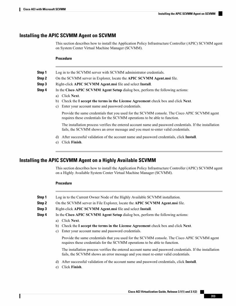
Installing the APIC SCVMM Agent on SCVMMThis section describes how to install the Application Policy Infrastructure Controller (APIC) SCVMM agenton System Center Virtual Machine Manager (SCVMM).
Procedure
Step 1 Log in to the SCVMM server with SCVMM administrator credentials.Step 2 On the SCVMM server in Explorer, locate the APIC SCVMM Agent.msi file.Step 3 Right-click APIC SCVMM Agent.msi file and select Install.Step 4 In the Cisco APIC SCVMM Agent Setup dialog box, perform the following actions:
a) Click Next.b) Check the I accept the terms in the License Agreement check box and click Next.c) Enter your account name and password credentials.
Provide the same credentials that you used for the SCVMM console. The Cisco APIC SCVMM agentrequires these credentials for the SCVMM operations to be able to function.
The installation process verifies the entered account name and password credentials. If the installationfails, the SCVMM shows an error message and you must re-enter valid credentials.
d) After successful validation of the account name and password credentials, click Install.e) Click Finish.
Installing the APIC SCVMM Agent on a Highly Available SCVMMThis section describes how to install the Application Policy Infrastructure Controller (APIC) SCVMM agenton a Highly Available System Center Virtual Machine Manager (SCVMM).
Procedure
Step 1 Log in to the Current Owner Node of the Highly Available SCVMM installation.Step 2 On the SCVMM server in File Explorer, locate the APIC SCVMM Agent.msi file.Step 3 Right-click APIC SCVMM Agent.msi file and select Install.Step 4 In the Cisco APIC SCVMM Agent Setup dialog box, perform the following actions:
a) Click Next.b) Check the I accept the terms in the License Agreement check box and click Next.c) Enter your account name and password credentials.
Provide the same credentials that you used for the SCVMM console. The Cisco APIC SCVMM agentrequires these credentials for the SCVMM operations to be able to function.
The installation process verifies the entered account name and password credentials. If the installationfails, the SCVMM shows an error message and you must re-enter valid credentials.
d) After successful validation of the account name and password credentials, click Install.e) Click Finish.
Cisco ACI Virtualization Guide, Release 3.1(1) and 3.1(2)313
Cisco ACI with Microsoft SCVMMInstalling the APIC SCVMM Agent on SCVMM
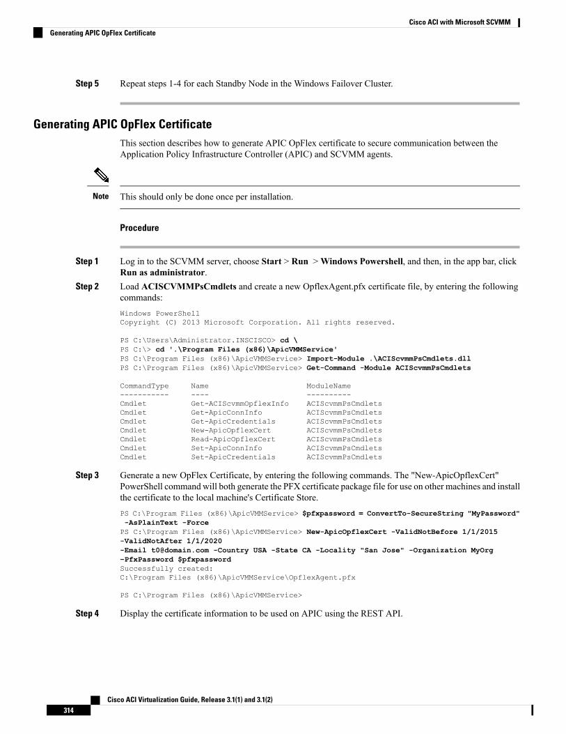
Step 5 Repeat steps 1-4 for each Standby Node in the Windows Failover Cluster.
Generating APIC OpFlex CertificateThis section describes how to generate APIC OpFlex certificate to secure communication between theApplication Policy Infrastructure Controller (APIC) and SCVMM agents.
This should only be done once per installation.Note
Procedure
Step 1 Log in to the SCVMM server, choose Start > Run >Windows Powershell, and then, in the app bar, clickRun as administrator.
Step 2 Load ACISCVMMPsCmdlets and create a new OpflexAgent.pfx certificate file, by entering the followingcommands:Windows PowerShellCopyright (C) 2013 Microsoft Corporation. All rights reserved.
PS C:\Users\Administrator.INSCISCO> cd \PS C:\> cd '.\Program Files (x86)\ApicVMMService'PS C:\Program Files (x86)\ApicVMMService> Import-Module .\ACIScvmmPsCmdlets.dllPS C:\Program Files (x86)\ApicVMMService> Get-Command -Module ACIScvmmPsCmdlets
CommandType Name ModuleName----------- ---- ----------Cmdlet Get-ACIScvmmOpflexInfo ACIScvmmPsCmdletsCmdlet Get-ApicConnInfo ACIScvmmPsCmdletsCmdlet Get-ApicCredentials ACIScvmmPsCmdletsCmdlet New-ApicOpflexCert ACIScvmmPsCmdletsCmdlet Read-ApicOpflexCert ACIScvmmPsCmdletsCmdlet Set-ApicConnInfo ACIScvmmPsCmdletsCmdlet Set-ApicCredentials ACIScvmmPsCmdlets
Step 3 Generate a new OpFlex Certificate, by entering the following commands. The "New-ApicOpflexCert"PowerShell command will both generate the PFX certificate package file for use on other machines and installthe certificate to the local machine's Certificate Store.PS C:\Program Files (x86)\ApicVMMService> $pfxpassword = ConvertTo-SecureString "MyPassword"-AsPlainText -ForcePS C:\Program Files (x86)\ApicVMMService> New-ApicOpflexCert -ValidNotBefore 1/1/2015-ValidNotAfter 1/1/2020-Email [email protected] -Country USA -State CA -Locality "San Jose" -Organization MyOrg–PfxPassword $pfxpasswordSuccessfully created:C:\Program Files (x86)\ApicVMMService\OpflexAgent.pfx
PS C:\Program Files (x86)\ApicVMMService>
Step 4 Display the certificate information to be used on APIC using the REST API.
Cisco ACI Virtualization Guide, Release 3.1(1) and 3.1(2)314
Cisco ACI with Microsoft SCVMMGenerating APIC OpFlex Certificate
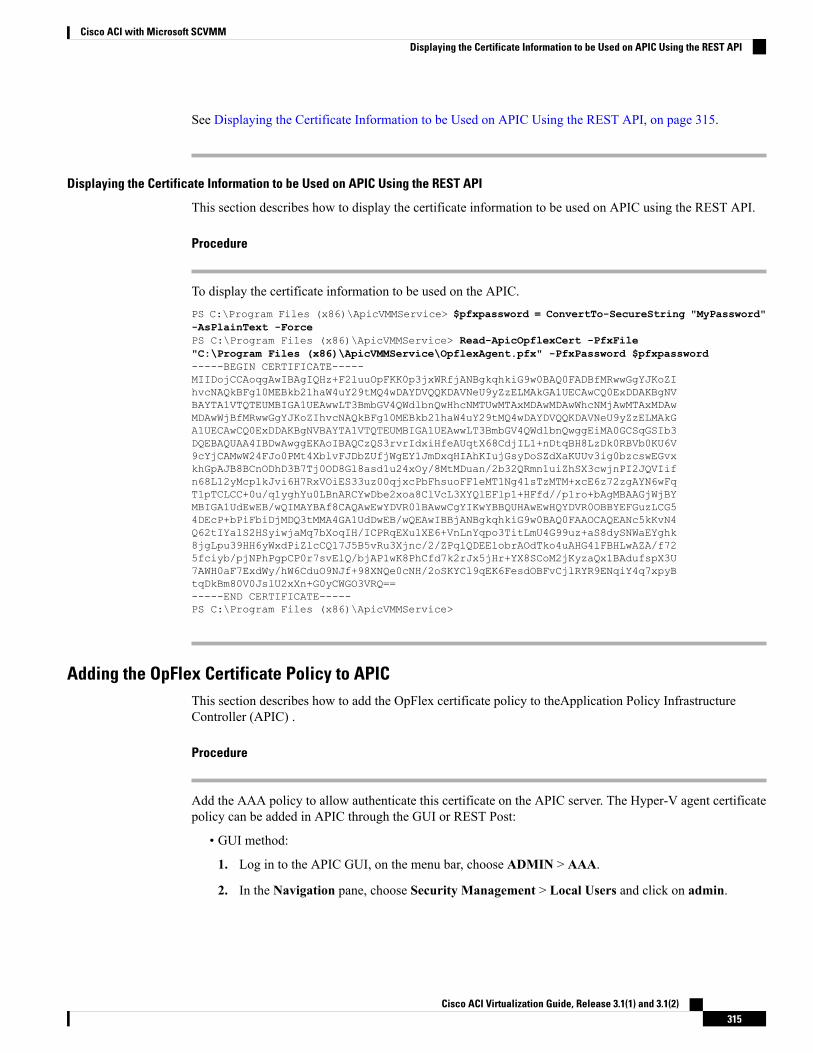
See Displaying the Certificate Information to be Used on APIC Using the REST API, on page 315.
Displaying the Certificate Information to be Used on APIC Using the REST API
This section describes how to display the certificate information to be used on APIC using the REST API.
Procedure
To display the certificate information to be used on the APIC.PS C:\Program Files (x86)\ApicVMMService> $pfxpassword = ConvertTo-SecureString "MyPassword"-AsPlainText -ForcePS C:\Program Files (x86)\ApicVMMService> Read-ApicOpflexCert -PfxFile"C:\Program Files (x86)\ApicVMMService\OpflexAgent.pfx" -PfxPassword $pfxpassword-----BEGIN CERTIFICATE-----MIIDojCCAoqgAwIBAgIQHz+F2luuOpFKK0p3jxWRfjANBgkqhkiG9w0BAQ0FADBfMRwwGgYJKoZIhvcNAQkBFg10MEBkb21haW4uY29tMQ4wDAYDVQQKDAVNeU9yZzELMAkGA1UECAwCQ0ExDDAKBgNVBAYTA1VTQTEUMBIGA1UEAwwLT3BmbGV4QWdlbnQwHhcNMTUwMTAxMDAwMDAwWhcNMjAwMTAxMDAwMDAwWjBfMRwwGgYJKoZIhvcNAQkBFg10MEBkb21haW4uY29tMQ4wDAYDVQQKDAVNeU9yZzELMAkGA1UECAwCQ0ExDDAKBgNVBAYTA1VTQTEUMBIGA1UEAwwLT3BmbGV4QWdlbnQwggEiMA0GCSqGSIb3DQEBAQUAA4IBDwAwggEKAoIBAQCzQS3rvrIdxiHfeAUqtX68CdjIL1+nDtqBH8LzDk0RBVb0KU6V9cYjCAMwW24FJo0PMt4XblvFJDbZUfjWgEY1JmDxqHIAhKIujGsyDoSZdXaKUUv3ig0bzcswEGvxkhGpAJB8BCnODhD3B7Tj0OD8Gl8asd1u24xOy/8MtMDuan/2b32QRmn1uiZhSX3cwjnPI2JQVIifn68L12yMcp1kJvi6H7RxVOiES33uz00qjxcPbFhsuoFF1eMT1Ng41sTzMTM+xcE6z72zgAYN6wFqT1pTCLCC+0u/q1yghYu0LBnARCYwDbe2xoa8ClVcL3XYQlEFlp1+HFfd//p1ro+bAgMBAAGjWjBYMBIGA1UdEwEB/wQIMAYBAf8CAQAwEwYDVR0lBAwwCgYIKwYBBQUHAwEwHQYDVR0OBBYEFGuzLCG54DEcP+bPiFbiDjMDQ3tMMA4GA1UdDwEB/wQEAwIBBjANBgkqhkiG9w0BAQ0FAAOCAQEANc5kKvN4Q62tIYa1S2HSyiwjaMq7bXoqIH/ICPRqEXu1XE6+VnLnYqpo3TitLmU4G99uz+aS8dySNWaEYghk8jgLpu39HH6yWxdPiZlcCQ17J5B5vRu3Xjnc/2/ZPqlQDEElobrAOdTko4uAHG4lFBHLwAZA/f725fciyb/pjNPhPgpCP0r7svElQ/bjAP1wK8PhCfd7k2rJx5jHr+YX8SCoM2jKyzaQx1BAdufspX3U7AWH0aF7ExdWy/hW6CduO9NJf+98XNQe0cNH/2oSKYCl9qEK6FesdOBFvCjlRYR9ENqiY4q7xpyBtqDkBm80V0JslU2xXn+G0yCWGO3VRQ==-----END CERTIFICATE-----PS C:\Program Files (x86)\ApicVMMService>
Adding the OpFlex Certificate Policy to APICThis section describes how to add the OpFlex certificate policy to theApplication Policy InfrastructureController (APIC) .
Procedure
Add the AAA policy to allow authenticate this certificate on the APIC server. The Hyper-V agent certificatepolicy can be added in APIC through the GUI or REST Post:
• GUI method:
1. Log in to the APIC GUI, on the menu bar, choose ADMIN > AAA.
2. In the Navigation pane, choose Security Management > Local Users and click on admin.
Cisco ACI Virtualization Guide, Release 3.1(1) and 3.1(2)315
Cisco ACI with Microsoft SCVMMDisplaying the Certificate Information to be Used on APIC Using the REST API
3. In the PROPERTIES pane, chooseActions >Create X509 Certificate, in the drop-down list, enterthe name and data.
4. In the Create X509 Certificate dialog box, in the Name field, you must enter "OpflexAgent".
5. On the SCVMM server, enter the output of the PowerShell Read-ApicOpflexCert cmdlet.
6. When you run the Read-ApicOpflexCert cmdlet, provide the full link when prompted for the nameof the pfx file:C:\ProgramFiles (x86)\ApicVMMService\OpflexAgent.pfx, then enter the password.
7. Copy from the beginning of "-----BEGIN CERTIFICATE-----" to the end of "-----ENDCERTIFICATE-----"and paste it in the DATA field.
8. Click SUBMIT.
9. In the PROPERTIES pane, under the User Certificates field, you will see the user certificatedisplayed.
• REST Post method:POSThttp://<apic-ip>/api/policymgr/mo/uni/userext/user-admin.json?rsp-subtree=full{"aaaUserCert":{"attributes":{"name":"OpflexAgent", "data":"-----BEGIN CERTIFICATE-----MIIDojCCAoqgAwIBAgIQHz+F2luuOpFKK0p3jxWRfjANBgkqhkiG9w0BAQ0FADBfMRwwGgYJKoZIhvcNAQkBFg10MEBkb21haW4uY29tMQ4wDAYDVQQKDAVNeU9yZzELMAkGA1UECAwCQ0ExDDAKBgNVBAYTA1VTQTEUMBIGA1UEAwwLT3BmbGV4QWdlbnQwHhcNMTUwMTAxMDAwMDAwWhcNMjAwMTAxMDAwMDAwWjBfMRwwGgYJKoZIhvcNAQkBFg10MEBkb21haW4uY29tMQ4wDAYDVQQKDAVNeU9yZzELMAkGA1UECAwCQ0ExDDAKBgNVBAYTA1VTQTEUMBIGA1UEAwwLT3BmbGV4QWdlbnQwggEiMA0GCSqGSIb3DQEBAQUAA4IBDwAwggEKAoIBAQCzQS3rvrIdxiHfeAUqtX68CdjIL1+nDtqBH8LzDk0RBVb0KU6V9cYjCAMwW24FJo0PMt4XblvFJDbZUfjWgEY1JmDxqHIAhKIujGsyDoSZdXaKUUv3ig0bzcswEGvxkhGpAJB8BCnODhD3B7Tj0OD8Gl8asd1u24xOy/8MtMDuan/2b32QRmn1uiZhSX3cwjnPI2JQVIifn68L12yMcp1kJvi6H7RxVOiES33uz00qjxcPbFhsuoFF1eMT1Ng41sTzMTM+xcE6z72zgAYN6wFqT1pTCLCC+0u/q1yghYu0LBnARCYwDbe2xoa8ClVcL3XYQlEFlp1+HFfd//p1ro+bAgMBAAGjWjBYMBIGA1UdEwEB/wQIMAYBAf8CAQAwEwYDVR0lBAwwCgYIKwYBBQUHAwEwHQYDVR0OBBYEFGuzLCG54DEcP+bPiFbiDjMDQ3tMMA4GA1UdDwEB/wQEAwIBBjANBgkqhkiG9w0BAQ0FAAOCAQEANc5kKvN4Q62tIYa1S2HSyiwjaMq7bXoqIH/ICPRqEXu1XE6+VnLnYqpo3TitLmU4G99uz+aS8dySNWaEYghk8jgLpu39HH6yWxdPiZlcCQ17J5B5vRu3Xjnc/2/ZPqlQDEElobrAOdTko4uAHG4lFBHLwAZA/f725fciyb/pjNPhPgpCP0r7svElQ/bjAP1wK8PhCfd7k2rJx5jHr+YX8SCoM2jKyzaQx1BAdufspX3U7AWH0aF7ExdWy/hW6CduO9NJf+98XNQe0cNH/2oSKYCl9qEK6FesdOBFvCjlRYR9ENqiY4q7xpyBtqDkBm80V0JslU2xXn+G0yCWGO3VRQ==-----END CERTIFICATE-----
Installing the OpflexAgent CertificateThis section describes how to install the OpflexAgent Certificate.
Procedure
Step 1 Log in to the SCVMM server with administrator credentials.Step 2 Use one of the following methods:
• For large-scale deployments, see Microsoft's documentation for Deploy Certificates by Using GroupPolicy:
Cisco ACI Virtualization Guide, Release 3.1(1) and 3.1(2)316
Cisco ACI with Microsoft SCVMMInstalling the OpflexAgent Certificate
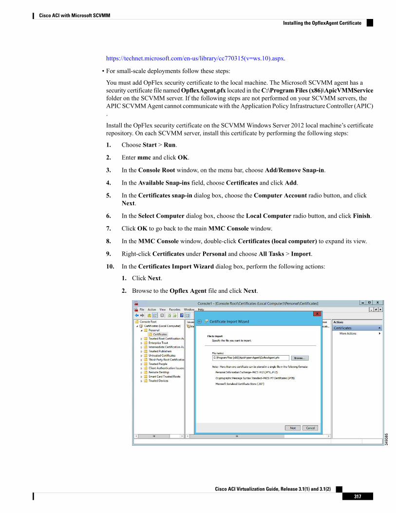
https://technet.microsoft.com/en-us/library/cc770315(v=ws.10).aspx.
• For small-scale deployments follow these steps:
You must add OpFlex security certificate to the local machine. The Microsoft SCVMM agent has asecurity certificate file namedOpflexAgent.pfx located in theC:\ProgramFiles (x86)\ApicVMMServicefolder on the SCVMM server. If the following steps are not performed on your SCVMM servers, theAPIC SCVMMAgent cannot communicate with the Application Policy Infrastructure Controller (APIC).
Install the OpFlex security certificate on the SCVMMWindows Server 2012 local machine’s certificaterepository. On each SCVMM server, install this certificate by performing the following steps:
1. Choose Start > Run.
2. Entermmc and click OK.
3. In the Console Root window, on the menu bar, choose Add/Remove Snap-in.
4. In the Available Snap-ins field, choose Certificates and click Add.
5. In the Certificates snap-in dialog box, choose the Computer Account radio button, and clickNext.
6. In the Select Computer dialog box, choose the Local Computer radio button, and click Finish.
7. Click OK to go back to the mainMMC Console window.
8. In theMMC Console window, double-click Certificates (local computer) to expand its view.
9. Right-click Certificates under Personal and choose All Tasks > Import.
10. In the Certificates Import Wizard dialog box, perform the following actions:
1. Click Next.
2. Browse to the Opflex Agent file and click Next.
Cisco ACI Virtualization Guide, Release 3.1(1) and 3.1(2)317
Cisco ACI with Microsoft SCVMMInstalling the OpflexAgent Certificate
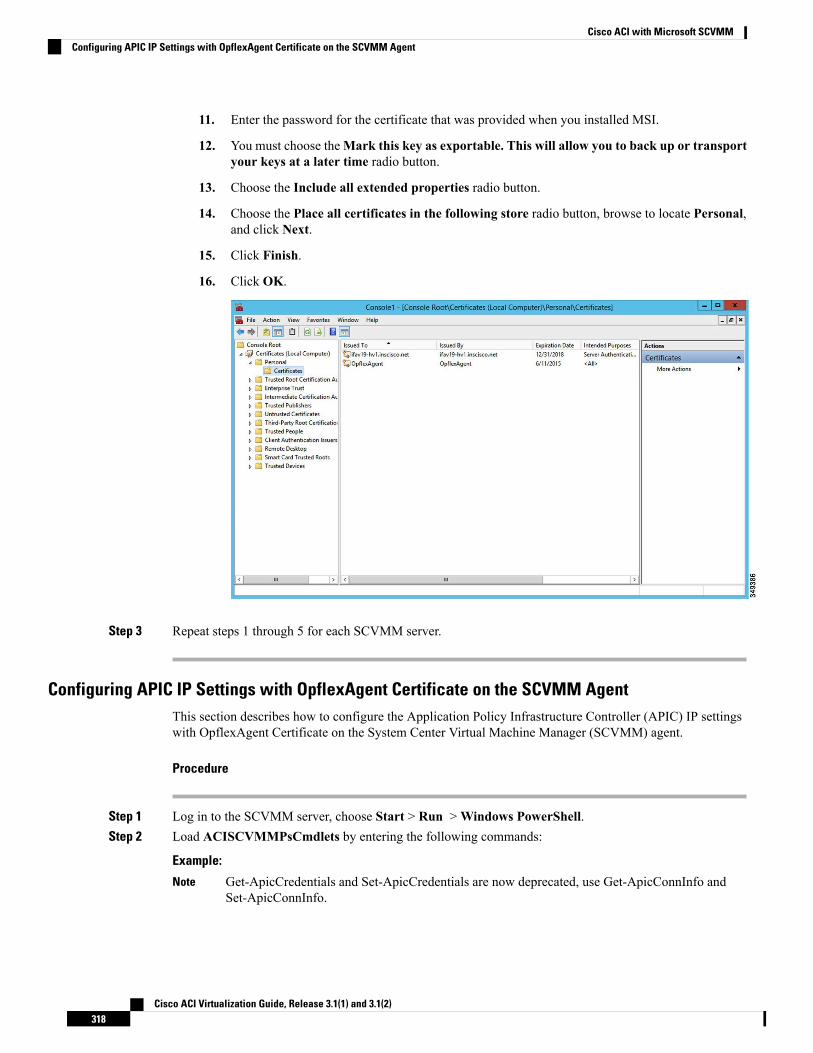
11. Enter the password for the certificate that was provided when you installed MSI.
12. You must choose theMark this key as exportable. This will allow you to back up or transportyour keys at a later time radio button.
13. Choose the Include all extended properties radio button.
14. Choose the Place all certificates in the following store radio button, browse to locate Personal,and click Next.
15. Click Finish.
16. Click OK.
Step 3 Repeat steps 1 through 5 for each SCVMM server.
Configuring APIC IP Settings with OpflexAgent Certificate on the SCVMM AgentThis section describes how to configure the Application Policy Infrastructure Controller (APIC) IP settingswith OpflexAgent Certificate on the System Center Virtual Machine Manager (SCVMM) agent.
Procedure
Step 1 Log in to the SCVMM server, choose Start > Run >Windows PowerShell.Step 2 Load ACISCVMMPsCmdlets by entering the following commands:
Example:
Get-ApicCredentials and Set-ApicCredentials are now deprecated, use Get-ApicConnInfo andSet-ApicConnInfo.
Note
Cisco ACI Virtualization Guide, Release 3.1(1) and 3.1(2)318
Cisco ACI with Microsoft SCVMMConfiguring APIC IP Settings with OpflexAgent Certificate on the SCVMM Agent
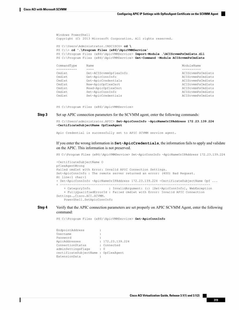
Windows PowerShellCopyright (C) 2013 Microsoft Corporation. All rights reserved.
PS C:\Users\Administrator.INSCISCO> cd \PS C:\> cd '.\Program Files (x86)\ApicVMMService'PS C:\Program Files (x86)\ApicVMMService> Import-Module .\ACIScvmmPsCmdlets.dllPS C:\Program Files (x86)\ApicVMMService> Get-Command -Module ACIScvmmPsCmdlets
CommandType Name ModuleName----------- ---- ----------Cmdlet Get-ACIScvmmOpflexInfo ACIScvmmPsCmdletsCmdlet Get-ApicConnInfo ACIScvmmPsCmdletsCmdlet Get-ApicCredentials ACIScvmmPsCmdletsCmdlet New-ApicOpflexCert ACIScvmmPsCmdletsCmdlet Read-ApicOpflexCert ACIScvmmPsCmdletsCmdlet Set-ApicConnInfo ACIScvmmPsCmdletsCmdlet Set-ApicCredentials ACIScvmmPsCmdlets
PS C:\Program Files (x86)\ApicVMMService>
Step 3 Set up APIC connection parameters for the SCVMM agent, enter the following commands:PS C:\Users\administrator.APIC> Set-ApicConnInfo -ApicNameOrIPAddress 172.23.139.224-CertificateSubjectName OpflexAgent
Apic Credential is successfully set to APIC SCVMM service agent.
If you enter the wrong information in Set-ApicCredentials, the information fails to apply and validateon the APIC. This information is not preserved.PS C:\Program Files (x86)\ApicVMMService> Set-ApicConnInfo -ApicNameOrIPAddress 172.23.139.224
-CertificateSubjectName OpflexAgentWrongFailed cmdlet with Error: Invalid APIC Connection Settings.Set-ApicConnInfo : The remote server returned an error: (400) Bad Request.At line:1 char:1+ Set-ApicConnInfo -ApicNameOrIPAddress 172.23.139.224 -CertificateSubjectName Opf ...+ ~~~~~~~~~~~~~~~~~~~~~~~~~~~~~~~~~~~~~~~~~~~~~~~~~~~~~~~~~~~~~~~~~~~~~~~~~~~~~~~~
+ CategoryInfo : InvalidArgument: (:) [Set-ApicConnInfo], WebException+ FullyQualifiedErrorId : Failed cmdlet with Error: Invalid APIC Connection
Settings.,Cisco.ACI.SCVMM.PowerShell.SetApicConnInfo
Step 4 Verify that the APIC connection parameters are set properly on APIC SCVMM Agent, enter the followingcommand:PS C:\Program Files (x86)\ApicVMMService> Get-ApicConnInfo
EndpointAddress :Username :Password :ApicAddresses : 172.23.139.224ConnectionStatus : ConnectedadminSettingsFlags : 0certificateSubjectName : OpflexAgentExtensionData :
Cisco ACI Virtualization Guide, Release 3.1(1) and 3.1(2)319
Cisco ACI with Microsoft SCVMMConfiguring APIC IP Settings with OpflexAgent Certificate on the SCVMM Agent
PS C:\Program Files (x86)\ApicVMMService>
Configuring APIC IP Settings with OpflexAgent Certificate on the SCVMM Agent on a HighlyAvailable SCVMM
This section describes how to configure the Application Policy Infrastructure Controller (APIC) IP settingswith OpflexAgent Certificate on the System Center Virtual Machine Manager (SCVMM) agent.
Procedure
Step 1 Log in to the Owner Node SCVMM server, choose Start > Run >Windows PowerShell.Step 2 Load ACISCVMMPsCmdlets by entering the following commands:
Example:
Get-ApicCredentials and Set-ApicCredentials are now deprecated, use Get-ApicConnInfo andSet-ApicConnInfo.
Note
Windows PowerShellCopyright (C) 2013 Microsoft Corporation. All rights reserved.
PS C:\Users\Administrator.INSCISCO> cd \PS C:\> cd '.\Program Files (x86)\ApicVMMService'PS C:\Program Files (x86)\ApicVMMService> Import-Module .\ACIScvmmPsCmdlets.dllPS C:\Program Files (x86)\ApicVMMService> Get-Command -Module ACIScvmmPsCmdlets
CommandType Name ModuleName----------- ---- ----------Cmdlet Get-ACIScvmmOpflexInfo ACIScvmmPsCmdletsCmdlet Get-ApicConnInfo ACIScvmmPsCmdletsCmdlet Get-ApicCredentials ACIScvmmPsCmdletsCmdlet New-ApicOpflexCert ACIScvmmPsCmdletsCmdlet Read-ApicOpflexCert ACIScvmmPsCmdletsCmdlet Set-ApicConnInfo ACIScvmmPsCmdletsCmdlet Set-ApicCredentials ACIScvmmPsCmdlets
PS C:\Program Files (x86)\ApicVMMService>
Step 3 Set up APIC connection parameters to the SCVMM agent, enter the following commands:PS C:\Users\administrator.APIC> Set-ApicConnInfo -ApicNameOrIPAddress 172.23.139.224-CertificateSubjectName OpflexAgent
Apic Credential is successfully set to APIC SCVMM service agent. 10:25 AM
If you enter the wrong information in Set-ApicCredentials, the information fails to apply and validateon the APIC. This information is not preserved.PS C:\Program Files (x86)\ApicVMMService> Set-ApicConnInfo -ApicNameOrIPAddress 172.23.139.224
-CertificateSubjectName OpflexAgentWrongFailed cmdlet with Error: Invalid APIC Connection Settings.Set-ApicConnInfo : The remote server returned an error: (400) Bad Request.
Cisco ACI Virtualization Guide, Release 3.1(1) and 3.1(2)320
Cisco ACI with Microsoft SCVMMConfiguring APIC IP Settings with OpflexAgent Certificate on the SCVMM Agent on a Highly Available SCVMM
At line:1 char:1+ Set-ApicConnInfo -ApicNameOrIPAddress 172.23.139.224 -CertificateSubjectName Opf ...+ ~~~~~~~~~~~~~~~~~~~~~~~~~~~~~~~~~~~~~~~~~~~~~~~~~~~~~~~~~~~~~~~~~~~~~~~~~~~~~~~~
+ CategoryInfo : InvalidArgument: (:) [Set-ApicConnInfo], WebException+ FullyQualifiedErrorId : Failed cmdlet with Error: Invalid APIC Connection
Settings.,Cisco.ACI.SCVMM.PowerShell.SetApicConnInfo
Step 4 Verify that the APIC connection parameters is set properly on APIC SCVMM Agent, enter the followingcommand:PS C:\Program Files (x86)\ApicVMMService> Get-ApicConnInfo
EndpointAddress :Username :Password :ApicAddresses : 172.23.139.224ConnectionStatus : ConnectedadminSettingsFlags : 0certificateSubjectName : OpflexAgentExtensionData
Installing the APIC Hyper-V Agent on the Hyper-V ServerThis section describes how to install the APIC Hyper-V agent on the Hyper-V server.
Before you begin
Scheduled downtime for the Hyper-V node. For more information regarding Hyper-V Maintenance Modebehavior, see: https://technet.microsoft.com/en-us/library/hh882398.aspx
Procedure
Step 1 Log on to the SCVMM server and bring the Hyper-V node into Maintenance Mode.Step 2 Log in to the Hyper-V server with administrator credentials.Step 3 On the Hyper-V server in File Explorer, locate the APIC Hyper-V Agent.msi file.Step 4 Right-click the APIC Hyper-V Agent.msi file and choose Install.Step 5 In the ApicHypervAgent Setup dialog box, perform the following actions:
a) Check the I accept the terms in the License Agreement check box.b) Click Install.c) Click Finish.
Step 6 Follow the steps in Microsoft's documentation to view and bring the apicVSwitch Logical Switch intocompliance. Also referred to in this guide as Host Remediate or Logical Switch Instance Remediation:https://technet.microsoft.com/en-us/library/dn249415.aspx
Step 7 Use one of the following methods:
• For large-scale deployments, see Microsoft's documentation for Deploy Certificates by Using GroupPolicy:
https://technet.microsoft.com/en-us/library/cc770315(v=ws.10).aspx
Cisco ACI Virtualization Guide, Release 3.1(1) and 3.1(2)321
Cisco ACI with Microsoft SCVMMInstalling the APIC Hyper-V Agent on the Hyper-V Server
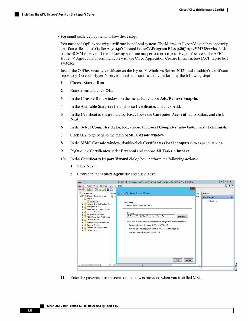
• For small-scale deployments follow these steps:
Youmust add OpFlex security certificate in the local system. TheMicrosoft Hyper-V agent has a securitycertificate file namedOpflexAgent.pfx located in theC:\ProgramFiles (x86)\ApicVMMService folderon the SCVMM server. If the following steps are not performed on your Hyper-V servers, the APICHyper-V Agent cannot communicate with the Cisco Application Centric Infrastructure (ACI) fabric leafswitches.
Install the OpFlex security certificate on the Hyper-V Windows Server 2012 local machine’s certificaterepository. On each Hyper-V server, install this certificate by performing the following steps:
1. Choose Start > Run.
2. Entermmc and click OK.
3. In the Console Root window, on the menu bar, choose Add/Remove Snap-in.
4. In the Available Snap-ins field, choose Certificates and click Add.
5. In the Certificates snap-in dialog box, choose the Computer Account radio button, and clickNext.
6. In the Select Computer dialog box, choose the Local Computer radio button, and click Finish.
7. Click OK to go back to the mainMMC Console window.
8. In theMMC Console window, double-click Certificates (local computer) to expand its view.
9. Right-click Certificates under Personal and choose All Tasks > Import.
10. In the Certificates Import Wizard dialog box, perform the following actions:
1. Click Next.
2. Browse to the Opflex Agent file and click Next.
11. Enter the password for the certificate that was provided when you installed MSI.
Cisco ACI Virtualization Guide, Release 3.1(1) and 3.1(2)322
Cisco ACI with Microsoft SCVMMInstalling the APIC Hyper-V Agent on the Hyper-V Server
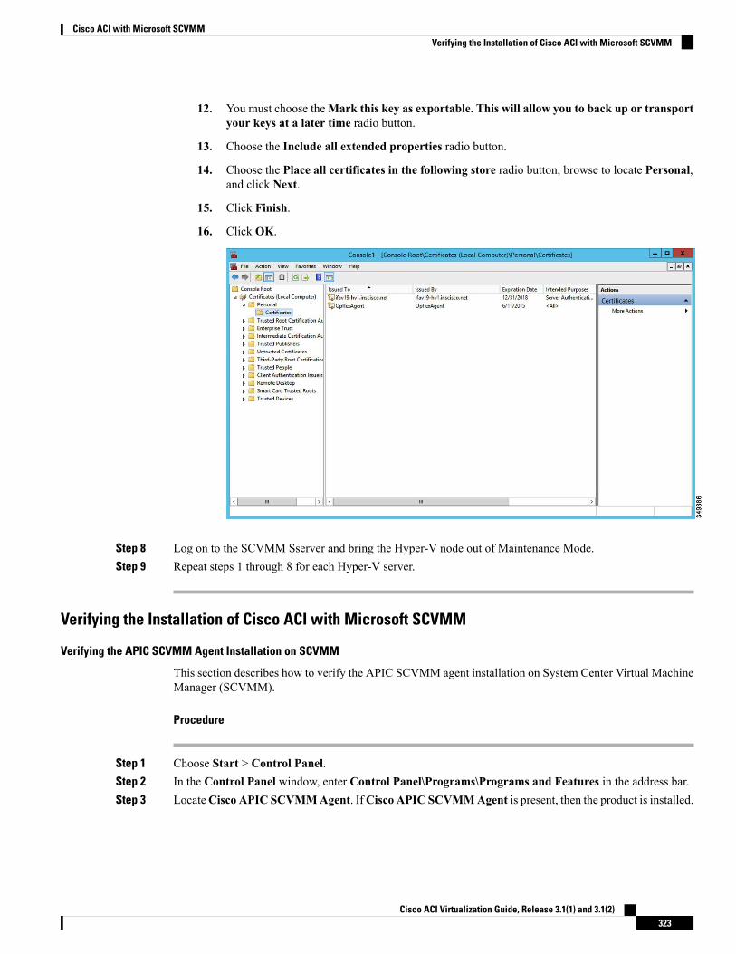
12. You must choose theMark this key as exportable. This will allow you to back up or transportyour keys at a later time radio button.
13. Choose the Include all extended properties radio button.
14. Choose the Place all certificates in the following store radio button, browse to locate Personal,and click Next.
15. Click Finish.
16. Click OK.
Step 8 Log on to the SCVMM Sserver and bring the Hyper-V node out of Maintenance Mode.Step 9 Repeat steps 1 through 8 for each Hyper-V server.
Verifying the Installation of Cisco ACI with Microsoft SCVMM
Verifying the APIC SCVMM Agent Installation on SCVMM
This section describes how to verify the APIC SCVMM agent installation on System Center Virtual MachineManager (SCVMM).
Procedure
Step 1 Choose Start > Control Panel.Step 2 In the Control Panel window, enter Control Panel\Programs\Programs and Features in the address bar.Step 3 LocateCisco APIC SCVMMAgent. IfCisco APIC SCVMMAgent is present, then the product is installed.
Cisco ACI Virtualization Guide, Release 3.1(1) and 3.1(2)323
Cisco ACI with Microsoft SCVMMVerifying the Installation of Cisco ACI with Microsoft SCVMM
If Cisco APIC SCVMM Agent is not present, then the product is not installed. See the Installing the APICSCVMM Agent on SCVMM, on page 313 or Installing the APIC Agent on SCVMM Using the WindowsCommand Prompt, on page 344 section.
Step 4 Verify the ApicVMMService is in RUNNING state through the GUI or CLI:
• GUI method: Choose Start > Run and enter services.msc. In the Service pane, locate theApicVMMService and verify the state is RUNNING.
• CLI method: From the command prompt, enter the sc.exe query ApicHypervAgent command and verifythe state is RUNNING:sc.exe query ApicVMMService
SERVICE_NAME: ApicVMMServiceTYPE : 10 WIN32_OWN_PROCESSSTATE : 4 RUNNING(STOPPABLE, NOT_PAUSABLE, ACCEPTS_SHUTDOWN)WIN32_EXIT_CODE : 0 (0x0)SERVICE_EXIT_CODE : 0 (0x0)CHECKPOINT : 0x0WAIT_HINT : 0x0
Verifying the APIC SCVMM Agent Installation on a Highly Available SCVMM
This section describes how to verify the APIC SCVMM agent installation on a Highly Available SystemCenter Virtual Machine Manager (SCVMM).
Procedure
Step 1 Choose Start > Control Panel.Step 2 In the Control Panel window, enter Control Panel\Programs\Programs and Features in the address bar.Step 3 LocateCisco APIC SCVMMAgent. IfCisco APIC SCVMMAgent is present, then the product is installed.
If Cisco APIC SCVMM Agent is not present, then the product is not installed. See the Installing the APICSCVMM Agent on SCVMM, on page 313 or Installing the APIC Agent on SCVMM Using the WindowsCommand Prompt, on page 344 section.
Step 4 Verify the ApicVMMService is in RUNNING state through the GUI or CLI:
• GUI method: Choose Start > Run and enter services.msc. In the Service pane, locate theApicVMMService and verify the state is RUNNING.
• CLI method: From the command prompt, enter the sc.exe query ApicHypervAgent command and verifythe state is RUNNING:sc.exe query ApicVMMService
SERVICE_NAME: ApicVMMServiceTYPE : 10 WIN32_OWN_PROCESSSTATE : 4 RUNNING(STOPPABLE, NOT_PAUSABLE, ACCEPTS_SHUTDOWN)WIN32_EXIT_CODE : 0 (0x0)SERVICE_EXIT_CODE : 0 (0x0)
Cisco ACI Virtualization Guide, Release 3.1(1) and 3.1(2)324
Cisco ACI with Microsoft SCVMMVerifying the APIC SCVMM Agent Installation on a Highly Available SCVMM
CHECKPOINT : 0x0WAIT_HINT : 0x0
Step 5 Choose Start > PowerShell and enter the following commands:PS C:\Users\administrator.APIC\Downloads> Get-ClusterResource -Name ApicVMMService
Name State OwnerGroup ResourceType---- ----- ---------- ------------ApicVMMService Online clustervmm07-ha Generic Service
PS C:\Users\administrator.APIC\Downloads> Get-ClusterCheckpoint -ResourceName ApicVMMService
Resource Name-------- ----ApicVMMService SOFTWARE\Wow6432Node\Cisco\Apic
PS C:\Users\administrator.APIC\Downloads> Get-ClusterResourceDependency -ResourceApicVMMService
Resource DependencyExpression-------- --------------------ApicVMMService ([VMM Service clustervmm07-ha])
Verifying the APIC Hyper-V Agent Installation on the Hyper-V Server
This section describes how to verify the APIC Hyper-V agent installation on the Hyper-V server.
Procedure
Step 1 Choose Start > Control Panel.Step 2 In the Control Panel window, enter Control Panel\Programs\Programs and Features in the address bar.Step 3 Locate Cisco APIC Hyperv Agent. If Cisco APIC Hyperv Agent is present, then the product is installed.
If Cisco APIC Hyperv Agent is not present, then the product is not installed. See the Installing the APICHyper-V Agent on the Hyper-V Server, on page 321 or Installing the APIC Hyper-V Agent on the Hyper-VServer Using the Windows Command Prompt , on page 345 section.
Step 4 Verify the ApicHypervAgent is in RUNNING state through the GUI or CLI:
• GUI method: Choose Start > Run and enter services.msc. In the Service pane, locate theApicHypervAgent and verify the state is RUNNING.
• CLI method: From the command prompt, enter the sc.exe query ApicHypervAgent command and verifythe state is RUNNING:sc.exe query ApicHypervAgent
SERVICE_NAME: ApicHypervAgentTYPE : 10 WIN32_OWN_PROCESSSTATE : 4 RUNNING(STOPPABLE, NOT_PAUSABLE, ACCEPTS_SHUTDOWN)WIN32_EXIT_CODE : 0 (0x0)SERVICE_EXIT_CODE : 0 (0x0)
Cisco ACI Virtualization Guide, Release 3.1(1) and 3.1(2)325
Cisco ACI with Microsoft SCVMMVerifying the APIC Hyper-V Agent Installation on the Hyper-V Server
CHECKPOINT : 0x0WAIT_HINT : 0x0
Setting Up ACI Policies
Creating SCVMM Domain Profiles
In this section, the examples of a VMM domain are System Center Virtual Machine Manager (SCVMM)domains. The example tasks are as follows:
• Configuring the VMM domain name and SCVMM controller.
• Creating an attach entity profile and associating it to the VMM domain.
• Configuring a pool.
• Verifying all configured controllers and their operational states.
Creating a SCVMM Domain Profile Using the GUI
Before you begin
Before you create a VMM domain profile, you must establish connectivity to an external network usingin-band or out-of-band management network on the Application Policy Infrastructure Controller (APIC).
Procedure
Step 1 Log in to the APIC GUI, and then choose Virtual Networking > Inventory.Step 2 In the Navigation pane, expand VMMDomains, right-click the VM ProviderMicrosoft and choose Create
SCVMM Domain.Step 3 In the Create SCVMM domain dialog box, in the Name field, enter the domain's name (productionDC).Step 4 Optional: In theDelimiter field, enter one of the following: |, ~, !,@, ^, +, or =. If you do not enter a symbol,
the system default | delimiter will appear in the policy.Step 5 In theAssociated Attachable Entity Profile field, from the drop-down list, chooseCreate Attachable Entity
Profile, and perform the following actions to configure the list of switch interfaces across the span of theVMM domain:a) In the Create Attachable Access Entity Profile dialog box, in the Profile area, in the Name field,
enter the name (profile1), and click Next.b) In the Association to Interfaces area, expand Interface Policy Group.c) In the Configured Interface, PC, and VPC dialog box, in the Configured Interfaces, PC, and VPC
area, expand Switch Profile.d) In the Switches field, from the drop-down list, check the check boxes next to the desired switch IDs
(101 and 102).e) In the Switch Profile Name field, enter the name (swprofile1).f) Expand the + icon to configure interfaces.g) Choose the appropriate interface ports individually in the switch image (interfaces 1/1, 1/2, and 1/3).
The Interfaces field gets populated with the corresponding interfaces.
Cisco ACI Virtualization Guide, Release 3.1(1) and 3.1(2)326
Cisco ACI with Microsoft SCVMMSetting Up ACI Policies
h) In the Interface Selector Name field, enter the name (selector1).i) In the Interface Policy Group field, from the drop-down list, choose Create Interface Policy Group.j) In the Create Access Port Policy Group dialog box, in the Name field, enter the name (group1).k) Click Submit.l) Click Save, and click Save again.m) Click Submit.n) In the Select the interfaces area, under Select Interfaces, click the All radio button.o) Verify that in the vSwitch Policies field, the Inherit radio button is selected.p) Click Finish.The Attach Entity Profile is selected and is displayed in the Associated Attachable Entity Profile field.
Step 6 In the VLAN Pool field, from the drop-down list, choose Create VLAN Pool. In the Create VLAN Pooldialog box, perform the following actions:a) In the Name field, enter the VLAN pool name (VlanRange).b) In the Allocation Mode field, verify that the Dynamic Allocation radio button is selected.c) Expand Encap Blocks to add a VLAN block. In the Create Ranges dialog box, enter a VLAN range.
We recommend a range of at least 200 VLAN numbers. Do not define a range that includes thereserved VLAN ID for infrastructure network because that VLAN is for internal use.
Note
d) Click OK, and click Submit.In the VLAN Pool field, "VlanRange-dynamic" is displayed.
Step 7 Expand SCVMM. In theCreate SCVMMController dialog box, verify that the Type is SCVMM, and thenperform the following actions:a) In the Name field, enter the name (SCVMM1).b) To connect to a SCVMMHACluster, specify the SCVMMHACluster IP address or the SCVMMCluster
Resource DNS name, which was specified during the SCVMM HA installation. See How to Connect toa Highly Available VMMManagement Server by Using the VMMConsole: https://technet.microsoft.com/en-us/library/gg610673.aspx
c) In the Host Name (or IP Address) field, enter the Fully Qualified Domain Name (FQDN) or IP addressof your SCVMM.
d) In the SCVMM Cloud Name field, enter the SCVMM cloud name (ACI-Cloud).e) Click OK.f) In the Create SCVMM Domain dialog box, click Submit.
Step 8 Verify the new domain and profiles, by performing the following actions:a) On the menu bar, choose Virtual Networking > Inventory.b) In the navigation pane, choose VMM Domains >Microsoft > productionDC > SCVMM1.c) In theWork pane, view the VMM domain name to verify that the controller is online.d) In theWork pane, the SCVMM1 properties are displayed including the operational status. The displayed
information confirms that connection from the APIC controller to the SCVMM server is established, andthe inventory is available.
Configuring the Port Channel Policy
This section describes how to configure the port channel policy.
Modifying the Interface Port Channel Policy
Cisco ACI Virtualization Guide, Release 3.1(1) and 3.1(2)327
Cisco ACI with Microsoft SCVMMConfiguring the Port Channel Policy
The ACI SCVMM Agent sync's the SCVMM uplink port profile with the aggregated interface port channelpolicies and performs an automated update when there are changes to the policy.
To update the policy for hyper-v servers perform the following steps.
Procedure
Step 1 Log in to the APIC GUI, on the menu bar, choose Fabric > Access Policies.Step 2 In the Navigation pane, expand Interface Policies > Policy Groups.Step 3 Choose the policy group and check the name of the policy group.Step 4 Navigate to the policy group and update it based on your requirements (e.g. LACP or MAC pinning).
Overriding the VMM Domain VSwitch Policies for Blade Servers
When Blade servers are connected to ACI fabric interface port channel policy will be used between interfaceand fabric interconnect. When fabric interconnect is configured for LACP you will need to configure theHyper-V server for MAC pinning mode.
To configure the Hyper-V server for MAC pinning mode perform the following steps.
Procedure
Step 1 Log in to the APIC GUI, on the menu bar, choose Virtual Networking.Step 2 In the navigation pane, expand VMM Domains >Microsoft > Domain_Name.Step 3 In theWork pane, click ACTIONS and choose Create VSwitch Policies.Step 4 On the port channel policy, select the existing policy for mac pinning or create a new policy.
If the hosts are already connected to logical switch, then the SCVMM admin should perform hostremediate for all the hosts for uplink policy to take effect.
Note
Verifying the SCVMM VMM Domain and SCVMM VMM
Procedure
In the System Center Virtual Machine Manager Console GUI, the following object has been created by theSCVMMagent for the newly created SCVMMVMMdomain andVMMController’s rootContName (SCVMMCloud Name):a) Click Fabric at the bottom left side pane and under fabric verify the following objects:
Example:
1. Choose Networking > Logical Switches and in the right side pane, the logical switch name isapicVSwitch_VMMdomainName.
2. Choose Networking > Logical Networks and in the right side pane, the logical network name isapicLogicalNetwork_VMMdomainName.
Cisco ACI Virtualization Guide, Release 3.1(1) and 3.1(2)328
Cisco ACI with Microsoft SCVMMOverriding the VMM Domain VSwitch Policies for Blade Servers
3. Choose Networking > Port Profiles and in the right side pane, the port profile name isapicUplinkPortProfile_VMMdomainName.
b) Click VMs and Services in the bottom left side pane.
Example:
1. Choose VM Networks.
2. In the right side pane, the VM network name is apicInfra|10.0.0.30|SCVMM ControllerHostNameORIPAddress filed value|VMMdomainName.
You must use infra VM Network to create VTEP on the Hyper-V server.
Deploying the Logical Switch to the Host on SCVMM
This section describes how to deploy the logical switch to the host on System Center Virtual MachineManager(SCVMM).
If SCVMM upgrade is performed and hosts are already connected to logical switch then SCVMM adminshould perform host remediation for all the hosts for hosts to establish connection to leaf.
Note
Procedure
Step 1 Log in to the SCVMM server, in the Navigation pane, choose Fabric on the bottom left.Step 2 In the Navigation pane, expand Networking > Logical Switches to ensure the logical switch is created
(apicVswitch_cloud1).Step 3 In the Navigation pane, choose VMs and Services on the bottom left.Step 4 In the Navigation pane, expand All Hosts.Step 5 Choose the Hyper-V host folder (Dev8).Step 6 Right-click the Hyper-V host (Dev8-HV1) and choose Properties.Step 7 In the Dev8-HV1.inscisco.net Properties dialog box, choose Virtual Switches and perform the following
actions:a) Choose + New Virtual Switch.b) Choose New Logical Switch.c) In the Logical switch field, from the drop-down list, choose a logical switch (apicVswitch_cloud1).d) In the Adapter field, from the drop-down list, choose an adapter (Leaf1-1-1 - Intel(R) Ethernet Server
Adapter X520-2 #2).e) In the Uplink Port Profile field, from the drop-down list, choose an Uplink Port Profile
(apicUplinkPortProfile_Cloud01).f) Click New Virtual Network Adapter, choose the unnamed virtual network adapter, and enter the name
(dev8-hv1-infra-vtep).g) Click Browse.h) In the Dev8-HV1.inscisco.net Properties dialog box, choose the VM network
(apicInfra|10.0.0.30|dev8-scvmm.apic.net|Cloud01) and click OK.
Cisco ACI Virtualization Guide, Release 3.1(1) and 3.1(2)329
Cisco ACI with Microsoft SCVMMDeploying the Logical Switch to the Host on SCVMM
i) In the Virtual Machine Manager dialog box, click OK.
Step 8 Click Jobs on the bottom left.Step 9 In theHistory pane, you can check the status of theChange properties of virtual machine host job to ensure
that the job has completed.Step 10 You must refresh the host under SCVMM for the Hyper-V server to reflect proper Hyper-V Host IP address
in SCVMM. Once it has been refreshed, the APIC GUI reflects the updated Hyper-V Host IP information.
Enabling the Logical Network on Tenant Clouds
This section describes how to enable the Cisco ACI Integration with SCVMM Tenant Clouds. For moreinformation, see the SCVMM Fabric Cloud and Tenant Clouds, on page 309.
Procedure
Step 1 Log in to the SCVMM server with SCVMM administrator credentials, and open up the SCVMM AdminConsole.
Step 2 On the SCVMM Admin Console, navigate to VMs and Services.Step 3 In the Navigation pane, expand Clouds, right-click on your target Tenant Cloud (HR_Cloud) and choose
Properties.Step 4 In the Pop-Up Window, in the Navigation pane, choose Logical Networks
a) Locate the logical network which was automatically created as part of associating the VMM Domain tothis SCVMM.
b) Click the logical network check box (apicLogicalNetwork_MyVmmDomain).c) Click OK.The tenant cloud is now ready to be used within ACI Integration at theWindows Azure Pack Plan configurationpage.
Upgrading the Cisco ACI with Microsoft SCVMM ComponentsIf you are trying to upgrade to SCVMM 2016, you must follow the Microsoft procedure and then install theCisco ACI with Microsoft SCVMM components as a fresh install.
Prerequisites:
If upgrading to SCVMM 2012 R2, Microsoft servers that you integrate into ACI must be updated with theKB2919355 and KB3000850 update rollups prior to upgrading ACI to the 2.2(1) release. The KB2919355update rollup includes the 2929781 patch, which adds new TLS cipher suites and changes the cipher suitepriorities in Windows 8.1 and Windows Server 2012 R2.
You must patch the following Microsoft servers:
• Microsoft Windows Azure Pack Resource Provider Servers
• Microsoft Windows Azure Pack Tenant Site Servers
• Microsoft Windows Azure Pack Admin Site Servers
Cisco ACI Virtualization Guide, Release 3.1(1) and 3.1(2)330
Cisco ACI with Microsoft SCVMMEnabling the Logical Network on Tenant Clouds
• Microsoft System Center Service Provider Foundation/Orchestration Servers
• Microsoft System Center 2012 R2 Servers
• Microsoft HyperV 2012 R2 Servers
Upgrading the ACI Microsoft SCVMM Components WorkflowThis sections describes upgrading the ACI Microsoft SCVMM components workflow.
Procedure
Step 1 Upgrade the APIC Controller and the Switch Software.
For more information, see the Cisco APIC Firmware Management Guide.
Step 2 Upgrade the APIC SCVMMAgent on SCVMM or Upgrade the APIC SCVMMAgent on a Highly AvailableSCVMM.
For more information, see Upgrading the APIC SCVMM Agent on SCVMM, on page 331.
For more information, see Upgrading the APIC SCVMMAgent on a High Available SCVMM, on page 332.
Step 3 Upgrade the APIC Hyper-V Agent.
For more information, see Upgrading the APIC Hyper-V Agent, on page 332.
Upgrading the APIC SCVMM Agent on SCVMMThis section describes how to upgrade the APIC SCVMM agent on System Center Virtual Machine Manager(SCVMM).
Before you begin
Scheduled downtime for the Microsoft SCVMM Server. The upgrade process will automatically restart theMicrosoft SystemCenter VirtualMachineManager Service, resulting in the SCVMMService to be temporarilyunable to handle any change or query requests.
Procedure
Upgrade the APIC SCVMM agent on SCVMM.
If upgrading from release 1.1(2x) or later:
a) Follow the steps outlined in the Installing the APIC SCVMM Agent on SCVMM, on page 313.
The MSI packages handles uninstalling the previous version and installing the new version as part of theupgrade.
If upgrading from a prior release of 1.1(2x):
Cisco ACI Virtualization Guide, Release 3.1(1) and 3.1(2)331
Cisco ACI with Microsoft SCVMMUpgrading the ACI Microsoft SCVMM Components Workflow
a) Follow the steps outlined in the Installing the APIC SCVMM Agent on SCVMM, on page 313.
The MSI packages handles uninstalling the previous version and installing the new version as part of theupgrade.
b) Follow the steps outline in the Exporting APIC OpFlex Certificate, on page 351.c) Follow the steps outline in the Installing the OpflexAgent Certificate, on page 316.d) Follow the steps outline in the Configuring APIC IP Settings with OpflexAgent Certificate on the SCVMM
Agent, on page 318 or Configuring APIC IP Settings with OpflexAgent Certificate on the SCVMMAgenton a Highly Available SCVMM, on page 320.
Upgrading the APIC SCVMM Agent on a High Available SCVMMThis section describes how to upgrade the APIC SCVMM agent on a high available System Center VirtualMachine Manager (SCVMM).
Procedure
Step 1 Log in to a Standby node of the Highly Available SCVMM installation.Step 2 On the SCVMM server in File Explorer, locate the APIC SCVMM Agent.msi file.Step 3 Right-click APIC SCVMM Agent.msi file and select Install.
The MSI packages handles uninstalling the previous version and installing the new version as part of theupgrade.
Step 4 In the Cisco APIC SCVMM Agent Setup dialog box, perform the following actions:a) Click Next.b) Check the I accept the terms in the License Agreement check box and click Next.c) Enter your account name and password credentials.
Provide the same credentials as used for the SCVMM console. The Cisco APIC SCVMM agent requiresthese credentials for the SCVMM operations to be able to function.
The installation process verifies the entered account name and password credentials. If the installationfails, the SCVMM shows an error message and you must re-enter valid credentials.
d) After successful validation of the account name and password credentials, click Install.e) Click Finish.
Step 5 Repeat steps 1-4 for each Standby Node in the Windows Failover Cluster.Step 6 Failover from the Current Owner Node of the Highly Available SCVMM installation to one of the newly
upgrade Standby Nodes.Step 7 Follow steps 2-4 on the final Standby Node of the Windows Failover Cluster.
Upgrading the APIC Hyper-V AgentThis section describes how to upgrade the APIC Hyper-V agent.
Cisco ACI Virtualization Guide, Release 3.1(1) and 3.1(2)332
Cisco ACI with Microsoft SCVMMUpgrading the APIC SCVMM Agent on a High Available SCVMM
Before you begin
Scheduled downtime for the Hyper-V node. For more information regarding Hyper-V Maintenance Modebehavior, see: https://technet.microsoft.com/en-us/library/hh882398.aspx
Procedure
Upgrade the APIC Hyper-V agent.
If upgrading from release 1.1(2x) or later:
a) Follow steps 1-8 in the Installing the APICHyper-V Agent on the Hyper-V Server, on page 321. Skip step7. Step 7 is not required for upgrades as the OpflexAgent certificate is already installed on the Hyper-Vnode.
The MSI packages handles uninstalling the previous version and installing the new version as part of theupgrade.
If upgrading from a prior release of 1.1(2x):
a) Follow the steps outlined in the Uninstalling the APIC Hyper-V Agent, on page 402.b) Follow steps 1-8 in the Installing the APICHyper-V Agent on the Hyper-V Server, on page 321. Skip step
7. Step 7 is not required for upgrades as the OpflexAgent certificate is already installed on the Hyper-Vnode.
The MSI packages handles uninstalling the previous version and installing the new version as part of theupgrade.
Deploying Tenant Policies
Deployment Tenant Policies PrerequisitesEnsure that your computing environment meets the following prerequisites:
• Ensure you have installed the APIC SCVMM Agent.
For details, see Installing the APIC SCVMM Agent on SCVMM, on page 313.
• Ensure you have installed the APIC Hyper-V Agent.
For details, see Installing the APIC Hyper-V Agent on the Hyper-V Server, on page 321.
• Ensure you have created a logical switch.
See Microsoft's documentation.
• Ensure you have created a virtual switch.
See Microsoft's documentation.
Cisco ACI Virtualization Guide, Release 3.1(1) and 3.1(2)333
Cisco ACI with Microsoft SCVMMDeploying Tenant Policies
Creating a Tenant
Procedure
Step 1 On the menu bar, choose TENANTS, and perform the following actions:a) Click Add Tenant.
The Create Tenant dialog box opens.b) In the Name field, add the tenant name (ExampleCorp).
Step 2 Click Finish.
See the Cisco APIC Basic Configuration Guide for more information.
Creating an EPGThis section describes how to create an endpoint group (EPG).
Procedure
Step 1 Log in to the APIC GUI, on the menu bar, choose TENANTS > Tenant Name.Step 2 In theNavigation pane, expandTenant Name >Application Profiles >Application Profile Name, right-click
Application EPGs, and choose Create Application EPG.Step 3 In the Create Application EPG dialog box, perform the following actions:
a) In the Name field, enter the name (EPG1).b) In the Bridge Domain field, from the drop-down list, choose one to associate with the bridge domain.c) In the Associate to VM Domain Profiles field, click the appropriate radio button and click Next.d) In the Associated VM Domain Profiles field, click the + icon, and choose a cloud to add (Cloud10).You have now created an EPG.
Associating the Microsoft VMM Domain with an EPGThis section describes how to create a VM Network by associating the Microsoft VMM domain with anendpoint group (EPG).
Before you begin
Ensure you have created an EPG.
Procedure
Step 1 Log in to the APIC GUI, on the menu bar, choose TENANTS > Tenant Name.
Cisco ACI Virtualization Guide, Release 3.1(1) and 3.1(2)334
Cisco ACI with Microsoft SCVMMCreating a Tenant
Step 2 In the Navigation pane, expand Tenant Name > Application Profiles > Application Profile Name >Application EPGs and select an existing EPG.
Step 3 In the Navigation pane, choose Domains (VMs and Bare-Metals).Step 4 In the Domains (VM and Bare-Metals) pane, click on the ACTIONS and choose Add VMM Domain
Association.Step 5 In theAdd VMMDomain Association dialog box, click theDeploy Immediacy field radio button for either
Immediate or On Demand.
See EPG Policy Resolution and Deployment Immediacy, on page 11 for more information.
Step 6 In the Add VMM Domain Association dialog box, click the Resolution Immediacy field radio button foreither Immediate, On Demand, or Pre-Provision.
See EPG Policy Resolution and Deployment Immediacy, on page 11 for more information.
You have now created a VM Network.Step 7 Optional: In the Delimiter field, use a single character as the VM Network Name delimiter, enter one of the
following: |, ~, !,@, ^, +, or = . If you do not enter a symbol, the system default of | will be used.
Verifying the EPG is Associated with the VMM Domain on APICThis section describes how to verify the endpoint group association with the VMM domain on ApplicationPolicy Infrastructure Controller (APIC).
Procedure
Step 1 Log in to the APIC GUI, on the menu bar, choose Virtual Networking > Inventory.Step 2 In the navigation pane, expand VMM Domains >Microsoft > Cloud10 > Controller > Controller1 >
Distributed Virtual Switch > SCVMM|Tenant|SCVMM|EPG1|Cloud1.
The name of the new VM Network is in the following format: Tenant Name|Application ProfileName|Application EPG Name|Microsoft VMM Domain.
Step 3 In the PROPERTIES pane, verify the EPG associated with the VMM domain, the VM Network, and thedetails such as NIC NAME, VM NAME, IP, MAC, and STATE.
Verifying the EPG is Associated with the VMM Domain on SCVMMThis section describes how to verify the endpoint group (EPG) associated with the VMM domain on SystemCenter Virtual Machine Manager (SCVMM).
Procedure
Step 1 Open the Virual Machine Manager Console icon on your desktop.Step 2 In the bottom left pane, click on VMs and Services or press Ctrl+M.
Cisco ACI Virtualization Guide, Release 3.1(1) and 3.1(2)335
Cisco ACI with Microsoft SCVMMVerifying the EPG is Associated with the VMM Domain on APIC
Step 3 In theVMs and Services pane, click onVMNetworks and verify the EPG associated with the VMMdomain.
The EPG associated with the VMM domain is in the following format: Tenant Name|Application ProfileName|Application EPG Name|Microsoft VMM Domain.
Creating a Static IP Address PoolStatic IP Address Pools enable anMicrosoft SCVMMServer to statically assign IP Address to virtual machinesduring the VM Template Deployment phase. This feature removes the need to request a DHCP address froma DHCP Server. This feature is most often used to deploy server VMs which require statically assigned IPAddresses in the network such as: Windows Active Directory Domain Controllers, DNS Servers, DHCPServers, Network Gateways, etc.
For more information regarding Static IP address pools, see the Microsoft Documentation:https://technet.microsoft.com/en-us/library/jj721568.aspx#BKMK_StaticIPAddressPools
With Cisco ACI SCVMM Integration - the Cisco APIC can automate the deployment of a Static IP AddressPool to a VM Network, bypassing the need to perform these operations on the Microsoft SCVMM Serveritself.
Before you begin
Ensure an EPG is associated to a Microsoft SCVMM VMM Domain.
Procedure
Step 1 Log in to the APIC GUI, on the menu bar, choose TENANTS > Tenant Name.Step 2 In the Navigation pane, expand Tenant Name > Application Profiles > Application Profile Name >
Application EPGs > Your Target EPG, right-click Subnets, and choose Create EPG Subnet.Step 3 In the Create EPG Subnet dialog box, perform the following actions:
a) Enter a default Gateway IP in address/mask format.b) Click Submit.
Step 4 Right-click on the newly created subnet and choose Create Static IP Pool Policy.Step 5 In the Create Static IP Pool Policy dialog box, perform the following actions:
a) Enter a Name (IP).b) Enter a Start IP and End IP.c) Enter optional Static IP Pool policies.
The DNS Servers, DNS Search Suffix, Wins Servers fields Allow a list of entries, simply use semicolonto separate the entries. For example within the DNS Servers Field:
192.168.1.1;192.168.1.2
Cisco ACI Virtualization Guide, Release 3.1(1) and 3.1(2)336
Cisco ACI with Microsoft SCVMMCreating a Static IP Address Pool
When configuring the Start IP and End IP, ensure they are within the same Subnet as the Gatewaydefined in Step 3. If not deployment of the Static IP Address Pool to SCVMM fails.
Only 1 Static IP Address Pool will be used for a given EPG. Do not create multiple Static IPPool Policies under a Subnet as the others will not take effect.
The Static IP Address Pool Policy follows the VMMDomain association. If this EPG is deployedto multiple SCVMMControllers in the same VMMDomain, then the same Static IP Addresseswill be deployed, causing duplicate IP Addresses. For this scenario, deploy an addition EPGwith a non-overlapping Address pool and create the necessary policies and contracts for theendpoints to communicate.
Note
Creating a Static IP Address Pool Using the NX-OS Style CLI
Procedure
Step 1 In the CLI, enter configuration mode:
Example:apic1# config
Step 2 Create the Static IP Address Pool:
Example:apic1(config)# tenant t0apic1(config-tenant)# application a0apic1(config-tenant-app)# epg e0apic1(config-tenant-app-epg)# micmicrosoft microsoft-domainapic1(config-tenant-app-epg)# microsoft static-ip-pool test_pool gateway 1.2.3.4/5apic1(config-tenant-app-epg-ms-ip-pool)# iprange 1.2.3.4 2.3.4.5apic1(config-tenant-app-epg-ms-ip-pool)# dnsdnssearchsuffix dnsservers dnssuffixapic1(config-tenant-app-epg-ms-ip-pool)# dnssuffix testsuffixapic1(config-tenant-app-epg-ms-ip-pool)# exitapic1(config-tenant-app-epg)# no mimicrosoft microsoft-domainapic1(config-tenant-app-epg)# no microsoft static-ip-pool ?test_poolapic1(config-tenant-app-epg)# no microsoft static-ip-pool test_pool gateway ?gwAddress gwAddressapic1(config-tenant-app-epg)# no microsoft static-ip-pool test_pool gateway 1.2.3.4/5apic1(config-tenant-app-epg)#
Step 3 Verify the Static IP Address Pool:
Example:apic1(config-tenant-app-epg-ms-ip-pool)# show running-config# Command: show running-config tenant t0 application a0 epg e0 microsoft static-ip-pooltest_pool gateway 1.2.3.4/5# Time: Thu Feb 11 23:08:04 2016
Cisco ACI Virtualization Guide, Release 3.1(1) and 3.1(2)337
Cisco ACI with Microsoft SCVMMCreating a Static IP Address Pool Using the NX-OS Style CLI
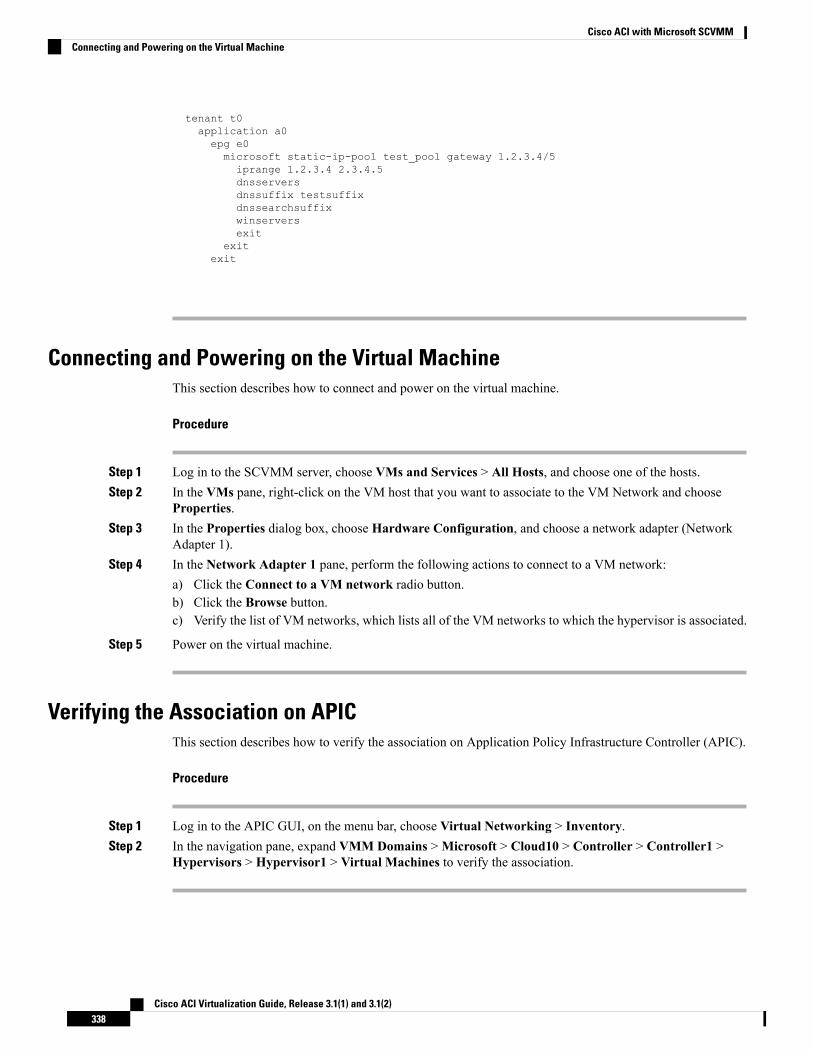
tenant t0application a0epg e0microsoft static-ip-pool test_pool gateway 1.2.3.4/5iprange 1.2.3.4 2.3.4.5dnsserversdnssuffix testsuffixdnssearchsuffixwinserversexit
exitexit
Connecting and Powering on the Virtual MachineThis section describes how to connect and power on the virtual machine.
Procedure
Step 1 Log in to the SCVMM server, choose VMs and Services > All Hosts, and choose one of the hosts.Step 2 In the VMs pane, right-click on the VM host that you want to associate to the VM Network and choose
Properties.Step 3 In the Properties dialog box, choose Hardware Configuration, and choose a network adapter (Network
Adapter 1).Step 4 In the Network Adapter 1 pane, perform the following actions to connect to a VM network:
a) Click the Connect to a VM network radio button.b) Click the Browse button.c) Verify the list of VM networks, which lists all of the VM networks to which the hypervisor is associated.
Step 5 Power on the virtual machine.
Verifying the Association on APICThis section describes how to verify the association on Application Policy Infrastructure Controller (APIC).
Procedure
Step 1 Log in to the APIC GUI, on the menu bar, choose Virtual Networking > Inventory.Step 2 In the navigation pane, expand VMM Domains >Microsoft > Cloud10 > Controller > Controller1 >
Hypervisors > Hypervisor1 > Virtual Machines to verify the association.
Cisco ACI Virtualization Guide, Release 3.1(1) and 3.1(2)338
Cisco ACI with Microsoft SCVMMConnecting and Powering on the Virtual Machine
Viewing EPGs on APICThis section describes how to view endpoint groups (EPGs) on the Application Policy Infrastructure Controller(APIC).
Procedure
Step 1 Log in to the APIC GUI, on the menu bar, choose TENANTS > Tenant Name.Step 2 In the Navigation pane, expand Tenant Name > Application Profiles > VMM > Application EPGs >
EPG1.Step 3 In the Application EPG - EPG1 pane, click the OPERATIONAL button, and verify if the endpoint group
is present.
Troubleshooting the Cisco ACI with Microsoft SCVMM
Troubleshooting APIC to SCVMM ConnectivityUse the ApicVMMService logs to debug the System Center Virtual Machine Manager (SCVMM) server.
Procedure
Step 1 Log in to the SCVMM server, go to the ApicVMMService logs. Located at C:\Program Files(X86)\ApicVMMService\Logs.
Step 2 Check the ApicVMMService logs to debug.
If you are unable to debug, on the SCVMM server copy all the ApicVMMService logs from C:\ProgramFiles (X86)\ApicVMMService\Logs and send them to Cisco Tech Support.
Troubleshooting Leaf to Hyper-V Host ConnectivityUse the ApicHypervAgent logs to debug the Hyper-V servers.
Procedure
Step 1 Log in to the Hyper-V servers, go to the ApicHypervAgent logs. Located at C:\Program Files(x86)\ApicHypervAgent\Logs.
Step 2 Check the ApicHypervAgent logs to debug.
Cisco ACI Virtualization Guide, Release 3.1(1) and 3.1(2)339
Cisco ACI with Microsoft SCVMMViewing EPGs on APIC
If you are unable to debug, on the Hyper-V servers copy all the ApicHypervAgent logs from C:\ProgramFiles (x86)\ApicHypervAgent\Logs and send them to Cisco Tech Support.
Responding to Traffic Failure after Leaf Switch ReplacementSwitch leaf replacement is not supported for leaves integrated with SCVMM hosts. After a leaf switch withan SCVMM integrated host is replaced, the VMs within the switch may be unable to send traffic through theCisco ACI fabric.
Even if the SCVMM integrated hosts have a VPC to another switch that was not replaced, the VLAN mayget pulled from that switch due to the VPC peer switch not having the matching VLANs during the replacementperiod.
This is because a new tunnel endpoint (TEP) IP address is pulled for the same leaf ID due to it having a newserial number. The SCVMM host is unable to automatically update with this new value.
Take the following step if traffic fails after a leaf switch is replaced.
Procedure
Restart the ApicHypervAgent on all hosts.
This should allow the agent to re-sync to the new and correct TEP IPs after switch replacement.
Troubleshooting the EPG Configuration IssueIf during the lifetime of the endpoint group (EPG), the VLAN ID of the EPG changes on the APIC, thenSCVMM needs to update the VLAN configuration on all virtual machines for the new setting to take effect.
Procedure
To perform this operation run the following PowerShell commands on the SCVMM server:
Example:$VMs = Get-SCVirtualMachine$VMs | Read-SCVirtualMachine$NonCompliantAdapters=Get-SCVirtualNetworkAdapter -All | Where-Object{$_.VirtualNetworkAdapterComplianceStatus -eq "NonCompliant"}$NonCompliantAdapters | Repair-SCVirtualNetworkAdapter
Cisco ACI Virtualization Guide, Release 3.1(1) and 3.1(2)340
Cisco ACI with Microsoft SCVMMResponding to Traffic Failure after Leaf Switch Replacement
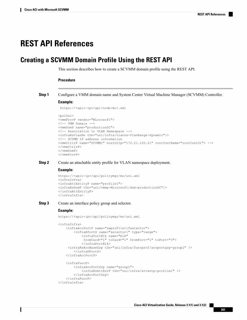
REST API References
Creating a SCVMM Domain Profile Using the REST APIThis section describes how to create a SCVMM domain profile using the REST API.
Procedure
Step 1 Configure a VMM domain name and System Center Virtual Machine Manager (SCVMM) Controller.
Example:https://<apic-ip>/api/node/mo/.xml
<polUni><vmmProvP vendor="Microsoft"><!-- VMM Domain --><vmmDomP name="productionDC"><!-- Association to VLAN Namespace --><infraRsVlanNs tDn="uni/infra/vlanns-VlanRange-dynamic"/><!-- SCVMM IP address information<vmmCtrlrP name="SCVMM1" hostOrIp="172.21.120.21" rootContName="rootCont01"> --></vmmCtrlrP></vmmDomP></vmmProvP>
Step 2 Create an attachable entity profile for VLAN namespace deployment.
Example:https://<apic-ip>/api/policymgr/mo/uni.xml<infraInfra><infraAttEntityP name="profile1"><infraRsDomP tDn="uni/vmmp-Microsoft/dom-productionDC"/></infraAttEntityP></infraInfra>
Step 3 Create an interface policy group and selector.
Example:https://<apic-ip>/api/policymgr/mo/uni.xml
<infraInfra><infraAccPortP name="swprofile1ifselector">
<infraHPortS name="selector1" type="range"><infraPortBlk name="blk"fromCard="1" toCard="1" fromPort="1" toPort="3"></infraPortBlk>
<infraRsAccBaseGrp tDn="uni/infra/funcprof/accportgrp-group1" /></infraHPortS>
</infraAccPortP>
<infraFuncP><infraAccPortGrp name="group1">
<infraRsAttEntP tDn="uni/infra/attentp-profile1" /></infraAccPortGrp>
</infraFuncP></infraInfra>
Cisco ACI Virtualization Guide, Release 3.1(1) and 3.1(2)341
Cisco ACI with Microsoft SCVMMREST API References
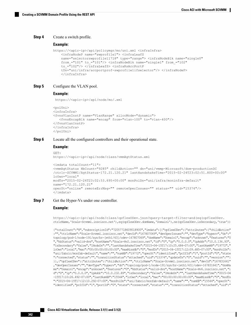
Step 4 Create a switch profile.
Example:https://<apic-ip>/api/policymgr/mo/uni.xml <infraInfra>
<infraNodeP name="swprofile1"> <infraLeafSname="selectorswprofile11718" type="range"> <infraNodeBlk name="single0"from_="101" to_="101"/> <infraNodeBlk name="single1" from_="102"to_="102"/> </infraLeafS> <infraRsAccPortPtDn="uni/infra/accportprof-swprofile1ifselector"/> </infraNodeP></infraInfra>
Step 5 Configure the VLAN pool.
Example:https://<apic-ip>/api/node/mo/.xml
<polUni><infraInfra><fvnsVlanInstP name="VlanRange" allocMode="dynamic">
<fvnsEncapBlk name="encap" from="vlan-100" to="vlan-400"/></fvnsVlanInstP></infraInfra></polUni>
Step 6 Locate all the configured controllers and their operational state.
Example:GET:https://<apic-ip>/api/node/class/vmmAgtStatus.xml
<imdata totalCount="11"><vmmAgtStatus HbCount="9285" childAction="" dn="uni/vmmp-Microsoft/dom-productionDC/ctrlr-SCVMM1/AgtStatus-172.21.120.21" lastHandshakeTime="2015-02-24T23:02:51.800+00:00"lcOwn="local"modTs="2015-02-24T23:02:53.695+00:00" monPolDn="uni/infra/moninfra-default"name="172.21.120.21"operSt="online" remoteErrMsg="" remoteOperIssues="" status="" uid="15374"/></imdata>
Step 7 Get the Hyper-Vs under one controller.
Example:
https://<apic-ip>/api/node/class/opflexODev.json?query-target-filter=and(eq(opflexODev.ctrlrName,'Scale-Scvmm1.inscisco.net'),eq(opflexODev.domName,'Domain1'),ne(opflexODev.isSecondary,'true'))
{"totalCount":"8","subscriptionId":"72057718609018900","imdata":[{"opflexODev":{"attributes":{"childAction":"","ctrlrName":"Scale-Scvmm1.inscisco.net","devId":"167807069","devOperIssues":"","devType":"hyperv","dn":"topology/pod-1/node-191/sys/br-[eth1/43]/odev-167807069","domName":"Domain1","encap":"unknown","features":"0","hbStatus":"valid-dvs","hostName":"Scale-Hv2.inscisco.net","id":"0","ip":"0.0.0.0","ipAddr":"10.0.136.93","isSecondary":"false","lNodeDn":"","lastHandshakeTime":"2015-04-15T17:10:25.684-07:00","lastNumHB":"19772","lcOwn":"local","mac":"00:00:00:00:00:00","maxMissHb":"0","modTs":"2015-04-15T17:12:09.485-07:00","monPolDn":"uni/fabric/monfab-default","name":"","numHB":"19772","operSt":"identified","pcIfId":"1","portId":"0","state":"connected","status":"","transitionStatus":"attached","uid":"15374","updateTs":"0","uuid":"","version":""}}},{"opflexODev":{"attributes":{"childAction":"","ctrlrName":"Scale-Scvmm1.inscisco.net","devId":"167831641","devOperIssues":"","devType":"hyperv","dn":"topology/pod-1/node-191/sys/br-[eth1/43]/odev-167831641","domName":"Domain1","encap":"unknown","features":"0","hbStatus":"valid-dvs","hostName":"Scale-Hv6.inscisco.net","id":"0","ip":"0.0.0.0","ipAddr":"10.0.232.89","isSecondary":"false","lNodeDn":"","lastHandshakeTime":"2015-04-15T17:10:26.492-07:00","lastNumHB":"15544","lcOwn":"local","mac":"00:00:00:00:00:00","maxMissHb":"0","modTs":"2015-04-15T17:12:10.292-07:00","monPolDn":"uni/fabric/monfab-default","name":"","numHB":"15544","operSt":"identified","pcIfId":"1","portId":"0","state":"connected","status":"","transitionStatus":"attached","uid":"
Cisco ACI Virtualization Guide, Release 3.1(1) and 3.1(2)342
Cisco ACI with Microsoft SCVMMCreating a SCVMM Domain Profile Using the REST API

15374","updateTs":"0","uuid":"","version":""}}},{"opflexODev":{"attributes":{"childAction":"","ctrlrName":"Scale-Scvmm1.inscisco.net","devId":"167831643","devOperIssues":"","devType":"hyperv","dn":"topology/pod-1/node-191/sys/br-[eth1/43]/odev-167831643","domName":"Domain1","encap":"unknown","features":"0","hbStatus":"valid-dvs","hostName":"Scale-Hv3.inscisco.net","id":"0","ip":"0.0.0.0","ipAddr":"10.0.232.91","isSecondary":"false","lNodeDn":"","lastHandshakeTime":"2015-04-15T17:10:23.268-07:00","lastNumHB":"15982","lcOwn":"local","mac":"00:00:00:00:00:00","maxMissHb":"0","modTs":"2015-04-15T17:12:07.068-07:00","monPolDn":"uni/fabric/monfab-default","name":"","numHB":"15982","operSt":"identified","pcIfId":"1","portId":"0","state":"connected","status":"","transitionStatus":"attached","uid":"15374","updateTs":"0","uuid":"","version":""}}},{"opflexODev":{"attributes":{"childAction":"","ctrlrName":"Scale-Scvmm1.inscisco.net","devId":"167807070","devOperIssues":"","devType":"hyperv","dn":"topology/pod-1/node-191/sys/br-[eth1/43]/odev-167807070","domName":"Domain1","encap":"unknown","features":"0","hbStatus":"valid-dvs","hostName":"Scale-Hv8.inscisco.net","id":"0","ip":"0.0.0.0","ipAddr":"10.0.136.94","isSecondary":"false","lNodeDn":"","lastHandshakeTime":"2015-04-15T17:10:26.563-07:00","lastNumHB":"14219","lcOwn":"local","mac":"00:00:00:00:00:00","maxMissHb":"0","modTs":"2015-04-15T17:12:10.364-07:00","monPolDn":"uni/fabric/monfab-default","name":"","numHB":"14219","operSt":"identified","pcIfId":"1","portId":"0","state":"connected","status":"","transitionStatus":"attached","uid":"15374","updateTs":"0","uuid":"","version":""}}},{"opflexODev":{"attributes":{"childAction":"","ctrlrName":"Scale-Scvmm1.inscisco.net","devId":"167831642","devOperIssues":"","devType":"hyperv","dn":"topology/pod-1/node-191/sys/br-[eth1/43]/odev-167831642","domName":"Domain1","encap":"unknown","features":"0","hbStatus":"valid-dvs","hostName":"Scale-Hv4.inscisco.net","id":"0","ip":"0.0.0.0","ipAddr":"10.0.232.90","isSecondary":"false","lNodeDn":"","lastHandshakeTime":"2015-04-15T17:10:24.978-07:00","lastNumHB":"13947","lcOwn":"local","mac":"00:00:00:00:00:00","maxMissHb":"0","modTs":"2015-04-15T17:12:08.778-07:00","monPolDn":"uni/fabric/monfab-default","name":"","numHB":"13947","operSt":"identified","pcIfId":"1","portId":"0","state":"connected","status":"","transitionStatus":"attached","uid":"15374","updateTs":"0","uuid":"","version":""}}},{"opflexODev":{"attributes":{"childAction":"","ctrlrName":"Scale-Scvmm1.inscisco.net","devId":"167807071","devOperIssues":"","devType":"hyperv","dn":"topology/pod-1/node-190/sys/br-[eth1/43]/odev-167807071","domName":"Domain1","encap":"unknown","features":"0","hbStatus":"valid-dvs","hostName":"Scale-Hv7.inscisco.net","id":"0","ip":"0.0.0.0","ipAddr":"10.0.136.95","isSecondary":"false","lNodeDn":"","lastHandshakeTime":"2015-04-15T17:12:10.057-07:00","lastNumHB":"5708","lcOwn":"local","mac":"00:00:00:00:00:00","maxMissHb":"0","modTs":"2015-04-15T17:12:09.659-07:00","monPolDn":"uni/fabric/monfab-default","name":"","numHB":"5708","operSt":"identified","pcIfId":"1","portId":"0","state":"connected","status":"","transitionStatus":"attached","uid":"15374","updateTs":"0","uuid":"","version":""}}},{"opflexODev":{"attributes":{"childAction":"","ctrlrName":"Scale-Scvmm1.inscisco.net","devId":"167807067","devOperIssues":"","devType":"hyperv","dn":"topology/pod-1/node-190/sys/br-[eth1/43]/odev-167807067","domName":"Domain1","encap":"unknown","features":"0","hbStatus":"valid-dvs","hostName":"Scale-Hv1.inscisco.net","id":"0","ip":"0.0.0.0","ipAddr":"10.0.136.91","isSecondary":"false","lNodeDn":"","lastHandshakeTime":"2015-04-15T17:12:08.637-07:00","lastNumHB":"17659","lcOwn":"local","mac":"00:00:00:00:00:00","maxMissHb":"0","modTs":"2015-04-15T17:12:08.240-07:00","monPolDn":"uni/fabric/monfab-default","name":"","numHB":"17659","operSt":"identified","pcIfId":"1","portId":"0","state":"connected","status":"","transitionStatus":"attached","uid":"15374","updateTs":"0","uuid":"","version":""}}},{"opflexODev":{"attributes":{"childAction":"","ctrlrName":"Scale-Scvmm1.inscisco.net","devId":"167831644","devOperIssues":"","devType":"hyperv","dn":"topology/pod-1/node-190/sys/br-[eth1/43]/odev-167831644","domName":"Domain1","encap":"unknown","features":"0","hbStatus":"valid-dvs","hostName":"Scale-Hv5.inscisco.net","id":"0","ip":"0.0.0.0","ipAddr":"10.0.232.92","isSecondary":"false","lNodeDn":"","lastHandshakeTime":"2015-04-15T17:12:09.093-07:00","lastNumHB":"15433","lcOwn":"local","mac":"00:00:00:00:00:00","maxMissHb":"0","modTs":"2015-04-15T17:12:08.695-07:00","monPolDn":"uni/fabric/monfab-default","name":"","numHB":"15433","operSt":"identified","pcIfId":"1","portId":"0","state":"connected","status":"","transitionStatus":"attached","uid":"15374","updateTs":"0","uuid":"","version":""}}}]}
Step 8 Get the VMs under one Hyper-V.
Example:
https://<apic-ip>/api/node/mo/topology/pod-1/node-190/sys/br-[eth1/43]/odev-167807067.json?query-target=children&target-subtree-class=opflexOVm&subscription=yes
{"totalCount":"1","subscriptionId":"72057718609018947","imdata":[{"opflexOVm":{"attributes":{"childAction":"","ctrlrName":"Scale-Scvmm1.inscisco.net","dn":"topology/pod-1/node-190/sys/br-[eth1/43]/odev-167807067/ovm-ExtConn_1002_EPG17_003","domName":"Domain1","id":"0","lcOwn":"local","modTs":"2015-04-14T17:36:51.512-07:00","name":"ExtConn_1002_EPG17_003","state":"Powered On","status":"","uid":"15374"}}}]}
Step 9 Get VNICs under one VM.
Example:
Cisco ACI Virtualization Guide, Release 3.1(1) and 3.1(2)343
Cisco ACI with Microsoft SCVMMCreating a SCVMM Domain Profile Using the REST API
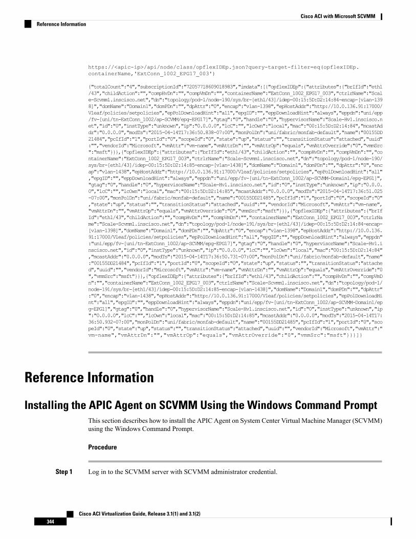
https://<apic-ip>/api/node/class/opflexIDEp.json?query-target-filter=eq(opflexIDEp.containerName,'ExtConn_1002_EPG17_003')
{"totalCount":"4","subscriptionId":"72057718609018983","imdata":[{"opflexIDEp":{"attributes":{"brIfId":"eth1/43","childAction":"","compHvDn":"","compVmDn":"","containerName":"ExtConn_1002_EPG17_003","ctrlrName":"Scale-Scvmm1.inscisco.net","dn":"topology/pod-1/node-190/sys/br-[eth1/43]/idep-00:15:5D:D2:14:84-encap-[vlan-1398]","domName":"Domain1","domPDn":"","dpAttr":"0","encap":"vlan-1398","epHostAddr":"http://10.0.136.91:17000/Vleaf/policies/setpolicies","epPolDownloadHint":"all","epgID":"","eppDownloadHint":"always","eppdn":"uni/epp/fv-[uni/tn-ExtConn_1002/ap-SCVMM/epg-EPG17]","gtag":"0","handle":"0","hypervisorName":"Scale-Hv1.inscisco.net","id":"0","instType":"unknown","ip":"0.0.0.0","lcC":"","lcOwn":"local","mac":"00:15:5D:D2:14:84","mcastAddr":"0.0.0.0","modTs":"2015-04-14T17:36:50.838-07:00","monPolDn":"uni/fabric/monfab-default","name":"00155DD21484","pcIfId":"1","portId":"0","scopeId":"0","state":"up","status":"","transitionStatus":"attached","uuid":"","vendorId":"Microsoft","vmAttr":"vm-name","vmAttrDn":"","vmAttrOp":"equals","vmAttrOverride":"0","vmmSrc":"msft"}}},{"opflexIDEp":{"attributes":{"brIfId":"eth1/43","childAction":"","compHvDn":"","compVmDn":"","containerName":"ExtConn_1002_EPG17_003","ctrlrName":"Scale-Scvmm1.inscisco.net","dn":"topology/pod-1/node-190/sys/br-[eth1/43]/idep-00:15:5D:D2:14:85-encap-[vlan-1438]","domName":"Domain1","domPDn":"","dpAttr":"0","encap":"vlan-1438","epHostAddr":"http://10.0.136.91:17000/Vleaf/policies/setpolicies","epPolDownloadHint":"all","epgID":"","eppDownloadHint":"always","eppdn":"uni/epp/fv-[uni/tn-ExtConn_1002/ap-SCVMM-Domain1/epg-EPG1]","gtag":"0","handle":"0","hypervisorName":"Scale-Hv1.inscisco.net","id":"0","instType":"unknown","ip":"0.0.0.0","lcC":"","lcOwn":"local","mac":"00:15:5D:D2:14:85","mcastAddr":"0.0.0.0","modTs":"2015-04-14T17:36:51.025-07:00","monPolDn":"uni/fabric/monfab-default","name":"00155DD21485","pcIfId":"1","portId":"0","scopeId":"0","state":"up","status":"","transitionStatus":"attached","uuid":"","vendorId":"Microsoft","vmAttr":"vm-name","vmAttrDn":"","vmAttrOp":"equals","vmAttrOverride":"0","vmmSrc":"msft"}}},{"opflexIDEp":{"attributes":{"brIfId":"eth1/43","childAction":"","compHvDn":"","compVmDn":"","containerName":"ExtConn_1002_EPG17_003","ctrlrName":"Scale-Scvmm1.inscisco.net","dn":"topology/pod-1/node-191/sys/br-[eth1/43]/idep-00:15:5D:D2:14:84-encap-[vlan-1398]","domName":"Domain1","domPDn":"","dpAttr":"0","encap":"vlan-1398","epHostAddr":"http://10.0.136.91:17000/Vleaf/policies/setpolicies","epPolDownloadHint":"all","epgID":"","eppDownloadHint":"always","eppdn":"uni/epp/fv-[uni/tn-ExtConn_1002/ap-SCVMM/epg-EPG17]","gtag":"0","handle":"0","hypervisorName":"Scale-Hv1.inscisco.net","id":"0","instType":"unknown","ip":"0.0.0.0","lcC":"","lcOwn":"local","mac":"00:15:5D:D2:14:84","mcastAddr":"0.0.0.0","modTs":"2015-04-14T17:36:50.731-07:00","monPolDn":"uni/fabric/monfab-default","name":"00155DD21484","pcIfId":"1","portId":"0","scopeId":"0","state":"up","status":"","transitionStatus":"attached","uuid":"","vendorId":"Microsoft","vmAttr":"vm-name","vmAttrDn":"","vmAttrOp":"equals","vmAttrOverride":"0","vmmSrc":"msft"}}},{"opflexIDEp":{"attributes":{"brIfId":"eth1/43","childAction":"","compHvDn":"","compVmDn":"","containerName":"ExtConn_1002_EPG17_003","ctrlrName":"Scale-Scvmm1.inscisco.net","dn":"topology/pod-1/node-191/sys/br-[eth1/43]/idep-00:15:5D:D2:14:85-encap-[vlan-1438]","domName":"Domain1","domPDn":"","dpAttr":"0","encap":"vlan-1438","epHostAddr":"http://10.0.136.91:17000/Vleaf/policies/setpolicies","epPolDownloadHint":"all","epgID":"","eppDownloadHint":"always","eppdn":"uni/epp/fv-[uni/tn-ExtConn_1002/ap-SCVMM-Domain1/epg-EPG1]","gtag":"0","handle":"0","hypervisorName":"Scale-Hv1.inscisco.net","id":"0","instType":"unknown","ip":"0.0.0.0","lcC":"","lcOwn":"local","mac":"00:15:5D:D2:14:85","mcastAddr":"0.0.0.0","modTs":"2015-04-14T17:36:50.932-07:00","monPolDn":"uni/fabric/monfab-default","name":"00155DD21485","pcIfId":"1","portId":"0","scopeId":"0","state":"up","status":"","transitionStatus":"attached","uuid":"","vendorId":"Microsoft","vmAttr":"vm-name","vmAttrDn":"","vmAttrOp":"equals","vmAttrOverride":"0","vmmSrc":"msft"}}}]}
Reference Information
Installing the APIC Agent on SCVMM Using the Windows Command PromptThis section describes how to install the APIC Agent on System Center Virtual Machine Manager (SCVMM)using the Windows Command Prompt.
Procedure
Step 1 Log in to the SCVMM server with SCVMM administrator credential.
Cisco ACI Virtualization Guide, Release 3.1(1) and 3.1(2)344
Cisco ACI with Microsoft SCVMMReference Information
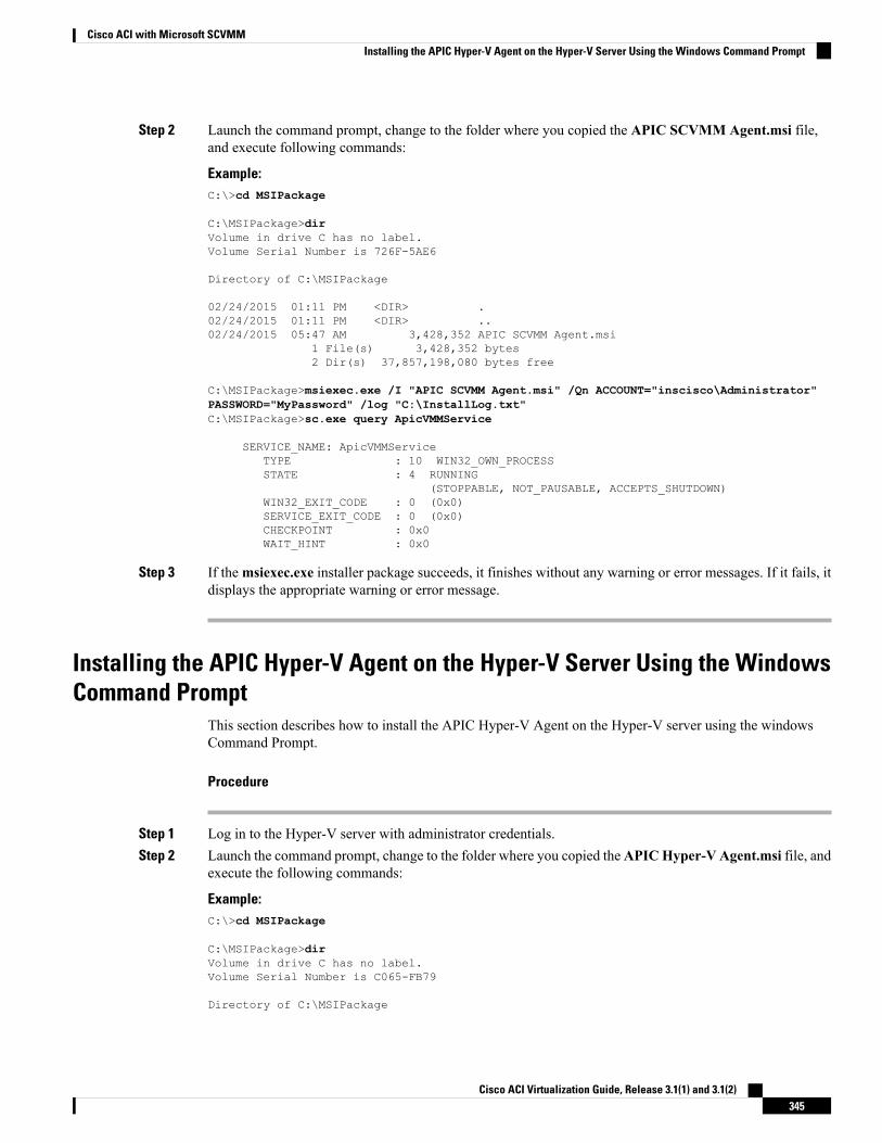
Step 2 Launch the command prompt, change to the folder where you copied the APIC SCVMM Agent.msi file,and execute following commands:
Example:C:\>cd MSIPackage
C:\MSIPackage>dirVolume in drive C has no label.Volume Serial Number is 726F-5AE6
Directory of C:\MSIPackage
02/24/2015 01:11 PM <DIR> .02/24/2015 01:11 PM <DIR> ..02/24/2015 05:47 AM 3,428,352 APIC SCVMM Agent.msi
1 File(s) 3,428,352 bytes2 Dir(s) 37,857,198,080 bytes free
C:\MSIPackage>msiexec.exe /I "APIC SCVMM Agent.msi" /Qn ACCOUNT="inscisco\Administrator"PASSWORD="MyPassword" /log "C:\InstallLog.txt"C:\MSIPackage>sc.exe query ApicVMMService
SERVICE_NAME: ApicVMMServiceTYPE : 10 WIN32_OWN_PROCESSSTATE : 4 RUNNING
(STOPPABLE, NOT_PAUSABLE, ACCEPTS_SHUTDOWN)WIN32_EXIT_CODE : 0 (0x0)SERVICE_EXIT_CODE : 0 (0x0)CHECKPOINT : 0x0WAIT_HINT : 0x0
Step 3 If themsiexec.exe installer package succeeds, it finishes without any warning or error messages. If it fails, itdisplays the appropriate warning or error message.
Installing the APIC Hyper-V Agent on the Hyper-V Server Using the WindowsCommand Prompt
This section describes how to install the APIC Hyper-V Agent on the Hyper-V server using the windowsCommand Prompt.
Procedure
Step 1 Log in to the Hyper-V server with administrator credentials.Step 2 Launch the command prompt, change to the folder where you copied theAPICHyper-V Agent.msi file, and
execute the following commands:
Example:C:\>cd MSIPackage
C:\MSIPackage>dirVolume in drive C has no label.Volume Serial Number is C065-FB79
Directory of C:\MSIPackage
Cisco ACI Virtualization Guide, Release 3.1(1) and 3.1(2)345
Cisco ACI with Microsoft SCVMMInstalling the APIC Hyper-V Agent on the Hyper-V Server Using the Windows Command Prompt
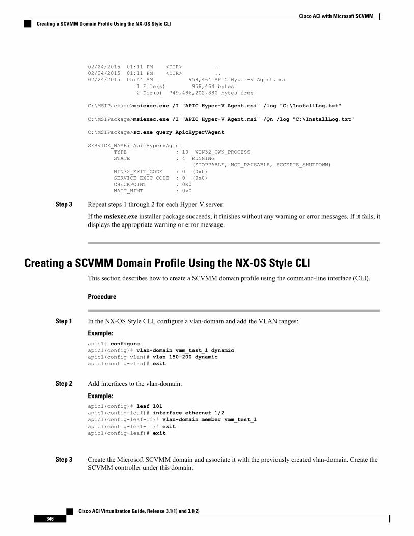
02/24/2015 01:11 PM <DIR> .02/24/2015 01:11 PM <DIR> ..02/24/2015 05:44 AM 958,464 APIC Hyper-V Agent.msi
1 File(s) 958,464 bytes2 Dir(s) 749,486,202,880 bytes free
C:\MSIPackage>msiexec.exe /I "APIC Hyper-V Agent.msi" /log "C:\InstallLog.txt"
C:\MSIPackage>msiexec.exe /I "APIC Hyper-V Agent.msi" /Qn /log "C:\InstallLog.txt"
C:\MSIPackage>sc.exe query ApicHyperVAgent
SERVICE_NAME: ApicHyperVAgentTYPE : 10 WIN32_OWN_PROCESSSTATE : 4 RUNNING
(STOPPABLE, NOT_PAUSABLE, ACCEPTS_SHUTDOWN)WIN32_EXIT_CODE : 0 (0x0)SERVICE_EXIT_CODE : 0 (0x0)CHECKPOINT : 0x0WAIT_HINT : 0x0
Step 3 Repeat steps 1 through 2 for each Hyper-V server.
If themsiexec.exe installer package succeeds, it finishes without any warning or error messages. If it fails, itdisplays the appropriate warning or error message.
Creating a SCVMM Domain Profile Using the NX-OS Style CLIThis section describes how to create a SCVMM domain profile using the command-line interface (CLI).
Procedure
Step 1 In the NX-OS Style CLI, configure a vlan-domain and add the VLAN ranges:
Example:apic1# configureapic1(config)# vlan-domain vmm_test_1 dynamicapic1(config-vlan)# vlan 150-200 dynamicapic1(config-vlan)# exit
Step 2 Add interfaces to the vlan-domain:
Example:apic1(config)# leaf 101apic1(config-leaf)# interface ethernet 1/2apic1(config-leaf-if)# vlan-domain member vmm_test_1apic1(config-leaf-if)# exitapic1(config-leaf)# exit
Step 3 Create the Microsoft SCVMM domain and associate it with the previously created vlan-domain. Create theSCVMM controller under this domain:
Cisco ACI Virtualization Guide, Release 3.1(1) and 3.1(2)346
Cisco ACI with Microsoft SCVMMCreating a SCVMM Domain Profile Using the NX-OS Style CLI
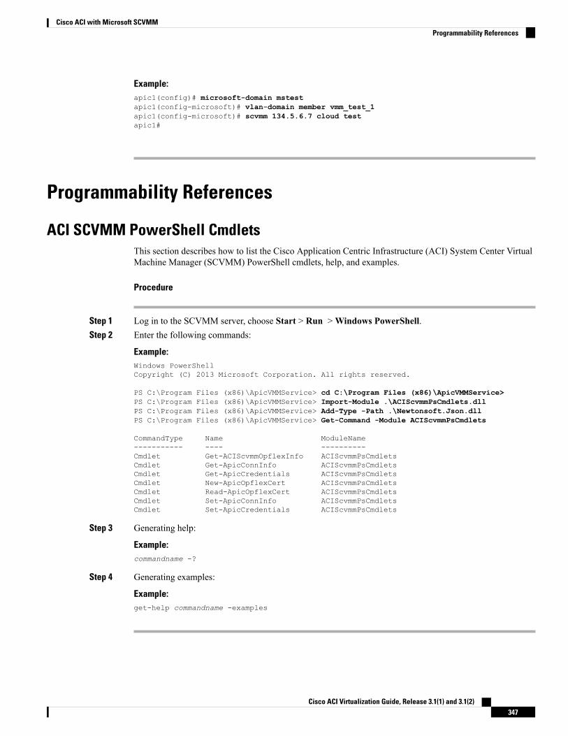
Example:apic1(config)# microsoft-domain mstestapic1(config-microsoft)# vlan-domain member vmm_test_1apic1(config-microsoft)# scvmm 134.5.6.7 cloud testapic1#
Programmability References
ACI SCVMM PowerShell CmdletsThis section describes how to list the Cisco Application Centric Infrastructure (ACI) System Center VirtualMachine Manager (SCVMM) PowerShell cmdlets, help, and examples.
Procedure
Step 1 Log in to the SCVMM server, choose Start > Run >Windows PowerShell.Step 2 Enter the following commands:
Example:Windows PowerShellCopyright (C) 2013 Microsoft Corporation. All rights reserved.
PS C:\Program Files (x86)\ApicVMMService> cd C:\Program Files (x86)\ApicVMMService>PS C:\Program Files (x86)\ApicVMMService> Import-Module .\ACIScvmmPsCmdlets.dllPS C:\Program Files (x86)\ApicVMMService> Add-Type -Path .\Newtonsoft.Json.dllPS C:\Program Files (x86)\ApicVMMService> Get-Command -Module ACIScvmmPsCmdlets
CommandType Name ModuleName----------- ---- ----------Cmdlet Get-ACIScvmmOpflexInfo ACIScvmmPsCmdletsCmdlet Get-ApicConnInfo ACIScvmmPsCmdletsCmdlet Get-ApicCredentials ACIScvmmPsCmdletsCmdlet New-ApicOpflexCert ACIScvmmPsCmdletsCmdlet Read-ApicOpflexCert ACIScvmmPsCmdletsCmdlet Set-ApicConnInfo ACIScvmmPsCmdletsCmdlet Set-ApicCredentials ACIScvmmPsCmdlets
Step 3 Generating help:
Example:commandname -?
Step 4 Generating examples:
Example:get-help commandname -examples
Cisco ACI Virtualization Guide, Release 3.1(1) and 3.1(2)347
Cisco ACI with Microsoft SCVMMProgrammability References
Configuration References
MAC Address Configuration RecommendationsThis section describes the MAC address configuration recommendations.
• Both Dynamic and Static MAC are supported.
• StaticMAC for the VM Network adapter is recommended if you want the VM inventory to show upquickly on APIC.
• If you choose DynamicMAC there is a delay for the VM inventory to show up on APIC. The delay isbecause Dynamic MACs are not learned by SCVMM right away.
The Data plane works fine even though the VM inventory does not show up.Note
Cisco ACI Virtualization Guide, Release 3.1(1) and 3.1(2)348
Cisco ACI with Microsoft SCVMMConfiguration References
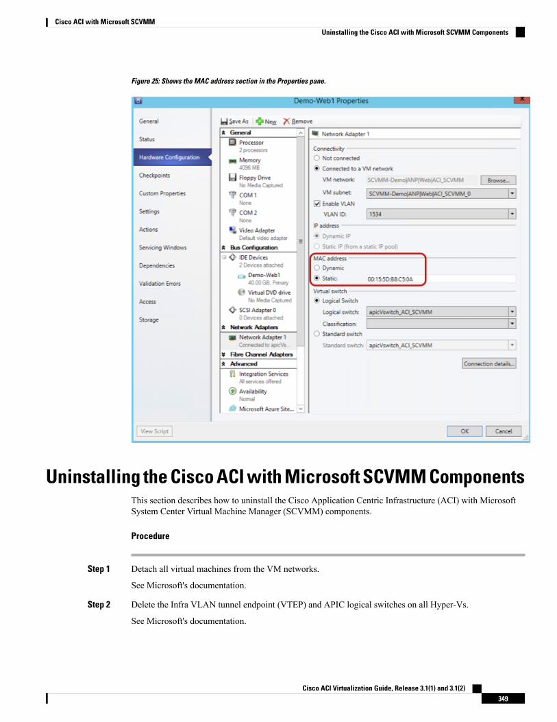
Figure 25: Shows the MAC address section in the Properties pane.
Uninstalling the Cisco ACI with Microsoft SCVMM ComponentsThis section describes how to uninstall the Cisco Application Centric Infrastructure (ACI) with MicrosoftSystem Center Virtual Machine Manager (SCVMM) components.
Procedure
Step 1 Detach all virtual machines from the VM networks.
See Microsoft's documentation.
Step 2 Delete the Infra VLAN tunnel endpoint (VTEP) and APIC logical switches on all Hyper-Vs.
See Microsoft's documentation.
Cisco ACI Virtualization Guide, Release 3.1(1) and 3.1(2)349
Cisco ACI with Microsoft SCVMMUninstalling the Cisco ACI with Microsoft SCVMM Components
Step 3 Verify the APIC GUI to make sure all the VMs and hosts are disconnected.Step 4 Delete the VMM Domain from the Application Policy Infrastructure Controller (APIC).
See Guidelines for Deleting VMM Domains, on page 13.
Step 5 Verify the logical switch and logical networks are removed from SCVMM.Step 6 Uninstall the APIC SCVMM Agent on SCVMM or on a Highly Available SCVMM.
See Uninstalling the APIC SCVMM Agent, on page 350.
See Uninstalling the APIC SCVMM Agent on a Highly Available SCVMM, on page 350
Uninstalling the APIC SCVMM AgentThis section describes how to uninstall the APIC SCVMM Agent.
Procedure
Step 1 Log in to the SCVMM server.Step 2 Choose Start > Control Panel > Uninstall a Program.Step 3 In the Programs and Features window, right-click ApicVMMService and choose Uninstall.
This uninstalls the APIC SCVMM Agent.Step 4 To verify if the APIC SCVMM Agent is uninstalled, in the Programs and Features window, verify that
ApicVMMService is not present.
Uninstalling the APIC SCVMM Agent on a Highly Available SCVMMThis section describes how to install the Application Policy Infrastructure Controller (APIC) SCVMM agenton a Highly Available System Center Virtual Machine Manager (SCVMM).
Procedure
Step 1 Log in to any node within the Highly Available SCVMM Failover Cluster.Step 2 Open the Failover Cluster Manager Application.Step 3 In theWindows Failover Cluster Manager window, select ApicVMMService in the Highly Available
SCVMM Roles/Resources tab.Step 4 Right-click on the ApicVMMService Role and choose Take Offline.Step 5 Once the Role is offline, right-click on the ApicVMMService Role and choose Remove.Step 6 On each node within the Highly Available SCVMMFailover Cluster, perform the following actions to uninstall
the APIC SCVMM Agent:a) Log in to the SCVMM server.b) Choose Start > Control Panel > Uninstall a Program.c) In the Programs and Features window, right-click ApicVMMService and choose Uninstall.
Cisco ACI Virtualization Guide, Release 3.1(1) and 3.1(2)350
Cisco ACI with Microsoft SCVMMUninstalling the APIC SCVMM Agent
This uninstalls the APIC SCVMM Agent.d) To verify if the APIC SCVMM Agent is uninstalled, in the Programs and Features window, verify that
ApicVMMService is not present.
Downgrading the APIC Controller and the Switch Software withCisco ACI with Microsoft SCVMM Components
This section describes how to downgrade the APIC controller and the switch software with Cisco ACI withMicrosoft System Center Virtual Machine Manager (SCVMM) Components.
Procedure
Step 1 Uninstall the APIC SCVMM Agent on SCVMM or on a Highly Available SCVMM.
See Uninstalling the APIC SCVMM Agent, on page 350.
See Uninstalling the APIC SCVMM Agent on a Highly Available SCVMM, on page 350
Step 2 Update the logical switch and virtual switch extension mapping.a) In the logical switch properties dialog box.b) Choose Extensions.c) Uncheck Cisco ACI Virtual Switch Filter.d) Click OK.
Step 3 Downgrade APIC controller.
See the Cisco APIC Firmware Management Guide.
Step 4 Install an older version of SCVMM agent.
Exporting APIC OpFlex CertificateThis section describes how to back up APIC OpFlex certificate to a file which can be used to deploy newHyper-V nodes, System Center Virtual Machine Manager (SCVMM) and Windows Azure Pack ResourceProvider servers to the ACI Fabric when the original OpFlex certificate cannot be located.
Procedure
Step 1 Log in to a Hyper-V node which is currently a member of the ACI Fabric.Step 2 Export the certificate from the Hyper-V node by performing the following actions:
a) Choose Start > Run and type certlm.msc to launch the Certificate Manager.b) In the navigation pane, right-click on Certificates - Local Computer and choose Find Certificates.
Cisco ACI Virtualization Guide, Release 3.1(1) and 3.1(2)351
Cisco ACI with Microsoft SCVMMDowngrading the APIC Controller and the Switch Software with Cisco ACI with Microsoft SCVMM Components
c) In the Find Certificate dialog box, perform the following actions:
• In the Find in field, from the drop-down list, choose All certificate stores.
• In the Contains field, enter OpflexAgent.
• In the Look in Field field, from the drop-down list, choose Issued By.
• Click Find Now.
Your result list should have a single Certificate in the list.
d) Right-click on the newly found OpflexAgent certificate and choose Export.
The Certificate Export Wizard will appear.
Step 3 In the Certificate Export Wizard dialog box, perform the following actions:a) In theWelcome to the Certificate Export Wizard dialog box, click Nextb) In the Export Private Key dialog box, choose the Yes, export the private key radio button, and click
Next.c) In theExport File Format dialog box, choose the Personal Information Exchange - PKCS #12 (.PFX)
radio button, check the Include all certificates in the certificate path if possible andExport all extendedproperties check box. Click Next.
d) In the Security dialog box, check the Password check box, enter your PFX password and enter yourPFX password again to confirm. Click Next.
Your PFX password will be used later to import the PFX file on the target machine.
e) In theFile to Export dialog box, enter the filename you wish to save the exported file (C:\OpflexAgent.pfx)and click Next.
f) In the Completing the Certificate Export Wizard dialog box, review all your specified settings arecorrect and click Finish.
g) The Certificate Export Wizard dialog box will appear with The export was successful. and click Ok.
Step 4 Copy the PFX file to a known location.
You can deploy the certificate through an Active Directory Group Policy or copy the file to your variousMicrosoft Servers which host your SCVMM,Windows Azure Pack Resource Provider, and Hyper-V servicesfor integration into the ACI Fabric.
Cisco ACI Virtualization Guide, Release 3.1(1) and 3.1(2)352
Cisco ACI with Microsoft SCVMMExporting APIC OpFlex Certificate
C H A P T E R 10Cisco ACI with Microsoft Windows Azure Pack
This chapter contains the following sections:
• About Cisco ACI with Microsoft Windows Azure Pack, on page 353• Getting Started with Cisco ACI with Microsoft Windows Azure Pack, on page 357• Upgrading the Cisco ACI with Microsoft Windows Azure Pack Components, on page 363• Use Case Scenarios for the Administrator and Tenant Experience, on page 366• Troubleshooting Cisco ACI with Microsoft Windows Azure Pack, on page 398• Programmability References, on page 398• Uninstalling the Cisco ACI with Microsoft Windows Azure Pack Components, on page 400• Downgrading Cisco APIC and the Switch Software with Cisco ACI andMicrosoft Windows Azure PackComponents, on page 402
About Cisco ACI with Microsoft Windows Azure PackCisco Application Centric Infrastructure (ACI) integrates in Microsoft Windows Azure Pack to provide aself-service experience for the tenant.
ACI enhances the network management capabilities of the platform. Microsoft Windows Azure Pack is builton top of an existing Microsoft System Center Virtual Machine Manager (SCVMM) installation. Cisco ACIhas integration points at each of these layers, enabling you to leverage the work performed in a SCVMMenvironment and use it in a Microsoft Windows Azure Pack installation.
• Cisco ACI with Microsoft Windows Azure Pack—Microsoft Windows Azure Pack for Windows Serveris a collection of Microsoft Azure technologies that include the following capabilities:
• Management portal for tenants
• Management portal for administrators
• Service management API
• Cisco ACI with Microsoft System Center Virtual Machine Manager —For information about how to setup Cisco ACI with Microsoft System Center Virtual Machine Manager (SCVMM), see details in CiscoACI with Microsoft SCVMM Solution Overview, on page 308.
Cisco ACI Virtualization Guide, Release 3.1(1) and 3.1(2)353
You cannot configure direct server return (DSR) through Windows Azure Pack. If you want to configureDSR, you must do so in Cisco APIC. See the chapter "Configuring Direct Server Return" in the Cisco APICLayer 4 to Layer 7 Services Deployment Guide for information.
Note
Cisco ACI with Microsoft Windows Azure Pack Solution OverviewCisco Application Centric Infrastructure (ACI) integrates in Microsoft Windows Azure Pack to provide aself-service experience for tenants. ACI resource provider in Windows Azure Pack drives the ApplicationPolicy Infrastructure Controller (APIC) for network management. Networks are created in System CenterVirtual Machine Manager (SCVMM) and are available in Windows Azure Pack for respective tenants. ACILayer 4 to Layer 7 capabilities for F5 and Citrix load balancers and stateless firewall are provided for tenants.For details, see the About Load Balancing, on page 375.
Windows Azure Pack for Windows Server is a collection of Microsoft Azure technologies, available toMicrosoft customers at no additional cost for installation into your data center. It runs on top of WindowsServer 2012 R2 and System Center 2012 R2 and, through the use of theWindows Azure technologies, enablesyou to offer a rich, self-service, multi-tenant cloud, consistent with the public Windows Azure experience.
Windows Azure Pack includes the following capabilities:
• Management portal for tenants—a customizable self-service portal for provisioning, monitoring, andmanaging services such as networks, bridge domains, VMs, firewalls, load balancers, external connectivity,and shared services. See the User Portal GUI.
• Management portal for administrators—a portal for administrators to configure and manage resourceclouds, user accounts, and tenant offers, quotas, pricing, Web Site Clouds, Virtual Machine Clouds, andService Bus Clouds.
• Service management API—a REST API that helps enable a range of integration scenarios includingcustom portal and billing systems.
See Use Case Scenarios for the Administrator and Tenant Experience, on page 366 for details.
Cisco ACI Virtualization Guide, Release 3.1(1) and 3.1(2)354
Cisco ACI with Microsoft Windows Azure PackCisco ACI with Microsoft Windows Azure Pack Solution Overview
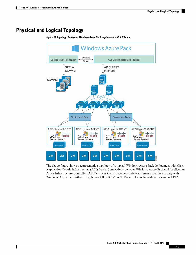
Physical and Logical TopologyFigure 26: Topology of a typical Windows Azure Pack deployment with ACI Fabric
The above figure shows a representative topology of a typical Windows Azure Pack deployment with CiscoApplication Centric Infrastructure (ACI) fabric. Connectivity betweenWindows Azure Pack and ApplicationPolicy Infrastructure Controller (APIC) is over the management network. Tenants interface is only withWindows Azure Pack either through the GUI or REST API. Tenants do not have direct access to APIC.
Cisco ACI Virtualization Guide, Release 3.1(1) and 3.1(2)355
Cisco ACI with Microsoft Windows Azure PackPhysical and Logical Topology
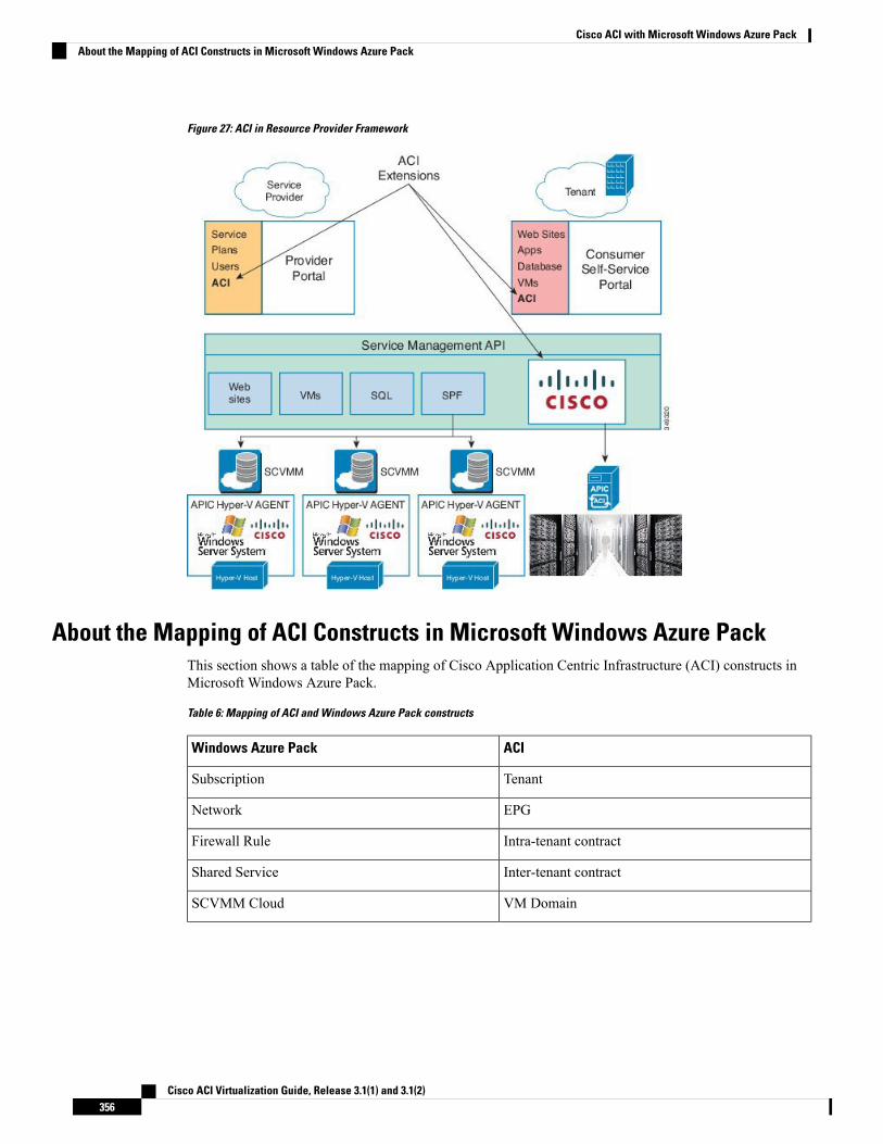
Figure 27: ACI in Resource Provider Framework
About the Mapping of ACI Constructs in Microsoft Windows Azure PackThis section shows a table of the mapping of Cisco Application Centric Infrastructure (ACI) constructs inMicrosoft Windows Azure Pack.
Table 6: Mapping of ACI and Windows Azure Pack constructs
ACIWindows Azure Pack
TenantSubscription
EPGNetwork
Intra-tenant contractFirewall Rule
Inter-tenant contractShared Service
VM DomainSCVMM Cloud
Cisco ACI Virtualization Guide, Release 3.1(1) and 3.1(2)356
Cisco ACI with Microsoft Windows Azure PackAbout the Mapping of ACI Constructs in Microsoft Windows Azure Pack
Getting Started with Cisco ACI with Microsoft Windows AzurePack
This section describes how to get started with Cisco ACI with Microsoft Windows Azure Pack.
Before you install Cisco ACI withMicrosoft Windows Azure Pack, download and unzip the folder containingthe Cisco ACI and matching Microsoft integration files for the Cisco APIC release.
1. Go to Cisco's Application Policy Infrastructure Controller (APIC) website.
2. Choose All Downloads for this Product > APIC Software.
3. Choose the release version and the matching zipped folder.
4. Click Download.
5. Unzip the zipped folder.
Cisco ACI with Microsoft Windows Azure Pack only supports ASCII characters. Non-ASCII characters arenot supported.
Ensure that English is set in the System Locale settings for Windows, otherwise Cisco ACI with WindowsAzure Pack will not install. Also, if the System Locale is modified to a non-English Locale after installation,the integration components may fail when communicating with Cisco APIC and the Cisco ACI fabric.
Note
Prerequisites for Getting Started with Cisco ACI with Microsoft WindowsAzure Pack
Before you get started, ensure that you have verified that your computing environment meets the followingprerequisites:
• Ensure Cisco Application Centric Infrastructure (ACI) with Microsoft System Center Virtual MachineManager (SCVMM) has been set up.
For more information, see Getting Started with Cisco ACI with Microsoft SCVMM, on page 310.
• Ensure that Microsoft Windows Azure Pack Update Rollup 5, 6, 7, 9, 10, or 11 is installed.
See Microsoft's documentation.
• Ensure that Windows Server 2016 is installed.
See Microsoft's documentation.
• Ensure that Hyper-V Host is installed.
See Microsoft's documentation.
• Ensure a cloud is configured on SCVMM.
See Microsoft's documentation.
Cisco ACI Virtualization Guide, Release 3.1(1) and 3.1(2)357
Cisco ACI with Microsoft Windows Azure PackGetting Started with Cisco ACI with Microsoft Windows Azure Pack
• Ensure a VM cloud is configured on Windows Azure Pack.
See Microsoft's documentation.
• Ensure "default" AEP exists with infrastructure VLAN enabled.
• Ensure "default" and "vpcDefault" bridge domains and corresponding "default" and "vpcDefault" EPGsexist in tenant common.
• Ensure you have the Cisco MSI files for APIC Windows Azure Pack Resource and the Host Agent.
For more information, see Getting Started with Cisco ACI with Microsoft SCVMM, on page 310.
Symptom: When you either create or update a plan it may fail with an error message.
Condition: If you have configured Microsoft's Windows Azure Pack without the FQDN, you will encounterthe following error message:
Cannot validate the new quota settings because one of the underlying services failed to
respond. Details: An error has occurred.
Workaround: When you configure the VM Clouds, follow Microsoft's Windows Azure Pack UI instructionswhich informs you to use the FQDN for your SCVMM server.
Note
Installing, Setting Up, and Verifying the Cisco ACI with Microsoft WindowsAzure Pack Components
This section describes how to install, set up, and verify the Cisco ACI with Microsoft Windows Azure Packcomponents.
TaskComponent
See Installing ACI Azure Pack Resource Provider, onpage 359.
Install ACI Azure Pack Resource Provider
See Installing the OpflexAgent Certificate, on page359.
Install the OpflexAgent certificate
See Configuring ACI Azure Pack Resource ProviderSite, on page 361.
Configure ACI Azure Pack Resource Provider Site
See Installing ACIAzure PackAdmin Site Extension,on page 362.
Install ACI Azure Pack Admin site extension
See Installing ACI Azure Pack Tenant Site Extension,on page 362.
Install ACI Azure Pack tenant site extension
See Setting Up ACI, on page 362.Set up the ACI
See Verifying the Windows Azure Pack ResourceProvider, on page 363.
Verify the Windows Azure Pack Resource Provider
Cisco ACI Virtualization Guide, Release 3.1(1) and 3.1(2)358
Cisco ACI with Microsoft Windows Azure PackInstalling, Setting Up, and Verifying the Cisco ACI with Microsoft Windows Azure Pack Components
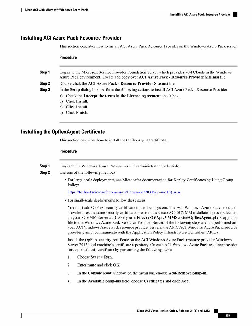
Installing ACI Azure Pack Resource ProviderThis section describes how to install ACI Azure Pack Resource Provider on the Windows Azure Pack server.
Procedure
Step 1 Log in to the Microsoft Service Provider Foundation Server which provides VM Clouds in the WindowsAzure Pack environment. Locate and copy over ACI Azure Pack - Resource Provider Site.msi file.
Step 2 Double-click the ACI Azure Pack - Resource Provider Site.msi file.Step 3 In the Setup dialog box, perform the following actions to install ACI Azure Pack - Resource Provider:
a) Check the I accept the terms in the License Agreement check box.b) Click Install.c) Click Install.d) Click Finish.
Installing the OpflexAgent CertificateThis section describes how to install the OpflexAgent Certificate.
Procedure
Step 1 Log in to the Windows Azure Pack server with administrator credentials.Step 2 Use one of the following methods:
• For large-scale deployments, see Microsoft's documentation for Deploy Certificates by Using GroupPolicy:
https://technet.microsoft.com/en-us/library/cc770315(v=ws.10).aspx.
• For small-scale deployments follow these steps:
You must add OpFlex security certificate to the local system. The ACI Windows Azure Pack resourceprovider uses the same security certificate file from the Cisco ACI SCVMM installation process locatedon your SCVMM Server at: C:\Program Files (x86)\ApicVMMService\OpflexAgent.pfx. Copy thisfile to the Windows Azure Pack Resource Provider Server. If the following steps are not performed onyour ACIWindows Azure Pack resource provider servers, the APIC ACIWindows Azure Pack resourceprovider cannot communicate with the Application Policy Infrastructure Controller (APIC) .
Install the OpFlex security certificate on the ACI Windows Azure Pack resource provider WindowsServer 2012 local machine’s certificate repository. On each ACIWindows Azure Pack resource providerserver, install this certificate by performing the following steps:
1. Choose Start > Run.
2. Entermmc and click OK.
3. In the Console Root window, on the menu bar, choose Add/Remove Snap-in.
4. In the Available Snap-ins field, choose Certificates and click Add.
Cisco ACI Virtualization Guide, Release 3.1(1) and 3.1(2)359
Cisco ACI with Microsoft Windows Azure PackInstalling ACI Azure Pack Resource Provider
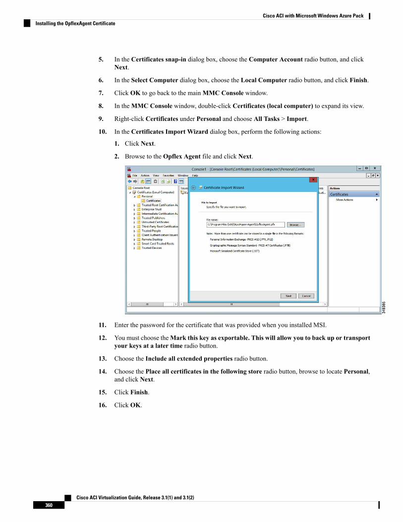
5. In the Certificates snap-in dialog box, choose the Computer Account radio button, and clickNext.
6. In the Select Computer dialog box, choose the Local Computer radio button, and click Finish.
7. Click OK to go back to the mainMMC Console window.
8. In theMMC Console window, double-click Certificates (local computer) to expand its view.
9. Right-click Certificates under Personal and choose All Tasks > Import.
10. In the Certificates Import Wizard dialog box, perform the following actions:
1. Click Next.
2. Browse to the Opflex Agent file and click Next.
11. Enter the password for the certificate that was provided when you installed MSI.
12. You must choose theMark this key as exportable. This will allow you to back up or transportyour keys at a later time radio button.
13. Choose the Include all extended properties radio button.
14. Choose the Place all certificates in the following store radio button, browse to locate Personal,and click Next.
15. Click Finish.
16. Click OK.
Cisco ACI Virtualization Guide, Release 3.1(1) and 3.1(2)360
Cisco ACI with Microsoft Windows Azure PackInstalling the OpflexAgent Certificate
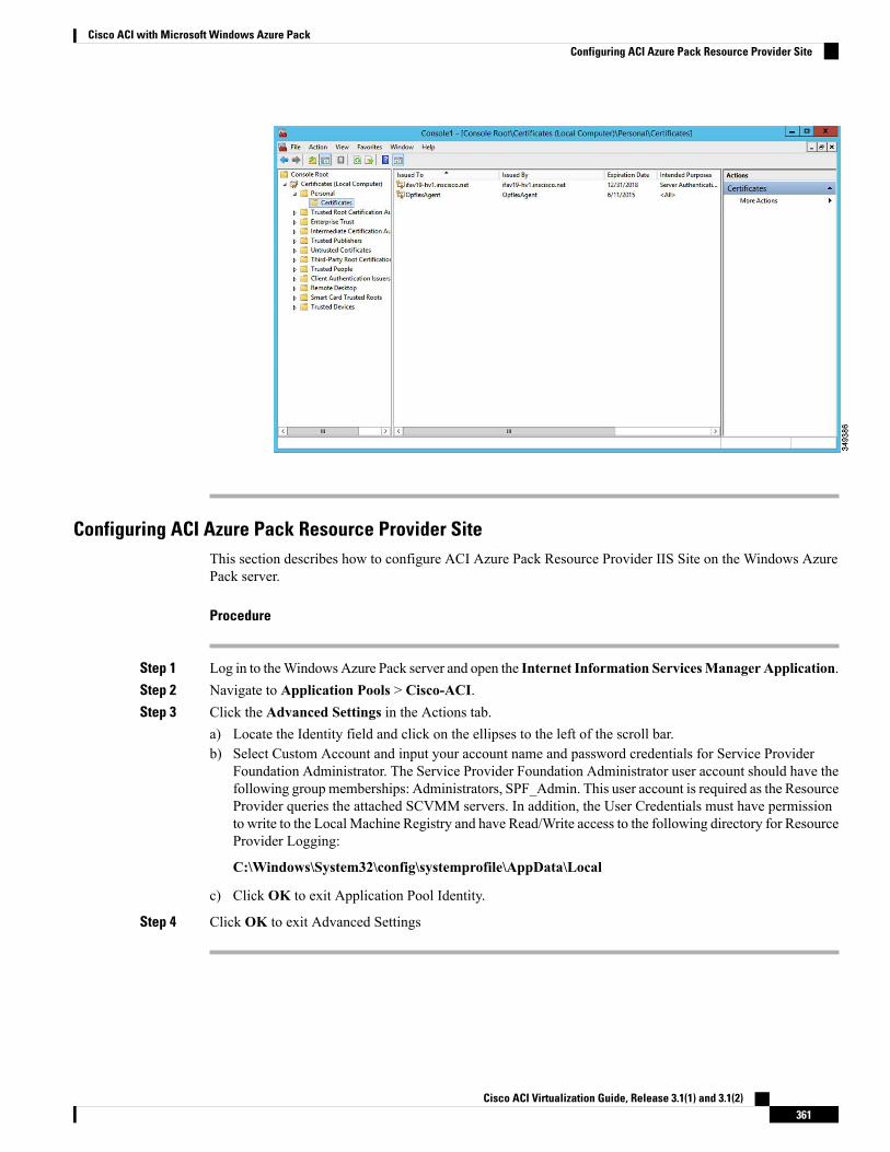
Configuring ACI Azure Pack Resource Provider SiteThis section describes how to configure ACI Azure Pack Resource Provider IIS Site on the Windows AzurePack server.
Procedure
Step 1 Log in to theWindowsAzure Pack server and open the Internet Information ServicesManager Application.Step 2 Navigate to Application Pools > Cisco-ACI.Step 3 Click the Advanced Settings in the Actions tab.
a) Locate the Identity field and click on the ellipses to the left of the scroll bar.b) Select Custom Account and input your account name and password credentials for Service Provider
Foundation Administrator. The Service Provider Foundation Administrator user account should have thefollowing group memberships: Administrators, SPF_Admin. This user account is required as the ResourceProvider queries the attached SCVMM servers. In addition, the User Credentials must have permissionto write to the Local Machine Registry and have Read/Write access to the following directory for ResourceProvider Logging:
C:\Windows\System32\config\systemprofile\AppData\Local
c) Click OK to exit Application Pool Identity.
Step 4 Click OK to exit Advanced Settings
Cisco ACI Virtualization Guide, Release 3.1(1) and 3.1(2)361
Cisco ACI with Microsoft Windows Azure PackConfiguring ACI Azure Pack Resource Provider Site
Installing ACI Azure Pack Admin Site ExtensionThis section describes how to install ACI Azure Pack Admin Site Extension on the Windows Azure Packserver.
Procedure
Step 1 Log in to the Windows Azure Pack server and locate the ACI Azure Pack - Admin Site Extension.msi file.Step 2 Double-click the ACI Azure Pack - Admin Site Extension.msi file.Step 3 In the Setup dialog box, perform the following actions to install ACI Azure Pack - Admin Site Extension:
a) Check the I accept the terms in the License Agreement check box.b) Click Install.c) Click Finish.
Installing ACI Azure Pack Tenant Site ExtensionThis section describes how to install ACI Azure Pack Tenant Site Extension on the Windows Azure Packserver.
Procedure
Step 1 Log in to the Windows Azure Pack server and locate the ACI Azure Pack - Tenant Site Extension.msi file.Step 2 Double-click the ACI Azure Pack - Tenant Site Extension.msi file.Step 3 In the Setup dialog box, perform the following actions to install ACI Azure Pack - Tenant Site Extension:
a) Check the I accept the terms in the License Agreement check box.b) Click Install.c) Click Finish.
Setting Up ACIThis section describes how to setup ACI.
Procedure
Step 1 Log in to the Service Management Portal.Step 2 In the navigation pane, choose ACI.
If you do not see ACI, click Refresh.
Step 3 Click the QuickStart icon.Step 4 In the QuickStart pane, perform the following actions in order:
a) Click on Register your ACI REST endpoint.
Cisco ACI Virtualization Guide, Release 3.1(1) and 3.1(2)362
Cisco ACI with Microsoft Windows Azure PackInstalling ACI Azure Pack Admin Site Extension
b) In the ENDPOINT URL field, enter the resource provider address:Cisco-ACI port(http://resource_provider_address:50030).
c) In the USERSNAME field, enter the user name (domain administrator).d) In the PASSWORD field, enter the password (domain administrator password).
Step 5 Choose the ACI > Setup tab, and perform the following actions:a) In the APIC ADDRESS field, enter the APIC IP Address(es).b) In the CERTIFICATE NAME field, enter OpflexAgent.
Verifying the Windows Azure Pack Resource ProviderThis section describes how to verify the Windows Azure Pack Resource Provider.
Procedure
Step 1 Log in to the Service Management Portal (Admin Portal).Step 2 In the navigation pane, choose ACI.Step 3 In the aci pane, choose the QuickStart Cloud icon.
Ensure the Register your ACI REST Endpoint link is greyed out.
Step 4 In the aci pane, choose SETUP.
Ensure that you see the APIC Address has valid apic addresses and the Certificate name is OpflexAgent.
Upgrading the Cisco ACI with Microsoft Windows Azure PackComponents
Prerequisites:
Microsoft servers that you integrate into ACI must be updated with the KB2919355 and KB3000850 updaterollups prior to upgrading ACI to the 2.0(1) release. The KB2919355 update rollup includes the 2929781patch, which adds new TLS cipher suites and changes the cipher suite priorities inWindows 8.1 andWindowsServer 2012 R2.
You must patch the following Microsoft servers:
• Microsoft Windows Azure Pack Resource Provider Servers
• Microsoft Windows Azure Pack Tenant Site Servers
• Microsoft Windows Azure Pack Admin Site Servers
• Microsoft System Center Service Provider Foundation/Orchestration Servers
• Microsoft System Center 2012 R2 Servers
• Microsoft HyperV 2012 R2 Servers
Cisco ACI Virtualization Guide, Release 3.1(1) and 3.1(2)363
Cisco ACI with Microsoft Windows Azure PackVerifying the Windows Azure Pack Resource Provider
To upgrade the .msi files for each Cisco ACI with Windows Azure Pack Integration follow the Microsoftgeneral guidelines for upgrading Windows Azure Pack Components listed per Update Rollup. The generalguidelines are:
• If the system is currently operational (handling customer traffic), schedule downtime for the Azureservers. The Windows Azure Pack does currently not support rolling upgrades.
• Stop or redirect customer traffic to sites that you consider satisfactory.
• Create backups of the computers.
If you are using virtual machines (VMs), take snapshots of their current state.
If you are not using VMs, take a backup of each MgmtSvc-* folder in the inetpub directory on eachmachine that has a Windows Azure Pack component installed.
Collect information and files that are related to your certificates, host headers, or any port changes.
Once the upgrade is complete and has been verified, follow Hyper-V best practices regarding managing VMsnapshots: https://technet.microsoft.com/en-us/library/dd560637(v=ws.10).aspx
Note
Upgrading the ACI Windows Azure Pack WorkflowThis section describes upgrading the ACI Windows Azure Pack Workflow.
Procedure
Step 1 Upgrade the APIC Controller and the Switch Software.
See the Cisco APIC Firmware Management Guide.
Step 2 Upgrade the ACI Windows Azure Pack.
If upgrading from a prior release of 1.1(2x):
a) Youmust uninstall the APICWindowsAzure Pack Resource Provider, see Uninstalling the APICWindowsAzure Pack Resource Provider, on page 400.
b) Follow the steps that are outlined in the Installing, Setting Up, and Verifying the Cisco ACI withMicrosoftWindows Azure Pack Components, on page 358.
c) Skip to step 6, Upgrade the APIC SCVMMAgent on SCVMM or Upgrade the APIC SCVMMAgent ona Highly Available SCVMM.
If upgrading from release 1.1(2x) or later:
a) Proceed to step 3.
Step 3 Upgrade the ACI Windows Azure Pack Resource Provider.
For more information, see Upgrading the ACI Windows Azure Pack Resource Provider, on page 365.
Step 4 Upgrade the ACI Azure Pack Admin Site Extension.
For more information, see Upgrading the ACI Azure Pack Admin Site Extension, on page 365.
Cisco ACI Virtualization Guide, Release 3.1(1) and 3.1(2)364
Cisco ACI with Microsoft Windows Azure PackUpgrading the ACI Windows Azure Pack Workflow
Step 5 Upgrade the ACI Azure Pack Tenant Site Extension.
For more information, see Upgrading the ACI Azure Pack Tenant Site Extension, on page 366.
Step 6 Upgrade the APIC SCVMMAgent on SCVMM or Upgrade the APIC SCVMMAgent on a Highly AvailableSCVMM.
For more information, see Upgrading the APIC SCVMM Agent on SCVMM, on page 331.
For more information, see Upgrading the APIC SCVMMAgent on a High Available SCVMM, on page 332.
Step 7 Upgrade the APIC Hyper-V Agent.
For more information, see Upgrading the APIC Hyper-V Agent, on page 332.
Upgrading the ACI Windows Azure Pack Resource ProviderThis section describes how to upgrade the ACI Windows Azure Pack resource provider.
Procedure
Upgrade the ACI Windows Azure Pack resource provider.
If upgrading from release 1.1(2x) or later:
a) Follow the steps outlined in the Installing ACI Azure Pack Resource Provider, on page 359.
The MSI packages handles uninstalling the previous version and installing the new version as part of theupgrade.
b) Follow the steps outline in the Configuring ACI Azure Pack Resource Provider Site, on page 361.
If upgrading from a prior release of 1.1(2x):
a) Follow the steps outlined in the Uninstalling the APICWindows Azure Pack Resource Provider, on page400.
b) Follow the steps outlined in the Installing ACI Azure Pack Resource Provider, on page 359.
The MSI packages handles uninstalling the previous version and installing the new version as part of theupgrade.
c) Follow the steps outline in the Configuring ACI Azure Pack Resource Provider Site, on page 361.
Upgrading the ACI Azure Pack Admin Site ExtensionThis section describes how to upgrade the ACI Azure Pack Admin site extension.
Procedure
Upgrade the ACI Azure Pack Admin site extension.
Cisco ACI Virtualization Guide, Release 3.1(1) and 3.1(2)365
Cisco ACI with Microsoft Windows Azure PackUpgrading the ACI Windows Azure Pack Resource Provider
a) Follow the steps outlined in the Installing ACI Azure Pack Admin Site Extension, on page 362.
The MSI packages handles uninstalling the previous version and installing the new version as part of theupgrade.
Upgrading the ACI Azure Pack Tenant Site ExtensionThis section describes how to upgrade the ACI Azure Pack Tenant site extension.
Procedure
Upgrade the ACI Azure Pack Tenant site extension.a) Follow the steps outlined in the Installing ACI Azure Pack Tenant Site Extension, on page 362.
The MSI packages handles uninstalling the previous version and installing the new version as part of theupgrade.
Use Case Scenarios for the Administrator and TenantExperience
This section describes the use case scenarios for the administrator and tenant experience.
If the shared service consumer is in a different VRF than the provider, route leaking between the VRFs willautomatically occur in order to enable the communication.
Note
TaskUserVPCPlan
SharedPlan
Use case
1. See About Plan Types, on page 369.AdminYesYesCreating a plan
This allows the administrator to createplans with their own moderation values.
2. See Creating a Plan, on page 371.Admin
See Creating a Tenant, on page 372.AdminYesYesCreating a tenant
This allows the administrator to create atenant.
Cisco ACI Virtualization Guide, Release 3.1(1) and 3.1(2)366
Cisco ACI with Microsoft Windows Azure PackUpgrading the ACI Azure Pack Tenant Site Extension
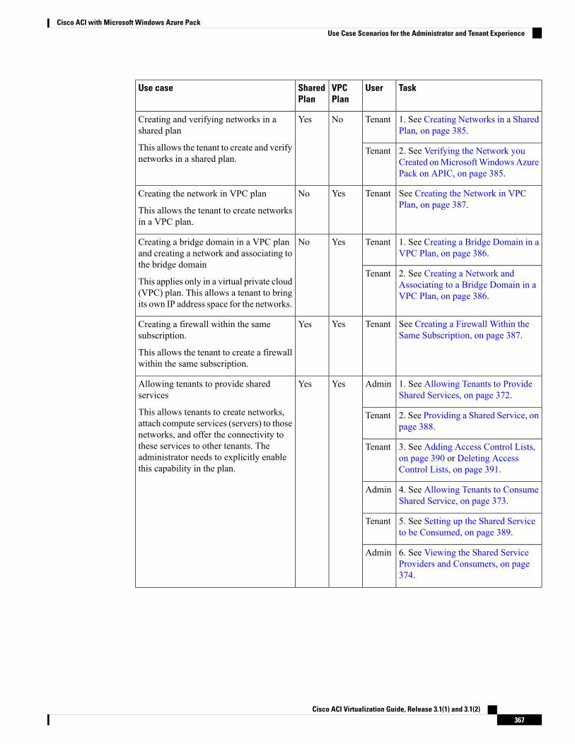
TaskUserVPCPlan
SharedPlan
Use case
1. See Creating Networks in a SharedPlan, on page 385.
TenantNoYesCreating and verifying networks in ashared plan
This allows the tenant to create and verifynetworks in a shared plan.
2. See Verifying the Network youCreated onMicrosoftWindows AzurePack on APIC, on page 385.
Tenant
See Creating the Network in VPCPlan, on page 387.
TenantYesNoCreating the network in VPC plan
This allows the tenant to create networksin a VPC plan.
1. See Creating a Bridge Domain in aVPC Plan, on page 386.
TenantYesNoCreating a bridge domain in a VPC planand creating a network and associating tothe bridge domain
This applies only in a virtual private cloud(VPC) plan. This allows a tenant to bringits own IP address space for the networks.
2. See Creating a Network andAssociating to a Bridge Domain in aVPC Plan, on page 386.
Tenant
See Creating a Firewall Within theSame Subscription, on page 387.
TenantYesYesCreating a firewall within the samesubscription.
This allows the tenant to create a firewallwithin the same subscription.
1. See Allowing Tenants to ProvideShared Services, on page 372.
AdminYesYesAllowing tenants to provide sharedservices
This allows tenants to create networks,attach compute services (servers) to thosenetworks, and offer the connectivity tothese services to other tenants. Theadministrator needs to explicitly enablethis capability in the plan.
2. See Providing a Shared Service, onpage 388.
Tenant
3. See Adding Access Control Lists,on page 390 or Deleting AccessControl Lists, on page 391.
Tenant
4. See Allowing Tenants to ConsumeShared Service, on page 373.
Admin
5. See Setting up the Shared Serviceto be Consumed, on page 389.
Tenant
6. See Viewing the Shared ServiceProviders and Consumers, on page374.
Admin
Cisco ACI Virtualization Guide, Release 3.1(1) and 3.1(2)367
Cisco ACI with Microsoft Windows Azure PackUse Case Scenarios for the Administrator and Tenant Experience
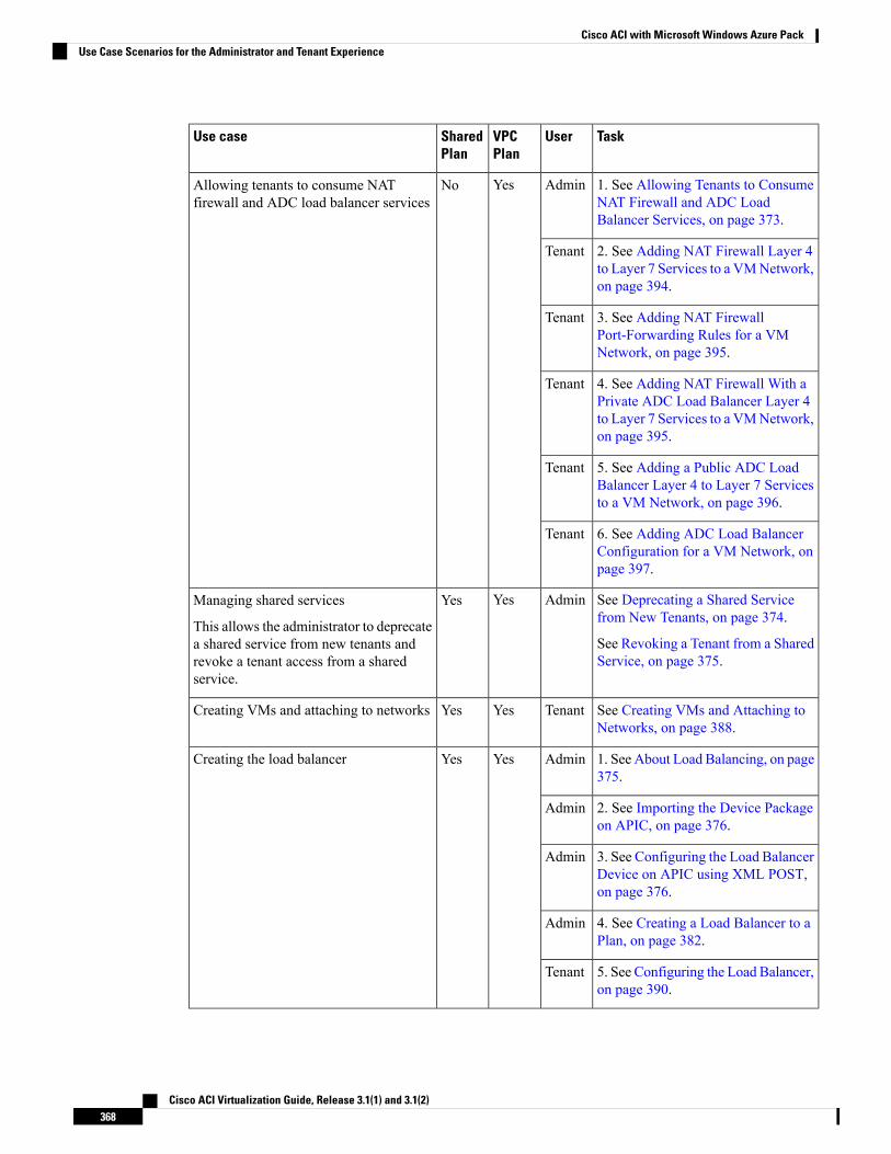
TaskUserVPCPlan
SharedPlan
Use case
1. See Allowing Tenants to ConsumeNAT Firewall and ADC LoadBalancer Services, on page 373.
AdminYesNoAllowing tenants to consume NATfirewall and ADC load balancer services
2. See Adding NAT Firewall Layer 4to Layer 7 Services to a VMNetwork,on page 394.
Tenant
3. See Adding NAT FirewallPort-Forwarding Rules for a VMNetwork, on page 395.
Tenant
4. See Adding NAT Firewall With aPrivate ADC Load Balancer Layer 4to Layer 7 Services to a VMNetwork,on page 395.
Tenant
5. See Adding a Public ADC LoadBalancer Layer 4 to Layer 7 Servicesto a VM Network, on page 396.
Tenant
6. See Adding ADC Load BalancerConfiguration for a VM Network, onpage 397.
Tenant
See Deprecating a Shared Servicefrom New Tenants, on page 374.
See Revoking a Tenant from a SharedService, on page 375.
AdminYesYesManaging shared services
This allows the administrator to deprecatea shared service from new tenants andrevoke a tenant access from a sharedservice.
See Creating VMs and Attaching toNetworks, on page 388.
TenantYesYesCreating VMs and attaching to networks
1. See About Load Balancing, on page375.
AdminYesYesCreating the load balancer
2. See Importing the Device Packageon APIC, on page 376.
Admin
3. See Configuring the Load BalancerDevice on APIC using XML POST,on page 376.
Admin
4. See Creating a Load Balancer to aPlan, on page 382.
Admin
5. See Configuring the Load Balancer,on page 390.
Tenant
Cisco ACI Virtualization Guide, Release 3.1(1) and 3.1(2)368
Cisco ACI with Microsoft Windows Azure PackUse Case Scenarios for the Administrator and Tenant Experience
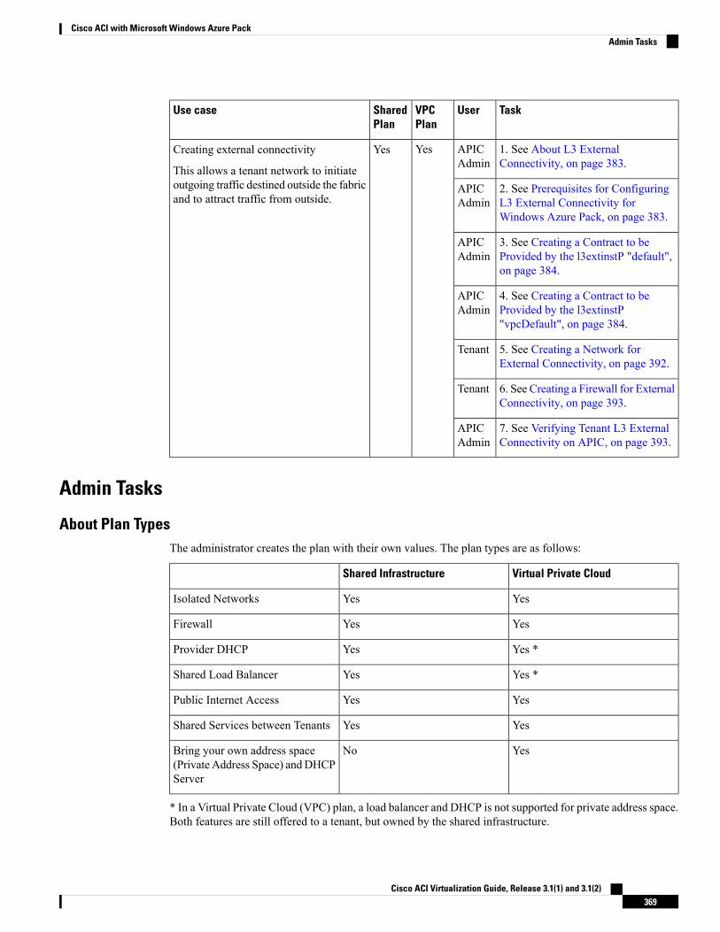
TaskUserVPCPlan
SharedPlan
Use case
1. See About L3 ExternalConnectivity, on page 383.
APICAdmin
YesYesCreating external connectivity
This allows a tenant network to initiateoutgoing traffic destined outside the fabricand to attract traffic from outside.
2. See Prerequisites for ConfiguringL3 External Connectivity forWindows Azure Pack, on page 383.
APICAdmin
3. See Creating a Contract to beProvided by the l3extinstP "default",on page 384.
APICAdmin
4. See Creating a Contract to beProvided by the l3extinstP"vpcDefault", on page 384.
APICAdmin
5. See Creating a Network forExternal Connectivity, on page 392.
Tenant
6. See Creating a Firewall for ExternalConnectivity, on page 393.
Tenant
7. See Verifying Tenant L3 ExternalConnectivity on APIC, on page 393.
APICAdmin
Admin Tasks
About Plan TypesThe administrator creates the plan with their own values. The plan types are as follows:
Virtual Private CloudShared Infrastructure
YesYesIsolated Networks
YesYesFirewall
Yes *YesProvider DHCP
Yes *YesShared Load Balancer
YesYesPublic Internet Access
YesYesShared Services between Tenants
YesNoBring your own address space(Private Address Space) andDHCPServer
* In a Virtual Private Cloud (VPC) plan, a load balancer and DHCP is not supported for private address space.Both features are still offered to a tenant, but owned by the shared infrastructure.
Cisco ACI Virtualization Guide, Release 3.1(1) and 3.1(2)369
Cisco ACI with Microsoft Windows Azure PackAdmin Tasks
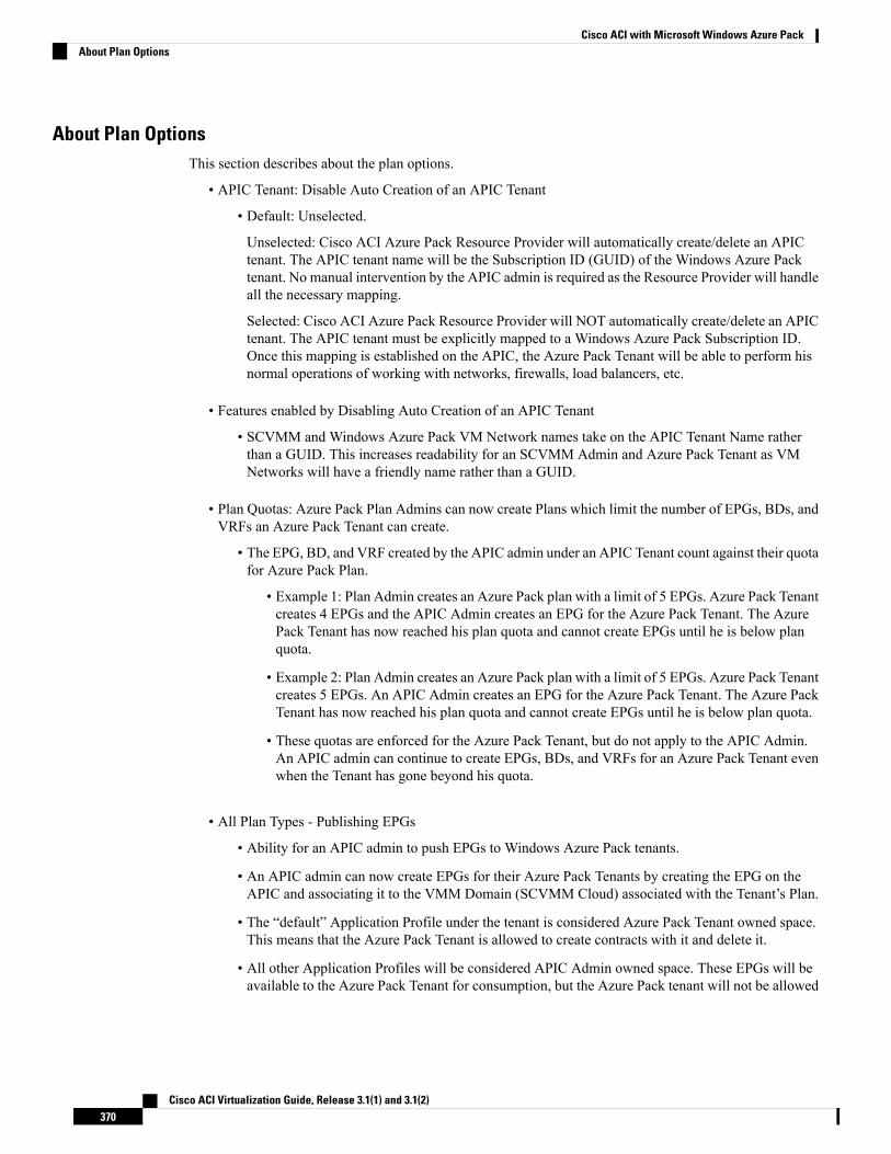
About Plan OptionsThis section describes about the plan options.
• APIC Tenant: Disable Auto Creation of an APIC Tenant
• Default: Unselected.
Unselected: Cisco ACI Azure Pack Resource Provider will automatically create/delete an APICtenant. The APIC tenant name will be the Subscription ID (GUID) of the Windows Azure Packtenant. No manual intervention by the APIC admin is required as the Resource Provider will handleall the necessary mapping.
Selected: Cisco ACI Azure Pack Resource Provider will NOT automatically create/delete an APICtenant. The APIC tenant must be explicitly mapped to a Windows Azure Pack Subscription ID.Once this mapping is established on the APIC, the Azure Pack Tenant will be able to perform hisnormal operations of working with networks, firewalls, load balancers, etc.
• Features enabled by Disabling Auto Creation of an APIC Tenant
• SCVMM and Windows Azure Pack VM Network names take on the APIC Tenant Name ratherthan a GUID. This increases readability for an SCVMM Admin and Azure Pack Tenant as VMNetworks will have a friendly name rather than a GUID.
• Plan Quotas: Azure Pack Plan Admins can now create Plans which limit the number of EPGs, BDs, andVRFs an Azure Pack Tenant can create.
• The EPG, BD, and VRF created by the APIC admin under an APIC Tenant count against their quotafor Azure Pack Plan.
• Example 1: Plan Admin creates an Azure Pack plan with a limit of 5 EPGs. Azure Pack Tenantcreates 4 EPGs and the APIC Admin creates an EPG for the Azure Pack Tenant. The AzurePack Tenant has now reached his plan quota and cannot create EPGs until he is below planquota.
• Example 2: Plan Admin creates an Azure Pack plan with a limit of 5 EPGs. Azure Pack Tenantcreates 5 EPGs. An APIC Admin creates an EPG for the Azure Pack Tenant. The Azure PackTenant has now reached his plan quota and cannot create EPGs until he is below plan quota.
• These quotas are enforced for the Azure Pack Tenant, but do not apply to the APIC Admin.An APIC admin can continue to create EPGs, BDs, and VRFs for an Azure Pack Tenant evenwhen the Tenant has gone beyond his quota.
• All Plan Types - Publishing EPGs
• Ability for an APIC admin to push EPGs to Windows Azure Pack tenants.
• An APIC admin can now create EPGs for their Azure Pack Tenants by creating the EPG on theAPIC and associating it to the VMM Domain (SCVMM Cloud) associated with the Tenant’s Plan.
• The “default” Application Profile under the tenant is considered Azure Pack Tenant owned space.This means that the Azure Pack Tenant is allowed to create contracts with it and delete it.
• All other Application Profiles will be considered APIC Admin owned space. These EPGs will beavailable to the Azure Pack Tenant for consumption, but the Azure Pack tenant will not be allowed
Cisco ACI Virtualization Guide, Release 3.1(1) and 3.1(2)370
Cisco ACI with Microsoft Windows Azure PackAbout Plan Options
to modify, delete, or work with the EPG outside of associating with a Virtual Machine NetworkAdapter.
Creating a PlanThis allows the administrator to create plans with their own values.
Procedure
Step 1 Log in to the Service Management Portal (Admin Portal).Step 2 In the navigation pane, choose PLANS.Step 3 Choose NEW.Step 4 In the NEW pane, choose CREATE PLAN.Step 5 In the Let's Create a Hosting Plan dialog box, enter the name for your plan (Bronze) and click the arrow
for next.Step 6 In the Select services for aHosting Plan dialog box, choose your features. Check the check box forVIRTUAL
MACHINE CLOUDS, NETWORKING (ACI), and click the arrow for next.Step 7 In the Select add-ons for the plan dialog box, click the checkmark for next.Step 8 In the plans pane, wait for the plan (Bronze) to be created and choose the (Bronze) plan arrow to configure
it.Step 9 In the Bronze pane under plan services, choose Virtual Machine Clouds arrow.Step 10 In the virtual machine clouds pane, perform the following actions:
a) In the VMMMANAGEMENT SERVER field, choose the VMMmanagement server (172.23.142.63).b) In the VIRTUAL MACHINE CLOUD field, choose the cloud name (Cloud01).c) Scroll down and choose Add templates.d) In the Select templates to add to this plan dialog box, check the check box for your template(s) and
click the checkmark for next.e) Scroll down to Custom Settings, check the Disable built-in network extensions for tenants check box
for SCVMM.f) Click SAVE at the bottom.g) Once completed, click OK.
Step 11 In the Service Management Portal, click the back arrow which takes you back to the Bronze pane.Step 12 In the Bronze pane under plan services, click Networking (ACI) and perform the following actions:
a) In the PLAN TYPE field, from the drop-down list, choose the plan type.b) For Virtual Private Cloud plan type, enter a valid value between 1 to 4000 number for the “Maximum
EPG allowed per tenant”, “Maximum BD allowed per tenant” and “Maximum CTX allowed per tenant”.
For Shared Infrastructure Plan type, enter a valid value between 1 to 4000 number for the “MaximumEPG allowed per tenant”.
c) Click SAVE.
Step 13 Click OK.You have now created a plan.
Cisco ACI Virtualization Guide, Release 3.1(1) and 3.1(2)371
Cisco ACI with Microsoft Windows Azure PackCreating a Plan
Creating a TenantThis allows the administrator to create a tenant.
Procedure
Step 1 Log in to the Service Management Portal (Admin Portal).Step 2 In the navigation pane, choose USER ACCOUNTS.Step 3 Choose NEW.Step 4 In the NEW pane, scroll down and choose USER ACCOUNTS.Step 5 In the NEW pane, choose QUICK CREATE and perform the following actions:
a) In the ENTER EMAIL ADDRESS field, enter the email address ([email protected]).b) In the ENTER PASSWORD field, enter the password.c) In the CONFIRM PASSWORD field, enter the password again.d) In the CHOOSE PLAN field, choose a plan (BRONZE).e) Click CREATE.f) Click OK.
You have now created a tenant.
Step 6 For Windows Azure Pack Tenants associated with Plans that “Disable Auto Creation of an APIC Tenant”,Take note of the Azure Pack Tenant Login and Subscription ID.a) Log in to the APICGUI, on the menu bar, chooseTENANTS >Tenant Name. The Tenant is the intended
APIC Tenant targeted for Azure Pack Subscription mapping.b) Select the Policy Tab.c) In the GUID section, click the + icon to add a new Azure Pack subscription mapping.d) Populate the GUID with the Azure Pack Tenant Subscription ID and the Account Name with the Azure
Pack Login Account.e) Click Submit to save the changes.
An APIC Tenant can only map to a single Azure Pack Tenant Subscription ID.Note
Allowing Tenants to Provide Shared ServicesThis option allows tenants to create networks, attach compute services (servers) to those networks, and offerthe connectivity to these services to other tenants. The administrator needs to explicitly enable this capabilityin the plan.
Procedure
Step 1 Log in to the Service Management Portal (Admin Portal).Step 2 In the navigation pane, choose PLANS.
a) Choose a plan.b) Click Networking (ACI) under plan services.
Cisco ACI Virtualization Guide, Release 3.1(1) and 3.1(2)372
Cisco ACI with Microsoft Windows Azure PackCreating a Tenant
Step 3 In the networking (aci) pane, check the allow tenants to provide shared services check box and click SAVE.
Allowing Tenants to Consume Shared ServiceEven though tenants are allowed to create a shared service to be used by other tenants, the administrator needsto select the services which can be shared across tenants. This procedure shows how Windows Azure Packadmin can choose the shared services for the plan:
Before you begin
• Ensure the administrator has allowed tenants to provide shared services.
• Ensure the tenant has provided a shared service.
Procedure
Step 1 Log in to the Service Management Portal (Admin Portal).Step 2 In the navigation pane, choose PLANS.Step 3 In the plans pane, choose PLANS.
a) Click on the plan (Gold).
Step 4 In the Gold pane, choose Networking (ACI).Step 5 In the networking (aci) pane, check the shared service check box you want to give access to (DBSrv).Step 6 Click SAVE.
Allowing Tenants to Consume NAT Firewall and ADC Load Balancer ServicesCisco Application Centric Infrastructure (ACI) has the concept of service graphs, which allows a tenant toinsert service nodes performing various Layer 4 to Layer 7 functions between two endpoint groups (EPGs)within the fabric.
Windows Azure Pack with ACI integration now includes the ability to easily and seamlessly provision anddeploy services graphs in a Virtual Private Cloud (VPC) setting where the external NAT firewall IP andexternal ADC load balancer sit within a shared space. The most common use-case for this is the serviceprovider model where a limited number externally accessible IP addresses are available for use, in which casevarious port-forwarding techniques or load balancing of an entire EPG is done against the one external IP.
Tenants within Azure Pack can utilize a strict VPC model where all their networking is contained within thetenant virtual routing and forwarding (VRF) or a split VRF model where an APIC admin can configure a setof L3Out which is accessible by all tenants utilizing the ACI fabric. The following are instructions on providinga split VRF workflow allowing Azure Pack tenants to consume the Layer 4 to Layer 7 service devices as wellas being allocated public addresses for the services provided from within the tenant VRF:
Before you begin
• Ensure the Application Policy Infrastructure Controller (APIC) administrator has configured at least 1Layer 4 to Layer 7 resource pool in tenant common. For information, see the chapter "Configuring Layer4 to Layer 7 Resource Pools" in the Cisco APIC Layer 4 to Layer 7 Services Deployment Guide.
Cisco ACI Virtualization Guide, Release 3.1(1) and 3.1(2)373
Cisco ACI with Microsoft Windows Azure PackAllowing Tenants to Consume Shared Service
Procedure
Step 1 Log in to the Service Management Portal (Admin Portal).Step 2 In the navigation pane, choose PLANS.Step 3 In the plans pane, choose PLANS.
a) Click on the plan (Gold).
Step 4 In the Gold pane, choose Networking (ACI).Step 5 In the networking (aci) pane, choose the Layer 4 to Layer 7 services pool provisioned by the APIC admin
for Azure Pack consumption.Step 6 Click SAVE.
Viewing the Shared Service Providers and ConsumersThis allows the administrator to view the shared service providers and consumers.
Before you begin
• Ensure the administrator has allowed tenants to provide shared services.
• Ensure the tenant has provided a shared service.
• Ensure the administrator has enabled the shared service on a plan.
• Ensure the tenant has set up the shared service to be consumed.
Procedure
Step 1 Log in to the Service Management Portal (Admin Portal).Step 2 In the navigation pane, choose ACI.Step 3 In the ACI pane, choose SHARED SERVICES to view the shared service providers.Step 4 Click on the provider.Step 5 Click INFO to display all the users that are consuming this shared service.
Managing Shared Services
Deprecating a Shared Service from New Tenants
This allows the administrator to deprecate a shared service from new tenants.
Procedure
Step 1 Log in to the Service Management Portal (Admin Portal).Step 2 In the navigation pane, choose PLANS.
Cisco ACI Virtualization Guide, Release 3.1(1) and 3.1(2)374
Cisco ACI with Microsoft Windows Azure PackViewing the Shared Service Providers and Consumers
Step 3 In the plans pane, choose the plan (Gold).Step 4 In the gold pane, choose Networking (ACI).Step 5 In the networking (aci) pane, uncheck the service from the plan and click SAVE.
You have deprecated the shared service from tenants.
Revoking a Tenant from a Shared Service
This allows the administrator to revoke a tenant from a shared service.
Procedure
Step 1 Log in to the Service Management Portal (Admin Portal).Step 2 In the navigation pane, choose ACI.Step 3 In the aci pane, choose the shared service (DBSrv).Step 4 Click INFO to ensure that the user you want to revoke is present in that shared service.Step 5 In the navigation pane, choose PLANS.Step 6 In the plans pane, choose the plan (Gold).Step 7 In the gold pane, choose Networking (ACI).Step 8 In the networking (aci) pane, uncheck the service from the plan and click SAVE.Step 9 In the navigation pane, choose ACI.Step 10 In the aci pane, choose SHARED SERVICES.Step 11 In the aci pane, choose the shared service (DBSrv) and click INFO.Step 12 In the Revoke Consumers of DBSrv dialog box, check the check box of the user you want to revoke.Step 13 Click the checkmark.
About Load BalancingVLAN, virtual routing and forwarding (VRF) stitching is supported by traditional service insertion models,the Application Policy Infrastructure Controller (APIC) can automate service insertion while acting as a centralpoint of policy control. The APIC policies manage both the network fabric and services appliances. The APICcan configure the network automatically so that traffic flows through the services. The APIC can alsoautomatically configure the service according to the application's requirements, which allows organizationsto automate service insertion and eliminate the challenge of managing the complex techniques of traditionalservice insertion.
See the Cisco APIC Layer 4 to Layer 7 Services Deployment Guide for more information.
You must perform the following tasks to deploy Layer 4 to Layer 7 services using the APIC GUI:
See Importing the Device Package on APIC, on page376.
Import the device package.
Only the administrator can import the device package.
Cisco ACI Virtualization Guide, Release 3.1(1) and 3.1(2)375
Cisco ACI with Microsoft Windows Azure PackRevoking a Tenant from a Shared Service
See Configuring the Load Balancer Device on APICusing XML POST, on page 376.
Configure and post the XML POST to ApplicationPolicy Infrastructure Controller (APIC)
Refer to Microsoft's Windows Azure Pack Servicessection about the device package.
Only the administrator can configure and post theXML POST.
See Creating a Load Balancer to a Plan, on page 382.Creating a load balancer to a plan
The VIP range to Windows Azure Pack is set.
Only the administrator can create a load balancer toa plan.
See Configuring the Load Balancer, on page 390.Configure the load balancer
Only the tenant can configure the load balancer.
Importing the Device Package on APIC
Only the administrator can import the device package. The administrator can import a device package intothe Application Policy Infrastructure Controller (APIC) so that the APIC knows what devices you have andwhat the devices can do.
Before you begin
Ensure you have downloaded the device package.
Procedure
Step 1 Log in to the APIC GUI, on the menu bar, choose L4-L7 SERVICES > PACKAGES.Step 2 In the navigation pane, choose Quick Start.Step 3 In the Quick Start pane, choose Import a Device Package.Step 4 In the Import Device Package dialog box, perform the following action:
a) Click BROWSE and locate your device package such as F5 or Citrix device package.b) Click SUBMIT.
Configuring the Load Balancer Device on APIC using XML POST
Only the administrator can configure and post the XML POST.
Before you begin
• The device package file should be uploaded on the Application Policy Infrastructure Controller (APIC).
See Cisco APIC Layer 4 to Layer 7 Device Package Development Guide for more information.
• The tenant common should have the two bridge domains named "default" and "vpcDefault". Ensure thatthe subnets being used by the tenant who is consuming the load balancer is added to these bridge domains.
Cisco ACI Virtualization Guide, Release 3.1(1) and 3.1(2)376
Cisco ACI with Microsoft Windows Azure PackImporting the Device Package on APIC
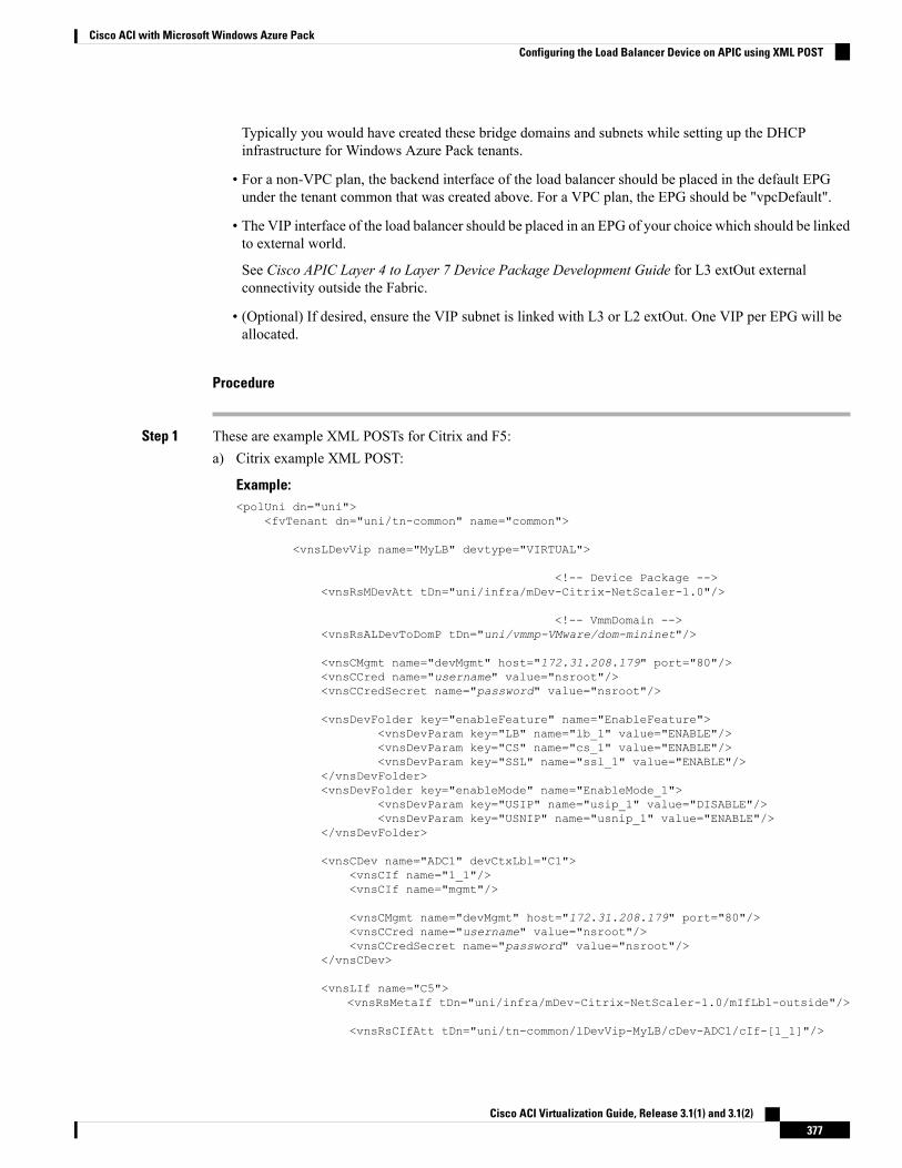
Typically you would have created these bridge domains and subnets while setting up the DHCPinfrastructure for Windows Azure Pack tenants.
• For a non-VPC plan, the backend interface of the load balancer should be placed in the default EPGunder the tenant common that was created above. For a VPC plan, the EPG should be "vpcDefault".
• The VIP interface of the load balancer should be placed in an EPG of your choice which should be linkedto external world.
See Cisco APIC Layer 4 to Layer 7 Device Package Development Guide for L3 extOut externalconnectivity outside the Fabric.
• (Optional) If desired, ensure the VIP subnet is linked with L3 or L2 extOut. One VIP per EPG will beallocated.
Procedure
Step 1 These are example XML POSTs for Citrix and F5:a) Citrix example XML POST:
Example:<polUni dn="uni">
<fvTenant dn="uni/tn-common" name="common">
<vnsLDevVip name="MyLB" devtype="VIRTUAL">
<!-- Device Package --><vnsRsMDevAtt tDn="uni/infra/mDev-Citrix-NetScaler-1.0"/>
<!-- VmmDomain --><vnsRsALDevToDomP tDn="uni/vmmp-VMware/dom-mininet"/>
<vnsCMgmt name="devMgmt" host="172.31.208.179" port="80"/><vnsCCred name="username" value="nsroot"/><vnsCCredSecret name="password" value="nsroot"/>
<vnsDevFolder key="enableFeature" name="EnableFeature"><vnsDevParam key="LB" name="lb_1" value="ENABLE"/><vnsDevParam key="CS" name="cs_1" value="ENABLE"/><vnsDevParam key="SSL" name="ssl_1" value="ENABLE"/>
</vnsDevFolder><vnsDevFolder key="enableMode" name="EnableMode_1">
<vnsDevParam key="USIP" name="usip_1" value="DISABLE"/><vnsDevParam key="USNIP" name="usnip_1" value="ENABLE"/>
</vnsDevFolder>
<vnsCDev name="ADC1" devCtxLbl="C1"><vnsCIf name="1_1"/><vnsCIf name="mgmt"/>
<vnsCMgmt name="devMgmt" host="172.31.208.179" port="80"/><vnsCCred name="username" value="nsroot"/><vnsCCredSecret name="password" value="nsroot"/>
</vnsCDev>
<vnsLIf name="C5"><vnsRsMetaIf tDn="uni/infra/mDev-Citrix-NetScaler-1.0/mIfLbl-outside"/>
<vnsRsCIfAtt tDn="uni/tn-common/lDevVip-MyLB/cDev-ADC1/cIf-[1_1]"/>
Cisco ACI Virtualization Guide, Release 3.1(1) and 3.1(2)377
Cisco ACI with Microsoft Windows Azure PackConfiguring the Load Balancer Device on APIC using XML POST
</vnsLIf><vnsLIf name="C4">
<vnsRsMetaIf tDn="uni/infra/mDev-Citrix-NetScaler-1.0/mIfLbl-inside"/><vnsRsCIfAtt tDn="uni/tn-common/lDevVip-MyLB/cDev-ADC1/cIf-[1_1]"/>
</vnsLIf>
</vnsLDevVip>
<vnsAbsGraph name ="MyLB">
<!-- Node2 Provides SLB functionality --><vnsAbsNode name = "Node2" funcType="GoTo" >
<vnsRsDefaultScopeToTermtDn="uni/tn-common/AbsGraph-MyLB/AbsTermNodeProv-Output1/outtmnl"/>
<vnsAbsFuncConn name = "C4"><vnsRsMConnAtt
tDn="uni/infra/mDev-Citrix-NetScaler-1.0/mFunc-LoadBalancing/mConn-external" /></vnsAbsFuncConn>
<vnsAbsFuncConn name = "C5" attNotify="true"><vnsRsMConnAtt
tDn="uni/infra/mDev-Citrix-NetScaler-1.0/mFunc-LoadBalancing/mConn-internal" /></vnsAbsFuncConn>
<vnsAbsDevCfg><vnsAbsFolder key="Network"
name="network"scopedBy="epg">
<vnsAbsFolder key="nsip" name="snip1"><vnsAbsParam key="ipaddress" name="ip1" value="5.5.5.251"/>
<vnsAbsParam key="netmask" name="netmask1"value="255.255.255.0"/>
<vnsAbsParam key="hostroute" name="hostroute"value="DISABLED"/>
<vnsAbsParam key="dynamicrouting" name="dynamicrouting"value="ENABLED"/>
<vnsAbsParam key="type" name="type" value="SNIP"/></vnsAbsFolder>
</vnsAbsFolder>
</vnsAbsDevCfg>
<vnsAbsFuncCfg><vnsAbsFolder key="internal_network"
name="internal_network"scopedBy="epg">
<vnsAbsCfgRel name="internal_network_key"key="internal_network_key"targetName="network/snip1"/>
</vnsAbsFolder></vnsAbsFuncCfg>
<vnsRsNodeToMFunctDn="uni/infra/mDev-Citrix-NetScaler-1.0/mFunc-LoadBalancing"/>
</vnsAbsNode>
<vnsAbsTermNodeCon name = "Input1"><vnsAbsTermConn name = "C1"/>
</vnsAbsTermNodeCon>
<vnsAbsTermNodeProv name = "Output1">
Cisco ACI Virtualization Guide, Release 3.1(1) and 3.1(2)378
Cisco ACI with Microsoft Windows Azure PackConfiguring the Load Balancer Device on APIC using XML POST
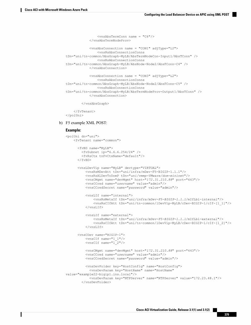
<vnsAbsTermConn name = "C6"/></vnsAbsTermNodeProv>
<vnsAbsConnection name = "CON1" adjType="L2"><vnsRsAbsConnectionConns
tDn="uni/tn-common/AbsGraph-MyLB/AbsTermNodeCon-Input1/AbsTConn" /><vnsRsAbsConnectionConns
tDn="uni/tn-common/AbsGraph-MyLB/AbsNode-Node2/AbsFConn-C4" /></vnsAbsConnection>
<vnsAbsConnection name = "CON3" adjType="L2"><vnsRsAbsConnectionConns
tDn="uni/tn-common/AbsGraph-MyLB/AbsNode-Node2/AbsFConn-C5" /><vnsRsAbsConnectionConns
tDn="uni/tn-common/AbsGraph-MyLB/AbsTermNodeProv-Output1/AbsTConn" /></vnsAbsConnection>
</vnsAbsGraph>
</fvTenant></polUni>
b) F5 example XML POST:
Example:<polUni dn="uni">
<fvTenant name="common">
<fvBD name="MyLB"><fvSubnet ip="6.6.6.254/24" /><fvRsCtx tnFvCtxName="default"/>
</fvBD>
<vnsLDevVip name="MyLB" devtype="VIRTUAL"><vnsRsMDevAtt tDn="uni/infra/mDev-F5-BIGIP-1.1.1"/><vnsRsALDevToDomP tDn="uni/vmmp-VMware/dom-mininet"/><vnsCMgmt name="devMgmt" host="172.31.210.88" port="443"/><vnsCCred name="username" value="admin"/><vnsCCredSecret name="password" value="admin"/>
<vnsLIf name="internal"><vnsRsMetaIf tDn="uni/infra/mDev-F5-BIGIP-1.1.1/mIfLbl-internal"/><vnsRsCIfAtt tDn="uni/tn-common/lDevVip-MyLB/cDev-BIGIP-1/cIf-[1_1]"/>
</vnsLIf>
<vnsLIf name="external"><vnsRsMetaIf tDn="uni/infra/mDev-F5-BIGIP-1.1.1/mIfLbl-external"/><vnsRsCIfAtt tDn="uni/tn-common/lDevVip-MyLB/cDev-BIGIP-1/cIf-[1_2]"/>
</vnsLIf>
<vnsCDev name="BIGIP-1"><vnsCIf name="1_1"/><vnsCIf name="1_2"/>
<vnsCMgmt name="devMgmt" host="172.31.210.88" port="443"/><vnsCCred name="username" value="admin"/><vnsCCredSecret name="password" value="admin"/>
<vnsDevFolder key="HostConfig" name="HostConfig"><vnsDevParam key="HostName" name="HostName"
value="example22-bigip1.ins.local"/><vnsDevParam key="NTPServer" name="NTPServer" value="172.23.48.1"/>
</vnsDevFolder>
Cisco ACI Virtualization Guide, Release 3.1(1) and 3.1(2)379
Cisco ACI with Microsoft Windows Azure PackConfiguring the Load Balancer Device on APIC using XML POST
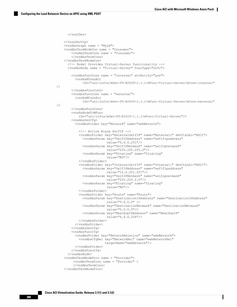
</vnsCDev>
</vnsLDevVip><vnsAbsGraph name = "MyLB"><vnsAbsTermNodeCon name = "Consumer">
<vnsAbsTermConn name = "Consumer"></vnsAbsTermConn>
</vnsAbsTermNodeCon><!-- Node1 Provides Virtual-Server functionality --><vnsAbsNode name = "Virtual-Server" funcType="GoTo">
<vnsAbsFuncConn name = "internal" attNotify="yes"><vnsRsMConnAtt
tDn="uni/infra/mDev-F5-BIGIP-1.1.1/mFunc-Virtual-Server/mConn-internal"/>
</vnsAbsFuncConn><vnsAbsFuncConn name = "external"><vnsRsMConnAtt
tDn="uni/infra/mDev-F5-BIGIP-1.1.1/mFunc-Virtual-Server/mConn-external"/>
</vnsAbsFuncConn><vnsRsNodeToMFunc
tDn="uni/infra/mDev-F5-BIGIP-1.1.1/mFunc-Virtual-Server"/><vnsAbsDevCfg><vnsAbsFolder key="Network" name="webNetwork">
<!-- Active Bigip SelfIP --><vnsAbsFolder key="ExternalSelfIP" name="External1" devCtxLbl="ADC1"><vnsAbsParam key="SelfIPAddress" name="seflfipaddress"
value="6.6.6.251"/><vnsAbsParam key="SelfIPNetmask" name="selfipnetmask"
value="255.255.255.0"/><vnsAbsParam key="Floating" name="floating"
value="NO"/></vnsAbsFolder><vnsAbsFolder key="InternalSelfIP" name="Internal1" devCtxLbl="ADC1"><vnsAbsParam key="SelfIPAddress" name="seflfipaddress"
value="12.0.251.251"/><vnsAbsParam key="SelfIPNetmask" name="selfipnetmask"
value="255.255.0.0"/><vnsAbsParam key="Floating" name="floating"
value="NO"/></vnsAbsFolder><vnsAbsFolder key="Route" name="Route"><vnsAbsParam key="DestinationIPAddress" name="DestinationIPAddress"
value="0.0.0.0" /><vnsAbsParam key="DestinationNetmask" name="DestinationNetmask"
value="0.0.0.0"/><vnsAbsParam key="NextHopIPAddress" name="NextHopIP"
value="6.6.6.254"/></vnsAbsFolder>
</vnsAbsFolder></vnsAbsDevCfg><vnsAbsFuncCfg><vnsAbsFolder key="NetworkRelation" name="webNetwork"><vnsAbsCfgRel key="NetworkRel" name="webNetworkRel"
targetName="webNetwork"/></vnsAbsFolder>
</vnsAbsFuncCfg></vnsAbsNode>
<vnsAbsTermNodeProv name = "Provider"><vnsAbsTermConn name = "Provider" ></vnsAbsTermConn>
</vnsAbsTermNodeProv>
Cisco ACI Virtualization Guide, Release 3.1(1) and 3.1(2)380
Cisco ACI with Microsoft Windows Azure PackConfiguring the Load Balancer Device on APIC using XML POST
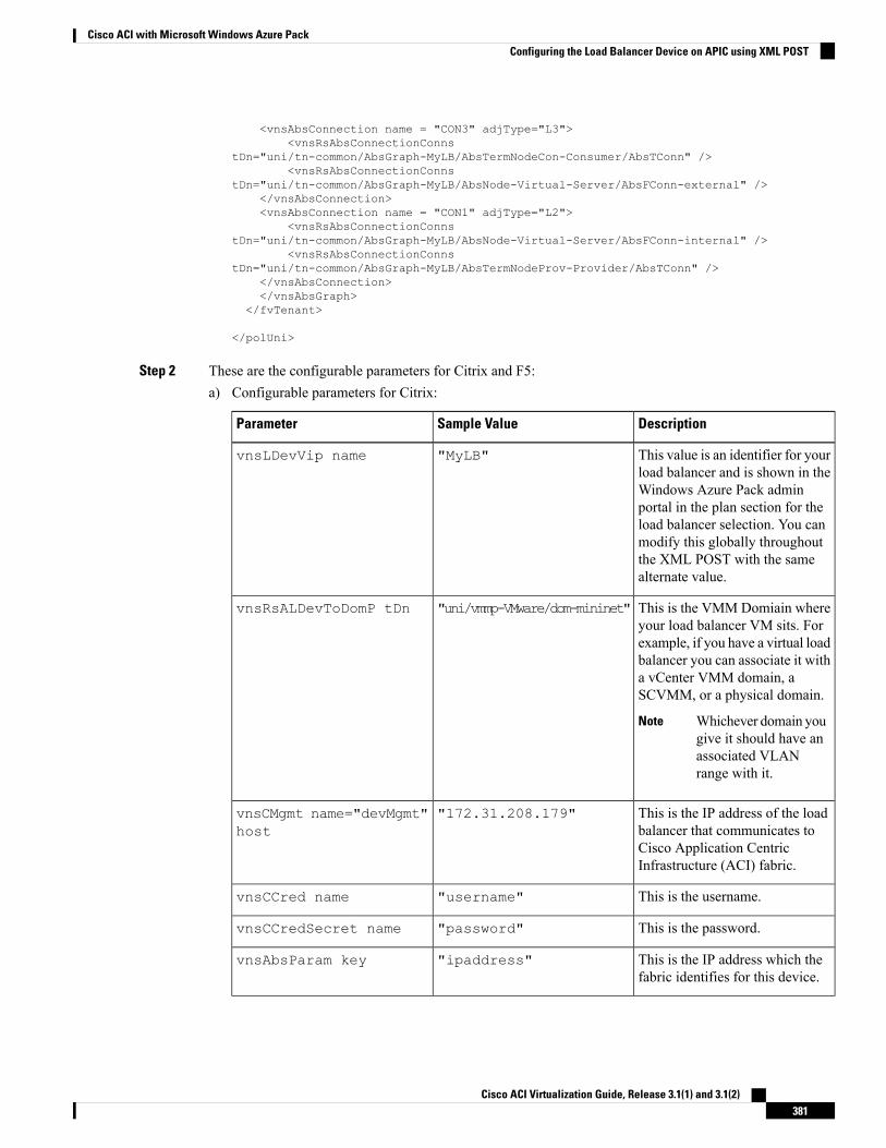
<vnsAbsConnection name = "CON3" adjType="L3"><vnsRsAbsConnectionConns
tDn="uni/tn-common/AbsGraph-MyLB/AbsTermNodeCon-Consumer/AbsTConn" /><vnsRsAbsConnectionConns
tDn="uni/tn-common/AbsGraph-MyLB/AbsNode-Virtual-Server/AbsFConn-external" /></vnsAbsConnection><vnsAbsConnection name = "CON1" adjType="L2">
<vnsRsAbsConnectionConnstDn="uni/tn-common/AbsGraph-MyLB/AbsNode-Virtual-Server/AbsFConn-internal" />
<vnsRsAbsConnectionConnstDn="uni/tn-common/AbsGraph-MyLB/AbsTermNodeProv-Provider/AbsTConn" />
</vnsAbsConnection></vnsAbsGraph>
</fvTenant>
</polUni>
Step 2 These are the configurable parameters for Citrix and F5:a) Configurable parameters for Citrix:
DescriptionSample ValueParameter
This value is an identifier for yourload balancer and is shown in theWindows Azure Pack adminportal in the plan section for theload balancer selection. You canmodify this globally throughoutthe XML POST with the samealternate value.
"MyLB"vnsLDevVip name
This is the VMM Domiain whereyour load balancer VM sits. Forexample, if you have a virtual loadbalancer you can associate it witha vCenter VMM domain, aSCVMM, or a physical domain.
Whichever domain yougive it should have anassociated VLANrange with it.
Note
"uni/vmmp-VMware/dom-mininet"vnsRsALDevToDomP tDn
This is the IP address of the loadbalancer that communicates toCisco Application CentricInfrastructure (ACI) fabric.
"172.31.208.179"vnsCMgmt name="devMgmt"host
This is the username."username"vnsCCred name
This is the password."password"vnsCCredSecret name
This is the IP address which thefabric identifies for this device.
"ipaddress"vnsAbsParam key
Cisco ACI Virtualization Guide, Release 3.1(1) and 3.1(2)381
Cisco ACI with Microsoft Windows Azure PackConfiguring the Load Balancer Device on APIC using XML POST
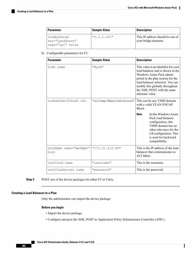
DescriptionSample ValueParameter
This IP address should be one ofyour bridge domains.
"5.5.5.251"vnsAbsParamkey="ipaddress"name="ip1" value
b) Configurable parameters for F5:
DescriptionSample ValueParameter
This value is an identifier for yourload balancer and is shown in theWindows Azure Pack adminportal in the plan section for theload balancer selection. You canmodify this globally throughoutthe XML POST with the samealternate value.
"MyLB"fvBD name
This can be any VMM domainwith a valid VLAN ENCAPBlock.
In thisWindowsAzurePack load balancerconfiguration, thisVMM domain has noother relevance for theLB configuration. Thisis used for backwardcompatibility.
Note
"uni/vmmp-VMware/dom-mininet"vnsRsALDevToDomP tDn
This is the IP address of the loadbalancer that communicates toACI fabric.
"172.31.210.88"vnsCMgmt name="devMgmt"host
This is the username."username"vnsCCred name
This is the password."password"vnsCCredSecret name
Step 3 POST one of the device packages for either F5 or Citrix.
Creating a Load Balancer to a Plan
Only the administrator can import the device package.
Before you begin
• Import the device package.
• Configure and post the XML POST to Application Policy Infrastructure Controller (APIC) .
Cisco ACI Virtualization Guide, Release 3.1(1) and 3.1(2)382
Cisco ACI with Microsoft Windows Azure PackCreating a Load Balancer to a Plan
Procedure
Step 1 Log in to the Service Management Portal (Admin Portal).Step 2 In the Navigation pane, choose PLANS.Step 3 In the plans pane, choose the plan that you want to add a load balancer (shareplan).Step 4 In the shareplan pane, choose Networking (ACI).Step 5 In the networking (aci) pane, perform the following actions to add a shared load balancer:
a) Check the shared load balancer check boxb) In the LB DEVICE ID IN APIC field, from the drop-down list, choose the load balancer (MyLB).c) In the VIP RANGE field, provide the VIP range (5.5.5.1 - 5.5.5.100).d) Click SAVE.
You can have a single load balancer that is shared across different plans as long as the VIPranges do not over lap.
Note
About L3 External ConnectivityLayer 3 (L3) external connectivity is an Cisco Application Centric Infrastructure (ACI) feature to connectACI fabric to an external network by L3 routing protocols, including static routing, OSPF, EIGRP, and BGP.By setting up L3 external connectivity for Microsoft Windows Azure Pack, it allows a tenant network toinitiate outgoing traffic destined outside the fabric and to attract traffic from outside. The assumption of thisfeature is the tenant virtual machine IP addresses are visible outside the fabric without NAT, ACI L3 externalconnectivity does not include NAT.
Prerequisites for Configuring L3 External Connectivity for Windows Azure Pack
To configure Layer 3 (L3) external connectivity for Windows Azure Pack, you must meet the followingprerequisites:
• Ensure you have logged in to the Application Policy Infrastructure Controller (APIC) GUI, on the menubar, choose TENANT > common.
• Create a l3ExtOut called “default”, refer to BD “default”.
• Create l3extInstP name="defaultInstP" under the l3ExtOut. This is to be used by shared servicetenants.
See the Cisco APIC Basic Configuration Guide for L3 external connectivity configuration.
• Ensure you have logged in to the APIC GUI, on the menu bar, choose TENANT > common.
• Create a l3ExtOut called "vpcDefault", refer to BD "vpcDefault".
• Create l3extInstP name="vpcDefaultInstP" under this l3ExtOut.
This is to be used by VPC tenants.
See the Cisco APIC Basic Configuration Guide for configuring external connectivity for tenants.
Windows Azure Pack leverages the common l3ExtOut configuration with no special requirement otherthan the naming convention highlighted above
Cisco ACI Virtualization Guide, Release 3.1(1) and 3.1(2)383
Cisco ACI with Microsoft Windows Azure PackAbout L3 External Connectivity
Creating a Contract to be Provided by the l3extinstP "default"
This section describes how to creating a contract to be provided by the l3extinstP "default".
See Prerequisites for Configuring L3 External Connectivity for Windows Azure Pack, on page 383.
Make sure the scope is "Global". This contract allows all traffic from consumer to provider, and only allowTCP established from provider to consumer.
Procedure
Step 1 Log in to the APIC GUI, on the menu bar, choose TENANTS > common.Step 2 In the Navigation pane, expand Tenant Name > Security Policies > Contracts.Step 3 Click ACTION, from the drop-down list, choose Create Contract.Step 4 In the Create Contract dialog box, perform the following actions:
a) In the Name field, enter the name (L3_DefaultOut).b) In the Scope field, from the drop-down list, choose Global.c) In the Subjects field, click the + icon.d) In the Create Contract Subject dialog box, perform the following actions:e) In the Name field, enter the name of your choice.f) Uncheck Apply Both direction.g) In the Filter Chain For Consumer to Provider field, click the + icon, from the drop-down list, choose
default/common, and click Update.h) In the Filter Chain For Provider to Consumer field, click the + icon, from the drop-down list, choose
est/common, and click Update.i) Click OK to close the Create Contract Subject dialog box.j) Click OK to close the Create Contractdialog box.You have now creating a contract to be provided by the l3extinstP "default".
Creating a Contract to be Provided by the l3extinstP "vpcDefault"
This section describes how to creating a contract to be provided by the l3extinstP "vpcDefault".
See Prerequisites for Configuring L3 External Connectivity for Windows Azure Pack, on page 383.
Make sure the scope is "Global". This contract allows all traffic from consumer to provider, and only allowTCP established from provider to consumer.
Procedure
Step 1 Log in to the APIC GUI, on the menu bar, choose TENANTS > common.Step 2 In the Navigation pane, expand Tenant Name > Security Policies > Contracts.Step 3 Click ACTION, from the drop-down list, choose Create Contract.Step 4 In the Create Contract dialog box, perform the following actions:
a) In the Name field, enter the name (L3_VpcDefaultOut).b) In the Scope field, from the drop-down list, choose Global.c) In the Subjects field, click the + icon.
Cisco ACI Virtualization Guide, Release 3.1(1) and 3.1(2)384
Cisco ACI with Microsoft Windows Azure PackCreating a Contract to be Provided by the l3extinstP "default"
d) In the Create Contract Subject dialog box, perform the following actions:e) In the Name field, enter the name of your choice.f) Uncheck Apply Both direction.g) In the Filter Chain For Consumer to Provider field, click the + icon, from the drop-down list, choose
default/common, and click Update.h) In the Filter Chain For Provider to Consumer field, click the + icon, from the drop-down list, choose
est/common, and click Update.i) Click OK to close the Create Contract Subject dialog box.j) Click OK to close the Create Contractdialog box.You have now creating a contract to be provided by the l3extinstP "vpcDefault".
Tenant TasksThis section describes the tenant tasks.
If the shared service consumer is in a different VRF than the provider, route leaking between the VRFs willautomatically occur in order to enable the communication.
Note
Shared or Virtual Private Cloud Plan ExperienceThis is an experience of a tenant in a shared or virtual private cloud (VPC) plan.
Creating Networks in a Shared Plan
This allows the administrator to create networks in a shared plan.
Procedure
Step 1 Log in to the Service Management Portal (Tenant Portal).Step 2 In the navigation pane, choose ACI.Step 3 In the ACI pane, choose NETWORKS.Step 4 Click NEW.Step 5 In the NEW pane, choose NETWORKS and perform the following actions:
a) In the NETWORK NAME field, enter the name of the network (S01).b) Click CREATE.c) Click REFRESH.
Verifying the Network you Created on Microsoft Windows Azure Pack on APIC
This section describes how to verify the network you created on Microsoft Windows Azure Pack on APIC.
Cisco ACI Virtualization Guide, Release 3.1(1) and 3.1(2)385
Cisco ACI with Microsoft Windows Azure PackTenant Tasks
Procedure
Step 1 Log in to the APIC GUI, on the menu bar, choose TENANTS.Step 2 In the Navigation pane, expand Tenant 018b2f7d-9e80-43f0-abff-7559c026bad5 > Application Profiles >
default >Application EPGs >EPGNetwork01 to verify that the network you created onMicrosoftWindowsAzure Pack was created on APIC.
Creating a Bridge Domain in a VPC Plan
This applies only in a virtual private cloud (VPC) plan. This allows a tenant to bring its own IP address spacefor the networks.
Procedure
Step 1 Log in to the Service Management Portal (Tenant Portal).Step 2 In the navigation pane, choose ACI.Step 3 Click NEW.Step 4 In the NEW pane, choose BRIDGE DOMAIN.Step 5 In the BRIDGE DOMAIN field, enter the bridge domain name (BD01).Step 6 If the current tenant is subscribed to multiple Azure Pack Plans, select the Subscription to create the Bridge
Domain against.Step 7 Optional: In the SUBNET'S GATEWAY field, enter the subnet's gateway (192.168.1.1/24).Step 8 In the CONTEXT field, select a Context that is already part of the subscription or choose Create One to
create a new Context for the Bridge Domain.Step 9 Click CREATE.
Creating a Network and Associating to a Bridge Domain in a VPC Plan
This allows the tenant to create a network and associate to a bridge domain in a VPC plan.
Procedure
Step 1 Log in to the Service Management Portal (Tenant Portal).Step 2 In the navigation pane, choose ACI.Step 3 Click NEW.Step 4 In the NEW pane, choose NETWORK.Step 5 In the NETWORK NAME field, enter the network name (S01).Step 6 In the BRIDGE NAME field, enter the bridge name (BD01).Step 7 Click CREATE.Step 8 In the aci pane, choose NETWORKS.
Cisco ACI Virtualization Guide, Release 3.1(1) and 3.1(2)386
Cisco ACI with Microsoft Windows Azure PackCreating a Bridge Domain in a VPC Plan
You will see the network is now associated to the bridge domain.
Creating a Firewall Within the Same Subscription
This allows the tenant to create a firewall within the same subscription.
Before you begin
Ensure two networks have been created.
Procedure
Step 1 Log in to the Service Management Portal (Tenant Portal).Step 2 In the navigation pane, choose ACI.Step 3 Click NEW.Step 4 In the NEW pane, choose FIREWALL.Step 5 In the FROM NETWORK field, in the drop-down list, choose the network name (WEB01).Step 6 In the TO NETWORK field, in the drop-down list, choose another network name (WEB02).Step 7 In the PROTOCOL field, enter the protocol (tcp).Step 8 In the PORT RANGE BEGIN field, enter the beginning port range (50).Step 9 In the PORT RANGE END field, enter the end of the port range (150).Step 10 Click CREATE.
You have added a firewall within the same subscription.
Creating the Network in VPC Plan
This allows the tenant to create networks in a VPC plan.
Procedure
Step 1 Log in to the Service Management Portal (Tenant Portal).Step 2 In the Navigation pane, choose ACI.Step 3 Click NEW.Step 4 In the NEW pane, choose ACI > NETWORK and perform the following actions:
a) In the NETWORK NAME field, enter the network name (Network01).b) Option 1: Creating a network in a shared Bridge Domain.
• In the BRIDGE DOMAIN field, from the drop-down, choose the bridge domain. (default).
• Click CREATE.
This could take a few minutes for this process to complete.
c) Option 2: Creating a network in a Tenant Bridge Domain.
Cisco ACI Virtualization Guide, Release 3.1(1) and 3.1(2)387
Cisco ACI with Microsoft Windows Azure PackCreating a Firewall Within the Same Subscription
• In theBRIDGEDOMAIN field, from the drop-down, choose the bridge domain (myBridgeDomain).
d) Optional: To deploy the Network with a Static IP Address Pool, perform the following actions:
• Enter a Gateway in Address/Mask format (192.168.1.1/24). The resultant Static IP Address Pool willuse the full range of the Gateway Subnet.
• Enter DNS Servers. If more than one is required, separate out the list with semicolons(192.168.1.2;192.168.1.3)
The Subnet will be validated against all other subnets in the Context. The Network createwill return an error if an overlap is detected.
Note
• Click CREATE.
This could take a few minutes for this process to complete.
Creating VMs and Attaching to Networks
This allows the tenant to create VMs and attach to networks.
Procedure
Step 1 Log in to the Service Management Portal (Tenant Portal).Step 2 In the navigation pane, choose ACI.Step 3 Click NEW.Step 4 In the NEW pane, choose STANDALONE VIRTUAL MACHINE > FROM GALLERY.Step 5 In the Virtual Machine Configuration dialog box, choose your configuration (LinuxCentOS).Step 6 Click the arrow for next.Step 7 In the Portal Virtual Machine Settings dialog box, perform the following actions:
a) In the NAME field, enter the VM name (SVM01).b) In the ADMINISTRATOR ACCOUNT field, root displays.c) In the NEW PASSWORD field, enter a new password.d) In the CONFIRM field, re-enter the password to confirm.e) Click the arrow for next.
Step 8 In the Provide Virtual Machine Hardware Information dialog box, perform the following actions:a) In theNETWORKADAPTER 1 field, from the drop-down list, choose the network adapter to associate
and compute (6C6DB302-aObb-4d49-a22c-151f2fbad0e9|default|S01).b) Click the checkmark.
Step 9 In the navigation pane, choose Virtual Machines to check the status of the VM (SVM01).
Providing a Shared Service
This allows the tenant to provide a shared service.
Cisco ACI Virtualization Guide, Release 3.1(1) and 3.1(2)388
Cisco ACI with Microsoft Windows Azure PackCreating VMs and Attaching to Networks
Before you begin
Ensure the administrator has allowed tenants to provide shared services.
Procedure
Step 1 Log in to the Service Management Portal (Tenant Portal).Step 2 In the navigation pane, choose ACI.Step 3 In the ACI pane, choose SHARED SERVICE.Step 4 In the SHARED SERVICES dialog box, perform the following actions:
a) In theACTION field, from the drop-down list, choosePROVIDEASHAREDSERVICECONTRACT.b) In the NETWORK field, from the drop-down list, choose the network (WEB01).c) In the SERVICE NAME field, enter the service name (DBSrv).d) In the DESCRIPTION field, enter the description.e) In the PROTOCOL field, enter the protocol (tcp).f) In the PORT RANGE BEGIN field, enter the beginning port range (139).g) In the PORT RANGE END field, enter the end port range (139).h) Click the checkmark.
Setting up the Shared Service to be Consumed
This allows the tenant to setup the shared service to be consumed.
Before you begin
• Ensure the administrator has allowed tenants to provide shared services.
• Ensure the tenant has provided a shared service.
• Ensure the administrator has enabled the shared service on a plan.
• If the shared service consumer is in a different VRF than the provider, route leaking between the VRFswill automatically occur in order to enable the communication.
Procedure
Step 1 Log in to the Service Management Portal (Tenant Portal).Step 2 In the navigation pane, choose ACI > SHARED SERVICE.Step 3 In the SHARED SERVICE dialog box, perform the following actions:
a) In the Network field, choose the network (V1).b) In the Consumed Services field, check the service check box (DBSrv).c) Check the checkmark.
Step 4 In the aci pane, choose SHARED SERVICES to check the consumer of the plan.
Cisco ACI Virtualization Guide, Release 3.1(1) and 3.1(2)389
Cisco ACI with Microsoft Windows Azure PackSetting up the Shared Service to be Consumed
Configuring the Load Balancer
This allows the tenant to configure the load balancer.
Before you begin
• Ensure the administrator imported the device package.
• Ensure the administrator configured and posted the XML POST to Application Policy InfrastructureController (APIC).
• Ensure the administrator added the load balancer to a plan.
Procedure
Step 1 Log in to the Service Management Portal (Tenant Portal).Step 2 In the navigation pane, choose ACI.Step 3 Click NEW.Step 4 In the NEW pane, choose LOAD BALANCER.Step 5 In the NETWORK NAME field, enter the network name (WEB01).Step 6 In the PORT field, enter the port (80).Step 7 In the PROTOCOL field, enter the protocol (tcp).Step 8 Click CREATE.Step 9 In the ACI pane, choose LOAD BALANCER to check the network, virtual server, application server, port,
and protocol of the load balancer.
The bridge domain should have the following subnets:
• SNIP subnet
• Host subnet
• VIP subnet
If you want the VIP subnet, it should be linked with L3 or L2 extOut.
Adding Access Control Lists
This allows the tenant to add access control lists (ACLs) to the shared service.
Procedure
Step 1 Log in to the Service Management Portal (Tenant Portal).Step 2 In the navigation pane, choose ACI.Step 3 In the aci pane, choose SHARED SERVICES.Step 4 In the aci pane, choose a shared service to which you want to add more ACLs (DBSrv).Step 5 Click +ACL to add ACLs.
Cisco ACI Virtualization Guide, Release 3.1(1) and 3.1(2)390
Cisco ACI with Microsoft Windows Azure PackConfiguring the Load Balancer
Step 6 In the Add ACL for DBSrv dialog box, perform the following actions:a) In the PROTOCOL field, enter the protocol (tcp).b) In the PORT NUMBER BEGIN field, enter the beginning port number (301).c) In the PORT NUMBER END field, enter the end port number (400).d) Click the checkmark.
Deleting Access Control Lists
This allows the tenant to delete access control lists (ACLs) from the shared service.
Procedure
Step 1 Log in to the Service Management Portal (Tenant Portal).Step 2 In the navigation pane, choose ACI.Step 3 In the aci pane, perform the following actions:
a) Choose SHARED SERVICES.b) Choose a shared service from which you want to delete ACLs (DBSrv).c) Click Trash ACL to delete ACLs.
Step 4 In the Delete ACL from DBSrv dialog box, check the ACLs check box that you want to delete and click thecheckmark.
Preparing a Tenant L3 External Out on APIC for Use at Windows Azure Pack
This section describes how to prepare a tenant L3 External Out on APIC for use at Windows Azure Pack.
Procedure
Step 1 Log in to the APIC GUI, on the menu bar, choose TENANTS > Tenant Name.Step 2 In the Navigation pane, expand Tenant Name > Networking > External Routed Networks, right-click
External Routed Networks, and choose Create Routed Outside.Step 3 In the Create Route Outside dialog box, perform the following actions:
a) Enter a Name (myRouteOut).b) Select a VRF (3b4efb29-f66e-4c93-aed4-dc88ed4be8f2/CTX_01).c) Configure the current dialog box according to your network config requirements. The following website
provides more information about ACI Fabric Layer 3 Outside Connectivity: http://www.cisco.com/c/en/us/td/docs/switches/datacenter/aci/apic/sw/1-x/basic-config/b_ACI_Config_Guide/b_ACI_Config_Guide_chapter_0110.html
d) Click Next.e) Click Finish.
Step 4 In theNavigation pane, expandTenant Name >Networking >External Routed Networks >RouteOutsideName, right-click Logical Node Profiles, and choose Create Node Profile.
Cisco ACI Virtualization Guide, Release 3.1(1) and 3.1(2)391
Cisco ACI with Microsoft Windows Azure PackDeleting Access Control Lists
Step 5 Follow the L3ExtOut Guide to complete your Node Profile Creation. The following website provides moreinformation about ACI Fabric Layer 3 Outside Connectivity: http://www.cisco.com/c/en/us/td/docs/switches/datacenter/aci/apic/sw/1-x/basic-config/b_ACI_Config_Guide/b_ACI_Config_Guide_chapter_0110.html
Step 6 In the Navigation pane, expandTenant Name >Networking >External RoutedNetworks >RouteOutsideName, right-click Networks, and choose Create External Network.
Step 7 In the Create External Network dialog box, perform the following actions:a) Enter the Name in the following format: <RouteOutsideName>InstP. For example: Route Outside Name
ismyRoutOut, my External Network Name ismyRoutOutInstP.b) In the Subnet section, click the + icon .c) Enter your External Subnet details in the Create Subnet dialog box per your network design.d) In the Create Subnet dialog box, click OK to complete.e) In the Create External Network dialog box, click Submit.
Step 8 In the Navigation pane, expand Tenant Name > Networking > Bridge Domains > Bridge Domain Name,select the L3 Configurations tab and perform the following actions:a) Click the + icon to the right of Associated L3 Outs.b) In the drop-down list, select the L3 Out (3b4efb29-f66e-4c93-aed4-dc88ed4be8f2/myRouteOut).c) Click UPDATE.d) Click Submit on the Bridge Domain - <Name> Page.
Step 9 Optional: For Tenant Networks which do not use the ACI Integrated Windows Azure Pack Integrated StaticIP Address Pool feature.
In the Navigation pane, expand Tenant Name > Networking > Bridge Domains > Bridge Domain Name,select the L3 Configurations tab and perform the following actions:
a) Click the + icon to the right of Subnets.b) In the Create Subnet dialog box, perform the following actions:
• Enter a Gateway IP in Address/Mask format.
• Check the Advertised Externally check box .
• Click Submit.
Creating a Network for External Connectivity
This allows the tenant to create a network for external connectivity.
External Connectivity can be established either through the ACI Common L3ExtOut or through a user definedL3ExtOut.
Procedure
Step 1 Log in to the Service Management Portal (Tenant Portal).Step 2 In the navigation pane, choose ACI.Step 3 Click NEW.Step 4 In the NEW pane, choose NETWORK.
Cisco ACI Virtualization Guide, Release 3.1(1) and 3.1(2)392
Cisco ACI with Microsoft Windows Azure PackCreating a Network for External Connectivity
Step 5 In the NETWORK NAME field, enter the network name (wapL3test).Step 6 Option 1: Uses the Bridge Domain's Subnet for Route Advertisement.
Click CREATE.
Step 7 Option 2: Uses the EPG's Subnet for Route Advertisement.
Enter a Gateway in Address/Mask format (192.168.1.1/24).
a) Click CREATE.
Creating a Firewall for External Connectivity
This allows the tenant to create a firewall for external connectivity.
External Connectivity can be established either through the ACI Common L3ExtOut or through a user definedL3ExtOut.
Procedure
Step 1 Log in to the Service Management Portal (Tenant Portal).Step 2 In the navigation pane, choose ACI.Step 3 Click NEW.Step 4 In the NEW pane, choose FIREWALL.Step 5 Option 1: For SharedWindows Azure Pack Plans or VPCWindows Azure Pack Plans using the ACI Common
L3ExtOut *External:default.a) In the FROM NETWORK field, in the drop-down list, choose the network name (*External:default).
Option 2: For VPC Windows Azure Pack Plans using a user defined External Network.
a) In the FROMNETWORK field, in the drop-down list, choose the network name (External:myRouteOut).
Step 6 In the TO NETWORK field, in the drop-down list, choose another network name (wapL3test).Step 7 In the PROTOCOL field, enter the protocol (tcp).Step 8 In the PORT RANGE BEGIN field, enter the beginning port range (12345).Step 9 In the PORT RANGE END field, enter the end of the port range (45678).Step 10 Click CREATE.
You have added a firewall for external connectivity.
Verifying Tenant L3 External Connectivity on APIC
This section describes how to verify the Tenant L3 External Connectivity on APIC.
Procedure
Step 1 Log in to the APIC GUI, on the menu bar, choose TENANTS.
Cisco ACI Virtualization Guide, Release 3.1(1) and 3.1(2)393
Cisco ACI with Microsoft Windows Azure PackCreating a Firewall for External Connectivity
Step 2 In theNavigation pane, expandTenant b81b7a5b-7ab8-4d75-a217-fee3bb23f427 >Application Profiles >Application EPG, ensure the network you created in Creating a Network for External Connectivity, on page392 exists (wapL3test).
Step 3 In the Navigation pane, expand EPG wapL3test > Contracts, ensure the contract name exists in the formatof L3+EPG name+protocols+port range (L3wapL3testtcp1234545678), the contract is Provided by the EPG,and the STATE is formed.
Step 4 Option1: For Shared L3 Out deployments, where the contract was created with *External:default, on the menubar, choose TENANTS > common.
Option 2: For Tenant owned L3 Out deployments, on the menu bar, choose TENANTS > <your tenant-id>.
Step 5 In theNavigation pane, expand Security Policies > Imported Contracts, ensure the contract that you verifiedin step 3 is imported as an contract interface.
Step 6 Option 1: For Shared L3 Out deployments, where the contract was created with *External:default, on themenu bar, choose TENANTS > common.
Option 2: For Tenant owned L3 Out deployments, choose TENANTS > <your tenant-id>.
Step 7 In the External Network Instance Profile -defaultInstP pane, in the Consumed Contracts field, searchfor the contract interface that you verified in step 5 and ensure it exists and the STATE is formed.
Step 8 On the menu bar, choose TENANTS.Step 9 In theNavigation pane, expandTenant b81b7a5b-7ab8-4d75-a217-fee3bb23f427 >Application Profiles >
Application EPG > EPG wapL3test > Contracts.Step 10 In the Contracts pane, in the Consumed Contracts field, ensure the default contract that you defined in
Prerequisites for Configuring L3 External Connectivity forWindows Azure Pack, on page 383 for either sharedservice tenant or for VPC tenant is consumed by this EPG and the STATE is formed.
Step 11 Option 2: For VPCWindows Azure Pack Plans using a user defined External Network with a Tenant Networkwith a Gateway specified.
In theNavigation pane, selectTenant Name >Application Profiles > Application EPG >EPGwapL3test >Subnets > Subnet Address, verify that the Scope is marked as Advertised Externally.
Adding NAT Firewall Layer 4 to Layer 7 Services to a VM Network
This provisions an Adaptive Security Appliance (ASA) firewall or firewall context, dynamically allocate anetwork address translation (NAT) IP from the external IP address pool, configure dynamic PAT on the ASAto allow outbound traffic, and provision the rest of the service graph for an easy deployment.
Before you begin
• Ensure the Azure Pack plan is configured to access an Layer 4 to Layer 7 service pool.
• Ensure the ACI VM network has been created with a gateway or subnet.
• If the private subnet of the Layer 4 to Layer 7 resource pool was not provided by the APIC admin,attempting to add Layer 4 to Layer 7 services with an overlapping subnet results in an error and noconfiguration will be pushed. In this case, delete and recreate the VM network with an alternate subnet.
Cisco ACI Virtualization Guide, Release 3.1(1) and 3.1(2)394
Cisco ACI with Microsoft Windows Azure PackAdding NAT Firewall Layer 4 to Layer 7 Services to a VM Network
Procedure
Step 1 Log in to the Service Management Portal (Tenant Portal).Step 2 In the navigation pane, choose ACI.Step 3 In the aci pane, choose NETWORKS, click on the arrow to enter further network configuration.Step 4 Click the Enable direct internet access using NAT check box.Step 5 Click SAVE.
Adding NAT Firewall Port-Forwarding Rules for a VM Network
This configures the network address translation (NAT) firewall to forward traffic from the NAT IP to theinternal IP within the VM network.
Before you begin
• Ensure the Cisco Application Centric Infrastructure (ACI) VM network has been configured to enableNAT.
Procedure
Step 1 Log in to the Service Management Portal (Tenant Portal).Step 2 In the navigation pane, choose ACI.Step 3 In the aci pane, choose NETWORKS, click on the arrow to enter further network configuration.Step 4 In the NETWORKS pane, choose RULES.Step 5 Click ADD at the bottom panel.Step 6 Input the required information for the Port-Forwarding Rule.
The destination IP address should be an IP address within the bounds of the VM network subnet.Note
Step 7 Click the SAVE checkmark.
Adding NAT Firewall With a Private ADC Load Balancer Layer 4 to Layer 7 Services to a VM Network
In addition to deploying a NAT firewall, this configuration will also deploy an internal load balancer. In thisscenario, the load balancer VIPs are dynamically allocated from the Layer 4 to Layer 7 private IP addresssubnet (per tenant VRF). In this 2-Node service graph deployment, it is assumed that the tenant creates aPort-Fowarding Rule to forward traffic to the internal load balancer for traffic load balancing.
Before you begin
• Ensure the Azure Pack Plan is configured to access an Layer 4 to Layer 7 service pool.
• Ensure the ACI VM network has been created with a gateway or subnet.
Cisco ACI Virtualization Guide, Release 3.1(1) and 3.1(2)395
Cisco ACI with Microsoft Windows Azure PackAdding NAT Firewall Port-Forwarding Rules for a VM Network
• If the private subnet of the Layer 4 to Layer 7 resource pool was not provided by the APIC admin,attempting to add Layer 4 to Layer 7 services with an overlapping subnet results in an error and noconfiguration will be pushed. In this case, delete and recreate the VM network with an alternate subnet.
Procedure
Step 1 Log in to the Service Management Portal (Tenant Portal).Step 2 In the navigation pane, choose ACI.Step 3 In the aci pane, choose NETWORKS, click on the arrow to enter further network configuration.Step 4 Click the Enable direct internet access using NAT check box.Step 5 Click the Enable internal load balancer (internal) check box.Step 6 Click SAVE.
Requesting Additional NAT Firewall Public IP Addresses for a VRF
Use this procedure to allocate additional public IP addresses for use with NAT rules. You can request thispublic IP address from any EPG where NAT is enabled. It is therefore available for all EPGs in the VRF.
NAT rules are saved for each EPG. So we recommend that the destination IP of the NAT rule points only toan endpoint within the EPG and not somewhere else in the VRF.
Before you begin
Ensure the Cisco ACI VM network has been configured for the NAT firewall.
Procedure
Step 1 Log in to the Service Management Portal (Tenant Portal).Step 2 In the navigation pane, choose ACI.Step 3 In the aci pane, choose NETWORKS, and then click the arrow to enter further network configuration.Step 4 In the NETWORKS pane, choose IP ADDRESS.Step 5 At the bottom panel, click REQUEST IP ADDRESS.Step 6 Click OK.
If there is an available public IP address in the L4-L7 resource pool, an IP address is allocated and be presentin this table. This IP address also is present in the RULES tab, for configuring inbound NAT rules.
Adding a Public ADC Load Balancer Layer 4 to Layer 7 Services to a VM Network
This provisions a load balancer, dynamically allocate a VIP from the external IP address pool, add the necessaryroutes and provision the rest of the service graph for an easy deployment.
Before you begin
• Ensure the Azure Pack Plan is configured to access an Layer 4 to Layer 7 service pool.
Cisco ACI Virtualization Guide, Release 3.1(1) and 3.1(2)396
Cisco ACI with Microsoft Windows Azure PackRequesting Additional NAT Firewall Public IP Addresses for a VRF
• Ensure the ACI VM network has been created with a gateway or subnet.
• If the private subnet of the Layer 4 to Layer 7 resource pool was not provided by the APIC admin,attempting to add Layer 4 to Layer 7 services with an overlapping subnet results in an error and noconfiguration will be pushed. In this case, delete and recreate the VM network with an alternate subnet.
Procedure
Step 1 Log in to the Service Management Portal (Tenant Portal).Step 2 In the navigation pane, choose ACI.Step 3 In the aci pane, choose NETWORKS, click on the arrow to enter further network configuration.Step 4 Click the Enable load balancer (public) check box.Step 5 (Optional) Click the Allow Outbound Connections check box.
This option is only available if NAT has NOT been configured for this VM network.Note
Step 6 Click SAVE.
Adding ADC Load Balancer Configuration for a VM Network
This configures either the public, private ADC load balancer, listening on the VIP allocated to the VM networkand forwarding load balancing traffic to the real servers based on the one with the least number of connections.The entire VM network will be load balanced. As VMs or VNICs come online, they will be added to the loadbalancer automatically. Since the entire VM Network is load balanced, it is assumed that all endpoints in theVM network are the same and can service the load balancer configuration defined.
Before you begin
• Ensure the ACI VM network has been configured for either public or private load balancing.
Procedure
Step 1 Log in to the Service Management Portal (Tenant Portal).Step 2 In the navigation pane, choose ACI.Step 3 In the aci pane, choose NETWORKS, click on the arrow to enter further network configuration.Step 4 In the NETWORKS pane, choose LOAD BALANCERS.Step 5 Click ADD at the bottom panel.Step 6 Input the required information for the load balancer (Name: HTTP, Protocol: TCP, Port: 80).Step 7 Click the SAVE checkmark.
Cisco ACI Virtualization Guide, Release 3.1(1) and 3.1(2)397
Cisco ACI with Microsoft Windows Azure PackAdding ADC Load Balancer Configuration for a VM Network
TroubleshootingCiscoACIwithMicrosoftWindowsAzurePack
Troubleshooting as an Admin
Procedure
Windows Azure Pack Administrator can look at all networks deployed by tenants in the admin portal. In casethere is an issue, use the APIC GUI to look for any faults on the following objects:a) VMM domainb) Tenant and EPG corresponding to the Windows Azure Pack tenant networks.
Troubleshooting as a TenantIf there is an error message, provide the error message along with the description of the workflow and actionto your Administrator.
Troubleshooting the EPG Configuration IssueIf during the lifetime of the endpoint group (EPG), the VLAN ID of the EPG changes on the APIC thenSCVMM needs to update the VLAN configuration on all virtual machines for the new setting to take effect.
Procedure
To perform this operation, run the following PowerShell commands on the SCVMM server:
Example:$VMs = Get-SCVirtualMachine$VMs | Read-SCVirtualMachine$NonCompliantAdapters=Get-SCVirtualNetworkAdapter -All | Where-Object{$_.VirtualNetworkAdapterComplianceStatus -eq "NonCompliant"}$NonCompliantAdapters | Repair-SCVirtualNetworkAdapter
Programmability References
ACI Windows Azure Pack PowerShell CmdletsThis section describes how to list the Cisco Application Centric Infrastructure (ACI) Windows Azure PackPowerShell cmdlets, help, and examples.
Cisco ACI Virtualization Guide, Release 3.1(1) and 3.1(2)398
Cisco ACI with Microsoft Windows Azure PackTroubleshooting Cisco ACI with Microsoft Windows Azure Pack
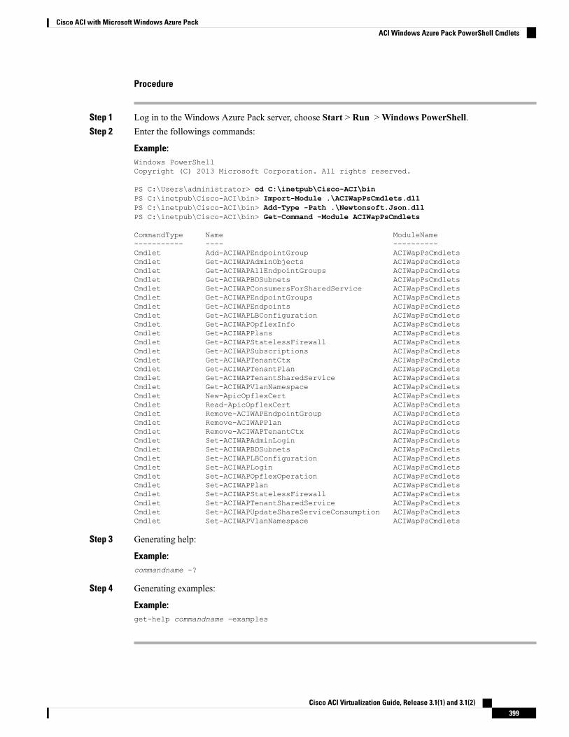
Procedure
Step 1 Log in to the Windows Azure Pack server, choose Start > Run >Windows PowerShell.Step 2 Enter the followings commands:
Example:Windows PowerShellCopyright (C) 2013 Microsoft Corporation. All rights reserved.
PS C:\Users\administrator> cd C:\inetpub\Cisco-ACI\binPS C:\inetpub\Cisco-ACI\bin> Import-Module .\ACIWapPsCmdlets.dllPS C:\inetpub\Cisco-ACI\bin> Add-Type -Path .\Newtonsoft.Json.dllPS C:\inetpub\Cisco-ACI\bin> Get-Command -Module ACIWapPsCmdlets
CommandType Name ModuleName----------- ---- ----------Cmdlet Add-ACIWAPEndpointGroup ACIWapPsCmdletsCmdlet Get-ACIWAPAdminObjects ACIWapPsCmdletsCmdlet Get-ACIWAPAllEndpointGroups ACIWapPsCmdletsCmdlet Get-ACIWAPBDSubnets ACIWapPsCmdletsCmdlet Get-ACIWAPConsumersForSharedService ACIWapPsCmdletsCmdlet Get-ACIWAPEndpointGroups ACIWapPsCmdletsCmdlet Get-ACIWAPEndpoints ACIWapPsCmdletsCmdlet Get-ACIWAPLBConfiguration ACIWapPsCmdletsCmdlet Get-ACIWAPOpflexInfo ACIWapPsCmdletsCmdlet Get-ACIWAPPlans ACIWapPsCmdletsCmdlet Get-ACIWAPStatelessFirewall ACIWapPsCmdletsCmdlet Get-ACIWAPSubscriptions ACIWapPsCmdletsCmdlet Get-ACIWAPTenantCtx ACIWapPsCmdletsCmdlet Get-ACIWAPTenantPlan ACIWapPsCmdletsCmdlet Get-ACIWAPTenantSharedService ACIWapPsCmdletsCmdlet Get-ACIWAPVlanNamespace ACIWapPsCmdletsCmdlet New-ApicOpflexCert ACIWapPsCmdletsCmdlet Read-ApicOpflexCert ACIWapPsCmdletsCmdlet Remove-ACIWAPEndpointGroup ACIWapPsCmdletsCmdlet Remove-ACIWAPPlan ACIWapPsCmdletsCmdlet Remove-ACIWAPTenantCtx ACIWapPsCmdletsCmdlet Set-ACIWAPAdminLogin ACIWapPsCmdletsCmdlet Set-ACIWAPBDSubnets ACIWapPsCmdletsCmdlet Set-ACIWAPLBConfiguration ACIWapPsCmdletsCmdlet Set-ACIWAPLogin ACIWapPsCmdletsCmdlet Set-ACIWAPOpflexOperation ACIWapPsCmdletsCmdlet Set-ACIWAPPlan ACIWapPsCmdletsCmdlet Set-ACIWAPStatelessFirewall ACIWapPsCmdletsCmdlet Set-ACIWAPTenantSharedService ACIWapPsCmdletsCmdlet Set-ACIWAPUpdateShareServiceConsumption ACIWapPsCmdletsCmdlet Set-ACIWAPVlanNamespace ACIWapPsCmdlets
Step 3 Generating help:
Example:commandname -?
Step 4 Generating examples:
Example:get-help commandname -examples
Cisco ACI Virtualization Guide, Release 3.1(1) and 3.1(2)399
Cisco ACI with Microsoft Windows Azure PackACI Windows Azure Pack PowerShell Cmdlets
Uninstalling the Cisco ACI with Microsoft Windows Azure PackComponents
This section describes how to uninstall the Cisco Application Centric Infrastructure (ACI) with MicrosoftWindows Azure Pack components.
Uninstall involves removing artifacts such as VM and logical networks. Uninstalling succeeds only when noother resource, such as a VM or a host, is consuming them.
Note
TaskComponent
See Microsoft's documentation.Detach all virtual machines from the VM networks
See Microsoft's documentation.Delete VXLAN tunnel endpoint (VTEP) logicalswitch on all hyper-Vs
See Microsoft's documentation.Delete cloud on System Center Virtual MachineManager (SCVMM)
See Uninstalling the APIC Windows Azure PackResource Provider, on page 400.
To uninstall the ACI with Microsoft Windows AzurePack 1.1(1j) release, uninstall the APIC WindowsAzure Pack Resource Provider
See Uninstalling the ACI Azure Pack ResourceProvider, on page 401.
See Uninstalling the ACI Azure Pack Admin SiteExtension, on page 401.
See Uninstalling the ACI Azure Pack Tenant SiteExtension, on page 401.
To uninstall this release of ACI with MicrosoftWindows Azure Pack, uninstall the following:
• ACI Azure Pack Resource Provider
• ACI Azure Pack Admin Site Extension
• ACI Azure Pack Tenant Site Extension
See Uninstalling the APIC Hyper-V Agent, on page402.
Uninstall the APIC Hyper-V Agent
Uninstalling the APIC Windows Azure Pack Resource ProviderThis section describes how to uninstall the APIC Windows Azure Pack Resource Provider.
Procedure
Step 1 Log in to the Windows Azure Pack server.Step 2 Choose Start > Control Panel > Uninstall a Program.Step 3 In the Programs and Features window, right-click APIC Windows Azure Pack Resource Provider and
choose Uninstall.This uninstalls the APIC Windows Azure Pack Resource Provider from the Windows Azure Pack server.
Cisco ACI Virtualization Guide, Release 3.1(1) and 3.1(2)400
Cisco ACI with Microsoft Windows Azure PackUninstalling the Cisco ACI with Microsoft Windows Azure Pack Components
Step 4 To verify if the APIC Windows Azure Pack Resource Provider is uninstalled, perform the following actions:a) Choose Start > Control Panel > Uninstall a Program.b) In the Programs and Features window, verify that APIC Windows Azure Pack Resource Provider
is not present.
Uninstalling the ACI Azure Pack Resource ProviderThis section describes how to uninstall the ACI Azure Pack Resource Provider.
Procedure
Step 1 Log in to the Windows Azure Pack server.Step 2 Choose Start > Control Panel > Uninstall a Program.Step 3 In the Programs and Features window, right-click ACI Azure Pack Resource Provider and choose
Uninstall.This uninstalls the ACI Azure Pack Resource Provider from the Windows Azure Pack server.
Step 4 To verify if the ACI Azure Pack Resource Provider is uninstalled, perform the following actions:a) Choose Start > Control Panel > Uninstall a Program.b) In the Programs and Features window, verify that ACI Azure Pack Resource Provider is not present.
Uninstalling the ACI Azure Pack Admin Site ExtensionThis section describes how to uninstall the ACI Azure Pack Admin Site Extension.
Procedure
Step 1 Log in to the Windows Azure Pack server.Step 2 Choose Start > Control Panel > Uninstall a Program.Step 3 In the Programs and Features window, right-click ACI Azure Pack Admin Site Extension and choose
Uninstall.This uninstalls the ACI Azure Pack Admin Site Extension from the Windows Azure Pack server.
Step 4 To verify if the ACI Azure Pack Admin Site Extension is uninstalled, perform the following actions:a) Choose Start > Control Panel > Uninstall a Program.b) In the Programs and Features window, verify that ACI Azure Pack Admin Site Extension is not
present.
Uninstalling the ACI Azure Pack Tenant Site ExtensionThis section describes how to uninstall the ACI Azure Pack Tenant Site Extension.
Cisco ACI Virtualization Guide, Release 3.1(1) and 3.1(2)401
Cisco ACI with Microsoft Windows Azure PackUninstalling the ACI Azure Pack Resource Provider
Procedure
Step 1 Log in to the Windows Azure Pack server.Step 2 Choose Start > Control Panel > Uninstall a Program.Step 3 In the Programs and Features window, right-click ACI Azure Pack Tenant Site Extension and choose
Uninstall.This uninstalls the ACI Azure Pack Tenant Site Extension from the Windows Azure Pack server.
Step 4 To verify if the ACI Azure Pack Tenant Site Extension is uninstalled, perform the following actions:a) Choose Start > Control Panel > Uninstall a Program.b) In the Programs and Features window, verify that ACI Azure Pack Tenant Site Extension is not
present.
Uninstalling the APIC Hyper-V AgentThis section describes how to uninstall the APIC Hyper-V Agent.
Procedure
Step 1 Log in to the Hyper-V server.Step 2 Choose Start > Control Panel > Uninstall a Program.Step 3 In the Programs and Features window, right-click Cisco APIC HyperV Agent and choose Uninstall.
This uninstalls the APIC Hyper-V Agent from the Hyper-V server.Step 4 To verify if the APIC Hyper-V Agent is uninstalled, perform the following actions:
a) Choose Start > Control Panel > Uninstall a Program.b) In the Programs and Features window, verify that Cisco APIC HyperV Agent is not present.
Step 5 Repeat steps 1-4 for each Hyper-V server.
Downgrading Cisco APIC and the Switch Software with CiscoACI and Microsoft Windows Azure Pack Components
This section describes how to downgrade the Cisco APIC and the switch software with Cisco ACI withMicrosoft Windows Azure Pack components.
Layer 4 to Layer 7 resource pool configurations created and used in Cisco APIC 3.1(1) and later are notcompatible with older Cisco APIC/Windows Azure Pack builds. Steps 1 to 3 apply when downgrading fromCisco APIC 3.1(1) or later to earlier versions.
Note
Cisco ACI Virtualization Guide, Release 3.1(1) and 3.1(2)402
Cisco ACI with Microsoft Windows Azure PackUninstalling the APIC Hyper-V Agent
Procedure
Step 1 Review the list of Layer 4 to Layer 7 resource pools on the Cisco APIC.
Note the list of resource pools that were created in Cisco APIC 3.1(1) or later. These resource pools have theFunction Profiles tab in the GUI and have version normalized in the NX-OS Style CLI configuration.
Step 2 Windows Azure Pack Tenants Portal: Perform the following steps for each Cisco ACI VM network that hasa Virtual Private Cloud using Layer 4 to Layer 7 Cloud orchestrator mode resource pools (resource poolscreated in Cisco APIC 3.1(1) or later):a) Log in to the Service Management Portal (Tenant Portal).b) In the navigation pane, choose ACI.c) In the aci pane, choose NETWORKS, click the arrow to enter further network configuration.d) Uncheck the box Enable direct internet access using NAT if it is checked.e) Uncheck the box Enable internal load balancer (internal) if it is checked.f) Uncheck the box Enable load balancer (public) if it is checked.g) Click SAVE.
Step 3 Windows Azure Pack Admin: Perform the following steps for each Windows Azure Pack plan where ACINetworking has been added as a Plan Service and the Plan is using Layer 4 to Layer 7 cloud orchestratormode resource pools.a) Log in to the Service Management Portal (Admin Portal).b) In the navigation pane, choose PLANS.c) In the plans pane, choose PLANS, and then click the plan (Gold).d) In the Gold pane, choose Networking (ACI).e) In the networking (aci) pane, perform one of the following steps:
• Choose the Layer 4 to Layer 7 resource pools provisioned by the Cisco APIC admin in Cisco APIC3.0(x) or earlier for Azure Pack consumption.
• Choose Choose one… to disable Virtual Private Cloud NAT Firewall and ADC Load Balancerservices for Azure Pack Tenants.
f) Click SAVE.
Step 4 Uninstall Cisco ACI with Microsoft Windows Azure Pack components.
See Uninstalling the Cisco ACI with Microsoft Windows Azure Pack Components, on page 400.
Step 5 Downgrade the APIC controller and the switch software.See the Cisco APIC Firmware Management, Installation, Upgrade, and Downgrade Guide.
Step 6 Install the downgrade version of Cisco ACI with Microsoft Windows Azure Pack components.
See the Installing, Setting Up, and Verifying the Cisco ACI withMicrosoftWindows Azure Pack Components,on page 358.
Cisco ACI Virtualization Guide, Release 3.1(1) and 3.1(2)403
Cisco ACI with Microsoft Windows Azure PackDowngrading Cisco APIC and the Switch Software with Cisco ACI and Microsoft Windows Azure Pack Components

Cisco ACI Virtualization Guide, Release 3.1(1) and 3.1(2)404
Cisco ACI with Microsoft Windows Azure PackDowngrading Cisco APIC and the Switch Software with Cisco ACI and Microsoft Windows Azure Pack Components
Related Documents