Hangzhou Boiler Group Co., Ltd. Circulating Fluidized Bed Boiler Training For SKIC Project

Circulating Fluidized Bed Boilers
Nov 28, 2015
Welcome message from author
This document is posted to help you gain knowledge. Please leave a comment to let me know what you think about it! Share it to your friends and learn new things together.
Transcript
Hangzhou Boiler Group Co., Ltd.
Circulating Fluidized Bed Boiler
Training For SKIC Project

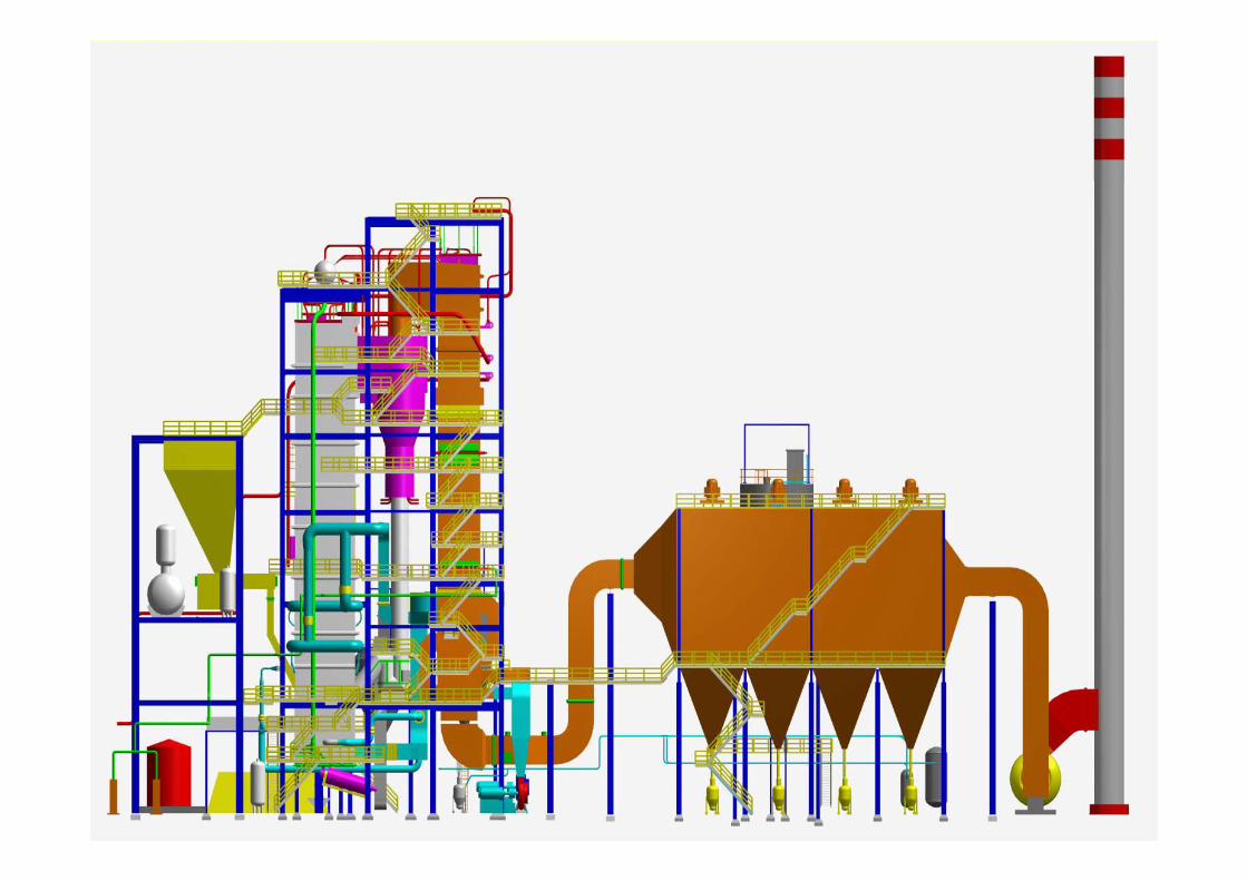
Boiler SpecificationsMaximum Steam Flow 130t/h
Superheat Steam Outlet Temperature510℃ +5
-10
Superheat Steam Outlet Pressure 100bar(g)
Feedwater Temperature 170℃
Ambient Air temperature 30℃
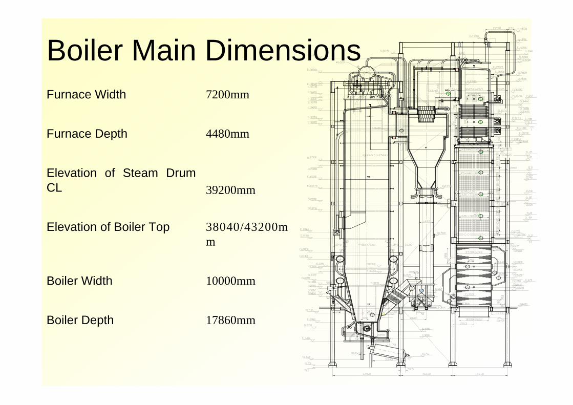
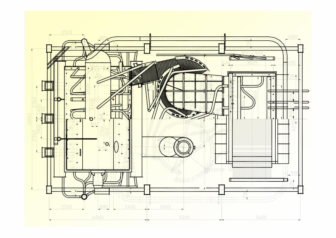
Boiler Main DimensionsFurnace Width 7200mm
Furnace Depth 4480mm
Elevation of Steam Drum CL 39200mm
Elevation of Boiler Top 38040/43200mm
Boiler Width 10000mm
Boiler Depth 17860mm
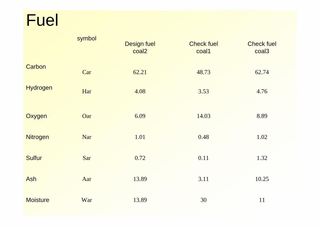
Fuelsymbol
Design fuelcoal2
Check fuelcoal1
Check fuelcoal3
CarbonCar 62.21 48.73 62.74
Hydrogen Har 4.08 3.53 4.76
Oxygen Oar 6.09 14.03 8.89
Nitrogen Nar 1.01 0.48 1.02
Sulfur Sar 0.72 0.11 1.32
Ash Aar 13.89 3.11 10.25
Moisture War 13.89 30 11

Other material
Limestone Sand
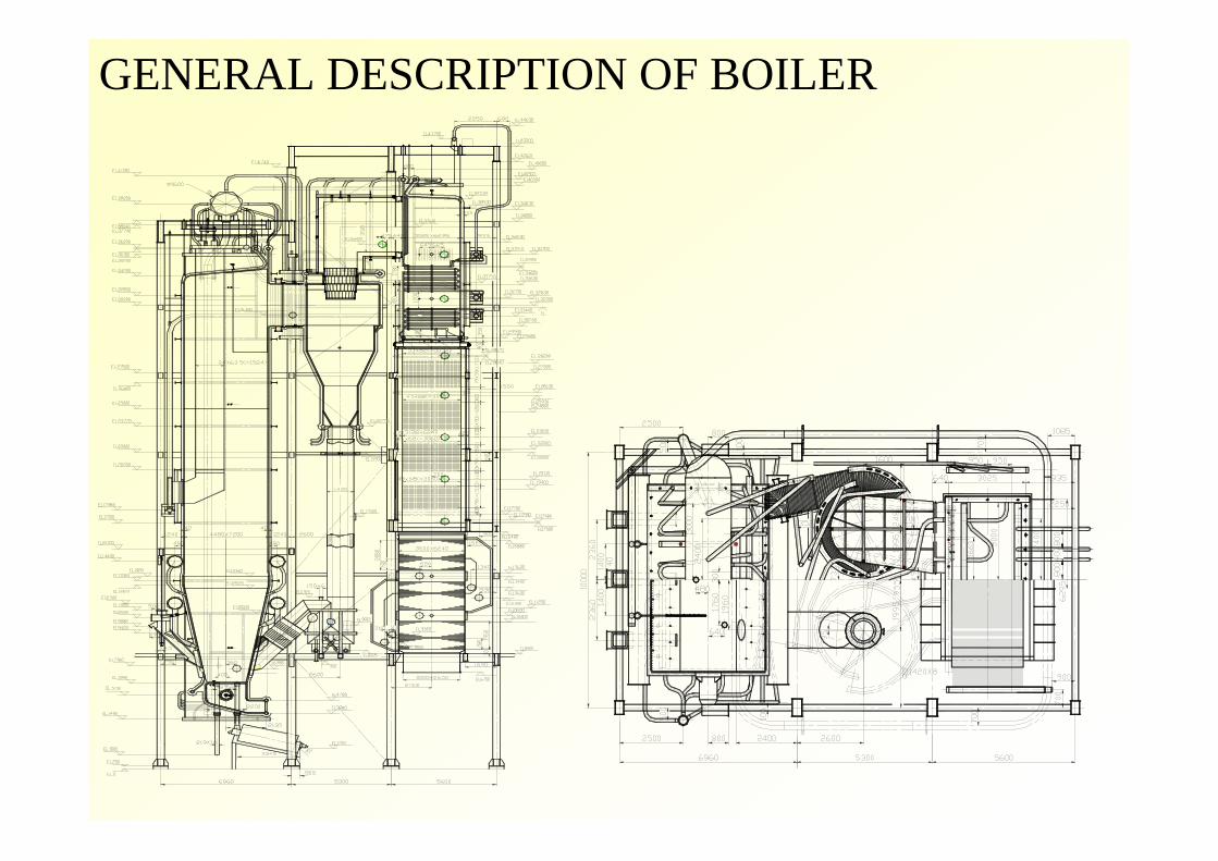
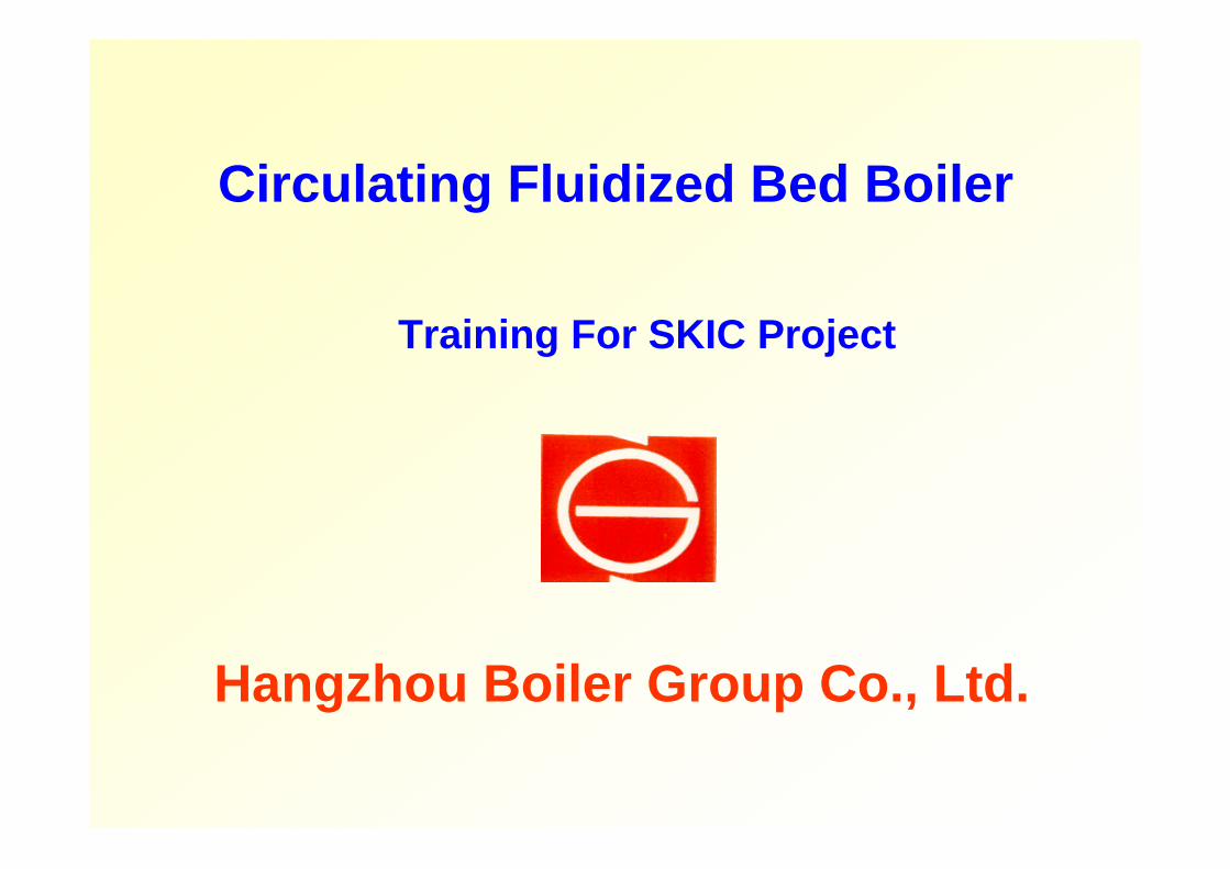
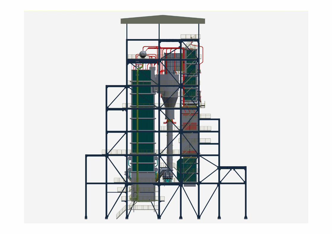
GENERAL DESCRIPTION OF BOILER

Steam and Water Flow
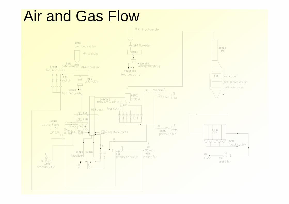
Air and Gas Flow
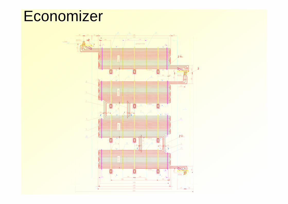
Economizer
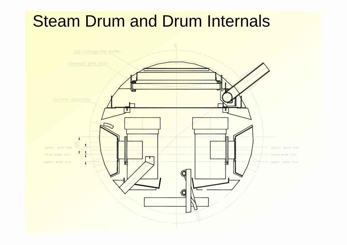
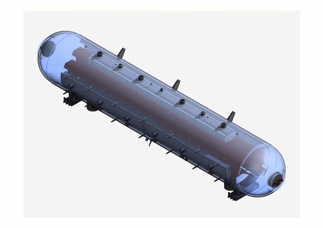
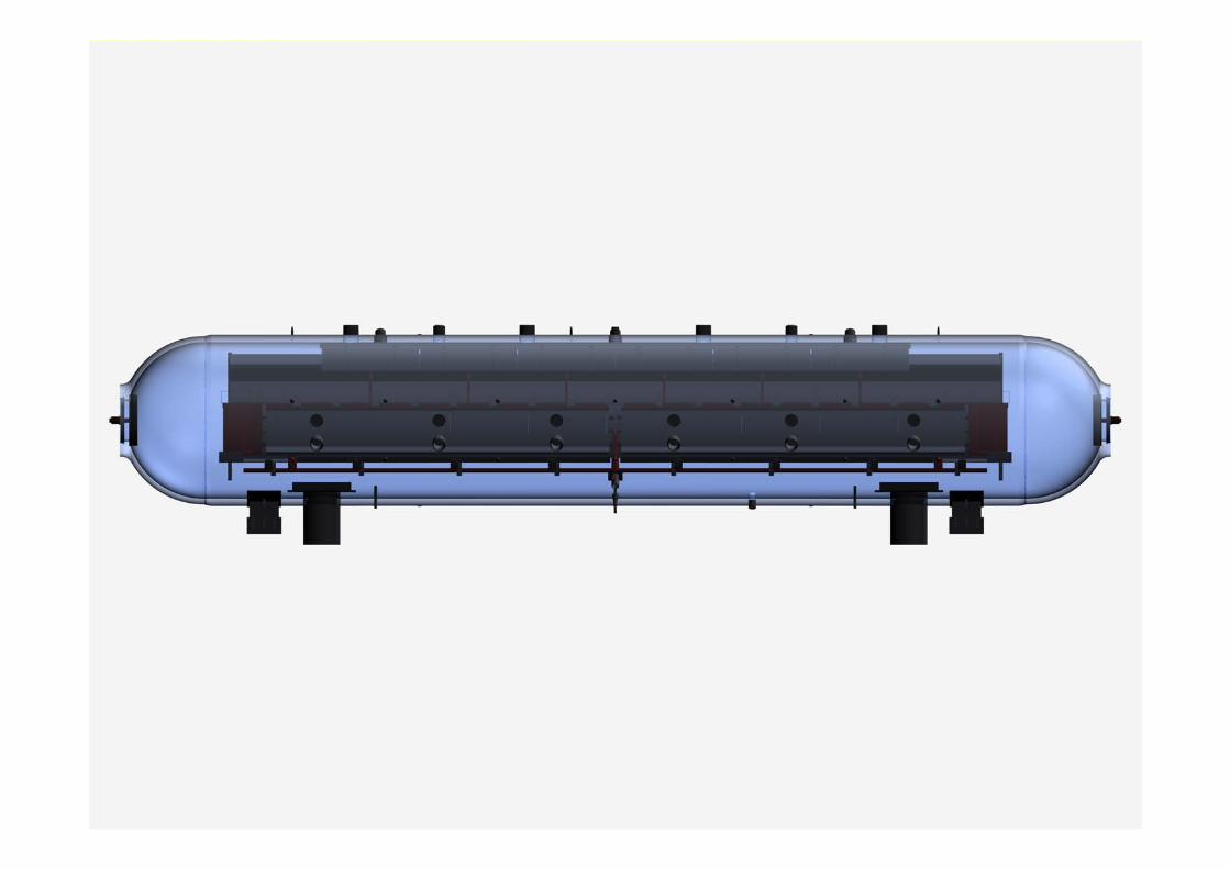
Steam Drum and Drum Internals
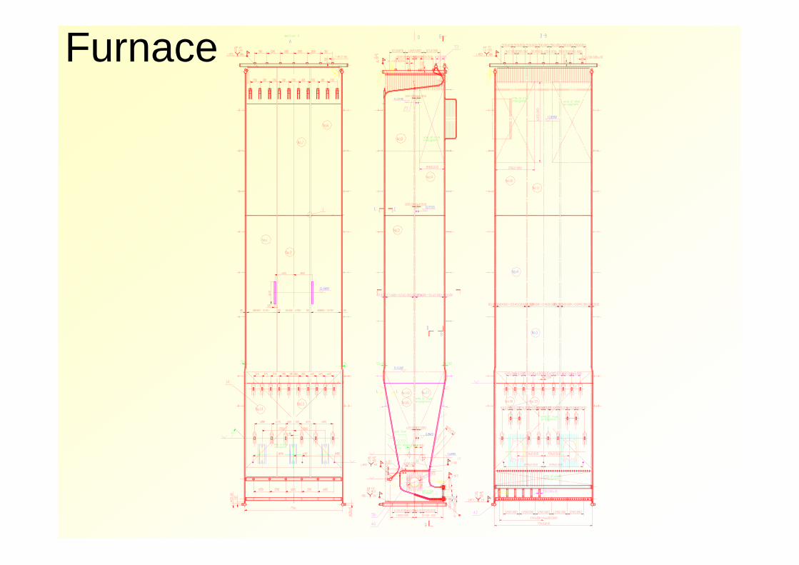
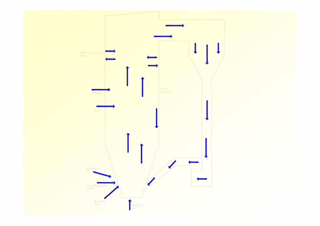
Furnace
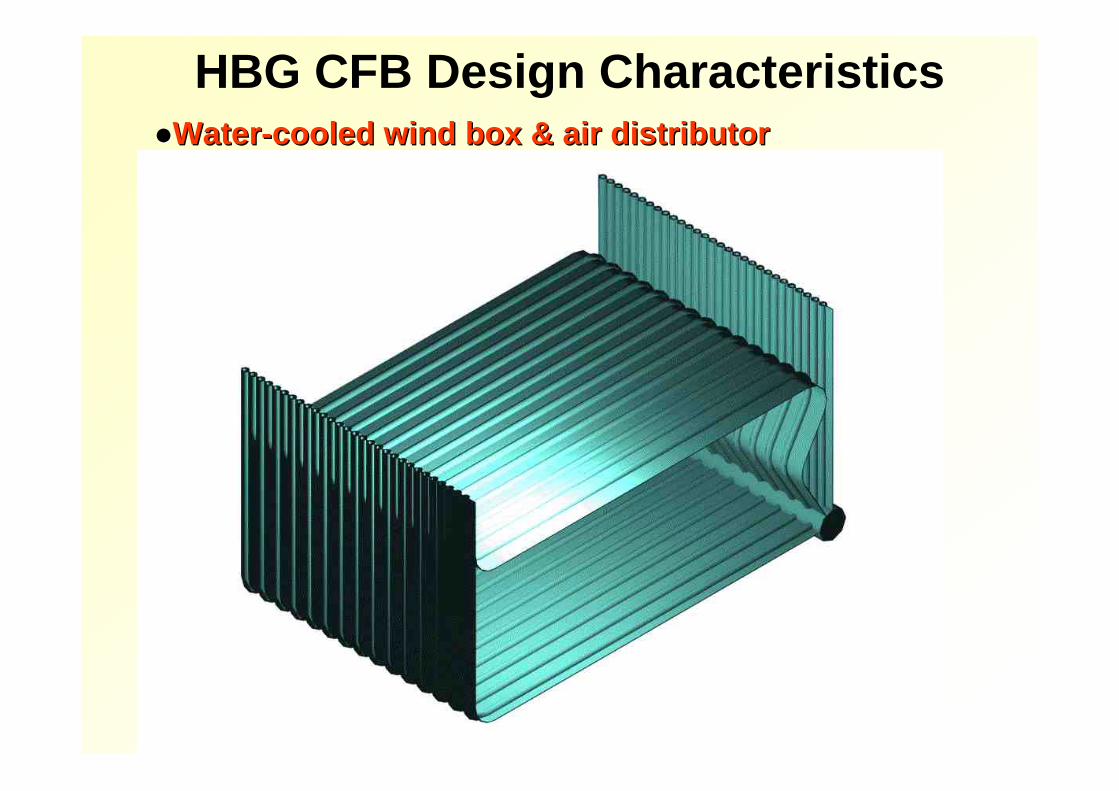
HBG CFB Design CharacteristicsWaterWater--cooled wind box & air distributorcooled wind box & air distributor
HBG CFB Design Characteristics
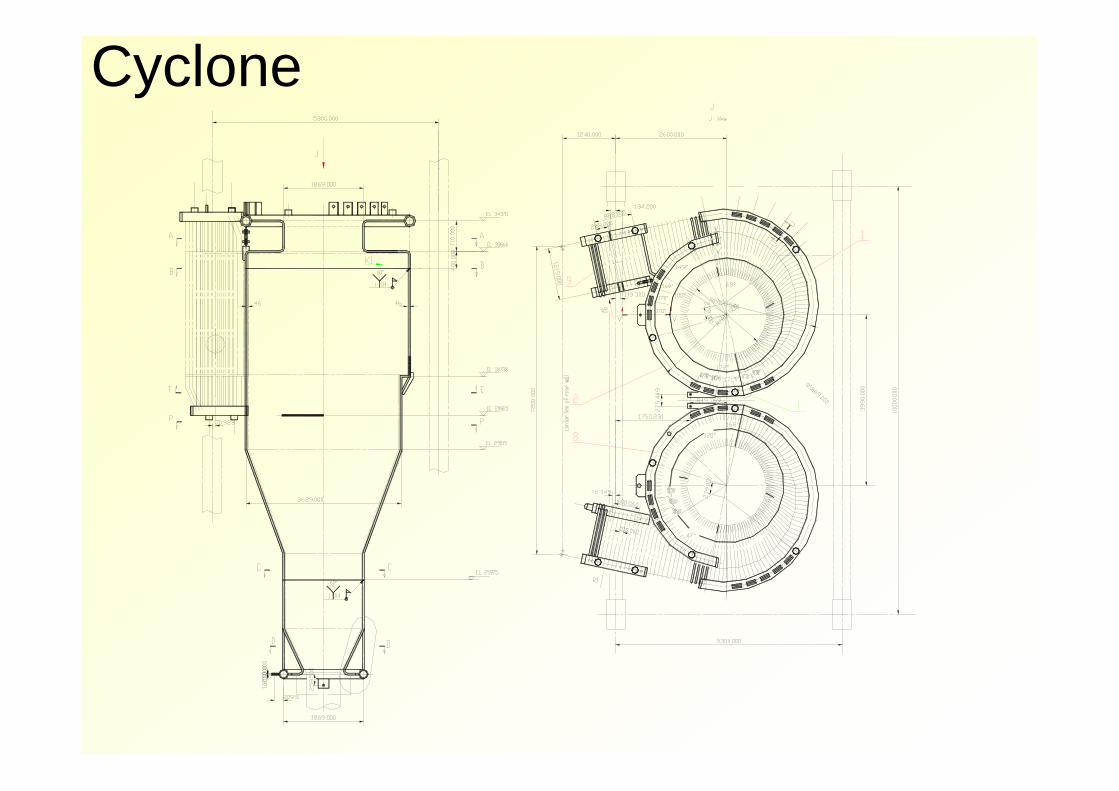
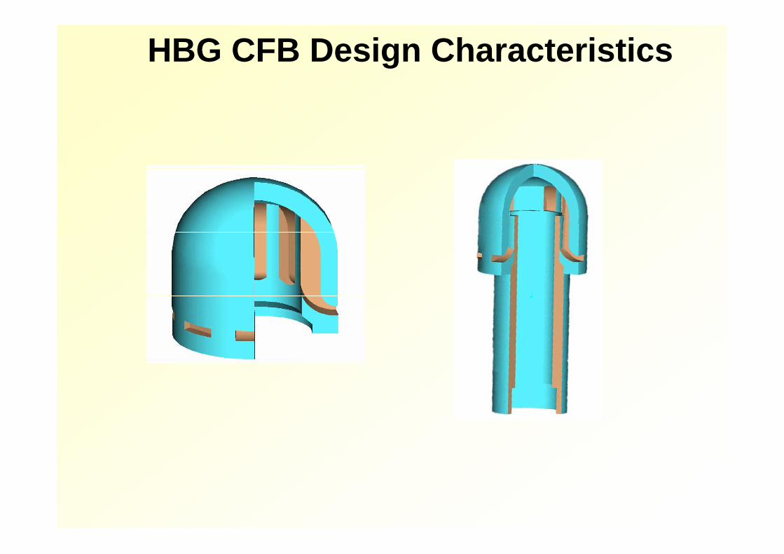
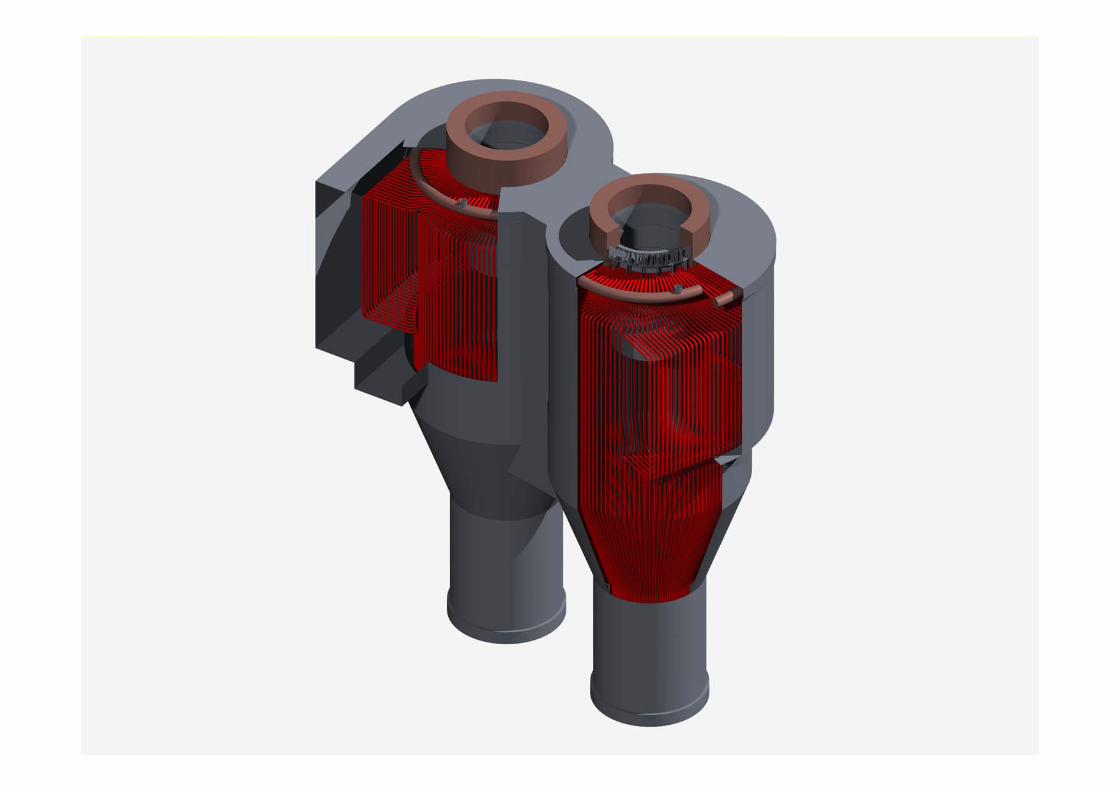
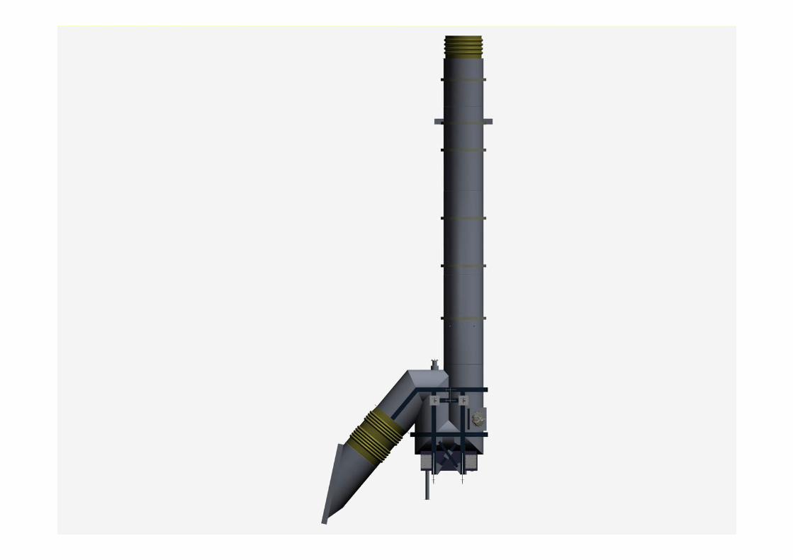
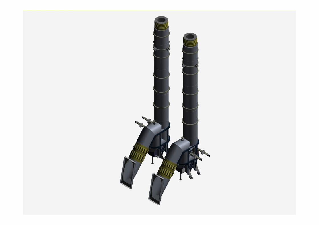
Cyclone
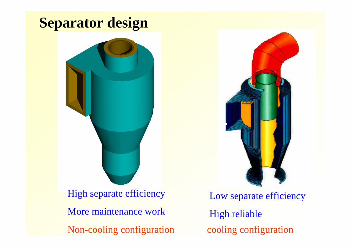
Separator design
Non-cooling configuration cooling configuration
High separate efficiency
More maintenance workLow separate efficiency
High reliable
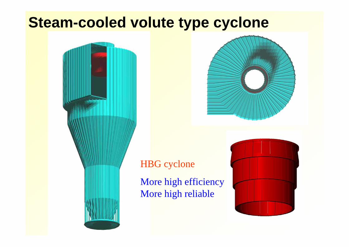
Steam-cooled volute type cyclone
HBG cyclone
More high efficiency More high reliable
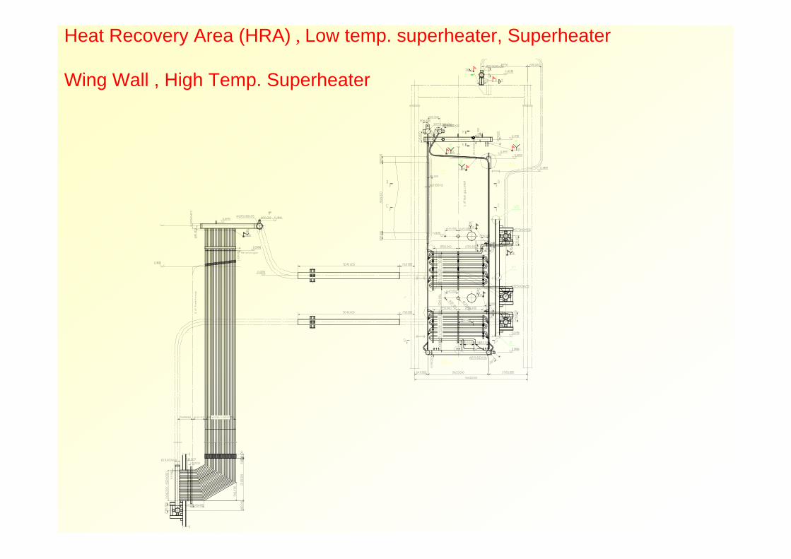
Heat Recovery Area (HRA) , Low temp. superheater, Superheater
Wing Wall , High Temp. Superheater
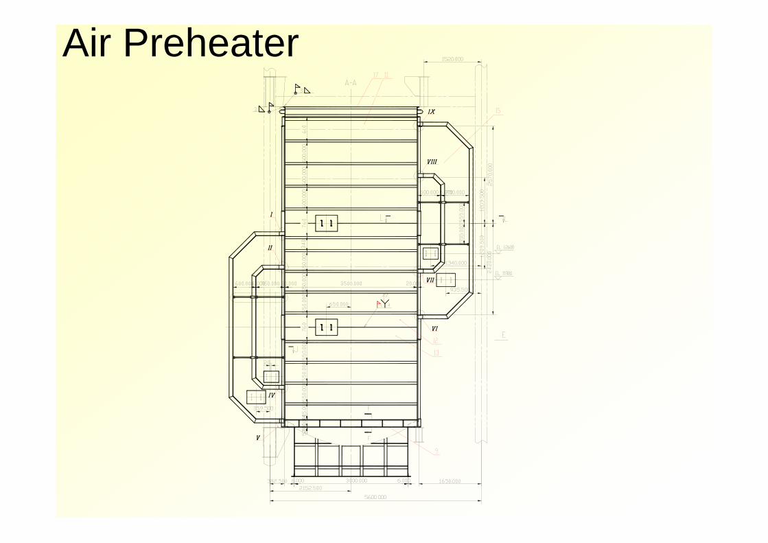
Air Preheater
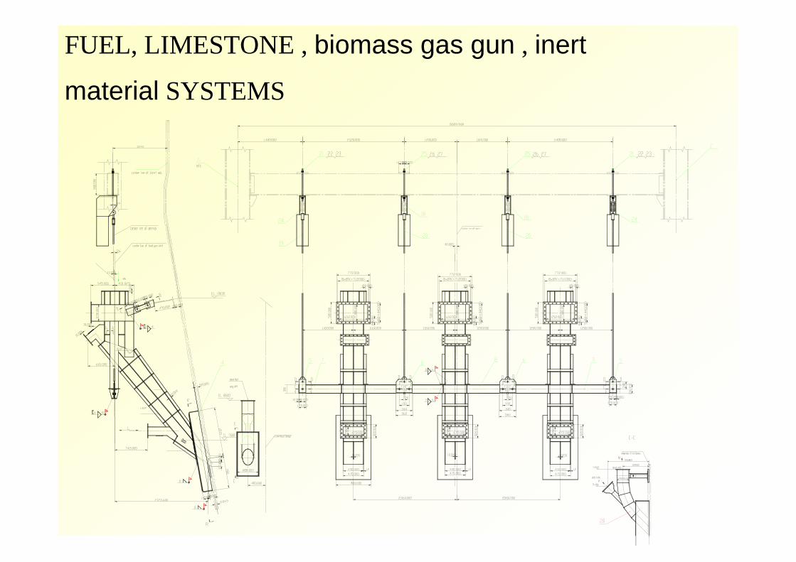
FUEL, LIMESTONE , biomass gas gun , inert
material SYSTEMS
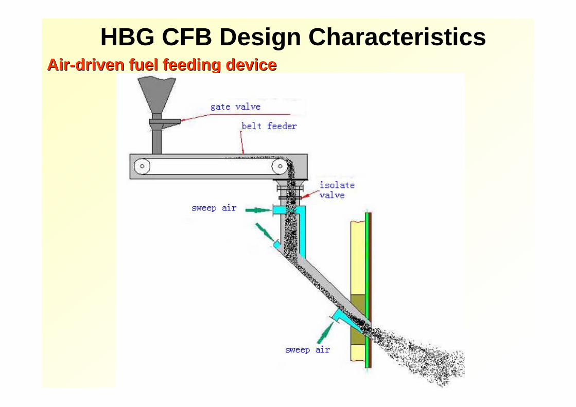
AirAir--driven fuel feeding devicedriven fuel feeding deviceHBG CFB Design Characteristics
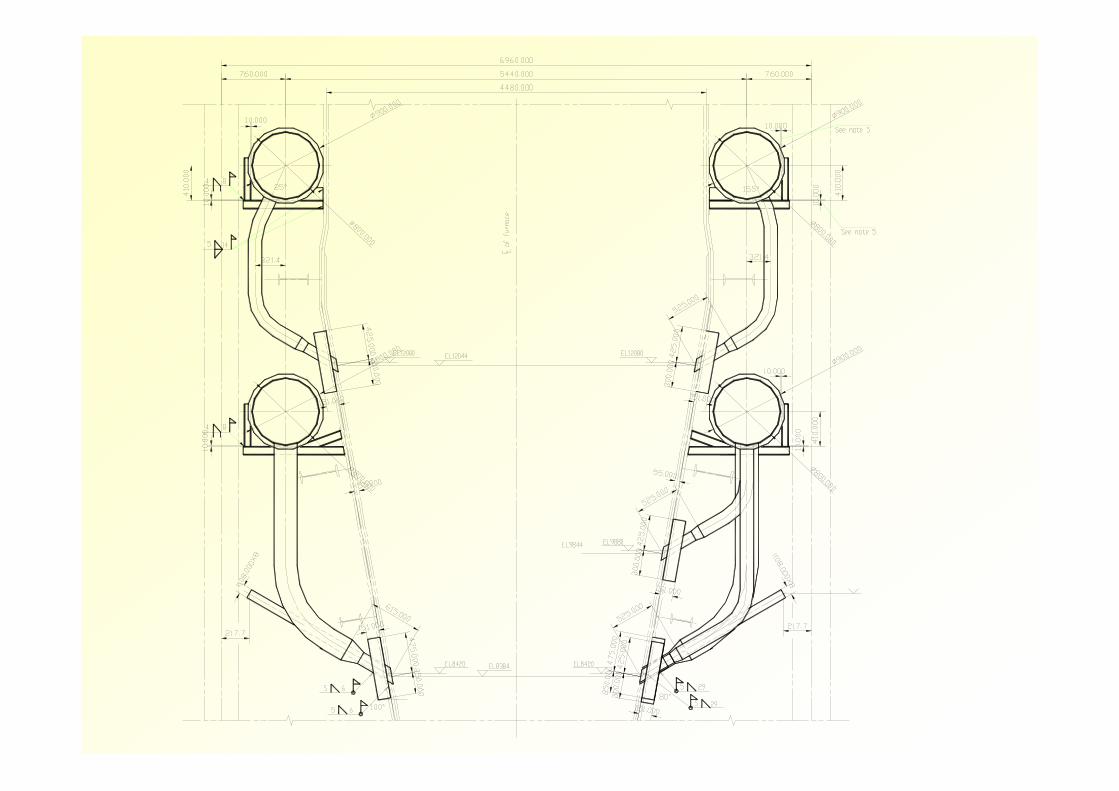
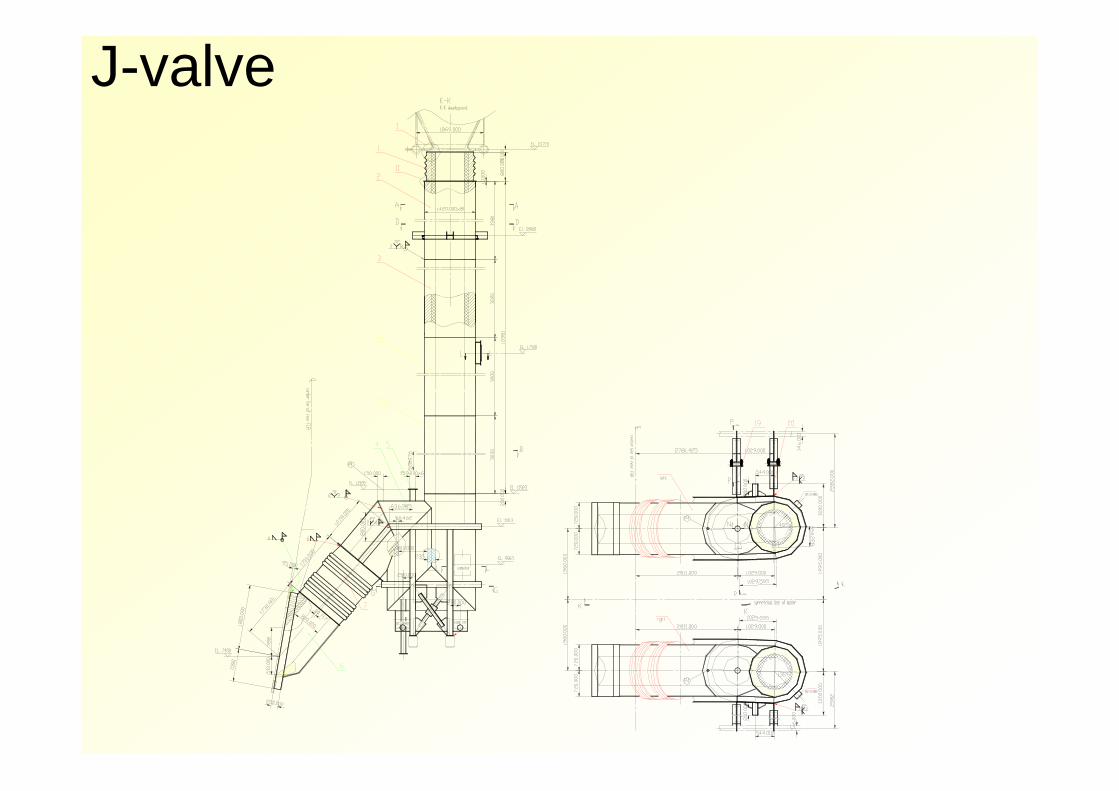
J-valve
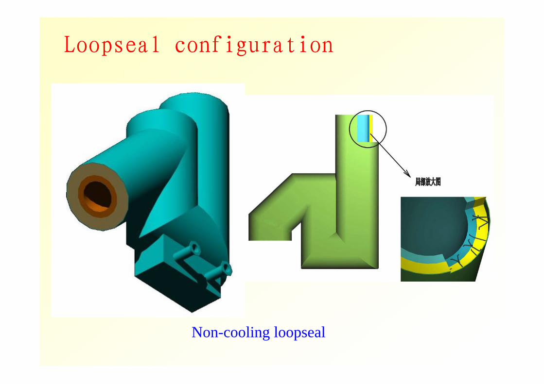
Loopseal configuration
Non-cooling loopseal
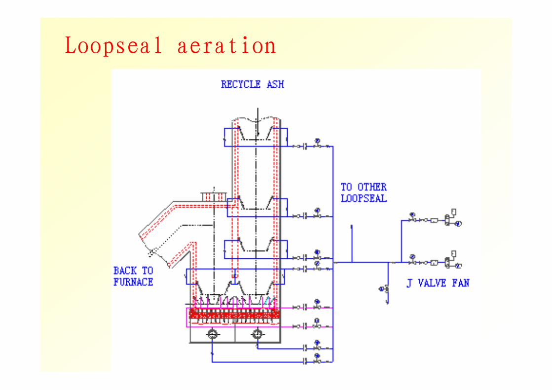
Loopseal aeration

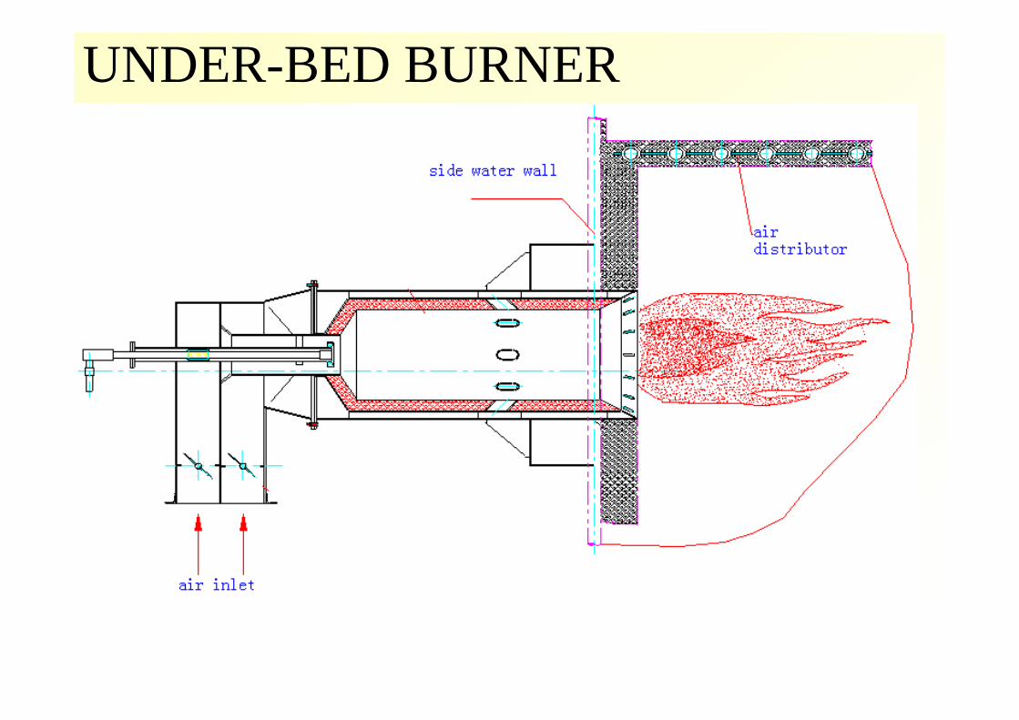
UNDER-BED BURNER
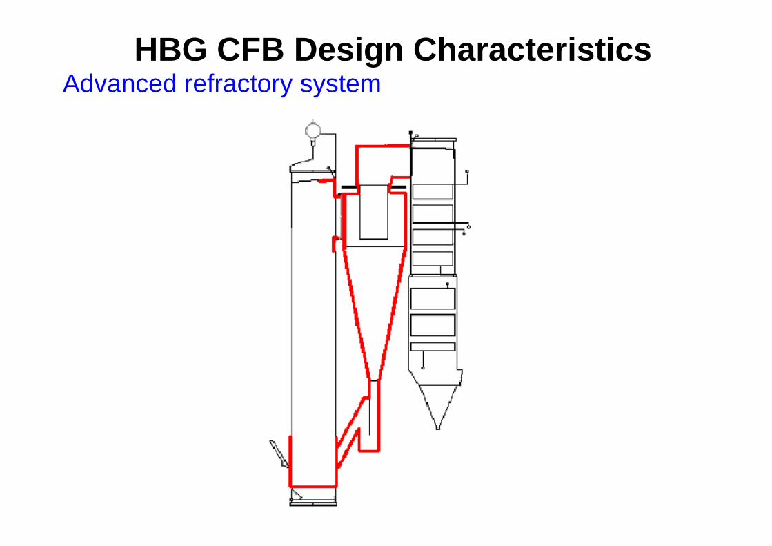
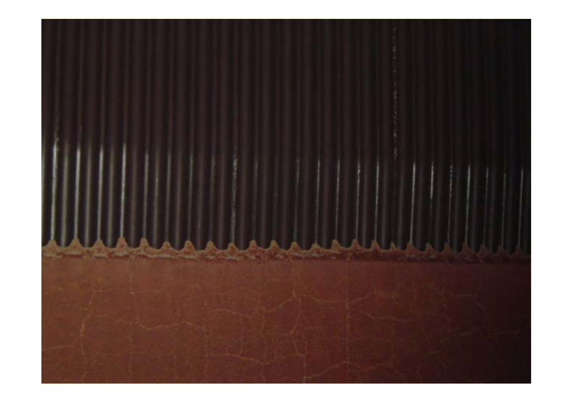
HBG CFB Design CharacteristicsAdvanced refractory system
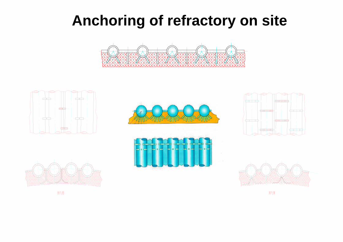
Anchoring of refractory on site
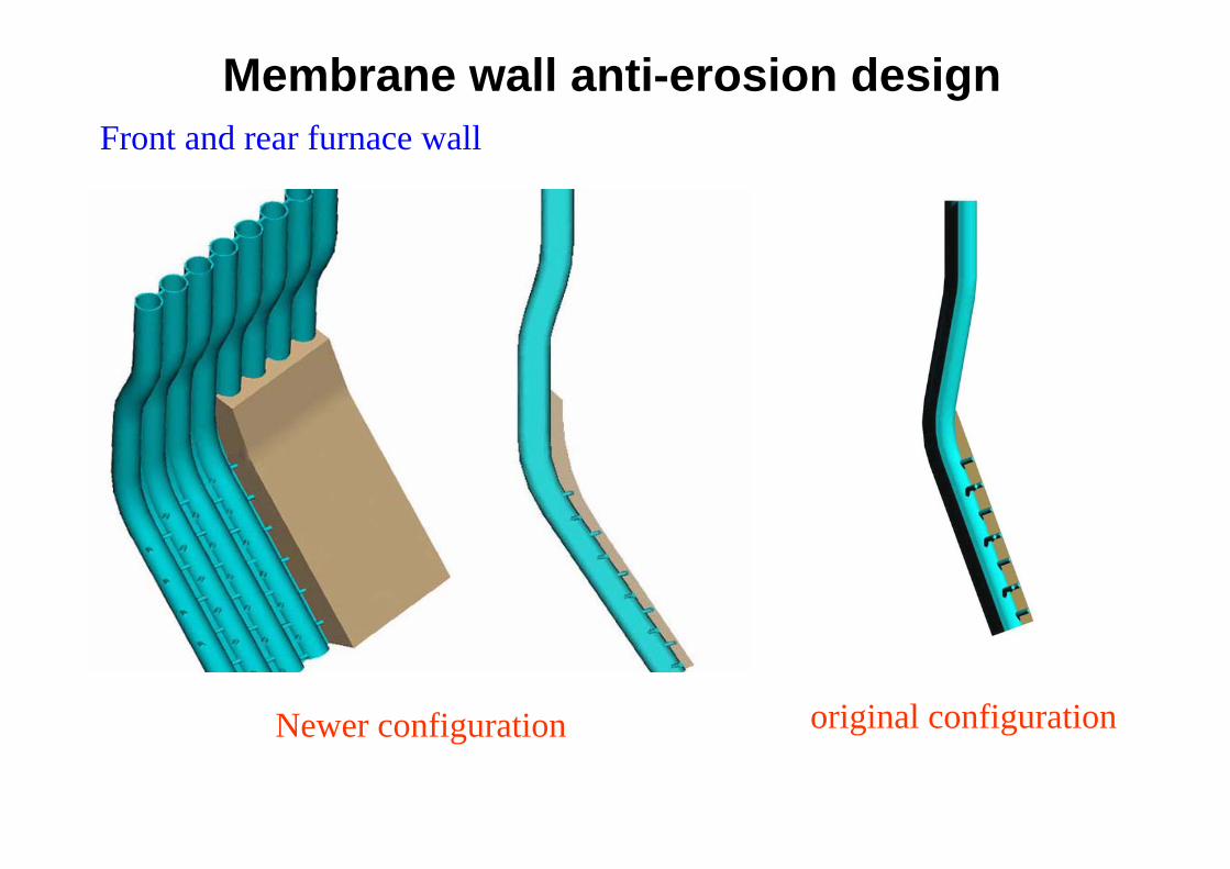
Membrane wall anti-erosion design
Newer configuration original configuration
Front and rear furnace wall
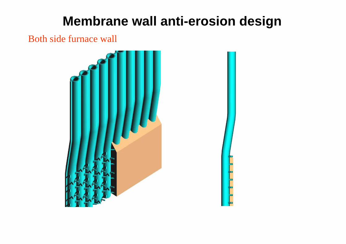
Membrane wall anti-erosion designBoth side furnace wall
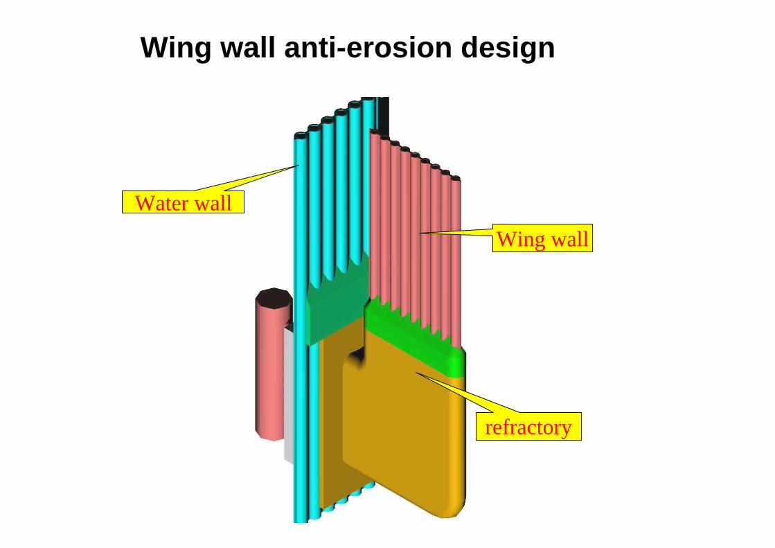
Wing wallWater wall
refractory
Wing wall anti-erosion design
OPERATION AND MAINTENANCE
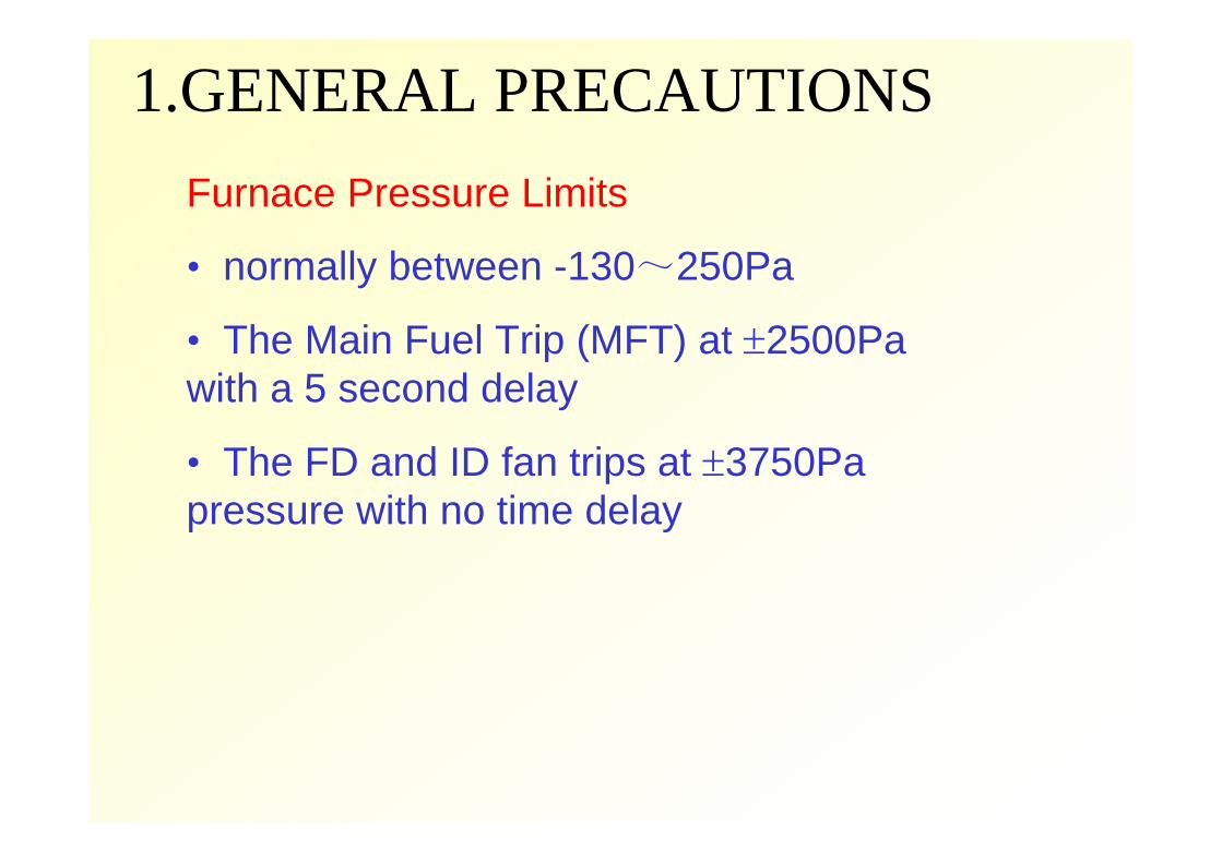
1.GENERAL PRECAUTIONS Furnace Pressure Limits
• normally between -130~250Pa
• The Main Fuel Trip (MFT) at ±2500Pa with a 5 second delay
• The FD and ID fan trips at ±3750Pa pressure with no time delay
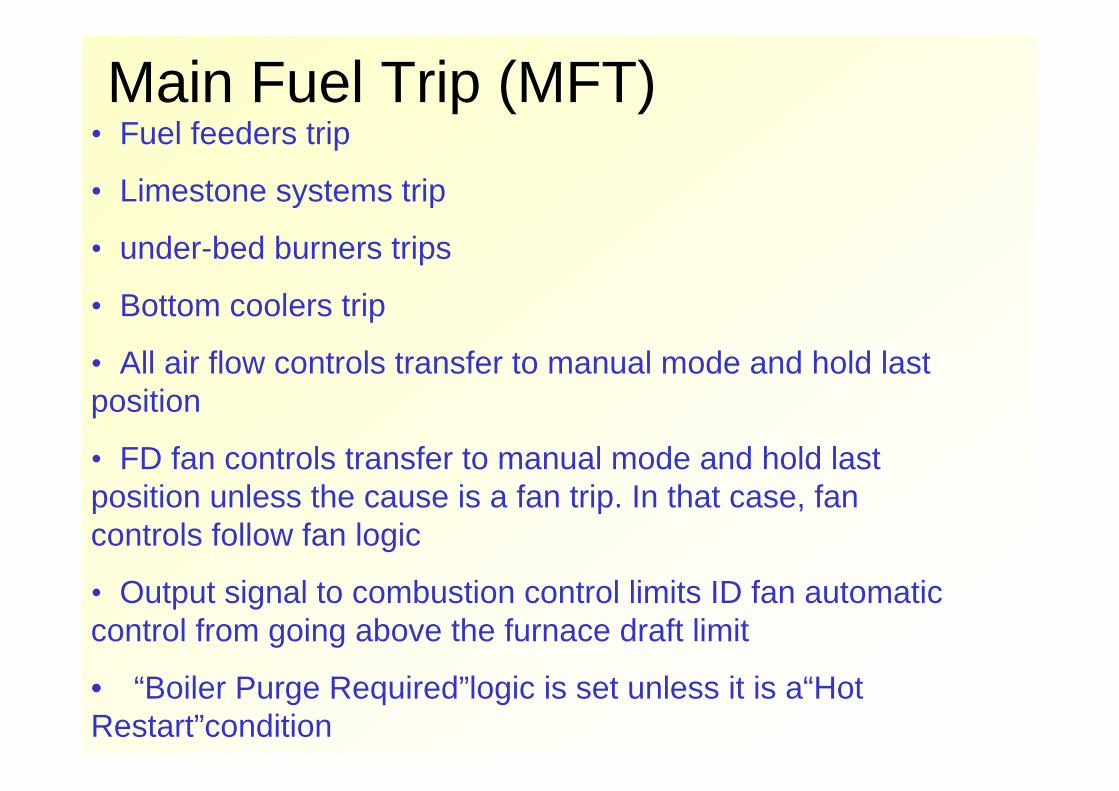
Main Fuel Trip (MFT)• Fuel feeders trip
• Limestone systems trip
• under-bed burners trips
• Bottom coolers trip
• All air flow controls transfer to manual mode and hold last position
• FD fan controls transfer to manual mode and hold last position unless the cause is a fan trip. In that case, fan controls follow fan logic
• Output signal to combustion control limits ID fan automatic control from going above the furnace draft limit
• “Boiler Purge Required”logic is set unless it is a“Hot Restart”condition
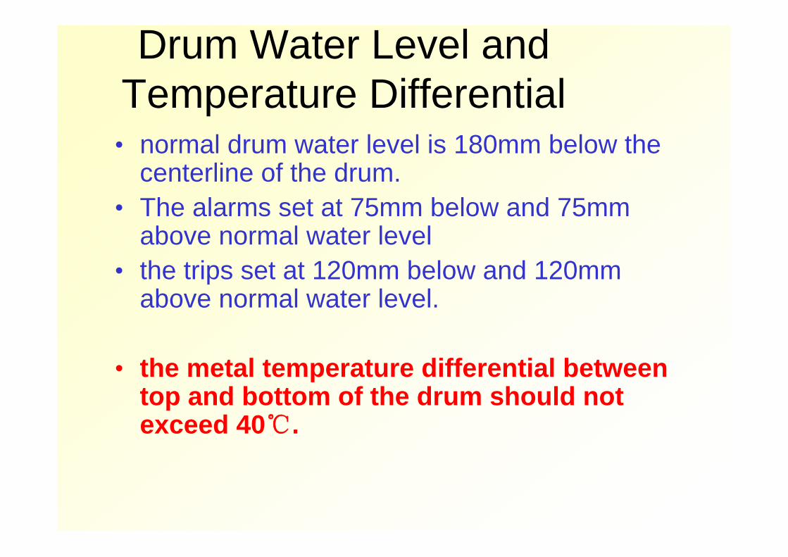
Drum Water Level and Temperature Differential
• normal drum water level is 180mm below the centerline of the drum.
• The alarms set at 75mm below and 75mm above normal water level
• the trips set at 120mm below and 120mm above normal water level.
• the metal temperature differential between top and bottom of the drum should not exceed 40℃.
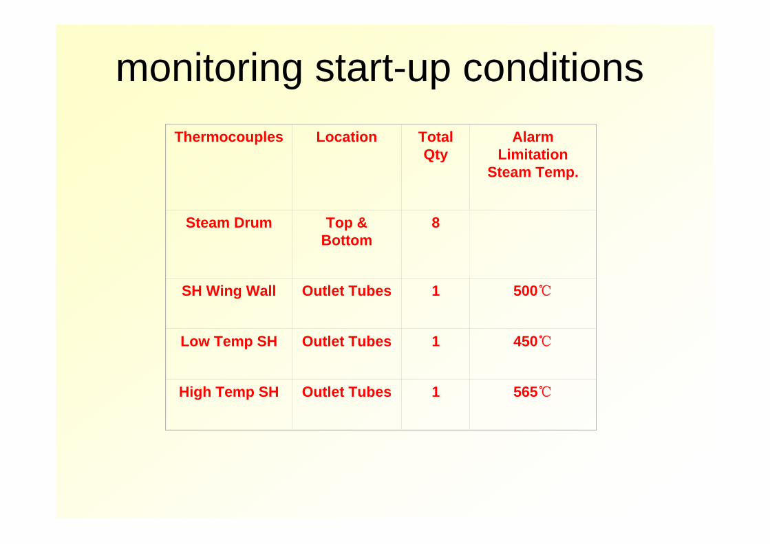
monitoring start-up conditionsThermocouples Location Total
Qty Alarm
Limitation Steam Temp.
Steam Drum Top & Bottom
8
SH Wing Wall Outlet Tubes 1 500℃
Low Temp SH Outlet Tubes 1 450℃
High Temp SH Outlet Tubes 1 565℃
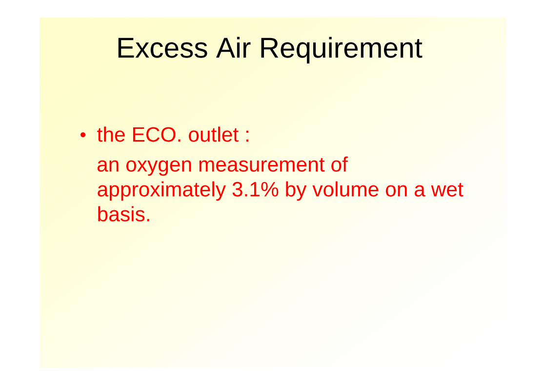
Excess Air Requirement
• the ECO. outlet :an oxygen measurement of approximately 3.1% by volume on a wet basis.
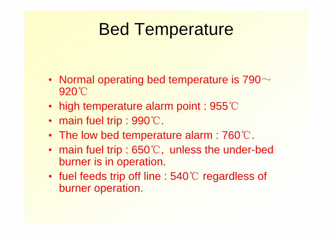
Bed Temperature
• Normal operating bed temperature is 790~920℃
• high temperature alarm point : 955℃• main fuel trip : 990℃.• The low bed temperature alarm : 760℃.• main fuel trip : 650℃, unless the under-bed
burner is in operation. • fuel feeds trip off line : 540℃ regardless of
burner operation.
Cyclone Tube Protection
• any one of these thermocouples : 420℃, cyclone cooling steam vent opened
• The vent closes : all of the thermocouples show temperatures below 410℃.
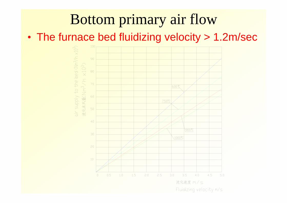
Bottom primary air flow• The furnace bed fluidizing velocity > 1.2m/sec
2.COLD START-UP PROCEDURE • Preparation Prior to Start-upall equipment is ready for start-up Fill the boiler by admitting waterinitial bed be chargedCheck that instrument and valves , damper
work under proper condition
COLD START-UP PROCEDURE• PurgingStart one J-Valve blower, the induced draft (ID), secondary fan,
primary fan.
Purge air flow: at least 25% (but not greater than 40%) total air flow
Purge time:at least 5 minutes. Purging will be accomplished and fans will be left in operation
for subsequent start-up.
COLD START-UP PROCEDURE• Warming The UnitEstablish combustion air flow at a minimum flow by
adjusting FD fan inlet vanes. Check that between economizer inlet and downcomer
recirculation shut-off valves are open.light-off the under-bed burner Heat the bed material and raise the drum pressure. Raise the bed temperature to 450℃
COLD START-UP PROCEDURE
• Start-up (Fuel Firing)Start three coal feeders : batch feeding coal into furnaceincreasing average bed temperature (ABT) to 760℃.
Shut off oil gun, the feeder can be left in operation. Boiler load can then be increased by increasing feeder capacity.
the steam flow is greater than 7%, close the economizer to downcomer recirculating shut-off valves.
Adjust combustion air flow and fuel flow to establish bed temperature of 900℃ maintain O2 at 3.1%
At this time begin operating the bottom ash coolers continually as cooler instruction.
HOT RESTART • fuel feed should be stopped • the FD and ID blowers, The J-valve blower should remain in
operation until cooling to below 260℃.• air and flue dampers be closed • hot restart condition: the average bed temperature is above
650℃. • Start one (1) J-valve blowers, ID fan and FD fan and following
cold start up procedure• When re-establishing air flows in a hot start condition, bed
temperatures may drop rapidly. Establish overfire air (secondary air) first and then grid air to minimize heat loss.
• if bed temperature does not rise within five minutes of the fuelfeed, ignition has not occurred. The feed must be stopped, the unit purged and the unit started following the normal cold start-up procedur
NORMAL OPERATION • Bed temperature • The SO2 emissions • the fluidized beds for even fluidization • the fluidized bed level • Water Chemistry and Steam Purity • SootBlowing
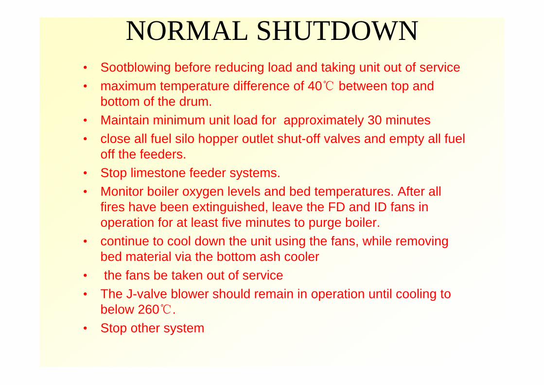
NORMAL SHUTDOWN • Sootblowing before reducing load and taking unit out of service• maximum temperature difference of 40℃ between top and
bottom of the drum. • Maintain minimum unit load for approximately 30 minutes• close all fuel silo hopper outlet shut-off valves and empty all fuel
off the feeders. • Stop limestone feeder systems. • Monitor boiler oxygen levels and bed temperatures. After all
fires have been extinguished, leave the FD and ID fans in operation for at least five minutes to purge boiler.
• continue to cool down the unit using the fans, while removing bed material via the bottom ash cooler
• the fans be taken out of service • The J-valve blower should remain in operation until cooling to
below 260℃. • Stop other system


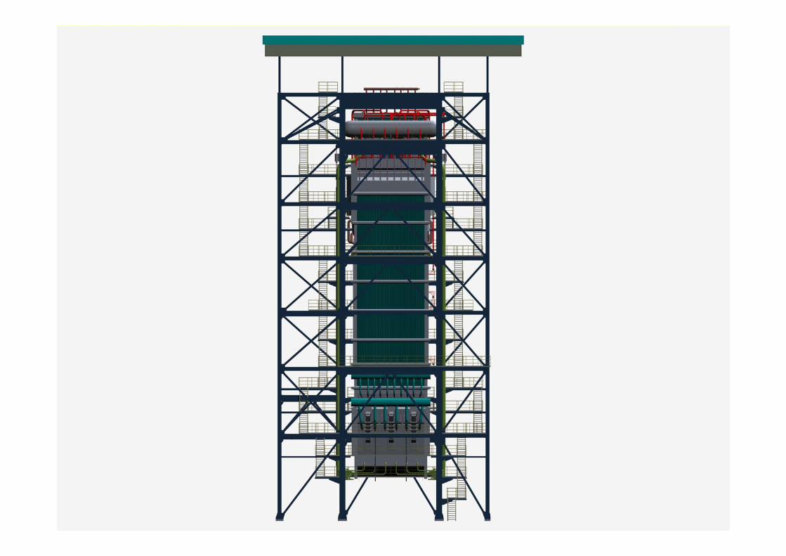
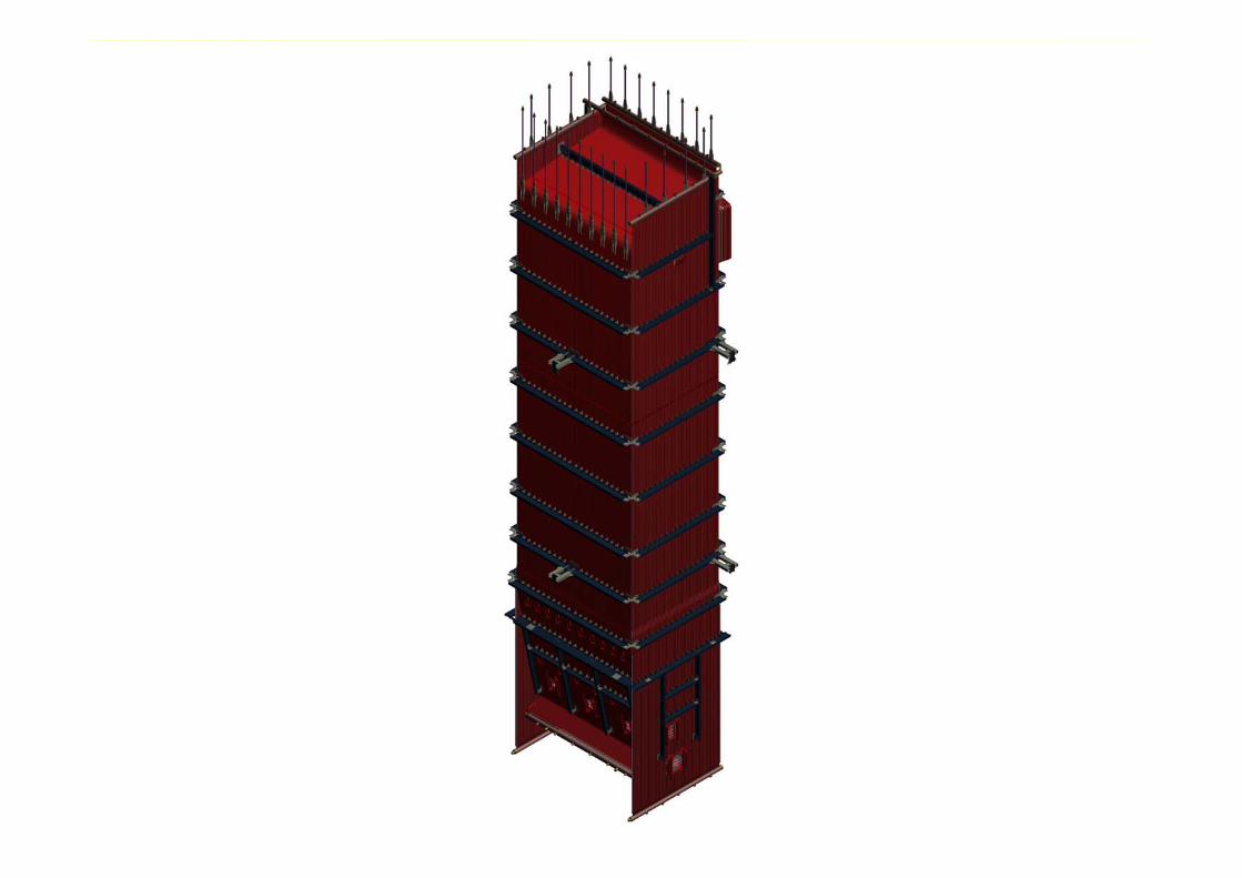
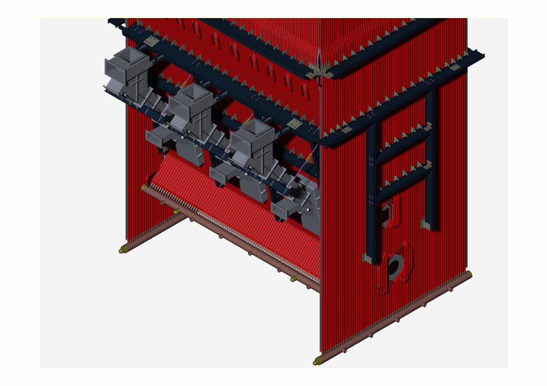
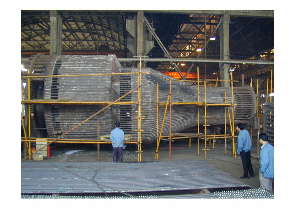
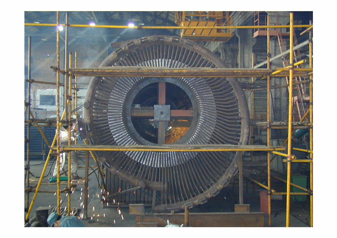
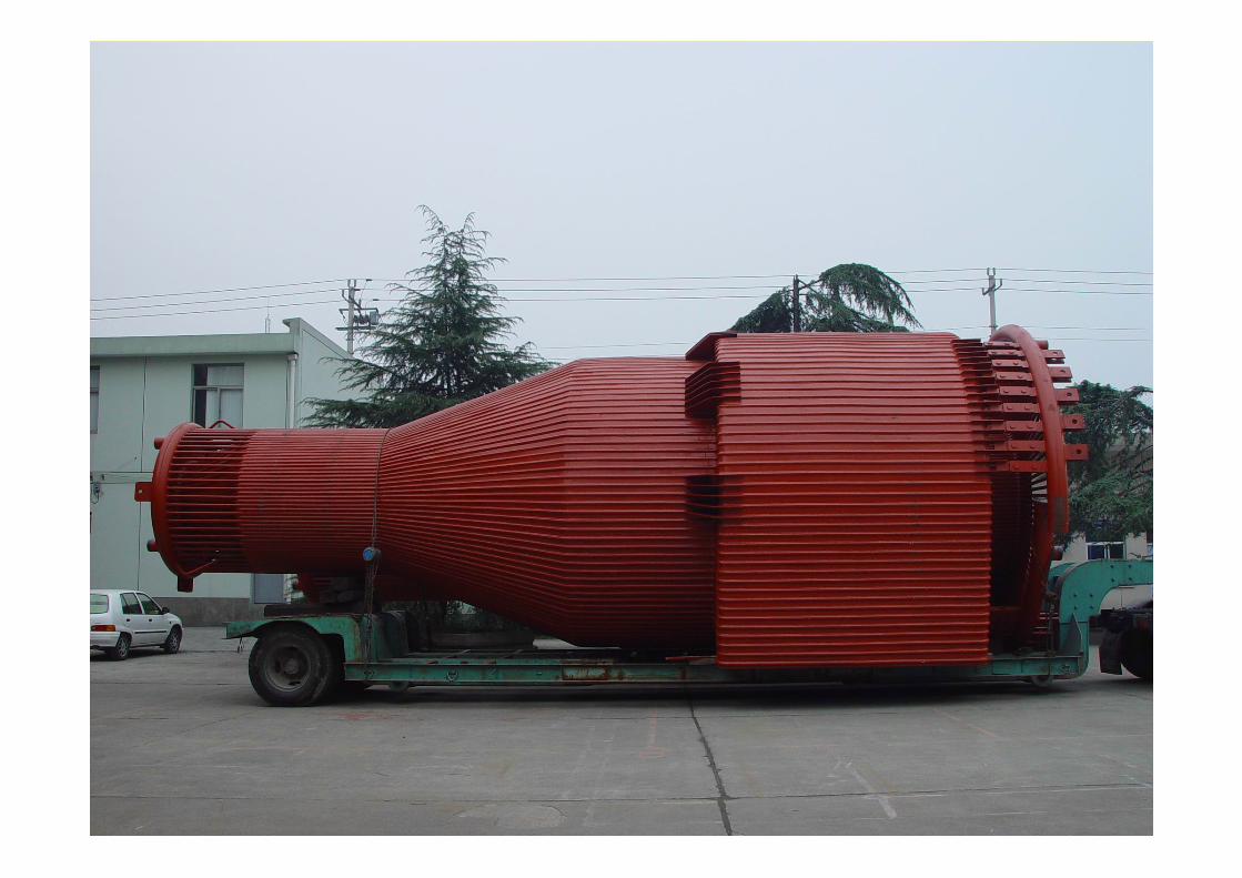
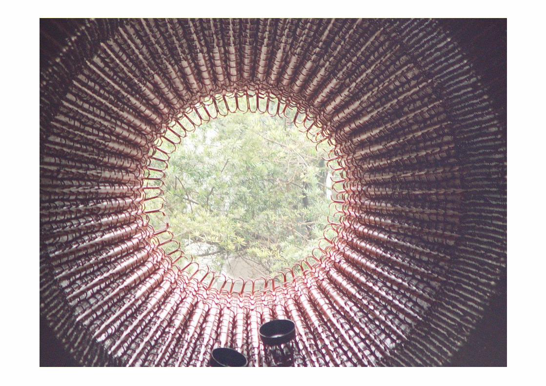
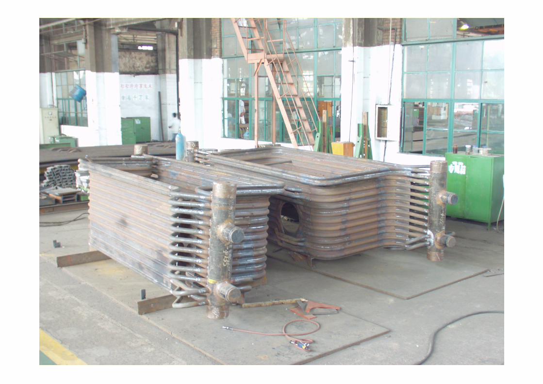
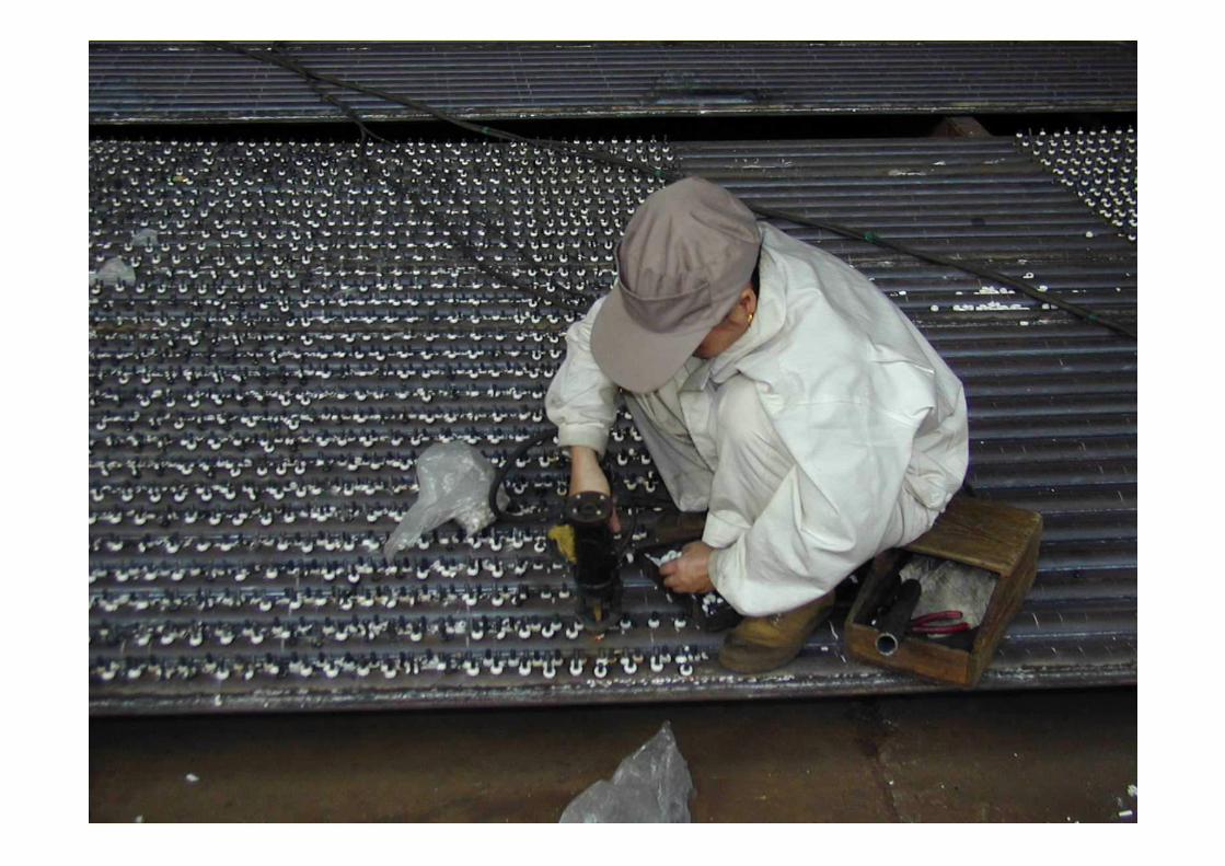
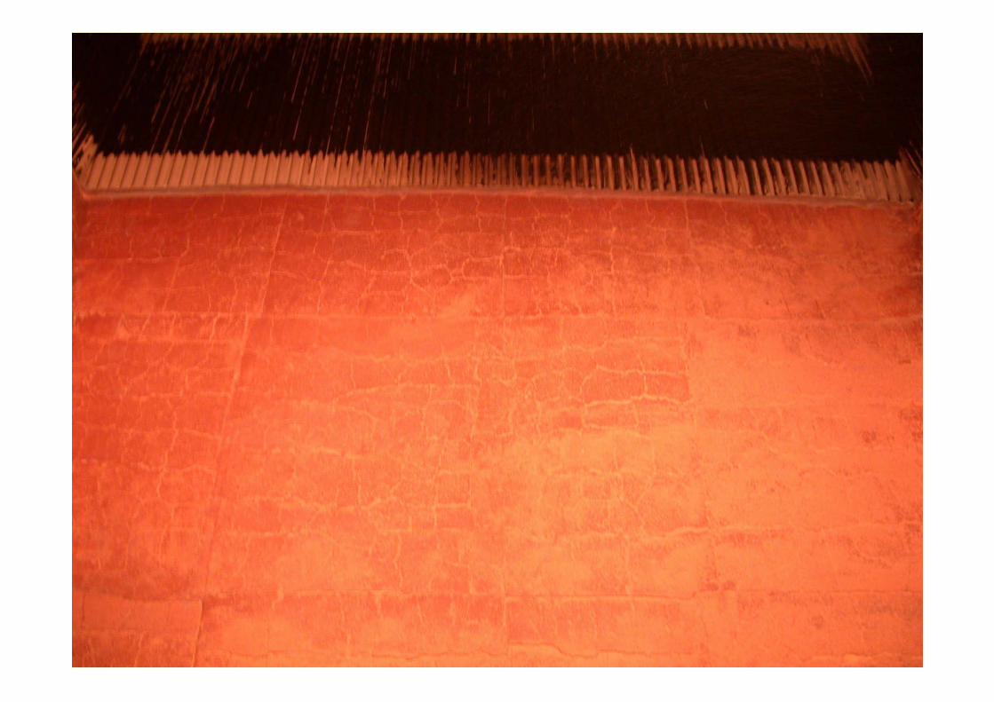
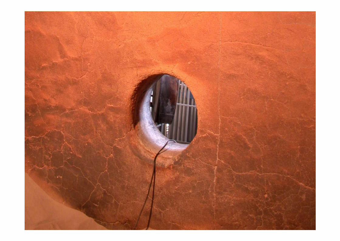
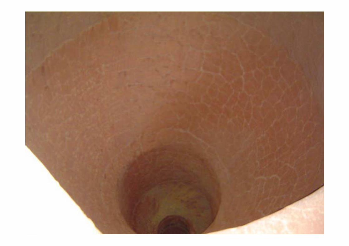
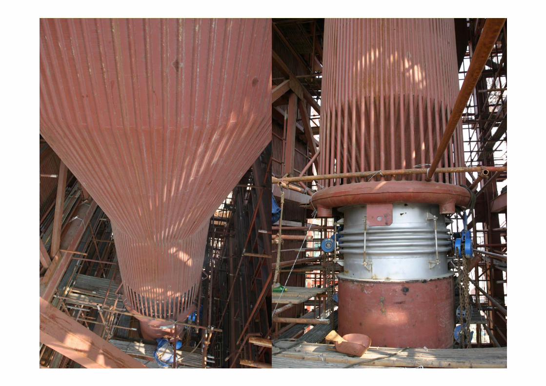
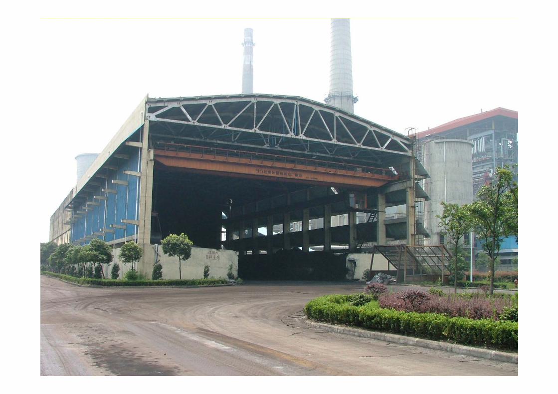
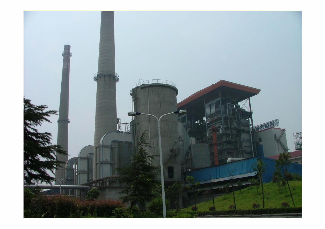
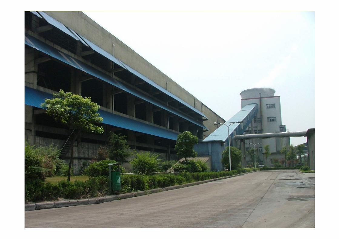
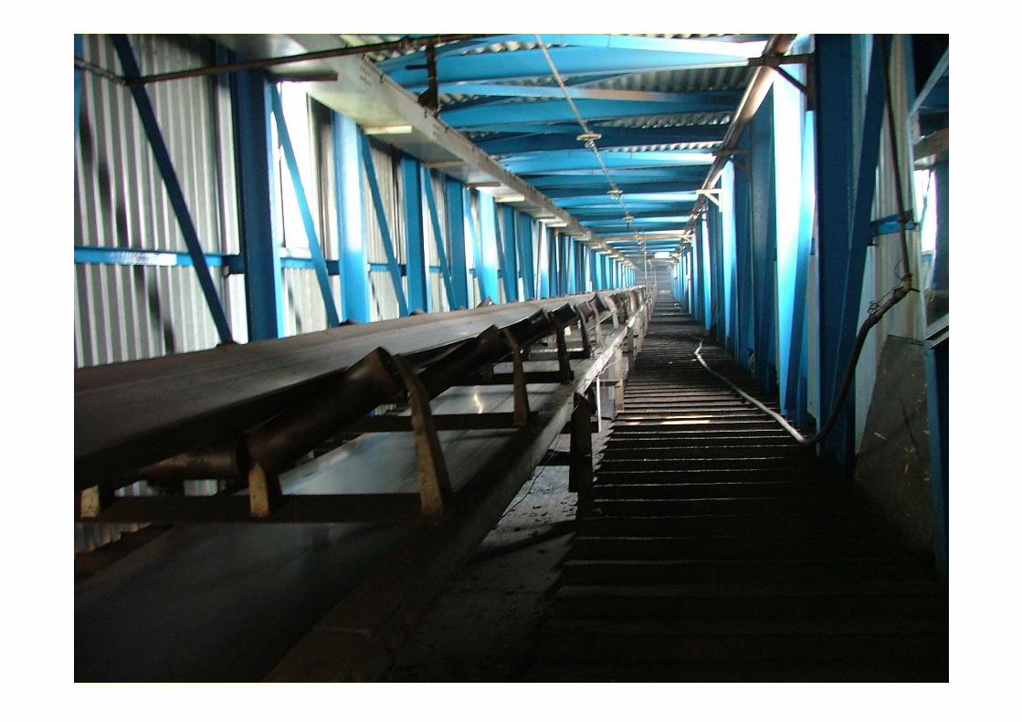
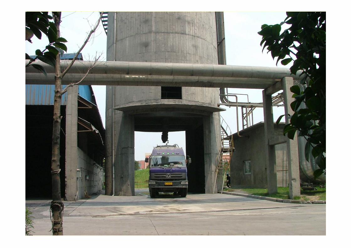
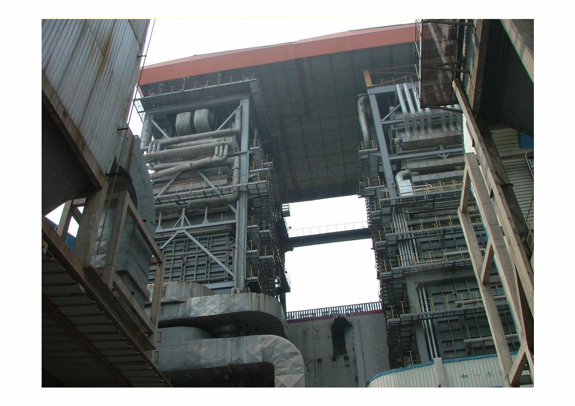
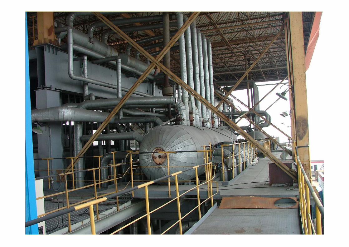
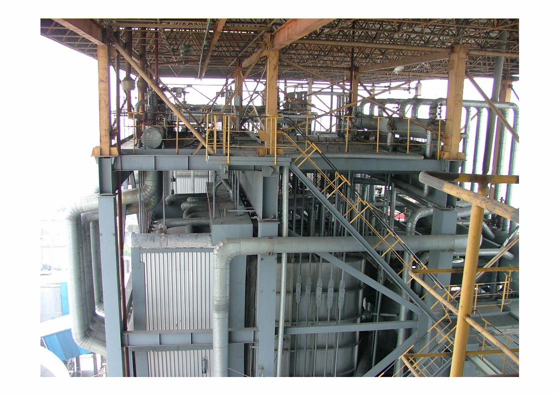
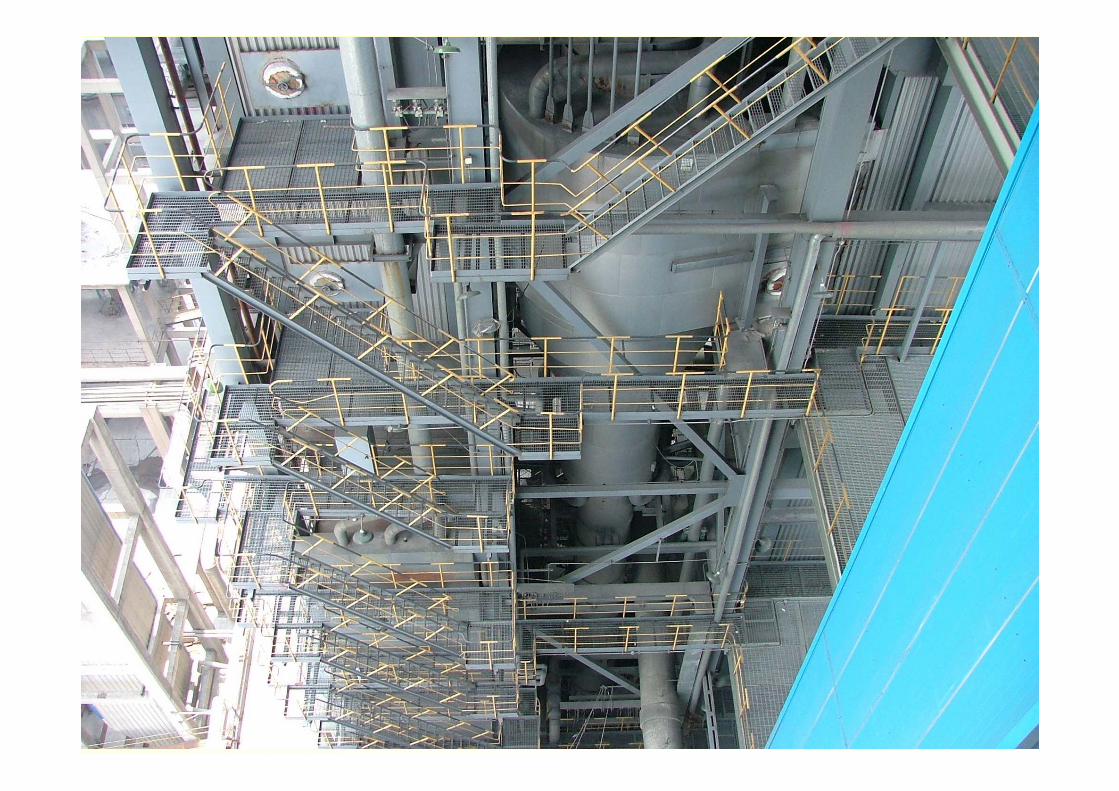
HBG CFB BOILER
PICTURE

Related Documents