Welcome message from author
This document is posted to help you gain knowledge. Please leave a comment to let me know what you think about it! Share it to your friends and learn new things together.
Transcript

c ~- -1
MICROCOMPUTER APPLICATIONS
PUBLISHERStephen J. Walters
Circuit Cellar Ink
EDITORIAL DIRECTORSteve Ciarcia
EXECUTIVE EDITORHarv Weiner
TECHNICAL EDITORSKenneth DavidsonJe jj Bachiochi
CONTRIBUTING EDITORSThomas CantrellEdward Nisley
CIRCULATION DIRECTORJeannette Do jan
CIRCULATION ASSISTANTDiane Morey
PRODUCTION MANAGERTricia Dziedzinski
BUSINESS MANAGERDaniel Rodrigues
STAFF RESEARCHERS
NortheastEric AlbertWilliam CurlewRichard SawyerRobert Stek
MidwestJohn ElsonTim McDonough
West CoastFrank KuechmannMark Voorhees
cov8rIlIlmtr8tionhyRobcrt~
TABLE OF CONTENTSEDITORIAL:
Inside the BOX Still Counts by Steve Ciarcia . . . . . . . . . . . . . . . . . . . . . . . . . . . . . . . . . . . . . . . . . . . . . . . 1
FEATURES:
The Circuit Cellar Motion Triggered Video Camera Multiplexerby Steve Ciarcia . . . . . . . . . . . . . . . . . . . . . . . . . . . . . . . . . . . . . . . . . . . . . . . . . . . . . . . . . . . . . . . . . . . . . . . . . . . . . . . . . . . . . . . . . . . . . . 5
High Security on a Budget-Build a Video Handscanner/Identifierby Ed Nisley . . . . . . . . . . . . . . . . . . . . . . . . . . . . . . . . . . . . . . . . . . . . . . . . . . . . . . . . . . . . . . . . . . . . . . . . . . . . . . . . . . . . . . . . . . . . . . .13
The Home Satellite Weather Center-Part 1: RGBI to NTSC Converterby Mark Voorheer . . . . . . . . . . . . . . . . . . . . . . . . . . . . . . . . . . .. . . . . . . . . . . . . . . . . . . . . . . . . . . . . . . . . . . . . . . . . . . . . . . . . . . . .29
DEPARTMENTS:
Firmware Furnace by Ed Nisley . . . . . . . . . . . . . . . . . . . . . . . . . . . . . . . . . . . . . . . . . . . . . . . . . . . . . . . . . . . . . . .35
Visible Ink . . . . . . . . . . . . . . . . . . . . . . . . . . . . . . . . . . . . . . . . . . . . . . . . . . . . . . . . . . . . . . . . . . . . . . . . . . . . . . . . . . . . . . . . . . . . . . .2
Ink Spot . . . . . . . . . . . . . . . . . . . . . . . . . . . . . . . . . . . . . . . . . . . . . . . . . . . . . . . . . . . . . . . . . . . . . . . . . . . . . . . . . . . . . . . . . . . . . . . . . . 11
Connectime . . . . . . . . . . . . . . . . . . . . . . . . . . . . . . . . . . . . . . . . . . . . . . . . . . . . . . . . . . . . . . . . . . . . . . . . . . . . . . . . . . . . . . . . . . . .22
CIRCUIT CELLAR INK ia published bi-monthly by Circuit Cellu Incorporated, 4 ParkStreet, Suite 12, Vernon, CT 06066 (203-875-2751). Second-c188spo&8ge prrid 8t Vernon, CTand additional mailing officer. One year (6 ieeu8n) ch8rter l ub8cription rate U.S.A. andporre8siona $14.95, Canada $17.95, all other countries $26.95..All rub8cription order8 p8y8bl8in US fund8 only, via international post81 money order or check drawn on US bank. Dinctrulmcription ordem to Circuit Cellar INK, Sub8cription8, P.O. Box 3378, Wallingford, CT96494.
POSTMASTER: Ple8ee md 8ddreu ehlurges to Circuit Cellu INK, Circulation Dept.,P.O. Box 3378, Wallingford, CT 66494.
Circuit Cellar BBS - 24 Hm. m/1206/2409 bps8 Bits, No parity, 1 Stop Bit
203-871-1988
The progmma and rchematiu provided in Ciiuit Cellrrr INK have been c8refully reviewedto ensure that their performance ir in accordance with the specification8 described. Mostprograme are ported on the Circuit Cellar BBS for electronic transfer by 8ubeCribem.
Circuit Cellar INK makee no warranties and 8eeumes no responribility or liability of any lrmdfor errom in theee progrunr or 8chematiu or for the conswquenceo of 8ny 8uch ermm.Furthermor8, b8c.auee of the pouible v8riation in the quality and condition of materida 8ndrorkm8n8hip of nlder-88eembled projeetr, Circuit Cellar INK di8claimm any rclponribility forthe rafe and proper function of reader-888embled project8 bared upon or from ~18~18,deecriptiom, or information publhhed in Circuit Cellar INK.
Entire content8 copyright 1988 by Circuit Cellar Incorporated. All right8 meerved. wduction of thii publication in whole or in p8rt without written con8ent from Circuit CeIl8rIncorporrrted in prohibited.
Circuit Cellar Ink
Inside the Box Still Countshinese restaurants are interesting places. I could say that the only reason I go is to get my latest fix of
L
General Tso’s spicy hot chicken and Tangerine beef, but, any escape from the humdrum regularity of businessresponsibility must be seen as an opportunity. To disguise the necessity of this occasional, but necessaryadventure, I often invite colleagues along and pass the event off as business with social overtones. Amid theconfused scents of odoriferous garlic and pepper-laden concoctions I get the necessary inspiration to return foran afternoon of work.
On one of these recent business luncheons, we were interrupted by a very boisterous individual at the nexttable. Chinese restaurants are usually like libraries - waiters and patrons talk almost in whispers. Perhaps that’swhat made this such a relaxing place. In any case, I would have ignored this very loud individual except thathe was talking about the computer business. Unfortunately, his volume combined with a sensitive subjectgenerated a priority interrupt and I found myself listening to his conversation.
Generally speaking, loud restaurant patrons take very little time to divulge their entire life’s story and thisman was no exception. He used to be a copier salesman and now sold personal computers for one of the computerstore chains. The people with him were prospective large volume purchasers of PC clones for a medium sizebusiness. What struck me most vividly about his conversation was the way he described his informed view ofthe computer industry.
“The world is divided into appliance PC users and hackers (his use of the word “hacker” was notcomplimentary). Computers have evolved to the point where they are merely appliances supported by thousandsof plug-and-go application programs. True computer users these days are the programmers who design and sellsoftware which further fosters this appliance concept. Real computer people don’t want to know what’s in thebox and don’t care.”
Unfortunately, this man has the mistaken impression that the world is only made up of volume businesscomputer purchasers. Like a child who thinks that milk comes from grocery stores, our transplanted copiersalesman and too many others like him, neglect the innovative designs and engineering talents that led to theproduction of their adopted appliance. Using his logic, we too could easily decide to eliminate teaching peopleto read now that television is the major medium for disseminating information.
It took a lot of effort not to stand up and jam a piece of garlic chicken in the man’s ear. What it did dohowever, was strengthen my resolve to further the education for and communication with those individualsintelligent enough to recognize that sometimes it is very important to know EXACTLY what’s in the box andhow it works. Without a continuous effort at understanding and improving present achievements, we cannotprogress to higher levels of achievement.
Circuit Cellar Ink is a publication designed to increase that awareness. We must not ignore the fact that itis a combination of people AND machines that create intelligent personal systems. Whether they be applied astoaster-like appliances thoughout an industry, serve as the control system of a CAT scanner, or function as avideo arcade game, the basic ingredients of computers are similar. It is the continual evolution of a computer’sconcept, design, and application which ultimately results in the perfection of the truly Intelligent Personal System.
Steve Ciarcia
2
Answers; Clear and Simple
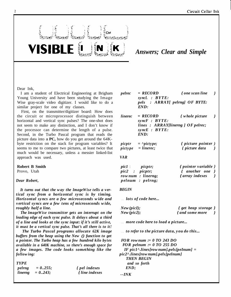
Dear Ink,I am a student of Electrical Engineering at Brigham pelrec = RECORD { one scan line }
Young University and have been studying the Image syncL : BYTE:Wise gray-scale video digitizer. I would like to do a pels : ARRAY[ pelrng] OF BYTE:similar project for one of my classes. END:
First, on the transmitter/digitizer board: How doesthe circuit or microprocessor distinguish betweenhorizontal and vertical sync pulses? The one-shot doesnot seem to make any distinction, and I don’t know ifthe processor can determine the length of a pulse.Second, in the Turbo Pascal program that reads thepicture data into a PC, how do you get around the 64K-byte restriction on the stack for program variables? Itseems to me to compare two pictures, at least twice thatmuch would be necessary, unless a messier linked-listapproach was used.
linerec = RECORD { whole picture }syncF : BYTE:lines : ARRAY[linerng ] OF pelrec;syncE : BYTE:END:
picptr = ^pictype; { picture pointer )pictype = linerec; { picture data }
VAR
Robert B SmithProvo, Utah
Dear Robert,
It turns out that the way the ImageWise tells a ver-tical sync from a horizontal sync is by timing.Horizontal syncs are a few microseconds wide andvertical syncs are a few tens of microseconds wide,roughly half a line.
The ImageWise transmitter gets an interrupt on theleading edge of each sync pulse. It delays about a thirdof a line and looks at the sync input: if it’s still active,it must be a vertical sync pulse. That’s all there is to it!
The Turbo Pascal programs allocate 62K imagebuffers from the heap using the New () function to geta pointer. The Turbo heap has a few hundred kilo bytesavailable in a 640K machine, so there’s enough space fora few images. The code looks something like thefollowing:
TYPEpelrng = 0..255; { pel indexeslinerng = 0..243; { line indexes }}
pic1 : picptr;pic2 : picptr;rownum : linerng;pelnum : pelrng;
{ pointer variable }{ another one }
{ array indexes }
BEGIN
. . . lots of code here...
New(picI);New(pic2);
{ get heap storage }{ and some more }
. . . more code here to load a picture...
. . . to refer to the picture data, you do this...
FOR rownum := 0 TO 243 DOFOR pelnum := 0 TO 255 DOIF pic1^.lines[rownum].pels[peInum] =
pic2^.lines[rownum].pels[pelnum]THEN BEGINand so forth
END;
--INK
Circuit Cellar Ink
Dear Ink,My question(s) regards pattern recognition soft-
ware. After reading several references made to it inrecent consumer magazine articles I have developed agreat interest but have precious little informationabout it.
Is there such a thing as a general pattern recognitionsoftware program; one that might be applied to asubject where there exists a recognizable pattern ofevents? Are any more specific pattern recognitionprograms available? Would you please recommend agood book on the subject? Thanks.
Bruce MillerLos Angeles, CA
Dear Bruce:As far as I know, pattern recognition programs must
be written for each application: there’s no pattern to theway patterns are recognized.
The problem is that each topic requires a differentway to represent its data: musical notes use frequency,overtones, timing information, and a pitch reference,while technical stock market analysis uses values anddates. The same program can’t handle both problems.
There are some tools available to simplify the patternrecognition task, but they tend to run on computersconsiderably more expensive than the usual PC clone.Indeed, the software alone tends to cost more than thetypical house.
And, as always with computer topics, the journalsdealing with the subject are clogged with fancymathematical notation that (we think) tends to obscurewhat’s really going on. You’ll need a solid backgroundin calculus and logic to make any headway.
The best way for you to get acquainted with the fieldis to drop into the UCLA or USC library and look inthe file cards under “pattern recognition” -- thenwander through the stacks until you find the walldevoted to the subject!
--INK
PS/2 and Microsoft’s OS/2 I would like to startpreparing for the oncoming changes. From what I readOS/2 is only for 286 or higher based machines. WhatI want is to be able to upgrade my system to cope withthe new DOS, giving me the possibility to develop newapplications under OS/2 Are there any 286 or 386boards available that would do this to my computer?
Jose Carlos do Santos MendesPortugal
Dear Jose:
As of right now, you can buy a PS/2 machine fromIBM along with DOS 3.3 to run all (well, almost all)of your favorite applications. And if you’ve got $3000to burn you can get the Microsoft OS/2 developer’s kitto start writing those protected-mode programs. Butthat’s it.
The official Microsoft position is that OS/2 will runon any IBM AT clone, regardless of what’s in theproprietary IBM PS/2 hardware. IBM, of course, isn’tsaying anything.
There are a number of subtle issues that may get inthe way of OS/2 compatibility. For example, thestandard AT BIOS that you’re used to won’t work forOS/2: it doesn’t run in protected mode. The PS/2machines include additional BIOS routines that will runin protected mode. So, will the clone makers have toprovide a protected-mode BIOS, will one be includedwith the Microsoft version of OS/2, or what? We don’tknow yet.
We suspect that the add-in boards that promise toturn your XT into an AT clone will also run OS/2, butthere’s absolutely no way to tell without the final code.Buying one now is almost certainly a guarantee thatyou’ll have one of the few boards that simply doesn’twork.
If you want to get started with OS/2 right now, theonly way to do it is to buy an IBM PS/2 and drop $3000on the OS/2 developer’s kit. The only other choice isto wait until the dust settles, then buy a board andOS/2 that are guaranteed to work together.
Anything else is just vaporware. -- INK
Dear INK, In Visible Ink, the Circuit Cellar Research Staff answers microcom-puting questions from the readership. The most representative
I develop software applications (mostly custom) forthe IBM PC and compatibles. I currently use a ZENITHXT clone. However, with the announcement of IBM’s
questions are published each month as space permits: Send yourinquiries to: INK Research Staff, c/o Circuit Cellar INK, Box 772,Vernon, CT 06066. All letters and photos become the property ofCCINK and cannot be returned.
4 Circui t Cellar Ink I
M&on Triggered VideoCamera Multiplexerby Steve Ciarcia
0 ne of the most successfulCircuit Cellar projects ever wasthe ImageWise video digitizingand display system (BYTE, May-August ‘87). It seems to be findingits way into a lot of industrialapplications. I suppose I shouldfeel flattered that a whole segmentof American industry mightsomeday depend on a CircuitCellar project, but I can’t let thathinder me from completing theproject that was the original in-centive for ImageWise Let meexplain.
How it all started
When I’m not in the CircuitCellar I’m across town at INK orin an office that I use to meet aprospective consulting client sothat he doesn’t think that I onlylead a subterranean existence.Rather than discuss the work donefor other clients to make my point,however, I usually demonstratemy engineering expertise moresubtly by just leaving some of theelectronic “toys” I’ve presentedlying around. The Fraggle Rocklunchbox w i t h t h e d u a l - d i s kSBI 80 in it gets them every time!
ImageWise was initially con-ceived to be the “piece de resis-tance"” of these hardware toys.The fact that it may have had somecommercial potential was secon-dary. I just wanted to see theexpressions on the faces of usuallystern businessmen when I ex-plained that the monitor on the
corner of my desk wasn’t a closed-circuit picture of the parking lotoutside my office building. It was alive video data transmission fromthe driveway at my house in anadjacent town.
Implementing this video systemtook a lot of work and it seems likeI’ve opened Pandora’s box in theprocess. It would have been a simplematter to just aim a camera at myhouse and transmit a picture to themonitor on the desk but the CircuitCellar creed is that hardware shouldactually work, not just impressbusiness executives.
ImageWise is a standalone serialvideo digitizer (there is a companionserial input video display unit aswell) which is not computer depend-ent. Attached to a standard videocamera, it takes a “video snapshot”at timed intervals or when manuallytriggered. The 256x244-pixel (64-level grayscale) image is digitizedand stored in a 62K-byte block ofmemory. It is then serially transmit-ted either as an uncompressed orrun-length-encoded compressedfile (this will generally reduce the62K bytes to about 40K bytes perpicture, depending upon content).
An ImageWise digitizer/trans-mitter normally communicates withits companion receiver/display at28.8K bits per second. Digitizedpictures therefore can be taken anddisplayed about every 14 seconds.While this might seem like a longtime, it is quite adequate for surveil-lance activities and approximatesthe picture taking rate of bank
security cameras.
“Real-Time” is relative
When we have to deal withremote rather than direct commu-nication, “freeze-frame” imagingsystems such as ImageWise canlose most of their “real time” ef-fectiveness as continuous-activitymonitors due to slow transmissionmediums. Using a 9600-bps mo-dem, a compressed image will takeabout 40 seconds to be displayed.At 1200 bps it will take over 5minutes!
Of course, using such narrowlogic could lead one to dismissfreeze-frame video imaging andopt for hardwired direct video,whatever the distance. However,unless you own a cable televisionor telephone company you mighthave a lot of trouble stringingwires across town.
All humor aside, the only rea-son for using continuous monitor-ing systems at all is to capture andrecord asynchronous “events.” Inthe case of a surveillance system,the “event” is when someone en-ters the area under surveillance.For the rest of the time, you mightas well be taking nature photosbecause, according to the defini-tion of an event, nothing else isimportant.
Most continuous surveillancevideo systems are, by necessity,real-time monitors as well. Be-cause they have no way to ascer-tain that an event has occurred
6 Circuit Cellar Inkc
they simply record everything andultimately capture the “event” bydefault. So what if there is 6 hoursof video tape or 200 gigabytes ofuseless video data transmissionaround a 4-second “event.”
If we know exactly when anevent occurs and take a freezeframe picture exactly at that time,there is no difference between itsrecord of the event and a real-timerecorder or snap-shot camera atthe same instant. The only differ-ence is that a freeze-frame re-corder needs some local intelli-gence to ascertain that an event isoccurring so that it knows when tosnap a picture. Sounds simple,right?
To put real-timing into mydriveway monitor, I combined avideo camera and an infraredmotion detector. When someone(or something) enters the triggerzone of the motion detector it willalso be within the field of thevideo camera. If motion is de-tected, the controller triggers theImageWise to capture that videoframe at that instant and transmitthe picture via modem immedi-ately.
The result is, in fact, real-timevideo, albeit delayed by 40 sec-onds. Using a 9600-bps modem,you will see what is going on 40seconds after it has occurred. (Ofcourse, you’ll see parts of thepicture sooner as it is painting onthe screen.) Subsequent motionwill trigger additional picturesuntil eventually the system sensesnothing and goes back to timedupdate. With such a system you’llalso gain new knowledge. You’llknow that it was the UPS truckthat drove over the hedge becauseyou were watching, but you aren’tquite sure who bagged the flowerbed.
Of course knowing a little bit issometimes worse than nothing at
all. While a single video camera andmotion detector might cover theaverage driveway, my driveway hasmultiple entrances and a variety ofparking areas. When I first installeda single camera to cover the mainentrance all it did was create frustra-tion. I would see a car enter andpark. If the person exited thevehicle they were soon out of viewof the camera and I’d be thinking,“OK, what are they doing?”
Rather than laying booby trapsfor some poor guy delivering news-papers, I decided to expand thesystem to cover additional territory.Ultimately, I installed three camerasand four motion detectors whichcould cover all important areas andprovide enough video resolution tospecifically recognize individuals.(Since I have four telephone linesinto my house and only one is beingused with ImageWise, I suppose thenext step is to use one of them as alive intercom to speak to thesevisitors. A third line already goes tothe home control system so I couldentertain less-welcome visitors witha few special effects).
Motion Triggered Video MUX
Enough of how I got into thismess! What this is all leading to isthe design of my motion triggeredvideo camera mul t ip lexing(MTVCM) system. I am presentingit because it was fun to do, it solveda particular personal problem, and ifI don’t document it somehow, 1’11never remember what I’ve got wiredthe next time I work on it.
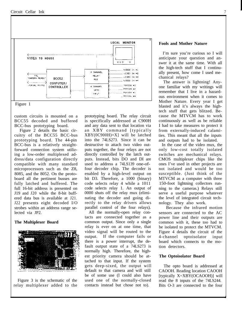
The MTVCM is a 3-board micro-computer-based 4-channel videomultiplexer with optoisolated trig-ger control inputs (see figure 1).Unlike the high-tech totally solid-state audio/video multiplexer(AVMUX) which I presented acouple years ago (BYTE Feb ‘86),the MTVCM is designed to be
simple, lightning-proof, reliable,and above all flexible.
The MTVCM is designed forrelatively harsh environments. Tominimize wire lengths from cam-eras and sensors, the MTVCM ismounted in an outside garagewhere its anticipated operatingtemperature range is -20°C to+85”C. The MTVCM operates asa standalone unit running a pre-programmed control program orcan be remotely commanded tooperate in a specific manner. It isconnected to the Imagwise andadditional electronics in the housevia a twisted-pair RS-232 line,one TTL “camera ready” line, anda video output cable.
At the heart of the MTVCM isan industrial temperature versionof the Micromint BCC52 8052-based controller which has anonboard full floating-point 8KBASIC, EPROM programmer,48K bytes of memory, 24 bits ofparallel I/O and 2 serial ports (formore information on the BCC52contact Micromint directly, seethe Articles section of the CircuitCellar BBS, see my article “Buildthe BASIC-52 Computer,” BYTE,Aug ‘85, or send $2 to CIRCUITCELLAR INK for a reprint of theoriginal BCC52 article). Becausethe BCC52 is well documented, Iwill not discuss it here.
The MTVCM is nothing morethan a specific application of aBCC52 process controller with alittle custom I/O. In the MTVCMthe custom I/O consists of a 4-channel relay multiplexer boardand a 4-channel optoisolated inputboard (Micromint now manufac-tures a BCC40R 8-channel relayoutput board and a BCC40D directdecoding 8-channel optoisolatedinput/output board. Their designis different and should not beconfused with my MTVCM cus-tom I/O boards). Each of my
Circuit Cellar Ink 7I
.
kE0 TO HOUSE
LOCAL MONITOR/ I
Figure 1
custom circuits is mounted on aBCC55 decoded and bufferedBCC-bus prototyping board.
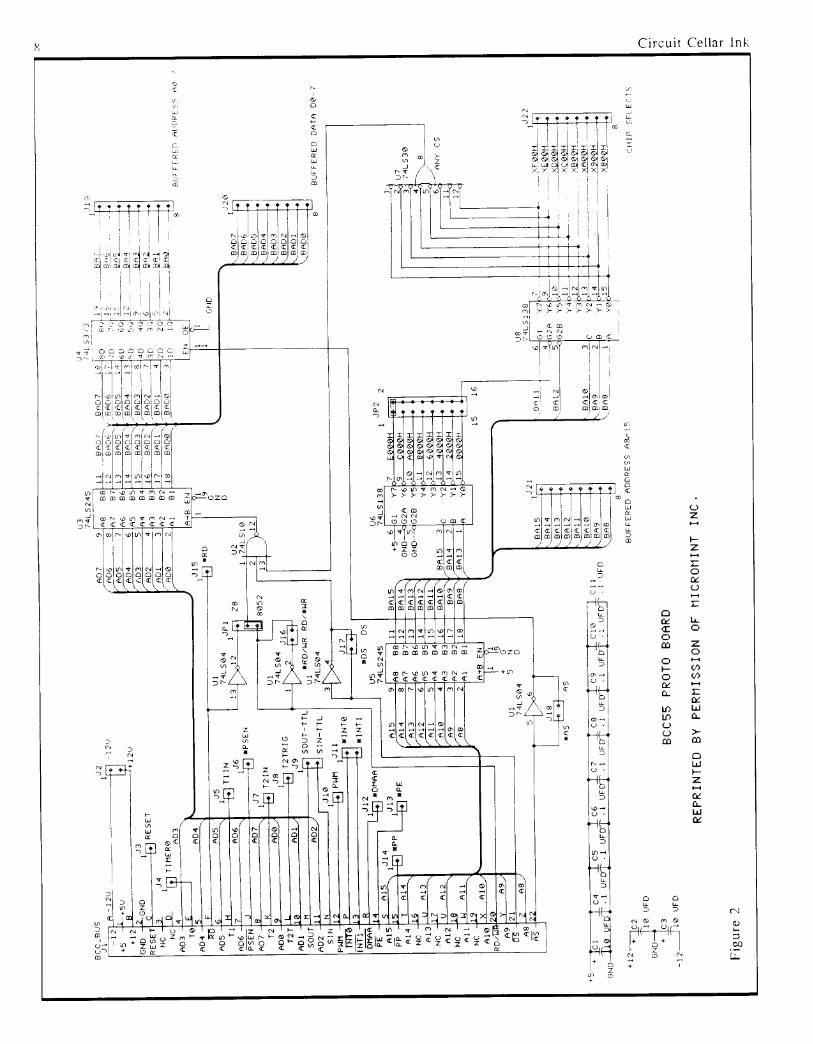
Figure 2 details the basic cir-cuitry of the BCC55 BCC-busprototyping board. The 44-pinBCC-bus is a relatively straight-forward connection system utiliz-ing a low-order multiplexed ad-dress/data configuration directlycompatible with many standardmicroprocessors such as the Z8,8085, and the 8052. On the proto-board all the pertinent busses arefully latched and buffered. Thefull 16-bit address is presented onJ19 and J20 while the 8-bit buff-ered data bus is available at J21.J22 presents eight decoded I/Ostrobes within an address range se-lected via JP2.
The Multiplexer Board
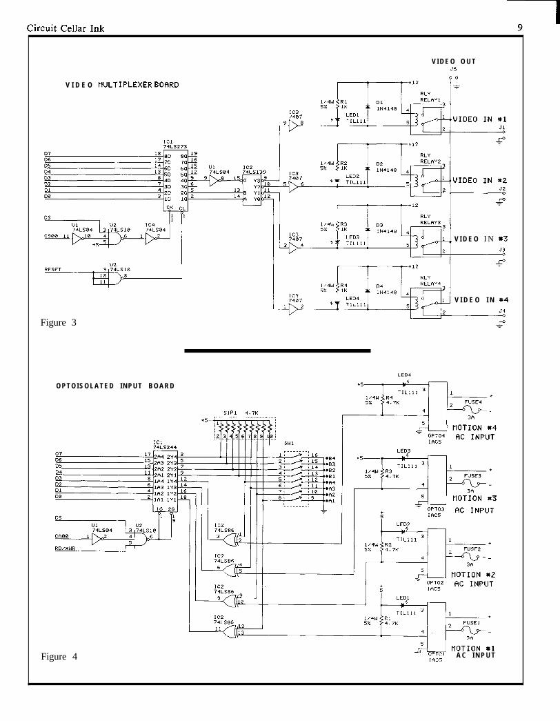
Figure 3 is the schematic of therelay multiplexer added to the
1
prototyping board. The relay circuitis specifically addressed at C900Hand any data sent to that location viaan XBY command [ t yp i ca l l yXBY(0C900H)=X] will be latchedinto the 74LS273. Since it can bedestructive to attach two video out-puts together, the four relays are notdirectly controlled by the latch out-puts. Instead, bits DO and Dl areused to address a 74LS139 one-of-four decoder chip. The decoder isenabled by a high-level output onbit D3. Therefore, a 1000 (binary)code selects relay 4 while a 1011code selects relay 1. An output of0000 shuts off the relay mux (elimi-nating the decoder and going di-rectly to the relay drivers allowsparallel control of the four relays).
All the normally-open relay con-tacts are connected together as acommon output. Since only a singlerelay is ever on at one time, thatvideo signal will be routed to theoutput. If the computer fails orthere is a power interrupt, the de-fault output state of a 74LS273 isnormally high. Therefore, the high-est priority camera should be at-tached to that input. If the systemgets deep-sixed, the output willdefault to that camera and will stillbe of some use (I could also haveused one of the normally-closedcontacts instead but chose not to).
Fools and Mother Nature
I’m sure you’re curious so I willanticipate your question and an-swer it at the same time. With allthe high-tech stuff that I continu-ally present, how come I used me-chanical relays?
The answer is lightning! Any-one familiar with my writings willremember that I live in a hazard-ous environment when it comes toMother Nature. Every year I getblasted and it’s always the high-tech stuff that gets blitzed. Be-cause the MTVCM has to workcontinuously as well as be reliableI had to take measures to protect itfrom externally-induced calami-ties. This meant that all the inputsand outputs had to be isolated.
In the case of the video mux, theonly low-cost totally isolatedswitches are mechanical relays.CMOS multiplexer chips like theones I’ve used in other projects arenot isolated and would be toosusceptible. (Just think of theMTVCM as a computer with three150-foot lightning collectors run-ning to the cameras.) Relays stillserve a useful purpose whateverthe level of integrated circuit tech-nology. They also work.
Because the infrared motionsensors are connected to the ACpower line and their outputs arecommon with it, these too had tobe isolated to protect the MTVCM.Figure 4 details the circuit of the4-channel optoisolator inputboard which connects to the mo-tion detectors.
The Optoisolator Board
The opto board is addressed atCAOOH. Reading location CAOOH[typically X=XBY(OCAOOH)] willread the 8 inputs of the 74LS244.Bits O-3 are connected to the four
V I D E O O U T35
V I D E O MJLTIPLEXER BOF1RD
V I D E O I N *3
V I D E O I N *4
Figure 3
LED4
O P T O I S O L A T E D I N P U T B O A R D
HOTION *3
Figure 4 = OPT01 A C I N P U TIAC5
10
optoisolators and bits 4-7 are con-nected to a 4-pole dip switchwhich is used for configurationand setup. Between the optoisola-tors and the LS244 are four74LS86 exclusive-OR gates. Theyfunction as selectable inverters.Depending upon the inputs to theoptoisolators (normally high orlow) and the settings of DIP SW2you can select what level outputsyou want for your program (guyslike me who never got the hang ofusing PNP transistors have todesign hardware so that whateverprogramming we are forced to docan at least be done in positivelogic).
The optoisolators are commonunits sold by OPT022, Gordos,and other manufacturers. Theyare generically designated as ei-ther IAC5 or IDC5 modules de-pending upon whether the inputvoltage is 115 VAC or 5-48 VDC.Since the motion detectors I usedwere designed to control AC floodlights, I used the IAC5 units con-nected across the lights.
Simple Software
Now that we have the hardwareI suppose we have to have somesoftware. For all practical pur-poses, however, virtually none isrequired. Since the MTVCM isdesigned with hardcoded parallelport addressing, you only needabout a three-line program to readthe inputs, make a decision and
select a video mux channel; youknow, something l ike READCAOOH, juggle it, and OUT C900H.I love simple software.
Of course, I got a little morecarried away when I actually wrotemy camera control program. I use alot of REM statements to figure outwhat I did. Since it would take uptoo much room here, I’ve posted theMTVCM mux control software onthe Circuit Cellar BBS (203-871-1988) where you can download it ifyou want to learn more. Basically,it just sits there looking at camera#l.. If it receives a motion inputfrom one of the sensors, it switchesto the appropriate camera and gen-erates a “camera ready” output(TTL output which is optoisolated atthe other end) to the ImageWise inthe house. It stays on that camera ifit senses additional motion orswitches to other cameras if it sensesmotion in their surveillance area.Eventually, it times out and goesback to camera # 1.
Basically, that’s all there is to the
MTVCM. If you are an engineeryou can think of it as a lightning-proof electrically-isolated proc-ess-control system. If not, just putit in your entertainment room anduse it as a real neat camera control-ler.
Now I’ve opened a real bag ofworms. Remotely controlling theImageWise digitizer/transmitterfrom my office through the houseto the MTVCM is turning into abigger task than I originally con-ceived. Getting the proper pictureand tracking someone in thedriveway is only part of the task.I can already envision a rack ofcomputer equipment in the housewhich has to synchronize this datatraffic. My biggest worry is nothow much coordination or equip-ment it will involve, but how I candesign it so that I can do it all witha three-line BASIC program! Beassured that I’ll tell you how as thesaga unfolds. nCall Circuit Cellar Inc. at (203)875-2751 forinformation and pricing on BCC52 and pe-ripheral boards.
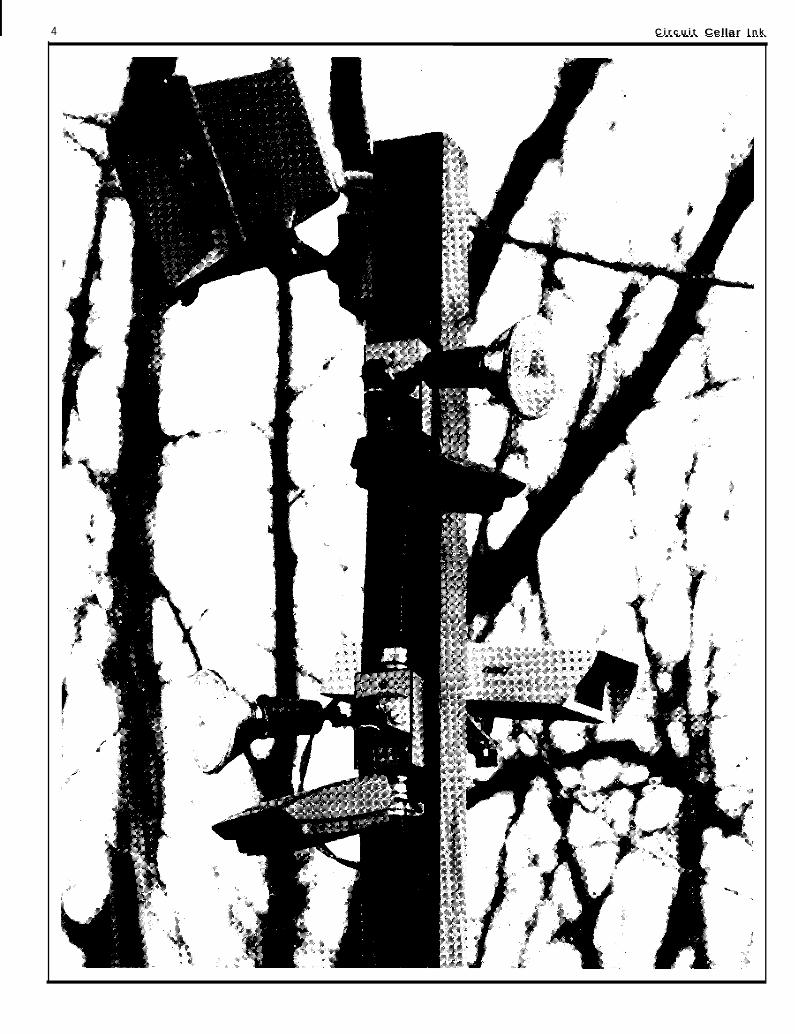
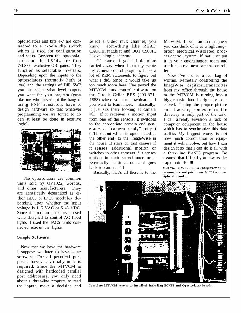
Complete MTVCM system as installed, including BCC52 and Optoisolator boards.
Circuit Cellar Ink 11
by Tom Cantrell
A rrgghh--the RISC hype (and puns) are reallygetting out of hand. Let’s face facts:
a) RISC has little to do with CPU performance.The bottom line: instruction set complexity is just notthat big a deal.
b) CPU performance has little to do with overallsystem performance. Ask an HP ‘Spectrum’ designerwhether RISC makes I/O faster.
c) System performance is only one factor inachieving success in the market. Ask IBM, DEC,or Apple.
Frankly, I’m shocked at the one-sided claims ofsome RISC (Reduced Instruction Set Computer) pro-ponents and the apples-and-oranges RISC/CISC(Complex Instruction Set Computer) comparisons.The worst are made by those who--surprise!--sellRISC computers. Typically, it’s a RISC with multi-register sets (MRS), giant on-chip cache and optimal,optimizing compiler vs. an old off-the-shelf CISC(VAX, 68000) with none of these. Proponents are gladto expand the definition of ‘RISC’ to accommodateevery new chip -the more, the merrier! It is amazinghow ‘CISC’y some ‘retro-marketed’ RISCs are--CLIPPER, AMD 29000, even the Novix FORTHchip! ‘RISC’s as useful as ‘MIPS (Meaningless Infor-mation Provided for Sales) - about the same as the‘New-Improved’ label on soap.
Here is the true meaning of RISC in easy-to-remember acronyms...
-RISC Is for Student Computers. Between footballgames and demonstrations, a few grad students can’tcome close to the hundreds of person-years needed todesign a CISC like the ‘386, 68020 or VAX, and evenif they could, who would make the chips? RISC
set which is 850K+ transistors).- Relegate the Impossible Stuff to the Compiler
writer. Cutting corners on the hardware means thesoftware has to be much smarter in areas like registerallocation, instruction reorganization, pipeline sched-uling, etc. Yes, smarter software is good--for bothRISC and CISC.
- RISC Is an excuSe to Change. Though usuallyconsidered a no-no, there are a number of reasons acompany may wish to abandon an existing architectureand switch to a new one, including NIH (Not InventedHere), ‘locking’ customers into a proprietary architec-ture and differentiation from competitors. Forinstance, which sounds better... ‘Moon Microsystemsis switching to RISC because it goes a hundred MIPsand the RISC/CISC war is over and RISC is thewinner’, or... ‘Moon Microsystems is switching toRISC so you’ll think we’re better than 32-bit PCswhich offer the same performance at half the price,more selection and lower cost hardware, software add-ons, and 1000x our installed base.’
Don’t get me wrong--I’m not a CISC evangelist andwelcome the good work and discoveries of the RISCcamp. In fact, I’m trying to protect the ‘good’ of RISCfrom falling with the ‘bad and ugly’ hype. Witnesswhat happened to yesterday’s over-promoted hot-button, Artificial Intelligence--anyone want to investin an AI (‘That which cannot be done on a computer’)company? Maybe a backlash is already starting--check out the article in the September 1987 issue ofCOMPUTER--‘And Now A Case For More ComplexInstruction Sets.’ Another is ‘Performance EvaluationOf Multiple Register Sets,’ Eickemeyer and Patel, 14thAnnual International Symposium on Computer Archi-tecture. RISC zealots--read and heed! n
allows students, and tiny companies, to build theirown small, simple CPU chips--a worthy goal. It’s Biography -- As an independent designer in Silicon Valley, Tom
only true for the original 20-30K transistor RISCs,Cantrell has worked on chip, board and software projects, and writtennumerous articles. For writing, Tom uses a 512K MAC but his favorite
not ‘CRISCs’ (‘Complex’ RISCs’ like CLIPPER 3-chip toy is an SB180.
12 Pnll..., II
1 II I I I I I I I I I I I I I I I I I I I I II I II ( l I/I
Circuit Cellar InkI
13
High Security on a BudgetBuild a Video Hand Scanner/Identifierby Ed Nisley
L et’s suppose you’re in chargeof security for a building, control-ling access to rooms full of valu-able equipment. You must devisea method that will allow onlyauthorized people to enter, and, asis usually the case, you only havea limited budget. Human guardsused to be excellent for this sort ofthing, but with the pressure ofsocial security, pension plans,medical care, vacation, sick leave,lunch breaks and so on, most econ-omy-minded companies keepmoving to electronics for relief.
While I suppose that somedaythis article could conceivably betitled, “ B u i l d Y o u r O w nRoboCop,” today we have to beconcerned with more basic issuesdictated by the state of currenttechnology.
All kidding aside, the mostobvious security advantage forhaving a human guard is visualrecognition. The guard is there to“see” and “recognize” people andtake appropriate action. Electroni-cally speaking, most of this can bedone by present computer tech-nology. A computer can digitize aperson’s face and compare thispicture to a library of images viaimage processing algorithms. Howfast and accurate it does this ofcourse is purely an economic deci-sion. A CRAY-XMP does the jobvery quickly and effectively.
Generally speaking, however,more of us own PC/ATs t h a nCRAYs. This doesn’t mean that weare back to contending with unionsand coffee breaks. We can still per-form useful image processing withan AT provided that we limit theamount of visual data that we pro-cess.
Full-face images, while certainlydifferent enough between individu-als, contain voluminous amounts ofdata that take a considerable amountof time to crunch. The trick is to findsome visible feature that will bothidentify each authorized person andreject every unauthorized one.Whatever feature you pick should bedifficult to counterfeit and easy toverify. Furthermore, the wholeprocess should take only a few sec-onds so that the system isn’t anirritant.
In true Circuit Cellar fashion,however, we are not here to philoso-phize about the elements of such asecurity system. We are here to buildand test it. This article describes theHandScanner, a prototype devicethat identifies people using imagesof their hands.
Using an ImageWise video dig-itizer (described in a constructionproject by Steve Ciarcia in the May-June ‘87 BYTE) and an IBM AT, theHandScanner takes digital TV pic-tures of hand prints and analyzes andidentifies the person in only a fewseconds.
What does it do?
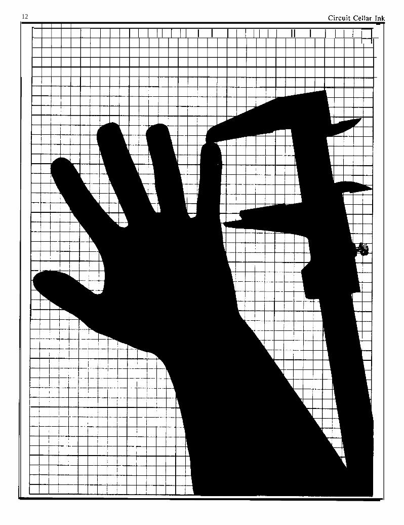
The basic idea behind theHandScanner was the (not verystunning) observation thatpeople’s hands look different:some are long, some short, othersfat or skinny. The overall handshape may not be as unique as afingerprint, but it seemed reason-able that there would be enoughdifference to make the projectfeasible. Best of all, hands areeasy to get into a TV picture.
Unfortunately, there is a bigstep between a human’s almostinstantaneous recognition of thedifference between two imagesand a computer program’s abilityto do the same thing. It’s not at allclear just how people recognizethings, so there’s no hope ofduplicating that feat in software.But there might be a way to extracta few significant numbers fromeach hand image that could serveas a signature.
The first chore was taking thepicture. It turned out that the onlyway to get a reliable picture of ahand was to backlight it against abright screen to form a silhouette.This eliminated any superfluousinformation provided by color ortexture. Finger lengths and theoverall width of the palm weredistinctly apparent and relatively
easy to measure. After a bit moreexperimenting, I had the basic ele-ments of the finger measurementalgorithm, and all the pieces werein place.
The HandScanner is composedof three parts: the scanner hard-ware, the firmware on the Image-Wise board, and the software tohandle the image analysis andrecognition. I’ll cover them insequence so you can see how theproject evolved, then discuss howwell it works in actual practice.
The Hardware
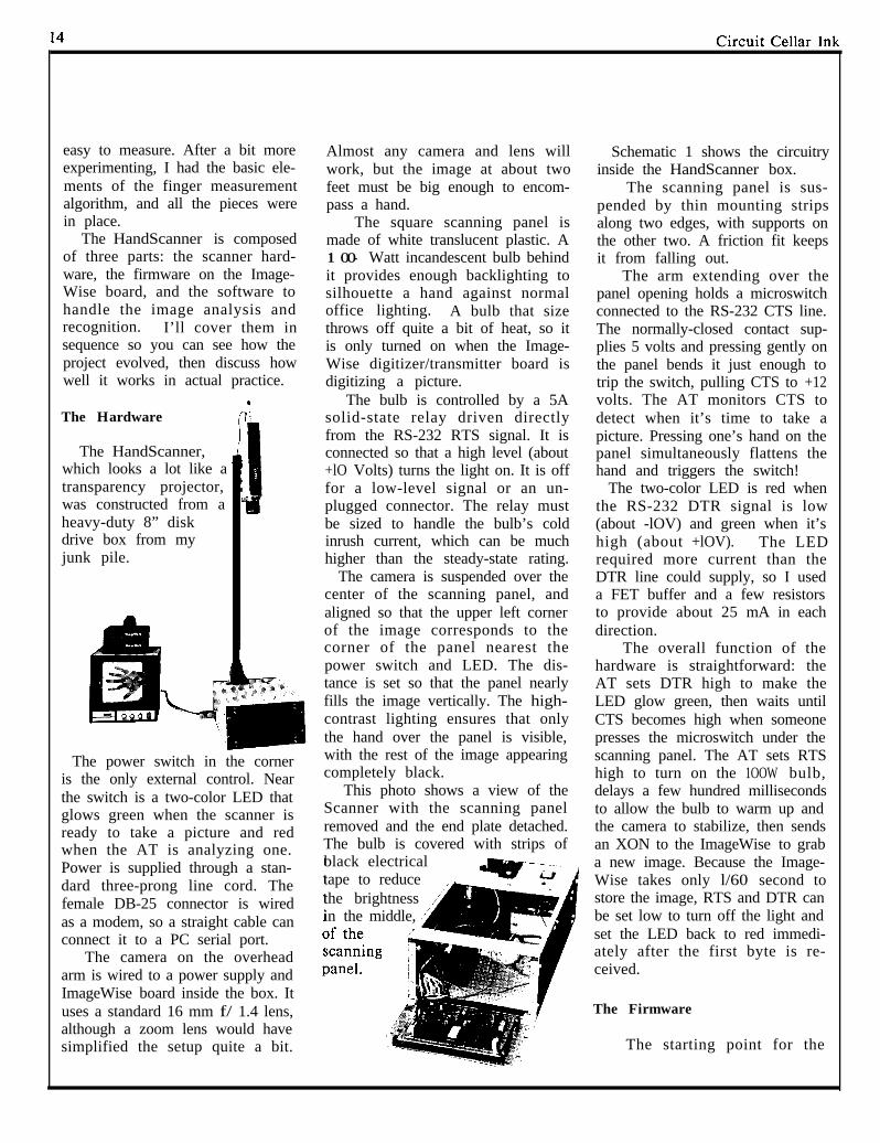
The HandScanner,which looks a lot like atransparency projector,was constructed from aheavy-duty 8” diskdrive box from myjunk pile.
The power switch in the corneris the only external control. Nearthe switch is a two-color LED thatglows green when the scanner isready to take a picture and redwhen the AT is analyzing one.Power is supplied through a stan-dard three-prong line cord. Thefemale DB-25 connector is wiredas a modem, so a straight cable canconnect it to a PC serial port.
The camera on the overheadarm is wired to a power supply andImageWise board inside the box. Ituses a standard 16 mm f/ 1.4 lens,although a zoom lens would havesimplified the setup quite a bit.
Almost any camera and lens willwork, but the image at about twofeet must be big enough to encom-pass a hand.
The square scanning panel ismade of white translucent plastic. A1 OO- Watt incandescent bulb behindit provides enough backlighting tosilhouette a hand against normaloffice lighting. A bulb that sizethrows off quite a bit of heat, so itis only turned on when the Image-Wise digitizer/transmitter board isdigitizing a picture.
The bulb is controlled by a 5Asolid-state relay driven directlyfrom the RS-232 RTS signal. It isconnected so that a high level (about+lO Volts) turns the light on. It is offfor a low-level signal or an un-plugged connector. The relay mustbe sized to handle the bulb’s coldinrush current, which can be muchhigher than the steady-state rating.
The camera is suspended over thecenter of the scanning panel, andaligned so that the upper left cornerof the image corresponds to thecorner of the panel nearest thepower switch and LED. The dis-tance is set so that the panel nearlyfills the image vertically. The high-contrast lighting ensures that onlythe hand over the panel is visible,with the rest of the image appearingcompletely black.
This photo shows a view of theScanner with the scanning panelremoved and the end plate detached.The bulb is covered with strips ofblack electricaltape to reduce ,L, ‘(the brightnessin the middle, ,’4
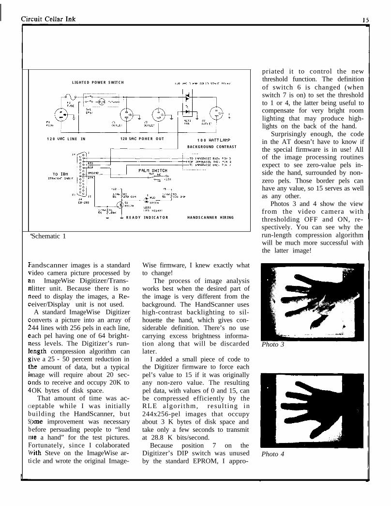
Schematic 1 shows the circuitryinside the HandScanner box.
The scanning panel is sus-pended by thin mounting stripsalong two edges, with supports onthe other two. A friction fit keepsit from falling out.
The arm extending over thepanel opening holds a microswitchconnected to the RS-232 CTS line.The normally-closed contact sup-plies 5 volts and pressing gently onthe panel bends it just enough totrip the switch, pulling CTS to +12volts. The AT monitors CTS todetect when it’s time to take apicture. Pressing one’s hand on thepanel simultaneously flattens thehand and triggers the switch!
The two-color LED is red whenthe RS-232 DTR signal is low(about -lOV) and green when it’shigh (about +lOV). The LEDrequired more current than theDTR line could supply, so I useda FET buffer and a few resistorsto provide about 25 mA in eachdirection.
The overall function of thehardware is straightforward: theAT sets DTR high to make theLED glow green, then waits untilCTS becomes high when someonepresses the microswitch under thescanning panel. The AT sets RTShigh to turn on the 1OOW bulb,delays a few hundred millisecondsto allow the bulb to warm up andthe camera to stabilize, then sendsan XON to the ImageWise to graba new image. Because the Image-Wise takes only l/60 second tostore the image, RTS and DTR canbe set low to turn off the light andset the LED back to red immedi-ately after the first byte is re-ceived.
The Firmware
The starting point for the
Circiiit Cellnr Tnlc
,
Cl
bS(bnFWti
L I G H T E D P O W E R S W I T C H
1 2 0 MC L I N E I N 1 2 0 WC P O H E R O U T 1 0 0 WTT LAtlP
B A C K G R O U N D C O N T R A S T
L & R E A D Y I N D I C A T O R H A N D S C A N N E R H I R I N G
Schematic 1
andscanner images is a standardideo camera picture processed byn ImageWise Digitizer/Trans-litter unit. Because there is noeed to display the images, a Re-eiver/Display unit is not used.A standard ImageWise Digitizer
onverts a picture into an array of44 lines with 256 pels in each line,ach pel having one of 64 bright-ess levels. The Digitizer’s run-:ngth compression algorithm canive a 25 - 50 percent reduction inle amount of data, but a typicalnage will require about 20 sec-nds to receive and occupy 20K toOK bytes of disk space.
That amount of time was ac-eptable while I was initiallyuilding the HandScanner, but)me improvement was necessaryefore persuading people to “lendte a hand” for the test pictures.ortunately, since I colaboratedrith Steve on the ImageWise ar-cle and wrote the original Image-
Wise firmware, I knew exactly whatto change!
The process of image analysisworks best when the desired part ofthe image is very different from thebackground. The HandScanner useshigh-contrast backlighting to sil-houette the hand, which gives con-siderable definition. There’s no usecarrying excess brightness informa-tion along that will be discardedlater.
I added a small piece of code tothe Digitizer firmware to force eachpel’s value to 15 if it was originallyany non-zero value. The resultingpel data, with values of 0 and 15, canbe compressed efficiently by theRLE algor i thm, resul t ing in244x256-pel images that occupyabout 3 K bytes of disk space andtake only a few seconds to transmitat 28.8 K bits/second.
Because position 7 on theDigitizer’s DIP switch was unusedby the standard EPROM, I appro-
priated it to control the newthreshold function. The definitionof switch 6 is changed (whenswitch 7 is on) to set the thresholdto 1 or 4, the latter being useful tocompensate for very bright roomlighting that may produce high-lights on the back of the hand.
Surprisingly enough, the codein the AT doesn’t have to know ifthe special firmware is in use! Allof the image processing routinesexpect to see zero-value pels in-side the hand, surrounded by non-zero pels. Those border pels canhave any value, so 15 serves as wellas any other.
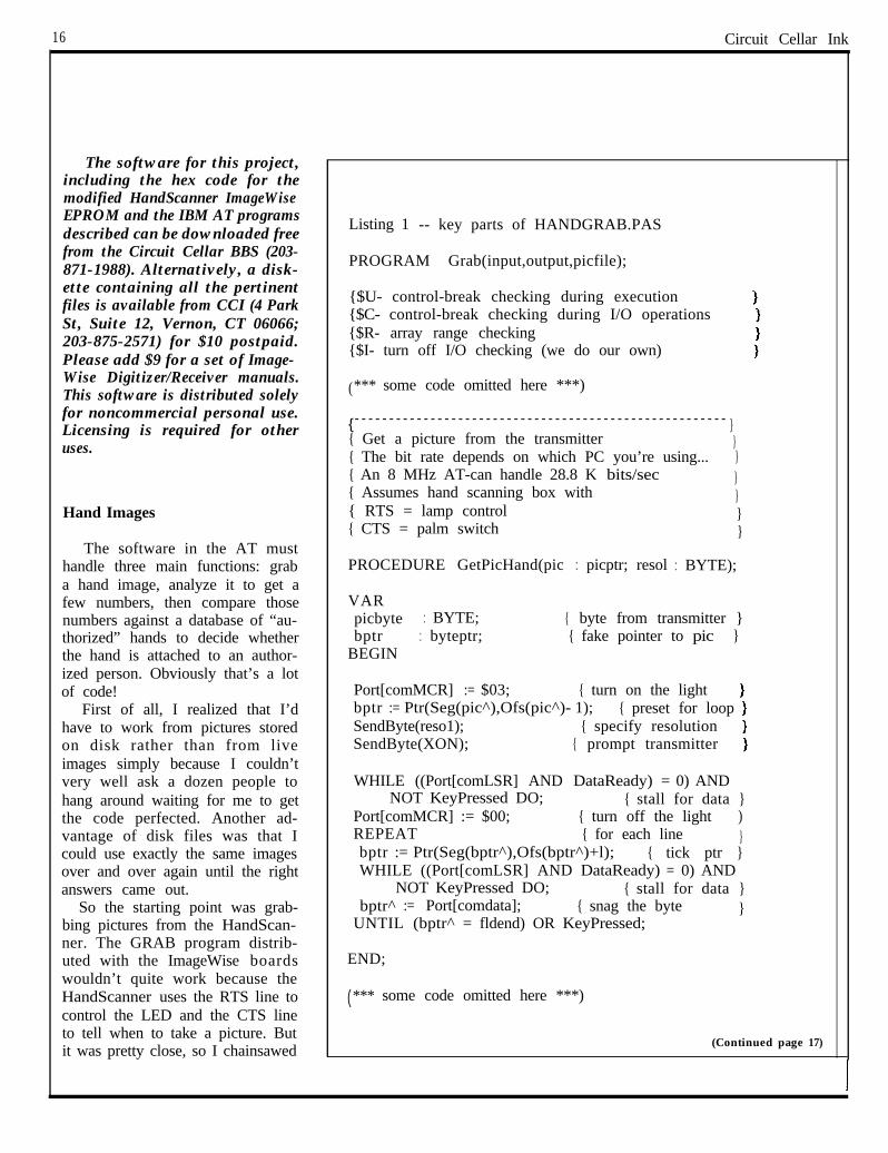
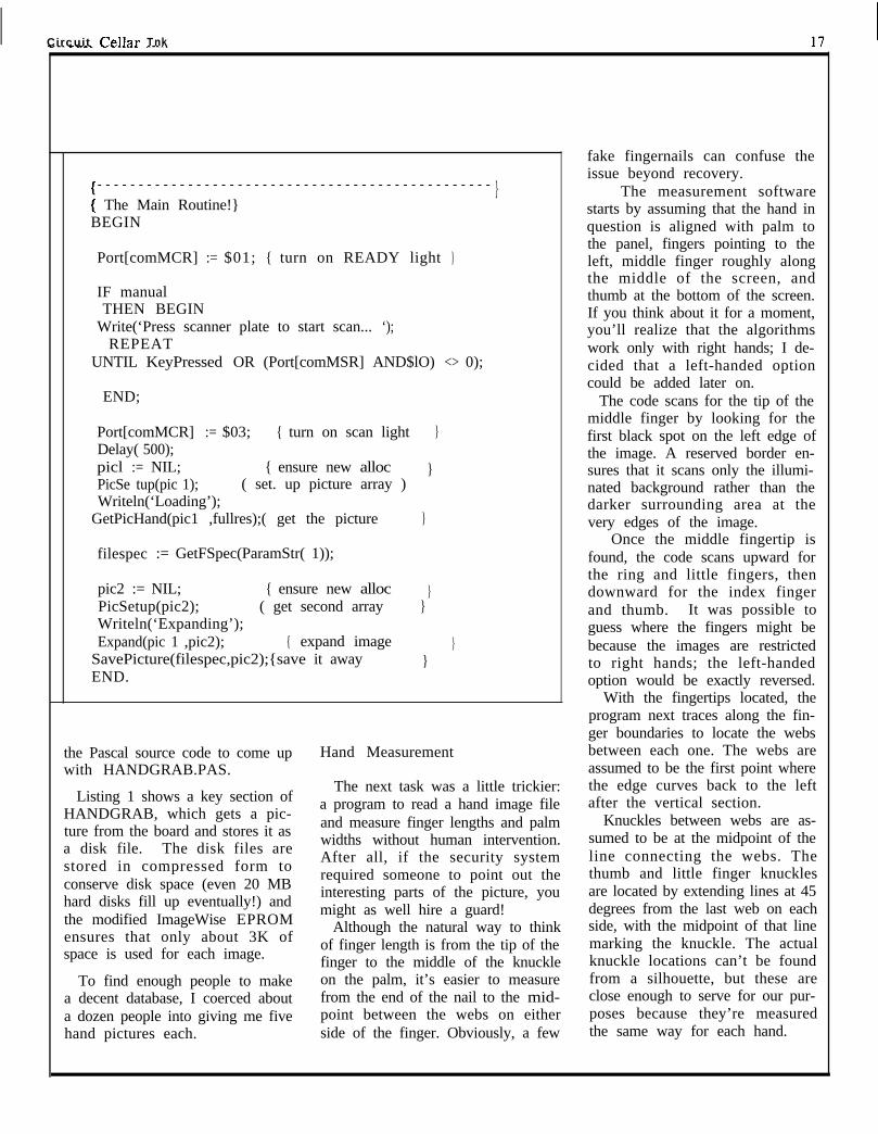
Photos 3 and 4 show the viewfrom the video camera withthresholding OFF and ON, re-spectively. You can see why therun-length compression algorithmwill be much more successful withthe latter image!
Photo 3
Photo 4
16 Circuit Cellar Ink
The software for this project,including the hex code for themodified HandScanner ImageWiseEPROM and the IBM AT programsdescribed can be downloaded freefrom the Circuit Cellar BBS (203-871-1988). Alternatively, a disk-ette containing all the pertinentfiles is available from CCI (4 ParkSt, Suite 12, Vernon, CT 06066;203-875-2571) for $10 postpaid.Please add $9 for a set of Image-Wise Digitizer/Receiver manuals.This software is distributed solelyfor noncommercial personal use.Licensing is required for otheruses.
Hand Images
The software in the AT musthandle three main functions: graba hand image, analyze it to get afew numbers, then compare thosenumbers against a database of “au-thorized” hands to decide whetherthe hand is attached to an author-ized person. Obviously that’s a lotof code!
First of all, I realized that I’dhave to work from pictures storedon disk rather than from liveimages simply because I couldn’tvery well ask a dozen people tohang around waiting for me to getthe code perfected. Another ad-vantage of disk files was that Icould use exactly the same imagesover and over again until the rightanswers came out.
So the starting point was grab-bing pictures from the HandScan-ner. The GRAB program distrib-uted with the ImageWise boardswouldn’t quite work because theHandScanner uses the RTS line tocontrol the LED and the CTS lineto tell when to take a picture. Butit was pretty close, so I chainsawed
Listing 1 -- key parts of HANDGRAB.PAS
PROGRAM Grab(input,output,picfile);
{$U- control-break checking during execution{$C- control-break checking during I/O operations{$R- array range checking{$I- turn off I/O checking (we do our own)
(*** some code omitted here ***)
{ An 8 MHz AT-can handle 28.8 K bits/sec{ Assumes hand scanning box with{ RTS = lamp control{ CTS = palm switch
{- - - - - - - - - - - - - - - - - - - - - - - - - - - - - - - - - - - - - - - - - - - - - - - - - - - - - - }{ Get a picture from the transmitter }{ The bit rate depends on which PC you’re using... }
}}}}
PROCEDURE GetPicHand(pic : picptr; resol : BYTE);
VARpicbyte : BYTE; { byte from transmitter }bptr : byteptr; { fake pointer to pic }
BEGIN
Port[comMCR] := $03; { turn on the lightbptr := Ptr(Seg(pic^),Ofs(pic^)- 1); { preset for loopSendByte(reso1); { specify resolutionSendByte(XON); { prompt transmitter
WHILE ((Port[comLSR] AND DataReady) = 0) ANDNOT KeyPressed DO; { stall for data }
Port[comMCR] := $00; { turn off the light )REPEAT { for each line }bptr := Ptr(Seg(bptr^),Ofs(bptr^)+l); { tick ptr }WHILE ((Port[comLSR] AND DataReady) = 0) AND
NOT KeyPressed DO; { stall for data }bptr^ := Port[comdata]; { snag the byte }
UNTIL (bptr^ = fldend) OR KeyPressed;
END;
(**** some code omitted here ***)
(Continued page 17)
I
Circuit Cellnr Tnk
- - - - - - - - - - - - - - - - - - - - - - - - - - - - - - - - - - - - - - - - - - - - - - - -
[ The Main Routine!}}
BEGIN
Port[comMCR] :== $01; { turn on READY light }
IF manualTHEN BEGIN
Write(‘Press scanner plate to start scan... ‘);REPEAT
UNTIL KeyPressed OR (Port[comMSR] AND$lO) <> 0);
END;
Port[comMCR] := $03; { turn on scan light }Delay( 500);picl := NIL; { ensure new alloc }PicSe tup(pic 1); ( set. up picture array )Writeln(‘Loading’);
GetPicHand(pic1 ,fullres);( get the picture }
filespec := GetFSpec(ParamStr( 1));
pic2 := NIL; { ensure new alloc }PicSetup(pic2); ( get second array }Writeln(‘Expanding’);Expand(pic 1 ,pic2); { expand image }
SavePicture(filespec,pic2);{save it away }END.
the Pascal source code to come up Hand Measurementwith HANDGRAB.PAS.
Listing 1 shows a key section ofHANDGRAB, which gets a pic-ture from the board and stores it asa disk file. The disk files arestored in compressed form toconserve disk space (even 20 MBhard disks fill up eventually!) andthe modified ImageWise EPROMensures that only about 3K ofspace is used for each image.
The next task was a little trickier:a program to read a hand image fileand measure finger lengths and palmwidths without human intervention.After all, if the security systemrequired someone to point out theinteresting parts of the picture, youmight as well hire a guard!
Although the natural way to thinkof finger length is from the tip of thefinger to the middle of the knuckle
To find enough people to make on the palm, it’s easier to measurea decent database, I coerced about from the end of the nail to the mid-a dozen people into giving me five point between the webs on eitherhand pictures each. side of the finger. Obviously, a few
fake fingernails can confuse theissue beyond recovery.
The measurement softwarestarts by assuming that the hand inquestion is aligned with palm tothe panel, fingers pointing to theleft, middle finger roughly alongthe middle of the screen, andthumb at the bottom of the screen.If you think about it for a moment,you’ll realize that the algorithmswork only with right hands; I de-cided that a left-handed optioncould be added later on.
The code scans for the tip of themiddle finger by looking for thefirst black spot on the left edge ofthe image. A reserved border en-sures that it scans only the illumi-nated background rather than thedarker surrounding area at thevery edges of the image.
Once the middle fingertip isfound, the code scans upward forthe ring and little fingers, thendownward for the index fingerand thumb. It was possible toguess where the fingers might bebecause the images are restrictedto right hands; the left-handedoption would be exactly reversed.
With the fingertips located, theprogram next traces along the fin-ger boundaries to locate the websbetween each one. The webs areassumed to be the first point wherethe edge curves back to the leftafter the vertical section.
Knuckles between webs are as-sumed to be at the midpoint of theline connecting the webs. Thethumb and little finger knucklesare located by extending lines at 45degrees from the last web on eachside, with the midpoint of that linemarking the knuckle. The actualknuckle locations can’t be foundfrom a silhouette, but these areclose enough to serve for our pur-poses because they’re measuredthe same way for each hand.
I8 Circuit Cellar Ink I
The complete hand analysisprogram is far too long to reprinthere, but the small section inListing 2 should give you an ideaof how it works. The coordinatesfor each measured point are or-ganized into an array of recordswith the array elements indexedby finger name. Thus, the coor-dinates of the tip of the littlefinger are held in the variablesHAND[LITTLE].TIP.PEL andHAND[LITTLE].TIP.LINE.
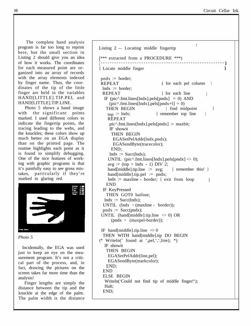
Photo 5 shows a hand imagewith the s ignif icant pointsmarked. I used different colors toindicate the fingertip points, thetracing leading to the webs, andthe knuckles; these colors show upmuch better on an EGA displaythan on the printed page. Theroutine highlights each point as itis found to simplify debugging.One of the nice features of work-ing with graphic programs is thatit’s painfully easy to see gross mis-takes, particularly if they’remarked in glaring red.
Photo 5
Incidentally, the EGA was usedjust to keep an eye on the mea-surement program. It’s not a criti-cal part of the process, and, infact, drawing the pictures on thescreen takes far more time than theanalysis!
Finger lengths are simply thedistance between the tip and theknuckle at the edge of the palm.The palm width is the distance
Listing 2 -- Locating middle fingertip/
{**** extracted from a PROCEDURE ***){ - - - - - - - - - - - - - - - - - - - - - - - - - - - - - - - - - - - - - - - - - - - - - - - - - - - - - - -{ Locate middle finger :
pndx := border;REPEAT ( for each pel column }lndx := border;REPEAT { for each line }IF (pic^.fmt.lines[lndx].pels[pndx] = 0) AND
(pic^.fmt.lines[lndx].pels[pndx+l] = 0)THEN BEGIN { find midpoint }top := lndx; { remember top line }REPEATpic^.fmt.lines[lndx].pels[pndx] := maxbit;IF showitTHEN BEGINEGASetPelAddr(lndx,pndx);EGASendByte(tracecolor);
END;lndx := Succ(lndx);
UNTIL (pic^.fmt.lines[lndx].pels[pndx] <> 0);avg := (top + lndx - 1) DIV 2;hand[middle].tip.line := avg; { remember this! }hand[middle].tip.pel := pndx;lndx := maxline - border; { exit from loop }
ENDIF KeyPressed
THEN GOT0 bailout;lndx := Succ(lndx);
UNTIL (lndx > (maxline - border));pndx := Succ(pndx);
UNTIL (hand[middle].tip.line <> 0) OR(pndx > (maxpel-border));
IF hand[middle].tip.line <> 0THEN WITH hand[middle].tip DO BEGIN
(* Writeln(’ found at ‘,pel,‘,‘,line); *)IF showitTHEN BEGINEGASetPelAddr(line,pel);EGASendByte(markcolor);
END;ENDELSE BEGINWriteln(‘Could not find tip of middle finger!‘);Halt;
END;
between the knuckles at the basesof the thumb and little finger. Thefinger lengths are computed inunits of pels.
Because the actual pel size de-pends on the hand-to-camera dis-tance and the lens focal length, it’sreasonable to normalize the fingerlengths to a standard. The middlefinger can be measured most accu-rately, so I divided all the otherfinger lengths by the length of themiddle finger. The resulting ratiosare independent of the actual pic-ture size.
The program appends these re-sults to the end of an ASCII filethat can be read and written by astandard text editor. By concen-trating all the data in one readablefile, I could manually delete in-correct records without having toregenerate the whole file fromscratch. Listing 3 shows a part ofthat file.
Hand Recognition
The remainder of the problemwas more of a database exercisethan anything else, so I switchedlanguages from Pascal to dBase totake advantage of the latter’s datamanipulation functions. The fileof hand data was easily convertedinto a dBase III database file andthe dBase routines look suspi-ciously like pidgin Pascal.
The database file contains onerecord for each hand image, witheach record including the imagefile-name and the key hand mea-surements described above. I hadabout 50 records to work with,which isn’t enough for a true sta-tistical analysis, but was about asmany as I could get without ex-hausting everyone’s patience.
I selected one data record atrandom for each person to serve asa test image; the four remaining
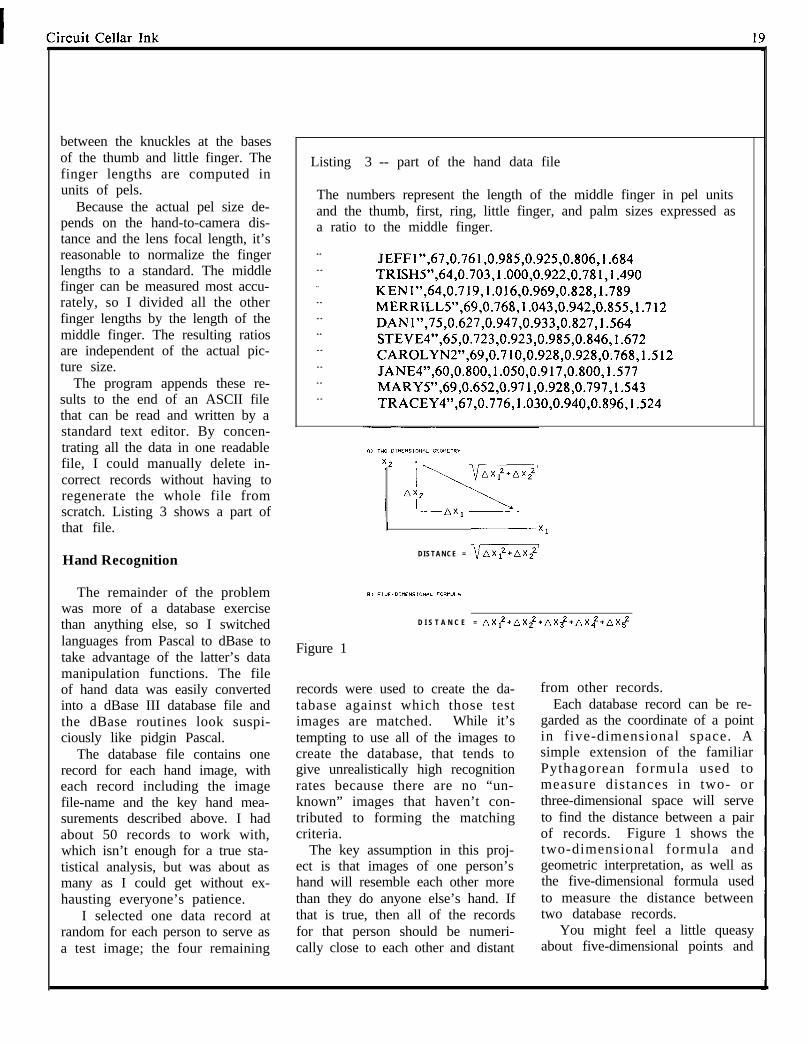
’ Listing 3 -- part of the hand data file
The numbers represent the length of the middle finger in pel unitsand the thumb, first, ring, little finger, and palm sizes expressed asa ratio to the middle finger.
“
“
"
“
“
“
“
“
“
“
JEFF1”,67,0.761,0.985,0.925,0.806,1.684TRISH5”,64,0.703,1.000,0.922,0.781,1.490KEN1”,64,0.719,1.016,0.969,0.828,1.789MERRILL5”,69,0.768,1.043,0.942,0.855,1.712DANl”,75,0.627,0.947,0.933,0.827,1.564STEVE4”,65,0.723,0.923,0.985,0.846,1.672CAROLYN2”,69,0.710,0.928,0.928,0.768,1.512JANE4”,60,0.800,1.050,0.917,0.800,1.577MARY5”,69,0.652,0.971,0.928,0.797,1.543TRACEY4”,67,0.776,1.030,0.940,0.896,1.524
I
D I S T A N C E = vnx:,x::’
D I S T A N C E = AXlz+AX,2+AX~2+AX.,z+AX5z
Figure 1
records were used to create the da-tabase against which those testimages are matched. While it’stempting to use all of the images tocreate the database, that tends togive unrealistically high recognitionrates because there are no “un-known” images that haven’t con-tributed to forming the matchingcriteria.
The key assumption in this proj-ect is that images of one person’shand will resemble each other morethan they do anyone else’s hand. Ifthat is true, then all of the recordsfor that person should be numeri-cally close to each other and distant
from other records.Each database record can be re-
garded as the coordinate of a pointin five-dimensional space. Asimple extension of the familiarPythagorean formula used tomeasure distances in two- orthree-dimensional space will serveto find the distance between a pairof records. Figure 1 shows thetwo-dimensional formula andgeometric interpretation, as well asthe five-dimensional formula usedto measure the distance betweentwo database records.
You might feel a little queasyabout five-dimensional points and
20
L
distances. This is actually a stan-dard mathematical process: thedimensions don’t really corre-spond to the ordinary ones oflength, width, and depth... we’renot venturing into Special Rela-tivity for this project! The dimen-sion of a point is just the numberof values needed to specify it: inour case there are five values, sowe need five dimensions.
The database records (but notthe test record!) for each personwere combined by simple averag-ing to get a single record repre-senting that person’s hand images.I assumed that each measurementwas contaminated by randomnoise, so that the averaging pro-cess would remove some of thenoise and provide a better estimateof the true location of the idealhand image in that five-dimen-sional space.
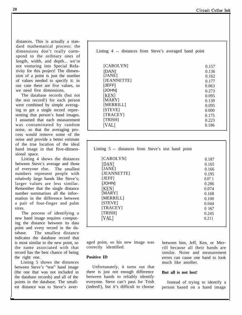
Listing 4 -- distances from Steve’s averaged hand point
[CAROLYN] 0.157[DAN] 0.136[JANE] 0.162[JEANNETTE] 0.177[JEFF] 0.063[JOHN] 0.273[KEN] 0.095[MARY] 0.139[MERRILL] 0.095[STEVE] 0.000[TRACEY] 0.175[TRISH] 0.223[VAL] 0.186
Listing 5 -- distances from Steve’s test hand point
Listing 4 shows the distances [CAROLYN] 0.187between Steve’s average and those [DAN] 0.165of everyone else. The smallest [JANE] 0.166numbers represent people with [JEANNETTE] 0.195relatively large hands like Steve’s; [JEFF] 0.07 1larger values are less similar. [JOHN] 0.286Remember that the single distance [KEN] 0.074number summarizes all the infor- [MARY] 0.168mation in the difference between [MERRILL] 0.100a pair of four-finger and palm [STEVE] 0.044sizes. [TRACEY] 0 167
The process of identifying a [TRISH] 0.245new hand image requires comput- [VAL] 0.211ing the distance between its datapoint and every record in the da-tabase. The smallest distanceindicates the database record thatis most similar to the new point, so aged point, so his new image was between him, Jeff, Ken, or Mer-the name associated with that correctly identified. rill because all their hands arerecord has the best chance of being similar. Noise and measurementthe right one. Positive ID errors can cause one hand to look
Listing 5 shows the distances much like another.between Steve’s “test” hand image Unfortunately, it turns out that(the one that was not included in there is just not enough difference But all is not lost!the database records) and all of the between hands to reliably identifypoints in the database. The small- everyone. Steve can’t pass for Trish Instead of trying to identify aest distance was to Steve’s aver- (indeed!), but it’s difficult to choose person based on a hand image
alone, we can verify that they are I Serial DigitA Imaging Systemwho they claim to be. For ex- Conclusionsample, if Steve provides both animage and his name, the program The HandScanner is not as good ascan measure the distance between a fingerprint matching system, thatthe image point and his database much is certain! However, it mayrecord. If there’s a close match well provide enough reliability forbetween the two, he’s presumed to low to moderate security areas, par-be Steve. ticularly if you have a small number
In Listing 5 you can see that the of people who are authorized for ac-next closest match is 0.071 (for cess. ImageWise functions as aJEFF), with the others above I suspect that some changes would I standalone video dieitizer or
0.100. It turns out that matching greatly improve the performance‘a complete tele-imaging and
hands tend to be within 0.080 ofvideo capture system.
and reliability. In particular, a Ima eWise!s serially bitthe matching record, so requiring better means of extracting the hand mappe. digitized pictures%
an unknown hand to be within measurements would reduce theare universally compatiblewith any computer or modem
0.090 of the record will give some errors in each length and reduce the It is ideally suited formargin for error. differences between measurements CAD/CAM Desktop Pub-
Security systems can fail in one of the same hand.lishing, Tefe-Imaging, andSecurrty.
of two ways: false positives and Optically, the hand images usefalse negatives. The false positive only about half of the picture area;
n System Specifications n
failures admit strangers to the a cylindrical lens would extend the*NOT bua dependent*Captures an image in 1/60th second
building, the false negatives reject image and increase the resolution. A *Accepts any B/W or color NTSC video
authorized people. In general, you zoom lens would allow some modi-*Resolution of transmitted image is
can reduce one type of failure only fication to the working distance, and256x244~64 gray scale. Resolutionselectable: High - Medium - Low
at the cost of increasing the other. a power zoom lens would allow theBecause the unknown hand is size of the image to be tailored to
tested against only one record in each hand.the database, the minimum dis- As I suggested at the start, youtance allowed for a match deter- might be able to adapt the Hand- I unretouched photos
mines the error rate. Too large a Scanner to industrial inspection ap- *Video Input: 76 Ohm, 1V peak-to-peakdistance will permit mismatches, plications rather than security sys- *Video Output: 75 Ohm, NTSC, 1.5V
but a very small distance will tems. For example, if you’re in- peak-to-peak.
reject an unreasonable number of volved with punching sheet metal,‘Serial Input/Output: RS-232 - 8 bit,one stop bit, no parity - 300 bps to
authorized people. The correct t h e HandScanner c a n t e l l y o u 57.6K bps selectable data rate -
value must be determined by ex- whether you’ve got a correctly sized Xon/Xoff handshaking - switch select-
perimentation and will surely de- hole in the right place in a fewable data compression (on/off).
*Modem compatible: Functions aa a
pend on the exact collection of seconds. Some changes to the me- video or a remote surveillance camera.
hands in the database. chanics would be needed to fit it into*Video proceseing: PC/MS-DOS picture
Of course, someone typing in aupload/download and conversion
your production line, but the prin- utilities to popular Paint k Desktop
name that’s not in the database can ciple remains the same. n Publishing programs.
be rejected immediately, simply Optional PC Utilities Disk converts
because all authorized people areImageWise files for use with popularDesktop and Paint programs.
in the database. An intruder mustknow which person on the author-
Please call CC1 for current pricing
ized list has a similar hand, which Acknowledgementon Experimenter’s and full Kits,
is rather hard to figure out by just power supply and case.
looking -- we humans are easily Thanks to Jeff Bachiochi, who wasdistracted by details that the
To order callthe first to say “Hey, I bet
HandScanner algorithms simply everybody’s fingers are different!” It(203) 875-2751
ignore.TELEX: 643331
was all downhill from there... CIRCUIT CELLqR INC4 Park St., Suite 12 Vernon, CT 06066
I
21
I Build Steve Ciarcia’s
Circuit Cellar Ink
Circuit Cellar Ink 1
CONNECTIMETHE CIRCUIT CELLAR BBS
300/1200/2400 bps24 hours/7 days a week
(203) 871-1988Vernon, Connecticut Sysop: Ken Davidson
And so the welcome file begins as your modemconnects with the Circuit Cellar BBS. If you keepreading, you’ll find that the CCBBS is set up toprovide support to Ciarcia’s Circuit Cellar and CircuitCellar Ink readers. It is here to answer questionsabout articles, to distribute files related to the articles,and for people to discuss just about anything concern-ing computers and electronics.
We have a devoted group of regular callers whoprovide a rich and diverse background in the fields ofelectronics and computer science. More than once I’veseen an off-the-wall question posted to “ALLUSERS” that I thought nobody could answer, just tofind a knowledgeable response to it the next day.
Connectime’s purpose is to provide you with asampling of what’s being discussed on the CCBBS.The CCBBS has been operational for over two yearsand we’re lucky to have some very gifted and talentedcallers who have contributed to its success. Unfortu-nately, it is very difficult to synopsize two years ofBBS traffic in a few pages of INK (especially themassive initial message traffic on the SB180). Thefollowing is just a sampling of some of the BBSconversations:
Msg #3006by Andrew CoileTo: Steve CiarciaRe: AVMUX Circuitry
Steve,I read your construction articles with much
interest and, for the first time, I am attempting tobuild an audio routing switcher (8x8x2) based on theAVMUX (Feb ‘86). After plotting out the schematic,some questions occurred to me.
In the AVMUX, you provide a 10K resistive
load to the input and then AC couple it through a 0.1 uFcapacitor to the input of the 74HC22106 cross-pointswitch. The output of the cross-point has a 1 Meg pull-down to ground at the input of an inverting (practi-cally) unity-gain buffer.
My questions is, what biases the inputs? If thereare internal biasing resistors on the 74HC22106 (I don’thave a data sheet on them, they’re too new), then theinput will get centered around Vcc/2, or 2.5 volts.Fine.
When there are no cross-points active for anoutput, is it safe to assume it is high impedance? (Iassume yes, otherwise why would you have the pull-down resistors to prevent the inputs from floating allover the place.) If this is true, wouldn’t the pull-downresistor pull the input toward ground, and then whena cross-point is activated, suddenly the 74HC22106output goes up to Vcc/2, giving you one massiveglitch? (I wouldn’t want to be standing in front of myspeakers when a glitch like that goes through.) Is thisthe case? If so, how can the 74HC22106 be biased tooperate noiselessly? Perhaps by running it on +/- 5Vand then playing games with the addressing and controllines?
I plan to run the cross-point with a ZZ8 usingMM5486 display drivers to run a 64-LED cross-pointdisplay. The routing switcher will also have thecapability to accept remote keyboard inputs. (I’ll sendyou a copy of the schematics and a photo of the boardwhen I get it done.)
I am a Systems Engineer by profession, andspecialize in dedicated microprocessor-driven indus-trial controllers. Thus I am familiar with this type ofcircuit.
Thank you very much for answering this question.
--Andrew Coile
Cirmit Cellnr Tnk
P.S. Doesn’t the Z80 have an I/O space of only 256ports? I thought the contents of the A register areplaced on the low-order address lines, but that is notreally true 16-bit addressing. Plus, that “feature” ofthe Z80 is not documented (I think). Good article oninterfacing, though. Keep up the good work!. . ..ACMC
Msg #3022by Steve CiarciaTo: Andrew CoileRe: AVMUX Circuitry[Reply to msg #3006]
Andy,You pretty much answered all your questions.
An unselected channel is a high impedance. I did find,however, that this was not a good idea and led to crosstalk. All output devices should have somethingselected as its source, even if only a grounded inputchannel. The input impedances of the monitors andamplifiers end up with garbage if left open-circuited.
While the Z8 is a good device, you may want toconsider the BCC52 after all. There is a new 4x20 and8x40 LCD display peripheral (BCC25) for the 52. Italso has provision for a parallel keyboard attachment.There will be a spec sheet in the articles section oneof these days. Finally, to my knowledge the Z80addresses 64K bytes of memory AND 64K bytes ofI/O. There are four control lines: RD\ (read), WR\(write), IOE\ (I/O enable), and ME\ (memory enable).
--SteveP.S. If there are any loud “pops” when switching
channels, I haven’t experienced it. I’m not using muchaudio, however. My switcher is primarily video.
name is Richard Hinton from Homewood, Illinois. Ifanyone has any information about same please sendalong or I will be calling back this BBS in a few days.
--Thanks.
Msg #3101by Marc BaconTo: Richard HintonRe: Carrier current systems[Reply to msg #3054]
Richard,
I am also interested in carrier current systems.Radio Shack makes an FM wireless intercom that usescarrier current and BSR makes the X- 10 home controlsystem. These two are not compatible and theintercom can cause some bizarre things to happen. Iasked Steve about this a few months ago and he statedthat it is hopeless to run the two. Steve’s Home ControlSystem allows you to control appliances in the BSR X-10 system using the HCS computer. I hope this mightbe of some help. Additional information can be foundin earlier Circuit Cellar projects including April andMay, 1978, January-March 1979, Jan, 1980 (BSR X-IO), Aug 1983, April-June 1985 and others I mighthave overlooked. These are in BYTE magazine andcopies can be obtained from libraries and computerinformation services such as the Source et al. They willalso be available from long term hackers (don’t talk tocrackers...they are the bad guys) who, like myself havecollected BYTEs from the early days. Good luck. Iam currently developing a project along these lines andI will try to keep you informed on this BBS as Ipromised Steve.
Later, --Marc
Carrier current systems is always a popular topicwhen dealing with retrofitting a house for automatedcontrol. The following series of messages addresses theissue:
Msg #3054by Richard HintonTo: ALL USERSRe: Carrier current systems
I am interested in a carrier current intercom and alsoan appliance control device ala carrier current. My
From carrier current in general, we move on to morespecific discussion about X-10 and HCS. We had a runon HCS questions during one week with a good deal ofinformation being exchanged.
Leo Taylor, who helped in the development of theHCS, had just answered a question for Jack Olivieri.The following is what transpired:
I24 Circuit Cellar Ink
1
Msg #3275by Jack OlivieriTo: Leo TaylorRe: HCS Modules
Leo - thanks for the info. Since you seem to beusing a lot of modules, just like me, I have a question.What have you done about the erratic nature ofoperation when the module you want to control is onone side of the 220VAC line and the controller is onthe other side? I was thinking of bridging the two1lOVAC lines with a O.luF, 600-Volt capacitor. Anycomments or suggestions?
Msg #3279by Leo TaylorTo: Jack OlivieriRe: HCS power bridge[Reply to msg #3275]
A common question! I had all my modules workingdependably sometime ago, then I had my houseupgraded to l00-Amp service. All of a sudden thingswere missing commands. I have tried a 1uF oil-filledcap, and it does work. I was uncomfortable with itthough; what if someday (perhaps years from now) thecap fails? 100 Amps at 220 Volts can do wonders toa large cap! So I rearranged the circuits in my breakerbox, putting all computer and BSR stuff on one side,and refrigerator, heat, and air conditioners (exceptbedroom which is controlled) on other side. I now havedependable action from the HCS, though my BSR-brand Control Box on the nightstand can’t hit theliving room. Also, be aware that some devices withcaps across the power will lower the output of BSRtransmitters and the HCS. I had to remove a cap frommy STAR SG- 10 printer: I missed events when theprinter was on!
Msg #3295by Jack OlivieriTo: Leo TaylorRe: HCS power bridge[Reply to msg #3279]
Leo - thanks for the info. I have 200-Amp serviceand with 40+ circuits it would very difficult to re-wire. Unquestionably there needs to be some protec-tion for a capacitor if shorted (fuse?). Interestingcomment about the fact that some devices have caps
across their power inputs. That could explain somethings I have been seeing. I would assume that thisproblem has been solved in a variety of ways.Again, thanks!
Msg #3328by Leo TaylorTo: Jack OlivieriRe: HCS power bridge[Reply to msg #3295]
Jack -Final word on power bridge. I had a fuse in series
with the cap while it was installed, found it had to beabout 3 Amps! Of course, that’s “funny” current; itactually may have reduced my bill by power factorcorrection. I fixed my STAR printer by clipping outthe cap. Now I have to figure out what part of my68000 Atari dulls the BSR!
Msg #3293by Bob MunckTo: ALL USERSRe: X- 10 on 2 “sides”
I’m running a fairly extensive set of BSR X-10modules controlling lights, furnace, fans, hifi, and soon, programmed by a Radio Shack Color Computer(CoCo) and a number of controllers. The CoCo andsome of the controllers have trouble reaching variousappliances unless I turn on the oven. My conjectureis that they are on different sides of the 220V linefeeding the house and that the oven provides a signalpath across from one 11OV circuit to the other. Is thereany more permanent and less expensive way to providethis signal path? For instance, the clothes dryer has220V/3-wire connections. Could I put a capacitoracross the two hot wires? What size and rating? Secondquestion: has anyone tried to RECEIVE X- 10 signalswith a computer. I’d like to use my controllers for input(on one set of house codes) and have the CoCo do allcontrol signals (on another set). I’m going to try towrite code in Pascal for OS-9 to do this. Anysuggestions?
Thanks, --Bob Munck

Circuit Cellar Ink
Msg #3298 check validity.by Steve Ciarcia BTW, I have about 20 modules and a bunch of otherTo: Bob Munck more direct controllers, including direct control of theRe: BSR furnace (and several temperature inputs), some con-[Reply to msg #3293] trol of the house telephones, a speech synthesizer that
drives the hifi, and an IR output that can tell myBob, remote-controllable receiver what to do. Future plans
Both you and Jack Olivieri seem to be having BSR include better phone control and using the touch-toneproblems. I may not have a solution for you but let pads on all phones to send commands to the CoCo,me tell you what I’ve done in my house. I have about switching of audio and video signals, and handling22 BSR modules in operation with a Micromint HCS. inputs from a weather station. A friend is looking intoThe modules are on both sides of the line. I used two converting an old 45 juke box to handle CDs for me,1 -microfarad mylar capacitors with series fuses across and the CoCo will drive it. I hope to get random accessthe hot lines. The place that I inject the transmissions to about 100 CDs and to be able to pick selections(the HCS transformer) is very close to the breaker box explicitly from the keyboards or set up a randomwhich contains the crossover caps. selection of pieces of a given mood. My expertise is
Results are relatively positive. One side of the line the programming -- I do Modula-2 and Ada at work.always works while only about 2/3 of the other side -- Bob Munckwill function continuously. I avoid using the outletsthat are intermittent. Msg #3342
Regarding spurious on/off BSR modules, I don’t by Bob Munckhave that problem because that is one major reason for To: Steve Ciarciausing the HCS. The HCS has the capability to restore Re: BSR Bridgingall modules to their proper setting, either on or off, [Reply to msg #3298]every four minutes. (It just retransmits the wholeoutput table every four minutes when commanded to Steve,do a restore). It also does a restore after any power I didn’t quite understand your solution to gettingoutage (the HCS has battery backup). BSR signals from one 11OV circuit to the other. Did
--Steve you meanP.S. There is one other way to handle both sides of theAC line and that is to transmit into both at the same hot hottime. The HCS power transformer is the transmitter o--cap--fuse--cap--ocoupler to the line. I suppose it would be possibe to 0
drive two transformers, one on each AC line, from one neutralHCS. I haven’t tried this, however, so I’m not orrecommending it as a solution.
hot hotMsg #3313 o--cap--fuse--o--fuse--cap--oby Bob Munck neutralTo: Steve CiarciaRe: BSR or some other arrangement? Thanks -- Bob Munck[Reply to msg #3298]
Msg #3355Steve, by Steve Ciarcia
Thanks for the info on the capacitors. 1’11 try it. For To: Bob Munckreceiving, I’m planning to tap into a spare module to Re: BSR Bridgingget the detected signal, and tie it to an input port on [Reply to msg #3342]my CoCo. I’ve already tied a house circuit zero-crossing detector to a non-maskable interrupt, so I Bob,know when to watch for the “BSR signal received.” I’ll The first circuit you presented is the way I wiredwrite software to assemble the incoming codes and it. --Steve
26 Circuit Ccll2r Tnk
The Infrared Master Controller presented in theMarch 1987 Circuit Cellar article was a big hit amongthe hard-core experimenters.
Msg #7413by Ken MandelbergTo: Steve CiarciaRe: Master Controller
SteveRight after the article on the Master Controller
came out, a few people (including me) asked you if thecommand set on the controller could be extended toallow the PC to ask the controller to send out one ofthe IR sequences. The idea was to let the PC use theMaster Controller as a dedicated peripheral. Youexpressed some interest in this and said you would talkto the programmer. Has anything come of this? Moregenerally, have your plans for the future of the MasterController developed any?
Msg #7424by Ken DavidsonTo: Ken MandelbergRe: Master Controller[Reply to msg #7413]
You might be interested in the file calledIRCMDS.DOC in the PROJECTS: area. It turns outthat the capability for the IBM to remotely press a keywas always there. It just took documenting therelatively untested and undocumented function tomake it a feature. Programmers sneak the strangestthings into their code when you’re not looking.
--Ken
Msg #7516by Burton FreemanTo: Steve CiarciaRe: IR Master Controller
When I try to download a menu to my MasterController I get “RAM size = - 16” and “Menu will notfit into remote RAM!” Do you know what this means?
Msg #7568by Jeff BachiochiTo: Burton FreemanRe: IR Master Controller[Reply to msg #7516]
Burt,Seems as though your MC unit thinks that there is
more than the 32K RAM installed. Check for apossible short or open in one of the address lines. ARAM size calculation of greater than 32K would givea negative value. Get out your ohm-meter andmagnifying glass. Good Luck!
-- Jeff
Msg #7681by Lloyd PrindleTo: Burton FreemanRe: Master Controller[Reply to msg #75 16]
Burt,I noticed you had the same problem with your
Master Controller. I, too, get “Ram = - 16”. I scopedall the address lines and there wasn’t an obviousproblem. Did you fix yours yet? If you did I wouldappreciate any help. Thanks.
--Lloyd
Msg #7871by Lloyd PrindleTo: Burton FreemanRe: Master Controller[Reply to msg #7681]
Burton,I found the problem with my Master Controller.
Address bit 13 was shorted to ground. I used a meterand checked all the address lines. I suspect you havethe same short I did. The circuit board design ran thisaddress line along a ground trace. I did not have asolder bridge. It is very hard to see; I spent two hourslooking right at it. You must take a sharp knife andscrape away the green mask to see the short. My shortwas located on the solder side next to the function scrollup switch. Hope this helps you. Let me know if it did.
The following discussion concerns the design of DC-to-DC converters.
(continued on page 40)
Circuit Cellar Ink
MICROCOMPUTER APPLICATIONS
“Practical Applicationsfor the Real World”
- Unique Hardware- Clever Software- Project Support- Techniques and
Technologies
In Upcoming Issues:- Video Biofeedback - Stepper Motors- 80386 Computer - Home Control- Print Spooler - Interfacing- Test Equipment- Satellite Photos
- Video Recognition- Multi Tasking
28
The Home SatelliteWeather Center Part 1
RGBI to NTSC Converterby Mark Voorhees
whether you’re planting thespring crops, planning a day at thelake, or just wondering if youshould wear your raincoat towork, local, regional, and nationalweather conditions play an im-portant part in our lives. Most ofus just listen to the radio or TV forthe weather report, while some ofthe “older generation” claim topredict the weather by the occur-rence of ailments or by folklore.Yet, some of us are not satisfied;we yearn to explore the technol-ogy of weather data and forecast-ing. It is to this group that thisseries of articles is dedicated.
I spend my “40-hour week” asa broadcast television engineer ata local station, and specialize inthe care and feeding of sophisti-cated technical equipment (espe-cially that which is “computer”-based). I became interested inweather technology when webegan exploring the use of spe-cialized weather graphics and datain our newscasts, and have createdseveral home projects -- some ofwhich will be detailed in this andsubsequent articles.
The series will describe theconstruction and operation of ahome weather center. Whencompleted, the system will main-tain a record of daily statistics,access various weather-relateddatabases, and display graphics.The graphics, generated by yourown processing of data and satel-lite facsimile information, will be
similar to that seen on a local news-cast! You will even be able to outputyour graphics to a VCR for long-term storage!
The system will interface to anIBM PC or compatible, but will alsooperate “stand-alone” in its datamonitoring and WEFAX (WeatherFacsimile) modes, so that the PCneed not be dedicated to the weatherfunctions.
The unit will be built in severalparts, each designed to fulfill a givenneed. The center of our system willbe a s ingle-board 68000-seriesmicrocomputer, which will handlethe routine functions of timed sam-pling of data, reception and storageof WEFAX and other information,and communication with the PC.Serving this “peripheral processor”will be several interfaces: parallelports, serial ports, WEFAX de-modulator and A/D, and other ac-cessory devices. Interfacing to in-struments such as Heathkit’s DigitalWeather Computer, Relative Hu-midity Indicator, and Rain Gagewill be discussed, as these instru-ments can provide local data, and areprobably more reasonably pricedand readily available than mostprofessional electronic instruments.
Several other accessories are “onthe drawing board,” awaiting yourinput. As you construct your HomeWeather Center, would these fea-tures enhance its operation?
- A graphics display card con-tained within the “Peripheral Proc-essor”?
- Some form of floppy or harddisk storage?
- A built-in Receiver for theWEFAX signals?
- A built-in interface to allowyou to use the WEFAX feed fromyour C-Band Satellite dish?
- A receiver for NWS wire datafrom satellite?
- Some other accessory of gen-eral interest?
As you can see, we’ll be cover-ing a wide selection of subjects,and it’s my hope that, when we’refinished, you not only will havecompleted a fully functioningsystem, but you will have alsogained knowledge in areas notpreviously investigated.
I will follow certain conven-tions throughout the projects thatwill help in modifying the device,or software, if desired:
- Graphic images will be pro-cessed and stored in the Compu-serve-sponsored GIF (GraphicsInterchange Format). This willallow your graphics files to betransmitted to another machine(even a non-PC compatible, suchas a Macintosh) via phone line,and will minimize the disk storagespace.
- Operating programs for the PCwill be written in “C”. On occa-sion, a BASIC-type program willbe included if it serves the appli-cation better, but this will be theexception rather than the rule.The purpose here is to maximizeportability of the software be-
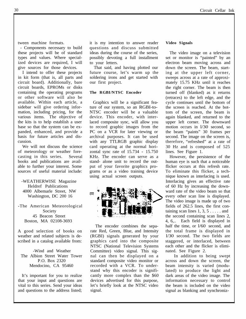
30 Circuit Cellar Ink I
tween machine formats.- Components necessary to build
these projects will be of standardtypes and values. Where special-ized devices are required, I willgive sources for those devices.
I intend to offer these projectsin kit form (that is, all parts andcircuit board). Additionally, barecircuit boards, EPROMs or diskscontaining the operating programsor other software will also beavailable. Within each article, asidebar will give ordering infor-mation, including pricing, for thevarious items. The objective ofthe kits is to help establish a userbase so that the system can be ex-panded, enhanced, and provide abasis for future articles and dis-cussion.
We will not discuss the scienceof meteorology or weather fore-casting in this series. Severalbooks and publications are avail-able to further your interest. Somesources of useful material include:
-WEATHERWISE MagazineHeldref Publications
4000 Albemarle Street, NWWashington, DC 200 16
-The American MeteorologicalSociety
45 Beacon StreetBoston, MA 02108-3693
A good selection of books onweather and related subjects is de-scribed in a catalog available from:
-Wind and WeatherThe Albion Street Water Tower
P.O. Box 2320Mendocino, CA 95460
It’s important for you to realizethat your input and questions arevital to this series. Send your ideasand questions to the address listed;
it is my intention to answer readerquestions and discuss submittedideas during the course of the series,possibly devoting a full installmentto your letters.
That said, and having plotted ourfuture course, let’s warm up thesoldering irons and get started withour first project.
The RGBI/NTSC Encoder
Graphics will be a significant fea-ture of our system, so an RGBI-to-NTSC encoder will be a valuabledevice. This encoder, with inter-laced composite sync, will allow youto record graphic images from thePC on a VCR for later viewing orarchival purposes. It can be usedwith any TTLRGB graphic displaycard operating at the normal hori-zontal sync rate of 15.734 - 15.750KHz. The encoder can serve as astand- alone unit to record the out-put of your favorite graphics pro-grams or as a video training deviceusing actual screen outputs.
The encoder combines the sepa-rate Red, Green, Blue, and Intensity(RGBI) signals generated by yourgraphics card into the compositeNTSC (National Television SystemsCommittee) video signal. This sig-nal can then be displayed on astandard composite video monitor orrecorded with a VCR. To under-stand why this encoder is signifi-cantly more complex than the $60devices advertised for this purpose,let’s briefly look at the NTSC videosignal.
Video Signals
The video image on a televisionset or monitor is “painted” by anelectron beam moving across anddown the screen. The beam, start-ing at the upper left corner,sweeps across at a rate of approxi-mately 15.75 KHz until it reachesthe right corner. The beam is thenturned off (blanked) as it returns(retraces) to the left edge, and thecycle continues until the bottom ofthe screen is reached. At the bot-tom of the screen, the beam isagain blanked, and returned to theupper left corner. The downwardmotion occurs in l/30 second, sothe beam “paints” 30 frames persecond. The image on the screen is,therefore, “refreshed” at a rate of30 Hz and is composed of 525lines. See Figure 1.
However, the persistence of thehuman eye is such that a noticeableflicker occurs at this refresh rate.To eliminate this flicker, a tech-nique known as interlacing is used.Interlacing gives an effective rateof 60 Hz by increasing the down-ward rate of the video beam so thatevery other scan line is displayed.The video image is made up of twofields of 262.5 lines, the first con-taining scan lines 1, 3, 5 . . . . . andthe second containing scan lines 2,4, 6,... Each field is displayed inhalf the time, or l/60 second, andthe total frame is displayed inl/30 second. The two fields arestaggered, or interlaced, betweeneach other and the flicker is elimi-nated. See Figure 2.
In addition to being sweptacross and down the screen, thebeam intensity is varied (modu-lated) to produce the light anddark areas of the video image. Theinformation necessary to controlthe beam is included on the videosignal as blanking and synchroniz-
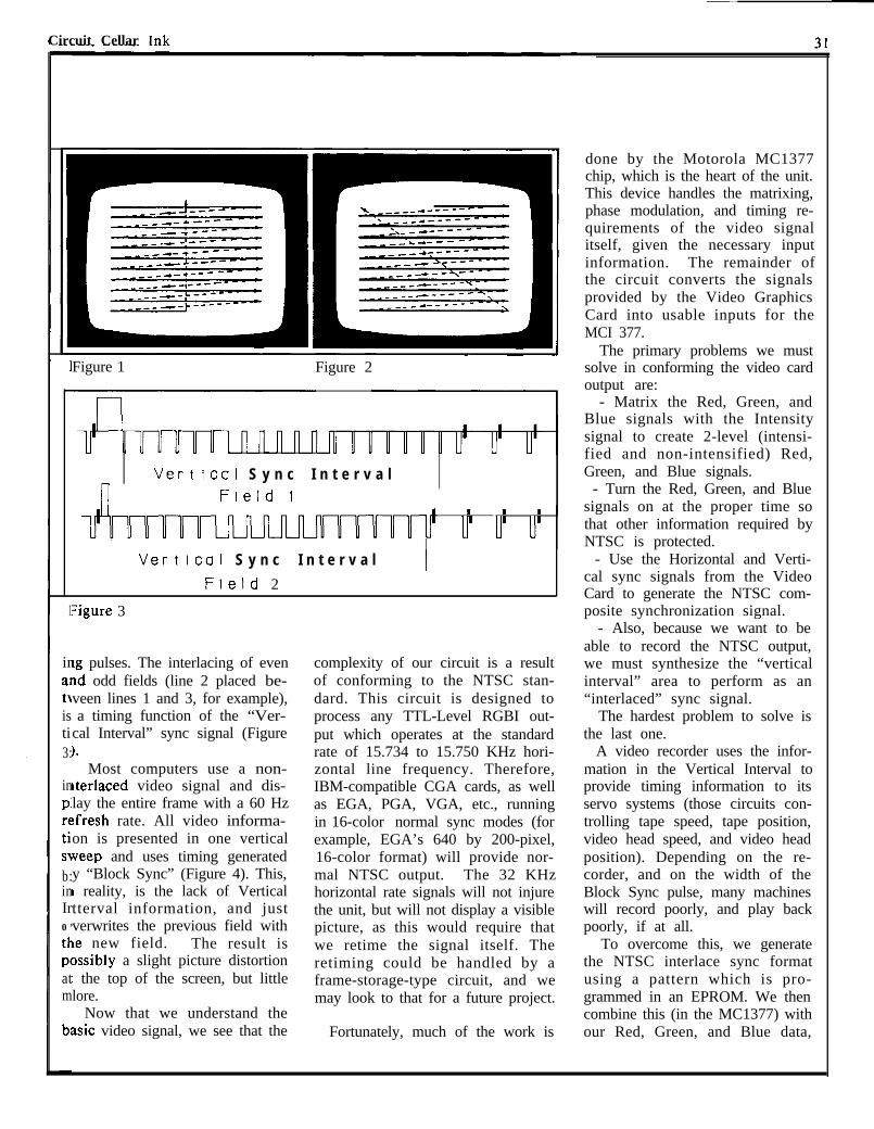
Circuit Cellar Tnk
Figure 1 Figure 2
n
Vertical S y n c I n t e r v a lField I
I I Innnniuuuuuuf r r rI
I Vertical S y n c I n t e r v a l IField 2
1?gure 3
irrg pulses. The interlacing of evenalId odd fields (line 2 placed be-t\;veen lines 1 and 3, for example),is a timing function of the “Ver-tical Interval” sync signal (Figure3:).
inPIreti’s\b:inIr0 ’
th
PCatm
Most computers use a non-lterlaced video signal and dis-lay the entire frame with a 60 Hz:fresh rate. All video informa-on is presented in one verticalKeep and uses timing generatedy “Block Sync” (Figure 4). This,I reality, is the lack of Verticaltterval information, and justverwrites the previous field withte new field. The result is>ssibly a slight picture distortion: the top of the screen, but littlelore.
Now that we understand theasic video signal, we see that theb:
complexity of our circuit is a resultof conforming to the NTSC stan-dard. This circuit is designed toprocess any TTL-Level RGBI out-put which operates at the standardrate of 15.734 to 15.750 KHz hori-zontal line frequency. Therefore,IBM-compatible CGA cards, as wellas EGA, PGA, VGA, etc., runningin 16-color normal sync modes (forexample, EGA’s 640 by 200-pixel,16-color format) will provide nor-mal NTSC output. The 32 KHzhorizontal rate signals will not injurethe unit, but will not display a visiblepicture, as this would require thatwe retime the signal itself. Theretiming could be handled by aframe-storage-type circuit, and wemay look to that for a future project.
Fortunately, much of the work is
done by the Motorola MC1377chip, which is the heart of the unit.This device handles the matrixing,phase modulation, and timing re-quirements of the video signalitself, given the necessary inputinformation. The remainder ofthe circuit converts the signalsprovided by the Video GraphicsCard into usable inputs for theMCI 377.
The primary problems we mustsolve in conforming the video cardoutput are:
- Matrix the Red, Green, andBlue signals with the Intensitysignal to create 2-level (intensi-fied and non-intensified) Red,Green, and Blue signals.
- Turn the Red, Green, and Bluesignals on at the proper time sothat other information required byNTSC is protected.
- Use the Horizontal and Verti-cal sync signals from the VideoCard to generate the NTSC com-posite synchronization signal.
- Also, because we want to beable to record the NTSC output,we must synthesize the “verticalinterval” area to perform as an“interlaced” sync signal.
The hardest problem to solve isthe last one.
A video recorder uses the infor-mation in the Vertical Interval toprovide timing information to itsservo systems (those circuits con-trolling tape speed, tape position,video head speed, and video headposition). Depending on the re-corder, and on the width of theBlock Sync pulse, many machineswill record poorly, and play backpoorly, if at all.
To overcome this, we generatethe NTSC interlace sync formatusing a pattern which is pro-grammed in an EPROM. We thencombine this (in the MC1377) withour Red, Green, and Blue data,
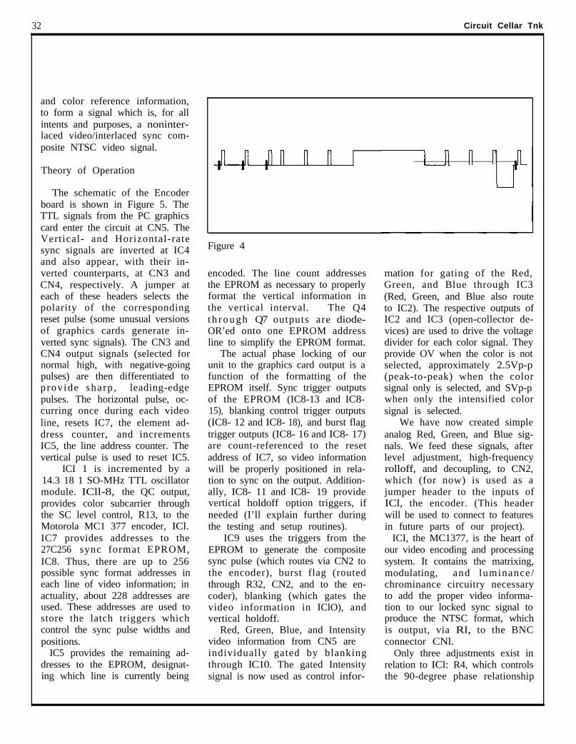
32 Circuit Cellar TnkI
and color reference information,to form a signal which is, for allintents and purposes, a noninter-laced video/interlaced sync com-posite NTSC video signal.
Theory of Operation
The schematic of the Encoderboard is shown in Figure 5. TheTTL signals from the PC graphicscard enter the circuit at CN5. TheVertical- and Horizontal-ratesync signals are inverted at IC4and also appear, with their in-verted counterparts, at CN3 andCN4, respectively. A jumper ateach of these headers selects thepolarity of the correspondingreset pulse (some unusual versionsof graphics cards generate in-verted sync signals). The CN3 andCN4 output signals (selected fornormal high, with negative-goingpulses) are then differentiated toprovide sharp , leading-edgepulses. The horizontal pulse, oc-curring once during each videoline, resets IC7, the element ad-dress counter, and incrementsIC5, the line address counter. Thevertical pulse is used to reset IC5.
ICI 1 is incremented by a14.3 18 1 SO-MHz TTL oscillatormodule. ICll-8, the QC output,provides color subcarrier throughthe SC level control, R13, to theMotorola MC1 377 encoder, ICl.IC7 provides addresses to the27C256 sync format EPROM,IC8. Thus, there are up to 256possible sync format addresses ineach line of video information; inactuality, about 228 addresses areused. These addresses are used tostore the latch triggers whichcontrol the sync pulse widths andpositions.
IC5 provides the remaining ad-dresses to the EPROM, designat-ing which line is currently being
Figure 4
encoded. The line count addressesthe EPROM as necessary to properlyformat the vertical information inthe vertical interval. The Q4t h r o u g h Q7 outputs are diode-OR’ed onto one EPROM addressline to simplify the EPROM format.
The actual phase locking of ourunit to the graphics card output is afunction of the formatting of theEPROM itself. Sync trigger outputsof the EPROM (IC8-13 and IC8-15), blanking control trigger outputs(IC8- 12 and IC8- 18), and burst flagtrigger outputs (IC8- 16 and IC8- 17)are count-referenced to the resetaddress of IC7, so video informationwill be properly positioned in rela-tion to sync on the output. Addition-ally, IC8- 11 and IC8- 19 providevertical holdoff option triggers, ifneeded (I’ll explain further duringthe testing and setup routines).
IC9 uses the triggers from theEPROM to generate the compositesync pulse (which routes via CN2 tothe encoder), burst flag (routedthrough R32, CN2, and to the en-coder), blanking (which gates thevideo information in IClO), andvertical holdoff.
Red, Green, Blue, and Intensityvideo information from CN5 areindividually gated by blankingthrough IC10. The gated Intensitysignal is now used as control infor-
n r
Ymation for gating of the Red,Green, and Blue through IC3(Red, Green, and Blue also routeto IC2). The respective outputs ofIC2 and IC3 (open-collector de-vices) are used to drive the voltagedivider for each color signal. Theyprovide OV when the color is notselected, approximately 2.5Vp-p(peak-to-peak) when the colorsignal only is selected, and SVp-pwhen only the intensified colorsignal is selected.
We have now created simpleanalog Red, Green, and Blue sig-nals. We feed these signals, afterlevel adjustment, high-frequencyrolloff, and decoupling, to CN2,which (for now) is used as ajumper header to the inputs ofICl, the encoder. (This headerwill be used to connect to featuresin future parts of our project).
ICI, the MC1377, is the heart ofour video encoding and processingsystem. It contains the matrixing,modulating, and luminance/chrominance circuitry necessaryto add the proper video informa-tion to our locked sync signal toproduce the NTSC format, whichis output, via Rl, to the BNCconnector CNl.
Only three adjustments exist inrelation to ICl: R4, which controlsthe 90-degree phase relationship
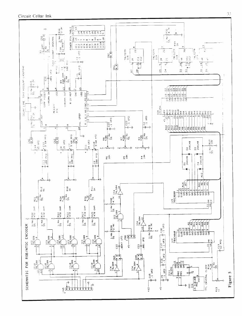
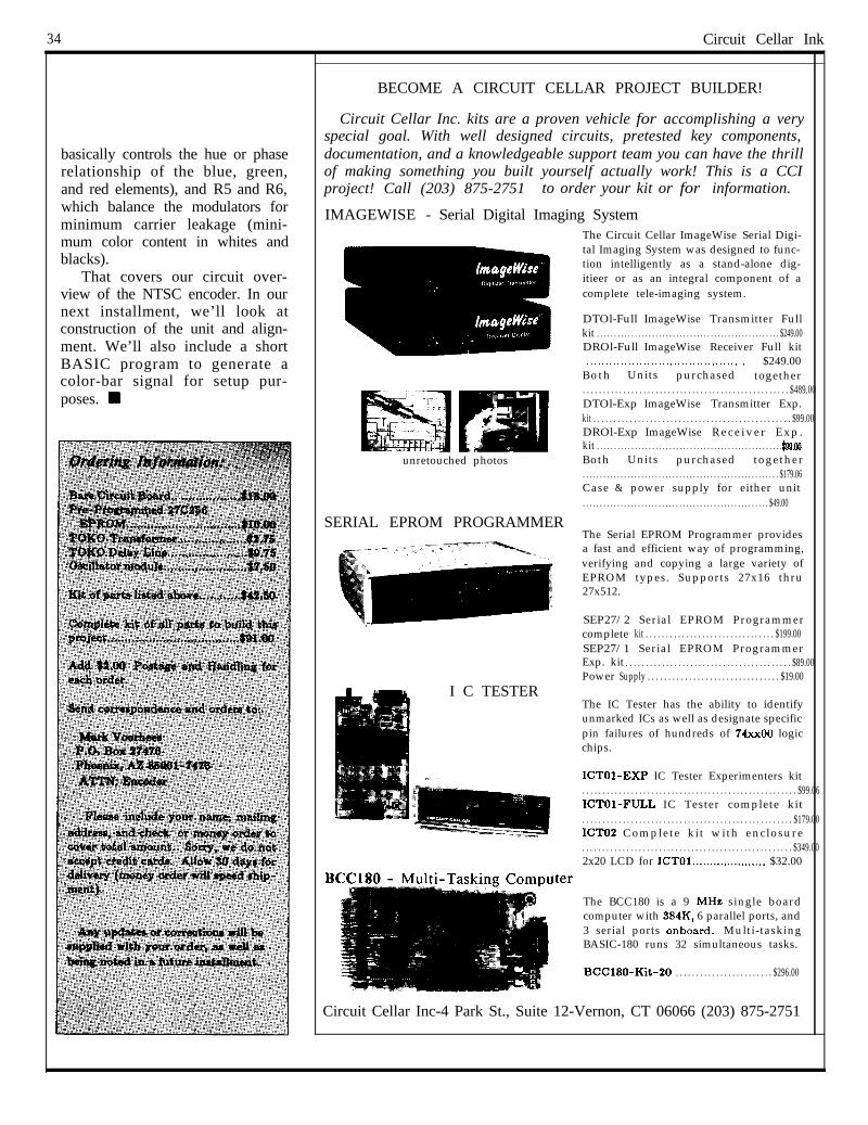
34 Circuit Cellar InkI
basically controls the hue or phaserelationship of the blue, green,and red elements), and R5 and R6,which balance the modulators forminimum carrier leakage (mini-mum color content in whites andblacks).
That covers our circuit over-view of the NTSC encoder. In ournext installment, we’ll look atconstruction of the unit and align-ment. We’ll also include a shortBASIC program to generate acolor-bar signal for setup pur-poses. H
BECOME A CIRCUIT CELLAR PROJECT BUILDER!
Circuit Cellar Inc. kits are a proven vehicle for accomplishing a veryspecial goal. With well designed circuits, pretested key components,documentation, and a knowledgeable support team you can have the thrillof making something you built yourself actually work! This is a CCIproject! Call (203) 875-2751 to order your kit or for information.
IMAGEWISE - Serial Digital Imaging System
unretouched photos
SERIAL EPROM PROGRAMMER
I C TESTER
The Circuit Cellar ImageWise Serial Digi-tal Imaging System was designed to func-tion intelligently as a stand-alone dig-itieer or as an integral component of acomplete tele-imaging system.
DTOl-Full ImageWise Transmitter Fullkit . . . . . . . . . . . . . . . . . . . . . . . . . . . . . . . . . . . . . . . . . . . . . . . . . . . . . $249.00DROl-Full ImageWise Receiver Full kit. . . . . . . . . . . . . . . . . . . . . . . . . . . . . . . . . . . . . . . . . . . $249.00Both Units purchased together. . . . . . . . . . . . . . . . . . . . . . . . . . . . . . . . . . . . . . . . . . . . . . . . . . . $489.00DTOl-Exp ImageWise Transmitter Exp.kit . . . . . . . . . . . . . . . . . . . . . . . . . . . . . . . . . . . . . . . . . . . . . . . . . $99.00DROl-Exp ImageWise Rece iver Exp .kit . . . . . . . . . . . . . . . . . . . . . . . . . . . . . . . . . . . . . . . . . . . . . . . . . . . . . . . tQQ.00Both Units purchased together. . . . . . . . . . . . . . . . . . . . . . . . . . . . . . . . . . . . . . . . . . . . . . . . . . . . . . . . . $179.06Case & power supply for either unit. . . . . . . . . . . . . . . . . . . . . . . . . . . . . . . . . . . . . . . . . . . . . . . . . . . . . . $49.00
The Serial EPROM Programmer providesa fast and efficient way of programming,verifying and copying a large variety ofEPROM types. Supports 27x16 thru27x512.
SEP27/2 Serial EPROM Programmercomplete kit . . . . . . . . . . . . . . . . . . . . . . . . . . . . . . . . $199.00SEP27/1 Serial EPROM ProgrammerExp. kit . . . . . . . . . . . . . . . . . . . . . . . . . . . . . . . . . . . . . . . . . $89.00Power Supply . . . . . . . . . . . . . . . . . . . . . . . . . . . . . . . . $19.00
The IC Tester has the ability to identifyunmarked ICs as well as designate specificpin failures of hundreds of 74~x00 logicchips.
ICTOl-EXP IC Tester Experimenters kit. . . . . . . . . . . . . . . . . . . . . . . . . . . . . . . . . . . . . . . . . . . . . . . . . . . . . $99.06ICTOl-FULL IC Tester complete kit. . . . . . . . . . . . . . . . . . . . . . . . . . . . . . . . . . . . . . . . . . . . . . . . . . . . $179.00ICTO2 Complete kit with enclosure. . . . . . . . . . . . . . . . . . . . . . . . . . . . . . . . . . . . . . . . . . . . . . . . . . . . $349.002x20 LCD for ICTOl..................... $32.00
lter
The BCC180 is a 9 MHe single boardcomputer with 384K, 6 parallel ports, and3 serial ports onboard. Multi-taskingBASIC-180 runs 32 simultaneous tasks.
BCC180-Kit-20 . . . . . . . . . . . . . . . . . . . . . . . . $296.00
Circuit Cellar Inc-4 Park St., Suite 12-Vernon, CT 06066 (203) 875-2751
__._-.. _____. _ . . . .
FIRMWARE FURNACEby Ed Nisley
what’s firm- is created to match a specific hard- holdoff and repeat timings, wait-ware configuration, so your system ing for a new keypress, and wait-
Single-chip microprocessors (whatever it is) surely won’t be ing for release. Each calls a singleare inexpensive, so they are often compatible. Of course, if you’ve routine that returns the number ofused to replace a board full of ICs. been paying attention, you can adapt the current key (0 indicates that noUnfortunately, these chips need both the code and circuitry to your key is pressed). This techniquesome instructions to make them needs.. . that’s what we’re here for! allows the keyboard’s physicalperform properly. This column I’ll use parts of the Circuit Cellar layout to be rearranged by chang-introduces the technique of writ- IR Master Controller as the basis for ing a single routine to assign newing software that works like hard- several columns. It uses minimal numbers to the keys. That’s ex-ware. hardware to solve interesting prob- actly what happened between the
Don’t expect machine-inde- lems, such as high-speed signal prototype and final Master Con-pendent high-level code, fancy detection and generation, keyboard troller circuits.CRT displays, or “enhanced” controls, LCD data output, and even The schematic diagram in Fig-keyboards. This is lean and mean some digital signal processing. The ure 1 shows that the six keys arecode, built to run right down on IR Master Controller was described (electrically) arrayed out in twothe bare metal. You might think in the March ‘87 issue of BYTE, so rows of three keys. Each key canof firmware as epoxy: mix the you might want to refresh your be identified by its location at theright combination of hardware memory before diving into this intersection of a row and column,and software and wait for it to set column. as well as a unique key number. Aup like a rock. common practice is to make the
Firmware is generally found in Minimalist Keying key number equal to:EPROMs and ROMs mountedclose to the processor, but 1’11 The Master Controller’s keyboard key#=(row #)(totalcoiumns)+(column #)
stretch its definition to include interface will serve as a simple be-the low-level code that works with ginning. Figure 1 shows the com- or
any hardware at the “logic gate” plete keyboard schematic diagram,level. We’ll make occasional for- which uses one IC to support a six- key # = (column #)(total rows) + (row #)
ays into IBM PC territory and even key keyboard. There are two pairshigh-level languages to handle an of keys to scroll, in either direction, The Master Controller uses theinteresting topic. through the lists of appliances and first equation. A technique to
These columns will blend both functions, a “do it” key to trigger create a table to relate the row/hardware and software descrip- the infrared signal, and a “learn” column key location to the finaltions because you must know some key to begin learning a new signal. key number is often used. You canof each to write good firmware. If The scrolling keys are used to produce any number for any keyyou feel a little unsure about search through a list, and should by changing that table.either, this may be a good way to repeat rapidly when they’re held A matrix keyboard has manyget your feet wet! Furthermore, down. An initial holdoff forces a keys connected to each row andyou’ll be exposed to a variety of delay to make it easier to scroll one column, so there’s no way tomicroprocessor architectures and entry at a time while still keeping a uniquely identify a single key inprogramming languages, so there’s fast scroll. This holdoff also elimi- the matrix with one action. Thesure to be something new for nates the need for an explicit de- process of determining which keyeveryone. bounce function: its period is long is pressed is called “scanning” the
There won’t be any complete, enough to bypass any glitches. keyboard. Each row in the Masterready-to-run programs. Firmware Separate routines are used for: Controller is scanned in turn for
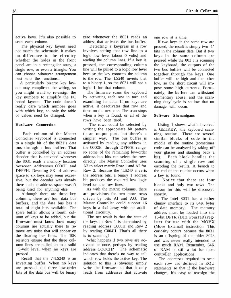
Cirmlit Cellar TnkI
active keys. It’s also possible to zero whenever the 8031 reads an one row at a time.scan each column. address that activates the bus buffer. If two keys in the same row are
The physical key layout need Detecting a keypress in a row pressed, the result is simply two ‘1’not match the schematic. It makes involves setting that row line to a bits in the column data. But if twono difference to the circuitry logic low level (about 0 volts) and keys in the same column arewhether the holes in the front reading the column lines. If a key is pressed while the 803 1 is scanningpanel are in a rectangular array, a pressed, the corresponding column the keyboard, the outputs of thesingle row, or even a triangle. You line will be pulled to a logic low level two bus buffers will be connectedcan choose whatever arrangement because the key connects the column together through the keys. Onebest suits the functions. to the row. The ‘LS240 inverts that buffer will be high and the other
A particularly bizarre key lay- to a binary 1, so the 8031 will see a low, so the short circuit will im-out may complicate the wiring, so logic 1 for that column. pose some high currents. Fortu-you might want to re-assign the The firmware scans the keyboard nately, the buffers can withstandkey numbers to simplify the PC by activating each row in turn and momentary abuse, and the scan-board layout. The code doesn’t examining its data. If no keys are ning duty cycle is so low that noreally care which number goes active, it deactivates that row and damage will occur.with which key, so only the table turns on the next one. The scan stopsof values need be changed. when a key is found, or all of the Software Shenanigans
rows have been tried.Hardware Connection The rows could be selected by Listing 1 shows what’s involved
writing the appropriate bit pattern in GETKEY, the keyboard scan-Each column of the Master to an output port, but there’s a ning routine. There are several
Controller keyboard is connected simpler way. The bus buffer is similar blocks of code in theto a single bit of the 8031’s data activated by reading any address in middle of the routine (sometimesbus through a bus buffer. That the COOOH through DFFFH range, code can be analyzed by taking offbuffer is controlled by an address so some of the remaining low-order your glasses and standing back adecoder that is activated whenever address bus bits can select the rows bit). Each block handles thethe 8031 reads a memory location directly. The Master Controller uses scanning of a single row andbetween addresses COOOH and A3 to select matrix Row 1 and A2 for encoding the results. A branch toDFFFH. Devoting 8K of address Row 2. Because the ‘LS240 inverts the end of the routine occurs whenspace to six keys may seem exces- the address bits, a binary 1 address a key is found.sive, but the decoder was already bit produces the required low logic Notice that there are fourthere and the address space wasn’t level on the row lines. blocks and only two rows. Thebeing used for anything else. As with the matrix columns, there reason for this will be discussed
Although there are three key are provisions for two more rows shortly.columns, there are four data bus driven by bits Al and AO. The The Intel 8031 has a ratherbuffers, and the data bus has a Master Controller could support 16 clumsy interface to its 64K bytestotal of eight bits available. The keys in a 4x4 array with no addi- of data memory. The memoryspare buffer allows a fourth col- tional circuitry. address must be loaded into theumn of keys to be added, but the The net result is that the state of 16-bit DPTR (Data PoinTeR) reg-firmware must know how many the keys in Row 1 is determined by ister for use with the MOVXcolumns are actually there to re- reading address C008H and Row 2 (Move External) instruction. Thismove any noise that will appear on by reading C004H. That’s all there curiosity occurs because the 8031the floating bus lines. The 10K is to scanning! is an offspring of the older 8048resistors ensure that the three col- What happens if two rows are ac- and was never really intended toumn lines are pulled up to a solid tivated at once, perhaps by reading use much RAM. Remember, 64K+5-volt level when no keys are address COOCH? The schematic of RAM is still a lot for mostpressed. indicates that there’s no way to tell controller applications.
Recall that the 74LS240 is an which row holds the active key. The The addresses required to scaninverting buffer. When no keys solution to this is obvious: simply each row are defined in EQUare pressed, the three low-order write the firmware so that it only statements so that if the hardwarebits of the data bus will be binary reads from addresses that activate changes, it’s easy to reassign the
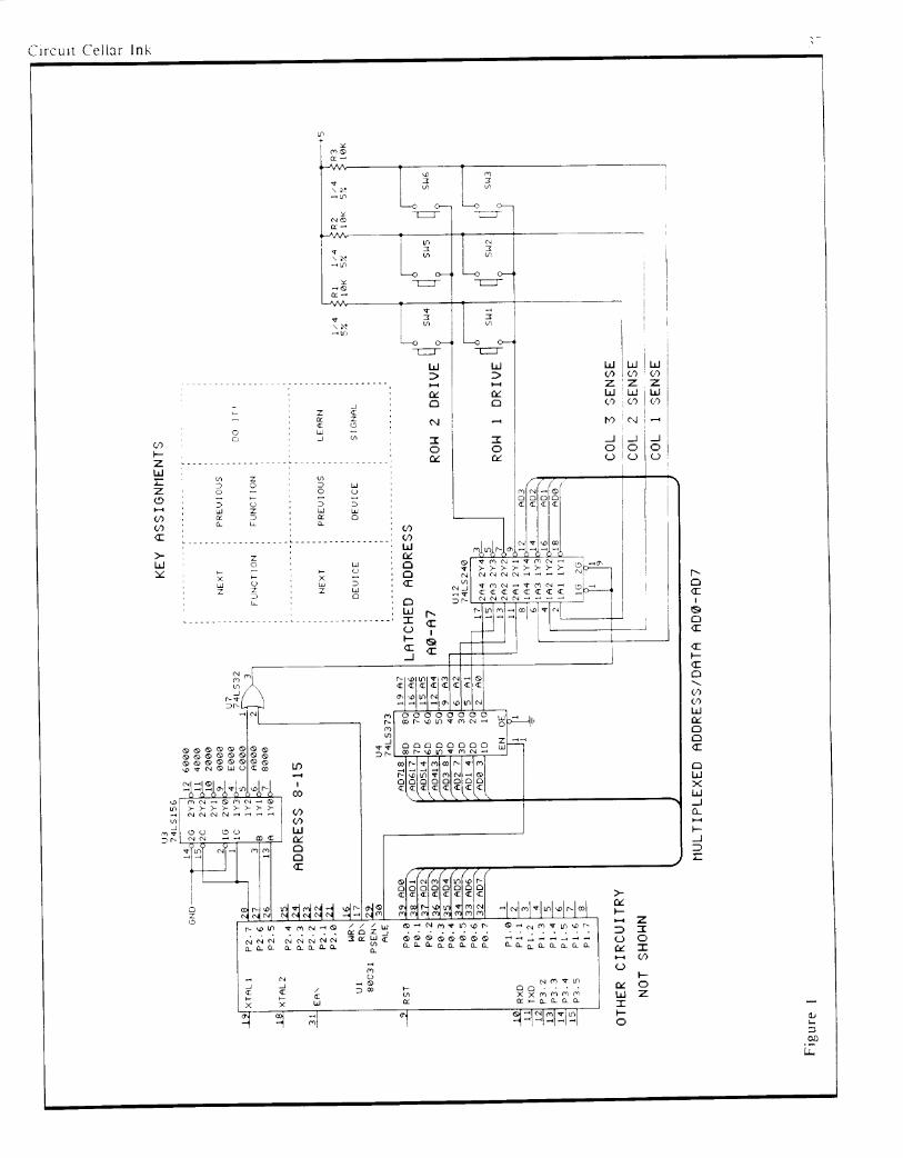
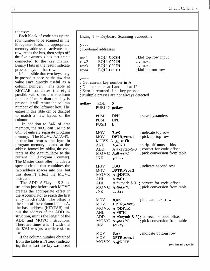
Circuit Cellar Ink
addresses.Each block of code sets up the
row number to be scanned in theB register, loads the appropriatememory address to activate thatrow, reads the bus, then strips offthe five extraneous bits that aren’tconnected to the key matrix.Binary 1 bits in the result indicatepressed keys in that row.
It’s possible that two keys maybe pressed at once, so the raw datavalue isn’t directly useful as acolumn number. The table atKEYTAB translates the eightpossible values into a true columnnumber. If more than one key ispressed, it will return the columnnumber of the leftmost key. Theentries in this table can be changedto match a new layout of thecolumns.
In addition to 64K of datamemory, the 8031 can use up to64K of entirely separate programmemory. The MOVC A,@A+PCinstruction returns the byte inprogram memory located at theaddress formed by adding the con-tents of the Accumulator to thecurrent PC (Program Counter).The Master Controller includes aspecial circuit that combines thetwo address spaces into one, butthis doesn’t affect the MOVCinstruction.
The ADD A,#keytab-$-3 in-struction just before each MOVCcreates the appropriate offset inthe Accumulator to reach the firstentry in KEYTAB. The offset isthe sum of the column bits in A,the base address (KEYTAB) mi-nus the address of the ADD in-struction, minus the length of theADD and MOVC instructions.There are times when I wish thatthe 8031 was just a trifle easier touse...
If the column number obtainedfrom the table isn’t zero (indicat-ing that at least one key was indeed
Listing 1 -- Keyboard Scanning Subroutine
*____,; Keyboard addresses
row 1 EQU C008Hrow2 EQU C004Hrow3 EQU C002Hrow4 EQU COOlH
; kbd top row input; . . next; . . next; kbd bottom row
;____; Get current key number in A; Numbers start at I and end at 12; Zero is returned if no key pressed; Multiple presses are not always detected
getkey EQU $PUBLIC getkey
PUSH DPHPUSH DPLPUSH B
; save bystanders
MOV B,#O ; indicate top rowMOV DPTR,#rowl ; pick up top rowMOVX A ,@DPTRANL A,#07H ; strip off unused bitsADD A,#keytab-$-3 ; correct for code offsetMOVC A,@A+PC ; pick conversion from tableJNZ gotkey
MOV B,#3 ; indicate second rowMOV DPTR,#row2MOVX A,@DPTRANL A,#07HADD A,#keytab-$-3 ; correct for code offsetMOVC A,@A+PC ; pick conversion from tableJNZ gotkey
MOV B,#6 ; indicate next rowMOV DPTR,#row3MOVX A,@DPTRANL A,#07HADD A,#keytab-$-3: ; correct for code offsetMOVC A,@A+PC ; pick conversion from tableJNZ gotkey
MOVMOV
B,#9 ; indicate bottom rowDPTR,#row4
MOVX A,@DPTR(continued page 39
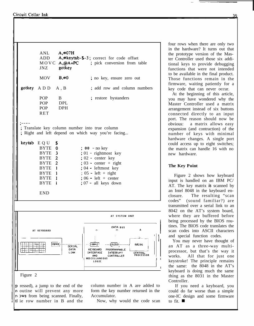
ANL A,#07HADD A,#keytab-$-3 ; correct for code offsetM O V C A,@A+PC ; pick conversion from tableJNZ gotkey
MOV B,#O ; no key, ensure zero out
gotkey A D D A , B ; add row and column numbers
POP BPOP DPLPOP DPHRET
; restore bystanders
* Translate key column number into true column9
* Right and left depend on which way you’re facing...3
keytab E Q UBYTEBYTEBYTEBYTEBYTEBYTEBYTEBYTE
END
; 00 - no key; 01 - rightmost key; 02 - center key; 03 - center + right; 04 - leftmost key; 05 - left + right; 06 - left + center* 07 - all keys down,
A T S Y S T E M U N I T
I/ I
! DATFI B U SA T K E Y B O A R D A n ... A
I I
P R O C E S S O R/ M I S C E L L A N E O U S I I
L O G I C
1 I
Figure 2
ressed), a jump to the end of the column number in A are added tooutine will prevent any more form the key number returned in theows from being scanned. Finally, Accumulator.ie row number in B and the Now, why would the code scan
four rows when there are only twoin the hardware? It turns out thatthe prototype version of the Mas-ter Controller used those six addi-tional keys to provide debuggingfunctions that were not intendedto be available in the final product.Those functions remain in thefirmware, waiting patiently for akey code that can never occur.
At the beginning of this article,you may have wondered why theMaster Controller used a matrixarrangement instead of six buttonsconnected directly to an inputport. The reason should now beobvious: a matrix allows easyexpansion (and contraction) of thenumber of keys with minimalhardware changes. A single portcould access up to eight switches;the matrix can handle 16 with nonew hardware.
The Key Point
Figure 2 shows how keyboardinput is handled on an IBM PC/AT. The key matrix is scanned byan Intel 8048 in the keyboard en-closure. The resulting “scancodes” (sound familiar?) aretransmitted over a serial link to an8042 on the AT’s system board,where they are buffered beforebeing processed by the BIOS rou-tines. The BIOS code translates thescan codes into ASCII charactersand special function codes.
You may never have thought ofan AT as a three-way multi-processor, but that’s the way itworks. All that for just onekeystroke! The principle remainsthe same: the 8048 in the AT’skeyboard is doing much the samething as the 8031 in the MasterController.
If you need a keyboard, youcould do far worse than a simpleone-IC design and some firmwareto fit. n
.
40I
Circuit Cellar Tnk
(continued from page 26)
Msg #8712by Dale NassarTo: Steve CiarciaRe: Inverter
Steve,What is the best way to get - 12V @lOOmA and
-5V @lOOmA (both regulated) from a 12V battery?Thanks.
--Dale
Msg #8745by Steve CiarciaTo: Dale NassarRe: Inverter[Reply to msg #8712]
5 mA is easy, 100 mA takes a little skill. What youneed is a DC-to-DC converter with inverted output.I have done two articles on the subject, Oct. ‘78 andNov. ‘81, which have some applicable circuits.Another option is to call Maxim and get theirapplications manual (Maxim’s number is (408) 737-7600). In it there are lots of circuits. You’ll also needa source for chokes.
--Steve
Msg #8720by Bob PaddockTo: Dale Nassar Well, that’s all we have space for in print this month.Re: Inverter But, if I’ve sparked your interest and you want to read[Reply to msg #8712] the hundreds of other messages on line, give the
CCBBS a call some time (203-871-1988). Remember,Look at Maxim’s MAX6xx family of parts. I don’t my name is Ken, and I’m your sysop.
have the data book right here, but I think it’s theMAX635 that will do positive-to-negative switching.
To: Dale NassarRe: Inverter[Reply to msg #8784]
I finally remembered to bring the Maxim book uphere. The following are DC-DC voltage inverters with+2V to +16.5V input: The MAX635 output is set for-5V, MAX636 = - 12V, MAX637 = -15V. With theaddition of two resistors all three can have theiroutput adjusted. On page 2-4 of Maxim’s “1987Analog Data Acquisition Applications Seminar,”there is a circuit for +5V in to +15/-15V @ lOOmAout. With alittle modification you could get your +12Vto - 12/-5V.
Msg #8856by Dale NassarTo: Bob PaddockRe: Inverter[Reply to msg #8824]
Bob, thanks for your information on the MaximICs. I learned a lot this week winding my own coilsbut am glad to hear that I don’t have to. I’ll be usingthe part you suggested.
--Dale
Msg #8784by Dale NassarTo: Bob PaddockRe: Inverter[Reply to msg #8720]
Bob, thanks for the info. I’m not sure that theMAX635 will give me enough current; the MAX680gives 10 mA. But I have ordered the data sheet.
--Dale
Msg #8824by Bob Paddock
WRITE FOR INK!
Writing technical articles won’t necessarily make you rich andfamous but it might be just what you need as incentive to finishthat lOO-MIPS computer you started last summer. Or, if yourexpertise is software, are current approaches to artificial intelli-gence or database manipulation all wet and you have an improvedtechnique? Perhaps it’s time you presented your talents to theworld.
Unlike most narrowly specialized publications these days,CIRCUlT CELLAR INK’s charter is to cover a wide variety ofhardware and software technology and ideas. If you have asoftware or hardware project worthy of publication in INK we’dlike to discuss it.
Send your project outline to Harv Weiner, CIRCUIT CELLARINK, PO Box 772, Vernon, CT, 06066, or contact him on theCIRCUIT CELLAR BBS at (203) 871-1988.
I I
Related Documents