Circuit Delays

Circuit Delays. Outline Calculation of Circuit Delays Faster Circuits Look-Ahead Carry Adder.
Jan 02, 2016
Welcome message from author
This document is posted to help you gain knowledge. Please leave a comment to let me know what you think about it! Share it to your friends and learn new things together.
Transcript

Circuit Delays
Outline
Calculation of Circuit Delays
Faster Circuits
Look-Ahead Carry Adder
Outline
Calculation of Circuit Delays
Faster Circuits
Look-Ahead Carry Adder
Calculation of Circuit Delays (1/5)
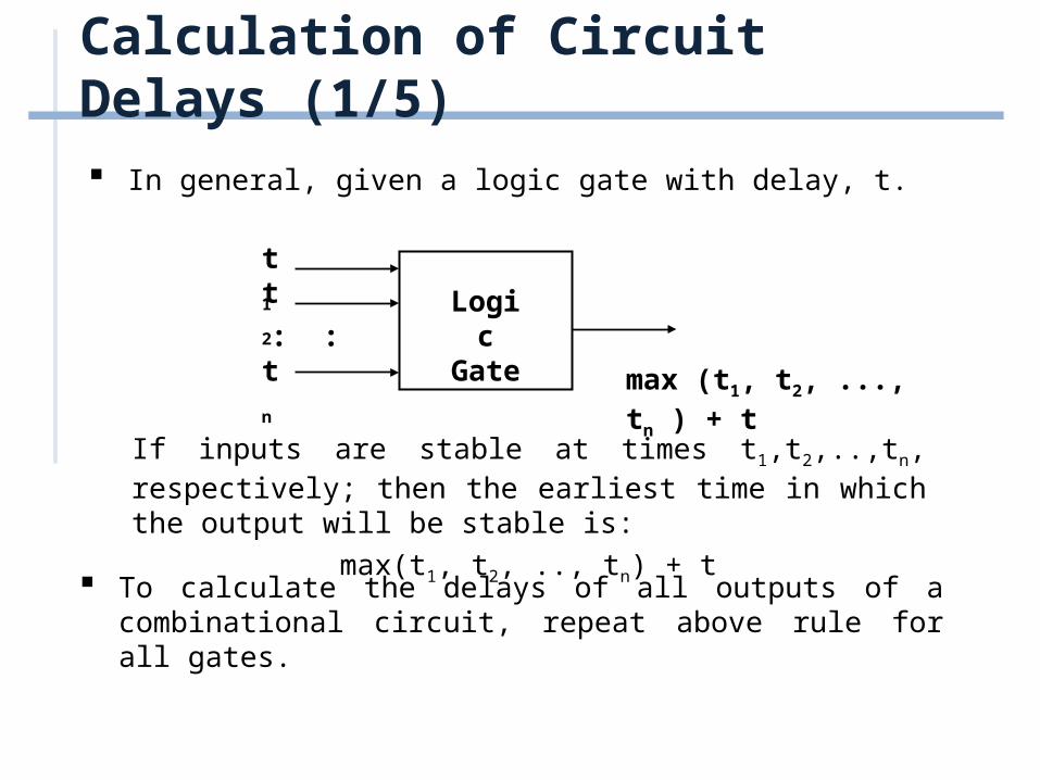
In general, given a logic gate with delay, t.
If inputs are stable at times t1,t2,..,tn, respectively; then the earliest time in which the output will be stable is:
max(t1, t2, .., tn) + t
LogicGate
t1
t2
tn
: :
max (t1, t2, ..., tn ) + t
To calculate the delays of all outputs of a combinational circuit, repeat above rule for all gates.

Calculation of Circuit Delays (2/5)
As a simple example, consider the full adder circuit where all inputs are available at time 0. (Assume each gate has delay t.)
where outputs S and C, experience delays of 2t and 3t, respectively.
XY S
C
Z
max(0,0)+t = t
t
0
0
0
max(t,0)+t = 2t
max(t,2t)+t = 3t2t

Calculation of Circuit Delays (3/5)
More complex example: 4-bits parallel adder.
C1
Y1 X1
S1
FA
C2
C5
Y2 X2
S2
FA
C3
Y3 X3
S3
FA
C4
Y4 X4
S4
FA0
00 00 00 00
Calculation of Circuit Delays (4/5)
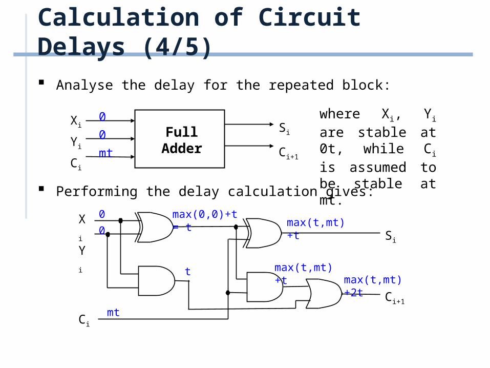
Analyse the delay for the repeated block:
where Xi, Yi are stable at 0t, while Ci is assumed to be stable at mt.
FullAdder
Xi
Yi
Ci
Si
Ci+1
0
0
mt
Performing the delay calculation gives:
Xi
Yi Si
Ci+1
Ci
max(0,0)+t = t
t
0
0
mt
max(t,mt)+t
max(t,mt)+2tmax(t,mt)+t

Calculation of Circuit Delays (5/5)
Calculating:
When i=1, m=0: S1 = 2t and C2 = 3t.
When i=2, m=3: S2 = 4t and C3 = 5t.
When i=3, m=5: S3 = 6t and C4 = 7t.
When i=4, m=7: S4 = 8t and C5 = 9t. In general, an n-bit ripple-carry parallel adder will experience: Sn = ((n-1)*2+2)t
Cn+1 = ((n-1)*2+3)tas their delay times.
Propagation delay of ripple-carry parallel adders is proportional to the number of bits it handles.
Maximum Delay: ((n-1)*2+3)t

Outline
Calculation of Circuit Delays
Faster Circuits
Look-Ahead Carry Adder

Faster Circuits
Three ways of improving the speed of these circuits:
(i) Use better technology (e.g. ECL faster than TTL gates), BUT(a) faster technology is more expensive, needs more power,
lower-level of integrations.
(b) physical limits (e.g. speed of light, size of atom).
(ii) Use gate-level designs to two-level circuits! (use sum- of-products/product-of-sums) BUT
(a) complicated designs for large circuits.
(b) product/sum terms need MANY inputs!
(iii) Use clever look-ahead techniques BUT there are additional costs (hopefully reasonable).

Outline
Calculation of Circuit Delays
Faster Circuits
Look-Ahead Carry Adder

Look-Ahead Carry Adder (1/6)
Consider the full adder:
where intermediate signals are labelled as Pi, Gi, and defined as: Pi = XiYi Gi = Xi.Yi
The outputs, Ci+1, Si, in terms of Pi ,Gi ,Ci , are:
Si = Pi Ci …(1) Ci+1 = Gi + Pi.Ci …(2)
If you look at equation (2),
Gi = Xi.Yi is a carry generate signal Pi = Xi Yi is a carry propagate signal
Xi
YiSi
Ci+1
Ci
Pi
Gi

Look-Ahead Carry Adder (2/6)
For 4-bit ripple-carry adder, the equations to obtain four carry signals are:
Ci+1 = Gi + Pi.Ci
Ci+2 = Gi+1 + Pi+1.Ci+1
Ci+3 = Gi+2 + Pi+2.Ci+2
Ci+4 = Gi+3 + Pi+3.Ci+3
These formulas are deeply nested, as shown here for Ci+2:
Ci
PiCi+1
Gi
Pi+1
Gi+1
Ci+2
4-level circuit for Ci+2 = Gi+1 + Pi+1.Ci+1
Look-Ahead Carry Adder (3/6)
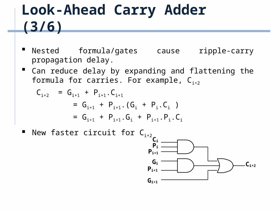
Nested formula/gates cause ripple-carry propagation delay. Can reduce delay by expanding and flattening the formula for
carries. For example, Ci+2
Ci+2 = Gi+1 + Pi+1.Ci+1
= Gi+1 + Pi+1.(Gi + Pi.Ci )
= Gi+1 + Pi+1.Gi + Pi+1.Pi.Ci
New faster circuit for Ci+2Ci
Pi
Pi+1
Gi
Pi+1
Gi+1
Ci+2
Look-Ahead Carry Adder (4/6)
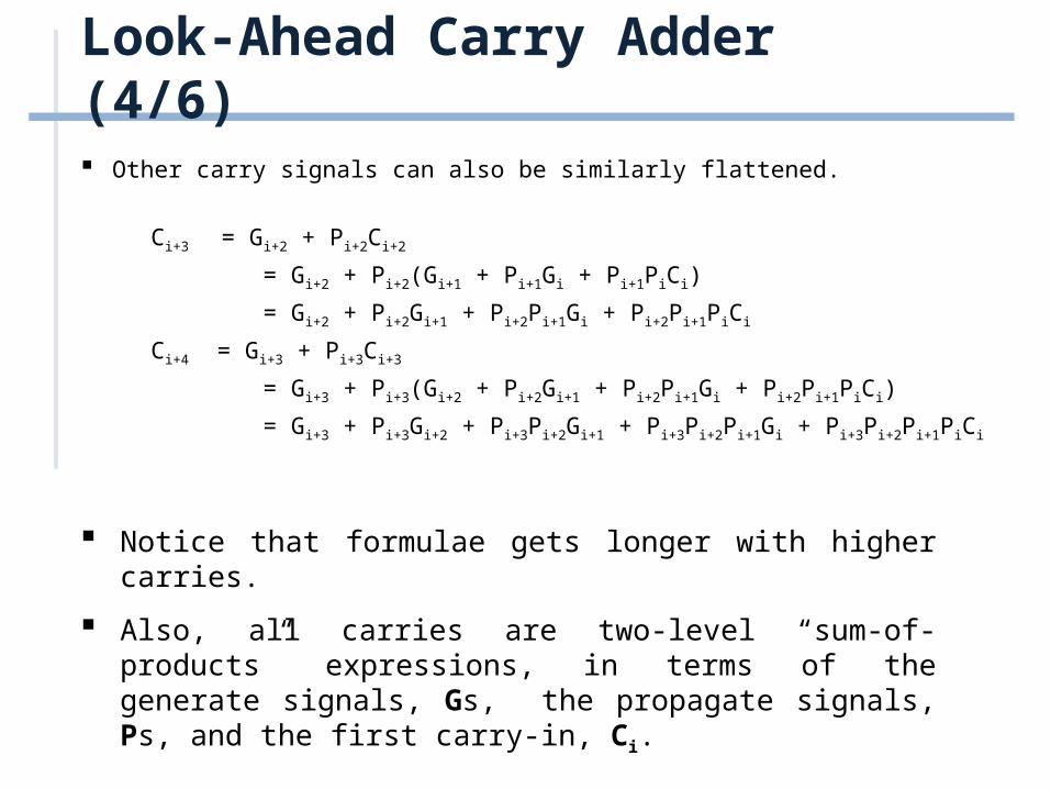
Other carry signals can also be similarly flattened.
Ci+3 = Gi+2 + Pi+2Ci+2
= Gi+2 + Pi+2(Gi+1 + Pi+1Gi + Pi+1PiCi)
= Gi+2 + Pi+2Gi+1 + Pi+2Pi+1Gi + Pi+2Pi+1PiCi
Ci+4 = Gi+3 + Pi+3Ci+3
= Gi+3 + Pi+3(Gi+2 + Pi+2Gi+1 + Pi+2Pi+1Gi + Pi+2Pi+1PiCi)
= Gi+3 + Pi+3Gi+2 + Pi+3Pi+2Gi+1 + Pi+3Pi+2Pi+1Gi + Pi+3Pi+2Pi+1PiCi
Notice that formulae gets longer with higher carries.
Also, all carries are two-level “sum-of-products” expressions, in terms of the generate signals, Gs, the propagate signals, Ps, and the first carry-in, Ci.

Look-Ahead Carry Adder (5/6)
We employ the look-ahead formula in this lookahead-carry adder circuit
Look-Ahead Carry Adder (6/6)
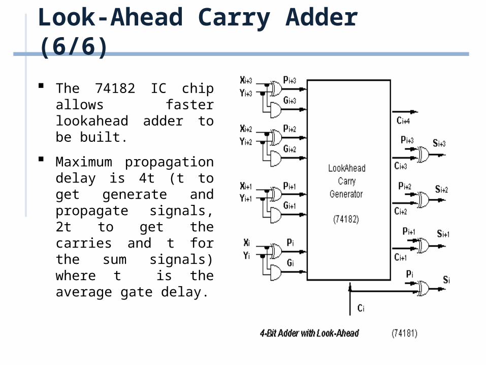
The 74182 IC chip allows faster lookahead adder to be built.
Maximum propagation delay is 4t (t to get generate and propagate signals, 2t to get the carries and t for the sum signals) where t is the average gate delay.
Related Documents


![Design of a Controllable Adder-Subtractor circuit using ... Issue 4/Version-3... · Serial adder and ripple carry adder is shown [15] using coplanar wire crossing. Half adder and](https://static.cupdf.com/doc/110x72/5c91648209d3f258468bb62e/design-of-a-controllable-adder-subtractor-circuit-using-issue-4version-3.jpg)


