7 9 25274 75349 02 > CIRCUIT CELLAR ® www.circuitcellar.com THE MAGAZINE FOR COMPUTER APPLICATIONS $4.95 U.S. ($5.95 Canada) #199 February 2007 WIRELESS COMMUNICATIONS Wireless Tracking Solution RFID Security System DSP-Based Vehicle Monitoring Nixie Tube Propeller Clock

Circuit Cellar #199 Feb 2007
Sep 08, 2014
Welcome message from author
This document is posted to help you gain knowledge. Please leave a comment to let me know what you think about it! Share it to your friends and learn new things together.
Transcript
7 925274 75349
02>
CIRCUITCELLAR
®
ww
w.c
irc
uit
ce
llar
.co
m
T H E M A G A Z I N E F O R C O M P U T E R A P P L I C AT I O N S
$4.95 U.S. ($5.95 Canada)
#199 February 2007
WIRELESS COMMUNICATIONSWireless TrackingSolution
RFID Security System
DSP-Based Vehicle Monitoring
Nixie Tube Propeller Clock
cover1.qxp 1/4/2007 2:22 PM Page 1

1.qxp 9/5/2006 2:33 PM Page 1

Link Instruments
17A Daniel Road East · Fairfield, NJ 07004 · Fax (973) 808-8786
www.Linkins4.com
Link Instruments (973) 808-8990
PC-Based Test Equipment
• 2 Channel Digital Oscilloscope• 500 MSa/s max single shot rate• 1Mpt sample memory
250 MSa/S (Dual channel) 512 Kpts500 MSa/S (Single channel) 1 Mpts
• Advanced Triggering• Only 9 oz and 7” x 3.5” x 1.5”• Portable and Battery powered• USB 2.0• Advanced Math• FFT Spectrum Analyzer• Priced at $950 Introductory Price $850
Logic Analyzers• 40 to 160 channels• up to 500 MSa/s• Variable Threshold• 8 External Clocks• 16 Level Triggering• up to 512K samples/ch• USB 2.0 and Parallel Interface• Pattern Generator option
LA5240 (200MHz, 40CH) $1700LA5280 (200MHz, 80CH) $2350LA5540 (500MHz, 40CH) $2500LA5580 (500MHz, 80CH) $3500LA55160 (500MHz, 160CH) $7500
Digital OscilloscopesNEW!
WindowsScreenshot
Windows Screenshot
500MSa/s1Mpts
2.qxp 11/30/2006 10:03 AM Page 1

A programmers wish list of built-in features
MOREBUILT-IN FEATURES
THAN YOU MAYEVER NEED...
� Up to 4 Independent Windows with Individual Control
� Many Int’l Font Sets with 16 User-Defined Characters
� Font Magnification
� Horizontal & Vertical Scrolling
� Proportional Fonts
� 8 Levels of Brightness Control
� Built-in Screen Savers
� Easily Combine Text & Graphics on One Screen
7 000
SHO
W&
TELL
™SE
RIES
www.noritake-elec.com/51Noritake Co., Inc. 2635 Clearbrook Dr., Arlington Heights, IL 60005 phone 1-800-779-5846 e-mail [email protected]
3.qxp 1/3/2007 9:14 AM Page 1
4 Issue 199 February 2007 www.circuitcellar.comCIRCUIT CELLAR®
FOUNDER/EDITORIAL DIRECTORSteve Ciarcia
MANAGING EDITORC.J. Abate
WEST COAST EDITORTom Cantrell
CONTRIBUTING EDITORSJeff Bachiochi Ingo Cyliax Fred EadyGeorge MartinEd Nisley
NEW PRODUCTS EDITORJohn Gorsky
PROJECT EDITORSSteve BedfordKen Davidson David Tweed
ASSOCIATE EDITORJesse Smolin
ADVERTISING860.875.2199 • Fax: 860.871.0411 • www.circuitcellar.com/advertise
PUBLISHERSean Donnelly Direct: 860.872.3064, Cell: 860.930.4326, E-mail: [email protected]
ADVERTISING REPRESENTATIVEShannon BarracloughDirect: 860.872.3064, E-mail: [email protected]
ADVERTISING COORDINATORValerie LusterE-mail: [email protected]
CONTACTSSUBSCRIPTIONS
Information: www.circuitcellar.com/subscribe, E-mail: [email protected]: 800.269.6301, www.circuitcellar.com/subscribe, Circuit Cellar Subscriptions, P.O. Box 5650, Hanover, NH 03755-5650Address Changes/Problems: E-mail: [email protected]
GENERAL INFORMATION860.875.2199, Fax: 860.871.0411, E-mail: [email protected] Office: Editor, Circuit Cellar, 4 Park St., Vernon, CT 06066, E-mail: [email protected] Products: New Products, Circuit Cellar, 4 Park St., Vernon, CT 06066, E-mail: [email protected]
AUTHORIZED REPRINTS INFORMATION860.875.2199, E-mail: [email protected]
AUTHORS Authors’ e-mail addresses (when available) are included at the end of each article.
CIRCUIT CELLAR®, THE MAGAZINE FOR COMPUTER APPLICATIONS (ISSN 1528-0608) is published monthly by Circuit CellarIncorporated, 4 Park Street, Vernon, CT 06066. Periodical rates paid at Vernon, CT and additional offices. One-year (12 issues)subscription rate USA and possessions $23.95, Canada/Mexico $34.95, all other countries $49.95.Two-year (24 issues) sub-scription rate USA and possessions $43.95, Canada/Mexico $59.95, all other countries $85. All subscription orders payable inU.S. funds only via Visa, MasterCard, international postal money order, or check drawn on U.S. bank. Direct subscription ordersand subscription-related questions to Circuit Cellar Subscriptions, P.O. Box 5650, Hanover, NH 03755-5650 or call800.269.6301.
Postmaster: Send address changes to Circuit Cellar, Circulation Dept., P.O. Box 5650, Hanover, NH 03755-5650.
Circuit Cellar® makes no warranties and assumes no responsibility or liability of any kind for errors in these programs or schematics or for theconsequences of any such errors. Furthermore, because of possible variation in the quality and condition of materials and workmanship of read-er-assembled projects, Circuit Cellar® disclaims any responsibility for the safe and proper function of reader-assembled projects based upon orfrom plans, descriptions, or information published by Circuit Cellar®.
The information provided by Circuit Cellar® is for educational purposes. Circuit Cellar® makes no claims or warrants that readers have a right tobuild things based upon these ideas under patent or other relevant intellectual property law in their jurisdiction, or that readers have a right toconstruct or operate any of the devices described herein under the relevant patent or other intellectual property law of the reader’s jurisdiction.The reader assumes any risk of infringement liability for constructing or operating such devices.
Entire contents copyright © 2007 by Circuit Cellar, Incorporated. All rights reserved. Circuit Cellar is a registered trademark of Circuit Cellar, Inc.Reproduction of this publication in whole or in part without written consent from Circuit Cellar Inc. is prohibited.
CHIEF FINANCIAL OFFICERJeannette Ciarcia
MEDIA CONSULTANTDan Rodrigues
CUSTOMER SERVICEDebbie Lavoie
CONTROLLERJeff Yanco
ART DIRECTORKC Prescott
GRAPHIC DESIGNERMary Turek
STAFF ENGINEER John Gorsky
Cover photography by Chris Rakoczy—Rakoczy Photographywww.rakoczyphoto.com
PRINTED IN THE UNITED STATES
TASK MANAGER
The type of engineer who reads Circuit Cellar on a monthly basis isthe sort of person who has his own thing—you know, a certain topic ofinterest that preoccupies his mind and keeps him surfing the Internetwell into the night. Steve Ciarcia is the type of guy who has a few things,many of which he has written about over the years: magazine publish-ing, BMWs, fine wine, haute cuisine, and, of course, his ever-evolvinghome control system (HCS). As you know, his interest in home controltechnology dates back to the mid-1980s, when the idea of an HCS wasrelegated to science fiction novels and movies. The technology has surecome a long way since then.
During the past 20 years, the systems Steve has rigged up haveincreased in functionality and complexity in direct proportion to thedevelopment of the new technologies we cover in this magazine. His cur-rent system incorporates the latest generation of web-enabled surveil-lance and data acquisition technologies. Motion sensors, zoom cam-eras, and time-logging software: they’re all included. As a result, family,friends, neighbors, and even local law enforcement officers here inConnecticut have come to regard Steve as “that guy”—the self-sufficientdigerati living in a high-tech house in rural New England.
Stop reading! Turn to Steve’s editorial on page 96.This month we feature articles by engineers who are all about wire-
less technology. These designers aren’t merely riding the wireless band-wagon, they’re driving it—remotely, of course. They’re the type of peoplewhose ears perk up when they hear words like “ZigBee” and “Bluetooth.”They’re visionaries who don’t consider cell phones to be mere acces-sories: they see them as potential remote control units for new designs.They’re the engineers whose designs will change the ways in which wecommunicate with each other in the coming decades.
On page 14, a team of designers from Camosun College walks youthrough the process of designing and building a functional modular wire-less tracking system. They designed the system so parents andguardians can monitor the meanderings of the young children undertheir care, but you can design a similar system to track various otherthings. Get creative!
Craig Ross and Ricardo Goto’s RFID security system (page 24) is agreat design for anyone trying to secure a building and keep tabs onentry/exit traffic. I can definitely see someone incorporating this sort oftechnology in a home control system.
If you’ve ever wanted to perform remote firmware updates, AlexDeyneko has the project for you (see page 54). Now you don’t have todisassemble your devices and their physical connections to CPUboards.
So, what’s your thing? Are you a wireless buff like the designerswhose projects are featured in this issue? Are you feverishly working onseveral robotic systems at once? Do you write hundreds of lines of codeeach day? Whatever your fancy, keep at it—and definitely keep usinformed about your progress.
What’s Your Thing?
199_masthead.qxp 1/4/2007 9:53 AM Page 4

www.silabs.com
Product details: www.silabs.com/USB
Low-Cost Embedded USBSilicon Laboratories’ extensive portfolio of USB MCUs and USB to UART Bridges include
complete, low-cost development tools and drivers to make system design quick and easy.
Software examples for real life systems are also available and include a mass storage
device, USB audio and human interface device. The USB MCUs feature an on-board USB
2.0 function controller with an integrated transceiver that requires no external oscillator.
On-chip resources include a high-speed 8051 CPU (up to 48 MIPS) with up to 64 kB
Flash, multi-channel 10-bit ADC, voltage reference, internal oscillator, UARTs, SMBus, SPI,
timers, counters and PWM generators.
MCUs TIMING POWER BROADCAST WIRELINE WIRELESS
USB to UART Bridge
• Single Chip (5x5 mm)
• USB 2.0 Controller
• UART Interface
• Update RS-232 Designs
5.qxp 1/4/2007 11:35 AM Page 1
6 Issue 199 February 2007 CIRCUIT CELLAR® www.circuitcellar.com
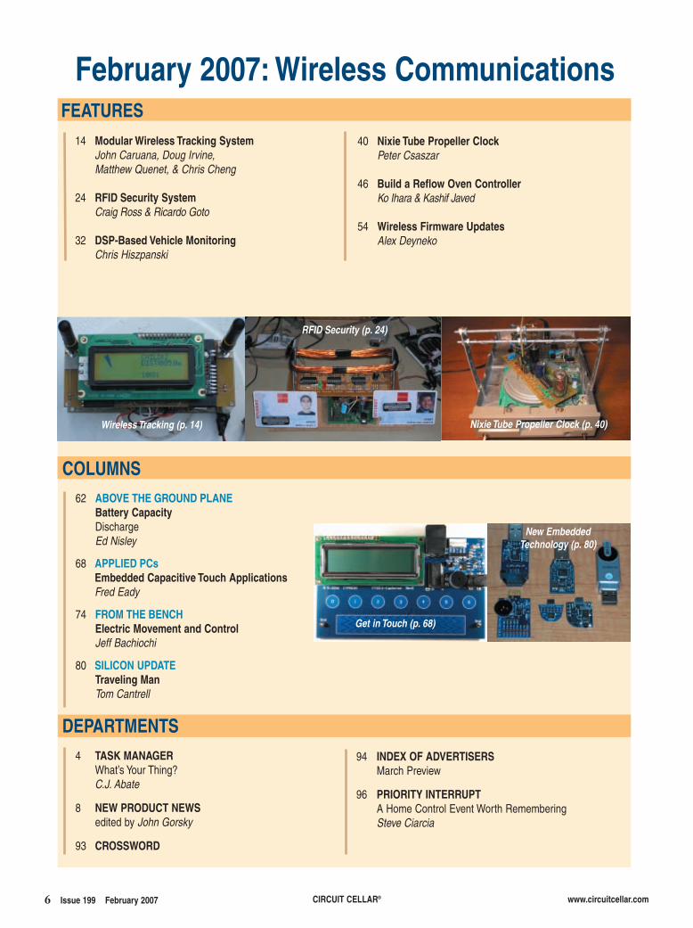
February 2007: Wireless Communications
4 TASK MANAGERWhat’s Your Thing?C.J. Abate
8 NEW PRODUCT NEWSedited by John Gorsky
93 CROSSWORD
FEATURES
DEPARTMENTS94 INDEX OF ADVERTISERS
March Preview
96 PRIORITY INTERRUPTA Home Control Event Worth RememberingSteve Ciarcia
62 ABOVE THE GROUND PLANEBattery CapacityDischargeEd Nisley
68 APPLIED PCsEmbedded Capacitive Touch ApplicationsFred Eady
74 FROM THE BENCHElectric Movement and ControlJeff Bachiochi
80 SILICON UPDATETraveling ManTom Cantrell
14 Modular Wireless Tracking SystemJohn Caruana, Doug Irvine, Matthew Quenet, & Chris Cheng
24 RFID Security SystemCraig Ross & Ricardo Goto
32 DSP-Based Vehicle MonitoringChris Hiszpanski
COLUMNS
Nixie Tube Propeller Clock (p. 40)
Get in Touch (p. 68)
New Embedded Technology (p. 80)
RFID Security (p. 24)
40 Nixie Tube Propeller ClockPeter Csaszar
46 Build a Reflow Oven ControllerKo Ihara & Kashif Javed
54 Wireless Firmware UpdatesAlex Deyneko
Wireless Tracking (p. 14)
199_toc.qxp 1/4/2007 9:54 AM Page 6

Dream of Darkness, Wasteman!
What can AVR picoPower do for your design?
• True 1.8V supply voltage enabling operation of all features and core down to 1.8V
• Minimized leakage current enabling 100 nA Power Down sleep consumption
• Sleeping brown-out detector enabling full protection with no power penalty
• Ultra low power 32 kHz crystal oscillator enabling operation at only 650 nA
7.qxp 10/4/2006 1:48 PM Page 1
PIEZO ULTRASONIC TRANSDUCER DRIVERThe 9000 Sonar Ranging Module is a new
transducer driver board. It provides engineersand designers with a fast and easy solution tointerfacing Piezo ultrasonic transducers, suchas the 9000 series transducer, with the exter-nal circuitry or a controller for ultrasonicsensing in a variety of applications. It operateson 5 VDC and provides a TTL pulse-widthoutput proportional to distance-to-target. As amatched component pair, the 9000 transducerand ranging module can detect objects or liq-uid surfaces from 1′ to 18′ (0.3 to 5.5 m). Com-mon applications include liquid level sensingin tanks, an anti-collision sensor for AGVs,and other industrial environment applications.
Also available is the Series 9000 OEM Kit forprototype and technology feasibility studies, aswell as an instructional tool for studies inultrasonic measurement and proximity experi-ments in high school and university labs.
The 9000 module costs $24.70 each in 10-piece quantities. The 9000 OEM Kit costs $103.
SensComp, Inc.www.senscomp.com
8 Issue 199 February 2007 CIRCUIT CELLAR® www.circuitcellar.com
NEW PRODUCT NEWS Edited by John Gorsky
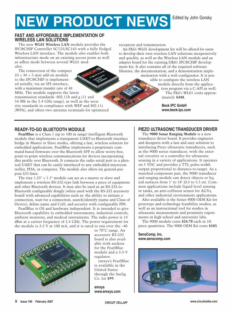
FAST AND AFFORDABLE IMPLEMENTATION OFWIRELESS LAN SOLUTIONS
The new WL01 Wireless LAN module provides theIPC@CHIP Controller SC123/SC143 with a fully fledgedWireless LAN interface. The module also enables bothinfrastructure mode on an existing access point as wellas adhoc mode between several WL01 mod-ules.
The connection of the compact23 × 36 × 5 mm add-on moduleto the IPC@CHIP is implement-ed serially, via an SPI interface,with a maximum transfer rate of 48MHz. The module supports the latesttransmission standards -802.11b and g (11 and54 Mb in the 2.4 GHz range), as well as the secu-rity standards in compliance with WEP and 802.11i(WPA), and offers two antenna terminals for optimized
reception and transmission.An FK61-WL01 development kit will be offered for users
to develop their own wireless LAN solutions inexpensivelyand quickly, as well as the Wireless LAN module and anadapter board for the existing DK61 IPC@CHIP develop-ment kit. It also contains all of the required softwarelibraries, the documentation, and a demonstration imple-
mentation with a web configurator. It is pos-sible to configure the wireless LAN
module directly from the applica-tion program via a C-API as well.
The FK61-WL01 costs approx-imately $448.
Beck IPC GmbHwww.beck-ipc.com
READY-TO-GO BLUETOOTH MODULEPearlBlue is a Class 1 (up to 100 m range) intelligent Bluetooth
module that implements a transparent UART-to-Bluetooth interfacebridge in Master or Slave modes, offering a fast, wireless solution forembedded applications. PearlBlue implements a proprietary com-mand-based firmware over the Bluetooth SPP to allow worry-free,point-to-point wireless communications for devices incorporatingthis profile over Bluetooth. It connects the radio serial port to a phys-ical UART that can be easily interfaced to any embedded microcon-troller, PDA, or computer. The module also offers six general-pur-pose I/O lines.
The tiny 1.25″ × 1.1″ module can act as a master or slave andimplement a wireless RS-232-type link between a piece of equipmentand other Bluetooth devices. It may also be used as an RS-232-to-Bluetooth configurable dongle (when used with the RS-232 accessoryboard) with advanced capabilities such as: the ability to initiate aconnection, wait for a connection, search/identify (name and Class ofDevice), define name and CoD, and security with configurable PIN.
PearlBlue is OS and hardware independent. It is intended to giveBluetooth capability to embedded instruments, industrial controls,ambient monitors, and medical instruments. The radio power is 14dBm at a carrier frequency of 2.4 GHz. The power requirement forthe module is 3.3 V at 100 mA, and it is rated to run over the –40
to 70°C range. Anaccessory RS-232board is also avail-able with socketsfor the PearlBluemodule and a 3.3-Vregulator.
emxys’s PearlBlueis available in theUnited Statesthrough the SaeligCo. for $99.
emxyswww.emxys.com
npn.qxp 1/4/2007 10:00 AM Page 8
www.circuitcellar.com CIRCUIT CELLAR® Issue 199 February 2007 9
NEW PRODUCT NEWSZigBee PLATFORM WITH TRANSCEIVER AND ANALYZER
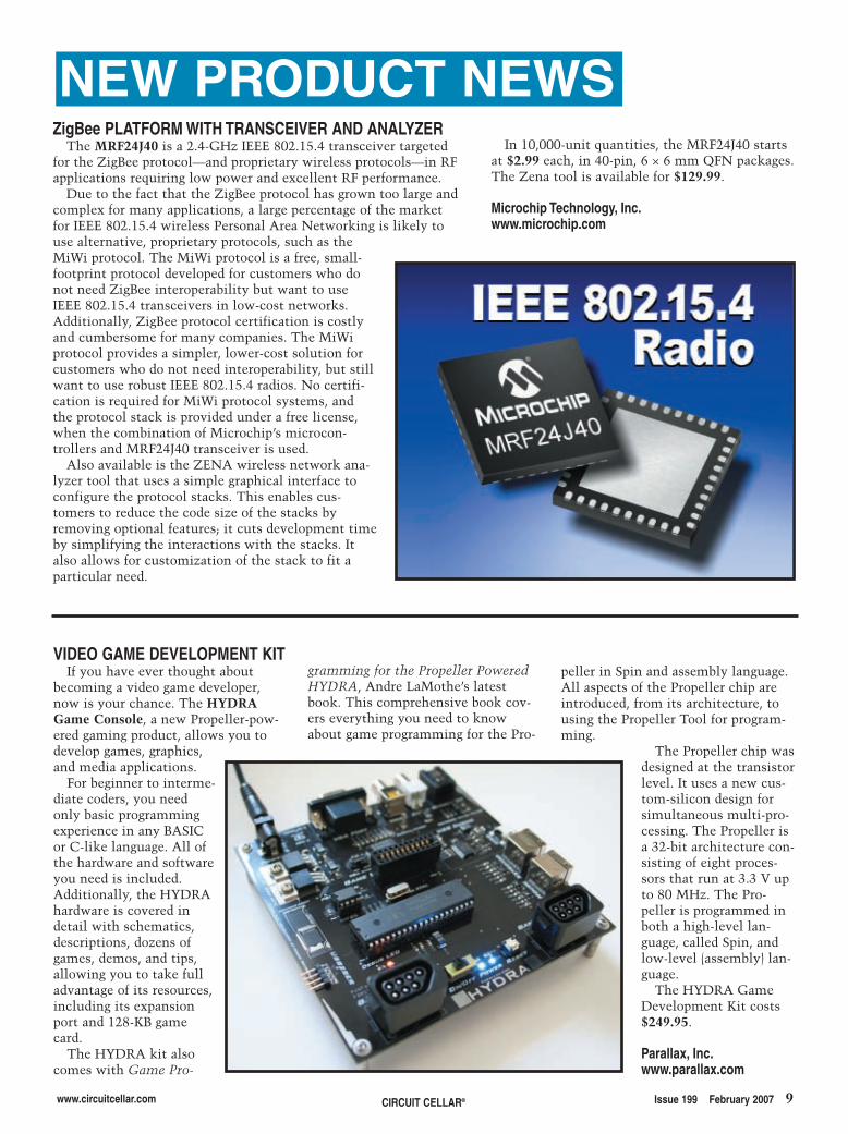
The MRF24J40 is a 2.4-GHz IEEE 802.15.4 transceiver targetedfor the ZigBee protocol—and proprietary wireless protocols—in RFapplications requiring low power and excellent RF performance.
Due to the fact that the ZigBee protocol has grown too large andcomplex for many applications, a large percentage of the marketfor IEEE 802.15.4 wireless Personal Area Networking is likely touse alternative, proprietary protocols, such as theMiWi protocol. The MiWi protocol is a free, small-footprint protocol developed for customers who donot need ZigBee interoperability but want to useIEEE 802.15.4 transceivers in low-cost networks.Additionally, ZigBee protocol certification is costlyand cumbersome for many companies. The MiWiprotocol provides a simpler, lower-cost solution forcustomers who do not need interoperability, but stillwant to use robust IEEE 802.15.4 radios. No certifi-cation is required for MiWi protocol systems, andthe protocol stack is provided under a free license,when the combination of Microchip’s microcon-trollers and MRF24J40 transceiver is used.
Also available is the ZENA wireless network ana-lyzer tool that uses a simple graphical interface toconfigure the protocol stacks. This enables cus-tomers to reduce the code size of the stacks byremoving optional features; it cuts development timeby simplifying the interactions with the stacks. Italso allows for customization of the stack to fit aparticular need.
VIDEO GAME DEVELOPMENT KITIf you have ever thought about
becoming a video game developer,now is your chance. The HYDRAGame Console, a new Propeller-pow-ered gaming product, allows you todevelop games, graphics,and media applications.
For beginner to interme-diate coders, you needonly basic programmingexperience in any BASICor C-like language. All ofthe hardware and softwareyou need is included.Additionally, the HYDRAhardware is covered indetail with schematics,descriptions, dozens ofgames, demos, and tips,allowing you to take fulladvantage of its resources,including its expansionport and 128-KB gamecard.
The HYDRA kit alsocomes with Game Pro-
In 10,000-unit quantities, the MRF24J40 startsat $2.99 each, in 40-pin, 6 × 6 mm QFN packages.The Zena tool is available for $129.99.
Microchip Technology, Inc.www.microchip.com
gramming for the Propeller PoweredHYDRA, Andre LaMothe’s latestbook. This comprehensive book cov-ers everything you need to knowabout game programming for the Pro-
peller in Spin and assembly language.All aspects of the Propeller chip areintroduced, from its architecture, tousing the Propeller Tool for program-ming.
The Propeller chip wasdesigned at the transistorlevel. It uses a new cus-tom-silicon design forsimultaneous multi-pro-cessing. The Propeller isa 32-bit architecture con-sisting of eight proces-sors that run at 3.3 V upto 80 MHz. The Pro-peller is programmed inboth a high-level lan-guage, called Spin, andlow-level (assembly) lan-guage.
The HYDRA GameDevelopment Kit costs$249.95.
Parallax, Inc.www.parallax.com
npn.qxp 1/4/2007 10:00 AM Page 9
10 Issue 199 February 2007 CIRCUIT CELLAR® www.circuitcellar.com
NEW PRODUCT NEWS500 MSa/s PC-BASED OSCILLOSCOPE
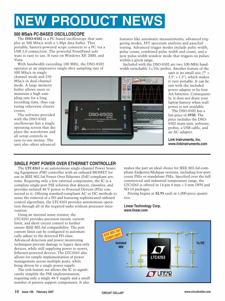
The DSO-8502 is a PC-based oscilloscope that sam-ples at 500 MSa/s with a 1-Mpt data buffer. Thisportable, battery-powered scope connects to a PC via aUSB 2.0 connection. The powerful FrontPanel soft-ware is easy to use. It runs on Windows XP, 2000, andVista.
With bandwidth exceeding 100 MHz, the DSO-8502operates at an impressive single-shot sampling rate of500 MSa/s in singlechannel mode and 250MSa/s in dual-channelmode. A large memorybuffer allows users tomaintain a high sam-pling rate for a longrecording time, thus cap-turing otherwise elusiveevents.
The software providedwith the DSO-8502oscilloscope has a singleoperating screen that dis-plays the waveforms andall setup controls ineasy-to-use menus. Theunit also offers advanced
features like automatic measurements, advanced trig-gering modes, FFT spectrum analysis and pass/failtesting. Advanced trigger modes include pulse width,pulse count, combined pulse width and count, and anew pulse-width window mode that triggers on pulseswithin a given range.
Included with the DSO-8502 are two 100-MHz band-width switchable 1×/10× probes. Another feature of the
unit is its small size (7″ ×3.5″ × 1.5″), which makesit very portable. It can berun with the includedpower adapter or by fourAA batteries. Consequent-ly, it does not drain yourlaptop battery when wallpower is not available.
The DSO-8502 has alist price of $950. Theprice includes the DSO-8502 main unit, software,probes, a USB cable, andan AC adapter.
Link Instruments, Inc.www.linkinstruments.com
SINGLE PORT POWER OVER ETHERNET CONTROLLERThe LTC4263 is an autonomous single-channel Power Sourc-
ing Equipment (PSE) controller with an onboard MOSFET foruse in IEEE 802.3af Power Over Ethernet (PoE) compliant sys-tems. Requiring only a few external components, the IC is acomplete single-port PSE solution that detects, classifies, andprovides isolated 48-V power to Powered Devices (PDs) con-nected to it. Offering standard-compliant AC or DC methods tosense the removal of a PD and featuring sophisticated onboardcontrol algorithms, the LTC4263 provides autonomous opera-tion through all of the required tasks without processor inter-vention.
Using an internal sense resistor, theLTC4263 provides precision inrush, currentlimit, and short circuit control to furtherensure IEEE 802.3af compatibility. The portcurrent limit can be configured to automati-cally adjust to the detected PD class.Advanced detection and power monitoringtechniques prevent damage to legacy data-onlydevices, while still supplying power to newer,Ethernet-powered devices. The LTC4263 alsoallows for simple implementation of powermanagement across multiple ports, whilebeing driven by a single power supply.
The rich feature set allows the IC to signifi-cantly simplify the PSE implementation,requiring only a single 48-V supply and a smallnumber of passive support components. It also
makes the part an ideal choice for IEEE 802.3af-com-pliant Endpoint/Midspan systems, including low-port-count PSEs or standalone PSEs. Specified over the fullcommercial and industrial temperature range, theLTC4263 is offered in 14-pin 4 mm × 3 mm DFN andSO-14 packages.
Pricing begins at $2.95 each in 1,000-piece quanti-ties.
Linear Technology Corp.www.linear.com
npn.qxp 1/4/2007 10:00 AM Page 10

HI-TECH Software delivers the industry’s most reliable embedded software development tools and compilers for over 12 different 8-bit, 16-bit, 32-bit, and DSP chip architectures!
S O F T W A R E
HI-TECH Software LLC 6600 Silacci Way Gilroy, CA 95020 USA
Ph: 800 735 5715 Web: http://www.htsoft.com/
We make chips think
intc;while(1){
c =ge
tcha
r()
;if(c
==EO
F)br
eak;
if (
isupper(c)) putchar(‘U’),u++; if (islow
er(c))putchar(‘l’),l++
#include
<ctype.h>
#include
<std
io.h
>
n,u,l,d,p;
main() {
unsigned
;if(
isdi
git(c
))pu
tcha
r(‘#’)
,d++; if(ispunct(c))
As one of the top five compiler vendors with the largest variety of supported chip architectures, HI-TECH Software’s product range is renowned for delivering cutting-edge technology and robust results for development teams worldwide.
putchar(‘?’)
,p++;n++;}}
HI-TECH C® is a registered trademark of HI-TECH Software. HI-TECH PICC™, HI-TECH PICC-18™ and HI-TECH dsPICC™ are licensed exclusively to HI-TECH Software by Microchip Technology Inc. All other trademarks and registered trademarks are the property of their respective owners.
To see how our compilers can improve your productivity, download a demo now at www.htsoft.com/downloads/demos.php.
With over two decades of industry
experience, our long-term
relationships with leading chip
manufacturers ensure that our
products are tightly attuned to new
technological releases.
Whichever processor family you are targeting, HI-TECH Software’s C compilers can help you write better code and bring it to market faster.
HI-TECH PICC™ Enterprise Edition
HI-TECH PICC™
HI-TECH PICC-18™
HI-TECH dsPICC™
HI-TECH C® for ARM®
HI-TECH C® for 8051
HI-TECH C® for MSP430
HI-TECH C® for HOLTEK MCU
HI-TECH C® for ARClite™
HI-TECH C® for XA
HI-TECH C® for Z80
HI-TECH C® for H8/300
HI-TECH C® for 68HC11
95.qxp 8/9/2006 2:12 PM Page 1
12 Issue 199 February 2007 CIRCUIT CELLAR® www.circuitcellar.com
NEW PRODUCT NEWS Visit www.circuitcellar.com/npnfor more New Product News.
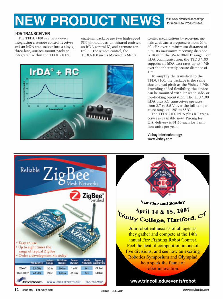
IrDA TRANSCEIVERThe TFDU7100 is a new device
integrating a remote control receiverand an IrDA transceiver into a single,three-lens, surface-mount package.Integrated within the TFDU7100’s
Center specifications by receiving sig-nals with carrier frequencies from 20 to60 kHz over a minimum distance of5 m. Its maximum receiving distanceis 18 m in the 36- to 38-kHz range. ForIrDA communication, the TFDU7100supports all IrDA data rates up to 4 Mbover the inherently secure distance of1 m.
To simplify the transition to theTFDU7100, the package is the samesize and pad pitch as the Vishay 4 Mb.Providing added flexibility, the devicecan be mounted with lenses in side- ortop-looking orientation. The TFU7100IrDA plus RC transceiver operatesfrom 2.7 to 5.5 V over the full temper-ature range of –25° to 85°C.
The TFDU7100 IrDA plus RC trans-ceiver is available now. Pricing forU.S. delivery is $1.50 each for 1 mil-lion units per year.
Vishay Intertechnologywww.vishay.com
eight-pin package are two high-speedPIN photodiodes, an infrared emitter,an IrDA control IC, and a remote con-trol IC. For remote control, theTFDU7100 meets Microsoft’s Media
www.trincoll.edu/events/robot
Join robot enthusiasts of all ages as they gather and compete at the 14th annual Fire Fighting Robot Contest.
Feel the heat of competition in one of five divisions, and see how an exciting Robotics Symposium and Olympiad
help spark the flame of robot innovation.
April 14 & 15, 2007
npn.qxp 1/4/2007 10:00 AM Page 12
14 Issue 199 February 2007 CIRCUIT CELLAR® www.circuitcellar.com
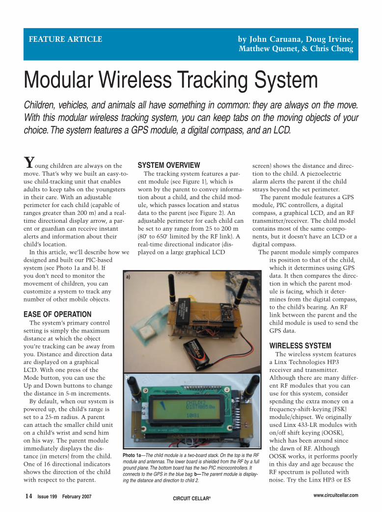
SYSTEM OVERVIEWThe tracking system features a par-
ent module (see Figure 1), which isworn by the parent to convey informa-tion about a child, and the child mod-ule, which passes location and statusdata to the parent (see Figure 2). Anadjustable perimeter for each child canbe set to any range from 25 to 200 m(80′ to 650′ limited by the RF link). Areal-time directional indicator (dis-played on a large graphical LCD
Young children are always on themove. That’s why we built an easy-to-use child-tracking unit that enablesadults to keep tabs on the youngstersin their care. With an adjustableperimeter for each child (capable ofranges greater than 200 m) and a real-time directional display arrow, a par-ent or guardian can receive instantalerts and information about theirchild’s location.
In this article, we’ll describe how wedesigned and built our PIC-basedsystem (see Photo 1a and b). Ifyou don’t need to monitor themovement of children, you cancustomize a system to track anynumber of other mobile objects.
EASE OF OPERATIONThe system’s primary control
setting is simply the maximumdistance at which the objectyou’re tracking can be away fromyou. Distance and direction dataare displayed on a graphicalLCD. With one press of theMode button, you can use theUp and Down buttons to changethe distance in 5-m increments.
By default, when our system ispowered up, the child’s range isset to a 25-m radius. A parentcan attach the smaller child uniton a child’s wrist and send himon his way. The parent moduleimmediately displays the dis-tance (in meters) from the child.One of 16 directional indicatorsshows the direction of the childwith respect to the parent.
screen) shows the distance and direc-tion to the child. A piezoelectricalarm alerts the parent if the childstrays beyond the set perimeter.
The parent module features a GPSmodule, PIC controllers, a digitalcompass, a graphical LCD, and an RFtransmitter/receiver. The child modelcontains most of the same compo-nents, but it doesn’t have an LCD or adigital compass.
The parent module simply comparesits position to that of the child,which it determines using GPSdata. It then compares the direc-tion in which the parent mod-ule is facing, which it deter-mines from the digital compass,to the child’s bearing. An RFlink between the parent and thechild module is used to send theGPS data.
WIRELESS SYSTEMThe wireless system features
a Linx Technologies HP3receiver and transmitter.Although there are many differ-ent RF modules that you canuse for this system, considerspending the extra money on afrequency-shift-keying (FSK)module/chipset. We originallyused Linx 433-LR modules withon/off shift keying (OOSK),which has been around sincethe dawn of RF. AlthoughOOSK works, it performs poorlyin this day and age because theRF spectrum is polluted withnoise. Try the Linx HP3 or ES
FEATURE ARTICLE by John Caruana, Doug Irvine,Matthew Quenet, & Chris Cheng
Modular Wireless Tracking SystemChildren, vehicles, and animals all have something in common: they are always on the move.With this modular wireless tracking system, you can keep tabs on the moving objects of yourchoice.The system features a GPS module, a digital compass, and an LCD.
Photo 1a—The child module is a two-board stack. On the top is the RFmodule and antennas. The lower board is shielded from the RF by a fullground plane. The bottom board has the two PIC microcontrollers. Itconnects to the GPS in the blue bag. b—The parent module is display-ing the distance and direction to child 2.
a)
b)
2702014 caruana.qxp 1/4/2007 10:06 AM Page 14
series. Both work with FSK. The ESmodule is a little cheaper because itdoesn’t allow for channel selection.We used Linx coiled quarter waveantennas and connected them to astandard SMA antenna connector.
We used a Microchip TechnologyPIC16F877A to control the RF portionof the project. Although it wasoverkill for our RF needs, we had plen-ty of them sitting around. The benefitof using a second processor is that theGPS data can be received at the sametime that data from the RF link isreceived.
TRANSMIT & RECEIVEWe used Manchester encoding for
the RF data transmission. Easy to setup, Manchester encoding ensuresthere is a logical transition for each bitthat is sent. These mandatory transi-tions make it very easy to have thereceiver sync with the transmitter.
They allow for a long packet lengthwithout the chance of a long string ofzeros or ones unsyncing the data.
A simple search on the Internet willprovide you with numerous links forinformation about Manchester encod-ing and piles of sample code, which isall that is required for this project.
ADDRESSING PROTOCOLOur system works in the crowded
915-MHz spectrum. The physicaldevice will inevitably be used nearother 915-MHz transmitters, so it isimportant to include noise filteringand addressing to ensure you onlytransmit and receive from the unitsassociated with your family.
To filter out noise, a specific pream-ble (start-up code) is transmitted toseparate our data from other data. Tokeep things simple, we used 1 byte(11010110). Therefore, any incomingtransmission (at the same data rate)
will be received, but it will only con-tinue the receive routine if the datastring has this first noise filter byte.Once the noise filter byte has beenchecked, another byte is sent. It is theunique address of the device thattransmitted the signal. The parentexamines this byte to see which childhas transmitted. The parent can alsouse this byte to send messages to spe-cific child units.
After the addressing has been sentout, there is an “info byte” that con-tains command codes for the differentunits. These command codes allowthe parent to ask the child unit toresend GPS data, pull in new GPSdata, turn on the alarm buzzer, or acti-vate various extra features. The fol-lowing 8 bytes of data are the x and yGPS coordinates, 4 bytes for each axis,and the final byte is a cyclic redundan-cy check (CRC).
Inside the receiver, a simple loop
www.circuitcellar.com CIRCUIT CELLAR® Issue 199 February 2007 15
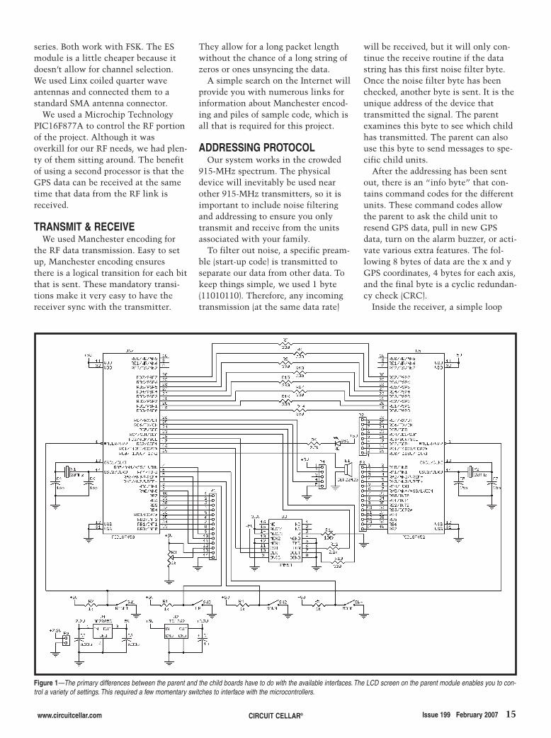
Figure 1—The primary differences between the parent and the child boards have to do with the available interfaces. The LCD screen on the parent module enables you to con-trol a variety of settings. This required a few momentary switches to interface with the microcontrollers.
2702014 caruana.qxp 1/4/2007 10:06 AM Page 15
vides updated heading data very quick-ly, which was essential for the prod-uct. Any compass placed on a personneeds to accommodate the quick handmovements of the person holding thedevice, most importantly in a panicsituation.
The HM55B supports SPI, but weelected to bit bang it, which was alsoeasy. Bit banging the HM55B also keptthe SPI free so we could use it for theinter-chip communication.
Using the most current GPS datapoints, the microcontroller can calcu-late the relative direction of the childmodule from the parent module. Wesimply determined the number ofdegrees from North, traveling in aclockwise rotation. Our digital com-pass data is also calculated in this for-mat, which made the relative calcula-tion for the child’s direction withrespect to the board a simple mathcalculation.
It is important to note that this dig-ital compass is influenced by metalin the same way as a regular com-pass. If it is to be placed by a little bitof metal in your design, a simple cali-bration will ensure accurate results.Note that digital compasses also tend
protocol at 4,800 bps. The EM-402 outputs its data at TTL
levels allowing for very easy interfac-ing to microcontrollers. Hooking upthe module so a PIC microcontrollercan interpret the data correctly takes acouple of days at most. The GPSstring also sends accurate time datathat we used to update the system’sclock. Remember to factor in the timedifference, as GPS outputs only Green-wich Mean Time.
The EM-402 costs around $70. Wewould like to thank Globalsat fordonating two EM-402 modules for thisproject.
DIGITAL COMPASSDigital compasses come in more
configurations than we had previouslythought. With degrees of resolutionranging from 60 points (6 degrees perpoint) up to 720 points (0.5 degree perpoint), some chips also send informa-tion on pitch. As with everything, youwill get what you pay for. We used aHitachi HM55B compass module,which has 60 points of reference anddoes not convey pitch. (We opted for a$3 bubble level as opposed to a $100chip that has pitch.) This compass pro-
16 Issue 199 February 2007 CIRCUIT CELLAR® www.circuitcellar.com
takes the most popular values of eachset of the three bytes. As a result, 1 in3 bytes can be completely corrupt andthe data will still get through.
When a transmission occurs, the 36-byte packet is transmitted three timesin quick succession (see Figure 3). Thereceiver fills a different array for eachtransmission, compares all threearrays, and takes the most likely bytevalue (i.e., 2 out of 3 bytes are thesame). In this way, each byte is actual-ly sent and compared nine times mak-ing the system very robust in noisyenvironments.
GPS SYSTEMGPS is a mature technology. Many
GPS choices were available for ourproject. Some modules can cost as lit-tle as $30, but if you want a perform-ance module, expect to pay more. Weused a Globalsat Technology GPSModule in SiRF (EM-402).
The EM-402 is a highly sensitivemodule that features 12-channel par-allel processing, an active antennapackage, and a super capacitor tohold up data for faster acquisitiontimes. Interfacing to this module iseasy. It supports the NMEA 0183 data
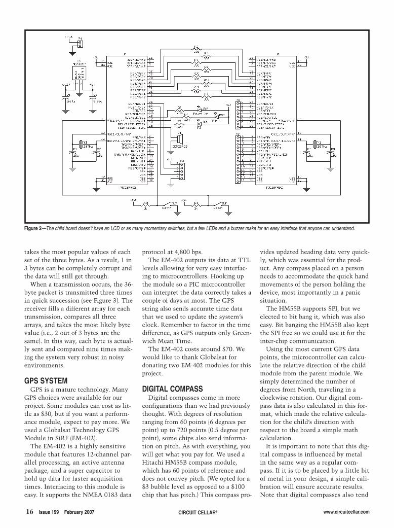
Figure 2—The child board doesn’t have an LCD or as many momentary switches, but a few LEDs and a buzzer make for an easy interface that anyone can understand.
2702014 caruana.qxp 1/4/2007 10:06 AM Page 16

18 Issue 199 February 2007 CIRCUIT CELLAR® www.circuitcellar.com
to be tiny; this one in particu-lar is a 16-pin J lead that isonly 5.3 mm × 4.6 mm, soexpect to think small and sol-der smaller.
The HM55B comes in module formwith through-hole leads (T. Cantrell,“Direction Finder,” Circuit Cellar183, October 2005). We recommendgetting this pinned module to avoidthe soldering. (We would like tothank Hitachi Metals America fordonating two HM55B modules that
we used for this project.)
LCDThe LCD you use is entirely up to
you. If you use a graphical LCD, itwill be easier to build the arrows thatpoint to your child, but you will haveto code or search the Internet to find a
good character set to use forthe text on the display. Ifyou use a character LCD,then the characters arealready built. Building the
arrows will be a bit challenging anddifficult to line up. A good alternativewould be a small character LCD sur-rounded by a simple ring of LEDs thatcould be used to display the directionof the child. You might want to tryusing a small LCD because this proj-ect is supposed to be wrist mounted.
We used a SunLike SG12232D 32 ×122 dot graphical LCD simply becausewe had one sitting around. The unin-tentional benefit of this display wasthat it has a separate microprocessorfor each side. Setting up one side forthe arrows and the other for the textwas easy. This LCD uses an SED1520dot-matrix LCD driver.
PIC ACCESSA problem that we had to resolve
was the division of available program-ming time slots. We have two majorwireless communications that eachrequire uninterrupted access to thePIC microcontroller. The GPS modulerequires approximately 200 ms toreceive all of the necessary GPS data.To keep accurate data in the GPScoordinate buffer, the main chipchecks for incoming information asfast as possible. For approximately30% of the time, the main chip isbusy pulling in GPS data. The RFtransmission takes about 500 ms ofuninterrupted processor time. Any RFcommunication could potentially be adistress call from the child; no RFtransmissions can be missed. Howev-er, without good GPS data, that dis-tress call could be pointing to a placewhere your child was, instead ofwhere your child is.
To get around this and keep thingssimple, we decided to use two chips.A PIC18F458 runs the GPS, digitalcompass, and LCD. It also acts as themaster. A PIC16F877A acts as a dedi-cated RF chip. Using a dedicated RFchip is very helpful if you are operat-ing in a noisy environment, where aninterrupt-based RF routine couldpotentially get tripped often enough todisrupt other functionality. Since the
Preamble byte Device address byte Information byte Data (8 bytes) CRC Byte
Figure 3—Each byte in this packet is transmitted three times. The entire packetis sent three times.
2702014 caruana.qxp 1/4/2007 10:06 AM Page 18
www.circuitcellar.com CIRCUIT CELLAR® Issue 199 February 2007 19
PIC16F877A has to deal with onlywireless communications, it can con-tinuously monitor the 915-MHz band,pull in all data that it sees, and sendinformation to the 458 only once ithas seen new, correct, and relevantdata.
POWER SUPPLYWe used a 5-V power supply because
of the LCD. However, if you can get a3.3-V LCD, you can make the entireproject with 3.3 V. While a switchingpower supply could be used to boostpower, switching power supplies andRF devices are generally not the bestof friends. So, we used a high-accuracy5-V linear power regulator that is fedby a 7.2-V lithium ion camera batterywith a 1,100-mAh capacity.
The RF receiver and transmittereach draw about 15 mA when opera-tional. Using the power-down function,only one is on at a time. Together theyaccount for a constant 15-mA drain.The LEDs are wired up for a 5-mAdrain. Only one LED is typically on.
The real power pig is the GPS, which
averages a little less than 60 mA. Intotal, the device typically wants about80 mA if you’re working off a 5-supdate rate on the GPS. The deviceslast a minimum of 10 h, but when weset the GPS update interval to 15 s,we can squeeze six more hours out ofthe modules. The only way to reallycut power consumption would be tofind a GPS module that uses lesspower or updates your GPS locationsless frequently.
SOFTWARE The software for this project is very
user-dependent and configurable (seeListing 1). You can use it to track chil-dren, pets, or anything outside that iswithin the range of your transmitterand receiver. You can also independ-ently set up any number of things tohappen should the target stray too far:alarms for the kids or shocks for thepets. Using the GPS to map locations,you can even hardcode off-limit areaslike the swimming pool for your kidsor the garden for your dog.
Our devices were designed for chil-
dren, so we worried only about situa-tions in which the child had wanderedtoo far from the parent or when thechild had pressed the Panic button.We consider these emergency situa-tions.
The parent module periodicallyqueries each child module for its cur-rent or last known GPS location. Eachchild has a unique child identificationnumber, which is sent to the parentwith each GPS update so the parentcan distinguish between each child.Once the parent receives an updatedGPS location from the child, it thenproceeds to calculate the distancebetween itself and the child, the bear-ing to the child (using the digital com-pass onboard), and it checks for out-of-range and panic situations.
LCD screen and digital compassupdates occur in between GPSupdates. The digital compass provides22 bits of data consisting of an x and ay coordinate. From this vector (x, y),the angle is calculated relative to 0°(which corresponds to MagneticNorth). Using trigonometric identities,
2702014 caruana.qxp 1/4/2007 10:06 AM Page 19
the bearing between the parent andthe child relative to True North wascalculated (accounting for the declina-tion discrepancies between MagneticNorth). This value is then subtractedfrom the GPS bearing to provide theactual position of the child.
EMERGENCY SITUATIONSWhile the units will happily plod
along while the child is within theboundary, what is to be done when thechild goes too far? Or what should thechild do when placed in a negative sit-uation? If the child wanders too faraway, the parent is alerted by thepanic LED as well as through a piezo-electric alarm. We also set up thechild’s device to set off the buzzer andflash the panic LED. The buzzer andflashing LED can be set off in one ofthree ways: the child wanders too faraway; the child presses the Panic but-ton; or the parent selects Panic fromthe options menu.
It would be nicer to send a voicemessage to the child, but that wouldreduce the amount of power yourtransmitter could legally put out (inaccordance with the FCC’s standards)with the 915-MHz spectrum. Becausethe device could be put into a wrist-sized device, a dead man switch isincorporated in the strap. So, if achild tries to take off the watch, or ifsomeone else removes the watch, thepanic alarm is automatically sent tothe parent.
The only other emergency situationis when a child has strayed beyondthe maximum distance that the trans-mitter can transmit. In this case, theparent module will alert the parentwith a panic alarm while displayingthe last known distance and positionof the child. This allows the parent toquickly move toward the child’s lastknown position to reestablish com-munication. When the child unit hasgone 30 s without hearing a transmis-sion from the parent module, it willbegin a calling schedule every 5 s, sothat the parent will be given updatedinformation the second it gets withinrange.
DigiKey carries a good selection ofpiezoelectric alarms. Alarms with upto 90-dB tones cost a few dollars; how-
www.circuitcellar.comCIRCUIT CELLAR®20 Issue 199 February 2007
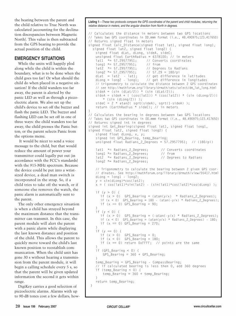
Listing 1—These two protocols compare the GPS coordinates of the parent and child modules, returning therelative distance in meters, and the angular direction from North in degrees.
// Calculates the distance in meters between two GPS locations// Takes two GPS coordinates in DD.mmm format (i.e., 48.490975;123.417650)// Returns signed float in meterssigned float Calc_Distance(signed float lat1, signed float long1,
signed float lat2, signed float long2) {signed float dLat, dLong, sideA, sideC;unsigned float EarthRadius = 6378100; // in meterslat1 *= 57.29577951; // Converts coordinateslong1 *= 57.29577951; // fromlat2 *= 57.29577951; // Degrees to Radianslong2 *= 57.29577951; // 57.29 = 180/pidLat = lat2 - lat1; // get difference in latitudesdLong = long2 - long1; // get difference in longitudes// trigonometry to calculate the distance between 2 GPS coordinates// see http://mathforum.org/library/drmath/sets/select/dm_lat_long.htmlsideA = (sin (dLat/2)) * (sin (dLat/2));sideA = sideA + ( (cos(lat1)) * (cos(lat2)) * (sin (dLong/2))|
* (sin (dLong/2)) );sideC = 2 * atan2( sqrt(sideA), sqrt(1-sideA) );return (EarthRadius * sideC); // in meters
}// Calculates the bearing in degrees between two GPS locations// Takes two GPS coordinates in DD.mmm format (i.e., 48.490975;123.417650)// Returns signed int in degreessigned int Get_Bearing(signed float lat1, signed float long1,signed float lat2, signed float long2) {
signed float dLong, x, y;signed int GPS_Bearing, temp_Bearing;unsigned float Radians_2_Degrees = 57.29577951; // (180/pi)
lat1 *= Radians_2_Degrees; // Converts coordinateslong1 *= Radians_2_Degrees; // fromlat2 *= Radians_2_Degrees; // Degrees to Radianslong2 *= Radians_2_Degrees;
// Trigonometry to calculate the bearing between 2 given GPS coor-// dinates. See http://mathforum.org/library/drmath/view/55417.htmldLong = long1 - long2;y = sin(dLong)*cos(lat2);x = ( cos(lat1)*sin(lat2) - (sin(lat1)*cos(lat2)*cos(dLong) );
if (y > 0) {if (x > 0) GPS_Bearing = (atan(y/x) * Radians_2_Degrees);if (x < 0) GPS_Bearing = 180 - (atan(-y/x) * Radians_2_Degrees);if (x == 0) GPS_Bearing = 90;
}if (y < 0) {
if (x > 0) GPS_Bearing = (-atan(-y/x) * Radians_2_Degrees);if (x < 0) GPS_Bearing = (atan(y/x) * Radians_2_Degrees) - 180;if (x == 0) GPS_Bearing = 270;
}if (y == 0) {
if (x > 0) GPS_Bearing = 0;if (x < 0) GPS_Bearing = 180;if (x == 0) return 0xFFFF; // points are the same
}if (GPS_Bearing < 0) {
GPS_Bearing = 360 + GPS_Bearing;}temp_Bearing = GPS_Bearing - CompassBearing;// if calculated bearing is less then 0, add 360 degreesif (temp_Bearing < 0) {
temp_Bearing = 360 + temp_Bearing;}return temp_Bearing;
}
2702014 caruana.qxp 1/4/2007 10:06 AM Page 20

www.keil.com800-348-8051
Only 4 Steps......are required to generate efficient, reliable
applications with the μVision IDE and
development tools from Keil.
Step 1. Select Microcontroller and
SpecifyTarget Hardware
Use the Keil Device Database ( ) to find the
optimum microcontroller for your application.
In Vision, select the microcontroller to pre-configure tools and
obtain CPU startup code.
www.keil.com/dd
μ
Step 2. Configure the Device and
Create Application Code
The μVision Configuration Wizard helps you tailor startup code
to match your target hardware and application requirements.
Extensive program examples and project templates help you
jump-start your designs.
Step 3. Verify Program Execution with
Device Simulation
High-speed simulation enables testing
before hardware is available and helps you
with features like instruction trace, code
coverage, and logic analysis.
Step 4. Download to Flash and
Test Application
Once your application is runs
in simulation, use the Keil
ULINK USB-JTAG Adapter for
Flash programming and final
application testing.
Keil Microcontroller DevelopmentTools
help you create embedded applications quickly
and accurately. Keil tools are easy to learn and
use, yet powerful enough for the most
demanding microcontroller projects.
Components of Keil Microcontroller Development Kits
Keil makes C compilers, macro assemblers,
real-time kernels, debuggers, simulators,
evaluation boards, and emulators.
Over 1,200 MCU devices are supported for:
- 8051 and extended 8051 variants
- C166, XC166, and ST10
- ARM7, ARM9, and Cortex-M3
Download an evaluation version from
�
�
�
8-bit
16-bit
32-bit
www.keil.com/demo
81.qxp 12/5/2006 1:31 PM Page 1
22 Issue 199 February 2007 CIRCUIT CELLAR® www.circuitcellar.com
ever, we assure you it’s in your bestinterest to order a 70-dB alarm.
FEATURES TO COMEGiven that our objective was to
build a functioning prototype within ashort amount of time, we decided tostick to this objective and produce areliable base model. As we worked onour project, we wrote up wish list ofextra features that could be built intothe system.
Consider adding a water sensor todetermine if a child has fallen into apool or some other water hazard. Anaccelerometer can be used to deter-mine if the child has had a rough fall.With a little extra code, various otherfeatures could be added.
By simply looking at the changingGPS locations, you can determine anobject’s velocity. This can give parentswarnings if the child is moving fast(e.g., in a car). Velocity data can alsogive you advanced warning that thechild is going to leave the area.
SUCCESSFUL TRACKINGOur tracking unit combines GPS
technology, RF technology, a digitalcompass, and an LCD for trackingobjects of all sorts. The two separatemodules are easy to use. With thepush of a few buttons, you can set amaximum perimeter to be monitored.
We demonstrated the effective useof our prototype. One of our teammembers walked around with thechild module while the rest of ustracked him with the parent module.We were able to determine his dis-tance from the parent as well as thedirection in which he was moving.
We built the entire system forapproximately $300. When evaluatingthe cost of a mass-marketed product,we speculated that we would be able toconstruct a finished system for about$200 for one parent module and onechild module. Each additional childmodule would cost around $80. I
SOURCESGPS Module in SiRF Star II (EM-402)Globalsat Technology Corp.www.globalsat.com.tw/
HM55B Compass moduleHitachi Metals Americawww.hitachimetals.com
HP3 Receiver and transmitterLinx Technologies, Inc. http://linxtechnologies.com
PIC16F877A MicrocontrollerMicrochip Technology, Inc.www.microchip.com
PROJECT FILESTo download code, go to ftp://ftp.circuitcellar.com/pub/Circuit_Cellar/2007/199.
RESOURCESource code and Protel PCBs,www.elex.camosun.bc.ca/programs/projects.htm.
John Caruana ([email protected])worked as a network administratorfor four years before graduating fromCamosun College’s electronics engi-neering technology program in 2006.He is an electronics technician for the
Doug Irvine ([email protected]) earned an electronics engineer-ing technology diploma from Camo-sun College. He is employed with thecity of Campbell River, BC, where helives with his wife and young son.Doug continues to develop innovativeprojects such as this child-trackingunit.
Matthew Quenet ([email protected]) underwent communica-tions training at the Canadian ForcesSchool of Communications and Elec-tronics. After his training, he volun-tarily served a tour of duty in Syriawith the United Nations. Matthewrecently graduated with a diploma inelectrical engineering technologies.
Christopher Cheng ([email protected]) graduated from the electronicsengineering technology program atCamosun College and is currentlyworking toward a degree in electricalengineering at the University of Victo-ria. He is interested in wireless com-munication and circuit design.
Canadian Coast Guard.
����������� �����
6V to 40V DC input range
+5V, +12V, -5V and -12V DC output
High efficiency up to 95%
PC/104 compliant
HE104-DX
Available in 40 and 44 pin header configuration
Support PIO 0-4 and Ultra DMA 3 mode.
Bootable from Transflash/micro SD.
Low power consumption.
SD-IDE-40/44
IDE Flash Drive Carrier Board with Micro SD Interface
60 Watt High Efficiency PC/104 PSU
1.800.665.5600www.tri-m.com [email protected]
tel: 604.945.9565 fax: 604.945.9566HEAD OFFICE: VANCOUVER
PC/104 Can-Tainer
Rugged anodized aluminum PC/104 enclosuredesigned for harsh environments.
Isolating shock mount and an internal stackvibration mount provides maximum protection
from high frequency vibrations and low frequency G-forces.
CT104
2702014 caruana.qxp 1/4/2007 10:06 AM Page 22

24 Issue 199 February 2007 CIRCUIT CELLAR® www.circuitcellar.com
because we thought it would be a bet-ter blend of hardware and softwaredesign. And, basically everything frompassports, to credit cards, to inventorytracking, has been adopting RFID tech-nology. We figured it would be a littlemore cutting edge and relevant to mod-ern topics of electrical engineering.
RFID TECHNOLOGYRFID technology is based on the
concept of magnetic coupling, whichis the principle that current flowing inone circuit can induce current flow inanother circuit through a magneticfield generated in the space betweenthe circuits. In passive RFID, there aretwo major components: the reader andthe mobile tag. The reader has twomain functions: the first is to transmita carrier signal, and the second is toreceive a response from any tags inproximity of the reader. A tag needs toreceive the carrier signal, modify it in
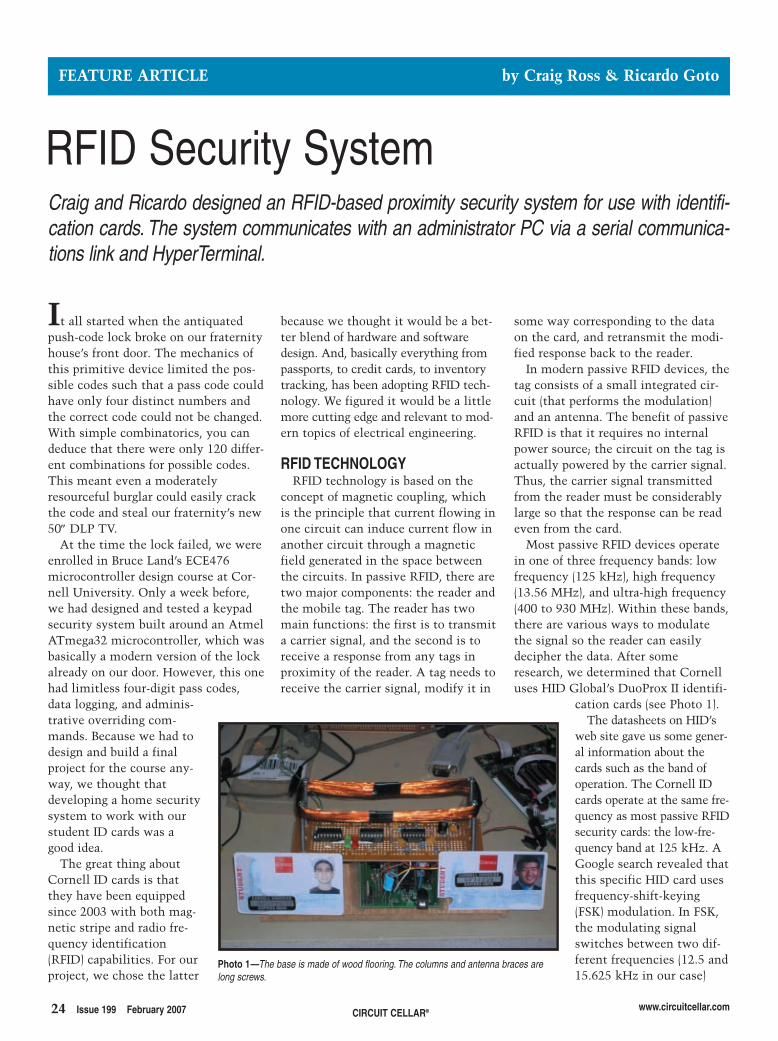
It all started when the antiquatedpush-code lock broke on our fraternityhouse’s front door. The mechanics ofthis primitive device limited the pos-sible codes such that a pass code couldhave only four distinct numbers andthe correct code could not be changed.With simple combinatorics, you candeduce that there were only 120 differ-ent combinations for possible codes.This meant even a moderatelyresourceful burglar could easily crackthe code and steal our fraternity’s new50″ DLP TV.
At the time the lock failed, we wereenrolled in Bruce Land’s ECE476microcontroller design course at Cor-nell University. Only a week before,we had designed and tested a keypadsecurity system built around an AtmelATmega32 microcontroller, which wasbasically a modern version of the lockalready on our door. However, this onehad limitless four-digit pass codes,data logging, and adminis-trative overriding com-mands. Because we had todesign and build a finalproject for the course any-way, we thought thatdeveloping a home securitysystem to work with ourstudent ID cards was agood idea.
The great thing aboutCornell ID cards is thatthey have been equippedsince 2003 with both mag-netic stripe and radio fre-quency identification(RFID) capabilities. For ourproject, we chose the latter
some way corresponding to the dataon the card, and retransmit the modi-fied response back to the reader.
In modern passive RFID devices, thetag consists of a small integrated cir-cuit (that performs the modulation)and an antenna. The benefit of passiveRFID is that it requires no internalpower source; the circuit on the tag isactually powered by the carrier signal.Thus, the carrier signal transmittedfrom the reader must be considerablylarge so that the response can be readeven from the card.
Most passive RFID devices operatein one of three frequency bands: lowfrequency (125 kHz), high frequency(13.56 MHz), and ultra-high frequency(400 to 930 MHz). Within these bands,there are various ways to modulatethe signal so the reader can easilydecipher the data. After someresearch, we determined that Cornelluses HID Global’s DuoProx II identifi-
cation cards (see Photo 1).The datasheets on HID’s
web site gave us some gener-al information about thecards such as the band ofoperation. The Cornell IDcards operate at the same fre-quency as most passive RFIDsecurity cards: the low-fre-quency band at 125 kHz. AGoogle search revealed thatthis specific HID card usesfrequency-shift-keying(FSK) modulation. In FSK,the modulating signalswitches between two dif-ferent frequencies (12.5 and15.625 kHz in our case)
FEATURE ARTICLE by Craig Ross & Ricardo Goto
RFID Security SystemCraig and Ricardo designed an RFID-based proximity security system for use with identifi-cation cards. The system communicates with an administrator PC via a serial communica-tions link and HyperTerminal.
Photo 1—The base is made of wood flooring. The columns and antenna braces arelong screws.
2702016Ross.qxp 1/4/2007 10:39 AM Page 24
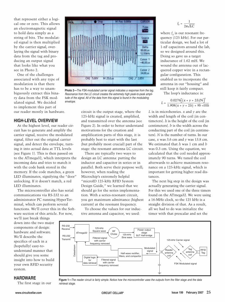
that represent either a logi-cal one or zero. This allowsan electromagnetic signalto hold data simply as astring of bits. The modulat-ed signal is then multipliedby the carrier signal, over-laying the signal with binarydata from the tag and pro-ducing an output signalthat looks like what yousee in Photo 2.
One of the challengesassociated with any type ofmodulation is that therehas to be a way to unam-biguously extract this bina-ry data from the FSK mod-ulated signal. We decidedto implement this part ofour reader mostly in hardware.
HIGH-LEVEL OVERVIEWAt the highest level, our reader cir-
cuit has to generate and amplify thecarrier signal, receive the modulatedsignal, filter out the original carriersignal, and detect the envelope, turn-ing it into actual data at TTL levels(see Figure 1). This is then passed onto the ATmega32, which interprets theincoming data and tries to match itwith the code bank stored in thememory. If the code matches, a greenLED illuminates, signifying the “door”unlocking. If it doesn’t match, a redLED illuminates.
The microcontroller also has serialcommunications via RS-232 to anadministrator PC running HyperTer-minal, which can perform severalfunctions. We’ll cover this in the Soft-ware section of this article. For now,we’ll just break thingsdown into the two majorcomponents of design:hardware and software.We’ll describe thespecifics of each in a(hopefully) easy-to-understand manner thatshould give you someinsight into how to buildyour own RFID securitysystem.
HARDWAREThe first stage in our
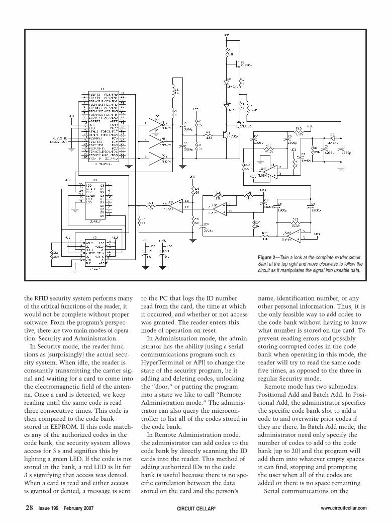
circuit is the output stage, where the125-kHz signal is created, amplified,and transmitted over the antenna (seeFigure 2). In order to better understandmotivations for the creation andamplification parts of this stage, it isprobably best to start with the last(but probably most crucial) part of thestage: the resonant antenna LC circuit.
There are typically two ways todesign an LC antenna: putting theinductor and capacitor in series or inparallel. Both serve their purpose well;however, when reading theMicrochip’s extremely helpful“microID 125-kHz RFID SystemDesign Guide,” we learned that weshould go for the series implementa-tion. With a series-resonant circuit,you get maximum admittance (highestcurrent) at the resonant frequency.
To choose the values for our induc-tive antenna and capacitor, we used:
where f0 is our resonant fre-quency (125 kHz). For our par-ticular design, we had a lot of1-nF capacitors around the lab,so we designed around this.Doing so gave us a targetinductance of 1.62 mH. Wewound the antenna out of lac-quered copper wire in a rectan-gular configuration. Thisenabled us to incorporate theantenna in our “housing” andstill keep it fairly compact.
The loop’s inductance is:
L is in microhenries. x and y are thewidth and length of the coil (in cen-timeters). h is the height of the coil (incentimeters). b is the width across theconducting part of the coil (in centime-ters). N is the number of turns. In ourcase, x was 3.6 cm and y was 13.8 cm.We estimated that h was 1 cm and bwas 0.3 cm. Using the equation, wecalculated that the coil needed approx-imately 90 turns. We tuned the coilafterwards to achieve maximum reso-nance on a 125-kHz signal, which isimportant for getting higher read dis-tances.
The next big step in the design wasactually generating the carrier signal.For this we used one of the three timersfound on the ATmega32. We were usinga 16-MHz clock, so the 125 kHz is astraight division of that. As a result,all we had to do was initialize thetimer with that prescalar and set the
L = x + y + h
x + y + h + b + h
0 0276 2
1 908 2 9 10
2.
.( )⎡⎣ ⎤⎦
( )N
f = 0
12π LC
www.circuitcellar.com CIRCUIT CELLAR® Issue 199 February 2007 25
ATmega32
RS-232Receive
RS-232
Transmit
Digital logicfor
data retrieval
Dat
astr
eam
Filtered signal with carrier
frequency removed
Filtered signal with carrier
frequency removed
Half-wave rectifier,filters, and comparitor
RFChoke
125-kHzSquare wave Power output
stageBJT Half-bridge125-kHz
Sine wave
Readerantenna
coil
Tagantenna
coil
125-kHz Carrier signal
FSK Modulated signal
Modulated signal RFID
Tag
Figure 1—The reader circuit is fairly simple. Notice how the microcontroller uses the outputs from the filter stage and the dataretrieval stage.
Photo 2—The FSK-modulated carrier signal indicates a response from the tag.Resonance from the LC circuit creates the extremely high peak-to-peak ampli-tude of the signal. All of the data from this signal is found in the modulatingenvelope.
2702016Ross.qxp 1/4/2007 10:39 AM Page 25
gathering data somewhatunreliable. Looking for analternative method to obtaindata, we found yet anotherbrilliant design in theMicrochip reference guidethat made use of flip-flopsand a decade (Johnson) count-er.
The rationale behind this“data formatting” stage wassimple: we needed to slowdown the incoming signal sothe ATmega32 could analyzeit without limiting the func-tionality of our security pro-gram. It also has the addedbenefit of creating a signalthat is only high when a 12.5-
kHz pulse is received and is zero oth-erwise (as opposed to switchingbetween logic 1 and logic 0 at differentfrequencies).
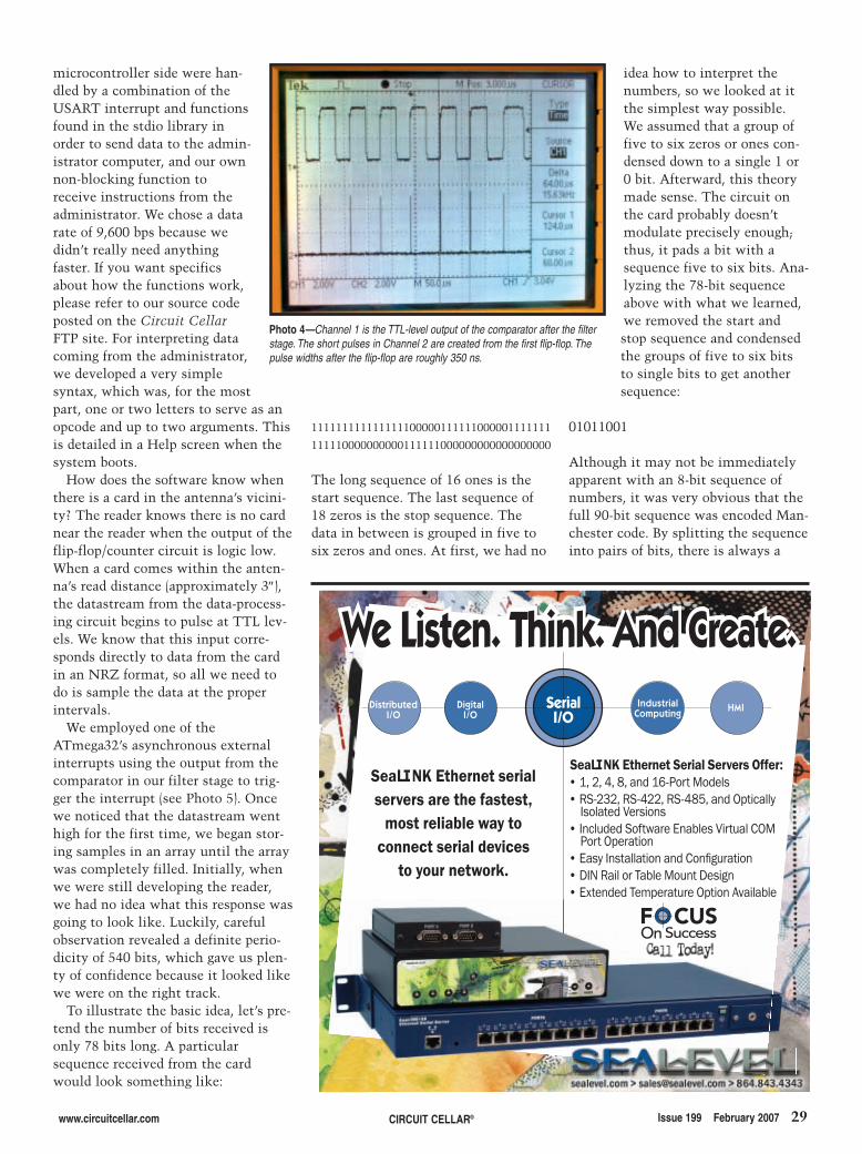
Implementing this stage was slight-ly complicated, but it didn’t requiretoo many extra components. The pur-pose of the first flip-flop is to generateextremely short pulses at its clock fre-quency, which we made the TTL out-put from the comparator. The lengthof these pulses are directly determinedby the size of the resistor used tobridge ~Q and ~CLR, and these areused to reset the decade counter andclock the second flip-flop. Photo 4illustrates this circuitry a little moreclearly.
The decade counter is a 1-hot counterthat shifts the ACTIVE pin with eachclock cycle. Because our two modulatingfrequencies are integer divisors of ourcarrier frequency (12.5 = 125/10 and15.625 = 125/8), it was convenient to usethe 125-kHz signal output from themicrocontroller for the carrier signal asthis clock cycle. The slower frequencycounts as logical 1 and the counter isreset at the modulating frequency, so allwe had to do was take the pin correspon-ding to 10 clock cycles in order to deter-mine if we were dealing with a one orzero. The purpose of the second flip-flopis to lengthen the duration of that one orzero and give us a constant datastream tobe ported to the ATmega32 (see Photo 5).
SOFTWAREAlthough the hardware portion of
After this, we put the signal throughan active low-pass Butterworth filterto give even more gain to frequencieswithin the original passband andquash all high frequencies, includingthe carrier signal. The Bode plot inFigure 3 illustrates the effects of thecascade.
Now we have a square wave signalthat oscillates at both of the modulat-ing frequencies when an ID card isplaced in the reader antenna’s proxim-ity. Lastly, we put the signal through acomparator and voltage divider to gen-erate a nice square wave at TTL levelsso that it could be further processedand analyzed.
Technically, from the output of thecomparator, we should have been ableto read and interpret data from thecard using a timer interrupt. Wequickly realized, however, that bydoing this we would cripple the sys-tem’s functionality. In order to accu-rately measure the frequency of theincoming datastream, we would realis-tically need to sample at 125 kHz,which meant that with a clock rate of16 MHz, we would have 128 clockcycles to run the rest of our programbefore the next interrupt. That wouldhave been extremely difficult toimplement along with the rest of oursystem, especially because beyond justgeneral code storing and checking, weplanned to implement a communica-tions protocol that could potentiallyblock the interrupt. Additionally, inpractice, we found this method for
26 Issue 199 February 2007 CIRCUIT CELLAR® www.circuitcellar.com
TIMSK register to outputthat from its respective out-put pin. We then put thesquare wave through an RFchoke (basically a beefy low-pass filter) in order to removeall the extra harmonics creat-ed by the square wave. Thisproduced a 125-kHz sinewave. Note that at maximumresonance we have extremelyhigh current, so we have toamplify this signal lest weblow out the ATmega32.
For the amplifier we used aPNP emitter-follower stagefollowed by a BJT Half-bridgepower amplifier to give usthe necessary power. For thispart, we used the 2N3904 and 2N3906NPN and PNP transistors becausethey were in our lab and convenient.To get a little more power out of thisstage, yielding a better read range, youcan use power MOSFETS.
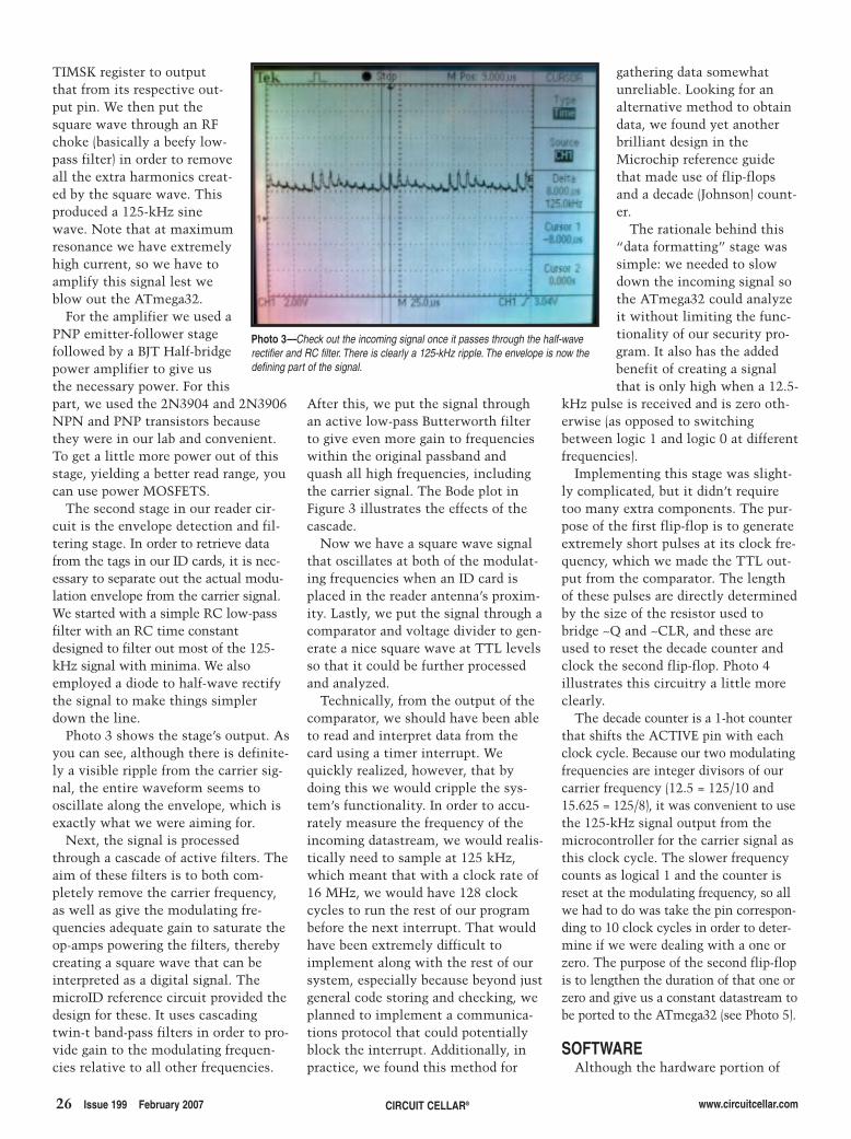
The second stage in our reader cir-cuit is the envelope detection and fil-tering stage. In order to retrieve datafrom the tags in our ID cards, it is nec-essary to separate out the actual modu-lation envelope from the carrier signal.We started with a simple RC low-passfilter with an RC time constantdesigned to filter out most of the 125-kHz signal with minima. We alsoemployed a diode to half-wave rectifythe signal to make things simplerdown the line.
Photo 3 shows the stage’s output. Asyou can see, although there is definite-ly a visible ripple from the carrier sig-nal, the entire waveform seems tooscillate along the envelope, which isexactly what we were aiming for.
Next, the signal is processedthrough a cascade of active filters. Theaim of these filters is to both com-pletely remove the carrier frequency,as well as give the modulating fre-quencies adequate gain to saturate theop-amps powering the filters, therebycreating a square wave that can beinterpreted as a digital signal. ThemicroID reference circuit provided thedesign for these. It uses cascadingtwin-t band-pass filters in order to pro-vide gain to the modulating frequen-cies relative to all other frequencies.
Photo 3—Check out the incoming signal once it passes through the half-waverectifier and RC filter. There is clearly a 125-kHz ripple. The envelope is now thedefining part of the signal.
2702016Ross.qxp 1/4/2007 10:39 AM Page 26

Mouser and Mouser Electronics are registered trademarks of Mouser Electronics, Inc. Other products, logos, and company names mentioned herein, may be trademarks of their respective owners.
The NEWEST Semiconductors | Passives | Interconnects | Power | Electromechanical | Test, Tools & Supplies from Mouser Electronics
The Mouser Advantage:Faster Time to Market for YOUR New Designs!
For over 40 years engineers have relied on Mouser as their source for electronic components. And with the most rapid introduction of new products, Mouser gives you a critical time-to-market advantage.
That’s why we deliver the ONLY 1,800+ page catalog of the newest product information 4 times a year. And with daily updates to over 740,000 products on-line, you can depend on Mouser to save you critical time to market!
Experience Mouser’s time-to-market advantage! Our vast selection of the NEWEST products, NEWEST technologies, new catalog every 90 days, no minimums, and same-day shipping on most orders, gets you to market faster. We make it easy to do business with Mouser!
mouser.com (800) 346-6873
The Newest Products For Your Newest Designs
Pic24 MCUs
High integration 16-bit MCUs designed to meet the demanding needs of real-time control. Features instruction set and architecture, peripherals, pin-out, and tool suite including MPLAB® IDE, MPLAB® C30 C Compiler, and MPLAB® PR3 Programmer.
mouser.com/microchip/a
B6TS – Capacitive Touch Sensing ICs
Capacitive touch sensing IC developed to be highly tolerant of its working environment with adaptive features such as self-teaching, auto threshold, and intelligent filtering to meet the demands of most applications today.
mouser.com/omron/a
Serial ATA Cable Assemblies
Cable assemblies with positive locking latches that ensure cable connection. Features high-speed data transfer at 300MBps, can be hot swapped without shutting down or restoring system, built-in RAID support, 26AWG wire size, 1.5A max. current, and 40V max. voltage.
mouser.com/molex/a
Non-Isolated SMT and SIP DC-DC Converters
Open-frame construction and small footprint enable designers to develop cost-and space-efficient solutions. Features programmable output voltage, remote on/off, output overcurrent protection, and a temperature range of -40˚C to +85˚C.
mouser.com/tycopowersystems/a
RGB LED Light Engine
Light engines with independent color control for dynamic or preset pre-set color display. Features round footprint for design flexibility, 350mA drive currents, three channel control with independent input/output, -4,000V HBM, and an isolated metal base that makes wiring in series or parallel on a common heat sink possible.
mouser.com/lamina/a
NEWEST ProductsNEWEST TechnologiesThe ONLY NEW Catalog Every 90 Days
27.qxp 12/19/2006 4:02 PM Page 1
28 Issue 199 February 2007 CIRCUIT CELLAR® www.circuitcellar.com
the RFID security system performs manyof the critical functions of the reader, itwould not be complete without propersoftware. From the program’s perspec-tive, there are two main modes of opera-tion: Security and Administration.
In Security mode, the reader func-tions as (surprisingly) the actual secu-rity system. When idle, the reader isconstantly transmitting the carrier sig-nal and waiting for a card to come intothe electromagnetic field of the anten-na. Once a card is detected, we keepreading until the same code is readthree consecutive times. This code isthen compared to the code bankstored in EEPROM. If this code match-es any of the authorized codes in thecode bank, the security system allowsaccess for 3 s and signifies this bylighting a green LED. If the code is notstored in the bank, a red LED is lit for3 s signifying that access was denied.When a card is read and either accessis granted or denied, a message is sent
to the PC that logs the ID numberread from the card, the time at whichit occurred, and whether or not accesswas granted. The reader enters thismode of operation on reset.
In Administration mode, the admin-istrator has the ability (using a serialcommunications program such asHyperTerminal or API) to change thestate of the security program, be itadding and deleting codes, unlockingthe “door,” or putting the programinto a state we like to call “RemoteAdministration mode.” The adminis-trator can also query the microcon-troller to list all of the codes stored inthe code bank.
In Remote Administration mode,the administrator can add codes to thecode bank by directly scanning the IDcards into the reader. This method ofadding authorized IDs to the codebank is useful because there is no spe-cific correlation between the datastored on the card and the person’s
name, identification number, or anyother personal information. Thus, it isthe only feasible way to add codes tothe code bank without having to knowwhat number is stored on the card. Toprevent reading errors and possiblystoring corrupted codes in the codebank when operating in this mode, thereader will try to read the same codefive times, as opposed to the three inregular Security mode.
Remote mode has two submodes:Positional Add and Batch Add. In Posi-tional Add, the administrator specifiesthe specific code bank slot to add acode to and overwrite prior codes ifthey are there. In Batch Add mode, theadministrator need only specify thenumber of codes to add to the codebank (up to 20) and the program willadd them into whatever empty spacesit can find, stopping and promptingthe user when all of the codes areadded or there is no space remaining.
Serial communications on the
Figure 2—Take a look at the complete reader circuit.Start at the top right and move clockwise to follow thecircuit as it manipulates the signal into useable data.
2702016Ross.qxp 1/4/2007 10:39 AM Page 28
www.circuitcellar.com CIRCUIT CELLAR® Issue 199 February 2007 29
microcontroller side were han-dled by a combination of theUSART interrupt and functionsfound in the stdio library inorder to send data to the admin-istrator computer, and our ownnon-blocking function toreceive instructions from theadministrator. We chose a datarate of 9,600 bps because wedidn’t really need anythingfaster. If you want specificsabout how the functions work,please refer to our source codeposted on the Circuit CellarFTP site. For interpreting datacoming from the administrator,we developed a very simplesyntax, which was, for the mostpart, one or two letters to serve as anopcode and up to two arguments. Thisis detailed in a Help screen when thesystem boots.
How does the software know whenthere is a card in the antenna’s vicini-ty? The reader knows there is no cardnear the reader when the output of theflip-flop/counter circuit is logic low.When a card comes within the anten-na’s read distance (approximately 3″),the datastream from the data-process-ing circuit begins to pulse at TTL lev-els. We know that this input corre-sponds directly to data from the cardin an NRZ format, so all we need todo is sample the data at the properintervals.
We employed one of theATmega32’s asynchronous externalinterrupts using the output from thecomparator in our filter stage to trig-ger the interrupt (see Photo 5). Oncewe noticed that the datastream wenthigh for the first time, we began stor-ing samples in an array until the arraywas completely filled. Initially, whenwe were still developing the reader,we had no idea what this response wasgoing to look like. Luckily, carefulobservation revealed a definite perio-dicity of 540 bits, which gave us plen-ty of confidence because it looked likewe were on the right track.
To illustrate the basic idea, let’s pre-tend the number of bits received isonly 78 bits long. A particularsequence received from the cardwould look something like:
111111111111111100000111111000001111111
111110000000000111111000000000000000000
The long sequence of 16 ones is thestart sequence. The last sequence of18 zeros is the stop sequence. Thedata in between is grouped in five tosix zeros and ones. At first, we had no
idea how to interpret thenumbers, so we looked at itthe simplest way possible.We assumed that a group offive to six zeros or ones con-densed down to a single 1 or0 bit. Afterward, this theorymade sense. The circuit onthe card probably doesn’tmodulate precisely enough;thus, it pads a bit with asequence five to six bits. Ana-lyzing the 78-bit sequenceabove with what we learned,we removed the start andstop sequence and condensedthe groups of five to six bitsto single bits to get anothersequence:
01011001
Although it may not be immediatelyapparent with an 8-bit sequence ofnumbers, it was very obvious that thefull 90-bit sequence was encoded Man-chester code. By splitting the sequenceinto pairs of bits, there is always a
Photo 4—Channel 1 is the TTL-level output of the comparator after the filterstage. The short pulses in Channel 2 are created from the first flip-flop. Thepulse widths after the flip-flop are roughly 350 ns.
HMIDistributedI/O
IndustrialComputing
DigitalI/O
SerialI/O
We Listen. Think. And Create.We Listen. Think. And Create.
SeaLINK Ethernet Serial Servers Offer:• 1, 2, 4, 8, and 16-Port Models• RS-232, RS-422, RS-485, and Optically
Isolated Versions• Included Software Enables Virtual COM
Port Operation• Easy Installation and Confi guration• DIN Rail or Table Mount Design• Extended Temperature Option Available
SeaLINK Ethernet serialservers are the fastest,
most reliable way to connect serial devices
to your network.
F CUSOn Success
2702016Ross.qxp 1/4/2007 10:39 AM Page 29
30 Issue 199 February 2007 CIRCUIT CELLAR® www.circuitcellar.com
transition, either from low to high orhigh to low. In Manchester code, theformer transition signifies a one andthe latter signifies a zero. Applyingthis to our existing sequence, we gotthe following sequence:
1101
As you can see, the long 78-bitsequence stored only 4 bits of actualdata. For our Cornell ID cards, the540-bit sequence decoded to a 45-bitcode.
DESIGN IMPROVEMENTSAlthough we were extremely happy
Craig Ross ([email protected]) studiescomputer engineering and architec-ture at Cornell University. In thesummer of 2006, he completed aninternship at Keithley Instruments.
Ricardo Goto ([email protected]) stud-ies computer engineering and architec-ture at Cornell University. In the sum-mer of 2006, he completed an intern-ship at Advanced Micro Devices.
SOURCESATmega32 MicrocontrollerAtmel Corp.www.atmel.com
DuoProx II Identification cardHID Global Corp.www.hidcorp.com
microID RFID SystemMicrochip Technology, Inc.www.microchip.com
PROJECT FILESTo download code, go to ftp://ftp.circuitcellar.com/pub/Circuit_Cellar/2007/199.
RESOURCESB. Land, ECE476 Designing withMicrocontrollers Course, Cornell Uni-versity, http://instruct1.cit.cornell.edu/courses/ee476/.
J. Westhues, “Proximity Cards,” 2003,http://cq.cx/prox.pl.
with our result, this was our first timetaking on such a project. Naturally,there is room for improvement. Thefirst of these would have to be the con-struction process. For this project, wehad a limited budget (we were requiredto spend no more than $50 or we wouldbe penalized), and we didn’t have a lotof time to complete the system.
The system’s housing basically com-prises a piece of wood tiling, four longscrews, a reference PCB prototype boardthat Professor Land designed for theATmega32, and our circuit on a piece ofsolder board. It served its purposes forour demonstration, but it did include alot of exposed wires and circuits.
Additionally, itprobably would havebeen better to movethe actual code bankonto the administra-tor computer andedit using an admin-istration programwith a specializedGUI. This wouldhave enabled us tostore infinitely morecodes and present abetter interface. Forthe purposes of thisproject, however, itwas more of a proof-of-concept than any-thing else. By keep-ing more things on
Photo 5—Channel 1 is the TTL-level output of the comparator after the filterstage. Channel 2 is the datastream from the Data Retrieval stage. Notice howChannel 2 is high only after a 12.5-kHz pulse is observed. Both of the signalsare used by the ATmega32 to determine the tag data.
the microcontroller, it better displayedour microcontroller-programmingprowess.
We could have done several thingsdifferently in terms of the hardware.We could have used a DSP instead ofenvelope detection hardware. A simpleFFT on the incoming signal from thetag would have told us everything weneeded to know about it and made ourdesign more flexible.
There are plenty of other designimprovements to be made, but we’llleave them up to you. At the veryleast, we hope that you have foundthis article informative. Now it’s yourturn to start a project based on RFIDtechnology. Good luck! IFigure 3—This is a Bode plot of each stage of the cascaded filters. The output of the first Twin-T filter is in blue, the
second is in red, and the output of the Butterworth filter is in green. Notice the 1-dB point at roughly 30 kHz. Thisstage’s output should be a square wave at this frequency (idle frequency) when no card is present.
2702016Ross.qxp 1/4/2007 10:39 AM Page 30
Tes
tin
gU
SB
Wir
ele
ss
I2C
I/O
Eth
ern
et
W ee s e a r c hh t h ee w o r l dd f o rr t i m e - s a v i n g ,,
e a s y - t o - u s ee s t a t e - o f - t h e - a r tt p r o d u c t s !
LCD Scope
PDS5022 - 25MHz 2-ch + trig.Standalone bench scope withUSB connection and 7.8”color LCD. Built-in meter -great for your service kit. PDS5022S $399
NEW
Low-Cost!
Handheld Scope
HDS1022M - 20MHz 2-chstandalone scope with USBconnection and 3.8” color LCD.Built-in meter - great for yourtool kit. HDS1022M $599
EMI Tents
EMI shielding tents made from Ni/Agfabric. -86dB 20MHz to 18GHz.Portable - tabletop to room/lab sizefor on-site, on-demand pre-compliancetesting. External PVC or aluminumframe. from $3500
PenScope
PP315 - High-perf. USB2.0-pwrdscope- in -a -p robe ! Up to100MS/s, 25MHz 24kS buffer.+/-100mV to +/-20V. 20ns/div– 50s/div C/VB/Delphi/LabView/VEE drivers. $199
USB I2C/IO - Provides a simple“drop-in” solution for connectingyour PC to 90kHz I2C + 20 I/Olines. Free software. Use mul-tiple boards for more I2C/IO.USB I2C/IO $79
USB to I2C Ethernet to I2C
NM7010A-LF - Complete, hardwiredTCP/IP-I2C module. Offloads stackfor hi-speed Internet-enablingmicroprocessor systems. Drop-inW3100A-based board for instantnetworkspeeds to 8Mbps. $21.99
Ethernet to I2C
FMod-TCP - TCP/IP server with I2C,19 x digital I/O, 5 x 10-bit A/Dinputs, and UART serial interface.Connect I2C devices/sensorsto an Ethernet network!FMod-TCP from $232
I2C for PCs
Stepper Motor
Easy-Step 3000- Advanced steppermotor drive and control system forunipolar stepper motors up to35V/3A- ideal for robots/industrialcontrol - turns you into aninstantmotorcontrol expert! $119
Signal Wizard
Signal Wizard - easy-use real-timeDSP-based filter board for audiobandwidth signals. Design filtersin seconds without any DSPknowledge!Signal Wizard II $399
PCI93LV: industry-standard I2C cardfor PCs. WINI2C/PCI softwaregives windows-interface to developand debug I2C bus systems.UCA93LV is new USB version.NOW! - transparently monitor at400kHz! $499
Call 1-888-7SAELIG
FREE COFFEE
Mention Offer# SBWto get a free
Starbucks Card with your order!
While supplies last - not available with any other offers
Ether-IO
Ether-IO - UDP/IP-controlled 24X digital I/O board. 3 x 8-bit TTLports each independentlyprogrammable. Connects to anyTCP/IP Ethernet network. Ether-IO 24 from $99
Byteparadigm - Fast USB 2.0multichannel input or output/arbitrary digital waveform generator/logic analyzer. 100MB/s burst;thruput to 48MB/s, 22 x I/O.GP-22050-BASE $1187
Fast USB I/O Easy USB
microUSB - Tiny ready-made USBInterface to 1 Mbps 0.7” x 0.5”based on SiLabs CP2101.Gnd/RX/TX Suspend, Reset, & 3.3V100mA source –40°C +85°C.microUSB $25
USB-Serial Adapter
USB-COM-S - Serial port for laptopswithout one! instantly adaptsolder RS232 products to USB!PC thinks it’s using COMportbut uses the USB - 45”.
$24.95 (1) or $18.50 (100)
Ellisys Tracker110 / Explorer200high-performance, economicalUSB 1.1/2.0 protocol analyzers.
$999/$2999USBEX300 for debugging USBwireless Wimedia CALL
USB Bus Analyzers GPS Logger
TrackStick - Lipstick-sized loggertracks position data for shipments,vehicles, personnel, etc. Recordsdate, time, location, speed, headingand altitude at pre-set intervals -shows route/speed on PC! $249
Radio Data
CDP-RX-02 (434MHz) - UHFNarrow Band Radio Data Receiverand Transmitter Modules. Greatfor adding wireless capability toyour equipment.CDP-RX-02 $144
Bluetooth
Emxys PearlBlue - 100m-Bluetoothmodule (UART master/slave bridge).Easy connection for micro's to PCs,PDAs, phones, etc. IceBlue - PIC16F877based emb. dev. system for shortestBluetooth development. <$119
easyRADIOTM TransceiverModules make wireless datatransmission simple for USAand Europe! Add wireless capabilityto your project today!ER900TRS from $35 (100)
easyRADIO
Owasys - GSM/GPRS/GPS/Bluetooth/Ethernet wirelesscontrollers for M2M - for autos,machines, etc. RS232/485/CAN/A/D-I/O. Owasys from $479
Wireless Controllers Data Modem
Data Modem - USB-poweredradio transceiver boards addwireless RS232 to your device!Get remote control for yourproduct from PC USB port!RTM-USA $89
Ethernet to Serial
EG-SR-7150MJ - Ready-to-goserial-to-Ethernet Gateway. Simpleset-up for 10/100Mbps Ethernet- 230kbps serial. Ethernet/Internet-enable any serial part.EG-SR-7150MJ <$35
Ethernet to I2C
FMod-TCP - TCP/IP server withI2C, 19 x digital I/O, 5 x 10-bit A/Dinputs, and UART serial interface.Connect I2C devices/sensorsto an Ethernet network!FMod-TCP from $232
Hunt Eng - RTG005 a new, self-contained ready-to-go FPGA sys-tem with CameraLink connection.Makes an ideal starter kit for devel-oping image processing systems.RTG005 from $2995
FPGA systems Touch-Sensing ICs
Quantum ICs - World-beating capacitivesensor ICs for switching & control.Patented Adj. Key Suppression,Spread-spectrum, adj.sensitivity. In useworldwide bytheworld’s largestconsumer/appliancemanufacturers <$1 (10K)
TCP/IP IC
W3150A+ - Hardwired TCP/IP stack- cheap micros can now haveinternet capabilities at full speed!10/100 Off-loads TCP/IP burdenfor fast time-to-market. Ethernet-enable almost ANYTHING! < $7.20
Motion Control
PIC-Servo - Motion control boardswith integrated power amplifiersfor DC-servo/brushless-servo/stepper-motors. Easy connectionto std serial ports for powerfulmulti-axis, mixed-motor control. $160
Micro ALFAT-SD - Ready-madeway to easily add SD storageto your product. Serial datain - FATfile data out. - $39.95Or design-in a micro ALFAT ICfor MB storage - $14.00 ea.
FATfile Storage
microLCD - Easy way to add 2” sqLCD to your project. microLCD128 x 128 color LCD. Addtext/graphics/animations forany micro with serial or USB. microLCD $69
Easy LCD
Serial-Ethernet Cable
28” cable links serial devices to networkwithout a PC, gives your product aninstant IP address.115Kbaud RS-232port compatible with most 10/100mpbsEthernet hubs. Network your serialproduct easily! eCOV-110-P $99.00
TinyOne Zigbee
TinyOne Zigbee - Complete RFsolution for fast and reliable datatransmission. Miniaturized OEMRF module ensures fast and easyintegration into wireless applications.TinyOne Zigbee <$30
I2C Monitor
I2C Bus Monitor - AvitProfmonitors bus traffic on I2C orSMBus to 400kHz. Master/slave/multimaster. Trigger output/filterfor scope. AvitProf $499
www.saelig.com
1-888-7SAELIG1-888-772-3544
585-385-1768 fax
STOPP THEE PRESS!
-- neww products
arr iv ingg everyy day !
Pleasee goo to
www.saelig.comm
forr l a te-b reak ing
announcements .
NEW Best Scope Adapter Anywhere!
100 MHz Scope and Logic Analyzerlets you do complex triggering to findhard-to-get-at glitches, spikes, etc.Huge 4 MB buffer for deep datadrilling and zooming. Optional built-inswept signal generator. 2 x 10 bitAnalog channels with more than 60 dBdynamic range. 8 digital input lines formixed signal display and triggering.
CS328 $999CS700 (signal generator) $199
31.qxp 12/19/2006 4:10 PM Page 1
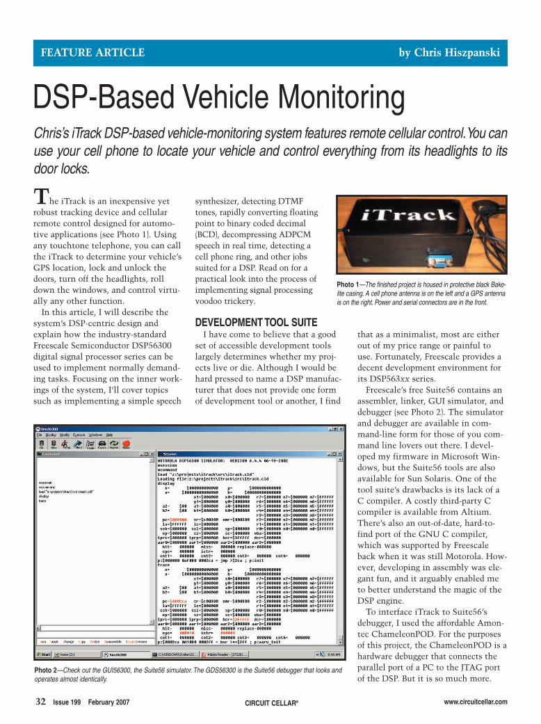
32 Issue 199 February 2007 CIRCUIT CELLAR® www.circuitcellar.com
that as a minimalist, most are eitherout of my price range or painful touse. Fortunately, Freescale provides adecent development environment forits DSP563xx series.
Freescale’s free Suite56 contains anassembler, linker, GUI simulator, anddebugger (see Photo 2). The simulatorand debugger are available in com-mand-line form for those of you com-mand line lovers out there. I devel-oped my firmware in Microsoft Win-dows, but the Suite56 tools are alsoavailable for Sun Solaris. One of thetool suite’s drawbacks is its lack of aC compiler. A costly third-party Ccompiler is available from Altium.There’s also an out-of-date, hard-to-find port of the GNU C compiler,which was supported by Freescaleback when it was still Motorola. How-ever, developing in assembly was ele-gant fun, and it arguably enabled meto better understand the magic of theDSP engine.
To interface iTrack to Suite56’sdebugger, I used the affordable Amon-tec ChameleonPOD. For the purposesof this project, the ChameleonPOD is ahardware debugger that connects theparallel port of a PC to the JTAG portof the DSP. But it is so much more.
synthesizer, detecting DTMFtones, rapidly converting floatingpoint to binary coded decimal(BCD), decompressing ADPCMspeech in real time, detecting acell phone ring, and other jobssuited for a DSP. Read on for apractical look into the process ofimplementing signal processingvoodoo trickery.
DEVELOPMENT TOOL SUITEI have come to believe that a good
set of accessible development toolslargely determines whether my proj-ects live or die. Although I would behard pressed to name a DSP manufac-turer that does not provide one formof development tool or another, I find
The iTrack is an inexpensive yetrobust tracking device and cellularremote control designed for automo-tive applications (see Photo 1). Usingany touchtone telephone, you can callthe iTrack to determine your vehicle’sGPS location, lock and unlock thedoors, turn off the headlights, rolldown the windows, and control virtu-ally any other function.
In this article, I will describe thesystem’s DSP-centric design andexplain how the industry-standardFreescale Semiconductor DSP56300digital signal processor series can beused to implement normally demand-ing tasks. Focusing on the inner work-ings of the system, I’ll cover topicssuch as implementing a simple speech
FEATURE ARTICLE by Chris Hiszpanski
DSP-Based Vehicle MonitoringChris’s iTrack DSP-based vehicle-monitoring system features remote cellular control.You canuse your cell phone to locate your vehicle and control everything from its headlights to itsdoor locks.
Photo 1—The finished project is housed in protective black Bake-lite casing. A cell phone antenna is on the left and a GPS antennais on the right. Power and serial connectors are in the front.
Photo 2—Check out the GUI56300, the Suite56 simulator. The GDS56300 is the Suite56 debugger that looks andoperates almost identically.
2702015 Hiszpanski.qxp 1/4/2007 10:40 AM Page 32
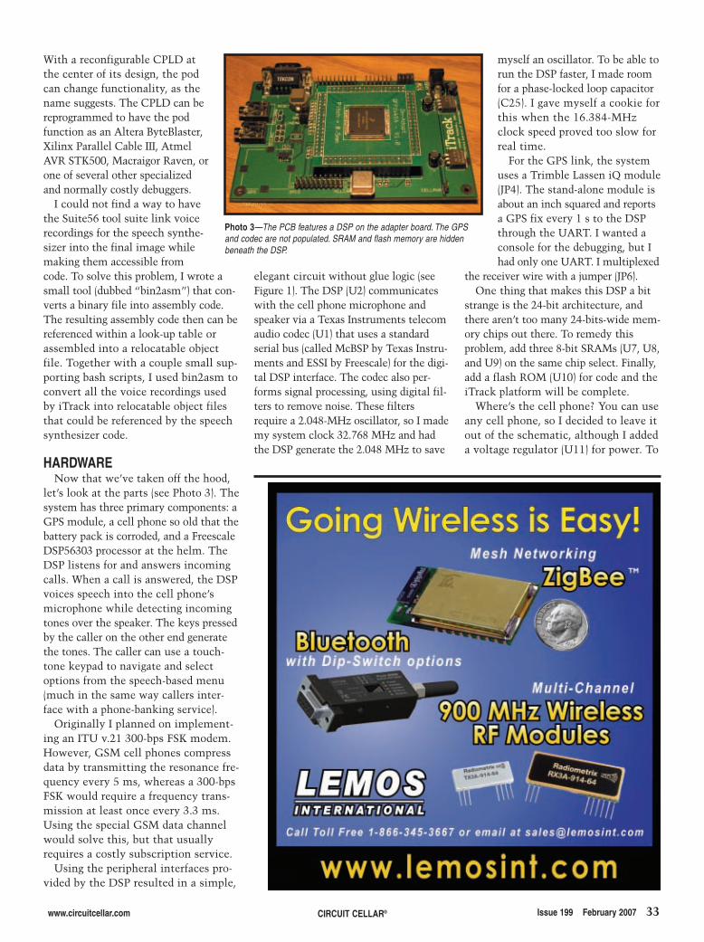
www.circuitcellar.com CIRCUIT CELLAR® Issue 199 February 2007 33
With a reconfigurable CPLD atthe center of its design, the podcan change functionality, as thename suggests. The CPLD can bereprogrammed to have the podfunction as an Altera ByteBlaster,Xilinx Parallel Cable III, AtmelAVR STK500, Macraigor Raven, orone of several other specializedand normally costly debuggers.
I could not find a way to havethe Suite56 tool suite link voicerecordings for the speech synthe-sizer into the final image whilemaking them accessible fromcode. To solve this problem, I wrote asmall tool (dubbed “bin2asm”) that con-verts a binary file into assembly code.The resulting assembly code then can bereferenced within a look-up table orassembled into a relocatable objectfile. Together with a couple small sup-porting bash scripts, I used bin2asm toconvert all the voice recordings usedby iTrack into relocatable object filesthat could be referenced by the speechsynthesizer code.
HARDWARENow that we’ve taken off the hood,
let’s look at the parts (see Photo 3). Thesystem has three primary components: aGPS module, a cell phone so old that thebattery pack is corroded, and a FreescaleDSP56303 processor at the helm. TheDSP listens for and answers incomingcalls. When a call is answered, the DSPvoices speech into the cell phone’smicrophone while detecting incomingtones over the speaker. The keys pressedby the caller on the other end generatethe tones. The caller can use a touch-tone keypad to navigate and selectoptions from the speech-based menu(much in the same way callers inter-face with a phone-banking service).
Originally I planned on implement-ing an ITU v.21 300-bps FSK modem.However, GSM cell phones compressdata by transmitting the resonance fre-quency every 5 ms, whereas a 300-bpsFSK would require a frequency trans-mission at least once every 3.3 ms.Using the special GSM data channelwould solve this, but that usuallyrequires a costly subscription service.
Using the peripheral interfaces pro-vided by the DSP resulted in a simple,
elegant circuit without glue logic (seeFigure 1). The DSP (U2) communicateswith the cell phone microphone andspeaker via a Texas Instruments telecomaudio codec (U1) that uses a standardserial bus (called McBSP by Texas Instru-ments and ESSI by Freescale) for the digi-tal DSP interface. The codec also per-forms signal processing, using digital fil-ters to remove noise. These filtersrequire a 2.048-MHz oscillator, so I mademy system clock 32.768 MHz and hadthe DSP generate the 2.048 MHz to save
myself an oscillator. To be able torun the DSP faster, I made roomfor a phase-locked loop capacitor(C25). I gave myself a cookie forthis when the 16.384-MHzclock speed proved too slow forreal time.
For the GPS link, the systemuses a Trimble Lassen iQ module(JP4). The stand-alone module isabout an inch squared and reportsa GPS fix every 1 s to the DSPthrough the UART. I wanted aconsole for the debugging, but Ihad only one UART. I multiplexed
the receiver wire with a jumper (JP6).One thing that makes this DSP a bit
strange is the 24-bit architecture, andthere aren’t too many 24-bits-wide mem-ory chips out there. To remedy thisproblem, add three 8-bit SRAMs (U7, U8,and U9) on the same chip select. Finally,add a flash ROM (U10) for code and theiTrack platform will be complete.
Where’s the cell phone? You can useany cell phone, so I decided to leave itout of the schematic, although I addeda voltage regulator (U11) for power. To
Photo 3—The PCB features a DSP on the adapter board. The GPSand codec are not populated. SRAM and flash memory are hiddenbeneath the DSP.
2702015 Hiszpanski.qxp 1/4/2007 10:40 AM Page 33
Mixed Signal OscilloscopeCapture and display up to 4 analog and 8 logic
channels with sophisticated cross-triggers.
Digital Storage OscilloscopeUp to 4 analog channels using industry standard
probes or POD connected analog inputs.
Spectrum AnalyzerIntegrated real-time spectrum analyzer for each
analog channel with concurrent waveform display.
Logic Analyzer8 logic, External Trigger and special purpose
inputs to capture digital signals down to 25nS.
Data RecorderRecord anything DSO can capture. Supports
live data replay and display export.
BitScope DSO is fast and intuitive multi-channel test and measurement software for yourPC or notebook. Whether it's a digital scope, spectrum analyzer, mixed signal scope,logic analyzer, waveform generator or data recorder, BitScope DSO supports them all.
Capture deep buffer one-shots or display waveforms live just like an analog scope.Comprehensive test instrument integration means you can view the same data indifferent ways simultaneously at the click of a button.
DSO may even be used stand-alone to share data with colleagues, students orcustomers. Waveforms may be exported as portable image files or live captures replayedon other PCs as if a BitScope was locally connected.
BitScope DSO supports all current BitScope models, auto-configures when it connectsand can manage multiple BitScopes concurrently. No manual setup is normally required.Data export is available for use with third party software tools and BitScope's networkeddata acquisition capabilities are fully supported.
PC Oscilloscopes & AnalyzersDSO Test Instrument Software for BitScope Mixed Signal Oscilloscopes
�
�
�
�
�Networking
Flexible network connectivity supporting
multi-scope operation, remote monitoring and
data acquisition.�
Data ExportExport data with DSO using portable CSV files or
use libraries to build custom BitScope solutions.� www.bitscope.comwww.bitscope.com
BitScope DSO Software for Windows and Linux
4 Channel BitScope 2 Channel BitScope Pocket Analyzer
DSO2.0
DSO2.0
5.qxp 10/26/2006 11:22 AM Page 1
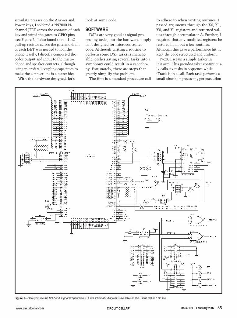
www.circuitcellar.com CIRCUIT CELLAR® Issue 199 February 2007 35
simulate presses on the Answer andPower keys, I soldered a 2N7000 N-channel JFET across the contacts of eachkey and wired the gates to GPIO pins(see Figure 2). I also found that a 1-kΩpull-up resistor across the gate and drainof each JFET was needed to fool thephone. Lastly, I directly connected thecodec output and input to the micro-phone and speaker contacts, althoughusing microfarad coupling capacitors tomake the connections is a better idea.
With the hardware designed, let’s
look at some code.
SOFTWAREDSPs are very good at signal pro-
cessing tasks, but the hardware simplyisn’t designed for microcontrollercode. Although writing a routine toperform some DSP tasks is manage-able, orchestrating several tasks into asymphony could result in a cacopho-ny. Fortunately, there are steps thatgreatly simplify the problem.
The first is a standard procedure call
to adhere to when writing routines. Ipassed arguments through the X0, X1,Y0, and Y1 registers and returned val-ues through accumulator A. Further, Irequired that any modified registers berestored in all but a few routines.Although this gave a performance hit, itkept the code structured and uniform.
Next, I set up a simple tasker ininit.asm. This pseudo-tasker continuous-ly calls six tasks in sequence whileiTrack is in a call. Each task performs asmall chunk of processing per execution
Figure 1—Here you see the DSP and supported peripherals. A full schematic diagram is available on the Circuit Cellar FTP site.
2702015 Hiszpanski.qxp 1/4/2007 10:40 AM Page 35
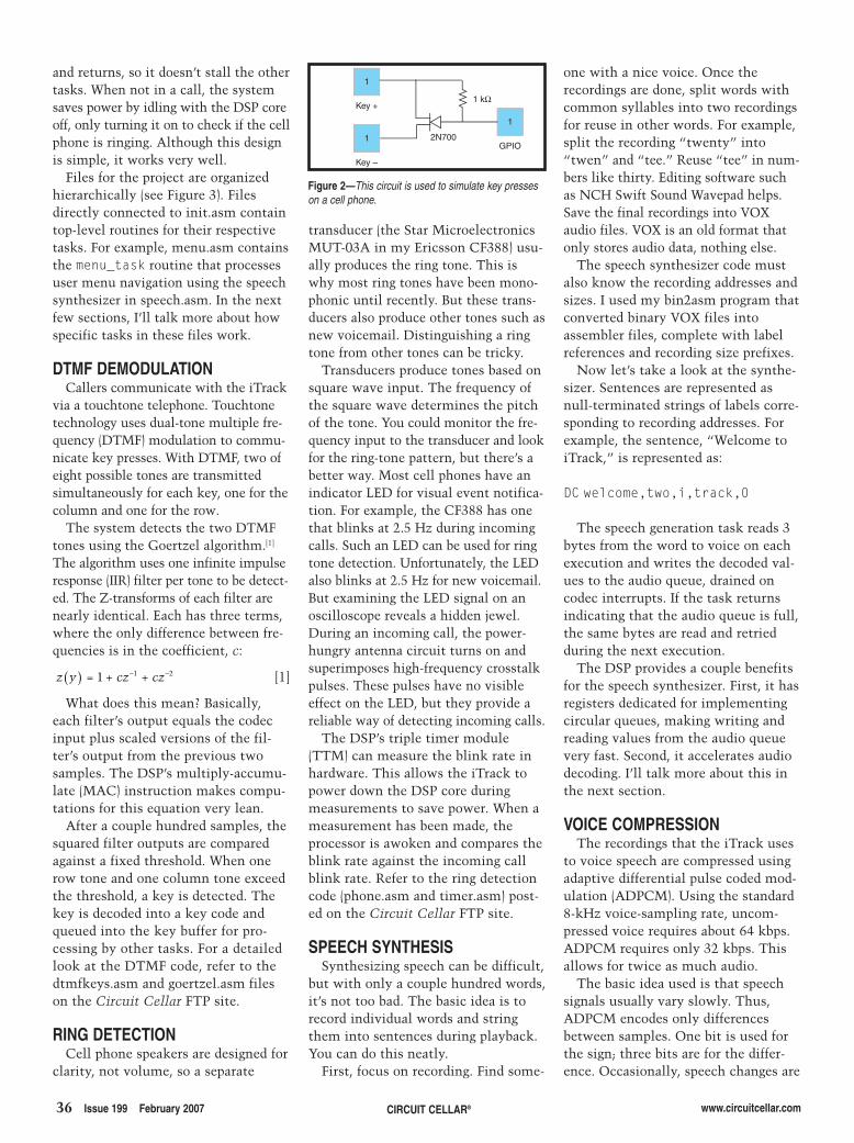
36 Issue 199 February 2007 CIRCUIT CELLAR® www.circuitcellar.com
and returns, so it doesn’t stall the othertasks. When not in a call, the systemsaves power by idling with the DSP coreoff, only turning it on to check if the cellphone is ringing. Although this designis simple, it works very well.
Files for the project are organizedhierarchically (see Figure 3). Filesdirectly connected to init.asm containtop-level routines for their respectivetasks. For example, menu.asm containsthe menu_task routine that processesuser menu navigation using the speechsynthesizer in speech.asm. In the nextfew sections, I’ll talk more about howspecific tasks in these files work.
DTMF DEMODULATIONCallers communicate with the iTrack
via a touchtone telephone. Touchtonetechnology uses dual-tone multiple fre-quency (DTMF) modulation to commu-nicate key presses. With DTMF, two ofeight possible tones are transmittedsimultaneously for each key, one for thecolumn and one for the row.
The system detects the two DTMFtones using the Goertzel algorithm.[1]
The algorithm uses one infinite impulseresponse (IIR) filter per tone to be detect-ed. The Z-transforms of each filter arenearly identical. Each has three terms,where the only difference between fre-quencies is in the coefficient, c:
[1]
What does this mean? Basically,each filter’s output equals the codecinput plus scaled versions of the fil-ter’s output from the previous twosamples. The DSP’s multiply-accumu-late (MAC) instruction makes compu-tations for this equation very lean.
After a couple hundred samples, thesquared filter outputs are comparedagainst a fixed threshold. When onerow tone and one column tone exceedthe threshold, a key is detected. Thekey is decoded into a key code andqueued into the key buffer for pro-cessing by other tasks. For a detailedlook at the DTMF code, refer to thedtmfkeys.asm and goertzel.asm fileson the Circuit Cellar FTP site.
RING DETECTIONCell phone speakers are designed for
clarity, not volume, so a separate
z y = + cz + cz( ) − −1 1 2
transducer (the Star MicroelectronicsMUT-03A in my Ericsson CF388) usu-ally produces the ring tone. This iswhy most ring tones have been mono-phonic until recently. But these trans-ducers also produce other tones such asnew voicemail. Distinguishing a ringtone from other tones can be tricky.
Transducers produce tones based onsquare wave input. The frequency ofthe square wave determines the pitchof the tone. You could monitor the fre-quency input to the transducer and lookfor the ring-tone pattern, but there’s abetter way. Most cell phones have anindicator LED for visual event notifica-tion. For example, the CF388 has onethat blinks at 2.5 Hz during incomingcalls. Such an LED can be used for ringtone detection. Unfortunately, the LEDalso blinks at 2.5 Hz for new voicemail.But examining the LED signal on anoscilloscope reveals a hidden jewel.During an incoming call, the power-hungry antenna circuit turns on andsuperimposes high-frequency crosstalkpulses. These pulses have no visibleeffect on the LED, but they provide areliable way of detecting incoming calls.
The DSP’s triple timer module(TTM) can measure the blink rate inhardware. This allows the iTrack topower down the DSP core duringmeasurements to save power. When ameasurement has been made, theprocessor is awoken and compares theblink rate against the incoming callblink rate. Refer to the ring detectioncode (phone.asm and timer.asm) post-ed on the Circuit Cellar FTP site.
SPEECH SYNTHESISSynthesizing speech can be difficult,
but with only a couple hundred words,it’s not too bad. The basic idea is torecord individual words and stringthem into sentences during playback.You can do this neatly.
First, focus on recording. Find some-
one with a nice voice. Once therecordings are done, split words withcommon syllables into two recordingsfor reuse in other words. For example,split the recording “twenty” into“twen” and “tee.” Reuse “tee” in num-bers like thirty. Editing software suchas NCH Swift Sound Wavepad helps.Save the final recordings into VOXaudio files. VOX is an old format thatonly stores audio data, nothing else.
The speech synthesizer code mustalso know the recording addresses andsizes. I used my bin2asm program thatconverted binary VOX files intoassembler files, complete with labelreferences and recording size prefixes.
Now let’s take a look at the synthe-sizer. Sentences are represented asnull-terminated strings of labels corre-sponding to recording addresses. Forexample, the sentence, “Welcome toiTrack,” is represented as:
DC welcome,two,i,track,0
The speech generation task reads 3bytes from the word to voice on eachexecution and writes the decoded val-ues to the audio queue, drained oncodec interrupts. If the task returnsindicating that the audio queue is full,the same bytes are read and retriedduring the next execution.
The DSP provides a couple benefitsfor the speech synthesizer. First, it hasregisters dedicated for implementingcircular queues, making writing andreading values from the audio queuevery fast. Second, it accelerates audiodecoding. I’ll talk more about this inthe next section.
VOICE COMPRESSIONThe recordings that the iTrack uses
to voice speech are compressed usingadaptive differential pulse coded mod-ulation (ADPCM). Using the standard8-kHz voice-sampling rate, uncom-pressed voice requires about 64 kbps.ADPCM requires only 32 kbps. Thisallows for twice as much audio.
The basic idea used is that speechsignals usually vary slowly. Thus,ADPCM encodes only differencesbetween samples. One bit is used forthe sign; three bits are for the differ-ence. Occasionally, speech changes are
Key +
1
Key –
1
1
GPIO2N700
1 kΩ
Figure 2—This circuit is used to simulate key presseson a cell phone.
2702015 Hiszpanski.qxp 1/4/2007 10:40 AM Page 36
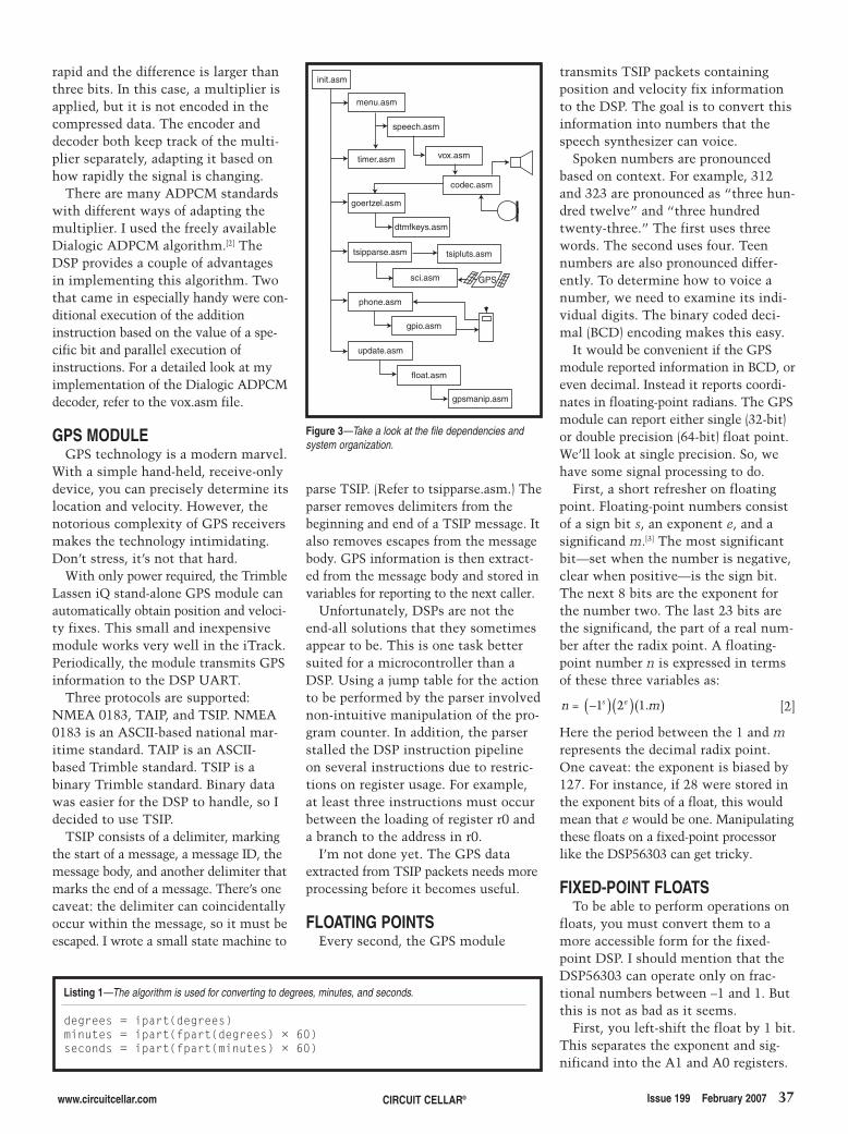
www.circuitcellar.com CIRCUIT CELLAR® Issue 199 February 2007 37
rapid and the difference is larger thanthree bits. In this case, a multiplier isapplied, but it is not encoded in thecompressed data. The encoder anddecoder both keep track of the multi-plier separately, adapting it based onhow rapidly the signal is changing.
There are many ADPCM standardswith different ways of adapting themultiplier. I used the freely availableDialogic ADPCM algorithm.[2] TheDSP provides a couple of advantagesin implementing this algorithm. Twothat came in especially handy were con-ditional execution of the additioninstruction based on the value of a spe-cific bit and parallel execution ofinstructions. For a detailed look at myimplementation of the Dialogic ADPCMdecoder, refer to the vox.asm file.
GPS MODULEGPS technology is a modern marvel.
With a simple hand-held, receive-onlydevice, you can precisely determine itslocation and velocity. However, thenotorious complexity of GPS receiversmakes the technology intimidating.Don’t stress, it’s not that hard.
With only power required, the TrimbleLassen iQ stand-alone GPS module canautomatically obtain position and veloci-ty fixes. This small and inexpensivemodule works very well in the iTrack.Periodically, the module transmits GPSinformation to the DSP UART.
Three protocols are supported:NMEA 0183, TAIP, and TSIP. NMEA0183 is an ASCII-based national mar-itime standard. TAIP is an ASCII-based Trimble standard. TSIP is abinary Trimble standard. Binary datawas easier for the DSP to handle, so Idecided to use TSIP.
TSIP consists of a delimiter, markingthe start of a message, a message ID, themessage body, and another delimiter thatmarks the end of a message. There’s onecaveat: the delimiter can coincidentallyoccur within the message, so it must beescaped. I wrote a small state machine to
parse TSIP. (Refer to tsipparse.asm.) Theparser removes delimiters from thebeginning and end of a TSIP message. Italso removes escapes from the messagebody. GPS information is then extract-ed from the message body and stored invariables for reporting to the next caller.
Unfortunately, DSPs are not theend-all solutions that they sometimesappear to be. This is one task bettersuited for a microcontroller than aDSP. Using a jump table for the actionto be performed by the parser involvednon-intuitive manipulation of the pro-gram counter. In addition, the parserstalled the DSP instruction pipelineon several instructions due to restric-tions on register usage. For example,at least three instructions must occurbetween the loading of register r0 anda branch to the address in r0.
I’m not done yet. The GPS dataextracted from TSIP packets needs moreprocessing before it becomes useful.
FLOATING POINTSEvery second, the GPS module
transmits TSIP packets containingposition and velocity fix informationto the DSP. The goal is to convert thisinformation into numbers that thespeech synthesizer can voice.
Spoken numbers are pronouncedbased on context. For example, 312and 323 are pronounced as “three hun-dred twelve” and “three hundredtwenty-three.” The first uses threewords. The second uses four. Teennumbers are also pronounced differ-ently. To determine how to voice anumber, we need to examine its indi-vidual digits. The binary coded deci-mal (BCD) encoding makes this easy.
It would be convenient if the GPSmodule reported information in BCD, oreven decimal. Instead it reports coordi-nates in floating-point radians. The GPSmodule can report either single (32-bit)or double precision (64-bit) float point.We’ll look at single precision. So, wehave some signal processing to do.
First, a short refresher on floatingpoint. Floating-point numbers consistof a sign bit s, an exponent e, and asignificand m.[3] The most significantbit—set when the number is negative,clear when positive—is the sign bit.The next 8 bits are the exponent forthe number two. The last 23 bits arethe significand, the part of a real num-ber after the radix point. A floating-point number n is expressed in termsof these three variables as:
[2]
Here the period between the 1 and mrepresents the decimal radix point.One caveat: the exponent is biased by127. For instance, if 28 were stored inthe exponent bits of a float, this wouldmean that e would be one. Manipulatingthese floats on a fixed-point processorlike the DSP56303 can get tricky.
FIXED-POINT FLOATSTo be able to perform operations on
floats, you must convert them to amore accessible form for the fixed-point DSP. I should mention that theDSP56303 can operate only on frac-tional numbers between –1 and 1. Butthis is not as bad as it seems.
First, you left-shift the float by 1 bit.This separates the exponent and sig-nificand into the A1 and A0 registers.
n = ms e−( )( )( )1 2 1.
init.asm
menu.asm
speech.asm
vox.asmtimer.asm
codec.asm
goertzel.asm
dtmfkeys.asm
tsipparse.asm tsipluts.asm
sci.asm
phone.asm
gpio.asm
update.asm
float.asm
gpsmanip.asm
GPS
Figure 3—Take a look at the file dependencies andsystem organization.
Listing 1—The algorithm is used for converting to degrees, minutes, and seconds.
degrees = ipart(degrees)minutes = ipart(fpart(degrees) × 60)seconds = ipart(fpart(minutes) × 60)
2702015 Hiszpanski.qxp 1/4/2007 10:40 AM Page 37
38 Issue 199 February 2007 CIRCUIT CELLAR® www.circuitcellar.com
PROJECT FILESTo download code and additional files,go to ftp://ftp.circuitcellar.com/pub/Circuit_Cellar/2007/199.
REFERENCES[1] K. Banks, “The Goertzel Algorithm,”
Embedded Systems Design, 2002.
[2] Dialogic Corp., “Dialogic ADPCMAlgorithm,” 1988.
[3] IEEE Standards Association, “Std754-1985: IEEE Standard for BinaryFloating-Point Arithmetic,”http://standards.ieee.org.
SOURCESChameleonPODAmontec Reconfigurable ComputerSystemswww.amontec.com
Swift sound wavepadNCH Swift Sound Softwarewww.nch.com.au
DSP56303 DSP and Suite56 forDSP566xx/DSP563xxFreescale Semiconductor, Inc.www.freescale.com
TLV320AIC1106 PCM CodecTexas Instruments, Inc.www.ti.com
Lassen iQ GPS moduleTrimble Navigation, Ltd.www.trimble.com
RESOURCESFreescale Semiconductor, “DSP56300Family Manual Addendum,”DSP56300FMAD, rev. 5, 2006.
———, “DSP56303 User’s Manual,”DSP56303UM, rev. 2, 2005.
You then remove the sign bit, negatingA0 if it was set. The significand is stillnot a number, but it’s part of a number.This would make computation tricky,so you divide it by two and add one tothe exponent. (Refer to the float.asmfile.) You now have a separate integerexponent and signed mantissa. Finally,something you can work with!
DEGREES, MINUTES, SECONDSRadians are not very useful for
determining a point on the globe, soconvert to degrees:
[3]
The magic number 0xE52EE0 arisesbecause the DSP multiplies fractionalnumbers between –1 and 1. In this case,you must multiply by 180/π, which isroughly 57.296. This number is greaterthan one, so you normalize it (i.e., divideby 26). The conversion factor 57.296hence becomes 0.895, less than one. Writ-ten as a 24-bit fractional number, it is:
[4]
How is this computation done infloating point? Simple. Six is added tothe exponent in A1 and 0xE52EE0multiplies the mantissa in A0.
Lastly, convert degrees into degrees,minutes, and seconds (see Listing 1).Multiplication by 60 is done the sameway as multiplication by 180/π.There’s another neat trick. Accumula-tor A has eight overflow bits (calledregister A2) for manipulating numbersup to 255. The number of degrees
0 895 0 52 0 2 24. = xE EE( )( )−
degrees radian
adians xE EE
=
=
( )⎛⎝⎜
⎞⎠⎟
( )( )
180
0 52 0
π
r
s
should never exceed this, so A2 can beconveniently used to extract the inte-ger portion of the product.
TO BCDCoordinates in terms of degrees,
minutes, and seconds are nice, but notyet useful. Each number must be con-verted to BCD so that its digits can beinterpreted and voiced. I used a tradi-tional algorithm for the conversion:divide by 100 to get the hundreds digit,divide the remainder by 10 to get thetens digit, and the remainder is theones digit. But division is expensive.The DSP has a division instruction, butit computes iteratively, 1 bit per cycle.
Multiplying by 1/100 is equivalent todividing by 100. The DSP can do thismultiplication in a single clock cycle.Converting to BCD then becomes verysimilar to the conversions in Equation 3and Listing 1. The code for the conver-sion is shown in Listing 2.
This is where the true power of theDSP shines. Perhaps you’ll be able tocompact this routine even further.
NEW HORIZONSMy hope is that this article has
removed some of the mystery sur-rounding DSPs without taking awaytheir luster. If I’ve whet your appetitefor an iTrack, even better. There’s stillplenty of room in the sandbox. Perhapsthe iTrack can be voice-controlled withspeech recognition. Or, perhaps it cananalyze GPS data to provide an esti-mated time of arrival at a coordinatespecified by the user. The possibilitiesoffered by DSPs are endless. Sometimesall you need is a challenging project. I
Listing 2—The DSP routine is for converting binary to binary coded decimal.
bin2bcd clr amove #0.010001,y0 ; b1 = ipart[bin/100]mpyuu x0,y0,b ; b0 = fpart[bin/100]move #>10,y0 ; digit extractor move b1,a1 ; a1 = hundreds digitmove b0,x0 ; x0 = rem
move #2,n0 ; 2 remaining digitsdo n0,_enddompyuu x0,y0,b ; b1 = ipart[(rem)*10]; b0 = fpart[(rem)*10]
asr b ; corrects multiplyasl #4,a,a ; next digitmove b1,x1or x1,a b0,x0 ; stores bcd digit
_enddo rts
Chris Hiszpanski ([email protected]) ispursuing an M.S. at Caltech with a spe-cialization in communications and sig-nal processing. He received a B.S. inelectrical engineering from Caltech inJune 2006. In addition to his interestsin electronics, Chris enjoys bicycling,playing card games, and discussingphilosophy in the company of friends.
2702015 Hiszpanski.qxp 1/4/2007 10:40 AM Page 38

2,600 NEW
B O U R N SPARTS
5,000 NEW
A M PPARTS
2,500 NEW
M A X I MPARTS
The industry’s fastest growing product offering!You know that Jameco’s catalogalways offers over 99% in-stockavailability—the best of any elec-tronic components distributor...
And now, they have thefastest growing product offeringin the industry!
They’ve just added another65,000 new parts to their onlinecatalog; and it’s everything from ICs to passives, optos tointerconnects, power suppliesto electromechanical.
Service & Availability!As Design Engineers know, Jameco offers greatservice, selection andsame-day shipping!
Now you can get thosesame benefits for evenmore great brands...
Wow! Jameco just added 65,000new major-brand products!
19,000 NEWT E X A S
I N S T R U M E N T SPARTS
2,900 NEWV I S H AY
PARTS
6,200 NEW
FAIRCHILDPARTS
2,000 NEW
M O L E XPARTS
2,800 NEWMICROCHIP
PARTS
Check out these newand expanded lines:
Aavid Thermalloy •AlcoSwitch • AMP •
Amphenol Connex •Aromat • Atmel •
Augat • Avago • AVX •Bourns • Buchanan • C & K Switches •
Comair Rotron • Condor PowerSupplies • CTS • Cypress • Dallas
Semiconductor • Elco • Fairchild •Grayhill • Intel • Intersil •
Keystone • Lumex • Lumileds •Maxim • Microchip • Micron
Technology • Molex •NXP/Philips • Panasonic •
Power-One • Raychem •Renesas Technology •
Sandisk • Siliconix • STMicro • Texas Instruments •Toshiba • Tyco Electronics •
Vishay Intertechnology •Wakefield...
Get it here. Right now:
3,000 NEWAV XPARTS
G r e a t P r o d u c t s . A w e s o m e P r i c e s .
Jameco.com/CCV
39.qxp 1/3/2007 9:40 AM Page 1
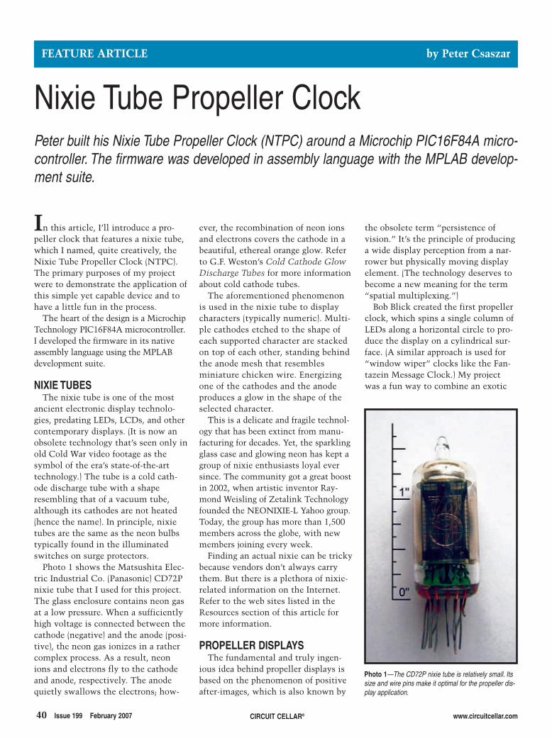
40 Issue 199 February 2007 CIRCUIT CELLAR® www.circuitcellar.com
ever, the recombination of neon ionsand electrons covers the cathode in abeautiful, ethereal orange glow. Referto G.F. Weston’s Cold Cathode GlowDischarge Tubes for more informationabout cold cathode tubes.
The aforementioned phenomenonis used in the nixie tube to displaycharacters (typically numeric). Multi-ple cathodes etched to the shape ofeach supported character are stackedon top of each other, standing behindthe anode mesh that resemblesminiature chicken wire. Energizingone of the cathodes and the anodeproduces a glow in the shape of theselected character.
This is a delicate and fragile technol-ogy that has been extinct from manu-facturing for decades. Yet, the sparklingglass case and glowing neon has kept agroup of nixie enthusiasts loyal eversince. The community got a great boostin 2002, when artistic inventor Ray-mond Weisling of Zetalink Technologyfounded the NEONIXIE-L Yahoo group.Today, the group has more than 1,500members across the globe, with newmembers joining every week.
Finding an actual nixie can be trickybecause vendors don’t always carrythem. But there is a plethora of nixie-related information on the Internet.Refer to the web sites listed in theResources section of this article formore information.
PROPELLER DISPLAYSThe fundamental and truly ingen-
ious idea behind propeller displays isbased on the phenomenon of positiveafter-images, which is also known by
In this article, I’ll introduce a pro-peller clock that features a nixie tube,which I named, quite creatively, theNixie Tube Propeller Clock (NTPC).The primary purposes of my projectwere to demonstrate the application ofthis simple yet capable device and tohave a little fun in the process.
The heart of the design is a MicrochipTechnology PIC16F84A microcontroller.I developed the firmware in its nativeassembly language using the MPLABdevelopment suite.
NIXIE TUBESThe nixie tube is one of the most
ancient electronic display technolo-gies, predating LEDs, LCDs, and othercontemporary displays. (It is now anobsolete technology that’s seen only inold Cold War video footage as thesymbol of the era’s state-of-the-arttechnology.) The tube is a cold cath-ode discharge tube with a shaperesembling that of a vacuum tube,although its cathodes are not heated(hence the name). In principle, nixietubes are the same as the neon bulbstypically found in the illuminatedswitches on surge protectors.
Photo 1 shows the Matsushita Elec-tric Industrial Co. (Panasonic) CD72Pnixie tube that I used for this project.The glass enclosure contains neon gasat a low pressure. When a sufficientlyhigh voltage is connected between thecathode (negative) and the anode (posi-tive), the neon gas ionizes in a rathercomplex process. As a result, neonions and electrons fly to the cathodeand anode, respectively. The anodequietly swallows the electrons; how-
the obsolete term “persistence ofvision.” It’s the principle of producinga wide display perception from a nar-rower but physically moving displayelement. (The technology deserves tobecome a new meaning for the term“spatial multiplexing.”)
Bob Blick created the first propellerclock, which spins a single column ofLEDs along a horizontal circle to pro-duce the display on a cylindrical sur-face. (A similar approach is used for“window wiper” clocks like the Fan-tazein Message Clock.) My projectwas a fun way to combine an exotic
FEATURE ARTICLE by Peter Csaszar
Nixie Tube Propeller ClockPeter built his Nixie Tube Propeller Clock (NTPC) around a Microchip PIC16F84A micro-controller. The firmware was developed in assembly language with the MPLAB develop-ment suite.
Photo 1—The CD72P nixie tube is relatively small. Itssize and wire pins make it optimal for the propeller dis-play application.
27020017Csaszar.qxp 1/4/2007 10:46 AM Page 40
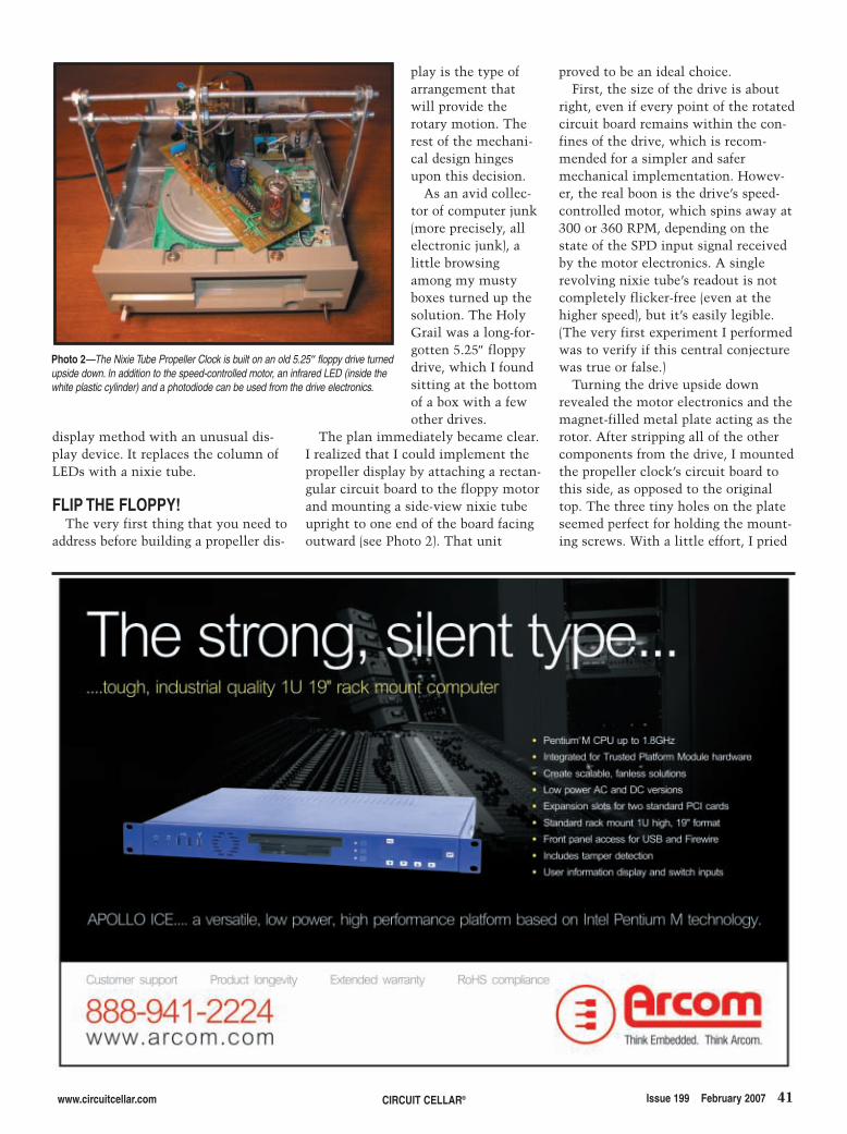
display method with an unusual dis-play device. It replaces the column ofLEDs with a nixie tube.
FLIP THE FLOPPY!The very first thing that you need to
address before building a propeller dis-
play is the type ofarrangement thatwill provide therotary motion. Therest of the mechani-cal design hingesupon this decision.
As an avid collec-tor of computer junk(more precisely, allelectronic junk), alittle browsingamong my mustyboxes turned up thesolution. The HolyGrail was a long-for-gotten 5.25″ floppydrive, which I foundsitting at the bottomof a box with a fewother drives.
The plan immediately became clear.I realized that I could implement thepropeller display by attaching a rectan-gular circuit board to the floppy motorand mounting a side-view nixie tubeupright to one end of the board facingoutward (see Photo 2). That unit
proved to be an ideal choice. First, the size of the drive is about
right, even if every point of the rotatedcircuit board remains within the con-fines of the drive, which is recom-mended for a simpler and safermechanical implementation. Howev-er, the real boon is the drive’s speed-controlled motor, which spins away at300 or 360 RPM, depending on thestate of the SPD input signal receivedby the motor electronics. A singlerevolving nixie tube’s readout is notcompletely flicker-free (even at thehigher speed), but it’s easily legible.(The very first experiment I performedwas to verify if this central conjecturewas true or false.)
Turning the drive upside downrevealed the motor electronics and themagnet-filled metal plate acting as therotor. After stripping all of the othercomponents from the drive, I mountedthe propeller clock’s circuit board tothis side, as opposed to the originaltop. The three tiny holes on the plateseemed perfect for holding the mount-ing screws. With a little effort, I pried
www.circuitcellar.com CIRCUIT CELLAR® Issue 199 February 2007 41
Photo 2—The Nixie Tube Propeller Clock is built on an old 5.25″ floppy drive turnedupside down. In addition to the speed-controlled motor, an infrared LED (inside thewhite plastic cylinder) and a photodiode can be used from the drive electronics.
27020017Csaszar.qxp 1/4/2007 10:46 AM Page 41
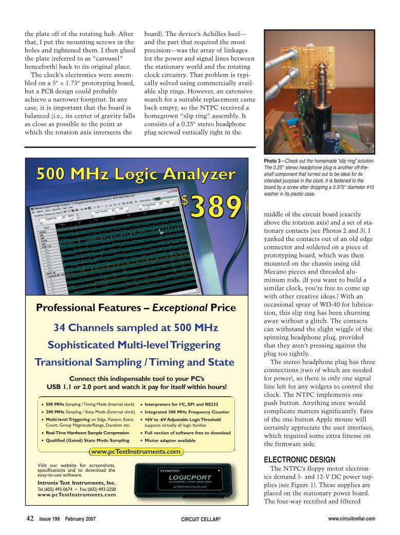
middle of the circuit board (exactlyabove the rotation axis) and a set of sta-tionary contacts (see Photos 2 and 3). Iyanked the contacts out of an old edgeconnector and soldered on a piece ofprototyping board, which was thenmounted on the chassis using oldMecano pieces and threaded alu-minum rods. (If you want to build asimilar clock, you’re free to come upwith other creative ideas.) With anoccasional spray of WD-40 for lubrica-tion, this slip ring has been churningaway without a glitch. The contactscan withstand the slight wiggle of thespinning headphone plug, providedthat they aren’t pressing against theplug too tightly.
The stereo headphone plug has threeconnections (two of which are neededfor power), so there is only one signalline left for any widgets to control theclock. The NTPC implements onepush button. Anything more wouldcomplicate matters significantly. Fansof the one-button Apple mouse willcertainly appreciate the user interface,which required some extra finesse onthe firmware side.
ELECTRONIC DESIGNThe NTPC’s floppy motor electron-
ics demand 5- and 12-V DC power sup-plies (see Figure 1). These supplies areplaced on the stationary power board.The four-way rectified and filtered
board). The device’s Achilles heel—and the part that required the mostprecision—was the array of linkagesfor the power and signal lines betweenthe stationary world and the rotatingclock circuitry. That problem is typi-cally solved using commercially avail-able slip rings. However, an extensivesearch for a suitable replacement cameback empty, so the NTPC received ahomegrown “slip ring” assembly. Itconsists of a 0.25″ stereo headphoneplug screwed vertically right in the
42 Issue 199 February 2007 CIRCUIT CELLAR® www.circuitcellar.com
the plate off of the rotating hub. Afterthat, I put the mounting screws in theholes and tightened them. I then gluedthe plate (referred to as “carousel”henceforth) back to its original place.
The clock’s electronics were assem-bled on a 5″ × 1.75″ prototyping board,but a PCB design could probablyachieve a narrower footprint. In anycase, it is important that the board isbalanced (i.e., its center of gravity fallsas close as possible to the point atwhich the rotation axis intersects the
Photo 3—Check out the homemade “slip ring” solution.The 0.25″ stereo headphone plug is another off-the-shelf component that turned out to be ideal for itsintended purpose in the clock. It is fastened to theboard by a screw after dropping a 0.375″ diameter #10washer in its plastic case.
500 MHz Sampling / Timing Mode (Internal clock)
200 MHz Sampling / State Mode (External clock)
Multi-level Triggering on Edge, Pattern, Event
Count, Group Magnitude/Range, Duration etc.
Real-Time Hardware Sample Compression
Qualified (Gated) State Mode Sampling
Interpreters for I2C, SPI and RS232
Integrated 300 MHz Frequency Counter
+6V to -6V Adjustable Logic Thresholdsupports virtually all logic families
Full version of software free to download
Mictor adapter available
www.pcTestInstruments.com
Connect this indispensable tool to your PC’sUSB 1.1 or 2.0 port and watch it pay for itself within hours!
Visit our website for screenshots,specifications and to download theeasy-to-use software.
Professional Features – Professional Features – Exceptional Exceptional Price Price
34 Channels sampled at 500 MHz 34 Channels sampled at 500 MHz
Sophisticated Multi-level TriggeringSophisticated Multi-levelTriggering
Transitional Sampling / Timing and State Transitional Sampling /Timing and State
Intronix Test Instruments, Inc.Tel: (602) 493-0674 Fax:(602) 493-2258
www.pcTestInstruments.com
27020017Csaszar.qxp 1/4/2007 10:46 AM Page 42
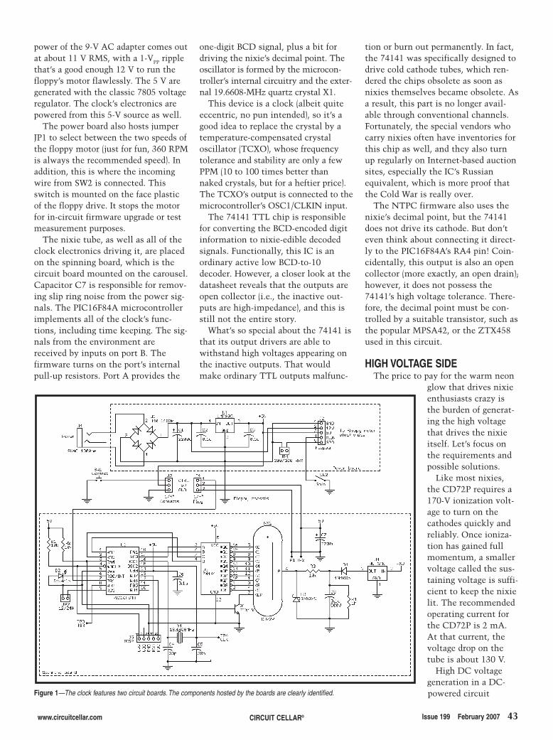
www.circuitcellar.com CIRCUIT CELLAR® Issue 199 February 2007 43
power of the 9-V AC adapter comes outat about 11 V RMS, with a 1-VPP ripplethat’s a good enough 12 V to run thefloppy’s motor flawlessly. The 5 V aregenerated with the classic 7805 voltageregulator. The clock’s electronics arepowered from this 5-V source as well.
The power board also hosts jumperJP1 to select between the two speeds ofthe floppy motor (just for fun, 360 RPMis always the recommended speed). Inaddition, this is where the incomingwire from SW2 is connected. Thisswitch is mounted on the face plasticof the floppy drive. It stops the motorfor in-circuit firmware upgrade or testmeasurement purposes.
The nixie tube, as well as all of theclock electronics driving it, are placedon the spinning board, which is thecircuit board mounted on the carousel.Capacitor C7 is responsible for remov-ing slip ring noise from the power sig-nals. The PIC16F84A microcontrollerimplements all of the clock’s func-tions, including time keeping. The sig-nals from the environment arereceived by inputs on port B. Thefirmware turns on the port’s internalpull-up resistors. Port A provides the
one-digit BCD signal, plus a bit fordriving the nixie’s decimal point. Theoscillator is formed by the microcon-troller’s internal circuitry and the exter-nal 19.6608-MHz quartz crystal X1.
This device is a clock (albeit quiteeccentric, no pun intended), so it’s agood idea to replace the crystal by atemperature-compensated crystaloscillator (TCXO), whose frequencytolerance and stability are only a fewPPM (10 to 100 times better thannaked crystals, but for a heftier price).The TCXO’s output is connected to themicrocontroller’s OSC1/CLKIN input.
The 74141 TTL chip is responsiblefor converting the BCD-encoded digitinformation to nixie-edible decodedsignals. Functionally, this IC is anordinary active low BCD-to-10decoder. However, a closer look at thedatasheet reveals that the outputs areopen collector (i.e., the inactive out-puts are high-impedance), and this isstill not the entire story.
What’s so special about the 74141 isthat its output drivers are able towithstand high voltages appearing onthe inactive outputs. That wouldmake ordinary TTL outputs malfunc-
tion or burn out permanently. In fact,the 74141 was specifically designed todrive cold cathode tubes, which ren-dered the chips obsolete as soon asnixies themselves became obsolete. Asa result, this part is no longer avail-able through conventional channels.Fortunately, the special vendors whocarry nixies often have inventories forthis chip as well, and they also turnup regularly on Internet-based auctionsites, especially the IC’s Russianequivalent, which is more proof thatthe Cold War is really over.
The NTPC firmware also uses thenixie’s decimal point, but the 74141does not drive its cathode. But don’teven think about connecting it direct-ly to the PIC16F84A’s RA4 pin! Coin-cidentally, this output is also an opencollector (more exactly, an open drain);however, it does not possess the74141’s high voltage tolerance. There-fore, the decimal point must be con-trolled by a suitable transistor, such asthe popular MPSA42, or the ZTX458used in this circuit.
HIGH VOLTAGE SIDEThe price to pay for the warm neon
glow that drives nixieenthusiasts crazy isthe burden of generat-ing the high voltagethat drives the nixieitself. Let’s focus onthe requirements andpossible solutions.
Like most nixies,the CD72P requires a170-V ionization volt-age to turn on thecathodes quickly andreliably. Once ioniza-tion has gained fullmomentum, a smallervoltage called the sus-taining voltage is suffi-cient to keep the nixielit. The recommendedoperating current forthe CD72P is 2 mA.At that current, thevoltage drop on thetube is about 130 V.
High DC voltagegeneration in a DC-powered circuitFigure 1—The clock features two circuit boards. The components hosted by the boards are clearly identified.
27020017Csaszar.qxp 1/4/2007 10:46 AM Page 43
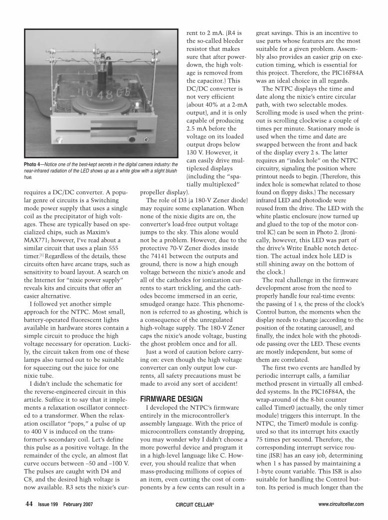
44 Issue 199 February 2007 CIRCUIT CELLAR® www.circuitcellar.com
requires a DC/DC converter. A popu-lar genre of circuits is a Switchingmode power supply that uses a singlecoil as the precipitator of high volt-ages. These are typically based on spe-cialized chips, such as Maxim’sMAX771; however, I’ve read about asimilar circuit that uses a plain 555timer.[1] Regardless of the details, thesecircuits often have arcane traps, such assensitivity to board layout. A search onthe Internet for “nixie power supply”reveals kits and circuits that offer aneasier alternative.
I followed yet another simpleapproach for the NTPC. Most small,battery-operated fluorescent lightsavailable in hardware stores contain asimple circuit to produce the highvoltage necessary for operation. Lucki-ly, the circuit taken from one of theselamps also turned out to be suitablefor squeezing out the juice for onenixie tube.
I didn’t include the schematic forthe reverse-engineered circuit in thisarticle. Suffice it to say that it imple-ments a relaxation oscillator connect-ed to a transformer. When the relax-ation oscillator “pops,” a pulse of upto 400 V is induced on the trans-former’s secondary coil. Let’s definethis pulse as a positive voltage. In theremainder of the cycle, an almost flatcurve occurs between –50 and –100 V.The pulses are caught with D4 andC8, and the desired high voltage isnow available. R3 sets the nixie’s cur-
rent to 2 mA. (R4 isthe so-called bleederresistor that makessure that after power-down, the high volt-age is removed fromthe capacitor.) ThisDC/DC converter isnot very efficient(about 40% at a 2-mAoutput), and it is onlycapable of producing2.5 mA before thevoltage on its loadedoutput drops below130 V. However, itcan easily drive mul-tiplexed displays(including the “spa-tially multiplexed”
propeller display). The role of D3 (a 180-V Zener diode)
may require some explanation. Whennone of the nixie digits are on, theconverter’s load-free output voltagejumps to the sky. This alone wouldnot be a problem. However, due to theprotective 70-V Zener diodes insidethe 74141 between the outputs andground, there is now a high enoughvoltage between the nixie’s anode andall of the cathodes for ionization cur-rents to start trickling, and the cath-odes become immersed in an eerie,smudged orange haze. This phenome-non is referred to as ghosting, which isa consequence of the unregulatedhigh-voltage supply. The 180-V Zenercaps the nixie’s anode voltage, bustingthe ghost problem once and for all.
Just a word of caution before carry-ing on: even though the high voltageconverter can only output low cur-rents, all safety precautions must bemade to avoid any sort of accident!
FIRMWARE DESIGNI developed the NTPC’s firmware
entirely in the microcontroller’sassembly language. With the price ofmicrocontrollers constantly dropping,you may wonder why I didn’t choose amore powerful device and program itin a high-level language like C. How-ever, you should realize that whenmass-producing millions of copies ofan item, even cutting the cost of com-ponents by a few cents can result in a
Photo 4—Notice one of the best-kept secrets in the digital camera industry: thenear-infrared radiation of the LED shows up as a white glow with a slight bluishhue.
great savings. This is an incentive touse parts whose features are the mostsuitable for a given problem. Assem-bly also provides an easier grip on exe-cution timing, which is essential forthis project. Therefore, the PIC16F84Awas an ideal choice in all regards.
The NTPC displays the time anddate along the nixie’s entire circularpath, with two selectable modes.Scrolling mode is used when the print-out is scrolling clockwise a couple oftimes per minute. Stationary mode isused when the time and date areswapped between the front and backof the display every 2 s. The latterrequires an “index hole” on the NTPCcircuitry, signaling the position whereprintout needs to begin. (Therefore, thisindex hole is somewhat related to thosefound on floppy disks.) The necessaryinfrared LED and photodiode werereused from the drive. The LED with thewhite plastic enclosure (now turned upand glued to the top of the motor con-trol IC) can be seen in Photo 2. (Ironi-cally, however, this LED was part ofthe drive’s Write Enable notch detec-tion. The actual index hole LED isstill shining away on the bottom ofthe clock.)
The real challenge in the firmwaredevelopment arose from the need toproperly handle four real-time events:the passing of 1 s, the press of the clock’sControl button, the moments when thedisplay needs to change (according to theposition of the rotating carousel), andfinally, the index hole with the photodi-ode passing over the LED. These eventsare mostly independent, but some ofthem are correlated.
The first two events are handled byperiodic interrupt calls, a familiarmethod present in virtually all embed-ded systems. In the PIC16F84A, thewrap-around of the 8-bit countercalled Timer0 (actually, the only timermodule) triggers this interrupt. In theNTPC, the Timer0 module is config-ured so that its interrupt hits exactly75 times per second. Therefore, thecorresponding interrupt service rou-tine (ISR) has an easy job, determiningwhen 1 s has passed by maintaining a1-byte count variable. This ISR is alsosuitable for handling the Control but-ton. Its period is much longer than the
27020017Csaszar.qxp 1/4/2007 10:47 AM Page 44
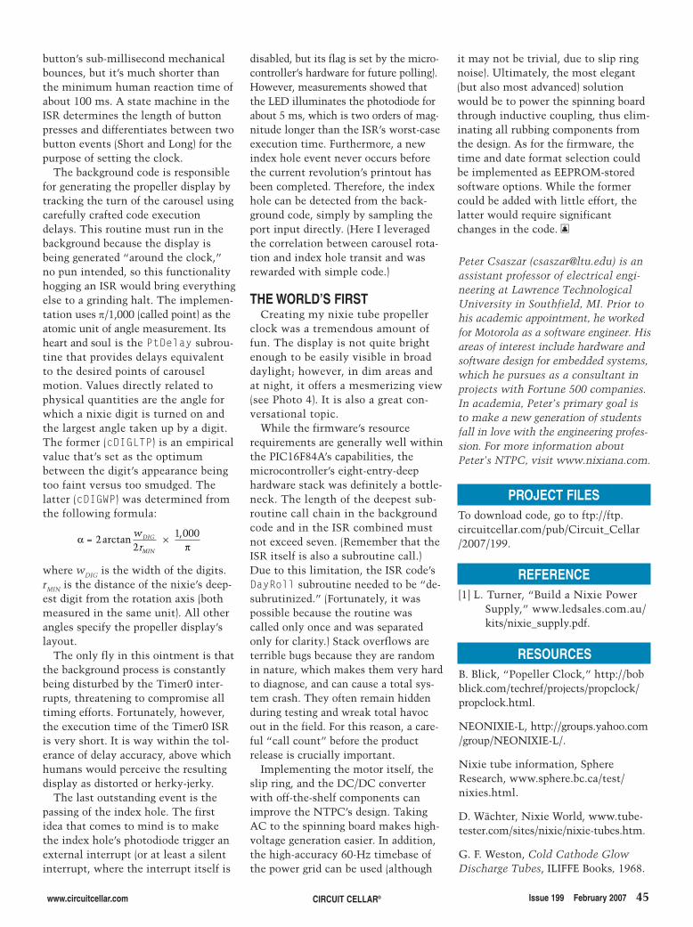
www.circuitcellar.com CIRCUIT CELLAR® Issue 199 February 2007 45
Peter Csaszar ([email protected]) is anassistant professor of electrical engi-neering at Lawrence TechnologicalUniversity in Southfield, MI. Prior tohis academic appointment, he workedfor Motorola as a software engineer. Hisareas of interest include hardware andsoftware design for embedded systems,which he pursues as a consultant inprojects with Fortune 500 companies.In academia, Peter’s primary goal isto make a new generation of studentsfall in love with the engineering profes-sion. For more information aboutPeter’s NTPC, visit www.nixiana.com.
RESOURCESB. Blick, “Popeller Clock,” http://bobblick.com/techref/projects/propclock/propclock.html.
NEONIXIE-L, http://groups.yahoo.com/group/NEONIXIE-L/.
Nixie tube information, SphereResearch, www.sphere.bc.ca/test/nixies.html.
D. Wächter, Nixie World, www.tube-tester.com/sites/nixie/nixie-tubes.htm.
G. F. Weston, Cold Cathode GlowDischarge Tubes, ILIFFE Books, 1968.
REFERENCE[1] L. Turner, “Build a Nixie Power
Supply,” www.ledsales.com.au/kits/nixie_supply.pdf.
PROJECT FILESTo download code, go to ftp://ftp.circuitcellar.com/pub/Circuit_Cellar/2007/199.
button’s sub-millisecond mechanicalbounces, but it’s much shorter thanthe minimum human reaction time ofabout 100 ms. A state machine in theISR determines the length of buttonpresses and differentiates between twobutton events (Short and Long) for thepurpose of setting the clock.
The background code is responsiblefor generating the propeller display bytracking the turn of the carousel usingcarefully crafted code executiondelays. This routine must run in thebackground because the display isbeing generated “around the clock,”no pun intended, so this functionalityhogging an ISR would bring everythingelse to a grinding halt. The implemen-tation uses π/1,000 (called point) as theatomic unit of angle measurement. Itsheart and soul is the PtDelay subrou-tine that provides delays equivalentto the desired points of carouselmotion. Values directly related tophysical quantities are the angle forwhich a nixie digit is turned on andthe largest angle taken up by a digit.The former (cDIGLTP) is an empiricalvalue that’s set as the optimumbetween the digit’s appearance beingtoo faint versus too smudged. Thelatter (cDIGWP) was determined fromthe following formula:
where wDIG is the width of the digits.rMIN is the distance of the nixie’s deep-est digit from the rotation axis (bothmeasured in the same unit). All otherangles specify the propeller display’slayout.
The only fly in this ointment is thatthe background process is constantlybeing disturbed by the Timer0 inter-rupts, threatening to compromise alltiming efforts. Fortunately, however,the execution time of the Timer0 ISRis very short. It is way within the tol-erance of delay accuracy, above whichhumans would perceive the resultingdisplay as distorted or herky-jerky.
The last outstanding event is thepassing of the index hole. The firstidea that comes to mind is to makethe index hole’s photodiode trigger anexternal interrupt (or at least a silentinterrupt, where the interrupt itself is
απ
= w
r DIG
MIN
22
1 000arctan
,×
disabled, but its flag is set by the micro-controller’s hardware for future polling).However, measurements showed thatthe LED illuminates the photodiode forabout 5 ms, which is two orders of mag-nitude longer than the ISR’s worst-caseexecution time. Furthermore, a newindex hole event never occurs beforethe current revolution’s printout hasbeen completed. Therefore, the indexhole can be detected from the back-ground code, simply by sampling theport input directly. (Here I leveragedthe correlation between carousel rota-tion and index hole transit and wasrewarded with simple code.)
THE WORLD’S FIRST Creating my nixie tube propeller
clock was a tremendous amount offun. The display is not quite brightenough to be easily visible in broaddaylight; however, in dim areas andat night, it offers a mesmerizing view(see Photo 4). It is also a great con-versational topic.
While the firmware’s resourcerequirements are generally well withinthe PIC16F84A’s capabilities, themicrocontroller’s eight-entry-deephardware stack was definitely a bottle-neck. The length of the deepest sub-routine call chain in the backgroundcode and in the ISR combined mustnot exceed seven. (Remember that theISR itself is also a subroutine call.)Due to this limitation, the ISR code’sDayRoll subroutine needed to be “de-subrutinized.” (Fortunately, it waspossible because the routine wascalled only once and was separatedonly for clarity.) Stack overflows areterrible bugs because they are randomin nature, which makes them very hardto diagnose, and can cause a total sys-tem crash. They often remain hiddenduring testing and wreak total havocout in the field. For this reason, a care-ful “call count” before the productrelease is crucially important.
Implementing the motor itself, theslip ring, and the DC/DC converterwith off-the-shelf components canimprove the NTPC’s design. TakingAC to the spinning board makes high-voltage generation easier. In addition,the high-accuracy 60-Hz timebase ofthe power grid can be used (although
it may not be trivial, due to slip ringnoise). Ultimately, the most elegant(but also most advanced) solutionwould be to power the spinning boardthrough inductive coupling, thus elim-inating all rubbing components fromthe design. As for the firmware, thetime and date format selection couldbe implemented as EEPROM-storedsoftware options. While the formercould be added with little effort, thelatter would require significantchanges in the code. I
27020017Csaszar.qxp 1/4/2007 10:47 AM Page 45
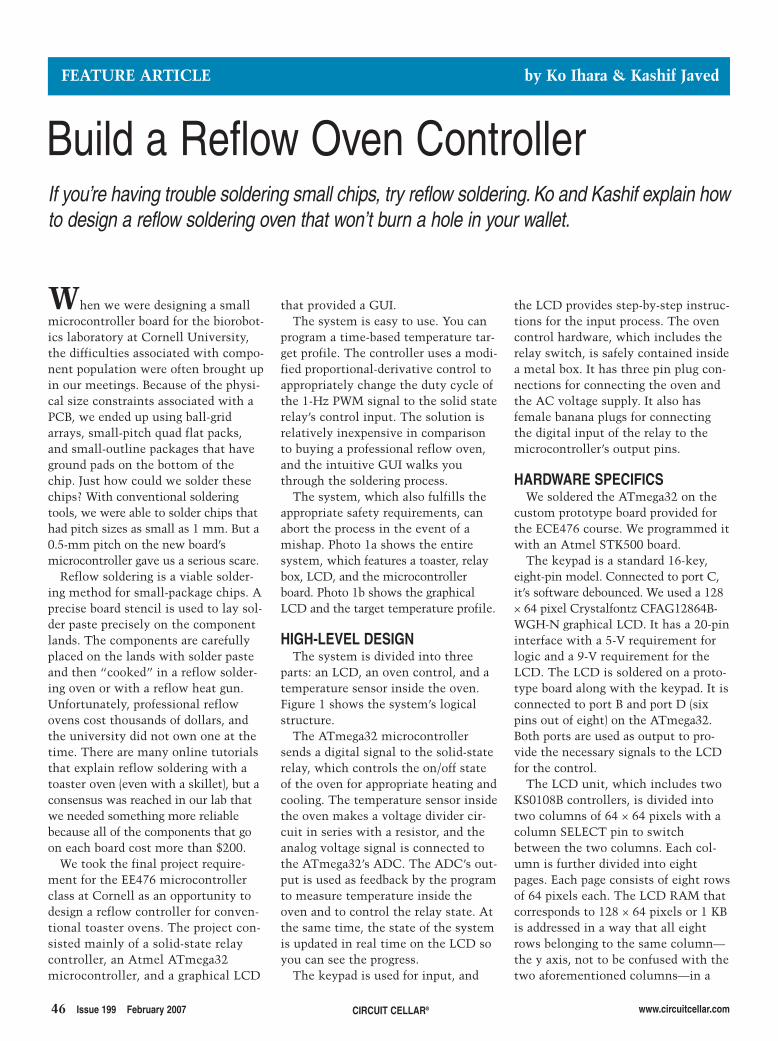
46 Issue 199 February 2007 CIRCUIT CELLAR® www.circuitcellar.com
that provided a GUI. The system is easy to use. You can
program a time-based temperature tar-get profile. The controller uses a modi-fied proportional-derivative control toappropriately change the duty cycle ofthe 1-Hz PWM signal to the solid staterelay’s control input. The solution isrelatively inexpensive in comparisonto buying a professional reflow oven,and the intuitive GUI walks youthrough the soldering process.
The system, which also fulfills theappropriate safety requirements, canabort the process in the event of amishap. Photo 1a shows the entiresystem, which features a toaster, relaybox, LCD, and the microcontrollerboard. Photo 1b shows the graphicalLCD and the target temperature profile.
HIGH-LEVEL DESIGNThe system is divided into three
parts: an LCD, an oven control, and atemperature sensor inside the oven.Figure 1 shows the system’s logicalstructure.
The ATmega32 microcontrollersends a digital signal to the solid-staterelay, which controls the on/off stateof the oven for appropriate heating andcooling. The temperature sensor insidethe oven makes a voltage divider cir-cuit in series with a resistor, and theanalog voltage signal is connected tothe ATmega32’s ADC. The ADC’s out-put is used as feedback by the programto measure temperature inside theoven and to control the relay state. Atthe same time, the state of the systemis updated in real time on the LCD soyou can see the progress.
The keypad is used for input, and
When we were designing a smallmicrocontroller board for the biorobot-ics laboratory at Cornell University,the difficulties associated with compo-nent population were often brought upin our meetings. Because of the physi-cal size constraints associated with aPCB, we ended up using ball-gridarrays, small-pitch quad flat packs,and small-outline packages that haveground pads on the bottom of thechip. Just how could we solder thesechips? With conventional solderingtools, we were able to solder chips thathad pitch sizes as small as 1 mm. But a0.5-mm pitch on the new board’smicrocontroller gave us a serious scare.
Reflow soldering is a viable solder-ing method for small-package chips. Aprecise board stencil is used to lay sol-der paste precisely on the componentlands. The components are carefullyplaced on the lands with solder pasteand then “cooked” in a reflow solder-ing oven or with a reflow heat gun.Unfortunately, professional reflowovens cost thousands of dollars, andthe university did not own one at thetime. There are many online tutorialsthat explain reflow soldering with atoaster oven (even with a skillet), but aconsensus was reached in our lab thatwe needed something more reliablebecause all of the components that goon each board cost more than $200.
We took the final project require-ment for the EE476 microcontrollerclass at Cornell as an opportunity todesign a reflow controller for conven-tional toaster ovens. The project con-sisted mainly of a solid-state relaycontroller, an Atmel ATmega32microcontroller, and a graphical LCD
the LCD provides step-by-step instruc-tions for the input process. The ovencontrol hardware, which includes therelay switch, is safely contained insidea metal box. It has three pin plug con-nections for connecting the oven andthe AC voltage supply. It also hasfemale banana plugs for connectingthe digital input of the relay to themicrocontroller’s output pins.
HARDWARE SPECIFICSWe soldered the ATmega32 on the
custom prototype board provided forthe ECE476 course. We programmed itwith an Atmel STK500 board.
The keypad is a standard 16-key,eight-pin model. Connected to port C,it’s software debounced. We used a 128× 64 pixel Crystalfontz CFAG12864B-WGH-N graphical LCD. It has a 20-pininterface with a 5-V requirement forlogic and a 9-V requirement for theLCD. The LCD is soldered on a proto-type board along with the keypad. It isconnected to port B and port D (sixpins out of eight) on the ATmega32.Both ports are used as output to pro-vide the necessary signals to the LCDfor the control.
The LCD unit, which includes twoKS0108B controllers, is divided intotwo columns of 64 × 64 pixels with acolumn SELECT pin to switchbetween the two columns. Each col-umn is further divided into eightpages. Each page consists of eight rowsof 64 pixels each. The LCD RAM thatcorresponds to 128 × 64 pixels or 1 KBis addressed in a way that all eightrows belonging to the same column—the y axis, not to be confused with thetwo aforementioned columns—in a
FEATURE ARTICLE by Ko Ihara & Kashif Javed
Build a Reflow Oven ControllerIf you’re having trouble soldering small chips, try reflow soldering. Ko and Kashif explain howto design a reflow soldering oven that won’t burn a hole in your wallet.
2701017 ihara.qxp 1/4/2007 10:48 AM Page 46
www.circuitcellar.com CIRCUIT CELLAR® Issue 199 February 2007 47
page can be read or written at a time.The pixels are set on logic high andcleared on low. The entire LCD RAMcould be updated on the order of mil-liseconds, which means that the LCDinteraction could be easily done in realtime. The LCD was powered througha voltage divider circuit using theMaxim ICL7660CPA reverse-voltagegenerator, which is also soldered onthe prototype board.
Omron Electronics was generousenough to provide a solid-state relayfor our project. The relay has the max-imum rating of 75 A at 24 to 240 AC,which is more than enough for a nor-mal toaster oven. We placed the relayswitch in a heatsink metal box withthree pin plug connectors mountedinside to connect the toaster oven andthe AC power supply. The digital inputwas connected via harness plugs drilled
into the box. The signalfor the solid state relayswitch was giventhrough PORTD[5] viathe prototype board.
The system includesa BC Components2322-633-83303 nega-tive temperature coeffi-cient (NTC) thermistorwith a temperaturerange from –40°C to300°C. The device wasplaced inside the ovenand connected to thevoltage-divider circuiton the prototype board.
We connected the thermistor inseries with a 2-kΩ resistor. This volt-age divider circuit was connected onone end to ground and another end tothe LM711 op-amp output, which wasconfigured in a voltage-follower onthe VCC signal. The variable voltageoutput between the thermistor andthe fixed resistor is fed to theATmega32 via pin A0 that goes intothe ADC on the chip.
Photo 1a—The reflow oven controller system includes a toaster (left), relay box (top right), LCD (bottom middle), and a microcontrollerboard (bottom right). b—We used a Crystalfontz CFAG12864B-WGH-N graphical LCD. Check out the target profile.
a) b)
2701017 ihara.qxp 1/4/2007 10:48 AM Page 47
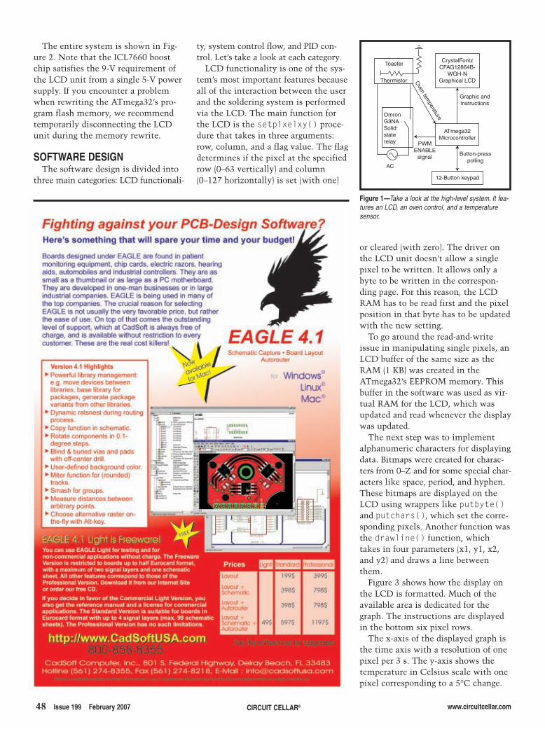
48 Issue 199 February 2007 CIRCUIT CELLAR® www.circuitcellar.com
The entire system is shown in Fig-ure 2. Note that the ICL7660 boostchip satisfies the 9-V requirement ofthe LCD unit from a single 5-V powersupply. If you encounter a problemwhen rewriting the ATmega32’s pro-gram flash memory, we recommendtemporarily disconnecting the LCDunit during the memory rewrite.
SOFTWARE DESIGNThe software design is divided into
three main categories: LCD functionali-
ty, system control flow, and PID con-trol. Let’s take a look at each category.
LCD functionality is one of the sys-tem’s most important features becauseall of the interaction between the userand the soldering system is performedvia the LCD. The main function forthe LCD is the setpixelxy() proce-dure that takes in three arguments:row, column, and a flag value. The flagdetermines if the pixel at the specifiedrow (0–63 vertically) and column(0–127 horizontally) is set (with one)
or cleared (with zero). The driver onthe LCD unit doesn’t allow a singlepixel to be written. It allows only abyte to be written in the correspon-ding page. For this reason, the LCDRAM has to be read first and the pixelposition in that byte has to be updatedwith the new setting.
To go around the read-and-writeissue in manipulating single pixels, anLCD buffer of the same size as theRAM (1 KB) was created in theATmega32’s EEPROM memory. Thisbuffer in the software was used as vir-tual RAM for the LCD, which wasupdated and read whenever the displaywas updated.
The next step was to implementalphanumeric characters for displayingdata. Bitmaps were created for charac-ters from 0–Z and for some special char-acters like space, period, and hyphen.These bitmaps are displayed on theLCD using wrappers like putbyte()and putchars(), which set the corre-sponding pixels. Another function wasthe drawline() function, whichtakes in four parameters (x1, y1, x2,and y2) and draws a line betweenthem.
Figure 3 shows how the display onthe LCD is formatted. Much of theavailable area is dedicated for thegraph. The instructions are displayedin the bottom six pixel rows.
The x-axis of the displayed graph isthe time axis with a resolution of onepixel per 3 s. The y-axis shows thetemperature in Celsius scale with onepixel corresponding to a 5°C change.
Toaster
Thermistor
OmronG3NASolidstaterelay
Oven tem
perature
PWMENABLE
signal
CrystalFontzCFAG12864B-
WGH-NGraphical LCD
Graphic andinstructions
ATmega32Microcontroller
Button-presspolling
12-Button keypad
AC
-
Figure 1—Take a look at the high-level system. It fea-tures an LCD, an oven control, and a temperaturesensor.
2701017 ihara.qxp 1/4/2007 10:48 AM Page 48

DESIGNSTELLARIS2006
Challenge yourself against other top embedded engineers around the world in
DesignStellaris2006, proudly sponsored by Luminary Micro, Keil, and Circuit Cellar.
Use any microcontroller in Luminary Micro’sStellaris™ family of ARM® Cortex™- M3 controllers with the
ARM RealView® Microcontroller Development Kit(MDK-ARM) to create your design contest entry,
and see how far your design will take you!
www.LuminaryMicro.com/DesignStellaris2006
DESIGNSTELLARIS2006
• No purchase necessary to enter.
• $10,000 in cash prizes!
• Entry deadline is February 7, 2007.
• Winners will be announced at the Embedded Systems show...Silicon Valley 2007.
• Submit your design today!
FOR COMPLETE DETAILS, VISITwww.LuminaryMicro.com/DesignStellaris2006
[ ]LUMINARY MICRO
LM3S811 EVALUATION KIT
Visit our websitefor more information!
THE LM3S811 EVALUATION KIT includesthe Stellaris LM3S811 Evaluation Board, an evalua-tion copy of MDK-ARM, USB cable, documentation,and programming examples.
2.qxp 10/5/2006 9:06 AM Page 1
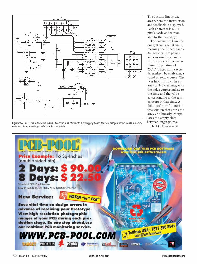
50 Issue 199 February 2007 CIRCUIT CELLAR® www.circuitcellar.com
The bottom line is thearea where the instructionand feedback is displayed.Each character is 5 × 4pixels wide and is read-able to the naked eye.
The maximum time forour system is set at 340 s,meaning that it can handle340 temperature pointsand can run for approxi-mately 3.5 s with a maxi-mum temperature of250°C. These limits weredetermined by analyzing astandard reflow curve. Theuser input is taken in anarray of 340 elements, withthe index corresponding tothe time and the valuecorresponding to the tem-perature at that time. Ainterpolate() functionwas written that scans thearray and linearly interpo-lates the empty slotsbetween target points.
The LCD has severalFigure 2—This is the reflow oven system.You could fit all of this into a prototyping board. But note that you should isolate the solid-state relay in a separate grounded box for your safety.
2701017 ihara.qxp 1/4/2007 10:48 AM Page 50
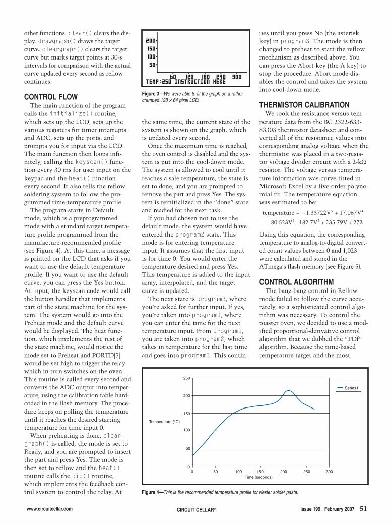
www.circuitcellar.com CIRCUIT CELLAR® Issue 199 February 2007 51
ues until you press No (the asteriskkey) in program3. The mode is thenchanged to preheat to start the reflowmechanism as described above. Youcan press the Abort key (the A key) tostop the procedure. Abort mode dis-ables the control and takes the systeminto cool-down mode.
THERMISTOR CALIBRATIONWe took the resistance versus tem-
perature data from the BC 2322-633-83303 thermistor datasheet and con-verted all of the resistance values intocorresponding analog voltage when thethermistor was placed in a two-resis-tor voltage divider circuit with a 2-kΩresistor. The voltage versus tempera-ture information was curve-fitted inMicrosoft Excel by a five-order polyno-mial fit. The temperature equationwas estimated to be:
Using this equation, the correspondingtemperature to analog-to-digital convert-ed count values between 0 and 1,023were calculated and stored in theATmega’s flash memory (see Figure 5).
CONTROL ALGORITHMThe bang-bang control in Reflow
mode failed to follow the curve accu-rately, so a sophisticated control algo-rithm was necessary. To control thetoaster oven, we decided to use a mod-ified proportional-derivative controlalgorithm that we dubbed the “PDf”algorithm. Because the time-basedtemperature target and the most
−temperature V V = + 1 33722 17 0675 4. .
– 80.523V2+ 182.7V2 + 235.79V + 272
the same time, the current state of thesystem is shown on the graph, whichis updated every second.
Once the maximum time is reached,the oven control is disabled and the sys-tem is put into the cool-down mode.The system is allowed to cool until itreaches a safe temperature, the state isset to done, and you are prompted toremove the part and press Yes. The sys-tem is reinitialized in the “done” stateand readied for the next task.
If you had chosen not to use thedefault mode, the system would haveentered the program2 state. Thismode is for entering temperatureinput. It assumes that the first inputis for time 0. You would enter thetemperature desired and press Yes.This temperature is added to the inputarray, interpolated, and the targetcurve is updated.
The next state is program3, whereyou’re asked for further input. If yes,you’re taken into program1, whereyou can enter the time for the nexttemperature input. From program1,you are taken into program2, whichtakes in temperature for the last timeand goes into program3. This contin-
other functions. clear() clears the dis-play. drawgraph() draws the targetcurve. cleargraph() clears the targetcurve but marks target points at 30-sintervals for comparison with the actualcurve updated every second as reflowcontinues.
CONTROL FLOWThe main function of the program
calls the initialize() routine,which sets up the LCD, sets up thevarious registers for timer interruptsand ADC, sets up the ports, andprompts you for input via the LCD.The main function then loops infi-nitely, calling the keyscan() func-tion every 30 ms for user input on thekeypad and the heat() functionevery second. It also tells the reflowsoldering system to follow the pro-grammed time-temperature profile.
The program starts in Defaultmode, which is a preprogrammedmode with a standard target tempera-ture profile programmed from themanufacture-recommended profile(see Figure 4). At this time, a messageis printed on the LCD that asks if youwant to use the default temperatureprofile. If you want to use the defaultcurve, you can press the Yes button.At input, the keyscan code would callthe button handler that implementspart of the state machine for the sys-tem. The system would go into thePreheat mode and the default curvewould be displayed. The heat func-tion, which implements the rest ofthe state machine, would notice themode set to Preheat and PORTD[5]would be set high to trigger the relaywhich in turn switches on the oven.This routine is called every second andconverts the ADC output into temper-ature, using the calibration table hard-coded in the flash memory. The proce-dure keeps on polling the temperatureuntil it reaches the desired startingtemperature for time input 0.
When preheating is done, clear-graph() is called, the mode is set toReady, and you are prompted to insertthe part and press Yes. The mode isthen set to reflow and the heat()routine calls the pid() routine,which implements the feedback con-trol system to control the relay. At
250
200
150
100
50
00 50 100 150 200 250 300
Time (seconds)
Temperature (°C)
Series1
Figure 4—This is the recommended temperature profile for Kester solder paste.
Figure 3—We were able to fit the graph on a rathercramped 128 × 64 pixel LCD.
2701017 ihara.qxp 1/4/2007 10:48 AM Page 51
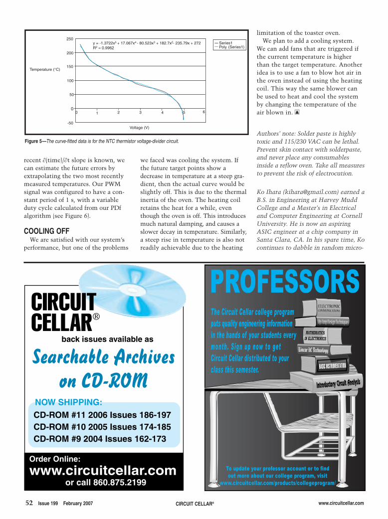
52 Issue 199 February 2007 CIRCUIT CELLAR® www.circuitcellar.com
recent ∂(time)/∂t slope is known, wecan estimate the future errors byextrapolating the two most recentlymeasured temperatures. Our PWMsignal was configured to have a con-stant period of 1 s, with a variableduty cycle calculated from our PDfalgorithm (see Figure 6).
COOLING OFFWe are satisfied with our system’s
performance, but one of the problems
we faced was cooling the system. Ifthe future target points show adecrease in temperature at a steep gra-dient, then the actual curve would beslightly off. This is due to the thermalinertia of the oven. The heating coilretains the heat for a while, eventhough the oven is off. This introducesmuch natural damping, and causes aslower decay in temperature. Similarly,a steep rise in temperature is also notreadily achievable due to the heating
limitation of the toaster oven. We plan to add a cooling system.
We can add fans that are triggered ifthe current temperature is higherthan the target temperature. Anotheridea is to use a fan to blow hot air inthe oven instead of using the heatingcoil. This way the same blower canbe used to heat and cool the systemby changing the temperature of theair blown in. I
Ko Ihara ([email protected]) earned aB.S. in Engineering at Harvey MuddCollege and a Master’s in Electricaland Computer Engineering at CornellUniversity. He is now an aspiringASIC engineer at a chip company inSanta Clara, CA. In his spare time, Kocontinues to dabble in random micro-
Authors’ note: Solder paste is highlytoxic and 115/230 VAC can be lethal.Prevent skin contact with solderpaste,and never place any consumablesinside a reflow oven. Take all measuresto prevent the risk of electrocution.
1 32 4 5 6
Voltage (V)
0
-50
0
50
100
150
200
250
Temperature (°C)
Series1Poly. (Series1)
y = -1.3722x5 + 17.067x4 - 80.523x3 + 182.7x2- 235.79x + 272R2 = 0.9962
Figure 5—The curve-fitted data is for the NTC thermistor voltage-divider circuit.
Order Online:
www.circuitcellar.com or call 860.875.2199
back issues available as
Searchable Archiveson CD-ROM
CD-ROM #11 2006 Issues 186-197CD-ROM #10 2005 Issues 174-185CD-ROM #9 2004 Issues 162-173
NOW SHIPPING:
Linear IC Technology
Introductory Circuit Analysis
Op-Amp Design Techniques
ELECTRONICCOMMUNICATIONS
MATHEMATICSIN ELECTRONICS
To update your professor account or to findout more about our college program, visit
www.circuitcellar.com/products/collegeprogram/
PROFESSORSThe Circuit Cellar college programputs quality engineering informationin the hands of your students everymonth. Sign up now to getCircuit Cellar distributed to yourclass this semester.
2701017 ihara.qxp 1/4/2007 10:48 AM Page 52
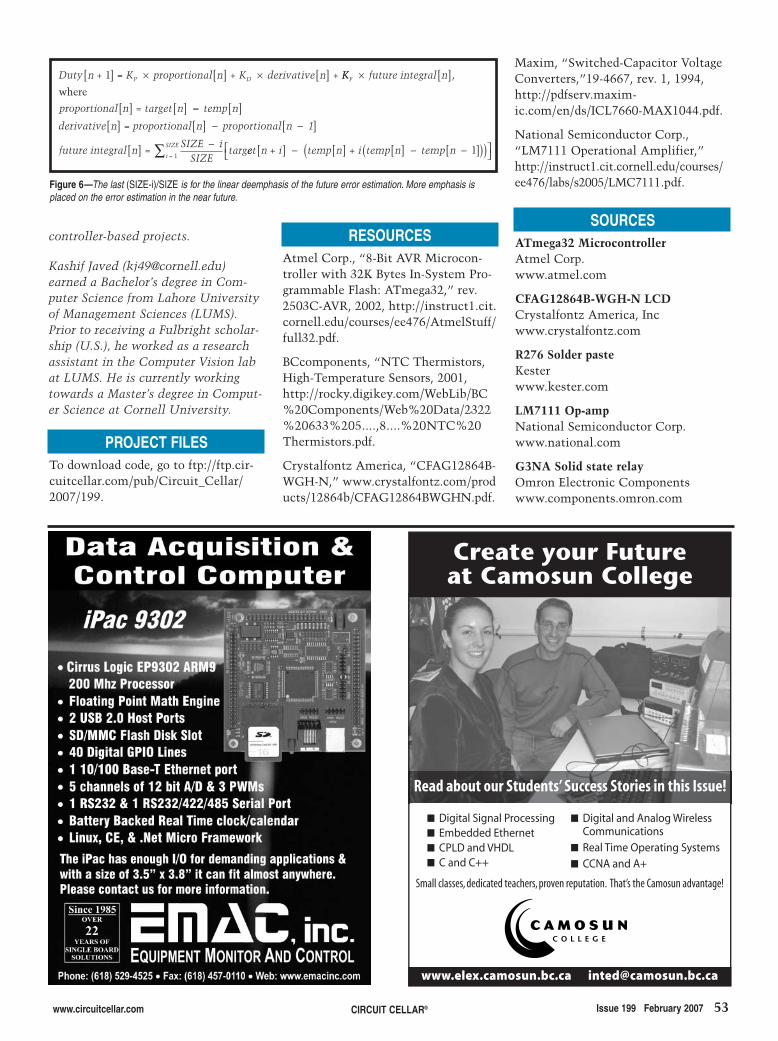
www.circuitcellar.com CIRCUIT CELLAR® Issue 199 February 2007 53
RESOURCESAtmel Corp., “8-Bit AVR Microcon-troller with 32K Bytes In-System Pro-grammable Flash: ATmega32,” rev.2503C-AVR, 2002, http://instruct1.cit.cornell.edu/courses/ee476/AtmelStuff/full32.pdf.
BCcomponents, “NTC Thermistors,High-Temperature Sensors, 2001,http://rocky.digikey.com/WebLib/BC%20Components/Web%20Data/2322%20633%205....,8....%20NTC%20Thermistors.pdf.
Crystalfontz America, “CFAG12864B-WGH-N,” www.crystalfontz.com/products/12864b/CFAG12864BWGHN.pdf.
SOURCESATmega32 MicrocontrollerAtmel Corp.www.atmel.com
CFAG12864B-WGH-N LCDCrystalfontz America, Incwww.crystalfontz.com
R276 Solder pasteKesterwww.kester.com
LM7111 Op-ampNational Semiconductor Corp.www.national.com
G3NA Solid state relayOmron Electronic Componentswww.components.omron.com
Kashif Javed ([email protected])earned a Bachelor’s degree in Com-puter Science from Lahore Universityof Management Sciences (LUMS).Prior to receiving a Fulbright scholar-ship (U.S.), he worked as a researchassistant in the Computer Vision labat LUMS. He is currently workingtowards a Master’s degree in Comput-er Science at Cornell University.
PROJECT FILESTo download code, go to ftp://ftp.cir-cuitcellar.com/pub/Circuit_Cellar/2007/199.
[ ]Duty n + 1 = K proportional n + K derivative n + P D× [ ] × [ ] KK future integral n
proportional n = target n
F × [ ]
[ ] [ ]
,
where
−− [ ][ ] [ ] −
temp n
derivative n = proportional n proportional n 1
future integral n = SIZE i
SIZEtarg
i =
SIZE
−[ ]
[ ] −∑ 1eet n + i temp n + i temp n temp n [ ] − [ ] [ ] − −[ ]( )( )⎡
⎣⎤⎦1
Figure 6—The last (SIZE-i)/SIZE is for the linear deemphasis of the future error estimation. More emphasis isplaced on the error estimation in the near future.
Maxim, “Switched-Capacitor VoltageConverters,”19-4667, rev. 1, 1994,http://pdfserv.maxim-ic.com/en/ds/ICL7660-MAX1044.pdf.
National Semiconductor Corp.,“LM7111 Operational Amplifier,”http://instruct1.cit.cornell.edu/courses/ee476/labs/s2005/LMC7111.pdf.
controller-based projects.
Create your Future at Camosun College
www.elex.camosun.bc.ca [email protected]
Digital Signal ProcessingEmbedded EthernetCPLD and VHDLC and C++
Digital and Analog WirelessCommunicationsReal Time Operating SystemsCCNA and A+
Small classes, dedicated teachers, proven reputation. That’s the Camosun advantage!
Read about our Students’ Success Stories in this Issue!
2701017 ihara.qxp 1/4/2007 10:48 AM Page 53
54 Issue 199 February 2007 CIRCUIT CELLAR® www.circuitcellar.com
the firmware utility that is runningfrom RAM in order to control communi-cation with the PC over a regular serialchannel, get new data from the PC, andwrite the data to flash memory. Toachieve this functionality and establishcommunication with the PC, the targetARM CPU has to initiate the loadingand running of its own firmware (usual-ly referred to as the bootloader).
In the AT91SAM7, the bootloader isin hidden ROM, where it’s invisibleunder normal conditions. In order toswitch the boot sequence to the boot-loader, the ARM SAM7 CPU has aspecial TST pin. “TST” is the abbrevi-ation for TEST SELECT pin. (Refer tothe SAM7 CPU’s datasheet). Whenyou apply VCC for 10 s to the TST pin ,the CPU copies the bootloaderfirmware from ROM to CPU RAM.Why is it so slow? At that time, theCPU is running on a 32-kHz crystal toensure the proper timing because thefrequency of the external crystal isunknown. The bootloader inside theARM CPU and the SAM-BA applica-tion on the PC must run at the sametime and communicate with each otherusing an x-modem predefined protocol.During this communication, the newdata for the flash memory is transferredfrom the PC to the ARM CPU.
While this idea seems fine, it has adisadvantage. The ARM CPU doesn’tknow when you’ve designed a firmwareupdate and if you’re running the SAM-BA software utility on your PC.
The Standard RS-232 channel doesnot have a spare wire to signal theARM CPU that it is time to initiatethe firmware update mode. This means
For many applications, especiallymobile and robotics designs, it wouldbe useful to be able to update theCPU’s firmware remotely, withouthaving to disassemble and reassemblethe device and its physical connectionto the CPU. This would save you a lotof time during the development stageof the design process. Such functional-ity would also be useful when you areworking with an ARM microcontrolleroperating in a potentially dangerousenvironment. Finally, note that thiskind of functionality can be very usefulfor field firmware updates, especiallywhen you don’t want the end user tohave to disassemble your device.
In this article, I’ll describe a few sim-ple ways to perform a remote firmwareupdate with an Atmel AT91SAM7SARM-based microcontroller. I used anAT91SAM7S-EK evaluation board forthis project. Atmel offers a free SAM-BA software utility for programmingthe CPU over a serial channel.
APPLICABLE METHODSAn ARM CPU can decode and run
firmware code from flash memory,just like every other microcontroller.In addition, it has the ability to decodeand run the code from RAM. Thismeans that you can place your code inthe RAM and run it from there. Dur-ing firmware execution, the flashmemory will remain untouchable. Ifthe flash memory is untouchable, itmeans that you can potentially modifythe flash memory on the fly withoutany collision with firmware that’salready running from RAM.
The next logical steps are to create
the PC can’t tell the ARM CPU that itis time to run the bootloader. Thus,you must do it manually. You mustapply VCC to the TST pin for 10 s. Afterthis, the CPU will copy the bootloaderfirmware from hidden ROM to RAMand run it from the RAM.
SEQUENCE OF ACTIONLet’s consider a typical sequence of
actions for updating the firmware on theAtmel ARM CPU, following the tradi-tional method. First, manually apply VCC
to the TST pin. Then you must wait 10s and release VCC from the TST pin. (Thefirst three steps will copy the bootloaderto the RAM.) Following this, run SAM-BA on the PC, update firmware, andpress the Reset button on the CPUboard. Finally, exit and run new code.
As you can see, you can control theentire process for firmware updatesfrom the PC via the serial channel(that means remotely and potentiallywirelessly), except for manipulation ofthe TST and RESET pins on the target-ed ARM CPU. In order to resolve thisproblem, I added a low-cost ATmega88microcontroller to my AT91SAM7Sevaluation board, which has a smallprototyping area (see Photo 1). To makethis modification, I had to connectthree pins (UART Rx, TST, and RESET)from the ATmega88 to the evaluationboard (see Figure 1). The ATmega88also requires power (from the evalua-tion board) and a crystal (7.37 MHz).
ATmega88 & CODEAlthough I used an ATmega88 (I had
a few of them on my shelf), you canuse any CPU in the AVR family with
FEATURE ARTICLE by Alex Deyneko
Wireless Firmware UpdatesAlex shows you how to perform a remote firmware update.You can use this technique for vir-tually all of your mobile and robotics applications. Now you don’t have to disassemble yourdevices and their physical connections to CPU boards.
2702018 deyneko.qxp 1/4/2007 10:50 AM Page 54
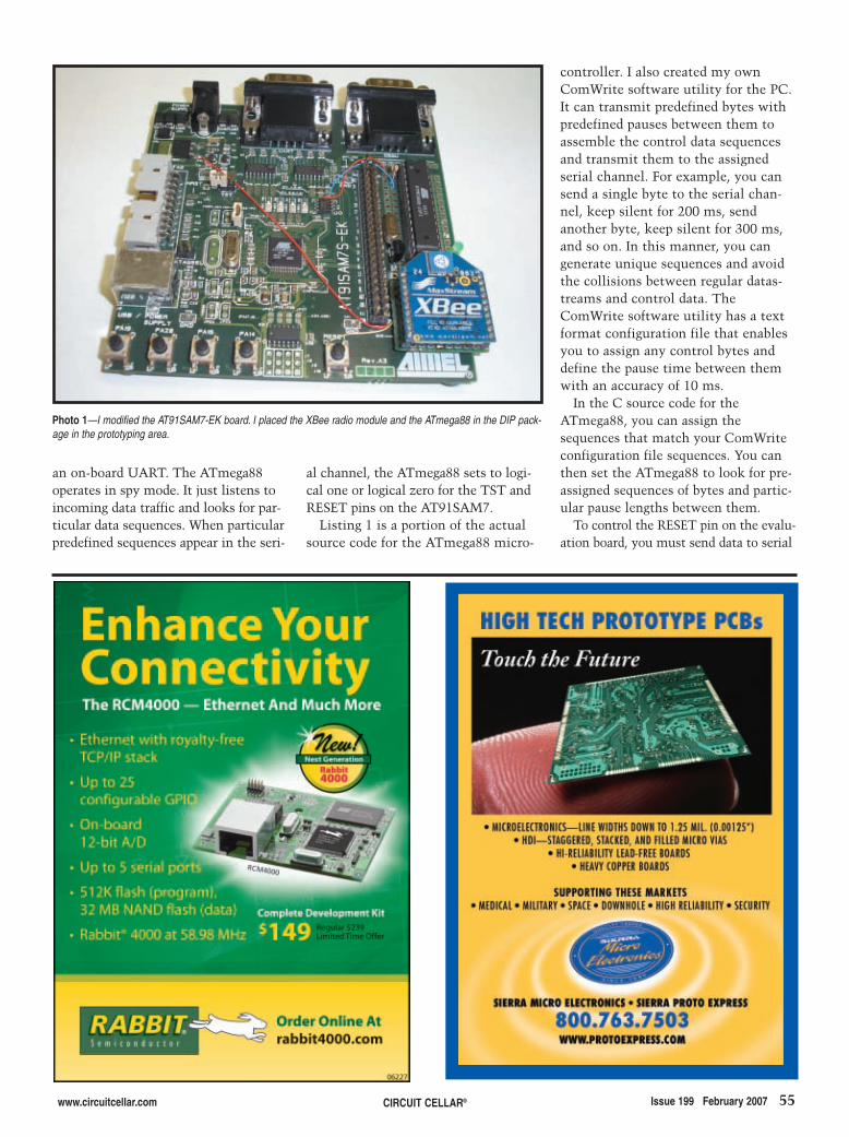
www.circuitcellar.com CIRCUIT CELLAR® Issue 199 February 2007 55
an on-board UART. The ATmega88operates in spy mode. It just listens toincoming data traffic and looks for par-ticular data sequences. When particularpredefined sequences appear in the seri-
al channel, the ATmega88 sets to logi-cal one or logical zero for the TST andRESET pins on the AT91SAM7.
Listing 1 is a portion of the actualsource code for the ATmega88 micro-
controller. I also created my ownComWrite software utility for the PC.It can transmit predefined bytes withpredefined pauses between them toassemble the control data sequencesand transmit them to the assignedserial channel. For example, you cansend a single byte to the serial chan-nel, keep silent for 200 ms, sendanother byte, keep silent for 300 ms,and so on. In this manner, you cangenerate unique sequences and avoidthe collisions between regular datas-treams and control data. TheComWrite software utility has a textformat configuration file that enablesyou to assign any control bytes anddefine the pause time between themwith an accuracy of 10 ms.
In the C source code for theATmega88, you can assign thesequences that match your ComWriteconfiguration file sequences. You canthen set the ATmega88 to look for pre-assigned sequences of bytes and partic-ular pause lengths between them.
To control the RESET pin on the evalu-ation board, you must send data to serial
Photo 1—I modified the AT91SAM7-EK board. I placed the XBee radio module and the ATmega88 in the DIP pack-age in the prototyping area.
2702018 deyneko.qxp 1/4/2007 10:50 AM Page 55

TS-5600 Shown with optional flash modules,A/D, RS-485 and Merlin cellular modem
TS-7200 shown with optional A/D converter,Compact Flash and RS-485
PC/104 Single Board Computers
Most products stocked and available
for next day shippingEngineers on Tech Support
Design your solution with one of our engineers (480) 837-5200
Custom configurations and designs w/
excellent pricing and turn-around time
Over 20 years in business
Never discontinued a product
133 MHz 586
Low Price, Low Power, High Reliability
using Linux development tools
see our website for 33 MHz 386 configurations
options include:onboard temperature sensor, A/D Converter 8 channel 12 bit, Extended Temperature,
Battery Backed Real Time Clock, USB Flash 256 M (with ARM Tool Chain), USB WiFi
SDRAM - up to 64MB
COM Ports - up to 4 ports
Fanless, no heat sink
Compact Flash adaptor
USB Ports (Except on TS-5300)
PCMCIA II adaptor
DIO Channels - up to 40
Ethernet Ports
Power as low as 800mA
options include:
RS-485 Half and Full Duplex, A/D Converter up to 8 Channels at
12 bits, DAC up to 2 Channels at 12 bits, Extended Temperature
Off-the-Shelf Solutions ready to design into
your project using DOS development tools
5 boards, over
2000 configurations
2 USB ports
10/100 Ethernet - up to 2
DIO lines - up to 55
Fanless, no heat sink
Flash - up to 128MB onboard
SDRAM - up to 128MB
Linux, Real Time extension, NetBSD
COM ports- up to 10
qty 10099$
qty 1129$
259$qty 1
229$qty 100
200 MHz ARM9Power as low as 1/4 Watt
SD card
option
NEW!
Open Source Vision
Programmable FPGAs VGA video
72.qxp 10/26/2006 11:13 AM Page 1

TechnologicS Y S T E M S
Visit our TS-7200 powered website at
We use our stuff.
www.embeddedARM.com
Tiny WiFi Controller
boots Linux in 1.1 seconds
Rugged aluminum enclosure
measures 1.1” x 4.9” x 3.1”
802.11g WiFi
200 MHz ARM9
SD Flash Card socket
1 external USB port
119$
Intelligent Battery Back-up
see our website for more boards and option details
12 bit A/D, DAC 8 channel 12-bit A/D converter, optional 2 channel 12-bit DAC,
A/D jumpered for 0-2.5V, 0-10V or 0-20mA
64 Digital I/O32 inputs, 32 outputs, 200 mA drive, optional 512 Kbyte or 1 MB
battery-backed SRAM, stack up to four boards, RoHS compliant
New Products and PC/104 Peripherals
Modems33.6K baud, 56K baud, AT commands, caller ID, cellular using
GSM and CDMA technologies
Non-volatile Memory up to 2MB, 10 year lithium battery
Serial Ports up to 4 serial ports with optional RS-485, opto-isolated available
ZigBee Wireless
CAN Bus ControllerPhilips SJA1000, opto-isolated, up to 1 megabit/sec
selectable termination resistor, Ocera Linux driver
qty 1249$
Up to 128M SDRAM
Run your system for days
with no external power source
qty 1
Up to 128MB Flash
3 TTL serial ports
1 10/100 Ethernet
low power wireless, simple serial interface, range up to 1 mile
73.qxp 10/26/2006 11:15 AM Page 1

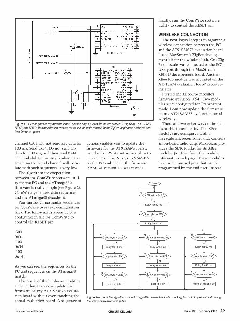
www.circuitcellar.com CIRCUIT CELLAR® Issue 199 February 2007 59
Finally, run the ComWrite softwareutility to control the RESET pin.
WIRELESS CONNECTIONThe next logical step is to organize a
wireless connection between the PCand the AT91SAM7S evaluation board.I used MaxStream’s ZigBee develop-ment kit for the wireless link. One Zig-Bee module was connected to the PC’sUSB port through the MaxStreamXBIB-U development board. AnotherXBee-Pro module was mounted on theAT91SAM evaluation board’ prototyp-ing area.
I tested the XBee-Pro module’sfirmware (revision 1094). Two mod-ules were configured for Transparentmode. I can now update the firmwareon my AT91SAM7S evaluation boardwirelessly.
There are two other ways to imple-ment this functionality. The XBeemodules are configured with aFreescale microcontroller that controlsan on-board radio chip. MaxSteam pro-vides the SDK toolkit for its XBeemodules (for free) from the moduleinformation web page. These moduleshave some unused pins that can beprogrammed by the end user. Instead
actions enables you to update thefirmware for the AT91SAM7. First,run the ComWrite software utility tocontrol TST pin. Next, run SAM-BAon the PC and update the firmware(SAM-BA version 1.9 was tested).
channel 0x01. Do not send any data for100 ms. Send 0x04. Do not send anydata for 100 ms, and then send 0x44.The probability that any random datas-tream on the serial channel will corre-late with such sequences is very low.
The algorithm for cooperationbetween the ComWrite software utili-ty for the PC and the ATmega88’sfirmware is really simple (see Figure 2).ComWrite generates data sequencesand the ATmega88 decodes it.
You can assign particular sequencesfor ComWrite over text configurationfiles. The following is a sample of aconfiguration file for ComWrite tocontrol the RESET pin:
.500 0x01.100 0x04.100 0x44
As you can see, the sequences on thePC and sequences on the ATmega88match.
The result of the hardware modifica-tions is that I can now update thefirmware on my AT91SAM7S evalua-tion board without even touching theactual evaluation board. A sequence of
Start
Is RX byte = 0x01?
Delay for 80 ms
Any byte on RX?
Delay for 40 ms
Is RX byte = 0x02?
Delay for 60 ms
Any byte on RX?
Delay for 40 ms
Is RX byte = 0x22?
Set TST pin
Is RX byte = 0x03?
Delay for 60 ms
Any byte on RX?
Delay for 40 ms
Is RX byte = 0x33?
Reset TST pin
Is RX byte = 0x04?
Delay for 60 ms
Any byte on RX?
Delay for 40 ms
Is RX byte = 0x44?
Pulse on RESET pin
N
N
N
N N
N N
Y Y Y
Y
Y
Y
Y
YY
Y
N N N
Y
N
Figure 2—This is the algorithm for the ATmega88 firmware. The CPU is looking for control bytes and calculatingthe timing between control bytes.
Figure 1—How do you like my modifications? I needed only six wires for the connection: 3.3 V, GND, TST, RESET,DTXD, and DRXD. This modification enables me to use the radio module for the ZigBee application and for a wire-less firmware update.
2702018 deyneko.qxp 1/4/2007 10:50 AM Page 59
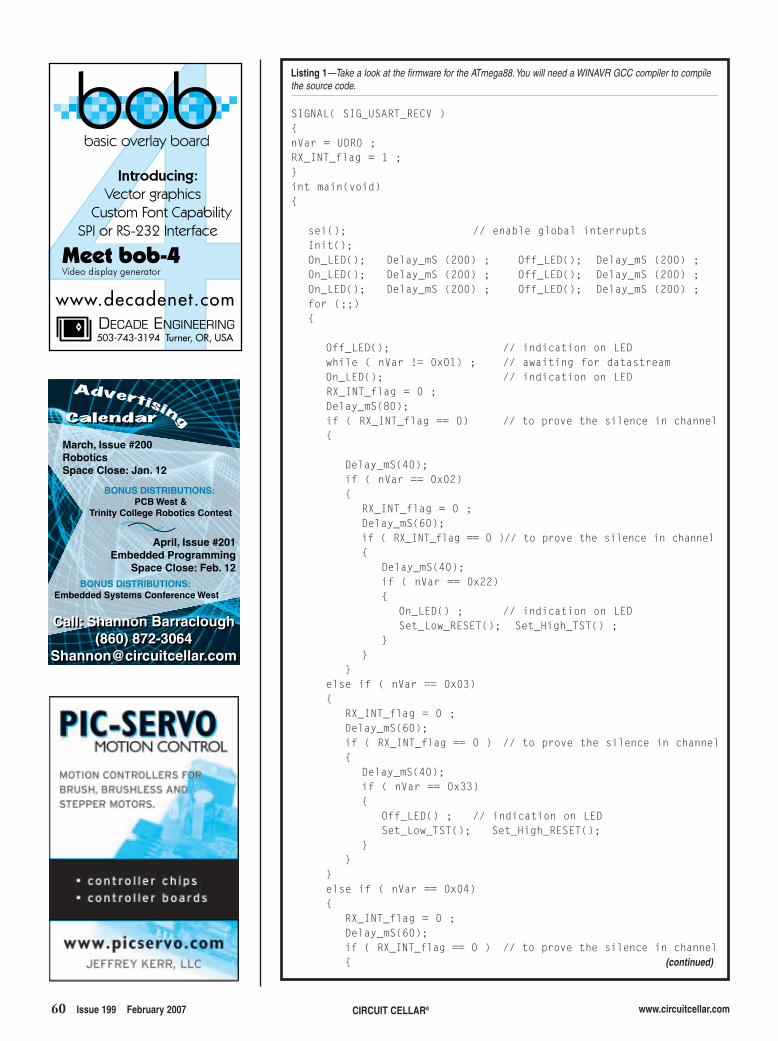
60 Issue 199 February 2007 CIRCUIT CELLAR® www.circuitcellar.com
Listing 1—Take a look at the firmware for the ATmega88.You will need a WINAVR GCC compiler to compilethe source code.
SIGNAL( SIG_USART_RECV ){nVar = UDR0 ;RX_INT_flag = 1 ;}int main(void){
sei(); // enable global interruptsInit();On_LED(); Delay_mS (200) ; Off_LED(); Delay_mS (200) ;On_LED(); Delay_mS (200) ; Off_LED(); Delay_mS (200) ;On_LED(); Delay_mS (200) ; Off_LED(); Delay_mS (200) ;for (;;){
Off_LED(); // indication on LEDwhile ( nVar != 0x01) ; // awaiting for datastreamOn_LED(); // indication on LEDRX_INT_flag = 0 ;Delay_mS(80);if ( RX_INT_flag == 0) // to prove the silence in channel{
Delay_mS(40);if ( nVar == 0x02){
RX_INT_flag = 0 ;Delay_mS(60);if ( RX_INT_flag == 0 )// to prove the silence in channel{
Delay_mS(40);if ( nVar == 0x22){
On_LED() ; // indication on LEDSet_Low_RESET(); Set_High_TST() ;
}}
}else if ( nVar == 0x03){
RX_INT_flag = 0 ;Delay_mS(60);if ( RX_INT_flag == 0 ) // to prove the silence in channel{
Delay_mS(40);if ( nVar == 0x33){
Off_LED() ; // indication on LEDSet_Low_TST(); Set_High_RESET();
}}
}else if ( nVar == 0x04){
RX_INT_flag = 0 ;Delay_mS(60);if ( RX_INT_flag == 0 ) // to prove the silence in channel{ (continued)
March, Issue #200
Robotics
Space Close: Jan. 12
BONUS DISTRIBUTIONS:
PCB West &
Trinity College Robotics Contest
April, Issue #201
Embedded Programming
Space Close: Feb. 12
Call: Shannon Barraclough
(860) 872-3064
Call: Shannon Barraclough
(860) 872-3064
BONUS DISTRIBUTIONS:
Embedded Systems Conference West
2702018 deyneko.qxp 1/4/2007 10:50 AM Page 60
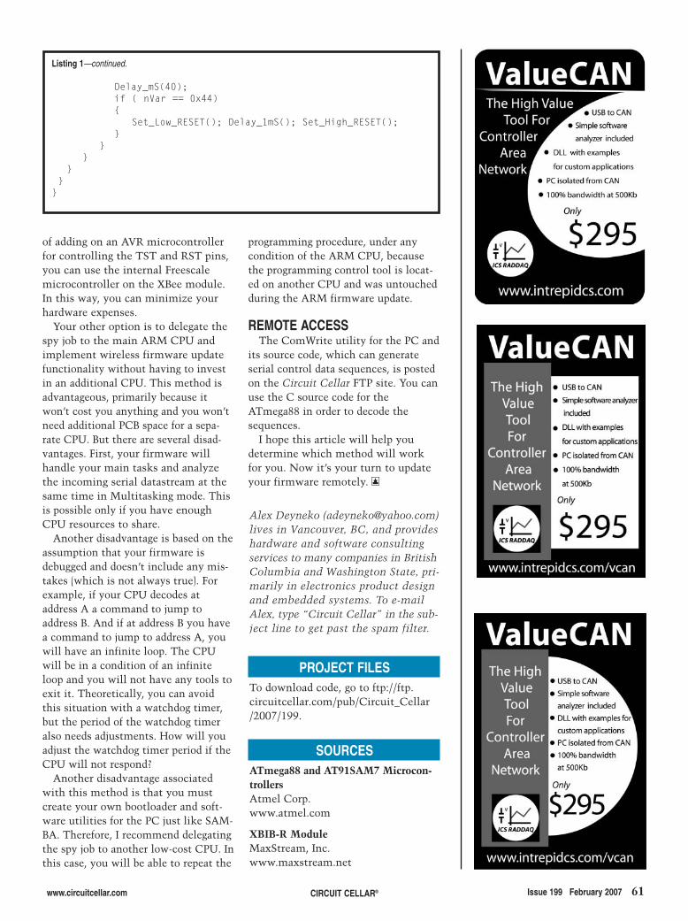
www.circuitcellar.com CIRCUIT CELLAR® Issue 199 February 2007 61
of adding on an AVR microcontrollerfor controlling the TST and RST pins,you can use the internal Freescalemicrocontroller on the XBee module.In this way, you can minimize yourhardware expenses.
Your other option is to delegate thespy job to the main ARM CPU andimplement wireless firmware updatefunctionality without having to investin an additional CPU. This method isadvantageous, primarily because itwon’t cost you anything and you won’tneed additional PCB space for a sepa-rate CPU. But there are several disad-vantages. First, your firmware willhandle your main tasks and analyzethe incoming serial datastream at thesame time in Multitasking mode. Thisis possible only if you have enoughCPU resources to share.
Another disadvantage is based on theassumption that your firmware isdebugged and doesn’t include any mis-takes (which is not always true). Forexample, if your CPU decodes ataddress A a command to jump toaddress B. And if at address B you havea command to jump to address A, youwill have an infinite loop. The CPUwill be in a condition of an infiniteloop and you will not have any tools toexit it. Theoretically, you can avoidthis situation with a watchdog timer,but the period of the watchdog timeralso needs adjustments. How will youadjust the watchdog timer period if theCPU will not respond?
Another disadvantage associatedwith this method is that you mustcreate your own bootloader and soft-ware utilities for the PC just like SAM-BA. Therefore, I recommend delegatingthe spy job to another low-cost CPU. Inthis case, you will be able to repeat the
Alex Deyneko ([email protected])lives in Vancouver, BC, and provideshardware and software consultingservices to many companies in BritishColumbia and Washington State, pri-marily in electronics product designand embedded systems. To e-mailAlex, type “Circuit Cellar” in the sub-ject line to get past the spam filter.
PROJECT FILESTo download code, go to ftp://ftp.circuitcellar.com/pub/Circuit_Cellar/2007/199.
SOURCESATmega88 and AT91SAM7 Microcon-trollersAtmel Corp.www.atmel.com
XBIB-R ModuleMaxStream, Inc.www.maxstream.net
programming procedure, under anycondition of the ARM CPU, becausethe programming control tool is locat-ed on another CPU and was untouchedduring the ARM firmware update.
REMOTE ACCESSThe ComWrite utility for the PC and
its source code, which can generateserial control data sequences, is postedon the Circuit Cellar FTP site. You canuse the C source code for theATmega88 in order to decode thesequences.
I hope this article will help youdetermine which method will workfor you. Now it’s your turn to updateyour firmware remotely. I
Listing 1—continued.
Delay_mS(40);if ( nVar == 0x44){
Set_Low_RESET(); Delay_1mS(); Set_High_RESET();}
}}
}}
}
2702018 deyneko.qxp 1/4/2007 10:50 AM Page 61
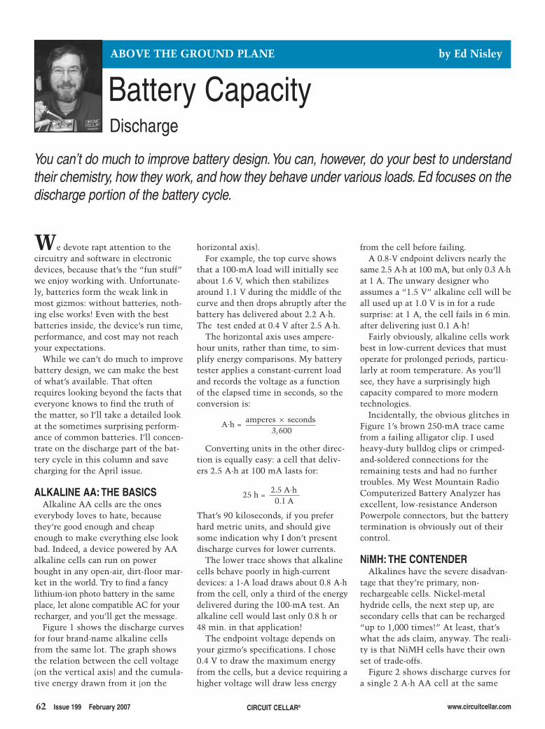
62 Issue 199 February 2007 CIRCUIT CELLAR® www.circuitcellar.com
We devote rapt attention to thecircuitry and software in electronicdevices, because that’s the “fun stuff”we enjoy working with. Unfortunate-ly, batteries form the weak link inmost gizmos: without batteries, noth-ing else works! Even with the bestbatteries inside, the device’s run time,performance, and cost may not reachyour expectations.
While we can’t do much to improvebattery design, we can make the bestof what’s available. That oftenrequires looking beyond the facts thateveryone knows to find the truth ofthe matter, so I’ll take a detailed lookat the sometimes surprising perform-ance of common batteries. I’ll concen-trate on the discharge part of the bat-tery cycle in this column and savecharging for the April issue.
ALKALINE AA: THE BASICSAlkaline AA cells are the ones
everybody loves to hate, becausethey’re good enough and cheapenough to make everything else lookbad. Indeed, a device powered by AAalkaline cells can run on powerbought in any open-air, dirt-floor mar-ket in the world. Try to find a fancylithium-ion photo battery in the sameplace, let alone compatible AC for yourrecharger, and you’ll get the message.
Figure 1 shows the discharge curvesfor four brand-name alkaline cellsfrom the same lot. The graph showsthe relation between the cell voltage(on the vertical axis) and the cumula-tive energy drawn from it (on the
horizontal axis).For example, the top curve shows
that a 100-mA load will initially seeabout 1.6 V, which then stabilizesaround 1.1 V during the middle of thecurve and then drops abruptly after thebattery has delivered about 2.2 A·h.The test ended at 0.4 V after 2.5 A·h.
The horizontal axis uses ampere-hour units, rather than time, to sim-plify energy comparisons. My batterytester applies a constant-current loadand records the voltage as a functionof the elapsed time in seconds, so theconversion is:
Converting units in the other direc-tion is equally easy: a cell that deliv-ers 2.5 A·h at 100 mA lasts for:
That’s 90 kiloseconds, if you preferhard metric units, and should givesome indication why I don’t presentdischarge curves for lower currents.
The lower trace shows that alkalinecells behave poorly in high-currentdevices: a 1-A load draws about 0.8 A·hfrom the cell, only a third of the energydelivered during the 100-mA test. Analkaline cell would last only 0.8 h or48 min. in that application!
The endpoint voltage depends onyour gizmo’s specifications. I chose0.4 V to draw the maximum energyfrom the cells, but a device requiring ahigher voltage will draw less energy
252 50 1
=
hA.hA
..
A.h = amperes × seconds,3 600
from the cell before failing.A 0.8-V endpoint delivers nearly the
same 2.5 A·h at 100 mA, but only 0.3 A·hat 1 A. The unwary designer whoassumes a “1.5 V” alkaline cell will beall used up at 1.0 V is in for a rudesurprise: at 1 A, the cell fails in 6 min.after delivering just 0.1 A·h!
Fairly obviously, alkaline cells workbest in low-current devices that mustoperate for prolonged periods, particu-larly at room temperature. As you’llsee, they have a surprisingly highcapacity compared to more moderntechnologies.
Incidentally, the obvious glitches inFigure 1’s brown 250-mA trace camefrom a failing alligator clip. I usedheavy-duty bulldog clips or crimped-and-soldered connections for theremaining tests and had no furthertroubles. My West Mountain RadioComputerized Battery Analyzer hasexcellent, low-resistance AndersonPowerpole connectors, but the batterytermination is obviously out of theircontrol.
NiMH: THE CONTENDERAlkalines have the severe disadvan-
tage that they’re primary, non-rechargeable cells. Nickel-metalhydride cells, the next step up, aresecondary cells that can be recharged“up to 1,000 times!” At least, that’swhat the ads claim, anyway. The reali-ty is that NiMH cells have their ownset of trade-offs.
Figure 2 shows discharge curves fora single 2 A·h AA cell at the same
Battery Capacity
You can’t do much to improve battery design.You can, however, do your best to understandtheir chemistry, how they work, and how they behave under various loads. Ed focuses on thedischarge portion of the battery cycle.
ABOVE THE GROUND PLANE by Ed Nisley
Discharge
2702004-nisley.qxp 1/4/2007 10:51 AM Page 62
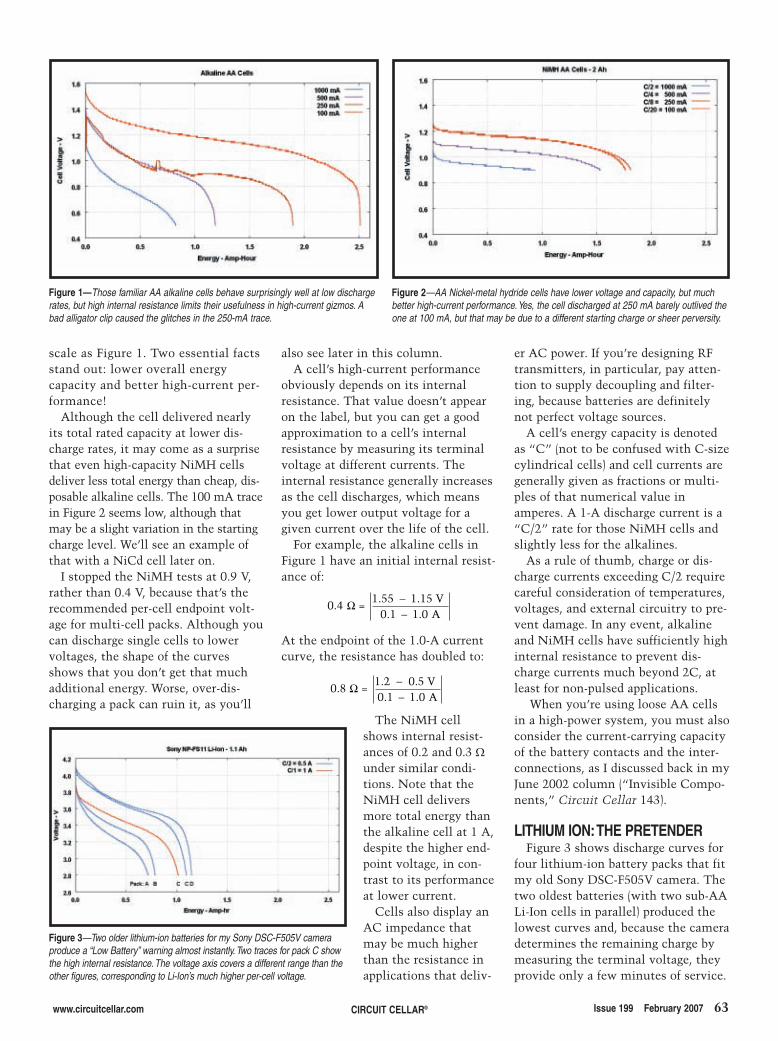
www.circuitcellar.com CIRCUIT CELLAR® Issue 199 February 2007 63
scale as Figure 1. Two essential factsstand out: lower overall energycapacity and better high-current per-formance!
Although the cell delivered nearlyits total rated capacity at lower dis-charge rates, it may come as a surprisethat even high-capacity NiMH cellsdeliver less total energy than cheap, dis-posable alkaline cells. The 100 mA tracein Figure 2 seems low, although thatmay be a slight variation in the startingcharge level. We’ll see an example ofthat with a NiCd cell later on.
I stopped the NiMH tests at 0.9 V,rather than 0.4 V, because that’s therecommended per-cell endpoint volt-age for multi-cell packs. Although youcan discharge single cells to lowervoltages, the shape of the curvesshows that you don’t get that muchadditional energy. Worse, over-dis-charging a pack can ruin it, as you’ll
also see later in this column.A cell’s high-current performance
obviously depends on its internalresistance. That value doesn’t appearon the label, but you can get a goodapproximation to a cell’s internalresistance by measuring its terminalvoltage at different currents. Theinternal resistance generally increasesas the cell discharges, which meansyou get lower output voltage for agiven current over the life of the cell.
For example, the alkaline cells inFigure 1 have an initial internal resist-ance of:
At the endpoint of the 1.0-A currentcurve, the resistance has doubled to:
The NiMH cellshows internal resist-ances of 0.2 and 0.3 Ωunder similar condi-tions. Note that theNiMH cell deliversmore total energy thanthe alkaline cell at 1 A,despite the higher end-point voltage, in con-trast to its performanceat lower current.
Cells also display anAC impedance thatmay be much higherthan the resistance inapplications that deliv-
0 81 2 0 50 1 1 0
.. .. .
=
Ω −−
VA
0 41 55 1 15
0 1 1 0.
. .. .
=
Ω −−
VA
er AC power. If you’re designing RFtransmitters, in particular, pay atten-tion to supply decoupling and filter-ing, because batteries are definitelynot perfect voltage sources.
A cell’s energy capacity is denotedas “C” (not to be confused with C-sizecylindrical cells) and cell currents aregenerally given as fractions or multi-ples of that numerical value inamperes. A 1-A discharge current is a“C/2” rate for those NiMH cells andslightly less for the alkalines.
As a rule of thumb, charge or dis-charge currents exceeding C/2 requirecareful consideration of temperatures,voltages, and external circuitry to pre-vent damage. In any event, alkalineand NiMH cells have sufficiently highinternal resistance to prevent dis-charge currents much beyond 2C, atleast for non-pulsed applications.
When you’re using loose AA cellsin a high-power system, you must alsoconsider the current-carrying capacityof the battery contacts and the inter-connections, as I discussed back in myJune 2002 column (“Invisible Compo-nents,” Circuit Cellar 143).
LITHIUM ION:THE PRETENDERFigure 3 shows discharge curves for
four lithium-ion battery packs that fitmy old Sony DSC-F505V camera. Thetwo oldest batteries (with two sub-AALi-Ion cells in parallel) produced thelowest curves and, because the cameradetermines the remaining charge bymeasuring the terminal voltage, theyprovide only a few minutes of service.
Figure 1—Those familiar AA alkaline cells behave surprisingly well at low dischargerates, but high internal resistance limits their usefulness in high-current gizmos. Abad alligator clip caused the glitches in the 250-mA trace.
Figure 2—AA Nickel-metal hydride cells have lower voltage and capacity, but muchbetter high-current performance.Yes, the cell discharged at 250 mA barely outlived theone at 100 mA, but that may be due to a different starting charge or sheer perversity.
Figure 3—Two older lithium-ion batteries for my Sony DSC-F505V cameraproduce a “Low Battery” warning almost instantly. Two traces for pack C showthe high internal resistance. The voltage axis covers a different range than theother figures, corresponding to Li-Ion’s much higher per-cell voltage.
2702004-nisley.qxp 1/4/2007 10:51 AM Page 63
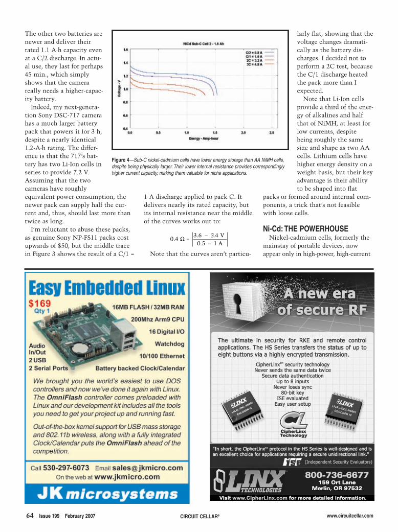
64 Issue 199 February 2007 CIRCUIT CELLAR® www.circuitcellar.com
The other two batteries arenewer and deliver theirrated 1.1 A·h capacity evenat a C/2 discharge. In actu-al use, they last for perhaps45 min., which simplyshows that the camerareally needs a higher-capac-ity battery.
Indeed, my next-genera-tion Sony DSC-717 camerahas a much larger batterypack that powers it for 3 h,despite a nearly identical1.2-A·h rating. The differ-ence is that the 717’s bat-tery has two Li-Ion cells inseries to provide 7.2 V.Assuming that the twocameras have roughlyequivalent power consumption, thenewer pack can supply half the cur-rent and, thus, should last more thantwice as long.
I’m reluctant to abuse these packs,as genuine Sony NP-FS11 packs costupwards of $50, but the middle tracein Figure 3 shows the result of a C/1 =
larly flat, showing that thevoltage changes dramati-cally as the battery dis-charges. I decided not toperform a 2C test, becausethe C/1 discharge heatedthe pack more than Iexpected.
Note that Li-Ion cellsprovide a third of the ener-gy of alkalines and halfthat of NiMH, at least forlow currents, despitebeing roughly the samesize and shape as two AAcells. Lithium cells havehigher energy density on aweight basis, but their keyadvantage is their abilityto be shaped into flat
packs or formed around internal com-ponents, a trick that’s not feasiblewith loose cells.
Ni-Cd: THE POWERHOUSENickel-cadmium cells, formerly the
mainstay of portable devices, nowappear only in high-power, high-current
1 A discharge applied to pack C. Itdelivers nearly its rated capacity, butits internal resistance near the middleof the curves works out to:
Note that the curves aren’t particu-
0 43 6 4
0 5 1.
. ..
= 3
Ω −
−V
A
Figure 4—Sub-C nickel-cadmium cells have lower energy storage than AA NiMH cells,despite being physically larger. Their lower internal resistance provides correspondinglyhigher current capacity, making them valuable for niche applications.
2702004-nisley.qxp 1/4/2007 10:51 AM Page 64
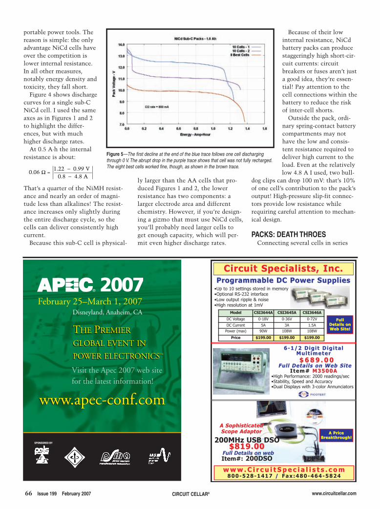
ly larger than the AA cells that pro-duced Figures 1 and 2, the lowerresistance has two components: alarger electrode area and differentchemistry. However, if you’re design-ing a gizmo that must use NiCd cells,you’ll probably need larger cells toget enough capacity, which will per-mit even higher discharge rates.
Because of their lowinternal resistance, NiCdbattery packs can producestaggeringly high short-cir-cuit currents: circuitbreakers or fuses aren’t justa good idea, they’re essen-tial! Pay attention to thecell connections within thebattery to reduce the riskof inter-cell shorts.
Outside the pack, ordi-nary spring-contact batterycompartments may nothave the low and consis-tent resistance required todeliver high current to theload. Even at the relativelylow 4.8 A I used, two bull-
dog clips can drop 100 mV: that’s 10%of one cell’s contribution to the pack’soutput! High-pressure slip-fit connec-tors provide low resistance whilerequiring careful attention to mechan-ical design.
PACKS: DEATH THROES Connecting several cells in series
66 Issue 199 February 2007 CIRCUIT CELLAR® www.circuitcellar.com
portable power tools. Thereason is simple: the onlyadvantage NiCd cells haveover the competition islower internal resistance.In all other measures,notably energy density andtoxicity, they fall short.
Figure 4 shows dischargecurves for a single sub-CNiCd cell. I used the sameaxes as in Figures 1 and 2to highlight the differ-ences, but with muchhigher discharge rates.
At 0.5 A·h the internalresistance is about:
That’s a quarter of the NiMH resist-ance and nearly an order of magni-tude less than alkalines! The resist-ance increases only slightly duringthe entire discharge cycle, so thecells can deliver consistently highcurrent.
Because this sub-C cell is physical-
0 061 22 0 99
0 8 4 8.
. .. .
=
Ω −−
VA
Figure 5—The first decline at the end of the blue trace follows one cell dischargingthrough 0 V. The abrupt drop in the purple trace shows that cell was not fully recharged.The eight best cells worked fine, though, as shown in the brown trace.
Visit the Apec 2007 web sitefor the latest information!
www.apec-conf.comwww.apec-conf.com
2007February 25–March 1, 2007
Disneyland, Anaheim, CA
THE PREMIER
GLOBAL EVENT IN
POWER ELECTRONICSTM
THE PREMIER
GLOBAL EVENT IN
POWER ELECTRONICSTM
SPONSORED BY
A SophisticatedA SophisticatedScope AdaptorScope Adaptor
200MHz USB DSO$819.00$819.00
Full Details on webItem#: 200DSO
A PriceA PriceBreakthrough!Breakthrough!
FullFullDetails onDetails onWeb Site!Web Site!
w w w . C i r c u i t S p e c i a l i s t s . c o mw w w . C i r c u i t S p e c i a l i s t s . c o m800-528-1417 / / Fax:480-464-5824
6-1/2 Digit Digital6-1/2 Digit DigitalMult imeterMult imeter$ 6 8 9 . 0 0$ 6 8 9 . 0 0
Full Details on Web SiteFull Details on Web SiteItem# Item# M3500AM3500A
•High Performance: 2000 readings/sec•Stability, Speed and Accuracy•Dual Displays with 3-color Annunciators
Programmable DC Power SuppliesProgrammable DC Power Supplies
Model CSI3644A CSI3645A CSI3646A
DC Voltage 0-18V 0-36V 0-72V
DC Current 5A 3A 1.5APower (max) 90W 108W 108W
Price $199.00 $199.00 $199.00
•Up to 10 settings stored in memory •Optional RS-232 interface•Low output ripple & noise •High resolution at 1mV
Circuit Specialists, Inc.Circuit Specialists, Inc.
2702004-nisley.qxp 1/4/2007 10:51 AM Page 66
inside a battery pack provides highervoltage and delivers more power atthe same current. The pack’s totalenergy is the sum of the individualcells, but it has the same A·h ratingas each cell because the same cur-rent passes through each one.
All of the cells in a pack should beidentical, but in real life that doesnot happen. Figure 5 shows the deathof a battery pack when the weakestcell fails.
The pack was a watertight casecontaining 10 1.6 A·h sub-C NiCdcells with an integral C/2 charger. Itwas a “New Old Stock” surplus itemthat had been built for a failed prod-uct line and, presumably, never used.I figured out how the chargerworked, charged the pack, and thenmeasured the pack’s performance.
The blue trace seems normal outto about 1.1 A·h, at which point oneof the cells was completely dis-charged and its voltage dropped tozero. Almost immediately anothercell discharged and, with two deadcells, the pack reached 9.0 V and thetest ended. The pack delivered some-what less than its rated 1.6 A·h, butwith at least one weak cell, it’s inbad shape.
The purple trace shows the resultafter recharging the pack. The weak-est cell evidently did not receive afull charge and dropped to 0 Valmost immediately. For the remain-der of the test, that cell was “reversecharging” and producing hydrogengas. NiCd cells can contain a limitedamount of hydrogen gas under thoseconditions and it probably didn’tvent the gas into the sealed enclosure,but you shouldn’t treat your batterieslike that. I terminated the test at 10 V,a more conservative 1 V/cell value,because I wanted to prevent any fur-ther damage.
I removed the two weakest cellsand the charger, manually charged theremaining eight cells, and the browntrace shows that they work fine withabout 1.4 A·h of energy. Because NiCdcells improve after a few charge-dis-charge cycles, these cells will playnicely together as a 9.6-V pack pow-ering the HT on my bike.
Contrary to what you might think,
the weakest cell isn’t dead and, infact, produced Figure 4. Its first solocharge cycle, though, was a bit of achallenge, but that’s a subject for thenext column.
CONTACT RELEASEI produced the discharge curves
for this column with a West Moun-tain Radio Computerized BatteryAnalyzer (CBA). It’s basically apower FET mounted on a fan-cooledheatsink, a voltmeter, and an amme-ter, all USB-interfaced to a loggingprogram. I wish it had Kelvin voltagesensing and a Linux driver, but itworks well enough.
The CBA records one data pointper second, producing huge files thatchoke spreadsheet programs. I usedGnuplot to produce these graphs,with Bash scripts feeding it the com-mands for each figure. The detailsare in this column’s downloadablefiles. I
www.circuitcellar.com CIRCUIT CELLAR® Issue 199 February 2007 67
Ed Nisley is an EE and author inPoughkeepsie, NY. You may contacthim at [email protected] with “Cir-cuit Cellar” in the subject to avoidspam filters.
PROJECT FILESTo download the Graphs, Gnuplotscripts, etc., go to ftp://ftp.circuitcel-lar.com/pub/Circuit_Cellar/2007/199.
RESOURCESExhaustive NiCd information, www.rcbatteryclinic.com/seminar.htm.
Excellent battery comparison,www.buchmann.ca/Article4-Page1.asp.
SOURCESGnuPlothttp://gnuplot.info/
Anderson PowerPolesPowerWerx www.powerwerkx.com
Computerized Battery AnalyzerWest Mountain Radio http://westmountainradio.com
2702004-nisley.qxp 1/4/2007 10:52 AM Page 67
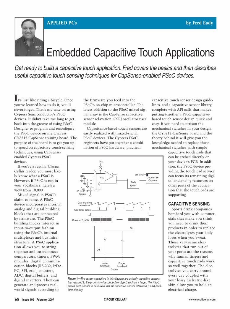
capacitive touch sensor design guide-lines, and a capacitive sensor library,complete with API calls that makesputting together a PSoC capacitive-based touch sensor design quick andeasy. If you need to jettison themechanical switches in your design,the CY3212-CapSense board and thetheory behind it will give you theknowledge needed to replace thosemechanical switches with simple
capacitive touch pads thatcan be etched directly onyour device’s PCB. In addi-tion, the PSoC device pro-viding the touch pad servicecan focus its remaining digi-tal and analog resources onother parts of the applica-tion that the touch pads aresupporting.
CAPACITIVE SENSING Sports drink companies
bombard you with commer-cials that make you thinkyou need to drink theirproducts in order to replacethe electrolytes your bodyloses when you sweat.Those very same elec-trolytes that run out ofyour pores are the reasonswhy human fingers andcapacitive touch pads workso well together. The elec-trolytes you carry aroundevery day coupled withyour lossy dielectric-likeskin allow you to hold anelectrical charge.
68 Issue 199 February 2007 CIRCUIT CELLAR® www.circuitcellar.com
the firmware you feed into thePSoC’s on-chip microcontroller. Thelatest addition to the PSoC mixed-sig-nal array is the CapSense capacitivesensor relaxation (CSR) oscillator usermodule.
Capacitance-based touch sensors areeasily realized with mixed-signalPSoC devices. The Cypress PSoCengineers have put together a combi-nation of PSoC hardware, practical
It’s just like riding a bicycle. Onceyou’ve learned how to do it, you’llnever forget. That’s my take on usingCypress Semiconductor’s PSoCdevices. It didn’t take me long to getback into the groove of using PSoCDesigner to program and reconfigurethe PSoC device on my CypressCY3212 CapSense training board. Thepurpose of the board is to get you upto speed on capacitive touch-sensingtechniques, using CapSense-enabled Cypress PSoCdevices.
If you’re a regular CircuitCellar reader, you most like-ly know what a PSoC is.However, if PSoC is not inyour vocabulary, here’s aview from 10,000′.
Mixed signal is PSoC’sclaim to fame. A PSoCdevice incorporates internalanalog and digital buildingblocks that are connectedby firmware. The PSoCbuilding blocks interact ininput-to-output fashionusing the PSoC’s internalmultiplexer and bus infra-structure. A PSoC applica-tion allows you to stringtogether and interconnectcomparators, timers, PWMmodules, digital communi-cation blocks (RS-232, IrDA,I2C, SPI, etc.), counters,ADC, digital buffers, anddigital inverters. They cangenerate and process real-world signals according to
Embedded Capacitive Touch Applications
APPLIED PCs by Fred Eady
Get ready to build a capacitive touch application. Fred covers the basics and then describesuseful capacitive touch sensing techniques for CapSense-enabled PSoC devices.
Counter 16Capture
PWM(gate)
24 MHzFOSC+
–VTH
VDD
Cp(i)
10 to 30 pFTypical
Cap chargingwaveform
Oscillator output
Counted SysClk
On
Off
Noisethreshold
Fingerthreshold
Counts
Figure 1—The sensor capacitors in this diagram are actually capacitive sensorsthat respond to the proximity of a conductive object, such as a finger. The PSoCallows each sensor to be muxed into the capacitive sensor relaxation (CSR) oscil-lator circuitry.
2702012-eady.qxp 1/4/2007 10:53 AM Page 68
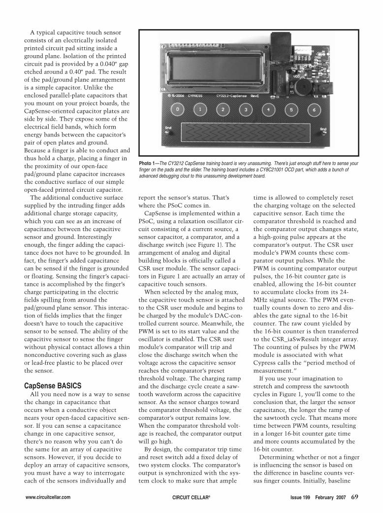
www.circuitcellar.com CIRCUIT CELLAR® Issue 199 February 2007 69
A typical capacitive touch sensorconsists of an electrically isolatedprinted circuit pad sitting inside aground plane. Isolation of the printedcircuit pad is provided by a 0.040″ gapetched around a 0.40″ pad. The resultof the pad/ground plane arrangementis a simple capacitor. Unlike theenclosed parallel-plate capacitors thatyou mount on your project boards, theCapSense-oriented capacitor plates areside by side. They expose some of theelectrical field bands, which formenergy bands between the capacitor’spair of open plates and ground.Because a finger is able to conduct andthus hold a charge, placing a finger inthe proximity of our open-facepad/ground plane capacitor increasesthe conductive surface of our simpleopen-faced printed circuit capacitor.
The additional conductive surfacesupplied by the intruding finger addsadditional charge storage capacity,which you can see as an increase ofcapacitance between the capacitivesensor and ground. Interestinglyenough, the finger adding the capaci-tance does not have to be grounded. Infact, the finger’s added capacitancecan be sensed if the finger is groundedor floating. Sensing the finger’s capaci-tance is accomplished by the finger’scharge participating in the electricfields spilling from around thepad/ground plane sensor. This interac-tion of fields implies that the fingerdoesn’t have to touch the capacitivesensor to be sensed. The ability of thecapacitive sensor to sense the fingerwithout physical contact allows a thinnonconductive covering such as glassor lead-free plastic to be placed overthe sensor.
CapSense BASICSAll you need now is a way to sense
the change in capacitance thatoccurs when a conductive objectnears your open-faced capacitive sen-sor. If you can sense a capacitancechange in one capacitive sensor,there’s no reason why you can’t dothe same for an array of capacitivesensors. However, if you decide todeploy an array of capacitive sensors,you must have a way to interrogateeach of the sensors individually and
report the sensor’s status. That’swhere the PSoC comes in.
CapSense is implemented within aPSoC, using a relaxation oscillator cir-cuit consisting of a current source, asensor capacitor, a comparator, and adischarge switch (see Figure 1). Thearrangement of analog and digitalbuilding blocks is officially called aCSR user module. The sensor capaci-tors in Figure 1 are actually an array ofcapacitive touch sensors.
When selected by the analog mux,the capacitive touch sensor is attachedto the CSR user module and begins tobe charged by the module’s DAC-con-trolled current source. Meanwhile, thePWM is set to its start value and theoscillator is enabled. The CSR usermodule’s comparator will trip andclose the discharge switch when thevoltage across the capacitive sensorreaches the comparator’s presetthreshold voltage. The charging rampand the discharge cycle create a saw-tooth waveform across the capacitivesensor. As the sensor charges towardthe comparator threshold voltage, thecomparator’s output remains low.When the comparator threshold volt-age is reached, the comparator outputwill go high.
By design, the comparator trip timeand reset switch add a fixed delay oftwo system clocks. The comparator’soutput is synchronized with the sys-tem clock to make sure that ample
time is allowed to completely resetthe charging voltage on the selectedcapacitive sensor. Each time thecomparator threshold is reached andthe comparator output changes state,a high-going pulse appears at thecomparator’s output. The CSR usermodule’s PWM counts these com-parator output pulses. While thePWM is counting comparator outputpulses, the 16-bit counter gate isenabled, allowing the 16-bit counterto accumulate clocks from its 24-MHz signal source. The PWM even-tually counts down to zero and dis-ables the gate signal to the 16-bitcounter. The raw count yielded bythe 16-bit counter is then transferredto the CSR_iaSwResult integer array.The counting of pulses by the PWMmodule is associated with whatCypress calls the “period method ofmeasurement.”
If you use your imagination tostretch and compress the sawtoothcycles in Figure 1, you’ll come to theconclusion that, the larger the sensorcapacitance, the longer the ramp ofthe sawtooth cycle. That means moretime between PWM counts, resultingin a longer 16-bit counter gate timeand more counts accumulated by the16-bit counter.
Determining whether or not a fingeris influencing the sensor is based onthe difference in baseline counts ver-sus finger counts. Initially, baseline
Photo 1—The CY3212 CapSense training board is very unassuming. There’s just enough stuff here to sense yourfinger on the pads and the slider. The training board includes a CY8C21001 OCD part, which adds a bunch ofadvanced debugging clout to this unassuming development board.
2702012-eady.qxp 1/4/2007 10:53 AM Page 69
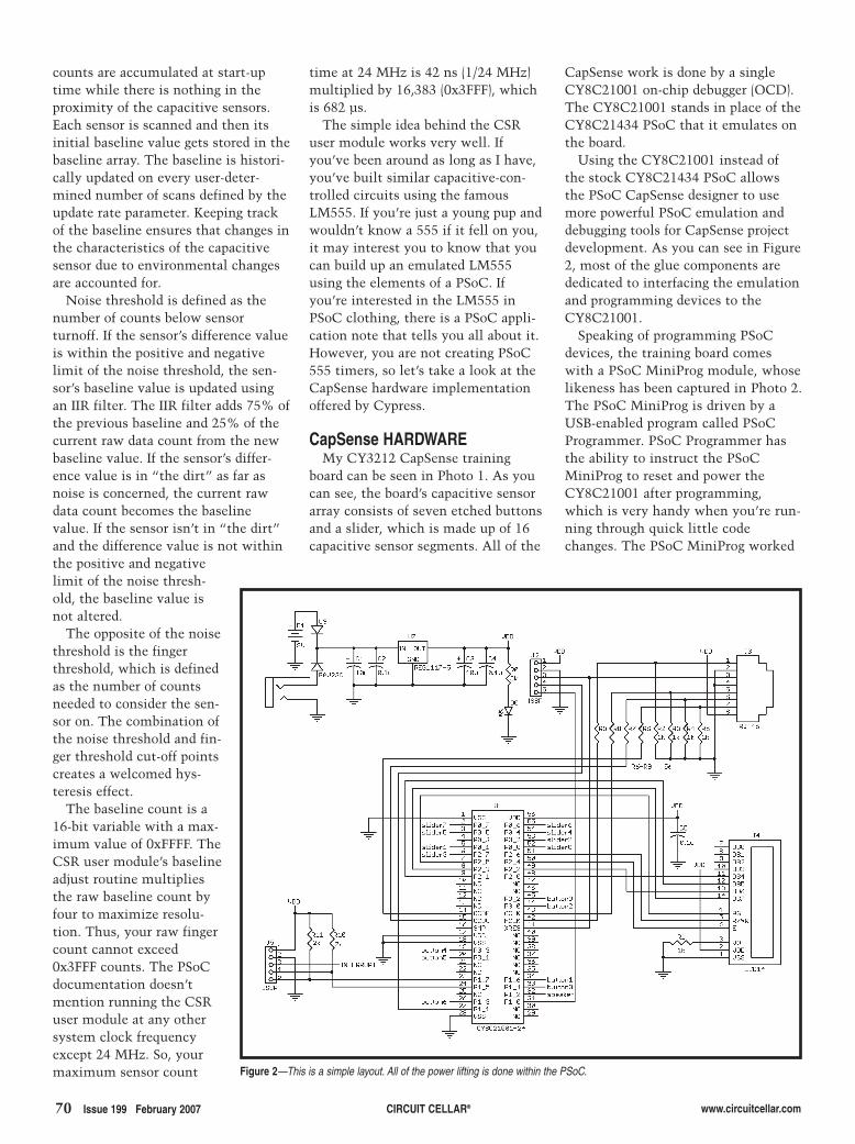
70 Issue 199 February 2007 CIRCUIT CELLAR® www.circuitcellar.com
counts are accumulated at start-uptime while there is nothing in theproximity of the capacitive sensors.Each sensor is scanned and then itsinitial baseline value gets stored in thebaseline array. The baseline is histori-cally updated on every user-deter-mined number of scans defined by theupdate rate parameter. Keeping trackof the baseline ensures that changes inthe characteristics of the capacitivesensor due to environmental changesare accounted for.
Noise threshold is defined as thenumber of counts below sensorturnoff. If the sensor’s difference valueis within the positive and negativelimit of the noise threshold, the sen-sor’s baseline value is updated usingan IIR filter. The IIR filter adds 75% ofthe previous baseline and 25% of thecurrent raw data count from the newbaseline value. If the sensor’s differ-ence value is in “the dirt” as far asnoise is concerned, the current rawdata count becomes the baselinevalue. If the sensor isn’t in “the dirt”and the difference value is not withinthe positive and negativelimit of the noise thresh-old, the baseline value isnot altered.
The opposite of the noisethreshold is the fingerthreshold, which is definedas the number of countsneeded to consider the sen-sor on. The combination ofthe noise threshold and fin-ger threshold cut-off pointscreates a welcomed hys-teresis effect.
The baseline count is a16-bit variable with a max-imum value of 0xFFFF. TheCSR user module’s baselineadjust routine multipliesthe raw baseline count byfour to maximize resolu-tion. Thus, your raw fingercount cannot exceed0x3FFF counts. The PSoCdocumentation doesn’tmention running the CSRuser module at any othersystem clock frequencyexcept 24 MHz. So, yourmaximum sensor count
time at 24 MHz is 42 ns (1/24 MHz)multiplied by 16,383 (0x3FFF), whichis 682 µs.
The simple idea behind the CSRuser module works very well. Ifyou’ve been around as long as I have,you’ve built similar capacitive-con-trolled circuits using the famousLM555. If you’re just a young pup andwouldn’t know a 555 if it fell on you,it may interest you to know that youcan build up an emulated LM555using the elements of a PSoC. Ifyou’re interested in the LM555 inPSoC clothing, there is a PSoC appli-cation note that tells you all about it.However, you are not creating PSoC555 timers, so let’s take a look at theCapSense hardware implementationoffered by Cypress.
CapSense HARDWAREMy CY3212 CapSense training
board can be seen in Photo 1. As youcan see, the board’s capacitive sensorarray consists of seven etched buttonsand a slider, which is made up of 16capacitive sensor segments. All of the
CapSense work is done by a singleCY8C21001 on-chip debugger (OCD).The CY8C21001 stands in place of theCY8C21434 PSoC that it emulates onthe board.
Using the CY8C21001 instead ofthe stock CY8C21434 PSoC allowsthe PSoC CapSense designer to usemore powerful PSoC emulation anddebugging tools for CapSense projectdevelopment. As you can see in Figure2, most of the glue components arededicated to interfacing the emulationand programming devices to theCY8C21001.
Speaking of programming PSoCdevices, the training board comeswith a PSoC MiniProg module, whoselikeness has been captured in Photo 2.The PSoC MiniProg is driven by aUSB-enabled program called PSoCProgrammer. PSoC Programmer hasthe ability to instruct the PSoCMiniProg to reset and power theCY8C21001 after programming,which is very handy when you’re run-ning through quick little codechanges. The PSoC MiniProg worked
Figure 2—This is a simple layout. All of the power lifting is done within the PSoC.
2702012-eady.qxp 1/4/2007 10:53 AM Page 70
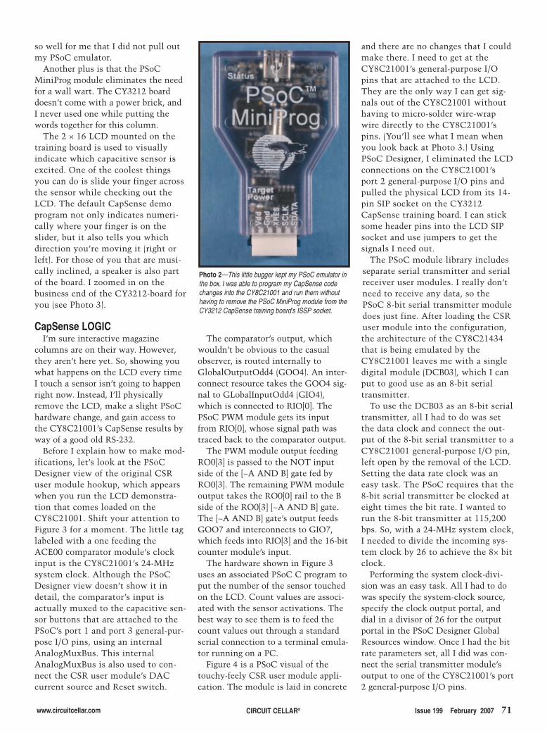
www.circuitcellar.com CIRCUIT CELLAR® Issue 199 February 2007 71
so well for me that I did not pull outmy PSoC emulator.
Another plus is that the PSoCMiniProg module eliminates the needfor a wall wart. The CY3212 boarddoesn’t come with a power brick, andI never used one while putting thewords together for this column.
The 2 × 16 LCD mounted on thetraining board is used to visuallyindicate which capacitive sensor isexcited. One of the coolest thingsyou can do is slide your finger acrossthe sensor while checking out theLCD. The default CapSense demoprogram not only indicates numeri-cally where your finger is on theslider, but it also tells you whichdirection you’re moving it (right orleft). For those of you that are musi-cally inclined, a speaker is also partof the board. I zoomed in on thebusiness end of the CY3212-board foryou (see Photo 3).
CapSense LOGICI’m sure interactive magazine
columns are on their way. However,they aren’t here yet. So, showing youwhat happens on the LCD every timeI touch a sensor isn’t going to happenright now. Instead, I’ll physicallyremove the LCD, make a slight PSoChardware change, and gain access tothe CY8C21001’s CapSense results byway of a good old RS-232.
Before I explain how to make mod-ifications, let’s look at the PSoCDesigner view of the original CSRuser module hookup, which appearswhen you run the LCD demonstra-tion that comes loaded on theCY8C21001. Shift your attention toFigure 3 for a moment. The little taglabeled with a one feeding theACE00 comparator module’s clockinput is the CY8C21001’s 24-MHzsystem clock. Although the PSoCDesigner view doesn’t show it indetail, the comparator’s input isactually muxed to the capacitive sen-sor buttons that are attached to thePSoC’s port 1 and port 3 general-pur-pose I/O pins, using an internalAnalogMuxBus. This internalAnalogMuxBus is also used to con-nect the CSR user module’s DACcurrent source and Reset switch.
The comparator’s output, whichwouldn’t be obvious to the casualobserver, is routed internally toGlobalOutputOdd4 (GOO4). An inter-connect resource takes the GOO4 sig-nal to GLobalInputOdd4 (GIO4),which is connected to RIO[0]. ThePSoC PWM module gets its inputfrom RIO[0], whose signal path wastraced back to the comparator output.
The PWM module output feedingRO0[3] is passed to the NOT inputside of the [~A AND B] gate fed byRO0[3]. The remaining PWM moduleoutput takes the RO0[0] rail to the Bside of the RO0[3] [~A AND B] gate.The [~A AND B] gate’s output feedsGOO7 and interconnects to GIO7,which feeds into RIO[3] and the 16-bitcounter module’s input.
The hardware shown in Figure 3uses an associated PSoC C program toput the number of the sensor touchedon the LCD. Count values are associ-ated with the sensor activations. Thebest way to see them is to feed thecount values out through a standardserial connection to a terminal emula-tor running on a PC.
Figure 4 is a PSoC visual of thetouchy-feely CSR user module appli-cation. The module is laid in concrete
and there are no changes that I couldmake there. I need to get at theCY8C21001’s general-purpose I/Opins that are attached to the LCD.They are the only way I can get sig-nals out of the CY8C21001 withouthaving to micro-solder wire-wrapwire directly to the CY8C21001’spins. (You’ll see what I mean whenyou look back at Photo 3.) UsingPSoC Designer, I eliminated the LCDconnections on the CY8C21001’sport 2 general-purpose I/O pins andpulled the physical LCD from its 14-pin SIP socket on the CY3212CapSense training board. I can sticksome header pins into the LCD SIPsocket and use jumpers to get thesignals I need out.
The PSoC module library includesseparate serial transmitter and serialreceiver user modules. I really don’tneed to receive any data, so thePSoC 8-bit serial transmitter moduledoes just fine. After loading the CSRuser module into the configuration,the architecture of the CY8C21434that is being emulated by theCY8C21001 leaves me with a singledigital module (DCB03), which I canput to good use as an 8-bit serialtransmitter.
To use the DCB03 as an 8-bit serialtransmitter, all I had to do was setthe data clock and connect the out-put of the 8-bit serial transmitter to aCY8C21001 general-purpose I/O pin,left open by the removal of the LCD.Setting the data rate clock was aneasy task. The PSoC requires that the8-bit serial transmitter be clocked ateight times the bit rate. I wanted torun the 8-bit transmitter at 115,200bps. So, with a 24-MHz system clock,I needed to divide the incoming sys-tem clock by 26 to achieve the 8× bitclock.
Performing the system clock-divi-sion was an easy task. All I had to dowas specify the system-clock source,specify the clock output portal, anddial in a divisor of 26 for the outputportal in the PSoC Designer GlobalResources window. Once I had the bitrate parameters set, all I did was con-nect the serial transmitter module’soutput to one of the CY8C21001’s port2 general-purpose I/O pins.
Photo 2—This little bugger kept my PSoC emulator inthe box. I was able to program my CapSense codechanges into the CY8C21001 and run them withouthaving to remove the PSoC MiniProg module from theCY3212 CapSense training board’s ISSP socket.
2702012-eady.qxp 1/4/2007 10:53 AM Page 71
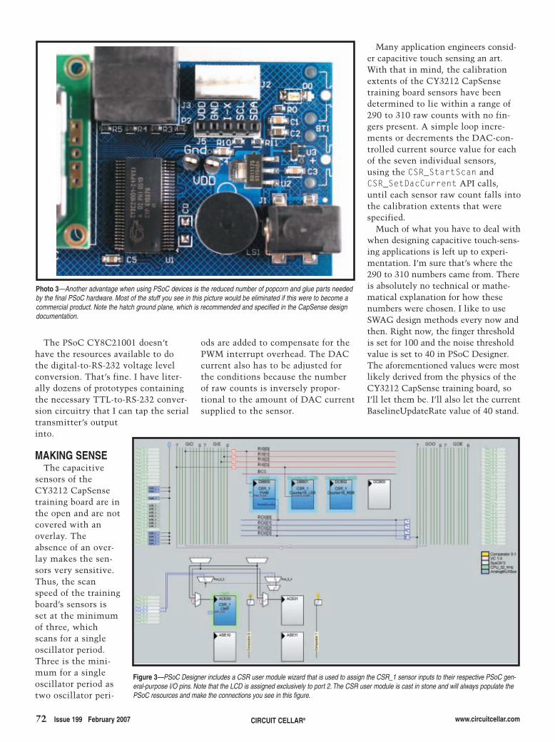
72 Issue 199 February 2007 www.circuitcellar.com
Many application engineers consid-er capacitive touch sensing an art.With that in mind, the calibrationextents of the CY3212 CapSensetraining board sensors have beendetermined to lie within a range of290 to 310 raw counts with no fin-gers present. A simple loop incre-ments or decrements the DAC-con-trolled current source value for eachof the seven individual sensors,using the CSR_StartScan andCSR_SetDacCurrent API calls,until each sensor raw count falls intothe calibration extents that werespecified.
Much of what you have to deal withwhen designing capacitive touch-sens-ing applications is left up to experi-mentation. I’m sure that’s where the290 to 310 numbers came from. Thereis absolutely no technical or mathe-matical explanation for how thesenumbers were chosen. I like to useSWAG design methods every now andthen. Right now, the finger thresholdis set for 100 and the noise thresholdvalue is set to 40 in PSoC Designer.The aforementioned values were mostlikely derived from the physics of theCY3212 CapSense training board, soI’ll let them be. I’ll also let the currentBaselineUpdateRate value of 40 stand.
CIRCUIT CELLAR®
The PSoC CY8C21001 doesn’thave the resources available to dothe digital-to-RS-232 voltage levelconversion. That’s fine. I have liter-ally dozens of prototypes containingthe necessary TTL-to-RS-232 conver-sion circuitry that I can tap the serialtransmitter’s outputinto.
MAKING SENSEThe capacitive
sensors of theCY3212 CapSensetraining board are inthe open and are notcovered with anoverlay. Theabsence of an over-lay makes the sen-sors very sensitive.Thus, the scanspeed of the trainingboard’s sensors isset at the minimumof three, whichscans for a singleoscillator period.Three is the mini-mum for a singleoscillator period astwo oscillator peri-
ods are added to compensate for thePWM interrupt overhead. The DACcurrent also has to be adjusted forthe conditions because the numberof raw counts is inversely propor-tional to the amount of DAC currentsupplied to the sensor.
Figure 3—PSoC Designer includes a CSR user module wizard that is used to assign the CSR_1 sensor inputs to their respective PSoC gen-eral-purpose I/O pins. Note that the LCD is assigned exclusively to port 2. The CSR user module is cast in stone and will always populate thePSoC resources and make the connections you see in this figure.
Photo 3—Another advantage when using PSoC devices is the reduced number of popcorn and glue parts neededby the final PSoC hardware. Most of the stuff you see in this picture would be eliminated if this were to become acommercial product. Note the hatch ground plane, which is recommended and specified in the CapSense designdocumentation.
2702012-eady.qxp 1/4/2007 10:53 AM Page 72
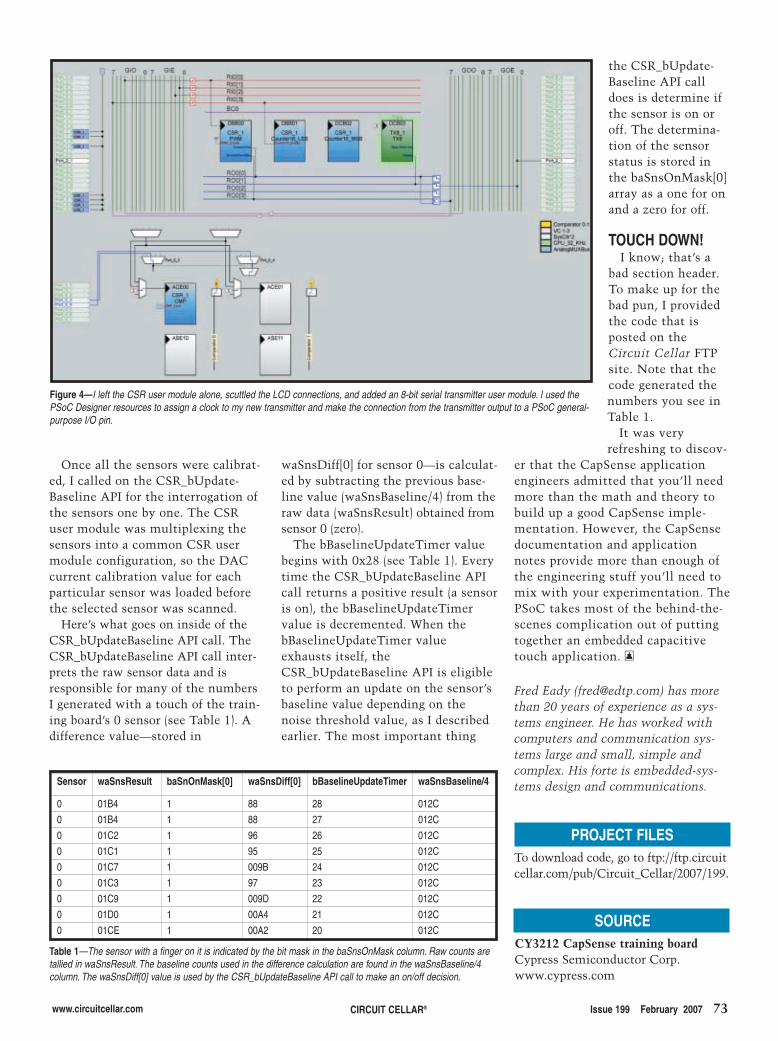
www.circuitcellar.com CIRCUIT CELLAR® Issue 199 February 2007 73
Fred Eady ([email protected]) has morethan 20 years of experience as a sys-tems engineer. He has worked withcomputers and communication sys-tems large and small, simple andcomplex. His forte is embedded-sys-tems design and communications.
PROJECT FILESTo download code, go to ftp://ftp.circuitcellar.com/pub/Circuit_Cellar/2007/199.
Once all the sensors were calibrat-ed, I called on the CSR_bUpdate-Baseline API for the interrogation ofthe sensors one by one. The CSRuser module was multiplexing thesensors into a common CSR usermodule configuration, so the DACcurrent calibration value for eachparticular sensor was loaded beforethe selected sensor was scanned.
Here’s what goes on inside of theCSR_bUpdateBaseline API call. TheCSR_bUpdateBaseline API call inter-prets the raw sensor data and isresponsible for many of the numbersI generated with a touch of the train-ing board’s 0 sensor (see Table 1). Adifference value—stored in
waSnsDiff[0] for sensor 0—is calculat-ed by subtracting the previous base-line value (waSnsBaseline/4) from theraw data (waSnsResult) obtained fromsensor 0 (zero).
The bBaselineUpdateTimer valuebegins with 0x28 (see Table 1). Everytime the CSR_bUpdateBaseline APIcall returns a positive result (a sensoris on), the bBaselineUpdateTimervalue is decremented. When thebBaselineUpdateTimer valueexhausts itself, theCSR_bUpdateBaseline API is eligibleto perform an update on the sensor’sbaseline value depending on thenoise threshold value, as I describedearlier. The most important thing
the CSR_bUpdate-Baseline API calldoes is determine ifthe sensor is on oroff. The determina-tion of the sensorstatus is stored inthe baSnsOnMask[0]array as a one for onand a zero for off.
TOUCH DOWN!I know; that’s a
bad section header.To make up for thebad pun, I providedthe code that isposted on theCircuit Cellar FTPsite. Note that thecode generated thenumbers you see inTable 1.
It was veryrefreshing to discov-
er that the CapSense applicationengineers admitted that you’ll needmore than the math and theory tobuild up a good CapSense imple-mentation. However, the CapSensedocumentation and applicationnotes provide more than enough ofthe engineering stuff you’ll need tomix with your experimentation. ThePSoC takes most of the behind-the-scenes complication out of puttingtogether an embedded capacitivetouch application. I
SOURCECY3212 CapSense training boardCypress Semiconductor Corp.www.cypress.com
Table 1—The sensor with a finger on it is indicated by the bit mask in the baSnsOnMask column. Raw counts aretallied in waSnsResult. The baseline counts used in the difference calculation are found in the waSnsBaseline/4column. The waSnsDiff[0] value is used by the CSR_bUpdateBaseline API call to make an on/off decision.
Sensor waSnsResult baSnOnMask[0] waSnsDiff[0] bBaselineUpdateTimer waSnsBaseline/4
0 01B4 1 88 28 012C
0 01B4 1 88 27 012C
0 01C2 1 96 26 012C
0 01C1 1 95 25 012C
0 01C7 1 009B 24 012C
0 01C3 1 97 23 012C
0 01C9 1 009D 22 012C
0 01D0 1 00A4 21 012C
0 01CE 1 00A2 20 012C
Figure 4—I left the CSR user module alone, scuttled the LCD connections, and added an 8-bit serial transmitter user module. I used thePSoC Designer resources to assign a clock to my new transmitter and make the connection from the transmitter output to a PSoC general-purpose I/O pin.
2702012-eady.qxp 1/4/2007 10:53 AM Page 73
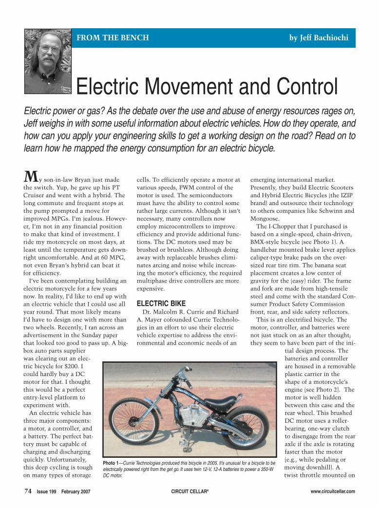
74 Issue 199 February 2007 CIRCUIT CELLAR® www.circuitcellar.com
emerging international market.Presently, they build Electric Scootersand Hybrid Electric Bicycles (the IZIPbrand) and outsource their technologyto others companies like Schwinn andMongoose.
The I-Chopper that I purchased isbased on a single-speed, chain-driven,BMX-style bicycle (see Photo 1). Ahandlebar mounted brake lever appliescaliper-type brake pads on the over-sized rear tire rim. The banana seatplacement creates a low center ofgravity for the (easy) rider. The frameand fork are made from high-tensilesteel and come with the standard Con-sumer Product Safety Commissionfront, rear, and side safety reflectors.
This is an electrified bicycle. Themotor, controller, and batteries werenot just stuck on as an after thought;they seem to have been part of the ini-
tial design process. Thebatteries and controllerare housed in a removableplastic carrier in theshape of a motorcycle’sengine (see Photo 2). Themotor is well hiddenbetween this case and therear wheel. This brushedDC motor uses a roller-bearing, one-way clutchto disengage from the rearaxle if the axle is rotatingfaster than the motor(e.g., while pedaling ormoving downhill). Atwist throttle mounted on
cells. To efficiently operate a motor atvarious speeds, PWM control of themotor is used. The semiconductorsmust have the ability to control somerather large currents. Although it isn’tnecessary, many controllers nowemploy microcontrollers to improveefficiency and provide additional func-tions. The DC motors used may bebrushed or brushless. Although doingaway with replaceable brushes elimi-nates arcing and noise while increas-ing the motor’s efficiency, the requiredmultiphase drive controllers are moreexpensive.
ELECTRIC BIKEDr. Malcolm R. Currie and Richard
A. Mayer cofounded Currie Technolo-gies in an effort to use their electricvehicle expertise to address the envi-ronmental and economic needs of an
My son-in-law Bryan just madethe switch. Yup, he gave up his PTCruiser and went with a hybrid. Thelong commute and frequent stops atthe pump prompted a move forimproved MPGs. I’m jealous. Howev-er, I’m not in any financial positionto make that kind of investment. Iride my motorcycle on most days, atleast until the temperature gets down-right uncomfortable. And at 60 MPG,not even Bryan’s hybrid can beat itfor efficiency.
I’ve been contemplating building anelectric motorcycle for a few yearsnow. In reality, I’d like to end up withan electric vehicle that I could use allyear round. That most likely meansI’d have to design one with more thantwo wheels. Recently, I ran across anadvertisement in the Sunday paperthat looked too good to pass up. A big-box auto parts supplierwas clearing out an elec-tric bicycle for $200. Icould hardly buy a DCmotor for that. I thoughtthis would be a perfectentry-level platform toexperiment with.
An electric vehicle hasthree major components:a motor, a controller, anda battery. The perfect bat-tery must be capable ofcharging and dischargingquickly. Unfortunately,this deep cycling is toughon many types of storage
Electric Movement and Control
FROM THE BENCH by Jeff Bachiochi
Electric power or gas? As the debate over the use and abuse of energy resources rages on,Jeff weighs in with some useful information about electric vehicles. How do they operate, andhow can you apply your engineering skills to get a working design on the road? Read on tolearn how he mapped the energy consumption for an electric bicycle.
Photo 1—Currie Technologies produced this bicycle in 2005. It’s unusual for a bicycle to beelectrically powered right from the get go. It uses twin 12-V, 12-A batteries to power a 350-WDC motor.
2702002-bachiochi.qxp 1/4/2007 11:05 AM Page 74
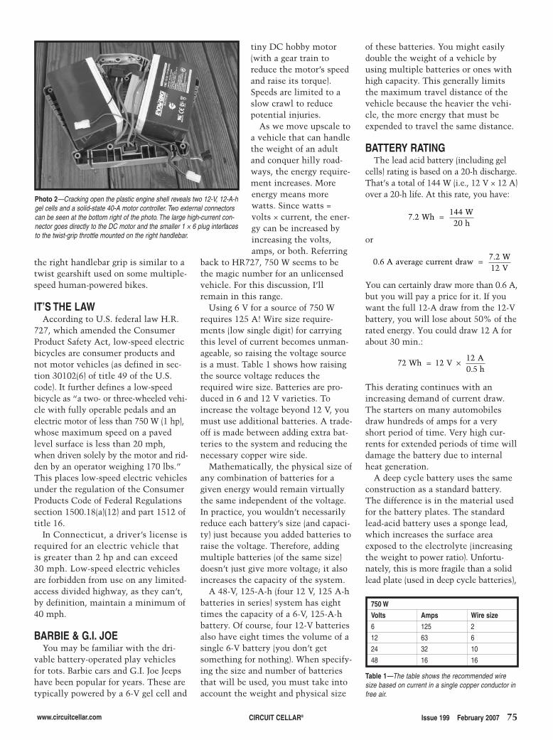
the right handlebar grip is similar to atwist gearshift used on some multiple-speed human-powered bikes.
IT’S THE LAWAccording to U.S. federal law H.R.
727, which amended the ConsumerProduct Safety Act, low-speed electricbicycles are consumer products andnot motor vehicles (as defined in sec-tion 30102(6) of title 49 of the U.S.code). It further defines a low-speedbicycle as “a two- or three-wheeled vehi-cle with fully operable pedals and anelectric motor of less than 750 W (1 hp),whose maximum speed on a pavedlevel surface is less than 20 mph,when driven solely by the motor and rid-den by an operator weighing 170 lbs.”This places low-speed electric vehiclesunder the regulation of the ConsumerProducts Code of Federal Regulationssection 1500.18(a)(12) and part 1512 oftitle 16.
In Connecticut, a driver’s license isrequired for an electric vehicle thatis greater than 2 hp and can exceed30 mph. Low-speed electric vehiclesare forbidden from use on any limited-access divided highway, as they can’t,by definition, maintain a minimum of40 mph.
BARBIE & G.I. JOEYou may be familiar with the dri-
vable battery-operated play vehiclesfor tots. Barbie cars and G.I. Joe Jeepshave been popular for years. These aretypically powered by a 6-V gel cell and
www.circuitcellar.com CIRCUIT CELLAR® Issue 199 February 2007 75
tiny DC hobby motor(with a gear train toreduce the motor’s speedand raise its torque).Speeds are limited to aslow crawl to reducepotential injuries.
As we move upscale toa vehicle that can handlethe weight of an adultand conquer hilly road-ways, the energy require-ment increases. Moreenergy means morewatts. Since watts =volts × current, the ener-gy can be increased byincreasing the volts,amps, or both. Referring
back to HR727, 750 W seems to bethe magic number for an unlicensedvehicle. For this discussion, I’llremain in this range.
Using 6 V for a source of 750 Wrequires 125 A! Wire size require-ments (low single digit) for carryingthis level of current becomes unman-ageable, so raising the voltage sourceis a must. Table 1 shows how raisingthe source voltage reduces therequired wire size. Batteries are pro-duced in 6 and 12 V varieties. Toincrease the voltage beyond 12 V, youmust use additional batteries. A trade-off is made between adding extra bat-teries to the system and reducing thenecessary copper wire side.
Mathematically, the physical size ofany combination of batteries for agiven energy would remain virtuallythe same independent of the voltage.In practice, you wouldn’t necessarilyreduce each battery’s size (and capaci-ty) just because you added batteries toraise the voltage. Therefore, addingmultiple batteries (of the same size)doesn’t just give more voltage; it alsoincreases the capacity of the system.
A 48-V, 125-A-h (four 12 V, 125 A-hbatteries in series) system has eighttimes the capacity of a 6-V, 125-A-hbattery. Of course, four 12-V batteriesalso have eight times the volume of asingle 6-V battery (you don’t getsomething for nothing). When specify-ing the size and number of batteriesthat will be used, you must take intoaccount the weight and physical size
of these batteries. You might easilydouble the weight of a vehicle byusing multiple batteries or ones withhigh capacity. This generally limitsthe maximum travel distance of thevehicle because the heavier the vehi-cle, the more energy that must beexpended to travel the same distance.
BATTERY RATINGThe lead acid battery (including gel
cells) rating is based on a 20-h discharge.That’s a total of 144 W (i.e., 12 V × 12 A)over a 20-h life. At this rate, you have:
or
You can certainly draw more than 0.6 A,but you will pay a price for it. If youwant the full 12-A draw from the 12-Vbattery, you will lose about 50% of therated energy. You could draw 12 A forabout 30 min.:
This derating continues with anincreasing demand of current draw.The starters on many automobilesdraw hundreds of amps for a veryshort period of time. Very high cur-rents for extended periods of time willdamage the battery due to internalheat generation.
A deep cycle battery uses the sameconstruction as a standard battery.The difference is in the material usedfor the battery plates. The standardlead-acid battery uses a sponge lead,which increases the surface areaexposed to the electrolyte (increasingthe weight to power ratio). Unfortu-nately, this is more fragile than a solidlead plate (used in deep cycle batteries),
72 12120 5
Wh VAh
= ×.
0 67 212
..
A average current drawWV
=
7 214420
.
WhWh
=
Photo 2—Cracking open the plastic engine shell reveals two 12-V, 12-A-hgel cells and a solid-state 40-A motor controller. Two external connectorscan be seen at the bottom right of the photo. The large high-current con-nector goes directly to the DC motor and the smaller 1 × 6 plug interfacesto the twist-grip throttle mounted on the right handlebar.
750 WVolts Amps Wire size6 125 2
12 63 6
24 32 10
48 16 16
Table 1—The table shows the recommended wiresize based on current in a single copper conductor infree air.
2702002-bachiochi.qxp 1/4/2007 11:05 AM Page 75
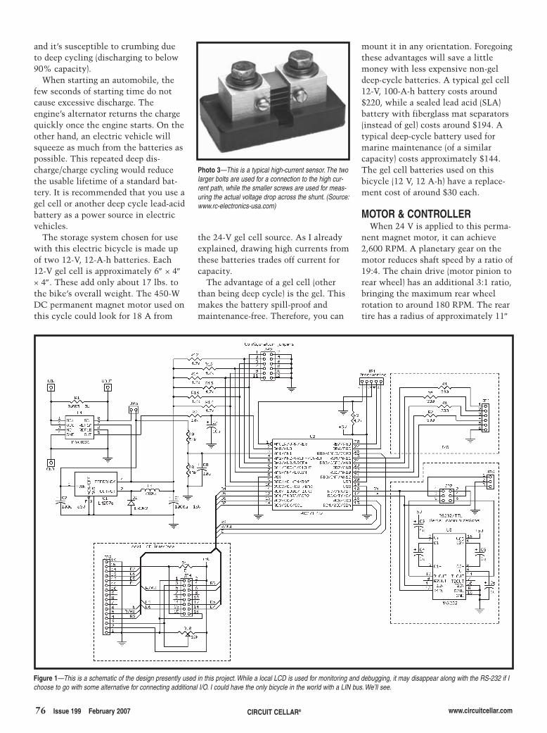
76 Issue 199 February 2007 CIRCUIT CELLAR® www.circuitcellar.com
and it’s susceptible to crumbing dueto deep cycling (discharging to below90% capacity).
When starting an automobile, thefew seconds of starting time do notcause excessive discharge. Theengine’s alternator returns the chargequickly once the engine starts. On theother hand, an electric vehicle willsqueeze as much from the batteries aspossible. This repeated deep dis-charge/charge cycling would reducethe usable lifetime of a standard bat-tery. It is recommended that you use agel cell or another deep cycle lead-acidbattery as a power source in electricvehicles.
The storage system chosen for usewith this electric bicycle is made upof two 12-V, 12-A-h batteries. Each12-V gel cell is approximately 6″ × 4″× 4″. These add only about 17 lbs. tothe bike’s overall weight. The 450-WDC permanent magnet motor used onthis cycle could look for 18 A from
the 24-V gel cell source. As I alreadyexplained, drawing high currents fromthese batteries trades off current forcapacity.
The advantage of a gel cell (otherthan being deep cycle) is the gel. Thismakes the battery spill-proof andmaintenance-free. Therefore, you can
mount it in any orientation. Foregoingthese advantages will save a littlemoney with less expensive non-geldeep-cycle batteries. A typical gel cell12-V, 100-A-h battery costs around$220, while a sealed lead acid (SLA)battery with fiberglass mat separators(instead of gel) costs around $194. Atypical deep-cycle battery used formarine maintenance (of a similarcapacity) costs approximately $144.The gel cell batteries used on thisbicycle (12 V, 12 A-h) have a replace-ment cost of around $30 each.
MOTOR & CONTROLLERWhen 24 V is applied to this perma-
nent magnet motor, it can achieve2,600 RPM. A planetary gear on themotor reduces shaft speed by a ratio of19:4. The chain drive (motor pinion torear wheel) has an additional 3:1 ratio,bringing the maximum rear wheelrotation to around 180 RPM. The reartire has a radius of approximately 11″
Figure 1—This is a schematic of the design presently used in this project. While a local LCD is used for monitoring and debugging, it may disappear along with the RS-232 if Ichoose to go with some alternative for connecting additional I/O. I could have the only bicycle in the world with a LIN bus. We’ll see.
Photo 3—This is a typical high-current sensor. The twolarger bolts are used for a connection to the high cur-rent path, while the smaller screws are used for meas-uring the actual voltage drop across the shunt. (Source:www.rc-electronics-usa.com)
2702002-bachiochi.qxp 1/4/2007 11:05 AM Page 76
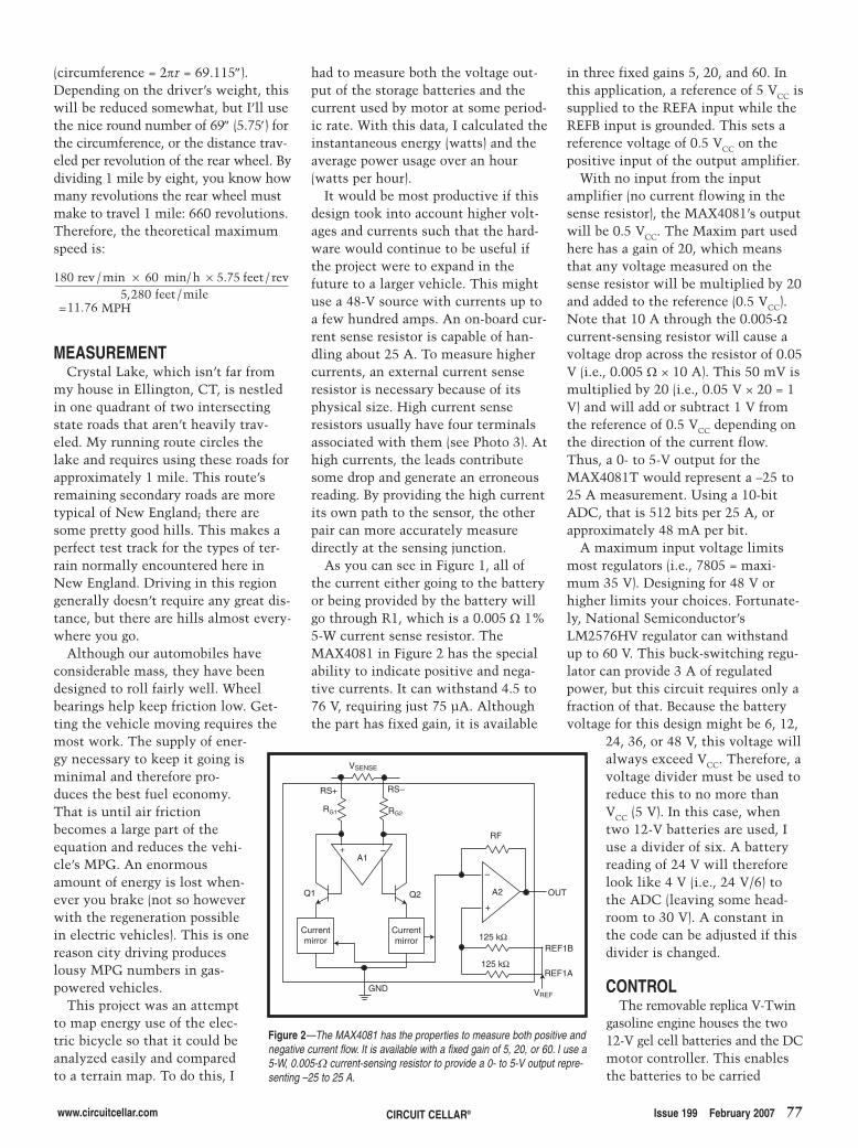
www.circuitcellar.com CIRCUIT CELLAR® Issue 199 February 2007 77
(circumference = 2πr = 69.115″).Depending on the driver’s weight, thiswill be reduced somewhat, but I’ll usethe nice round number of 69″ (5.75′) forthe circumference, or the distance trav-eled per revolution of the rear wheel. Bydividing 1 mile by eight, you know howmany revolutions the rear wheel mustmake to travel 1 mile: 660 revolutions.Therefore, the theoretical maximumspeed is:
MEASUREMENTCrystal Lake, which isn’t far from
my house in Ellington, CT, is nestledin one quadrant of two intersectingstate roads that aren’t heavily trav-eled. My running route circles thelake and requires using these roads forapproximately 1 mile. This route’sremaining secondary roads are moretypical of New England; there aresome pretty good hills. This makes aperfect test track for the types of ter-rain normally encountered here inNew England. Driving in this regiongenerally doesn’t require any great dis-tance, but there are hills almost every-where you go.
Although our automobiles haveconsiderable mass, they have beendesigned to roll fairly well. Wheelbearings help keep friction low. Get-ting the vehicle moving requires themost work. The supply of ener-gy necessary to keep it going isminimal and therefore pro-duces the best fuel economy.That is until air frictionbecomes a large part of theequation and reduces the vehi-cle’s MPG. An enormousamount of energy is lost when-ever you brake (not so howeverwith the regeneration possiblein electric vehicles). This is onereason city driving produceslousy MPG numbers in gas-powered vehicles.
This project was an attemptto map energy use of the elec-tric bicycle so that it could beanalyzed easily and comparedto a terrain map. To do this, I
v h× ×180 605 280
11.76
5.75
re feet revfeet mile
MP
/min min/ /, /
= H
had to measure both the voltage out-put of the storage batteries and thecurrent used by motor at some period-ic rate. With this data, I calculated theinstantaneous energy (watts) and theaverage power usage over an hour(watts per hour).
It would be most productive if thisdesign took into account higher volt-ages and currents such that the hard-ware would continue to be useful ifthe project were to expand in thefuture to a larger vehicle. This mightuse a 48-V source with currents up toa few hundred amps. An on-board cur-rent sense resistor is capable of han-dling about 25 A. To measure highercurrents, an external current senseresistor is necessary because of itsphysical size. High current senseresistors usually have four terminalsassociated with them (see Photo 3). Athigh currents, the leads contributesome drop and generate an erroneousreading. By providing the high currentits own path to the sensor, the otherpair can more accurately measuredirectly at the sensing junction.
As you can see in Figure 1, all ofthe current either going to the batteryor being provided by the battery willgo through R1, which is a 0.005 Ω 1%5-W current sense resistor. TheMAX4081 in Figure 2 has the specialability to indicate positive and nega-tive currents. It can withstand 4.5 to76 V, requiring just 75 µA. Althoughthe part has fixed gain, it is available
in three fixed gains 5, 20, and 60. Inthis application, a reference of 5 VCC issupplied to the REFA input while theREFB input is grounded. This sets areference voltage of 0.5 VCC on thepositive input of the output amplifier.
With no input from the inputamplifier (no current flowing in thesense resistor), the MAX4081’s outputwill be 0.5 VCC. The Maxim part usedhere has a gain of 20, which meansthat any voltage measured on thesense resistor will be multiplied by 20and added to the reference (0.5 VCC).Note that 10 A through the 0.005-Ωcurrent-sensing resistor will cause avoltage drop across the resistor of 0.05V (i.e., 0.005 Ω × 10 A). This 50 mV ismultiplied by 20 (i.e., 0.05 V × 20 = 1V) and will add or subtract 1 V fromthe reference of 0.5 VCC depending onthe direction of the current flow.Thus, a 0- to 5-V output for theMAX4081T would represent a –25 to25 A measurement. Using a 10-bitADC, that is 512 bits per 25 A, orapproximately 48 mA per bit.
A maximum input voltage limitsmost regulators (i.e., 7805 = maxi-mum 35 V). Designing for 48 V orhigher limits your choices. Fortunate-ly, National Semiconductor’sLM2576HV regulator can withstandup to 60 V. This buck-switching regu-lator can provide 3 A of regulatedpower, but this circuit requires only afraction of that. Because the batteryvoltage for this design might be 6, 12,
24, 36, or 48 V, this voltage willalways exceed VCC. Therefore, avoltage divider must be used toreduce this to no more thanVCC (5 V). In this case, whentwo 12-V batteries are used, Iuse a divider of six. A batteryreading of 24 V will thereforelook like 4 V (i.e., 24 V/6) tothe ADC (leaving some head-room to 30 V). A constant inthe code can be adjusted if thisdivider is changed.
CONTROLThe removable replica V-Twin
gasoline engine houses the two12-V gel cell batteries and the DCmotor controller. This enablesthe batteries to be carried
VSENSE
RS+ RS–
RG1 RG2
+ –A1
Currentmirror
Currentmirror
Q1 Q2
GND
+
–
A2
RF
125 kΩ
125 kΩ
OUT
REF1B
REF1A
VREF
Figure 2—The MAX4081 has the properties to measure both positive andnegative current flow. It is available with a fixed gain of 5, 20, or 60. I use a5-W, 0.005-Ω current-sensing resistor to provide a 0- to 5-V output repre-senting –25 to 25 A.
2702002-bachiochi.qxp 1/4/2007 11:05 AM Page 77
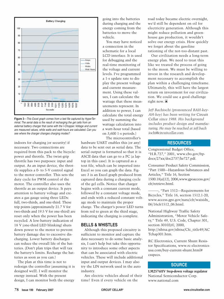
78 Issue 199 February 2007 CIRCUIT CELLAR® www.circuitcellar.com
indoors for charging (or security) ifnecessary. Two connections arerequired from this pack to the bicycle:power and throttle. The twist-gripthrottle has two purposes: input andoutput. As an input device, the throt-tle supplies a 0- to 5-V control signalto the motor controller. This sets theduty cycle for PWM control of themotor. The controller also uses thethrottle as an output device. It paysattention to battery voltage and cre-ates a gas gauge using three LEDs:full, two-thirds, and one-third. Thesetrip points (approximately 21.7 V fortwo-thirds and 19.5 V for one-third) arereset only when the power has beenrecycled. A low-battery indication of18 V (one-third LED blinking) shutsdown power to the motor to preventbattery damage due to excessive dis-charging. Lower battery dischargescan reduce the overall life of the bat-teries. (Don’t plan trips that will taxthe battery’s limits. Recharge the bat-teries as soon as you can.)
The plan at this time is not toredesign the controller (assuming it isdesigned well). I will monitor theenergy instead. With the presentdesign, I can monitor both the energy
going into the batteriesduring charging and theenergy coming from thebatteries to move thevehicle.
You may have noticeda connection in theschematic for a localLCD interface. It is usedfor debugging and thereal-time monitoring ofthe voltage and currentlevels. I’ve programmeda 1-s update rate to dis-play the present voltageand current measure-ment. Using these val-ues, I can calculate thewattage that these meas-urements represent. Inaddition to power, I cancalculate the total energyused by summing thewattage calculation intoa watt-hour total (basedon 3,600 1-s periods.)
The microcontroller’shardware UART enables this (or any)data to be sent out as serial data. Theserial output is formatted so that it isASCII data that can go to a PC (a lap-top in this case). It is captured as atext file, which can be imported intoExcel so you can graph the data. Fig-ure 3 is an Excel graph produced fromcaptured data during a charging cycleof the gel cells. Notice that chargerbegins with a constant current mode,followed by a constant voltage mode,and ends with a reduced constant volt-age mode to maintain the propercharge. The charger’s power LED turnsfrom red to green at the third stage,indicating the charging is complete.
BELLS & WHISTLESAlthough this proposed circuitry is
sufficient to monitor and capture thedata necessary to do some basic analy-sis, I can’t help but take this opportu-nity to introduce some other aspectsthat can be associated with electricvehicles. These will include additionalinput and output devices. I may alsotry the LIN network used in the autoindustry.
Are electric vehicles ahead of theirtime? Even if every vehicle on the
Figure 3—This Excel graph comes from a text file captured by HyperTer-minal. The serial data is the result of recharging the gel cells from anexternal battery charger that came with the I-Chopper. Voltage and currentare measured values, while watts and watt-hours are calculated. Can yousee where the charger changes charging modes?
Jeff Bachiochi (pronounced BAH-key-AH-key) has been writing for CircuitCellar since 1988. His backgroundincludes product design and manufac-turing. He may be reached at [email protected].
RESOURCESCongressional Budget Office,“H.R.727,” 2001, www.cbo.gov/ftp-docs/27xx/doc2737/hr727.pdf.
Consumer Product Safety Commission,“Part 1500—Hazardous Substances andArticles,” Title 16, Section1500.18(a)(12), 2006,www.gpoaccess.gov/cfr/retrieve.html.
———, “Part 1512—Requirements forBicycles,” Title 16, section 1512.1-20,www.access.gpo.gov/nara/cfr/waisidx_06/16cfr1512_06.html.
National Highway Traffic SafetyAdministration, “Motor Vehicle Safe-ty,” Title 49, U.S. Code, Chapter 301,section 30102(6), 2000,http://nhtsa.gov/nhtsa/Cfc_title49/ACTchap301.htm.
RC Electronics, Current Shunt Resis-tor Specifications, www.rc-electronics-usa.com/buy-current-shunt.html#csspecs.
SOURCELM2576HV Step-down voltage regulatorNational Semiconductor Corp.www.national.com
road today became electric overnight,we’d still be dependent on oil forelectricity generation. Although thismight reduce pollution and green-house gas production, it wouldn’tsolve our energy crisis. How quicklywe forget about the gasolinerationing of the not-too-distant past.
Our civilization needs a long-termenergy plan. We need to treat thislike we treated the process of goingto the moon. We must be willing toinvest in the research and develop-ment necessary to accomplish theplan within a challenging timeframe.Ultimately, this will have the largestreturn on investment for our civiliza-tion. We could use a good challengeright now. I
2702002-bachiochi.qxp 1/4/2007 3:02 PM Page 78
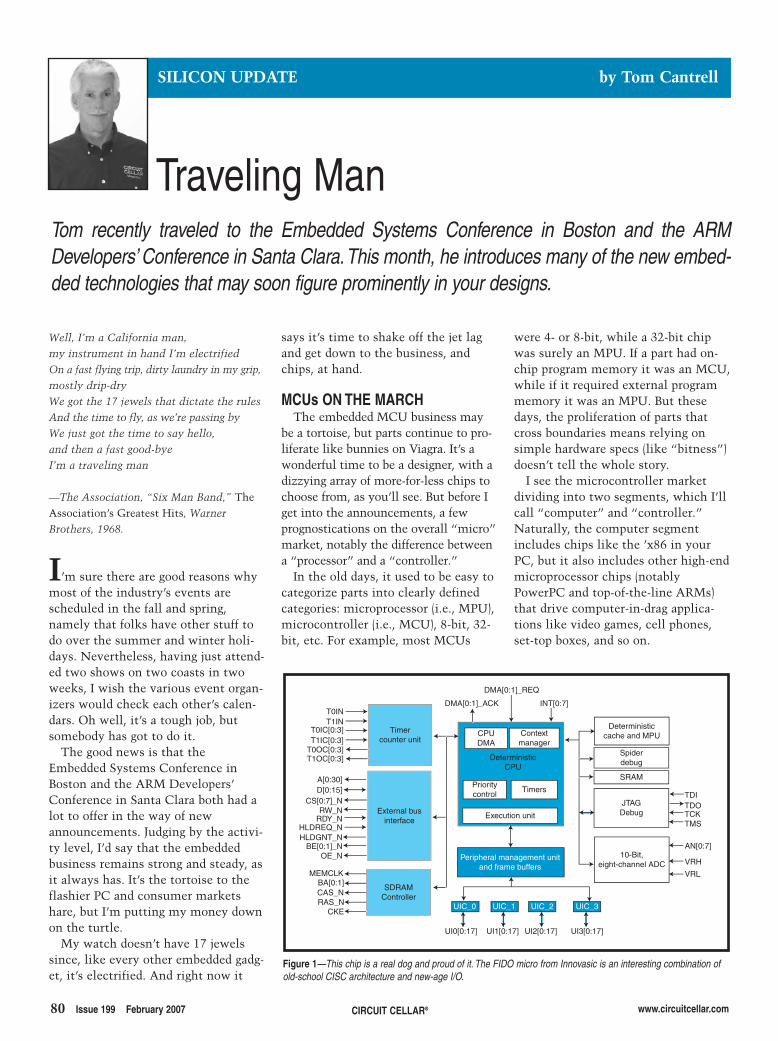
80 Issue 199 February 2007 CIRCUIT CELLAR® www.circuitcellar.com
were 4- or 8-bit, while a 32-bit chipwas surely an MPU. If a part had on-chip program memory it was an MCU,while if it required external programmemory it was an MPU. But thesedays, the proliferation of parts thatcross boundaries means relying onsimple hardware specs (like “bitness”)doesn’t tell the whole story.
I see the microcontroller marketdividing into two segments, which I’llcall “computer” and “controller.”Naturally, the computer segmentincludes chips like the ’x86 in yourPC, but it also includes other high-endmicroprocessor chips (notablyPowerPC and top-of-the-line ARMs)that drive computer-in-drag applica-tions like video games, cell phones,set-top boxes, and so on.
says it’s time to shake off the jet lagand get down to the business, andchips, at hand.
MCUs ON THE MARCHThe embedded MCU business may
be a tortoise, but parts continue to pro-liferate like bunnies on Viagra. It’s awonderful time to be a designer, with adizzying array of more-for-less chips tochoose from, as you’ll see. But before Iget into the announcements, a fewprognostications on the overall “micro”market, notably the difference betweena “processor” and a “controller.”
In the old days, it used to be easy tocategorize parts into clearly definedcategories: microprocessor (i.e., MPU),microcontroller (i.e., MCU), 8-bit, 32-bit, etc. For example, most MCUs
Well, I’m a California man, my instrument in hand I’m electrified On a fast flying trip, dirty laundry in my grip,mostly drip-dry We got the 17 jewels that dictate the rules And the time to fly, as we’re passing by We just got the time to say hello, and then a fast good-bye I’m a traveling man
—The Association, “Six Man Band,” TheAssociation’s Greatest Hits, WarnerBrothers, 1968.
I’m sure there are good reasons whymost of the industry’s events arescheduled in the fall and spring,namely that folks have other stuff todo over the summer and winter holi-days. Nevertheless, having just attend-ed two shows on two coasts in twoweeks, I wish the various event organ-izers would check each other’s calen-dars. Oh well, it’s a tough job, butsomebody has got to do it.
The good news is that theEmbedded Systems Conference inBoston and the ARM Developers’Conference in Santa Clara both had alot to offer in the way of newannouncements. Judging by the activi-ty level, I’d say that the embeddedbusiness remains strong and steady, asit always has. It’s the tortoise to theflashier PC and consumer marketshare, but I’m putting my money downon the turtle.
My watch doesn’t have 17 jewelssince, like every other embedded gadg-et, it’s electrified. And right now it
Traveling Man
SILICON UPDATE by Tom Cantrell
Tom recently traveled to the Embedded Systems Conference in Boston and the ARMDevelopers’ Conference in Santa Clara.This month, he introduces many of the new embed-ded technologies that may soon figure prominently in your designs.
Timercounter unit
T0INT1IN
T0IC[0:3]T1IC[0:3]
T0OC[0:3]T1OC[0:3]
External businterface
A[0:30]D[0:15]
CS[0:7]_NRW_N
RDY_NHLDREQ_NHLDGNT_N
BE[0:1]_NOE_N
SDRAMController
MEMCLKBA[0:1]CAS_NRAS_N
CKE
DMA[0:1]_ACK
DMA[0:1]_REQ
INT[0:7]
CPUDMA
Contextmanager
DeterministicCPU
Prioritycontrol
Timers
Execution unit
Peripheral management unitand frame buffers
UIC_0 UIC_1 UIC_2 UIC_3
UI0[0:17] UI1[0:17] UI2[0:17] UI3[0:17]
Deterministiccache and MPU
Spiderdebug
SRAM
JTAGDebug
10-Bit,eight-channel ADC
TDITDOTCKTMS
AN[0:7]
VRH
VRL
Figure 1—This chip is a real dog and proud of it. The FIDO micro from Innovasic is an interesting combination ofold-school CISC architecture and new-age I/O.
2702003-Cantrell.qxp 1/4/2007 11:08 AM Page 80
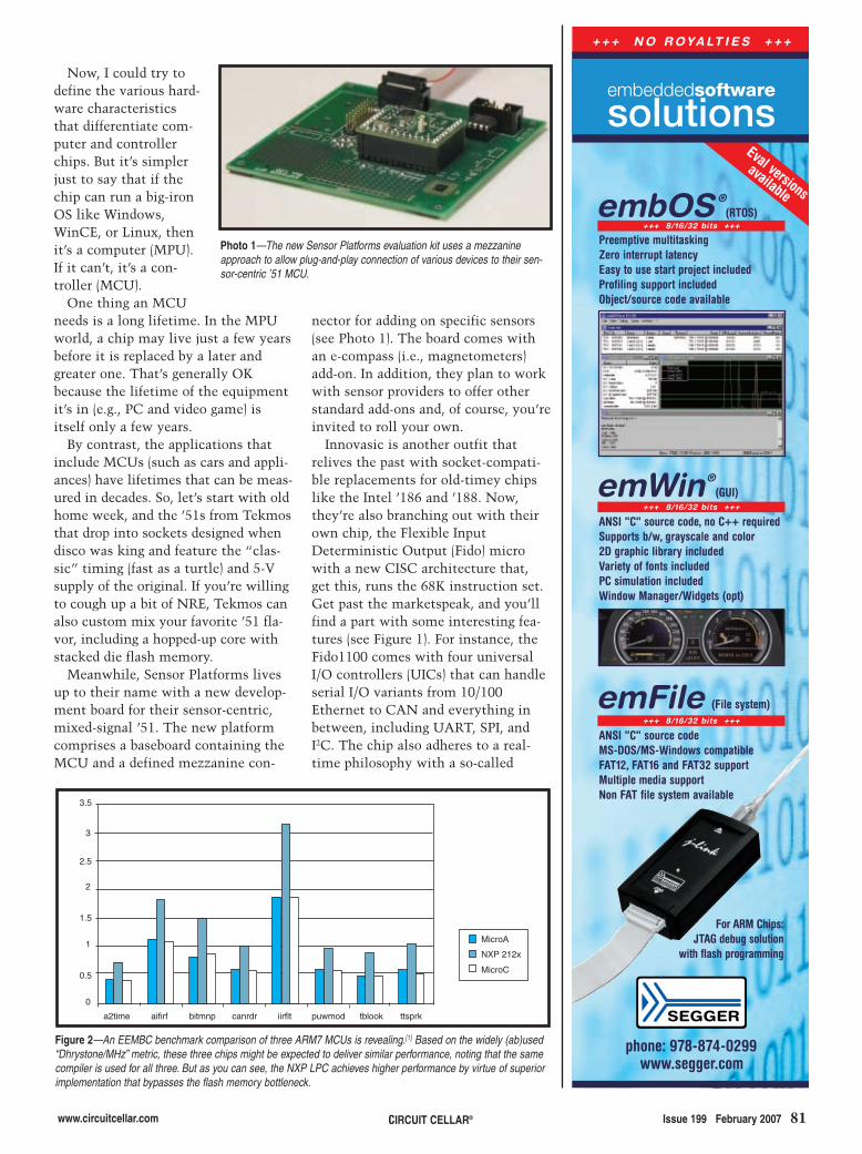
www.circuitcellar.com Issue 199 February 2007 81CIRCUIT CELLAR®
Now, I could try todefine the various hard-ware characteristicsthat differentiate com-puter and controllerchips. But it’s simplerjust to say that if thechip can run a big-ironOS like Windows,WinCE, or Linux, thenit’s a computer (MPU).If it can’t, it’s a con-troller (MCU).
One thing an MCUneeds is a long lifetime. In the MPUworld, a chip may live just a few yearsbefore it is replaced by a later andgreater one. That’s generally OKbecause the lifetime of the equipmentit’s in (e.g., PC and video game) isitself only a few years.
By contrast, the applications thatinclude MCUs (such as cars and appli-ances) have lifetimes that can be meas-ured in decades. So, let’s start with oldhome week, and the ’51s from Tekmosthat drop into sockets designed whendisco was king and feature the “clas-sic” timing (fast as a turtle) and 5-Vsupply of the original. If you’re willingto cough up a bit of NRE, Tekmos canalso custom mix your favorite ’51 fla-vor, including a hopped-up core withstacked die flash memory.
Meanwhile, Sensor Platforms livesup to their name with a new develop-ment board for their sensor-centric,mixed-signal ’51. The new platformcomprises a baseboard containing theMCU and a defined mezzanine con-
nector for adding on specific sensors(see Photo 1). The board comes withan e-compass (i.e., magnetometers)add-on. In addition, they plan to workwith sensor providers to offer otherstandard add-ons and, of course, you’reinvited to roll your own.
Innovasic is another outfit thatrelives the past with socket-compati-ble replacements for old-timey chipslike the Intel ’186 and ’188. Now,they’re also branching out with theirown chip, the Flexible InputDeterministic Output (Fido) microwith a new CISC architecture that,get this, runs the 68K instruction set.Get past the marketspeak, and you’llfind a part with some interesting fea-tures (see Figure 1). For instance, theFido1100 comes with four universalI/O controllers (UICs) that can handleserial I/O variants from 10/100Ethernet to CAN and everything inbetween, including UART, SPI, andI2C. The chip also adheres to a real-time philosophy with a so-called
Figure 2—An EEMBC benchmark comparison of three ARM7 MCUs is revealing.[1] Based on the widely (ab)used“Dhrystone/MHz” metric, these three chips might be expected to deliver similar performance, noting that the samecompiler is used for all three. But as you can see, the NXP LPC achieves higher performance by virtue of superiorimplementation that bypasses the flash memory bottleneck.
3.5
3
2.5
2
1.5
1
0.5
0
a2time aifirf bitmnp canrdr iirflt puwmod tblook ttsprk
MicroA
NXP 212x
MicroC
Photo 1—The new Sensor Platforms evaluation kit uses a mezzanineapproach to allow plug-and-play connection of various devices to their sen-sor-centric ’51 MCU.
phone: 978-874-0299www.segger.com
emWin®(GUI)
embOS ®(RTOS)
emFile (File system)
+ + + N O R O YA LT I E S + + +
Preemptive multitaskingZero interrupt latencyEasy to use start project includedProfiling support includedObject/source code available
ANSI "C" source codeMS-DOS/MS-Windows compatibleFAT12, FAT16 and FAT32 supportMultiple media supportNon FAT file system available
ANSI "C" source code, no C++ requiredSupports b/w, grayscale and color2D graphic library includedVariety of fonts included PC simulation includedWindow Manager/Widgets (opt)
For ARM Chips:JTAG debug solution
with flash programming
+++ 8/16/32 bits +++
+++ 8/16/32 bits +++
+++ 8/16/32 bits +++
embeddedsoftware
solutionsEval versions
available
2702003-Cantrell.qxp 1/4/2007 11:08 AM Page 81
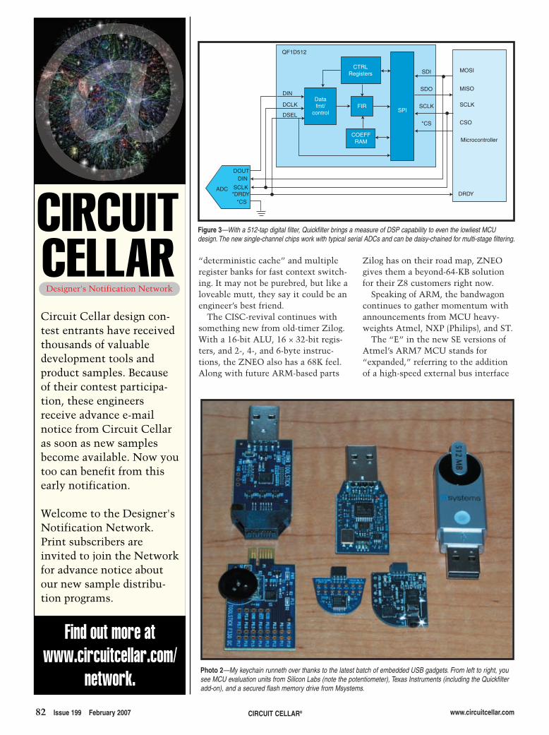
“deterministic cache” and multipleregister banks for fast context switch-ing. It may not be purebred, but like aloveable mutt, they say it could be anengineer’s best friend.
The CISC-revival continues withsomething new from old-timer Zilog.With a 16-bit ALU, 16 × 32-bit regis-ters, and 2-, 4-, and 6-byte instruc-tions, the ZNEO also has a 68K feel.Along with future ARM-based parts
82 Issue 199 February 2007 CIRCUIT CELLAR® www.circuitcellar.com
Zilog has on their road map, ZNEOgives them a beyond-64-KB solutionfor their Z8 customers right now.
Speaking of ARM, the bandwagoncontinues to gather momentum withannouncements from MCU heavy-weights Atmel, NXP (Philips), and ST.
The “E” in the new SE versions ofAtmel’s ARM7 MCU stands for“expanded,” referring to the additionof a high-speed external bus interface
QF1D512
CTRLRegisters
Datafmt/
controlFIR
COEFFRAM
SPI
DIN
DCLK
DSEL
SDI
SDO
SCLK
*CS
MOSI
MISO
SCLK
CSO
Microcontroller
DRDYADC
DOUTDIN
SCLK*DRDY
*CS
Figure 3—With a 512-tap digital filter, Quickfilter brings a measure of DSP capability to even the lowliest MCUdesign. The new single-channel chips work with typical serial ADCs and can be daisy-chained for multi-stage filtering.
Photo 2—My keychain runneth over thanks to the latest batch of embedded USB gadgets. From left to right, yousee MCU evaluation units from Silicon Labs (note the potentiometer), Texas Instruments (including the Quickfilteradd-on), and a secured flash memory drive from Msystems.
Circuit Cellar design con-test entrants have received thousands of valuable development tools and product samples. Because of their contest participa-tion, these engineers receive advance e-mail notice from Circuit Cellar as soon as new samples become available. Now you too can benefit from this early notification.
Welcome to the Designer's Notification Network. Print subscribers areinvited to join the Network for advance notice about our new sample distribu-tion programs.
Designer's Notification Network
2702003-Cantrell.qxp 1/4/2007 11:08 AM Page 82
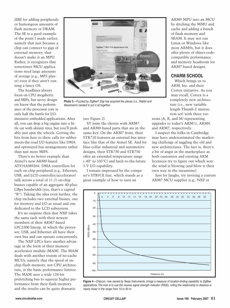
www.circuitcellar.com CIRCUIT CELLAR® Issue 199 February 2007 83
(EBI) for adding peripheralsor humongous amounts offlash memory or DRAM.The SE is a good exampleof the point I made earlier,namely that just because achip can connect to gigs ofexternal memory, thatdoesn’t make it an MPU.Rather, it recognizes thatsometimes MCU applica-tions need large amountsof storage (e.g., MP3 play-er) even if they aren’t run-ning a fancy OS.
The headlines alwaysfocus on CPU megahertzand MIPs, but savvy design-ers know that the perform-ance of the processor core isonly half the battle for I/O-intensive embedded applications. Afterall, you can drop a big engine into a lit-tle car with skinny tires, but you’ll prob-ably just spin the wheels. Getting thebits from here to there calls for rubber-meets-the-road I/O features like DMAand optimized bus arrangements ratherthan just more MIPS.
There’s no better example thanAtmel’s new ARM9-basedAT91SAM9264. DMA controllers foreach on-chip peripheral (e.g., Ethernet,USB, and LCD controller/accelerator)talk across a total of 11 (!) on-chipbusses capable of an aggregate 40-plus-GBps bandwidth (yes, that’s a capital“B”). Taking the idea even further, thechip includes two external busses, onefor memory and I/O as usual and onededicated to the LCD subsystem.
It’s no surprise then that NXP takesthe same tack with their newestmembers of their ARM7-basedLPC2300 lineup, in which the proces-sor, USB, and Ethernet all have theirown bus and can operate concurrently.
The NXP LPCs have another advan-tage in the form of their memoryaccelerator module (MAM). The MAMdeals with another truism of no-cacheMCUs, namely that the speed of on-chip flash memory, not CPU architec-ture, is the basic performance limiter.The MAM uses a wide 128-bitprefetching bus to squeeze higher per-formance from their flash memoryand the results can be quite dramatic
(see Figure 2).ST joins the chorus with ARM7-
and ARM9-based parts that are in thesame key. On the ARM7 front, theirSTR710 features an external bus inter-face like that of the Atmel SE. And forblue-collar industrial and automotivedesigns, their STR730 and STR750offer an extended temperature range(–40° to 105°C) and back-to-the-future5-V I/O capability.
I remain impressed by the compa-ny’s STR91X line, which stands as agreat example of how to turn an
ARM9 MPU into an MCUby ditching the MMU andcache and adding a bunchof flash memory andSRAM. It may not runLinux or Windows likemost ARM9s, but it doesoffer plenty of object-code-compatible performanceand memory headroom forARM7-based designs.
CHARM SCHOOLWhich brings us to
ARM, Inc. and theirCortex initiative. As youmay recall, Cortex is a
completely new architec-ture (i.e., new variablelength Thumb-2 instruc-tion set) with three ver-
sions (A, R, and M) representingupgrades to today’s ARM11, ARM9,and ARM7, respectively.
I suspect the folks in Cambridgemay have underestimated the market-ing challenge of juggling the old andnew architectures. The fact is, there’sa bit of angst in the marketplace asboth customers and existing ARMlicensees try to figure out which waythe wind is blowing (and blow it theirown way in the meantime).
Just for laughs, try inviting a currentARM7 MCU supplier (e.g., NXP or
Figure 4—Chipcon, now owned by Texas Instruments, brings a measure of location-finding capability to ZigBeeapplications. The trick is to use the receive signal strength indicator (RSSI), noting the relationship to distance isnearly linear in the range from 10 to 40 m.
Distance (m)
0
2 4 6 8 10 12 14 16 18 20 22 24 26 28 30 32 34 36 38 402 4 6 8 10 12 14 16 18 20 22 24 26 28 30 32 34 36 38 40
-10
-20
-30
-40
-50
-60
-70
-80
-90
-100
RS
SI (
dBm
)
Photo 3—Puzzled by ZigBee? Digi has acquired the pieces (i.e., Rabbit andMaxstream) needed to put it all together.
2702003-Cantrell.qxp 1/4/2007 11:08 AM Page 83
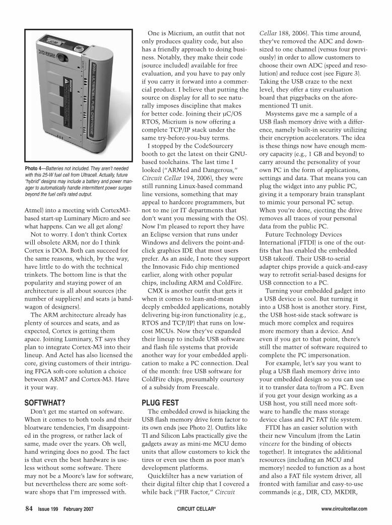
84 Issue 199 February 2007 CIRCUIT CELLAR® www.circuitcellar.com
Atmel) into a meeting with CortexM3-based start-up Luminary Micro and seewhat happens. Can we all get along?
Not to worry. I don’t think Cortexwill obsolete ARM; nor do I thinkCortex is DOA. Both can succeed forthe same reasons, which, by the way,have little to do with the technicaltrinkets. The bottom line is that thepopularity and staying power of anarchitecture is all about sources (thenumber of suppliers) and seats (a band-wagon of designers).
The ARM architecture already hasplenty of sources and seats, and asexpected, Cortex is getting themapace. Joining Luminary, ST says theyplan to integrate Cortex-M3 into theirlineup. And Actel has also licensed thecore, giving customers of their intrigu-ing FPGA soft-core solution a choicebetween ARM7 and Cortex-M3. Haveit your way.
SOFTWHAT?Don’t get me started on software.
When it comes to both tools and theirbloatware tendencies, I’m disappoint-ed in the progress, or rather lack ofsame, made over the years. Oh well,hand wringing does no good. The factis that even the best hardware is use-less without some software. Theremay not be a Moore’s law for software,but nevertheless there are some soft-ware shops that I’m impressed with.
One is Micrium, an outfit that notonly produces quality code, but alsohas a friendly approach to doing busi-ness. Notably, they make their code(source included) available for freeevaluation, and you have to pay onlyif you carry it forward into a commer-cial product. I believe that putting thesource on display for all to see natu-rally imposes discipline that makesfor better code. Joining their µC/OSRTOS, Micrium is now offering acomplete TCP/IP stack under thesame try-before-you-buy terms.
I stopped by the CodeSourcerybooth to get the latest on their GNU-based toolchains. The last time Ilooked (“ARMed and Dangerous,”Circuit Cellar 194, 2006), they werestill running Linux-based commandline versions, something that mayappeal to hardcore programmers, butnot to me (or IT departments thatdon’t want you messing with the OS).Now I’m pleased to report they havean Eclipse version that runs underWindows and delivers the point-and-click graphics IDE that most usersprefer. As an aside, I note they supportthe Innovasic Fido chip mentionedearlier, along with other popularchips, including ARM and ColdFire.
CMX is another outfit that gets itwhen it comes to lean-and-meandeeply embedded applications, notablydelivering big-iron functionality (e.g.,RTOS and TCP/IP) that runs on low-cost MCUs. Now they’ve expandedtheir lineup to include USB softwareand flash file systems that provideanother way for your embedded appli-cation to make a PC connection. Dealof the month: free USB software forColdFire chips, presumably courtesyof a subsidy from Freescale.
PLUG FESTThe embedded crowd is hijacking the
USB flash memory drive form factor toits own ends (see Photo 2). Outfits likeTI and Silicon Labs practically give thegadgets away as mini-me MCU demounits that allow customers to kick thetires or even use them as poor man’sdevelopment platforms.
Quickfilter has a new variation oftheir digital filter chip that I covered awhile back (“FIR Factor,” Circuit
Photo 4—Batteries not included. They aren’t neededwith this 25-W fuel cell from Ultracell. Actually, future“hybrid” designs may include a battery and power man-ager to automatically handle intermittent power surgesbeyond the fuel cell’s rated output.
Cellar 188, 2006). This time around,they’ve removed the ADC and down-sized to one channel (versus four previ-ously) in order to allow customers tochoose their own ADC (speed and reso-lution) and reduce cost (see Figure 3).Taking the USB craze to the nextlevel, they offer a tiny evaluationboard that piggybacks on the afore-mentioned TI unit.
Msystems gave me a sample of aUSB flash memory drive with a differ-ence, namely built-in security utilizingtheir encryption accelerators. The ideais these things now have enough mem-ory capacity (e.g., 1 GB and beyond) tocarry around the personality of yourown PC in the form of applications,settings and data. That means you canplug the widget into any public PC,giving it a temporary brain transplantto mimic your personal PC setup.When you’re done, ejecting the driveremoves all traces of your personaldata from the public PC.
Future Technology DevicesInternational (FTDI) is one of the out-fits that has enabled the embeddedUSB takeoff. Their USB-to-serialadapter chips provide a quick-and-easyway to retrofit serial-based designs forUSB connection to a PC.
Turning your embedded gadget intoa USB device is cool. But turning itinto a USB host is another story. First,the USB host-side stack software ismuch more complex and requiresmore memory than a device. Andeven if you get to that point, there’sstill the matter of software required tocomplete the PC impersonation.
For example, let’s say you want toplug a USB flash memory drive intoyour embedded design so you can useit to transfer data to/from a PC. Evenif you get your design working as aUSB host, you still need more soft-ware to handle the mass storagedevice class and PC FAT file system.
FTDI has an easier solution withtheir new Vinculum (from the Latinvincere for the binding of objectstogether). It integrates the additionalresources (including an MCU andmemory) needed to function as a hostand also a FAT file system driver, allfronted with familiar and easy-to-usecommands (e.g., DIR, CD, MKDIR,
2702003-Cantrell.qxp 1/4/2007 11:08 AM Page 84
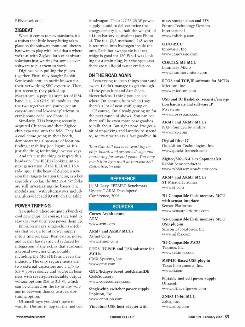
www.circuitcellar.com CIRCUIT CELLAR® Issue 199 February 2007 85
REFERENCE[1] M. Levy, “EEMBC BenchmarkUpdate,” ARM Developers’Conference, 2006.
SOURCESCortex ArchitectureARM www.arm.com
ARM7 and ARM9 MCUsAtmel Corp.www.atmel.com
RTOS, TCP/IP, and USB software forMCUsCMX Systems, Inc.www.cmx.com
GNU/Eclipse-based toolchain/IDECodeSourcerywww.codesourcery.com
Single-chip switcher power supplyEnpirion, Inc.www.enpirion.com
Vinculum USB host adapter with
Tom Cantrell has been working onchip, board, and systems design andmarketing for several years. You mayreach him by e-mail at [email protected].
mass storage class and FFSFuture Technology DevicesInternationalwww.ftdichip.com
FIDO MCUInnovasic, Inc. www.innovasic.com
CORTEX M3 MCULuminary Microwww.luminarymicro.com
RTOS and TCP/IP software for MCUsMicrium, Inc.www.micrium.com
USB and IC flashdisk, security/encryp-tion hardware and software IPMsystemswww.m-systems.com
ARM7 and ARM9 MCUsNXP (founded by Philips)www.nxp.com
Digital filter ICQuickfilter Technologies, Inc.www.quickfiltertech.com
ZigBee/802.15.4 Development kitRabbit Semiconductor www.rabbitsemiconductor.com
ARM7 and ARM9 MCUsST Microelectronics www.st.com
’51-Compatible flash memory MCUwith sensor interfaceSensor Platformswww.sensorplatforms.com
’51-Compatible flash memory MCUUSB plug-inSilicon Laboratories, Inc.www.silabs.com
’51-Compatible MCUTekmos, Inc.www.tekmos.com
MSP430-Based USB plug-inTexas Instruments, Inc.www.ti.com
Portable fuel cell power supplyUltracellwww.ultracellpower.com
ZNEO 16-bit MCUZilog, Inc.www.zilog.com
REN(ame), etc.).
ZIGBEATWhen it comes to new standards, it’s
a truism that little heavy-lifting takesplace on the software front until there’shardware to play with. And that’s wherewe’re at with ZigBee: lot’s of hardwaresolutions just waiting for some cleversoftware to put them to work.
Digi has been pulling the piecestogether. First, they bought RabbitSemiconductor, an outfit known fortheir networking SBC expertise. Then,just recently, they picked upMaxstream, a popular supplier of ISM-band (e.g., 2.4 GHz) RF modules. Putthe two together and you’ve got aneasy-to-use and low-cost platform tocrank some code (see Photo 3).
Similarly, TI is bringing recentlyacquired Chipcon and their ZigBeechip expertise into the fold. They hada cool demo going in their booth,demonstrating a measure of location-finding capability (see Figure 4). It’sjust the thing for finding lost car keys.
And it’s just the thing to inspire thisheads-up. The IEEE is looking into anext generation of the IEEE 802.15.4radio spec at the heart of ZigBee, a revi-sion that targets location finding as a keycapability. So far, the 802.15.4 “a” folksare still investigating the basics (e.g.,modulation), with alternatives includ-ing ultrawideband (UWB) on the table.
POWER TRIPPINGYes, indeed. There are quite a bunch of
cool new chips. Of course, they tend tostay that way until you power them up.
Enpirion makes single-chip switch-ers that pack a lot of power supplyinto a tiny package. Real estate, noise,and design hassles are all reduced byintegration of the extras that surrounda typical switcher chip, notablyincluding the MOSFETs and even theinductor. The only requirements aretwo external capacitors and a 2.4- to5.5-V power source and you’re in busi-ness with seven-pin-selectable outputvoltage options (0.6 to 3.3 V), whichcan be changed on the fly or any volt-age in between thanks to a resistor-tuning option.
Ultracell says you don’t have towait for Detroit to hop on the fuel cell
bandwagon. Their UC25 25-W powersupply is said to deliver twice theenergy density (i.e., half the weight) ofa Li-on battery equivalent (see Photo4). The fuel (2/3 methanol, 1/3 water)is reformed into hydrogen inside theunit. Each hot-swappable fuel car-tridge is good for 180 Wh. I was look-ing for a drain plug, but the spec saysthere are no liquid water emissions.
ON THE ROAD AGAINEven trying to keep things short and
sweet, I didn’t manage to get throughall the press kits and datasheets.Nevertheless, I think you can seewhere I’m coming from when I saythere’s a lot of neat stuff going on.
Of course, I’m already gearing up forthe next round of shows. You can betthere will be even more new goodiesto talk about. But right now, I’ve got abit of unpacking and laundry to attendto, so it’s time to say a fast goodbye. I
2702003-Cantrell.qxp 1/4/2007 11:08 AM Page 85
86 Issue 199 February 2007 CIRCUIT CELLAR® www.circuitcellar.com
IDEA BOXTHE DIRECTORY OF PRODUCTS AND SERVICES
AD FORMAT: Advertisers must furnish digital submission sheet and digital files that meet the specifications on the digital submission sheet. ALL TEXT AND OTHER ELEMENTS MUST FIT WITHIN A 2†† ·· 3††FORMAT. Call for current rate and deadline information. Send your disk and digital submission sheetto: IDEA BOX, Circuit Cellar, 4 Park Street, Vernon, CT 06066 or e-mail [email protected]. For more information call Shannon Barraclough at (860) 872-3064.
The Suppliers Directory at www.circuitcellar.com/suppliers_dir/ is your guide to a variety of engineering products and services.
UUSSBBAdd USB to your next
project—it’s easier than youmight think!
USB-FIFO up to 8 mbpsUSB-UART up to 3 mbpsUSB/Microcontroller boards
pre-programmed with firmware2.4GHz ZigBee™ & 802.15.4RFID Reader/Writer
Absolutely NO driver softwaredevelopment required!
www.dlpdesign.com
Low Cost EDA SoftwareFor Windows 98, XP, NT, 2000
Circuit design package withschematic entry, circuit boardlayout and simulation (SPICEand digital) for only $599Buy modules for as low as $119Purchase and downloadproducts instantly from ourwebsite! Libraries include latest micros, memories, analog, and others
Contact Mental Automation at(253) 858-8104
http://www.mentala.com
phyCORE® OEMable Single Board Computers
PHYTEC America, LLC � 203 Parfitt Way SW, G100 � Bainbridge Island, WA 98110 USA
XScale:XScale:XScale:XScale:XScale: PXA270, PXA255
ARM:ARM:ARM:ARM:ARM: LPC3180 (ARM9); LPC22xx, LPC229x, AT91 (ARM7)
PowerPC:PowerPC:PowerPC:PowerPC:PowerPC: MPC5554, MPC5200B, MPC565, MPC555
ColdFire:ColdFire:ColdFire:ColdFire:ColdFire: MCF5485
C 1 6 6 / X C 1 6 x / S T 1 0 / 8 0 5 1 CANCANCANCANCANx86x86x86x86x86::::: Elan SC520
www.phytec.com � (800) 278-9913 � www.phycore.com
Faster-to-Market: Save time byintegrating a PHYTEC SingleBoard Computer Module intoyour target circuitry.Make -or - Buy: Why makeyour own when you can buyPHYTEC off-shelf solutions,cost-effective to 1000s units/year?
Integrated Support Services: Let PHYTEC assist you in the design of yourend product: from tools and RTOSes to production. Our hardware isbundled with leading compilers (Keil, IAR, CodeWarrior), RTOSes (WinCE,Linux) and debuggers.Immediate Support: Talk to PHYTEC technical staff with every call. Nowaiting for answers.Your OEM solution: With 20 years design, production, and integrationexperience, PHYTEC is your OEM partner.
Blackfin:Blackfin:Blackfin:Blackfin:Blackfin: BF537
ib-199.qxp 1/4/2007 1:41 PM Page 86
www.circuitcellar.com CIRCUIT CELLAR® Issue 199 February 2007 87
tm
Fully Functional Demos!
Fully FunctionalFully FunctionalFully Functional Demos! Demos! Demos!
Fully Functional Demos!Plus:
AVR, ARM & HCS12 Hardware Kits
ib-199.qxp 1/4/2007 1:41 PM Page 87

88 Issue 199 February 2007 CIRCUIT CELLAR® www.circuitcellar.com
Pioneer Hill Software360 697-3472 [email protected]
SpectraPLUS 5.0Audio Spectrum AnalysisFeaturesSound Card based I/OFFT sizes to 1048576pts, 1/96 OctaveUp to 24 bit, 200kHz sampling rates3-D Surface and SpectrogramDigital Filtering, Signal GenerationTHD, IMD, SNR, Transfer FunctionsDDE, Macros, Data Logging,Vibration Analysis, Acoustic Tools
FREE 30 day trial!www.spectraplus.com
Microcontroller Projects
Self-assembly ICD2 for $36.
Electronic parts. Low or FREE shipping.
DIPmicro ElectronicsFax: (866) 603-7109 [email protected]
www.dipmicro.com
Low Cost CANUSB Adapter
+1 630-245-1445Naperville, Illinois USAwww.c-a-n.com
$99.95
Qty 1
Simple configuration & use
ib-199.qxp 1/4/2007 2:03 PM Page 88

ABACOMTechnologies
ABACOMdirect.comABACOM .comdirecttel: +1(416) 236 3858
fax: +1(416) 236 8866ABACOMTechnologies
ABACOMdirect.comABACOM .comdirecttel: +1(416) 236 3858
fax: +1(416) 236 8866
ZigbeeZigbeewatchoutwatchout
here comeshere comesSpiderSpiderauto-binding multidrop sensor / actuator
network podsnetwork pods
wirelesswireless
enter coupon code CCI at checkoutSAVE 5%enter coupon code CCI at checkoutSAVE 5%
ABACOMTechnologies
ABACOMdirect.comABACOM .comdirecttel: +1(416) 236 3858
fax: +1(416) 236 8866
Wireless I/OWireless I/O
enter coupon code CCI at checkoutSAVE 5%
programmableprogrammablerevolutionaryrevolutionary
extend
100’s feet
tens
your digital I/O’s
over of up to
of - in bothdirections - with the
RF transceivermodules
miles
16IO-SSRT
Net ModulesNet Modules
www.circuitcellar.com CIRCUIT CELLAR® Issue 199 February 2007 89
WWW.MYLYDIA.COM
MYLYDIA, INC.MYLYDIA, INC.LLaayyoouutt GGeerrbbeerr,,
PPrroottoottyyppee MMaakkiinngg
QQUUIICCKK TTUURRNNPPCCBB && TTuurrnnkkeeyy
@TThhee BBeesstt PPrriicceess
WWW.MYLYDIA.COM
ib-199.qxp 1/4/2007 2:04 PM Page 89

90 Issue 199 February 2007 CIRCUIT CELLAR® www.circuitcellar.com
Mosaic Industries Inc.tel: 510-790-1255 fax: 510-790-0925
www.mosaic-industries.com
� Standard RJ45 jack hosts10/100Mbit Ethernet
� HTTP, SMTP, TCP, DHCP, ICMP,and ARP Protocols
� Email program-controlled messagesto a specified LAN IP address
� Establish a TCP/IP connection toexchange binary or ASCII data
� Serve software-controlled dynamiccontent to your web browser
$140/100s
EtherSmart WildcardTM
Network -Enables Your Product
ib-199.qxp 1/4/2007 2:04 PM Page 90

www.circuitcellar.com CIRCUIT CELLAR® Issue 199 February 2007 91
��� ����� ��. .��� ����� ��. .
High Quality EnclosuresThe Most Competitive Price*
*
*
*
*
* , ,
Sheet Metal CabinetsAluminium Extruded Enclosures19inch Standard Cabinets
Highly Custom MadeFast PrototypingFrom 1pc to 10 000 000 pcs
*
*
Plastic InjectionPrecision Aluminium Die Casting
www.schmartboard.com
ANYONE Can Now Easi ly
Hand Solder Surface- Mount Components!
Even A 10 Year Old!
ib-199.qxp 1/4/2007 2:04 PM Page 91

92 Issue 199 February 2007 CIRCUIT CELLAR® www.circuitcellar.com
DDevelopmentt Toolss forr PIC® Microcontrollers
microEngineeringg Labs,, Inc. Phone:: (719)) 520-5323Fax:: (719)) 520-1867
Boxx 60039Coloradoo Springs,, COO 80960
Orderr onlinee at:www.melabs.com
BASIC Compilers for PICmicro®
PICBASIC PRO™ Compiler $249.95
Easy-To-Use BASIC CommandsWindows 9x/Me/2K/XP Interface
PICBASIC™ Compiler $99.95BASIC Stamp 1 CompatibleSupports most 14-bit Core PICsBuilt-In Serial Comm Commands
Supports All PICmicro® MCU FamiliesDirect Access to Internal RegistersSupports In-Line Assembly LanguageInterrupts in PICBASIC and AssemblyBuilt-In USB, I2C, RS-232 and MoreSource Level Debugging
See our full range of products, includingbooks, accessories, and components at:
www.melabs.com
USB Programmer for PIC® MCUs
Includes:Programmer, USB Cable,ZIF Programming Adapter for 8 to 40-pin DIP,Software for Windows 98/Me/NT/2K/XP
Pre-Assembled BoardsAvailable for 8, 14, 18, 28, and 40-pin PIC® MCUs2-line, 20-char LCD Module9-pin Serial PortSample ProgramsFull Schematic Diagram
Pricing from $79.95 to $349.95
PICPROTO™ Prototyping BoardsDouble-Sided with Plate-Thru HolesCircuitry for Power Supply and ClockLarge Prototype AreaBoards Available for Most PIC® MCUsDocumentation and Schematic
Pricing from $8.95 to $19.95
LAB-X Experimenter Boards
Parallel Port Programmerstarting at $59.95Serial Port Programmerstarting at $79.95EPIC™
(with accessories)$119.95
RoHSCompliantProgramsPIC MCUsincludinglow-voltage(3.3V) devices
ib-199.qxp 1/4/2007 2:04 PM Page 92

1
3
4 5 6
7
8
10 11
12 13
14
15 16
17
18
19
2
9
www.circuitcellar.com CIRCUIT CELLAR® Issue 199 February 2007 93
CCRROOSSSSWWOORRDD
Across3. Computer chip used to run electronic devices4. A circuit board that attaches to a larger circuit board7. Unscramble the following:
ONSYSTEMCHIPPROGRAMMABLE8. An “L” word. Not Google, not Yahoo!, not AltaVista.13. The upper-level of the solar atmosphere known for low
densities and high temperatures14. A group of frequencies higher or lower than the carrier fre-
quency15. An open-source Internet search browser17. The lowest points in the range of a function18. Started in 2005, this free video-sharing site was purchased
in 2006 by Google for approximately $1.65 billion.19. Causing dissolution of electrical energy
The answers are available atwww.circuitcellar.com/crossword.
Down1. His law (1965) regards the number of transistors on
the most complex chips.2. TM5. Music file extension used by Apple’s iPod6. \9. An acronym (typically used online) that means to
jump around like a common zoo animal10. To visit numerous web sites (or pubs)11. The degree to which an electronic system correctly
reproduces its input12. A popular description language for hardware13. American scientist (1943–present) born in New
Haven, CT, who is known for helping develop the’Net and the TCP/IP protocol. In 2005, Google hiredhim as a “Chief Internet Evangelist.”
16. Bus system used in automotive networks
crossword2.qxp 1/4/2007 2:17 PM Page 93

94 Issue 199 February 2007 CIRCUIT CELLAR® www.circuitcellar.com
Robotic Arm Control System
Servo Control
Inertial Rolling Robot
Animatronic System Control
ATir Keyboard Interface
A Plethora of Projects
Then and Now
LESSONS FROM THE TRENCHES More “Hello World”: Moving What You’ve Learnedto the Hardware
APPLIED PCs Build a PIC Platform
FROM THE BENCH Embedded USB Breakthrough
SILICON UPDATE Code Like the Wind World Tour
91 AAG Electronica, LLC
90 AP Circuits
66 APEC
89 Abacom Technologies
95 Aerocomm, Inc.
86 All Electronics Corp.
87 Apex Embedded Systems
41 Arcom Control Systems
7 Atmel
34 Bitscope Designs
65 CWAV
48 CadSoft Computer, Inc.
53 Camosun College
66 Circuit Specialists, Inc.
90 Conitec
90 Custom Computer Services, Inc.
1 Cypress
88 DIPmicro Electronics
86 DLP Design
60 Decade Engineering
53 EMAC, Inc.
58 ESC-West
87 Earth Computer Technologies
88 eMicros
18 ExpressPCB
The Index of Advertisers with links to their web sites is located at www.circuitcellar.com under the current issue.Page
47, 91 ezPCB
86 FDI-Future Designs, Inc.
90 Front Panel Express, LLC
92 Futurlec
89 General Circuits, Inc.
88, 91 Grid Connect
11 HI-TECH Software LLC
17 Holmate/Holtek Semiconductor, Inc.
87 IMAGEcraft
90 Intec Automation, Inc.
61 Intrepid Control Systems
42 Intronix Test Instruments, Inc.
92 Ironwood Electronics
64, 91 JK microsystems, Inc.
39 Jameco
60 Jeffrey Kerr, LLC
21 Keil Software
67 LabJack Corp.
67 Lakeview Research
87 Lawicel AB
33 Lemos International
2 Link Instruments
64 Linx Technologies
49 Luminary Micro
87 MCC (Micro Computer Control)
89 MSC Conference
79 Matrix Orbital
12 Maxstream
86 Mental Automation
88, 91 Micro Digital, Inc.
92 microEngineering Labs, Inc.
90 Mosaic Industries, Inc.
27 Mouser Electronics
89 Mylydia, Inc.
C2 NetBurner
3 Noritake Co., Inc.
67 Nurve Networks LLC
92 Ontrak Control Systems
91 Ozitronics
89 PCB Fab Express
50 PCB-Pool
C4 Parallax, Inc.
86 Phytec America LLC
87 Pioneer Automation, Inc.
88 Pioneer Hill Software
88 Pro-Tech Electronics Canada
91 Pulsar, Inc.
23, 55 Rabbit Semiconductor
87 Rabbit Semiconductor
87 Reach Technology, Inc.
Page Page Page
13 Renesas
31 Saelig Company
91 Schmartboard
29 Sealevel Systems
81 SEGGER Microcontroller Sys. LLC
55 Sierra Proto Express
5 Silicon Laboratories, Inc.
92 Systronix
C3 Tech Tools
56, 57 Technologic Systems
88 Technological Arts
89 Tern, Inc.
19 Tibbo Technology, Inc.
92 Trace Systems, Inc.
22 Tri-M Systems, Inc.
88 Triangle Reasearch Int’l, Inc.
12 Trinity College Robot Contest
86 WCSC (Willies Computer Software Co.)
88 Zanthic Technologies, Inc.
April Issue 201Deadlines
Space Close: Feb. 12Material Close: Feb. 20
Theme:Embedded Programming
BONUS DISTRIBUTION:Embedded Systems
Conference West
ATTENTION ADVERTISERS
Call Shannon Barraclough now to reserve your space!
860.872.3064e-mail: [email protected]
INDEX OF ADVERTISERS
Preview of March Issue 200Theme: Robotics
94-advertiser's index.qxp 1/4/2007 11:19 AM Page 94

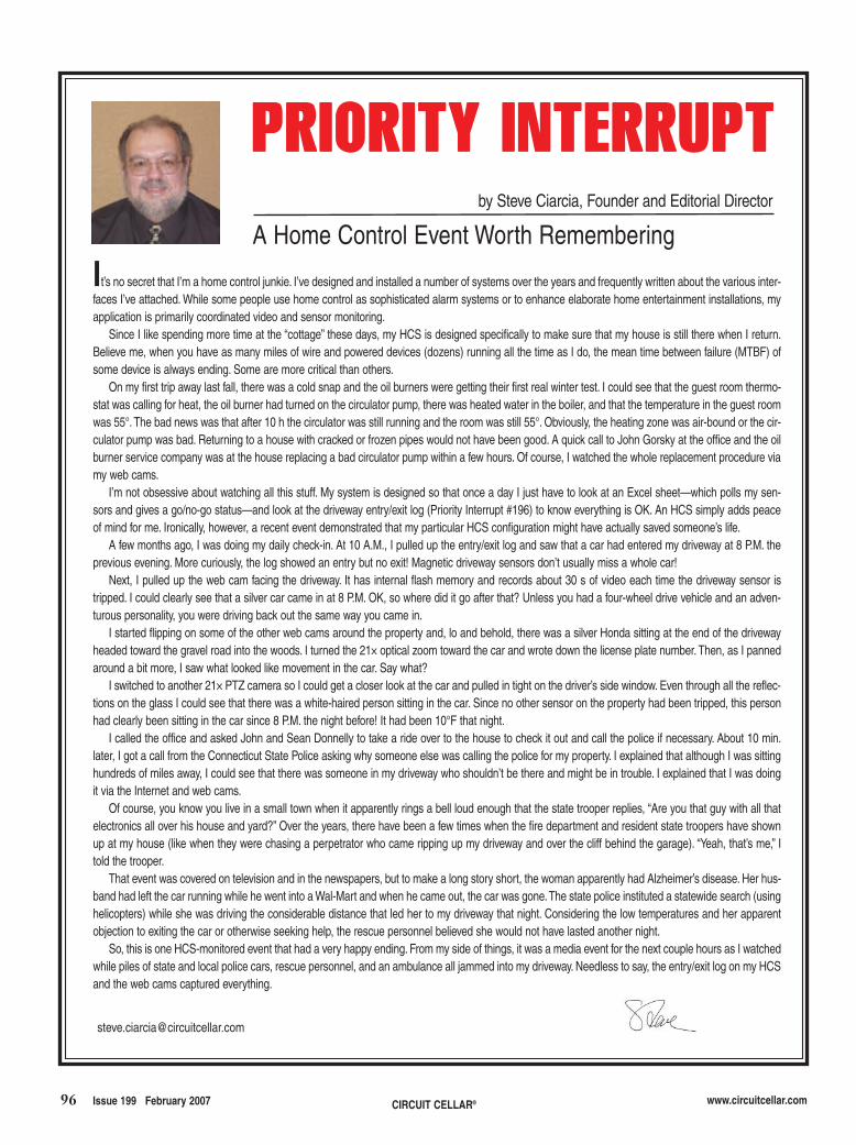
96 Issue 199 February 2007 CIRCUIT CELLAR® www.circuitcellar.com
It’s no secret that I’m a home control junkie. I’ve designed and installed a number of systems over the years and frequently written about the various inter-faces I’ve attached. While some people use home control as sophisticated alarm systems or to enhance elaborate home entertainment installations, myapplication is primarily coordinated video and sensor monitoring.
Since I like spending more time at the “cottage” these days, my HCS is designed specifically to make sure that my house is still there when I return.Believe me, when you have as many miles of wire and powered devices (dozens) running all the time as I do, the mean time between failure (MTBF) ofsome device is always ending. Some are more critical than others.
On my first trip away last fall, there was a cold snap and the oil burners were getting their first real winter test. I could see that the guest room thermo-stat was calling for heat, the oil burner had turned on the circulator pump, there was heated water in the boiler, and that the temperature in the guest roomwas 55°.The bad news was that after 10 h the circulator was still running and the room was still 55°. Obviously, the heating zone was air-bound or the cir-culator pump was bad. Returning to a house with cracked or frozen pipes would not have been good. A quick call to John Gorsky at the office and the oilburner service company was at the house replacing a bad circulator pump within a few hours. Of course, I watched the whole replacement procedure viamy web cams.
I’m not obsessive about watching all this stuff. My system is designed so that once a day I just have to look at an Excel sheet—which polls my sen-sors and gives a go/no-go status—and look at the driveway entry/exit log (Priority Interrupt #196) to know everything is OK. An HCS simply adds peaceof mind for me. Ironically, however, a recent event demonstrated that my particular HCS configuration might have actually saved someone’s life.
A few months ago, I was doing my daily check-in. At 10 A.M., I pulled up the entry/exit log and saw that a car had entered my driveway at 8 P.M. theprevious evening. More curiously, the log showed an entry but no exit! Magnetic driveway sensors don’t usually miss a whole car!
Next, I pulled up the web cam facing the driveway. It has internal flash memory and records about 30 s of video each time the driveway sensor istripped. I could clearly see that a silver car came in at 8 P.M. OK, so where did it go after that? Unless you had a four-wheel drive vehicle and an adven-turous personality, you were driving back out the same way you came in.
I started flipping on some of the other web cams around the property and, lo and behold, there was a silver Honda sitting at the end of the drivewayheaded toward the gravel road into the woods. I turned the 21× optical zoom toward the car and wrote down the license plate number. Then, as I pannedaround a bit more, I saw what looked like movement in the car. Say what?
I switched to another 21× PTZ camera so I could get a closer look at the car and pulled in tight on the driver’s side window. Even through all the reflec-tions on the glass I could see that there was a white-haired person sitting in the car. Since no other sensor on the property had been tripped, this personhad clearly been sitting in the car since 8 P.M. the night before! It had been 10°F that night.
I called the office and asked John and Sean Donnelly to take a ride over to the house to check it out and call the police if necessary. About 10 min.later, I got a call from the Connecticut State Police asking why someone else was calling the police for my property. I explained that although I was sittinghundreds of miles away, I could see that there was someone in my driveway who shouldn’t be there and might be in trouble. I explained that I was doingit via the Internet and web cams.
Of course, you know you live in a small town when it apparently rings a bell loud enough that the state trooper replies, “Are you that guy with all thatelectronics all over his house and yard?” Over the years, there have been a few times when the fire department and resident state troopers have shownup at my house (like when they were chasing a perpetrator who came ripping up my driveway and over the cliff behind the garage). “Yeah, that’s me,” Itold the trooper.
That event was covered on television and in the newspapers, but to make a long story short, the woman apparently had Alzheimer’s disease. Her hus-band had left the car running while he went into a Wal-Mart and when he came out, the car was gone.The state police instituted a statewide search (usinghelicopters) while she was driving the considerable distance that led her to my driveway that night. Considering the low temperatures and her apparentobjection to exiting the car or otherwise seeking help, the rescue personnel believed she would not have lasted another night.
So, this is one HCS-monitored event that had a very happy ending. From my side of things, it was a media event for the next couple hours as I watchedwhile piles of state and local police cars, rescue personnel, and an ambulance all jammed into my driveway. Needless to say, the entry/exit log on my HCSand the web cams captured everything.
A Home Control Event Worth Remembering
PPRRIIOORRIITTYY IINNTTEERRRRUUPPTT
by Steve Ciarcia, Founder and Editorial Director
steve_edit_199.qxp 1/4/2007 2:17 PM Page 96

Related Documents