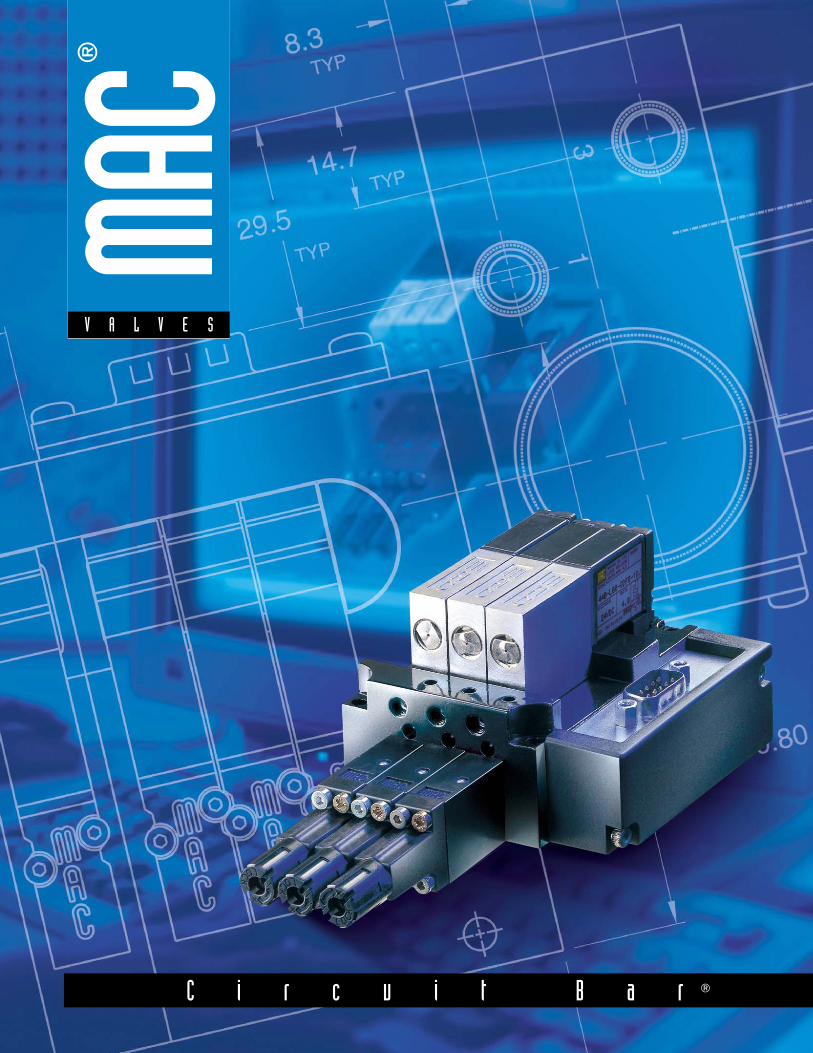
C i r c u i t B a r ®

Welcome message from author
This document is posted to help you gain knowledge. Please leave a comment to let me know what you think about it! Share it to your friends and learn new things together.
Transcript
C i r c u i t B a r ®
Consult “Precautions” before use, installation or service of MAC Valves.
I n t r o d u c t i o n
S e c t i o n 1 Direct solenoid and solenoid pilot operated valves
CIRCUIT BAR®
CIRCUIT BAR® is an extruded block of aluminum with pneumatic circuits machined right in the bar.The design of these circuits can be very simple or complex depending upon the requirements of theapplication.
CIRCUIT BAR® are a means by which individual components (i.e. valves, regulators and flow controls)comprising a circuit, can be combined into one extruded CIRCUIT BAR®. The CIRCUIT BAR® will elimi-nate extra piping and fittings, as well as saving space and money.
Contact your local MAC distributor for more information as to how MAC’S CIRCUIT BAR® can satisfyyour needs.
Consult “Precautions” before use, installation or service of MAC Valves.
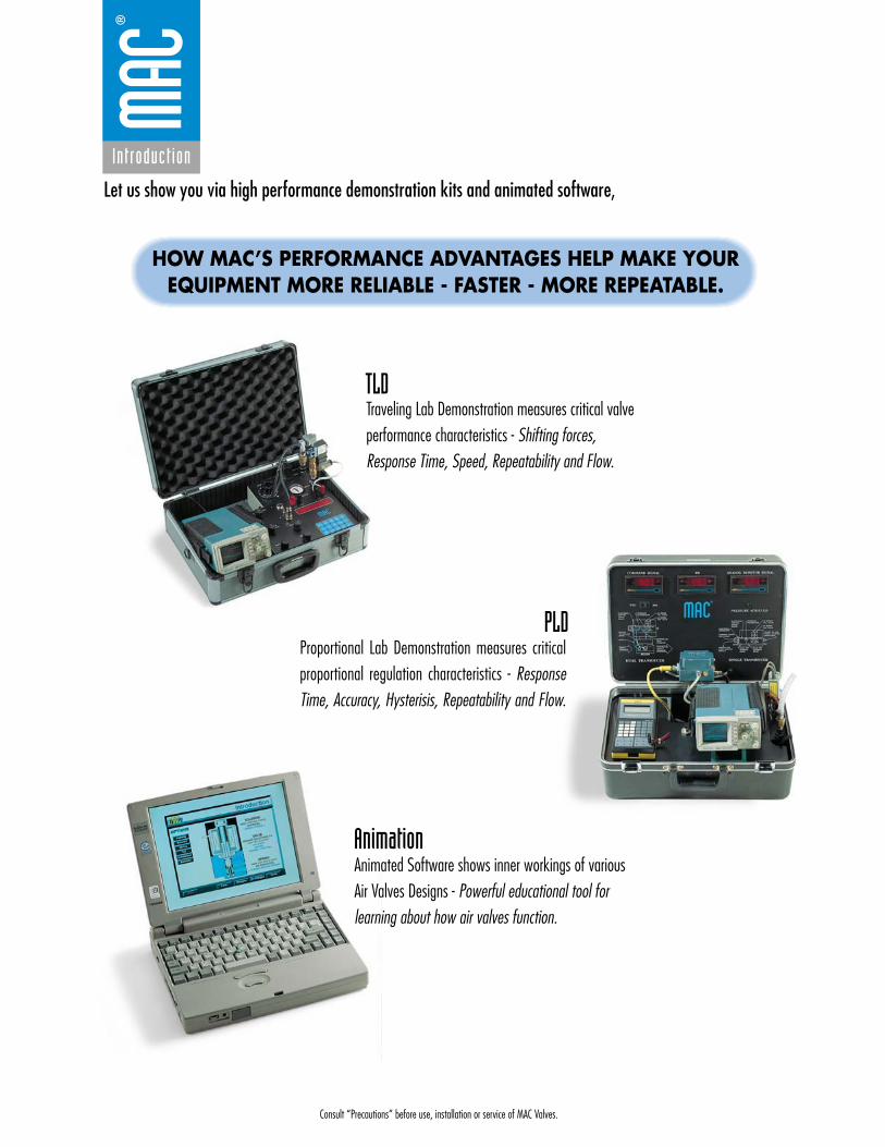
TLD
PLD
Animation
Traveling Lab Demonstration measures critical valveperformance characteristics - Shifting forces,Response Time, Speed, Repeatability and Flow.
Animated Software shows inner workings of variousAir Valves Designs - Powerful educational tool forlearning about how air valves function.
Proportional Lab Demonstration measures criticalproportional regulation characteristics - ResponseTime, Accuracy, Hysterisis, Repeatability and Flow.
Let us show you via high performance demonstration kits and animated software,
HOW MAC’S PERFORMANCE ADVANTAGES HELP MAKE YOUREQUIPMENT MORE RELIABLE - FASTER - MORE REPEATABLE.
Introduct ion
Consult “Precautions” before use, installation or service of MAC Valves.
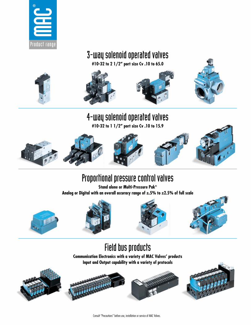
3-way solenoid operated valves#10-32 to 2 1/2” port size Cv .10 to 65.0
4-way solenoid operated valves#10-32 to 1 1/2” port size Cv .10 to 15.9
Proportional pressure control valvesStand alone or Multi-Pressure Pak®
Analog or Digital with an overall accuracy range of ±.5% to ±2.5% of full scale
Field bus productsCommunication Electronics with a variety of MAC Valves’ products
Input and Output capability with a variety of protocols
Product range

Consult “Precautions” before use, installation or service of MAC Valves.
S e c t i o n 1 Direct solenoid and solenoid pilot operated valves
35
34
37
44
45
47
Consult “Precautions” before use, installation or service of MAC Valves.
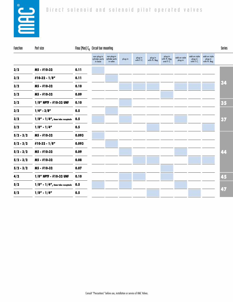
Function Port size Flow (Max) Cv Circuit bar mounting Series
D i r e c t s o l e n o i d a n d s o l e n o i d p i l o t o p e r a t e d v a l v e s
3/2
3/2
3/2
3/2
3/2
3/2
3/2
3/2
5/2 - 3/2
5/2 - 3/2
5/2 - 3/2
5/2 - 3/2
5/2 - 3/2
4/2
5/2
5/2
M5 - #10-32
#10-32 - 1/8”
M5 - #10-32
M5 - #10-32
1/8” NPTF - #10-32 UNF
1/4” - 3/8”
1/8” - 1/4”, 6mm tube receptacle
1/8” - 1/4”
M5 - #10-32
#10-32 - 1/8”
M5 - #10-32
M5 - #10-32
M5 - #10-32
1/8” NPTF - #10-32 UNF
1/8” - 1/4”, 6mm tube receptacle
1/8” - 1/4”
0.11
0.11
0.10
0.09
0.10
0.5
0.5
0.5
0.093
0.093
0.09
0.08
0.07
0.10
0.5
0.5
non plug-incylinder ports
in valveplug-in plug-in
with F. C. plug-in
with Pr. Reg.
plug-in with Pr. Reg.
and F. C.
add-on styleplug-in
add-on styleplug-in
with F. C.
add-on styleplug-in
with Pr. Reg.
non plug-incylinder ports
in base
34
37
44
47
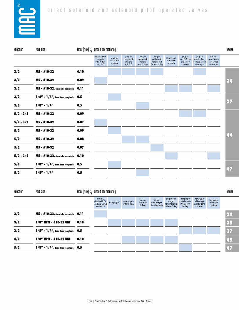
Function Port size Flow (Max) Cv Circuit bar mounting Series
D i r e c t s o l e n o i d a n d s o l e n o i d p i l o t o p e r a t e d v a l v e s
3/2
3/2
3/2
3/2
3/2
5/2 - 3/2
5/2 - 3/2
5/2
5/2
5/2
5/2 - 3/2
5/2
5/2
M5 - #10-32
M5 - #10-32
M5 - #10-32, 4mm tube receptacle
1/8” - 1/4”, 6mm tube receptacle
1/8” - 1/4”
M5 - #10-32
M5 - #10-32
M5 - #10-32
M5 - #10-32
M5 - #10-32
M5 - #10-32, 4mm tube receptacle
1/8” - 1/4”, 6mm tube receptacle
1/8” - 1/4”
0.10
0.09
0.11
0.5
0.5
0.09
0.07
0.09
0.08
0.07
0.10
0.5
0.5
plug-in add-a-unit
stations
plug-in add-a-unit
stationswith F. C.
plug-in add-a-unit
stationswith Pr. Reg.
plug-in add-a-unit
stations with F. C. and Pr. Reg.
plug-in withpre-wiredconnector
plug-in with F. C. and
pre-wiredconnector
plug-in with Pr. Reg.
and pre-wiredconnector
din rail, plug-in withpre-wiredconnector
add-on styleplug-in
with Pr. Reg.and F. C.
3534
37
45
47
Function Port size Flow (Max) Cv Circuit bar mounting Series
3/2
3/2
3/2
4/2
5/2
M5 - #10-32, 4mm tube receptacle
1/8” NPTF - #10-32 UNF
1/8” - 1/4”, 6mm tube receptacle
1/8” NPTF - #10-32 UNF
1/8” - 1/4”, 6mm tube receptacle
0.11
0.10
0.5
0.10
0.5
non plug-in non plug-inwith Pr. Reg.
plug-in with side Pr. Reg.
plug-in with integralterminal strip
plug-in withintegral
terminal stripand side Pr. Reg.
non plug-incylinder ports in base with
Pr. Reg.
non plug-inadd-on stylecylinder ports
in base
non plug-inadd-a-unit
stations
din rail, plug-in with F. C.and pre-wired
connector
Consult “Precautions” before use, installation or service of MAC Valves.

Consult “Precautions” before use, installation or service of MAC Valves.
D i r e c t s o l e n o i d a n d s o l e n o i d p i l o t o p e r a t e d v a l v e s
4552
800
Function Port size Flow (Max) Cv Circuit bar mounting Series
3/2
4/2
5/2 - 5/3
1/8” - 1/4”
1/8” NPTF - #10-32 UNF
1/4”
1.2
0.10
1.3
add-on stylecylinder ports
in valve
cylinder portsin base
add-on stylecylinder ports
in base
add-a-unitstations for
CBM052A bar
add-a-unitstations for
CBP052A bar
non plug-inwith or
without F. C.
non plug-inwith Pr. Reg.
and F. C.
plug-in with sandwich
Pr. Reg.
cylinder portsin valve
47
45
Function Port size Flow (Max) Cv Circuit bar mounting Series
4/2
5/2
5/2
1/8” NPTF - #10-32 UNF
3/8”
1/8” - 1/4”, 6mm tube receptacle
0.10
0.5
0.5
plug-in withintegral
terminal stripwith F. C.
plug-in withintegral terminal
strip with Pr. Reg. and F. C.
non plug-incyl. ports invalve with opt. F. C.
non plug-incyl. ports inbase with opt. F. C.
add-on stylenon plug-in cyl.ports in valvewith opt. F. C.
add-on stylenon plug-in cyl.
ports in basewith opt. F. C.
non plug-incyl. ports
in valve with opt. Pr. Reg.
add-on stylenon plug-in
cyl. ports in base
plug-in withintegral terminal
strip and sandwich Pr. Reg.
400
47
Function Port size Flow (Max) Cv Circuit bar mounting Series
5/2
5/2 - 5/3
5/2 - 5/3
1/8” - 1/4”, 6mm tube receptacle
1/8” - 1/4”
1/8”
0.5
1.0
1.0
low profilecylinder ports
in valve
low profilecylinder ports
in base
mid profilecylinder ports
in valve
mid profile -add on stylecylinder ports
in valve
add-a-unitstations for
CBM403A bar
mid profilecylinder ports
in base
mid profile -add on stylecylinder ports
in base
add-a-unitstations for
CBM404A bar
add-on style non plug-in cyl.
ports in basewith Pr. Reg.
92400
800
Function Port size Flow (Max) Cv Circuit bar mounting Series
5/2 - 5/3
5/2 - 5/3 - 3/2
5/2 - 5/3
1/8” - 1/4”
1/8 - 1/4 - 3/8
1/4”
1.0
1.0
1.3
high profile -add on stylecylinder ports
in base
add-a-unitstations for
CBM405A barstandard add-on style
add-a-unitstations forCBM092B
with shut-offvalve
high profilecylinder ports
in base

Consult “Precautions” before use, installation or service of MAC Valves.
non plug-incylinder ports
in base
non plug-incylinder ports
in valveplug-in plug-in
with F. C. plug-in
with Pr. Reg.
plug-inwith Pr. Reg.
and F. C.
add-on styleplug-in
add-on styleplug-in
with F. C.
Series 34
Circuit bar mounting
add-on styleplug-in
with Pr. Reg.
add-on styleplug-in
with Pr. Reg.and F. C.
plug-inadd-a-unit
stations
plug-inadd-a-unit
stationswith F. C.
plug-inadd-a-unit
stationswith Pr. Reg.
plug-inadd-a-unit
stations with F. C. and Pr. Reg.
plug-in withpre-wiredconnector
plug-in with F. C. and pre-wiredconnector
plug-in withPr. Reg. andpre-wiredconnector
din rail, plug-in withpre-wiredconnector
din rail, plug-in with F. C. and pre-
wired connector
D i r e c t s o l e n o i d a n d s o l e n o i d p i l o t o p e r a t e d v a l v e s
SERIES FEATURES
• High force MACSOLENOID®.• Universal porting.• #10-32 or M5 ports.• Rated for lubricated or non-lubricated service.• 10mm direct operated.• Cylinder port in valve or in circuit bar.
Push pin
Manual operator
Armature
Coil
Poppet
“D” seal
Valve spring
Consult “Precautions” before use, installation or service of MAC Valves.
Reset
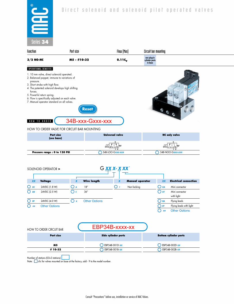
Series 34
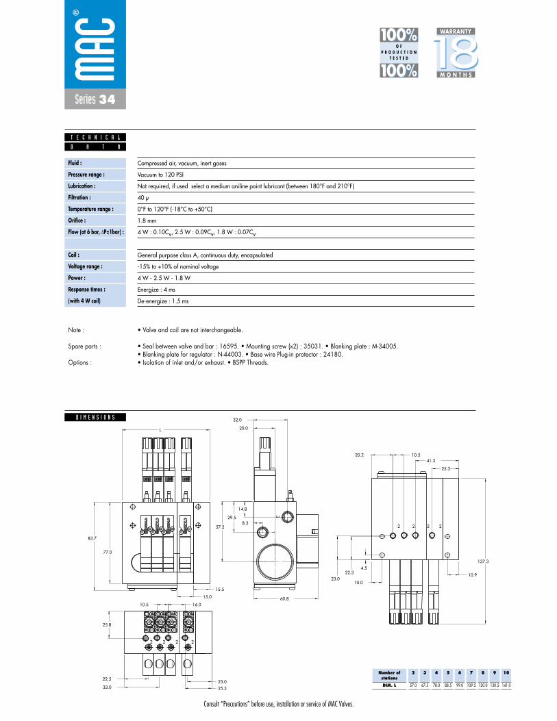
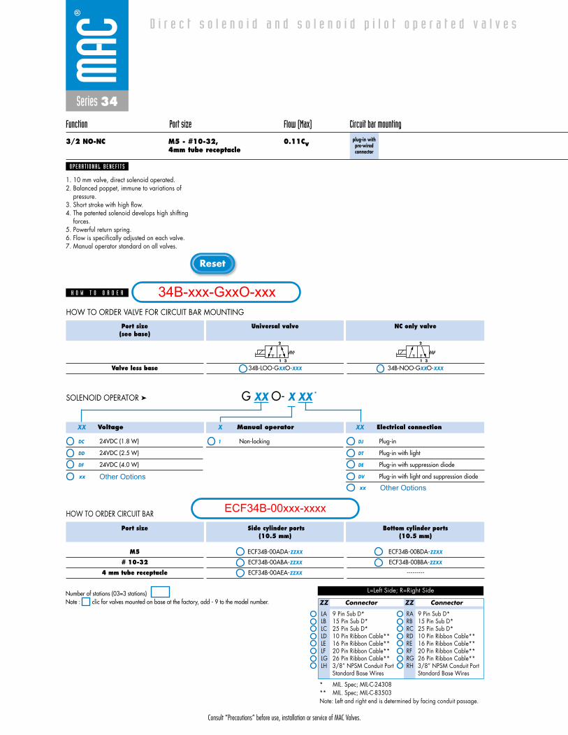
Function Port size Flow (Max) Circuit bar mounting
3/2 NO-NC M5 - #10-32 0.11Cvnon plug-in
cylinder portsin base
1. 10 mm valve, direct solenoid operated.2. Balanced poppet, immune to variations of
pressure.3. Short stroke with high flow.4. The patented solenoid develops high shifting
forces.5. Powerful return spring.6. Flow is specifically adjusted on each valve.7. Manual operator standard on all valves.
O P E R A T I O N A L B E N E F I T S
D i r e c t s o l e n o i d a n d s o l e n o i d p i l o t o p e r a t e d v a l v e s
H O W T O O R D E R
Port size(see base)
Pressure range : 0 to 120 PSI
Universal valve
34B-LOO-GXXX-XXX
NC only valve
34B-NOO-GXXX-XXX
2
1 3
2
1 3
Port size
M5
# 10-32
Side cylinder ports
EBP34B-001D-XX
EBP34B-001B-XX
Bottom cylinder ports
EBP34B-002D-XX
EBP34B-002B-XX
HOW TO ORDER CIRCUIT BAR
HOW TO ORDER VALVE FOR CIRCUIT BAR MOUNTING
Number of stations (03=3 stations)Note : clic for valves mounted on base at the factory, add - 9 to the model number.
Voltage
DC 24VDC (1.8 W)
DD 24VDC (2.5 W)
DF 24VDC (4.0 W)
Wire length
A 18”
C 36”
Manual operator
1 Non-locking
Electrical connection
KA Mini connector
KT Mini connector
with light
BA Flying leads
BT Flying leads with light
G XX X- X XX *SOLENOID OPERATOR ➤
XX X X XX
34B-xxx-Gxxx-xxx
EBP34B-xxxx-xx
Other Optionsxx
x Other Options
xx Other Options
Consult “Precautions” before use, installation or service of MAC Valves.
Series 34
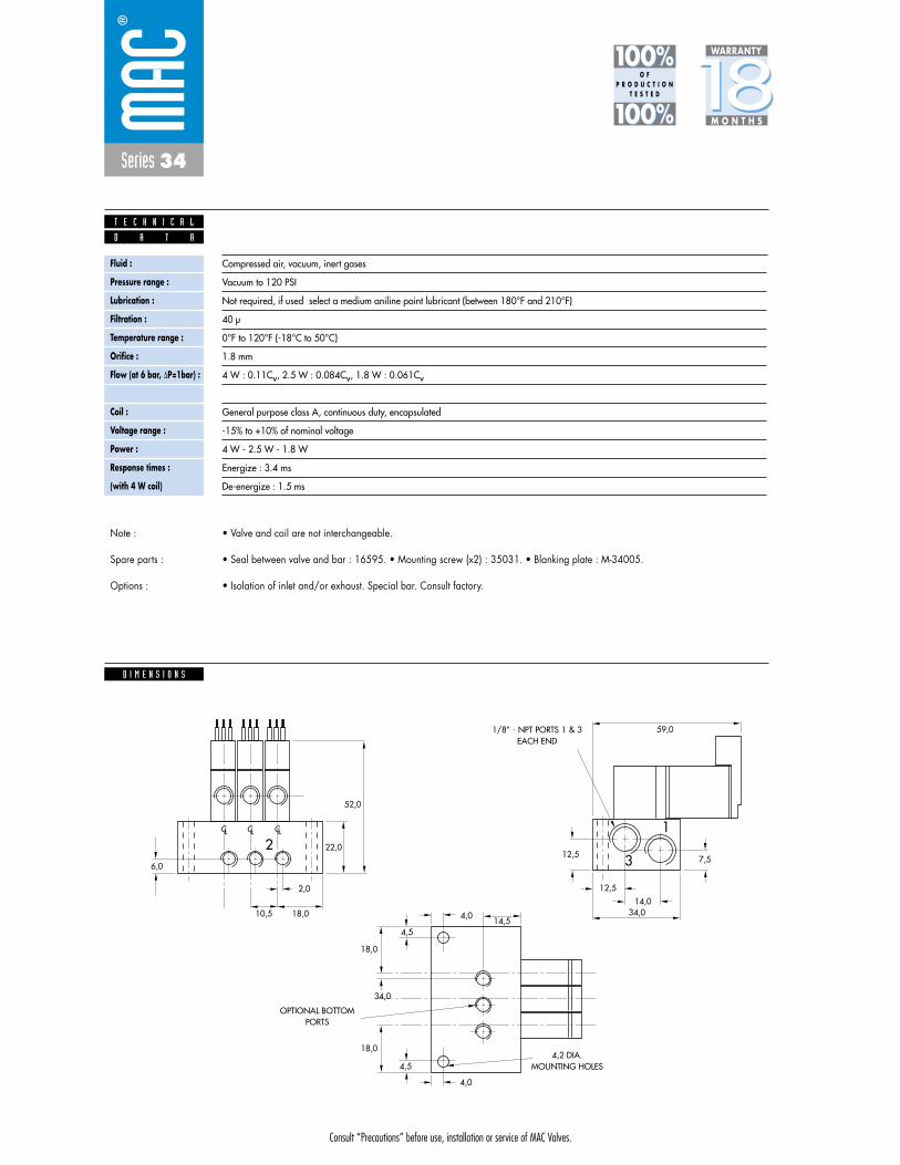
D I M E N S I O N S
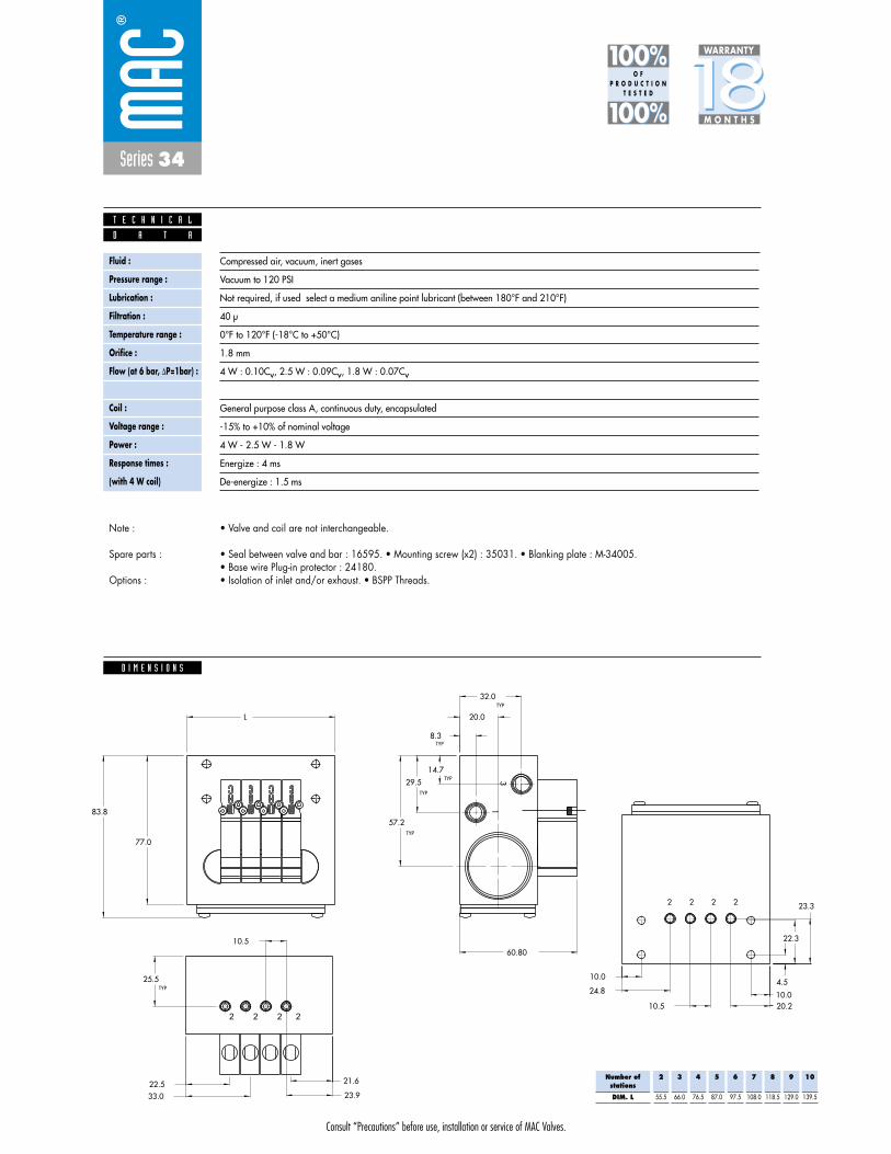
Fluid :
Pressure range :
Lubrication :
Filtration :
Temperature range :
Orifice :
Flow (at 6 bar, �P=1bar) :
Leak rate :
Coil :
Voltage range :
Power :
Response times :
(with 4 W coil)
Compressed air, vacuum, inert gases
Vacuum to 120 PSI
Not required, if used select a medium aniline point lubricant (between 180°F and 210°F)
40 μ
0°F to 120°F (-18°C to 50°C)
1.8 mm
4 W : 0.11Cv, 2.5 W : 0.084Cv, 1.8 W : 0.061Cv
50 cm3/min
General purpose class A, continuous duty, encapsulated
-15% to +10% of nominal voltage
4 W - 2.5 W - 1.8 W
Energize : 3.4 ms
De-energize : 1.5 ms
22,012,5 7,5
12,5
14,034,04,0
14,54,5
18,0
18,0
34,0
4,0
4,5
59,0
52,0
6,0
10,5 18,0
2,0
CLCLCL
23
1
D A T A
T E C H N I C A L
1818100%100%
100%100% M O N T H S
WARRANTY
O FP R O D U C T I O N
T E S T E D
• Valve and coil are not interchangeable.
• Seal between valve and bar : 16595. • Mounting screw (x2) : 35031. • Blanking plate : M-34005.
• Isolation of inlet and/or exhaust. Special bar. Consult factory.
Note :
Spare parts :
Options :
1/8” - NPT PORTS 1 & 3EACH END
4,2 DIA. MOUNTING HOLES
OPTIONAL BOTTOMPORTS
Consult “Precautions” before use, installation or service of MAC Valves.
Reset
Series 34
Function Port size (Inlet & Exhaust) Flow (Max) Circuit bar mounting
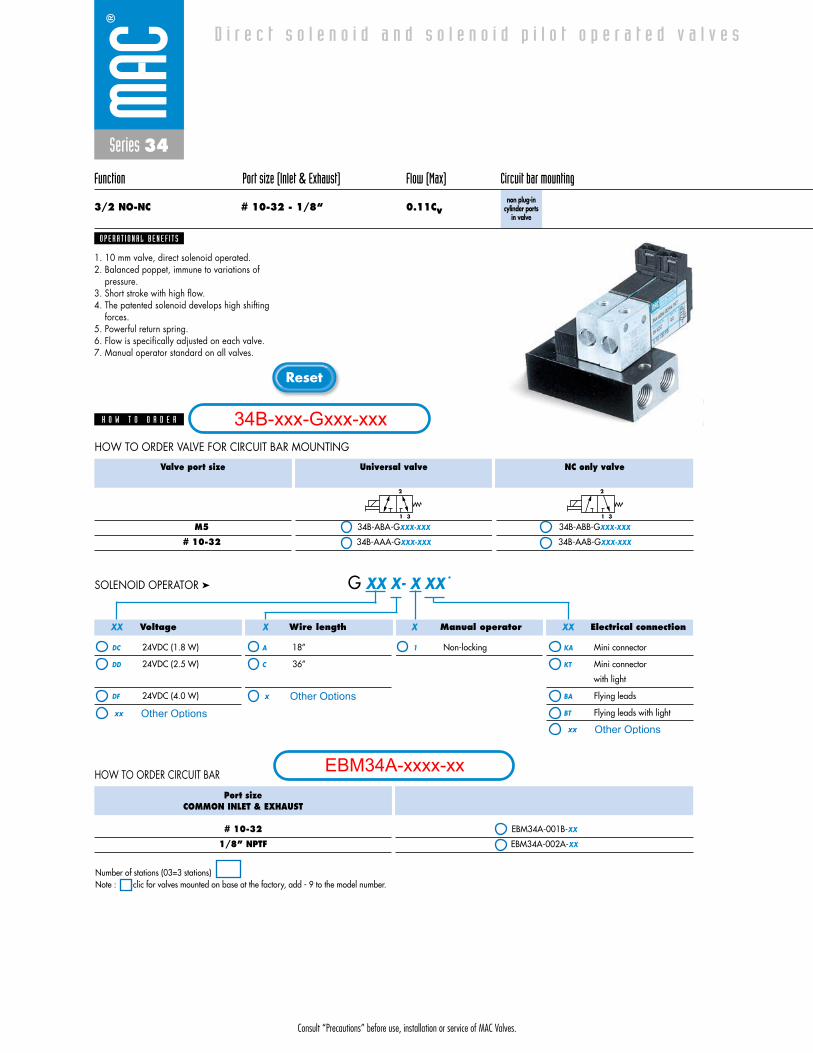
3/2 NO-NC # 10-32 - 1/8“ 0.11Cvnon plug-in
cylinder ports in valve
1. 10 mm valve, direct solenoid operated.2. Balanced poppet, immune to variations of
pressure.3. Short stroke with high flow.4. The patented solenoid develops high shifting
forces.5. Powerful return spring.6. Flow is specifically adjusted on each valve.7. Manual operator standard on all valves.
O P E R A T I O N A L B E N E F I T S
D i r e c t s o l e n o i d a n d s o l e n o i d p i l o t o p e r a t e d v a l v e s
H O W T O O R D E R
Valve port size
M5
# 10-32
Universal valve
34B-ABA-GXXX-XXX
34B-AAA-GXXX-XXX
NC only valve
34B-ABB-GXXX-XXX
34B-AAB-GXXX-XXX
2
1 3
2
1 3
HOW TO ORDER VALVE FOR CIRCUIT BAR MOUNTING
Voltage
DC 24VDC (1.8 W)
DD 24VDC (2.5 W)
DF 24VDC (4.0 W)
Wire length
A 18”
C 36”
Manual operator
1 Non-locking
Electrical connection
KA Mini connector
KT Mini connector
with light
BA Flying leads
BT Flying leads with light
G XX X- X XX *SOLENOID OPERATOR ➤
Port sizeCOMMON INLET & EXHAUST
# 10-32
1/8” NPTF
EBM34A-001B-XX
EBM34A-002A-XX
HOW TO ORDER CIRCUIT BAR
XX X X XX
Number of stations (03=3 stations)Note : clic for valves mounted on base at the factory, add - 9 to the model number.
34B-xxx-Gxxx-xxx
EBM34A-xxxx-xx
Other Optionsxx
x Other Options
xx Other Options

Consult “Precautions” before use, installation or service of MAC Valves.
Series 34
D I M E N S I O N S
Fluid :
Pressure range :
Lubrication :
Filtration :
Temperature range :
Orifice :
Flow (at 6 bar, �P=1bar) :
Leak rate :
Coil :
Voltage range :
Power :
Response times :
(with 4 W coil)
Compressed air, vacuum, inert gases
Vacuum to 120 PSI
Not required, if used select a medium aniline point lubricant (between 180°F and 210°F)
40 μ
0°F to 120°F (-18°C to +50°C)
1.8 mm
4 W : 0.11Cv, 2.5 W : 0.084Cv, 1.8 W : 0.061Cv
50 cm3/min
General purpose class A, continuous duty, encapsulated
-15% to +10% of nominal voltage
4 W - 2.5 W - 1.8 W
Energize : 3.4 ms
De-energize : 1.5 ms
C
G
A
B
2
3 1
19,0
F
E
D
38,5
14,0
10,5
D A T A
T E C H N I C A L
1818100%100%
100%100% M O N T H S
WARRANTY
O FP R O D U C T I O N
T E S T E D
• Valve and coil are not interchangeable.
• Valve fastening kit : M34001-01 (1/8” Bar); M34001-21 (#10-32 Bar) • Blanking plate : 30456-A.
• Isolation of inlet and/or exhaust. Special bar. Consult factory.
Note :
Spare parts :
Options :
Port size
1/8”
M5
A
16.0
12.0
B
47.5
43.5
C
57.4
51.5
D
8.0
9.0
E
23.0
18.0
F
31.0
26.0
G
8.0
6.0
Consult “Precautions” before use, installation or service of MAC Valves.
Reset
Series 34
Function Port size Flow (Max) Circuit bar mounting
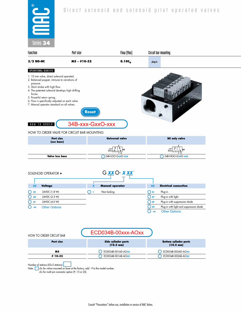
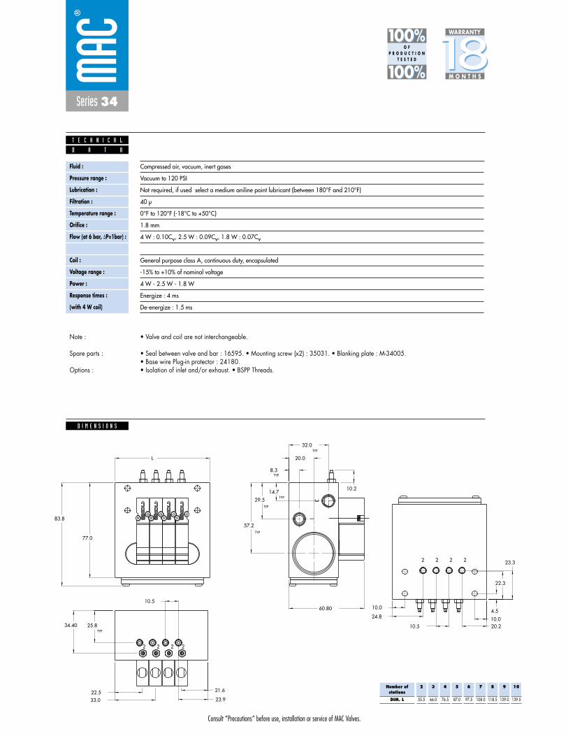
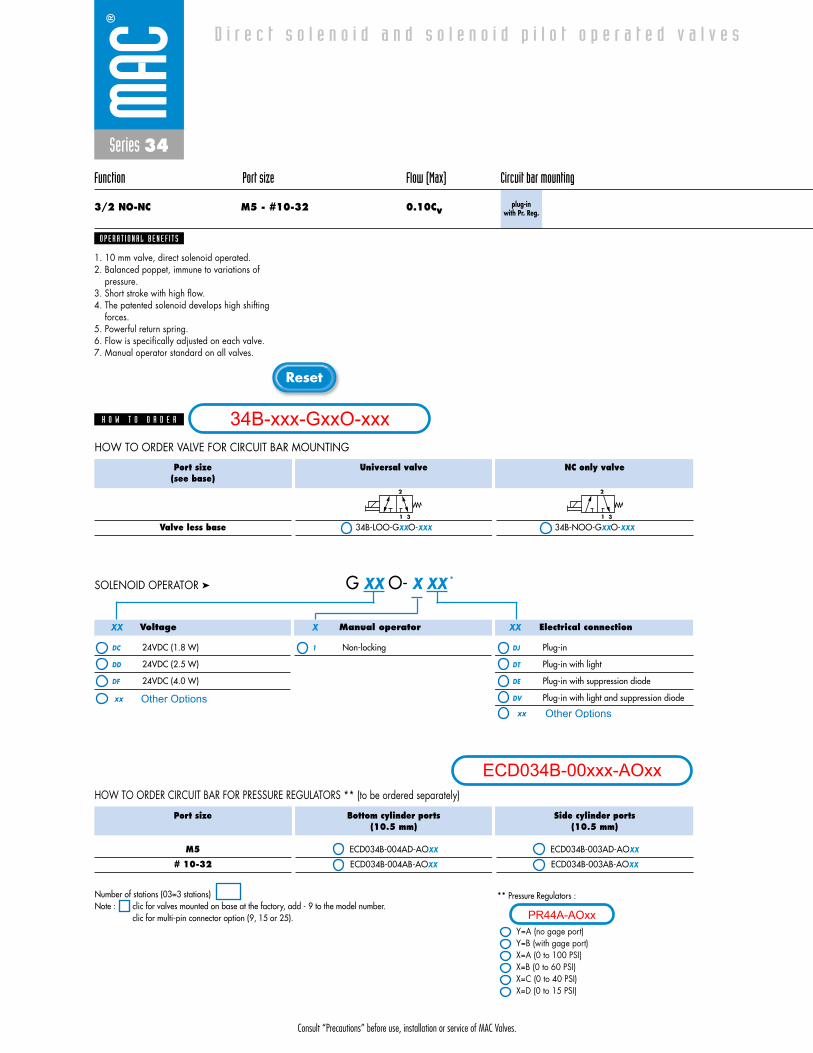
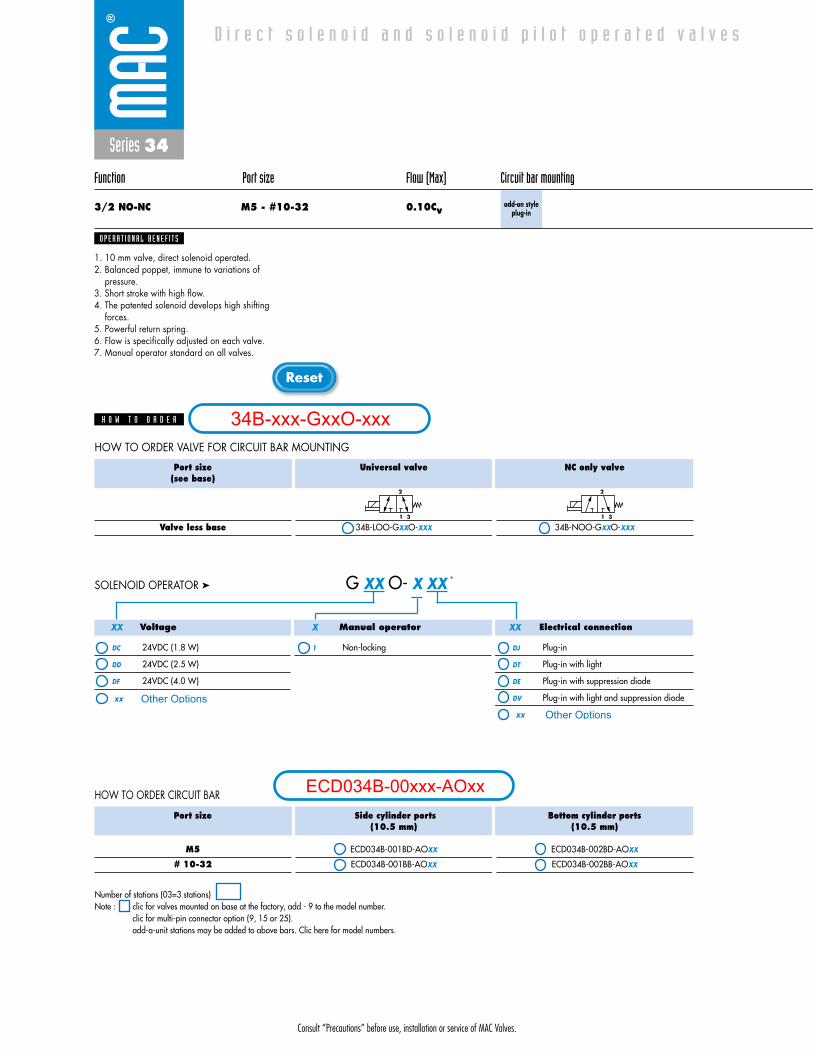
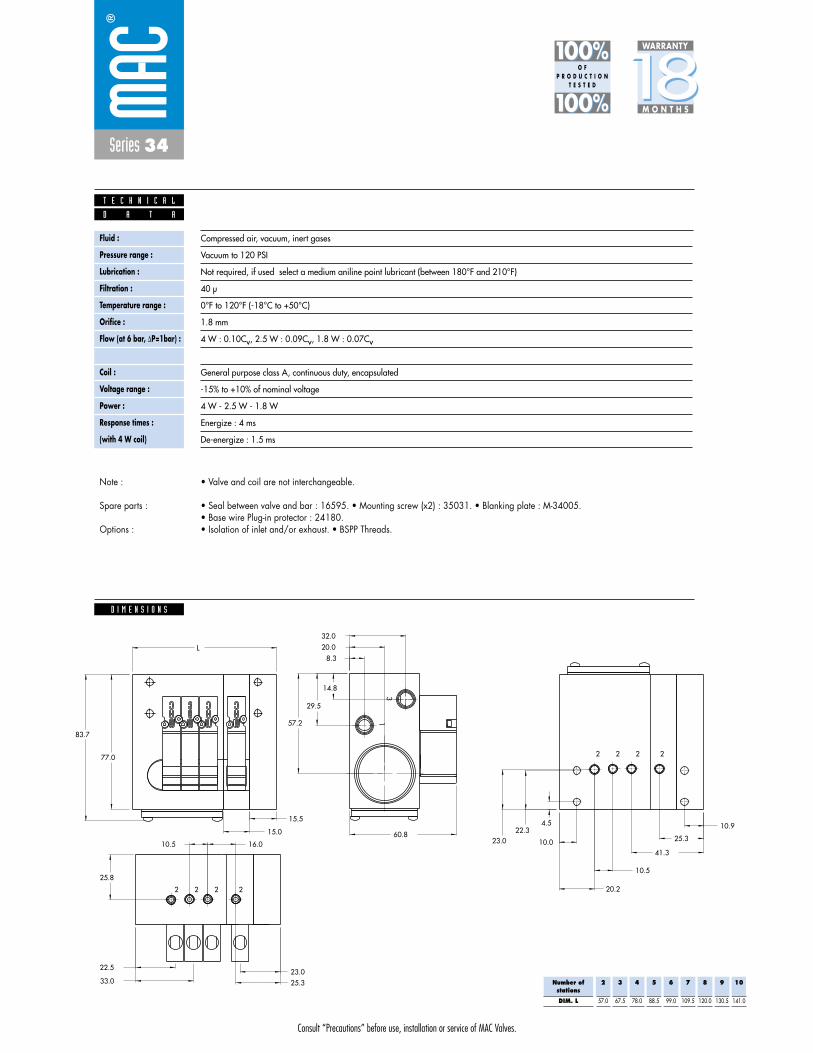
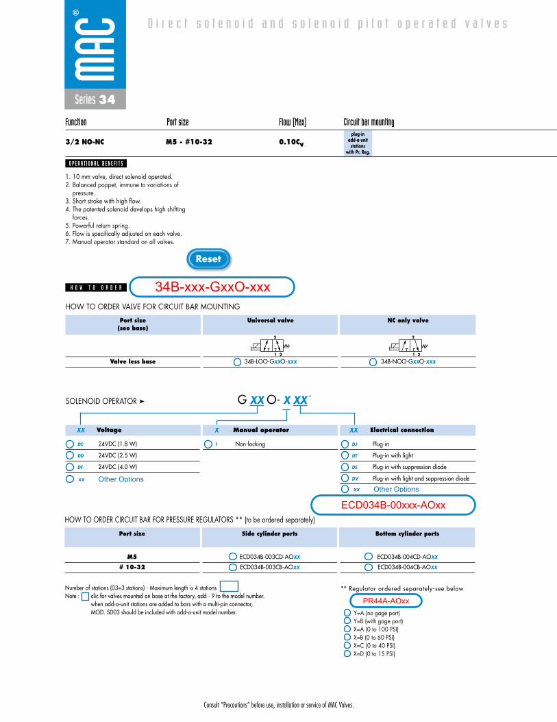
3/2 NO-NC M5 - #10-32 0.10Cv plug-in
1. 10 mm valve, direct solenoid operated.2. Balanced poppet, immune to variations of
pressure.3. Short stroke with high flow.4. The patented solenoid develops high shifting
forces.5. Powerful return spring.6. Flow is specifically adjusted on each valve.7. Manual operator standard on all valves.
O P E R A T I O N A L B E N E F I T S
D i r e c t s o l e n o i d a n d s o l e n o i d p i l o t o p e r a t e d v a l v e s
H O W T O O R D E R
Port size(see base)
Valve less base
Universal valve
34B-LOO-GXXO-XXX
NC only valve
34B-NOO-GXXO-XXX
2
1 3
2
1 3
Port size
M5
# 10-32
Side cylinder ports(10.5 mm)
ECD034B-001AD-AOXX
ECD034B-001AB-AOXX
Bottom cylinder ports(10.5 mm)
ECD034B-002AD-AOXX
ECD034B-002AB-AOXX
Voltage
DC 24VDC (1.8 W)
DD 24VDC (2.5 W)
DF 24VDC (4.0 W)
Manual operator
1 Non-locking
Electrical connection
DJ Plug-in
DT Plug-in with light
DE Plug-in with suppression diode
DV Plug-in with light and suppression diode
G XX O- X XX *SOLENOID OPERATOR ➤
HOW TO ORDER CIRCUIT BAR
HOW TO ORDER VALVE FOR CIRCUIT BAR MOUNTING
XX X XX
Number of stations (03=3 stations)Note : clic for valves mounted on base at the factory, add - 9 to the model number.
clic for multi-pin connector option (9, 15 or 25).
34B-xxx-GxxO-xxx
ECD034B-00xxx-AOxx
Other Optionsxx
xx Other Options
Consult “Precautions” before use, installation or service of MAC Valves.
Series 34
D I M E N S I O N S
Fluid :
Pressure range :
Lubrication :
Filtration :
Temperature range :
Orifice :
Flow (at 6 bar, �P=1bar) :
Leak rate :
Coil :
Voltage range :
Power :
Response times :
(with 4 W coil)
Compressed air, vacuum, inert gases
Vacuum to 120 PSI
Not required, if used select a medium aniline point lubricant (between 180°F and 210°F)
40 μ
0°F to 120°F (-18°C to +50°C)
1.8 mm
4 W : 0.10Cv, 2.5 W : 0.09Cv, 1.8 W : 0.07Cv
50 cm3/min
General purpose class A, continuous duty, encapsulated
-15% to +10% of nominal voltage
4 W - 2.5 W - 1.8 W
Energize : 4 ms
De-energize : 1.5 ms
21.6
23.933.022.5
10.5
23.3
22.3
4.5
10.020.210.5
24.8
10.0
60.80
83.8
77.0
L
2 2 2 2
13
2 2 2 2
8.3
20.0
32.0
14.7
29.5
57.2
25.5
TYP
TYP
TYP
TYP
TYP
TYP
D A T A
T E C H N I C A L
1818100%100%
100%100% M O N T H S
WARRANTY
O FP R O D U C T I O N
T E S T E D
• Valve and coil are not interchangeable.
• Seal between valve and bar : 16595. • Mounting screw (x2) : 35031. • Blanking plate : M-34005.• Base wire Plug-in protector : 24180.• Isolation of inlet and/or exhaust. • BSPP Threads.
Note :
Spare parts :
Options :
Number ofstations
DIM. L
2
55.5
3
66.0
4
76.5
5
87.0
6
97.5
7
108.0
8
118.5
9
129.0
10
139.5
Consult “Precautions” before use, installation or service of MAC Valves.
Reset
Series 34
Function Port size Flow (Max) Circuit bar mounting
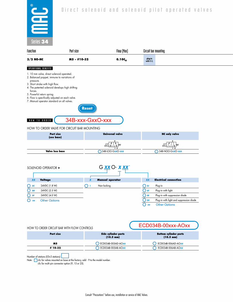
3/2 NO-NC M5 - #10-32 0.10Cvplug-in
with F. C.
1. 10 mm valve, direct solenoid operated.2. Balanced poppet, immune to variations of
pressure.3. Short stroke with high flow.4. The patented solenoid develops high shifting
forces.5. Powerful return spring.6. Flow is specifically adjusted on each valve.7. Manual operator standard on all valves.
O P E R A T I O N A L B E N E F I T S
D i r e c t s o l e n o i d a n d s o l e n o i d p i l o t o p e r a t e d v a l v e s
H O W T O O R D E R
Port size(see base)
Valve less base
Universal valve
34B-LOO-GXXO-XXX
NC only valve
34B-NOO-GXXO-XXX
2
1 3
2
1 3
Port size
M5
# 10-32
Side cylinder ports(10.5 mm)
ECD034B-005AD-AOXX
ECD034B-005AB-AOXX
Bottom cylinder ports(10.5 mm)
ECD034B-006AD-AOXX
ECD034B-006AB-AOXX
Voltage
DC 24VDC (1.8 W)
DD 24VDC (2.5 W)
DF 24VDC (4.0 W)
Manual operator
1 Non-locking
Electrical connection
DJ Plug-in
DT Plug-in with light
DE Plug-in with suppression diode
DV Plug-in with light and suppression diode
G XX O- X XX *SOLENOID OPERATOR ➤
HOW TO ORDER CIRCUIT BAR WITH FLOW CONTROLS
HOW TO ORDER VALVE FOR CIRCUIT BAR MOUNTING
XX X XX
Number of stations (03=3 stations)Note : clic for valves mounted on base at the factory, add - 9 to the model number.
clic for multi-pin connector option (9, 15 or 25).
34B-xxx-GxxO-xxx
ECD034B-00xxx-AOxx
Other Optionsxx
xx Other Options
Consult “Precautions” before use, installation or service of MAC Valves.
Series 34
D I M E N S I O N S
Fluid :
Pressure range :
Lubrication :
Filtration :
Temperature range :
Orifice :
Flow (at 6 bar, �P=1bar) :
Leak rate :
Coil :
Voltage range :
Power :
Response times :
(with 4 W coil)
Compressed air, vacuum, inert gases
Vacuum to 120 PSI
Not required, if used select a medium aniline point lubricant (between 180°F and 210°F)
40 μ
0°F to 120°F (-18°C to +50°C)
1.8 mm
4 W : 0.10Cv, 2.5 W : 0.09Cv, 1.8 W : 0.07Cv
50 cm3/min
General purpose class A, continuous duty, encapsulated
-15% to +10% of nominal voltage
4 W - 2.5 W - 1.8 W
Energize : 4 ms
De-energize : 1.5 ms
21.6
23.933.022.5
10.5
23.3
22.3
4.5
10.020.210.5
24.8
10.060.80
83.8
77.0
L
2 2 2 2
13
2 2 2 2
8.3
20.0
32.0
14.7
29.5
57.2
25.8
TYP
TYP
TYP
TYP
TYP
TYP
10.2
34.40
D A T A
T E C H N I C A L
1818100%100%
100%100% M O N T H S
WARRANTY
O FP R O D U C T I O N
T E S T E D
• Valve and coil are not interchangeable.
• Seal between valve and bar : 16595. • Mounting screw (x2) : 35031. • Blanking plate : M-34005.• Base wire Plug-in protector : 24180.• Isolation of inlet and/or exhaust. • BSPP Threads.
Note :
Spare parts :
Options :
Number ofstations
DIM. L
2
55.5
3
66.0
4
76.5
5
87.0
6
97.5
7
108.0
8
118.5
9
129.0
10
139.5
Consult “Precautions” before use, installation or service of MAC Valves.
Reset
Series 34
Function Port size Flow (Max) Circuit bar mounting
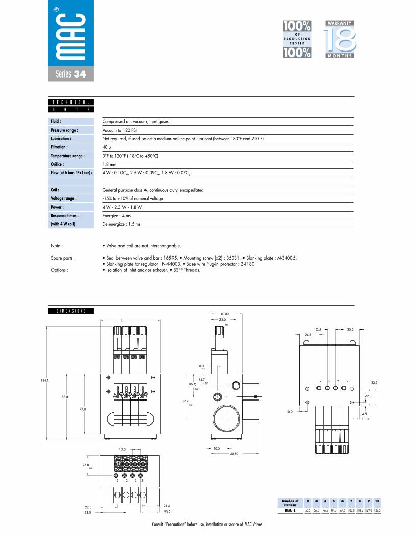
3/2 NO-NC M5 - #10-32 0.10Cvplug-in
with Pr. Reg.
1. 10 mm valve, direct solenoid operated.2. Balanced poppet, immune to variations of
pressure.3. Short stroke with high flow.4. The patented solenoid develops high shifting
forces.5. Powerful return spring.6. Flow is specifically adjusted on each valve.7. Manual operator standard on all valves.
O P E R A T I O N A L B E N E F I T S
D i r e c t s o l e n o i d a n d s o l e n o i d p i l o t o p e r a t e d v a l v e s
H O W T O O R D E R
Port size(see base)
Valve less base
Universal valve
34B-LOO-GXXO-XXX
NC only valve
34B-NOO-GXXO-XXX
2
1 3
2
1 3
Port size
M5
# 10-32
Bottom cylinder ports(10.5 mm)
ECD034B-004AD-AOXX
ECD034B-004AB-AOXX
Side cylinder ports(10.5 mm)
ECD034B-003AD-AOXX
ECD034B-003AB-AOXX
Voltage
DC 24VDC (1.8 W)
DD 24VDC (2.5 W)
DF 24VDC (4.0 W)
Manual operator
1 Non-locking
Electrical connection
DJ Plug-in
DT Plug-in with light
DE Plug-in with suppression diode
DV Plug-in with light and suppression diode
G XX O- X XX *SOLENOID OPERATOR ➤
HOW TO ORDER CIRCUIT BAR FOR PRESSURE REGULATORS ** (to be ordered separately)
HOW TO ORDER VALVE FOR CIRCUIT BAR MOUNTING
XX X XX
** Pressure Regulators :
Y=A (no gage port)Y=B (with gage port)X=A (0 to 100 PSI)X=B (0 to 60 PSI)X=C (0 to 40 PSI)X=D (0 to 15 PSI)
Number of stations (03=3 stations)Note : clic for valves mounted on base at the factory, add - 9 to the model number.
clic for multi-pin connector option (9, 15 or 25).
34B-xxx-GxxO-xxx
ECD034B-00xxx-AOxx
Other Optionsxx
xx Other Options
PR44A-AOxx
Consult “Precautions” before use, installation or service of MAC Valves.
Series 34
D I M E N S I O N S
Fluid :
Pressure range :
Lubrication :
Filtration :
Temperature range :
Orifice :
Flow (at 6 bar, �P=1bar) :
Leak rate :
Coil :
Voltage range :
Power :
Response times :
(with 4 W coil)
Compressed air, vacuum, inert gases
Vacuum to 120 PSI
Not required, if used select a medium aniline point lubricant (between 180°F and 210°F)
40 μ
0°F to 120°F (-18°C to +50°C)
1.8 mm
4 W : 0.10Cv, 2.5 W : 0.09Cv, 1.8 W : 0.07Cv
50 cm3/min
General purpose class A, continuous duty, encapsulated
-15% to +10% of nominal voltage
4 W - 2.5 W - 1.8 W
Energize : 4 ms
De-energize : 1.5 ms
-+
L
OCK
-+
L
OCK
-+
L
OCK
-+
L
OCK
144.1
21.6
23.933.022.5
10.5
23.3
22.3
4.5
10.0
20.210.524.8
10.0
60.80
83.8
77.0
L
2 2 2 2
13
2 2 2 2
8.3
20.0
32.0
14.7
29.5
57.2
25.8
TYP
TYP
TYP
TYP
TYP
TYP
40.00
D A T A
T E C H N I C A L
1818100%100%
100%100% M O N T H S
WARRANTY
O FP R O D U C T I O N
T E S T E D
• Valve and coil are not interchangeable.
• Seal between valve and bar : 16595. • Mounting screw (x2) : 35031. • Blanking plate : M-34005.• Blanking plate for regulator : N-44003. • Base wire Plug-in protector : 24180.• Isolation of inlet and/or exhaust. • BSPP Threads.
Note :
Spare parts :
Options :
Number ofstations
DIM. L
2
55.5
3
66.0
4
76.5
5
87.0
6
97.5
7
108.0
8
118.5
9
129.0
10
139.5

Consult “Precautions” before use, installation or service of MAC Valves.
Reset
Series 34
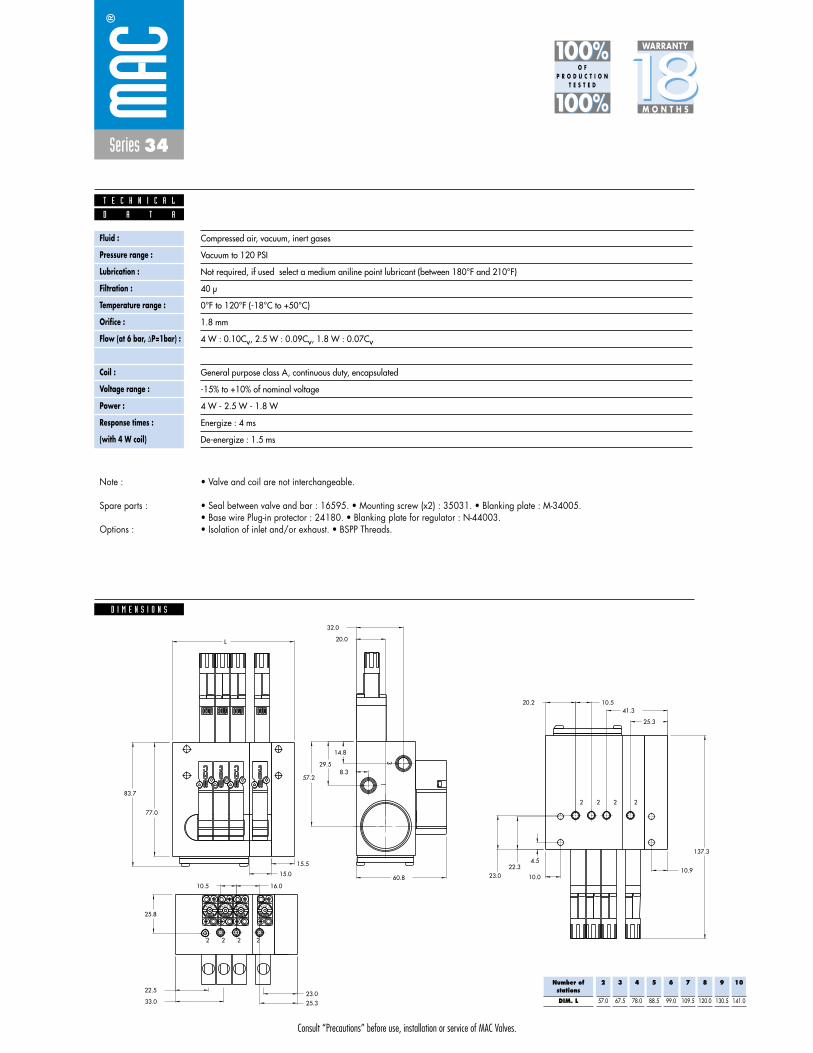
Function Port size Flow (Max) Circuit bar mounting
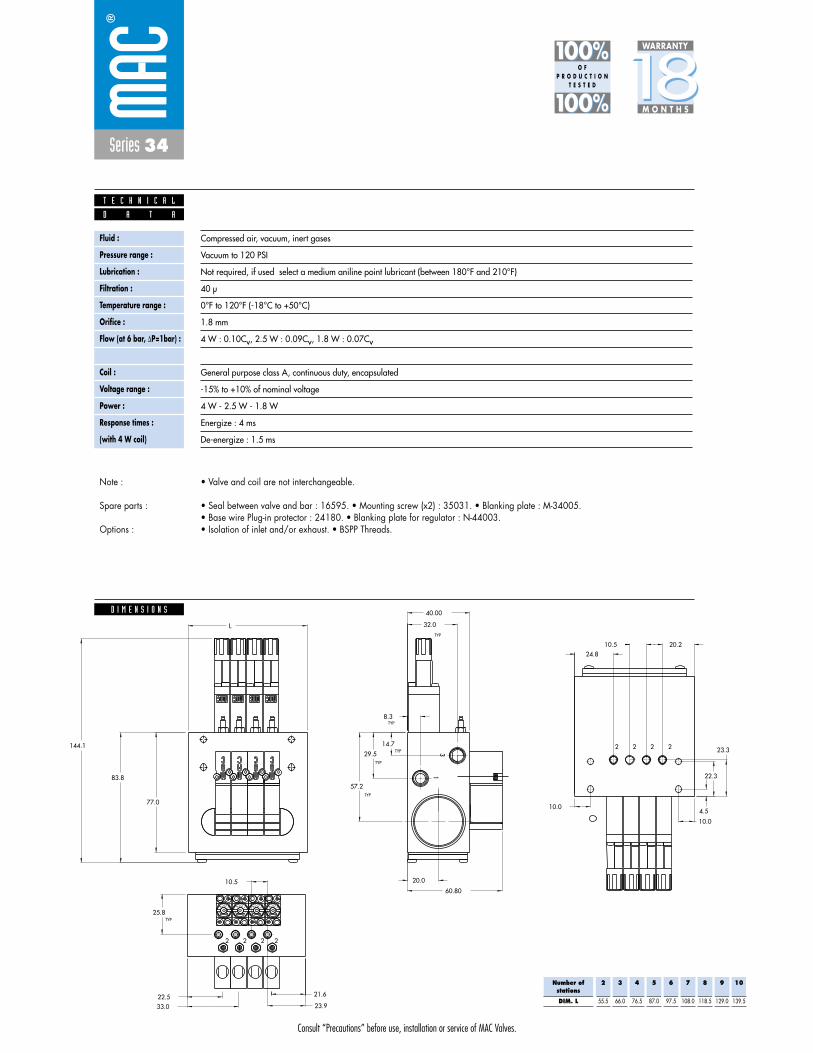
3/2 NO-NC M5 - #10-32 0.09Cvplug-in
with Pr. Reg.and F. C.
1. 10 mm valve, direct solenoid operated.2. Balanced poppet, immune to variations of
pressure.3. Short stroke with high flow.4. The patented solenoid develops high shifting
forces.5. Powerful return spring.6. Flow is specifically adjusted on each valve.7. Manual operator standard on all valves.
O P E R A T I O N A L B E N E F I T S
D i r e c t s o l e n o i d a n d s o l e n o i d p i l o t o p e r a t e d v a l v e s
H O W T O O R D E R
Port size(see base)
Valve less base
Universal valve
34B-LOO-GXXO-XXX
NC only valve
34B-NOO-GXXO-XXX
2
1 3
2
1 3
Port size
M5
# 10-32
Bottom cylinder ports(10.5 mm)
ECD034B-007AD-AOXX
ECD034B-007AB-AOXX
Side cylinder ports(10.5 mm)
ECD034B-008AD-AOXX
ECD034B-008AB-AOXX
Voltage
DC 24VDC (1.8 W)
DD 24VDC (2.5 W)
DF 24VDC (4.0 W)
Manual operator
1 Non-locking
Electrical connection
DJ Plug-in
DT Plug-in with light
DE Plug-in with suppression diode
DV Plug-in with light and suppression diode
G XX O- X XX *SOLENOID OPERATOR ➤
HOW TO ORDER CIRCUIT BAR WITH FLOW CONTROLS AND PRESSURE REGULATORS ** (pressure regulators to be ordered separately)
HOW TO ORDER VALVE FOR CIRCUIT BAR MOUNTING
XX X XX
** Pressure Regulators :
Y=A (no gage port)Y=B (with gage port)X=A (0 to 100 PSI)X=B (0 to 60 PSI)X=C (0 to 40 PSI)X=D (0 to 15 PSI)
Number of stations (03=3 stations)Note : clic for valves mounted on base at the factory, add - 9 to the model number.
clic for multi-pin connector option (9, 15 or 25).
34B-xxx-GxxO-xxx
ECD034B-00xxx-AOxx
Other Optionsxx
xx Other Options
PR44A-AOxx
Consult “Precautions” before use, installation or service of MAC Valves.
Series 34
D I M E N S I O N S
Fluid :
Pressure range :
Lubrication :
Filtration :
Temperature range :
Orifice :
Flow (at 6 bar, �P=1bar) :
Leak rate :
Coil :
Voltage range :
Power :
Response times :
(with 4 W coil)
Compressed air, vacuum, inert gases
Vacuum to 120 PSI
Not required, if used select a medium aniline point lubricant (between 180°F and 210°F)
40 μ
0°F to 120°F (-18°C to +50°C)
1.8 mm
4 W : 0.10Cv, 2.5 W : 0.09Cv, 1.8 W : 0.07Cv
50 cm3/min
General purpose class A, continuous duty, encapsulated
-15% to +10% of nominal voltage
4 W - 2.5 W - 1.8 W
Energize : 4 ms
De-energize : 1.5 ms
-+
L
OCK
-+
L
OCK
-+
L
OCK
-+
L
OCK
144.1
21.6
23.933.022.5
10.5
23.3
22.3
4.5
10.0
20.210.524.8
10.0
60.80
83.8
77.0
L
2 2 2 2
13
2 2 2 2
8.3
20.0
32.0
14.7
29.5
57.2
25.8
TYP
TYP
TYP
TYP
TYP
TYP
40.00
D A T A
T E C H N I C A L
1818100%100%
100%100% M O N T H S
WARRANTY
O FP R O D U C T I O N
T E S T E D
• Valve and coil are not interchangeable.
• Seal between valve and bar : 16595. • Mounting screw (x2) : 35031. • Blanking plate : M-34005.• Base wire Plug-in protector : 24180. • Blanking plate for regulator : N-44003.• Isolation of inlet and/or exhaust. • BSPP Threads.
Note :
Spare parts :
Options :
Number ofstations
DIM. L
2
55.5
3
66.0
4
76.5
5
87.0
6
97.5
7
108.0
8
118.5
9
129.0
10
139.5
Consult “Precautions” before use, installation or service of MAC Valves.
Reset
Series 34
Function Port size Flow (Max) Circuit bar mounting
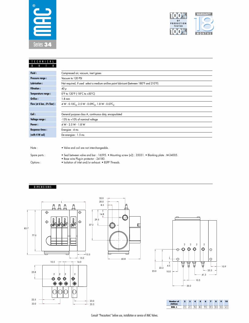
3/2 NO-NC M5 - #10-32 0.10Cvadd-on style
plug-in
1. 10 mm valve, direct solenoid operated.2. Balanced poppet, immune to variations of
pressure.3. Short stroke with high flow.4. The patented solenoid develops high shifting
forces.5. Powerful return spring.6. Flow is specifically adjusted on each valve.7. Manual operator standard on all valves.
O P E R A T I O N A L B E N E F I T S
D i r e c t s o l e n o i d a n d s o l e n o i d p i l o t o p e r a t e d v a l v e s
H O W T O O R D E R
Port size(see base)
Valve less base
Universal valve
34B-LOO-GXXO-XXX
NC only valve
34B-NOO-GXXO-XXX
2
1 3
2
1 3
Port size
M5
# 10-32
Side cylinder ports(10.5 mm)
ECD034B-001BD-AOXX
ECD034B-001BB-AOXX
Bottom cylinder ports(10.5 mm)
ECD034B-002BD-AOXX
ECD034B-002BB-AOXX
Voltage
DC 24VDC (1.8 W)
DD 24VDC (2.5 W)
DF 24VDC (4.0 W)
Manual operator
1 Non-locking
Electrical connection
DJ Plug-in
DT Plug-in with light
DE Plug-in with suppression diode
DV Plug-in with light and suppression diode
G XX O- X XX *SOLENOID OPERATOR ➤
HOW TO ORDER CIRCUIT BAR
HOW TO ORDER VALVE FOR CIRCUIT BAR MOUNTING
XX X XX
Number of stations (03=3 stations)Note : clic for valves mounted on base at the factory, add - 9 to the model number.
clic for multi-pin connector option (9, 15 or 25).add-a-unit stations may be added to above bars. Clic here for model numbers.
34B-xxx-GxxO-xxx
ECD034B-00xxx-AOxx
Other Optionsxx
xx Other Options

Consult “Precautions” before use, installation or service of MAC Valves.
Series 34
D I M E N S I O N S
Fluid :
Pressure range :
Lubrication :
Filtration :
Temperature range :
Orifice :
Flow (at 6 bar, �P=1bar) :
Leak rate :
Coil :
Voltage range :
Power :
Response times :
(with 4 W coil)
Compressed air, vacuum, inert gases
Vacuum to 120 PSI
Not required, if used select a medium aniline point lubricant (between 180°F and 210°F)
40 μ
0°F to 120°F (-18°C to +50°C)
1.8 mm
4 W : 0.10Cv, 2.5 W : 0.09Cv, 1.8 W : 0.07Cv
50 cm3/min
General purpose class A, continuous duty, encapsulated
-15% to +10% of nominal voltage
4 W - 2.5 W - 1.8 W
Energize : 4 ms
De-energize : 1.5 ms
15.5
15.0
23.025.3
22.5
33.0
25.8
10.5 16.0
10.9
25.3
41.3
10.5
20.2
10.023.022.3
4.5
32.0
20.0
8.3
14.8
29.5
57.2
60.8
77.0
83.7
L
13
2 2 2 2
2 2 2 2
D A T A
T E C H N I C A L
1818100%100%
100%100% M O N T H S
WARRANTY
O FP R O D U C T I O N
T E S T E D
• Valve and coil are not interchangeable.
• Seal between valve and bar : 16595. • Mounting screw (x2) : 35031. • Blanking plate : M-34005.• Base wire Plug-in protector : 24180.• Isolation of inlet and/or exhaust. • BSPP Threads.
Note :
Spare parts :
Options :
Number ofstations
DIM. L
2
57.0
3
67.5
4
78.0
5
88.5
6
99.0
7
109.5
8
120.0
9
130.5
10
141.0

Consult “Precautions” before use, installation or service of MAC Valves.
Reset
Series 34
Function Port size Flow (Max) Circuit bar mounting
3/2 NO-NC M5 - #10-32 0.10Cvadd-on style
plug-inwith F. C.
1. 10 mm valve, direct solenoid operated.2. Balanced poppet, immune to variations of
pressure.3. Short stroke with high flow.4. The patented solenoid develops high shifting
forces.5. Powerful return spring.6. Flow is specifically adjusted on each valve.7. Manual operator standard on all valves.
O P E R A T I O N A L B E N E F I T S
D i r e c t s o l e n o i d a n d s o l e n o i d p i l o t o p e r a t e d v a l v e s
H O W T O O R D E R
Port size(see base)
Valve less base
Universal valve
34B-LOO-GXXO-XXX
NC only valve
34B-NOO-GXXO-XXX
2
1 3
2
1 3
Port size
M5
# 10-32
Side cylinder ports(10.5 mm)
ECD034B-005BD-AOXX
ECD034B-005BB-AOXX
Bottom cylinder ports(10.5 mm)
ECD034B-006BD-AOXX
ECD034B-006BB-AOXX
Voltage
DC 24VDC (1.8 W)
DD 24VDC (2.5 W)
DF 24VDC (4.0 W)
Manual operator
1 Non-locking
Electrical connection
DJ Plug-in
DT Plug-in with light
DE Plug-in with suppression diode
DV Plug-in with light and suppression diode
G XX O- X XX *SOLENOID OPERATOR ➤
HOW TO ORDER CIRCUIT BAR WITH FLOW CONTROLS
HOW TO ORDER VALVE FOR CIRCUIT BAR MOUNTING
XX X XX
Number of stations (03=3 stations)Note : clic for valves mounted on base at the factory, add - 9 to the model number.
clic for multi-pin connector option (9, 15 or 25).add-a-unit stations may be added to above bars. Clic here for model numbers.
34B-xxx-GxxO-xxx
ECD034B-00xxx-AOxx
Other Optionsxx
xx Other Options
Consult “Precautions” before use, installation or service of MAC Valves.
Series 34
D I M E N S I O N S
Fluid :
Pressure range :
Lubrication :
Filtration :
Temperature range :
Orifice :
Flow (at 6 bar, �P=1bar) :
Leak rate :
Coil :
Voltage range :
Power :
Response times :
(with 4 W coil)
Compressed air, vacuum, inert gases
Vacuum to 120 PSI
Not required, if used select a medium aniline point lubricant (between 180°F and 210°F)
40 μ
0°F to 120°F (-18°C to +50°C)
1.8 mm
4 W : 0.10Cv, 2.5 W : 0.09Cv, 1.8 W : 0.07Cv
50 cm3/min
General purpose class A, continuous duty, encapsulated
-15% to +10% of nominal voltage
4 W - 2.5 W - 1.8 W
Energize : 4 ms
De-energize : 1.5 ms
15.5
15.0
23.025.3
22.5
33.0
25.8
10.5 16.0
10.9
25.3
41.3
10.5
20.2
10.023.022.3
4.5
32.0
20.0
8.3
14.8
29.5
57.2
60.8
77.0
83.7
L
13
2 2 2 2
2 2 2 2
D A T A
T E C H N I C A L
1818100%100%
100%100% M O N T H S
WARRANTY
O FP R O D U C T I O N
T E S T E D
• Valve and coil are not interchangeable.
• Seal between valve and bar : 16595. • Mounting screw (x2) : 35031. • Blanking plate : M-34005.• Base wire Plug-in protector : 24180.• Isolation of inlet and/or exhaust. • BSPP Threads.
Note :
Spare parts :
Options :
Number ofstations
DIM. L
2
57.0
3
67.5
4
78.0
5
88.5
6
99.0
7
109.5
8
120.0
9
130.5
10
141.0

Consult “Precautions” before use, installation or service of MAC Valves.
Reset
Series 34
Function Port size Flow (Max) Circuit bar mounting
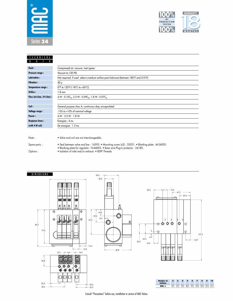
3/2 NO-NC M5 - #10-32 0.10Cvadd-on style
plug-inwith Pr. Reg.
1. 10 mm valve, direct solenoid operated.2. Balanced poppet, immune to variations of
pressure.3. Short stroke with high flow.4. The patented solenoid develops high shifting
forces.5. Powerful return spring.6. Flow is specifically adjusted on each valve.7. Manual operator standard on all valves.
O P E R A T I O N A L B E N E F I T S
D i r e c t s o l e n o i d a n d s o l e n o i d p i l o t o p e r a t e d v a l v e s
H O W T O O R D E R
Port size(see base)
Valve less base
Universal valve
34B-LOO-GXXO-XXX
NC only valve
34B-NOO-GXXO-XXX
2
1 3
2
1 3
Port size
M5
# 10-32
Bottom cylinder ports(10.5 mm)
ECD034B-004BD-AOXX
ECD034B-004BB-AOXX
Side cylinder ports(10.5 mm)
ECD034B-003BD-AOXX
ECD034B-003BB-AOXX
Voltage
DC 24VDC (1.8 W)
DD 24VDC (2.5 W)
DF 24VDC (4.0 W)
Manual operator
1 Non-locking
Electrical connection
DJ Plug-in
DT Plug-in with light
DE Plug-in with suppression diode
DV Plug-in with light and suppression diode
G XX O- X XX *SOLENOID OPERATOR ➤
HOW TO ORDER CIRCUIT BAR FOR PRESSURE REGULATORS ** (to be ordered separately)
HOW TO ORDER VALVE FOR CIRCUIT BAR MOUNTING
XX X XX
** Pressure Regulators :
Y=A (no gage port)Y=B (with gage port)X=A (0 to 100 PSI)X=B (0 to 60 PSI)X=C (0 to 40 PSI)X=D (0 to 15 PSI)
Number of stations (03=3 stations)Note : clic for valves mounted on base at the factory, add - 9 to the model number.
clic for multi-pin connector option (9, 15 or 25).add-a-unit stations may be added to above bars. Clic here for model numbers.
34B-xxx-GxxO-xxx
ECD034B-00xxx-AOxx
Other Optionsxx
xx Other Options
PR44A-AOxx

Consult “Precautions” before use, installation or service of MAC Valves.
Series 34
D I M E N S I O N S
Fluid :
Pressure range :
Lubrication :
Filtration :
Temperature range :
Orifice :
Flow (at 6 bar, �P=1bar) :
Leak rate :
Coil :
Voltage range :
Power :
Response times :
(with 4 W coil)
Compressed air, vacuum, inert gases
Vacuum to 120 PSI
Not required, if used select a medium aniline point lubricant (between 180°F and 210°F)
40 μ
0°F to 120°F (-18°C to +50°C)
1.8 mm
4 W : 0.10Cv, 2.5 W : 0.09Cv, 1.8 W : 0.07Cv
50 cm3/min
General purpose class A, continuous duty, encapsulated
-15% to +10% of nominal voltage
4 W - 2.5 W - 1.8 W
Energize : 4 ms
De-energize : 1.5 ms
15.5
15.0
2 2 2 2
2 2 2 2
31
L
83.7
77.0
60.8
57.2
29.5
14.8
8.3
20.0
32.0
4.522.3
23.0 10.0
20.2 10.541.3
25.3
10.9
16.010.5
25.8
33.0
22.5
25.323.0
K C O
L
+ -
K C O
L
+ -
K C O
L
+ -
K C O
L
+ -
137.3
D A T A
T E C H N I C A L
1818100%100%
100%100% M O N T H S
WARRANTY
O FP R O D U C T I O N
T E S T E D
• Valve and coil are not interchangeable.
• Seal between valve and bar : 16595. • Mounting screw (x2) : 35031. • Blanking plate : M-34005.• Base wire Plug-in protector : 24180. • Blanking plate for regulator : N-44003.• Isolation of inlet and/or exhaust. • BSPP Threads.
Note :
Spare parts :
Options :
Number ofstations
DIM. L
2
57.0
3
67.5
4
78.0
5
88.5
6
99.0
7
109.5
8
120.0
9
130.5
10
141.0

Consult “Precautions” before use, installation or service of MAC Valves.
Reset
Series 34
Function Port size Flow (Max) Circuit bar mounting
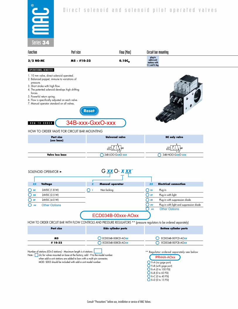
3/2 NO-NC M5 - #10-32 0.09Cvadd-on style
plug-inwith Pr. Reg.
and F. C.
1. 10 mm valve, direct solenoid operated.2. Balanced poppet, immune to variations of
pressure.3. Short stroke with high flow.4. The patented solenoid develops high shifting
forces.5. Powerful return spring.6. Flow is specifically adjusted on each valve.7. Manual operator standard on all valves.
O P E R A T I O N A L B E N E F I T S
D i r e c t s o l e n o i d a n d s o l e n o i d p i l o t o p e r a t e d v a l v e s
H O W T O O R D E R
Port size(see base)
Valve less base
Universal valve
34B-LOO-GXXO-XXX
NC only valve
34B-NOO-GXXO-XXX
2
1 3
2
1 3
Port size
M5
# 10-32
Bottom cylinder ports(10.5 mm)
ECD034B-007BD-AOXX
ECD034B-007BB-AOXX
Side cylinder ports(10.5 mm)
ECD034B-008BD-AOXX
ECD034B-008BB-AOXX
Voltage
DC 24VDC (1.8 W)
DD 24VDC (2.5 W)
DF 24VDC (4.0 W)
Manual operator
1 Non-locking
Electrical connection
DJ Plug-in
DT Plug-in with light
DE Plug-in with suppression diode
DV Plug-in with light and suppression diode
G XX O- X XX *SOLENOID OPERATOR ➤
HOW TO ORDER CIRCUIT BAR WITH FLOW CONTROLS AND PRESSURE REGULATORS ** (pressure regulators to be ordered separately)
HOW TO ORDER VALVE FOR CIRCUIT BAR MOUNTING
XX X XX
** Pressure Regulators :
Y=A (no gage port)Y=B (with gage port)X=A (0 to 100 PSI)X=B (0 to 60 PSI)X=C (0 to 40 PSI)X=D (0 to 15 PSI)
Number of stations (03=3 stations)Note : clic for valves mounted on base at the factory, add - 9 to the model number.
clic for multi-pin connector option (9, 15 or 25).add-a-unit stations may be added to above bars. Clic here for model numbers.
34B-xxx-GxxO-xxx
ECD034B-00xxx-AOxx
Other Optionsxx
xx Other Options
PR44A-AOxx
Consult “Precautions” before use, installation or service of MAC Valves.
Series 34
D I M E N S I O N S
Fluid :
Pressure range :
Lubrication :
Filtration :
Temperature range :
Orifice :
Flow (at 6 bar, �P=1bar) :
Leak rate :
Coil :
Voltage range :
Power :
Response times :
(with 4 W coil)
Compressed air, vacuum, inert gases
Vacuum to 120 PSI
Not required, if used select a medium aniline point lubricant (between 180°F and 210°F)
40 μ
0°F to 120°F (-18°C to +50°C)
1.8 mm
4 W : 0.10Cv, 2.5 W : 0.09Cv, 1.8 W : 0.07Cv
50 cm3/min
General purpose class A, continuous duty, encapsulated
-15% to +10% of nominal voltage
4 W - 2.5 W - 1.8 W
Energize : 4 ms
De-energize : 1.5 ms
15.0
15.5
137.3
-+
L
OCK
-+
L
OCK
-+
L
OCK
-+
L
OCK
23.025.3
22.5
33.0
25.8
10.5 16.0
10.9
25.3
41.310.520.2
10.023.0
22.34.5
32.0
20.0
8.3
14.8
29.5
57.2
60.8
77.0
83.7
L
13
2 2 2 2
2 2 2 2
D A T A
T E C H N I C A L
1818100%100%
100%100% M O N T H S
WARRANTY
O FP R O D U C T I O N
T E S T E D
• Valve and coil are not interchangeable.
• Seal between valve and bar : 16595. • Mounting screw (x2) : 35031. • Blanking plate : M-34005.• Blanking plate for regulator : N-44003. • Base wire Plug-in protector : 24180.• Isolation of inlet and/or exhaust. • BSPP Threads.
Note :
Spare parts :
Options :
Number ofstations
DIM. L
2
57.0
3
67.5
4
78.0
5
88.5
6
99.0
7
109.5
8
120.0
9
130.5
10
141.0
Consult “Precautions” before use, installation or service of MAC Valves.
Reset
Series 34
Function Port size Flow (Max) Circuit bar mounting
3/2 NO-NC M5 - #10-32 0.10Cvplug-in
add-a-unitstations
D i r e c t s o l e n o i d a n d s o l e n o i d p i l o t o p e r a t e d v a l v e s
Port size
M5
# 10-32
Side cylinder ports
ECD034B-001CD-AOXX
ECD034B-001CB-AOXX
Bottom cylinder ports
ECD034B-002CD-AOXX
ECD034B-002CB-AOXX
HOW TO ORDER CIRCUIT BAR
1. 10 mm valve, direct solenoid operated.2. Balanced poppet, immune to variations of
pressure.3. Short stroke with high flow.4. The patented solenoid develops high shifting
forces.5. Powerful return spring.6. Flow is specifically adjusted on each valve.7. Manual operator standard on all valves.
O P E R A T I O N A L B E N E F I T S
H O W T O O R D E R
Port size(see base)
Valve less base
Universal valve
34B-LOO-GXXO-XXX
NC only valve
34B-NOO-GXXO-XXX
2
1 3
2
1 3
Voltage
DC 24VDC (1.8 W)
DD 24VDC (2.5 W)
DF 24VDC (4.0 W)
Manual operator
1 Non-locking
Electrical connection
DJ Plug-in
DT Plug-in with light
DE Plug-in with suppression diode
DV Plug-in with light and suppression diode
G XX O- X XX *SOLENOID OPERATOR ➤
HOW TO ORDER VALVE FOR CIRCUIT BAR MOUNTING
XX X XX
Number of stations (03=3 stations) - Maximum length is 4 stationsNote : clic for valves mounted on base at the factory, add - 9 to the model number.
when add-a-unit stations are added to bars with a multi-pin connector, MOD. SD03 should be included with add-a-unit model number.
34B-xxx-GxxO-xxx
ECD034B-00xxx-AOxx
Other Optionsxx
xx Other Options
Consult “Precautions” before use, installation or service of MAC Valves.
Series 34
D I M E N S I O N S
Fluid :
Pressure range :
Lubrication :
Filtration :
Temperature range :
Orifice :
Flow (at 6 bar, �P=1bar) :
Leak rate :
Coil :
Voltage range :
Power :
Response times :
(with 4 W coil)
Compressed air, vacuum, inert gases
Vacuum to 120 PSI
Not required, if used select a medium aniline point lubricant (between 180°F and 210°F)
40 μ
0°F to 120°F (-18°C to +50°C)
1.8 mm
4 W : 0.10Cv, 2.5 W : 0.09Cv, 1.8 W : 0.07Cv
50 cm3/min
General purpose class A, continuous duty, encapsulated
-15% to +10% of nominal voltage
4 W - 2.5 W - 1.8 W
Energize : 4 ms
De-energize : 1.5 ms
15.5
15.0
23.025.3
22.5
33.0
25.8
10.5 16.0
10.9
25.3
41.3
10.5
20.2
10.023.022.3
4.5
32.0
20.0
8.3
14.8
29.5
57.2
60.8
77.0
83.7
L
13
2 2 2 2
2 2 2 2
D A T A
T E C H N I C A L
1818100%100%
100%100% M O N T H S
WARRANTY
O FP R O D U C T I O N
T E S T E D
• Valve and coil are not interchangeable.
• Seal between valve and bar : 16595. • Mounting screw (x2) : 35031. • Blanking plate : M-34005.• Base wire Plug-in protector : 24180.• Isolation of inlet and/or exhaust. • BSPP Threads.
Note :
Spare parts :
Options :
Number ofstations
DIM. L
2
57.0
3
67.5
4
78.0
5
88.5
6
99.0
7
109.5
8
120.0
9
130.5
10
141.0

Consult “Precautions” before use, installation or service of MAC Valves.
Reset
Series 34
Function Port size Flow (Max) Circuit bar mounting
3/2 NO-NC M5 - #10-32 0.10Cvplug-in
add-a-unitstations with
F. C.
D i r e c t s o l e n o i d a n d s o l e n o i d p i l o t o p e r a t e d v a l v e s
Port size
M5
# 10-32
Side cylinder ports
ECD034B-005CD-AOXX
ECD034B-005CB-AOXX
Bottom cylinder ports
ECD034B-006CD-AOXX
ECD034B-006CB-AOXX
HOW TO ORDER CIRCUIT BAR WITH FLOW CONTROLS
1. 10 mm valve, direct solenoid operated.2. Balanced poppet, immune to variations of
pressure.3. Short stroke with high flow.4. The patented solenoid develops high shifting
forces.5. Powerful return spring.6. Flow is specifically adjusted on each valve.7. Manual operator standard on all valves.
O P E R A T I O N A L B E N E F I T S
H O W T O O R D E R
Port size(see base)
Valve less base
Universal valve
34B-LOO-GXXO-XXX
NC only valve
34B-NOO-GXXO-XXX
2
1 3
2
1 3
Voltage
DC 24VDC (1.8 W)
DD 24VDC (2.5 W)
DF 24VDC (4.0 W)
Manual operator
1 Non-locking
Electrical connection
DJ Plug-in
DT Plug-in with light
DE Plug-in with suppression diode
DV Plug-in with light and suppression diode
G XX O- X XX *SOLENOID OPERATOR ➤
HOW TO ORDER VALVE FOR CIRCUIT BAR MOUNTING
XX X XX
Number of stations (03=3 stations) - Maximum length is 4 stationsNote : clic for valves mounted on base at the factory, add - 9 to the model number.
when add-a-unit stations are added to bars with a multi-pin connector, MOD. SD03 should be included with add-a-unit model number.
34B-xxx-GxxO-xxx
ECD034B-00xxx-AOxx
Other Optionsxx
xx Other Options

Consult “Precautions” before use, installation or service of MAC Valves.
Series 34
D I M E N S I O N S
Fluid :
Pressure range :
Lubrication :
Filtration :
Temperature range :
Orifice :
Flow (at 6 bar, �P=1bar) :
Leak rate :
Coil :
Voltage range :
Power :
Response times :
(with 4 W coil)
Compressed air, vacuum, inert gases
Vacuum to 120 PSI
Not required, if used select a medium aniline point lubricant (between 180°F and 210°F)
40 μ
0°F to 120°F (-18°C to +50°C)
1.8 mm
4 W : 0.10Cv, 2.5 W : 0.09Cv, 1.8 W : 0.07Cv
50 cm3/min
General purpose class A, continuous duty, encapsulated
-15% to +10% of nominal voltage
4 W - 2.5 W - 1.8 W
Energize : 4 ms
De-energize : 1.5 ms
15.5
15.0
23.025.3
22.5
33.0
25.8
10.5 16.0
10.9
25.3
41.3
10.5
20.2
10.023.022.3
4.5
32.0
20.0
8.3
14.8
29.5
57.2
60.8
77.0
83.7
L
13
2 2 2 2
2 2 2 2
D A T A
T E C H N I C A L
1818100%100%
100%100% M O N T H S
WARRANTY
O FP R O D U C T I O N
T E S T E D
• Valve and coil are not interchangeable.
• Seal between valve and bar : 16595. • Mounting screw (x2) : 35031. • Blanking plate : M-34005.• Base wire Plug-in protector : 24180.• Isolation of inlet and/or exhaust. • BSPP Threads.
Note :
Spare parts :
Options :
Number ofstations
DIM. L
2
57.0
3
67.5
4
78.0
5
88.5
6
99.0
7
109.5
8
120.0
9
130.5
10
141.0
Consult “Precautions” before use, installation or service of MAC Valves.
Reset
** Regulator ordered separately-see below
Y=A (no gage port)Y=B (with gage port)X=A (0 to 100 PSI)X=B (0 to 60 PSI)X=C (0 to 40 PSI)X=D (0 to 15 PSI)
Series 34
Function Port size Flow (Max) Circuit bar mounting
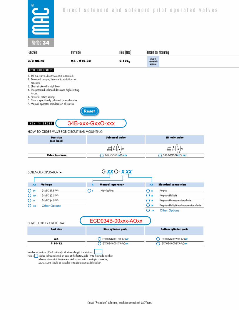
3/2 NO-NC M5 - #10-32 0.10Cvplug-in
add-a-unitstations
with Pr. Reg.
D i r e c t s o l e n o i d a n d s o l e n o i d p i l o t o p e r a t e d v a l v e s
Port size
M5
# 10-32
Side cylinder ports
ECD034B-003CD-AOXX
ECD034B-003CB-AOXX
Bottom cylinder ports
ECD034B-004CD-AOXX
ECD034B-004CB-AOXX
HOW TO ORDER CIRCUIT BAR FOR PRESSURE REGULATORS ** (to be ordered separately)
1. 10 mm valve, direct solenoid operated.2. Balanced poppet, immune to variations of
pressure.3. Short stroke with high flow.4. The patented solenoid develops high shifting
forces.5. Powerful return spring.6. Flow is specifically adjusted on each valve.7. Manual operator standard on all valves.
O P E R A T I O N A L B E N E F I T S
H O W T O O R D E R
Port size(see base)
Valve less base
Universal valve
34B-LOO-GXXO-XXX
NC only valve
34B-NOO-GXXO-XXX
2
1 3
2
1 3
Voltage
DC 24VDC (1.8 W)
DD 24VDC (2.5 W)
DF 24VDC (4.0 W)
Manual operator
1 Non-locking
Electrical connection
DJ Plug-in
DT Plug-in with light
DE Plug-in with suppression diode
DV Plug-in with light and suppression diode
G XX O- X XX *SOLENOID OPERATOR ➤
HOW TO ORDER VALVE FOR CIRCUIT BAR MOUNTING
XX X XX
Number of stations (03=3 stations) - Maximum length is 4 stationsNote : clic for valves mounted on base at the factory, add - 9 to the model number.
when add-a-unit stations are added to bars with a multi-pin connector, MOD. SD03 should be included with add-a-unit model number.
34B-xxx-GxxO-xxx
ECD034B-00xxx-AOxx
Other Optionsxx
xx Other Options
PR44A-AOxx
Consult “Precautions” before use, installation or service of MAC Valves.
Series 34
D I M E N S I O N S
Fluid :
Pressure range :
Lubrication :
Filtration :
Temperature range :
Orifice :
Flow (at 6 bar, �P=1bar) :
Leak rate :
Coil :
Voltage range :
Power :
Response times :
(with 4 W coil)
Compressed air, vacuum, inert gases
Vacuum to 120 PSI
Not required, if used select a medium aniline point lubricant (between 180°F and 210°F)
40 μ
0°F to 120°F (-18°C to +50°C)
1.8 mm
4 W : 0.10Cv, 2.5 W : 0.09Cv, 1.8 W : 0.07Cv
50 cm3/min
General purpose class A, continuous duty, encapsulated
-15% to +10% of nominal voltage
4 W - 2.5 W - 1.8 W
Energize : 4 ms
De-energize : 1.5 ms
15.5
15.0
2 2 2 2
2 2 2 2
31
L
83.7
77.0
60.8
57.2
29.5
14.8
8.3
20.0
32.0
4.522.3
23.0 10.0
20.2 10.541.3
25.3
10.9
16.010.5
25.8
33.0
22.5
25.323.0
K C O
L
+ -
K C O
L
+ -
K C O
L
+ -
K C O
L
+ -
137.3
D A T A
T E C H N I C A L
1818100%100%
100%100% M O N T H S
WARRANTY
O FP R O D U C T I O N
T E S T E D
• Valve and coil are not interchangeable.
• Seal between valve and bar : 16595. • Mounting screw (x2) : 35031. • Blanking plate : M-34005.• Base wire Plug-in protector : 24180. • Blanking plate for regulator : N-44003.• Isolation of inlet and/or exhaust. • BSPP Threads.
Note :
Spare parts :
Options :
Number ofstations
DIM. L
2
57.0
3
67.5
4
78.0
5
88.5
6
99.0
7
109.5
8
120.0
9
130.5
10
141.0
Consult “Precautions” before use, installation or service of MAC Valves.
Reset
** Regulator ordered separately-see below
Y=A (no gage port)Y=B (with gage port)X=A (0 to 100 PSI)X=B (0 to 60 PSI)X=C (0 to 40 PSI)X=D (0 to 15 PSI)
Series 34
Function Port size Flow (Max) Circuit bar mounting
3/2 NO-NC M5 - #10-32 0.10Cvplug-in
add-a-unitstations with
F. C. and Pr. Reg.
D i r e c t s o l e n o i d a n d s o l e n o i d p i l o t o p e r a t e d v a l v e s
Port size
M5
# 10-32
Side cylinder ports
ECD034B-008CD-AOXX
ECD034B-008CB-AOXX
Bottom cylinder ports
ECD034B-007CD-AOXX
ECD034B-007CB-AOXX
HOW TO ORDER CIRCUIT BAR WITH FLOW CONTROLS AND PRESSURE REGULATORS ** (pressure regulators to be ordered separately)
1. 10 mm valve, direct solenoid operated.2. Balanced poppet, immune to variations of
pressure.3. Short stroke with high flow.4. The patented solenoid develops high shifting
forces.5. Powerful return spring.6. Flow is specifically adjusted on each valve.7. Manual operator standard on all valves.
O P E R A T I O N A L B E N E F I T S
H O W T O O R D E R
Port size(see base)
Valve less base
Universal valve
34B-LOO-GXXO-XXX
NC only valve
34B-NOO-GXXO-XXX
2
1 3
2
1 3
Voltage
DC 24VDC (1.8 W)
DD 24VDC (2.5 W)
DF 24VDC (4.0 W)
Manual operator
1 Non-locking
Electrical connection
DJ Plug-in
DT Plug-in with light
DE Plug-in with suppression diode
DV Plug-in with light and suppression diode
G XX O- X XX *SOLENOID OPERATOR ➤
HOW TO ORDER VALVE FOR CIRCUIT BAR MOUNTING
XX X XX
Number of stations (03=3 stations) - Maximum length is 4 stationsNote : clic for valves mounted on base at the factory, add - 9 to the model number.
when add-a-unit stations are added to bars with a multi-pin connector, MOD. SD03 should be included with add-a-unit model number.
34B-xxx-GxxO-xxx
ECD034B-00xxx-AOxx
Other Optionsxxxx Other Options
PR44A-AOxx
Consult “Precautions” before use, installation or service of MAC Valves.
Series 34
D I M E N S I O N S
Fluid :
Pressure range :
Lubrication :
Filtration :
Temperature range :
Orifice :
Flow (at 6 bar, �P=1bar) :
Leak rate :
Coil :
Voltage range :
Power :
Response times :
(with 4 W coil)
Compressed air, vacuum, inert gases
Vacuum to 120 PSI
Not required, if used select a medium aniline point lubricant (between 180°F and 210°F)
40 μ
0°F to 120°F (-18°C to +50°C)
1.8 mm
4 W : 0.10Cv, 2.5 W : 0.09Cv, 1.8 W : 0.07Cv
50 cm3/min
General purpose class A, continuous duty, encapsulated
-15% to +10% of nominal voltage
4 W - 2.5 W - 1.8 W
Energize : 4 ms
De-energize : 1.5 ms
15.0
15.5
137.3
-+
L
OCK
-+
L
OCK
-+
L
OCK
-+
L
OCK
23.025.3
22.5
33.0
25.8
10.5 16.0
10.9
25.3
41.310.520.2
10.023.0
22.34.5
32.0
20.0
8.3
14.8
29.5
57.2
60.8
77.0
83.7
L
13
2 2 2 2
2 2 2 2
D A T A
T E C H N I C A L
1818100%100%
100%100% M O N T H S
WARRANTY
O FP R O D U C T I O N
T E S T E D
• Valve and coil are not interchangeable.
• Seal between valve and bar : 16595. • Mounting screw (x2) : 35031. • Blanking plate : M-34005.• Blanking plate for regulator : N-44003. • Base wire Plug-in protector : 24180.• Isolation of inlet and/or exhaust. • BSPP Threads.
Note :
Spare parts :
Options :
Number ofstations
DIM. L
2
57.0
3
67.5
4
78.0
5
88.5
6
99.0
7
109.5
8
120.0
9
130.5
10
141.0
Series 34
Function Port size Flow (Max) Circuit bar mounting
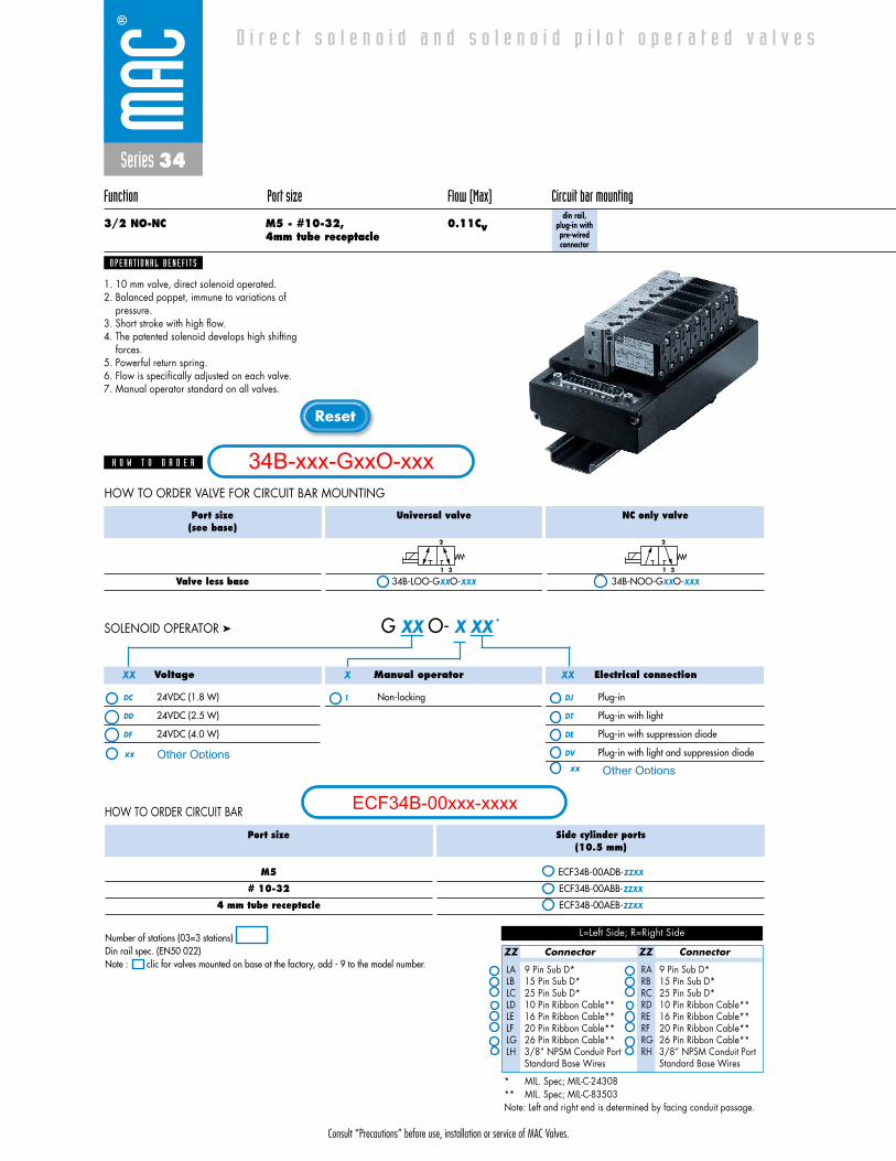
3/2 NO-NC M5 - #10-32, 0.11Cv4mm tube receptacle
plug-in withpre-wiredconnector
1. 10 mm valve, direct solenoid operated.2. Balanced poppet, immune to variations of
pressure.3. Short stroke with high flow.4. The patented solenoid develops high shifting
forces.5. Powerful return spring.6. Flow is specifically adjusted on each valve.7. Manual operator standard on all valves.
O P E R A T I O N A L B E N E F I T S
D i r e c t s o l e n o i d a n d s o l e n o i d p i l o t o p e r a t e d v a l v e s
H O W T O O R D E R
Port size(see base)
Valve less base
Universal valve
34B-LOO-GXXO-XXX
NC only valve
34B-NOO-GXXO-XXX
2
1 3
2
1 3
Port size
M5
# 10-32
4 mm tube receptacle
Side cylinder ports(10.5 mm)
ECF34B-00ADA-ZZXX
ECF34B-00ABA-ZZXX
ECF34B-00AEA-ZZXX
Bottom cylinder ports(10.5 mm)
ECF34B-00BDA-ZZXX
ECF34B-00BBA-ZZXX
---------
HOW TO ORDER CIRCUIT BAR
HOW TO ORDER VALVE FOR CIRCUIT BAR MOUNTING
ZZ Connector
LA 9 Pin Sub D*LB 15 Pin Sub D*LC 25 Pin Sub D*LD 10 Pin Ribbon Cable**LE 16 Pin Ribbon Cable**LF 20 Pin Ribbon Cable**LG 26 Pin Ribbon Cable**LH 3/8” NPSM Conduit Port
Standard Base Wires
ZZ Connector
RA 9 Pin Sub D*RB 15 Pin Sub D*RC 25 Pin Sub D*RD 10 Pin Ribbon Cable**RE 16 Pin Ribbon Cable**RF 20 Pin Ribbon Cable**RG 26 Pin Ribbon Cable**RH 3/8” NPSM Conduit Port
Standard Base Wires
L=Left Side; R=Right Side
* MIL. Spec; MIL-C-24308** MIL. Spec; MIL-C-83503Note: Left and right end is determined by facing conduit passage.
Voltage
DC 24VDC (1.8 W)
DD 24VDC (2.5 W)
DF 24VDC (4.0 W)
Manual operator
1 Non-locking
Electrical connection
DJ Plug-in
DT Plug-in with light
DE Plug-in with suppression diode
DV Plug-in with light and suppression diode
G XX O- X XX *SOLENOID OPERATOR ➤
XX X XX
Number of stations (03=3 stations)Note : clic for valves mounted on base at the factory, add - 9 to the model number.
Consult “Precautions” before use, installation or service of MAC Valves.
Reset
34B-xxx-GxxO-xxx
ECF34B-00xxx-xxxx
Other Optionsxx
xx Other Options
Consult “Precautions” before use, installation or service of MAC Valves.
Series 34
D I M E N S I O N S
Fluid :
Pressure range :
Lubrication :
Filtration :
Temperature range :
Orifice :
Flow (at 6 bar, �P=1bar) :
Leak rate :
Coil :
Voltage range :
Power :
Response times :
(with 4 W coil)
Compressed air, vacuum, inert gases
Vacuum to 120 PSI
Not required, if used select a medium aniline point lubricant (between 180°F and 210°F)
40 μ
0°F to 120°F (-18°C to +50°C)
1.8 mm
4 W : 0.10Cv, 2.5 W : 0.09Cv, 1.8 W : 0.07Cv
50 cm3/min
General purpose class A, continuous duty, encapsulated
-15% to +10% of nominal voltage
4 W - 2.5 W - 1.8 W
Energize : 4 ms
De-energize : 1.5 ms
20.0
88.7
10.520.2
10.0
26.8
10.5 13.05.0
51.6
16.7
37.9
72.6
17.49.0
53.5 22 2
2 2 2
1
3
2
2
D A T A
T E C H N I C A L
1818100%100%
100%100% M O N T H S
WARRANTY
O FP R O D U C T I O N
T E S T E D
• Valve and coil are not interchangeable.
• Seal between valve and bar : 16595. • Mounting screw (x2) : 35031. • Blanking plate : M-34005.• Base wire Plug-in protector : 24180.• Isolation of inlet and/or exhaust. • BSPP Threads.
Note :
Spare parts :
Options :

Series 34
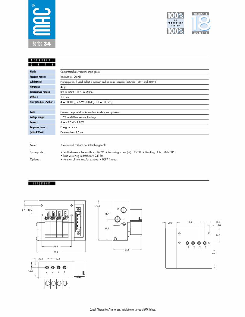
Function Port size Flow (Max) Circuit bar mounting
3/2 NO-NC M5 - #10-32, 0.11Cv4mm tube receptacle
plug-in with F. C. and pre-wiredconnector
1. 10 mm valve, direct solenoid operated.2. Balanced poppet, immune to variations of
pressure.3. Short stroke with high flow.4. The patented solenoid develops high shifting
forces.5. Powerful return spring.6. Flow is specifically adjusted on each valve.7. Manual operator standard on all valves.
O P E R A T I O N A L B E N E F I T S
D i r e c t s o l e n o i d a n d s o l e n o i d p i l o t o p e r a t e d v a l v e s
H O W T O O R D E R
Port size(see base)
Valve less base
Universal valve
34B-LOO-GXXO-XXX
NC only valve
34B-NOO-GXXO-XXX
2
1 3
2
1 3
Port size
M5
# 10-32
4 mm tube receptacle
Side cylinder ports(10.5 mm)
ECF34B-00CDA-ZZXX
ECF34B-00CBA-ZZXX
ECF34B-00CEA-ZZXX
Bottom cylinder ports(10.5 mm)
ECF34B-00DDA-ZZXX
ECF34B-00DBA-ZZXX
---------
HOW TO ORDER CIRCUIT BAR WITH FLOW CONTROLS
HOW TO ORDER VALVE FOR CIRCUIT BAR MOUNTING
ZZ Connector
LA 9 Pin Sub D*LB 15 Pin Sub D*LC 25 Pin Sub D*LD 10 Pin Ribbon Cable**LE 16 Pin Ribbon Cable**LF 20 Pin Ribbon Cable**LG 26 Pin Ribbon Cable**LH 3/8” NPSM Conduit Port
Standard Base Wires
ZZ Connector
RA 9 Pin Sub D*RB 15 Pin Sub D*RC 25 Pin Sub D*RD 10 Pin Ribbon Cable**RE 16 Pin Ribbon Cable**RF 20 Pin Ribbon Cable**RG 26 Pin Ribbon Cable**RH 3/8” NPSM Conduit Port
Standard Base Wires
L=Left Side; R=Right Side
* MIL. Spec; MIL-C-24308** MIL. Spec; MIL-C-83503Note: Left and right end is determined by facing conduit passage.
Voltage
DC 24VDC (1.8 W)
DD 24VDC (2.5 W)
DF 24VDC (4.0 W)
Manual operator
1 Non-locking
Electrical connection
DJ Plug-in
DT Plug-in with light
DE Plug-in with suppression diode
DV Plug-in with light and suppression diode
G XX O- X XX *SOLENOID OPERATOR ➤
XX X XX
Number of stations (03=3 stations)Note : clic for valves mounted on base at the factory, add - 9 to the model number.
Consult “Precautions” before use, installation or service of MAC Valves.
Reset
34B-xxx-GxxO-xxx
ECF34B-00xxx-xxxx
Other Optionsxx
xx Other Options

Consult “Precautions” before use, installation or service of MAC Valves.
Series 34
D I M E N S I O N S
Fluid :
Pressure range :
Lubrication :
Filtration :
Temperature range :
Orifice :
Flow (at 6 bar, �P=1bar) :
Leak rate :
Coil :
Voltage range :
Power :
Response times :
(with 4 W coil)
Compressed air, vacuum, inert gases
Vacuum to 120 PSI
Not required, if used select a medium aniline point lubricant (between 180°F and 210°F)
40 μ
0°F to 120°F (-18°C to +50°C)
1.8 mm
4 W : 0.11Cv, 2.5 W : 0.09Cv, 1.8 W : 0.06Cv
50 cm3/min
General purpose class A, continuous duty, encapsulated
-15% to +10% of nominal voltage
4 W - 2.5 W - 1.8 W
Energize : 4 ms
De-energize : 1.5 ms
2
2
3
1
222
22 253.5
9.0 17.4
37.9
16.7
51.6
5.013.010.5
26.8
10.0
20.2 10.5
88.7
20.0
80.1
D A T A
T E C H N I C A L
1818100%100%
100%100% M O N T H S
WARRANTY
O FP R O D U C T I O N
T E S T E D
• Valve and coil are not interchangeable.
• Seal between valve and bar : 16595. • Mounting screw (x2) : 35031. • Blanking plate : M-34005.• Base wire Plug-in protector : 24180.• Isolation of inlet and/or exhaust. • BSPP Threads.
Note :
Spare parts :
Options :
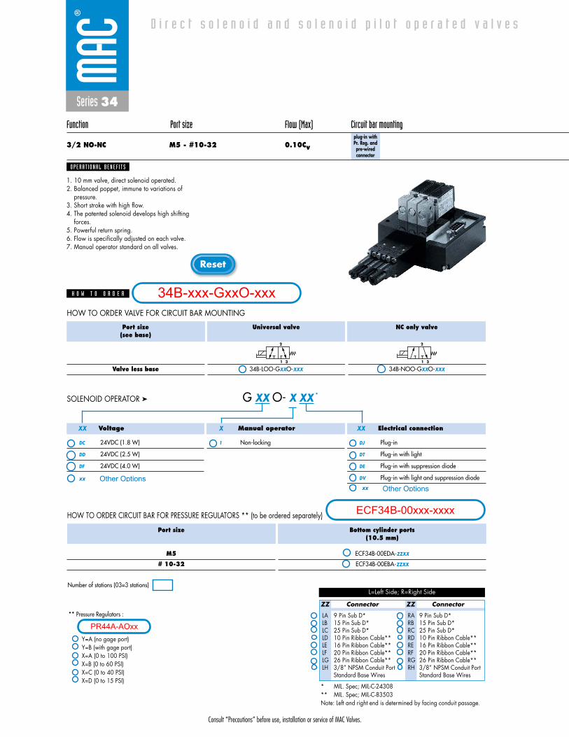
Series 34
Function Port size Flow (Max) Circuit bar mounting
3/2 NO-NC M5 - #10-32 0.10Cvplug-in withPr. Reg. andpre-wiredconnector
1. 10 mm valve, direct solenoid operated.2. Balanced poppet, immune to variations of
pressure.3. Short stroke with high flow.4. The patented solenoid develops high shifting
forces.5. Powerful return spring.6. Flow is specifically adjusted on each valve.7. Manual operator standard on all valves.
O P E R A T I O N A L B E N E F I T S
D i r e c t s o l e n o i d a n d s o l e n o i d p i l o t o p e r a t e d v a l v e s
H O W T O O R D E R
Port size(see base)
Valve less base
Universal valve
34B-LOO-GXXO-XXX
NC only valve
34B-NOO-GXXO-XXX
2
1 3
2
1 3
HOW TO ORDER VALVE FOR CIRCUIT BAR MOUNTING
ZZ Connector
LA 9 Pin Sub D*LB 15 Pin Sub D*LC 25 Pin Sub D*LD 10 Pin Ribbon Cable**LE 16 Pin Ribbon Cable**LF 20 Pin Ribbon Cable**LG 26 Pin Ribbon Cable**LH 3/8” NPSM Conduit Port
Standard Base Wires
ZZ Connector
RA 9 Pin Sub D*RB 15 Pin Sub D*RC 25 Pin Sub D*RD 10 Pin Ribbon Cable**RE 16 Pin Ribbon Cable**RF 20 Pin Ribbon Cable**RG 26 Pin Ribbon Cable**RH 3/8” NPSM Conduit Port
Standard Base Wires
L=Left Side; R=Right Side
* MIL. Spec; MIL-C-24308** MIL. Spec; MIL-C-83503Note: Left and right end is determined by facing conduit passage.
Voltage
DC 24VDC (1.8 W)
DD 24VDC (2.5 W)
DF 24VDC (4.0 W)
Manual operator
1 Non-locking
Electrical connection
DJ Plug-in
DT Plug-in with light
DE Plug-in with suppression diode
DV Plug-in with light and suppression diode
G XX O- X XX *SOLENOID OPERATOR ➤
XX X XX
HOW TO ORDER CIRCUIT BAR FOR PRESSURE REGULATORS ** (to be ordered separately)
Port size
M5
# 10-32
Bottom cylinder ports(10.5 mm)
ECF34B-00EDA-ZZXX
ECF34B-00EBA-ZZXX
** Pressure Regulators :
Y=A (no gage port)Y=B (with gage port)X=A (0 to 100 PSI)X=B (0 to 60 PSI)X=C (0 to 40 PSI)X=D (0 to 15 PSI)
Number of stations (03=3 stations)
Consult “Precautions” before use, installation or service of MAC Valves.
Reset
34B-xxx-GxxO-xxx
ECF34B-00xxx-xxxx
Other Optionsxxxx Other Options
PR44A-AOxx

Consult “Precautions” before use, installation or service of MAC Valves.
Series 34
D I M E N S I O N S
Fluid :
Pressure range :
Lubrication :
Filtration :
Temperature range :
Orifice :
Flow (at 6 bar, �P=1bar) :
Leak rate :
Coil :
Voltage range :
Power :
Response times :
(with 4 W coil)
Compressed air, vacuum, inert gases
Vacuum to 120 PSI
Not required, if used select a medium aniline point lubricant (between 180°F and 210°F)
40 μ
0°F to 120°F (-18°C to +50°C)
1.8 mm
4 W : 0.10Cv, 2.5 W : 0.09Cv, 1.8 W : 0.07Cv
50 cm3/min
General purpose class A, continuous duty, encapsulated
-15% to +10% of nominal voltage
4 W - 2.5 W - 1.8 W
Energize : 4 ms
De-energize : 1.5 ms
132.9
K C O
L
+ -
2
K C O
L
+ -
K C O
L
+ -
K C O
L
+ -
2
3
1
22 253.5
9.0 17.4
37.9
16.7
51.6
5.0
13.010.5
26.8
88.7
20.0
D A T A
T E C H N I C A L
1818100%100%
100%100% M O N T H S
WARRANTY
O FP R O D U C T I O N
T E S T E D
• Valve and coil are not interchangeable.
• Seal between valve and bar : 16595. • Mounting screw (x2) : 35031. • Blanking plate : M-34005.• Blanking plate for regulator : N-44003. • Base wire Plug-in protector : 24180.• Isolation of inlet and/or exhaust. • BSPP Threads.
Note :
Spare parts :
Options :
Series 34
Function Port size Flow (Max) Circuit bar mounting
3/2 NO-NC M5 - #10-32, 0.11Cv4mm tube receptacle
din rail, plug-in withpre-wiredconnector
1. 10 mm valve, direct solenoid operated.2. Balanced poppet, immune to variations of
pressure.3. Short stroke with high flow.4. The patented solenoid develops high shifting
forces.5. Powerful return spring.6. Flow is specifically adjusted on each valve.7. Manual operator standard on all valves.
O P E R A T I O N A L B E N E F I T S
D i r e c t s o l e n o i d a n d s o l e n o i d p i l o t o p e r a t e d v a l v e s
H O W T O O R D E R
Port size(see base)
Valve less base
Universal valve
34B-LOO-GXXO-XXX
NC only valve
34B-NOO-GXXO-XXX
2
1 3
2
1 3
HOW TO ORDER VALVE FOR CIRCUIT BAR MOUNTING
ZZ Connector
LA 9 Pin Sub D*LB 15 Pin Sub D*LC 25 Pin Sub D*LD 10 Pin Ribbon Cable**LE 16 Pin Ribbon Cable**LF 20 Pin Ribbon Cable**LG 26 Pin Ribbon Cable**LH 3/8” NPSM Conduit Port
Standard Base Wires
ZZ Connector
RA 9 Pin Sub D*RB 15 Pin Sub D*RC 25 Pin Sub D*RD 10 Pin Ribbon Cable**RE 16 Pin Ribbon Cable**RF 20 Pin Ribbon Cable**RG 26 Pin Ribbon Cable**RH 3/8” NPSM Conduit Port
Standard Base Wires
L=Left Side; R=Right Side
* MIL. Spec; MIL-C-24308** MIL. Spec; MIL-C-83503Note: Left and right end is determined by facing conduit passage.
Voltage
DC 24VDC (1.8 W)
DD 24VDC (2.5 W)
DF 24VDC (4.0 W)
Manual operator
1 Non-locking
Electrical connection
DJ Plug-in
DT Plug-in with light
DE Plug-in with suppression diode
DV Plug-in with light and suppression diode
G XX O- X XX *SOLENOID OPERATOR ➤
XX X XX
HOW TO ORDER CIRCUIT BAR
Port size
M5
# 10-32
4 mm tube receptacle
Side cylinder ports(10.5 mm)
ECF34B-00ADB-ZZXX
ECF34B-00ABB-ZZXX
ECF34B-00AEB-ZZXX
Number of stations (03=3 stations)Din rail spec. (EN50 022)Note : clic for valves mounted on base at the factory, add - 9 to the model number.
Consult “Precautions” before use, installation or service of MAC Valves.
Reset
34B-xxx-GxxO-xxx
ECF34B-00xxx-xxxx
Other Optionsxxxx Other Options

Consult “Precautions” before use, installation or service of MAC Valves.
Series 34
D I M E N S I O N S
Fluid :
Pressure range :
Lubrication :
Filtration :
Temperature range :
Orifice :
Flow (at 6 bar, �P=1bar) :
Leak rate :
Coil :
Voltage range :
Power :
Response times :
(with 4 W coil)
Compressed air, vacuum, inert gases
Vacuum to 120 PSI
Not required, if used select a medium aniline point lubricant (between 180°F and 210°F)
40 μ
0°F to 120°F (-18°C to +50°C)
1.8 mm
4 W : 0.11Cv, 2.5 W : 0.09Cv, 1.8 W : 0.06Cv
50 cm3/min
General purpose class A, continuous duty, encapsulated
-15% to +10% of nominal voltage
4 W - 2.5 W - 1.8 W
Energize : 4 ms
De-energize : 1.5 ms
20.0
88.7
10.520.2
10.0
5.0
16.7
37.9
72.6
17.49.0
53.5
2 2 2 2
MO
DIF.
AUCKLA
ND,N
.Z.LIEG
E,BELGIUM
WIXO
M,M
I.USA
MO
DEL
ELECTRIC
AL
WA
TTS
VA
C TO
120 PSI2
1 3
3
1
60.9
D A T A
T E C H N I C A L
1818100%100%
100%100% M O N T H S
WARRANTY
O FP R O D U C T I O N
T E S T E D
• Valve and coil are not interchangeable.
• Seal between valve and bar : 16595. • Mounting screw (x2) : 35031. • Blanking plate : M-34005.• Base wire Plug-in protector : 24180.• Isolation of inlet and/or exhaust. • BSPP Threads.
Note :
Spare parts :
Options :
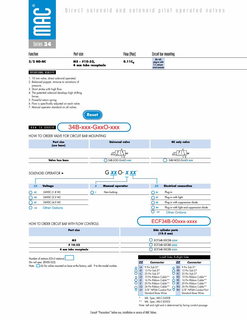
Series 34
Function Port size Flow (Max) Circuit bar mounting
3/2 NO-NC M5 - #10-32, 0.11Cv4 mm tube receptacle
din rail, plug-in with F. C. and pre-
wired connector
1. 10 mm valve, direct solenoid operated.2. Balanced poppet, immune to variations of
pressure.3. Short stroke with high flow.4. The patented solenoid develops high shifting
forces.5. Powerful return spring.6. Flow is specifically adjusted on each valve.7. Manual operator standard on all valves.
O P E R A T I O N A L B E N E F I T S
D i r e c t s o l e n o i d a n d s o l e n o i d p i l o t o p e r a t e d v a l v e s
H O W T O O R D E R
Port size(see base)
Valve less base
Universal valve
34B-LOO-GXXO-XXX
NC only valve
34B-NOO-GXXO-XXX
2
1 3
2
1 3
HOW TO ORDER VALVE FOR CIRCUIT BAR MOUNTING
ZZ Connector
LA 9 Pin Sub D*LB 15 Pin Sub D*LC 25 Pin Sub D*LD 10 Pin Ribbon Cable**LE 16 Pin Ribbon Cable**LF 20 Pin Ribbon Cable**LG 26 Pin Ribbon Cable**LH 3/8” NPSM Conduit Port
Standard Base Wires
ZZ Connector
RA 9 Pin Sub D*RB 15 Pin Sub D*RC 25 Pin Sub D*RD 10 Pin Ribbon Cable**RE 16 Pin Ribbon Cable**RF 20 Pin Ribbon Cable**RG 26 Pin Ribbon Cable**RH 3/8” NPSM Conduit Port
Standard Base Wires
L=Left Side; R=Right Side
* MIL. Spec; MIL-C-24308** MIL. Spec; MIL-C-83503Note: Left and right end is determined by facing conduit passage.
Voltage
DC 24VDC (1.8 W)
DD 24VDC (2.5 W)
DF 24VDC (4.0 W)
Manual operator
1 Non-locking
Electrical connection
DJ Plug-in
DT Plug-in with light
DE Plug-in with suppression diode
DV Plug-in with light and suppression diode
G XX O- X XX *SOLENOID OPERATOR ➤
XX X XX
HOW TO ORDER CIRCUIT BAR WITH FLOW CONTROLS
Port size
M5
# 10-32
4 mm tube receptacle
Side cylinder ports(10.5 mm)
ECF34B-00CDB-ZZXX
ECF34B-00CBB-ZZXX
ECF34B-00CEB-ZZXX
Number of stations (03=3 stations)Din rail spec. (EN50 022)Note : clic for valves mounted on base at the factory, add - 9 to the model number.
Consult “Precautions” before use, installation or service of MAC Valves.
Reset
34B-xxx-GxxO-xxx
ECF34B-00xxx-xxxx
Other Optionsxxxx Other Options
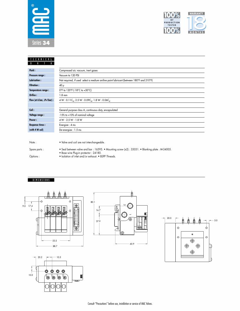
Consult “Precautions” before use, installation or service of MAC Valves.
Series 34
D I M E N S I O N S
Fluid :
Pressure range :
Lubrication :
Filtration :
Temperature range :
Orifice :
Flow (at 6 bar, �P=1bar) :
Leak rate :
Coil :
Voltage range :
Power :
Response times :
(with 4 W coil)
Compressed air, vacuum, inert gases
Vacuum to 120 PSI
Not required, if used select a medium aniline point lubricant (between 180°F and 210°F)
40 μ
0°F to 120°F (-18°C to +50°C)
1.8 mm
4 W : 0.11Cv, 2.5 W : 0.09Cv, 1.8 W : 0.06Cv
50 cm3/min
General purpose class A, continuous duty, encapsulated
-15% to +10% of nominal voltage
4 W - 2.5 W - 1.8 W
Energize : 4 ms
De-energize : 1.5 ms
80.1
60.9
1
3
312
VA
C TO
120 PSI
WA
TTSELEC
TRICA
L
MO
DEL
AUCKLA
ND,N
.Z.LIEG
E,BELGIUM
WIXO
M,M
I.USAM
OD
IF.
2222
53.5
9.0 17.4
37.9
16.7
5.0
10.0
20.2 10.5
88.7
20.0
D A T A
T E C H N I C A L
1818100%100%
100%100% M O N T H S
WARRANTY
O FP R O D U C T I O N
T E S T E D
• Valve and coil are not interchangeable.
• Seal between valve and bar : 16595. • Mounting screw (x2) : 35031. • Blanking plate : M-34005.• Base wire Plug-in protector : 24180.• Isolation of inlet and/or exhaust. • BSPP Threads.
Note :
Spare parts :
Options :

Consult “Precautions” before use, installation or service of MAC Valves.
S e c t i o n 2 Opt ions

Consult “Precautions”before use, installation or service of MAC Valves.
O P T I O N S
O p t i o n s
Codification table for voltages / Manual operator / Electrical connection
- G XX X - X XX1 2 3 4
VALVE CODE ➤
- solenoid valves 34 & 44 Series
OPTIONS AVAILABLE FOR
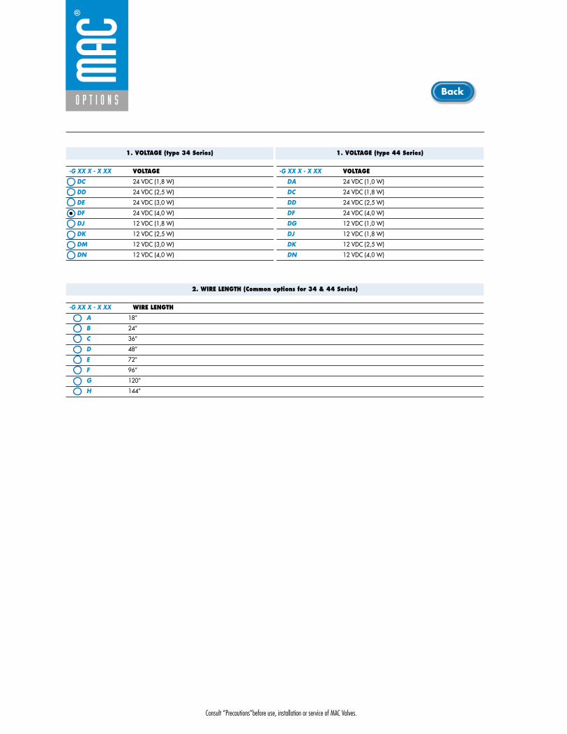
Consult “Precautions”before use, installation or service of MAC Valves.
O P T I O N S
1. VOLTAGE (type 34 Series)
-G XX X - X XX VOLTAGE
DC 24 VDC (1,8 W)
DD 24 VDC (2,5 W)
DE 24 VDC (3,0 W)
DF 24 VDC (4,0 W)
DJ 12 VDC (1,8 W)
DK 12 VDC (2,5 W)
DM 12 VDC (3,0 W)
DN 12 VDC (4,0 W)
1. VOLTAGE (type 44 Series)
-G XX X - X XX VOLTAGE
DA 24 VDC (1,0 W)
DC 24 VDC (1,8 W)
DD 24 VDC (2,5 W)
DF 24 VDC (4,0 W)
DG 12 VDC (1,0 W)
DJ 12 VDC (1,8 W)
DK 12 VDC (2,5 W)
DN 12 VDC (4,0 W)
2. WIRE LENGTH (Common options for 34 & 44 Series)
-G XX X - X XX WIRE LENGTH
A 18”
B 24”
C 36”
D 48”
E 72”
F 96”
G 120”
H 144”
Back

Consult “Precautions”before use, installation or service of MAC Valves.
O P T I O N S
O p t i o n s
3. MANUAL OPERATOR (COMMON OPTIONS FOR 34 & 44 SERIES)
-G XX X - X XX MANUAL OPERATOR
1 Non-locking recessed
3 Non-locking extended
4. ELECTRICAL CONNECTION (COMMON OPTIONS FOR 34 & 44 SERIES)
-G XX X - X XX NO CONNECTOR
BA Flying leads
BB BA with ground wire
BC BA with light
BD BA with light and ground wire
BE BA with suppression diode
BF BA with suppression diode and ground wire
BG BA with suppression diode and light
BH BA with suppression diode, light and ground wire
BN BA with suppression diode and blocking diode
BP BA with suppression diode, blocking diode and ground wire
BR BA with suppression diode, blocking diode and light
BS BA with suppression diode, blocking diode, light and ground wire
BT BA with light
BU BA with light and ground wire
BV BA with suppression diode and light
BW BA with suppression diode, light and ground wire
BX BA with suppression diode, blocking diode and light
BY BA with suppression diode, blocking diode, light and ground wire
-G XX X - X XX PLUG-IN CONNECTOR
KA Mini connector with flying leads
KB KA with ground wire
KE KA with suppression diode
KF KA with suppression diode and ground wire
KJ Mini connector for KA option
KM Mini connector for KB option
KN KA with suppression diode and blocking diode
KP KA with suppression diode, blocking diode and ground wire
KT KA with light
KU KA with light and ground wire
KV KA with suppression diode and light
KW KA with suppression diode, light and ground wire
KX KA with suppression diode, blocking diode and light
KY KA with suppression diode, blocking diode, light and ground wire
Back
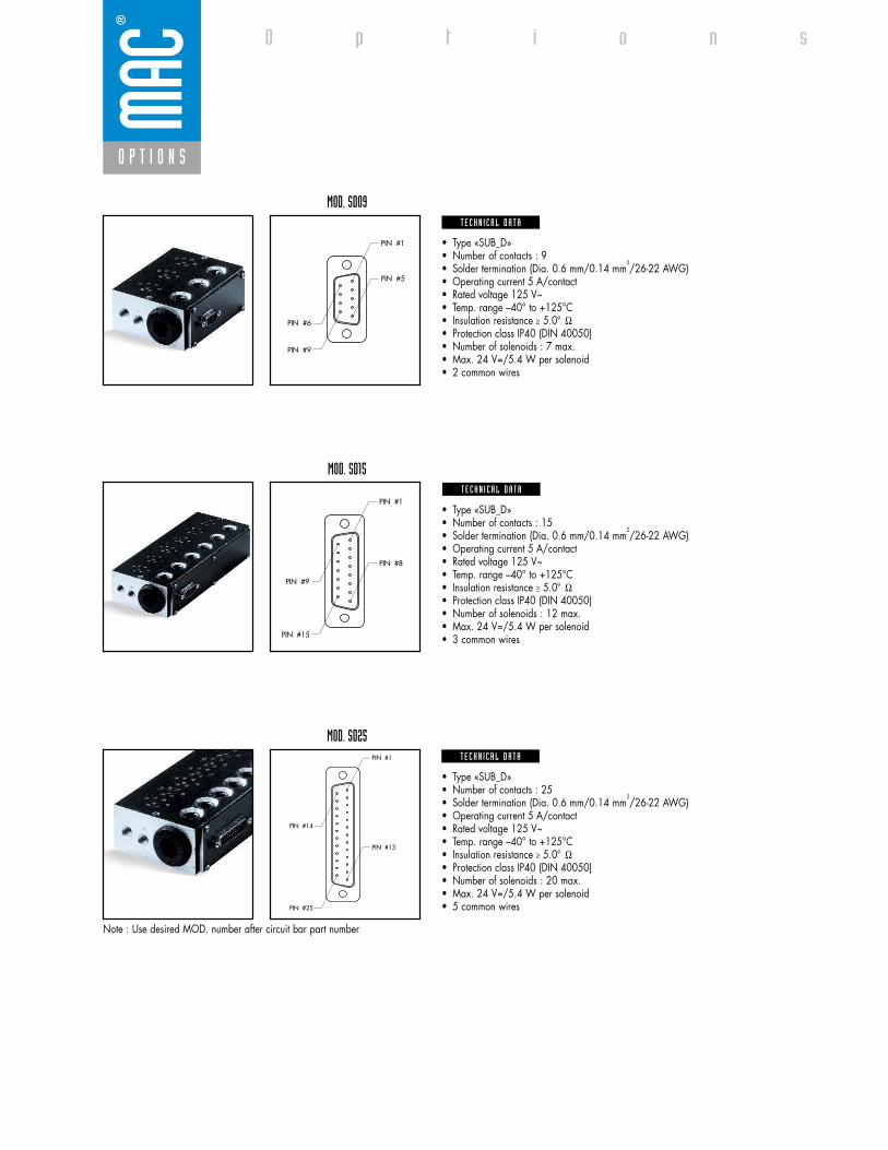
• Type «SUB_D»• Number of contacts : 9• Solder termination (Dia. 0.6 mm/0.14 mm
2/26-22 AWG)
• Operating current 5 A/contact• Rated voltage 125 V~• Temp. range –40° to +125°C• Insulation resistance � 5.09 �• Protection class IP40 (DIN 40050)• Number of solenoids : 7 max.• Max. 24 V=/5.4 W per solenoid• 2 common wires
MOD. SD09
MOD. SD15
MOD. SD25
PIN #1
PIN #5
PIN #6
PIN #9
PIN #1
PIN #8
PIN #9
PIN #15
PIN #1
PIN #13
PIN #14
PIN #25
• Type «SUB_D»• Number of contacts : 25• Solder termination (Dia. 0.6 mm/0.14 mm
2/26-22 AWG)
• Operating current 5 A/contact• Rated voltage 125 V~• Temp. range –40° to +125°C• Insulation resistance � 5.09 �• Protection class IP40 (DIN 40050)• Number of solenoids : 20 max.• Max. 24 V=/5.4 W per solenoid• 5 common wires
Note : Use desired MOD. number after circuit bar part number
• Type «SUB_D»• Number of contacts : 15• Solder termination (Dia. 0.6 mm/0.14 mm
2/26-22 AWG)
• Operating current 5 A/contact• Rated voltage 125 V~• Temp. range –40° to +125°C• Insulation resistance � 5.09 �• Protection class IP40 (DIN 40050)• Number of solenoids : 12 max.• Max. 24 V=/5.4 W per solenoid• 3 common wires
T E C H N I C A L D A T A
T E C H N I C A L D A T A
T E C H N I C A L D A T A
O P T I O N S
O p t i o n s
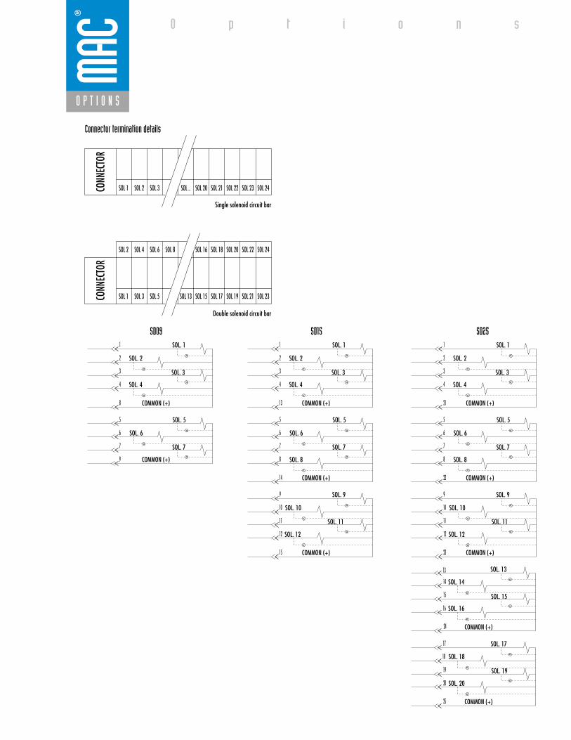
SD09 SD15 SD25
Connector termination details
SOL 2 SOL 4 SOL 6 SOL 8 SOL 16 SOL 18 SOL 20 SOL 22 SOL 24
SOL 1CONN
ECTO
RCO
NNEC
TOR
SOL 2 SOL 3 SOL .. SOL 20 SOL 21 SOL 22 SOL 23 SOL 24
SOL 1 SOL 3 SOL 5 SOL 13 SOL 15 SOL 17
Double solenoid circuit bar
Single solenoid circuit bar
SOL 21 SOL 23SOL 19
SOL. 3
SOL. 1
SOL. 2
1
2
3
4
COMMON (+)
COMMON (+)
8
SOL. 4
5
6
7
9
SOL. 5
SOL. 7
SOL. 6
SOL. 3
SOL. 1
SOL. 2
1
2
3
4
COMMON (+)
COMMON (+)
COMMON (+)
13
SOL. 4
5
6
7
8
14
SOL. 5
SOL. 7
SOL. 6
SOL. 8
9
10
11
12
15
SOL. 9
SOL. 11
SOL. 10
SOL. 12
SOL. 3
SOL. 1
SOL. 2
1
2
3
4
COMMON (+)
COMMON (+)
COMMON (+)
COMMON (+)
COMMON (+)
21
SOL. 4
5
6
7
8
22
SOL. 5
SOL. 7
SOL. 6
SOL. 8
9
10
11
12
23
SOL. 9
SOL. 11
SOL. 10
SOL. 12
13
14
15
16
24
SOL. 13
SOL. 15
SOL. 14
SOL. 16
17
18
19
20
25
SOL. 17
SOL. 19
SOL. 18
SOL. 20
O P T I O N S
O p t i o n s

Consult “Precautions” before use, installation or service of MAC Valves.
Series 35
D i r e c t s o l e n o i d a n d s o l e n o i d p i l o t o p e r a t e d v a l v e s
1
2
CYL.PORT
N.C.PORT
3
non plug-in non plug-inwith Pr. Reg. plug-in
plug-inwith side Pr. Reg.
plug-inwith integral terminal strip
plug-in with integral terminal
strip and side Pr. Reg.
Circuit bar mounting
Push pin
Manual operator
Armature
Epoxy encapsulated solenoid
Spring biased moveable pole piece
Bonded balanced poppet
Spring return
SERIES FEATURES
• Patented MACSOLENOID® for fastest possible response times.• Balanced poppet permits versatility in function :
- 3 way N.C. - 3 way N.O. - Divertor - Selector• Extremely high cycle rate capability.• Various solenoid enclosures and plug-in connectors.• Low wattage DC solenoids - down to 1.8 watts.• Rated for lubricated or non-lubricated service.

Consult “Precautions” before use, installation or service of MAC Valves.
Reset
Series 35
Function Port size Flow (Max) Circuit bar mounting
3/2 NO-NC 1/8” NPTF - #10-32 UNF 0.10Cv non plug-in
1. Balanced poppet, immune to variations ofpressure.
2. Short stroke with high flow.3. The patented solenoid develops high shifting
forces.4. Powerful return spring.5. Manual operator standard on all valves.6. Burn-out proof solenoid on AC service.
O P E R A T I O N A L B E N E F I T S
D i r e c t s o l e n o i d a n d s o l e n o i d p i l o t o p e r a t e d v a l v e s
H O W T O O R D E R
Valve less base
Universal valve
35A-B00-DXXX-XXX
CYL
IN EXH
HOW TO ORDER VALVE FOR CIRCUIT BAR MOUNTING
Voltage
AA 120/60, 110/50
AB 240/60, 220/50
AC 24/60, 24/50
FB 24VDC (1.8 W)
DA 24VDC (5.4 W)
DF 24VDC (12.7 W)
Wire length
A 18” (Flying leads)
J Connector
Manual operator
1 Non-locking Recessed
2 Locking Recessed
Electrical connection
KA Square connector
KD Square connector
with light
BA Flying leads
D XX X- X XX *SOLENOID OPERATOR ➤
Port size
1/8” NPTF
# 10-32 UNF
Side cylinder portsSpacing 21 mm
EBM35A-001A-XX
EBM35A-001B-XX
Bottom cylinder portsSpacing 21 mm
EBM35A-002A-XX
EBM35A-002B-XX
HOW TO ORDER CIRCUIT BAR**
XX X X XX
Number of stations (03=3 stations)* * Other options available. Consult factory.Note : clic for valves mounted on base at the factory, add - 9 to the model number.
35A-xxx-Dxxx-xxx
EBM35A-xxxx-xx
Other Optionsxx
x Other Options
xx Other Options
x Other Options
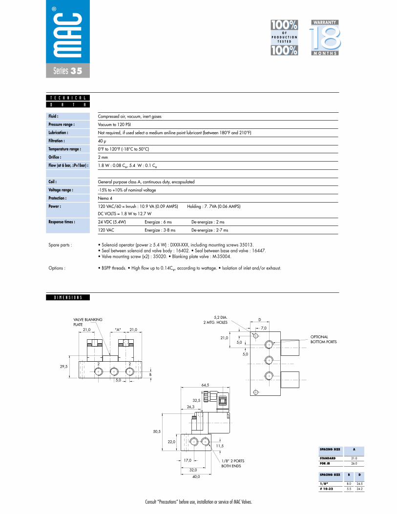
Consult “Precautions” before use, installation or service of MAC Valves.
Series 35
D I M E N S I O N S
Fluid :
Pressure range :
Lubrication :
Filtration :
Temperature range :
Orifice :
Flow (at 6 bar, �P=1bar) :
Leak rate :
Coil :
Voltage range :
Protection :
Power :
Response times :
Compressed air, vacuum, inert gases
Vacuum to 120 PSI
Not required, if used select a medium aniline point lubricant (between 180°F and 210°F)
40 μ
0°F to 120°F (-18°C to 50°C)
2 mm
1.8 W : 0.08 Cv, 5.4 W : 0.1 Cv
50 cm3/min
General purpose class A, continuous duty, encapsulated
-15% to +10% of nominal voltage
Nema 4
120 VAC/60 = Inrush : 10.9 VA (0.09 AMPS) Holding : 7. 7VA (0.06 AMPS)
DC VOLTS = 1.8 W to 12.7 W
24 VDC (5.4W) Energize : 6 ms De-energize : 2 ms
120 VAC Energize : 3-8 ms De-energize : 2-7 ms
D A T A
T E C H N I C A L
1818100%100%
100%100% M O N T H S
WARRANTY
O FP R O D U C T I O N
T E S T E D
• Solenoid operator (power � 5.4 W) : DXXX-XXX, including mounting screws 35013. • Seal between solenoid and valve body : 16402. • Seal between base and valve : 16447. • Valve mounting screw (x2) : 35020. • Blanking plate valve : M-35004.
• BSPP threads. • High flow up to 0.14Cv, according to wattage. • Isolation of inlet and/or exhaust.
Spare parts :
Options :
32,5
29,5
21,0
D
7,0
5,0
5,0
64,5
26,3
17,0
11,5
32,0
40,0
21,0
5,0
"A"
B
2 2
21,0
50,5
22,0
SPACING SIZE
STANDARD
FOR JB
A
21.0
26.0
SPACING SIZE
1/8”
# 10-32
B
8.0
5.5
D
24.5
24.2
VALVE BLANKINGPLATE
5,2 DIA.2 MTG. HOLES
1/8” 2 PORTSBOTH ENDS
OPTIONALBOTTOM PORTS
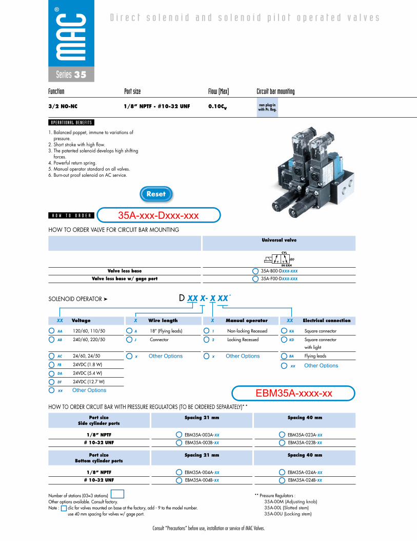
Consult “Precautions” before use, installation or service of MAC Valves.
Reset
Series 35
Function Port size Flow (Max) Circuit bar mounting
3/2 NO-NC 1/8” NPTF - #10-32 UNF 0.10Cvnon plug-in
with Pr. Reg.
1. Balanced poppet, immune to variations ofpressure.
2. Short stroke with high flow.3. The patented solenoid develops high shifting
forces.4. Powerful return spring.5. Manual operator standard on all valves.6. Burn-out proof solenoid on AC service.
O P E R A T I O N A L B E N E F I T S
D i r e c t s o l e n o i d a n d s o l e n o i d p i l o t o p e r a t e d v a l v e s
H O W T O O R D E R
Valve less base
Valve less base w/ gage port
Universal valve
35A-B00-DXXX-XXX
35A-F00-DXXX-XXX
CYL
IN EXH
HOW TO ORDER VALVE FOR CIRCUIT BAR MOUNTING
Voltage
AA 120/60, 110/50
AB 240/60, 220/50
AC 24/60, 24/50
FB 24VDC (1.8 W)
DA 24VDC (5.4 W)
DF 24VDC (12.7 W)
Wire length
A 18” (Flying leads)
J Connector
Manual operator
1 Non-locking Recessed
2 Locking Recessed
Electrical connection
KA Square connector
KD Square connector
with light
BA Flying leads
D XX X- X XX *SOLENOID OPERATOR ➤
Port sizeSide cylinder ports
1/8” NPTF
# 10-32 UNF
Spacing 21 mm
EBM35A-003A-XX
EBM35A-003B-XX
Spacing 40 mm
EBM35A-023A-XX
EBM35A-023B-XX
HOW TO ORDER CIRCUIT BAR WITH PRESSURE REGULATORS (TO BE ORDERED SEPARATELY)* *
** Pressure Regulators : 35A-00M (Adjusting knob)35A-00L (Slotted stem)35A-00U (Locking stem)
Port sizeBottom cylinder ports
1/8” NPTF
# 10-32 UNF
Spacing 21 mm
EBM35A-004A-XX
EBM35A-004B-XX
Spacing 40 mm
EBM35A-024A-XX
EBM35A-024B-XX
XX X X XX
Number of stations (03=3 stations)Other options available. Consult factory.Note : clic for valves mounted on base at the factory, add - 9 to the model number.
use 40 mm spacing for valves w/ gage port.
35A-xxx-Dxxx-xxx
EBM35A-xxxx-xxOther Optionsxx
x Other Options
xx Other Options
x Other Options
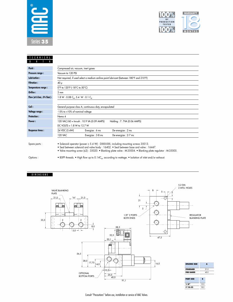
Consult “Precautions” before use, installation or service of MAC Valves.
Series 35
Fluid :
Pressure range :
Lubrication :
Filtration :
Temperature range :
Orifice :
Flow (at 6 bar, �P=1bar) :
Leak rate :
Coil :
Voltage range :
Protection :
Power :
Response times :
Compressed air, vacuum, inert gases
Vacuum to 120 PSI
Not required, if used select a medium aniline point lubricant (between 180°F and 210°F)
40 μ
0°F to 120°F (-18°C to 50°C)
2 mm
1.8 W : 0.08 Cv, 5.4 W : 0.1 Cv
50 cm3/min
General purpose class A, continuous duty, encapsulated
-15% to +10% of nominal voltage
Nema 4
120 VAC/60 = Inrush : 10.9 VA (0.09 AMPS) Holding : 7. 7VA (0.06 AMPS)
DC VOLTS = 1.8 W to 12.7 W
24 VDC (5.4W) Energize : 6 ms De-energize : 2 ms
120 VAC Energize : 3-8 ms De-energize : 2-7 ms
D A T A
T E C H N I C A L
1818100%100%
100%100% M O N T H S
WARRANTY
O FP R O D U C T I O N
T E S T E D
• Solenoid operator (power � 5.4 W) : DXXX-XXX, including mounting screws 35013. • Seal between solenoid and valve body : 16402. • Seal between base and valve : 16447. • Valve mounting screw (x2) : 35020. • Blanking plate valve : M-35004. • Blanking plate regulator : M-35005.
• BSPP threads. • High flow up to 0.14Cv, according to wattage. • Isolation of inlet and/or exhaust.
Spare parts :
Options :
D I M E N S I O N S
35,5
56,5
5,0
8,0 58,3
20,1
10,5
2 2
B
5
47,5
21
5 5
21,0 "A" 21,0
28,017,75
14,0 16,0
25,540,0
91,1
32,5
SPACING SIZE
STANDARD
FOR GAGES
A
21.0
40.0
PORT SIZE
1/8”
# 10-32
B
15.5
18.0
VALVE BLANKINGPLATE
1/8” 2 PORTS BOTH ENDS
REGULATORBLANKING PLATE
5,2 DIA2 MTG. HOLES
OPTIONALBOTTOM PORTS

Consult “Precautions” before use, installation or service of MAC Valves.
Reset
Series 35
Function Port size Flow (Max) Circuit bar mounting
3/2 NO-NC 1/8” NPTF - #10-32 UNF 0.10Cv plug-in
1. Balanced poppet, immune to variations ofpressure.
2. Short stroke with high flow.3. The patented solenoid develops high shifting
forces.4. Powerful return spring.5. Manual operator standard on all valves.6. Burn-out proof solenoid on AC service.
O P E R A T I O N A L B E N E F I T S
D i r e c t s o l e n o i d a n d s o l e n o i d p i l o t o p e r a t e d v a l v e s
H O W T O O R D E R
Valve less base
Universal valve
35A-B00-DXXJ-XFM
CYL
IN EXH
HOW TO ORDER VALVE FOR "PLUG-IN" CIRCUIT BAR
Voltage
AA 120/60, 110/50
AB 240/60, 220/50
AC 24/60, 24/50
FB 24VDC (1.8 W)
DA 24VDC (5.4 W)
DF 24VDC (12.7 W)
Manual operator
1 Non-locking Recessed
2 Locking Recessed
D XX J- X FM *SOLENOID OPERATOR ➤
Port size
1/8” NPTF
# 10-32 UNF
1/8” NPTF
# 10-32 UNF
Spacingmm
21
21
30
30
Side cylinder ports
ECD35A-001A-A0-XX*
ECD35A-001B-A0-XX*
ECD35A-031A-C0-XX*
ECD35A-031B-C0-XX*
Bottom cylinder ports
ECD35A-002A-A0-XX*
ECD35A-002B-A0-XX*
ECD35A-032A-C0-XX*
ECD35A-032B-C0-XX*
HOW TO ORDER "PLUG-IN" CIRCUIT BAR * *
XXX
* A0 = without lightAA = with light (120V)AB = with light (240V)AD = with light (24V)C0 = terminal stripCA = terminal w/light (120V)CB = terminal w/light (240V)CD = terminal w/light (24V)
Number of stations (03=3 stations)* * Other options available. Consult factory.Note : clic for valves mounted on base at the factory, add - 9 to the model number.
clic for multi-pin connector (9, 15 or 25).
35A-xxx-DxxJ-xFM
ECD35A-xxxx-xx-xx
Other Optionsxx
x Other Options
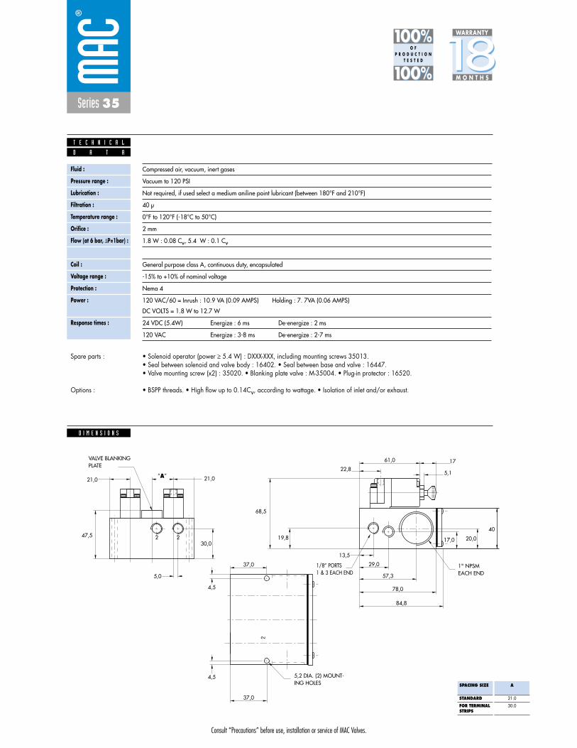
Consult “Precautions” before use, installation or service of MAC Valves.
Series 35
Fluid :
Pressure range :
Lubrication :
Filtration :
Temperature range :
Orifice :
Flow (at 6 bar, �P=1bar) :
Leak rate :
Coil :
Voltage range :
Protection :
Power :
Response times :
Compressed air, vacuum, inert gases
Vacuum to 120 PSI
Not required, if used select a medium aniline point lubricant (between 180°F and 210°F)
40 μ
0°F to 120°F (-18°C to 50°C)
2 mm
1.8 W : 0.08 Cv, 5.4 W : 0.1 Cv
50 cm3/min
General purpose class A, continuous duty, encapsulated
-15% to +10% of nominal voltage
Nema 4
120 VAC/60 = Inrush : 10.9 VA (0.09 AMPS) Holding : 7. 7VA (0.06 AMPS)
DC VOLTS = 1.8 W to 12.7 W
24 VDC (5.4W) Energize : 6 ms De-energize : 2 ms
120 VAC Energize : 3-8 ms De-energize : 2-7 ms
D A T A
T E C H N I C A L
1818100%100%
100%100% M O N T H S
WARRANTY
O FP R O D U C T I O N
T E S T E D
• Solenoid operator (power � 5.4 W) : DXXX-XXX, including mounting screws 35013. • Seal between solenoid and valve body : 16402. • Seal between base and valve : 16447. • Valve mounting screw (x2) : 35020. • Blanking plate valve : M-35004. • Plug-in protector : 16520.
• BSPP threads. • High flow up to 0.14Cv, according to wattage. • Isolation of inlet and/or exhaust.
Spare parts :
Options :
D I M E N S I O N S
21,0
2
5,0
2
21,021,0
47,530,0
2
68,5
19,8 17,0 20,0
40
61,0
22,8
4,5
4,5
37,0
13,5
29,0
57,3
78,0
84,8
5,1
17
37,0
VALVE BLANKINGPLATE
5,2 DIA. (2) MOUNT-ING HOLES
1" NPSMEACH END
1/8” PORTS 1 & 3 EACH END
“A”
SPACING SIZE
STANDARD
FOR TERMINALSTRIPS
A
21.0
30.0

Consult “Precautions” before use, installation or service of MAC Valves.
Reset
Series 35
Function Port size Flow (Max) Circuit bar mounting
3/2 NO-NC 1/8” NPTF - #10-32 UNF 0.10Cvplug-in
with side Pr. Reg.
1. Balanced poppet, immune to variations ofpressure.
2. Short stroke with high flow.3. The patented solenoid develops high shifting
forces.4. Powerful return spring.5. Manual operator standard on all valves.6. Burn-out proof solenoid on AC service.
O P E R A T I O N A L B E N E F I T S
D i r e c t s o l e n o i d a n d s o l e n o i d p i l o t o p e r a t e d v a l v e s
H O W T O O R D E R
Valve less base
Valve less base w/ gage port
Universal valve
35A-B00-DXXJ-XFM
35A-F00-DXXJ-XFM
CYL
IN EXH
HOW TO ORDER VALVE FOR "PLUG-IN" CIRCUIT BAR
Voltage
AA 120/60, 110/50
AB 240/60, 220/50
AC 24/60, 24/50
FB 24VDC (1.8 W)
DA 24VDC (5.4 W)
DF 24VDC (12.7 W)
Manual operator
1 Non-locking Recessed
2 Locking Recessed
D XX J- X FM *SOLENOID OPERATOR ➤
Port size
1/8” NPTF
# 10-32 UNF
1/8” NPTF
# 10-32 UNF
1/8” NPTF
# 10-32 UNF
Spacingmm
21
21
30
30
40
40
Bottom cylinder ports
ECD35A-004A-A0-XX*
ECD35A-004B-A0-XX*
ECD35A-034A-C0-XX*
ECD35A-034B-C0-XX*
ECD35A-024A-A0-XX*
ECD35A-024B-A0-XX*
HOW TO ORDER "PLUG-IN" CIRCUIT BAR WITH PRESSURE REGULATORS (TO BE ORDERED SEPARATELY)* *
XX X
* A0 = without lightAA = with light (120V)AB = with light (240V)AD = with light (24V)C0 = terminal stripCA = terminal w/light (120V)CB = terminal w/light (240V)CD = terminal w/light (24V)
Number of stations (03=3 stations)* * Other options available. Consult factory.Note : clic for valves mounted on base at the factory, add - 9 to the model number.
clic for multi-pin connector (9, 15 or 25).minimum spacing for terminal strips is 30 mm.use 40 mm spacing for valves w/gage port.
** Pressure Regulators : 35A-00M (Adjusting knob)35A-00L (Slotted stem)35A-00U (Locking stem)
35A-xxx-DxxJ-xFM
ECD35A-xxxx-xx-xxOther Optionsxx
x Other Options
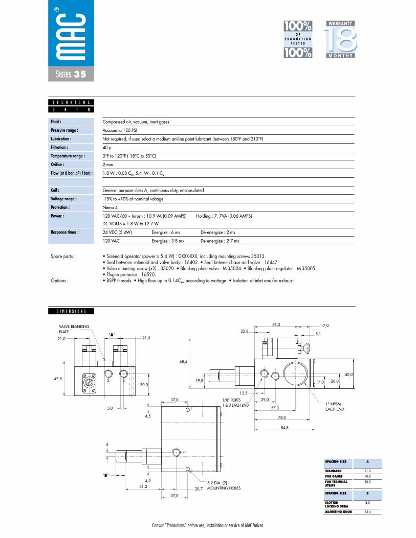
Series 35
Fluid :
Pressure range :
Lubrication :
Filtration :
Temperature range :
Orifice :
Flow (at 6 bar, �P=1bar) :
Leak rate :
Coil :
Voltage range :
Protection :
Power :
Response times :
Compressed air, vacuum, inert gases
Vacuum to 120 PSI
Not required, if used select a medium aniline point lubricant (between 180°F and 210°F)
40 μ
0°F to 120°F (-18°C to 50°C)
2 mm
1.8 W : 0.08 Cv, 5.4 W : 0.1 Cv
50 cm3/min
General purpose class A, continuous duty, encapsulated
-15% to +10% of nominal voltage
Nema 4
120 VAC/60 = Inrush : 10.9 VA (0.09 AMPS) Holding : 7. 7VA (0.06 AMPS)
DC VOLTS = 1.8 W to 12.7 W
24 VDC (5.4W) Energize : 6 ms De-energize : 2 ms
120 VAC Energize : 3-8 ms De-energize : 2-7 ms
D A T A
T E C H N I C A L
1818100%100%
100%100% M O N T H S
WARRANTY
O FP R O D U C T I O N
T E S T E D
• Solenoid operator (power � 5.4 W) : DXXX-XXX, including mounting screws 35013. • Seal between solenoid and valve body : 16402. • Seal between base and valve : 16447. • Valve mounting screw (x2) : 35020. • Blanking plate valve : M-35004. • Blanking plate regulator : M-35005.• Plug-in protector : 16520.• BSPP threads. • High flow up to 0.14Cv, according to wattage. • Isolation of inlet and/or exhaust.
Spare parts :
Options :
D I M E N S I O N S
2
5,0
2
21,021,0
21,0
47,530,0
2
68,5
19,8 17,0 20,0
40,0
61,0
22,8
4,5
4,5
5
13,4
51,0 20,7
37,0
13,5
29,0
57,3
78,0
84,8
5,1
17,0
37,0
VALVE BLANKINGPLATE
5,2 DIA. (2)MOUNTING HOLES
1" NPSMEACH END
1/8” PORTS 1 & 3 EACH END
“A”
“B”
SPACING SIZE
STANDARD
FOR GAGES
FOR TERMINALSTRIPS
A
21.0
40.0
30.0
SPACING SIZE
SLOTTEDLOCKING STEM
ADJUSTING KNOB
B
6.0
13.4
Consult “Precautions” before use, installation or service of MAC Valves.
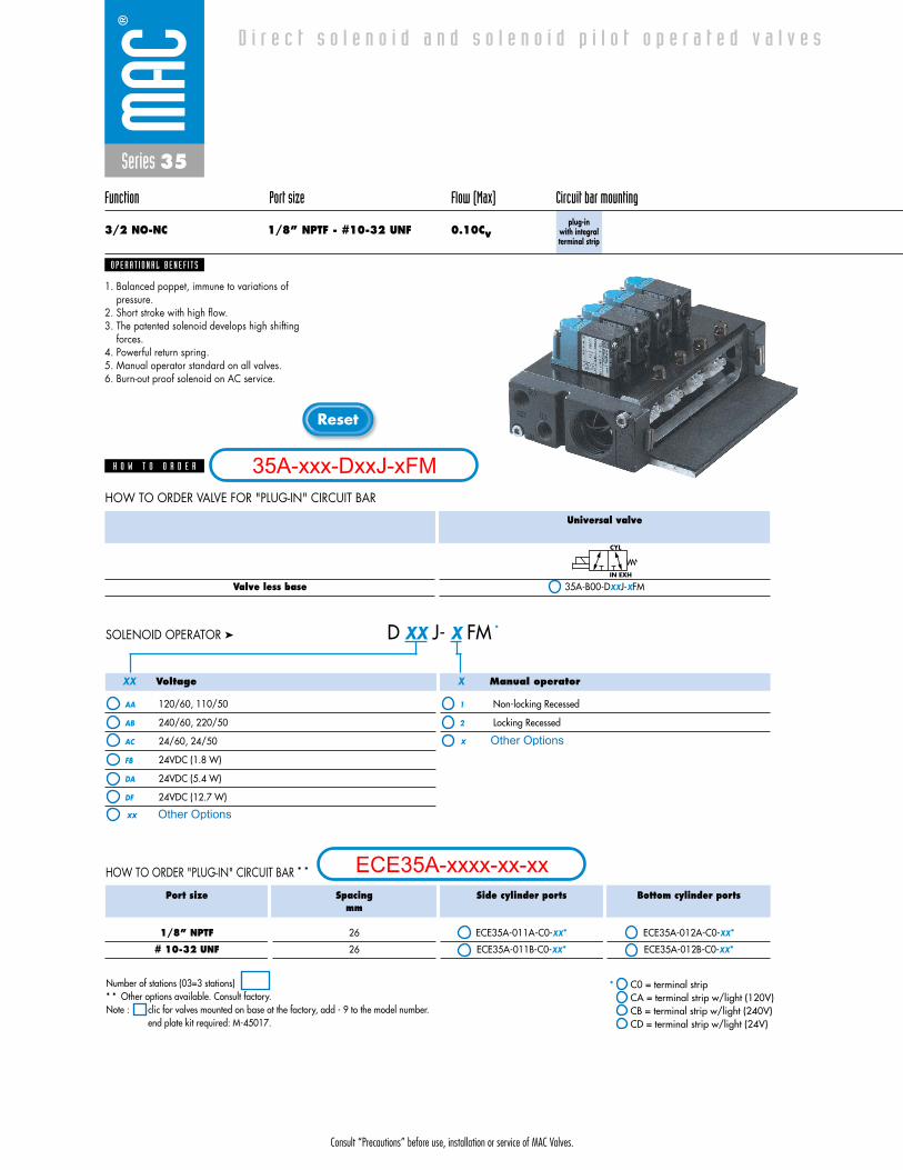
Consult “Precautions” before use, installation or service of MAC Valves.
Reset
Series 35
Function Port size Flow (Max) Circuit bar mounting
3/2 NO-NC 1/8” NPTF - #10-32 UNF 0.10Cvplug-in
with integral terminal strip
1. Balanced poppet, immune to variations ofpressure.
2. Short stroke with high flow.3. The patented solenoid develops high shifting
forces.4. Powerful return spring.5. Manual operator standard on all valves.6. Burn-out proof solenoid on AC service.
O P E R A T I O N A L B E N E F I T S
D i r e c t s o l e n o i d a n d s o l e n o i d p i l o t o p e r a t e d v a l v e s
H O W T O O R D E R
Valve less base
Universal valve
35A-B00-DXXJ-XFM
CYL
IN EXH
HOW TO ORDER VALVE FOR "PLUG-IN" CIRCUIT BAR
Voltage
AA 120/60, 110/50
AB 240/60, 220/50
AC 24/60, 24/50
FB 24VDC (1.8 W)
DA 24VDC (5.4 W)
DF 24VDC (12.7 W)
Manual operator
1 Non-locking Recessed
2 Locking Recessed
D XX J- X FM *SOLENOID OPERATOR ➤
Port size
1/8” NPTF
# 10-32 UNF
Spacingmm
26
26
Side cylinder ports
ECE35A-011A-C0-XX*
ECE35A-011B-C0-XX*
Bottom cylinder ports
ECE35A-012A-C0-XX*
ECE35A-012B-C0-XX*
HOW TO ORDER "PLUG-IN" CIRCUIT BAR * *
XXX
* C0 = terminal stripCA = terminal strip w/light (120V)CB = terminal strip w/light (240V)CD = terminal strip w/light (24V)
Number of stations (03=3 stations)* * Other options available. Consult factory.Note : clic for valves mounted on base at the factory, add - 9 to the model number.
end plate kit required: M-45017.
35A-xxx-DxxJ-xFM
ECE35A-xxxx-xx-xx
Other Optionsxx
x Other Options
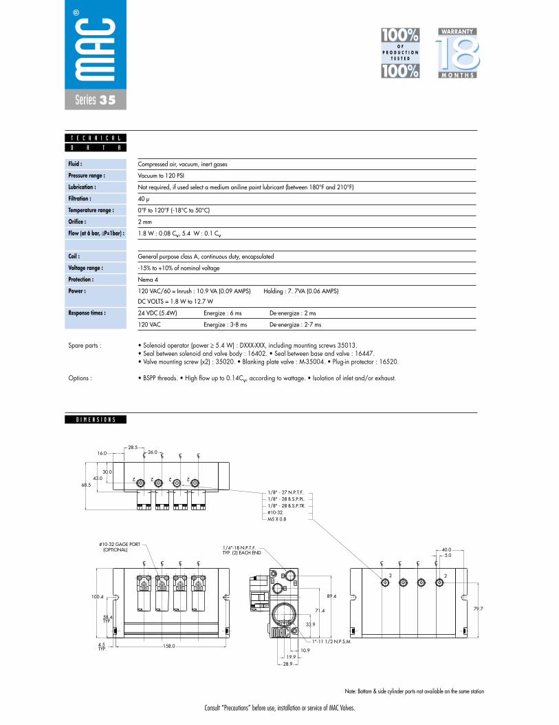
Consult “Precautions” before use, installation or service of MAC Valves.
Series 35
D I M E N S I O N S
Fluid :
Pressure range :
Lubrication :
Filtration :
Temperature range :
Orifice :
Flow (at 6 bar, �P=1bar) :
Leak rate :
Coil :
Voltage range :
Protection :
Power :
Response times :
Compressed air, vacuum, inert gases
Vacuum to 120 PSI
Not required, if used select a medium aniline point lubricant (between 180°F and 210°F)
40 μ
0°F to 120°F (-18°C to 50°C)
2 mm
1.8 W : 0.08 Cv, 5.4 W : 0.1 Cv
50 cm3/min
General purpose class A, continuous duty, encapsulated
-15% to +10% of nominal voltage
Nema 4
120 VAC/60 = Inrush : 10.9 VA (0.09 AMPS) Holding : 7. 7VA (0.06 AMPS)
DC VOLTS = 1.8 W to 12.7 W
24 VDC (5.4W) Energize : 6 ms De-energize : 2 ms
120 VAC Energize : 3-8 ms De-energize : 2-7 ms
D A T A
T E C H N I C A L
1818100%100%
100%100% M O N T H S
WARRANTY
O FP R O D U C T I O N
T E S T E D
• Solenoid operator (power � 5.4 W) : DXXX-XXX, including mounting screws 35013. • Seal between solenoid and valve body : 16402. • Seal between base and valve : 16447. • Valve mounting screw (x2) : 35020. • Blanking plate valve : M-35004. • Plug-in protector : 16520.
• BSPP threads. • High flow up to 0.14Cv, according to wattage. • Isolation of inlet and/or exhaust.
Spare parts :
Options :
LCLC
LCLC
M5 X 0.8#10-321/8" - 28 B.S.P.TR.1/8" - 28 B.S.P.PL.1/8" - 27 N.P.T.F.
79.7
5.040.0
30.0
2 2
2222
158.0
28.919.9
10.9
100.4
26.028.5
16.0
ININ EX
EX
G
TYP. (2) EACH END1/4"-18 N.P.T.F.
1"-11 1/2 N.P.S.M.
(OPTIONAL)#10-32 GAGE PORT
CLCL CL
CLCL
CLCLCL
MODEL
68.543.0
TYP.58.4
TYP.4.5
33.9
71.4
89.4
Note: Bottom & side cylinder ports not available on the same station
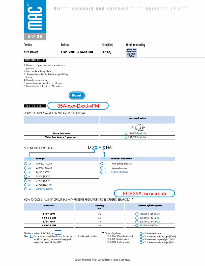
Consult “Precautions” before use, installation or service of MAC Valves.
Reset
Series 35
Function Port size Flow (Max) Circuit bar mounting
3/2 NO-NC 1/8” NPTF - #10-32 UNF 0.10Cvplug-in with
integral terminalstrip and side
Pr. Reg.
1. Balanced poppet, immune to variations ofpressure.
2. Short stroke with high flow.3. The patented solenoid develops high shifting
forces.4. Powerful return spring.5. Manual operator standard on all valves.6. Burn-out proof solenoid on AC service.
O P E R A T I O N A L B E N E F I T S
D i r e c t s o l e n o i d a n d s o l e n o i d p i l o t o p e r a t e d v a l v e s
H O W T O O R D E R
Valve less base
Valve less base w/ gage port
Universal valve
35A-B00-DXXJ-XFM
35A-F00-DXXJ-XFM
CYL
IN EXH
HOW TO ORDER VALVE FOR "PLUG-IN" CIRCUIT BAR
Voltage
AA 120/60, 110/50
AB 240/60, 220/50
AC 24/60, 24/50
FB 24VDC (1.8 W)
DA 24VDC (5.4 W)
DF 24VDC (12.7 W)
Manual operator
1 Non-locking Recessed
2 Locking Recessed
D XX J- X FM *SOLENOID OPERATOR ➤
HOW TO ORDER "PLUG-IN" CIRCUIT BAR WITH PRESSURE REGULATORS (TO BE ORDERED SEPARATELY)* *
XXX
Port size
1/8” NPTF
# 10-32 UNF
1/8” NPTF
# 10-32 UNF
Spacingmm
26
26
40
40
Bottom cylinder ports
ECE35A-014A-C0-XX*
ECE35A-014B-C0-XX*
ECE35A-024A-C0-XX*
ECE35A-024B-C0-XX*
* C0 = terminal stripCA = terminal strip w/light (120V)CB = terminal strip w/light (240V)CD = terminal strip w/light (24V)
Number of stations (03=3 stations)Note : clic for valves mounted on base at the factory, add - 9 to the model number.
use 40 mm spacing for valves w/ gage port.end plate kit required: M-45017.
** Pressure Regulators : 35A-00M (Adjusting knob)35A-00L (Slotted stem)35A-00U (Locking stem)
35A-xxx-DxxJ-xFM
ECE35A-xxxx-xx-xxOther Optionsxx
x Other Options
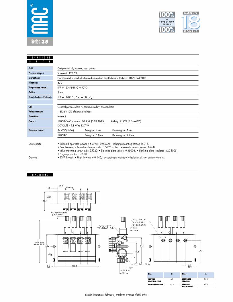
Consult “Precautions” before use, installation or service of MAC Valves.
Series 35
D I M E N S I O N S
Fluid :
Pressure range :
Lubrication :
Filtration :
Temperature range :
Orifice :
Flow (at 6 bar, �P=1bar) :
Leak rate :
Coil :
Voltage range :
Protection :
Power :
Response times :
Compressed air, vacuum, inert gases
Vacuum to 120 PSI
Not required, if used select a medium aniline point lubricant (between 180°F and 210°F)
40 μ
0°F to 120°F (-18°C to 50°C)
2 mm
1.8 W : 0.08 Cv, 5.4 W : 0.1 Cv
50 cm3/min
General purpose class A, continuous duty, encapsulated
-15% to +10% of nominal voltage
Nema 4
120 VAC/60 = Inrush : 10.9 VA (0.09 AMPS) Holding : 7. 7VA (0.06 AMPS)
DC VOLTS = 1.8 W to 12.7 W
24 VDC (5.4W) Energize : 6 ms De-energize : 2 ms
120 VAC Energize : 3-8 ms De-energize : 2-7 ms
D A T A
T E C H N I C A L
1818100%100%
100%100% M O N T H S
WARRANTY
O FP R O D U C T I O N
T E S T E D
• Solenoid operator (power � 5.4 W) : DXXX-XXX, including mounting screws 35013. • Seal between solenoid and valve body : 16402. • Seal between base and valve : 16447. • Valve mounting screw (x2) : 35020. • Blanking plate valve : M-35004. • Blanking plate regulator : M-35005.• Plug-in protector : 16520.• BSPP threads. • High flow up to 0.14Cv, according to wattage. • Isolation of inlet and/or exhaust.
Spare parts :
Options :
LCLC
LCLC
M5 X 0.8#10-321/8" - 28 B.S.P.TR.1/8" - 28 B.S.P.PL.1/8" - 27 N.P.T.F.
79.7
5.040.0
2 2
158.0
28.919.9
10.9
REGULATORWITH SIDE 151.4
100.4
A28.5
16.0
IN
IN EX
EX
G
TYP. (2) EACH END1/4"-18 N.P.T.F.
1"-11 1/2 N.P.S.M.
(OPTIONAL)#10-32 GAGE PORT
CLCL CL
CLCL
CLCLCL
MODEL
68.5
43.0
TYP.58.4
TYP.4.5
33.9
71.4
89.4
L O C K L O C K L O C K L O C K
LCLC
B
CL CL
Dim.
STANDARDSPACING
SPACINGFOR GAUGES
A
26.0
40.0
Dim.
SLOTTEDLOCKING STEM
ADJUSTABLE KNOB
B
6.0
13.4

Consult “Precautions” before use, installation or service of MAC Valves.
S e c t i o n 2 Opt ions

Consult “Precautions”before use, installation or service of MAC Valves.
O P T I O N S
O p t i o n s
Codification table for voltages / Wire length / Manual operators / Electrical connections
- Solenoid valves 35 & 45 Series
- D XX X - X XX1 2 3 4
VALVE CODE ➤
OPTIONS AVAILABLE FOR
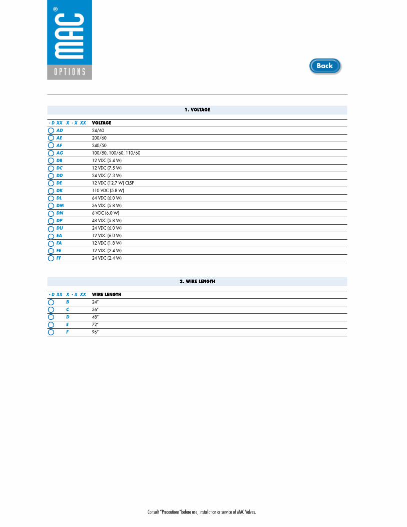
Consult “Precautions”before use, installation or service of MAC Valves.
O P T I O N S
1. VOLTAGE
- D XX X - X XX VOLTAGE
AD 24/60
AE 200/60
AF 240/50
AG 100/50, 100/60, 110/60
DB 12 VDC (5.4 W)
DC 12 VDC (7.5 W)
DD 24 VDC (7.3 W)
DE 12 VDC (12.7 W) CLSF
DK 110 VDC (5.8 W)
DL 64 VDC (6.0 W)
DM 36 VDC (5.8 W)
DN 6 VDC (6.0 W)
DP 48 VDC (5.8 W)
DU 24 VDC (6.0 W)
EA 12 VDC (6.0 W)
FA 12 VDC (1.8 W)
FE 12 VDC (2.4 W)
FF 24 VDC (2.4 W)
2. WIRE LENGTH
- D XX X - X XX WIRE LENGTH
B 24”
C 36”
D 48”
E 72”
F 96”
Back

Consult “Precautions”before use, installation or service of MAC Valves.
O P T I O N S
O p t i o n s
3. MANUAL OPERATOR
- D XX X - X XX MANUAL OPERATOR
0 No operator
1 Non-locking recessed
2 Locking recessed
3 Non-locking extended
4 Locking extended
4. ELECTRICAL CONNECTION
- D XX X - X XX ELECTRICAL CONNECTION
BA Flying leads
BK BA with protection diode
BL BA with protection varistor
CA 1/2" NPS conduit
*FN Plug-in with diode
*FP Plug-in with M.O.V.
JB Rectangular connector
JD Rectangular connector with light
JM Rectangular connector, male only
KA Square connector
KB Square connector with protection diode
KC Square connector with protection varistor
KD Square connector with light
KE Square connector with light and protection diode
KF Square connector with light and protection varistor
KJ Square connector (male only)
KK Square connector with protection diode (male only)
KL Square connector with protection varistor (male only)
TA Dual tabs
TB TA with protection diode
TD TA with light
TE TA with light and protection diode
TJ Dual tabs (male only)
TK TJ with protection diode
TM TJ with light
TN TJ with light and protection diode
* For use with the ECD and ECE style circuit bars.
Back

• Type «SUB_D»• Number of contacts : 9• Solder termination (Dia. 0.6 mm/0.14 mm
2/26-22 AWG)
• Operating current 5 A/contact• Rated voltage 125 V~• Temp. range –40° to +125°C• Insulation resistance � 5.09 �• Protection class IP40 (DIN 40050)• Number of solenoids : 7 max.• Max. 24 V=/5.4 W per solenoid• 2 common wires
MOD. SD09
MOD. SD15
MOD. SD25
PIN #1
PIN #5
PIN #6
PIN #9
PIN #1
PIN #8
PIN #9
PIN #15
PIN #1
PIN #13
PIN #14
PIN #25
• Type «SUB_D»• Number of contacts : 25• Solder termination (Dia. 0.6 mm/0.14 mm
2/26-22 AWG)
• Operating current 5 A/contact• Rated voltage 125 V~• Temp. range –40° to +125°C• Insulation resistance � 5.09 �• Protection class IP40 (DIN 40050)• Number of solenoids : 20 max.• Max. 24 V=/5.4 W per solenoid• 5 common wires
Note : Use desired MOD. number after circuit bar part number
• Type «SUB_D»• Number of contacts : 15• Solder termination (Dia. 0.6 mm/0.14 mm
2/26-22 AWG)
• Operating current 5 A/contact• Rated voltage 125 V~• Temp. range –40° to +125°C• Insulation resistance � 5.09 �• Protection class IP40 (DIN 40050)• Number of solenoids : 12 max.• Max. 24 V=/5.4 W per solenoid• 3 common wires
T E C H N I C A L D A T A
T E C H N I C A L D A T A
T E C H N I C A L D A T A
O P T I O N S
O p t i o n s

SD09 SD15 SD25
Connector termination details
SOL 2 SOL 4 SOL 6 SOL 8 SOL 16 SOL 18 SOL 20 SOL 22 SOL 24
SOL 1CONN
ECTO
RCO
NNEC
TOR
SOL 2 SOL 3 SOL .. SOL 20 SOL 21 SOL 22 SOL 23 SOL 24
SOL 1 SOL 3 SOL 5 SOL 13 SOL 15 SOL 17
Double solenoid circuit bar
Single solenoid circuit bar
SOL 21 SOL 23SOL 19
SOL. 3
SOL. 1
SOL. 2
1
2
3
4
COMMON (+)
COMMON (+)
8
SOL. 4
5
6
7
9
SOL. 5
SOL. 7
SOL. 6
SOL. 3
SOL. 1
SOL. 2
1
2
3
4
COMMON (+)
COMMON (+)
COMMON (+)
13
SOL. 4
5
6
7
8
14
SOL. 5
SOL. 7
SOL. 6
SOL. 8
9
10
11
12
15
SOL. 9
SOL. 11
SOL. 10
SOL. 12
SOL. 3
SOL. 1
SOL. 2
1
2
3
4
COMMON (+)
COMMON (+)
COMMON (+)
COMMON (+)
COMMON (+)
21
SOL. 4
5
6
7
8
22
SOL. 5
SOL. 7
SOL. 6
SOL. 8
9
10
11
12
23
SOL. 9
SOL. 11
SOL. 10
SOL. 12
13
14
15
16
24
SOL. 13
SOL. 15
SOL. 14
SOL. 16
17
18
19
20
25
SOL. 17
SOL. 19
SOL. 18
SOL. 20
O P T I O N S
O p t i o n s
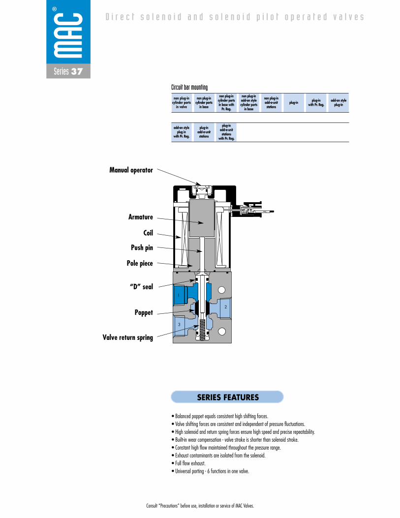
Consult “Precautions” before use, installation or service of MAC Valves.
Series 37
D i r e c t s o l e n o i d a n d s o l e n o i d p i l o t o p e r a t e d v a l v e s
1
3
2
non plug-incylinder ports
in valve
non plug-incylinder ports
in base
non plug-incylinder ports in base with
Pr. Reg.
non plug-in add-on style cylinder ports
in base
non plug-in add-a-unitstations
plug-in plug-inwith Pr. Reg.
add-on styleplug-in
Circuit bar mounting
add-on styleplug in
with Pr. Reg.
plug-inadd-a-unitstations
plug-inadd-a-unitstations
with Pr. Reg.
SERIES FEATURES
• Balanced poppet equals consistent high shifting forces.• Valve shifting forces are consistent and independent of pressure fluctuations.• High solenoid and return spring forces ensure high speed and precise repeatability.• Built-in wear compensation - valve stroke is shorter than solenoid stroke.• Constant high flow maintained throughout the pressure range.• Exhaust contaminants are isolated from the solenoid.• Full flow exhaust.• Universal porting - 6 functions in one valve.
Push pin
Manual operator
Armature
Coil
“D” seal
Poppet
Valve return spring
Pole piece

Consult “Precautions” before use, installation or service of MAC Valves.
Reset
Series 37
Function Port size (Inlet & Exhaust) Flow (Max) Circuit bar mounting Profile
3/2 NO-NC 1/4” - 3/8” 0.5Cv26 mm38 mm
non plug-incylinder ports
in valve
1. Direct solenoid operated valve.2. Balanced poppet, immune to variations of
pressure.3. Short stroke with high flow.4. The patented solenoid develops high shifting
forces.5. Powerful return spring.6. Manual operator standard on all valves.
O P E R A T I O N A L B E N E F I T S
D i r e c t s o l e n o i d a n d s o l e n o i d p i l o t o p e r a t e d v a l v e s
H O W T O O R D E R
Port sizeCOMMON INLET & EXHAUST
26mm Profile 1/4” NPTF
38mm Profile 3/8” NPTF
Without regulators (20mm)
EBM37A-01CAK-XX
-
With regulators (20mm)
-
EBM37A-01JAK-XX
Voltage
DC 24VDC (1.8 W)
DB 24VDC (2.4 W)
DA 24VDC (5.2 W)
AA 120VAC (must use with
rectified connector)
Wire length
A 18”
C 36”
Manual operator
1 Non-locking
Electrical connection
MA Plug-in wire assy
MC Plug-in wire assy
with light
BA Flying leads
BC Flying leads with light
HA Plug-in connector with
rectifier and light
H XX X- X XX *SOLENOID OPERATOR ➤
HOW TO ORDER CIRCUIT BAR (REGULATORS ORDERED SEPARATELY)**
XX X X XX
Valve port size
1/8” NPTF
1/4” NPTF
Universal valve
37A-EGO-HXXX-XXX
37A-EHO-HXXX-XXX
NC only valve
37A-FGO-HXXX-XXX
37A-FHO-HXXX-XXX
2
1 3
2
1 3
HOW TO ORDER VALVE FOR CIRCUIT BAR MOUNTING
** Pressure Regulators :
X=A (0 to 120 PSI)X=B (0 to 80 PSI)X=C (0 to 30 PSI)
Number of stations (03=3 stations)Note : clic for valves mounted on base at the factory, add - 9 to the model number.
37A-xxx-Hxxx-xxx
EBM37A-xxxxx-xx
Other Optionsxx
x Other Options
xx Other Options
PR37A-GOAx

Consult “Precautions” before use, installation or service of MAC Valves.
Series 37
D I M E N S I O N S
Fluid :
Pressure range :
Lubrication :
Filtration :
Temperature range :
Orifice :
Flow (at 6 bar, �P=1bar) :
Leak rate :
Coil :
Voltage range :
Power :
Response times :
(with 5.2 W coil)
Compressed air, vacuum, inert gases
Vacuum to 120 PSI
Not required, if used select a medium aniline point lubricant (between 180°F and 210°F)
40 μ
0°F to 120°F (-18°C to 50°C)
4.3 mm
5.2 W : 0.50Cv, 2.4 W : 0.25Cv, 1.8 W : 0.15Cv
50 cm3/min
General purpose class A, continuous duty, encapsulated
-15% to +10% of nominal voltage
5.2 W - 2.4 W - 1.8 W - 1.0 W
Energize : 17.0 ms
De-energize : 6.0 ms
10
12
13
7.0
21.5
24.5
109.9
63.0
B
29.2
12
10
12
10
12
10
A
97.5
25.0 20.5
TYP.
D A T A
T E C H N I C A L
1818100%100%
100%100% M O N T H S
WARRANTY
O FP R O D U C T I O N
T E S T E D
• Valve and coil are not interchangeable.
• Seal between valve and bar : 16630. • Mounting screw (x2) : 35043. • Blanking plate : M-37002.• Regulator blanking plate : R-47003.• Isolation of inlet and/or exhaust. Special bar. Consult factory. • BSPP Threads.
Note :
Spare parts :
Options :
Dim.
“A”
“B”
26 mm
26.0
75.1
38 mm
38.0
87.1

Consult “Precautions” before use, installation or service of MAC Valves.
Reset
Series 37
Function Port size Flow (Max) Circuit bar mounting Profile
3/2 NO-NC 1/8” - 1/4” 0.5Cv6 mm tube receptacle
non plug-incylinder ports
in base
1. Direct solenoid operated valve.2. Balanced poppet, immune to variations of
pressure.3. Short stroke with high flow.4. The patented solenoid develops high shifting
forces.5. Powerful return spring.6. Manual operator standard on all valves.
O P E R A T I O N A L B E N E F I T S
D i r e c t s o l e n o i d a n d s o l e n o i d p i l o t o p e r a t e d v a l v e s
H O W T O O R D E R
Port size(see base)
Valve less base
Universal valve
37A-C10-HXXX-XXX
NC only valve
37A-D10-HXXX-XXX
2
1 3
2
1 3
HOW TO ORDER VALVE FOR CIRCUIT BAR MOUNTING
Voltage
DC 24VDC (1.8 W)
DB 24VDC (2.4 W)
DA 24VDC (5.2 W)
AA 120VAC (must use with
rectified connector)
Wire length
A 18”
C 36”
Manual operator
1 Non-locking
Electrical connection
MA Plug-in wire assy
MC Plug-in wire assy
with light
BA Flying leads
BC Flying leads with light
HA Plug-in connector with
rectifier and light
H XX X- X XX *SOLENOID OPERATOR ➤
HOW TO ORDER CIRCUIT BAR
XX X X XX
26 mm
Port size
1/8” NPTF
1/4” NPTF
6 mm tube receptacle
Side cylinder ports (18 mm)
EBM37A-00AAA-XX
EBM37A-00AAB-XX
EBM37A-00AAG-XX
Bottom cylinder ports (18 mm)
EBM37A-00BAA-XX
EBM37A-00BAB-XX
EBM37A-00BAG-XX
Number of stations (03=3 stations)Note : clic for valves mounted on base at the factory, add - 9 to the model number.
37A-xxx-Hxxx-xxx
EBM37A-00xxx-xx
Other Optionsxx
x Other Options
xx Other Options
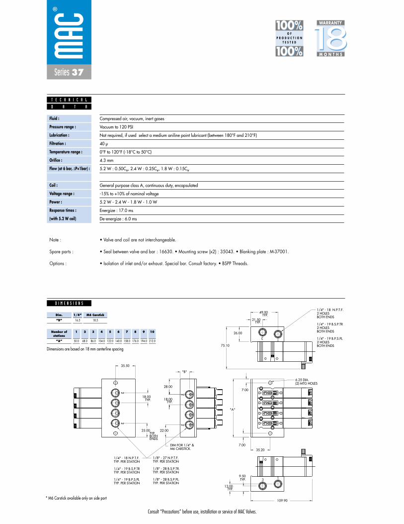
Consult “Precautions” before use, installation or service of MAC Valves.
Series 37
D I M E N S I O N S
Fluid :
Pressure range :
Lubrication :
Filtration :
Temperature range :
Orifice :
Flow (at 6 bar, �P=1bar) :
Leak rate :
Coil :
Voltage range :
Power :
Response times :
(with 5.2 W coil)
Compressed air, vacuum, inert gases
Vacuum to 120 PSI
Not required, if used select a medium aniline point lubricant (between 180°F and 210°F)
40 μ
0°F to 120°F (-18°C to 50°C)
4.3 mm
5.2 W : 0.50Cv, 2.4 W : 0.25Cv, 1.8 W : 0.15Cv
50 cm3/min
General purpose class A, continuous duty, encapsulated
-15% to +10% of nominal voltage
5.2 W - 2.4 W - 1.8 W - 1.0 W
Energize : 17.0 ms
De-energize : 6.0 ms
13
3 1
22
22
7.00
(2) MTG HOLES6.25 DIA.
7.0035.20
"A"
BOTH ENDS2 HOLES1/4" - 19 B.P.S.PL
BOTH ENDS2 HOLES1/4" - 19 B.S.P.TR
BOTH ENDS2 HOLES 1/4" - 18 N.P.T.F.
109.90
12
10
12
10
12
10
12
10
"B"
18.00
TYP. PER STATION1/8" - 28 B.S.P.PL.
TYP. PER STATION1/8" - 28 B.S.P.TR.
TYP. PER STATION 1/8" - 27 N.P.T.F.
TYP. PER STATION1/4" - 19 B.P.S.PL
TYP. PER STATION 1/4" - 19 B.S.P.TR
TYP. PER STATION1/4" - 18 N.P.T.F.
21.50
49.00
26.00
9.50
13.00TYP.
TYP.
TYP.
TYP.
28.00
18.00TYP.
22.00
75.10
TYP.
M6 CARSTICK.DIM FOR 1/4" &
25.00
ENDSBOTHTYP.
35.50
D A T A
T E C H N I C A L
1818100%100%
100%100% M O N T H S
WARRANTY
O FP R O D U C T I O N
T E S T E D
• Valve and coil are not interchangeable.
• Seal between valve and bar : 16630. • Mounting screw (x2) : 35043. • Blanking plate : M-37001.
• Isolation of inlet and/or exhaust. Special bar. Consult factory. • BSPP Threads.
Note :
Spare parts :
Options :
Number ofstations
“A”
1
50.0
2
68.0
3
86.0
4
104.0
5
122.0
6
140.0
7
158.0
8
176.0
9
194.0
10
212.0
Dim.
“B”
1/4”
16.5
M6 Carstick
18.5
Dimensions are based on 18 mm centerline spacing
* M6 Carstick available only on side port
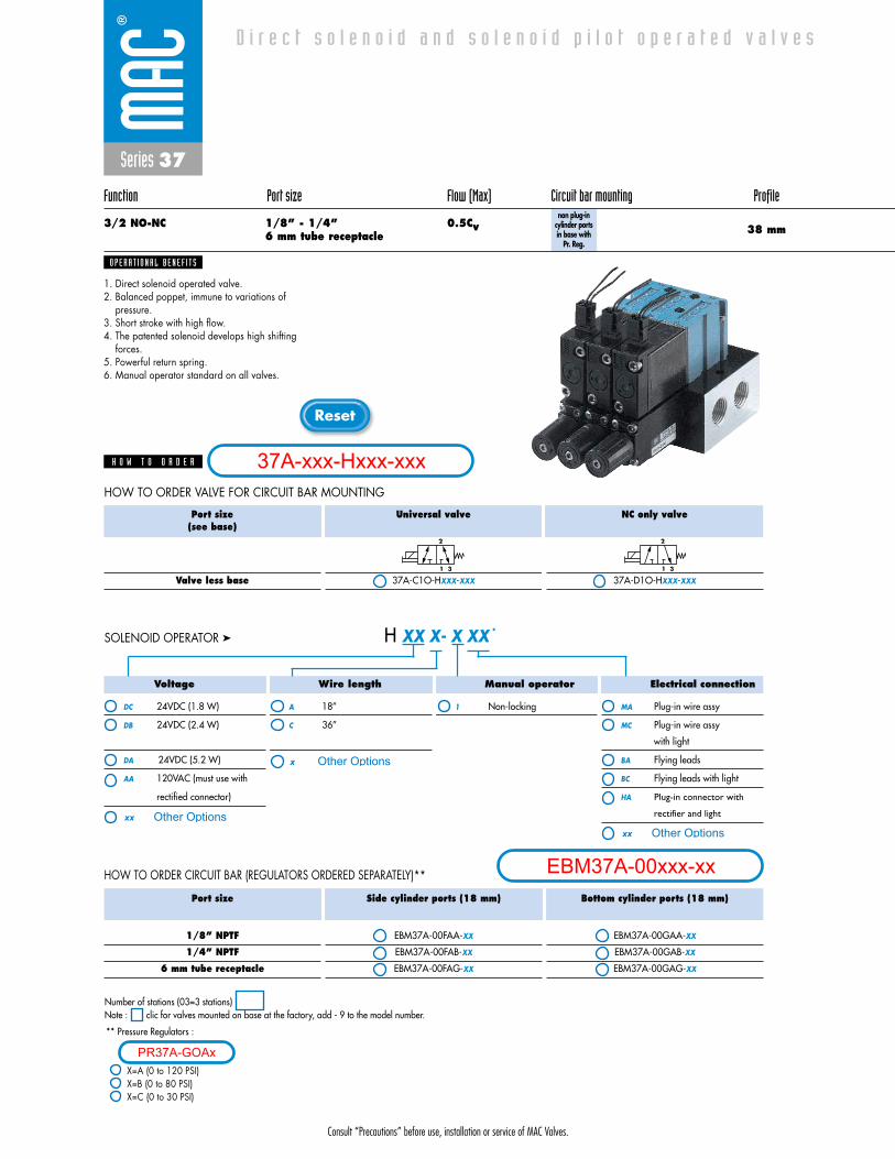
Consult “Precautions” before use, installation or service of MAC Valves.
Reset
Series 37
Function Port size Flow (Max) Circuit bar mounting Profile
3/2 NO-NC 1/8” - 1/4” 0.5Cv6 mm tube receptacle
non plug-incylinder ports in base with
Pr. Reg.
1. Direct solenoid operated valve.2. Balanced poppet, immune to variations of
pressure.3. Short stroke with high flow.4. The patented solenoid develops high shifting
forces.5. Powerful return spring.6. Manual operator standard on all valves.
O P E R A T I O N A L B E N E F I T S
D i r e c t s o l e n o i d a n d s o l e n o i d p i l o t o p e r a t e d v a l v e s
H O W T O O R D E R
Port size(see base)
Valve less base
Universal valve
37A-C1O-HXXX-XXX
NC only valve
37A-D1O-HXXX-XXX
2
1 3
2
1 3
HOW TO ORDER CIRCUIT BAR (REGULATORS ORDERED SEPARATELY)**
HOW TO ORDER VALVE FOR CIRCUIT BAR MOUNTING
38 mm
Voltage
DC 24VDC (1.8 W)
DB 24VDC (2.4 W)
DA 24VDC (5.2 W)
AA 120VAC (must use with
rectified connector)
Wire length
A 18”
C 36”
Manual operator
1 Non-locking
Electrical connection
MA Plug-in wire assy
MC Plug-in wire assy
with light
BA Flying leads
BC Flying leads with light
HA Plug-in connector with
rectifier and light
H XX X- X XX *SOLENOID OPERATOR ➤
Port size
1/8” NPTF
1/4” NPTF
6 mm tube receptacle
Side cylinder ports (18 mm)
EBM37A-00FAA-XX
EBM37A-00FAB-XX
EBM37A-00FAG-XX
Bottom cylinder ports (18 mm)
EBM37A-00GAA-XX
EBM37A-00GAB-XX
EBM37A-00GAG-XX
** Pressure Regulators :
X=A (0 to 120 PSI)X=B (0 to 80 PSI)X=C (0 to 30 PSI)
Number of stations (03=3 stations)Note : clic for valves mounted on base at the factory, add - 9 to the model number.
37A-xxx-Hxxx-xxx
EBM37A-00xxx-xx
Other Optionsxx
x Other Options
xx Other Options
PR37A-GOAx
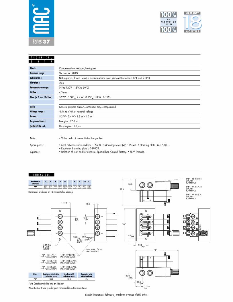
Consult “Precautions” before use, installation or service of MAC Valves.
Series 37
D I M E N S I O N S
Fluid :
Pressure range :
Lubrication :
Filtration :
Temperature range :
Orifice :
Flow (at 6 bar, �P=1bar) :
Leak rate :
Coil :
Voltage range :
Power :
Response times :
(with 5.2 W coil)
Compressed air, vacuum, inert gases
Vacuum to 120 PSI
Not required, if used select a medium aniline point lubricant (between 180°F and 210°F)
40 μ
0°F to 120°F (-18°C to 50°C)
4.3 mm
5.2 W : 0.50Cv, 2.4 W : 0.25Cv, 1.8 W : 0.15Cv
50 cm3/min
General purpose class A, continuous duty, encapsulated
-15% to +10% of nominal voltage
5.2 W - 2.4 W - 1.8 W - 1.0 W
Energize : 17.0 ms
De-energize : 6.0 ms
"E"
13
20.0
13
ENDSBOTHTYP ENDS
TYP BOTH
22
22
"A"
TYP
TYP
46.0
21.5
BOTH ENDS2 HOLES3/8" - 19 B.P.S.PL
BOTH ENDS2 HOLES3/8" - 19 B.S.P.TR
BOTH ENDS2 HOLES 3/8" - 18 N.P.T.F.
12
10
12
10
12
10
12
10
TYP.
18.0TYP.
25.0
10.0
TYP.
TYP.
33.8
7.0
87.6
38.0
18.0
25.0
TYP.
HOLES2 MTG.6.25 DIA.
TYP. PER STATION1/8" - 28 B.S.P.PL.
TYP. PER STATION1/8" - 28 B.S.P.TR.
TYP. PER STATION1/8" - 27 N.P.T.F.
TYP. PER STATION1/4" - 19 B.P.S.PL
TYP. PER STATION1/4" - 19 B.S.P.TR
TYP. PER STATION1/4" - 18 N.P.T.F.
GA
GE
33.8
M6 CARSTICKDIM. FOR 1/4" &
D A T A
T E C H N I C A L
1818100%100%
100%100% M O N T H S
WARRANTY
O FP R O D U C T I O N
T E S T E D
• Valve and coil are not interchangeable.
• Seal between valve and bar : 16630. • Mounting screw (x2) : 35043. • Blanking plate : M-37001.• Regulator blanking plate : R-47003.• Isolation of inlet and/or exhaust. Special bar. Consult factory. • BSPP Threads.
Note :
Spare parts :
Options :
Note: Bottom & side cylinder ports not available on the same station
Number ofstations
“A”
2
63.7
3
81.7
4
99.7
5
117.7
6
135.7
7
153.7
8
171.7
9
189.7
10
207.7
11
225.7
Dimensions are based on 18 mm centerline spacing
* M6 Carstick available only on side port
Dim.
“E”
Regulator with lockingadjusting screw
135.8
Regulator withadjusting screw
131.8
Regulator withadjusting knob
139.6

Consult “Precautions” before use, installation or service of MAC Valves.
Reset
Series 37
Function Port size Flow (Max) Circuit bar mounting Profile
3/2 NO-NC 1/8” - 1/4” 0.5Cv6 mm tube receptacle
non plug-in add-on style cylinder ports
in base
1. Direct solenoid operated valve.2. Balanced poppet, immune to variations of
pressure.3. Short stroke with high flow.4. The patented solenoid develops high shifting
forces.5. Powerful return spring.6. Manual operator standard on all valves.
O P E R A T I O N A L B E N E F I T S
D i r e c t s o l e n o i d a n d s o l e n o i d p i l o t o p e r a t e d v a l v e s
H O W T O O R D E R
Port size(see base)
Valve less base
Universal valve
37A-C1O-HXXX-XXX
NC only valve
37A-D1O-HXXX-XXX
2
1 3
2
1 3
HOW TO ORDER VALVE FOR CIRCUIT BAR MOUNTING
38 mm
HOW TO ORDER CIRCUIT BAR
Voltage
DC 24VDC (1.8 W)
DB 24VDC (2.4 W)
DA 24VDC (5.2 W)
AA 120VAC (must use with
rectified connector)
Wire length
A 18”
C 36”
Manual operator
1 Non-locking
Electrical connection
MA Plug-in wire assy
MC Plug-in wire assy
with light
BA Flying leads
BC Flying leads with light
HA Plug-in connector with
rectifier and light
H XX X- X XX *SOLENOID OPERATOR ➤
Port size
1/8” NPTF
1/4” NPTF
6 mm tube receptacle
Side cylinder ports (18 mm)
EBM37A-00DBA-XX
EBM37A-00DBB-XX
EBM37A-00DBG-XX
Bottom cylinder ports (18 mm)
EBM37A-00EBA-XX
EBM37A-00EBB-XX
EBM37A-00EBG-XX
Number of stations (03=3 stations)Note : clic for valves mounted on base at the factory, add - 9 to the model number.
add-a-unit stations may be added to above bars. Clic here for model numbers.
37A-xxx-Hxxx-xxx
EBM37A-00xxx-xx
Other Optionsxx
x Other Options
xx Other Options

Consult “Precautions” before use, installation or service of MAC Valves.
Series 37
D I M E N S I O N S
Fluid :
Pressure range :
Lubrication :
Filtration :
Temperature range :
Orifice :
Flow (at 6 bar, �P=1bar) :
Leak rate :
Coil :
Voltage range :
Power :
Response times :
(with 5.2 W coil)
Compressed air, vacuum, inert gases
Vacuum to 120 PSI
Not required, if used select a medium aniline point lubricant (between 180°F and 210°F)
40 μ
0°F to 120°F (-18°C to 50°C)
4.3 mm
5.2 W : 0.50Cv, 2.4 W : 0.25Cv, 1.8 W : 0.15Cv
50 cm3/min
General purpose class A, continuous duty, encapsulated
-15% to +10% of nominal voltage
5.2 W - 2.4 W - 1.8 W - 1.0 W
Energize : 17.0 ms
De-energize : 6.0 ms
TYP.7.0
33.8
21.7 18.0 25.0
38.0
25.0 18.0 21.7 26.8
10.0
87.6
24.5
21.5
63.0114.4
99.6
2 2 2
13
2 22
12
10
12
10
12
1010
12
D A T A
T E C H N I C A L
1818100%100%
100%100% M O N T H S
WARRANTY
O FP R O D U C T I O N
T E S T E D
• Valve and coil are not interchangeable.
• Seal between valve and bar : 16630. • Mounting screw (x2) : 35043. • Blanking plate : M-37001. • End plate Kit : M-37005-0
• Isolation of inlet and/or exhaust. Special bar. Consult factory. • BSPP Threads.
Note :
Spare parts :
Options :
Note: Bottom & side cylinder ports not available on the same station

Consult “Precautions” before use, installation or service of MAC Valves.
Reset
Series 37
Function Port size Flow (Max) Circuit bar mounting Profile
3/2 NO-NC 1/8” - 1/4” 0.5Cv6 mm tube receptacle
non plug-in add-a-unitstations
1. Direct solenoid operated valve.2. Balanced poppet, immune to variations of
pressure.3. Short stroke with high flow.4. The patented solenoid develops high shifting
forces.5. Powerful return spring.6. Manual operator standard on all valves.
O P E R A T I O N A L B E N E F I T S
D i r e c t s o l e n o i d a n d s o l e n o i d p i l o t o p e r a t e d v a l v e s
H O W T O O R D E R
Port size(see base)
Valve less base
Universal valve
37A-C1O-HXXX-XXX
NC only valve
37A-D1O-HXXX-XXX
2
1 3
2
1 3
HOW TO ORDER VALVE FOR CIRCUIT BAR MOUNTING
38 mm
HOW TO ORDER CIRCUIT BAR
Voltage
DC 24VDC (1.8 W)
DB 24VDC (2.4 W)
DA 24VDC (5.2 W)
AA 120VAC (must use with
rectified connector)
Wire length
A 18”
C 36”
Manual operator
1 Non-locking
Electrical connection
MA Plug-in wire assy
MC Plug-in wire assy
with light
BA Flying leads
BC Flying leads with light
HA Plug-in connector with
rectifier and light
H XX X- X XX *SOLENOID OPERATOR ➤
Port size
1/8” NPTF
1/4” NPTF
6 mm tube receptacle
Side cylinder ports (18 mm)
EBM37A-00DCA-XX
EBM37A-00DCB-XX
EBM37A-00DCG-XX
Bottom cylinder ports (18 mm)
EBM37A-00ECA-XX
EBM37A-00ECB-XX
EBM37A-00ECG-XX
Number of stations (01, 02, 03 or 04)Note : clic for valves mounted on base at the factory, add - 9 to the model number.
37A-xxx-Hxxx-xxx
EBM37A-00xxx-xx
Other Optionsxx
x Other Options
xx Other Options
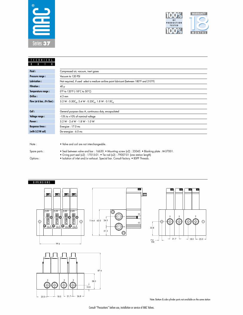
Consult “Precautions” before use, installation or service of MAC Valves.
Series 37
D I M E N S I O N S
Fluid :
Pressure range :
Lubrication :
Filtration :
Temperature range :
Orifice :
Flow (at 6 bar, �P=1bar) :
Leak rate :
Coil :
Voltage range :
Power :
Response times :
(with 5.2 W coil)
Compressed air, vacuum, inert gases
Vacuum to 120 PSI
Not required, if used select a medium aniline point lubricant (between 180°F and 210°F)
40 μ
0°F to 120°F (-18°C to 50°C)
4.3 mm
5.2 W : 0.50Cv, 2.4 W : 0.25Cv, 1.8 W : 0.15Cv
50 cm3/min
General purpose class A, continuous duty, encapsulated
-15% to +10% of nominal voltage
5.2 W - 2.4 W - 1.8 W - 1.0 W
Energize : 17.0 ms
De-energize : 6.0 ms
TYP.7.0
33.8
21.7 18.0 25.0
38.0
25.0 18.0 21.7 26.8
10.0
87.6
24.5
21.5
63.0114.4
99.6
2 2 2
13
2 22
12
10
12
10
12
1010
12
D A T A
T E C H N I C A L
1818100%100%
100%100% M O N T H S
WARRANTY
O FP R O D U C T I O N
T E S T E D
• Valve and coil are not interchangeable.
• Seal between valve and bar : 16630. • Mounting screw (x2) : 35043. • Blanking plate : M-37001.• O-ring port seal (x2) : 17015-01. • Tie rod (x2) : 79007-01 (one station length)• Isolation of inlet and/or exhaust. Special bar. Consult factory. • BSPP Threads.
Note :
Spare parts :
Options :
Note: Bottom & side cylinder ports not available on the same station
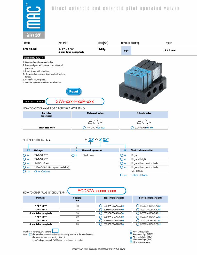
Consult “Precautions” before use, installation or service of MAC Valves.
Reset
Series 37
Function Port size Flow (Max) Circuit bar mounting Profile
3/2 NO-NC 1/8” - 1/4” 0.5Cv6 mm tube receptacle
plug-in
1. Direct solenoid operated valve.2. Balanced poppet, immune to variations of
pressure.3. Short stroke with high flow.4. The patented solenoid develops high shifting
forces.5. Powerful return spring.6. Manual operator standard on all valves.
O P E R A T I O N A L B E N E F I T S
D i r e c t s o l e n o i d a n d s o l e n o i d p i l o t o p e r a t e d v a l v e s
H O W T O O R D E R
Port size(see base)
Valve less base
Universal valve
37A-C1O-HXXP-XXX
NC only valve
37A-D1O-HXXP-XXX
2
1 3
2
1 3
HOW TO ORDER VALVE FOR CIRCUIT BAR MOUNTING
32.5 mm
HOW TO ORDER “PLUG-IN” CIRCUIT BAR**
Voltage
DC 24VDC (1.8 W)
DB 24VDC (2.4 W)
DA 24VDC (5.2 W)
AA 120VAC (Mod. No. required see below)
Manual operator
1 Non-locking
Electrical connection
FA Plug-in
FC Plug-in with light
FE Plug-in with suppression diode
FG Plug-in with suppression diode
with LED light
H XX P- X XX *SOLENOID OPERATOR ➤
XX X XX
Port size
1/8” NPTF
1/4” NPTF
6 mm tube receptacle
1/8” NPTF
1/4” NPTF
6 mm tube receptacle
Spacingmm
18
18
18
30
30
30
Side cylinder ports
ECD37A-00AAA-A0XX
ECD37A-00AAB-A0XX
ECD37A-00AAG-A0XX
ECD37A-01AAA-C0XX
ECD37A-01AAB-C0XX
ECD37A-01AAG-C0XX
Bottom cylinder ports
ECD37A-00BAA-A0XX
ECD37A-00BAB-A0XX
ECD37A-00BAG-A0XX
ECD37A-01BAA-C0XX
ECD37A-01BAB-C0XX
ECD37A-01BAG-C0XX
A0 = without lightAA = with light (120V)AB = with light (240V)AD = with light (24V)C0 = terminal strip
Number of stations (03=3 stations)Note : clic for valves mounted on base at the factory, add - 9 to the model number.
clic for multi-pin connector (9, 15 or 25).for AC voltage use mod. FWR2 after circuit bar model number.
37A-xxx-HxxP-xxx
ECD37A-xxxxx-xxxx
Other Optionsxx
xx Other Options
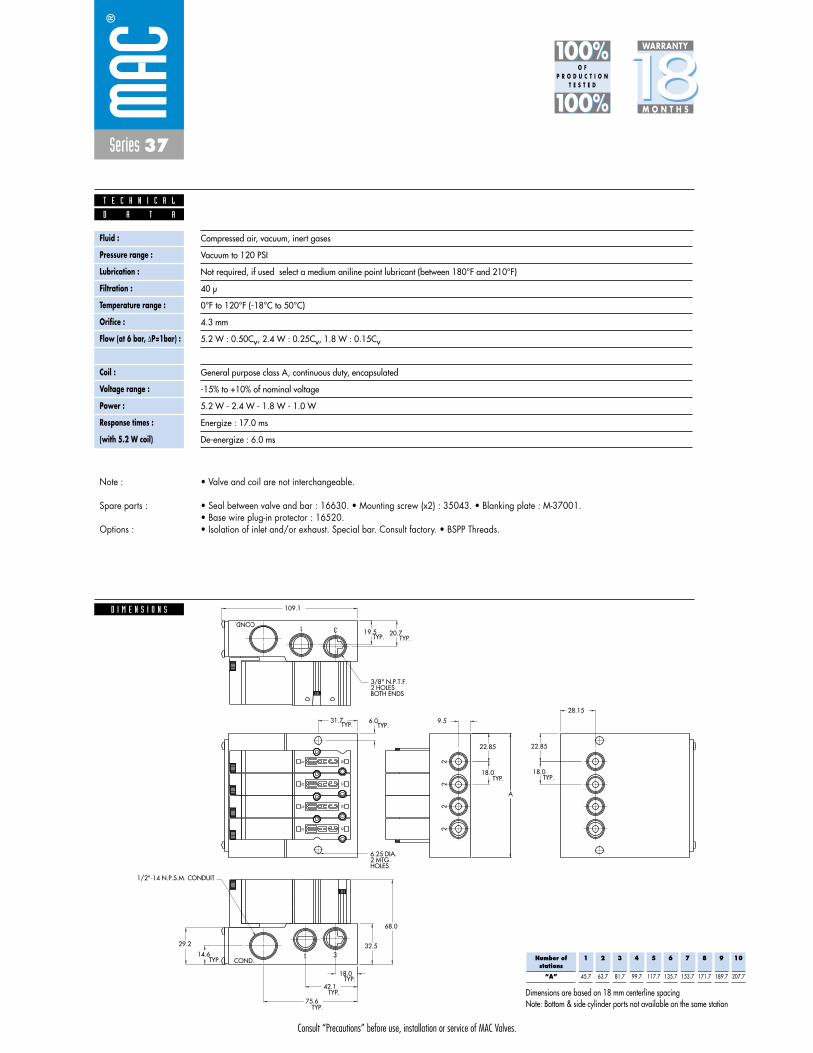
Consult “Precautions” before use, installation or service of MAC Valves.
Series 37
D I M E N S I O N S
Fluid :
Pressure range :
Lubrication :
Filtration :
Temperature range :
Orifice :
Flow (at 6 bar, �P=1bar) :
Leak rate :
Coil :
Voltage range :
Power :
Response times :
(with 5.2 W coil)
Compressed air, vacuum, inert gases
Vacuum to 120 PSI
Not required, if used select a medium aniline point lubricant (between 180°F and 210°F)
40 μ
0°F to 120°F (-18°C to 50°C)
4.3 mm
5.2 W : 0.50Cv, 2.4 W : 0.25Cv, 1.8 W : 0.15Cv
50 cm3/min
General purpose class A, continuous duty, encapsulated
-15% to +10% of nominal voltage
5.2 W - 2.4 W - 1.8 W - 1.0 W
Energize : 17.0 ms
De-energize : 6.0 ms
1/2"-14 N.P.S.M. CONDUIT
28.15
TYP.18.0
22.85
A
9.5
TYP.18.0
22.85
HOLES2 MTG.6.25 DIA.
BOTH ENDS2 HOLES3/8" N.P.T.F.
TYP.
TYP.
TYP.
75.6
42.1
18.0
TYP.
68.0
32.529.2
14.6
TYP.TYP. 6.031.7
TYP.TYP.19.5 20.7
109.1
12
10
12
10
12
10
12
10
1
1 3
3
2
COND.
COND.
22
2
D A T A
T E C H N I C A L
1818100%100%
100%100% M O N T H S
WARRANTY
O FP R O D U C T I O N
T E S T E D
• Valve and coil are not interchangeable.
• Seal between valve and bar : 16630. • Mounting screw (x2) : 35043. • Blanking plate : M-37001.• Base wire plug-in protector : 16520.• Isolation of inlet and/or exhaust. Special bar. Consult factory. • BSPP Threads.
Note :
Spare parts :
Options :
Note: Bottom & side cylinder ports not available on the same station
Number ofstations
“A”
1
45.7
2
63.7
3
81.7
4
99.7
5
117.7
6
135.7
7
153.7
8
171.7
9
189.7
10
207.7
Dimensions are based on 18 mm centerline spacing

Consult “Precautions” before use, installation or service of MAC Valves.
Reset
Series 37
Function Port size Flow (Max) Circuit bar mounting Profile
3/2 NO-NC 1/8” - 1/4” 0.5Cvplug-in
with Pr. Reg.
1. Direct solenoid operated valve.2. Balanced poppet, immune to variations of
pressure.3. Short stroke with high flow.4. The patented solenoid develops high shifting
forces.5. Powerful return spring.6. Manual operator standard on all valves.
O P E R A T I O N A L B E N E F I T S
D i r e c t s o l e n o i d a n d s o l e n o i d p i l o t o p e r a t e d v a l v e s
H O W T O O R D E R
Port size(see base)
Valve less base
Universal valve
37A-C1O-HXXP-XXX
NC only valve
37A-D1O-HXXP-XXX
2
1 3
2
1 3
HOW TO ORDER VALVE FOR CIRCUIT BAR MOUNTING
44 mm
Voltage
DC 24VDC (1.8 W)
DB 24VDC (2.4 W)
DA 24VDC (5.2 W)
AA 120VAC (Mod. No. required see below)
Manual operator
1 Non-locking
Electrical connection
FA Plug-in
FC Plug-in with light
FE Plug-in with suppression diode
FG Plug-in with suppression diode
with LED light
H XX P- X XX *SOLENOID OPERATOR ➤
XX X XX
HOW TO ORDER “PLUG-IN” CIRCUIT BAR (REGULATORS ORDERED SEPARATELY)**
Port size
1/8” NPTF
1/4” NPTF
1/8” NPTF
1/4” NPTF
Spacing mm
18
18
30
30
Bottom cylinder ports
ECD37A-00CDA-A0XX
ECD37A-00CDB-A0XX
ECD37A-01CDA-C0XX
ECD37A-01CDB-C0XX
** Pressure Regulators :
X=A (0 to 120 PSI)X=B (0 to 80 PSI)X=C (0 to 30 PSI)
A0 = without lightAA = with light (120V)AB = with light (240V)AD = with light (24V)C0 = terminal stripCA = terminal strip with light (120V)CB = terminal strip with light (240V)CD = terminal strip with light (24V)
Number of stations (03=3 stations)** Other options available, consult factory.Note : clic for valves mounted on base at the factory, add - 9 to the model number.
clic for multi-pin connector (9, 15 or 25).for AC voltage use mod. FWR2 after circuit bar model number.
37A-xxx-HxxP-xxx
ECD37A-xxxxx-xxxx
Other Optionsxx
xx Other Options
PR37A-GOAx

Series 37
D I M E N S I O N S
Fluid :
Pressure range :
Lubrication :
Filtration :
Temperature range :
Orifice :
Flow (at 6 bar, �P=1bar) :
Leak rate :
Coil :
Voltage range :
Power :
Response times :
(with 5.2 W coil)
Compressed air, vacuum, inert gases
Vacuum to 120 PSI
Not required, if used select a medium aniline point lubricant (between 180°F and 210°F)
40 μ
0°F to 120°F (-18°C to 50°C)
4.3 mm
5.2 W : 0.50Cv, 2.4 W : 0.25Cv, 1.8 W : 0.15Cv
50 cm3/min
General purpose class A, continuous duty, encapsulated
-15% to +10% of nominal voltage
5.2 W - 2.4 W - 1.8 W - 1.0 W
Energize : 17.0 ms
De-energize : 6.0 ms
116.1
HOLES2 MTG.6.25 DIA.
TYP.TYP.19.2 23.2
TYP.18.0
22.85
33.55
TYP.18.0
A
TYP.TYP. 6.0
33.0
TYP.
TYP.
TYP.
40.7
20.35
44.0
18.5
48.6
87.1
COND. 1 3
31COND.
22
12
10
12
10
12
10
12
10
9.5
B
C
BOTH ENDS3 HOLES3/8" N.P.T.F.
CONDUIT1"- 11 1/2 N.P.S.M.
REGULATORSHOWN W\ SANDWICH
REGULATORSHOWN W\ STANDARD
D
D A T A
T E C H N I C A L
1818100%100%
100%100% M O N T H S
WARRANTY
O FP R O D U C T I O N
T E S T E D
• Valve and coil are not interchangeable.
• Seal between valve and bar : 16630. • Mounting screw (x2) : 35043. • Blanking plate : M-37001.• Base wire plug-in protector : 16520. • Regulator blanking plate : R-47003.• Isolation of inlet and/or exhaust. Special bar. Consult factory. • BSPP Threads.
Note :
Spare parts :
Options :
Number ofstations
“C”
1
45.7
2
63.7
3
81.7
4
99.7
5
117.7
6
135.7
7
153.7
8
171.7
9
189.7
10
207.7
Dimensions are based on 18 mm centerline spacing
Dim.
“A”
1/4”
25.85
1/8”
25.85
6 mm Legris
22.85
Dim.
“B”
“D”
Regulator with lockingadjusting screw
188.8
182.5
Regulator withadjusting screw
184.7
178.4
Regulator withadjusting knob
191.7
185.4 Note: Bottom & side cylinder ports not available on the same station
Consult “Precautions” before use, installation or service of MAC Valves.

Consult “Precautions” before use, installation or service of MAC Valves.
Reset
Series 37
Function Port size Flow (Max) Circuit bar mounting Profile
3/2 NO-NC 1/8” - 1/4” 0.5Cv6 mm tube receptacle
add-on styleplug-in
1. Direct solenoid operated valve.2. Balanced poppet, immune to variations of
pressure.3. Short stroke with high flow.4. The patented solenoid develops high shifting
forces.5. Powerful return spring.6. Manual operator standard on all valves.
O P E R A T I O N A L B E N E F I T S
D i r e c t s o l e n o i d a n d s o l e n o i d p i l o t o p e r a t e d v a l v e s
H O W T O O R D E R
Port size(see base)
Valve less base
Universal valve
37A-C1O-HXXP-XXX
NC only valve
37A-D1O-HXXP-XXX
2
1 3
2
1 3
HOW TO ORDER VALVE FOR CIRCUIT BAR MOUNTING
44 mm
HOW TO ORDER “PLUG-IN” CIRCUIT BAR**
Voltage
DC 24VDC (1.8 W)
DB 24VDC (2.4 W)
DA 24VDC (5.2 W)
AA 120VAC (Mod. No. required see below)
Manual operator
1 Non-locking
Electrical connection
FA Plug-in
FC Plug-in with light
FE Plug-in with suppression diode
FG Plug-in with suppression diode
with LED light
H XX P- X XX *SOLENOID OPERATOR ➤
XX X XX
Port size
1/8” NPTF
1/4” NPTF
6 mm tube receptacle
1/8” NPTF
1/4” NPTF
6 mm tube receptacle
Spacingmm
18
18
18
30
30
30
Side cylinder ports
ECD37A-00AEA-A0XX
ECD37A-00AEB-A0XX
ECD37A-00AEG-A0XX
ECD37A-01AEA-C0XX
ECD37A-01AEB-C0XX
ECD37A-01AEG-C0XX
Bottom cylinder ports
ECD37A-00BEA-A0XX
ECD37A-00BEB-A0XX
ECD37A-00BEG-A0XX
ECD37A-01BEA-C0XX
ECD37A-01BEB-C0XX
ECD37A-01BEG-C0XX
A0 = without lightAA = with light (120V)AB = with light (240V)AD = with light (24V)C0 = terminal stripCA = terminal strip with light (120V)CB = terminal strip with light (240V)CD = terminal strip with light (24V)
Number of stations (03=3 stations)** Other options available, consult factory.Note : clic for valves mounted on base at the factory, add - 9 to the model number.
clic for multi-pin connector (9, 15 or 25).for AC voltage use mod. FWR2 after circuit bar model number.add-a-unit stations may be added to above bars. Clic here for model numbers.
37A-xxx-HxxP-xxx
ECD37A-xxxxx-xxxx
Other Optionsxx
xx Other Options

Consult “Precautions” before use, installation or service of MAC Valves.
Series 37
D I M E N S I O N S
Fluid :
Pressure range :
Lubrication :
Filtration :
Temperature range :
Orifice :
Flow (at 6 bar, �P=1bar) :
Leak rate :
Coil :
Voltage range :
Power :
Response times :
(with 5.2 W coil)
Compressed air, vacuum, inert gases
Vacuum to 120 PSI
Not required, if used select a medium aniline point lubricant (between 180°F and 210°F)
40 μ
0°F to 120°F (-18°C to 50°C)
4.3 mm
5.2 W : 0.50Cv, 2.4 W : 0.25Cv, 1.8 W : 0.15Cv
50 cm3/min
General purpose class A, continuous duty, encapsulated
-15% to +10% of nominal voltage
5.2 W - 2.4 W - 1.8 W - 1.0 W
Energize : 17.0 ms
De-energize : 6.0 ms
10
12
10.85
10.85
A
9.533.55
B
87.1
48.618.5
40.720.3519.223.2
44.0
3 1 COND.
COND.13
2
2
12
10
2
12
102
2
D
C
79.2
117.3
TYP.
TYP.
TYP.TYP.
TYP. TYP.
TYP.TYP.
TYP.
TYP.
1"-11 1/2 N.P.S.M. CONDUIT
TYP.(2) BOTH ENDS3/8" N.PT.F.
16.0
33.06.0 6.25 DIA. HOLETYP.TYP.
TYP.(2)
D A T A
T E C H N I C A L
1818100%100%
100%100% M O N T H S
WARRANTY
O FP R O D U C T I O N
T E S T E D
• Valve and coil are not interchangeable.
• Seal between valve and bar : 16630. • Mounting screw (x2) : 35043. • Blanking plate : M-37001. • End plate kit : M-37003-01• Base wire plug-in protector : 16520. • Isolator disc between add-a-units : 28438.• Isolation of inlet and/or exhaust. Special bar. Consult factory. • BSPP Threads.
Note :
Spare parts :
Options :
Note: Bottom & side cylinder ports not available on the same station
Number ofstations
“C” w/regulator
“C” w/o regulator
“D”
1
-
-
21.7
2
53.6
51.85
39.7
3
71.6
69.85
57.7
4
89.6
87.85
75.7
5
107.6
105.85
-
6
125.6
123.85
-
7
143.6
141.85
-
8
161.6
159.85
-
9
179.6
177.85
-
10
197.6
195.85
-
Dimensions are based on 18 mm centerline spacing
Dim.
“A”
“B”
1/8”
22.65
22.85
1/4”
24.20
22.85
6 mm Legris
22.85
25.85
1/8” w/regulator
-
21.20
1/4” w/regulator
-
22.60
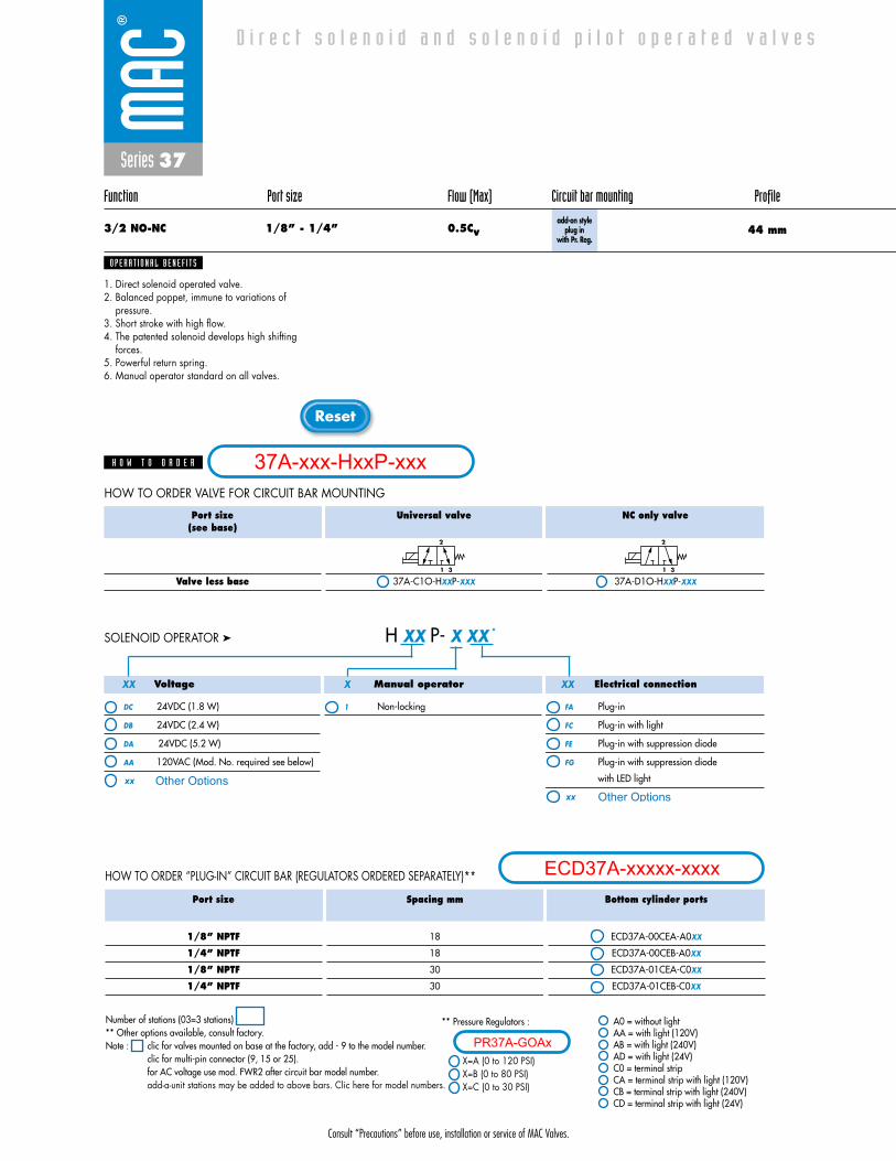
Consult “Precautions” before use, installation or service of MAC Valves.
Reset
Series 37
Function Port size Flow (Max) Circuit bar mounting Profile
3/2 NO-NC 1/8” - 1/4” 0.5Cvadd-on style
plug in with Pr. Reg.
1. Direct solenoid operated valve.2. Balanced poppet, immune to variations of
pressure.3. Short stroke with high flow.4. The patented solenoid develops high shifting
forces.5. Powerful return spring.6. Manual operator standard on all valves.
O P E R A T I O N A L B E N E F I T S
D i r e c t s o l e n o i d a n d s o l e n o i d p i l o t o p e r a t e d v a l v e s
H O W T O O R D E R
Port size(see base)
Valve less base
Universal valve
37A-C1O-HXXP-XXX
NC only valve
37A-D1O-HXXP-XXX
2
1 3
2
1 3
HOW TO ORDER VALVE FOR CIRCUIT BAR MOUNTING
44 mm
Voltage
DC 24VDC (1.8 W)
DB 24VDC (2.4 W)
DA 24VDC (5.2 W)
AA 120VAC (Mod. No. required see below)
Manual operator
1 Non-locking
Electrical connection
FA Plug-in
FC Plug-in with light
FE Plug-in with suppression diode
FG Plug-in with suppression diode
with LED light
H XX P- X XX *SOLENOID OPERATOR ➤
XX X XX
HOW TO ORDER “PLUG-IN” CIRCUIT BAR (REGULATORS ORDERED SEPARATELY)**
Port size
1/8” NPTF
1/4” NPTF
1/8” NPTF
1/4” NPTF
Spacing mm
18
18
30
30
Bottom cylinder ports
ECD37A-00CEA-A0XX
ECD37A-00CEB-A0XX
ECD37A-01CEA-C0XX
ECD37A-01CEB-C0XX
** Pressure Regulators :
X=A (0 to 120 PSI)X=B (0 to 80 PSI)X=C (0 to 30 PSI)
A0 = without lightAA = with light (120V)AB = with light (240V)AD = with light (24V)C0 = terminal stripCA = terminal strip with light (120V)CB = terminal strip with light (240V)CD = terminal strip with light (24V)
Number of stations (03=3 stations)** Other options available, consult factory.Note : clic for valves mounted on base at the factory, add - 9 to the model number.
clic for multi-pin connector (9, 15 or 25).for AC voltage use mod. FWR2 after circuit bar model number.add-a-unit stations may be added to above bars. Clic here for model numbers.
37A-xxx-HxxP-xxx
ECD37A-xxxxx-xxxx
Other Optionsxx
xx Other Options
PR37A-GOAx

Consult “Precautions” before use, installation or service of MAC Valves.
Series 37
D I M E N S I O N S
Fluid :
Pressure range :
Lubrication :
Filtration :
Temperature range :
Orifice :
Flow (at 6 bar, �P=1bar) :
Leak rate :
Coil :
Voltage range :
Power :
Response times :
(with 5.2 W coil)
Compressed air, vacuum, inert gases
Vacuum to 120 PSI
Not required, if used select a medium aniline point lubricant (between 180°F and 210°F)
40 μ
0°F to 120°F (-18°C to 50°C)
4.3 mm
5.2 W : 0.50Cv, 2.4 W : 0.25Cv, 1.8 W : 0.15Cv
50 cm3/min
General purpose class A, continuous duty, encapsulated
-15% to +10% of nominal voltage
5.2 W - 2.4 W - 1.8 W - 1.0 W
Energize : 17.0 ms
De-energize : 6.0 ms
D A T A
T E C H N I C A L
1818100%100%
100%100% M O N T H S
WARRANTY
O FP R O D U C T I O N
T E S T E D
• Valve and coil are not interchangeable.
• Seal between valve and bar : 16630. • Mounting screw (x2) : 35043. • Blanking plate : M-37001. • End plate kit : M-37003-01• Base wire plug-in protector : 16520. • Isolator disc between add-a-units : 28438.• Isolation of inlet and/or exhaust. Special bar. Consult factory. • BSPP Threads.
Note :
Spare parts :
Options :
10
12
103.0
10.85
10.85
A
9.533.55
B
87.1
48.618.5
40.720.3519.223.2
44.0
F
3 1 COND.
COND.13
2
2
12
10
2
12
102
2
D
C
E
79.2
117.3
TYP.
TYP.
TYP.TYP.
TYP. TYP.
TYP.TYP.
TYP.
TYP.
REGULATORSHOWN W/STANDARD
REGULATORSHOWN W/SANDWICH
1"-11 1/2 N.P.S.M. CONDUIT
TYP.(2) BOTH ENDS3/8" N.PT.F.
16.0
33.06.0 6.25 DIA. HOLETYP.TYP.
TYP.(2)
Note: Bottom & side cylinder ports not available on the same station
Number ofstations
“C” w/regulator
“C” w/o regulator
“D”
1
-
-
21.7
2
53.6
51.85
39.7
3
71.6
69.85
57.7
4
89.6
87.85
75.7
5
107.6
105.85
-
6
125.6
123.85
-
7
143.6
141.85
-
8
161.6
159.85
-
9
179.6
177.85
-
10
197.6
195.85
-
Dimensions are based on 18 mm centerline spacing
Dim.
“A”
“B”
1/8”
22.65
22.85
1/4”
24.20
22.85
6 mm Legris
22.85
25.85
1/8” w/regulator
-
21.20
1/4” w/regulator
-
22.60
Dim.
“E”
“F”
Regulator with lockingadjusting screw
188.8
182.5
Regulator withadjusting screw
184.7
178.4
Regulator withadjusting knob
191.7
185.4

Consult “Precautions” before use, installation or service of MAC Valves.
Reset
Series 37
Function Port size Flow (Max) Circuit bar mounting Profile
3/2 NO-NC 1/8” - 1/4” 0.5Cv6 mm tube receptacle
plug-inadd-a-unitstations
1. Direct solenoid operated valve.2. Balanced poppet, immune to variations of
pressure.3. Short stroke with high flow.4. The patented solenoid develops high shifting
forces.5. Powerful return spring.6. Manual operator standard on all valves.
O P E R A T I O N A L B E N E F I T S
D i r e c t s o l e n o i d a n d s o l e n o i d p i l o t o p e r a t e d v a l v e s
H O W T O O R D E R
Port size(see base)
Valve less base
Universal valve
37A-C1O-HXXP-XXX
NC only valve
37A-D1O-HXXP-XXX
2
1 3
2
1 3
HOW TO ORDER VALVE FOR CIRCUIT BAR MOUNTING
44 mm
HOW TO ORDER “PLUG-IN” CIRCUIT BAR**
Voltage
DC 24VDC (1.8 W)
DB 24VDC (2.4 W)
DA 24VDC (5.2 W)
AA 120VAC (Mod. No. required see below)
Manual operator
1 Non-locking
Electrical connection
FA Plug-in
FC Plug-in with light
FE Plug-in with suppression diode
FG Plug-in with suppression diode
with LED light
H XX P- X XX *SOLENOID OPERATOR ➤
XX X XX
Port size
1/8” NPTF
1/4” NPTF
6 mm tube receptacle
1/8” NPTF
1/4” NPTF
6 mm tube receptacle
Spacingmm
18
18
18
30
30
30
Side cylinder ports
ECD37A-00AFA-A0XX
ECD37A-00AFB-A0XX
ECD37A-00AFG-A0XX
ECD37A-01AFA-C0XX
ECD37A-01AFB-C0XX
ECD37A-01AFG-C0XX
Bottom cylinder ports
ECD37A-00BFA-A0XX
ECD37A-00BFB-A0XX
ECD37A-00BFG-A0XX
ECD37A-01BFA-C0XX
ECD37A-01BFB-C0XX
ECD37A-01BFG-C0XX
A0 = without lightAA = with light (120V)AB = with light (240V)AD = with light (24V)C0 = terminal stripCA = terminal strip with light (120V)CB = terminal strip with light (240V)CD = terminal strip with light (24V)
Number of stations (03=3 stations) - maximum length is 4 stations.** Other options available, consult factory.Note : clic for valves mounted on base at the factory, add - 9 to the model number.
for AC voltage use mod. FWR2 after circuit bar model number.when add-a-unit stations are added to bars with a multi-pin connector, mod SD03 should be included with add-a-unit model number.
37A-xxx-HxxP-xxx
ECD37A-xxxxx-xxxx
Other Optionsxx
xx Other Options
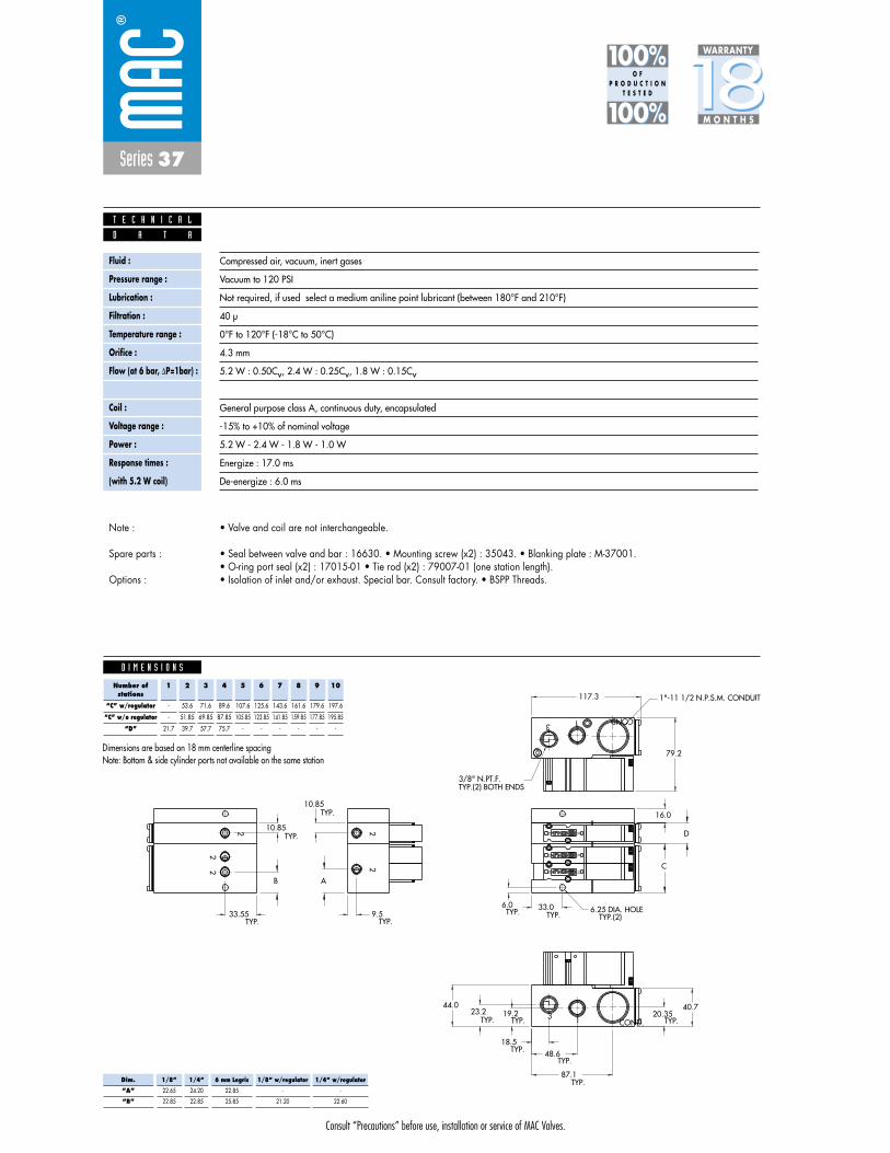
Consult “Precautions” before use, installation or service of MAC Valves.
Series 37
D I M E N S I O N S
Fluid :
Pressure range :
Lubrication :
Filtration :
Temperature range :
Orifice :
Flow (at 6 bar, �P=1bar) :
Leak rate :
Coil :
Voltage range :
Power :
Response times :
(with 5.2 W coil)
Compressed air, vacuum, inert gases
Vacuum to 120 PSI
Not required, if used select a medium aniline point lubricant (between 180°F and 210°F)
40 μ
0°F to 120°F (-18°C to 50°C)
4.3 mm
5.2 W : 0.50Cv, 2.4 W : 0.25Cv, 1.8 W : 0.15Cv
50 cm3/min
General purpose class A, continuous duty, encapsulated
-15% to +10% of nominal voltage
5.2 W - 2.4 W - 1.8 W - 1.0 W
Energize : 17.0 ms
De-energize : 6.0 ms
D A T A
T E C H N I C A L
1818100%100%
100%100% M O N T H S
WARRANTY
O FP R O D U C T I O N
T E S T E D
• Valve and coil are not interchangeable.
• Seal between valve and bar : 16630. • Mounting screw (x2) : 35043. • Blanking plate : M-37001.• O-ring port seal (x2) : 17015-01 • Tie rod (x2) : 79007-01 (one station length).• Isolation of inlet and/or exhaust. Special bar. Consult factory. • BSPP Threads.
Note :
Spare parts :
Options :
10
12
10.85
10.85
A
9.533.55
B
87.1
48.618.5
40.720.3519.223.2
44.0
3 1 COND.
COND.13
2
2
12
10
2
12
102
2
D
C
79.2
117.3
TYP.
TYP.
TYP.TYP.
TYP. TYP.
TYP.TYP.
TYP.
TYP.
1"-11 1/2 N.P.S.M. CONDUIT
TYP.(2) BOTH ENDS3/8" N.PT.F.
16.0
33.06.0 6.25 DIA. HOLETYP.TYP.
TYP.(2)
Note: Bottom & side cylinder ports not available on the same station
Number ofstations
“C” w/regulator
“C” w/o regulator
“D”
1
-
-
21.7
2
53.6
51.85
39.7
3
71.6
69.85
57.7
4
89.6
87.85
75.7
5
107.6
105.85
-
6
125.6
123.85
-
7
143.6
141.85
-
8
161.6
159.85
-
9
179.6
177.85
-
10
197.6
195.85
-
Dimensions are based on 18 mm centerline spacing
Dim.
“A”
“B”
1/8”
22.65
22.85
1/4”
24.20
22.85
6 mm Legris
22.85
25.85
1/8” w/regulator
-
21.20
1/4” w/regulator
-
22.60

Consult “Precautions” before use, installation or service of MAC Valves.
Reset
Series 37
Function Port size Flow (Max) Circuit bar mounting Profile
3/2 NO-NC 1/8” - 1/4” 0.5Cvplug-in
add-a-unitstations
with Pr. Reg.
1. Direct solenoid operated valve.2. Balanced poppet, immune to variations of
pressure.3. Short stroke with high flow.4. The patented solenoid develops high shifting
forces.5. Powerful return spring.6. Manual operator standard on all valves.
O P E R A T I O N A L B E N E F I T S
D i r e c t s o l e n o i d a n d s o l e n o i d p i l o t o p e r a t e d v a l v e s
H O W T O O R D E R
Port size(see base)
Valve less base
Universal valve
37A-C1O-HXXP-XXX
NC only valve
37A-D1O-HXXP-XXX
2
1 3
2
1 3
HOW TO ORDER VALVE FOR CIRCUIT BAR MOUNTING
44 mm
Voltage
DC 24VDC (1.8 W)
DB 24VDC (2.4 W)
DA 24VDC (5.2 W)
AA 120VAC (Mod. No. required see below)
Manual operator
1 Non-locking
Electrical connection
FA Plug-in
FC Plug-in with light
FE Plug-in with suppression diode
FG Plug-in with suppression diode
with LED light
H XX P- X XX *SOLENOID OPERATOR ➤
XX X XX
HOW TO ORDER “PLUG-IN” CIRCUIT BAR (REGULATORS ORDERED SEPARATELY)**
Port size
1/8” NPTF
1/4” NPTF
1/8” NPTF
1/4” NPTF
Spacing mm
18
18
30
30
Bottom cylinder ports
ECD37A-00CFA-A0XX
ECD37A-00CFB-A0XX
ECD37A-01CFA-C0XX
ECD37A-01CFB-C0XX
** Pressure Regulators :
X=A (0 to 120 PSI)X=B (0 to 80 PSI)X=C (0 to 30 PSI)
A0 = without lightAA = with light (120V)AB = with light (240V)AD = with light (24V)C0 = terminal stripCA = terminal strip with light (120V)CB = terminal strip with light (240V)CD = terminal strip with light (24V)
Number of stations (03=3 stations) - maximum length is 4 stations.** Other options available, consult factory.Note : clic for valves mounted on base at the factory, add - 9 to the model number.
for AC voltage use mod. FWR2 after circuit bar model number.when add-a-unit stations are added to bars with a multi-pin connector, mod SD03 should be included with add-a-unit model number.
37A-xxx-HxxP-xxx
ECD37A-xxxxx-xxxx
Other Optionsxx
xx Other Options
PR37A-GOAx

Consult “Precautions” before use, installation or service of MAC Valves.
Series 37
D I M E N S I O N S
Fluid :
Pressure range :
Lubrication :
Filtration :
Temperature range :
Orifice :
Flow (at 6 bar, �P=1bar) :
Leak rate :
Coil :
Voltage range :
Power :
Response times :
(with 5.2 W coil)
Compressed air, vacuum, inert gases
Vacuum to 120 PSI
Not required, if used select a medium aniline point lubricant (between 180°F and 210°F)
40 μ
0°F to 120°F (-18°C to 50°C)
4.3 mm
5.2 W : 0.50Cv, 2.4 W : 0.25Cv, 1.8 W : 0.15Cv
50 cm3/min
General purpose class A, continuous duty, encapsulated
-15% to +10% of nominal voltage
5.2 W - 2.4 W - 1.8 W - 1.0 W
Energize : 17.0 ms
De-energize : 6.0 ms
D A T A
T E C H N I C A L
1818100%100%
100%100% M O N T H S
WARRANTY
O FP R O D U C T I O N
T E S T E D
• Valve and coil are not interchangeable.
• Seal between valve and bar : 16630. • Mounting screw (x2) : 35043. • Blanking plate : M-37001.• O-ring port seal (x2) : 17015-01 • Tie rod (x2) : 79007-01 (one station length). • Regulator blanking plate : R-47003.• Isolation of inlet and/or exhaust. Special bar. Consult factory. • BSPP Threads.
Note :
Spare parts :
Options :
10
12
103.0
10.85
10.85
A
9.533.55
B
87.1
48.618.5
40.720.3519.223.2
44.0
F
3 1 COND.
COND.13
2
2
12
10
2
12
102
2
D
C
E
79.2
117.3
TYP.
TYP.
TYP.TYP.
TYP. TYP.
TYP.TYP.
TYP.
TYP.
REGULATORSHOWN W/STANDARD
REGULATORSHOWN W/SANDWICH
1"-11 1/2 N.P.S.M. CONDUIT
TYP.(2) BOTH ENDS3/8" N.PT.F.
16.0
33.06.0 6.25 DIA. HOLETYP.TYP.
TYP.(2)
Note: Bottom & side cylinder ports not available on the same station
Number ofstations
“C” w/regulator
“C” w/o regulator
“D”
1
-
-
21.7
2
53.6
51.85
39.7
3
71.6
69.85
57.7
4
89.6
87.85
75.7
5
107.6
105.85
-
6
125.6
123.85
-
7
143.6
141.85
-
8
161.6
159.85
-
9
179.6
177.85
-
10
197.6
195.85
-
Dimensions are based on 18 mm centerline spacing
Dim.
“A”
“B”
1/8”
22.65
22.85
1/4”
24.20
22.85
6 mm Legris
22.85
25.85
1/8” w/regulator
-
21.20
1/4” w/regulator
-
22.60
Dim.
“E”
“F”
Regulator with lockingadjusting screw
188.8
182.5
Regulator withadjusting screw
184.7
178.4
Regulator withadjusting knob
191.7
185.4

Consult “Precautions” before use, installation or service of MAC Valves.
S e c t i o n 2 Opt ions

Consult “Precautions”before use, installation or service of MAC Valves.
O P T I O N S
O p t i o n s
Codification table for voltages / Wire length / Manual operators / Electrical connections
- Solenoid valves 37 & 47 Series
- H XX X - X XX1 2 3 4
VALVE CODE ➤
OPTIONS AVAILABLE FOR
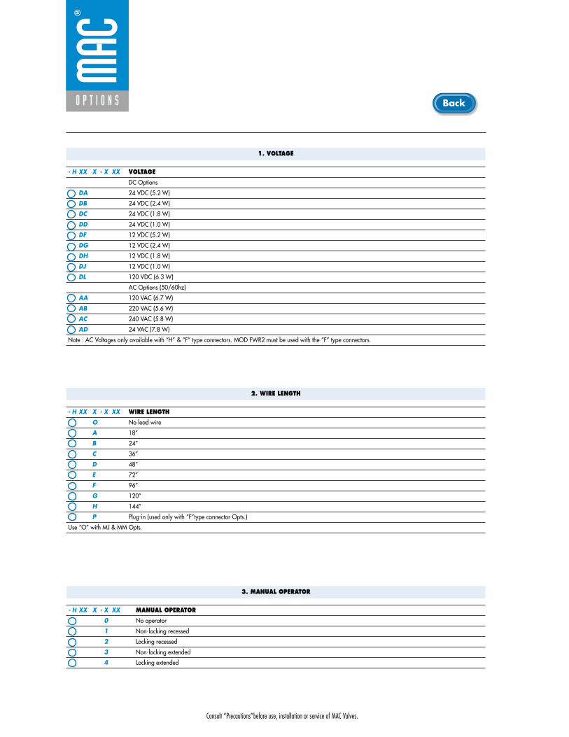
Consult “Precautions”before use, installation or service of MAC Valves.
O P T I O N S
1. VOLTAGE
- H XX X - X XX VOLTAGE
DC Options
DA 24 VDC (5.2 W)
DB 24 VDC (2.4 W)
DC 24 VDC (1.8 W)
DD 24 VDC (1.0 W)
DF 12 VDC (5.2 W)
DG 12 VDC (2.4 W)
DH 12 VDC (1.8 W)
DJ 12 VDC (1.0 W)
DL 120 VDC (6.3 W)
AC Options (50/60hz)
AA 120 VAC (6.7 W)
AB 220 VAC (5.6 W)
AC 240 VAC (5.8 W)
AD 24 VAC (7.8 W)
Note : AC Voltages only available with “H” & “F” type connectors. MOD FWR2 must be used with the “F” type connectors.
2. WIRE LENGTH
- H XX X - X XX WIRE LENGTH
O No lead wire
A 18”
B 24”
C 36”
D 48”
E 72”
F 96”
G 120”
H 144”
P Plug-in (used only with “F”type connector Opts.)
Use “O” with MJ & MM Opts.
3. MANUAL OPERATOR
- H XX X - X XX MANUAL OPERATOR
0 No operator
1 Non-locking recessed
2 Locking recessed
3 Non-locking extended
4 Locking extended
Back
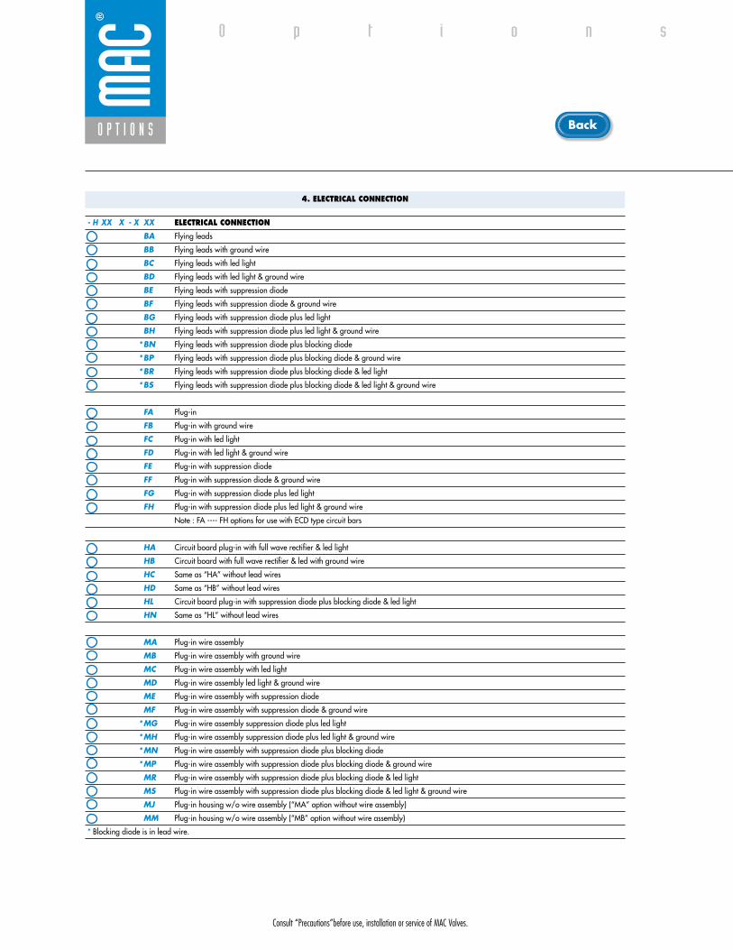
Consult “Precautions”before use, installation or service of MAC Valves.
O P T I O N S
O p t i o n s
4. ELECTRICAL CONNECTION
- H XX X - X XX ELECTRICAL CONNECTION
BA Flying leads
BB Flying leads with ground wire
BC Flying leads with led light
BD Flying leads with led light & ground wire
BE Flying leads with suppression diode
BF Flying leads with suppression diode & ground wire
BG Flying leads with suppression diode plus led light
BH Flying leads with suppression diode plus led light & ground wire
*BN Flying leads with suppression diode plus blocking diode
*BP Flying leads with suppression diode plus blocking diode & ground wire
*BR Flying leads with suppression diode plus blocking diode & led light
*BS Flying leads with suppression diode plus blocking diode & led light & ground wire
FA Plug-in
FB Plug-in with ground wire
FC Plug-in with led light
FD Plug-in with led light & ground wire
FE Plug-in with suppression diode
FF Plug-in with suppression diode & ground wire
FG Plug-in with suppression diode plus led light
FH Plug-in with suppression diode plus led light & ground wire
Note : FA ---- FH options for use with ECD type circuit bars
HA Circuit board plug-in with full wave rectifier & led light
HB Circuit board with full wave rectifier & led with ground wire
HC Same as “HA” without lead wires
HD Same as “HB” without lead wires
HL Circuit board plug-in with suppression diode plus blocking diode & led light
HN Same as “HL” without lead wires
MA Plug-in wire assembly
MB Plug-in wire assembly with ground wire
MC Plug-in wire assembly with led light
MD Plug-in wire assembly led light & ground wire
ME Plug-in wire assembly with suppression diode
MF Plug-in wire assembly with suppression diode & ground wire
*MG Plug-in wire assembly suppression diode plus led light
*MH Plug-in wire assembly suppression diode plus led light & ground wire
*MN Plug-in wire assembly with suppression diode plus blocking diode
*MP Plug-in wire assembly with suppression diode plus blocking diode & ground wire
MR Plug-in wire assembly with suppression diode plus blocking diode & led light
MS Plug-in wire assembly with suppression diode plus blocking diode & led light & ground wire
MJ Plug-in housing w/o wire assembly (“MA” option without wire assembly)
MM Plug-in housing w/o wire assembly (“MB” option without wire assembly)
* Blocking diode is in lead wire.
Back

• Type «SUB_D»• Number of contacts : 9• Solder termination (Dia. 0.6 mm/0.14 mm
2/26-22 AWG)
• Operating current 5 A/contact• Rated voltage 125 V~• Temp. range –40° to +125°C• Insulation resistance � 5.09 �• Protection class IP40 (DIN 40050)• Number of solenoids : 7 max.• Max. 24 V=/5.4 W per solenoid• 2 common wires
MOD. SD09
MOD. SD15
MOD. SD25
PIN #1
PIN #5
PIN #6
PIN #9
PIN #1
PIN #8
PIN #9
PIN #15
PIN #1
PIN #13
PIN #14
PIN #25
• Type «SUB_D»• Number of contacts : 25• Solder termination (Dia. 0.6 mm/0.14 mm
2/26-22 AWG)
• Operating current 5 A/contact• Rated voltage 125 V~• Temp. range –40° to +125°C• Insulation resistance � 5.09 �• Protection class IP40 (DIN 40050)• Number of solenoids : 20 max.• Max. 24 V=/5.4 W per solenoid• 5 common wires
Note : Use desired MOD. number after circuit bar part number
• Type «SUB_D»• Number of contacts : 15• Solder termination (Dia. 0.6 mm/0.14 mm
2/26-22 AWG)
• Operating current 5 A/contact• Rated voltage 125 V~• Temp. range –40° to +125°C• Insulation resistance � 5.09 �• Protection class IP40 (DIN 40050)• Number of solenoids : 12 max.• Max. 24 V=/5.4 W per solenoid• 3 common wires
T E C H N I C A L D A T A
T E C H N I C A L D A T A
T E C H N I C A L D A T A
O P T I O N S
O p t i o n s

SD09 SD15 SD25
Connector termination details
SOL 2 SOL 4 SOL 6 SOL 8 SOL 16 SOL 18 SOL 20 SOL 22 SOL 24
SOL 1CONN
ECTO
RCO
NNEC
TOR
SOL 2 SOL 3 SOL .. SOL 20 SOL 21 SOL 22 SOL 23 SOL 24
SOL 1 SOL 3 SOL 5 SOL 13 SOL 15 SOL 17
Double solenoid circuit bar
Single solenoid circuit bar
SOL 21 SOL 23SOL 19
SOL. 3
SOL. 1
SOL. 2
1
2
3
4
COMMON (+)
COMMON (+)
8
SOL. 4
5
6
7
9
SOL. 5
SOL. 7
SOL. 6
SOL. 3
SOL. 1
SOL. 2
1
2
3
4
COMMON (+)
COMMON (+)
COMMON (+)
13
SOL. 4
5
6
7
8
14
SOL. 5
SOL. 7
SOL. 6
SOL. 8
9
10
11
12
15
SOL. 9
SOL. 11
SOL. 10
SOL. 12
SOL. 3
SOL. 1
SOL. 2
1
2
3
4
COMMON (+)
COMMON (+)
COMMON (+)
COMMON (+)
COMMON (+)
21
SOL. 4
5
6
7
8
22
SOL. 5
SOL. 7
SOL. 6
SOL. 8
9
10
11
12
23
SOL. 9
SOL. 11
SOL. 10
SOL. 12
13
14
15
16
24
SOL. 13
SOL. 15
SOL. 14
SOL. 16
17
18
19
20
25
SOL. 17
SOL. 19
SOL. 18
SOL. 20
O P T I O N S
O p t i o n s
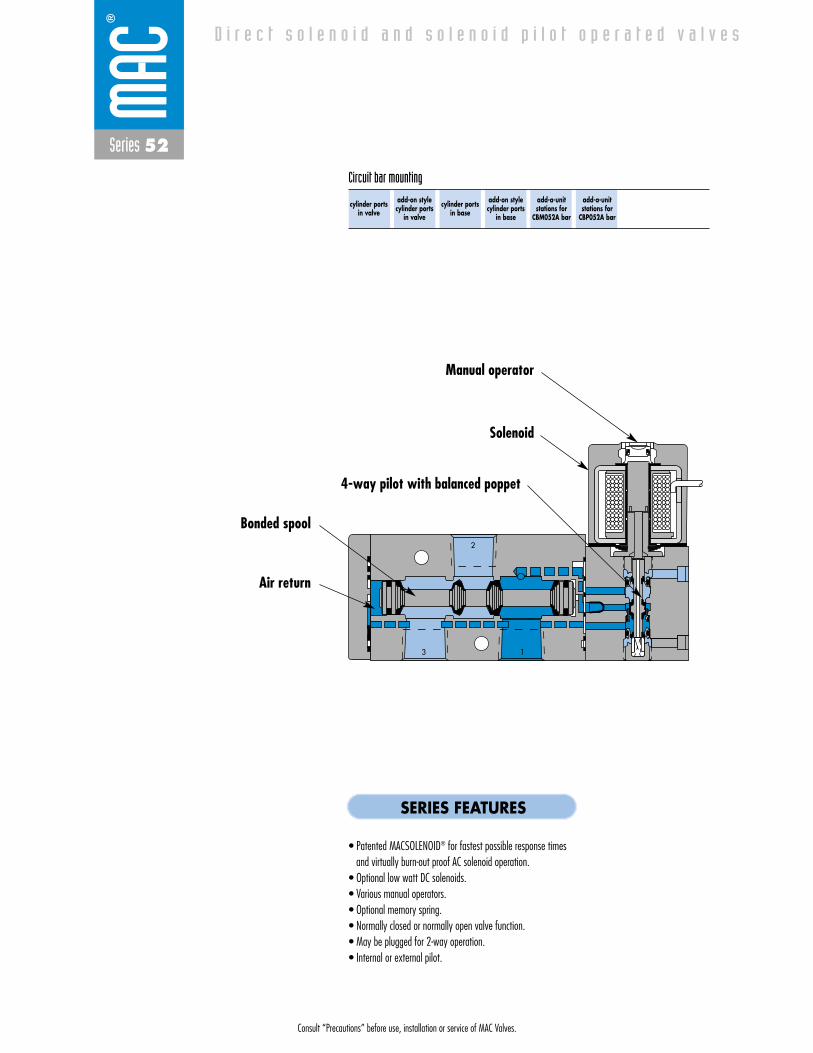
Consult “Precautions” before use, installation or service of MAC Valves.
Series 52
D i r e c t s o l e n o i d a n d s o l e n o i d p i l o t o p e r a t e d v a l v e s
2
13
cylinder portsin valve
add-on stylecylinder ports
in valve
cylinder portsin base
add-on stylecylinder ports
in base
add-a-unitstations for
CBM052A bar
add-a-unitstations for
CBP052A bar
Circuit bar mounting
SERIES FEATURES
• Patented MACSOLENOID® for fastest possible response timesand virtually burn-out proof AC solenoid operation.
• Optional low watt DC solenoids.• Various manual operators.• Optional memory spring.• Normally closed or normally open valve function.• May be plugged for 2-way operation.• Internal or external pilot.
Air return
Bonded spool
Manual operator
Solenoid
4-way pilot with balanced poppet
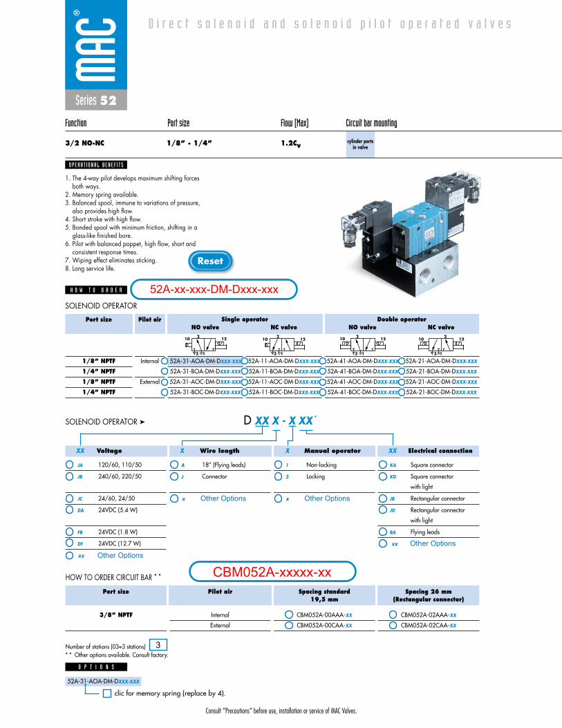
Consult “Precautions” before use, installation or service of MAC Valves.
Reset
Series 52
Function Port size Flow (Max) Circuit bar mounting
3/2 NO-NC 1/8” - 1/4” 1.2Cvcylinder ports
in valve
1. The 4-way pilot develops maximum shifting forcesboth ways.
2. Memory spring available.3. Balanced spool, immune to variations of pressure,
also provides high flow.4. Short stroke with high flow.5. Bonded spool with minimum friction, shifting in a
glass-like finished bore.6. Pilot with balanced poppet, high flow, short and
consistent response times.7. Wiping effect eliminates sticking.8. Long service life.
O P E R A T I O N A L B E N E F I T S
D i r e c t s o l e n o i d a n d s o l e n o i d p i l o t o p e r a t e d v a l v e s
H O W T O O R D E R
NO valve
52A-31-COA-DM-DXXX-XXX
52A-31-BOA-DM-DXXX-XXX
52A-31-AOC-DM-DXXX-XXX
52A-31-BOC-DM-DXXX-XXX
NC valve
52A-11-AOA-DM-DXXX-XXX
52A-11-BOA-DM-DXXX-XXX
52A-11-AOC-DM-DXXX-XXX
52A-11-BOC-DM-DXXX-XXX
NO valve
52A-41-AOA-DM-DXXX-XXX
52A-41-BOA-DM-DXXX-XXX
52A-41-AOC-DM-DXXX-XXX
52A-41-BOC-DM-DXXX-XXX
NC valve
52A-21-AOA-DM-DXXX-XXX
52A-21-BOA-DM-DXXX-XXX
52A-21-AOC-DM-DXXX-XXX
52A-21-BOC-DM-DXXX-XXX
Port size
1/8” NPTF
1/4” NPTF
1/8” NPTF
1/4” NPTF
Pilot air
Internal
External
21210
13
2 1210
13
21210
13
2 12
13
10
Single operator Double operator
Voltage
JA 120/60, 110/50
JB 240/60, 220/50
JC 24/60, 24/50
DA 24VDC (5.4 W)
FB 24VDC (1.8 W)
DF 24VDC (12.7 W)
Wire length
A 18” (Flying leads)
J Connector
Manual operator
1 Non-locking
2 Locking
Electrical connection
KA Square connector
KD Square connector
with light
JB Rectangular connector
JD Rectangular connector
with light
BA Flying leads
D XX X - X XX *SOLENOID OPERATOR ➤
XXXX X X
52A-31-AOA-DM-DXXX-XXX
52A-31-AOA-DM-DXXX-XXX
O P T I O N S
clic for memory spring (replace by 4).
Port size
3/8” NPTF
Pilot air
Internal
External
Spacing standard19,5 mm
CBM052A-00AAA-XX
CBM052A-00CAA-XX
Spacing 26 mm(Rectangular connector)
CBM052A-02AAA-XX
CBM052A-02CAA-XX
HOW TO ORDER CIRCUIT BAR * *
SOLENOID OPERATOR
Number of stations (03=3 stations)* * Other options available. Consult factory.
52A-xx-xxx-DM-Dxxx-xxx
3
CBM052A-xxxxx-xxOther Optionsxx
x Other Options
xx Other Options
x Other Options
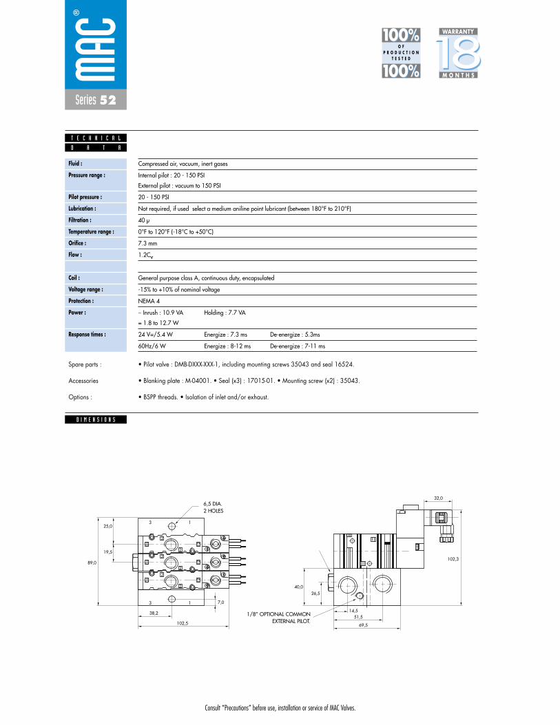
Consult “Precautions” before use, installation or service of MAC Valves.
Series 52
D I M E N S I O N S
D A T A
T E C H N I C A L
1818100%100%
100%100% M O N T H S
WARRANTY
O FP R O D U C T I O N
T E S T E D
• Pilot valve : DMB-DXXX-XXX-1, including mounting screws 35043 and seal 16524.
• Blanking plate : M-04001. • Seal (x3) : 17015-01. • Mounting screw (x2) : 35043.
• BSPP threads. • Isolation of inlet and/or exhaust.
Spare parts :
Accessories
Options :
Fluid :
Pressure range :
Pilot pressure :
Lubrication :
Filtration :
Temperature range :
Orifice :
Flow :
Leak rate :
Coil :
Voltage range :
Protection :
Power :
Response times :
Compressed air, vacuum, inert gases
Internal pilot : 20 - 150 PSI
External pilot : vacuum to 150 PSI
20 - 150 PSI
Not required, if used select a medium aniline point lubricant (between 180°F to 210°F)
40 μ
0°F to 120°F (-18°C to +50°C)
7.3 mm
1.2Cv
50 cm3/min
General purpose class A, continuous duty, encapsulated
-15% to +10% of nominal voltage
NEMA 4
� Inrush : 10.9 VA Holding : 7.7 VA
= 1.8 to 12.7 W
24 V=/5.4 W Energize : 7.3 ms De-energize : 5.3ms
60Hz/6 W Energize : 8-12 ms De-energize : 7-11 ms
13
13
2
89,0
102,5
38,2
7,0
19,5
25,0
2
2
2
1212
12
1010
10
2
2
26,5
14,551,5
69,5
40,0
102,3
32,0
1/8” OPTIONAL COMMONEXTERNAL PILOT.
6,5 DIA.2 HOLES
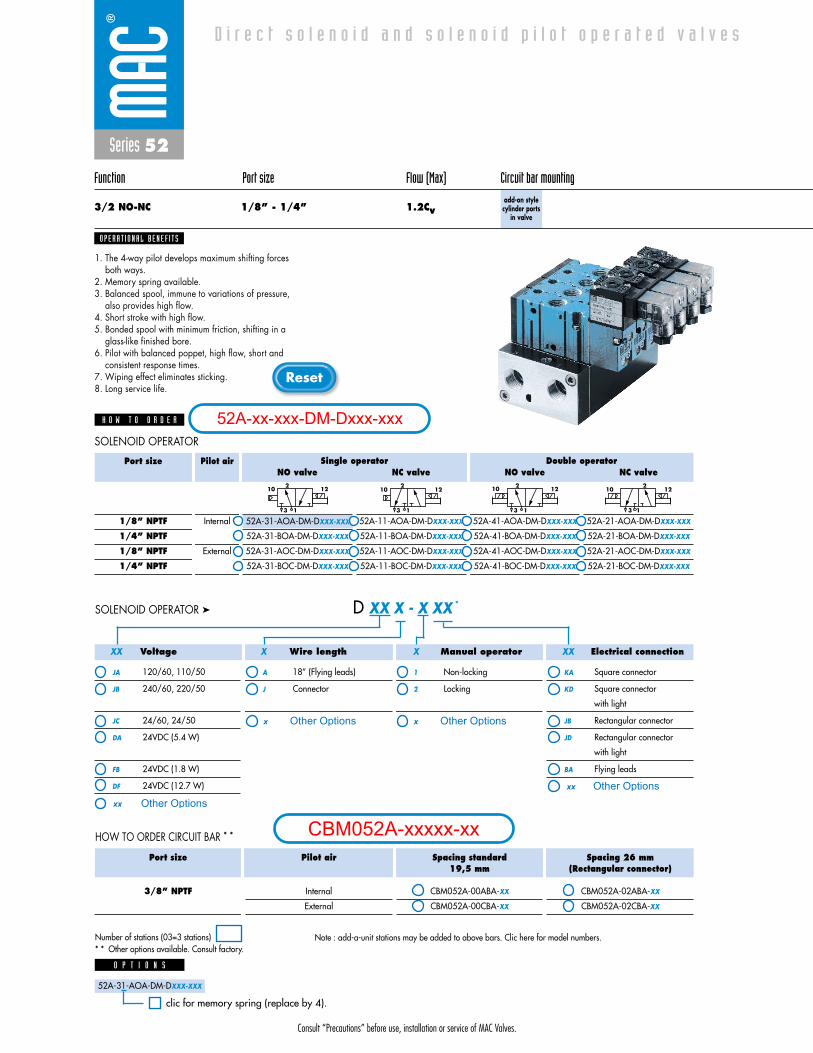
Series 52
Function Port size Flow (Max) Circuit bar mounting
3/2 NO-NC 1/8” - 1/4” 1.2Cvadd-on stylecylinder ports
in valve
O P E R A T I O N A L B E N E F I T S
D i r e c t s o l e n o i d a n d s o l e n o i d p i l o t o p e r a t e d v a l v e s
1. The 4-way pilot develops maximum shifting forcesboth ways.
2. Memory spring available.3. Balanced spool, immune to variations of pressure,
also provides high flow.4. Short stroke with high flow.5. Bonded spool with minimum friction, shifting in a
glass-like finished bore.6. Pilot with balanced poppet, high flow, short and
consistent response times.7. Wiping effect eliminates sticking.8. Long service life.
H O W T O O R D E R
NO valve
52A-31-COA-DM-DXXX-XXX
52A-31-BOA-DM-DXXX-XXX
52A-31-AOC-DM-DXXX-XXX
52A-31-BOC-DM-DXXX-XXX
NC valve
52A-11-AOA-DM-DXXX-XXX
52A-11-BOA-DM-DXXX-XXX
52A-11-AOC-DM-DXXX-XXX
52A-11-BOC-DM-DXXX-XXX
NO valve
52A-41-AOA-DM-DXXX-XXX
52A-41-BOA-DM-DXXX-XXX
52A-41-AOC-DM-DXXX-XXX
52A-41-BOC-DM-DXXX-XXX
NC valve
52A-21-AOA-DM-DXXX-XXX
52A-21-BOA-DM-DXXX-XXX
52A-21-AOC-DM-DXXX-XXX
52A-21-BOC-DM-DXXX-XXX
Port size
1/8” NPTF
1/4” NPTF
1/8” NPTF
1/4” NPTF
Pilot air
Internal
External
21210
13
2 1210
13
21210
13
2 12
13
10
Single operator Double operator
Voltage
JA 120/60, 110/50
JB 240/60, 220/50
JC 24/60, 24/50
DA 24VDC (5.4 W)
FB 24VDC (1.8 W)
DF 24VDC (12.7 W)
Wire length
A 18” (Flying leads)
J Connector
Manual operator
1 Non-locking
2 Locking
Electrical connection
KA Square connector
KD Square connector
with light
JB Rectangular connector
JD Rectangular connector
with light
BA Flying leads
D XX X - X XX *SOLENOID OPERATOR ➤
XXXX X X
52A-31-AOA-DM-DXXX-XXX
52A-31-AOA-DM-DXXX-XXX
O P T I O N S
clic for memory spring (replace by 4).
Port size
3/8” NPTF
Pilot air
Internal
External
Spacing standard19,5 mm
CBM052A-00ABA-XX
CBM052A-00CBA-XX
Spacing 26 mm(Rectangular connector)
CBM052A-02ABA-XX
CBM052A-02CBA-XX
HOW TO ORDER CIRCUIT BAR * *
Note : add-a-unit stations may be added to above bars. Clic here for model numbers.
SOLENOID OPERATOR
Number of stations (03=3 stations)* * Other options available. Consult factory.
Consult “Precautions” before use, installation or service of MAC Valves.
Reset
52A-xx-xxx-DM-Dxxx-xxx
CBM052A-xxxxx-xxOther Optionsxx
x Other Options
xx Other Options
x Other Options
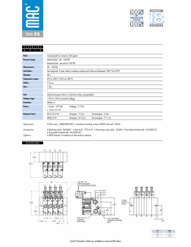
Consult “Precautions” before use, installation or service of MAC Valves.
Series 52
1818100%100%
100%100% M O N T H S
WARRANTY
O FP R O D U C T I O N
T E S T E D
D I M E N S I O N S
D A T A
T E C H N I C A L
• Pilot valve : DMB-DXXX-XXX-1, including mounting screws 35043 and seal 16524.
• Blanking plate : M-04001. • Seal (x3) : 17015-01. • Mounting screw (x2) : 35043. • End plate kit (Internal) : M-52001-01.• End plate kit (External) : M-52002-01.• BSPP threads. • Isolation of inlet and/or exhaust.
Spare parts :
Accessories
Options :
Fluid :
Pressure range :
Pilot pressure :
Lubrication :
Filtration :
Temperature range :
Orifice :
Flow :
Leak rate :
Coil :
Voltage range :
Protection :
Power :
Response times :
Compressed air, vacuum, inert gases
Internal pilot : 20 - 150 PSI
External pilot : vacuum to 150 PSI
20 - 150 PSI
Not required, if used select a medium aniline point lubricant (between 180°F to 210°F)
40 μ
0°F to 120°F (-18°C to +50°C)
7.3 mm
1.2Cv
50 cm3/min
General purpose class A, continuous duty, encapsulated
-15% to +10% of nominal voltage
NEMA 4
� Inrush : 10.9 VA Holding : 7.7 VA
= 1.8 to 12.7 W
24 V=/5.4 W Energize : 7.3 ms De-energize : 5.3ms
60Hz/6 W Energize : 8-12 ms De-energize : 7-11 ms
38.235.0
BOTH ENDS2 PLACES3/8" N.P.T.F.
PILOTCOMMON EXTERNAL1/8" OPTIONAL
ON THE BOTTOM OR SIDEPORTS AVAILABLE1/8" OR 1/4"
10.021.0
102.3
23.2
69.596.0
12
10
2
2
12
10
2
2
1
3
2
2
10
1212
10
2
2
13
13
MODEL
40.0
HOLES2 MTG.6.5 DIA.
CL CL CL CL
CL CL CL CL
CL CL CL CL
7.025.0
YY
XX
21.0
TYP.
14.529.0
52.5
16.010.8
YY
19.5
26
XX
113
119.5
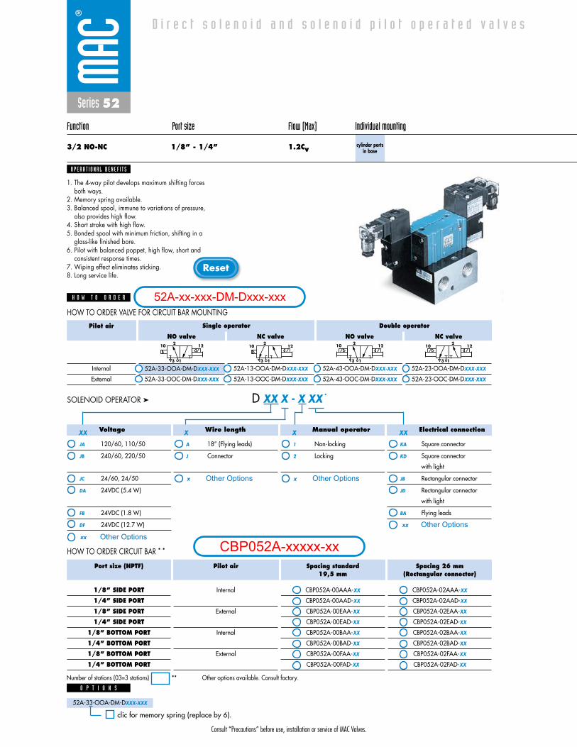
Consult “Precautions” before use, installation or service of MAC Valves.
Reset
Series 52
Function Port size Flow (Max) Individual mounting
3/2 NO-NC 1/8” - 1/4” 1.2Cvcylinder ports
in base
O P E R A T I O N A L B E N E F I T S
D i r e c t s o l e n o i d a n d s o l e n o i d p i l o t o p e r a t e d v a l v e s
1. The 4-way pilot develops maximum shifting forcesboth ways.
2. Memory spring available.3. Balanced spool, immune to variations of pressure,
also provides high flow.4. Short stroke with high flow.5. Bonded spool with minimum friction, shifting in a
glass-like finished bore.6. Pilot with balanced poppet, high flow, short and
consistent response times.7. Wiping effect eliminates sticking.8. Long service life.
H O W T O O R D E R
NO valve
52A-33-OOA-DM-DXXX-XXX
52A-33-OOC-DM-DXXX-XXX
NC valve
52A-13-OOA-DM-DXXX-XXX
52A-13-OOC-DM-DXXX-XXX
NO valve
52A-43-OOA-DM-DXXX-XXX
52A-43-OOC-DM-DXXX-XXX
NC valve
52A-23-OOA-DM-DXXX-XXX
52A-23-OOC-DM-DXXX-XXX
Pilot air
Internal
External
2 1210
13
21210
13
2 12
13
10 21210
13
Single operator Double operator
Voltage
JA 120/60, 110/50
JB 240/60, 220/50
JC 24/60, 24/50
DA 24VDC (5.4 W)
FB 24VDC (1.8 W)
DF 24VDC (12.7 W)
Wire length
A 18” (Flying leads)
J Connector
Manual operator
1 Non-locking
2 Locking
Electrical connection
KA Square connector
KD Square connector
with light
JB Rectangular connector
JD Rectangular connector
with light
BA Flying leads
D XX X - X XX *SOLENOID OPERATOR ➤
XX X X XX
Port size (NPTF)
1/8” SIDE PORT
1/4” SIDE PORT
1/8” SIDE PORT
1/4” SIDE PORT
1/8” BOTTOM PORT
1/4” BOTTOM PORT
1/8” BOTTOM PORT
1/4” BOTTOM PORT
Pilot air
Internal
External
Internal
External
Spacing standard19,5 mm
CBP052A-00AAA-XX
CBP052A-00AAD-XX
CBP052A-00EAA-XX
CBP052A-00EAD-XX
CBP052A-00BAA-XX
CBP052A-00BAD-XX
CBP052A-00FAA-XX
CBP052A-00FAD-XX
Spacing 26 mm(Rectangular connector)
CBP052A-02AAA-XX
CBP052A-02AAD-XX
CBP052A-02EAA-XX
CBP052A-02EAD-XX
CBP052A-02BAA-XX
CBP052A-02BAD-XX
CBP052A-02FAA-XX
CBP052A-02FAD-XX
HOW TO ORDER CIRCUIT BAR * *
HOW TO ORDER VALVE FOR CIRCUIT BAR MOUNTING
Number of stations (03=3 stations) ** Other options available. Consult factory.
52A-33-OOA-DM-DXXX-XXX
52A-33-OOA-DM-DXXX-XXX
O P T I O N S
clic for memory spring (replace by 6).
52A-xx-xxx-DM-Dxxx-xxx
CBP052A-xxxxx-xxOther Optionsxx
x Other Options
xx Other Options
x Other Options
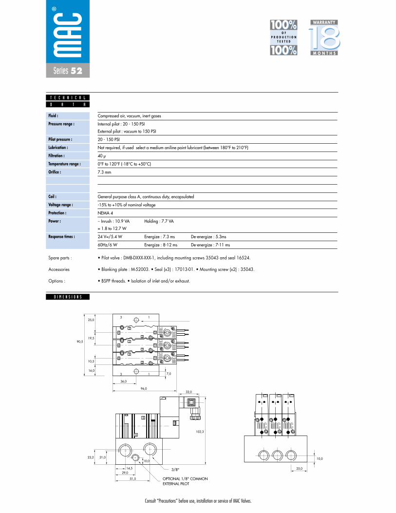
Consult “Precautions” before use, installation or service of MAC Valves.
13
13
2
90,5
96,0
36,0
16,07,0
10,5
19,5
25,0
2
2
2
1212
12
1010
10
2
2
21,0
14,5
10,0
29,0
51,5
23,2
102,3
32,0
25,0
10,0
Series 52
1818100%100%
100%100% M O N T H S
WARRANTY
O FP R O D U C T I O N
T E S T E D
D I M E N S I O N S
D A T A
T E C H N I C A L
• Pilot valve : DMB-DXXX-XXX-1, including mounting screws 35043 and seal 16524.
• Blanking plate : M-52003. • Seal (x3) : 17013-01. • Mounting screw (x2) : 35043.
• BSPP threads. • Isolation of inlet and/or exhaust.
Spare parts :
Accessories
Options :
Fluid :
Pressure range :
Pilot pressure :
Lubrication :
Filtration :
Temperature range :
Orifice :
Flow :
Leak rate :
Coil :
Voltage range :
Protection :
Power :
Response times :
Compressed air, vacuum, inert gases
Internal pilot : 20 - 150 PSI
External pilot : vacuum to 150 PSI
20 - 150 PSI
Not required, if used select a medium aniline point lubricant (between 180°F to 210°F)
40 μ
0°F to 120°F (-18°C to +50°C)
7.3 mm
1.2Cv
50 cm3/min
General purpose class A, continuous duty, encapsulated
-15% to +10% of nominal voltage
NEMA 4
� Inrush : 10.9 VA Holding : 7.7 VA
= 1.8 to 12.7 W
24 V=/5.4 W Energize : 7.3 ms De-energize : 5.3ms
60Hz/6 W Energize : 8-12 ms De-energize : 7-11 ms
3/8"
OPTIONAL 1/8" COMMONEXTERNAL PILOT

Consult “Precautions” before use, installation or service of MAC Valves.
Reset
D i r e c t s o l e n o i d a n d s o l e n o i d p i l o t o p e r a t e d v a l v e s
Series 52
Function Port size Flow (Max) Individual mounting
3/2 NO-NC 1/8” - 1/4” 1.2Cvadd-on stylecylinder ports
in base
O P E R A T I O N A L B E N E F I T S
D i r e c t s o l e n o i d a n d s o l e n o i d p i l o t o p e r a t e d v a l v e s
1. The 4-way pilot develops maximum shifting forcesboth ways.
2. Memory spring available.3. Balanced spool, immune to variations of pressure,
also provides high flow.4. Short stroke with high flow.5. Bonded spool with minimum friction, shifting in a
glass-like finished bore.6. Pilot with balanced poppet, high flow, short and
consistent response times.7. Wiping effect eliminates sticking.8. Long service life.
H O W T O O R D E R
NO valve
52A-33-OOA-DM-DXXX-XXX
52A-33-OOC-DM-DXXX-XXX
NC valve
52A-13-OOA-DM-DXXX-XXX
52A-13-OOC-DM-DXXX-XXX
NO valve
52A-43-OOA-DM-DXXX-XXX
52A-43-OOC-DM-DXXX-XXX
NC valve
52A-23-OOA-DM-DXXX-XXX
52A-23-OOC-DM-DXXX-XXX
Pilot air
Internal
External
2 1210
13
21210
13
2 12
13
10 21210
13
Single operator Double operator
Voltage
JA 120/60, 110/50
JB 240/60, 220/50
JC 24/60, 24/50
DA 24VDC (5.4 W)
FB 24VDC (1.8 W)
DF 24VDC (12.7 W)
Wire length
A 18” (Flying leads)
J Connector
Manual operator
1 Non-locking
2 Locking
Electrical connection
KA Square connector
KD Square connector
with light
JB Rectangular connector
JD Rectangular connector
with light
BA Flying leads
D XX X - X XX *SOLENOID OPERATOR ➤
XX X X XX
Port size (NPTF)
1/8” SIDE PORT
1/4” SIDE PORT
1/8” SIDE PORT
1/4” SIDE PORT
1/8” BOTTOM PORT
1/4” BOTTOM PORT
1/8” BOTTOM PORT
1/4” BOTTOM PORT
Pilot air
Internal
External
Internal
External
Spacing standard19,5 mm
CBP052A-00ABA-XX
CBP052A-00ABD-XX
CBP052A-00EBA-XX
CBP052A-00EBD-XX
CBP052A-00BBA-XX
CBP052A-00BBD-XX
CBP052A-00FBA-XX
CBP052A-00FBD-XX
Spacing 26 mm(Rectangular connector)
CBP052A-02ABA-XX
CBP052A-02ABD-XX
CBP052A-02EBA-XX
CBP052A-02EBD-XX
CBP052A-02BBA-XX
CBP052A-02BBD-XX
CBP052A-02FBA-XX
CBP052A-02FBD-XX
HOW TO ORDER CIRCUIT BAR * *
HOW TO ORDER VALVE FOR CIRCUIT BAR MOUNTING
Number of stations (03=3 stations) ** Other options available. Consult factory.
52A-33-OOA-DM-DXXX-XXX
52A-33-OOA-DM-DXXX-XXX
O P T I O N S
clic for memory spring (replace by 6).
Note : add-a-unit stations may be added to above bars. Clic here for model numbers.
52A-xx-xxx-DM-Dxxx-xxx
CBP052A-xxxxx-xxOther Optionsxx
x Other Options
xx Other Options
x Other Options
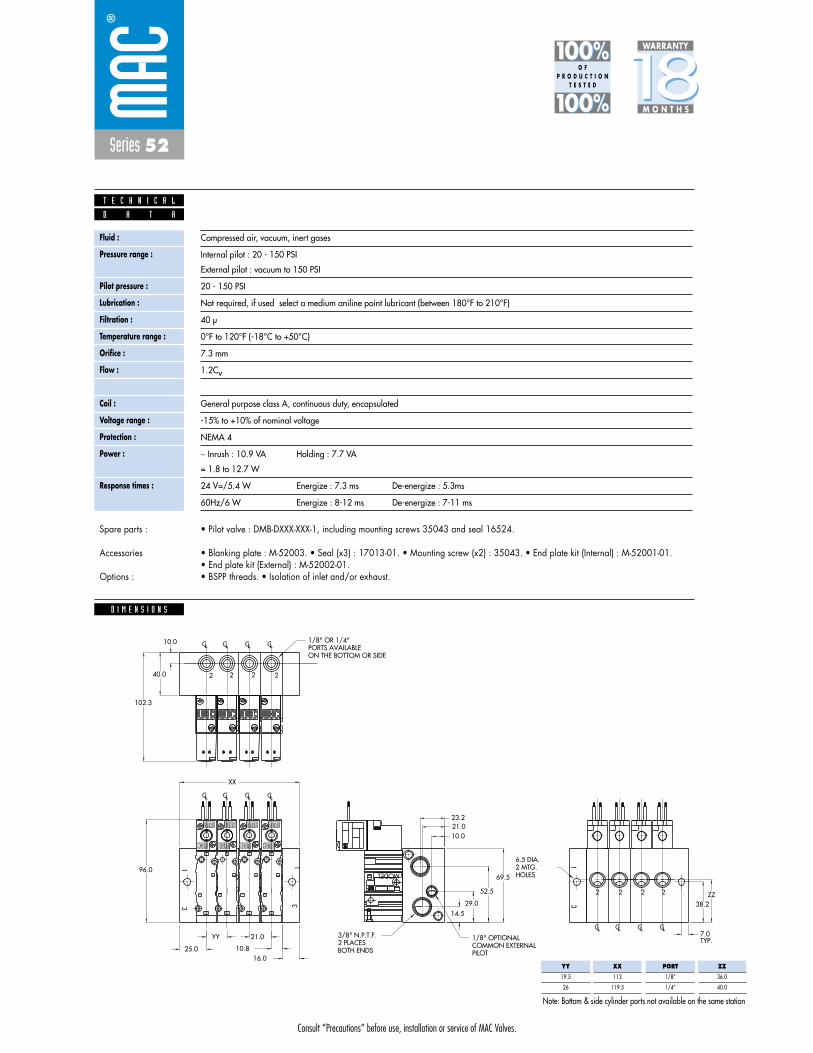
Consult “Precautions” before use, installation or service of MAC Valves.
10.816.0
52.5
29.014.5
TYP.21.0
XX
YY
25.0
7.0LCLCLCLC
LCLCLCLC
LCLCLCLC
HOLES2 MTG.6.5 DIA.
ZZ38.2
10.0
40.0
MODEL
2
31
31
2
10
12 12
10
3
1
2
2
10
12
10
12
2
2
2
2
2
96.069.5
23.2
102.3
21.010.0
ON THE BOTTOM OR SIDEPORTS AVAILABLE1/8" OR 1/4"
PILOTCOMMON EXTERNAL1/8" OPTIONAL
BOTH ENDS2 PLACES3/8" N.P.T.F.
2
2
22
2
22
Series 52
1818100%100%
100%100% M O N T H S
WARRANTY
O FP R O D U C T I O N
T E S T E D
D I M E N S I O N S
D A T A
T E C H N I C A L
• Pilot valve : DMB-DXXX-XXX-1, including mounting screws 35043 and seal 16524.
• Blanking plate : M-52003. • Seal (x3) : 17013-01. • Mounting screw (x2) : 35043. • End plate kit (Internal) : M-52001-01.• End plate kit (External) : M-52002-01.• BSPP threads. • Isolation of inlet and/or exhaust.
Spare parts :
Accessories
Options :
Fluid :
Pressure range :
Pilot pressure :
Lubrication :
Filtration :
Temperature range :
Orifice :
Flow :
Leak rate :
Coil :
Voltage range :
Protection :
Power :
Response times :
Compressed air, vacuum, inert gases
Internal pilot : 20 - 150 PSI
External pilot : vacuum to 150 PSI
20 - 150 PSI
Not required, if used select a medium aniline point lubricant (between 180°F to 210°F)
40 μ
0°F to 120°F (-18°C to +50°C)
7.3 mm
1.2Cv
50 cm3/min
General purpose class A, continuous duty, encapsulated
-15% to +10% of nominal voltage
NEMA 4
� Inrush : 10.9 VA Holding : 7.7 VA
= 1.8 to 12.7 W
24 V=/5.4 W Energize : 7.3 ms De-energize : 5.3ms
60Hz/6 W Energize : 8-12 ms De-energize : 7-11 ms
PORT
1/8”
1/4”
ZZ
36.0
40.0
YY
19.5
26
XX
113
119.5
Note: Bottom & side cylinder ports not available on the same station

Consult “Precautions” before use, installation or service of MAC Valves.
Reset
Series 52
Function Port size Flow (Max) Circuit bar mounting
3/2 NO-NC 1/8” - 1/4” 1.2Cvadd-a-unitstations for
CBM052A bar
1. The 4-way pilot develops maximum shifting forcesboth ways.
2. Memory spring available.3. Balanced spool, immune to variations of pressure,
also provides high flow.4. Short stroke with high flow.5. Bonded spool with minimum friction, shifting in a
glass-like finished bore.6. Pilot with balanced poppet, high flow, short and
consistent response times.7. Wiping effect eliminates sticking.8. Long service life.
O P E R A T I O N A L B E N E F I T S
D i r e c t s o l e n o i d a n d s o l e n o i d p i l o t o p e r a t e d v a l v e s
H O W T O O R D E R
NO valve
52A-31-COA-DM-DXXX-XXX
52A-31-BOA-DM-DXXX-XXX
52A-31-AOC-DM-DXXX-XXX
52A-31-BOC-DM-DXXX-XXX
NC valve
52A-11-AOA-DM-DXXX-XXX
52A-11-BOA-DM-DXXX-XXX
52A-11-AOC-DM-DXXX-XXX
52A-11-BOC-DM-DXXX-XXX
NO valve
52A-41-AOA-DM-DXXX-XXX
52A-41-BOA-DM-DXXX-XXX
52A-41-AOC-DM-DXXX-XXX
52A-41-BOC-DM-DXXX-XXX
NC valve
52A-21-AOA-DM-DXXX-XXX
52A-21-BOA-DM-DXXX-XXX
52A-21-AOC-DM-DXXX-XXX
52A-21-BOC-DM-DXXX-XXX
Port size
1/8” NPTF
1/4” NPTF
1/8” NPTF
1/4” NPTF
Pilot air
Internal
External
21210
13
2 1210
13
21210
13
2 12
13
10
Single operator Double operator
Voltage
JA 120/60, 110/50
JB 240/60, 220/50
JC 24/60, 24/50
DA 24VDC (5.4 W)
FB 24VDC (1.8 W)
DF 24VDC (12.7 W)
Wire length
A 18” (Flying leads)
J Connector
Manual operator
1 Non-locking
2 Locking
Electrical connection
KA Square connector
KD Square connector
with light
JB Rectangular connector
JD Rectangular connector
with light
BA Flying leads
D XX X - X XX *SOLENOID OPERATOR ➤
XXXX X X
52A-31-AOA-DM-DXXX-XXX
52A-31-AOA-DM-DXXX-XXX
O P T I O N S
clic for memory spring (replace by 4).
Port size
3/8” NPTF
Pilot air
Internal
External
Spacing standard21 mm
CBM052A-01AEA-XX
CBM052A-01CEA-XX
Spacing 26 mm(Rectangular connector)
CBM052A-02AEA-XX
CBM052A-02CEA-XX
HOW TO ORDER CIRCUIT BAR * *
SOLENOID OPERATOR
Note : add-a-unit stations available in lengths up to 4 stations (01, 02, 03 or 04).Number of stations (01=1 station)* * Other options available. Consult factory.
52A-xx-xxx-DM-Dxxx-xxx
CBM052A-xxxxx-xx
Other Optionsxx
x Other Options
xx Other Options
x Other Options

Consult “Precautions” before use, installation or service of MAC Valves.
Series 52
1818100%100%
100%100% M O N T H S
WARRANTY
O FP R O D U C T I O N
T E S T E D
D I M E N S I O N S
D A T A
T E C H N I C A L
• Pilot valve : DMB-DXXX-XXX-1, including mounting screws 35043 and seal 16524.
• Blanking plate : M-04001. • Seal (x3) : 17015-01. • Mounting screw (x2) : 35043.
• BSPP threads. • Isolation of inlet and/or exhaust.
Spare parts :
Accessories
Options :
Fluid :
Pressure range :
Pilot pressure :
Lubrication :
Filtration :
Temperature range :
Orifice :
Flow :
Leak rate :
Coil :
Voltage range :
Protection :
Power :
Response times :
Compressed air, vacuum, inert gases
Internal pilot : 20 - 150 PSI
External pilot : vacuum to 150 PSI
20 - 150 PSI
Not required, if used select a medium aniline point lubricant (between 180°F to 210°F)
40 μ
0°F to 120°F (-18°C to +50°C)
7.3 mm
1.2Cv
50 cm3/min
General purpose class A, continuous duty, encapsulated
-15% to +10% of nominal voltage
NEMA 4
� Inrush : 10.9 VA Holding : 7.7 VA
= 1.8 to 12.7 W
24 V=/5.4 W Energize : 7.3 ms De-energize : 5.3ms
60Hz/6 W Energize : 8-12 ms De-energize : 7-11 ms
38.235.0
BOTH ENDS2 PLACES3/8" N.P.T.F.
PILOTCOMMON EXTERNAL1/8" OPTIONAL
ON THE BOTTOM OR SIDEPORTS AVAILABLE1/8" OR 1/4"
10.021.0
102.3
23.2
69.596.0
12
10
2
2
12
10
2
2
1
3
2
2
10
1212
10
2
2
13
13
MODEL
40.0
HOLES2 MTG.6.5 DIA.
CL CL CL CL
CL CL CL CL
CL CL CL CL
7.025.0
YY
XX
21.0
TYP.
14.529.0
52.5
16.010.8
YY
19.5
26
XX
113
119.5

Consult “Precautions” before use, installation or service of MAC Valves.
Reset
D i r e c t s o l e n o i d a n d s o l e n o i d p i l o t o p e r a t e d v a l v e s
Series 52
Function Port size Flow (Max) Individual mounting
3/2 NO-NC 1/8” - 1/4” 1.2Cvadd-a-unitstations for
CBP052A bar
O P E R A T I O N A L B E N E F I T S
D i r e c t s o l e n o i d a n d s o l e n o i d p i l o t o p e r a t e d v a l v e s
1. The 4-way pilot develops maximum shifting forcesboth ways.
2. Memory spring available.3. Balanced spool, immune to variations of pressure,
also provides high flow.4. Short stroke with high flow.5. Bonded spool with minimum friction, shifting in a
glass-like finished bore.6. Pilot with balanced poppet, high flow, short and
consistent response times.7. Wiping effect eliminates sticking.8. Long service life.
H O W T O O R D E R
NO valve
52A-33-OOA-DM-DXXX-XXX
52A-33-OOC-DM-DXXX-XXX
NC valve
52A-13-OOA-DM-DXXX-XXX
52A-13-OOC-DM-DXXX-XXX
NO valve
52A-43-OOA-DM-DXXX-XXX
52A-43-OOC-DM-DXXX-XXX
NC valve
52A-23-OOA-DM-DXXX-XXX
52A-23-OOC-DM-DXXX-XXX
Pilot air
Internal
External
2 1210
13
21210
13
2 12
13
10 21210
13
Single operator Double operator
Voltage
JA 120/60, 110/50
JB 240/60, 220/50
JC 24/60, 24/50
DA 24VDC (5.4 W)
FB 24VDC (1.8 W)
DF 24VDC (12.7 W)
Wire length
A 18” (Flying leads)
J Connector
Manual operator
1 Non-locking
2 Locking
Electrical connection
KA Square connector
KD Square connector
with light
JB Rectangular connector
JD Rectangular connector
with light
BA Flying leads
D XX X - X XX *SOLENOID OPERATOR ➤
XX X X XX
Port size (NPTF)
1/8” SIDE PORT
1/4” SIDE PORT
1/8” SIDE PORT
1/4” SIDE PORT
1/8” BOTTOM PORT
1/4” BOTTOM PORT
1/8” BOTTOM PORT
1/4” BOTTOM PORT
Pilot air
Internal
External
Internal
External
Spacing standard21 mm
CBP052A-01AEA-XX
CBP052A-01AED-XX
CBP052A-01EEA-XX
CBP052A-01EED-XX
CBP052A-01BEA-XX
CBP052A-01BED-XX
CBP052A-01FEA-XX
CBP052A-01FED-XX
Spacing 26 mm(Rectangular connector)
CBP052A-02AEA-XX
CBP052A-02AED-XX
CBP052A-02EEA-XX
CBP052A-02EED-XX
CBP052A-02BEA-XX
CBP052A-02BED-XX
CBP052A-02FEA-XX
CBP052A-02FED-XX
HOW TO ORDER CIRCUIT BAR * *
HOW TO ORDER VALVE FOR CIRCUIT BAR MOUNTING
52A-33-OOA-DM-DXXX-XXX
52A-33-OOA-DM-DXXX-XXX
O P T I O N S
clic for memory spring (replace by 6).
Note : add-a-unit stations available in lengths up to 4 stations (01, 02, 03 or 04).
Number of stations (03=3 stations) ** Other options available. Consult factory.
52A-xx-xxx-DM-Dxxx-xxx
CBP052A-xxxxx-xxOther Optionsxx
x Other Options
xx Other Options
x Other Options
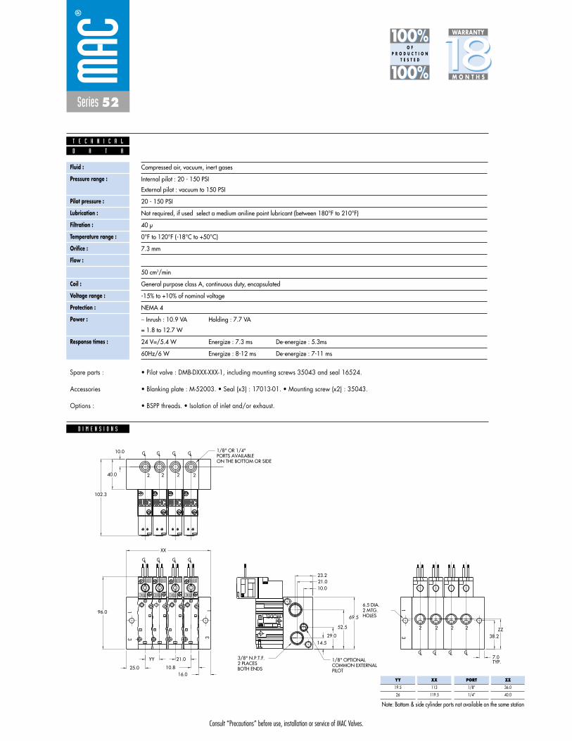
Consult “Precautions” before use, installation or service of MAC Valves.
Series 52
1818100%100%
100%100% M O N T H S
WARRANTY
O FP R O D U C T I O N
T E S T E D
D I M E N S I O N S
D A T A
T E C H N I C A L
• Pilot valve : DMB-DXXX-XXX-1, including mounting screws 35043 and seal 16524.
• Blanking plate : M-52003. • Seal (x3) : 17013-01. • Mounting screw (x2) : 35043.
• BSPP threads. • Isolation of inlet and/or exhaust.
Spare parts :
Accessories
Options :
Fluid :
Pressure range :
Pilot pressure :
Lubrication :
Filtration :
Temperature range :
Orifice :
Flow :
Leak rate :
Coil :
Voltage range :
Protection :
Power :
Response times :
Compressed air, vacuum, inert gases
Internal pilot : 20 - 150 PSI
External pilot : vacuum to 150 PSI
20 - 150 PSI
Not required, if used select a medium aniline point lubricant (between 180°F to 210°F)
40 μ
0°F to 120°F (-18°C to +50°C)
7.3 mm
1.2Cv
50 cm3/min
General purpose class A, continuous duty, encapsulated
-15% to +10% of nominal voltage
NEMA 4
� Inrush : 10.9 VA Holding : 7.7 VA
= 1.8 to 12.7 W
24 V=/5.4 W Energize : 7.3 ms De-energize : 5.3ms
60Hz/6 W Energize : 8-12 ms De-energize : 7-11 ms
10.816.0
52.5
29.014.5
TYP.21.0
XX
YY
25.0
7.0LCLCLCLC
LCLCLCLC
LCLCLCLC
HOLES2 MTG.6.5 DIA.
ZZ38.2
10.0
40.0
MODEL
2
31
31
2
10
12 12
10
3
1
2
2
10
12
10
12
2
2
2
2
2
96.069.5
23.2
102.3
21.010.0
ON THE BOTTOM OR SIDEPORTS AVAILABLE1/8" OR 1/4"
PILOTCOMMON EXTERNAL1/8" OPTIONAL
BOTH ENDS2 PLACES3/8" N.P.T.F.
2
2
22
2
22
PORT
1/8”
1/4”
ZZ
36.0
40.0
YY
19.5
26
XX
113
119.5
Note: Bottom & side cylinder ports not available on the same station
Consult “Precautions” before use, installation or service of MAC Valves.
S e c t i o n 2 Opt ions

Consult “Precautions”before use, installation or service of MAC Valves.
O P T I O N S
O p t i o n s
Codification table for voltages / Wire length / Manual operator / Electrical connection
- pilot operated valves 400, 52 & 92 Series
D M - D XX X - X XX1 2 3 4
VALVE CODE ➤
OPTIONS AVAILABLE FOR
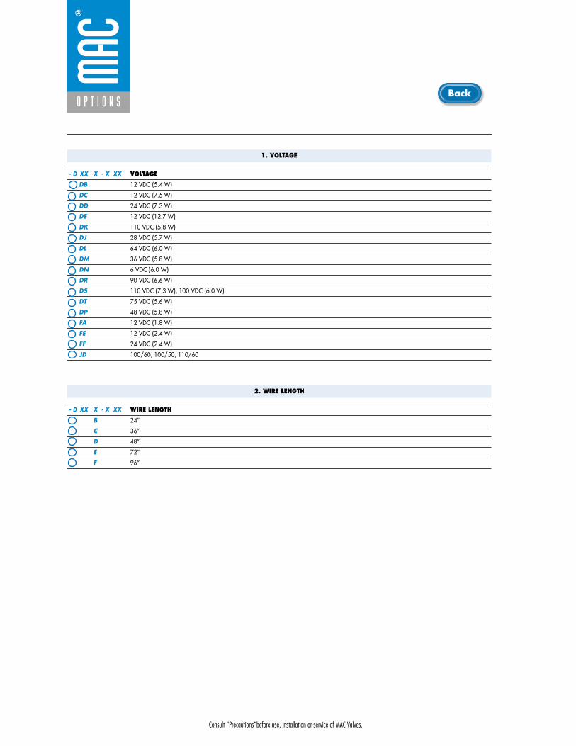
Consult “Precautions”before use, installation or service of MAC Valves.
O P T I O N S
1. VOLTAGE
- D XX X - X XX VOLTAGE
DB 12 VDC (5.4 W)
DC 12 VDC (7.5 W)
DD 24 VDC (7.3 W)
DE 12 VDC (12.7 W)
DK 110 VDC (5.8 W)
DJ 28 VDC (5.7 W)
DL 64 VDC (6.0 W)
DM 36 VDC (5.8 W)
DN 6 VDC (6.0 W)
DR 90 VDC (6,6 W)
DS 110 VDC (7.3 W), 100 VDC (6.0 W)
DT 75 VDC (5.6 W)
DP 48 VDC (5.8 W)
FA 12 VDC (1.8 W)
FE 12 VDC (2.4 W)
FF 24 VDC (2.4 W)
JD 100/60, 100/50, 110/60
2. WIRE LENGTH
- D XX X - X XX WIRE LENGTH
B 24”
C 36”
D 48”
E 72”
F 96”
Back
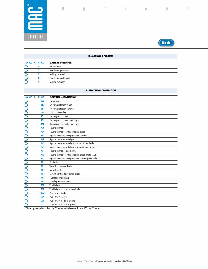
Consult “Precautions”before use, installation or service of MAC Valves.
O P T I O N S
O p t i o n s
3. MANUAL OPERATOR
- D XX X - X XX MANUAL OPERATOR
0 No operator
1 Non-locking recessed
2 Locking recessed
3 Non-locking extended
4 Locking extended
4. ELECTRICAL CONNECTION
- D XX X - X XX ELECTRICAL CONNECTION
BA Flying leads
BK BA with protection diode
BL BA with protection varistor
CA 1/2" NPS conduit
JB Rectangular connector
JD Rectangular connector with light
JM Rectangular connector, male only
KA Square connector
KB Square connector with protection diode
KC Square connector with protection varistor
KD Square connector with light
KE Square connector with light and protection diode
KF Square connector with light and protection varistor
KJ Square connector (male only)
KK Square connector with protection diode (male only)
KL Square connector with protection varistor (male only)
TA Dual tabs
TB TA with protection diode
TD TA with light
TE TA with light and protection diode
TJ Dual tabs (male only)
TK TJ with protection diode
TM TJ with light
TN TJ with light and protection diode
*DN Plug-in with diode
*DP Plug-in with M.O.V.
*DH Plug-in with diode & ground
*DJ Plug-in with M.O.V & ground
* These options only apply to the 92 series. All others are for the 400 and 52 series.
Back

• Type «SUB_D»• Number of contacts : 9• Solder termination (Dia. 0.6 mm/0.14 mm
2/26-22 AWG)
• Operating current 5 A/contact• Rated voltage 125 V~• Temp. range –40° to +125°C• Insulation resistance � 5.09 �• Protection class IP40 (DIN 40050)• Number of solenoids : 7 max.• Max. 24 V=/5.4 W per solenoid• 2 common wires
MOD. SD09
MOD. SD15
MOD. SD25
PIN #1
PIN #5
PIN #6
PIN #9
PIN #1
PIN #8
PIN #9
PIN #15
PIN #1
PIN #13
PIN #14
PIN #25
• Type «SUB_D»• Number of contacts : 25• Solder termination (Dia. 0.6 mm/0.14 mm
2/26-22 AWG)
• Operating current 5 A/contact• Rated voltage 125 V~• Temp. range –40° to +125°C• Insulation resistance � 5.09 �• Protection class IP40 (DIN 40050)• Number of solenoids : 20 max.• Max. 24 V=/5.4 W per solenoid• 5 common wires
Note : Use desired MOD. number after circuit bar part number
• Type «SUB_D»• Number of contacts : 15• Solder termination (Dia. 0.6 mm/0.14 mm
2/26-22 AWG)
• Operating current 5 A/contact• Rated voltage 125 V~• Temp. range –40° to +125°C• Insulation resistance � 5.09 �• Protection class IP40 (DIN 40050)• Number of solenoids : 12 max.• Max. 24 V=/5.4 W per solenoid• 3 common wires
T E C H N I C A L D A T A
T E C H N I C A L D A T A
T E C H N I C A L D A T A
O P T I O N S
O p t i o n s

SD09 SD15 SD25
Connector termination details
SOL 2 SOL 4 SOL 6 SOL 8 SOL 16 SOL 18 SOL 20 SOL 22 SOL 24
SOL 1CONN
ECTO
RCO
NNEC
TOR
SOL 2 SOL 3 SOL .. SOL 20 SOL 21 SOL 22 SOL 23 SOL 24
SOL 1 SOL 3 SOL 5 SOL 13 SOL 15 SOL 17
Double solenoid circuit bar
Single solenoid circuit bar
SOL 21 SOL 23SOL 19
SOL. 3
SOL. 1
SOL. 2
1
2
3
4
COMMON (+)
COMMON (+)
8
SOL. 4
5
6
7
9
SOL. 5
SOL. 7
SOL. 6
SOL. 3
SOL. 1
SOL. 2
1
2
3
4
COMMON (+)
COMMON (+)
COMMON (+)
13
SOL. 4
5
6
7
8
14
SOL. 5
SOL. 7
SOL. 6
SOL. 8
9
10
11
12
15
SOL. 9
SOL. 11
SOL. 10
SOL. 12
SOL. 3
SOL. 1
SOL. 2
1
2
3
4
COMMON (+)
COMMON (+)
COMMON (+)
COMMON (+)
COMMON (+)
21
SOL. 4
5
6
7
8
22
SOL. 5
SOL. 7
SOL. 6
SOL. 8
9
10
11
12
23
SOL. 9
SOL. 11
SOL. 10
SOL. 12
13
14
15
16
24
SOL. 13
SOL. 15
SOL. 14
SOL. 16
17
18
19
20
25
SOL. 17
SOL. 19
SOL. 18
SOL. 20
O P T I O N S
O p t i o n s

EAIN
EB
BA
Consult “Precautions” before use, installation or service of MAC Valves.
Series 44
D i r e c t s o l e n o i d a n d s o l e n o i d p i l o t o p e r a t e d v a l v e s
non plug-incylinder ports
in base
non plug-incylinder ports
in valveplug-in plug-in
with F. C. plug-in
with Pr. Reg.
plug-inwith Pr. Reg.
and F. C.
add-on styleplug-in
add-on styleplug-in
with F. C.
Circuit bar mounting
add-on styleplug-in
with Pr. Reg.
add-on styleplug-in
with Pr. Reg.and F. C.
plug-inadd-a-unit
stations
plug-inadd-a-unit
stationswith F. C.
plug-inadd-a-unit
stationswith Pr. Reg.
plug-inadd-a-unit
stations with F. C. and Pr. Reg.
plug-in withpre-wiredconnector
plug-in with F. C. and pre-wiredconnector
plug-in with Pr. Reg. andpre-wiredconnector
din rail, plug-in withpre-wiredconnector
SERIES FEATURES
• High force MACSOLENOID®.• 10mm direct operated.• # 10-32 or M5 ports.• Rated for lubricated or non-lubricated service.• Cylinder ports in valve or in circuit bar.
Manual operator
Armature
Coil
Push Pin
Valve spring
“D” seal 4 Balanced poppets
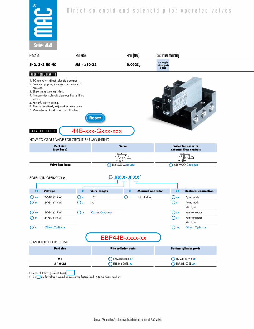
Consult “Precautions” before use, installation or service of MAC Valves.
Reset
Series 44
Function Port size Flow (Max) Circuit bar mounting
5/2, 3/2 NO-NC M5 - #10-32 0.093Cvnon plug-in
cylinder portsin base
1. 10 mm valve, direct solenoid operated.2. Balanced poppet, immune to variations of
pressure.3. Short stroke with high flow.4. The patented solenoid develops high shifting
forces.5. Powerful return spring.6. Flow is specifically adjusted on each valve.7. Manual operator standard on all valves.
O P E R A T I O N A L B E N E F I T S
D i r e c t s o l e n o i d a n d s o l e n o i d p i l o t o p e r a t e d v a l v e s
H O W T O O R D E R
Port size(see base)
Valve less base
Valve
44B-LOO-GXXX-XXX
Valve for use with external flow controls
44B-MOO-GXXX-XXX
EB
B A
INEA EB
B A
INEA
HOW TO ORDER VALVE FOR CIRCUIT BAR MOUNTING
Voltage
DA 24VDC (1.0 W)
DC 24VDC (1.8 W)
DD 24VDC (2.5 W)
DF 24VDC (4.0 W)
Wire length
A 18”
C 36”
Manual operator
1 Non-locking
Electrical connection
BA Flying leads
BT Flying leads
with light
KA Mini connector
KT Mini connector
with light
G XX X- X XX *SOLENOID OPERATOR ➤
XX X X XX
Port size
M5
# 10-32
Side cylinder ports
EBP44B-001D-XX
EBP44B-001B-XX
Bottom cylinder ports
EBP44B-002D-XX
EBP44B-002B-XX
HOW TO ORDER CIRCUIT BAR
Number of stations (03=3 stations)Note : clic for valves mounted on base at the factory (add - 9 to the model number).
44B-xxx-Gxxx-xxx
EBP44B-xxxx-xx
Other Optionsxx
x Other Options
xx Other Options

Consult “Precautions” before use, installation or service of MAC Valves.
Series 44
D I M E N S I O N S
Fluid :
Pressure range :
Lubrication :
Filtration :
Temperature range :
Orifice :
Flow (at 6 bar, �P=1bar) :
Leak rate :
Coil :
Voltage range :
Power :
Response times :
(with 4 W coil)
Compressed air, vacuum, inert gases
Vacuum to 120 PSI
Not required, if used select a medium aniline point lubricant (between 180°F and 210°F)
40 μ
0°F to 120°F (-18°C to +50°C)
1.8 mm
4 W : 0.093 Cv, 2.5 W : 0.077 Cv, 1,8 W : 0.057 Cv, 1.0 W : 0.048 Cv
50 cm3/min
General purpose class A, continuous duty, encapsulated
-15% to +10% of nominal voltage
4 W - 2.5 W - 1.8 W - 1.0 W
Energize : 3.4 ms
De-energize : 1.5 ms
B B
A A EAIN
EB
5,5
16,25
15,5
59,5
15,0
15,0 15,5
15,5
71,2
10,5
10,5
10,5 5,0
2,5
10,0
5,3
18,3
24,8
44,8
56,3
57,3
D A T A
T E C H N I C A L
1818100%100%
100%100% M O N T H S
WARRANTY
O FP R O D U C T I O N
T E S T E D
• Valve and coil are not interchangeable.
• Valve mounting kit : N-44001-03. • Blanking plate : M-44003.
• Isolation of inlet and/or exhaust. Special bar. Consult Factory.
Note :
Spare parts :
Options :
M5 VALVE MTG. SCR.
1/8” NPTF PORTS
4 � Ø 4,3

Voltage
DA 24VDC (1.0 W)
DC 24VDC (1.8 W)
DD 24VDC (2.5 W)
DF 24VDC (4.0 W)
Wire length
A 18”
C 36”
Manual operator
1 Non-locking
Electrical connection
BA Flying leads
BT Flying leads
with light
KA Mini connector
KT Mini connector
with light
G XX X- X XX *SOLENOID OPERATOR ➤
Consult “Precautions” before use, installation or service of MAC Valves.
Reset
Series 44
Function Port size (Inlet & Exhaust) Flow (Max) Circuit bar mounting
5/2, 3/2 NO-NC # 10-32 - 1/8” 0.093Cvnon plug-in
cylinder ports in valve
1. 10 mm valve, direct solenoid operated.2. Balanced poppet, immune to variations of
pressure.3. Short stroke with high flow.4. The patented solenoid develops high shifting
forces.5. Powerful return spring.6. Flow is specifically adjusted on each valve.7. Manual operator standard on all valves.
O P E R A T I O N A L B E N E F I T S
D i r e c t s o l e n o i d a n d s o l e n o i d p i l o t o p e r a t e d v a l v e s
H O W T O O R D E R
Valve port size
M5
# 10-32
Valve
44B-ABA-GXXX-XXX
44B-AAA-GXXX-XXX
Valve for use with external flow controls
44B-BBA-GXXX-XXX
44B-BAA-GXXX-XXX
EB
B A
INEA EB
B A
INEA
HOW TO ORDER VALVE FOR CIRCUIT BAR MOUNTING
Port sizeCOMMON INLET & EXHAUST
# 10-32
1/8” NPTF
EBM44A-001B-XX
EBM44A-002A-XX
HOW TO ORDER CIRCUIT BAR
XX X X XX
Number of stations (03=3 stations)Note : clic for valves mounted on base at the factory (add - 9 to the model number).
44B-xxx-Gxxx-xxx
EBM44A-xxxx-xx
Other Optionsxx
x Other Options
xx Other Options
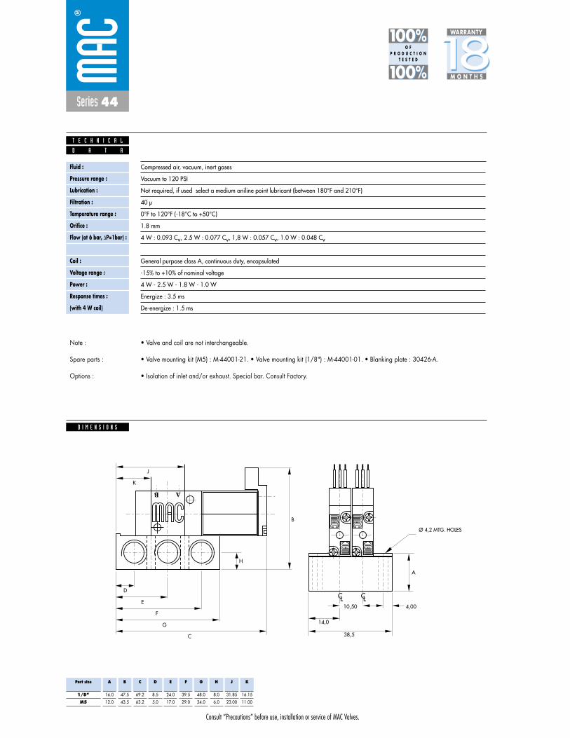
Consult “Precautions” before use, installation or service of MAC Valves.
Series 44
D I M E N S I O N S
Fluid :
Pressure range :
Lubrication :
Filtration :
Temperature range :
Orifice :
Flow (at 6 bar, �P=1bar) :
Leak rate :
Coil :
Voltage range :
Power :
Response times :
(with 4 W coil)
Compressed air, vacuum, inert gases
Vacuum to 120 PSI
Not required, if used select a medium aniline point lubricant (between 180°F and 210°F)
40 μ
0°F to 120°F (-18°C to +50°C)
1.8 mm
4 W : 0.093 Cv, 2.5 W : 0.077 Cv, 1,8 W : 0.057 Cv, 1.0 W : 0.048 Cv
50 cm3/min
General purpose class A, continuous duty, encapsulated
-15% to +10% of nominal voltage
4 W - 2.5 W - 1.8 W - 1.0 W
Energize : 3.5 ms
De-energize : 1.5 ms
B
A
H
38,5
14,0
10,50
CLCL4,00
C
G
F
E
D
K
J
AB
D A T A
T E C H N I C A L
1818100%100%
100%100% M O N T H S
WARRANTY
O FP R O D U C T I O N
T E S T E D
• Valve and coil are not interchangeable.
• Valve mounting kit (M5) : M-44001-21. • Valve mounting kit (1/8") : M-44001-01. • Blanking plate : 30426-A.
• Isolation of inlet and/or exhaust. Special bar. Consult Factory.
Note :
Spare parts :
Options :
Port size
1/8”
M5
A
16.0
12.0
B
47.5
43.5
C
69.2
63.2
D
8.5
5.0
E
24.0
17.0
F
39.5
29.0
G
48.0
34.0
H
8.0
6.0
J
31.85
23.00
K
16.15
11.00
Ø 4,2 MTG. HOLES
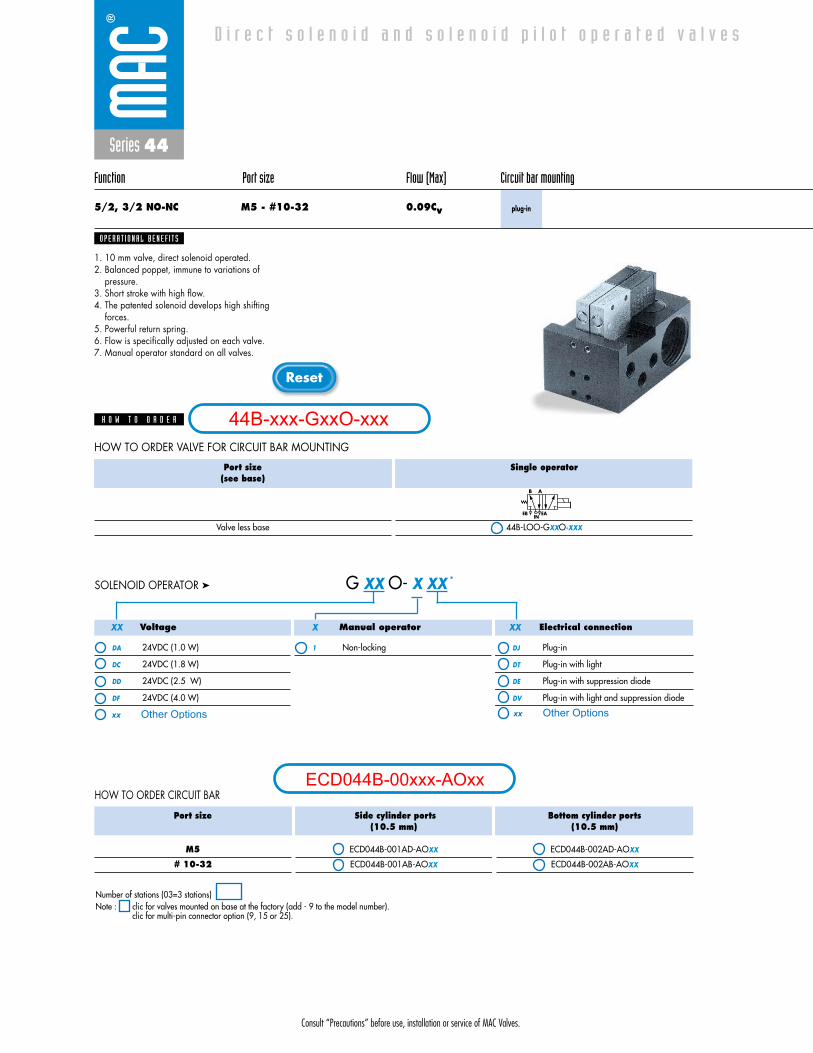
Consult “Precautions” before use, installation or service of MAC Valves.
Reset
Series 44
Function Port size Flow (Max) Circuit bar mounting
5/2, 3/2 NO-NC M5 - #10-32 0.09Cv plug-in
1. 10 mm valve, direct solenoid operated.2. Balanced poppet, immune to variations of
pressure.3. Short stroke with high flow.4. The patented solenoid develops high shifting
forces.5. Powerful return spring.6. Flow is specifically adjusted on each valve.7. Manual operator standard on all valves.
O P E R A T I O N A L B E N E F I T S
D i r e c t s o l e n o i d a n d s o l e n o i d p i l o t o p e r a t e d v a l v e s
H O W T O O R D E R
Port size
M5
# 10-32
Side cylinder ports(10.5 mm)
ECD044B-001AD-AOXX
ECD044B-001AB-AOXX
Bottom cylinder ports(10.5 mm)
ECD044B-002AD-AOXX
ECD044B-002AB-AOXX
Voltage
DA 24VDC (1.0 W)
DC 24VDC (1.8 W)
DD 24VDC (2.5 W)
DF 24VDC (4.0 W)
Manual operator
1 Non-locking
Electrical connection
DJ Plug-in
DT Plug-in with light
DE Plug-in with suppression diode
DV Plug-in with light and suppression diode
G XX O- X XX *SOLENOID OPERATOR ➤
HOW TO ORDER CIRCUIT BAR
XX X XX
Port size(see base)
Valve less base
Single operator
44B-LOO-GXXO-XXX
EB
B A
INEA
HOW TO ORDER VALVE FOR CIRCUIT BAR MOUNTING
Number of stations (03=3 stations)Note : clic for valves mounted on base at the factory (add - 9 to the model number).
clic for multi-pin connector option (9, 15 or 25).
44B-xxx-GxxO-xxx
ECD044B-00xxx-AOxx
Other Optionsxx xx Other Options
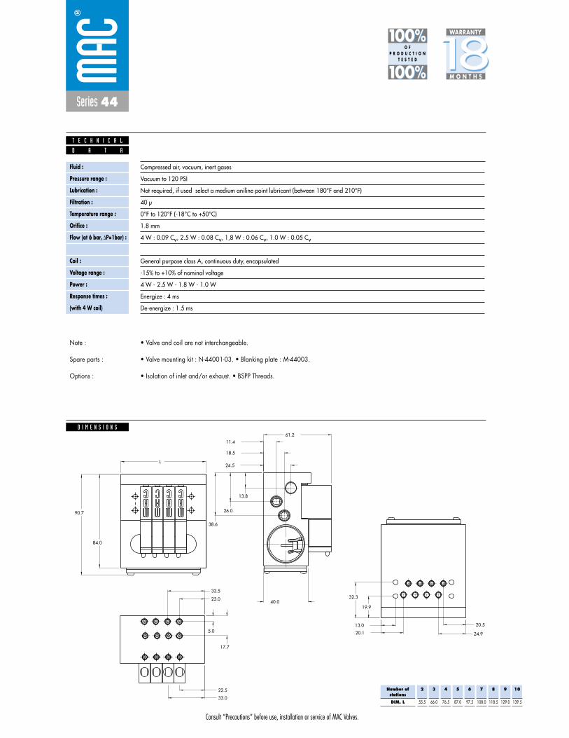
Consult “Precautions” before use, installation or service of MAC Valves.
Series 44
D I M E N S I O N S
Fluid :
Pressure range :
Lubrication :
Filtration :
Temperature range :
Orifice :
Flow (at 6 bar, �P=1bar) :
Leak rate :
Coil :
Voltage range :
Power :
Response times :
(with 4 W coil)
Compressed air, vacuum, inert gases
Vacuum to 120 PSI
Not required, if used select a medium aniline point lubricant (between 180°F and 210°F)
40 μ
0°F to 120°F (-18°C to +50°C)
1.8 mm
4 W : 0.09 Cv, 2.5 W : 0.08 Cv, 1,8 W : 0.06 Cv, 1.0 W : 0.05 Cv
50 cm3/min
General purpose class A, continuous duty, encapsulated
-15% to +10% of nominal voltage
4 W - 2.5 W - 1.8 W - 1.0 W
Energize : 4 ms
De-energize : 1.5 ms
D A T A
T E C H N I C A L
1818100%100%
100%100% M O N T H S
WARRANTY
O FP R O D U C T I O N
T E S T E D
• Valve and coil are not interchangeable.
• Valve mounting kit : N-44001-03. • Blanking plate : M-44003.
• Isolation of inlet and/or exhaust. • BSPP Threads.
Note :
Spare parts :
Options :
33.0
22.5
17.7
5.0
33.5
23.0 32.3
19.9
20.5
24.920.1
13.0
38.6
26.0
13.8
24.5
18.5
11.4
40.0
61.2
L
90.7
84.0
Number ofstations
DIM. L
2
55.5
3
66.0
4
76.5
5
87.0
6
97.5
7
108.0
8
118.5
9
129.0
10
139.5

Consult “Precautions” before use, installation or service of MAC Valves.
Reset
Series 44
Function Port size Flow (Max) Circuit bar mounting
5/2, 3/2 NO-NC M5 - #10-32 0.08Cvplug-in
with F. C.
1. 10 mm valve, direct solenoid operated.2. Balanced poppet, immune to variations of
pressure.3. Short stroke with high flow.4. The patented solenoid develops high shifting
forces.5. Powerful return spring.6. Flow is specifically adjusted on each valve.7. Manual operator standard on all valves.
O P E R A T I O N A L B E N E F I T S
D i r e c t s o l e n o i d a n d s o l e n o i d p i l o t o p e r a t e d v a l v e s
H O W T O O R D E R
Port size
M5
# 10-32
Side cylinder ports(10.5 mm)
ECD044B-005AD-AOXX
ECD044B-005AB-AOXX
Bottom cylinder ports(10.5 mm)
ECD044B-006AD-AOXX
ECD044B-006AB-AOXX
Voltage
DA 24VDC (1.0 W)
DC 24VDC (1.8 W)
DD 24VDC (2.5 W)
DF 24VDC (4.0 W)
Manual operator
1 Non-locking
Electrical connection
DJ Plug-in
DT Plug-in with light
DE Plug-in with suppression diode
DV Plug-in with light and suppression diode
G XX O- X XX *SOLENOID OPERATOR ➤
HOW TO ORDER CIRCUIT BAR WITH FLOW CONTROLS
XX X XX
Port size(see base)
Valve less base
Single operator
44B-MOO-GXXO-XXX
EB
B A
INEA
HOW TO ORDER VALVE FOR CIRCUIT BAR MOUNTING
Number of stations (03=3 stations)Note : clic for valves mounted on base at the factory (add - 9 to the model number).
clic for multi-pin connector option (9, 15 or 25).
44B-xxx-GxxO-xxx
ECD044B-00xxx-AOxx
Other Optionsxx xx Other Options

Consult “Precautions” before use, installation or service of MAC Valves.
Series 44
D I M E N S I O N S
Fluid :
Pressure range :
Lubrication :
Filtration :
Temperature range :
Orifice :
Flow (at 6 bar, �P=1bar) :
Leak rate :
Coil :
Voltage range :
Power :
Response times :
(with 4 W coil)
Compressed air, vacuum, inert gases
Vacuum to 120 PSI
Not required, if used select a medium aniline point lubricant (between 180°F and 210°F)
40 μ
0°F to 120°F (-18°C to +50°C)
1.8 mm
4 W : 0.09 Cv, 2.5 W : 0.08 Cv, 1,8 W : 0.06 Cv, 1.0 W : 0.05 Cv
50 cm3/min
General purpose class A, continuous duty, encapsulated
-15% to +10% of nominal voltage
4 W - 2.5 W - 1.8 W - 1.0 W
Energize : 4 ms
De-energize : 1.5 ms
D A T A
T E C H N I C A L
1818100%100%
100%100% M O N T H S
WARRANTY
O FP R O D U C T I O N
T E S T E D
• Valve and coil are not interchangeable.
• Valve mounting kit : N-44001-03. • Blanking plate : M-44003. • Flow control needle (x2): N-44002.• Base wire Plug-in protector : 24180.• Isolation of inlet and/or exhaust. • BSPP Threads.
Note :
Spare parts :
Options :
84.0
90.7
L61.2
40.0
11.418.5
24.5
13.8
26.0
38.6
13.0
20.1 24.9
20.5
19.9
32.323.0
33.5
5.0
17.7
22.5
33.0
Number ofstations
DIM. L
2
55.5
3
66.0
4
76.5
5
87.0
6
97.5
7
108.0
8
118.5
9
129.0
10
139.5

Consult “Precautions” before use, installation or service of MAC Valves.
Reset
Series 44
Function Port size Flow (Max) Circuit bar mounting
5/2, 3/2 NO-NC M5 - #10-32 0.08Cvplug-in
with Pr. Reg.
1. 10 mm valve, direct solenoid operated.2. Balanced poppet, immune to variations of
pressure.3. Short stroke with high flow.4. The patented solenoid develops high shifting
forces.5. Powerful return spring.6. Flow is specifically adjusted on each valve.7. Manual operator standard on all valves.
O P E R A T I O N A L B E N E F I T S
D i r e c t s o l e n o i d a n d s o l e n o i d p i l o t o p e r a t e d v a l v e s
H O W T O O R D E R
Voltage
DA 24VDC (1.0 W)
DC 24VDC (1.8 W)
DD 24VDC (2.5 W)
DF 24VDC (4.0 W)
Manual operator
1 Non-locking
Electrical connection
DJ Plug-in
DT Plug-in with light
DE Plug-in with suppression diode
DV Plug-in with light and suppression diode
G XX O- X XX *SOLENOID OPERATOR ➤
XX X XX
Port size(see base)
Valve less base
Single operator
44B-LOO-GXXO-XXX
EB
B A
INEA
HOW TO ORDER VALVE FOR CIRCUIT BAR MOUNTING
Port size
M5
# 10-32
Bottom cylinder ports(10,5 mm)
ECD044B-004AD-A0-XX
ECD044B-004AB-A0-XX
HOW TO ORDER CIRCUIT BAR FOR PRESSURE REGULATORS** (to be ordered separately)
** Pressure Regulators :
Y=A (no gage port)Y=B (with gage port)X=A (0 to 100 PSI)X=B (0 to 60 PSI)X=C (0 to 40 PSI)X=D (0 to 15 PSI)
Number of stations (03=3 stations)Note : clic for valves mounted on base at the factory (add - 9 to the model number).
clic for multi-pin connector option (9, 15 or 25).
44B-xxx-GxxO-xxx
ECD044B-00xxx-AOxx
Other Optionsxx xx Other Options
PR44A-AOxx

Consult “Precautions” before use, installation or service of MAC Valves.
Series 44
D I M E N S I O N S
Fluid :
Pressure range :
Lubrication :
Filtration :
Temperature range :
Orifice :
Flow (at 6 bar, �P=1bar) :
Leak rate :
Coil :
Voltage range :
Power :
Response times :
(with 4 W coil)
Compressed air, vacuum, inert gases
Vacuum to 120 PSI
Not required, if used select a medium aniline point lubricant (between 180°F and 210°F)
40 μ
0°F to 120°F (-18°C to +50°C)
1.8 mm
4 W : 0.09 Cv, 2.5 W : 0.08 Cv, 1,8 W : 0.06 Cv, 1.0 W : 0.05 Cv
50 cm3/min
General purpose class A, continuous duty, encapsulated
-15% to +10% of nominal voltage
4 W - 2.5 W - 1.8 W - 1.0 W
Energize : 4 ms
De-energize : 1.5 ms
D A T A
T E C H N I C A L
1818100%100%
100%100% M O N T H S
WARRANTY
O FP R O D U C T I O N
T E S T E D
• Valve and coil are not interchangeable.• Pressure range regulators : (0-100 PSI).• Valve mounting kit : N-44001-03. • Blanking plate : M-44003. • Blanking plate regulator: N-44003.• Base wire Plug-in protector : 24180.• Isolation of inlet and/or exhaust. • BSPP Threads.
Note :
Spare parts :
Options :
144.3
33.0
22.5
17.7
5.0
33.5
23.0
32.3
19.9
20.5
24.920.1
13.0
38.6
26.0
13.8
24.5
18.5
11.4
40.0
61.2L
90.7
84.0
Number ofstations
DIM. L
2
55.5
3
66.0
4
76.5
5
87.0
6
97.5
7
108.0
8
118.5
9
129.0
10
139.5
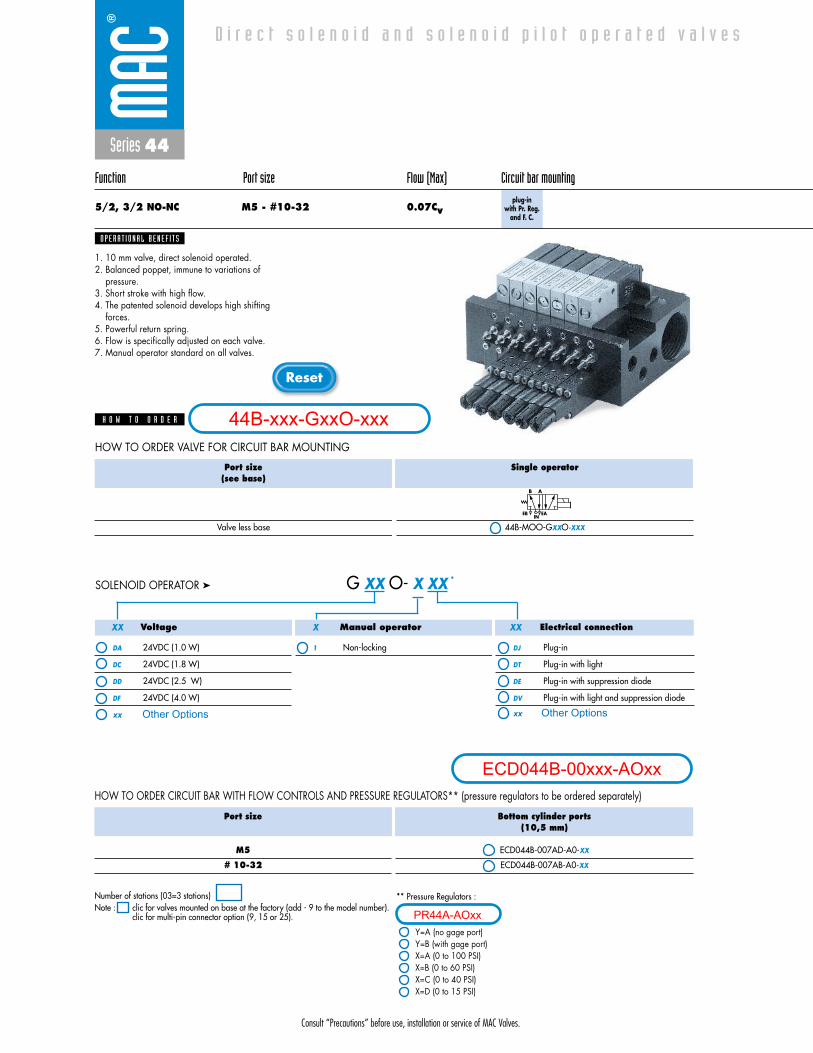
Consult “Precautions” before use, installation or service of MAC Valves.
Reset
Series 44
Function Port size Flow (Max) Circuit bar mounting
5/2, 3/2 NO-NC M5 - #10-32 0.07Cvplug-in
with Pr. Reg.and F. C.
1. 10 mm valve, direct solenoid operated.2. Balanced poppet, immune to variations of
pressure.3. Short stroke with high flow.4. The patented solenoid develops high shifting
forces.5. Powerful return spring.6. Flow is specifically adjusted on each valve.7. Manual operator standard on all valves.
O P E R A T I O N A L B E N E F I T S
D i r e c t s o l e n o i d a n d s o l e n o i d p i l o t o p e r a t e d v a l v e s
H O W T O O R D E R
Voltage
DA 24VDC (1.0 W)
DC 24VDC (1.8 W)
DD 24VDC (2.5 W)
DF 24VDC (4.0 W)
Manual operator
1 Non-locking
Electrical connection
DJ Plug-in
DT Plug-in with light
DE Plug-in with suppression diode
DV Plug-in with light and suppression diode
G XX O- X XX *SOLENOID OPERATOR ➤
XX X XX
Port size(see base)
Valve less base
Single operator
44B-MOO-GXXO-XXX
EB
B A
INEA
HOW TO ORDER VALVE FOR CIRCUIT BAR MOUNTING
Port size
M5
# 10-32
Bottom cylinder ports(10,5 mm)
ECD044B-007AD-A0-XX
ECD044B-007AB-A0-XX
HOW TO ORDER CIRCUIT BAR WITH FLOW CONTROLS AND PRESSURE REGULATORS** (pressure regulators to be ordered separately)
** Pressure Regulators :
Y=A (no gage port)Y=B (with gage port)X=A (0 to 100 PSI)X=B (0 to 60 PSI)X=C (0 to 40 PSI)X=D (0 to 15 PSI)
Number of stations (03=3 stations)Note : clic for valves mounted on base at the factory (add - 9 to the model number).
clic for multi-pin connector option (9, 15 or 25).
44B-xxx-GxxO-xxx
ECD044B-00xxx-AOxx
Other Optionsxx xx Other Options
PR44A-AOxx
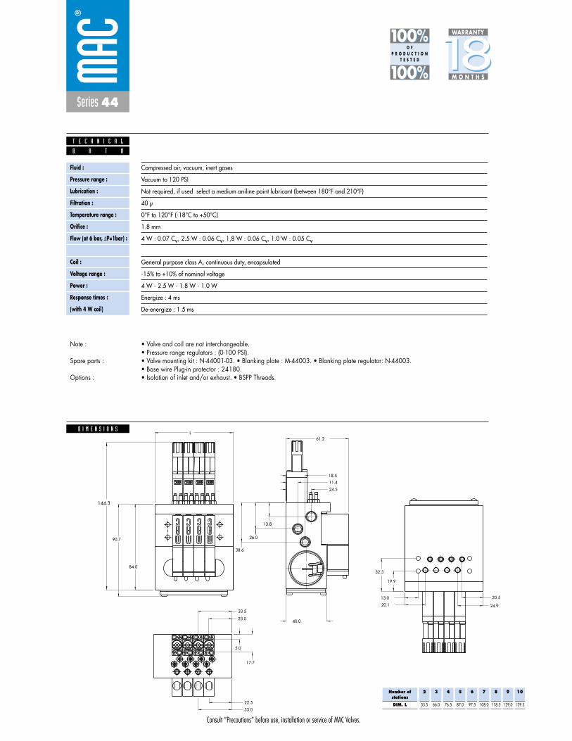
Consult “Precautions” before use, installation or service of MAC Valves.
Series 44
D I M E N S I O N S
Fluid :
Pressure range :
Lubrication :
Filtration :
Temperature range :
Orifice :
Flow (at 6 bar, �P=1bar) :
Leak rate :
Coil :
Voltage range :
Power :
Response times :
(with 4 W coil)
Compressed air, vacuum, inert gases
Vacuum to 120 PSI
Not required, if used select a medium aniline point lubricant (between 180°F and 210°F)
40 μ
0°F to 120°F (-18°C to +50°C)
1.8 mm
4 W : 0.07 Cv, 2.5 W : 0.06 Cv, 1,8 W : 0.06 Cv, 1.0 W : 0.05 Cv
50 cm3/min
General purpose class A, continuous duty, encapsulated
-15% to +10% of nominal voltage
4 W - 2.5 W - 1.8 W - 1.0 W
Energize : 4 ms
De-energize : 1.5 ms
D A T A
T E C H N I C A L
1818100%100%
100%100% M O N T H S
WARRANTY
O FP R O D U C T I O N
T E S T E D
• Valve and coil are not interchangeable.• Pressure range regulators : (0-100 PSI).• Valve mounting kit : N-44001-03. • Blanking plate : M-44003. • Blanking plate regulator: N-44003.• Base wire Plug-in protector : 24180.• Isolation of inlet and/or exhaust. • BSPP Threads.
Note :
Spare parts :
Options :
144.3
33.0
22.5
17.7
5.0
33.5
23.0
32.3
19.9
20.5
24.920.1
13.0
38.6
26.0
13.8
24.5
18.5
11.4
40.0
61.2L
90.7
84.0
Number ofstations
DIM. L
2
55.5
3
66.0
4
76.5
5
87.0
6
97.5
7
108.0
8
118.5
9
129.0
10
139.5
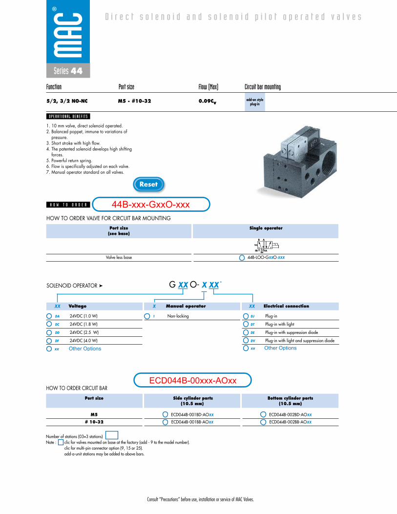
Consult “Precautions” before use, installation or service of MAC Valves.
Reset
Series 44
Function Port size Flow (Max) Circuit bar mounting
5/2, 3/2 NO-NC M5 - #10-32 0.09Cvadd-on style
plug-in
1. 10 mm valve, direct solenoid operated.2. Balanced poppet, immune to variations of
pressure.3. Short stroke with high flow.4. The patented solenoid develops high shifting
forces.5. Powerful return spring.6. Flow is specifically adjusted on each valve.7. Manual operator standard on all valves.
O P E R A T I O N A L B E N E F I T S
D i r e c t s o l e n o i d a n d s o l e n o i d p i l o t o p e r a t e d v a l v e s
H O W T O O R D E R
Voltage
DA 24VDC (1.0 W)
DC 24VDC (1.8 W)
DD 24VDC (2.5 W)
DF 24VDC (4.0 W)
Manual operator
1 Non-locking
Electrical connection
DJ Plug-in
DT Plug-in with light
DE Plug-in with suppression diode
DV Plug-in with light and suppression diode
G XX O- X XX *SOLENOID OPERATOR ➤
XX X XX
Port size(see base)
Valve less base
Single operator
44B-LOO-GXXO-XXX
EB
B A
INEA
HOW TO ORDER VALVE FOR CIRCUIT BAR MOUNTING
Port size
M5
# 10-32
Side cylinder ports(10.5 mm)
ECD044B-001BD-AOXX
ECD044B-001BB-AOXX
Bottom cylinder ports(10.5 mm)
ECD044B-002BD-AOXX
ECD044B-002BB-AOXX
HOW TO ORDER CIRCUIT BAR
Number of stations (03=3 stations)Note : clic for valves mounted on base at the factory (add - 9 to the model number).
clic for multi-pin connector option (9, 15 or 25).add-a-unit stations may be added to above bars.
44B-xxx-GxxO-xxx
ECD044B-00xxx-AOxx
Other Optionsxx xx Other Options

Consult “Precautions” before use, installation or service of MAC Valves.
Series 44
D I M E N S I O N S
Fluid :
Pressure range :
Lubrication :
Filtration :
Temperature range :
Orifice :
Flow (at 6 bar, �P=1bar) :
Leak rate :
Coil :
Voltage range :
Power :
Response times :
(with 4 W coil)
Compressed air, vacuum, inert gases
Vacuum to 120 PSI
Not required, if used select a medium aniline point lubricant (between 180°F and 210°F)
40 μ
0°F to 120°F (-18°C to +50°C)
1.8 mm
4 W : 0.09 Cv, 2.5 W : 0.08 Cv, 1,8 W : 0.06 Cv, 1.0 W : 0.05 Cv
50 cm3/min
General purpose class A, continuous duty, encapsulated
-15% to +10% of nominal voltage
4 W - 2.5 W - 1.8 W - 1.0 W
Energize : 4 ms
De-energize : 1.5 ms
D A T A
T E C H N I C A L
1818100%100%
100%100% M O N T H S
WARRANTY
O FP R O D U C T I O N
T E S T E D
• Valve and coil are not interchangeable.
• Valve mounting kit : N-44001-03. • Blanking plate : M-44003.
• Isolation of inlet and/or exhaust. • BSPP Threads.
Note :
Spare parts :
Options :
A
B
A
B
20.0
18.5
11.3
24.5
90.7
60.5
15.510.510.5
41.5
A
BB
AA
B
B
A
EXH
EXH
IN
84.0
B
A
32.331.320.919.9
13.0
20.5
25.0
10.5
5.017.7
20.7
60.5
13.8
26.0
38.6
64.2

Consult “Precautions” before use, installation or service of MAC Valves.
Reset
Series 44
Function Port size Flow (Max) Circuit bar mounting
5/2, 3/2 NO-NC M5 - #10-32 0.08Cvadd-on style
plug-inwith F. C.
1. 10 mm valve, direct solenoid operated.2. Balanced poppet, immune to variations of
pressure.3. Short stroke with high flow.4. The patented solenoid develops high shifting
forces.5. Powerful return spring.6. Flow is specifically adjusted on each valve.7. Manual operator standard on all valves.
O P E R A T I O N A L B E N E F I T S
D i r e c t s o l e n o i d a n d s o l e n o i d p i l o t o p e r a t e d v a l v e s
H O W T O O R D E R
Voltage
DA 24VDC (1.0 W)
DC 24VDC (1.8 W)
DD 24VDC (2.5 W)
DF 24VDC (4.0 W)
Manual operator
1 Non-locking
Electrical connection
DJ Plug-in
DT Plug-in with light
DE Plug-in with suppression diode
DV Plug-in with light and suppression diode
G XX O- X XX *SOLENOID OPERATOR ➤
XX X XX
Port size(see base)
Valve less base
Single operator
44B-MOO-GXXO-XXX
EB
B A
INEA
HOW TO ORDER VALVE FOR CIRCUIT BAR MOUNTING
Port size
M5
# 10-32
Side cylinder ports(10.5 mm)
ECD044B-005BD-AOXX
ECD044B-005BB-AOXX
Bottom cylinder ports(10.5 mm)
ECD044B-006BD-AOXX
ECD044B-006BB-AOXX
HOW TO ORDER CIRCUIT BAR WITH FLOW CONTROLS
Number of stations (03=3 stations)Note : clic for valves mounted on base at the factory (add - 9 to the model number).
clic for multi-pin connector option (9, 15 or 25).add-a-unit stations may be added to above bars.
44B-xxx-GxxO-xxx
ECD044B-00xxx-AOxx
Other Optionsxx xx Other Options
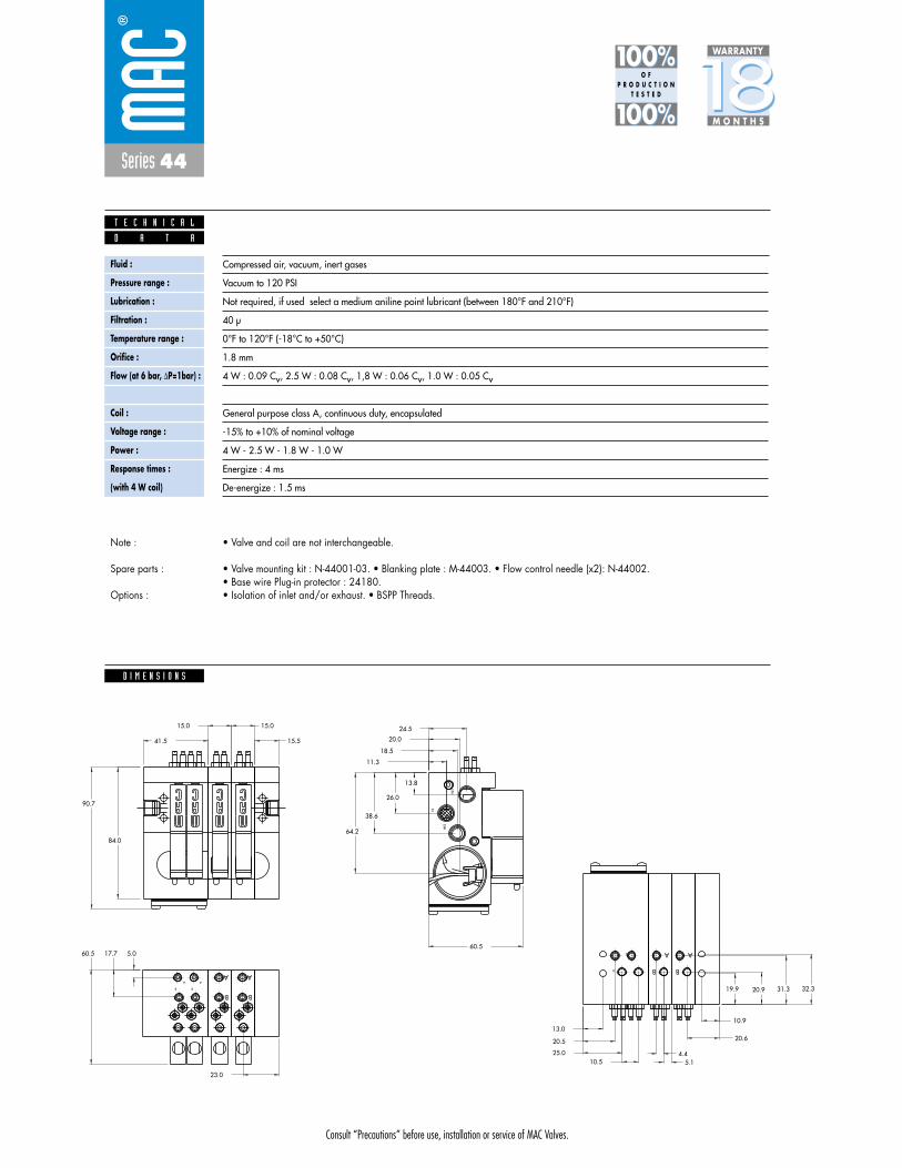
Consult “Precautions” before use, installation or service of MAC Valves.
Series 44
D I M E N S I O N S
Fluid :
Pressure range :
Lubrication :
Filtration :
Temperature range :
Orifice :
Flow (at 6 bar, �P=1bar) :
Leak rate :
Coil :
Voltage range :
Power :
Response times :
(with 4 W coil)
Compressed air, vacuum, inert gases
Vacuum to 120 PSI
Not required, if used select a medium aniline point lubricant (between 180°F and 210°F)
40 μ
0°F to 120°F (-18°C to +50°C)
1.8 mm
4 W : 0.09 Cv, 2.5 W : 0.08 Cv, 1,8 W : 0.06 Cv, 1.0 W : 0.05 Cv
50 cm3/min
General purpose class A, continuous duty, encapsulated
-15% to +10% of nominal voltage
4 W - 2.5 W - 1.8 W - 1.0 W
Energize : 4 ms
De-energize : 1.5 ms
D A T A
T E C H N I C A L
1818100%100%
100%100% M O N T H S
WARRANTY
O FP R O D U C T I O N
T E S T E D
• Valve and coil are not interchangeable.
• Valve mounting kit : N-44001-03. • Blanking plate : M-44003. • Flow control needle (x2): N-44002.• Base wire Plug-in protector : 24180.• Isolation of inlet and/or exhaust. • BSPP Threads.
Note :
Spare parts :
Options :
23.0
4.45.1
20.6
10.9
32.331.320.919.9
15.0
15.5
15.0
IN
EXH
EXH
A
B
B
A A
B
B
A
B
A
A
B
A
B
64.2
38.6
26.0
13.8
60.5 17.7 5.0
10.525.0
20.5
13.0
84.0
41.5
60.5
90.7
24.5
11.3
18.5
20.0

Consult “Precautions” before use, installation or service of MAC Valves.
Reset
Series 44
Function Port size Flow (Max) Circuit bar mounting
5/2, 3/2 NO-NC M5 - #10-32 0.08Cvadd-on style
plug-inwith Pr. Reg.
1. 10 mm valve, direct solenoid operated.2. Balanced poppet, immune to variations of
pressure.3. Short stroke with high flow.4. The patented solenoid develops high shifting
forces.5. Powerful return spring.6. Flow is specifically adjusted on each valve.7. Manual operator standard on all valves.
O P E R A T I O N A L B E N E F I T S
D i r e c t s o l e n o i d a n d s o l e n o i d p i l o t o p e r a t e d v a l v e s
H O W T O O R D E R
Voltage
DA 24VDC (1.0 W)
DC 24VDC (1.8 W)
DD 24VDC (2.5 W)
DF 24VDC (4.0 W)
Manual operator
1 Non-locking
Electrical connection
DJ Plug-in
DT Plug-in with light
DE Plug-in with suppression diode
DV Plug-in with light and suppression diode
G XX O- X XX *SOLENOID OPERATOR ➤
XX X XX
Port size(see base)
Valve less base
Single operator
44B-LOO-GXXO-XXX
EB
B A
INEA
HOW TO ORDER VALVE FOR CIRCUIT BAR MOUNTING
Port size
M5
# 10-32
Bottom cylinder ports(10,5 mm)
ECD044B-004BD-A0-XX
ECD044B-004BB-A0-XX
HOW TO ORDER CIRCUIT BAR FOR PRESSURE REGULATORS** (to be ordered separately)
** Pressure Regulators :
Y=A (no gage port)Y=B (with gage port)X=A (0 to 100 PSI)X=B (0 to 60 PSI)X=C (0 to 40 PSI)X=D (0 to 15 PSI)
Number of stations (03=3 stations)Note : clic for valves mounted on base at the factory (add - 9 to the model number).
clic for multi-pin connector option (9, 15 or 25).add-a-unit stations may be added to above bars.
44B-xxx-GxxO-xxx
ECD044B-00xxx-AOxx
Other Optionsxx xx Other Options
PR44A-AOxx

Consult “Precautions” before use, installation or service of MAC Valves.
Series 44
D I M E N S I O N S
Fluid :
Pressure range :
Lubrication :
Filtration :
Temperature range :
Orifice :
Flow (at 6 bar, �P=1bar) :
Leak rate :
Coil :
Voltage range :
Power :
Response times :
(with 4 W coil)
Compressed air, vacuum, inert gases
Vacuum to 120 PSI
Not required, if used select a medium aniline point lubricant (between 180°F and 210°F)
40 μ
0°F to 120°F (-18°C to +50°C)
1.8 mm
4 W : 0.09 Cv, 2.5 W : 0.08 Cv, 1,8 W : 0.06 Cv, 1.0 W : 0.05 Cv
50 cm3/min
General purpose class A, continuous duty, encapsulated
-15% to +10% of nominal voltage
4 W - 2.5 W - 1.8 W - 1.0 W
Energize : 4 ms
De-energize : 1.5 ms
D A T A
T E C H N I C A L
1818100%100%
100%100% M O N T H S
WARRANTY
O FP R O D U C T I O N
T E S T E D
• Valve and coil are not interchangeable.• Pressure range regulators : (0-100 PSI).• Valve mounting kit : N-44001-03. • Blanking plate : M-44003. • Blanking plate regulator: N-44003.• Base wire Plug-in protector : 24180.• Isolation of inlet and/or exhaust. • BSPP Threads.
Note :
Spare parts :
Options :
144.3
-+
L
OCK
-+
L
OCKA K C O
L
+ -
K C O
L
+ -
A
B
A
B
20.0
18.5
11.3
24.5
90.7
60.5
15.5
10.510.541.5
B
A
EXH
EXH
IN
84.0
32.331.320.919.9
13.0
20.5
25.0
10.5
5.017.7
20.7
60.5
13.8
26.0
38.6
64.2
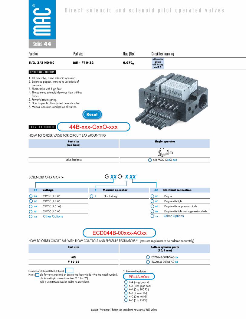
Consult “Precautions” before use, installation or service of MAC Valves.
Reset
Series 44
Function Port size Flow (Max) Circuit bar mounting
5/2, 3/2 NO-NC M5 - #10-32 0.07Cvadd-on style
plug-inwith Pr. Reg.
and F. C.
1. 10 mm valve, direct solenoid operated.2. Balanced poppet, immune to variations of
pressure.3. Short stroke with high flow.4. The patented solenoid develops high shifting
forces.5. Powerful return spring.6. Flow is specifically adjusted on each valve.7. Manual operator standard on all valves.
O P E R A T I O N A L B E N E F I T S
D i r e c t s o l e n o i d a n d s o l e n o i d p i l o t o p e r a t e d v a l v e s
H O W T O O R D E R
Voltage
DA 24VDC (1.0 W)
DC 24VDC (1.8 W)
DD 24VDC (2.5 W)
DF 24VDC (4.0 W)
Manual operator
1 Non-locking
Electrical connection
DJ Plug-in
DT Plug-in with light
DE Plug-in with suppression diode
DV Plug-in with light and suppression diode
G XX O- X XX *SOLENOID OPERATOR ➤
XX X XX
Port size(see base)
Valve less base
Single operator
44B-MOO-GXXO-XXX
EB
B A
INEA
HOW TO ORDER VALVE FOR CIRCUIT BAR MOUNTING
Port size
M5
# 10-32
Bottom cylinder ports(10,5 mm)
ECD044B-007BD-A0-XX
ECD044B-007BB-A0-XX
HOW TO ORDER CIRCUIT BAR WITH FLOW CONTROLS AND PRESSURE REGULATORS** (pressure regulators to be ordered separately)
** Pressure Regulators :
Y=A (no gage port)Y=B (with gage port)X=A (0 to 100 PSI)X=B (0 to 60 PSI)X=C (0 to 40 PSI)X=D (0 to 15 PSI)
Number of stations (03=3 stations)Note : clic for valves mounted on base at the factory (add - 9 to the model number).
clic for multi-pin connector option (9, 15 or 25).add-a-unit stations may be added to above bars.
44B-xxx-GxxO-xxx
ECD044B-00xxx-AOxx
Other Optionsxx xx Other Options
PR44A-AOxx
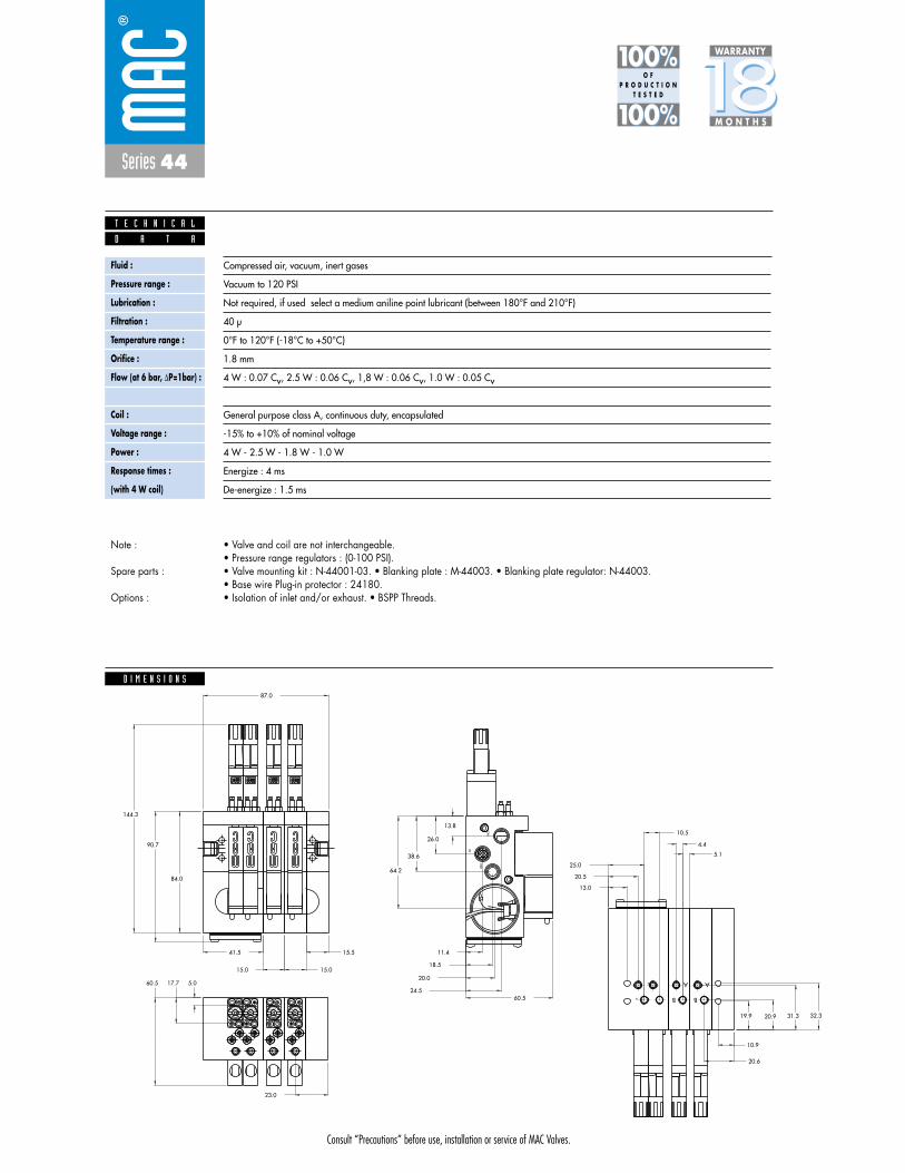
Consult “Precautions” before use, installation or service of MAC Valves.
Series 44
D I M E N S I O N S
Fluid :
Pressure range :
Lubrication :
Filtration :
Temperature range :
Orifice :
Flow (at 6 bar, �P=1bar) :
Leak rate :
Coil :
Voltage range :
Power :
Response times :
(with 4 W coil)
Compressed air, vacuum, inert gases
Vacuum to 120 PSI
Not required, if used select a medium aniline point lubricant (between 180°F and 210°F)
40 μ
0°F to 120°F (-18°C to +50°C)
1.8 mm
4 W : 0.07 Cv, 2.5 W : 0.06 Cv, 1,8 W : 0.06 Cv, 1.0 W : 0.05 Cv
50 cm3/min
General purpose class A, continuous duty, encapsulated
-15% to +10% of nominal voltage
4 W - 2.5 W - 1.8 W - 1.0 W
Energize : 4 ms
De-energize : 1.5 ms
D A T A
T E C H N I C A L
1818100%100%
100%100% M O N T H S
WARRANTY
O FP R O D U C T I O N
T E S T E D
• Valve and coil are not interchangeable.• Pressure range regulators : (0-100 PSI).• Valve mounting kit : N-44001-03. • Blanking plate : M-44003. • Blanking plate regulator: N-44003.• Base wire Plug-in protector : 24180.• Isolation of inlet and/or exhaust. • BSPP Threads.
Note :
Spare parts :
Options :
144.3
87.0
25.0
20.5
13.0
24.5
20.0
18.5
11.415.5
15.015.0
41.5
K C O
L
+ -
K C O
L
+ -
K C O
L
+ -
K C O
L
+ -
B
A
B
A
B
A
EXH
EXH
IN
19.9 20.9 31.3 32.3
10.9
20.6
5.1
4.4
23.0
90.7
60.5
84.0
10.5
5.017.760.5
13.8
26.0
38.6
64.2

Consult “Precautions” before use, installation or service of MAC Valves.
Reset
Series 44
Function Port size Flow (Max) Circuit bar mounting
5/2 M5 - #10-32 0.09Cvplug-in
add-a-unitstations
1. 10 mm valve, direct solenoid operated.2. Balanced poppet, immune to variations of
pressure.3. Short stroke with high flow.4. The patented solenoid develops high shifting
forces.5. Powerful return spring.6. Flow is specifically adjusted on each valve.7. Manual operator standard on all valves.
O P E R A T I O N A L B E N E F I T S
D i r e c t s o l e n o i d a n d s o l e n o i d p i l o t o p e r a t e d v a l v e s
H O W T O O R D E R
HOW TO ORDER VALVE FOR CIRCUIT BAR MOUNTING
Port size
M5
# 10-32
Side cylinder ports
ECD044B-001CD-AOXX
ECD044B-001CB-AOXX
Bottom cylinder ports
ECD044B-002CD-AOXX
ECD044B-002CB-AOXX
HOW TO ORDER CIRCUIT BAR
Voltage
DA 24VDC (1.0 W)
DC 24VDC (1.8 W)
DD 24VDC (2.5 W)
DF 24VDC (4.0 W)
Manual operator
1 Non-locking
Electrical connection
DJ Plug-in
DT Plug-in with light
DE Plug-in with suppression diode
DV Plug-in with light and suppression diode
G XX O- X XX *SOLENOID OPERATOR ➤
XX X XX
Number of stations (03=3 stations) - Maximum length is 4 stationsNote : clic for valves mounted on base at the factory (add - 9 to the model number).
when add-a-unit stations are added to bars with a multi-pin connector,MOD. SD03 should be included with add-a-unit model number.
Port size(see base)
Valve less base
Single operator
44B-LOO-GXXO-XXX
EB
B A
INEA
44B-xxx-GxxO-xxx
ECD044B-00xxx-AOxx
Other Optionsxx xx Other Options
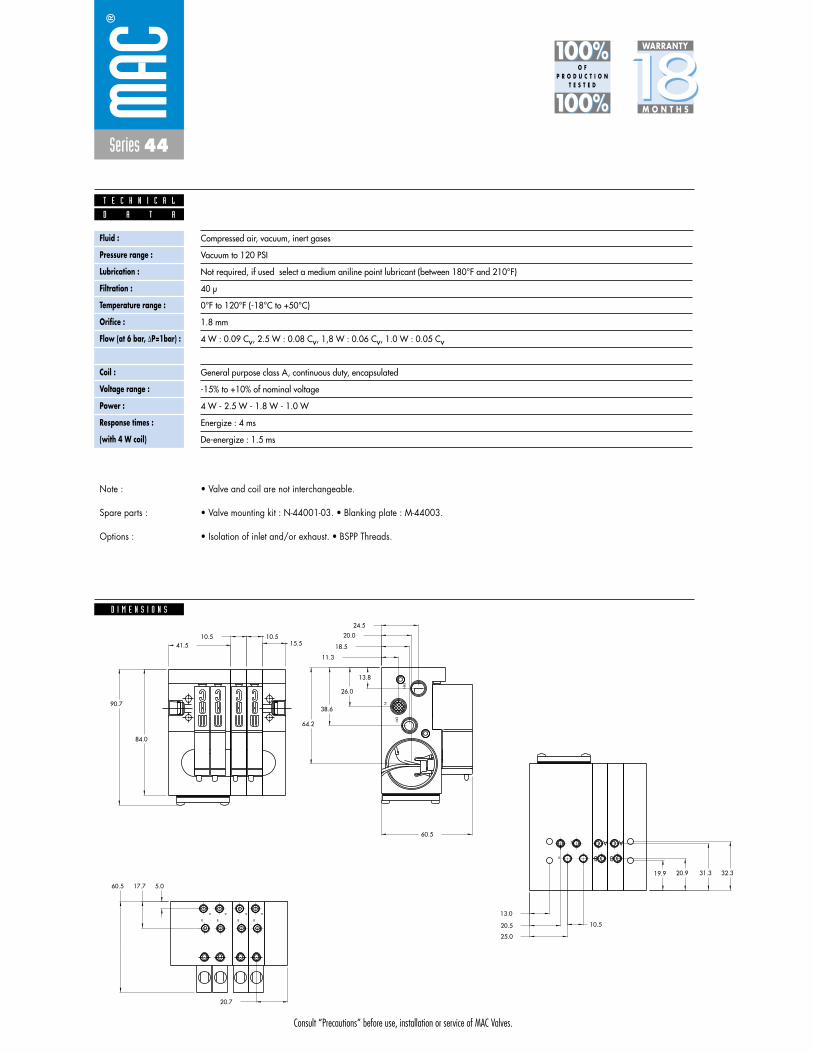
Consult “Precautions” before use, installation or service of MAC Valves.
Series 44
D I M E N S I O N S
Fluid :
Pressure range :
Lubrication :
Filtration :
Temperature range :
Orifice :
Flow (at 6 bar, �P=1bar) :
Leak rate :
Coil :
Voltage range :
Power :
Response times :
(with 4 W coil)
Compressed air, vacuum, inert gases
Vacuum to 120 PSI
Not required, if used select a medium aniline point lubricant (between 180°F and 210°F)
40 μ
0°F to 120°F (-18°C to +50°C)
1.8 mm
4 W : 0.09 Cv, 2.5 W : 0.08 Cv, 1,8 W : 0.06 Cv, 1.0 W : 0.05 Cv
50 cm3/min
General purpose class A, continuous duty, encapsulated
-15% to +10% of nominal voltage
4 W - 2.5 W - 1.8 W - 1.0 W
Energize : 4 ms
De-energize : 1.5 ms
D A T A
T E C H N I C A L
1818100%100%
100%100% M O N T H S
WARRANTY
O FP R O D U C T I O N
T E S T E D
• Valve and coil are not interchangeable.
• Valve mounting kit : N-44001-03. • Blanking plate : M-44003.
• Isolation of inlet and/or exhaust. • BSPP Threads.
Note :
Spare parts :
Options :
A
B
A
B
20.0
18.5
11.3
24.5
90.7
60.5
15.510.510.5
41.5
A
BB
AA
B
B
A
EXH
EXH
IN
84.0
B
A
32.331.320.919.9
13.0
20.5
25.0
10.5
5.017.7
20.7
60.5
13.8
26.0
38.6
64.2
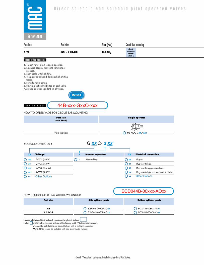
Consult “Precautions” before use, installation or service of MAC Valves.
Reset
Series 44
Function Port size Flow (Max) Circuit bar mounting
5/2 M5 - #10-32 0.08Cvplug-in
add-a-unitstations
with F. C.
1. 10 mm valve, direct solenoid operated.2. Balanced poppet, immune to variations of
pressure.3. Short stroke with high flow.4. The patented solenoid develops high shifting
forces.5. Powerful return spring.6. Flow is specifically adjusted on each valve.7. Manual operator standard on all valves.
O P E R A T I O N A L B E N E F I T S
D i r e c t s o l e n o i d a n d s o l e n o i d p i l o t o p e r a t e d v a l v e s
H O W T O O R D E R
Port size
M5
# 10-32
Side cylinder ports
ECD044B-005CD-AOXX
ECD044B-005CB-AOXX
Bottom cylinder ports
ECD044B-006CD-AOXX
ECD044B-006CB-AOXX
HOW TO ORDER CIRCUIT BAR WITH FLOW CONTROLS
Voltage
DA 24VDC (1.0 W)
DC 24VDC (1.8 W)
DD 24VDC (2.5 W)
DF 24VDC (4.0 W)
Manual operator
1 Non-locking
Electrical connection
DJ Plug-in
DT Plug-in with light
DE Plug-in with suppression diode
DV Plug-in with light and suppression diode
G XX O- X XX *SOLENOID OPERATOR ➤
XX X XX
Number of stations (03=3 stations) - Maximum length is 4 stationsNote : clic for valves mounted on base at the factory (add - 9 to the model number).
when add-a-unit stations are added to bars with a multi-pin connector, MOD. SD03 should be included with add-a-unit model number.
HOW TO ORDER VALVE FOR CIRCUIT BAR MOUNTING
Port size(see base)
Valve less base
Single operator
44B-MOO-GXXO-XXX
EB
B A
INEA
44B-xxx-GxxO-xxx
ECD044B-00xxx-AOxx
Other Optionsxx xx Other Options

Consult “Precautions” before use, installation or service of MAC Valves.
Series 44
D I M E N S I O N S
Fluid :
Pressure range :
Lubrication :
Filtration :
Temperature range :
Orifice :
Flow (at 6 bar, �P=1bar) :
Leak rate :
Coil :
Voltage range :
Power :
Response times :
(with 4 W coil)
Compressed air, vacuum, inert gases
Vacuum to 120 PSI
Not required, if used select a medium aniline point lubricant (between 180°F and 210°F)
40 μ
0°F to 120°F (-18°C to +50°C)
1.8 mm
4 W : 0.09 Cv, 2.5 W : 0.08 Cv, 1,8 W : 0.06 Cv, 1.0 W : 0.05 Cv
50 cm3/min
General purpose class A, continuous duty, encapsulated
-15% to +10% of nominal voltage
4 W - 2.5 W - 1.8 W - 1.0 W
Energize : 4 ms
De-energize : 1.5 ms
D A T A
T E C H N I C A L
1818100%100%
100%100% M O N T H S
WARRANTY
O FP R O D U C T I O N
T E S T E D
• Valve and coil are not interchangeable.
• Valve mounting kit : N-44001-03. • Blanking plate : M-44003. • Flow control needle (x2): N-44002.• Base wire Plug-in protector : 24180.• Isolation of inlet and/or exhaust. • BSPP Threads.
Note :
Spare parts :
Options :
23.0
4.45.1
20.6
10.9
32.331.320.919.9
15.0
15.5
15.0
IN
EXH
EXH
A
B
B
A A
B
B
A
B
A
A
B
A
B
64.2
38.6
26.0
13.8
60.5 17.7 5.0
10.525.0
20.5
13.0
84.0
41.5
60.5
90.7
24.5
11.3
18.5
20.0

Consult “Precautions” before use, installation or service of MAC Valves.
Reset
Series 44
Function Port size Flow (Max) Circuit bar mounting
5/2 M5 - #10-32 0.08Cvplug-in
add-a-unitstations
with Pr. Reg.
1. 10 mm valve, direct solenoid operated.2. Balanced poppet, immune to variations of
pressure.3. Short stroke with high flow.4. The patented solenoid develops high shifting
forces.5. Powerful return spring.6. Flow is specifically adjusted on each valve.7. Manual operator standard on all valves.
O P E R A T I O N A L B E N E F I T S
D i r e c t s o l e n o i d a n d s o l e n o i d p i l o t o p e r a t e d v a l v e s
H O W T O O R D E R
HOW TO ORDER CIRCUIT BAR FOR PRESSURE REGULATORS ** (to be ordered separately)
** Regulator ordered separately-see below :
Y=A (no gage port)Y=B (with gage port)X=A (0 to 100 PSI)X=B (0 to 60 PSI)X=C (0 to 40 PSI)X=D (0 to 15 PSI)
Port size
M5
# 10-32
Bottom cylinder ports(10,5 mm)
ECD044B-004CD-AOXX
ECD044B-004CB-AOXX
Voltage
DA 24VDC (1.0 W)
DC 24VDC (1.8 W)
DD 24VDC (2.5 W)
DF 24VDC (4.0 W)
Manual operator
1 Non-locking
Electrical connection
DJ Plug-in
DT Plug-in with light
DE Plug-in with suppression diode
DV Plug-in with light and suppression diode
G XX O- X XX *SOLENOID OPERATOR ➤
XX X XX
Number of stations (03=3 stations) - Maximum length is 4 stationsNote : clic for valves mounted on base at the factory (add - 9 to the model number).
when add-a-unit stations are added to bars with a multi-pin connector, MOD. SD03 should be included with add-a-unit model number.
HOW TO ORDER VALVE FOR CIRCUIT BAR MOUNTING
Port size(see base)
Valve less base
Single operator
44B-LOO-GXXO-XXX
EB
B A
INEA
44B-xxx-GxxO-xxx
ECD044B-00xxx-AOxx
Other Optionsxx xx Other Options
PR44A-AOxx
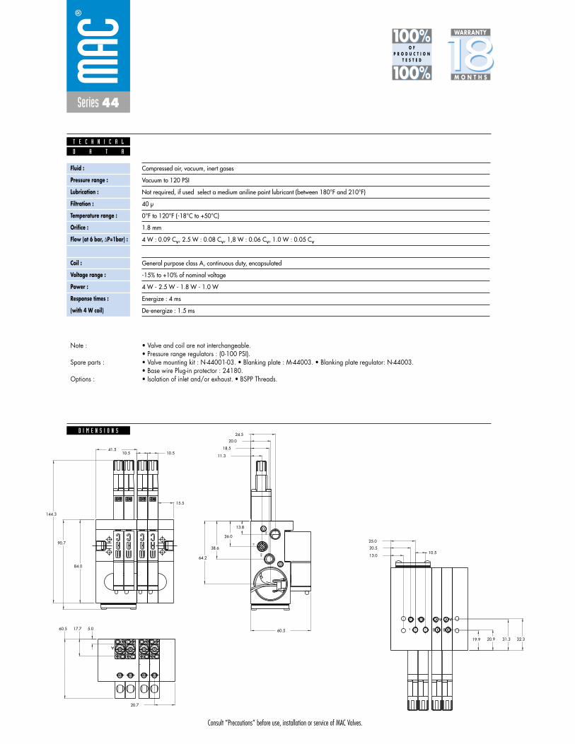
Consult “Precautions” before use, installation or service of MAC Valves.
Series 44
D I M E N S I O N S
Fluid :
Pressure range :
Lubrication :
Filtration :
Temperature range :
Orifice :
Flow (at 6 bar, �P=1bar) :
Leak rate :
Coil :
Voltage range :
Power :
Response times :
(with 4 W coil)
Compressed air, vacuum, inert gases
Vacuum to 120 PSI
Not required, if used select a medium aniline point lubricant (between 180°F and 210°F)
40 μ
0°F to 120°F (-18°C to +50°C)
1.8 mm
4 W : 0.09 Cv, 2.5 W : 0.08 Cv, 1,8 W : 0.06 Cv, 1.0 W : 0.05 Cv
50 cm3/min
General purpose class A, continuous duty, encapsulated
-15% to +10% of nominal voltage
4 W - 2.5 W - 1.8 W - 1.0 W
Energize : 4 ms
De-energize : 1.5 ms
D A T A
T E C H N I C A L
1818100%100%
100%100% M O N T H S
WARRANTY
O FP R O D U C T I O N
T E S T E D
• Valve and coil are not interchangeable.• Pressure range regulators : (0-100 PSI).• Valve mounting kit : N-44001-03. • Blanking plate : M-44003. • Blanking plate regulator: N-44003.• Base wire Plug-in protector : 24180.• Isolation of inlet and/or exhaust. • BSPP Threads.
Note :
Spare parts :
Options :
144.3
-+
L
OCK
-+
L
OCKA K C O
L
+ -
K C O
L
+ -
A
B
A
B
20.0
18.5
11.3
24.5
90.7
60.5
15.5
10.510.541.5
B
A
EXH
EXH
IN
84.0
32.331.320.919.9
13.0
20.5
25.0
10.5
5.017.7
20.7
60.5
13.8
26.0
38.6
64.2
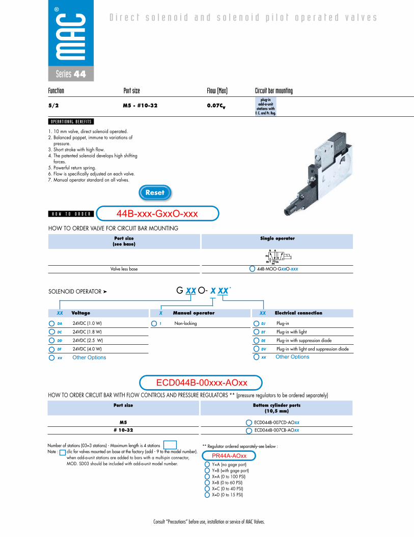
Consult “Precautions” before use, installation or service of MAC Valves.
Reset
Series 44
Function Port size Flow (Max) Circuit bar mounting
5/2 M5 - #10-32 0.07Cvplug-in
add-a-unitstations with
F. C. and Pr. Reg.
1. 10 mm valve, direct solenoid operated.2. Balanced poppet, immune to variations of
pressure.3. Short stroke with high flow.4. The patented solenoid develops high shifting
forces.5. Powerful return spring.6. Flow is specifically adjusted on each valve.7. Manual operator standard on all valves.
O P E R A T I O N A L B E N E F I T S
D i r e c t s o l e n o i d a n d s o l e n o i d p i l o t o p e r a t e d v a l v e s
H O W T O O R D E R
HOW TO ORDER CIRCUIT BAR WITH FLOW CONTROLS AND PRESSURE REGULATORS ** (pressure regulators to be ordered separately)
Port size
M5
# 10-32
Bottom cylinder ports(10,5 mm)
ECD044B-007CD-AOXX
ECD044B-007CB-AOXX
Voltage
DA 24VDC (1.0 W)
DC 24VDC (1.8 W)
DD 24VDC (2.5 W)
DF 24VDC (4.0 W)
Manual operator
1 Non-locking
Electrical connection
DJ Plug-in
DT Plug-in with light
DE Plug-in with suppression diode
DV Plug-in with light and suppression diode
G XX O- X XX *SOLENOID OPERATOR ➤
XX X XX
** Regulator ordered separately-see below :
Y=A (no gage port)Y=B (with gage port)X=A (0 to 100 PSI)X=B (0 to 60 PSI)X=C (0 to 40 PSI)X=D (0 to 15 PSI)
Number of stations (03=3 stations) - Maximum length is 4 stationsNote : clic for valves mounted on base at the factory (add - 9 to the model number).
when add-a-unit stations are added to bars with a multi-pin connector, MOD. SD03 should be included with add-a-unit model number.
HOW TO ORDER VALVE FOR CIRCUIT BAR MOUNTING
Port size(see base)
Valve less base
Single operator
44B-MOO-GXXO-XXX
EB
B A
INEA
44B-xxx-GxxO-xxx
ECD044B-00xxx-AOxx
Other Optionsxx xx Other Options
PR44A-AOxx

Consult “Precautions” before use, installation or service of MAC Valves.
Series 44
D I M E N S I O N S
Fluid :
Pressure range :
Lubrication :
Filtration :
Temperature range :
Orifice :
Flow (at 6 bar, �P=1bar) :
Leak rate :
Coil :
Voltage range :
Power :
Response times :
(with 4 W coil)
Compressed air, vacuum, inert gases
Vacuum to 120 PSI
Not required, if used select a medium aniline point lubricant (between 180°F and 210°F)
40 μ
0°F to 120°F (-18°C to +50°C)
1.8 mm
4 W : 0.07 Cv, 2.5 W : 0.06 Cv, 1,8 W : 0.06 Cv, 1.0 W : 0.05 Cv
50 cm3/min
General purpose class A, continuous duty, encapsulated
-15% to +10% of nominal voltage
4 W - 2.5 W - 1.8 W - 1.0 W
Energize : 4 ms
De-energize : 1.5 ms
D A T A
T E C H N I C A L
1818100%100%
100%100% M O N T H S
WARRANTY
O FP R O D U C T I O N
T E S T E D
• Valve and coil are not interchangeable.• Pressure range regulators : (0-100 PSI).• Valve mounting kit : N-44001-03. • Blanking plate : M-44003. • Blanking plate regulator: N-44003.• Base wire Plug-in protector : 24180.• Isolation of inlet and/or exhaust. • BSPP Threads.
Note :
Spare parts :
Options :
144.3
87.0
25.0
20.5
13.0
24.5
20.0
18.5
11.415.5
15.015.0
41.5
K C O
L
+ -
K C O
L
+ -
K C O
L
+ -
K C O
L
+ -
B
A
B
A
B
A
EXH
EXH
IN
19.9 20.9 31.3 32.3
10.9
20.6
5.1
4.4
23.0
90.7
60.5
84.0
10.5
5.017.760.5
13.8
26.0
38.6
64.2

Series 44
Function Port size Flow (Max) Circuit bar mounting
5/2, 3/2 NO-NC M5 - #10-32, 0.10Cv4 mm tube receptacle
plug-in withpre-wiredconnector
1. 10 mm valve, direct solenoid operated.2. Balanced poppet, immune to variations of
pressure.3. Short stroke with high flow.4. The patented solenoid develops high shifting
forces.5. Powerful return spring.6. Flow is specifically adjusted on each valve.7. Manual operator standard on all valves.
O P E R A T I O N A L B E N E F I T S
D i r e c t s o l e n o i d a n d s o l e n o i d p i l o t o p e r a t e d v a l v e s
H O W T O O R D E R
Port size
M5
# 10-32
4 mm tube receptacle
Side cylinder ports(10.5 mm)
ECF44B-00BDA-ZZXX
ECF44B-00BBA-ZZXX
ECF44B-00BEA-ZZXX
Bottom cylinder ports(10.5 mm)
ECF44B-00CDA-ZZXX
ECF44B-00CBA-ZZXX
---------
Voltage
DA 24VDC (1.0 W)
DC 24VDC (1.8 W)
DD 24VDC (2.5 W)
DF 24VDC (4.0 W)
Manual operator
1 Non-locking
Electrical connection
DJ Plug-in
DT Plug-in with light
DE Plug-in with suppression diode
DV Plug-in with light and suppression diode
G XX O- X XX *SOLENOID OPERATOR ➤
HOW TO ORDER CIRCUIT BAR **
XX X XX
Port size(see base)
Valve less base
Single operator
44B-LOO-GXXO-XXX
EB
B A
INEA
HOW TO ORDER VALVE FOR CIRCUIT BAR MOUNTING
ZZ Connector
LA 9 Pin Sub D*LB 15 Pin Sub D*LC 25 Pin Sub D*LD 10 Pin Ribbon Cable**LE 16 Pin Ribbon Cable**LF 20 Pin Ribbon Cable**LG 26 Pin Ribbon Cable**LH 3/8” NPSM Conduit Port
Standard Base Wires
ZZ Connector
RA 9 Pin Sub D*RB 15 Pin Sub D*RC 25 Pin Sub D*RD 10 Pin Ribbon Cable**RE 16 Pin Ribbon Cable**RF 20 Pin Ribbon Cable**RG 26 Pin Ribbon Cable**RH 3/8” NPSM Conduit Port
Standard Base Wires
L=Left Side; R=Right Side
* MIL. Spec; MIL-C-24308** MIL. Spec; MIL-C-83503Note: Left and right end is determined by facing conduit passage.
Number of stations (03=3 stations)** Other options available Consult factory.Note : clic for valves mounted on base at the factory (add - 9 to the model number).
Consult “Precautions” before use, installation or service of MAC Valves.
Reset
44B-xxx-GxxO-xxx
Other Optionsxx xx Other Options
ECF44B-00xxx-xxxx
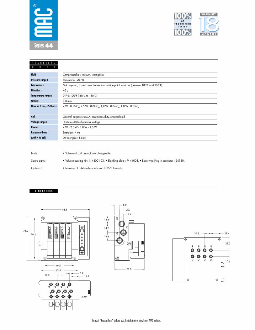
Consult “Precautions” before use, installation or service of MAC Valves.
Series 44
D I M E N S I O N S
Fluid :
Pressure range :
Lubrication :
Filtration :
Temperature range :
Orifice :
Flow (at 6 bar, �P=1bar) :
Leak rate :
Coil :
Voltage range :
Power :
Response times :
(with 4 W coil)
Compressed air, vacuum, inert gases
Vacuum to 120 PSI
Not required, if used select a medium aniline point lubricant (between 180°F and 210°F)
40 μ
0°F to 120°F (-18°C to +50°C)
1.8 mm
4 W : 0.10 Cv, 2.5 W : 0.08 Cv, 1,8 W : 0.06 Cv, 1.0 W : 0.05 Cv
50 cm3/min
General purpose class A, continuous duty, encapsulated
-15% to +10% of nominal voltage
4 W - 2.5 W - 1.8 W - 1.0 W
Energize : 4 ms
De-energize : 1.5 ms
D A T A
T E C H N I C A L
1818100%100%
100%100% M O N T H S
WARRANTY
O FP R O D U C T I O N
T E S T E D
• Valve and coil are not interchangeable.
• Valve mounting kit : N-44001-03. • Blanking plate : M-44003. • Base wire Plug-in protector : 24180.
• Isolation of inlet and/or exhaust. • BSPP threads.
Note :
Spare parts :
Options :
10.52.8
13.2
10.5 17.4
10.6
22.0
49.5
63.5
83.5
51.0
13.6
14.9
13.3
8.7
3.5
2.9
70.4
76.2
B
A
B
A
B
A
B
A
B
A
B
AA
B
EXHEXH
IN
A
B

Series 44
Function Port size Flow (Max) Circuit bar mounting
5/2, 3/2 NO-NC M5 - #10-32 0.09Cvplug-in with
F. C. and pre-wiredconnector
1. 10 mm valve, direct solenoid operated.2. Balanced poppet, immune to variations of
pressure.3. Short stroke with high flow.4. The patented solenoid develops high shifting
forces.5. Powerful return spring.6. Flow is specifically adjusted on each valve.7. Manual operator standard on all valves.
O P E R A T I O N A L B E N E F I T S
D i r e c t s o l e n o i d a n d s o l e n o i d p i l o t o p e r a t e d v a l v e s
H O W T O O R D E R
Voltage
DA 24VDC (1.0 W)
DC 24VDC (1.8 W)
DD 24VDC (2.5 W)
DF 24VDC (4.0 W)
Manual operator
1 Non-locking
Electrical connection
DJ Plug-in
DT Plug-in with light
DE Plug-in with suppression diode
DV Plug-in with light and suppression diode
G XX O- X XX *SOLENOID OPERATOR ➤
HOW TO ORDER CIRCUIT BAR WITH FLOW CONTROLS **
XX X XX
Port size(see base)
Valve less base
Single operator
44B-MOO-GXXO-XXX
EB
B A
INEA
HOW TO ORDER VALVE FOR CIRCUIT BAR MOUNTING
ZZ Connector
LA 9 Pin Sub D*LB 15 Pin Sub D*LC 25 Pin Sub D*LD 10 Pin Ribbon Cable**LE 16 Pin Ribbon Cable**LF 20 Pin Ribbon Cable**LG 26 Pin Ribbon Cable**LH 3/8” NPSM Conduit Port
Standard Base Wires
ZZ Connector
RA 9 Pin Sub D*RB 15 Pin Sub D*RC 25 Pin Sub D*RD 10 Pin Ribbon Cable**RE 16 Pin Ribbon Cable**RF 20 Pin Ribbon Cable**RG 26 Pin Ribbon Cable**RH 3/8” NPSM Conduit Port
Standard Base Wires
L=Left Side; R=Right Side
* MIL. Spec; MIL-C-24308** MIL. Spec; MIL-C-83503Note: Left and right end is determined by facing conduit passage.
Port size
M5
# 10-32
Bottom cylinder ports(10.5 mm)
ECF44B-00EDA-ZZXX
ECF44B-00EBA-ZZXX
Number of stations (03=3 stations)** Other options available Consult factory.Note : clic for valves mounted on base at the factory (add - 9 to the model number).
Consult “Precautions” before use, installation or service of MAC Valves.
Reset
44B-xxx-GxxO-xxx
Other Optionsxx xx Other Options
ECF44B-00xxx-xxxx
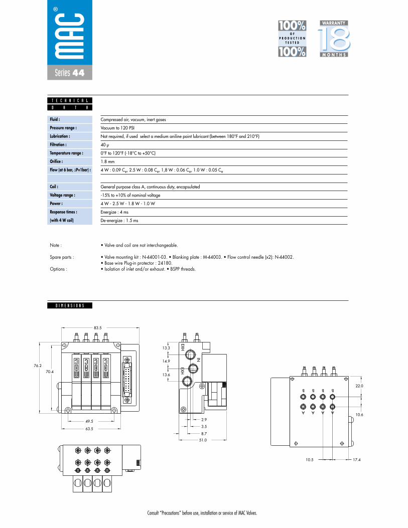
Consult “Precautions” before use, installation or service of MAC Valves.
Series 44
D I M E N S I O N S
Fluid :
Pressure range :
Lubrication :
Filtration :
Temperature range :
Orifice :
Flow (at 6 bar, �P=1bar) :
Leak rate :
Coil :
Voltage range :
Power :
Response times :
(with 4 W coil)
Compressed air, vacuum, inert gases
Vacuum to 120 PSI
Not required, if used select a medium aniline point lubricant (between 180°F and 210°F)
40 μ
0°F to 120°F (-18°C to +50°C)
1.8 mm
4 W : 0.09 Cv, 2.5 W : 0.08 Cv, 1,8 W : 0.06 Cv, 1.0 W : 0.05 Cv
50 cm3/min
General purpose class A, continuous duty, encapsulated
-15% to +10% of nominal voltage
4 W - 2.5 W - 1.8 W - 1.0 W
Energize : 4 ms
De-energize : 1.5 ms
D A T A
T E C H N I C A L
1818100%100%
100%100% M O N T H S
WARRANTY
O FP R O D U C T I O N
T E S T E D
• Valve and coil are not interchangeable.
• Valve mounting kit : N-44001-03. • Blanking plate : M-44003. • Flow control needle (x2): N-44002.• Base wire Plug-in protector : 24180.• Isolation of inlet and/or exhaust. • BSPP threads.
Note :
Spare parts :
Options :
IN
EXHEXH
B
A A
B
A
B
A
B
76.2
70.4
2.9
3.5
8.7
13.3
14.9
13.6
51.0
83.5
63.5
49.5
22.0
10.6
17.410.5

Series 44
Function Port size Flow (Max) Circuit bar mounting
5/2, 3/2 NO-NC M5 - #10-32 0.09Cvplug-in with Pr. Reg. andpre-wiredconnector
1. 10 mm valve, direct solenoid operated.2. Balanced poppet, immune to variations of
pressure.3. Short stroke with high flow.4. The patented solenoid develops high shifting
forces.5. Powerful return spring.6. Flow is specifically adjusted on each valve.7. Manual operator standard on all valves.
O P E R A T I O N A L B E N E F I T S
D i r e c t s o l e n o i d a n d s o l e n o i d p i l o t o p e r a t e d v a l v e s
H O W T O O R D E R
Voltage
DA 24VDC (1.0 W)
DC 24VDC (1.8 W)
DD 24VDC (2.5 W)
DF 24VDC (4.0 W)
Manual operator
1 Non-locking
Electrical connection
DJ Plug-in
DT Plug-in with light
DE Plug-in with suppression diode
DV Plug-in with light and suppression diode
G XX O- X XX *SOLENOID OPERATOR ➤
HOW TO ORDER CIRCUIT BAR FOR PRESSURE REGULATORS ** (to be ordered separately)
XX X XX
Port size(see base)
Valve less base
Single operator
44B-LOO-GXXO-XXX
EB
B A
INEA
HOW TO ORDER VALVE FOR CIRCUIT BAR MOUNTING
ZZ Connector
LA 9 Pin Sub D*LB 15 Pin Sub D*LC 25 Pin Sub D*LD 10 Pin Ribbon Cable**LE 16 Pin Ribbon Cable**LF 20 Pin Ribbon Cable**LG 26 Pin Ribbon Cable**LH 3/8” NPSM Conduit Port
Standard Base Wires
ZZ Connector
RA 9 Pin Sub D*RB 15 Pin Sub D*RC 25 Pin Sub D*RD 10 Pin Ribbon Cable**RE 16 Pin Ribbon Cable**RF 20 Pin Ribbon Cable**RG 26 Pin Ribbon Cable**RH 3/8” NPSM Conduit Port
Standard Base Wires
L=Left Side; R=Right Side
* MIL. Spec; MIL-C-24308** MIL. Spec; MIL-C-83503Note: Left and right end is determined by facing conduit passage.
Port size
M5
# 10-32
Bottom cylinder ports(10.5 mm)
ECF44B-00GDA-ZZXX
ECF44B-00GBA-ZZXX
** Pressure Regulators :
Y=A (no gage port)Y=B (with gage port)X=A (0 to 100 PSI)X=B (0 to 60 PSI)X=C (0 to 40 PSI)X=D (0 to 15 PSI)
Number of stations (03=3 stations)** Other options available Consult factory.Note : clic for valves mounted on base at the factory (add - 9 to the model number).
Consult “Precautions” before use, installation or service of MAC Valves.
Reset
44B-xxx-GxxO-xxx
Other Optionsxx xx Other Options
ECF44B-00xxx-xxxx
PR44A-AOxx

Consult “Precautions” before use, installation or service of MAC Valves.
Series 44
D I M E N S I O N S
Fluid :
Pressure range :
Lubrication :
Filtration :
Temperature range :
Orifice :
Flow (at 6 bar, �P=1bar) :
Leak rate :
Coil :
Voltage range :
Power :
Response times :
(with 4 W coil)
Compressed air, vacuum, inert gases
Vacuum to 120 PSI
Not required, if used select a medium aniline point lubricant (between 180°F and 210°F)
40 μ
0°F to 120°F (-18°C to +50°C)
1.8 mm
4 W : 0.09 Cv, 2.5 W : 0.08 Cv, 1,8 W : 0.06 Cv, 1.0 W : 0.05 Cv
50 cm3/min
General purpose class A, continuous duty, encapsulated
-15% to +10% of nominal voltage
4 W - 2.5 W - 1.8 W - 1.0 W
Energize : 4 ms
De-energize : 1.5 ms
D A T A
T E C H N I C A L
1818100%100%
100%100% M O N T H S
WARRANTY
O FP R O D U C T I O N
T E S T E D
• Valve and coil are not interchangeable.• Pressure range regulator (0-100 PSI)• Valve mounting kit : N-44001-03. • Blanking plate : M-44003. • Blanking plate regulator : N-44003.• Base wire Plug-in protector : 24180.• Isolation of inlet and/or exhaust. • BSPP threads.
Note :
Spare parts :
Options :
K C O
L
+ -
K C O
L
+ -
K C O
L
+ -
K C O
L
+ -
136.5
IN
EXHEXH
B
A A
B
A
B
A
B
70.4
2.9
3.5
8.7
13.3
14.9
13.6
51.0
83.5
63.5
49.5
22.0
10.6
17.410.5
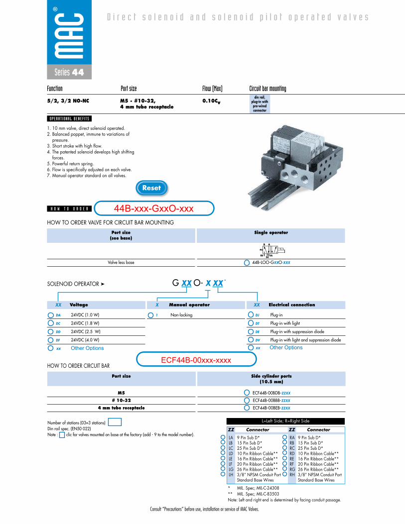
Series 44
Function Port size Flow (Max) Circuit bar mounting
5/2, 3/2 NO-NC M5 - #10-32, 0.10Cv4 mm tube receptacle
din rail, plug-in withpre-wiredconnector
1. 10 mm valve, direct solenoid operated.2. Balanced poppet, immune to variations of
pressure.3. Short stroke with high flow.4. The patented solenoid develops high shifting
forces.5. Powerful return spring.6. Flow is specifically adjusted on each valve.7. Manual operator standard on all valves.
O P E R A T I O N A L B E N E F I T S
D i r e c t s o l e n o i d a n d s o l e n o i d p i l o t o p e r a t e d v a l v e s
H O W T O O R D E R
Voltage
DA 24VDC (1.0 W)
DC 24VDC (1.8 W)
DD 24VDC (2.5 W)
DF 24VDC (4.0 W)
Manual operator
1 Non-locking
Electrical connection
DJ Plug-in
DT Plug-in with light
DE Plug-in with suppression diode
DV Plug-in with light and suppression diode
G XX O- X XX *SOLENOID OPERATOR ➤
HOW TO ORDER CIRCUIT BAR
XX X XX
Port size(see base)
Valve less base
Single operator
44B-LOO-GXXO-XXX
EB
B A
INEA
HOW TO ORDER VALVE FOR CIRCUIT BAR MOUNTING
ZZ Connector
LA 9 Pin Sub D*LB 15 Pin Sub D*LC 25 Pin Sub D*LD 10 Pin Ribbon Cable**LE 16 Pin Ribbon Cable**LF 20 Pin Ribbon Cable**LG 26 Pin Ribbon Cable**LH 3/8” NPSM Conduit Port
Standard Base Wires
ZZ Connector
RA 9 Pin Sub D*RB 15 Pin Sub D*RC 25 Pin Sub D*RD 10 Pin Ribbon Cable**RE 16 Pin Ribbon Cable**RF 20 Pin Ribbon Cable**RG 26 Pin Ribbon Cable**RH 3/8” NPSM Conduit Port
Standard Base Wires
L=Left Side; R=Right Side
* MIL. Spec; MIL-C-24308** MIL. Spec; MIL-C-83503Note: Left and right end is determined by facing conduit passage.
Port size
M5
# 10-32
4 mm tube receptacle
Side cylinder ports(10.5 mm)
ECF44B-00BDB-ZZXX
ECF44B-00BBB-ZZXX
ECF44B-00BEB-ZZXX
Number of stations (03=3 stations)Din rail spec. (EN50 022)Note : clic for valves mounted on base at the factory (add - 9 to the model number).
Consult “Precautions” before use, installation or service of MAC Valves.
Reset
44B-xxx-GxxO-xxx
Other Optionsxx xx Other Options
ECF44B-00xxx-xxxx

Consult “Precautions” before use, installation or service of MAC Valves.
Series 44
D I M E N S I O N S
Fluid :
Pressure range :
Lubrication :
Filtration :
Temperature range :
Orifice :
Flow (at 6 bar, �P=1bar) :
Leak rate :
Coil :
Voltage range :
Power :
Response times :
(with 4 W coil)
Compressed air, vacuum, inert gases
Vacuum to 120 PSI
Not required, if used select a medium aniline point lubricant (between 180°F and 210°F)
40 μ
0°F to 120°F (-18°C to +50°C)
1.8 mm
4 W : 0.10 Cv, 2.5 W : 0.08 Cv, 1,8 W : 0.06 Cv, 1.0 W : 0.05 Cv
50 cm3/min
General purpose class A, continuous duty, encapsulated
-15% to +10% of nominal voltage
4 W - 2.5 W - 1.8 W - 1.0 W
Energize : 4 ms
De-energize : 1.5 ms
D A T A
T E C H N I C A L
1818100%100%
100%100% M O N T H S
WARRANTY
O FP R O D U C T I O N
T E S T E D
• Valve and coil are not interchangeable.
• Valve mounting kit : N-44001-03. • Blanking plate : M-44003. • Base wire Plug-in protector : 24180.
• Isolation of inlet and/or exhaust. • BSPP threads.
Note :
Spare parts :
Options :
5.4
9.8
42.6
54.4
60.5
B
A
IN
EXHEXH
A
B
A
B
A
B
76.2
70.4
2.9
3.5
8.7
13.3
14.9
13.6
83.5
63.5
49.5
13.22.810.5

Consult “Precautions” before use, installation or service of MAC Valves.
S e c t i o n 2 Opt ions

Consult “Precautions”before use, installation or service of MAC Valves.
O P T I O N S
O p t i o n s
Codification table for voltages / Manual operator / Electrical connection
- G XX X - X XX1 2 3 4
VALVE CODE ➤
- solenoid valves 34 & 44 Series
OPTIONS AVAILABLE FOR

Consult “Precautions”before use, installation or service of MAC Valves.
O P T I O N S
1. VOLTAGE (type 34 Series)
-G XX X - X XX VOLTAGE
DC 24 VDC (1,8 W)
DD 24 VDC (2,5 W)
DE 24 VDC (3,0 W)
DF 24 VDC (4,0 W)
DJ 12 VDC (1,8 W)
DK 12 VDC (2,5 W)
DM 12 VDC (3,0 W)
DN 12 VDC (4,0 W)
1. VOLTAGE (type 44 Series)
-G XX X - X XX VOLTAGE
DA 24 VDC (1,0 W)
DC 24 VDC (1,8 W)
DD 24 VDC (2,5 W)
DF 24 VDC (4,0 W)
DG 12 VDC (1,0 W)
DJ 12 VDC (1,8 W)
DK 12 VDC (2,5 W)
DN 12 VDC (4,0 W)
2. WIRE LENGTH (Common options for 34 & 44 Series)
-G XX X - X XX WIRE LENGTH
A 18”
B 24”
C 36”
D 48”
E 72”
F 96”
G 120”
H 144”
Back
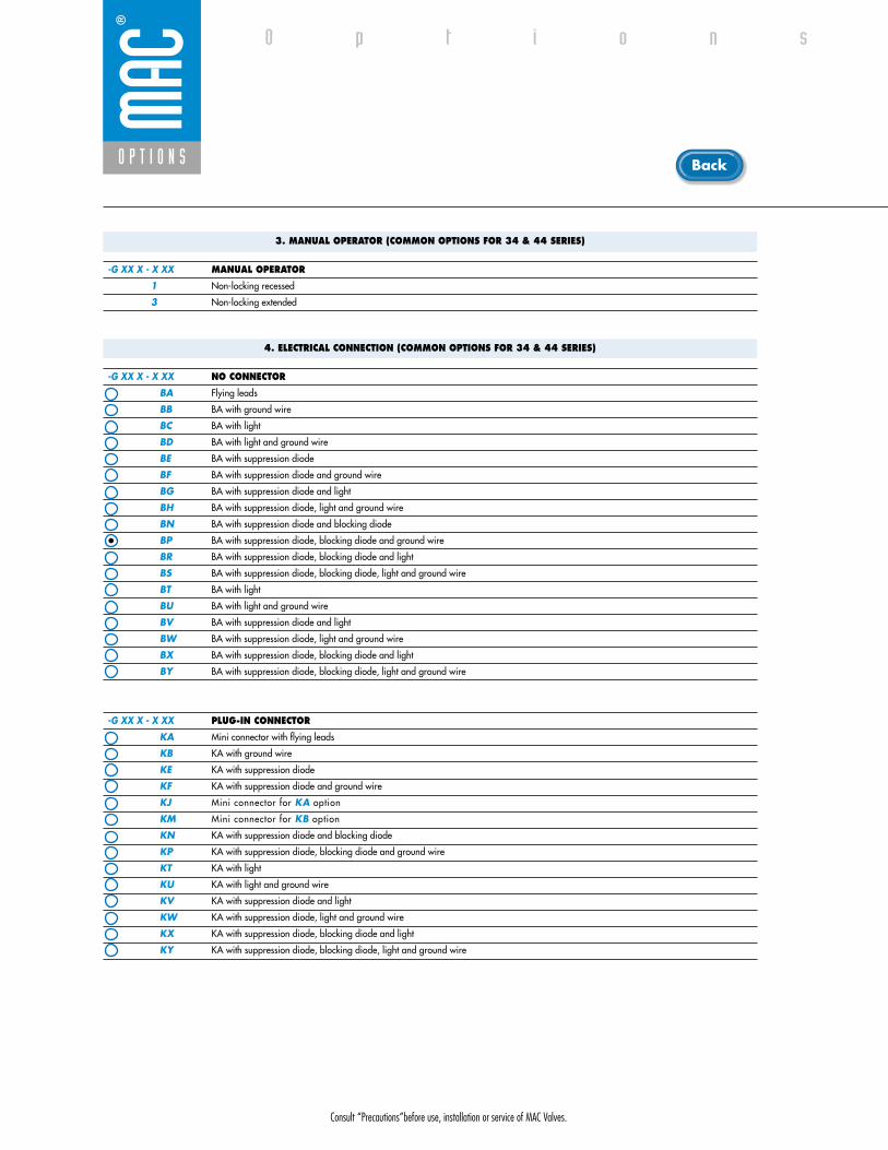
Consult “Precautions”before use, installation or service of MAC Valves.
O P T I O N S
O p t i o n s
3. MANUAL OPERATOR (COMMON OPTIONS FOR 34 & 44 SERIES)
-G XX X - X XX MANUAL OPERATOR
1 Non-locking recessed
3 Non-locking extended
4. ELECTRICAL CONNECTION (COMMON OPTIONS FOR 34 & 44 SERIES)
-G XX X - X XX NO CONNECTOR
BA Flying leads
BB BA with ground wire
BC BA with light
BD BA with light and ground wire
BE BA with suppression diode
BF BA with suppression diode and ground wire
BG BA with suppression diode and light
BH BA with suppression diode, light and ground wire
BN BA with suppression diode and blocking diode
BP BA with suppression diode, blocking diode and ground wire
BR BA with suppression diode, blocking diode and light
BS BA with suppression diode, blocking diode, light and ground wire
BT BA with light
BU BA with light and ground wire
BV BA with suppression diode and light
BW BA with suppression diode, light and ground wire
BX BA with suppression diode, blocking diode and light
BY BA with suppression diode, blocking diode, light and ground wire
-G XX X - X XX PLUG-IN CONNECTOR
KA Mini connector with flying leads
KB KA with ground wire
KE KA with suppression diode
KF KA with suppression diode and ground wire
KJ Mini connector for KA option
KM Mini connector for KB option
KN KA with suppression diode and blocking diode
KP KA with suppression diode, blocking diode and ground wire
KT KA with light
KU KA with light and ground wire
KV KA with suppression diode and light
KW KA with suppression diode, light and ground wire
KX KA with suppression diode, blocking diode and light
KY KA with suppression diode, blocking diode, light and ground wire
Back

• Type «SUB_D»• Number of contacts : 9• Solder termination (Dia. 0.6 mm/0.14 mm
2/26-22 AWG)
• Operating current 5 A/contact• Rated voltage 125 V~• Temp. range –40° to +125°C• Insulation resistance � 5.09 �• Protection class IP40 (DIN 40050)• Number of solenoids : 7 max.• Max. 24 V=/5.4 W per solenoid• 2 common wires
MOD. SD09
MOD. SD15
MOD. SD25
PIN #1
PIN #5
PIN #6
PIN #9
PIN #1
PIN #8
PIN #9
PIN #15
PIN #1
PIN #13
PIN #14
PIN #25
• Type «SUB_D»• Number of contacts : 25• Solder termination (Dia. 0.6 mm/0.14 mm
2/26-22 AWG)
• Operating current 5 A/contact• Rated voltage 125 V~• Temp. range –40° to +125°C• Insulation resistance � 5.09 �• Protection class IP40 (DIN 40050)• Number of solenoids : 20 max.• Max. 24 V=/5.4 W per solenoid• 5 common wires
Note : Use desired MOD. number after circuit bar part number
• Type «SUB_D»• Number of contacts : 15• Solder termination (Dia. 0.6 mm/0.14 mm
2/26-22 AWG)
• Operating current 5 A/contact• Rated voltage 125 V~• Temp. range –40° to +125°C• Insulation resistance � 5.09 �• Protection class IP40 (DIN 40050)• Number of solenoids : 12 max.• Max. 24 V=/5.4 W per solenoid• 3 common wires
T E C H N I C A L D A T A
T E C H N I C A L D A T A
T E C H N I C A L D A T A
O P T I O N S
O p t i o n s

SD09 SD15 SD25
Connector termination details
SOL 2 SOL 4 SOL 6 SOL 8 SOL 16 SOL 18 SOL 20 SOL 22 SOL 24
SOL 1CONN
ECTO
RCO
NNEC
TOR
SOL 2 SOL 3 SOL .. SOL 20 SOL 21 SOL 22 SOL 23 SOL 24
SOL 1 SOL 3 SOL 5 SOL 13 SOL 15 SOL 17
Double solenoid circuit bar
Single solenoid circuit bar
SOL 21 SOL 23SOL 19
SOL. 3
SOL. 1
SOL. 2
1
2
3
4
COMMON (+)
COMMON (+)
8
SOL. 4
5
6
7
9
SOL. 5
SOL. 7
SOL. 6
SOL. 3
SOL. 1
SOL. 2
1
2
3
4
COMMON (+)
COMMON (+)
COMMON (+)
13
SOL. 4
5
6
7
8
14
SOL. 5
SOL. 7
SOL. 6
SOL. 8
9
10
11
12
15
SOL. 9
SOL. 11
SOL. 10
SOL. 12
SOL. 3
SOL. 1
SOL. 2
1
2
3
4
COMMON (+)
COMMON (+)
COMMON (+)
COMMON (+)
COMMON (+)
21
SOL. 4
5
6
7
8
22
SOL. 5
SOL. 7
SOL. 6
SOL. 8
9
10
11
12
23
SOL. 9
SOL. 11
SOL. 10
SOL. 12
13
14
15
16
24
SOL. 13
SOL. 15
SOL. 14
SOL. 16
17
18
19
20
25
SOL. 17
SOL. 19
SOL. 18
SOL. 20
O P T I O N S
O p t i o n s
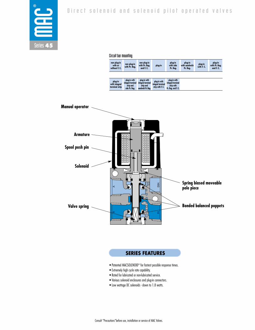
Consult “Precautions”before use, installation or service of MAC Valves.
Series 45
D i r e c t s o l e n o i d a n d s o l e n o i d p i l o t o p e r a t e d v a l v e s
EXH
.IN
AB
non plug-inwith or
without F. C.
non plug-inwith Pr. Reg.
non plug-inwith Pr. Reg.
and F. C.plug-in
plug-inwith sidePr. Reg.
plug-inwith sandwich
Pr. Reg.
plug-inwith F. C.
plug-inwith Pr. Reg.
and F. C.
Circuit bar mounting
plug-inwith integral terminal strip
plug-in with integral terminal
strip and side Pr. Reg.
plug-in with integral terminal
strip and sandwich Pr. Reg.
plug-in with integral terminalstrip with F. C.
plug-in with integral terminal
strip with Pr. Reg. and F. C.
SERIES FEATURES
• Patented MACSOLENOID® for fastest possible response times.• Extremely high cycle rate capability.• Rated for lubricated or non-lubricated service.• Various solenoid enclosures and plug-in connectors.• Low wattage DC solenoids - down to 1.8 watts.
Armature
Spool push pin
Manual operator
Solenoid
Valve spring Bonded balanced poppets
Spring biased moveablepole piece
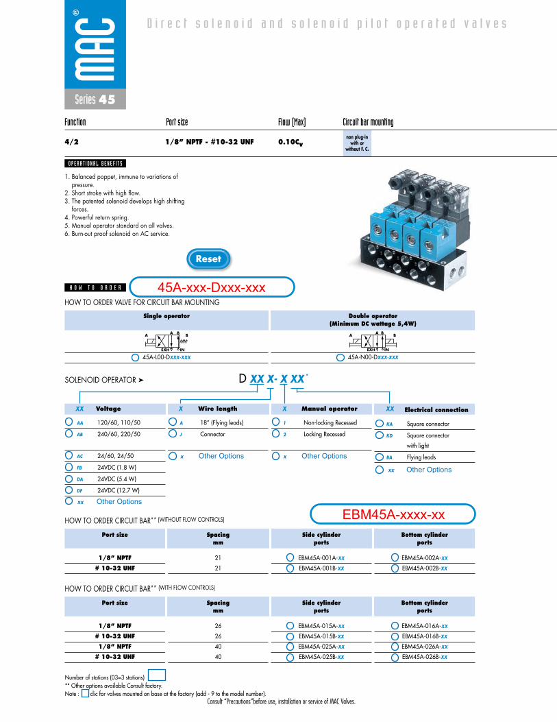
Consult “Precautions”before use, installation or service of MAC Valves.
Reset
Series 45
Function Port size Flow (Max) Circuit bar mounting
4/2 1/8” NPTF - #10-32 UNF 0.10Cvnon plug-in
with or without F. C.
1. Balanced poppet, immune to variations ofpressure.
2. Short stroke with high flow.3. The patented solenoid develops high shifting
forces.4. Powerful return spring.5. Manual operator standard on all valves.6. Burn-out proof solenoid on AC service.
O P E R A T I O N A L B E N E F I T S
D i r e c t s o l e n o i d a n d s o l e n o i d p i l o t o p e r a t e d v a l v e s
H O W T O O R D E R
Single operator
45A-L00-DXXX-XXX
Double operator(Minimum DC wattage 5,4W)
45A-N00-DXXX-XXX
A BA B
EXH IN
A BA B
EXH IN
Voltage
AA 120/60, 110/50
AB 240/60, 220/50
AC 24/60, 24/50
FB 24VDC (1.8 W)
DA 24VDC (5.4 W)
DF 24VDC (12.7 W)
Wire length
A 18” (Flying leads)
J Connector
Manual operator
1 Non-locking Recessed
2 Locking Recessed
Electrical connection
KA Square connector
KD Square connector
with light
BA Flying leads
D XX X- X XX *SOLENOID OPERATOR ➤
Port size
1/8” NPTF
# 10-32 UNF
Spacingmm
21
21
Side cylinder ports
EBM45A-001A-XX
EBM45A-001B-XX
Bottom cylinder ports
EBM45A-002A-XX
EBM45A-002B-XX
HOW TO ORDER CIRCUIT BAR** (WITHOUT FLOW CONTROLS)
Port size
1/8” NPTF
# 10-32 UNF
1/8” NPTF
# 10-32 UNF
Spacingmm
26
26
40
40
Side cylinder ports
EBM45A-015A-XX
EBM45A-015B-XX
EBM45A-025A-XX
EBM45A-025B-XX
Bottom cylinder ports
EBM45A-016A-XX
EBM45A-016B-XX
EBM45A-026A-XX
EBM45A-026B-XX
HOW TO ORDER CIRCUIT BAR** (WITH FLOW CONTROLS)
HOW TO ORDER VALVE FOR CIRCUIT BAR MOUNTING
XX X X XX
Number of stations (03=3 stations)** Other options available Consult factory.Note : clic for valves mounted on base at the factory (add - 9 to the model number).
45A-xxx-Dxxx-xxx
EBM45A-xxxx-xxOther Optionsxx
x Other Options
xx Other Options
x Other Options
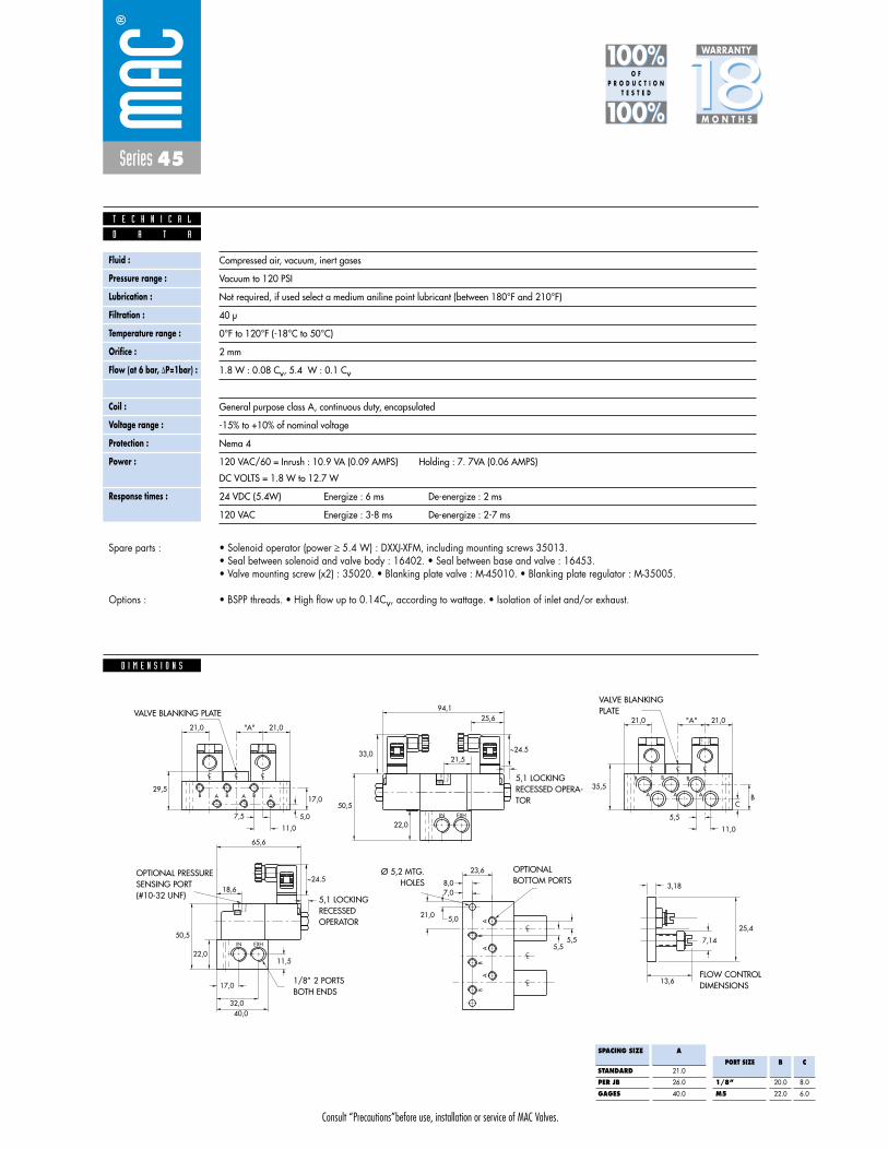
Consult “Precautions”before use, installation or service of MAC Valves.
Series 45
Fluid :
Pressure range :
Lubrication :
Filtration :
Temperature range :
Orifice :
Flow (at 6 bar, �P=1bar) :
Leak rate :
Coil :
Voltage range :
Protection :
Power :
Response times :
Compressed air, vacuum, inert gases
Vacuum to 120 PSI
Not required, if used select a medium aniline point lubricant (between 180°F and 210°F)
40 μ
0°F to 120°F (-18°C to 50°C)
2 mm
1.8 W : 0.08 Cv, 5.4 W : 0.1 Cv
50 cm3/min
General purpose class A, continuous duty, encapsulated
-15% to +10% of nominal voltage
Nema 4
120 VAC/60 = Inrush : 10.9 VA (0.09 AMPS) Holding : 7. 7VA (0.06 AMPS)
DC VOLTS = 1.8 W to 12.7 W
24 VDC (5.4W) Energize : 6 ms De-energize : 2 ms
120 VAC Energize : 3-8 ms De-energize : 2-7 ms
D A T A
T E C H N I C A L
1818100%100%
100%100% M O N T H S
WARRANTY
O FP R O D U C T I O N
T E S T E D
• Solenoid operator (power � 5.4 W) : DXXJ-XFM, including mounting screws 35013. • Seal between solenoid and valve body : 16402. • Seal between base and valve : 16453. • Valve mounting screw (x2) : 35020. • Blanking plate valve : M-45010. • Blanking plate regulator : M-35005.
• BSPP threads. • High flow up to 0.14Cv, according to wattage. • Isolation of inlet and/or exhaust.
Spare parts :
Options :
D I M E N S I O N S
~24.533,0
B
CL CL CL
B BA A A
IN EXH
21,0
5,0
17,0
21,0
29,5
7,5
11,0
94,125,6
21,5
50,5
22,0
"A"
~24.5
IN EXH
65,6
22,011,5
17,0
32,040,0
50,5
18,6
BB
BA
AA
CL
CL
CL
23,6
8,07,0
5,0
5,55,5
21,0
B
CL CL CLB B
A A A
21,0
BC
21,0
35,5
5,5
11,0
"A"
25,4
7,14
13,6
3,18
SPACING SIZE
STANDARD
PER JB
GAGES
A
21.0
26.0
40.0
PORT SIZE
1/8”
M5
B
20.0
22.0
C
8.0
6.0
OPTIONAL PRESSURESENSING PORT (#10-32 UNF)
1/8” 2 PORTSBOTH ENDS
Ø 5,2 MTG.HOLES
OPTIONALBOTTOM PORTS
FLOW CONTROLDIMENSIONS
VALVE BLANKINGPLATE
5,1 LOCKINGRECESSED OPERA-TOR
VALVE BLANKING PLATE
5,1 LOCKING RECESSEDOPERATOR
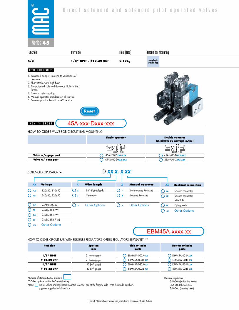
Consult “Precautions”before use, installation or service of MAC Valves.
Reset
Series 45
Function Port size Flow (Max) Circuit bar mounting
4/2 1/8” NPTF - #10-32 UNF 0.10Cvnon plug-in
with Pr. Reg.
1. Balanced poppet, immune to variations ofpressure.
2. Short stroke with high flow.3. The patented solenoid develops high shifting
forces.4. Powerful return spring.5. Manual operator standard on all valves.6. Burn-out proof solenoid on AC service.
O P E R A T I O N A L B E N E F I T S
D i r e c t s o l e n o i d a n d s o l e n o i d p i l o t o p e r a t e d v a l v e s
H O W T O O R D E R
Valve w/o gage port
Valve w/ gage port
Single operator
45A-L00-DXXX-XXX
45A-M00-DXXX-XXX
Double operator(Minimum DC wattage 5,4W)
45A-N00-DXXX-XXX
45A-P00-DXXX-XXX
A BA B
EXH IN
A BA B
EXH IN
HOW TO ORDER VALVE FOR CIRCUIT BAR MOUNTING
Voltage
AA 120/60, 110/50
AB 240/60, 220/50
AC 24/60, 24/50
FB 24VDC (1.8 W)
DA 24VDC (5.4 W)
DF 24VDC (12.7 W)
Wire length
A 18” (Flying leads)
J Connector
Manual operator
1 Non-locking Recessed
2 Locking Recessed
Electrical connection
KA Square connector
KD Square connector
with light
BA Flying leads
D XX X- X XX *SOLENOID OPERATOR ➤
Port size
1/8” NPTF
# 10-32 UNF
1/8” NPTF
# 10-32 UNF
Spacingmm
21 (w/o gage)
21 (w/o gage)
40 (w/ gage)
40 (w/ gage)
Side cylinder ports
EBM45A-003A-XX
EBM45A-003B-XX
EBM45A-023A-XX
EBM45A-023B-XX
Bottom cylinder ports
EBM45A-004A-XX
EBM45A-004B-XX
EBM45A-024A-XX
EBM45A-024B-XX
HOW TO ORDER CIRCUIT BAR WITH PRESSURE REGULATORS (ORDER REGULATORS SEPARATELY) **
XX X X XX
Number of stations (03=3 stations)** Other options available Consult factory.Note : clic for valves and regulators mounted to circuit bar at the factory (add - 9 to the model number).
gage not supplied w/circuit bar.
Pressure regulators : 35A-00M (Adjusting knob)35A-00L (Slotted stem)35A-00U (Locking stem)
45A-xxx-Dxxx-xxx
EBM45A-xxxx-xxOther Optionsxx
x Other Options
xx Other Options
x Other Options
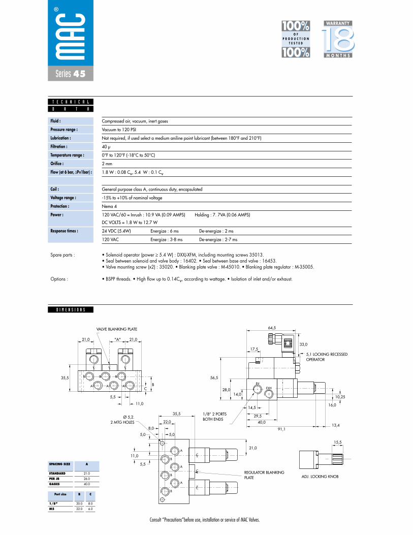
Consult “Precautions”before use, installation or service of MAC Valves.
Series 45
Fluid :
Pressure range :
Lubrication :
Filtration :
Temperature range :
Orifice :
Flow (at 6 bar, �P=1bar) :
Leak rate :
Coil :
Voltage range :
Protection :
Power :
Response times :
Compressed air, vacuum, inert gases
Vacuum to 120 PSI
Not required, if used select a medium aniline point lubricant (between 180°F and 210°F)
40 μ
0°F to 120°F (-18°C to 50°C)
2 mm
1.8 W : 0.08 Cv, 5.4 W : 0.1 Cv
50 cm3/min
General purpose class A, continuous duty, encapsulated
-15% to +10% of nominal voltage
Nema 4
120 VAC/60 = Inrush : 10.9 VA (0.09 AMPS) Holding : 7. 7VA (0.06 AMPS)
DC VOLTS = 1.8 W to 12.7 W
24 VDC (5.4W) Energize : 6 ms De-energize : 2 ms
120 VAC Energize : 3-8 ms De-energize : 2-7 ms
D A T A
T E C H N I C A L
1818100%100%
100%100% M O N T H S
WARRANTY
O FP R O D U C T I O N
T E S T E D
• Solenoid operator (power � 5.4 W) : DXXJ-XFM, including mounting screws 35013. • Seal between solenoid and valve body : 16402. • Seal between base and valve : 16453. • Valve mounting screw (x2) : 35020. • Blanking plate valve : M-45010. • Blanking plate regulator : M-35005.
• BSPP threads. • High flow up to 0.14Cv, according to wattage. • Isolation of inlet and/or exhaust.
Spare parts :
Options :
D I M E N S I O N S
33,0
B
CL CL CL
B B
A A AIN
EXH
15,5
21,0
64,5
17,5
56,5
28,014,0
14,5
29,5
40,0
91,1
16,0
10,25
13,4
"A"
CB
5,5
11,0
21,0
35,5
CL
CLB
B
B
A
A
A
CL
35,5
8,0
5,05,0
5,5
11,0
21,0
22,0
SPACING SIZE
STANDARD
PER JB
GAGES
A
21.0
26.0
40.0
Port size
1/8”
M5
B
20.0
22.0
C
8.0
6.0
5,1 LOCKING RECESSEDOPERATOR
1/8” 2 PORTSBOTH ENDSØ 5,2.
2 MTG HOLES
REGULATOR BLANKINGPLATE ADJ. LOCKING KNOB
VALVE BLANKING PLATE

Consult “Precautions”before use, installation or service of MAC Valves.
Reset
Series 45
Function Port size Flow (Max) Circuit bar mounting
4/2 1/8” NPTF - #10-32 UNF 0.10Cvnon plug-in
with Pr. Reg.and F. C.
1. Balanced poppet, immune to variations ofpressure.
2. Short stroke with high flow.3. The patented solenoid develops high shifting
forces.4. Powerful return spring.5. Manual operator standard on all valves.6. Burn-out proof solenoid on AC service.
O P E R A T I O N A L B E N E F I T S
D i r e c t s o l e n o i d a n d s o l e n o i d p i l o t o p e r a t e d v a l v e s
H O W T O O R D E R
Valve w/o gage port
Valve w/ gage port
Single operator
45A-L00-DXXX-XXX
45A-M00-DXXX-XXX
Double operator(Minimum DC wattage 5,4W)
45A-N00-DXXX-XXX
45A-P00-DXXX-XXX
A BA B
EXH IN
A BA B
EXH IN
HOW TO ORDER VALVE FOR CIRCUIT BAR MOUNTING
Voltage
AA 120/60, 110/50
AB 240/60, 220/50
AC 24/60, 24/50
FB 24VDC (1.8 W)
DA 24VDC (5.4 W)
DF 24VDC (12.7 W)
Wire length
A 18” (Flying leads)
J Connector
Manual operator
1 Non-locking Recessed
2 Locking Recessed
Electrical connection
KA Square connector
KD Square connector
with light
BA Flying leads
D XX X- X XX *SOLENOID OPERATOR ➤
Port size
1/8” NPTF
# 10-32 UNF
1/8” NPTF
# 10-32 UNF
Spacingmm
21 (w/o gage)
21 (w/o gage)
40 (w/ gage)
40 (w/ gage)
Side cylinder ports
EBM45A-007A-XX
EBM45A-007B-XX
EBM45A-027A-XX
EBM45A-027B-XX
Bottom cylinder ports
EBM45A-008A-XX
EBM45A-008B-XX
EBM45A-028A-XX
EBM45A-028B-XX
HOW TO ORDER CIRCUIT BAR WITH PRESSURE REGULATORS AND FLOW CONTROLS (ORDER REGULATOR AND FLOW CONTROL SEPARATELY) **
XX X X XX
Number of stations (03=3 stations)** Other options available Consult factory.Note : clic for valves, regulators and flow controls mounted to circuit bar at the factory (add - 9 to the model number).
gage not supplied w/circuit bar
Pressure regulators and flow controls: 45A-001 (Slotted stem)45A-002 (Adjusting knob)45A-003 (Locking stem)
45A-xxx-Dxxx-xxx
EBM45A-xxxx-xxOther Optionsxx
x Other Options
xx Other Options
x Other Options

Consult “Precautions”before use, installation or service of MAC Valves.
Series 45
Fluid :
Pressure range :
Lubrication :
Filtration :
Temperature range :
Orifice :
Flow (at 6 bar, �P=1bar) :
Leak rate :
Coil :
Voltage range :
Protection :
Power :
Response times :
Compressed air, vacuum, inert gases
Vacuum to 120 PSI
Not required, if used select a medium aniline point lubricant (between 180°F and 210°F)
40 μ
0°F to 120°F (-18°C to 50°C)
2 mm
1.8 W : 0.08 Cv, 5.4 W : 0.1 Cv
50 cm3/min
General purpose class A, continuous duty, encapsulated
-15% to +10% of nominal voltage
Nema 4
120 VAC/60 = Inrush : 10.9 VA (0.09 AMPS) Holding : 7. 7VA (0.06 AMPS)
DC VOLTS = 1.8 W to 12.7 W
24 VDC (5.4W) Energize : 6 ms De-energize : 2 ms
120 VAC Energize : 3-8 ms De-energize : 2-7 ms
D A T A
T E C H N I C A L
1818100%100%
100%100% M O N T H S
WARRANTY
O FP R O D U C T I O N
T E S T E D
• Solenoid operator (power � 5.4 W) : DXXJ-XFM, including mounting screws 35013. • Seal between solenoid and valve body : 16402. • Seal between base and valve : 16453. • Valve mounting screw (x2) : 35020. • Blanking plate valve : M-45010. • Blanking plate regulator : M-35005.
• BSPP threads. • High flow up to 0.14Cv, according to wattage. • Isolation of inlet and/or exhaust.
Spare parts :
Options :
D I M E N S I O N S
++A B
28.58.0
A
A15.5
26.5
27.0
8.0
5.0
A
A 26.5
15.5
5.0
34.5
19.5
19.0
15.3
38.0
45.0
66.5
A21.0
B
A
B
A
B
A
B
A
LC LCLCLC LCLC
LLL CCC
LCLCLC
AA
BB
CL
CL
CL CL
BA ++
5.0
M5 X 0.8#10-32 UNF1/8" - 28 B.S.P.TR. 1/8" - 28 B.S.P.PL.1/8" - 27 N.P.T.F.
APPROX. 95.6
B
EXIN
AA
BB
Dim.
STANDARDSPACING
SPACINGFOR GAUGES
A
21.0
40.0
Dim.
SLOTTEDLOCKING STEM
ADJUSTING KNOB
B
6.0
13.4
Note: Bottom & side cylinder ports not available on the same station

Consult “Precautions”before use, installation or service of MAC Valves.
Reset
Series 45
Function Port size Flow (Max) Circuit bar mounting
4/2 1/8” NPTF - #10-32 UNF 0.10Cv plug-in
1. Balanced poppet, immune to variations ofpressure.
2. Short stroke with high flow.3. The patented solenoid develops high shifting
forces.4. Powerful return spring.5. Manual operator standard on all valves.6. Burn-out proof solenoid on AC service.
O P E R A T I O N A L B E N E F I T S
D i r e c t s o l e n o i d a n d s o l e n o i d p i l o t o p e r a t e d v a l v e s
H O W T O O R D E R
Single operator
45A-L00-DXXJ-XFM
Double operator(Minimum DC wattage 5,4W)
45A-N00-DXXJ-XFM
A BA B
EXH IN
A BA B
EXH IN
HOW TO ORDER VALVE FOR CIRCUIT BAR MOUNTING “PLUG-IN”
Voltage
AA 120/60, 110/50
AB 240/60, 220/50
AC 24/60, 24/50
FB 24VDC (1.8 W)
DA 24VDC (5.4 W)
DF 24VDC (12.7 W)
Manual operator
1 Non-locking Recessed
2 Locking Recessed
D XX J- X FM *SOLENOID OPERATOR ➤
Port size
1/8” NPTF
# 10-32 UNF
1/8” NPTF
# 10-32 UNF
Spacingmm
21
21
30
30
Side cylinder ports
ECD45A-001A-A0-XX
ECD45A-001B-A0-XX
ECD45A-031A-C0-XX
ECD45A-031B-C0-XX
Bottom cylinder ports
ECD45A-002A-A0-XX
ECD45A-002B-A0-XX
ECD45A-032A-C0-XX
ECD45A-032B-C0-XX
HOW TO ORDER “PLUG-IN” CIRCUIT BAR**
XX X
ECD45A-002A-A0-XX
O P T I O N S
- clic for double operator valve (replace by 8) (Bottom cylinder ports).
* * A0 = without lightAA = with light (120V)AB = with light (240V)AD = with light (24V)C0 = terminal stripCA = terminal w/light (120V)CB = terminal w/light (240V)CD = terminal w/light (24V)
Number of stations (03=3 stations)Note : clic for valves mounted on base at the factory (add - 9 to the model number).
for multi-pin connector (9, 15 or 25).
45A-xxx-DxxJ-xFM
ECD45A-xxxx-xx-xxOther Optionsxx
x Other Options

Consult “Precautions”before use, installation or service of MAC Valves.
Series 45
D I M E N S I O N S
Fluid :
Pressure range :
Lubrication :
Filtration :
Temperature range :
Orifice :
Flow (at 6 bar, �P=1bar) :
Leak rate :
Coil :
Voltage range :
Protection :
Power :
Response times :
Compressed air, vacuum, inert gases
Vacuum to 120 PSI
Not required, if used select a medium aniline point lubricant (between 180°F and 210°F)
40 μ
0°F to 120°F (-18°C to 50°C)
2 mm
1.8 W : 0.08 Cv, 5.4 W : 0.1 Cv
50 cm3/min
General purpose class A, continuous duty, encapsulated
-15% to +10% of nominal voltage
Nema 4
120 VAC/60 = Inrush : 10.9 VA (0.09 AMPS) Holding : 7. 7VA (0.06 AMPS)
DC VOLTS = 1.8 W to 12.7 W
24 VDC (5.4W) Energize : 6 ms De-energize : 2 ms
120 VAC Energize : 3-8 ms De-energize : 2-7 ms
D A T A
T E C H N I C A L
1818100%100%
100%100% M O N T H S
WARRANTY
O FP R O D U C T I O N
T E S T E D
• Solenoid operator (power � 5.4 W) : DXXJ-XFM, including mounting screws 35013. • Seal between solenoid and valve body : 16402. • Seal between base and valve : 16453. • Valve mounting screw (x2) : 35020. • Blanking plate valve : M-45010. • Blanking plate regulator : M-35005.
• BSPP threads. • High flow up to 0.14Cv, according to wattage. • Isolation of inlet and/or exhaust.
Spare parts :
Options :
CL CL CL CL
AB B
AAB B
A
EXIN
21,0
47,5
28,5
68,5
19,8
13,5
29,0
40,020,017,0
26,873,8
57,3
78,0
84,8
10,0
1,45
4,5
37,0
4,5
6,011,0
21,030,0 30,0 21,0
40,0
13,529,0
57,3
68,5
105,58
17,0 19,0
18,3
5,5
5,57,8
1,8
34,5
37,7
4,5
8,0
OPTIONAL PRESSURESENSING PORT
Ø 5,2 MOUNTING HOLES
BLANKING STATION KIT
5,1 LOCKING RECESSEDOPERATOR
1” NPSMCONDUITEACH END1/8”
INLET & EXHAUSTPORTS EACH END

Consult “Precautions”before use, installation or service of MAC Valves.
Reset
Series 45
Function Port size Flow (Max) Circuit bar mounting
4/2 1/8” NPTF - #10-32 UNF 0.10Cvplug-in
with sidePr. Reg.
1. Balanced poppet, immune to variations ofpressure.
2. Short stroke with high flow.3. The patented solenoid develops high shifting
forces.4. Powerful return spring.5. Manual operator standard on all valves.6. Burn-out proof solenoid on AC service.
O P E R A T I O N A L B E N E F I T S
D i r e c t s o l e n o i d a n d s o l e n o i d p i l o t o p e r a t e d v a l v e s
H O W T O O R D E R
Single operator
45A-L00-DXXJ-XFM
45A-M00-DXXJ-XFM
Valve w/o gage port
Valve w/ gage port
A BA B
EXH IN
HOW TO ORDER VALVE FOR "PLUG-IN" CIRCUIT BAR
Voltage
AA 120/60, 110/50
AB 240/60, 220/50
AC 24/60, 24/50
FB 24VDC (1.8 W)
DA 24VDC (5.4 W)
DF 24VDC (12.7 W)
Manual operator
1 Non-locking Recessed
2 Locking Recessed
D XX J- X FM*SOLENOID OPERATOR ➤
Port size
1/8” NPTF
# 10-32 UNF
1/8” NPTF
# 10-32 UNF
1/8” NPTF
# 10-32 UNF
Spacingmm
21
21
30
30
40
40
Bottom cylinder ports
ECD45A-004A-A0-XX
ECD45A-004B-A0-XX
ECD45A-034A-C0-XX
ECD45A-034B-C0-XX
ECD45A-024A-A0-XX
ECD45A-024B-A0-XX
HOW TO ORDER CIRCUIT BAR WITH PRESSURE REGULATORS (TO BE ORDERED SEPARATELY) **
XXX
* * A0 = without lightAA = with light (120V)AB = with light (240V)AD = with light (24V)C0 = terminal stripCA = terminal w/light (120V)CB = terminal w/light (240V)CD = terminal w/light (24V)
Number of stations (03=3 stations)Note : clic for valves and regulators mounted to circuit bar at the factory (add - 9 to
the model number).for multi-pin connector (9, 15 or 25).minimum spacing for terminal strips is 30 mm.use 40 mm spacing for gages.
** Pressure Regulators : 35A-00M (Adjusting knob)35A-00L (Slotted stem)35A-00U (Locking stem)
45A-xxx-DxxJ-xFM
ECD45A-xxxx-xx-xxOther Optionsxx
x Other Options
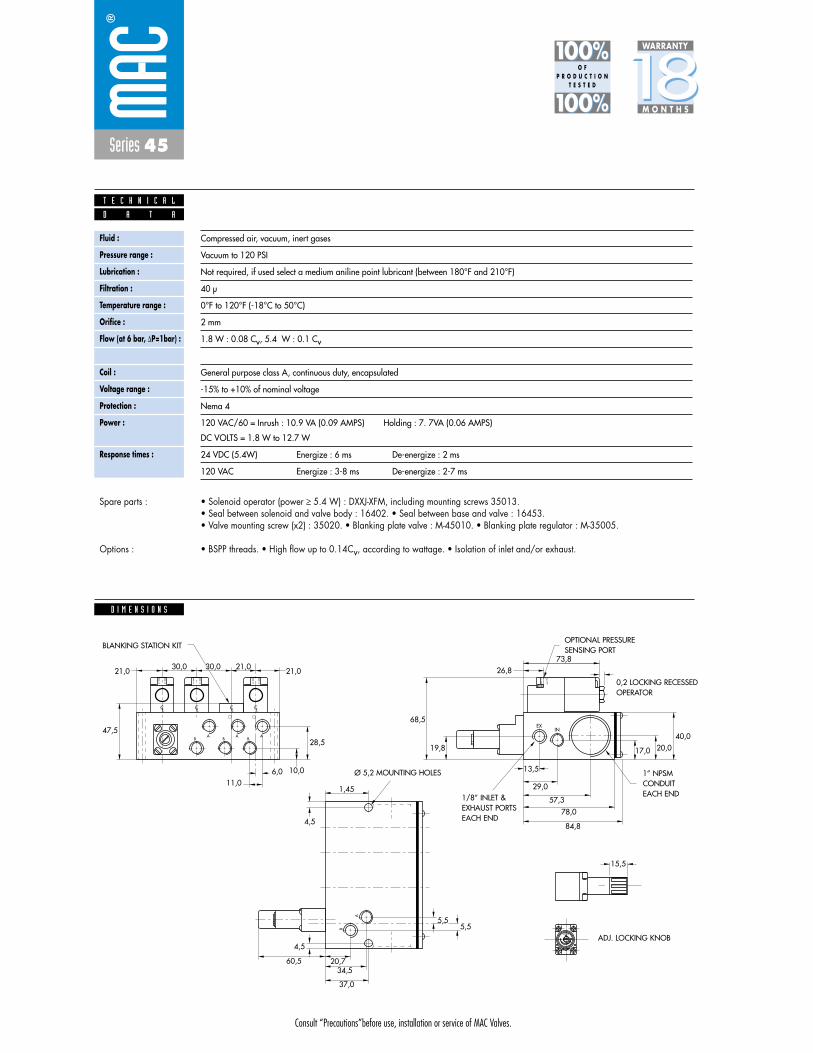
Consult “Precautions”before use, installation or service of MAC Valves.
Series 45
D I M E N S I O N S
Fluid :
Pressure range :
Lubrication :
Filtration :
Temperature range :
Orifice :
Flow (at 6 bar, �P=1bar) :
Leak rate :
Coil :
Voltage range :
Protection :
Power :
Response times :
Compressed air, vacuum, inert gases
Vacuum to 120 PSI
Not required, if used select a medium aniline point lubricant (between 180°F and 210°F)
40 μ
0°F to 120°F (-18°C to 50°C)
2 mm
1.8 W : 0.08 Cv, 5.4 W : 0.1 Cv
50 cm3/min
General purpose class A, continuous duty, encapsulated
-15% to +10% of nominal voltage
Nema 4
120 VAC/60 = Inrush : 10.9 VA (0.09 AMPS) Holding : 7. 7VA (0.06 AMPS)
DC VOLTS = 1.8 W to 12.7 W
24 VDC (5.4W) Energize : 6 ms De-energize : 2 ms
120 VAC Energize : 3-8 ms De-energize : 2-7 ms
D A T A
T E C H N I C A L
1818100%100%
100%100% M O N T H S
WARRANTY
O FP R O D U C T I O N
T E S T E D
• Solenoid operator (power � 5.4 W) : DXXJ-XFM, including mounting screws 35013. • Seal between solenoid and valve body : 16402. • Seal between base and valve : 16453. • Valve mounting screw (x2) : 35020. • Blanking plate valve : M-45010. • Blanking plate regulator : M-35005.
• BSPP threads. • High flow up to 0.14Cv, according to wattage. • Isolation of inlet and/or exhaust.
Spare parts :
Options :
CL CL CL CL
AB
AB B
A
EXIN
A
B
21,0
47,5
28,5
68,5
19,8
13,5
29,0
40,020,017,0
26,873,8
57,3
78,0
84,8
10,0
1,45
4,5
60,5 20,7
5,55,5
34,5
37,0
4,5
6,011,0
21,030,0 30,0 21,0
LOCK
15,5
OPTIONAL PRESSURESENSING PORT
Ø 5,2 MOUNTING HOLES
BLANKING STATION KIT
0,2 LOCKING RECESSEDOPERATOR
1” NPSMCONDUITEACH END
ADJ. LOCKING KNOB
1/8” INLET &EXHAUST PORTS EACH END
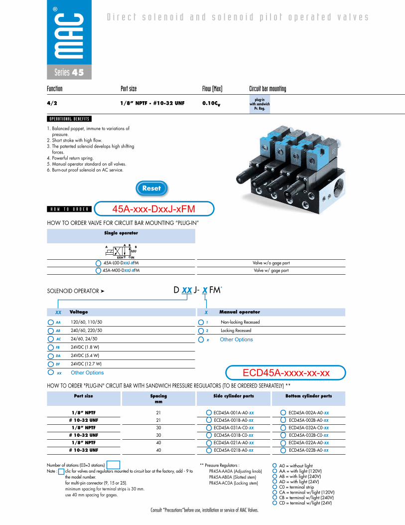
Consult “Precautions”before use, installation or service of MAC Valves.
Reset
Series 45
Function Port size Flow (Max) Circuit bar mounting
4/2 1/8” NPTF - #10-32 UNF 0.10Cvplug-in
with sandwich Pr. Reg.
1. Balanced poppet, immune to variations ofpressure.
2. Short stroke with high flow.3. The patented solenoid develops high shifting
forces.4. Powerful return spring.5. Manual operator standard on all valves.6. Burn-out proof solenoid on AC service.
O P E R A T I O N A L B E N E F I T S
D i r e c t s o l e n o i d a n d s o l e n o i d p i l o t o p e r a t e d v a l v e s
H O W T O O R D E R
Single operator
45A-L00-DXXJ-XFM
45A-M00-DXXJ-XFM
Valve w/o gage port
Valve w/ gage port
A BA B
EXH IN
HOW TO ORDER VALVE FOR CIRCUIT BAR MOUNTING “PLUG-IN”
Voltage
AA 120/60, 110/50
AB 240/60, 220/50
AC 24/60, 24/50
FB 24VDC (1.8 W)
DA 24VDC (5.4 W)
DF 24VDC (12.7 W)
Manual operator
1 Non-locking Recessed
2 Locking Recessed
D XX J- X FM*SOLENOID OPERATOR ➤
Port size
1/8” NPTF
# 10-32 UNF
1/8” NPTF
# 10-32 UNF
1/8” NPTF
# 10-32 UNF
Spacingmm
21
21
30
30
40
40
Side cylinder ports
ECD45A-001A-A0-XX
ECD45A-001B-A0-XX
ECD45A-031A-C0-XX
ECD45A-031B-C0-XX
ECD45A-021A-A0-XX
ECD45A-021B-A0-XX
Bottom cylinder ports
ECD45A-002A-A0-XX
ECD45A-002B-A0-XX
ECD45A-032A-C0-XX
ECD45A-032B-C0-XX
ECD45A-022A-A0-XX
ECD45A-022B-A0-XX
HOW TO ORDER "PLUG-IN" CIRCUIT BAR WITH SANDWICH PRESSURE REGULATORS (TO BE ORDERED SEPARATELY) **
XXX
* * A0 = without lightAA = with light (120V)AB = with light (240V)AD = with light (24V)C0 = terminal stripCA = terminal w/light (120V)CB = terminal w/light (240V)CD = terminal w/light (24V)
Number of stations (03=3 stations)Note : clic for valves and regulators mounted to circuit bar at the factory, add - 9 to
the model number.for multi-pin connector (9, 15 or 25).minimum spacing for terminal strips is 30 mm.use 40 mm spacing for gages.
** Pressure Regulators : PR45A-AA0A (Adjusting knob)PR45A-AB0A (Slotted stem)PR45A-AC0A (Locking stem)
45A-xxx-DxxJ-xFM
ECD45A-xxxx-xx-xxOther Optionsxx
x Other Options
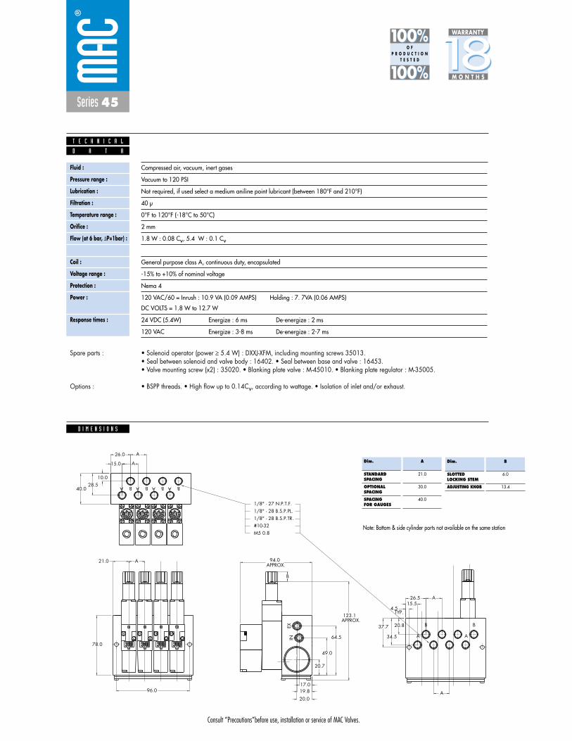
Consult “Precautions”before use, installation or service of MAC Valves.
Series 45
D I M E N S I O N S
Fluid :
Pressure range :
Lubrication :
Filtration :
Temperature range :
Orifice :
Flow (at 6 bar, �P=1bar) :
Leak rate :
Coil :
Voltage range :
Protection :
Power :
Response times :
Compressed air, vacuum, inert gases
Vacuum to 120 PSI
Not required, if used select a medium aniline point lubricant (between 180°F and 210°F)
40 μ
0°F to 120°F (-18°C to 50°C)
2 mm
1.8 W : 0.08 Cv, 5.4 W : 0.1 Cv
50 cm3/min
General purpose class A, continuous duty, encapsulated
-15% to +10% of nominal voltage
Nema 4
120 VAC/60 = Inrush : 10.9 VA (0.09 AMPS) Holding : 7. 7VA (0.06 AMPS)
DC VOLTS = 1.8 W to 12.7 W
24 VDC (5.4W) Energize : 6 ms De-energize : 2 ms
120 VAC Energize : 3-8 ms De-energize : 2-7 ms
D A T A
T E C H N I C A L
1818100%100%
100%100% M O N T H S
WARRANTY
O FP R O D U C T I O N
T E S T E D
• Solenoid operator (power � 5.4 W) : DXXJ-XFM, including mounting screws 35013. • Seal between solenoid and valve body : 16402. • Seal between base and valve : 16453. • Valve mounting screw (x2) : 35020. • Blanking plate valve : M-45010. • Blanking plate regulator : M-35005.
• BSPP threads. • High flow up to 0.14Cv, according to wattage. • Isolation of inlet and/or exhaust.
Spare parts :
Options :
M5 0.8#10-321/8" - 28 B.S.P.TR.1/8" - 28 B.S.P.PL.1/8" - 27 N.P.T.F.
A BA BA BA B
26.0
15.0
A
A
10.028.5
37.7
4.5
26.515.5
B
A
20.8
34.5 A
B
A
A
TYP.
96.0
A21.0
APPROX. 123.1
B
APPROX.94.0
L OCKL OCKL OCKKCOL
19.817.0
20.0
20.7
49.0
64.578.0
A
B
A
B
A
B
A
B
40.0
EXIN
Dim.
STANDARDSPACING
OPTIONALSPACING
SPACINGFOR GAUGES
A
21.0
30.0
40.0
Dim.
SLOTTEDLOCKING STEM
ADJUSTING KNOB
B
6.0
13.4
Note: Bottom & side cylinder ports not available on the same station
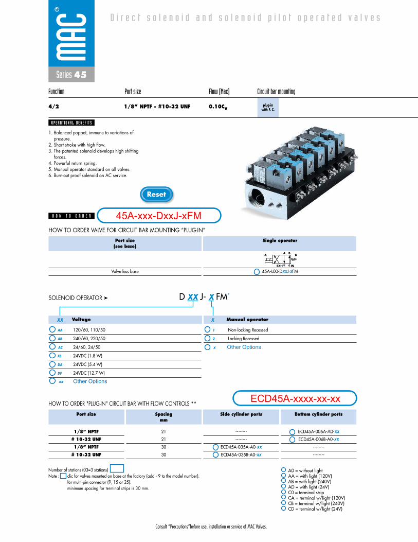
Consult “Precautions”before use, installation or service of MAC Valves.
Reset
Series 45
Function Port size Flow (Max) Circuit bar mounting
4/2 1/8” NPTF - #10-32 UNF 0.10Cvplug-in
with F. C.
1. Balanced poppet, immune to variations ofpressure.
2. Short stroke with high flow.3. The patented solenoid develops high shifting
forces.4. Powerful return spring.5. Manual operator standard on all valves.6. Burn-out proof solenoid on AC service.
O P E R A T I O N A L B E N E F I T S
D i r e c t s o l e n o i d a n d s o l e n o i d p i l o t o p e r a t e d v a l v e s
H O W T O O R D E R
Port size(see base)
Valve less base
Single operator
45A-L00-DXXJ-XFM
A BA B
EXH IN
HOW TO ORDER VALVE FOR CIRCUIT BAR MOUNTING “PLUG-IN”
Voltage
AA 120/60, 110/50
AB 240/60, 220/50
AC 24/60, 24/50
FB 24VDC (1.8 W)
DA 24VDC (5.4 W)
DF 24VDC (12.7 W)
Manual operator
1 Non-locking Recessed
2 Locking Recessed
D XX J- X FM*SOLENOID OPERATOR ➤
Port size
1/8” NPTF
# 10-32 UNF
1/8” NPTF
# 10-32 UNF
Spacingmm
21
21
30
30
Side cylinder ports
--------
--------
ECD45A-035A-A0-XX
ECD45A-035B-A0-XX
Bottom cylinder ports
ECD45A-006A-A0-XX
ECD45A-006B-A0-XX
--------
--------
HOW TO ORDER "PLUG-IN" CIRCUIT BAR WITH FLOW CONTROLS **
XXX
* * A0 = without lightAA = with light (120V)AB = with light (240V)AD = with light (24V)C0 = terminal stripCA = terminal w/light (120V)CB = terminal w/light (240V)CD = terminal w/light (24V)
Number of stations (03=3 stations)Note : clic for valves mounted on base at the factory (add - 9 to the model number).
for multi-pin connector (9, 15 or 25).minimum spacing for terminal strips is 30 mm.
45A-xxx-DxxJ-xFM
ECD45A-xxxx-xx-xx
Other Optionsxx
x Other Options
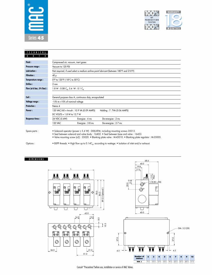
Consult “Precautions”before use, installation or service of MAC Valves.
Series 45
D I M E N S I O N S
Fluid :
Pressure range :
Lubrication :
Filtration :
Temperature range :
Orifice :
Flow (at 6 bar, �P=1bar) :
Leak rate :
Coil :
Voltage range :
Protection :
Power :
Response times :
Compressed air, vacuum, inert gases
Vacuum to 120 PSI
Not required, if used select a medium aniline point lubricant (between 180°F and 210°F)
40 μ
0°F to 120°F (-18°C to 50°C)
2 mm
1.8 W : 0.08 Cv, 5.4 W : 0.1 Cv
50 cm3/min
General purpose class A, continuous duty, encapsulated
-15% to +10% of nominal voltage
Nema 4
120 VAC/60 = Inrush : 10.9 VA (0.09 AMPS) Holding : 7. 7VA (0.06 AMPS)
DC VOLTS = 1.8 W to 12.7 W
24 VDC (5.4W) Energize : 6 ms De-energize : 2 ms
120 VAC Energize : 3-8 ms De-energize : 2-7 ms
D A T A
T E C H N I C A L
1818100%100%
100%100% M O N T H S
WARRANTY
O FP R O D U C T I O N
T E S T E D
• Solenoid operator (power � 5.4 W) : DXXJ-XFM, including mounting screws 35013. • Seal between solenoid and valve body : 16402. • Seal between base and valve : 16453. • Valve mounting screw (x2) : 35020. • Blanking plate valve : M-45010. • Blanking plate regulator : M-35005.
• BSPP threads. • High flow up to 0.14Cv, according to wattage. • Isolation of inlet and/or exhaust.
Spare parts :
Options :
Number ofstations
DIM. L
2
77.0
3
107.0
4
137.0
5
167.0
6
197.0
7
227.0
8
257.0
9
287.0
10
317.0
EXIN
84.3
78.0
89.2
( O
ptio
nal )
L
68.640.0
19.817.0
13.2
Max
.
13.5
29.0
40.0
1/8 (IN + EX)
A A A A BBBB
13.0
43.0
14.5
10.3
8.0
51.0
21.026.0
37.0
4.54.5
37.0
DIA. 5.2 (2X)
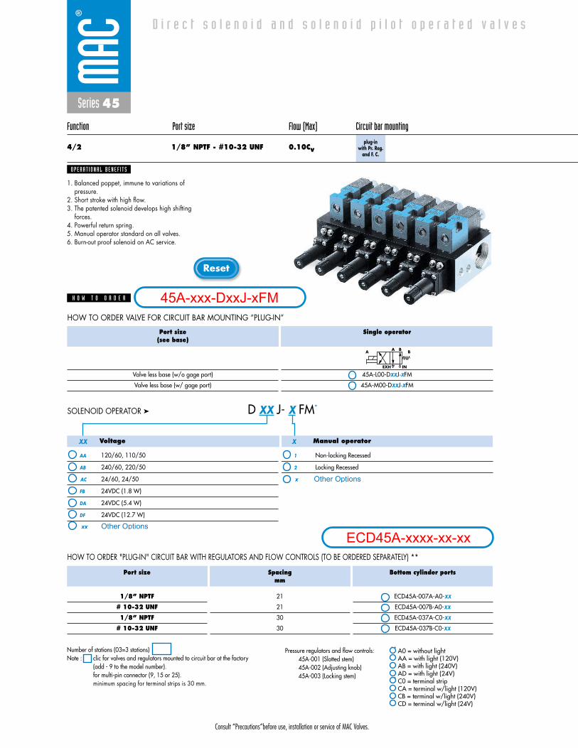
Consult “Precautions”before use, installation or service of MAC Valves.
Reset
Series 45
Function Port size Flow (Max) Circuit bar mounting
4/2 1/8” NPTF - #10-32 UNF 0.10Cvplug-in
with Pr. Reg.and F. C.
1. Balanced poppet, immune to variations ofpressure.
2. Short stroke with high flow.3. The patented solenoid develops high shifting
forces.4. Powerful return spring.5. Manual operator standard on all valves.6. Burn-out proof solenoid on AC service.
O P E R A T I O N A L B E N E F I T S
D i r e c t s o l e n o i d a n d s o l e n o i d p i l o t o p e r a t e d v a l v e s
H O W T O O R D E R
Port size(see base)
Valve less base (w/o gage port)
Valve less base (w/ gage port)
Single operator
45A-L00-DXXJ-XFM
45A-M00-DXXJ-XFM
A BA B
EXH IN
HOW TO ORDER VALVE FOR CIRCUIT BAR MOUNTING “PLUG-IN”
Voltage
AA 120/60, 110/50
AB 240/60, 220/50
AC 24/60, 24/50
FB 24VDC (1.8 W)
DA 24VDC (5.4 W)
DF 24VDC (12.7 W)
Manual operator
1 Non-locking Recessed
2 Locking Recessed
D XX J- X FM*SOLENOID OPERATOR ➤
HOW TO ORDER "PLUG-IN" CIRCUIT BAR WITH REGULATORS AND FLOW CONTROLS (TO BE ORDERED SEPARATELY) **
XXX
Port size
1/8” NPTF
# 10-32 UNF
1/8” NPTF
# 10-32 UNF
Spacingmm
21
21
30
30
Bottom cylinder ports
ECD45A-007A-A0-XX
ECD45A-007B-A0-XX
ECD45A-037A-C0-XX
ECD45A-037B-C0-XX
Number of stations (03=3 stations)Note : clic for valves and regulators mounted to circuit bar at the factory
(add - 9 to the model number).for multi-pin connector (9, 15 or 25).minimum spacing for terminal strips is 30 mm.
Pressure regulators and flow controls: 45A-001 (Slotted stem)45A-002 (Adjusting knob)45A-003 (Locking stem)
** A0 = without lightAA = with light (120V)AB = with light (240V)AD = with light (24V)
** C0 = terminal stripCA = terminal w/light (120V)CB = terminal w/light (240V)CD = terminal w/light (24V)
45A-xxx-DxxJ-xFM
ECD45A-xxxx-xx-xxOther Optionsxx
x Other Options
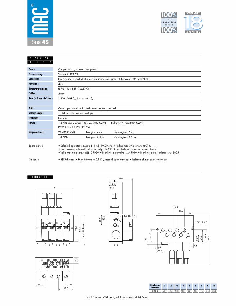
Consult “Precautions”before use, installation or service of MAC Valves.
Series 45
D I M E N S I O N S
Fluid :
Pressure range :
Lubrication :
Filtration :
Temperature range :
Orifice :
Flow (at 6 bar, �P=1bar) :
Leak rate :
Coil :
Voltage range :
Protection :
Power :
Response times :
Compressed air, vacuum, inert gases
Vacuum to 120 PSI
Not required, if used select a medium aniline point lubricant (between 180°F and 210°F)
40 μ
0°F to 120°F (-18°C to 50°C)
2 mm
1.8 W : 0.08 Cv, 5.4 W : 0.1 Cv
50 cm3/min
General purpose class A, continuous duty, encapsulated
-15% to +10% of nominal voltage
Nema 4
120 VAC/60 = Inrush : 10.9 VA (0.09 AMPS) Holding : 7. 7VA (0.06 AMPS)
DC VOLTS = 1.8 W to 12.7 W
24 VDC (5.4W) Energize : 6 ms De-energize : 2 ms
120 VAC Energize : 3-8 ms De-energize : 2-7 ms
D A T A
T E C H N I C A L
1818100%100%
100%100% M O N T H S
WARRANTY
O FP R O D U C T I O N
T E S T E D
• Solenoid operator (power � 5.4 W) : DXXJ-XFM, including mounting screws 35013. • Seal between solenoid and valve body : 16402. • Seal between base and valve : 16453. • Valve mounting screw (x2) : 35020. • Blanking plate valve : M-45010. • Blanking plate regulator : M-35005.
• BSPP threads. • High flow up to 0.14Cv, according to wattage. • Isolation of inlet and/or exhaust.
Spare parts :
Options :
Number ofstations
DIM. L
2
68.0
3
89.0
4
110.0
5
131.0
6
152.0
7
173.0
8
194.0
9
215.0
10
236.0
1/8 (IN + EX)
L
84.3
78.0
89.2
( O
ptio
nal )
17.019.8
40.068.6
13.5
29.0
EX
IN
DIA. 5.2 (2
A A A A
B BBB
10.0
21.0
37.0
34.5
20.7
148.
2
4.5
20.5
4.5
37.0
7.0
17.3
42.0
21.026.0

Consult “Precautions”before use, installation or service of MAC Valves.
Reset
Series 45
Function Port size Flow (Max) Circuit bar mounting s
4/2 1/8” NPTF - #10-32 UNF 0.10Cvplug-in
with integral terminal strip
1. Balanced poppet, immune to variations ofpressure.
2. Short stroke with high flow.3. The patented solenoid develops high shifting
forces.4. Powerful return spring.5. Manual operator standard on all valves.6. Burn-out proof solenoid on AC service.
O P E R A T I O N A L B E N E F I T S
D i r e c t s o l e n o i d a n d s o l e n o i d p i l o t o p e r a t e d v a l v e s
H O W T O O R D E R
Single operator
45A-L00-DXXJ-XFM Valve less base
A BA B
EXH IN
HOW TO ORDER VALVE FOR CIRCUIT BAR MOUNTING “PLUG-IN”
Voltage
AA 120/60, 110/50
AB 240/60, 220/50
AC 24/60, 24/50
FB 24VDC (1.8 W)
DA 24VDC (5.4 W)
DF 24VDC (12.7 W)
Manual operator
1 Non-locking Recessed
2 Locking Recessed
D XX J- X FM *SOLENOID OPERATOR ➤
Port size
1/8” NPTF
# 10-32 UNF
Spacingmm
26
26
Side cylinder ports
ECE45A-011A-C0-XX
ECE45A-011B-C0-XX
Bottom cylinder ports
ECE45A-012A-C0-XX
ECE45A-012B-C0-XX
HOW TO ORDER “PLUG-IN” CIRCUIT BAR**
XX X
** C0 = terminal stripCA = terminal strip w/light (120V)CB = terminal strip w/light (240V)CD = terminal strip w/light (24V)
Number of stations (03=3 stations)End plate kit required : M-45017Note : clic for valves mounted on circuit bar at the factory (add - 9 to the
model number).
45A-LOO-DxxJ-xFM
2
ECE45A-011A-CD-02
Other Optionsxx
x Other Options
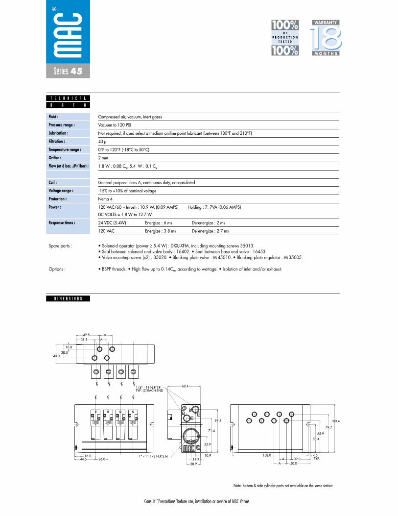
Consult “Precautions”before use, installation or service of MAC Valves.
Series 45
D I M E N S I O N S
Fluid :
Pressure range :
Lubrication :
Filtration :
Temperature range :
Orifice :
Flow (at 6 bar, �P=1bar) :
Leak rate :
Coil :
Voltage range :
Protection :
Power :
Response times :
Compressed air, vacuum, inert gases
Vacuum to 120 PSI
Not required, if used select a medium aniline point lubricant (between 180°F and 210°F)
40 μ
0°F to 120°F (-18°C to 50°C)
2 mm
1.8 W : 0.08 Cv, 5.4 W : 0.1 Cv
50 cm3/min
General purpose class A, continuous duty, encapsulated
-15% to +10% of nominal voltage
Nema 4
120 VAC/60 = Inrush : 10.9 VA (0.09 AMPS) Holding : 7. 7VA (0.06 AMPS)
DC VOLTS = 1.8 W to 12.7 W
24 VDC (5.4W) Energize : 6 ms De-energize : 2 ms
120 VAC Energize : 3-8 ms De-energize : 2-7 ms
D A T A
T E C H N I C A L
1818100%100%
100%100% M O N T H S
WARRANTY
O FP R O D U C T I O N
T E S T E D
• Solenoid operator (power � 5.4 W) : DXXJ-XFM, including mounting screws 35013. • Seal between solenoid and valve body : 16402. • Seal between base and valve : 16453. • Valve mounting screw (x2) : 35020. • Blanking plate valve : M-45010. • Blanking plate regulator : M-35005.
• BSPP threads. • High flow up to 0.14Cv, according to wattage. • Isolation of inlet and/or exhaust.
Spare parts :
Options :
Note: Bottom & side cylinder ports not available on the same station
100.4
TYP.158.0
CL CLCL CL
IN
IN EX
EX
G
B
A
B
A
B
A
B
A
CL CL CL
40.0
68.4
33.9
71.4
89.4
10.919.9
28.9
58.4
4.544.5
16.026.0
TYP. (2) EACH END1/4" - 18 N.P.T.F.
1" - 11 1/2 N.P.S.M
LC
38.549.5
AA
10.0
28.5
A 50.0A 39.0
65.9
79.7

Consult “Precautions”before use, installation or service of MAC Valves.
Reset
Series 45
Function Port size Flow (Max) Circuit bar mounting
4/2 1/8” NPTF - #10-32 UNF 0.10Cvplug-in with
integral terminalstrip and
side Pr. Reg.
1. Balanced poppet, immune to variations ofpressure.
2. Short stroke with high flow.3. The patented solenoid develops high shifting
forces.4. Powerful return spring.5. Manual operator standard on all valves.6. Burn-out proof solenoid on AC service.
O P E R A T I O N A L B E N E F I T S
D i r e c t s o l e n o i d a n d s o l e n o i d p i l o t o p e r a t e d v a l v e s
H O W T O O R D E R
Single operator
45A-L00-DXXJ-XFM
45A-M00-DXXJ-XFM
Valve less base w/o gage port
Valve less base w/ gage port
A BA B
EXH IN
HOW TO ORDER VALVE FOR “PLUG-IN” CIRCUIT BAR
Voltage
AA 120/60, 110/50
AB 240/60, 220/50
AC 24/60, 24/50
FB 24VDC (1.8 W)
DA 24VDC (5.4 W)
DF 24VDC (12.7 W)
Manual operator
1 Non-locking Recessed
2 Locking Recessed
D XX J- X FM *SOLENOID OPERATOR ➤
HOW TO ORDER CIRCUIT BAR WITH PRESSURE REGULATORS (TO BE ORDERED SEPARATELY) **
XX X
Port size
1/8” NPTF
# 10-32 UNF
1/8” NPTF
# 10-32 UNF
Spacingmm
26
26
40
40
Bottom cylinder ports
ECE45A-014A-C0-XX
ECE45A-014B-C0-XX
ECE45A-024A-C0-XX
ECE45A-024B-C0-XX
** C0 = terminal stripCA = terminal strip w/light (120V)CB = terminal strip w/light (240V)CD = terminal strip w/light (24V)
Number of stations (03=3 stations)End plate kit required : M-45017Note : clic for valves and regulators mounted to circuit
bar at the factory (add - 9 to the model number).Use 40 mm spacing for valves w/ gage port.
** Pressure Regulators : 35A-00M (Adjusting knob)35A-00L (Slotted stem)35A-00U (Locking stem)
45A-xxx-DxxJ-xFM
ECE45A-xxxx-xx-xxOther Optionsxx
x Other Options

Consult “Precautions”before use, installation or service of MAC Valves.
Series 45
Fluid :
Pressure range :
Lubrication :
Filtration :
Temperature range :
Orifice :
Flow (at 6 bar, �P=1bar) :
Leak rate :
Coil :
Voltage range :
Protection :
Power :
Response times :
Compressed air, vacuum, inert gases
Vacuum to 120 PSI
Not required, if used select a medium aniline point lubricant (between 180°F and 210°F)
40 μ
0°F to 120°F (-18°C to 50°C)
2 mm
1.8 W : 0.08 Cv, 5.4 W : 0.1 Cv
50 cm3/min
General purpose class A, continuous duty, encapsulated
-15% to +10% of nominal voltage
Nema 4
120 VAC/60 = Inrush : 10.9 VA (0.09 AMPS) Holding : 7. 7VA (0.06 AMPS)
DC VOLTS = 1.8 W to 12.7 W
24 VDC (5.4W) Energize : 6 ms De-energize : 2 ms
120 VAC Energize : 3-8 ms De-energize : 2-7 ms
D A T A
T E C H N I C A L
1818100%100%
100%100% M O N T H S
WARRANTY
O FP R O D U C T I O N
T E S T E D
• Solenoid operator (power � 5.4 W) : DXXJ-XFM, including mounting screws 35013. • Seal between solenoid and valve body : 16402. • Seal between base and valve : 16453. • Valve mounting screw (x2) : 35020. • Blanking plate valve : M-45010. • Blanking plate regulator : M-35005.
• BSPP threads. • High flow up to 0.14Cv, according to wattage. • Isolation of inlet and/or exhaust.
Spare parts :
Options :
D I M E N S I O N S
100.4
158.01" - 11 1/2 N.P.S.M
TYP. (2) EACH END1/4" - 18 N.P.T.F.
B
154.5
A16.0
44.5
CL CL CL CL CL CL CL CL
4.5
58.4
28.919.9
10.9
89.4
71.4
33.9
68.4
40.0
LCLCLC
A
B
A
B
A
B
A
B
G
EX
EXIN
IN
CL
79.7
65.9
50.0A39.0A
Dim.
STANDARDSPACING
SPACINGFOR GAUGES
A
26.0
40.0
Dim.
SLOTTEDLOCKING STEM
ADJUSTING KNOB
B
6.0
13.4
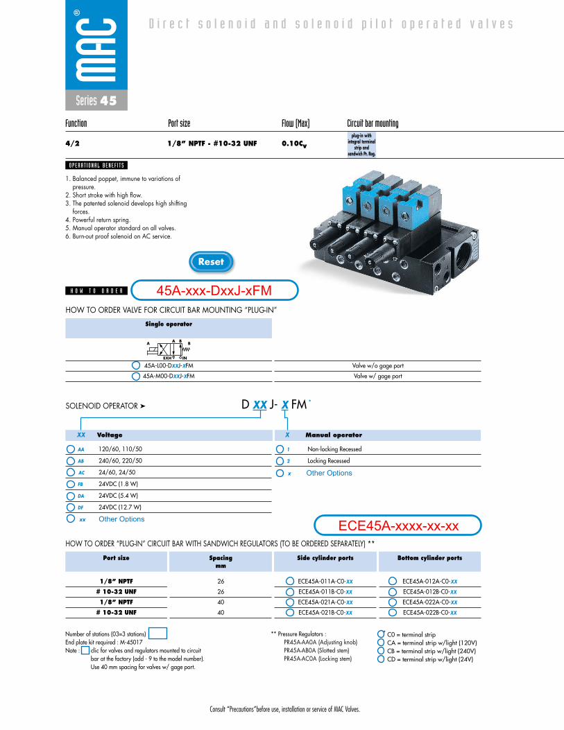
Consult “Precautions”before use, installation or service of MAC Valves.
Reset
Series 45
Function Port size Flow (Max) Circuit bar mounting
4/2 1/8” NPTF - #10-32 UNF 0.10Cvplug-in with
integral terminalstrip and
sandwich Pr. Reg.
1. Balanced poppet, immune to variations ofpressure.
2. Short stroke with high flow.3. The patented solenoid develops high shifting
forces.4. Powerful return spring.5. Manual operator standard on all valves.6. Burn-out proof solenoid on AC service.
O P E R A T I O N A L B E N E F I T S
D i r e c t s o l e n o i d a n d s o l e n o i d p i l o t o p e r a t e d v a l v e s
H O W T O O R D E R
Single operator
45A-L00-DXXJ-XFM
45A-M00-DXXJ-XFM
Valve w/o gage port
Valve w/ gage port
A BA B
EXH IN
HOW TO ORDER VALVE FOR CIRCUIT BAR MOUNTING “PLUG-IN”
Voltage
AA 120/60, 110/50
AB 240/60, 220/50
AC 24/60, 24/50
FB 24VDC (1.8 W)
DA 24VDC (5.4 W)
DF 24VDC (12.7 W)
Manual operator
1 Non-locking Recessed
2 Locking Recessed
D XX J- X FM *SOLENOID OPERATOR ➤
HOW TO ORDER “PLUG-IN” CIRCUIT BAR WITH SANDWICH REGULATORS (TO BE ORDERED SEPARATELY) **
XX X
Port size
1/8” NPTF
# 10-32 UNF
1/8” NPTF
# 10-32 UNF
Spacingmm
26
26
40
40
Side cylinder ports
ECE45A-011A-C0-XX
ECE45A-011B-C0-XX
ECE45A-021A-C0-XX
ECE45A-021B-C0-XX
Bottom cylinder ports
ECE45A-012A-C0-XX
ECE45A-012B-C0-XX
ECE45A-022A-C0-XX
ECE45A-022B-C0-XX
** C0 = terminal stripCA = terminal strip w/light (120V)CB = terminal strip w/light (240V)CD = terminal strip w/light (24V)
Number of stations (03=3 stations)End plate kit required : M-45017Note : clic for valves and regulators mounted to circuit
bar at the factory (add - 9 to the model number).Use 40 mm spacing for valves w/ gage port.
** Pressure Regulators : PR45A-AA0A (Adjusting knob)PR45A-AB0A (Slotted stem)PR45A-AC0A (Locking stem)
45A-xxx-DxxJ-xFM
ECE45A-xxxx-xx-xxOther Optionsxx
x Other Options

Consult “Precautions”before use, installation or service of MAC Valves.
Series 45
D I M E N S I O N S
Fluid :
Pressure range :
Lubrication :
Filtration :
Temperature range :
Orifice :
Flow (at 6 bar, �P=1bar) :
Leak rate :
Coil :
Voltage range :
Protection :
Power :
Response times :
Compressed air, vacuum, inert gases
Vacuum to 120 PSI
Not required, if used select a medium aniline point lubricant (between 180°F and 210°F)
40 μ
0°F to 120°F (-18°C to 50°C)
2 mm
1.8 W : 0.08 Cv, 5.4 W : 0.1 Cv
50 cm3/min
General purpose class A, continuous duty, encapsulated
-15% to +10% of nominal voltage
Nema 4
120 VAC/60 = Inrush : 10.9 VA (0.09 AMPS) Holding : 7. 7VA (0.06 AMPS)
DC VOLTS = 1.8 W to 12.7 W
24 VDC (5.4W) Energize : 6 ms De-energize : 2 ms
120 VAC Energize : 3-8 ms De-energize : 2-7 ms
D A T A
T E C H N I C A L
1818100%100%
100%100% M O N T H S
WARRANTY
O FP R O D U C T I O N
T E S T E D
• Solenoid operator (power � 5.4 W) : DXXJ-XFM, including mounting screws 35013. • Seal between solenoid and valve body : 16402. • Seal between base and valve : 16453. • Valve mounting screw (x2) : 35020. • Blanking plate valve : M-45010. • Blanking plate regulator : M-35005.
• BSPP threads. • High flow up to 0.14Cv, according to wattage. • Isolation of inlet and/or exhaust.
Spare parts :
Options :
1/8" - 27 N.P.T.F.1/8" - 28 B.S.P.PL.
M5 X 0.8
1/8" - 28 B.S.P.TR.#10-32
28.5
10.0
AA
49.538.5
65.9
79.7
39.050.0
AA
APPROX. 144.5
B
93.8
KCOLKCOLKCOL
ININ EX
EX
G
B
A
B
A
B
A
B
A
40.0
33.9
71.4
89.4
10.919.9
28.9
58.4
4.5
LCLCLCLCLCLCLCLC
44.516.0
A
L OCK
TYP. (2) EACH END1/4" - 18 N.P.T.F.
1" - 11 1/2 N.P.S.M
Dim.
STANDARDSPACING
SPACING FORGAUGES
A
26.0
40.0
Dim.
SLOTTEDLOCKING STEM
ADJUSTING KNOB
B
6.0
13.4
Note: Bottom & side cylinder ports not available on the same station

Consult “Precautions”before use, installation or service of MAC Valves.
Reset
Series 45
Function Port size Flow (Max) Circuit bar mounting
4/2 1/8” NPTF - #10-32 UNF 0.10Cvplug-in with
integral terminalstrip with F. C.
1. Balanced poppet, immune to variations ofpressure.
2. Short stroke with high flow.3. The patented solenoid develops high shifting
forces.4. Powerful return spring.5. Manual operator standard on all valves.6. Burn-out proof solenoid on AC service.
O P E R A T I O N A L B E N E F I T S
D i r e c t s o l e n o i d a n d s o l e n o i d p i l o t o p e r a t e d v a l v e s
H O W T O O R D E R
Single operator
45A-L00-DXXJ-XFM Valve less base
A BA B
EXH IN
HOW TO ORDER VALVE FOR CIRCUIT BAR MOUNTING “PLUG-IN”
Voltage
AA 120/60, 110/50
AB 240/60, 220/50
AC 24/60, 24/50
FB 24VDC (1.8 W)
DA 24VDC (5.4 W)
DF 24VDC (12.7 W)
Manual operator
1 Non-locking Recessed
2 Locking Recessed
D XX J- X FM *SOLENOID OPERATOR ➤
HOW TO ORDER “PLUG-IN” CIRCUIT BAR WITH FLOW CONTROLS **
XX X
Port size
1/8” NPTF
# 10-32 UNF
1/8” NPTF
# 10-32 UNF
Spacingmm
26
26
30
30
Side cylinder ports
--------
--------
ECE45A-035A-C0-XX
ECE45A-035B-C0-XX
Bottom cylinder ports
ECE45A-016A-C0-XX
ECE45A-016B-C0-XX
--------
--------
** C0 = terminal stripCA = terminal strip w/light (120V)CB = terminal strip w/light (240V)CD = terminal strip w/light (24V)
Number of stations (03=3 stations)End plate kit required : M-45017Note : clic for valves and regulators mounted to circuit
bar at the factory (add - 9 to the model number).
45A-xxx-DxxJ-xFM
ECE45A-xxxx-xx-xxOther Optionsxx
x Other Options

Consult “Precautions”before use, installation or service of MAC Valves.
Series 45
Fluid :
Pressure range :
Lubrication :
Filtration :
Temperature range :
Orifice :
Flow (at 6 bar, �P=1bar) :
Leak rate :
Coil :
Voltage range :
Protection :
Power :
Response times :
Compressed air, vacuum, inert gases
Vacuum to 120 PSI
Not required, if used select a medium aniline point lubricant (between 180°F and 210°F)
40 μ
0°F to 120°F (-18°C to 50°C)
2 mm
1.8 W : 0.08 Cv, 5.4 W : 0.1 Cv
50 cm3/min
General purpose class A, continuous duty, encapsulated
-15% to +10% of nominal voltage
Nema 4
120 VAC/60 = Inrush : 10.9 VA (0.09 AMPS) Holding : 7. 7VA (0.06 AMPS)
DC VOLTS = 1.8 W to 12.7 W
24 VDC (5.4W) Energize : 6 ms De-energize : 2 ms
120 VAC Energize : 3-8 ms De-energize : 2-7 ms
D A T A
T E C H N I C A L
1818100%100%
100%100% M O N T H S
WARRANTY
O FP R O D U C T I O N
T E S T E D
• Solenoid operator (power � 5.4 W) : DXXJ-XFM, including mounting screws 35013. • Seal between solenoid and valve body : 16402. • Seal between base and valve : 16453. • Valve mounting screw (x2) : 35020. • Blanking plate valve : M-45010. • Blanking plate regulator : M-35005.
• BSPP threads. • High flow up to 0.14Cv, according to wattage. • Isolation of inlet and/or exhaust.
Spare parts :
Options :
D I M E N S I O N S
111.9
LC
IN
IN EX
EX
G
B
A
B
A
B
A
B
A
CL CL CL
40.0
68.4
33.9
71.4
89.4
10.919.9
28.9
58.4
4.544.5
16.0A
TYP. (2) EACH END1/4" - 18 N.P.T.F.
1" - 11 1/2 N.P.S.M 158.0
50.0A39.0A
79.7
65.9
+ +
BA
13.027.5
8.0 10.3
+ +
BA
+ +
BA
+ +
BA
1/8" - 27 N.P.T.F.1/8" - 28 B.S.P.PL.1/8" - 28 B.S.P.TR.#10-32M5 X 0.8
Dim.
STANDARDSPACING
OPTIONALSPACING
A
26.0
30.0
Note: Bottom & side cylinder ports not available on the same station
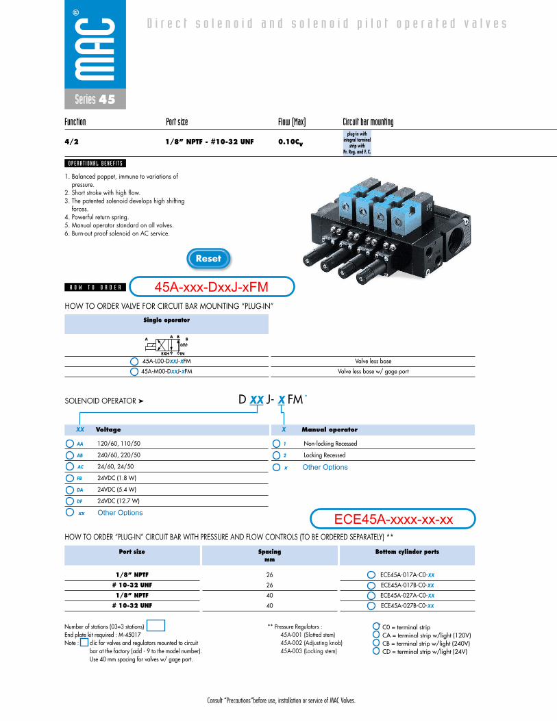
Consult “Precautions”before use, installation or service of MAC Valves.
Reset
Series 45
Function Port size Flow (Max) Circuit bar mounting
4/2 1/8” NPTF - #10-32 UNF 0.10Cvplug-in with
integral terminalstrip with
Pr. Reg. and F. C.
1. Balanced poppet, immune to variations ofpressure.
2. Short stroke with high flow.3. The patented solenoid develops high shifting
forces.4. Powerful return spring.5. Manual operator standard on all valves.6. Burn-out proof solenoid on AC service.
O P E R A T I O N A L B E N E F I T S
D i r e c t s o l e n o i d a n d s o l e n o i d p i l o t o p e r a t e d v a l v e s
H O W T O O R D E R
Single operator
45A-L00-DXXJ-XFM
45A-M00-DXXJ-XFM
Valve less base
Valve less base w/ gage port
A BA B
EXH IN
HOW TO ORDER VALVE FOR CIRCUIT BAR MOUNTING “PLUG-IN”
Voltage
AA 120/60, 110/50
AB 240/60, 220/50
AC 24/60, 24/50
FB 24VDC (1.8 W)
DA 24VDC (5.4 W)
DF 24VDC (12.7 W)
Manual operator
1 Non-locking Recessed
2 Locking Recessed
D XX J- X FM *SOLENOID OPERATOR ➤
HOW TO ORDER “PLUG-IN” CIRCUIT BAR WITH PRESSURE AND FLOW CONTROLS (TO BE ORDERED SEPARATELY) **
XX X
Port size
1/8” NPTF
# 10-32 UNF
1/8” NPTF
# 10-32 UNF
Spacingmm
26
26
40
40
Bottom cylinder ports
ECE45A-017A-C0-XX
ECE45A-017B-C0-XX
ECE45A-027A-C0-XX
ECE45A-027B-C0-XX
** C0 = terminal stripCA = terminal strip w/light (120V)CB = terminal strip w/light (240V)CD = terminal strip w/light (24V)
Number of stations (03=3 stations)End plate kit required : M-45017Note : clic for valves and regulators mounted to circuit
bar at the factory (add - 9 to the model number).Use 40 mm spacing for valves w/ gage port.
** Pressure Regulators : 45A-001 (Slotted stem)45A-002 (Adjusting knob)45A-003 (Locking stem)
45A-xxx-DxxJ-xFM
ECE45A-xxxx-xx-xxOther Optionsxx
x Other Options
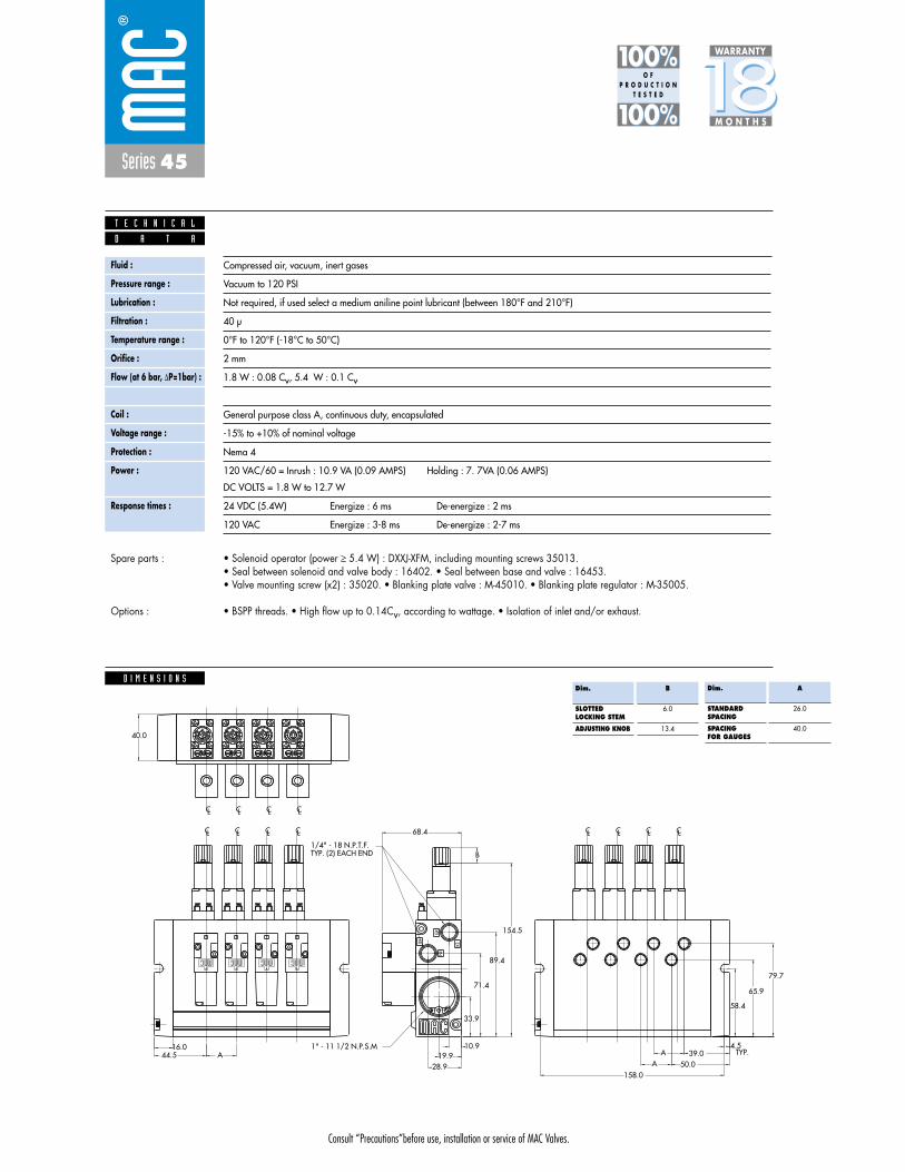
Consult “Precautions”before use, installation or service of MAC Valves.
Series 45
Fluid :
Pressure range :
Lubrication :
Filtration :
Temperature range :
Orifice :
Flow (at 6 bar, �P=1bar) :
Leak rate :
Coil :
Voltage range :
Protection :
Power :
Response times :
Compressed air, vacuum, inert gases
Vacuum to 120 PSI
Not required, if used select a medium aniline point lubricant (between 180°F and 210°F)
40 μ
0°F to 120°F (-18°C to 50°C)
2 mm
1.8 W : 0.08 Cv, 5.4 W : 0.1 Cv
50 cm3/min
General purpose class A, continuous duty, encapsulated
-15% to +10% of nominal voltage
Nema 4
120 VAC/60 = Inrush : 10.9 VA (0.09 AMPS) Holding : 7. 7VA (0.06 AMPS)
DC VOLTS = 1.8 W to 12.7 W
24 VDC (5.4W) Energize : 6 ms De-energize : 2 ms
120 VAC Energize : 3-8 ms De-energize : 2-7 ms
D A T A
T E C H N I C A L
1818100%100%
100%100% M O N T H S
WARRANTY
O FP R O D U C T I O N
T E S T E D
• Solenoid operator (power � 5.4 W) : DXXJ-XFM, including mounting screws 35013. • Seal between solenoid and valve body : 16402. • Seal between base and valve : 16453. • Valve mounting screw (x2) : 35020. • Blanking plate valve : M-45010. • Blanking plate regulator : M-35005.
• BSPP threads. • High flow up to 0.14Cv, according to wattage. • Isolation of inlet and/or exhaust.
Spare parts :
Options :
D I M E N S I O N S
TYP.
158.0
IN
IN EX
EX
G
B
A
B
A
B
A
B
A
CL CL CL
40.0
68.4
33.9
71.4
89.4
10.919.9
28.9
58.4
4.5
LCLCLCLCLCLCLCLC
44.516.0
A
CKOL
+
+
A B
154.5
BTYP. (2) EACH END1/4" - 18 N.P.T.F.
1" - 11 1/2 N.P.S.M
BA
+
+
L O KC
BA
+
+
L O KC
BA
+
+
L O KC
LC
79.7
65.9
39.050.0A
A
Dim.
STANDARDSPACING
SPACINGFOR GAUGES
A
26.0
40.0
Dim.
SLOTTEDLOCKING STEM
ADJUSTING KNOB
B
6.0
13.4

Consult “Precautions” before use, installation or service of MAC Valves.
S e c t i o n 2 Opt ions

Consult “Precautions”before use, installation or service of MAC Valves.
O P T I O N S
O p t i o n s
Codification table for voltages / Wire length / Manual operators / Electrical connections
- Solenoid valves 35 & 45 Series
- D XX X - X XX1 2 3 4
VALVE CODE ➤
OPTIONS AVAILABLE FOR

Consult “Precautions”before use, installation or service of MAC Valves.
O P T I O N S
1. VOLTAGE
- D XX X - X XX VOLTAGE
AD 24/60
AE 200/60
AF 240/50
AG 100/50, 100/60, 110/60
DB 12 VDC (5.4 W)
DC 12 VDC (7.5 W)
DD 24 VDC (7.3 W)
DE 12 VDC (12.7 W) CLSF
DK 110 VDC (5.8 W)
DL 64 VDC (6.0 W)
DM 36 VDC (5.8 W)
DN 6 VDC (6.0 W)
DP 48 VDC (5.8 W)
DU 24 VDC (6.0 W)
EA 12 VDC (6.0 W)
FA 12 VDC (1.8 W)
FE 12 VDC (2.4 W)
FF 24 VDC (2.4 W)
2. WIRE LENGTH
- D XX X - X XX WIRE LENGTH
B 24”
C 36”
D 48”
E 72”
F 96”
Back
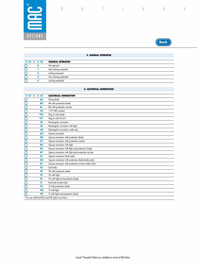
Consult “Precautions”before use, installation or service of MAC Valves.
O P T I O N S
O p t i o n s
3. MANUAL OPERATOR
- D XX X - X XX MANUAL OPERATOR
0 No operator
1 Non-locking recessed
2 Locking recessed
3 Non-locking extended
4 Locking extended
4. ELECTRICAL CONNECTION
- D XX X - X XX ELECTRICAL CONNECTION
BA Flying leads
BK BA with protection diode
BL BA with protection varistor
CA 1/2" NPS conduit
*FN Plug-in with diode
*FP Plug-in with M.O.V.
JB Rectangular connector
JD Rectangular connector with light
JM Rectangular connector, male only
KA Square connector
KB Square connector with protection diode
KC Square connector with protection varistor
KD Square connector with light
KE Square connector with light and protection diode
KF Square connector with light and protection varistor
KJ Square connector (male only)
KK Square connector with protection diode (male only)
KL Square connector with protection varistor (male only)
TA Dual tabs
TB TA with protection diode
TD TA with light
TE TA with light and protection diode
TJ Dual tabs (male only)
TK TJ with protection diode
TM TJ with light
TN TJ with light and protection diode
* For use with the ECD and ECE style circuit bars.
Back

• Type «SUB_D»• Number of contacts : 9• Solder termination (Dia. 0.6 mm/0.14 mm
2/26-22 AWG)
• Operating current 5 A/contact• Rated voltage 125 V~• Temp. range –40° to +125°C• Insulation resistance � 5.09 �• Protection class IP40 (DIN 40050)• Number of solenoids : 7 max.• Max. 24 V=/5.4 W per solenoid• 2 common wires
MOD. SD09
MOD. SD15
MOD. SD25
PIN #1
PIN #5
PIN #6
PIN #9
PIN #1
PIN #8
PIN #9
PIN #15
PIN #1
PIN #13
PIN #14
PIN #25
• Type «SUB_D»• Number of contacts : 25• Solder termination (Dia. 0.6 mm/0.14 mm
2/26-22 AWG)
• Operating current 5 A/contact• Rated voltage 125 V~• Temp. range –40° to +125°C• Insulation resistance � 5.09 �• Protection class IP40 (DIN 40050)• Number of solenoids : 20 max.• Max. 24 V=/5.4 W per solenoid• 5 common wires
Note : Use desired MOD. number after circuit bar part number
• Type «SUB_D»• Number of contacts : 15• Solder termination (Dia. 0.6 mm/0.14 mm
2/26-22 AWG)
• Operating current 5 A/contact• Rated voltage 125 V~• Temp. range –40° to +125°C• Insulation resistance � 5.09 �• Protection class IP40 (DIN 40050)• Number of solenoids : 12 max.• Max. 24 V=/5.4 W per solenoid• 3 common wires
T E C H N I C A L D A T A
T E C H N I C A L D A T A
T E C H N I C A L D A T A
O P T I O N S
O p t i o n s

SD09 SD15 SD25
Connector termination details
SOL 2 SOL 4 SOL 6 SOL 8 SOL 16 SOL 18 SOL 20 SOL 22 SOL 24
SOL 1CONN
ECTO
RCO
NNEC
TOR
SOL 2 SOL 3 SOL .. SOL 20 SOL 21 SOL 22 SOL 23 SOL 24
SOL 1 SOL 3 SOL 5 SOL 13 SOL 15 SOL 17
Double solenoid circuit bar
Single solenoid circuit bar
SOL 21 SOL 23SOL 19
SOL. 3
SOL. 1
SOL. 2
1
2
3
4
COMMON (+)
COMMON (+)
8
SOL. 4
5
6
7
9
SOL. 5
SOL. 7
SOL. 6
SOL. 3
SOL. 1
SOL. 2
1
2
3
4
COMMON (+)
COMMON (+)
COMMON (+)
13
SOL. 4
5
6
7
8
14
SOL. 5
SOL. 7
SOL. 6
SOL. 8
9
10
11
12
15
SOL. 9
SOL. 11
SOL. 10
SOL. 12
SOL. 3
SOL. 1
SOL. 2
1
2
3
4
COMMON (+)
COMMON (+)
COMMON (+)
COMMON (+)
COMMON (+)
21
SOL. 4
5
6
7
8
22
SOL. 5
SOL. 7
SOL. 6
SOL. 8
9
10
11
12
23
SOL. 9
SOL. 11
SOL. 10
SOL. 12
13
14
15
16
24
SOL. 13
SOL. 15
SOL. 14
SOL. 16
17
18
19
20
25
SOL. 17
SOL. 19
SOL. 18
SOL. 20
O P T I O N S
O p t i o n s
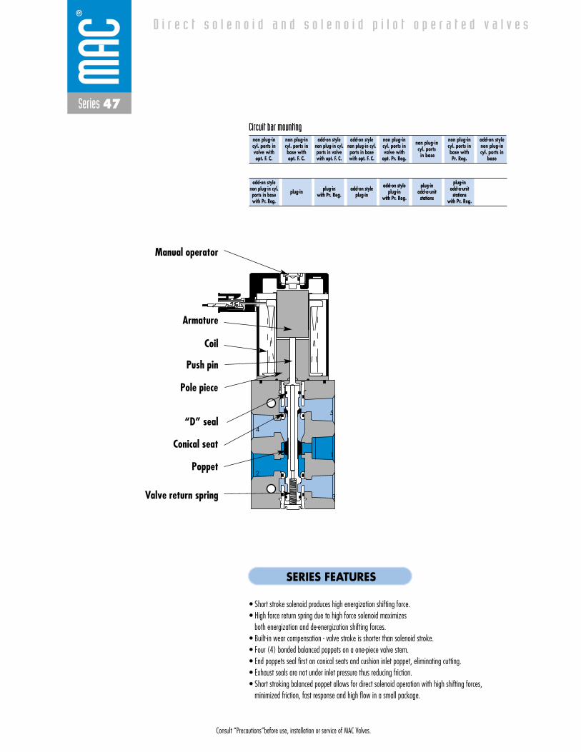
Consult “Precautions”before use, installation or service of MAC Valves.
Series 47
D i r e c t s o l e n o i d a n d s o l e n o i d p i l o t o p e r a t e d v a l v e s
non plug-incyl. ports invalve withopt. F. C.
non plug-incyl. ports inbase with opt. F. C.
add-on style non plug-in cyl.ports in valvewith opt. F. C.
add-on style non plug-in cyl.ports in basewith opt. F. C.
non plug-incyl. ports invalve with
opt. Pr. Reg.
non plug-incyl. ports
in base
non plug-incyl. ports inbase with Pr. Reg.
add-on stylenon plug-incyl. ports in
base
Circuit bar mounting
add-on style non plug-in cyl.ports in basewith Pr. Reg.
plug-in plug-inwith Pr. Reg.
add-on style plug-in
add-on styleplug-in
with Pr. Reg.
plug-inadd-a-unitstations
plug-inadd-a-unitstations
with Pr. Reg.
SERIES FEATURES
• Short stroke solenoid produces high energization shifting force.• High force return spring due to high force solenoid maximizes
both energization and de-energization shifting forces.• Built-in wear compensation - valve stroke is shorter than solenoid stroke.• Four (4) bonded balanced poppets on a one-piece valve stem.• End poppets seal first on conical seats and cushion inlet poppet, eliminating cutting.• Exhaust seals are not under inlet pressure thus reducing friction.• Short stroking balanced poppet allows for direct solenoid operation with high shifting forces,
minimized friction, fast response and high flow in a small package.
4
2
1
5
3
Push pin
Manual operator
Armature
Coil
“D” seal
Poppet
Valve return spring
Pole piece
Conical seat
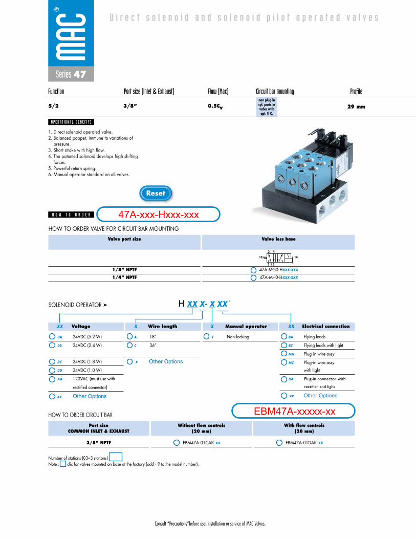
Consult “Precautions”before use, installation or service of MAC Valves.
Reset
Series 47
Function Port size (Inlet & Exhaust) Flow (Max) Circuit bar mounting Profile
5/2 3/8” 0.5Cv 29 mmnon plug-incyl. ports invalve withopt. F. C.
1. Direct solenoid operated valve.2. Balanced poppet, immune to variations of
pressure.3. Short stroke with high flow.4. The patented solenoid develops high shifting
forces.5. Powerful return spring.6. Manual operator standard on all valves.
O P E R A T I O N A L B E N E F I T S
D i r e c t s o l e n o i d a n d s o l e n o i d p i l o t o p e r a t e d v a l v e s
H O W T O O R D E R
Port sizeCOMMON INLET & EXHAUST
3/8” NPTF
Without flow controls(20 mm)
EBM47A-01CAK-XX
With flow controls(20 mm)
EBM47A-01DAK-XX
Voltage
DA 24VDC (5.2 W)
DB 24VDC (2.4 W)
DC 24VDC (1.8 W)
DD 24VDC (1.0 W)
AA 120VAC (must use with
rectified connector)
Wire length
A 18”
C 36”
Manual operator
1 Non-locking
Electrical connection
BA Flying leads
BC Flying leads with light
MA Plug-in wire assy
MC Plug-in wire assy
with light
HA Plug-in connector with
rectifier and light
H XX X- X XX *SOLENOID OPERATOR ➤
HOW TO ORDER CIRCUIT BAR
XX X X XX
Valve port size
1/8” NPTF
1/4” NPTF
Valve less base
47A-MG0-HXXX-XXX
47A-MH0-HXXX-XXX
3
4
1
2
5
1412
HOW TO ORDER VALVE FOR CIRCUIT BAR MOUNTING
Number of stations (03=3 stations)Note : clic for valves mounted on base at the factory (add - 9 to the model number).
47A-xxx-Hxxx-xxx
EBM47A-xxxxx-xxOther Optionsxx
x Other Options
xx Other Options
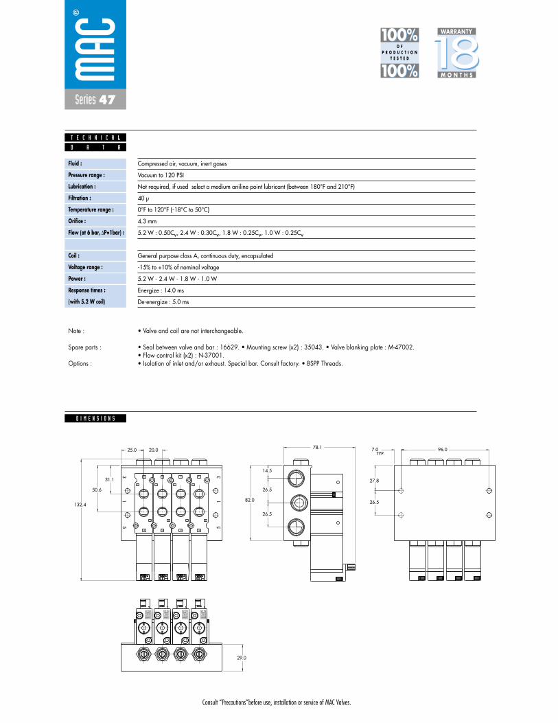
Consult “Precautions”before use, installation or service of MAC Valves.
Series 47
D I M E N S I O N S
Fluid :
Pressure range :
Lubrication :
Filtration :
Temperature range :
Orifice :
Flow (at 6 bar, �P=1bar) :
Leak rate :
Coil :
Voltage range :
Power :
Response times :
(with 5.2 W coil)
Compressed air, vacuum, inert gases
Vacuum to 120 PSI
Not required, if used select a medium aniline point lubricant (between 180°F and 210°F)
40 μ
0°F to 120°F (-18°C to 50°C)
4.3 mm
5.2 W : 0.50Cv, 2.4 W : 0.30Cv, 1.8 W : 0.25Cv, 1.0 W : 0.25Cv
50 cm3/min
General purpose class A, continuous duty, encapsulated
-15% to +10% of nominal voltage
5.2 W - 2.4 W - 1.8 W - 1.0 W
Energize : 14.0 ms
De-energize : 5.0 ms
TYP.
29.0
50.6
31.1
20.025.0 96.0
2
4
12
14
2
4
12
14
2
4
12
14
26.5
27.8
7.0
26.5
26.5
14.5
82.0132.4
78.1
31
5
31
5
14
12
4
2
D A T A
T E C H N I C A L
1818100%100%
100%100% M O N T H S
WARRANTY
O FP R O D U C T I O N
T E S T E D
• Valve and coil are not interchangeable.
• Seal between valve and bar : 16629. • Mounting screw (x2) : 35043. • Valve blanking plate : M-47002.• Flow control kit (x2) : N-37001.• Isolation of inlet and/or exhaust. Special bar. Consult factory. • BSPP Threads.
Note :
Spare parts :
Options :
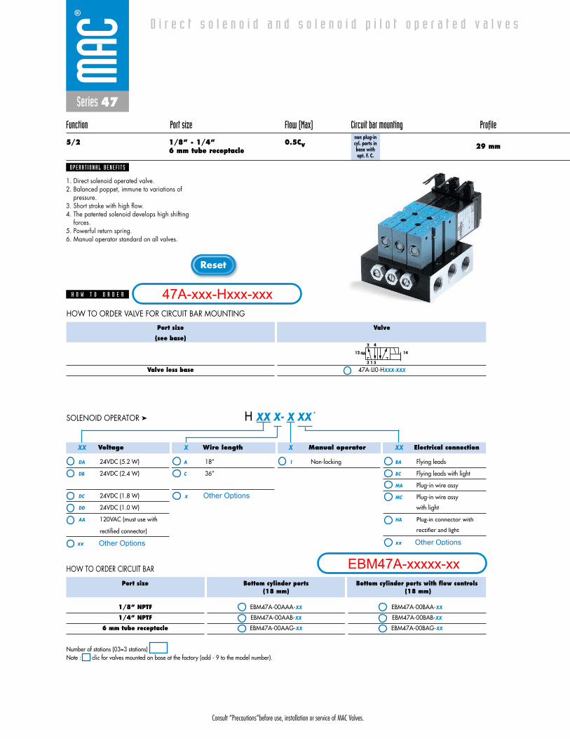
Consult “Precautions”before use, installation or service of MAC Valves.
Reset
Series 47
Function Port size Flow (Max) Circuit bar mounting Profile
5/2 1/8” - 1/4” 0.5Cv6 mm tube receptacle 29 mm
non plug-incyl. ports inbase with opt. F. C.
1. Direct solenoid operated valve.2. Balanced poppet, immune to variations of
pressure.3. Short stroke with high flow.4. The patented solenoid develops high shifting
forces.5. Powerful return spring.6. Manual operator standard on all valves.
O P E R A T I O N A L B E N E F I T S
D i r e c t s o l e n o i d a n d s o l e n o i d p i l o t o p e r a t e d v a l v e s
H O W T O O R D E R
Port size
1/8” NPTF
1/4” NPTF
6 mm tube receptacle
Bottom cylinder ports(18 mm)
EBM47A-00AAA-XX
EBM47A-00AAB-XX
EBM47A-00AAG-XX
Bottom cylinder ports with flow controls(18 mm)
EBM47A-00BAA-XX
EBM47A-00BAB-XX
EBM47A-00BAG-XX
Voltage
DA 24VDC (5.2 W)
DB 24VDC (2.4 W)
DC 24VDC (1.8 W)
DD 24VDC (1.0 W)
AA 120VAC (must use with
rectified connector)
Wire length
A 18”
C 36”
Manual operator
1 Non-locking
Electrical connection
BA Flying leads
BC Flying leads with light
MA Plug-in wire assy
MC Plug-in wire assy
with light
HA Plug-in connector with
rectifier and light
H XX X- X XX *SOLENOID OPERATOR ➤
HOW TO ORDER CIRCUIT BAR
XX X X XX
Port size
(see base)
Valve less base
Valve
47A-LI0-HXXX-XXX
3
4
1
2
5
1412
HOW TO ORDER VALVE FOR CIRCUIT BAR MOUNTING
Number of stations (03=3 stations)Note : clic for valves mounted on base at the factory (add - 9 to the model number).
47A-xxx-Hxxx-xxx
EBM47A-xxxxx-xxOther Optionsxx
x Other Options
xx Other Options

Consult “Precautions”before use, installation or service of MAC Valves.
Series 47
D I M E N S I O N S
Fluid :
Pressure range :
Lubrication :
Filtration :
Temperature range :
Orifice :
Flow (at 6 bar, �P=1bar) :
Leak rate :
Coil :
Voltage range :
Power :
Response times :
(with 5.2 W coil)
Compressed air, vacuum, inert gases
Vacuum to 120 PSI
Not required, if used select a medium aniline point lubricant (between 180°F and 210°F)
40 μ
0°F to 120°F (-18°C to 50°C)
4.3 mm
5.2 W : 0.50Cv, 2.4 W : 0.30Cv, 1.8 W : 0.25Cv, 1.0 W : 0.25Cv
50 cm3/min
General purpose class A, continuous duty, encapsulated
-15% to +10% of nominal voltage
5.2 W - 2.4 W - 1.8 W - 1.0 W
Energize : 14.0 ms
De-energize : 5.0 ms
29.0
22.0
30.0
26.5
27.8
7.0
25.0 18.0
90.0
26.5
26.5
14.5
82.0
132.4
78.1104.0
12
14
12
1414
12
14
1231
5
31
5
2
4 4
2
D A T A
T E C H N I C A L
1818100%100%
100%100% M O N T H S
WARRANTY
O FP R O D U C T I O N
T E S T E D
• Valve and coil are not interchangeable.
• Seal between valve and bar : 16629. • Mounting screw (x2) : 35043. • Valve blanking plate : M-47001.• Flow control kit (x2) : N-37001.• Isolation of inlet and/or exhaust. Special bar. Consult factory. • BSPP Threads.
Note :
Spare parts :
Options :

Consult “Precautions”before use, installation or service of MAC Valves.
Reset
Series 47
Function Port size (Inlet & Exhaust) Flow (Max) Circuit bar mounting Profile
5/2 3/8” 0.5Cv 35 mmadd-on style
non plug-in cyl.ports in valvewith opt. F. C.
1. Direct solenoid operated valve.2. Balanced poppet, immune to variations of
pressure.3. Short stroke with high flow.4. The patented solenoid develops high shifting
forces.5. Powerful return spring.6. Manual operator standard on all valves.
O P E R A T I O N A L B E N E F I T S
D i r e c t s o l e n o i d a n d s o l e n o i d p i l o t o p e r a t e d v a l v e s
H O W T O O R D E R
Port sizeCOMMON INLET & EXHAUST
3/8” NPTF
Without flow controls(20 mm)
EBM47A-01GBK-XX
With flow controls(20 mm)
EBM47A-01HBK-XX
Voltage
DA 24VDC (5.2 W)
DB 24VDC (2.4 W)
DC 24VDC (1.8 W)
DD 24VDC (1.0 W)
AA 120VAC (must use with
rectified connector)
Wire length
A 18”
C 36”
Manual operator
1 Non-locking
Electrical connection
BA Flying leads
BC Flying leads with light
MA Plug-in wire assy
MC Plug-in wire assy
with light
HA Plug-in connector with
rectifier and light
H XX X- X XX *SOLENOID OPERATOR ➤
HOW TO ORDER CIRCUIT BAR
XX X X XX
Valve port size
1/8” NPTF
1/4” NPTF
Valve
47A-MG0-HXXX-XXX
47A-MH0-HXXX-XXX
3
4
1
2
5
1412
HOW TO ORDER VALVE FOR CIRCUIT BAR MOUNTING
Number of stations (03=3 stations)Note : clic for valves mounted on base at the factory (add - 9 to the model number).
add-a-unit stations may be added to above bars.Maximum length for add-a-unit is 4 stations.
EBM47A-01GBK-XX
O P T I O N S
- clic replace with “C” for add-a-unit.
47A-xxx-Hxxx-xxx
EBM47A-xxxxx-xxOther Optionsxx
x Other Options
xx Other Options
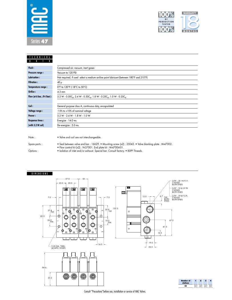
Consult “Precautions”before use, installation or service of MAC Valves.
Series 47
D I M E N S I O N S
Fluid :
Pressure range :
Lubrication :
Filtration :
Temperature range :
Orifice :
Flow (at 6 bar, �P=1bar) :
Leak rate :
Coil :
Voltage range :
Power :
Response times :
(with 5.2 W coil)
Compressed air, vacuum, inert gases
Vacuum to 120 PSI
Not required, if used select a medium aniline point lubricant (between 180°F and 210°F)
40 μ
0°F to 120°F (-18°C to 50°C)
4.3 mm
5.2 W : 0.50Cv, 2.4 W : 0.30Cv, 1.8 W : 0.25Cv, 1.0 W : 0.25Cv
50 cm3/min
General purpose class A, continuous duty, encapsulated
-15% to +10% of nominal voltage
5.2 W - 2.4 W - 1.8 W - 1.0 W
Energize : 14.0 ms
De-energize : 5.0 ms
67.5
41.0
14.5
23.5
19.0
12.0
31
5
(4) MTG. HOLES5.20 DIA. THRU.
ENDSBOTHTYP.
6.7
BOTH ENDS3 HOLES3/8" - 19 B.P.S.PL
BOTH ENDS3 HOLES3/8" - 19 B.S.P.TR
BOTH ENDS3 HOLES 3/8" - 18 N.P.T.F.
14
12
4
2
14
12
4
2
14
12
4
2
14
12
4
2
51
3
7.0
27.8
26.5
82.0
132.5
TYP.
TYP.
84.6
35.0
30.9
19.5
TYP.
TYP.
25.0 20.0
57.0 XX
7.0
16.0
D A T A
T E C H N I C A L
1818100%100%
100%100% M O N T H S
WARRANTY
O FP R O D U C T I O N
T E S T E D
• Valve and coil are not interchangeable.
• Seal between valve and bar : 16629. • Mounting screw (x2) : 35043. • Valve blanking plate : M-47002.• Flow control kit (x2) : N-37001. End plate kit : M-47004-01.• Isolation of inlet and/or exhaust. Special bar. Consult factory. • BSPP Threads.
Note :
Spare parts :
Options :
Number ofstations
XX
1
24.0
2
44.0
3
64.0
4
84.0

Consult “Precautions”before use, installation or service of MAC Valves.
Reset
Series 47
Function Port size Flow (Max) Circuit bar mounting Profile
5/2 1/8” - 1/4” 0.5Cv6 mm tube receptacle 35 mm
add-on style non plug-in cyl.ports in basewith opt. F. C.
1. Direct solenoid operated valve.2. Balanced poppet, immune to variations of
pressure.3. Short stroke with high flow.4. The patented solenoid develops high shifting
forces.5. Powerful return spring.6. Manual operator standard on all valves.
O P E R A T I O N A L B E N E F I T S
D i r e c t s o l e n o i d a n d s o l e n o i d p i l o t o p e r a t e d v a l v e s
H O W T O O R D E R
Port size
1/8” NPTF
1/4” NPTF
6 mm tube receptacle
Bottom cylinder ports(18 mm)
EBM47A-00EBA-XX
EBM47A-00EBB-XX
EBM47A-00EBG-XX
Bottom cylinder ports with flow controls(18 mm)
EBM47A-00FBA-XX
EBM47A-00FBB-XX
EBM47A-00FBG-XX
Voltage
DA 24VDC (5.2 W)
DB 24VDC (2.4 W)
DC 24VDC (1.8 W)
DD 24VDC (1.0 W)
AA 120VAC (must use with
rectified connector)
Wire length
A 18”
C 36”
Manual operator
1 Non-locking
Electrical connection
BA Flying leads
BC Flying leads with light
MA Plug-in wire assy
MC Plug-in wire assy
with light
HA Plug-in connector with
rectifier and light
H XX X- X XX *SOLENOID OPERATOR ➤
HOW TO ORDER CIRCUIT BAR
XX X X XX
Port size
(see base)
Valve less base
Valve
47A-LI0-HXXX-XXX
3
4
1
2
5
1412
HOW TO ORDER VALVE FOR CIRCUIT BAR MOUNTING
Number of stations (03=3 stations)Note : clic for valves mounted on base at the factory (add - 9 to the model number).
add-a-unit stations may be added to above bars. Maximum length for add-a-unit is 4 stations.
EBM47A-00EBA-XX
O P T I O N S
- clic replace with “C” for add-a-unit.
47A-xxx-Hxxx-xxx
EBM47A-xxxxx-xxOther Optionsxx
x Other Options
xx Other Options

Consult “Precautions”before use, installation or service of MAC Valves.
Series 47
D I M E N S I O N S
Fluid :
Pressure range :
Lubrication :
Filtration :
Temperature range :
Orifice :
Flow (at 6 bar, �P=1bar) :
Leak rate :
Coil :
Voltage range :
Power :
Response times :
(with 5.2 W coil)
Compressed air, vacuum, inert gases
Vacuum to 120 PSI
Not required, if used select a medium aniline point lubricant (between 180°F and 210°F)
40 μ
0°F to 120°F (-18°C to 50°C)
4.3 mm
5.2 W : 0.50Cv, 2.4 W : 0.30Cv, 1.8 W : 0.25Cv, 1.0 W : 0.25Cv
50 cm3/min
General purpose class A, continuous duty, encapsulated
-15% to +10% of nominal voltage
5.2 W - 2.4 W - 1.8 W - 1.0 W
Energize : 14.0 ms
De-energize : 5.0 ms
35.0
16.0
99.3(4) MTG. HOLES5.20 DIA. THRU.
84.6
2
4
2
4 4
2
ENDSBOTHTYP.6.719.0
67.5
41.0
14.5
21.0
12.0
BOTH ENDS2 HOLES3/8" - 19 B.P.S.PL
BOTH ENDS2 HOLES3/8" - 19 B.S.P.TR
BOTH ENDS2 HOLES 3/8" - 18 N.P.T.F.
125.18
7.00
27.75
54.25
TYP
51
3
51
3
14
12 12
14
12
14
12
14
25.0
18.0
21.7TYP.
30.0
22.0
D A T A
T E C H N I C A L
1818100%100%
100%100% M O N T H S
WARRANTY
O FP R O D U C T I O N
T E S T E D
• Valve and coil are not interchangeable.
• Seal between valve and bar : 16629. • Mounting screw (x2) : 35043. • Valve blanking plate : M-47001.• Flow control kit (x2) : N-37001. End plate kit : M-47004-01.• Isolation of inlet and/or exhaust. Special bar. Consult factory. • BSPP Threads.
Note :
Spare parts :
Options :

Consult “Precautions”before use, installation or service of MAC Valves.
Reset
Series 47
Function Port size (Inlet & Exhaust) Flow (Max) Circuit bar mounting Profile
5/2 3/8” 0.5Cv 44 mmnon plug-incyl. ports invalve with
opt. Pr. Reg.
1. Direct solenoid operated valve.2. Balanced poppet, immune to variations of
pressure.3. Short stroke with high flow.4. The patented solenoid develops high shifting
forces.5. Powerful return spring.6. Manual operator standard on all valves.
O P E R A T I O N A L B E N E F I T S
D i r e c t s o l e n o i d a n d s o l e n o i d p i l o t o p e r a t e d v a l v e s
H O W T O O R D E R
Port sizeCOMMON INLET & EXHAUST
3/8” NPTF
Without regulator(20 mm)
EBM47A-01NAK-XX
With regulator(20 mm)
EBM47A-01PAK-XX
Voltage
DA 24VDC (5.2 W)
DB 24VDC (2.4 W)
DC 24VDC (1.8 W)
DD 24VDC (1.0 W)
AA 120VAC (must use with
rectified connector)
Wire length
A 18”
C 36”
Manual operator
1 Non-locking
Electrical connection
BA Flying leads
BC Flying leads with light
MA Plug-in wire assy
MC Plug-in wire assy
with light
HA Plug-in connector with
rectifier and light
H XX X- X XX *SOLENOID OPERATOR ➤
HOW TO ORDER CIRCUIT BAR (REGULATOR ORDERED SEPARATELY)**
XX X X XX
Valve port size
1/8” NPTF
1/4” NPTF
Valve
47A-MG0-HXXX-XXX
47A-MH0-HXXX-XXX
3
4
1
2
5
1412
HOW TO ORDER VALVE FOR CIRCUIT BAR MOUNTING
** Pressure Regulators :
X=A (0 to 120 PSI)X=B (0 to 80 PSI)X=C (0 to 30 PSI)
Number of stations (03=3 stations)Note : clic for valves mounted on base at the factory (add - 9 to the model number).
47A-xxx-Hxxx-xxx
EBM47A-xxxxx-xxOther Optionsxx
x Other Options
xx Other Options
PR47A-GOAx

Consult “Precautions”before use, installation or service of MAC Valves.
Series 47
D I M E N S I O N S
Fluid :
Pressure range :
Lubrication :
Filtration :
Temperature range :
Orifice :
Flow (at 6 bar, �P=1bar) :
Leak rate :
Coil :
Voltage range :
Power :
Response times :
(with 5.2 W coil)
Compressed air, vacuum, inert gases
Vacuum to 120 PSI
Not required, if used select a medium aniline point lubricant (between 180°F and 210°F)
40 μ
0°F to 120°F (-18°C to 50°C)
4.3 mm
5.2 W : 0.50Cv, 2.4 W : 0.30Cv, 1.8 W : 0.25Cv, 1.0 W : 0.25Cv
50 cm3/min
General purpose class A, continuous duty, encapsulated
-15% to +10% of nominal voltage
5.2 W - 2.4 W - 1.8 W - 1.0 W
Energize : 14.0 ms
De-energize : 5.0 ms
90.0
26.2
22.0
73.5
48.0
23.0
93.6
10.0
60.8
35.4
GAGE
"E"
31
5
31
5
44.0
GAGEGAGEGAGE
TYP.
TYP.
TYP.
TYP.
TYP.
TYP.
TYP.
14
12
4
22
4
12
14
2
4
12
14
2
4
12
14 BOTH ENDS2 HOLES3/8" - 19 B.P.S.PLBOTH ENDS2 HOLES3/8" - 19 B.S.P.TR BOTH ENDS2 HOLES 3/8" - 18 N.P.T.F.
HOLES4 MTG.5.20 DIA.
39.2
19.5
25.0
20.0
D A T A
T E C H N I C A L
1818100%100%
100%100% M O N T H S
WARRANTY
O FP R O D U C T I O N
T E S T E D
• Valve and coil are not interchangeable.
• Seal between valve and bar : 16629. • Mounting screw (x2) : 35043. • Valve blanking plate : M-47002.• Regulator blanking plate : R-47003.• Isolation of inlet and/or exhaust. Special bar. Consult factory. • BSPP Threads.
Note :
Spare parts :
Options :
Dim.
“E”
Regulator with lockingadjusting screw
159.8
Regulator withadjusting screw
155.6
Regulator withadjusting knob
163.6

Consult “Precautions”before use, installation or service of MAC Valves.
Reset
Series 47
Function Port size Flow (Max) Circuit bar mounting Profile
5/2 1/8” - 1/4” 0.5Cv6 mm tube receptacle 44 mm
non plug-incyl. ports in base
1. Direct solenoid operated valve.2. Balanced poppet, immune to variations of
pressure.3. Short stroke with high flow.4. The patented solenoid develops high shifting
forces.5. Powerful return spring.6. Manual operator standard on all valves.
O P E R A T I O N A L B E N E F I T S
D i r e c t s o l e n o i d a n d s o l e n o i d p i l o t o p e r a t e d v a l v e s
H O W T O O R D E R
Port size
1/8” NPTF
1/4” NPTF
6 mm tube receptacle
Side cylinder ports(18 mm)
EBM47A-00JAA-XX
EBM47A-00JAB-XX
EBM47A-00JAG-XX
Bottom cylinder ports(18 mm)
EBM47A-00LAA-XX
EBM47A-00LAB-XX
EBM47A-00LAG-XX
Voltage
DA 24VDC (5.2 W)
DB 24VDC (2.4 W)
DC 24VDC (1.8 W)
DD 24VDC (1.0 W)
AA 120VAC (must use with
rectified connector)
Wire length
A 18”
C 36”
Manual operator
1 Non-locking
Electrical connection
BA Flying leads
BC Flying leads with light
MA Plug-in wire assy
MC Plug-in wire assy
with light
HA Plug-in connector with
rectifier and light
H XX X- X XX *SOLENOID OPERATOR ➤
HOW TO ORDER CIRCUIT BAR
XX X X XX
Port size
(see base)
Valve less base
Valve
47A-LI0-HXXX-XXX
3
4
1
2
5
1412
HOW TO ORDER VALVE FOR CIRCUIT BAR MOUNTING
Number of stations (03=3 stations)Note : clic for valves mounted on base at the factory (add - 9 to the model number).
47A-xxx-Hxxx-xxx
EBM47A-xxxxx-xxOther Optionsxx
x Other Options
xx Other Options

Consult “Precautions”before use, installation or service of MAC Valves.
Series 47
D I M E N S I O N S
Fluid :
Pressure range :
Lubrication :
Filtration :
Temperature range :
Orifice :
Flow (at 6 bar, �P=1bar) :
Leak rate :
Coil :
Voltage range :
Power :
Response times :
(with 5.2 W coil)
Compressed air, vacuum, inert gases
Vacuum to 120 PSI
Not required, if used select a medium aniline point lubricant (between 180°F and 210°F)
40 μ
0°F to 120°F (-18°C to 50°C)
4.3 mm
5.2 W : 0.50Cv, 2.4 W : 0.30Cv, 1.8 W : 0.25Cv, 1.0 W : 0.25Cv
50 cm3/min
General purpose class A, continuous duty, encapsulated
-15% to +10% of nominal voltage
5.2 W - 2.4 W - 1.8 W - 1.0 W
Energize : 14.0 ms
De-energize : 5.0 ms
26.20 22.00
73.50
48.00
23.00
38.3
59.434.5
9.5
TYP. 2 PER STATION1/4" - 19 B.S.P.PL
TYP. 2 PER STATION1/4" - 19 B.S.P.TR
TYP. 2 PER STATION1/4" - 18 N.P.T.F.
HOLES2 MTG.5.20 DIA.
BOTH ENDS2 HOLES3/8" - 19 B.P.S.PL
BOTH ENDS2 HOLES3/8" - 19 B.S.P.TR
BOTH ENDS2 HOLES 3/8" - 18 N.P.T.F.
TYP
TYP
TYP
TYP TYP
93.6
"A"
TYP
TYP
TYP10.0
60.75
35.4
18.0018.00
"D"
GA
GE
12 14
12 1414
12
14
12
"B""C"
TYP
3 1 5
3 1 5
22
44
44
22
44.0
D A T A
T E C H N I C A L
1818100%100%
100%100% M O N T H S
WARRANTY
O FP R O D U C T I O N
T E S T E D
• Valve and coil are not interchangeable.
• Seal between valve and bar : 16629. • Mounting screw (x2) : 35043. • Valve blanking plate : M-47001.
• Isolation of inlet and/or exhaust. Special bar. Consult factory. • BSPP Threads.
Note :
Spare parts :
Options :
Note: Bottom & side cylinder ports not available on the same station
Number ofstations
“A”
“B”
“C”
1/4” Port
M6 Carstick port
1
-
25.90
28.60
25.00
2
68.0
25.90
28.60
25.00
3
86.0
25.90
28.60
25.00
4
104.0
25.90
28.60
25.00
5
122.0
25.90
28.60
25.00
N/A
6
140.0
25.90
28.60
25.00
7
158.0
25.90
28.60
25.00
8
178.0
25.90
28.60
25.00
9
194.0
25.90
28.60
25.00
10
212.0
25.90
28.60
25.00
Dimensions are based on18 mm centerline spacing
“D”
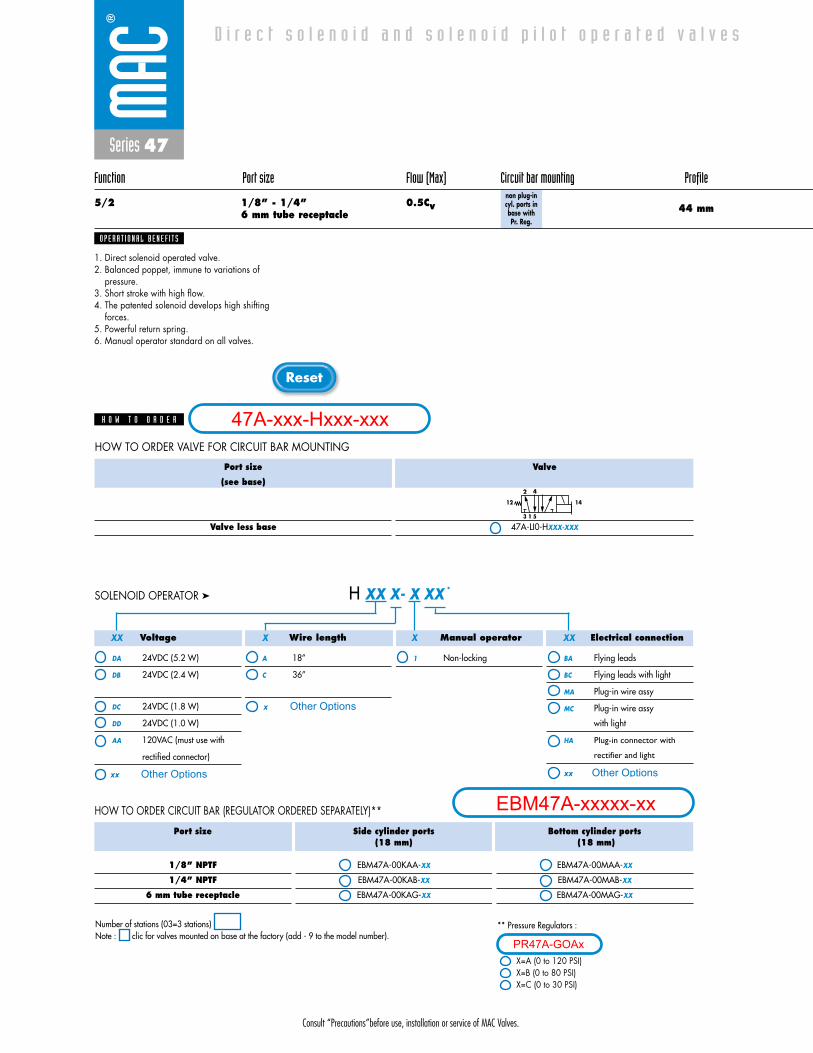
Consult “Precautions”before use, installation or service of MAC Valves.
Reset
Series 47
Function Port size Flow (Max) Circuit bar mounting Profile
5/2 1/8” - 1/4” 0.5Cv6 mm tube receptacle 44 mm
non plug-incyl. ports inbase with Pr. Reg.
1. Direct solenoid operated valve.2. Balanced poppet, immune to variations of
pressure.3. Short stroke with high flow.4. The patented solenoid develops high shifting
forces.5. Powerful return spring.6. Manual operator standard on all valves.
O P E R A T I O N A L B E N E F I T S
D i r e c t s o l e n o i d a n d s o l e n o i d p i l o t o p e r a t e d v a l v e s
H O W T O O R D E R
Port size
1/8” NPTF
1/4” NPTF
6 mm tube receptacle
Side cylinder ports(18 mm)
EBM47A-00KAA-XX
EBM47A-00KAB-XX
EBM47A-00KAG-XX
Bottom cylinder ports(18 mm)
EBM47A-00MAA-XX
EBM47A-00MAB-XX
EBM47A-00MAG-XX
Voltage
DA 24VDC (5.2 W)
DB 24VDC (2.4 W)
DC 24VDC (1.8 W)
DD 24VDC (1.0 W)
AA 120VAC (must use with
rectified connector)
Wire length
A 18”
C 36”
Manual operator
1 Non-locking
Electrical connection
BA Flying leads
BC Flying leads with light
MA Plug-in wire assy
MC Plug-in wire assy
with light
HA Plug-in connector with
rectifier and light
H XX X- X XX *SOLENOID OPERATOR ➤
HOW TO ORDER CIRCUIT BAR (REGULATOR ORDERED SEPARATELY)**
XX X X XX
Port size
(see base)
Valve less base
Valve
47A-LI0-HXXX-XXX
3
4
1
2
5
1412
HOW TO ORDER VALVE FOR CIRCUIT BAR MOUNTING
** Pressure Regulators :
X=A (0 to 120 PSI)X=B (0 to 80 PSI)X=C (0 to 30 PSI)
Number of stations (03=3 stations)Note : clic for valves mounted on base at the factory (add - 9 to the model number).
47A-xxx-Hxxx-xxx
EBM47A-xxxxx-xxOther Optionsxx
x Other Options
xx Other Options
PR47A-GOAx
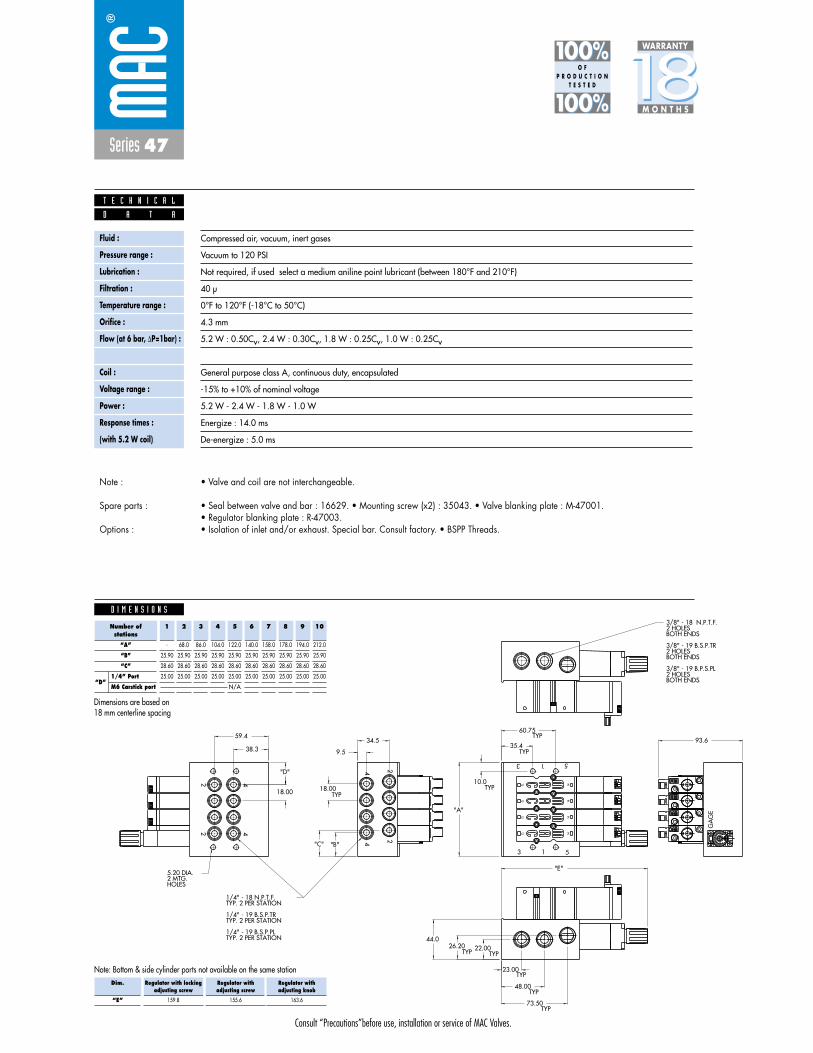
Consult “Precautions”before use, installation or service of MAC Valves.
Series 47
D I M E N S I O N S
Fluid :
Pressure range :
Lubrication :
Filtration :
Temperature range :
Orifice :
Flow (at 6 bar, �P=1bar) :
Leak rate :
Coil :
Voltage range :
Power :
Response times :
(with 5.2 W coil)
Compressed air, vacuum, inert gases
Vacuum to 120 PSI
Not required, if used select a medium aniline point lubricant (between 180°F and 210°F)
40 μ
0°F to 120°F (-18°C to 50°C)
4.3 mm
5.2 W : 0.50Cv, 2.4 W : 0.30Cv, 1.8 W : 0.25Cv, 1.0 W : 0.25Cv
50 cm3/min
General purpose class A, continuous duty, encapsulated
-15% to +10% of nominal voltage
5.2 W - 2.4 W - 1.8 W - 1.0 W
Energize : 14.0 ms
De-energize : 5.0 ms
D A T A
T E C H N I C A L
1818100%100%
100%100% M O N T H S
WARRANTY
O FP R O D U C T I O N
T E S T E D
• Valve and coil are not interchangeable.
• Seal between valve and bar : 16629. • Mounting screw (x2) : 35043. • Valve blanking plate : M-47001.• Regulator blanking plate : R-47003.• Isolation of inlet and/or exhaust. Special bar. Consult factory. • BSPP Threads.
Note :
Spare parts :
Options :
26.20 22.00
73.50
48.00
23.00
38.3
59.434.5
9.5
TYP. 2 PER STATION1/4" - 19 B.S.P.PL
TYP. 2 PER STATION1/4" - 19 B.S.P.TR
TYP. 2 PER STATION1/4" - 18 N.P.T.F.
HOLES2 MTG.5.20 DIA.
BOTH ENDS2 HOLES3/8" - 19 B.P.S.PL
BOTH ENDS2 HOLES3/8" - 19 B.S.P.TR
BOTH ENDS2 HOLES 3/8" - 18 N.P.T.F.
TYP
TYP
TYP
TYP TYP
93.6
"A"
TYP
TYP
TYP10.0
60.75
35.4
18.0018.00
"D"
GA
GE
12 14
12 1414
12
14
12
"B""C"
TYP
"E"
3 1 5
3 1 5
22
44
44
22
44.0
Note: Bottom & side cylinder ports not available on the same station
Number ofstations
“A”
“B”
“C”
1/4” Port
M6 Carstick port
1
-
25.90
28.60
25.00
2
68.0
25.90
28.60
25.00
3
86.0
25.90
28.60
25.00
4
104.0
25.90
28.60
25.00
5
122.0
25.90
28.60
25.00
N/A
6
140.0
25.90
28.60
25.00
7
158.0
25.90
28.60
25.00
8
178.0
25.90
28.60
25.00
9
194.0
25.90
28.60
25.00
10
212.0
25.90
28.60
25.00
Dimensions are based on18 mm centerline spacing
Dim.
“E”
Regulator with lockingadjusting screw
159.8
Regulator withadjusting screw
155.6
Regulator withadjusting knob
163.6
“D”

Consult “Precautions”before use, installation or service of MAC Valves.
Reset
Series 47
Function Port size Flow (Max) Circuit bar mounting Profile
5/2 1/8” - 1/4” 0.5Cv6 mm tube receptacle 44 mm
add-on stylenon plug-incyl. ports in
base
1. Direct solenoid operated valve.2. Balanced poppet, immune to variations of
pressure.3. Short stroke with high flow.4. The patented solenoid develops high shifting
forces.5. Powerful return spring.6. Manual operator standard on all valves.
O P E R A T I O N A L B E N E F I T S
D i r e c t s o l e n o i d a n d s o l e n o i d p i l o t o p e r a t e d v a l v e s
H O W T O O R D E R
Port size
1/8” NPTF
1/4” NPTF
6 mm tube receptacle
Side cylinder ports(18 mm)
EBM47A-00JBA-XX
EBM47A-00JBB-XX
EBM47A-00JBG-XX
Bottom cylinder ports(18 mm)
EBM47A-00LBA-XX
EBM47A-00LBB-XX
EBM47A-00LBG-XX
Voltage
DA 24VDC (5.2 W)
DB 24VDC (2.4 W)
DC 24VDC (1.8 W)
DD 24VDC (1.0 W)
AA 120VAC (must use with
rectified connector)
Wire length
A 18”
C 36”
Manual operator
1 Non-locking
Electrical connection
BA Flying leads
BC Flying leads with light
MA Plug-in wire assy
MC Plug-in wire assy
with light
HA Plug-in connector with
rectifier and light
H XX X- X XX *SOLENOID OPERATOR ➤
HOW TO ORDER CIRCUIT BAR
XX X X XX
Port size
(see base)
Valve less base
Valve
47A-LI0-HXXX-XXX
3
4
1
2
5
1412
HOW TO ORDER VALVE FOR CIRCUIT BAR MOUNTING
Number of stations (03=3 stations)Note : clic for valves mounted on base at the factory (add - 9 to the model number).
add-a-unit stations may be added to above bars. Maximum length for add-a-unit is 4 stations.
EBM47A-00JBA-XX
O P T I O N S
- clic replace with “C” for add-a-unit.
47A-xxx-Hxxx-xxx
EBM47A-xxxxx-xxOther Optionsxx
x Other Options
xx Other Options
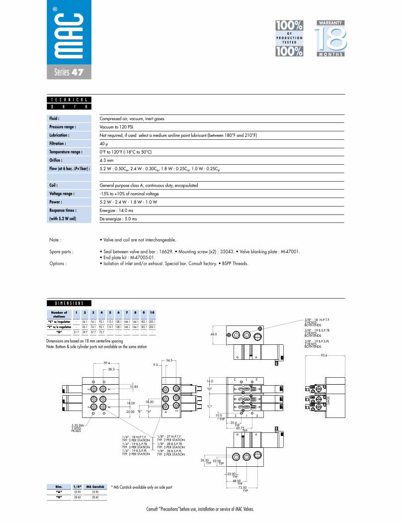
Consult “Precautions”before use, installation or service of MAC Valves.
Series 47
D I M E N S I O N S
Fluid :
Pressure range :
Lubrication :
Filtration :
Temperature range :
Orifice :
Flow (at 6 bar, �P=1bar) :
Leak rate :
Coil :
Voltage range :
Power :
Response times :
(with 5.2 W coil)
Compressed air, vacuum, inert gases
Vacuum to 120 PSI
Not required, if used select a medium aniline point lubricant (between 180°F and 210°F)
40 μ
0°F to 120°F (-18°C to 50°C)
4.3 mm
5.2 W : 0.50Cv, 2.4 W : 0.30Cv, 1.8 W : 0.25Cv, 1.0 W : 0.25Cv
50 cm3/min
General purpose class A, continuous duty, encapsulated
-15% to +10% of nominal voltage
5.2 W - 2.4 W - 1.8 W - 1.0 W
Energize : 14.0 ms
De-energize : 5.0 ms
TYP. 2 PER STATION1/8" - 28 B.S.P.PL.TYP. 2 PER STATION1/8" - 28 B.S.P.TR.TYP. 2 PER STATION1/8" - 27 N.P.T.F.
22 4
4
18.00
4 2
18.00
TYP
513
513
44.0
"D"
10.0
60.75
35.4
10.85
25.00 "A"
16.0
"C"
26.20 22.00
73.50
48.00
23.00
93.6
38.3
59.434.5
9.5
TYP. 2 PER STATION1/4" - 19 B.S.P.PL TYP. 2 PER STATION1/4" - 19 B.S.P.TRTYP. 2 PER STATION1/4" - 18 N.P.T.F.
HOLES2 MTG.5.20 DIA.
BOTH ENDS2 HOLES3/8" - 19 B.P.S.PL
BOTH ENDS2 HOLES3/8" - 19 B.S.P.TR
BOTH ENDS2 HOLES 3/8" - 18 N.P.T.F.
TYP
TYP
TYP
TYP TYP
TYP
TYP
GA
GE
12
1414
12
14
12
"B"
D A T A
T E C H N I C A L
1818100%100%
100%100% M O N T H S
WARRANTY
O FP R O D U C T I O N
T E S T E D
• Valve and coil are not interchangeable.
• Seal between valve and bar : 16629. • Mounting screw (x2) : 35043. • Valve blanking plate : M-47001.• End plate kit : M-47005-01.• Isolation of inlet and/or exhaust. Special bar. Consult factory. • BSPP Threads.
Note :
Spare parts :
Options :
Note: Bottom & side cylinder ports not available on the same station
Number ofstations
“C” w/regulator
“C” w/o regulator
“D”
1
-
-
21.7
2
56.1
56.1
39.7
3
74.1
74.1
57.7
4
92.1
92.1
75.7
5
110.1
110.1
-
6
128.1
128.1
-
7
146.1
146.1
-
8
164.1
164.1
-
9
182.1
182.1
-
10
200.1
200.1
-
Dimensions are based on 18 mm centerline spacing
* M6 Carstick available only on side portDim.
“A”
“B”
1/4”
25.90
28.60
M6 Carstick
25.90
28.60
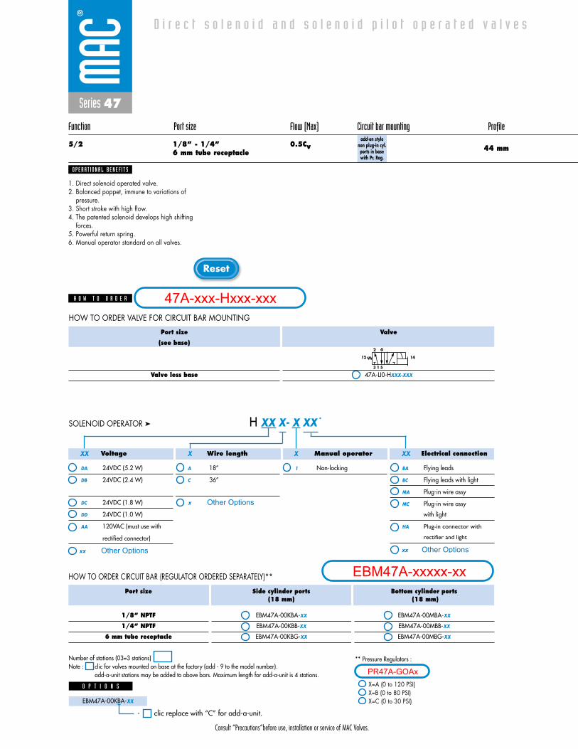
Consult “Precautions”before use, installation or service of MAC Valves.
Reset
Series 47
Function Port size Flow (Max) Circuit bar mounting Profile
5/2 1/8” - 1/4” 0.5Cv6 mm tube receptacle 44 mm
add-on style non plug-in cyl.ports in basewith Pr. Reg.
1. Direct solenoid operated valve.2. Balanced poppet, immune to variations of
pressure.3. Short stroke with high flow.4. The patented solenoid develops high shifting
forces.5. Powerful return spring.6. Manual operator standard on all valves.
O P E R A T I O N A L B E N E F I T S
D i r e c t s o l e n o i d a n d s o l e n o i d p i l o t o p e r a t e d v a l v e s
H O W T O O R D E R
Port size
1/8” NPTF
1/4” NPTF
6 mm tube receptacle
Side cylinder ports(18 mm)
EBM47A-00KBA-XX
EBM47A-00KBB-XX
EBM47A-00KBG-XX
Bottom cylinder ports(18 mm)
EBM47A-00MBA-XX
EBM47A-00MBB-XX
EBM47A-00MBG-XX
Voltage
DA 24VDC (5.2 W)
DB 24VDC (2.4 W)
DC 24VDC (1.8 W)
DD 24VDC (1.0 W)
AA 120VAC (must use with
rectified connector)
Wire length
A 18”
C 36”
Manual operator
1 Non-locking
Electrical connection
BA Flying leads
BC Flying leads with light
MA Plug-in wire assy
MC Plug-in wire assy
with light
HA Plug-in connector with
rectifier and light
H XX X- X XX *SOLENOID OPERATOR ➤
HOW TO ORDER CIRCUIT BAR (REGULATOR ORDERED SEPARATELY)**
XX X X XX
Port size
(see base)
Valve less base
Valve
47A-LI0-HXXX-XXX
3
4
1
2
5
1412
HOW TO ORDER VALVE FOR CIRCUIT BAR MOUNTING
Number of stations (03=3 stations)Note : clic for valves mounted on base at the factory (add - 9 to the model number).
add-a-unit stations may be added to above bars. Maximum length for add-a-unit is 4 stations.
** Pressure Regulators :
X=A (0 to 120 PSI)X=B (0 to 80 PSI)X=C (0 to 30 PSI)EBM47A-00KBA-XX
O P T I O N S
- clic replace with “C” for add-a-unit.
47A-xxx-Hxxx-xxx
EBM47A-xxxxx-xxOther Optionsxx
x Other Options
xx Other Options
PR47A-GOAx
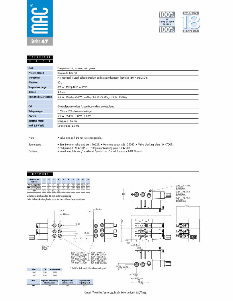
Consult “Precautions”before use, installation or service of MAC Valves.
Series 47
D I M E N S I O N S
Fluid :
Pressure range :
Lubrication :
Filtration :
Temperature range :
Orifice :
Flow (at 6 bar, �P=1bar) :
Leak rate :
Coil :
Voltage range :
Power :
Response times :
(with 5.2 W coil)
Compressed air, vacuum, inert gases
Vacuum to 120 PSI
Not required, if used select a medium aniline point lubricant (between 180°F and 210°F)
40 μ
0°F to 120°F (-18°C to 50°C)
4.3 mm
5.2 W : 0.50Cv, 2.4 W : 0.30Cv, 1.8 W : 0.25Cv, 1.0 W : 0.25Cv
50 cm3/min
General purpose class A, continuous duty, encapsulated
-15% to +10% of nominal voltage
5.2 W - 2.4 W - 1.8 W - 1.0 W
Energize : 14.0 ms
De-energize : 5.0 ms
D A T A
T E C H N I C A L
1818100%100%
100%100% M O N T H S
WARRANTY
O FP R O D U C T I O N
T E S T E D
• Valve and coil are not interchangeable.
• Seal between valve and bar : 16629. • Mounting screw (x2) : 35043. • Valve blanking plate : M-47001.• End plate kit : M-47005-01. • Regulator blanking plate : R-47003.• Isolation of inlet and/or exhaust. Special bar. Consult factory. • BSPP Threads.
Note :
Spare parts :
Options :
TYP. 2 PER STATION1/8" - 28 B.S.P.PL.TYP. 2 PER STATION1/8" - 28 B.S.P.TR.TYP. 2 PER STATION1/8" - 27 N.P.T.F.
22 4
4
18.00
4 2
18.00
TYP
513
513
44.0
"D"
10.0
60.75
35.4
10.85
25.00 "A"
16.0
"C"
26.20 22.00
73.50
48.00
23.00
93.6
38.3
59.434.5
9.5
TYP. 2 PER STATION1/4" - 19 B.S.P.PL TYP. 2 PER STATION1/4" - 19 B.S.P.TRTYP. 2 PER STATION1/4" - 18 N.P.T.F.
HOLES2 MTG.5.20 DIA.
BOTH ENDS2 HOLES3/8" - 19 B.P.S.PL
BOTH ENDS2 HOLES3/8" - 19 B.S.P.TR
BOTH ENDS2 HOLES 3/8" - 18 N.P.T.F.
TYP
TYP
TYP
TYP TYP
TYP
TYP
GA
GE
12
1414
12
14
12
"E"
"B"
Note: Bottom & side cylinder ports not available on the same station
Number ofstations
“C” w/regulator
“C” w/o regulator
“D”
1
-
-
21.7
2
56.1
56.1
39.7
3
74.1
74.1
57.7
4
92.1
92.1
75.7
5
110.1
110.1
-
6
128.1
128.1
-
7
146.1
146.1
-
8
164.1
164.1
-
9
182.1
182.1
-
10
200.1
200.1
-
Dimensions are based on 18 mm centerline spacing
Dim.
“E”
Regulator with lockingadjusting screw
158.8
Regulator withadjusting screw
155.6
Regulator withadjusting knob
163.6
* M6 Carstick available only on side portDim.
“A”
“B”
1/4”
25.90
28.60
M6 Carstick
25.90
28.60
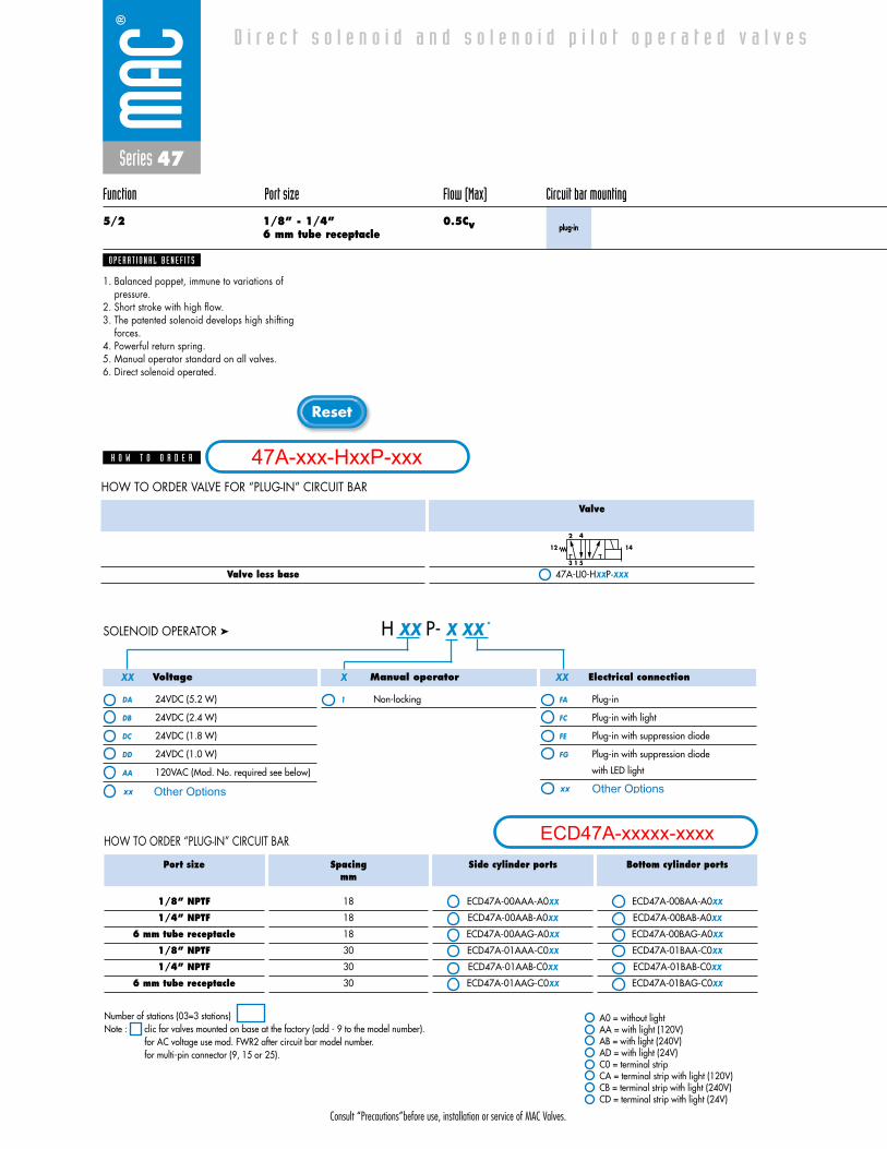
Consult “Precautions”before use, installation or service of MAC Valves.
Reset
Series 47
Function Port size Flow (Max) Circuit bar mounting
5/2 1/8” - 1/4” 0.5Cv6 mm tube receptacle
plug-in
1. Balanced poppet, immune to variations ofpressure.
2. Short stroke with high flow.3. The patented solenoid develops high shifting
forces.4. Powerful return spring.5. Manual operator standard on all valves.6. Direct solenoid operated.
O P E R A T I O N A L B E N E F I T S
D i r e c t s o l e n o i d a n d s o l e n o i d p i l o t o p e r a t e d v a l v e s
H O W T O O R D E R
HOW TO ORDER “PLUG-IN” CIRCUIT BAR
Voltage
DA 24VDC (5.2 W)
DB 24VDC (2.4 W)
DC 24VDC (1.8 W)
DD 24VDC (1.0 W)
AA 120VAC (Mod. No. required see below)
Manual operator
1 Non-locking
Electrical connection
FA Plug-in
FC Plug-in with light
FE Plug-in with suppression diode
FG Plug-in with suppression diode
with LED light
H XX P- X XX *SOLENOID OPERATOR ➤
XX X XX
Port size
1/8” NPTF
1/4” NPTF
6 mm tube receptacle
1/8” NPTF
1/4” NPTF
6 mm tube receptacle
Spacingmm
18
18
18
30
30
30
Side cylinder ports
ECD47A-00AAA-A0XX
ECD47A-00AAB-A0XX
ECD47A-00AAG-A0XX
ECD47A-01AAA-C0XX
ECD47A-01AAB-C0XX
ECD47A-01AAG-C0XX
Bottom cylinder ports
ECD47A-00BAA-A0XX
ECD47A-00BAB-A0XX
ECD47A-00BAG-A0XX
ECD47A-01BAA-C0XX
ECD47A-01BAB-C0XX
ECD47A-01BAG-C0XX
A0 = without lightAA = with light (120V)AB = with light (240V)AD = with light (24V)C0 = terminal stripCA = terminal strip with light (120V)CB = terminal strip with light (240V)CD = terminal strip with light (24V)
Valve less base
Valve
47A-LI0-HXXP-XXX
3
4
1
2
5
1412
HOW TO ORDER VALVE FOR “PLUG-IN” CIRCUIT BAR
Number of stations (03=3 stations)Note : clic for valves mounted on base at the factory (add - 9 to the model number).
for AC voltage use mod. FWR2 after circuit bar model number.for multi-pin connector (9, 15 or 25).
47A-xxx-HxxP-xxx
ECD47A-xxxxx-xxxx
Other Optionsxx xx Other Options
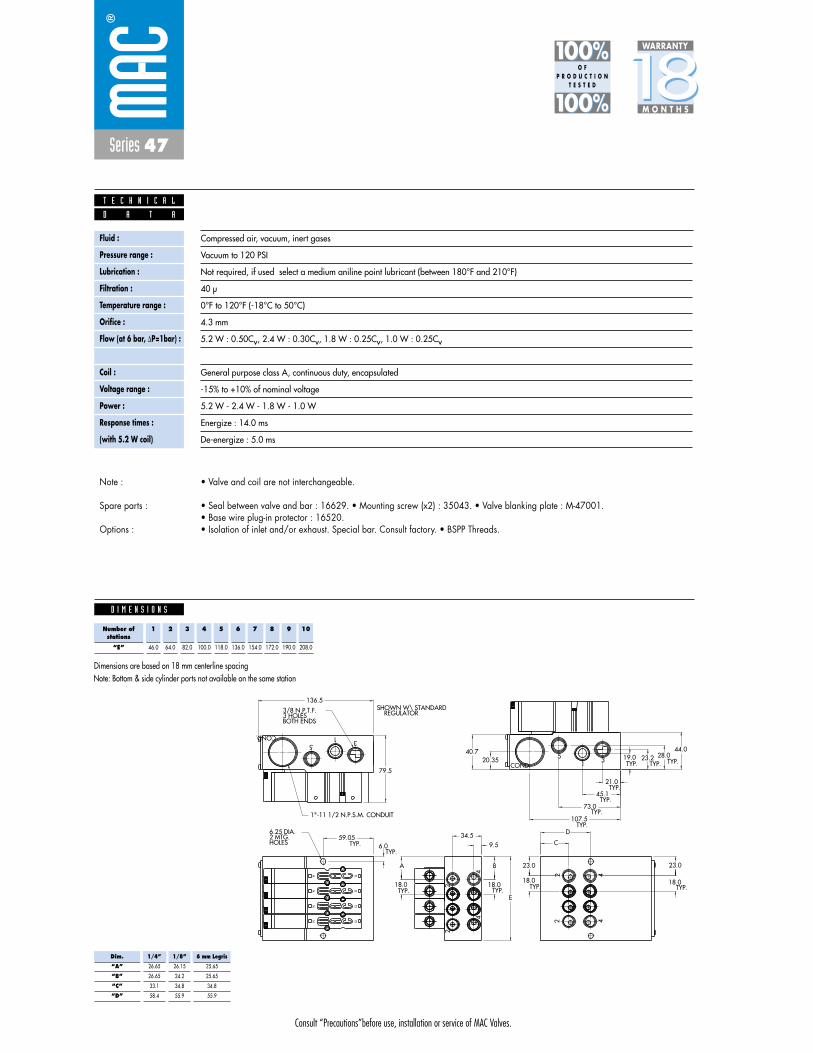
Consult “Precautions”before use, installation or service of MAC Valves.
Series 47
D I M E N S I O N S
Fluid :
Pressure range :
Lubrication :
Filtration :
Temperature range :
Orifice :
Flow (at 6 bar, �P=1bar) :
Leak rate :
Coil :
Voltage range :
Power :
Response times :
(with 5.2 W coil)
Compressed air, vacuum, inert gases
Vacuum to 120 PSI
Not required, if used select a medium aniline point lubricant (between 180°F and 210°F)
40 μ
0°F to 120°F (-18°C to 50°C)
4.3 mm
5.2 W : 0.50Cv, 2.4 W : 0.30Cv, 1.8 W : 0.25Cv, 1.0 W : 0.25Cv
50 cm3/min
General purpose class A, continuous duty, encapsulated
-15% to +10% of nominal voltage
5.2 W - 2.4 W - 1.8 W - 1.0 W
Energize : 14.0 ms
De-energize : 5.0 ms
4
2
79.5TYP.TYP.TYP.
28.023.219.0
BOTH ENDS3 HOLES3/8 N.P.T.F.
E
TYP.TYP. 6.0
59.05
40.720.35
44.0
TYP.
TYP.
TYP.
TYP.
107.5
73.0
45.1
21.0
136.5
2 412
14
12
1414
12
14
12
4
2
COND. 15 3
COND.31
5
42
BA
18.018.0
C
D
23.0 23.0
18.018.0
TYP. TYP. TYP.TYP.
9.534.5
REGULATORSHOWN W\ STANDARD
HOLES2 MTG.6.25 DIA.
1"-11 1/2 N.P.S.M. CONDUIT
D A T A
T E C H N I C A L
1818100%100%
100%100% M O N T H S
WARRANTY
O FP R O D U C T I O N
T E S T E D
• Valve and coil are not interchangeable.
• Seal between valve and bar : 16629. • Mounting screw (x2) : 35043. • Valve blanking plate : M-47001.• Base wire plug-in protector : 16520.• Isolation of inlet and/or exhaust. Special bar. Consult factory. • BSPP Threads.
Note :
Spare parts :
Options :
Dim.
“A”
“B”
“C”
“D”
1/4”
26.65
26.65
33.1
58.4
1/8”
26.15
24.2
34.8
55.9
6 mm Legris
25.65
25.65
34.8
55.9
Note: Bottom & side cylinder ports not available on the same station
Number ofstations
“E”
1
46.0
2
64.0
3
82.0
4
100.0
5
118.0
6
136.0
7
154.0
8
172.0
9
190.0
10
208.0
Dimensions are based on 18 mm centerline spacing

Consult “Precautions”before use, installation or service of MAC Valves.
Reset
Series 47
Function Port size Flow (Max) Circuit bar mounting
5/2 1/8” - 1/4” 0.5Cvplug-in
with Pr. Reg.
1. Balanced poppet, immune to variations ofpressure.
2. Short stroke with high flow.3. The patented solenoid develops high shifting
forces.4. Powerful return spring.5. Manual operator standard on all valves.6. Direct solenoid operated.
O P E R A T I O N A L B E N E F I T S
D i r e c t s o l e n o i d a n d s o l e n o i d p i l o t o p e r a t e d v a l v e s
H O W T O O R D E R
Voltage
DA 24VDC (5.2 W)
DB 24VDC (2.4 W)
DC 24VDC (1.8 W)
DD 24VDC (1.0 W)
AA 120VAC (Mod. No. required see below)
Manual operator
1 Non-locking
Electrical connection
FA Plug-in
FC Plug-in with light
FE Plug-in with suppression diode
FG Plug-in with suppression diode
with LED light
H XX P- X XX *SOLENOID OPERATOR ➤
XX X XX
HOW TO ORDER “PLUG-IN” CIRCUIT BAR (REGULATORS ORDERED SEPARATELY)**
Port size
1/8” NPTF
1/4” NPTF
1/8” NPTF
1/4” NPTF
Spacing mm
18
18
30
30
Bottom cylinder ports
ECD47A-00CAA-A0XX
ECD47A-00CAB-A0XX
ECD47A-01CAA-C0XX
ECD47A-01CAB-C0XX
Valve less base
Valve
47A-LI0-HXXP-XXX
3
4
1
2
5
1412
HOW TO ORDER VALVE FOR “PLUG-IN” CIRCUIT BAR
A0 = without lightAA = with light (120V)AB = with light (240V)AD = with light (24V)C0 = terminal stripCA = terminal strip with light (120V)CB = terminal strip with light (240V)CD = terminal strip with light (24V)
Number of stations (03=3 stations)Note : clic for valves mounted on base at the factory (add - 9 to the model number).
for AC voltage use mod. FWR2 after circuit bar model number.for multi-pin connector (9, 15 or 25).
** Pressure Regulators :
X=A (0 to 120 PSI)X=B (0 to 80 PSI)X=C (0 to 30 PSI)
47A-xxx-HxxP-xxx
ECD47A-xxxxx-xxxx
Other Optionsxx xx Other Options
PR47A-GOAx
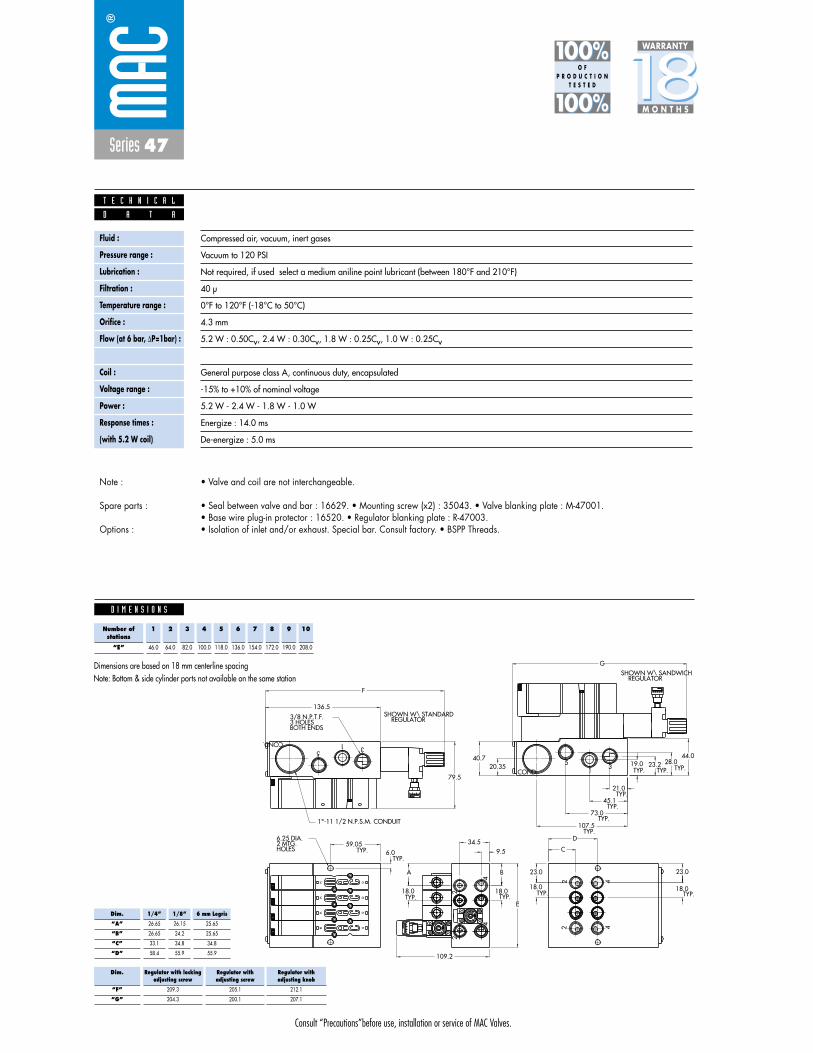
Consult “Precautions”before use, installation or service of MAC Valves.
Series 47
D I M E N S I O N S
Fluid :
Pressure range :
Lubrication :
Filtration :
Temperature range :
Orifice :
Flow (at 6 bar, �P=1bar) :
Leak rate :
Coil :
Voltage range :
Power :
Response times :
(with 5.2 W coil)
Compressed air, vacuum, inert gases
Vacuum to 120 PSI
Not required, if used select a medium aniline point lubricant (between 180°F and 210°F)
40 μ
0°F to 120°F (-18°C to 50°C)
4.3 mm
5.2 W : 0.50Cv, 2.4 W : 0.30Cv, 1.8 W : 0.25Cv, 1.0 W : 0.25Cv
50 cm3/min
General purpose class A, continuous duty, encapsulated
-15% to +10% of nominal voltage
5.2 W - 2.4 W - 1.8 W - 1.0 W
Energize : 14.0 ms
De-energize : 5.0 ms
D A T A
T E C H N I C A L
1818100%100%
100%100% M O N T H S
WARRANTY
O FP R O D U C T I O N
T E S T E D
• Valve and coil are not interchangeable.
• Seal between valve and bar : 16629. • Mounting screw (x2) : 35043. • Valve blanking plate : M-47001.• Base wire plug-in protector : 16520. • Regulator blanking plate : R-47003.• Isolation of inlet and/or exhaust. Special bar. Consult factory. • BSPP Threads.
Note :
Spare parts :
Options :
4
2
79.5
F
TYP.TYP.TYP.28.023.219.0
BOTH ENDS3 HOLES3/8 N.P.T.F.
E
TYP.TYP. 6.0
59.05
40.720.35
44.0
TYP.
TYP.
TYP.
TYP.
107.5
73.0
45.1
21.0
136.5
2 412
14
12
1414
12
14
12
4
2
COND. 15 3
COND.31
5
42
BA
18.018.0
C
D
23.0 23.0
18.018.0
TYP. TYP. TYP.TYP.
9.534.5
G
REGULATORSHOWN W\ STANDARD
REGULATORSHOWN W\ SANDWICH
109.2
HOLES2 MTG.6.25 DIA.
1"-11 1/2 N.P.S.M. CONDUIT
Dim.
“A”
“B”
“C”
“D”
1/4”
26.65
26.65
33.1
58.4
1/8”
26.15
24.2
34.8
55.9
6 mm Legris
25.65
25.65
34.8
55.9
Dim.
“F”
“G”
Regulator with lockingadjusting screw
209.3
204.3
Regulator withadjusting screw
205.1
200.1
Regulator withadjusting knob
212.1
207.1
Note: Bottom & side cylinder ports not available on the same station
Number ofstations
“E”
1
46.0
2
64.0
3
82.0
4
100.0
5
118.0
6
136.0
7
154.0
8
172.0
9
190.0
10
208.0
Dimensions are based on 18 mm centerline spacing
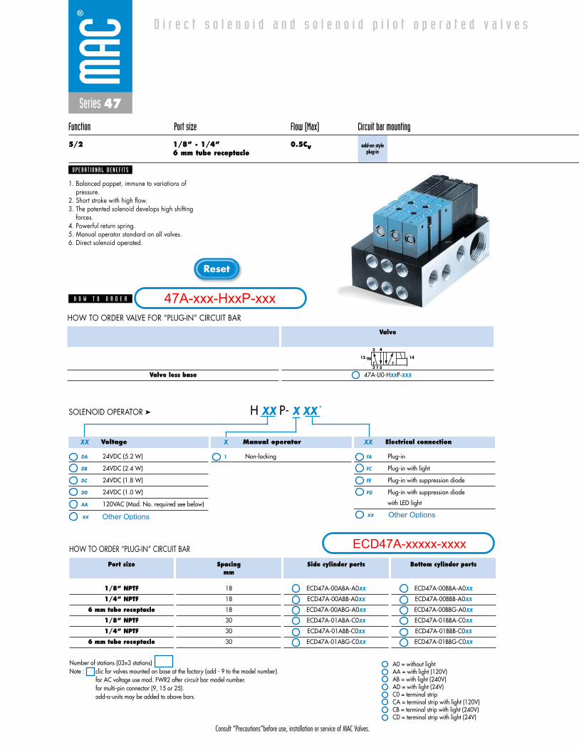
Consult “Precautions”before use, installation or service of MAC Valves.
Reset
Series 47
Function Port size Flow (Max) Circuit bar mounting
5/2 1/8” - 1/4” 0.5Cv6 mm tube receptacle
add-on style plug-in
1. Balanced poppet, immune to variations ofpressure.
2. Short stroke with high flow.3. The patented solenoid develops high shifting
forces.4. Powerful return spring.5. Manual operator standard on all valves.6. Direct solenoid operated.
O P E R A T I O N A L B E N E F I T S
D i r e c t s o l e n o i d a n d s o l e n o i d p i l o t o p e r a t e d v a l v e s
H O W T O O R D E R
HOW TO ORDER “PLUG-IN” CIRCUIT BAR
Voltage
DA 24VDC (5.2 W)
DB 24VDC (2.4 W)
DC 24VDC (1.8 W)
DD 24VDC (1.0 W)
AA 120VAC (Mod. No. required see below)
Manual operator
1 Non-locking
Electrical connection
FA Plug-in
FC Plug-in with light
FE Plug-in with suppression diode
FG Plug-in with suppression diode
with LED light
H XX P- X XX *SOLENOID OPERATOR ➤
XX X XX
Port size
1/8” NPTF
1/4” NPTF
6 mm tube receptacle
1/8” NPTF
1/4” NPTF
6 mm tube receptacle
Spacingmm
18
18
18
30
30
30
Side cylinder ports
ECD47A-00ABA-A0XX
ECD47A-00ABB-A0XX
ECD47A-00ABG-A0XX
ECD47A-01ABA-C0XX
ECD47A-01ABB-C0XX
ECD47A-01ABG-C0XX
Bottom cylinder ports
ECD47A-00BBA-A0XX
ECD47A-00BBB-A0XX
ECD47A-00BBG-A0XX
ECD47A-01BBA-C0XX
ECD47A-01BBB-C0XX
ECD47A-01BBG-C0XX
Valve less base
Valve
47A-LI0-HXXP-XXX
3
4
1
2
5
1412
HOW TO ORDER VALVE FOR “PLUG-IN” CIRCUIT BAR
A0 = without lightAA = with light (120V)AB = with light (240V)AD = with light (24V)C0 = terminal stripCA = terminal strip with light (120V)CB = terminal strip with light (240V)CD = terminal strip with light (24V)
Number of stations (03=3 stations)Note : clic for valves mounted on base at the factory (add - 9 to the model number).
for AC voltage use mod. FWR2 after circuit bar model number.for multi-pin connector (9, 15 or 25).add-a-units may be added to above bars.
47A-xxx-HxxP-xxx
ECD47A-xxxxx-xxxx
Other Optionsxx xx Other Options
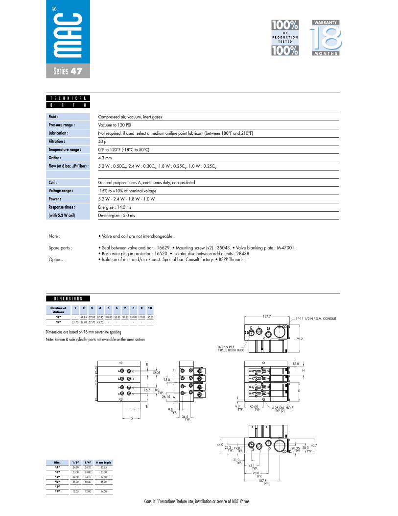
Consult “Precautions”before use, installation or service of MAC Valves.
Series 47
D I M E N S I O N S
Fluid :
Pressure range :
Lubrication :
Filtration :
Temperature range :
Orifice :
Flow (at 6 bar, �P=1bar) :
Leak rate :
Coil :
Voltage range :
Power :
Response times :
(with 5.2 W coil)
Compressed air, vacuum, inert gases
Vacuum to 120 PSI
Not required, if used select a medium aniline point lubricant (between 180°F and 210°F)
40 μ
0°F to 120°F (-18°C to 50°C)
4.3 mm
5.2 W : 0.50Cv, 2.4 W : 0.30Cv, 1.8 W : 0.25Cv, 1.0 W : 0.25Cv
50 cm3/min
General purpose class A, continuous duty, encapsulated
-15% to +10% of nominal voltage
5.2 W - 2.4 W - 1.8 W - 1.0 W
Energize : 14.0 ms
De-energize : 5.0 ms
18.016.7
12.05
12
14
5
13 COND.
3 51 COND.
14
12
24
TYP.(2)6.25 DIA. HOLE
TYP.(3) BOTH ENDS3/8" N.PT.F.
1"-11 1/2 N.P.S.M. CONDUIT
4 224
12
14
12
14
4
224
4
2
24
24
137.7
79.2
16.0
H
G
40.720.35 28.019.023.2
44.0
C
D
B
A26.15
F
13.0
E
9.5
34.5
TYP.
TYP.
TYP.
TYP. TYP. TYP. TYP.
TYP.
TYP.
TYP.
TYP.
21.0
45.1
73.0
107.5
TYP.TYP.6.0 59.05
D A T A
T E C H N I C A L
1818100%100%
100%100% M O N T H S
WARRANTY
O FP R O D U C T I O N
T E S T E D
• Valve and coil are not interchangeable.
• Seal between valve and bar : 16629. • Mounting screw (x2) : 35043. • Valve blanking plate : M-47001.• Base wire plug-in protector : 16520. • Isolator disc between add-a-units : 28438.• Isolation of inlet and/or exhaust. Special bar. Consult factory. • BSPP Threads.
Note :
Spare parts :
Options :
Note: Bottom & side cylinder ports not available on the same station
Number ofstations
“G”
“H”
1
-
21.70
2
51.85
39.70
3
69.85
57.70
4
87.85
75.70
5
105.85
-
6
123.85
-
7
141.85
-
8
159.85
-
9
177.85
-
10
195.85
-
Dimensions are based on 18 mm centerline spacing
Dim.
“A”
“B”
“C”
“D”
“E”
“F”
1/8”
24.20
23.00
34.80
55.90
-
12.05
1/4”
24.20
23.00
33.10
58.40
-
12.00
6 mm Legris
25.65
23.00
34.80
55.90
-
14.00
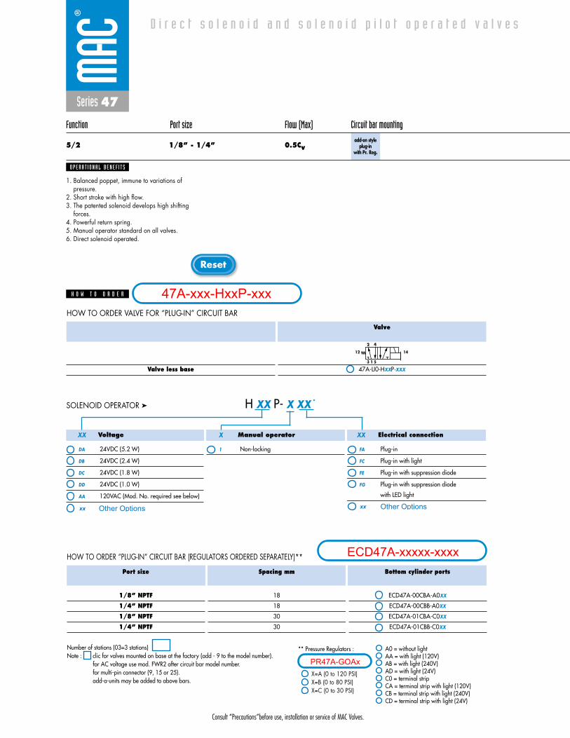
Consult “Precautions”before use, installation or service of MAC Valves.
Reset
Series 47
Function Port size Flow (Max) Circuit bar mounting
5/2 1/8” - 1/4” 0.5Cvadd-on style
plug-inwith Pr. Reg.
1. Balanced poppet, immune to variations ofpressure.
2. Short stroke with high flow.3. The patented solenoid develops high shifting
forces.4. Powerful return spring.5. Manual operator standard on all valves.6. Direct solenoid operated.
O P E R A T I O N A L B E N E F I T S
D i r e c t s o l e n o i d a n d s o l e n o i d p i l o t o p e r a t e d v a l v e s
H O W T O O R D E R
Voltage
DA 24VDC (5.2 W)
DB 24VDC (2.4 W)
DC 24VDC (1.8 W)
DD 24VDC (1.0 W)
AA 120VAC (Mod. No. required see below)
Manual operator
1 Non-locking
Electrical connection
FA Plug-in
FC Plug-in with light
FE Plug-in with suppression diode
FG Plug-in with suppression diode
with LED light
H XX P- X XX *SOLENOID OPERATOR ➤
XX X XX
HOW TO ORDER “PLUG-IN” CIRCUIT BAR (REGULATORS ORDERED SEPARATELY)**
Port size
1/8” NPTF
1/4” NPTF
1/8” NPTF
1/4” NPTF
Spacing mm
18
18
30
30
Bottom cylinder ports
ECD47A-00CBA-A0XX
ECD47A-00CBB-A0XX
ECD47A-01CBA-C0XX
ECD47A-01CBB-C0XX
Valve less base
Valve
47A-LI0-HXXP-XXX
3
4
1
2
5
1412
HOW TO ORDER VALVE FOR “PLUG-IN” CIRCUIT BAR
A0 = without lightAA = with light (120V)AB = with light (240V)AD = with light (24V)C0 = terminal stripCA = terminal strip with light (120V)CB = terminal strip with light (240V)CD = terminal strip with light (24V)
Number of stations (03=3 stations)Note : clic for valves mounted on base at the factory (add - 9 to the model number).
for AC voltage use mod. FWR2 after circuit bar model number.for multi-pin connector (9, 15 or 25).add-a-units may be added to above bars.
** Pressure Regulators :
X=A (0 to 120 PSI)X=B (0 to 80 PSI)X=C (0 to 30 PSI)
47A-xxx-HxxP-xxx
ECD47A-xxxxx-xxxx
Other Optionsxx xx Other Options
PR47A-GOAx
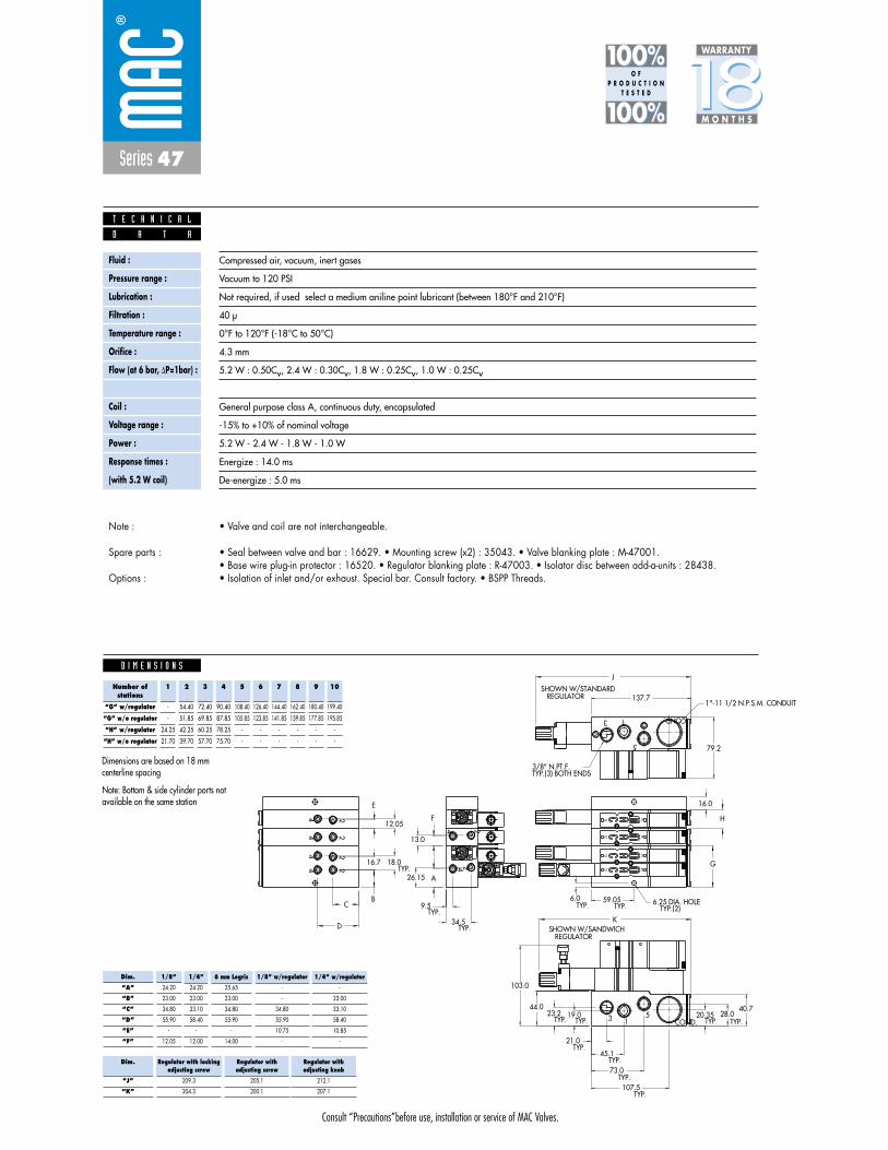
Consult “Precautions”before use, installation or service of MAC Valves.
Series 47
D I M E N S I O N S
Fluid :
Pressure range :
Lubrication :
Filtration :
Temperature range :
Orifice :
Flow (at 6 bar, �P=1bar) :
Leak rate :
Coil :
Voltage range :
Power :
Response times :
(with 5.2 W coil)
Compressed air, vacuum, inert gases
Vacuum to 120 PSI
Not required, if used select a medium aniline point lubricant (between 180°F and 210°F)
40 μ
0°F to 120°F (-18°C to 50°C)
4.3 mm
5.2 W : 0.50Cv, 2.4 W : 0.30Cv, 1.8 W : 0.25Cv, 1.0 W : 0.25Cv
50 cm3/min
General purpose class A, continuous duty, encapsulated
-15% to +10% of nominal voltage
5.2 W - 2.4 W - 1.8 W - 1.0 W
Energize : 14.0 ms
De-energize : 5.0 ms
D A T A
T E C H N I C A L
1818100%100%
100%100% M O N T H S
WARRANTY
O FP R O D U C T I O N
T E S T E D
• Valve and coil are not interchangeable.
• Seal between valve and bar : 16629. • Mounting screw (x2) : 35043. • Valve blanking plate : M-47001.• Base wire plug-in protector : 16520. • Regulator blanking plate : R-47003. • Isolator disc between add-a-units : 28438.• Isolation of inlet and/or exhaust. Special bar. Consult factory. • BSPP Threads.
Note :
Spare parts :
Options :
18.016.7
12.05
12
14
5
13 COND.
3 51 COND.
14
12
24
TYP.(2)6.25 DIA. HOLE
TYP.(3) BOTH ENDS3/8" N.PT.F.
1"-11 1/2 N.P.S.M. CONDUIT
REGULATORSHOWN W/SANDWICH
REGULATORSHOWN W/STANDARD
4 224
12
14
12
14
4 224
24
J
K
137.7
79.2
16.0
H
G
40.720.35 28.019.023.2
44.0
103.0
C
D
B
A26.15
F
13.0
E
9.5
34.5
TYP.
TYP.
TYP.
TYP. TYP. TYP. TYP.
TYP.
TYP.
TYP.
TYP.
21.0
45.1
73.0
107.5
TYP.TYP.6.0 59.05
Note: Bottom & side cylinder ports notavailable on the same station
Number ofstations
“G” w/regulator
“G” w/o regulator
“H” w/regulator
“H” w/o regulator
1
-
-
24.25
21.70
2
54.40
51.85
42.25
39.70
3
72.40
69.85
60.25
57.70
4
90.40
87.85
78.25
75.70
5
108.40
105.85
-
-
6
126.40
123.85
-
-
7
144.40
141.85
-
-
8
162.40
159.85
-
-
9
180.40
177.85
-
-
10
199.40
195.85
-
-
Dimensions are based on 18 mmcenterline spacing
Dim.
“J”
“K”
Regulator with lockingadjusting screw
209.3
204.3
Regulator withadjusting screw
205.1
200.1
Regulator withadjusting knob
212.1
207.1
Dim.
“A”
“B”
“C”
“D”
“E”
“F”
1/8”
24.20
23.00
34.80
55.90
-
12.05
1/4”
24.20
23.00
33.10
58.40
-
12.00
6 mm Legris
25.65
23.00
34.80
55.90
-
14.00
1/8” w/regulator
-
-
34.80
55.90
10.75
-
1/4” w/regulator
-
23.00
33.10
58.40
10.85
-

Consult “Precautions”before use, installation or service of MAC Valves.
Reset
Series 47
Function Port size Flow (Max) Circuit bar mounting
5/2 1/8” - 1/4” 0.5Cv6 mm tube receptacle
plug-inadd-a-unitstations
1. Balanced poppet, immune to variations ofpressure.
2. Short stroke with high flow.3. The patented solenoid develops high shifting
forces.4. Powerful return spring.5. Manual operator standard on all valves.6. Direct solenoid operated.
O P E R A T I O N A L B E N E F I T S
D i r e c t s o l e n o i d a n d s o l e n o i d p i l o t o p e r a t e d v a l v e s
H O W T O O R D E R
HOW TO ORDER “PLUG-IN” CIRCUIT BAR
Voltage
DA 24VDC (5.2 W)
DB 24VDC (2.4 W)
DC 24VDC (1.8 W)
DD 24VDC (1.0 W)
AA 120VAC (Mod. No. required see below)
Manual operator
1 Non-locking
Electrical connection
FA Plug-in
FC Plug-in with light
FE Plug-in with suppression diode
FG Plug-in with suppression diode
with LED light
H XX P- X XX *SOLENOID OPERATOR ➤
XX X XX
Port size
1/8” NPTF
1/4” NPTF
6 mm tube receptacle
1/8” NPTF
1/4” NPTF
6 mm tube receptacle
Spacingmm
18
18
18
30
30
30
Side cylinder ports
ECD47A-00ACA-A0XX
ECD47A-00ACB-A0XX
ECD47A-00ACG-A0XX
ECD47A-01ACA-C0XX
ECD47A-01ACB-C0XX
ECD47A-01ACG-C0XX
Bottom cylinder ports
ECD47A-00BCA-A0XX
ECD47A-00BCB-A0XX
ECD47A-00BCG-A0XX
ECD47A-01BCA-C0XX
ECD47A-01BCB-C0XX
ECD47A-01BCG-C0XX
Valve less base
Valve
47A-LI0-HXXP-XXX
3
4
1
2
5
1412
HOW TO ORDER VALVE FOR “PLUG-IN” CIRCUIT BAR
A0 = without lightAA = with light (120V)AB = with light (240V)AD = with light (24V)C0 = terminal stripCA = terminal strip with light (120V)CB = terminal strip with light (240V)CD = terminal strip with light (24V)
Number of stations (01=1 station). Maximum length is 4 stationsNote : clic for valves mounted on base at the factory (add - 9 to the model number).
when add-a-unit stations are added to bars with a multi-pin connector, MOD SD03 should be included with add-a-unit model number.for AC voltage use mod. FWR2 after circuit bar model number.
47A-xxx-HxxP-xxx
ECD47A-xxxxx-xxxx
Other Optionsxx xx Other Options

Consult “Precautions”before use, installation or service of MAC Valves.
Series 47
D I M E N S I O N S
Fluid :
Pressure range :
Lubrication :
Filtration :
Temperature range :
Orifice :
Flow (at 6 bar, �P=1bar) :
Leak rate :
Coil :
Voltage range :
Power :
Response times :
(with 5.2 W coil)
Compressed air, vacuum, inert gases
Vacuum to 120 PSI
Not required, if used select a medium aniline point lubricant (between 180°F and 210°F)
40 μ
0°F to 120°F (-18°C to 50°C)
4.3 mm
5.2 W : 0.50Cv, 2.4 W : 0.30Cv, 1.8 W : 0.25Cv, 1.0 W : 0.25Cv
50 cm3/min
General purpose class A, continuous duty, encapsulated
-15% to +10% of nominal voltage
5.2 W - 2.4 W - 1.8 W - 1.0 W
Energize : 14.0 ms
De-energize : 5.0 ms
D A T A
T E C H N I C A L
1818100%100%
100%100% M O N T H S
WARRANTY
O FP R O D U C T I O N
T E S T E D
• Valve and coil are not interchangeable.
• Seal between valve and bar : 16629. • Mounting screw (x2) : 35043. • Valve blanking plate : M-47001.• O-ring port seal (x3) : 17015-01 • Tie rod (x2) : 79007-01 (one station length).• Isolation of inlet and/or exhaust. Special bar. Consult factory. • BSPP Threads.
Note :
Spare parts :
Options :
18.016.7
12.05
12
14
5
13 COND.
3 51 COND.
14
12
24
TYP.(2)6.25 DIA. HOLE
TYP.(3) BOTH ENDS3/8" N.PT.F.
1"-11 1/2 N.P.S.M. CONDUIT
4 224
12
14
12
14
4
224
4
2
24
24
137.7
79.2
16.0
H
G
40.720.35 28.019.023.2
44.0
C
D
B
A26.15
F
13.0
E
9.5
34.5
TYP.
TYP.
TYP.
TYP. TYP. TYP. TYP.
TYP.
TYP.
TYP.
TYP.
21.0
45.1
73.0
107.5
TYP.TYP.6.0 59.05
Note: Bottom & side cylinder ports not available on the same station
Number ofstations
“G”
“H”
1
-
21.70
2
51.85
39.70
3
69.85
57.70
4
87.85
75.70
5
105.85
-
6
123.85
-
7
141.85
-
8
159.85
-
9
177.85
-
10
195.85
-
Dimensions are based on 18 mm centerline spacing
Dim.
“A”
“B”
“C”
“D”
“E”
“F”
1/8”
24.20
23.00
34.80
55.90
-
12.05
1/4”
24.20
23.00
33.10
58.40
-
12.00
6 mm Legris
25.65
23.00
34.80
55.90
-
14.00

Consult “Precautions”before use, installation or service of MAC Valves.
Reset
Series 47
Function Port size Flow (Max) Circuit bar mounting
5/2 1/8” - 1/4” 0.5Cvplug-in
add-a-unitstations
with Pr. Reg.
1. Balanced poppet, immune to variations ofpressure.
2. Short stroke with high flow.3. The patented solenoid develops high shifting
forces.4. Powerful return spring.5. Manual operator standard on all valves.6. Direct solenoid operated.
O P E R A T I O N A L B E N E F I T S
D i r e c t s o l e n o i d a n d s o l e n o i d p i l o t o p e r a t e d v a l v e s
H O W T O O R D E R
Voltage
DA 24VDC (5.2 W)
DB 24VDC (2.4 W)
DC 24VDC (1.8 W)
DD 24VDC (1.0 W)
AA 120VAC (Mod. No. required see below)
Manual operator
1 Non-locking
Electrical connection
FA Plug-in
FC Plug-in with light
FE Plug-in with suppression diode
FG Plug-in with suppression diode
with LED light
H XX P- X XX *SOLENOID OPERATOR ➤
XX X XX
HOW TO ORDER “PLUG-IN” CIRCUIT BAR (REGULATORS ORDERED SEPARATELY)**
Port size
1/8” NPTF
1/4” NPTF
1/8” NPTF
1/4” NPTF
Spacing mm
18
18
30
30
Bottom cylinder ports
ECD47A-00CCA-A0XX
ECD47A-00CCB-A0XX
ECD47A-01CCA-C0XX
ECD47A-01CCB-C0XX
Valve less base
Valve
47A-LI0-HXXP-XXX
3
4
1
2
5
1412
HOW TO ORDER VALVE FOR “PLUG-IN” CIRCUIT BAR
A0 = without lightAA = with light (120V)AB = with light (240V)AD = with light (24V)C0 = terminal stripCA = terminal strip with light (120V)CB = terminal strip with light (240V)CD = terminal strip with light (24V)
Number of stations (01=1 station). Maximum length is 4 stationsNote : clic for valves mounted on base at the factory (add - 9 to the model number).
when add-a-unit stations are added to bars with a multi-pin connector, MOD SD03 should be included with add-a-unit model number.for AC voltage use mod. FWR2 after circuit bar model number.
** Pressure Regulators :
X=A (0 to 120 PSI)X=B (0 to 80 PSI)X=C (0 to 30 PSI)
47A-xxx-HxxP-xxx
ECD47A-xxxxx-xxxx
Other Optionsxx xx Other Options
PR47A-GOAx

Consult “Precautions”before use, installation or service of MAC Valves.
Series 47
D I M E N S I O N S
Fluid :
Pressure range :
Lubrication :
Filtration :
Temperature range :
Orifice :
Flow (at 6 bar, �P=1bar) :
Leak rate :
Coil :
Voltage range :
Power :
Response times :
(with 5.2 W coil)
Compressed air, vacuum, inert gases
Vacuum to 120 PSI
Not required, if used select a medium aniline point lubricant (between 180°F and 210°F)
40 μ
0°F to 120°F (-18°C to 50°C)
4.3 mm
5.2 W : 0.50Cv, 2.4 W : 0.30Cv, 1.8 W : 0.25Cv, 1.0 W : 0.25Cv
50 cm3/min
General purpose class A, continuous duty, encapsulated
-15% to +10% of nominal voltage
5.2 W - 2.4 W - 1.8 W - 1.0 W
Energize : 14.0 ms
De-energize : 5.0 ms
D A T A
T E C H N I C A L
1818100%100%
100%100% M O N T H S
WARRANTY
O FP R O D U C T I O N
T E S T E D
• Valve and coil are not interchangeable.
• Seal between valve and bar : 16629. • Mounting screw (x2) : 35043. • Valve blanking plate : M-47001.• O-ring port seal (x3) : 17015-01 • Tie rod (x2) : 79007-01 (one station length). • Regulator blanking plate : R-47003.• Isolation of inlet and/or exhaust. Special bar. Consult factory. • BSPP Threads.
Note :
Spare parts :
Options :
18.016.7
12.05
12
14
5
13 COND.
3 51 COND.
14
12
24
TYP.(2)6.25 DIA. HOLE
TYP.(3) BOTH ENDS3/8" N.PT.F.
1"-11 1/2 N.P.S.M. CONDUIT
REGULATORSHOWN W/SANDWICH
REGULATORSHOWN W/STANDARD
4 224
12
14
12
14
4 224
24
J
K
137.7
79.2
16.0
H
G
40.720.35 28.019.023.2
44.0
103.0
C
D
B
A26.15
F
13.0
E
9.5
34.5
TYP.
TYP.
TYP.
TYP. TYP. TYP. TYP.
TYP.
TYP.
TYP.
TYP.
21.0
45.1
73.0
107.5
TYP.TYP.6.0 59.05
Note: Bottom & side cylinder ports notavailable on the same station
Number ofstations
“G” w/regulator
“G” w/o regulator
“H” w/regulator
“H” w/o regulator
1
-
-
24.25
21.70
2
54.40
51.85
42.25
39.70
3
72.40
69.85
60.25
57.70
4
90.40
87.85
78.25
75.70
5
108.40
105.85
-
-
6
126.40
123.85
-
-
7
144.40
141.85
-
-
8
162.40
159.85
-
-
9
180.40
177.85
-
-
10
199.40
195.85
-
-
Dimensions are based on 18 mmcenterline spacing
Dim.
“J”
“K”
Regulator with lockingadjusting screw
209.3
204.3
Regulator withadjusting screw
205.1
200.1
Regulator withadjusting knob
212.1
207.1
Dim.
“A”
“B”
“C”
“D”
“E”
“F”
1/8”
24.20
23.00
34.80
55.90
-
12.05
1/4”
24.20
23.00
33.10
58.40
-
12.00
6 mm Legris
25.65
23.00
34.80
55.90
-
14.00
1/8” w/regulator
-
-
34.80
55.90
10.75
-
1/4” w/regulator
-
23.00
33.10
58.40
10.85
-

Consult “Precautions” before use, installation or service of MAC Valves.
S e c t i o n 2 Opt ions

Consult “Precautions”before use, installation or service of MAC Valves.
O P T I O N S
O p t i o n s
Codification table for voltages / Wire length / Manual operators / Electrical connections
- Solenoid valves 37 & 47 Series
- H XX X - X XX1 2 3 4
VALVE CODE ➤
OPTIONS AVAILABLE FOR
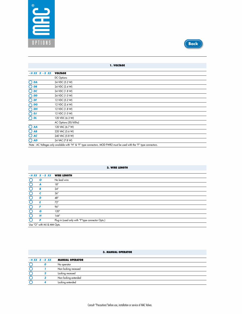
Consult “Precautions”before use, installation or service of MAC Valves.
O P T I O N S
1. VOLTAGE
- H XX X - X XX VOLTAGE
DC Options
DA 24 VDC (5.2 W)
DB 24 VDC (2.4 W)
DC 24 VDC (1.8 W)
DD 24 VDC (1.0 W)
DF 12 VDC (5.2 W)
DG 12 VDC (2.4 W)
DH 12 VDC (1.8 W)
DJ 12 VDC (1.0 W)
DL 120 VDC (6.3 W)
AC Options (50/60hz)
AA 120 VAC (6.7 W)
AB 220 VAC (5.6 W)
AC 240 VAC (5.8 W)
AD 24 VAC (7.8 W)
Note : AC Voltages only available with “H” & “F” type connectors. MOD FWR2 must be used with the “F” type connectors.
2. WIRE LENGTH
- H XX X - X XX WIRE LENGTH
O No lead wire
A 18”
B 24”
C 36”
D 48”
E 72”
F 96”
G 120”
H 144”
P Plug-in (used only with “F”type connector Opts.)
Use “O” with MJ & MM Opts.
3. MANUAL OPERATOR
- H XX X - X XX MANUAL OPERATOR
0 No operator
1 Non-locking recessed
2 Locking recessed
3 Non-locking extended
4 Locking extended
Back

Consult “Precautions”before use, installation or service of MAC Valves.
O P T I O N S
O p t i o n s
4. ELECTRICAL CONNECTION
- H XX X - X XX ELECTRICAL CONNECTION
BA Flying leads
BB Flying leads with ground wire
BC Flying leads with led light
BD Flying leads with led light & ground wire
BE Flying leads with suppression diode
BF Flying leads with suppression diode & ground wire
BG Flying leads with suppression diode plus led light
BH Flying leads with suppression diode plus led light & ground wire
*BN Flying leads with suppression diode plus blocking diode
*BP Flying leads with suppression diode plus blocking diode & ground wire
*BR Flying leads with suppression diode plus blocking diode & led light
*BS Flying leads with suppression diode plus blocking diode & led light & ground wire
FA Plug-in
FB Plug-in with ground wire
FC Plug-in with led light
FD Plug-in with led light & ground wire
FE Plug-in with suppression diode
FF Plug-in with suppression diode & ground wire
FG Plug-in with suppression diode plus led light
FH Plug-in with suppression diode plus led light & ground wire
Note : FA ---- FH options for use with ECD type circuit bars
HA Circuit board plug-in with full wave rectifier & led light
HB Circuit board with full wave rectifier & led with ground wire
HC Same as “HA” without lead wires
HD Same as “HB” without lead wires
HL Circuit board plug-in with suppression diode plus blocking diode & led light
HN Same as “HL” without lead wires
MA Plug-in wire assembly
MB Plug-in wire assembly with ground wire
MC Plug-in wire assembly with led light
MD Plug-in wire assembly led light & ground wire
ME Plug-in wire assembly with suppression diode
MF Plug-in wire assembly with suppression diode & ground wire
*MG Plug-in wire assembly suppression diode plus led light
*MH Plug-in wire assembly suppression diode plus led light & ground wire
*MN Plug-in wire assembly with suppression diode plus blocking diode
*MP Plug-in wire assembly with suppression diode plus blocking diode & ground wire
MR Plug-in wire assembly with suppression diode plus blocking diode & led light
MS Plug-in wire assembly with suppression diode plus blocking diode & led light & ground wire
MJ Plug-in housing w/o wire assembly (“MA” option without wire assembly)
MM Plug-in housing w/o wire assembly (“MB” option without wire assembly)
* Blocking diode is in lead wire.
Back

• Type «SUB_D»• Number of contacts : 9• Solder termination (Dia. 0.6 mm/0.14 mm
2/26-22 AWG)
• Operating current 5 A/contact• Rated voltage 125 V~• Temp. range –40° to +125°C• Insulation resistance � 5.09 �• Protection class IP40 (DIN 40050)• Number of solenoids : 7 max.• Max. 24 V=/5.4 W per solenoid• 2 common wires
MOD. SD09
MOD. SD15
MOD. SD25
PIN #1
PIN #5
PIN #6
PIN #9
PIN #1
PIN #8
PIN #9
PIN #15
PIN #1
PIN #13
PIN #14
PIN #25
• Type «SUB_D»• Number of contacts : 25• Solder termination (Dia. 0.6 mm/0.14 mm
2/26-22 AWG)
• Operating current 5 A/contact• Rated voltage 125 V~• Temp. range –40° to +125°C• Insulation resistance � 5.09 �• Protection class IP40 (DIN 40050)• Number of solenoids : 20 max.• Max. 24 V=/5.4 W per solenoid• 5 common wires
Note : Use desired MOD. number after circuit bar part number
• Type «SUB_D»• Number of contacts : 15• Solder termination (Dia. 0.6 mm/0.14 mm
2/26-22 AWG)
• Operating current 5 A/contact• Rated voltage 125 V~• Temp. range –40° to +125°C• Insulation resistance � 5.09 �• Protection class IP40 (DIN 40050)• Number of solenoids : 12 max.• Max. 24 V=/5.4 W per solenoid• 3 common wires
T E C H N I C A L D A T A
T E C H N I C A L D A T A
T E C H N I C A L D A T A
O P T I O N S
O p t i o n s

SD09 SD15 SD25
Connector termination details
SOL 2 SOL 4 SOL 6 SOL 8 SOL 16 SOL 18 SOL 20 SOL 22 SOL 24
SOL 1CONN
ECTO
RCO
NNEC
TOR
SOL 2 SOL 3 SOL .. SOL 20 SOL 21 SOL 22 SOL 23 SOL 24
SOL 1 SOL 3 SOL 5 SOL 13 SOL 15 SOL 17
Double solenoid circuit bar
Single solenoid circuit bar
SOL 21 SOL 23SOL 19
SOL. 3
SOL. 1
SOL. 2
1
2
3
4
COMMON (+)
COMMON (+)
8
SOL. 4
5
6
7
9
SOL. 5
SOL. 7
SOL. 6
SOL. 3
SOL. 1
SOL. 2
1
2
3
4
COMMON (+)
COMMON (+)
COMMON (+)
13
SOL. 4
5
6
7
8
14
SOL. 5
SOL. 7
SOL. 6
SOL. 8
9
10
11
12
15
SOL. 9
SOL. 11
SOL. 10
SOL. 12
SOL. 3
SOL. 1
SOL. 2
1
2
3
4
COMMON (+)
COMMON (+)
COMMON (+)
COMMON (+)
COMMON (+)
21
SOL. 4
5
6
7
8
22
SOL. 5
SOL. 7
SOL. 6
SOL. 8
9
10
11
12
23
SOL. 9
SOL. 11
SOL. 10
SOL. 12
13
14
15
16
24
SOL. 13
SOL. 15
SOL. 14
SOL. 16
17
18
19
20
25
SOL. 17
SOL. 19
SOL. 18
SOL. 20
O P T I O N S
O p t i o n s

Consult “Precautions”before use, installation or service of MAC Valves.
Series 400
D i r e c t s o l e n o i d a n d s o l e n o i d p i l o t o p e r a t e d v a l v e s
2 4
1 53
low profilecylinder ports
in valve
low profilecylinder ports
in base
mid profilecylinder ports
in valve
mid profile -add on stylecylinder ports
in valve
add-a-unitstations for
CBM403A bar
mid profilecylinder ports
in base
mid profile -add on stylecylinder ports
in base
add-a-unitstations for
CBM404A bar
Circuit bar mounting
high profilecylinder ports
in base
high profile -add on stylecylinder ports
in base
add-a-unitstations for
CBM405A bar
SERIES FEATURES
• Patented MACSOLENOID® for fastest possible response timesand virtually burn-out proof AC solenoid operation.
• Optional low watt DC solenoids.• Various manual operators.• Optional memory spring.• 2 position or 3 position valve configurations.• Internal or external pilot.
Air return
Bonded spool
Manual operator
Solenoid
4-way pilot with balanced poppet

Consult “Precautions”before use, installation or service of MAC Valves.
Reset
Series 400
Function Port size (NPTF) Flow (Max) Circuit bar mounting
5/2 - 5/3 1/8” - 1/4” 1.0Cvlow profile
cylinder portsin valve
1. The 4-way pilot develops maximum shifting forcesboth ways.
2. Memory spring available.3. Balanced spool, immune to variations of pressure,
also provides high flow.4. Short stroke with high flow.5. Bonded spool with minimum friction, shifting in a
glass-like finished bore.6. Pilot with balanced poppet, high flow, short and
consistent response times.7. Wiping effect eliminates sticking.8. Long service life.
O P E R A T I O N A L B E N E F I T S
D i r e c t s o l e n o i d a n d s o l e n o i d p i l o t o p e r a t e d v a l v e s
H O W T O O R D E R
Voltage
JB 240/60, 220/50
JA 120/60, 110/50
JC 24/60, 24/50
FB 24VDC (1.8 W)
DA 24VDC (5.4 W)
DF 24VDC (12.7 W)
Wire length
A 18” (Flying leads)
J Connector
Manual operator
1 Non-locking
2 Locking
Electrical connection
KA Square connector
KD Square connectorwith light
JB Rectangular connector
JD Rectangular connector with light
BA Flying leads
D XX X- X XX *SOLENOID OPERATOR ➤
XX X X XX
411A-AOA-DM-DXXX-XXX
O P T I O N S
- clic with memory spring (replace by 4).
HOW TO ORDER VALVE FOR CIRCUIT BAR MOUNTING
5/2Single operator
411A-COA-DM-DXXX-XXX
411A-BOA-DM-DXXX-XXX
5/2Double operator
421A-AOA-DM-DXXX-XXX
421A-BOA-DM-DXXX-XXX
5/3Closed center
451A-AOA-DM-DXXX-XXX
451A-BOA-DM-DXXX-XXX
5/3Open center
461A-AOA-DM-DXXX-XXX
461A-BOA-DM-DXXX-XXX
5/3Pressure center
471A-AOA-DM-DXXX-XXX
471A-BOA-DM-DXXX-XXX
Port size
1/8” NPT
1/4” NPT
Pilot air
Internal
2 412 14
3 1 5
2 412 14
3 1 5
2 412 14
3 1 5
2 412 14
3 1 5
2 412 14
3 1 5
411A-AOA-DM-DXXX-XXX
w/o flow controls
CBM401A-00AAA-XX
w/ flow controls
CBM401A-00BAA-XX
w/o flow controls
CBM401A-02AAA-XX
w/ flow controls
CBM401A-02BAA-XX
Spacing standard 19,5 mm Spacing 26 mm (Rectangular connector)
HOW TO ORDER CIRCUIT BAR **
Port size
3/8” NPTF
Pilot air
Internal
Number of stations (03=3 stations)** Other options available. Consult factory.
xxxx-xxx-DM-Dxxx-xxx
CBM401A-xxxxx-xx
Other Optionsxx
x Other Options
xx Other Options
x Other Options

Consult “Precautions”before use, installation or service of MAC Valves.
Series 400
D I M E N S I O N S
Fluid :
Pressure range :
Pilot pressure :
Lubrication :
Filtration :
Temperature range :
Orifice :
Flow :
Leak rate :
Coil :
Voltage range :
Protection :
Power :
Response times :
Compressed air, vacuum, inert gases
20 - 150 PSI
20 - 150 PSI
Not required, if used select a medium aniline point lubricant (between 180°F to 210°F)
40 μ
0°F to 120°F (-18°C to +50°C)
6.2 mm
1.0Cv
50 cm3/min
General purpose class A, continuous duty, encapsulated
-15% to +10% of nominal voltage
NEMA 4
� Inrush : 10.9 VA Holding : 7.7 VA
= 1.8 to 12.7 W
24 V=/5.4 W Energize : 7.3 ms De-energize : 5.3ms
60Hz/6 W Energize : 8-12 ms De-energize : 7-11 ms
D A T A
T E C H N I C A L
1818100%100%
100%100% M O N T H S
WARRANTY
O FP R O D U C T I O N
T E S T E D
• Pilot valve : DMB-DXXX-XXX-1, including mounting screws 35069 and seal 16524.
• Blanking plate : M-04001. • Flow control (x2) : N-04001. • Seal (x2) : 17013-01, (x1) : 17015-01. • Mounting screw (x2) : 35043.
• BSPP threads. • Isolation of inlet and/or exhaust.
Spare parts :
Accessories :
Options :3
51
CL
35
1
CL
6.7
21.532.0
14
12
14
12
14
12
14
12
108.5 94.3
94.5
7.0
27.8
14.5
41.0
67.5
16.018.5
25.0 39.0
82.0
64.0
25.0
TYP.1/8" PORTS
TYP.3/8" PORTS
É” 6.50 TYP.
118.0 DOUBLE
108.2 SINGLE
31.550.7
19.5

Consult “Precautions”before use, installation or service of MAC Valves.
Reset
Series 400
Function Port size (NPTF) Flow (Max) Circuit bar mounting
5/2 - 5/3 1/8” 1.0Cvlow profile
cylinder portsin base
1. The 4-way pilot develops maximum shifting forcesboth ways.
2. Memory spring available.3. Balanced spool, immune to variations of pressure,
also provides high flow.4. Short stroke with high flow.5. Bonded spool with minimum friction, shifting in a
glass-like finished bore.6. Pilot with balanced poppet, high flow, short and
consistent response times.7. Wiping effect eliminates sticking.8. Long service life.
O P E R A T I O N A L B E N E F I T S
D i r e c t s o l e n o i d a n d s o l e n o i d p i l o t o p e r a t e d v a l v e s
H O W T O O R D E R
HOW TO ORDER VALVE FOR CIRCUIT BAR MOUNTING
5/2Single operator
413A-OOA-DM-DXXX-XXX
5/2Double operator
423A-OOA-DM-DXXX-XXX
5/3Closed center
453A-OOA-DM-DXXX-XXX
5/3Open center
463A-OOA-DM-DXXX-XXX
5/3Pressure center
473A-OOA-DM-DXXX-XXX
Pilot air
Internal
2 412 14
3 1 5
2 412 14
3 1 5
2 412 14
3 1 5
2 412 14
3 1 5
2 412 14
3 1 5
413A-OOA-DM-DXXX-XXX
Voltage
JB 240/60, 220/50
JA 120/60, 110/50
JC 24/60, 24/50
FB 24VDC (1.8 W)
DA 24VDC (5.4 W)
DF 24VDC (12.7 W)
Wire length
A 18” (Flying leads)
J Connector
Manual operator
1 Non-locking
2 Locking
Electrical connection
KA Square connector
KD Square connectorwith light
JB Rectangular connector
JD Rectangular connector with light
BA Flying leads
D XX X- X XX *SOLENOID OPERATOR ➤
XX X X XX
413A-OOA-DM-DXXX-XXX
O P T I O N S
- clic with memory spring (replace by 6).
w/o flow controls
CBM402A-00AAA-XX
w/ flow controls
CBM402A-00BAA-XX
w/o flow controls
CBM402A-02AAA-XX
w/ flow controls
CBM402A-02BAA-XX
Spacing standard 19,5 mm Spacing 26 mm (Rectangular connector)
HOW TO ORDER CIRCUIT BAR (BOTTOM CYLINDER PORTS) **
Port size
1/8” NPTF
Pilot air
Internal
Number of stations (03=3 stations)** Other options available. Consult factory.
xxxx-xxx-DM-Dxxx-xxx
CBM402A-xxxxx-xx
Other Optionsxx
x Other Options
xx Other Options
x Other Options
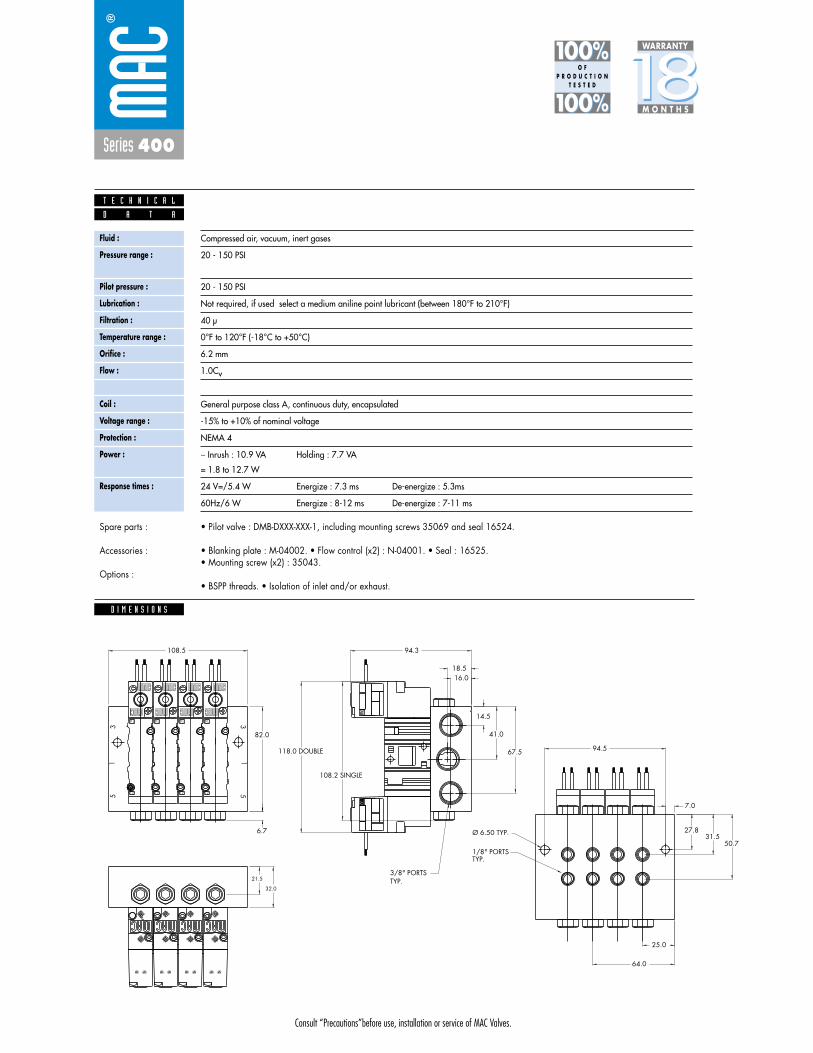
Consult “Precautions”before use, installation or service of MAC Valves.
Series 400
D I M E N S I O N S
Fluid :
Pressure range :
Pilot pressure :
Lubrication :
Filtration :
Temperature range :
Orifice :
Flow :
Leak rate :
Coil :
Voltage range :
Protection :
Power :
Response times :
Compressed air, vacuum, inert gases
20 - 150 PSI
20 - 150 PSI
Not required, if used select a medium aniline point lubricant (between 180°F to 210°F)
40 μ
0°F to 120°F (-18°C to +50°C)
6.2 mm
1.0Cv
50 cm3/min
General purpose class A, continuous duty, encapsulated
-15% to +10% of nominal voltage
NEMA 4
� Inrush : 10.9 VA Holding : 7.7 VA
= 1.8 to 12.7 W
24 V=/5.4 W Energize : 7.3 ms De-energize : 5.3ms
60Hz/6 W Energize : 8-12 ms De-energize : 7-11 ms
D A T A
T E C H N I C A L
1818100%100%
100%100% M O N T H S
WARRANTY
O FP R O D U C T I O N
T E S T E D
• Pilot valve : DMB-DXXX-XXX-1, including mounting screws 35069 and seal 16524.
• Blanking plate : M-04002. • Flow control (x2) : N-04001. • Seal : 16525. • Mounting screw (x2) : 35043.
• BSPP threads. • Isolation of inlet and/or exhaust.
Spare parts :
Accessories :
Options :3
51
CL
35
1
CL
6.7
21.5
32.0
14
12
14
12
14
12
14
12
108.5 94.3
94.5
7.0
27.8
14.5
41.0
67.5
16.018.5
82.0
64.0
25.0
TYP.1/8" PORTS
TYP.3/8" PORTS
Ø 6.50 TYP.
118.0 DOUBLE
108.2 SINGLE
31.550.7

Consult “Precautions”before use, installation or service of MAC Valves.
Reset
Series 400
Function Port size (NPTF) Flow (Max) Circuit bar mounting
5/2 - 5/3 1/8” - 1/4” 1.0Cvmid profile
cylinder ports in valve
1. The 4-way pilot develops maximum shifting forcesboth ways.
2. Memory spring available.3. Balanced spool, immune to variations of pressure,
also provides high flow.4. Short stroke with high flow.5. Bonded spool with minimum friction, shifting in a
glass-like finished bore.6. Pilot with balanced poppet, high flow, short and
consistent response times.7. Wiping effect eliminates sticking.8. Long service life.
O P E R A T I O N A L B E N E F I T S
D i r e c t s o l e n o i d a n d s o l e n o i d p i l o t o p e r a t e d v a l v e s
H O W T O O R D E R
HOW TO ORDER VALVE FOR CIRCUIT BAR MOUNTING
5/2Single operator
411A-COA-DM-DXXX-XXX
411A-BOA-DM-DXXX-XXX
411A-AOD-DM-DXXX-XXX
411A-BOD-DM-DXXX-XXX
5/2Double operator
421A-AOA-DM-DXXX-XXX
421A-BOA-DM-DXXX-XXX
421A-AOD-DM-DXXX-XXX
421A-BOD-DM-DXXX-XXX
5/3Closed center
451A-AOA-DM-DXXX-XXX
451A-BOA-DM-DXXX-XXX
451A-AOD-DM-DXXX-XXX
451A-BOD-DM-DXXX-XXX
5/3Open center
461A-AOA-DM-DXXX-XXX
461A-BOA-DM-DXXX-XXX
461A-AOD-DM-DXXX-XXX
461A-BOD-DM-DXXX-XXX
5/3Pressure center
471A-AOA-DM-DXXX-XXX
471A-BOA-DM-DXXX-XXX
471A-AOD-DM-DXXX-XXX
471A-BOD-DM-DXXX-XXX
Port size
1/8” NPT
1/4” NPT
1/8” NPT
1/4” NPT
Pilot air
Internal
External
2 412 14
3 1 5
2 412 14
3 1 5
2 412 14
3 1 5
2 412 14
3 1 5
2 412 14
3 1 5
411A-AOA-DM-DXXX-XXX
Voltage
JB 240/60, 220/50
JA 120/60, 110/50
JC 24/60, 24/50
FB 24VDC (1.8 W)
DA 24VDC (5.4 W)
DF 24VDC (12.7 W)
Wire length
A 18” (Flying leads)
J Connector
Manual operator
1 Non-locking
2 Locking
Electrical connection
KA Square connector
KD Square connectorwith light
JB Rectangular connector
JD Rectangular connector with light
BA Flying leads
D XX X- X XX *SOLENOID OPERATOR ➤
XX X X XX
w/o flow controls
CBM403A-00AAA-XX
CBM403A-00CAA-XX
w/ flow controls
CBM403A-00BAA-XX
CBM403A-00DAA-XX
w/o flow controls
CBM403A-02AAA-XX
CBM403A-02CAA-XX
w/ flow controls
CBM403A-02BAA-XX
CBM403A-02DAA-XX
Spacing standard 19,5 mm Spacing 26 mm (Rectangular connector)
HOW TO ORDER CIRCUIT BAR **
Port size
3/8” NPTF
Pilot air
Internal
Common external
411A-AOA-DM-DXXX-XXX
O P T I O N S
- clic with memory spring (replace by 4).
Number of stations (03=3 stations)** Other options available. Consult factory.
xxxx-xxx-DM-Dxxx-xxx
CBM403A-xxxxx-xxOther Optionsxx
x Other Options
xx Other Options
x Other Options
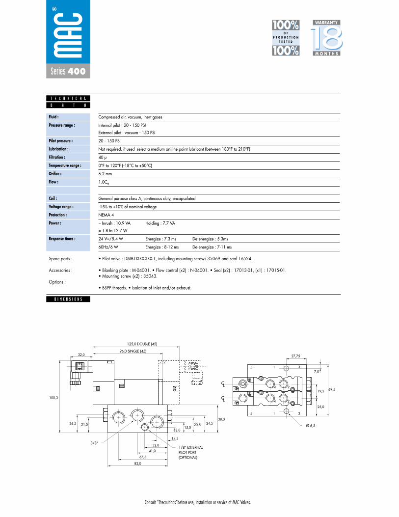
Consult “Precautions”before use, installation or service of MAC Valves.
Series 400
D I M E N S I O N S
Fluid :
Pressure range :
Pilot pressure :
Lubrication :
Filtration :
Temperature range :
Orifice :
Flow :
Leak rate :
Coil :
Voltage range :
Protection :
Power :
Response times :
Compressed air, vacuum, inert gases
Internal pilot : 20 - 150 PSI
External pilot : vacuum - 150 PSI
20 - 150 PSI
Not required, if used select a medium aniline point lubricant (between 180°F to 210°F)
40 μ
0°F to 120°F (-18°C to +50°C)
6.2 mm
1.0Cv
50 cm3/min
General purpose class A, continuous duty, encapsulated
-15% to +10% of nominal voltage
NEMA 4
� Inrush : 10.9 VA Holding : 7.7 VA
= 1.8 to 12.7 W
24 V=/5.4 W Energize : 7.3 ms De-energize : 5.3ms
60Hz/6 W Energize : 8-12 ms De-energize : 7-11 ms
D A T A
T E C H N I C A L
1818100%100%
100%100% M O N T H S
WARRANTY
O FP R O D U C T I O N
T E S T E D
• Pilot valve : DMB-DXXX-XXX-1, including mounting screws 35069 and seal 16524.
• Blanking plate : M-04001. • Flow control (x2) : N-04001. • Seal (x2) : 17013-01, (x1) : 17015-01.• Mounting screw (x2) : 35043.
• BSPP threads. • Isolation of inlet and/or exhaust.
Spare parts :
Accessories :
Options :
5 1 3
5 1 3
4 2
4 2
69,519,5
27,75
25,0
38,024,5
8,015,0
20,521,026,5
100,3
82,0
67,5
41,0
32,0
14,5
7,0
32,0
CL
CL
3/8"1/8” EXTERNALPILOT PORT(OPTIONAL)
Ø 6,5
125,0 DOUBLE (45)
96,0 SINGLE (45)

Consult “Precautions”before use, installation or service of MAC Valves.
Reset
Series 400
Function Port size (NPTF) Flow (Max) Circuit bar mounting
5/2 - 5/3 1/8” - 1/4” 1.0Cvmid profile -add on stylecylinder ports
in valve
1. The 4-way pilot develops maximum shifting forcesboth ways.
2. Memory spring available.3. Balanced spool, immune to variations of pressure,
also provides high flow.4. Short stroke with high flow.5. Bonded spool with minimum friction, shifting in a
glass-like finished bore.6. Pilot with balanced poppet, high flow, short and
consistent response times.7. Wiping effect eliminates sticking.8. Long service life.
O P E R A T I O N A L B E N E F I T S
D i r e c t s o l e n o i d a n d s o l e n o i d p i l o t o p e r a t e d v a l v e s
H O W T O O R D E R
Voltage
JB 240/60, 220/50
JA 120/60, 110/50
JC 24/60, 24/50
FB 24VDC (1.8 W)
DA 24VDC (5.4 W)
DF 24VDC (12.7 W)
Wire length
A 18” (Flying leads)
J Connector
Manual operator
1 Non-locking
2 Locking
Electrical connection
KA Square connector
KD Square connectorwith light
JB Rectangular connector
JD Rectangular connector with light
BA Flying leads
D XX X- X XX *SOLENOID OPERATOR ➤
XX X X XX
411A-AOA-DM-DXXX-XXX
O P T I O N S
- clic with memory spring (replace by 4).
HOW TO ORDER VALVE FOR CIRCUIT BAR MOUNTING
5/2Single operator
411A-COA-DM-DXXX-XXX
411A-BOA-DM-DXXX-XXX
411A-AOD-DM-DXXX-XXX
411A-BOD-DM-DXXX-XXX
5/2Double operator
421A-AOA-DM-DXXX-XXX
421A-BOA-DM-DXXX-XXX
421A-AOD-DM-DXXX-XXX
421A-BOD-DM-DXXX-XXX
5/3Closed center
451A-AOA-DM-DXXX-XXX
451A-BOA-DM-DXXX-XXX
451A-AOD-DM-DXXX-XXX
451A-BOD-DM-DXXX-XXX
5/3Open center
461A-AOA-DM-DXXX-XXX
461A-BOA-DM-DXXX-XXX
461A-AOD-DM-DXXX-XXX
461A-BOD-DM-DXXX-XXX
5/3Pressure center
471A-AOA-DM-DXXX-XXX
471A-BOA-DM-DXXX-XXX
471A-AOD-DM-DXXX-XXX
471A-BOD-DM-DXXX-XXX
Port size
1/8” NPT
1/4” NPT
1/8” NPT
1/4” NPT
Pilot air
Internal
External
2 412 14
3 1 5
2 412 14
3 1 5
2 412 14
3 1 5
2 412 14
3 1 5
2 412 14
3 1 5
411A-AOA-DM-DXXX-XXX
w/o flow controls
CBM403A-00ABA-XX
CBM403A-00CBA-XX
w/ flow controls
CBM403A-00BBA-XX
CBM403A-00DBA-XX
w/o flow controls
CBM403A-02ABA-XX
CBM403A-02CBA-XX
w/ flow controls
CBM403A-02BBA-XX
CBM403A-02DBA-XX
Spacing standard 19,5 mm Spacing 26 mm (Rectangular connector)
HOW TO ORDER CIRCUIT BAR **
Port size
3/8” NPTF
Pilot air
Internal
Common external
Number of stations (03=3 stations)** Other options available. Consult factory.Note: add-a-unit stations may be added to above bars.
xxxx-xxx-DM-Dxxx-xxx
CBM403A-xxxxx-xxOther Optionsxx
x Other Options
xx Other Options
x Other Options

Consult “Precautions”before use, installation or service of MAC Valves.
Series 400
D I M E N S I O N S
Fluid :
Pressure range :
Pilot pressure :
Lubrication :
Filtration :
Temperature range :
Orifice :
Flow :
Leak rate :
Coil :
Voltage range :
Protection :
Power :
Response times :
Compressed air, vacuum, inert gases
Internal pilot : 20 - 150 PSI
External pilot : vacuum - 150 PSI
20 - 150 PSI
Not required, if used select a medium aniline point lubricant (between 180°F to 210°F)
40 μ
0°F to 120°F (-18°C to +50°C)
6.2 mm
1.0Cv
50 cm3/min
General purpose class A, continuous duty, encapsulated
-15% to +10% of nominal voltage
NEMA 4
� Inrush : 10.9 VA Holding : 7.7 VA
= 1.8 to 12.7 W
24 V=/5.4 W Energize : 7.3 ms De-energize : 5.3ms
60Hz/6 W Energize : 8-12 ms De-energize : 7-11 ms
D A T A
T E C H N I C A L
1818100%100%
100%100% M O N T H S
WARRANTY
O FP R O D U C T I O N
T E S T E D
• Pilot valve : DMB-DXXX-XXX-1, including mounting screws 35069 and seal 16524.
• Blanking plate : M-04001. • Flow control (x2) : N-04001. • Seal (x2) : 17013-01, (x1) : 17015-01.• Mounting screw (x2) : 35043. • End plate kit : M-04003-01. • End plate kit for common external : M-04004-01.
• BSPP threads. • Isolation of inlet and/or exhaust.
Spare parts :
Accessories :
Options :
6.5
82.0
20.5
21.055.0TYP. 8 PLACES
1/8" PORTS
OPTIONAL
PILOT PORT
1/8" EXTERNAL
TYP.
3/8" PORTS
32.0
8.0
67.5
41.0
14.5
380
107.9 SINGLE
117.5 DOUBLE
21.0
24.5
15.0
100.3
CLC
Ø 6.5 TYP.
51
3
12
14
CLCL
14
12
422
4
12
14
12
14
15
3
113.0 99.0
7.0
27.8
19.5
32.0
18.0
25.0
40.5
16.0
42
42

Consult “Precautions”before use, installation or service of MAC Valves.
Reset
Series 400
Function Port size (NPTF) Flow (Max) Circuit bar mounting
5/2 - 5/3 1/8” - 1/4” 1.0Cvadd-a-unitstations for
CBM403A bar
1. The 4-way pilot develops maximum shifting forcesboth ways.
2. Memory spring available.3. Balanced spool, immune to variations of pressure,
also provides high flow.4. Short stroke with high flow.5. Bonded spool with minimum friction, shifting in a
glass-like finished bore.6. Pilot with balanced poppet, high flow, short and
consistent response times.7. Wiping effect eliminates sticking.8. Long service life.
O P E R A T I O N A L B E N E F I T S
D i r e c t s o l e n o i d a n d s o l e n o i d p i l o t o p e r a t e d v a l v e s
H O W T O O R D E R
Voltage
JB 240/60, 220/50
JA 120/60, 110/50
JC 24/60, 24/50
FB 24VDC (1.8 W)
DA 24VDC (5.4 W)
DF 24VDC (12.7 W)
Wire length
A 18” (Flying leads)
J Connector
Manual operator
1 Non-locking
2 Locking
Electrical connection
KA Square connector
KD Square connectorwith light
JB Rectangular connector
JD Rectangular connector with light
BA Flying leads
D XX X- X XX *SOLENOID OPERATOR ➤
XX X X XX
411A-AOA-DM-DXXX-XXX
O P T I O N S
- clic with memory spring (replace by 4).
HOW TO ORDER VALVE FOR CIRCUIT BAR MOUNTING
5/2Single operator
411A-COA-DM-DXXX-XXX
411A-BOA-DM-DXXX-XXX
411A-AOD-DM-DXXX-XXX
411A-BOD-DM-DXXX-XXX
5/2Double operator
421A-AOA-DM-DXXX-XXX
421A-BOA-DM-DXXX-XXX
421A-AOD-DM-DXXX-XXX
421A-BOD-DM-DXXX-XXX
5/3Closed center
451A-AOA-DM-DXXX-XXX
451A-BOA-DM-DXXX-XXX
451A-AOD-DM-DXXX-XXX
451A-BOD-DM-DXXX-XXX
5/3Open center
461A-AOA-DM-DXXX-XXX
461A-BOA-DM-DXXX-XXX
461A-AOD-DM-DXXX-XXX
461A-BOD-DM-DXXX-XXX
5/3Pressure center
471A-AOA-DM-DXXX-XXX
471A-BOA-DM-DXXX-XXX
471A-AOD-DM-DXXX-XXX
471A-BOD-DM-DXXX-XXX
Port size
1/8” NPT
1/4” NPT
1/8” NPT
1/4” NPT
Pilot air
Internal
External
2 412 14
3 1 5
2 412 14
3 1 5
2 412 14
3 1 5
2 412 14
3 1 5
2 412 14
3 1 5
411A-AOA-DM-DXXX-XXX
w/o flow controls
CBM403A-01AEA-XX
CBM403A-01CEA-XX
w/ flow controls
CBM403A-01BEA-XX
CBM403A-01DEA-XX
w/o flow controls
CBM403A-02AEA-XX
CBM403A-02CEA-XX
w/ flow controls
CBM403A-02BEA-XX
CBM403A-02DEA-XX
Spacing 21 mm Spacing 26 mm (Rectangular connector)
HOW TO ORDER CIRCUIT BAR **
Port size
3/8” NPTF
Pilot air
Internal
Common external
Number of stations (01, 02, 03, or 04)** Other options available. Consult factory.
xxxx-xxx-DM-Dxxx-xxx
CBM403A-xxxxx-xxOther Optionsxx
x Other Options
xx Other Options
x Other Options
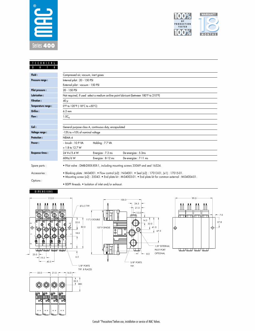
Consult “Precautions”before use, installation or service of MAC Valves.
Series 400
D I M E N S I O N S
Fluid :
Pressure range :
Pilot pressure :
Lubrication :
Filtration :
Temperature range :
Orifice :
Flow :
Leak rate :
Coil :
Voltage range :
Protection :
Power :
Response times :
Compressed air, vacuum, inert gases
Internal pilot : 20 - 150 PSI
External pilot : vacuum - 150 PSI
20 - 150 PSI
Not required, if used select a medium aniline point lubricant (between 180°F to 210°F)
40 μ
0°F to 120°F (-18°C to +50°C)
6.2 mm
1.0Cv
50 cm3/min
General purpose class A, continuous duty, encapsulated
-15% to +10% of nominal voltage
NEMA 4
� Inrush : 10.9 VA Holding : 7.7 VA
= 1.8 to 12.7 W
24 V=/5.4 W Energize : 7.3 ms De-energize : 5.3ms
60Hz/6 W Energize : 8-12 ms De-energize : 7-11 ms
D A T A
T E C H N I C A L
1818100%100%
100%100% M O N T H S
WARRANTY
O FP R O D U C T I O N
T E S T E D
• Pilot valve : DMB-DXXX-XXX-1, including mounting screws 35069 and seal 16524.
• Blanking plate : M-04001. • Flow control (x2) : N-04001. • Seal (x2) : 17013-01, (x1) : 17015-01.• Mounting screw (x2) : 35043. • End plate kit : M-04003-01. • End plate kit for common external : M-04004-01.
• BSPP threads. • Isolation of inlet and/or exhaust.
Spare parts :
Accessories :
Options :
6.5
82.0
20.5
21.055.0TYP. 8 PLACES
1/8" PORTS
OPTIONAL
PILOT PORT
1/8" EXTERNAL
TYP.
3/8" PORTS
32.0
8.0
67.5
41.0
14.5
380
107.9 SINGLE
117.5 DOUBLE
21.0
24.5
15.0
100.3
CLC
Ø 6.5 TYP.
51
3
12
14
CLCL
14
12
422
4
12
14
12
14
15
3
113.0 99.0
7.0
27.8
19.5
32.0
18.0
25.0
40.5
16.0
42
42
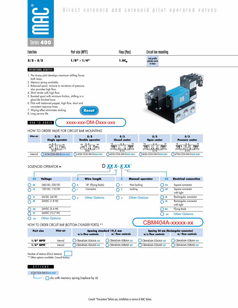
Consult “Precautions”before use, installation or service of MAC Valves.
Reset
Series 400
Function Port size (NPTF) Flow (Max) Circuit bar mounting
5/2 - 5/3 1/8” - 1/4” 1.0Cvmid profile
cylinder portsin base
1. The 4-way pilot develops maximum shifting forcesboth ways.
2. Memory spring available.3. Balanced spool, immune to variations of pressure,
also provides high flow.4. Short stroke with high flow.5. Bonded spool with minimum friction, shifting in a
glass-like finished bore.6. Pilot with balanced poppet, high flow, short and
consistent response times.7. Wiping effect eliminates sticking.8. Long service life.
O P E R A T I O N A L B E N E F I T S
D i r e c t s o l e n o i d a n d s o l e n o i d p i l o t o p e r a t e d v a l v e s
H O W T O O R D E R
HOW TO ORDER VALVE FOR CIRCUIT BAR MOUNTING
5/2Single operator
413A-OOA-DM-DXXX-XXX
5/2Double operator
423A-OOA-DM-DXXX-XXX
5/3Closed center
453A-OOA-DM-DXXX-XXX
5/3Open center
463A-OOA-DM-DXXX-XXX
5/3Pressure center
473A-OOA-DM-DXXX-XXX
Pilot air
Internal
2 412 14
3 1 5
2 412 14
3 1 5
2 412 14
3 1 5
2 412 14
3 1 5
2 412 14
3 1 5
413A-OOA-DM-DXXX-XXX
Voltage
JB 240/60, 220/50
JA 120/60, 110/50
JC 24/60, 24/50
FB 24VDC (1.8 W)
DA 24VDC (5.4 W)
DF 24VDC (12.7 W)
Wire length
A 18” (Flying leads)
J Connector
Manual operator
1 Non-locking
2 Locking
Electrical connection
KA Square connector
KD Square connectorwith light
JB Rectangular connector
JD Rectangular connector with light
BA Flying leads
D XX X- X XX *SOLENOID OPERATOR ➤
XX X X XX
413A-OOA-DM-DXXX-XXX
O P T I O N S
- clic with memory spring (replace by 6).
w/o flow controls
CBM404A-00AAA-XX
CBM404A-00AAD-XX
w/ flow controls
CBM404A-00BAA-XX
CBM404A-00BAD-XX
w/o flow controls
CBM404A-02AAA-XX
CBM404A-02AAD-XX
w/ flow controls
CBM404A-02BAA-XX
CBM404A-02BAD-XX
Spacing standard 19,5 mm Spacing 26 mm (Rectangular connector)
HOW TO ORDER CIRCUIT BAR (BOTTOM CYLINDER PORTS) **
Port size
1/8” NPTF
1/4” NPTF
Pilot air
Internal
Internal
Number of stations (03=3 stations)** Other options available. Consult factory.
xxxx-xxx-DM-Dxxx-xxx
CBM404A-xxxxx-xxOther Optionsxx
x Other Options
xx Other Options
x Other Options

Consult “Precautions”before use, installation or service of MAC Valves.
Series 400
D I M E N S I O N S
Fluid :
Pressure range :
Pilot pressure :
Lubrication :
Filtration :
Temperature range :
Orifice :
Flow :
Leak rate :
Coil :
Voltage range :
Protection :
Power :
Response times :
Compressed air, vacuum, inert gases
20 - 150 PSI
20 - 150 PSI
Not required, if used select a medium aniline point lubricant (between 180°F to 210°F)
40 μ
0°F to 120°F (-18°C to +50°C)
6.2 mm
1.0Cv
50 cm3/min
General purpose class A, continuous duty, encapsulated
-15% to +10% of nominal voltage
NEMA 4
� Inrush : 10.9 VA Holding : 7.7 VA
= 1.8 to 12.7 W
24 V=/5.4 W Energize : 7.3 ms De-energize : 5.3ms
60Hz/6 W Energize : 8-12 ms De-energize : 7-11 ms
D A T A
T E C H N I C A L
1818100%100%
100%100% M O N T H S
WARRANTY
O FP R O D U C T I O N
T E S T E D
• Pilot valve : DMB-DXXX-XXX-1, including mounting screws 35069 and seal 16524.
• Blanking plate : M-04002. • Flow control (x2) : N-04001. • Seal : 16525. • Mounting screw (x2) : 35043.
• BSPP threads. • Isolation of inlet and/or exhaust.
Spare parts :
Accessories :
Options :
5 1 3
5 1 3
4 2
4 2
69,519,5
25,0
38,024,5
15,020,521,026,5
100,3
82,0
67,5
41,0
B
4 2
A14,5
32,0
CL
CL
7,0
27,8
Port size
1/8”
1/4”
A
31.5
32.0
B
19.0
20.0
3/8 " PORTS
125,0 DOUBLE (45)
96,0 SINGLE (45)
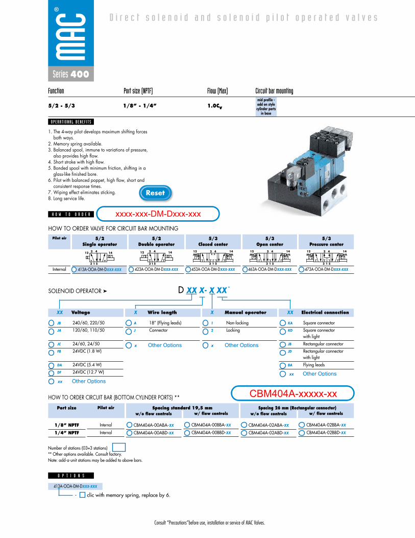
Consult “Precautions”before use, installation or service of MAC Valves.
Reset
Series 400
Function Port size (NPTF) Flow (Max) Circuit bar mounting
5/2 - 5/3 1/8” - 1/4” 1.0Cvmid profile -add on stylecylinder ports
in base
1. The 4-way pilot develops maximum shifting forcesboth ways.
2. Memory spring available.3. Balanced spool, immune to variations of pressure,
also provides high flow.4. Short stroke with high flow.5. Bonded spool with minimum friction, shifting in a
glass-like finished bore.6. Pilot with balanced poppet, high flow, short and
consistent response times.7. Wiping effect eliminates sticking.8. Long service life.
O P E R A T I O N A L B E N E F I T S
D i r e c t s o l e n o i d a n d s o l e n o i d p i l o t o p e r a t e d v a l v e s
H O W T O O R D E R
HOW TO ORDER VALVE FOR CIRCUIT BAR MOUNTING
5/2Single operator
413A-OOA-DM-DXXX-XXX
5/2Double operator
423A-OOA-DM-DXXX-XXX
5/3Closed center
453A-OOA-DM-DXXX-XXX
5/3Open center
463A-OOA-DM-DXXX-XXX
5/3Pressure center
473A-OOA-DM-DXXX-XXX
Pilot air
Internal
2 412 14
3 1 5
2 412 14
3 1 5
2 412 14
3 1 5
2 412 14
3 1 5
2 412 14
3 1 5
413A-OOA-DM-DXXX-XXX
Voltage
JB 240/60, 220/50
JA 120/60, 110/50
JC 24/60, 24/50
FB 24VDC (1.8 W)
DA 24VDC (5.4 W)
DF 24VDC (12.7 W)
Wire length
A 18” (Flying leads)
J Connector
Manual operator
1 Non-locking
2 Locking
Electrical connection
KA Square connector
KD Square connectorwith light
JB Rectangular connector
JD Rectangular connector with light
BA Flying leads
D XX X- X XX *SOLENOID OPERATOR ➤
XX X X XX
413A-OOA-DM-DXXX-XXX
O P T I O N S
- clic with memory spring, replace by 6.
w/o flow controls
CBM404A-00ABA-XX
CBM404A-00ABD-XX
w/ flow controls
CBM404A-00BBA-XX
CBM404A-00BBD-XX
w/o flow controls
CBM404A-02ABA-XX
CBM404A-02ABD-XX
w/ flow controls
CBM404A-02BBA-XX
CBM404A-02BBD-XX
Spacing standard 19,5 mm Spacing 26 mm (Rectangular connector)
HOW TO ORDER CIRCUIT BAR (BOTTOM CYLINDER PORTS) **
Port size
1/8” NPTF
1/4” NPTF
Pilot air
Internal
Internal
Number of stations (03=3 stations)** Other options available. Consult factory.Note: add-a-unit stations may be added to above bars.
xxxx-xxx-DM-Dxxx-xxx
CBM404A-xxxxx-xxOther Optionsxx
x Other Options
xx Other Options
x Other Options

Consult “Precautions”before use, installation or service of MAC Valves.
Series 400
D I M E N S I O N S
Fluid :
Pressure range :
Pilot pressure :
Lubrication :
Filtration :
Temperature range :
Orifice :
Flow :
Leak rate :
Coil :
Voltage range :
Protection :
Power :
Response times :
Compressed air, vacuum, inert gases
20 - 150 PSI
20 - 150 PSI
Not required, if used select a medium aniline point lubricant (between 180°F to 210°F)
40 μ
0°F to 120°F (-18°C to +50°C)
6.2 mm
1.0Cv
50 cm3/min
General purpose class A, continuous duty, encapsulated
-15% to +10% of nominal voltage
NEMA 4
� Inrush : 10.9 VA Holding : 7.7 VA
= 1.8 to 12.7 W
24 V=/5.4 W Energize : 7.3 ms De-energize : 5.3ms
60Hz/6 W Energize : 8-12 ms De-energize : 7-11 ms
D A T A
T E C H N I C A L
1818100%100%
100%100% M O N T H S
WARRANTY
O FP R O D U C T I O N
T E S T E D
• Pilot valve : DMB-DXXX-XXX-1, including mounting screws 35069 and seal 16524.
• Blanking plate : M-04002. • Flow control (x2) : N-04001. • Seal : 16525. • Mounting screw (x2) : 35043. • End plate kit : M-04003-01.
• BSPP threads. • Isolation of inlet and/or exhaust.
Spare parts :
Accessories :
Options :
6.5
82.0
20.5
21.055.0 TYP. 8 PLACES1/8" PORTS
OPTIONALPILOT PORT1/8" EXTERNAL
TYP.3/8" PORTS
32.0
8.0
67.5
41.0
14.5
38.0
107.9 SINGLE
117.5 DOUBLE
21.0
24.5
15.0
100.3
LCLC
É” 6.5 TYP.
51
3
LC
12
14
CLCL
14
1212
14
12
14
15
3
4
2
4
2
4
2
4
2
113.0
99.0
7.0
27.831.5
50.5
26.542.0
19.5
25.0
40.5
16.0

Consult “Precautions”before use, installation or service of MAC Valves.
Reset
Series 400
Function Port size (NPTF) Flow (Max) Circuit bar mounting
5/2 - 5/3 1/8” - 1/4” 1.0Cvadd-a-unitstations for
CBM404A bar
1. The 4-way pilot develops maximum shifting forcesboth ways.
2. Memory spring available.3. Balanced spool, immune to variations of pressure,
also provides high flow.4. Short stroke with high flow.5. Bonded spool with minimum friction, shifting in a
glass-like finished bore.6. Pilot with balanced poppet, high flow, short and
consistent response times.7. Wiping effect eliminates sticking.8. Long service life.
O P E R A T I O N A L B E N E F I T S
D i r e c t s o l e n o i d a n d s o l e n o i d p i l o t o p e r a t e d v a l v e s
H O W T O O R D E R
HOW TO ORDER VALVE FOR CIRCUIT BAR MOUNTING
5/2Single operator
413A-OOA-DM-DXXX-XXX
5/2Double operator
423A-OOA-DM-DXXX-XXX
5/3Closed center
453A-OOA-DM-DXXX-XXX
5/3Open center
463A-OOA-DM-DXXX-XXX
5/3Pressure center
473A-OOA-DM-DXXX-XXX
Pilot air
Internal
2 412 14
3 1 5
2 412 14
3 1 5
2 412 14
3 1 5
2 412 14
3 1 5
2 412 14
3 1 5
413A-OOA-DM-DXXX-XXX
Voltage
JB 240/60, 220/50
JA 120/60, 110/50
JC 24/60, 24/50
FB 24VDC (1.8 W)
DA 24VDC (5.4 W)
DF 24VDC (12.7 W)
Wire length
A 18” (Flying leads)
J Connector
Manual operator
1 Non-locking
2 Locking
Electrical connection
KA Square connector
KD Square connectorwith light
JB Rectangular connector
JD Rectangular connector with light
BA Flying leads
D XX X- X XX *SOLENOID OPERATOR ➤
XX X X XX
413A-OOA-DM-DXXX-XXX
O P T I O N S
- clic with memory spring (replace by 6).
w/o flow controls
CBM404A-01AEA-XX
CBM404A-01AED-XX
w/ flow controls
CBM404A-01BEA-XX
CBM404A-01BED-XX
w/o flow controls
CBM404A-02AEA-XX
CBM404A-02AED-XX
w/ flow controls
CBM404A-02BEA-XX
CBM404A-02BED-XX
Spacing 21 mm Spacing 26 mm (Rectangular connector)
HOW TO ORDER CIRCUIT BAR (BOTTOM CYLINDER PORTS) **
Port size
1/8” NPTF
1/4” NPTF
Pilot air
Internal
Internal
Number of stations (01, 02, 03, or 04)** Other options available. Consult factory.
xxxx-xxx-DM-Dxxx-xxx
CBM404A-xxxxx-xxOther Optionsxx
x Other Options
xx Other Options
x Other Options
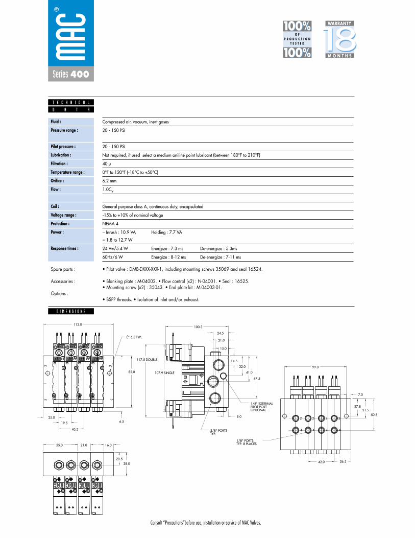
Consult “Precautions”before use, installation or service of MAC Valves.
Series 400
D I M E N S I O N S
Fluid :
Pressure range :
Pilot pressure :
Lubrication :
Filtration :
Temperature range :
Orifice :
Flow :
Leak rate :
Coil :
Voltage range :
Protection :
Power :
Response times :
Compressed air, vacuum, inert gases
20 - 150 PSI
20 - 150 PSI
Not required, if used select a medium aniline point lubricant (between 180°F to 210°F)
40 μ
0°F to 120°F (-18°C to +50°C)
6.2 mm
1.0Cv
50 cm3/min
General purpose class A, continuous duty, encapsulated
-15% to +10% of nominal voltage
NEMA 4
� Inrush : 10.9 VA Holding : 7.7 VA
= 1.8 to 12.7 W
24 V=/5.4 W Energize : 7.3 ms De-energize : 5.3ms
60Hz/6 W Energize : 8-12 ms De-energize : 7-11 ms
D A T A
T E C H N I C A L
1818100%100%
100%100% M O N T H S
WARRANTY
O FP R O D U C T I O N
T E S T E D
• Pilot valve : DMB-DXXX-XXX-1, including mounting screws 35069 and seal 16524.
• Blanking plate : M-04002. • Flow control (x2) : N-04001. • Seal : 16525. • Mounting screw (x2) : 35043. • End plate kit : M-04003-01.
• BSPP threads. • Isolation of inlet and/or exhaust.
Spare parts :
Accessories :
Options :
6.5
82.0
20.5
21.055.0 TYP. 8 PLACES1/8" PORTS
OPTIONALPILOT PORT1/8" EXTERNAL
TYP.3/8" PORTS
32.0
8.0
67.5
41.0
14.5
38.0
107.9 SINGLE
117.5 DOUBLE
21.0
24.5
15.0
100.3
LCLC
É” 6.5 TYP.
51
3
LC
12
14
CLCL
14
1212
14
12
14
15
3
4
2
4
2
4
2
4
2
113.0
99.0
7.0
27.831.5
50.5
26.542.0
19.5
25.0
40.5
16.0

Consult “Precautions”before use, installation or service of MAC Valves.
Reset
Series 400
Function Port size (NPTF) Flow (Max) Circuit bar mounting
5/2 - 5/3 1/8” - 1/4” 1.0Cvhigh profile
cylinder portsin base
1. The 4-way pilot develops maximum shifting forcesboth ways.
2. Memory spring available.3. Balanced spool, immune to variations of pressure,
also provides high flow.4. Short stroke with high flow.5. Bonded spool with minimum friction, shifting in a
glass-like finished bore.6. Pilot with balanced poppet, high flow, short and
consistent response times.7. Wiping effect eliminates sticking.8. Long service life.
O P E R A T I O N A L B E N E F I T S
D i r e c t s o l e n o i d a n d s o l e n o i d p i l o t o p e r a t e d v a l v e s
H O W T O O R D E R
HOW TO ORDER VALVE FOR CIRCUIT BAR MOUNTING
5/2Single operator
413A-OOA-DM-DXXX-XXX
413A-OOD-DM-DXXX-XXX
5/2Double operator
423A-OOA-DM-DXXX-XXX
423A-OOD-DM-DXXX-XXX
5/3Closed center
453A-OOA-DM-DXXX-XXX
453A-OOD-DM-DXXX-XXX
5/3Open center
463A-OOA-DM-DXXX-XXX
463A-OOD-DM-DXXX-XXX
5/3Pressure center
473A-OOA-DM-DXXX-XXX
473A-OOD-DM-DXXX-XXX
Pilot air
Internal
External
2 412 14
3 1 5
2 412 14
3 1 5
2 412 14
3 1 5
2 412 14
3 1 5
2 412 14
3 1 5
413A-OOA-DM-DXXX-XXX
Voltage
JB 240/60, 220/50
JA 120/60, 110/50
JC 24/60, 24/50
FB 24VDC (1.8 W)
DA 24VDC (5.4 W)
DF 24VDC (12.7 W)
Wire length
A 18” (Flying leads)
J Connector
Manual operator
1 Non-locking
2 Locking
Electrical connection
KA Square connector
KD Square connectorwith light
JB Rectangular connector
JD Rectangular connector with light
BA Flying leads
D XX X- X XX *SOLENOID OPERATOR ➤
XX X X XX
Spacing standard 19,5 mm
CBM405A-00AAA-XX
CBM405A-00BAA-XX
CBM405A-00AAD-XX
CBM405A-00BAD-XX
Spacing 26 mm (Rectangular connector)
CBM405A-02AAA-XX
CBM405A-02BAA-XX
CBM405A-02AAD-XX
CBM405A-02BAD-XX
HOW TO ORDER CIRCUIT BAR (SIDE CYLINDER PORTS) **
Port size
1/8” NPTF
1/4” NPTF
Pilot air
Internal
Common external
Internal
Common external
413A-OOA-DM-DXXX-XXX
O P T I O N S
- clic with memory spring (replace by 6).
Number of stations (03=3 stations)** Other options available. Consult factory.
xxxx-xxx-DM-Dxxx-xxx
CBM405A-xxxxx-xxOther Optionsxx
x Other Options
xx Other Options
x Other Options

Consult “Precautions”before use, installation or service of MAC Valves.
Series 400
D I M E N S I O N S
Fluid :
Pressure range :
Pilot pressure :
Lubrication :
Filtration :
Temperature range :
Orifice :
Flow :
Leak rate :
Coil :
Voltage range :
Protection :
Power :
Response times :
Compressed air, vacuum, inert gases
Internal pilot : 20 - 150 PSI
External pilot : vacuum - 150 PSI
20 - 150 PSI
Not required, if used select a medium aniline point lubricant (between 180°F to 210°F)
40 μ
0°F to 120°F (-18°C to +50°C)
6.2 mm
1.0Cv
50 cm3/min
General purpose class A, continuous duty, encapsulated
-15% to +10% of nominal voltage
NEMA 4
� Inrush : 10.9 VA Holding : 7.7 VA
= 1.8 to 12.7 W
24 V=/5.4 W Energize : 7.3 ms De-energize : 5.3ms
60Hz/6 W Energize : 8-12 ms De-energize : 7-11 ms
D A T A
T E C H N I C A L
1818100%100%
100%100% M O N T H S
WARRANTY
O FP R O D U C T I O N
T E S T E D
• Pilot valve : DMB-DXXX-XXX-1, including mounting screws 35069 and seal 16524.
• Blanking plate : M-04002. • Seal : 16525. • Mounting screw (x2) : 35043.
• BSPP threads. • Isolation of inlet and/or exhaust.
Spare parts :
Accessories :
Options :
52,022,0
4
2
9,5
33,519,0
40,0
114,3
72,0
46,0
35,0
20,0
59,0
32,0
4 2
5 1 3
5 1 3
4 269,5
25,0
19,5CL
CL
7,0
3/8" PORTS
1/8” EXTERNALPILOT PORT(OPTIONAL)
125,0 DOUBLE (45)96,0 SINGLE (45)

Consult “Precautions”before use, installation or service of MAC Valves.
Reset
Series 400
Function Port size (NPTF) Flow (Max) Circuit bar mounting
5/2 - 5/3 1/8” - 1/4” 1.0Cvhigh profile -add on stylecylinder ports
in base
1. The 4-way pilot develops maximum shifting forcesboth ways.
2. Memory spring available.3. Balanced spool, immune to variations of pressure,
also provides high flow.4. Short stroke with high flow.5. Bonded spool with minimum friction, shifting in a
glass-like finished bore.6. Pilot with balanced poppet, high flow, short and
consistent response times.7. Wiping effect eliminates sticking.8. Long service life.
O P E R A T I O N A L B E N E F I T S
D i r e c t s o l e n o i d a n d s o l e n o i d p i l o t o p e r a t e d v a l v e s
H O W T O O R D E R
HOW TO ORDER VALVE FOR CIRCUIT BAR MOUNTING
5/2Single operator
413A-OOA-DM-DXXX-XXX
413A-OOD-DM-DXXX-XXX
5/2Double operator
423A-OOA-DM-DXXX-XXX
423A-OOD-DM-DXXX-XXX
5/3Closed center
453A-OOA-DM-DXXX-XXX
453A-OOD-DM-DXXX-XXX
5/3Open center
463A-OOA-DM-DXXX-XXX
463A-OOD-DM-DXXX-XXX
5/3Pressure center
473A-OOA-DM-DXXX-XXX
473A-OOD-DM-DXXX-XXX
Pilot air
Internal
External
2 412 14
3 1 5
2 412 14
3 1 5
2 412 14
3 1 5
2 412 14
3 1 5
2 412 14
3 1 5
413A-OOA-DM-DXXX-XXX
Voltage
JB 240/60, 220/50
JA 120/60, 110/50
JC 24/60, 24/50
FB 24VDC (1.8 W)
DA 24VDC (5.4 W)
DF 24VDC (12.7 W)
Wire length
A 18” (Flying leads)
J Connector
Manual operator
1 Non-locking
2 Locking
Electrical connection
KA Square connector
KD Square connectorwith light
JB Rectangular connector
JD Rectangular connector with light
BA Flying leads
D XX X- X XX *SOLENOID OPERATOR ➤
XX X X XX
Spacing standard 19,5 mm
CBM405A-00ABA-XX
CBM405A-00BCA-XX
CBM405A-00ABD-XX
CBM405A-00BCD-XX
Spacing 26 mm (Rectangular connector)
CBM405A-02ABA-XX
CBM405A-02BCA-XX
CBM405A-02ABD-XX
CBM405A-02BCD-XX
HOW TO ORDER CIRCUIT BAR (SIDE CYLINDER PORTS) **
Port size
1/8” NPTF
1/4” NPTF
Pilot air
Internal
Common external
Internal
Common external
413A-OOA-DM-DXXX-XXX
O P T I O N S
- clic with memory spring (replace by 6).
Number of stations (03=3 stations)** Other options available. Consult factory.Note: add-a-unit stations may be added to above bars.
xxxx-xxx-DM-Dxxx-xxx
CBM405A-xxxxx-xxOther Optionsxx
x Other Options
xx Other Options
x Other Options

Consult “Precautions”before use, installation or service of MAC Valves.
Series 400
D I M E N S I O N S
Fluid :
Pressure range :
Pilot pressure :
Lubrication :
Filtration :
Temperature range :
Orifice :
Flow :
Leak rate :
Coil :
Voltage range :
Protection :
Power :
Response times :
Compressed air, vacuum, inert gases
Internal pilot : 20 - 150 PSI
External pilot : vacuum - 150 PSI
20 - 150 PSI
Not required, if used select a medium aniline point lubricant (between 180°F to 210°F)
40 μ
0°F to 120°F (-18°C to +50°C)
6.2 mm
1.0Cv
50 cm3/min
General purpose class A, continuous duty, encapsulated
-15% to +10% of nominal voltage
NEMA 4
� Inrush : 10.9 VA Holding : 7.7 VA
= 1.8 to 12.7 W
24 V=/5.4 W Energize : 7.3 ms De-energize : 5.3ms
60Hz/6 W Energize : 8-12 ms De-energize : 7-11 ms
D A T A
T E C H N I C A L
1818100%100%
100%100% M O N T H S
WARRANTY
O FP R O D U C T I O N
T E S T E D
• Pilot valve : DMB-DXXX-XXX-1, including mounting screws 35069 and seal 16524.
• Blanking plate : M-04002. • Seal : 16525. • Mounting screw (x2) : 35043.• End plate kit : M-04005-01. • End plate kit for common external pilot : M-04006-01.
• BSPP threads. • Isolation of inlet and/or exhaust.
Spare parts :
Accessories :
Options :
21.0
16.0
21.0
10.5
12
1414
1212
14
12
14
51
3
40.0
33.5
19.0
114.3
TYP.3/8" PORTS
OPTIONALPILOT PORT1/8" EXTERNAL
118.0 DOUBLE
98.5 SINGLE
20.035.0
46.072.0
TYP 2Ø 6.50
2
4
31
5
113.0
99.0
7.0
16.0
21.0
55.0
59.0
9.5
20.0
52.0
84.0

Consult “Precautions”before use, installation or service of MAC Valves.
Reset
Series 400
Function Port size (NPTF) Flow (Max) Circuit bar mounting
5/2 - 5/3 1/8” - 1/4” 1.0Cvadd-a-unitstations for
CBM405A bar
1. The 4-way pilot develops maximum shifting forcesboth ways.
2. Memory spring available.3. Balanced spool, immune to variations of pressure,
also provides high flow.4. Short stroke with high flow.5. Bonded spool with minimum friction, shifting in a
glass-like finished bore.6. Pilot with balanced poppet, high flow, short and
consistent response times.7. Wiping effect eliminates sticking.8. Long service life.
O P E R A T I O N A L B E N E F I T S
D i r e c t s o l e n o i d a n d s o l e n o i d p i l o t o p e r a t e d v a l v e s
H O W T O O R D E R
HOW TO ORDER VALVE FOR CIRCUIT BAR MOUNTING
5/2Single operator
413A-OOA-DM-DXXX-XXX
413A-OOD-DM-DXXX-XXX
5/2Double operator
423A-OOA-DM-DXXX-XXX
423A-OOD-DM-DXXX-XXX
5/3Closed center
453A-OOA-DM-DXXX-XXX
453A-OOD-DM-DXXX-XXX
5/3Open center
463A-OOA-DM-DXXX-XXX
463A-OOD-DM-DXXX-XXX
5/3Pressure center
473A-OOA-DM-DXXX-XXX
473A-OOD-DM-DXXX-XXX
Pilot air
Internal
External
2 412 14
3 1 5
2 412 14
3 1 5
2 412 14
3 1 5
2 412 14
3 1 5
2 412 14
3 1 5
413A-OOA-DM-DXXX-XXX
Voltage
JB 240/60, 220/50
JA 120/60, 110/50
JC 24/60, 24/50
FB 24VDC (1.8 W)
DA 24VDC (5.4 W)
DF 24VDC (12.7 W)
Wire length
A 18” (Flying leads)
J Connector
Manual operator
1 Non-locking
2 Locking
Electrical connection
KA Square connector
KD Square connectorwith light
JB Rectangular connector
JD Rectangular connector with light
BA Flying leads
D XX X- X XX *SOLENOID OPERATOR ➤
XX X X XX
Spacing 21 mm
CBM405A-01AEA-XX
CBM405A-01BEA-XX
CBM405A-01AED-XX
CBM405A-01BED-XX
Spacing 26 mm (Rectangular connector)
CBM405A-02AEA-XX
CBM405A-02BEA-XX
CBM405A-02AED-XX
CBM405A-02BED-XX
HOW TO ORDER CIRCUIT BAR (SIDE CYLINDER PORTS) **
Port size
1/8” NPTF
1/4” NPTF
Pilot air
Internal
Common external
Internal
Common external
413A-OOA-DM-DXXX-XXX
O P T I O N S
- clic with memory spring (replace by 6).
Number of stations (01, 02, 03, or 04)** Other options available. Consult factory.
xxxx-xxx-DM-Dxxx-xxx
CBM405A-xxxxx-xxOther Optionsxx
x Other Options
xx Other Options
x Other Options
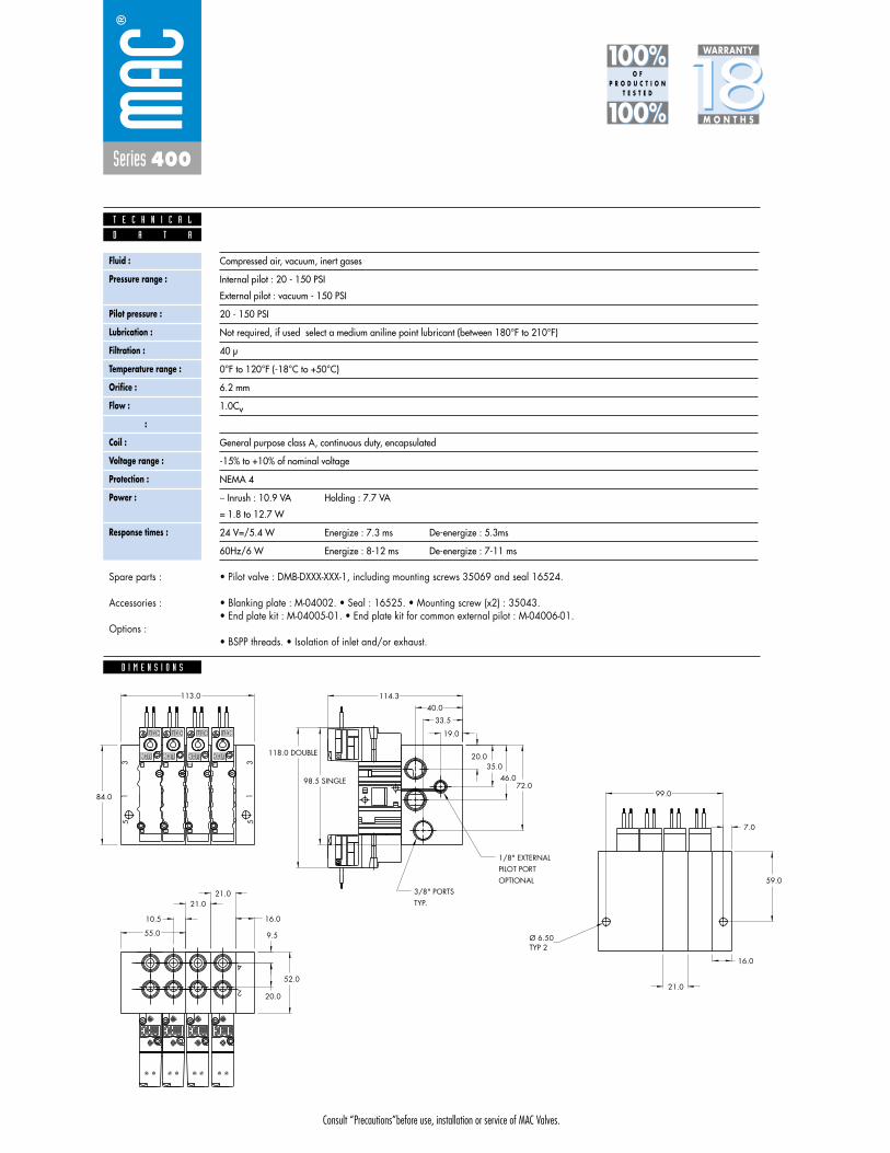
Consult “Precautions”before use, installation or service of MAC Valves.
Series 400
D I M E N S I O N S
Fluid :
Pressure range :
Pilot pressure :
Lubrication :
Filtration :
Temperature range :
Orifice :
Flow :
Leak rate :
Coil :
Voltage range :
Protection :
Power :
Response times :
Compressed air, vacuum, inert gases
Internal pilot : 20 - 150 PSI
External pilot : vacuum - 150 PSI
20 - 150 PSI
Not required, if used select a medium aniline point lubricant (between 180°F to 210°F)
40 μ
0°F to 120°F (-18°C to +50°C)
6.2 mm
1.0Cv
50 cm3/min
General purpose class A, continuous duty, encapsulated
-15% to +10% of nominal voltage
NEMA 4
� Inrush : 10.9 VA Holding : 7.7 VA
= 1.8 to 12.7 W
24 V=/5.4 W Energize : 7.3 ms De-energize : 5.3ms
60Hz/6 W Energize : 8-12 ms De-energize : 7-11 ms
D A T A
T E C H N I C A L
1818100%100%
100%100% M O N T H S
WARRANTY
O FP R O D U C T I O N
T E S T E D
• Pilot valve : DMB-DXXX-XXX-1, including mounting screws 35069 and seal 16524.
• Blanking plate : M-04002. • Seal : 16525. • Mounting screw (x2) : 35043.• End plate kit : M-04005-01. • End plate kit for common external pilot : M-04006-01.
• BSPP threads. • Isolation of inlet and/or exhaust.
Spare parts :
Accessories :
Options :
21.0
16.0
21.0
10.5
12
1414
1212
14
12
14
51
3
40.0
33.5
19.0
114.3
TYP.3/8" PORTS
OPTIONALPILOT PORT1/8" EXTERNAL
118.0 DOUBLE
98.5 SINGLE
20.035.0
46.072.0
TYP 2Ø 6.50
2
4
31
5
113.0
99.0
7.0
16.0
21.0
55.0
59.0
9.5
20.0
52.0
84.0

Consult “Precautions” before use, installation or service of MAC Valves.
S e c t i o n 2 Opt ions

Consult “Precautions”before use, installation or service of MAC Valves.
O P T I O N S
O p t i o n s
Codification table for voltages / Wire length / Manual operator / Electrical connection
- pilot operated valves 400, 52 & 92 Series
D M - D XX X - X XX1 2 3 4
VALVE CODE ➤
OPTIONS AVAILABLE FOR

Consult “Precautions”before use, installation or service of MAC Valves.
O P T I O N S
1. VOLTAGE
- D XX X - X XX VOLTAGE
DB 12 VDC (5.4 W)
DC 12 VDC (7.5 W)
DD 24 VDC (7.3 W)
DE 12 VDC (12.7 W)
DK 110 VDC (5.8 W)
DJ 28 VDC (5.7 W)
DL 64 VDC (6.0 W)
DM 36 VDC (5.8 W)
DN 6 VDC (6.0 W)
DR 90 VDC (6,6 W)
DS 110 VDC (7.3 W), 100 VDC (6.0 W)
DT 75 VDC (5.6 W)
DP 48 VDC (5.8 W)
FA 12 VDC (1.8 W)
FE 12 VDC (2.4 W)
FF 24 VDC (2.4 W)
JD 100/60, 100/50, 110/60
2. WIRE LENGTH
- D XX X - X XX WIRE LENGTH
B 24”
C 36”
D 48”
E 72”
F 96”
Back

Consult “Precautions”before use, installation or service of MAC Valves.
O P T I O N S
O p t i o n s
3. MANUAL OPERATOR
- D XX X - X XX MANUAL OPERATOR
0 No operator
1 Non-locking recessed
2 Locking recessed
3 Non-locking extended
4 Locking extended
4. ELECTRICAL CONNECTION
- D XX X - X XX ELECTRICAL CONNECTION
BA Flying leads
BK BA with protection diode
BL BA with protection varistor
CA 1/2" NPS conduit
JB Rectangular connector
JD Rectangular connector with light
JM Rectangular connector, male only
KA Square connector
KB Square connector with protection diode
KC Square connector with protection varistor
KD Square connector with light
KE Square connector with light and protection diode
KF Square connector with light and protection varistor
KJ Square connector (male only)
KK Square connector with protection diode (male only)
KL Square connector with protection varistor (male only)
TA Dual tabs
TB TA with protection diode
TD TA with light
TE TA with light and protection diode
TJ Dual tabs (male only)
TK TJ with protection diode
TM TJ with light
TN TJ with light and protection diode
*DN Plug-in with diode
*DP Plug-in with M.O.V.
*DH Plug-in with diode & ground
*DJ Plug-in with M.O.V & ground
* These options only apply to the 92 series. All others are for the 400 and 52 series.
Back

• Type «SUB_D»• Number of contacts : 9• Solder termination (Dia. 0.6 mm/0.14 mm
2/26-22 AWG)
• Operating current 5 A/contact• Rated voltage 125 V~• Temp. range –40° to +125°C• Insulation resistance � 5.09 �• Protection class IP40 (DIN 40050)• Number of solenoids : 7 max.• Max. 24 V=/5.4 W per solenoid• 2 common wires
MOD. SD09
MOD. SD15
MOD. SD25
PIN #1
PIN #5
PIN #6
PIN #9
PIN #1
PIN #8
PIN #9
PIN #15
PIN #1
PIN #13
PIN #14
PIN #25
• Type «SUB_D»• Number of contacts : 25• Solder termination (Dia. 0.6 mm/0.14 mm
2/26-22 AWG)
• Operating current 5 A/contact• Rated voltage 125 V~• Temp. range –40° to +125°C• Insulation resistance � 5.09 �• Protection class IP40 (DIN 40050)• Number of solenoids : 20 max.• Max. 24 V=/5.4 W per solenoid• 5 common wires
Note : Use desired MOD. number after circuit bar part number
• Type «SUB_D»• Number of contacts : 15• Solder termination (Dia. 0.6 mm/0.14 mm
2/26-22 AWG)
• Operating current 5 A/contact• Rated voltage 125 V~• Temp. range –40° to +125°C• Insulation resistance � 5.09 �• Protection class IP40 (DIN 40050)• Number of solenoids : 12 max.• Max. 24 V=/5.4 W per solenoid• 3 common wires
T E C H N I C A L D A T A
T E C H N I C A L D A T A
T E C H N I C A L D A T A
O P T I O N S
O p t i o n s

SD09 SD15 SD25
Connector termination details
SOL 2 SOL 4 SOL 6 SOL 8 SOL 16 SOL 18 SOL 20 SOL 22 SOL 24
SOL 1CONN
ECTO
RCO
NNEC
TOR
SOL 2 SOL 3 SOL .. SOL 20 SOL 21 SOL 22 SOL 23 SOL 24
SOL 1 SOL 3 SOL 5 SOL 13 SOL 15 SOL 17
Double solenoid circuit bar
Single solenoid circuit bar
SOL 21 SOL 23SOL 19
SOL. 3
SOL. 1
SOL. 2
1
2
3
4
COMMON (+)
COMMON (+)
8
SOL. 4
5
6
7
9
SOL. 5
SOL. 7
SOL. 6
SOL. 3
SOL. 1
SOL. 2
1
2
3
4
COMMON (+)
COMMON (+)
COMMON (+)
13
SOL. 4
5
6
7
8
14
SOL. 5
SOL. 7
SOL. 6
SOL. 8
9
10
11
12
15
SOL. 9
SOL. 11
SOL. 10
SOL. 12
SOL. 3
SOL. 1
SOL. 2
1
2
3
4
COMMON (+)
COMMON (+)
COMMON (+)
COMMON (+)
COMMON (+)
21
SOL. 4
5
6
7
8
22
SOL. 5
SOL. 7
SOL. 6
SOL. 8
9
10
11
12
23
SOL. 9
SOL. 11
SOL. 10
SOL. 12
13
14
15
16
24
SOL. 13
SOL. 15
SOL. 14
SOL. 16
17
18
19
20
25
SOL. 17
SOL. 19
SOL. 18
SOL. 20
O P T I O N S
O p t i o n s
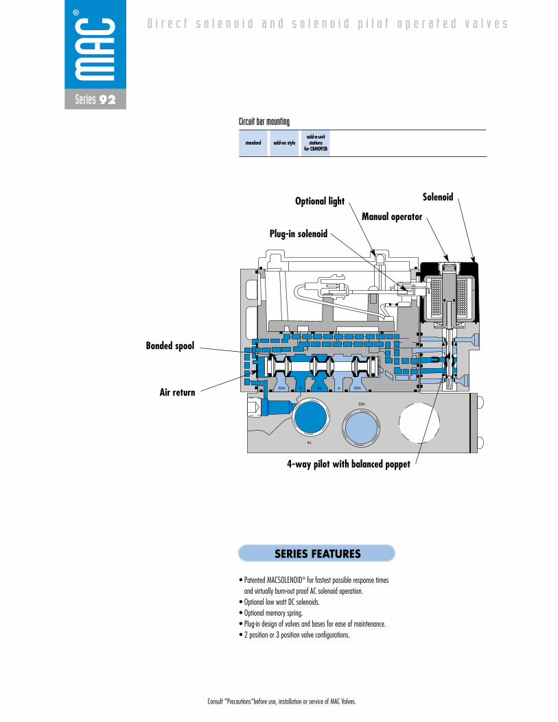
Consult “Precautions”before use, installation or service of MAC Valves.
Series 92
D i r e c t s o l e n o i d a n d s o l e n o i d p i l o t o p e r a t e d v a l v e s
EXH. EXH.
EXH.
IN.
IN. AB
standard add-on styleadd-a-unitstations
for CBM092B
Circuit bar mounting
SERIES FEATURES
• Patented MACSOLENOID® for fastest possible response timesand virtually burn-out proof AC solenoid operation.
• Optional low watt DC solenoids.• Optional memory spring.• Plug-in design of valves and bases for ease of maintenance.• 2 position or 3 position valve configurations.
Bonded spool
Optional lightManual operator
Solenoid
Plug-in solenoid
4-way pilot with balanced poppet
Air return

Consult “Precautions”before use, installation or service of MAC Valves.
Reset
Series 92
Function Port size Flow (Max) Circuit bar mounting
5/2 - 5/3 - 3/2 1/8 - 1/4 - 3/8 1.0Cv standard
1. The 4--way pilot develops maximum shifting forces both ways.
2. Memory spring available.3. Balanced spool, immune to variations of
pressure, also provides high flow.4. Short stroke with high flow.5. Bonded seal spool with minimum friction,
shifting in a glass-like finished bore.6. Pilot with balanced poppet, high flow, short
and consistent response times.7. Wiping effect eliminates sticking.8. Long service life.
O P E R A T I O N A L B E N E F I T S
Direct solenoid and solenoid pilot operated valves with multi-pin connector
H O W T O O R D E R V A L V E F O R C I R C U I T B A R M O U N T I N G
5/2Single operator
92B-AAA-000-DM-DXXP-XXX
5/2Double operator
92B-BAA-000-DM-DXXP-XXX
5/3Closed center
92B-EAA-000-DM-DXXP-XXX
5/3Open center
92B-FAA-000-DM-DXXP-XXX
5/3Pressure center
92B-GAA-000-DM-DXXP-XXX
Port size(see circuit bar)
Valve less base
Voltage
JB 240/60, 220/50
JA 120/60, 110/50
JC 24/60, 24/50
FB 24VDC (1.8 W)
DA 24VDC (5.4 W)
DF 24VDC (12.7 W)
Manual operator
1 Non-locking
2 Locking
Electrical connection
DM Plug-in
DG Plug-in w/ground
DM-DXX P- X XX *SOLENOID OPERATOR ➤
SINGLE PRESSURE MODELS
5/2Single operator
92B-CAA-000-DM-DXXP-XXX
5/2Double operator
92B-DAA-000-DM-DXXP-XXX
Port size(see circuit bar)
Valve less base
DUAL PRESSURE MODELS (REQUIRES SANDWICH PRESSURE REGULATOR)
HOW TO ORDER CIRCUIT BAR
XX XXX
Port size
1/8 NPTF
1/4 NPTF
3/8 NPTF
Pilot air
Internal
Common external
Internal
Common external
Internal
Common external
Side cylinder ports(25 mm)
CBM092B-01AAA-A0*XX
CBM092B-01CAA-A0*XX
CBM092B-01AAD-A0*XX
CBM092B-01CAD-A0*XX
CBM092B-01AAG-A0*XX
CBM092B-01CAG-A0*XX
Bottom cylinder ports(25 mm)
CBM092B-01BAA-A0*XX
CBM092B-01DAA-A0*XX
CBM092B-01BAD-A0*XX
CBM092B-01DAD-A0*XX
CBM092B-01BAG-A0*XX
CBM092B-01DAG-A0*XX
* If replaced by BO : circuit bar for single operator valves only.
Note : Ground wire required for solenoids 30 voltsand above.
Number of stations (03=3 stations)Note : clic for valves mounted on base at the factory (add - 9 to the model number).
for multi-pin connector (9, 15 or 25).
92B-xxx-000-DM-DxxP-xxx
CBM092B-01xxx-AOxxOther Optionsxx
xx Other Options
Other Optionsxx

Consult “Precautions”before use, installation or service of MAC Valves.
Series 92
D I M E N S I O N S
Fluid :
Pressure range :
Pilot pressure :
Lubrication :
Filtration :
Temperature range :
Orifice :
Flow (at 6 bar, �P=1bar) :
Leak rate :
Coil :
Voltage range :
Protection :
Power :
Response times :
Compressed air, vacuum, inert gases
Internal pilot : 20 to 120 PSI 3 positions : 35 to 120 PSI
External pilot : vacuum to 120 PSI 3 positions : 35 to 120 PSI
20 to 120 PSI 3 positions : 35 to 120 PSI
Not required, if used select a medium aniline point lubricant (between 180°F to 210°F)
40 μ
0°F to 120°F (-18°C to +50°C)
6.2 mm
1.0 Cv
50 cm3/min
General purpose class A, continuous duty, encapsulated
-15% to +10% of nominal voltage
NEMA 4
� Inrush : 7.6 VA Holding : 4.8 VA
= 1.8 to 12.7 W
24 V=/5.4 W Energize : 8 ms De-energize : 7 ms
60Hz/2.9 W Energize : 7-13 ms De-energize : 12-20 ms
AA
BB
CO
ND
.
EXT.
P
EBIN
EA
B
A
B
MO
DEL
A
B
MO
DEL
A
B
MO
DEL
A
B
MO
DEL
A
BEXT.P
A
B
A
B
A
B B
A
B
A
TYP.
TYP.25.0 G
25.0 E
F
H
BOTH ENDS3 PLACES3/8" PORTS
SOLENOIDW/ SINGLEAPROX.148.3
TYP.
TYP.
40.4
A
C TYP.81.5
5.5
7.0
42.036.5
25.6
25.521.5
115.573.1
51.227.025.5
118.7
OR BOTTOMAVAILABE ON SIDE1/8",1/4",3/8",PORTS
PILOT PORT 3 PLACES1/8" PORTS EXTERNAL
HOLES 4 PLACES 6.3 DIA. MT'G
ENDSCONDUIT BOTH1 1/4" N.P.S.M.
34.0 D
18.4
B
25.0
25.0
TYP.
TYP.
52.0
SIOLENOIDW/DOUBLEAPROX.164.3
D A T A
T E C H N I C A L
1818100%100%
100%100% M O N T H S
WARRANTY
O FP R O D U C T I O N
T E S T E D
• Pilot valve : DMB-DXXP-XXX-1 including mounting screws 35069 (x2) and seal 16544. • Pressure seal between valve and base : 16543. • Mounting screws valve to base (x2) : 35050. • Blanking plate : M-92002.
• BSPP threads. • Isolation of inlet and/or exhaust. • Circuit bar for number of stations > 24.
Spare parts :
Options :
Sandwich flow controls available, consult factory.
92B-AAA-000-DM-DXXP-1DM
O P T I O N S
For lights on valve, replace by B.For lights and diode on valve, replace by F.For lights and MOV on valve, replace by H.
Note: Bottom & side cylinder ports not available on the same station
Number ofstations
“H”
1
60.0
2
85.0
3
110.0
4
135.0
5
160.0
6
185.0
7
210.0
8
235.0
9
260.0
10
285.0
Dimensions are based on 25 mm centerline spacing
Dim.
“A”
“B”
“C”
“D”
“E”
“F”
“G”
1/8”
30.0
39.0
10.0
33.0
40.9
61.1
30.1
1/4”
30.0
39.0
10.0
33.0
36.9
61.1
30.9
3/8”
32.5
36.5
11.0
34.0
35.5
62.6
30.7
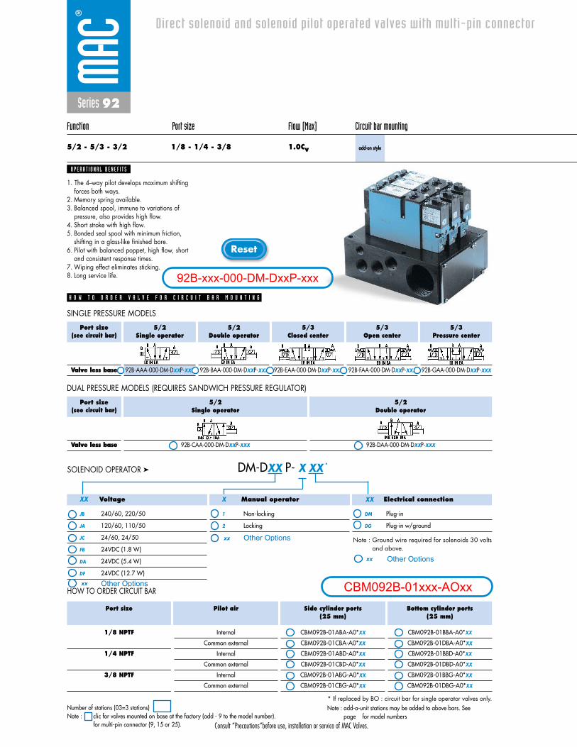
Consult “Precautions”before use, installation or service of MAC Valves.
Reset
Series 92
Function Port size Flow (Max) Circuit bar mounting
5/2 - 5/3 - 3/2 1/8 - 1/4 - 3/8 1.0Cv add-on style
1. The 4--way pilot develops maximum shifting forces both ways.
2. Memory spring available.3. Balanced spool, immune to variations of
pressure, also provides high flow.4. Short stroke with high flow.5. Bonded seal spool with minimum friction,
shifting in a glass-like finished bore.6. Pilot with balanced poppet, high flow, short
and consistent response times.7. Wiping effect eliminates sticking.8. Long service life.
O P E R A T I O N A L B E N E F I T S
Direct solenoid and solenoid pilot operated valves with multi-pin connector
H O W T O O R D E R V A L V E F O R C I R C U I T B A R M O U N T I N G
5/2Single operator
92B-AAA-000-DM-DXXP-XXX
5/2Double operator
92B-BAA-000-DM-DXXP-XXX
5/3Closed center
92B-EAA-000-DM-DXXP-XXX
5/3Open center
92B-FAA-000-DM-DXXP-XXX
5/3Pressure center
92B-GAA-000-DM-DXXP-XXX
Port size(see circuit bar)
Valve less base
Voltage
JB 240/60, 220/50
JA 120/60, 110/50
JC 24/60, 24/50
FB 24VDC (1.8 W)
DA 24VDC (5.4 W)
DF 24VDC (12.7 W)
Manual operator
1 Non-locking
2 Locking
Electrical connection
DM Plug-in
DG Plug-in w/ground
Note : Ground wire required for solenoids 30 voltsand above.
DM-DXX P- X XX *SOLENOID OPERATOR ➤
SINGLE PRESSURE MODELS
5/2Single operator
92B-CAA-000-DM-DXXP-XXX
5/2Double operator
92B-DAA-000-DM-DXXP-XXX
Port size(see circuit bar)
Valve less base
DUAL PRESSURE MODELS (REQUIRES SANDWICH PRESSURE REGULATOR)
HOW TO ORDER CIRCUIT BAR
XX XXX
Port size
1/8 NPTF
1/4 NPTF
3/8 NPTF
Pilot air
Internal
Common external
Internal
Common external
Internal
Common external
Side cylinder ports(25 mm)
CBM092B-01ABA-A0*XX
CBM092B-01CBA-A0*XX
CBM092B-01ABD-A0*XX
CBM092B-01CBD-A0*XX
CBM092B-01ABG-A0*XX
CBM092B-01CBG-A0*XX
Bottom cylinder ports(25 mm)
CBM092B-01BBA-A0*XX
CBM092B-01DBA-A0*XX
CBM092B-01BBD-A0*XX
CBM092B-01DBD-A0*XX
CBM092B-01BBG-A0*XX
CBM092B-01DBG-A0*XX
Note : add-a-unit stations may be added to above bars. Seepage for model numbers
* If replaced by BO : circuit bar for single operator valves only.Number of stations (03=3 stations)Note : clic for valves mounted on base at the factory (add - 9 to the model number).
for multi-pin connector (9, 15 or 25).
92B-xxx-000-DM-DxxP-xxx
CBM092B-01xxx-AOxxOther Optionsxx
xx Other Options
Other Optionsxx
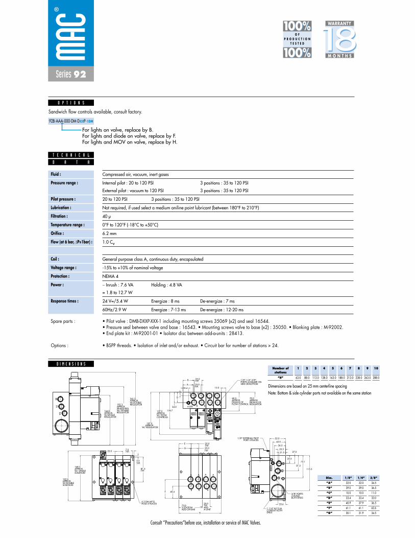
Consult “Precautions”before use, installation or service of MAC Valves.
Series 92
1818100%100%
100%100% M O N T H S
WARRANTY
O FP R O D U C T I O N
T E S T E D
D I M E N S I O N S
Fluid :
Pressure range :
Pilot pressure :
Lubrication :
Filtration :
Temperature range :
Orifice :
Flow (at 6 bar, �P=1bar) :
Leak rate :
Coil :
Voltage range :
Protection :
Power :
Response times :
Compressed air, vacuum, inert gases
Internal pilot : 20 to 120 PSI 3 positions : 35 to 120 PSI
External pilot : vacuum to 120 PSI 3 positions : 35 to 120 PSI
20 to 120 PSI 3 positions : 35 to 120 PSI
Not required, if used select a medium aniline point lubricant (between 180°F to 210°F)
40 μ
0°F to 120°F (-18°C to +50°C)
6.2 mm
1.0 Cv
50 cm3/min
General purpose class A, continuous duty, encapsulated
-15% to +10% of nominal voltage
NEMA 4
� Inrush : 7.6 VA Holding : 4.8 VA
= 1.8 to 12.7 W
24 V=/5.4 W Energize : 8 ms De-energize : 7 ms
60Hz/2.9 W Energize : 7-13 ms De-energize : 12-20 ms
EAIN
EB
CONTROLSW/ FLOW APPROX.137.0
MO
DIF
.
GAGE
REGULATORW/DOUBLEAPPROX.241.0
REGULATORW/ DOUBLESINGLE REG.APPROX.192.3
REGULATORW/SINGLEAPPROX.164.0
MO
DEL
TYP.25.0B
25.0
15.0A
18.4
TYP.81.5
5.5
TYP.7.0
HOLE 4 PLACES6.3 DIA.MT'G
SIDE OR BOTTOMPORTS AVAILABE ON1/8",1/4",3/8",
ENDSCONDUIT BOTH1 1/4" N.P.S.M.
BOTH ENDS3 HOLES 3/8" PORTS
PORT 3 PLACES1/8" EXTERNAL PILOT
34.0
D
C
118.7
115.5
73.1
51.2
27.0
25.5
42.0
36.5
25.6
25.521.5
SOLENOIDW/ SINGLEAPPROX.148.3
B
A
B
A
CO
ND
EA
INEB
EXT.
P
EXT.P
A
B
A
B
A
B
A
B
A
B
A
B
A
B
A
B
A
BB
A
TYP.
25.0
52.0
ADD-ON BAR2-STATION73.0
A-UNITADDTYP.25.0
H
40.4F
G
E
25.0
25.0
TYP.
TYP.
TYP.
SOLENOIDW/DOUBLEAPPROX.162.6
W/ REGULATORAPPROX.157.5
REGULATORFROM C OFAPPROX.70.0
FLOW CONTROLFROM C OF APPROX.60.5
L L
D A T A
T E C H N I C A L
• Pilot valve : DMB-DXXP-XXX-1 including mounting screws 35069 (x2) and seal 16544. • Pressure seal between valve and base : 16543. • Mounting screws valve to base (x2) : 35050. • Blanking plate : M-92002. • End plate kit : M-92001-01 • Isolator disc between add-a-units : 28413.
• BSPP threads. • Isolation of inlet and/or exhaust. • Circuit bar for number of stations > 24.
Spare parts :
Options :
Sandwich flow controls available, consult factory.
92B-AAA-000-DM-DXXP-1DM
O P T I O N S
For lights on valve, replace by B.For lights and diode on valve, replace by F.For lights and MOV on valve, replace by H.
Note: Bottom & side cylinder ports not available on the same station
Number ofstations
“H”
1
63.0
2
88.0
3
113.0
4
138.0
5
163.0
6
188.0
7
213.0
8
238.0
9
263.0
10
288.0
Dimensions are based on 25 mm centerline spacing
Dim.
“A”
“B”
“C”
“D”
“E”
“F”
“G”
1/8”
32.0
39.0
10.0
33.4
40.9
61.1
30.1
1/4”
32.0
39.0
10.0
33.4
37.9
61.1
31.9
3/8”
34.5
36.5
11.0
33.0
36.5
62.6
34.5
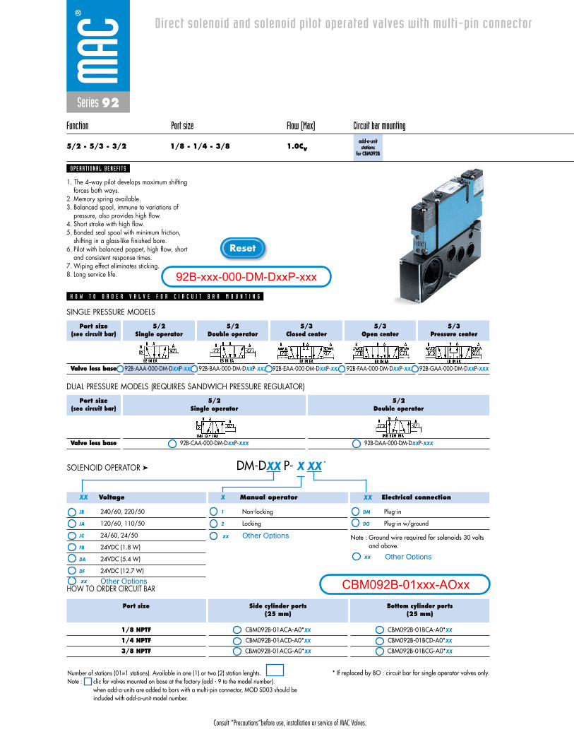
Consult “Precautions”before use, installation or service of MAC Valves.
Reset
Series 92
Function Port size Flow (Max) Circuit bar mounting
5/2 - 5/3 - 3/2 1/8 - 1/4 - 3/8 1.0Cvadd-a-unitstations
for CBM092B
1. The 4--way pilot develops maximum shifting forces both ways.
2. Memory spring available.3. Balanced spool, immune to variations of
pressure, also provides high flow.4. Short stroke with high flow.5. Bonded seal spool with minimum friction,
shifting in a glass-like finished bore.6. Pilot with balanced poppet, high flow, short
and consistent response times.7. Wiping effect eliminates sticking.8. Long service life.
O P E R A T I O N A L B E N E F I T S
Direct solenoid and solenoid pilot operated valves with multi-pin connector
H O W T O O R D E R V A L V E F O R C I R C U I T B A R M O U N T I N G
5/2Single operator
92B-AAA-000-DM-DXXP-XXX
5/2Double operator
92B-BAA-000-DM-DXXP-XXX
5/3Closed center
92B-EAA-000-DM-DXXP-XXX
5/3Open center
92B-FAA-000-DM-DXXP-XXX
5/3Pressure center
92B-GAA-000-DM-DXXP-XXX
Port size(see circuit bar)
Valve less base
Voltage
JB 240/60, 220/50
JA 120/60, 110/50
JC 24/60, 24/50
FB 24VDC (1.8 W)
DA 24VDC (5.4 W)
DF 24VDC (12.7 W)
Manual operator
1 Non-locking
2 Locking
Electrical connection
DM Plug-in
DG Plug-in w/ground
DM-DXX P- X XX *SOLENOID OPERATOR ➤
SINGLE PRESSURE MODELS
5/2Single operator
92B-CAA-000-DM-DXXP-XXX
5/2Double operator
92B-DAA-000-DM-DXXP-XXX
Port size(see circuit bar)
Valve less base
DUAL PRESSURE MODELS (REQUIRES SANDWICH PRESSURE REGULATOR)
HOW TO ORDER CIRCUIT BAR
XX XXX
Port size
1/8 NPTF
1/4 NPTF
3/8 NPTF
Side cylinder ports(25 mm)
CBM092B-01ACA-A0*XX
CBM092B-01ACD-A0*XX
CBM092B-01ACG-A0*XX
Bottom cylinder ports(25 mm)
CBM092B-01BCA-A0*XX
CBM092B-01BCD-A0*XX
CBM092B-01BCG-A0*XX
* If replaced by BO : circuit bar for single operator valves only.
Note : Ground wire required for solenoids 30 voltsand above.
Number of stations (01=1 stations). Available in one (1) or two (2) station lenghts.Note : clic for valves mounted on base at the factory (add - 9 to the model number).
when add-a-units are added to bars with a multi-pin connector, MOD SD03 should beincluded with add-a-unit model number.
92B-xxx-000-DM-DxxP-xxx
CBM092B-01xxx-AOxxOther Optionsxx
xx Other Options
Other Optionsxx
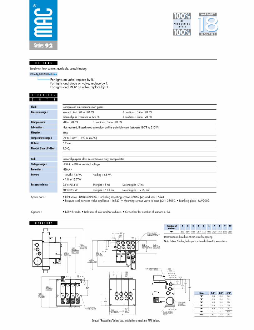
Consult “Precautions”before use, installation or service of MAC Valves.
D I M E N S I O N S
Fluid :
Pressure range :
Pilot pressure :
Lubrication :
Filtration :
Temperature range :
Orifice :
Flow (at 6 bar, �P=1bar) :
Leak rate :
Coil :
Voltage range :
Protection :
Power :
Response times :
Compressed air, vacuum, inert gases
Internal pilot : 20 to 120 PSI 3 positions : 35 to 120 PSI
External pilot : vacuum to 120 PSI 3 positions : 35 to 120 PSI
20 to 120 PSI 3 positions : 35 to 120 PSI
Not required, if used select a medium aniline point lubricant (between 180°F to 210°F)
40 μ
0°F to 120°F (-18°C to +50°C)
6.2 mm
1.0 Cv
50 cm3/min
General purpose class A, continuous duty, encapsulated
-15% to +10% of nominal voltage
NEMA 4
� Inrush : 7.6 VA Holding : 4.8 VA
= 1.8 to 12.7 W
24 V=/5.4 W Energize : 8 ms De-energize : 7 ms
60Hz/2.9 W Energize : 7-13 ms De-energize : 12-20 ms
D A T A
T E C H N I C A L
• Pilot valve : DMB-DXXP-XXX-1 including mounting screws 35069 (x2) and seal 16544. • Pressure seal between valve and base : 16543. • Mounting screws valve to base (x2) : 35050. • Blanking plate : M-92002.
• BSPP threads. • Isolation of inlet and/or exhaust. • Circuit bar for number of stations > 24.
Spare parts :
Options :
Sandwich flow controls available, consult factory.
92B-AAA-000-DM-DXXP-1DM
O P T I O N S
For lights on valve, replace by B.For lights and diode on valve, replace by F.For lights and MOV on valve, replace by H.
Series 92
1818100%100%
100%100% M O N T H S
WARRANTY
O FP R O D U C T I O N
T E S T E D
EAIN
EB
CONTROLSW/ FLOW APPROX.137.0
MO
DIF
.
GAGE
REGULATORW/DOUBLEAPPROX.241.0
REGULATORW/ DOUBLESINGLE REG.APPROX.192.3
REGULATORW/SINGLEAPPROX.164.0
MO
DEL
TYP.25.0B
25.0
15.0A
18.4
TYP.81.5
5.5
TYP.7.0
HOLE 4 PLACES6.3 DIA.MT'G
SIDE OR BOTTOMPORTS AVAILABE ON1/8",1/4",3/8",
ENDSCONDUIT BOTH1 1/4" N.P.S.M.
BOTH ENDS3 HOLES 3/8" PORTS
PORT 3 PLACES1/8" EXTERNAL PILOT
34.0
D
C
118.7
115.5
73.1
51.2
27.0
25.5
42.0
36.5
25.6
25.521.5
SOLENOIDW/ SINGLEAPPROX.148.3
B
A
B
A
CO
ND
EA
INEB
EXT.
P
EXT.P
A
B
A
B
A
B
A
B
A
B
A
B
A
B
A
B
A
BB
A
TYP.
25.0
52.0
ADD-ON BAR2-STATION73.0
A-UNITADDTYP.25.0
H
40.4F
G
E
25.0
25.0
TYP.
TYP.
TYP.
SOLENOIDW/DOUBLEAPPROX.162.6
W/ REGULATORAPPROX.157.5
REGULATORFROM C OFAPPROX.70.0
FLOW CONTROLFROM C OF APPROX.60.5
L L
Note: Bottom & side cylinder ports not available on the same station
Number ofstations
“H”
1
63.0
2
88.0
3
113.0
4
138.0
5
163.0
6
188.0
7
213.0
8
238.0
9
263.0
10
288.0
Dimensions are based on 25 mm centerline spacing
Dim.
“A”
“B”
“C”
“D”
“E”
“F”
“G”
1/8”
32.0
39.0
10.0
33.4
40.9
61.1
30.1
1/4”
32.0
39.0
10.0
33.4
37.9
61.1
31.9
3/8”
34.5
36.5
11.0
33.0
36.5
62.6
34.5

Consult “Precautions” before use, installation or service of MAC Valves.
S e c t i o n 2 Opt ions
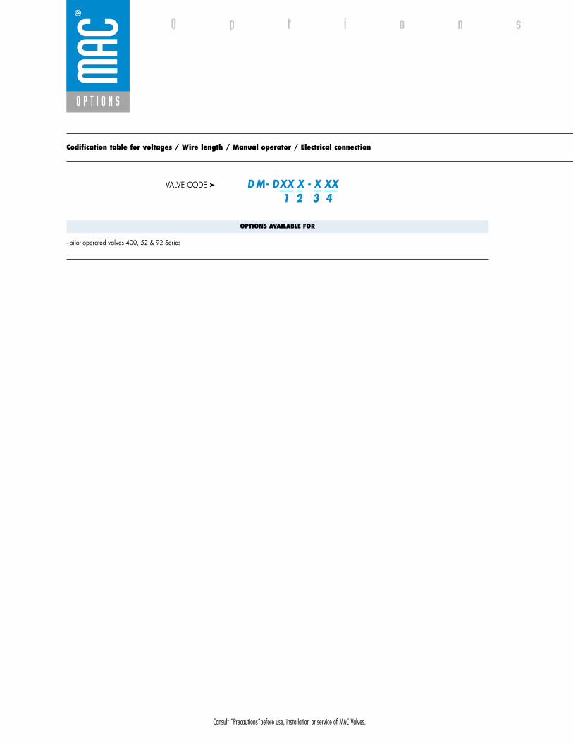
Consult “Precautions”before use, installation or service of MAC Valves.
O P T I O N S
O p t i o n s
Codification table for voltages / Wire length / Manual operator / Electrical connection
- pilot operated valves 400, 52 & 92 Series
D M - D XX X - X XX1 2 3 4
VALVE CODE ➤
OPTIONS AVAILABLE FOR

Consult “Precautions”before use, installation or service of MAC Valves.
O P T I O N S
1. VOLTAGE
- D XX X - X XX VOLTAGE
DB 12 VDC (5.4 W)
DC 12 VDC (7.5 W)
DD 24 VDC (7.3 W)
DE 12 VDC (12.7 W)
DK 110 VDC (5.8 W)
DJ 28 VDC (5.7 W)
DL 64 VDC (6.0 W)
DM 36 VDC (5.8 W)
DN 6 VDC (6.0 W)
DR 90 VDC (6,6 W)
DS 110 VDC (7.3 W), 100 VDC (6.0 W)
DT 75 VDC (5.6 W)
DP 48 VDC (5.8 W)
FA 12 VDC (1.8 W)
FE 12 VDC (2.4 W)
FF 24 VDC (2.4 W)
JD 100/60, 100/50, 110/60
2. WIRE LENGTH
- D XX X - X XX WIRE LENGTH
B 24”
C 36”
D 48”
E 72”
F 96”
Back

Consult “Precautions”before use, installation or service of MAC Valves.
O P T I O N S
O p t i o n s
3. MANUAL OPERATOR
- D XX X - X XX MANUAL OPERATOR
0 No operator
1 Non-locking recessed
2 Locking recessed
3 Non-locking extended
4 Locking extended
4. ELECTRICAL CONNECTION
- D XX X - X XX ELECTRICAL CONNECTION
BA Flying leads
BK BA with protection diode
BL BA with protection varistor
CA 1/2" NPS conduit
JB Rectangular connector
JD Rectangular connector with light
JM Rectangular connector, male only
KA Square connector
KB Square connector with protection diode
KC Square connector with protection varistor
KD Square connector with light
KE Square connector with light and protection diode
KF Square connector with light and protection varistor
KJ Square connector (male only)
KK Square connector with protection diode (male only)
KL Square connector with protection varistor (male only)
TA Dual tabs
TB TA with protection diode
TD TA with light
TE TA with light and protection diode
TJ Dual tabs (male only)
TK TJ with protection diode
TM TJ with light
TN TJ with light and protection diode
*DN Plug-in with diode
*DP Plug-in with M.O.V.
*DH Plug-in with diode & ground
*DJ Plug-in with M.O.V & ground
* These options only apply to the 92 series. All others are for the 400 and 52 series.
Back

• Type «SUB_D»• Number of contacts : 9• Solder termination (Dia. 0.6 mm/0.14 mm
2/26-22 AWG)
• Operating current 5 A/contact• Rated voltage 125 V~• Temp. range –40° to +125°C• Insulation resistance � 5.09 �• Protection class IP40 (DIN 40050)• Number of solenoids : 7 max.• Max. 24 V=/5.4 W per solenoid• 2 common wires
MOD. SD09
MOD. SD15
MOD. SD25
PIN #1
PIN #5
PIN #6
PIN #9
PIN #1
PIN #8
PIN #9
PIN #15
PIN #1
PIN #13
PIN #14
PIN #25
• Type «SUB_D»• Number of contacts : 25• Solder termination (Dia. 0.6 mm/0.14 mm
2/26-22 AWG)
• Operating current 5 A/contact• Rated voltage 125 V~• Temp. range –40° to +125°C• Insulation resistance � 5.09 �• Protection class IP40 (DIN 40050)• Number of solenoids : 20 max.• Max. 24 V=/5.4 W per solenoid• 5 common wires
Note : Use desired MOD. number after circuit bar part number
• Type «SUB_D»• Number of contacts : 15• Solder termination (Dia. 0.6 mm/0.14 mm
2/26-22 AWG)
• Operating current 5 A/contact• Rated voltage 125 V~• Temp. range –40° to +125°C• Insulation resistance � 5.09 �• Protection class IP40 (DIN 40050)• Number of solenoids : 12 max.• Max. 24 V=/5.4 W per solenoid• 3 common wires
T E C H N I C A L D A T A
T E C H N I C A L D A T A
T E C H N I C A L D A T A
O P T I O N S
O p t i o n s

SD09 SD15 SD25
Connector termination details
SOL 2 SOL 4 SOL 6 SOL 8 SOL 16 SOL 18 SOL 20 SOL 22 SOL 24
SOL 1CONN
ECTO
RCO
NNEC
TOR
SOL 2 SOL 3 SOL .. SOL 20 SOL 21 SOL 22 SOL 23 SOL 24
SOL 1 SOL 3 SOL 5 SOL 13 SOL 15 SOL 17
Double solenoid circuit bar
Single solenoid circuit bar
SOL 21 SOL 23SOL 19
SOL. 3
SOL. 1
SOL. 2
1
2
3
4
COMMON (+)
COMMON (+)
8
SOL. 4
5
6
7
9
SOL. 5
SOL. 7
SOL. 6
SOL. 3
SOL. 1
SOL. 2
1
2
3
4
COMMON (+)
COMMON (+)
COMMON (+)
13
SOL. 4
5
6
7
8
14
SOL. 5
SOL. 7
SOL. 6
SOL. 8
9
10
11
12
15
SOL. 9
SOL. 11
SOL. 10
SOL. 12
SOL. 3
SOL. 1
SOL. 2
1
2
3
4
COMMON (+)
COMMON (+)
COMMON (+)
COMMON (+)
COMMON (+)
21
SOL. 4
5
6
7
8
22
SOL. 5
SOL. 7
SOL. 6
SOL. 8
9
10
11
12
23
SOL. 9
SOL. 11
SOL. 10
SOL. 12
13
14
15
16
24
SOL. 13
SOL. 15
SOL. 14
SOL. 16
17
18
19
20
25
SOL. 17
SOL. 19
SOL. 18
SOL. 20
O P T I O N S
O p t i o n s
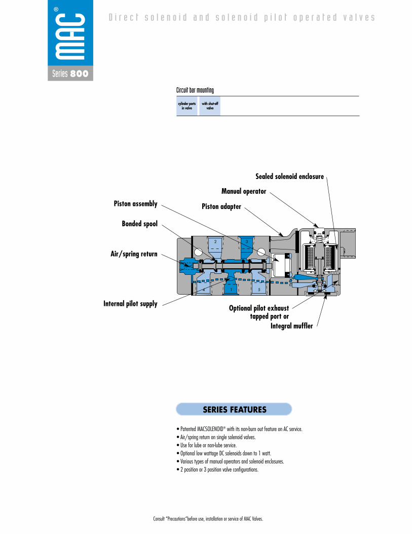
Consult “Precautions”before use, installation or service of MAC Valves.
Series 800
D i r e c t s o l e n o i d a n d s o l e n o i d p i l o t o p e r a t e d v a l v e s
2
4 1 5
3
cylinder ports in valve
with shut-offvalve
Circuit bar mounting
SERIES FEATURES
• Patented MACSOLENOID® with its non-burn out feature on AC service.• Air/spring return on single solenoid valves.• Use for lube or non-lube service.• Optional low wattage DC solenoids down to 1 watt.• Various types of manual operators and solenoid enclosures.• 2 position or 3 position valve configurations.
Air/spring return
Internal pilot supply
Bonded spool
Manual operator
Sealed solenoid enclosure
Piston adapter
Optional pilot exhaust tapped port or
Integral muffler
Piston assembly

Consult “Precautions”before use, installation or service of MAC Valves.
Reset
Series 800
Function Port size Flow (Max) Circuit bar mounting
5/2 - 5/3 1/4” 1.3Cvcylinder ports
in valve
1. Balanced spool, immune to variations of pressure.2. Short stroke with high flow.3. The piston (booster) provides maximum shifting
forces.4. Powerful return force thanks to the combination of
mechanical and air springs.5. Bonded spool with minimum friction, shifting in a
glass-like finished bore.6. Wiping effect eliminates sticking.7. Pilot valve with balanced poppet, high flow, short
and consistent response times.8. Long service life.
O P E R A T I O N A L B E N E F I T S
D i r e c t s o l e n o i d a n d s o l e n o i d p i l o t o p e r a t e d v a l v e s
H O W T O O R D E R
5/2Single operator
811C-PM-XXYZZ-172
5/2Double operator
821C-PM-XXYZZ-172
5/3Closed center
825C-PM-XXYZZ-572
5/3Open center
825C-PM-XXYZZ-672
5/3Pressure center
825C-PM-XXYZZ-872
Port size
1/4” NPTF
2B 3 A
4 51
3A 2 B
51
4
3A 2 B
51
4
2B 3 A
4 51
2B 3 A
4 51
Voltage
11 120/60, 110/50
12 240/60, 220/50
22 24/50, 24/60
59 24VDC (2.5 W)
87 24VDC (17.1 W)
61 24VDC (8.5 W)
Manual operator
1 Non-locking
2 Locking
Electrical connection
JB Rectangular connector
JD Rectangular connector
with light
BA Flying leads (18”)
XX Y ZZ *SOLENOID OPERATOR ➤
HOW TO ORDER VALVE FOR CIRCUIT BAR MOUNTING
Port size(Spacing 31 mm)
3/8” NPTF
Standard circuit bar
EBM800A-001A-XX
Circuit bar with flow controls (2 per station)
EBM800A-002A-XX
HOW TO ORDER CIRCUIT BAR**
Number of stations (03=3 stations)Other options available. Consult factory.Note : clic for valves mounted on base at the factory (add - 9 to the model number).
xxxx-PM-xxxxx-xxx
EBM800A-xxxx-xx
Other Optionsxx
xx Other OptionsOther Optionsxx
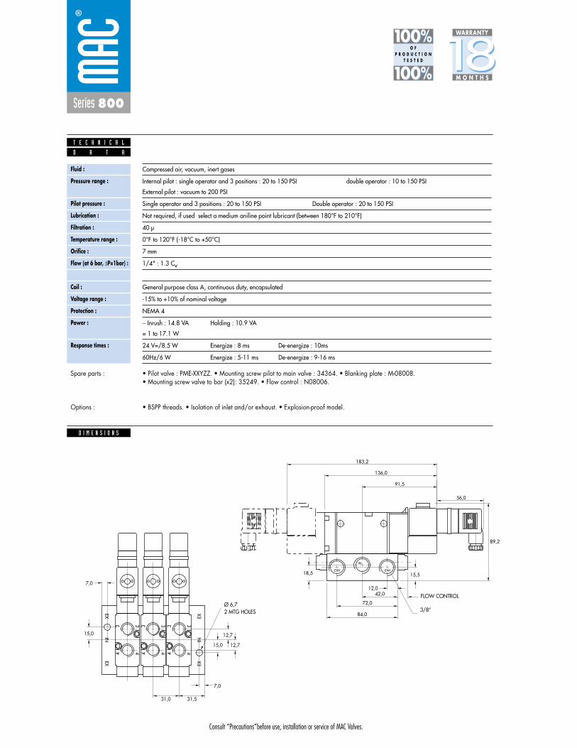
Consult “Precautions”before use, installation or service of MAC Valves.
Series 800
D I M E N S I O N S
Fluid :
Pressure range :
Pilot pressure :
Lubrication :
Filtration :
Temperature range :
Orifice :
Flow (at 6 bar, �P=1bar) :
Leak rate :
Coil :
Voltage range :
Protection :
Power :
Response times :
Compressed air, vacuum, inert gases
Internal pilot : single operator and 3 positions : 20 to 150 PSI double operator : 10 to 150 PSI
External pilot : vacuum to 200 PSI
Single operator and 3 positions : 20 to 150 PSI Double operator : 20 to 150 PSI
Not required, if used select a medium aniline point lubricant (between 180°F to 210°F)
40 μ
0°F to 120°F (-18°C to +50°C)
7 mm
1/4" : 1.3 Cv
50 cm3/min
General purpose class A, continuous duty, encapsulated
-15% to +10% of nominal voltage
NEMA 4
� Inrush : 14.8 VA Holding : 10.9 VA
= 1 to 17.1 W
24 V=/8.5 W Energize : 8 ms De-energize : 10ms
60Hz/6 W Energize : 5-11 ms De-energize : 9-16 ms
3 3
4 4
3 3
4 4
3 3
4 4
EXEX
IN
EXIN
EX
IN
EXHEXH
56,0
7,0
7,0
31,531,0
15,0 12,7
18,5
84,0
72,0
42,012,0
15,5
89,2
91,5
136,0
183,2
12,715,0
D A T A
T E C H N I C A L
1818100%100%
100%100% M O N T H S
WARRANTY
O FP R O D U C T I O N
T E S T E D
• Pilot valve : PME-XXYZZ. • Mounting screw pilot to main valve : 34364. • Blanking plate : M-08008. • Mounting screw valve to bar (x2): 35249. • Flow control : N08006.
• BSPP threads. • Isolation of inlet and/or exhaust. • Explosion-proof model.
Spare parts :
Options :
3/8ӯ 6,72 MTG HOLES
FLOW CONTROL
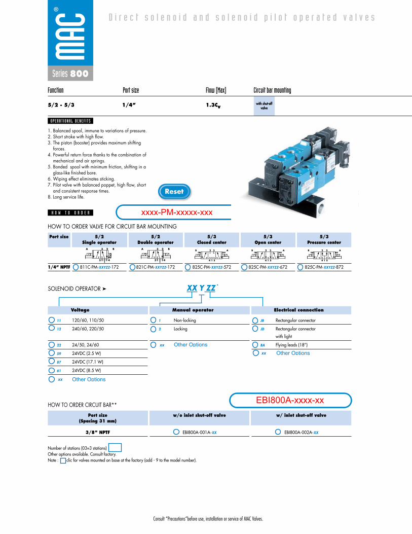
Consult “Precautions”before use, installation or service of MAC Valves.
Reset
Series 800
Function Port size Flow (Max) Circuit bar mounting
5/2 - 5/3 1/4” 1.3Cvwith shut-off
valve
1. Balanced spool, immune to variations of pressure.2. Short stroke with high flow.3. The piston (booster) provides maximum shifting
forces.4. Powerful return force thanks to the combination of
mechanical and air springs.5. Bonded spool with minimum friction, shifting in a
glass-like finished bore.6. Wiping effect eliminates sticking.7. Pilot valve with balanced poppet, high flow, short
and consistent response times.8. Long service life.
O P E R A T I O N A L B E N E F I T S
D i r e c t s o l e n o i d a n d s o l e n o i d p i l o t o p e r a t e d v a l v e s
H O W T O O R D E R
5/2Single operator
811C-PM-XXYZZ-172
5/2Double operator
821C-PM-XXYZZ-172
5/3Closed center
825C-PM-XXYZZ-572
5/3Open center
825C-PM-XXYZZ-672
5/3Pressure center
825C-PM-XXYZZ-872
Port size
1/4” NPTF
2B 3 A
4 51
3A 2 B
51
4
3A 2 B
51
4
2B 3 A
4 51
2B 3 A
4 51
Voltage
11 120/60, 110/50
12 240/60, 220/50
22 24/50, 24/60
59 24VDC (2.5 W)
87 24VDC (17.1 W)
61 24VDC (8.5 W)
Manual operator
1 Non-locking
2 Locking
Electrical connection
JB Rectangular connector
JD Rectangular connector
with light
BA Flying leads (18”)
XX Y ZZ *SOLENOID OPERATOR ➤
HOW TO ORDER VALVE FOR CIRCUIT BAR MOUNTING
Port size(Spacing 31 mm)
3/8" NPTF
w/o inlet shut-off valve
EBI800A-001A-XX
w/ inlet shut-off valve
EBI800A-002A-XX
HOW TO ORDER CIRCUIT BAR**
Number of stations (03=3 stations)Other options available. Consult factory.Note : clic for valves mounted on base at the factory (add - 9 to the model number).
xxxx-PM-xxxxx-xxx
EBI800A-xxxx-xx
Other Optionsxx
xx Other OptionsOther Optionsxx
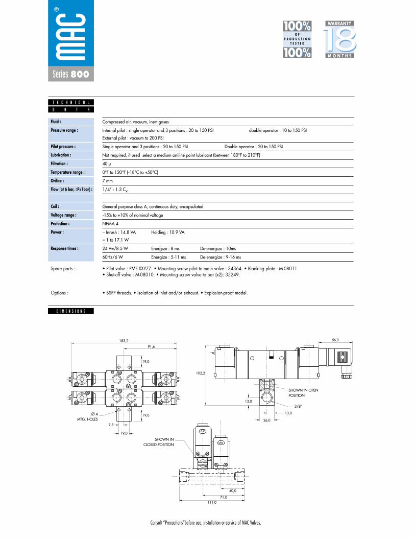
Consult “Precautions”before use, installation or service of MAC Valves.
Series 800
Fluid :
Pressure range :
Pilot pressure :
Lubrication :
Filtration :
Temperature range :
Orifice :
Flow (at 6 bar, �P=1bar) :
Leak rate :
Coil :
Voltage range :
Protection :
Power :
Response times :
Compressed air, vacuum, inert gases
Internal pilot : single operator and 3 positions : 20 to 150 PSI double operator : 10 to 150 PSI
External pilot : vacuum to 200 PSI
Single operator and 3 positions : 20 to 150 PSI Double operator : 20 to 150 PSI
Not required, if used select a medium aniline point lubricant (between 180°F to 210°F)
40 μ
0°F to 120°F (-18°C to +50°C)
7 mm
1/4" : 1.3 Cv
50 cm3/min
General purpose class A, continuous duty, encapsulated
-15% to +10% of nominal voltage
NEMA 4
� Inrush : 14.8 VA Holding : 10.9 VA
= 1 to 17.1 W
24 V=/8.5 W Energize : 8 ms De-energize : 10ms
60Hz/6 W Energize : 5-11 ms De-energize : 9-16 ms
D A T A
T E C H N I C A L
1818100%100%
100%100% M O N T H S
WARRANTY
O FP R O D U C T I O N
T E S T E D
• Pilot valve : PME-XXYZZ. • Mounting screw pilot to main valve : 34364. • Blanking plate : M-08011. • Shut-off valve : M-08010. • Mounting screw valve to bar (x2): 35249.
• BSPP threads. • Isolation of inlet and/or exhaust. • Explosion-proof model.
Spare parts :
Options :
D I M E N S I O N S
56,0
3 2
23
LOCK
L O C K
3 2
23
L O C K
LOCK
L O C K
LOCK
L O C K
LOCK
EXH
183,2
91,6
19,0
19,0
102,2
13,0
13,0
26,09,5
19,0
40,0
71,0111,0
SHOWN IN OPENPOSITION
3/8”
SHOWN INCLOSED POSITION
Ø 4 MTG. HOLES

Consult “Precautions” before use, installation or service of MAC Valves.
S e c t i o n 2 Opt ions

Consult “Precautions”before use, installation or service of MAC Valves.
O P T I O N S
Codification table for voltages / Manual operator / Electrical connection / Wire length
- valves type 800 Series
O p t i o n s
- XX Y ZZ (-VV)1 2 3 4
VALVE CODE ➤
OPTIONS AVAILABLE FOR

Consult “Precautions”before use, installation or service of MAC Valves.
O P T I O N S
1. VOLTAGE
- XX Y ZZ VOLTAGE
11 120/60 - 110/50
12 240/60 - 220/50
13 100/60 - 100/50
15 200/60 - 200 V~/50 Hz
16 10/60
20 6/60
21 12/50 - 12/60
22 24/60 - 24/50
23 32/60 - 32/50
24 48/60 - 42/50
26 380/50, 440/50 -440/60,
480/60-CLSF
29 200/60
34 127/50 - 120/50
35 48/50
36 16/60
B1 24/50
50 24 VDC (6W)
51 24 VDC (4W)
54 12 VDC (4W)
55 12 VDC (6W)
57 12 VDC (2.5W)
59 24 VDC (2.5W)
60 12 VDC (8.5W)
61 24 VDC (8.5W)
64 6 VDC (6W)
65 32 VDC (7W)
66 48 VDC (5.8W)
67 64 VDC (7.5W)
68 120 VDC (6.4W)
75 90 VDC (8.8W)
76 100 VDC (6.9W)
* 84 125 VDC (10.9W)
* 87 24 VDC (17.1W)
* 88 12 VDC (17.4W)
* 89 36 VDC (18.8W)
90 28 VDC (8.2W)
* 91 6 VDC (10.6W)
92 190 VDC (6.5W)
94 3 VDC (7W)
95 38 VDC (6.4W)
A1 24 VDC (1.0W)
A2 12 VDC (1.0W)
A3 9 VDC (1.0W)
MOD. DD01 : Protection diode (DC)
MOD. MOV1 : Protection varistor (AC)
MOD. DD01 : max. 8,5 W
MOD. MOV1 : max. 8,5 W
* Voltages are CLSF only
Back

Consult “Precautions”before use, installation or service of MAC Valves.
O P T I O N S
O p t i o n s
2. MANUAL OPERATOR
- XX Y ZZ MANUAL OPERATOR
0 No operator
1 Non-locking recessed
2 Locking recessed
3 Non-locking extended
4 Locking extended
3. ELECTRICAL CONNECTION
- XX Y ZZ ELECTRICAL CONNECTION
AA Wiring box with 1/2" NPS conduit
BA Flying leads
CA 1/2" NPS conduit
CC 1/2" NPT conduit
FA Military type 2 PIN
GA Military type 3 PIN
HA AA with ground wire
JA Square connector
JB Rectangular connector
JC Square connector with light
JD Rectangular connector with light
JJ Square connector, male only
JM Rectangular connector, male only
NA CA with ground wire
NC CC with ground wire
RA 3/8" NPS conduit
CD 20 mm conduit
4. WIRE LENGTH
- XX Y ZZ (-VV) WIRE LENGTH
AA 18”
AB 24”
AD 36”
AE 48”
AF 72”
AG 6”
AR 12”
AU 120”
BA 60”
BB 144”
Back

• Type «SUB_D»• Number of contacts : 9• Solder termination (Dia. 0.6 mm/0.14 mm
2/26-22 AWG)
• Operating current 5 A/contact• Rated voltage 125 V~• Temp. range –40° to +125°C• Insulation resistance � 5.09 �• Protection class IP40 (DIN 40050)• Number of solenoids : 7 max.• Max. 24 V=/5.4 W per solenoid• 2 common wires
MOD. SD09
MOD. SD15
MOD. SD25
PIN #1
PIN #5
PIN #6
PIN #9
PIN #1
PIN #8
PIN #9
PIN #15
PIN #1
PIN #13
PIN #14
PIN #25
• Type «SUB_D»• Number of contacts : 25• Solder termination (Dia. 0.6 mm/0.14 mm
2/26-22 AWG)
• Operating current 5 A/contact• Rated voltage 125 V~• Temp. range –40° to +125°C• Insulation resistance � 5.09 �• Protection class IP40 (DIN 40050)• Number of solenoids : 20 max.• Max. 24 V=/5.4 W per solenoid• 5 common wires
Note : Use desired MOD. number after circuit bar part number
• Type «SUB_D»• Number of contacts : 15• Solder termination (Dia. 0.6 mm/0.14 mm
2/26-22 AWG)
• Operating current 5 A/contact• Rated voltage 125 V~• Temp. range –40° to +125°C• Insulation resistance � 5.09 �• Protection class IP40 (DIN 40050)• Number of solenoids : 12 max.• Max. 24 V=/5.4 W per solenoid• 3 common wires
T E C H N I C A L D A T A
T E C H N I C A L D A T A
T E C H N I C A L D A T A
O P T I O N S
O p t i o n s

SD09 SD15 SD25
Connector termination details
SOL 2 SOL 4 SOL 6 SOL 8 SOL 16 SOL 18 SOL 20 SOL 22 SOL 24
SOL 1CONN
ECTO
RCO
NNEC
TOR
SOL 2 SOL 3 SOL .. SOL 20 SOL 21 SOL 22 SOL 23 SOL 24
SOL 1 SOL 3 SOL 5 SOL 13 SOL 15 SOL 17
Double solenoid circuit bar
Single solenoid circuit bar
SOL 21 SOL 23SOL 19
SOL. 3
SOL. 1
SOL. 2
1
2
3
4
COMMON (+)
COMMON (+)
8
SOL. 4
5
6
7
9
SOL. 5
SOL. 7
SOL. 6
SOL. 3
SOL. 1
SOL. 2
1
2
3
4
COMMON (+)
COMMON (+)
COMMON (+)
13
SOL. 4
5
6
7
8
14
SOL. 5
SOL. 7
SOL. 6
SOL. 8
9
10
11
12
15
SOL. 9
SOL. 11
SOL. 10
SOL. 12
SOL. 3
SOL. 1
SOL. 2
1
2
3
4
COMMON (+)
COMMON (+)
COMMON (+)
COMMON (+)
COMMON (+)
21
SOL. 4
5
6
7
8
22
SOL. 5
SOL. 7
SOL. 6
SOL. 8
9
10
11
12
23
SOL. 9
SOL. 11
SOL. 10
SOL. 12
13
14
15
16
24
SOL. 13
SOL. 15
SOL. 14
SOL. 16
17
18
19
20
25
SOL. 17
SOL. 19
SOL. 18
SOL. 20
O P T I O N S
O p t i o n s
PRECAUTIONS AND WARNINGSCONCERNING THE APPLICATION, INSTALLATION AND SERVICE OF MAC VALVES AND OTHER MAC VALVES PRODUCTS
The warnings and precautions below are important to be read and understood beforedesigning into a system any MAC Valves products, and before installing or servicing any MAC Valves product. Improper use, installation or servicing of any MAC Valves product in some systems could create a hazard to personnel or equipment. No distinction in importance should be made between the terms warnings and precautions.
WARNING : .Under no circumstances are MAC Valves products to be used in any application or in any manner where failure of the MAC Valves product to operate as intended could in any way jeopardize the safety of the operator or any other person or property. • Do not operate outside of pressure range listed on a valve label or outside of the designated
temperature range.• Air supply must be clean and dry. Moisture or contamination can affect proper operation of the
valve.• Before attempting to repair, adjust or clean a MAC Valves product, consult catalog, parts & operation
sheet, or factory for proper maintenance procedures, lubrication and cleaning agents. Never attempt to repair or perform other maintenance with air pressure to the valve.
• If air line lubrication is used do not use any lubrication other than those recommended in the catalog, parts & operation sheet or by the factory.
APPLICATION PRECAUTIONS : .INDUSTRIAL USE -• MAC Valve products are intended for general use in industrial pneumatic and/or vacuum systems.
They are general purpose industrial products with literally thousands of different applications in industrial systems. These products are not inherently dangerous, but they are only a component of an overall system. The system in which they are used must provide adequate safeguards to prevent injury or damage in the event failure occurs, whether it be failure of switches, regulators, cylinders, valves or any other component.
POWER PRESSES -MAC Valve products are not designed nor intended to be used to operate and/or control the operation of clutch and/or brake systems on power presses. There are special products on the market for such use.
2-POSITION VALVES -Some MAC valves are 2-position, 4-way valves. When air is supplied to the inlet port(s) of these valves, there will always be a flow path from the inlet to one of the outlets regardless of which of the two positions the valve is situated. Therefore, if pressurized air retained in the system would present a hazard in the application or servicing of the valve or system, a separate method in the system must be provided to remove the trapped air.
3- POSITION VALVES-Some MAC valves are 3-position, 4-way valves. These valves are either double solenoid or double remote air operated.If either of the two operators is in control, air supplied to the inlet port(s) will pass through the valve to one of the outlets as on 2-position, 4-way valves. However, if neither operator is in control, the valve moves to a center position. Listed below are the various center position functions :
A. CLOSED CENTER- With this type valve, when in the center position all ports are blocked (inlets and exhausts) meaning the air at both outlet ports is trapped. If trapping the air in both outlet ports would present a hazard in the application or servicing, a separate method in the system must be provided to remove the trapped air or this type valve should not be used.
B. OPEN CENTER- With this type valve, when in the center position, the inlet port(s) is blocked and the two outlet ports are open to the exhaust port(s) of the valve. If having no air in either outlet port would present a hazard in the application or servicing, this type valve should not be used.
C. PRESSURE CENTER- With this type valve, when in the center position, the inlet port(s) is connected to both outlet ports of the valve. If having pressurized air to either or both outlet ports would present a hazard in the application or servicing of the valve or system, a separate method in the system must be provided to remove the retained air or this type valve should not be used.
OPERATING SPECIFICATIONS -MAC Valves products are to be installed only on applications that meet all operating specifications described in the MAC catalog for the MAC Valves product.
MANUAL OPERATORS-Most MAC valves can be ordered with manual operators. Manual operators when depressed, are designed to shift the valve to the same position as would the corresponding solenoid or remote air pilot operator if it were activated. Care must be taken to order a type, if any, that will be safe for the physical location of the manual operator in the system. If intentional or accidental operation of a valve by a manual operator could cause personal injury or property damage, a manual operator should not be used.
REMOTE AIR OPERATED VALVESPilot valves supplying signal pressure to remote air operated valves should be 3-way valves with adequate supply and exhaust capacity to provide positive pressurizing and exhausting of the pilot supply line. Pilot lines should be open to exhaust when valves are deenergized.
INSTALLATION PRECAUTIONS : .A. Do not install any MAC Valves product without first turning off air (bleed system completely) and
electricity to the machine.B. MAC Valves products should only be installed by qualified, knowledgeable personnel who
understand how the specific valve is to be pneumatically piped and electrically connected (where applicable). Flow paths through the valve are shown in the catalog and on the valve by use of ANSI or ISO type standard graphic symbols. Do not install unless these symbols and the valve functions and operations are thoroughly understood.
C. If air line lubrication is used do not use any lubrication other than those recommended in the catalog, parts & operation sheet or by the factory.
SERVICE PRECAUTIONS :A. Do not service or remove from service any MAC Valves product without first shutting off both the
air and electricity to the valve and making certain no pressurized air which could present a hazard is retained in the system.
B. MAC Valves products should only be serviced or removed from service by qualified, knowledgeable personnel who understand how the specific product is used and/or how the specific valve is piped and used and whether there is air retained in the connecting lines to the valve or electric power still connected to the valve.
C. Before attempting to repair, adjust or clean a MAC Valves product, consult catalog, parts & operation sheet, or factory for proper maintenance procedures, lubrication and cleaning agents. Never attempt to repair or perform other maintenance with air pressure to the valve.
D. MAC Valves products are never to be stepped on while working on a machine. Damage to a MAC valve, or other product or lines to the product (either air or electrical lines) or accidental activation of a manual operator on the valve could result in personal injury or property damage.
LIMITATION OF GUARANTEE .This Guarantee is limited to the replacement or rebuilding of any valve or other product which should fail to operate properly. Valves or other products, under the MAC Guarantee, must be returned (with or without bases) transportation prepaid and received at our factory within the Guarantee period. They will be returned to the customer at the expense of MAC Valves, Inc., and will carry the same guarantee as provided under the Flat Rate Rebuild Program.
DISCLAIMER OF GUARANTEE .No claims for labor, material, time, damage, or transportation are allowable nor will any valve or other product be replaced or rebuilt under this guarantee which has been damaged by the purchaser not in the normal course of its use and maintenance during the warranty period. The guarantee does not apply to loss or damage caused by fire, theft, riot, explosion, labor dispute, act of God, or other causes beyond the control of MAC Valves,Inc. MAC Valves, Inc. shall in no event be liable for remote, special or consequential damages under the MAC Guarantee, nor under any implied warranties, including the implied warranty of merchantability.
The above Guarantee is our manner of extending the engineering and service resources of the MAC Valves, Inc. organization to assure our customer long, and continued satisfaction.
364
MAC VALVES Warranty, Warranty Limitations, Flat Rate Rebuild Program
M A C V a l v e s P r o d u c t W a r r a n t y I n f o r m a t i o n
The MAC Valves organization has established a reputation over many years for fulfilling the needs and requirements of the users of its products. All MAC Valves are quality products specifically designed and built for long and rugged service. For this reason, MAC Valves is able to provide the Buyer a limited warranty.
WARRANTY: MAC Valves, Inc. hereby warrants to Buyer that, for a period of 18 months from the original date of shipment of each valve from our factory (“Warranty Period”), such valve will be free from significant defects in material and workmanship and will conform to all specifications agreed to by MAC Valves, Inc.. In addition, MAC Valves, Inc. warrants that the electrical coils on such valves will be free from significant defects in material and workmanship for their normal useful life. EXCEPT FOR THESE LIMITED WARRANTIES, MAC VALVES, INC. EXPRESSLY DISCLAIMS ALL REPRESENTATIONS AND WARRANTIES OF ANY KIND (WHETHER EXPRESS, IMPLIED OR ARISING BY OPERATION OF LAW) WITH RESPECT TO THE VALVES, INCLUDING, WITHOUT LIMITATION, ANY WARRANTIES OR REPRESENTATIONS AS TO MERCHANTABILITY, FITNESS FOR A PARTICULAR PURPOSE OR ANY OTHER MATTER. THIS SECTION SURVIVES THE EXPIRATION, TERMINATION OR CANCELLATION OF ANY AGREEMENTS BETWEEN THE PARTIES RELATING TO THE PURCHASE OF THE VALVES.
WARRANTY LIMITATIONS: This Warranty does not apply where the valves have been (i) subjected to abuse, misuse, damage, neglect, negligence, accident, improper testing, improper installation, improper storage, improper handling, abnormal physical stress, abnormal environmental condition, or use contrary to any instructions issued by MAC Valves, Inc.; (ii) modified, reconstructed, repaired, or altered by persons other than MAC Valves, Inc. or its authorized representative; or (iii) used with any third-party product, hardware, software or other product that has not been previously approved in writing by MAC Valves, Inc. Additionally, this Warranty does not cover claims for labor, material, time or transportation, and does not apply to loss or damage caused by fire, theft, riot, explosion, labor dispute, act of God, or other causes beyond the control of MAC Valves, Inc.
EXCLUSIVE REMEDY: The Buyer’s sole remedy under this Warranty is limited to the replacement or rebuilding of any valve which does not conform to the warranties provided herein or, in MAC Valves, Inc.’s sole discretion, refund of the purchase price for the non-conform-ing valve. Buyer’s remedy is conditioned on Buyer’s compliance with its obligations under this Warranty. Valves that Buyer believes do not conform to this Warranty must be returned (with or without bases) transportation prepaid and received at our factory within the Warranty Period. If MAC Valves, Inc. determines that the valve is non-conforming and is otherwise covered by this Warranty, the rebuilt or replaced valve will be returned to the customer at the expense of MAC Valves, Inc., and will carry the same warranties as provided under the Flat Rate Rebuild Program described below. MAC VALVES, INC. WILL NOT BE RESPONSIBLE FOR ANY INCIDENTAL, SPECIAL, EXEMPLARY OR CONSEQUENTIAL DAMAGES, INCLUDING WITHOUT LIMITATION DIRECT AND INDIRECT LOST PROFITS, REGARDLESS OF WHETHER THOSE DAMAGES WERE FORESEEABLE. THE FLAT REBUILD PROGRAM: Valves no longer covered by the MAC Warranty may be eligible for a one-time rebuild under the MAC Valves, Inc. Flat Rate Rebuild Program. Our constant research and testing program is dedicated to extending the life of our valves and maximizing their reliability under the most adverse conditions. Valves returned under this limited program are completely disassembled, inspected, rebuilt to current operating standards whenever possible, tested and returned within a few weeks for a nominal flat rate charge. All rebuilt valves carry the same warranty described (in our MAC Warranty) for new valves for a warranty period of 90 days from the date of shipment from our factory. Valves that have gone through the one-time rebuild will have been marked with a letter “R” as part of the date stamp (This is an example of a rebuild date stamp from this month E(May)17(Year)Tester Symbol R(Indicates Rebuild). Please note that any valves sent back for subsequent rebuild that have already been through the program previously (indicated by the “R”) will not be eligible for additional rebuild.
Related Documents