CIM PACA Characterisation Lab Your partner of choice for the chemical characterisation of your materials Partners:

Welcome message from author
This document is posted to help you gain knowledge. Please leave a comment to let me know what you think about it! Share it to your friends and learn new things together.
Transcript
CIM PACA Characterisation Lab
Your partner of choice
for the
chemical characterisation of your materials
Partners:

Who are we?
• The CIM PACA Characterisation Lab was registered in 2005 as a not-for-profit association under French Law.
• The lab is in the ROUSSET industrial park in the South of France.
• Members of the association include:
– major industrial companies (world-leading semiconductor manufacturers)
– small businesses (specialising in surface analysis, ion implantation, photovoltaic systems and testing & failure analysis for integrated circuits)
– Université Paul Cézanne, in its own capacity and as a representative of public research bodies in the Provence-Alpes-Côte d'Azur region
• The activities of the lab are managed by an Operations Committee comprising the founding members of the association.

Why work with us?
• The CIM PACA Characterisation Lab is unique in Europe in offering a range of
complementary expertise:
– in physico-chemical materials analysis and in failure analysis
– for issues relevant to a wide range of business fields (semiconductors, photovoltaic technologies, aerospace industry, etc.)
• The lab provides analytic support to help characterise and model processes and solve problems relating to faults and failures.
• State-of-the-art equipment is used and operated by experts.
• Our holistic approach looks at an issue in its full context, in order to provide a comprehensive solution
The lab has been approved for French Research Tax Credits:
which means that any R&D work is eligible for tax credits in France under this scheme

• The CIM PACA Characterisation Lab offers comprehensive chemical characterisation service packages (with a detailed materials analysis report provided)
• It can meet most needs in this area using four complementary micro-analysis techniques (see next page):
– D-SIMS
– ToF-SIMS
– Micro-XPS (ESCA)
– Nano-AES
Contacts Vincent GOUBIER Operations Director Office line: +33 (0)4 42 68 51 60 Mobile: +33 (0)6 47 23 84 75 E-mail: [email protected] Catherine GROSJEAN Micro-analysis Expert Office line: +33 (0)4 42 68 86 08 E-mail: [email protected]
What we offer principally
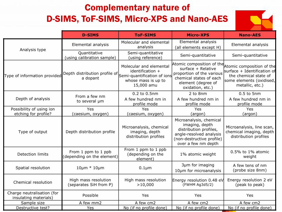
Complementary nature of
D-SIMS, ToF-SIMS, Micro-XPS and Nano-AES
D-SIMS ToF-SIMS Micro-XPS Nano-AES
Analysis type
Elemental analysis Molecular and elemental
analysis
Elemental analysis
(all elements except H) Elemental analysis
Quantitative (using calibration sample)
Semi-quantitative (using reference)
Semi-quantitative Semi-quantitative
Type of information provided Depth distribution profile of
a dopant
Molecular and elemental identification +
Semi-quantification of ions whose mass is up to
15,000 amu
Atomic composition of the surface + Relative
proportion of the various chemical states of each
element (degree of oxidation, etc.)
Atomic composition of the surface + Identification of
the chemical state of some elements (oxidised,
metallic, etc.)
Depth of analysis From a few nm to several µm
0.2 to 0.5nm
A few hundred nm in profile mode
2 to 8nm
A few hundred nm in profile mode
0.5 to 5nm
A few hundred nm in profile mode
Possibility of using ion etching for profile?
Yes (caesium, oxygen)
Yes (caesium, oxygen)
Yes (argon)
Yes (argon)
Type of output Depth distribution profile Microanalysis, chemical
imaging, depth distribution profiles
Microanalysis, chemical imaging, depth
distribution profiles, angle-resolved analysis (non-destructive profile)
over a few nm depth
Microanalysis, line scan, chemical imaging, depth
distribution profiles
Detection limits From 1 ppm to 1 ppb
(depending on the element)
From 1 ppm to 1 ppb (depending on the
element) 1% atomic weight
0.5% to 1% atomic weight
Spatial resolution 10µm * 10µm 0.1µm 3µm for imaging
10µm for microanalysis
A few tens of nm (probe size 8nm)
Chemical resolution High mass resolution
(separates SiH from P) High mass resolution
>10,000 Energy resolution 0.48 eV
(FWHM Ag3d5/2)
Energy resolution 2 eV (peak to peak)
Charge neutralisation (for insulating materials)
Possible Yes Yes Yes
Sample size A few mm2 A few cm2 A few cm2 A few cm2
Destructive test? Yes No (if no profile done) No (if no profile done) No (if no profile done)

Possible applications
• With ToF-SIMS technique
– Molecular and elemental surface analysis
– Parallel identification of all ions present (highly sensitive identification of unknown element)
– Determining the molecular structure of polymers
– Analysis of insulators and fragile materials (soft ionisation technique)
– Multilayer analysis (photovoltaic cells, telescope mirrors, etc.)
– Identification of interface contaminants in the event of delamination
• With Micro-XPS technique
– Analysis of surface chemicals and their states (passivation, cleaning residues, etc.)
– Analysis of insulators (no charging effects)
– Analysis of fragile materials (powders, etc.)
– Non-destructive test for thin films of less than 10nm thick
• With Nano-AES technique
– Pad analysis (analysis of surface and deep contamination)
– Characterisation of submicronic defects (particles, filaments, staining, etc.)
– Analysis of micro-sections prepared using FIB (no shadow effect through use of a coaxial analyser; FIB preparation available at the lab)
• With D-SIMS technique
– Semiconductor analysis (distribution of dopants, contaminants or majority elements in materials such as Si, poly-Si, SiO2, SiON, ONO, FSG, BPSG, SOI, SiGeC, NiSi, SiC, MnGe, metal multilayers, etc.)
– Calibration of process simulators
– Characterisation of ultra-shallow junctions
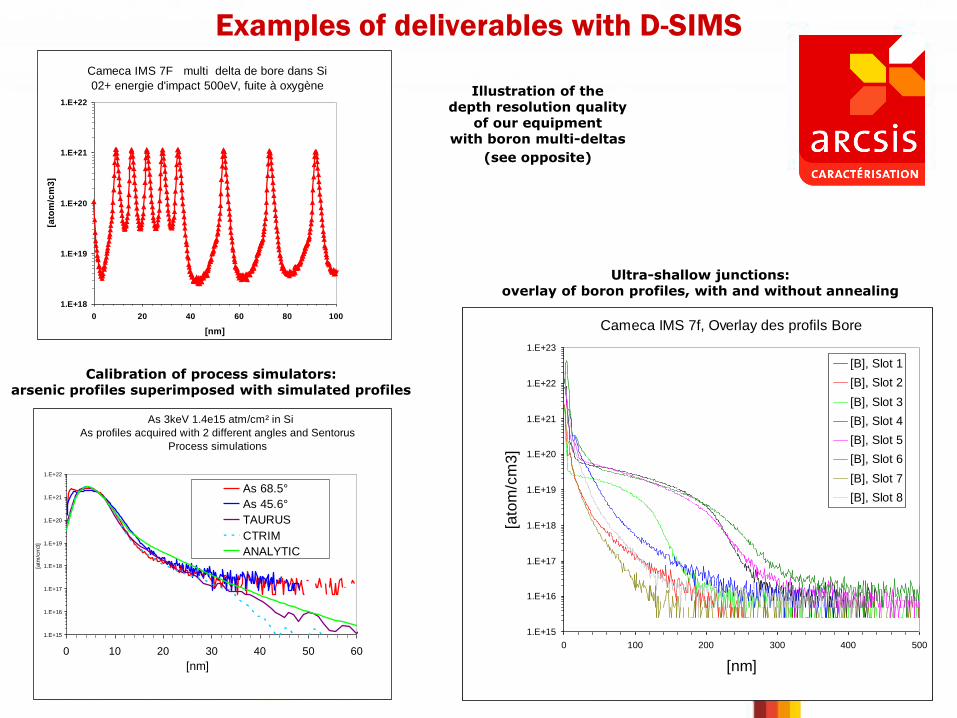
Examples of deliverables with D-SIMS
Cameca IMS 7f, Overlay des profils Bore
1.E+15
1.E+16
1.E+17
1.E+18
1.E+19
1.E+20
1.E+21
1.E+22
1.E+23
0 100 200 300 400 500
[nm]
[ato
m/c
m3]
[B], Slot 1
[B], Slot 2
[B], Slot 3
[B], Slot 4
[B], Slot 5
[B], Slot 6
[B], Slot 7
[B], Slot 8
Cameca IMS 7F multi delta de bore dans Si
02+ energie d'impact 500eV, fuite à oxygène
1.E+18
1.E+19
1.E+20
1.E+21
1.E+22
0 20 40 60 80 100
[nm]
[ato
m/c
m3
]
Illustration of the depth resolution quality
of our equipment with boron multi-deltas
(see opposite)
Ultra-shallow junctions: overlay of boron profiles, with and without annealing
As 3keV 1.4e15 atm/cm² in Si
As profiles acquired with 2 different angles and Sentorus
Process simulations
1.E+15
1.E+16
1.E+17
1.E+18
1.E+19
1.E+20
1.E+21
1.E+22
0 10 20 30 40 50 60
[nm]
[atm
/cm
3]
As 68.5°
As 45.6°
TAURUS
CTRIM
ANALYTIC
Calibration of process simulators: arsenic profiles superimposed with simulated profiles
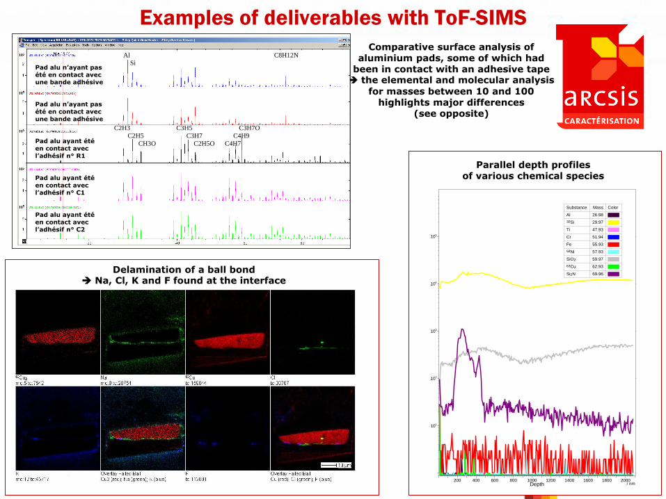
Comparative surface analysis of aluminium pads, some of which had
been in contact with an adhesive tape the elemental and molecular analysis
for masses between 10 and 100 highlights major differences
(see opposite)
Examples of deliverables with ToF-SIMS
Delamination of a ball bond Na, Cl, K and F found at the interface
/ nmDepth200 400 600 800 1000 1200 1400 1600 1800 2000
110
210
310
410
510
[coun
ts]
Inte
nsity
Substance Mass Color
Al 26.98
30Si 29.97
Ti 47.93
Cr 51.94
Fe 55.93
58Ni 57.93
SiO2 59.97
63Cu 62.93
Si2N 69.96
Parallel depth profiles of various chemical species
Al C8H12N
Si
C2H3 C3H5 C3H7O
C2H5 C3H7 C4H9
CH3O C2H5O C4H7
Pad alu n’ayant pas été en contact avec une bande adhésive Pad alu n’ayant pas
été en contact avec
une bande adhésive Pad alu ayant été en contact avec
l’adhésif n° R1
Pad alu ayant été en contact avec l’adhésif n° C1
Pad alu ayant été en contact avec
l’adhésif n° C2

Examples of deliverables with Micro-XPS
CIMPACA - Characterization Platform
09-342-70726_slot24.vms : Ti 2p/8
Exp Variable 0 d
Pass Energy: 20 W.F.: -4.8
T otal Acquisition T ime 10.025 (mins) (298.5 (ms) x 5 x 403)
Acquired On: 2009/12/ 9 19:30:0
Source: Mono(Al (Mono)) (225 W)
T i 2p 3/2 TiN
T i 2p 1/2 TiN
T i 2p 3/2 TiO2
T i 2p 1/2 TiO2
Name
Ti 2p 3/2 TiN
Ti 2p 3/2 TiO2
Pos.
455.4515
458.5446
At%
48.21
51.79
x 102
0
10
20
30
40
50
60
70
80
90
CPS
468 464 460 456 452
Binding Energy (eV)CIMPACA - Characterization Platform
09-342-70726_slot25.vms : Ti 2p/7
Exp Variable 0 d
Pass Energy: 20 W.F.: -4.8
T otal Acquisition T ime 10.025 (mins) (298.5 (ms) x 5 x 403)
Acquired On: 2009/12/ 9 20:47:29
Source: Mono(Al (Mono)) (225 W)
T i 2p 3/2 TiOxFy
T i 2p 1/2 TiOxFy
T i 2p 3/2 TiN
T i 2p 1/2 TiNT i 2p 3/2 TiO2
T i 2p 1/2 TiO2
Name
Ti 2p 3/2 TiOxFy
Ti 2p 3/2 TiN
Ti 2p 3/2 TiO2
Pos.
459.2226
455.4600
458.5500
At%
49.93
35.16
14.91
x 102
0
10
20
30
40
50
60
70
CPS
468 464 460 456 452
Binding Energy (eV)
48.2
35.2
51.8
14.9
0.0
49.9
0.0
20.0
40.0
60.0
80.0
100.0
120.0
slot 24 slot 25
Rela
tive c
om
po
sit
ion
s
TiOxFy %
TiO2 %
TiN %
0
20
40
60
80
100
120
slot 24 slot 25
Rela
tive c
om
po
sit
ion
s
TiOxFy %
TiO2 %
TiN %
Depth distribution profile of silicon in its various chemical states within a sample
(profiles generated by angle-resolved analysis - AR-XPS)
Characterisation of titanium in its various chemical states on the surface of 2 samples that had undergone different cleaning processes
the relative proportions vary significantly between the 2 samples

Examples of deliverables with Nano-AES
Retrospective data processing identified
aluminium in its various chemical states
Copper
Aluminium Silicon
SEM Image
Depth distribution profile of elements within a pad
(showing fluorine contamination on the pad surface)
SEM image and corresponding chemical imaging output for a Al stringer
28oct.124_1.lin: Sample 4.1 PHI USA
2005 Oct 28 20.0 kV 0 FRR 1.7746e+005 max
O1 (NormLine Binom3)
0 0.1 0.2 0.3 0.4 0.5 0.6 0.7 0.8 0.9 10
0.2
0.4
0.6
0.8
1
1.2
1.4
1.6
1.8
2x 10
5 28oct.124_1.lin
Distance (µm)
Inte
nsity
Line 1
O
W
AlTi
Ti
W2
Al2
Ti1
O1
28oct.124_3.lin: Sample 4.1 PHI USA
2005 Oct 28 20.0 kV 0 FRR 1.7984e+005 max
O1 (NormLine Binom3)
0 0.1 0.2 0.3 0.4 0.5 0.6 0.7 0.8 0.9 10
0.2
0.4
0.6
0.8
1
1.2
1.4
1.6
1.8
2
x 105 28oct.124_3.lin
Distance (µm)
Inte
nsity
Line 3Ti Al
O
W
Ti
Ti
Al
W2
Al2
Ti1
O1
FOV: 1.0 µm 20.000 keV
Sample 4.1 - Via 10 10/28/2005F
0.2 µm
28oct.124_2.lin: Sample 4.1 PHI USA
2005 Oct 28 20.0 kV 0 FRR 1.9091e+005 max
O1 (NormLine Binom3)
0 0.1 0.2 0.3 0.4 0.5 0.6 0.7 0.8 0.9 10
0.2
0.4
0.6
0.8
1
1.2
1.4
1.6
1.8
2
x 105 28oct.124_2.lin
Distance (µm)
Inte
nsity
Line 2
W
OAl
Ti
Ti
W2
Al2
Ti1
O1
FOV: 1.0 µm 20.000 keV
Sample 4.1 - Via 10 10/28/2005F
0.2 µm FOV: 1.0 µm 20.000 keV
Sample 4.1 - Via 10 10/28/2005F
0.2 µm
Characterisation of a pit (copper compound)
Analysis of a defect (Ti compound) at the bottom of a via, characterised using line scans (below) or chemical imaging (opposite)

Equipment Description
D-SIMS, ToF-SIMS, Micro-XPS and Nano-AES systems

CAMECA IMS7f (D-SIMS)
• Secondary Ion Mass Spectrometry (SIMS) is a highly sensitive physico-chemical surface analysis technique. The sample surface is sputtered with a primary ion beam, eroding the surface and generating secondary ions, which are detected by the system.
• SIMS can be used for elemental depth profile analysis (from the nm to µm scale) on solids, with an extremely high sensitivity (in the parts per billion range for some elements). Analysis can be carried out on dopant distribution within silicon, for
instance.
• The minimum analysis size in terms of lateral resolution is of the order of 10*10 µm depending on the target concentration.
• Key features:
– Small sample size (approximately 7mm*7mm)
– High mass resolution (separates 30SiH from P)
– Can be used on areas < 50µm2 (with reduced sensitivity)
– Good ultimate vacuum (Spec 7e-10mbar)
– Up to 500eV impact energy with O2+ (Shallow B)
– Up to 3keV impact energy with Cs- (As,P)
– Up to 500eV impact energy with Cs+
– Oxygen flooding can be used to reduce surface transient
» An AlphaStep profilometer (KLA-Tencor) is used to measure the depth of SIMS craters, which allows for depth calibration of the profiles

ION-TOF 5 (ToF-SIMS)
• Time-of-Flight Secondary Ion Mass Spectrometry (ToF-SIMS) is based on static secondary ion emission. Unlike Dynamic SIMS (D-SIMS), which by nature erodes and deteriorates the sputtered surface, ToF-SIMS uses a total dose of primary ions of less than 1012 ions per cm² (just one primary ion for every 1000 surface atoms). ToF-SIMS is thus a soft ionisation technique and can therefore be used for molecular surface analysis.
• The main application is highly sensitive elemental and molecular analysis of trace substances on a surface.
• A scanning beam of primary ions is used to map the various elements and molecular species present on the surface with a submicronic level of resolution.
• If the data acquisition process is coupled with an abrasion sequence, a composition profile can be plotted with a very high depth resolution.
KRATOS Axis Nova (Micro-XPS)
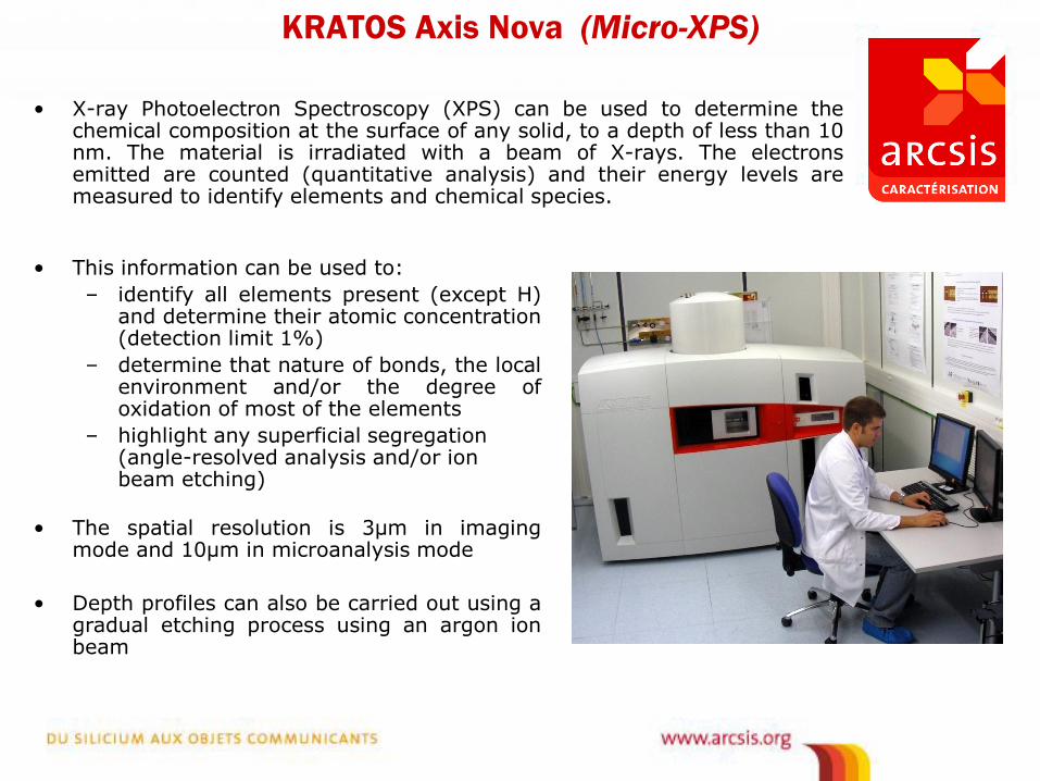
• X-ray Photoelectron Spectroscopy (XPS) can be used to determine the chemical composition at the surface of any solid, to a depth of less than 10 nm. The material is irradiated with a beam of X-rays. The electrons emitted are counted (quantitative analysis) and their energy levels are measured to identify elements and chemical species.
• This information can be used to:
– identify all elements present (except H) and determine their atomic concentration (detection limit 1%)
– determine that nature of bonds, the local environment and/or the degree of oxidation of most of the elements
– highlight any superficial segregation (angle-resolved analysis and/or ion beam etching)
• The spatial resolution is 3µm in imaging mode and 10µm in microanalysis mode
• Depth profiles can also be carried out using a gradual etching process using an argon ion beam

PHI 700 (Nano-AES)
• Nano Auger Electron Spectroscopy (Nano-AES) can be used for elemental surface analysis on solids (to depths of 0.5nm to 5nm) for elements at concentrations greater than 0.5% to 1%.
• The material is subjected to a beam of electrons and emits Auger electrons . The electrons emitted are counted (quantitative analysis) and their energy levels are measured to identify elements and chemical species.
• The scanning Auger nanoprobe uses a field effect electron gun and its argon ion source can be used to sputter surfaces for the purpose of depth profiling. The electron beam can be scanned to produce Auger chemical images.
• In some cases, the nanoprobe can give information about the bonding state of atoms (oxidised, metallic etc.)
• Lateral resolution is of the same order of magnitude as an SEM (particles ≥ 50nm)
Related Documents