IE 447 CIM Lecture Notes – Chapter 4: CAD/CAM Systems - 38 CHAPTER 4: CAD/CAM SYSTEMS 4.1 CAD/CAM Overview In the past fifteen years the interactive computer graphics and CAD/CAM technology have been impacting the drafting, design, and manufacturing tools significantly. The purpose of this chapter is to present CAD/CAM principles and tools in generic and basic terms. These principles are supplemented with engineering and design applications as well as problems. The chapter is also concerned with developing basic abilities to utilise the existing CAD/CAM systems in engineering practice. Figure 4.1: The structure of CAD/CAM DEMAND DESIGN MANUFACTURING PRODUCT Conceptual design Mathematical analysis Geometric data (graphical representation) Process design Process planning (CNC codes) Tool selection Facilities management CAD CAM CAD/CAM

Welcome message from author
This document is posted to help you gain knowledge. Please leave a comment to let me know what you think about it! Share it to your friends and learn new things together.
Transcript

7/31/2019 CIM Lecture Notes 4
http://slidepdf.com/reader/full/cim-lecture-notes-4 1/26
CHAPTER 4: CAD/CAM SYSTEMS
4.1 CAD/CAM Overview
In the past fifteen years the interactive computer graphics and CAD/CAM technology
have been impacting the drafting, design, and manufacturing tools significantly. The purpose
of this chapter is to present CAD/CAM principles and tools in generic and basic terms. These
principles are supplemented with engineering and design applications as well as problems.
The chapter is also concerned with developing basic abilities to utilise the existing
CAD/CAM systems in engineering practice.
Figure 4.1: The structure of CAD/CAM
DEMAND DESIGN MANUFACTURING PRODUCT
Conceptual design
Mathematical analysis
Geometric data
(graphical
representation)
Process design
Process planning (CNC
codes)
Tool selection
Facilities management
CAD CAM
CAD/CAM

7/31/2019 CIM Lecture Notes 4
http://slidepdf.com/reader/full/cim-lecture-notes-4 2/26
4.1.1 CAD/CAM contents and tools
In engineering practice, CAD/CAM has been utilised in different ways by different people.
Some of the applications of this technology are:
• production of drawings and design documents;
• visualisation tool for generating shaded images and animated displays;
• engineering analysis of the geometric models (finite element analysis, kinematic
analysis, etc.);
• process planning and generation of NC part programmes.
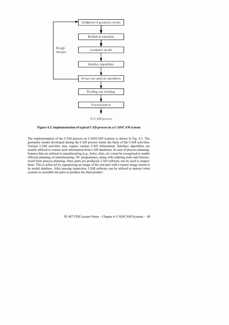
The CAD process is a subset of the design process. Similarly, the CAM process is a
subset of the manufacturing process. The implementation of the CAD process on current
systems takes the generic flow presented in Fig. 4.2. Once a conceptual design materialises in
the designer’s mind, the definition of a geometric model starts via the user interface provided
by the relevant CAD system. The choice of a geometric model to CAD is analogous to the
choice of mathematical model to engineering analysis. For example, FEA might require a
different model than kinematic analysis.
A valid geometrical model is created by the CAD system through its definition translator
which converts the designer input into the proper database format. In order to apply
engineering analysis to the geometric model, interface algorithms are provided by the system
to extract the required data from the model database to perform the analysis.
In the case of FEA, these algorithms form the FEM package of the system. Design testing and
evaluation may require changing the geometric model before finalising it. When the final
design is achieved the drafting and detailing of the models starts, followed by documentationand production of final drawings.
The core of the CAD tools are geometric modelling and graphics applications. Aids such as
colour, grids, geometric modifiers, and group facilitate structuring geometric models.
Manipulations include transformation of the model in space so it can be viewed properly.
Visualisation is achieved via shaded images and animation procedures which help design
conceptualisation, communication, and interference detections in some cases. Tools for design
modelling and simulation are well diversified and are closely related to the available analysis
packages. Some FEM packages provide some form of shape and structural optimisation.
Adding tolerances, performing tolerance analysis, generating a bill of materials, and
investigating the effect of manufacturing on the design by utilising NC packages are also
valuable tools that are available to designers.
7/31/2019 CIM Lecture Notes 4
http://slidepdf.com/reader/full/cim-lecture-notes-4 3/26
Figure 4.2: Implementation of typical CAD process in a CAD/CAM system
The implementation of the CAM process on CAD/CAM systems is shown in Fig. 4.3. The
geometric model developed during the CAD process forms the basis of the CAM activities.
Various CAM activities may require various CAD information. Interface algorithms are
usually utilised to extract such information from CAD databases. In case of process planning,
features that are utilised in manufacturing (e.g., holes, slots, etc.) must be recognised to enableefficient planning of manufacturing. NC programmes, along with ordering tools and fixtures,
result from process planning. Once parts are produced, CAD software can be used to inspect
them. This is achieved by superposing an image of the real part with a master image stored in
its model database. After passing inspection, CAM software can be utilised to instruct robot
systems to assemble the parts to produce the final product.

7/31/2019 CIM Lecture Notes 4
http://slidepdf.com/reader/full/cim-lecture-notes-4 4/26
Figure 4.3: Implementation of a typical CAM process on a CAD/CAM system
4.2 Definition of CAD/CAM tools
Employing their constituents, CAD tools can be defined as the intersection of three sets:
geometric modelling, computer graphics, and the design tools (Fig. 4.4). As can be perceived
from this figure, the abstracted concepts of geometric modelling and computer graphics must
be applied innovatively to serve the design process. Based on implementation in a designenvironment, CAD tools can be defined as the design tools (analysis codes, heuristic
procedures, design practices, etc.) being augmented by computer hardware and software
throughout its various phases to achieve the design goal efficiently and competitively. The
level of augmentation determines the design capabilities of the various CAD/CAM systems
and the effectiveness of the CAD tools they provide. Designer will always require tools that

7/31/2019 CIM Lecture Notes 4
http://slidepdf.com/reader/full/cim-lecture-notes-4 5/26
Similar to the definition of CAD tools, CAM tools can be defined as the intersection of three
sets: CAD tools, networking concepts, and the manufacturing tools (Fig. 4.4). This definition
enforces the link between CAD and CAM as well as database centralisation. There are two
main factors that determine the success of this implementation.
• The link between CAD and CAM must be a two-way route. CAD databases must reflect
manufacturing requirements such as tolerances and features. Designers must think in term
of CAM requirements when finalising their designs. On the other hand, CAD databases
and their limitations must be conveyed to manufacturing engineers who plan to utilise
them in process planning and other manufacturing functions. It should be pointed out that
not all manufacturing processes are, or need to be, computer driven.
Figure 4.4: Main constituents of CAD tools
• The hardware and software networking of the various CAM elements to automate the
manufacturing process. The factory of the future and its levels of automation are directly
related to the soundness of the networking concepts. Timely synchronisation among
robots, vision systems, manufacturing cells, material handling systems, and other shop-
floor tasks is one of the most challenging networking problems that face the
i l t ti f CAM

7/31/2019 CIM Lecture Notes 4
http://slidepdf.com/reader/full/cim-lecture-notes-4 6/26
systems as well as hardwire them to various manufacturing cells and facilities. They can also
run third party software to augment the analysis capabilities typically provided by CAD/CAM
vendors. With the advancements in the computer technology, current CAD/CAM systems are
based on the workstation concept. Such a concept provides both single-user and timesharingenvironments.
CAD/CAM systems based on the workstation concept represent a distinct philosophy or trend
in hardware technology which is based on a distributed (stand-alone) but networked (linked)
environment. Workstations can be linked together as well as to mainframes dedicated to
numerical computations. Other processors may exist in the network to control other types of
hardware such as file and print servers. These distributed systems are able to perform major
graphics functions locally at the workstations, and operations that require more power aresend to the mainframe. The communication between devices in this distributed design and
manufacturing environment becomes an important part of the system configuration and design.
The dynamics and rapid changes in the hardware technology have created an absorption
problem at the user’s part. There are always various types and configurations of CAD/CAM
systems to choose from. To choose and implement a system requires the development of a set
of guidelines that must address both hardware and software requirements. A key factor in a
system evaluation is the capabilities and integration of its software which influence the
productivity rate directly.

7/31/2019 CIM Lecture Notes 4
http://slidepdf.com/reader/full/cim-lecture-notes-4 7/26
7/31/2019 CIM Lecture Notes 4
http://slidepdf.com/reader/full/cim-lecture-notes-4 8/26
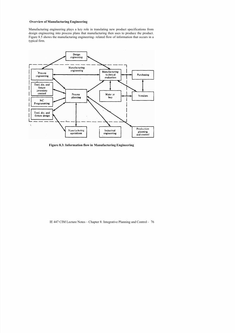
Overview of Manufacturing Engineering
Manufacturing engineering plays a key role in translating new product specifications from
design engineering into process plans that manufacturing then uses to produce the product.Figure 8.5 shows the manufacturing engineering- related flow of information that occurs in a
typical firm.
Figure 8.3: Information flow in Manufacturing Engineering

7/31/2019 CIM Lecture Notes 4
http://slidepdf.com/reader/full/cim-lecture-notes-4 9/26
Overview of Production Control
Figure 8.6 shows the basic elements of the production control function. Demand forecasting
provides an estimate of the demand for each type of product sold.
Figure 8.4: Production control information flow
7/31/2019 CIM Lecture Notes 4
http://slidepdf.com/reader/full/cim-lecture-notes-4 10/26
CHAPTER 5: CONCURRENT ENGINEERING
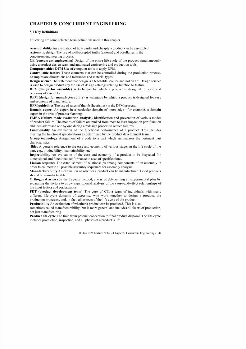
5.1 Key Definitions
Following are some selected term definitions used in this chapter.
Assemblability An evaluation of how easily and cheaply a product can be assembled.
Axiomatic design The use of well-accepted truths (axioms) and corollaries in the
concurrent engineering process.
CE (concurrent engineering) Design of the entire life cycle of the product simultaneously
using a product design team and automated engineering and production tools.
Computer-aided DFM Use of computer tools to apply DFM.
Controllable factors Those elements that can be controlled during the production process.
Examples are dimensions and tolerances and material types.
Design science The statement that design is a teachable science and not an art. Design science
is used to design products by the use of design catalogs relating function to feature.
DFA (design for assembly) A technique by which a product is designed for ease and
economy of assembly.
DFM (design for manufacturability) A technique by which a product is designed for ease
and economy of manufacture.DFM guidelines The use of rules of thumb (heuristics) in the DFM process.
Domain expert An expert in a particular domain of knowledge—for example, a domain
expert in the area of process planning.
FMEA (failure-mode evaluation analysis) Identification and prevention of various modes
of product failure. The modes of failure are ranked from most to least impact on part function
and then addressed one by one during a redesign process to reduce failures.
Functionality An evaluation of the functional performance of a product. This includes
meeting the functional specifications as determined by the product development team.Group technology Assignment of a code to a part which summarizes the pertinent part
characteristics.
-iities A generic reference to the ease and economy of various stages in the life cycle of the
part, e.g., producibility, maintainability, etc.
Inspectability An evaluation of the ease and economy of a product to be inspected for
dimensional and functional conformance to a set of specifications.
Liaison sequence The establishment of relationships among components of an assembly in
order to enumerate all possible assembly sequences for assembly analysis.Manufacturability An evaluation of whether a product can be manufactured. Good products
should be manufacturable.
Orthogonal arrays In the Taguchi method, a way of determining an experimental plan by
separating the factors to allow experimental analysis of the cause-and-effect relationships of
the input factors and performance.

7/31/2019 CIM Lecture Notes 4
http://slidepdf.com/reader/full/cim-lecture-notes-4 11/26
SAPD (strategic approach to product design) A concurrent engineering architecture
emphasizing a thorough product analysis instead of the use of design rules.
Serviceability An evaluation of the ease with which a product can be serviced in the field.
Signal-to-noise ratio A measure of a system’s resistance to being influenced by noise. The
signal is the measure of performance and the noise is a measure of uncontrollable factors.
Taguchi method A technique for designing robustness into a product design which
establishes design parameters, system parameters, and tolerance parameters.
ULCE (unified life-cycle engineering) A concurrent engineering architecture developed by
the U.S. Air Force that emphasizes the integration of modules including design rules and
metadesign knowledge about the designer’s intent.
Uncontrollable factors Those elements which are not controllable, e.g., noise, factors.
Examples are the weather and the stock market.Value engineering A technique for measuring the quality of a product design as a ratio of
performance to life-cycle cost.
5.2 Concurrent Engineering
Concurrent engineering has as its purpose to detail the design while simultaneously
developing production capability, field-support capability, and quality. It consists of a
methodology using multi-disciplined teams to carry out this concurrency. CE tools in theform of algorithms, techniques, and software, and the expertise and judgment of people who
make up the complete design and production sequence. The essence of CE is the integration
of product design and process planning into one common activity. Concurrent design helps
improve the quality of early design decisions and has a tremendous impact on life cycle cost
of the product.
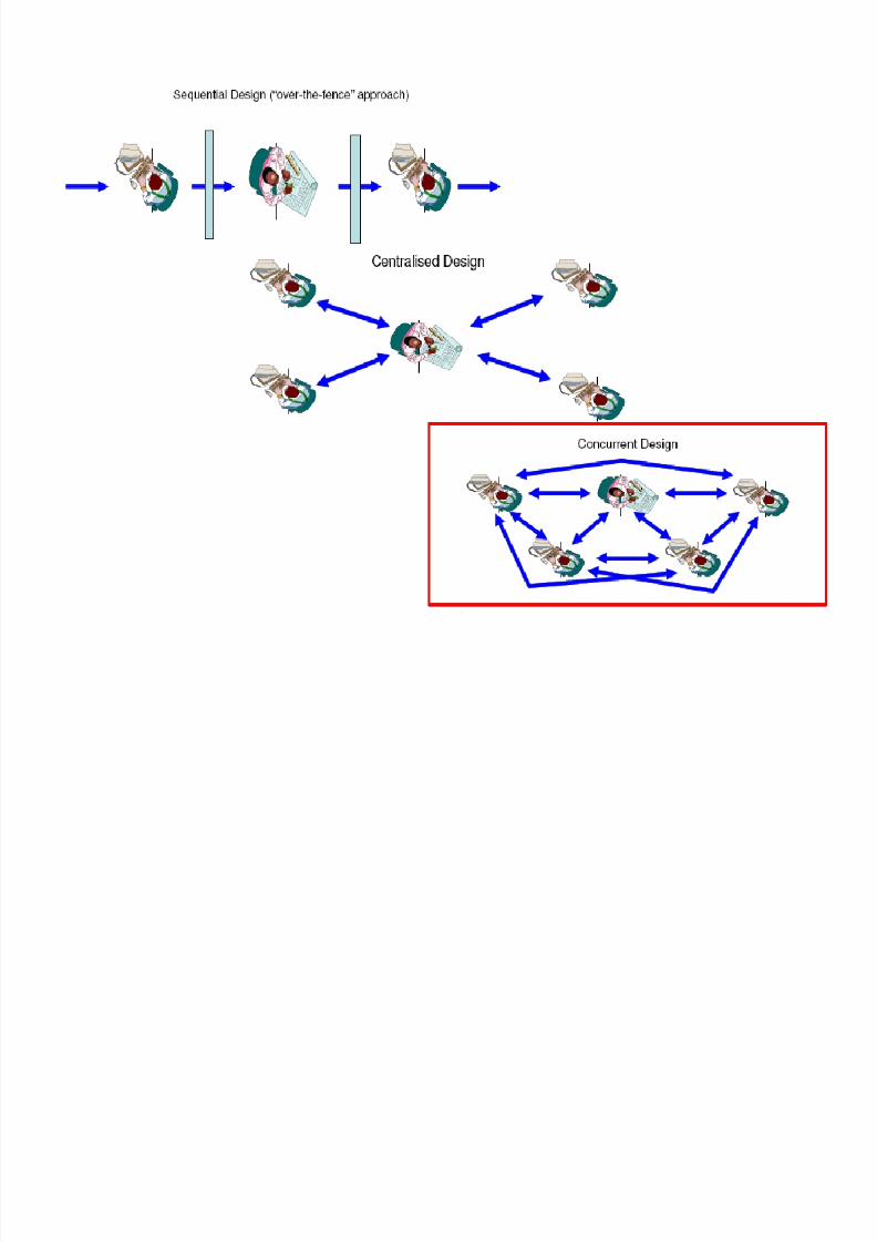
CE can be visualized as illustrated in Figure 5.1. In this figure, the designer represented by
the hub of the wheel, coordinates the comments and re-design suggestions from each of the
domain experts around the circumference.Communications among the experts is indicated by the circumferential arrows. In this design
procedure, a conceptual design is presented radially to the group of experts, at which time
each can comment on the design relative to his or her own area. Assembly experts consider
assemblability problems, process planning experts consider the process sequence, and metal
removal experts consider the available machine tools, new removal techniques and the
requirements of the design and so on. The number of domain experts around the rim varies,
but the typical domains are;
• Assembly
• Fabrication
• Inspection
• Field maintenance
• Marketing
D i ifi i i f i li

7/31/2019 CIM Lecture Notes 4
http://slidepdf.com/reader/full/cim-lecture-notes-4 12/26

7/31/2019 CIM Lecture Notes 4
http://slidepdf.com/reader/full/cim-lecture-notes-4 13/26
• Costs or making the optimum choice of materials and processes e.g.. can the component be
cold-headed and finish-machined rather than machined from bar stock?
7/31/2019 CIM Lecture Notes 4
http://slidepdf.com/reader/full/cim-lecture-notes-4 14/26
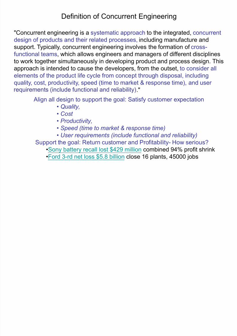
Definition of Concurrent Engineering
"Concurrent engineering is a systematic approach to the integrated, concurrentdesign of products and their related processes, including manufacture andsupport. Typically, concurrent engineering involves the formation of cross-functional teams, which allows engineers and managers of different disciplinesto work together simultaneously in developing product and process design. Thisapproach is intended to cause the developers, from the outset, to consider allelements of the product life cycle from concept through disposal, includingquality, cost, productivity, speed (time to market & response time), and user
" .
Align all design to support the goal: Satisfy customer expectation• Quality,
• Cost
• Productivity,
• Speed (time to market & response time)• User requirements (include functional and reliability)
Support the goal: Return customer and Profitability- How serious?•Sony battery recall lost $429 million combined 94% profit shrink•Ford 3-rd net loss $5.8 billion close 16 plants, 45000 jobs

7/31/2019 CIM Lecture Notes 4
http://slidepdf.com/reader/full/cim-lecture-notes-4 15/26
Field warranty service
Productionsystem
Prototyping
ProcessdesignGD&T
Qualitycontrol
ProductdesignGD&T
EngineeringModeling
Marketanalysis,
R&D
Cell, Quick
Response
Manufacturing
StatisticProcess
Control (SPC)
Computer
Aided Design
(CAD)
Computer
Aided
Manufacturing
(CAM)
Rapid
Prototyping
Manufacturing in the Product Life Cycle

7/31/2019 CIM Lecture Notes 4
http://slidepdf.com/reader/full/cim-lecture-notes-4 16/26

7/31/2019 CIM Lecture Notes 4
http://slidepdf.com/reader/full/cim-lecture-notes-4 17/26
•Why do companies now want to move away from serial productdevelopment process ?
Concurrent engineering of productsAddress all issues related to the complete life cycle
of the product at the product design stage - from
initial conce tualization to dis osal/scra of the
product.
7/31/2019 CIM Lecture Notes 4
http://slidepdf.com/reader/full/cim-lecture-notes-4 18/26

7/31/2019 CIM Lecture Notes 4
http://slidepdf.com/reader/full/cim-lecture-notes-4 19/26
Concurrent engineering
• Has to be supported by top management.
• All product development team members should be
.
• Each phase in product development has to be
carefully
planned before actual application.
• New product’s lifecycle has to fit in in the existing
product program lifecycles in a company.

7/31/2019 CIM Lecture Notes 4
http://slidepdf.com/reader/full/cim-lecture-notes-4 20/26

7/31/2019 CIM Lecture Notes 4
http://slidepdf.com/reader/full/cim-lecture-notes-4 21/26
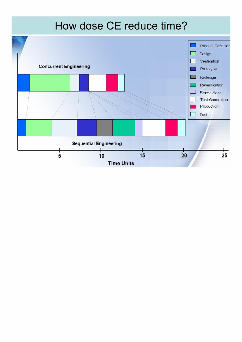
Benefits of Concurrent Engineering•Reduces time from design concept to market
launch by 25% or more
• Reduces Capital investment by 20% or more
• Supports total quality from the start of production with earlier
opportunities for continuous improvement
Development
• mp es a er-sa es serv ce
• Increases product life-cycle profitability
throughout the supply
system
7/31/2019 CIM Lecture Notes 4
http://slidepdf.com/reader/full/cim-lecture-notes-4 22/26
How dose CE reduce time?

7/31/2019 CIM Lecture Notes 4
http://slidepdf.com/reader/full/cim-lecture-notes-4 23/26
Production Processthe main problems/difficulties
associated with traditional design
and production process:
FOR COMPLEX PRODUCTSFOR COMPLEX PRODUCTS::
•• Cycle Time Too LongCycle Time Too Long•• Facility IntensiveFacility Intensive
•• Cost HighCost High
•• Convergence Not AssuredConvergence Not Assured

7/31/2019 CIM Lecture Notes 4
http://slidepdf.com/reader/full/cim-lecture-notes-4 24/26
CE
CE
is
able
on
These
area
7/31/2019 CIM Lecture Notes 4
http://slidepdf.com/reader/full/cim-lecture-notes-4 25/26
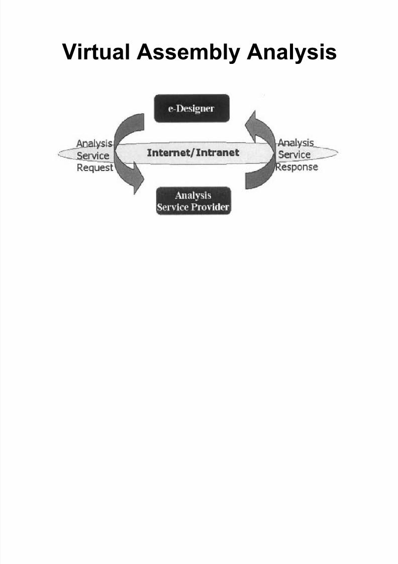
Virtual Assembly Analysis

7/31/2019 CIM Lecture Notes 4
http://slidepdf.com/reader/full/cim-lecture-notes-4 26/26
Service-oriented VAA
Architecture and Components
Related Documents