CIGRE Study Committes A3 CIGRE Study Committes A3 CIGRE Study Committes A3 CIGRE Study Committes A3 High Voltage Equipment High Voltage Equipment UHV equipment specifications UHV equipment specifications Circuit breakers and interrupting phnomena Circuit breakers and interrupting phnomena Vacuum switchgear at transmission voltages Vacuum switchgear at transmission voltages Vacuum switchgear at transmission voltages Vacuum switchgear at transmission voltages DC interruption and DC switchgears DC interruption and DC switchgears Controlled switching Controlled switching Hiroki Ito Hiroki Ito Hiroki Ito Hiroki Ito Chairman, CIGRE Study Committee A3 Chairman, CIGRE Study Committee A3 Mitsubishi Electric Corporation Mitsubishi Electric Corporation MITSUBISHI ELECTRIC 1 CIGRE session during ELECRAMA, Bangalore on 9th January 2014 ELECTRIC

Welcome message from author
This document is posted to help you gain knowledge. Please leave a comment to let me know what you think about it! Share it to your friends and learn new things together.
Transcript
CIGRE Study Committes A3CIGRE Study Committes A3CIGRE Study Committes A3CIGRE Study Committes A3High Voltage EquipmentHigh Voltage Equipment
UHV equipment specificationsUHV equipment specificationsCircuit breakers and interrupting phnomenaCircuit breakers and interrupting phnomenaVacuum switchgear at transmission voltagesVacuum switchgear at transmission voltagesVacuum switchgear at transmission voltagesVacuum switchgear at transmission voltagesDC interruption and DC switchgearsDC interruption and DC switchgearsControlled switchingControlled switching
Hiroki ItoHiroki ItoHiroki ItoHiroki ItoChairman, CIGRE Study Committee A3Chairman, CIGRE Study Committee A3
Mitsubishi Electric CorporationMitsubishi Electric CorporationMITSUBISHI ELECTRIC
1CIGRE session during ELECRAMA, Bangalore on 9th January 2014
ELECTRIC

What is CIGRE?What is CIGRE?Founded in 1921, CIGRE, the Council on Large Electric Systems, is aninternational Non-profit Association for promoting collaboration withexperts from around the world by sharing knowledge and joiningexperts from around the world by sharing knowledge and joiningforces to improve electric power systems of today and tomorrow.
Perform studies on topical issues of the electric power systemPerform studies on topical issues of the electric power system,such as Supergrid, Microgrid and lifetime management of aged assets,and disseminate new technology and improve energy efficiency.
Review the state-of-the-art of technical specifications for powersystems & equipment and provide technical background based on thecollected information for IEC to assist international standardizations.
Maintain its values by delivering unbiased information based onfield experience
2

CIGRE Technical Committee CIGRE Technical Committee 16 Study Committees16 Study Committees
A1 Rotating electricalA1 Rotating electrical machinesmachines B1 Insulated cablesB1 Insulated cables C1 System development C1 System development && economicseconomics
A: EquipmentA: Equipment B: SubB: Sub--systemsystem C: SystemC: System
E. Figueiredo (Brazil) E. Figueiredo (Brazil) P. Argaut (France)P. Argaut (France) P. Southwell (Australia)P. Southwell (Australia)
A2 TransformersA2 Transformers
A3 Hi h lt i tA3 Hi h lt i t
B2 Overhead linesB2 Overhead lines
B3 S b iB3 S b i
C2 System operation C2 System operation & & controlcontrol
C3 S i l fC3 S i l f
gue edo ( a )gue edo ( a )
C. Rajotte (Canada) C. Rajotte (Canada)
gaut ( a ce)gaut ( a ce)
K. Papailiou (Switzerland) K. Papailiou (Switzerland)
Sout e ( ust a a)Sout e ( ust a a)
J. Vanzetta (Germany)J. Vanzetta (Germany)
A3 High voltage equipmentA3 High voltage equipment
B4 HVDC and B4 HVDC and PPowerower electronicselectronics
B3 SubstationsB3 Substations C3 System environmental performanceC3 System environmental performance
C4 System technical performanceC4 System technical performanceDisseminate new technology and Disseminate new technology and
H. Ito (Japan) H. Ito (Japan) T. Krieg (Australia)T. Krieg (Australia) F. Parada (Portugal)F. Parada (Portugal)
B5 Protection and B5 Protection and AAutomationutomation C5 Electricity marketsC5 Electricity markets && regulationsregulations
Promote international standardizationPromote international standardization B. Anderson (United Kingdom)B. Anderson (United Kingdom)
I. Patriota de Siqueira (Brazil)I. Patriota de Siqueira (Brazil)
P. Pourbeik (USA)P. Pourbeik (USA)
O. Fosso (Norway)O. Fosso (Norway)Technical committeeTechnical committeeChairman: Mark Waldron (UK) Chairman: Mark Waldron (UK)
C6 Distribution systems C6 Distribution systems &&dispersed generationdispersed generation
D: Common technologyD: Common technology
Perform studies on topical issues of Perform studies on topical issues of electric power systemelectric power system and and Facilitate the Facilitate the exchange of informationexchange of information N. Hatziagyriou (Greece)N. Hatziagyriou (Greece)
Chairman: Mark Waldron (UK) Chairman: Mark Waldron (UK) Secretary: Yves Maugain (France)Secretary: Yves Maugain (France)
3
D 1 Materials and emerging D 1 Materials and emerging test techniquetest technique D 2 Information systems and telecommunicationD 2 Information systems and telecommunication
D: Common technologyD: Common technology
J. Kindersberger (Germany)J. Kindersberger (Germany) C. Samitier (Spain)C. Samitier (Spain)

SD1 P th “ t d t” t f th f t
CIGRE Technical Committee Strategic Directions (SD)CIGRE Technical Committee Strategic Directions (SD)SD1: Prepare the “strong and smart” power system of the futureSD2: Make the best use of the existing equipment and systemSD3 A th i t SD3: Answer the environment concernsSD4: Develop knowledge and information
4

StudyStudy CommitteeCommittee AA33 isis responsibleresponsible forfor thethe theorytheory designdesign andand applicationapplication ofof substationsubstationWhat is What is Study Committee A3Study Committee A3
StudyStudy CommitteeCommittee AA33 isis responsibleresponsible forfor thethe theory,theory, designdesign andand applicationapplication ofof substationsubstationequipmentequipment appliedapplied toto ACAC andand DCDC systemssystems fromfrom distributiondistribution throughthrough transmissiontransmissionvoltagesvoltages whichwhich areare notnot specificallyspecifically coveredcovered underunder thethe scopescope ofof otherother studystudycommitteescommittees.. AA33 coverscovers allall switchingswitching devices,devices, surgesurge arresters,arresters, capacitors,capacitors, instrumentinstrumenttransformerstransformers insulatorsinsulators bushingsbushings faultfault currentcurrent limiterslimiters andand monitoringmonitoring techniquestechniquestransformers,transformers, insulators,insulators, bushings,bushings, faultfault currentcurrent limiterslimiters andand monitoringmonitoring techniquestechniques..
-- Requirements under changing networks and standardisationRequirements under changing networks and standardisation
5
Requirements under changing networks and standardisationRequirements under changing networks and standardisation-- Design and development of substation equipmentDesign and development of substation equipment-- New and improved testing and simulation techniquesNew and improved testing and simulation techniques-- Reliability assessment and lifetime managementReliability assessment and lifetime management
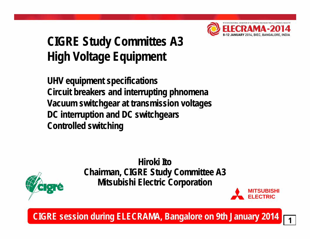
Population, Electricity Supply and ForecastPopulation, Electricity Supply and Forecast
World population is assumed to rise from 4 billion in 2008 to 8 billion World population is assumed to rise from 4 billion in 2008 to 8 billion in 2020, 8.6 billion in 2035. Global primary energy demand increases in 2020, 8.6 billion in 2035. Global primary energy demand increases more than 30% in the period to 2020. Over 80% of the electricity more than 30% in the period to 2020. Over 80% of the electricity d d th i i d d th i i OECD t i ti $37 t illi f OECD t i ti $37 t illi f demand growth arises in nondemand growth arises in non--OECD countries expecting $37 trillion of OECD countries expecting $37 trillion of investment in the world’s energy supply infrastructure.investment in the world’s energy supply infrastructure.Electricity of 1000 TWh is consumed per 0.1 billion population in the Electricity of 1000 TWh is consumed per 0.1 billion population in the
66
y p p py p p pUS and Japan. China and India are foreseen to continue their US and Japan. China and India are foreseen to continue their investments on energy supply infrastructure.investments on energy supply infrastructure.

1200kV 1200kVHighest voltage of AC power transmission kV
WG A3.22/28: Requirements for UHV equipmentWG A3.22/28: Requirements for UHV equipment
800
1200kV(1985-91,USSR)
1100kV(2008-,China)
1200kV(2012-,India)1100kV field tests
(1996-,Japan)
420kV
787kV(1967-,USSR) 800kV
(USA, South Africa, Brazil, Korea, China)735/765kV(1965-,Canada)
11001200
12.1 14.020.1
25.7
7 6
550380kV
(1952-,Sweden)300
420kV(1957-,USSR)
( , , , , )
4 8
(1965 ,Canada)
World electricity consumption (1000TWh)
420
7.6200019901980197019601950 2010 2020
year
4.8 World electricity consumption (1000TWh)
A3 provided IEC technical background of UHV specifications A3 provided IEC technical background of UHV specifications for their standardisation worksfor their standardisation works
Russia 1200kV GCB Japan 1100kV testing field China 1100kV projects India 1200kV testing field
7
A3 provided IEC technical background of UHV specifications A3 provided IEC technical background of UHV specifications for their standardisation worksfor their standardisation worksTB362: Technical requirements for substation equipment TB362: Technical requirements for substation equipment exceeding 800 kVexceeding 800 kVTB456: Background of technical specifications for substation equipment TB456: Background of technical specifications for substation equipment exceeding 800 kVexceeding 800 kVTB570: Switching phenomena of UHV & EHV equipmentTB570: Switching phenomena of UHV & EHV equipment

CIGRE UHV project provided excellent opportunities for optimising both CIGRE UHV project provided excellent opportunities for optimising both
Major results on UHV investigations CIGRE UHV project provided excellent opportunities for optimising both CIGRE UHV project provided excellent opportunities for optimising both the size & cost of UHV equipment. the size & cost of UHV equipment. The CIGRE UHV project has been completed in coordination by several The CIGRE UHV project has been completed in coordination by several The CIGRE UHV project has been completed in coordination by several The CIGRE UHV project has been completed in coordination by several SCs such as SCs such as WG B3.22/29WG B3.22/29 onon--site testing procedures (site testing procedures (TB 400, TB562TB 400, TB562), ), WG C4.306WG C4.306 on UHV insulation coordination (on UHV insulation coordination (TB 542TB 542) and AG D1.03 on ) and AG D1.03 on Very Fast Transient Phenomena (Very Fast Transient Phenomena (TB 519TB 519) beside ) beside WG A3.22WG A3.22 and and A3.28A3.28 on on Very Fast Transient Phenomena (Very Fast Transient Phenomena (TB 519TB 519) beside ) beside WG A3.22WG A3.22 and and A3.28A3.28 on on Substation equipment specifications (Substation equipment specifications (TB362, TB456, TB570TB362, TB456, TB570).).UHVUHV transmissiontransmission cancan bebe achievedachieved byby optimizationoptimization ofof thethe insulationinsulation
di idi i bb li ili i ff hi hhi h ff MOSAMOSA i hi h llcoordinationcoordination byby applicationapplication ofof higherhigher performanceperformance MOSAMOSA withwith lowerlowervoltagevoltage protectionprotection levelslevels thatthat cancan leadlead toto muchmuch smallersmaller towerstowers &&substationssubstations forfor realizingrealizing reliablereliable // economicaleconomical UHVUHV systemssystems && equipmentequipment..WG A3.28 studied switching phenomena of UHV & EHV equipment in WG A3.28 studied switching phenomena of UHV & EHV equipment in order to support the UHV standardisation works in IEC SC 17A. order to support the UHV standardisation works in IEC SC 17A.
8

Insulation level: LIWV and LIPLInsulation level: LIWV and LIPLol
tage
(p.u
.)e W
ithst
and
Vo
r men
t
r men
t
r men
t
r ent
r ent
r ent
r ent
r ent
r men
t
r men
t
inakV Quebec RNAS
EP Russia Vgh
ting
Impu
lse
Tran
sfor
mer
Othe
r equ
ipm
Tran
sfor
mer
Othe
r equ
ipm
Tran
sfor
mer
Othe
r equ
ipm
an
Tran
sfor
mer
Othe
r equ
ipm
e
dia
Tran
sfor
mer
Othe
r equ
ipm
e
Tran
sfor
mer
Othe
r equ
ipm
e
Tran
sfor
mer
Othe
r equ
ipm
ly
Tran
sfor
mer
Othe
r equ
ipm
e
PCO
Tran
sfor
mer
Othe
r equ
ipm
Tran
sfor
mer
Othe
r equ
ipm
LIWV LIWV for UHVfor UHV=(1.25~1.48) x LIPL =(1.25~1.48) x LIPL is reduced as compared withis reduced as compared with LIWVLIWV for 800 kVfor 800 kV=(1.34~1.71) x LIPL=(1.34~1.71) x LIPLidi LIPL ith th id l lt f MOSA t 20 kAidi LIPL ith th id l lt f MOSA t 20 kA
China
1100 kVIEC 800 kV
Hydro Que
765 kV FURNA
800 kV AEP
800 kV Russ
1200 kV
(With MOSA)Lig
Japan
1100 kVIndia
1200 kVItaly
1050 kVKEPCO
800 kV
providing LIPL with the residual voltage of MOSA at 20 kA.providing LIPL with the residual voltage of MOSA at 20 kA.
Typical MOSA arrangement at line entrance, both ends of busbar and transformer terminalTypical MOSA arrangement at line entrance, both ends of busbar and transformer terminal
LIWV requirements for UHV transformers in Italy Russia India and China are comparable LIWV requirements for UHV transformers in Italy Russia India and China are comparable
9
LIWV requirements for UHV transformers in Italy, Russia, India and China are comparable. LIWV requirements for UHV transformers in Italy, Russia, India and China are comparable. LIWV requirements for other UHV equipment are fairly close.LIWV requirements for other UHV equipment are fairly close.
9
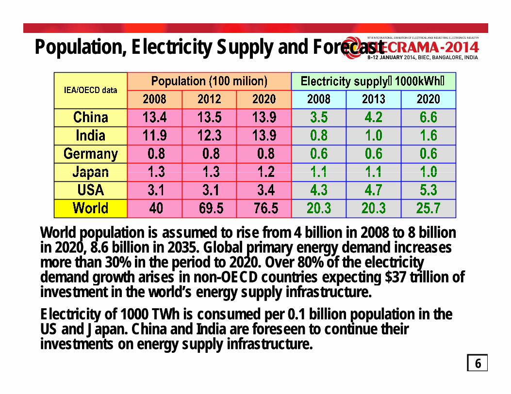
Insulation level: SIWV and SIPLInsulation level: SIWV and SIPL
3
4
Volta
ge (p
.u.)
x1.18 x1.25 x1.28 x1.42SIWV = (1.18-1.42) x SIPL for 800 kV, (1.08-1.23) x SIPL for UHV
x1.07 x1.36
x1.15x1.16
x1.24
x1.20 x1.23 x1.08x1.18x1.25
2
3
1.992.18
e With
stan
d V
SIPL:1.85
2.37 2.18en
tSIPL:1.75
2.37 2.37
ent
SIPL:1.85
2.60 2.60
entSIPL:1.83
1.84 1.84
entSIPL:1.60
2.10 1.95
entSIPL:1.69
1.84 1.84
entSIPL:1.53
2.00 2.00
entSIPL:1.63
1.59 1.73
ent(SIPL:1.60)
2.30 2.18
ent
SIPL:1.84
ent
0
1
kV Quebec NAS EPtc
hing
Impu
ls
Tran
sfor
mer
Othe
r equ
ipm
e
Tran
sfor
mer
Othe
r equ
ipm
Tran
sfor
mer
Othe
r equ
ipm
eussia
V
Tran
sfor
mer
Othe
r equ
ipm
ly
Tran
sfor
mer
Othe
r equ
ipm
dia
Tran
sfor
mer
Othe
r equ
ipm
e
ina
Tran
sfor
mer
Othe
r equ
ipm
e
an
Tran
sfor
mer
Othe
r equ
ipm
e
PCO
Tran
sfor
mer
Othe
r equ
ipm
e
Tran
sfor
mer
Othe
r equ
ipm
e
IEC 800 kVHydro Que
765 kV FURNAS
800 kV AEP
800 kVSwi Russ
1200 kV
(With MOSA)Italy
1050 kV India
1200 kV China
1100 kV Japan
1100 kVKEPCO
800 kV
SIWV SIWV for UHVfor UHV=(1.08~1.23) x SIPL =(1.08~1.23) x SIPL is reduced as compared withis reduced as compared with SIWVSIWV for 800 kVfor 800 kV=(1.18~1.42) x SIPL=(1.18~1.42) x SIPLSIWV SIWV for UHVfor UHV (1.08 1.23) x SIPL (1.08 1.23) x SIPL is reduced as compared withis reduced as compared with SIWVSIWV for 800 kVfor 800 kV (1.18 1.42) x SIPL(1.18 1.42) x SIPLproviding SIPL with the residual voltage of MOSA at 2 kA.providing SIPL with the residual voltage of MOSA at 2 kA.
Mitigation measures such as MOSA with higher performance, CB with opening/closing Mitigation measures such as MOSA with higher performance, CB with opening/closing resistors DS with switching resistor can effectively suppress the switching surgesresistors DS with switching resistor can effectively suppress the switching surges
1010
resistors, DS with switching resistor can effectively suppress the switching surges.resistors, DS with switching resistor can effectively suppress the switching surges.
SIWV requirements for 1200 kV in Russia and India have the same values.SIWV requirements for 1200 kV in Russia and India have the same values.SIWV requirements for 1100 kV in China and Japan are slightly different.SIWV requirements for 1100 kV in China and Japan are slightly different.

Lightning strokes and shielding at towerLightning strokes and shielding at tower
Lightning stroke to Transmission linesLightning stroke to Transmission lines
11Lightning stroke to Grounding wireLightning stroke to Grounding wire
IEEE transactions on power delivery,vol.22,No.1,January 2007

Lightning impulse current surveyLightning impulse current survey
Typical measurement of lightning currentTypical measurement of lightning current
Lightning current waveform for UHV
Distribution of lightning currents with di/dt
12
The maximum lightning current of more than 200 kA is generally used for Lightning The maximum lightning current of more than 200 kA is generally used for Lightning surge analysis for systems of 800 kV and above. surge analysis for systems of 800 kV and above.
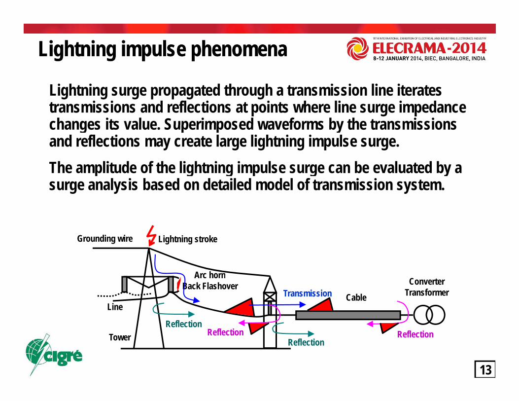
Lightning impulse phenomenaLightning impulse phenomena
Lightning surge propagated through a transmission line iterates transmissions and reflections at points where line surge impedance changes its value Superimposed waveforms by the transmissions changes its value. Superimposed waveforms by the transmissions and reflections may create large lightning impulse surge.The amplitude of the lightning impulse surge can be evaluated by a p g g p g ysurge analysis based on detailed model of transmission system.
Lightning stroke
Arc horn
Grounding wire
Arc hornBack Flashover
Transmission CableConverter
TransformerLine
Reflection
13
Reflection ReflectionTowerReflection
Reflection

LIWV evaluation for different MOSA arrangementsLIWV evaluation for different MOSA arrangements
LIWV with MOSA at transformer
Lightning strokeGrounding wire
Transmission lineTransmission lineTower
LIWV with MOSA at line terminal and transformer
Line terminal
LIWV with MOSA at line terminal, transformer and ,bus terminals
Busbar
14Transformer MOSA: Metal Oxide Surge Arrester
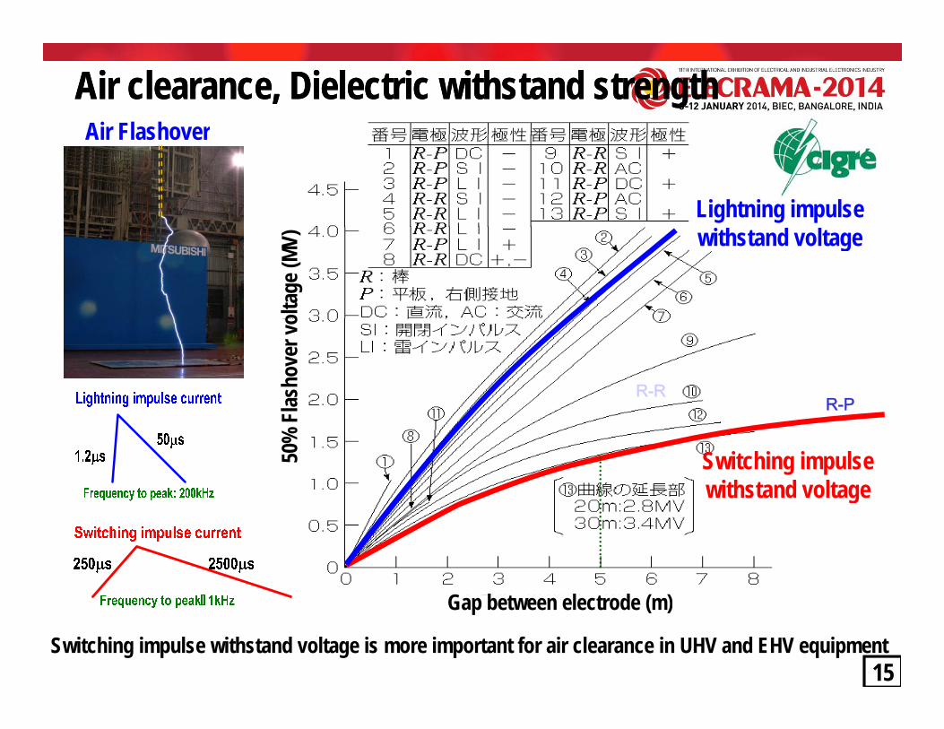
Air FlashoverAir clearance, Dielectric withstand strengthAir clearance, Dielectric withstand strength
Lightning impulse
Air Flashover
withstand voltage
olta
ge (M
V)
R-RR-Plas
hove
r vo
Switching impulse withstand voltage
50%
Fl
g
G b l d ( )
15Switching impulse withstand voltage is more important for air clearance in UHV and EHV equipment
15
Gap between electrode (m)

The loss of largeThe loss of large--capacity and longcapacity and long--distance AC transmission have been reduced by uprating of distance AC transmission have been reduced by uprating of
Technical limitation for AC transmissionTechnical limitation for AC transmission
16
18
The loss of largeThe loss of large capacity and longcapacity and long distance AC transmission have been reduced by uprating of distance AC transmission have been reduced by uprating of transmission voltage but may attain its technical limitation around 1100/1200 kV AC transmission.transmission voltage but may attain its technical limitation around 1100/1200 kV AC transmission.
SIWV:2350kV*: twice SIWV of 550 kV standard 1100kV bushing: 15m1100kV bushing: 15mm)
12
14 *1100kV SIWV is reduced to 1800 kV using several mitigations besides optimal d
istan
ce (m
engt
h
8
10
mitigations besides optimal MOSA arrangement so actual height is about 12 m
, insu
latio
n
Trip
le ga
p le
4
6 550 kV SIWV:1175kV
r clea
ranc
e
550kV bushing: 5m550kV bushing: 5m
Twice withstand
0 500 1000 1500 2000 25000
2
SIWV: Switching Impulse Withstand Voltage (kV)
Air
16
SIWV: Switching Impulse Withstand Voltage (kV) The yield of bushing longer than 15m is significantly reduced so it is difficult to produce it at economical price. The yield of bushing longer than 15m is significantly reduced so it is difficult to produce it at economical price. 1100kV Bushing…15 m correspond to 4 story building, 1650kV Bushing…25 m correspond to 7 story building, 1100kV Bushing…15 m correspond to 4 story building, 1650kV Bushing…25 m correspond to 7 story building, 2200kV Bushing…46 m corresponds to 13 story building2200kV Bushing…46 m corresponds to 13 story building
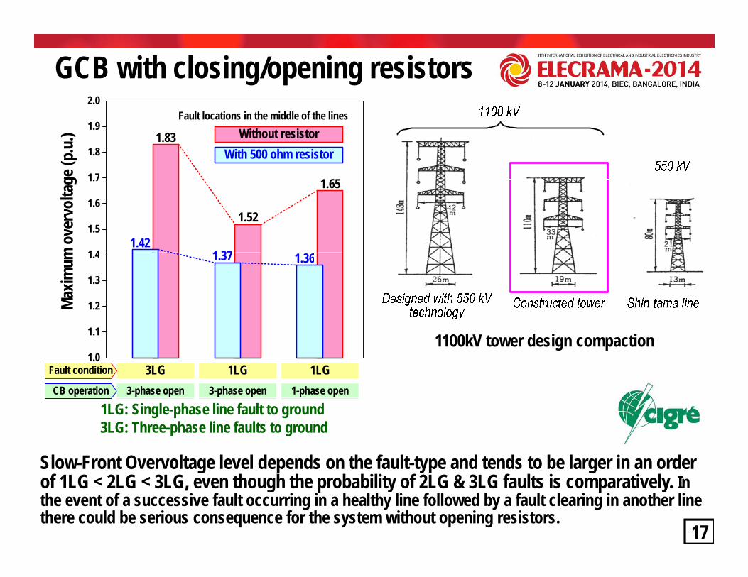
GCB with closing/opening resistors2.0
1 651 7
1.8
1.9
ge (p
.u.) 1.83
With 500 ohm resistorWithout resistor
Fault locations in the middle of the lines
1.65
1 37
1.52
1 4
1.5
1.6
1.7
m o
verv
olta
g
1.421.361.37
1.2
1.3
1.4
Maxim
um
3LG 1LG 1LGFault condition
CB operation 3-phase open 3-phase open 1-phase open
1.0
1.1 1100kV tower design compaction
Slow-Front Overvoltage level depends on the fault-type and tends to be larger in an order
1LG: Single-phase line fault to ground3LG: Three-phase line faults to ground
17
g p yp gof 1LG < 2LG < 3LG, even though the probability of 2LG & 3LG faults is comparatively. In the event of a successive fault occurring in a healthy line followed by a fault clearing in another line there could be serious consequence for the system without opening resistors.
17
DC time constants in fault currentsCalculations predict a large DC time constants in fault current in UHV transmission systems due
Tower and conductor designs
Calculations predict a large DC time constants in fault current in UHV transmission systems due to usage of multi-bundles conductor and the existence of large capacity power transformers.
1100kV transmission lines 800kV transmission lines
Highest voltage(kV)
ConductorsSize
(mm2)Bundlenumber
DC time constants
(ms)
15.5m
19m
810mm sq. -8 conductors
1100kV transmission lines
54.5)
m(4
2.1) m
12m 12m
20.12m1360mm sq. -4 conductors
800kV transmission lines(mm ) number800
Canada 686 4 75800USA 572 6 89800
South Africa 428 6 67
16m
15.5m
1360mm sq. -4 conductors
800kV transmission lines
35 (
22.6
( 12m 12mSouth Africa 428 6 67800
Brazil 603 4 88800
Korea 480 6 80800
Chi 400 6 7516.5m
72.5m
90m
107.5
m12
0m
27.4m40
.3m 15.24m
42.7mChina 400 6 751200
Russia 400 8 911050Italy 520 8 1001100 810 8 150 2
Japan 810 8 1501100China 500 8 1201200India 774 8 100
18
Influences of the high DC component on testInfluences of the high DC component on test--duty T100a does not show any significant duty T100a does not show any significant difference when the constant exceeds around 120 ms. Therefore, it was recommended to difference when the constant exceeds around 120 ms. Therefore, it was recommended to use a time constant of 120 ms for rated voltages higher than 800 kV.use a time constant of 120 ms for rated voltages higher than 800 kV. 18

TRV: Transient Recovery VoltageTRV: Transient Recovery Voltage
The voltage at line side will recover to the source voltage after a fault clearing which I
V
Voltage at source side
after a fault clearing, which causes oscillation around the value of the source voltage.
I
Volta
ge This voltage oscillation immediately after interruption is called as TRV.
ent
TimeTime
Arc voltageArc voltageThe frequency and the amplitude of TRV changes depends on the network
Curre
Arcing timeArcing timeOpening timeOpening timeRelay timeRelay time
configuration, source capacity and a fault location.
19Fault occurrenceFault occurrence Open contactOpen contact InterruptionInterruptionTrip commandTrip command
ggp gp gyy

TRV for Breaker terminal faultsTRV for Breaker terminal faultsF1F2
GW
TRCB1
F1F2
CB2
Load
G
W
Busbar
F3 CB3
F lt F1 CB1 F lt F2 CB2 F lt F3 CB3
GBusbar
Fault F1 CB1T10 duty I=10%
Fault F2 CB2T30, T60 duties I=30, 60%
Fault F3 CB3T100s, a duties I=100%
High TRV
High RRRV
TRV lower than T10
Medium RRRV L RRRV
TRV lower than T30
20
High RRRV Medium RRRV Low RRRV

CIGRE Radial network modelCIGRE Radial network model 1100 kV t i J1100 kV t i J
UHV TRV simulations
D s/s D9 D10D8
231U 231L
FDBLTransmission line
(50km)
Double circuit lines without transposition
15.5m
107.5
m 120 m
16.0m
19.0m 19.0m
16.0m
16.5m 16.5m
0 m
15.5m
CIGRE Radial network modelCIGRE Radial network model 1100 kV system in Japan1100 kV system in Japan
Tr 2×
50kA
D-S/S
F24 Double circuit lines with transposition
A11 A12
A10
E8 E9E10 E11
E7
B11 B7 B8 B12B6
B9 B10B1
224 218 204A 204B
FAELFEALFEBL
FBEL
FBDL
FBCL
FBBUS
( )
B s/s
Transmission line(40km) E s/s A s/sTransmission line
(210km)
Transmission line
72.5
m
Earth Resistivity = 100ohm-m or 500 ohm-m
9
120km 240km
360km
F21
F22
F23
with transposition
Japan 1100kV tower design
C8 C9C7
C1
226
FCBL
FCBUS
: Power transformer
: Fault pointC s/s
Transmission line(138km)
Tr 2× Tr 2× Tr 2× A-S/S B-S/S C-S/S
50kA 50kA 50kA TB 362 “Technical requirements for substation equipment exceeding 800kV”. December 2008, pp.94-95
Line length: 40km, 50km,138km and 210km
2000 1100 kV TRV envelope for T10 duty (Uc=1897kV RRRV=7kV/ s)
1100 kV TRV envelope for OoP duty (Uc=2245 kV)
TRV calculated in 1100 kV radial network model
1000
1500
2000
TRV(
kV)
1100 kV TRV envelope for T30 duty (Uc=1660kV, RRRV=5kV/ s)
1100 kV TRV envelope for T10 duty (Uc=1897kV, RRRV=7kV/ s)TR
V(kV
)
210
500
0 1 2 3Time (ms)

UHV TRV requirements
)U
(kV)
UHV First-pole-to-clear factor
Amplitude factor 1100 kV 1200 kV Rate of Rise of
TRV Time to TRV peak
t
Time to TRV peak
t1.2 (1.3)T100 1617
DUTY
T60T30
Kpp
1.2 (1.3)
1 2 (1 3)
Kaf
1.5 (1.4)
1.51 54
TRV peak (kV)
16171660
1764TRV peak (kV)
17641811
RRRV (kV/ s)
235
t2
3.0*t1 (4*t1)
4.5*t1 (6*t1)
t3
t3 (t3)
TLFOut-of-phase
T30T10
2.0
1.2 (1.3)
1.2 (1.3)
1.2 (1.5)
1.541.76
0.9*1.71.25
1660189716492245
1811207617992450
57(*)
t3 (t3)
t3 (t3)
(*)
1.38*t1 (2*t1)
22
Values ( ) are standards for 800 kV and below. t1 and t3 are based on Kpp=1.2(*) : RRRV= Uc / t3 with t3 =6 * Ur / I 0.21 shown in the ANSI C37.06.1-2000 for transformers up to 550 kVFor UHV transformers, RRRV and t3 are determined by the transformer impedance and its equivalent surge capacitance (specified as 9 nF)

Influence of fault locations on TRV Influence of fault locations on TRV for LLF conditions for LLF conditions Shorter LongerDistance to the fault point
V
(a)=(b)
(d)
V
(a)
(b)US
Source side TRV(a)
V
USUS=US’ (e)Traveling Wave
Travelingwave
Traveling
Source side TRV Source side TRV
Shorter LongerDistance to the fault point
t0
(d)
t0
Line side(c)
(d)
UL
US’
t0
Line side
(b)
(c)
(d)UL
US’ UL
Traveling Wave from another line
Travelingwave
t0 t0 t0
Line sidevoltage
SSS CLt π= L/c2t2=
(c)
(ii) Middle distance(i) Short distance (iii) Long distance
Line sidevoltage
SSS CLt π=L/c 2t2=
Line sidevoltage
SSS CLt π= L/c2t2=
stTR
V [k
V]
Breaking current =11.3 kA rms (di/dt=5.02A/μs)
Voltage across CB
Uo=458kV
Source side voltage
Line side voltage
Breaking current =7.1 kA rms (di/dt=3.15 A/μs)
Uo=602kV
RV [k
V]
TRV
[kV]
Breaking current =5.1 kA rms (di/dt=2.26 A/μs)
Uo=666kV
1s
Up=1084kV
Tp=0.796msUp=1401kV
Tp=1.62ms
1stT
1stT
Up=1539kV
Tp=2.41ms
23
Tp 1.62ms p
23
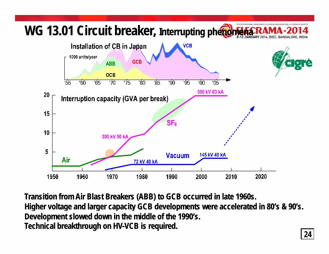
WG 13.01 Circuit breaker, WG 13.01 Circuit breaker, Interrupting phenomenaInterrupting phenomena
Transition from Air Blast Breakers (ABB) to GCB occurred in late 1960s.Transition from Air Blast Breakers (ABB) to GCB occurred in late 1960s.Higher voltage and larger capacity GCB developments were accelerated in 80’s & 90’sHigher voltage and larger capacity GCB developments were accelerated in 80’s & 90’s
24
Higher voltage and larger capacity GCB developments were accelerated in 80 s & 90 s.Higher voltage and larger capacity GCB developments were accelerated in 80 s & 90 s.Development slowed down in the middle of the 1990’s.Development slowed down in the middle of the 1990’s.Technical breakthrough on HVTechnical breakthrough on HV--VCB is required.VCB is required.
Interrupting capability of different gasesInterrupting capability of different gases
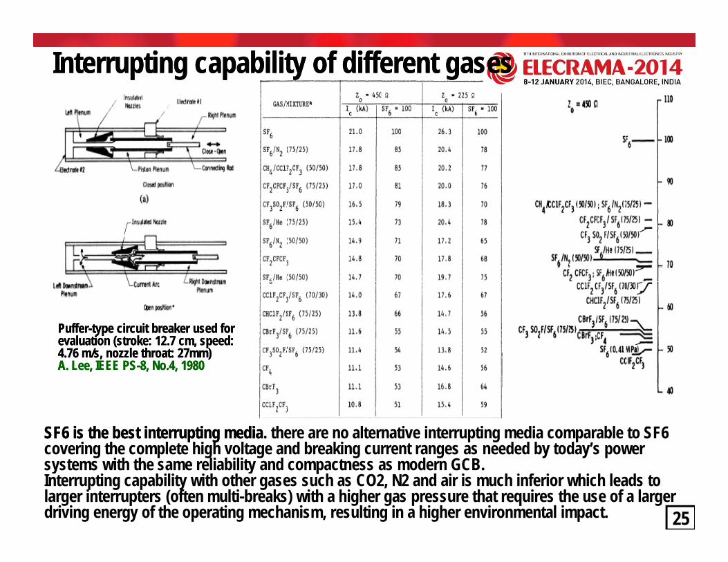
PufferPuffer--type circuit breaker used for type circuit breaker used for evaluation (stroke: 12.7 cm, speed: evaluation (stroke: 12.7 cm, speed: 4.76 m/s, nozzle throat: 27mm)4.76 m/s, nozzle throat: 27mm)A. Lee, IEEE PSA. Lee, IEEE PS--8, No.4, 19808, No.4, 1980
SF6 is the best interrupting mediaSF6 is the best interrupting media. there are no alternative interrupting media comparable to SF6 covering the complete high voltage and breaking current ranges as needed by today’s power
i h h li bili d d GCB
25
systems with the same reliability and compactness as modern GCB.Interrupting capability with other gases such as CO2, N2 and air is much inferior which leads to larger interrupters (often multi-breaks) with a higher gas pressure that requires the use of a larger driving energy of the operating mechanism, resulting in a higher environmental impact.

Superior SFSuperior SF66 dielectric / interrupting performancedielectric / interrupting performanceDielectric performance: 3 times better
SFSFvo
ltage
(kV
volta
ge (k
V rm
srm
s) ) SF6 RodRod--PlanePlaneGapGap::38mm38mm
SFSF66-- Smaller diameter in arc Smaller diameter in arc (Less energy dispassion)(Less energy dispassion)-- Rapid switching: Rapid switching: conductor to insulatorconductor to insulator
Flas
hove
r vFl
asho
ver v Air
Gas pressure (MPa) Gas pressure (MPa)
conductor to insulatorconductor to insulator(Faster resistance change)(Faster resistance change)
Less breaks for interrupterLess breaks for interrupter
SF6
t (k
A rm
s)t
(kA
rms)
Interrupting performance: 100 times betterpp
Compact equipment & substationCompact equipment & substation
Aierru
ptin
g cu
rrent
erru
ptin
g cu
rrent
Air insulated substation (AIS)Air insulated substation (AIS)
Air
Puffer pressure (MPa)Puffer pressure (MPa)
Criti
cal in
teCr
itica
l inte
26
Gas insulated substation (GIS)Gas insulated substation (GIS)5% installation area, 1% volume as compared with AIS5% installation area, 1% volume as compared with AIS
Environmental impactGlobal Warming Potential value of 22800 (calculated Global Warming Potential value of 22800 (calculated in terms of the in terms of the 100100--year warming potential of one year warming potential of one kilogram of SFkilogram of SF66 relative to one kilogram of COrelative to one kilogram of CO22))

WG A3.06: Circuit Breaker Reliability surveysWG A3.06: Circuit Breaker Reliability surveys
Part 1: Summary and general matters (TB 509)Part 2: SF6 gas circuit breakers (TB 510)6 g ( )Part 3: Disconnectors and Earthing switches (TB 511)Part 4: Instrument transformers (TB 512)Part 5: Gas insulated switchgears (TB 513)Part 5: Gas insulated switchgears (TB 513)Part 6: GIS practices (TB 514)
27CB Major failure frequency for different voltage levels CB Major failure frequency for different voltage levels CB Major failure frequency for different kinds of service CB Major failure frequency for different kinds of service

WG A3.06: CB Reliability surveys : rating voltagesWG A3.06: CB Reliability surveys : rating voltages
28The increased application of spring operating mechanisms improved CB reliability.The increased application of spring operating mechanisms improved CB reliability.

WG A3.06: CB Reliability surveys : componentsWG A3.06: CB Reliability surveys : components
Half of the Major / Minor failures are responsible for operating mechanisms.Half of the Major / Minor failures are responsible for operating mechanisms.
SF6 circuit breakers: SF6 circuit breakers: 0.30 0.30 (0.67)(0.67) MaF / 100 CBMaF / 100 CB--yearsyearsDisconnectors and earthing switches:Disconnectors and earthing switches: 0.21 MaF / 100 DE0.21 MaF / 100 DE--yearsyearsInstrument transformers:Instrument transformers: 0.053 MaF / 100 IT0.053 MaF / 100 IT--years (1years (1--phase units)phase units)
29
Gas insulated switchgear:Gas insulated switchgear: 0.37 0.37 (0.53)(0.53) MaF / 100 GIS CBMaF / 100 GIS CB--baybay--yearsyears

WG A2.37: Transformer ReliabilityWG A2.37: Transformer ReliabilityReview all existing national surveys.Preliminary results, based on a transformer population with more than150.000 unit-years and 685 major failures in 48 utilities, indicate a150.000 unit years and 685 major failures in 48 utilities, indicate afailure rate of 0.44%.Winding related failures appear to be the largest contributor of majorfailures and a significant decrease in tap changer related failuresfailures, and a significant decrease in tap changer related failures.
30

WG A3.27: Application of vacuum switchgear at WG A3.27: Application of vacuum switchgear at transmission voltagetransmission voltagetransmission voltagetransmission voltage
72 kV VCB (China)132 kV 16 kA VCB (UK)245 kV load switch (USA) 145 kV & 72 kV VI (Germany)72 kV 31.5 kA VCB (Japan)72.5 kV 31.5 kA VCB (France)
HV-VCB technical meritsFrequent switching capability, Less maintenance work, SF6 freeHV-VCB challenges at transmission level despite of excellent experience at distributionLimited experience on long term reliabilityScatter of dielectric performance especially for capacitive current switching
31
Scatter of dielectric performance especially for capacitive current switchingLimited current carrying capability, limited unit voltage

Difficulty of higher voltage vacuum interrupterDifficulty of higher voltage vacuum interrupter
Recovery voltage of Recovery voltage of small capacitive current small capacitive current interruptioninterruptionVoltage factor = 1 7Voltage factor = 1 7 V)V)
CIGRE investigation
Voltage factor = 1.7Voltage factor = 1.7
TransmissionTransmission volta
ge (k
Vvo
ltage
(kV
………..84kV……(165kV)TransmissionTransmission165 kV for 84 kV165 kV for 84 kV141 kV for 145 kV141 kV for 145 kV
DistributionDistribution Flas
hove
r vFl
asho
ver v
36 ( 1 )DistributionDistribution71kV for 36 kV71kV for 36 kV47kV for 24 kV47kV for 24 kV
FF ……….…………...36kV…. (71kV)
Gap distance (mm)Gap distance (mm)Gap distance (mm)Gap distance (mm)
32
Dielectric withstand voltage in SF6 linearly increases with gap distance but that in Dielectric withstand voltage in SF6 linearly increases with gap distance but that in Vacuum tends to saturate, which makes difficult to increase a unit voltage per break.Vacuum tends to saturate, which makes difficult to increase a unit voltage per break.
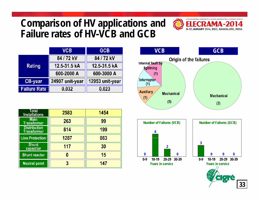
Comparison of HV applications and Failure rates of HV-VCB and GCBFailure rates of HV VCB and GCB
VCB GCB
6
Number of Failures (VCB) Number of Failures (GCB)
10-19Years in ser ice
20-29 30-390-9
2
0010-19
Years in ser ice20-29 30-390-9
3
00 0
33
Years in service Years in service

Motivations for VCB developments & installations in Japan& installations in Japan
Utilities Industrial system
Advantages of VCB
・Less maintenance work・Frequent switching capability
・Non-flammability・Low operating energy
y
A large number of VCBs have been put in service at transmission voltages since 1970’s A large number of VCBs have been put in service at transmission voltages since 1970’s and and installed to special switching requirements in the 1980’s and 1990’s installed to special switching requirements in the 1980’s and 1990’s . . Apparently, the reduction of SF6 gas usage seems not to be a primary factor of utilities’ Apparently, the reduction of SF6 gas usage seems not to be a primary factor of utilities’
34
pp y g g p ypp y g g p ypolicy and decision for policy and decision for VCB installations since it wasVCB installations since it was 1997 when COP3 conference was 1997 when COP3 conference was defined as SF6 gas to be one of the global warming gas. defined as SF6 gas to be one of the global warming gas.

JWG A3/B4.34 DC current interruptionJWG A3/B4.34 DC current interruptionCurrent limiting scheme Forced current zero formation Resonant current zero formationCurrent limiting scheme Forced current zero formation Resonant current zero formation
MOSA
I Va
Circuit Breaker
I
Va t
Arc voltage
The scheme is applied to several 100 V class DC-NFB & 2000 V class air-blast type high speed switch used for railway
The scheme can potentially applicable to interrupt HVDC current even though a large capacity capacitor bank is
The scheme is applied to MRTB which interrupt the DC current in the neutral line of HVDC transmissionspeed switch used for railway
system.The arc generated voltage across the circuit breaker contacts limits the DC c rrent
capacity capacitor bank is required.The pre-charged capacitor imposes an reverse current on faulted DC current and creates
transmission.
The parallel capacitor and reactor across the circuit breaker generates the current
35
contacts limits the DC current. faulted DC current and creates the current zero within a few milliseconds.
breaker generates the current oscillation, which eventually leads to the current zero.

Current limiting scheme: DCCurrent limiting scheme: DC--NFBNFBDC480V15kA-NFB Rated voltage: DC 480V
Rated interrupting current: DC 15kATypical interrupting time: 5ms
arc voltageShort circuit current
NFB tripCurrent level q
circuit voltage
t1 t3
t2 t4tT
q
Smoothing L RMITSUBISHI ELECTRIC
t1: time to the NFB trip current levelT2: contact parting timeT3: time from the instant of contact parting
to the instant of current peakT4: Arcing time
LordShort
NFB2 E
NFB1
36
4 gtT: total time of interruptionq: rate of rise of current (di/dt)
circuit

Forced current commutation scheme DCCBHi h S d V Ci it B k (HSVCB) f il li tiRated voltage: DC 750, 1500 VRated nominal current: 3-4 kA R t d i t ti t DC 100kA DC P
Auxiliary VCBHigh Speed Vacuum Circuit Breaker (HSVCB) for railway application
Rated interrupting current: DC 100kAInterrupter: VCB
Fault occurrence
DC Powersupply
Vacuuminterrupter
Main circuit current
M i VCB tInterruption of main VCB
Interruption of main circuit
ElectromagneticRepelling drive
Main VCB current
Commutating circuit currentEnergizing of commutating current
Making switch(Thyristor)
Fault current limiter
NLR current
Energizing of open operation of main VCB
+
- External DC source
(Capacitor)
Main CB(VCB)
MO Varistor
37
Main VCB contact
Auxially CB(VCB)
In case of fault occurrence, external DC source discharge a reverse current and create a current zero. MITSUBISHI
ELECTRIC

W ti h SF6 HV d b k t t
Self current commutation scheme: DCCB
DCCB for DC transmission lineWestinghouse SF6 HV-dc breaker prototype
In 1985, Europe and US developed DC 550 kV / 2200 A In 1985, Europe and US developed DC 550 kV / 2200 A DCCB with four break SF6 GCB and tested in the field DCCB with four break SF6 GCB and tested in the field at 400 kV Pacific DC intertie with 1360 km lineat 400 kV Pacific DC intertie with 1360 km line
Rated voltage: DC 550 kV
Circuit
The current oscillation caused by reaction of arc and parallel impedance continues to grow and lead to a current zero
Rated voltage: DC 550 kVRated interrupting current: DC 2200 AInterrupter: SF6 puffer typeTypical interrupting time: 25 ms
~10ms
CircuitFaultcurrent
I0
ArcC t
<1ms~10ms
12.7μFStray inductance20 H
Stray inductance:20μHZ O Z O Z O Z O
I0Current
Arc/Recoveryvoltage
~1ms:20μH
CS S1 S1CS
CBRR
CS S1 S1CS
CBRR
CB CB
ZnO ZnO ZnO ZnO
38ArcingBegins
InstabilityBeginsS1 closes
voltage
ZnOConducts
CommutationReference: HVDC CIRCUIT BREAKER DEVELOPMENT AND FIELD TEST, Reference: HVDC CIRCUIT BREAKER DEVELOPMENT AND FIELD TEST, IEEE Trans. Vol. PASIEEE Trans. Vol. PAS--104, No.10, Oct. 1985104, No.10, Oct. 1985
RRS2 S2
RRS2
S2

Resonant current commutation schemeMRTB (Metric return transfer breaker) for the neutral line of HVDC transmission
Rated voltage: DC 250 kVR t d i t ti t DC 2800/3500 ARated interrupting current: DC 2800/3500 AInterrupter: SF6 puffer typeTypical interrupting time: 20-40 ms
Artificial grounding DC current interruption by MRTB
39H. Ito, et al., Instability of DC arc in SF6 circuit breaker”, IEEE 96 WM, PEH. Ito, et al., Instability of DC arc in SF6 circuit breaker”, IEEE 96 WM, PE--057057--PWRDPWRD--00--1111--19961996

Hybrid type HVDC CB based on power electronic devices
③ ②②③
⑤ ①④ ①④⑤
③③②
③
④
②③
④Development targetRated voltage: DC 320 kVRated nominal current: DC 2000 A
①⑤
①⑤
1. Fault occurrence
Rated nominal current: DC 2000 ARated interrupting current: DC 9 kAInterrupter: Power electronics devicesTypical interrupting time: 5 ms
40
2. Commutate the current by Auxiliary DC Breaker3. Disconnect the main circuit by Fast DS4. Interrupt the current by power electronics DCCB5. Disconnect the residual current
ABB Grid Systems, Technical Paper Nov. 2012

CIGRE TF 13 00 01 C t ll d S it hi 1990 1995CIGRE/IEC Controlled Switching Survey CIGRE/IEC Controlled Switching Survey CIGRE TF 13.00.01:Controlled Switching, 1990-1995Field experience of controlled switching WG 13/A3.07: Controlled switching of HVAC circuit-breakers, 1996-2003g ,Application guide for lines, reactors, capacitors, transformers switchingFurther applications such as unloaded transformer switching, load and fault interruption and circuit-breaker uprating Benefits and Economic aspectsPlanning, Specifications & Testing of controlled switchingIEC62271-302: High voltage alternating current circuit-breaker with IEC62271 302: High voltage alternating current circuit breaker with internationally non-simultaneous pole operation, 2004-2006CIGRE WG A3.35: Guidelines and Best Practices for theCommissioning and Operation of Controlled Switching Projects 2014Commissioning and Operation of Controlled Switching Projects, 2014-
41

WG A3.07:WG A3.07: Controlled switching surveyControlled switching survey
42The number of installations is based on several WG members’ reports so it did The number of installations is based on several WG members’ reports so it did not cover the worldwide statistics but shows the trend of applications.not cover the worldwide statistics but shows the trend of applications.

CIGRE TF 13.00.01: Controlled SwitchingCIGRE TF 13.00.01: Controlled Switching
Application Conventional practice Controlled switchingNo load Voltage peak No load Transformer Closing resistor Voltage peak
(low residual flux)
No load line Closing resistorS t Voltage zero across CB
Capacitor Voltage zero across CB
No load line Surge arresterClosing resistorSurge arrester
Voltage zero across CB
Surge arrester Maximum arcing time
g
Rector Maximum arcing time to avoid restrike
Opening resistorSurge arrester
43

Compensation functions required for a ControllerCompensation functions required for a ControllerWG 13.07: Controlled switchingWG 13.07: Controlled switching
Compensation functions required for a ControllerCompensation functions required for a ControllerConditional compensation :Conditional compensation :Variations of operating time depending on ambient temperature, control Variations of operating time depending on ambient temperature, control voltage and mechanical pressurevoltage and mechanical pressureg pg pIdle time compensation :Idle time compensation :Delay of operating time after an idle time of the breaker for next operationDelay of operating time after an idle time of the breaker for next operationAdaptive compensation :Adaptive compensation :Deviation of operating time due to longDeviation of operating time due to long term aging during the term aging during the Deviation of operating time due to longDeviation of operating time due to long--term aging during the term aging during the consecutive operationsconsecutive operations
Factory Tests for Circuit BreakersFactory Tests for Circuit BreakersFactory Tests for Circuit BreakersFactory Tests for Circuit Breakers
44

Controlled transformer switchingControlled transformer switchingTransientTransient InrushInrush CurrentCurrent atat energizationenergization dependsdepends onon thethe switchingswitching angleangle andand thethe residualresidual fluxflux ofof
Symmetrical Flux Flux Asymmetrical Flux Flux
TransientTransient InrushInrush CurrentCurrent atat energizationenergization dependsdepends onon thethe switchingswitching angleangle andand thethe residualresidual fluxflux ofofthethe corecore.. TheThe higherhigher residualresidual fluxflux causescauses thethe corecore saturationsaturation resultingresulting inin largerlarger inrushinrush currentcurrent..
tVoltage
CurrentVoltage
Current
Residual Flux
tizin
g cu
rrenVoltage
curre
nt
Random energisationControlled energisationMa
gnet
Inru
sh cRandom energisationControlled energisation
Inrush current: 1120AInrush current: 1120AVoltage disturbance: 15 %Voltage disturbance: 15 %
Inrush current: <100 AInrush current: <100 AVoltage disturbance: <1 %Voltage disturbance: <1 %
45
The optimum targets should be adjusted taking into account the residual flux. The inrush The optimum targets should be adjusted taking into account the residual flux. The inrush current can be only eliminated by energisation when the prospective normal core flux is current can be only eliminated by energisation when the prospective normal core flux is identical to the residual flux.identical to the residual flux.

Compensated Line switchingCompensated Line switchingTheThe degreedegree ofof compensationcompensation hashas significantsignificant effecteffect onon thethe lineline--sideside voltagevoltage..TheThe voltagevoltage acrossacross thethe breakerbreaker showshow aa prominentprominent beatbeat especiallyespecially forfor aa highhighdegreedegree ofof compensationcompensation..gg ppTheThe optimumoptimum instantinstant isis voltagevoltage minimumminimum acrossacross thethe breaker,breaker, preferablypreferablyduringduring aa periodperiod ofof thethe minimumminimum voltagevoltage beatbeat
46

CIGRE Controlled Switching Publication CIGRE Controlled Switching Publication CIGRE TF 13.00.01:Controlled SwitchingCIGRE TF 13.00.01:Controlled SwitchingA stateA state--ofof--thethe--art survey, Part 1, ELECTRA NR. 163, pp65art survey, Part 1, ELECTRA NR. 163, pp65--96, 199596, 1995A stateA state--ofof--thethe--art survey, Part 2, ELECTRA NR. 164, pp39art survey, Part 2, ELECTRA NR. 164, pp39--61, 1996 61, 1996
WG 13.07: Controlled switching of HVAC circuitWG 13.07: Controlled switching of HVAC circuit--breakersbreakersGuide for application lines, reactors, capacitors, transformers 1Guide for application lines, reactors, capacitors, transformers 1stst part. ELECTRA 183, part. ELECTRA 183, April 1999, 2April 1999, 2ndnd Part, ELECTRA 185, August 1999 Part, ELECTRA 185, August 1999 Planning, specification and testing of controlled switching systems, ELECTRA 197, Planning, specification and testing of controlled switching systems, ELECTRA 197, August 2001 August 2001 Controlled switching of unloaded power transformers, ELECTRA 212, February 2004 Controlled switching of unloaded power transformers, ELECTRA 212, February 2004 Controlled Switching : nonControlled Switching : non--conventional applications ELECTRA 214 June 2004 conventional applications ELECTRA 214 June 2004 Controlled Switching : nonControlled Switching : non--conventional applications, ELECTRA 214, June 2004 conventional applications, ELECTRA 214, June 2004 Benefits and Economic aspects, ELECTRA 217, December 2004 Benefits and Economic aspects, ELECTRA 217, December 2004 Benefits & Economic Aspects, TB262, December 2004Benefits & Economic Aspects, TB262, December 2004G id f f th li ti i l di l d d t f it hi l d d G id f f th li ti i l di l d d t f it hi l d d Guidance for further applications including unloaded transformer switching, load and Guidance for further applications including unloaded transformer switching, load and fault interruption and circuitfault interruption and circuit--breaker uprating, TB263, December 2004 breaker uprating, TB263, December 2004 Planning, Specifications & Testing of controlled switching systems, TB264, December Planning, Specifications & Testing of controlled switching systems, TB264, December 2004 2004
47

Study Committee A3, summaryStudy Committee A3, summaryA3 S
Design and development of substation equipmentNew and improved testing techniques
A3 Scope
p g qMaintenance, Refurbishment and Lifetime management Reliability assessment and Condition monitoring Requirements presented by changing networks, standardizations q p y g g ,
WG investigationsWG A3.06: Reliability of High Voltage EquipmentWG A3.25: MO Surge Arresters for emerging system conditionsWG A3.26: Influence of shunt capacitor banks on circuit breaker fault interruption dutiesWG A3.27: Impact of the application of vacuum switchgear at transmission voltagesWG A3.28: Switching phenomena and testing requirements for UHV & EHV equipmentWG A3.29: Deterioration and ageing of substation equipmentWG A3.30: Overstressing of substation equipmentWG A3.31: Accuracy, Calibration & Interfacing of Instrument Transformers with Digital OutputsJWG A3.32/CIRED: Non-intrusive methods for condition assessment of T&D switchgears
48
WG A3.33: Experience with equipment for series / shunt compensationJWG A3/B4.34: DC switchgearWG A3.35: Commissioning practices of controlled switching projects

Study Committee A3: EquipmentStudy Committee A3: Equipment
Thank you very much for your attentionThank you very much for your attention
4953
Related Documents