CHW 469 : Embedded Systems Instructor: Dr. Ahmed Shalaby http://bu.edu.eg/staff/ahmedshalaby14# Embedded Systems https:// piazza.com/fci.bu.edu.eg/spring2017/chw469/home

Welcome message from author
This document is posted to help you gain knowledge. Please leave a comment to let me know what you think about it! Share it to your friends and learn new things together.
Transcript

CHW 469 : Embedded Systems
Instructor:Dr. Ahmed Shalaby http://bu.edu.eg/staff/ahmedshalaby14#
Embedded Systems
https://piazza.com/fci.bu.edu.eg/spring2017/chw469/home
Assignment no. 6
Embedded Systems
Draw the memory Map for Cortex-M0.
Define the different structures for Embedded System Program flow.

38
Instruction Set Architecture: Defines how the program execution should
behave and how the debuggers. ( Software view )
Microarchitecture: the exact implementation details of the processor, for
example, how many pipeline stages, instruction cycles, what type of bus
interface used, etc. ( Hardware view )
Embedded Systems
Architecture of the Cortex M0
39
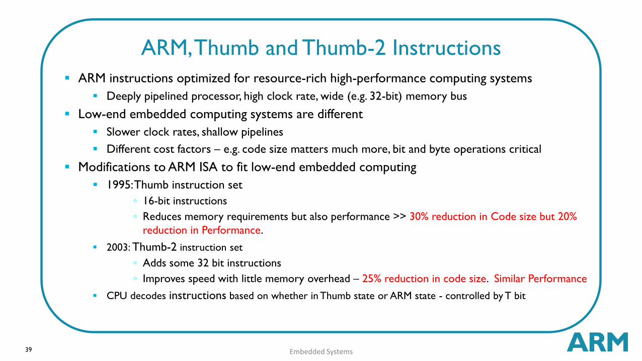
ARM instructions optimized for resource-rich high-performance computing systems
Deeply pipelined processor, high clock rate, wide (e.g. 32-bit) memory bus
Low-end embedded computing systems are different
Slower clock rates, shallow pipelines
Different cost factors – e.g. code size matters much more, bit and byte operations critical
Modifications to ARM ISA to fit low-end embedded computing
1995: Thumb instruction set
◦ 16-bit instructions
◦ Reduces memory requirements but also performance >> 30% reduction in Code size but 20%
reduction in Performance.
2003: Thumb-2 instruction set
◦ Adds some 32 bit instructions
◦ Improves speed with little memory overhead – 25% reduction in code size. Similar Performance
CPU decodes instructions based on whether in Thumb state or ARM state - controlled by T bit
Embedded Systems
ARM, Thumb and Thumb-2 Instructions

40
Based on an architecture specification called ARMv6-M Architecture. Only a
subset of the Thumb ISA is used (56 of them).
Most instructions are 16 bits long, some are 32 bits
Most 16-bit instructions can only access low registers (R0-R7), but some can access high
registers (R8-R15)
Half-word aligned instructions.
Types of Instructions:
Data processing ( Operation – logical, arithmetic ).
Memory access ( read, write to memory ).
Program flow control ( Branching ).
Access to special Register. (MSP).
Exception and OS Support. ( Enable/Disable Interrupts ).
Sleep Operation. ( Waif for Interrupt ).
Memory Barrier ( Stop execution of next instructions, memory transfer ).
Embedded Systems
Instruction Set

41 Embedded Systems
Instruction Set Summary
The Definitive Guide to the ARM® Cortex®-M0 and Cortex-M0+ Processors
42 Embedded Systems
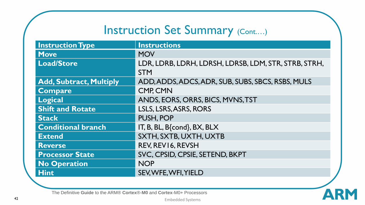
Instruction Set Summary (Cont.…)
The Definitive Guide to the ARM® Cortex®-M0 and Cortex-M0+ Processors
Instruction Type Instructions
Move MOV
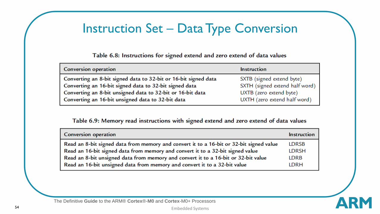
Load/Store LDR, LDRB, LDRH, LDRSH, LDRSB, LDM, STR, STRB, STRH,
STM
Add, Subtract, Multiply ADD, ADDS, ADCS, ADR, SUB, SUBS, SBCS, RSBS, MULS
Compare CMP, CMN
Logical ANDS, EORS, ORRS, BICS, MVNS, TST
Shift and Rotate LSLS, LSRS, ASRS, RORS
Stack PUSH, POP
Conditional branch IT, B, BL, B{cond}, BX, BLX
Extend SXTH, SXTB, UXTH, UXTB
Reverse REV, REV16, REVSH
Processor State SVC, CPSID, CPSIE, SETEND, BKPT
No Operation NOP
Hint SEV, WFE, WFI, YIELD
43
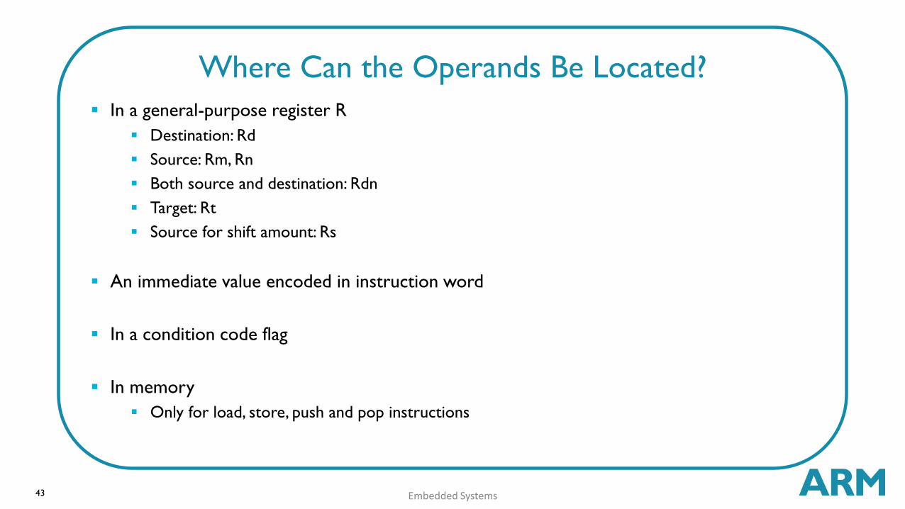
In a general-purpose register R
Destination: Rd
Source: Rm, Rn
Both source and destination: Rdn
Target: Rt
Source for shift amount: Rs
An immediate value encoded in instruction word
In a condition code flag
In memory
Only for load, store, push and pop instructions
Embedded Systems
Where Can the Operands Be Located?
44
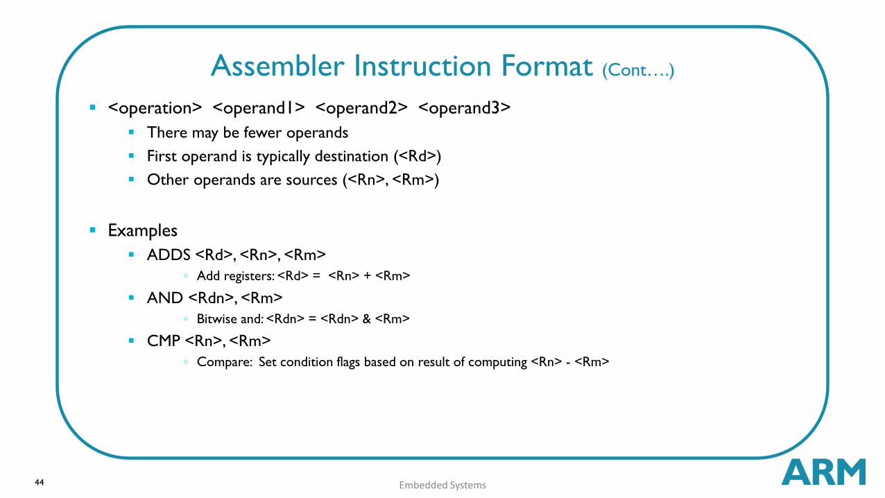
<operation> <operand1> <operand2> <operand3>
There may be fewer operands
First operand is typically destination (<Rd>)
Other operands are sources (<Rn>, <Rm>)
Examples
ADDS <Rd>, <Rn>, <Rm>
◦ Add registers: <Rd> = <Rn> + <Rm>
AND <Rdn>, <Rm>
◦ Bitwise and: <Rdn> = <Rdn> & <Rm>
CMP <Rn>, <Rm>
◦ Compare: Set condition flags based on result of computing <Rn> - <Rm>
Embedded Systems
Assembler Instruction Format (Cont….)
45
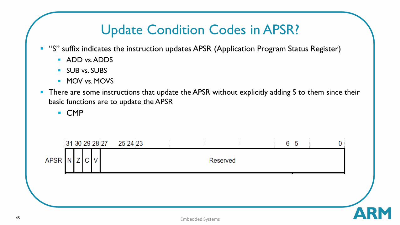
“S” suffix indicates the instruction updates APSR (Application Program Status Register)
ADD vs. ADDS
SUB vs. SUBS
MOV vs. MOVS
There are some instructions that update the APSR without explicitly adding S to them since their
basic functions are to update the APSR
CMP
Embedded Systems
Update Condition Codes in APSR?

46
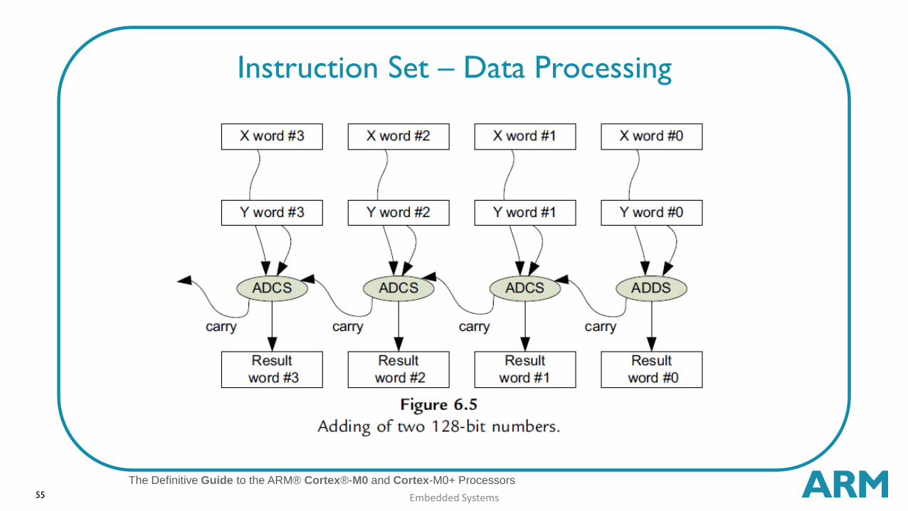
Add registers, update condition flags
ADDS <Rd>,<Rn>,<Rm>
Add registers and carry bit, update condition flags
ADCS <Rdn>,<Rm>
Add registers
ADD <Rdn>,<Rm>
Add immediate value to register
ADDS <Rd>,<Rn>,#<imm3>
ADDS <Rdn>,#<imm8>
Embedded Systems
Instruction Set – Data Processing - Add

47
REV - reverse all bytes in word
REV <Rd>,<Rm>
REV16 - reverse bytes in both half-words
REV16 <Rd>,<Rm>
REVSH - reverse bytes in low half-word
(signed) and sign-extend
REVSH <Rd>,<Rm>
Embedded Systems
Instruction Set – Data Processing - Reversing Bytes
The Definitive Guide to the ARM® Cortex®-M0 and Cortex-M0+ Processors
48
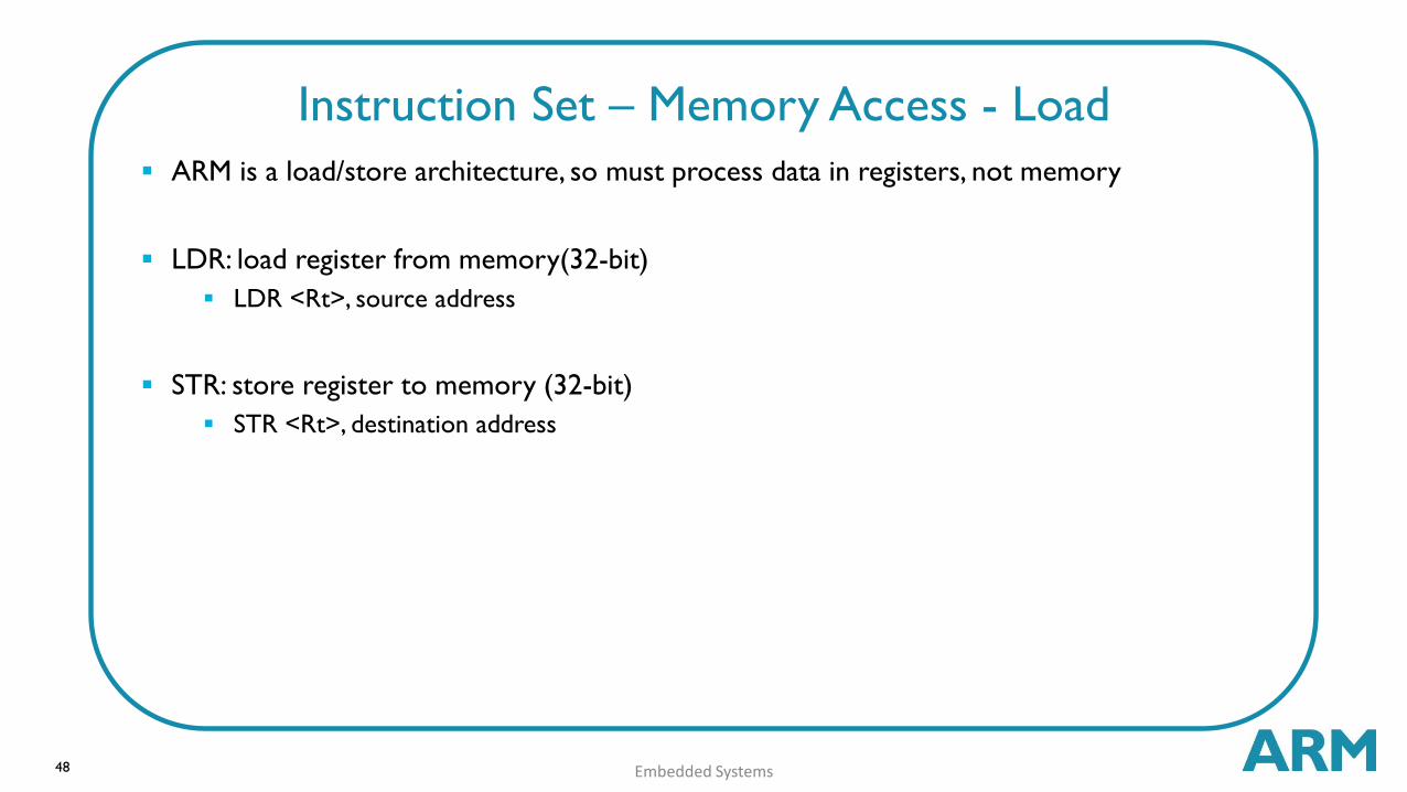
ARM is a load/store architecture, so must process data in registers, not memory
LDR: load register from memory(32-bit)
LDR <Rt>, source address
STR: store register to memory (32-bit)
STR <Rt>, destination address
Embedded Systems
Instruction Set – Memory Access - Load

49
Move to Register from Special
Register
MSR <Rd>, <spec_reg>
Move to Special Register from
Register
MRS <spec_reg>, <Rd>
Change Processor State - Modify
PRIMASK register
CPSIE - Interrupt enable
CPSID - Interrupt disable
Embedded Systems
Instruction Set – Access Special Register

50
No Operation - does nothing!
NOP
Breakpoint - causes hard fault or debug halt - used to implement software breakpoints
BKPT #<imm8>
Wait for interrupt - Pause program, enter low-power state until a WFI wake-up event
occurs (e.g. an interrupt)
WFI
Supervisor call generates SVC exception (#11), same as software interrupt
SVC #<imm>
Embedded Systems
Instruction Set – Others
51 Embedded Systems
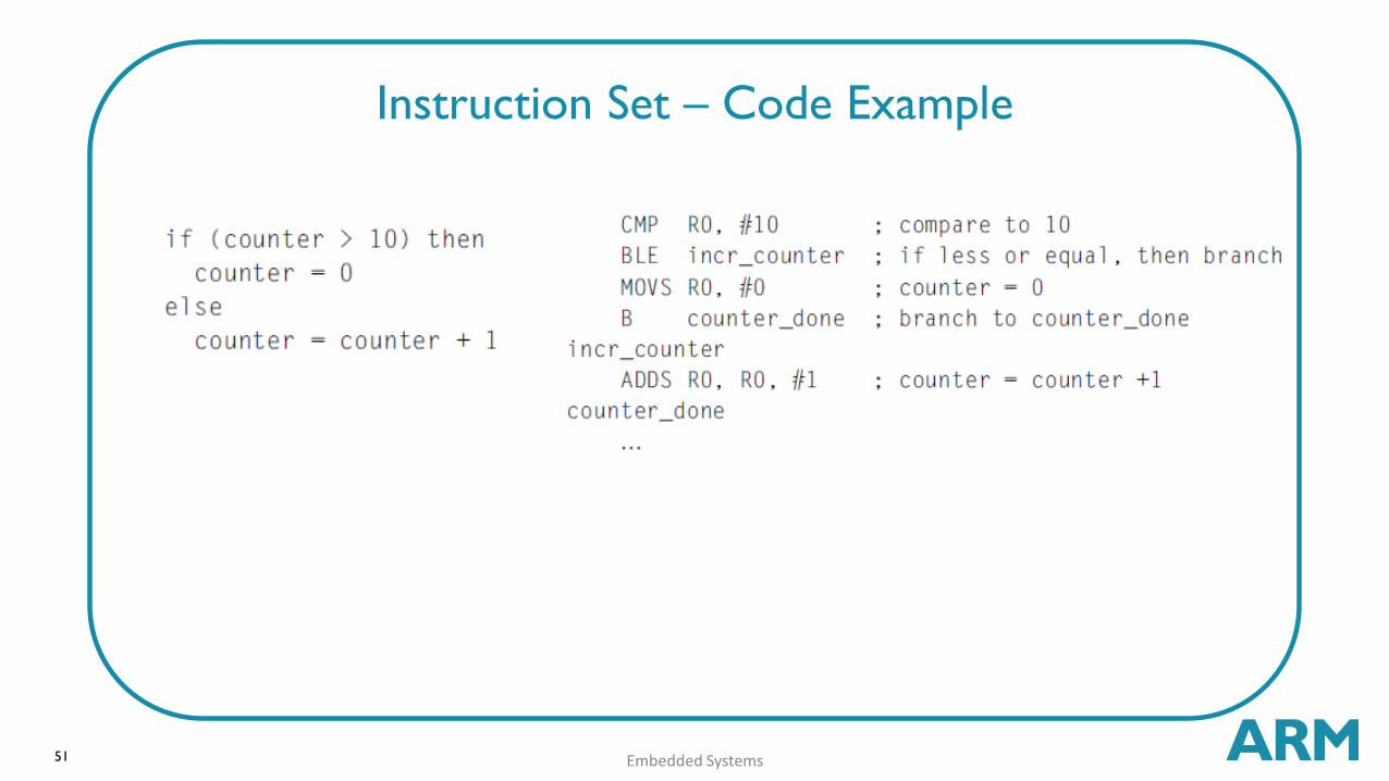
Instruction Set – Code Example

52 Embedded Systems
Instruction Set – Data Types
The Definitive Guide to the ARM® Cortex®-M0 and Cortex-M0+ Processors

53 Embedded Systems
Instruction Set – Data Types
The Definitive Guide to the ARM® Cortex®-M0 and Cortex-M0+ Processors
54 Embedded Systems
Instruction Set – Data Type Conversion
The Definitive Guide to the ARM® Cortex®-M0 and Cortex-M0+ Processors
55 Embedded Systems
Instruction Set – Data Processing
The Definitive Guide to the ARM® Cortex®-M0 and Cortex-M0+ Processors

56 Embedded Systems
Instruction Set – Data Processing
The Definitive Guide to the ARM® Cortex®-M0 and Cortex-M0+ Processors
The Cortex-M0 processors do not have integer
divide instructions.
For users who program their applications in C
language, the C compilers automatically inserts the
required C library function that handles integer
divide when needed.

57 Embedded Systems
Program Image
The Definitive Guide to the ARM® Cortex®-M0 and Cortex-M0+ Processors
Inside the Program Image:
Vector table :
◦ Contains the starting addresses of each exception and interrupt.
Reset handler/startup code :
◦ The reset handler contains program code that is executed as soon as the processor exits from
reset.
Startup code
◦ The processor needs to execute some program code to set up the program execution
environment (e.g., setup initial data values in SRAM, such as global variables).
Application code
◦ The instructions generated from your application program code carry out the tasks you specified.
Runtime library functions
◦ Library code is injected into the program image by the linker.
Other data

58 Embedded Systems
Code Optimizations
The Definitive Guide to the ARM® Cortex®-M0 and Cortex-M0+ Processors
Compiler and rest of tool-chain try to optimize code:
Simplifying operations
Removing “dead” code
Using registers
These optimizations often get in way of understanding what the code does
Fundamental trade-off: Fast or comprehensible code?
Compiler optimization levels: Level 0 to Level 3

59 Embedded Systems
Cortex Microcontroller Software Interface Standard
CMSIS
The Definitive Guide to the ARM® Cortex®-M0 and Cortex-M0+ Processors
It provides a standardized software interface to the processor features like
interrupt control and system control functions.

60 Embedded Systems
Final Project - Assignment no. 7
The Definitive Guide to the ARM® Cortex®-M0 and Cortex-M0+ Processors
Deliver the design document for the final project.
Related Documents