Choose the best harmonic mitigation solution for your drive (Comparison of harmonic mitigation solutions)

Welcome message from author
This document is posted to help you gain knowledge. Please leave a comment to let me know what you think about it! Share it to your friends and learn new things together.
Transcript

Choose the best harmonic mitigation solution for your drive (Comparison of harmonic mitigation solutions)
Comparison of harmonic mitigation solutions white paper | 3
Choose the best harmonic mitigation solution for your drive
2 | Comparison of harmonic mitigation solutions white paper
Choose the best harmonic mitigation solution for your drive
Table of contents
Introduction ..................................................................................................................... 3
Fourier series ............................................................................................................... 3
Common Definition ................................................................................................. 4
Harmonics: origin and consequences ............................................................................. 5
Impact according to the load nature ................................................................................ 6
Non-linear loads on the mains current ......................................................................... 6
Non-linear loads on the mains voltage ......................................................................... 6
Devices connected in series with non-linear loads ...................................................... 7
Devices connected in parallel with non-linear loads ..................................................... 7
Economical consequences of harmonics .................................................................... 7
What is THD? .................................................................................................................. 8
Misinterpretation of THDi measurement with partial load ............................................. 9
How is THD used in Harmonic Emission standards? ................................................... 10
What are the available solutions? ..................................................................................... 12
AC-Line Reactor or DC-Link Chokes for Drives ........................................................... 12
12-pulse arrangement ................................................................................................. 13
Passive Filter ............................................................................................................... 15
Active Filter .................................................................................................................. 16
Low Harmonic Drive .................................................................................................... 17
How to choose the best solution for your application? .................................................... 18
Compactness (least space required) ........................................................................... 18
Simplicity (easiest design, installation and maintenance) ................................................. 20
Total harmonic mitigation ............................................................................................. 21
Energy efficiency ......................................................................................................... 22
Value for money ........................................................................................................... 23
What is the most suitable solution for you? ..................................................................... 25
Harmonic mitigation at a glance .................................................................................. 27
List of references ............................................................................................................. 28
List of abbreviation .......................................................................................................... 28
Introduction
An increasing number of AC drives are controlled
by inverters. This fact, combined with the presence
of high technology solutions, makes harmonics
a major issue for industrial customers. The topic
is under frequent discussion and many adapted
harmonic mitigation solutions are available. In this
context, a more in-depth presentation of technical
possibilities seems suitable.
The objective of this paper is to discuss and
compare the most popular harmonic mitigation
solutions. To enable a better understanding of
the topic, a short description of harmonics, their
origins and consequences is given. This is
followed by a description and comparison of
harmonic mitigation solutions.
The right choice of a harmonic mitigation solution
enables an estimated CAPEX reduction of up to
15% as well as an OPEX reduction of up to 10%.
The idea behind the Fourier analysis is to get
an equation of these harmonics in order to obtain a
mathematical description of the sum
of the harmonics.
Fourier seriesMany procedures in nature and engineering are
repetitive and periodical. These functions can be
very complex. The Fourier series decomposes
periodic functions into the sum of all their included
sines and cosines. This means that every periodic
function is the result of an overlay of many
harmonic oscillations.
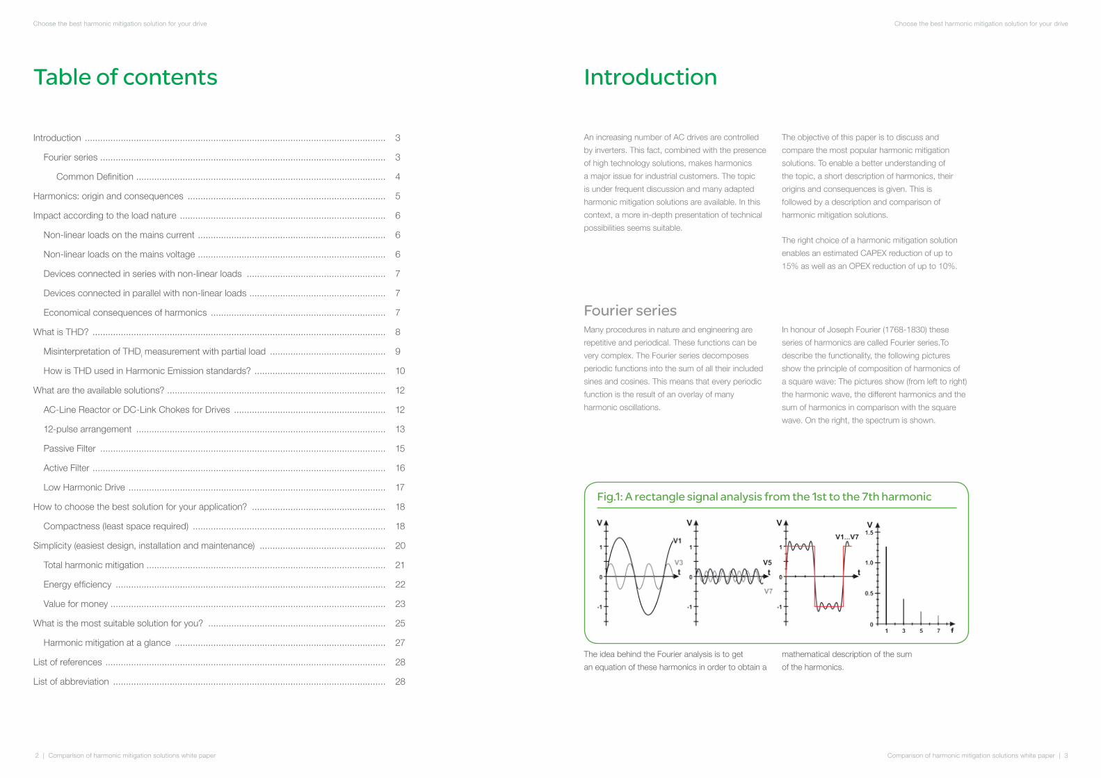
In honour of Joseph Fourier (1768-1830) these
series of harmonics are called Fourier series.To
describe the functionality, the following pictures
show the principle of composition of harmonics of
a square wave: The pictures show (from left to right)
the harmonic wave, the different harmonics and the
sum of harmonics in comparison with the square
wave. On the right, the spectrum is shown.
Fig.1: A rectangle signal analysis from the 1st to the 7th harmonic
Comparison of harmonic mitigation solutions white paper | 5
Choose the best harmonic mitigation solution for your drive
4 | Comparison of harmonic mitigation solutions white paper
Choose the best harmonic mitigation solution for your drive
Common DefinitionTo explain the common definition of the formula, a periodical function is taken (period T>0). This function
can be described as a series of sines and cosines. The frequency of them is a whole-number multiple of
the fundamental frequency.
f (t) = + [ak • cos(k • ω • t) + bk • sin(k • ω • t)]2a0 S
k=1
8
In practice a finite approximation is enough (a subtotal )
The coefficients for this formula are:
c stands for an offset of the interval and can vary for simplification.
The constant component of the equation is the component without alteration.
Simple characteristics of the formula are:
• For all even functions bk=0 f (-x) = f (x)
• For all odd functions ak=0 f (-x) = -f (x)
f n(t)
f n(t) = + [ak • cos(k • ω • t) + bk • sin(k • ω • t)]2a0 S
k=1
n
ak = [f(t) • cos(k • ω • t)]dt 2T
c+T
cbk = [f(t) • sin(k • ω • t)]dt 2
Tc+T
c
2a0 = [f(t)]dt2
Tc+T
c
ω = 2 • pT
Harmonics: origin and consequences
An ideal mains voltage should be a sinusoidal
voltage with constant amplitude and frequency.
But in reality this ideal mains does not exist because
of impedances, voltage distortion and current
distortions. These distortions are caused by different
loads. The loads can be classified into two families:
• Linear loads,
• Non linear loads.
We are talking about a linear load if the current
has the same waveform as the supply voltage i.e.
a sine wave. Motors, incandescent lights, heating
elements using resistor, capacitors and inductances
are linear loads.
Industrial equipment comprising power electronics
circuits are, most of the time, non-linear loads
(welding machines, arc and induction furnaces,
battery chargers). Variable speed drives for AC
or DC motors, uninterruptible power supplies,
office equipment (PCs, printers, servers, etc.) are
non-linear loads and their currents deviate from
sinusoidal waveforms. Those loads create some
harmonic current through the distribution system
and, due to the network impedance, cause
voltage distortion.
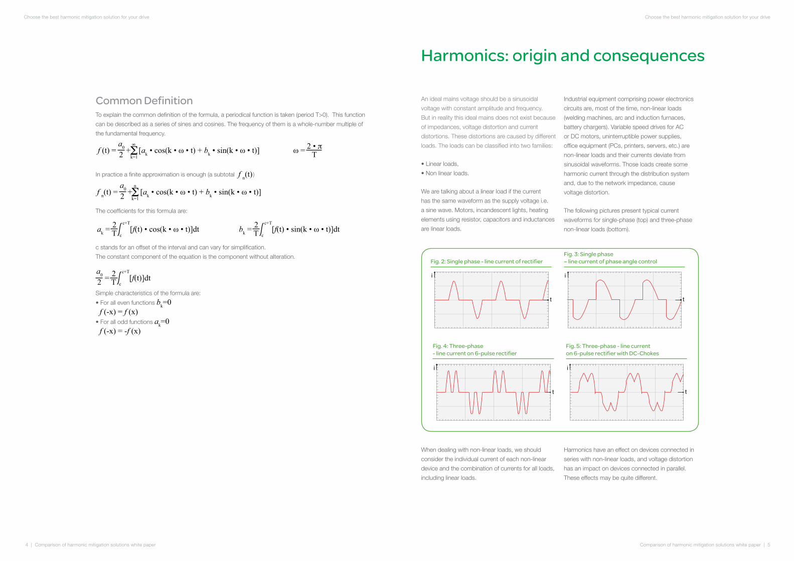
The following pictures present typical current
waveforms for single-phase (top) and three-phase
non-linear loads (bottom).
Fig. 2: Single phase - line current of rectifier
Fig. 3: Single phase – line current of phase angle control
Fig. 4: Three-phase - line current on 6-pulse rectifier
Fig. 5: Three-phase - line current on 6-pulse rectifier with DC-Chokes
t
i
t
i
t
i
t
i
When dealing with non-linear loads, we should
consider the individual current of each non-linear
device and the combination of currents for all loads,
including linear loads.
Harmonics have an effect on devices connected in
series with non-linear loads, and voltage distortion
has an impact on devices connected in parallel.
These effects may be quite different.
Comparison of harmonic mitigation solutions white paper | 7
Choose the best harmonic mitigation solution for your drive
6 | Comparison of harmonic mitigation solutions white paper
Choose the best harmonic mitigation solution for your drive
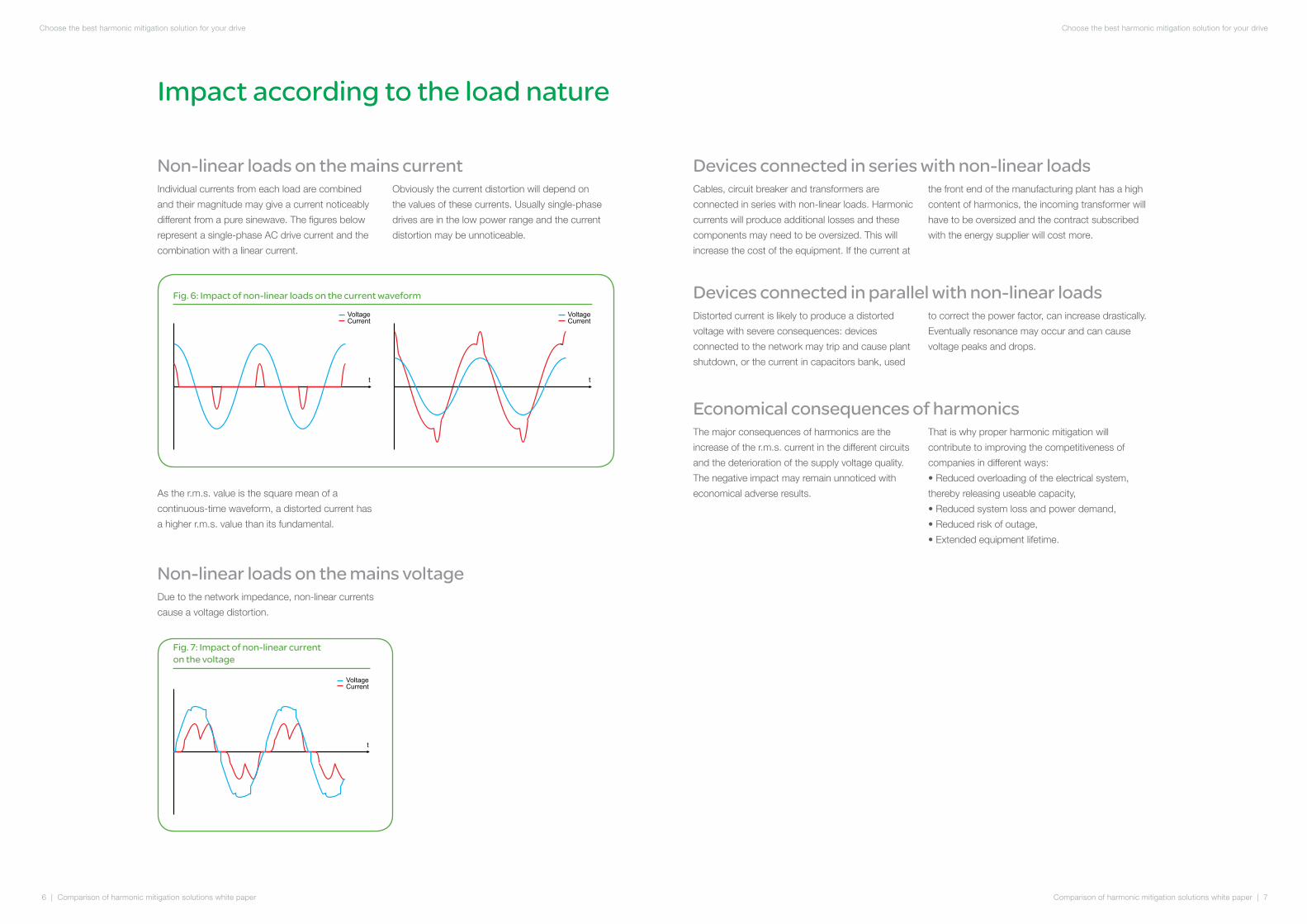
Fig. 6: Impact of non-linear loads on the current waveform
Voltage
Current
t
Voltage
Current
t
Impact according to the load nature
Non-linear loads on the mains currentIndividual currents from each load are combined
and their magnitude may give a current noticeably
different from a pure sinewave. The figures below
represent a single-phase AC drive current and the
combination with a linear current.
Obviously the current distortion will depend on
the values of these currents. Usually single-phase
drives are in the low power range and the current
distortion may be unnoticeable.
Voltage
Current
t
Voltage
Current
t
As the r.m.s. value is the square mean of a
continuous-time waveform, a distorted current has
a higher r.m.s. value than its fundamental.
Non-linear loads on the mains voltageDue to the network impedance, non-linear currents
cause a voltage distortion.
Fig. 7: Impact of non-linear current on the voltage
Voltage
Current
t
Devices connected in series with non-linear loadsCables, circuit breaker and transformers are
connected in series with non-linear loads. Harmonic
currents will produce additional losses and these
components may need to be oversized. This will
increase the cost of the equipment. If the current at
the front end of the manufacturing plant has a high
content of harmonics, the incoming transformer will
have to be oversized and the contract subscribed
with the energy supplier will cost more.
Devices connected in parallel with non-linear loadsDistorted current is likely to produce a distorted
voltage with severe consequences: devices
connected to the network may trip and cause plant
shutdown, or the current in capacitors bank, used
to correct the power factor, can increase drastically.
Eventually resonance may occur and can cause
voltage peaks and drops.
Economical consequences of harmonicsThe major consequences of harmonics are the
increase of the r.m.s. current in the different circuits
and the deterioration of the supply voltage quality.
The negative impact may remain unnoticed with
economical adverse results.
That is why proper harmonic mitigation will
contribute to improving the competitiveness of
companies in different ways:
• Reduced overloading of the electrical system,
thereby releasing useable capacity,
• Reduced system loss and power demand,
• Reduced risk of outage,
• Extended equipment lifetime.

Comparison of harmonic mitigation solutions white paper | 9
Choose the best harmonic mitigation solution for your drive
8 | Comparison of harmonic mitigation solutions white paper
Choose the best harmonic mitigation solution for your drive
What is THD?
The total harmonic distortion (THD) is the usual parameter to evaluate the level of distortion of an
alternating signal. The harmonic distortion can be seen for voltage distortion THDu as well as for
current distortion THDi.
The THD is defined as the ratio of the sum of all Harmonic-Power (Ph) to the Power of the first
harmonic (P1). The indication is done in %.
Fig. 8: Harmonic spectrum 6 pulse rectifier
THD% = x 100Ph
P1
The calculation of the THDu and THDi is therefore the following:
THDu = V1
V22+ V3
2+ V42+...+ Vn
2
THDi = I1
I22+ I3
2+ I42+...+ In
2
I2, I3, I4, ... In ... harmonics (100, 150, 200, ... Hz or 120, 180, 240, ... Hz
I1 ... fundamental current (50 Hz or 60 Hz)
100%
0%
I1 = fundamental (50/60 Hz)
Ih = summation of harmonics
Misinterpretation of THDi measurement with partial loadThe operating point of the variable speed drives
(VSD) is optimized for the production and often they
do not work under full load conditions. These partial
load operations create a lot of misinterpretation in
the measurement of harmonics.
The panel meter shows the ratio between sums of
harmonics currents in percent to the fundamental
current. If the VSD is working at 100% load
operation, the current of the fundamental I1 is
equivalent to the nominal current Inom. The
shown THDi measured in percent approximately
conforms with the percent value given by the
producers of VSDs (differences are possible due
to different mains impedances). In case of partial
load operation, the fundamental current I1 declines
(red line) but the sum of the harmonics currents is
relatively constant (green line), and so the THDi [%]
increases (violet line) according to the functional
relationship of THDi.
Due the ratio it seems that the THDi increases but
the absolute values of the harmonic currents will be
constant or decreased.
1 5 7 11 13 17 19 23 25 29 31 35 37 40 43 47 49
Fig. 9: THDi - partial load operation
curr
ent [
A]
THD
i [%
]
100
0
200
300
400
500
600
012345678
partial load [%]100 80 60 40 20
rms
harmonicsi I
ITH D
101112
9
I = 552AI = 20ATHD = 3,6%
rms
harmonics
i
I = 174AI = 15ATHD = 8,6%
rms
harmonics
i
I I THDrms harmonics i
=
THD
i [%
]
curr
ent [
A]

Comparison of harmonic mitigation solutions white paper | 11
Choose the best harmonic mitigation solution for your drive
10 | Comparison of harmonic mitigation solutions white paper
Choose the best harmonic mitigation solution for your drive
How is THD used in Harmonic Emission standards?Regarding harmonics, the purpose of
standardization is to ensure that the voltage
distortion at the Point of Common Coupling (PCC)
is kept sufficiently low, so that other customers
connected through the same point are not
disturbed. This is the basic idea behind the concept
of Electromagnetic Compatibility (EMC).
For low power equipment connected directly to the
Low Voltage (LV) supply system, current emission
limits given by international standards are applicable
to pieces of equipment.
For global installations, emission limits are set by the
Utilities based on the local applicable standards or
regulations. Generally, limits are established for the
Total Harmonic Voltage Distortion (THDu), the Total
Harmonic Current Distortion (THDi), and individual
harmonic currents (Ih).
The main parameters taken into account are the
short-circuit power Ssc of the supply system and
the agreed power (or total demand power) of the
customer installation.
The principle is to allow each customer to
contribute to the global distortion, in proportion
to the agreed power of the installation. The global
resulting distortion must be kept under certain
limits so that the Electromagnetic Compatibility
can be ensured.
The application area of the main standards dealing
with harmonics is presented in the following figure.
Fig. 10: Standards and recommendations concerning harmonics
It should be noted that overly stringent harmonic
emission limits could become very expensive.
That’s why a careful application of standards
should be performed. The following diagram
can clarify this.
Fig. 11: Point of common coupling
The THDu limits are considered at the Point of
Common Coupling (PCC) within the public network
(low voltage (LV) or medium voltage (MV)) from
which the different customers are supplied by the
Utility. Limits must be applied at the PCC in order
to ensure that the Utility (often by duty constraints)
supplies the different customers with a good quality
of power, i.e. with non-distorted voltage.
For LV customers, IEC 61000-3-2 and 61000-3-
12 are harmonic emission standards applicable at
equipment level. THDi and individual LH limits are
required for pieces of equipment up to 75A. Above
this value, an agreement is usually needed between
the Utility and the customer before connection.
Local country regulations, based on other standards
or codes (such as ER G5/4- 1 or IEEE 519), should
be considered when requested.
Industrial networkPublic network
Requirement at installation level (PCC)
Requirement at equipment level
IEEE 519
IEC 61800-3
IEC 61000-3-6
IEC 61000-3-14
ER G5/4-1
IEC 61000-3-12
IEC 61000-3-2
Buildings
Public MV Network(IEC 61000-3-6)
Public LV Network (IEC 61000-3-14)
HVAC Lift
Other industrialcustomers
Industrialcustomers
MV / LV
HV / MV
MV / LV
PCC
PCC
IEEE 519 - ER G5/4-1National regulations
PrivateLV Network
Residential
IEC 61000-3-2 /-3-12
Commercial &Light industries
IEC 61000-3-12
IEC 61000-3-12 EN 12015
Equipment Machine 1(i.e. IEC 61800-3 as guidance)
Equipment Machine 2
Comparison of harmonic mitigation solutions white paper | 13
Choose the best harmonic mitigation solution for your drive
12 | Comparison of harmonic mitigation solutions white paper
Choose the best harmonic mitigation solution for your drive
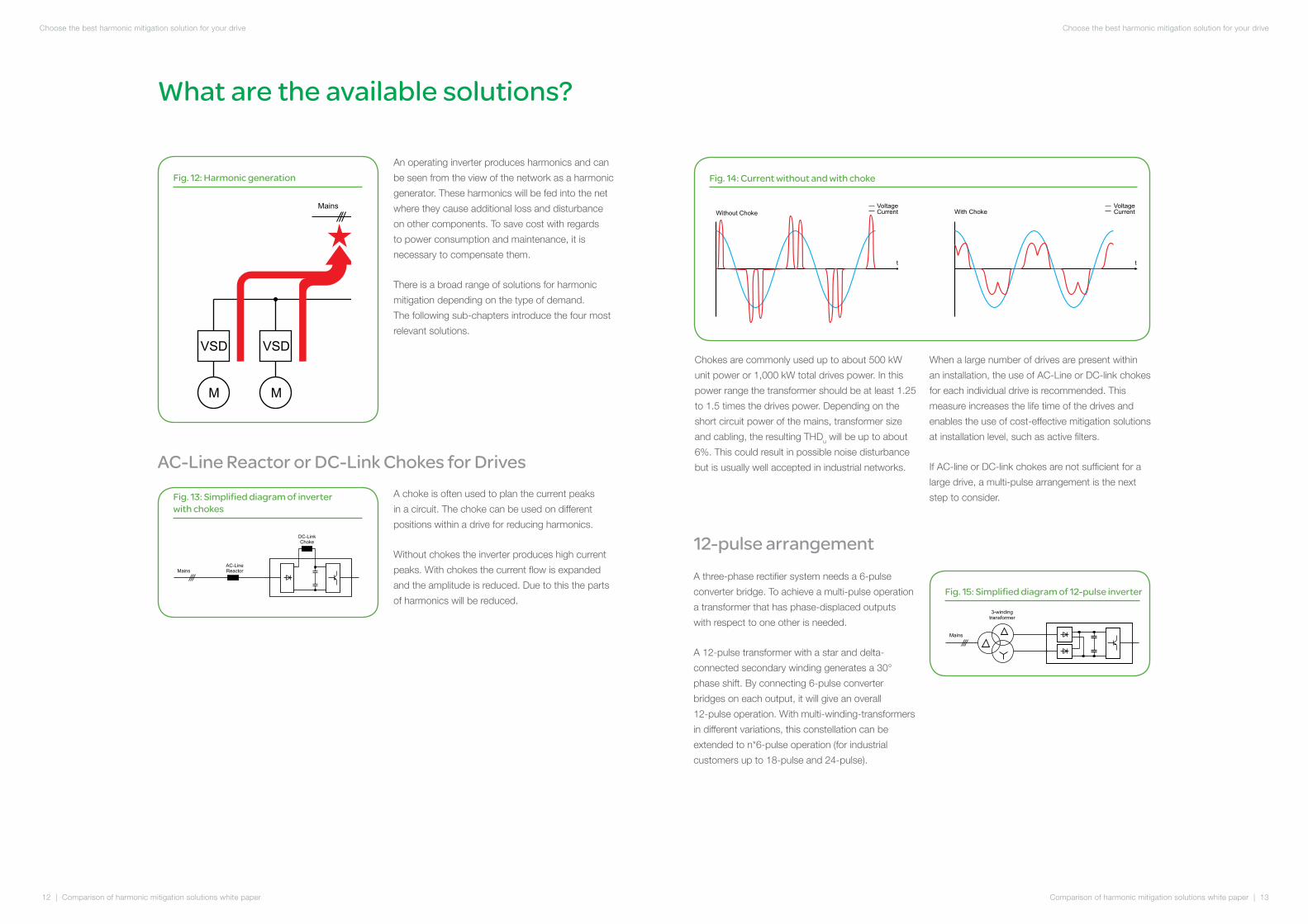
An operating inverter produces harmonics and can
be seen from the view of the network as a harmonic
generator. These harmonics will be fed into the net
where they cause additional loss and disturbance
on other components. To save cost with regards
to power consumption and maintenance, it is
necessary to compensate them.
There is a broad range of solutions for harmonic
mitigation depending on the type of demand.
The following sub-chapters introduce the four most
relevant solutions.
Fig. 12: Harmonic generation
What are the available solutions?
Mains
VSD
M
VSD
M
AC-Line Reactor or DC-Link Chokes for DrivesA choke is often used to plan the current peaks
in a circuit. The choke can be used on different
positions within a drive for reducing harmonics.
Without chokes the inverter produces high current
peaks. With chokes the current flow is expanded
and the amplitude is reduced. Due to this the parts
of harmonics will be reduced.
Fig. 13: Simplified diagram of inverter with chokes
DC-Link
Choke
Mains
AC-Line
Reactor
Chokes are commonly used up to about 500 kW
unit power or 1,000 kW total drives power. In this
power range the transformer should be at least 1.25
to 1.5 times the drives power. Depending on the
short circuit power of the mains, transformer size
and cabling, the resulting THDu will be up to about
6%. This could result in possible noise disturbance
but is usually well accepted in industrial networks.
When a large number of drives are present within
an installation, the use of AC-Line or DC-link chokes
for each individual drive is recommended. This
measure increases the life time of the drives and
enables the use of cost-effective mitigation solutions
at installation level, such as active filters.
If AC-line or DC-link chokes are not sufficient for a
large drive, a multi-pulse arrangement is the next
step to consider.
Fig. 14: Current without and with choke
Voltage
Current
Voltage
Current
t t
Without Choke With Choke
12-pulse arrangementA three-phase rectifier system needs a 6-pulse
converter bridge. To achieve a multi-pulse operation
a transformer that has phase-displaced outputs
with respect to one other is needed.
A 12-pulse transformer with a star and delta-
connected secondary winding generates a 30°
phase shift. By connecting 6-pulse converter
bridges on each output, it will give an overall
12-pulse operation. With multi-winding-transformers
in different variations, this constellation can be
extended to n*6-pulse operation (for industrial
customers up to 18-pulse and 24-pulse).
Fig. 15: Simplified diagram of 12-pulse inverter
Mains
3-winding
transformer
Comparison of harmonic mitigation solutions white paper | 15
Choose the best harmonic mitigation solution for your drive
14 | Comparison of harmonic mitigation solutions white paper
Choose the best harmonic mitigation solution for your drive
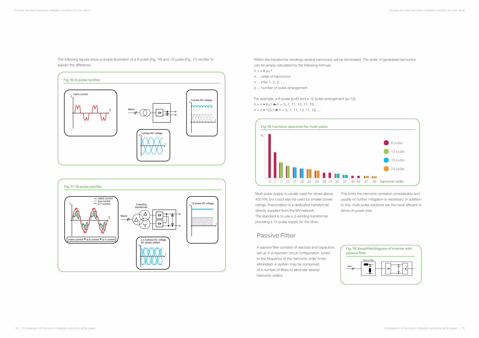
The following figures show a simple illustration of a 6-pulse (Fig. 16) and 12-pulse (Fig. 17) rectifier to
explain the difference.
Fig. 16: 6-pulse rectifier
Mains
t
3-phase AC voltage
t
6-pulse DC voltageu
u
t
imains current
Fig. 17: 12-pulse rectifier
t
i 3-winding
transformer
t
2 x 3-phase AC voltage
30° phase shifted
12-pulse DC voltage
Mains
u
t
u
mains current
- current
-Y current
Δ Δ
Δ
mains current - current -Y current= +Δ Δ Δ
Within the transformer windings several harmonics will be terminated. The order of generated harmonics
can be simply calculated by the following formula:
h = n • p±1
h ... order of harmonics
n ... inter 1, 2, 3, ...
p ... number of pulse arrangement
For example, a 6-pulse (p=6) and a 12-pulse arrangement (p=12):
h = n • 6±1 h = 5, 7, 11, 13, 17, 19, ...
h = n • 12±1 h = 5, 7, 11, 13, 17, 19, ...
Multi-pulse supply is usually used for drives above
400 kW, but could also be used for smaller power
ratings. Precondition is a dedicated transformer
directly supplied from the MV network.
The standard is to use a 3-winding transformer
providing a 12-pulse supply for the drive.
This limits the harmonic emission considerably and
usually no further mitigation is necessary. In addition
to this, multi-pulse solutions are the most efficient in
terms of power loss.
Passive FilterA passive filter consists of reactors and capacitors
set up in a resonant circuit configuration, tuned
to the frequency of the harmonic order to be
eliminated. A system may be composed
of a number of filters to eliminate several
harmonic orders.
Fig. 19: Simplified diagram of inverter with passive filter
Mains
Passive-Filter
Fig. 18: harmonic spectrum for multi-pulse
6 pulse
18 pulse
12 pulse
24 pulse
%
harmonic order5 7 11 13 17 19 23 25 29 31 35 37 40 43 47 49
Comparison of harmonic mitigation solutions white paper | 17
Choose the best harmonic mitigation solution for your drive
16 | Comparison of harmonic mitigation solutions white paper
Choose the best harmonic mitigation solution for your drive
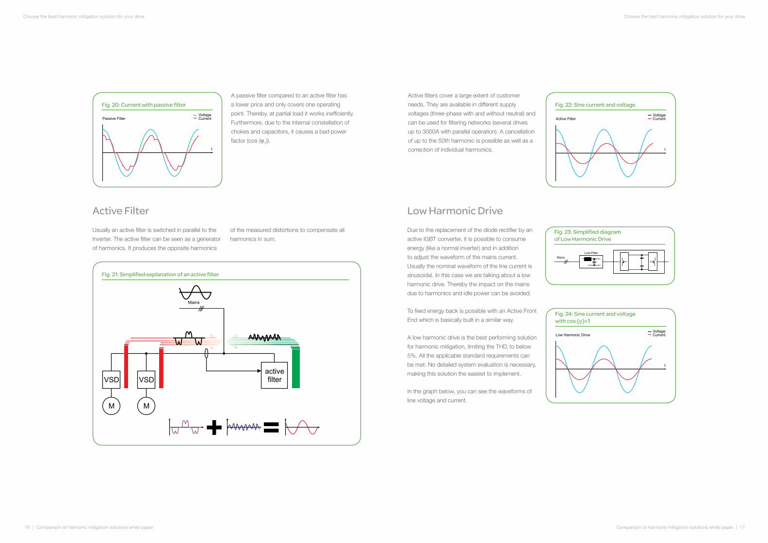
A passive filter compared to an active filter has
a lower price and only covers one operating
point. Thereby, at partial load it works inefficiently.
Furthermore, due to the internal constellation of
chokes and capacitors, it causes a bad power
factor (cos (φ1)).
Active FilterUsually an active filter is switched in parallel to the
inverter. The active filter can be seen as a generator
of harmonics. It produces the opposite harmonics
of the measured distortions to compensate all
harmonics in sum.
Fig. 21: Simplified explanation of an active filter
Mains
VSD
M
VSD
M
active
filter
+ =
Fig. 20: Current with passive filter
Voltage
Current
t
Passive Filter
Mains
VSD
M
VSD
M
active
filter
+ =
Active filters cover a large extent of customer
needs. They are available in different supply
voltages (three-phase with and without neutral) and
can be used for filtering networks (several drives
up to 3000A with parallel operation). A cancellation
of up to the 50th harmonic is possible as well as a
correction of individual harmonics.
Fig. 22: Sine current and voltage
Voltage
Current
t
Active Filter
Low Harmonic DriveDue to the replacement of the diode rectifier by an
active IGBT converter, it is possible to consume
energy (like a normal inverter) and in addition
to adjust the waveform of the mains current.
Usually the nominal waveform of the line current is
sinusoidal. In this case we are talking about a low
harmonic drive. Thereby the impact on the mains
due to harmonics and idle power can be avoided.
To feed energy back is possible with an Active Front
End which is basically built in a similar way.
A low harmonic drive is the best performing solution
for harmonic mitigation, limiting the THDi to below
5%. All the applicable standard requirements can
be met. No detailed system evaluation is necessary,
making this solution the easiest to implement.
In the graph below, you can see the waveforms of
line voltage and current.
Fig. 23: Simplified diagram of Low Harmonic Drive
Mains
Line-Filter
Fig. 24: Sine current and voltage with cos (φ)=1
Voltage
Current
t
Low Harmonic Drive
Comparison of harmonic mitigation solutions white paper | 19
Choose the best harmonic mitigation solution for your drive
18 | Comparison of harmonic mitigation solutions white paper
Choose the best harmonic mitigation solution for your drive
Compactness (least space required)All components of a system need space, and more
of it is required when a choke is installed in addition
to the inverter or if an active filter for reducing
harmonics is used. For this reason, a comparison of
the amount of required space was performed.
The comparison of space required by each solution
can be split into three subcriteria.
The subcriterion of additional installation includes all
relevant components needed to install the harmonic
mitigation solution, such as additional cables,
cubicles, etc.
The subcriterion of additional components includes
only the harmonic mitigation solution itself, namely:
• only the line choke
• the size difference between 6-pulse and
12-pulse transformer
• the active filter (alone), and
• the low harmonic drive
The scope of this paper is a comparison of the
described harmonic mitigation solutions. The
analyzed criteria will include:
• Compactness
This part will analyze which solution requires
the least space.
• Simplicity
This part will identify the solution that is the
easiest to operate.
• THDi – mitigation
This part will compare the solutions in terms
of their harmonic mitigation.
• Efficiency
This part will discuss the energy efficiency level
of the solutions.
• Value for money
This parts will analyze the solutions in terms
of costs.
To enable comparison with regards to these
criteria, the following quality rating system shall be
used based on points. Each solution is awarded
one to five points for each criterion, where one
point means the solution requires more effort and
five points mean it requires less effort. The rating
is performed in relation to the other harmonic
mitigating solutions under evaluation. Due to the
fact that not all of the five criteria can be evaluated
in the same way, the assignment of points is
discussed in each section to make it clearer.
It is hard to compare the different solutions in an
objective manner. An active filter is often used to
mitigate the harmonics from several drives. The
12-pulse solution is the only one in this type of
solution where the transformer is included in the
comparison. Due to the unique disadvantages of
the passive filter when compared with the other
solutions like low power factor at partial load, risk of
causing resonances within the grid, etc., will not be
included in the comparison section.
How to choose the best solution for your application?
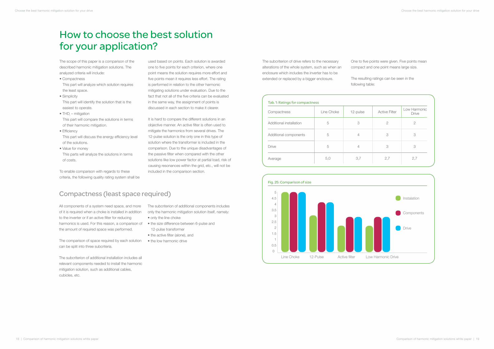
Tab. 1: Ratings for compactness
The subcriterion of drive refers to the necessary
alterations of the whole system, such as when an
enclosure which includes the inverter has to be
extended or replaced by a bigger enclosure.
One to five points were given. Five points mean
compact and one point means large size.
The resulting ratings can be seen in the
following table:
Compactness
Additional installation
Additional components
Drive
Average
Line Choke
5
5
5
5,0
3
4
4
3,7
2
3
3
2,7
2
3
3
2,7
12-pulse Active FilterLow Harmonic
Drive
Fig. 25: Comparison of size
4
0
3
2
1
0.5
1.5
2.5
3.5
4.5
5
Line Choke 12-Pulse Active filter Low Harmonic Drive
Instalation
Components
Drive

Comparison of harmonic mitigation solutions white paper | 21
Choose the best harmonic mitigation solution for your drive
20 | Comparison of harmonic mitigation solutions white paper
Choose the best harmonic mitigation solution for your drive
To examine the level of simplicity of each solution, a
rating was performed. The analysis compares and
evaluates it with respect to three subcriteria: design,
installation, and maintenance.
The subcriterion of design includes the effort
required before the system is built.
The subcriterion of installation refers to all additional
workload that is necessary, such as additional
wiring and additional components for an inverter
without any harmonic mitigation solution.
The last subcriterion, maintenance, addresses
the additional requirement for service and
maintenance.
One to five points were given.
One point means much effort is required for
the design, installation, and maintenance of the
solution. Five points mean the solution is a simple
system requiring only minimum effort.
The resulting ratings can be seen in the
following table:
Simplicity (easiest design, installation and maintenance)
Tab. 2: Ratings for simplicity
Simplicity
Design
Installation
Maintenance
Average
Line Choke
5
5
5
5,0
3
2
2
2,3
2
4
2
2,7
5
5
2
4,0
12-pulse Active FilterLow Harmonic
Drive
Fig. 26: Comparison of simplicity
4
0
3
2
1
0.5
1.5
2.5
3.5
4.5
5
Line Choke 12-Pulse Active filter Low Harmonic Drive
Design
Installation
Maintenance
Total harmonic mitigationThe disassembling of the line current into their
shares of frequency shows the fundamental and
the harmonics. After the inductive idle power, the
harmonics cause the second largest distortion in
the mains.
The total harmonic distortion (THD) is a specification
that qualifes the rate of non-linear deformation
of the current or voltage. In the following graph,
the comparison of all solutions is shown. The low
harmonic drive achieves the best results.
Fig. 27: Comparison of THDiComparison of THDi
choke(solitary)
6...15% (*1)
30...48%
45...80%
2...5%
12-pulse
supply Active Filter Low Harmonic
Drive with ...Drive
3...20% (*2)
(*1)... View on the MV side
(*2)... Compensation rate depending on settings and sizing
One to five points were given.
One point means bad level of harmonic mitigation.
Five points mean very good level of harmonic mitigation.

Comparison of harmonic mitigation solutions white paper | 23
Choose the best harmonic mitigation solution for your drive
22 | Comparison of harmonic mitigation solutions white paper
Choose the best harmonic mitigation solution for your drive
The resulting ratings can be seen in the
following table:
Tab. 3: Ratings for THDi
Harmonic mitigation
THDi
Average
Line Choke
1
1
3
3
4
4
5
5
12-pulse Active FilterLow Harmonic
Drive
Fig. 28: Comparison of efficiency
96...95%96,5...95% (*1)
97...96%
98...97%98...97%
choke(solitary)12-pulsesupply Active Filter Low Harmonic
Drive with ...Drive
(*1) Efficiency depending on compansation rate...
Comparison of efficiency
Energy efficiencyIndustry needs a lot of energy to power the
production process. Efficient energy use is an
important topic as energy costs continue to grow.
The following graph compares the efficiency of
some solutions:
For criterion of energy efficiency only the losses of
each solution are observed. Savings resulting from
reduction of losses on other consumer loads (with
harmonic mitigation) or a power factor (cos (φ) = 1)
as an indicator for real power are not pictured in
this figure.
One to five points were given. One point means low
efficiency and five points mean high efficiency.
The resulting ratings can be seen in the
following table:
Tab. 4: Ratings for efficiency
Effeciency
Energy efficiency
Average
Line Choke
4
4
5
5
3
3
3
3
12-pulse Active FilterLow Harmonic
Drive
Value for moneyCalculating the cost of adding a new solution
requires totalling up the cost of all parts, such as
transformers, supply cables, and the whole drive.
It ultimately depends on the specific solution and
the planning associated with it to determine the
list and the dimensions of components required.
Therefore, some costs are often visible right from
the start. As an example, a seemingly economically
priced solution for harmonic mitigation may not
include the projected costs of energy or installation.
A rating was performed to identify the solution
offering the best value for money. The projected
costs of energy supply, installation and the drive
itself were reviewed and evaluated by experts.
One to five points were given.
One point means low cost-effectiveness, and five
points mean the best value for money.
The resulting ratings can be seen in the
following table:
Tab. 5: Ratings for cost-effectiveness
Value for money
Energy supply
Installation
Drive and components
Average
Line Choke
5
5
5
5,0
3
4
5
4,0
2
3
3
2,7
5
4
2
3,7
12-pulse Active FilterLow Harmonic
Drive
Comparison of harmonic mitigation solutions white paper | 25
Choose the best harmonic mitigation solution for your drive
24 | Comparison of harmonic mitigation solutions white paper
Choose the best harmonic mitigation solution for your drive
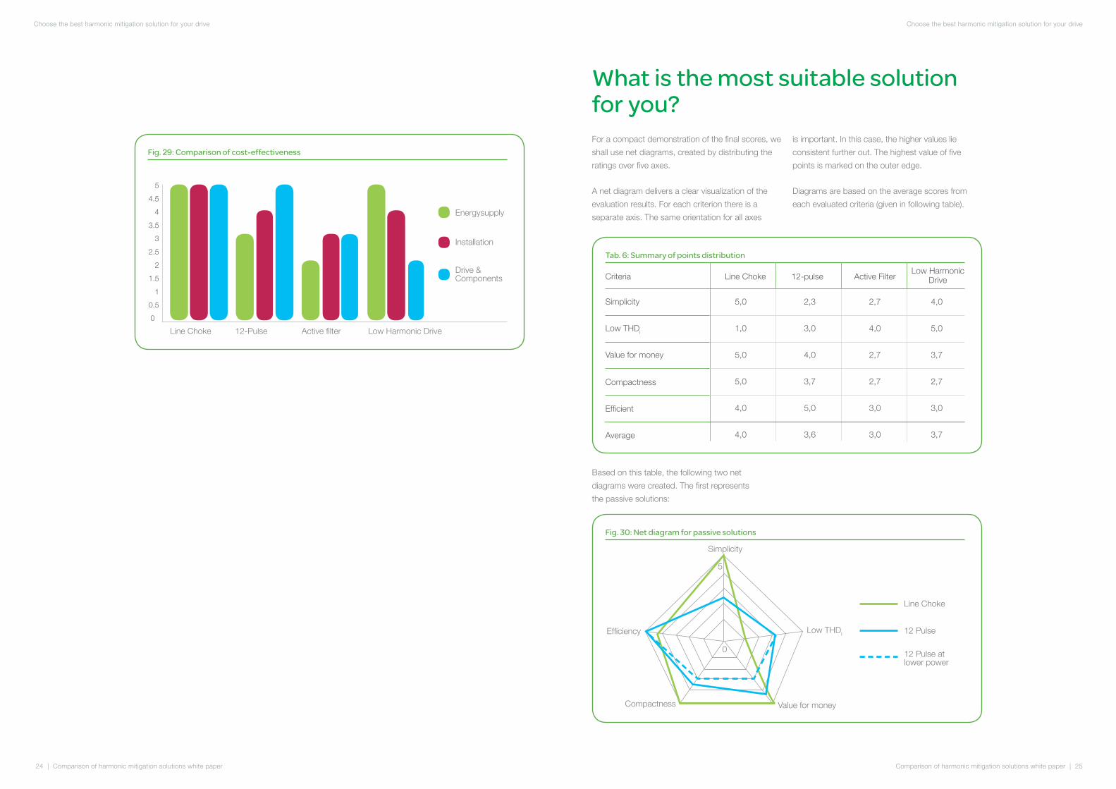
Fig. 29: Comparison of cost-effectiveness
4
0
3
2
1
0.5
1.5
2.5
3.5
4.5
5
Line Choke 12-Pulse Active filter Low Harmonic Drive
Energysupply
Installation
Drive & Components
What is the most suitable solution for you?For a compact demonstration of the final scores, we
shall use net diagrams, created by distributing the
ratings over five axes.
A net diagram delivers a clear visualization of the
evaluation results. For each criterion there is a
separate axis. The same orientation for all axes
is important. In this case, the higher values lie
consistent further out. The highest value of five
points is marked on the outer edge.
Diagrams are based on the average scores from
each evaluated criteria (given in following table).
Tab. 6: Summary of points distribution
Criteria
Simplicity
Low THDi
Value for money
Compactness
Line Choke
5,0
1,0
5,0
5,0
2,3
3,0
4,0
3,7
2,7
4,0
2,7
2,7
4,0
5,0
3,7
2,7
12-pulse Active FilterLow Harmonic
Drive
Efficient
Average
4,0 5,0 3,0 3,0
4,0 3,6 3,0 3,7
Based on this table, the following two net
diagrams were created. The first represents
the passive solutions:
Fig. 30: Net diagram for passive solutions
Simplicity
Low THDI
Value for money
Efficiency
Compactness
Line Choke
12 Pulse
12 Pulse at lower power
0
5
Comparison of harmonic mitigation solutions white paper | 27
Choose the best harmonic mitigation solution for your drive
26 | Comparison of harmonic mitigation solutions white paper
Choose the best harmonic mitigation solution for your drive
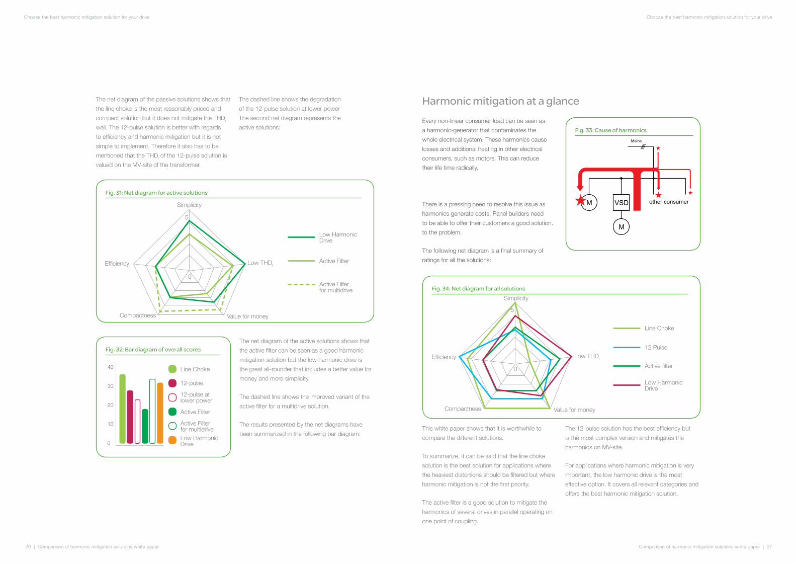
The net diagram of the passive solutions shows that
the line choke is the most reasonably priced and
compact solution but it does not mitigate the THDi
well. The 12-pulse solution is better with regards
to efficiency and harmonic mitigation but it is not
simple to implement. Therefore it also has to be
mentioned that the THDi of the 12-pulse solution is
valued on the MV-site of the transformer.
The dashed line shows the degradation
of the 12-pulse solution at lower power
The second net diagram represents the
active solutions:
Fig. 31: Net diagram for active solutions
The net diagram of the active solutions shows that
the active filter can be seen as a good harmonic
mitigation solution but the low harmonic drive is
the great all-rounder that includes a better value for
money and more simplicity.
The dashed line shows the improved variant of the
active filter for a multidrive solution.
The results presented by the net diagrams have
been summarized in the following bar diagram:
Fig. 32: Bar diagram of overall scores
40
0
30
20
10
Line Choke
12-pulse
12-pulse at lower power
Active Filter
Active Filterfor multidriveLow Harmonic Drive
Active Filter for multidrive
Active Filter
Low Harmonic Drive
Simplicity
Low THDI
Value for money
Efficiency
Compactness
Harmonic mitigation at a glanceEvery non-linear consumer load can be seen as
a harmonic-generator that contaminates the
whole electrical system. These harmonics cause
losses and additional heating in other electrical
consumers, such as motors. This can reduce
their life time radically.
There is a pressing need to resolve this issue as
harmonics generate costs. Panel builders need
to be able to offer their customers a good solution.
to the problem.
The following net diagram is a final summary of
ratings for all the solutions:
Fig. 33: Cause of harmonics
Mains
VSDM
M
other consumer
Fig. 34: Net diagram for all solutions
This white paper shows that it is worthwhile to
compare the different solutions.
To summarize, it can be said that the line choke
solution is the best solution for applications where
the heaviest distortions should be filtered but where
harmonic mitigation is not the first priority.
The active filter is a good solution to mitigate the
harmonics of several drives in parallel operating on
one point of coupling.
The 12-pulse solution has the best efficiency but
is the most complex version and mitigates the
harmonics on MV-site.
For applications where harmonic mitigation is very
important, the low harmonic drive is the most
effective option. It covers all relevant categories and
offers the best harmonic mitigation solution.
Simplicity
Low THDI
Value for money
Efficiency
Compactness
Line Choke
12 Pulse
Active filter
Low Harmonic Drive
0
5
0
5

Comparison of harmonic mitigation solutions white paper | 29
Choose the best harmonic mitigation solution for your drive
28 | Comparison of harmonic mitigation solutions white paper
Choose the best harmonic mitigation solution for your drive
• Schneider electric; 2009; Harmonic mitigation Solution Handbook
• Mehlhorn 2004; Dipl. Ing. Klaus Mehlhorn, ew Heft 1-2; 2004; Fachthema Versogungsnetze;
Artikel: Bestimmung der elektrischen Verluste im Netz eines städtischen Netzbetreibers / Determination
of the Electrical Losses in the Net of an Urban Network Carrier.
• Brosch, 2008; Peter F.Brosch, Moderne Stromrichterantriebe; Vogel Industrie medien GmbH
& Co KG; Wurzburg.
List of references
Abbr. Description
PCC Point of Common Coupling
HV High Voltage
MV Medium Voltage
LV Low Voltage
THD Total Harmonic Distortion
THDi Total Harmonic Distortion of Current
THDu Total Harmonic Distortion of Voltage
AC Alternating Current
EMC Electro-Magnetic Compatibility
LH Low Harmonic
Ih Harmonic Current
DC Direct Current
r.m.s. Root Mean Square
Ssc Short Circuit Power
HVAC Heating, Ventilation and Air Conditioning
AFE Active Front End
VSD Variable Speed Drive
List of abbreviation
List of figures
List of tables
Fig. 1: A rectangle signal analysis from the 1st to the 7th harmonic ................................................. 3Fig. 2: Single phase - line current of rectifier .................................................................................... 5Fig. 3: : Single phase – line current of phase angle control.................................................... ................ 5 Fig. 4: Three-phase - line current on 6-pulse rectifier ...................................................................... 5Fig. 5: Three-phase - line current on 6-pulse rectifier with DC-Chokes ........................................... 5 Fig. 6: Impact of non-linear loads on the current waveform ............................................................. 6Fig. 7: Impact of non-linear current on the voltage .......................................................................... 6Fig. 8: Harmonic spectrum 6 pulse rectifier ..................................................................................... 8Fig. 9: THDi - partial load operation ................................................................................................. 9Fig. 10: Standards and recommendations concerning harmonics .................................................. 10Fig. 11: Point of common coupling .................................................................................................. 11 Fig. 12: Harmonic generation .......................................................................................................... 12Fig. 13: Simplified diagram of inverter with chokes .......................................................................... 12Fig. 14: Current without and with choke .......................................................................................... 13 Fig. 15: Simplified diagram of 12-pulse inverter ............................................................................... 13Fig. 16: 6-pulse rectifier ................................................................................................................... 14Fig. 17: 12-pulse rectifier .................................................................................................................. 14Fig. 18: harmonic spectrum for multi-pulse ..................................................................................... 15Fig. 19: Simplified diagram of inverter with passive filter .................................................................. 15Fig. 20: Current with passive filter ................................................................................................... 16 Fig. 21: Simplified explanation of an active filter ............................................................................... 16Fig. 22: Sine current and voltage ..................................................................................................... 17Fig. 23: Simplified diagram of Low Harmonic Drive ......................................................................... 17Fig. 24: Sine current and voltage with cos (φ)=1 .............................................................................. 17Fig. 25: Comparison of size ............................................................................................................ 19Fig. 26: Comparison of simplicity .................................................................................................... 20Fig. 27: Comparison of THD
i ........................................................................................................... 21Fig. 28: Comparison of efficiency .................................................................................................... 22Fig. 29: Comparison of cost-effectiveness ...................................................................................... 24Fig. 30: Net diagram for passive solutions ....................................................................................... 25Fig. 31: Net diagram for active solutions .......................................................................................... 26Fig. 32: Bar diagram of overall scores ............................................................................................. 26Fig. 33: Cause of harmonics ........................................................................................................... 27Fig. 34: Net diagram for all solutions ............................................................................................... 27
Tab. 1: Ratings for compactness .................................................................................................... 19Tab. 2: Ratings for simplicity ............................................................................................................ 20 Tab. 3: Ratings for THDi ................................................................................................................... 22 Tab. 4: Ratings for efficiency ........................................................................................................... 23Tab. 5: Ratings for cost-effectiveness .............................................................................................. 23 Tab. 6: Summary of points distribution ............................................................................................ 25
Possible keywords: Harmonic, Harmonic solutions, comparison, Fourier, Fourier series, Fourier
analysis, Harmonics origin, Harmonics consequences, Impact non-linear loads, THD, THDi, Low
Harmonic, AC-Line Choke, DC-Line Choke, multi-pulse, 12-pulse, active filter, low harmonic drive, AFE.

10-2012998-1175581_GM-GB WP2121101EN
©2012 Schneider Electric. All Rights Reserved. All trademarks are owned by Schneider Electric Industries SAS or its affiliated companies.
Related Documents