e University of Akron IdeaExchange@UAkron Honors Research Projects e Dr. Gary B. and Pamela S. Williams Honors College Spring 2017 Chocolate Bar Wrapping Machine Austin M. Hoff e University of Akron, [email protected] Daniel R. Trepke e University of Akron, [email protected] Caleb B. Krichbuam e University of Akron, [email protected] Please take a moment to share how this work helps you through this survey. Your feedback will be important as we plan further development of our repository. Follow this and additional works at: hp://ideaexchange.uakron.edu/honors_research_projects Part of the Applied Mechanics Commons , Computer-Aided Engineering and Design Commons , Ergonomics Commons , Food Processing Commons , Industrial Technology Commons , Manufacturing Commons , and the Other Operations Research, Systems Engineering and Industrial Engineering Commons is Honors Research Project is brought to you for free and open access by e Dr. Gary B. and Pamela S. Williams Honors College at IdeaExchange@UAkron, the institutional repository of e University of Akron in Akron, Ohio, USA. It has been accepted for inclusion in Honors Research Projects by an authorized administrator of IdeaExchange@UAkron. For more information, please contact [email protected], [email protected]. Recommended Citation Hoff, Austin M.; Trepke, Daniel R.; and Krichbuam, Caleb B., "Chocolate Bar Wrapping Machine" (2017). Honors Research Projects. 511. hp://ideaexchange.uakron.edu/honors_research_projects/511

Welcome message from author
This document is posted to help you gain knowledge. Please leave a comment to let me know what you think about it! Share it to your friends and learn new things together.
Transcript

The University of AkronIdeaExchange@UAkron
Honors Research Projects The Dr. Gary B. and Pamela S. Williams HonorsCollege
Spring 2017
Chocolate Bar Wrapping MachineAustin M. HoffThe University of Akron, [email protected]
Daniel R. TrepkeThe University of Akron, [email protected]
Caleb B. KrichbuamThe University of Akron, [email protected]
Please take a moment to share how this work helps you through this survey. Your feedback will beimportant as we plan further development of our repository.Follow this and additional works at: http://ideaexchange.uakron.edu/honors_research_projects
Part of the Applied Mechanics Commons, Computer-Aided Engineering and Design Commons,Ergonomics Commons, Food Processing Commons, Industrial Technology Commons,Manufacturing Commons, and the Other Operations Research, Systems Engineering and IndustrialEngineering Commons
This Honors Research Project is brought to you for free and open access by The Dr. Gary B. and Pamela S. WilliamsHonors College at IdeaExchange@UAkron, the institutional repository of The University of Akron in Akron, Ohio,USA. It has been accepted for inclusion in Honors Research Projects by an authorized administrator ofIdeaExchange@UAkron. For more information, please contact [email protected], [email protected].
Recommended CitationHoff, Austin M.; Trepke, Daniel R.; and Krichbuam, Caleb B., "Chocolate Bar Wrapping Machine" (2017). HonorsResearch Projects. 511.http://ideaexchange.uakron.edu/honors_research_projects/511

Chocolate Bar Wrapping Machine
Honors Senior Design Project
Final Design Report
4-28-2017
Written by:
Austin Hoff
Caleb Krichbaum
Dan Trepke

1
Table of Contents
Executive Summary: 2
Background 3
Operation 3
Product Definition 3
Preliminary Design Brief 4
Expanded Design Brief 4
Structure Diagrams 5 Controller 6
Schematic Diagram 10
Embodiment Rules and Principles 11
FMEA 12
Preliminary Material Selection 12
Numerical Calculations 13
Gear Direction Layout 15
Layout Drawings 19
Standard Components from Catalogues 21
Explanation of Calculations 21
Materials and Manufacturing Methods Used 22
Part Drawings 23
Assembly Drawings 32
Exploded View Drawings 34

2
Executive Summary:
Gilbert Chocolates has proposed to manufacture a machine to wrap chocolate bars. This
machine is intended to replace two people wrapping the chocolate bars by hand, which is a time
consuming method. This is especially apparent between October and January when the workers
are working long hours in preparation for the Christmas rush of customers. Currently wrapping a
bar takes about a minute and Gilbert Chocolates wants this time reduced down to 20-30 seconds.
The budget for this project is set at $1000, and is being funded by the company. This machine
needs to fit in a cubic foot of space and weigh under 30 pounds for storage purposes. This
device can be either purely mechanical with manual input, or it may use step motors and a
controller.
This project pulls from our knowledge in kinematics, dynamics, 3D modeling, tolerance
analysis, material selection, manufacturing techniques, and design of components. From doing
this project we will learn how to apply all of these concepts together to solve real world
problems. This project will encompass the design, manufacturing of a prototype, and
optimization of the chocolate bar wrapping machine in hopes that the price of manufacturing
chocolate bars can be reduced for Gilbert Chocolates.
The final presentation of this project will include a working prototype, a report, and a
presentation. The project will be presented at the Engineering Senior Design Project day. The
machine will be operated and displayed at this event.

3
Chapter 1: Introduction & Background
Background
Gilbert Chocolates, which is based out of Jackson, MI, has requested we design a
chocolate wrapping machine for their chocolate bars. However, chocolate bars are not the
primary form of chocolate they sell, so buying an automatic machine for $7,000 is
uneconomical. Thus, the target goal is $1,000 dollars. Currently, the company wraps the bars by
hand, which takes about 1 minute. Our machine must be able to wrap both the aluminium foil
and paper sleeve around the bar in 20-30 seconds. To achieve this, the machine must have a short
setup time, and a short wrapping time. Also, there is a lack of consistency when wrapping by
hand, and the machine is designed to not make mistakes, which would require re-wrapping.
Operation
The machine is designed to require little to no training and decrease the wrapping time of
the bars. First the bar is loaded into position with the foil and paper beneath it. The worker then
spins the bar into the machine where the foil will be wrapped. The worker manually inputs
energy into the system which will begin folding the foil. After the foil wrapping is completed, a
new bar is placed onto the loading point. As the recently wrapped bar is spun out of the machine,
a gear will contact a gear track, causing the paper to be folded around the bar. The worker can
then tape the paper and remove the fully wrapped bar.
Product Definition
Our machine is designed to wrap chocolate bars in foil and paper. To do this, two levers
and a combination of gears will be used to fold the wrappers over the bars. The planned cost of
manufacturing is between $500-$1000. To allow for easy storage and movement to a work area,
the footprint of the whole machine will be under 12”x 12”x 12.” Initially, the machine will be
designed to wrap chocolate bars that are 2”x 4.5” for Gilbert Chocolates. This could be modified
to wrap larger or smaller bars for other companies and marketed to other small chocolate
businesses.

4
Chapter 2: Conceptual Design
Preliminary Design Brief
In order to increase production of chocolate bars and save money, Gilbert Chocolates has
requested that a machine be designed and manufactured to wrap their chocolate bar products.
This machine should be able to wrap both the inner foil and the outer paper sleeve in a manner
that makes repeatable and neat folds, while being quicker than wrapping by hand. To make this
machine as easy as possible to use and reduce costs we are using a manually operated approach.
This will eliminate tedious human movements of folding with a simple human movement to
drive a mechanism that will precisely fold the wrapper around the chocolate bar.
Expanded Design Brief
Gilbert Chocolates has contacted our design team to design and manufacture a product
capable of wrapping both the outer paper stock sleeves and the inner metallic foil for their
chocolate bars. Currently, they wrap these chocolate bars by hand, but have found that this
method is time consuming as well as it tends to yield inconsistent folds. It has also been
requested that the machine to be restrained to under a cubic foot of space.
Looking at other methods used to wrap chocolate bars we found that most are highly
automated turn key operations that can be in excess of $10,000. With the budget of $1000 and
the needs of Gilbert Chocolates in mind, we have decided to not use an automated approach but
rather a simple mechanized operation driven by manual input. This makes it simple to use, easy
to manufacture and repair, and able to fold precisely in a quick manner.
As simple mechanical machine will keep the budget and the footprint small enough to be
within Gilbert Chocolates’ restrictions where an automated system would fail. It is also going to
be fast enough to beat the 30 seconds needed by manually wrapping, while making even more
precise folds. Thus this machine should be able to help Gilbert produce more and better looking
chocolate bars, while reducing their overall cost.

5
Structure Diagrams
Figure 1: Overall Function Structure Diagram
Figure 2: Detailed Function Structure Diagrams
From these four function diagrams, we developed six distinct categories for our machine to satisfy. Manual input is how the operator will directly interact with the machine, putting the necessary energy to wrap the bar. Energy storage is how the motion of the manual input is stored in the machine until the wrapping occurs. Manual trigger is how the operator will release the stored energy, ultimately wrapping the bar. Loading method is how the bar will reach the wrapping zone. The wrapping method is how the foil will actually be wrapped around the chocolate bar. Then the unloading method will be how the finished bar will be removed from the machine.
While we developed several ideas on the storage and trigger methods, we also included the option of no storage or trigger. In those cases the manual input directly drives the wrapping action of the machine. Also, while the company specified a specifically mechanical machine, we included the option of an electrically driven computer setup. This was incase the computer method developed fell within the price and size limits the company gave us.

6
Morphological Chart
Manual Input
Energy Storage
Manual Trigger
Loading Method
Wrapping Method
Unloading Method
Crank
NONE NONE Hand
Wiper
Piston
Lever
Torsional
Button
Piston
Hinged Flap
Hand
Slot
Axial
Switch
Ramp
Piston
Tilt
Pump
Hanging Weight
Controller
Spinning Tray
Choco-flip
Spinning Tray
Electric Motor
NONE Knob
Roller
NONE Trap Door
Figure 3: Morphological Chart
From the chart above, we developed eight different possible combinations of the above options. They are shown in Figure 4 below.

7
Combinations
A) Crank Torsion Switch Piston Flap Piston
B) Lever Weight Button Ramp Piston Tilt
C) Slot Axial Swtch Tray Wiper Tray
D) Motor None Controller Roller Choco-Flip Tilt
E) Pump Weight Knob Tray Piston Tilt
F) Lever None None Hand Flap Hand
G) Slot None None Tray Wiper Tray
Figure 4: Combinations of Morphological Chart
We then ranked the eight categories in terms of their importance. We weighted them in two different ways, a standard ranking as well as an objective tree weighing scale. The first method was a standard order of what we determined to be the most important. The second method placed an additional weighting scale with the added level of objective vs subjective categories.
Each ranking system developed similar weighted values, placing safety, footprint and consistency at the top.
Category Ranking
Safety 1
Footprint 2
Manufacturability 3
Consistent 4
Cycle Time 5
Cost 6
Ease of Use 7
Longevity 8
Figure 5: Ranking System

8
Figure 6: Objective Tree
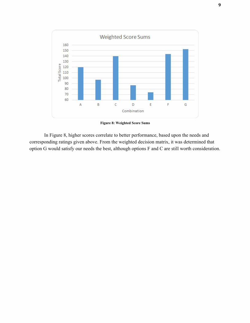
Figure 7 shows the scores of each design for each category based on the ratings we gave
them. These scores are summed up and graphed in Figure 8.
Weighted Decision Matrix
Combo Safety Footprint Manuf. Consist. Cycle T. Cost EOU Longev.
8 7 6 5 4 3 2 1
A) 3 / 24 4 / 28 3 / 18 4 / 20 4 / 16 2 / 6 3 / 6 2 / 2
B) 3 / 24 3 / 21 2 / 12 2 / 10 3 / 12 2 / 6 4 / 8 4 / 4
C) 4 / 32 4 / 28 4 / 24 4 / 20 4 / 16 3 / 9 4 / 8 3 / 3
D) 5 / 40 2 / 14 1 / 6 1 / 5 2 / 8 1 / 3 5 / 10 1 / 1
E) 2 / 16 1 / 7 2 / 12 3 / 15 3 / 12 2 / 6 2 / 4 2 / 2
F) 2 / 16 5 / 35 5 / 30 5 / 25 3 / 12 5 / 15 3 / 6 5 / 5
G) 3 / 24 5 / 35 5 / 30 4 / 20 4 / 16 5 / 15 4 / 8 5 / 5
Figure 7: Weighted Decision Matrix
9
Figure 8: Weighted Score Sums
In Figure 8, higher scores correlate to better performance, based upon the needs and corresponding ratings given above. From the weighted decision matrix, it was determined that option G would satisfy our needs the best, although options F and C are still worth consideration.

10
Chapter 3: Embodiment Design Schematic Diagram
Figure 9: Top view schematic
Figure 10: Side view schematic

11
Embodiment Rules and Principles
There are 3 rules and 3 principles for Embodiment Design:
Rules
Clarity is the first rule of embodiment design. Clarity must be used to prevent the product
from being misused, damaged, or from operating incorrectly. For our design, we put several
systems into place to prevent any of the mistakes listed below. First we wanted to prevent the
paper or foil from being misplaced while the machine is operated. To do so, the flaps will be
labeled, and a slight etch will be cut into the machine. Second, we needed to prevent them from
turning the lever the wrong way, wrong time, or at the wrong speed. To do this, each lever will
be labeled with a number and an arrow indicating the direction it should be pulled. To keep them
from pulling the lever too fast, a rotational damper will be included in the system.
The second rule of embodiment design is simplicity. The purpose of simplicity is to
prevent confusion. In this case, our primary concern was reducing the confusion for the untrained
operators, as well as the technician repairing the machine. Thus, we attempted to minimize the
number of levers the operator would need to pull. Furthermore, we tried to use the same gears as
frequently as possible to reduce the part numbers. Finally, the gears will be color coded and will
be able to “snap-on” to the rods to make gear replacement easier.
The last rule is safety. There are three types of safety: Direct, indirect, and warning.
Direct is when no danger is present. Indirect is when the danger is covered in some sort of cage.
Warning is when the operator is simply warned that there is danger, but little to no preventive
measures can be made. In our case, we used a combination of direct and indirect safety. Our
primary concern was pinch points that could hurt fingers or catch hair. To avoid these problems,
most of the gears will be below the operating zone, and any gears gears level with the zone will
be covered in a cage.
We also addressed the principles of embodiment design. The first rule is the division of
tasks. For this machine, the gears and belts will be used to turn the shafts to transmit the force
through the machine and fold the paper and foil. The supports will hold the gears, and will allow
the gears and shafts to turn in place. The next principle is self-help. The gears will snap into
place, the gears will be cut with the necessary number of teeth. Furthermore, the gears will mesh

12
with each other, which will hold them in the desired position. Finally, the last principle is
stability, which is achieved by even distribution of gears on a shaft, and a bottom heavy design to
reduce wobbling or rocking.
FMEA
For every design, a Failure Mode Effects Analysis must be performed. The purpose of
doing so is to predict possible failures that could occur during the operation of our product. By
doing so, we can create control systems to prevent or reduce the effects of the failure.
FMEA
Potential Failure
Potential Effects Severity Causes Current Controls
Does not wrap the bar well
● Frustrated Customer ● Time spent rewrapping
5 ● Lever pulled too fast ● Minor gear jamming
● Rotational Damper ● Gearbox access for visual verification
Wraps the bar to slowly
● Annoyed Customer ● More time required to wrap the
same amount of bars
3 ● Lever pulled to slow ● Internal resistance ● Minor jamming
● Manager’s opinion
Does not wrap the bar at all
● Customer upset that the product does perform its stated function
● Wastes time ● Product objective not achieved
7 ● Major jamming ● Broken gear ● Foil or paper not in position
● Visual Verification ● Gear replacement
Breaks the chocolate bar
● Upset Customer ● Loss of product and profit ● Refund demanded
9 ● Lever pulled too fast ● Lever pulled too far
● Rotational Damper ● Lever stop bar
Broken Gear ● Frustrated Customer ● Time spent replacing gears ● Material for new gear ● Suspension of production
● Lever pulled too fast ● Lever pulled too far ● Gears weren't meshed ● Material Fatigue
● Rotational Damper ● Lever stop bar ● Gear ratio analysis ● 3D printed parts are quicker to replace
Figure 11: FMEA Analysis
Preliminary Material Selection
For the preliminary material selection, we had to determine what to used based on three
factors: cost, reproducibility, wear resistance, and weight. Furthermore, because these materials
will be in close proximity to food, the materials must be deemed food safe, as determined by the
USDA.

13
First we determined that the gears would be 3d printed instead of machined, because
many of the gear would need to be custom made, which would increase the cost. Because metal
based 3d printers are expensive, it was quickly determined we should use a plastic. Our initial
plan was to use the common 3d printing material, ABS plastic, but it is not food-safe. However,
PLA filament, which is also commonly used, is food safe, has high strength, and is relatively
cheap. Thus for the gears we determined that PLA filament would be the best prototype material
Second, we needed to determine the material for the frame. We wanted to keep costs low
and the weight down. Because the frame should undergo little stress, having high strength was
deemed unnecessary, but we didn't want a material that was porous, which would encourage
bacteria growth. We decided on aluminum because it is food-safe, relatively low weight, low
cost, and non-porous.
Numerical Calculations
Calculate Pitch: where and P = NP Πd* itch diameterP d = p umber of teethN = n
Standard Spur Gear: 267P = 242.04 Π* = .
Planetary gears
Sun: 175P = 362 Π* = .
Solar: 175P = 724 Π* = .
Satellite: 175P = 181 Π* = .
22.5° angled gear : 131P = 12.5 Π* = .
Calculate Gear Ratio: R = P d1P d2
= N2
N1
Solar/Satellite: R = 1872 = 4
Sun/Satellite: R = 1836 = 2

14
Calculate the pitch length of the timing belts: p 2 ) .57 D ) L = ( * C + 1 * ( 1 + D2 + 4C(D −D ) 1 2
2
, where , ,p itch lengthL = p itch diameter of the f irst gearD1 = p
, and itch diameter of the second gearD2 = p istance between centersC = d
Shaft A to Shaft C: p 2 .8) 1.57 1.528 .528)) 2.4 inchesL = ( * 3 + ( * ( + 1 + 0 = 1
Shaft A to Shaft H: p 2 .88) 1.57 1.528 .528)) 0.6 inchesL = ( * 2 + ( * ( + 1 + 0 = 1
Shaft A to Shaft F: p 2 .8) 1.57 1.528 .528)) 4.4 inchesL = ( * 4 + ( * ( + 1 + 0 = 1
Vertical Belts: p 2 .75) 1.57 1.528 .528)) .96 inchesL = ( * 2 + ( * ( + 1 + 0 = 6
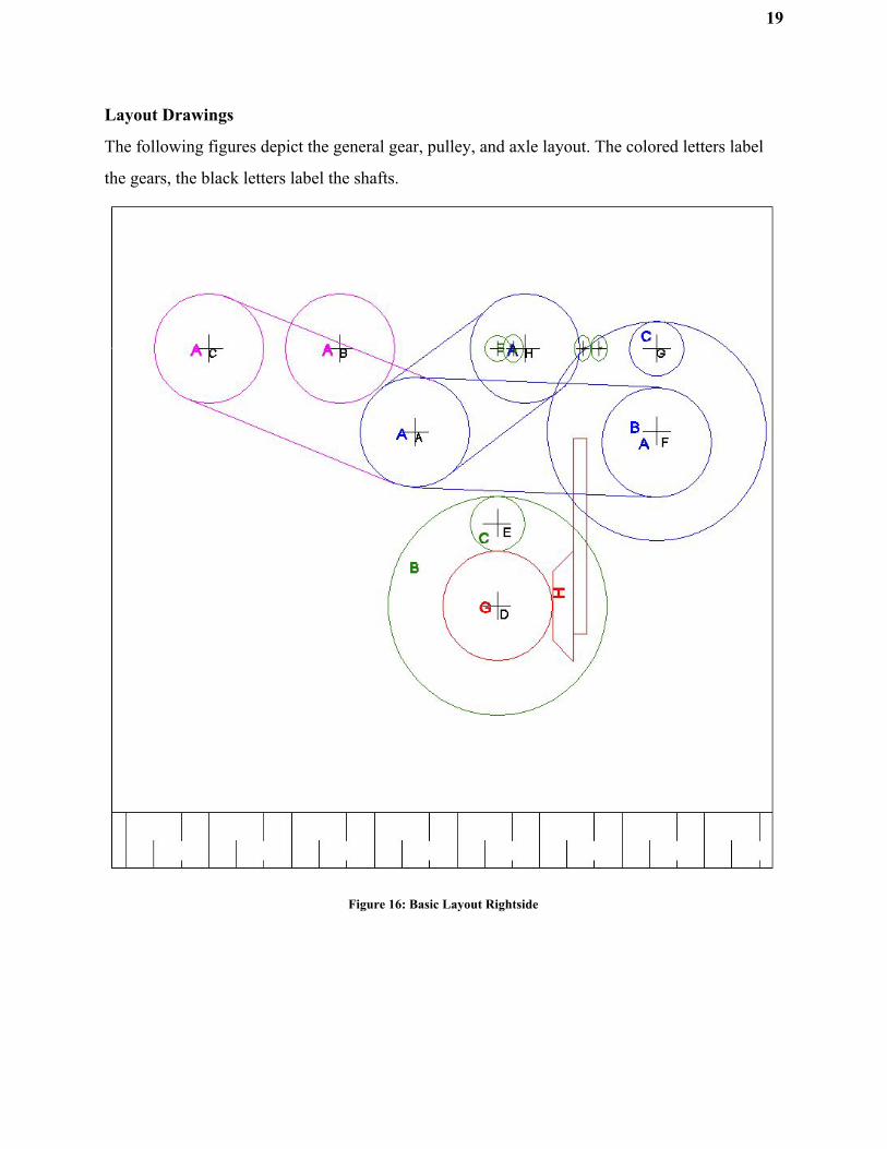
Shafts are labeled in black text on Figure 16.
15
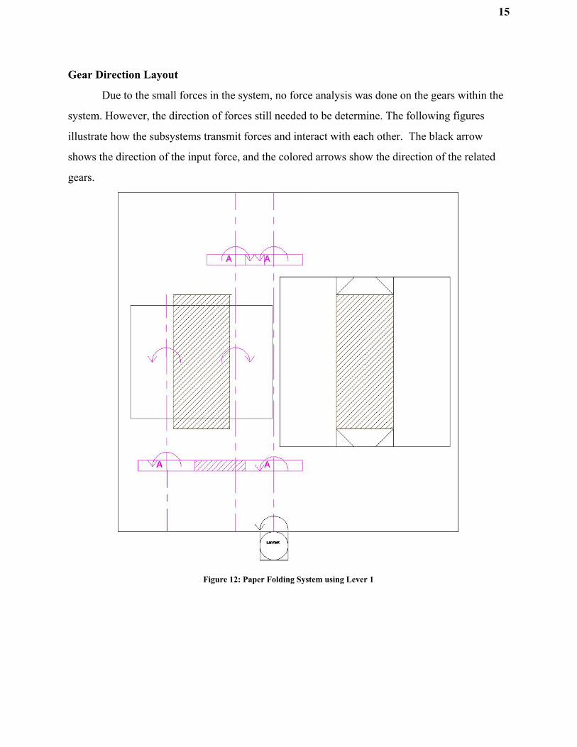
Gear Direction Layout
Due to the small forces in the system, no force analysis was done on the gears within the
system. However, the direction of forces still needed to be determine. The following figures
illustrate how the subsystems transmit forces and interact with each other. The black arrow
shows the direction of the input force, and the colored arrows show the direction of the related
gears.
Figure 12: Paper Folding System using Lever 1

16
Figure 13: Long Direction Paper Folding System using Lever 1

17
Figure 14: Short Direction Paper Folding System using Lever 2

18
Figure 15: Angled Direction Paper Folding System using Lever 2
19
Layout Drawings
The following figures depict the general gear, pulley, and axle layout. The colored letters label
the gears, the black letters label the shafts.
Figure 16: Basic Layout Rightside

20
Figure 17: Basic Layout Top
21
Chapter 4: Detail Design
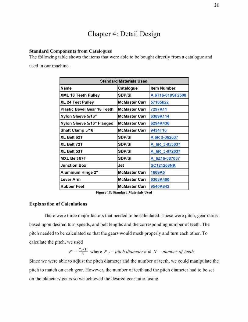
Standard Components from Catalogues The following table shows the items that were able to be bought directly from a catalogue and
used in our machine.
Standard Materials Used
Name Catalogue Item Number XML 18 Teeth Pulley SDP/SI A 6T16-018SF2508 XL 24 Teet Pulley McMaster Carr 57105k22 Plastic Bevel Gear 18 Teeth McMaster Carr 7297K11 Nylon Sleeve 5/16" McMaster Carr 6389K114 Nylon Sleeve 5/16" Flanged McMaster Carr 6294K436 Shaft Clamp 5/16 McMaster Carr 9434T16 XL Belt 62T SDP/SI A 6R 3-062037 XL Belt 72T SDP/SI A_6R_3-053037 XL Belt 53T SDP/SI A_6R_3-072037 MXL Belt 87T SDP/SI A_6Z16-087037 Junction Box Jet SC121208NK Aluminum Hinge 2" McMaster Carr 1609A5 Lever Arm McMaster Carr 6303K400 Rubber Feet McMaster Carr 9540K842
Figure 18: Standard Materials Used
Explanation of Calculations
There were three major factors that needed to be calculated. These were pitch, gear ratios
based upon desired turn speeds, and belt lengths and the corresponding number of teeth. The
pitch needed to be calculated so that the gears would mesh properly and turn each other. To
calculate the pitch, we used
where and P = NP Πd* itch diameterP d = p umber of teethN = n
Since we were able to adjust the pitch diameter and the number of teeth, we could manipulate the
pitch to match on each gear. However, the number of teeth and the pitch diameter had to be set
on the planetary gears so we achieved the desired gear ratio, using

22
R = P d1P d2
= N2
N1
In our situation, we needed a gear ratio of two between the satellite and the sun gear, and a gear
ratio of four between the satellite and the solar gear. Finally, we needed to calculate the number
of teeth on our belts. To calculate we used
, where ,p 2 ) .57 D ) L = ( * C + 1 * ( 1 + D2 + 4C(D −D ) 1 2
2
p itch lengthL = p
, , anditch diameter of the f irst gearD1 = p itch diameter of the second gearD2 = p
istance between centersC = d
At this point, the pitch had been calculated, the pitch diameter had been set, and so all we needed
was to determine the necessary belt length.
Materials and Manufacturing Methods Used
Our machine consisted of several materials and methods of manufacturing. The majority
of our more complex parts (e.g. the planetary gears and angled gear supports) were 3D printed
using a food safe PLA filament. For other complex parts that were either too large to print like
the gear covers, or required a less porous material than is possible on a 3D printer like the flaps,
the use of a molded food safe resin was used. To do this a prototype part was made, either using
a 3D printer in the case of the flaps or MDF for the gear cover, then a two part silicon solution
was poured around the part to make a mold. Once dried the part was removed from the mold and
then a 2 part resin was poured into the mold to produce the desired part after curing for 24 hours.
Less complex parts were able to be machined out of aluminum. The axle supports were
made from 1 x 0.25” aluminum bar stock and 1 x 0.125” angle stock. These were simply cut
down to length, had appropriate holes drilled on a drill press, and then deburred. A similar
method was made to make the lever mounts out of a 2” diameter aluminum round stock. To
make the table top of the machine, we used the steel top that was supplied with the junction box.
We then drilled small holes in each corner and used a rotary cutting tool to cut out the desired
shape.

23
Part Drawings
Figure 19: Gear A
Figure 20: Planetary Gear B

24
Figure 21: Planetary Gear C
Figure 22: Bevel Gear D
25
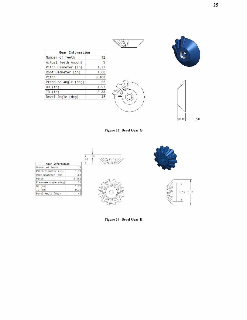
Figure 23: Bevel Gear G
Figure 24: Bevel Gear H

26
Figure 25: Large Paper Flap
Figure 26: Short Paper Flap

27
Figure 27: Long Foil Flap
Figure 28: Short Paper Flap

28
Figure 29: Angle Flap
Figure 30: Gear Cover

29
Figure 31: Table Top
Figure 32: Angled Gear and Flap Support

30
Figure 33: Single Axle Support
Figure 34: Double Axle Support

31
Figure 35: Angle bracket for axle support
Figure 36: Lever mount

32
Assembly Drawings
Figure 37: Drive Shaft A Assembly
Figure 38: Drive Shaft B Assembly

33
Figure 39: Planetary Gear Assembly
Figure 40: Table Flap Assembly

34
Exploded View Drawings
Figure 41: Angular Bracket Exploded View

35
Chapter 5: Discussion
With the design we selected, numerous gear calculations were needed to ensure correct
operation of the machine. With our two levers, we had to accurately deliver the 180° of motion
required to the flaps. For the long side of the foil flaps, we had to achieve 180° of motion both
forward and back in one lever turn, for only one of the flaps. We designed it this way to prevent
the two long foil flaps for colliding into each other. This is why the planetary gear was design.
With the correct number of teeth and pitch on each gear in the set, the first flap folds in and
comes back out before the second flap folds in.
Because most gears are produced through stamping, we decided to use the on-campus
3D-printer to print the non-standard ones. Also, more of the complex parts that were not easily
machinable were printed. This included the planetary gear set, Gear A, each flap, and most of the
angular flap assembly. By using the 3D printers, we were able to create otherwise
cost-prohibitive parts for significantly cheaper.
A prototype was built to test out the motion of the rods and gears. We used ¼” plywood
to build the first unit, for easy assembly and dimensional trials. This was the unit that was
showcased at the Senior Design Day Presentations. While the prototype was not quite a
looks-like and functions-like model, it was able to show the inner workings of the gears to
observers.
The actual machine is to be built shortly after the prototype is completed. It will be the
final product that Gilbert Chocolates receives, and could potentially be marketed to other small
businesses. The final product costs $430 to manufacture, and with further development, could
potentially be reduced further.

36
Chapter 6: Conclusion
This project was begun with the intent of designing a machine capable of decreasing the
time needed for Gilbert Chocolate’s employees to wrap candy bars. By doing so, the workers
could spend more time producing more chocolate to sell. Furthermore, the machine needed to be
affordable for a small business, and needed to easily moveable for when it was needed.
The importance of all of these design criteria cannot be overstated. If the machine failed
to reduce the time required to wrap the bars, the machine serves little benefit over wrapping by
hand. Furthermore, if the machine costs well over $1000 dollars, the payback time may be
undesirable. With further research and development, these machines could be improved and
optimized for Gilbert Chocolates, but also for other small chocolate businesses. As the product is
optimized, the cost of manufacturing can be reduced, making it more beneficial for more
companies, and reducing their payback time.
We believe that this machine achieved its purpose. The price was below the stated price
requirement, it reduces the time required to wrap the bars, and is contained within a cubic foot.
We also believe that this product is marketable to other small chocolate businesses looking to
reduce wrapping time without spending an exorbitant amount of money on a machine way
beyond their product capabilities.
37
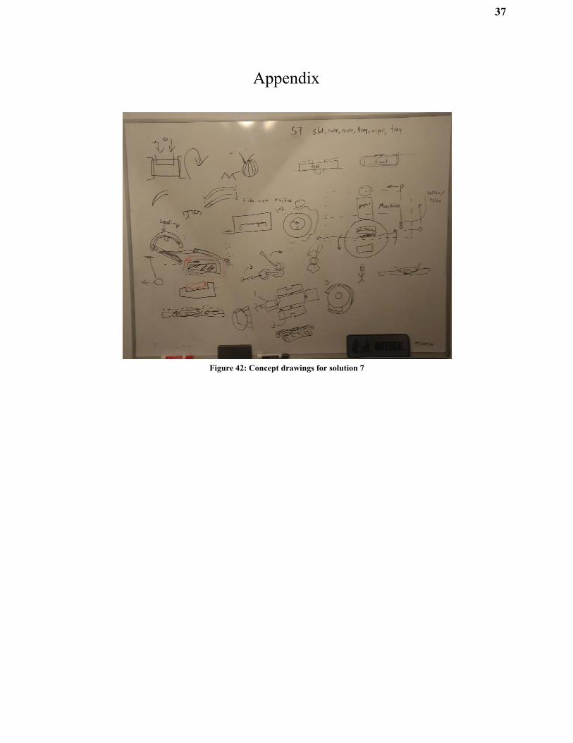
Appendix
Figure 42: Concept drawings for solution 7

38
Common Name Exact Name/Prt # Qty Process Description
Cost (per
piece) Total Cost
Gears
Gear A - 2
3D Print
(Makerbot)
Common gear used throughout
machine $0.00 $0.00
Gear B - 2
3D Print
(Makerbot) Planetary gear $0.00 $0.00
Gear C - 2 3D Print (uPrint) Gear that sits inside Gear B $20.00 $40.00
Gear D - 4 3D Print (uPrint) 22.5 bevel gear $6.00 $24.00
Gear E A 6T16-018SF2508 4 Purch Belted gear to angled flaps $4.76 $19.04
Gear F 7297K11 4 Purch Small 45 bevel gear to angle flaps $5.19 $20.76
Gear G - 2
3D Print
(Makerbot) 45 bevel gear with teeth removed $0.00 $0.00
Gear H - 2
3D Print
(Makerbot)
45 bevel gear with all teeth and nub
for piston $0.00 $0.00
Belt Pulley 57105k22 6 Purch Pulley for belt driven shafts $8.20 $49.20
Shafts & Sleeves
Drive Shaft 1570K23 2 Purch
13" length; dia = 5/16"; attaches to
lever; cut to length $13.10 $26.20
Shaft A 1570K23 5 Purch
10" length; dia = 5/16"; connects to
flap; cut to length $10.08 $50.38
Shaft B 1570K23 3 Purch
3" length; dia = 5/16"; where Gear H
sit; cut to length $3.02 $9.07
Shaft C 1570K23 2 Purch
2" length; dia = 5/16"; where Gear H
sit; cut to length $2.02 $4.03
Shaft D - 2 Purch 2" length; dia = 1/8"; $0.13 $0.26
Shaft E - 2 Purch 1.25" length; dia = 1/8" $0.08 $0.17
Shaft F - 2 Purch .75" length; dia = 1/8" $0.05 $0.10
Nylon Sleeve
5/16" 6389K114 17 Purch
Provides a low friction surface for the
shafts $0.73 $12.41
Nylon Sleeve
5/16" 6294K436 6 Purch
Provides a low friction surface for the
shafts, now with flange $1.14 $6.84
Shaft Clamp 5/16 9434T16 12 Purch Holds shaft and sleeve in place $0.09 $1.04

39
Flaps
Paper Flap Short - 1
3D Print
(Makerbot)
Flap for short side of paper; keyed out
center to allow taping $0.00 $0.00
Paper Flap Long - 1
3D Print
(Makerbot)
Flap for long side of paper; keyed out
center to allow taping $0.00 $0.00
Long Flap - 2
3D Print
(Makerbot)
Flap with raised ends to fold flat to
bottom of bar $0.00 $0.00
Angle Flap - 4
3D Print
(Makerbot) Flap for triangle fold $0.00 $0.00
Short Flap - 2
3D Print
(Makerbot) Flap for smaller end of bar $0.00 $0.00
Alum. Piston Arm - 2 Machined Connects to short flap to engage flap $0.37 $0.74
Belts
XL Belt 62T A 6R 3-062037 1 Purch Meshes with Gear A $6.84 $6.84
XL Belt 72T A_6R_3-053037 1 Purch Meshes with Gear A $6.59 $6.59
XL Belt 53T A_6R_3-072037 1 Purch Meshes with Gear A $7.11 $7.11
MXL Belt 87T A_6Z16-087037 2 Purch Meshes with Gear D $5.21 $10.42
Frame
Junction Box SC121208NK 1 Purch
1 sq. ft steel box used as support and
container $38.86 $38.86
Alum. Shaft
Support 8975K596 2 Machined
Supports mid span and ends of some
shafts $0.73 $1.46
Alum. Duo Shaft
Support 8975K596 2 Machined Supports 2 rods at same time $0.96 $1.91
Cover Alum.
Hinge 1609A5 4 Purch
Hinges to connect the gear covers to
the junction box $2.44 $9.76
Gear Cover - 2 Mold
Attaches to Top Frame via hinges;
encloses gears for safety $2.25 $4.50
Angle Bracket 8982K4 5 Purch Connects Shaft Supports to Frame $0.24 $1.20
Misc.
3/64 Dowel Pin 97155A112 10 Purch Help lock gears and flaps to shafts $0.06 $0.60
Lever Arm 6303K400 2 Purch Engages entire machine $6.55 $13.10
Silicon Molding OOMOO 25 1 Purch Used to make a mold $25.00 $25.00
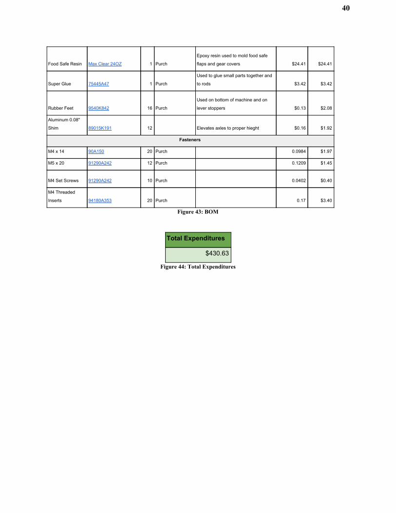
40
Food Safe Resin Max Clear 24OZ 1 Purch
Epoxy resin used to mold food safe
flaps and gear covers $24.41 $24.41
Super Glue 75445A47 1 Purch
Used to glue small parts together and
to rods $3.42 $3.42
Rubber Feet 9540K842 16 Purch
Used on bottom of machine and on
lever stoppers $0.13 $2.08
Aluminum 0.08"
Shim 89015K191 12 Elevates axles to proper hieght $0.16 $1.92
Fasteners
M4 x 14 90A150 20 Purch 0.0984 $1.97
M5 x 20 91290A242 12 Purch 0.1209 $1.45
M4 Set Screws 91290A242 10 Purch 0.0402 $0.40
M4 Threaded
Inserts 94180A353 20 Purch 0.17 $3.40
Figure 43: BOM
Total Expenditures
$430.63
Figure 44: Total Expenditures
Related Documents