// ITES LAB1-1, Copyright 2013-2014 ProLinear/PONTECH, Inc. // Lab 1 - Installing and Using the MPIDE Development Tool Part 1 - Installing MPIDE MPIDE is a "Muitiplatform Arduino Compatible Integrated Development Environment". "Multiplatform" implies that it works with more than one platform, in this case chipKIT and Arduino. "Arduino Compatible" because it is a fork from the primary Ardunio IDE. "Integrated Development Environment " is a tool that combines editing source code compiling and uploading your compiled program to your target platform. Where to find MPIDE MPIDE can be downloaded from this web page: http://chipkit.net/started/install-chipkit-software/ MPIDE is a fast changing open source tool and there are many versions to choose from. Additionally MPIDE is compiled to run on a Windows PC, MAC OSX and Linux. This revision of the lab manual is written for the specific version 20130715 of MPIDE. Download version 20130715 of MPIDE for the operating system you will be using to test and demonstrate your programs. Download the install file and save it on the desktop of your computer. Unzipping the file in Windows The file you have downloaded, regardless of the operating system, is a compressed file. In Windows this file can be extracted by right clicking on the downloaded file and picking the "Extract All..." item on the pop-up menu. A new dialog will appear that asks for the location to extract the files. This location should be your desktop.

Welcome message from author
This document is posted to help you gain knowledge. Please leave a comment to let me know what you think about it! Share it to your friends and learn new things together.
Transcript

// ITES LAB1-1, Copyright 2013-2014 ProLinear/PONTECH, Inc. //
Lab 1 - Installing and Using the MPIDE Development Tool
Part 1 - Installing MPIDE
MPIDE is a "Muitiplatform Arduino Compatible Integrated Development Environment". "Multiplatform"
implies that it works with more than one platform, in this case chipKIT and Arduino. "Arduino
Compatible" because it is a fork from the primary Ardunio IDE. "Integrated Development Environment "
is a tool that combines editing source code compiling and uploading your compiled program to your
target platform.
Where to find MPIDE
MPIDE can be downloaded from this web page:
http://chipkit.net/started/install-chipkit-software/
MPIDE is a fast changing open source tool and there are many versions to choose from. Additionally
MPIDE is compiled to run on a Windows PC, MAC OSX and Linux. This revision of the lab manual is
written for the specific version 20130715 of MPIDE. Download version 20130715 of MPIDE for the
operating system you will be using to test and demonstrate your programs.
Download the install file and save it on the desktop of your computer.
Unzipping the file in Windows
The file you have downloaded, regardless of the
operating system, is a compressed file. In
Windows this file can be extracted by right clicking
on the downloaded file and picking the "Extract
All..." item on the pop-up menu.
A new dialog will appear that asks for the location to extract the files. This location should be your
desktop.
// ITES LAB1-2, Copyright 2013-2014 ProLinear/PONTECH, Inc. //
Click the "Extract" button to extract MPIDE. This may take a few minutes due to the large size of the
program but when complete will result in a new folder on your desktop called "mpide-0023-windows-
20130715" which will contain the extracted development tools.
MPIDE should work from any folder but for consistency in this manual it will be assumed that the MPIDE
will be in a folder onto the Desktop.
For instructions on installing MPIDE on a Mac or Linux computer visit the following site for additional
information:
http://chipkit.net/started/
Creating a Shortcut
You could easily run MPIDE by just double click on mpide.exe in the unzipped folder , however for the
class we will make a shortcut to the executable by right clicking on mpide.exe and selecting copy then
right clicking on the desktop and pasting.
Your desktop will now look something like this:
// ITES LAB1-3, Copyright 2013-2014 ProLinear/PONTECH, Inc. //
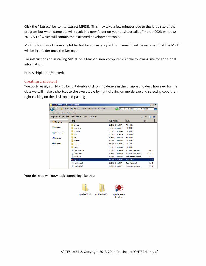
How to run MPIDE
Double click on "mpide.exe - Shortcut"
icon on your desktop and you should get a
window that looks something like the one
pictured to the right.
The most important buttons to you right
now are the five on the left in the upper
red bar.
1. Verify: compiles your code
and tells you about any errors
with text in the black box at
the bottom of the ide.
2. Upload: Compiles your code
then attempts to write the
compiled program to a
connected board.
3. New: Creates a new sketch
4. Open: opens existing sketches 5. Save: Saves your work
6. A sixth icon is used for open a serial terminal which we will not be using in this lab.
Check off
Part 1 of the lab is complete, call the instructor over to verify your installation.
// ITES LAB1-4, Copyright 2013-2014 ProLinear/PONTECH, Inc. //
Part 2-6 - Get a Blink sketch working on 5 different boards
Sketches
All programs written using MPIDE are called
sketches. The idea behind the sketch is that
MPIDE makes programming as simple to start
as an artist picking up a paper to draw a sketch
and hence the name.
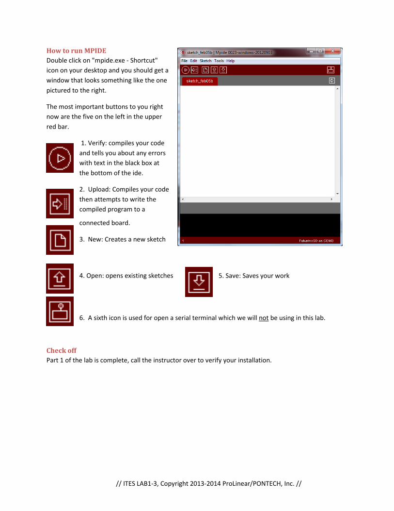
Example Sketches
Like anything new, one way to learn is by
looking at examples. MPIDE comes with
several example sketches to help you
understand how the write programs for
chipKIT, Arduino and Wiring compatible
boards. These sketches are accessible from the
File menu by mousing over Examples. As you
can see from the image to the right in this
installation there are many examples to choose
from. We will start at the beginning and try a
"Basic" sketch called "Blink". Click on the
"Blink" sketch to open the example file.
When you select the "Blink" example a new
MPIDE window will open leaving your unused
sketch behind the new example sketch. Two
things will look different in this new window.
1. The tab will be named "Blink"
2. The bulk of the window that was previously
blank is now filled with colorful text that is the
extent of the sketch.
The "Blink" sketch will blink a LED connected to
the board at a rate of 1/2Hz (one second on
then one second off). The MPIDE editor has
color coded the "source code" to make it easy
to distinguish the parts of the code.
Green: User comments, red: Qualifiers, orange:
function calls, purple: function definitions,
blue: constants. More about these later.

// ITES LAB1-5, Copyright 2013-2014 ProLinear/PONTECH, Inc. //
Selecting the board
After selecting the sketch that we want to
try we must next select the board we
wish to run our program on. This is done
from the "Tools->Board" menu. In this
lab we will be trying to run the "Blink"
sketch on five different boards. Select a
board to use for testing the sketch.
Fubarino SD
http://fubarino.org
Digilent Uno32, uC32 and Max32
http://www.digilentinc.com
PONTECH UAV100 and Quick-240
http://www.pontech.com
Arduino
http://arduino.cc
Drivers
Each board will require a driver in order for your computer to recognize it. Some boards share drivers
and for this class only two drivers are needed.
FTDI: http://www.ftdichip.com/Drivers/D2XX.htm
Download the setup executable.
chipKIT: USB for Serial: http://pontech.dyndns.org/pontech/uav100/Stk500v2.inf
Install by right click on inf file and choosing install from the dropdown menu.
// ITES LAB1-6, Copyright 2013-2014 ProLinear/PONTECH, Inc. //
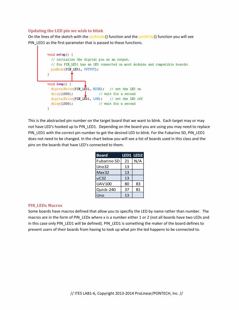
Updating the LED pin we wish to blink
On the lines of the sketch with the pinMode() function and the pinWrite() function you will see
PIN_LED1 as the first parameter that is passed to these functions.
This is the abstracted pin number on the target board that we want to blink. Each target may or may
not have LED's hooked up to PIN_LED1. Depending on the board you are using you may need to replace
PIN_LED1 with the correct pin number to get the desired LED to blink. For the Fubarino SD, PIN_LED1
does not need to be changed. In the chart below you will see a list of boards used in this class and the
pins on the boards that have LED's connected to them.
Board LED1 LED2
Fubarino SD 21 N/A
Uno32 13
Max32 13
uC32 13
UAV100 80 83
Quick-240 37 81
Uno 13
PIN_LEDx Macros
Some boards have macros defined that allow you to specifiy the LED by name rather than number. The
macros are in the form of PIN_LEDx where x is a number either 1 or 2 (not all boards have two LEDs and
in this case only PIN_LED1 will be defined). PIN_LED1 is something the maker of the board defines to
prevent users of their boards from having to look up what pin the led happens to be connected to.

// ITES LAB1-7, Copyright 2013-2014 ProLinear/PONTECH, Inc. //
Compiling the Sketch
Before we actually try to program our board, we need to verify that our program is syntactically correct.
As mentioned previously the "Verify" button will compile the program. When you press it the bottom of
the MPIDE interface will indicate that the program is compiling by displaying "Compiling sketch..." and
showing a progress bar.
When finished compiling the stats will change to "Done compiling." and if everything was syntactically
correct the size of the sketch will be displayed.
Connection the board to the computer
Most chipKIT and Arduino boards will connect to a computer with a USB cable. Additionally, most
boards will also be power by the computer stealing power from the USB port. USB cables have four
connections: +5VDC, GND (ground), DATA+, and DATA-. Newer microcontrollers run on +3.3V or lower
and boards such as the Fubarino SD, chipKIT Uno32 and PONTECH Quick-240 will have voltage regulators
on board that lower the +5VDC from the USB cable to a usable +3.3VDC for the microcontroller.

// ITES LAB1-8, Copyright 2013-2014 ProLinear/PONTECH, Inc. //
Getting to the Bootloader
A bootloader is a small program that is pre-loaded on to each board by the manufacturer (or yourself if
you happen to be the manufacturer) that allows the board to communicate with another computer in
order to receive additional programs.
Before you can program the board it needs to be ready to receive the data and "sitting in the
bootloader" the Uno32 and Arduino Uno do this automatically but the others need more steps.
Fubarino SD: The Fubarino SD has two buttons on the top of the board labeled PRG and RESET. The
Reset button does just that, it will reset the microcontroller. The PRG button, if held down during a
reset will cause the board to go into enter the bootloader. When in the bootloader the GREEN led will
blink rapidly.
A video showing the procedure to get the Fubarino SD into the bootloader can be found here:
http://www.youtube.com/watch?v=7Knri2QWEFU
PONTECH UAV100: Put the jumper in the programming position, then push the button.

// ITES LAB1
PONTECH Quick-240: Similar to the UAV except rotated and you short
instead of using a button
The Arduino Uno, chipKIT Uno32, chipKIT Max32 and chipKIT
reset line of the microcontroller allowing MPIDE to force the device into reset prior to programming so
no special reset sequence is needed to program these boards.
LAB1-9, Copyright 2013-2014 ProLinear/PONTECH, Inc.
240: Similar to the UAV except rotated and you short the two pins next to the jumper
The Arduino Uno, chipKIT Uno32, chipKIT Max32 and chipKIT uC32 have special that can control the
reset line of the microcontroller allowing MPIDE to force the device into reset prior to programming so
no special reset sequence is needed to program these boards.
//
two pins next to the jumper
uC32 have special that can control the
reset line of the microcontroller allowing MPIDE to force the device into reset prior to programming so

// ITES LAB1-10, Copyright 2013-2014 ProLinear/PONTECH, Inc. //
Selecting the Serial Port
When a chipKIT or Arduino board
is plugged into your USB port and
the driver for it is installed
correctly a COM port for it should
appear in your "Tools->Serial
Port" menu list. The COM port
should be the same for each
board plugged in on a specific
computer, but may change if the
board is plugged into a different
computer. This is due to the COM
port number being chosen by the
computer. If there is only a single
device that has a COM port on the
computer then finding the correct
COM port is easy, for it will the
only one in the list. However, if
there is more than one COM
device connected to the computer
you will need to figure out which
COM port is for the device you
want to program. This is simply
done by looking at the list of
available COM ports prior to connecting your board and then again and noting the new COM port that
was added after your board was plugged in. If no additional COM port is found after plugging your
board this could be due to one of two possible issues. Either the driver for the board you are using is
not installed on the computer you are using or the device you are using is not in the bootloader.

// ITES LAB1-11, Copyright 2013-2014 ProLinear/PONTECH, Inc. //
Uploading the Sketch
Once we have verified the syntax of our program, connected the board, selected it from the boards list
and chosen the correct COM port to communicate to the bootloader we are ready to upload our
program to the board. Push the upload button:
The program will once again compile but when it finishes the status will indicate that it is "Uploading..."
to the board.
When complete the status will change to "Done uploading." then the program will being to run on the
board.
Check off
Part 2 of the lab is complete, call the instructor over to verify your installation.
Parts 3-6
Repeat part 2 of this lab for four more boards. Uno32, Uno, PONTECH Quick240, PONTECH UAV100. Call
the instructor over to verify you were able to get the Blink sketch running on each board.

// ITES LAB1-12, Copyright 2013-2014 ProLinear/PONTECH, Inc. //
Part 7 - Anatomy of a Sketch and User Sketches
Anatomy of a Sketch
Let's examine each parts of the Blink sketch in detail. The first six lines of green text in the sketch are in
encapsulated with the delimiters /* and */.
These delimiters and everything between them are called a multiline comment. Comments in general
are notes that the programmer leaves for themselves to remind them what the program does or
specifics that need to be adhered to when altering the program. Comments have no affect on how the
program runs or what it does.
Next is the setup function.
The setup function is five lines long. The first and last of the function are what define and encapsulate
the function. The function consists of four important aspects.
1. The return type. In this case void which simply means this function if void of a return type.
2. The function name. In this case: setup.
3. The parameter list, a comma separated listed encapsulated by parenthesis. In this case an
empty list.
4. The function encapsulating braces which are always { and }. The function definition exists
between these two braces.
The setup(); is a function that is run only once at the start of the program. Setup as its name implies is
usually used to setup the processor for the remainder of the program.

// ITES LAB1-13, Copyright 2013-2014 ProLinear/PONTECH, Inc. //
Again the lines that are in a green font are comments.
However, these comments are single line comments and are delimited by the // at the beginning of the
comment and a newline at then end.
Finally, a function call to pinMode(pin, pin-mode);.
This function configures pin of the control board (pin 21) to be an of pin-mode type OUTPUT. The
values PIN_LED1 and OUTPUT are said to be the parameters that are passed to the function. The
parameters for the function are encapsulated by parenthesis and separated by commas. Finally the call
the pinMode() ends with the semicolon.
The second function is called loop().
The loop function has four function calls and four comments. The digitalWrite(pin,state); is used to set
the selected pin to the selected state. In our case we are setting pin 21 to either HIGH or LOW. The
delay(ms); causes the program to wait ms milliseconds.
As you might guessed the loop() is a function is run over and over. Loop is the location where you put
the portion of your code you want to repeat, to perform the main task of the device.
So the loop() causes pin 21 to go HIGH, waits for 1 second then causes pin 21 to go LOW and waits an
additional second. The program then repeats unit the board is reset or until power is lost.
User Sketches
You cannot modify and save an example sketch. If you modify the program and want to save, it will then
become a User Sketch. They are accessible from the Open Icon and File->Open->Sketchbook
The default save location in Windows is C:\Users\<username>\Documents\mpide
Where <username> is the name of the computer user that you are logged on to the computer as.

// ITES LAB1-14, Copyright 2013-2014 ProLinear/PONTECH, Inc. //
Modified Blink
Replace the loop() function in your code with the one shown below. Save it as a user sketch, compile
and upload it to a board.
Check off
Call the instructor over for a check off. You will need to demonstrate the uploading of the program to
the board.
Part 8 - More advanced Blink
Alter the loop so that you will get a pattern of one long, two short, one long, then one short blink.
Check off
Call the instructor over for a check off. You will need to demonstrate the uploading of the program to
the board.

// ITES LAB1-15, Copyright 2013-2014 ProLinear/PONTECH, Inc. //
Lab 1 Homework
Get MPIDE working on your own
Get MPIDE working on your own computer or a computer you have access outside of class. Get the
blink sketch working and uploading to a board on your own.
Investigate chipKIT on the internet
chipKIT Web Page
chipkit.net
chipKIT Forum
The chipKIT forum (http://chipkit.net/forum/) is a place people can go to get help with a problem they
are having in using chipKIT compatible boards, get code other people have written for their own
projects, or share code they think will be helpful to others.
Investigate Fubarino SD
Web Site: fubarino.org
Development Repository: https://github.com/fubarino/fubarino.github.com
Investigate Open Source
Many of the boards you are going to be using are Open Source. Open Source is an idea where a Product
or Software has if schematics and source code available for other people to use. This can help users of
the product to get the most out of it because if they don't like a part of it they have the information
needed to change it. Open Source also allows people to make new products based off old ones without
having to start from scratch.
Be prepared to discuss advantages and disadvantages in next class.
Investigate Wiring Pin Abstractions
http://wiring.org.co/
Most brands of microcontrollers have different ways that the software uses to control the output pins of
the part. This compiler uses Pin Abstractions to prevent this from being a problem, it knows what kind of
chip is being programmed and uses the correct method. They also allow the designer of the board to use
pins that are not adjacent on the processor as sequential abstracted pins.
Related Documents