O05E.pdf Nov.25,2013 !Note • Please read rating and !CAUTION (for storage, operating, rating, soldering, mounting and handling) in this catalog to prevent smoking and/or burning, etc. • This catalog has only typical specifications. Therefore, please approve our product specifications or transact the approval sheet for product specifications before ordering.

Welcome message from author
This document is posted to help you gain knowledge. Please leave a comment to let me know what you think about it! Share it to your friends and learn new things together.
Transcript
O05E.pdfNov.25,2013
!Note • Please read rating and !CAUTION (for storage, operating, rating, soldering, mounting and handling) in this catalog to prevent smoking and/or burning, etc.• This catalog has only typical specifi cations. Therefore, please approve our product specifi cations or transact the approval sheet for product specifi cations before ordering.
FlowOK
XX
ReflowOK
Low Rdc Bias
Introduction
Murata has various chip inductors for every application such as power
circuits and high frequency circuits.
There are 3 types of structure: wirewound, multilayer, and film.
These variations enable the best selection for every user's needs.
We will support customers using material technologies and highly
developed design technologies.
EU RoHS Compliant All the products in this catalog comply with EU RoHS. EU RoHS is "the European Directive 2011/65/EU on the Restriction of the Use of Certain
Hazardous Substances in Electrical and Electronic Equipment." For more details, please refer to our website 'Murata's Approach for EU RoHS'
(http://www.murata.com/info/rohs.html).
New product Design kit available
E12 step inductance variation E24 step inductance variation
Bias current characteristics improved
Explanation of symbols in this catalogFeatures of each series
Features of each item
New product
Max height xxmm
Reflow soldering applicable
Low DC resistance type
Flow soldering applicable
Hi Q type
Tight inductance tolerance available
O05E.pdfNov.25,2013
!Note • Please read rating and !CAUTION (for storage, operating, rating, soldering, mounting and handling) in this catalog to prevent smoking and/or burning, etc.• This catalog has only typical specifi cations. Therefore, please approve our product specifi cations or transact the approval sheet for product specifi cations before ordering.
CONTENTS
Indu
ctor
s fo
r P
ower
Lin
esIn
duct
ors
for
Gen
eral
Use
RF
Indu
ctor
s
aInductors for Power Lines
aInductors for General Use
aRF Inductors
·········
·······················································
·····················································
···································
····················································
··············································
················································
············································
··································
······················································
·····················································
··············································
················································
············································
··································
······················································
·····················································
···················································
··············································
················································
············································
··································
······················································
·····················································
································
·················
···············
·····
Introduction
Part Numbering
Product Detail
!Caution/Notice
Soldering and Mounting
Packaging
Design Kits
12
14
16
100
102
107
111
Part Numbering
Product Detail
!Caution/Notice
Soldering and Mounting
Packaging
Design Kits
118
119
136
137
141
142
Introduction
Part Numbering
Product Detail
!Caution/Notice
Soldering and Mounting
Packaging
Design Kits
146
147
148
225
227
231
232
Part Number Quick Reference
Introduction of Web Site Design Tools
EMICON-FUN!
Products Information
Classification and Structure of Chip Inductors
Product Guide
Selection Guide
Product Guide by Thickness
2
4
8
9
243
244
245
246
O05E.pdfNov.25,2013
!Note • Please read rating and !CAUTION (for storage, operating, rating, soldering, mounting and handling) in this catalog to prevent smoking and/or burning, etc.• This catalog has only typical specifi cations. Therefore, please approve our product specifi cations or transact the approval sheet for product specifi cations before ordering.
2
!Note • Please read rating and !CAUTION (for storage, operating, rating, soldering, mounting and handling) in this catalog to prevent smoking and/or burning, etc.• This catalog has only typical specifi cations. Therefore, please approve our product specifi cations or transact the approval sheet for product specifi cations before ordering.
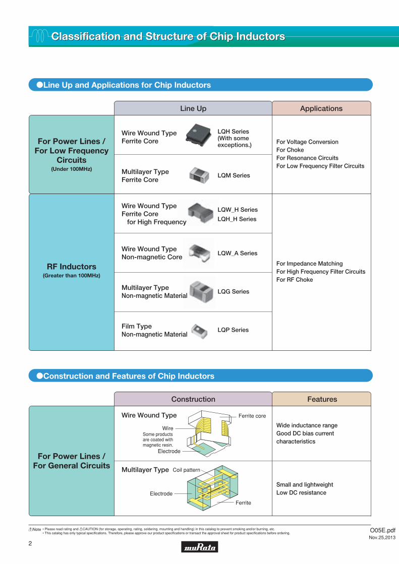
LQW_H Series
LQH_H Series
LQH Series(With some exceptions.)
LQM Series
LQW_A Series
LQG Series
LQP Series
Classification and Structure of Chip InductorsClassification and Structure of Chip Inductors
oLine Up and Applications for Chip Inductors
oConstruction and Features of Chip Inductors
For Power Lines /For Low Frequency
Circuits(Under 100MHz)
For Power Lines /For General Circuits
For Voltage ConversionFor ChokeFor Resonance CircuitsFor Low Frequency Filter Circuits
For Impedance MatchingFor High Frequency Filter CircuitsFor RF Choke
RF Inductors(Greater than 100MHz)
Wire Wound TypeFerrite Core
Multilayer TypeFerrite Core
Wire Wound TypeFerrite Core for High Frequency
Wire Wound TypeNon-magnetic Core
Multilayer TypeNon-magnetic Material
Film TypeNon-magnetic Material
Wide inductance rangeGood DC bias currentcharacteristics
Small and lightweightLow DC resistance
Wire Wound Type
Multilayer Type
Line Up Applications
Construction Features
Wire
Ferrite core
Electrode
Coil pattern
Electrode
Ferrite
Some products are coated with magnetic resin.
O05E.pdfNov.25,2013

3
!Note • Please read rating and !CAUTION (for storage, operating, rating, soldering, mounting and handling) in this catalog to prevent smoking and/or burning, etc.• This catalog has only typical specifi cations. Therefore, please approve our product specifi cations or transact the approval sheet for product specifi cations before ordering.
100
80
60
40
20
050k10k 100k 500k 1M 5M 10M
A
B
C
14
10
12
8
6
4
0
2
10 2 3 4 5 6
2.5 2.5
2.5
1
21
1 15.51.3
High Q at intermeditate
frequency
Industrial standard design
Small size, but high Q
oTechnical Data
High Q
Large inductance
Construction Features
RF Inductors
Wire Wound TypeFor Radio Frequency
Wire Wound TypeFor IntermediateFrequency
Multilayer Type
Film Type
Wire
Wire
Electrode
Outer electrode
Outer electrode
Coil pattern
Non-magneticceramic
Electrode
Resin coatingon the top
Resin coatingon the top
Ferrite core forhigh frequency
Non-magneticceramic core
Inner electrode, which is produced using photolithography process
1. Land Area and Q-F Characteristics 2. Coupling Coefficient Versus Distance between Parts
LQH32MN680K23LQH32M Series
PCB: Ag-Pb printed land formed on 0.6mm-thick alumina plateSoldering: Reflow solderingSolder layer: Sections shown by oblique lines in figure
(in mm)
Characteristic of chip mounted on land
Characteristic of chip mounted on land
A : Net characteristics without land pattern
C :
B :
Distance between parts
Q
Frequency (Hz) Distance between Parts (mm)
1μH 330μH
Co
uplin
g C
oef
ficie
nt (%
)
O05E.pdfNov.25,2013

4
!Note • Please read rating and !CAUTION (for storage, operating, rating, soldering, mounting and handling) in this catalog to prevent smoking and/or burning, etc.• This catalog has only typical specifi cations. Therefore, please approve our product specifi cations or transact the approval sheet for product specifi cations before ordering.
0603 (1608)
0402 (1005)
2525 (6363)2220 (5750)
0805 (2012)0805 (2012)0805 (2012)0402 (1005)0603 (1608)
0805 (2012)0603 (1608)
0806 (2016)
1206 (3216)
1812 (4532)1812 (4532)
1210 (3225)1210 (3225)
1206 (3216)
1210 (3225)1210 (3225)1210 (3225)1210 (3225)1812 (4532)1812 (4532)
1515 (4040)2020 (5050)
1515 (4040)
2020 (5050)
1212 (3030)
0806 (2016)1008 (2520)1008 (2520)
1206 (3216)1210 (3225)
0805 (2012)
0805 (2012)0805 (2012)
0603 (1608)0603 (1608)
0603 (1608)0603 (1608)
0805 (2012)
1008 (2520)1008 (2520)
1008 (2520)
0806 (2016)0806 (2016)
1008 (2520)1008 (2520)
1008 (2520)1008 (2520)
1212 (3030)1212 (3030)1212 (3030)
LQW15CN_00LQW15CN_10LQW18CN_00LQH2MCN_02LQH2MCN_52LQH2HPN_G0LQH2HPN_GR LQH2HPN_J0LQH2HPN_M0LQH3NPN_G0LQH3NPN_J0LQH3NPN_M0LQH3NPN_MRLQH32PN_N0LQH32PN_NCLQH32PB_N0LQH32PB_NCLQH43PN_26LQH43PB_26LQH44PN_J0LQH44PN_P0LQH5BPN_T0LQH5BPB_T0LQH31CN_03LQH32CN_23/33LQH32CN_53LQH43CN_03LQH43CN_33LQH55DN_03LQH66SN_03LQM18PN_B0LQM18PN_C0LQM18PN_D0LQM18PN_F0LQM18PN_FRLQM21PN_C0LQM21PN_G0LQM21PN_GSLQM21PN_GCLQM21PN_GRLQM2MPN_G0LQM2MPN_GHLQM2HPN_G0LQM2HPN_GSLQM2HPN_GCLQM2HPN_GHLQM2HPN_J0LQM2HPN_JCLQM2HPN_JHLQM2HPN_E0LQM31PN_00LQM31PN_C0LQM32PN_G0LQM18FN_00LQM21DN_00LQM21FN_00 LQM21FN_70LQM21FN_80LQB15NN_10LQB18NN_10LQM18NN_00LQM21NN_10LQH31MN_03LQH32MN_23LQH43M(N)N_03LQH44NN_03
0402 (1005)
1008 (2520)1008 (2520)
0603 (1608)
0805 (2012)
1008 (2520)
0603 (1608)0805 (2012)1206 (3216)1210 (3225)1812 (4532)1515 (4040)
10μH1.0μH
10μH4.7μH
10μH4.7μH
22μH1.0μH
100μH2.2μH
1.0μH 47μH
1.0μH 220μH
1.0μH 220μH
560nH
470nH
120μH
82μH1.0μH
270nH 10mH
120nH 10mH
47μH1.0μH
100μH1.0μH
4.7μH1.0μH
47μH1.0μH
2.2μH1.0μH
22μH1.0μH
47μH1.0μH
47μH1.0μH
470μH1.0μH
470μH510nH
1.0μH
150nH 560μH
120nH 100μH
100μH
1.0μH 250μH
1.5μH 10μH
2.2μH 4.7μH
2.2μH 4.7μH
1.0μH 3.3μH
470nH
470nH 2.2μH
470nH 2.2μH
160nH 2.2μH
220nH 4.7μH
220nH 560nH
220nH 560nH
1.5μH
1.0μH
1.0μH
2.5μH
470nH 4.7μH
4.9nH 650nH
18nH 200nH
560nH 3.9μH
220nH 560nH
470nH 4.7μH
1.0μH 4.7μH
4.7μH
3.3μH
2.2μH 4.7μH
1.0μH 2.2μH
470nH 2.2μH
470nH 2.2μH
470nH 2.2μH
470nH
22μH470nH
22μH470nH
22μH470nH
120μH470nH
22μH470nH
22μH470nH
47nH 2.2μH
100nH 4.7μH
150nH 100μH
560μH1.0μH
2.2mH1.0μH
p86
p87
p89
p42
p44
p46
p48
p50
p52
p59
p57
p53
p55
p61
p63
p65
p67
p69
p71
p75
p73
p77
p79
p90
p91
p93
p94
p95
p96
p98
p16
p17
p18
p19
p20
p22
p23
p24
p25
p26
p27
p29
p34
p35
p36
p37
p31
p33
p32
p38
p39
p40
p41
p81
p82
p83
p84
p85
p119
p121
p123
p125
p127
p129
p131
p134
1n 10m1m100μ10μ1μ100n10nPart Number Structure Size Code
in inch (in mm)Inductance Range (H)
Murata's LQp series of chip inductors (chip coils) consists of compact, high-performance inductors. Their innovative coil and case structures mean low DC resistance and outstanding high-frequency characteristics. The series is designed for a variety of applications, facilitating component selection for individual circuit requirements.
CAUTION: Use rosin-based flux, but not strong acidic flux (with chlorine content exceeding 0.2wt%) when soldering chip inductors (chip coils). Do not use water-soluble flux.
Product GuideProduct GuideIn
duc
tors
fo
r P
ow
er L
ines
Multilayer Type(Ferrite Core)
Wire Wound Type(Ferrite Core)
Ind
ucto
rsfo
r G
ener
al U
se
Wire Wound Type(Ferrite Core)
Multilayer Type(Ferrite Core)
: E-24 or Higher
: E-12
: 0.1nH Step
: Other
Inductance Lineup
*There are some items that do not match to E step.
O05E.pdfNov.25,2013

5
!Note • Please read rating and !CAUTION (for storage, operating, rating, soldering, mounting and handling) in this catalog to prevent smoking and/or burning, etc.• This catalog has only typical specifi cations. Therefore, please approve our product specifi cations or transact the approval sheet for product specifi cations before ordering.
LQW15CN_00LQW15CN_10LQW18CN_00LQH2MCN_02LQH2MCN_52LQH2HPN_G0LQH2HPN_GR LQH2HPN_J0LQH2HPN_M0LQH3NPN_G0LQH3NPN_J0LQH3NPN_M0LQH3NPN_MRLQH32PN_N0LQH32PN_NCLQH32PB_N0LQH32PB_NCLQH43PN_26LQH43PB_26LQH44PN_J0LQH44PN_P0LQH5BPN_T0LQH5BPB_T0LQH31CN_03LQH32CN_23/33LQH32CN_53LQH43CN_03LQH43CN_33LQH55DN_03LQH66SN_03LQM18PN_B0LQM18PN_C0LQM18PN_D0LQM18PN_F0LQM18PN_FRLQM21PN_C0LQM21PN_G0LQM21PN_GSLQM21PN_GCLQM21PN_GRLQM2MPN_G0LQM2MPN_GHLQM2HPN_G0LQM2HPN_GSLQM2HPN_GCLQM2HPN_GHLQM2HPN_J0LQM2HPN_JCLQM2HPN_JHLQM2HPN_E0LQM31PN_00LQM31PN_C0LQM32PN_G0LQM18FN_00LQM21DN_00LQM21FN_00 LQM21FN_70LQM21FN_80LQB15NN_10LQB18NN_10LQM18NN_00LQM21NN_10LQH31MN_03LQH32MN_23LQH43M(N)N_03LQH44NN_03
430mA 2.6A
430mA 2.52A
390mA 1.4A
15mA 50mA
30mA 250mA
45mA 250mA
40mA 445mA
30mA 500mA
145mA 4.5A
600mA 1.1A
750mA 950mA
620mA 1.25A
600mA
600mA
700mA
700mA
1.1A 1.6A
1.1A 1.8A
1.0A 4.0A
1.0A 1.5A
1.0A 1.5A
1.0A 1.1A
800mA 1.25A
550mA 1.5A
800mA 1.5A
1.5A 2.6A
1.5A 2.7A
1.05A 4.0A
1.05A 4.0A
1.5A
1.8A
700mA 1.4A
900mA 1.3A
90mA 485mA
130mA 595mA
130mA
130mA
1.0A
1.525A
240mA 2.05A
240mA 3.3A
240mA 3.3A
460mA 2.15A
200mA 2.55A
200mA 2.55A
300mA 450mA
380mA 1.53A
790mA 2.45A
350mA 1.62A
550mA 2.9A
550mA 2.9A
800mA 1.3A
800mA 1.3A
800mA 900mA
50mA 150mA
7.0mA 60mA
7.0mA 220mA
100mA 120mA
100mA 120mA
300mA 380mA
300mA 450mA
80mA 970mA
60mA 1.45A
100mA 1.0A
90mA 1.08A
1.6A 2.95A
850mA
50mA 6.0A
50mA 6.0A
p86
p87
p89
p42
p44
p46
p48
p50
p52
p59
p57
p53
p55
p61
p63
p65
p67
p69
p71
p75
p73
p77
p79
p90
p91
p93
p94
p95
p96
p98
p16
p17
p18
p19
p20
p22
p23
p24
p25
p26
p27
p29
p34
p35
p36
p37
p31
p33
p32
p38
p39
p40
p41
p81
p82
p83
p84
p85
p119
p121
p123
p125
p127
p129
p131
p134
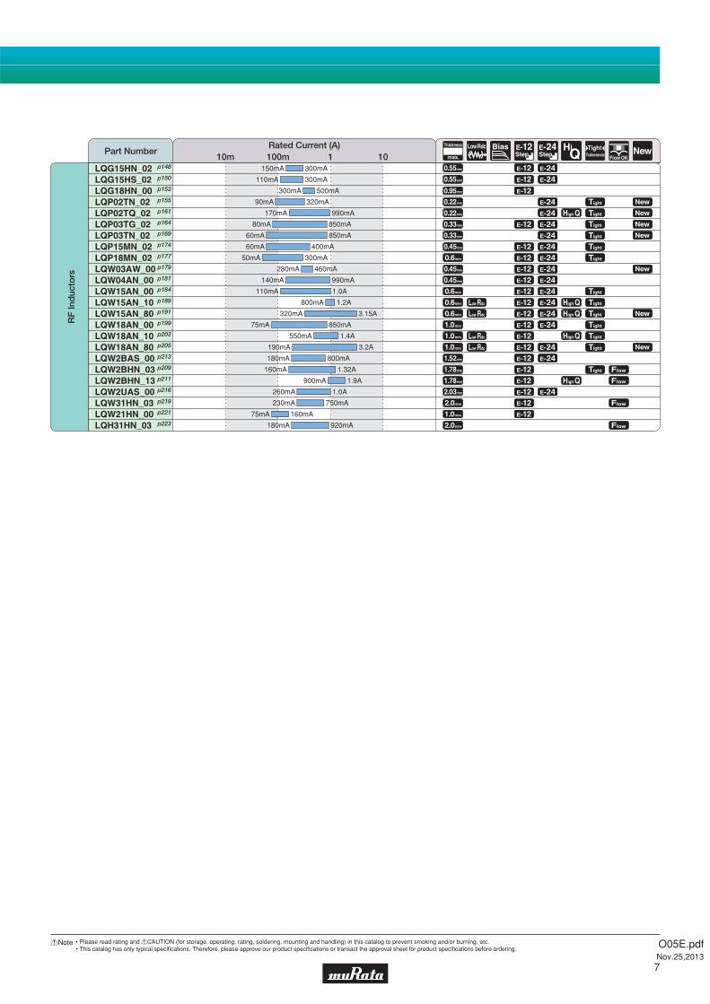
10m 100m 1 10Rated Current (A)
Part Number
Ind
ucto
rs f
or
Po
wer
Lin
esIn
duc
tors
for
Gen
eral
Use
Continued on the following page.
O05E.pdfNov.25,2013

6
!Note • Please read rating and !CAUTION (for storage, operating, rating, soldering, mounting and handling) in this catalog to prevent smoking and/or burning, etc.• This catalog has only typical specifi cations. Therefore, please approve our product specifi cations or transact the approval sheet for product specifi cations before ordering.
1206 (3216)
1206 (3216)
0805 (2015)
1008 (2520)
0402 (1005)0402 (1005)
0402 (1005)
0402 (1005)0402 (1005)
0402 (1005)03015 (0804)
0603 (1608)
0603 (1608)0603 (1608)0603 (1608)
0805 (2015)
0805 (2015)
0603 (1608)-
0805 (2012)
0201 (0603)
01005 (0402)01005 (0402)
LQG15HN_02LQG15HS_02LQG18HN_00LQP02TN_02LQP02TQ_02LQP03TG_02LQP03TN_02LQP15MN_02LQP18MN_02LQW03AW_00LQW04AN_00LQW15AN_00LQW15AN_10LQW15AN_80LQW18AN_00LQW18AN_10LQW18AN_80LQW2BAS_00LQW2BHN_03LQW2BHN_13LQW2UAS_00LQW31HN_03LQW21HN_00LQH31HN_03
0201 (0603)
8.8nH 100nH
1.0nH 120nH
1.0nH 270nH
54nH 880nH
2.7nH 27nH
3.3nH 470nH
12nH 4.7μH
2.8nH 820nH
1.0nH 33nH
1.3nH 5.6nH
1.3nH 75nH
1.5nH 120nH
1.1nH 33nH
100nH1.2nH
470nH2.2nH
33nH2.2nH
390nH2.2nH
0.6nH 270nH
0.6nH 120nH
0.2nH 39nH
0.4nH 10nH
5.4nH 13nH
100nH1.3nH
470nH 2.2μH
p148
p150
p153
p155
p161
p164
p169
p174
p177
p179
p181
p184
p189
p191
p199
p203
p205
p213
p209
p211
p216
p219
p221
p223
1n 10m1m100μ10μ1μ100n10nPart Number Structure Size Code
in inch (in mm)Inductance Range (H)
Product GuideProduct Guide
CAUTION: Use rosin-based flux, but not strong acidic flux (with chlorine content exceeding 0.2wt%) when soldering chip inductors (chip coils). Do not use water-soluble flux.
RF
Ind
ucto
rs
Wire Wound Type(Non-Magnetic Core)
Film Type(Non-Magnetic Core)
Multilayer Type(Non-Magnetic Core)
Wire Wound Type(Ferrite Core)
: E-24 or Higher
: E-12
: 0.1nH Step
: Other
Inductance Lineup
*There are some items that do not match to E step.
O05E.pdfNov.25,2013
7
!Note • Please read rating and !CAUTION (for storage, operating, rating, soldering, mounting and handling) in this catalog to prevent smoking and/or burning, etc.• This catalog has only typical specifi cations. Therefore, please approve our product specifi cations or transact the approval sheet for product specifi cations before ordering.
LQG15HN_02LQG15HS_02LQG18HN_00LQP02TN_02LQP02TQ_02LQP03TG_02LQP03TN_02LQP15MN_02LQP18MN_02LQW03AW_00LQW04AN_00LQW15AN_00LQW15AN_10LQW15AN_80LQW18AN_00LQW18AN_10LQW18AN_80LQW2BAS_00LQW2BHN_03LQW2BHN_13LQW2UAS_00LQW31HN_03LQW21HN_00LQH31HN_03
150mA 300mA
110mA 300mA
300mA 500mA
90mA 320mA
60mA 850mA
60mA 400mA
50mA 300mA
280mA 460mA
140mA 990mA
170mA 990mA
80mA 850mA
110mA 1.0A
800mA 1.2A
320mA 3.15A
550mA 1.4A
190mA 3.2A
75mA 850mA
160mA 1.32A
900mA 1.9A
230mA 750mA
260mA 1.0A
75mA 160mA
180mA 920mA
180mA 800mA
p148
p150
p153
p155
p161
p164
p169
p174
p177
p179
p181
p184
p189
p191
p199
p203
p205
p213
p209
p211
p216
p219
p221
p223
10m 100m 1 10Rated Current (A)
Part Number
RF
Ind
ucto
rs
O05E.pdfNov.25,2013
8
!Note • Please read rating and !CAUTION (for storage, operating, rating, soldering, mounting and handling) in this catalog to prevent smoking and/or burning, etc.• This catalog has only typical specifi cations. Therefore, please approve our product specifi cations or transact the approval sheet for product specifi cations before ordering.
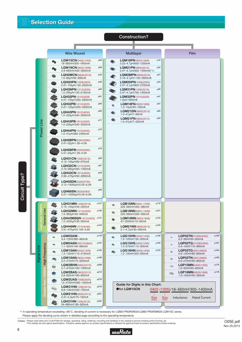
Selection GuideSelection Guide
LQH2MCN/0806(2016)1.0–82μH/90–595mA
LQH2HPN/1008(2520)0.47–100μH/130–2520mA
LQH3NPN/1212(3030)1.0–250μH/130–2150mA
LQH32PN/1210(3225)0.47–120μH/200–2900mA
LQH43PB/1812(4532)1.0–220μH/240–3300mA
LQH44PN/1515(4040)1.0–47μH/380–2450mA
LQH5BPN/2020(5050)0.47–22μH/1.05–4.0A
LQM21PN/0805(2012)0.47–4.7μH/600–1300mA(*1)
LQM18PN/0603(1608)0.22–4.7μH/600–1250mA
LQM2MPN/0806(2016)0.16–4.7μH/1100–4000mA
LQM2HPN/1008(2520)0.47–4.7μH/800–2700mA
LQM31PN/1206(3216)0.47–4.7μH/700–1400mA
LQH31CN/1206(3216)0.12–100μH/80–970mA
LQH32CN/1210(3225)0.15–560μH/60–1450mA
LQH43CN/1812(4532)0.56–470μH/90–2950mA
LQH55DN/2220(5750)0.12–10000μH/0.05–6.0A
LQH66SN/2525(6363)0.27–10000μH/0.05–6.0A
LQM18FN/0603(1608)1.0–10μH/50–150mA
LQM21DN/0805(2012)1.0–47μH/7–60mA
LQM21FN/0805(2012)1.0–47μH/7–220mA
LQH32PB/1210(3225)0.47–120μH/200–2900mA
LQM32PN/1210(3225)1.0μH/1800mA
LQW04AN/03015(0804)1.1–33nH/140–990mA
LQW15AN/0402(1005)1.3–120nH/110–3150mA
LQW18AN/0603(1608)2.2–470nH/75–3200mA
LQW2BAS/0805(2015)2.8–820nH/180–800mA
LQW2BHN/0805(2015)2.7–470nH/160–1900mA
LQW2UAS/1008(2520)12–4700nH/260–1000mA
LQW31HN/1206(3216)8.8–100nH/230–750mA
LQW21HN/0805(2012)0.47–2.2μH/75–160mA
LQG15HS/0402(1005)1.0–270nH/110–300mA
LQG15HN/0402(1005)1.0–120nH/150–300mA
LQG18HN/0603(1608)1.2–100nH/300–500mA
LQH31HN/1206(3216)54–880nH/180–920mA
LQP02TN/01005(0402)0.2–39nH/90–320mA
LQP02TQ/01005(0402)0.4–10nH/170–990mA
LQP03TG/0201(0603)0.6–120nH/80–850mA
LQP03TN/0201(0603)0.6–270nH/60–850mA
LQP15MN/0402(1005)1.0–33nH/60–400mA
LQP18MN/0603(1608)1.3–100nH/50–300mA
LQH31MN/1206(3216)0.15–100μH/45–250mA
LQH32MN/1210(3225)1.0–560μH/40–445mA
LQH43M(N)N/1812(4532)1.0–2200μH/30–500mA
LQH44NN/1515(4040)0.51–470μH/0.145–4.5A
LQB15NN/0402 (1005)220–560nH/300–380mA
LQB18NN/0603 (1608)220–560nH/300–450mA
LQM18NN/0603(1608)47–2200nH/15–50mA
LQM21NN/0805(2012)0.1–4.7μH/30–250mA
LQW03AW/–5.4–13nH/280–460mA
LQW18CN/0603(1608)4.9–650nH/430–2600mA
LQW15CN/0402(1005)18–560nH/300–1400mA
LQH5BPB/2020(5050)0.47–22μH/1.05–4.0A
LQH43PN/1812(4532)1.0–220μH/240–3300mA
Less
tha
n 10
0MH
zG
ener
al U
se
Construction?
Cir
cuit
Typ
e?
Wire Wound Multilayer Film
Sig
nal L
ine
Po
wer
Lin
eG
reat
er t
han
100M
Hz
Hig
h F
req
uenc
y
*1 In operating temperature exceeding +85°C, derating of current is necessary for LQM21PN3R3NG0/LQM21PN3R3MG0·LQW15C series.
Please apply the derating curve shown in detailed page according to the operating temperature.
p42
p46
p59
p61
p65
p71
p69
p75
p77
p79
p16
p22
p27
p34
p39
p41
p86
p89
p90
p91
p94
p96
p98
p81
p82
p83
p127
p129
p131
p134
p119
p121
p123
p125
p181
p179
p184
p199
p213
p209
p216
p219
p221
p223
p150
p148
p153
p155
p161
p164
p169
p174
p179
0402 (1005)/18–560nH/300–1400mA
Size(inch)
Size(mm)
Rated CurrentInductance
ofor LQW15CNGuide for Digits in this Chart:
O05E.pdfNov.25,2013

9
!Note • Please read rating and !CAUTION (for storage, operating, rating, soldering, mounting and handling) in this catalog to prevent smoking and/or burning, etc.• This catalog has only typical specifi cations. Therefore, please approve our product specifi cations or transact the approval sheet for product specifi cations before ordering.
0.35mm
0.5mm
0.6mm
0.65mm
0.7mm
0.8mm
0.85mm
0.9mm
1.1mm
1.25mm
1.4mm
1.55mm
1.65mm
1.8mm
2.0mm
2.6mm
4.7mm
LQM18P_B0
LQM18P_C0 /LQM21P_C0 /LQM31P_C0
LQM18P_D0
LQM2HP_E0
LQM18P_F0 / FR
LQM31P_00
LQM21P_G0 / GS / GC / GR /LQM2MP_G0 / GH /LQM2HP_G0 / GS / GC / GH /LQM32P_G0
LQM2HP_J0 / JH
LQH2MC_52
LQH2MC_02 / LQH2HP_G0 / GR /LQH3NP_G0
LQH2HP_J0 / LQH3NP_J0 / LQH44P_J0
LQH2HP_M0LQH3NP_M0 / MR
LQH32P_N0 / NC
LQH44P_P0
LQH5BP_T0
LQH43P_26
LQM18F
LQM21D (1.0 to 10μH) / LQM21F_00 (1.0 to 2.2μH)
LQM21D (22 to 47μH) / LQM21F_00 (4.7 to 47μH) / LQM21F_70 / 80
LQW15C
LQW18C
LQH32C_53
LQH31C
LQH32C_23 / 33
LQH43C_03 / 33
LQH55D / LQH66S
0.2mm
0.3mm
0.35mm
0.4mm
0.5mm
0.8mm
0.85mm
0.9mm
1.25mm
1.42mm
1.7mm
1.8mm
1.83mm
2.0mm
2.6mm
4.3mm
LQB15N
LQB18N / LQM18N
LQM21N (0.1 to 2.2μH)
LQM21N (2.7 to 4.7μH)
LQH31M
LQH32M
LQH43M(N)
LQH44N
LQG15HN / LQG15HS
LQG18H
LQP02T
LQP03T
LQP15M
LQP15T
LQP18M
LQW03AW / LQW04A
LQW15A
LQW18A
LQW21H
LQW2BA
LQW2BH
LQH31H / LQW31H
LQW2UA
WhichThickness?
WhichThickness?
Multilayer Type Wire Wound Type for ChokeMultilayer Type for ChokeWire Wound Type
Multilayer Type Wire Wound Type Multilayer Type Film Type Wire Wound Type
Inductors for Power Lines
Inductors for General Use RF Inductors
Product Guide by ThicknessProduct Guide by Thickness
O05E.pdfNov.25,2013
10
!Note • Please read rating and !CAUTION (for storage, operating, rating, soldering, mounting and handling) in this catalog to prevent smoking and/or burning, etc.• This catalog has only typical specifi cations. Therefore, please approve our product specifi cations or transact the approval sheet for product specifi cations before ordering.
Memo
O05E.pdfNov.25,2013

aInductors for Power Lines
Introduction
Part Numbering
Product Detail
!Caution/Notice
Soldering and Mounting
Packaging
Design Kits
12
14
16
100
102
107
111
O05E.pdfNov.25,2013
!Note • Please read rating and !CAUTION (for storage, operating, rating, soldering, mounting and handling) in this catalog to prevent smoking and/or burning, etc.• This catalog has only typical specifi cations. Therefore, please approve our product specifi cations or transact the approval sheet for product specifi cations before ordering.
Indu
ctor
s fo
r P
ower
Lin
esIn
duct
ors
for
Gen
eral
Use
RF
Indu
ctor
sIn
duct
ors
for
Pow
er L
ines
Indu
ctor
s fo
r P
ower
Lin
esIn
duct
ors
for
Gen
eral
Use
RF
Indu
ctor
sIn
duct
ors
for
Pow
er L
ines
90
85
80
75
70
65
600.1 1 10 100 1000
90
85
80
75
70
65
600.1 1 10 100 1000
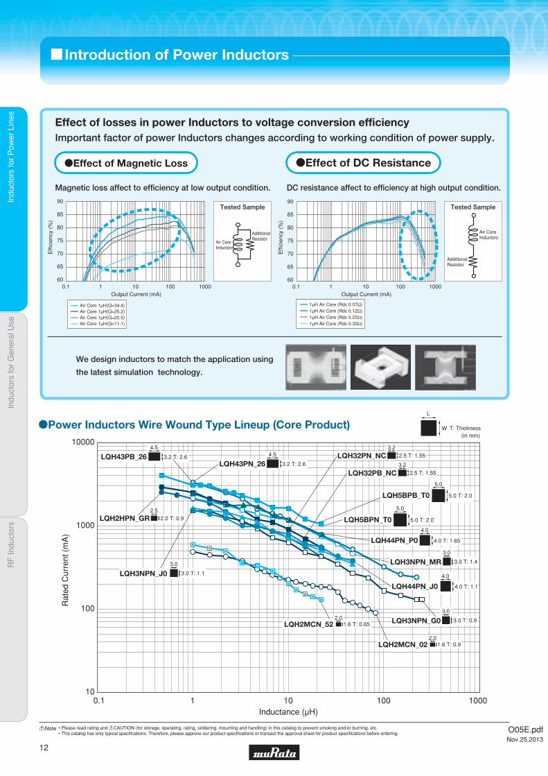
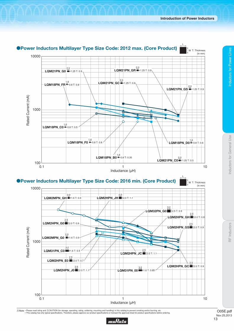
c Introduction of Power Inductors
Air Core 1μH(Q=34.4)Air Core 1μH(Q=25.2)Air Core 1μH(Q=20.5)Air Core 1μH(Q=11.1)
1μH Air Core (Rdc 0.07Ω)1μH Air Core (Rdc 0.12Ω)1μH Air Core (Rdc 0.22Ω)1μH Air Core (Rdc 0.32Ω)
Effect of losses in power Inductors to voltage conversion efficiencyImportant factor of power Inductors changes according to working condition of power supply.
oEffect of Magnetic Loss
Magnetic loss affect to efficiency at low output condition. DC resistance affect to efficiency at high output condition.
oEffect of DC Resistance
Output Current (mA)
Effi
cien
cy (
%)
Output Current (mA)
Effi
cien
cy (
%)
AdditionalResistor
Air CoreInductors
Tested Sample
We design inductors to match the application using
the latest simulation technology.
AdditionalResistor
Air CoreInductors
Tested Sample
oPower Inductors Wire Wound Type Lineup (Core Product) W T: Thickness(in mm)
L
4.0 T: 1.1
4.0
LQH44PN_J0
3.2 T: 2.6
4.5
LQH43PB_26
1.6 T: 0.652.0
LQH2MCN_52
4.0 T: 1.65
4.0
LQH44PN_P0
3.2 T: 2.6
4.5
LQH43PN_26 2.5 T: 1.55
3.2
LQH32PB_NC
2.5 T: 1.55
3.2
LQH32PN_NC
3.0 T: 1.1
3.0
LQH3NPN_J0
3.0 T: 0.9
3.0
LQH3NPN_G0
5.0 T: 2.0
5.0
LQH5BPB_T0
5.0 T: 2.0
5.0
LQH5BPN_T0
1.6 T: 0.92.0
LQH2MCN_02
0.1 1 10 100 1000Inductance (μH)
2.0 T: 0.92.5
LQH2HPN_GR
3.0 T: 1.4
3.0
LQH3NPN_MR
10
100
1000
10000
Rat
ed C
urre
nt (
mA
)
O05E.pdfNov.25,2013
12
!Note • Please read rating and !CAUTION (for storage, operating, rating, soldering, mounting and handling) in this catalog to prevent smoking and/or burning, etc.• This catalog has only typical specifi cations. Therefore, please approve our product specifi cations or transact the approval sheet for product specifi cations before ordering.
Indu
ctor
s fo
r P
ower
Lin
esIn
duct
ors
for
Gen
eral
Use
RF
Indu
ctor
sIn
duct
ors
for
Pow
er L
ines
Introduction of Power Inductors
W T: Thickness(in mm)
L
W T: Thickness
L
(in mm)
oPower Inductors Multilayer Type Size Code: 2016 min. (Core Product)
oPower Inductors Multilayer Type Size Code: 2012 max. (Core Product)
1.25 T: 0.52.0
LQM21PN_C0
1.25 T: 0.92.0
LQM21PN_GC
1.25 T: 0.92.0
LQM21PN_GR
1.25 T: 0.92.0
LQM21PN_GS
1.25 T: 0.92.0
LQM21PN_G0
0.8 T: 0.81.6
LQM18PN_FR
0.8 T: 0.61.6
LQM18PN_D0
0.8 T: 0.351.6
LQM18PN_B0
0.8 T: 0.81.6
LQM18PN_F0
0.8 T: 0.51.6
LQM18PN_C0
Rat
ed C
urre
nt (
mA
)
100
1000
10000
Inductance (μH)0.1 1 10
2.0 T: 1.1
2.5
LQM2HPN_JH
2.0 T: 1.1
2.5
LQM2HPN_JC
2.0 T: 0.9
2.5
LQM2HPN_GC
2.0 T: 0.9
2.5
LQM2HPN_GS2.0 T: 0.9
2.5
LQM2HPN_G0
2.0 T: 0.7
2.5
LQM2HPN_E0
2.0 T: 0.9
2.5
LQM2HPN_GH
2.0 T: 1.1
2.5
LQM2HPN_J03.2
1.6 T: 0.85LQM31PN_00
3.21.6 T: 0.5LQM31PN_C0
2.5 T: 0.9
3.2
LQM32PN_G0
1.6 T: 0.92.0
LQM2MPN_GH
1.6 T: 0.92.0
LQM2MPN_G0
Rat
ed C
urre
nt (
mA
)
100
1000
10000
Inductance (μH)0.1 1 10
O05E.pdfNov.25,2013
13
!Note • Please read rating and !CAUTION (for storage, operating, rating, soldering, mounting and handling) in this catalog to prevent smoking and/or burning, etc.• This catalog has only typical specifi cations. Therefore, please approve our product specifi cations or transact the approval sheet for product specifi cations before ordering.
Indu
ctor
s fo
r P
ower
Lin
esIn
duct
ors
for
Gen
eral
Use
RF
Indu
ctor
sIn
duct
ors
for
Pow
er L
ines
(Part Number)
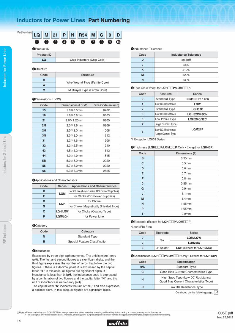
Inductors for Power Lines Part Numbering
uInductance Tolerance
eDimensions (LgW)
Code
1.0g0.5mm
1.6g0.8mm
2.0g1.25mm
2.0g1.6mm
2.5g2.0mm
3.0g3.0mm
3.2g1.6mm
3.2g2.5mm
4.5g3.2mm
4.0g4.0mm
5.0g5.0mm
5.7g5.0mm
6.3g6.3mm
Dimensions (LgW)
0402
0603
0805
0806
1008
1212
1206
1210
1812
1515
2020
2220
2525
Size Code (in inch)
15
18
21
2M
2H
3N
31
32
43
44
5B
55
66
Code
D
J
K
M
N
±0.5nH
±5%
±10%
±20%
±30%
Inductance Tolerance
qProduct ID
LQ Chip Inductors (Chip Coils)
Product ID
wStructure
Code
H
W
M
Wire Wound Type (Ferrite Core)
Multilayer Type (Ferrite Core)
Structure
rApplications and Characteristics
Code
for Choke (Low-current DC Power Supplies)
for Choke (DC Power Supplies)
for Choke
for Choke (Magnetically Shielded Type)
for Choke (Coating Type)
for Power Line
Applications and Characteristics
D
F
D
S
C
P
Series
LQM
LQH
LQH/LQW
LQM/LQH
yInductance
Expressed by three-digit alphanumerics. The unit is micro-henry (μH). The first and second figures are significant digits, and the third figure expresses the number of zeros that follow the two figures. If there is a decimal point, it is expressed by the capital letter "R." In this case, all figures are significant digits. If inductance is less than 0.1μH, the inductance code is expressed by a combination of two figures and the capital letter "N," and the unit of inductance is nano-henry (nH).The capital letter "N" indicates the unit of "nH," and also expresses a decimal point. In this case, all figures are significant digits.
tCategory
N
B
Standard Type
Special Feature Classification
Code Category
Continued on the following page.
q
LQ
y
R54
e
21
w
M
r
P
t
N
u
M
i
G
o
0
!0
D
iThickness (LQHppP/LQMppP LQH43P)
B
C
D
E
F
0
G
J
M
N
P
T
0.35mm
0.5mm
0.6mm
0.7mm
0.8mm
0.85mm
0.9mm
1.1mm
1.4mm
1.55mm
1.65mm
2.0mm
Code Dimensions (T)
iFeatures (Except for LQHppP/LQMppP)
0
1
2
3
5
7
8
Standard Type
Low DC Resistance
Standard Type
Low DC Resistance
Low Profile Type
Large Current Type
Low DC Resistance/Large Current Type
Code Features Series
LQM/LQH*1 /LQW
LQW
LQH32C
LQH32C/43CN
LQH2MC/32C
LQM21F
*1 Except for LQH32 Series
0
2
3
Sn
LF Solder
Code Electrode
LQM/LQW
LQH2MC
LQH (Except for LQH2MC)
Series
oElectrode (Except for LQHppP/LQMppP)
oSpecification (LQHppP/LQMppP LQH43P)
0/S
C
H
R
Standard Type
Good Bias Current Characteristics Type
High Spec Type (Low DC Resistance/Good Bias Current Characteristics Type)
Low DC Resistance Type
Code Specification
O05E.pdfNov.25,2013
14
!Note • Please read rating and !CAUTION (for storage, operating, rating, soldering, mounting and handling) in this catalog to prevent smoking and/or burning, etc.• This catalog has only typical specifi cations. Therefore, please approve our product specifi cations or transact the approval sheet for product specifi cations before ordering.
Indu
ctor
s fo
r P
ower
Lin
esIn
duct
ors
for
Gen
eral
Use
RF
Indu
ctor
sIn
duct
ors
for
Pow
er L
ines
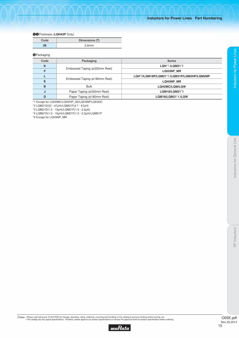
!0Packaging
K
F
L
E
B
J
D
LQH*1 /LQM21*2
LQH3NP_MR
LQH*5/LQM18P/LQM21*2 /LQM31P/LQM2HP/LQM2MP
LQH3NP_MR
LQH2MC/LQM/LQW
LQM18/LQM21*3
LQM18/LQM21*4 /LQW
Embossed Taping (ø330mm Reel)
Embossed Taping (ø180mm Reel)
Bulk
Paper Taping (ø330mm Reel)
Paper Taping (ø180mm Reel)
Code Packaging Series
*1 Except for LQH2MC/LQH2HP_G0/LQH3NP/LQH43C*2 LQM21D(22 - 47μH)/LQM21F(4.7 - 47μH)*3 LQM21D(1.0 - 10μH)/LQM21F(1.0 - 2.2μH)*4 LQM21D(1.0 - 10μH)/LQM21F(1.0 - 2.2μH)/LQM21P*5 Except for LQH3NP_MR
ioThickness (LQH43P Only)
26 2.6mm
Code Dimensions (T)
Inductors for Power Lines Part Numbering
O05E.pdfNov.25,2013
15
!Note • Please read rating and !CAUTION (for storage, operating, rating, soldering, mounting and handling) in this catalog to prevent smoking and/or burning, etc.• This catalog has only typical specifi cations. Therefore, please approve our product specifi cations or transact the approval sheet for product specifi cations before ordering.

Code PackagingMinimumQuantity
L ø180mm Embossed Taping 4000
B Packing in Bulk 1000
0.4Thickness
mmmax.
ReflowOK FlowOK
Indu
ctor
s fo
r P
ower
Lin
esIn
duct
ors
for
Gen
eral
Use
RF
Indu
ctor
sIn
duct
ors
for
Pow
er L
ines
Mul
tilay
er T
ype
(Fer
rite
Cor
e)
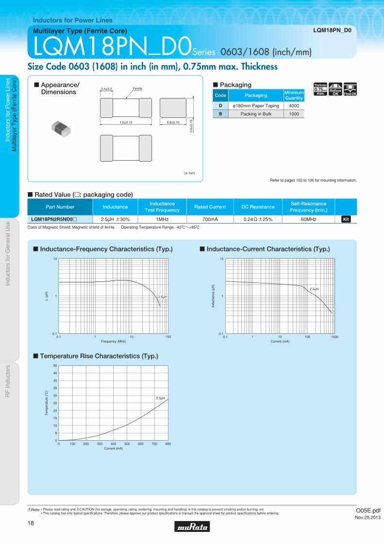
Multilayer Type (Ferrite Core) LQM18PN_B0
Inductors for Power Lines
LQM18PN_B0Series 0603/1608 (inch/mm)Size Code 0603 (1608) in inch (in mm), 0.4mm max. Thickness
c Inductance-Frequency Characteristics (Typ.)
c Temperature Rise Characteristics (Typ.)
c Inductance-Current Characteristics (Typ.)
c Rated Value (p: packaging code)
Refer to pages 102 to 106 for mounting information.
(in mm)
1.6±0.15
0.35
±0.
050.8±0.15
0.4±0.2 Ferrite
c Appearance/Dimensions
c Packaging
Class of Magnetic Shield: Magnetic shield of ferrite Operating Temperature Range: -55℃~+125℃
0.1
1
10
0.1 1 10 100Frequency (MHz)
L (μ
H)
1.5μH
Current (mA)
Tem
pera
ture
(°C
)
50
40
30
20
10
45
35
25
15
5
00 100 200 300 400 700600500
1.5μH
0.1
1
10
0.1 1 100010010Current (mA)
Indu
ctan
ce (
μH)
1.5μH
Part Number InductanceInductance
Test FrequencyRated Current DC Resistance
Self-ResonanceFrequency (min.)
LQM18PN1R5NB0p 1.5µH ±30% 1MHz 600mA 0.35Ω±25% 50MHz
O05E.pdfNov.25,2013
16
!Note • Please read rating and !CAUTION (for storage, operating, rating, soldering, mounting and handling) in this catalog to prevent smoking and/or burning, etc.• This catalog has only typical specifi cations. Therefore, please approve our product specifi cations or transact the approval sheet for product specifi cations before ordering.

Code PackagingMinimumQuantity
L ø180mm Embossed Taping 4000
B Packing in Bulk 1000
0.55Thickness
mmmax.
ReflowOK FlowOK
Indu
ctor
s fo
r P
ower
Lin
esIn
duct
ors
for
Gen
eral
Use
RF
Indu
ctor
sIn
duct
ors
for
Pow
er L
ines
Mul
tilay
er T
ype
(Fer
rite
Cor
e)
Multilayer Type (Ferrite Core) LQM18PN_C0
Inductors for Power Lines
LQM18PN_C0Series 0603/1608 (inch/mm)Size Code 0603 (1608) in inch (in mm), 0.55mm max. Thickness
c Inductance-Frequency Characteristics (Typ.)
c Temperature Rise Characteristics (Typ.)
c Inductance-Current Characteristics (Typ.)
c Rated Value (p: packaging code)
Refer to pages 102 to 106 for mounting information.
(in mm)
1.6±0.15
0.5±
0.050.8±0.15
0.4±0.2 Ferritec Appearance/
Dimensionsc Packaging
Class of Magnetic Shield: Magnetic shield of ferrite Operating Temperature Range: -55℃~+125℃
1.8μH
1.5μH
1.0μH
0.47μH
2.2μH
0.1
1
10
0.1 1 10 1000100Frequency (MHz)
L (μ
H)
2.2μH
1.5μH
1.0μH
0.47μH
1.8μH
0
5
20
35
10
25
40
15
30
45
50
0 100 300 500 700200 400 600 800 900 1000Current (mA)
Tem
pera
ture
(°C
)
1.8μH
1.5μH
1.0μH
0.47μH
2.2μH
0.1
1
10
0.1 1 10 1000100Current (mA)
Indu
ctan
ce (
μH)
Part Number InductanceInductance
Test FrequencyRated Current DC Resistance
Self-ResonanceFrequency (min.)
LQM18PNR47NC0p 0.47µH ±30% 1MHz 850mA 0.15Ω±25% 50MHz LQM18PN1R0NC0p 1.0µH ±30% 1MHz 750mA 0.20Ω±25% 50MHz LQM18PN1R5NC0p 1.5µH ±30% 1MHz 720mA 0.22Ω±25% 50MHz LQM18PN1R8NC0p 1.8µH ±30% 1MHz 700mA 0.24Ω±25% 50MHz LQM18PN2R2NC0p 2.2µH ±30% 1MHz 700mA 0.24Ω±25% 50MHz
O05E.pdfNov.25,2013
17
!Note • Please read rating and !CAUTION (for storage, operating, rating, soldering, mounting and handling) in this catalog to prevent smoking and/or burning, etc.• This catalog has only typical specifi cations. Therefore, please approve our product specifi cations or transact the approval sheet for product specifi cations before ordering.
Code PackagingMinimumQuantity
D ø180mm Paper Taping 4000
B Packing in Bulk 1000
0.75Thickness
mmmax.
ReflowOK FlowOK
Indu
ctor
s fo
r P
ower
Lin
esIn
duct
ors
for
Gen
eral
Use
RF
Indu
ctor
sIn
duct
ors
for
Pow
er L
ines
Mul
tilay
er T
ype
(Fer
rite
Cor
e)
Multilayer Type (Ferrite Core) LQM18PN_D0
Inductors for Power Lines
LQM18PN_D0Series 0603/1608 (inch/mm)Size Code 0603 (1608) in inch (in mm), 0.75mm max. Thickness
c Inductance-Frequency Characteristics (Typ.)
c Temperature Rise Characteristics (Typ.)
c Inductance-Current Characteristics (Typ.)
c Rated Value (p: packaging code)
Refer to pages 102 to 106 for mounting information.
(in mm)
1.6±0.15
0.6±
0.150.8±0.15
0.4±0.2 Ferritec Appearance/
Dimensionsc Packaging
Class of Magnetic Shield: Magnetic shield of ferrite Operating Temperature Range: -40℃~+85℃
0.1
1
10
0.1 1 10 100Frequency (MHz)
L (μ
H)
2.5μH
Current (mA)
Tem
pera
ture
(°C
)
50
40
30
20
10
45
35
25
15
5
00 100 200 300 400 800600 700500
2.5μH
0.1
1
10
0.1 1 100010010Current (mA)
Indu
ctan
ce (
μH)
2.5μH
Part Number InductanceInductance
Test FrequencyRated Current DC Resistance
Self-ResonanceFrequency (min.)
LQM18PN2R5ND0p 2.5µH ±30% 1MHz 700mA 0.24Ω±25% 60MHz
O05E.pdfNov.25,2013
18
!Note • Please read rating and !CAUTION (for storage, operating, rating, soldering, mounting and handling) in this catalog to prevent smoking and/or burning, etc.• This catalog has only typical specifi cations. Therefore, please approve our product specifi cations or transact the approval sheet for product specifi cations before ordering.
Code PackagingMinimumQuantity
L ø180mm Embossed Taping 4000
B Packing in Bulk 1000
0.95Thickness
mmmax.
ReflowOK FlowOK
Indu
ctor
s fo
r P
ower
Lin
esIn
duct
ors
for
Gen
eral
Use
RF
Indu
ctor
sIn
duct
ors
for
Pow
er L
ines
Mul
tilay
er T
ype
(Fer
rite
Cor
e)
Multilayer Type (Ferrite Core) LQM18PN_F0
Inductors for Power Lines
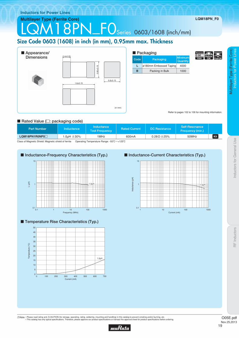
LQM18PN_F0Series 0603/1608 (inch/mm)Size Code 0603 (1608) in inch (in mm), 0.95mm max. Thickness
c Inductance-Frequency Characteristics (Typ.)
c Temperature Rise Characteristics (Typ.)
c Inductance-Current Characteristics (Typ.)
c Rated Value (p: packaging code)
Refer to pages 102 to 106 for mounting information.
(in mm)
1.6±0.150.8±0.15
0.80
±0.
15
0.4±0.20c Appearance/
Dimensionsc Packaging
Class of Magnetic Shield: Magnetic shield of ferrite Operating Temperature Range: -55℃~+125℃
0.1
1
10
0.1 1 100010010Frequency (MHz)
L (μ
H)
1.0μH
Current (mA)
Tem
pera
ture
(°C
)
50
40
30
20
10
45
35
25
15
5
00 100 200 300 400 700600500
1.0μH
0.1
1
10
1 10 100 1000Current (mA)
Indu
ctan
ce (
μH)
1.0μH
Part Number InductanceInductance
Test FrequencyRated Current DC Resistance
Self-ResonanceFrequency (min.)
LQM18PN1R0NF0p 1.0µH ±30% 1MHz 600mA 0.28Ω±25% 50MHz
O05E.pdfNov.25,2013
19
!Note • Please read rating and !CAUTION (for storage, operating, rating, soldering, mounting and handling) in this catalog to prevent smoking and/or burning, etc.• This catalog has only typical specifi cations. Therefore, please approve our product specifi cations or transact the approval sheet for product specifi cations before ordering.
Code PackagingMinimumQuantity
L ø180mm Embossed Taping 4000
B Packing in Bulk 1000
0.95Thickness
mmmax.
Low RdcReflow
OK
FlowOK
Indu
ctor
s fo
r P
ower
Lin
esIn
duct
ors
for
Gen
eral
Use
RF
Indu
ctor
sIn
duct
ors
for
Pow
er L
ines
Mul
tilay
er T
ype
(Fer
rite
Cor
e)
Multilayer Type (Ferrite Core) LQM18PN_FR
Inductors for Power Lines
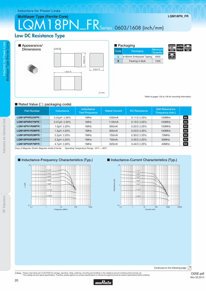
LQM18PN_FRSeries 0603/1608 (inch/mm)Low DC Resistance Type
c Inductance-Frequency Characteristics (Typ.) c Inductance-Current Characteristics (Typ.)
c Rated Value (p: packaging code)
Refer to pages 102 to 106 for mounting information.
(in mm)
1.6±0.150.8±0.15
0.80
±0.
15
0.4±0.20
Continued on the following page.
c Appearance/Dimensions
c Packaging
Class of Magnetic Shield: Magnetic shield of ferrite Operating Temperature Range: -40℃~+85℃
0.1
1
10
0.1 1 100010010Frequency (MHz)
L (μ
H)
2.2μH
3.3μH
4.7μH
1.5μH
1.0μH
0.47μH
0.22μH
0.1
1
10
0.1 1 1000 1000010010Current (mA)
Indu
ctan
ce (
μH)
2.2μH
3.3μH
4.7μH
1.5μH
1.0μH
0.47μH
0.22μH
Part Number InductanceInductance
Test FrequencyRated Current DC Resistance
Self-ResonanceFrequency (min.)
LQM18PNR22NFRp 0.22µH ±30% 1MHz 1250mA 0.11Ω±25% 100MHz LQM18PNR47NFRp 0.47µH ±30% 1MHz 1100mA 0.15Ω±25% 100MHz LQM18PN1R0MFRp 1.0µH ±20% 1MHz 950mA 0.20Ω±25% 100MHz LQM18PN1R5MFRp 1.5µH ±20% 1MHz 800mA 0.23Ω±25% 100MHz LQM18PN2R2MFRp 2.2µH ±20% 1MHz 750mA 0.30Ω±25% 70MHz LQM18PN3R3MFRp 3.3µH ±20% 1MHz 700mA 0.35Ω±25% 60MHz LQM18PN4R7MFRp 4.7µH ±20% 1MHz 620mA 0.44Ω±25% 40MHz
O05E.pdfNov.25,2013
20
!Note • Please read rating and !CAUTION (for storage, operating, rating, soldering, mounting and handling) in this catalog to prevent smoking and/or burning, etc.• This catalog has only typical specifi cations. Therefore, please approve our product specifi cations or transact the approval sheet for product specifi cations before ordering.

Indu
ctor
s fo
r P
ower
Lin
esIn
duct
ors
for
Gen
eral
Use
RF
Indu
ctor
sIn
duct
ors
for
Pow
er L
ines
Mul
tilay
er T
ype
(Fer
rite
Cor
e)
LQM18PN_FR
c Temperature Rise Characteristics (Typ.)
Current (mA)
Tem
pera
ture
(°C
)
50
40
30
20
10
45
35
25
15
5
00 200 400 600 800 140012001000
1.0μH
1.5μH2.2μH
3.3μH
4.7μH
0.47μH
0.22μH
O05E.pdfNov.25,2013
21
!Note • Please read rating and !CAUTION (for storage, operating, rating, soldering, mounting and handling) in this catalog to prevent smoking and/or burning, etc.• This catalog has only typical specifi cations. Therefore, please approve our product specifi cations or transact the approval sheet for product specifi cations before ordering.

Code PackagingMinimumQuantity
D ø180mm Paper Taping 4000
B Packing in Bulk 1000
0.55Thickness
mmmax.
ReflowOK FlowOK
Indu
ctor
s fo
r P
ower
Lin
esIn
duct
ors
for
Gen
eral
Use
RF
Indu
ctor
sIn
duct
ors
for
Pow
er L
ines
Mul
tilay
er T
ype
(Fer
rite
Cor
e)
Multilayer Type (Ferrite Core) LQM21PN_C0
Inductors for Power Lines
LQM21PN_C0Series 0805/2012 (inch/mm)Size Code 0805 (2012) in inch (in mm), 0.55mm max. Thickness
c Inductance-Frequency Characteristics (Typ.)
c Temperature Rise Characteristics (Typ.)
c Inductance-Current Characteristics (Typ.)
c Rated Value (p: packaging code)
Refer to pages 102 to 106 for mounting information.
0.5±0.2
2.0±0.2
1.25±0.2
0.5±
0.05
Ferrite
(in mm)
c Appearance/Dimensions
c Packaging
Class of Magnetic Shield: Magnetic shield of ferrite Operating Temperature Range: -55℃~+125℃
0.1
1
10
0.1 1 100010010Frequency (MHz)
L (μ
H)
2.2μH
1.5μH
1.0μH
0.47μH
Current (mA)
Tem
pera
ture
(°C
)
50
40
30
20
10
45
35
25
15
5
00 200 400 600 800 140012001000
2.2μH 1.5μH1.0μH
0.47μH
0.1
1
10
1 10 100001000100Current (mA)
Indu
ctan
ce (
μH)
2.2μH
1.5μH
1.0μH
0.47μH
Part Number InductanceInductance
Test FrequencyRated Current DC Resistance
Self-ResonanceFrequency (min.)
LQM21PNR47MC0p 0.47µH ±20% 1MHz 1100mA 0.12Ω±25% 100MHz LQM21PN1R0MC0p 1.0µH ±20% 1MHz 800mA 0.19Ω±25% 90MHz LQM21PN1R5MC0p 1.5µH ±20% 1MHz 700mA 0.26Ω±25% 70MHz LQM21PN2R2MC0p 2.2µH ±20% 1MHz 600mA 0.34Ω±25% 50MHz
O05E.pdfNov.25,2013
22
!Note • Please read rating and !CAUTION (for storage, operating, rating, soldering, mounting and handling) in this catalog to prevent smoking and/or burning, etc.• This catalog has only typical specifi cations. Therefore, please approve our product specifi cations or transact the approval sheet for product specifi cations before ordering.

Code PackagingMinimumQuantity
D ø180mm Paper Taping 4000
B Packing in Bulk 1000
1.0Thickness
mmmax.
ReflowOK FlowOK
Part Number InductanceInductance
Test FrequencyRated Current DC Resistance
Self-ResonanceFrequency (min.)
LQM21PNR47MG0p 0.47µH ±20% 1MHz 1300mA 0.075Ω±25% 100MHz LQM21PNR54MG0p 0.54µH ±20% 1MHz 1300mA 0.075Ω±25% 100MHz LQM21PN3R3MG0p 3.3µH ±20% 1MHz 800mA 0.165Ω±25% 30MHz LQM21PN3R3NG0p 3.3µH ±30% 1MHz 800mA 0.165Ω±25% 30MHz
Indu
ctor
s fo
r P
ower
Lin
esIn
duct
ors
for
Gen
eral
Use
RF
Indu
ctor
sIn
duct
ors
for
Pow
er L
ines
Mul
tilay
er T
ype
(Fer
rite
Cor
e)
Multilayer Type (Ferrite Core) LQM21PN_G0
Inductors for Power Lines
LQM21PN_G0Series 0805/2012 (inch/mm)Size Code 0805 (2012) in inch (in mm), 1.0mm max. Thickness
c Inductance-Frequency Characteristics (Typ.)
c Temperature Rise Characteristics (Typ.)
c Inductance-Current Characteristics (Typ.)
c Derating of Rated Current
c Rated Value (p: packaging code)
Refer to pages 102 to 106 for mounting information.
0.5±0.2
2.0±0.15 1.25±0.15
0.9±0.1
(in mm)
c Appearance/Dimensions
c Packaging
Class of Magnetic Shield: Magnetic shield of ferrite Operating Temperature Range: -55℃~+125℃
0.1
1
10
0.1 1 100010010Frequency (MHz)
L (μ
H)
3.3μH
0.47μH
0.54μH
Current (mA)
Tem
pera
ture
(°C
)
50
40
30
20
10
45
35
25
15
5
00 200 400 600 800 16001200 14001000
3.3μH
0.54μH0.47μH
0.1
1
10
0.1 1 1000 1000010010Current (mA)
Indu
ctan
ce (
μH)
3.3μH
0.47μH
0.54μH
In operating temperature exceeding +85°C, derating of current is necessary for LQM21PN3R3MG0/LQM21PN3R3NG0.Please apply the derating curve shown in the chart according to the operating temperature.
Derating of Rated Current
(LQM21PN3R3MG0/LQM21PN3R3NG0)
800
550
125850
Rat
ed C
urre
nt (
mA
)
Operating Temperature (°C)
O05E.pdfNov.25,2013
23
!Note • Please read rating and !CAUTION (for storage, operating, rating, soldering, mounting and handling) in this catalog to prevent smoking and/or burning, etc.• This catalog has only typical specifi cations. Therefore, please approve our product specifi cations or transact the approval sheet for product specifi cations before ordering.

Code PackagingMinimumQuantity
D ø180mm Paper Taping 4000
B Packing in Bulk 1000
1.0Thickness
mmmax.
ReflowOK FlowOK
Part Number InductanceInductance
Test FrequencyRated Current DC Resistance
Self-ResonanceFrequency (min.)
LQM21PN2R2MGSp 2.2µH ±20% 1MHz 950mA 0.180Ω±25% 40MHz LQM21PN4R7MGSp 4.7µH ±20% 1MHz 750mA 0.290Ω±25% 20MHz
Indu
ctor
s fo
r P
ower
Lin
esIn
duct
ors
for
Gen
eral
Use
RF
Indu
ctor
sIn
duct
ors
for
Pow
er L
ines
Mul
tilay
er T
ype
(Fer
rite
Cor
e)
Multilayer Type (Ferrite Core) LQM21PN_GS
Inductors for Power Lines
LQM21PN_GSSeries 0805/2012 (inch/mm)Size Code 0805 (2012) in inch (in mm), 1.0mm max. Thickness
c Inductance-Frequency Characteristics (Typ.)
c Temperature Rise Characteristics (Typ.)
c Inductance-Current Characteristics (Typ.)
c Rated Value (p: packaging code)
Refer to pages 102 to 106 for mounting information.
0.5±0.2
2.0±0.15 1.25±0.15
0.9±0.1
(in mm)
c Appearance/Dimensions
c Packaging
Class of Magnetic Shield: Magnetic shield of ferrite Operating Temperature Range: -40℃~+85℃
0.1
1
10
0.1 1 10 100Frequency (MHz)
L (μ
H)
2.2μH
4.7μH
Current (mA)
Tem
pera
ture
(°C
)
50
40
30
20
10
45
35
25
15
5
00 200 400 600 800 12001000
4.7μH2.2μH
0.1
1
10
0.1 1 100010010Current (mA)
Indu
ctan
ce (
μH)
2.2μH
4.7μH
O05E.pdfNov.25,2013
24
!Note • Please read rating and !CAUTION (for storage, operating, rating, soldering, mounting and handling) in this catalog to prevent smoking and/or burning, etc.• This catalog has only typical specifi cations. Therefore, please approve our product specifi cations or transact the approval sheet for product specifi cations before ordering.

Code PackagingMinimumQuantity
D ø180mm Paper Taping 4000
B Packing in Bulk 1000
1.0Thickness
mmmax.
BiasReflow
OK
FlowOK
Part Number InductanceInductance
Test FrequencyRated Current DC Resistance
Self-ResonanceFrequency (min.)
LQM21PN1R0NGCp 1.0µH ±30% 1MHz 900mA 0.10Ω±25% 50MHz LQM21PN2R2NGCp 2.2µH ±30% 1MHz 800mA 0.23Ω±25% 40MHz
Indu
ctor
s fo
r P
ower
Lin
esIn
duct
ors
for
Gen
eral
Use
RF
Indu
ctor
sIn
duct
ors
for
Pow
er L
ines
Mul
tilay
er T
ype
(Fer
rite
Cor
e)
Multilayer Type (Ferrite Core) LQM21PN_GC
Inductors for Power Lines
LQM21PN_GCSeries 0805/2012 (inch/mm)Bias Current Characteristics Improved
c Inductance-Frequency Characteristics (Typ.)
c Temperature Rise Characteristics (Typ.)
c Inductance-Current Characteristics (Typ.)
c Rated Value (p: packaging code)
Refer to pages 102 to 106 for mounting information.
0.5±0.2
2.0±0.15 1.25±0.15
0.9±0.1
(in mm)
c Appearance/Dimensions
c Packaging
Class of Magnetic Shield: Magnetic shield of ferrite Operating Temperature Range: -55℃~+125℃
0.1
1
10
0.1 1 10 100Frequency (MHz)
L (μ
H)
2.2μH
1.0μH
Current (mA)
Tem
pera
ture
(°C
)
50
40
30
20
10
45
35
25
15
5
00 100 200 300 400 1000800 900600 700500
2.2μH
1.0μH
0.1
1
10
0.1 1 100010010Current (mA)
Indu
ctan
ce (
μH)
2.2μH
1.0μH
O05E.pdfNov.25,2013
25
!Note • Please read rating and !CAUTION (for storage, operating, rating, soldering, mounting and handling) in this catalog to prevent smoking and/or burning, etc.• This catalog has only typical specifi cations. Therefore, please approve our product specifi cations or transact the approval sheet for product specifi cations before ordering.

Code PackagingMinimumQuantity
D ø180mm Paper Taping 4000
B Packing in Bulk 1000
1.0Thickness
mmmax.
Low RdcReflow
OK
FlowOK
Indu
ctor
s fo
r P
ower
Lin
esIn
duct
ors
for
Gen
eral
Use
RF
Indu
ctor
sIn
duct
ors
for
Pow
er L
ines
Mul
tilay
er T
ype
(Fer
rite
Cor
e)
Multilayer Type (Ferrite Core) LQM21PN_GR
Inductors for Power Lines
LQM21PN_GRSeries 0805/2012 (inch/mm)Low DC Resistance Type
c Inductance-Frequency Characteristics (Typ.)
c Temperature Rise Characteristics (Typ.)
c Inductance-Current Characteristics (Typ.)
c Rated Value (p: packaging code)
Refer to pages 102 to 106 for mounting information.
0.5±0.2
2.0±0.15 1.25±0.15
0.9±0.1
(in mm)
c Appearance/Dimensions
c Packaging
Class of Magnetic Shield: Magnetic shield of ferrite Operating Temperature Range: -55℃~+125℃
0.1
1
10
0.1 1 100010010Frequency (MHz)
L (μ
H)
4.7μH
3.3μH
1.0μH
Current (mA)
Tem
pera
ture
(°C
)
50
40
30
20
10
45
35
25
15
5
00 200 400 600 800 140012001000
4.7μH
3.3μH1.0μH
0.1
1
10
0.1 1 1000 1000010010Current (mA)
Indu
ctan
ce (
μH)
3.3μH
4.7μH
1.0μH
Part Number InductanceInductance
Test FrequencyRated Current DC Resistance
Self-ResonanceFrequency (min.)
LQM21PN1R0NGRp 1.0µH ±30% 1MHz 1300mA 0.066Ω±25% 50MHz LQM21PN3R3MGRp 3.3µH ±20% 1MHz 1000mA 0.150Ω±25% 30MHz LQM21PN3R3NGRp 3.3µH ±30% 1MHz 1000mA 0.150Ω±25% 30MHz
LQM21PN4R7MGRp 4.7µH ±20% 1MHz 800mA 0.23Ω±25% 30MHz LQM21PN4R7NGRp 4.7µH ±30% 1MHz 800mA 0.23Ω±25% 30MHz
O05E.pdfNov.25,2013
26
!Note • Please read rating and !CAUTION (for storage, operating, rating, soldering, mounting and handling) in this catalog to prevent smoking and/or burning, etc.• This catalog has only typical specifi cations. Therefore, please approve our product specifi cations or transact the approval sheet for product specifi cations before ordering.
Code PackagingMinimumQuantity
L ø180mm Embossed Taping 3000
B Packing in Bulk 1000
1.0Thickness
mmmax.
ReflowOK FlowOK
Indu
ctor
s fo
r P
ower
Lin
esIn
duct
ors
for
Gen
eral
Use
RF
Indu
ctor
sIn
duct
ors
for
Pow
er L
ines
Mul
tilay
er T
ype
(Fer
rite
Cor
e)
Multilayer Type (Ferrite Core) LQM2MPN_G0
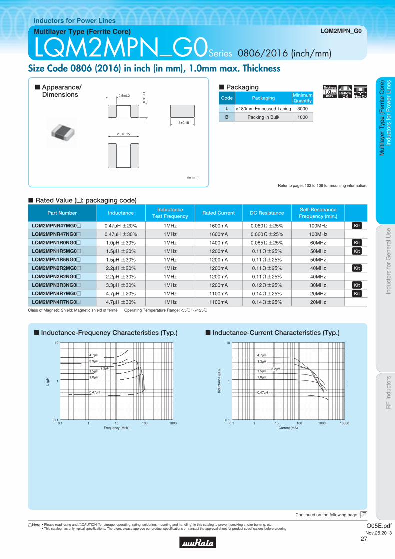
Inductors for Power Lines
LQM2MPN_G0Series 0806/2016 (inch/mm)Size Code 0806 (2016) in inch (in mm), 1.0mm max. Thickness
c Inductance-Frequency Characteristics (Typ.) c Inductance-Current Characteristics (Typ.)
c Rated Value (p: packaging code)
Refer to pages 102 to 106 for mounting information.
(in mm)
2.0±0.15
0.5±0.2
1.6±0.15
0.9±
0.1
Continued on the following page.
c Appearance/Dimensions
c Packaging
Class of Magnetic Shield: Magnetic shield of ferrite Operating Temperature Range: -55℃~+125℃
0.1
1
10
0.1 1 100010010Frequency (MHz)
L (μ
H)
2.2μH
4.7μH
3.3μH
1.5μH
1.0μH
0.47μH
0.1
1
10
0.1 1 1000 1000010010Current (mA)
Indu
ctan
ce (
μH) 2.2μH
3.3μH
4.7μH
1.5μH
1.0μH
0.47μH
Part Number InductanceInductance
Test FrequencyRated Current DC Resistance
Self-ResonanceFrequency (min.)
LQM2MPNR47MG0p 0.47µH ±20% 1MHz 1600mA 0.060Ω±25% 100MHz LQM2MPNR47NG0p 0.47µH ±30% 1MHz 1600mA 0.060Ω±25% 100MHz
LQM2MPN1R0NG0p 1.0µH ±30% 1MHz 1400mA 0.085Ω±25% 60MHz LQM2MPN1R5MG0p 1.5µH ±20% 1MHz 1200mA 0.11Ω±25% 50MHz LQM2MPN1R5NG0p 1.5µH ±30% 1MHz 1200mA 0.11Ω±25% 50MHz
LQM2MPN2R2MG0p 2.2µH ±20% 1MHz 1200mA 0.11Ω±25% 40MHz LQM2MPN2R2NG0p 2.2µH ±30% 1MHz 1200mA 0.11Ω±25% 40MHz
LQM2MPN3R3NG0p 3.3µH ±30% 1MHz 1200mA 0.12Ω±25% 30MHz LQM2MPN4R7MG0p 4.7µH ±20% 1MHz 1100mA 0.14Ω±25% 20MHz LQM2MPN4R7NG0p 4.7µH ±30% 1MHz 1100mA 0.14Ω±25% 20MHz
O05E.pdfNov.25,2013
27
!Note • Please read rating and !CAUTION (for storage, operating, rating, soldering, mounting and handling) in this catalog to prevent smoking and/or burning, etc.• This catalog has only typical specifi cations. Therefore, please approve our product specifi cations or transact the approval sheet for product specifi cations before ordering.
Indu
ctor
s fo
r P
ower
Lin
esIn
duct
ors
for
Gen
eral
Use
RF
Indu
ctor
sIn
duct
ors
for
Pow
er L
ines
Mul
tilay
er T
ype
(Fer
rite
Cor
e)
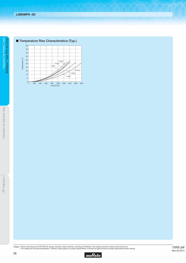
LQM2MPN_G0
c Temperature Rise Characteristics (Typ.)
Current (mA)
Tem
pera
ture
(°C
)
50
40
30
20
10
45
35
25
15
5
00 200 400 600 800 180016001200 14001000
4.7μH
3.3μH2.2μH
1.5μH
1.0μH
0.47μH
O05E.pdfNov.25,2013
28
!Note • Please read rating and !CAUTION (for storage, operating, rating, soldering, mounting and handling) in this catalog to prevent smoking and/or burning, etc.• This catalog has only typical specifi cations. Therefore, please approve our product specifi cations or transact the approval sheet for product specifi cations before ordering.

Code PackagingMinimumQuantity
L ø180mm Embossed Taping 3000
1.0Thickness
mmmax.
Low Rdc Bias
ReflowOK
Indu
ctor
s fo
r P
ower
Lin
esIn
duct
ors
for
Gen
eral
Use
RF
Indu
ctor
sIn
duct
ors
for
Pow
er L
ines
Mul
tilay
er T
ype
(Fer
rite
Cor
e)
Multilayer Type (Ferrite Core) LQM2MPN_GH
Inductors for Power Lines
LQM2MPN_GHSeries 0806/2016 (inch/mm)High Spec Type (Low DC Resistance / Good Bias Current Characteristics Type)
c Inductance-Frequency Characteristics (Typ.) c Inductance-Current Characteristics (Typ.)
c Rated Value (p: packaging code)
Refer to pages 102 to 106 for mounting information.
(in mm)
2.0±0.3
0.5±0.2
1.6±0.2
0.9±
0.1
Continued on the following page.
c Appearance/Dimensions
c Packaging
Inductance Test Frequency: 1MHz Class of Magnetic Shield: Magnetic shield of ferriteOperating Temperature Range: -40℃~+85℃For refl ow soldering only.*1 When applied rated current to the products, inductance will be within -30% of initial inductance value. Typical value is actual performance.*2 When applied rated current to the products, temperature rise caused by self heating will be 40℃ or less. Typical value is actual performance.*3 Keep the temperature of product (ambient temperature plus self-generation of heat) under 125℃.
0.1
1
10
0.1 1 100010010Frequency (MHz)
L (μ
H)
2.2μH
1.5μH
1.0μH
0.68μH0.47μH
0.33μH
0.24μH
0.16μH
0.1
1
10
1 10 100001000100Current (mA)
Indu
ctan
ce (
μH)
2.2μH
1.5μH
1.0μH
0.68μH
0.47μH
0.33μH
0.24μH
0.16μH
Part Number Inductance*1*3Rated Current
(Based on Inductance Change)
*2*3Rated Current(Based on Temperature Rise)
Max. of DC ResistanceSelf-ResonanceFrequency (min.)
LQM2MPNR16MGHp 0.16µH ±20% 5.0A(Max)/5.5A(Typ.) 4.0A(Max)/5.0A(Typ.) 18mΩ(Max)/14mΩ(Typ.) 150MHz LQM2MPNR24MGHp 0.24µH ±20% 4.8A(Max)/5.0A(Typ.) 3.4A(Max)/4.4A(Typ.) 25mΩ(Max)/20mΩ(Typ.) 130MHz LQM2MPNR33MGHp 0.33µH ±20% 3.7A(Max)/3.9A(Typ.) 3.1A(Max)/4.0A(Typ.) 30mΩ(Max)/24mΩ(Typ.) 90MHz LQM2MPNR47MGHp 0.47µH ±20% 3.4A(Max)/3.6A(Typ.) 2.5A(Max)/3.2A(Typ.) 46mΩ(Max)/37mΩ(Typ.) 80MHz LQM2MPNR68MGHp 0.68µH ±20% 3.1A(Max)/3.4A(Typ.) 1.9A(Max)/2.5A(Typ.) 75mΩ(Max)/60mΩ(Typ.) 60MHz LQM2MPN1R0MGHp 1.0µH ±20% 2.0A(Max)/2.3A(Typ.) 1.9A(Max)/2.4A(Typ.) 80mΩ(Max)/64mΩ(Typ.) 60MHz LQM2MPN1R5MGHp 1.5µH ±20% 1.8A(Max)/2.0A(Typ.) 1.5A(Max)/1.9A(Typ.) 130mΩ(Max)/104mΩ(Typ.) 50MHz LQM2MPN2R2MGHp 2.2µH ±20% 1.3A(Max)/1.5A(Typ.) 1.0A(Max)/1.3A(Typ.) 263mΩ(Max)/210mΩ(Typ.) 40MHz
O05E.pdfNov.25,2013
29
!Note • Please read rating and !CAUTION (for storage, operating, rating, soldering, mounting and handling) in this catalog to prevent smoking and/or burning, etc.• This catalog has only typical specifi cations. Therefore, please approve our product specifi cations or transact the approval sheet for product specifi cations before ordering.

Indu
ctor
s fo
r P
ower
Lin
esIn
duct
ors
for
Gen
eral
Use
RF
Indu
ctor
sIn
duct
ors
for
Pow
er L
ines
Mul
tilay
er T
ype
(Fer
rite
Cor
e)
LQM2MPN_GH
c Temperature Rise Characteristics (Typ.)
Current (mA)
Tem
pera
ture
(°C
)
50
40
30
20
10
45
35
25
15
5
00 1000 2000 3000 3500 45004000500 1500 2500
1.5μH
2.2μH
1.0μH
0.68μH0.47μH
0.33μH
0.24μH
0.16μH
O05E.pdfNov.25,2013
30
!Note • Please read rating and !CAUTION (for storage, operating, rating, soldering, mounting and handling) in this catalog to prevent smoking and/or burning, etc.• This catalog has only typical specifi cations. Therefore, please approve our product specifi cations or transact the approval sheet for product specifi cations before ordering.

Code PackagingMinimumQuantity
L ø180mm Embossed Taping 3000
B Packing in Bulk 1000
1.2Thickness
mmmax.
ReflowOK FlowOK
Indu
ctor
s fo
r P
ower
Lin
esIn
duct
ors
for
Gen
eral
Use
RF
Indu
ctor
sIn
duct
ors
for
Pow
er L
ines
Mul
tilay
er T
ype
(Fer
rite
Cor
e)
Multilayer Type (Ferrite Core) LQM2HPN_J0
Inductors for Power Lines
LQM2HPN_ J0Series 1008/2520 (inch/mm)Size Code 1008 (2520) in inch (in mm), 1.2mm max. Thickness
c Inductance-Frequency Characteristics (Typ.)
c Temperature Rise Characteristics (Typ.)
c Inductance-Current Characteristics (Typ.)
c Rated Value (p: packaging code)
Refer to pages 102 to 106 for mounting information.
(in mm)
2.5±0.2
0.6±0.2
2.0±0.2
1.1±
0.1
c Appearance/Dimensions
c Packaging
Class of Magnetic Shield: Magnetic shield of ferrite Operating Temperature Range: -55℃~+125℃
0.1
1
10
0.1 1 100010010Frequency (MHz)
L (μ
H)
2.2μH
3.3μH
1.0μH
Current (mA)
Tem
pera
ture
(°C
)
50
40
30
20
10
45
35
25
15
5
00 200 400 600 800 180016001200 14001000
3.3μH2.2μH
1.0μH
0.1
1
10
1 10 100001000100Current (mA)
Indu
ctan
ce (
μH)
2.2μH
3.3μH
1.0μH
Part Number InductanceInductance
Test FrequencyRated Current DC Resistance
Self-ResonanceFrequency (min.)
LQM2HPN1R0MJ0p 1.0µH ±20% 1MHz 1500mA 0.09Ω±25% 70MHz LQM2HPN2R2MJ0p 2.2µH ±20% 1MHz 1000mA 0.12Ω±25% 40MHz LQM2HPN3R3MJ0p 3.3µH ±20% 1MHz 1000mA 0.12Ω±25% 30MHz
O05E.pdfNov.25,2013
31
!Note • Please read rating and !CAUTION (for storage, operating, rating, soldering, mounting and handling) in this catalog to prevent smoking and/or burning, etc.• This catalog has only typical specifi cations. Therefore, please approve our product specifi cations or transact the approval sheet for product specifi cations before ordering.

Code PackagingMinimumQuantity
L ø180mm Embossed Taping 3000
1.2Thickness
mmmax.
Low Rdc Bias
ReflowOK
Part Number Inductance*1*3Rated Current
(Based on Inductance Change)
*2*3Rated Current(Based on Temperature Rise)
Max. of DC ResistanceSelf-ResonanceFrequency (min.)
LQM2HPNR47MJHp 0.47µH ±20% 3.2A(Max)/3.5A(Typ.) 2.7A(Max)/3.4A(Typ.) 46mΩ(Max)/37mΩ(Typ.) 70MHz LQM2HPN1R0MJHp 1.0µH ±20% 2.1A(Max)/2.4A(Typ.) 2.3A(Max)/2.9A(Typ.) 63mΩ(Max)/50mΩ(Typ.) 50MHz LQM2HPN2R2MJHp 2.2µH ±20% 1.4A(Max)/1.6A(Typ.) 1.5A(Max)/1.9A(Typ.) 138mΩ(Max)/110mΩ(Typ.) 30MHz
Indu
ctor
s fo
r P
ower
Lin
esIn
duct
ors
for
Gen
eral
Use
RF
Indu
ctor
sIn
duct
ors
for
Pow
er L
ines
Mul
tilay
er T
ype
(Fer
rite
Cor
e)
Multilayer Type (Ferrite Core) LQM2HPN_JH
Inductors for Power Lines
LQM2HPN_ JHSeries 1008/2520 (inch/mm)High Spec Type (Low DC Resistance / Good Bias Current Characteristics Type)
c Inductance-Frequency Characteristics (Typ.)
c Temperature Rise Characteristics (Typ.)
c Inductance-Current Characteristics (Typ.)
c Rated Value (p: packaging code)
Refer to pages 102 to 106 for mounting information.
(in mm)
2.5±0.2
0.6±0.2
2.0±0.2
1.1±
0.1
c Appearance/Dimensions
c Packaging
Inductance Test Frequency: 1MHz Class of Magnetic Shield: Magnetic shield of ferriteOperating Temperature Range: -40℃~+85℃For refl ow soldering only.*1 When applied rated current to the products, inductance will be within -30% of initial inductance value. Typical value is actual performance.*2 When applied rated current to the products, temperature rise caused by self heating will be 40℃ or less. Typical value is actual performance.*3 Keep the temperature of product (ambient temperature plus self-generation of heat) under 125℃.
0.1
1
10
0.1 1 10 100Frequency (MHz)
L (μ
H)
2.2μH
1.0μH
0.47μH
Current (mA)
Tem
pera
ture
(°C
)
50
40
30
20
10
45
35
25
15
5
00 400 800 1200 1400 1600200 600 1000
2.2μH
1.0μH
0.47μH
0.1
1
10
1 10 100001000100Current (mA)
Indu
ctan
ce (
μH)
2.2μH
1.0μH
0.47μH
O05E.pdfNov.25,2013
32
!Note • Please read rating and !CAUTION (for storage, operating, rating, soldering, mounting and handling) in this catalog to prevent smoking and/or burning, etc.• This catalog has only typical specifi cations. Therefore, please approve our product specifi cations or transact the approval sheet for product specifi cations before ordering.
Code PackagingMinimumQuantity
L ø180mm Embossed Taping 3000
B Packing in Bulk 1000
1.2Thickness
mmmax.
BiasReflow
OK
FlowOK
Indu
ctor
s fo
r P
ower
Lin
esIn
duct
ors
for
Gen
eral
Use
RF
Indu
ctor
sIn
duct
ors
for
Pow
er L
ines
Mul
tilay
er T
ype
(Fer
rite
Cor
e)
Multilayer Type (Ferrite Core) LQM2HPN_JC
Inductors for Power Lines
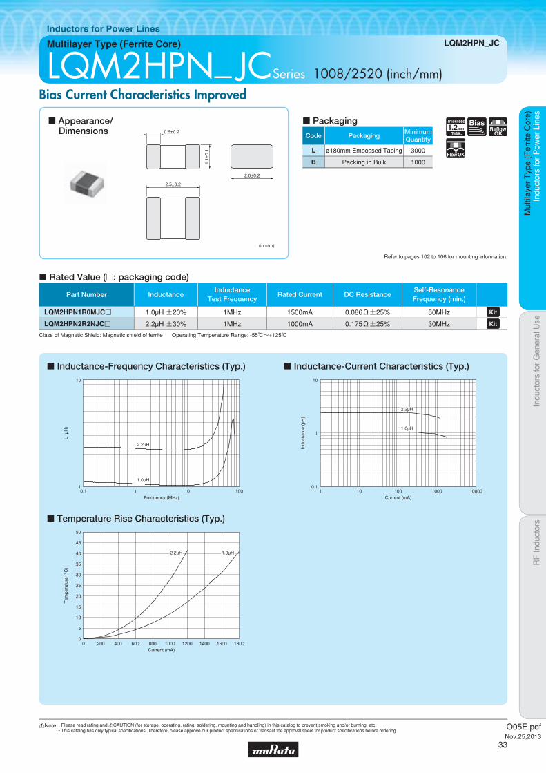
LQM2HPN_ JCSeries 1008/2520 (inch/mm)Bias Current Characteristics Improved
c Inductance-Frequency Characteristics (Typ.)
c Temperature Rise Characteristics (Typ.)
c Inductance-Current Characteristics (Typ.)
c Rated Value (p: packaging code)
Refer to pages 102 to 106 for mounting information.
(in mm)
2.5±0.2
0.6±0.2
2.0±0.2
1.1±
0.1
c Appearance/Dimensions
c Packaging
Class of Magnetic Shield: Magnetic shield of ferrite Operating Temperature Range: -55℃~+125℃
0.1 1 10 100Frequency (MHz)
L (μ
H)
1
10
2.2μH
1.0μH
Current (mA)
Tem
pera
ture
(°C
)
50
40
30
20
10
45
35
25
15
5
00 200 400 600 800 180016001200 14001000
2.2μH 1.0μH
0.1
1
10
1 10 100001000100Current (mA)
Indu
ctan
ce (
μH)
2.2μH
1.0μH
Part Number InductanceInductance
Test FrequencyRated Current DC Resistance
Self-ResonanceFrequency (min.)
LQM2HPN1R0MJCp 1.0µH ±20% 1MHz 1500mA 0.086Ω±25% 50MHz LQM2HPN2R2NJCp 2.2µH ±30% 1MHz 1000mA 0.175Ω±25% 30MHz
O05E.pdfNov.25,2013
33
!Note • Please read rating and !CAUTION (for storage, operating, rating, soldering, mounting and handling) in this catalog to prevent smoking and/or burning, etc.• This catalog has only typical specifi cations. Therefore, please approve our product specifi cations or transact the approval sheet for product specifi cations before ordering.

Code PackagingMinimumQuantity
L ø180mm Embossed Taping 3000
B Packing in Bulk 1000
1.0Thickness
mmmax.
ReflowOK FlowOK
Indu
ctor
s fo
r P
ower
Lin
esIn
duct
ors
for
Gen
eral
Use
RF
Indu
ctor
sIn
duct
ors
for
Pow
er L
ines
Mul
tilay
er T
ype
(Fer
rite
Cor
e)
Multilayer Type (Ferrite Core) LQM2HPN_G0
Inductors for Power Lines
LQM2HPN_G0Series 1008/2520 (inch/mm)Size Code 1008 (2520) in inch (in mm), 1.0mm max. Thickness
c Inductance-Frequency Characteristics (Typ.)
c Temperature Rise Characteristics (Typ.)
c Inductance-Current Characteristics (Typ.)
c Rated Value (p: packaging code)
Refer to pages 102 to 106 for mounting information.
2.5±0.2
0.6±0.2
2.0±0.2
(in mm)
0.9±
0.1
c Appearance/Dimensions
c Packaging
Class of Magnetic Shield: Magnetic shield of ferrite Operating Temperature Range: -55℃~+125℃
L (μ
H)
Frequency (MHz)
0.1
1
10
100
0.1 1 100010010
4.7μH3.3μH
2.2μH
1.5μH1.0μH
0.47μH
Current (mA)
Tem
pera
ture
(°C
)
50
40
30
20
10
45
35
25
15
5
00 500 1000 1500 2000 2500
4.7μH
3.3μH
2.2μH 1.0μH
1.5μH
0.47μH
0.1
1
10
0.1 1 1000 1000010010Current (mA)
Indu
ctan
ce (
μH)
2.2μH
3.3μH
4.7μH
1.5μH
1.0μH
0.47μH
Part Number InductanceInductance
Test FrequencyRated Current DC Resistance
Self-ResonanceFrequency (min.)
LQM2HPNR47MG0p 0.47µH ±20% 1MHz 1800mA 0.04Ω±25% 100MHz LQM2HPN1R0MG0p 1.0µH ±20% 1MHz 1600mA 0.055Ω±25% 60MHz LQM2HPN1R5MG0p 1.5µH ±20% 1MHz 1500mA 0.07Ω±25% 50MHz LQM2HPN2R2MG0p 2.2µH ±20% 1MHz 1300mA 0.08Ω±25% 40MHz LQM2HPN3R3MG0p 3.3µH ±20% 1MHz 1200mA 0.10Ω±25% 30MHz LQM2HPN4R7MG0p 4.7µH ±20% 1MHz 1100mA 0.11Ω±25% 25MHz
O05E.pdfNov.25,2013
34
!Note • Please read rating and !CAUTION (for storage, operating, rating, soldering, mounting and handling) in this catalog to prevent smoking and/or burning, etc.• This catalog has only typical specifi cations. Therefore, please approve our product specifi cations or transact the approval sheet for product specifi cations before ordering.

Code PackagingMinimumQuantity
L ø180mm Embossed Taping 3000
B Packing in Bulk 1000
1.0Thickness
mmmax.
ReflowOK FlowOK
Indu
ctor
s fo
r P
ower
Lin
esIn
duct
ors
for
Gen
eral
Use
RF
Indu
ctor
sIn
duct
ors
for
Pow
er L
ines
Mul
tilay
er T
ype
(Fer
rite
Cor
e)
Multilayer Type (Ferrite Core) LQM2HPN_GS
Inductors for Power Lines
LQM2HPN_GSSeries 1008/2520 (inch/mm)Size Code 1008 (2520) in inch (in mm), 1.0mm max. Thickness
c Inductance-Frequency Characteristics (Typ.)
c Temperature Rise Characteristics (Typ.)
c Inductance-Current Characteristics (Typ.)
c Rated Value (p: packaging code)
Refer to pages 102 to 106 for mounting information.
2.5±0.2
0.6±0.2
2.0±0.2
(in mm)
0.9±
0.1
c Appearance/Dimensions
c Packaging
Class of Magnetic Shield: Magnetic shield of ferrite Operating Temperature Range: -40℃~+85℃
0.1
1
10
1 10 100Frequency (MHz)
L (μ
H)
2.2μH
3.3μH
4.7μH
Current (mA)
Tem
pera
ture
(°C
)
50
40
30
20
10
45
35
25
15
5
00 200 400 600 800 140012001000
4.7μH
2.2μH
3.3μH
1
10
0.1 1 1000 1000010010Current (mA)
Indu
ctan
ce (
μH) 4.7μH
3.3μH
2.2μH
Part Number InductanceInductance
Test FrequencyRated Current DC Resistance
Self-ResonanceFrequency (min.)
LQM2HPN2R2MGSp 2.2µH ±20% 1MHz 1100mA 0.18Ω±25% 40MHz LQM2HPN3R3MGSp 3.3µH ±20% 1MHz 1050mA 0.21Ω±25% 20MHz LQM2HPN4R7MGSp 4.7µH ±20% 1MHz 1000mA 0.25Ω±25% 20MHz
O05E.pdfNov.25,2013
35
!Note • Please read rating and !CAUTION (for storage, operating, rating, soldering, mounting and handling) in this catalog to prevent smoking and/or burning, etc.• This catalog has only typical specifi cations. Therefore, please approve our product specifi cations or transact the approval sheet for product specifi cations before ordering.

Code PackagingMinimumQuantity
L ø180mm Embossed Taping 3000
B Packing in Bulk 1000
1.0Thickness
mmmax.
BiasReflow
OK
FlowOK
Indu
ctor
s fo
r P
ower
Lin
esIn
duct
ors
for
Gen
eral
Use
RF
Indu
ctor
sIn
duct
ors
for
Pow
er L
ines
Mul
tilay
er T
ype
(Fer
rite
Cor
e)
Multilayer Type (Ferrite Core) LQM2HPN_GC
Inductors for Power Lines
LQM2HPN_GCSeries 1008/2520 (inch/mm)Bias Current Characteristics Improved
c Inductance-Frequency Characteristics (Typ.)
c Temperature Rise Characteristics (Typ.)
c Inductance-Current Characteristics (Typ.)
c Rated Value (p: packaging code)
Refer to pages 102 to 106 for mounting information.
2.5±0.2
0.6±0.2
2.0±0.2
(in mm)
0.9±
0.1
c Appearance/Dimensions
c Packaging
Class of Magnetic Shield: Magnetic shield of ferrite
0.1
1
10
1 10 100Frequency (MHz)
L (μ
H)
4.7μH
3.3μH
1.0μH
Current (mA)
Tem
pera
ture
(°C
)
50
40
30
20
10
45
35
25
15
5
00 200 400 600 800 180016001200 14001000
4.7μH
3.3μH 1.0μH
0.1
1
10
0.1 1 1000 1000010010Current (mA)
Indu
ctan
ce (
μH)
3.3μH
4.7μH
1.0μH
Part Number InductanceInductance
Test FrequencyRated Current DC Resistance
Self-ResonanceFrequency (min.)
OperatingTemperature Range
LQM2HPN1R0MGCp 1.0µH ±20% 1MHz 1500mA 0.08Ω±25% 50MHz -30℃~+85℃ LQM2HPN3R3MGCp 3.3µH ±20% 1MHz 1000mA 0.16Ω±25% 30MHz -55℃~+125℃ LQM2HPN4R7MGCp 4.7µH ±20% 1MHz 800mA 0.18Ω±25% 25MHz -55℃~+125℃
O05E.pdfNov.25,2013
36
!Note • Please read rating and !CAUTION (for storage, operating, rating, soldering, mounting and handling) in this catalog to prevent smoking and/or burning, etc.• This catalog has only typical specifi cations. Therefore, please approve our product specifi cations or transact the approval sheet for product specifi cations before ordering.

Code PackagingMinimumQuantity
L ø180mm Embossed Taping 3000
1.0Thickness
mmmax.
Low Rdc Bias
ReflowOK
Indu
ctor
s fo
r P
ower
Lin
esIn
duct
ors
for
Gen
eral
Use
RF
Indu
ctor
sIn
duct
ors
for
Pow
er L
ines
Mul
tilay
er T
ype
(Fer
rite
Cor
e)
Multilayer Type (Ferrite Core) LQM2HPN_GH
Inductors for Power Lines
LQM2HPN_GHSeries 1008/2520 (inch/mm)High Spec Type (Low DC Resistance / Good Bias Current Characteristics Type)
c Inductance-Frequency Characteristics (Typ.)
c Temperature Rise Characteristics (Typ.)
c Inductance-Current Characteristics (Typ.)
c Rated Value (p: packaging code)
Refer to pages 102 to 106 for mounting information.
2.5±0.2
0.6±0.2
2.0±0.2
(in mm)
0.9±
0.1
c Appearance/Dimensions
c Packaging
Inductance Test Frequency: 1MHz Class of Magnetic Shield: Magnetic shield of ferrite Operating Temperature Range: -40℃~+85℃ For refl ow soldering only.*1 When applied rated current to the products, inductance will be within -30% of initial inductance value. Typical value is actual performance.*2 When applied rated current to the products, temperature rise caused by self heating will be 40℃ or less. Typical value is actual performance.*3 Keep the temperature of product (ambient temperature plus self-generation of heat) under 125℃.
0.1
1
10
0.1 1 100010010Frequency (MHz)
L (μ
H)
2.2μH
1.5μH
1.0μH
0.47μH
Current (mA)
Tem
pera
ture
(°C
)
50
40
30
20
10
45
35
25
15
5
00 1000 2000 3000500 1500 2500
2.2μH
1.5μH
1.0μH
0.47μH
0.1
1
10
1 10 100001000100Current (mA)
Indu
ctan
ce (
μH)
2.2μH
1.5μH
1.0μH
0.47μH
Part Number Inductance*1*3Rated Current
(Based on Inductance Change)
*2*3Rated Current(Based on Temperature Rise)
Max. of DC ResistanceSelf-ResonanceFrequency (min.)
LQM2HPNR47MGHp 0.47µH ±20% 4.5A(Max)/4.8A(Typ.) 2.6A(Max)/3.3A(Typ.) 50mΩ(Max)/40mΩ(Typ.) 80MHz LQM2HPNR68MGHp 0.68µH ±20% 4.0A(Max)/3.8A(Typ.) 2.3A(Max)/2.9A(Typ.) 63mΩ(Max)/50mΩ(Typ.) 60MHz LQM2HPN1R0MGHp 1.0µH ±20% 2.0A(Max)/2.3A(Typ.) 2.3A(Max)/2.9A(Typ.) 63mΩ(Max)/50mΩ(Typ.) 50MHz LQM2HPN1R5MGHp 1.5µH ±20% 1.5A(Max)/1.6A(Typ.) 2.0A(Max)/2.6A(Typ.) 81mΩ(Max)/65mΩ(Typ.) 40MHz LQM2HPN2R2MGHp 2.2µH ±20% 1.5A(Max)/1.6A(Typ.) 1.5A(Max)/1.9A(Typ.) 138mΩ(Max)/110mΩ(Typ.) 30MHz
O05E.pdfNov.25,2013
37
!Note • Please read rating and !CAUTION (for storage, operating, rating, soldering, mounting and handling) in this catalog to prevent smoking and/or burning, etc.• This catalog has only typical specifi cations. Therefore, please approve our product specifi cations or transact the approval sheet for product specifi cations before ordering.

Code PackagingMinimumQuantity
L ø180mm Embossed Taping 3000
B Packing in Bulk 1000
0.8Thickness
mmmax.
ReflowOK FlowOK
Indu
ctor
s fo
r P
ower
Lin
esIn
duct
ors
for
Gen
eral
Use
RF
Indu
ctor
sIn
duct
ors
for
Pow
er L
ines
Mul
tilay
er T
ype
(Fer
rite
Cor
e)
Multilayer Type (Ferrite Core) LQM2HPN_E0
Inductors for Power Lines
LQM2HPN_E0Series 1008/2520 (inch/mm)Size Code 1008 (2520) in inch (in mm), 0.8mm max. Thickness
c Inductance-Frequency Characteristics (Typ.)
c Temperature Rise Characteristics (Typ.)
c Inductance-Current Characteristics (Typ.)
c Rated Value (p: packaging code)
Refer to pages 102 to 106 for mounting information.
2.5±0.2
0.6±0.2
2.0±0.2
(in mm)
0.7±
0.1
c Appearance/Dimensions
c Packaging
Class of Magnetic Shield: Magnetic shield of ferrite Operating Temperature Range: -55℃~+125℃
Frequency (MHz)
L (μ
H)
0.1 1 100010010
0.56μH
0.1
1
Current (mA)
Tem
pera
ture
(°C
)
50
40
30
20
10
45
35
25
15
5
00 200 400 600 800 180016001200 14001000
0.56μH
Current (mA)
Indu
ctan
ce (
μH)
1 10 100001000100
0.56μH
0.1
1
Part Number InductanceInductance
Test FrequencyRated Current DC Resistance
Self-ResonanceFrequency (min.)
LQM2HPNR56ME0p 0.56µH ±20% 1MHz 1500mA 0.06Ω±25% 70MHz
O05E.pdfNov.25,2013
38
!Note • Please read rating and !CAUTION (for storage, operating, rating, soldering, mounting and handling) in this catalog to prevent smoking and/or burning, etc.• This catalog has only typical specifi cations. Therefore, please approve our product specifi cations or transact the approval sheet for product specifi cations before ordering.

Code PackagingMinimumQuantity
L ø180mm Embossed Taping 3000
B Packing in Bulk 1000
0.95Thickness
mmmax.
ReflowOK FlowOK
Indu
ctor
s fo
r P
ower
Lin
esIn
duct
ors
for
Gen
eral
Use
RF
Indu
ctor
sIn
duct
ors
for
Pow
er L
ines
Mul
tilay
er T
ype
(Fer
rite
Cor
e)
Multilayer Type (Ferrite Core) LQM31PN_00
Inductors for Power Lines
LQM31PN_00Series 1206/3216 (inch/mm)Size Code 1206 (3216) in inch (in mm), 0.95mm max. Thickness
c Inductance-Frequency Characteristics (Typ.)
c Temperature Rise Characteristics (Typ.)
c Inductance-Current Characteristics (Typ.)
c Rated Value (p: packaging code)
Refer to pages 102 to 106 for mounting information.
(in mm)
3.2±0.2
0.6±0.2
1.6±0.2
0.85
±0.1
c Appearance/Dimensions
c Packaging
Class of Magnetic Shield: Magnetic shield of ferrite Operating Temperature Range: -55℃~+125℃
L (μ
H)
Frequency (MHz)
0.1
1
10
10001001010.1
0.47μH
1.0μH
1.5μH
2.2μH
3.3μH
4.7μH
Current (mA)
Tem
pera
ture
(°C
)
50
40
30
20
10
45
35
25
15
0
5
0 400 800 1200 1600200 600 1000 1400
4.7μH3.3μH 2.2μH
1.5μH 1.0μH0.47μH
Indu
ctan
ce (
μH)
Current (mA)
0.1
1
10
100001000100101
0.47μH
1.0μH
1.5μH
2.2μH
3.3μH
4.7μH
Part Number InductanceInductance
Test FrequencyRated Current DC Resistance
Self-ResonanceFrequency (min.)
LQM31PNR47M00p 0.47µH ±20% 1MHz 1400mA 0.07Ω±25% 80MHz LQM31PN1R0M00p 1.0µH ±20% 1MHz 1200mA 0.12Ω±25% 60MHz LQM31PN1R5M00p 1.5µH ±20% 1MHz 1000mA 0.14Ω±25% 50MHz LQM31PN2R2M00p 2.2µH ±20% 1MHz 900mA 0.19Ω±25% 40MHz LQM31PN3R3M00p 3.3µH ±20% 1MHz 800mA 0.24Ω±25% 30MHz LQM31PN4R7M00p 4.7µH ±20% 1MHz 700mA 0.30Ω±25% 25MHz
O05E.pdfNov.25,2013
39
!Note • Please read rating and !CAUTION (for storage, operating, rating, soldering, mounting and handling) in this catalog to prevent smoking and/or burning, etc.• This catalog has only typical specifi cations. Therefore, please approve our product specifi cations or transact the approval sheet for product specifi cations before ordering.
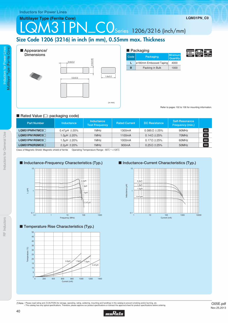
Code PackagingMinimumQuantity
L ø180mm Embossed Taping 4000
B Packing in Bulk 1000
0.55Thickness
mmmax.
ReflowOK FlowOK
Indu
ctor
s fo
r P
ower
Lin
esIn
duct
ors
for
Gen
eral
Use
RF
Indu
ctor
sIn
duct
ors
for
Pow
er L
ines
Mul
tilay
er T
ype
(Fer
rite
Cor
e)
Multilayer Type (Ferrite Core) LQM31PN_C0
Inductors for Power Lines
LQM31PN_C0Series 1206/3216 (inch/mm)Size Code 1206 (3216) in inch (in mm), 0.55mm max. Thickness
c Inductance-Frequency Characteristics (Typ.)
c Temperature Rise Characteristics (Typ.)
c Inductance-Current Characteristics (Typ.)
c Rated Value (p: packaging code)
Refer to pages 102 to 106 for mounting information.
3.2±0.2
0.6±0.2
1.6±0.2
(in mm)
0.5±
0.05
c Appearance/Dimensions
c Packaging
Class of Magnetic Shield: Magnetic shield of ferrite Operating Temperature Range: -55℃~+125℃
L (μ
H)
Frequency (MHz)
0.1
1
10
10001001010.1
0.47μH
1.0μH
1.5μH
2.2μH
Current (mA)
Tem
pera
ture
(°C
)
50
40
30
20
10
45
35
25
15
0
5
0 400 800 1200200 600 1000 1400
2.2μH 1.5μH 1.0μH
0.47μH
Indu
ctan
ce (
μH)
Current (mA)
0.1
1
10
100001000100101
0.47μH
1.0μH
1.5μH
2.2μH
Part Number InductanceInductance
Test FrequencyRated Current DC Resistance
Self-ResonanceFrequency (min.)
LQM31PNR47MC0p 0.47µH ±20% 1MHz 1300mA 0.085Ω±25% 90MHz LQM31PN1R0MC0p 1.0µH ±20% 1MHz 1100mA 0.14Ω±25% 70MHz LQM31PN1R5MC0p 1.5µH ±20% 1MHz 1000mA 0.17Ω±25% 60MHz LQM31PN2R2MC0p 2.2µH ±20% 1MHz 900mA 0.25Ω±25% 50MHz
O05E.pdfNov.25,2013
40
!Note • Please read rating and !CAUTION (for storage, operating, rating, soldering, mounting and handling) in this catalog to prevent smoking and/or burning, etc.• This catalog has only typical specifi cations. Therefore, please approve our product specifi cations or transact the approval sheet for product specifi cations before ordering.

Code PackagingMinimumQuantity
L ø180mm Embossed Taping 3000
B Packing in Bulk 1000
1.0Thickness
mmmax.
ReflowOK
Indu
ctor
s fo
r P
ower
Lin
esIn
duct
ors
for
Gen
eral
Use
RF
Indu
ctor
sIn
duct
ors
for
Pow
er L
ines
Mul
tilay
er T
ype
(Fer
rite
Cor
e)
Multilayer Type (Ferrite Core) LQM32PN_G0
Inductors for Power Lines
LQM32PN_G0Series 1210/3225 (inch/mm)Size Code 1210 (3225) in inch (in mm), 0.55mm max. Thickness
c Inductance-Frequency Characteristics (Typ.)
c Temperature Rise Characteristics (Typ.)
c Inductance-Current Characteristics (Typ.)
c Rated Value (p: packaging code)
Refer to pages 102 to 106 for mounting information.
3.2±0.15
0.6±0.2
2.5±0.15
0.9±
0.1
(in mm)
c Appearance/Dimensions
c Packaging
Class of Magnetic Shield: Magnetic shield of ferrite Operating Temperature Range: -40℃~+85℃For refl ow soldering only.
10
1
0.1
L (μ
H)
0.1 1 10 100Frequency (MHz)
1.0μH
Current (mA)
Tem
pera
ture
(°C
)
50
40
30
20
10
45
35
25
15
0
5
0 200 400 600 800 1000 1200 1400 1600 1800 2000
1.0μH
0.1
Current (mA)
Indu
ctan
ce (
μH)
1
1.0μH
0.1 1 10 100 1000 10000
Part Number InductanceInductance
Test FrequencyRated Current DC Resistance
Self-ResonanceFrequency (min.)
LQM32PN1R0MG0p 1.0µH ±20% 1MHz 1800mA 0.048Ω±25% 40MHz
O05E.pdfNov.25,2013
41
!Note • Please read rating and !CAUTION (for storage, operating, rating, soldering, mounting and handling) in this catalog to prevent smoking and/or burning, etc.• This catalog has only typical specifi cations. Therefore, please approve our product specifi cations or transact the approval sheet for product specifi cations before ordering.

Code PackagingMinimumQuantity
L ø180mm Embossed Taping 3000
B Packing in Bulk 100
Indu
ctor
s fo
r P
ower
Lin
esIn
duct
ors
for
Gen
eral
Use
RF
Indu
ctor
sIn
duct
ors
for
Pow
er L
ines
Wire
Wou
nd T
ype
(Fer
rite
Cor
e)
Wire Wound Type (Ferrite Core) LQH2MCN_02
Inductors for Power Lines
LQH2MCN_02Series 0806/2016 (inch/mm)Size Code 0806 (2016) in inch (in mm), 0.95mm max. Thickness
c Rated Value (p: packaging code)
Refer to pages 102 to 106 for mounting information.
(in mm)
2.0±0.2
0.6±0.2 0.8±0.2 0.6±0.2
1.6±0.2
0.90
±0.
05
Continued on the following page.
c Appearance/Dimensions
c Packaging
Class of Magnetic Shield: No magnetic shieldOperating Temperature Range (Self-temperature rise is not included): -40℃~+85℃For refl ow soldering only.*1 When applied rated current to the products, self-temperature rise shall be limited to 40℃ max. and inductance will be within ±10% of initial inductance value.
0.95Thickness
mmmax.
ReflowOK
Part Number InductanceInductance
Test Frequency
*1Rated Current DC Resistance
Self-ResonanceFrequency (min.)
LQH2MCN1R0M02p 1.0µH ±20% 1MHz 485mA 0.30Ω±30% 100MHz LQH2MCN1R5M02p 1.5µH ±20% 1MHz 445mA 0.40Ω±30% 95MHz LQH2MCN2R2M02p 2.2µH ±20% 1MHz 425mA 0.48Ω±30% 70MHz LQH2MCN3R3M02p 3.3µH ±20% 1MHz 375mA 0.60Ω±30% 65MHz LQH2MCN4R7M02p 4.7µH ±20% 1MHz 300mA 0.8Ω±30% 60MHz LQH2MCN5R6M02p 5.6µH ±20% 1MHz 280mA 0.9Ω±30% 60MHz LQH2MCN6R8M02p 6.8µH ±20% 1MHz 255mA 1.0Ω±30% 55MHz LQH2MCN8R2M02p 8.2µH ±20% 1MHz 235mA 1.1Ω±30% 50MHz LQH2MCN100K02p 10µH ±10% 1MHz 225mA 1.2Ω±30% 48MHz LQH2MCN120K02p 12µH ±10% 1MHz 210mA 1.4Ω±30% 44MHz LQH2MCN150K02p 15µH ±10% 1MHz 200mA 1.6Ω±30% 40MHz LQH2MCN180K02p 18µH ±10% 1MHz 190mA 1.8Ω±30% 35MHz LQH2MCN220K02p 22µH ±10% 1MHz 185mA 2.1Ω±30% 30MHz LQH2MCN270K02p 27µH ±10% 1MHz 180mA 2.5Ω±30% 30MHz LQH2MCN330K02p 33µH ±10% 1MHz 160mA 2.8Ω±30% 28MHz LQH2MCN390K02p 39µH ±10% 1MHz 125mA 4.4Ω±30% 24MHz LQH2MCN470K02p 47µH ±10% 1MHz 120mA 5.1Ω±30% 18MHz LQH2MCN560K02p 56µH ±10% 1MHz 110mA 5.7Ω±30% 17MHz LQH2MCN680K02p 68µH ±10% 1MHz 100mA 6.6Ω±30% 14MHz LQH2MCN820K02p 82µH ±10% 1MHz 90mA 7.5Ω±30% 14MHz
O05E.pdfNov.25,2013
42
!Note • Please read rating and !CAUTION (for storage, operating, rating, soldering, mounting and handling) in this catalog to prevent smoking and/or burning, etc.• This catalog has only typical specifi cations. Therefore, please approve our product specifi cations or transact the approval sheet for product specifi cations before ordering.

Indu
ctor
s fo
r P
ower
Lin
esIn
duct
ors
for
Gen
eral
Use
RF
Indu
ctor
sIn
duct
ors
for
Pow
er L
ines
Wire
Wou
nd T
ype
(Fer
rite
Cor
e)
LQH2MCN_02
c Inductance-Frequency Characteristics (Typ.)
c Temperature Rise Characteristics (Typ.)
c Inductance-Current Characteristics (Typ.)
0.01 0.1 1 10010
1000
100
10
1
0.1
Frequency (MHz)
L (μ
H)
15μH 18μH 22μH 27μH33μH 39μH 47μH 56μH 68μH 82μH
1.0μH 1.5μH 2.2μH 3.3μH 4.7μH 5.6μH 6.8μH 8.2μH 10μH 12μH
Current (mA)
Tem
pera
ture
(°C
)
50
40
30
20
10
5
45
35
25
15
00 100 200 300 400 50050 150 250 350 450
47μH
39μH
33μH
15μH10μH
8.2μH
6.8μH
5.6μH
4.7μH
3.3μH
2.2μH1.5μH
1.0μH
Indu
ctan
ce (
μH)
Current (mA)
1
10
100
10001001010.1
82μH68μH
56μH47μH
39μH33μH
27μH22μH 18μH
15μH12μH10μH8.2μH6.8μH5.6μH4.7μH
3.3μH
2.2μH
1.0μH
O05E.pdfNov.25,2013
43
!Note • Please read rating and !CAUTION (for storage, operating, rating, soldering, mounting and handling) in this catalog to prevent smoking and/or burning, etc.• This catalog has only typical specifi cations. Therefore, please approve our product specifi cations or transact the approval sheet for product specifi cations before ordering.
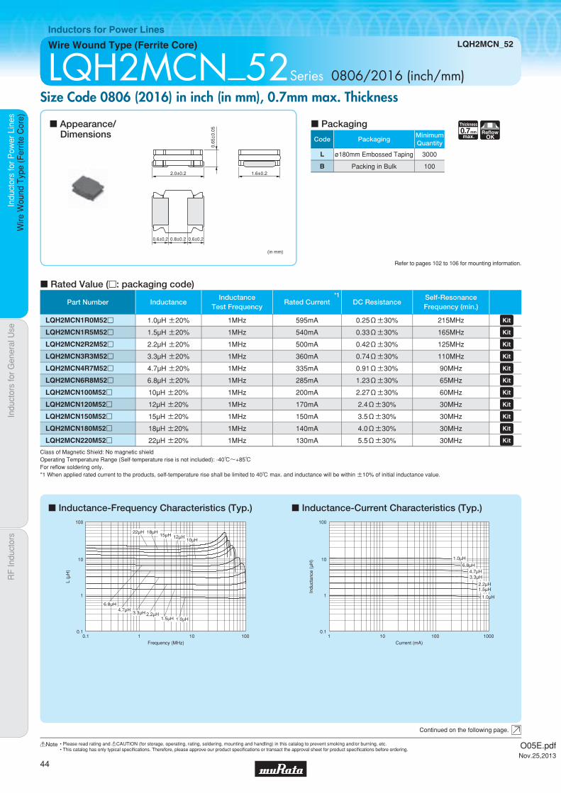
Code PackagingMinimumQuantity
L ø180mm Embossed Taping 3000
B Packing in Bulk 100
0.7Thickness
mmmax.
ReflowOK
Part Number InductanceInductance
Test Frequency
*1Rated Current DC Resistance
Self-ResonanceFrequency (min.)
LQH2MCN1R0M52p 1.0µH ±20% 1MHz 595mA 0.25Ω±30% 215MHz LQH2MCN1R5M52p 1.5µH ±20% 1MHz 540mA 0.33Ω±30% 165MHz LQH2MCN2R2M52p 2.2µH ±20% 1MHz 500mA 0.42Ω±30% 125MHz LQH2MCN3R3M52p 3.3µH ±20% 1MHz 360mA 0.74Ω±30% 110MHz LQH2MCN4R7M52p 4.7µH ±20% 1MHz 335mA 0.91Ω±30% 90MHz LQH2MCN6R8M52p 6.8µH ±20% 1MHz 285mA 1.23Ω±30% 65MHz LQH2MCN100M52p 10µH ±20% 1MHz 200mA 2.27Ω±30% 60MHz LQH2MCN120M52p 12µH ±20% 1MHz 170mA 2.4Ω±30% 30MHz LQH2MCN150M52p 15µH ±20% 1MHz 150mA 3.5Ω±30% 30MHz LQH2MCN180M52p 18µH ±20% 1MHz 140mA 4.0Ω±30% 30MHz LQH2MCN220M52p 22µH ±20% 1MHz 130mA 5.5Ω±30% 30MHz
Indu
ctor
s fo
r P
ower
Lin
esIn
duct
ors
for
Gen
eral
Use
RF
Indu
ctor
sIn
duct
ors
for
Pow
er L
ines
Wire
Wou
nd T
ype
(Fer
rite
Cor
e)
Wire Wound Type (Ferrite Core) LQH2MCN_52
Inductors for Power Lines
LQH2MCN_52Series 0806/2016 (inch/mm)Size Code 0806 (2016) in inch (in mm), 0.7mm max. Thickness
c Inductance-Frequency Characteristics (Typ.) c Inductance-Current Characteristics (Typ.)
c Rated Value (p: packaging code)
Refer to pages 102 to 106 for mounting information.
(in mm)
2.0±0.2
0.6±0.2 0.8±0.2 0.6±0.2
1.6±0.2
0.65
±0.
05
Continued on the following page.
c Appearance/Dimensions
c Packaging
Class of Magnetic Shield: No magnetic shieldOperating Temperature Range (Self-temperature rise is not included): -40℃~+85℃For refl ow soldering only.*1 When applied rated current to the products, self-temperature rise shall be limited to 40℃ max. and inductance will be within ±10% of initial inductance value.
0.1 1 10 100
100
10
0.1
1
Frequency (MHz)
L (μ
H)
3.3μH 2.2μH1.5μH
4.7μH6.8μH
10μH12μH15μH
18μH22μH
1.0μH
1 10 100 1000
100
10
0.1
1
Current (mA)
Indu
ctan
ce (
μH)
1.0μH
1.5μH2.2μH
3.3μH4.7μH
6.8μH
1.0μH
O05E.pdfNov.25,2013
44
!Note • Please read rating and !CAUTION (for storage, operating, rating, soldering, mounting and handling) in this catalog to prevent smoking and/or burning, etc.• This catalog has only typical specifi cations. Therefore, please approve our product specifi cations or transact the approval sheet for product specifi cations before ordering.

Indu
ctor
s fo
r P
ower
Lin
esIn
duct
ors
for
Gen
eral
Use
RF
Indu
ctor
sIn
duct
ors
for
Pow
er L
ines
Wire
Wou
nd T
ype
(Fer
rite
Cor
e)
LQH2MCN_52
c Temperature Rise Characteristics (Typ.)
Current (mA)
Tem
pera
ture
(°C
)
50
40
30
20
10
5
45
35
25
15
00 100 200 300 400 500 600
10μH 6.8μH
4.7μH 3.3μH2.2μH
1.5μH
1.0μH
O05E.pdfNov.25,2013
45
!Note • Please read rating and !CAUTION (for storage, operating, rating, soldering, mounting and handling) in this catalog to prevent smoking and/or burning, etc.• This catalog has only typical specifi cations. Therefore, please approve our product specifi cations or transact the approval sheet for product specifi cations before ordering.

Code PackagingMinimumQuantity
L ø180mm Embossed Taping 3000
1.0Thickness
mmmax.
ReflowOK
Indu
ctor
s fo
r P
ower
Lin
esIn
duct
ors
for
Gen
eral
Use
RF
Indu
ctor
sIn
duct
ors
for
Pow
er L
ines
Wire
Wou
nd T
ype
(Fer
rite
Cor
e)
Wire Wound Type (Ferrite Core) LQH2HPN_G0
Inductors for Power Lines
LQH2HPN_G0Series 1008/2520 (inch/mm)Size Code 1008 (2520) in inch (in mm), 1.0mm max. Thickness
c Inductance-Frequency Characteristics (Typ.) c Inductance-Current Characteristics (Typ.)
c Rated Value (p: packaging code)
Refer to pages 102 to 106 for mounting information.
2.5±0.2
0.85±0.3 0.85±0.3
(in mm)
0.9±
0.1
2.0±0.2
Polarity Marking
Continued on the following page.
c Appearance/Dimensions
c Packaging
Inductance Test Frequency: 1MHz Class of Magnetic Shield: Magnetic shield of magnetic powder in resinOperating Temperature Range (Self-temperature rise is not included): -40℃~+85℃For refl ow soldering only.*1 When applied rated current to the products, inductance will be within -30% of minimum rated inductance value.*2 When applied rated current to the products, self-temperature rise shall be limited to 40℃ max.*3 Keep the temperature (ambient temperature plus self-generation of heat) under 125℃.
L (μ
H)
Frequency (MHz)
1
10
100
1000
0.1 1 10 100 1000
2.2μH
3.3μH
4.7μH6.8μH
10μH
22μH
100μH
Current (mA)0.1 1 10 100 1000 10000
100μH
22μH
10μH6.8μH
4.7μH3.3μH2.2μH
Indu
ctan
ce (
μH)
1
10
100
1000
Part Number Inductance*1*3Rated Current
(Based on Inductance Change)
*2*3Rated Current(Based on Temperature Rise)
DC ResistanceSelf-ResonanceFrequency (min.)
LQH2HPN2R2MG0p 2.2µH ±20% 1640mA 1000mA 0.17Ω±20% 80MHz LQH2HPN3R3MG0p 3.3µH ±20% 1290mA 810mA 0.27Ω±20% 65MHz LQH2HPN4R7MG0p 4.7µH ±20% 1000mA 700mA 0.36Ω±20% 60MHz LQH2HPN6R8MG0p 6.8µH ±20% 800mA 590mA 0.5Ω±20% 10MHz LQH2HPN100MG0p 10µH ±20% 700mA 490mA 0.73Ω±20% 10MHz LQH2HPN220MG0p 22µH ±20% 490mA 340mA 1.6Ω±20% 10MHz LQH2HPN101MG0p 100µH ±20% 210mA 130mA 10.0Ω±20% 5MHz
O05E.pdfNov.25,2013
46
!Note • Please read rating and !CAUTION (for storage, operating, rating, soldering, mounting and handling) in this catalog to prevent smoking and/or burning, etc.• This catalog has only typical specifi cations. Therefore, please approve our product specifi cations or transact the approval sheet for product specifi cations before ordering.
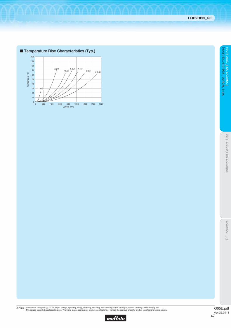
Indu
ctor
s fo
r P
ower
Lin
esIn
duct
ors
for
Gen
eral
Use
RF
Indu
ctor
sIn
duct
ors
for
Pow
er L
ines
Wire
Wou
nd T
ype
(Fer
rite
Cor
e)
LQH2HPN_G0
c Temperature Rise Characteristics (Typ.)
Current (mA)
Tem
pera
ture
(°C
)
100
80
60
40
20
10
90
70
50
30
00 1600200 400 600 800 1000 1200 1400
22μH10μH
6.8μH 4.7μH3.3μH
2.2μH
100μH
O05E.pdfNov.25,2013
47
!Note • Please read rating and !CAUTION (for storage, operating, rating, soldering, mounting and handling) in this catalog to prevent smoking and/or burning, etc.• This catalog has only typical specifi cations. Therefore, please approve our product specifi cations or transact the approval sheet for product specifi cations before ordering.

Code PackagingMinimumQuantity
L ø180mm Embossed Taping 3000
1.0Thickness
mmmax.
Low RdcReflow
OK
Part Number Inductance*1*3Rated Current
(Based on Inductance Change)
*2*3Rated Current(Based on Temperature Rise)
DC ResistanceSelf-ResonanceFrequency (min.)
LQH2HPNR47MGRp 0.47µH ±20% 2900mA 2520mA 0.045Ω±20% 120MHz LQH2HPNR68MGRp 0.68µH ±20% 2430mA 2330mA 0.055Ω±20% 110MHz LQH2HPN1R0MGRp 1.0µH ±20% 2130mA 2100mA 0.068Ω±20% 100MHz LQH2HPN1R5MGRp 1.5µH ±20% 1700mA 1850mA 0.087Ω±20% 90MHz LQH2HPN2R2MGRp 2.2µH ±20% 1550mA 1470mA 0.134Ω±20% 80MHz LQH2HPN3R3MGRp 3.3µH ±20% 1230mA 1100mA 0.225Ω±20% 70MHz LQH2HPN4R7MGRp 4.7µH ±20% 1090mA 1000mA 0.300Ω±20% 50MHz LQH2HPN6R8MGRp 6.8µH ±20% 830mA 860mA 0.395Ω±20% 40MHz LQH2HPN100MGRp 10µH ±20% 700mA 710mA 0.560Ω±20% 30MHz LQH2HPN150MGRp 15µH ±20% 570mA 560mA 0.925Ω±20% 20MHz LQH2HPN220MGRp 22µH ±20% 460mA 430mA 1.360Ω±20% 15MHz
Indu
ctor
s fo
r P
ower
Lin
esIn
duct
ors
for
Gen
eral
Use
RF
Indu
ctor
sIn
duct
ors
for
Pow
er L
ines
Wire
Wou
nd T
ype
(Fer
rite
Cor
e)
Wire Wound Type (Ferrite Core) LQH2HPN_GR
Inductors for Power Lines
LQH2HPN_GRSeries 1008/2520 (inch/mm)Size Code 1008 (2520) in inch (in mm), 1.0mm max. Thickness. Low DC resistance design
c Inductance-Frequency Characteristics (Typ.) c Inductance-Current Characteristics (Typ.)
c Rated Value (p: packaging code)
Refer to pages 102 to 106 for mounting information.
2.5±0.2
0.62±0.2
(in mm)
0.9±
0.1
2.0±0.2
2.0±
0.2
0.62±0.2
Continued on the following page.
c Appearance/Dimensions
c Packaging
Inductance Test Frequency: 1MHz Class of Magnetic Shield: Magnetic shield of magnetic powder in resinOperating Temperature Range (Self-temperature rise is not included): -40℃~+85℃For refl ow soldering only.*1 When applied rated current to the products, inductance will be within -30% of minimum rated inductance value.*2 When applied rated current to the products, self-temperature rise shall be limited to 40℃ max.*3 Keep the temperature (ambient temperature plus self-generation of heat) under 125℃.
L (μ
H)
Frequency (MHz)
0.1
1
10
100
0.1 100101 1000
22μH
15μH10μH6.8μH
4.7μH
3.3μH
2.2μH
1.5μH1.0μH
0.68μH0.47μH
0.1
10
1
100
0.1 1 1000 1000010010Current (mA)
Indu
ctan
ce (
μH)
22μH15μH
10μH6.8μH
4.7μH3.3μH
2.2μH
1.5μH1.0μH
0.68μH0.47μH
O05E.pdfNov.25,2013
48
!Note • Please read rating and !CAUTION (for storage, operating, rating, soldering, mounting and handling) in this catalog to prevent smoking and/or burning, etc.• This catalog has only typical specifi cations. Therefore, please approve our product specifi cations or transact the approval sheet for product specifi cations before ordering.

Indu
ctor
s fo
r P
ower
Lin
esIn
duct
ors
for
Gen
eral
Use
RF
Indu
ctor
sIn
duct
ors
for
Pow
er L
ines
Wire
Wou
nd T
ype
(Fer
rite
Cor
e)
LQH2HPN_GR
c Temperature Rise Characteristics (Typ.)
Current (mA)
Tem
pera
ture
(°C
)
50
40
30
20
10
45
35
25
15
5
00 500 1000 1500 2000 30002500
22μH
15μH
10μH
6.8μH4.7μH
3.3μH
2.2μH
1.5μH
1.0μH
0.68μH
0.47μH
O05E.pdfNov.25,2013
49
!Note • Please read rating and !CAUTION (for storage, operating, rating, soldering, mounting and handling) in this catalog to prevent smoking and/or burning, etc.• This catalog has only typical specifi cations. Therefore, please approve our product specifi cations or transact the approval sheet for product specifi cations before ordering.

Code PackagingMinimumQuantity
L ø180mm Embossed Taping 2000
1.2Thickness
mmmax.
ReflowOK
Indu
ctor
s fo
r P
ower
Lin
esIn
duct
ors
for
Gen
eral
Use
RF
Indu
ctor
sIn
duct
ors
for
Pow
er L
ines
Wire
Wou
nd T
ype
(Fer
rite
Cor
e)
Wire Wound Type (Ferrite Core) LQH2HPN_J0
Inductors for Power Lines
LQH2HPN_ J0Series 1008/2520 (inch/mm)Size Code 1008 (2520) in inch (in mm), 1.2mm max. Thickness
c Inductance-Frequency Characteristics (Typ.) c Inductance-Current Characteristics (Typ.)
c Rated Value (p: packaging code)
Refer to pages 102 to 106 for mounting information.
2.5±0.2
0.85±0.3 0.85±0.3
(in mm)
1.1±
0.1
2.0±0.2
Polarity Marking
Continued on the following page.
c Appearance/Dimensions
c Packaging
Inductance Test Frequency: 1MHz Class of Magnetic Shield: Magnetic shield of magnetic powder in resinOperating Temperature Range (Self-temperature rise is not included): -40℃~+85℃For refl ow soldering only.*1 When applied rated current to the products, inductance will be within -30% of minimum rated inductance value.*2 When applied rated current to the products, self-temperature rise shall be limited to 40℃ max.*3 Keep the temperature (ambient temperature plus self-generation of heat) under 125℃.
L (μ
H)
Frequency (MHz)
1
10
100
10001001010.1
10μH
6.8μH
4.7μH
3.3μH
2.2μH
1.5μH
Current (mA)0.1 1 10 100 1000 10000
10μH
6.8μH4.7μH3.3μH
2.2μH
1.5μH
Indu
ctan
ce (
μH)
0.1
1
10
100
Part Number Inductance*1*3Rated Current
(Based on Inductance Change)
*2*3Rated Current(Based on Temperature Rise)
DC ResistanceSelf-ResonanceFrequency (min.)
LQH2HPN1R5NJ0p 1.5µH ±30% 2400mA 1500mA 0.096Ω±20% 10MHz LQH2HPN2R2MJ0p 2.2µH ±20% 1800mA 1300mA 0.132Ω±20% 10MHz LQH2HPN3R3MJ0p 3.3µH ±20% 1500mA 950mA 0.230Ω±20% 10MHz LQH2HPN4R7MJ0p 4.7µH ±20% 1250mA 700mA 0.330Ω±20% 10MHz LQH2HPN6R8MJ0p 6.8µH ±20% 1100mA 600mA 0.448Ω±20% 10MHz LQH2HPN100MJ0p 10µH ±20% 820mA 550mA 0.641Ω±20% 10MHz
O05E.pdfNov.25,2013
50
!Note • Please read rating and !CAUTION (for storage, operating, rating, soldering, mounting and handling) in this catalog to prevent smoking and/or burning, etc.• This catalog has only typical specifi cations. Therefore, please approve our product specifi cations or transact the approval sheet for product specifi cations before ordering.

Indu
ctor
s fo
r P
ower
Lin
esIn
duct
ors
for
Gen
eral
Use
RF
Indu
ctor
sIn
duct
ors
for
Pow
er L
ines
Wire
Wou
nd T
ype
(Fer
rite
Cor
e)
LQH2HPN_J0
c Temperature Rise Characteristics (Typ.)
Current (mA)
Tem
pera
ture
(°C
)
200
160
120
80
40
20
180
140
100
60
00 500 1000 1500 2000 2500 3000
10μH
6.8μH
4.7μH 3.3μH
2.2μH
1.5μH
O05E.pdfNov.25,2013
51
!Note • Please read rating and !CAUTION (for storage, operating, rating, soldering, mounting and handling) in this catalog to prevent smoking and/or burning, etc.• This catalog has only typical specifi cations. Therefore, please approve our product specifi cations or transact the approval sheet for product specifi cations before ordering.

Code PackagingMinimumQuantity
L ø180mm Embossed Taping 2000
1.5Thickness
mmmax.
ReflowOK
Indu
ctor
s fo
r P
ower
Lin
esIn
duct
ors
for
Gen
eral
Use
RF
Indu
ctor
sIn
duct
ors
for
Pow
er L
ines
Wire
Wou
nd T
ype
(Fer
rite
Cor
e)
Wire Wound Type (Ferrite Core) LQH2HPN_M0
Inductors for Power Lines
LQH2HPN_M0Series 1008/2520 (inch/mm)Size Code 1008 (2520) in inch (in mm), 1.5mm max. Thickness
c Inductance-Frequency Characteristics (Typ.)
c Temperature Rise Characteristics (Typ.)
c Inductance-Current Characteristics (Typ.)
c Rated Value (p: packaging code)
Refer to pages 102 to 106 for mounting information.
2.5±0.2
0.85±0.3 0.85±0.3
(in mm)
1.4±
0.1
2.0±0.2
Polarity Marking
c Appearance/Dimensions
c Packaging
Inductance Test Frequency: 1MHz Class of Magnetic Shield: Magnetic shield of magnetic powder in resinOperating Temperature Range (Self-temperature rise is not included): -40℃~+85℃For refl ow soldering only.*1 When applied rated current to the products, inductance will be within ±30% of initial inductance value.*2 When applied rated current to the products, self-temperature rise shall be limited to 40℃ max.*3 Keep the temperature (ambient temperature plus self-generation of heat) under 125℃.
100
10
1
L (n
H)
0.1 1 10 100Frequency (MHz)
4.7nH
2.2nH
Current (mA)
Tem
pera
ture
(°C
)
100
80
60
40
20
10
90
70
50
30
00 400 800 1200 1600 2000200 600 1000 1400 1800
2.2μH4.7μH
Current (mA)0.1 1 10 100 1000 10000
4.7μH
2.2μH
Indu
ctan
ce (
μH)
1
10
Part Number Inductance*1*3Rated Current
(Based on Inductance Change)
*2*3Rated Current(Based on Temperature Rise)
DC ResistanceSelf-ResonanceFrequency (min.)
LQH2HPN2R2MM0p 2.2µH ±20% 1700mA 1250mA 0.146Ω±20% 10MHz LQH2HPN4R7NM0p 4.7µH ±30% 1200mA 800mA 0.342Ω±20% 10MHz
O05E.pdfNov.25,2013
52
!Note • Please read rating and !CAUTION (for storage, operating, rating, soldering, mounting and handling) in this catalog to prevent smoking and/or burning, etc.• This catalog has only typical specifi cations. Therefore, please approve our product specifi cations or transact the approval sheet for product specifi cations before ordering.
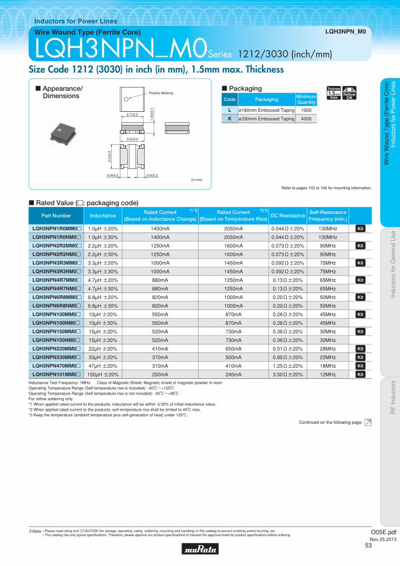
Code PackagingMinimumQuantity
L ø180mm Embossed Taping 1000
K ø330mm Embossed Taping 4000
1.5Thickness
mmmax.
ReflowOK
Indu
ctor
s fo
r P
ower
Lin
esIn
duct
ors
for
Gen
eral
Use
RF
Indu
ctor
sIn
duct
ors
for
Pow
er L
ines
Wire
Wou
nd T
ype
(Fer
rite
Cor
e)
Wire Wound Type (Ferrite Core) LQH3NPN_M0
Inductors for Power Lines
LQH3NPN_M0Series 1212/3030 (inch/mm)Size Code 1212 (3030) in inch (in mm), 1.5mm max. Thickness
c Rated Value (p: packaging code)
Refer to pages 102 to 106 for mounting information.
2.7±0.2
3.0±0.2
0.9±0.2 0.9±0.2(in mm)
3.0±
0.2
1.40
±0.
1
Polarity Marking
Continued on the following page.
c Appearance/Dimensions
c Packaging
Inductance Test Frequency: 1MHz Class of Magnetic Shield: Magnetic shield of magnetic powder in resinOperating Temperature Range (Self-temperature rise is included): -40℃~+125℃Operating Temperature Range (Self-temperature rise is not included): -40℃~+85℃For refl ow soldering only.*1 When applied rated current to the products, inductance will be within ±30% of initial inductance value.*2 When applied rated current to the products, self-temperature rise shall be limited to 40℃ max.*3 Keep the temperature (ambient temperature plus self-generation of heat) under 125℃.
Part Number Inductance*1*3Rated Current
(Based on Inductance Change)
*2*3Rated Current(Based on Temperature Rise)
DC ResistanceSelf-ResonanceFrequency (min.)
LQH3NPN1R0MM0p 1.0µH ±20% 1400mA 2050mA 0.044Ω±20% 130MHz LQH3NPN1R0NM0p 1.0µH ±30% 1400mA 2050mA 0.044Ω±20% 130MHz
LQH3NPN2R2MM0p 2.2µH ±20% 1250mA 1600mA 0.073Ω±20% 90MHz LQH3NPN2R2NM0p 2.2µH ±30% 1250mA 1600mA 0.073Ω±20% 90MHz
LQH3NPN3R3MM0p 3.3µH ±20% 1000mA 1450mA 0.092Ω±20% 75MHz LQH3NPN3R3NM0p 3.3µH ±30% 1000mA 1450mA 0.092Ω±20% 75MHz
LQH3NPN4R7MM0p 4.7µH ±20% 880mA 1250mA 0.13Ω±20% 65MHz LQH3NPN4R7NM0p 4.7µH ±30% 880mA 1250mA 0.13Ω±20% 65MHz
LQH3NPN6R8MM0p 6.8µH ±20% 820mA 1000mA 0.20Ω±20% 50MHz LQH3NPN6R8NM0p 6.8µH ±30% 820mA 1000mA 0.20Ω±20% 50MHz
LQH3NPN100MM0p 10µH ±20% 550mA 870mA 0.26Ω±20% 45MHz LQH3NPN100NM0p 10µH ±30% 550mA 870mA 0.26Ω±20% 45MHz
LQH3NPN150MM0p 15µH ±20% 520mA 730mA 0.36Ω±20% 30MHz LQH3NPN150NM0p 15µH ±30% 520mA 730mA 0.36Ω±20% 30MHz
LQH3NPN220MM0p 22µH ±20% 410mA 650mA 0.51Ω±20% 28MHz LQH3NPN330MM0p 33µH ±20% 370mA 500mA 0.85Ω±20% 22MHz LQH3NPN470MM0p 47µH ±20% 310mA 410mA 1.25Ω±20% 18MHz LQH3NPN101MM0p 100µH ±20% 200mA 240mA 3.50Ω±20% 12MHz
O05E.pdfNov.25,2013
53
!Note • Please read rating and !CAUTION (for storage, operating, rating, soldering, mounting and handling) in this catalog to prevent smoking and/or burning, etc.• This catalog has only typical specifi cations. Therefore, please approve our product specifi cations or transact the approval sheet for product specifi cations before ordering.

Indu
ctor
s fo
r P
ower
Lin
esIn
duct
ors
for
Gen
eral
Use
RF
Indu
ctor
sIn
duct
ors
for
Pow
er L
ines
Wire
Wou
nd T
ype
(Fer
rite
Cor
e)
LQH3NPN_M0
c Inductance-Frequency Characteristics (Typ.)
c Temperature Rise Characteristics (Typ.)
c Inductance-Current Characteristics (Typ.)
0.1 1 10 1000100
1000
100
10
1
0.1
Frequency (MHz)
L (μ
H)
100μH
47μH
33μH22μH
15μH10μH6.8μH
4.7μH3.3μH
2.2μH
1.0μH
Current (mA)
Tem
pera
ture
(°C
)
100
80
60
40
20
10
90
70
50
30
00 500 1000 1500 2000 2500
47μH33μH
22μH15μH
10μH 6.8μH4.7μH
3.3μH2.2μH
1.0μH
100μH
Current (mA)0.1 1 10 100 1000 10000
2.2μH3.3μH
4.7μH6.8μH
10μH22μH
33μH47μH
100μH
1.0μH
Indu
ctan
ce (
μH)
1000
100
10
1
0.1
O05E.pdfNov.25,2013
54
!Note • Please read rating and !CAUTION (for storage, operating, rating, soldering, mounting and handling) in this catalog to prevent smoking and/or burning, etc.• This catalog has only typical specifi cations. Therefore, please approve our product specifi cations or transact the approval sheet for product specifi cations before ordering.

Code PackagingMinimumQuantity
E ø180mm Embossed Taping 2000
F ø330mm Embossed Taping 8000
1.5Thickness
mmmax.
Low RdcReflow
OK
Part Number Inductance*1*3Rated Current
(Based on Inductance Change)
*2*3Rated Current(Based on Temperature Rise)
DC ResistanceSelf-ResonanceFrequency (min.)
LQH3NPN1R0MMRp 1.0µH ±20% 1600mA 2150mA 0.042Ω±20% 135MHz LQH3NPN2R2MMRp 2.2µH ±20% 1380mA 1750mA 0.068Ω±20% 75MHz LQH3NPN3R3MMRp 3.3µH ±20% 1200mA 1550mA 0.088Ω±20% 70MHz LQH3NPN4R7MMRp 4.7µH ±20% 950mA 1400mA 0.105Ω±20% 57MHz LQH3NPN6R8MMRp 6.8µH ±20% 830mA 1250mA 0.155Ω±20% 40MHz LQH3NPN100MMRp 10µH ±20% 590mA 1150mA 0.210Ω±20% 30MHz LQH3NPN220MMRp 22µH ±20% 430mA 750mA 0.480Ω±20% 20MHz LQH3NPN330MMRp 33µH ±20% 380mA 600mA 0.790Ω±20% 15MHz LQH3NPN470MMRp 47µH ±20% 320mA 460mA 1.140Ω±20% 10MHz
Indu
ctor
s fo
r P
ower
Lin
esIn
duct
ors
for
Gen
eral
Use
RF
Indu
ctor
sIn
duct
ors
for
Pow
er L
ines
Wire
Wou
nd T
ype
(Fer
rite
Cor
e)
Wire Wound Type (Ferrite Core) LQH3NPN_MR
Inductors for Power Lines
LQH3NPN_MRSeries 1212/3030 (inch/mm)Low DC Resistance Type
c Inductance-Frequency Characteristics (Typ.) c Inductance-Current Characteristics (Typ.)
c Rated Value (p: packaging code)
Refer to pages 102 to 106 for mounting information.
3.0±0.2
3.0±0.2
1.0±0.2 1.0±0.2 (in mm)
3.0±
0.2
1.40
±0.
1
Polarity Marking
Continued on the following page.
c Appearance/Dimensions
c Packaging
Inductance Test Frequency: 1MHz Class of Magnetic Shield: Magnetic shield of magnetic powder in resinOperating Temperature Range (Self-temperature rise is included): -40℃~+125℃Operating Temperature Range (Self-temperature rise is not included): -40℃~+85℃For refl ow soldering only.*1 When applied rated current to the products, inductance will be within ±30% of initial inductance value.*2 When applied rated current to the products, self-temperature rise shall be limited to 40℃ max.*3 Keep the temperature (ambient temperature plus self-generation of heat) under 125℃.
0.1 1 10 1000100
1000
100
10
1
0.1
Frequency (MHz)
L (μ
H)
47μH
6.8μH
33μH
4.7μH
22μH
3.3μH
10μH
2.2μH
1.0μH
Current (mA)0.1 1 10 100 1000 10000
4.7μH
2.2μH
3.3μH
1.0μHIndu
ctan
ce (
μH)
0.1
1
10
O05E.pdfNov.25,2013
55
!Note • Please read rating and !CAUTION (for storage, operating, rating, soldering, mounting and handling) in this catalog to prevent smoking and/or burning, etc.• This catalog has only typical specifi cations. Therefore, please approve our product specifi cations or transact the approval sheet for product specifi cations before ordering.

Indu
ctor
s fo
r P
ower
Lin
esIn
duct
ors
for
Gen
eral
Use
RF
Indu
ctor
sIn
duct
ors
for
Pow
er L
ines
Wire
Wou
nd T
ype
(Fer
rite
Cor
e)
LQH3NPN_MR
c Temperature Rise Characteristics (Typ.)
Current (mA)
Tem
pera
ture
(°C
)
50
40
30
20
10
5
45
35
25
15
00 500 1000 1500 2000 2500
47μH33μH 22μH
10μH
6.8μH
4.7μH3.3μH
2.2μH
1.0μH
O05E.pdfNov.25,2013
56
!Note • Please read rating and !CAUTION (for storage, operating, rating, soldering, mounting and handling) in this catalog to prevent smoking and/or burning, etc.• This catalog has only typical specifi cations. Therefore, please approve our product specifi cations or transact the approval sheet for product specifi cations before ordering.

Code PackagingMinimumQuantity
L ø180mm Embossed Taping 1000
K ø330mm Embossed Taping 5000
1.2Thickness
mmmax.
ReflowOK
Indu
ctor
s fo
r P
ower
Lin
esIn
duct
ors
for
Gen
eral
Use
RF
Indu
ctor
sIn
duct
ors
for
Pow
er L
ines
Wire
Wou
nd T
ype
(Fer
rite
Cor
e)
Wire Wound Type (Ferrite Core) LQH3NPN_J0
Inductors for Power Lines
LQH3NPN_ J0Series 1212/3030 (inch/mm)Size Code 1212 (3030) in inch (in mm), 1.2mm max. Thickness
c Rated Value (p: packaging code)
Refer to pages 102 to 106 for mounting information.
3.0±0.2
0.9±0.2 0.9±0.2(in mm)
3.0±
0.2
1.1±
0.1
3.0±0.2
Polarity Marking
Continued on the following page.
c Appearance/Dimensions
c Packaging
Inductance Test Frequency: 1MHz Class of Magnetic Shield: Magnetic shield of magnetic powder in resinOperating Temperature Range (Self-temperature rise is included): -40℃~+125℃Operating Temperature Range (Self-temperature rise is not included): -40℃~+85℃For refl ow soldering only.*1 When applied rated current to the products, inductance will be within ±30% of initial inductance value.*2 When applied rated current to the products, self-temperature rise shall be limited to 40℃ max.*3 Keep the temperature (ambient temperature plus self-generation of heat) under 125℃.
Part Number Inductance*1*3Rated Current
(Based on Inductance Change)
*2*3Rated Current(Based on Temperature Rise)
DC ResistanceSelf-ResonanceFrequency (min.)
LQH3NPN1R0NJ0p 1.0µH ±30% 1650mA 1620mA 0.040Ω±20% 140MHz LQH3NPN1R5NJ0p 1.5µH ±30% 1200mA 1500mA 0.055Ω±20% 90MHz LQH3NPN2R2MJ0p 2.2µH ±20% 1150mA 1460mA 0.069Ω±20% 90MHz LQH3NPN2R2NJ0p 2.2µH ±30% 1150mA 1460mA 0.069Ω±20% 90MHz
LQH3NPN3R3MJ0p 3.3µH ±20% 950mA 1270mA 0.105Ω±20% 70MHz LQH3NPN3R3NJ0p 3.3µH ±30% 950mA 1270mA 0.105Ω±20% 70MHz
LQH3NPN4R7MJ0p 4.7µH ±20% 780mA 1120mA 0.130Ω±20% 65MHz LQH3NPN4R7NJ0p 4.7µH ±30% 780mA 1120mA 0.130Ω±20% 65MHz
LQH3NPN6R8MJ0p 6.8µH ±20% 700mA 850mA 0.210Ω±20% 45MHz LQH3NPN6R8NJ0p 6.8µH ±30% 700mA 850mA 0.210Ω±20% 45MHz
LQH3NPN100MJ0p 10µH ±20% 560mA 710mA 0.300Ω±20% 35MHz LQH3NPN100NJ0p 10µH ±30% 560mA 710mA 0.300Ω±20% 35MHz
LQH3NPN150MJ0p 15µH ±20% 440mA 590mA 0.440Ω±20% 30MHz LQH3NPN150NJ0p 15µH ±30% 440mA 590mA 0.440Ω±20% 30MHz
LQH3NPN220MJ0p 22µH ±20% 350mA 510mA 0.600Ω±20% 25MHz LQH3NPN220NJ0p 22µH ±30% 350mA 510mA 0.600Ω±20% 25MHz
LQH3NPN330MJ0p 33µH ±20% 280mA 410mA 0.900Ω±20% 20MHz LQH3NPN330NJ0p 33µH ±30% 280mA 410mA 0.900Ω±20% 20MHz
LQH3NPN470MJ0p 47µH ±20% 200mA 350mA 1.30Ω±20% 15MHz LQH3NPN470NJ0p 47µH ±30% 200mA 350mA 1.30Ω±20% 15MHz
O05E.pdfNov.25,2013
57
!Note • Please read rating and !CAUTION (for storage, operating, rating, soldering, mounting and handling) in this catalog to prevent smoking and/or burning, etc.• This catalog has only typical specifi cations. Therefore, please approve our product specifi cations or transact the approval sheet for product specifi cations before ordering.
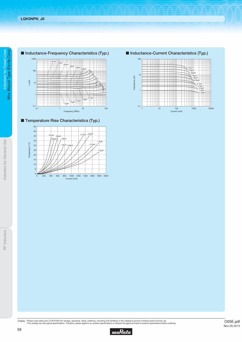
Indu
ctor
s fo
r P
ower
Lin
esIn
duct
ors
for
Gen
eral
Use
RF
Indu
ctor
sIn
duct
ors
for
Pow
er L
ines
Wire
Wou
nd T
ype
(Fer
rite
Cor
e)
LQH3NPN_J0
c Inductance-Frequency Characteristics (Typ.)
c Temperature Rise Characteristics (Typ.)
c Inductance-Current Characteristics (Typ.)
100
1000
10
1
0.1
47μH33μH
22μH15μH
10μH6.8μH
4.7μH3.3μH
2.2μH1.5μH
1.0μH
10.1 10 100
L (μ
H)
Frequency (MHz)
Current (mA)
Tem
pera
ture
(°C
)
50
40
30
20
10
5
45
35
25
15
00 400 800 1200 1600 2000200 600 1000 1400 1800
47μH
33μH22μH
15μH
10μH 6.8μH
4.7μH 3.3μH
2.2μH
1.5μH
1.0μH
Indu
ctan
ce (
μH)
Current (mA)
0.1
1
10
100
1 10 100 1000 10000
47μH33μH
22μH15μH10μH
6.8μH
4.7μH3.3μH
2.2μH1.5μH1.0μH
O05E.pdfNov.25,2013
58
!Note • Please read rating and !CAUTION (for storage, operating, rating, soldering, mounting and handling) in this catalog to prevent smoking and/or burning, etc.• This catalog has only typical specifi cations. Therefore, please approve our product specifi cations or transact the approval sheet for product specifi cations before ordering.

Code PackagingMinimumQuantity
L ø180mm Embossed Taping 1500
K ø330mm Embossed Taping 6000
1.0Thickness
mmmax.
ReflowOK
Part Number Inductance*1*3Rated Current
(Based on Inductance Change)
*2*3Rated Current(Based on Temperature Rise)
DC ResistanceSelf-ResonanceFrequency (min.)
LQH3NPN1R0NG0p 1.0µH ±30% 1650mA 1525mA 0.08Ω±20% 160MHz LQH3NPN1R5NG0p 1.5µH ±30% 1300mA 1470mA 0.10Ω±20% 130MHz LQH3NPN2R2NG0p 2.2µH ±30% 1250mA 1270mA 0.14Ω±20% 100MHz LQH3NPN3R3NG0p 3.3µH ±30% 850mA 1130mA 0.18Ω±20% 75MHz LQH3NPN4R7NG0p 4.7µH ±30% 800mA 925mA 0.26Ω±20% 60MHz LQH3NPN6R8NG0p 6.8µH ±30% 650mA 710mA 0.45Ω±20% 48MHz LQH3NPN100MG0p 10µH ±20% 500mA 630mA 0.57Ω±20% 45MHz LQH3NPN100NG0p 10µH ±30% 500mA 630mA 0.57Ω±20% 45MHz
LQH3NPN150NG0p 15µH ±30% 370mA 475mA 0.91Ω±20% 35MHz LQH3NPN220MG0p 22µH ±20% 340mA 430mA 1.1Ω±20% 25MHz LQH3NPN220NG0p 22µH ±30% 340mA 430mA 1.1Ω±20% 25MHz
LQH3NPN330MG0p 33µH ±20% 250mA 345mA 2.1Ω±20% 24MHz LQH3NPN330NG0p 33µH ±30% 250mA 345mA 2.1Ω±20% 24MHz
LQH3NPN470MG0p 47µH ±20% 170mA 270mA 3.0Ω±20% 19MHz LQH3NPN470NG0p 47µH ±30% 170mA 270mA 3.0Ω±20% 19MHz
LQH3NPN680MG0p 68µH ±20% 150mA 235mA 4.2Ω±20% 16MHz LQH3NPN680NG0p 68µH ±30% 150mA 235mA 4.2Ω±20% 16MHz
LQH3NPN101MG0p 100µH ±20% 140mA 165mA 8.0Ω±20% 10MHz LQH3NPN101NG0p 100µH ±30% 140mA 165mA 8.0Ω±20% 10MHz
LQH3NPN151MG0p 150µH ±20% 110mA 145mA 11.0Ω±20% 10MHz LQH3NPN151NG0p 150µH ±30% 110mA 145mA 11.0Ω±20% 10MHz
LQH3NPN221MG0p 220µH ±20% 100mA 130mA 14.0Ω±20% 8.5MHz LQH3NPN221NG0p 220µH ±30% 100mA 130mA 14.0Ω±20% 8.5MHz
LQH3NPN251MG0p 250µH ±20% 80mA 130mA 15.0Ω±20% 8.0MHz LQH3NPN251NG0p 250µH ±30% 80mA 130mA 15.0Ω±20% 8.0MHz
Indu
ctor
s fo
r P
ower
Lin
esIn
duct
ors
for
Gen
eral
Use
RF
Indu
ctor
sIn
duct
ors
for
Pow
er L
ines
Wire
Wou
nd T
ype
(Fer
rite
Cor
e)
Wire Wound Type (Ferrite Core) LQH3NPN_G0
Inductors for Power Lines
LQH3NPN_G0Series 1212/3030 (inch/mm)Size Code 1212 (3030) in inch (in mm), 1.0mm max. Thickness
c Rated Value (p: packaging code)
Refer to pages 102 to 106 for mounting information.
2.7±0.2
3.0±0.2
0.9±0.2 0.9±0.2
1.2±0.2 (in mm)
3.0±
0.2
0.90
±0.
1
Polarity Marking
Continued on the following page.
c Appearance/Dimensions
c Packaging
Inductance Test Frequency: 1MHz Class of Magnetic Shield: Magnetic shield of magnetic powder in resinOperating Temperature Range (Self-temperature rise is not included): -40℃~+85℃For refl ow soldering only.*1 When applied rated current to the products, inductance will be within ±30% of initial inductance value.*2 When applied rated current to the products, self-temperature rise shall be limited to 40℃ max.*3 Keep the temperature (ambient temperature plus self-generation of heat) under 125℃.
O05E.pdfNov.25,2013
59
!Note • Please read rating and !CAUTION (for storage, operating, rating, soldering, mounting and handling) in this catalog to prevent smoking and/or burning, etc.• This catalog has only typical specifi cations. Therefore, please approve our product specifi cations or transact the approval sheet for product specifi cations before ordering.

Indu
ctor
s fo
r P
ower
Lin
esIn
duct
ors
for
Gen
eral
Use
RF
Indu
ctor
sIn
duct
ors
for
Pow
er L
ines
Wire
Wou
nd T
ype
(Fer
rite
Cor
e)
LQH3NPN_G0
c Inductance-Frequency Characteristics (Typ.)
c Temperature Rise Characteristics (Typ.)
c Inductance-Current Characteristics (Typ.)
Frequency (MHz)0.001 0.01 0.1 1 10 100
250μH220μH
150μH
100μH
68μH47μH
33μH22μH
15μH10μH
6.8μH
4.7μH3.3μH
2.2μH1.5μH
1.0μH
L (μ
H)
10000
1000
100
10
1
Current (mA)
Tem
pera
ture
(°C
)
50
40
45
30
20
10
35
25
15
5
00 200 400 600 800 1000 1200 1400 1600 1800
250μH 220μH 150μH100μH
68μH47μH
33μH22μH
15μH10μH
6.8μH4.7μH
3.3μH2.2μH
1.5μH
1.0μH
Current (mA)0.1 1 10 100 1000 10000
250μH220μH150μH
100μH68μH47μH33μH
22μH15μH
10μH6.8μH4.7μH
3.3μH2.2μH1.5μH1.0μH
Indu
ctan
ce (
μH)
1000
100
10
1
0.1
O05E.pdfNov.25,2013
60
!Note • Please read rating and !CAUTION (for storage, operating, rating, soldering, mounting and handling) in this catalog to prevent smoking and/or burning, etc.• This catalog has only typical specifi cations. Therefore, please approve our product specifi cations or transact the approval sheet for product specifi cations before ordering.
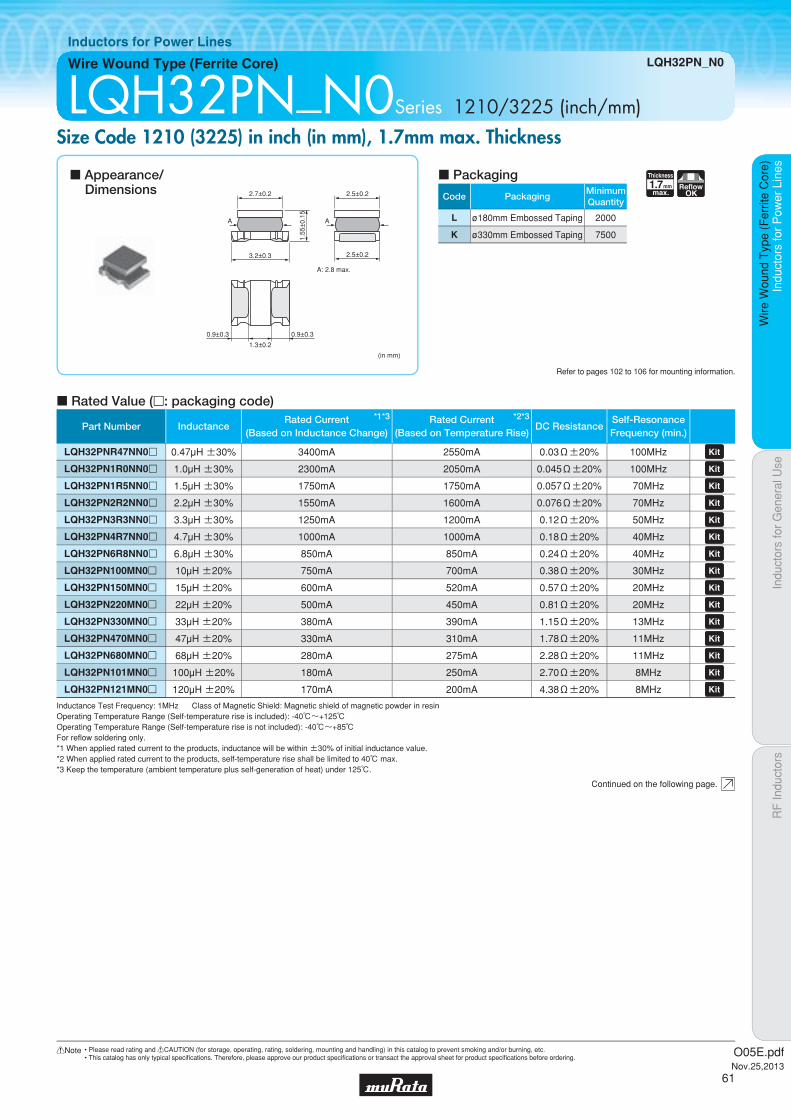
Code PackagingMinimumQuantity
L ø180mm Embossed Taping 2000
K ø330mm Embossed Taping 7500
1.7Thickness
mmmax.
ReflowOK
Indu
ctor
s fo
r P
ower
Lin
esIn
duct
ors
for
Gen
eral
Use
RF
Indu
ctor
sIn
duct
ors
for
Pow
er L
ines
Wire
Wou
nd T
ype
(Fer
rite
Cor
e)
Wire Wound Type (Ferrite Core) LQH32PN_N0
Inductors for Power Lines
LQH32PN_N0Series 1210/3225 (inch/mm)Size Code 1210 (3225) in inch (in mm), 1.7mm max. Thickness
c Rated Value (p: packaging code)
Refer to pages 102 to 106 for mounting information.
2.7±0.2
(in mm)
3.2±0.3
2.5±0.2
2.5±0.2
A: 2.8 max.
AA
1.3±0.2
0.9±0.30.9±0.3
1.55
±0.
15
Continued on the following page.
c Appearance/Dimensions
c Packaging
Inductance Test Frequency: 1MHz Class of Magnetic Shield: Magnetic shield of magnetic powder in resinOperating Temperature Range (Self-temperature rise is included): -40℃~+125℃Operating Temperature Range (Self-temperature rise is not included): -40℃~+85℃For refl ow soldering only.*1 When applied rated current to the products, inductance will be within ±30% of initial inductance value.*2 When applied rated current to the products, self-temperature rise shall be limited to 40℃ max.*3 Keep the temperature (ambient temperature plus self-generation of heat) under 125℃.
Part Number Inductance*1*3Rated Current
(Based on Inductance Change)
*2*3Rated Current(Based on Temperature Rise)
DC ResistanceSelf-ResonanceFrequency (min.)
LQH32PNR47NN0p 0.47µH ±30% 3400mA 2550mA 0.03Ω±20% 100MHz LQH32PN1R0NN0p 1.0µH ±30% 2300mA 2050mA 0.045Ω±20% 100MHz LQH32PN1R5NN0p 1.5µH ±30% 1750mA 1750mA 0.057Ω±20% 70MHz LQH32PN2R2NN0p 2.2µH ±30% 1550mA 1600mA 0.076Ω±20% 70MHz LQH32PN3R3NN0p 3.3µH ±30% 1250mA 1200mA 0.12Ω±20% 50MHz LQH32PN4R7NN0p 4.7µH ±30% 1000mA 1000mA 0.18Ω±20% 40MHz LQH32PN6R8NN0p 6.8µH ±30% 850mA 850mA 0.24Ω±20% 40MHz LQH32PN100MN0p 10µH ±20% 750mA 700mA 0.38Ω±20% 30MHz LQH32PN150MN0p 15µH ±20% 600mA 520mA 0.57Ω±20% 20MHz LQH32PN220MN0p 22µH ±20% 500mA 450mA 0.81Ω±20% 20MHz LQH32PN330MN0p 33µH ±20% 380mA 390mA 1.15Ω±20% 13MHz LQH32PN470MN0p 47µH ±20% 330mA 310mA 1.78Ω±20% 11MHz LQH32PN680MN0p 68µH ±20% 280mA 275mA 2.28Ω±20% 11MHz LQH32PN101MN0p 100µH ±20% 180mA 250mA 2.70Ω±20% 8MHz LQH32PN121MN0p 120µH ±20% 170mA 200mA 4.38Ω±20% 8MHz
O05E.pdfNov.25,2013
61
!Note • Please read rating and !CAUTION (for storage, operating, rating, soldering, mounting and handling) in this catalog to prevent smoking and/or burning, etc.• This catalog has only typical specifi cations. Therefore, please approve our product specifi cations or transact the approval sheet for product specifi cations before ordering.
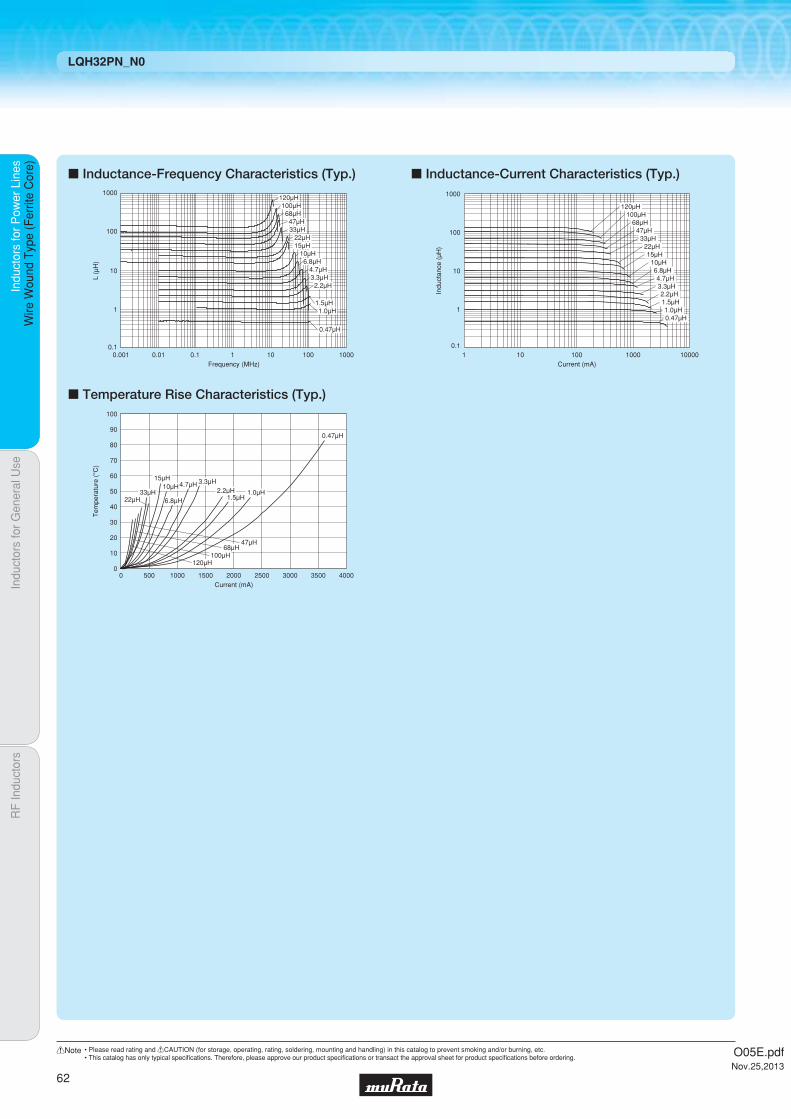
Indu
ctor
s fo
r P
ower
Lin
esIn
duct
ors
for
Gen
eral
Use
RF
Indu
ctor
sIn
duct
ors
for
Pow
er L
ines
Wire
Wou
nd T
ype
(Fer
rite
Cor
e)
LQH32PN_N0
c Inductance-Frequency Characteristics (Typ.)
c Temperature Rise Characteristics (Typ.)
c Inductance-Current Characteristics (Typ.)
100
1000
10
1
0.1
120μH100μH68μH47μH33μH
22μH15μH
10μH6.8μH
4.7μH3.3μH2.2μH
1.5μH1.0μH
0.47μH
0.10.001 1010.01 100 1000
L (μ
H)
Frequency (MHz)
Current (mA)
Tem
pera
ture
(°C
)
100
80
60
40
20
10
90
70
50
30
00 4000500 1000 1500 2000 2500 3000 3500
120μH100μH
68μH47μH
22μH33μH
15μH10μH
6.8μH
4.7μH 3.3μH2.2μH
1.5μH1.0μH
0.47μH
1 10 100 100001000
1000
100
10
1
0.1
Current (mA)
Indu
ctan
ce (
μH)
120μH100μH
68μH47μH
33μH22μH15μH
10μH6.8μH4.7μH3.3μH2.2μH1.5μH1.0μH0.47μH
O05E.pdfNov.25,2013
62
!Note • Please read rating and !CAUTION (for storage, operating, rating, soldering, mounting and handling) in this catalog to prevent smoking and/or burning, etc.• This catalog has only typical specifi cations. Therefore, please approve our product specifi cations or transact the approval sheet for product specifi cations before ordering.

Code PackagingMinimumQuantity
L ø180mm Embossed Taping 2000
K ø330mm Embossed Taping 7500
1.7Thickness
mmmax.
BiasReflow
OK
Part Number Inductance*1*3Rated Current
(Based on Inductance Change)
*2*3Rated Current(Based on Temperature Rise)
DC ResistanceSelf-ResonanceFrequency (min.)
LQH32PNR47NNCp 0.47µH ±30% 4400mA 2900mA 0.024Ω±20% 100MHz LQH32PN1R0NNCp 1.0µH ±30% 3000mA 2500mA 0.036Ω±20% 100MHz LQH32PN1R5NNCp 1.5µH ±30% 2600mA 2100mA 0.053Ω±20% 70MHz LQH32PN2R2NNCp 2.2µH ±30% 2000mA 1850mA 0.064Ω±20% 70MHz LQH32PN3R3NNCp 3.3µH ±30% 1900mA 1550mA 0.100Ω±20% 50MHz LQH32PN4R7NNCp 4.7µH ±30% 1600mA 1200mA 0.155Ω±20% 40MHz LQH32PN6R8NNCp 6.8µH ±30% 1300mA 1100mA 0.220Ω±20% 40MHz LQH32PN100MNCp 10µH ±20% 1000mA 900mA 0.295Ω±20% 30MHz LQH32PN150MNCp 15µH ±20% 800mA 700mA 0.475Ω±20% 20MHz LQH32PN220MNCp 22µH ±20% 650mA 550mA 0.685Ω±20% 20MHz
Indu
ctor
s fo
r P
ower
Lin
esIn
duct
ors
for
Gen
eral
Use
RF
Indu
ctor
sIn
duct
ors
for
Pow
er L
ines
Wire
Wou
nd T
ype
(Fer
rite
Cor
e)
Wire Wound Type (Ferrite Core) LQH32PN_NC
Inductors for Power Lines
LQH32PN_NCSeries 1210/3225 (inch/mm)Bias Current Characteristics Improved
c Inductance-Frequency Characteristics (Typ.) c Inductance-Current Characteristics (Typ.)
c Rated Value (p: packaging code)
Refer to pages 102 to 106 for mounting information.
2.7±0.2
(in mm)
3.2±0.3
2.5±0.2
2.5±0.2
1.3±0.2
0.9±0.30.9±0.3
1.55
±0.
15
Continued on the following page.
c Appearance/Dimensions
c Packaging
Inductance Test Frequency: 1MHz Class of Magnetic Shield: Magnetic shield of magnetic powder in resinOperating Temperature Range (Self-temperature rise is included): -40℃~+125℃Operating Temperature Range (Self-temperature rise is not included): -40℃~+85℃For refl ow soldering only.*1 When applied rated current to the products, inductance will be within ±30% of initial inductance value.*2 When applied rated current to the products, self-temperature rise shall be limited to 40℃ max.*3 Keep the temperature (ambient temperature plus self-generation of heat) under 125℃.
L (μ
H)
Frequency (MHz)
0.1
1
10
100
1 10010 1000
10μH
15μH22μH
6.8μH
4.7μH
3.3μH
2.2μH
1.5μH
1.0μH
0.47μH
0.1
10
1
100
0.1 1 1000 1000010010Current (mA)
Indu
ctan
ce (
μH) 10μH
15μH
22μH
6.8μH
4.7μH3.3μH2.2μH
1.5μH
1.0μH
0.47μH
O05E.pdfNov.25,2013
63
!Note • Please read rating and !CAUTION (for storage, operating, rating, soldering, mounting and handling) in this catalog to prevent smoking and/or burning, etc.• This catalog has only typical specifi cations. Therefore, please approve our product specifi cations or transact the approval sheet for product specifi cations before ordering.

Indu
ctor
s fo
r P
ower
Lin
esIn
duct
ors
for
Gen
eral
Use
RF
Indu
ctor
sIn
duct
ors
for
Pow
er L
ines
Wire
Wou
nd T
ype
(Fer
rite
Cor
e)
LQH32PN_NC
c Temperature Rise Characteristics (Typ.)
Current (mA)
Tem
pera
ture
(°C
)
100
80
60
40
20
90
70
50
30
10
00 500 1000 1500 2000 5000450040003000 35002500
22μH
15μH
10μH
6.8μH
4.7μH
3.3μH
2.2μH
1.5μH
1.0μH
0.47μH
O05E.pdfNov.25,2013
64
!Note • Please read rating and !CAUTION (for storage, operating, rating, soldering, mounting and handling) in this catalog to prevent smoking and/or burning, etc.• This catalog has only typical specifi cations. Therefore, please approve our product specifi cations or transact the approval sheet for product specifi cations before ordering.
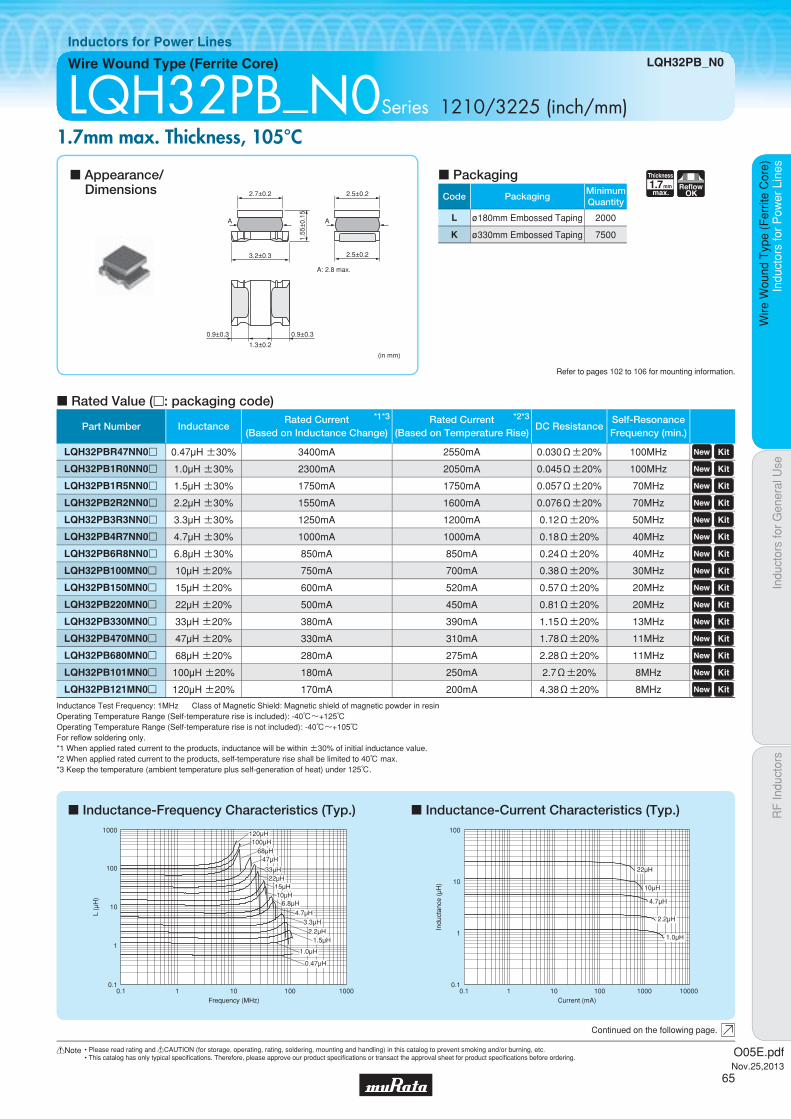
Code PackagingMinimumQuantity
L ø180mm Embossed Taping 2000
K ø330mm Embossed Taping 7500
1.7Thickness
mmmax.
ReflowOK
Indu
ctor
s fo
r P
ower
Lin
esIn
duct
ors
for
Gen
eral
Use
RF
Indu
ctor
sIn
duct
ors
for
Pow
er L
ines
Wire
Wou
nd T
ype
(Fer
rite
Cor
e)
Wire Wound Type (Ferrite Core) LQH32PB_N0
Inductors for Power Lines
LQH32PB_N0Series 1210/3225 (inch/mm)1.7mm max. Thickness, 105°C
c Inductance-Frequency Characteristics (Typ.) c Inductance-Current Characteristics (Typ.)
c Rated Value (p: packaging code)
Refer to pages 102 to 106 for mounting information.
2.7±0.2
(in mm)
3.2±0.3
2.5±0.2
2.5±0.2
A: 2.8 max.
AA
1.3±0.2
0.9±0.30.9±0.3
1.55
±0.
15
Continued on the following page.
c Appearance/Dimensions
c Packaging
Inductance Test Frequency: 1MHz Class of Magnetic Shield: Magnetic shield of magnetic powder in resinOperating Temperature Range (Self-temperature rise is included): -40℃~+125℃Operating Temperature Range (Self-temperature rise is not included): -40℃~+105℃For refl ow soldering only.*1 When applied rated current to the products, inductance will be within ±30% of initial inductance value.*2 When applied rated current to the products, self-temperature rise shall be limited to 40℃ max.*3 Keep the temperature (ambient temperature plus self-generation of heat) under 125℃.
0.1
1
10
100
1000
0.1 1 10 100 1000Frequency (MHz)
L (μ
H)
120μH
68μH
6.8μH
100μH
47μH
33μH22μH
15μH10μH
4.7μH3.3μH
2.2μH1.5μH
1.0μH
0.47μH
0.1
10
1
100
0.1 1 1000 1000010010Current (mA)
Indu
ctan
ce (
μH)
1.0μH
22μH
10μH
2.2μH
4.7μH
Part Number Inductance*1*3Rated Current
(Based on Inductance Change)
*2*3Rated Current(Based on Temperature Rise)
DC ResistanceSelf-ResonanceFrequency (min.)
LQH32PBR47NN0p 0.47µH ±30% 3400mA 2550mA 0.030Ω±20% 100MHz LQH32PB1R0NN0p 1.0µH ±30% 2300mA 2050mA 0.045Ω±20% 100MHz LQH32PB1R5NN0p 1.5µH ±30% 1750mA 1750mA 0.057Ω±20% 70MHz LQH32PB2R2NN0p 2.2µH ±30% 1550mA 1600mA 0.076Ω±20% 70MHz LQH32PB3R3NN0p 3.3µH ±30% 1250mA 1200mA 0.12Ω±20% 50MHz LQH32PB4R7NN0p 4.7µH ±30% 1000mA 1000mA 0.18Ω±20% 40MHz LQH32PB6R8NN0p 6.8µH ±30% 850mA 850mA 0.24Ω±20% 40MHz LQH32PB100MN0p 10µH ±20% 750mA 700mA 0.38Ω±20% 30MHz LQH32PB150MN0p 15µH ±20% 600mA 520mA 0.57Ω±20% 20MHz LQH32PB220MN0p 22µH ±20% 500mA 450mA 0.81Ω±20% 20MHz LQH32PB330MN0p 33µH ±20% 380mA 390mA 1.15Ω±20% 13MHz LQH32PB470MN0p 47µH ±20% 330mA 310mA 1.78Ω±20% 11MHz LQH32PB680MN0p 68µH ±20% 280mA 275mA 2.28Ω±20% 11MHz LQH32PB101MN0p 100µH ±20% 180mA 250mA 2.7Ω±20% 8MHz LQH32PB121MN0p 120µH ±20% 170mA 200mA 4.38Ω±20% 8MHz
O05E.pdfNov.25,2013
65
!Note • Please read rating and !CAUTION (for storage, operating, rating, soldering, mounting and handling) in this catalog to prevent smoking and/or burning, etc.• This catalog has only typical specifi cations. Therefore, please approve our product specifi cations or transact the approval sheet for product specifi cations before ordering.
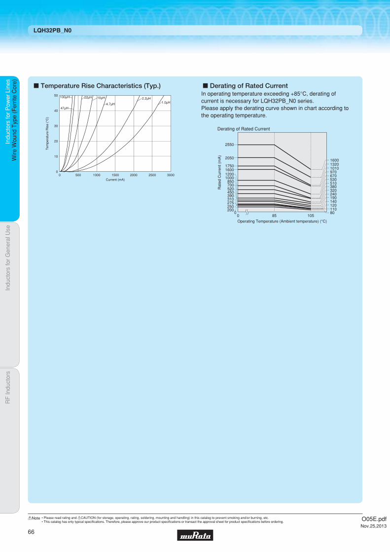
Indu
ctor
s fo
r P
ower
Lin
esIn
duct
ors
for
Gen
eral
Use
RF
Indu
ctor
sIn
duct
ors
for
Pow
er L
ines
Wire
Wou
nd T
ype
(Fer
rite
Cor
e)
LQH32PB_N0
c Temperature Rise Characteristics (Typ.) c Derating of Rated Current
Current (mA)
Tem
pera
ture
Ris
e (°
C)
50
40
30
20
10
00 1000 2000500 1500 2500 3000
100μH
47μH
22μH
4.7μH
2.2μH1.0μH
10μHIn operating temperature exceeding +85°C, derating of current is necessary for LQH32PB_N0 series.Please apply the derating curve shown in chart according to the operating temperature.
Derating of Rated Current
Rat
ed C
urre
nt (
mA
)
2550
2050
17501600
80110200
0
120140190240320380510530670970101013201600
250275310390450520700850
10001200
Operating Temperature (Ambient temperature) (°C)105850
O05E.pdfNov.25,2013
66
!Note • Please read rating and !CAUTION (for storage, operating, rating, soldering, mounting and handling) in this catalog to prevent smoking and/or burning, etc.• This catalog has only typical specifi cations. Therefore, please approve our product specifi cations or transact the approval sheet for product specifi cations before ordering.
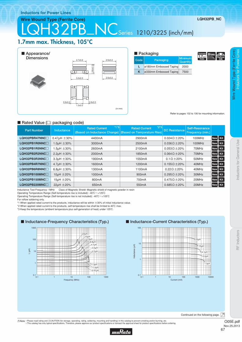
Code PackagingMinimumQuantity
L ø180mm Embossed Taping 2000
K ø330mm Embossed Taping 7500
1.7Thickness
mmmax.
BiasReflow
OK
Part Number Inductance*1*3Rated Current
(Based on Inductance Change)
*2*3Rated Current(Based on Temperature Rise)
DC ResistanceSelf-ResonanceFrequency (min.)
LQH32PBR47NNCp 0.47µH ±30% 4400mA 2900mA 0.024Ω±20% 100MHz LQH32PB1R0NNCp 1.0µH ±30% 3000mA 2500mA 0.036Ω±20% 100MHz LQH32PB1R5NNCp 1.5µH ±30% 2600mA 2100mA 0.053Ω±20% 70MHz LQH32PB2R2NNCp 2.2µH ±30% 2000mA 1850mA 0.064Ω±20% 70MHz LQH32PB3R3NNCp 3.3µH ±30% 1900mA 1550mA 0.1Ω±20% 50MHz LQH32PB4R7NNCp 4.7µH ±30% 1600mA 1200mA 0.155Ω±20% 40MHz LQH32PB6R8NNCp 6.8µH ±30% 1300mA 1100mA 0.22Ω±20% 40MHz LQH32PB100MNCp 10µH ±20% 1000mA 900mA 0.295Ω±20% 30MHz LQH32PB150MNCp 15µH ±20% 800mA 700mA 0.475Ω±20% 20MHz LQH32PB220MNCp 22µH ±20% 650mA 550mA 0.685Ω±20% 20MHz
Indu
ctor
s fo
r P
ower
Lin
esIn
duct
ors
for
Gen
eral
Use
RF
Indu
ctor
sIn
duct
ors
for
Pow
er L
ines
Wire
Wou
nd T
ype
(Fer
rite
Cor
e)
Wire Wound Type (Ferrite Core) LQH32PB_NC
Inductors for Power Lines
LQH32PB_NCSeries 1210/3225 (inch/mm)1.7mm max. Thickness, 105°C
c Inductance-Frequency Characteristics (Typ.) c Inductance-Current Characteristics (Typ.)
c Rated Value (p: packaging code)
Refer to pages 102 to 106 for mounting information.
2.7±0.2
(in mm)
3.2±0.3
2.5±0.2
2.5±0.2
1.3±0.2
0.9±0.30.9±0.3
1.55
±0.
15
Continued on the following page.
c Appearance/Dimensions
c Packaging
Inductance Test Frequency: 1MHz Class of Magnetic Shield: Magnetic shield of magnetic powder in resinOperating Temperature Range (Self-temperature rise is included): -40℃~+125℃Operating Temperature Range (Self-temperature rise is not included): -40℃~+105℃For refl ow soldering only.*1 When applied rated current to the products, inductance will be within ±30% of initial inductance value.*2 When applied rated current to the products, self-temperature rise shall be limited to 40℃ max.*3 Keep the temperature (ambient temperature plus self-generation of heat) under 125℃.
0.1
1
10
100
1000
0.1 1 10 100 1000Frequency (MHz)
L (μ
H)
6.8μH
22μH15μH
10μH
4.7μH
3.3μH
2.2μH
1.5μH
1.0μH
0.47μH
0.1
10
1
100
0.1 1 1000 1000010010Current (mA)
Indu
ctan
ce (
μH)
1.0μH
22μH
10μH
2.2μH
4.7μH
O05E.pdfNov.25,2013
67
!Note • Please read rating and !CAUTION (for storage, operating, rating, soldering, mounting and handling) in this catalog to prevent smoking and/or burning, etc.• This catalog has only typical specifi cations. Therefore, please approve our product specifi cations or transact the approval sheet for product specifi cations before ordering.

Indu
ctor
s fo
r P
ower
Lin
esIn
duct
ors
for
Gen
eral
Use
RF
Indu
ctor
sIn
duct
ors
for
Pow
er L
ines
Wire
Wou
nd T
ype
(Fer
rite
Cor
e)
LQH32PB_NC
c Temperature Rise Characteristics (Typ.) c Derating of Rated Current
Current (mA)
Tem
pera
ture
Ris
e (°
C)
50
40
30
20
10
00 1000 2000 3000 4000
22μH 10μH 4.7μH 2.2μH 1.0μH
In operating temperature exceeding +85°C, derating of current is necessary for LQH32PB_NC series.Please apply the derating curve shown in chart according to the operating temperature.
Derating of Rated Current
Rat
ed C
urre
nt (
mA
)
2900
270
1110
550700900
11001200
1550
18502100
2500
0
450550
330
Operating Temperature (Ambient temperature) (°C)105850
910800610
13801490
O05E.pdfNov.25,2013
68
!Note • Please read rating and !CAUTION (for storage, operating, rating, soldering, mounting and handling) in this catalog to prevent smoking and/or burning, etc.• This catalog has only typical specifi cations. Therefore, please approve our product specifi cations or transact the approval sheet for product specifi cations before ordering.

Code PackagingMinimumQuantity
L ø180mm Embossed Taping 500
K ø330mm Embossed Taping 2500
2.8Thickness
mmmax.
ReflowOK FlowOK
Indu
ctor
s fo
r P
ower
Lin
esIn
duct
ors
for
Gen
eral
Use
RF
Indu
ctor
sIn
duct
ors
for
Pow
er L
ines
Wire
Wou
nd T
ype
(Fer
rite
Cor
e)
Wire Wound Type (Ferrite Core) LQH43PN_26
Inductors for Power Lines
LQH43PN_26Series 1812/4532 (inch/mm)Size Code 1812 (4532) in inch (in mm), 2.8mm max. Thickness
c Inductance-Frequency Characteristics (Typ.) c Inductance-Current Characteristics (Typ.)
c Rated Value (p: packaging code)
Refer to pages 102 to 106 for mounting information.
3.6±0.2
4.5±0.3
2.6±
0.2
3.2±0.2
3.2±0.2
1.0min. 1.0min. 1.0min.(in mm)
Continued on the following page.
c Appearance/Dimensions
c Packaging
Inductance Test Frequency: 1MHz Class of Magnetic Shield: Magnetic shield of magnetic powder in resinOperating Temperature Range (Self-temperature rise is not included): -40℃~+85℃*1 When applied rated current to the products, inductance will be within ±30% of initial inductance value.*2 When applied rated current to the products, self-temperature rise shall be limited to 40℃ max.*3 Keep the temperature (ambient temperature plus self-generation of heat) under 125℃.
Frequency (MHz)
L (μ
H)
0.1
1
10
100
1000
0.1 1 10 100 1000
220μH 150μH
100μH
47μH22μH
10μH 8.2μH4.7μH
3.3μH
2.2μH
6.8μH
1.0μH
Indu
ctan
ce (
μH)
0.1
1
10
100
1000
0.1 1 10 100 1000 10000Current (mA)
1.0μH
2.2μH
4.7μH
22μH
100μH
10μH
47μH
220μH
Part Number Inductance*1*3Rated Current
(Based on Inductance Change)
*2*3Rated Current(Based on Temperature Rise)
DC ResistanceSelf-ResonanceFrequency (min.)
LQH43PN1R0N26p 1.0µH ±30% 3400mA 3300mA 0.026Ω±20% 100MHz LQH43PN2R2M26p 2.2µH ±20% 2300mA 2500mA 0.042Ω±20% 45MHz LQH43PN3R3M26p 3.3µH ±20% 1800mA 2100mA 0.052Ω±20% 40MHz LQH43PN4R7M26p 4.7µH ±20% 1400mA 1600mA 0.075Ω±20% 35MHz LQH43PN6R8M26p 6.8µH ±20% 1200mA 1400mA 0.098Ω±20% 30MHz LQH43PN8R2M26p 8.2µH ±20% 1100mA 1300mA 0.128Ω±20% 25MHz LQH43PN100M26p 10µH ±20% 1050mA 1170mA 0.147Ω±20% 20MHz LQH43PN220M26p 22µH ±20% 700mA 780mA 0.327Ω±20% 15MHz LQH43PN470M26p 47µH ±20% 470mA 520mA 0.718Ω±20% 8MHz LQH43PN101M26p 100µH ±20% 320mA 320mA 1.538Ω±20% 4MHz LQH43PN151M26p 150µH ±20% 280mA 260mA 2.362Ω±20% 3MHz LQH43PN221M26p 220µH ±20% 220mA 240mA 2.900Ω±20% 2MHz
O05E.pdfNov.25,2013
69
!Note • Please read rating and !CAUTION (for storage, operating, rating, soldering, mounting and handling) in this catalog to prevent smoking and/or burning, etc.• This catalog has only typical specifi cations. Therefore, please approve our product specifi cations or transact the approval sheet for product specifi cations before ordering.
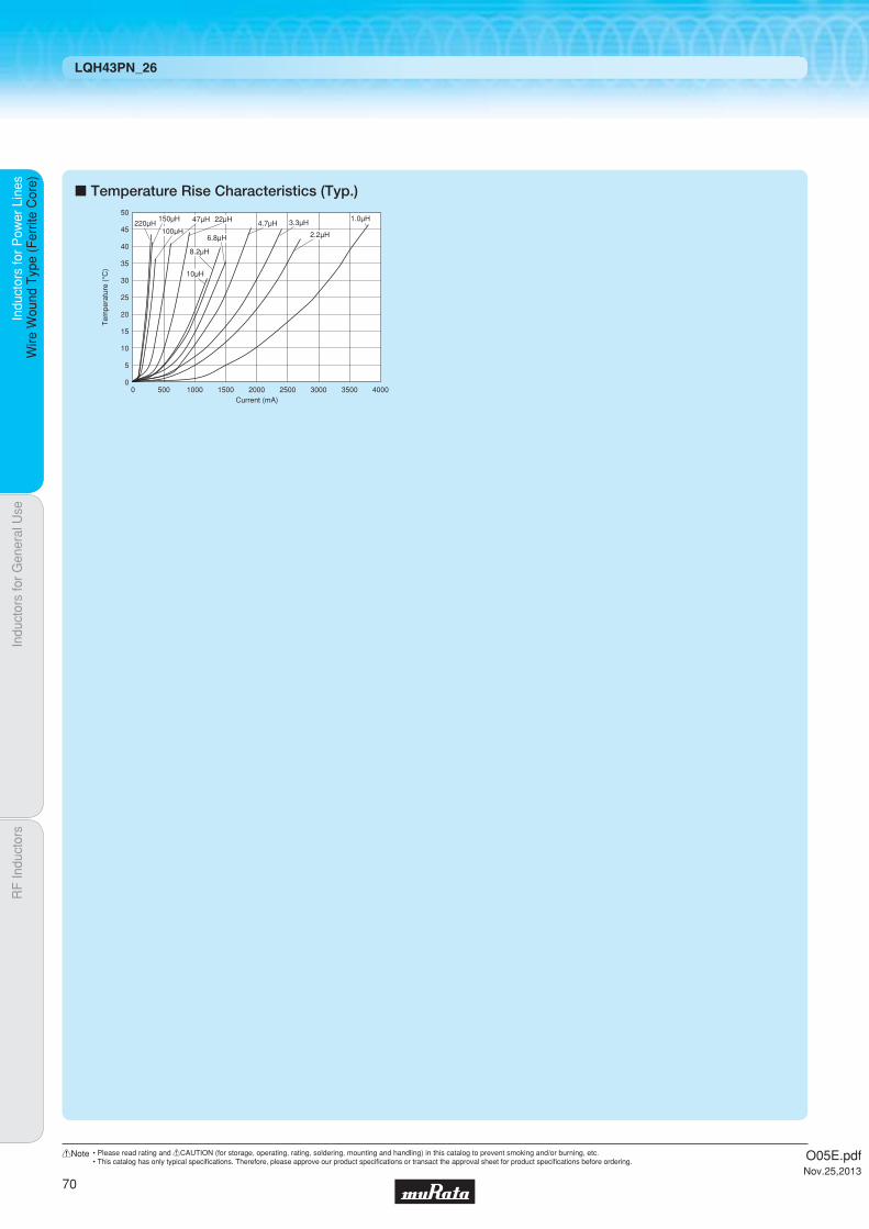
Indu
ctor
s fo
r P
ower
Lin
esIn
duct
ors
for
Gen
eral
Use
RF
Indu
ctor
sIn
duct
ors
for
Pow
er L
ines
Wire
Wou
nd T
ype
(Fer
rite
Cor
e)
LQH43PN_26
c Temperature Rise Characteristics (Typ.)
Current (mA)
Tem
pera
ture
(°C
)
50
40
30
20
10
45
35
25
15
5
00 1000 2000 3000 3500 4000500 1500 2500
220μH150μH
100μH
47μH 22μH
10μH
8.2μH
4.7μH 3.3μH
2.2μH6.8μH
1.0μH
O05E.pdfNov.25,2013
70
!Note • Please read rating and !CAUTION (for storage, operating, rating, soldering, mounting and handling) in this catalog to prevent smoking and/or burning, etc.• This catalog has only typical specifi cations. Therefore, please approve our product specifi cations or transact the approval sheet for product specifi cations before ordering.

Code PackagingMinimumQuantity
L ø180mm Embossed Taping 500
K ø330mm Embossed Taping 2500
2.8Thickness
mmmax.
ReflowOK
Part Number Inductance*1*3Rated Current
(Based on Inductance Change)
*2*3Rated Current(Based on Temperature Rise)
DC ResistanceSelf-ResonanceFrequency (min.)
LQH43PB1R0N26p 1.0µH ±30% 3400mA 3300mA 0.026Ω±20% 100MHz LQH43PB2R2M26p 2.2µH ±20% 2300mA 2500mA 0.042Ω±20% 45MHz LQH43PB3R3M26p 3.3µH ±20% 1800mA 2100mA 0.052Ω±20% 40MHz LQH43PB4R7M26p 4.7µH ±20% 1400mA 1600mA 0.075Ω±20% 35MHz LQH43PB6R8M26p 6.8µH ±20% 1200mA 1400mA 0.098Ω±20% 30MHz LQH43PB8R2M26p 8.2µH ±20% 1100mA 1300mA 0.128Ω±20% 25MHz LQH43PB100M26p 10µH ±20% 1050mA 1170mA 0.147Ω±20% 20MHz LQH43PB220M26p 22µH ±20% 700mA 780mA 0.327Ω±20% 15MHz LQH43PB470M26p 47µH ±20% 470mA 520mA 0.718Ω±20% 8MHz LQH43PB101M26p 100µH ±20% 320mA 320mA 1.538Ω±20% 4MHz LQH43PB151M26p 150µH ±20% 280mA 260mA 2.362Ω±20% 3MHz LQH43PB221M26p 220µH ±20% 220mA 240mA 2.900Ω±20% 2MHz
Indu
ctor
s fo
r P
ower
Lin
esIn
duct
ors
for
Gen
eral
Use
RF
Indu
ctor
sIn
duct
ors
for
Pow
er L
ines
Wire
Wou
nd T
ype
(Fer
rite
Cor
e)
Wire Wound Type (Ferrite Core) LQH43PB_26
Inductors for Power Lines
LQH43PB_26Series 1812/4532 (inch/mm)For Automotive Use *Expect for the portion asked for high reliability ex. power train
c Inductance-Frequency Characteristics (Typ.) c Inductance-Current Characteristics (Typ.)
c Rated Value (p: packaging code)
Refer to pages 102 to 106 for mounting information.
3.6±0.2
4.5±0.3
2.6±
0.2
3.2±0.2
3.2±0.2
1.0min. 1.0min.(in mm)
Continued on the following page.
c Appearance/Dimensions
c Packaging
Inductance Test Frequency: 1MHz Class of Magnetic Shield: Magnetic shield of magnetic powder in resinOperating Temperature Range (Self-temperature rise is included): -40℃~+125℃Operating Temperature Range (Self-temperature rise is not included): -40℃~+105℃For refl ow soldering only.*1 When applied rated current to the products, inductance will be within ±30% of initial inductance value.*2 When applied rated current to the products, self-temperature rise shall be limited to 40℃ max.*3 Keep the temperature (ambient temperature plus self-generation of heat) under 125℃.
0.1
1
10
100
1000
0.1 1 10 100 1000Frequency (MHz)
L (μ
H)
220μH150μH100μH
47μH22μH
10μH 8.2μH
6.8μH4.7μH
3.3μH
2.2μH
1.0μH
0.1
1
10
100
1000
0.1 1 10 100 1000 10000Current (mA)
Indu
ctan
ce (
μH)
220μH
150μH
100μH
47μH
22μH 10μH8.2μH
4.7μH
3.3μH
2.2μH
6.8μH
1.0μH
O05E.pdfNov.25,2013
71
!Note • Please read rating and !CAUTION (for storage, operating, rating, soldering, mounting and handling) in this catalog to prevent smoking and/or burning, etc.• This catalog has only typical specifi cations. Therefore, please approve our product specifi cations or transact the approval sheet for product specifi cations before ordering.

Indu
ctor
s fo
r P
ower
Lin
esIn
duct
ors
for
Gen
eral
Use
RF
Indu
ctor
sIn
duct
ors
for
Pow
er L
ines
Wire
Wou
nd T
ype
(Fer
rite
Cor
e)
LQH43PB_26
c Temperature Rise Characteristics (Typ.) c Derating of Rated Current
Current (mA)
Tem
pera
ture
(°C
)
50
40
30
20
10
45
35
25
15
5
00 1000 2000 3000 3500500 1500 2500
220μH
150μH
100μH
47μH
22μH
10μH
8.2μH
4.7μH
3.3μH
2.2μH6.8μH
1.0μH
In operating temperature exceeding +85°C, derating of current is necessary for LQH43PB series.Please apply the derating curve shown in chart according to the operating temperature.
Derating of Rated Current
Rat
ed C
urre
nt (
mA
)
130140180
0
280400
67076078010001120
1410
620
Operating Temperature (Ambient temperature) (°C)105850
11701300
1600
2500
3300
2100
1400
240260
520780
0
320
O05E.pdfNov.25,2013
72
!Note • Please read rating and !CAUTION (for storage, operating, rating, soldering, mounting and handling) in this catalog to prevent smoking and/or burning, etc.• This catalog has only typical specifi cations. Therefore, please approve our product specifi cations or transact the approval sheet for product specifi cations before ordering.

Code PackagingMinimumQuantity
L ø180mm Embossed Taping 1000
K ø330mm Embossed Taping 3500
1.8Thickness
mmmax.
ReflowOK
Part Number Inductance*1*3Rated Current
(Based on Inductance Change)
*2*3Rated Current(Based on Temperature Rise)
DC ResistanceSelf-ResonanceFrequency (min.)
LQH44PN1R0NP0p 1.0µH ±30% 2950mA 2450mA 0.030Ω±20% 90MHz LQH44PN2R2MP0p 2.2µH ±20% 2500mA 1800mA 0.049Ω±20% 70MHz LQH44PN3R3MP0p 3.3µH ±20% 2100mA 1770mA 0.065Ω±20% 50MHz LQH44PN4R7MP0p 4.7µH ±20% 1700mA 1700mA 0.080Ω±20% 40MHz LQH44PN6R8MP0p 6.8µH ±20% 1400mA 1340mA 0.12Ω±20% 35MHz LQH44PN100MP0p 10µH ±20% 1150mA 1170mA 0.16Ω±20% 25MHz LQH44PN220MP0p 22µH ±20% 800mA 790mA 0.37Ω±20% 17MHz
Indu
ctor
s fo
r P
ower
Lin
esIn
duct
ors
for
Gen
eral
Use
RF
Indu
ctor
sIn
duct
ors
for
Pow
er L
ines
Wire
Wou
nd T
ype
(Fer
rite
Cor
e)
Wire Wound Type (Ferrite Core) LQH44PN_P0
Inductors for Power Lines
LQH44PN_P0Series 1515/4040 (inch/mm)Size Code 1515 (4040) in inch (in mm), 1.8mm max. Thickness
c Inductance-Frequency Characteristics (Typ.) c Inductance-Current Characteristics (Typ.)
c Rated Value (p: packaging code)
Refer to pages 102 to 106 for mounting information.
1.65
±0.
15
4.0±0.2
1.2±0.2 1.2±0.2
4.0±
0.2
(in mm)
Continued on the following page.
c Appearance/Dimensions
c Packaging
Inductance Test Frequency: 1MHz Class of Magnetic Shield: Magnetic shield of magnetic powder in resinOperating Temperature Range (Self-temperature rise is included): -40℃~+125℃Operating Temperature Range (Self-temperature rise is not included): -40℃~+85℃For refl ow soldering only.*1 When applied rated current to the products, inductance will be within ±30% of initial inductance value.*2 When applied rated current to the products, self-temperature rise shall be limited to 40℃ max.*3 Keep the temperature (ambient temperature plus self-generation of heat) under 125℃.
L (μ
H)
Frequency (MHz)
0.1
1
10
100
0.01 0.1 1 10 100
22μH
10μH
6.8μH
4.7μH
3.3μH
2.2μH
1.0μH
Indu
ctan
ce (
μH)
Current (mA)
0.1
1
10
100
1 10 100 1000 10000
22μH
10μH6.8μH
4.7μH3.3μH
2.2μH
1.0μH
O05E.pdfNov.25,2013
73
!Note • Please read rating and !CAUTION (for storage, operating, rating, soldering, mounting and handling) in this catalog to prevent smoking and/or burning, etc.• This catalog has only typical specifi cations. Therefore, please approve our product specifi cations or transact the approval sheet for product specifi cations before ordering.

Indu
ctor
s fo
r P
ower
Lin
esIn
duct
ors
for
Gen
eral
Use
RF
Indu
ctor
sIn
duct
ors
for
Pow
er L
ines
Wire
Wou
nd T
ype
(Fer
rite
Cor
e)
LQH44PN_P0
c Temperature Rise Characteristics (Typ.)
Current (mA)
Tem
pera
ture
(°C
)
50
40
30
20
10
5
45
35
25
15
00 500 1000 1500 2000 2500
22μH
10μH
6.8μH4.7μH
3.3μH
2.2μH
1.0μH
O05E.pdfNov.25,2013
74
!Note • Please read rating and !CAUTION (for storage, operating, rating, soldering, mounting and handling) in this catalog to prevent smoking and/or burning, etc.• This catalog has only typical specifi cations. Therefore, please approve our product specifi cations or transact the approval sheet for product specifi cations before ordering.

Code PackagingMinimumQuantity
L ø180mm Embossed Taping 1000
K ø330mm Embossed Taping 3500
1.2Thickness
mmmax.
ReflowOK
Indu
ctor
s fo
r P
ower
Lin
esIn
duct
ors
for
Gen
eral
Use
RF
Indu
ctor
sIn
duct
ors
for
Pow
er L
ines
Wire
Wou
nd T
ype
(Fer
rite
Cor
e)
Wire Wound Type (Ferrite Core) LQH44PN_J0
Inductors for Power Lines
LQH44PN_ J0Series 1515/4040 (inch/mm)Size Code 1515 (4040) in inch (in mm), 1.2mm max. Thickness
c Inductance-Frequency Characteristics (Typ.) c Inductance-Current Characteristics (Typ.)
c Rated Value (p: packaging code)
Refer to pages 102 to 106 for mounting information.
4.0±0.2
1.1±0.2 1.1±0.2
4.0±
0.2
1.5
(typ
.) 0.4
(typ
.)
1.1±
0.1
(0.1
2)
(in mm)
Continued on the following page.
c Appearance/Dimensions
c Packaging
Inductance Test Frequency: 100kHz Class of Magnetic Shield: Magnetic shield of magnetic powder in resinOperating Temperature Range (Self-temperature rise is included): -40℃~+125℃Operating Temperature Range (Self-temperature rise is not included): -40℃~+85℃For refl ow soldering only.*1 When applied rated current to the products, inductance will be within ±30% of initial inductance value.*2 When applied rated current to the products, self-temperature rise shall be limited to 40℃ max.*3 Keep the temperature (ambient temperature plus self-generation of heat) under 125℃.
100
1000
10
1
0.1
L (μ
H)
Frequency (MHz)
47μH33μH
22μH
15μH
10μH6.8μH
4.7μH3.3μH
2.2μH
1.5μH 1.0μH
0.1 1 100010010
Indu
ctan
ce (
μH)
Current (mA)
0.1
1
10
100
10μH15μH
22μH
33μH47μH
6.8μH4.7μH3.3μH
2.2μH1.5μH
1.0μH
1 10 100001000100
Part Number Inductance*1*3Rated Current
(Based on Inductance Change)
*2*3Rated Current(Based on Temperature Rise)
DC ResistanceSelf-ResonanceFrequency (min.)
LQH44PN1R0NJ0p 1.0µH ±30% 2000mA 1530mA 0.048Ω±20% 130MHz LQH44PN1R5MJ0p 1.5µH ±20% 1600mA 1380mA 0.061Ω±20% 90MHz LQH44PN2R2MJ0p 2.2µH ±20% 1320mA 1230mA 0.074Ω±20% 68MHz LQH44PN3R3MJ0p 3.3µH ±20% 900mA 1000mA 0.088Ω±20% 55MHz LQH44PN4R7MJ0p 4.7µH ±20% 840mA 980mA 0.117Ω±20% 50MHz LQH44PN6R8MJ0p 6.8µH ±20% 720mA 860mA 0.143Ω±20% 38MHz LQH44PN100MJ0p 10µH ±20% 560mA 790mA 0.207Ω±20% 30MHz LQH44PN150MJ0p 15µH ±20% 430mA 610mA 0.385Ω±20% 25MHz LQH44PN220MJ0p 22µH ±20% 400mA 550mA 0.480Ω±20% 18MHz LQH44PN330MJ0p 33µH ±20% 360mA 430mA 0.740Ω±20% 15MHz LQH44PN470MJ0p 47µH ±20% 300mA 380mA 1.014Ω±20% 13MHz
O05E.pdfNov.25,2013
75
!Note • Please read rating and !CAUTION (for storage, operating, rating, soldering, mounting and handling) in this catalog to prevent smoking and/or burning, etc.• This catalog has only typical specifi cations. Therefore, please approve our product specifi cations or transact the approval sheet for product specifi cations before ordering.

Indu
ctor
s fo
r P
ower
Lin
esIn
duct
ors
for
Gen
eral
Use
RF
Indu
ctor
sIn
duct
ors
for
Pow
er L
ines
Wire
Wou
nd T
ype
(Fer
rite
Cor
e)
LQH44PN_J0
c Temperature Rise Characteristics (Typ.)
Current (mA)
Tem
pera
ture
(°C
)
100
80
60
40
20
90
70
50
30
10
00 500 1000 1500 2000 30002500
22μH
33μH
47μH
15μH
10μH
6.8μH
4.7μH 3.3μH
2.2μH
1.5μH
1.0μH
O05E.pdfNov.25,2013
76
!Note • Please read rating and !CAUTION (for storage, operating, rating, soldering, mounting and handling) in this catalog to prevent smoking and/or burning, etc.• This catalog has only typical specifi cations. Therefore, please approve our product specifi cations or transact the approval sheet for product specifi cations before ordering.

Code PackagingMinimumQuantity
L ø180mm Embossed Taping 500
K ø330mm Embossed Taping 3000
2.2Thickness
mmmax.
ReflowOK
Part Number Inductance*1*3Rated Current
(Based on Inductance Change)
*2*3Rated Current(Based on Temperature Rise)
DC ResistanceSelf-ResonanceFrequency (min.)
LQH5BPNR47NT0p 0.47µH ±30% 7.7A 4.0A 0.012Ω±20% 220MHz LQH5BPN1R0NT0p 1.0µH ±30% 5.8A 3.1A 0.019Ω±20% 90MHz LQH5BPN1R2NT0p 1.2µH ±30% 5.4A 3.1A 0.019Ω±20% 90MHz LQH5BPN1R5NT0p 1.5µH ±30% 5.0A 3.0A 0.024Ω±20% 70MHz LQH5BPN2R2NT0p 2.2µH ±30% 4.0A 2.6A 0.030Ω±20% 55MHz LQH5BPN2R7NT0p 2.7µH ±30% 3.8A 2.5A 0.035Ω±20% 50MHz LQH5BPN3R3NT0p 3.3µH ±30% 3.5A 2.3A 0.044Ω±20% 40MHz LQH5BPN4R7NT0p 4.7µH ±30% 3.0A 2.0A 0.058Ω±20% 40MHz LQH5BPN6R8NT0p 6.8µH ±30% 2.5A 1.65A 0.083Ω±20% 30MHz LQH5BPN100MT0p 10µH ±20% 2.0A 1.60A 0.106Ω±20% 25MHz LQH5BPN150MT0p 15µH ±20% 1.6A 1.20A 0.187Ω±20% 18MHz LQH5BPN220MT0p 22µH ±20% 1.4A 1.05A 0.259Ω±20% 15MHz
Indu
ctor
s fo
r P
ower
Lin
esIn
duct
ors
for
Gen
eral
Use
RF
Indu
ctor
sIn
duct
ors
for
Pow
er L
ines
Wire
Wou
nd T
ype
(Fer
rite
Cor
e)
Wire Wound Type (Ferrite Core) LQH5BPN_T0
Inductors for Power Lines
LQH5BPN_T0Series 2020/5050 (inch/mm)Size Code 2020 (5050) in inch (in mm), 2.2mm max. Thickness
c Inductance-Frequency Characteristics (Typ.) c Inductance-Current Characteristics (Typ.)
c Rated Value (p: packaging code)
Refer to pages 102 to 106 for mounting information.
5.0±0.2
5.0±0.2
1.5±0.2 1.5±0.2
5.0±
0.2
2.0±
0.2
(0.2
)
(in mm)
Continued on the following page.
c Appearance/Dimensions
c Packaging
Inductance Test Frequency: 100kHz Class of Magnetic Shield: Magnetic shield of magnetic powder in resinOperating Temperature Range (Self-temperature rise is included): -40℃~+125℃Operating Temperature Range (Self-temperature rise is not included): -40℃~+85℃For refl ow soldering only.*1 When applied rated current to the products, inductance will be within ±30% of initial inductance value.*2 When applied rated current to the products, self-temperature rise shall be limited to 40℃ max.*3 Keep the temperature (ambient temperature plus self-generation of heat) under 125℃.
L (μ
H)
Frequency (MHz)
0.1
1
10
100
0.01 1010.1 100
22μH15μH 10μH 6.8μH 4.7μH 3.3μH
2.7μH
1.5μH2.2μH1.0μH
0.47μH
Indu
ctan
ce (
μH)
Current (mA)
0.1
1
10
100
1 100010010 10000
22μH15μH 10μH
6.8μH4.7μH 3.3μH
2.7μH
1.5μH2.2μH1.0μH
0.47μH
O05E.pdfNov.25,2013
77
!Note • Please read rating and !CAUTION (for storage, operating, rating, soldering, mounting and handling) in this catalog to prevent smoking and/or burning, etc.• This catalog has only typical specifi cations. Therefore, please approve our product specifi cations or transact the approval sheet for product specifi cations before ordering.

Indu
ctor
s fo
r P
ower
Lin
esIn
duct
ors
for
Gen
eral
Use
RF
Indu
ctor
sIn
duct
ors
for
Pow
er L
ines
Wire
Wou
nd T
ype
(Fer
rite
Cor
e)
LQH5BPN_T0
c Temperature Rise Characteristics (Typ.)
Current (mA)
Tem
pera
ture
(°C
)
140
120
80
40
100
60
20
00 1000 2000 3000 4000 80006000 70005000
22μH
15μH
10μH6.8μH 4.7μH
3.3μH
2.2μH
2.7μH
1.5μH
1.0μH
0.47μH
O05E.pdfNov.25,2013
78
!Note • Please read rating and !CAUTION (for storage, operating, rating, soldering, mounting and handling) in this catalog to prevent smoking and/or burning, etc.• This catalog has only typical specifi cations. Therefore, please approve our product specifi cations or transact the approval sheet for product specifi cations before ordering.

Code PackagingMinimumQuantity
L ø180mm Embossed Taping 500
K ø330mm Embossed Taping 3000
2.2Thickness
mmmax.
ReflowOK
Part Number Inductance*1*3Rated Current
(Based on Inductance Change)
*2*3Rated Current(Based on Temperature Rise)
DC ResistanceSelf-ResonanceFrequency (min.)
LQH5BPBR47NT0p 0.47µH ±30% 7.7A 4A 0.012Ω±20% 220MHz LQH5BPB1R0NT0p 1µH ±30% 5.8A 3.1A 0.019Ω±20% 90MHz LQH5BPB1R2NT0p 1.2µH ±30% 5.4A 3.1A 0.019Ω±20% 90MHz LQH5BPB1R5NT0p 1.5µH ±30% 5.0A 3A 0.024Ω±20% 70MHz LQH5BPB2R2NT0p 2.2µH ±30% 4.0A 2.6A 0.030Ω±20% 55MHz LQH5BPB2R7NT0p 2.7µH ±30% 3.8A 2.5A 0.035Ω±20% 50MHz LQH5BPB3R3NT0p 3.3µH ±30% 3.5A 2.3A 0.044Ω±20% 40MHz LQH5BPB4R7NT0p 4.7µH ±30% 3.0A 2A 0.058Ω±20% 40MHz LQH5BPB6R8NT0p 6.8µH ±30% 2.5A 1.65A 0.083Ω±20% 30MHz LQH5BPB100MT0p 10µH ±20% 2.0A 1.6A 0.106Ω±20% 25MHz LQH5BPB150MT0p 15µH ±20% 1.6A 1.2A 0.187Ω±20% 18MHz LQH5BPB220MT0p 22µH ±20% 1.4A 1.05A 0.259Ω±20% 15MHz
Indu
ctor
s fo
r P
ower
Lin
esIn
duct
ors
for
Gen
eral
Use
RF
Indu
ctor
sIn
duct
ors
for
Pow
er L
ines
Wire
Wou
nd T
ype
(Fer
rite
Cor
e)
Wire Wound Type (Ferrite Core) LQH5BPB_T0
Inductors for Power Lines
LQH5BPB_T0Series 2020/5050 (inch/mm)For Automotive Use *Expect for the portion asked for high reliability ex. power train
c Inductance-Frequency Characteristics (Typ.) c Inductance-Current Characteristics (Typ.)
c Rated Value (p: packaging code)
Refer to pages 102 to 106 for mounting information.
5.0±0.2
5.0±0.2
1.5±0.2 1.5±0.2
5.0±
0.2
2.0±
0.2
(0.2
)
(in mm)
Continued on the following page.
c Appearance/Dimensions
c Packaging
Inductance Test Frequency: 100kHz Class of Magnetic Shield: Magnetic shield of magnetic powder in resinOperating Temperature Range (Self-temperature rise is included): -40℃~+125℃Operating Temperature Range (Self-temperature rise is not included): -40℃~+105℃For refl ow soldering only.*1 When applied rated current to the products, inductance will be within ±30% of initial inductance value.*2 When applied rated current to the products, self-temperature rise shall be limited to 40℃ max.*3 Keep the temperature (ambient temperature plus self-generation of heat) under 125℃.
L (μ
H)
Frequency (MHz)
0.1
1
10
100
0.1 100101 1000
22μH 15μH
10μH
6.8μH
4.7μH3.3μH
2.2μH
2.7μH
1.5μH1.2μH
1.0μH
0.47μH
0.1
10
1
100
0.1 1 1000 1000010010Current (mA)
Indu
ctan
ce (
μH)
22μH15μH
10μH6.8μH 4.7μH 3.3μH
2.7μH
2.2μH
1.5μH1.2μH
1.0μH0.47μH
O05E.pdfNov.25,2013
79
!Note • Please read rating and !CAUTION (for storage, operating, rating, soldering, mounting and handling) in this catalog to prevent smoking and/or burning, etc.• This catalog has only typical specifi cations. Therefore, please approve our product specifi cations or transact the approval sheet for product specifi cations before ordering.

Indu
ctor
s fo
r P
ower
Lin
esIn
duct
ors
for
Gen
eral
Use
RF
Indu
ctor
sIn
duct
ors
for
Pow
er L
ines
Wire
Wou
nd T
ype
(Fer
rite
Cor
e)
LQH5BPB_T0
c Temperature Rise Characteristics (Typ.) c Derating of Rated Current
Current (mA)
Tem
pera
ture
(°C
)
50
40
30
20
10
45
35
25
15
5
00 500 1000 1500 2000 450040003000 35002500
22μH
15μH
10μH
6.8μH
4.7μH3.3μH
2.2μH
2.7μH
1.5μH
1.0μH
0.47μH
In operating temperature exceeding +85°C, derating of current is necessary for LQH5BPB series.Please apply the derating curve shown in chart according to the operating temperature.
Derating of Rated Current
Rat
ed C
urre
nt (
A)
3.03.1
4.0
0.87
2.0
0
0.55
2.6
1.65
1.2
2.5
1.6
1.05
2.3
0.96
1.211.231.371.63 1.682.05
1.09
Operating Temperature (Ambient Temperature) (°C)105850
0.62
O05E.pdfNov.25,2013
80
!Note • Please read rating and !CAUTION (for storage, operating, rating, soldering, mounting and handling) in this catalog to prevent smoking and/or burning, etc.• This catalog has only typical specifi cations. Therefore, please approve our product specifi cations or transact the approval sheet for product specifi cations before ordering.

Code PackagingMinimumQuantity
D ø180mm Paper Taping 4000
J ø330mm Paper Taping 10000
B Packing in Bulk 1000
0.9Thickness
mmmax.
ReflowOK FlowOK
Indu
ctor
s fo
r P
ower
Lin
esIn
duct
ors
for
Gen
eral
Use
RF
Indu
ctor
sIn
duct
ors
for
Pow
er L
ines
Mul
tilay
er T
ype
(Fer
rite
Cor
e)
Multilayer Type (Ferrite Core) LQM18FN_00
Inductors for Power Lines
LQM18FN_00Series 0603/1608 (inch/mm)Size Code 0603 (1608) in inch (in mm)
c Impedance-Frequency Characteristics (Typ.) c Inductance-Current Characteristics (Typ.)
c Rated Value (p: packaging code)
Refer to pages 102 to 106 for mounting information.
1.6±0.1
0.3±0.2
0.8±0.1
0.8±
0.1
(in mm)
c Appearance/Dimensions
c Packaging
Class of Magnetic Shield: Magnetic shield of ferriteOperating Temperature Range (Self-temperature rise is not included): -55℃~+125℃
Impe
danc
e (Ω
)
1 10 100 1000Frequency (MHz)
1
100
1000
10
10000
10μH
4.7μH
1.0μH
2.2μH
100
10
1
0.11 10 100 1000
Current (mA)
Indu
ctan
ce (
μH)
10μH
4.7μH
2.2μH
1.0μH
Part Number InductanceInductance
Test FrequencyRated Current DC Resistance
Self-ResonanceFrequency (min.)
LQM18FN1R0M00p 1.0µH ±20% 1MHz 150mA 0.20Ω ±30% 120MHz LQM18FN2R2M00p 2.2µH ±20% 1MHz 120mA 0.40Ω ±30% 80MHz LQM18FN4R7M00p 4.7µH ±20% 1MHz 80mA 0.60Ω ±30% 50MHz LQM18FN100M00p 10µH ±20% 1MHz 50mA 0.90Ω ±30% 30MHz
O05E.pdfNov.25,2013
81
!Note • Please read rating and !CAUTION (for storage, operating, rating, soldering, mounting and handling) in this catalog to prevent smoking and/or burning, etc.• This catalog has only typical specifi cations. Therefore, please approve our product specifi cations or transact the approval sheet for product specifi cations before ordering.

Code PackagingMinimumQuantity
D ø180mm Paper Taping 4000
L ø180mm Embossed Taping 3000
J ø330mm Paper Taping 10000
K ø330mm Embossed Taping 10000
B Packing in Bulk 1000
1.45Thickness
mmmax.
ReflowOK FlowOK
Indu
ctor
s fo
r P
ower
Lin
esIn
duct
ors
for
Gen
eral
Use
RF
Indu
ctor
sIn
duct
ors
for
Pow
er L
ines
Mul
tilay
er T
ype
(Fer
rite
Cor
e)
Multilayer Type (Ferrite Core) LQM21DN_00
Inductors for Power Lines
LQM21DN_00Series 0805/2012 (inch/mm)Low DC Resistance Type
c Impedance-Frequency Characteristics (Typ.) c Inductance-Current Characteristics (Typ.)
c Rated Value (p: packaging code)
Refer to pages 102 to 106 for mounting information.
2.0±0.2
0.5±0.3
1.25±0.2
t
(in mm)
Inductance: 1.0 to 10μHDimension of t
Inductance: 22 to 47μH
0.85±0.2
1.25±0.2
c Appearance/Dimensions
c Packaging
Class of Magnetic Shield: Magnetic shield of ferriteOperating Temperature Range (Self-temperature rise is not included): -40℃~+85℃
47μH22μH10μH
4.7μH2.2μH
1 10 100 10001
10
100
1000
10000
Frequency (MHz)
Impe
danc
e (Ω
)
1.0μH
1 10 100Current (mA)
Indu
ctan
ce (
μH)
0.1
10
1
100
1000
47μH
22μH
10μH
4.7μH
2.2μH
1.0μH
Part Number InductanceInductance
Test FrequencyRated Current Max. of DC Resistance
Self-ResonanceFrequency (min.)
LQM21DN1R0N00p 1.0µH ±30% 1MHz 60mA 0.10Ω 75MHz
LQM21DN2R2N00p 2.2µH ±30% 1MHz 40mA 0.17Ω 50MHz
LQM21DN4R7N00p 4.7µH ±30% 1MHz 30mA 0.30Ω 35MHz
LQM21DN100N00p 10µH ±30% 1MHz 15mA 0.50Ω 24MHz
LQM21DN220N00p 22µH ±30% 1MHz 13mA 0.65Ω 16MHz
LQM21DN470N00p 47µH ±30% 1MHz 7.0mA 1.20Ω 7.5MHz
O05E.pdfNov.25,2013
82
!Note • Please read rating and !CAUTION (for storage, operating, rating, soldering, mounting and handling) in this catalog to prevent smoking and/or burning, etc.• This catalog has only typical specifi cations. Therefore, please approve our product specifi cations or transact the approval sheet for product specifi cations before ordering.

Code PackagingMinimumQuantity
D ø180mm Paper Taping 4000
L ø180mm Embossed Taping 3000
J ø330mm Paper Taping 10000
K ø330mm Embossed Taping 10000
B Packing in Bulk 1000
1.45Thickness
mmmax.
ReflowOK FlowOK
Part Number InductanceInductance
Test FrequencyRated Current DC Resistance
Self-ResonanceFrequency (min.)
LQM21FN1R0N00p 1.0µH ±30% 1MHz 220mA 0.20Ω ±30% 105MHz LQM21FN2R2N00p 2.2µH ±30% 1MHz 150mA 0.28Ω ±30% 70MHz LQM21FN4R7N00p 4.7µH ±30% 1MHz 80mA 0.30Ω ±30% 25MHz
LQM21FN100N00p 10µH ±30% 1MHz 60mA 0.50Ω ±30% 15MHz
LQM21FN220N00p 22µH ±30% 1MHz 13mA 0.35Ω ±30% 15MHz LQM21FN470N00p 47µH ±30% 1MHz 7.0mA 0.60Ω ±30% 7.5MHz
Indu
ctor
s fo
r P
ower
Lin
esIn
duct
ors
for
Gen
eral
Use
RF
Indu
ctor
sIn
duct
ors
for
Pow
er L
ines
Mul
tilay
er T
ype
(Fer
rite
Cor
e)
Multilayer Type (Ferrite Core) LQM21FN_00
Inductors for Power Lines
LQM21FN_00Series 0805/2012 (inch/mm)Bias Current Characteristics Improved
c Impedance-Frequency Characteristics (Typ.) c Inductance-Current Characteristics (Typ.)
c Rated Value (p: packaging code)
Refer to pages 102 to 106 for mounting information.
2.0±0.2
0.5±0.3
t
(in mm)
Inductance: 1.0 to 2.2μHDimension of t
Inductance: 4.7 to 47μH
0.85±0.2
1.25±0.2
1.25±0.2
c Appearance/Dimensions
c Packaging
Class of Magnetic Shield: Magnetic shield of ferriteOperating Temperature Range (Self-temperature rise is not included): -40℃~+85℃
1 10 100 1000
100000
10000
1000
100
10
1
10μH
4.7μH
2.2μH
22μH
1.0μH
47μH
Frequency (MHz)
Impe
danc
e (Ω
)
1 10 100 1000
100
10
0.1
1
Current (mA)
Indu
ctan
ce (
μH)
10μH
4.7μH
2.2μH
22μH
1.0μH
47μH
O05E.pdfNov.25,2013
83
!Note • Please read rating and !CAUTION (for storage, operating, rating, soldering, mounting and handling) in this catalog to prevent smoking and/or burning, etc.• This catalog has only typical specifi cations. Therefore, please approve our product specifi cations or transact the approval sheet for product specifi cations before ordering.

Code PackagingMinimumQuantity
L ø180mm Embossed Taping 3000
B Packing in Bulk 1000
1.45Thickness
mmmax.
ReflowOK FlowOK
Indu
ctor
s fo
r P
ower
Lin
esIn
duct
ors
for
Gen
eral
Use
RF
Indu
ctor
sIn
duct
ors
for
Pow
er L
ines
Mul
tilay
er T
ype
(Fer
rite
Cor
e)
Multilayer Type (Ferrite Core) LQM21FN_70
Inductors for Power Lines
LQM21FN_70Series 0805/2012 (inch/mm)Large Current
c Impedance-Frequency Characteristics (Typ.) c Inductance-Current Characteristics (Typ.)
c Rated Value (p: packaging code)
Refer to pages 102 to 106 for mounting information.
2.0±0.2
0.5±0.3
1.25±0.2
1.25
±0.
2
(in mm)
c Appearance/Dimensions
c Packaging
Class of Magnetic Shield: Magnetic shield of ferriteOperating Temperature Range (Self-temperature rise is not included): -55℃~+125℃
1 10 100 10001
10
100
1000
10000
Frequency (MHz)
Impe
danc
e (Ω
) 10μH4.7μH
Indu
ctan
ce (
μH)
Current (mA)
0.1
1
10
100
1 10010 1000
10μH
4.7μH
Part Number InductanceInductance
Test FrequencyRated Current DC Resistance
Self-ResonanceFrequency (min.)
LQM21FN4R7M70p 4.7µH ±20% 1MHz 120mA 0.35Ω ±30% 25MHz LQM21FN100M70p 10µH ±20% 1MHz 100mA 0.60Ω ±30% 15MHz
O05E.pdfNov.25,2013
84
!Note • Please read rating and !CAUTION (for storage, operating, rating, soldering, mounting and handling) in this catalog to prevent smoking and/or burning, etc.• This catalog has only typical specifi cations. Therefore, please approve our product specifi cations or transact the approval sheet for product specifi cations before ordering.

Code PackagingMinimumQuantity
L ø180mm Embossed Taping 3000
K ø330mm Embossed Taping 10000
B Packing in Bulk 1000
1.45Thickness
mmmax.
ReflowOK FlowOK
Part Number InductanceInductance
Test FrequencyRated Current DC Resistance
Self-ResonanceFrequency (min.)
LQM21FN4R7M80p 4.7µH ±20% 1MHz 120mA 0.18Ω ±30% 25MHz LQM21FN100M80p 10µH ±20% 1MHz 100mA 0.30Ω ±30% 15MHz
Indu
ctor
s fo
r P
ower
Lin
esIn
duct
ors
for
Gen
eral
Use
RF
Indu
ctor
sIn
duct
ors
for
Pow
er L
ines
Mul
tilay
er T
ype
(Fer
rite
Cor
e)
Multilayer Type (Ferrite Core) LQM21FN_80
Inductors for Power Lines
LQM21FN_80Series 0805/2012 (inch/mm)Large Current, Low DC Resistance Type
c Impedance-Frequency Characteristics (Typ.) c Inductance-Current Characteristics (Typ.)
c Rated Value (p: packaging code)
Refer to pages 102 to 106 for mounting information.
2.0±0.2
0.5±0.3
1.25±0.2
1.25
±0.
2
(in mm)
c Appearance/Dimensions
c Packaging
Class of Magnetic Shield: Magnetic shield of ferriteOperating Temperature Range (Self-temperature rise is not included): -55℃~+125℃
1 10 100 10001
10
100
1000
10000
Frequency (MHz)
Impe
danc
e (Ω
)
10μH
4.7μH
0.1
1
10
100
Indu
ctan
ce (
μH)
1 10 100 1000Current (mA)
10μH
4.7μH
O05E.pdfNov.25,2013
85
!Note • Please read rating and !CAUTION (for storage, operating, rating, soldering, mounting and handling) in this catalog to prevent smoking and/or burning, etc.• This catalog has only typical specifi cations. Therefore, please approve our product specifi cations or transact the approval sheet for product specifi cations before ordering.
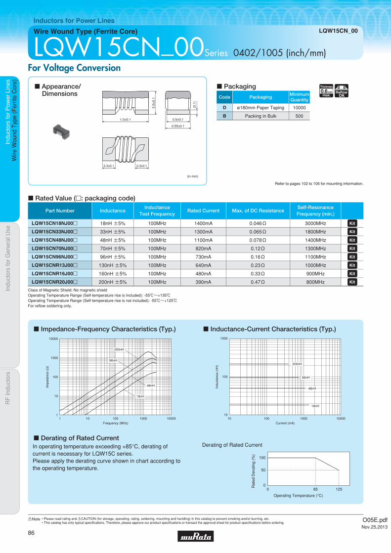
Code PackagingMinimumQuantity
D ø180mm Paper Taping 10000
B Packing in Bulk 500
0.6Thickness
mmmax.
ReflowOK
Part Number InductanceInductance
Test FrequencyRated Current Max. of DC Resistance
Self-ResonanceFrequency (min.)
LQW15CN18NJ00p 18nH ±5% 100MHz 1400mA 0.046Ω 3000MHz LQW15CN33NJ00p 33nH ±5% 100MHz 1300mA 0.065Ω 1800MHz LQW15CN48NJ00p 48nH ±5% 100MHz 1100mA 0.078Ω 1400MHz LQW15CN70NJ00p 70nH ±5% 100MHz 820mA 0.12Ω 1300MHz LQW15CN96NJ00p 96nH ±5% 100MHz 730mA 0.16Ω 1100MHz LQW15CNR13J00p 130nH ±5% 100MHz 640mA 0.23Ω 1000MHz LQW15CNR16J00p 160nH ±5% 100MHz 480mA 0.33Ω 900MHz LQW15CNR20J00p 200nH ±5% 100MHz 390mA 0.47Ω 800MHz
Indu
ctor
s fo
r P
ower
Lin
esIn
duct
ors
for
Gen
eral
Use
RF
Indu
ctor
sIn
duct
ors
for
Pow
er L
ines
Wire
Wou
nd T
ype
(Fer
rite
Cor
e)
Wire Wound Type (Ferrite Core) LQW15CN_00
Inductors for Power Lines
LQW15CN_00Series 0402/1005 (inch/mm)For Voltage Conversion
c Impedance-Frequency Characteristics (Typ.)
c Derating of Rated Current
c Inductance-Current Characteristics (Typ.)
c Rated Value (p: packaging code)
Refer to pages 102 to 106 for mounting information.
1.0±0.1
0.5±
0.1
(0.1
)
0.3±0.1 0.3±0.1
(in mm)
0.5±0.1
0.55±0.1
c Appearance/Dimensions
c Packaging
Class of Magnetic Shield: No magnetic shieldOperating Temperature Range (Self-temperature rise is included): -55℃~+135℃Operating Temperature Range (Self-temperature rise is not included): -55℃~+125℃For refl ow soldering only.
96nH
48nH
18nH
200nH
1
10
100
1000
10000
1 10 100 1000 10000Frequency (MHz)
Impe
danc
e (Ω
)
In operating temperature exceeding +85°C, derating of current is necessary for LQW15C series.Please apply the derating curve shown in chart according to the operating temperature.
96nH
48nH
18nH
200nH
10
100
1000
10 1000100 10000Current (mA)
Indu
ctan
ce (
nH)
Derating of Rated Current
0
50
100
Rat
ed D
erat
ing
(%)
Operating Temperature (°C)
125850
O05E.pdfNov.25,2013
86
!Note • Please read rating and !CAUTION (for storage, operating, rating, soldering, mounting and handling) in this catalog to prevent smoking and/or burning, etc.• This catalog has only typical specifi cations. Therefore, please approve our product specifi cations or transact the approval sheet for product specifi cations before ordering.
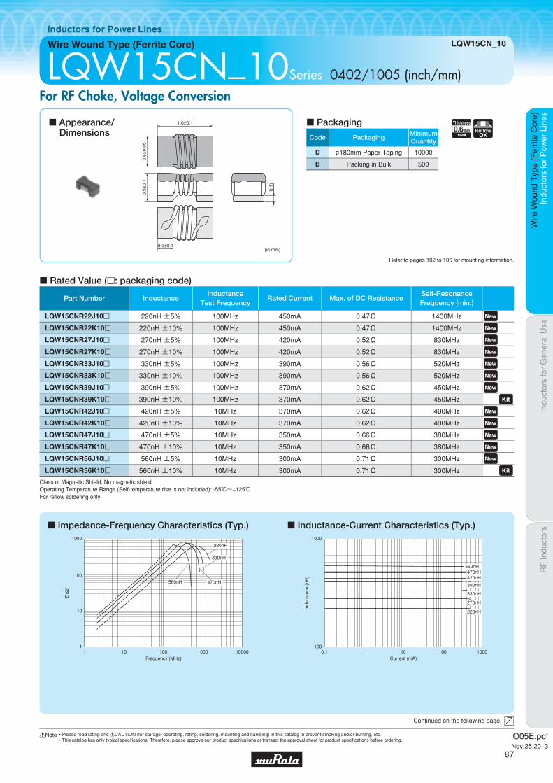
Code PackagingMinimumQuantity
D ø180mm Paper Taping 10000
B Packing in Bulk 500
0.6Thickness
mmmax.
ReflowOK
Part Number InductanceInductance
Test FrequencyRated Current Max. of DC Resistance
Self-ResonanceFrequency (min.)
LQW15CNR22J10p 220nH ±5% 100MHz 450mA 0.47Ω 1400MHz LQW15CNR22K10p 220nH ±10% 100MHz 450mA 0.47Ω 1400MHz LQW15CNR27J10p 270nH ±5% 100MHz 420mA 0.52Ω 830MHz LQW15CNR27K10p 270nH ±10% 100MHz 420mA 0.52Ω 830MHz LQW15CNR33J10p 330nH ±5% 100MHz 390mA 0.56Ω 520MHz LQW15CNR33K10p 330nH ±10% 100MHz 390mA 0.56Ω 520MHz LQW15CNR39J10p 390nH ±5% 100MHz 370mA 0.62Ω 450MHz LQW15CNR39K10p 390nH ±10% 100MHz 370mA 0.62Ω 450MHz LQW15CNR42J10p 420nH ±5% 10MHz 370mA 0.62Ω 400MHz LQW15CNR42K10p 420nH ±10% 10MHz 370mA 0.62Ω 400MHz LQW15CNR47J10p 470nH ±5% 10MHz 350mA 0.66Ω 380MHz LQW15CNR47K10p 470nH ±10% 10MHz 350mA 0.66Ω 380MHz LQW15CNR56J10p 560nH ±5% 10MHz 300mA 0.71Ω 300MHz LQW15CNR56K10p 560nH ±10% 10MHz 300mA 0.71Ω 300MHz
Indu
ctor
s fo
r P
ower
Lin
esIn
duct
ors
for
Gen
eral
Use
RF
Indu
ctor
sIn
duct
ors
for
Pow
er L
ines
Wire
Wou
nd T
ype
(Fer
rite
Cor
e)
Wire Wound Type (Ferrite Core) LQW15CN_10
Inductors for Power Lines
LQW15CN_10Series 0402/1005 (inch/mm)For RF Choke, Voltage Conversion
c Impedance-Frequency Characteristics (Typ.) c Inductance-Current Characteristics (Typ.)
c Rated Value (p: packaging code)
Refer to pages 102 to 106 for mounting information.
1.0±0.1
0.3±0.1
(0.1
)
0.6±
0.05
0.5±
0.1
(in mm)
Continued on the following page.
c Appearance/Dimensions
c Packaging
Class of Magnetic Shield: No magnetic shieldOperating Temperature Range (Self-temperature rise is not included): -55℃~+125℃For refl ow soldering only.
Z (
Ω)
Frequency (MHz)
1
10
100
1000
1 100010010 10000
470nH
330nH
220nH
560nH
470nH
390nH
560nH
420nH
330nH
270nH
220nH
100
1000
0.1 1 10010 1000Current (mA)
Indu
ctan
ce (
nH)
O05E.pdfNov.25,2013
87
!Note • Please read rating and !CAUTION (for storage, operating, rating, soldering, mounting and handling) in this catalog to prevent smoking and/or burning, etc.• This catalog has only typical specifi cations. Therefore, please approve our product specifi cations or transact the approval sheet for product specifi cations before ordering.

Indu
ctor
s fo
r P
ower
Lin
esIn
duct
ors
for
Gen
eral
Use
RF
Indu
ctor
sIn
duct
ors
for
Pow
er L
ines
Wire
Wou
nd T
ype
(Fer
rite
Cor
e)
LQW15CN_10
c Derating of Rated Current
Derating of Rated Current
0
50
100
Rat
ed D
erat
ing
(%)
Operating Temperature (°C)
125850
In operating temperature exceeding +85°C, derating of current is necessary for LQW15C series.Please apply the derating curve shown in chart according to the operating temperature.
O05E.pdfNov.25,2013
88
!Note • Please read rating and !CAUTION (for storage, operating, rating, soldering, mounting and handling) in this catalog to prevent smoking and/or burning, etc.• This catalog has only typical specifi cations. Therefore, please approve our product specifi cations or transact the approval sheet for product specifi cations before ordering.

Code PackagingMinimumQuantity
D ø180mm Paper Taping 4000
B Packing in Bulk 500
0.95Thickness
mmmax.
ReflowOK
Part Number InductanceInductance
Test FrequencyRated Current Max. of DC Resistance
Self-ResonanceFrequency (min.)
LQW18CN4N9D00p 4.9nH ±0.5nH 10MHz 2600mA 0.015Ω 2300MHz LQW18CN15NJ00p 15nH ±5% 10MHz 2200mA 0.025Ω 2000MHz LQW18CN33NJ00p 33nH ±5% 10MHz 1700mA 0.035Ω 1800MHz LQW18CN55NJ00p 55nH ±5% 10MHz 1500mA 0.045Ω 1600MHz LQW18CN85NJ00p 85nH ±5% 10MHz 1400mA 0.060Ω 1380MHz LQW18CNR10K00p 100nH ±10% 10MHz 1000mA 0.10Ω 1260MHz LQW18CNR12J00p 120nH ±5% 10MHz 1100mA 0.085Ω 1200MHz LQW18CNR16J00p 160nH ±5% 10MHz 1000mA 0.10Ω 900MHz LQW18CNR21J00p 210nH ±5% 10MHz 800mA 0.15Ω 720MHz LQW18CNR27J00p 270nH ±5% 10MHz 750mA 0.16Ω 660MHz LQW18CNR33J00p 330nH ±5% 10MHz 630mA 0.25Ω 600MHz LQW18CNR39J00p 390nH ±5% 10MHz 620mA 0.28Ω 570MHz LQW18CNR47J00p 470nH ±5% 10MHz 500mA 0.45Ω 555MHz LQW18CNR56J00p 560nH ±5% 10MHz 450mA 0.48Ω 540MHz LQW18CNR65J00p 650nH ±5% 10MHz 430mA 0.52Ω 510MHz
Indu
ctor
s fo
r P
ower
Lin
esIn
duct
ors
for
Gen
eral
Use
RF
Indu
ctor
sIn
duct
ors
for
Pow
er L
ines
Wire
Wou
nd T
ype
(Fer
rite
Cor
e)
Wire Wound Type (Ferrite Core) LQW18CN_00
Inductors for Power Lines
LQW18CN_00Series 0603/1608 (inch/mm)for FM/TV Band Choke
c Impedance-Frequency Characteristics (Typ.) c Inductance-Current Characteristics (Typ.)
c Rated Value (p: packaging code)
Refer to pages 102 to 106 for mounting information.
1.6±0.15 0.8±0.15
0.8±
0.15
(0.2
)
0.4±0.1 0.4±0.1
(in mm)
c Appearance/Dimensions
c Packaging
Class of Magnetic Shield: No magnetic shieldOperating Temperature Range (Self-temperature rise is not included): -40℃~+85℃For refl ow soldering only.
1 10 100 1000 10000
1000
10000
100
10
1
0.1
0.01
Frequency (MHz)
Impe
danc
e (Ω
)
650nH
330nH
100nH
4.9nH
0.1
1
10
100
1000
10 100 1000Current (mA)
Indu
ctan
ce (
nH)
650nH
330nH
100nH
4.9nH
O05E.pdfNov.25,2013
89
!Note • Please read rating and !CAUTION (for storage, operating, rating, soldering, mounting and handling) in this catalog to prevent smoking and/or burning, etc.• This catalog has only typical specifi cations. Therefore, please approve our product specifi cations or transact the approval sheet for product specifi cations before ordering.
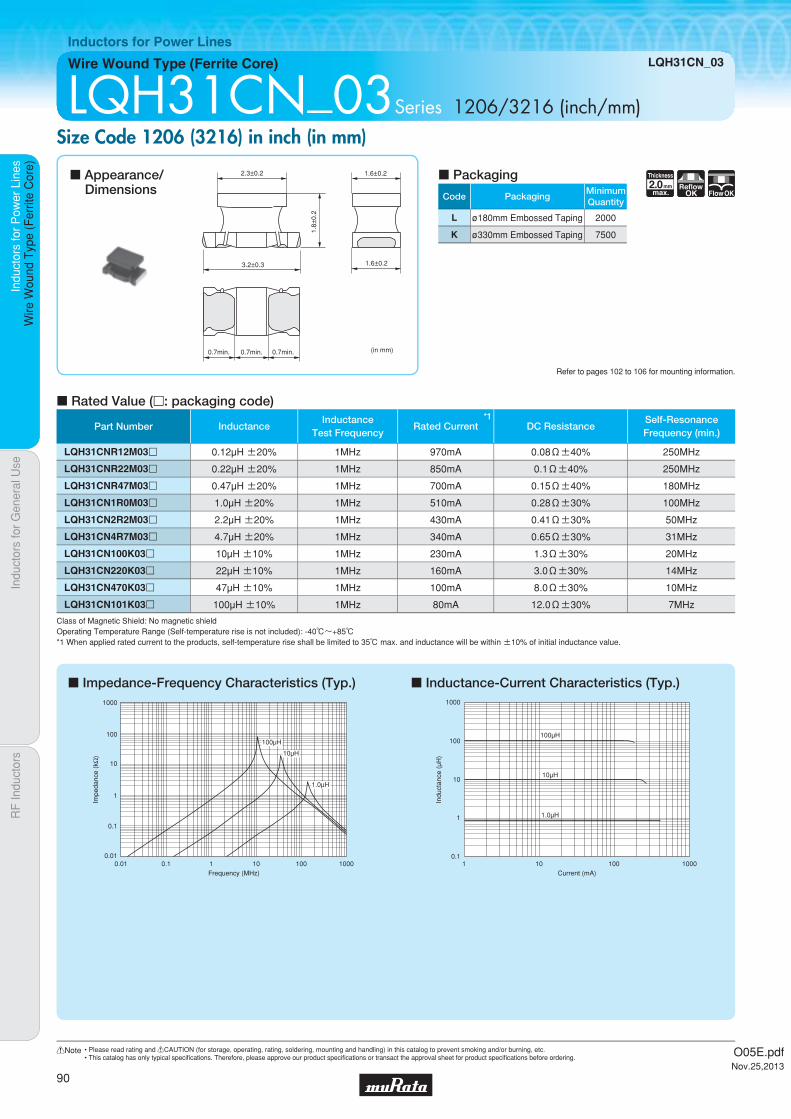
Code PackagingMinimumQuantity
L ø180mm Embossed Taping 2000
K ø330mm Embossed Taping 7500
2.0Thickness
mmmax.
ReflowOK FlowOK
Part Number InductanceInductance
Test Frequency
*1Rated Current DC Resistance
Self-ResonanceFrequency (min.)
LQH31CNR12M03p 0.12µH ±20% 1MHz 970mA 0.08Ω±40% 250MHz
LQH31CNR22M03p 0.22µH ±20% 1MHz 850mA 0.1Ω±40% 250MHz
LQH31CNR47M03p 0.47µH ±20% 1MHz 700mA 0.15Ω±40% 180MHz
LQH31CN1R0M03p 1.0µH ±20% 1MHz 510mA 0.28Ω±30% 100MHz
LQH31CN2R2M03p 2.2µH ±20% 1MHz 430mA 0.41Ω±30% 50MHz
LQH31CN4R7M03p 4.7µH ±20% 1MHz 340mA 0.65Ω±30% 31MHz
LQH31CN100K03p 10µH ±10% 1MHz 230mA 1.3Ω±30% 20MHz
LQH31CN220K03p 22µH ±10% 1MHz 160mA 3.0Ω±30% 14MHz
LQH31CN470K03p 47µH ±10% 1MHz 100mA 8.0Ω±30% 10MHz
LQH31CN101K03p 100µH ±10% 1MHz 80mA 12.0Ω±30% 7MHz
Indu
ctor
s fo
r P
ower
Lin
esIn
duct
ors
for
Gen
eral
Use
RF
Indu
ctor
sIn
duct
ors
for
Pow
er L
ines
Wire
Wou
nd T
ype
(Fer
rite
Cor
e)
Wire Wound Type (Ferrite Core) LQH31CN_03
Inductors for Power Lines
LQH31CN_03Series 1206/3216 (inch/mm)Size Code 1206 (3216) in inch (in mm)
c Impedance-Frequency Characteristics (Typ.) c Inductance-Current Characteristics (Typ.)
c Rated Value (p: packaging code)
Refer to pages 102 to 106 for mounting information.
2.3±0.2
1.8±
0.2
1.6±0.2
1.6±0.23.2±0.3
0.7min. 0.7min. 0.7min. (in mm)
c Appearance/Dimensions
c Packaging
Class of Magnetic Shield: No magnetic shieldOperating Temperature Range (Self-temperature rise is not included): -40℃~+85℃*1 When applied rated current to the products, self-temperature rise shall be limited to 35℃ max. and inductance will be within ±10% of initial inductance value.
0.01
0.1
1
10
100
1000
0.01 0.1 1 10 100 1000Frequency (MHz)
Impe
danc
e (k
Ω) 10μH
1.0μH
100μH100μH
10μH
1.0μH
100
1000
10
1
0.1101 100 1000
Current (mA)
Indu
ctan
ce (
μH)
O05E.pdfNov.25,2013
90
!Note • Please read rating and !CAUTION (for storage, operating, rating, soldering, mounting and handling) in this catalog to prevent smoking and/or burning, etc.• This catalog has only typical specifi cations. Therefore, please approve our product specifi cations or transact the approval sheet for product specifi cations before ordering.

Code PackagingMinimumQuantity
L ø180mm Embossed Taping 2000
K ø330mm Embossed Taping 7500
2.2Thickness
mmmax.
ReflowOK FlowOK
Indu
ctor
s fo
r P
ower
Lin
esIn
duct
ors
for
Gen
eral
Use
RF
Indu
ctor
sIn
duct
ors
for
Pow
er L
ines
Wire
Wou
nd T
ype
(Fer
rite
Cor
e)
Wire Wound Type (Ferrite Core) LQH32CN_23/LQH32CN_33
Inductors for Power Lines
LQH32CN_23/LQH32CN_33Series 1210/3225 (inch/mm)Size Code 1210 (3225) in inch (in mm)
c Rated Value (p: packaging code)
Refer to pages 102 to 106 for mounting information.
2.5±0.2
2.0±
0.2
2.5±0.23.2±0.3
0.9±0.3
1.3±0.2
0.9±0.3
2.5±0.2 2.5±0.2
A
A: 2.8 max.
* Please refer to dimension A for LQH32CN_33 (2R2M, 4R7M, 100K) types. (See Fig. 1)
Fig. 1
2.5±0.2
(in mm)
Continued on the following page.
c Appearance/Dimensions
c Packaging
Class of Magnetic Shield: No magnetic shieldOperating Temperature Range (Self-temperature rise is not included): -40℃~+85℃*1 When applied rated current to the products, self-temperature rise shall be limited to 20℃ max. and inductance will be within ±10% of initial inductance value.
Part Number InductanceInductance
Test Frequency
*1Rated Current DC Resistance
Self-ResonanceFrequency (min.)
LQH32CN1R0M23p 1.0µH ±20% 1MHz 800mA 0.09Ω±30% 96MHz LQH32CN2R2M23p 2.2µH ±20% 1MHz 600mA 0.13Ω±30% 64MHz LQH32CN4R7M23p 4.7µH ±20% 1MHz 450mA 0.2Ω±30% 43MHz LQH32CN100K23p 10µH ±10% 1MHz 300mA 0.44Ω±30% 26MHz LQH32CN220K23p 22µH ±10% 1MHz 250mA 0.71Ω±30% 19MHz LQH32CN470K23p 47µH ±10% 1MHz 170mA 1.3Ω±30% 15MHz LQH32CN101K23p 100µH ±10% 1MHz 100mA 3.5Ω±30% 10MHz LQH32CN221K23p 220µH ±10% 1MHz 70mA 8.4Ω±30% 6.8MHz LQH32CN331K23p 330µH ±10% 1MHz 60mA 10.0Ω±30% 5.6MHz LQH32CN391K23p 390µH ±10% 1MHz 60mA 17Ω±30% 5MHz LQH32CN471K23p 470µH ±10% 1kHz 60mA 19Ω±30% 5MHz LQH32CN561K23p 560µH ±10% 1kHz 60mA 22.0Ω±30% 5MHz LQH32CNR15M33p 0.15µH ±20% 1MHz 1450mA 0.028Ω±30% 400MHz LQH32CNR27M33p 0.27µH ±20% 1MHz 1250mA 0.034Ω±30% 250MHz LQH32CNR47M33p 0.47µH ±20% 1MHz 1100mA 0.042Ω±30% 150MHz LQH32CN1R0M33p 1.0µH ±20% 1MHz 1000mA 0.06Ω±30% 100MHz LQH32CN2R2M33p 2.2µH ±20% 1MHz 790mA 0.097Ω±30% 64MHz LQH32CN4R7M33p 4.7µH ±20% 1MHz 650mA 0.15Ω±30% 43MHz LQH32CN100K33p 10µH ±10% 1MHz 450mA 0.3Ω±30% 26MHz
O05E.pdfNov.25,2013
91
!Note • Please read rating and !CAUTION (for storage, operating, rating, soldering, mounting and handling) in this catalog to prevent smoking and/or burning, etc.• This catalog has only typical specifi cations. Therefore, please approve our product specifi cations or transact the approval sheet for product specifi cations before ordering.

Indu
ctor
s fo
r P
ower
Lin
esIn
duct
ors
for
Gen
eral
Use
RF
Indu
ctor
sIn
duct
ors
for
Pow
er L
ines
Wire
Wou
nd T
ype
(Fer
rite
Cor
e)
LQH32CN_23/LQH32CN_33
c Impedance-Frequency Characteristics (Typ.) c Inductance-Current Characteristics (Typ.)
0.01
0.1
1
10
100
1000
0.01 0.1 1 10 100 1000Frequency (MHz)
Impe
danc
e (k
Ω)
100μH
10μH
1.0μH
1 10 1000100
1000
100
10
1
0.1
Current (mA)
Indu
ctan
ce (
μH)
100μH
10μH
1.0μH
O05E.pdfNov.25,2013
92
!Note • Please read rating and !CAUTION (for storage, operating, rating, soldering, mounting and handling) in this catalog to prevent smoking and/or burning, etc.• This catalog has only typical specifi cations. Therefore, please approve our product specifi cations or transact the approval sheet for product specifi cations before ordering.

Code PackagingMinimumQuantity
L ø180mm Embossed Taping 2000
K ø330mm Embossed Taping 7500
1.7Thickness
mmmax.
ReflowOK FlowOK
Indu
ctor
s fo
r P
ower
Lin
esIn
duct
ors
for
Gen
eral
Use
RF
Indu
ctor
sIn
duct
ors
for
Pow
er L
ines
Wire
Wou
nd T
ype
(Fer
rite
Cor
e)
Wire Wound Type (Ferrite Core) LQH32CN_53
Inductors for Power Lines
LQH32CN_53Series 1210/3225 (inch/mm)Size Code 1210 (3225) in inch (in mm)
c Impedance-Frequency Characteristics (Typ.) c Inductance-Current Characteristics (Typ.)
c Rated Value (p: packaging code)
Refer to pages 102 to 106 for mounting information.
2.5±0.2 2.5±0.2
1.55
±0.
15
2.5±0.23.2±0.3
A : 2.8 max.
A
0.9±0.3 1.3±0.2 0.9±0.3
A
(in mm)
c Appearance/Dimensions
c Packaging
Class of Magnetic Shield: No magnetic shieldOperating Temperature Range (Self-temperature rise is not included): -40℃~+85℃*1 When applied rated current to the products, self-temperature rise shall be limited to 20℃ max. and inductance will be within ±10% of initial inductance value.
1 10 100
10
100
1
0.1
0.01
0.0011000
10μH
1.0μH
Impe
danc
e (k
Ω)
Frequency (MHz)
100μH
1 10 100
100
1000
10
1
0.11000
100μH
10μH
1.0μH
Current (mA)
Indu
ctan
ce (
μH)
Part Number InductanceInductance
Test Frequency
*1Rated Current DC Resistance
Self-ResonanceFrequency (min.)
LQH32CN1R0M53p 1.0µH ±20% 1MHz 1000mA 0.060Ω±30% 100MHz LQH32CN2R2M53p 2.2µH ±20% 1MHz 790mA 0.097Ω±30% 64MHz LQH32CN3R3M53p 3.3µH ±20% 1MHz 710mA 0.12Ω±30% 50MHz
LQH32CN4R7M53p 4.7µH ±20% 1MHz 650mA 0.15Ω±30% 43MHz LQH32CN6R8M53p 6.8µH ±20% 1MHz 540mA 0.25Ω±30% 32MHz
LQH32CN100K53p 10µH ±10% 1MHz 450mA 0.30Ω±30% 26MHz LQH32CN150K53p 15µH ±10% 1MHz 300mA 0.58Ω±30% 26MHz LQH32CN220K53p 22µH ±10% 1MHz 250mA 0.71Ω±30% 19MHz LQH32CN330K53p 33µH ±10% 1MHz 200mA 1.1Ω±30% 17MHz LQH32CN470K53p 47µH ±10% 1MHz 170mA 1.3Ω±30% 15MHz LQH32CN680K53p 68µH ±10% 1MHz 130mA 2.2Ω±30% 12MHz LQH32CN101K53p 100µH ±10% 1MHz 100mA 3.5Ω±30% 10MHz
O05E.pdfNov.25,2013
93
!Note • Please read rating and !CAUTION (for storage, operating, rating, soldering, mounting and handling) in this catalog to prevent smoking and/or burning, etc.• This catalog has only typical specifi cations. Therefore, please approve our product specifi cations or transact the approval sheet for product specifi cations before ordering.

Code PackagingMinimumQuantity
L ø180mm Embossed Taping 500
2.8Thickness
mmmax.
ReflowOK FlowOK
Part Number InductanceInductance
Test Frequency
*1Rated Current Max. of DC Resistance
Self-ResonanceFrequency (min.)
LQH43CN1R0M03p 1.0µH ±20% 1MHz 1080mA 0.08Ω 100MHz LQH43CN1R5M03p 1.5µH ±20% 1MHz 1000mA 0.09Ω 85MHz LQH43CN2R2M03p 2.2µH ±20% 1MHz 900mA 0.11Ω 60MHz LQH43CN3R3M03p 3.3µH ±20% 1MHz 800mA 0.13Ω 47MHz LQH43CN4R7M03p 4.7µH ±20% 1MHz 750mA 0.15Ω 35MHz LQH43CN6R8M03p 6.8µH ±20% 1MHz 720mA 0.20Ω 30MHz LQH43CN100K03p 10µH ±10% 1MHz 650mA 0.24Ω 23MHz LQH43CN150K03p 15µH ±10% 1MHz 570mA 0.32Ω 20MHz LQH43CN220K03p 22µH ±10% 1MHz 420mA 0.6Ω 15MHz LQH43CN330K03p 33µH ±10% 1MHz 310mA 1.0Ω 12MHz LQH43CN470K03p 47µH ±10% 1MHz 280mA 1.1Ω 10MHz LQH43CN680K03p 68µH ±10% 1MHz 220mA 1.7Ω 8.4MHz LQH43CN101K03p 100µH ±10% 1MHz 190mA 2.2Ω 6.8MHz LQH43CN151K03p 150µH ±10% 1MHz 130mA 3.5Ω 5.5MHz LQH43CN221K03p 220µH ±10% 1MHz 110mA 4.0Ω 4.5MHz LQH43CN331K03p 330µH ±10% 1MHz 100mA 6.8Ω 3.6MHz LQH43CN471K03p 470µH ±10% 1kHz 90mA 8.5Ω 3.0MHz
Indu
ctor
s fo
r P
ower
Lin
esIn
duct
ors
for
Gen
eral
Use
RF
Indu
ctor
sIn
duct
ors
for
Pow
er L
ines
Wire
Wou
nd T
ype
(Fer
rite
Cor
e)
Wire Wound Type (Ferrite Core) LQH43CN_03
Inductors for Power Lines
LQH43CN_03Series 1812/4532 (inch/mm)Size Code 1812 (4532) in inch (in mm)
c Impedance-Frequency Characteristics (Typ.) c Inductance-Current Characteristics (Typ.)
c Rated Value (p: packaging code)
Refer to pages 102 to 106 for mounting information.
3.6±0.2
4.5±0.3
2.6±
0.2
3.2±0.2
3.2±0.2
1.0min. 1.0min. 1.0min.(in mm)
c Appearance/Dimensions
c Packaging
Class of Magnetic Shield: No magnetic shieldOperating Temperature Range (Self-temperature rise is not included): -40℃~+85℃*1 When applied rated current to the products, self-temperature rise shall be limited to 20℃ max. and inductance will be within ±10% of initial inductance value.
0.01 0.1 1 10010
100
1000
10
1
0.1
0.011000
Impe
danc
e (k
Ω)
Frequency (MHz)
1.0μH
100μH
10μH
1 10 100 100001000
1000
100
10
1
0.1
Current (mA)
Indu
ctan
ce (
μH)
100μH
10μH
1.0μH
O05E.pdfNov.25,2013
94
!Note • Please read rating and !CAUTION (for storage, operating, rating, soldering, mounting and handling) in this catalog to prevent smoking and/or burning, etc.• This catalog has only typical specifi cations. Therefore, please approve our product specifi cations or transact the approval sheet for product specifi cations before ordering.

Code PackagingMinimumQuantity
L ø180mm Embossed Taping 500
2.8Thickness
mmmax.
ReflowOK FlowOK
Part Number InductanceInductance
Test Frequency
*1Rated Current DC Resistance
Self-ResonanceFrequency (min.)
LQH43CNR56M33p 0.56µH ±20% 1MHz 2950mA 0.023Ω ±30% 160MHz LQH43CNR82M33p 0.82µH ±20% 1MHz 2800mA 0.027Ω ±30% 130MHz LQH43CN1R0M33p 1.0µH ±20% 1MHz 2600mA 0.032Ω ±30% 110MHz LQH43CN1R5M33p 1.5µH ±20% 1MHz 2450mA 0.036Ω ±30% 80MHz LQH43CN1R8M33p 1.8µH ±20% 1MHz 2300mA 0.042Ω ±30% 70MHz LQH43CN2R2M33p 2.2µH ±20% 1MHz 2100mA 0.047Ω ±30% 60MHz LQH43CN2R7M33p 2.7µH ±20% 1MHz 1800mA 0.053Ω ±30% 50MHz LQH43CN3R3M33p 3.3µH ±20% 1MHz 1650mA 0.076Ω ±30% 47MHz LQH43CN3R9M33p 3.9µH ±20% 1MHz 1600mA 0.082Ω ±30% 40MHz
Indu
ctor
s fo
r P
ower
Lin
esIn
duct
ors
for
Gen
eral
Use
RF
Indu
ctor
sIn
duct
ors
for
Pow
er L
ines
Wire
Wou
nd T
ype
(Fer
rite
Cor
e)
Wire Wound Type (Ferrite Core) LQH43CN_33
Inductors for Power Lines
LQH43CN_33Series 1812/4532 (inch/mm)Low DC Resistance Type
c Impedance-Frequency Characteristics (Typ.) c Inductance-Current Characteristics (Typ.)
c Rated Value (p: packaging code)
Refer to pages 102 to 106 for mounting information.
3.6±0.2
4.5±0.3
2.6±
0.2
3.2±0.2
3.2±0.2
1.0min. 1.0min. 1.0min.(in mm)
c Appearance/Dimensions
c Packaging
Class of Magnetic Shield: No magnetic shieldOperating Temperature Range (Self-temperature rise is not included): -40℃~+85℃*1 When applied rated current to the products, self-temperature rise shall be limited to 40℃ max. and inductance will be within ±20% of initial inductance value.
10
100
1000
10000
1 10 100 1000 10000Frequency (MHz)
Impe
danc
e (Ω
)
3.3μH
2.2μH
1.5μH
1.0μH
Indu
ctan
ce (
μH)
0.1
1
10
100
10 100 1000 10000Current (mA)
3.3μH2.2μH
1.5μH 1.0μH
O05E.pdfNov.25,2013
95
!Note • Please read rating and !CAUTION (for storage, operating, rating, soldering, mounting and handling) in this catalog to prevent smoking and/or burning, etc.• This catalog has only typical specifi cations. Therefore, please approve our product specifi cations or transact the approval sheet for product specifi cations before ordering.

Code PackagingMinimumQuantity
L ø180mm Embossed Taping 350
K ø330mm Embossed Taping 1500
5.0Thickness
mmmax.
ReflowOK
Indu
ctor
s fo
r P
ower
Lin
esIn
duct
ors
for
Gen
eral
Use
RF
Indu
ctor
sIn
duct
ors
for
Pow
er L
ines
Wire
Wou
nd T
ype
(Fer
rite
Cor
e)
Wire Wound Type (Ferrite Core) LQH55DN_03
Inductors for Power Lines
LQH55DN_03Series 2220/5750 (inch/mm)Large Current
c Rated Value (p: packaging code)
Refer to pages 102 to 106 for mounting information.
4.7±
0.3
5.0±0.3 5.0±0.3
5.7±0.3
1.7min.
1.3min.
1.3min. (in mm)
Continued on the following page.
c Appearance/Dimensions
c Packaging
Class of Magnetic Shield: No magnetic shieldOperating Temperature Range (Self-temperature rise is not included): -40℃~+80℃For refl ow soldering only.*1 When applied rated current to the products, self-temperature rise shall be limited to 40℃ max. and inductance will be within ±40% of initial inductance value.
Part Number InductanceInductance
Test Frequency
*1Rated Current DC Resistance
Self-ResonanceFrequency (min.)
LQH55DNR12M03p 0.12µH ±20% 1MHz 6000mA 0.007Ω ±40% 450MHz
LQH55DNR27M03p 0.27µH ±20% 1MHz 5300mA 0.010Ω ±40% 300MHz
LQH55DNR47M03p 0.47µH ±20% 1MHz 4800mA 0.013Ω ±40% 200MHz
LQH55DN1R0M03p 1.0µH ±20% 1MHz 4000mA 0.019Ω ±40% 150MHz
LQH55DN1R5M03p 1.5µH ±20% 1MHz 3700mA 0.022Ω ±40% 110MHz
LQH55DN2R2M03p 2.2µH ±20% 1MHz 3200mA 0.029Ω ±40% 80MHz
LQH55DN3R3M03p 3.3µH ±20% 1MHz 2900mA 0.036Ω ±40% 40MHz
LQH55DN4R7M03p 4.7µH ±20% 1MHz 2700mA 0.041Ω ±40% 30MHz
LQH55DN6R8M03p 6.8µH ±20% 1MHz 2000mA 0.074Ω ±40% 25MHz
LQH55DN100M03p 10µH ±20% 1MHz 1700mA 0.093Ω ±40% 20MHz
LQH55DN150M03p 15µH ±20% 1MHz 1400mA 0.15Ω ±40% 17MHz
LQH55DN220M03p 22µH ±20% 1MHz 1200mA 0.19Ω ±40% 15MHz
LQH55DN330M03p 33µH ±20% 1MHz 900mA 0.32Ω ±40% 12MHz
LQH55DN470M03p 47µH ±20% 1MHz 800mA 0.40Ω ±40% 10MHz
LQH55DN680M03p 68µH ±20% 1MHz 640mA 0.67Ω ±40% 7.6MHz
LQH55DN101M03p 100µH ±20% 100kHz 560mA 0.86Ω ±40% 6.5MHz
LQH55DN151M03p 150µH ±20% 100kHz 420mA 1.9Ω ±40% 5.0MHz
LQH55DN221M03p 220µH ±20% 100kHz 320mA 2.4Ω ±40% 4.0MHz
LQH55DN331M03p 330µH ±20% 100kHz 270mA 4.4Ω ±40% 3.1MHz
LQH55DN471M03p 470µH ±20% 100kHz 240mA 5.4Ω ±40% 2.4MHz
LQH55DN681M03p 680µH ±20% 100kHz 190mA 8.1Ω ±40% 1.9MHz
LQH55DN102M03p 1000µH ±20% 10kHz 150mA 10.3Ω ±40% 1.7MHz
LQH55DN222M03p 2200µH ±20% 10kHz 100mA 21.5Ω ±40% 1.2MHz
LQH55DN472M03p 4700µH ±20% 10kHz 70mA 43.6Ω ±40% 0.8MHz
LQH55DN103M03p 10000µH ±20% 10kHz 50mA 100Ω ±40% 0.5MHz
O05E.pdfNov.25,2013
96
!Note • Please read rating and !CAUTION (for storage, operating, rating, soldering, mounting and handling) in this catalog to prevent smoking and/or burning, etc.• This catalog has only typical specifi cations. Therefore, please approve our product specifi cations or transact the approval sheet for product specifi cations before ordering.
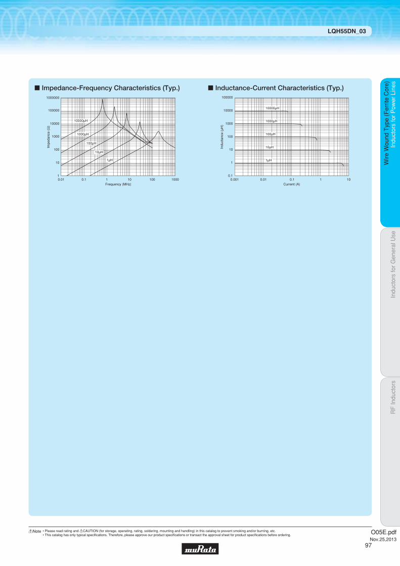
Indu
ctor
s fo
r P
ower
Lin
esIn
duct
ors
for
Gen
eral
Use
RF
Indu
ctor
sIn
duct
ors
for
Pow
er L
ines
Wire
Wou
nd T
ype
(Fer
rite
Cor
e)
LQH55DN_03
c Impedance-Frequency Characteristics (Typ.) c Inductance-Current Characteristics (Typ.)
10000μH
Frequency (MHz)
10
100
1000
10000
100000
1000000
10.01 0.1 1 10 100 1000
1000μH
100μH
10μH
1μH
Impe
danc
e (Ω
)
Indu
ctan
ce (
μH)
Current (A)
10000
1000
100000
100
10
1
0.10.010.001 0.1 1 10
1μH
10μH
10000μH
1000μH
100μH
O05E.pdfNov.25,2013
97
!Note • Please read rating and !CAUTION (for storage, operating, rating, soldering, mounting and handling) in this catalog to prevent smoking and/or burning, etc.• This catalog has only typical specifi cations. Therefore, please approve our product specifi cations or transact the approval sheet for product specifi cations before ordering.

Code PackagingMinimumQuantity
L ø180mm Embossed Taping 350
K ø330mm Embossed Taping 1500
5.0Thickness
mmmax.
ReflowOK
Indu
ctor
s fo
r P
ower
Lin
esIn
duct
ors
for
Gen
eral
Use
RF
Indu
ctor
sIn
duct
ors
for
Pow
er L
ines
Wire
Wou
nd T
ype
(Fer
rite
Cor
e)
Wire Wound Type (Ferrite Core) LQH66SN_03
Inductors for Power Lines
LQH66SN_03Series 2525/6363 (inch/mm)Closed Magnetic Circuit
c Rated Value (p: packaging code)
Refer to pages 102 to 106 for mounting information.
4.7±
0.3
6.3±0.3 6.3±0.3
6.3±0.3
(in mm)1.7min.
1.3min.
1.3min.
Continued on the following page.
c Appearance/Dimensions
c Packaging
Class of Magnetic Shield: Magnetic shield of ferriteOperating Temperature Range (Self-temperature rise is not included): -40℃~+80℃For refl ow soldering only.*1 When applied rated current to the products, self-temperature rise shall be limited to 40℃ max. and inductance will be within ±40% of initial inductance value.
Part Number InductanceInductance
Test Frequency
*1Rated Current DC Resistance
Self-ResonanceFrequency (min.)
LQH66SNR27M03p 0.27µH ±20% 1MHz 6000mA 0.007Ω ±40% 300MHz
LQH66SNR68M03p 0.68µH ±20% 1MHz 5300mA 0.010Ω ±40% 180MHz
LQH66SN1R0M03p 1.0µH ±20% 1MHz 4700mA 0.013Ω ±40% 150MHz
LQH66SN1R5M03p 1.5µH ±20% 1MHz 3800mA 0.016Ω ±40% 110MHz
LQH66SN2R2M03p 2.2µH ±20% 1MHz 3300mA 0.019Ω ±40% 80MHz
LQH66SN3R3M03p 3.3µH ±20% 1MHz 2600mA 0.022Ω ±40% 40MHz
LQH66SN4R7M03p 4.7µH ±20% 1MHz 2200mA 0.025Ω ±40% 30MHz
LQH66SN6R8M03p 6.8µH ±20% 1MHz 1800mA 0.029Ω ±40% 25MHz
LQH66SN100M03p 10µH ±20% 1MHz 1600mA 0.036Ω ±40% 20MHz
LQH66SN150M03p 15µH ±20% 1MHz 1300mA 0.069Ω ±40% 17MHz
LQH66SN220M03p 22µH ±20% 1MHz 1100mA 0.087Ω ±40% 15MHz
LQH66SN330M03p 33µH ±20% 1MHz 860mA 0.14Ω ±40% 12MHz
LQH66SN470M03p 47µH ±20% 1MHz 760mA 0.17Ω ±40% 10MHz
LQH66SN680M03p 68µH ±20% 1MHz 600mA 0.29Ω ±40% 7.6MHz
LQH66SN101M03p 100µH ±20% 100kHz 520mA 0.36Ω ±40% 6.5MHz
LQH66SN151M03p 150µH ±20% 100kHz 420mA 0.63Ω ±40% 5.0MHz
LQH66SN221M03p 220µH ±20% 100kHz 350mA 0.79Ω ±40% 4.0MHz
LQH66SN331M03p 330µH ±20% 100kHz 280mA 1.8Ω ±40% 3.2MHz
LQH66SN471M03p 470µH ±20% 100kHz 240mA 2.2Ω ±40% 2.5MHz
LQH66SN681M03p 680µH ±20% 100kHz 200mA 3.9Ω ±40% 2.0MHz
LQH66SN102M03p 1000µH ±20% 10kHz 160mA 4.9Ω ±40% 1.7MHz
LQH66SN222M03p 2200µH ±20% 10kHz 100mA 9.4Ω ±40% 1.2MHz
LQH66SN472M03p 4700µH ±20% 10kHz 70mA 19.5Ω ±40% 0.8MHz
LQH66SN103M03p 10000µH ±20% 10kHz 50mA 39.7Ω ±40% 0.5MHz
O05E.pdfNov.25,2013
98
!Note • Please read rating and !CAUTION (for storage, operating, rating, soldering, mounting and handling) in this catalog to prevent smoking and/or burning, etc.• This catalog has only typical specifi cations. Therefore, please approve our product specifi cations or transact the approval sheet for product specifi cations before ordering.

Indu
ctor
s fo
r P
ower
Lin
esIn
duct
ors
for
Gen
eral
Use
RF
Indu
ctor
sIn
duct
ors
for
Pow
er L
ines
Wire
Wou
nd T
ype
(Fer
rite
Cor
e)
LQH66SN_03
c Impedance-Frequency Characteristics (Typ.) c Inductance-Current Characteristics (Typ.)
10000μH
Frequency (MHz)
Impe
danc
e (Ω
)
10
100
1000
10000
100000
1000000
10.01 0.1 1 10 100 1000
100μH
10μH
1μH
1000μH
Current (A)
Indu
ctan
ce (
μH)
10000
100000
1000
100
10
0.1
1
0.010.001 0.1 1 10
1μH
10μH
10000μH
1000μH
100μH
O05E.pdfNov.25,2013
99
!Note • Please read rating and !CAUTION (for storage, operating, rating, soldering, mounting and handling) in this catalog to prevent smoking and/or burning, etc.• This catalog has only typical specifi cations. Therefore, please approve our product specifi cations or transact the approval sheet for product specifi cations before ordering.
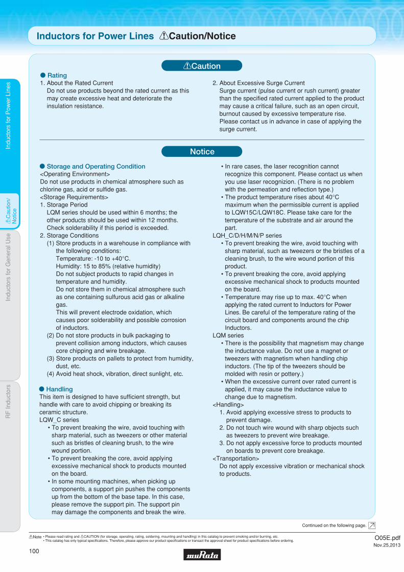
Indu
ctor
s fo
r P
ower
Lin
esIn
duct
ors
for
Gen
eral
Use
RF
Indu
ctor
sIn
duct
ors
for
Pow
er L
ines
!C
autio
n/N
otic
e
1. About the Rated CurrentDo not use products beyond the rated current as this may create excessive heat and deteriorate the insulation resistance.
o Rating
o Storage and Operating Condition<Operating Environment>Do not use products in chemical atmosphere such as chlorine gas, acid or sulfide gas.<Storage Requirements>1. Storage Period
LQM series should be used within 6 months; the other products should be used within 12 months.Check solderability if this period is exceeded.
2. Storage Conditions(1) Store products in a warehouse in compliance with
the following conditions:Temperature: -10 to +40°C.Humidity: 15 to 85% (relative humidity)Do not subject products to rapid changes in temperature and humidity.Do not store them in chemical atmosphere such as one containing sulfurous acid gas or alkaline gas.This will prevent electrode oxidation, which causes poor solderability and possible corrosion of inductors.
(2) Do not store products in bulk packaging to prevent collision among inductors, which causes core chipping and wire breakage.
(3) Store products on pallets to protect from humidity, dust, etc.
(4) Avoid heat shock, vibration, direct sunlight, etc.
o HandlingThis item is designed to have sufficient strength, but handle with care to avoid chipping or breaking its ceramic structure.LQW_C series
sharp material, such as tweezers or other material such as bristles of cleaning brush, to the wire wound portion.
excessive mechanical shock to products mounted on the board.
components, a support pin pushes the components
please remove the support pin. The support pin may damage the components and break the wire.
recognize this component. Please contact us when you use laser recognizion. (There is no problem with the permeation and reflection type.)
maximum when the permissible current is applied to LQW15C/LQW18C. Please take care for the temperature of the substrate and air around the part.
LQH_C/D/H/M/N/P series
sharp material, such as tweezers or the bristles of a cleaning brush, to the wire wound portion of this product.
excessive mechanical shock to products mounted on the board.
Lines. Be careful of the temperature rating of the circuit board and components around the chip
LQM series
the inductance value. Do not use a magnet or tweezers with magnetism when handling chip inductors. (The tip of the tweezers should be molded with resin or pottery.)
applied, it may cause the inductance value to change due to magnetism.
<Handling>1. Avoid applying excessive stress to products to
prevent damage.2. Do not touch wire wound with sharp objects such
as tweezers to prevent wire breakage.3. Do not apply excessive force to products mounted
on boards to prevent core breakage.<Transportation>
Do not apply excessive vibration or mechanical shock to products.
!Caution
Notice
Inductors for Power Lines !Caution/Notice
Continued on the following page.
2. About Excessive Surge CurrentSurge current (pulse current or rush current) greater than the specified rated current applied to the product may cause a critical failure, such as an open circuit, burnout caused by excessive temperature rise. Please contact us in advance in case of applying the surge current.
O05E.pdfNov.25,2013
100
!Note • Please read rating and !CAUTION (for storage, operating, rating, soldering, mounting and handling) in this catalog to prevent smoking and/or burning, etc.• This catalog has only typical specifi cations. Therefore, please approve our product specifi cations or transact the approval sheet for product specifi cations before ordering.

Indu
ctor
s fo
r P
ower
Lin
esIn
duct
ors
for
Gen
eral
Use
RF
Indu
ctor
sIn
duct
ors
for
Pow
er L
ines
!C
autio
n/N
otic
e
Measuring Method of Inductance/Q
<Rated Current>(LQH2HP_G0·LQH2HP_J0 Series)
Inductance will be more than the value, which is 30% down from minimum rated Inductance value.
(Other LQH_P Series except for LQH2HP_G0 Series)Inductance will be within ±30% of nominal Inductance value.
For LQH2MC series and LQH_P series, rated current is set to keep temperature rise caused by self heating 40°C or less.For other Inductors for Power Lines, please refer to individual specifications.
<Resin Coating>When coating products with resin, the relatively high resin curing stress may change inductance values.For exterior coating, select resin carefully so that electrical and mechanical performance of the product is not affected. Prior to use, please evaluate reliability with the product mounted in your application set.(LQW, LQH series)
An open circuit issue may occur by mechanical stress caused by the resin, amount/cured shape of resin, or operating conditions, etc. Some resins containing impurities or chloride may possibly generate chlorine by hydrolysis under some operating conditions, causing corrosion of the inductor wire and leading to an open circuit.
1. Residual elements and stray elements of test fixtures can be described by F-parameter as shown in the following:
current/voltage.
following:
4. Lx and Qx should be calculated with the following equation.
o Measuring Method
V1 A=
I1 C D
V2
I2
A
C DV1 V2
I1 I2
Product
V1
I1 ,
V2
I2
βΓ
αwhere, α = D / A = 1 β Γ
om: measured admittance when opening the fixture
0.556nH
0.771nH
LQW15C
LQW18C
ResidualImpedance Series
Lx: Inductance of chip Inductors (chip coils)Qx: Q of chip Inductors (chip coils)f: Measuring frequency
,2πfLx = Qx =
<Handling of a Substrate>After mounting products on a substrate, do not apply any stress to the product caused by bending or twisting the substrate when cropping the substrate, inserting and removing a connector from the substrate, or tightening a screw to the substrate. Excessive mechanical stress may cause cracking in the Product.
Inductors for Power Lines !Caution/Notice
O05E.pdfNov.25,2013
101
!Note • Please read rating and !CAUTION (for storage, operating, rating, soldering, mounting and handling) in this catalog to prevent smoking and/or burning, etc.• This catalog has only typical specifi cations. Therefore, please approve our product specifi cations or transact the approval sheet for product specifi cations before ordering.

Indu
ctor
s fo
r P
ower
Lin
esIn
duct
ors
for
Gen
eral
Use
RF
Indu
ctor
sIn
duct
ors
for
Pow
er L
ines
Sol
derin
g an
d M
ount
ing
1. Standard Land Pattern Dimensions
A high Q value is achieved when the PCB electrode land pattern is designed so that it does not project beyond the chip Inductors (chip coils) electrode.
(in mm)
a
c
b
Standard Land DimensionsSeries
LQH44P
LQH5BP
LQH55D/66S
LQW15C_00
LQW15C_10
LQW18C
3.0
4.1
3.5
0.6
0.66
1.0
4.4
5.5
8.0
1.4
1.4
2.2
1.3
1.8
2.0
0.4
0.4
0.7
LQM21D/21F/21P
LQM2MP
LQM2HP
LQM31P
LQM32P
LQH2MC
LQH31C
LQH32P
LQM18F/18P 0.7
1.0
1.8
1.5
1.2
2.7
1.0
1.5
2.0
2.2-2.6
1.8-2.0
3.0-4.0
2.4
3.0
4.2-5.2
3.6
2.6
4.5
3.8
0.7
1.2
0.8
1.6
2.0
1.9
0.8
1.0
1.3
LQM18F/18PLQM21D/21F/21PLQM2MP(Expect for LQM2MP_GH)LQM2HP(Except for LQM2HP_GH/JH)LQM31PLQM32PLQH2MCLQH31CLQH32PLQH44PLQH5BPLQH55D/66SLQW15C_00LQW15C_10LQW18C
LQH32C
LQH2HP(Except for LQH2HP_GR)
Part Number a b c
Land PatternLand Pattern + Solder Resist Solder Resist
5.5
1.0
2.0
1.0
1.3 1.0
Flow
Reflow
Attention should be paid to potential magnetic coupling effects when using the Inductors (coils) as a resonator.
Soldering and MountingInductors for Power Lines
Continued on the following page.
1.4
3.0
0.8
LQH2HP_GR
2.0
2.51.25
LQM2MP_GH
LQM2HP_GH
LQM2HP_JH
2.4
3.0
3.0
Part NumberRated
Current(A)
0.8
1.6
1.6
a
0-1.5
1.5-2.5
2.5-5.0
0-1.5
1.5-2.6
2.6-3.3
0-1.6
1.6-2.4
2.4-3.5
b
1.8
1.5
1.5
c
1.8
2.4
5.0
1.5
2.4
3.6
1.5
2.4
3.6
18μm
1.8
1.8
2.4
1.5
1.5
2.4
1.5
1.5
2.4
35μm
1.8
1.8
1.8
1.5
1.5
1.5
1.5
1.5
1.5
70μm
Land Pad Thicknessand Dimension d
LQM2MP_GHLQM2HP_GH/JH
a
dc
b
chip coil
O05E.pdfNov.25,2013
102
!Note • Please read rating and !CAUTION (for storage, operating, rating, soldering, mounting and handling) in this catalog to prevent smoking and/or burning, etc.• This catalog has only typical specifi cations. Therefore, please approve our product specifi cations or transact the approval sheet for product specifi cations before ordering.
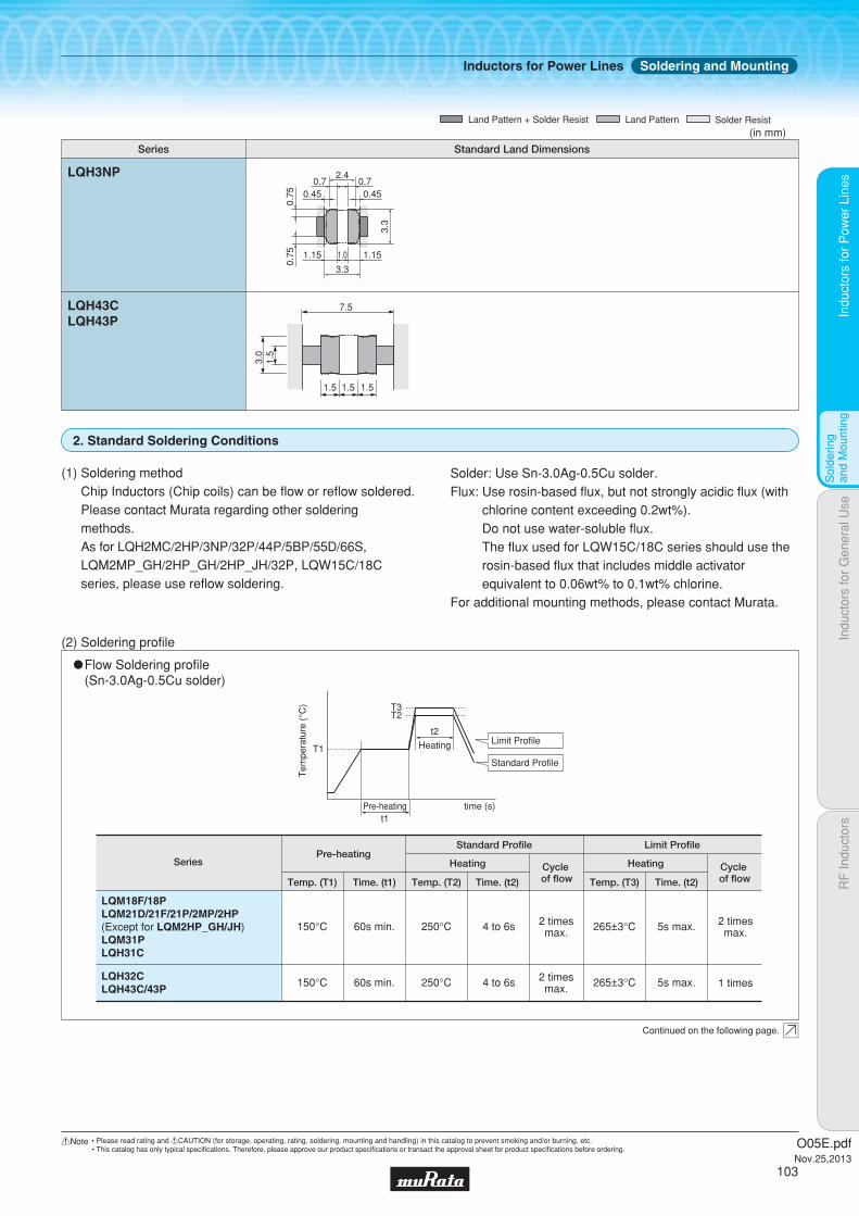
Indu
ctor
s fo
r P
ower
Lin
esIn
duct
ors
for
Gen
eral
Use
RF
Indu
ctor
sIn
duct
ors
for
Pow
er L
ines
Sol
derin
g an
d M
ount
ing
2. Standard Soldering Conditions
(1) Soldering methodChip Inductors (Chip coils) can be flow or reflow soldered. Please contact Murata regarding other soldering methods.As for LQH2MC/2HP/3NP/32P/44P/5BP/55D/66S, LQM2MP_GH/2HP_GH/2HP_JH/32P, LQW15C/18C series, please use reflow soldering.
Solder: Use Sn-3.0Ag-0.5Cu solder.Flux: Use rosin-based flux, but not strongly acidic flux (with
chlorine content exceeding 0.2wt%).Do not use water-soluble flux.The flux used for LQW15C/18C series should use the rosin-based flux that includes middle activator equivalent to 0.06wt% to 0.1wt% chlorine.
For additional mounting methods, please contact Murata.
(2) Soldering profile
"Flow Soldering profile (Sn-3.0Ag-0.5Cu solder)
SeriesPre-heating
Standard Profile Limit Profile
Heating
Temp. (T1) Temp. (T2)Time. (t1)
150°C 60s min. 250°C 4 to 6s 2 timesmax. 5s max. 2 times
max.265±3°C
Time. (t2)
HeatingCycle of flow Temp. (T3) Time. (t2)
Cycle of flow
T1
T3T2
Tem
pera
ture
(°C
)
Pre-heating time (s)
t2
Heating Limit Profile
Standard Profile
t1
150°C 60s min. 250°C 4 to 6s 2 timesmax. 5s max. 1 times265±3°C
LQM18F/18PLQM21D/21F/21P/2MP/2HP(Except for LQM2HP_GH/JH)LQM31PLQH31C
LQH32CLQH43C/43P
Continued on the following page.
(in mm)
Standard Land DimensionsSeries
Land PatternLand Pattern + Solder Resist Solder Resist
7.5
1.5
3.0
1.5
1.5 1.5
LQH43CLQH43P
2.4
0.75
0.75
3.3
1.01.15 1.15
0.45 0.450.7 0.7
3.3
LQH3NP
Inductors for Power Lines Soldering and Mounting
O05E.pdfNov.25,2013
103
!Note • Please read rating and !CAUTION (for storage, operating, rating, soldering, mounting and handling) in this catalog to prevent smoking and/or burning, etc.• This catalog has only typical specifi cations. Therefore, please approve our product specifi cations or transact the approval sheet for product specifi cations before ordering.
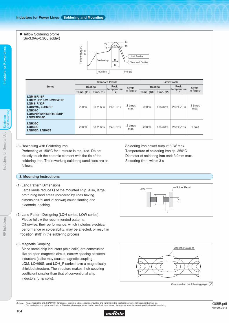
Indu
ctor
s fo
r P
ower
Lin
esIn
duct
ors
for
Gen
eral
Use
RF
Indu
ctor
sIn
duct
ors
for
Pow
er L
ines
Sol
derin
g an
d M
ount
ing
(3) Reworking with Soldering IronPreheating at 150°C for 1 minute is required. Do not directly touch the ceramic element with the tip of the soldering iron. The reworking soldering conditions are as follows:
Soldering iron power output: 80W max.Temperature of soldering iron tip: 350°CDiameter of soldering iron end: 3.0mm max.Soldering time: within 3 s
3. Mounting Instructions
(1) Land Pattern DimensionsLarge lands reduce Q of the mounted chip. Also, large protruding land areas (bordered by lines having dimensions 'c' and 'd' shown) cause floating and electrode leaching.
(2) Land Pattern Designing (LQH series, LQW series)Please follow the recommended patterns.Otherwise, their performance, which includes electrical performance or solderability, may be affected, or result in
“position shift” in the soldering process.
(3) Magnetic CouplingSince some chip inductors (chip coils) are constructed like an open magnetic circuit, narrow spacing between inductors (coils) may cause magnetic coupling.LQM, LQH66S, and LQH_P series have a magnetically shielded structure. The structure makes their coupling coefficient smaller than that of conventional chip inductors (chip coils).
d
c
Magnetic Coupling
Land Solder Resist
Continued on the following page.
"Reflow Soldering profile (Sn-3.0Ag-0.5Cu solder)
Series
Standard Profile Limit Profile
Temp. (T1) Time. (t1)
Heating
220°C 30 to 60s 245±3°C 2 timesmax. 230°C 260°C/10s 2 times
max.60s max.
Cycle of reflow
Peak temperature
(T2) Temp. (T3) Time. (t2)
Heating Cycle of reflow
Peak temperature
(T4)
150180
T2T4
T3T1
Tem
pera
ture
(°C
)
90±30s time (s)
t2
t1Limit Profile
Standard ProfilePre-heating
LQM18F/18PLQM21D/21F/21P/2MP/2HPLQM31P/32PLQH2MC, LQH2HPLQH31CLQH3NP/32P/43P/44P/5BPLQW15C/18C
LQH32CLQH43CLQH55D, LQH66S
220°C 30 to 60s 245±3°C 2 timesmax. 230°C 260°C/10s 1 time60s max.
Inductors for Power Lines Soldering and Mounting
O05E.pdfNov.25,2013
104
!Note • Please read rating and !CAUTION (for storage, operating, rating, soldering, mounting and handling) in this catalog to prevent smoking and/or burning, etc.• This catalog has only typical specifi cations. Therefore, please approve our product specifi cations or transact the approval sheet for product specifi cations before ordering.

Indu
ctor
s fo
r P
ower
Lin
esIn
duct
ors
for
Gen
eral
Use
RF
Indu
ctor
sIn
duct
ors
for
Pow
er L
ines
Sol
derin
g an
d M
ount
ing
LQH_C/H/M/N LQM
LQM18F/18P
LQM21D/21F/21P/2MP
LQM2HP/31P
LQH31C
LQH32C
LQH43C
0.06-0.07
0.20-0.25
0.25-0.30
0.20-0.25
0.27-0.35
0.60-0.80
(6) Amount of AdhesiveIf too much adhesive is applied, then it may overflow into the land or termination areas and yield poor solderability. In contrast, if insufficient adhesive is applied, or if the adhesive is not sufficiently hardened, then the chip may become detached during flow soldering. Apply the adhesive in accordance with the conditions shown in the chart.
Typical Application Amount (in:mg)Part Number
IR-100
LQM
LQH_C/D/H/N/P LQH_S
(5) Amount of Solder PasteExcessive solder causes electrode corrosion, while insufficient solder causes low electrode bonding strength. Adjust the amount of solder paste as shown on the right so that solder is applied." Guideline of solder paste thickness
· LQW15C: 50 to 100μm · LQM, LQW18C, LQH2MC/2HP, LQH3NP/32P, LQH44P/5BP/55P: 100 to 150μm
· LQH31C/32C, LQH43C/43P, LQH55D, LQH66S: 200 to 300μm
LQW_C
(4) PCB WarpingPCB should be designed so that products are not subjected to the mechanical stress caused by warping the board.
Poor example
except LQH3NP/44P/5BP
Products should be located in a sideways direction (Length: a<b) to the mechanical stress.
Good example
a
b
Poor example
LQH3NP/44P/5BP
The electrode part of the product should be located as in the figure to avoid mechanical stress.
Good example
electrode
electrode
Continued on the following page.
Inductors for Power Lines Soldering and Mounting
O05E.pdfNov.25,2013
105
!Note • Please read rating and !CAUTION (for storage, operating, rating, soldering, mounting and handling) in this catalog to prevent smoking and/or burning, etc.• This catalog has only typical specifi cations. Therefore, please approve our product specifi cations or transact the approval sheet for product specifi cations before ordering.

Indu
ctor
s fo
r P
ower
Lin
esIn
duct
ors
for
Gen
eral
Use
RF
Indu
ctor
sIn
duct
ors
for
Pow
er L
ines
Sol
derin
g an
d M
ount
ing
The following conditions should be observed when cleaning chip inductors (chip coils):(1) Cleaning Temperature: 60°C max. (40°C max. for
alcohol cleaning agents)(2) Ultrasonic
Output: 20W/l max.Duration: 5 minutes max.Frequency: 28 to 40kHzCare should be taken not to cause resonance of thePCB and mounted products.
(3) Cleaning agent The following cleaning agents have been tested on individual components. Evaluation in complete assembly should be done prior to production.(a) Alcohol cleaning agents
Isopropyl alcohol (IPA)(b) Aqueous cleaning agents
Pine Alpha ST-100SLQH66S series: Aqueous agents should not be used because they may cause quality deterioration or damage to appearance.
(4) Ensure that flux residue is completely removed.Component should be thoroughly dried after aqueous agents have been removed with deionized water.
For additional cleaning methods, please contact Murata.
4. Cleaning
Inductors for Power Lines Soldering and Mounting
O05E.pdfNov.25,2013
106
!Note • Please read rating and !CAUTION (for storage, operating, rating, soldering, mounting and handling) in this catalog to prevent smoking and/or burning, etc.• This catalog has only typical specifi cations. Therefore, please approve our product specifi cations or transact the approval sheet for product specifi cations before ordering.

Indu
ctor
s fo
r P
ower
Lin
esIn
duct
ors
for
Gen
eral
Use
RF
Indu
ctor
sIn
duct
ors
for
Pow
er L
ines
Pac
kagi
ng
Inductors for Power Lines Packaging
Continued on the following page.
c Minimum Quantity and 8mm Width Taping Dimensions
Direction of feed
2.0±0.05 4.0±0.1
a
b
1.75
±0.1
ø1.5 +0.1-0
3.5±
0.05
(8.0
)
2.0±0.05
c
LQW15C
Part Numbera
Paper Tape
LQW15C_00
LQW15C_10
0.64
0.69
b
1.18
1.18
c
0.8 max.
0.8 max.
ø180mm reel
D [10000]
D [10000]
ø330mm reel
Dimensions Total Thickness of Tape Packaging Code (Minimum Qty. [pcs.])
-
-
Bulk
B [500]
B [500]
(in mm)
O05E.pdfNov.25,2013
107
!Note • Please read rating and !CAUTION (for storage, operating, rating, soldering, mounting and handling) in this catalog to prevent smoking and/or burning, etc.• This catalog has only typical specifi cations. Therefore, please approve our product specifi cations or transact the approval sheet for product specifi cations before ordering.

Indu
ctor
s fo
r P
ower
Lin
esIn
duct
ors
for
Gen
eral
Use
RF
Indu
ctor
sIn
duct
ors
for
Pow
er L
ines
Pac
kagi
ng
a
b
cDirection of feed
Dimension of the cavity of embossed tape is measured at the bottom side.
4.0±0.1 4.0±0.1
2.0±0.05
0.2
3.5±
0.05 1.
75±
0.1
(8.
0)
ø1.5 +0.1-0
∗1
∗1: 0.25 LQM2HP/2MP/31P_00, LQH2
c Minimum Quantity and 8mm Width Taping Dimensions
<Embossed> <Paper>
c
(in mm)
Part Numbera
Paper Tape
LQM21D (1-10μH)
LQM21F (1-2.2μH)
LQM18F
1.45
1.45
1.05
b
2.25
2.25
1.85
c
1.1 max.
1.1 max.
1.1 max.
ø180mm reel ø330mm reel
Dimensions Packaging Code (Minimum Qty. [pcs.])
Bulk
D [4000] J [10000] B [1000]
D [4000] J [10000] B [1000]
D [4000] J [10000] B [1000]
LQM21P_C0 1.45 2.25 0.8 max. D [4000] - B [1000]
LQM21P_G 1.45 2.25 1.1 max. D [4000] - B [1000]
Part Numbera
Embossed Tape
LQM21D (22-47μH)
LQM21F (4.7-47μH)
LQH31C
LQH32C_33/_23
LQH32C_53
1.45
1.45
1.9
2.9
2.9
b
2.25
2.25
3.6
3.6
3.6
c
1.3
1.3
2.0
2.1
1.7
ø180mm reel ø330mm reel
Dimensions
Total Thickness of Tape
Depth of Cavity Packaging Code (Minimum Qty. [pcs.])
Bulk
L [3000] K [10000] B [1000]
L [3000] K [10000] B [1000]
LQM2HP_G 2.3 2.8 1.1 L [3000] - B [1000]
L [2000] K [7500] -
LQM32P_G0 2.9 3.6 1.15 L [3000] - B [1000]
L [2000] K [7500] -
L [2000] K [7500] -
LQH32P 2.9 3.6 1.7 L [2000] K [7500] -
LQM18P_B0 1.0 1.8 0.50 L [4000] - B [1000]
LQM18P_C0 1.0 1.8 0.60 L [4000] - B [1000]
LQM18P_F0 1.0 1.8 1.0 L [4000] - B [1000]
LQM2HP_JH 2.25 2.75 1.3 L [3000] - -
LQM2HP_E0 2.3 2.8 0.9 L [3000] - B [1000]
LQM2HP_GH 2.3 2.8 1.1 L [3000] - -
LQM2HP_J0/JC 2.25 2.75 1.3 L [3000] - B [1000]
LQM31P_00 1.9 3.5 1.05 L [3000] - B [1000]
LQM2MP_GH 1.9 2.4 1.1 L [3000] - -
LQM31P_C0 1.9 3.5 0.75 L [4000] - B [1000]
LQH2MC_02 1.9 2.3 1.05 L [3000] - B [100]
LQH2MC_52 1.9 2.3 0.8 L [3000] - B [100]
LQM2MP_G0 1.85 2.25 1.1 L [3000] - B [1000]
Continued on the following page.
LQW18C 1.0 1.8 1.1 max. D [4000] - B [500]
LQM18P_D0 1.05 1.85 0.85 max. D [4000] - B [1000]
Inductors for Power Lines Packaging
O05E.pdfNov.25,2013
108
!Note • Please read rating and !CAUTION (for storage, operating, rating, soldering, mounting and handling) in this catalog to prevent smoking and/or burning, etc.• This catalog has only typical specifi cations. Therefore, please approve our product specifi cations or transact the approval sheet for product specifi cations before ordering.
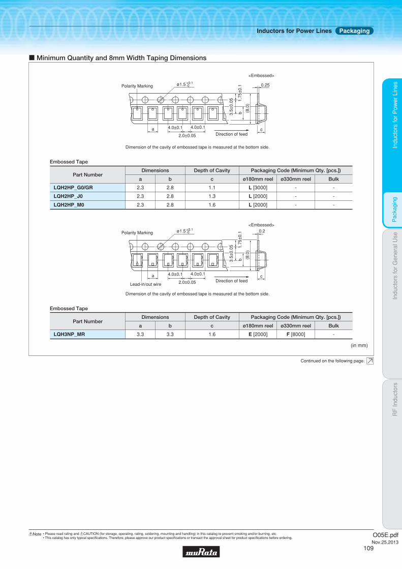
Indu
ctor
s fo
r P
ower
Lin
esIn
duct
ors
for
Gen
eral
Use
RF
Indu
ctor
sIn
duct
ors
for
Pow
er L
ines
Pac
kagi
ng
c Minimum Quantity and 8mm Width Taping Dimensions
(in mm)
Part Numbera
Embossed Tape
b c ø180mm reel ø330mm reel
Dimensions Depth of Cavity Packaging Code (Minimum Qty. [pcs.])
Bulk
LQH2HP_G0/GR 2.3 2.8 1.1 L [3000] - -
LQH2HP_J0 2.3 2.8 1.3 L [2000] - -
LQH2HP_M0 2.3 2.8 1.6 L [2000] - -
Part Numbera
Embossed Tape
b c ø180mm reel ø330mm reel
Dimensions Depth of Cavity Packaging Code (Minimum Qty. [pcs.])
Bulk
LQH3NP_MR 3.3 3.3 1.6 E [2000] F [8000] -
Continued on the following page.
<Embossed>
a
b
cDirection of feed
Dimension of the cavity of embossed tape is measured at the bottom side.
4.0±0.1 4.0±0.1
2.0±0.05
0.25
3.5±
0.05 1.
75±
0.1
(8.
0)
ø1.5 +0.1-0Polarity Marking
a
b
cDirection of feed
Dimension of the cavity of embossed tape is measured at the bottom side.
4.0±0.1 4.0±0.1
2.0±0.05
0.23.
5±0.
05 1.75
±0.
1
(8.
0)
ø1.5 +0.1-0
<Embossed>
Polarity Marking
Lead-in/out wire
Inductors for Power Lines Packaging
O05E.pdfNov.25,2013
109
!Note • Please read rating and !CAUTION (for storage, operating, rating, soldering, mounting and handling) in this catalog to prevent smoking and/or burning, etc.• This catalog has only typical specifi cations. Therefore, please approve our product specifi cations or transact the approval sheet for product specifi cations before ordering.

Indu
ctor
s fo
r P
ower
Lin
esIn
duct
ors
for
Gen
eral
Use
RF
Indu
ctor
sIn
duct
ors
for
Pow
er L
ines
Pac
kagi
ng
(in mm)
a
b
c
d8.0±0.1
2.0±0.054.0±0.1
5.5±
0.05
1.75
±0.
1
(12.
0)
ø1.5+0.1-0
Direction of feed
c Minimum Quantity and 12mm Width Embossed Taping Dimensions
Dimension of the cavity of embossed tape is measured at the bottom side.
a
b
c
d8.0±0.1
2.0±0.054.0±0.1
5.5±
0.05
1.75
±0.
1
(12.
0)
ø1.5+0.1-0
Direction of feed
Dimension of the cavity of embossed tape is measured at the bottom side.
Part Numbera
Embossed Tape
b c d ø180mm reel
Dimensions (*c: Depth of Cavity) Packaging Code (Minimum Qty. [pcs.])
ø330mm reel Bulk
LQH3NP_G0 3.3 3.3 1.1 0.25 L [1500] K [6000] -
LQH3NP_J0 3.3 3.3 1.3 0.25 L [1000] K [5000] -
LQH3NP_M0 3.3 3.3 1.6 0.25 L [1000] K [4000] -
Part Numbera
Embossed Tape
LQH43C
LQH55D
LQH66S
3.6
5.4
6.7
b
4.9
6.1
6.7
c
2.7
5.0
5.6
d ø180mm reel
Dimensions (*c: Depth of Cavity) Packaging Code (Minimum Qty. [pcs.])
ø330mm reel
0.3 L [500] -
0.4 L [350] K [1500]
0.4 L [350] K [1500]
Bulk
-
LQH43P 3.6 4.9 2.7 0.3 L [500] K [2500] -
-
-
LQH44 P_J0 4.3 4.3 1.4 0.3 L [1000] K [3500] -
LQH44P_P0 4.3 4.3 1.9 0.3 L [1000] K [3500] -
LQH5BP 5.3 5.3 2.4 0.3 L [500] K [3000] -
Polarity Marking
Lead-in/out wire
Inductors for Power Lines Packaging
O05E.pdfNov.25,2013
110
!Note • Please read rating and !CAUTION (for storage, operating, rating, soldering, mounting and handling) in this catalog to prevent smoking and/or burning, etc.• This catalog has only typical specifi cations. Therefore, please approve our product specifi cations or transact the approval sheet for product specifi cations before ordering.

Indu
ctor
s fo
r P
ower
Lin
esIn
duct
ors
for
Gen
eral
Use
RF
Indu
ctor
sIn
duct
ors
for
Pow
er L
ines
Des
ign
Kits
oEKLMQM2PK-KIT (Inductors for Power Lines: Multilayer Type)
c Holder Type
LQM2HPN1R0MJCLQM2HPN2R2NJC
4849
15001000
0.086±25%0.175±25%
±20%±30%
1.0μH2.2μH
1010
LQM2HPN1R0MJ0LQM2HPN2R2MJ0LQM2HPN3R3MJ0
454647
150010001000
0.09±25%0.12±25%0.12±25%
±20%±20%±20%
1.0μH2.2μH3.3μH
101010
LQM18PNR22NFRLQM18PNR47NFRLQM18PN1R0MFRLQM18PN1R5MFRLQM18PN2R2MFRLQM18PN3R3MFRLQM18PN4R7MFR
567891011
12501100950800750700620
0.11±25%0.15±25%0.20±25%0.23±25%0.30±25%0.35±25%0.44±25%
±30%±30%±20%±20%±20%±20%±20%
0.22μH0.47μH1.0μH1.5μH2.2μH3.3μH4.7μH
10101010101010
LQM21PNR47MC0LQM21PN1R0MC0LQM21PN1R5MC0LQM21PN2R2MC0
12131415
1100800700600
0.12±25%0.19±25%0.26±25%0.34±25%
±20%±20%±20%±20%
0.47μH1.0μH1.5μH2.2μH
10101010
LQM21PNR54MG0LQM21PN3R3MG0
1718
1300800
0.075±25%0.165±25%
±20%±20%
0.54μH3.3μH
1010
LQM21PN2R2MGSLQM21PN4R7MGS
1920
950750
0.180±25%0.290±25%
±20%±20%
2.2μH4.7μH
1010
LQM21PNR47MG016 13000.075±25%±20%0.47μH10
LQM21PN1R0NGCLQM21PN2R2NGC
2122
900800
0.10±25%0.23±25%
±30%±30%
1.0μH2.2μH
1010
LQM2MPNR47MG026 16000.060±25%±20%0.47μH10
LQM21PN1R0NGRLQM21PN3R3MGRLQM21PN4R7MGR
232425
13001000800
0.066±25%0.150±25%0.23±25%
±30%±20%±20%
1.0μH3.3μH4.7μH
101010
LQM2MPN1R0NG0LQM2MPN1R5MG0LQM2MPN2R2MG0LQM2MPN3R3NG0
27282930
1400120012001200
0.085±25%0.11±25%0.11±25%0.12±25%
±30%±20%±20%±30%
1.0μH1.5μH2.2μH3.3μH
10101010
LQM2MPN4R7MG031 11000.14±25%±20%4.7μH10LQM2HPNR56ME032 15000.06±25%±20%0.56μH10LQM2HPNR47MG0LQM2HPN1R0MG0LQM2HPN1R5MG0LQM2HPN2R2MG0LQM2HPN3R3MG0LQM2HPN4R7MG0
333435363738
180016001500130012001100
0.04±25%0.055±25%0.07±25%0.08±25%0.10±25%0.11±25%
±20%±20%±20%±20%±20%±20%
0.47μH1.0μH1.5μH2.2μH3.3μH4.7μH
101010101010
LQM2HPN1R0MGCLQM2HPN3R3MGCLQM2HPN4R7MGC
394041
15001000800
0.08±25%0.16±25%0.18±25%
±20%±20%±20%
1.0μH3.3μH4.7μH
101010
LQM2HPN2R2MGSLQM2HPN3R3MGSLQM2HPN4R7MGS
424344
110010501000
0.18±25%0.21±25%0.25±25%
±20%±20%±20%
2.2μH3.3μH4.7μH
101010
LQM18PN1R5NB0LQM18PN1R8NC0LQM18PN2R5ND0LQM18PN1R0NF0
1234
600700700600
0.35±25%0.24±25%0.24±25%0.28±25%
±30%±30%±30%±30%
1.5μH1.8μH2.5μH1.0μH
10101010
LQM31PNR47M00LQM31PN1R0M00
5455
14001200
0.07±25%0.12±25%
±20%±20%
0.47μH1.0μH
1010
LQM31PNR47MC0LQM31PN1R0MC0LQM31PN1R5MC0LQM31PN2R2MC0
50515253
130011001000900
0.085±25%0.14±25%0.17±25%0.25±25%
±20%±20%±20%±20%
0.47μH1.0μH1.5μH2.2μH
10101010
Part NumberNo.Rated Current
(mA)DC Resistance
(Ω)ToleranceNominalInductanceQuantity
(pcs.)
Continued on the following page.
Design KitsInductors for Power Lines
O05E.pdfNov.25,2013
111
!Note • Please read rating and !CAUTION (for storage, operating, rating, soldering, mounting and handling) in this catalog to prevent smoking and/or burning, etc.• This catalog has only typical specifi cations. Therefore, please approve our product specifi cations or transact the approval sheet for product specifi cations before ordering.
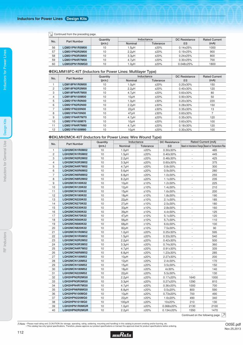
Indu
ctor
s fo
r P
ower
Lin
esIn
duct
ors
for
Gen
eral
Use
RF
Indu
ctor
sIn
duct
ors
for
Pow
er L
ines
Des
ign
Kits
LQH2MCN470K02LQH2MCN560K02LQH2MCN680K02LQH2MCN820K02LQH2MCN1R0M52LQH2MCN1R5M52LQH2MCN2R2M52LQH2MCN3R3M52LQH2MCN4R7M52LQH2MCN6R8M52LQH2MCN100M52
1718192021222324252627
1010101010101010101010
47μH56μH68μH82μH1.0μH1.5μH2.2μH3.3μH4.7μH6.8μH10μH
±10%±10%±10%±10%±20%±20%±20%±20%±20%±20%±20%
5.1±30%5.7±30%6.6±30%7.5±30%
0.25±30%0.33±30%0.42±30%0.74±30%0.91±30%1.23±30%2.27±30%
12011010090595540500360335285200
-----------
LQH2MCN120M52LQH2MCN150M52LQH2MCN180M52LQH2MCN220M52
28293031
10101010
12μH15μH18μH22μH
±20%±20%±20%±20%
2.4±30%3.5±30%4±30%
5.5±30%
170150140130
----
LQH2HPN2R2MG0LQH2HPN3R3MG0LQH2HPN4R7MG0LQH2HPN6R8MG0LQH2HPN100MG0LQH2HPN220MG0LQH2HPN101MG0
32333435363738
10101010101010
2.2μH3.3μH4.7μH6.8μH10μH22μH
100μH
±20%±20%±20%±20%±20%±20%±20%
0.17±20%0.27±20%0.36±20%0.5±20%
0.73±20%1.6±20%10±20%
1000810700590490340130
164012901000800700490210
LQH2HPN1R0MGRLQH2HPN2R2MGR
3940
1010
1.0μH2.2μH
±20%±20%
0.068±20%0.134±20%
21001470
21301550
LQH2MCN6R8M02LQH2MCN8R2M02LQH2MCN100K02LQH2MCN120K02LQH2MCN150K02LQH2MCN180K02LQH2MCN220K02LQH2MCN270K02LQH2MCN330K02LQH2MCN390K02
78910111213141516
10101010101010101010
6.8μH8.2μH10μH12μH15μH18μH22μH27μH33μH39μH
±20%±20%±10%±10%±10%±10%±10%±10%±10%±10%
1.0±30%1.1±30%1.2±30%1.4±30%1.6±30%1.8±30%2.1±30%2.5±30%2.8±30%4.4±30%
255235225210200190185180160125
----------
oEKLMH2MCK-KIT (Inductors for Power Lines: Wire Wound Type)
LQH2MCN1R0M02LQH2MCN1R5M02LQH2MCN2R2M02LQH2MCN3R3M02LQH2MCN4R7M02LQH2MCN5R6M02
123456
101010101010
1.0μH1.5μH2.2μH3.3μH4.7μH5.6μH
±20%±20%±20%±20%±20%±20%
0.30±30%0.40±30%0.48±30%0.60±30%0.8±30%0.9±30%
485445425375300280
------
Part NumberNo.DC Resistance
(Ω)ToleranceNominalInductanceQuantity
(pcs.) Based on Inductance Change Based on Temperature RiseRated Current (mA)
LQM31PN1R5M00LQM31PN2R2M00LQM31PN3R3M00LQM31PN4R7M00
56575859
1000900800700
0.14±25%0.19±25%0.24±25%0.30±25%
±20%±20%±20%±20%
1.5μH2.2μH3.3μH4.7μH
10101010
LQM32PN1R0MG060 18000.048±25%±20%1.0μH10
Part NumberNo.Rated Current
(mA)DC Resistance
(Ω)ToleranceNominalInductanceQuantity
(pcs.)
oEKLMM18FC-KIT (Inductors for Power Lines: Multilayer Type)
LQM18FN1R0M00LQM18FN2R2M00LQM18FN4R7M00LQM18FN100M00LQM21FN1R0N00LQM21FN2R2N00LQM21FN220N00LQM21FN470N00LQM21FN4R7M70LQM21FN100M70LQM21FN4R7M80LQM21FN100M80
123456789101112
101010101010101010101010
1.0μH2.2μH4.7μH10μH1.0μH2.2μH22μH47μH4.7μH10μH4.7μH10μH
±20%±20%±20%±20%±30%±30%±30%±30%±20%±20%±20%±20%
0.20±30%0.40±30%0.60±30%0.90±30%0.20±30%0.28±30%0.35±30%0.60±30%0.35±30%0.60±30%0.18±30%0.30±30%
1501208050220150137
120100120100
Part NumberNo.Rated Current
(mA)DC Resistance
(Ω)ToleranceNominalInductanceQuantity
(pcs.)
Continued from the preceding page.
Continued on the following page.
Inductors for Power Lines Design Kits
O05E.pdfNov.25,2013
112
!Note • Please read rating and !CAUTION (for storage, operating, rating, soldering, mounting and handling) in this catalog to prevent smoking and/or burning, etc.• This catalog has only typical specifi cations. Therefore, please approve our product specifi cations or transact the approval sheet for product specifi cations before ordering.

Indu
ctor
s fo
r P
ower
Lin
esIn
duct
ors
for
Gen
eral
Use
RF
Indu
ctor
sIn
duct
ors
for
Pow
er L
ines
Des
ign
Kits
Part NumberNo.DC Resistance
(Ω)ToleranceNominalInductanceQuantity
(pcs.) Based on Inductance Change Based on Temperature RiseRated Current (mA)
LQH3NPN470MM0LQH3NPN101MM0
3738
310200
410240
1.25±20%3.50±20%
±20%±20%
47μH100μH
1010
LQH32PNR47NN0LQH32PN1R0NN0LQH32PN1R5NN0LQH32PN2R2NN0LQH32PN3R3NN0LQH32PN4R7NN0
484950515253
340023001750155012501000
255020501750160012001000
0.030±20%0.045±20%0.057±20%0.076±20%0.12±20%0.18±20%
±30%±30%±30%±30%±30%±30%
0.47μH1.0μH1.5μH2.2μH3.3μH4.7μH
101010101010
LQH3NPN6R8MJ0LQH3NPN100MJ0LQH3NPN150MJ0LQH3NPN220MJ0LQH3NPN330MJ0LQH3NPN470MJ0LQH3NPN1R0MM0LQH3NPN2R2MM0LQH3NPN3R3MM0LQH3NPN4R7MM0LQH3NPN6R8MM0LQH3NPN100MM0LQH3NPN150MM0LQH3NPN220MM0LQH3NPN330MM0
222324252627282930313233343536
700560440350280200
140012501000880820550520410370
85071059051041035020501600145012501000870730650500
0.210±20%0.300±20%0.440±20%0.600±20%0.900±20%1.30±20%
0.044±20%0.073±20%0.092±20%0.13±20%0.20±20%0.26±20%0.36±20%0.51±20%0.85±20%
±20%±20%±20%±20%±20%±20%±20%±20%±20%±20%±20%±20%±20%±20%±20%
6.8μH10μH15μH22μH33μH47μH1.0μH2.2μH3.3μH4.7μH6.8μH10μH15μH22μH33μH
101010101010101010101010101010
LQH3NPN1R0MMRLQH3NPN2R2MMRLQH3NPN3R3MMRLQH3NPN4R7MMRLQH3NPN6R8MMRLQH3NPN100MMRLQH3NPN220MMRLQH3NPN330MMRLQH3NPN470MMR
394041424344454647
160013801200950830590430380320
215017501550140012501150750600460
0.042±20%0.068±20%0.088±20%0.105±20%0.155±20%0.210±20%0.480±20%0.790±20%1.140±20%
±20%±20%±20%±20%±20%±20%±20%±20%±20%
1.0μH2.2μH3.3μH4.7μH6.8μH10μH22μH33μH47μH
101010101010101010
LQH3NPN151MG0LQH3NPN221MG0LQH3NPN251MG0LQH3NPN1R0NJ0LQH3NPN1R5NJ0LQH3NPN2R2MJ0LQH3NPN3R3MJ0LQH3NPN4R7MJ0
1415161718192021
11010080
165012001150950780
14513013016201500146012701120
11±20%14±20%15±20%
0.040±20%0.055±20%0.069±20%0.105±20%0.130±20%
±20%±20%±20%±30%±30%±20%±20%±20%
150μH220μH250μH1.0μH1.5μH2.2μH3.3μH4.7μH
1010101010101010
LQH3NPN100MG0LQH3NPN150NG0LQH3NPN220MG0LQH3NPN330MG0LQH3NPN470MG0LQH3NPN680MG0LQH3NPN101MG0
78910111213
500370340250170150140
630475430345270235165
0.57±20%0.91±20%1.1±20%2.1±20%3.0±20%4.2±20%8.0±20%
±20%±30%±20%±20%±20%±20%±20%
10μH15μH22μH33μH47μH68μH100μH
10101010101010
LQH3NPN4R7NG0LQH3NPN6R8NG0
56
800650
925710
0.26±20%0.45±20%
±30%±30%
4.7μH6.8μH
1010
oEKLMQH3PE-KIT (Inductors for Power Lines: Wire Wound Type)
LQH2HPN1R5NJ0LQH2HPN2R2MJ0LQH2HPN3R3MJ0LQH2HPN4R7MJ0LQH2HPN6R8MJ0LQH2HPN100MJ0LQH2HPN2R2MM0LQH2HPN4R7NM0
4142434445464748
1010101010101010
1.5μH2.2μH3.3μH4.7μH6.8μH10μH2.2μH4.7μH
±30%±20%±20%±20%±20%±20%±20%±30%
0.096±20%0.132±20%0.230±20%0.330±20%0.448±20%0.641±20%0.146±20%0.342±20%
150013009507006005501250800
24001800150012501100820
17001200
LQH3NPN1R0NG0LQH3NPN1R5NG0LQH3NPN2R2NG0LQH3NPN3R3NG0
1234
165013001250850
1525147012701130
0.08±20%0.10±20%0.14±20%0.18±20%
±30%±30%±30%±30%
1.0μH1.5μH2.2μH3.3μH
10101010
Part NumberNo.DC Resistance
(Ω)ToleranceNominalInductanceQuantity
(pcs.) Based on Inductance Change Based on Temperature RiseRated Current (mA)
Continued from the preceding page.
Continued on the following page.
Inductors for Power Lines Design Kits
O05E.pdfNov.25,2013
113
!Note • Please read rating and !CAUTION (for storage, operating, rating, soldering, mounting and handling) in this catalog to prevent smoking and/or burning, etc.• This catalog has only typical specifi cations. Therefore, please approve our product specifi cations or transact the approval sheet for product specifi cations before ordering.

Indu
ctor
s fo
r P
ower
Lin
esIn
duct
ors
for
Gen
eral
Use
RF
Indu
ctor
sIn
duct
ors
for
Pow
er L
ines
Des
ign
Kits
LQH44PN470MJ011 300 3801.014±20%±20%47μH10LQH44PN1R0NP012 2950 24500.030±20%±30%1.0μH10
LQH44PN2R2MJ0LQH44PN3R3MJ0LQH44PN4R7MJ0LQH44PN6R8MJ0LQH44PN100MJ0LQH44PN150MJ0LQH44PN220MJ0LQH44PN330MJ0
345678910
1320900840720560430400360
12301000980860790610550430
0.074±20%0.088±20%0.117±20%0.143±20%0.207±20%0.385±20%0.480±20%0.740±20%
±20%±20%±20%±20%±20%±20%±20%±20%
2.2μH3.3μH4.7μH6.8μH10μH15μH22μH33μH
1010101010101010
oEKLMQH4PD-KIT (Inductors for Power Lines: Wire Wound Type)
LQH44PN1R0NJ0LQH44PN1R5MJ0
12
20001600
15301380
0.048±20%0.061±20%
±30%±20%
1.0μH1.5μH
1010
Part NumberNo.ToleranceNominal
InductanceQuantity(pcs.) Based on Inductance Change Based on Temperature Rise
Rated Current (mA)DC Resistance(Ω)
oEKLMQH3BA-KIT (Inductors for Power Lines: Wire Wound Type)
LQH32PBR47NN0LQH32PB1R0NN0LQH32PB1R5NN0LQH32PB2R2NN0LQH32PB3R3NN0LQH32PB4R7NN0LQH32PB6R8NN0LQH32PB100MN0LQH32PB150MN0LQH32PB220MN0LQH32PB330MN0LQH32PB470MN0LQH32PB680MN0LQH32PB101MN0LQH32PB121MN0LQH32PBR47NNCLQH32PB1R0NNCLQH32PB1R5NNCLQH32PB2R2NNCLQH32PB3R3NNCLQH32PB4R7NNCLQH32PB6R8NNCLQH32PB100MNCLQH32PB150MNCLQH32PB220MNC
12345678910111213141516171819202122232425
340023001750155012501000850750600500380330280180170
44003000260020001900160013001000800650
255020501750160012001000850700520450390310275250200
2900250021001850155012001100900700550
16001320101097067053051038032024019014012011080
149013801110910800610550450330270
0.030±20%0.045±20%0.057±20%0.076±20%0.12±20%0.18±20%0.24±20%0.38±20%0.57±20%0.81±20%1.15±20%1.78±20%2.28±20%2.70±20%4.38±20%
0.024±20%0.036±20%0.053±20%0.064±20%0.100±20%0.155±20%0.220±20%0.295±20%0.475±20%0.685±20%
±30%±30%±30%±30%±30%±30%±30%±20%±20%±20%±20%±20%±20%±20%±20%±30%±30%±30%±30%±30%±30%±30%±20%±20%±20%
0.47μH1.0μH1.5μH2.2μH3.3μH4.7μH6.8μH10μH15μH22μH33μH47μH68μH
100μH120μH0.47μH1.0μH1.5μH2.2μH3.3μH4.7μH6.8μH10μH15μH22μH
10101010101010101010101010101010101010101010101010
Part NumberNo.ToleranceNominal
InductanceQuantity(pcs.)
Based on Inductance Change
Based on Temperature RiseAmbient temperature 85°C Ambient temperature 105°C
Rated Current (mA)DC Resistance
(Ω)
Part NumberNo.DC Resistance
(Ω)ToleranceNominalInductanceQuantity
(pcs.) Based on Inductance Change Based on Temperature RiseRated Current (mA)
LQH32PN100MNCLQH32PN150MNCLQH32PN220MNC
707172
1000800650
900700550
0.295±20%0.475±20%0.685±20%
±20%±20%±20%
10μH15μH22μH
101010
LQH32PN150MN0LQH32PN220MN0LQH32PN330MN0LQH32PN470MN0LQH32PN680MN0LQH32PN101MN0LQH32PN121MN0
56575859606162
600500380330280180170
520450390310275250200
0.57±20%0.81±20%1.15±20%1.78±20%2.28±20%2.70±20%4.38±20%
±20%±20%±20%±20%±20%±20%±20%
15μH22μH33μH47μH68μH
100μH120μH
10101010101010
LQH32PN6R8NN0LQH32PN100MN0
5455
850750
850700
0.24±20%0.38±20%
±30%±20%
6.8μH10μH
1010
LQH32PNR47NNCLQH32PN1R0NNCLQH32PN1R5NNCLQH32PN2R2NNCLQH32PN3R3NNCLQH32PN4R7NNCLQH32PN6R8NNC
63646566676869
4400300026002000190016001300
2900250021001850155012001100
0.024±20%0.036±20%0.053±20%0.064±20%0.100±20%0.155±20%0.220±20%
±30%±30%±30%±30%±30%±30%±30%
0.47μH1.0μH1.5μH2.2μH3.3μH4.7μH6.8μH
10101010101010
Continued from the preceding page.
Continued on the following page.
Inductors for Power Lines Design Kits
O05E.pdfNov.25,2013
114
!Note • Please read rating and !CAUTION (for storage, operating, rating, soldering, mounting and handling) in this catalog to prevent smoking and/or burning, etc.• This catalog has only typical specifi cations. Therefore, please approve our product specifi cations or transact the approval sheet for product specifi cations before ordering.

Indu
ctor
s fo
r P
ower
Lin
esIn
duct
ors
for
Gen
eral
Use
RF
Indu
ctor
sIn
duct
ors
for
Pow
er L
ines
Des
ign
Kits
LQH32CN100K53LQH32CN150K53LQH32CN220K53LQH32CN330K53LQH32CN470K53
2324252627
1010101010
10μH15μH22μH33μH47μH
±10%±10%±10%±10%±10%
0.3±30%0.58±30%0.71±30%1.1±30%1.3±30%
450300250200170
LQH32CN1R0M53LQH32CN2R2M53LQH32CN4R7M53
202122
101010
1.0μH2.2μH4.7μH
±20%±20%±20%
0.06±30%0.097±30%0.15±30%
1000790650
LQH32CN331K23LQH32CN391K23LQH32CN471K23LQH32CN561K23
16171819
10101010
330μH390μH470μH560μH
±10%±10%±10%±10%
10±30%17±30%19±30%22±30%
60606060
LQH32CN470K23LQH32CN101K23LQH32CN221K23
131415
101010
47μH100μH220μH
±10%±10%±10%
1.3±30%3.5±30%8.4±30%
17010070
LQH32CN2R2M23LQH32CN4R7M23LQH32CN100K23LQH32CN220K23
9101112
10101010
2.2μH4.7μH10μH22μH
±20%±20%±10%±10%
0.13±30%0.2±30%
0.44±30%0.71±30%
600450300250
LQH32CN100K33LQH32CN1R0M23
78
1010
10μH1.0μH
±10%±20%
0.3±30%0.09±30%
450800
LQH32CN1R0M33LQH32CN2R2M33
45
1010
1.0μH2.2μH
±20%±20%
0.06±30%0.097±30%
1000790
LQH32CN4R7M336 10 4.7μH ±20% 0.15±30% 650
oEKLMH32CC-KIT (Inductors for Power Lines: Wire Wound Type)
LQH32CNR15M33LQH32CNR27M33LQH32CNR47M33
123
101010
0.15μH0.27μH0.47μH
±20%±20%±20%
0.028±30%0.034±30%0.042±30%
145012501100
Part NumberNo.Rated Current
(mA)DC Resistance
(Ω)ToleranceNominalInductanceQuantity
(pcs.)
oEKLMQH5PC-KIT (Inductors for Power Lines: Wire Wound Type)
LQH5BPNR47NT0LQH5BPN1R0NT0LQH5BPN1R2NT0LQH5BPN1R5NT0LQH5BPN2R2NT0LQH5BPN2R7NT0LQH5BPN3R3NT0LQH5BPN4R7NT0LQH5BPN6R8NT0LQH5BPN100MT0LQH5BPN150MT0LQH5BPN220MT0
123456789101112
770058005400500040003800350030002500200016001400
400031003100300026002500230020001650160012001050
0.012±20%0.019±20%0.019±20%0.024±20%0.030±20%0.035±20%0.044±20%0.058±20%0.083±20%0.106±20%0.187±20%0.259±20%
±30%±30%±30%±30%±30%±30%±30%±30%±30%±20%±20%±20%
0.47μH1.0μH1.2μH1.5μH2.2μH2.7μH3.3μH4.7μH6.8μH10μH15μH22μH
101010101010101010101010
Part NumberNo.ToleranceNominal
InductanceQuantity(pcs.) Based on Inductance Change Based on Temperature Rise
Rated Current (mA)DC Resistance(Ω)
LQH43PN151M26LQH43PN221M26
2930
280220
260240
2.362±20%2.900±20%
±20%±20%
150μH220μH
1010
Part NumberNo.ToleranceNominal
InductanceQuantity(pcs.) Based on Inductance Change Based on Temperature Rise
Rated Current (mA)DC Resistance(Ω)
LQH43PN1R0N26LQH43PN2R2M26LQH43PN3R3M26LQH43PN4R7M26LQH43PN6R8M26LQH43PN8R2M26LQH43PN100M26LQH43PN220M26LQH43PN470M26LQH43PN101M26
19202122232425262728
3400230018001400120011001050700470320
3300250021001600140013001170780520320
0.026±20%0.042±20%0.052±20%0.075±20%0.098±20%0.128±20%0.147±20%0.327±20%0.718±20%1.538±20%
±30%±20%±20%±20%±20%±20%±20%±20%±20%±20%
1.0μH2.2μH3.3μH4.7μH6.8μH8.2μH10μH22μH47μH
100μH
10101010101010101010
LQH44PN2R2MP0LQH44PN3R3MP0LQH44PN4R7MP0LQH44PN6R8MP0LQH44PN100MP0LQH44PN220MP0
131415161718
25002100170014001150800
18001770170013401170790
0.049±20%0.065±20%0.080±20%0.12±20%0.16±20%0.37±20%
±20%±20%±20%±20%±20%±20%
2.2μH3.3μH4.7μH6.8μH10μH22μH
101010101010
Continued from the preceding page.
Continued on the following page.
Inductors for Power Lines Design Kits
O05E.pdfNov.25,2013
115
!Note • Please read rating and !CAUTION (for storage, operating, rating, soldering, mounting and handling) in this catalog to prevent smoking and/or burning, etc.• This catalog has only typical specifi cations. Therefore, please approve our product specifi cations or transact the approval sheet for product specifi cations before ordering.
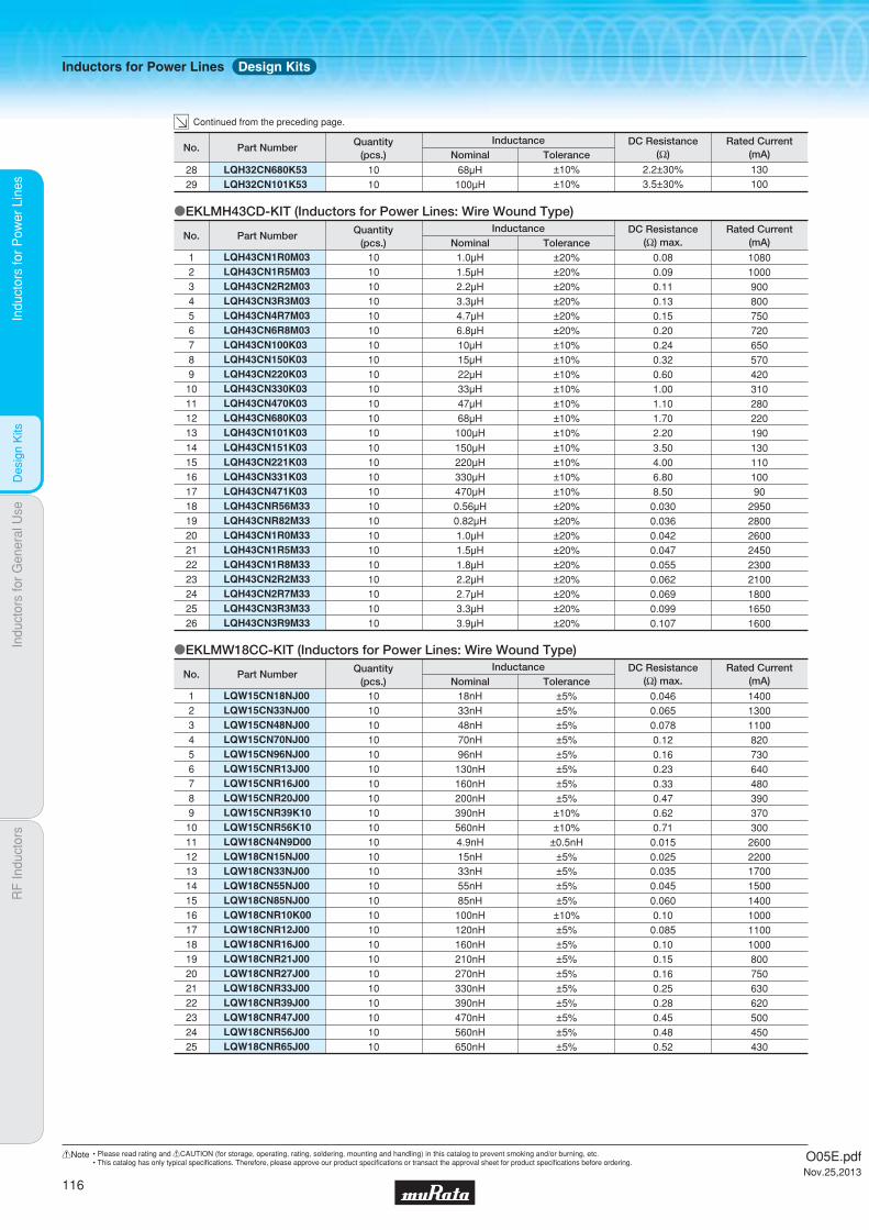
Indu
ctor
s fo
r P
ower
Lin
esIn
duct
ors
for
Gen
eral
Use
RF
Indu
ctor
sIn
duct
ors
for
Pow
er L
ines
Des
ign
Kits
LQW18CN33NJ00 LQW18CN55NJ00
1314
1010
33nH55nH
±5%±5%
0.0350.045
17001500
LQW18CN85NJ00 LQW18CNR10K00LQW18CNR12J00 LQW18CNR16J00LQW18CNR21J00LQW18CNR27J00 LQW18CNR33J00LQW18CNR39J00 LQW18CNR47J00 LQW18CNR56J00 LQW18CNR65J00
1516171819202122232425
1010101010101010101010
85nH100nH120nH160nH210nH270nH330nH390nH470nH560nH650nH
±5%±10%±5%±5%±5%±5%±5%±5%±5%±5%±5%
0.0600.10
0.0850.100.150.160.250.280.450.480.52
1400100011001000800750630620500450430
oEKLMW18CC-KIT (Inductors for Power Lines: Wire Wound Type)
LQW15CN18NJ00LQW15CN33NJ00LQW15CN48NJ00LQW15CN70NJ00LQW15CN96NJ00LQW15CNR13J00LQW15CNR16J00LQW15CNR20J00LQW15CNR39K10LQW15CNR56K10LQW18CN4N9D00LQW18CN15NJ00
123456789101112
101010101010101010101010
18nH33nH48nH70nH96nH
130nH160nH200nH390nH560nH4.9nH15nH
±5%±5%±5%±5%±5%±5%±5%±5%
±10%±10%
±0.5nH±5%
0.0460.0650.0780.120.160.230.330.470.620.71
0.0150.025
140013001100820730640480390370300
26002200
Part NumberNo.Rated Current
(mA)ToleranceNominalInductanceQuantity
(pcs.)DC Resistance
(Ω) max.
LQH43CN151K03LQH43CN221K03LQH43CN331K03LQH43CN471K03LQH43CNR56M33LQH43CNR82M33LQH43CN1R0M33LQH43CN1R5M33LQH43CN1R8M33LQH43CN2R2M33LQH43CN2R7M33LQH43CN3R3M33LQH43CN3R9M33
14151617181920212223242526
10101010101010101010101010
150μH220μH330μH470μH0.56μH0.82μH1.0μH1.5μH1.8μH2.2μH2.7μH3.3μH3.9μH
±10%±10%±10%±10%±20%±20%±20%±20%±20%±20%±20%±20%±20%
3.504.006.808.50
0.0300.0360.0420.0470.0550.0620.0690.0990.107
13011010090
295028002600245023002100180016501600
oEKLMH43CD-KIT (Inductors for Power Lines: Wire Wound Type)
LQH43CN1R0M03LQH43CN1R5M03LQH43CN2R2M03LQH43CN3R3M03LQH43CN4R7M03LQH43CN6R8M03LQH43CN100K03LQH43CN150K03LQH43CN220K03LQH43CN330K03LQH43CN470K03LQH43CN680K03LQH43CN101K03
12345678910111213
10101010101010101010101010
1.0μH1.5μH2.2μH3.3μH4.7μH6.8μH10μH15μH22μH33μH47μH68μH
100μH
±20%±20%±20%±20%±20%±20%±10%±10%±10%±10%±10%±10%±10%
0.080.090.110.130.150.200.240.320.601.001.101.702.20
10801000900800750720650570420310280220190
Part NumberNo.Rated Current
(mA)DC Resistance
(Ω) max.ToleranceNominalInductanceQuantity
(pcs.)
LQH32CN680K53LQH32CN101K53
2829
1010
68μH100μH
±10%±10%
2.2±30%3.5±30%
130100
Part NumberNo.Rated Current
(mA)DC Resistance
(Ω)ToleranceNominalInductanceQuantity
(pcs.)
Continued from the preceding page.
Inductors for Power Lines Design Kits
O05E.pdfNov.25,2013
116
!Note • Please read rating and !CAUTION (for storage, operating, rating, soldering, mounting and handling) in this catalog to prevent smoking and/or burning, etc.• This catalog has only typical specifi cations. Therefore, please approve our product specifi cations or transact the approval sheet for product specifi cations before ordering.
aInductors for General Use
Part Numbering
Product Detail
!Caution/Notice
Soldering and Mounting
Packaging
Design Kits
118
119
136
137
141
142
O05E.pdfNov.25,2013
!Note • Please read rating and !CAUTION (for storage, operating, rating, soldering, mounting and handling) in this catalog to prevent smoking and/or burning, etc.• This catalog has only typical specifi cations. Therefore, please approve our product specifi cations or transact the approval sheet for product specifi cations before ordering.
Indu
ctor
s fo
r P
ower
Lin
esIn
duct
ors
for
Gen
eral
Use
RF
Indu
ctor
sIn
duct
ors
for
Gen
eral
Use
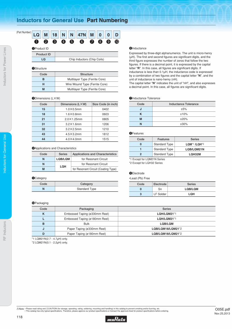
Indu
ctor
s fo
r P
ower
Lin
esIn
duct
ors
for
Gen
eral
Use
RF
Indu
ctor
sIn
duct
ors
for
Gen
eral
Use
(Part Number)
Inductors for General Use Part Numbering
uInductance ToleranceeDimensions (LgW)
Code
1.0g0.5mm
1.6g0.8mm
2.0g1.25mm
3.2g1.6mm
3.2g2.5mm
4.5g3.2mm
4.0g4.0mm
Dimensions (LgW)
0402
0603
0805
1206
1210
1812
1515
Size Code (in inch)
15
18
21
31
32
43
44
Code
J
K
M
N
±5%
±10%
±20%
±30%
Inductance Tolerance
qProduct ID
LQ Chip Inductors (Chip Coils)
Product ID
wStructure
Code
B
H
M
Multilayer Type (Ferrite Core)
Wire Wound Type (Ferrite Core)
Multilayer Type (Ferrite Core)
Structure
rApplications and Characteristics
Code
for Resonant Circuit
for Resonant Circuit
for Resonant Circuit (Coating Type)
Applications and Characteristics
N
N
M
Series
LQB/LQM
LQH
yInductance
Expressed by three-digit alphanumerics. The unit is micro-henry (μH). The first and second figures are significant digits, and the third figure expresses the number of zeros that follow the two figures. If there is a decimal point, it is expressed by the capital letter "R". In this case, all figures are significant digits. If inductance is less than 0.1μH, the inductance code is expressed by a combination of two figures and the capital letter "N", and the unit of inductance is nano-henry (nH).The capital letter "N" indicates the unit of "nH", and also expresses a decimal point. In this case, all figures are significant digits.
tCategory
N Standard Type
Code Category
q
LQ
y
47N
e
18
w
M
r
N
t
N
u
M
i
0
o
0
!0
D
0
3
Sn
LF Solder
Code Electrode
LQB/LQM
LQH
Series
oElectrode
iFeatures
0
1
2
Standard Type
Standard Type
Standard Type
Code Features Series
LQM*1 /LQH*2
LQB/LQM21N
LQH32M
*1 Except for LQM21N Series*2 Except for LQH32 Series
!0Packaging
K
L
B
J
D
LQH/LQM21*1
LQH/LQM21*1
LQB/LQM
LQB/LQM18/LQM21*2
LQB/LQM18/LQM21*2
Embossed Taping (ø330mm Reel)
Embossed Taping (ø180mm Reel)
Bulk
Paper Taping (ø330mm Reel)
Paper Taping (ø180mm Reel)
Code Packaging Series
*1 LQM21N(2.7 - 4.7μH) only.*2 LQM21N(0.1 - 2.2μH) only.
O05E.pdfNov.25,2013
118
!Note • Please read rating and !CAUTION (for storage, operating, rating, soldering, mounting and handling) in this catalog to prevent smoking and/or burning, etc.• This catalog has only typical specifi cations. Therefore, please approve our product specifi cations or transact the approval sheet for product specifi cations before ordering.

Code PackagingMinimumQuantity
D ø180mm Paper Taping 10000
J ø330mm Paper Taping 50000
B Packing in Bulk 1000
0.55Thickness
mmmax.
E-12Step Reflow
OK
Indu
ctor
s fo
r P
ower
Lin
esIn
duct
ors
for
Gen
eral
Use
RF
Indu
ctor
sIn
duct
ors
for
Gen
eral
Use
Mul
tilay
er T
ype
(Fer
rite
Cor
e)
Multilayer Type (Ferrite Core) LQB15NN_10
Inductors for General Use
LQB15NN_10Series 0402/1005 (inch/mm)For Near Field Communication, Matching, Choke
c Rated Value (p: packaging code)
Refer to pages 137 to 140 for mounting information.
1.0±0.05 0.5±0.05
: Electrode
0.25±0.1
0.5±
0.05
(in mm)
Continued on the following page.
c Appearance/Dimensions
c Packaging
Class of Magnetic Shield: Magnetic shield of ferriteOperating Temperature Range: -55℃~+125℃For refl ow soldering only.*1 When rated current is applied to the products, self-generation of heat will rise to 25℃ or less.
Part Number InductanceInductance
Test Frequency
*1Rated Current DC Resistance Q (min.) Q Test Frequency
Self-ResonanceFrequency (min.)
LQB15NNR22J10p 220nH ±5% 25MHz 380mA 0.35Ω±25% 10 25MHz 80MHz LQB15NNR22K10p 220nH ±10% 25MHz 380mA 0.35Ω±25% 10 25MHz 80MHz LQB15NNR22M10p 220nH ±20% 25MHz 380mA 0.35Ω±25% 10 25MHz 80MHz LQB15NNR27J10p 270nH ±5% 25MHz 330mA 0.41Ω±25% 10 25MHz 80MHz LQB15NNR27K10p 270nH ±10% 25MHz 330mA 0.41Ω±25% 10 25MHz 80MHz LQB15NNR27M10p 270nH ±20% 25MHz 330mA 0.41Ω±25% 10 25MHz 80MHz LQB15NNR33J10p 330nH ±5% 25MHz 300mA 0.48Ω±25% 10 25MHz 80MHz LQB15NNR33K10p 330nH ±10% 25MHz 300mA 0.48Ω±25% 10 25MHz 80MHz LQB15NNR33M10p 330nH ±20% 25MHz 300mA 0.48Ω±25% 10 25MHz 80MHz LQB15NNR39J10p 390nH ±5% 25MHz 300mA 0.54Ω±25% 10 25MHz 80MHz LQB15NNR39K10p 390nH ±10% 25MHz 300mA 0.54Ω±25% 10 25MHz 80MHz LQB15NNR39M10p 390nH ±20% 25MHz 300mA 0.54Ω±25% 10 25MHz 80MHz LQB15NNR47J10p 470nH ±5% 25MHz 300mA 0.64Ω±25% 10 25MHz 80MHz LQB15NNR47K10p 470nH ±10% 25MHz 300mA 0.64Ω±25% 10 25MHz 80MHz LQB15NNR47M10p 470nH ±20% 25MHz 300mA 0.64Ω±25% 10 25MHz 80MHz LQB15NNR56J10p 560nH ±5% 25MHz 300mA 0.73Ω±25% 10 25MHz 80MHz LQB15NNR56K10p 560nH ±10% 25MHz 300mA 0.73Ω±25% 10 25MHz 80MHz LQB15NNR56M10p 560nH ±20% 25MHz 300mA 0.73Ω±25% 10 25MHz 80MHz
O05E.pdfNov.25,2013
119
!Note • Please read rating and !CAUTION (for storage, operating, rating, soldering, mounting and handling) in this catalog to prevent smoking and/or burning, etc.• This catalog has only typical specifi cations. Therefore, please approve our product specifi cations or transact the approval sheet for product specifi cations before ordering.
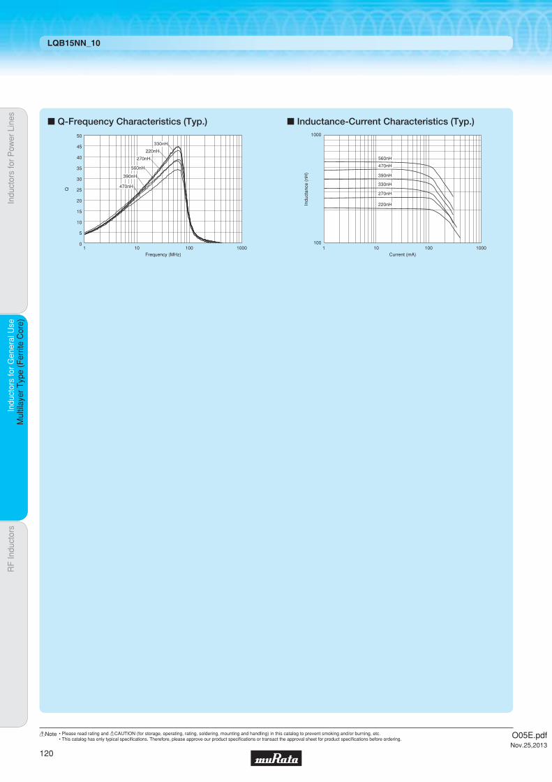
Indu
ctor
s fo
r P
ower
Lin
esIn
duct
ors
for
Gen
eral
Use
RF
Indu
ctor
sIn
duct
ors
for
Gen
eral
Use
Mul
tilay
er T
ype
(Fer
rite
Cor
e)
LQB15NN_10
c Q-Frequency Characteristics (Typ.) c Inductance-Current Characteristics (Typ.)
0
10
20
30
40
50
5
15
25
35
45
1 10 100 1000Frequency (MHz)
Q
560nH
470nH
390nH
330nH
270nH
220nH
560nH
470nH
390nH
330nH
270nH
220nH
100
1000
1 10 100 1000Current (mA)
Indu
ctan
ce (
nH)
O05E.pdfNov.25,2013
120
!Note • Please read rating and !CAUTION (for storage, operating, rating, soldering, mounting and handling) in this catalog to prevent smoking and/or burning, etc.• This catalog has only typical specifi cations. Therefore, please approve our product specifi cations or transact the approval sheet for product specifi cations before ordering.

Code PackagingMinimumQuantity
D ø180mm Paper Taping 4000
B Packing in Bulk 1000
0.95Thickness
mmmax.
E-12Step Reflow
OK
FlowOK
Indu
ctor
s fo
r P
ower
Lin
esIn
duct
ors
for
Gen
eral
Use
RF
Indu
ctor
sIn
duct
ors
for
Gen
eral
Use
Mul
tilay
er T
ype
(Fer
rite
Cor
e)
Multilayer Type (Ferrite Core) LQB18NN_10
Inductors for General Use
LQB18NN_10Series 0603/1608 (inch/mm)For Near Field Communication, Matching, Choke
c Rated Value (p: packaging code)
Refer to pages 137 to 140 for mounting information.
1.6±0.15
0.4±0.2
0.8±0.15
0.8±
0.15
(in mm)
Continued on the following page.
c Appearance/Dimensions
c Packaging
Class of Magnetic Shield: Magnetic shield of ferriteOperating Temperature Range: -55℃~+125℃
Part Number InductanceInductance
Test FrequencyRated Current
Max. of DCResistance
Q (min.) Q Test FrequencySelf-ResonanceFrequency (min.)
LQB18NNR22J10p 220nH ±5% 25MHz 450mA 0.37Ω 25 25MHz 80MHz LQB18NNR22K10p 220nH ±10% 25MHz 450mA 0.37Ω 25 25MHz 80MHz LQB18NNR22M10p 220nH ±20% 25MHz 450mA 0.37Ω 25 25MHz 80MHz LQB18NNR22N10p 220nH ±30% 25MHz 450mA 0.37Ω 25 25MHz 80MHz LQB18NNR27J10p 270nH ±5% 25MHz 450mA 0.45Ω 25 25MHz 80MHz LQB18NNR27K10p 270nH ±10% 25MHz 450mA 0.45Ω 25 25MHz 80MHz LQB18NNR27M10p 270nH ±20% 25MHz 450mA 0.45Ω 25 25MHz 80MHz LQB18NNR27N10p 270nH ±30% 25MHz 450mA 0.45Ω 25 25MHz 80MHz LQB18NNR33J10p 330nH ±5% 25MHz 450mA 0.45Ω 25 25MHz 80MHz LQB18NNR33K10p 330nH ±10% 25MHz 450mA 0.45Ω 25 25MHz 80MHz LQB18NNR33M10p 330nH ±20% 25MHz 450mA 0.45Ω 25 25MHz 80MHz LQB18NNR33N10p 330nH ±30% 25MHz 450mA 0.45Ω 25 25MHz 80MHz LQB18NNR39J10p 390nH ±5% 25MHz 450mA 0.58Ω 25 25MHz 80MHz LQB18NNR39K10p 390nH ±10% 25MHz 450mA 0.58Ω 25 25MHz 80MHz LQB18NNR39M10p 390nH ±20% 25MHz 450mA 0.58Ω 25 25MHz 80MHz LQB18NNR39N10p 390nH ±30% 25MHz 450mA 0.58Ω 25 25MHz 80MHz LQB18NNR47J10p 470nH ±5% 25MHz 400mA 0.58Ω 25 25MHz 80MHz LQB18NNR47K10p 470nH ±10% 25MHz 400mA 0.58Ω 25 25MHz 80MHz LQB18NNR47M10p 470nH ±20% 25MHz 400mA 0.58Ω 25 25MHz 80MHz LQB18NNR47N10p 470nH ±30% 25MHz 400mA 0.58Ω 25 25MHz 80MHz LQB18NNR56J10p 560nH ±5% 25MHz 300mA 0.85Ω 25 25MHz 80MHz LQB18NNR56K10p 560nH ±10% 25MHz 300mA 0.85Ω 25 25MHz 80MHz LQB18NNR56M10p 560nH ±20% 25MHz 300mA 0.85Ω 25 25MHz 80MHz LQB18NNR56N10p 560nH ±30% 25MHz 300mA 0.85Ω 25 25MHz 80MHz
O05E.pdfNov.25,2013
121
!Note • Please read rating and !CAUTION (for storage, operating, rating, soldering, mounting and handling) in this catalog to prevent smoking and/or burning, etc.• This catalog has only typical specifi cations. Therefore, please approve our product specifi cations or transact the approval sheet for product specifi cations before ordering.

Indu
ctor
s fo
r P
ower
Lin
esIn
duct
ors
for
Gen
eral
Use
RF
Indu
ctor
sIn
duct
ors
for
Gen
eral
Use
Mul
tilay
er T
ype
(Fer
rite
Cor
e)
LQB18NN_10
c Q-Frequency Characteristics (Typ.) c Inductance-Current Characteristics (Typ.)
0
10
20
30
40
50
5
15
25
35
45
1 10 100 1000Frequency (MHz)
Q
560nH
470nH
390nH
330nH
270nH
220nH560nH
470nH
390nH
330nH
270nH
220nH
100
1000
1 10 100 1000Current (mA)
Indu
ctan
ce (
nH)
O05E.pdfNov.25,2013
122
!Note • Please read rating and !CAUTION (for storage, operating, rating, soldering, mounting and handling) in this catalog to prevent smoking and/or burning, etc.• This catalog has only typical specifi cations. Therefore, please approve our product specifi cations or transact the approval sheet for product specifi cations before ordering.
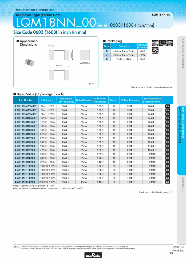
Code PackagingMinimumQuantity
D ø180mm Paper Taping 4000
J ø330mm Paper Taping 10000
B Packing in Bulk 1000
0.95Thickness
mmmax.
E-12Step Reflow
OK
FlowOK
Indu
ctor
s fo
r P
ower
Lin
esIn
duct
ors
for
Gen
eral
Use
RF
Indu
ctor
sIn
duct
ors
for
Gen
eral
Use
Mul
tilay
er T
ype
(Fer
rite
Cor
e)
Multilayer Type (Ferrite Core) LQM18NN_00
Inductors for General Use
LQM18NN_00Series 0603/1608 (inch/mm)Size Code 0603 (1608) in inch (in mm)
c Rated Value (p: packaging code)
Refer to pages 137 to 140 for mounting information.
1.6±0.15
0.35±0.15
0.8±0.15
0.8±
0.15
(in mm)
Continued on the following page.
c Appearance/Dimensions
c Packaging
Class of Magnetic Shield: Magnetic shield of ferriteOperating Temperature Range (Self-temperature rise is not included): -40℃~+85℃
Part Number InductanceInductance
Test FrequencyRated Current
Max. of DCResistance
Q (min.) Q Test FrequencySelf-ResonanceFrequency (min.)
LQM18NN47NM00p 47nH ±20% 50MHz 50mA 0.30Ω 10 50MHz 260MHz LQM18NN68NM00p 68nH ±20% 50MHz 50mA 0.30Ω 10 50MHz 250MHz LQM18NN82NM00p 82nH ±20% 50MHz 50mA 0.30Ω 10 50MHz 245MHz LQM18NNR10K00p 100nH ±10% 25MHz 50mA 0.50Ω 15 25MHz 240MHz LQM18NNR12K00p 120nH ±10% 25MHz 50mA 0.50Ω 15 25MHz 205MHz LQM18NNR15K00p 150nH ±10% 25MHz 50mA 0.60Ω 15 25MHz 180MHz LQM18NNR18K00p 180nH ±10% 25MHz 50mA 0.60Ω 15 25MHz 165MHz LQM18NNR22K00p 220nH ±10% 25MHz 50mA 0.80Ω 15 25MHz 150MHz LQM18NNR27K00p 270nH ±10% 25MHz 50mA 0.80Ω 15 25MHz 136MHz LQM18NNR33K00p 330nH ±10% 25MHz 35mA 0.85Ω 15 25MHz 125MHz LQM18NNR39K00p 390nH ±10% 25MHz 35mA 1.00Ω 15 25MHz 110MHz LQM18NNR47K00p 470nH ±10% 25MHz 35mA 1.35Ω 15 25MHz 105MHz LQM18NNR56K00p 560nH ±10% 25MHz 35mA 1.55Ω 15 25MHz 95MHz LQM18NNR68K00p 680nH ±10% 25MHz 35mA 1.70Ω 15 25MHz 90MHz LQM18NNR82K00p 820nH ±10% 25MHz 35mA 2.10Ω 15 25MHz 85MHz LQM18NN1R0K00p 1000nH ±10% 10MHz 25mA 0.60Ω 35 10MHz 75MHz LQM18NN1R2K00p 1200nH ±10% 10MHz 25mA 0.80Ω 35 10MHz 65MHz LQM18NN1R5K00p 1500nH ±10% 10MHz 25mA 0.80Ω 35 10MHz 60MHz LQM18NN1R8K00p 1800nH ±10% 10MHz 25mA 0.95Ω 35 10MHz 55MHz LQM18NN2R2K00p 2200nH ±10% 10MHz 15mA 1.15Ω 35 10MHz 50MHz
O05E.pdfNov.25,2013
123
!Note • Please read rating and !CAUTION (for storage, operating, rating, soldering, mounting and handling) in this catalog to prevent smoking and/or burning, etc.• This catalog has only typical specifi cations. Therefore, please approve our product specifi cations or transact the approval sheet for product specifi cations before ordering.

Indu
ctor
s fo
r P
ower
Lin
esIn
duct
ors
for
Gen
eral
Use
RF
Indu
ctor
sIn
duct
ors
for
Gen
eral
Use
Mul
tilay
er T
ype
(Fer
rite
Cor
e)
LQM18NN_00
c Q-Frequency Characteristics (Typ.) c Inductance-Current Characteristics (Typ.)
47nH
80
60
40
20
01000100101
Q
Frequency (MHz)
100nH
820nH
2200nH
Indu
ctan
ce (
nH)
Current (mA)
10000
1000
100
10
11 10 100 1000
2200nH
820nH
100nH
47nH
O05E.pdfNov.25,2013
124
!Note • Please read rating and !CAUTION (for storage, operating, rating, soldering, mounting and handling) in this catalog to prevent smoking and/or burning, etc.• This catalog has only typical specifi cations. Therefore, please approve our product specifi cations or transact the approval sheet for product specifi cations before ordering.
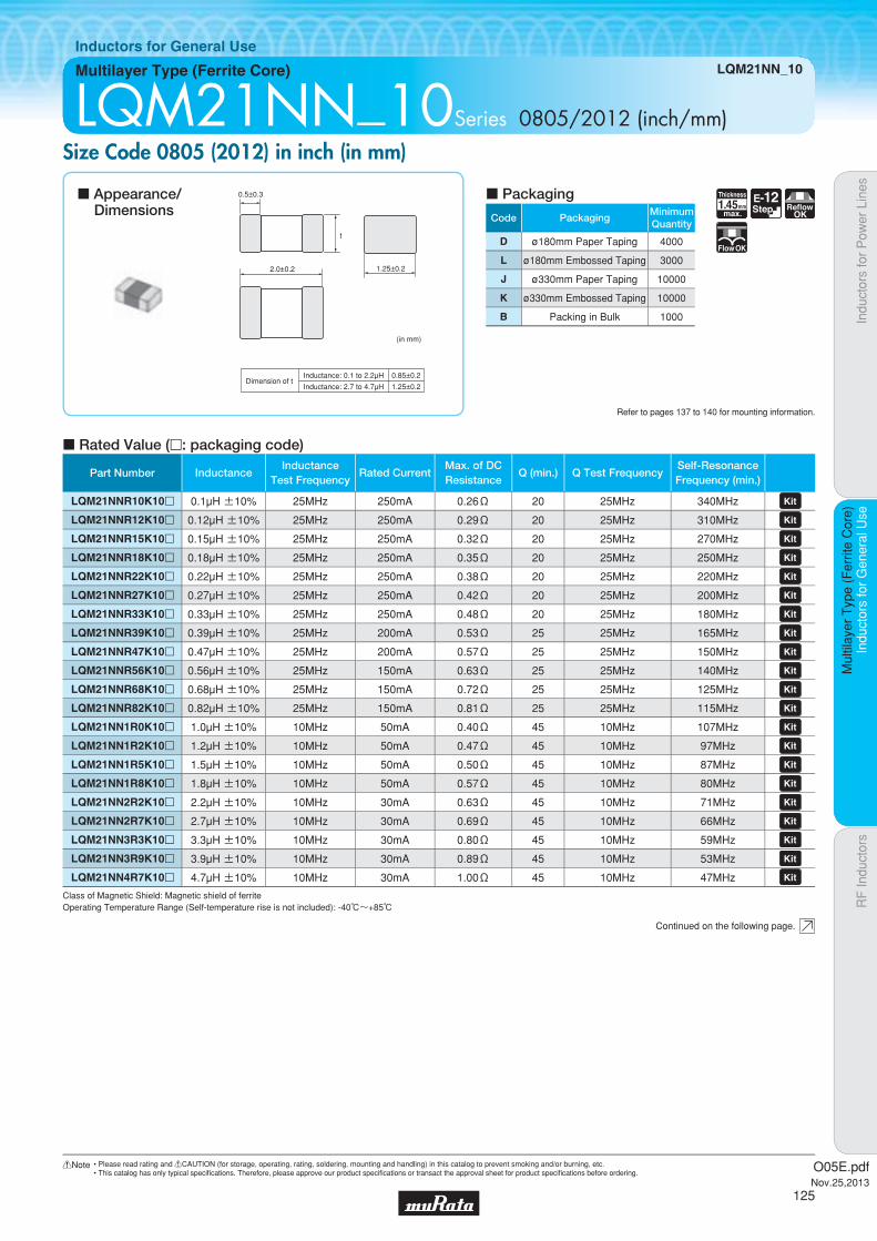
Code PackagingMinimumQuantity
D ø180mm Paper Taping 4000
L ø180mm Embossed Taping 3000
J ø330mm Paper Taping 10000
K ø330mm Embossed Taping 10000
B Packing in Bulk 1000
1.45Thickness
mmmax.
E-12Step Reflow
OK
FlowOK
Indu
ctor
s fo
r P
ower
Lin
esIn
duct
ors
for
Gen
eral
Use
RF
Indu
ctor
sIn
duct
ors
for
Gen
eral
Use
Mul
tilay
er T
ype
(Fer
rite
Cor
e)
Multilayer Type (Ferrite Core) LQM21NN_10
Inductors for General Use
LQM21NN_10Series 0805/2012 (inch/mm)Size Code 0805 (2012) in inch (in mm)
c Rated Value (p: packaging code)
Refer to pages 137 to 140 for mounting information.
2.0±0.2
0.5±0.3
1.25±0.2
t
(in mm)
Inductance: 0.1 to 2.2μHDimension of t
Inductance: 2.7 to 4.7μH
0.85±0.2
1.25±0.2
Continued on the following page.
c Appearance/Dimensions
c Packaging
Class of Magnetic Shield: Magnetic shield of ferriteOperating Temperature Range (Self-temperature rise is not included): -40℃~+85℃
Part Number InductanceInductance
Test FrequencyRated Current
Max. of DCResistance
Q (min.) Q Test FrequencySelf-ResonanceFrequency (min.)
LQM21NNR10K10p 0.1µH ±10% 25MHz 250mA 0.26Ω 20 25MHz 340MHz LQM21NNR12K10p 0.12µH ±10% 25MHz 250mA 0.29Ω 20 25MHz 310MHz LQM21NNR15K10p 0.15µH ±10% 25MHz 250mA 0.32Ω 20 25MHz 270MHz LQM21NNR18K10p 0.18µH ±10% 25MHz 250mA 0.35Ω 20 25MHz 250MHz LQM21NNR22K10p 0.22µH ±10% 25MHz 250mA 0.38Ω 20 25MHz 220MHz LQM21NNR27K10p 0.27µH ±10% 25MHz 250mA 0.42Ω 20 25MHz 200MHz LQM21NNR33K10p 0.33µH ±10% 25MHz 250mA 0.48Ω 20 25MHz 180MHz LQM21NNR39K10p 0.39µH ±10% 25MHz 200mA 0.53Ω 25 25MHz 165MHz LQM21NNR47K10p 0.47µH ±10% 25MHz 200mA 0.57Ω 25 25MHz 150MHz LQM21NNR56K10p 0.56µH ±10% 25MHz 150mA 0.63Ω 25 25MHz 140MHz LQM21NNR68K10p 0.68µH ±10% 25MHz 150mA 0.72Ω 25 25MHz 125MHz LQM21NNR82K10p 0.82µH ±10% 25MHz 150mA 0.81Ω 25 25MHz 115MHz LQM21NN1R0K10p 1.0µH ±10% 10MHz 50mA 0.40Ω 45 10MHz 107MHz LQM21NN1R2K10p 1.2µH ±10% 10MHz 50mA 0.47Ω 45 10MHz 97MHz LQM21NN1R5K10p 1.5µH ±10% 10MHz 50mA 0.50Ω 45 10MHz 87MHz LQM21NN1R8K10p 1.8µH ±10% 10MHz 50mA 0.57Ω 45 10MHz 80MHz LQM21NN2R2K10p 2.2µH ±10% 10MHz 30mA 0.63Ω 45 10MHz 71MHz LQM21NN2R7K10p 2.7µH ±10% 10MHz 30mA 0.69Ω 45 10MHz 66MHz LQM21NN3R3K10p 3.3µH ±10% 10MHz 30mA 0.80Ω 45 10MHz 59MHz LQM21NN3R9K10p 3.9µH ±10% 10MHz 30mA 0.89Ω 45 10MHz 53MHz LQM21NN4R7K10p 4.7µH ±10% 10MHz 30mA 1.00Ω 45 10MHz 47MHz
O05E.pdfNov.25,2013
125
!Note • Please read rating and !CAUTION (for storage, operating, rating, soldering, mounting and handling) in this catalog to prevent smoking and/or burning, etc.• This catalog has only typical specifi cations. Therefore, please approve our product specifi cations or transact the approval sheet for product specifi cations before ordering.

Indu
ctor
s fo
r P
ower
Lin
esIn
duct
ors
for
Gen
eral
Use
RF
Indu
ctor
sIn
duct
ors
for
Gen
eral
Use
Mul
tilay
er T
ype
(Fer
rite
Cor
e)
LQM21NN_10
c Q-Frequency Characteristics (Typ.) c Inductance-Current Characteristics (Typ.)
Frequency (MHz)
100
0
80
60
20
40
1 10 100 1000
Q
4.7μH
1.0μH
1.8μH 0.1μH
0.22μH
0.18μH
10
100
1
0.1
0.01
Indu
ctan
ce (
μH)
1 10 100 1000Current (mA)
1.0μH1.8μH
4.7μH
0.22μH
0.10μH
0.82μH
O05E.pdfNov.25,2013
126
!Note • Please read rating and !CAUTION (for storage, operating, rating, soldering, mounting and handling) in this catalog to prevent smoking and/or burning, etc.• This catalog has only typical specifi cations. Therefore, please approve our product specifi cations or transact the approval sheet for product specifi cations before ordering.
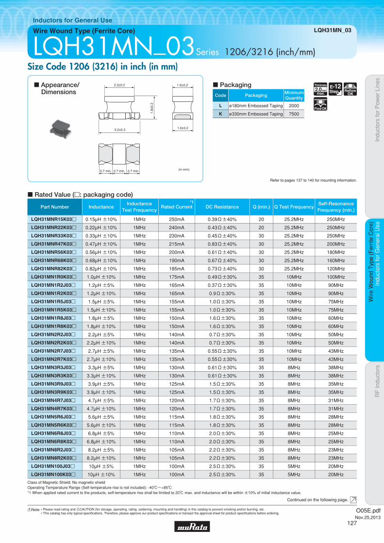
Code PackagingMinimumQuantity
L ø180mm Embossed Taping 2000
K ø330mm Embossed Taping 7500
2.0Thickness
mmmax.
E-12Step Reflow
OK
FlowOK
Part Number InductanceInductance
Test Frequency
*1Rated Current DC Resistance Q (min.) Q Test Frequency
Self-ResonanceFrequency (min.)
LQH31MNR15K03p 0.15µH ±10% 1MHz 250mA 0.39Ω±40% 20 25.2MHz 250MHz
LQH31MNR22K03p 0.22µH ±10% 1MHz 240mA 0.43Ω±40% 20 25.2MHz 250MHz
LQH31MNR33K03p 0.33µH ±10% 1MHz 230mA 0.45Ω±40% 30 25.2MHz 250MHz
LQH31MNR47K03p 0.47µH ±10% 1MHz 215mA 0.83Ω±40% 30 25.2MHz 200MHz
LQH31MNR56K03p 0.56µH ±10% 1MHz 200mA 0.61Ω±40% 30 25.2MHz 180MHz
LQH31MNR68K03p 0.68µH ±10% 1MHz 190mA 0.67Ω±40% 30 25.2MHz 160MHz
LQH31MNR82K03p 0.82µH ±10% 1MHz 185mA 0.73Ω±40% 30 25.2MHz 120MHz
LQH31MN1R0K03p 1.0µH ±10% 1MHz 175mA 0.49Ω±30% 35 10MHz 100MHz
LQH31MN1R2J03p 1.2µH ±5% 1MHz 165mA 0.37Ω±30% 35 10MHz 90MHz
LQH31MN1R2K03p 1.2µH ±10% 1MHz 165mA 0.9Ω±30% 35 10MHz 90MHz
LQH31MN1R5J03p 1.5µH ±5% 1MHz 155mA 1.0Ω±30% 35 10MHz 75MHz
LQH31MN1R5K03p 1.5µH ±10% 1MHz 155mA 1.0Ω±30% 35 10MHz 75MHz
LQH31MN1R8J03p 1.8µH ±5% 1MHz 150mA 1.6Ω±30% 35 10MHz 60MHz
LQH31MN1R8K03p 1.8µH ±10% 1MHz 150mA 1.6Ω±30% 35 10MHz 60MHz
LQH31MN2R2J03p 2.2µH ±5% 1MHz 140mA 0.7Ω±30% 35 10MHz 50MHz
LQH31MN2R2K03p 2.2µH ±10% 1MHz 140mA 0.7Ω±30% 35 10MHz 50MHz
LQH31MN2R7J03p 2.7µH ±5% 1MHz 135mA 0.55Ω±30% 35 10MHz 43MHz
LQH31MN2R7K03p 2.7µH ±10% 1MHz 135mA 0.55Ω±30% 35 10MHz 43MHz
LQH31MN3R3J03p 3.3µH ±5% 1MHz 130mA 0.61Ω±30% 35 8MHz 38MHz
LQH31MN3R3K03p 3.3µH ±10% 1MHz 130mA 0.61Ω±30% 35 8MHz 38MHz
LQH31MN3R9J03p 3.9µH ±5% 1MHz 125mA 1.5Ω±30% 35 8MHz 35MHz
LQH31MN3R9K03p 3.9µH ±10% 1MHz 125mA 1.5Ω±30% 35 8MHz 35MHz
LQH31MN4R7J03p 4.7µH ±5% 1MHz 120mA 1.7Ω±30% 35 8MHz 31MHz
LQH31MN4R7K03p 4.7µH ±10% 1MHz 120mA 1.7Ω±30% 35 8MHz 31MHz
LQH31MN5R6J03p 5.6µH ±5% 1MHz 115mA 1.8Ω±30% 35 8MHz 28MHz
LQH31MN5R6K03p 5.6µH ±10% 1MHz 115mA 1.8Ω±30% 35 8MHz 28MHz
LQH31MN6R8J03p 6.8µH ±5% 1MHz 110mA 2.0Ω±30% 35 8MHz 25MHz
LQH31MN6R8K03p 6.8µH ±10% 1MHz 110mA 2.0Ω±30% 35 8MHz 25MHz
LQH31MN8R2J03p 8.2µH ±5% 1MHz 105mA 2.2Ω±30% 35 8MHz 23MHz
LQH31MN8R2K03p 8.2µH ±10% 1MHz 105mA 2.2Ω±30% 35 8MHz 23MHz
LQH31MN100J03p 10µH ±5% 1MHz 100mA 2.5Ω±30% 35 5MHz 20MHz
LQH31MN100K03p 10µH ±10% 1MHz 100mA 2.5Ω±30% 35 5MHz 20MHz
Indu
ctor
s fo
r P
ower
Lin
esIn
duct
ors
for
Gen
eral
Use
RF
Indu
ctor
sIn
duct
ors
for
Gen
eral
Use
Wire
Wou
nd T
ype
(Fer
rite
Cor
e)
Wire Wound Type (Ferrite Core) LQH31MN_03
Inductors for General Use
LQH31MN_03Series 1206/3216 (inch/mm)Size Code 1206 (3216) in inch (in mm)
c Rated Value (p: packaging code)
Refer to pages 137 to 140 for mounting information.
2.3±0.2
1.8±
0.2
1.6±0.2
1.6±0.23.2±0.3
0.7 min. 0.7 min. 0.7 min. (in mm)
Continued on the following page.
c Appearance/Dimensions
c Packaging
Class of Magnetic Shield: No magnetic shieldOperating Temperature Range (Self-temperature rise is not included): -40℃~+85℃*1 When applied rated current to the products, self-temperature rise shall be limited to 20℃ max. and inductance will be within ±10% of initial inductance value.
O05E.pdfNov.25,2013
127
!Note • Please read rating and !CAUTION (for storage, operating, rating, soldering, mounting and handling) in this catalog to prevent smoking and/or burning, etc.• This catalog has only typical specifi cations. Therefore, please approve our product specifi cations or transact the approval sheet for product specifi cations before ordering.

Class of Magnetic Shield: No magnetic shieldOperating Temperature Range (Self-temperature rise is not included): -40℃~+85℃*1 When applied rated current to the products, self-temperature rise shall be limited to 20℃ max. and inductance will be within ±10% of initial inductance value.
Part Number InductanceInductance
Test Frequency
*1Rated Current DC Resistance Q (min.) Q Test Frequency
Self-ResonanceFrequency (min.)
LQH31MN120J03p 12µH ±5% 1MHz 95mA 2.7Ω±30% 35 5MHz 18MHz
LQH31MN120K03p 12µH ±10% 1MHz 95mA 2.7Ω±30% 35 5MHz 18MHz
LQH31MN150J03p 15µH ±5% 1MHz 90mA 3.0Ω±30% 35 5MHz 16MHz
LQH31MN150K03p 15µH ±10% 1MHz 90mA 3.0Ω±30% 35 5MHz 16MHz
LQH31MN180J03p 18µH ±5% 1MHz 85mA 3.4Ω±30% 35 5MHz 15MHz
LQH31MN180K03p 18µH ±10% 1MHz 85mA 3.4Ω±30% 35 5MHz 15MHz
LQH31MN220J03p 22µH ±5% 1MHz 85mA 3.1Ω±30% 40 2.5MHz 14MHz
LQH31MN220K03p 22µH ±10% 1MHz 85mA 3.1Ω±30% 40 2.5MHz 14MHz
LQH31MN270J03p 27µH ±5% 1MHz 85mA 3.4Ω±30% 40 2.5MHz 13MHz
LQH31MN270K03p 27µH ±10% 1MHz 85mA 3.4Ω±30% 40 2.5MHz 13MHz
LQH31MN330J03p 33µH ±5% 1MHz 80mA 3.8Ω±30% 40 2.5MHz 12MHz
LQH31MN330K03p 33µH ±10% 1MHz 80mA 3.8Ω±30% 40 2.5MHz 12MHz
LQH31MN390J03p 39µH ±5% 1MHz 55mA 7.2Ω±30% 40 2.5MHz 11MHz
LQH31MN390K03p 39µH ±10% 1MHz 55mA 7.2Ω±30% 40 2.5MHz 11MHz
LQH31MN470J03p 47µH ±5% 1MHz 55mA 8.0Ω±30% 40 2.5MHz 10MHz
LQH31MN470K03p 47µH ±10% 1MHz 55mA 8.0Ω±30% 40 2.5MHz 10MHz
LQH31MN560J03p 56µH ±5% 1MHz 50mA 8.9Ω±30% 40 2.5MHz 9MHz
LQH31MN560K03p 56µH ±10% 1MHz 50mA 8.9Ω±30% 40 2.5MHz 9MHz
LQH31MN680J03p 68µH ±5% 1MHz 50mA 9.9Ω±30% 40 2.5MHz 8.5MHz
LQH31MN680K03p 68µH ±10% 1MHz 50mA 9.9Ω±30% 40 2.5MHz 8.5MHz
LQH31MN820J03p 82µH ±5% 1MHz 45mA 11.0Ω±30% 40 2.5MHz 7.5MHz
LQH31MN820K03p 82µH ±10% 1MHz 45mA 11.0Ω±30% 40 2.5MHz 7.5MHz
LQH31MN101J03p 100µH ±5% 1MHz 45mA 12.0Ω±30% 40 2.5MHz 7MHz
LQH31MN101K03p 100µH ±10% 1MHz 45mA 12.0Ω±30% 40 2.5MHz 7MHz
Indu
ctor
s fo
r P
ower
Lin
esIn
duct
ors
for
Gen
eral
Use
RF
Indu
ctor
sIn
duct
ors
for
Gen
eral
Use
Wire
Wou
nd T
ype
(Fer
rite
Cor
e)
LQH31MN_03
c Q-Frequency Characteristics (Typ.) c Inductance-Current Characteristics (Typ.)
0
20
40
60
80
100
10.1 10 100Frequency (MHz)
Q
100μH 10μH 1μH
100
1000
10
1
0.1
100μH
33μH
10μH
1.0μH
101 100 1000
Indu
ctan
ce (
μH)
Current (mA)
O05E.pdfNov.25,2013
128
!Note • Please read rating and !CAUTION (for storage, operating, rating, soldering, mounting and handling) in this catalog to prevent smoking and/or burning, etc.• This catalog has only typical specifi cations. Therefore, please approve our product specifi cations or transact the approval sheet for product specifi cations before ordering.

Code PackagingMinimumQuantity
L ø180mm Embossed Taping 2000
K ø330mm Embossed Taping 7500
2.2Thickness
mmmax.
E-12Step Reflow
OK
FlowOK
Part Number InductanceInductance
Test FrequencyRated Current
Max. of DCResistance
Q (min.) Q Test FrequencySelf-ResonanceFrequency (min.)
LQH32MN1R0M23p 1.0µH ±20% 1MHz 445mA 0.5Ω 20 1MHz 100MHz LQH32MN1R2M23p 1.2µH ±20% 1MHz 425mA 0.6Ω 20 1MHz 100MHz LQH32MN1R5K23p 1.5µH ±10% 1MHz 400mA 0.6Ω 20 1MHz 75MHz LQH32MN1R8K23p 1.8µH ±10% 1MHz 390mA 0.7Ω 20 1MHz 60MHz LQH32MN2R2K23p 2.2µH ±10% 1MHz 370mA 0.8Ω 20 1MHz 50MHz LQH32MN2R7K23p 2.7µH ±10% 1MHz 320mA 0.9Ω 20 1MHz 43MHz LQH32MN3R3K23p 3.3µH ±10% 1MHz 300mA 1.0Ω 20 1MHz 38MHz LQH32MN3R9K23p 3.9µH ±10% 1MHz 290mA 1.1Ω 20 1MHz 35MHz LQH32MN4R7K23p 4.7µH ±10% 1MHz 270mA 1.2Ω 20 1MHz 31MHz LQH32MN5R6K23p 5.6µH ±10% 1MHz 250mA 1.3Ω 20 1MHz 28MHz LQH32MN6R8K23p 6.8µH ±10% 1MHz 240mA 1.5Ω 20 1MHz 25MHz LQH32MN8R2K23p 8.2µH ±10% 1MHz 225mA 1.6Ω 20 1MHz 23MHz LQH32MN100J23p 10µH ±5% 1MHz 190mA 1.8Ω 35 1MHz 20MHz
LQH32MN100K23p 10µH ±10% 1MHz 190mA 1.8Ω 35 1MHz 20MHz LQH32MN120J23p 12µH ±5% 1MHz 180mA 2.0Ω 35 1MHz 18MHz
LQH32MN120K23p 12µH ±10% 1MHz 180mA 2.0Ω 35 1MHz 18MHz LQH32MN150J23p 15µH ±5% 1MHz 170mA 2.2Ω 35 1MHz 16MHz
LQH32MN150K23p 15µH ±10% 1MHz 170mA 2.2Ω 35 1MHz 16MHz LQH32MN180J23p 18µH ±5% 1MHz 165mA 2.5Ω 35 1MHz 15MHz
LQH32MN180K23p 18µH ±10% 1MHz 165mA 2.5Ω 35 1MHz 15MHz LQH32MN220J23p 22µH ±5% 1MHz 150mA 2.8Ω 35 1MHz 14MHz
LQH32MN220K23p 22µH ±10% 1MHz 150mA 2.8Ω 35 1MHz 14MHz LQH32MN270J23p 27µH ±5% 1MHz 125mA 3.1Ω 35 1MHz 13MHz
LQH32MN270K23p 27µH ±10% 1MHz 125mA 3.1Ω 35 1MHz 13MHz LQH32MN330J23p 33µH ±5% 1MHz 115mA 3.5Ω 40 1MHz 12MHz
LQH32MN330K23p 33µH ±10% 1MHz 115mA 3.5Ω 40 1MHz 12MHz LQH32MN390J23p 39µH ±5% 1MHz 110mA 3.9Ω 40 1MHz 11MHz
LQH32MN390K23p 39µH ±10% 1MHz 110mA 3.9Ω 40 1MHz 11MHz LQH32MN470J23p 47µH ±5% 1MHz 100mA 4.3Ω 40 1MHz 11MHz
LQH32MN470K23p 47µH ±10% 1MHz 100mA 4.3Ω 40 1MHz 11MHz LQH32MN560J23p 56µH ±5% 1MHz 85mA 4.9Ω 40 1MHz 10MHz
LQH32MN560K23p 56µH ±10% 1MHz 85mA 4.9Ω 40 1MHz 10MHz
Indu
ctor
s fo
r P
ower
Lin
esIn
duct
ors
for
Gen
eral
Use
RF
Indu
ctor
sIn
duct
ors
for
Gen
eral
Use
Wire
Wou
nd T
ype
(Fer
rite
Cor
e)
Wire Wound Type (Ferrite Core) LQH32MN_23
Inductors for General Use
LQH32MN_23Series 1210/3225 (inch/mm)Size Code 1210 (3225) in inch (in mm)
c Rated Value (p: packaging code)
Refer to pages 137 to 140 for mounting information.
2.5±0.2
2.0±
0.2
2.5±0.23.2±0.3
0.9±0.3
1.3±0.2
0.9±0.3
2.5±0.2 2.5±0.2
A
A: 2.8 max.
* Please refer to dimension A for LQH32CN_33 (2R2M, 4R7M, 100K) types. (See Fig. 1)
Fig. 1
2.5±0.2
(in mm)
Continued on the following page.
c Appearance/Dimensions
c Packaging
Class of Magnetic Shield: No magnetic shieldOperating Temperature Range (Self-temperature rise is not included): -40℃~+85℃
O05E.pdfNov.25,2013
129
!Note • Please read rating and !CAUTION (for storage, operating, rating, soldering, mounting and handling) in this catalog to prevent smoking and/or burning, etc.• This catalog has only typical specifi cations. Therefore, please approve our product specifi cations or transact the approval sheet for product specifi cations before ordering.
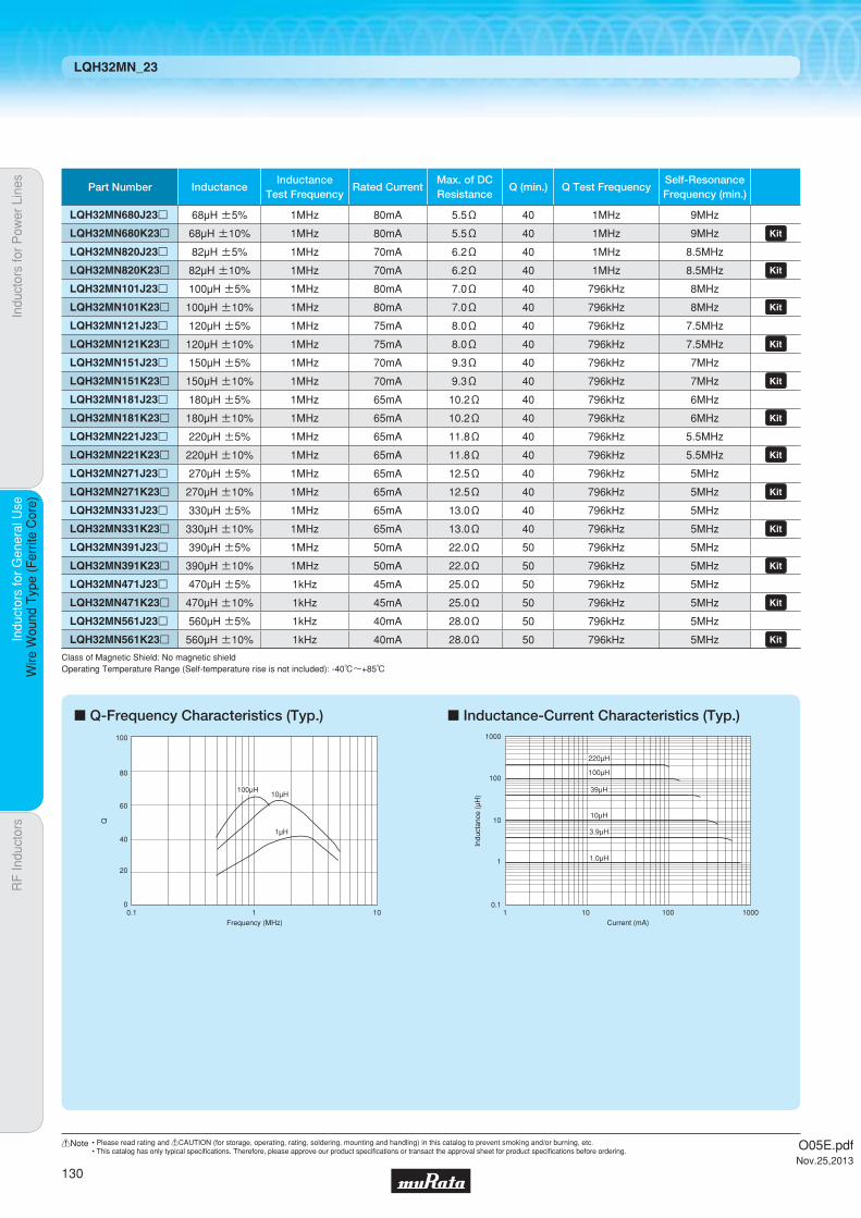
Class of Magnetic Shield: No magnetic shieldOperating Temperature Range (Self-temperature rise is not included): -40℃~+85℃
Part Number InductanceInductance
Test FrequencyRated Current
Max. of DCResistance
Q (min.) Q Test FrequencySelf-ResonanceFrequency (min.)
LQH32MN680J23p 68µH ±5% 1MHz 80mA 5.5Ω 40 1MHz 9MHz
LQH32MN680K23p 68µH ±10% 1MHz 80mA 5.5Ω 40 1MHz 9MHz LQH32MN820J23p 82µH ±5% 1MHz 70mA 6.2Ω 40 1MHz 8.5MHz
LQH32MN820K23p 82µH ±10% 1MHz 70mA 6.2Ω 40 1MHz 8.5MHz LQH32MN101J23p 100µH ±5% 1MHz 80mA 7.0Ω 40 796kHz 8MHz
LQH32MN101K23p 100µH ±10% 1MHz 80mA 7.0Ω 40 796kHz 8MHz LQH32MN121J23p 120µH ±5% 1MHz 75mA 8.0Ω 40 796kHz 7.5MHz
LQH32MN121K23p 120µH ±10% 1MHz 75mA 8.0Ω 40 796kHz 7.5MHz LQH32MN151J23p 150µH ±5% 1MHz 70mA 9.3Ω 40 796kHz 7MHz
LQH32MN151K23p 150µH ±10% 1MHz 70mA 9.3Ω 40 796kHz 7MHz LQH32MN181J23p 180µH ±5% 1MHz 65mA 10.2Ω 40 796kHz 6MHz
LQH32MN181K23p 180µH ±10% 1MHz 65mA 10.2Ω 40 796kHz 6MHz LQH32MN221J23p 220µH ±5% 1MHz 65mA 11.8Ω 40 796kHz 5.5MHz
LQH32MN221K23p 220µH ±10% 1MHz 65mA 11.8Ω 40 796kHz 5.5MHz LQH32MN271J23p 270µH ±5% 1MHz 65mA 12.5Ω 40 796kHz 5MHz
LQH32MN271K23p 270µH ±10% 1MHz 65mA 12.5Ω 40 796kHz 5MHz LQH32MN331J23p 330µH ±5% 1MHz 65mA 13.0Ω 40 796kHz 5MHz
LQH32MN331K23p 330µH ±10% 1MHz 65mA 13.0Ω 40 796kHz 5MHz LQH32MN391J23p 390µH ±5% 1MHz 50mA 22.0Ω 50 796kHz 5MHz
LQH32MN391K23p 390µH ±10% 1MHz 50mA 22.0Ω 50 796kHz 5MHz LQH32MN471J23p 470µH ±5% 1kHz 45mA 25.0Ω 50 796kHz 5MHz
LQH32MN471K23p 470µH ±10% 1kHz 45mA 25.0Ω 50 796kHz 5MHz LQH32MN561J23p 560µH ±5% 1kHz 40mA 28.0Ω 50 796kHz 5MHz
LQH32MN561K23p 560µH ±10% 1kHz 40mA 28.0Ω 50 796kHz 5MHz
Indu
ctor
s fo
r P
ower
Lin
esIn
duct
ors
for
Gen
eral
Use
RF
Indu
ctor
sIn
duct
ors
for
Gen
eral
Use
Wire
Wou
nd T
ype
(Fer
rite
Cor
e)
LQH32MN_23
c Q-Frequency Characteristics (Typ.) c Inductance-Current Characteristics (Typ.)
0
20
40
60
80
100
0.1 1 10Frequency (MHz)
Q
100μH10μH
1μH
100
1000
10
1
0.1
100μH
101 100 1000
Indu
ctan
ce (
μH)
220μH
39μH
10μH
3.9μH
1.0μH
Current (mA)
O05E.pdfNov.25,2013
130
!Note • Please read rating and !CAUTION (for storage, operating, rating, soldering, mounting and handling) in this catalog to prevent smoking and/or burning, etc.• This catalog has only typical specifi cations. Therefore, please approve our product specifi cations or transact the approval sheet for product specifi cations before ordering.

Code PackagingMinimumQuantity
L ø180mm Embossed Taping 500
K ø330mm Embossed Taping 2500
2.8Thickness
mmmax.
E-12Step Reflow
OK
FlowOK
Indu
ctor
s fo
r P
ower
Lin
esIn
duct
ors
for
Gen
eral
Use
RF
Indu
ctor
sIn
duct
ors
for
Gen
eral
Use
Wire
Wou
nd T
ype
(Fer
rite
Cor
e)
Wire Wound Type (Ferrite Core) LQH43MN_03/LQH43NN_03
Inductors for General Use
LQH43MN_03/LQH43NN_03Series 1812/4532 (inch/mm)Size Code 1812 (4532) in inch (in mm)
c Rated Value (p: packaging code)
Refer to pages 137 to 140 for mounting information.
3.6±0.2
4.5±0.3
2.6±
0.2
3.2±0.2
3.2±0.2
1.0min. 1.0min. 1.0min.(in mm)
Continued on the following page.
c Appearance/Dimensions
c Packaging
Class of Magnetic Shield: No magnetic shieldOperating Temperature Range (Self-temperature rise is not included): -40℃~+85℃
Part Number InductanceInductance
Test FrequencyRated Current
Max. of DCResistance
Q (min.) Q Test FrequencySelf-ResonanceFrequency (min.)
LQH43MN1R0M03p 1.0µH ±20% 1MHz 500mA 0.20Ω 20 1MHz 120MHz LQH43MN1R2M03p 1.2µH ±20% 1MHz 500mA 0.20Ω 20 1MHz 100MHz LQH43MN1R5M03p 1.5µH ±20% 1MHz 500mA 0.30Ω 20 1MHz 85MHz LQH43MN1R8M03p 1.8µH ±20% 1MHz 500mA 0.30Ω 20 1MHz 75MHz LQH43MN2R2M03p 2.2µH ±20% 1MHz 500mA 0.30Ω 20 1MHz 62MHz LQH43MN2R7M03p 2.7µH ±20% 1MHz 500mA 0.32Ω 20 1MHz 53MHz LQH43MN3R3M03p 3.3µH ±20% 1MHz 500mA 0.35Ω 20 1MHz 47MHz LQH43MN3R9M03p 3.9µH ±20% 1MHz 500mA 0.38Ω 20 1MHz 41MHz LQH43MN4R7K03p 4.7µH ±10% 1MHz 500mA 0.40Ω 30 1MHz 38MHz LQH43MN5R6K03p 5.6µH ±10% 1MHz 500mA 0.47Ω 30 1MHz 33MHz LQH43MN6R8K03p 6.8µH ±10% 1MHz 450mA 0.50Ω 30 1MHz 31MHz LQH43MN8R2K03p 8.2µH ±10% 1MHz 450mA 0.56Ω 30 1MHz 27MHz LQH43MN100J03p 10µH ±5% 1MHz 400mA 0.56Ω 35 1MHz 23MHz
LQH43MN100K03p 10µH ±10% 1MHz 400mA 0.56Ω 35 1MHz 23MHz LQH43MN120J03p 12µH ±5% 1MHz 380mA 0.62Ω 35 1MHz 21MHz
LQH43MN120K03p 12µH ±10% 1MHz 380mA 0.62Ω 35 1MHz 21MHz LQH43MN150J03p 15µH ±5% 1MHz 360mA 0.73Ω 35 1MHz 19MHz
LQH43MN150K03p 15µH ±10% 1MHz 360mA 0.73Ω 35 1MHz 19MHz LQH43MN180J03p 18µH ±5% 1MHz 340mA 0.82Ω 35 1MHz 17MHz
LQH43MN180K03p 18µH ±10% 1MHz 340mA 0.82Ω 35 1MHz 17MHz LQH43MN220J03p 22µH ±5% 1MHz 320mA 0.94Ω 35 1MHz 15MHz
LQH43MN220K03p 22µH ±10% 1MHz 320mA 0.94Ω 35 1MHz 15MHz LQH43MN270J03p 27µH ±5% 1MHz 300mA 1.1Ω 35 1MHz 14MHz
LQH43MN270K03p 27µH ±10% 1MHz 300mA 1.1Ω 35 1MHz 14MHz LQH43MN330J03p 33µH ±5% 1MHz 270mA 1.2Ω 35 1MHz 12MHz
LQH43MN330K03p 33µH ±10% 1MHz 270mA 1.2Ω 35 1MHz 12MHz LQH43MN390J03p 39µH ±5% 1MHz 240mA 1.4Ω 35 1MHz 11MHz
LQH43MN390K03p 39µH ±10% 1MHz 240mA 1.4Ω 35 1MHz 11MHz LQH43MN470J03p 47µH ±5% 1MHz 220mA 1.5Ω 35 1MHz 10MHz
LQH43MN470K03p 47µH ±10% 1MHz 220mA 1.5Ω 35 1MHz 10MHz LQH43MN560J03p 56µH ±5% 1MHz 200mA 1.7Ω 35 1MHz 9.3MHz
LQH43MN560K03p 56µH ±10% 1MHz 200mA 1.7Ω 35 1MHz 9.3MHz
O05E.pdfNov.25,2013
131
!Note • Please read rating and !CAUTION (for storage, operating, rating, soldering, mounting and handling) in this catalog to prevent smoking and/or burning, etc.• This catalog has only typical specifi cations. Therefore, please approve our product specifi cations or transact the approval sheet for product specifi cations before ordering.
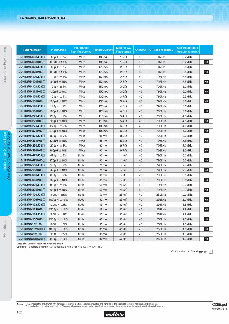
Indu
ctor
s fo
r P
ower
Lin
esIn
duct
ors
for
Gen
eral
Use
RF
Indu
ctor
sIn
duct
ors
for
Gen
eral
Use
Wire
Wou
nd T
ype
(Fer
rite
Cor
e)
LQH43MN_03/LQH43NN_03
Continued on the following page.
Class of Magnetic Shield: No magnetic shieldOperating Temperature Range (Self-temperature rise is not included): -40℃~+85℃
Part Number InductanceInductance
Test FrequencyRated Current
Max. of DCResistance
Q (min.) Q Test FrequencySelf-ResonanceFrequency (min.)
LQH43MN680J03p 68µH ±5% 1MHz 180mA 1.9Ω 35 1MHz 8.4MHz
LQH43MN680K03p 68µH ±10% 1MHz 180mA 1.9Ω 35 1MHz 8.4MHz LQH43MN820J03p 82µH ±5% 1MHz 170mA 2.2Ω 35 1MHz 7.5MHz
LQH43MN820K03p 82µH ±10% 1MHz 170mA 2.2Ω 35 1MHz 7.5MHz LQH43MN101J03p 100µH ±5% 1MHz 160mA 2.5Ω 40 796kHz 6.8MHz
LQH43MN101K03p 100µH ±10% 1MHz 160mA 2.5Ω 40 796kHz 6.8MHz LQH43MN121J03p 120µH ±5% 1MHz 150mA 3.0Ω 40 796kHz 6.2MHz
LQH43MN121K03p 120µH ±10% 1MHz 150mA 3.0Ω 40 796kHz 6.2MHz LQH43MN151J03p 150µH ±5% 1MHz 130mA 3.7Ω 40 796kHz 5.5MHz
LQH43MN151K03p 150µH ±10% 1MHz 130mA 3.7Ω 40 796kHz 5.5MHz LQH43MN181J03p 180µH ±5% 1MHz 120mA 4.5Ω 40 796kHz 5.0MHz
LQH43MN181K03p 180µH ±10% 1MHz 120mA 4.5Ω 40 796kHz 5.0MHz LQH43MN221J03p 220µH ±5% 1MHz 110mA 5.4Ω 40 796kHz 4.5MHz
LQH43MN221K03p 220µH ±10% 1MHz 110mA 5.4Ω 40 796kHz 4.5MHz LQH43MN271J03p 270µH ±5% 1MHz 100mA 6.8Ω 40 796kHz 4.0MHz
LQH43MN271K03p 270µH ±10% 1MHz 100mA 6.8Ω 40 796kHz 4.0MHz LQH43MN331J03p 330µH ±5% 1MHz 95mA 8.2Ω 40 796kHz 3.6MHz
LQH43MN331K03p 330µH ±10% 1MHz 95mA 8.2Ω 40 796kHz 3.6MHz LQH43MN391J03p 390µH ±5% 1MHz 90mA 9.7Ω 40 796kHz 3.3MHz
LQH43MN391K03p 390µH ±10% 1MHz 90mA 9.7Ω 40 796kHz 3.3MHz LQH43MN471J03p 470µH ±5% 1kHz 80mA 11.8Ω 40 796kHz 3.0MHz
LQH43MN471K03p 470µH ±10% 1kHz 80mA 11.8Ω 40 796kHz 3.0MHz LQH43MN561J03p 560µH ±5% 1kHz 70mA 14.5Ω 40 796kHz 2.7MHz
LQH43MN561K03p 560µH ±10% 1kHz 70mA 14.5Ω 40 796kHz 2.7MHz LQH43MN681J03p 680µH ±5% 1kHz 65mA 17.0Ω 40 796kHz 2.5MHz
LQH43MN681K03p 680µH ±10% 1kHz 65mA 17.0Ω 40 796kHz 2.5MHz LQH43MN821J03p 820µH ±5% 1kHz 60mA 20.5Ω 40 796kHz 2.2MHz
LQH43MN821K03p 820µH ±10% 1kHz 60mA 20.5Ω 40 796kHz 2.2MHz LQH43MN102J03p 1000µH ±5% 1kHz 50mA 25.0Ω 40 252kHz 2.0MHz
LQH43MN102K03p 1000µH ±10% 1kHz 50mA 25.0Ω 40 252kHz 2.0MHz LQH43MN122J03p 1200µH ±5% 1kHz 45mA 30.0Ω 40 252kHz 1.8MHz
LQH43MN122K03p 1200µH ±10% 1kHz 45mA 30.0Ω 40 252kHz 1.8MHz LQH43MN152J03p 1500µH ±5% 1kHz 40mA 37.0Ω 40 252kHz 1.6MHz
LQH43MN152K03p 1500µH ±10% 1kHz 40mA 37.0Ω 40 252kHz 1.6MHz LQH43NN182J03p 1800µH ±5% 1kHz 35mA 45.0Ω 40 252kHz 1.5MHz
LQH43NN182K03p 1800µH ±10% 1kHz 35mA 45.0Ω 40 252kHz 1.5MHz LQH43NN222J03p 2200µH ±5% 1kHz 30mA 50.0Ω 40 252kHz 1.3MHz
LQH43NN222K03p 2200µH ±10% 1kHz 30mA 50.0Ω 40 252kHz 1.3MHz
O05E.pdfNov.25,2013
132
!Note • Please read rating and !CAUTION (for storage, operating, rating, soldering, mounting and handling) in this catalog to prevent smoking and/or burning, etc.• This catalog has only typical specifi cations. Therefore, please approve our product specifi cations or transact the approval sheet for product specifi cations before ordering.
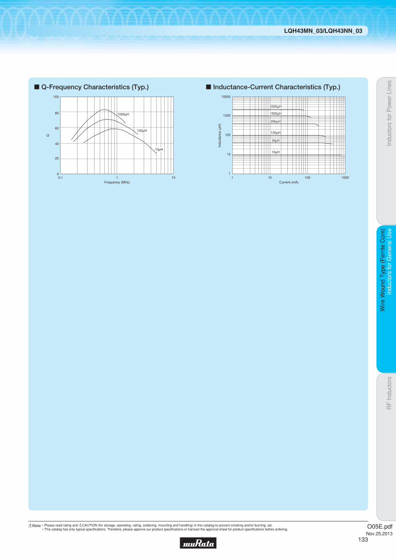
Indu
ctor
s fo
r P
ower
Lin
esIn
duct
ors
for
Gen
eral
Use
RF
Indu
ctor
sIn
duct
ors
for
Gen
eral
Use
Wire
Wou
nd T
ype
(Fer
rite
Cor
e)
LQH43MN_03/LQH43NN_03
c Q-Frequency Characteristics (Typ.) c Inductance-Current Characteristics (Typ.)
0
20
40
60
80
100
0.1 1 10Frequency (MHz)
Q
1000μH
100μH
10μH
1000
10000
100
10
1
100μH
101 100 1000
Indu
ctan
ce (
μH)
Current (mA)
390μH
1000μH
2200μH
39μH
10μH
O05E.pdfNov.25,2013
133
!Note • Please read rating and !CAUTION (for storage, operating, rating, soldering, mounting and handling) in this catalog to prevent smoking and/or burning, etc.• This catalog has only typical specifi cations. Therefore, please approve our product specifi cations or transact the approval sheet for product specifi cations before ordering.
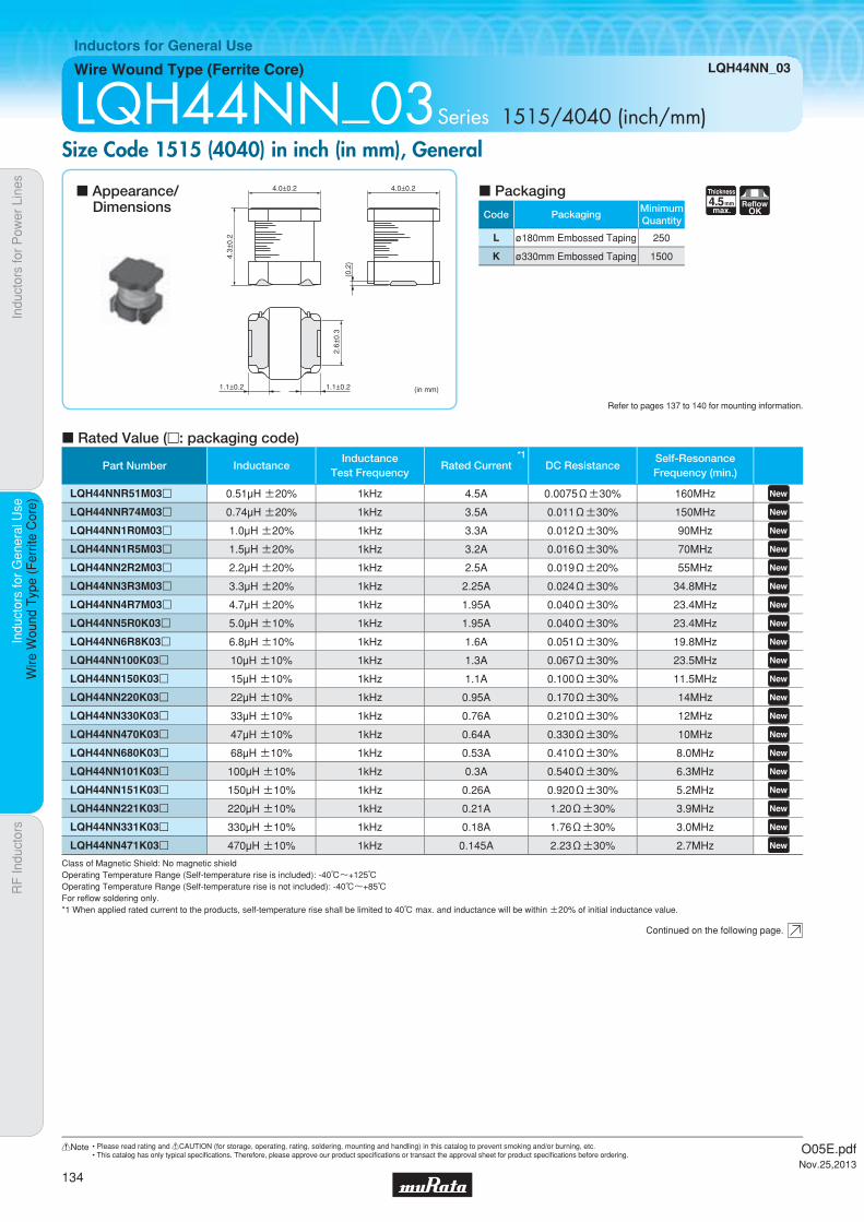
Code PackagingMinimumQuantity
L ø180mm Embossed Taping 250
K ø330mm Embossed Taping 1500
4.5Thickness
mmmax.
ReflowOK
Indu
ctor
s fo
r P
ower
Lin
esIn
duct
ors
for
Gen
eral
Use
RF
Indu
ctor
sIn
duct
ors
for
Gen
eral
Use
Wire
Wou
nd T
ype
(Fer
rite
Cor
e)
Wire Wound Type (Ferrite Core) LQH44NN_03
Inductors for General Use
LQH44NN_03Series 1515/4040 (inch/mm)Size Code 1515 (4040) in inch (in mm), General
c Rated Value (p: packaging code)
Refer to pages 137 to 140 for mounting information.
(in mm)
4.0±0.2
2.6±
0.3
(0.2
)
4.0±0.2
1.1±0.2 1.1±0.2
4.3±
0.2
Continued on the following page.
c Appearance/Dimensions
c Packaging
Class of Magnetic Shield: No magnetic shieldOperating Temperature Range (Self-temperature rise is included): -40℃~+125℃Operating Temperature Range (Self-temperature rise is not included): -40℃~+85℃For refl ow soldering only.*1 When applied rated current to the products, self-temperature rise shall be limited to 40℃ max. and inductance will be within ±20% of initial inductance value.
Part Number InductanceInductance
Test Frequency
*1Rated Current DC Resistance
Self-ResonanceFrequency (min.)
LQH44NNR51M03p 0.51µH ±20% 1kHz 4.5A 0.0075Ω±30% 160MHz LQH44NNR74M03p 0.74µH ±20% 1kHz 3.5A 0.011Ω±30% 150MHz LQH44NN1R0M03p 1.0µH ±20% 1kHz 3.3A 0.012Ω±30% 90MHz LQH44NN1R5M03p 1.5µH ±20% 1kHz 3.2A 0.016Ω±30% 70MHz LQH44NN2R2M03p 2.2µH ±20% 1kHz 2.5A 0.019Ω±20% 55MHz LQH44NN3R3M03p 3.3µH ±20% 1kHz 2.25A 0.024Ω±30% 34.8MHz LQH44NN4R7M03p 4.7µH ±20% 1kHz 1.95A 0.040Ω±30% 23.4MHz LQH44NN5R0K03p 5.0µH ±10% 1kHz 1.95A 0.040Ω±30% 23.4MHz LQH44NN6R8K03p 6.8µH ±10% 1kHz 1.6A 0.051Ω±30% 19.8MHz LQH44NN100K03p 10µH ±10% 1kHz 1.3A 0.067Ω±30% 23.5MHz LQH44NN150K03p 15µH ±10% 1kHz 1.1A 0.100Ω±30% 11.5MHz LQH44NN220K03p 22µH ±10% 1kHz 0.95A 0.170Ω±30% 14MHz LQH44NN330K03p 33µH ±10% 1kHz 0.76A 0.210Ω±30% 12MHz LQH44NN470K03p 47µH ±10% 1kHz 0.64A 0.330Ω±30% 10MHz LQH44NN680K03p 68µH ±10% 1kHz 0.53A 0.410Ω±30% 8.0MHz LQH44NN101K03p 100µH ±10% 1kHz 0.3A 0.540Ω±30% 6.3MHz LQH44NN151K03p 150µH ±10% 1kHz 0.26A 0.920Ω±30% 5.2MHz LQH44NN221K03p 220µH ±10% 1kHz 0.21A 1.20Ω±30% 3.9MHz LQH44NN331K03p 330µH ±10% 1kHz 0.18A 1.76Ω±30% 3.0MHz LQH44NN471K03p 470µH ±10% 1kHz 0.145A 2.23Ω±30% 2.7MHz
O05E.pdfNov.25,2013
134
!Note • Please read rating and !CAUTION (for storage, operating, rating, soldering, mounting and handling) in this catalog to prevent smoking and/or burning, etc.• This catalog has only typical specifi cations. Therefore, please approve our product specifi cations or transact the approval sheet for product specifi cations before ordering.

Indu
ctor
s fo
r P
ower
Lin
esIn
duct
ors
for
Gen
eral
Use
RF
Indu
ctor
sIn
duct
ors
for
Gen
eral
Use
Wire
Wou
nd T
ype
(Fer
rite
Cor
e)
LQH44NN_03
c Inductance-Current Characteristics (Typ.)
0.1
1
10
100
1000
0.1 1 10 100 1000 10000Current (mA)
Indu
ctan
ce (
μH)
470μH
220μH
100μH
47μH
22μH
3.3μH
6.8μH
1.0μH
0.51μH
O05E.pdfNov.25,2013
135
!Note • Please read rating and !CAUTION (for storage, operating, rating, soldering, mounting and handling) in this catalog to prevent smoking and/or burning, etc.• This catalog has only typical specifi cations. Therefore, please approve our product specifi cations or transact the approval sheet for product specifi cations before ordering.

Indu
ctor
s fo
r P
ower
Lin
esIn
duct
ors
for
Gen
eral
Use
RF
Indu
ctor
sIn
duct
ors
for
Gen
eral
Use
!C
autio
n/N
otic
e
o Storage and Operating Condition<Operating Environment>Do not use products in chemical atmosphere such as chlorine gas, acid or sulfide gas.<Storage Requirements>1. Storage Period
LQB series and LQM series should be used within 6 months; the other products should be used within 12 months.Check solderability if this period is exceeded.
2. Storage Conditions(1) Store products in a warehouse in compliance with
the following conditions:Temperature: -10 to +40 degrees C.Humidity: 15 to 85% (relative humidity)Do not subject products to rapid changes in temperature and humidity.Do not store them in chemical atmosphere such as one containing sulfurous acid gas or alkaline gas.This will prevent electrode oxidation, which causes poor solderability and possible corrosion of inductors.
(2) Do not store products in bulk packaging to prevent collision among inductors, which causes core chipping and wire breakage.
(3) Store products on pallets to protect from humidity, dust, etc.
(4) Avoid heat shock, vibration, direct sunlight, etc.
o HandlingThis item is designed to have sufficient strength, but handle with care to avoid chipping or breaking its ceramic structure.LQH_M/N series
sharp material, such as tweezers or the bristles of a cleaning brush, to the wire wound portion of this product.
excessive mechanical shock to products mounted on the board.
LQB series and LQM series
the inductance value. Do not use a magnet or
tweezers with magnetism when handling chip inductors. (The tip of the tweezers should be molded with resin or pottery.)
applied, it may cause the inductance value to change due to magnetism.
<Handling>1. Avoid applying excessive stress to products to
prevent damage.2. Do not touch wire wound with sharp objects such
as tweezers to prevent wire breakage.3. Do not apply excessive force to products mounted
on boards to prevent core breakage.<Transportation>
Do not apply excessive vibration or mechanical shock to products.
<Resin Coating>
resin curing stress may change inductance values.For exterior coating, select resin carefully so that electrical and mechanical performance of the product is not affected. Prior to use, please evaluate reliability with the product mounted in your application set.(LQH series)
An open circuit issue may occur by mechanical stress caused by the resin, amount/cured shape of resin, or operating conditions, etc. Some resins containing impurities or chloride may possibly generate chlorine by hydrolysis under some operating conditions, causing corrosion of the inductor wire and leading to an open circuit.
!Caution
Notice
Inductors for General Use !Caution/Notice
<Handling of a Substrate>After mounting products on a substrate, do not apply any stress to the product caused by bending or twisting the substrate when cropping the substrate, inserting and removing a connector from the substrate, or tightening a screw to the substrate. Excessive mechanical stress may cause cracking in the Product.
Bending Twisting
1. About the Rated CurrentDo not use products beyond the rated current as this may create excessive heat and deteriorate the insulation resistance.
o Rating2. About Excessive Surge Current
Surge current (pulse current or rush current) greater than the specified rated current applied to the product may cause a critical failure, such as an open circuit, burnout caused by excessive temperature rise. Please contact us in advance in case of applying the surge current.
O05E.pdfNov.25,2013
136
!Note • Please read rating and !CAUTION (for storage, operating, rating, soldering, mounting and handling) in this catalog to prevent smoking and/or burning, etc.• This catalog has only typical specifi cations. Therefore, please approve our product specifi cations or transact the approval sheet for product specifi cations before ordering.

Indu
ctor
s fo
r P
ower
Lin
esIn
duct
ors
for
Gen
eral
Use
RF
Indu
ctor
sIn
duct
ors
for
Gen
eral
Use
Sol
derin
g an
d M
ount
ing
1. Standard Land Pattern Dimensions
A high Q value is achieved when the PCB electrode land pattern is designed so that it does not project beyond the chip Inductors (chip coils) electrode.
(in mm)
a
c
b
Standard Land DimensionsSeries
LQH31M
LQH44N
1.5
3.0
4.5
4.4
1.0
1.3
LQB15NN 0.51.2-1.40.4
LQB18NLQM18N
LQM21N
0.7
1.0
2.2-2.6
1.8-2.0
3.0-4.0
0.7
1.2
LQB15NLQB18NLQM18NLQM21NLQH31MLQH44N
LQH32M
Part Number a b c
Attention should be paid to potential magnetic coupling effects when using the Inductors (coils) as a resonator.
Land Pattern
Land Pattern+ Solder Resist
Solder Resist
5.5
1.0
2.0
1.0
1.3 1.0
Flow
Reflow
Reflow
7.5
1.5
3.0
1.5
1.5 1.5
LQH43MLQH43N
2. Standard Soldering Conditions
(1) Soldering methodChip Inductors (Chip coils) can be flow or reflow soldered. Please contact Murata regarding other soldering methods.
Solder: Use Sn-3.0Ag-0.5Cu solder.Flux: Use rosin-based flux, but not strongly acidic flux (with
chlorine content exceeding 0.2wt%).Do not use water-soluble flux.
For additional mounting methods, please contact Murata.
Soldering and MountingInductors for General Use
Continued on the following page.
O05E.pdfNov.25,2013
137
!Note • Please read rating and !CAUTION (for storage, operating, rating, soldering, mounting and handling) in this catalog to prevent smoking and/or burning, etc.• This catalog has only typical specifi cations. Therefore, please approve our product specifi cations or transact the approval sheet for product specifi cations before ordering.
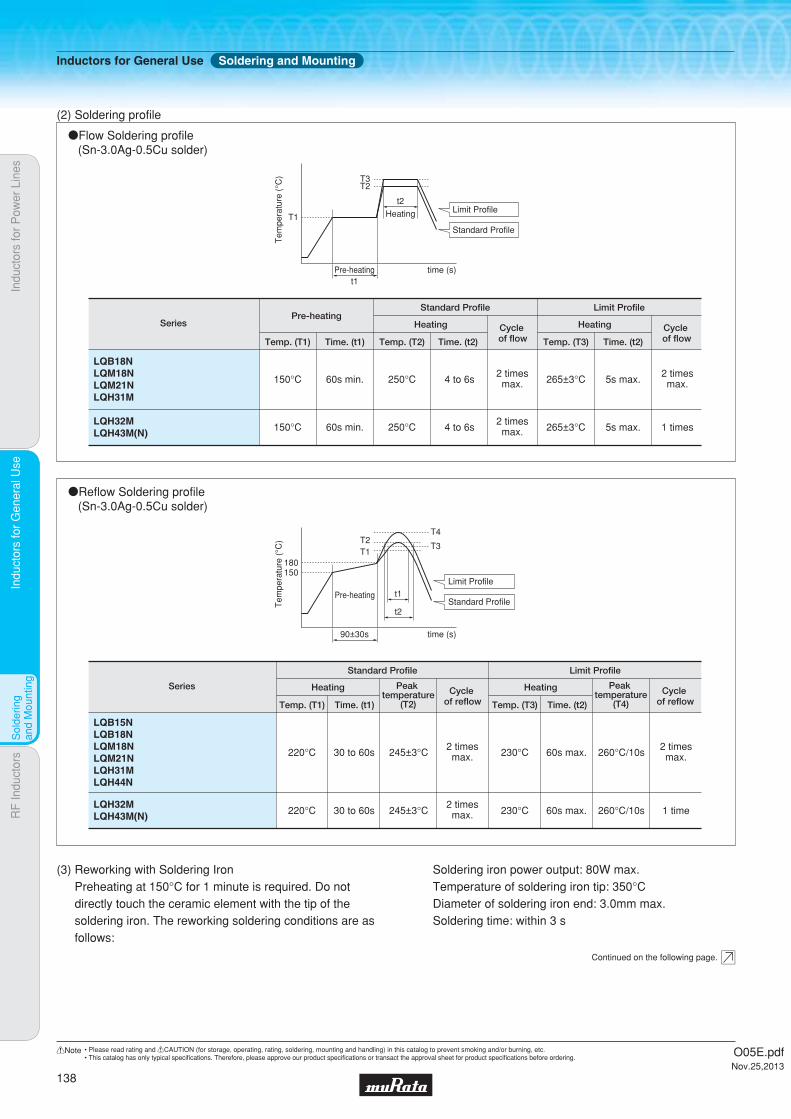
Indu
ctor
s fo
r P
ower
Lin
esIn
duct
ors
for
Gen
eral
Use
RF
Indu
ctor
sIn
duct
ors
for
Gen
eral
Use
Sol
derin
g an
d M
ount
ing
oReflow Soldering profile (Sn-3.0Ag-0.5Cu solder)
Series
Standard Profile Limit Profile
Temp. (T1) Time. (t1)
Heating
220°C 30 to 60s 245±3°C2 timesmax. 230°C 260°C/10s
2 timesmax.60s max.
Cycle of reflow
Peak temperature
(T2) Temp. (T3) Time. (t2)
Heating Cycle of reflow
Peak temperature
(T4)
150180
T2T4
T3T1
Tem
pera
ture
(°C
)
90±30s time (s)
t2
t1Limit Profile
Standard ProfilePre-heating
LQB15NLQB18NLQM18NLQM21NLQH31MLQH44N
LQH32MLQH43M(N) 220°C 30 to 60s 245±3°C
2 timesmax. 230°C 260°C/10s 1 time60s max.
(2) Soldering profile
oFlow Soldering profile (Sn-3.0Ag-0.5Cu solder)
SeriesPre-heating
Standard Profile Limit Profile
Heating
Temp. (T1) Temp. (T2)Time. (t1)
150°C 60s min. 250°C 4 to 6s2 timesmax. 5s max.
2 timesmax.265±3°C
Time. (t2)
HeatingCycle of flow Temp. (T3) Time. (t2)
Cycle of flow
T1
T3T2
Tem
pera
ture
(°C
)Pre-heating time (s)
t2
Heating Limit Profile
Standard Profile
t1
150°C 60s min. 250°C 4 to 6s2 timesmax. 5s max. 1 times265±3°C
LQB18NLQM18NLQM21NLQH31M
LQH32MLQH43M(N)
(3) Reworking with Soldering IronPreheating at 150°C for 1 minute is required. Do not directly touch the ceramic element with the tip of the soldering iron. The reworking soldering conditions are as follows:
Soldering iron power output: 80W max.Temperature of soldering iron tip: 350°CDiameter of soldering iron end: 3.0mm max.Soldering time: within 3 s
Continued on the following page.
Inductors for General Use Soldering and Mounting
O05E.pdfNov.25,2013
138
!Note • Please read rating and !CAUTION (for storage, operating, rating, soldering, mounting and handling) in this catalog to prevent smoking and/or burning, etc.• This catalog has only typical specifi cations. Therefore, please approve our product specifi cations or transact the approval sheet for product specifi cations before ordering.

Indu
ctor
s fo
r P
ower
Lin
esIn
duct
ors
for
Gen
eral
Use
RF
Indu
ctor
sIn
duct
ors
for
Gen
eral
Use
Sol
derin
g an
d M
ount
ing
3. Mounting Instructions
(4) PCB WarpingPCB should be designed so that products are not subjected to the mechanical stress caused by warping the board.
Poor example
Products should be located in a sideways direction (Length: a<b) to the mechanical stress.
Good example
a
b
Poor example
The electrode part of the product should be located as in the figure to avoid mechanical stress.
Good example
(1) Land Pattern DimensionsLarge lands reduce Q of the mounted chip. Also, large protruding land areas (bordered by lines having dimensions 'c' and 'd' shown) cause floating and electrode leaching.
(3) Magnetic CouplingSince some chip inductors (chip coils) are constructed like an open magnetic circuit, narrow spacing between inductors (coils) may cause magnetic coupling.LQB/LQM series have a magnetically shielded structure. The structure makes their coupling coefficient smaller than that of conventional chip inductors (chip coils).
d
c
Magnetic Coupling
Land Solder Resist
electrode
electrode
LQMLQH_M
(5) Amount of Solder PasteExcessive solder causes electrode corrosion, while insufficient solder causes low electrode bonding strength. Adjust the amount of solder paste as shown on the right so that solder is applied.o Guideline of solder paste thickness
· LQB/LQM: 100 to 150μm· LQHs except for ones written above: 200 to 300μm
Continued on the following page.
(2) Land Pattern Designing (LQH series)Please follow the recommended patterns.Otherwise, their performance, which includes electrical performance or solderability, may be affected, or result in
“position shift” in the soldering process.
Inductors for General Use Soldering and Mounting
O05E.pdfNov.25,2013
139
!Note • Please read rating and !CAUTION (for storage, operating, rating, soldering, mounting and handling) in this catalog to prevent smoking and/or burning, etc.• This catalog has only typical specifi cations. Therefore, please approve our product specifi cations or transact the approval sheet for product specifi cations before ordering.

Indu
ctor
s fo
r P
ower
Lin
esIn
duct
ors
for
Gen
eral
Use
RF
Indu
ctor
sIn
duct
ors
for
Gen
eral
Use
Sol
derin
g an
d M
ount
ing
LQM
LQB18N/LQM18N
LQM21N
LQH31M
LQH32M
LQH43M(N)
0.06-0.07
0.20-0.25
0.20-0.25
0.27-0.35
0.60-0.80
(6) Amount of AdhesiveIf too much adhesive is applied, then it may overflow into the land or termination areas and yield poor solderability. In contrast, if insufficient adhesive is applied, or if the adhesive is not sufficiently hardened, then the chip may become detached during flow soldering. Apply the adhesive in accordance with the conditions shown in the chart.
Typical Application Amount (in:mg)Part Number
IR-100
The following conditions should be observed when cleaning chip inductors (chip coils):(1) Cleaning Temperature: 60°C max. (40°C max. for
alcohol cleaning agents)(2) Ultrasonic
Output: 20W/l max.Duration: 5 minutes max.Frequency: 28 to 40kHzCare should be taken not to cause resonance of thePCB and mounted products.
(3) Cleaning agent The following cleaning agents have been tested on individual components. Evaluation in complete assembly should be done prior to production.(a) Alcohol cleaning agents
Isopropyl alcohol (IPA)(b) Aqueous cleaning agents
Pine Alpha ST-100S
(4) Ensure that flux residue is completely removed.Component should be thoroughly dried after aqueous agents have been removed with deionized water.
For additional cleaning methods, please contact Murata.
4. Cleaning
LQH_M/N
Inductors for General Use Soldering and Mounting
O05E.pdfNov.25,2013
140
!Note • Please read rating and !CAUTION (for storage, operating, rating, soldering, mounting and handling) in this catalog to prevent smoking and/or burning, etc.• This catalog has only typical specifi cations. Therefore, please approve our product specifi cations or transact the approval sheet for product specifi cations before ordering.
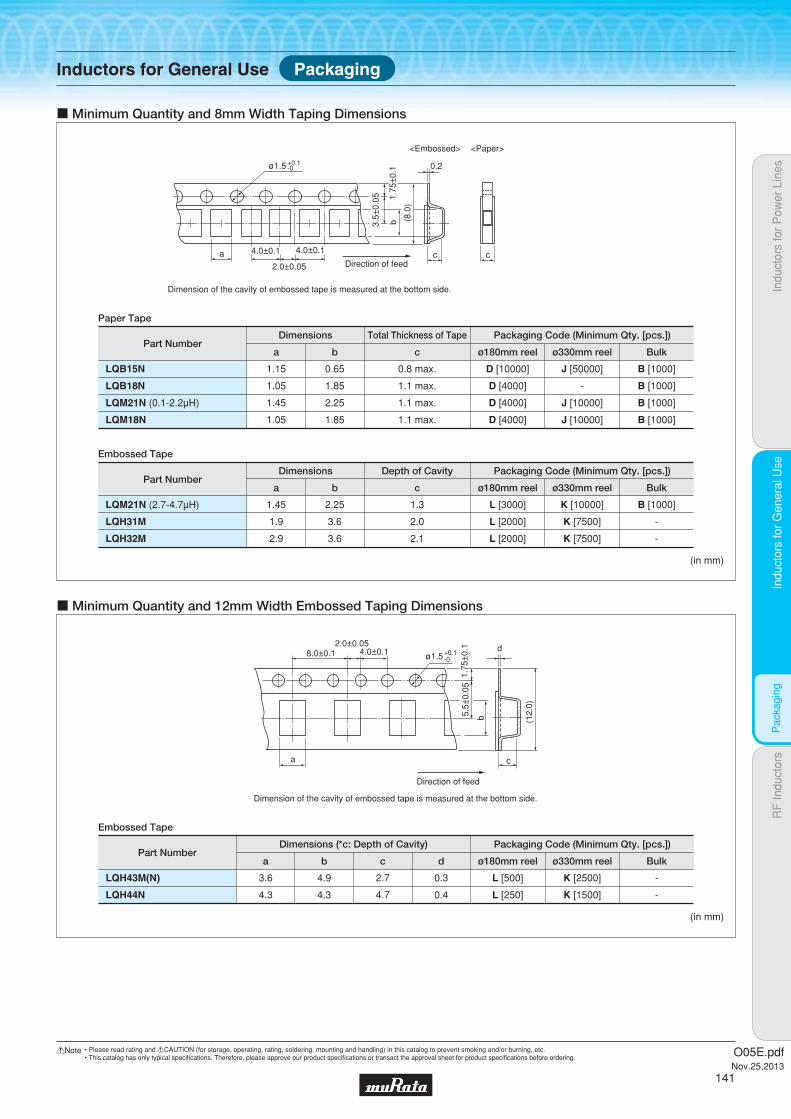
Indu
ctor
s fo
r P
ower
Lin
esIn
duct
ors
for
Gen
eral
Use
RF
Indu
ctor
sIn
duct
ors
for
Gen
eral
Use
Pac
kagi
ng
a
b
cDirection of feed
Dimension of the cavity of embossed tape is measured at the bottom side.
4.0±0.1 4.0±0.1
2.0±0.05
0.2
3.5±
0.05 1.
75±
0.1
(8.
0)
ø1.5 +0.1-0
c Minimum Quantity and 8mm Width Taping Dimensions
<Embossed> <Paper>
c
(in mm)
Part Numbera
Paper Tape
LQM21N (0.1-2.2μH)
LQM18N
1.45
1.05
b
2.25
1.85
c
1.1 max.
1.1 max.
ø180mm reel
D [4000]
ø330mm reel
Dimensions Packaging Code (Minimum Qty. [pcs.])
J [10000]
Bulk
B [1000]
D [4000] J [10000] B [1000]
LQB18N 1.05 1.85 1.1 max. D [4000] - B [1000]
LQB15N 1.15 0.65 0.8 max. D [10000] J [50000] B [1000]
Part Numbera
Embossed Tape
LQM21N (2.7-4.7μH)
LQH31M
LQH32M
1.45
1.9
2.9
b
2.25
3.6
3.6
c
1.3
2.0
2.1
ø180mm reel
L [3000]
ø330mm reel
Dimensions
Total Thickness of Tape
Depth of Cavity Packaging Code (Minimum Qty. [pcs.])
K [10000]
Bulk
B [1000]
L [2000] K [7500] -
L [2000] K [7500] -
(in mm)
a
b
c
d8.0±0.1
2.0±0.054.0±0.1
5.5±
0.05
1.75
±0.
1
(12.
0)
ø1.5+0.1-0
Direction of feed
c Minimum Quantity and 12mm Width Embossed Taping Dimensions
Dimension of the cavity of embossed tape is measured at the bottom side.
Part Numbera
Embossed Tape
LQH43M(N) 3.6
b
4.9
c
2.7
d ø180mm reel
Dimensions (*c: Depth of Cavity) Packaging Code (Minimum Qty. [pcs.])
ø330mm reel
0.3 L [500] K [2500]
Bulk
-
LQH44N 4.3 4.3 4.7 0.4 L [250] K [1500] -
Inductors for General Use Packaging
O05E.pdfNov.25,2013
141
!Note • Please read rating and !CAUTION (for storage, operating, rating, soldering, mounting and handling) in this catalog to prevent smoking and/or burning, etc.• This catalog has only typical specifi cations. Therefore, please approve our product specifi cations or transact the approval sheet for product specifi cations before ordering.
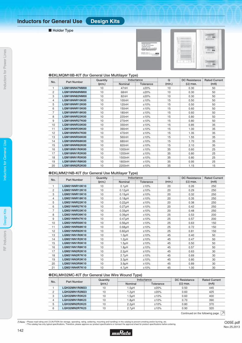
Indu
ctor
s fo
r P
ower
Lin
esIn
duct
ors
for
Gen
eral
Use
RF
Indu
ctor
sIn
duct
ors
for
Gen
eral
Use
Des
ign
Kits
oEKLMQM18B-KIT (for General Use Multilayer Type)
oEKLMM21NB-KIT (for General Use Multilayer Type)
c Holder Type
LQM18NN47NM00LQM18NN68NM00LQM18NN82NM00
123
101010
47nH68nH82nH
±20%±20%±20%
101010
0.300.300.30
505050
LQM18NNR10K004 10 100nH ±10% 15 0.50 50LQM18NNR12K00LQM18NNR15K00LQM18NNR18K00LQM18NNR22K00LQM18NNR27K00LQM18NNR33K00LQM18NNR39K00LQM18NNR47K00
56789101112
1010101010101010
120nH150nH180nH220nH270nH330nH390nH470nH
±10%±10%±10%±10%±10%±10%±10%±10%
1515151515151515
0.500.600.600.800.800.851.001.35
5050505050353535
LQM18NNR56K00LQM18NNR68K00LQM18NNR82K00LQM18NN1R0K00LQM18NN1R2K00LQM18NN1R5K00LQM18NN1R8K00LQM18NN2R2K00
1314151617181920
1010101010101010
560nH680nH820nH
1000nH1200nH1500nH1800nH2200nH
±10%±10%±10%±10%±10%±10%±10%±10%
1515153535353535
1.551.702.100.600.800.800.951.15
3535352525252515
LQM21NN1R5K10LQM21NN1R8K10LQM21NN2R2K10LQM21NN2R7K10LQM21NN3R3K10LQM21NN3R9K10LQM21NN4R7K10
15161718192021
10101010101010
1.5μH1.8μH2.2μH2.7μH3.3μH3.9μH4.7μH
±10%±10%±10%±10%±10%±10%±10%
45454545454545
0.500.570.630.690.800.891.00
50503030303030
LQM21NNR10K10LQM21NNR12K10
12
1010
0.1μH0.12μH
±10%±10%
2020
0.260.29
250250
LQM21NNR15K10LQM21NNR18K10LQM21NNR22K10LQM21NNR27K10LQM21NNR33K10LQM21NNR39K10LQM21NNR47K10
3456789
10101010101010
0.15μH0.18μH0.22μH0.27μH0.33μH0.39μH0.47μH
±10%±10%±10%±10%±10%±10%±10%
20202020202525
0.320.350.380.420.480.530.57
250250250250250200200
LQM21NNR56K10LQM21NNR68K10LQM21NNR82K10LQM21NN1R0K10LQM21NN1R2K10
1011121314
1010101010
0.56μH0.68μH0.82μH1.0μH1.2μH
±10%±10%±10%±10%±10%
2525254545
0.630.720.810.400.47
1501501505050
oEKLMH32MC-KIT (for General Use Wire Wound Type)
LQH32MN1R0M23LQH32MN1R2M23LQH32MN1R5K23LQH32MN1R8K23LQH32MN2R2K23
12345
1010101010
1.0μH1.2μH1.5μH1.8μH2.2μH
±20%±20%±10%±10%±10%
0.500.600.600.700.80
445425400390370
LQH32MN2R7K236 10 2.7μH ±10% 0.90 320
Part NumberNo.Rated Current
(mA)DC Resistance
(Ω) max.Q
(min.)ToleranceNominalInductanceQuantity
(pcs.)
Part NumberNo.Rated Current
(mA)DC Resistance
(Ω) max.Q
(min.)ToleranceNominalInductanceQuantity
(pcs.)
Part NumberNo.Rated Current
(mA)DC Resistance
(Ω) max.ToleranceNominalInductanceQuantity
(pcs.)
Continued on the following page.
Design KitsInductors for General Use
O05E.pdfNov.25,2013
142
!Note • Please read rating and !CAUTION (for storage, operating, rating, soldering, mounting and handling) in this catalog to prevent smoking and/or burning, etc.• This catalog has only typical specifi cations. Therefore, please approve our product specifi cations or transact the approval sheet for product specifi cations before ordering.
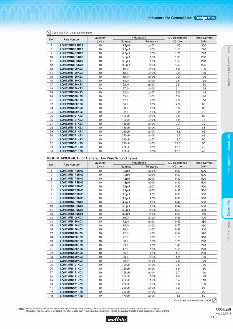
Indu
ctor
s fo
r P
ower
Lin
esIn
duct
ors
for
Gen
eral
Use
RF
Indu
ctor
sIn
duct
ors
for
Gen
eral
Use
Des
ign
Kits
oEKLMH43MB-KIT (for General Use Wire Wound Type)
LQH32MN3R3K23LQH32MN3R9K23LQH32MN4R7K23LQH32MN5R6K23LQH32MN6R8K23LQH32MN8R2K23LQH32MN100K23
78910111213
10101010101010
3.3μH3.9μH4.7μH5.6μH6.8μH8.2μH10μH
±10%±10%±10%±10%±10%±10%±10%
1.001.101.201.301.501.601.8
300290270250240225190
LQH32MN120K23LQH32MN150K23LQH32MN180K23LQH32MN220K23LQH32MN270K23LQH32MN330K23LQH32MN390K23LQH32MN470K23LQH32MN560K23LQH32MN680K23LQH32MN820K23LQH32MN101K23
141516171819202122232425
101010101010101010101010
12μH15μH18μH22μH27μH33μH39μH47μH56μH68μH82μH
100μH
±10%±10%±10%±10%±10%±10%±10%±10%±10%±10%±10%±10%
2.02.22.52.83.13.53.94.34.95.56.27.0
18017016515012511511010085807080
LQH32MN121K23LQH32MN151K23LQH32MN181K23LQH32MN221K23
26272829
10101010
120μH150μH180μH220μH
±10%±10%±10%±10%
8.09.3
10.211.8
75706565
LQH32MN271K23LQH32MN331K23LQH32MN391K23LQH32MN471K23LQH32MN561K23
3031323334
1010101010
270μH330μH390μH470μH560μH
±10%±10%±10%±10%±10%
12.513.022.025.028.0
6565504540
LQH43MN100K03LQH43MN120K03LQH43MN150K03LQH43MN180K03LQH43MN220K03LQH43MN270K03LQH43MN330K03
13141516171819
10101010101010
10μH12μH15μH18μH22μH27μH33μH
±10%±10%±10%±10%±10%±10%±10%
0.560.620.730.820.941.101.20
400380360340320300270
LQH43MN1R0M03LQH43MN1R2M03LQH43MN1R5M03LQH43MN1R8M03LQH43MN2R2M03LQH43MN2R7M03LQH43MN3R3M03LQH43MN3R9M03LQH43MN4R7K03LQH43MN5R6K03LQH43MN6R8K03LQH43MN8R2K03
123456789101112
101010101010101010101010
1.0μH1.2μH1.5μH1.8μH2.2μH2.7μH3.3μH3.9μH4.7μH5.6μH6.8μH8.2μH
±20%±20%±20%±20%±20%±20%±20%±20%±10%±10%±10%±10%
0.200.200.300.300.300.320.350.380.400.470.500.56
500500500500500500500500500500450450
LQH43MN390K03LQH43MN470K03LQH43MN560K03LQH43MN680K03LQH43MN820K03LQH43MN101K03LQH43MN121K03LQH43MN151K03
2021222324252627
1010101010101010
39μH47μH56μH68μH82μH
100μH120μH150μH
±10%±10%±10%±10%±10%±10%±10%±10%
1.401.501.71.92.22.53.03.7
240220200180170160150130
LQH43MN181K03LQH43MN221K03LQH43MN271K03LQH43MN331K03LQH43MN391K03LQH43MN471K03
282930313233
101010101010
180μH220μH270μH330μH390μH470μH
±10%±10%±10%±10%±10%±10%
4.55.46.88.29.7
11.8
120110100959080
Part NumberNo.Rated Current
(mA)DC Resistance
(Ω) max.ToleranceNominalInductanceQuantity
(pcs.)
Part NumberNo.Rated Current
(mA)DC Resistance
(Ω) max.ToleranceNominalInductanceQuantity
(pcs.)
Continued from the preceding page.
Continued on the following page.
Inductors for General Use Design Kits
O05E.pdfNov.25,2013
143
!Note • Please read rating and !CAUTION (for storage, operating, rating, soldering, mounting and handling) in this catalog to prevent smoking and/or burning, etc.• This catalog has only typical specifi cations. Therefore, please approve our product specifi cations or transact the approval sheet for product specifi cations before ordering.

Indu
ctor
s fo
r P
ower
Lin
esIn
duct
ors
for
Gen
eral
Use
RF
Indu
ctor
sIn
duct
ors
for
Gen
eral
Use
Des
ign
Kits
LQH43MN561K03LQH43MN681K03LQH43MN821K03LQH43MN102K03LQH43MN122K03LQH43MN152K03
343536373839
101010101010
560μH680μH820μH
1000μH1200μH1500μH
±10%±10%±10%±10%±10%±10%
14.517.020.525.030.037.0
706560504540
LQH43NN182K03LQH43NN222K03
4041
1010
1800μH2200μH
±10%±10%
45.050.0
3530
Part NumberNo.Rated Current
(mA)DC Resistance
(Ω) max.ToleranceNominalInductanceQuantity
(pcs.)
Continued from the preceding page.
Inductors for General Use Design Kits
O05E.pdfNov.25,2013
144
!Note • Please read rating and !CAUTION (for storage, operating, rating, soldering, mounting and handling) in this catalog to prevent smoking and/or burning, etc.• This catalog has only typical specifi cations. Therefore, please approve our product specifi cations or transact the approval sheet for product specifi cations before ordering.

aRF Inductors
146
147
148
225
227
231
232
Introduction
Part Numbering
Product Detail
!Caution/Notice
Soldering and Mounting
Packaging
Design Kits
O05E.pdfNov.25,2013
!Note • Please read rating and !CAUTION (for storage, operating, rating, soldering, mounting and handling) in this catalog to prevent smoking and/or burning, etc.• This catalog has only typical specifi cations. Therefore, please approve our product specifi cations or transact the approval sheet for product specifi cations before ordering.
Indu
ctor
s fo
r P
ower
Lin
esIn
duct
ors
for
Gen
eral
Use
RF
Indu
ctor
sR
F In
duct
ors

Indu
ctor
s fo
r P
ower
Lin
esIn
duct
ors
for
Gen
eral
Use
RF
Indu
ctor
sR
F In
duct
ors
INPUT OUTPUTSAW Filter
Vt
P OutBufferStage
OscillationStage
Vdd1 Vdd2
IN Out
VGG VGG
Vdd3
LNA
Vco
LNA
IF SAW Filter
VCO
PA
ANTENNA
c Introduction of RF Inductors
oApplications of RF Inductors
For Matching
High Q or tight inductance tolerance is required to improve signal quality. Especially, film type is suitable at receiver circuit because tight tolerance is required.cRecommended
Film Type LQP03T Series (for miniaturization) LQP15M SeriesMultilayer Type LQG15H Series
For Matching
High Q is required to reduce signal loss. Wire wound type and film type are suitable when tight tolerance is essential.cRecommended
Wire Wound Type LQW15A Series LQW18A Series LQW2BH SeriesFilm Type LQP03T Series LQP15M Series
For Matching For Oscillator
High Q or tight inductance tolerance is required to stabilize oscillation and signal quality.Wire wound type is suitable for high Q, film type is suitable for tight tolerance.
For RF Choke
For RF Choke
Low DC resistance is required because of large operation current. Wire wound type or multilayer type is suitable.
cRecommendedWire Wound Type LQW15A Series LQW18A Series LQW18A_10 Series
For Matching
Small shape is required.Film type is suitable because of its tight inductance tolerance and fine inductance step.cRecommended
Film Type LQP02T Series LQP03T Series (for miniaturization) LQP15M Series (for frequency selectivity)
For Matching
LQW series is suitable for attaining high antenna sensitivity because of its high Q and tight tolerance spec.cRecommended
Wire Wound Type LQW15A Series LQW18A Series
For RF Choke
Low DC resistance is required because of large operation current. Especially, wire wound type is suitable for GSM because over 1A of current is working.cRecommended
Wire Wound Type LQW15A Series LQW18A Series LQW18A_10 Series LQW2BH Series(for output efficiency improvement)
Multilayer Type LQG15H Series
Multilayer Type LQG15H Series
cRecommendedWire Wound Type LQW15A Series LQW18A Series LQW18A_10 SeriesMultilayer Type LQG15H Series
Low DC resistance is required because of large operation current. Wire wound type or multilayer type is suitable.cRecommended
Wire Wound Type LQW15A Series LQW18A SeriesMultilayer Type LQG15H Series
Wire Wound Type LQW15A Series LQW18A Series
RF Choke
RF Choke
RF Choke
RF Choke RF Choke RF Choke
Matching
Matching
Matching
Matching Matching Matching Matching
for Oscillator
Matching
Matching
Multilayer Type LQG15H Series
(for output efficiency improvement)
Film Type LQP03T Series (for miniaturization) LQP15M Series (for frequency selectivity)Multilayer Type LQG15H Series
O05E.pdfNov.25,2013
146
!Note • Please read rating and !CAUTION (for storage, operating, rating, soldering, mounting and handling) in this catalog to prevent smoking and/or burning, etc.• This catalog has only typical specifi cations. Therefore, please approve our product specifi cations or transact the approval sheet for product specifi cations before ordering.
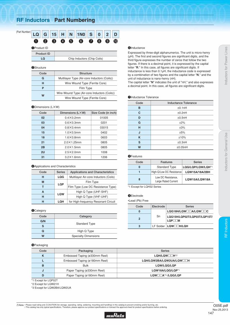
Indu
ctor
s fo
r P
ower
Lin
esIn
duct
ors
for
Gen
eral
Use
RF
Indu
ctor
sR
F In
duct
ors
(Part Number)
RF Inductors Part Numbering
uInductance Tolerance
eDimensions (LgW)
Code
0.4g0.2mm
0.6g0.3mm
0.8g0.4mm
1.0g0.5mm
1.6g0.8mm
2.0g1.25mm
2.0g1.5mm
2.5g2.0mm
3.2g1.6mm
Dimensions (LgW)
01005
0201
03015
0402
0603
0805
0805
1008
1206
Size Code (in inch)
02
03
04
15
18
21
2B
2U
31
Code
B
C
D
G
H
J
K
S
W
±0.1nH
±0.2nH
±0.5nH
±2%
±3%
±5%
±10%
±0.3nH
±0.05nH
Inductance Tolerance
qProduct ID
LQ Chip Inductors (Chip Coils)
Product ID
wStructure
Code
G
H
P
W
Multilayer Type (Air-core Inductors (Coils))
Wire Wound Type (Ferrite Core)
Film Type
Wire Wound Type (Air-core Inductors (Coils))
Wire Wound Type (Ferrite Core)
Structure
rApplications and Characteristics
Code
Multilayer Air-core Inductors (Coils)
Film Type
Film Type (Low DC Resistance Type)
High Q Type (UHF-SHF)
High Q Type (VHF-UHF)
for High-frequency Resonant Circuit
Applications and Characteristics
H
M
T
A
H
H
Series
LQG
LQP
LQW
LQH
yInductance
Expressed by three-digit alphanumerics. The unit is micro-henry (μH). The first and second figures are significant digits, and the third figure expresses the number of zeros that follow the two figures. If there is a decimal point, it is expressed by the capital letter "R." In this case, all figures are significant digits. If inductance is less than 0.1μH, the inductance code is expressed by a combination of two figures and the capital letter "N," and the unit of inductance is nano-henry (nH).The capital letter "N" indicates the unit of "nH," and also expresses a decimal point. In this case, all figures are significant digits.
tCategory
G/N
S
Q
W
Standard Type
High Q Type
Specialty Dimensions
Code Category
q
LQ
y
1N0
e
15
w
G
r
H
t
N
u
S
i
0
o
2
!0
D
0
2
3
Sn
LF Solder
Code Electrode
LQG18H/LQWppA/LQWppC
LQG15H/LQP02T/LQP03T/LQP15T/LQPppM
LQWppH/LQH
Series
oElectrode
iFeatures
0
1
8
Standard Type
High-Q/Low DC Resistance
Low DC Resistance,Large Rated Current
Code Features Series
LQG/LQP/LQW/LQH*1
LQW15A/18A/2BH
LQW15A/LQW18A
*1 Except for LQH32 Series
!0Packaging
K
L
B
J
D
LQH/LQWppH*2
LQH/LQW2BA/LQW2UA/LQWppH
LQW/LQG/LQP
LQW18A/LQG/LQP*1
LQWppA*3 /LQG/LQP
Embossed Taping (ø330mm Reel)
Embossed Taping (ø180mm Reel)
Bulk
Paper Taping (ø330mm Reel)
Paper Taping (ø180mm Reel)
Code Packaging Series
*1 Except for LQP02T*2 Except for LQW21H*3 Except for LQW2BA/LQW2UA
O05E.pdfNov.25,2013
147
!Note • Please read rating and !CAUTION (for storage, operating, rating, soldering, mounting and handling) in this catalog to prevent smoking and/or burning, etc.• This catalog has only typical specifi cations. Therefore, please approve our product specifi cations or transact the approval sheet for product specifi cations before ordering.

Code PackagingMinimumQuantity
D ø180mm Paper Taping 10000
J ø330mm Paper Taping 50000
B Packing in Bulk 1000
0.55Thickness
mmmax.
E-12Step
E-24Step
ReflowOK
Indu
ctor
s fo
r P
ower
Lin
esIn
duct
ors
for
Gen
eral
Use
RF
Indu
ctor
sR
F In
duct
ors
Mul
tilay
er T
ype
(Non
-Mag
netic
Cor
e)
Multilayer Type (Non-Magnetic Core) LQG15HN_02
RF Inductors
LQG15HN_02Series 0402/1005 (inch/mm)Size Code 0402 (1005) in inch (in mm), Multilayer Type
c Rated Value (p: packaging code)
Refer to pages 227 to 230 for mounting information.
0.5±0.05
(in mm)
1.0±0.05
0.5±
0.05
0.25±0.1
Polarity Marking
Continued on the following page.
c Appearance/Dimensions
c Packaging
Operating Temperature Range (Self-temperature rise is not included): -55℃~+125℃For refl ow soldering only.
Part Number InductanceInductance
Test FrequencyRated Current Max. of DC Resistance Q (min.) Q Test Frequency
Self-ResonanceFrequency (min.)
LQG15HN1N0S02p 1.0nH ±0.3nH 100MHz 300mA 0.10Ω 8 100MHz 6000MHz
LQG15HN1N1S02p 1.1nH ±0.3nH 100MHz 300mA 0.10Ω 8 100MHz 6000MHz
LQG15HN1N2S02p 1.2nH ±0.3nH 100MHz 300mA 0.10Ω 8 100MHz 6000MHz
LQG15HN1N3S02p 1.3nH ±0.3nH 100MHz 300mA 0.10Ω 8 100MHz 6000MHz
LQG15HN1N5S02p 1.5nH ±0.3nH 100MHz 300mA 0.10Ω 8 100MHz 6000MHz
LQG15HN1N6S02p 1.6nH ±0.3nH 100MHz 300mA 0.10Ω 8 100MHz 6000MHz
LQG15HN1N8S02p 1.8nH ±0.3nH 100MHz 300mA 0.10Ω 8 100MHz 6000MHz
LQG15HN2N0S02p 2.0nH ±0.3nH 100MHz 300mA 0.12Ω 8 100MHz 6000MHz
LQG15HN2N2S02p 2.2nH ±0.3nH 100MHz 300mA 0.15Ω 8 100MHz 6000MHz
LQG15HN2N4S02p 2.4nH ±0.3nH 100MHz 300mA 0.16Ω 8 100MHz 6000MHz
LQG15HN2N7S02p 2.7nH ±0.3nH 100MHz 300mA 0.17Ω 8 100MHz 6000MHz
LQG15HN3N0S02p 3.0nH ±0.3nH 100MHz 300mA 0.18Ω 8 100MHz 6000MHz
LQG15HN3N3S02p 3.3nH ±0.3nH 100MHz 300mA 0.19Ω 8 100MHz 6000MHz
LQG15HN3N6S02p 3.6nH ±0.3nH 100MHz 300mA 0.19Ω 8 100MHz 6000MHz
LQG15HN3N9S02p 3.9nH ±0.3nH 100MHz 300mA 0.19Ω 8 100MHz 6000MHz
LQG15HN4N3S02p 4.3nH ±0.3nH 100MHz 300mA 0.21Ω 8 100MHz 6000MHz
LQG15HN4N7S02p 4.7nH ±0.3nH 100MHz 300mA 0.23Ω 8 100MHz 6000MHz
LQG15HN5N1S02p 5.1nH ±0.3nH 100MHz 300mA 0.24Ω 8 100MHz 6000MHz
LQG15HN5N6S02p 5.6nH ±0.3nH 100MHz 300mA 0.26Ω 8 100MHz 5300MHz
LQG15HN6N2S02p 6.2nH ±0.3nH 100MHz 300mA 0.27Ω 8 100MHz 4300MHz
LQG15HN6N8J02p 6.8nH ±5% 100MHz 300mA 0.29Ω 8 100MHz 4200MHz
LQG15HN7N5J02p 7.5nH ±5% 100MHz 300mA 0.31Ω 8 100MHz 3900MHz
LQG15HN8N2J02p 8.2nH ±5% 100MHz 300mA 0.33Ω 8 100MHz 3600MHz
LQG15HN9N1J02p 9.1nH ±5% 100MHz 300mA 0.34Ω 8 100MHz 3400MHz
LQG15HN10NJ02p 10nH ±5% 100MHz 300mA 0.35Ω 8 100MHz 3200MHz
LQG15HN12NJ02p 12nH ±5% 100MHz 300mA 0.41Ω 8 100MHz 2800MHz
LQG15HN15NJ02p 15nH ±5% 100MHz 300mA 0.46Ω 8 100MHz 2300MHz
LQG15HN18NJ02p 18nH ±5% 100MHz 300mA 0.51Ω 8 100MHz 2100MHz
LQG15HN22NJ02p 22nH ±5% 100MHz 300mA 0.58Ω 8 100MHz 1800MHz
LQG15HN27NJ02p 27nH ±5% 100MHz 300mA 0.67Ω 8 100MHz 1600MHz
LQG15HN33NJ02p 33nH ±5% 100MHz 200mA 0.67Ω 8 100MHz 1500MHz
LQG15HN39NJ02p 39nH ±5% 100MHz 200mA 1.06Ω 8 100MHz 1200MHz
O05E.pdfNov.25,2013
148
!Note • Please read rating and !CAUTION (for storage, operating, rating, soldering, mounting and handling) in this catalog to prevent smoking and/or burning, etc.• This catalog has only typical specifi cations. Therefore, please approve our product specifi cations or transact the approval sheet for product specifi cations before ordering.

Indu
ctor
s fo
r P
ower
Lin
esIn
duct
ors
for
Gen
eral
Use
RF
Indu
ctor
sR
F In
duct
ors
Mul
tilay
er T
ype
(Non
-Mag
netic
Cor
e)
LQG15HN_02
c Q-Frequency Characteristics (Typ.) c Inductance-Frequency Characteristics (Typ.)
10 100 1000 10000Frequency (MHz)
140
120
100
80
60
40
20
0
Q
1.0nH
3.3nH
10nH
56nH120nH
100
1000
10
1
0.110010 1000 10000
L (n
H)
Frequency (MHz)
120nH
56nH
10nH
3.3nH
1.0nH
Operating Temperature Range (Self-temperature rise is not included): -55℃~+125℃For refl ow soldering only.
Part Number InductanceInductance
Test FrequencyRated Current Max. of DC Resistance Q (min.) Q Test Frequency
Self-ResonanceFrequency (min.)
LQG15HN47NJ02p 47nH ±5% 100MHz 200mA 1.15Ω 8 100MHz 1000MHz
LQG15HN56NJ02p 56nH ±5% 100MHz 200mA 1.20Ω 8 100MHz 800MHz
LQG15HN68NJ02p 68nH ±5% 100MHz 180mA 1.25Ω 8 100MHz 800MHz
LQG15HN82NJ02p 82nH ±5% 100MHz 150mA 1.60Ω 8 100MHz 600MHz
LQG15HNR10J02p 100nH ±5% 100MHz 150mA 1.60Ω 8 100MHz 600MHz
LQG15HNR12J02p 120nH ±5% 100MHz 150mA 1.60Ω 8 100MHz 600MHz
O05E.pdfNov.25,2013
149
!Note • Please read rating and !CAUTION (for storage, operating, rating, soldering, mounting and handling) in this catalog to prevent smoking and/or burning, etc.• This catalog has only typical specifi cations. Therefore, please approve our product specifi cations or transact the approval sheet for product specifi cations before ordering.

Code PackagingMinimumQuantity
D ø180mm Paper Taping 10000
J ø330mm Paper Taping 50000
B Packing in Bulk 1000
0.55Thickness
mmmax.
E-12Step
E-24Step
ReflowOK
Indu
ctor
s fo
r P
ower
Lin
esIn
duct
ors
for
Gen
eral
Use
RF
Indu
ctor
sR
F In
duct
ors
Mul
tilay
er T
ype
(Non
-Mag
netic
Cor
e)
Multilayer Type (Non-Magnetic Core) LQG15HS_02
RF Inductors
LQG15HS_02Series 0402/1005 (inch/mm)Designed under Industrial Global Standard
c Rated Value (p: packaging code)
Refer to pages 227 to 230 for mounting information.
0.5±0.05
(in mm)
1.0±0.05
0.5±
0.05
0.25±0.1
Polarity Marking
Continued on the following page.
c Appearance/Dimensions
c Packaging
Operating Temperature Range (Self-temperature rise is not included): -55℃~+125℃For refl ow soldering only.
Part Number InductanceInductance
Test FrequencyRated Current
Max. of DCResistance
Q (min.) Q Test FrequencySelf-ResonanceFrequency (min.)
LQG15HS1N0S02p 1.0nH ±0.3nH 100MHz 300mA 0.07Ω 8 100MHz 10000MHz LQG15HS1N1S02p 1.1nH ±0.3nH 100MHz 300mA 0.09Ω 8 100MHz 6000MHz LQG15HS1N2S02p 1.2nH ±0.3nH 100MHz 300mA 0.09Ω 8 100MHz 6000MHz LQG15HS1N3S02p 1.3nH ±0.3nH 100MHz 300mA 0.09Ω 8 100MHz 6000MHz LQG15HS1N5S02p 1.5nH ±0.3nH 100MHz 300mA 0.10Ω 8 100MHz 6000MHz LQG15HS1N6S02p 1.6nH ±0.3nH 100MHz 300mA 0.10Ω 8 100MHz 6000MHz LQG15HS1N8S02p 1.8nH ±0.3nH 100MHz 300mA 0.10Ω 8 100MHz 6000MHz LQG15HS2N0S02p 2.0nH ±0.3nH 100MHz 300mA 0.10Ω 8 100MHz 6000MHz LQG15HS2N2S02p 2.2nH ±0.3nH 100MHz 300mA 0.12Ω 8 100MHz 6000MHz LQG15HS2N4S02p 2.4nH ±0.3nH 100MHz 300mA 0.15Ω 8 100MHz 6000MHz LQG15HS2N7S02p 2.7nH ±0.3nH 100MHz 300mA 0.15Ω 8 100MHz 6000MHz LQG15HS3N0S02p 3.0nH ±0.3nH 100MHz 300mA 0.17Ω 8 100MHz 6000MHz LQG15HS3N3S02p 3.3nH ±0.3nH 100MHz 300mA 0.17Ω 8 100MHz 6000MHz LQG15HS3N6S02p 3.6nH ±0.3nH 100MHz 300mA 0.18Ω 8 100MHz 6000MHz LQG15HS3N9S02p 3.9nH ±0.3nH 100MHz 300mA 0.18Ω 8 100MHz 6000MHz LQG15HS4N3S02p 4.3nH ±0.3nH 100MHz 300mA 0.18Ω 8 100MHz 6000MHz LQG15HS4N7S02p 4.7nH ±0.3nH 100MHz 300mA 0.18Ω 8 100MHz 6000MHz LQG15HS5N1S02p 5.1nH ±0.3nH 100MHz 300mA 0.20Ω 8 100MHz 5300MHz LQG15HS5N6S02p 5.6nH ±0.3nH 100MHz 300mA 0.20Ω 8 100MHz 4500MHz LQG15HS6N2S02p 6.2nH ±0.3nH 100MHz 300mA 0.22Ω 8 100MHz 4500MHz LQG15HS6N8J02p 6.8nH ±5% 100MHz 300mA 0.24Ω 8 100MHz 4500MHz LQG15HS7N5J02p 7.5nH ±5% 100MHz 300mA 0.24Ω 8 100MHz 4200MHz LQG15HS8N2J02p 8.2nH ±5% 100MHz 300mA 0.24Ω 8 100MHz 3700MHz LQG15HS9N1J02p 9.1nH ±5% 100MHz 300mA 0.26Ω 8 100MHz 3400MHz LQG15HS10NJ02p 10nH ±5% 100MHz 300mA 0.26Ω 8 100MHz 3400MHz LQG15HS12NJ02p 12nH ±5% 100MHz 300mA 0.28Ω 8 100MHz 3000MHz LQG15HS15NJ02p 15nH ±5% 100MHz 300mA 0.32Ω 8 100MHz 2500MHz LQG15HS18NJ02p 18nH ±5% 100MHz 300mA 0.36Ω 8 100MHz 2200MHz LQG15HS22NJ02p 22nH ±5% 100MHz 300mA 0.42Ω 8 100MHz 1900MHz LQG15HS27NJ02p 27nH ±5% 100MHz 300mA 0.46Ω 8 100MHz 1700MHz LQG15HS33NJ02p 33nH ±5% 100MHz 200mA 0.58Ω 8 100MHz 1600MHz LQG15HS39NJ02p 39nH ±5% 100MHz 200mA 0.65Ω 8 100MHz 1200MHz
O05E.pdfNov.25,2013
150
!Note • Please read rating and !CAUTION (for storage, operating, rating, soldering, mounting and handling) in this catalog to prevent smoking and/or burning, etc.• This catalog has only typical specifi cations. Therefore, please approve our product specifi cations or transact the approval sheet for product specifi cations before ordering.

Indu
ctor
s fo
r P
ower
Lin
esIn
duct
ors
for
Gen
eral
Use
RF
Indu
ctor
sR
F In
duct
ors
Mul
tilay
er T
ype
(Non
-Mag
netic
Cor
e)
LQG15HS_02
c Q-Frequency Characteristics (Typ.) c Inductance-Frequency Characteristics (Typ.)
0
20
40
60
80
100
10
30
50
70
90
10 100 1000 10000Frequency (MHz)
Q
56nH
3.3nH
1.0nH
10nH
270nH
10 100 1000 10000
10000
1000
100
10
1
0.1
56nH
10nH
3.3nH
1.0nH
270nH
Frequency (MHz)
L (n
H)
Continued on the following page.
Operating Temperature Range (Self-temperature rise is not included): -55℃~+125℃For refl ow soldering only.
Part Number InductanceInductance
Test FrequencyRated Current
Max. of DCResistance
Q (min.) Q Test FrequencySelf-ResonanceFrequency (min.)
LQG15HS47NJ02p 47nH ±5% 100MHz 200mA 0.72Ω 8 100MHz 1000MHz LQG15HS56NJ02p 56nH ±5% 100MHz 200mA 0.82Ω 8 100MHz 800MHz LQG15HS68NJ02p 68nH ±5% 100MHz 180mA 0.92Ω 8 100MHz 800MHz LQG15HS82NJ02p 82nH ±5% 100MHz 150mA 1.20Ω 8 100MHz 700MHz LQG15HSR10J02p 100nH ±5% 100MHz 150mA 1.25Ω 8 100MHz 600MHz LQG15HSR12J02p 120nH ±5% 100MHz 150mA 1.30Ω 8 100MHz 600MHz LQG15HSR15J02p 150nH ±5% 100MHz 140mA 2.99Ω 8 100MHz 550MHz LQG15HSR18J02p 180nH ±5% 100MHz 130mA 3.38Ω 8 100MHz 500MHz LQG15HSR22J02p 220nH ±5% 100MHz 120mA 3.77Ω 8 100MHz 450MHz LQG15HSR27J02p 270nH ±5% 100MHz 110mA 4.94Ω 8 100MHz 400MHz
O05E.pdfNov.25,2013
151
!Note • Please read rating and !CAUTION (for storage, operating, rating, soldering, mounting and handling) in this catalog to prevent smoking and/or burning, etc.• This catalog has only typical specifi cations. Therefore, please approve our product specifi cations or transact the approval sheet for product specifi cations before ordering.

Part Number
LQG15HS1N0p02
LQG15HS1N1p02
LQG15HS1N2p02
LQG15HS1N3p02
LQG15HS1N5p02
LQG15HS1N6p02
LQG15HS1N8p02
LQG15HS2N0p02
LQG15HS2N2p02
LQG15HS2N4p02
LQG15HS2N7p02
LQG15HS3N0p02
LQG15HS3N3p02
LQG15HS3N6p02
LQG15HS3N9p02
LQG15HS4N3p02
LQG15HS4N7p02
LQG15HS5N1p02
LQG15HS5N6p02
LQG15HS6N2p02
LQG15HS6N8p02
LQG15HS7N5p02
LQG15HS8N2p02
LQG15HS9N1p02
LQG15HS10Np02
LQG15HS12Np02
LQG15HS15Np02
LQG15HS18Np02
LQG15HS22Np02
LQG15HS27Np02
LQG15HS33Np02
LQG15HS39Np02
LQG15HS47Np02
LQG15HS56Np02
LQG15HS68Np02
LQG15HS82Np02
LQG15HSR10p02
LQG15HSR12p02
32
24
29
35
31
31
31
33
29
28
29
28
29
28
28
27
28
28
28
26
26
27
27
26
26
25
24
24
23
21
20
19
17
15
12
9
-
-
800MHz
34
26
31
37
32
33
33
35
31
29
30
30
31
29
29
29
29
30
29
28
28
28
28
27
28
26
25
25
24
21
20
19
16
13
10
6
-
-
900MHz
49
41
47
51
46
48
47
47
44
42
43
42
42
42
40
39
39
39
36
36
36
35
33
33
33
26
22
21
17
-
-
-
-
-
-
-
-
-
1.8GHz
Q (Typ.)
52
43
49
53
49
50
48
48
45
44
44
44
43
43
41
40
40
40
36
36
36
35
32
32
32
24
19
18
-
-
-
-
-
-
-
-
-
-
2.0GHz
55
47
53
54
51
52
50
49
46
47
47
47
44
46
44
42
41
41
35
36
35
33
29
29
29
17
11
-
-
-
-
-
-
-
-
-
-
-
2.4GHz
4991A&16196Dc Reference Data
Indu
ctor
s fo
r P
ower
Lin
esIn
duct
ors
for
Gen
eral
Use
RF
Indu
ctor
sR
F In
duct
ors
Mul
tilay
er T
ype
(Non
-Mag
netic
Cor
e)
LQG15HS_02
O05E.pdfNov.25,2013
152
!Note • Please read rating and !CAUTION (for storage, operating, rating, soldering, mounting and handling) in this catalog to prevent smoking and/or burning, etc.• This catalog has only typical specifi cations. Therefore, please approve our product specifi cations or transact the approval sheet for product specifi cations before ordering.
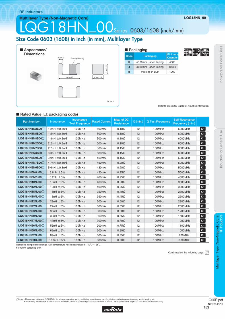
Code PackagingMinimumQuantity
D ø180mm Paper Taping 4000
J ø330mm Paper Taping 10000
B Packing in Bulk 1000
0.95Thickness
mmmax.
E-12Step Reflow
OK
Indu
ctor
s fo
r P
ower
Lin
esIn
duct
ors
for
Gen
eral
Use
RF
Indu
ctor
sR
F In
duct
ors
Mul
tilay
er T
ype
(Non
-Mag
netic
Cor
e)
Multilayer Type (Non-Magnetic Core) LQG18HN_00
RF Inductors
LQG18HN_00Series 0603/1608 (inch/mm)Size Code 0603 (1608) in inch (in mm), Multilayer Type
c Rated Value (p: packaging code)
Refer to pages 227 to 230 for mounting information.
1.6±0.15
0.3±0.2 Polarity Marking
0.8±0.15
(in mm)
0.8±
0.15
Continued on the following page.
c Appearance/Dimensions
c Packaging
Operating Temperature Range (Self-temperature rise is not included): -40℃~+85℃For refl ow soldering only.
Part Number InductanceInductance
Test FrequencyRated Current
Max. of DCResistance
Q (min.) Q Test FrequencySelf-ResonanceFrequency (min.)
LQG18HN1N2S00p 1.2nH ±0.3nH 100MHz 500mA 0.10Ω 12 100MHz 6000MHz LQG18HN1N5S00p 1.5nH ±0.3nH 100MHz 500mA 0.10Ω 12 100MHz 6000MHz LQG18HN1N8S00p 1.8nH ±0.3nH 100MHz 500mA 0.10Ω 12 100MHz 6000MHz LQG18HN2N2S00p 2.2nH ±0.3nH 100MHz 500mA 0.10Ω 12 100MHz 6000MHz LQG18HN2N7S00p 2.7nH ±0.3nH 100MHz 500mA 0.15Ω 12 100MHz 6000MHz LQG18HN3N3S00p 3.3nH ±0.3nH 100MHz 500mA 0.15Ω 12 100MHz 6000MHz LQG18HN3N9S00p 3.9nH ±0.3nH 100MHz 450mA 0.15Ω 12 100MHz 6000MHz LQG18HN4N7S00p 4.7nH ±0.3nH 100MHz 450mA 0.20Ω 12 100MHz 6000MHz LQG18HN5N6S00p 5.6nH ±0.3nH 100MHz 430mA 0.20Ω 12 100MHz 5000MHz LQG18HN6N8J00p 6.8nH ±5% 100MHz 430mA 0.25Ω 12 100MHz 5000MHz LQG18HN8N2J00p 8.2nH ±5% 100MHz 400mA 0.25Ω 12 100MHz 4000MHz LQG18HN10NJ00p 10nH ±5% 100MHz 400mA 0.30Ω 12 100MHz 3500MHz LQG18HN12NJ00p 12nH ±5% 100MHz 400mA 0.35Ω 12 100MHz 3000MHz LQG18HN15NJ00p 15nH ±5% 100MHz 350mA 0.40Ω 12 100MHz 2800MHz LQG18HN18NJ00p 18nH ±5% 100MHz 350mA 0.45Ω 12 100MHz 2600MHz LQG18HN22NJ00p 22nH ±5% 100MHz 300mA 0.50Ω 12 100MHz 2300MHz LQG18HN27NJ00p 27nH ±5% 100MHz 300mA 0.55Ω 12 100MHz 2000MHz LQG18HN33NJ00p 33nH ±5% 100MHz 300mA 0.60Ω 12 100MHz 1700MHz LQG18HN39NJ00p 39nH ±5% 100MHz 300mA 0.65Ω 12 100MHz 1500MHz LQG18HN47NJ00p 47nH ±5% 100MHz 300mA 0.70Ω 12 100MHz 1200MHz LQG18HN56NJ00p 56nH ±5% 100MHz 300mA 0.75Ω 12 100MHz 1100MHz LQG18HN68NJ00p 68nH ±5% 100MHz 300mA 0.80Ω 12 100MHz 1000MHz LQG18HN82NJ00p 82nH ±5% 100MHz 300mA 0.85Ω 12 100MHz 900MHz LQG18HNR10J00p 100nH ±5% 100MHz 300mA 0.90Ω 12 100MHz 800MHz
O05E.pdfNov.25,2013
153
!Note • Please read rating and !CAUTION (for storage, operating, rating, soldering, mounting and handling) in this catalog to prevent smoking and/or burning, etc.• This catalog has only typical specifi cations. Therefore, please approve our product specifi cations or transact the approval sheet for product specifi cations before ordering.

Indu
ctor
s fo
r P
ower
Lin
esIn
duct
ors
for
Gen
eral
Use
RF
Indu
ctor
sR
F In
duct
ors
Mul
tilay
er T
ype
(Non
-Mag
netic
Cor
e)
LQG18HN_00
c Q-Frequency Characteristics (Typ.) c Inductance-Frequency Characteristics (Typ.)
0
50
150
250
300
100
200
10 100 1000 10000Frequency (MHz)
Q
100nH 27nH
5.6nH
1.2nH
10 100 1000 10000
1000
100
1
10
Frequency (MHz)
L (n
H)
5.6nH
1.2nH
27nH
100nH
O05E.pdfNov.25,2013
154
!Note • Please read rating and !CAUTION (for storage, operating, rating, soldering, mounting and handling) in this catalog to prevent smoking and/or burning, etc.• This catalog has only typical specifi cations. Therefore, please approve our product specifi cations or transact the approval sheet for product specifi cations before ordering.

Code PackagingMinimumQuantity
D ø180mm Paper Taping 20000
B Packing in Bulk 500
Indu
ctor
s fo
r P
ower
Lin
esIn
duct
ors
for
Gen
eral
Use
RF
Indu
ctor
sR
F In
duct
ors
Film
Typ
e (N
on-M
agne
tic C
ore)
Film Type (Non-Magnetic Core) LQP02TN_02
RF Inductors
LQP02TN_02Series 01005/0402 (inch/mm)Size Code 01005 (0402) in inch (in mm)
c Rated Value (p: packaging code)
Refer to pages 227 to 230 for mounting information.
(in mm)
0.2±
0.02
0.4±0.02
0.2±
0.02
0.095±0.025
Polarity Marking
Continued on the following page.
c Appearance/Dimensions
c Packaging
Operating Temperature Range (Self-temperature rise is not included): -55℃~+125℃For refl ow soldering only.
0.22Thickness
mmmax.
E-24Step
TightTolerance
ReflowOK
Part Number InductanceInductance
Test FrequencyRated Current
Max. of DCResistance
Q (min.) Q Test FrequencySelf-ResonanceFrequency (min.)
LQP02TN0N2B02p 0.2nH ±0.1nH 500MHz 320mA 0.50Ω - - 20000MHz LQP02TN0N2C02p 0.2nH ±0.2nH 500MHz 320mA 0.50Ω - - 20000MHz LQP02TN0N3B02p 0.3nH ±0.1nH 500MHz 320mA 0.50Ω - - 20000MHz LQP02TN0N3C02p 0.3nH ±0.2nH 500MHz 320mA 0.50Ω - - 20000MHz LQP02TN0N4B02p 0.4nH ±0.1nH 500MHz 320mA 0.50Ω 8 500MHz 18000MHz LQP02TN0N4C02p 0.4nH ±0.2nH 500MHz 320mA 0.50Ω 8 500MHz 18000MHz LQP02TN0N4S02p 0.4nH ±0.3nH 500MHz 320mA 0.50Ω 8 500MHz 18000MHz
LQP02TN0N5B02p 0.5nH ±0.1nH 500MHz 320mA 0.50Ω 8 500MHz 18000MHz LQP02TN0N5C02p 0.5nH ±0.2nH 500MHz 320mA 0.50Ω 8 500MHz 18000MHz
LQP02TN0N5S02p 0.5nH ±0.3nH 500MHz 320mA 0.50Ω 8 500MHz 18000MHz
LQP02TN0N6B02p 0.6nH ±0.1nH 500MHz 320mA 0.50Ω 8 500MHz 17000MHz LQP02TN0N6C02p 0.6nH ±0.2nH 500MHz 320mA 0.50Ω 8 500MHz 17000MHz LQP02TN0N6S02p 0.6nH ±0.3nH 500MHz 320mA 0.50Ω 8 500MHz 17000MHz
LQP02TN0N7B02p 0.7nH ±0.1nH 500MHz 320mA 0.50Ω 8 500MHz 16500MHz LQP02TN0N7C02p 0.7nH ±0.2nH 500MHz 320mA 0.50Ω 8 500MHz 16500MHz LQP02TN0N7S02p 0.7nH ±0.3nH 500MHz 320mA 0.50Ω 8 500MHz 16500MHz
LQP02TN0N8B02p 0.8nH ±0.1nH 500MHz 320mA 0.50Ω 8 500MHz 16500MHz LQP02TN0N8C02p 0.8nH ±0.2nH 500MHz 320mA 0.50Ω 8 500MHz 16500MHz LQP02TN0N8S02p 0.8nH ±0.3nH 500MHz 320mA 0.50Ω 8 500MHz 16500MHz
LQP02TN0N9B02p 0.9nH ±0.1nH 500MHz 320mA 0.50Ω 8 500MHz 13000MHz LQP02TN0N9C02p 0.9nH ±0.2nH 500MHz 320mA 0.50Ω 8 500MHz 13000MHz LQP02TN0N9S02p 0.9nH ±0.3nH 500MHz 320mA 0.50Ω 8 500MHz 13000MHz
LQP02TN1N0B02p 1.0nH ±0.1nH 500MHz 220mA 0.60Ω 8 500MHz 13000MHz LQP02TN1N0C02p 1.0nH ±0.2nH 500MHz 220mA 0.60Ω 8 500MHz 13000MHz LQP02TN1N0S02p 1.0nH ±0.3nH 500MHz 220mA 0.60Ω 8 500MHz 13000MHz
LQP02TN1N1B02p 1.1nH ±0.1nH 500MHz 220mA 0.60Ω 8 500MHz 12500MHz LQP02TN1N1C02p 1.1nH ±0.2nH 500MHz 220mA 0.60Ω 8 500MHz 12500MHz
LQP02TN1N1S02p 1.1nH ±0.3nH 500MHz 220mA 0.60Ω 8 500MHz 12500MHz
LQP02TN1N2B02p 1.2nH ±0.1nH 500MHz 220mA 0.60Ω 8 500MHz 12500MHz LQP02TN1N2C02p 1.2nH ±0.2nH 500MHz 220mA 0.60Ω 8 500MHz 12500MHz
LQP02TN1N2S02p 1.2nH ±0.3nH 500MHz 220mA 0.60Ω 8 500MHz 12500MHz
LQP02TN1N3B02p 1.3nH ±0.1nH 500MHz 220mA 0.60Ω 8 500MHz 11500MHz
O05E.pdfNov.25,2013
155
!Note • Please read rating and !CAUTION (for storage, operating, rating, soldering, mounting and handling) in this catalog to prevent smoking and/or burning, etc.• This catalog has only typical specifi cations. Therefore, please approve our product specifi cations or transact the approval sheet for product specifi cations before ordering.

Indu
ctor
s fo
r P
ower
Lin
esIn
duct
ors
for
Gen
eral
Use
RF
Indu
ctor
sR
F In
duct
ors
Film
Typ
e (N
on-M
agne
tic C
ore)
LQP02TN_02
Continued on the following page.
Operating Temperature Range (Self-temperature rise is not included): -55℃~+125℃For refl ow soldering only.
Part Number InductanceInductance
Test FrequencyRated Current
Max. of DCResistance
Q (min.) Q Test FrequencySelf-ResonanceFrequency (min.)
LQP02TN1N3C02p 1.3nH ±0.2nH 500MHz 220mA 0.60Ω 8 500MHz 11500MHz
LQP02TN1N3S02p 1.3nH ±0.3nH 500MHz 220mA 0.60Ω 8 500MHz 11500MHz
LQP02TN1N4B02p 1.4nH ±0.1nH 500MHz 220mA 0.60Ω 8 500MHz 11500MHz LQP02TN1N4C02p 1.4nH ±0.2nH 500MHz 220mA 0.60Ω 8 500MHz 11500MHz
LQP02TN1N4S02p 1.4nH ±0.3nH 500MHz 220mA 0.60Ω 8 500MHz 11500MHz
LQP02TN1N5B02p 1.5nH ±0.1nH 500MHz 220mA 0.60Ω 8 500MHz 9500MHz LQP02TN1N5C02p 1.5nH ±0.2nH 500MHz 220mA 0.60Ω 8 500MHz 9500MHz
LQP02TN1N5S02p 1.5nH ±0.3nH 500MHz 220mA 0.60Ω 8 500MHz 9500MHz
LQP02TN1N6B02p 1.6nH ±0.1nH 500MHz 220mA 0.60Ω 8 500MHz 9500MHz LQP02TN1N6C02p 1.6nH ±0.2nH 500MHz 220mA 0.60Ω 8 500MHz 9500MHz
LQP02TN1N6S02p 1.6nH ±0.3nH 500MHz 220mA 0.60Ω 8 500MHz 9500MHz
LQP02TN1N7B02p 1.7nH ±0.1nH 500MHz 200mA 0.70Ω 8 500MHz 9500MHz LQP02TN1N7C02p 1.7nH ±0.2nH 500MHz 200mA 0.70Ω 8 500MHz 9500MHz
LQP02TN1N7S02p 1.7nH ±0.3nH 500MHz 200mA 0.70Ω 8 500MHz 9500MHz
LQP02TN1N8B02p 1.8nH ±0.1nH 500MHz 200mA 0.70Ω 8 500MHz 9000MHz LQP02TN1N8C02p 1.8nH ±0.2nH 500MHz 200mA 0.70Ω 8 500MHz 9000MHz
LQP02TN1N8S02p 1.8nH ±0.3nH 500MHz 200mA 0.70Ω 8 500MHz 9000MHz
LQP02TN1N9B02p 1.9nH ±0.1nH 500MHz 200mA 0.75Ω 8 500MHz 9000MHz LQP02TN1N9C02p 1.9nH ±0.2nH 500MHz 200mA 0.75Ω 8 500MHz 9000MHz
LQP02TN1N9S02p 1.9nH ±0.3nH 500MHz 200mA 0.75Ω 8 500MHz 9000MHz
LQP02TN2N0B02p 2.0nH ±0.1nH 500MHz 200mA 0.75Ω 8 500MHz 9000MHz LQP02TN2N0C02p 2.0nH ±0.2nH 500MHz 200mA 0.75Ω 8 500MHz 9000MHz
LQP02TN2N0S02p 2.0nH ±0.3nH 500MHz 200mA 0.75Ω 8 500MHz 9000MHz
LQP02TN2N1B02p 2.1nH ±0.1nH 500MHz 200mA 0.75Ω 8 500MHz 9000MHz LQP02TN2N1C02p 2.1nH ±0.2nH 500MHz 200mA 0.75Ω 8 500MHz 9000MHz
LQP02TN2N1S02p 2.1nH ±0.3nH 500MHz 200mA 0.75Ω 8 500MHz 9000MHz
LQP02TN2N2B02p 2.2nH ±0.1nH 500MHz 200mA 0.75Ω 8 500MHz 7500MHz LQP02TN2N2C02p 2.2nH ±0.2nH 500MHz 200mA 0.75Ω 8 500MHz 7500MHz
LQP02TN2N2S02p 2.2nH ±0.3nH 500MHz 200mA 0.75Ω 8 500MHz 7500MHz
LQP02TN2N3B02p 2.3nH ±0.1nH 500MHz 200mA 0.75Ω 8 500MHz 7500MHz LQP02TN2N3C02p 2.3nH ±0.2nH 500MHz 200mA 0.75Ω 8 500MHz 7500MHz
LQP02TN2N3S02p 2.3nH ±0.3nH 500MHz 200mA 0.75Ω 8 500MHz 7500MHz
LQP02TN2N4B02p 2.4nH ±0.1nH 500MHz 200mA 0.75Ω 8 500MHz 7500MHz LQP02TN2N4C02p 2.4nH ±0.2nH 500MHz 200mA 0.75Ω 8 500MHz 7500MHz
LQP02TN2N4S02p 2.4nH ±0.3nH 500MHz 200mA 0.75Ω 8 500MHz 7500MHz
LQP02TN2N5B02p 2.5nH ±0.1nH 500MHz 200mA 0.80Ω 8 500MHz 7500MHz LQP02TN2N5C02p 2.5nH ±0.2nH 500MHz 200mA 0.80Ω 8 500MHz 7500MHz
LQP02TN2N5S02p 2.5nH ±0.3nH 500MHz 200mA 0.80Ω 8 500MHz 7500MHz
LQP02TN2N6B02p 2.6nH ±0.1nH 500MHz 200mA 0.80Ω 8 500MHz 7500MHz LQP02TN2N6C02p 2.6nH ±0.2nH 500MHz 200mA 0.80Ω 8 500MHz 7500MHz
LQP02TN2N6S02p 2.6nH ±0.3nH 500MHz 200mA 0.80Ω 8 500MHz 7500MHz
LQP02TN2N7B02p 2.7nH ±0.1nH 500MHz 200mA 0.80Ω 8 500MHz 7500MHz LQP02TN2N7C02p 2.7nH ±0.2nH 500MHz 200mA 0.80Ω 8 500MHz 7500MHz
LQP02TN2N7S02p 2.7nH ±0.3nH 500MHz 200mA 0.80Ω 8 500MHz 7500MHz
LQP02TN2N8B02p 2.8nH ±0.1nH 500MHz 200mA 1.10Ω 8 500MHz 7500MHz LQP02TN2N8C02p 2.8nH ±0.2nH 500MHz 200mA 1.10Ω 8 500MHz 7500MHz
LQP02TN2N8S02p 2.8nH ±0.3nH 500MHz 200mA 1.10Ω 8 500MHz 7500MHz
O05E.pdfNov.25,2013
156
!Note • Please read rating and !CAUTION (for storage, operating, rating, soldering, mounting and handling) in this catalog to prevent smoking and/or burning, etc.• This catalog has only typical specifi cations. Therefore, please approve our product specifi cations or transact the approval sheet for product specifi cations before ordering.

Indu
ctor
s fo
r P
ower
Lin
esIn
duct
ors
for
Gen
eral
Use
RF
Indu
ctor
sR
F In
duct
ors
Film
Typ
e (N
on-M
agne
tic C
ore)
LQP02TN_02
Continued on the following page.
Operating Temperature Range (Self-temperature rise is not included): -55℃~+125℃For refl ow soldering only.
Part Number InductanceInductance
Test FrequencyRated Current
Max. of DCResistance
Q (min.) Q Test FrequencySelf-ResonanceFrequency (min.)
LQP02TN2N9B02p 2.9nH ±0.1nH 500MHz 200mA 1.10Ω 8 500MHz 7500MHz LQP02TN2N9C02p 2.9nH ±0.2nH 500MHz 200mA 1.10Ω 8 500MHz 7500MHz
LQP02TN2N9S02p 2.9nH ±0.3nH 500MHz 200mA 1.10Ω 8 500MHz 7500MHz
LQP02TN3N0B02p 3.0nH ±0.1nH 500MHz 200mA 1.10Ω 8 500MHz 7500MHz LQP02TN3N0C02p 3.0nH ±0.2nH 500MHz 200mA 1.10Ω 8 500MHz 7500MHz
LQP02TN3N0S02p 3.0nH ±0.3nH 500MHz 200mA 1.10Ω 8 500MHz 7500MHz
LQP02TN3N1B02p 3.1nH ±0.1nH 500MHz 180mA 1.30Ω 8 500MHz 7500MHz LQP02TN3N1C02p 3.1nH ±0.2nH 500MHz 180mA 1.30Ω 8 500MHz 7500MHz
LQP02TN3N1S02p 3.1nH ±0.3nH 500MHz 180mA 1.30Ω 8 500MHz 7500MHz
LQP02TN3N2B02p 3.2nH ±0.1nH 500MHz 180mA 1.30Ω 8 500MHz 7500MHz LQP02TN3N2C02p 3.2nH ±0.2nH 500MHz 180mA 1.30Ω 8 500MHz 7500MHz
LQP02TN3N2S02p 3.2nH ±0.3nH 500MHz 180mA 1.30Ω 8 500MHz 7500MHz
LQP02TN3N3B02p 3.3nH ±0.1nH 500MHz 180mA 1.30Ω 8 500MHz 7500MHz LQP02TN3N3C02p 3.3nH ±0.2nH 500MHz 180mA 1.30Ω 8 500MHz 7500MHz
LQP02TN3N3S02p 3.3nH ±0.3nH 500MHz 180mA 1.30Ω 8 500MHz 7500MHz
LQP02TN3N4B02p 3.4nH ±0.1nH 500MHz 180mA 1.30Ω 8 500MHz 7500MHz LQP02TN3N4C02p 3.4nH ±0.2nH 500MHz 180mA 1.30Ω 8 500MHz 7500MHz
LQP02TN3N4S02p 3.4nH ±0.3nH 500MHz 180mA 1.30Ω 8 500MHz 7500MHz
LQP02TN3N5B02p 3.5nH ±0.1nH 500MHz 180mA 1.30Ω 8 500MHz 7500MHz LQP02TN3N5C02p 3.5nH ±0.2nH 500MHz 180mA 1.30Ω 8 500MHz 7500MHz
LQP02TN3N5S02p 3.5nH ±0.3nH 500MHz 180mA 1.30Ω 8 500MHz 7500MHz
LQP02TN3N6B02p 3.6nH ±0.1nH 500MHz 180mA 1.30Ω 8 500MHz 7500MHz LQP02TN3N6C02p 3.6nH ±0.2nH 500MHz 180mA 1.30Ω 8 500MHz 7500MHz
LQP02TN3N6S02p 3.6nH ±0.3nH 500MHz 180mA 1.30Ω 8 500MHz 7500MHz
LQP02TN3N7B02p 3.7nH ±0.1nH 500MHz 180mA 1.30Ω 8 500MHz 7500MHz LQP02TN3N7C02p 3.7nH ±0.2nH 500MHz 180mA 1.30Ω 8 500MHz 7500MHz
LQP02TN3N7S02p 3.7nH ±0.3nH 500MHz 180mA 1.30Ω 8 500MHz 7500MHz
LQP02TN3N8B02p 3.8nH ±0.1nH 500MHz 180mA 1.30Ω 8 500MHz 7500MHz LQP02TN3N8C02p 3.8nH ±0.2nH 500MHz 180mA 1.30Ω 8 500MHz 7500MHz
LQP02TN3N8S02p 3.8nH ±0.3nH 500MHz 180mA 1.30Ω 8 500MHz 7500MHz
LQP02TN3N9B02p 3.9nH ±0.1nH 500MHz 180mA 1.30Ω 8 500MHz 7500MHz LQP02TN3N9C02p 3.9nH ±0.2nH 500MHz 180mA 1.30Ω 8 500MHz 7500MHz
LQP02TN3N9S02p 3.9nH ±0.3nH 500MHz 180mA 1.30Ω 8 500MHz 7500MHz
LQP02TN4N0B02p 4.0nH ±0.1nH 500MHz 180mA 1.30Ω 8 500MHz 7500MHz LQP02TN4N0C02p 4.0nH ±0.2nH 500MHz 180mA 1.30Ω 8 500MHz 7500MHz
LQP02TN4N0S02p 4.0nH ±0.3nH 500MHz 180mA 1.30Ω 8 500MHz 7500MHz
LQP02TN4N1B02p 4.1nH ±0.1nH 500MHz 180mA 1.30Ω 8 500MHz 7500MHz LQP02TN4N1C02p 4.1nH ±0.2nH 500MHz 180mA 1.30Ω 8 500MHz 7500MHz
LQP02TN4N1S02p 4.1nH ±0.3nH 500MHz 180mA 1.30Ω 8 500MHz 7500MHz
LQP02TN4N2B02p 4.2nH ±0.1nH 500MHz 180mA 1.30Ω 8 500MHz 7000MHz LQP02TN4N2C02p 4.2nH ±0.2nH 500MHz 180mA 1.30Ω 8 500MHz 7000MHz
LQP02TN4N2S02p 4.2nH ±0.3nH 500MHz 180mA 1.30Ω 8 500MHz 7000MHz
LQP02TN4N3H02p 4.3nH ±3% 500MHz 180mA 1.30Ω 8 500MHz 7000MHz LQP02TN4N3J02p 4.3nH ±5% 500MHz 180mA 1.30Ω 8 500MHz 7000MHz LQP02TN4N3S02p 4.3nH ±0.3nH 500MHz 180mA 1.30Ω 8 500MHz 7000MHz
LQP02TN4N7H02p 4.7nH ±3% 500MHz 160mA 1.50Ω 8 500MHz 6500MHz LQP02TN4N7J02p 4.7nH ±5% 500MHz 160mA 1.50Ω 8 500MHz 6500MHz
O05E.pdfNov.25,2013
157
!Note • Please read rating and !CAUTION (for storage, operating, rating, soldering, mounting and handling) in this catalog to prevent smoking and/or burning, etc.• This catalog has only typical specifi cations. Therefore, please approve our product specifi cations or transact the approval sheet for product specifi cations before ordering.
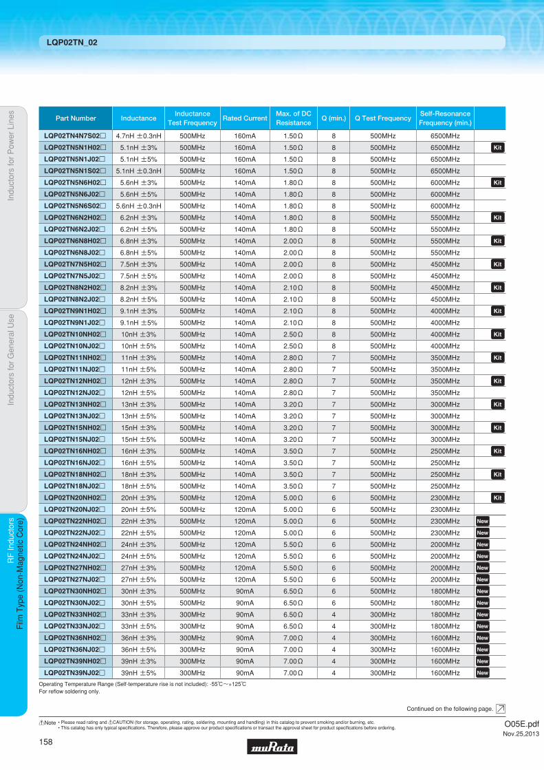
Indu
ctor
s fo
r P
ower
Lin
esIn
duct
ors
for
Gen
eral
Use
RF
Indu
ctor
sR
F In
duct
ors
Film
Typ
e (N
on-M
agne
tic C
ore)
LQP02TN_02
Continued on the following page.
Operating Temperature Range (Self-temperature rise is not included): -55℃~+125℃For refl ow soldering only.
Part Number InductanceInductance
Test FrequencyRated Current
Max. of DCResistance
Q (min.) Q Test FrequencySelf-ResonanceFrequency (min.)
LQP02TN4N7S02p 4.7nH ±0.3nH 500MHz 160mA 1.50Ω 8 500MHz 6500MHz
LQP02TN5N1H02p 5.1nH ±3% 500MHz 160mA 1.50Ω 8 500MHz 6500MHz LQP02TN5N1J02p 5.1nH ±5% 500MHz 160mA 1.50Ω 8 500MHz 6500MHz LQP02TN5N1S02p 5.1nH ±0.3nH 500MHz 160mA 1.50Ω 8 500MHz 6500MHz
LQP02TN5N6H02p 5.6nH ±3% 500MHz 140mA 1.80Ω 8 500MHz 6000MHz LQP02TN5N6J02p 5.6nH ±5% 500MHz 140mA 1.80Ω 8 500MHz 6000MHz LQP02TN5N6S02p 5.6nH ±0.3nH 500MHz 140mA 1.80Ω 8 500MHz 6000MHz
LQP02TN6N2H02p 6.2nH ±3% 500MHz 140mA 1.80Ω 8 500MHz 5500MHz LQP02TN6N2J02p 6.2nH ±5% 500MHz 140mA 1.80Ω 8 500MHz 5500MHz
LQP02TN6N8H02p 6.8nH ±3% 500MHz 140mA 2.00Ω 8 500MHz 5500MHz LQP02TN6N8J02p 6.8nH ±5% 500MHz 140mA 2.00Ω 8 500MHz 5500MHz
LQP02TN7N5H02p 7.5nH ±3% 500MHz 140mA 2.00Ω 8 500MHz 4500MHz LQP02TN7N5J02p 7.5nH ±5% 500MHz 140mA 2.00Ω 8 500MHz 4500MHz
LQP02TN8N2H02p 8.2nH ±3% 500MHz 140mA 2.10Ω 8 500MHz 4500MHz LQP02TN8N2J02p 8.2nH ±5% 500MHz 140mA 2.10Ω 8 500MHz 4500MHz
LQP02TN9N1H02p 9.1nH ±3% 500MHz 140mA 2.10Ω 8 500MHz 4000MHz LQP02TN9N1J02p 9.1nH ±5% 500MHz 140mA 2.10Ω 8 500MHz 4000MHz
LQP02TN10NH02p 10nH ±3% 500MHz 140mA 2.50Ω 8 500MHz 4000MHz LQP02TN10NJ02p 10nH ±5% 500MHz 140mA 2.50Ω 8 500MHz 4000MHz
LQP02TN11NH02p 11nH ±3% 500MHz 140mA 2.80Ω 7 500MHz 3500MHz LQP02TN11NJ02p 11nH ±5% 500MHz 140mA 2.80Ω 7 500MHz 3500MHz LQP02TN12NH02p 12nH ±3% 500MHz 140mA 2.80Ω 7 500MHz 3500MHz LQP02TN12NJ02p 12nH ±5% 500MHz 140mA 2.80Ω 7 500MHz 3500MHz
LQP02TN13NH02p 13nH ±3% 500MHz 140mA 3.20Ω 7 500MHz 3000MHz LQP02TN13NJ02p 13nH ±5% 500MHz 140mA 3.20Ω 7 500MHz 3000MHz LQP02TN15NH02p 15nH ±3% 500MHz 140mA 3.20Ω 7 500MHz 3000MHz LQP02TN15NJ02p 15nH ±5% 500MHz 140mA 3.20Ω 7 500MHz 3000MHz
LQP02TN16NH02p 16nH ±3% 500MHz 140mA 3.50Ω 7 500MHz 2500MHz LQP02TN16NJ02p 16nH ±5% 500MHz 140mA 3.50Ω 7 500MHz 2500MHz LQP02TN18NH02p 18nH ±3% 500MHz 140mA 3.50Ω 7 500MHz 2500MHz LQP02TN18NJ02p 18nH ±5% 500MHz 140mA 3.50Ω 7 500MHz 2500MHz
LQP02TN20NH02p 20nH ±3% 500MHz 120mA 5.00Ω 6 500MHz 2300MHz LQP02TN20NJ02p 20nH ±5% 500MHz 120mA 5.00Ω 6 500MHz 2300MHz LQP02TN22NH02p 22nH ±3% 500MHz 120mA 5.00Ω 6 500MHz 2300MHz LQP02TN22NJ02p 22nH ±5% 500MHz 120mA 5.00Ω 6 500MHz 2300MHz LQP02TN24NH02p 24nH ±3% 500MHz 120mA 5.50Ω 6 500MHz 2000MHz LQP02TN24NJ02p 24nH ±5% 500MHz 120mA 5.50Ω 6 500MHz 2000MHz LQP02TN27NH02p 27nH ±3% 500MHz 120mA 5.50Ω 6 500MHz 2000MHz LQP02TN27NJ02p 27nH ±5% 500MHz 120mA 5.50Ω 6 500MHz 2000MHz LQP02TN30NH02p 30nH ±3% 500MHz 90mA 6.50Ω 6 500MHz 1800MHz LQP02TN30NJ02p 30nH ±5% 500MHz 90mA 6.50Ω 6 500MHz 1800MHz LQP02TN33NH02p 33nH ±3% 300MHz 90mA 6.50Ω 4 300MHz 1800MHz LQP02TN33NJ02p 33nH ±5% 300MHz 90mA 6.50Ω 4 300MHz 1800MHz LQP02TN36NH02p 36nH ±3% 300MHz 90mA 7.00Ω 4 300MHz 1600MHz LQP02TN36NJ02p 36nH ±5% 300MHz 90mA 7.00Ω 4 300MHz 1600MHz LQP02TN39NH02p 39nH ±3% 300MHz 90mA 7.00Ω 4 300MHz 1600MHz LQP02TN39NJ02p 39nH ±5% 300MHz 90mA 7.00Ω 4 300MHz 1600MHz
O05E.pdfNov.25,2013
158
!Note • Please read rating and !CAUTION (for storage, operating, rating, soldering, mounting and handling) in this catalog to prevent smoking and/or burning, etc.• This catalog has only typical specifi cations. Therefore, please approve our product specifi cations or transact the approval sheet for product specifi cations before ordering.

c Reference Data
Part Number
LQP02TN0N2p02
LQP02TN0N3p02
LQP02TN0N4p02
LQP02TN0N5p02
LQP02TN0N6p02
LQP02TN0N7p02
LQP02TN0N8p02
LQP02TN0N9p02
LQP02TN1N0p02
LQP02TN1N1p02
LQP02TN1N2p02
LQP02TN1N3p02
LQP02TN1N4p02
LQP02TN1N5p02
LQP02TN1N6p02
LQP02TN1N7p02
LQP02TN1N8p02
LQP02TN1N9p02
LQP02TN2N0p02
LQP02TN2N1p02
LQP02TN2N2p02
LQP02TN2N3p02
LQP02TN2N4p02
LQP02TN2N5p02
LQP02TN2N6p02
LQP02TN2N7p02
LQP02TN2N8p02
LQP02TN2N9p02
LQP02TN3N0p02
LQP02TN3N1p02
LQP02TN3N2p02
LQP02TN3N3p02
LQP02TN3N4p02
20
21
13
13
15
14
14
15
13
14
14
14
14
13
14
13
14
14
14
14
13
13
13
14
14
14
11
13
13
12
13
14
13
800MHz
40
24
14
14
16
15
15
16
14
15
15
15
15
14
15
14
15
15
15
15
14
14
14
14
15
14
12
14
14
13
13
14
14
900MHz
69
37
22
23
25
23
22
23
21
23
22
23
23
21
22
21
22
22
22
22
20
21
21
21
22
22
18
20
20
20
20
21
20
1.8GHz
Q (Typ.)
65
38
24
24
26
24
24
25
23
25
23
24
24
23
24
23
23
23
24
23
21
22
22
22
23
23
19
21
22
21
21
22
22
2.0GHz
74
43
26
27
32
27
27
29
26
28
26
27
27
25
26
25
26
26
26
25
23
24
24
23
25
25
21
23
23
23
23
24
23
2.4GHz
4991A&16196D
Indu
ctor
s fo
r P
ower
Lin
esIn
duct
ors
for
Gen
eral
Use
RF
Indu
ctor
sR
F In
duct
ors
Film
Typ
e (N
on-M
agne
tic C
ore)
LQP02TN_02
c Q-Frequency Characteristics (Typ.) c Inductance-Frequency Characteristics (Typ.)
10 100 1000 10000Frequency (MHz)
100
90
70
50
80
60
40
30
20
10
0
Q
5.6nH
1.0nH
0.2nH
2.2nH
3.3nH
10nH 20nH30nH
39nH
100
1000
10
1
0.110010 1000 10000
L (n
H)
Frequency (MHz)
10nH
30nH
20nH
39nH
5.6nH
3.3nH2.2nH
1.0nH
0.2nH
Continued on the following page.
O05E.pdfNov.25,2013
159
!Note • Please read rating and !CAUTION (for storage, operating, rating, soldering, mounting and handling) in this catalog to prevent smoking and/or burning, etc.• This catalog has only typical specifi cations. Therefore, please approve our product specifi cations or transact the approval sheet for product specifi cations before ordering.

Part Number
LQP02TN8N2p02
LQP02TN9N1p02
LQP02TN10Np02
LQP02TN11Np02
LQP02TN12Np02
LQP02TN13Np02
LQP02TN15Np02
LQP02TN16Np02
LQP02TN18Np02
LQP02TN20Np02
LQP02TN22Np02
LQP02TN24Np02
LQP02TN27Np02
LQP02TN30Np02
LQP02TN33Np02
LQP02TN36Np02
LQP02TN39Np02
13
13
14
14
14
14
15
13
12
10
10
10
10
9
10
8
8
800MHz
14
14
14
14
15
15
15
13
13
11
10
10
10
9
10
9
9
900MHz
20
18
19
18
18
19
18
15
14
11
10
10
8
7
7
6
4
1.8GHz
Q (Typ.)
20
19
20
18
18
19
18
14
13
10
9
9
7
6
5
4
2
2.0GHz
22
19
20
17
18
18
16
12
11
7
7
6
3
-
-
-
-
2.4GHz
4991A&16196D
LQP02TN3N5p02
LQP02TN3N6p02
LQP02TN3N7p02
LQP02TN3N8p02
LQP02TN3N9p02
LQP02TN4N0p02
LQP02TN4N1p02
LQP02TN4N2p02
LQP02TN4N3p02
LQP02TN4N7p02
LQP02TN5N1p02
LQP02TN5N6p02
LQP02TN6N2p02
LQP02TN6N8p02
LQP02TN7N5p02
13
13
13
13
13
13
13
14
13
13
14
14
13
13
14
14
14
14
14
14
14
14
14
14
14
15
14
14
14
15
20
21
21
20
20
20
20
20
21
20
21
20
20
20
21
22
22
22
21
22
21
21
22
22
21
22
22
21
21
22
23
24
23
23
23
23
23
23
24
23
24
23
22
22
23
Indu
ctor
s fo
r P
ower
Lin
esIn
duct
ors
for
Gen
eral
Use
RF
Indu
ctor
sR
F In
duct
ors
Film
Typ
e (N
on-M
agne
tic C
ore)
LQP02TN_02
O05E.pdfNov.25,2013
160
!Note • Please read rating and !CAUTION (for storage, operating, rating, soldering, mounting and handling) in this catalog to prevent smoking and/or burning, etc.• This catalog has only typical specifi cations. Therefore, please approve our product specifi cations or transact the approval sheet for product specifi cations before ordering.
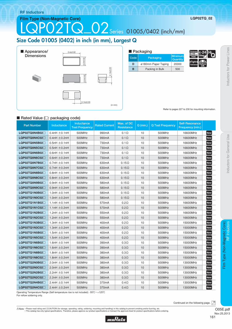
Code PackagingMinimumQuantity
D ø180mm Paper Taping 20000
B Packing in Bulk 500
Indu
ctor
s fo
r P
ower
Lin
esIn
duct
ors
for
Gen
eral
Use
RF
Indu
ctor
sR
F In
duct
ors
Film
Typ
e (N
on-M
agne
tic C
ore)
Film Type (Non-Magnetic Core) LQP02TQ_02
RF Inductors
LQP02TQ_02Series 01005/0402 (inch/mm)Size Code 01005 (0402) in inch (in mm), Largest Q
c Rated Value (p: packaging code)
Refer to pages 227 to 230 for mounting information.
(in mm)
0.4±0.02
0.2±
0.02
0.2±
0.02 0.
14±
0.03
0.14±0.03
Continued on the following page.
c Appearance/Dimensions
c Packaging
Operating Temperature Range (Self-temperature rise is not included): -55℃~+125℃For refl ow soldering only.
0.22Thickness
mmmax.
E-24Step
HiQ
TightTolerance Reflow
OK
Part Number InductanceInductance
Test FrequencyRated Current
Max. of DCResistance
Q (min.) Q Test FrequencySelf-ResonanceFrequency (min.)
LQP02TQ0N4B02p 0.4nH ±0.1nH 500MHz 990mA 0.1Ω 10 500MHz 16600MHz LQP02TQ0N4C02p 0.4nH ±0.2nH 500MHz 990mA 0.1Ω 10 500MHz 16600MHz LQP02TQ0N5B02p 0.5nH ±0.1nH 500MHz 730mA 0.1Ω 10 500MHz 16600MHz LQP02TQ0N5C02p 0.5nH ±0.2nH 500MHz 730mA 0.1Ω 10 500MHz 16600MHz LQP02TQ0N6B02p 0.6nH ±0.1nH 500MHz 730mA 0.1Ω 10 500MHz 16600MHz LQP02TQ0N6C02p 0.6nH ±0.2nH 500MHz 730mA 0.1Ω 10 500MHz 16600MHz LQP02TQ0N7B02p 0.7nH ±0.1nH 500MHz 630mA 0.15Ω 10 500MHz 16600MHz LQP02TQ0N7C02p 0.7nH ±0.2nH 500MHz 630mA 0.15Ω 10 500MHz 16600MHz LQP02TQ0N8B02p 0.8nH ±0.1nH 500MHz 630mA 0.15Ω 10 500MHz 16600MHz LQP02TQ0N8C02p 0.8nH ±0.2nH 500MHz 630mA 0.15Ω 10 500MHz 16600MHz LQP02TQ0N9B02p 0.9nH ±0.1nH 500MHz 580mA 0.15Ω 10 500MHz 16600MHz LQP02TQ0N9C02p 0.9nH ±0.2nH 500MHz 580mA 0.15Ω 10 500MHz 16600MHz LQP02TQ1N0B02p 1.0nH ±0.1nH 500MHz 580mA 0.15Ω 10 500MHz 16600MHz LQP02TQ1N0C02p 1.0nH ±0.2nH 500MHz 580mA 0.15Ω 10 500MHz 16600MHz LQP02TQ1N1B02p 1.1nH ±0.1nH 500MHz 570mA 0.2Ω 10 500MHz 16600MHz LQP02TQ1N1C02p 1.1nH ±0.2nH 500MHz 570mA 0.2Ω 10 500MHz 16600MHz LQP02TQ1N2B02p 1.2nH ±0.1nH 500MHz 550mA 0.2Ω 10 500MHz 16600MHz LQP02TQ1N2C02p 1.2nH ±0.2nH 500MHz 550mA 0.2Ω 10 500MHz 16600MHz LQP02TQ1N3B02p 1.3nH ±0.1nH 500MHz 400mA 0.2Ω 10 500MHz 15000MHz LQP02TQ1N3C02p 1.3nH ±0.2nH 500MHz 400mA 0.2Ω 10 500MHz 15000MHz LQP02TQ1N5B02p 1.5nH ±0.1nH 500MHz 400mA 0.2Ω 10 500MHz 15000MHz LQP02TQ1N5C02p 1.5nH ±0.2nH 500MHz 400mA 0.2Ω 10 500MHz 15000MHz LQP02TQ1N6B02p 1.6nH ±0.1nH 500MHz 390mA 0.3Ω 10 500MHz 15000MHz LQP02TQ1N6C02p 1.6nH ±0.2nH 500MHz 390mA 0.3Ω 10 500MHz 15000MHz LQP02TQ1N8B02p 1.8nH ±0.1nH 500MHz 380mA 0.3Ω 10 500MHz 15000MHz LQP02TQ1N8C02p 1.8nH ±0.2nH 500MHz 380mA 0.3Ω 10 500MHz 15000MHz LQP02TQ2N0B02p 2.0nH ±0.1nH 500MHz 380mA 0.3Ω 10 500MHz 13000MHz LQP02TQ2N0C02p 2.0nH ±0.2nH 500MHz 380mA 0.3Ω 10 500MHz 13000MHz LQP02TQ2N2B02p 2.2nH ±0.1nH 500MHz 380mA 0.3Ω 10 500MHz 13000MHz LQP02TQ2N2C02p 2.2nH ±0.2nH 500MHz 380mA 0.3Ω 10 500MHz 13000MHz LQP02TQ2N4B02p 2.4nH ±0.1nH 500MHz 370mA 0.4Ω 10 500MHz 13000MHz LQP02TQ2N4C02p 2.4nH ±0.2nH 500MHz 370mA 0.4Ω 10 500MHz 13000MHz
O05E.pdfNov.25,2013
161
!Note • Please read rating and !CAUTION (for storage, operating, rating, soldering, mounting and handling) in this catalog to prevent smoking and/or burning, etc.• This catalog has only typical specifi cations. Therefore, please approve our product specifi cations or transact the approval sheet for product specifi cations before ordering.
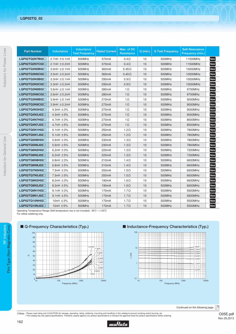
Indu
ctor
s fo
r P
ower
Lin
esIn
duct
ors
for
Gen
eral
Use
RF
Indu
ctor
sR
F In
duct
ors
Film
Typ
e (N
on-M
agne
tic C
ore)
LQP02TQ_02
c Q-Frequency Characteristics (Typ.) c Inductance-Frequency Characteristics (Typ.)
0
20
40
60
80
10
30
50
70
100
90
10 100 1000 10000Frequency (MHz)
Q
7.5nH
5.6nH
4.3nH
3.0nH
2.0nH
1.0nH0.4nH
10nH
L (n
H)
Frequency (MHz)
0.1
1
10
100
10 1000100 10000
10nH7.5nH5.6nH4.3nH3.0nH
2.0nH
1.0nH
0.4nH
Continued on the following page.
Operating Temperature Range (Self-temperature rise is not included): -55℃~+125℃For refl ow soldering only.
Part Number InductanceInductance
Test FrequencyRated Current
Max. of DCResistance
Q (min.) Q Test FrequencySelf-ResonanceFrequency (min.)
LQP02TQ2N7B02p 2.7nH ±0.1nH 500MHz 370mA 0.4Ω 10 500MHz 11500MHz LQP02TQ2N7C02p 2.7nH ±0.2nH 500MHz 370mA 0.4Ω 10 500MHz 11500MHz LQP02TQ3N0B02p 3.0nH ±0.1nH 500MHz 360mA 0.45Ω 10 500MHz 10000MHz LQP02TQ3N0C02p 3.0nH ±0.2nH 500MHz 360mA 0.45Ω 10 500MHz 10000MHz LQP02TQ3N3B02p 3.3nH ±0.1nH 500MHz 290mA 0.9Ω 10 500MHz 10000MHz LQP02TQ3N3C02p 3.3nH ±0.2nH 500MHz 290mA 0.9Ω 10 500MHz 10000MHz LQP02TQ3N6B02p 3.6nH ±0.1nH 500MHz 280mA 1Ω 10 500MHz 9700MHz LQP02TQ3N6C02p 3.6nH ±0.2nH 500MHz 280mA 1Ω 10 500MHz 9700MHz LQP02TQ3N9B02p 3.9nH ±0.1nH 500MHz 270mA 1Ω 10 500MHz 9000MHz LQP02TQ3N9C02p 3.9nH ±0.2nH 500MHz 270mA 1Ω 10 500MHz 9000MHz LQP02TQ4N3H02p 4.3nH ±3% 500MHz 270mA 1Ω 10 500MHz 9000MHz LQP02TQ4N3J02p 4.3nH ±5% 500MHz 270mA 1Ω 10 500MHz 9000MHz LQP02TQ4N7H02p 4.7nH ±3% 500MHz 270mA 1Ω 10 500MHz 8500MHz LQP02TQ4N7J02p 4.7nH ±5% 500MHz 270mA 1Ω 10 500MHz 8500MHz LQP02TQ5N1H02p 5.1nH ±3% 500MHz 250mA 1.2Ω 10 500MHz 7800MHz LQP02TQ5N1J02p 5.1nH ±5% 500MHz 250mA 1.2Ω 10 500MHz 7800MHz LQP02TQ5N6H02p 5.6nH ±3% 500MHz 230mA 1.3Ω 10 500MHz 7800MHz LQP02TQ5N6J02p 5.6nH ±5% 500MHz 230mA 1.3Ω 10 500MHz 7800MHz LQP02TQ6N2H02p 6.2nH ±3% 500MHz 220mA 1.3Ω 10 500MHz 7200MHz LQP02TQ6N2J02p 6.2nH ±5% 500MHz 220mA 1.3Ω 10 500MHz 7200MHz LQP02TQ6N8H02p 6.8nH ±3% 500MHz 210mA 1.4Ω 10 500MHz 6600MHz LQP02TQ6N8J02p 6.8nH ±5% 500MHz 210mA 1.4Ω 10 500MHz 6600MHz LQP02TQ7N5H02p 7.5nH ±3% 500MHz 200mA 1.5Ω 10 500MHz 6600MHz LQP02TQ7N5J02p 7.5nH ±5% 500MHz 200mA 1.5Ω 10 500MHz 6600MHz LQP02TQ8N2H02p 8.2nH ±3% 500MHz 190mA 1.6Ω 10 500MHz 6600MHz LQP02TQ8N2J02p 8.2nH ±5% 500MHz 190mA 1.6Ω 10 500MHz 6600MHz LQP02TQ9N1H02p 9.1nH ±3% 500MHz 170mA 1.7Ω 10 500MHz 5900MHz LQP02TQ9N1J02p 9.1nH ±5% 500MHz 170mA 1.7Ω 10 500MHz 5900MHz LQP02TQ10NH02p 10nH ±3% 500MHz 170mA 1.7Ω 10 500MHz 5500MHz LQP02TQ10NJ02p 10nH ±5% 500MHz 170mA 1.7Ω 10 500MHz 5500MHz
O05E.pdfNov.25,2013
162
!Note • Please read rating and !CAUTION (for storage, operating, rating, soldering, mounting and handling) in this catalog to prevent smoking and/or burning, etc.• This catalog has only typical specifi cations. Therefore, please approve our product specifi cations or transact the approval sheet for product specifi cations before ordering.
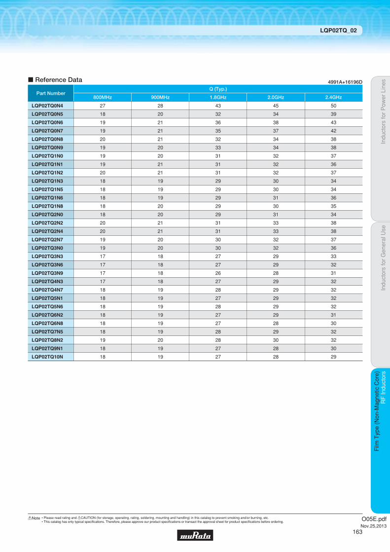
c Reference Data
Part Number
LQP02TQ0N4
LQP02TQ0N5
LQP02TQ0N6
LQP02TQ0N7
LQP02TQ0N8
LQP02TQ0N9
LQP02TQ1N0
LQP02TQ1N1
LQP02TQ1N2
LQP02TQ1N3
LQP02TQ1N5
LQP02TQ1N6
LQP02TQ1N8
LQP02TQ2N0
LQP02TQ2N2
LQP02TQ2N4
LQP02TQ2N7
LQP02TQ3N0
LQP02TQ3N3
LQP02TQ3N6
LQP02TQ3N9
LQP02TQ4N3
LQP02TQ4N7
LQP02TQ5N1
LQP02TQ5N6
LQP02TQ6N2
LQP02TQ6N8
LQP02TQ7N5
LQP02TQ8N2
LQP02TQ9N1
LQP02TQ10N
27
18
19
19
20
19
19
19
20
18
18
18
18
18
20
20
19
19
17
17
17
17
18
18
18
18
18
18
19
18
18
800MHz
28
20
21
21
21
20
20
21
21
19
19
19
20
20
21
21
20
20
18
18
18
18
19
19
19
19
19
19
20
19
19
900MHz
43
32
36
35
32
33
31
31
31
29
29
29
29
29
31
31
30
30
27
27
26
27
28
27
28
27
27
28
28
27
27
1.8GHz
Q (Typ.)
45
34
38
37
34
34
32
32
32
30
30
31
30
31
33
33
32
32
29
29
28
29
29
29
29
29
28
29
30
28
28
2.0GHz
50
39
43
42
38
38
37
36
37
34
34
36
35
34
38
38
37
36
33
32
31
32
32
32
32
31
30
32
32
30
29
2.4GHz
4991A+16196D
Indu
ctor
s fo
r P
ower
Lin
esIn
duct
ors
for
Gen
eral
Use
RF
Indu
ctor
sR
F In
duct
ors
Film
Typ
e (N
on-M
agne
tic C
ore)
LQP02TQ_02
O05E.pdfNov.25,2013
163
!Note • Please read rating and !CAUTION (for storage, operating, rating, soldering, mounting and handling) in this catalog to prevent smoking and/or burning, etc.• This catalog has only typical specifi cations. Therefore, please approve our product specifi cations or transact the approval sheet for product specifi cations before ordering.

Code PackagingMinimumQuantity
D ø180mm Paper Taping 15000
J ø330mm Paper Taping 50000
B Packing in Bulk 500
0.33Thickness
mmmax.
E-12Step
E-24Step
TightTolerance Reflow
OK
Indu
ctor
s fo
r P
ower
Lin
esIn
duct
ors
for
Gen
eral
Use
RF
Indu
ctor
sR
F In
duct
ors
Film
Typ
e (N
on-M
agne
tic C
ore)
Film Type (Non-Magnetic Core) LQP03TG_02
RF Inductors
LQP03TG_02Series 0201/0603 (inch/mm)Size Code 0201 (0603) in inch (in mm), Standard Type
c Rated Value (p: packaging code)
Refer to pages 227 to 230 for mounting information.
(in mm)
Polarity MarkingColored Side
0.6±0.03
0.3±
0.03
0.3±
0.03
0.15±0.05
Continued on the following page.
c Appearance/Dimensions
c Packaging
Operating Temperature Range (Self-temperature rise is not included): -55℃~+125℃For refl ow soldering only.
Part Number InductanceInductance
Test FrequencyRated Current
Max. of DCResistance
Q (min.) Q Test FrequencySelf-ResonanceFrequency (min.)
LQP03TG0N6B02p 0.6nH ±0.1nH 500MHz 850mA 0.08Ω 11 500MHz 18000MHz LQP03TG0N6C02p 0.6nH ±0.2nH 500MHz 850mA 0.08Ω 11 500MHz 18000MHz LQP03TG0N7B02p 0.7nH ±0.1nH 500MHz 750mA 0.10Ω 12 500MHz 18000MHz LQP03TG0N7C02p 0.7nH ±0.2nH 500MHz 750mA 0.10Ω 12 500MHz 18000MHz LQP03TG0N8B02p 0.8nH ±0.1nH 500MHz 750mA 0.10Ω 12 500MHz 18000MHz LQP03TG0N8C02p 0.8nH ±0.2nH 500MHz 750mA 0.10Ω 12 500MHz 18000MHz LQP03TG0N9B02p 0.9nH ±0.1nH 500MHz 700mA 0.12Ω 12 500MHz 18000MHz LQP03TG0N9C02p 0.9nH ±0.2nH 500MHz 700mA 0.12Ω 12 500MHz 18000MHz LQP03TG1N0B02p 1.0nH ±0.1nH 500MHz 600mA 0.15Ω 12 500MHz 17000MHz LQP03TG1N0C02p 1.0nH ±0.2nH 500MHz 600mA 0.15Ω 12 500MHz 17000MHz LQP03TG1N1B02p 1.1nH ±0.1nH 500MHz 600mA 0.15Ω 12 500MHz 17000MHz LQP03TG1N1C02p 1.1nH ±0.2nH 500MHz 600mA 0.15Ω 12 500MHz 17000MHz LQP03TG1N2B02p 1.2nH ±0.1nH 500MHz 600mA 0.15Ω 13 500MHz 15000MHz LQP03TG1N2C02p 1.2nH ±0.2nH 500MHz 600mA 0.15Ω 13 500MHz 15000MHz LQP03TG1N3B02p 1.3nH ±0.1nH 500MHz 600mA 0.15Ω 13 500MHz 15000MHz LQP03TG1N3C02p 1.3nH ±0.2nH 500MHz 600mA 0.15Ω 13 500MHz 15000MHz LQP03TG1N4B02p 1.4nH ±0.1nH 500MHz 600mA 0.15Ω 13 500MHz 14000MHz LQP03TG1N4C02p 1.4nH ±0.2nH 500MHz 600mA 0.15Ω 13 500MHz 14000MHz LQP03TG1N5B02p 1.5nH ±0.1nH 500MHz 600mA 0.15Ω 13 500MHz 13500MHz LQP03TG1N5C02p 1.5nH ±0.2nH 500MHz 600mA 0.15Ω 13 500MHz 13500MHz LQP03TG1N6B02p 1.6nH ±0.1nH 500MHz 600mA 0.15Ω 13 500MHz 13000MHz LQP03TG1N6C02p 1.6nH ±0.2nH 500MHz 600mA 0.15Ω 13 500MHz 13000MHz LQP03TG1N7B02p 1.7nH ±0.1nH 500MHz 500mA 0.20Ω 13 500MHz 12500MHz LQP03TG1N7C02p 1.7nH ±0.2nH 500MHz 500mA 0.20Ω 13 500MHz 12500MHz LQP03TG1N8B02p 1.8nH ±0.1nH 500MHz 500mA 0.20Ω 13 500MHz 12500MHz LQP03TG1N8C02p 1.8nH ±0.2nH 500MHz 500mA 0.20Ω 13 500MHz 12500MHz LQP03TG1N9B02p 1.9nH ±0.1nH 500MHz 450mA 0.25Ω 13 500MHz 12500MHz LQP03TG1N9C02p 1.9nH ±0.2nH 500MHz 450mA 0.25Ω 13 500MHz 12500MHz LQP03TG2N0B02p 2.0nH ±0.1nH 500MHz 450mA 0.25Ω 13 500MHz 12500MHz LQP03TG2N0C02p 2.0nH ±0.2nH 500MHz 450mA 0.25Ω 13 500MHz 12500MHz LQP03TG2N1B02p 2.1nH ±0.1nH 500MHz 450mA 0.25Ω 13 500MHz 12000MHz LQP03TG2N1C02p 2.1nH ±0.2nH 500MHz 450mA 0.25Ω 13 500MHz 12000MHz
O05E.pdfNov.25,2013
164
!Note • Please read rating and !CAUTION (for storage, operating, rating, soldering, mounting and handling) in this catalog to prevent smoking and/or burning, etc.• This catalog has only typical specifi cations. Therefore, please approve our product specifi cations or transact the approval sheet for product specifi cations before ordering.

Indu
ctor
s fo
r P
ower
Lin
esIn
duct
ors
for
Gen
eral
Use
RF
Indu
ctor
sR
F In
duct
ors
Film
Typ
e (N
on-M
agne
tic C
ore)
LQP03TG_02
Continued on the following page.
Operating Temperature Range (Self-temperature rise is not included): -55℃~+125℃For refl ow soldering only.
Part Number InductanceInductance
Test FrequencyRated Current
Max. of DCResistance
Q (min.) Q Test FrequencySelf-ResonanceFrequency (min.)
LQP03TG2N2B02p 2.2nH ±0.1nH 500MHz 450mA 0.25Ω 13 500MHz 12000MHz LQP03TG2N2C02p 2.2nH ±0.2nH 500MHz 450mA 0.25Ω 13 500MHz 12000MHz LQP03TG2N3B02p 2.3nH ±0.1nH 500MHz 450mA 0.25Ω 13 500MHz 11500MHz LQP03TG2N3C02p 2.3nH ±0.2nH 500MHz 450mA 0.25Ω 13 500MHz 11500MHz LQP03TG2N4B02p 2.4nH ±0.1nH 500MHz 450mA 0.25Ω 13 500MHz 11000MHz LQP03TG2N4C02p 2.4nH ±0.2nH 500MHz 450mA 0.25Ω 13 500MHz 11000MHz LQP03TG2N5B02p 2.5nH ±0.1nH 500MHz 450mA 0.25Ω 13 500MHz 11000MHz LQP03TG2N5C02p 2.5nH ±0.2nH 500MHz 450mA 0.25Ω 13 500MHz 11000MHz LQP03TG2N6B02p 2.6nH ±0.1nH 500MHz 450mA 0.25Ω 13 500MHz 11000MHz LQP03TG2N6C02p 2.6nH ±0.2nH 500MHz 450mA 0.25Ω 13 500MHz 11000MHz LQP03TG2N7B02p 2.7nH ±0.1nH 500MHz 450mA 0.25Ω 13 500MHz 11000MHz LQP03TG2N7C02p 2.7nH ±0.2nH 500MHz 450mA 0.25Ω 13 500MHz 11000MHz LQP03TG2N8B02p 2.8nH ±0.1nH 500MHz 450mA 0.25Ω 13 500MHz 9500MHz LQP03TG2N8C02p 2.8nH ±0.2nH 500MHz 450mA 0.25Ω 13 500MHz 9500MHz LQP03TG2N9B02p 2.9nH ±0.1nH 500MHz 450mA 0.25Ω 13 500MHz 9500MHz LQP03TG2N9C02p 2.9nH ±0.2nH 500MHz 450mA 0.25Ω 13 500MHz 9500MHz LQP03TG3N0B02p 3.0nH ±0.1nH 500MHz 450mA 0.25Ω 13 500MHz 9500MHz LQP03TG3N0C02p 3.0nH ±0.2nH 500MHz 450mA 0.25Ω 13 500MHz 9500MHz LQP03TG3N1B02p 3.1nH ±0.1nH 500MHz 400mA 0.32Ω 13 500MHz 9500MHz LQP03TG3N1C02p 3.1nH ±0.2nH 500MHz 400mA 0.32Ω 13 500MHz 9500MHz LQP03TG3N2B02p 3.2nH ±0.1nH 500MHz 400mA 0.32Ω 13 500MHz 9500MHz LQP03TG3N2C02p 3.2nH ±0.2nH 500MHz 400mA 0.32Ω 13 500MHz 9500MHz LQP03TG3N3B02p 3.3nH ±0.1nH 500MHz 400mA 0.32Ω 13 500MHz 9500MHz LQP03TG3N3C02p 3.3nH ±0.2nH 500MHz 400mA 0.32Ω 13 500MHz 9500MHz LQP03TG3N4B02p 3.4nH ±0.1nH 500MHz 350mA 0.35Ω 13 500MHz 8000MHz LQP03TG3N4C02p 3.4nH ±0.2nH 500MHz 350mA 0.35Ω 13 500MHz 8000MHz LQP03TG3N5B02p 3.5nH ±0.1nH 500MHz 350mA 0.35Ω 13 500MHz 8000MHz LQP03TG3N5C02p 3.5nH ±0.2nH 500MHz 350mA 0.35Ω 13 500MHz 8000MHz LQP03TG3N6B02p 3.6nH ±0.1nH 500MHz 350mA 0.35Ω 13 500MHz 8000MHz LQP03TG3N6C02p 3.6nH ±0.2nH 500MHz 350mA 0.35Ω 13 500MHz 8000MHz LQP03TG3N7B02p 3.7nH ±0.1nH 500MHz 350mA 0.35Ω 13 500MHz 7000MHz LQP03TG3N7C02p 3.7nH ±0.2nH 500MHz 350mA 0.35Ω 13 500MHz 7000MHz LQP03TG3N8B02p 3.8nH ±0.1nH 500MHz 350mA 0.35Ω 13 500MHz 7000MHz LQP03TG3N8C02p 3.8nH ±0.2nH 500MHz 350mA 0.35Ω 13 500MHz 7000MHz LQP03TG3N9B02p 3.9nH ±0.1nH 500MHz 350mA 0.35Ω 13 500MHz 6500MHz LQP03TG3N9C02p 3.9nH ±0.2nH 500MHz 350mA 0.35Ω 13 500MHz 6500MHz LQP03TG4N3H02p 4.3nH ±3% 500MHz 300mA 0.58Ω 13 500MHz 6500MHz LQP03TG4N3J02p 4.3nH ±5% 500MHz 300mA 0.58Ω 13 500MHz 6500MHz LQP03TG4N7H02p 4.7nH ±3% 500MHz 250mA 0.72Ω 12 500MHz 6500MHz LQP03TG4N7J02p 4.7nH ±5% 500MHz 250mA 0.72Ω 12 500MHz 6500MHz LQP03TG5N1H02p 5.1nH ±3% 500MHz 250mA 0.72Ω 12 500MHz 6500MHz LQP03TG5N1J02p 5.1nH ±5% 500MHz 250mA 0.72Ω 12 500MHz 6500MHz LQP03TG5N6H02p 5.6nH ±3% 500MHz 250mA 0.88Ω 12 500MHz 6000MHz LQP03TG5N6J02p 5.6nH ±5% 500MHz 250mA 0.88Ω 12 500MHz 6000MHz LQP03TG6N2H02p 6.2nH ±3% 500MHz 200mA 1.15Ω 12 500MHz 6000MHz LQP03TG6N2J02p 6.2nH ±5% 500MHz 200mA 1.15Ω 12 500MHz 6000MHz LQP03TG6N8H02p 6.8nH ±3% 500MHz 200mA 1.15Ω 12 500MHz 5400MHz
O05E.pdfNov.25,2013
165
!Note • Please read rating and !CAUTION (for storage, operating, rating, soldering, mounting and handling) in this catalog to prevent smoking and/or burning, etc.• This catalog has only typical specifi cations. Therefore, please approve our product specifi cations or transact the approval sheet for product specifi cations before ordering.
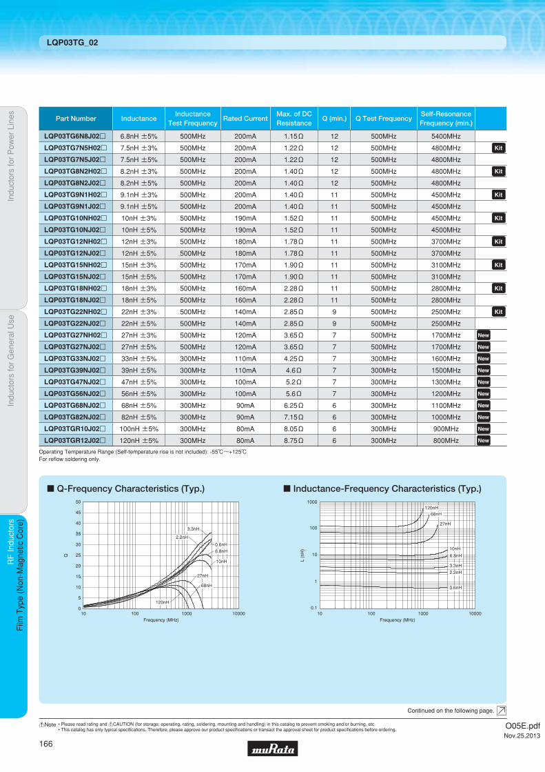
c Q-Frequency Characteristics (Typ.) c Inductance-Frequency Characteristics (Typ.)
10 100 1000 10000Frequency (MHz)
50
45
35
25
40
30
20
15
10
5
0
Q
10nH
120nH
68nH
27nH
6.8nH
3.3nH
2.2nH
0.6nH
100
1000
10
1
0.110010 1000 10000
L (n
H)
Frequency (MHz)
10nH
120nH68nH
27nH
6.8nH
3.3nH
2.2nH
0.6nH
Indu
ctor
s fo
r P
ower
Lin
esIn
duct
ors
for
Gen
eral
Use
RF
Indu
ctor
sR
F In
duct
ors
Film
Typ
e (N
on-M
agne
tic C
ore)
LQP03TG_02
Continued on the following page.
Operating Temperature Range (Self-temperature rise is not included): -55℃~+125℃For refl ow soldering only.
Part Number InductanceInductance
Test FrequencyRated Current
Max. of DCResistance
Q (min.) Q Test FrequencySelf-ResonanceFrequency (min.)
LQP03TG6N8J02p 6.8nH ±5% 500MHz 200mA 1.15Ω 12 500MHz 5400MHz LQP03TG7N5H02p 7.5nH ±3% 500MHz 200mA 1.22Ω 12 500MHz 4800MHz LQP03TG7N5J02p 7.5nH ±5% 500MHz 200mA 1.22Ω 12 500MHz 4800MHz LQP03TG8N2H02p 8.2nH ±3% 500MHz 200mA 1.40Ω 12 500MHz 4800MHz LQP03TG8N2J02p 8.2nH ±5% 500MHz 200mA 1.40Ω 12 500MHz 4800MHz LQP03TG9N1H02p 9.1nH ±3% 500MHz 200mA 1.40Ω 11 500MHz 4500MHz LQP03TG9N1J02p 9.1nH ±5% 500MHz 200mA 1.40Ω 11 500MHz 4500MHz LQP03TG10NH02p 10nH ±3% 500MHz 190mA 1.52Ω 11 500MHz 4500MHz LQP03TG10NJ02p 10nH ±5% 500MHz 190mA 1.52Ω 11 500MHz 4500MHz LQP03TG12NH02p 12nH ±3% 500MHz 180mA 1.78Ω 11 500MHz 3700MHz LQP03TG12NJ02p 12nH ±5% 500MHz 180mA 1.78Ω 11 500MHz 3700MHz LQP03TG15NH02p 15nH ±3% 500MHz 170mA 1.90Ω 11 500MHz 3100MHz LQP03TG15NJ02p 15nH ±5% 500MHz 170mA 1.90Ω 11 500MHz 3100MHz LQP03TG18NH02p 18nH ±3% 500MHz 160mA 2.28Ω 11 500MHz 2800MHz LQP03TG18NJ02p 18nH ±5% 500MHz 160mA 2.28Ω 11 500MHz 2800MHz LQP03TG22NH02p 22nH ±3% 500MHz 140mA 2.85Ω 9 500MHz 2500MHz LQP03TG22NJ02p 22nH ±5% 500MHz 140mA 2.85Ω 9 500MHz 2500MHz LQP03TG27NH02p 27nH ±3% 500MHz 120mA 3.65Ω 7 500MHz 1700MHz LQP03TG27NJ02p 27nH ±5% 500MHz 120mA 3.65Ω 7 500MHz 1700MHz LQP03TG33NJ02p 33nH ±5% 300MHz 110mA 4.25Ω 7 300MHz 1600MHz LQP03TG39NJ02p 39nH ±5% 300MHz 110mA 4.6Ω 7 300MHz 1500MHz LQP03TG47NJ02p 47nH ±5% 300MHz 100mA 5.2Ω 7 300MHz 1300MHz LQP03TG56NJ02p 56nH ±5% 300MHz 100mA 5.6Ω 7 300MHz 1200MHz LQP03TG68NJ02p 68nH ±5% 300MHz 90mA 6.25Ω 6 300MHz 1100MHz LQP03TG82NJ02p 82nH ±5% 300MHz 90mA 7.15Ω 6 300MHz 1000MHz LQP03TGR10J02p 100nH ±5% 300MHz 80mA 8.05Ω 6 300MHz 900MHz LQP03TGR12J02p 120nH ±5% 300MHz 80mA 8.75Ω 6 300MHz 800MHz
O05E.pdfNov.25,2013
166
!Note • Please read rating and !CAUTION (for storage, operating, rating, soldering, mounting and handling) in this catalog to prevent smoking and/or burning, etc.• This catalog has only typical specifi cations. Therefore, please approve our product specifi cations or transact the approval sheet for product specifi cations before ordering.

c Reference Data
Indu
ctor
s fo
r P
ower
Lin
esIn
duct
ors
for
Gen
eral
Use
RF
Indu
ctor
sR
F In
duct
ors
Film
Typ
e (N
on-M
agne
tic C
ore)
LQP03TG_02
Continued on the following page.
Part Number
LQP03TG0N6
LQP03TG0N7
LQP03TG0N8
LQP03TG0N9
LQP03TG1N0
LQP03TG1N1
LQP03TG1N2
LQP03TG1N3
LQP03TG1N4
LQP03TG1N5
LQP03TG1N6
LQP03TG1N7
LQP03TG1N8
LQP03TG1N9
LQP03TG2N0
LQP03TG2N1
LQP03TG2N2
LQP03TG2N3
LQP03TG2N4
LQP03TG2N5
LQP03TG2N6
LQP03TG2N7
LQP03TG2N8
LQP03TG2N9
LQP03TG3N0
LQP03TG3N1
LQP03TG3N2
LQP03TG3N3
LQP03TG3N4
LQP03TG3N5
LQP03TG3N6
LQP03TG3N7
LQP03TG3N8
LQP03TG3N9
LQP03TG4N3
LQP03TG4N7
LQP03TG5N1
LQP03TG5N6
LQP03TG6N2
LQP03TG6N8
LQP03TG7N5
LQP03TG8N2
LQP03TG9N1
LQP03TG10N
LQP03TG12N
LQP03TG15N
LQP03TG18N
LQP03TG22N
17
18
18
19
18
18
19
18
20
21
18
19
20
19
20
19
19
19
20
19
19
19
20
20
21
20
20
21
20
19
20
18
18
20
19
19
19
18
18
18
18
18
18
18
17
17
15
13
800MHz
18
20
20
20
19
20
20
19
21
22
20
20
21
20
21
20
20
20
21
20
20
20
21
21
22
21
21
22
21
20
21
20
19
21
21
20
20
19
19
19
19
19
19
19
18
18
16
14
900MHz
26
29
29
30
28
28
29
28
31
32
29
29
30
29
30
28
28
28
30
29
28
29
30
30
30
30
30
31
29
28
29
28
27
29
28
27
27
25
25
25
24
24
23
23
20
18
14
11
1.8GHz
Q (Typ.)
27
30
30
31
29
29
30
29
32
33
30
30
31
31
31
29
29
29
31
30
30
30
31
31
31
31
31
31
30
29
29
29
28
30
28
28
27
26
26
25
24
24
22
23
20
17
13
9
2.0GHz
29
33
33
34
31
32
33
32
34
35
32
33
33
33
33
31
31
32
34
32
32
31
33
34
33
34
33
34
32
31
31
30
30
31
30
29
29
27
26
25
24
24
22
22
17
13
8
4
2.4GHz
4991A+16197A
O05E.pdfNov.25,2013
167
!Note • Please read rating and !CAUTION (for storage, operating, rating, soldering, mounting and handling) in this catalog to prevent smoking and/or burning, etc.• This catalog has only typical specifi cations. Therefore, please approve our product specifi cations or transact the approval sheet for product specifi cations before ordering.

Indu
ctor
s fo
r P
ower
Lin
esIn
duct
ors
for
Gen
eral
Use
RF
Indu
ctor
sR
F In
duct
ors
Film
Typ
e (N
on-M
agne
tic C
ore)
LQP03TG_02
Part Number800MHz 900MHz 1.8GHz
Q (Typ.)
2.0GHz
LQP03TG27N
LQP03TG33N
LQP03TG39N
LQP03TG47N
LQP03TG56N
LQP03TG68N
LQP03TG82N
LQP03TGR10
LQP03TGR12
13
13
13
13
11
10
9
7
7
13
12
12
12
10
9
8
6
5
5
-
-
-
-
-
-
-
-
-
-
-
-
-
-
-
-
-
-
-
-
-
-
-
-
-
-
2.4GHz
4991A+16197A
O05E.pdfNov.25,2013
168
!Note • Please read rating and !CAUTION (for storage, operating, rating, soldering, mounting and handling) in this catalog to prevent smoking and/or burning, etc.• This catalog has only typical specifi cations. Therefore, please approve our product specifi cations or transact the approval sheet for product specifi cations before ordering.
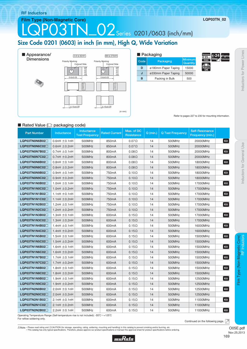
Code PackagingMinimumQuantity
D ø180mm Paper Taping 15000
J ø330mm Paper Taping 50000
B Packing in Bulk 500
0.33Thickness
mmmax.
E-24Step
TightTolerance
ReflowOK
Indu
ctor
s fo
r P
ower
Lin
esIn
duct
ors
for
Gen
eral
Use
RF
Indu
ctor
sR
F In
duct
ors
Film
Typ
e (N
on-M
agne
tic C
ore)
Film Type (Non-Magnetic Core) LQP03TN_02
RF Inductors
LQP03TN_02Series 0201/0603 (inch/mm)Size Code 0201 (0603) in inch (in mm), High Q, Wide Variation
c Rated Value (p: packaging code)
Refer to pages 227 to 230 for mounting information.
0.6±0.03
0.3±
0.03
0.3±
0.03
0.15±0.05
(in mm)
Polarity Marking
0.6 to 62nH 68 to 270nH
Colored SidePolarity Marking
Colored Side
0.6±0.03
0.3±
0.03
0.3±
0.03
0.15±0.05
Continued on the following page.
c Appearance/Dimensions
c Packaging
Operating Temperature Range (Self-temperature rise is not included): -55℃~+125℃For refl ow soldering only.
Part Number InductanceInductance
Test FrequencyRated Current
Max. of DCResistance
Q (min.) Q Test FrequencySelf-ResonanceFrequency (min.)
LQP03TN0N6B02p 0.6nH ±0.1nH 500MHz 850mA 0.07Ω 14 500MHz 20000MHz LQP03TN0N6C02p 0.6nH ±0.2nH 500MHz 850mA 0.07Ω 14 500MHz 20000MHz
LQP03TN0N7B02p 0.7nH ±0.1nH 500MHz 800mA 0.08Ω 14 500MHz 20000MHz LQP03TN0N7C02p 0.7nH ±0.2nH 500MHz 800mA 0.08Ω 14 500MHz 20000MHz
LQP03TN0N8B02p 0.8nH ±0.1nH 500MHz 800mA 0.08Ω 14 500MHz 18000MHz LQP03TN0N8C02p 0.8nH ±0.2nH 500MHz 800mA 0.08Ω 14 500MHz 18000MHz
LQP03TN0N9B02p 0.9nH ±0.1nH 500MHz 750mA 0.10Ω 14 500MHz 18000MHz LQP03TN0N9C02p 0.9nH ±0.2nH 500MHz 750mA 0.10Ω 14 500MHz 18000MHz
LQP03TN1N0B02p 1.0nH ±0.1nH 500MHz 750mA 0.10Ω 14 500MHz 17000MHz LQP03TN1N0C02p 1.0nH ±0.2nH 500MHz 750mA 0.10Ω 14 500MHz 17000MHz
LQP03TN1N1B02p 1.1nH ±0.1nH 500MHz 750mA 0.10Ω 14 500MHz 17000MHz LQP03TN1N1C02p 1.1nH ±0.2nH 500MHz 750mA 0.10Ω 14 500MHz 17000MHz
LQP03TN1N2B02p 1.2nH ±0.1nH 500MHz 750mA 0.10Ω 14 500MHz 17000MHz LQP03TN1N2C02p 1.2nH ±0.2nH 500MHz 750mA 0.10Ω 14 500MHz 17000MHz
LQP03TN1N3B02p 1.3nH ±0.1nH 500MHz 600mA 0.15Ω 14 500MHz 17000MHz LQP03TN1N3C02p 1.3nH ±0.2nH 500MHz 600mA 0.15Ω 14 500MHz 17000MHz
LQP03TN1N4B02p 1.4nH ±0.1nH 500MHz 600mA 0.15Ω 14 500MHz 16000MHz LQP03TN1N4C02p 1.4nH ±0.2nH 500MHz 600mA 0.15Ω 14 500MHz 16000MHz
LQP03TN1N5B02p 1.5nH ±0.1nH 500MHz 600mA 0.15Ω 14 500MHz 15000MHz LQP03TN1N5C02p 1.5nH ±0.2nH 500MHz 600mA 0.15Ω 14 500MHz 15000MHz
LQP03TN1N6B02p 1.6nH ±0.1nH 500MHz 600mA 0.15Ω 14 500MHz 15000MHz LQP03TN1N6C02p 1.6nH ±0.2nH 500MHz 600mA 0.15Ω 14 500MHz 15000MHz
LQP03TN1N7B02p 1.7nH ±0.1nH 500MHz 600mA 0.15Ω 14 500MHz 15000MHz LQP03TN1N7C02p 1.7nH ±0.2nH 500MHz 600mA 0.15Ω 14 500MHz 15000MHz
LQP03TN1N8B02p 1.8nH ±0.1nH 500MHz 600mA 0.15Ω 14 500MHz 15000MHz LQP03TN1N8C02p 1.8nH ±0.2nH 500MHz 600mA 0.15Ω 14 500MHz 15000MHz
LQP03TN1N9B02p 1.9nH ±0.1nH 500MHz 600mA 0.15Ω 14 500MHz 12500MHz LQP03TN1N9C02p 1.9nH ±0.2nH 500MHz 600mA 0.15Ω 14 500MHz 12500MHz
LQP03TN2N0B02p 2.0nH ±0.1nH 500MHz 600mA 0.15Ω 14 500MHz 12500MHz LQP03TN2N0C02p 2.0nH ±0.2nH 500MHz 600mA 0.15Ω 14 500MHz 12500MHz
LQP03TN2N1B02p 2.1nH ±0.1nH 500MHz 600mA 0.15Ω 14 500MHz 11000MHz LQP03TN2N1C02p 2.1nH ±0.2nH 500MHz 600mA 0.15Ω 14 500MHz 11000MHz
LQP03TN2N2B02p 2.2nH ±0.1nH 500MHz 600mA 0.15Ω 14 500MHz 11000MHz
O05E.pdfNov.25,2013
169
!Note • Please read rating and !CAUTION (for storage, operating, rating, soldering, mounting and handling) in this catalog to prevent smoking and/or burning, etc.• This catalog has only typical specifi cations. Therefore, please approve our product specifi cations or transact the approval sheet for product specifi cations before ordering.
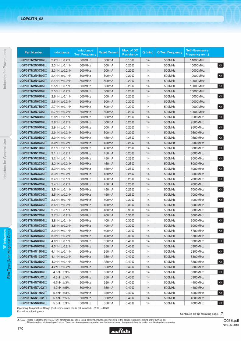
Indu
ctor
s fo
r P
ower
Lin
esIn
duct
ors
for
Gen
eral
Use
RF
Indu
ctor
sR
F In
duct
ors
Film
Typ
e (N
on-M
agne
tic C
ore)
LQP03TN_02
Continued on the following page.
Operating Temperature Range (Self-temperature rise is not included): -55℃~+125℃For refl ow soldering only.
Part Number InductanceInductance
Test FrequencyRated Current
Max. of DCResistance
Q (min.) Q Test FrequencySelf-ResonanceFrequency (min.)
LQP03TN2N2C02p 2.2nH ±0.2nH 500MHz 600mA 0.15Ω 14 500MHz 11000MHz
LQP03TN2N3B02p 2.3nH ±0.1nH 500MHz 500mA 0.20Ω 14 500MHz 10000MHz LQP03TN2N3C02p 2.3nH ±0.2nH 500MHz 500mA 0.20Ω 14 500MHz 10000MHz
LQP03TN2N4B02p 2.4nH ±0.1nH 500MHz 500mA 0.20Ω 14 500MHz 10000MHz LQP03TN2N4C02p 2.4nH ±0.2nH 500MHz 500mA 0.20Ω 14 500MHz 10000MHz
LQP03TN2N5B02p 2.5nH ±0.1nH 500MHz 500mA 0.20Ω 14 500MHz 10000MHz LQP03TN2N5C02p 2.5nH ±0.2nH 500MHz 500mA 0.20Ω 14 500MHz 10000MHz
LQP03TN2N6B02p 2.6nH ±0.1nH 500MHz 500mA 0.20Ω 14 500MHz 10000MHz LQP03TN2N6C02p 2.6nH ±0.2nH 500MHz 500mA 0.20Ω 14 500MHz 10000MHz
LQP03TN2N7B02p 2.7nH ±0.1nH 500MHz 500mA 0.20Ω 14 500MHz 10000MHz LQP03TN2N7C02p 2.7nH ±0.2nH 500MHz 500mA 0.20Ω 14 500MHz 10000MHz
LQP03TN2N8B02p 2.8nH ±0.1nH 500MHz 500mA 0.20Ω 14 500MHz 9500MHz LQP03TN2N8C02p 2.8nH ±0.2nH 500MHz 500mA 0.20Ω 14 500MHz 9500MHz
LQP03TN2N9B02p 2.9nH ±0.1nH 500MHz 500mA 0.20Ω 14 500MHz 9500MHz LQP03TN2N9C02p 2.9nH ±0.2nH 500MHz 500mA 0.20Ω 14 500MHz 9500MHz
LQP03TN3N0B02p 3.0nH ±0.1nH 500MHz 450mA 0.25Ω 14 500MHz 9500MHz LQP03TN3N0C02p 3.0nH ±0.2nH 500MHz 450mA 0.25Ω 14 500MHz 9500MHz
LQP03TN3N1B02p 3.1nH ±0.1nH 500MHz 450mA 0.25Ω 14 500MHz 8000MHz LQP03TN3N1C02p 3.1nH ±0.2nH 500MHz 450mA 0.25Ω 14 500MHz 8000MHz
LQP03TN3N2B02p 3.2nH ±0.1nH 500MHz 450mA 0.25Ω 14 500MHz 8000MHz LQP03TN3N2C02p 3.2nH ±0.2nH 500MHz 450mA 0.25Ω 14 500MHz 8000MHz
LQP03TN3N3B02p 3.3nH ±0.1nH 500MHz 450mA 0.25Ω 14 500MHz 8000MHz LQP03TN3N3C02p 3.3nH ±0.2nH 500MHz 450mA 0.25Ω 14 500MHz 8000MHz
LQP03TN3N4B02p 3.4nH ±0.1nH 500MHz 450mA 0.25Ω 14 500MHz 7000MHz LQP03TN3N4C02p 3.4nH ±0.2nH 500MHz 450mA 0.25Ω 14 500MHz 7000MHz
LQP03TN3N5B02p 3.5nH ±0.1nH 500MHz 450mA 0.25Ω 14 500MHz 7000MHz LQP03TN3N5C02p 3.5nH ±0.2nH 500MHz 450mA 0.25Ω 14 500MHz 7000MHz
LQP03TN3N6B02p 3.6nH ±0.1nH 500MHz 400mA 0.30Ω 14 500MHz 6000MHz LQP03TN3N6C02p 3.6nH ±0.2nH 500MHz 400mA 0.30Ω 14 500MHz 6000MHz
LQP03TN3N7B02p 3.7nH ±0.1nH 500MHz 400mA 0.30Ω 14 500MHz 6000MHz LQP03TN3N7C02p 3.7nH ±0.2nH 500MHz 400mA 0.30Ω 14 500MHz 6000MHz
LQP03TN3N8B02p 3.8nH ±0.1nH 500MHz 400mA 0.30Ω 14 500MHz 6000MHz LQP03TN3N8C02p 3.8nH ±0.2nH 500MHz 400mA 0.30Ω 14 500MHz 6000MHz
LQP03TN3N9B02p 3.9nH ±0.1nH 500MHz 400mA 0.30Ω 14 500MHz 5700MHz LQP03TN3N9C02p 3.9nH ±0.2nH 500MHz 400mA 0.30Ω 14 500MHz 5700MHz
LQP03TN4N0B02p 4.0nH ±0.1nH 500MHz 350mA 0.40Ω 14 500MHz 5300MHz LQP03TN4N0C02p 4.0nH ±0.2nH 500MHz 350mA 0.40Ω 14 500MHz 5300MHz LQP03TN4N1B02p 4.1nH ±0.1nH 500MHz 350mA 0.40Ω 14 500MHz 5300MHz LQP03TN4N1C02p 4.1nH ±0.2nH 500MHz 350mA 0.40Ω 14 500MHz 5300MHz LQP03TN4N2B02p 4.2nH ±0.1nH 500MHz 350mA 0.40Ω 14 500MHz 5300MHz LQP03TN4N2C02p 4.2nH ±0.2nH 500MHz 350mA 0.40Ω 14 500MHz 5300MHz LQP03TN4N3H02p 4.3nH ±3% 500MHz 350mA 0.40Ω 14 500MHz 5300MHz LQP03TN4N3J02p 4.3nH ±5% 500MHz 350mA 0.40Ω 14 500MHz 5300MHz
LQP03TN4N7H02p 4.7nH ±3% 500MHz 350mA 0.40Ω 14 500MHz 4400MHz LQP03TN4N7J02p 4.7nH ±5% 500MHz 350mA 0.40Ω 14 500MHz 4400MHz
LQP03TN5N1H02p 5.1nH ±3% 500MHz 350mA 0.40Ω 14 500MHz 4200MHz LQP03TN5N1J02p 5.1nH ±5% 500MHz 350mA 0.40Ω 14 500MHz 4200MHz
LQP03TN5N6H02p 5.6nH ±3% 500MHz 350mA 0.40Ω 14 500MHz 4000MHz
O05E.pdfNov.25,2013
170
!Note • Please read rating and !CAUTION (for storage, operating, rating, soldering, mounting and handling) in this catalog to prevent smoking and/or burning, etc.• This catalog has only typical specifi cations. Therefore, please approve our product specifi cations or transact the approval sheet for product specifi cations before ordering.

Indu
ctor
s fo
r P
ower
Lin
esIn
duct
ors
for
Gen
eral
Use
RF
Indu
ctor
sR
F In
duct
ors
Film
Typ
e (N
on-M
agne
tic C
ore)
LQP03TN_02
Continued on the following page.
Operating Temperature Range (Self-temperature rise is not included): -55℃~+125℃For refl ow soldering only.
Part Number InductanceInductance
Test FrequencyRated Current
Max. of DCResistance
Q (min.) Q Test FrequencySelf-ResonanceFrequency (min.)
LQP03TN5N6J02p 5.6nH ±5% 500MHz 350mA 0.40Ω 14 500MHz 4000MHz
LQP03TN6N2H02p 6.2nH ±3% 500MHz 300mA 0.60Ω 14 500MHz 4000MHz LQP03TN6N2J02p 6.2nH ±5% 500MHz 300mA 0.60Ω 14 500MHz 4000MHz
LQP03TN6N8H02p 6.8nH ±3% 500MHz 300mA 0.60Ω 14 500MHz 3900MHz LQP03TN6N8J02p 6.8nH ±5% 500MHz 300mA 0.60Ω 14 500MHz 3900MHz
LQP03TN7N5H02p 7.5nH ±3% 500MHz 300mA 0.60Ω 14 500MHz 3700MHz LQP03TN7N5J02p 7.5nH ±5% 500MHz 300mA 0.60Ω 14 500MHz 3700MHz
LQP03TN8N2H02p 8.2nH ±3% 500MHz 250mA 0.70Ω 14 500MHz 3600MHz LQP03TN8N2J02p 8.2nH ±5% 500MHz 250mA 0.70Ω 14 500MHz 3600MHz
LQP03TN9N1H02p 9.1nH ±3% 500MHz 250mA 0.70Ω 14 500MHz 3300MHz LQP03TN9N1J02p 9.1nH ±5% 500MHz 250mA 0.70Ω 14 500MHz 3300MHz
LQP03TN10NH02p 10nH ±3% 500MHz 250mA 0.70Ω 14 500MHz 3200MHz LQP03TN10NJ02p 10nH ±5% 500MHz 250mA 0.70Ω 14 500MHz 3200MHz
LQP03TN11NH02p 11nH ±3% 500MHz 250mA 0.80Ω 14 500MHz 2900MHz LQP03TN11NJ02p 11nH ±5% 500MHz 250mA 0.80Ω 14 500MHz 2900MHz LQP03TN12NH02p 12nH ±3% 500MHz 250mA 0.70Ω 12 500MHz 2900MHz LQP03TN12NJ02p 12nH ±5% 500MHz 250mA 0.70Ω 12 500MHz 2900MHz
LQP03TN13NH02p 13nH ±3% 500MHz 250mA 0.80Ω 12 500MHz 2600MHz LQP03TN13NJ02p 13nH ±5% 500MHz 250mA 0.80Ω 12 500MHz 2600MHz LQP03TN15NH02p 15nH ±3% 500MHz 250mA 0.70Ω 12 500MHz 2600MHz LQP03TN15NJ02p 15nH ±5% 500MHz 250mA 0.70Ω 12 500MHz 2600MHz
LQP03TN16NH02p 16nH ±3% 500MHz 200mA 0.95Ω 12 500MHz 2200MHz LQP03TN16NJ02p 16nH ±5% 500MHz 200mA 0.95Ω 12 500MHz 2200MHz LQP03TN18NH02p 18nH ±3% 500MHz 200mA 0.80Ω 12 500MHz 2200MHz LQP03TN18NJ02p 18nH ±5% 500MHz 200mA 0.80Ω 12 500MHz 2200MHz
LQP03TN20NH02p 20nH ±3% 500MHz 150mA 2.30Ω 12 500MHz 2200MHz LQP03TN20NJ02p 20nH ±5% 500MHz 150mA 2.30Ω 12 500MHz 2200MHz LQP03TN22NH02p 22nH ±3% 500MHz 150mA 1.90Ω 12 500MHz 2200MHz LQP03TN22NJ02p 22nH ±5% 500MHz 150mA 1.90Ω 12 500MHz 2200MHz
LQP03TN24NH02p 24nH ±3% 500MHz 140mA 2.30Ω 12 500MHz 2000MHz LQP03TN24NJ02p 24nH ±5% 500MHz 140mA 2.30Ω 12 500MHz 2000MHz LQP03TN27NH02p 27nH ±3% 500MHz 140mA 2.30Ω 12 500MHz 2000MHz LQP03TN27NJ02p 27nH ±5% 500MHz 140mA 2.30Ω 12 500MHz 2000MHz
LQP03TN30NH02p 30nH ±3% 500MHz 120mA 2.95Ω 9 500MHz 1700MHz LQP03TN30NJ02p 30nH ±5% 500MHz 120mA 2.95Ω 9 500MHz 1700MHz LQP03TN33NJ02p 33nH ±5% 300MHz 120mA 2.95Ω 9 300MHz 1700MHz LQP03TN36NJ02p 36nH ±5% 300MHz 120mA 3.00Ω 9 300MHz 1500MHz LQP03TN39NJ02p 39nH ±5% 300MHz 120mA 3.00Ω 9 300MHz 1500MHz LQP03TN43NJ02p 43nH ±5% 300MHz 100mA 3.60Ω 9 300MHz 1300MHz LQP03TN47NJ02p 47nH ±5% 300MHz 100mA 3.60Ω 9 300MHz 1300MHz LQP03TN51NJ02p 51nH ±5% 300MHz 100mA 3.90Ω 9 300MHz 1200MHz LQP03TN56NJ02p 56nH ±5% 300MHz 100mA 3.90Ω 9 300MHz 1200MHz LQP03TN62NJ02p 62nH ±5% 300MHz 100mA 8Ω 8 300MHz 1100MHz LQP03TN68NJ02p 68nH ±5% 300MHz 100mA 8Ω 8 300MHz 1100MHz LQP03TN75NJ02p 75nH ±5% 300MHz 100mA 10Ω 8 300MHz 1000MHz LQP03TN82NJ02p 82nH ±5% 300MHz 100mA 10Ω 8 300MHz 1000MHz LQP03TN91NJ02p 91nH ±5% 300MHz 80mA 10Ω 8 300MHz 900MHz LQP03TNR10J02p 100nH ±5% 300MHz 80mA 10Ω 8 300MHz 900MHz
O05E.pdfNov.25,2013
171
!Note • Please read rating and !CAUTION (for storage, operating, rating, soldering, mounting and handling) in this catalog to prevent smoking and/or burning, etc.• This catalog has only typical specifi cations. Therefore, please approve our product specifi cations or transact the approval sheet for product specifi cations before ordering.

Indu
ctor
s fo
r P
ower
Lin
esIn
duct
ors
for
Gen
eral
Use
RF
Indu
ctor
sR
F In
duct
ors
Film
Typ
e (N
on-M
agne
tic C
ore)
LQP03TN_02
c Q-Frequency Characteristics (Typ.) c Inductance-Frequency Characteristics (Typ.)
10 100 1000 10000Frequency (MHz)
700
600
500
400
300
200
100
0
Q
0.6nH
2.2nH3.3nH
5.6nH10nH
22nH56nH
120nH270nH
10 100 1000 10000
10000
1000
100
10
1
0.1
56nH
22nH
10nH
5.6nH3.3nH2.2nH
0.6nH
270nH
120nH
Frequency (MHz)
L (n
H)
Continued on the following page.
Operating Temperature Range (Self-temperature rise is not included): -55℃~+125℃For refl ow soldering only.
Part Number InductanceInductance
Test FrequencyRated Current
Max. of DCResistance
Q (min.) Q Test FrequencySelf-ResonanceFrequency (min.)
LQP03TNR11J02p 110nH ±5% 300MHz 80mA 12Ω 8 300MHz 800MHz LQP03TNR12J02p 120nH ±5% 300MHz 80mA 12Ω 8 300MHz 800MHz LQP03TNR13J02p 130nH ±5% 100MHz 80mA 9Ω 5 100MHz 650MHz LQP03TNR15J02p 150nH ±5% 100MHz 80mA 9Ω 5 100MHz 650MHz LQP03TNR16J02p 160nH ±5% 100MHz 70mA 11Ω 5 100MHz 600MHz LQP03TNR18J02p 180nH ±5% 100MHz 70mA 11Ω 5 100MHz 600MHz LQP03TNR20J02p 200nH ±5% 100MHz 60mA 13Ω 5 100MHz 500MHz LQP03TNR22J02p 220nH ±5% 100MHz 60mA 13Ω 5 100MHz 500MHz LQP03TNR24J02p 240nH ±5% 100MHz 60mA 15Ω 5 100MHz 450MHz LQP03TNR27J02p 270nH ±5% 100MHz 60mA 15Ω 5 100MHz 450MHz
c Reference Data 4991A&16197A
Part Number
LQP03TN0N6p02
LQP03TN0N7p02
LQP03TN0N8p02
LQP03TN0N9p02
LQP03TN1N0p02
LQP03TN1N1p02
LQP03TN1N2p02
LQP03TN1N3p02
LQP03TN1N4p02
LQP03TN1N5p02
LQP03TN1N6p02
LQP03TN1N7p02
LQP03TN1N8p02
LQP03TN1N9p02
LQP03TN2N0p02
LQP03TN2N1p02
LQP03TN2N2p02
LQP03TN2N3p02
LQP03TN2N4p02
LQP03TN2N5p02
35 min.
35 min.
35 min.
35 min.
35 min.
35 min.
31
34
31
29
30
30
32
29
28
30
30
29
28
27
800MHz
40 min.
40 min.
40 min.
40 min.
40 min.
40 min.
34
36
34
31
32
31
34
31
30
31
32
30
30
29
900MHz
62 min.
62 min.
62 min.
62 min.
62 min.
62 min.
51
55
52
47
47
47
50
45
44
46
46
44
43
41
1.8GHz
Q (Typ.)
67 min.
67 min.
67 min.
67 min.
67 min.
67 min.
54
58
55
49
49
49
53
48
46
48
48
46
45
43
2.0GHz
71 min.
71 min.
71 min.
71 min.
71 min.
71 min.
59
64
61
54
54
53
57
52
50
52
52
50
49
47
2.4GHz
O05E.pdfNov.25,2013
172
!Note • Please read rating and !CAUTION (for storage, operating, rating, soldering, mounting and handling) in this catalog to prevent smoking and/or burning, etc.• This catalog has only typical specifi cations. Therefore, please approve our product specifi cations or transact the approval sheet for product specifi cations before ordering.
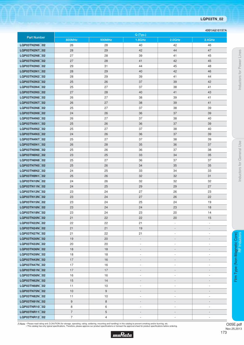
Indu
ctor
s fo
r P
ower
Lin
esIn
duct
ors
for
Gen
eral
Use
RF
Indu
ctor
sR
F In
duct
ors
Film
Typ
e (N
on-M
agne
tic C
ore)
LQP03TN_02
4991A&16197A
Part Number
LQP03TN12Np02
LQP03TN13Np02
LQP03TN15Np02
LQP03TN16Np02
LQP03TN18Np02
LQP03TN20Np02
LQP03TN22Np02
LQP03TN24Np02
LQP03TN27Np02
LQP03TN30Np02
LQP03TN33Np02
LQP03TN36Np02
LQP03TN39Np02
LQP03TN43Np02
LQP03TN47Np02
LQP03TN51Np02
LQP03TN56Np02
LQP03TN62Np02
LQP03TN68Np02
LQP03TN75Np02
LQP03TN82Np02
LQP03TN91Np02
LQP03TNR10p02
LQP03TNR11p02
LQP03TNR12p02
23
23
23
23
23
21
22
21
21
19
20
18
18
17
17
17
16
15
11
10
11
9
8
7
7
800MHz
24
24
24
24
24
22
22
21
22
20
20
18
18
16
16
17
16
14
10
9
10
8
6
5
4
900MHz
27
27
25
24
23
22
21
19
21
-
-
-
-
-
-
-
-
-
-
-
-
-
-
-
-
1.8GHz
Q (Typ.)
26
26
24
23
20
20
-
-
-
-
-
-
-
-
-
-
-
-
-
-
-
-
-
-
-
2.0GHz
23
22
19
18
14
15
-
-
-
-
-
-
-
-
-
-
-
-
-
-
-
-
-
-
-
2.4GHz
LQP03TN2N6p02
LQP03TN2N7p02
LQP03TN2N8p02
LQP03TN2N9p02
LQP03TN3N0p02
LQP03TN3N1p02
LQP03TN3N2p02
LQP03TN3N3p02
LQP03TN3N4p02
LQP03TN3N5p02
LQP03TN3N6p02
LQP03TN3N7p02
LQP03TN3N8p02
LQP03TN3N9p02
LQP03TN4N0p02
LQP03TN4N1p02
LQP03TN4N2p02
LQP03TN4N3p02
LQP03TN4N7p02
LQP03TN5N1p02
LQP03TN5N6p02
LQP03TN6N2p02
LQP03TN6N8p02
LQP03TN7N5p02
LQP03TN8N2p02
LQP03TN9N1p02
LQP03TN10Np02
LQP03TN11Np02
26
28
27
27
29
28
28
25
25
27
26
26
25
24
26
25
25
24
25
26
25
23
25
25
24
25
24
24
28
29
28
28
31
29
29
26
27
28
27
27
27
26
27
26
27
26
27
28
26
25
27
26
25
26
26
25
40
42
39
41
44
40
39
37
37
40
38
38
37
36
37
36
37
36
37
35
36
33
36
34
33
32
32
29
42
44
41
42
45
42
41
39
38
41
39
39
38
37
38
37
38
37
38
36
37
34
37
35
34
32
32
29
46
47
45
45
48
46
44
42
41
43
41
41
39
39
40
39
40
39
39
37
38
35
37
35
33
31
32
27
O05E.pdfNov.25,2013
173
!Note • Please read rating and !CAUTION (for storage, operating, rating, soldering, mounting and handling) in this catalog to prevent smoking and/or burning, etc.• This catalog has only typical specifi cations. Therefore, please approve our product specifi cations or transact the approval sheet for product specifi cations before ordering.

Code PackagingMinimumQuantity
D ø180mm Paper Taping 10000
J ø330mm Paper Taping 50000
B Packing in Bulk 500
0.45Thickness
mmmax.
E-12Step
E-24Step
TightTolerance Reflow
OK
Indu
ctor
s fo
r P
ower
Lin
esIn
duct
ors
for
Gen
eral
Use
RF
Indu
ctor
sR
F In
duct
ors
Film
Typ
e (N
on-M
agne
tic C
ore)
Film Type (Non-Magnetic Core) LQP15MN_02
RF Inductors
LQP15MN_02Series 0402/1005 (inch/mm)Size Code 0402 (1005) in inch (in mm), Tight Inductance Tolerance, Film Type
c Rated Value (p: packaging code)
Refer to pages 227 to 230 for mounting information.
1.0±0.1
0.5±
0.1
0.25±0.1
0.35
±0.
1
(in mm)
Continued on the following page.
c Appearance/Dimensions
c Packaging
Operating Temperature Range (Self-temperature rise is not included): -40℃~+85℃For refl ow soldering only.
Part Number InductanceInductance
Test FrequencyRated Current
Max. of DCResistance
Q (min.) Q Test FrequencySelf-ResonanceFrequency (min.)
LQP15MN1N0B02p 1.0nH ±0.1nH 500MHz 400mA 0.1Ω 13 500MHz 6000MHz LQP15MN1N0W02p 1.0nH ±0.05nH 500MHz 400mA 0.1Ω 13 500MHz 6000MHz
LQP15MN1N1B02p 1.1nH ±0.1nH 500MHz 390mA 0.1Ω 13 500MHz 6000MHz LQP15MN1N1W02p 1.1nH ±0.05nH 500MHz 390mA 0.1Ω 13 500MHz 6000MHz
LQP15MN1N2B02p 1.2nH ±0.1nH 500MHz 390mA 0.1Ω 13 500MHz 6000MHz LQP15MN1N2W02p 1.2nH ±0.05nH 500MHz 390mA 0.1Ω 13 500MHz 6000MHz
LQP15MN1N3B02p 1.3nH ±0.1nH 500MHz 280mA 0.2Ω 13 500MHz 6000MHz LQP15MN1N3W02p 1.3nH ±0.05nH 500MHz 280mA 0.2Ω 13 500MHz 6000MHz
LQP15MN1N4W02p 1.4nH ±0.05nH 500MHz 280mA 0.2Ω 13 500MHz 6000MHz
LQP15MN1N5B02p 1.5nH ±0.1nH 500MHz 280mA 0.2Ω 13 500MHz 6000MHz LQP15MN1N5W02p 1.5nH ±0.05nH 500MHz 280mA 0.2Ω 13 500MHz 6000MHz
LQP15MN1N6B02p 1.6nH ±0.1nH 500MHz 220mA 0.3Ω 13 500MHz 6000MHz LQP15MN1N6W02p 1.6nH ±0.05nH 500MHz 220mA 0.3Ω 13 500MHz 6000MHz
LQP15MN1N7W02p 1.7nH ±0.05nH 500MHz 280mA 0.2Ω 13 500MHz 6000MHz
LQP15MN1N8B02p 1.8nH ±0.1nH 500MHz 280mA 0.2Ω 13 500MHz 6000MHz LQP15MN1N8W02p 1.8nH ±0.05nH 500MHz 280mA 0.2Ω 13 500MHz 6000MHz
LQP15MN1N9W02p 1.9nH ±0.05nH 500MHz 220mA 0.3Ω 13 500MHz 6000MHz
LQP15MN2N0B02p 2.0nH ±0.1nH 500MHz 220mA 0.3Ω 13 500MHz 6000MHz LQP15MN2N0W02p 2.0nH ±0.05nH 500MHz 220mA 0.3Ω 13 500MHz 6000MHz
LQP15MN2N1W02p 2.1nH ±0.05nH 500MHz 220mA 0.3Ω 13 500MHz 6000MHz
LQP15MN2N2B02p 2.2nH ±0.1nH 500MHz 220mA 0.3Ω 13 500MHz 6000MHz LQP15MN2N2W02p 2.2nH ±0.05nH 500MHz 220mA 0.3Ω 13 500MHz 6000MHz
LQP15MN2N3W02p 2.3nH ±0.05nH 500MHz 220mA 0.3Ω 13 500MHz 6000MHz
LQP15MN2N4B02p 2.4nH ±0.1nH 500MHz 220mA 0.3Ω 13 500MHz 6000MHz LQP15MN2N4W02p 2.4nH ±0.05nH 500MHz 220mA 0.3Ω 13 500MHz 6000MHz
LQP15MN2N5W02p 2.5nH ±0.05nH 500MHz 220mA 0.3Ω 13 500MHz 6000MHz
LQP15MN2N6W02p 2.6nH ±0.05nH 500MHz 220mA 0.3Ω 13 500MHz 6000MHz
LQP15MN2N7B02p 2.7nH ±0.1nH 500MHz 220mA 0.3Ω 13 500MHz 6000MHz LQP15MN2N7W02p 2.7nH ±0.05nH 500MHz 220mA 0.3Ω 13 500MHz 6000MHz
LQP15MN2N8W02p 2.8nH ±0.05nH 500MHz 190mA 0.4Ω 13 500MHz 6000MHz
LQP15MN2N9W02p 2.9nH ±0.05nH 500MHz 190mA 0.4Ω 13 500MHz 6000MHz
LQP15MN3N0B02p 3.0nH ±0.1nH 500MHz 190mA 0.4Ω 13 500MHz 6000MHz
O05E.pdfNov.25,2013
174
!Note • Please read rating and !CAUTION (for storage, operating, rating, soldering, mounting and handling) in this catalog to prevent smoking and/or burning, etc.• This catalog has only typical specifi cations. Therefore, please approve our product specifi cations or transact the approval sheet for product specifi cations before ordering.

Indu
ctor
s fo
r P
ower
Lin
esIn
duct
ors
for
Gen
eral
Use
RF
Indu
ctor
sR
F In
duct
ors
Film
Typ
e (N
on-M
agne
tic C
ore)
LQP15MN_02
c Q-Frequency Characteristics (Typ.) c Inductance-Frequency Characteristics (Typ.)
0
40
80
120
160
200
20
60
100
140
180
10 100 1000 10000Frequency (MHz)
Q
33nH
10nH5.6nH3.3nH
2.2nH
1.0nH
100
1000
10
1
0.110010 1000 10000
L (n
H)
Frequency (MHz)
33nH
10nH
3.3nH2.2nH
5.6nH
1.0nH
Continued on the following page.
Operating Temperature Range (Self-temperature rise is not included): -40℃~+85℃For refl ow soldering only.
Part Number InductanceInductance
Test FrequencyRated Current
Max. of DCResistance
Q (min.) Q Test FrequencySelf-ResonanceFrequency (min.)
LQP15MN3N0W02p 3.0nH ±0.05nH 500MHz 190mA 0.4Ω 13 500MHz 6000MHz
LQP15MN3N1W02p 3.1nH ±0.05nH 500MHz 190mA 0.4Ω 13 500MHz 6000MHz
LQP15MN3N2W02p 3.2nH ±0.05nH 500MHz 190mA 0.4Ω 13 500MHz 6000MHz
LQP15MN3N3B02p 3.3nH ±0.1nH 500MHz 190mA 0.4Ω 13 500MHz 6000MHz LQP15MN3N3W02p 3.3nH ±0.05nH 500MHz 190mA 0.4Ω 13 500MHz 6000MHz
LQP15MN3N4W02p 3.4nH ±0.05nH 500MHz 170mA 0.5Ω 13 500MHz 6000MHz
LQP15MN3N5W02p 3.5nH ±0.05nH 500MHz 170mA 0.5Ω 13 500MHz 6000MHz
LQP15MN3N6B02p 3.6nH ±0.1nH 500MHz 170mA 0.5Ω 13 500MHz 6000MHz LQP15MN3N6W02p 3.6nH ±0.05nH 500MHz 170mA 0.5Ω 13 500MHz 6000MHz
LQP15MN3N7W02p 3.7nH ±0.05nH 500MHz 170mA 0.5Ω 13 500MHz 6000MHz
LQP15MN3N8W02p 3.8nH ±0.05nH 500MHz 170mA 0.5Ω 13 500MHz 6000MHz
LQP15MN3N9B02p 3.9nH ±0.1nH 500MHz 170mA 0.5Ω 13 500MHz 6000MHz LQP15MN3N9W02p 3.9nH ±0.05nH 500MHz 170mA 0.5Ω 13 500MHz 6000MHz
LQP15MN4N3B02p 4.3nH ±0.1nH 500MHz 160mA 0.6Ω 13 500MHz 6000MHz LQP15MN4N7B02p 4.7nH ±0.1nH 500MHz 160mA 0.6Ω 13 500MHz 6000MHz LQP15MN5N1B02p 5.1nH ±0.1nH 500MHz 140mA 0.7Ω 13 500MHz 6000MHz LQP15MN5N6B02p 5.6nH ±0.1nH 500MHz 140mA 0.7Ω 13 500MHz 6000MHz LQP15MN6N2B02p 6.2nH ±0.1nH 500MHz 130mA 0.9Ω 13 500MHz 6000MHz LQP15MN6N8B02p 6.8nH ±0.1nH 500MHz 130mA 0.9Ω 13 500MHz 6000MHz LQP15MN7N5B02p 7.5nH ±0.1nH 500MHz 110mA 1.1Ω 13 500MHz 5500MHz LQP15MN8N2B02p 8.2nH ±0.1nH 500MHz 110mA 1.1Ω 13 500MHz 5500MHz LQP15MN9N1B02p 9.1nH ±0.1nH 500MHz 100mA 1.3Ω 13 500MHz 4500MHz LQP15MN10NG02p 10nH ±2% 500MHz 100mA 1.3Ω 13 500MHz 4500MHz LQP15MN12NG02p 12nH ±2% 500MHz 90mA 1.6Ω 13 500MHz 3700MHz LQP15MN15NG02p 15nH ±2% 500MHz 90mA 1.8Ω 13 500MHz 3300MHz LQP15MN18NG02p 18nH ±2% 500MHz 80mA 2.0Ω 13 500MHz 3100MHz LQP15MN22NG02p 22nH ±2% 500MHz 70mA 2.6Ω 13 500MHz 2800MHz LQP15MN27NG02p 27nH ±2% 500MHz 70mA 3.1Ω 13 500MHz 2500MHz LQP15MN33NG02p 33nH ±2% 500MHz 60mA 3.8Ω 13 500MHz 2100MHz
O05E.pdfNov.25,2013
175
!Note • Please read rating and !CAUTION (for storage, operating, rating, soldering, mounting and handling) in this catalog to prevent smoking and/or burning, etc.• This catalog has only typical specifi cations. Therefore, please approve our product specifi cations or transact the approval sheet for product specifi cations before ordering.

Indu
ctor
s fo
r P
ower
Lin
esIn
duct
ors
for
Gen
eral
Use
RF
Indu
ctor
sR
F In
duct
ors
Film
Typ
e (N
on-M
agne
tic C
ore)
LQP15MN_02
c Reference Data
Part Number
LQP15MN1N0p02
LQP15MN1N1p02
LQP15MN1N2p02
LQP15MN1N3p02
LQP15MN1N4p02
LQP15MN1N5p02
LQP15MN1N6p02
LQP15MN1N7p02
LQP15MN1N8p02
LQP15MN1N9p02
LQP15MN2N0p02
LQP15MN2N1p02
LQP15MN2N2p02
LQP15MN2N3p02
LQP15MN2N4p02
LQP15MN2N5p02
LQP15MN2N6p02
LQP15MN2N7p02
LQP15MN2N8p02
LQP15MN2N9p02
LQP15MN3N0p02
LQP15MN3N1p02
LQP15MN3N2p02
LQP15MN3N3p02
LQP15MN3N4p02
LQP15MN3N5p02
LQP15MN3N6p02
LQP15MN3N7p02
LQP15MN3N8p02
LQP15MN3N9p02
LQP15MN4N3p02
LQP15MN4N7p02
LQP15MN5N1p02
LQP15MN5N6p02
LQP15MN6N2p02
LQP15MN6N8p02
LQP15MN7N5p02
LQP15MN8N2p02
LQP15MN9N1p02
LQP15MN10Np02
LQP15MN12Np02
LQP15MN15Np02
LQP15MN18Np02
LQP15MN22Np02
LQP15MN27Np02
LQP15MN33Np02
80
60
56
46
40
34
25
29
32
34
32
34
31
32
32
31
29
29
28
28
27
25
24
23
24
25
24
25
25
25
25
26
26
22
22
22
23
23
23
23
24
23
22
23
23
22
800MHz
88
65
61
50
44
36
27
32
35
36
34
37
33
34
34
33
32
32
30
30
29
27
26
25
25
27
26
27
26
27
26
28
27
23
23
24
24
25
24
24
26
24
23
24
24
23
900MHz
157
107
100
77
65
55
40
47
51
54
51
55
49
51
51
50
47
47
45
44
43
39
36
36
36
38
38
38
37
38
38
40
39
32
33
32
32
34
33
31
32
28
25
24
22
20
1.8GHz
172
115
104
81
68
57
42
49
53
56
53
57
51
54
53
52
49
49
46
45
44
41
37
37
37
39
39
39
38
40
39
41
40
32
33
33
33
35
33
31
32
28
24
22
20
-
2.0GHz
188
125
114
86
73
62
46
53
57
60
57
61
55
58
57
56
53
53
50
48
48
44
40
39
39
42
42
42
41
42
42
43
42
34
35
34
34
36
34
-
-
-
-
-
-
-
2.4GHz
Q (Typ.)4991A&16197A
O05E.pdfNov.25,2013
176
!Note • Please read rating and !CAUTION (for storage, operating, rating, soldering, mounting and handling) in this catalog to prevent smoking and/or burning, etc.• This catalog has only typical specifi cations. Therefore, please approve our product specifi cations or transact the approval sheet for product specifi cations before ordering.

Code PackagingMinimumQuantity
D ø180mm Paper Taping 4000
J ø330mm Paper Taping 10000
B Packing in Bulk 500
0.6Thickness
mmmax.
E-12Step
E-24Step
TightTolerance Reflow
OK
Indu
ctor
s fo
r P
ower
Lin
esIn
duct
ors
for
Gen
eral
Use
RF
Indu
ctor
sR
F In
duct
ors
Film
Typ
e (N
on-M
agne
tic C
ore)
Film Type (Non-Magnetic Core) LQP18MN_02
RF Inductors
LQP18MN_02Series 0603/1608 (inch/mm)Size Code 0603 (1608) in inch (in mm), Film Type
c Rated Value (p: packaging code)
Refer to pages 227 to 230 for mounting information.
1.6±0.15
0.2 min.0.
8±0.
150.
5±0.
1
(in mm)
Continued on the following page.
c Appearance/Dimensions
c Packaging
Operating Temperature Range (Self-temperature rise is not included): -40℃~+85℃For refl ow soldering only.
Part Number InductanceInductance
Test FrequencyRated Current Max. of DC Resistance Q (min.) Q Test Frequency
Self-ResonanceFrequency (min.)
LQP18MN1N3C02p 1.3nH ±0.2nH 500MHz 300mA 0.3Ω 17 500MHz 6000MHz
LQP18MN1N5C02p 1.5nH ±0.2nH 500MHz 300mA 0.3Ω 17 500MHz 6000MHz
LQP18MN1N8C02p 1.8nH ±0.2nH 500MHz 250mA 0.4Ω 17 500MHz 6000MHz
LQP18MN2N2C02p 2.2nH ±0.2nH 500MHz 250mA 0.4Ω 17 500MHz 6000MHz
LQP18MN2N7C02p 2.7nH ±0.2nH 500MHz 250mA 0.4Ω 17 500MHz 6000MHz
LQP18MN3N3C02p 3.3nH ±0.2nH 500MHz 250mA 0.4Ω 17 500MHz 6000MHz
LQP18MN3N9C02p 3.9nH ±0.2nH 500MHz 200mA 0.5Ω 17 500MHz 5900MHz
LQP18MN4N7C02p 4.7nH ±0.2nH 500MHz 200mA 0.5Ω 17 500MHz 5200MHz
LQP18MN5N6C02p 5.6nH ±0.2nH 500MHz 200mA 0.6Ω 17 500MHz 4700MHz
LQP18MN6N8C02p 6.8nH ±0.2nH 500MHz 200mA 0.7Ω 17 500MHz 4300MHz
LQP18MN8N2C02p 8.2nH ±0.2nH 500MHz 150mA 0.8Ω 17 500MHz 3600MHz
LQP18MN10NG02p 10nH ±2% 500MHz 150mA 1.0Ω 17 500MHz 3400MHz
LQP18MN12NG02p 12nH ±2% 500MHz 150mA 1.0Ω 17 500MHz 3000MHz
LQP18MN15NG02p 15nH ±2% 500MHz 150mA 1.3Ω 17 500MHz 2700MHz
LQP18MN18NG02p 18nH ±2% 500MHz 100mA 1.5Ω 17 500MHz 2300MHz
LQP18MN22NG02p 22nH ±2% 500MHz 100mA 1.9Ω 17 500MHz 2100MHz
LQP18MN27NG02p 27nH ±2% 500MHz 100mA 2.4Ω 17 500MHz 1900MHz
LQP18MN33NG02p 33nH ±2% 500MHz 100mA 2.8Ω 17 500MHz 1700MHz
LQP18MN39NG02p 39nH ±2% 500MHz 100mA 2.8Ω 17 500MHz 1400MHz
LQP18MN47NG02p 47nH ±2% 300MHz 100mA 2.2Ω 17 300MHz 1200MHz
LQP18MN56NG02p 56nH ±2% 300MHz 50mA 3.4Ω 17 300MHz 1000MHz
LQP18MN68NG02p 68nH ±2% 300MHz 50mA 3.5Ω 17 300MHz 900MHz
LQP18MN82NG02p 82nH ±2% 300MHz 50mA 4.6Ω 17 300MHz 800MHz
LQP18MNR10G02p 100nH ±2% 300MHz 50mA 6.1Ω 17 300MHz 700MHz
O05E.pdfNov.25,2013
177
!Note • Please read rating and !CAUTION (for storage, operating, rating, soldering, mounting and handling) in this catalog to prevent smoking and/or burning, etc.• This catalog has only typical specifi cations. Therefore, please approve our product specifi cations or transact the approval sheet for product specifi cations before ordering.
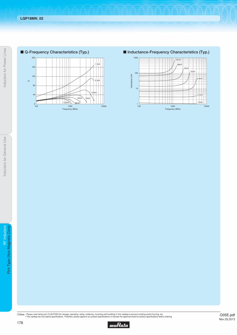
Indu
ctor
s fo
r P
ower
Lin
esIn
duct
ors
for
Gen
eral
Use
RF
Indu
ctor
sR
F In
duct
ors
Film
Typ
e (N
on-M
agne
tic C
ore)
LQP18MN_02
c Q-Frequency Characteristics (Typ.) c Inductance-Frequency Characteristics (Typ.)
100 1000 10000
200
160
120
80
40
0
Q
1.5nH
3.3nH
6.8nH
15nH33nH
68nH100nH
Frequency (MHz)100 1000 10000
Frequency (MHz)
1000
100
10
11.5nH
3.3nH
6.8nH
15nH
33nH
68nH
100nH
Indu
ctan
ce (
nH)
O05E.pdfNov.25,2013
178
!Note • Please read rating and !CAUTION (for storage, operating, rating, soldering, mounting and handling) in this catalog to prevent smoking and/or burning, etc.• This catalog has only typical specifi cations. Therefore, please approve our product specifi cations or transact the approval sheet for product specifi cations before ordering.

Code PackagingMinimumQuantity
D ø180mm Paper Taping 10000
Indu
ctor
s fo
r P
ower
Lin
esIn
duct
ors
for
Gen
eral
Use
RF
Indu
ctor
sR
F In
duct
ors
Wire
Wou
nd T
ype
(Non
-Mag
netic
Cor
e)
Wire Wound Type (Non-Magnetic Core) LQW03AW_00
RF Inductors
LQW03AW_00Series Suitable for Mounting in a Narrow Space in Antenna Matching Circuits
c Q-Frequency Characteristics (Typ.) c Inductance-Frequency Characteristics (Typ.)
c Rated Value (p: packaging code)
Refer to pages 227 to 230 for mounting information.
0.53±0.05
0.4±
0.05
0.4±
0.05
0.15±0.05
(in mm)
0.06
+0.
07-
0.03
Continued on the following page.
c Appearance/Dimensions
c Packaging
Operating Temperature Range (Self-temperature rise is included): -55℃~+125℃For refl ow soldering only.
0
30
50
80
10
20
40
60
90
70
100
1 10 100 1000 10000Frequency (MHz)
Q
13nH
9.1nH
8.7nH
7.5nH6.8nH
5.8nH
5.6nH
5.4nH
1
10
100
1 10 100001000100Frequency (MHz)
L (n
H)
13nH9.1nH8.7nH7.5nH
6.8nH
5.8nH
5.6nH
5.4nH
0.45Thickness
mmmax.
E-12Step
E-24Step
ReflowOK
Part Number InductanceInductance
Test FrequencyRated Current
Max. of DCResistance
Q (min.) Q Test FrequencySelf-ResonanceFrequency (min.)
LQW03AW5N4C00p 5.4nH ±0.2nH 100MHz 420mA 0.21Ω 46 (Typ.) 900MHz 8.5GHz LQW03AW5N4J00p 5.4nH ±5% 100MHz 420mA 0.21Ω 46 (Typ.) 900MHz 8.5GHz LQW03AW5N6C00p 5.6nH ±0.2nH 100MHz 330mA 0.33Ω 37 (Typ.) 900MHz 8.3GHz LQW03AW5N6J00p 5.6nH ±5% 100MHz 330mA 0.33Ω 37 (Typ.) 900MHz 8.3GHz LQW03AW5N8C00p 5.8nH ±0.2nH 100MHz 460mA 0.16Ω 47 (Typ.) 900MHz 8.8GHz LQW03AW5N8J00p 5.8nH ±5% 100MHz 460mA 0.16Ω 47 (Typ.) 900MHz 8.8GHz LQW03AW6N8C00p 6.8nH ±0.2nH 100MHz 460mA 0.18Ω 42 (Typ.) 900MHz 7.7GHz LQW03AW6N8J00p 6.8nH ±5% 100MHz 460mA 0.18Ω 42 (Typ.) 900MHz 7.7GHz LQW03AW7N5C00p 7.5nH ±0.2nH 100MHz 400mA 0.24Ω 41 (Typ.) 900MHz 7.5GHz LQW03AW7N5J00p 7.5nH ±5% 100MHz 400mA 0.24Ω 41 (Typ.) 900MHz 7.5GHz LQW03AW8N7C00p 8.7nH ±0.2nH 100MHz 290mA 0.42Ω 39 (Typ.) 900MHz 7.5GHz LQW03AW8N7J00p 8.7nH ±5% 100MHz 290mA 0.42Ω 39 (Typ.) 900MHz 7.5GHz LQW03AW9N1C00p 9.1nH ±0.2nH 100MHz 460mA 0.22Ω 46 (Typ.) 900MHz 6.4GHz LQW03AW9N1J00p 9.1nH ±5% 100MHz 460mA 0.22Ω 46 (Typ.) 900MHz 6.4GHz LQW03AW13NJ00p 13nH ±5% 100MHz 280mA 0.54Ω 39 (Typ.) 900MHz 5.9GHz
O05E.pdfNov.25,2013
179
!Note • Please read rating and !CAUTION (for storage, operating, rating, soldering, mounting and handling) in this catalog to prevent smoking and/or burning, etc.• This catalog has only typical specifi cations. Therefore, please approve our product specifi cations or transact the approval sheet for product specifi cations before ordering.

Indu
ctor
s fo
r P
ower
Lin
esIn
duct
ors
for
Gen
eral
Use
RF
Indu
ctor
sR
F In
duct
ors
Wire
Wou
nd T
ype
(Non
-Mag
netic
Cor
e)
LQW03AW_00
c Reference Data
Part Number
LQW03AW5N4
LQW03AW5N6
LQW03AW5N8
LQW03AW6N8
LQW03AW7N5
LQW03AW8N7
LQW03AW9N1
LQW03AW13N
5.4
5.6
5.8
6.8
7.5
8.7
9.1
13.0
Nominal
43
34
44
40
38
37
42
37
800MHz
46
37
48
42
41
39
46
40
900MHz
64
51
67
59
57
55
63
52
1.8GHz
66
53
68
60
58
56
63
53
2.0GHz
69
56
71
63
61
59
65
55
2.4GHz
Inductance (nH) Q (Typ.)4991A&16197A
O05E.pdfNov.25,2013
180
!Note • Please read rating and !CAUTION (for storage, operating, rating, soldering, mounting and handling) in this catalog to prevent smoking and/or burning, etc.• This catalog has only typical specifi cations. Therefore, please approve our product specifi cations or transact the approval sheet for product specifi cations before ordering.

Code PackagingMinimumQuantity
D ø180mm Paper Taping 10000
B Packing in Bulk 500
0.45Thickness
mmmax.
E-12Step
E-24Step
ReflowOK
Indu
ctor
s fo
r P
ower
Lin
esIn
duct
ors
for
Gen
eral
Use
RF
Indu
ctor
sR
F In
duct
ors
Wire
Wou
nd T
ype
(Non
-Mag
netic
Cor
e)
Wire Wound Type (Non-Magnetic Core) LQW04AN_00
RF Inductors
LQW04AN_00Series 03015/0804 (inch/mm)Size Code 03015 (0804) in inch (in mm), Wound Type
c Rated Value (p: packaging code)
Refer to pages 227 to 230 for mounting information.
0.8±0.05
0.4±
0.05
0.15±0.05
(in mm)
0.4±0.05
0.06
+0.
09-
0.03
Continued on the following page.
c Appearance/Dimensions
c Packaging
Operating Temperature Range (Self-temperature rise is not included): -55℃~+125℃For refl ow soldering only.
Part Number InductanceInductance
Test FrequencyRated Current
Max. of DCResistance
Q (min.) Q Test FrequencySelf-ResonanceFrequency (min.)
LQW04AN1N1C00p 1.1nH ±0.2nH 100MHz 990mA 0.03Ω 15 250MHz 20.0GHz LQW04AN1N1D00p 1.1nH ±0.5nH 100MHz 990mA 0.03Ω 15 250MHz 20.0GHz
LQW04AN1N8C00p 1.8nH ±0.2nH 100MHz 700mA 0.06Ω 15 250MHz 17.0GHz LQW04AN1N8D00p 1.8nH ±0.5nH 100MHz 700mA 0.06Ω 15 250MHz 17.0GHz
LQW04AN2N7C00p 2.7nH ±0.2nH 100MHz 570mA 0.07Ω 15 250MHz 15.0GHz LQW04AN2N7D00p 2.7nH ±0.5nH 100MHz 570mA 0.07Ω 15 250MHz 15.0GHz
LQW04AN3N0C00p 3.0nH ±0.2nH 100MHz 620mA 0.07Ω 15 250MHz 13.0GHz LQW04AN3N0D00p 3.0nH ±0.5nH 100MHz 620mA 0.07Ω 15 250MHz 13.0GHz
LQW04AN3N3C00p 3.3nH ±0.2nH 100MHz 440mA 0.14Ω 10 250MHz 10.0GHz LQW04AN3N3D00p 3.3nH ±0.5nH 100MHz 440mA 0.14Ω 10 250MHz 10.0GHz
LQW04AN3N6C00p 3.6nH ±0.2nH 100MHz 530mA 0.10Ω 15 250MHz 13.0GHz LQW04AN3N6D00p 3.6nH ±0.5nH 100MHz 530mA 0.10Ω 15 250MHz 13.0GHz
LQW04AN3N9C00p 3.9nH ±0.2nH 100MHz 530mA 0.10Ω 15 250MHz 12.0GHz LQW04AN3N9D00p 3.9nH ±0.5nH 100MHz 530mA 0.10Ω 15 250MHz 12.0GHz
LQW04AN4N3C00p 4.3nH ±0.2nH 100MHz 530mA 0.10Ω 15 250MHz 11.0GHz LQW04AN4N3D00p 4.3nH ±0.5nH 100MHz 530mA 0.10Ω 15 250MHz 11.0GHz
LQW04AN4N7C00p 4.7nH ±0.2nH 100MHz 440mA 0.14Ω 20 250MHz 10.0GHz LQW04AN4N7D00p 4.7nH ±0.5nH 100MHz 440mA 0.14Ω 20 250MHz 10.0GHz
LQW04AN5N1C00p 5.1nH ±0.2nH 100MHz 470mA 0.12Ω 20 250MHz 10.0GHz LQW04AN5N1D00p 5.1nH ±0.5nH 100MHz 470mA 0.12Ω 20 250MHz 10.0GHz
LQW04AN5N6C00p 5.6nH ±0.2nH 100MHz 470mA 0.12Ω 20 250MHz 9.0GHz LQW04AN5N6D00p 5.6nH ±0.5nH 100MHz 470mA 0.12Ω 20 250MHz 9.0GHz
LQW04AN6N2C00p 6.2nH ±0.2nH 100MHz 390mA 0.19Ω 20 250MHz 9.0GHz LQW04AN6N2D00p 6.2nH ±0.5nH 100MHz 390mA 0.19Ω 20 250MHz 9.0GHz
LQW04AN6N8C00p 6.8nH ±0.2nH 100MHz 440mA 0.14Ω 20 250MHz 9.0GHz LQW04AN6N8D00p 6.8nH ±0.5nH 100MHz 440mA 0.14Ω 20 250MHz 9.0GHz
LQW04AN7N5C00p 7.5nH ±0.2nH 100MHz 440mA 0.14Ω 20 250MHz 8.0GHz LQW04AN7N5D00p 7.5nH ±0.5nH 100MHz 440mA 0.14Ω 20 250MHz 8.0GHz
LQW04AN8N2C00p 8.2nH ±0.2nH 100MHz 350mA 0.23Ω 20 250MHz 8.0GHz LQW04AN8N2D00p 8.2nH ±0.5nH 100MHz 350mA 0.23Ω 20 250MHz 8.0GHz
LQW04AN9N1C00p 9.1nH ±0.2nH 100MHz 400mA 0.16Ω 20 250MHz 7.0GHz LQW04AN9N1D00p 9.1nH ±0.5nH 100MHz 400mA 0.16Ω 20 250MHz 7.0GHz
O05E.pdfNov.25,2013
181
!Note • Please read rating and !CAUTION (for storage, operating, rating, soldering, mounting and handling) in this catalog to prevent smoking and/or burning, etc.• This catalog has only typical specifi cations. Therefore, please approve our product specifi cations or transact the approval sheet for product specifi cations before ordering.

Indu
ctor
s fo
r P
ower
Lin
esIn
duct
ors
for
Gen
eral
Use
RF
Indu
ctor
sR
F In
duct
ors
Wire
Wou
nd T
ype
(Non
-Mag
netic
Cor
e)
LQW04AN_00
c Q-Frequency Characteristics (Typ.) c Inductance-Frequency Characteristics (Typ.)
0
20
40
60
80
100
10
30
50
70
90
10 100 1000 10000Frequency (MHz)
Q
33nH
22nH
10nH
5.6nH 3.3nH
1.1nH
10 100 1000 10000Frequency (MHz)
L (n
H)
33nH
22nH
10nH
5.6nH
3.3nH
1.1nH1
10
100
Continued on the following page.
Operating Temperature Range (Self-temperature rise is not included): -55℃~+125℃For refl ow soldering only.
Part Number InductanceInductance
Test FrequencyRated Current
Max. of DCResistance
Q (min.) Q Test FrequencySelf-ResonanceFrequency (min.)
LQW04AN10NH00p 10nH ±3% 100MHz 330mA 0.26Ω 20 250MHz 7.0GHz LQW04AN10NJ00p 10nH ±5% 100MHz 330mA 0.26Ω 20 250MHz 7.0GHz
LQW04AN11NH00p 11nH ±3% 100MHz 310mA 0.28Ω 15 250MHz 7.0GHz LQW04AN11NJ00p 11nH ±5% 100MHz 310mA 0.28Ω 15 250MHz 7.0GHz
LQW04AN12NH00p 12nH ±3% 100MHz 310mA 0.28Ω 15 250MHz 6.0GHz LQW04AN12NJ00p 12nH ±5% 100MHz 310mA 0.28Ω 15 250MHz 6.0GHz
LQW04AN13NH00p 13nH ±3% 100MHz 280mA 0.34Ω 15 250MHz 6.0GHz LQW04AN13NJ00p 13nH ±5% 100MHz 280mA 0.34Ω 15 250MHz 6.0GHz
LQW04AN15NH00p 15nH ±3% 100MHz 240mA 0.48Ω 15 250MHz 5.5GHz LQW04AN15NJ00p 15nH ±5% 100MHz 240mA 0.48Ω 15 250MHz 5.5GHz
LQW04AN16NH00p 16nH ±3% 100MHz 270mA 0.38Ω 15 250MHz 5.5GHz LQW04AN16NJ00p 16nH ±5% 100MHz 270mA 0.38Ω 15 250MHz 5.5GHz
LQW04AN18NH00p 18nH ±3% 100MHz 220mA 0.54Ω 15 250MHz 5.0GHz LQW04AN18NJ00p 18nH ±5% 100MHz 220mA 0.54Ω 15 250MHz 5.0GHz
LQW04AN19NH00p 19nH ±3% 100MHz 160mA 0.73Ω 15 250MHz 5.0GHz LQW04AN19NJ00p 19nH ±5% 100MHz 160mA 0.73Ω 15 250MHz 5.0GHz
LQW04AN20NH00p 20nH ±3% 100MHz 210mA 0.56Ω 15 250MHz 5.0GHz LQW04AN20NJ00p 20nH ±5% 100MHz 210mA 0.56Ω 15 250MHz 5.0GHz
LQW04AN22NH00p 22nH ±3% 100MHz 200mA 0.63Ω 15 250MHz 5.0GHz LQW04AN22NJ00p 22nH ±5% 100MHz 200mA 0.63Ω 15 250MHz 5.0GHz
LQW04AN23NH00p 23nH ±3% 100MHz 160mA 0.95Ω 15 250MHz 4.0GHz LQW04AN23NJ00p 23nH ±5% 100MHz 160mA 0.95Ω 15 250MHz 4.0GHz
LQW04AN24NH00p 24nH ±3% 100MHz 160mA 0.95Ω 15 250MHz 4.0GHz LQW04AN24NJ00p 24nH ±5% 100MHz 160mA 0.95Ω 15 250MHz 4.0GHz
LQW04AN25NH00p 25nH ±3% 100MHz 160mA 0.95Ω 15 250MHz 4.0GHz LQW04AN25NJ00p 25nH ±5% 100MHz 160mA 0.95Ω 15 250MHz 4.0GHz
LQW04AN27NH00p 27nH ±3% 100MHz 160mA 0.95Ω 15 250MHz 4.0GHz LQW04AN27NJ00p 27nH ±5% 100MHz 160mA 0.95Ω 15 250MHz 4.0GHz
LQW04AN33NH00p 33nH ±3% 100MHz 140mA 1.11Ω 15 250MHz 4.0GHz LQW04AN33NJ00p 33nH ±5% 100MHz 140mA 1.11Ω 15 250MHz 4.0GHz
O05E.pdfNov.25,2013
182
!Note • Please read rating and !CAUTION (for storage, operating, rating, soldering, mounting and handling) in this catalog to prevent smoking and/or burning, etc.• This catalog has only typical specifi cations. Therefore, please approve our product specifi cations or transact the approval sheet for product specifi cations before ordering.

Indu
ctor
s fo
r P
ower
Lin
esIn
duct
ors
for
Gen
eral
Use
RF
Indu
ctor
sR
F In
duct
ors
Wire
Wou
nd T
ype
(Non
-Mag
netic
Cor
e)
LQW04AN_00
c Reference Data
Part Number
LQW04AN1N1
LQW04AN1N8
LQW04AN2N7
LQW04AN3N0
LQW04AN3N3
LQW04AN3N6
LQW04AN3N9
LQW04AN4N3
LQW04AN4N7
LQW04AN5N1
LQW04AN5N6
LQW04AN6N2
LQW04AN6N8
LQW04AN7N5
LQW04AN8N2
LQW04AN9N1
LQW04AN10N
LQW04AN11N
LQW04AN12N
LQW04AN13N
LQW04AN15N
LQW04AN16N
LQW04AN18N
LQW04AN20N
LQW04AN22N
LQW04AN27N
LQW04AN33N
61
48
46
47
40
46
46
47
43
47
47
42
45
45
43
45
43
43
44
44
43
43
42
42
42
42
43
800MHz
65
52
50
50
43
48
48
50
45
49
49
45
48
47
45
47
46
46
47
46
45
47
45
45
46
44
45
900MHz
79
75
70
70
62
69
69
69
63
69
69
63
66
66
61
65
61
63
63
62
59
60
57
57
56
51
52
1.8GHz
85
80
75
75
64
72
72
73
67
72
72
65
68
67
63
66
63
65
64
64
60
61
58
58
57
50
50
2.0GHz
92
88
85
85
69
78
79
79
72
80
79
70
74
70
67
68
65
67
66
66
61
61
57
55
55
47
47
2.4GHz
Q (Typ.)
1.1
1.8
2.7
3.0
3.3
3.6
3.9
4.3
4.7
5.1
5.6
6.2
6.8
7.5
8.2
9.1
10
11
12
13
15
16
18
20
22
27
33
Nominal
Inductance (nH)4991A&16197A
O05E.pdfNov.25,2013
183
!Note • Please read rating and !CAUTION (for storage, operating, rating, soldering, mounting and handling) in this catalog to prevent smoking and/or burning, etc.• This catalog has only typical specifi cations. Therefore, please approve our product specifi cations or transact the approval sheet for product specifi cations before ordering.

Code PackagingMinimumQuantity
D ø180mm Paper Taping 10000
B Packing in Bulk 500
0.6Thickness
mmmax.
E-12Step
E-24Step
TightTolerance Reflow
OK
Indu
ctor
s fo
r P
ower
Lin
esIn
duct
ors
for
Gen
eral
Use
RF
Indu
ctor
sR
F In
duct
ors
Wire
Wou
nd T
ype
(Non
-Mag
netic
Cor
e)
Wire Wound Type (Non-Magnetic Core) LQW15AN_00
RF Inductors
LQW15AN_00Series 0402/1005 (inch/mm)Size Code 0402 (1005) in inch (in mm), Wound Type
c Rated Value (p: packaging code)
Refer to pages 227 to 230 for mounting information.
1.0±0.1
0.5±
0.1
0.10
±0.
05
0.2±0.1 0.2±0.1
W∗
W0.6±0.10.5±0.1
Inductance (nH)1.5-2324-120
(in mm)
∗
0.5±0.1
Continued on the following page.
c Appearance/Dimensions
c Packaging
Operating Temperature Range (Self-temperature rise is not included): -55℃~+125℃For refl ow soldering only.
Part Number InductanceInductance
Test FrequencyRated Current
Max. of DCResistance
Q (min.) Q Test FrequencySelf-ResonanceFrequency (min.)
LQW15AN1N5B00p 1.5nH ±0.1nH 100MHz 1000mA 0.03Ω 10 250MHz 18.0GHz LQW15AN1N5C00p 1.5nH ±0.2nH 100MHz 1000mA 0.03Ω 10 250MHz 18.0GHz
LQW15AN1N5D00p 1.5nH ±0.5nH 100MHz 1000mA 0.03Ω 10 250MHz 18.0GHz
LQW15AN2N4B00p 2.4nH ±0.1nH 100MHz 850mA 0.05Ω 20 250MHz 15.0GHz LQW15AN2N4C00p 2.4nH ±0.2nH 100MHz 850mA 0.05Ω 20 250MHz 15.0GHz
LQW15AN2N4D00p 2.4nH ±0.5nH 100MHz 850mA 0.05Ω 20 250MHz 15.0GHz
LQW15AN2N5B00p 2.5nH ±0.1nH 100MHz 850mA 0.05Ω 20 250MHz 15.0GHz LQW15AN2N5C00p 2.5nH ±0.2nH 100MHz 850mA 0.05Ω 20 250MHz 15.0GHz
LQW15AN2N5D00p 2.5nH ±0.5nH 100MHz 850mA 0.05Ω 20 250MHz 15.0GHz
LQW15AN2N7B00p 2.7nH ±0.1nH 100MHz 850mA 0.05Ω 20 250MHz 15.0GHz LQW15AN2N7C00p 2.7nH ±0.2nH 100MHz 850mA 0.05Ω 20 250MHz 15.0GHz
LQW15AN2N7D00p 2.7nH ±0.5nH 100MHz 850mA 0.05Ω 20 250MHz 15.0GHz
LQW15AN2N9B00p 2.9nH ±0.1nH 100MHz 750mA 0.07Ω 20 250MHz 15.0GHz LQW15AN2N9C00p 2.9nH ±0.2nH 100MHz 750mA 0.07Ω 20 250MHz 15.0GHz
LQW15AN2N9D00p 2.9nH ±0.5nH 100MHz 750mA 0.07Ω 20 250MHz 15.0GHz
LQW15AN3N9B00p 3.9nH ±0.1nH 100MHz 750mA 0.07Ω 25 250MHz 10.0GHz LQW15AN3N9C00p 3.9nH ±0.2nH 100MHz 750mA 0.07Ω 25 250MHz 10.0GHz
LQW15AN3N9D00p 3.9nH ±0.5nH 100MHz 750mA 0.07Ω 25 250MHz 10.0GHz
LQW15AN4N1B00p 4.1nH ±0.1nH 100MHz 750mA 0.07Ω 25 250MHz 10.0GHz LQW15AN4N1C00p 4.1nH ±0.2nH 100MHz 750mA 0.07Ω 25 250MHz 10.0GHz
LQW15AN4N1D00p 4.1nH ±0.5nH 100MHz 750mA 0.07Ω 25 250MHz 10.0GHz
LQW15AN4N3B00p 4.3nH ±0.1nH 100MHz 750mA 0.07Ω 25 250MHz 10.0GHz LQW15AN4N3C00p 4.3nH ±0.2nH 100MHz 750mA 0.07Ω 25 250MHz 10.0GHz
LQW15AN4N3D00p 4.3nH ±0.5nH 100MHz 750mA 0.07Ω 25 250MHz 10.0GHz
LQW15AN4N7B00p 4.7nH ±0.1nH 100MHz 750mA 0.07Ω 25 250MHz 8.0GHz LQW15AN4N7C00p 4.7nH ±0.2nH 100MHz 750mA 0.07Ω 25 250MHz 8.0GHz
LQW15AN4N7D00p 4.7nH ±0.5nH 100MHz 750mA 0.07Ω 25 250MHz 8.0GHz
LQW15AN5N1B00p 5.1nH ±0.1nH 100MHz 600mA 0.12Ω 25 250MHz 8.0GHz LQW15AN5N1C00p 5.1nH ±0.2nH 100MHz 600mA 0.12Ω 25 250MHz 8.0GHz
LQW15AN5N1D00p 5.1nH ±0.5nH 100MHz 600mA 0.12Ω 25 250MHz 8.0GHz
LQW15AN5N8B00p 5.8nH ±0.1nH 100MHz 700mA 0.12Ω 25 250MHz 8.0GHz LQW15AN5N8C00p 5.8nH ±0.2nH 100MHz 700mA 0.12Ω 25 250MHz 8.0GHz
O05E.pdfNov.25,2013
184
!Note • Please read rating and !CAUTION (for storage, operating, rating, soldering, mounting and handling) in this catalog to prevent smoking and/or burning, etc.• This catalog has only typical specifi cations. Therefore, please approve our product specifi cations or transact the approval sheet for product specifi cations before ordering.
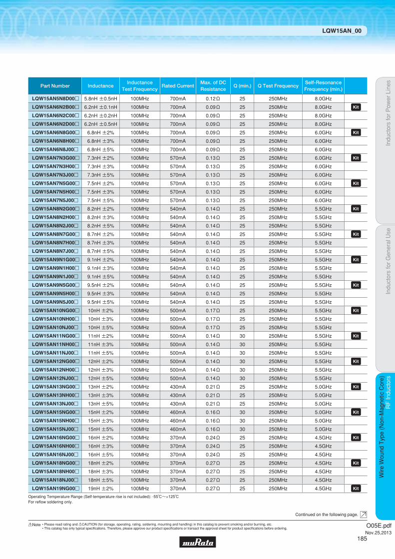
Indu
ctor
s fo
r P
ower
Lin
esIn
duct
ors
for
Gen
eral
Use
RF
Indu
ctor
sR
F In
duct
ors
Wire
Wou
nd T
ype
(Non
-Mag
netic
Cor
e)
LQW15AN_00
Continued on the following page.
Operating Temperature Range (Self-temperature rise is not included): -55℃~+125℃For refl ow soldering only.
Part Number InductanceInductance
Test FrequencyRated Current
Max. of DCResistance
Q (min.) Q Test FrequencySelf-ResonanceFrequency (min.)
LQW15AN5N8D00p 5.8nH ±0.5nH 100MHz 700mA 0.12Ω 25 250MHz 8.0GHz
LQW15AN6N2B00p 6.2nH ±0.1nH 100MHz 700mA 0.09Ω 25 250MHz 8.0GHz LQW15AN6N2C00p 6.2nH ±0.2nH 100MHz 700mA 0.09Ω 25 250MHz 8.0GHz
LQW15AN6N2D00p 6.2nH ±0.5nH 100MHz 700mA 0.09Ω 25 250MHz 8.0GHz
LQW15AN6N8G00p 6.8nH ±2% 100MHz 700mA 0.09Ω 25 250MHz 6.0GHz LQW15AN6N8H00p 6.8nH ±3% 100MHz 700mA 0.09Ω 25 250MHz 6.0GHz
LQW15AN6N8J00p 6.8nH ±5% 100MHz 700mA 0.09Ω 25 250MHz 6.0GHz
LQW15AN7N3G00p 7.3nH ±2% 100MHz 570mA 0.13Ω 25 250MHz 6.0GHz LQW15AN7N3H00p 7.3nH ±3% 100MHz 570mA 0.13Ω 25 250MHz 6.0GHz
LQW15AN7N3J00p 7.3nH ±5% 100MHz 570mA 0.13Ω 25 250MHz 6.0GHz
LQW15AN7N5G00p 7.5nH ±2% 100MHz 570mA 0.13Ω 25 250MHz 6.0GHz LQW15AN7N5H00p 7.5nH ±3% 100MHz 570mA 0.13Ω 25 250MHz 6.0GHz
LQW15AN7N5J00p 7.5nH ±5% 100MHz 570mA 0.13Ω 25 250MHz 6.0GHz
LQW15AN8N2G00p 8.2nH ±2% 100MHz 540mA 0.14Ω 25 250MHz 5.5GHz LQW15AN8N2H00p 8.2nH ±3% 100MHz 540mA 0.14Ω 25 250MHz 5.5GHz
LQW15AN8N2J00p 8.2nH ±5% 100MHz 540mA 0.14Ω 25 250MHz 5.5GHz
LQW15AN8N7G00p 8.7nH ±2% 100MHz 540mA 0.14Ω 25 250MHz 5.5GHz LQW15AN8N7H00p 8.7nH ±3% 100MHz 540mA 0.14Ω 25 250MHz 5.5GHz
LQW15AN8N7J00p 8.7nH ±5% 100MHz 540mA 0.14Ω 25 250MHz 5.5GHz
LQW15AN9N1G00p 9.1nH ±2% 100MHz 540mA 0.14Ω 25 250MHz 5.5GHz LQW15AN9N1H00p 9.1nH ±3% 100MHz 540mA 0.14Ω 25 250MHz 5.5GHz
LQW15AN9N1J00p 9.1nH ±5% 100MHz 540mA 0.14Ω 25 250MHz 5.5GHz
LQW15AN9N5G00p 9.5nH ±2% 100MHz 540mA 0.14Ω 25 250MHz 5.5GHz LQW15AN9N5H00p 9.5nH ±3% 100MHz 540mA 0.14Ω 25 250MHz 5.5GHz
LQW15AN9N5J00p 9.5nH ±5% 100MHz 540mA 0.14Ω 25 250MHz 5.5GHz
LQW15AN10NG00p 10nH ±2% 100MHz 500mA 0.17Ω 25 250MHz 5.5GHz LQW15AN10NH00p 10nH ±3% 100MHz 500mA 0.17Ω 25 250MHz 5.5GHz
LQW15AN10NJ00p 10nH ±5% 100MHz 500mA 0.17Ω 25 250MHz 5.5GHz
LQW15AN11NG00p 11nH ±2% 100MHz 500mA 0.14Ω 30 250MHz 5.5GHz LQW15AN11NH00p 11nH ±3% 100MHz 500mA 0.14Ω 30 250MHz 5.5GHz
LQW15AN11NJ00p 11nH ±5% 100MHz 500mA 0.14Ω 30 250MHz 5.5GHz
LQW15AN12NG00p 12nH ±2% 100MHz 500mA 0.14Ω 30 250MHz 5.5GHz LQW15AN12NH00p 12nH ±3% 100MHz 500mA 0.14Ω 30 250MHz 5.5GHz
LQW15AN12NJ00p 12nH ±5% 100MHz 500mA 0.14Ω 30 250MHz 5.5GHz
LQW15AN13NG00p 13nH ±2% 100MHz 430mA 0.21Ω 25 250MHz 5.0GHz LQW15AN13NH00p 13nH ±3% 100MHz 430mA 0.21Ω 25 250MHz 5.0GHz
LQW15AN13NJ00p 13nH ±5% 100MHz 430mA 0.21Ω 25 250MHz 5.0GHz
LQW15AN15NG00p 15nH ±2% 100MHz 460mA 0.16Ω 30 250MHz 5.0GHz LQW15AN15NH00p 15nH ±3% 100MHz 460mA 0.16Ω 30 250MHz 5.0GHz
LQW15AN15NJ00p 15nH ±5% 100MHz 460mA 0.16Ω 30 250MHz 5.0GHz
LQW15AN16NG00p 16nH ±2% 100MHz 370mA 0.24Ω 25 250MHz 4.5GHz LQW15AN16NH00p 16nH ±3% 100MHz 370mA 0.24Ω 25 250MHz 4.5GHz
LQW15AN16NJ00p 16nH ±5% 100MHz 370mA 0.24Ω 25 250MHz 4.5GHz
LQW15AN18NG00p 18nH ±2% 100MHz 370mA 0.27Ω 25 250MHz 4.5GHz LQW15AN18NH00p 18nH ±3% 100MHz 370mA 0.27Ω 25 250MHz 4.5GHz
LQW15AN18NJ00p 18nH ±5% 100MHz 370mA 0.27Ω 25 250MHz 4.5GHz
LQW15AN19NG00p 19nH ±2% 100MHz 370mA 0.27Ω 25 250MHz 4.5GHz
O05E.pdfNov.25,2013
185
!Note • Please read rating and !CAUTION (for storage, operating, rating, soldering, mounting and handling) in this catalog to prevent smoking and/or burning, etc.• This catalog has only typical specifi cations. Therefore, please approve our product specifi cations or transact the approval sheet for product specifi cations before ordering.

Indu
ctor
s fo
r P
ower
Lin
esIn
duct
ors
for
Gen
eral
Use
RF
Indu
ctor
sR
F In
duct
ors
Wire
Wou
nd T
ype
(Non
-Mag
netic
Cor
e)
LQW15AN_00
Continued on the following page.
Operating Temperature Range (Self-temperature rise is not included): -55℃~+125℃For refl ow soldering only.
Part Number InductanceInductance
Test FrequencyRated Current
Max. of DCResistance
Q (min.) Q Test FrequencySelf-ResonanceFrequency (min.)
LQW15AN19NH00p 19nH ±3% 100MHz 370mA 0.27Ω 25 250MHz 4.5GHz
LQW15AN19NJ00p 19nH ±5% 100MHz 370mA 0.27Ω 25 250MHz 4.5GHz
LQW15AN20NG00p 20nH ±2% 100MHz 370mA 0.27Ω 25 250MHz 4.0GHz LQW15AN20NH00p 20nH ±3% 100MHz 370mA 0.27Ω 25 250MHz 4.0GHz
LQW15AN20NJ00p 20nH ±5% 100MHz 370mA 0.27Ω 25 250MHz 4.0GHz
LQW15AN22NG00p 22nH ±2% 100MHz 310mA 0.30Ω 25 250MHz 4.0GHz LQW15AN22NH00p 22nH ±3% 100MHz 310mA 0.30Ω 25 250MHz 4.0GHz
LQW15AN22NJ00p 22nH ±5% 100MHz 310mA 0.30Ω 25 250MHz 4.0GHz
LQW15AN23NG00p 23nH ±2% 100MHz 310mA 0.30Ω 25 250MHz 3.8GHz LQW15AN23NH00p 23nH ±3% 100MHz 310mA 0.30Ω 25 250MHz 3.8GHz
LQW15AN23NJ00p 23nH ±5% 100MHz 310mA 0.30Ω 25 250MHz 3.8GHz
LQW15AN24NG00p 24nH ±2% 100MHz 280mA 0.52Ω 25 250MHz 3.5GHz LQW15AN24NH00p 24nH ±3% 100MHz 280mA 0.52Ω 25 250MHz 3.5GHz
LQW15AN24NJ00p 24nH ±5% 100MHz 280mA 0.52Ω 25 250MHz 3.5GHz
LQW15AN27NG00p 27nH ±2% 100MHz 280mA 0.52Ω 25 250MHz 3.5GHz LQW15AN27NH00p 27nH ±3% 100MHz 280mA 0.52Ω 25 250MHz 3.5GHz
LQW15AN27NJ00p 27nH ±5% 100MHz 280mA 0.52Ω 25 250MHz 3.5GHz
LQW15AN30NG00p 30nH ±2% 100MHz 270mA 0.58Ω 25 250MHz 3.3GHz LQW15AN30NH00p 30nH ±3% 100MHz 270mA 0.58Ω 25 250MHz 3.3GHz
LQW15AN30NJ00p 30nH ±5% 100MHz 270mA 0.58Ω 25 250MHz 3.3GHz
LQW15AN33NG00p 33nH ±2% 100MHz 260mA 0.63Ω 25 250MHz 3.2GHz LQW15AN33NH00p 33nH ±3% 100MHz 260mA 0.63Ω 25 250MHz 3.2GHz
LQW15AN33NJ00p 33nH ±5% 100MHz 260mA 0.63Ω 25 250MHz 3.2GHz
LQW15AN36NG00p 36nH ±2% 100MHz 260mA 0.63Ω 25 250MHz 3.1GHz LQW15AN36NH00p 36nH ±3% 100MHz 260mA 0.63Ω 25 250MHz 3.1GHz
LQW15AN36NJ00p 36nH ±5% 100MHz 260mA 0.63Ω 25 250MHz 3.1GHz
LQW15AN39NG00p 39nH ±2% 100MHz 250mA 0.70Ω 25 250MHz 3.0GHz LQW15AN39NH00p 39nH ±3% 100MHz 250mA 0.70Ω 25 250MHz 3.0GHz
LQW15AN39NJ00p 39nH ±5% 100MHz 250mA 0.70Ω 25 250MHz 3.0GHz
LQW15AN40NG00p 40nH ±2% 100MHz 250mA 0.70Ω 25 250MHz 3.0GHz LQW15AN40NH00p 40nH ±3% 100MHz 250mA 0.70Ω 25 250MHz 3.0GHz
LQW15AN40NJ00p 40nH ±5% 100MHz 250mA 0.70Ω 25 250MHz 3.0GHz
LQW15AN43NG00p 43nH ±2% 100MHz 250mA 0.70Ω 25 250MHz 3.0GHz LQW15AN43NH00p 43nH ±3% 100MHz 250mA 0.70Ω 25 250MHz 3.0GHz
LQW15AN43NJ00p 43nH ±5% 100MHz 250mA 0.70Ω 25 250MHz 3.0GHz
LQW15AN47NG00p 47nH ±2% 100MHz 210mA 1.08Ω 25 200MHz 2.9GHz LQW15AN47NH00p 47nH ±3% 100MHz 210mA 1.08Ω 25 200MHz 2.9GHz
LQW15AN47NJ00p 47nH ±5% 100MHz 210mA 1.08Ω 25 200MHz 2.9GHz
LQW15AN51NG00p 51nH ±2% 100MHz 210mA 1.08Ω 25 200MHz 2.85GHz LQW15AN51NH00p 51nH ±3% 100MHz 210mA 1.08Ω 25 200MHz 2.85GHz
LQW15AN51NJ00p 51nH ±5% 100MHz 210mA 1.08Ω 25 200MHz 2.85GHz
LQW15AN56NG00p 56nH ±2% 100MHz 200mA 1.17Ω 25 200MHz 2.8GHz LQW15AN56NH00p 56nH ±3% 100MHz 200mA 1.17Ω 25 200MHz 2.8GHz
LQW15AN56NJ00p 56nH ±5% 100MHz 200mA 1.17Ω 25 200MHz 2.8GHz
LQW15AN62NG00p 62nH ±2% 100MHz 145mA 1.82Ω 20 200MHz 2.6GHz LQW15AN62NH00p 62nH ±3% 100MHz 145mA 1.82Ω 20 200MHz 2.6GHz
LQW15AN62NJ00p 62nH ±5% 100MHz 145mA 1.82Ω 20 200MHz 2.6GHz
O05E.pdfNov.25,2013
186
!Note • Please read rating and !CAUTION (for storage, operating, rating, soldering, mounting and handling) in this catalog to prevent smoking and/or burning, etc.• This catalog has only typical specifi cations. Therefore, please approve our product specifi cations or transact the approval sheet for product specifi cations before ordering.

Indu
ctor
s fo
r P
ower
Lin
esIn
duct
ors
for
Gen
eral
Use
RF
Indu
ctor
sR
F In
duct
ors
Wire
Wou
nd T
ype
(Non
-Mag
netic
Cor
e)
LQW15AN_00
c Q-Frequency Characteristics (Typ.) c Inductance-Frequency Characteristics (Typ.)
10 100 1000 10000Frequency (MHz)
140
120
100
80
60
40
20
0
Q
68nH
120nH
22nH
47nH
5.8nH10nH
1.5nH
L (n
H)
Frequency (MHz)
1
10
100
1000
10 1000100 10000
120nH
68nH
47nH
22nH
10nH
5.8nH
1.5nH
Continued on the following page.
Operating Temperature Range (Self-temperature rise is not included): -55℃~+125℃For refl ow soldering only.
Part Number InductanceInductance
Test FrequencyRated Current
Max. of DCResistance
Q (min.) Q Test FrequencySelf-ResonanceFrequency (min.)
LQW15AN68NG00p 68nH ±2% 100MHz 140mA 1.96Ω 20 200MHz 2.5GHz LQW15AN68NJ00p 68nH ±5% 100MHz 140mA 1.96Ω 20 200MHz 2.5GHz
LQW15AN72NG00p 72nH ±2% 100MHz 135mA 2.10Ω 20 150MHz 2.5GHz LQW15AN72NJ00p 72nH ±5% 100MHz 135mA 2.10Ω 20 150MHz 2.5GHz
LQW15AN75NG00p 75nH ±2% 100MHz 135mA 2.10Ω 20 150MHz 2.4GHz LQW15AN75NJ00p 75nH ±5% 100MHz 135mA 2.10Ω 20 150MHz 2.4GHz
LQW15AN82NG00p 82nH ±2% 100MHz 130mA 2.24Ω 20 150MHz 2.3GHz LQW15AN82NJ00p 82nH ±5% 100MHz 130mA 2.24Ω 20 150MHz 2.3GHz
LQW15AN91NG00p 91nH ±2% 100MHz 125mA 2.38Ω 20 150MHz 2.1GHz LQW15AN91NJ00p 91nH ±5% 100MHz 125mA 2.38Ω 20 150MHz 2.1GHz
LQW15ANR10J00p 100nH ±5% 100MHz 120mA 2.52Ω 20 150MHz 1.5GHz LQW15ANR12J00p 120nH ±5% 100MHz 110mA 2.66Ω 20 150MHz 1.0GHz
O05E.pdfNov.25,2013
187
!Note • Please read rating and !CAUTION (for storage, operating, rating, soldering, mounting and handling) in this catalog to prevent smoking and/or burning, etc.• This catalog has only typical specifi cations. Therefore, please approve our product specifi cations or transact the approval sheet for product specifi cations before ordering.

Indu
ctor
s fo
r P
ower
Lin
esIn
duct
ors
for
Gen
eral
Use
RF
Indu
ctor
sR
F In
duct
ors
Wire
Wou
nd T
ype
(Non
-Mag
netic
Cor
e)
LQW15AN_00
c Reference Data
Part Number
LQW15AN1N5
LQW15AN2N4
LQW15AN2N5
LQW15AN2N7
LQW15AN2N9
LQW15AN3N9
LQW15AN4N1
LQW15AN4N3
LQW15AN4N7
LQW15AN5N1
LQW15AN5N8
LQW15AN6N2
LQW15AN6N8
LQW15AN7N3
LQW15AN7N5
LQW15AN8N2
LQW15AN8N7
LQW15AN9N1
LQW15AN9N5
LQW15AN10N
LQW15AN11N
LQW15AN12N
LQW15AN13N
LQW15AN15N
LQW15AN16N
LQW15AN18N
LQW15AN19N
LQW15AN20N
LQW15AN22N
LQW15AN23N
LQW15AN24N
LQW15AN27N
LQW15AN30N
LQW15AN33N
LQW15AN36N
LQW15AN39N
LQW15AN40N
LQW15AN43N
LQW15AN47N
LQW15AN51N
LQW15AN56N
LQW15AN62N
LQW15AN68N
LQW15AN72N
LQW15AN75N
LQW15AN82N
LQW15AN91N
LQW15ANR10
LQW15ANR12
55
65
65
67
53
58
58
58
65
60
63
63
70
58
58
62
60
62
62
60
65
60
60
60
60
63
57
57
55
55
50
55
55
55
52
55
55
55
52
52
53
51
49
49
49
49
52
43
30
800MHz
60
67
67
73
58
61
61
61
67
65
67
65
72
63
63
67
62
68
68
65
70
62
62
65
63
65
62
62
58
58
50
56
58
56
52
56
56
56
54
54
55
52
52
52
52
50
53
43
23
900MHz
90
98
90
100
80
88
88
88
88
85
88
90
96
88
88
90
85
90
90
82
105
85
72
85
90
88
80
80
75
75
42
58
68
53
42
-
-
-
-
-
-
-
-
-
-
-
-
-
-
1.8GHz
100
108
100
105
85
92
92
92
92
90
92
95
100
90
90
95
90
92
92
85
110
90
71
88
100
87
82
82
78
78
-
-
-
-
-
-
-
-
-
-
-
-
-
-
-
-
-
-
-
2.0GHz
115
120
110
120
92
100
100
100
95
95
105
105
103
92
92
102
92
95
95
84
120
91
67
90
110
85
83
83
-
-
-
-
-
-
-
-
-
-
-
-
-
-
-
-
-
-
-
-
-
2.4GHz
Q (Typ.)
LQW15AN_00
1.5
2.4
2.5
2.7
2.9
3.9
4.1
4.3
4.7
5.1
5.8
6.2
6.8
7.3
7.5
8.2
8.7
9.1
9.5
10
11
12
13
15
16
18
19
20
22
23
24
27
30
33
36
39
40
43
47
51
56
62
68
72
75
82
91
100
120
Nominal
Inductance (nH)4991A&16197A
O05E.pdfNov.25,2013
188
!Note • Please read rating and !CAUTION (for storage, operating, rating, soldering, mounting and handling) in this catalog to prevent smoking and/or burning, etc.• This catalog has only typical specifi cations. Therefore, please approve our product specifi cations or transact the approval sheet for product specifi cations before ordering.
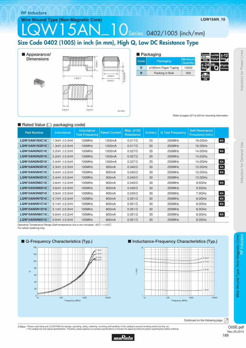
Code PackagingMinimumQuantity
D ø180mm Paper Taping 10000
B Packing in Bulk 500
0.6Thickness
mmmax.
E-12Step
E-24Step
HiQ
TightTolerance
ReflowOK
Low Rdc
Indu
ctor
s fo
r P
ower
Lin
esIn
duct
ors
for
Gen
eral
Use
RF
Indu
ctor
sR
F In
duct
ors
Wire
Wou
nd T
ype
(Non
-Mag
netic
Cor
e)
Wire Wound Type (Non-Magnetic Core) LQW15AN_10
RF Inductors
LQW15AN_10Series 0402/1005 (inch/mm)Size Code 0402 (1005) in inch (in mm), High Q, Low DC Resistance Type
c Q-Frequency Characteristics (Typ.) c Inductance-Frequency Characteristics (Typ.)
c Rated Value (p: packaging code)
Refer to pages 227 to 230 for mounting information.
0.6±0.11.0±0.1
0.5±
0.1
0.10
±0.
05
0.2±0.1 0.2±0.1 (in mm)
0.5±0.1
Continued on the following page.
c Appearance/Dimensions
c Packaging
Operating Temperature Range (Self-temperature rise is not included): -55℃~+125℃For refl ow soldering only.
10 100 1000 10000Frequency (MHz)
140
120
100
80
60
40
20
0
Q
5.6nH4.7nH
3.3nH
1.3nH
10 100 1000 10000Frequency (MHz)
L (n
H)
5.6nH
4.7nH
3.3nH
1.3nH
1
10
Part Number InductanceInductance
Test FrequencyRated Current
Max. of DCResistance
Q (min.) Q Test FrequencySelf-ResonanceFrequency (min.)
LQW15AN1N3C10p 1.3nH ±0.2nH 100MHz 1200mA 0.017Ω 20 250MHz 16.0GHz LQW15AN1N3D10p 1.3nH ±0.5nH 100MHz 1200mA 0.017Ω 20 250MHz 16.0GHz
LQW15AN2N2C10p 2.2nH ±0.2nH 100MHz 1000mA 0.027Ω 25 250MHz 14.0GHz LQW15AN2N2D10p 2.2nH ±0.5nH 100MHz 1000mA 0.027Ω 25 250MHz 14.0GHz
LQW15AN2N4D10p 2.4nH ±0.5nH 100MHz 1000mA 0.027Ω 25 250MHz 14.0GHz LQW15AN3N3D10p 3.3nH ±0.5nH 100MHz 900mA 0.040Ω 30 250MHz 12.0GHz LQW15AN3N4C10p 3.4nH ±0.2nH 100MHz 900mA 0.040Ω 30 250MHz 12.0GHz LQW15AN3N4D10p 3.4nH ±0.5nH 100MHz 900mA 0.040Ω 30 250MHz 12.0GHz
LQW15AN3N6C10p 3.6nH ±0.2nH 100MHz 900mA 0.040Ω 30 250MHz 9.5GHz LQW15AN3N6D10p 3.6nH ±0.5nH 100MHz 900mA 0.040Ω 30 250MHz 9.5GHz
LQW15AN3N9D10p 3.9nH ±0.5nH 100MHz 900mA 0.040Ω 30 250MHz 7.0GHz LQW15AN4N7D10p 4.7nH ±0.5nH 100MHz 800mA 0.051Ω 30 250MHz 8.0GHz LQW15AN5N1C10p 5.1nH ±0.2nH 100MHz 800mA 0.051Ω 30 250MHz 8.0GHz LQW15AN5N1D10p 5.1nH ±0.5nH 100MHz 800mA 0.051Ω 30 250MHz 8.0GHz
LQW15AN5N6C10p 5.6nH ±0.2nH 100MHz 800mA 0.051Ω 30 250MHz 8.0GHz LQW15AN5N6D10p 5.6nH ±0.5nH 100MHz 800mA 0.051Ω 30 250MHz 8.0GHz
O05E.pdfNov.25,2013
189
!Note • Please read rating and !CAUTION (for storage, operating, rating, soldering, mounting and handling) in this catalog to prevent smoking and/or burning, etc.• This catalog has only typical specifi cations. Therefore, please approve our product specifi cations or transact the approval sheet for product specifi cations before ordering.

Indu
ctor
s fo
r P
ower
Lin
esIn
duct
ors
for
Gen
eral
Use
RF
Indu
ctor
sR
F In
duct
ors
Wire
Wou
nd T
ype
(Non
-Mag
netic
Cor
e)
LQW15AN_10
c Reference Data
Part Number
LQW15AN1N3
LQW15AN2N2
LQW15AN2N4
LQW15AN3N3
LQW15AN3N4
LQW15AN3N6
LQW15AN3N9
LQW15AN4N7
LQW15AN5N1
LQW15AN5N6
90
85
80
80
80
73
75
75
75
70
800MHz
95
90
85
85
85
75
80
80
80
75
900MHz
145
130
130
120
120
110
110
113
110
100
1.8GHz
160
140
140
128
128
115
115
120
115
105
2.0GHz
180
160
160
140
140
130
120
132
128
110
2.4GHz
Q (Typ.)
LQW15AN_10
1.3
2.2
2.4
3.3
3.4
3.6
3.9
4.7
5.1
5.6
Nominal
Inductance (nH)4991A&16197A
O05E.pdfNov.25,2013
190
!Note • Please read rating and !CAUTION (for storage, operating, rating, soldering, mounting and handling) in this catalog to prevent smoking and/or burning, etc.• This catalog has only typical specifi cations. Therefore, please approve our product specifi cations or transact the approval sheet for product specifi cations before ordering.

Code PackagingMinimumQuantity
D ø180mm Paper Taping 10000
B Packing in Bulk 500
0.6Thickness
mmmax.
Low Rdc E-12Step
E-24Step
HiQ
TightTolerance
ReflowOK
Indu
ctor
s fo
r P
ower
Lin
esIn
duct
ors
for
Gen
eral
Use
RF
Indu
ctor
sR
F In
duct
ors
Wire
Wou
nd T
ype
(Non
-Mag
netic
Cor
e)
Wire Wound Type (Non-Magnetic Core) LQW15AN_80
RF Inductors
LQW15AN_80Series 0402/1005 (inch/mm)Size Code 0402 (1005) in inch (in mm), Wound Type
c Rated Value (p: packaging code)
Refer to pages 227 to 230 for mounting information.
1.0±0.1
0.5±
0.1
0.6±
0.1
0.1±
0.05
0.2±0.1 0.2±0.1
(in mm)
0.6±0.1
Continued on the following page.
c Appearance/Dimensions
c Packaging
Operating Temperature Range (Self-temperature rise is not included): -55℃~+125℃For refl ow soldering only.
Part Number InductanceInductance
Test FrequencyRated Current
Max. of DCResistance
Q (min.) Q Test FrequencySelf-ResonanceFrequency (min.)
LQW15AN1N3C80p 1.3nH ±0.2nH 100MHz 3150mA 0.012Ω 20 250MHz 18.0GHz LQW15AN1N3D80p 1.3nH ±0.5nH 100MHz 3150mA 0.012Ω 20 250MHz 18.0GHz LQW15AN1N5C80p 1.5nH ±0.2nH 100MHz 2100mA 0.028Ω 20 250MHz 18.0GHz LQW15AN1N5D80p 1.5nH ±0.5nH 100MHz 2100mA 0.028Ω 20 250MHz 18.0GHz LQW15AN1N6C80p 1.6nH ±0.2nH 100MHz 1450mA 0.045Ω 20 250MHz 18.0GHz LQW15AN1N6D80p 1.6nH ±0.5nH 100MHz 1450mA 0.045Ω 20 250MHz 18.0GHz LQW15AN1N7C80p 1.7nH ±0.2nH 100MHz 1150mA 0.065Ω 20 250MHz 18.0GHz LQW15AN1N7D80p 1.7nH ±0.5nH 100MHz 1150mA 0.065Ω 20 250MHz 18.0GHz LQW15AN2N2B80p 2.2nH ±0.1nH 100MHz 2530mA 0.022Ω 30 250MHz 15.5GHz LQW15AN2N2C80p 2.2nH ±0.2nH 100MHz 2530mA 0.022Ω 30 250MHz 15.5GHz LQW15AN2N2D80p 2.2nH ±0.5nH 100MHz 2530mA 0.022Ω 30 250MHz 15.5GHz LQW15AN2N3B80p 2.3nH ±0.1nH 100MHz 2530mA 0.022Ω 30 250MHz 15.5GHz LQW15AN2N3C80p 2.3nH ±0.2nH 100MHz 2530mA 0.022Ω 30 250MHz 15.5GHz LQW15AN2N3D80p 2.3nH ±0.5nH 100MHz 2530mA 0.022Ω 30 250MHz 15.5GHz LQW15AN2N4B80p 2.4nH ±0.1nH 100MHz 2530mA 0.022Ω 30 250MHz 15.5GHz LQW15AN2N4C80p 2.4nH ±0.2nH 100MHz 2530mA 0.022Ω 30 250MHz 15.5GHz LQW15AN2N4D80p 2.4nH ±0.5nH 100MHz 2530mA 0.022Ω 30 250MHz 15.5GHz LQW15AN2N5B80p 2.5nH ±0.1nH 100MHz 2100mA 0.030Ω 30 250MHz 15.5GHz LQW15AN2N5C80p 2.5nH ±0.2nH 100MHz 2100mA 0.030Ω 30 250MHz 15.5GHz LQW15AN2N5D80p 2.5nH ±0.5nH 100MHz 2100mA 0.030Ω 30 250MHz 15.5GHz LQW15AN2N6B80p 2.6nH ±0.1nH 100MHz 1950mA 0.035Ω 30 250MHz 14.5GHz LQW15AN2N6C80p 2.6nH ±0.2nH 100MHz 1950mA 0.035Ω 30 250MHz 14.5GHz LQW15AN2N6D80p 2.6nH ±0.5nH 100MHz 1950mA 0.035Ω 30 250MHz 14.5GHz LQW15AN2N7B80p 2.7nH ±0.1nH 100MHz 1500mA 0.047Ω 28 250MHz 14.0GHz LQW15AN2N7C80p 2.7nH ±0.2nH 100MHz 1500mA 0.047Ω 28 250MHz 14.0GHz LQW15AN2N7D80p 2.7nH ±0.5nH 100MHz 1500mA 0.047Ω 28 250MHz 14.0GHz LQW15AN2N8B80p 2.8nH ±0.1nH 100MHz 1500mA 0.047Ω 27 250MHz 13.5GHz LQW15AN2N8C80p 2.8nH ±0.2nH 100MHz 1500mA 0.047Ω 27 250MHz 13.5GHz LQW15AN2N8D80p 2.8nH ±0.5nH 100MHz 1500mA 0.047Ω 27 250MHz 13.5GHz LQW15AN2N9B80p 2.9nH ±0.1nH 100MHz 1500mA 0.047Ω 25 250MHz 12.5GHz LQW15AN2N9C80p 2.9nH ±0.2nH 100MHz 1500mA 0.047Ω 25 250MHz 12.5GHz LQW15AN2N9D80p 2.9nH ±0.5nH 100MHz 1500mA 0.047Ω 25 250MHz 12.5GHz LQW15AN3N0B80p 3nH ±0.1nH 100MHz 1350mA 0.063Ω 20 250MHz 12.5GHz
O05E.pdfNov.25,2013
191
!Note • Please read rating and !CAUTION (for storage, operating, rating, soldering, mounting and handling) in this catalog to prevent smoking and/or burning, etc.• This catalog has only typical specifi cations. Therefore, please approve our product specifi cations or transact the approval sheet for product specifi cations before ordering.

Indu
ctor
s fo
r P
ower
Lin
esIn
duct
ors
for
Gen
eral
Use
RF
Indu
ctor
sR
F In
duct
ors
Wire
Wou
nd T
ype
(Non
-Mag
netic
Cor
e)
LQW15AN_80
Continued on the following page.
Operating Temperature Range (Self-temperature rise is not included): -55℃~+125℃For refl ow soldering only.
Part Number InductanceInductance
Test FrequencyRated Current
Max. of DCResistance
Q (min.) Q Test FrequencySelf-ResonanceFrequency (min.)
LQW15AN3N0C80p 3nH ±0.2nH 100MHz 1350mA 0.063Ω 20 250MHz 12.5GHz LQW15AN3N0D80p 3nH ±0.5nH 100MHz 1350mA 0.063Ω 20 250MHz 12.5GHz LQW15AN3N3B80p 3.3nH ±0.1nH 100MHz 2000mA 0.030Ω 30 250MHz 14.0GHz LQW15AN3N3C80p 3.3nH ±0.2nH 100MHz 2000mA 0.030Ω 30 250MHz 14.0GHz LQW15AN3N3D80p 3.3nH ±0.5nH 100MHz 2000mA 0.030Ω 30 250MHz 14.0GHz LQW15AN3N4B80p 3.4nH ±0.1nH 100MHz 1950mA 0.030Ω 30 250MHz 10.0GHz LQW15AN3N4C80p 3.4nH ±0.2nH 100MHz 1950mA 0.030Ω 30 250MHz 10.0GHz LQW15AN3N4D80p 3.4nH ±0.5nH 100MHz 1950mA 0.030Ω 30 250MHz 10.0GHz LQW15AN3N5B80p 3.5nH ±0.1nH 100MHz 1950mA 0.030Ω 30 250MHz 10.0GHz LQW15AN3N5C80p 3.5nH ±0.2nH 100MHz 1950mA 0.030Ω 30 250MHz 10.0GHz LQW15AN3N5D80p 3.5nH ±0.5nH 100MHz 1950mA 0.030Ω 30 250MHz 10.0GHz LQW15AN3N6B80p 3.6nH ±0.1nH 100MHz 1950mA 0.030Ω 30 250MHz 10.0GHz LQW15AN3N6C80p 3.6nH ±0.2nH 100MHz 1950mA 0.030Ω 30 250MHz 10.0GHz LQW15AN3N6D80p 3.6nH ±0.5nH 100MHz 1950mA 0.030Ω 30 250MHz 10.0GHz LQW15AN3N7B80p 3.7nH ±0.1nH 100MHz 1950mA 0.030Ω 35 250MHz 10.0GHz LQW15AN3N7C80p 3.7nH ±0.2nH 100MHz 1950mA 0.030Ω 35 250MHz 10.0GHz LQW15AN3N7D80p 3.7nH ±0.5nH 100MHz 1950mA 0.030Ω 35 250MHz 10.0GHz LQW15AN3N8B80p 3.8nH ±0.1nH 100MHz 1950mA 0.030Ω 35 250MHz 10.0GHz LQW15AN3N8C80p 3.8nH ±0.2nH 100MHz 1950mA 0.030Ω 35 250MHz 10.0GHz LQW15AN3N8D80p 3.8nH ±0.5nH 100MHz 1950mA 0.030Ω 35 250MHz 10.0GHz LQW15AN3N9B80p 3.9nH ±0.1nH 100MHz 1950mA 0.030Ω 35 250MHz 10.0GHz LQW15AN3N9C80p 3.9nH ±0.2nH 100MHz 1950mA 0.030Ω 35 250MHz 10.0GHz LQW15AN3N9D80p 3.9nH ±0.5nH 100MHz 1950mA 0.030Ω 35 250MHz 10.0GHz LQW15AN4N0B80p 4.0nH ±0.1nH 100MHz 1950mA 0.030Ω 30 250MHz 10.0GHz LQW15AN4N0C80p 4.0nH ±0.2nH 100MHz 1950mA 0.030Ω 30 250MHz 10.0GHz LQW15AN4N0D80p 4.0nH ±0.5nH 100MHz 1950mA 0.030Ω 30 250MHz 10.0GHz LQW15AN4N1B80p 4.1nH ±0.1nH 100MHz 1800mA 0.044Ω 30 250MHz 9.6GHz LQW15AN4N1C80p 4.1nH ±0.2nH 100MHz 1800mA 0.044Ω 30 250MHz 9.6GHz LQW15AN4N1D80p 4.1nH ±0.5nH 100MHz 1800mA 0.044Ω 30 250MHz 9.6GHz LQW15AN4N2B80p 4.2nH ±0.1nH 100MHz 1800mA 0.044Ω 30 250MHz 9.6GHz LQW15AN4N2C80p 4.2nH ±0.2nH 100MHz 1800mA 0.044Ω 30 250MHz 9.6GHz LQW15AN4N2D80p 4.2nH ±0.5nH 100MHz 1800mA 0.044Ω 30 250MHz 9.6GHz LQW15AN4N3B80p 4.3nH ±0.1nH 100MHz 1800mA 0.044Ω 32 250MHz 9.6GHz LQW15AN4N3C80p 4.3nH ±0.2nH 100MHz 1800mA 0.044Ω 32 250MHz 9.6GHz LQW15AN4N3D80p 4.3nH ±0.5nH 100MHz 1800mA 0.044Ω 32 250MHz 9.6GHz LQW15AN4N4B80p 4.4nH ±0.1nH 100MHz 1600mA 0.052Ω 34 250MHz 9.6GHz LQW15AN4N4C80p 4.4nH ±0.2nH 100MHz 1600mA 0.052Ω 34 250MHz 9.6GHz LQW15AN4N4D80p 4.4nH ±0.5nH 100MHz 1600mA 0.052Ω 34 250MHz 9.6GHz LQW15AN4N5B80p 4.5nH ±0.1nH 100MHz 1450mA 0.060Ω 34 250MHz 9.6GHz LQW15AN4N5C80p 4.5nH ±0.2nH 100MHz 1450mA 0.060Ω 34 250MHz 9.6GHz LQW15AN4N5D80p 4.5nH ±0.5nH 100MHz 1450mA 0.060Ω 34 250MHz 9.6GHz LQW15AN4N6B80p 4.6nH ±0.1nH 100MHz 1450mA 0.060Ω 32 250MHz 9.6GHz LQW15AN4N6C80p 4.6nH ±0.2nH 100MHz 1450mA 0.060Ω 32 250MHz 9.6GHz LQW15AN4N6D80p 4.6nH ±0.5nH 100MHz 1450mA 0.060Ω 32 250MHz 9.6GHz LQW15AN4N7B80p 4.7nH ±0.1nH 100MHz 1200mA 0.071Ω 31 250MHz 8.0GHz LQW15AN4N7C80p 4.7nH ±0.2nH 100MHz 1200mA 0.071Ω 31 250MHz 8.0GHz LQW15AN4N7D80p 4.7nH ±0.5nH 100MHz 1200mA 0.071Ω 31 250MHz 8.0GHz LQW15AN4N8B80p 4.8nH ±0.1nH 100MHz 1200mA 0.071Ω 30 250MHz 8.0GHz
O05E.pdfNov.25,2013
192
!Note • Please read rating and !CAUTION (for storage, operating, rating, soldering, mounting and handling) in this catalog to prevent smoking and/or burning, etc.• This catalog has only typical specifi cations. Therefore, please approve our product specifi cations or transact the approval sheet for product specifi cations before ordering.
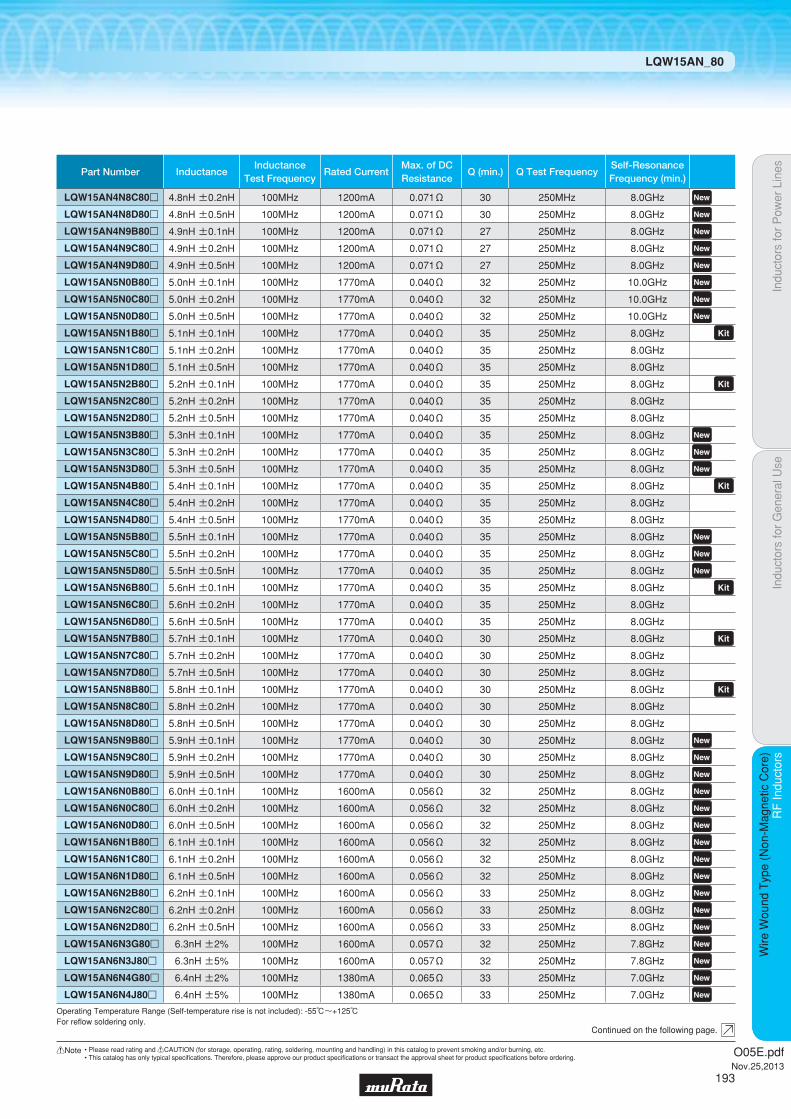
Indu
ctor
s fo
r P
ower
Lin
esIn
duct
ors
for
Gen
eral
Use
RF
Indu
ctor
sR
F In
duct
ors
Wire
Wou
nd T
ype
(Non
-Mag
netic
Cor
e)
LQW15AN_80
Continued on the following page.
Operating Temperature Range (Self-temperature rise is not included): -55℃~+125℃For refl ow soldering only.
Part Number InductanceInductance
Test FrequencyRated Current
Max. of DCResistance
Q (min.) Q Test FrequencySelf-ResonanceFrequency (min.)
LQW15AN4N8C80p 4.8nH ±0.2nH 100MHz 1200mA 0.071Ω 30 250MHz 8.0GHz LQW15AN4N8D80p 4.8nH ±0.5nH 100MHz 1200mA 0.071Ω 30 250MHz 8.0GHz LQW15AN4N9B80p 4.9nH ±0.1nH 100MHz 1200mA 0.071Ω 27 250MHz 8.0GHz LQW15AN4N9C80p 4.9nH ±0.2nH 100MHz 1200mA 0.071Ω 27 250MHz 8.0GHz LQW15AN4N9D80p 4.9nH ±0.5nH 100MHz 1200mA 0.071Ω 27 250MHz 8.0GHz LQW15AN5N0B80p 5.0nH ±0.1nH 100MHz 1770mA 0.040Ω 32 250MHz 10.0GHz LQW15AN5N0C80p 5.0nH ±0.2nH 100MHz 1770mA 0.040Ω 32 250MHz 10.0GHz LQW15AN5N0D80p 5.0nH ±0.5nH 100MHz 1770mA 0.040Ω 32 250MHz 10.0GHz LQW15AN5N1B80p 5.1nH ±0.1nH 100MHz 1770mA 0.040Ω 35 250MHz 8.0GHz LQW15AN5N1C80p 5.1nH ±0.2nH 100MHz 1770mA 0.040Ω 35 250MHz 8.0GHz LQW15AN5N1D80p 5.1nH ±0.5nH 100MHz 1770mA 0.040Ω 35 250MHz 8.0GHz LQW15AN5N2B80p 5.2nH ±0.1nH 100MHz 1770mA 0.040Ω 35 250MHz 8.0GHz LQW15AN5N2C80p 5.2nH ±0.2nH 100MHz 1770mA 0.040Ω 35 250MHz 8.0GHz LQW15AN5N2D80p 5.2nH ±0.5nH 100MHz 1770mA 0.040Ω 35 250MHz 8.0GHz LQW15AN5N3B80p 5.3nH ±0.1nH 100MHz 1770mA 0.040Ω 35 250MHz 8.0GHz LQW15AN5N3C80p 5.3nH ±0.2nH 100MHz 1770mA 0.040Ω 35 250MHz 8.0GHz LQW15AN5N3D80p 5.3nH ±0.5nH 100MHz 1770mA 0.040Ω 35 250MHz 8.0GHz LQW15AN5N4B80p 5.4nH ±0.1nH 100MHz 1770mA 0.040Ω 35 250MHz 8.0GHz LQW15AN5N4C80p 5.4nH ±0.2nH 100MHz 1770mA 0.040Ω 35 250MHz 8.0GHz LQW15AN5N4D80p 5.4nH ±0.5nH 100MHz 1770mA 0.040Ω 35 250MHz 8.0GHz LQW15AN5N5B80p 5.5nH ±0.1nH 100MHz 1770mA 0.040Ω 35 250MHz 8.0GHz LQW15AN5N5C80p 5.5nH ±0.2nH 100MHz 1770mA 0.040Ω 35 250MHz 8.0GHz LQW15AN5N5D80p 5.5nH ±0.5nH 100MHz 1770mA 0.040Ω 35 250MHz 8.0GHz LQW15AN5N6B80p 5.6nH ±0.1nH 100MHz 1770mA 0.040Ω 35 250MHz 8.0GHz LQW15AN5N6C80p 5.6nH ±0.2nH 100MHz 1770mA 0.040Ω 35 250MHz 8.0GHz LQW15AN5N6D80p 5.6nH ±0.5nH 100MHz 1770mA 0.040Ω 35 250MHz 8.0GHz LQW15AN5N7B80p 5.7nH ±0.1nH 100MHz 1770mA 0.040Ω 30 250MHz 8.0GHz LQW15AN5N7C80p 5.7nH ±0.2nH 100MHz 1770mA 0.040Ω 30 250MHz 8.0GHz LQW15AN5N7D80p 5.7nH ±0.5nH 100MHz 1770mA 0.040Ω 30 250MHz 8.0GHz LQW15AN5N8B80p 5.8nH ±0.1nH 100MHz 1770mA 0.040Ω 30 250MHz 8.0GHz LQW15AN5N8C80p 5.8nH ±0.2nH 100MHz 1770mA 0.040Ω 30 250MHz 8.0GHz LQW15AN5N8D80p 5.8nH ±0.5nH 100MHz 1770mA 0.040Ω 30 250MHz 8.0GHz LQW15AN5N9B80p 5.9nH ±0.1nH 100MHz 1770mA 0.040Ω 30 250MHz 8.0GHz LQW15AN5N9C80p 5.9nH ±0.2nH 100MHz 1770mA 0.040Ω 30 250MHz 8.0GHz LQW15AN5N9D80p 5.9nH ±0.5nH 100MHz 1770mA 0.040Ω 30 250MHz 8.0GHz LQW15AN6N0B80p 6.0nH ±0.1nH 100MHz 1600mA 0.056Ω 32 250MHz 8.0GHz LQW15AN6N0C80p 6.0nH ±0.2nH 100MHz 1600mA 0.056Ω 32 250MHz 8.0GHz LQW15AN6N0D80p 6.0nH ±0.5nH 100MHz 1600mA 0.056Ω 32 250MHz 8.0GHz LQW15AN6N1B80p 6.1nH ±0.1nH 100MHz 1600mA 0.056Ω 32 250MHz 8.0GHz LQW15AN6N1C80p 6.1nH ±0.2nH 100MHz 1600mA 0.056Ω 32 250MHz 8.0GHz LQW15AN6N1D80p 6.1nH ±0.5nH 100MHz 1600mA 0.056Ω 32 250MHz 8.0GHz LQW15AN6N2B80p 6.2nH ±0.1nH 100MHz 1600mA 0.056Ω 33 250MHz 8.0GHz LQW15AN6N2C80p 6.2nH ±0.2nH 100MHz 1600mA 0.056Ω 33 250MHz 8.0GHz LQW15AN6N2D80p 6.2nH ±0.5nH 100MHz 1600mA 0.056Ω 33 250MHz 8.0GHz LQW15AN6N3G80p 6.3nH ±2% 100MHz 1600mA 0.057Ω 32 250MHz 7.8GHz LQW15AN6N3J80p 6.3nH ±5% 100MHz 1600mA 0.057Ω 32 250MHz 7.8GHz LQW15AN6N4G80p 6.4nH ±2% 100MHz 1380mA 0.065Ω 33 250MHz 7.0GHz LQW15AN6N4J80p 6.4nH ±5% 100MHz 1380mA 0.065Ω 33 250MHz 7.0GHz
O05E.pdfNov.25,2013
193
!Note • Please read rating and !CAUTION (for storage, operating, rating, soldering, mounting and handling) in this catalog to prevent smoking and/or burning, etc.• This catalog has only typical specifi cations. Therefore, please approve our product specifi cations or transact the approval sheet for product specifi cations before ordering.

Indu
ctor
s fo
r P
ower
Lin
esIn
duct
ors
for
Gen
eral
Use
RF
Indu
ctor
sR
F In
duct
ors
Wire
Wou
nd T
ype
(Non
-Mag
netic
Cor
e)
LQW15AN_80
Continued on the following page.
Operating Temperature Range (Self-temperature rise is not included): -55℃~+125℃For refl ow soldering only.
Part Number InductanceInductance
Test FrequencyRated Current
Max. of DCResistance
Q (min.) Q Test FrequencySelf-ResonanceFrequency (min.)
LQW15AN6N5G80p 6.5nH ±2% 100MHz 1380mA 0.065Ω 32 250MHz 7.0GHz LQW15AN6N5J80p 6.5nH ±5% 100MHz 1380mA 0.065Ω 32 250MHz 7.0GHz LQW15AN6N6G80p 6.6nH ±2% 100MHz 1280mA 0.078Ω 30 250MHz 7.0GHz LQW15AN6N6J80p 6.6nH ±5% 100MHz 1280mA 0.078Ω 30 250MHz 7.0GHz LQW15AN6N7G80p 6.7nH ±2% 100MHz 1280mA 0.078Ω 30 250MHz 7.0GHz LQW15AN6N7J80p 6.7nH ±5% 100MHz 1280mA 0.078Ω 30 250MHz 7.0GHz LQW15AN6N8G80p 6.8nH ±2% 100MHz 1450mA 0.068Ω 30 250MHz 7.0GHz LQW15AN6N8J80p 6.8nH ±5% 100MHz 1450mA 0.068Ω 30 250MHz 7.0GHz LQW15AN6N9G80p 6.9nH ±2% 100MHz 1420mA 0.069Ω 32 250MHz 8.5GHz LQW15AN6N9J80p 6.9nH ±5% 100MHz 1420mA 0.069Ω 32 250MHz 8.5GHz LQW15AN7N0G80p 7.0nH ±2% 100MHz 1420mA 0.069Ω 33 250MHz 8.0GHz LQW15AN7N0J80p 7.0nH ±5% 100MHz 1420mA 0.069Ω 33 250MHz 8.0GHz LQW15AN7N1G80p 7.1nH ±2% 100MHz 1420mA 0.069Ω 32 250MHz 7.0GHz LQW15AN7N1J80p 7.1nH ±5% 100MHz 1420mA 0.069Ω 32 250MHz 7.0GHz LQW15AN7N2G80p 7.2nH ±2% 100MHz 1700mA 0.050Ω 32 250MHz 7.0GHz LQW15AN7N2J80p 7.2nH ±5% 100MHz 1700mA 0.050Ω 32 250MHz 7.0GHz LQW15AN7N3G80p 7.3nH ±2% 100MHz 1700mA 0.050Ω 32 250MHz 7.0GHz LQW15AN7N3J80p 7.3nH ±5% 100MHz 1700mA 0.050Ω 32 250MHz 7.0GHz LQW15AN7N4G80p 7.4nH ±2% 100MHz 1700mA 0.050Ω 30 250MHz 7.0GHz LQW15AN7N4J80p 7.4nH ±5% 100MHz 1700mA 0.050Ω 30 250MHz 7.0GHz LQW15AN7N5G80p 7.5nH ±2% 100MHz 1700mA 0.050Ω 35 250MHz 7.0GHz LQW15AN7N5J80p 7.5nH ±5% 100MHz 1700mA 0.050Ω 35 250MHz 7.0GHz LQW15AN7N6G80p 7.6nH ±2% 100MHz 1700mA 0.050Ω 30 250MHz 7.0GHz LQW15AN7N6J80p 7.6nH ±5% 100MHz 1700mA 0.050Ω 30 250MHz 7.0GHz LQW15AN7N7G80p 7.7nH ±2% 100MHz 1700mA 0.050Ω 30 250MHz 7.0GHz LQW15AN7N7J80p 7.7nH ±5% 100MHz 1700mA 0.050Ω 30 250MHz 7.0GHz LQW15AN7N8G80p 7.8nH ±2% 100MHz 1700mA 0.050Ω 30 250MHz 7.0GHz LQW15AN7N8J80p 7.8nH ±5% 100MHz 1700mA 0.050Ω 30 250MHz 7.0GHz LQW15AN7N9G80p 7.9nH ±2% 100MHz 1700mA 0.050Ω 30 250MHz 7.0GHz LQW15AN7N9J80p 7.9nH ±5% 100MHz 1700mA 0.050Ω 30 250MHz 7.0GHz LQW15AN8N0G80p 8.0nH ±2% 100MHz 1700mA 0.050Ω 30 250MHz 7.0GHz LQW15AN8N0J80p 8.0nH ±5% 100MHz 1700mA 0.050Ω 30 250MHz 7.0GHz LQW15AN8N1G80p 8.1nH ±2% 100MHz 1500mA 0.069Ω 32 250MHz 6.5GHz LQW15AN8N1J80p 8.1nH ±5% 100MHz 1500mA 0.069Ω 32 250MHz 6.5GHz LQW15AN8N2G80p 8.2nH ±2% 100MHz 1500mA 0.069Ω 32 250MHz 6.5GHz LQW15AN8N2J80p 8.2nH ±5% 100MHz 1500mA 0.069Ω 32 250MHz 6.5GHz LQW15AN8N3G80p 8.3nH ±2% 100MHz 1500mA 0.069Ω 32 250MHz 6.5GHz LQW15AN8N3J80p 8.3nH ±5% 100MHz 1500mA 0.069Ω 32 250MHz 6.5GHz LQW15AN8N4G80p 8.4nH ±2% 100MHz 1500mA 0.069Ω 32 250MHz 6.5GHz LQW15AN8N4J80p 8.4nH ±5% 100MHz 1500mA 0.069Ω 32 250MHz 6.5GHz LQW15AN8N5G80p 8.5nH ±2% 100MHz 1500mA 0.069Ω 32 250MHz 6.5GHz LQW15AN8N5J80p 8.5nH ±5% 100MHz 1500mA 0.069Ω 32 250MHz 6.5GHz LQW15AN8N6G80p 8.6nH ±2% 100MHz 1420mA 0.070Ω 31 250MHz 6.5GHz LQW15AN8N6J80p 8.6nH ±5% 100MHz 1420mA 0.070Ω 31 250MHz 6.5GHz LQW15AN8N7G80p 8.7nH ±2% 100MHz 1420mA 0.070Ω 31 250MHz 6.5GHz LQW15AN8N7J80p 8.7nH ±5% 100MHz 1420mA 0.070Ω 31 250MHz 6.5GHz LQW15AN8N8G80p 8.8nH ±2% 100MHz 1420mA 0.070Ω 31 250MHz 6.5GHz LQW15AN8N8J80p 8.8nH ±5% 100MHz 1420mA 0.070Ω 31 250MHz 6.5GHz
O05E.pdfNov.25,2013
194
!Note • Please read rating and !CAUTION (for storage, operating, rating, soldering, mounting and handling) in this catalog to prevent smoking and/or burning, etc.• This catalog has only typical specifi cations. Therefore, please approve our product specifi cations or transact the approval sheet for product specifi cations before ordering.

Indu
ctor
s fo
r P
ower
Lin
esIn
duct
ors
for
Gen
eral
Use
RF
Indu
ctor
sR
F In
duct
ors
Wire
Wou
nd T
ype
(Non
-Mag
netic
Cor
e)
LQW15AN_80
Continued on the following page.
Operating Temperature Range (Self-temperature rise is not included): -55℃~+125℃For refl ow soldering only.
Part Number InductanceInductance
Test FrequencyRated Current
Max. of DCResistance
Q (min.) Q Test FrequencySelf-ResonanceFrequency (min.)
LQW15AN8N9G80p 8.9nH ±2% 100MHz 1420mA 0.070Ω 31 250MHz 6.5GHz LQW15AN8N9J80p 8.9nH ±5% 100MHz 1420mA 0.070Ω 31 250MHz 6.5GHz LQW15AN9N0G80p 9nH ±2% 100MHz 1420mA 0.070Ω 30 250MHz 6.5GHz LQW15AN9N0J80p 9nH ±5% 100MHz 1420mA 0.070Ω 30 250MHz 6.5GHz LQW15AN9N1G80p 9.1nH ±2% 100MHz 1400mA 0.080Ω 32 250MHz 6.5GHz LQW15AN9N1J80p 9.1nH ±5% 100MHz 1400mA 0.080Ω 32 250MHz 6.5GHz LQW15AN9N2G80p 9.2nH ±2% 100MHz 1400mA 0.081Ω 32 250MHz 6.0GHz LQW15AN9N2J80p 9.2nH ±5% 100MHz 1400mA 0.081Ω 32 250MHz 6.0GHz LQW15AN9N3G80p 9.3nH ±2% 100MHz 1400mA 0.081Ω 34 250MHz 6.0GHz LQW15AN9N3J80p 9.3nH ±5% 100MHz 1400mA 0.081Ω 34 250MHz 6.0GHz LQW15AN9N4G80p 9.4nH ±2% 100MHz 1400mA 0.081Ω 33 250MHz 6.0GHz LQW15AN9N4J80p 9.4nH ±5% 100MHz 1400mA 0.081Ω 33 250MHz 6.0GHz LQW15AN9N5G80p 9.5nH ±2% 100MHz 1400mA 0.081Ω 32 250MHz 6.0GHz LQW15AN9N5J80p 9.5nH ±5% 100MHz 1400mA 0.081Ω 32 250MHz 6.0GHz LQW15AN9N6G80p 9.6nH ±2% 100MHz 1400mA 0.081Ω 33 250MHz 6.0GHz LQW15AN9N6J80p 9.6nH ±5% 100MHz 1400mA 0.081Ω 33 250MHz 6.0GHz LQW15AN9N7G80p 9.7nH ±2% 100MHz 1400mA 0.081Ω 33 250MHz 6.0GHz LQW15AN9N7J80p 9.7nH ±5% 100MHz 1400mA 0.081Ω 33 250MHz 6.0GHz LQW15AN9N8G80p 9.8nH ±2% 100MHz 1400mA 0.081Ω 34 250MHz 6.0GHz LQW15AN9N8J80p 9.8nH ±5% 100MHz 1400mA 0.081Ω 34 250MHz 6.0GHz LQW15AN9N9G80p 9.9nH ±2% 100MHz 1400mA 0.081Ω 32 250MHz 6.0GHz LQW15AN9N9J80p 9.9nH ±5% 100MHz 1400mA 0.081Ω 32 250MHz 6.0GHz LQW15AN10NG80p 10nH ±2% 100MHz 1400mA 0.081Ω 31 250MHz 6.0GHz LQW15AN10NJ80p 10nH ±5% 100MHz 1400mA 0.081Ω 31 250MHz 6.0GHz LQW15AN11NG80p 11nH ±2% 100MHz 1400mA 0.083Ω 32 250MHz 6.2GHz LQW15AN11NJ80p 11nH ±5% 100MHz 1400mA 0.083Ω 32 250MHz 6.2GHz LQW15AN12NG80p 12nH ±2% 100MHz 1240mA 0.093Ω 30 250MHz 5.2GHz LQW15AN12NJ80p 12nH ±5% 100MHz 1240mA 0.093Ω 30 250MHz 5.2GHz LQW15AN13NG80p 13nH ±2% 100MHz 1240mA 0.093Ω 30 250MHz 5.2GHz LQW15AN13NJ80p 13nH ±5% 100MHz 1240mA 0.093Ω 30 250MHz 5.2GHz LQW15AN14NG80p 14nH ±2% 100MHz 1150mA 0.111Ω 31 250MHz 5.2GHz LQW15AN14NJ80p 14nH ±5% 100MHz 1150mA 0.111Ω 31 250MHz 5.2GHz LQW15AN15NG80p 15nH ±2% 100MHz 1150mA 0.114Ω 31 250MHz 5.5GHz LQW15AN15NJ80p 15nH ±5% 100MHz 1150mA 0.114Ω 31 250MHz 5.5GHz LQW15AN16NG80p 16nH ±2% 100MHz 1000mA 0.126Ω 31 250MHz 5.0GHz LQW15AN16NJ80p 16nH ±5% 100MHz 1000mA 0.126Ω 31 250MHz 5.0GHz LQW15AN17NG80p 17nH ±2% 100MHz 1000mA 0.126Ω 30 250MHz 5.0GHz LQW15AN17NJ80p 17nH ±5% 100MHz 1000mA 0.126Ω 30 250MHz 5.0GHz LQW15AN18NG80p 18nH ±2% 100MHz 1050mA 0.130Ω 30 250MHz 5.2GHz LQW15AN18NJ80p 18nH ±5% 100MHz 1050mA 0.130Ω 30 250MHz 5.2GHz LQW15AN19NG80p 19nH ±2% 100MHz 920mA 0.156Ω 30 250MHz 5.0GHz LQW15AN19NJ80p 19nH ±5% 100MHz 920mA 0.156Ω 30 250MHz 5.0GHz LQW15AN20NG80p 20nH ±2% 100MHz 800mA 0.186Ω 30 250MHz 4.5GHz LQW15AN20NJ80p 20nH ±5% 100MHz 800mA 0.186Ω 30 250MHz 4.5GHz LQW15AN21NG80p 21nH ±2% 100MHz 780mA 0.202Ω 30 250MHz 4.5GHz LQW15AN21NJ80p 21nH ±5% 100MHz 780mA 0.202Ω 30 250MHz 4.5GHz LQW15AN22NG80p 22nH ±2% 100MHz 780mA 0.202Ω 30 250MHz 4.5GHz LQW15AN22NJ80p 22nH ±5% 100MHz 780mA 0.202Ω 30 250MHz 4.5GHz
O05E.pdfNov.25,2013
195
!Note • Please read rating and !CAUTION (for storage, operating, rating, soldering, mounting and handling) in this catalog to prevent smoking and/or burning, etc.• This catalog has only typical specifi cations. Therefore, please approve our product specifi cations or transact the approval sheet for product specifi cations before ordering.
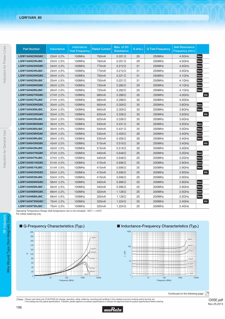
Indu
ctor
s fo
r P
ower
Lin
esIn
duct
ors
for
Gen
eral
Use
RF
Indu
ctor
sR
F In
duct
ors
Wire
Wou
nd T
ype
(Non
-Mag
netic
Cor
e)
LQW15AN_80
c Q-Frequency Characteristics (Typ.) c Inductance-Frequency Characteristics (Typ.)
0
60
100
160
20
40
80
120
180
140
200
1 10 100 1000 10000Frequency (MHz)
Q
1.3nH
5.6nH
3.6nH
27nH
10nH
43nH
75nH
L (
nH)
Frequency (MHz)
1
10
100
1000
1 100010010 10000
75nH
43nH
27nH
10nH
5.6nH
3.6nH
1.3nH
Continued on the following page.
Operating Temperature Range (Self-temperature rise is not included): -55℃~+125℃For refl ow soldering only.
Part Number InductanceInductance
Test FrequencyRated Current
Max. of DCResistance
Q (min.) Q Test FrequencySelf-ResonanceFrequency (min.)
LQW15AN23NG80p 23nH ±2% 100MHz 760mA 0.201Ω 29 250MHz 4.5GHz LQW15AN23NJ80p 23nH ±5% 100MHz 760mA 0.201Ω 29 250MHz 4.5GHz LQW15AN24NG80p 24nH ±2% 100MHz 770mA 0.212Ω 31 250MHz 4.0GHz LQW15AN24NJ80p 24nH ±5% 100MHz 770mA 0.212Ω 31 250MHz 4.0GHz LQW15AN25NG80p 25nH ±2% 100MHz 750mA 0.221Ω 31 250MHz 4.1GHz LQW15AN25NJ80p 25nH ±5% 100MHz 750mA 0.221Ω 31 250MHz 4.1GHz LQW15AN26NG80p 26nH ±2% 100MHz 720mA 0.282Ω 29 250MHz 4.1GHz LQW15AN26NJ80p 26nH ±5% 100MHz 720mA 0.282Ω 29 250MHz 4.1GHz LQW15AN27NG80p 27nH ±2% 100MHz 680mA 0.288Ω 30 250MHz 4.0GHz LQW15AN27NJ80p 27nH ±5% 100MHz 680mA 0.288Ω 30 250MHz 4.0GHz LQW15AN30NG80p 30nH ±2% 100MHz 660mA 0.309Ω 30 250MHz 3.8GHz LQW15AN30NJ80p 30nH ±5% 100MHz 660mA 0.309Ω 30 250MHz 3.8GHz LQW15AN33NG80p 33nH ±2% 100MHz 620mA 0.336Ω 30 250MHz 3.6GHz LQW15AN33NJ80p 33nH ±5% 100MHz 620mA 0.336Ω 30 250MHz 3.6GHz LQW15AN36NG80p 36nH ±2% 100MHz 540mA 0.431Ω 30 250MHz 3.5GHz LQW15AN36NJ80p 36nH ±5% 100MHz 540mA 0.431Ω 30 250MHz 3.5GHz LQW15AN39NG80p 39nH ±2% 100MHz 530mA 0.456Ω 28 250MHz 3.4GHz LQW15AN39NJ80p 39nH ±5% 100MHz 530mA 0.456Ω 28 250MHz 3.4GHz LQW15AN43NG80p 43nH ±2% 100MHz 515mA 0.516Ω 30 250MHz 3.4GHz LQW15AN43NJ80p 43nH ±5% 100MHz 515mA 0.516Ω 30 250MHz 3.4GHz LQW15AN47NG80p 47nH ±2% 100MHz 440mA 0.648Ω 25 200MHz 3.2GHz LQW15AN47NJ80p 47nH ±5% 100MHz 440mA 0.648Ω 25 200MHz 3.2GHz LQW15AN51NG80p 51nH ±2% 100MHz 415mA 0.696Ω 25 200MHz 2.9GHz LQW15AN51NJ80p 51nH ±5% 100MHz 415mA 0.696Ω 25 200MHz 2.9GHz LQW15AN53NG80p 53nH ±2% 100MHz 415mA 0.696Ω 25 200MHz 2.9GHz LQW15AN53NJ80p 53nH ±5% 100MHz 415mA 0.696Ω 25 200MHz 2.9GHz LQW15AN56NG80p 56nH ±2% 100MHz 340mA 0.996Ω 25 200MHz 2.9GHz LQW15AN56NJ80p 56nH ±5% 100MHz 340mA 0.996Ω 25 200MHz 2.9GHz LQW15AN68NG80p 68nH ±2% 100MHz 320mA 1.128Ω 25 200MHz 2.5GHz LQW15AN68NJ80p 68nH ±5% 100MHz 320mA 1.128Ω 25 200MHz 2.5GHz LQW15AN75NG80p 75nH ±2% 100MHz 320mA 1.224Ω 25 200MHz 2.4GHz LQW15AN75NJ80p 75nH ±5% 100MHz 320mA 1.224Ω 25 200MHz 2.4GHz
O05E.pdfNov.25,2013
196
!Note • Please read rating and !CAUTION (for storage, operating, rating, soldering, mounting and handling) in this catalog to prevent smoking and/or burning, etc.• This catalog has only typical specifi cations. Therefore, please approve our product specifi cations or transact the approval sheet for product specifi cations before ordering.
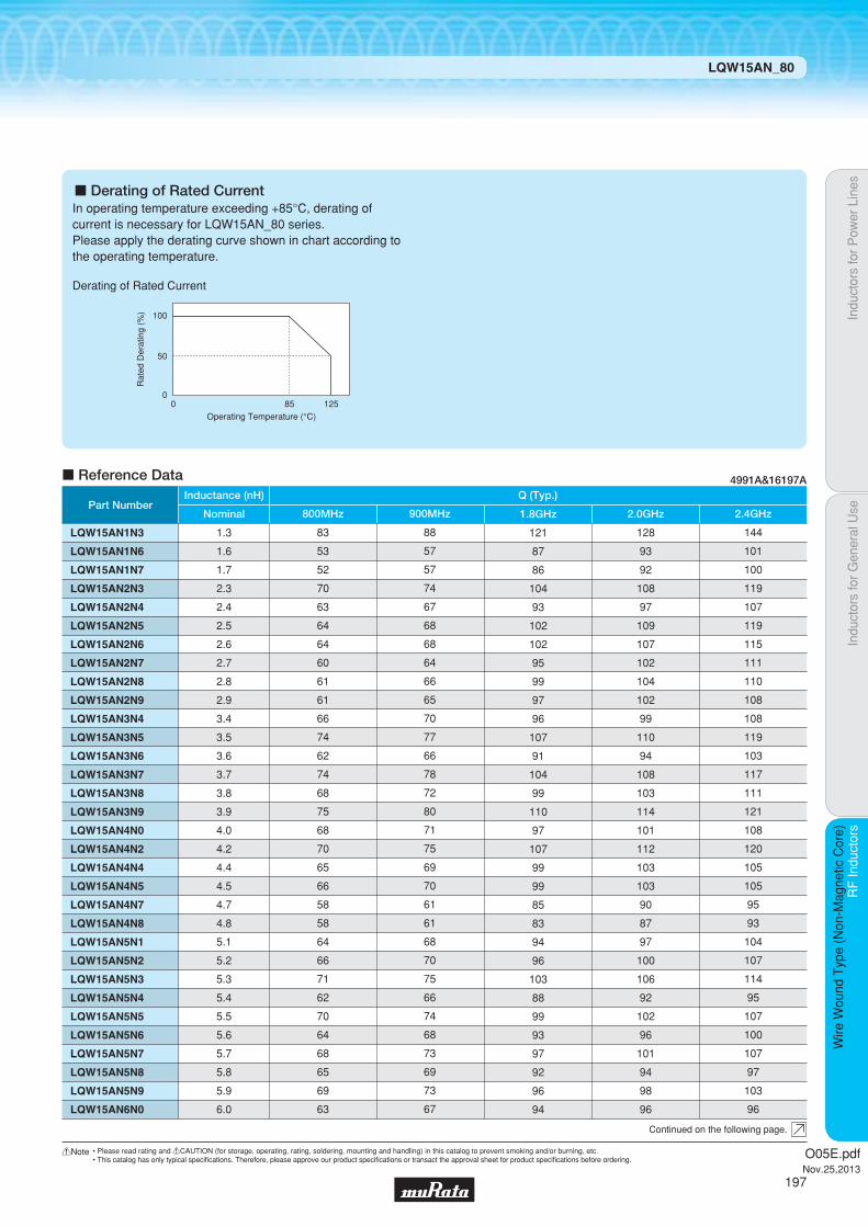
Indu
ctor
s fo
r P
ower
Lin
esIn
duct
ors
for
Gen
eral
Use
RF
Indu
ctor
sR
F In
duct
ors
Wire
Wou
nd T
ype
(Non
-Mag
netic
Cor
e)
LQW15AN_80
Continued on the following page.
c Reference Data
Part Number
LQW15AN1N3
LQW15AN1N6
LQW15AN1N7
LQW15AN2N3
LQW15AN2N4
LQW15AN2N5
LQW15AN2N6
LQW15AN2N7
LQW15AN2N8
LQW15AN2N9
LQW15AN3N4
LQW15AN3N5
LQW15AN3N6
LQW15AN3N7
LQW15AN3N8
LQW15AN3N9
LQW15AN4N0
LQW15AN4N2
LQW15AN4N4
LQW15AN4N5
LQW15AN4N7
LQW15AN4N8
LQW15AN5N1
LQW15AN5N2
LQW15AN5N3
LQW15AN5N4
LQW15AN5N5
LQW15AN5N6
LQW15AN5N7
LQW15AN5N8
LQW15AN5N9
LQW15AN6N0
1.3
1.6
1.7
2.3
2.4
2.5
2.6
2.7
2.8
2.9
3.4
3.5
3.6
3.7
3.8
3.9
4.0
4.2
4.4
4.5
4.7
4.8
5.1
5.2
5.3
5.4
5.5
5.6
5.7
5.8
5.9
6.0
Nominal
83
53
52
70
63
64
64
60
61
61
66
74
62
74
68
75
68
70
65
66
58
58
64
66
71
62
70
64
68
65
69
63
800MHz
88
57
57
74
67
68
68
64
66
65
70
77
66
78
72
80
71
75
69
70
61
61
68
70
75
66
74
68
73
69
73
67
900MHz
121
87
86
104
93
102
102
95
99
97
96
107
91
104
99
110
97
107
99
99
85
83
94
96
103
88
99
93
97
92
96
94
1.8GHz
128
93
92
108
97
109
107
102
104
102
99
110
94
108
103
114
101
112
103
103
90
87
97
100
106
92
102
96
101
94
98
96
2.0GHz
144
101
100
119
107
119
115
111
110
108
108
119
103
117
111
121
108
120
105
105
95
93
104
107
114
95
107
100
107
97
103
96
2.4GHz
Inductance (nH) Q (Typ.)4991A&16197A
c Derating of Rated CurrentIn operating temperature exceeding +85°C, derating of current is necessary for LQW15AN_80 series.Please apply the derating curve shown in chart according to the operating temperature.
Derating of Rated Current
100
50
0125850
Rat
ed D
erat
ing
(%)
Operating Temperature (°C)
O05E.pdfNov.25,2013
197
!Note • Please read rating and !CAUTION (for storage, operating, rating, soldering, mounting and handling) in this catalog to prevent smoking and/or burning, etc.• This catalog has only typical specifi cations. Therefore, please approve our product specifi cations or transact the approval sheet for product specifi cations before ordering.
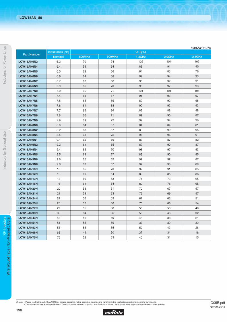
Indu
ctor
s fo
r P
ower
Lin
esIn
duct
ors
for
Gen
eral
Use
RF
Indu
ctor
sR
F In
duct
ors
Wire
Wou
nd T
ype
(Non
-Mag
netic
Cor
e)
LQW15AN_80
Part Number
LQW15AN9N1
LQW15AN9N2
LQW15AN9N4
LQW15AN9N5
LQW15AN9N6
LQW15AN9N8
LQW15AN10N
LQW15AN12N
LQW15AN13N
LQW15AN16N
LQW15AN20N
LQW15AN21N
LQW15AN24N
LQW15AN25N
LQW15AN27N
LQW15AN33N
LQW15AN43N
LQW15AN51N
LQW15AN53N
LQW15AN68N
LQW15AN75N
9.1
9.2
9.4
9.5
9.6
9.8
10
12
13
16
20
21
24
25
27
33
43
51
53
68
75
Nominal
62
61
65
63
65
63
65
60
60
61
58
59
56
57
55
54
56
55
53
49
52
800MHz
66
65
70
67
69
67
70
64
63
64
61
63
59
60
58
56
59
59
55
50
53
900MHz
87
89
96
89
92
92
92
82
74
80
70
72
67
70
58
50
48
37
50
37
40
1.8GHz
87
90
97
90
92
93
91
85
73
78
67
69
63
66
53
45
38
30
43
31
31
2.0GHz
82
87
93
85
87
89
85
86
65
68
57
57
51
54
40
32
21
32
26
16
15
2.4GHz
Inductance (nH) Q (Typ.)4991A&16197A
LQW15AN6N2
LQW15AN6N4
LQW15AN6N5
LQW15AN6N6
LQW15AN6N7
LQW15AN6N9
LQW15AN7N0
LQW15AN7N4
LQW15AN7N5
LQW15AN7N6
LQW15AN7N7
LQW15AN7N8
LQW15AN7N9
LQW15AN8N0
LQW15AN8N2
LQW15AN8N4
6.2
6.4
6.5
6.6
6.7
6.9
7.0
7.4
7.5
7.6
7.7
7.8
7.9
8.0
8.2
8.4
70
59
62
64
62
65
66
63
65
64
62
66
69
64
63
68
74
64
66
68
66
70
71
67
69
68
66
71
72
67
67
72
102
89
84
92
90
96
101
91
89
90
86
89
92
84
89
96
104
91
83
94
92
97
104
93
92
92
88
90
94
84
92
96
102
90
76
93
91
93
105
97
98
93
88
87
96
81
95
91
O05E.pdfNov.25,2013
198
!Note • Please read rating and !CAUTION (for storage, operating, rating, soldering, mounting and handling) in this catalog to prevent smoking and/or burning, etc.• This catalog has only typical specifi cations. Therefore, please approve our product specifi cations or transact the approval sheet for product specifi cations before ordering.

Code PackagingMinimumQuantity
D ø180mm Paper Taping 4000
J ø330mm Paper Taping 10000
B Packing in Bulk 500
1.0Thickness
mmmax.
E-12Step
E-24Step
TightTolerance Reflow
OK
Part Number InductanceInductance
Test FrequencyRated Current
Max. of DCResistance
Q (min.) Q Test FrequencySelf-ResonanceFrequency (min.)
LQW18AN2N2D00p 2.2nH ±0.5nH 100MHz 700mA 0.049Ω 16 250MHz 6000MHz
LQW18AN3N6C00p 3.6nH ±0.2nH 100MHz 850mA 0.059Ω 25 250MHz 6000MHz LQW18AN3N6D00p 3.6nH ±0.5nH 100MHz 850mA 0.059Ω 25 250MHz 6000MHz
LQW18AN3N9C00p 3.9nH ±0.2nH 100MHz 850mA 0.059Ω 35 250MHz 6000MHz LQW18AN3N9D00p 3.9nH ±0.5nH 100MHz 850mA 0.059Ω 35 250MHz 6000MHz
LQW18AN4N3C00p 4.3nH ±0.2nH 100MHz 850mA 0.059Ω 35 250MHz 6000MHz LQW18AN4N3D00p 4.3nH ±0.5nH 100MHz 850mA 0.059Ω 35 250MHz 6000MHz
LQW18AN4N7D00p 4.7nH ±0.5nH 100MHz 850mA 0.059Ω 35 250MHz 6000MHz
LQW18AN5N6C00p 5.6nH ±0.2nH 100MHz 750mA 0.082Ω 35 250MHz 6000MHz LQW18AN5N6D00p 5.6nH ±0.5nH 100MHz 750mA 0.082Ω 35 250MHz 6000MHz
LQW18AN6N2C00p 6.2nH ±0.2nH 100MHz 750mA 0.082Ω 35 250MHz 6000MHz LQW18AN6N2D00p 6.2nH ±0.5nH 100MHz 750mA 0.082Ω 35 250MHz 6000MHz
LQW18AN6N8C00p 6.8nH ±0.2nH 100MHz 750mA 0.082Ω 35 250MHz 6000MHz LQW18AN6N8D00p 6.8nH ±0.5nH 100MHz 750mA 0.082Ω 35 250MHz 6000MHz
LQW18AN7N5C00p 7.5nH ±0.2nH 100MHz 750mA 0.082Ω 35 250MHz 6000MHz LQW18AN7N5D00p 7.5nH ±0.5nH 100MHz 750mA 0.082Ω 35 250MHz 6000MHz
LQW18AN8N2C00p 8.2nH ±0.2nH 100MHz 650mA 0.11Ω 35 250MHz 6000MHz LQW18AN8N2D00p 8.2nH ±0.5nH 100MHz 650mA 0.11Ω 35 250MHz 6000MHz
LQW18AN8N7C00p 8.7nH ±0.2nH 100MHz 650mA 0.11Ω 35 250MHz 6000MHz LQW18AN8N7D00p 8.7nH ±0.5nH 100MHz 650mA 0.11Ω 35 250MHz 6000MHz
LQW18AN9N1C00p 9.1nH ±0.2nH 100MHz 650mA 0.11Ω 35 250MHz 6000MHz LQW18AN9N1D00p 9.1nH ±0.5nH 100MHz 650mA 0.11Ω 35 250MHz 6000MHz
LQW18AN9N5D00p 9.5nH ±0.5nH 100MHz 650mA 0.11Ω 35 250MHz 6000MHz
LQW18AN10NG00p 10nH ±2% 100MHz 650mA 0.11Ω 35 250MHz 6000MHz LQW18AN10NJ00p 10nH ±5% 100MHz 650mA 0.11Ω 35 250MHz 6000MHz
LQW18AN11NG00p 11nH ±2% 100MHz 650mA 0.11Ω 35 250MHz 6000MHz LQW18AN11NJ00p 11nH ±5% 100MHz 650mA 0.11Ω 35 250MHz 6000MHz
LQW18AN12NG00p 12nH ±2% 100MHz 600mA 0.13Ω 35 250MHz 6000MHz LQW18AN12NJ00p 12nH ±5% 100MHz 600mA 0.13Ω 35 250MHz 6000MHz
LQW18AN13NG00p 13nH ±2% 100MHz 600mA 0.13Ω 35 250MHz 6000MHz LQW18AN13NJ00p 13nH ±5% 100MHz 600mA 0.13Ω 35 250MHz 6000MHz
LQW18AN15NG00p 15nH ±2% 100MHz 600mA 0.13Ω 40 250MHz 6000MHz
Indu
ctor
s fo
r P
ower
Lin
esIn
duct
ors
for
Gen
eral
Use
RF
Indu
ctor
sR
F In
duct
ors
Wire
Wou
nd T
ype
(Non
-Mag
netic
Cor
e)
Wire Wound Type (Non-Magnetic Core) LQW18AN_00
RF Inductors
LQW18AN_00Series 0603/1608 (inch/mm)Size Code 0603 (1608) in inch (in mm), Wound Type
c Rated Value (p: packaging code)
Refer to pages 227 to 230 for mounting information.
1.6±0.2
*1 0.8±0.2
0.80±0.15
(in mm)
0.8±
0.2
0.2±
0.1
0.3±0.1 0.3±0.1
*1 LQW18AN_10: 0.8±0.3
Continued on the following page.
c Appearance/Dimensions
c Packaging
Operating Temperature Range (Self-temperature rise is not included): -55℃~+125℃For refl ow soldering only.
O05E.pdfNov.25,2013
199
!Note • Please read rating and !CAUTION (for storage, operating, rating, soldering, mounting and handling) in this catalog to prevent smoking and/or burning, etc.• This catalog has only typical specifi cations. Therefore, please approve our product specifi cations or transact the approval sheet for product specifi cations before ordering.

Part Number InductanceInductance
Test FrequencyRated Current
Max. of DCResistance
Q (min.) Q Test FrequencySelf-ResonanceFrequency (min.)
LQW18AN15NJ00p 15nH ±5% 100MHz 600mA 0.13Ω 40 250MHz 6000MHz
LQW18AN16NG00p 16nH ±2% 100MHz 550mA 0.16Ω 40 250MHz 5500MHz LQW18AN16NJ00p 16nH ±5% 100MHz 550mA 0.16Ω 40 250MHz 5500MHz
LQW18AN18NG00p 18nH ±2% 100MHz 550mA 0.16Ω 40 250MHz 5500MHz LQW18AN18NJ00p 18nH ±5% 100MHz 550mA 0.16Ω 40 250MHz 5500MHz
LQW18AN20NG00p 20nH ±2% 100MHz 550mA 0.16Ω 40 250MHz 4900MHz LQW18AN20NJ00p 20nH ±5% 100MHz 550mA 0.16Ω 40 250MHz 4900MHz
LQW18AN22NG00p 22nH ±2% 100MHz 500mA 0.17Ω 40 250MHz 4600MHz LQW18AN22NJ00p 22nH ±5% 100MHz 500mA 0.17Ω 40 250MHz 4600MHz
LQW18AN24NG00p 24nH ±2% 100MHz 500mA 0.21Ω 40 250MHz 3800MHz LQW18AN24NJ00p 24nH ±5% 100MHz 500mA 0.21Ω 40 250MHz 3800MHz
LQW18AN27NG00p 27nH ±2% 100MHz 440mA 0.21Ω 40 250MHz 3700MHz LQW18AN27NJ00p 27nH ±5% 100MHz 440mA 0.21Ω 40 250MHz 3700MHz
LQW18AN30NG00p 30nH ±2% 100MHz 420mA 0.23Ω 40 250MHz 3300MHz LQW18AN30NJ00p 30nH ±5% 100MHz 420mA 0.23Ω 40 250MHz 3300MHz
LQW18AN33NG00p 33nH ±2% 100MHz 420mA 0.23Ω 40 250MHz 3200MHz LQW18AN33NJ00p 33nH ±5% 100MHz 420mA 0.23Ω 40 250MHz 3200MHz
LQW18AN36NG00p 36nH ±2% 100MHz 400mA 0.26Ω 40 250MHz 2900MHz LQW18AN36NJ00p 36nH ±5% 100MHz 400mA 0.26Ω 40 250MHz 2900MHz
LQW18AN39NG00p 39nH ±2% 100MHz 400mA 0.26Ω 40 250MHz 2800MHz LQW18AN39NJ00p 39nH ±5% 100MHz 400mA 0.26Ω 40 250MHz 2800MHz
LQW18AN43NG00p 43nH ±2% 100MHz 380mA 0.29Ω 40 200MHz 2700MHz LQW18AN43NJ00p 43nH ±5% 100MHz 380mA 0.29Ω 40 200MHz 2700MHz
LQW18AN47NG00p 47nH ±2% 100MHz 380mA 0.29Ω 38 200MHz 2600MHz LQW18AN47NJ00p 47nH ±5% 100MHz 380mA 0.29Ω 38 200MHz 2600MHz
LQW18AN51NG00p 51nH ±2% 100MHz 370mA 0.33Ω 38 200MHz 2500MHz LQW18AN51NJ00p 51nH ±5% 100MHz 370mA 0.33Ω 38 200MHz 2500MHz
LQW18AN56NG00p 56nH ±2% 100MHz 360mA 0.35Ω 38 200MHz 2400MHz LQW18AN56NJ00p 56nH ±5% 100MHz 360mA 0.35Ω 38 200MHz 2400MHz
LQW18AN62NG00p 62nH ±2% 100MHz 280mA 0.51Ω 38 200MHz 2300MHz LQW18AN62NJ00p 62nH ±5% 100MHz 280mA 0.51Ω 38 200MHz 2300MHz
LQW18AN68NG00p 68nH ±2% 100MHz 340mA 0.38Ω 38 200MHz 2200MHz LQW18AN68NJ00p 68nH ±5% 100MHz 340mA 0.38Ω 38 200MHz 2200MHz
LQW18AN72NG00p 72nH ±2% 100MHz 270mA 0.56Ω 34 150MHz 2100MHz LQW18AN72NJ00p 72nH ±5% 100MHz 270mA 0.56Ω 34 150MHz 2100MHz
LQW18AN75NG00p 75nH ±2% 100MHz 270mA 0.56Ω 34 150MHz 2050MHz LQW18AN75NJ00p 75nH ±5% 100MHz 270mA 0.56Ω 34 150MHz 2050MHz
LQW18AN82NG00p 82nH ±2% 100MHz 250mA 0.60Ω 34 150MHz 2000MHz LQW18AN82NJ00p 82nH ±5% 100MHz 250mA 0.60Ω 34 150MHz 2000MHz
LQW18AN91NG00p 91nH ±2% 100MHz 230mA 0.64Ω 34 150MHz 1900MHz LQW18AN91NJ00p 91nH ±5% 100MHz 230mA 0.64Ω 34 150MHz 1900MHz
LQW18ANR10G00p 100nH ±2% 100MHz 220mA 0.68Ω 34 150MHz 1800MHz LQW18ANR10J00p 100nH ±5% 100MHz 220mA 0.68Ω 34 150MHz 1800MHz
LQW18ANR11G00p 110nH ±2% 100MHz 200mA 1.2Ω 32 150MHz 1700MHz LQW18ANR11J00p 110nH ±5% 100MHz 200mA 1.2Ω 32 150MHz 1700MHz
LQW18ANR12G00p 120nH ±2% 100MHz 180mA 1.3Ω 32 150MHz 1600MHz LQW18ANR12J00p 120nH ±5% 100MHz 180mA 1.3Ω 32 150MHz 1600MHz
Indu
ctor
s fo
r P
ower
Lin
esIn
duct
ors
for
Gen
eral
Use
RF
Indu
ctor
sR
F In
duct
ors
Wire
Wou
nd T
ype
(Non
-Mag
netic
Cor
e)
LQW18AN_00
Continued on the following page.
Operating Temperature Range (Self-temperature rise is not included): -55℃~+125℃For refl ow soldering only.
O05E.pdfNov.25,2013
200
!Note • Please read rating and !CAUTION (for storage, operating, rating, soldering, mounting and handling) in this catalog to prevent smoking and/or burning, etc.• This catalog has only typical specifi cations. Therefore, please approve our product specifi cations or transact the approval sheet for product specifi cations before ordering.
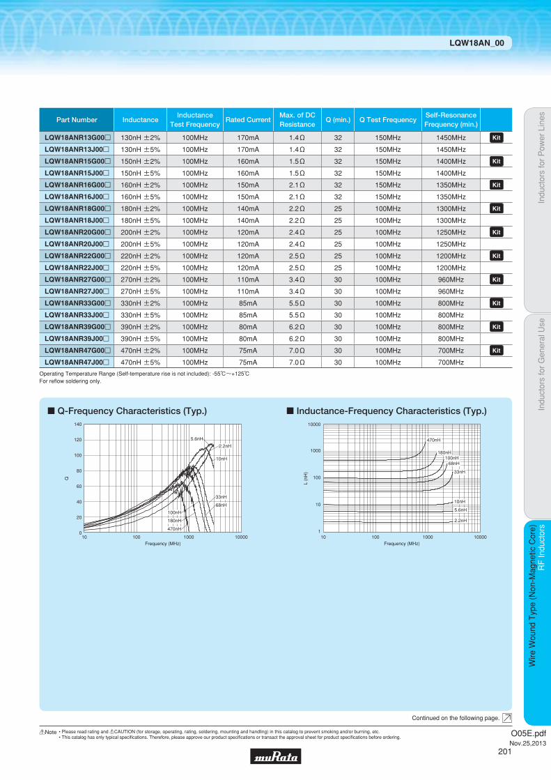
Part Number InductanceInductance
Test FrequencyRated Current
Max. of DCResistance
Q (min.) Q Test FrequencySelf-ResonanceFrequency (min.)
LQW18ANR13G00p 130nH ±2% 100MHz 170mA 1.4Ω 32 150MHz 1450MHz LQW18ANR13J00p 130nH ±5% 100MHz 170mA 1.4Ω 32 150MHz 1450MHz
LQW18ANR15G00p 150nH ±2% 100MHz 160mA 1.5Ω 32 150MHz 1400MHz LQW18ANR15J00p 150nH ±5% 100MHz 160mA 1.5Ω 32 150MHz 1400MHz
LQW18ANR16G00p 160nH ±2% 100MHz 150mA 2.1Ω 32 150MHz 1350MHz LQW18ANR16J00p 160nH ±5% 100MHz 150mA 2.1Ω 32 150MHz 1350MHz
LQW18ANR18G00p 180nH ±2% 100MHz 140mA 2.2Ω 25 100MHz 1300MHz LQW18ANR18J00p 180nH ±5% 100MHz 140mA 2.2Ω 25 100MHz 1300MHz
LQW18ANR20G00p 200nH ±2% 100MHz 120mA 2.4Ω 25 100MHz 1250MHz LQW18ANR20J00p 200nH ±5% 100MHz 120mA 2.4Ω 25 100MHz 1250MHz
LQW18ANR22G00p 220nH ±2% 100MHz 120mA 2.5Ω 25 100MHz 1200MHz LQW18ANR22J00p 220nH ±5% 100MHz 120mA 2.5Ω 25 100MHz 1200MHz
LQW18ANR27G00p 270nH ±2% 100MHz 110mA 3.4Ω 30 100MHz 960MHz LQW18ANR27J00p 270nH ±5% 100MHz 110mA 3.4Ω 30 100MHz 960MHz
LQW18ANR33G00p 330nH ±2% 100MHz 85mA 5.5Ω 30 100MHz 800MHz LQW18ANR33J00p 330nH ±5% 100MHz 85mA 5.5Ω 30 100MHz 800MHz
LQW18ANR39G00p 390nH ±2% 100MHz 80mA 6.2Ω 30 100MHz 800MHz LQW18ANR39J00p 390nH ±5% 100MHz 80mA 6.2Ω 30 100MHz 800MHz
LQW18ANR47G00p 470nH ±2% 100MHz 75mA 7.0Ω 30 100MHz 700MHz LQW18ANR47J00p 470nH ±5% 100MHz 75mA 7.0Ω 30 100MHz 700MHz
Indu
ctor
s fo
r P
ower
Lin
esIn
duct
ors
for
Gen
eral
Use
RF
Indu
ctor
sR
F In
duct
ors
Wire
Wou
nd T
ype
(Non
-Mag
netic
Cor
e)
LQW18AN_00
c Q-Frequency Characteristics (Typ.) c Inductance-Frequency Characteristics (Typ.)
10 100 1000 10000Frequency (MHz)
140
120
100
80
60
40
20
0
Q
68nH
470nH
180nH
100nH
33nH
5.6nH
10nH
2.2nH1000
10000
100
10
110010 1000 10000
L (n
H)
Frequency (MHz)
10nH
100nH180nH
470nH
68nH
33nH
5.6nH
2.2nH
Continued on the following page.
Operating Temperature Range (Self-temperature rise is not included): -55℃~+125℃For refl ow soldering only.
O05E.pdfNov.25,2013
201
!Note • Please read rating and !CAUTION (for storage, operating, rating, soldering, mounting and handling) in this catalog to prevent smoking and/or burning, etc.• This catalog has only typical specifi cations. Therefore, please approve our product specifi cations or transact the approval sheet for product specifi cations before ordering.

Indu
ctor
s fo
r P
ower
Lin
esIn
duct
ors
for
Gen
eral
Use
RF
Indu
ctor
sR
F In
duct
ors
Wire
Wou
nd T
ype
(Non
-Mag
netic
Cor
e)
LQW18AN_00
Continued on the following page.
c Reference Data
Part Number
LQW18AN2N2p00
LQW18AN3N6p00
LQW18AN3N9p00
LQW18AN4N3p00
LQW18AN4N7p00
LQW18AN5N6p00
LQW18AN6N2p00
LQW18AN6N8p00
LQW18AN7N5p00
LQW18AN8N2p00
LQW18AN8N7p00
LQW18AN9N1p00
LQW18AN9N5p00
LQW18AN10Np00
LQW18AN11Np00
LQW18AN12Np00
LQW18AN13Np00
LQW18AN15Np00
LQW18AN16Np00
LQW18AN18Np00
LQW18AN20Np00
LQW18AN22Np00
LQW18AN24Np00
LQW18AN27Np00
LQW18AN30Np00
LQW18AN33Np00
LQW18AN36Np00
LQW18AN39Np00
LQW18AN43Np00
LQW18AN47Np00
LQW18AN51Np00
LQW18AN56Np00
LQW18AN62Np00
LQW18AN68Np00
LQW18AN72Np00
LQW18AN75Np00
LQW18AN82Np00
LQW18AN91Np00
LQW18ANR10p00
LQW18ANR11p00
LQW18ANR12p00
LQW18ANR13p00
LQW18ANR15p00
LQW18ANR16p00
LQW18ANR18p00
LQW18ANR20p00
LQW18ANR22p00
LQW18ANR27p00
LQW18ANR33p00
LQW18ANR39p00
LQW18ANR47p00
2.2
3.6
3.9
4.3
4.7
5.6
6.2
6.8
7.5
8.2
8.7
9.1
9.5
10
11
12
13
15
16
18
20
22
24
27
30
33
36
39
43
47
51
56
62
68
72
75
82
91
100
110
120
130
150
160
180
200
220
270
330
390
470
Nominal
74
60
65
71
72
67
70
78
85
73
80
86
79
75
82
80
79
81
86
82
81
84
80
79
81
78
79
78
79
75
77
80
71
75
69
68
66
66
68
65
64
62
60
59
60
57
54
52
47
33
22
800MHz
77
63
68
74
75
70
73
82
86
78
82
88
84
78
85
84
82
84
90
85
83
88
82
81
82
79
81
78
81
74
78
82
71
77
69
66
64
65
67
63
62
59
57
54
55
54
47
46
35
23
13
900MHz
113
92
97
105
108
100
105
115
117
112
115
124
119
103
110
114
108
102
119
101
95
104
92
80
84
71
73
66
73
55
60
66
40
46
37
32
26
22
24
15
11
7
3
-
-
-
-
-
-
-
-
1.8GHz
124
94
99
107
120
103
107
117
132
116
132
142
119
102
108
114
105
97
116
96
90
101
86
72
75
60
62
55
61
42
46
51
26
31
23
18
12
8
9
1
-
-
-
-
-
-
-
-
-
-
-
2.0GHz
134
103
109
118
130
113
118
127
140
130
143
155
132
105
110
120
107
92
119
89
78
95
75
57
59
43
44
37
43
24
26
31
7
11
4
-
-
-
-
-
-
-
-
-
-
-
-
-
-
-
-
2.4GHz
Inductance (nH) Q (Typ.)
LQW18AN_00 4991A&16197A
O05E.pdfNov.25,2013
202
!Note • Please read rating and !CAUTION (for storage, operating, rating, soldering, mounting and handling) in this catalog to prevent smoking and/or burning, etc.• This catalog has only typical specifi cations. Therefore, please approve our product specifi cations or transact the approval sheet for product specifi cations before ordering.
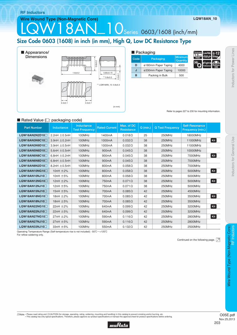
Code PackagingMinimumQuantity
D ø180mm Paper Taping 4000
J ø330mm Paper Taping 10000
B Packing in Bulk 500
1.0Thickness
mmmax.
Low Rdc E-12Step
HiQ
TightTolerance Reflow
OK
Indu
ctor
s fo
r P
ower
Lin
esIn
duct
ors
for
Gen
eral
Use
RF
Indu
ctor
sR
F In
duct
ors
Wire
Wou
nd T
ype
(Non
-Mag
netic
Cor
e)
Wire Wound Type (Non-Magnetic Core) LQW18AN_10
RF Inductors
LQW18AN_10Series 0603/1608 (inch/mm)Size Code 0603 (1608) in inch (in mm), High Q, Low DC Resistance Type
c Rated Value (p: packaging code)
Refer to pages 227 to 230 for mounting information.
1.6±0.2
*1 0.8±0.2
0.80±0.15
(in mm)
0.8±
0.2
0.2±
0.1
0.3±0.1 0.3±0.1
*1 LQW18AN_10: 0.8±0.3
Continued on the following page.
c Appearance/Dimensions
c Packaging
Operating Temperature Range (Self-temperature rise is not included): -55℃~+125℃For refl ow soldering only.
Part Number InductanceInductance
Test FrequencyRated Current
Max. of DCResistance
Q (min.) Q Test FrequencySelf-ResonanceFrequency (min.)
LQW18AN2N2D10p 2.2nH ±0.5nH 100MHz 1400mA 0.018Ω 25 250MHz 18000MHz
LQW18AN3N9C10p 3.9nH ±0.2nH 100MHz 1000mA 0.032Ω 38 250MHz 11000MHz LQW18AN3N9D10p 3.9nH ±0.5nH 100MHz 1000mA 0.032Ω 38 250MHz 11000MHz
LQW18AN5N6D10p 5.6nH ±0.5nH 100MHz 900mA 0.045Ω 38 250MHz 10000MHz
LQW18AN6N8C10p 6.8nH ±0.2nH 100MHz 900mA 0.045Ω 38 250MHz 7000MHz LQW18AN6N8D10p 6.8nH ±0.5nH 100MHz 900mA 0.045Ω 38 250MHz 7000MHz
LQW18AN8N2D10p 8.2nH ±0.5nH 100MHz 800mA 0.058Ω 38 250MHz 7000MHz
LQW18AN10NG10p 10nH ±2% 100MHz 800mA 0.058Ω 38 250MHz 5000MHz LQW18AN10NJ10p 10nH ±5% 100MHz 800mA 0.058Ω 38 250MHz 5000MHz
LQW18AN12NG10p 12nH ±2% 100MHz 750mA 0.071Ω 38 250MHz 5000MHz LQW18AN12NJ10p 12nH ±5% 100MHz 750mA 0.071Ω 38 250MHz 5000MHz
LQW18AN15NJ10p 15nH ±5% 100MHz 700mA 0.085Ω 42 250MHz 4500MHz
LQW18AN18NG10p 18nH ±2% 100MHz 700mA 0.085Ω 42 250MHz 3500MHz LQW18AN18NJ10p 18nH ±5% 100MHz 700mA 0.085Ω 42 250MHz 3500MHz
LQW18AN22NG10p 22nH ±2% 100MHz 640mA 0.099Ω 42 250MHz 3200MHz LQW18AN22NJ10p 22nH ±5% 100MHz 640mA 0.099Ω 42 250MHz 3200MHz
LQW18AN27NG10p 27nH ±2% 100MHz 590mA 0.116Ω 42 250MHz 2800MHz LQW18AN27NJ10p 27nH ±5% 100MHz 590mA 0.116Ω 42 250MHz 2800MHz
LQW18AN33NJ10p 33nH ±5% 100MHz 550mA 0.132Ω 42 250MHz 2500MHz
O05E.pdfNov.25,2013
203
!Note • Please read rating and !CAUTION (for storage, operating, rating, soldering, mounting and handling) in this catalog to prevent smoking and/or burning, etc.• This catalog has only typical specifi cations. Therefore, please approve our product specifi cations or transact the approval sheet for product specifi cations before ordering.

c Reference Data
Indu
ctor
s fo
r P
ower
Lin
esIn
duct
ors
for
Gen
eral
Use
RF
Indu
ctor
sR
F In
duct
ors
Wire
Wou
nd T
ype
(Non
-Mag
netic
Cor
e)
LQW18AN_10
c Q-Frequency Characteristics (Typ.) c Inductance-Frequency Characteristics (Typ.)
0
40
80
120
160
200
20
60
100
140
180
10 100 1000 10000Frequency (MHz)
Q
33nH
22nH
10nH
6.8nH
2.2nH
100
10
1
L (n
H)
10 100 1000 10000Frequency (MHz)
33nH
22nH
10nH
6.8nH
2.2nH
Part Number
LQW18AN2N2p10
LQW18AN3N9p10
LQW18AN5N6p10
LQW18AN6N8p10
LQW18AN8N2p10
LQW18AN10Np10
LQW18AN12Np10
LQW18AN15Np10
LQW18AN18Np10
LQW18AN22Np10
LQW18AN27Np10
LQW18AN33Np10
2.2
3.9
5.6
6.8
8.2
10
12
15
18
22
27
33
Nominal
72
75
73
85
86
84
88
81
90
88
83
94
800MHz
75
81
76
91
89
89
95
85
96
93
88
93
900MHz
114
117
109
124
130
117
125
125
112
97
85
107
1.8GHz
125
120
124
124
152
115
123
149
106
90
77
121
2.0GHz
134
130
136
131
171
119
128
169
101
80
63
121
2.4GHz
Inductance (nH) Q (Typ.)
LQW18AN_10 4991A&16197A
O05E.pdfNov.25,2013
204
!Note • Please read rating and !CAUTION (for storage, operating, rating, soldering, mounting and handling) in this catalog to prevent smoking and/or burning, etc.• This catalog has only typical specifi cations. Therefore, please approve our product specifi cations or transact the approval sheet for product specifi cations before ordering.

Code PackagingMinimumQuantity
D ø180mm Paper Taping 4000
J ø330mm Paper Taping 10000
B Packing in Bulk 500
Indu
ctor
s fo
r P
ower
Lin
esIn
duct
ors
for
Gen
eral
Use
RF
Indu
ctor
sR
F In
duct
ors
Wire
Wou
nd T
ype
(Non
-Mag
netic
Cor
e)
Wire Wound Type (Non-Magnetic Core) LQW18AN_80
RF Inductors
LQW18AN_80Series 0603/1608 (inch/mm)High Frequency Inductors with Low DC Resistance and High Current Capability
c Rated Value (p: packaging code)
Refer to pages 227 to 230 for mounting information.
1.65±0.1
0.26±0.1
0.2±
0.1
0.9±
0.1
0.99
±0.
1
(in mm)
Continued on the following page.
c Appearance/Dimensions
c Packaging
Operating Temperature Range (Self-temperature rise is not included): -55℃~+125℃For refl ow soldering only.
1.0Thickness
mmmax.
Low Rdc E-12Step
E-24Step
TightTolerance Reflow
OK
Part Number InductanceInductance
Test FrequencyRated Current
Max. of DCResistance
Q (min.) Q Test FrequencySelf-ResonanceFrequency (min.)
LQW18AN2N2C80p 2.2nH ±0.2nH 100MHz 3200mA 0.018Ω 24 250MHz 15000MHz LQW18AN2N4C80p 2.4nH ±0.2nH 100MHz 2400mA 0.026Ω 18 250MHz 15000MHz LQW18AN3N0C80p 3.0nH ±0.2nH 100MHz 670mA 0.17Ω 13 250MHz 15000MHz LQW18AN3N9B80p 3.9nH ±0.1nH 100MHz 2200mA 0.028Ω 30 250MHz 10000MHz LQW18AN3N9C80p 3.9nH ±0.2nH 100MHz 2200mA 0.028Ω 30 250MHz 10000MHz LQW18AN4N1B80p 4.1nH ±0.1nH 100MHz 2200mA 0.028Ω 30 250MHz 10000MHz LQW18AN4N1C80p 4.1nH ±0.2nH 100MHz 2200mA 0.028Ω 30 250MHz 10000MHz LQW18AN4N2B80p 4.2nH ±0.1nH 100MHz 2200mA 0.028Ω 30 250MHz 10000MHz LQW18AN4N2C80p 4.2nH ±0.2nH 100MHz 2200mA 0.028Ω 30 250MHz 10000MHz LQW18AN4N3B80p 4.3nH ±0.1nH 100MHz 2100mA 0.036Ω 35 250MHz 11600MHz LQW18AN4N3C80p 4.3nH ±0.2nH 100MHz 2100mA 0.036Ω 35 250MHz 11600MHz LQW18AN4N7B80p 4.7nH ±0.1nH 100MHz 1500mA 0.054Ω 25 250MHz 10400MHz LQW18AN4N7C80p 4.7nH ±0.2nH 100MHz 1500mA 0.054Ω 25 250MHz 10400MHz LQW18AN4N9B80p 4.9nH ±0.1nH 100MHz 1200mA 0.081Ω 23 250MHz 7300MHz LQW18AN4N9C80p 4.9nH ±0.2nH 100MHz 1200mA 0.081Ω 23 250MHz 7300MHz LQW18AN5N6C80p 5.6nH ±0.2nH 100MHz 1900mA 0.04Ω 38 250MHz 6650MHz LQW18AN6N0C80p 6.0nH ±0.2nH 100MHz 1900mA 0.04Ω 40 250MHz 6650MHz LQW18AN6N5C80p 6.5nH ±0.2nH 100MHz 1900mA 0.04Ω 40 250MHz 6650MHz LQW18AN6N8C80p 6.8nH ±0.2nH 100MHz 1900mA 0.04Ω 40 250MHz 6650MHz LQW18AN7N2C80p 7.2nH ±0.2nH 100MHz 1900mA 0.04Ω 38 250MHz 6650MHz LQW18AN7N5C80p 7.5nH ±0.2nH 100MHz 1500mA 0.048Ω 35 250MHz 7000MHz LQW18AN8N2C80p 8.2nH ±0.2nH 100MHz 1600mA 0.052Ω 38 250MHz 4750MHz LQW18AN8N4C80p 8.4nH ±0.2nH 100MHz 1600mA 0.052Ω 38 250MHz 4750MHz LQW18AN8N7C80p 8.7nH ±0.2nH 100MHz 1600mA 0.052Ω 38 250MHz 4750MHz LQW18AN9N1C80p 9.1nH ±0.2nH 100MHz 1600mA 0.052Ω 38 250MHz 4750MHz LQW18AN9N5C80p 9.5nH ±0.2nH 100MHz 1600mA 0.052Ω 38 250MHz 4750MHz LQW18AN9N9C80p 9.9nH ±0.2nH 100MHz 1600mA 0.052Ω 38 250MHz 4750MHz LQW18AN10NG80p 10nH ±2% 100MHz 1600mA 0.052Ω 38 250MHz 4750MHz LQW18AN10NJ80p 10nH ±5% 100MHz 1600mA 0.052Ω 38 250MHz 4750MHz LQW18AN11NG80p 11nH ±2% 100MHz 1600mA 0.052Ω 40 250MHz 4750MHz LQW18AN11NJ80p 11nH ±5% 100MHz 1600mA 0.052Ω 40 250MHz 4750MHz LQW18AN12NG80p 12nH ±2% 100MHz 1500mA 0.064Ω 37 250MHz 5000MHz
O05E.pdfNov.25,2013
205
!Note • Please read rating and !CAUTION (for storage, operating, rating, soldering, mounting and handling) in this catalog to prevent smoking and/or burning, etc.• This catalog has only typical specifi cations. Therefore, please approve our product specifi cations or transact the approval sheet for product specifi cations before ordering.

Indu
ctor
s fo
r P
ower
Lin
esIn
duct
ors
for
Gen
eral
Use
RF
Indu
ctor
sR
F In
duct
ors
Wire
Wou
nd T
ype
(Non
-Mag
netic
Cor
e)
LQW18AN_80
Continued on the following page.
Operating Temperature Range (Self-temperature rise is not included): -55℃~+125℃For refl ow soldering only.
Part Number InductanceInductance
Test FrequencyRated Current
Max. of DCResistance
Q (min.) Q Test FrequencySelf-ResonanceFrequency (min.)
LQW18AN12NJ80p 12nH ±5% 100MHz 1500mA 0.064Ω 37 250MHz 5000MHz LQW18AN13NG80p 13nH ±2% 100MHz 1500mA 0.064Ω 37 250MHz 5000MHz LQW18AN13NJ80p 13nH ±5% 100MHz 1500mA 0.064Ω 37 250MHz 5000MHz LQW18AN15NG80p 15nH ±2% 100MHz 1400mA 0.075Ω 38 250MHz 4600MHz LQW18AN15NJ80p 15nH ±5% 100MHz 1400mA 0.075Ω 38 250MHz 4600MHz LQW18AN16NG80p 16nH ±2% 100MHz 1400mA 0.075Ω 40 250MHz 4600MHz LQW18AN16NJ80p 16nH ±5% 100MHz 1400mA 0.075Ω 40 250MHz 4600MHz LQW18AN17NG80p 17nH ±2% 100MHz 1400mA 0.075Ω 40 250MHz 4600MHz LQW18AN17NJ80p 17nH ±5% 100MHz 1400mA 0.075Ω 40 250MHz 4600MHz LQW18AN18NG80p 18nH ±2% 100MHz 1400mA 0.075Ω 40 250MHz 4600MHz LQW18AN18NJ80p 18nH ±5% 100MHz 1400mA 0.075Ω 40 250MHz 4600MHz LQW18AN19NG80p 19nH ±2% 100MHz 1400mA 0.075Ω 40 250MHz 4600MHz LQW18AN19NJ80p 19nH ±5% 100MHz 1400mA 0.075Ω 40 250MHz 4600MHz LQW18AN22NG80p 22nH ±2% 100MHz 1300mA 0.086Ω 40 250MHz 3450MHz LQW18AN22NJ80p 22nH ±5% 100MHz 1300mA 0.086Ω 40 250MHz 3450MHz LQW18AN23NG80p 23nH ±2% 100MHz 1300mA 0.086Ω 40 250MHz 3450MHz LQW18AN23NJ80p 23nH ±5% 100MHz 1300mA 0.086Ω 40 250MHz 3450MHz LQW18AN24NG80p 24nH ±2% 100MHz 1300mA 0.086Ω 40 250MHz 3450MHz LQW18AN24NJ80p 24nH ±5% 100MHz 1300mA 0.086Ω 40 250MHz 3450MHz LQW18AN25NG80p 25nH ±2% 100MHz 1200mA 0.098Ω 40 250MHz 3600MHz LQW18AN25NJ80p 25nH ±5% 100MHz 1200mA 0.098Ω 40 250MHz 3600MHz LQW18AN27NG80p 27nH ±2% 100MHz 1200mA 0.098Ω 40 250MHz 3600MHz LQW18AN27NJ80p 27nH ±5% 100MHz 1200mA 0.098Ω 40 250MHz 3600MHz LQW18AN28NG80p 28nH ±2% 100MHz 1200mA 0.098Ω 40 250MHz 3600MHz LQW18AN28NJ80p 28nH ±5% 100MHz 1200mA 0.098Ω 40 250MHz 3600MHz LQW18AN30NG80p 30nH ±2% 100MHz 1100mA 0.12Ω 40 250MHz 2880MHz LQW18AN30NJ80p 30nH ±5% 100MHz 1100mA 0.12Ω 40 250MHz 2880MHz LQW18AN31NG80p 31nH ±2% 100MHz 1100mA 0.11Ω 40 250MHz 3150MHz LQW18AN31NJ80p 31nH ±5% 100MHz 1100mA 0.11Ω 40 250MHz 3150MHz LQW18AN33NG80p 33nH ±2% 100MHz 1100mA 0.11Ω 40 250MHz 3150MHz LQW18AN33NJ80p 33nH ±5% 100MHz 1100mA 0.11Ω 40 250MHz 3150MHz LQW18AN34NG80p 34nH ±2% 100MHz 1050mA 0.15Ω 40 250MHz 3000MHz LQW18AN34NJ80p 34nH ±5% 100MHz 1050mA 0.15Ω 40 250MHz 3000MHz LQW18AN36NG80p 36nH ±2% 100MHz 910mA 0.20Ω 37 250MHz 3000MHz LQW18AN36NJ80p 36nH ±5% 100MHz 910mA 0.20Ω 37 250MHz 3000MHz LQW18AN37NG80p 37nH ±2% 100MHz 910mA 0.20Ω 37 250MHz 3000MHz LQW18AN37NJ80p 37nH ±5% 100MHz 910mA 0.20Ω 37 250MHz 3000MHz LQW18AN39NG80p 39nH ±2% 100MHz 1000mA 0.16Ω 40 250MHz 3280MHz LQW18AN39NJ80p 39nH ±5% 100MHz 1000mA 0.16Ω 40 250MHz 3280MHz LQW18AN41NG80p 41nH ±2% 100MHz 1000mA 0.16Ω 40 250MHz 3280MHz LQW18AN41NJ80p 41nH ±5% 100MHz 1000mA 0.16Ω 40 250MHz 3280MHz LQW18AN43NG80p 43nH ±2% 100MHz 840mA 0.21Ω 40 250MHz 2780MHz LQW18AN43NJ80p 43nH ±5% 100MHz 840mA 0.21Ω 40 250MHz 2780MHz LQW18AN44NG80p 44nH ±2% 100MHz 840mA 0.21Ω 40 250MHz 2780MHz LQW18AN44NJ80p 44nH ±5% 100MHz 840mA 0.21Ω 40 250MHz 2780MHz LQW18AN47NG80p 47nH ±2% 100MHz 830mA 0.23Ω 32 200MHz 2700MHz LQW18AN47NJ80p 47nH ±5% 100MHz 830mA 0.23Ω 32 200MHz 2700MHz
O05E.pdfNov.25,2013
206
!Note • Please read rating and !CAUTION (for storage, operating, rating, soldering, mounting and handling) in this catalog to prevent smoking and/or burning, etc.• This catalog has only typical specifi cations. Therefore, please approve our product specifi cations or transact the approval sheet for product specifi cations before ordering.
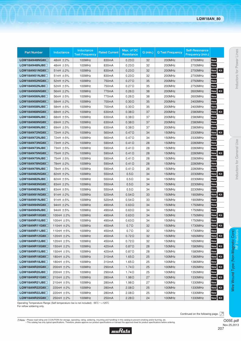
Indu
ctor
s fo
r P
ower
Lin
esIn
duct
ors
for
Gen
eral
Use
RF
Indu
ctor
sR
F In
duct
ors
Wire
Wou
nd T
ype
(Non
-Mag
netic
Cor
e)
LQW18AN_80
Continued on the following page.
Operating Temperature Range (Self-temperature rise is not included): -55℃~+125℃For refl ow soldering only.
Part Number InductanceInductance
Test FrequencyRated Current
Max. of DCResistance
Q (min.) Q Test FrequencySelf-ResonanceFrequency (min.)
LQW18AN48NG80p 48nH ±2% 100MHz 830mA 0.23Ω 32 200MHz 2700MHz LQW18AN48NJ80p 48nH ±5% 100MHz 830mA 0.23Ω 32 200MHz 2700MHz LQW18AN51NG80p 51nH ±2% 100MHz 830mA 0.23Ω 32 200MHz 2700MHz LQW18AN51NJ80p 51nH ±5% 100MHz 830mA 0.23Ω 32 200MHz 2700MHz LQW18AN52NG80p 52nH ±2% 100MHz 750mA 0.27Ω 35 200MHz 2750MHz LQW18AN52NJ80p 52nH ±5% 100MHz 750mA 0.27Ω 35 200MHz 2750MHz LQW18AN56NG80p 56nH ±2% 100MHz 770mA 0.26Ω 38 200MHz 2600MHz LQW18AN56NJ80p 56nH ±5% 100MHz 770mA 0.26Ω 38 200MHz 2600MHz LQW18AN58NG80p 58nH ±2% 100MHz 700mA 0.30Ω 35 200MHz 2400MHz LQW18AN58NJ80p 58nH ±5% 100MHz 700mA 0.30Ω 35 200MHz 2400MHz LQW18AN68NG80p 68nH ±2% 100MHz 630mA 0.38Ω 37 200MHz 2380MHz LQW18AN68NJ80p 68nH ±5% 100MHz 630mA 0.38Ω 37 200MHz 2380MHz LQW18AN69NG80p 69nH ±2% 100MHz 630mA 0.38Ω 37 200MHz 2380MHz LQW18AN69NJ80p 69nH ±5% 100MHz 630mA 0.38Ω 37 200MHz 2380MHz LQW18AN72NG80p 72nH ±2% 100MHz 560mA 0.47Ω 34 150MHz 2330MHz LQW18AN72NJ80p 72nH ±5% 100MHz 560mA 0.47Ω 34 150MHz 2330MHz LQW18AN73NG80p 73nH ±2% 100MHz 590mA 0.41Ω 28 150MHz 2280MHz LQW18AN73NJ80p 73nH ±5% 100MHz 590mA 0.41Ω 28 150MHz 2280MHz LQW18AN75NG80p 75nH ±2% 100MHz 590mA 0.41Ω 28 150MHz 2280MHz LQW18AN75NJ80p 75nH ±5% 100MHz 590mA 0.41Ω 28 150MHz 2280MHz LQW18AN78NG80p 78nH ±2% 100MHz 590mA 0.41Ω 28 150MHz 2280MHz LQW18AN78NJ80p 78nH ±5% 100MHz 590mA 0.41Ω 28 150MHz 2280MHz LQW18AN82NG80p 82nH ±2% 100MHz 550mA 0.5Ω 34 150MHz 2230MHz LQW18AN82NJ80p 82nH ±5% 100MHz 550mA 0.5Ω 34 150MHz 2230MHz LQW18AN83NG80p 83nH ±2% 100MHz 550mA 0.5Ω 34 150MHz 2230MHz LQW18AN83NJ80p 83nH ±5% 100MHz 550mA 0.5Ω 34 150MHz 2230MHz LQW18AN91NG80p 91nH ±2% 100MHz 520mA 0.54Ω 33 150MHz 1900MHz LQW18AN91NJ80p 91nH ±5% 100MHz 520mA 0.54Ω 33 150MHz 1900MHz LQW18AN94NG80p 94nH ±2% 100MHz 490mA 0.63Ω 34 150MHz 1750MHz LQW18AN94NJ80p 94nH ±5% 100MHz 490mA 0.63Ω 34 150MHz 1750MHz LQW18ANR10G80p 100nH ±2% 100MHz 490mA 0.63Ω 34 150MHz 1750MHz LQW18ANR10J80p 100nH ±5% 100MHz 490mA 0.63Ω 34 150MHz 1750MHz LQW18ANR11G80p 110nH ±2% 100MHz 450mA 0.7Ω 32 150MHz 1730MHz LQW18ANR11J80p 110nH ±5% 100MHz 450mA 0.7Ω 32 150MHz 1730MHz LQW18ANR12G80p 120nH ±2% 100MHz 450mA 0.72Ω 32 150MHz 1650MHz LQW18ANR12J80p 120nH ±5% 100MHz 450mA 0.72Ω 32 150MHz 1650MHz LQW18ANR15G80p 150nH ±2% 100MHz 420mA 0.87Ω 28 150MHz 1580MHz LQW18ANR15J80p 150nH ±5% 100MHz 420mA 0.87Ω 28 150MHz 1580MHz LQW18ANR18G80p 180nH ±2% 100MHz 310mA 1.65Ω 25 100MHz 1380MHz LQW18ANR18J80p 180nH ±5% 100MHz 310mA 1.65Ω 25 100MHz 1380MHz LQW18ANR20G80p 200nH ±2% 100MHz 290mA 1.74Ω 25 100MHz 1350MHz LQW18ANR20J80p 200nH ±5% 100MHz 290mA 1.74Ω 25 100MHz 1350MHz LQW18ANR21G80p 210nH ±2% 100MHz 280mA 1.98Ω 27 100MHz 1330MHz LQW18ANR21J80p 210nH ±5% 100MHz 280mA 1.98Ω 27 100MHz 1330MHz LQW18ANR22G80p 220nH ±2% 100MHz 280mA 2.08Ω 25 100MHz 1330MHz LQW18ANR22J80p 220nH ±5% 100MHz 280mA 2.08Ω 25 100MHz 1330MHz LQW18ANR25G80p 250nH ±2% 100MHz 250mA 2.28Ω 24 100MHz 1330MHz
O05E.pdfNov.25,2013
207
!Note • Please read rating and !CAUTION (for storage, operating, rating, soldering, mounting and handling) in this catalog to prevent smoking and/or burning, etc.• This catalog has only typical specifi cations. Therefore, please approve our product specifi cations or transact the approval sheet for product specifi cations before ordering.

Indu
ctor
s fo
r P
ower
Lin
esIn
duct
ors
for
Gen
eral
Use
RF
Indu
ctor
sR
F In
duct
ors
Wire
Wou
nd T
ype
(Non
-Mag
netic
Cor
e)
LQW18AN_80
c Q-Frequency Characteristics (Typ.)
c Derating of Rated Current
c Inductance-Frequency Characteristics (Typ.)
10 100 1000 10000Frequency (MHz)
140
120
100
80
60
40
20
0
Q
390nH250nH
150nH
72nH
43nH
27nH
12nH
7.5nH
4.2nH
2.2nH
In operating temperature exceeding +85°C, derating of current is necessary for LQW18AN_80 series.Please apply the derating curve shown in chart according to the operating temperature.
Derating of Rated Current
100
50
0125850
Cur
rent
der
atin
g (%
)
Temperature (°C)
1000
10000
100
10
110010 1000 10000
L (n
H)
Frequency (MHz)
390nH250nH
150nH
72nH43nH
27nH
12nH7.5nH
4.2nH
2.2nH
Operating Temperature Range (Self-temperature rise is not included): -55℃~+125℃For refl ow soldering only.
Part Number InductanceInductance
Test FrequencyRated Current
Max. of DCResistance
Q (min.) Q Test FrequencySelf-ResonanceFrequency (min.)
LQW18ANR25J80p 250nH ±5% 100MHz 250mA 2.28Ω 24 100MHz 1330MHz LQW18ANR27G80p 270nH ±2% 100MHz 260mA 2.42Ω 24 100MHz 1250MHz LQW18ANR27J80p 270nH ±5% 100MHz 260mA 2.42Ω 24 100MHz 1250MHz LQW18ANR30G80p 300nH ±2% 100MHz 220mA 3.12Ω 25 100MHz 1200MHz LQW18ANR30J80p 300nH ±5% 100MHz 220mA 3.12Ω 25 100MHz 1200MHz LQW18ANR33G80p 330nH ±2% 100MHz 190mA 3.84Ω 25 100MHz 1100MHz LQW18ANR33J80p 330nH ±5% 100MHz 190mA 3.84Ω 25 100MHz 1100MHz LQW18ANR36G80p 360nH ±2% 100MHz 190mA 3.98Ω 25 100MHz 1050MHz LQW18ANR36J80p 360nH ±5% 100MHz 190mA 3.98Ω 25 100MHz 1050MHz LQW18ANR39G80p 390nH ±2% 100MHz 190mA 4.23Ω 25 100MHz 1100MHz LQW18ANR39J80p 390nH ±5% 100MHz 190mA 4.23Ω 25 100MHz 1100MHz
O05E.pdfNov.25,2013
208
!Note • Please read rating and !CAUTION (for storage, operating, rating, soldering, mounting and handling) in this catalog to prevent smoking and/or burning, etc.• This catalog has only typical specifi cations. Therefore, please approve our product specifi cations or transact the approval sheet for product specifi cations before ordering.

Code PackagingMinimumQuantity
L ø180mm Embossed Taping 2000
K ø330mm Embossed Taping 7500
1.78Thickness
mmmax.
E-12Step
TightTolerance
ReflowOK FlowOK
Indu
ctor
s fo
r P
ower
Lin
esIn
duct
ors
for
Gen
eral
Use
RF
Indu
ctor
sR
F In
duct
ors
Wire
Wou
nd T
ype
(Non
-Mag
netic
Cor
e)
Wire Wound Type (Non-Magnetic Core) LQW2BHN_03
RF Inductors
LQW2BHN_03Series 0805/2015 (inch/mm)Size Code 0805 (2015) in inch (in mm), Wound Type
c Rated Value (p: packaging code)
Refer to pages 227 to 230 for mounting information.
2.0±0.2
1.5±0.2
0.5 min.0.5 min.0.5 min.
1.5±0.2
1.5±0.2
(in mm)
1.7
+0.
08-0
.1
Continued on the following page.
c Appearance/Dimensions
c Packaging
Operating Temperature Range (Self-temperature rise is not included): -40℃~+85℃
Part Number InductanceInductance
Test FrequencyRated Current
Max. of DCResistance
Q (min.) Q Test FrequencySelf-ResonanceFrequency (min.)
LQW2BHN3N3D03p 3.3nH ±0.5nH 100MHz 910mA 0.05Ω 10 250MHz 6000MHz
LQW2BHN6N8D03p 6.8nH ±0.5nH 100MHz 680mA 0.11Ω 20 250MHz 5400MHz
LQW2BHN8N2D03p 8.2nH ±0.5nH 100MHz 630mA 0.12Ω 20 250MHz 3900MHz
LQW2BHN10NJ03p 10nH ±5% 100MHz 1320mA 0.03Ω 30 250MHz 3300MHz
LQW2BHN12NJ03p 12nH ±5% 100MHz 680mA 0.11Ω 30 250MHz 3200MHz
LQW2BHN15NJ03p 15nH ±5% 100MHz 630mA 0.12Ω 30 250MHz 2700MHz
LQW2BHN18NJ03p 18nH ±5% 100MHz 690mA 0.10Ω 30 250MHz 2600MHz
LQW2BHN22NJ03p 22nH ±5% 100MHz 720mA 0.09Ω 30 250MHz 2100MHz
LQW2BHN27NJ03p 27nH ±5% 100MHz 540mA 0.17Ω 40 250MHz 2300MHz
LQW2BHN33NG03p 33nH ±2% 100MHz 570mA 0.15Ω 40 250MHz 1900MHz LQW2BHN33NJ03p 33nH ±5% 100MHz 570mA 0.15Ω 40 250MHz 1900MHz LQW2BHN39NG03p 39nH ±2% 100MHz 730mA 0.09Ω 40 250MHz 1700MHz LQW2BHN39NJ03p 39nH ±5% 100MHz 730mA 0.09Ω 40 250MHz 1700MHz LQW2BHN47NG03p 47nH ±2% 100MHz 450mA 0.23Ω 40 200MHz 1600MHz LQW2BHN47NJ03p 47nH ±5% 100MHz 450mA 0.23Ω 40 200MHz 1600MHz LQW2BHN56NG03p 56nH ±2% 100MHz 430mA 0.26Ω 40 200MHz 1500MHz LQW2BHN56NJ03p 56nH ±5% 100MHz 430mA 0.26Ω 40 200MHz 1500MHz LQW2BHN68NG03p 68nH ±2% 100MHz 460mA 0.23Ω 40 200MHz 1200MHz LQW2BHN68NJ03p 68nH ±5% 100MHz 460mA 0.23Ω 40 200MHz 1200MHz LQW2BHN82NG03p 82nH ±2% 100MHz 320mA 0.42Ω 40 150MHz 1100MHz LQW2BHN82NJ03p 82nH ±5% 100MHz 320mA 0.42Ω 40 150MHz 1100MHz LQW2BHNR10G03p 100nH ±2% 100MHz 270mA 0.55Ω 35 150MHz 900MHz LQW2BHNR10J03p 100nH ±5% 100MHz 350mA 0.38Ω 40 150MHz 900MHz LQW2BHNR12G03p 120nH ±2% 100MHz 320mA 0.40Ω 40 150MHz 750MHz LQW2BHNR12J03p 120nH ±5% 100MHz 320mA 0.40Ω 40 150MHz 750MHz LQW2BHNR15G03p 150nH ±2% 100MHz 260mA 0.68Ω 30 150MHz 350MHz LQW2BHNR15J03p 150nH ±5% 100MHz 390mA 0.47Ω 30 150MHz 350MHz LQW2BHNR18G03p 180nH ±2% 100MHz 250mA 0.71Ω 35 100MHz 700MHz LQW2BHNR18J03p 180nH ±5% 100MHz 250mA 0.71Ω 35 100MHz 700MHz LQW2BHNR22G03p 220nH ±2% 100MHz 240mA 0.70Ω 35 100MHz 500MHz LQW2BHNR22J03p 220nH ±5% 100MHz 240mA 0.70Ω 35 100MHz 500MHz LQW2BHNR27J03p 270nH ±5% 10MHz 190mA 2.00Ω 15 25.2MHz 550MHz
LQW2BHNR27K03p 270nH ±10% 10MHz 190mA 2.00Ω 15 25.2MHz 550MHz
O05E.pdfNov.25,2013
209
!Note • Please read rating and !CAUTION (for storage, operating, rating, soldering, mounting and handling) in this catalog to prevent smoking and/or burning, etc.• This catalog has only typical specifi cations. Therefore, please approve our product specifi cations or transact the approval sheet for product specifi cations before ordering.

c Reference Data
Indu
ctor
s fo
r P
ower
Lin
esIn
duct
ors
for
Gen
eral
Use
RF
Indu
ctor
sR
F In
duct
ors
Wire
Wou
nd T
ype
(Non
-Mag
netic
Cor
e)
LQW2BHN_03
c Q-Frequency Characteristics (Typ.) c Inductance-Frequency Characteristics (Typ.)
0
20
40
60
100
140
80
120
10 100 1000 10000Frequency (MHz)
Q
470nH
330nH
3.3nH
10nH
33nH
100nH
1000
10000
100
10
110010 1000 10000
L (n
H)
Frequency (MHz)
470nH
330nH
100nH
33nH
10nH
3.3nH
Part Number
LQW2BHN3N3p03
LQW2BHN6N8p03
LQW2BHN8N2p03
LQW2BHN10Np03
LQW2BHN12Np03
LQW2BHN15Np03
LQW2BHN18Np03
LQW2BHN22Np03
LQW2BHN27Np03
LQW2BHN33Np03
LQW2BHN39Np03
LQW2BHN47Np03
LQW2BHN56Np03
LQW2BHN68Np03
LQW2BHN82Np03
LQW2BHNR10p03
LQW2BHNR12p03
LQW2BHNR15p03
LQW2BHNR18p03
LQW2BHNR22p03
LQW2BHNR27p03
LQW2BHNR33p03
LQW2BHNR39p03
LQW2BHNR47p03
3.3
6.8
8.2
10
12
15
18
22
27
33
39
47
56
68
82
100
120
150
180
220
270
330
390
470
100MHz
55
51
60
81
77
76
81
85
77
76
83
70
73
62
64
50
31
21
1
-
-
-
-
-
800MHz
58
55
64
86
81
80
83
87
79
77
76
64
67
51
56
37
15
4
-
-
-
-
-
-
900MHz
85
77
88
114
88
75
70
47
43
15
-
-
-
-
-
-
-
-
-
-
-
-
-
-
1.8GHz
88
78
88
110
83
66
58
31
28
1
-
-
-
-
-
-
-
-
-
-
-
-
-
-
2.0GHz
98
80
88
100
77
50
39
8
6
-
-
-
-
-
-
-
-
-
-
-
-
-
-
-
2.4GHz
Inductance (nH) Q (Typ.)
LQW2BHN_03 4991A&16197A
Operating Temperature Range (Self-temperature rise is not included): -40℃~+85℃
Part Number InductanceInductance
Test FrequencyRated Current
Max. of DCResistance
Q (min.) Q Test FrequencySelf-ResonanceFrequency (min.)
LQW2BHNR33J03p 330nH ±5% 10MHz 180mA 2.20Ω 15 25.2MHz 500MHz
LQW2BHNR33K03p 330nH ±10% 10MHz 180mA 2.20Ω 15 25.2MHz 500MHz LQW2BHNR39J03p 390nH ±5% 10MHz 170mA 2.50Ω 15 25.2MHz 400MHz
LQW2BHNR39K03p 390nH ±10% 10MHz 170mA 2.50Ω 15 25.2MHz 400MHz LQW2BHNR47J03p 470nH ±5% 10MHz 160mA 2.80Ω 15 25.2MHz 350MHz
LQW2BHNR47K03p 470nH ±10% 10MHz 160mA 2.80Ω 15 25.2MHz 350MHz
O05E.pdfNov.25,2013
210
!Note • Please read rating and !CAUTION (for storage, operating, rating, soldering, mounting and handling) in this catalog to prevent smoking and/or burning, etc.• This catalog has only typical specifi cations. Therefore, please approve our product specifi cations or transact the approval sheet for product specifi cations before ordering.
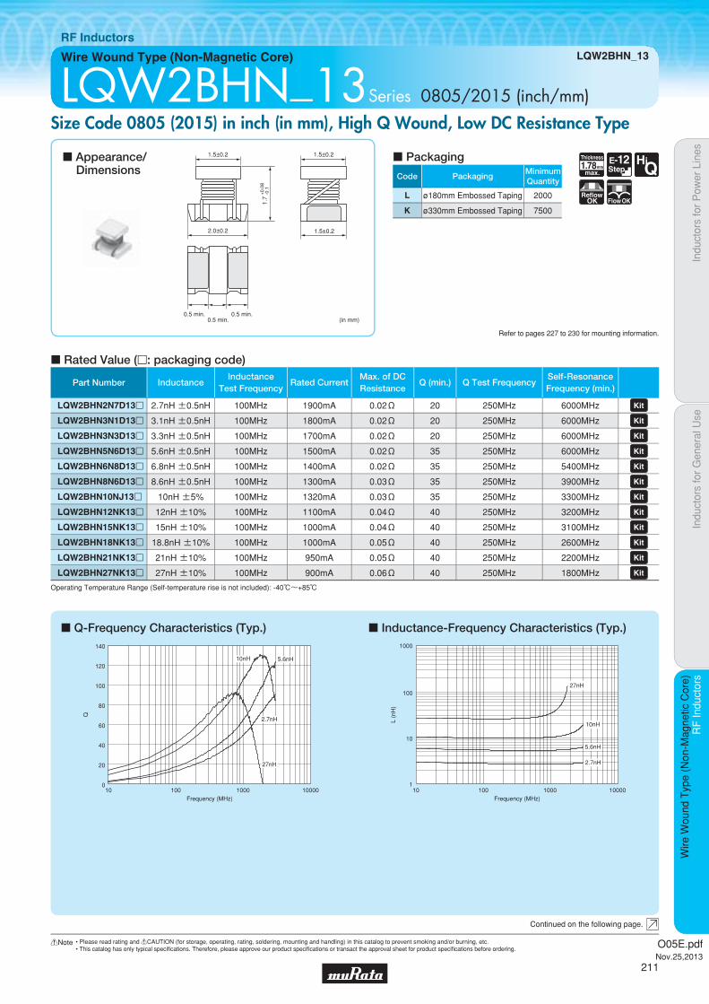
Code PackagingMinimumQuantity
L ø180mm Embossed Taping 2000
K ø330mm Embossed Taping 7500
Indu
ctor
s fo
r P
ower
Lin
esIn
duct
ors
for
Gen
eral
Use
RF
Indu
ctor
sR
F In
duct
ors
Wire
Wou
nd T
ype
(Non
-Mag
netic
Cor
e)
Wire Wound Type (Non-Magnetic Core) LQW2BHN_13
RF Inductors
LQW2BHN_13Series 0805/2015 (inch/mm)Size Code 0805 (2015) in inch (in mm), High Q Wound, Low DC Resistance Type
c Q-Frequency Characteristics (Typ.) c Inductance-Frequency Characteristics (Typ.)
c Rated Value (p: packaging code)
Refer to pages 227 to 230 for mounting information.
2.0±0.2
1.5±0.2
0.5 min.0.5 min.0.5 min.
1.5±0.2
1.5±0.2
(in mm)
1.7
+0.
08-0
.1
Continued on the following page.
c Appearance/Dimensions
c Packaging
Operating Temperature Range (Self-temperature rise is not included): -40℃~+85℃
0
20
40
60
100
140
80
120
10 100 1000 10000Frequency (MHz)
Q
27nH
5.6nH10nH
2.7nH
10 100 1000 10000
1000
100
1
10
Frequency (MHz)
L (n
H)
5.6nH
2.7nH
27nH
10nH
1.78Thickness
mmmax.
E-12Step
HiQ
ReflowOK FlowOK
Part Number InductanceInductance
Test FrequencyRated Current
Max. of DCResistance
Q (min.) Q Test FrequencySelf-ResonanceFrequency (min.)
LQW2BHN2N7D13p 2.7nH ±0.5nH 100MHz 1900mA 0.02Ω 20 250MHz 6000MHz LQW2BHN3N1D13p 3.1nH ±0.5nH 100MHz 1800mA 0.02Ω 20 250MHz 6000MHz LQW2BHN3N3D13p 3.3nH ±0.5nH 100MHz 1700mA 0.02Ω 20 250MHz 6000MHz LQW2BHN5N6D13p 5.6nH ±0.5nH 100MHz 1500mA 0.02Ω 35 250MHz 6000MHz LQW2BHN6N8D13p 6.8nH ±0.5nH 100MHz 1400mA 0.02Ω 35 250MHz 5400MHz LQW2BHN8N6D13p 8.6nH ±0.5nH 100MHz 1300mA 0.03Ω 35 250MHz 3900MHz LQW2BHN10NJ13p 10nH ±5% 100MHz 1320mA 0.03Ω 35 250MHz 3300MHz LQW2BHN12NK13p 12nH ±10% 100MHz 1100mA 0.04Ω 40 250MHz 3200MHz LQW2BHN15NK13p 15nH ±10% 100MHz 1000mA 0.04Ω 40 250MHz 3100MHz LQW2BHN18NK13p 18.8nH ±10% 100MHz 1000mA 0.05Ω 40 250MHz 2600MHz LQW2BHN21NK13p 21nH ±10% 100MHz 950mA 0.05Ω 40 250MHz 2200MHz LQW2BHN27NK13p 27nH ±10% 100MHz 900mA 0.06Ω 40 250MHz 1800MHz
O05E.pdfNov.25,2013
211
!Note • Please read rating and !CAUTION (for storage, operating, rating, soldering, mounting and handling) in this catalog to prevent smoking and/or burning, etc.• This catalog has only typical specifi cations. Therefore, please approve our product specifi cations or transact the approval sheet for product specifi cations before ordering.
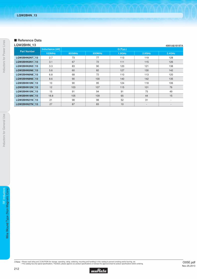
Indu
ctor
s fo
r P
ower
Lin
esIn
duct
ors
for
Gen
eral
Use
RF
Indu
ctor
sR
F In
duct
ors
Wire
Wou
nd T
ype
(Non
-Mag
netic
Cor
e)
LQW2BHN_13
c Reference Data
Part Number
LQW2BHN2N7p13
LQW2BHN3N1p13
LQW2BHN3N3p13
LQW2BHN5N6p13
LQW2BHN6N8p13
LQW2BHN8N6p13
LQW2BHN10Np13
LQW2BHN12Np13
LQW2BHN15Np13
LQW2BHN18Np13
LQW2BHN21Np13
LQW2BHN27Np13
2.7
3.1
3.3
5.6
6.8
8.6
10
12
15
18.8
21
27
100MHz
73
67
83
60
68
90
90
103
91
105
98
87
800MHz
77
72
90
82
72
100
95
107
94
109
98
83
900MHz
113
111
120
127
110
140
124
115
91
65
52
10
1.8GHz
119
115
121
130
113
142
118
101
75
44
31
-
2.0GHz
128
126
138
142
120
135
106
76
49
15
-
-
2.4GHz
Inductance (nH) Q (Typ.)
LQW2BHN_13 4991A&16197A
O05E.pdfNov.25,2013
212
!Note • Please read rating and !CAUTION (for storage, operating, rating, soldering, mounting and handling) in this catalog to prevent smoking and/or burning, etc.• This catalog has only typical specifi cations. Therefore, please approve our product specifi cations or transact the approval sheet for product specifi cations before ordering.

Code PackagingMinimumQuantity
L ø180mm Embossed Taping 2000
1.52Thickness
mmmax.
E-12Step
E-24Step
ReflowOK
Indu
ctor
s fo
r P
ower
Lin
esIn
duct
ors
for
Gen
eral
Use
RF
Indu
ctor
sR
F In
duct
ors
Wire
Wou
nd T
ype
(Non
-Mag
netic
Cor
e)
Wire Wound Type (Non-Magnetic Core) LQW2BAS_00
RF Inductors
LQW2BAS_00Series 0805/2015 (inch/mm)Size Code 0805 (2015) in inch (in mm), Horizontal Wound Type
c Rated Value (p: packaging code)
Refer to pages 227 to 230 for mounting information.
(in mm)
0.5±0.1
1.5±0.2
2.09±0.2
0.25
±0.
15
1.42
±0.
1
1.53±0.2
Continued on the following page.
c Appearance/Dimensions
c Packaging
Operating Temperature Range (Self-temperature rise is not included): -55℃~+125℃For refl ow soldering only.
Part Number InductanceInductance
Test FrequencyRated Current
Max. of DCResistance
Q (min.) Q Test FrequencySelf-ResonanceFrequency (min.)
LQW2BAS2N8J00p 2.8nH ±5% 250MHz 800mA 0.06Ω 80 1500MHz 12200MHz LQW2BAS3N0J00p 3.0nH ±5% 250MHz 800mA 0.06Ω 65 1500MHz 12200MHz LQW2BAS5N6J00p 5.6nH ±5% 250MHz 600mA 0.08Ω 65 1000MHz 5900MHz LQW2BAS6N8J00p 6.8nH ±5% 250MHz 600mA 0.11Ω 50 1000MHz 5600MHz LQW2BAS7N5J00p 7.5nH ±5% 250MHz 600mA 0.14Ω 50 1000MHz 4800MHz LQW2BAS8N2J00p 8.2nH ±5% 250MHz 600mA 0.12Ω 50 1000MHz 4400MHz LQW2BAS10NJ00p 10nH ±5% 250MHz 600mA 0.10Ω 60 500MHz 4300MHz LQW2BAS12NJ00p 12nH ±5% 250MHz 600mA 0.15Ω 50 500MHz 4000MHz LQW2BAS15NJ00p 15nH ±5% 250MHz 600mA 0.17Ω 50 500MHz 3200MHz LQW2BAS18NJ00p 18nH ±5% 250MHz 600mA 0.20Ω 50 500MHz 3100MHz LQW2BAS22NJ00p 22nH ±5% 250MHz 500mA 0.22Ω 55 500MHz 2600MHz LQW2BAS24NJ00p 24nH ±5% 250MHz 500mA 0.22Ω 50 500MHz 2400MHz LQW2BAS27NJ00p 27nH ±5% 250MHz 500mA 0.25Ω 55 500MHz 2580MHz LQW2BAS33NG00p 33nH ±2% 250MHz 500mA 0.27Ω 60 500MHz 2150MHz LQW2BAS33NJ00p 33nH ±5% 250MHz 500mA 0.27Ω 60 500MHz 2150MHz LQW2BAS36NG00p 36nH ±2% 250MHz 500mA 0.27Ω 55 500MHz 1900MHz LQW2BAS36NJ00p 36nH ±5% 250MHz 500mA 0.27Ω 55 500MHz 1900MHz LQW2BAS39NG00p 39nH ±2% 250MHz 500mA 0.29Ω 60 500MHz 2000MHz LQW2BAS39NJ00p 39nH ±5% 250MHz 500mA 0.29Ω 60 500MHz 2000MHz LQW2BAS43NG00p 43nH ±2% 200MHz 500mA 0.34Ω 60 500MHz 1800MHz LQW2BAS43NJ00p 43nH ±5% 200MHz 500mA 0.34Ω 60 500MHz 1800MHz LQW2BAS47NG00p 47nH ±2% 200MHz 500mA 0.31Ω 60 500MHz 1700MHz LQW2BAS47NJ00p 47nH ±5% 200MHz 500mA 0.31Ω 60 500MHz 1700MHz LQW2BAS56NG00p 56nH ±2% 200MHz 500mA 0.34Ω 60 500MHz 1600MHz LQW2BAS56NJ00p 56nH ±5% 200MHz 500mA 0.34Ω 60 500MHz 1600MHz LQW2BAS68NG00p 68nH ±2% 200MHz 500mA 0.38Ω 60 500MHz 1500MHz LQW2BAS68NJ00p 68nH ±5% 200MHz 500mA 0.38Ω 60 500MHz 1500MHz LQW2BAS82NG00p 82nH ±2% 150MHz 400mA 0.42Ω 65 500MHz 1330MHz LQW2BAS82NJ00p 82nH ±5% 150MHz 400mA 0.42Ω 65 500MHz 1330MHz LQW2BAS91NG00p 91nH ±2% 150MHz 400mA 0.48Ω 65 500MHz 1330MHz LQW2BAS91NJ00p 91nH ±5% 150MHz 400mA 0.48Ω 65 500MHz 1330MHz LQW2BASR10G00p 100nH ±2% 150MHz 400mA 0.46Ω 65 500MHz 1250MHz
O05E.pdfNov.25,2013
213
!Note • Please read rating and !CAUTION (for storage, operating, rating, soldering, mounting and handling) in this catalog to prevent smoking and/or burning, etc.• This catalog has only typical specifi cations. Therefore, please approve our product specifi cations or transact the approval sheet for product specifi cations before ordering.

Indu
ctor
s fo
r P
ower
Lin
esIn
duct
ors
for
Gen
eral
Use
RF
Indu
ctor
sR
F In
duct
ors
Wire
Wou
nd T
ype
(Non
-Mag
netic
Cor
e)
LQW2BAS_00
c Q-Frequency Characteristics (Typ.) c Inductance-Frequency Characteristics (Typ.)
0
40
80
120
160
200
20
60
100
140
180
10 100 1000 10000Frequency (MHz)
Q
820nH 220nH 82nH22nH
8.2nH
2.8nH
1000
10000
100
10
110010 1000 10000
L (n
H)
Frequency (MHz)
22nH
82nH
220nH
820nH
8.2nH
2.8nH
Continued on the following page.
Operating Temperature Range (Self-temperature rise is not included): -55℃~+125℃For refl ow soldering only.
Part Number InductanceInductance
Test FrequencyRated Current
Max. of DCResistance
Q (min.) Q Test FrequencySelf-ResonanceFrequency (min.)
LQW2BASR10J00p 100nH ±5% 150MHz 400mA 0.46Ω 65 500MHz 1250MHz LQW2BASR11G00p 110nH ±2% 150MHz 400mA 0.48Ω 50 250MHz 1100MHz LQW2BASR11J00p 110nH ±5% 150MHz 400mA 0.48Ω 50 250MHz 1100MHz LQW2BASR12G00p 120nH ±2% 150MHz 400mA 0.51Ω 50 250MHz 1100MHz LQW2BASR12J00p 120nH ±5% 150MHz 400mA 0.51Ω 50 250MHz 1100MHz LQW2BASR15G00p 150nH ±2% 100MHz 400mA 0.56Ω 50 250MHz 920MHz LQW2BASR15J00p 150nH ±5% 100MHz 400mA 0.56Ω 50 250MHz 920MHz LQW2BASR18G00p 180nH ±2% 100MHz 400mA 0.64Ω 50 250MHz 920MHz LQW2BASR18J00p 180nH ±5% 100MHz 400mA 0.64Ω 50 250MHz 920MHz LQW2BASR22G00p 220nH ±2% 100MHz 400mA 0.70Ω 50 250MHz 820MHz LQW2BASR22J00p 220nH ±5% 100MHz 400mA 0.70Ω 50 250MHz 820MHz LQW2BASR24G00p 240nH ±2% 100MHz 350mA 1.00Ω 44 250MHz 770MHz LQW2BASR24J00p 240nH ±5% 100MHz 350mA 1.00Ω 44 250MHz 770MHz LQW2BASR27G00p 270nH ±2% 100MHz 350mA 1.00Ω 48 250MHz 730MHz LQW2BASR27J00p 270nH ±5% 100MHz 350mA 1.00Ω 48 250MHz 730MHz LQW2BASR33G00p 330nH ±2% 100MHz 310mA 1.40Ω 48 250MHz 650MHz LQW2BASR33J00p 330nH ±5% 100MHz 310mA 1.40Ω 48 250MHz 650MHz LQW2BASR39J00p 390nH ±5% 100MHz 290mA 1.50Ω 48 250MHz 600MHz LQW2BASR47J00p 470nH ±5% 50MHz 250mA 1.76Ω 33 100MHz 300MHz LQW2BASR56J00p 560nH ±5% 25MHz 230mA 1.90Ω 23 50MHz 270MHz LQW2BASR68J00p 680nH ±5% 25MHz 190mA 2.20Ω 23 50MHz 250MHz LQW2BASR82J00p 820nH ±5% 25MHz 180mA 2.35Ω 23 50MHz 230MHz
O05E.pdfNov.25,2013
214
!Note • Please read rating and !CAUTION (for storage, operating, rating, soldering, mounting and handling) in this catalog to prevent smoking and/or burning, etc.• This catalog has only typical specifi cations. Therefore, please approve our product specifi cations or transact the approval sheet for product specifi cations before ordering.

Indu
ctor
s fo
r P
ower
Lin
esIn
duct
ors
for
Gen
eral
Use
RF
Indu
ctor
sR
F In
duct
ors
Wire
Wou
nd T
ype
(Non
-Mag
netic
Cor
e)
LQW2BAS_00
c Reference Data
Part Number
LQW2BAS2N8p00
LQW2BAS3N0p00
LQW2BAS5N6p00
LQW2BAS6N8p00
LQW2BAS7N5p00
LQW2BAS8N2p00
LQW2BAS10Np00
LQW2BAS12Np00
LQW2BAS15Np00
LQW2BAS18Np00
LQW2BAS22Np00
LQW2BAS24Np00
LQW2BAS27Np00
LQW2BAS33Np00
LQW2BAS36Np00
LQW2BAS39Np00
LQW2BAS43Np00
LQW2BAS47Np00
LQW2BAS56Np00
LQW2BAS68Np00
LQW2BAS82Np00
LQW2BAS91Np00
LQW2BASR10p00
LQW2BASR11p00
LQW2BASR12p00
LQW2BASR15p00
LQW2BASR18p00
LQW2BASR22p00
LQW2BASR24p00
LQW2BASR27p00
LQW2BASR33p00
LQW2BASR39p00
LQW2BASR47p00
LQW2BASR56p00
LQW2BASR68p00
LQW2BASR82p00
2.8
3
5.6
6.8
7.5
8.2
10
12
15
18
22
24
27
33
36
39
43
47
56
68
82
91
100
110
120
150
180
220
240
270
330
390
470
560
680
820
100MHz
100
63
96
77
66
64
96
73
78
84
91
87
90
92
92
96
95
91
92
91
85
83
78
68
48
48
34
29
22
11
4
-
-
-
-
-
800MHz
95
67
100
70
70
70
100
77
80
89
90
87
92
93
93
95
96
88
90
87
75
74
64
50
28
32
20
11
5
-
-
-
-
-
-
-
900MHz
170
100
150
97
91
94
138
120
92
104
89
63
93
60
43
61
37
24
17
4
-
-
-
-
-
-
-
-
-
-
-
-
-
-
-
-
1.8GHz
175
104
153
100
90
94
140
103
80
100
80
51
89
45
26
41
17
5
-
-
-
-
-
-
-
-
-
-
-
-
-
-
-
-
-
-
2.0GHz
190
110
160
106
94
96
138
101
76
86
56
36
65
13
2
15
-
-
-
-
-
-
-
-
-
-
-
-
-
-
-
-
-
-
-
-
2.4GHz
Inductance (nH) Q (Typ.)
LQW2BAS_00 4991A&16197A
O05E.pdfNov.25,2013
215
!Note • Please read rating and !CAUTION (for storage, operating, rating, soldering, mounting and handling) in this catalog to prevent smoking and/or burning, etc.• This catalog has only typical specifi cations. Therefore, please approve our product specifi cations or transact the approval sheet for product specifi cations before ordering.

Code PackagingMinimumQuantity
L ø180mm Embossed Taping 2000
2.03Thickness
mmmax.
E-12Step
E-24Step
ReflowOK
Indu
ctor
s fo
r P
ower
Lin
esIn
duct
ors
for
Gen
eral
Use
RF
Indu
ctor
sR
F In
duct
ors
Wire
Wou
nd T
ype
(Non
-Mag
netic
Cor
e)
Wire Wound Type (Non-Magnetic Core) LQW2UAS_00
RF Inductors
LQW2UAS_00Series 1008/2520 (inch/mm)Size Code 1008 (2520) in inch (in mm), Wound Type
c Rated Value (p: packaging code)
Refer to pages 227 to 230 for mounting information.
0.6±0.1
2.3±0.2
2.62±0.3 2.45±0.2
0.25
±0.
15
(in mm)
1.83
±0.
2
Continued on the following page.
c Appearance/Dimensions
c Packaging
Operating Temperature Range (Self-temperature rise is not included): -55℃~+125℃For refl ow soldering only.
Part Number InductanceInductance
Test FrequencyRated Current
Max. of DCResistance
Q (min.) Q Test FrequencySelf-ResonanceFrequency (min.)
LQW2UAS12NG00p 12nH ±2% 50MHz 1000mA 0.09Ω 50 500MHz 3300MHz LQW2UAS12NJ00p 12nH ±5% 50MHz 1000mA 0.09Ω 50 500MHz 3300MHz LQW2UAS18NG00p 18nH ±2% 50MHz 1000mA 0.11Ω 50 350MHz 2500MHz LQW2UAS18NJ00p 18nH ±5% 50MHz 1000mA 0.11Ω 50 350MHz 2500MHz LQW2UAS22NG00p 22nH ±2% 50MHz 1000mA 0.12Ω 55 350MHz 2400MHz LQW2UAS22NJ00p 22nH ±5% 50MHz 1000mA 0.12Ω 55 350MHz 2400MHz LQW2UAS27NG00p 27nH ±2% 50MHz 1000mA 0.13Ω 55 350MHz 1600MHz LQW2UAS27NJ00p 27nH ±5% 50MHz 1000mA 0.13Ω 55 350MHz 1600MHz LQW2UAS33NG00p 33nH ±2% 50MHz 1000mA 0.14Ω 60 350MHz 1600MHz LQW2UAS33NJ00p 33nH ±5% 50MHz 1000mA 0.14Ω 60 350MHz 1600MHz LQW2UAS39NG00p 39nH ±2% 50MHz 1000mA 0.15Ω 60 350MHz 1500MHz LQW2UAS39NJ00p 39nH ±5% 50MHz 1000mA 0.15Ω 60 350MHz 1500MHz LQW2UAS47NG00p 47nH ±2% 50MHz 1000mA 0.16Ω 65 350MHz 1500MHz LQW2UAS47NJ00p 47nH ±5% 50MHz 1000mA 0.16Ω 65 350MHz 1500MHz LQW2UAS56NG00p 56nH ±2% 50MHz 1000mA 0.18Ω 65 350MHz 1300MHz LQW2UAS56NJ00p 56nH ±5% 50MHz 1000mA 0.18Ω 65 350MHz 1300MHz LQW2UAS68NG00p 68nH ±2% 50MHz 1000mA 0.2Ω 65 350MHz 1300MHz LQW2UAS68NJ00p 68nH ±5% 50MHz 1000mA 0.2Ω 65 350MHz 1300MHz LQW2UAS82NG00p 82nH ±2% 50MHz 1000mA 0.22Ω 60 350MHz 1000MHz LQW2UAS82NJ00p 82nH ±5% 50MHz 1000mA 0.22Ω 60 350MHz 1000MHz LQW2UASR10G00p 100nH ±2% 25MHz 650mA 0.56Ω 60 350MHz 1000MHz LQW2UASR10J00p 100nH ±5% 25MHz 650mA 0.56Ω 60 350MHz 1000MHz LQW2UASR12G00p 120nH ±2% 25MHz 650mA 0.63Ω 60 350MHz 950MHz LQW2UASR12J00p 120nH ±5% 25MHz 650mA 0.63Ω 60 350MHz 950MHz LQW2UASR15G00p 150nH ±2% 25MHz 580mA 0.7Ω 45 100MHz 850MHz LQW2UASR15J00p 150nH ±5% 25MHz 580mA 0.7Ω 45 100MHz 850MHz LQW2UASR18G00p 180nH ±2% 25MHz 620mA 0.77Ω 45 100MHz 750MHz LQW2UASR18J00p 180nH ±5% 25MHz 620mA 0.77Ω 45 100MHz 750MHz LQW2UASR22G00p 220nH ±2% 25MHz 500mA 0.84Ω 45 100MHz 700MHz LQW2UASR22J00p 220nH ±5% 25MHz 500mA 0.84Ω 45 100MHz 700MHz LQW2UASR27G00p 270nH ±2% 25MHz 500mA 0.91Ω 45 100MHz 600MHz LQW2UASR27J00p 270nH ±5% 25MHz 500mA 0.91Ω 45 100MHz 600MHz
O05E.pdfNov.25,2013
216
!Note • Please read rating and !CAUTION (for storage, operating, rating, soldering, mounting and handling) in this catalog to prevent smoking and/or burning, etc.• This catalog has only typical specifi cations. Therefore, please approve our product specifi cations or transact the approval sheet for product specifi cations before ordering.

Indu
ctor
s fo
r P
ower
Lin
esIn
duct
ors
for
Gen
eral
Use
RF
Indu
ctor
sR
F In
duct
ors
Wire
Wou
nd T
ype
(Non
-Mag
netic
Cor
e)
LQW2UAS_00
c Q-Frequency Characteristics (Typ.) c Inductance-Frequency Characteristics (Typ.)
10 100 1000 10000Frequency (MHz)
140
120
100
80
60
40
20
0
Q
12nH
39nH
100nH
390nH820nH
3300nH
4700nH
10000
100000
1000
100
1010010 1000 10000
L (n
H)
Frequency (MHz)
12nH
39nH
100nH
390nH
820nH
3300nH
4700nH
Continued on the following page.
Operating Temperature Range (Self-temperature rise is not included): -55℃~+125℃For refl ow soldering only.
Part Number InductanceInductance
Test FrequencyRated Current
Max. of DCResistance
Q (min.) Q Test FrequencySelf-ResonanceFrequency (min.)
LQW2UASR33G00p 330nH ±2% 25MHz 450mA 1.05Ω 45 100MHz 570MHz LQW2UASR33J00p 330nH ±5% 25MHz 450mA 1.05Ω 45 100MHz 570MHz LQW2UASR39G00p 390nH ±2% 25MHz 470mA 1.12Ω 45 100MHz 500MHz LQW2UASR39J00p 390nH ±5% 25MHz 470mA 1.12Ω 45 100MHz 500MHz LQW2UASR47G00p 470nH ±2% 25MHz 470mA 1.19Ω 45 100MHz 450MHz LQW2UASR47J00p 470nH ±5% 25MHz 470mA 1.19Ω 45 100MHz 450MHz LQW2UASR56G00p 560nH ±2% 25MHz 400mA 1.33Ω 45 100MHz 415MHz LQW2UASR56J00p 560nH ±5% 25MHz 400mA 1.33Ω 45 100MHz 415MHz LQW2UASR62G00p 620nH ±2% 25MHz 300mA 1.4Ω 45 100MHz 375MHz LQW2UASR62J00p 620nH ±5% 25MHz 300mA 1.4Ω 45 100MHz 375MHz LQW2UASR68G00p 680nH ±2% 25MHz 400mA 1.47Ω 45 100MHz 375MHz LQW2UASR68J00p 680nH ±5% 25MHz 400mA 1.47Ω 45 100MHz 375MHz LQW2UASR75G00p 750nH ±2% 25MHz 360mA 1.54Ω 45 100MHz 360MHz LQW2UASR75J00p 750nH ±5% 25MHz 360mA 1.54Ω 45 100MHz 360MHz LQW2UASR82G00p 820nH ±2% 25MHz 400mA 1.61Ω 45 100MHz 350MHz LQW2UASR82J00p 820nH ±5% 25MHz 400mA 1.61Ω 45 100MHz 350MHz LQW2UASR91G00p 910nH ±2% 25MHz 380mA 1.68Ω 35 50MHz 320MHz LQW2UASR91J00p 910nH ±5% 25MHz 380mA 1.68Ω 35 50MHz 320MHz LQW2UAS1R0G00p 1000nH ±2% 25MHz 370mA 1.75Ω 35 50MHz 290MHz LQW2UAS1R0J00p 1000nH ±5% 25MHz 370mA 1.75Ω 35 50MHz 290MHz LQW2UAS1R2J00p 1200nH ±5% 7.9MHz 310mA 2.0Ω 35 50MHz 210MHz LQW2UAS1R5J00p 1500nH ±5% 7.9MHz 330mA 2.3Ω 28 50MHz 120MHz LQW2UAS1R8J00p 1800nH ±5% 7.9MHz 300mA 2.6Ω 28 50MHz 140MHz LQW2UAS2R2J00p 2200nH ±5% 7.9MHz 280mA 2.8Ω 28 50MHz 130MHz LQW2UAS2R7J00p 2700nH ±5% 7.9MHz 290mA 3.2Ω 22 25MHz 110MHz LQW2UAS3R3J00p 3300nH ±5% 7.9MHz 290mA 3.4Ω 22 25MHz 90MHz LQW2UAS3R9J00p 3900nH ±5% 7.9MHz 260mA 3.6Ω 20 25MHz 70MHz LQW2UAS4R7J00p 4700nH ±5% 7.9MHz 260mA 4.0Ω 20 25MHz 60MHz
O05E.pdfNov.25,2013
217
!Note • Please read rating and !CAUTION (for storage, operating, rating, soldering, mounting and handling) in this catalog to prevent smoking and/or burning, etc.• This catalog has only typical specifi cations. Therefore, please approve our product specifi cations or transact the approval sheet for product specifi cations before ordering.
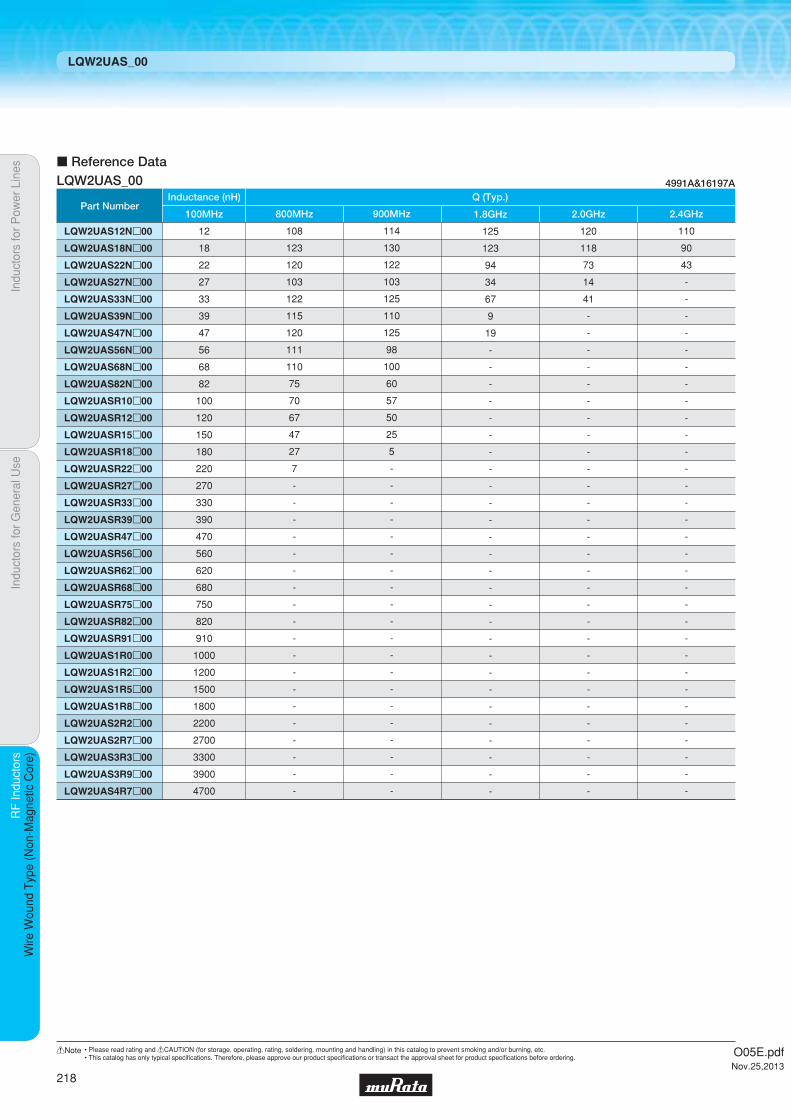
Indu
ctor
s fo
r P
ower
Lin
esIn
duct
ors
for
Gen
eral
Use
RF
Indu
ctor
sR
F In
duct
ors
Wire
Wou
nd T
ype
(Non
-Mag
netic
Cor
e)
LQW2UAS_00
c Reference Data
Part Number
LQW2UAS12Np00
LQW2UAS18Np00
LQW2UAS22Np00
LQW2UAS27Np00
LQW2UAS33Np00
LQW2UAS39Np00
LQW2UAS47Np00
LQW2UAS56Np00
LQW2UAS68Np00
LQW2UAS82Np00
LQW2UASR10p00
LQW2UASR12p00
LQW2UASR15p00
LQW2UASR18p00
LQW2UASR22p00
LQW2UASR27p00
LQW2UASR33p00
LQW2UASR39p00
LQW2UASR47p00
LQW2UASR56p00
LQW2UASR62p00
LQW2UASR68p00
LQW2UASR75p00
LQW2UASR82p00
LQW2UASR91p00
LQW2UAS1R0p00
LQW2UAS1R2p00
LQW2UAS1R5p00
LQW2UAS1R8p00
LQW2UAS2R2p00
LQW2UAS2R7p00
LQW2UAS3R3p00
LQW2UAS3R9p00
LQW2UAS4R7p00
12
18
22
27
33
39
47
56
68
82
100
120
150
180
220
270
330
390
470
560
620
680
750
820
910
1000
1200
1500
1800
2200
2700
3300
3900
4700
100MHz
108
123
120
103
122
115
120
111
110
75
70
67
47
27
7
-
-
-
-
-
-
-
-
-
-
-
-
-
-
-
-
-
-
-
800MHz
114
130
122
103
125
110
125
98
100
60
57
50
25
5
-
-
-
-
-
-
-
-
-
-
-
-
-
-
-
-
-
-
-
-
900MHz
125
123
94
34
67
9
19
-
-
-
-
-
-
-
-
-
-
-
-
-
-
-
-
-
-
-
-
-
-
-
-
-
-
-
1.8GHz
120
118
73
14
41
-
-
-
-
-
-
-
-
-
-
-
-
-
-
-
-
-
-
-
-
-
-
-
-
-
-
-
-
-
2.0GHz
110
90
43
-
-
-
-
-
-
-
-
-
-
-
-
-
-
-
-
-
-
-
-
-
-
-
-
-
-
-
-
-
-
-
2.4GHz
Inductance (nH) Q (Typ.)
LQW2UAS_00 4991A&16197A
O05E.pdfNov.25,2013
218
!Note • Please read rating and !CAUTION (for storage, operating, rating, soldering, mounting and handling) in this catalog to prevent smoking and/or burning, etc.• This catalog has only typical specifi cations. Therefore, please approve our product specifi cations or transact the approval sheet for product specifi cations before ordering.
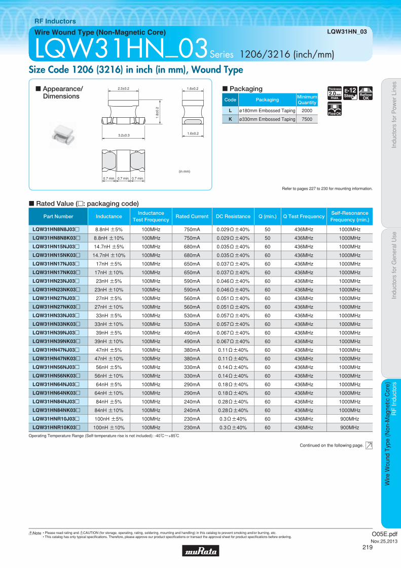
Code PackagingMinimumQuantity
L ø180mm Embossed Taping 2000
K ø330mm Embossed Taping 7500
2.0Thickness
mmmax.
E-12Step Reflow
OK
FlowOK
Indu
ctor
s fo
r P
ower
Lin
esIn
duct
ors
for
Gen
eral
Use
RF
Indu
ctor
sR
F In
duct
ors
Wire
Wou
nd T
ype
(Non
-Mag
netic
Cor
e)
Wire Wound Type (Non-Magnetic Core) LQW31HN_03
RF Inductors
LQW31HN_03Series 1206/3216 (inch/mm)Size Code 1206 (3216) in inch (in mm), Wound Type
c Rated Value (p: packaging code)
Refer to pages 227 to 230 for mounting information.
2.3±0.2
1.8±
0.2
1.6±0.2
1.6±0.23.2±0.3
0.7 min. 0.7 min. 0.7 min.
(in mm)
Continued on the following page.
c Appearance/Dimensions
c Packaging
Operating Temperature Range (Self-temperature rise is not included): -40℃~+85℃
Part Number InductanceInductance
Test FrequencyRated Current DC Resistance Q (min.) Q Test Frequency
Self-ResonanceFrequency (min.)
LQW31HN8N8J03p 8.8nH ±5% 100MHz 750mA 0.029Ω±40% 50 436MHz 1000MHz
LQW31HN8N8K03p 8.8nH ±10% 100MHz 750mA 0.029Ω±40% 50 436MHz 1000MHz
LQW31HN15NJ03p 14.7nH ±5% 100MHz 680mA 0.035Ω±40% 60 436MHz 1000MHz
LQW31HN15NK03p 14.7nH ±10% 100MHz 680mA 0.035Ω±40% 60 436MHz 1000MHz
LQW31HN17NJ03p 17nH ±5% 100MHz 650mA 0.037Ω±40% 60 436MHz 1000MHz
LQW31HN17NK03p 17nH ±10% 100MHz 650mA 0.037Ω±40% 60 436MHz 1000MHz
LQW31HN23NJ03p 23nH ±5% 100MHz 590mA 0.046Ω±40% 60 436MHz 1000MHz
LQW31HN23NK03p 23nH ±10% 100MHz 590mA 0.046Ω±40% 60 436MHz 1000MHz
LQW31HN27NJ03p 27nH ±5% 100MHz 560mA 0.051Ω±40% 60 436MHz 1000MHz
LQW31HN27NK03p 27nH ±10% 100MHz 560mA 0.051Ω±40% 60 436MHz 1000MHz
LQW31HN33NJ03p 33nH ±5% 100MHz 530mA 0.057Ω±40% 60 436MHz 1000MHz
LQW31HN33NK03p 33nH ±10% 100MHz 530mA 0.057Ω±40% 60 436MHz 1000MHz
LQW31HN39NJ03p 39nH ±5% 100MHz 490mA 0.067Ω±40% 60 436MHz 1000MHz
LQW31HN39NK03p 39nH ±10% 100MHz 490mA 0.067Ω±40% 60 436MHz 1000MHz
LQW31HN47NJ03p 47nH ±5% 100MHz 380mA 0.11Ω±40% 60 436MHz 1000MHz
LQW31HN47NK03p 47nH ±10% 100MHz 380mA 0.11Ω±40% 60 436MHz 1000MHz
LQW31HN56NJ03p 56nH ±5% 100MHz 330mA 0.14Ω±40% 60 436MHz 1000MHz
LQW31HN56NK03p 56nH ±10% 100MHz 330mA 0.14Ω±40% 60 436MHz 1000MHz
LQW31HN64NJ03p 64nH ±5% 100MHz 290mA 0.18Ω±40% 60 436MHz 1000MHz
LQW31HN64NK03p 64nH ±10% 100MHz 290mA 0.18Ω±40% 60 436MHz 1000MHz
LQW31HN84NJ03p 84nH ±5% 100MHz 240mA 0.28Ω±40% 60 436MHz 1000MHz
LQW31HN84NK03p 84nH ±10% 100MHz 240mA 0.28Ω±40% 60 436MHz 1000MHz
LQW31HNR10J03p 100nH ±5% 100MHz 230mA 0.3Ω±40% 60 436MHz 900MHz
LQW31HNR10K03p 100nH ±10% 100MHz 230mA 0.3Ω±40% 60 436MHz 900MHz
O05E.pdfNov.25,2013
219
!Note • Please read rating and !CAUTION (for storage, operating, rating, soldering, mounting and handling) in this catalog to prevent smoking and/or burning, etc.• This catalog has only typical specifi cations. Therefore, please approve our product specifi cations or transact the approval sheet for product specifi cations before ordering.

Indu
ctor
s fo
r P
ower
Lin
esIn
duct
ors
for
Gen
eral
Use
RF
Indu
ctor
sR
F In
duct
ors
Wire
Wou
nd T
ype
(Non
-Mag
netic
Cor
e)
LQW31HN_03
c Q-Frequency Characteristics (Typ.) c Inductance-Frequency Characteristics (Typ.)
0
20
40
60
100
140
80
120
10 100 1000 10000Frequency (MHz)
Q
8.8nH
33nH
56nH
100nH
10 100 1000 10000
1000
100
1
10
Frequency (MHz)
L (n
H)
8.8nH
56nH
33nH
100nH
c Reference Data
Part Number
LQW31HN8N8p03
LQW31HN15Np03
LQW31HN17Np03
LQW31HN23Np03
LQW31HN27Np03
LQW31HN33Np03
LQW31HN39Np03
LQW31HN47Np03
LQW31HN56Np03
LQW31HN64Np03
LQW31HN84Np03
LQW31HNR10p03
8.8
14.7
17
23
27
33
39
47
56
64
84
100
100MHz
101
105
106
109
106
98
90
80
77
73
59
40
800MHz
107
108
108
109
109
96
88
72
67
61
47
25
900MHz
146
92
66
53
37
5
-
-
-
-
-
-
1.8GHz
146
75
47
32
14
-
-
-
-
-
-
-
2.0GHz
157
50
22
-
-
-
-
-
-
-
-
-
2.4GHz
Inductance (nH) Q (Typ.)
LQW31HN_03 4991A&16197A
O05E.pdfNov.25,2013
220
!Note • Please read rating and !CAUTION (for storage, operating, rating, soldering, mounting and handling) in this catalog to prevent smoking and/or burning, etc.• This catalog has only typical specifi cations. Therefore, please approve our product specifi cations or transact the approval sheet for product specifi cations before ordering.

Code PackagingMinimumQuantity
L ø180mm Embossed Taping 3000
B Packing in Bulk 500
Indu
ctor
s fo
r P
ower
Lin
esIn
duct
ors
for
Gen
eral
Use
RF
Indu
ctor
sR
F In
duct
ors
Wire
Wou
nd T
ype
(Fer
rite
Cor
e)
Wire Wound Type (Ferrite Core) LQW21HN_00
RF Inductors
LQW21HN_00Series 0805/2012 (inch/mm)Size Code 0805 (2012) in inch (in mm), Ferrite Core High Frequency Wound Type
c Q-Frequency Characteristics (Typ.) c Inductance-Frequency Characteristics (Typ.)
c Rated Value (p: packaging code)
Refer to pages 227 to 230 for mounting information.
0.45±0.1
1.2±0.2
2.0±0.2
0.15
±0.
1
(in mm)
0.9±
0.1
Continued on the following page.
c Appearance/Dimensions
c Packaging
Operating Temperature Range (Self-temperature rise is not included): -40℃~+85℃For refl ow soldering only.
Frequency (MHz)
Q
0
20
40
60
80
1 10 100 1000
0.47μH
0.68μH
1.0μH
2.2μH
1.5μH
Indu
ctan
ce (
μH)
Frequency (MHz)
0.11
1
10
10
1000100
2.2μH
1.5μH
1.0μH
0.68μH
0.47μH
1.0Thickness
mmmax.
E-12Step Reflow
OK
Part Number InductanceInductance
Test FrequencyRated Current
Max. of DCResistance
Q (min.) Q Test FrequencySelf-ResonanceFrequency (min.)
LQW21HNR47J00p 0.47µH ±5% 10MHz 160mA 1.30Ω 35 100MHz 620MHz LQW21HNR56J00p 0.56µH ±5% 10MHz 150mA 1.43Ω 35 100MHz 580MHz LQW21HNR68J00p 0.68µH ±5% 10MHz 130mA 2.21Ω 35 100MHz 520MHz LQW21HNR82J00p 0.82µH ±5% 10MHz 125mA 2.34Ω 35 100MHz 480MHz LQW21HN1R0J00p 1.0µH ±5% 10MHz 115mA 2.86Ω 35 100MHz 450MHz LQW21HN1R2J00p 1.2µH ±5% 10MHz 100mA 3.12Ω 35 100MHz 400MHz LQW21HN1R5J00p 1.5µH ±5% 10MHz 85mA 5.33Ω 35 100MHz 350MHz LQW21HN1R8J00p 1.8µH ±5% 10MHz 80mA 5.85Ω 35 100MHz 320MHz LQW21HN2R2J00p 2.2µH ±5% 10MHz 75mA 6.50Ω 35 100MHz 300MHz
O05E.pdfNov.25,2013
221
!Note • Please read rating and !CAUTION (for storage, operating, rating, soldering, mounting and handling) in this catalog to prevent smoking and/or burning, etc.• This catalog has only typical specifi cations. Therefore, please approve our product specifi cations or transact the approval sheet for product specifi cations before ordering.

Indu
ctor
s fo
r P
ower
Lin
esIn
duct
ors
for
Gen
eral
Use
RF
Indu
ctor
sR
F In
duct
ors
Wire
Wou
nd T
ype
(Fer
rite
Cor
e)
LQW21HN_00
c Reference Data
Part Number
LQW21HNR47p00
LQW21HNR56p00
LQW21HNR68p00
LQW21HNR82p00
LQW21HN1R0p00
LQW21HN1R2p00
LQW21HN1R5p00
LQW21HN1R8p00
LQW21HN2R2p00
0.47
0.56
0.68
0.82
1.0
1.2
1.5
1.8
2.2
100MHz
40
46
41
41
44
44
39
41
43
30MHz
54
63
56
57
54
57
56
56
57
70MHz
55
64
56
58
54
58
56
55
55
80MHz
56
64
57
59
54
58
56
54
55
90MHz
55
60
54
57
50
52
53
50
50
100MHz
Inductance (μH) Q (Typ.)
LQW21HN_00 4991A&16197A
O05E.pdfNov.25,2013
222
!Note • Please read rating and !CAUTION (for storage, operating, rating, soldering, mounting and handling) in this catalog to prevent smoking and/or burning, etc.• This catalog has only typical specifi cations. Therefore, please approve our product specifi cations or transact the approval sheet for product specifi cations before ordering.

Code PackagingMinimumQuantity
L ø180mm Embossed Taping 2000
K ø330mm Embossed Taping 7500
2.0Thickness
mmmax.
ReflowOK FlowOK
Part Number InductanceInductance
Test FrequencyRated Current DC Resistance Q (min.) Q Test Frequency
Self-ResonanceFrequency (min.)
LQH31HN54NK03p 54nH ±10% 1MHz 920mA 0.035Ω±30% 50 100MHz 800MHz
LQH31HN95NK03p 95nH ±10% 1MHz 790mA 0.047Ω±30% 60 100MHz 650MHz
LQH31HNR14J03p 145nH ±5% 1MHz 700mA 0.061Ω±30% 60 100MHz 500MHz
LQH31HNR14K03p 145nH ±10% 1MHz 700mA 0.061Ω±30% 60 100MHz 500MHz
LQH31HNR21J03p 215nH ±5% 1MHz 520mA 0.11Ω±30% 60 100MHz 430MHz
LQH31HNR21K03p 215nH ±10% 1MHz 520mA 0.11Ω±30% 60 100MHz 430MHz
LQH31HNR29J03p 290nH ±5% 1MHz 420mA 0.17Ω±30% 60 100MHz 360MHz
LQH31HNR29K03p 290nH ±10% 1MHz 420mA 0.17Ω±30% 60 100MHz 360MHz
LQH31HNR39J03p 390nH ±5% 1MHz 330mA 0.26Ω±30% 60 100MHz 300MHz
LQH31HNR39K03p 390nH ±10% 1MHz 330mA 0.26Ω±30% 60 100MHz 300MHz
LQH31HNR50J03p 500nH ±5% 1MHz 260mA 0.44Ω±30% 60 100MHz 270MHz
LQH31HNR50K03p 500nH ±10% 1MHz 260mA 0.44Ω±30% 60 100MHz 270MHz
LQH31HNR61J03p 610nH ±5% 1MHz 250mA 0.48Ω±30% 60 100MHz 240MHz
LQH31HNR61K03p 610nH ±10% 1MHz 250mA 0.48Ω±30% 60 100MHz 240MHz
LQH31HNR75J03p 750nH ±5% 1MHz 190mA 0.79Ω±30% 60 100MHz 220MHz
LQH31HNR75K03p 750nH ±10% 1MHz 190mA 0.79Ω±30% 60 100MHz 220MHz
LQH31HNR88J03p 880nH ±5% 1MHz 180mA 0.86Ω±30% 60 100MHz 200MHz
LQH31HNR88K03p 880nH ±10% 1MHz 180mA 0.86Ω±30% 60 100MHz 200MHz
Indu
ctor
s fo
r P
ower
Lin
esIn
duct
ors
for
Gen
eral
Use
RF
Indu
ctor
sR
F In
duct
ors
Wire
Wou
nd T
ype
(Fer
rite
Cor
e)
Wire Wound Type (Ferrite Core) LQH31HN_03
RF Inductors
LQH31HN_03Series 1206/3216 (inch/mm)Size Code 1206 (3216) in inch (in mm), Ferrite Core High Frequency Wound Type
c Q-Frequency Characteristics (Typ.)
c Rated Value (p: packaging code)
Refer to pages 227 to 230 for mounting information.
2.3±0.2
1.8±
0.2
1.6±0.2
1.6±0.23.2±0.3
0.7 min. 0.7 min. 0.7 min.
(in mm)
Continued on the following page.
c Appearance/Dimensions
c Packaging
Operating Temperature Range (Self-temperature rise is not included): -40℃~+85℃
215nH
880nH
54nH
1 10 100 1000Frequency (MHz)
100
80
60
40
20
0
Q
O05E.pdfNov.25,2013
223
!Note • Please read rating and !CAUTION (for storage, operating, rating, soldering, mounting and handling) in this catalog to prevent smoking and/or burning, etc.• This catalog has only typical specifi cations. Therefore, please approve our product specifi cations or transact the approval sheet for product specifi cations before ordering.

Indu
ctor
s fo
r P
ower
Lin
esIn
duct
ors
for
Gen
eral
Use
RF
Indu
ctor
sR
F In
duct
ors
Wire
Wou
nd T
ype
(Fer
rite
Cor
e)
LQH31HN_03
c Reference Data
Part Number
LQH31HN54Np03
LQH31HN95Np03
LQH31HNR14p03
LQH31HNR21p03
LQH31HNR29p03
LQH31HNR39p03
LQH31HNR50p03
LQH31HNR61p03
LQH31HNR75p03
LQH31HNR88p03
54
95
145
215
290
390
500
610
750
880
100MHz
2
1
-
-
-
-
-
-
-
-
800MHz
1
-
-
-
-
-
-
-
-
-
900MHz
-
-
-
-
-
-
-
-
-
-
1.8GHz
-
-
-
-
-
-
-
-
-
-
2.0GHz
-
-
-
-
-
-
-
-
-
-
2.4GHz
Inductance (nH) Q (Typ.)
LQH31HN_03 4991A&16197A
O05E.pdfNov.25,2013
224
!Note • Please read rating and !CAUTION (for storage, operating, rating, soldering, mounting and handling) in this catalog to prevent smoking and/or burning, etc.• This catalog has only typical specifi cations. Therefore, please approve our product specifi cations or transact the approval sheet for product specifi cations before ordering.
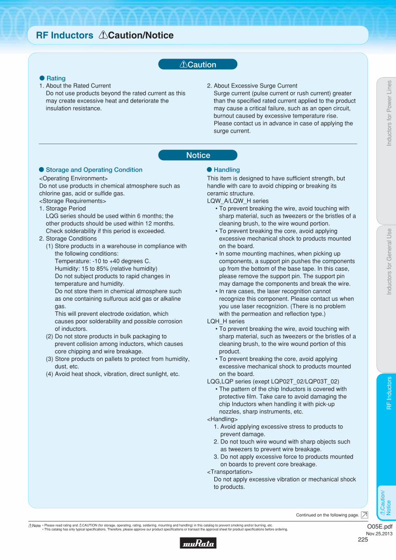
Indu
ctor
s fo
r P
ower
Lin
esIn
duct
ors
for
Gen
eral
Use
RF
Indu
ctor
sR
F In
duct
ors
!C
autio
n/N
otic
e
o Rating
o Storage and Operating Condition<Operating Environment>Do not use products in chemical atmosphere such as chlorine gas, acid or sulfide gas.<Storage Requirements>1. Storage Period
LQG series should be used within 6 months; the other products should be used within 12 months.Check solderability if this period is exceeded.
2. Storage Conditions(1) Store products in a warehouse in compliance with
the following conditions:Temperature: -10 to +40 degrees C.Humidity: 15 to 85% (relative humidity)Do not subject products to rapid changes in temperature and humidity.Do not store them in chemical atmosphere such as one containing sulfurous acid gas or alkaline gas.This will prevent electrode oxidation, which causes poor solderability and possible corrosion of inductors.
(2) Do not store products in bulk packaging to prevent collision among inductors, which causes core chipping and wire breakage.
(3) Store products on pallets to protect from humidity, dust, etc.
(4) Avoid heat shock, vibration, direct sunlight, etc.
o HandlingThis item is designed to have sufficient strength, but handle with care to avoid chipping or breaking its ceramic structure.LQW_A/LQW_H series
sharp material, such as tweezers or the bristles of a cleaning brush, to the wire wound portion.
excessive mechanical shock to products mounted on the board.
components, a support pin pushes the components
please remove the support pin. The support pin may damage the components and break the wire.
recognize this component. Please contact us when you use laser recognizion. (There is no problem with the permeation and reflection type.)
LQH_H series
sharp material, such as tweezers or the bristles of a cleaning brush, to the wire wound portion of this product.
excessive mechanical shock to products mounted on the board.
LQG,LQP series (exept LQP02T_02/LQP03T_02)
protective film. Take care to avoid damaging the
nozzles, sharp instruments, etc.<Handling>
1. Avoid applying excessive stress to products to prevent damage.
2. Do not touch wire wound with sharp objects such as tweezers to prevent wire breakage.
3. Do not apply excessive force to products mounted on boards to prevent core breakage.
<Transportation>Do not apply excessive vibration or mechanical shock to products.
!Caution
Notice
RF Inductors !Caution/Notice
Continued on the following page.
1. About the Rated CurrentDo not use products beyond the rated current as this may create excessive heat and deteriorate the insulation resistance.
2. About Excessive Surge CurrentSurge current (pulse current or rush current) greater than the specified rated current applied to the product may cause a critical failure, such as an open circuit, burnout caused by excessive temperature rise. Please contact us in advance in case of applying the surge current.
O05E.pdfNov.25,2013
225
!Note • Please read rating and !CAUTION (for storage, operating, rating, soldering, mounting and handling) in this catalog to prevent smoking and/or burning, etc.• This catalog has only typical specifi cations. Therefore, please approve our product specifi cations or transact the approval sheet for product specifi cations before ordering.

Indu
ctor
s fo
r P
ower
Lin
esIn
duct
ors
for
Gen
eral
Use
RF
Indu
ctor
sR
F In
duct
ors
!C
autio
n/N
otic
e
Measuring Method of Inductance/Q1. Residual elements and stray elements of test fixtures
can be described by F-parameter as shown in the following:
2. The impedance of chip Inductors (chip coils) Zx and measured value Zm can be described by input/output current/voltage.
3. Thus, the relation between Zx and Zm is shown in the following:
4. Lx and Qx should be calculated with the following equation.
o Measuring Method
V1 A=
B
I1 C D
V2
I2
A B
C D
Zm ZxV1 V2
I1 I2
ProductTest fixtureTest Head
V1
I1 ,Zm =
V2
I2Zx =
Zm - β1 - ZmΓ
Zx = αwhere, α = D / A = 1 β = B / D = Zsm - (1 - Yom Zsm) Zss Γ = C / A = Yom
Zsm: measured impedance of short chipZss: residual impedance of short chip*Yom: measured admittance when opening the fixture
0nH LQG15HS/LQP03TG
0.110nH LQP02TN/LQP02TQ
0.480nH LQP03TN_02
0.556nH LQG15HN, LQW15A, LQP15M
0.771nH LQG18H, LQP18M, LQW18A, LQW21H
ResidualImpedance Series
*Residual impedance of short chip
Lx: Inductance of chip Inductors (chip coils)Qx: Q of chip Inductors (chip coils)f: Measuring frequency
,
Im (Zx)
2πfLx =
Im (Zx)
Re (Zx)Qx =
<Handling of a Substrate>After mounting products on a substrate, do not apply any stress to the product caused by bending or twisting the substrate when cropping the substrate, inserting and removing a connector from the substrate, or tightening a screw to the substrate. Excessive mechanical stress may cause cracking in the Product.
Bending Twisting
<Resin Coating>When coating products with resin, the relatively high resin curing stress may change inductance values.For exterior coating, select resin carefully so that electrical and mechanical performance of the product is not affected. Prior to use, please evaluate reliability with the product mounted in your application set.
(LQW,LQH series)An open circuit issue may occur by mechanical stress caused by the resin, amount/cured shape of resin, or operating conditions, etc. Some resins containing impurities or chloride may possibly generate chlorine by hydrolysis under some operating conditions, causing corrosion of the inductor wire and leading to an open circuit.
(LQP02T_02,LQP03T_02)When products are coated with resin, please contact us in advance.
RF Inductors !Caution/Notice
O05E.pdfNov.25,2013
226
!Note • Please read rating and !CAUTION (for storage, operating, rating, soldering, mounting and handling) in this catalog to prevent smoking and/or burning, etc.• This catalog has only typical specifi cations. Therefore, please approve our product specifi cations or transact the approval sheet for product specifi cations before ordering.

Indu
ctor
s fo
r P
ower
Lin
esIn
duct
ors
for
Gen
eral
Use
RF
Indu
ctor
sR
F In
duct
ors
Sol
derin
g an
d M
ount
ing
1. Standard Land Pattern Dimensions
A high Q value is achieved when the PCB electrode land pattern is designed so that it does not project beyond the chip Inductors (chip coils) electrode.
(in mm)
a
c
b
Standard Land DimensionsSeries
LQW03A
LQW04A
LQW15A_00/10
LQW15A_80
LQW18A_00/10
LQW18A_80
LQW21H
LQW2BH
0.4
0.4
0.65
0.66
0.7-1.0
1.15
1.2
1.2
0.65
1.0
1.2
1.42
1.9-2.0
2.0
2.6
3.0
0.23
0.4
0.5
0.6
0.6-0.8
0.86
1.0
0.8
LQW2BA
LQW2UA
1.78
2.54
2.8
3.3
0.76
1.27
LQH31HLQW31H
1.54.51.0
LQG15H
LQG18H
LQP02TN
LQP02TQ
LQP03T
LQP15M
LQP18M
0.5-0.6
0.6-0.8
0.2-0.23
0.2
0.2-0.3
0.5-0.6
0.6-0.8
1.4-1.5
1.8-2.2
0.4-0.56
0.56
0.8-0.9
1.4-1.5
1.8-2.2
0.4
0.6-0.8
0.16-0.2
0.2
0.2-0.3
0.4
0.7-0.9
LQG15HLQG18HLQP02TNLQP02TQLQP03TLQP15MLQP18MLQW03ALQW04ALQW15ALQW18ALQW21HLQW2BHLQW2BALQW2UALQW31HLQH31H
Part Number a b c
Attention should be paid to potential magnetic coupling effects when using the Inductors (coils) as a resonator.
Land Pattern
Land Pattern+ Solder Resist
Solder Resist
2. Standard Soldering Conditions
(1) Soldering methodChip Inductors (Chip coils) can be flow or reflow soldered. Please contact Murata regarding other soldering methods.As for LQG, LQP, LQW03A/04A/15A/18A/21H/2BA/2UA series, please use reflow soldering.
Solder: Use Sn-3.0Ag-0.5Cu solder.Flux: Use rosin-based flux, but not strongly acidic flux (with
chlorine content exceeding 0.2wt%).Do not use water-soluble flux.The flux used for LQW03/04/15/18/21/2BA/2UA series should use the rosin-based flux that includes middle activator equivalent to 0.06wt% to 0.1wt% chlorine.
For additional mounting methods, please contact Murata.
Soldering and MountingRF Inductors
Continued on the following page.
O05E.pdfNov.25,2013
227
!Note • Please read rating and !CAUTION (for storage, operating, rating, soldering, mounting and handling) in this catalog to prevent smoking and/or burning, etc.• This catalog has only typical specifi cations. Therefore, please approve our product specifi cations or transact the approval sheet for product specifi cations before ordering.
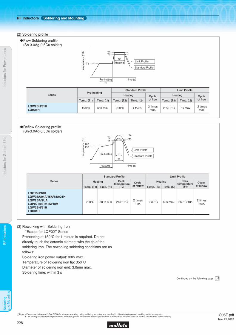
Indu
ctor
s fo
r P
ower
Lin
esIn
duct
ors
for
Gen
eral
Use
RF
Indu
ctor
sR
F In
duct
ors
Sol
derin
g an
d M
ount
ing
"Reflow Soldering profile (Sn-3.0Ag-0.5Cu solder)
Series
Standard Profile Limit Profile
Temp. (T1) Time. (t1)
Heating
220°C 30 to 60s 245±3°C 2 timesmax. 230°C 260°C/10s 2 times
max.60s max.
Cycle of reflow
Peak temperature
(T2) Temp. (T3) Time. (t2)
Heating Cycle of reflow
Peak temperature
(T4)
150180
T2T4
T3T1
Tem
pera
ture
(°C
)
90±30s time (s)
t2
t1Limit Profile
Standard ProfilePre-heating
LQG15H/18HLQW03A/04A/15A/18A/21HLQW2BA/2UALQP02T/03T/15M/18MLQW2BH/31HLQH31H
(2) Soldering profile
"Flow Soldering profile (Sn-3.0Ag-0.5Cu solder)
SeriesPre-heating
Standard Profile Limit Profile
Heating
Temp. (T1) Temp. (T2)Time. (t1)
150°C 60s min. 250°C 4 to 6s 2 timesmax. 5s max. 2 times
max.265±3°C
Time. (t2)
HeatingCycle of flow Temp. (T3) Time. (t2)
Cycle of flow
T1
T3T2
Tem
pera
ture
(°C
)Pre-heating time (s)
t2
Heating Limit Profile
Standard Profile
t1
LQW2BH/31HLQH31H
(3) Reworking with Soldering Iron *Except for LQP02T SeriesPreheating at 150°C for 1 minute is required. Do not directly touch the ceramic element with the tip of the soldering iron. The reworking soldering conditions are as follows:Soldering iron power output: 80W max.Temperature of soldering iron tip: 350°CDiameter of soldering iron end: 3.0mm max.Soldering time: within 3 s
Continued on the following page.
RF Inductors Soldering and Mounting
O05E.pdfNov.25,2013
228
!Note • Please read rating and !CAUTION (for storage, operating, rating, soldering, mounting and handling) in this catalog to prevent smoking and/or burning, etc.• This catalog has only typical specifi cations. Therefore, please approve our product specifi cations or transact the approval sheet for product specifi cations before ordering.
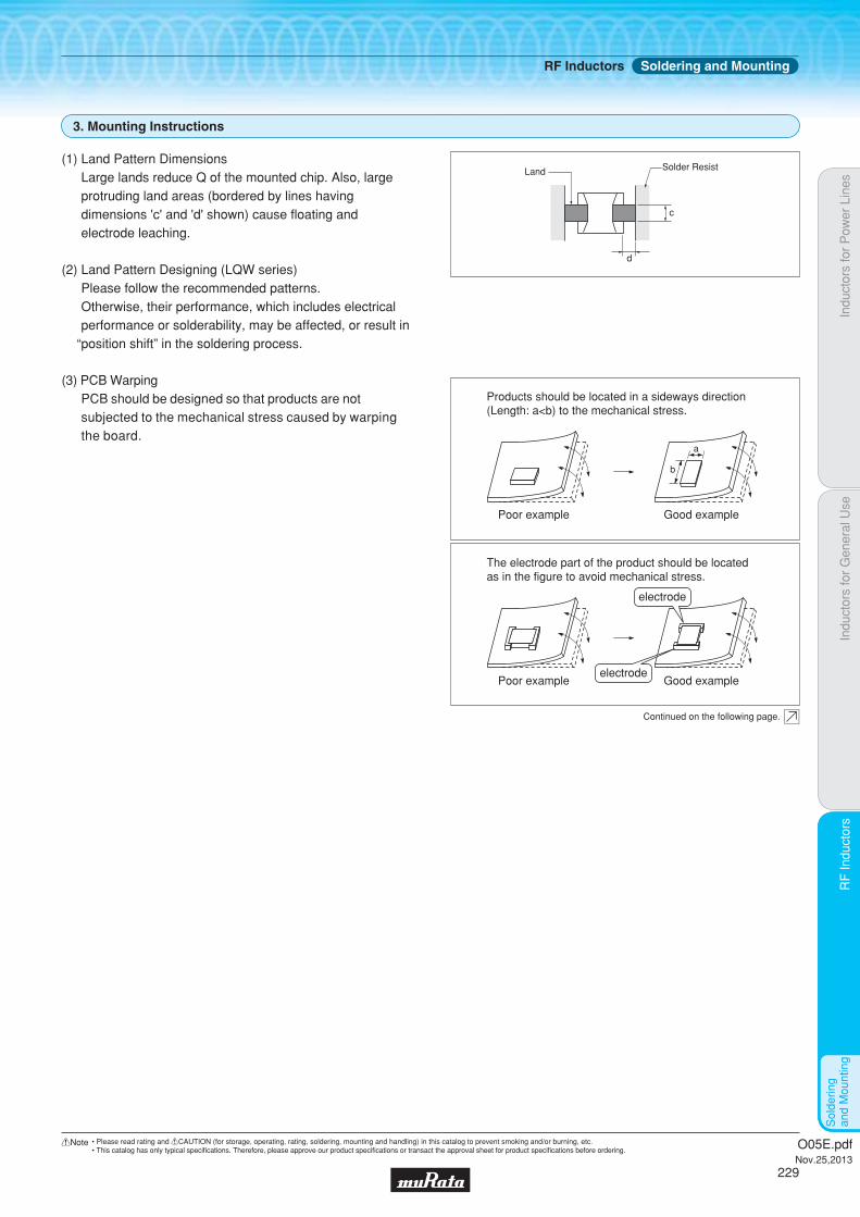
Indu
ctor
s fo
r P
ower
Lin
esIn
duct
ors
for
Gen
eral
Use
RF
Indu
ctor
sR
F In
duct
ors
Sol
derin
g an
d M
ount
ing
3. Mounting Instructions
(3) PCB WarpingPCB should be designed so that products are not subjected to the mechanical stress caused by warping the board.
Poor example
Products should be located in a sideways direction (Length: a<b) to the mechanical stress.
Good example
a
b
Poor example
The electrode part of the product should be located as in the figure to avoid mechanical stress.
Good example
(1) Land Pattern DimensionsLarge lands reduce Q of the mounted chip. Also, large protruding land areas (bordered by lines having dimensions 'c' and 'd' shown) cause floating and electrode leaching.
(2) Land Pattern Designing (LQW series)Please follow the recommended patterns.Otherwise, their performance, which includes electrical performance or solderability, may be affected, or result in
“position shift” in the soldering process.
d
c
Land Solder Resist
electrode
electrode
Continued on the following page.
RF Inductors Soldering and Mounting
O05E.pdfNov.25,2013
229
!Note • Please read rating and !CAUTION (for storage, operating, rating, soldering, mounting and handling) in this catalog to prevent smoking and/or burning, etc.• This catalog has only typical specifi cations. Therefore, please approve our product specifi cations or transact the approval sheet for product specifi cations before ordering.
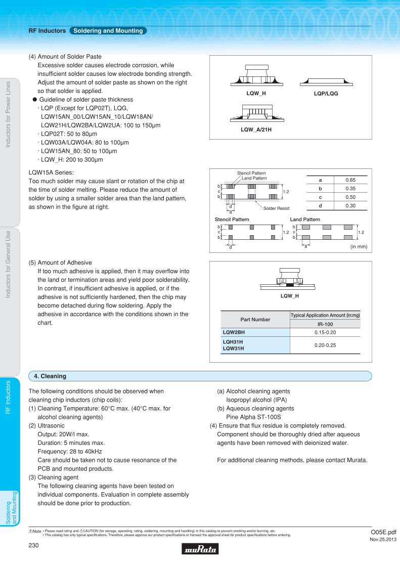
Indu
ctor
s fo
r P
ower
Lin
esIn
duct
ors
for
Gen
eral
Use
RF
Indu
ctor
sR
F In
duct
ors
Sol
derin
g an
d M
ount
ing
LQW_H
LQW2BH
LQH31HLQW31H
0.15-0.20
0.20-0.25
(5) Amount of AdhesiveIf too much adhesive is applied, then it may overflow into the land or termination areas and yield poor solderability. In contrast, if insufficient adhesive is applied, or if the adhesive is not sufficiently hardened, then the chip may become detached during flow soldering. Apply the adhesive in accordance with the conditions shown in the chart.
Typical Application Amount (in:mg)Part Number
IR-100
The following conditions should be observed when cleaning chip inductors (chip coils):(1) Cleaning Temperature: 60°C max. (40°C max. for
alcohol cleaning agents)(2) Ultrasonic
Output: 20W/l max.Duration: 5 minutes max.Frequency: 28 to 40kHzCare should be taken not to cause resonance of thePCB and mounted products.
(3) Cleaning agent The following cleaning agents have been tested on individual components. Evaluation in complete assembly should be done prior to production.
(a) Alcohol cleaning agentsIsopropyl alcohol (IPA)
(b) Aqueous cleaning agentsPine Alpha ST-100S
(4) Ensure that flux residue is completely removed.Component should be thoroughly dried after aqueous agents have been removed with deionized water.
For additional cleaning methods, please contact Murata.
4. Cleaning
LQP/LQGLQW_H
LQW_A/21H
(4) Amount of Solder PasteExcessive solder causes electrode corrosion, while insufficient solder causes low electrode bonding strength. Adjust the amount of solder paste as shown on the right so that solder is applied." Guideline of solder paste thickness
· LQP (Except for LQP02T), LQG, LQW15AN_00/LQW15AN_10/LQW18AN/ LQW21H/LQW2BA/LQW2UA: 100 to 150μm· LQP02T: 50 to 80μm· LQW03A/LQW04A: 80 to 100μm· LQW15AN_80: 50 to 100μm· LQW_H: 200 to 300μm
LQW15A Series:Too much solder may cause slant or rotation of the chip at the time of solder melting. Please reduce the amount of solder by using a smaller solder area than the land pattern, as shown in the figure at right.
a 0.65
(in mm)
b 0.35
c 0.50
d 0.30
1.2
Stencil PatternLand Pattern
Solder Resista
b
bc
d
1.2
Stencil Patternb
bc
d
1.2
Land Pattern
a
b
bc
RF Inductors Soldering and Mounting
O05E.pdfNov.25,2013
230
!Note • Please read rating and !CAUTION (for storage, operating, rating, soldering, mounting and handling) in this catalog to prevent smoking and/or burning, etc.• This catalog has only typical specifi cations. Therefore, please approve our product specifi cations or transact the approval sheet for product specifi cations before ordering.

Indu
ctor
s fo
r P
ower
Lin
esIn
duct
ors
for
Gen
eral
Use
RF
Indu
ctor
sR
F In
duct
ors
Pac
kagi
ng
c Minimum Quantity and 8mm Width Taping Dimensions
Direction of feed
2.0±0.05 4.0±0.1
ab
c
1.75
±0.1
ø1.5 +0.1-0
3.5±
0.05
(8.0
)
2.0±0.05
c
LQG15H,LQP15M/18M
LQP02T/03T/15T,LQW03A/04A/15A
Part Numbera
Paper Tape
LQG15H
LQP15M
LQP18M
LQW04A
LQW15A_00 ∗2
LQW15A_10 ∗3
0.62
0.70
1.19
0.50
0.64/0.66/0.69
0.66/0.69
b
1.12
1.20
2.0
0.905
1.18
1.18
c
0.8 max.
0.8 max.
0.8 max.
0.75 max.
0.8 max.
0.8 max.
ø180mm reel
D [10000]
ø330mm reel
Dimensions Total Thickness of Tape Packaging Code (Minimum Qty. [pcs.])
J [50000]
Bulk
B [1000]
D [10000] J [50000] B [500]
D [4000] J [10000] B [500]
D [10000] - B [500]
D [10000] - B [500]
D [10000] - B [500]
LQP03T ∗1 0.35 0.65/0.67 0.55 max. D [15000] J [50000] B [500]
LQP02TN 0.24 0.47 0.39 max. D [20000] - B [500]
LQP02TQ 0.24 0.45 0.39 max. D [20000] - B [500]
LQW03A 0.52 0.65 0.75 max. D [10000] - -
LQW15A_80 0.75 1.18 0.8 max. D [10000] - B [500]
(in mm)
∗2 0.69 (1.5-2.7nH, 3.9-4.7nH, 5.8-6.8nH, 8.2-9.5nH, 11nH, 12nH, 15nH)
0.66 (2.9nH, 5.1nH, 7.3nH, 7.5nH, 10nH, 13nH, 16-23nH, 100nH, 120nH)
0.64 (24-91nH)
∗3 0.69 (1.3nH)
0.66 (2.2-5.6nH)
∗1 0.67 (LQP03TG · LQP03TN_02; 0.6-62nH, 130-270nH)
0.65 (LQP03TN_02; 68-120nH)
a
b
cDirection of feed
Dimension of the cavity of embossed tape is measured at the bottom side.
4.0±0.1 4.0±0.1
2.0±0.05
0.2
3.5±
0.05 1.
75±
0.1
(8.
0)
ø1.5 +0.1-0
∗1
∗1: 0.3 LQW2BH 0.25 LQW21H
c Minimum Quantity and 8mm Width Taping Dimensions
<Embossed> <Paper>
c
(in mm)
Part Numbera
Paper Tape
LQG18H
LQW18A_00
LQW18A_10
1.05
1.0
1.1
b
1.85
1.8
1.9
c
1.1 max.
1.1 max.
1.1 max.
ø180mm reel ø330mm reel
Dimensions Packaging Code (Minimum Qty. [pcs.])
Bulk
D [4000] J [10000] B [1000]
D [4000] J [10000] B [500]
D [4000] J [10000] B [500]
LQW18A_80 1.15 1.9 1.1 max. D [4000] J [10000] B [500]
Part Numbera
Embossed Tape
LQH31H, LQW31H 1.9
b
3.6
c
2.0
ø180mm reel ø330mm reel
Dimensions
Total Thickness of Tape
Depth of Cavity Packaging Code (Minimum Qty. [pcs.])
Bulk
L [2000] K [7500] -
LQW2BH 1.75 2.3 2.0 L [2000] K [7500] -
LQW2BA 1.8 2.3 1.65 L [2000] - -
LQW2UA 2.7 2.8 2.15 L [2000] - -
LQW21H 1.55 2.3 1.1 L [3000] - B [500]
RF Inductors Packaging
O05E.pdfNov.25,2013
231
!Note • Please read rating and !CAUTION (for storage, operating, rating, soldering, mounting and handling) in this catalog to prevent smoking and/or burning, etc.• This catalog has only typical specifi cations. Therefore, please approve our product specifi cations or transact the approval sheet for product specifi cations before ordering.
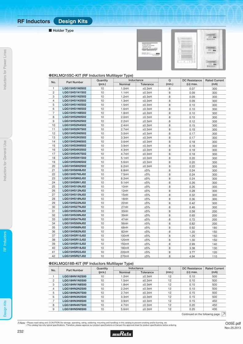
Indu
ctor
s fo
r P
ower
Lin
esIn
duct
ors
for
Gen
eral
Use
RF
Indu
ctor
sR
F In
duct
ors
Des
ign
Kits
LQG15HS1N0S02LQG15HS1N1S02LQG15HS1N2S02LQG15HS1N3S02LQG15HS1N5S02LQG15HS1N6S02LQG15HS1N8S02LQG15HS2N0S02LQG15HS2N2S02LQG15HS2N4S02LQG15HS2N7S02LQG15HS3N0S02LQG15HS3N3S02LQG15HS3N6S02LQG15HS3N9S02LQG15HS4N3S02LQG15HS4N7S02LQG15HS5N1S02LQG15HS5N6S02LQG15HS6N2S02LQG15HS6N8J02LQG15HS7N5J02LQG15HS8N2J02LQG15HS9N1J02LQG15HS10NJ02LQG15HS12NJ02LQG15HS15NJ02LQG15HS18NJ02LQG15HS22NJ02LQG15HS27NJ02LQG15HS33NJ02LQG15HS39NJ02LQG15HS47NJ02LQG15HS56NJ02LQG15HS68NJ02LQG15HS82NJ02LQG15HSR10J02LQG15HSR12J02LQG15HSR15J02LQG15HSR18J02LQG15HSR22J02LQG15HSR27J02
123456789101112131415161718192021222324252627282930313233343536373839404142
101010101010101010101010101010101010101010101010101010101010101010101010101010101010
1.0nH1.1nH1.2nH1.3nH1.5nH1.6nH1.8nH2.0nH2.2nH2.4nH2.7nH3.0nH3.3nH3.6nH3.9nH4.3nH4.7nH5.1nH5.6nH6.2nH6.8nH7.5nH8.2nH9.1nH10nH12nH15nH18nH22nH27nH33nH39nH47nH56nH68nH82nH
100nH120nH150nH180nH220nH270nH
±0.3nH±0.3nH±0.3nH±0.3nH±0.3nH±0.3nH±0.3nH±0.3nH±0.3nH±0.3nH±0.3nH±0.3nH±0.3nH±0.3nH±0.3nH±0.3nH±0.3nH±0.3nH±0.3nH±0.3nH
±5%±5%±5%±5%±5%±5%±5%±5%±5%±5%±5%±5%±5%±5%±5%±5%±5%±5%±5%±5%±5%±5%
888888888888888888888888888888888888888888
0.070.090.090.090.100.100.100.100.120.150.150.170.170.180.180.180.180.200.200.220.240.240.240.260.260.280.320.360.420.460.580.650.720.820.921.201.251.302.993.383.774.94
300300300300300300300300300300300300300300300300300300300300300300300300300300300300300300200200200200180150150150140130120110
oEKLMQ15SC-KIT (RF Inductors Multilayer Type)
oEKLMQG18B-KIT (RF Inductors Multilayer Type)
c Holder Type
LQG18HN1N2S00LQG18HN1N5S00LQG18HN1N8S00LQG18HN2N2S00
1234
10101010
1.2nH1.5nH1.8nH2.2nH
±0.3nH±0.3nH±0.3nH±0.3nH
12121212
0.100.100.100.10
500500500500
LQG18HN2N7S00LQG18HN3N3S00LQG18HN3N9S00LQG18HN4N7S00LQG18HN5N6S00
56789
1010101010
2.7nH3.3nH3.9nH4.7nH5.6nH
±0.3nH±0.3nH±0.3nH±0.3nH±0.3nH
1212121212
0.150.150.150.200.20
500500450450430
Part NumberNo.Rated Current
(mA)DC Resistance
(Ω) max.Q
(min.)InductanceQuantity
(pcs.) ToleranceNominal
Part NumberNo.Rated Current
(mA)DC Resistance
(Ω) max.Q
(min.)ToleranceNominalInductanceQuantity
(pcs.)
Continued on the following page.
Design KitsRF Inductors
O05E.pdfNov.25,2013
232
!Note • Please read rating and !CAUTION (for storage, operating, rating, soldering, mounting and handling) in this catalog to prevent smoking and/or burning, etc.• This catalog has only typical specifi cations. Therefore, please approve our product specifi cations or transact the approval sheet for product specifi cations before ordering.

Indu
ctor
s fo
r P
ower
Lin
esIn
duct
ors
for
Gen
eral
Use
RF
Indu
ctor
sR
F In
duct
ors
Des
ign
Kits
oEKLMQP02F-KIT (RF Inductors Film Type)
LQG18HN6N8J00LQG18HN8N2J00LQG18HN10NJ00LQG18HN12NJ00LQG18HN15NJ00LQG18HN18NJ00LQG18HN22NJ00LQG18HN27NJ00LQG18HN33NJ00LQG18HN39NJ00LQG18HN47NJ00LQG18HN56NJ00LQG18HN68NJ00LQG18HN82NJ00LQG18HNR10J00
101112131415161718192021222324
101010101010101010101010101010
6.8nH8.2nH10nH12nH15nH18nH22nH27nH33nH39nH47nH56nH68nH82nH
100nH
±5%±5%±5%±5%±5%±5%±5%±5%±5%±5%±5%±5%±5%±5%±5%
121212121212121212121212121212
0.250.250.300.350.400.450.500.550.600.650.700.750.800.850.90
430400400400350350300300300300300300300300300
LQP02TN0N2B02LQP02TN0N3B02LQP02TN0N4B02LQP02TN0N5B02LQP02TN0N6B02LQP02TN0N7B02LQP02TN0N8B02LQP02TN0N9B02LQP02TN1N0B02LQP02TN1N1B02LQP02TN1N2B02LQP02TN1N3B02LQP02TN1N4B02LQP02TN1N5B02LQP02TN1N6B02LQP02TN1N7B02LQP02TN1N8B02LQP02TN1N9B02LQP02TN2N0B02LQP02TN2N1B02LQP02TN2N2B02LQP02TN2N3B02LQP02TN2N4B02LQP02TN2N5B02LQP02TN2N6B02LQP02TN2N7B02LQP02TN2N8B02LQP02TN2N9B02LQP02TN3N0B02LQP02TN3N1B02LQP02TN3N2B02LQP02TN3N3B02LQP02TN3N4B02LQP02TN3N5B02LQP02TN3N6B02LQP02TN3N7B02LQP02TN3N8B02LQP02TN3N9B02LQP02TN4N0B02LQP02TN4N1B02LQP02TN4N2B02LQP02TN4N3H02LQP02TN4N7H02LQP02TN5N1H02LQP02TN5N6H02LQP02TN6N2H02
12345678910111213141516171819202122232425262728293031323334353637383940414243444546
10101010101010101010101010101010101010101010101010101010101010101010101010101010101010101010
0.2nH0.3nH0.4nH0.5nH0.6nH0.7nH0.8nH0.9nH1.0nH1.1nH1.2nH1.3nH1.4nH1.5nH1.6nH1.7nH1.8nH1.9nH2.0nH2.1nH2.2nH2.3nH2.4nH2.5nH2.6nH2.7nH2.8nH2.9nH3.0nH3.1nH3.2nH3.3nH3.4nH3.5nH3.6nH3.7nH3.8nH3.9nH4.0nH4.1nH4.2nH4.3nH4.7nH5.1nH5.6nH6.2nH
±0.1nH±0.1nH±0.1nH±0.1nH±0.1nH±0.1nH±0.1nH±0.1nH±0.1nH±0.1nH±0.1nH±0.1nH±0.1nH±0.1nH±0.1nH±0.1nH±0.1nH±0.1nH±0.1nH±0.1nH±0.1nH±0.1nH±0.1nH±0.1nH±0.1nH±0.1nH±0.1nH±0.1nH±0.1nH±0.1nH±0.1nH±0.1nH±0.1nH±0.1nH±0.1nH±0.1nH±0.1nH±0.1nH±0.1nH±0.1nH±0.1nH
±3%±3%±3%±3%±3%
--88888888888888888888888888888888888888888888
0.500.500.500.500.500.500.500.500.600.600.600.600.600.600.600.700.700.750.750.750.750.750.750.800.800.801.101.101.101.301.301.301.301.301.301.301.301.301.301.301.301.301.501.501.801.80
320320320320320320320320220220220220220220220200200200200200200200200200200200200200200180180180180180180180180180180180180180160160140140
Part NumberNo.Rated Current
(mA)DC Resistance
(Ω) max.Q
(min.)ToleranceNominalInductanceQuantity
(pcs.)
Part NumberNo.Rated Current
(mA)DC Resistance
(Ω) max.Q
(min.)ToleranceNominalInductanceQuantity
(pcs.)
Continued from the preceding page.
Continued on the following page.
RF Inductors Design Kits
O05E.pdfNov.25,2013
233
!Note • Please read rating and !CAUTION (for storage, operating, rating, soldering, mounting and handling) in this catalog to prevent smoking and/or burning, etc.• This catalog has only typical specifi cations. Therefore, please approve our product specifi cations or transact the approval sheet for product specifi cations before ordering.

Indu
ctor
s fo
r P
ower
Lin
esIn
duct
ors
for
Gen
eral
Use
RF
Indu
ctor
sR
F In
duct
ors
Des
ign
Kits
LQP02TN6N8H02LQP02TN7N5H02LQP02TN8N2H02LQP02TN9N1H02LQP02TN10NH02LQP02TN11NH02LQP02TN12NH02LQP02TN13NH02LQP02TN15NH02LQP02TN16NH02LQP02TN18NH02LQP02TN20NH02
474849505152535455565758
101010101010101010101010
6.8nH7.5nH8.2nH9.1nH10nH11nH12nH13nH15nH16nH18nH20nH
±3%±3%±3%±3%±3%±3%±3%±3%±3%±3%±3%±3%
888887777776
2.002.002.102.102.502.802.803.203.203.503.505.00
140140140140140140140140140140140100
Part NumberNo.Rated Current
(mA)DC Resistance
(Ω) max.Q
(min.)ToleranceNominalInductanceQuantity
(pcs.)
oEKLMQP3GC-KIT (RF Inductors Film Type)
LQP03TG0N6B02LQP03TG0N7B02LQP03TG0N8B02LQP03TG0N9B02LQP03TG1N0B02LQP03TG1N1B02LQP03TG1N2B02LQP03TG1N3B02LQP03TG1N4B02LQP03TG1N5B02LQP03TG1N6B02LQP03TG1N7B02LQP03TG1N8B02LQP03TG1N9B02LQP03TG2N0B02LQP03TG2N1B02LQP03TG2N2B02LQP03TG2N3B02LQP03TG2N4B02LQP03TG2N5B02LQP03TG2N6B02LQP03TG2N7B02LQP03TG2N8B02LQP03TG2N9B02LQP03TG3N0B02LQP03TG3N1B02LQP03TG3N2B02LQP03TG3N3B02LQP03TG3N4B02LQP03TG3N5B02LQP03TG3N6B02LQP03TG3N7B02LQP03TG3N8B02LQP03TG3N9B02LQP03TG4N3H02LQP03TG4N7H02LQP03TG5N1H02LQP03TG5N6H02LQP03TG6N2H02LQP03TG6N8H02LQP03TG7N5H02LQP03TG8N2H02LQP03TG9N1H02LQP03TG10NH02LQP03TG12NH02LQP03TG15NH02LQP03TG18NH02LQP03TG22NH02
123456789101112131415161718192021222324252627282930313233343536373839404142434445464748
101010101010101010101010101010101010101010101010101010101010101010101010101010101010101010101010
0.6nH0.7nH0.8nH0.9nH1.0nH1.1nH1.2nH1.3nH1.4nH1.5nH1.6nH1.7nH1.8nH1.9nH2.0nH2.1nH2.2nH2.3nH2.4nH2.5nH2.6nH2.7nH2.8nH2.9nH3.0nH3.1nH3.2nH3.3nH3.4nH3.5nH3.6nH3.7nH3.8nH3.9nH4.3nH4.7nH5.1nH5.6nH6.2nH6.8nH7.5nH8.2nH9.1nH10nH12nH15nH18nH22nH
±0.1nH±0.1nH±0.1nH±0.1nH±0.1nH±0.1nH±0.1nH±0.1nH±0.1nH±0.1nH±0.1nH±0.1nH±0.1nH±0.1nH±0.1nH±0.1nH±0.1nH±0.1nH±0.1nH±0.1nH±0.1nH±0.1nH±0.1nH±0.1nH±0.1nH±0.1nH±0.1nH±0.1nH±0.1nH±0.1nH±0.1nH±0.1nH±0.1nH±0.1nH
±3%±3%±3%±3%±3%±3%±3%±3%±3%±3%±3%±3%±3%±3%
11121212121213131313131313131313131313131313131313131313131313131313131212121212121211111111119
0.080.100.100.120.150.150.150.150.150.150.150.200.200.250.250.250.250.250.250.250.250.250.250.250.250.320.320.320.350.350.350.350.350.350.580.720.720.881.151.151.221.401.401.521.781.902.282.85
850750750700600600600600600600600500500450450450450450450450450450450450450400400400350350350350350350300250250250200200200200200190180170160140
Part NumberNo.Rated Current
(mA)DC Resistance
(Ω) max.Q
(min.)ToleranceNominalInductanceQuantity
(pcs.)
Continued from the preceding page.
Continued on the following page.
RF Inductors Design Kits
O05E.pdfNov.25,2013
234
!Note • Please read rating and !CAUTION (for storage, operating, rating, soldering, mounting and handling) in this catalog to prevent smoking and/or burning, etc.• This catalog has only typical specifi cations. Therefore, please approve our product specifi cations or transact the approval sheet for product specifi cations before ordering.
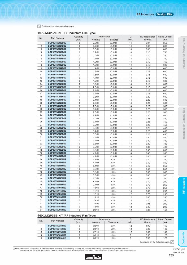
Indu
ctor
s fo
r P
ower
Lin
esIn
duct
ors
for
Gen
eral
Use
RF
Indu
ctor
sR
F In
duct
ors
Des
ign
Kits
LQP03TN2N7B02LQP03TN2N8B02LQP03TN2N9B02LQP03TN3N0B02LQP03TN3N1B02LQP03TN3N2B02LQP03TN3N3B02LQP03TN3N4B02LQP03TN3N5B02LQP03TN3N6B02LQP03TN3N7B02LQP03TN3N8B02LQP03TN3N9B02LQP03TN4N0B02LQP03TN4N1B02LQP03TN4N2B02LQP03TN4N3H02LQP03TN4N7H02LQP03TN5N1H02LQP03TN5N6H02LQP03TN6N2H02LQP03TN6N8H02LQP03TN7N5H02LQP03TN8N2H02LQP03TN9N1H02LQP03TN10NH02LQP03TN11NH02LQP03TN12NH02LQP03TN13NH02LQP03TN15NH02LQP03TN16NH02LQP03TN18NH02LQP03TN20NH02
222324252627282930313233343536373839404142434445464748495051525354
101010101010101010101010101010101010101010101010101010101010101010
2.7nH2.8nH2.9nH3.0nH3.1nH3.2nH3.3nH3.4nH3.5nH3.6nH3.7nH3.8nH3.9nH4.0nH4.1nH4.2nH4.3nH4.7nH5.1nH5.6nH6.2nH6.8nH7.5nH8.2nH9.1nH10nH11nH12nH13nH15nH16nH18nH20nH
±0.1nH±0.1nH±0.1nH±0.1nH±0.1nH±0.1nH±0.1nH±0.1nH±0.1nH±0.1nH±0.1nH±0.1nH±0.1nH±0.1nH±0.1nH±0.1nH
±3%±3%±3%±3%±3%±3%±3%±3%±3%±3%±3%±3%±3%±3%±3%±3%±3%
141414141414141414141414141414141414141414141414141414121212121212
0.200.200.200.250.250.250.250.250.250.300.300.300.300.400.400.400.400.400.400.400.600.600.600.700.700.700.800.700.800.700.950.802.30
500500500450450450450450450400400400400350350350350350350350300300300250250250250250250250200200150
LQP03TN22NH02LQP03TN24NH02LQP03TN27NH02LQP03TN30NH02
1234
10101010
22nH24nH27nH30nH
±3%±3%±3%±3%
1212129
1.902.302.302.95
150140140120
LQP03TN1N4B02LQP03TN1N5B02LQP03TN1N6B02LQP03TN1N7B02LQP03TN1N8B02LQP03TN1N9B02LQP03TN2N0B02LQP03TN2N1B02LQP03TN2N2B02LQP03TN2N3B02LQP03TN2N4B02
910111213141516171819
1010101010101010101010
1.4nH1.5nH1.6nH1.7nH1.8nH1.9nH2.0nH2.1nH2.2nH2.3nH2.4nH
±0.1nH±0.1nH±0.1nH±0.1nH±0.1nH±0.1nH±0.1nH±0.1nH±0.1nH±0.1nH±0.1nH
1414141414141414141414
0.150.150.150.150.150.150.150.150.150.200.20
600600600600600600600600600500500
LQP03TN2N5B02LQP03TN2N6B02
2021
1010
2.5nH2.6nH
±0.1nH±0.1nH
1414
0.200.20
500500
oEKLMQP3AB-KIT (RF Inductors Film Type)
LQP03TN0N6B02LQP03TN0N7B02LQP03TN0N8B02LQP03TN0N9B02LQP03TN1N0B02LQP03TN1N1B02LQP03TN1N2B02LQP03TN1N3B02
12345678
1010101010101010
0.6nH0.7nH0.8nH0.9nH1.0nH1.1nH1.2nH1.3nH
±0.1nH±0.1nH±0.1nH±0.1nH±0.1nH±0.1nH±0.1nH±0.1nH
1414141414141414
0.070.080.080.100.100.100.100.15
850800800750750750750600
Part NumberNo.Rated Current
(mA)DC Resistance
(Ω) max.Q
(min.)ToleranceNominalInductanceQuantity
(pcs.)
oEKLMQP3BB-KIT (RF Inductors Film Type)
Part NumberNo.Rated Current
(mA)DC Resistance
(Ω) max.Q
(min.)ToleranceNominalInductanceQuantity
(pcs.)
LQP03TN33NJ025 10 33nH ±5% 9 2.95 120
Continued from the preceding page.
Continued on the following page.
RF Inductors Design Kits
O05E.pdfNov.25,2013
235
!Note • Please read rating and !CAUTION (for storage, operating, rating, soldering, mounting and handling) in this catalog to prevent smoking and/or burning, etc.• This catalog has only typical specifi cations. Therefore, please approve our product specifi cations or transact the approval sheet for product specifi cations before ordering.

Indu
ctor
s fo
r P
ower
Lin
esIn
duct
ors
for
Gen
eral
Use
RF
Indu
ctor
sR
F In
duct
ors
Des
ign
Kits
oEKLMQW03A-KIT (RF Inductors Wire Wound Type)
LQW03AW5N4J00LQW03AW5N6J00LQW03AW5N8J00LQW03AW6N8J00
1234
10101010
5.4nH5.6nH5.8nH6.8nH
±5%±5%±5%±5%
0.210.330.160.18
420330460460
Part NumberNo.Rated Current
(mA)DC Resistance
(Ω) max.ToleranceNominalInductanceQuantity
(pcs.)
LQP15MN12NG02LQP15MN15NG02LQP15MN18NG02LQP15MN22NG02LQP15MN27NG02LQP15MN33NG02
262728293031
101010101010
12nH15nH18nH22nH27nH33nH
±2%±2%±2%±2%±2%±2%
131313131313
1.61.82.02.63.13.8
909080707060
LQP15MN3N3B02LQP15MN3N6B02LQP15MN3N9B02LQP15MN4N3B02LQP15MN4N7B02LQP15MN5N1B02LQP15MN5N6B02LQP15MN6N2B02LQP15MN6N8B02LQP15MN7N5B02LQP15MN8N2B02
1314151617181920212223
1010101010101010101010
3.3nH3.6nH3.9nH4.3nH4.7nH5.1nH5.6nH6.2nH6.8nH7.5nH8.2nH
±0.1nH±0.1nH±0.1nH±0.1nH±0.1nH±0.1nH±0.1nH±0.1nH±0.1nH±0.1nH±0.1nH
1313131313131313131313
0.40.50.50.60.60.70.70.90.91.11.1
190170170160160140140130130110110
LQP15MN9N1B02LQP15MN10NG02
2425
1010
9.1nH10nH
±0.1nH±2%
1313
1.31.3
100100
oEKLMQP15B-KIT (RF Inductors Film Type)
LQP15MN3N0B0212 10 3.0nH ±0.1nH 13 0.4 190
LQP15MN1N0B02LQP15MN1N1B02LQP15MN1N2B02LQP15MN1N3B02LQP15MN1N5B02LQP15MN1N6B02LQP15MN1N8B02LQP15MN2N0B02LQP15MN2N2B02LQP15MN2N4B02LQP15MN2N7B02
1234567891011
1010101010101010101010
1.0nH1.1nH1.2nH1.3nH1.5nH1.6nH1.8nH2.0nH2.2nH2.4nH2.7nH
±0.1nH±0.1nH±0.1nH±0.1nH±0.1nH±0.1nH±0.1nH±0.1nH±0.1nH±0.1nH±0.1nH
1313131313131313131313
0.10.10.10.20.20.30.20.30.30.30.3
400390390280280220280220220220220
Part NumberNo.Rated Current
(mA)DC Resistance
(Ω) max.Q
(min.)ToleranceNominalInductanceQuantity
(pcs.)
LQP03TN36NJ02LQP03TN39NJ02LQP03TN43NJ02LQP03TN47NJ02LQP03TN51NJ02LQP03TN56NJ02LQP03TN62NJ02LQP03TN68NJ02LQP03TN75NJ02LQP03TN82NJ02LQP03TN91NJ02LQP03TNR10J02LQP03TNR11J02LQP03TNR12J02LQP03TNR13J02LQP03TNR15J02LQP03TNR16J02LQP03TNR18J02LQP03TNR20J02LQP03TNR22J02LQP03TNR24J02LQP03TNR27J02
6789101112131415161718192021222324252627
10101010101010101010101010101010101010101010
36nH39nH43nH47nH51nH56nH62nH68nH75nH82nH91nH
100nH110nH120nH130nH150nH160nH180nH200nH220nH240nH270nH
±5%±5%±5%±5%±5%±5%±5%±5%±5%±5%±5%±5%±5%±5%±5%±5%±5%±5%±5%±5%±5%±5%
9999998888888855555555
3.003.003.603.603.903.90
88
10101010121299
111113131515
120120100100100100100100100100808080808080707060606060
Part NumberNo.Rated Current
(mA)DC Resistance
(Ω) max.Q
(min.)ToleranceNominalInductanceQuantity
(pcs.)
Continued from the preceding page.
Continued on the following page.
RF Inductors Design Kits
O05E.pdfNov.25,2013
236
!Note • Please read rating and !CAUTION (for storage, operating, rating, soldering, mounting and handling) in this catalog to prevent smoking and/or burning, etc.• This catalog has only typical specifi cations. Therefore, please approve our product specifi cations or transact the approval sheet for product specifi cations before ordering.

Indu
ctor
s fo
r P
ower
Lin
esIn
duct
ors
for
Gen
eral
Use
RF
Indu
ctor
sR
F In
duct
ors
Des
ign
Kits
LQW15AN7N5G00LQW15AN8N2G00LQW15AN8N7G00LQW15AN9N1G00LQW15AN9N5G00LQW15AN10NG00LQW15AN11NG00LQW15AN12NG00
1516171819202122
1010101010101010
7.5nH8.2nH8.7nH9.1nH9.5nH10nH11nH12nH
±2%±2%±2%±2%±2%±2%±2%±2%
2525252525253030
0.130.140.140.140.140.170.140.14
570540540540540500500500
LQW15AN1N5B00LQW15AN2N4B00LQW15AN2N5B00LQW15AN2N7B00LQW15AN2N9B00LQW15AN3N9B00LQW15AN4N1B00LQW15AN4N3B00LQW15AN4N7B00
123456789
101010101010101010
1.5nH2.4nH2.5nH2.7nH2.9nH3.9nH4.1nH4.3nH4.7nH
±0.1nH±0.1nH±0.1nH±0.1nH±0.1nH±0.1nH±0.1nH±0.1nH±0.1nH
102020202025252525
0.030.050.050.050.070.070.070.070.07
1000850850850750750750750750
LQW15AN5N1B00LQW15AN5N8B00LQW15AN6N2B00
101112
101010
5.1nH5.8nH6.2nH
±0.1nH±0.1nH±0.1nH
252525
0.120.120.09
600700700
LQW15AN6N8G00LQW15AN7N3G00
1314
1010
6.8nH7.3nH
±2%±2%
2525
0.090.13
700570
oEKLMQW15K-KIT (RF Inductors Wire Wound Type)
LQW04AN10NH00LQW04AN11NH00LQW04AN12NH00LQW04AN13NH00LQW04AN15NH00LQW04AN16NH00LQW04AN18NH00LQW04AN19NH00LQW04AN20NH00LQW04AN22NH00LQW04AN23NH00LQW04AN24NH00LQW04AN25NH00LQW04AN27NH00LQW04AN33NH00
171819202122232425262728293031
101010101010101010101010101010
10nH11nH12nH13nH15nH16nH18nH19nH20nH22nH23nH24nH25nH27nH33nH
±3%±3%±3%±3%±3%±3%±3%±3%±3%±3%±3%±3%±3%±3%±3%
201515151515151515151515151515
0.260.280.280.340.480.380.540.730.560.630.950.950.950.951.11
330310310280240270220160210200160160160160140
LQW04AN6N2C00LQW04AN6N8C00LQW04AN7N5C00LQW04AN8N2C00LQW04AN9N1C00
1213141516
1010101010
6.2nH6.8nH7.5nH8.2nH9.1nH
±0.2nH±0.2nH±0.2nH±0.2nH±0.2nH
2020202020
0.190.140.140.230.16
390440440350400
Part NumberNo.Rated Current
(mA)DC Resistance
(Ω) max.Q
(min.)ToleranceNominalInductanceQuantity
(pcs.)
LQW04AN3N3C00LQW04AN3N6C00LQW04AN3N9C00LQW04AN4N3C00
5678
10101010
3.3nH3.6nH3.9nH4.3nH
±0.2nH±0.2nH±0.2nH±0.2nH
10151515
0.140.100.100.10
440530530530
LQW04AN4N7C00LQW04AN5N1C00
910
1010
4.7nH5.1nH
±0.2nH±0.2nH
2020
0.140.12
440470
LQW04AN5N6C0011 10 5.6nH ±0.2nH 20 0.12 470
LQW04AN3N0C004 10 3.0nH ±0.2nH 15 0.07 620
oEKLMQW04D-KIT (RF Inductors Wire Wound Type)
LQW04AN1N1C00LQW04AN1N8C00LQW04AN2N7C00
123
101010
1.1nH1.8nH2.7nH
±0.2nH±0.2nH±0.2nH
151515
0.030.060.07
990700570
Part NumberNo.Rated Current
(mA)DC Resistance
(Ω) max.Q
(min.)ToleranceNominalInductanceQuantity
(pcs.)
LQW03AW7N5J00LQW03AW8N7J00LQW03AW9N1J00LQW03AW13NJ00
5678
10101010
7.5nH8.7nH9.1nH13nH
±5%±5%±5%±5%
0.240.420.220.54
400290460280
Part NumberNo.Rated Current
(mA)DC Resistance
(Ω) max.ToleranceNominalInductanceQuantity
(pcs.)
Continued from the preceding page.
Continued on the following page.
RF Inductors Design Kits
O05E.pdfNov.25,2013
237
!Note • Please read rating and !CAUTION (for storage, operating, rating, soldering, mounting and handling) in this catalog to prevent smoking and/or burning, etc.• This catalog has only typical specifi cations. Therefore, please approve our product specifi cations or transact the approval sheet for product specifi cations before ordering.
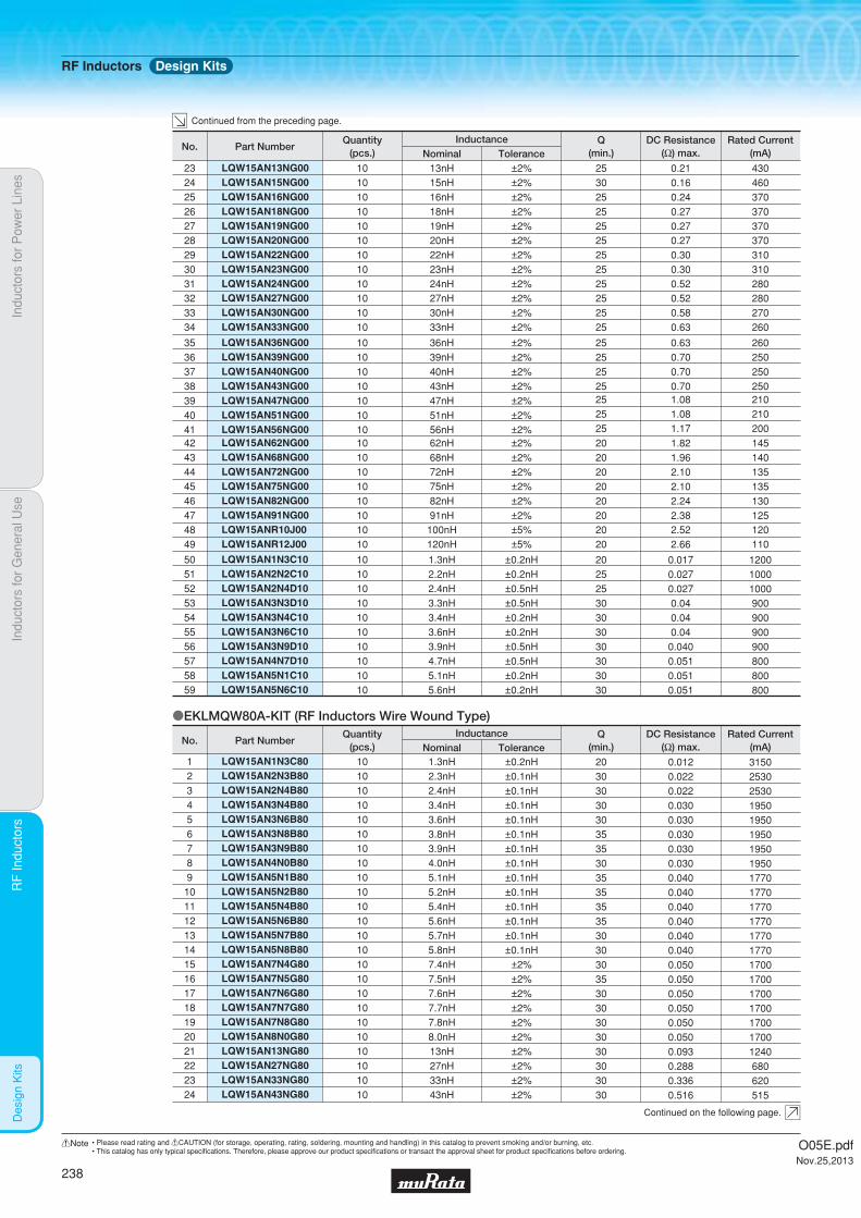
Indu
ctor
s fo
r P
ower
Lin
esIn
duct
ors
for
Gen
eral
Use
RF
Indu
ctor
sR
F In
duct
ors
Des
ign
Kits
LQW15ANR10J00LQW15ANR12J00
4849
1010
100nH120nH
±5%±5%
2020
2.522.66
120110
LQW15AN62NG00LQW15AN68NG00LQW15AN72NG00LQW15AN75NG00LQW15AN82NG00LQW15AN91NG00
424344454647
101010101010
62nH68nH72nH75nH82nH91nH
±2%±2%±2%±2%±2%±2%
202020202020
1.821.962.102.102.242.38
145140135135130125
oEKLMQW80A-KIT (RF Inductors Wire Wound Type)
LQW15AN1N3C80LQW15AN2N3B80LQW15AN2N4B80LQW15AN3N4B80LQW15AN3N6B80LQW15AN3N8B80LQW15AN3N9B80LQW15AN4N0B80LQW15AN5N1B80LQW15AN5N2B80LQW15AN5N4B80LQW15AN5N6B80LQW15AN5N7B80LQW15AN5N8B80LQW15AN7N4G80LQW15AN7N5G80LQW15AN7N6G80LQW15AN7N7G80LQW15AN7N8G80LQW15AN8N0G80LQW15AN13NG80LQW15AN27NG80LQW15AN33NG80LQW15AN43NG80
123456789101112131415161718192021222324
101010101010101010101010101010101010101010101010
1.3nH2.3nH2.4nH3.4nH3.6nH3.8nH3.9nH4.0nH5.1nH5.2nH5.4nH5.6nH5.7nH5.8nH7.4nH7.5nH7.6nH7.7nH7.8nH8.0nH13nH27nH33nH43nH
±0.2nH±0.1nH±0.1nH±0.1nH±0.1nH±0.1nH±0.1nH±0.1nH±0.1nH±0.1nH±0.1nH±0.1nH±0.1nH±0.1nH
±2%±2%±2%±2%±2%±2%±2%±2%±2%±2%
203030303035353035353535303030353030303030303030
0.0120.0220.0220.0300.0300.0300.0300.0300.0400.0400.0400.0400.0400.0400.0500.0500.0500.0500.0500.0500.0930.2880.3360.516
315025302530195019501950195019501770177017701770177017701700170017001700170017001240680620515
Part NumberNo.Rated Current
(mA)DC Resistance
(Ω) max.Q
(min.)ToleranceNominalInductanceQuantity
(pcs.)
LQW15AN1N3C10LQW15AN2N2C10LQW15AN2N4D10LQW15AN3N3D10LQW15AN3N4C10LQW15AN3N6C10LQW15AN3N9D10LQW15AN4N7D10LQW15AN5N1C10LQW15AN5N6C10
50515253545556575859
10101010101010101010
1.3nH2.2nH2.4nH3.3nH3.4nH3.6nH3.9nH4.7nH5.1nH5.6nH
±0.2nH±0.2nH±0.5nH±0.5nH±0.2nH±0.2nH±0.5nH±0.5nH±0.2nH±0.2nH
20252530303030303030
0.0170.0270.0270.040.040.04
0.0400.0510.0510.051
120010001000900900900900800800800
LQW15AN36NG00LQW15AN39NG00LQW15AN40NG00LQW15AN43NG00
35363738
10101010
36nH39nH40nH43nH
±2%±2%±2%±2%
25252525
0.630.700.700.70
260250250250
LQW15AN47NG00LQW15AN51NG00LQW15AN56NG00
394041
101010
47nH51nH56nH
±2%±2%±2%
252525
1.081.081.17
210210200
LQW15AN27NG00LQW15AN30NG00LQW15AN33NG00
323334
101010
27nH30nH33nH
±2%±2%±2%
252525
0.520.580.63
280270260
LQW15AN20NG00LQW15AN22NG00LQW15AN23NG00LQW15AN24NG00
28293031
10101010
20nH22nH23nH24nH
±2%±2%±2%±2%
25252525
0.270.300.300.52
370310310280
LQW15AN13NG00LQW15AN15NG00LQW15AN16NG00LQW15AN18NG00LQW15AN19NG00
2324252627
1010101010
13nH15nH16nH18nH19nH
±2%±2%±2%±2%±2%
2530252525
0.210.160.240.270.27
430460370370370
Part NumberNo.Rated Current
(mA)DC Resistance
(Ω) max.Q
(min.)ToleranceNominalInductanceQuantity
(pcs.)
Continued from the preceding page.
Continued on the following page.
RF Inductors Design Kits
O05E.pdfNov.25,2013
238
!Note • Please read rating and !CAUTION (for storage, operating, rating, soldering, mounting and handling) in this catalog to prevent smoking and/or burning, etc.• This catalog has only typical specifi cations. Therefore, please approve our product specifi cations or transact the approval sheet for product specifi cations before ordering.

Indu
ctor
s fo
r P
ower
Lin
esIn
duct
ors
for
Gen
eral
Use
RF
Indu
ctor
sR
F In
duct
ors
Des
ign
Kits
oEKLMQ80GB-KIT (RF Inductors Wire Wound Type)
LQW18ANR27G00LQW18ANR33G00LQW18ANR39G00LQW18ANR47G00LQW18AN3N9C10LQW18AN6N8C10
414243444546
101010101010
270nH330nH390nH470nH3.9nH6.8nH
±2%±2%±2%±2%
±0.2nH±0.2nH
303030303838
3.45.56.27.0
0.0320.045
110858075
1000900
LQW18AN10NG10LQW18AN12NG10LQW18AN18NG10LQW18AN22NG10LQW18AN27NG10
4748495051
1010101010
10nH12nH18nH22nH27nH
±2%±2%±2%±2%±2%
3838424242
0.0580.0710.0850.0990.116
800750700640590
LQW18AN4N3B80LQW18AN4N7B80LQW18AN4N9B80LQW18AN30NG80
1234
2100150012001100
0.0360.0540.0810.12
35252340
±0.1nH±0.1nH±0.1nH
±2%
4.3nH4.7nH4.9nH30nH
10101010
Part NumberNo.Rated Current
(mA)DC Resistance
(Ω) max.Q
(min.)ToleranceNominalInductanceQuantity
(pcs.)
LQW18ANR10G00LQW18ANR11G00LQW18ANR12G00LQW18ANR13G00LQW18ANR15G00LQW18ANR16G00LQW18ANR18G00LQW18ANR20G00LQW18ANR22G00
323334353637383940
101010101010101010
100nH110nH120nH130nH150nH160nH180nH200nH220nH
±2%±2%±2%±2%±2%±2%±2%±2%±2%
343232323232252525
0.681.21.31.41.52.12.22.42.5
220200180170160150140120120
LQW18AN72NG00LQW18AN75NG00LQW18AN82NG00LQW18AN91NG00
28293031
10101010
72nH75nH82nH91nH
±2%±2%±2%±2%
34343434
0.560.560.600.64
270270250230
LQW18AN43NG00LQW18AN47NG00LQW18AN51NG00LQW18AN56NG00
22232425
10101010
43nH47nH51nH56nH
±2%±2%±2%±2%
40383838
0.290.290.330.35
380380370360
LQW18AN22NG00LQW18AN24NG00LQW18AN27NG00LQW18AN30NG00LQW18AN33NG00LQW18AN36NG00LQW18AN39NG00
15161718192021
10101010101010
22nH24nH27nH30nH33nH36nH39nH
±2%±2%±2%±2%±2%±2%±2%
40404040404040
0.170.210.210.230.230.260.26
500500440420420400400
LQW18AN62NG00LQW18AN68NG00
2627
1010
62nH68nH
±2%±2%
3838
0.510.38
280340
LQW18AN20NG0014 10 20nH ±2% 40 0.16 550
LQW18AN10NG00LQW18AN11NG00LQW18AN12NG00LQW18AN13NG00
78910
10101010
10nH11nH12nH13nH
±2%±2%±2%±2%
35353535
0.110.110.130.13
650650600600
LQW18AN15NG00LQW18AN16NG00LQW18AN18NG00
111213
101010
15nH16nH18nH
±2%±2%±2%
404040
0.130.160.16
600550550
oEKLMQW18A-KIT (RF Inductors Wire Wound Type)
LQW18AN4N3C00LQW18AN5N6C00LQW18AN6N2C00LQW18AN6N8C00
3456
10101010
4.3nH5.6nH6.2nH6.8nH
±0.2nH±0.2nH±0.2nH±0.2nH
35353535
0.0590.0820.0820.082
850750750750
LQW18AN3N6C00LQW18AN3N9C00
12
1010
3.6nH3.9nH
±0.2nH±0.2nH
2535
0.0590.059
850850
Part NumberNo.Rated Current
(mA)DC Resistance
(Ω) max.Q
(min.)ToleranceNominalInductanceQuantity
(pcs.)
LQW15AN53NG80LQW15AN75NG80
2526
1010
53nH75nH
±2%±2%
2525
0.6961.224
415320
Part NumberNo.Rated Current
(mA)DC Resistance
(Ω) max.Q
(min.)ToleranceNominalInductanceQuantity
(pcs.)
Continued from the preceding page.
Continued on the following page.
RF Inductors Design Kits
O05E.pdfNov.25,2013
239
!Note • Please read rating and !CAUTION (for storage, operating, rating, soldering, mounting and handling) in this catalog to prevent smoking and/or burning, etc.• This catalog has only typical specifi cations. Therefore, please approve our product specifi cations or transact the approval sheet for product specifi cations before ordering.

Indu
ctor
s fo
r P
ower
Lin
esIn
duct
ors
for
Gen
eral
Use
RF
Indu
ctor
sR
F In
duct
ors
Des
ign
Kits
LQW2BHN33NG03LQW2BHN39NG03LQW2BHN47NG03LQW2BHN56NG03LQW2BHN68NG03LQW2BHN82NG03LQW2BHNR10G03LQW2BHNR12G03LQW2BHNR15G03LQW2BHNR18G03LQW2BHNR22G03
1314151617181920212223
570730450430460320270320260250240
0.150.090.230.260.230.420.550.400.680.710.70
4040404040403540303535
±2%±2%±2%±2%±2%±2%±2%±2%±2%±2%±2%
33nH39nH47nH56nH68nH82nH
100nH120nH150nH180nH220nH
1010101010101010101010
LQW2BHN21NK13LQW2BHN27NK13
1112
950900
0.050.06
4040
±10%±10%
21nH27nH
1010
oEKLMQW21A-KIT (RF Inductors Wire Wound Ferrite Core Type)
LQW21HNR47J00LQW21HNR56J00LQW21HNR68J00LQW21HNR82J00LQW21HN1R0J00LQW21HN1R2J00
123456
160150130125115100
1.301.432.212.342.863.12
353535353535
±5%±5%±5%±5%±5%±5%
0.47μH0.56μH0.68μH0.82μH1.0μH1.2μH
101010101010
oEKLMQW2BC-KIT (RF Inductors Wire Wound Air Core Type)
LQW21HN1R5J00LQW21HN1R8J00LQW21HN2R2J00
789
858075
5.335.856.50
353535
±5%±5%±5%
1.5μH1.8μH2.2μH
101010
Part NumberNo.Rated Current
(mA)DC Resistance
(Ω) max.Q
(min.)ToleranceNominalInductanceQuantity
(pcs.)
LQW2BHN2N7D13LQW2BHN3N1D13LQW2BHN3N3D13LQW2BHN5N6D13LQW2BHN6N8D13LQW2BHN8N6D13LQW2BHN10NJ13
1234567
1900180017001500140013001320
0.020.020.020.020.020.030.03
20202035353535
±0.5nH±0.5nH±0.5nH±0.5nH±0.5nH±0.5nH
±5%
2.7nH3.1nH3.3nH5.6nH6.8nH8.6nH10nH
10101010101010
Part NumberNo.Rated Current
(mA)DC Resistance
(Ω) max.Q
(min.)ToleranceNominalInductanceQuantity
(pcs.)
LQW2BHN12NK13LQW2BHN15NK13LQW2BHN18NK13
8910
110010001000
0.040.040.05
404040
±10%±10%±10%
12nH15nH
18.8nH
101010
LQW18ANR11G80LQW18ANR12G80LQW18ANR15G80LQW18ANR18G80LQW18ANR20G80LQW18ANR21G80LQW18ANR22G80LQW18ANR25G80LQW18ANR27G80LQW18ANR30G80LQW18ANR33G80LQW18ANR36G80LQW18ANR39G80
17181920212223242526272829
450450420310290280280250260220190190190
0.70.720.871.651.741.982.082.282.423.123.843.984.23
32322825252725242425252525
±2%±2%±2%±2%±2%±2%±2%±2%±2%±2%±2%±2%±2%
110nH120nH150nH180nH200nH210nH220nH250nH270nH300nH330nH360nH390nH
10101010101010101010101010
Part NumberNo.Rated Current
(mA)DC Resistance
(Ω) max.Q
(min.)ToleranceNominalInductanceQuantity
(pcs.)
LQW18AN36NG80LQW18AN39NG80LQW18AN43NG80LQW18AN47NG80LQW18AN51NG80LQW18AN56NG80LQW18AN68NG80LQW18AN72NG80LQW18AN75NG80LQW18AN82NG80LQW18AN91NG80LQW18ANR10G80
5678910111213141516
9101000840830830770630560590550520490
0.20.160.210.230.230.260.380.470.410.5
0.540.63
374040323238373428343334
±2%±2%±2%±2%±2%±2%±2%±2%±2%±2%±2%±2%
36nH39nH43nH47nH51nH56nH68nH72nH75nH82nH91nH
100nH
101010101010101010101010
Continued from the preceding page.
Continued on the following page.
RF Inductors Design Kits
O05E.pdfNov.25,2013
240
!Note • Please read rating and !CAUTION (for storage, operating, rating, soldering, mounting and handling) in this catalog to prevent smoking and/or burning, etc.• This catalog has only typical specifi cations. Therefore, please approve our product specifi cations or transact the approval sheet for product specifi cations before ordering.

Indu
ctor
s fo
r P
ower
Lin
esIn
duct
ors
for
Gen
eral
Use
RF
Indu
ctor
sR
F In
duct
ors
Des
ign
Kits
LQW2UAS68NG00LQW2UAS82NG00LQW2UASR10G00LQW2UASR12G00LQW2UASR15G00LQW2UASR18G00LQW2UASR22G00LQW2UASR27G00LQW2UASR33G00LQW2UASR39G00LQW2UASR47G00LQW2UASR56G00LQW2UASR62G00
45464748495051525354555657
10001000650650580620500500450470470400300
0.20.220.560.630.7
0.770.840.911.051.121.191.331.4
65606060454545454545454545
±2%±2%±2%±2%±2%±2%±2%±2%±2%±2%±2%±2%±2%
68nH82nH
100nH120nH150nH180nH220nH270nH330nH390nH470nH560nH620nH
10101010101010101010101010
LQW2BAS7N5J00LQW2BAS8N2J00LQW2BAS10NJ00LQW2BAS12NJ00LQW2BAS15NJ00LQW2BAS18NJ00LQW2BAS22NJ00LQW2BAS24NJ00LQW2BAS27NJ00LQW2BAS33NG00LQW2BAS36NG00LQW2BAS39NG00LQW2BAS43NG00LQW2BAS47NG00LQW2BAS56NG00LQW2BAS68NG00LQW2BAS82NG00LQW2BAS91NG00LQW2BASR10G00LQW2BASR11G00LQW2BASR12G00LQW2BASR15G00LQW2BASR18G00LQW2BASR22G00LQW2BASR24G00LQW2BASR27G00LQW2BASR33G00LQW2BASR39J00LQW2BASR47J00LQW2BASR56J00LQW2BASR68J00LQW2BASR82J00
56789101112131415161718192021222324252627282930313233343536
600600600600600600500500500500500500500500500500400400400400400400400400350350310290250230190180
0.140.120.100.150.170.200.220.220.250.270.270.290.340.310.340.380.420.480.460.480.510.560.640.70 1.00 1.00 1.40 1.501.761.902.202.35
5050605050505550556055606060606065656550505050504448484833232323
±5%±5%±5%±5%±5%±5%±5%±5%±5%±2%±2%±2%±2%±2%±2%±2%±2%±2%±2%±2%±2%±2%±2%±2%±2%±2%±2%±5%±5%±5%±5%±5%
7.5nH8.2nH10nH12nH15nH18nH22nH24nH27nH33nH36nH39nH43nH47nH56nH68nH82nH91nH
100nH110nH120nH150nH180nH220nH240nH270nH330nH390nH470nH560nH680nH820nH
1010101010101010101010101010101010101010101010101010101010101010
LQW2UAS12NG00LQW2UAS18NG00LQW2UAS22NG00LQW2UAS27NG00LQW2UAS33NG00
3738394041
10001000100010001000
0.090.110.120.130.14
5050555560
±2%±2%±2%±2%±2%
12nH18nH22nH27nH33nH
1010101010
LQW2UAS39NG00LQW2UAS47NG00LQW2UAS56NG00
424344
100010001000
0.150.160.18
606565
±2%±2%±2%
39nH47nH56nH
101010
oEKLMW2BUB-KIT (RF Inductors Wire Wound Type)
LQW2BAS2N8J00LQW2BAS3N0J00LQW2BAS5N6J00LQW2BAS6N8J00
1234
800800600600
0.060.060.080.11
80656550
±5%±5%±5%±5%
2.8nH3nH
5.6nH6.8nH
10101010
Part NumberNo.Rated Current
(mA)DC Resistance
(Ω) max.Q
(min.)ToleranceNominalInductanceQuantity
(pcs.)
LQW2BHNR33K03LQW2BHNR39K03LQW2BHNR47K03
252627
180170160
2.202.502.80
151515
±10%±10%±10%
330nH390nH470nH
101010
LQW2BHNR27K0324 1902.0015±10%270nH10
Part NumberNo.Rated Current
(mA)DC Resistance
(Ω) max.Q
(min.)ToleranceNominalInductanceQuantity
(pcs.)
Continued from the preceding page.
Continued on the following page.
RF Inductors Design Kits
O05E.pdfNov.25,2013
241
!Note • Please read rating and !CAUTION (for storage, operating, rating, soldering, mounting and handling) in this catalog to prevent smoking and/or burning, etc.• This catalog has only typical specifi cations. Therefore, please approve our product specifi cations or transact the approval sheet for product specifi cations before ordering.

Indu
ctor
s fo
r P
ower
Lin
esIn
duct
ors
for
Gen
eral
Use
RF
Indu
ctor
sR
F In
duct
ors
Des
ign
Kits
LQW2UAS1R2J00LQW2UAS1R5J00LQW2UAS1R8J00LQW2UAS2R2J00LQW2UAS2R7J00LQW2UAS3R3J00LQW2UAS3R9J00LQW2UAS4R7J00
6364656667686970
310330300280290290260260
2.02.32.62.83.23.43.64.0
3528282822222020
±5%±5%±5%±5%±5%±5%±5%±5%
1200nH1500nH1800nH2200nH2700nH3300nH3900nH4700nH
1010101010101010
LQW2UASR68G00LQW2UASR75G00LQW2UASR82G00LQW2UASR91G00LQW2UAS1R0G00
5859606162
400360400380370
1.471.541.611.681.75
4545453535
±2%±2%±2%±2%±2%
680nH750nH820nH910nH
1000nH
1010101010
Part NumberNo.Rated Current
(mA)DC Resistance
(Ω) max.Q
(min.)ToleranceNominalInductanceQuantity
(pcs.)
Continued from the preceding page.
RF Inductors Design Kits
O05E.pdfNov.25,2013
242
!Note • Please read rating and !CAUTION (for storage, operating, rating, soldering, mounting and handling) in this catalog to prevent smoking and/or burning, etc.• This catalog has only typical specifi cations. Therefore, please approve our product specifi cations or transact the approval sheet for product specifi cations before ordering.

243
!Note • Please read rating and !CAUTION (for storage, operating, rating, soldering, mounting and handling) in this catalog to prevent smoking and/or burning, etc.• This catalog has only typical specifi cations. Therefore, please approve our product specifi cations or transact the approval sheet for product specifi cations before ordering.
LQH2HPN
LQH2MCN
LQH31CN
LQH32CN
LQH32PB
LQH32PN
LQH3NPN
LQH43CN
LQH43PB
LQH43PN
LQH44PN
LQH55DN
LQH5BPB
LQH5BPN
LQH66SN
LQM18FN
LQM18PN
LQM21DN
LQM21FN
LQM21PN
LQM2HPN
LQM2MPN
LQM31PN
LQM32PN
LQW15CN
LQW18CN
p.46
p.42
p.90
p.91
p.65
p.61
p.59
p.94
p.71
p.69
p.75
p.96
p.79
p.77
p.98
p.81
p.16
p.82
p.83
p.22
p.38
p.27
p.39
p.41
p.86
p.89
p.148
p.150
p.153
p.223
p.155
p.161
p.164
p.169
p.174
p.177
p.179
p.181
p.184
p.199
p.221
p.213
p.209
p.216
p.219
p.119
p.121
p.127
p.129
p.131
p.131
p.134
p.123
p.125
LQB15NN
LQB18NN
LQH31MN
LQH32MN
LQH43MN
LQH43NN
LQH44NN
LQM18NN
LQM21NN
LQG15HN
LQG15HS
LQG18HN
LQH31HN
LQP02TN
LQP02TQ
LQP03TG
LQP03TN
LQP15MN
LQP18MN
LQW03AW
LQW04AN
LQW15AN
LQW18AN
LQW21HN
LQW2BAS
LQW2BHN
LQW2UAS
LQW31HN
Part Number Quick ReferencePart Number Quick Reference
Inductors for Power Lines Inductors for General Use RF Inductors
O05E.pdfNov.25,2013

244
!Note • Please read rating and !CAUTION (for storage, operating, rating, soldering, mounting and handling) in this catalog to prevent smoking and/or burning, etc.• This catalog has only typical specifi cations. Therefore, please approve our product specifi cations or transact the approval sheet for product specifi cations before ordering.
http://ds.murata.co.jp/software/simsurfing/en-us/
Design Support SoftwareSimSurfing
SimSurfing is the latest tool to get the electrical characteristics for Power Inductors or RF Inductors on the Internet !
You can easily search and download the following data for Inductors with no special software.
Introduction of Chip Inductors Web Site
Some function of Microsoft Excel® application version "Power Inductor Selection Tool" has been
integrated to SimSurfing. (※)
New Features 《Power Inductor Selection Tool》
※The function of this tool is limited from Excel® application version. Excel® application version can be downloaded at following URL. http://www.murata.com/products/design_support/dl_soft/index.html
Preferred power inductor to DC-DC convertor operating condition will be listed in the format of ranking.
Operating condition setting of DC-DC converter
Start this tool on the category page in [power inductors].
O05E.pdfNov.25,2013

245
!Note • Please read rating and !CAUTION (for storage, operating, rating, soldering, mounting and handling) in this catalog to prevent smoking and/or burning, etc.• This catalog has only typical specifi cations. Therefore, please approve our product specifi cations or transact the approval sheet for product specifi cations before ordering.
Introduction of Chip Inductors Web Site
You can register from Murata Manufacturing Web site page TOP.http://www.murata.com/products/
This banner is the entrance ofregister form
EMICON-FUN! is disseminated widely from basics (principles, characteristics, mounting, etc.) of capacitors, EMI suppression filters and inductorsto information that can be used practically.Updated information is also distributed via the mail magazine.
Please check out Murata’s newsletter!Have fun while learning about electronic components.http://www.murata.com/products/emicon_fun/
Click here to register as reader https://fofa.jp/murata/a.p/107/
##################################################################
EMICON-FUN !
email Magazine: Have fun while learning about electronic components
The index of Jan.28 issue
-------------------------------------------------------------------------------------
- Inductor Room - Product News - Proposal of New Tape Packaging - Course for Noise Suppression against LTE Noise (3rd)
-------------------------------------------------------------------------------------
Expertly written articles explain the basics of capacitors,
inductors and EMI suppression filters. ##################################################################
==========================================================
Inductor Room Why second-generation film-type inductors are incredible!
==========================================================
The film-type inductor (LQP series) products are becoming increasingly smaller,
but the main market for high-frequency inductors is currently
the 0603 (in mm)/ 0201 (in inch) size (0.6 x 0.3 mm).
Murata components are also used in compact mobile devices such as smartphones.
We would like to introduce the history and features of the LQP03TN_02 series
as a representative example.http://www.murata.com/products/emicon_fun/2013/01/inductor_en28.html==========================================================
Product News==========================================================
-Common Mode Choke Coil (Film Type)<DLP0NS Series>1. Small size and tight dimensional tolerance
Size:0.85x0.65x0.45mm
O05E.pdfNov.25,2013

247
!Note • Please read rating and !CAUTION (for storage, operating, rating, soldering, mounting and handling) in this catalog to prevent smoking and/or burning, etc.• This catalog has only typical specifi cations. Therefore, please approve our product specifi cations or transact the approval sheet for product specifi cations before ordering.
246
!Note • Please read rating and !CAUTION (for storage, operating, rating, soldering, mounting and handling) in this catalog to prevent smoking and/or burning, etc.• This catalog has only typical specifi cations. Therefore, please approve our product specifi cations or transact the approval sheet for product specifi cations before ordering.
The product search engine has been replaced by poweful one!
New contents such as inductors selection guide, products recommendation for each application has been added.
Point 1
Point 2
Point 3Inductors are classified into high frequency inductors and power inductors.
The top page is divided.
Explain about inductors from basic to practice
Design assistance tools such as characteristics viewers and simulation libraries
Frequently Asked Questions (FAQ)
Shows selection guides of Murata inductors, recommended products to each application.
1 2 3 4
1Search product in product series lineup list.
Search in the lineups
You can see product data from various viewpoint2
Search product with specifications such as inductance value, rated current or dimension.
Search by specifications
3Search Murata's alternative product specifying other vender's part numbers.
Search by competitor's part number 4Search product specifying Murata's part numbers.
Search by part number
You can make inquiry or download catalogs from here.
Chip Inductors product information page has been drastically updated.
Products Information
inductor murata http://www.murata.com/products/inductor/
Introduction of Chip Inductors Web Site
O05E.pdfNov.25,2013
O05E.pdfNov.25,2013

Cat. No. O05E-25
O05E.pdfNov.25,2013
!Note • Please read rating and !CAUTION (for storage, operating, rating, soldering, mounting and handling) in this catalog to prevent smoking and/or burning, etc.• This catalog has only typical specifi cations. Therefore, please approve our product specifi cations or transact the approval sheet for product specifi cations before ordering.
Related Documents


