Chinese SONG progress and its design introduction Guomin Wang Guomin Wang [email protected] [email protected] 2011-9-16 2011-9-16 Nanjing Institute of Astronomical Optics & Technology Nanjing Institute of Astronomical Optics & Technology SONG 4 SONG 4 th th Workshop Workshop College of Charleston College of Charleston

Chinese SONG progress and its design introduction Guomin Wang [email protected] Nanjing Institute of Astronomical Optics & Technology Nanjing.
Dec 31, 2015
Welcome message from author
This document is posted to help you gain knowledge. Please leave a comment to let me know what you think about it! Share it to your friends and learn new things together.
Transcript

Chinese SONG progress and
its design introduction
Guomin WangGuomin [email protected] [email protected]
2011-9-162011-9-16 Nanjing Institute of Astronomical Optics & Nanjing Institute of Astronomical Optics &
TechnologyTechnology
SONG 4SONG 4thth Workshop Workshop College of CharlestonCollege of Charleston

Outline:
Progress introduction
Telescope design introduction

PROGRESS INTRODUCTION

August 13,
2010:
Finished the
PDR

December 25,
2010:
Finished the CDR

Now, we are…
Structure
constructing

Now, we are…
mirror fabrication
Mirrors material test report from
Russia LZOS
Preparing

Large bearing manufacturing
Azimuth bearing φ680 ×φ880 × 80
Delivery time: 4 months

Large bearing
manufacturing
Altitude bearing φ240 ×φ320 × 38
Delivery time: 4 months

Preparing contract for long-term elements, such as . . .
Torque motors
Encoders

Telescope schedule
Item Schedule Status
Preliminary Design
Review
Aug., 2010 Closed
Critical Design Review Dec., 2010 Closed
Factory Acceptance Nov., 2012 On going
Ready for Shipment Dec.,2012 . . .
On site Acceptance Apr., 2013 . . .

TELESCOPE DESIGN INTRODUCTION

General requirements
Cassegrain system;
M1: paraboloid, 1m clear aperture, Zeodur material,
active support and close-loop controled through S-H;
M2: hyperboloid, fused silica material, active positioned
by 5-DOF unit;
M3: flat mirror, Zeodur material, 180°turn to direct the
light to different Nasmyth platform;
System ratio: F/36.7;

General requirements Image quality: 80% energy encircled in 0.3″ @ lucky
imaging focus ; Nasmyth focus: VIS camera (450 - 650nm), RED camera
(650 - 1000nm), Focus monitoring camera (< 450nm),
auxiliary focus;
FOV @ Nasmyth: R32.52″ ; Coudé focus: spectrograph (480 - 680nm);
FOV @ Coudé: 10″ ;
ADC: doublet prism;
Optical derotator: three - mirror

General requirements Range of azimuth: 0 º ~ ±220º;
Range of altitude: 10 º ~ 89º
Max. acceleration: 2 º/sec2 ;
Max. pointing speed: 20 º/sec;
Blind spot: 2 º (diameter);
Tracking accuracy: RMS 0.3″ , 90s, no guiding ; Pointing accuracy: RMS 5″, 70 º ≥ ZD ≥ 1 º;
Repeat pointing accuracy: ≤ RMS 1″, 70 º ≥ ZD ≥ 1 º;
First frequency: large than 8 Hz;

General view

F/36.7 layout

F/36.7 parameters
Item ParametersM1 ф1000Primary ratio F2.3System ratio F36.667Primary focus length 2300System focus length 36666.8 ( λ=546.1nm )FOV R32.52″M1-M2 distance 2100 mmM2–M3 distance 1600 mmM3–focus distance 1588.3 mmWorking wavelength VIS ( λ=450 ~ 650nm )
RED ( λ=650 ~ 1000nm )

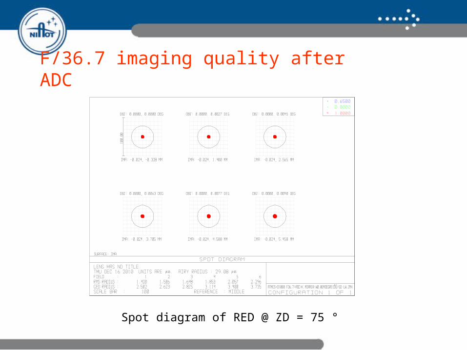
F/36.7 imaging quality after ADC
Spot diagram of VIS @ ZD = 5 °

F/36.7 imaging quality after ADC
Spot diagram of VIS @ ZD = 45 °

F/36.7 imaging quality after ADC
Spot diagram of VIS @ ZD = 75 °

F/36.7 imaging quality after ADC
Spot diagram of RED @ ZD = 5 °

F/36.7 imaging quality after ADC
Spot diagram of RED @ ZD = 45 °
F/36.7 imaging quality after ADC
Spot diagram of RED @ ZD = 75 °

Nasmyth optical design
From telescope
To Coudé

Nasmyth structure

Cou
dé o
pti
cal d
esi
gn
From telescope

Coudé structure

Optical elements list
Item Size ( mm) Material CoatingAccuracy
Qty.
M1 φ1030x75 Zeodur AL λ/50 1
M2 φ96x25 Fused silica AL λ/60 1
M3 φ76X15 Zeodur AL λ/60 1
M4 φ30x5 Zeodur AL λ/60 3
M5 φ54x8 AL Zeodur λ/60 5
Wedge prism
φ40x6,∠5° H-LAK10/H-ZF1
450-1000nmantireflection λ/60 2
K mirror 1 60x44x10 Zeodur AL λ/60 2
K mirror 2 36x30x8 Zeodur AL λ/60 1
Dichroic mirror 1
φ30x3 Fused silica450-620nm (R)680-1000nm (T)
λ/30 1
Dichroic mirror 2
φ30x3 Fused silica450-620nmHalf-reflection λ/30 1

Item Size (mm)
Coating Material Accuracy Qty.
Field lens 1 φ20x4 Antireflective H-K9L N=1, ΔN=0.1
1
Field lens 2 φ20x5 Antireflective H-K9L N=1, ΔN=0.1
1
Achromatic lense1
φ20x7.5 Antireflective H-K9L/H-ZF2 N=1, ΔN=0.2
1
Achromatic lense2
φ20x7.2 Antireflective H-K9L/H-ZF2 N=1, ΔN=0.2
1
Achromatic lense3
φ38x7.5 Antireflective H-K9L/H-ZF2 N=1, ΔN=0.2
1
Achromatic lense4
φ22x7 Antireflective H-K9L/H-ZF2 N=1, ΔN=0.2
1
Achromatic lense5
φ24x9 Antireflective H-K9L/H-ZF2 N=1, ΔN=0.2
1
Achromatic lense6
φ22x7.2 Antireflective H-K9L/H-ZF2 N=1, ΔN=0.2
2
Protect mirror φ54x8 Antireflective Fused silica λ/10 3Dichroic prism 32x32x
32Antireflective Fused silica λ/10±10″ 1
Dichroic mirror 4 φ32x3 Half-reflective Fused silica λ/10 1Tilt mirror φ32x5 Al 480-680nm Zeodur λ/20 1Filter φ22x3 480-680nm Fused silica λ/10 3

Basem
en
t S
tru
ctu
re
Constrained the 8 fixed anchor bolts;
Applied 3.5 t on the bearing place to simulate the above weight;
Apply 1g on the structure; Apply 700N on the place of
1373mm from the bearing to simulate the wind force at 15 m/s;
Max. stress: 49.92 Mpa
Max. deformation: 0.022 mm
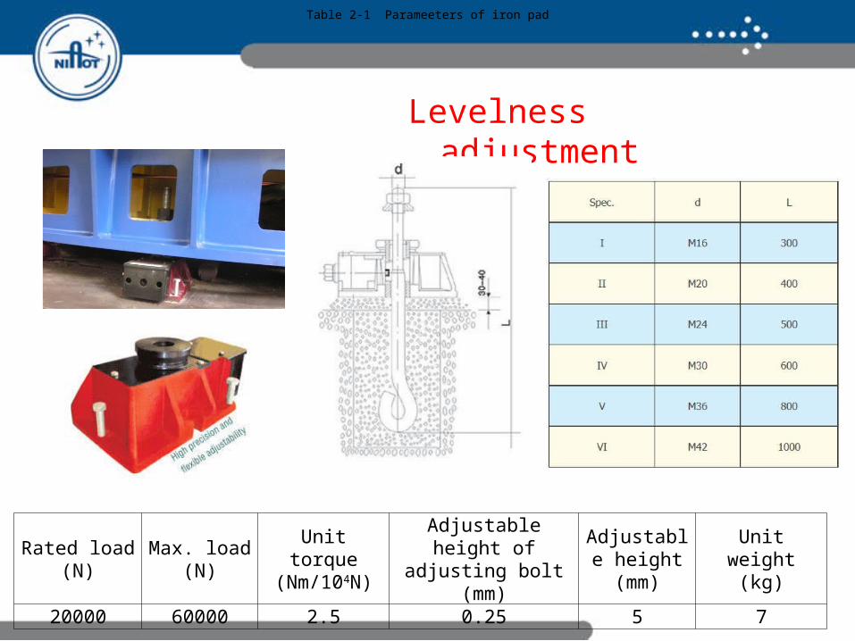
Levelness adjustment
Rated load(N)
Max. load(N)
Unit torque(Nm/104N)
Adjustable height of adjusting bolt
(mm)
Adjustable height(mm)
Unit weight(kg)
20000 60000 2.5 0.25 5 7
Table 2-1 Parameeters of iron pad

Azimuth bearing
TypeCrossed roller bearing
d 680 mm
D 880 mm
H 80 mm
Axial runout < 0.02 mm
Radial runout < 0.02 mm
Axial sitffness 5000 N/m
Radial stiffness
10000 N/m
Tilt stiffness 450000 Nm/mrad

Azimuth encoder

Azimuth motor
Friction torque: 67.5N.m ; Inertial torque: 50N.m ; Wind torque: 139N.m ;
Swiss Etel Company:
TMB0450-100;
Rated torque: 561Nm;
Rated current: 11.3A;

Max. deformation: 0.042mm
Constrain nodes connecting to bearing;
Add 1180N on top surface of center section to simulate the above weight;
Add 5390N on the down surface to simulate the down weight;
Add 1g to the structure; Apply 400N at the place of
149.5mm above center section to simulate the wind force;
Max. stress: 12.64 Mpa

M1 support ¢ 1010mm, thickness 45mm, center hole 65mm, flat bottom;
Axial supporting:
Fixed supporting: 3;
Pneumatic active supporting: 33 (6+9+18);
Lateral supporting: 10 counterweight level;
R1 = 151.72mm, F1 = 28.664N ;
R2 = 296.5mm, F2=31.183N;
R3 = 449.12mm, F3=36.775N;

Mir
ror
cell c
alc
ula
tion
Max. stress: 2.9 MPaMax. deformation: 0.58 um

For
ce a
ctuat
orD
iaphra
gm
Air
C
ylin
der
(Bel
lofr
am)

Electro- pneumatic regulator
SMC Regulator

Force sensor

M2 positioning unit
Δx (ΔY) ±7 μm
ΔZ ±3μm
Δθx(Δθx) ±20″

43
M1-M2 offset calculation
θ° uy ( um ) uz ( um ) Rotx(″)
0 0.00 11.71 0.00
10 1.52 11.57 0.14
20 2.79 11.15 0.27
30 3.80 10.44 0.39
40 4.56 9.44 0.50
50 5.10 8.13 0.58
60 5.46 6.51 0.65
70 5.68 4.59 0.70
80 5.79 2.41 0.73
90 5.83 0.00 0.74
Uz-altitute angle Uy-altitute angle Rotx-altitute angle

Fre
quency
ca
lcula
tion
Mode Frequency (Hz) Mode shape
1 24.8 Fork lateral
2 26.8 Fork fore-and-aft
3 46.4 Truss lateral
4 52.2 Truss fore-and-aft
5 54.5 Top ring torsion
6 73.7 Center section

Con
trol arc
hit
ectu
re

TCS configuration
Master Computer (Advantech Industrial PC)
Slave Computer(UMAC)

M2 control configuration

Communication

3-D Of SONG telescope

THANK YOU !!!THANK YOU !!!
Related Documents