Designing of A Blow-down Heat Recovery System for an 8 TPH Boiler for Dairibord Zimbabwe (Pvt) Ltd 2012 DESIGN OF A BLOW-DOWN HEAT RECOVERY SYSTEM FOR AN 8 TPH BOILER FOR DAIRIBORD ZIMBABWE (PVT) LTD NAME : CHIMEDZA WISDOM REG No. : R089991E E-MAIL ADRESSES : [email protected] DEPARTMENT : MECHANICAL ENGINEERING, PART IV Compiled By Chimedza Wisdom (R089991E) Supervised By Eng. L. Madiye Page 1

chimedza w: boiler blowdown heat recovery project
Oct 15, 2014
chimedza wisdom boiler blowdown heat recovery system
Welcome message from author
This document is posted to help you gain knowledge. Please leave a comment to let me know what you think about it! Share it to your friends and learn new things together.
Transcript
Designing of A Blow-down Heat Recovery System for an 8 TPH Boiler for Dairibord Zimbabwe (Pvt) Ltd
2012
DESIGN OF A BLOW-DOWN HEAT RECOVERY SYSTEM FOR AN 8 TPH BOILER FOR DAIRIBORD ZIMBABWE (PVT) LTD
NAME : CHIMEDZA WISDOM
REG No. : R089991E
E-MAIL ADRESSES : [email protected]
DEPARTMENT : MECHANICAL ENGINEERING, PART IV
SUPERVISOR : ENGINEER MADIYE L
Compiled By Chimedza Wisdom (R089991E) Supervised By Eng. L. Madiye Page 1
Designing of A Blow-down Heat Recovery System for an 8 TPH Boiler for Dairibord Zimbabwe (Pvt) Ltd
2012
1.0 INTRODUCTION
Heat recovery systems can be defined as the various techniques which can be used to harness heat energy in industrial wastes for economic purposes. In any mining/industrial set-up, the availability of energy is crucial, so there is need to conserve the available heat energy produced by boilers. Therefore the design of blow-down heat recovery systems and proper maintenance are of utmost importance.
The various heat recovery systems which can be used for boilers are;
Flue gas heat recovery systems( economizers and air preheaters) Blow-down heat recovery systems( heat exchangers, flash tank and heat wheels) Steam piping insulation
Improved energy efficiency is the best way to mitigate rising coal prices and hence the best way is to optimize the efficiency of boilers by using waste heat recovery systems.
Blowdown of water from the boiler results in heat energy losses to the environment and hence it is the aim of this research project to find ways of trying to reduce these losses. An increase in blowdown increase costs of water treatment and hence should be balanced by the benefits of recovering the heat.
1.1 BACKGROUND
Dairibord Zimbabwe Ltd is located in Southerton Industrial Area. Dairibord Zimbabwe Ltd is a milk products manufacturer for both local and export consumption. The company owns 2 x 8 TPH coal fired, fire tube boilers. The research I had carried out in 2010 on boiler efficiency had revealed that substantial heat energy is lost through blow-down processes each year. This was attributable to poor blow-down methods being practiced at the company and absence of heat recovery systems to harness useful heat energy which was lost on blow-down.
The useful amounts of heat energy were lost due to excessive blow-downs (8 – 10 blow-downs per shift) caused by poor feed-water treatments methods used by the company.
The various heat energy losses are sometimes overlooked by plant engineers in industries (which translate into thousands of dollars per annum) and this means various energy conservation opportunities have to be taken seriously and implemented in order to reduce energy losses incurred daily, hence improving boiler thermal efficiency.
Compiled By Chimedza Wisdom (R089991E) Supervised By Eng. L. Madiye Page 2
Designing of A Blow-down Heat Recovery System for an 8 TPH Boiler for Dairibord Zimbabwe (Pvt) Ltd
2012
1.2 PROBLEM STATEMENT
Designing of a boiler blow-down heat recovery system for Dairibord Zimbabwe Ltd – Belvedere Factory, Harare.
From the research on boiler efficiency carried by the author in 2010, it has been shown that;
A substantial heat energy is lost to the environment through blow-down Therefore there is need to harness the amounts of heat losses by using heat recovery
systems such as blow-down heat exchangers, automatic blow-down, flash tanks and so on
1.3 PROJECT AIM
The aim of this project is to design a blow-down heat recovery system for an 8 TPH boiler for Dairibord Zimbabwe Ltd. The aim should be achieved by a detailed selection and design of a heat recovery system.
1.4 PROJECT OBJECTIVES
The project objectives are; To harness the heat in blow-down and use it to preheat the boiler make-up water To reduce boiler blow-down heat losses by at least 15% To reduce annual coal consumption by at least 2% To improve available energy utilization by using heat recovery systems
1.5 PROJECT JUSTIFICATIONDairibord Zimbabwe (Pvt) Ltd will benefit, in one way or the other, from this project. The design of heat recovery system will increase boiler thermal efficiency and reduce coal consumption indirectly. These are major initiatives in ensuring high profits margins and hence lowering production costs of a company. The following merits will also be guaranteed to Dairibord Zimbabwe Ltd;
A decreased coal expenditure per unit production of a company( economic advantage). This is also directly linked to reduction in fossil fuel consumption hence reduction in Global Warming and ozone depletion( although the effect very minimal)
Reduce temperature of blow-down discharge to drain so that it meet statute requirements of Environmental Management Agency( E.M.A)
Compiled By Chimedza Wisdom (R089991E) Supervised By Eng. L. Madiye Page 3

Designing of A Blow-down Heat Recovery System for an 8 TPH Boiler for Dairibord Zimbabwe (Pvt) Ltd
2012
Longer life of the boiler due to reduced thermal stresses in the boiler. The make-up water will enter at an elevated temperature hence small temperature differential hence reduction in boiler thermal failures
Increase in the boiler evaporative capacity due to make-up water entering at a higher temperature
Improves reliability and capacity utilization
1.6.0 METHODOLOGY
In trying to achieve the aims and goals of this project the following shall be undertaken;
1.6.1 Literature Review
In coming up with the literature review I shall use; Library textbooks, ZIE journals and other published journals Internet Consultancy of plant engineers, technicians and boiler operators of different companies
which utilizes boilers
1.6.2 InterviewsFor brainstorming purposes during breakfast and lunch times
1.6.3 Industrial VisitsIndustrial visits will be twice per week and also other companies (Delta, TPZ and Olivine industries) which use boilers in-order to get blow-down information
1.6.4 Data Collection, Analysis of Results and Design Measure of several variables which shall be used for design purposes Design and Cost Optimization Calculation of payback period for the design project
CHAPTER 2: LITERATURE REVIEW
Compiled By Chimedza Wisdom (R089991E) Supervised By Eng. L. Madiye Page 4
Designing of A Blow-down Heat Recovery System for an 8 TPH Boiler for Dairibord Zimbabwe (Pvt) Ltd
2012
2.1 INTRODUCTIONHeat energy produced by boilers is not all used; some is lost to the environment as heat in stack gases, incomplete combustion, and blowdown losses and so on. According to the Second Law of Thermodynamics, no machine is 100% efficient. Heat losses should be minimal in order to give maximum possible useful heat. Careful design of blow-down heat recovery system becomes very crucial.
2.2 HEAT RECOVERY SYSTEMS FOR A BOILER PLANTBoiler accessories are installed along with a boiler to improve the operating conditions and overall thermal efficiency of a boiler plant. Important boiler accessories include economizers, superheaters and blowdown heat exchangers, to name a few.
2.3.0 BLOW-DOWN HEAT RECOVERY SYSTEMSBoiler blow-down is defined as the removal of a portion of boiler drum water in excess of recommended solid concentrations and replacing it with make-up water of lower concentration. Available methods may vary in accordance with the type of blow-down used by the company. Additional merits of boiler blow-down are;
Reduced thermal stresses hence increasing boiler operational life Reduced maintenance down time Reduced coal consumption per unit production
2.3.1 Limiting factors affecting blow-down
The primary purpose of blowdown is to maintain the solids content of boiler water within certain limits. This may be required for specific reasons, such as contamination of the boiler water. In this case, a high blowdown rate is required to eliminate the contaminants as rapidly as possible. The blowdown rate required for a particular boiler depends on the boiler design, the operating conditions, and the feed-water contaminant levels. In many systems, the blowdown rate is determined according to total dissolved solids. In other systems, alkalinity, silica, or suspended solids levels determine required blowdown rate. For many years, boiler blowdown rates were established to limit boiler water contaminants to levels set by the American Boiler Manufacturers' Association (ABMA) in its Standard Guarantee of Steam Purity.
This consensus applies to deposition control as well as steam quality. Good engineering judgment must be used in all cases. Because each specific boiler system is different, control limits may be different as well. There are many mechanical factors that can affect the blowdown control limits, including boiler design, rating, water level, load characteristics, and type of fuel.
In some cases, the blowdown control limits for a particular system may be determined by operating experience, equipment inspections, or steam purity testing rather than ASME or
Compiled By Chimedza Wisdom (R089991E) Supervised By Eng. L. Madiye Page 5

Designing of A Blow-down Heat Recovery System for an 8 TPH Boiler for Dairibord Zimbabwe (Pvt) Ltd
2012
ABMA water quality criteria. In certain cases, it is possible to exceed standard total solids (or conductivity), silica, or alkalinity limits. The maximum levels possible for each specific system can be determined only from experience. The effect of water characteristics on steam quality can be verified with steam purity testing. However, the effects on internal conditions must be determined from the results observed during the turnaround for the specific unit.
Certain boilers may require lower than normal blowdown levels due to unusual boiler design or operating criteria or an exceptionally pure feed-water requirement. In some plants, boiler blowdown limits are lower than necessary due to a conservative operating philosophy.
2.3.1 Continuous Blow-down SystemsThere is a steady and constant dispatch of small streams of boiler water band replacement by steady and constant inflow of feed-water. This ensures constant TDS and steam purity at given steam load. Once blow-down is set for given conditions, there is no need for regular operator intervention. Even though large quantities of heat are wasted, opportunities exist for recovering this heat by blowing into flash tank and generating flash steam and inclusion of heat exchangers. This flash steam can be used for preheating the boiler make-up water.
Continuous blowdown is the removal of water from the boiler by steady and constant dispatch of small streams of blowdown water. This kind offers crucial merits which require to be given constant attention and also provides the opportunity to use bottom blow-down system. The main purpose of this method is to remove total dissolved salts (TDS) from the location of high concentration in the boiler blow-down water. This means that proper feed-water treatment is crucial as this affects the amount of automatic continuous blowdown. Also, a minimal amount of water may be required to remove maximum of dissolved solids from the boiler. Manual blowdown is usually limited to approximately one short blow per shift to remove suspended solids which may have clogged near the manual blowdown connection when continuous blow-down is in operation.
Advantages of Continuous Blow-down System It allows for the recovery of large amounts of heat energy through the use of heat
exchangers and blow-down flash tanks connected in cascade Results in the reduction of scale build-up hence reducing caustic embrittlement Boiler water reduction – resulting in the saving of fuel and water and hence saving in
water treatment chemical costs
2.3.2 Intermittent Blow-downThis is usually carried out if the feed-water is exceptionally pure as in feed-water condensate or evaporated make-up water. It is manually operated and therefore may result in wide fluctuations
Compiled By Chimedza Wisdom (R089991E) Supervised By Eng. L. Madiye Page 6

Designing of A Blow-down Heat Recovery System for an 8 TPH Boiler for Dairibord Zimbabwe (Pvt) Ltd
2012
in boiler TDS, thereby causing fluctuations of water level in the boiler due to changes in steam bubble size and distribution which accompany changes in concentration of solids. A substantial amount of heat is also lost with intermittent blow-down. At Dairibord Zimbabwe Ltd, intermittent blow-down varies from 4 – 8 times per shift depending on the quantity of feed-water chemicals added to make-up water. The more the chemicals added to make up water, the less the number of blow-downs required.
Intermittent manual blowdown is designed to remove suspended solids, including any sludge formed in the boiler water. The manual blowdown take-
off is usually located in the bottom of the lowest boiler drum, where any sludge formed would tend to settle.
Properly controlled intermittent manual blowdown removes suspended solids, allowing satisfactory boiler operation. Most industrial boiler systems contain both a manual intermittent blowdown and a continuous blowdown
system. In practice, the manual blowdown valves are opened periodically in accordance with an operating schedule. To optimize suspended solids removal and operating economy, frequent short blows are preferred to
infrequent lengthy blows. Very little sludge is formed in systems using boiler feedwater of exceptionally high quality. The manual blowdown can be less
frequent in these systems than in those using feedwater that is contaminated with hardness or iron. The water treatment consultant can
recommend an appropriate manual blowdown schedule.
Blowdown valves on the water wall headers of a boiler should be operated in strict accordance with the manufacturer's recommendations. Usually, due to possible circulation problems, water wall headers are not blown down while the unit is steaming. Blowdown normally takes place when the unit is taken out of service or banked. The water level should be watched closely during
periods of manual blowdown.
2.3.3 Flash TankIt is used to generate steam which can then be used to preheat the boiler feed-water. Preheated feed-water increases boiler evaporative capacity. In most cases, to recover the maximum possible heat a combination of flash tank and a blow-down heat exchanger is connected to each other in cascade.Flash tanks provide one or more of the following:
A common lower pressure point for collecting condensate from steam equipment operating at different temperatures
A means to cool hot condensate to allow the use of low temperature rated pumping equipment
Compiled By Chimedza Wisdom (R089991E) Supervised By Eng. L. Madiye Page 7

Designing of A Blow-down Heat Recovery System for an 8 TPH Boiler for Dairibord Zimbabwe (Pvt) Ltd
2012
A source of low pressure steam for heating or process use
One of the simplest flash tank applications uses high pressure condensate to raise the average temperature of a mixture of low pressure condensate and make-up feed water in a vented receiver. Installation of a flash tank vented to the atmosphere reduce the possibility of back-pressure and allows all of the units to drain, increasing their productivity and minimizing the potential for heat exchanger damage due to condensate flooding. Although the flash steam is often vented directly to the atmosphere, may have recognized the significant waste energy and water associated with this practice, and installed another heat exchanger ( called a vent condenser) to condense the flash steam, recovering the heat and water.
If several steam loads are operating at constant pressure, we may connect them to a flash tank operating at a pressure lower than the load’s, but higher than atmospheric. In this way, the flash tank can be recovered under pressure and flash tank becomes a source of low pressure steam.
Another common use for flash tank is to recover heat from continuous blow-down or surface blow from the boiler. Another additional liquid-to-liquid heat exchanger can extract still more energy from the boiler water leaving the flash tank by cooling it to an environmentally acceptable temperatures before discharging it to waste.
2.3.4 HEAT EXCHANGERSHeat exchangers are devices that facilitate heat transfer from one fluid stream to another. A great variety of heat exchangers are employed in engineering applications. The geometry of flow configuration, the type of heat exchange surface and the materials of construction all vary according to the design requirements. There are described below.
Shell and Tube Heat Exchangers (STHE)
If the required heat exchange area is large, STHE is recommended due to the exposure of up to several hundred square metres as the heat transfer surface. This is practically achieved economically by placing tubes in bundles. The resultant bundles are usually enclosed within a cylindrical casing called the shell. The first fluid flow on shell side whilst the second fluid flows around and through the tube bundles.
Direct Contact Heat Exchangers (DCHE)
In this type of heat exchanger there is direct contact between the two fluids. These are more commonly used for mass and simultaneous heat and mass transfer, e.g. water heater in which
Compiled By Chimedza Wisdom (R089991E) Supervised By Eng. L. Madiye Page 8

Designing of A Blow-down Heat Recovery System for an 8 TPH Boiler for Dairibord Zimbabwe (Pvt) Ltd
2012
steam is bubbled through water. Two-stream DCHE may involve transfer between two immiscible liquids such as oil and water.
Coil Type Heat Exchangers
These are composed of spiral or helical coils. They find applications particularly at high temperature and pressure. They are simple in construction and less expensive in fabrication. The disadvantage is that of high pressure drop in the coils.
Spiral Heat Exchangers
These consists of two plates wound spirally, one inside the other; so that two rectangular narrow passages result. Through these passages two heat-exchanging fluids flow counter currently. The hot fluid enters the unit at the centre. It leaves at the periphery after flowing through the inner passage. The cold fluid, on the other hand, enters at the periphery and it flows through the outer passage, counter currently in the adjacent channels and then it exits at the centre.
Plate Type Heat Exchangers
These consist of a series of metal plates, usually with corrugated faces, held firmly together between parallel frames. Heat exchanging fluid travels in countercurrent directions and heat exchange take place through the plates. Hot fluid circulates between alternate pairs of plates, transferring heat to the cold fluid in adjacent spaces.
Advantages
Low pressure drop High rates of heat transfer Ease of cleaning
Finned Tube Heat Exchangers
They have extended surfaces. Fins are used to compensate for low heat transfer coefficients as encountered in heating air or gas. The heat transfer surface exposed to these fluids may be
Compiled By Chimedza Wisdom (R089991E) Supervised By Eng. L. Madiye Page 9
Designing of A Blow-down Heat Recovery System for an 8 TPH Boiler for Dairibord Zimbabwe (Pvt) Ltd
2012
substantially increased, in given amount of space, by extension of the surface resulting from addition of fins to the outside of tubes.
HEAT EXCHANGER ANALYSIS
THE LOGARITHMIC MEAN TEMPERATURE DIFFERENCE (LMTD)
To design or predict the performance of a heat exchanger, it is essential to relate the total heat transfer rate to quantities such as inlet and outlet temperatures, the overall heat transfer coefficient, and the total surface area for heat transfer. Two such relations may be readily be obtained by applying overall energy balances to hot and cold fluids.
q = UA∆TLMTD ......... Equation 1
where q = total rate of heat transfer between hot and cold fluids,
U = overall heat transfer coefficient and ∆TLMTD = log mean temperature difference
Diagram
Compiled By Chimedza Wisdom (R089991E) Supervised By Eng. L. Madiye Page 10
Designing of A Blow-down Heat Recovery System for an 8 TPH Boiler for Dairibord Zimbabwe (Pvt) Ltd
2012
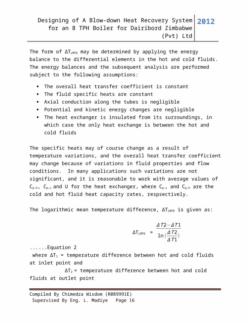
The form of ∆TLMTD may be determined by applying the energy balance to the differential elements in the hot and cold fluids. The energy balances and the subsequent analysis are performed subject to the following assumptions:
The overall heat transfer coefficient is constant The fluid specific heats are constant Axial conduction along the tubes is negligible Potential and kinetic energy changes are negligible The heat exchanger is insulated from its surroundings, in which case the only heat
exchange is between the hot and cold fluids
The specific heats may of course change as a result of temperature variations, and the overall heat transfer coefficient may change because of variations in fluid properties and flow conditions. In many applications such variations are not significant, and it is reasonable to work with average values of Cp,h, Cp,c and U for the heat exchanger, where Cp,c and Cp,h are the cold and hot fluid heat capacity rates, respsectively.
The logarithmic mean temperature difference, ∆TLMTD is given as:
∆TLMTD = ∆T 2−∆ T 1
ln (∆T 2∆T 1
) ......Equation 2
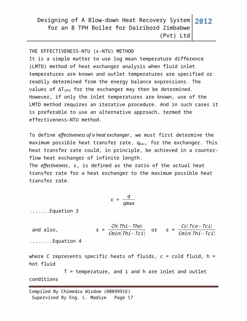
where ∆T1 = temperature difference between hot and cold fluids at inlet point and ∆T2 = temperature difference between hot and cold fluids at outlet pointTHE EFFECTIVENESS-NTU (ϵ-NTU) METHODIt is a simple matter to use log mean temperature difference (LMTD) method of heat exchanger analysis when fluid inlet temperatures are known and outlet temperatures are specified or readily determined from the energy balance expressions. The values of ∆TLMTD for the exchanger may then be determined. However, if only the inlet temperatures are known, use of the LMTD method requires an iterative procedure. And in such cases it is preferable to use an alternative approach, termed the effectiveness-NTU method.
To define effectivenessofaheatexchanger, we must first determine the maximum possible heat transfer rate, qmax, for the exchanger. This heat transfer rate could, in principle, be achieved in a counter-flow heat exchanger of infinite length.The effectiveness, ϵ, is defined as the ratio of the actual heat transfer rate for a heat exchanger to the maximum possible heat transfer rate.
ϵ = q
qmax .......Equation 3
Compiled By Chimedza Wisdom (R089991E) Supervised By Eng. L. Madiye Page 11
Designing of A Blow-down Heat Recovery System for an 8 TPH Boiler for Dairibord Zimbabwe (Pvt) Ltd
2012
and also, ϵ = Ch(Thi−Tho)
Cmin(Thi−Tci) or ϵ =
Cc (Tco−Tci)Cmin(Thi−Tci)
........Equation
4
where C represents specific heats of fluids, c = cold fluid, h = hot fluid T = temperature, and i and h are inlet and outlet conditions
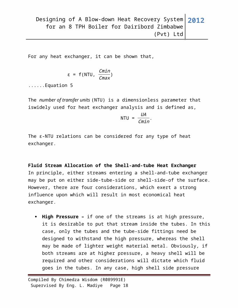
For any heat exchanger, it can be shown that,
ϵ = f(NTU, CminCmax
) ......Equation 5
The numberoftransferunits(NTU) is a dimensionless parameter that iswidely used for heat exchanger analysis and is defined as,
NTU = UA
Cmin.
The ϵ-NTU relations can be considered for any type of heat exchanger.
Fluid Stream Allocation of the Shell-and-tube Heat ExchangerIn principle, either streams entering a shell-and-tube exchanger may be put on either side-tube-side or shell-side-of the surface. However, there are four considerations, which exert a strong influence upon which will result in most economical heat exchanger.
High Pressure – if one of the streams is at high pressure, it is desirable to put that stream inside the tubes. In this case, only the tubes and the tube-side fittings need be designed to withstand the high pressure, whereas the shell may be made of lighter weight material metal. Obviously, if both streams are at higher pressure, a heavy shell will be required and other considerations will dictate which fluid goes in the tubes. In any case, high shell side pressure puts a premium on the design of long, small diameter heat exchangers.
Corrosion – corrosion generally dictates the choice of material of construction, rather than heat exchanger design. However, since most corrosion-resistant alloys are more expensive than the ordinary materials for construction, the corrosive fluid will ordinarily be placed in the tubes so that at least the shell need not be corrosion-resistant material. If corrosion cannot be effectively prevented but only slowed by choice of material, a design
Compiled By Chimedza Wisdom (R089991E) Supervised By Eng. L. Madiye Page 12
Designing of A Blow-down Heat Recovery System for an 8 TPH Boiler for Dairibord Zimbabwe (Pvt) Ltd
2012
must be chosen in which corrodible components can be easily replaced (unless it is more economical to scrap the whole unit and start over).
Fouling – fouling enters into the design of almost every process heat exchanger to a measurable extent, but certain streams foul so badly that the entire design is dominated by features which seek:
a. To minimize fouling( for example, high velocities, avoidance of dead or eddy flow regions)
b. To facilitate cleaning (fouling fluid on tube-side, wide pitch and rotated square layout if shell-side fluid is fouling) to extend operational life by multiple units.
Low Heat Transfer Coefficient – if one stream has an inherently low heat transfer coefficient (such as low pressure gases or viscous liquids), this stream is preferentially put on the shell-side so that extended surface may be used to reduce the total cost of the heat exchanger.
Compiled By Chimedza Wisdom (R089991E) Supervised By Eng. L. Madiye Page 13
Designing of A Blow-down Heat Recovery System for an 8 TPH Boiler for Dairibord Zimbabwe (Pvt) Ltd
2012
CHAPTER 3: PRODUCT DESIGN SPECIFICATION (P.D.S)
3.1 IntroductionThis project seeks to design the appropriate blow-down heat recovery system (HRS) for an 8 tonne/hour boiler for Dairibord Zimbabwe (Pvt) Ltd. The design of the system should well suit with the specifications of the customer/ client. Some of the specifications are:
Performance requirements Manufacturing requirements Operational requirements Constraints(weight, costs, product quality etc) Functional requirements
The structure of the detailed P.D.S should constitute at least four of the above specifications and at the same time satisfying the environmental requirements to avoid being sued by Environmental Management Agency.
3.2 Design Specifications The Blow-down Heat Recovery System (BDHRS) to be designed in this research is to
harness excess heat energy in the blow-down water and use it to heat the incoming boiler feed- water.
In other words the system should be able to cool the higher temperature blow-down water and the coolant (cooling fluid) being the incoming boiler feed-water and hence increases the temperature of the boiler feed-water.
3.3 Functional Requirements The inlet and outlet temperatures of the hot blow-down water should be …… and
………..deg C respectively The mass flow rate and volume flow rate of the hot blow-down water are …..and……
respectively ( measured from the boiler blow-down value directly) The mass and volume flow rates of the colder boiler make-up feed-water is to be
determined from design calculations Special data required such as specific heat capacities, thermal conductivities, thermal
coefficients and so on are to be interpreted from standard engineering tables(in the appendices)
The blow-down heat recovery should be capable of cooling at least ……….m3 of blow-down water per day
Compiled By Chimedza Wisdom (R089991E) Supervised By Eng. L. Madiye Page 14
Designing of A Blow-down Heat Recovery System for an 8 TPH Boiler for Dairibord Zimbabwe (Pvt) Ltd
2012
Capable of operating at least 20 hours non-stop per day
3.4 Constraints
Compiled By Chimedza Wisdom (R089991E) Supervised By Eng. L. Madiye Page 15
Designing of A Blow-down Heat Recovery System for an 8 TPH Boiler for Dairibord Zimbabwe (Pvt) Ltd
2012
CHAPTER 4: CONCEPT GENERATION
4.1 INTRODUCTIONIn any design process it is obvious that soon after the functional and technical specifications are obtained, the next step is to consider the different design concepts. All of the functional and technical specifications were dealt in previous chapters. It will be best to show the concept as simple diagrams/illustrations.
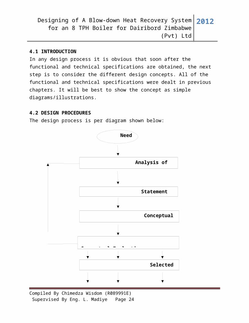
4.2 DESIGN PROCEDURESThe design process is per diagram shown below:
Compiled By Chimedza Wisdom (R089991E) Supervised By Eng. L. Madiye Page 16
Need
Analysis of the Problem
Statement of the Problem
Conceptual Generation
Conceptual Evaluation
Selected Schemes/Concepts
Designing of A Blow-down Heat Recovery System for an 8 TPH Boiler for Dairibord Zimbabwe (Pvt) Ltd
2012
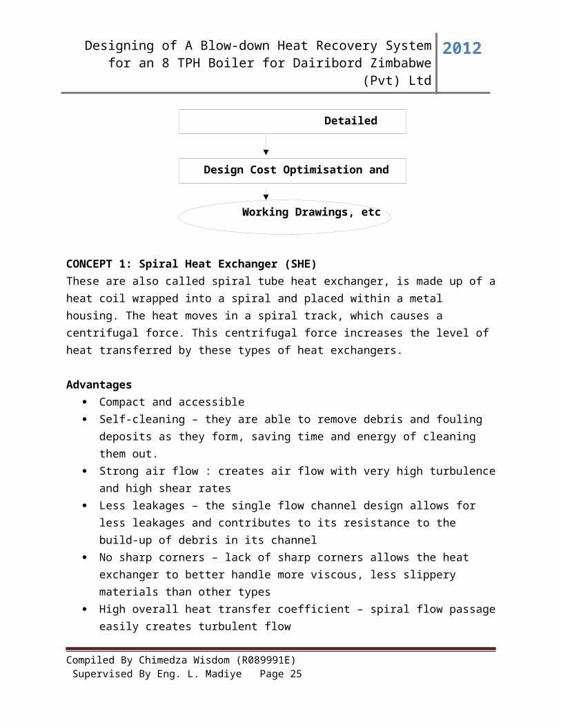
CONCEPT 1: Spiral Heat Exchanger (SHE)These are also called spiral tube heat exchanger, is made up of a heat coil wrapped into a spiral and placed within a metal housing. The heat moves in a spiral track, which causes a centrifugal force. This centrifugal force increases the level of heat transferred by these types of heat exchangers.
Advantages Compact and accessible Self-cleaning – they are able to remove debris and fouling deposits as they form, saving
time and energy of cleaning them out. Strong air flow : creates air flow with very high turbulence and high shear rates Less leakages – the single flow channel design allows for less leakages and contributes to
its resistance to the build-up of debris in its channel No sharp corners – lack of sharp corners allows the heat exchanger to better handle more
viscous, less slippery materials than other types High overall heat transfer coefficient – spiral flow passage easily creates turbulent flow Low pressure drop – in the shell and coil exchanger pressure drop is low Easy and cheaper maintenance – the heat exchange part can easily access and checked.
This is easily done by removing the cover of both ends, for inspection of the inside
Disadvantages Designs are proprietary – limited number of manufacturers Working pressure and temperature are not too high( max pressure of 2MPa) Not easy to repair i.e the whole spiral-plate heat exchanger is rolled, and once the leakage
occurs, it is hard to repair its inner part
Compiled By Chimedza Wisdom (R089991E) Supervised By Eng. L. Madiye Page 17
Detailed Design
Design Cost Optimisation and Costing
Working Drawings, etc
Designing of A Blow-down Heat Recovery System for an 8 TPH Boiler for Dairibord Zimbabwe (Pvt) Ltd
2012
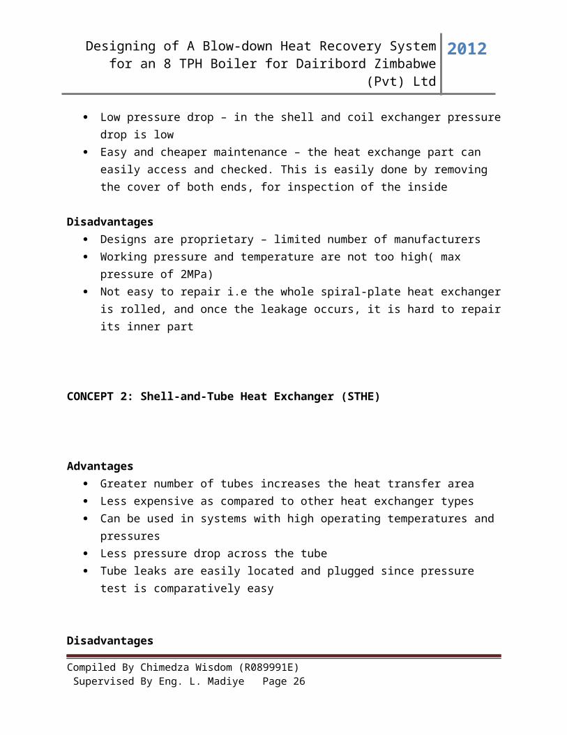
CONCEPT 2: Shell-and-Tube Heat Exchanger (STHE)
Advantages Greater number of tubes increases the heat transfer area Less expensive as compared to other heat exchanger types Can be used in systems with high operating temperatures and pressures Less pressure drop across the tube Tube leaks are easily located and plugged since pressure test is comparatively easy
Disadvantages Requires more space in comparison to plate type heat exchangers Cleaning and maintenance is difficult in the tube side of the exchanger Affected by fouling and corrosion which inhibit heat transfer rate
CONCEPT 3: Plate type Heat Exchanger
Advantages Simple and compact in size Heat transfer efficiency is more Can be cleaned easily No extra space is required for dismantling Capacity can be increased by introducing plates in pairs Maintenance is simple Turbulent flow help to reduce deposits which would interfere with heat transfer Capability of withstanding high pressures
Disadvantages Initial cost is high since Titanium plates are expensive
Compiled By Chimedza Wisdom (R089991E) Supervised By Eng. L. Madiye Page 18

Designing of A Blow-down Heat Recovery System for an 8 TPH Boiler for Dairibord Zimbabwe (Pvt) Ltd
2012
Finding leakage is difficult since pressure test is not as easy as in the shell-and-tube heat exchanger
Bonding material between the plates limits operating temperature of the cooler Higher pressure drop across the heat exchanger Overtightening of clamping bolts results in increased pressure drop across the cooler Since Titanium is a noble gas, other parts of the cooling system are susceptible to
corrosion It is difficult to readily inspect the shell side of the tubes for scaling or tube damage
CONCEPT 4: Direct Contact Heat Exchanger
These involve heat transfer between hot and cold streams of two phases in the absence of a separating wall, for example Water cooling towers
Thus such heat exchangers can be classified as:
i. Gas-liquidii. Solid-liquid
iii. Solid-gasiv. Immiscible liquid-liquid
Advantages
No surfaces to corrode or foul, or otherwise degrade the heat transfer performance Superior heat transfer for a given volume of heat exchanger due to large heat transfer
surface area achievable The ability to transfer heat to much lower temperature difference between two streams Much lower pressure drop associated with direct contactors as compared to their tubular
counterparts
Compiled By Chimedza Wisdom (R089991E) Supervised By Eng. L. Madiye Page 19

Designing of A Blow-down Heat Recovery System for an 8 TPH Boiler for Dairibord Zimbabwe (Pvt) Ltd
2012
Disadvantages There’s the mixing of the fluids hence contaminating each other Two streams must be at the same pressure in a direct contactor, which could lead to
additional costs Cannot be used in food industry as there will be contamination of fluids on mixing
CONCEPT 5: Double Pipe Heat ExchangerThis is one of the simplest forms of shell-and-tube heat exchanger. Here, just one pipe inside another large pipe. One fluid flows through the inside pipe and the other flow through the annulus between the two pipes. The wall of the inner pipe is the heat transfer surface. Advantages
Cheaper than any other type of heat exchangers Easy to construct and maintain Potential need for expansion joint is eliminated due to U-tube construction Shortened delivery times can result from the use of stock components that can be
assembled into standard sections Simple construction leads to ease of cleaning, inspection and tube element replacement
Disadvantages Limited to small heat exchange surface area Proprietary closure design requires special gaskets Multiple hairpin sections are not always economically competitive with a single shell-
and-tube heat exchanger
CONCEPT 6: Finned Heat ExchangersThis type of heat exchanger uses “sandwiched” passages containing fins to increase the effectivity of the unit. The design includes cross-flow and counterflow coupled with various fin configurations such as straight fins, offset fins and wavy fins. It is usually made of aluminum alloys which provide higher heat transfer efficiency. The material enables the system to operate at lower temperature and reduce the weight of the equipment.
Advantages Large heat transfer area High heat transfer efficiency especially in gas treatment Approximately five times lighter in weight than shell-and-tube heat exchanger Able to withstand high pressures
Disadvantages
Compiled By Chimedza Wisdom (R089991E) Supervised By Eng. L. Madiye Page 20

Designing of A Blow-down Heat Recovery System for an 8 TPH Boiler for Dairibord Zimbabwe (Pvt) Ltd
2012
Difficult to clean the pathways Might cause clogging as the pathways are very narrow Aluminum are susceptible to embrittlement failure
CONCEPT 7: Flash EconomizerA flash economizer employing an enclosed upright container has upper, intermediate and lower chambers for flashing pressurized blow down effluent in the nature of moisture-contaminated steam. It is constructed to initially separate and remove pure steam in its upper so-called flashing chamber and to thereafter maximize, principally in the intermediate chamber, an indirect transfer of heat from the remaining heat-containing condensate or water to a clean effluent, such as make-up water.
Enlarged inlet and outlet tubing members extend into and along the lower and into the intermediate chamber in a spaced relation with respect to each other, with the outlet or return tubing member extending along an inner periphery of the tubing array and along a substantially central supporting structure about which the array extends within the intermediate chamber. Downflow of heated condensate is proportioned to maintain a full spiral downflow within the enclosing structure along the tubing array while providing a central downflow along the inside of the central supporting structure.
Advantages
Concept 8: Steam Flash Tank
Compiled By Chimedza Wisdom (R089991E) Supervised By Eng. L. Madiye Page 21

Designing of A Blow-down Heat Recovery System for an 8 TPH Boiler for Dairibord Zimbabwe (Pvt) Ltd
2012
CHAPTER 5: CONCEPT EVALUATION AND ANALYSIS
5.0 INTRODUCTIONEvaluation is concerned with assessing the suitability of an alternative to satisfy the aims and objectives of the original specifications. It reflects the expert opinion of the designer, and that in turn is derived from the cultural background, education, training and experience. This helps guide the designer through the whole process, and ensures that no loose ends are left.
5.1 Subjective Decision-MakingDecision-making in design is perhaps best likened to the application of a series of filters, some course, and some fine, which reduce the original list of concepts generated to manageable proportions. The course filters are applied at first and may include basic calculations to establish non-viability, experimental work of simple nature and simple modeling.
5.2.0 Design MethodologyDesign Methodology refers to the development of a system or method for a unique situation. Design Methodology is finding the best solution for each design situation, whether it be in industrial design, or architecture or technology. It stresses the use of brainstorming to encourage innovative ideas and collaborative thinking to work through each idea and arrive at the best solution and also employs basic research methods, such as analysis and testing. Meeting the needs and wants of the end-user is the most critical concern. There are basic methods used in the design namely:
Weighted Objective Method Datum Method or Harris Profile
The methodology of arriving at a suitable blow-down heat recovery system is a complex one, not only because of the mathematics involved, but more particularly because of the many qualitative judgments that must be introduced. Due to this a careful procedure is required inorder to come up with the best design.For the sake of this design project, the author would use the Weighted Objective Method as a way of screening generated concepts.
5.2.1 Weighted Objective Method
Compiled By Chimedza Wisdom (R089991E) Supervised By Eng. L. Madiye Page 22

Designing of A Blow-down Heat Recovery System for an 8 TPH Boiler for Dairibord Zimbabwe (Pvt) Ltd
2012
The weighted objective method provides means of assessing and comparing alternative designs, using differentially weighted objectives. This method assigns numerical weights to objectives, and numerical scores to the performance of alternative designs measured against these objectives. However, it must be emphasized that such weighting and scoring can lead the unwary into some very dubious mathematics. Simply assigning numbers to objectives, or objects, does not mean that arithmetical operations can be applied to them. Arithmetic operations can only be applied to data, which have been measured on interval or ratio scale.The following representations are to be used to save space in the table below.
A - represents pressure drop across the exchangerB – represents reliabilityC – represents running costsD – represents ease of manufactureE – represents fluid flow capacityF – represents maintainabilityG – represents cleanability and repairH – represents heat transfer rate
Table 5.----: BINARY DOMINANCE MATRIX
Criteria A B C D E F G H Total RankA - 1 1 1 1 1 1 0 6 2B 0 - 0 0 0.5 0 0 0 0.5 7C 0 1 - 1 1 0 0 0 3 5D 0 1 0 - 1 0 0 0 2 6E 0 0.5 0 0 - 0 0 0 0.5 7F 0 1 1 1 1 - 1 0 5 3G 0 1 1 1 1 0 - 0 4 4H 1 1 1 1 1 1 1 - 7 1Grand Total
28
Key: 0 represents less important
1 represents more important
0.5 represents equally important
Compiled By Chimedza Wisdom (R089991E) Supervised By Eng. L. Madiye Page 23
Designing of A Blow-down Heat Recovery System for an 8 TPH Boiler for Dairibord Zimbabwe (Pvt) Ltd
2012
After identifying the design attributes, these attributes were tabulated as in the above and each one compared against the other to establish an order of importance. An attribute which was found to be more important than the other was awarded a numerical score of one(1), otherwise a zero(0), for instance when considering row F against D, and F(maintainability) is found to be more important than B(reliability) then F scores a 1(one) and B a zero(0). A half (0.5) is awarded for the attributes which are equally important. The attribute scores in each row were summed up to yield a score. The highest attribute total score is indicated the highest priority and the lowest showed the least priority hence an order of importance had been established.
5.2.2 Generating the Scale Factor
Table 5…..: Rating of the Selection Criteria
Selection Criteria
H A F G C D B E
Scaled Weighting Factor
1.00 0.84 0.72 0.56 0.44 0.28 0.08 0.08
Scale Factor
10 8 7 6 4 3 1 1
Objective Weighting Factor
50 42 36 28 22 14 4 4
Table 5.-----: Criteria Ranking and Weighting Matrix
Selection Criteria
Total Rank Weighting Scaled Weighing Factor
Scale Factor
H 7 1 0.25 1.00 10A 6 2 0.21 0.84 8F 5 3 0.18 0.72 7
Compiled By Chimedza Wisdom (R089991E) Supervised By Eng. L. Madiye Page 24
Designing of A Blow-down Heat Recovery System for an 8 TPH Boiler for Dairibord Zimbabwe (Pvt) Ltd
2012
G 4 4 0.14 0.56 6C 3 5 0.11 0.44 4D 2 6 0.07 0.28 3B 0.5 7 0.02 0.08 1E 0.5 7 0.02 0.08 1Grand Total 28
After the establishment of the priority orders, a value has to be assigned to each attribute. The value of weighting factor is obtained by giving any numerical value against the objective without use of any scale but only considering order of priority. This assigned value is called the weighted value factor. The scaled value factor was obtained using the below equation:
Scaled Weighting Factor = ObjectiveWeighting FactorHighest Weighting Factor
The scale factor was then obtained by using the equation below:
Scale factor = scaled weighting factor × 10 (1 s.f)
The order of merit was obtained through assigning a numerical value on scale from 0-100 against each concept. This was a weighting based on how the concept fulfilled the design attributes and functional requirements. The concept/attribute value factor was obtained using the below formula:
Concept/Attribute scale factor = Concept / AttributeWeighting Factor
AttributeValue Factor
A summation of all the Concept/Attributed weighting factors yields an overall score of how much each concept met the design attributed and functional requirements without subjectivity. An order of merit would be a mere comparison of these scores.
5.2.3 Scores of Possible Solutions
Usually the concept with the highest score is selected as it is the best optimal design since it can meet both the design attributes and functional requirements.
Compiled By Chimedza Wisdom (R089991E) Supervised By Eng. L. Madiye Page 25
Designing of A Blow-down Heat Recovery System for an 8 TPH Boiler for Dairibord Zimbabwe (Pvt) Ltd
2012
Table 5.----: Weighted Objective Evaluation Chart for Blow-down Heat Recovery System Options
Selection Criterion
H A F G C D B E Total
Concept 1 660
648
642
636
624
515
66
77
238
Concept 2 990
756
642
742
728
824
77
66
295
Concept 3 770
864
749
742
728
721
77
99
290
Concept 4 770
432
749
742
936
721
33
77
260
Concept 5 660
756
642
636
832
927
77
77
267
Concept 6 990
540
428
424
520
515
88
33
228
Concept 7 990
756
428
318
520
515
99
88
244
Concept 8 550
972
856
742
832
721
88
1010
291
Attribute Scale Factor
10 8 7 6 4 3 1 1
Key (As per chapter 4):
Concept 1 – Spiral heat exchanger
Concept 2 – Shell-and-tube heat exchanger
Concept 3 – Plate type heat exchanger
Concept 4 – Direct contact heat exchanger
Concept 5 – Double pipe heat exchanger
Concept 6 – Finned heat exchanger
Concept 7 – Flash Economizer
Concept 8 – Steam flash tank
Compiled By Chimedza Wisdom (R089991E) Supervised By Eng. L. Madiye Page 26
Designing of A Blow-down Heat Recovery System for an 8 TPH Boiler for Dairibord Zimbabwe (Pvt) Ltd
2012
5.2.4 DeductionConcept 2, which is a Shell-and-tube heat exchanger (STHE), came up to be the optimal design solution (since it has the highest score) which could meet the design attributes and functional requirements. So the shell-and-tube heat exchanger shall be conceptually designed fully below in order to capture other concept and then full detailed design to follow in the next chapter.
5.3.0 SHELL-AND-TUBE HEAT EXCHANGER DESIGN
The design of heat exchanger follows 3 stages namely:
Thermal Design – which involves the selection of the type of heat exchanger and the evaluation of the required heat transfer area between the two fluids.
Mechanical Design – is associated with the pressure drop in and the corrosive properties of both fluids, with provisions being made for thermal expansion and for thermal stresses resulting from unavoidable constrictions.
Manufacturing Design – based on satisfying the thermal and mechanical design requirements at the lowest cost. Also, to reduce the costs further, one may select a standard (commercially available) heat exchanger which fulfills thermal and mechanical design requirements for a particular situation.
5.3.1 The Fixed Tube DesignThe tubes bundles are fixed at both ends and cannot be removed for inspection, cleaning and there is no provision for differential thermal expansion of the shell and the tubes.
Advantages Less costly than the removable bundle heat exchanger Provides maximum heat transfer surface per given shell and the tube size Provides multi-tube-pass arrangements
Disadvantages Shell side can be cleaned only by chemical means No provision to correct for differential thermal expansion between the shell and tubes
5.3.2 The U-tube/U-bundle DesignThe tubes are bending in form of a U-shape.
Compiled By Chimedza Wisdom (R089991E) Supervised By Eng. L. Madiye Page 27

Designing of A Blow-down Heat Recovery System for an 8 TPH Boiler for Dairibord Zimbabwe (Pvt) Ltd
2012
Advantages Less costly than floating head or packed floating tube sheet designs Provides multi-tube pass arrangements Allows for differential thermal expansion between the shell and the tubes, as well as
between individual tubes High surface per given shell and tube size Capable of withstanding thermal shock
Disadvantages Tube side can be cleaned only by chemical means Individual tube replacement is not practical Cannot be made single pass on tube side, therefore, true counter-flow is not possible Tube wall at U-Bend is thinner than at straight portion of the tube Draining tube side difficult in vertical(head up) position
5.3.3 External Floating Head, Packed Gland Design
In the external floating head designs, the floating head joint is located outside the shell, and the shell sealed with sliding gland joint employing a stuffing box. Because of the danger of leaks through glands, the shell side pressure is limited to about 20 bars, and flammable or toxic materials should not be used on the shell side.
Advantages
Floating end allows for differential thermal expansion between the shell and the tubes Shell side can be steam or mechanically cleaned Bundle can be easily repaired or replaced Less costly than full, internal floating head type construction Maximum surface per given shell and tube size for removal bundle design
Disadvantages Shell side fluids limited to nonvolatile and/ or non-toxic fluids i.e lube oils, hydraulic oils Tube side arrangements limited to one or two passes Tubes expand as a group, not individually( as in U-tube unit) therefore sudden shocking
should be avoided Packing limits design pressure and temperature
5.3.4 Internal Floating Head without Clamp Ring
Compiled By Chimedza Wisdom (R089991E) Supervised By Eng. L. Madiye Page 28
Designing of A Blow-down Heat Recovery System for an 8 TPH Boiler for Dairibord Zimbabwe (Pvt) Ltd
2012
This type meets the expansion problem by having one stationary tube sheet, and one free to move – “float” – back and forth as the tubes expand and contract under the influence of temperature differentials.
Advantages Allows for differential thermal expansion between the shell and the tubes Bundles can be removed from shell, for cleaning or repairing without removing the
floating head cover Provides multi-tube pass arrangements Provides large bundle entrance area Excellent for handling flammable and/ or toxic fluids
Disadvantages
For a given set of conditions, it is mostly costly of all the basic types of heat exchanger design
Less surface per given shell and tube size
5.3.5 Internal Floating Head with Clamp RingThis type meets the expansion problem by having one stationary tube sheet, and one free to move – “float” – back and forth as the tubes expand and contract under the influence of temperature differentials.
Advantages Allows for differential thermal expansion between the shell and the tubes Excellent for handling flammable and/ or toxic fluids High surface per given shell and tube size Provides multi-tube pass arrangements
Disadvantages Shell cover, clamp ring and floating head cover must be removed prior to removing the
bundles Results in higher maintenance cost More costly than fixed tube or U-tube heat exchanger designs
5.4 Conceptual Evaluation of Shell-and-tube heat exchanger types
Compiled By Chimedza Wisdom (R089991E) Supervised By Eng. L. Madiye Page 29
Designing of A Blow-down Heat Recovery System for an 8 TPH Boiler for Dairibord Zimbabwe (Pvt) Ltd
2012
The methods of Weighted Objective described previously (in this chapter) shall be employed. The following representations are to be used to save space in the table below.
A – represents ReliabilityB – represents Danger of LeakagesC – represents Shell PressureD – represents Temperature DifferentialE – represents Ease of ManufactureF – represents Cleanability and repairG – represents Maintainability
Table 5….. : BINARY DOMINANCE MATRIX for Concepts
Criteria
A B C D E F G Total Rank
A - 1 1 1 0 1 0 4 3B 0 - 0 0.5 0 0 0 0.5 6C 0 1 - 1 0 0 0 2 5D 0 0.5 0 - 0 0 0 0.5 6E 1 1 1 1 - 1 0 5 2F 0 1 1 1 0 - 0 3 4G 1 1 1 1 1 1 - 6 1Total 21
Key: 1 – more important 0 – less important 0.5 – equally important
5.5 Generating the Scale FactorThe following formulae are to be used to come up with the scale factor and the objective weighting factors and construction of the following two tables.
Scale factor = scaled weighting factor × 10 (1 s.f) ,
Scaled Weighting Factor = ObjectiveWeighting FactorHighest Weighting Factor
Compiled By Chimedza Wisdom (R089991E) Supervised By Eng. L. Madiye Page 30

Designing of A Blow-down Heat Recovery System for an 8 TPH Boiler for Dairibord Zimbabwe (Pvt) Ltd
2012
Table 5…: Rating of the Selection Criteria
Selection Criteria
G E A F C B D
Scaled Weighting Factor
1.00 0.83 0.66 0.48 0.34 0.07 0.07
Scale Factor
10 8 7 5 3 1 1
Objective Weighting Factor
50 42 33 24 17 4 4
Table 5. -----: Criteria Ranking and Weighting Matrix
Selection Criteria
Total Rank Weighting Scaled Weighting Factor
Scale Factor
G 6 1 0.29 1.00 10E 5 2 0.24 0.83 8A 4 3 0.19 0.66 7F 3 4 0.14 0.48 5C 2 5 0.10 0.34 3B 0.5 6 0.02 0.07 1D 0.5 6 0.02 0.07 1Grand Total 21 1.00
The order of merit was obtained through assigning a numerical value on scale from 0-100 against each concept. This was a weighting based on how the concept fulfilled the design attributes and functional requirements. The concept/attribute value factor was obtained using the below formula:
Concept/Attribute scale factor = Concept / AttributeWeighting Factor
AttributeValue Factor
A summation of all the Concept/Attributed weighting factors yields an overall score of how much each concept met the design attributed and functional requirements without subjectivity. An order of merit would be a mere comparison of these scores.
5.6 Scores of Possible Solutions
Compiled By Chimedza Wisdom (R089991E) Supervised By Eng. L. Madiye Page 31
Designing of A Blow-down Heat Recovery System for an 8 TPH Boiler for Dairibord Zimbabwe (Pvt) Ltd
2012
Usually the concept with the highest score is selected as it is the best optimal design since it can meet both the design attributes and functional requirements.
Table 5…... Weighted Objective Evaluation Chart for Shell-and-tube heat exchanger types
Selection Criterion
G E A F C B D Total
Concept 1 440
864
535
525
721
88
55
198
Concept 2 440
540
535
525
721
88
55
174
Concept 3 880
756
642
840
618
44
88
248
Concept 4 770
648
749
735
721
55
88
236
Concept 5 660
540
856
630
721
44
77
218
Attribute Scale Factor
10 8 7 5 3 1 1
Key: Concept 1 – The Fixed Tube Design
Concept 2 – The U-bundle (U-tube) Design
Concept 3 – External Floating Head, Packed Gland Design
Concept 4 – Internal Floating Head without Clamp Ring
Concept 4 – Internal Floating Head with Clamp Ring
5.7 Conclusion
Concept 3, which is a Shell-and-tube heat exchanger (STHE), with External Floating Head, Packed Gland Design, came up to be the optimal design solution (since it has the highest score)
Compiled By Chimedza Wisdom (R089991E) Supervised By Eng. L. Madiye Page 32
Designing of A Blow-down Heat Recovery System for an 8 TPH Boiler for Dairibord Zimbabwe (Pvt) Ltd
2012
which could meet the design attributes and functional requirements. So this type of exchanger shall be dealt in the Detailed Design fully in the next chapters.
Compiled By Chimedza Wisdom (R089991E) Supervised By Eng. L. Madiye Page 33

Designing of A Blow-down Heat Recovery System for an 8 TPH Boiler for Dairibord Zimbabwe (Pvt) Ltd
2012
References
1. Smith C.B(1981) Energy Management Principles, Pergamon Press, New York2. Yogesh, J(1998) Design and Optimization of Thermal Systems, McGraw-Hill, Singapore3. Incopera, F.P. and Dewitt, D.P(1996) Fundamental of Heat and Mass Transfer, 4th
Edition, Wiley, New York4. Boehm, R.F(1997) Design Analysis of Thermal Systems, Wiley, New York5. Janna, W.S(1993) Design of Fluid Thermal Systems, PWS – Kent, Boston, MA6. Kern, D.Q(1950) Process Heat Transfer, McGraw-Hill, New York7. Perry, R.H., Green, D.W(1997) Eds. Perry’s Chemical Engineers’ Handbook, 7th Edition,
McGraw-Hill, New York8. Purohit, R.K(1994) Thermal Engineering In SI Units, Jordphur Scientific Publishers,
India
Compiled By Chimedza Wisdom (R089991E) Supervised By Eng. L. Madiye Page 34
Related Documents