humidification-for-life .com High Efficiency Solutions. chillBooster: story of a simple yet powerful product

Welcome message from author
This document is posted to help you gain knowledge. Please leave a comment to let me know what you think about it! Share it to your friends and learn new things together.
Transcript

humidifi cation-for-life .com
High
Effi ciency
Solutions.
chillBooster: story of a simple yet powerful product


3
Content
1. GOALS OF THIS PAPER 5
2. CHILLERS, CONDENSERS, DRY COOLERS AND ALIKE: BASIC INTRODUCTION 5
3. WHAT IS CHILLBOOSTER? 6
3.1 Description, working principle and parts ......................................6
3.1.1 Description and working principle .......................................................... 63.1.1.1 Fins need not be too long for a strong evaporative-cooling eff ect..................... 7
3.1.2 Main parts of chillBooster ............................................................................... 9
3.2 Supply water quality...........................................................................11
3.3 Installation of chillBooster onto a chiller ....................................12
3.4 Maintenance of a chillBooster system .........................................13
4. CONVENIENCE OF CHILLBOOSTER AS BOOSTER OF EXISTING CHILLERS AND SIMILAR EQUIPMENTS 14
4.1 Why and in which conditions is chillBooster convenient? ..........14
4.2 How much is chillBooster convenient? ........................................14
4.2.1 Limit of the estimation method ...............................................................14
4.2.2 Data required for the estimation of the convenience ................14
4.2.3 1st phase - Manual procedure for assessing
the evaporation ..................................................................................................15
4.2.4 2nd phase - Estimation of the evap.-cooling power .....................17
4.2.5 3rd phase - Sizing the chillBooster system ..........................................18
4.2.6 4th phase - Convenience of using chillBooster: ..................................
break-even point................................................................................................204.2.6.1 Costs ..........................................................................................................................................20
4.2.6.2 Savings .....................................................................................................................................21
5. USING CHILLBOOSTER TO BUY A NEW, SMALLER CHILLER OR SIMILAR EQUIPMENT 22
5.2.1 4th phase - Convenience of using chillBooster:
break-even point................................................................................................225.2.1.1 Costs ..........................................................................................................................................23
5.2.1.2 Savings .....................................................................................................................................23
6. EXCEL FILE FOR ESTIMATING THE RETURN-ON-INVESTMENT 24
7. APPENDIX A – MASS CONVECTION: BASICS (SI ONLY) 25

Application note: chillBooster: story of a simple yet powerful product 4
5
1. GOALS OF THIS PAPER
2. CHILLERS, CONDENSERS, DRY COOLERS AND ALIKE:
BASIC INTRODUCTION
• Understanding how to invest in energy saving with a break-even point of
a couple of months
• Understanding evaporative cooling by water on cooling coils for saving
energy
• Understanding chillBooster and how cooling-coiled equipments can
benefi t from it
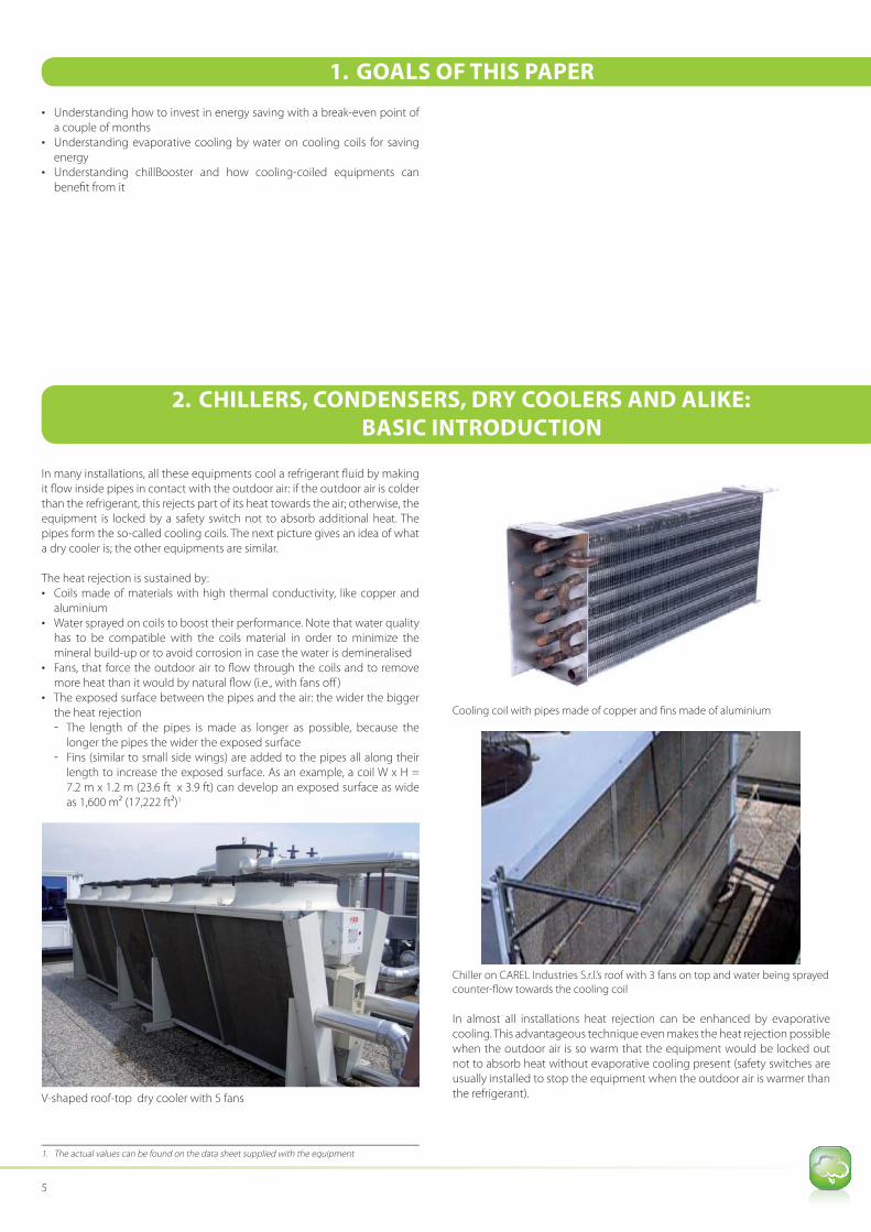
In many installations, all these equipments cool a refrigerant fl uid by making
it fl ow inside pipes in contact with the outdoor air: if the outdoor air is colder
than the refrigerant, this rejects part of its heat towards the air; otherwise, the
equipment is locked by a safety switch not to absorb additional heat. The
pipes form the so-called cooling coils. The next picture gives an idea of what
a dry cooler is; the other equipments are similar.
The heat rejection is sustained by:
• Coils made of materials with high thermal conductivity, like copper and
aluminium
• Water sprayed on coils to boost their performance. Note that water quality
has to be compatible with the coils material in order to minimize the
mineral build-up or to avoid corrosion in case the water is demineralised
• Fans, that force the outdoor air to fl ow through the coils and to remove
more heat than it would by natural fl ow (i.e., with fans off )
• The exposed surface between the pipes and the air: the wider the bigger
the heat rejection
- The length of the pipes is made as longer as possible, because the
longer the pipes the wider the exposed surface
- Fins (similar to small side wings) are added to the pipes all along their
length to increase the exposed surface. As an example, a coil W x H =
7.2 m x 1.2 m (23.6 ft x 3.9 ft) can develop an exposed surface as wide
as 1,600 m2 (17,222 ft2)1
V-shaped roof-top dry cooler with 5 fans
1. The actual values can be found on the data sheet supplied with the equipment
Cooling coil with pipes made of copper and fi ns made of aluminium
Chiller on CAREL Industries S.r.l.’s roof with 3 fans on top and water being sprayed
counter-fl ow towards the cooling coil
In almost all installations heat rejection can be enhanced by evaporative
cooling. This advantageous technique even makes the heat rejection possible
when the outdoor air is so warm that the equipment would be locked out
not to absorb heat without evaporative cooling present (safety switches are
usually installed to stop the equipment when the outdoor air is warmer than
the refrigerant).

Application note: chillBooster: story of a simple yet powerful product 6
Why and how all this is possible is explained in the following sections.
This chapter covers the following topics:
1. Description, working principle and parts
2. Water quality3. Installation
4. Maintenance
3.1 Descript ion, working principle and parts
3.1.1 Descript ion and working principlechillBooster is a simple atomizer that sprays water in small drops, whose
Sauter diameter is approx. 35 μm1.
The typical structure and use of a chillBooster system is represented in the
following picture, where chillBooster is shown to support the heat rejection
of a dry cooler by exploiting the cooling eff ect of evaporating water
(evaporative cooling):
cooled hair
cooling/atomizing nozzles
hot summer air
hot summer air
Tap and filter arerecommended
discharged air
Chiller
chillBooster
Drops are usually sprayed against the air fl ow so that they partially evaporate
before depositing on coils. Then, most of the deposited water evaporates
from the coils, greatly enhancing the rejection of heat from the chiller; the
part of the water that does not evaporate, drips, bringing away some more
heat.
The phenomena that help to increase the heat rejection from the coils are, in
order of occurrence:
1. Water eva poration in air reduces the air temperature by a few degrees
(maximum), thanks to the evaporative-cooling eff ect. It is well known
that 1 L of water evaporating in 1 hour absorbs approx. 700 W of heat
from the surrounding air, which becomes cooler and more humid [700
W/(L/h) 1,000 BTU/hr per lb/hr of evaporating water]. Since cooling
1. The drops generated by any water atomizer are diff erent from each other both in shape and dimensions. However, in order to make the study of their eff ects on the air simple, drops are idealized as spheres all having the same diameter: this is the so-called Sauter diameter. The Sauter diameter is
calculated as the ratio between the total mass of all drops, M, and their total surface, S:
(ρ is the water density approximately equal to 1,000 kg/m3 or 62.43 lbs/ft3).
coils are sensitive to temperature, chillBooster gives a fi rst advantage by
the evaporative cooling of the air, that may boost the rejected heat by
up to 20%2. An additional increase of the heat rejection comes from the evaporation of the water deposited on the coils, as explained hereafter.
2. Water dro ps not evaporated in air deposit on the fi ns of the coils and,
immediately, water starts to evaporate into the air streaming through the
coils. This evaporation is forced by the so-called mass convection3:
a. As long a s the air in the stream is not saturated at the temperature of the water on the fi ns, it will continuously absorb and bring away (mass
convection) the vapour that is always present on the surface of the water present on the fi ns;
2. The evaporative cooling of air continues also through the coils thanks to the carried-over drops. As a rule of thumb, an increment of 1 g
water/kg
dry air (7 gr
water/lbs
dry air) by evaporative cooling generates
a cooling eff ect of approx. -2.5 °C (-4.5 °F). Note that such decrement, only apparently small, may boost the reject heat by up to 20%. It is also important to point out that the actual temperature drop depends on the conditions of the outdoor air, the sprayed water fl ow and the distance between the nozzles and the coils; moreover, the real rejection enhancement depends also on the characteristics of the equipment.
3. Refer to Appendix A for basic information on mass convection
3. WHAT IS CHILLBOOSTER?
7
b. As a consequence, new water will evaporate to replace the vapour
“stolen” from its surface and …
c. … the whole process will continue as long as there is water on the
coils (loop to a)
Evaporation is a change of phase from liquid to vapour: it occurs by
absorbing heat mainly from the coils, where water is deposited [approx.
700 W per L/h of evaporating water, 1,000 (BTU/hr)/(lb/hr)], and in a
much smaller amount (actually, negligible) from the air stream. The heat
absorbed by the evaporating water greatly increases the heat rejection,
as if the coils were operating with dry coils and the outdoor air were even
5-10 °C (9-18 °F) colder. This way the heat rejection may further increase
by 40% or more! It is worth pointing out that the total length of the fi ns
along the air-stream direction plays an important role in the evaporation
rate and in the evaporative-cooling eff ect: given a certain area for the
coils’ exposed surface to the air, it is not worth having too long fi ns, since
the overall evaporation (i.e., the evaporative cooling) does not increase
signifi cantly beyond a certain value of the lenght along the air-stream
direction. This concept is better explained in section 3.1.1.1 below.
3. Finally, th e water not evaporated from the coils drips. chillBooster-like
systems are usually oversized so that some water will always fl ush the
coils to reduce the build-up of minerals. This is particularly important
when spraying mains water because it may have a signifi cant content of
minerals (read also sect. 3.2). Note that the dripping water draws some
heat but has a negligible eff ect on the total heat rejection compared to
that guaranteed by the evaporation from the coil
The three phenomena above increase the heat rejected by the chiller
even by 40% or more depending on the following parameters:
• Amount of water sprayed over the coils
• Outdoor air conditions
• Coils’ characteristics that aff ect the evaporation. These are:
- Design conditions: outdoor air temperature, refrigerant
temperature, rejected heat, coils’ total exposed surface to the air
stream, length of the fi ns along the air direction, fi ns’ effi ciency
- No. of coils - Total actual air fl ow through the coils
- Percentage of the exposed surface wet by the sprayed water
- Actual temperature of the fl uid fl owing inside the coils
The enhancement of the heat rejection is equivalent to operating the
equipment with dry coils and outdoor air even 5-10 °C (9-18 °F) colder
than the actual temperature.
3.1.1.1 Fins need not be too long for a strong evaporative-
cooling eff ect
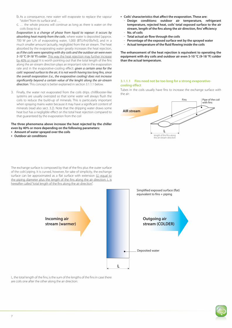
Tubes in the coils usually have fi ns to increase the exchange surface with
the air:
AIR stream
L
Fins
length of the fins alongthe air-stream direction
Pipe of the coil with fins
The exchange surface is composed by that of the fi ns plus the outer surface
of the coils’ piping. It is curved, however, for sake of simplicity, the exchange
surface can be approximated as a fl at surface with extension (L) equal to
the piping diameter plus the length of the fi ns along the air direction: L is
hereafter called “total length of the fi ns along the air direction”.
Deposited water
Simplified exposed surface (flat)
equivalent to fins + piping
L
Incoming air
stream (warmer)
Outgoing air
stream (COLDER)
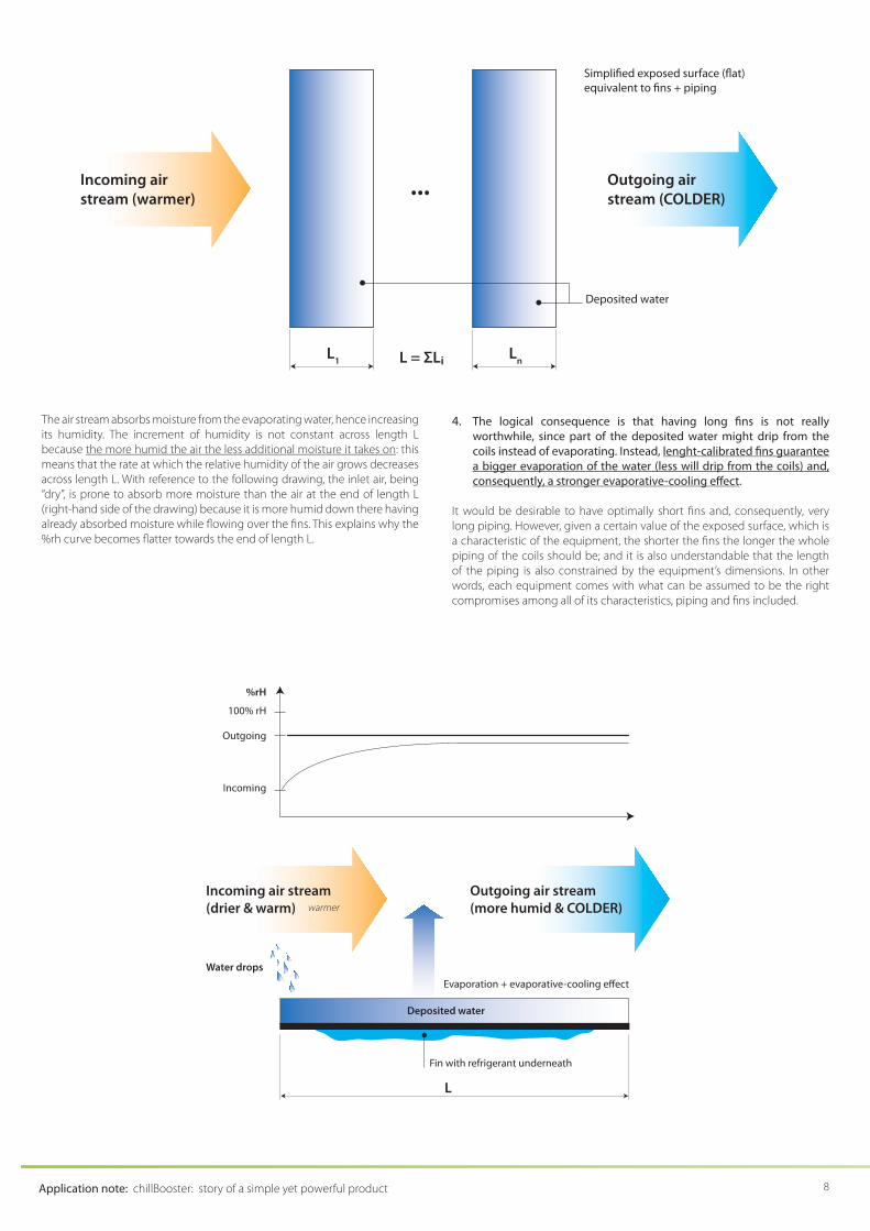
L, the total length of the fi ns, is the sum of the lengths of the fi ns in case there
are coils one after the other along the air direction:
Application note: chillBooster: story of a simple yet powerful product 8
Deposited water
Simplified exposed surface (flat)
equivalent to fins + piping
Ln
L1 L = ΣLi
Incoming airstream (warmer)
... Outgoing airstream (COLDER)
The air stream absorbs moisture from the evaporating water, hence increasing
its humidity. The increment of humidity is not constant across length L
because the more humid the air the less additional moisture it takes on: this
means that the rate at which the relative humidity of the air grows decreases
across length L. With reference to the following drawing, the inlet air, being
“dry”, is prone to absorb more moisture than the air at the end of length L
(right-hand side of the drawing) because it is more humid down there having
already absorbed moisture while fl owing over the fi ns. This explains why the
%rh curve becomes fl atter towards the end of length L.
4. The logical consequence is that having long fi ns is not really
worthwhile, since part of the deposited water might drip from the
coils instead of evaporating. Instead, lenght-calibrated fi ns guarantee
a bigger evaporation of the water (less will drip from the coils) and,
consequently, a stronger evaporative-cooling eff ect.
It would be desirable to have optimally short fi ns and, consequently, very
long piping. However, given a certain value of the exposed surface, which is
a characteristic of the equipment, the shorter the fi ns the longer the whole
piping of the coils should be; and it is also understandable that the length
of the piping is also constrained by the equipment’s dimensions. In other
words, each equipment comes with what can be assumed to be the right
compromises among all of its characteristics, piping and fi ns included.
Fin with refrigerant underneath
Evaporation + evaporative-cooling effect
L
Incoming air stream
(drier & warm)
Outgoing air stream
(more humid & COLDER)
Deposited water
Water drops
%rH
100% rH
Outgoing
Incoming
warmer
9
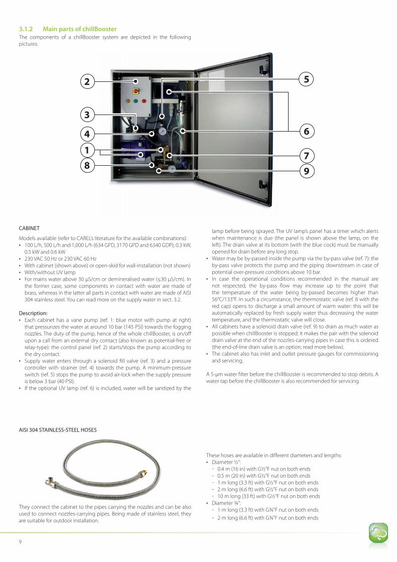
3.1.2 Main p arts of chillBoosterThe components of a chillBooster system are depicted in the following
pictures:
4
8
2
7
9
6
1
3
5
CABINET
Models available (refer to CAREL’s literature for the available combinations):• 100 L/h, 500 L/h and 1,000 L/h (634 GPD, 3170 GPD and 6340 GDP); 0.3 kW,
0.5 kW and 0.6 kW
• 230 VAC 50 Hz or 230 VAC 60 Hz• With cabinet (shown above) or open-skid for wall-installation (not shown)
• With/without UV lamp
• For mains water above 30 μS/cm or demineralised water (≤30 μS/cm). In
the former case, some components in contact with water are made of
brass, whereas in the latter all parts in contact with water are made of AISI
304 stainless steel. You can read more on the supply water in sect. 3.2.
Description:
• Each cabinet has a vane pump (ref. 1: blue motor with pump at right)
that pressurizes the water at around 10 bar (145 PSI) towards the fogging
nozzles. The duty of the pump, hence of the whole chillBooster, is on/off
upon a call from an external dry contact (also known as potential-free or
relay-type): the control panel (ref. 2) starts/stops the pump according to
the dry contact.
• Supply water enters through a solenoid fi ll valve (ref. 3) and a pressure
controller with strainer (ref. 4) towards the pump. A minimum-pressure
switch (ref. 5) stops the pump to avoid air-lock when the supply pressure
is below 3 bar (40 PSI).
• If the optional UV lamp (ref. 6) is included, water will be sanitized by the
lamp before being sprayed. The UV lamp’s panel has a timer which alerts
when maintenance is due (the panel is shown above the lamp, on the
left). The drain valve at its bottom (with the blue cock) must be manually
opened for drain before any long stop.• Water may be by-passed inside the pump via the by-pass valve (ref. 7): the
by-pass valve protects the pump and the piping downstream in case of
potential over-pressure conditions above 10 bar.
• In case the operational conditions recommended in the manual are
not respected, the by-pass fl ow may increase up to the point that
the temperature of the water being by-passed becomes higher than
56°C/133°F. In such a circumstance, the thermostatic valve (ref. 8 with the
red cap) opens to discharge a small amount of warm water: this will be
automatically replaced by fresh supply water thus decreasing the water
temperature, and the thermostatic valve will close.
• All cabinets have a solenoid drain valve (ref. 9) to drain as much water as
possible when chillBooster is stopped; it makes the pair with the solenoid
drain valve at the end of the nozzles-carrying pipes in case this is ordered
(the end-of-line drain valve is an option; read more below).
• The cabinet also has inlet and outlet pressure gauges for commissioning and servicing.
A 5-μm water fi lter before the chillBooster is recommended to stop debris. A
water tap before the chillBooster is also recommended for servicing.
AISI 304 STAINLESS-STEEL HOSES
They connect the cabinet to the pipes carrying the nozzles and can be also
used to connect nozzles-carrying pipes. Being made of stainless steel, they
are suitable for outdoor installation.
These hoses are available in diff erent diameters and lengths:
• Diameter ½”:
- 0.4 m (16 in) with G½”F nut on both ends
- 0.5 m (20 in) with G½”F nut on both ends - 1 m long (3.3 ft) with G½”F nut on both ends
- 2 m long (6.6 ft) with G½”F nut on both ends
- 10 m long (33 ft) with G½”F nut on both ends
• Diameter ¾”:
- 1 m long (3.3 ft) with G¾”F nut on both ends
- 2 m long (6.6 ft) with G¾”F nut on both ends
Application note: chillBooster: story of a simple yet powerful product 10
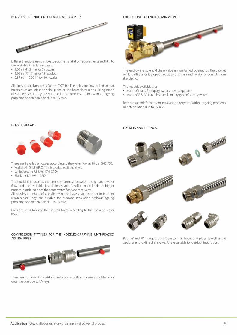
NOZZLES-CARRYING UNTHREADED AISI 304 PIPES
Diff erent lengths are available to suit the installation requirements and fi t into
the available installation space:
• 1.05 m (41.34 in) for 7 nozzles
• 1.96 m (77.17 in) for 13 nozzles• 2.87 m (112.99 in) for 19 nozzles
All pipes’ outer diameter is 20 mm (0.79 in). The holes are fl ow-drilled so that
no residues are left inside the pipes or the holes themselves. Being made
of stainless steel, they are suitable for outdoor installation without ageing
problems or deterioration due to UV rays.
NOZZLES & CAPS
There are 3 available nozzles according to the water fl ow at 10 bar (145 PSI):
• Red: 5 L/h (31.1 GPD). This is available off the shelf.
• White/cream: 7.5 L/h (47.6 GPD)
• Black: 15 L/h (95.1 GPD)
The model is chosen as the best compromise between the required water
fl ow and the available installation space (smaller space leads to bigger
nozzles in order to have the same water fl ow and vice-versa).
All nozzles are made of acetylic resin and have a steel strainer inside (not
replaceable). They are suitable for outdoor installation without ageing
problems or deterioration due to UV rays.
Caps are used to close the unused holes according to the required water
fl ow.
COMPRESSION FITTINGS FOR THE NOZZLES-CARRYING UNTHREADED
AISI 304 PIPES
They are suitable for outdoor installation without ageing problems or
deterioration due to UV rays.
END-OF-LINE SOLENOID DRAIN VALVES
The end-of-line solenoid drain valve is maintained opened by the cabinet
while chillBooster is stopped so as to drain as much water as possible from
the piping.
The models available are:
• Made of brass, for supply water above 30 μS/cm• Made of AISI 304 stainless steel, for any type of supply water
Both are suitable for outdoor installation any type of without ageing problems
or deterioration due to UV rays.
GASKETS AND FITTINGS
Both ½” and ¾” fi ttings are available to fi t all hoses and pipes as well as the
optional end-of-line drain valve. All are suitable for outdoor installation.
11
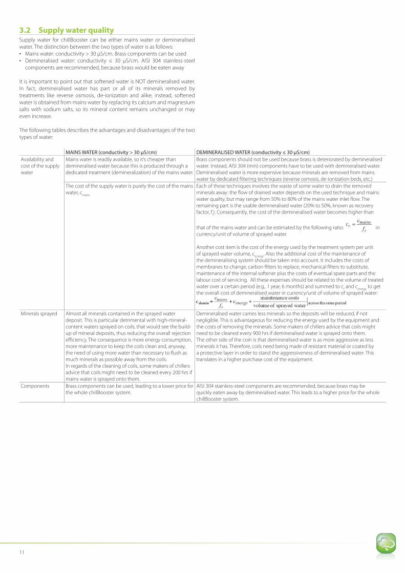
3.2 Supply w ater qualitySupply water for chillBooster can be either mains water or demineralised
water. The distinction between the two types of water is as follows:
• Mains water: conductivity > 30 μS/cm. Brass components can be used• Demineralised water: conductivity ≤ 30 μS/cm. AISI 304 stainless-steel
components are recommended, because brass would be eaten away
It is important to point out that softened water is NOT demineralised water.
In fact, demineralised water has part or all of its minerals removed by
treatments like reverse osmosis, de-ionization and alike; instead, softened
water is obtained from mains water by replacing its calcium and magnesium
salts with sodium salts, so its mineral content remains unchanged or may
even increase.
The following tables describes the advantages and disadvantages of the two
types of water:
MAINS WATER (conductivity > 30 μS/cm) DEMINERALISED WATER (conductivity ≤ 30 μS/cm)
Availability and
cost of the supply
water
Mains water is readily available, so it’s cheaper than
demineralised water because this is produced through a
dedicated treatment (demineralization) of the mains water.
Brass components should not be used because brass is deteriorated by demineralised
water. Instead, AISI 304 (min) components have to be used with demineralised water.
Demineralised water is more expensive because minerals are removed from mains
water by dedicated fi ltering techniques (reverse osmosis, de-ionization beds, etc.)
The cost of the supply water is purely the cost of the mains
water, cmains
Each of these techniques involves the waste of some water to drain the removed
minerals away: the fl ow of drained water depends on the used technique and mains
water quality, but may range from 50% to 80% of the mains water inlet fl ow. The
remaining part is the usable demineralised water (20% to 50%, known as recovery
factor, fr). Consequently, the cost of the demineralised water becomes higher than
that of the mains water and can be estimated by the following ratio: in
currency/unit of volume of sprayed water.
Another cost item is the cost of the energy used by the treatment system per unit
of sprayed water volume, cenergy
. Also the additional cost of the maintenance of
the demineralising system should be taken into account. It includes the costs of
membranes to change, carbon fi lters to replace, mechanical fi lters to substitute,
maintenance of the internal softener plus the costs of eventual spare parts and the
labour cost of servicing. All these expenses should be related to the volume of treated
water over a certain period (e.g., 1 year, 6 months) and summed to cr and c
energy to get
the overall cost of demineralised water in currency/unit of volume of sprayed water:
Minerals sprayed Almost all minerals contained in the sprayed water
deposit. This is particular detrimental with high-mineral-
content waters sprayed on coils, that would see the build-
up of mineral deposits, thus reducing the overall rejection
effi ciency. The consequence is more energy consumption,
more maintenance to keep the coils clean and, anyway,
the need of using more water than necessary to fl ush as
much minerals as possible away from the coils.
In regards of the cleaning of coils, some makers of chillers
advice that coils might need to be cleaned every 200 hrs if
mains water is sprayed onto them.
Demineralised water carries less minerals so the deposits will be reduced, if not
negligible. This is advantageous for reducing the energy used by the equipment and
the costs of removing the minerals. Some makers of chillers advice that coils might
need to be cleaned every 900 hrs if demineralised water is sprayed onto them.
The other side of the coin is that demineralised water is as more aggressive as less
minerals it has. Therefore, coils need being made of resistant material or coated by
a protective layer in order to stand the aggressiveness of demineralised water. This
translates in a higher purchase cost of the equipment.
Components Brass components can be used, leading to a lower price for
the whole chillBooster system.
AISI 304 stainless-steel components are recommended, because brass may be
quickly eaten away by demineralised water. This leads to a higher price for the whole
chillBooster system.
Application note: chillBooster: story of a simple yet powerful product 12
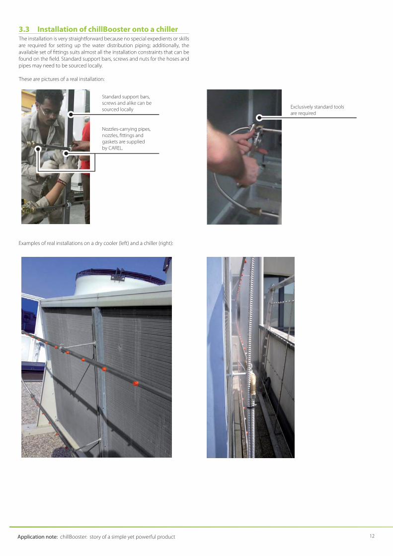
3.3 Installation of chillBooster onto a chillerThe installation is very straightforward because no special expedients or skills
are required for setting up the water distribution piping; additionally, the
available set of fi ttings suits almost all the installation constraints that can be
found on the fi eld. Standard support bars, screws and nuts for the hoses and
pipes may need to be sourced locally.
These are pictures of a real installation:
Examples of real installations on a dry cooler (left) and a chiller (right):
Exclusively standard tools
are required
Standard support bars,
screws and alike can be
sourced locally
Nozzles-carrying pipes,
nozzles, fi ttings and
gaskets are supplied
by CAREL.

13
3.4 Maintenan ce of a chillBooster systemMaintenance of a chillBooster system is easy and simple:
4
1
6
7
REFERENCE Components Frequency Activities
(not shown) Nozzles Annual or in case they do not spray
water
Check the conditions; eventually
clean/replace
(not shown) Water fi lter before chillBooster’s cabinet Annual Check and clean/replace
4 Water fi lter inside chillBooster’s cabinet Annual Check and clean/replace
(not shown) Water connections inside and outside
chillBooster’s cabinet
At seasonal restarts or in case
spraying is low and the pump is ok
Check for leaks and correct
6 UV lamp (if present) Monthly Check the red led on the lamp’s panel: if ON, replace the lamp. ON
= lamp exhausted. The red led is activated by the lamp’s timer to
alert the user.
Every 5,000-7,500 hrs It is usually time to replace the lamp if the red led on the lamp’s
panel is ON.
1 Pump Whenever the outlet pressure does
not reach 10 bar, even after adjusting
the by-pass valve (ref. 7) AND there
are no leaks downstream of the
pump.
There is no preventive maintenance for the pump: it runs until it
has to be replaced.
A pump needs to be replaced when the outlet pressure does not
reach 10 bar even after adjusting the by-pass valve (ref. 7), with no
leaks downstream of the pump.

Application note: chillBooster: story of a simple yet powerful product 14
4. CONVENIENC E OF CHILLBOOSTER AS BOOSTER OF
EXISTING CHILLERS AND SIMILAR EQUIPMENTS
IMPORTANT: The estimation method hereafter described can also be used
for any water sprayers whose drops have a Sauter diameter greater than
or equal to 10-15 μm, i.e. starting from humiFog.
This section covers the following topics:1. Why and in which conditions is chillBooster convenient?
2. How much is it convenient?
4.1 Why and in which conditions is chillBooster convenient?
As explained in sect. 3.1.1, water evaporation from coils increases the heat
rejected by the chiller or condenser even by 30% or more.
Water evaporation occurs by mass convection thanks to the air stream
fl owing over the water layer deposited on the fi ns: as long as the air in the
stream is not saturated at the temperature of the water on the fi ns, it will
continuously absorb and bring away (mass convection) the vapour that is
always present on the surface of the water layer; as a consequence, new
water will evaporate to replace the vapour “stolen” from its surface and the
whole process will continue as long as there is water on the fi ns.
The interesting point is that the evaporation from the water layer is continuous
and spontaneous if the partial pressure of vapour in the air stream is lower
than that of the water layer. The partial pressure of vapour is a measure of
the amount of vapour present in the fl uid (either air or water): the higher
the amount of vapour the higher its partial pressure, and vice versa. The idea
that the amount of vapour generates a pressure helps to understand why
the vapour moves spontaneously from the water to the air, causing water to
evaporate: in fact, like gases, vapour diff uses spontaneously from locations
with higher (vapour) pressure to locations with lower (vapour) pressure, until
the pressures equalize. For this reason, since vapour pressure is usually higher
over the water layer than in the air stream, vapour spontaneously transits
towards the air stream, and this process continues as long as the incoming
air has a vapour pressure lower than the water layer’s.
So, everything works as long as the incoming air has a vapour pressure lower
than the water layer’s.
Now the question is: are there cases when the air’s vapour pressure is higher
than the water layer’s? Yes, there are, and in those cases water will not
evaporate. Luckily enough, these cases are rare.
The vapour pressure of the water layer depends on the water temperature:
it increases when temperature increases, and vice versa1. The sprayed water
absorbs heat from the coils, because these are usually warmer; an additional
contribution comes from the incoming air if this is warmer than the sprayed
water. These contributions warm the water up, so that temperatures close to
those of the refrigerant are usual for the deposited water (e.g., 20 °C to 35 °C
/ 68 °F to 95 °F).
The second heat gain, that from the incoming air, is particular interesting: the
warmer the air the warmer the water tends to be. This is extremely important
in tropical areas, where the high humidity would mistakenly lead to the
conclusion that the evaporation cannot take place: in fact, it does, because
the high air temperature may increase that of the deposited water, hence its
vapour pressure, thus sustaining the evaporation. One consequence is that,
in some conditions, fog forms downstream of the fans when the amount
of evaporated water exceeds the saturation of the outdoor air, i.e. mass
convection may force the evaporation of more water than the air can carry
just because this is “forced” evaporation, not “natural” (this is a similar fog that
can be seen at the discharge of cooling towers).
Even in hot and humid climates (e.g., Tropics), chillBooster may be
benefi cial for chillers and alike.
1. The relationship is totally non-linear
4.2 How much is chi llBooster convenient?
The estimation method described in the following can be used to see
whether the application of a water sprayer like chillBooster can help the
chiller to overcome peaks of cooling demand.
The estimated evaporative-cooling power can be seen as the additional
heat rejected by the coils on top of that rejected when they are fully dry. For
instance, when they are fully dry, the rejected heat = 100 kW; by spraying 150
L/h of water the evaporative-cooling power = 90 kW, so the total rejected
heat becomes approximately equal to 190 kW. In case the total rejected
heat estimated this way (190 kW in the example above) is higher than what
actually needed (e.g., 180 kW), the diff erence (10 kW) generates a reduction
of the electric energy used by the chiller.
The overall method is not exactly precise, but can be used as a quick
assessment of whether or not the chillBooster is of any help for the chiller.
More precise estimations can be made by CAREL.
The estimation of the convenience proceeds in 4 phases:1. Assessment of whether or not the evaporation can occur
2. If it does, the estimation of the cooling power generated by the
evaporating water follows
3. Sizing of the chillBooster system
4. Finally, the convenience (i.e., break-even point) of using chillBooster is
estimated
The following sections explain them all.
4.2.1 Limit of the es timation method• The method described hereafter yields approximated estimations due to
the simplifi ed way they are made: the error may be as much as ±20%. The
results should not be used as supporting data for projects: for more precise
estimates, please, refer to CAREL
• The method estimates only the evaporative-cooling power given by the
evaporation of water both in the air and from the coils
• The method does NOT take into account the heat drawn by the water
dripping from the coils, if any, and the heat rejected by the dry parts of
the coils, if any
• This means that the evaporative-cooling power estimated by this method
is a fi gure of how much heat can be rejected thanks to water evaporation;
instead, it is NOT the total heat rejected by the coils because that given by the dry parts and the dripping water is not included. Ask CAREL for a
comprehensive estimation that includes these missing parts
4.2.2 Data required fo r the estimation of the convenienceThe data required for the assessment of the convenience are:• Outdoor air conditions. IMPORTANT: the humidity ratio has to be expressed
in kgw/kg
da or lbs
w/lb
da
• Condenser or dry cooler:
- Temperature of the refrigerant fl uid inside the coils (°C). This can be
found from its data sheet or by asking the maker - Total width and height (W
coils , H
coils) of the coils (m). Refer to the
equipment’s data sheet or ask the maker.
- Air speed through the coils, vair
(m/s). Refer to the equipment’s data
sheet or ask the maker
- Total exposed surface to the air, A (m2). This is the contact surface
between the air and the piping of the coils; it can be found from the
equipment’s data sheet or by asking the maker (it is of the order of
hundreds or thousands of m2; thousands or tens of thousands of ft2)
- Total length of the fi ns along the air direction, L (mm)

15
4.2.3 1st phase - Manual p rocedure for assessing the evaporation
The manual (approximate) procedure for assessing whether evaporation
takes place involves the use of the humidity ratio. This expresses the amount
of moisture present in the air as mass of vapour, in kg, per kg of dry air and is
1:1 related to the partial vapour pressure of the air. The advantage of using
the humidity ratio is that it is on the vertical axis of the psychrometric chart,
so the psychrometric chart can show both the conditions of the outdoor air
and whether water can evaporate from the coils.
The assessment of whether the deposited water evaporates from the coils
is as follows:
1. Find the outdoor air conditions on the psychrometric chart. Let Wair
be its
humidity ratio. Example: Singapore 30 °C (86 °F), 80 %rh, Wair
= 0.022 kgw/
kgda
(0.022 lbsw/lb
da)
5
10
15
20
25
30
35
40
45
50
55
60
65
70
75
80
85
90
95
100
105
110
115
120
125
130
135
140 145 150
5 10 15 20 25 30 35 40 45 50
DR
Y BU
LB T
EMPE
RAT
UR
E - °
C
,001
,002
,003
,004
,005
,006
,007
,008
,009
,010
,011
,012
,013
,014
,015
,016
,017
,018
,019
,020
,021
,022
,023
,024
,025
,026
,027
,028
,029
,030
,031
,032
,033
,034
,035
,036
,037
,038
,039
,040
10% RELATIVE HUMIDITY
20%
30%
40%
50%
60%
70%
80%
90%
5
510
10
15
15
20
20
25
25
30
30
35 WET BULB TEMPERATURE - °C
35
HU
MID
ITY
RA
TIO
- K
ILO
GR
AM
S M
OIS
TUR
E P
ER
KIL
OG
RA
M D
RY
AIR
AIR
2. Find the temperature of the fl uid inside the chiller or condenser from its data sheet or by asking the maker. Example: 36 °C (97 °F)
3. Estimate the deposited water temperature as the arithmetic mean of the
temperatures of the coils (assumed equal to the refrigerant’s temperature)
and that of the outdoor air decreased by 2 °C – 4 °F due to the evaporative
cooling2. Example: 32 °C (90 °F) = [ (30-2) + 36 ] / 2, (this is in °C)
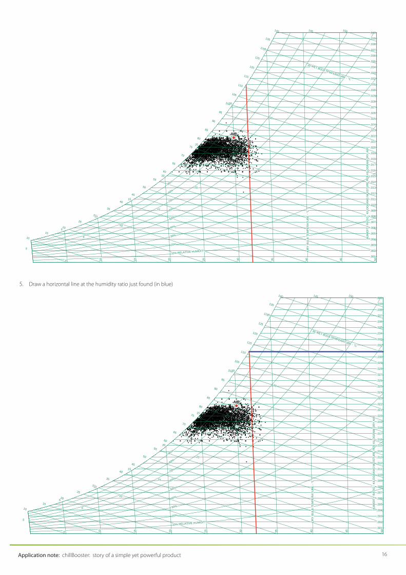
4. Enter the psychrometric chart with the deposited water temperature just
estimated up to the saturation line and fi nd the corresponding humidity
ratio above the water layer, Wwater layer
(it is assumed that air right above the water layer is saturated at the temperature of the water layer itself ).
The red line shows how to fi nd this humidity ratio starting from the water
temperature. Example: 0.031 kgw/kg
da (0.031 lbs
w/lb
da)
2. 2 °C (4 °F) is an average value. The real one depends on the outdoor air conditions, air fl ow and sprayed water fl ow. Ask CAREL for more precise estimates.
Application note: chillBooster: story of a simple yet powerful product 16
5
10
15
20
25
30
35
40
45
50
55
60
65
70
75
80
85
90
95
100
105
110
115
120
125
130
135
140 145 150
5 10 15 20 25 30 35 40 45 50
DR
Y BU
LB T
EMPE
RAT
UR
E - °
C
,001
,002
,003
,004
,005
,006
,007
,008
,009
,010
,011
,012
,013
,014
,015
,016
,017
,018
,019
,020
,021
,022
,023
,024
,025
,026
,027
,028
,029
,030
,031
,032
,033
,034
,035
,036
,037
,038
,039
,040
10% RELATIVE HUMIDITY
20%
30%
40%
50%
60%
70%
80%
90%
5
510
10
15
15
20
20
25
25
30
30
35 WET BULB TEMPERATURE - °C
35
HU
MID
ITY
RAT
IO -
KILO
GR
AMS
MO
ISTU
RE
PER
KIL
OG
RAM
DR
Y AI
R
AIR
5. Draw a horizontal line at the h umidity ratio just found (in blue)
5
10
15
20
25
30
35
40
45
50
55
60
65
70
75
80
85
90
95
100
105
110
115
120
125
130
135
140 145 150
5 10 15 20 25 30 35 40 45 50
DR
Y BU
LB T
EMPE
RAT
UR
E - °
C
,001
,002
,003
,004
,005
,006
,007
,008
,009
,010
,011
,012
,013
,014
,015
,016
,017
,018
,019
,020
,021
,022
,023
,024
,025
,026
,027
,028
,029
,030
,031
,032
,033
,034
,035
,036
,037
,038
,039
,040
10% RELATIVE HUMIDITY
20%
30%
40%
50%
60%
70%
80%
90%
5
510
10
15
15
20
20
25
25
30
30
35 WET BULB TEMPERATURE - °C
35
HU
MID
ITY
RAT
IO -
KILO
GR
AMS
MO
ISTU
RE
PER
KIL
OG
RAM
DR
Y AI
R
AIR

17
6. If the outdoor air is below the line, then evaporation will take place,
so you can proceed to the estimation of the cooling power generated
by the water evaporation (2nd phase); otherwise it will not start.
In the example, even in the hot and humid Singapore chillBooster would
be benefi cial.
4.2.4 2nd phase - Estimation of the ev ap.-cooling powerThe estimation of the evaporative-cooling power can be done only in
case the humidity ratio above the water layer is higher than the humidity
ratio of the outdoor air (i.e., in case the blue line is above the outdoor air’s
representative point in steps 5 & 6 above).
The estimation of the evaporative-cooling power is based on two main steps:• Estimation of the maximum possibile evaporation rate from the coils
• Estimation of the evaporative-cooling power based on the real sprayed
water fl ow rate
Consider that if the sprayed water fl ow is higher than the maximum
evaporation rate, part of the sprayed water will drip from the coils. Since this
method does not take into account the heat removed by the dripping water,
the real sprayed water fl ow rate should be less than or equal to the maximum
evaporation rate, otherwise the estimated evaporative-cooling power might
be aff ected by larger approximation errors. Obviously, when the real sprayed
water fl ow rate is less than the maximum evaporation rate, part of the coils
will remain dry. The method does not estimate the heat rejected by the
dry parts: it only estimates the heat rejected thanks to water evaporation
by the wet parts. The evaporative-cooling value given by the method can
be thought of as the additional heat rejected by the coils thanks to the
evaporation of water: this additional heat sums up to that rejected by fully
dry coils to give the overall heat rejection. As already stated, although this is
not precise, it is a simple manual method for understanding how much more
heat can be rejected by a cooling-coiled system thanks to the evaporation of
sprayed water. CAREL can make more precise and comprehensive estimates
if needed.
Proceed as follows (refer to Appendix A for more information on steps 7-9;
formulas in steps 7-18 are valid in the SI system only):
7. Calculate the Reynolds number of the air stream over the water:
Lvairf ××≅ 60Re
• vair
is the air speed in m/s
• L is the length of the fi ns along the air direction, in mm
Example with vair
= 2 m/s and L = 30 mm: 600,330260Re =××≅f
8. Calculate the Sherwood number of the limit layer:
( )
( )⎪⎩
⎪⎨
⎧
>⇐××
≤⇐××≅
fins) over theflow (turbulent 000,500Re8.0
fins) over theflow (laminar 000,500Re3.4
54
fair
fairf
Lv
LvSh
• vair
is the air speed in m/s• L is the length of the fi ns along the air direction, in mm
Example with vair
= 2 m/s and L = 30 mm:
• 600,3Re ≅f from above, so the air fl ow is laminar over the fi ns
• ( ) ( ) 1.337.73.4603.43023.43.4 ≅×≅×=××=××≅ LvSh airf
9. Calculate the mass convection coeffi c ient in m/s: L
Shh f
M×
≅03.0
• L is the length of the fi ns along the air direction, in mm
Example with vair
= 2 m/s and L = 30 mm 03.030
1.3303.003.0≅
×≅
×≅
LSh
h fM
m/s
10. Use the total exposed surface of the coils to the air, A, in m2. This can be
found from the data sheet of the equipment or can be asked for to the
maker. Example: A = 1,000 m2
11. Calculate the diff erence Wwater layer
– Wa ir
IMPORTANT: respect this order of the terms in the diff erence! This
must be positive if in step 5 the humidity ratio above the water layer
has been proved to be higher than that of the outdoor air.
Example: Wwater layer
– Wair
= 0.031 – 0.022 = 0.009 kgw/kg
da (0.009 lbs
w/lb
da)
5
10
15
20
25
30
35
40
45
50
55
60
65
70
75
80
85
90
95
100
105
110
115
120
125
130
135
140 145 150
5 10 15 20 25 30 35 40 45 50
DR
Y BU
LB T
EMPE
RAT
UR
E - °
C
,001
,002
,003
,004
,005
,006
,007
,008
,009
,010
,011
,012
,013
,014
,015
,016
,017
,018
,019
,020
,021
,022
,023
,024
,025
,026
,027
,028
,029
,030
,031
,032
,033
,034
,035
,036
,037
,038
,039
,040
10% RELATIVE HUMIDITY
20%
30%
40%
50%
60%
70%
80%
90%
5
510
10
15
15
20
20
25
25
30
30
35 WET BULB TEMPERATURE - °C
350,80
0,82
0,84
0,86
0,88 VOLUME - CUBIC M
ETER PER KG DRY AIR0,90
HU
MID
ITY
RA
TIO
- K
ILO
GR
AM
S M
OIS
TUR
E PE
R K
ILO
GR
AM D
RY
AIR
AIR
Wwater layer
– Wair

Application note: chillBooster: story of a simple yet powerful product 18
12. Calculate the maximum evaporation rate in k g/h:
( )airlayerwaterM WWAhR −×××≅ ,max 320,4
Example:
( ) 166,1009.0000,103.0320,4320,4 ,max ≅×××≅−×××≅ airlayerwaterM WWAhR
kg/h
13. If the sprayed water fl ow is less than Rmax
then all the sprayed water will
evaporate, otherwise part of it will drip from the coils. This method does
not allow to estimate the additional heat rejected when water drips
from the coils, so in case the sprayed water fl ow is grater than Rmax
the
following estimates may be approximated per defect (refer to CAREL for
more prices values).
14. Set the evaporation rate Revaporation
from th e coils as follows (in kg/h):
⎪⎩
⎪⎨⎧
=⇒>
=⇒≤
maxmax
max
watersprayed
watersprayed watersprayed:
RRR
RRR
nevaporatio
nevaporationevaporatio
IMPORTANT: the sprayed water fl ow MUST be expressed in kg/h
Example 1: sprayed water = 130 kg/h sprayed water ≤
Rmax
= 1,166 kg/h Revaporation
= 130 kg/h
Example 2: sprayed water = 1,200 kg/h sprayed water >
Rmax
= 1,166 kg/h Revaporation
= 1,166 kg/h
15. Calculate the estimated evaporative-cooling po wer in kW:
nevaporatiocoolingevap RP ×≅ 7.0. 0.7 is the latent power of evaporation,
in kW, of 1 kg/h of evaporating water
Example 1: 911307.07.0. ≅×≅×≅ nevaporatiocoolingevap RP kW
Example 2: 816166,17.07.0. ≅×≅×≅ nevaporatiocoolingevap RP kW.
This may be approximated per defect because it does not take into
account the heat drawn by the dripping water.
16. At this point the heat rejected thanks to the evaporative cooling has
been estimated
17. When the sprayed water fl ow is less than the maximum evaporation rate,
its value can be added the heat rejected by fully dry coils to understand
what is the total heat rejected by the chiller.
Examples:
• Heat rejected by fully dry coils = 10 kW; evaporative-cooling power = 91 kW total rejected heat = 10 + 91 = 101 kW
• Heat rejected by fully dry coils = -15 kW (i.e., the chiller would lock out);
evaporative-cooling power = 91 kW total rejected heat = -15 + 91
= 76 kW. chillBooster allows the chiller to run, whereas it would stop
without chillBooster!
18. When the sprayed water fl ow is equal to the maximum evaporation rate,
then the total rejected heat is equal to the estimated evaporative-cooling
power because the rejection is due only to the evaporation of the water.
Example: heat rejected by fully dry coils = xxx kW; evaporative-cooling
power = 816 kW total rejected heat = 816 kW
The estimated values are not exact, however the method is quite reasonable
for manual evaluation. In case more precise estimates are required, CAREL can do them.
4.2.5 3rd phase - Sizing the chillBooster systemThe st eps for sizing a chillBooster systems are:
19. It is advisable to spray an amount of water that dri ps from the coils to
wash away the minerals it contains: a 20% increment of Rmax
seems
reasonable, although in many real cases even smaller sprayed fl ow
rates may fl ush the coils. The resulting sprayed water fl ow, qwater
, is the
total water fl ow that chillBooster has to spray: qwater
= Rmax
+ 20% (or
whatever value that guarantees coils fl ushing).
Note: that some minerals will anyway build up on the coils, making
their periodic cleaning necessary; this can be reduced by spraying
demineralised water, but care is required because demineralised water
can corrode the coils (refer to sect. 3.2 for more information).
Example: qwater
= Rmax
+ 20% = 1,166 kg/h + 20% = 1,399 kg/h = 3,085
lbs/hr
20. Bill of material of the chillBooster system:
IMP ORTANT: the values given as examples change according to the real
installation; for this reason the total list price is not calculated. Additionally,
this step is informative: refer to the chillBooster manual and price list for
properly sizing a chillBooster system or seek advice from CAREL.
a. Start by defi ning the type of supply water, suppl y voltage (Vac
and frequency), presence of UV lamp, closed cabinet or open-skid
cabinet. Example: mains water, 230 VAC 50 Hz, UV lamp on board,
closed cabinet.
b. Choose the proper cabinet to guarantee at least w ater fl ow qwater
calculated at step 19. If no cabinet is available (e.g., because qwater
is too big), then either split qwater
among more than 1 cabinet or
choose the biggest available cabinet (the reduced sprayed water
fl ow will generate a lower evaporative-cooling benefi t). The choice
between the 2 options can be made by estimating the break-even
points and evaporative-cooling eff ects of both (do all the 4 phases
described across this section 4.2 and then take a decision). Example:
qwater
= 562 kg/h, so we choose the 1,000-kg/h cabinet cabinet
AC100D0010 (also use the data defi ned in step 20.a above). Using
the data of steps 14 and 15 above, Pevap cooling
= 0.7 x 562 = 393.4 kW
c. Defi ne the nozzles, nozzles-carrying pipes and caps:
• Nozzles: the type available off the shelf is ACKNR00000 (kit with
10x 5-L/h nozzles); quantity nnozzles
= 113 pcs. (= qwater
/ 5 = 562 / 5 =
112.4, rounded up to the closest integer = 113) è 12x ACKNR00000
• Nozzles-carrying pipes: these hold the nozzles and must fi t within
the coils’ dimensions. Select the longest pipe model that fi ts the
coils’ width (Wcoils
); this can handle a characteristic max. no. of
nozzles (nmax
). Then fi nd out how many of such pipes are necessary
by dividing nnozzles
/ nmax
= npipes
; they shall be installed horizontally
within the coils’ height (Hcoils
).
Example:
- Wcoils
= 3 m (9.8 ft) longest pipe is ACKT019000 (2.87 m – 113 in) for n
max = 19 nozzles
- No. of pipes npipes
= nnozzles
/nmax
= 113 / 19= 5.9 rounded to 6
- Hcoils
2 m (6.6 ft) the 6 pipes shall be installed horizontally
within the 2-m height, 1 every 40 cm (1.3 ft) = Hcoils
/ (npipes
– 1)
= 2 m / (6-1)

19
cooled hair
cooling/atomizing nozzles
hot summer air
Wcoils
Hcoils
discharged air
• If the npipes
pipes hold more nozzles than required, the surplus
holes shall be closed by caps code ACKCAP0000: ncaps
= npipes
x
nmax
– nnozzles
. The caps can be distributed across the pipes with no
specifi c constraint because all pipes start/stop together.
Example: ncaps
= npipes
x nmax
– nnozzles
= 6 x 19 – 113 = 1 caps
d. Defi ne the connections between the nozzles-carrying pipes:
• Corrugated hoses: 1 between each pair of nozzles-carrying pipes,
i.e. nconn. hoses
= npipes
- 1. Diff erent lengths are available, from 0.4 m
(16 in) to 10 m (33 ft), so choose the best-fi t one.
Example: choose code ACKT1F0500 (0.5 m – 20 in) because the
distance between pipes is 40 cm (1.3 ft); quantity: nconn. hoses
= n
pipes – 1 = 6 – 1 = 5
• Joints between the corrugated hoses: code ACKRDM0000;
quantity equal to 2 pcs. per nozzles-carrying pipe: njoints
= 2 x npipes
Example: code ACKRDM0000, njoints
= 12 pcs. (= 2 x 6)
e. End-of-line drain valve: the type depends on the type of supply
water, mains or demineralised.
Example: code ACKRDM0000, 1 pc.
f. Connection between the cabinet and the nozzles: the type and no.
of pipes/hoses depend on the location of the cabinet compared to
that of the nozzles. Diff erent pipes/hoses are available, so choose the
best combination.
Example: the cabinet is installed some 8 m (26 ft) away from the
coils, so corrugated hose ACKT1FA100 is chosen (10-m/33-ft long), 1
pc.
g. Gaskets: 1 gasket per joint is required (code ACKG100000 is a kit with
2 gaskets).
Example: code ACKG100000, 8 pcs. because there are 13 joints so 13
gaskets are necessary (8x ACKG100000 = 16 gaskets of which 3 are
spares)
Application note: chillBooster: story of a simple yet powerful product 20
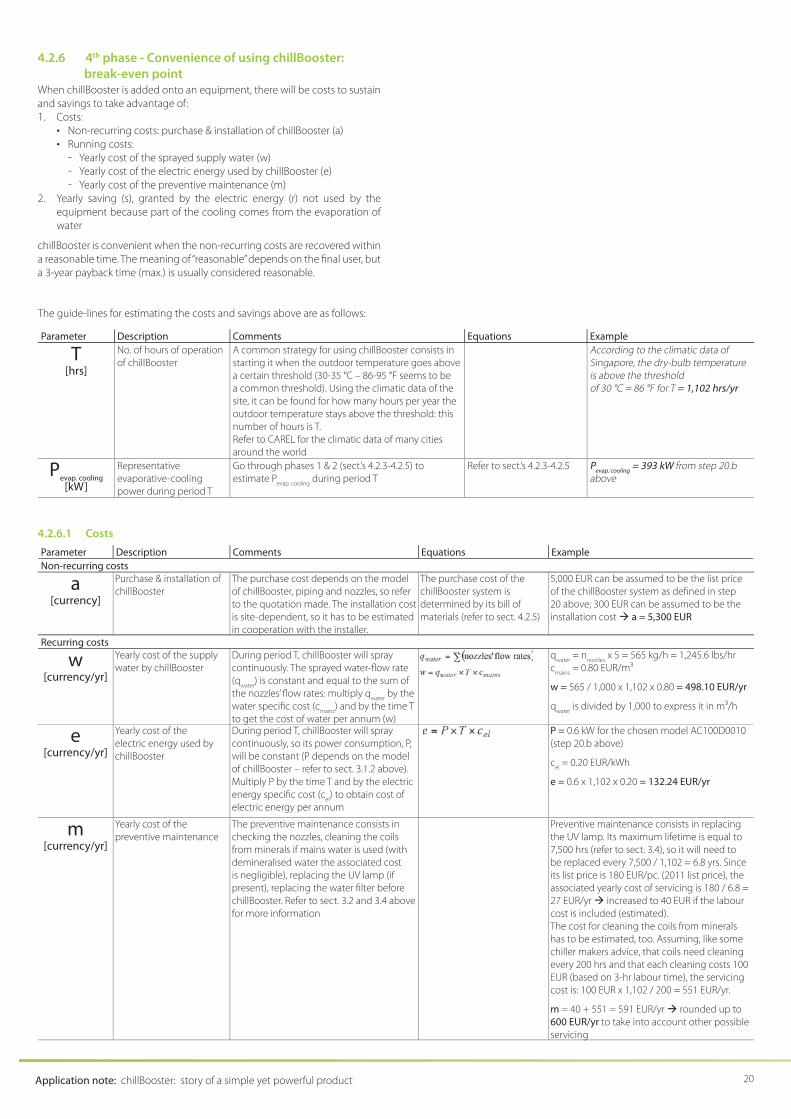
4.2.6 4th phase - Convenience of using chillBooster: break-even point
When chillBooster is added onto an equipment, there will be costs to sustain
and savings to take advantage of:
1. Costs:
• Non-recurring costs: purchase & installation of chi llBooster (a)
• Running costs:
- Yearly cost of the sprayed supply water (w) - Yearly cost of the electric energy used by chillBooster (e)
- Yearly cost of the preventive maintenance (m)
2. Yearly saving (s), granted by the electric energy (r) not used by the
equipment because part of the cooling comes from the evaporation of
water
chillBooster is convenient when the non-recurring costs are recovered within
a reasonable time. The meaning of “reasonable” depends on the fi nal user, but
a 3-year payback time (max.) is usually considered reasonable.
The guide-lines for estimating the costs and savings above are as follows:
Parameter Description Comments Equations Example
T
[hrs]
No. of hours of operation
of chillBooster
A common strategy for using chillBooster consists in
starting it when the outdoor temperature goes above
a certain threshold (30-35 °C – 86-95 °F seems to be
a common threshold). Using the climatic data of the
site, it can be found for how many hours per year the
outdoor temperature stays above the threshold: this
number of hours is T.
Refer to CAREL for the climatic data of many cities
around the world
According to the climatic data of Singapore, the dry-bulb temperature is above the thresholdof 30 °C = 86 °F for T = 1,102 hrs/yr
Pevap. cooling
[kW]
Representative
evaporative-cooling
power during period T
Go through phases 1 & 2 (sect.’s 4.2.3-4.2.5) to
estimate Pevap. cooling
during period T
Refer to sect.’s 4.2.3-4.2.5 Pevap. cooling
= 393 kW from step 20.b above
4.2.6.1 Costs
Parameter Description Comments Equations Example
Non-recurring costs
a
[currency]
Purchase & installation of
chillBooster
The purchase cost depends on the model
of chillBooster, piping and nozzles, so refer
to the quotation made. The installation cost
is site-dependent, so it has to be estimated
in cooperation with the installer.
The purchase cost of the
chillBooster system is
determined by its bill of
materials (refer to sect. 4.2.5)
5,000 EUR can be assumed to be the list price
of the chillBooster system as defi ned in step
20 above; 300 EUR can be assumed to be the
installation cost a = 5,300 EUR
Recurring costs
w
[currency/yr]
Yearly cost of the supply
water by chillBooster
During period T, chillBooster will spray
continuously. The sprayed water-fl ow rate
(qwater
) is constant and equal to the sum of
the nozzles’ fl ow rates: multiply qwater
by the
water specifi c cost (cmains
) and by the time T
to get the cost of water per annum (w)
qwater
= nnozzles
x 5 = 565 kg/h = 1,245.6 lbs/hr
cmains
= 0.80 EUR/m3
w = 565 / 1,000 x 1,102 x 0.80 = 498.10 EUR/yr
qwater
is divided by 1,000 to express it in m3/h
e
[currency/yr]
Yearly cost of the
electric energy used by
chillBooster
During period T, chillBooster will spray
continuously, so its power consumption, P,
will be constant (P depends on the model
of chillBooster – refer to sect. 3.1.2 above).
Multiply P by the time T and by the electric
energy specifi c cost (cel) to obtain cost of
electric energy per annum
P = 0.6 kW for the chosen model AC100D0010
(step 20.b above)
cel = 0.20 EUR/kWh
e = 0.6 x 1,102 x 0.20 = 132.24 EUR/yr
m
[currency/yr]
Yearly cost of the
preventive maintenance
The preventive maintenance consists in
checking the nozzles, cleaning the coils
from minerals if mains water is used (with
demineralised water the associated cost
is negligible), replacing the UV lamp (if
present), replacing the water fi lter before
chillBooster. Refer to sect. 3.2 and 3.4 above
for more information
Preventive maintenance consists in replacing
the UV lamp. Its maximum lifetime is equal to
7,500 hrs (refer to sect. 3.4), so it will need to
be replaced every 7,500 / 1,102 = 6.8 yrs. Since
its list price is 180 EUR/pc. (2011 list price), the
associated yearly cost of servicing is 180 / 6.8 =
27 EUR/yr increased to 40 EUR if the labour
cost is included (estimated).
The cost for cleaning the coils from minerals
has to be estimated, too. Assuming, like some
chiller makers advice, that coils need cleaning
every 200 hrs and that each cleaning costs 100
EUR (based on 3-hr labour time), the servicing
cost is: 100 EUR x 1,102 / 200 = 551 EUR/yr.
m = 40 + 551 = 591 EUR/yr rounded up to
600 EUR/yr to take into account other possible
servicing
21
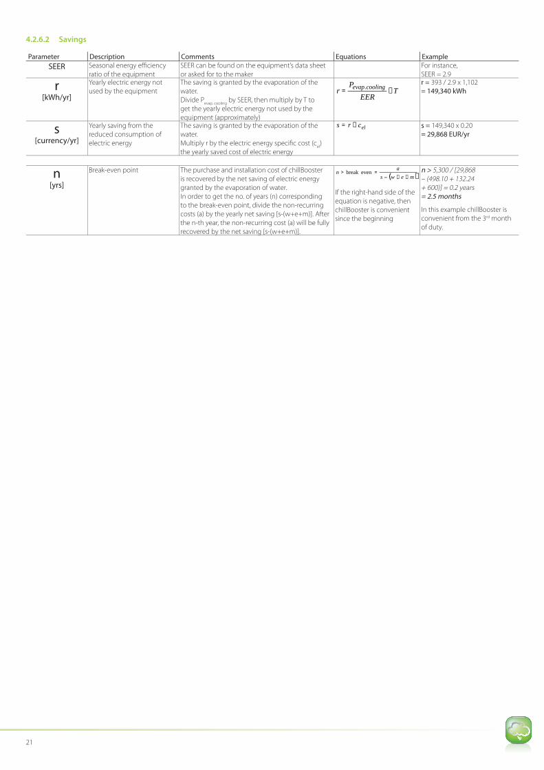
4.2.6.2 Savings
Parameter Description Comments Equations Example
SEER Seasonal energy effi ciency
ratio of the equipment
SEER can be found on the equipment’s data sheet
or asked for to the maker
For instance,
SEER = 2.9
r
[kWh/yr]
Yearly electric energy not
used by the equipment
The saving is granted by the evaporation of the
water.
Divide Pevap. cooling
by SEER, then multiply by T to
get the yearly electric energy not used by the
equipment (approximately)
TEER
Pr coolingevap ×= .
r = 393 / 2.9 x 1,102
= 149,340 kWh
s
[currency/yr]
Yearly saving from the
reduced consumption of
electric energy
The saving is granted by the evaporation of the
water.
Multiply r by the electric energy specifi c cost (cel)
the yearly saved cost of electric energy
elcrs ×= s = 149,340 x 0.20
= 29,868 EUR/yr
n
[yrs]
Break-even point The purchase and installation cost of chillBooster
is recovered by the net saving of electric energy
granted by the evaporation of water.
In order to get the no. of years (n) corresponding
to the break-even point, divide the non-recurring
costs (a) by the yearly net saving [s-(w+e+m)]. After
the n-th year, the non-recurring cost (a) will be fully
recovered by the net saving [s-(w+e+m)].
( )mewsa
n++−
=> evenbreak
If the right-hand side of the
equation is negative, then
chillBooster is convenient
since the beginning
n > 5,300 / [29,868 – (498.10 + 132.24 + 600)] = 0.2 years= 2.5 months
In this example chillBooster is
convenient from the 3rd month
of duty.
Application note: chillBooster: story of a simple yet powerful product 22
5. USING CHILLBOOSTER TO BUY A NEW,
SMALLER CHILLER OR SIMILAR EQUIPMENT
Proceed as follows:
1. Choose the proper chiller (or similar equipment) that would be suitable
for the application without spraying water, i.e. with dry coils
2. Go through sect. 4.1. It is informative and valid also in this case: read it
thoroughly
3. Go through sect. 4.2.1. It is still valid: read it thoroughly4. Go through sect. 4.2.2. It lists the data required for the next steps: do as
described therein
5. Go through sect. 4.2.3: do the assessment as described therein
6. Go through sect. 4.2.4: estimate the evaporative-cooling power as per
the instructions in that section.
IMPORTANT!
• The evaporative-cooling power is the additional heat rejected by the
wet coils
• So the chiller (equipment) model can be down-sized by the same
amount• Set the sprayed water fl ow so as to choose the fi rst smaller model of
equipment (or even a smaller one depending on the need)
Example:
• The right chiller for an application without chillBooster has to reject
500 kW with dry coils; the fi rst smaller model rejects 400 kW with dry
coils
• Using the data of the examples in sect. 4.2.4, in order to have
Pevap. cooling
≥100 kW, the sprayed water fl ow should be minimum 100 /
0.7 = 143 kg/h
• Round up to at least 150 kg/h to be on the safe side
• Verify that, when 150 kg/h of water are sprayed onto the 400-kW
chiller, its total rejected heat is equal to at least 500 kW by applying
the method in sect. 4.2.4. If this is the case, 150 kg/h of sprayed water
allow to use the smaller chiller, otherwise the water fl ow rate will have
to be increased until the requirement of 500 kW is achieved with the
smaller chiller
• Of course, if more water were sprayed, an even smaller chiller could
be used
7. Sect. 4.2.5: size chillBooster as described in that section
Then, continue with the following section.
5.2.1 4th phase - Convenience of using chillBooster: break-even point
When chillBooster is used to reduce the size of an equipment, there will be
costs to sustain and savings to take advantage of:
1. Costs:
• Non-recurring costs: purchase & installation of chi llBooster (a)
• Running costs:
- Yearly cost of the sprayed supply water (w) - Yearly cost of the electric energy used by chillBooster (e)
- Yearly cost of the preventive maintenance (m)
2. Savings:• Non-recurring saving: reduction (z) of the purchase cost of the
equipment
• Yearly saving (s), granted by the electric energy (r) not used by the
equipment because part of the cooling comes from the evaporation of water
chillBooster is convenient when the diff erence between the non-recurring
costs and the non-recurring saving is recovered within a reasonable time. The meaning of “reasonable” depends on the fi nal user, but a 3-year payback time
(max.) is usually considered reasonable.
The guide-lines for estimating the costs and savings above are as follow
Parameter Description Comments Equations Example
T
[hrs]
No. of hours of operation
of chillBooster
A common strategy for using chillBooster consists in
starting it when the outdoor temperature goes above
a certain threshold (30-35 °C – 86-95 °F seems to be a
common threshold). Using the climatic data of the site, it
can be found for how many hours per year the outdoor
temperature stays above the threshold: this number of
hours is T.
Refer to CAREL for the climatic data of many cities around
the world
According to the climatic data of Singapore, the dry-bulb temperature is above the threshold of 30 °C = 86 °F for T = 1,102 hrs/yr
Pevap. cooling
[kW]
Representative
evaporative-cooling power
during period T
Go through steps 4)-7) above to estimate Pevap. cooling
during
period T
Refer to steps 4)-7) above Pevap. cooling
= 100 kW from step 6) above
23
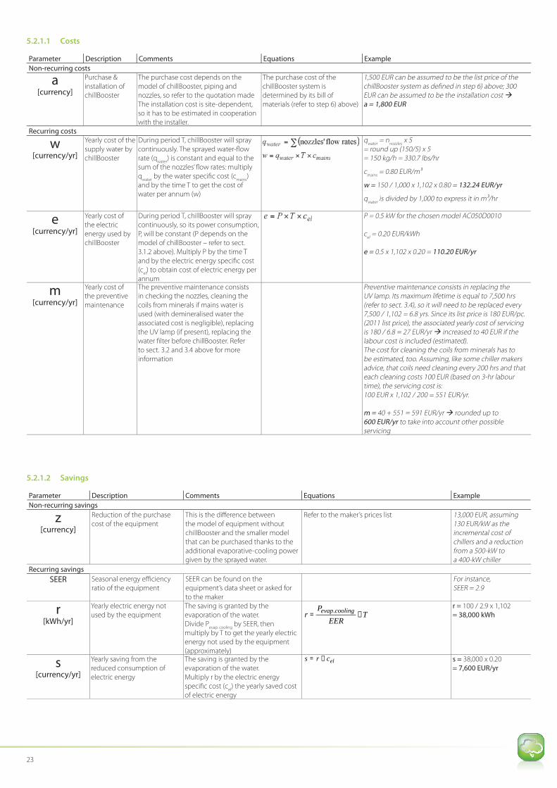
5.2.1.1 Costs
Parameter Description Comments Equations Example
Non-recurring costs
a
[currency]
Purchase &
installation of
chillBooster
The purchase cost depends on the
model of chillBooster, piping and
nozzles, so refer to the quotation made
The installation cost is site-dependent,
so it has to be estimated in cooperation
with the installer.
The purchase cost of the
chillBooster system is
determined by its bill of
materials (refer to step 6) above)
1,500 EUR can be assumed to be the list price of the chillBooster system as defi ned in step 6) above; 300 EUR can be assumed to be the installation cost a = 1,800 EUR
Recurring costs
w
[currency/yr]
Yearly cost of the
supply water by
chillBooster
During period T, chillBooster will spray
continuously. The sprayed water-fl ow
rate (qwater
) is constant and equal to the
sum of the nozzles’ fl ow rates: multiply
qwater
by the water specifi c cost (cmains
)
and by the time T to get the cost of
water per annum (w)
qwater
= nnozzles
x 5 = round up (150/5) x 5 = 150 kg/h = 330.7 lbs/hr
cmains
= 0.80 EUR/m3
w = 150 / 1,000 x 1,102 x 0.80 = 132.24 EUR/yr
qwater
is divided by 1,000 to express it in m3/hr
e
[currency/yr]
Yearly cost of
the electric
energy used by
chillBooster
During period T, chillBooster will spray
continuously, so its power consumption,
P, will be constant (P depends on the
model of chillBooster – refer to sect.
3.1.2 above). Multiply P by the time T
and by the electric energy specifi c cost
(cel) to obtain cost of electric energy per
annum
P = 0.5 kW for the chosen model AC050D0010
cel = 0.20 EUR/kWh
e = 0.5 x 1,102 x 0.20 = 110.20 EUR/yr
m
[currency/yr]
Yearly cost of
the preventive
maintenance
The preventive maintenance consists
in checking the nozzles, cleaning the
coils from minerals if mains water is
used (with demineralised water the
associated cost is negligible), replacing
the UV lamp (if present), replacing the
water fi lter before chillBooster. Refer
to sect. 3.2 and 3.4 above for more
information
Preventive maintenance consists in replacing the UV lamp. Its maximum lifetime is equal to 7,500 hrs (refer to sect. 3.4), so it will need to be replaced every 7,500 / 1,102 = 6.8 yrs. Since its list price is 180 EUR/pc. (2011 list price), the associated yearly cost of servicing is 180 / 6.8 = 27 EUR/yr increased to 40 EUR if the labour cost is included (estimated).The cost for cleaning the coils from minerals has to be estimated, too. Assuming, like some chiller makers advice, that coils need cleaning every 200 hrs and that each cleaning costs 100 EUR (based on 3-hr labour time), the servicing cost is: 100 EUR x 1,102 / 200 = 551 EUR/yr.
m = 40 + 551 = 591 EUR/yr rounded up to 600 EUR/yr to take into account other possible servicing
5.2.1.2 Savings
Parameter Description Comments Equations Example
Non-recurring savings
z
[currency]
Reduction of the purchase
cost of the equipment
This is the diff erence between
the model of equipment without
chillBooster and the smaller model
that can be purchased thanks to the
additional evaporative-cooling power
given by the sprayed water.
Refer to the maker’s prices list 13,000 EUR, assuming 130 EUR/kW as the incremental cost of chillers and a reduction from a 500-kW to a 400-kW chiller
Recurring savings
SEER Seasonal energy effi ciency
ratio of the equipment
SEER can be found on the
equipment’s data sheet or asked for
to the maker
For instance, SEER = 2.9
r
[kWh/yr]
Yearly electric energy not
used by the equipment
The saving is granted by the
evaporation of the water.
Divide Pevap. cooling
by SEER, then
multiply by T to get the yearly electric
energy not used by the equipment
(approximately)
TEER
Pr coolingevap ×= .
r = 100 / 2.9 x 1,102
= 38,000 kWh
s
[currency/yr]
Yearly saving from the
reduced consumption of
electric energy
The saving is granted by the
evaporation of the water.
Multiply r by the electric energy
specifi c cost (cel) the yearly saved cost
of electric energy
elcrs ×= s = 38,000 x 0.20
= 7,600 EUR/yr

Application note: chillBooster: story of a simple yet powerful product 24
Parameter Description Comments Equations Example
n
[yrs]
Break-even point The purchase and installation cost of
chillBooster is recovered by the net
saving of electric energy granted by
the evaporation of water.
In order to get the no. of years (n)
corresponding to the break-even
point, divide the non-recurring
costs (a-z) by the yearly net saving
[s-(w+e+m)]
s - (w + e + m) > 0
If the right-hand side of the equation is negative,
then chillBooster is convenient since the
beginning.
s - (w + e + m) < 0
If the right-hand side of the equation is negative,
then chillBooster is never convenient, otherwise
it is convenient for the initial “n” years.
(1,800 – 13,000) / [7,600 – (132.24 + 110.20 + 600)] = -1.7 negative!
In this example chillBooster is convenient since the beginning.
The following attached Excel fi le does the estimates described
in sections 4 & 5.
6. EXCEL FILE FOR ESTIMATING THE RETURN-ON-INVESTMENT
25
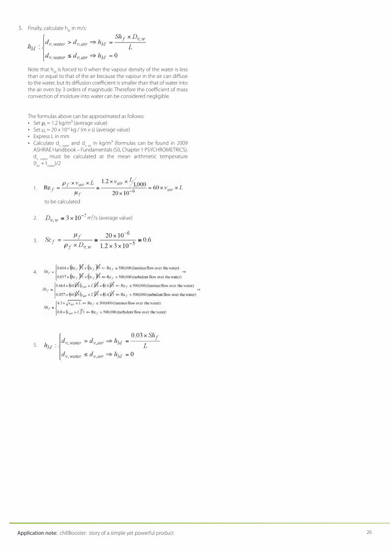
2. Calculate the diff usion coeffi cient of water into the air:
, in m2/s
Where:
• tf is the temperature of the limit layer in °C, usually taken equal to
(tair
+ twater
) / 2• p is the absolute air pressure in Pa (e.g., 101,325 Pa at the sea level)
3. Calculate the Schmidt number of the limit layer (adimensional number):
4. Calculate the Sherwood number of the limit layer (adimensional
number):
7. APPENDIX A – MASS CONVECTION: BASICS (SI ONLY)
INFORMATION: This appendix is based mainly on 2009 ASHRAE Handbook
– Fundamentals (SI), Chapter 6 MASS TRANSFER and, in particular, to its
example 4 on page 6.6.
Mass convection is characterized by two fl uids (A and B) in relative movement,
with one of the two (e.g. B) moving over the other one (A).
Any fl uid tends to diff use into other fl uids it is in contact with, so fl uid A
will diff use into the moving fl uid B. Fluid B, thanks to its movement, will
continuously carry away the mass of fl uid A diff used into it, thus sustaining
the diff usion of A into B. This way, fl uid A will see its mass continuously
reduced.
If you replace A with “water over the coils” and B with “air streaming through
the coils” you get the evaporation of water from the coils due to mass
convection.
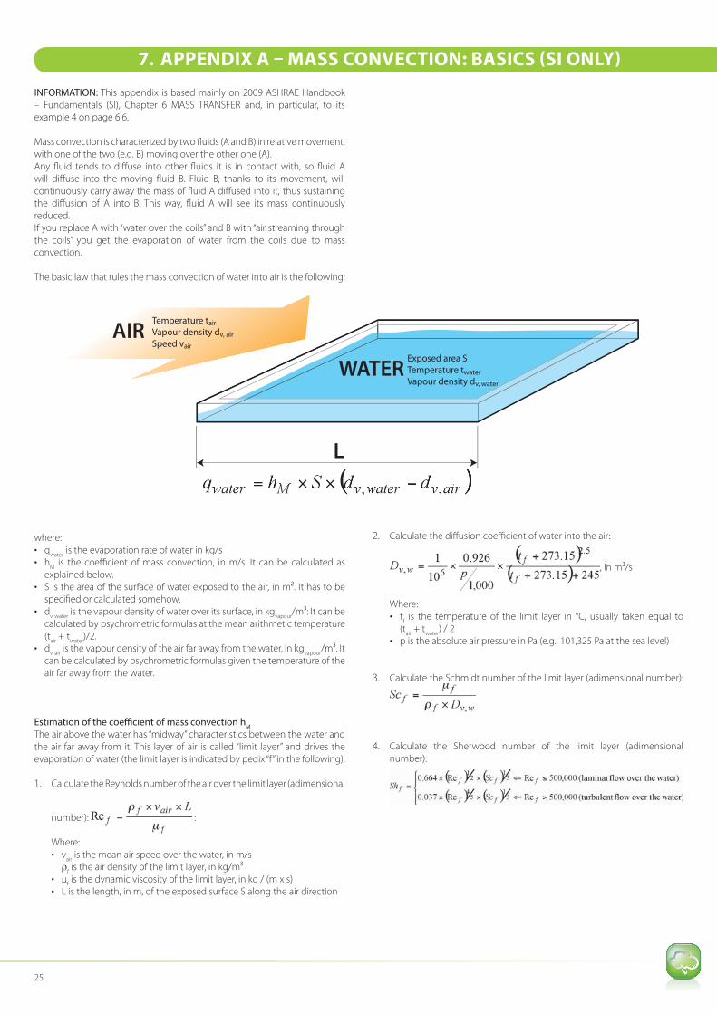
The basic law that rules the mass convection of water into air is the following:
Temperature tair
Vapour density dv, air
Speed vair
AIRExposed area S
Temperature twater
Vapour density dv, water
WATER
L
where:• q
water is the evaporation rate of water in kg/s
• hM
is the coeffi cient of mass convection, in m/s. It can be calculated as
explained below.
• S is the area of the surface of water exposed to the air, in m2. It has to be
specifi ed or calculated somehow.
• dv, water
is the vapour density of water over its surface, in kgvapour
/m3: It can be
calculated by psychrometric formulas at the mean arithmetic temperature
(tair
+ twater
)/2.
• dv, air
is the vapour density of the air far away from the water, in kgvapour
/m3. It
can be calculated by psychrometric formulas given the temperature of the air far away from the water.
Estimation of the coeffi cient of mass convection hM
The air above the water has “midway” characteristics between the water and
the air far away from it. This layer of air is called “limit layer” and drives the
evaporation of water (the limit layer is indicated by pedix “f” in the following).
1. Calculate the Reynolds number of the air over the limit layer (adimensional
number):
:
Where:• v
air is the mean air speed over the water, in m/s
• ρf is the air density of the limit layer, in kg/m3
• μf is the dynamic viscosity of the limit layer, in kg / (m x s)
• L is the length, in m, of the exposed surface S along the air direction
Application note: chillBooster: story of a simple yet powerful product 26
5. Finally, cal culate hM
in m/s:
Note that hM
is forced to 0 when the vapour density of the water is less
than or equal to that of the air because the vapour in the air can diff use
to the water, but its diff usion coeffi cient is smaller than that of water into
the air even by 3 orders of magnitude. Therefore the coeffi cient of mass
convection of moisture into water can be considered negligible.
The formulas above can be approximated as follows:
• Set ρf = 1.2 kg/m3 (average value)
• Set μf = 20 x 10-6 kg / (m x s) (average value)
• Express L in mm
• Calculate dv, water
and dv, air
in kg/m3 (formulas can be found in 2009
ASHRAE Handb ook – Fundamentals (SI), Chapter 1 PSYCHROMETRICS).
dv, water
must be calculated at the mean arithmetic temperature
(tair
+ twater
)/2
1.
to be calculated
2. m2/s (average value)
3.
4.
5.

Related Documents


