Электрическая схема Chery Amulet Содержание Notes On Battery, Ac Generator, Ignition Switch, Starting Motor MPI System (UAES), part 1 MPI System (UAES), part 2 Air Conditioner, Operation Mechanism, Cooling System A/C switch, Internal circulation solenoid valve, High and low voltage switch Oil pressure switch, Coolant temperature sensor, Hand brake indicator light switch, Odometer sensor Radio and Six channel loudspeaker Instrument Panel And MFA Front Fog Lamp, Cigarette Lighter, A/C Panel Indicator Light Compressor Magnetic Clutch, Dual-Tone Horn, Rear Window Heating System Wiper, Washer, Horn Button Front Headlamp, Light Relay, Front Position Light Light Switch Turn Signal Lamp Switch, Emergency Alarm Relay Tail Lamp, Stop Lamp, Side Lamp Rear Fog Lamp, Backup Lamp Interior front and rear lamp, Trunk lamp, Door switch, License lamp, Shadow shield light Central Door Lock Electrical Rearview Mirror ABS Air Bag Control Module Control Unit Of Electrical Window Regulator Control Switch Of Electrical Window Regulator

Welcome message from author
This document is posted to help you gain knowledge. Please leave a comment to let me know what you think about it! Share it to your friends and learn new things together.
Transcript

Электрическая схема Chery Amulet Содержание
Notes On Battery, Ac Generator, Ignition Switch, Starting Motor MPI System (UAES), part 1 MPI System (UAES), part 2 Air Conditioner, Operation Mechanism, Cooling System A/C switch, Internal circulation solenoid valve, High and low voltage switch Oil pressure switch, Coolant temperature sensor, Hand brake indicator light switch, Odometer sensor Radio and Six channel loudspeaker Instrument Panel And MFA Front Fog Lamp, Cigarette Lighter, A/C Panel Indicator Light Compressor Magnetic Clutch, Dual-Tone Horn, Rear Window Heating System Wiper, Washer, Horn Button Front Headlamp, Light Relay, Front Position Light Light Switch Turn Signal Lamp Switch, Emergency Alarm Relay Tail Lamp, Stop Lamp, Side Lamp Rear Fog Lamp, Backup Lamp Interior front and rear lamp, Trunk lamp, Door switch, License lamp, Shadow shield light Central Door Lock Electrical Rearview Mirror ABS Air Bag Control Module Control Unit Of Electrical Window Regulator Control Switch Of Electrical Window Regulator

2

3
NOTES ON COMPILATION 1. The circuit code on the main circuit board of the central electrical box 30: No fuse, positive grid is connected directly from the battery; 15: No fuse, the positive grid is connect to the ignition switch; X: No fuse, the positive grid is connect to the ignition switch, and cut off in the starting process. 31: Dummy ground wire, this wire maybe exist or not. Example: 30(E8) indicates that the positive grid wire of No.30 in the central electrical box is directly output from the battery and connected to the 8# pin of plug base E in the central electrical box, other symbols such as 30(C16), 15(D10), X(D12):can be interpreted in the same way. 2. The segmentation of the main circuit board in the central electrical box This segmentation of the main electrical circuit board includes fuses, relays and connectors. 3. Indicating the extension of the wire or circuit The circumstances that the wire or circuit been extended are as follows: --Located at right of the circuit diagram on previous page --Located at left of the circuit diagram on next page 4. Symbol of the contact point (pin) on the main circuit board of central electrical box Can be used as "help" in referring to the circuit diagram of main circuit board, example: E/8 indicates the 8th pin of the plug base E in the central electrical box. 5. Color of the wire and cross sectional area of the wire in square millimeters (color of the wire may not match with the actual item, so the color indicated is only used for reference) 6. Symbol of connector This symbol is usually marked on the component itself. 7. Name of the part or component (Description can be found at the bottom left in every page of the electrical circuit diagram). 8. Number label for the extension of circuit or wire The number in the square box indicates the corresponding circuit serial number with the extension of the wire in the circuit. 9. Internal wire For the purpose of searching internal circuit of the component. The circuit comprised of this wire maybe exist or not. 10. Grounding point Indicated by a numerical code enclosed in a circle, its connection points are indicated in every electrical circuit diagram. 11. Circuit serial number Used for searching components and connection points of the discontinuous wires. 12. Connection points used in the multi-socket plug base Given the corresponding terminal number for the socket. B=White N=Black R=Red M=Brown V=Green A=Blue H=Grey Z=Violet G=Yellow

4
Switch, Battery, Ac Generator, Ignition Starting Motor
A Battery B Starting Motor C Ac Generator C1 Voltage Regulation D Ignition Switch (1) Grounding Point, ground bracket beside the central electrical box (2) Car body connection point, close to the battery. (3) Grounding point of the engine, located at the side of gearbox. TQ4 Double-socket plug in connector B=White N=Black R=Red M=Brown V=Green A=Blue H=Grey Z=Violet G=Yellow

5
MPI System (UAES), part 1
S35 System Fuse S36 Fuel Pump Fuse S37 Ecu Fuse A+ Positive Grid Of Battery N1 1~4 Cylinder Ignition Coils N2 2~3 Cylinder Ignition Coils Q Spark Plug N01-N04 Fuel Injector G Fuel Level Sensor G6 Fuel Pump B=White N=Black R=Red M=Brown V=Green A=Blue H=Grey Z=Violet G=Yellow

6
MPI System (UAES), part 2
S35 System Fuse S36 Fuel Pump Fuse S37 Ecu Fuse A+ Positive Grid Of Battery N1 1~4 Cylinder Ignition Coils N2 2~3 Cylinder Ignition Coils Q Spark Plug N01-N04 Fuel Injector G Fuel Level Sensor G6 Fuel Pump B=White N=Black R=Red M=Brown V=Green A=Blue H=Grey Z=Violet G=Yellow

7
Air Conditioner, Operation Mechanism, Cooling System
A+ Positive grid of battery E9 Air blower switch F18 Thermal-sensitive switch N23 Air blower serial regulation resistor V2 Air blower V7 Fan motor J32 Grounding point, ground bracket beside of the central electrical box J69 Cooling fan high speed relay J70 Cooling fan low speed relay J5 Air blower relay for air conditioner (in the electrical box) J6 Rear window preheating relay (in the electrical box) (5) Grounding point, in the harness of the i protection sleeve (5) Grounding point, ground bracket beside of the central electrical box B=White N=Black R=Red M=Brown V=Green A=Blue H=Grey Z=Violet G=Yellow
8
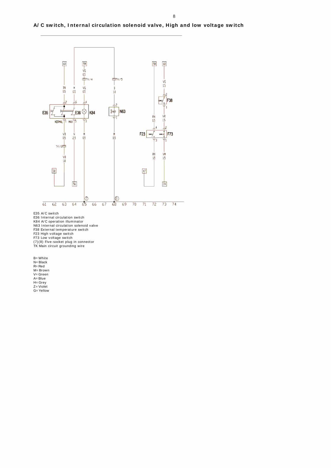
A/C switch, Internal circulation solenoid valve, High and low voltage switch
E35 A/C switch E36 Internal circulation switch K84 A/C operation illuminator N63 Internal circulation solenoid valve F38 External temperature switch F23 High voltage switch F73 Low voltage switch (7)(8) Five-socket plug in connector TK Main circuit grounding wire B=White N=Black R=Red M=Brown V=Green A=Blue H=Grey Z=Violet G=Yellow
9
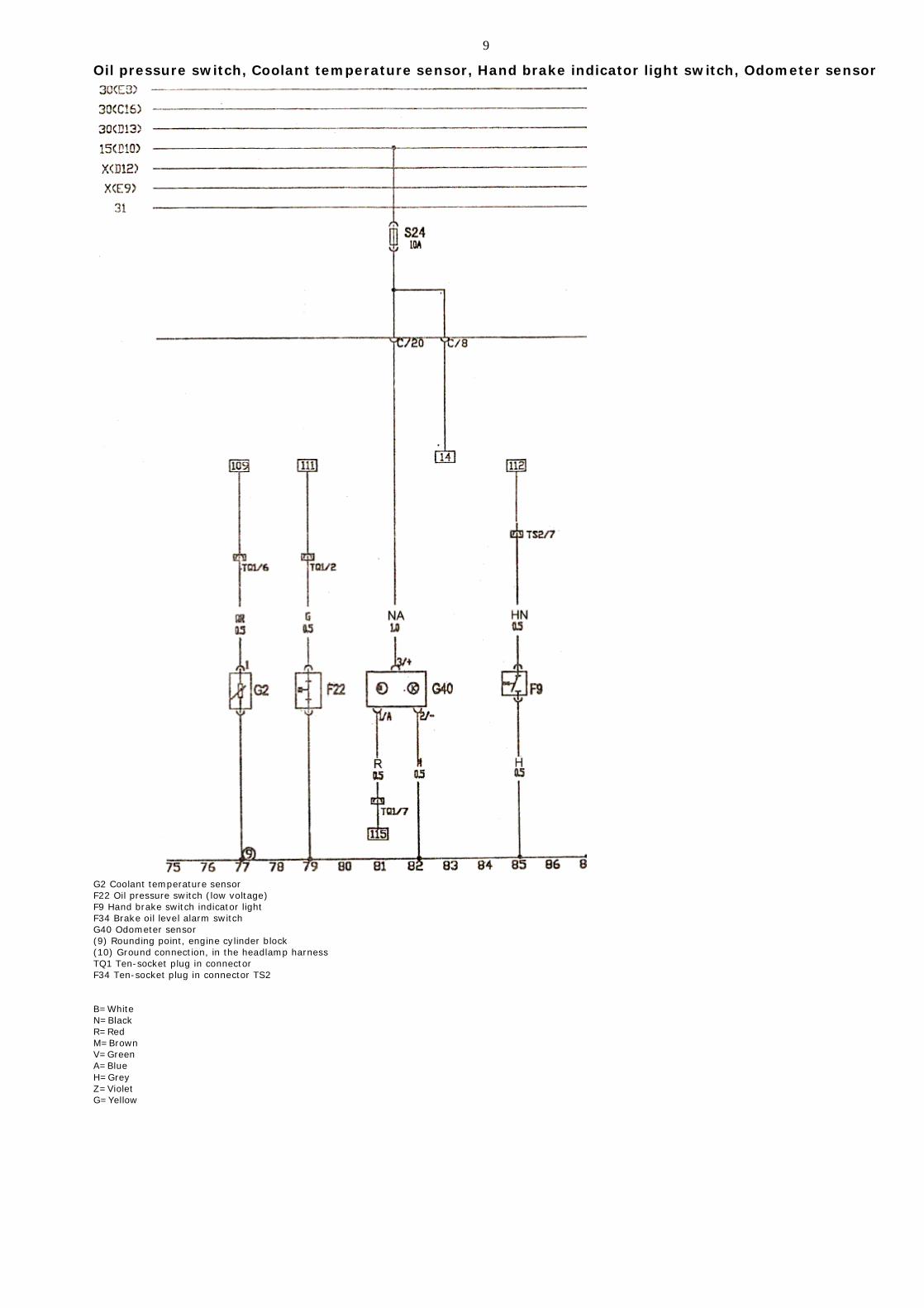
Oil pressure switch, Coolant temperature sensor, Hand brake indicator light switch, Odometer sensor
G2 Coolant temperature sensor F22 Oil pressure switch (low voltage) F9 Hand brake switch indicator light F34 Brake oil level alarm switch G40 Odometer sensor (9) Rounding point, engine cylinder block (10) Ground connection, in the headlamp harness TQ1 Ten-socket plug in connector F34 Ten-socket plug in connector TS2 B=White N=Black R=Red M=Brown V=Green A=Blue H=Grey Z=Violet G=Yellow

10
Radio and Six channel loudspeaker
R Radio R2 Front left loudspeaker R3 Front Right loudspeaker R4 Rear right loudspeaker R5 Rear left loudspeaker R6 Front left loudspeaker R7 Front right loudspeaker R1 Antenna T8 8 socket plug in connector T1 Single-socket plug in connector B=White N=Black R=Red M=Brown V=Green A=Blue H=Grey Z=Violet G=Yellow

11
Instrument Panel And MFA
F10 Multi-channel converter F15 Stabilizer G20 Fuel sensor G25 Coolant temperature sensor G30 Rpm sensor G35 Preset level comparator J114 Control unit J119 Multi-function display K1 Abs alarm light K2 Left-turn signal lamp K3 Right turn signal lamp K4 Generator charging alarm light K5 Engine self-inspection indicator light K6 Hand brake alarm light Oil pressure alarm light Engine over-temperature alarm light Instrument panel illumination light Instrument panel illumination light Instrument panel illumination light Instrument panel illumination light Low beam lamp,position alarm light K14 Single socket plugin connector K15 Fuel alarm light Y1 Digital clock T1 High beam alarm light
B=White N=Black R=Red M=Brown V=Green A=Blue H=Grey Z=Violet G=Yellow

12
Front Fog Lamp, Cigarette Lighter, A/C Panel Indicator Light
A/C panel indictor light Front right fog lamp Front left fog lamp Coolant level switch Cigarette lighter indicator light Cigarette lighter (11)Grounding point, in the headlamp harness B=White N=Black R=Red M=Brown V=Green A=Blue H=Grey Z=Violet G=Yellow
13
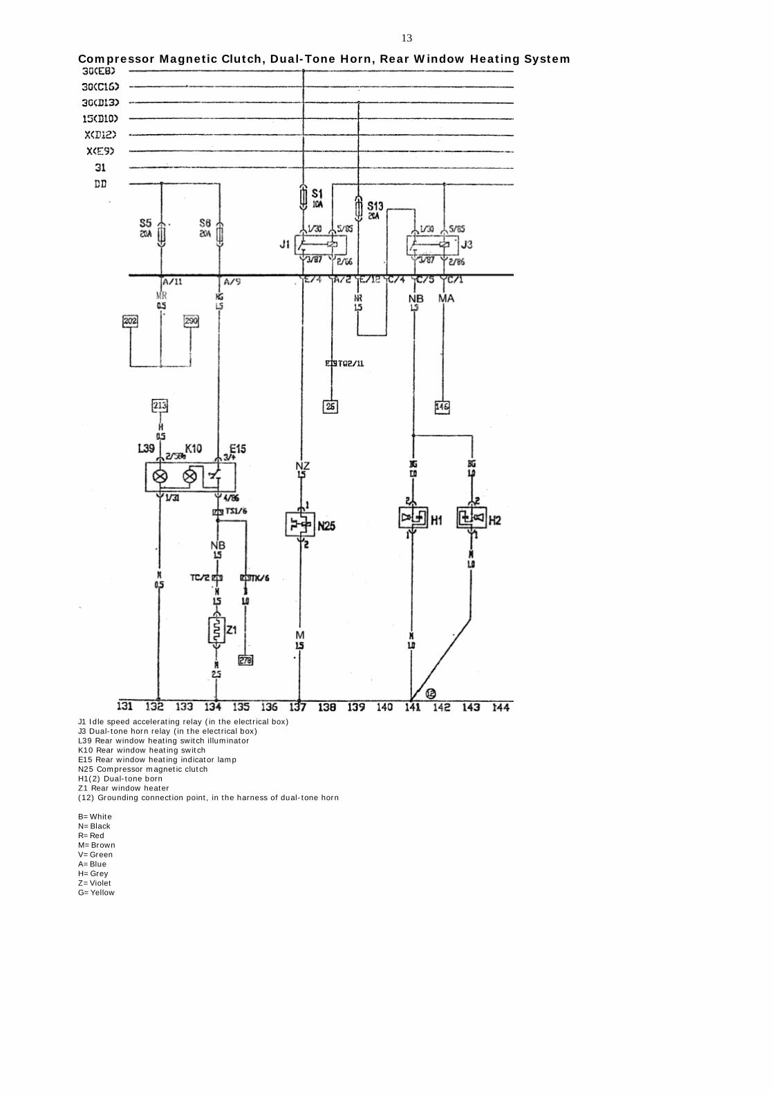
Compressor Magnetic Clutch, Dual-Tone Horn, Rear Window Heating System
J1 Idle speed accelerating relay (in the electrical box) J3 Dual-tone horn relay (in the electrical box) L39 Rear window heating switch illuminator K10 Rear window heating switch E15 Rear window heating indicator lamp N25 Compressor magnetic clutch H1(2) Dual-tone born Z1 Rear window heater (12) Grounding connection point, in the harness of dual-tone horn B=White N=Black R=Red M=Brown V=Green A=Blue H=Grey Z=Violet G=Yellow

14
Wiper, Washer, Horn Button
E22 Wiper switch H Horn button J31 Intermittent wiper relay S5 Fuse 15A V Wiper motor V5 Washer B=White N=Black R=Red M=Brown V=Green A=Blue H=Grey Z=Violet G=Yellow

15
Front Headlamp, Light Relay, Front Position Light
A+ Positive grid of battery L1 Left high beam lamp L2 Left low beam lamp L3 Right low beam lamp L4 Right high beam lamp M1 Right position lamp M3 Left position lamp J55 Light relay S27 Right high beam lamp fuse 10A S28 Left low beam lamp fuse 10A S29 Left position lamp fuse 10A S30 left high beam lamp fuse 10A S31 Right low beam lamp fuse 10A S32 Right position lamp fuse 10A (13) Grounding point, in the harness of headlamp B=White N=Black R=Red M=Brown V=Green A=Blue H=Grey Z=Violet G=Yellow
16
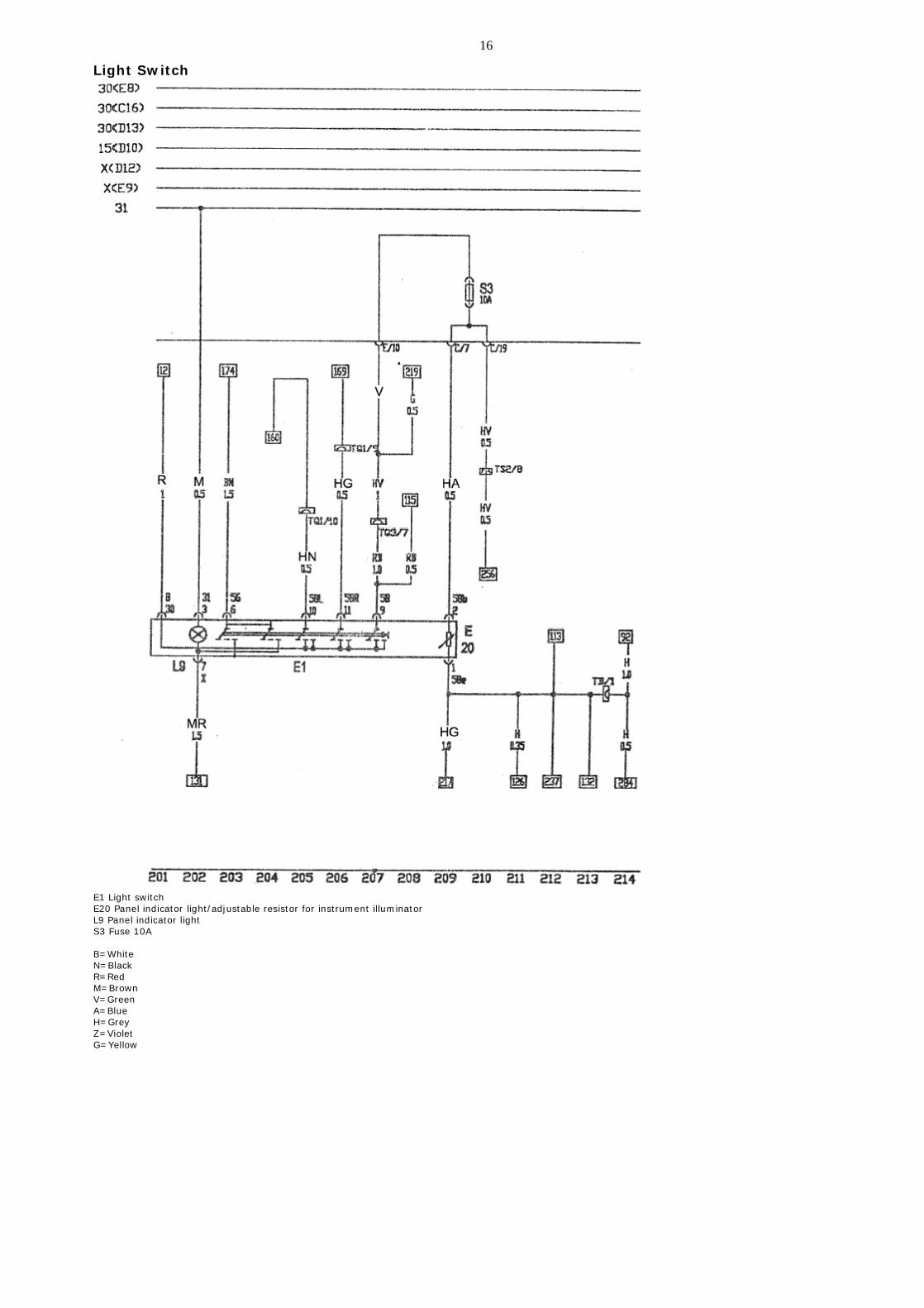
Light Switch
E1 Light switch E20 Panel indicator light/adjustable resistor for instrument illuminator L9 Panel indicator light S3 Fuse 10A B=White N=Black R=Red M=Brown V=Green A=Blue H=Grey Z=Violet G=Yellow

17
Turn Signal Lamp Switch, Emergency Alarm Relay
E2 Turn signal lamp switch E3 Emergency alarm light switch E4 Light changing and turn signal lamp switch E19 Parking lamp switch J2 Emergency alarm light relay K6 Emergency alarm light S17 Fuse 10A B=White N=Black R=Red M=Brown V=Green A=Blue H=Grey Z=Violet G=Yellow
18
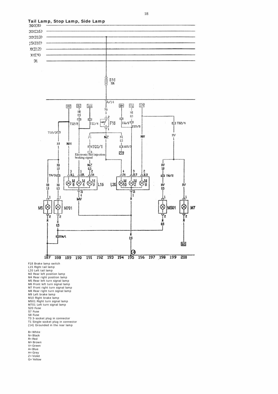
Tail Lamp, Stop Lamp, Side Lamp
F18 Brake lamp switch L15 Right tail lamp L20 Left tail lamp M2 Rear left position lamp M4 Rear right position lamp M5 Rear left turn signal lamp M6 Front left turn signal lamp M7 Front right turn signal lamp M8 Rear right turn signal lamp M9 Left brake lamp M10 Right brake lamp M501 Right turn signal lamp M701 Left turn signal lamp S20 Fuse S7 Fuse S8 Fuse T3 3-socket plug in connector T1 Single-socket plug in connector (14) Grounded in the rear lamp B=White N=Black R=Red M=Brown V=Green A=Blue H=Grey Z=Violet G=Yellow

19
Rear Fog Lamp, Backup Lamp
E23 Front fog lamp switch J4 Fog lamp relay (in the electrical box) K17 Rear fog indication lamp L1 Rear fog lamp L40 Front and rear fog lamp switch illuminator S10 Fuse 15A S14 Fuse 10A E24 Rear fog lamp switch T3 Three-socket plug in connector T3a Three-socket plug in connector T2 Two-socket plug in connector T1 Single-socket plug in connector T1a Single-socket plug in connector B=White N=Black R=Red M=Brown V=Green A=Blue H=Grey Z=Violet G=Yellow

20
Interior front and rear lamp, Trunk lamp, Door switch, License lamp, Shadow shield light
F2 Front left door switch F3 Right front door switch F5 Luggage boot light switch F10 Rear right door switch F11 Rear left door switch TB Two-socket plug in connector TD Four-socket plug in connector TAa Two-socket plug in connector, left of luggage boot W1 License lamp W3 Trunk lamp W4 Shadow shield light W5 Delay on/off interior front ceiling light X Interior rear ceiling light B=White N=Black R=Red M=Brown V=Green A=Blue H=Grey Z=Violet G=Yellow

21
Central Door Lock
C Central lock controller (in the front left door) V28 Front right door lock control motor V29 Rear left door lock control motor V30 Fuel tank lid control motor V31 Trunk lock control motor V32 Rear right door lock control motor TB1 Four-socket plug in connector (left column B) TB2 Four-socket plug in connector (right column B) TK1 12-socket plug in connector (left column A) TK2 12-socket plug in connector (right column A) Ty Two-socket plug in connector (left column C) (17) Grounding point beside of the central electrical box B=White N=Black R=Red M=Brown V=Green A=Blue H=Grey Z=Violet G=Yellow
22
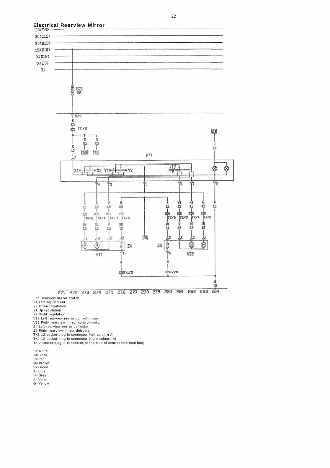
Electrical Rearview Mirror
F77 Rearview mirror switch X1 Left adjustment X2 Down regulation Y1 Up regulation Y2 Right regulation V17 Left rearview mirror control motor V25 Right rearview mirror control motor Z4 Left rearview mirror defroster Z5 Right rearview mirror defroster TK1 12-socket plug in connector (left column A) TK2 12-socket plug in connector (right column A) TZ 2-socket plug in connector(at the side of central electrical box) B=White N=Black R=Red M=Brown V=Green A=Blue H=Grey Z=Violet G=Yellow

23
ABS
J104 ABS controller A Battery N55 ABS solenoid valve VG4 ABS hydraulic pump G44 Rear right wheel RPM sensor G45 Front right wheel RPM sensor G46 Rear left wheel RPM sensor G47 Front left wheel RPM sensor S33 Power supply fuse of ABS solenoid valve S34 Power supply fuse of ABS hydraulic pump TK Diagnostic port (18) Grounding point, ground bracket at the side of central electrical box B=White N=Black R=Red M=Brown V=Green A=Blue H=Grey Z=Violet G=Yellow

24
Air Bag Control Module
B=White N=Black R=Red M=Brown V=Green A=Blue H=Grey Z=Violet G=Yellow

25
Control Unit Of Electrical Window Regulator
G Window regulator module E40 Front left window regulator switch E81 Front right window regulator motor V14 Motor of front right window regulator V15 Motor of front left window regulator (19) At the side of central electrical box TK1 12-socket plug in connector (right column b) TK2 12-socket plug in connector (left column b) B=White N=Black R=Red M=Brown V=Green A=Blue H=Grey Z=Violet G=Yellow

26
Control Switch Of Electrical Window Regulator
E39 Rear window regulator lock switch E52 Rear left door window regulator switch E54 Rear right door window regulator switch E53 Rear right door window regulator switch E55 Rear left door window regulator switch V26 Rear left door window regulator motor V27 Rear right door window regulator motor TA1 4-socket plug in connector (right column b) TA2 4-socket plug in connector (left column b) B=White N=Black R=Red M=Brown V=Green A=Blue H=Grey Z=Violet G=Yellow
Related Documents