Chemical Reaction Engineering Lecture 3

Welcome message from author
This document is posted to help you gain knowledge. Please leave a comment to let me know what you think about it! Share it to your friends and learn new things together.
Transcript

Chemical Reaction Engineering
Lecture 3
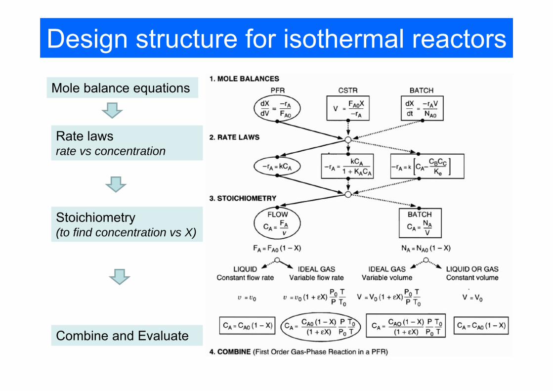
Design structure for isothermal reactors
Mole balance equations
Rate lawsrate vs concentration
Stoichiometry(to find concentration vs X)
Combine and Evaluate
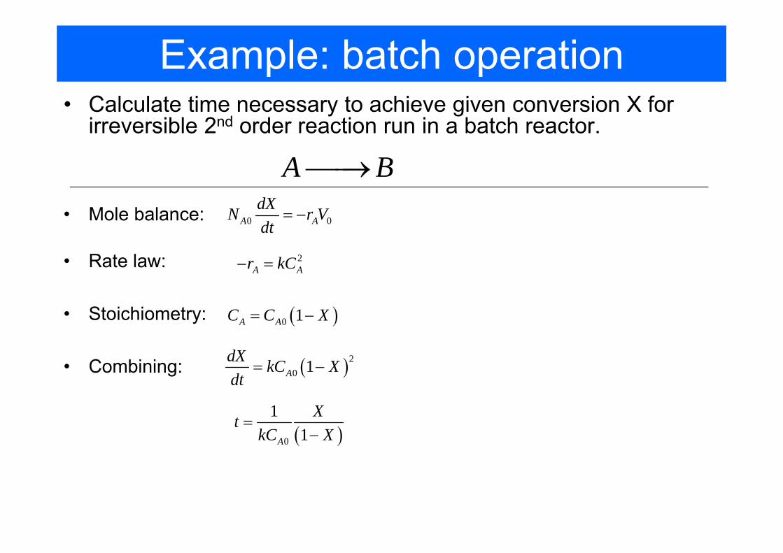
Example: batch operation• Calculate time necessary to achieve given conversion X for
irreversible 2nd order reaction run in a batch reactor.
A B⎯⎯→• Mole balance: 0 0A A
dXN r Vdt
= −
• Rate law: 2A Ar kC− =
• Stoichiometry: ( )0 1A AC C X= −
• Combining: ( )20 1A
dX kC Xdt
= −
( )0
11A
XtkC X
=−
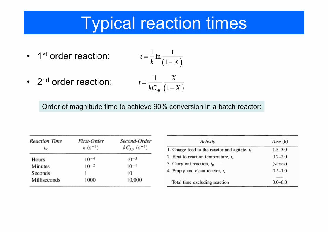
Typical reaction times
• 2nd order reaction: ( )0
11A
XtkC X
=−
• 1st order reaction: ( )1 1ln
1t
k X=
−
Order of magnitude time to achieve 90% conversion in a batch reactor:
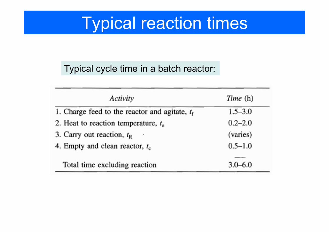
Typical reaction times
Typical cycle time in a batch reactor:

CSTR
• single CSTR mole balance:
( )0A
A exit
F XVr
=−
( )0
0
A
A exit
C XVv r
τ = =−
• rate law (1st order) A Ar kC− =
• Stoichiometry: ( )0 1A AC C X= −
design equation:
space time:
CSTR with a liquid-phase reaction:

CSTR
( )0A
A exit
F XVr
=− A Ar kC− = ( )0 1A AC C X= −
11
Xk X
τ ⎛ ⎞= ⎜ ⎟−⎝ ⎠• Combining
0
1A
ACC
kτ=
+
Dahmköhler number
( )0
0
A
A exit
C XVv r
τ = =−
1kX
kττ
=+
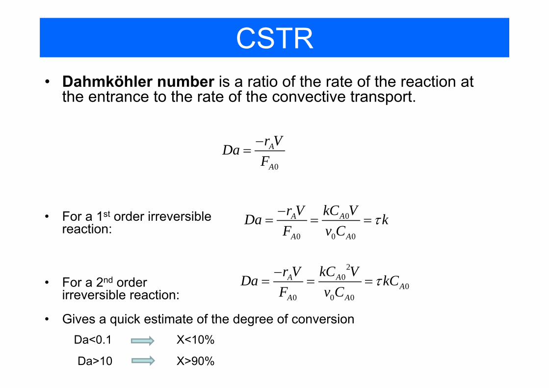
CSTR• Dahmköhler number is a ratio of the rate of the reaction at
the entrance to the rate of the convective transport.
0
A
A
r VDaF−
=
• For a 1st order irreversible reaction:
0
0 0 0
AA
A A
kC Vr VDa kF v C
τ−= = =
• For a 2nd order irreversible reaction:
20
00 0 0
AAA
A A
kC Vr VDa kCF v C
τ−= = =
Da<0.1
• Gives a quick estimate of the degree of conversion
Da>10
X<10%
X>90%

CSTR in Series
• concentration flowing to the 2nd reactor 01
1 11A
ACC
kτ=
+
• design equation the 2nd reactor ( )0 1 21 2
2 2 2
A AA A
A A
v C CF FVr k C
−−= =
−
• so, ( ) ( )0
21 1 2 21 1
AA
CCk kτ τ
=+ +
• if the reactors have the same size and temperature: ( )
02 21
AA
CCkτ
=+
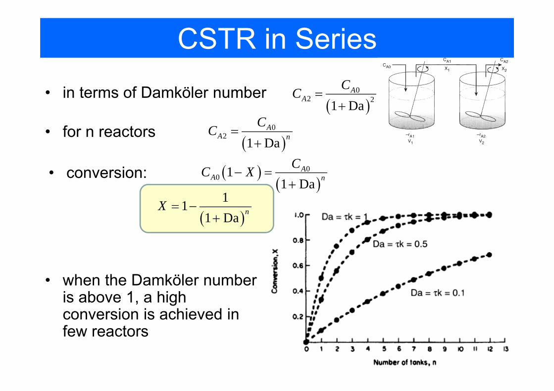
CSTR in Series
• in terms of Damköler number
• for n reactors
• conversion:
• when the Damköler number is above 1, a high conversion is achieved in few reactors
( )0
2 21 DaA
ACC =+
( )0
21 Da
AA n
CC =+
( )( )
00 1
1 DaA
A nCC X− =+
( )11
1 Da nX = −+
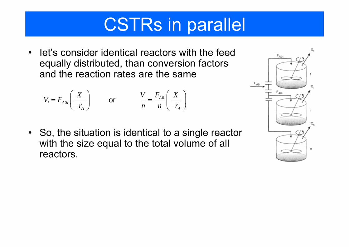
CSTRs in parallel• Iet’s consider identical reactors with the feed
equally distributed, than conversion factors and the reaction rates are the same
0i A iA
XV Fr
⎛ ⎞= ⎜ ⎟−⎝ ⎠
0A
A
FV Xn n r
⎛ ⎞= ⎜ ⎟−⎝ ⎠
or
• So, the situation is identical to a single reactor with the size equal to the total volume of all reactors.
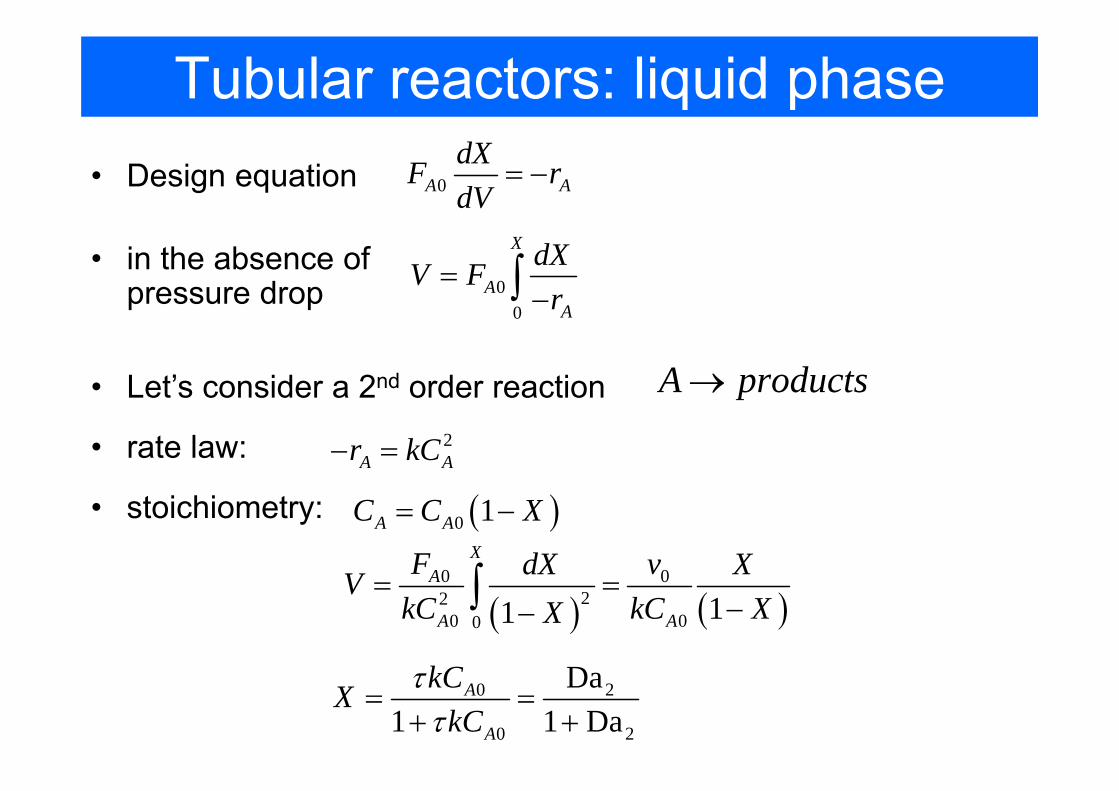
Tubular reactors: liquid phase• Design equation 0A A
dXF rdV
= −
00
X
AA
dXV Fr
=−∫
• in the absence of pressure drop
• Let’s consider a 2nd order reaction2
A Ar kC− =
A products→
• rate law:
• stoichiometry: ( )0 1A AC C X= −
( ) ( )0 0
220 00 11
XA
A A
F vdX XVkC kC XX
= =−−∫
0 2
0 2
Da1 1 Da
A
A
kCXkC
ττ
= =+ +
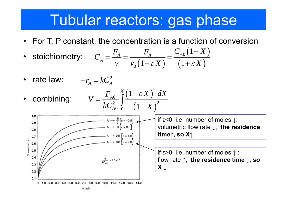
Tubular reactors: gas phase• For T, P constant, the concentration is a function of conversion
2A Ar kC− =• rate law:
• stoichiometry: ( )
( )( )
0
0
11 1
AA AA
C XF FCv v X Xε ε
−= = =
+ +
( )( )
20
220 0
11
XA
A
X dXFVkC X
ε+=
−∫• combining:
if ε<0: i.e. number of moles ↓: volumetric flow rate ↓, the residence time↑, so X↑
if ε>0: i.e. number of moles ↑ : flow rate ↑, the residence time ↓, so X ↓
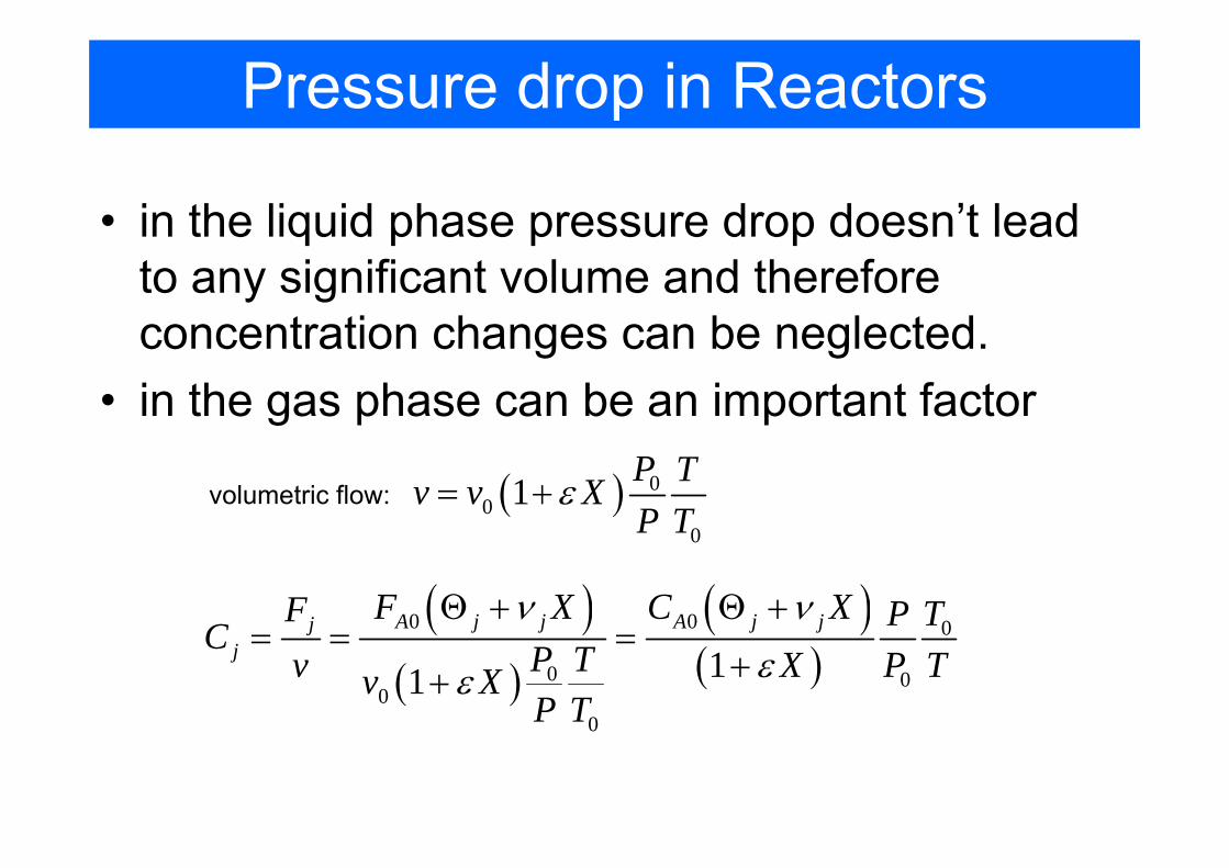
Pressure drop in Reactors
• in the liquid phase pressure drop doesn’t lead to any significant volume and therefore concentration changes can be neglected.
• in the gas phase can be an important factor
( ) 00
0
1 P Tv v XP T
ε= +volumetric flow:
( )( )
( )( )
0 0 0
0 00
0
11
A j j A j jjj
F X C XF P TC P Tv X P Tv XP T
ν νεε
Θ + Θ += = =
++

Pressure drop in Reactors• to account for a pressure drop we have to use differential
form of the equation
0A AdXF rdW
= −
2A Ar kC− =• rate law:
• stoichiometry: ( )( )
0 0
0
11A
A
C X TPCX P Tε−
=+
( )( )
2
0 0
0
11A
A
C X TPr kX P Tε
⎡ ⎤−= ⎢ ⎥+⎣ ⎦
• for isothermal operation:
( )( )
( )( )
2 2
0 0 0
0 0 0 0
1 111 1A A
A
C X XT kCdX P PkdW F X P T v X Pε ε
⎡ ⎤ ⎡ ⎤− −= =⎢ ⎥ ⎢ ⎥+ +⎣ ⎦ ⎣ ⎦
2A B C→ +
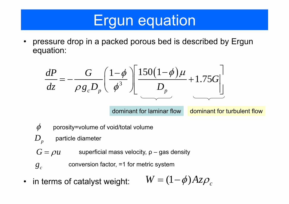
Ergun equation• pressure drop in a packed porous bed is described by Ergun
equation:
( )3
150 11 1.75c p p
dP G Gdz g D D
φ μφρ φ
⎡ ⎤−⎛ ⎞−= − +⎢ ⎥⎜ ⎟
⎝ ⎠ ⎢ ⎥⎣ ⎦
dominant for laminar flow dominant for turbulent flow
φ porosity=volume of void/total volume
particle diameterpDsuperficial mass velocity, ρ – gas densityG uρ=
conversion factor, =1 for metric systemcg
• in terms of catalyst weight: (1 ) cW Azφ ρ= −

Mole Balance in terms of Concentration and Molar Flow Rates
• Working in terms of number of moles (NA, NB,..) or molar flow rates (FA, FB etc) rather than conversion could be more convenient at some instances (e.g. multiple reactions and membrane reactors)
• The difference in calculation: we will write mole balance for each and every species in the reactor

Isothermal reaction design algorithm
Mole balance for every species
Rate law in terms of concentration
Rate of reactions for every species from stoichiometry
Concentration for every species
Calculate pressure drop if necessary
Combine and use ODE solver
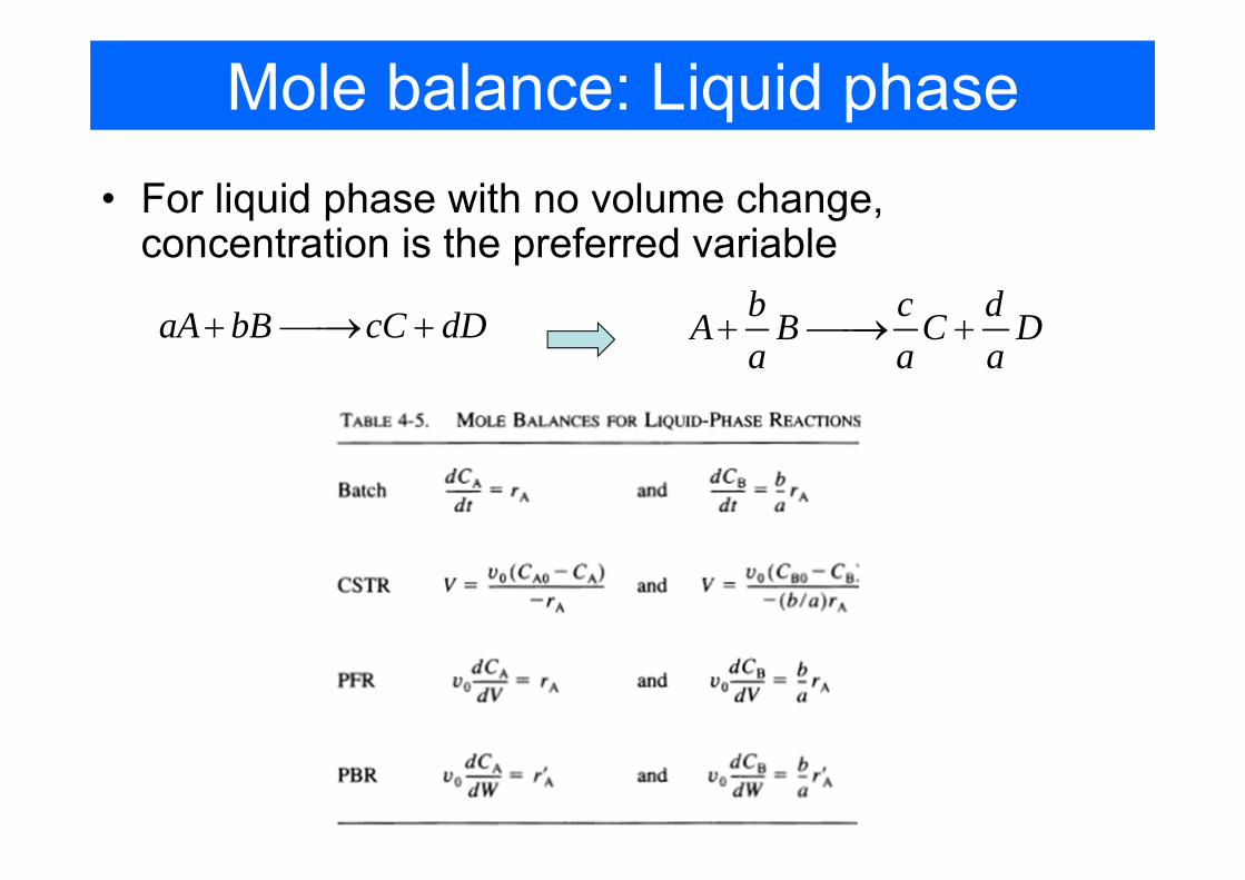
Mole balance: Liquid phase• For liquid phase with no volume change,
concentration is the preferred variable
aA bB cC dD+ ⎯⎯→ + b c dA B C Da a a
+ ⎯⎯→ +
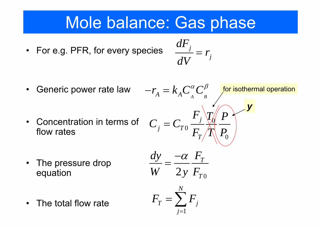
Mole balance: Gas phase• For e.g. PFR, for every species j
j
dFr
dV=
A BA Ar k C Cα β− =
1
N
T jj
F F=
=∑
• Generic power rate law
00
0
jj T
T
F T PC CF T P
=
y
for isothermal operation
• Concentration in terms of flow rates
• The pressure drop equation 02
T
T
FdyW y F
α−=
• The total flow rate
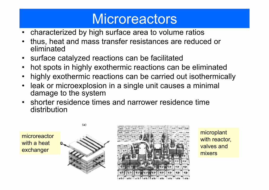
Microreactors• characterized by high surface area to volume ratios• thus, heat and mass transfer resistances are reduced or
eliminated• surface catalyzed reactions can be facilitated• hot spots in highly exothermic reactions can be eliminated• highly exothermic reactions can be carried out isothermically• leak or microexplosion in a single unit causes a minimal
damage to the system• shorter residence times and narrower residence time
distribution
microreactor with a heat exchanger
microplant with reactor, valves and mixers
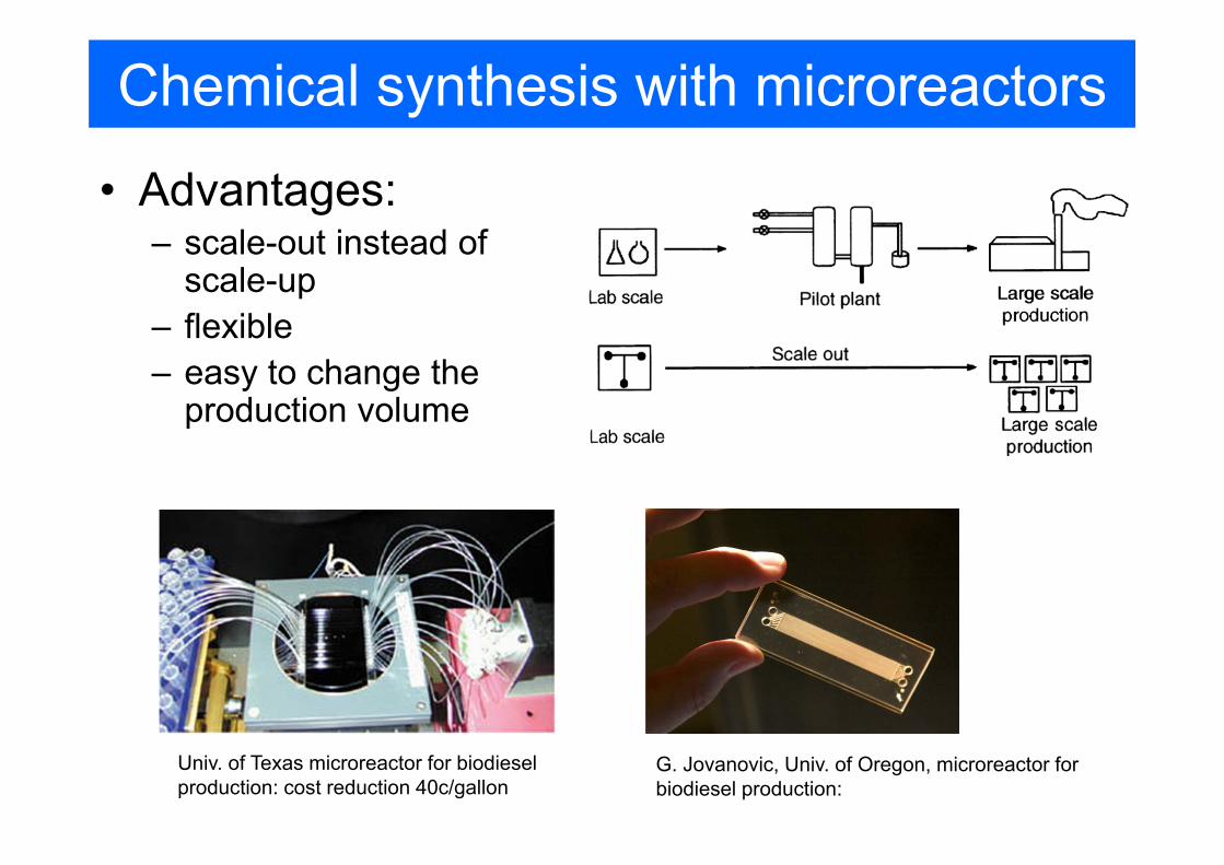
Chemical synthesis with microreactors
• Advantages:– scale-out instead of
scale-up– flexible– easy to change the
production volume
Univ. of Texas microreactor for biodiesel production: cost reduction 40c/gallon
G. Jovanovic, Univ. of Oregon, microreactor for biodiesel production:
Chemical synthesis with microreactors
• not every reaction benefits from microreactor• however:
– exothermic reactions are usually easier to control in microreactors due to better temperature control(reactions involving explosives, regionselective reactions)
– photochemical reactions can be easier arranged to absorb more light
– multistep reactions (e.g. peptide synthesis)– biphasic reactions (gas-liquid)– synthesis of analytically pure components
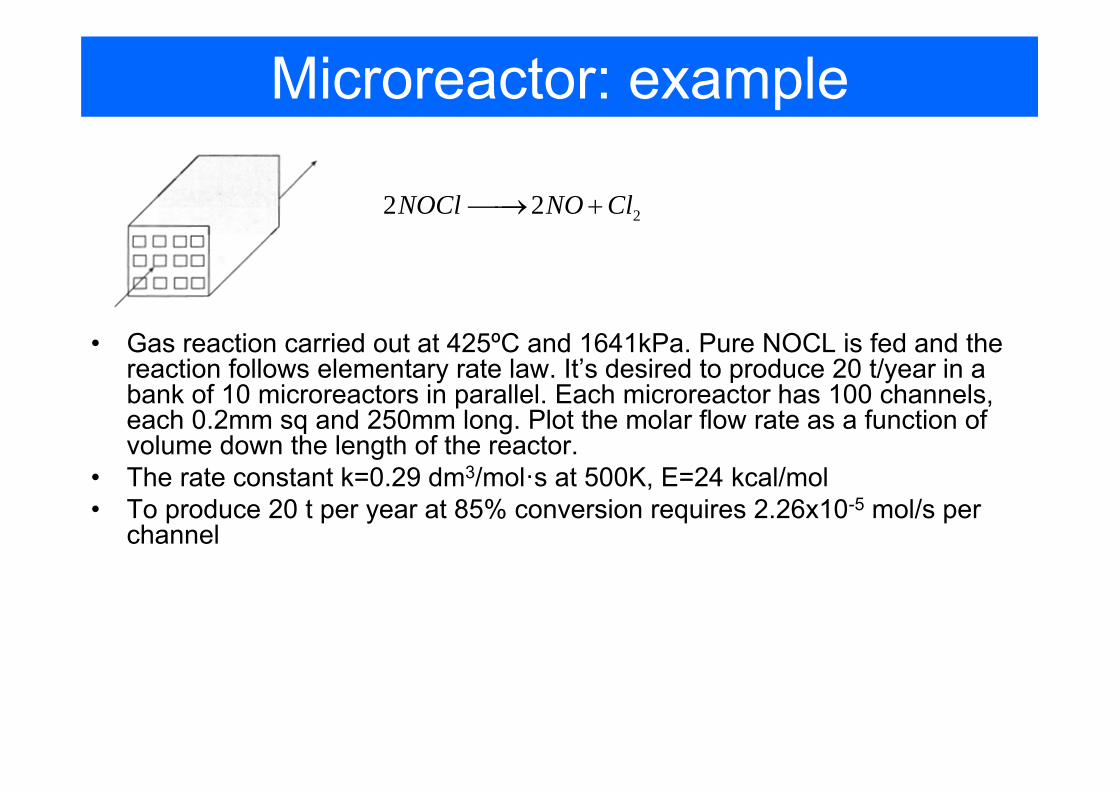
Microreactor: example
• Gas reaction carried out at 425ºC and 1641kPa. Pure NOCL is fed and the reaction follows elementary rate law. It’s desired to produce 20 t/year in a bank of 10 microreactors in parallel. Each microreactor has 100 channels, each 0.2mm sq and 250mm long. Plot the molar flow rate as a function of volume down the length of the reactor.
• The rate constant k=0.29 dm3/mol·s at 500K, E=24 kcal/mol• To produce 20 t per year at 85% conversion requires 2.26x10⁻⁵ mol/s per
channel
22 2NOCl NO Cl⎯⎯→ +
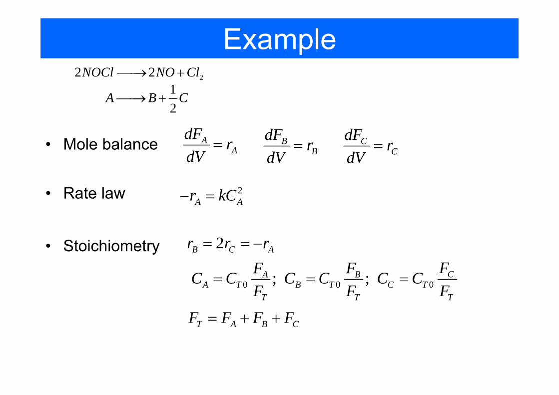
Example
• Mole balance
22 2NOCl NO Cl⎯⎯→ +12
A B C⎯⎯→ +
AA
dF rdV
= BB
dF rdV
= CC
dF rdV
=
• Rate law 2A Ar kC− =
• Stoichiometry 2B C Ar r r= = −
0 0 0; ; CA BA T B T C T
T T T
FF FC C C C C CF F F
= = =
T A B CF F F F= + +
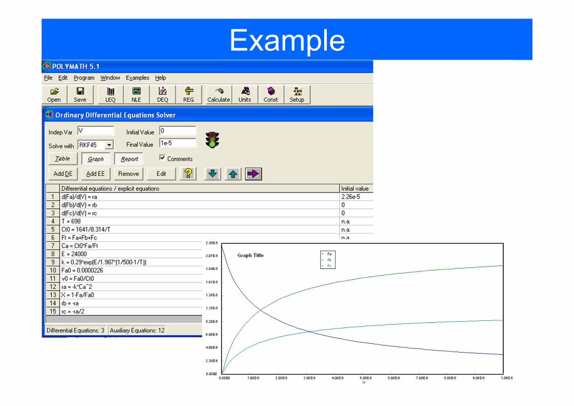
Example
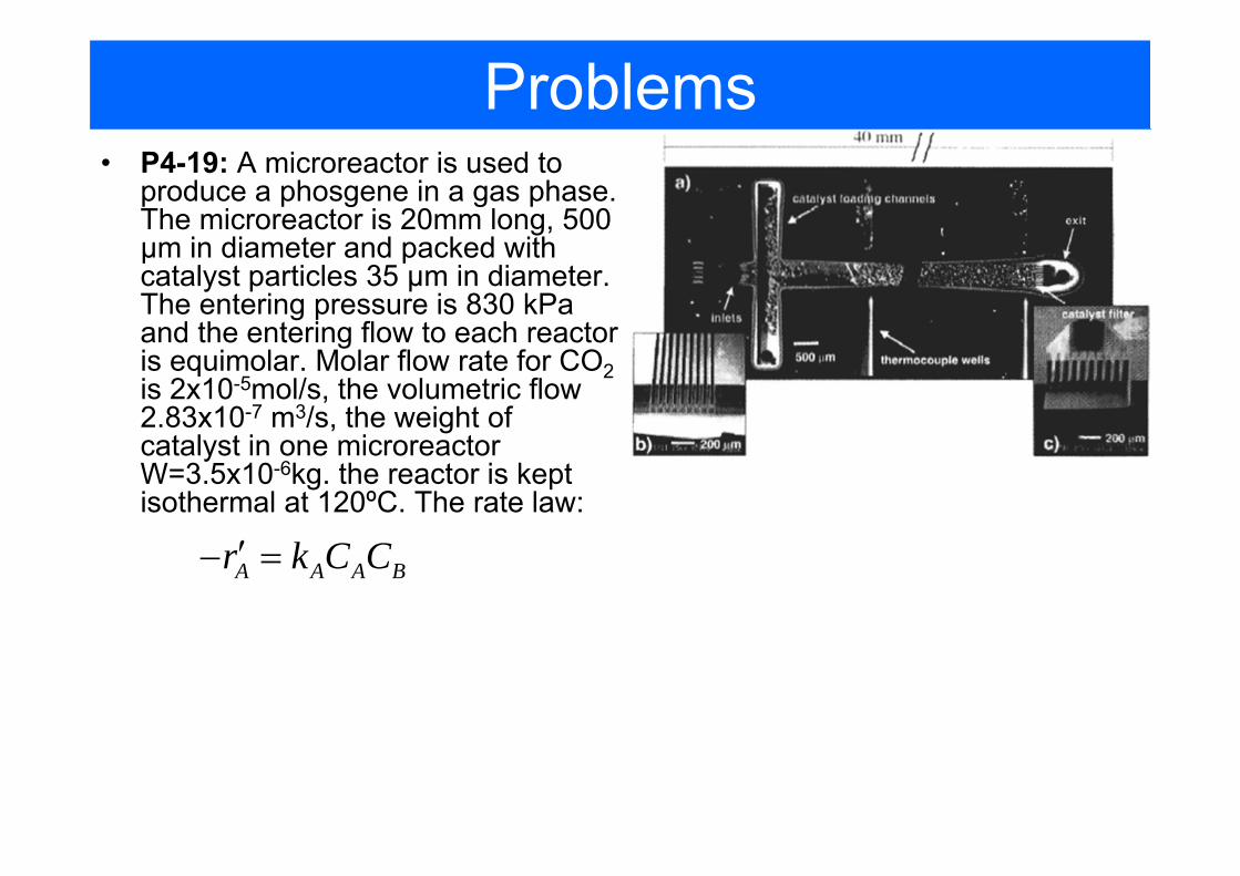
Problems
A A A Br k C C′− =
• P4-19: A microreactor is used to produce a phosgene in a gas phase. The microreactor is 20mm long, 500 µm in diameter and packed with catalyst particles 35 µm in diameter. The entering pressure is 830 kPa and the entering flow to each reactor is equimolar. Molar flow rate for CO2is 2x10⁻⁵mol/s, the volumetric flow 2.83x10⁻⁷ m3/s, the weight of catalyst in one microreactor W=3.5x10⁻⁶kg. the reactor is kept isothermal at 120ºC. The rate law:
Home problem analysis
P3-13, Hippo’s digestion
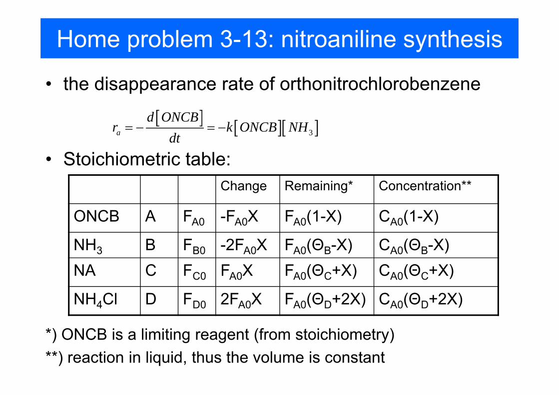
Home problem 3-13: nitroaniline synthesis
• the disappearance rate of orthonitrochlorobenzene
[ ] [ ][ ]3a
d ONCBr k ONCB NH
dt= − = −
• Stoichiometric table:Change Remaining* Concentration**
ONCB A FA0 -FA0X FA0(1-X) CA0(1-X)
NH3 B FB0 -2FA0X FA0(ΘB-X) CA0(ΘB-X)NA C FC0 FA0X FA0(ΘC+X) CA0(ΘC+X)
NH4Cl D FD0 2FA0X FA0(ΘD+2X) CA0(ΘD+2X)
*) ONCB is a limiting reagent (from stoichiometry)**) reaction in liquid, thus the volume is constant
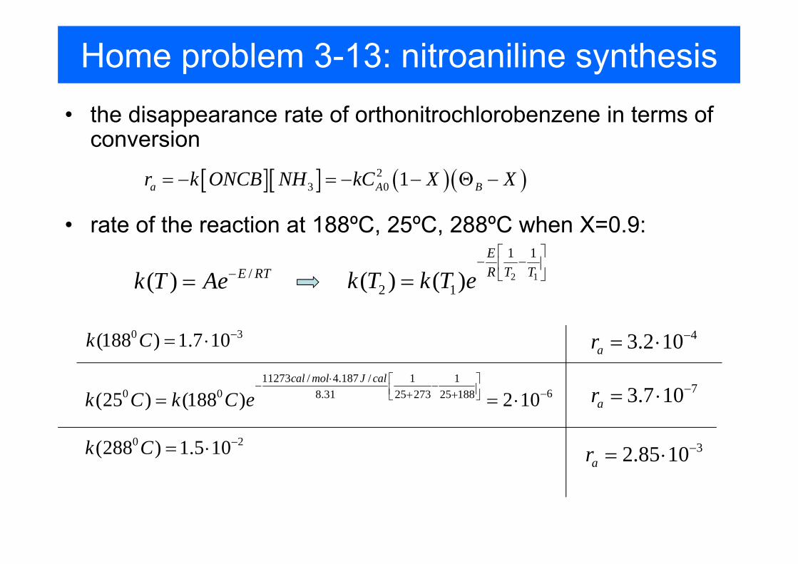
Home problem 3-13: nitroaniline synthesis• the disappearance rate of orthonitrochlorobenzene in terms of
conversion
[ ][ ] ( )( )23 0 1a A Br k ONCB NH kC X X= − = − − Θ −
• rate of the reaction at 188ºC, 25ºC, 288ºC when X=0.9:
/( ) E RTk T Ae−= 2 1
1 1
2 1( ) ( )ER T Tk T k T e⎡ ⎤
− −⎢ ⎥⎣ ⎦=
11273 / 4.187 / 1 10 0 68.31 25 273 25 188(25 ) (188 ) 2 10
cal mol J cal
k C k C e⋅ ⎡ ⎤− −⎢ ⎥ −+ +⎣ ⎦= = ⋅
0 2(288 ) 1.5 10k C −= ⋅ 32.85 10ar−= ⋅
43.2 10ar−= ⋅0 3(188 ) 1.7 10k C −= ⋅
73.7 10ar−= ⋅
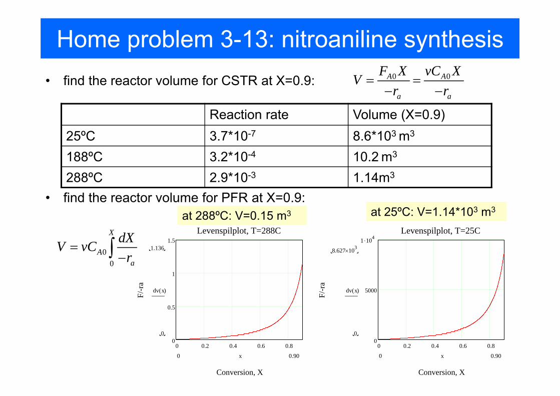
Home problem 3-13: nitroaniline synthesis• find the reactor volume for CSTR at X=0.9: 0 0A A
a a
F X vC XVr r
= =− −
• find the reactor volume for PFR at X=0.9:
Reaction rate Volume (X=0.9)25ºC 3.7*10-7 8.6*103 m3
188ºC 3.2*10-4 10.2 m3
288ºC 2.9*10-3 1.14m3
0 0.2 0.4 0.6 0.80
0.5
1
1.5Levenspilplot, T=288C
Conversion, X
F/-r
a
1.136
0
dv x( )
0.900 x
at 288ºC: V=0.15 m3 at 25ºC: V=1.14*103 m3
0 0.2 0.4 0.6 0.80
5000
1 .104Levenspilplot, T=25C
Conversion, X
F/-r
a
8.627 103×
0
dv x( )
0.900 x
00
X
Aa
dXV vCr
=−∫
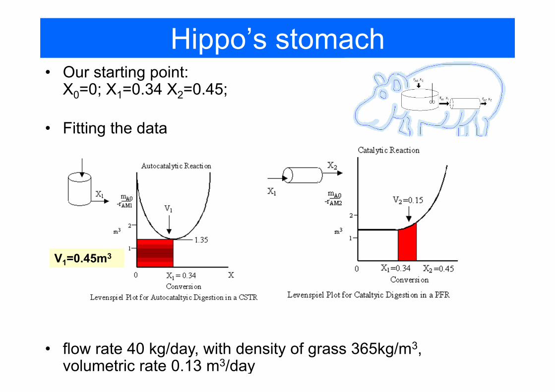
Hippo’s stomach• Our starting point:
X0=0; X1=0.34 X2=0.45;
• Fitting the data
• flow rate 40 kg/day, with density of grass 365kg/m3, volumetric rate 0.13 m3/day
V1=0.45m3
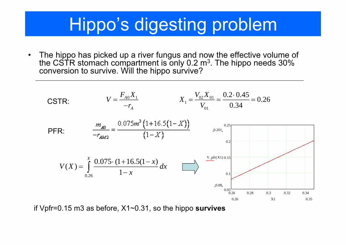
Hippo’s digesting problem• The hippo has picked up a river fungus and now the effective volume of
the CSTR stomach compartment is only 0.2 m3. The hippo needs 30% conversion to survive. Will the hippo survive?
0 1A
A
F XVr
=−CSTR:
02 011
01
0.2 0.45 0.260.34
V XXV
⋅= = =
PFR:
0.26 0.28 0.3 0.32 0.340.05
0.1
0.15
0.2
0.250.201
0.08
V_pfr X1( )
0.350.26 X1
0.26
0.075 (1 16.5(1 )( )1
X xV X dxx
⋅ + −=
−∫
if Vpfr=0.15 m3 as before, X1~0.31, so the hippo survives
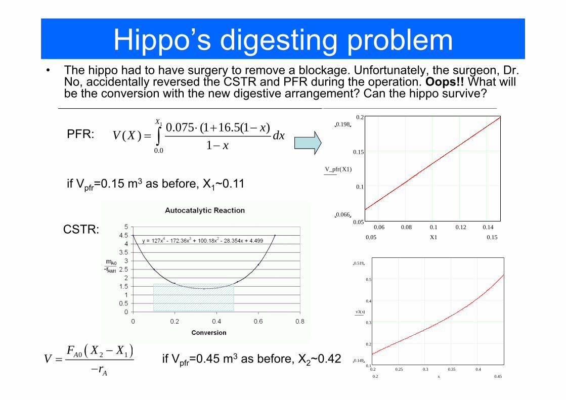
Hippo’s digesting problem• The hippo had to have surgery to remove a blockage. Unfortunately, the surgeon, Dr.
No, accidentally reversed the CSTR and PFR during the operation. Oops!! What will be the conversion with the new digestive arrangement? Can the hippo survive?
( )0 2 1A
A
F X XV
r−
=−
CSTR:
PFR:1
0.0
0.075 (1 16.5(1 )( )1
X xV X dxx
⋅ + −=
−∫
if Vpfr=0.15 m3 as before, X1~0.11
0.06 0.08 0.1 0.12 0.140.05
0.1
0.15
0.20.198
0.066
V_pfr X1( )
0.150.05 X1
if Vpfr=0.45 m3 as before, X2~0.420.2 0.25 0.3 0.35 0.4
0.1
0.2
0.3
0.4
0.5
0.519
0.149
v3 x( )
0.450.2 x
Related Documents