Citation: Czakiert, T.; Krzywanski, J.; Zylka, A.; Nowak, W. Chemical Looping Combustion: A Brief Overview. Energies 2022, 15, 1563. https://doi.org/10.3390/en15041563 Academic Editor: Antonio Crespo Received: 1 February 2022 Accepted: 18 February 2022 Published: 20 February 2022 Publisher’s Note: MDPI stays neutral with regard to jurisdictional claims in published maps and institutional affil- iations. Copyright: © 2022 by the authors. Licensee MDPI, Basel, Switzerland. This article is an open access article distributed under the terms and conditions of the Creative Commons Attribution (CC BY) license (https:// creativecommons.org/licenses/by/ 4.0/). energies Review Chemical Looping Combustion: A Brief Overview Tomasz Czakiert 1, * , Jaroslaw Krzywanski 2 , Anna Zylka 2 and Wojciech Nowak 3 1 Department of Advanced Energy Technologies, Faculty of Infrastructure and Environment, Czestochowa University of Technology, 42-201 Czestochowa, Poland 2 Division of Advanced Computational Methods, Faculty of Science and Technology, Jan Dlugosz University in Czestochowa, 42-200 Czestochowa, Poland; [email protected] (J.K.); [email protected] (A.Z.) 3 Department of Thermal and Fluid-Flow Machinery, Faculty of Energy and Fuels, AGH University of Science and Technology, 30-059 Cracow, Poland; [email protected] * Correspondence: [email protected] Abstract: The current development of chemical looping combustion (CLC) technology is presented in this paper. This technique of energy conversion enables burning of hydrocarbon fuels with dramatically reduced CO 2 emission into the atmosphere, since the inherent separation of carbon dioxide takes place directly in a combustion unit. In the beginning, the general idea of the CLC process is described, which takes advantage of solids (so-called oxygen carriers) being able to transport oxygen between combustion air and burning fuel. The main groups of oxygen carriers (OC) are characterized and compared, which are Fe-, Mn-, Cu-, Ni-, and Co-based materials. Moreover, different constructions of reactors tailored to perform the CLC process are described, including fluidized-bed reactors, swing reactors, and rotary reactors. The whole systems are based on the chemical looping concept, such as syngas CLC (SG-CLC), in situ Gasification CLC (iG-CLC), chemical looping with oxygen uncoupling (CLOU), and chemical looping reforming (CLR), are discussed as well. Finally, a comparison with other pro-CCS (carbon capture and storage) technologies is provided. Keywords: CLC; oxygen carriers; reactors; systems 1. Introduction Carbon dioxide emission from anthropogenic sources, including the power industry, has attracted more and more attention over the last 15 years. This interest brings rapid development of so-called pro-CCS (carbon capture and storage) technologies, which offer the ability to reduce significantly the emission of CO 2 into the atmosphere. As a result, three of these methods, such as pre-combustion capture, post-combustion capture, and oxy-fuel combustion [1–4], have achieved satisfied technological maturity. Nevertheless, commercial implementation on a large scale is still very limited, mainly due to the high energy-efficiency penalty associated among others with ASU (air separation unit) operation [5]. This problem does not concern, however, the innovative technique of chemical looping combustion CLC [6], where solid particles are used to transport oxygen from combustion air to the burning fuel. The CLC process is usually conducted in a system of two reactors (Figure 1), which consists of the fuel reactor (FR), where combustion takes place, and the air reactor (AR), where oxygen carriers (OC) are regenerated. Thus, oxygen carriers are subjected to contin- uous oxidation and reduction (Equations (1) and (2)) [7] while they circulate throughout the combined CLC unit. There are two crucial benefits of OCs employment in a power generation system, which are the elimination of conventional energy-consuming air separa- tion units and the inherent separation of forming flue gases (mainly CO 2 and H 2 O) from the air supplied to the combustion process. As a result, the flue gas that leaves the fuel reactor is free of atmospheric nitrogen and thus it becomes almost ready for geological sequestration—CCS (carbon capture and storage) and/or commercial utilization—CCU Energies 2022, 15, 1563. https://doi.org/10.3390/en15041563 https://www.mdpi.com/journal/energies

Welcome message from author
This document is posted to help you gain knowledge. Please leave a comment to let me know what you think about it! Share it to your friends and learn new things together.
Transcript
�����������������
Citation: Czakiert, T.; Krzywanski, J.;
Zylka, A.; Nowak, W. Chemical
Looping Combustion: A Brief
Overview. Energies 2022, 15, 1563.
https://doi.org/10.3390/en15041563
Academic Editor: Antonio Crespo
Received: 1 February 2022
Accepted: 18 February 2022
Published: 20 February 2022
Publisher’s Note: MDPI stays neutral
with regard to jurisdictional claims in
published maps and institutional affil-
iations.
Copyright: © 2022 by the authors.
Licensee MDPI, Basel, Switzerland.
This article is an open access article
distributed under the terms and
conditions of the Creative Commons
Attribution (CC BY) license (https://
creativecommons.org/licenses/by/
4.0/).
energies
Review
Chemical Looping Combustion: A Brief OverviewTomasz Czakiert 1,* , Jaroslaw Krzywanski 2 , Anna Zylka 2 and Wojciech Nowak 3
1 Department of Advanced Energy Technologies, Faculty of Infrastructure and Environment,Czestochowa University of Technology, 42-201 Czestochowa, Poland
2 Division of Advanced Computational Methods, Faculty of Science and Technology, Jan Dlugosz University inCzestochowa, 42-200 Czestochowa, Poland; [email protected] (J.K.); [email protected] (A.Z.)
3 Department of Thermal and Fluid-Flow Machinery, Faculty of Energy and Fuels, AGH University of Scienceand Technology, 30-059 Cracow, Poland; [email protected]
* Correspondence: [email protected]
Abstract: The current development of chemical looping combustion (CLC) technology is presentedin this paper. This technique of energy conversion enables burning of hydrocarbon fuels withdramatically reduced CO2 emission into the atmosphere, since the inherent separation of carbondioxide takes place directly in a combustion unit. In the beginning, the general idea of the CLCprocess is described, which takes advantage of solids (so-called oxygen carriers) being able totransport oxygen between combustion air and burning fuel. The main groups of oxygen carriers (OC)are characterized and compared, which are Fe-, Mn-, Cu-, Ni-, and Co-based materials. Moreover,different constructions of reactors tailored to perform the CLC process are described, includingfluidized-bed reactors, swing reactors, and rotary reactors. The whole systems are based on thechemical looping concept, such as syngas CLC (SG-CLC), in situ Gasification CLC (iG-CLC), chemicallooping with oxygen uncoupling (CLOU), and chemical looping reforming (CLR), are discussed aswell. Finally, a comparison with other pro-CCS (carbon capture and storage) technologies is provided.
Keywords: CLC; oxygen carriers; reactors; systems
1. Introduction
Carbon dioxide emission from anthropogenic sources, including the power industry,has attracted more and more attention over the last 15 years. This interest brings rapiddevelopment of so-called pro-CCS (carbon capture and storage) technologies, which offerthe ability to reduce significantly the emission of CO2 into the atmosphere. As a result, threeof these methods, such as pre-combustion capture, post-combustion capture, and oxy-fuelcombustion [1–4], have achieved satisfied technological maturity. Nevertheless, commercialimplementation on a large scale is still very limited, mainly due to the high energy-efficiencypenalty associated among others with ASU (air separation unit) operation [5]. This problemdoes not concern, however, the innovative technique of chemical looping combustionCLC [6], where solid particles are used to transport oxygen from combustion air to theburning fuel.
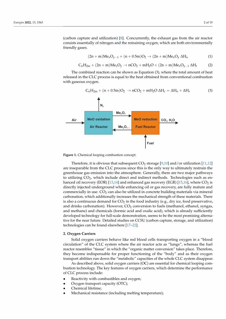
The CLC process is usually conducted in a system of two reactors (Figure 1), whichconsists of the fuel reactor (FR), where combustion takes place, and the air reactor (AR),where oxygen carriers (OC) are regenerated. Thus, oxygen carriers are subjected to contin-uous oxidation and reduction (Equations (1) and (2)) [7] while they circulate throughoutthe combined CLC unit. There are two crucial benefits of OCs employment in a powergeneration system, which are the elimination of conventional energy-consuming air separa-tion units and the inherent separation of forming flue gases (mainly CO2 and H2O) fromthe air supplied to the combustion process. As a result, the flue gas that leaves the fuelreactor is free of atmospheric nitrogen and thus it becomes almost ready for geologicalsequestration—CCS (carbon capture and storage) and/or commercial utilization—CCU
Energies 2022, 15, 1563. https://doi.org/10.3390/en15041563 https://www.mdpi.com/journal/energies
Energies 2022, 15, 1563 2 of 19
(carbon capture and utilization) [8]. Concurrently, the exhaust gas from the air reactorconsists essentially of nitrogen and the remaining oxygen, which are both environmentallyfriendly gases.
(2n + m)MexOy−1 + (n + 0.5m)O2 → (2n + m)MexOy ∆Ho (1)
CnH2m + (2n + m)MexOy → nCO2 + mH2O + (2n + m)MexOy−1 ∆Hr (2)
The combined reaction can be shown as Equation (3), where the total amount of heatreleased in the CLC process is equal to the heat obtained from conventional combustionwith gaseous oxygen.
CnH2m + (n + 0.5m)O2 → nCO2 + mH2O ∆Hc = ∆Ho + ∆Hr (3)
Energies 2022, 15, 1563 2 of 20
geological sequestration—CCS (carbon capture and storage) and/or commercial utiliza-tion—CCU (carbon capture and utilization) [8]. Concurrently, the exhaust gas from the air reactor consists essentially of nitrogen and the remaining oxygen, which are both en-vironmentally friendly gases. 2n + m Me O + n + 0.5m O → 2n + m Me O ∆H (1) C H + 2n + m Me O → nCO + mH O + 2n + m Me O ∆H (2)
The combined reaction can be shown as Equation (3), where the total amount of heat released in the CLC process is equal to the heat obtained from conventional combustion with gaseous oxygen. C H + n + 0.5m O → nCO + mH O ∆H = ∆H + ∆H (3)
Figure 1. Chemical looping combustion concept.
Therefore, it is obvious that subsequent CO2 storage [9,10] and/or utilization [11,12] are inseparable from the CLC process since this is the only way to ultimately restrain the greenhouse gas emission into the atmosphere. Generally, there are two major pathways to utilizing CO2, which include direct and indirect methods. Technologies such as en-hanced oil recovery (EOR) [13,14] and enhanced gas recovery (EGR) [15,16], where CO2 is directly injected underground while enhancing oil or gas recovery, are fully mature and commercially in use. CO2 can also be utilized in concrete building materials via mineral carbonation, which additionally increases the mechanical strength of these materials. There is also a continuous demand for CO2 in the food industry (e.g., dry ice, food pre-servative, and drinks carbonation). However, CO2 conversion to fuels (methanol, ethanol, syngas, and methane) and chemicals (formic acid and oxalic acid), which is already suf-ficiently developed technology for full-scale demonstration, seems to be the most prom-ising alternative for the near future. Detailed studies on CCSU (carbon capture, storage, and utilization) technologies can be found elsewhere [17–22].
2. Oxygen Carriers Solid oxygen carriers behave like red blood cells transporting oxygen in a “blood
circulation” of the CLC system where the air reactor acts as “lungs”, whereas the fuel reactor resembles “tissue” in which the “organic matter conversion” takes place. There-fore, they become indispensable for proper functioning of the “body” and as their oxygen transport abilities run down the “metabolic” capacities of the whole CLC system disap-pear.
As described above, solid oxygen carriers (OC) are essential for chemical looping combustion technology. The key features of oxygen carriers, which determine the per-formance of CLC process include: • Reactivity with combustibles and oxygen; • Oxygen transport capacity (OTC);
Figure 1. Chemical looping combustion concept.
Therefore, it is obvious that subsequent CO2 storage [9,10] and/or utilization [11,12]are inseparable from the CLC process since this is the only way to ultimately restrain thegreenhouse gas emission into the atmosphere. Generally, there are two major pathwaysto utilizing CO2, which include direct and indirect methods. Technologies such as en-hanced oil recovery (EOR) [13,14] and enhanced gas recovery (EGR) [15,16], where CO2 isdirectly injected underground while enhancing oil or gas recovery, are fully mature andcommercially in use. CO2 can also be utilized in concrete building materials via mineralcarbonation, which additionally increases the mechanical strength of these materials. Thereis also a continuous demand for CO2 in the food industry (e.g., dry ice, food preservative,and drinks carbonation). However, CO2 conversion to fuels (methanol, ethanol, syngas,and methane) and chemicals (formic acid and oxalic acid), which is already sufficientlydeveloped technology for full-scale demonstration, seems to be the most promising alterna-tive for the near future. Detailed studies on CCSU (carbon capture, storage, and utilization)technologies can be found elsewhere [17–22].
2. Oxygen Carriers
Solid oxygen carriers behave like red blood cells transporting oxygen in a “bloodcirculation” of the CLC system where the air reactor acts as “lungs”, whereas the fuelreactor resembles “tissue” in which the “organic matter conversion” takes place. Therefore,they become indispensable for proper functioning of the “body” and as their oxygentransport abilities run down the “metabolic” capacities of the whole CLC system disappear.
As described above, solid oxygen carriers (OC) are essential for chemical looping com-bustion technology. The key features of oxygen carriers, which determine the performanceof CLC process include:
• Reactivity with combustibles and oxygen;• Oxygen transport capacity (OTC);• Chemical lifetime;• Mechanical resistance (including melting temperature);
Energies 2022, 15, 1563 3 of 19
• Tendency to carbon deposition on oxygen carrier surface;• Toxicity and environmental impact;• Price and availability.
Oxygen carriers can be classified into several categories. The first one is based on theorigin, which means natural OCs (e.g., ilmenite) and synthetic OCs (e.g., Cu0.95Fe1.05AlO4).Another criterion takes into account the number of active compounds (e.g., NiO or (Mn,Fe)2O3)and their structure (e.g., perovskites [23,24]). Finally, the ability of oxygen uncoupling inan environment of a fuel reactor (CLOU-type OC) is taken into consideration. Recently,very promising novel synthetic oxygen carriers based on geopolymer composites wereproposed [25]. The main advantages of geopolymer OCs are, among others, low cost, greensynthesis, non-toxicity, and CLOU feature [26]. Furthermore, a good mechanical resistancemakes them suitable for fluidized bed applications [27]. In the search for potential oxygencarriers, steel converter slag was also tested with success under circulating fluidized bed(CFB) conditions [28]. Usually, however, solid oxygen carriers are simply divided into fivegroups, which are: Fe−, Cu−, Mn−, Co−, and Ni-based OC. Moreover, in addition to metaloxides the supports of different kinds are used, which enriched their inherent properties,among others are: Al2O3, MgAl2O4, TiO2, SiO2, ZrO2, and bentonite.
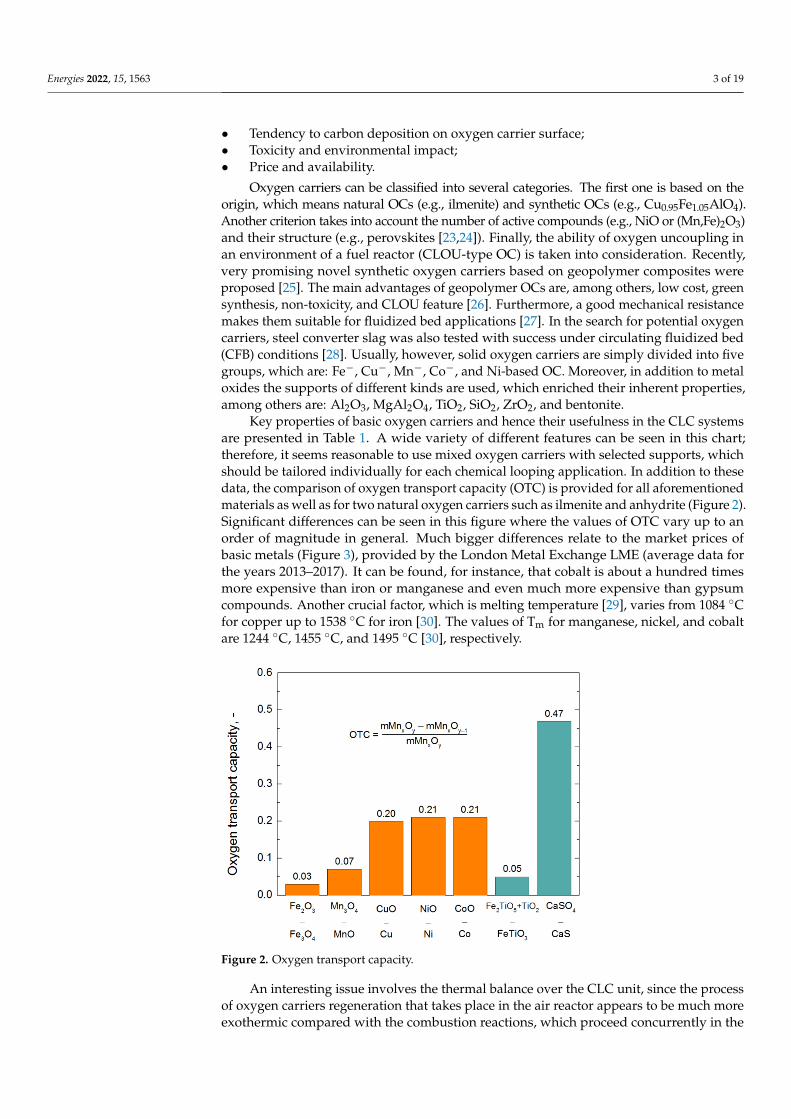
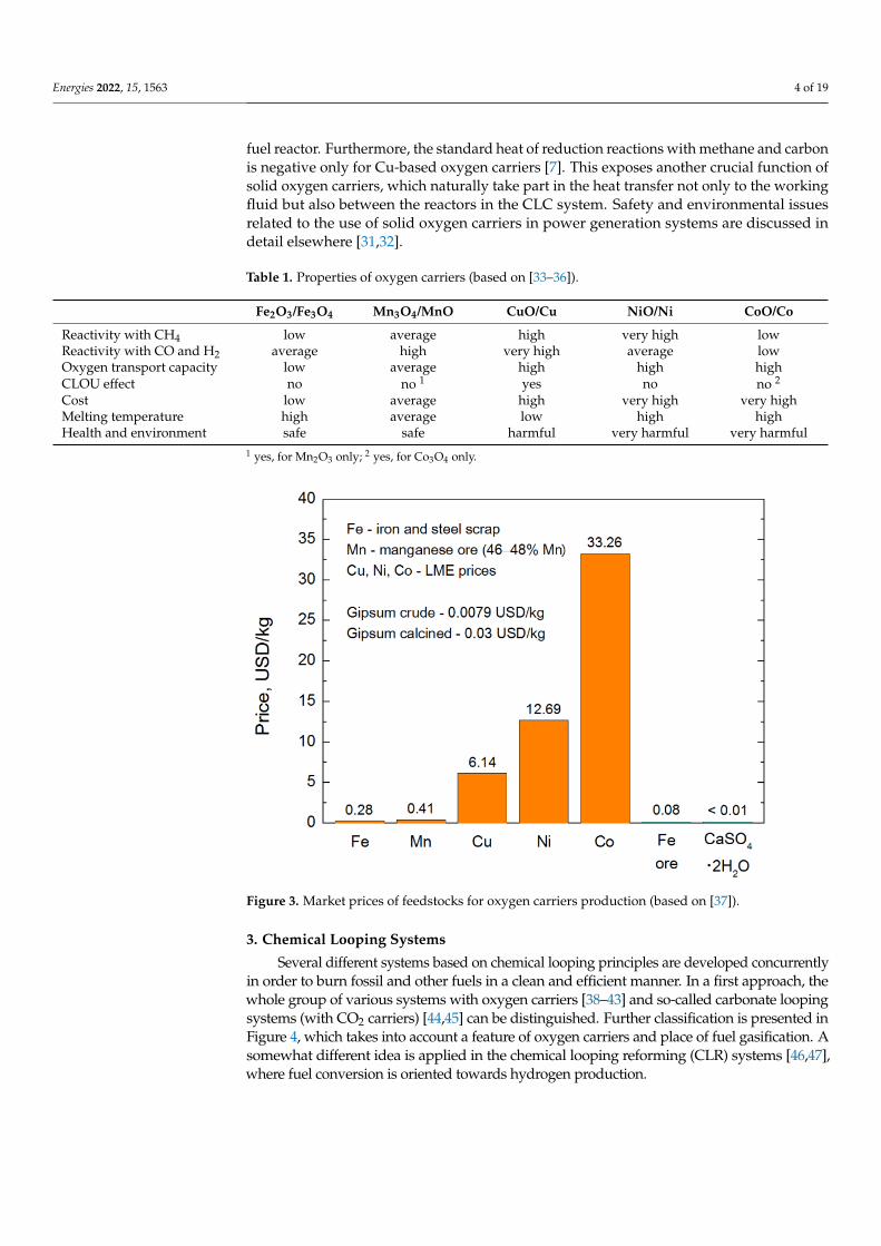
Key properties of basic oxygen carriers and hence their usefulness in the CLC systemsare presented in Table 1. A wide variety of different features can be seen in this chart;therefore, it seems reasonable to use mixed oxygen carriers with selected supports, whichshould be tailored individually for each chemical looping application. In addition to thesedata, the comparison of oxygen transport capacity (OTC) is provided for all aforementionedmaterials as well as for two natural oxygen carriers such as ilmenite and anhydrite (Figure 2).Significant differences can be seen in this figure where the values of OTC vary up to anorder of magnitude in general. Much bigger differences relate to the market prices ofbasic metals (Figure 3), provided by the London Metal Exchange LME (average data forthe years 2013–2017). It can be found, for instance, that cobalt is about a hundred timesmore expensive than iron or manganese and even much more expensive than gypsumcompounds. Another crucial factor, which is melting temperature [29], varies from 1084 ◦Cfor copper up to 1538 ◦C for iron [30]. The values of Tm for manganese, nickel, and cobaltare 1244 ◦C, 1455 ◦C, and 1495 ◦C [30], respectively.
Energies 2022, 15, 1563 3 of 20
• Chemical lifetime; • Mechanical resistance (including melting temperature); • Tendency to carbon deposition on oxygen carrier surface; • Toxicity and environmental impact; • Price and availability.
Oxygen carriers can be classified into several categories. The first one is based on the origin, which means natural OCs (e.g., ilmenite) and synthetic OCs (e.g., Cu0.95Fe1.05AlO4). Another criterion takes into account the number of active compounds (e.g., NiO or (Mn,Fe)2O3) and their structure (e.g., perovskites [23,24]). Finally, the ability of oxygen uncoupling in an environment of a fuel reactor (CLOU-type OC) is taken into considera-tion. Recently, very promising novel synthetic oxygen carriers based on geopolymer composites were proposed [25]. The main advantages of geopolymer OCs are, among others, low cost, green synthesis, non-toxicity, and CLOU feature [26]. Furthermore, a good mechanical resistance makes them suitable for fluidized bed applications [27]. In the search for potential oxygen carriers, steel converter slag was also tested with success under circulating fluidized bed (CFB) conditions [28]. Usually, however, solid oxygen carriers are simply divided into five groups, which are: Fe-, Cu-, Mn-, Co-, and Ni-based OC. Moreover, in addition to metal oxides the supports of different kinds are used, which enriched their inherent properties, among others are: Al2O3, MgAl2O4, TiO2, SiO2, ZrO2, and bentonite.
Key properties of basic oxygen carriers and hence their usefulness in the CLC sys-tems are presented in Table 1. A wide variety of different features can be seen in this chart; therefore, it seems reasonable to use mixed oxygen carriers with selected supports, which should be tailored individually for each chemical looping application. In addition to these data, the comparison of oxygen transport capacity (OTC) is provided for all aforementioned materials as well as for two natural oxygen carriers such as ilmenite and anhydrite (Figure 2). Significant differences can be seen in this figure where the values of OTC vary up to an order of magnitude in general. Much bigger differences relate to the market prices of basic metals (Figure 3), provided by the London Metal Exchange LME (average data for the years 2013–2017). It can be found, for instance, that cobalt is about a hundred times more expensive than iron or manganese and even much more expensive than gypsum compounds. Another crucial factor, which is melting temperature [29], varies from 1084 °C for copper up to 1538 °C for iron [30]. The values of Tm for manga-nese, nickel, and cobalt are 1244 °C, 1455 °C, and 1495 °C [30], respectively.
Figure 2. Oxygen transport capacity. Figure 2. Oxygen transport capacity.
An interesting issue involves the thermal balance over the CLC unit, since the processof oxygen carriers regeneration that takes place in the air reactor appears to be much moreexothermic compared with the combustion reactions, which proceed concurrently in the
Energies 2022, 15, 1563 4 of 19
fuel reactor. Furthermore, the standard heat of reduction reactions with methane and carbonis negative only for Cu-based oxygen carriers [7]. This exposes another crucial function ofsolid oxygen carriers, which naturally take part in the heat transfer not only to the workingfluid but also between the reactors in the CLC system. Safety and environmental issuesrelated to the use of solid oxygen carriers in power generation systems are discussed indetail elsewhere [31,32].
Table 1. Properties of oxygen carriers (based on [33–36]).
Fe2O3/Fe3O4 Mn3O4/MnO CuO/Cu NiO/Ni CoO/Co
Reactivity with CH4 low average high very high lowReactivity with CO and H2 average high very high average lowOxygen transport capacity low average high high highCLOU effect no no 1 yes no no 2
Cost low average high very high very highMelting temperature high average low high highHealth and environment safe safe harmful very harmful very harmful
1 yes, for Mn2O3 only; 2 yes, for Co3O4 only.
Energies 2022, 15, 1563 4 of 20
An interesting issue involves the thermal balance over the CLC unit, since the pro-cess of oxygen carriers regeneration that takes place in the air reactor appears to be much more exothermic compared with the combustion reactions, which proceed concurrently in the fuel reactor. Furthermore, the standard heat of reduction reactions with methane and carbon is negative only for Cu-based oxygen carriers [7]. This exposes another cru-cial function of solid oxygen carriers, which naturally take part in the heat transfer not only to the working fluid but also between the reactors in the CLC system. Safety and environmental issues related to the use of solid oxygen carriers in power generation systems are discussed in detail elsewhere [31,32].
Table 1. Properties of oxygen carriers (based on [33–36]).
Fe2O3/Fe3O4 Mn3O4/MnO CuO/Cu NiO/Ni CoO/Co Reactivity with CH4 low average high very high low Reactivity with CO and H2 average high very high average low Oxygen transport capacity low average high high high CLOU effect no no 1 yes no no 2 Cost low average high very high very high Melting temperature high average low high high Health and environment safe safe harmful very harmful very harmful
1 yes, for Mn2O3 only; 2 yes, for Co3O4 only.
Figure 3. Market prices of feedstocks for oxygen carriers production (based on [37]).
3. Chemical Looping Systems Several different systems based on chemical looping principles are developed con-
currently in order to burn fossil and other fuels in a clean and efficient manner. In a first approach, the whole group of various systems with oxygen carriers [38–43] and so-called carbonate looping systems (with CO2 carriers) [44,45] can be distinguished. Further clas-sification is presented in Figure 4, which takes into account a feature of oxygen carriers and place of fuel gasification. A somewhat different idea is applied in the chemical looping reforming (CLR) systems [46,47], where fuel conversion is oriented towards hy-drogen production.
Figure 3. Market prices of feedstocks for oxygen carriers production (based on [37]).
3. Chemical Looping Systems
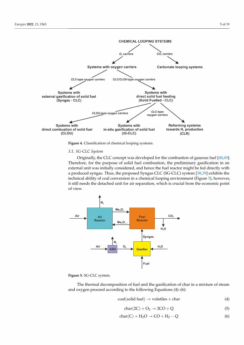
Several different systems based on chemical looping principles are developed concurrentlyin order to burn fossil and other fuels in a clean and efficient manner. In a first approach, thewhole group of various systems with oxygen carriers [38–43] and so-called carbonate loopingsystems (with CO2 carriers) [44,45] can be distinguished. Further classification is presented inFigure 4, which takes into account a feature of oxygen carriers and place of fuel gasification. Asomewhat different idea is applied in the chemical looping reforming (CLR) systems [46,47],where fuel conversion is oriented towards hydrogen production.
Energies 2022, 15, 1563 5 of 19Energies 2022, 15, 1563 5 of 20
Figure 4. Classification of chemical looping systems.
3.1. SG-CLC System Originally, the CLC concept was developed for the combustion of gaseous fuel
[48,49]. Therefore, for the purpose of solid fuel combustion, the preliminary gasification in an external unit was initially considered, and hence the fuel reactor might be fed di-rectly with a produced syngas. Thus, the proposed Syngas CLC (SG-CLC) system [38,39] exhibits the technical ability of coal conversion in a chemical looping environment (Fig-ure 5), however, it still needs the detached unit for air separation, which is crucial from the economic point of view.
Figure 5. SG-CLC system.
The thermal decomposition of fuel and the gasification of char in a mixture of steam and oxygen proceed according to the following Equations (4)–(6): coal solid fuel → volatiles + char (4) char 2C + O → 2CO + Q (5)
Figure 4. Classification of chemical looping systems.
3.1. SG-CLC System
Originally, the CLC concept was developed for the combustion of gaseous fuel [48,49].Therefore, for the purpose of solid fuel combustion, the preliminary gasification in anexternal unit was initially considered, and hence the fuel reactor might be fed directly witha produced syngas. Thus, the proposed Syngas CLC (SG-CLC) system [38,39] exhibits thetechnical ability of coal conversion in a chemical looping environment (Figure 5), however,it still needs the detached unit for air separation, which is crucial from the economic pointof view.
Energies 2022, 15, 1563 5 of 20
Figure 4. Classification of chemical looping systems.
3.1. SG-CLC System Originally, the CLC concept was developed for the combustion of gaseous fuel
[48,49]. Therefore, for the purpose of solid fuel combustion, the preliminary gasification in an external unit was initially considered, and hence the fuel reactor might be fed di-rectly with a produced syngas. Thus, the proposed Syngas CLC (SG-CLC) system [38,39] exhibits the technical ability of coal conversion in a chemical looping environment (Fig-ure 5), however, it still needs the detached unit for air separation, which is crucial from the economic point of view.
Figure 5. SG-CLC system.
The thermal decomposition of fuel and the gasification of char in a mixture of steam and oxygen proceed according to the following Equations (4)–(6): coal solid fuel → volatiles + char (4) char 2C + O → 2CO + Q (5)
Figure 5. SG-CLC system.
The thermal decomposition of fuel and the gasification of char in a mixture of steamand oxygen proceed according to the following Equations (4)–(6):
coal(solid fuel)→ volatiles + char (4)
char(2C) + O2 → 2CO + Q (5)
char(C) + H2O→ CO + H2 −Q (6)
Energies 2022, 15, 1563 6 of 19
whereas subsequent combustion of volatiles and syngas both being in contact with solidoxygen carriers can be described by the reactions (7) and (8):
CO + H2 + volatiles + nMexOy → CO2 + H2O + nMexOy−1 (7)
CO + H2O→ CO2 + H2 + Q (8)
Concurrently, the reduced oxygen carriers undergo regeneration (Equation (9)) in theair reactor, before they are returned to the combustion zone, which makes the chemicalloop complete.
MexOy−1 + 0.5O2 → MexOy (9)
3.2. iG-CLC System
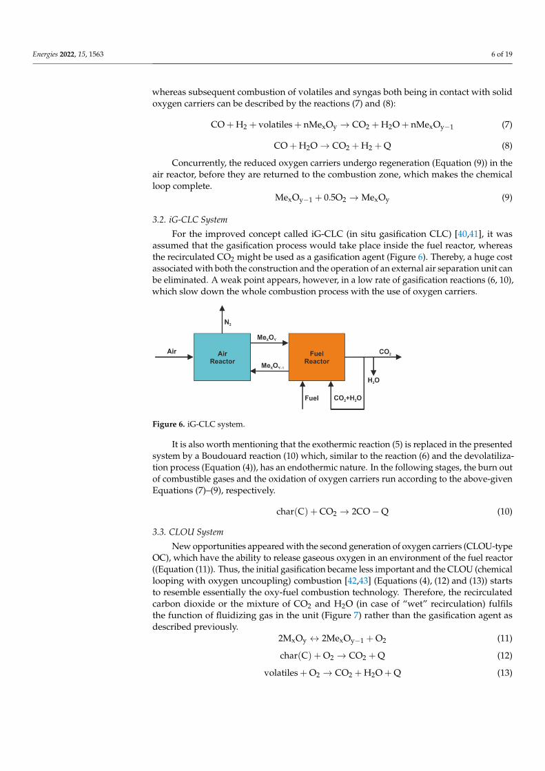
For the improved concept called iG-CLC (in situ gasification CLC) [40,41], it wasassumed that the gasification process would take place inside the fuel reactor, whereasthe recirculated CO2 might be used as a gasification agent (Figure 6). Thereby, a huge costassociated with both the construction and the operation of an external air separation unit canbe eliminated. A weak point appears, however, in a low rate of gasification reactions (6, 10),which slow down the whole combustion process with the use of oxygen carriers.
Energies 2022, 15, 1563 6 of 20
char C + H O → CO + H − Q (6)
whereas subsequent combustion of volatiles and syngas both being in contact with solid oxygen carriers can be described by the reactions (7) and (8): CO + H + volatiles + nMe O → CO + H O + nMe O (7) CO + H O → CO + H + Q (8)
Concurrently, the reduced oxygen carriers undergo regeneration (Equation (9)) in the air reactor, before they are returned to the combustion zone, which makes the chem-ical loop complete. Me O + 0.5O → Me O (9)
3.2. iG-CLC System For the improved concept called iG-CLC (in situ gasification CLC) [40,41], it was
assumed that the gasification process would take place inside the fuel reactor, whereas the recirculated CO2 might be used as a gasification agent (Figure 6). Thereby, a huge cost associated with both the construction and the operation of an external air separation unit can be eliminated. A weak point appears, however, in a low rate of gasification reactions (6, 10), which slow down the whole combustion process with the use of oxygen carriers.
Figure 6. iG-CLC system.
It is also worth mentioning that the exothermic reaction (5) is replaced in the pre-sented system by a Boudouard reaction (10) which, similar to the reaction (6) and the devolatilization process (Equation (4)), has an endothermic nature. In the following stages, the burn out of combustible gases and the oxidation of oxygen carriers run ac-cording to the above-given Equations (7)–(9), respectively. char C + CO → 2CO − Q (10)
3.3. CLOU System New opportunities appeared with the second generation of oxygen carriers
(CLOU-type OC), which have the ability to release gaseous oxygen in an environment of the fuel reactor ((Equation (11)). Thus, the initial gasification became less important and the CLOU (chemical looping with oxygen uncoupling) combustion [42,43] (Equations (4), (12) and (13)) starts to resemble essentially the oxy-fuel combustion technology. There-fore, the recirculated carbon dioxide or the mixture of CO2 and H2O (in case of “wet” re-circulation) fulfils the function of fluidizing gas in the unit (Figure 7) rather than the gas-ification agent as described previously.
Figure 6. iG-CLC system.
It is also worth mentioning that the exothermic reaction (5) is replaced in the presentedsystem by a Boudouard reaction (10) which, similar to the reaction (6) and the devolatiliza-tion process (Equation (4)), has an endothermic nature. In the following stages, the burn outof combustible gases and the oxidation of oxygen carriers run according to the above-givenEquations (7)–(9), respectively.
char(C) + CO2 → 2CO−Q (10)
3.3. CLOU System
New opportunities appeared with the second generation of oxygen carriers (CLOU-typeOC), which have the ability to release gaseous oxygen in an environment of the fuel reactor((Equation (11)). Thus, the initial gasification became less important and the CLOU (chemicallooping with oxygen uncoupling) combustion [42,43] (Equations (4), (12) and (13)) startsto resemble essentially the oxy-fuel combustion technology. Therefore, the recirculatedcarbon dioxide or the mixture of CO2 and H2O (in case of “wet” recirculation) fulfilsthe function of fluidizing gas in the unit (Figure 7) rather than the gasification agent asdescribed previously.
2MxOy ↔ 2MexOy−1 + O2 (11)
char(C) + O2 → CO2 + Q (12)
volatiles + O2 → CO2 + H2O + Q (13)
Energies 2022, 15, 1563 7 of 19Energies 2022, 15, 1563 7 of 20
Figure 7. CLOU system.
2M O ↔ 2Me O + O (11) char C + O → CO + Q (12) volatiles + O → CO + H O + Q (13)
It can be claimed thereby that the intensive investigations focused on inexpensive oxygen carriers with increased O2 transport capacity, improved reactivity, and high mechanical strength are currently of great importance for further accelerated develop-ment of the chemical looping combustion technology.
3.4. CLR System Another interesting concept based on the chemical looping idea is oriented towards
hydrogen production and it is widely known as chemical looping reforming (CLR) [46,47]. Two different techniques can be found under this name, which are Dry CLR and Steam CLR, where the fuel reactor is supplied with CO2 or H2O, respectively (Figure 8). Concurrently, oxygen is provided to the fuel reactor with the use of solid oxygen carriers and hence the whole gasification process can be described by the Equations (4) and (14) together with Equation (10) in the case of Dry CLR or Equation (6) for the steam-reforming method. volatiles + char + nMe O → CO + H + nMe O (14)
In the second stage, the products of aforementioned Equations (6), (10) and (14) are directed from the fuel reactor to the shift reactor (SR), where CO is converted into CO2 according to the following Equation (15): CO + H + H O → CO + 2H (15)
Moreover, two additional options are considered for the regeneration of oxygen carriers, which take into account the use of steam (Equation (16)) or CO2 (Equation (17)) instead of air (Equation (9)) that is usually utilized for this purpose in the air reactor (see: Figure 8). Me O + H O → Me O + H (16) Me O + CO → Me O + CO (17)
The biggest challenge seems to be, however, the selective oxygen carriers, which react very easily with carbon (conversion to CO) rather than with hydrogen and initially generated carbon monoxide. A very narrow group of such materials includes, among others, some ferrites (e.g., CaFe2O4 or BaFe2O4) [50,51]. It is also worth mentioning that the gasification reactions can be accelerated by the catalysts (e.g., Ni-Fe composites) [52,53] introduced directly into the fuel reactor, which is distinguished as a cata-
Figure 7. CLOU system.
It can be claimed thereby that the intensive investigations focused on inexpensiveoxygen carriers with increased O2 transport capacity, improved reactivity, and high me-chanical strength are currently of great importance for further accelerated development ofthe chemical looping combustion technology.
3.4. CLR System
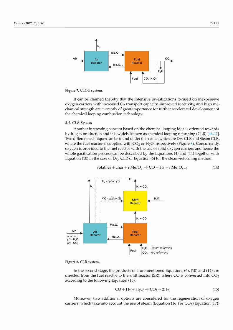
Another interesting concept based on the chemical looping idea is oriented towardshydrogen production and it is widely known as chemical looping reforming (CLR) [46,47].Two different techniques can be found under this name, which are Dry CLR and Steam CLR,where the fuel reactor is supplied with CO2 or H2O, respectively (Figure 8). Concurrently,oxygen is provided to the fuel reactor with the use of solid oxygen carriers and hence thewhole gasification process can be described by the Equations (4) and (14) together withEquation (10) in the case of Dry CLR or Equation (6) for the steam-reforming method.
volatiles + char + nMexOy → CO + H2 + nMexOy−1 (14)
Energies 2022, 15, 1563 8 of 20
lyst-assisted CLR technique. The results of the experimental investigations on CLR can be found in [54–57].
Figure 8. CLR system.
4. Chemical Looping Reactors Generally, three basic constructions of reactors are considered in order to put the
idea of chemical looping combustion into practice, which are as follows: • Dual fluidized-bed reactors [33,58,59]; • Swing reactors or fixed (packed) bed reactors [60,61]; • Rotary (rotating bed) reactors [62,63].
Each aforementioned design certainly has its advantages and disadvantages. Simi-larly, one has a facility for gaseous fuel combustion while the other can be easily adapted to burn solid fuels. Nevertheless, every construction should meet three common criteria, which finally affect the operation efficiency of the CLC unit. The first one concerns maintaining the oxygen carriers-to-fuel ratio by means of an appropriate recirculation rate (fluidized-bed reactors), oxidation–reduction sequence (swing reactors), and rota-tional speed (rotary reactors). Another issue involves the sufficient residence times of oxygen carriers in both air and fuel reactors, which influence the combustion process as well. The last question relates to the efficient capture of CO2, which is executed by the effective sealing of the sections with fuel conversion and oxygen carriers regeneration. This prevents gas (particularly CO2) from leaking between AR and FR as well as from char slipping into the air reactor.
4.1. Dual Fluidized-Bed Reactor Most of the CLC reactors presented in the literature are dual fluidized-bed (DFB)
reactors [33,58,59] of peculiar design. This is due to the high efficiency of fuel conversion of these reactors and their ability to burn solid fuels. Other advantages of this kind of reactor is the suitability for scaling-up [64,65], high throughout output capacity, and smooth operation [66]. On the other hand, the construction of DFB reactors is more so-phisticated and hence the operation appears to be more demanding compared with other designs mentioned above. Moreover, the mechanical attrition caused by moving particles may lead to serious problems, which are common for circulating fluidized bed units in general.
A dual fluidized-bed reactor consists of two combined reactors, which are the fuel reactor and the air reactor (Figure 9). The fuel reactor is fed with fuel being burnt with the help of oxygen carriers, which are further regenerated in the air reactor. Solids circulation
Figure 8. CLR system.
In the second stage, the products of aforementioned Equations (6), (10) and (14) aredirected from the fuel reactor to the shift reactor (SR), where CO is converted into CO2according to the following Equation (15):
CO + H2 + H2O→ CO2 + 2H2 (15)
Moreover, two additional options are considered for the regeneration of oxygencarriers, which take into account the use of steam (Equation (16)) or CO2 (Equation (17))
Energies 2022, 15, 1563 8 of 19
instead of air (Equation (9)) that is usually utilized for this purpose in the air reactor (see:Figure 8).
MexOy−1 + H2O→ MexOy + H2 (16)
MexOy−1 + CO2 → MexOy + CO (17)
The biggest challenge seems to be, however, the selective oxygen carriers, whichreact very easily with carbon (conversion to CO) rather than with hydrogen and initiallygenerated carbon monoxide. A very narrow group of such materials includes, amongothers, some ferrites (e.g., CaFe2O4 or BaFe2O4) [50,51]. It is also worth mentioning thatthe gasification reactions can be accelerated by the catalysts (e.g., Ni-Fe composites) [52,53]introduced directly into the fuel reactor, which is distinguished as a catalyst-assisted CLRtechnique. The results of the experimental investigations on CLR can be found in [54–57].
4. Chemical Looping Reactors
Generally, three basic constructions of reactors are considered in order to put the ideaof chemical looping combustion into practice, which are as follows:
• Dual fluidized-bed reactors [33,58,59];• Swing reactors or fixed (packed) bed reactors [60,61];• Rotary (rotating bed) reactors [62,63].
Each aforementioned design certainly has its advantages and disadvantages. Similarly,one has a facility for gaseous fuel combustion while the other can be easily adapted to burnsolid fuels. Nevertheless, every construction should meet three common criteria, whichfinally affect the operation efficiency of the CLC unit. The first one concerns maintainingthe oxygen carriers-to-fuel ratio by means of an appropriate recirculation rate (fluidized-bed reactors), oxidation–reduction sequence (swing reactors), and rotational speed (rotaryreactors). Another issue involves the sufficient residence times of oxygen carriers in both airand fuel reactors, which influence the combustion process as well. The last question relatesto the efficient capture of CO2, which is executed by the effective sealing of the sectionswith fuel conversion and oxygen carriers regeneration. This prevents gas (particularly CO2)from leaking between AR and FR as well as from char slipping into the air reactor.
4.1. Dual Fluidized-Bed Reactor
Most of the CLC reactors presented in the literature are dual fluidized-bed (DFB)reactors [33,58,59] of peculiar design. This is due to the high efficiency of fuel conversionof these reactors and their ability to burn solid fuels. Other advantages of this kind ofreactor is the suitability for scaling-up [64,65], high throughout output capacity, and smoothoperation [66]. On the other hand, the construction of DFB reactors is more sophisticatedand hence the operation appears to be more demanding compared with other designsmentioned above. Moreover, the mechanical attrition caused by moving particles may leadto serious problems, which are common for circulating fluidized bed units in general.
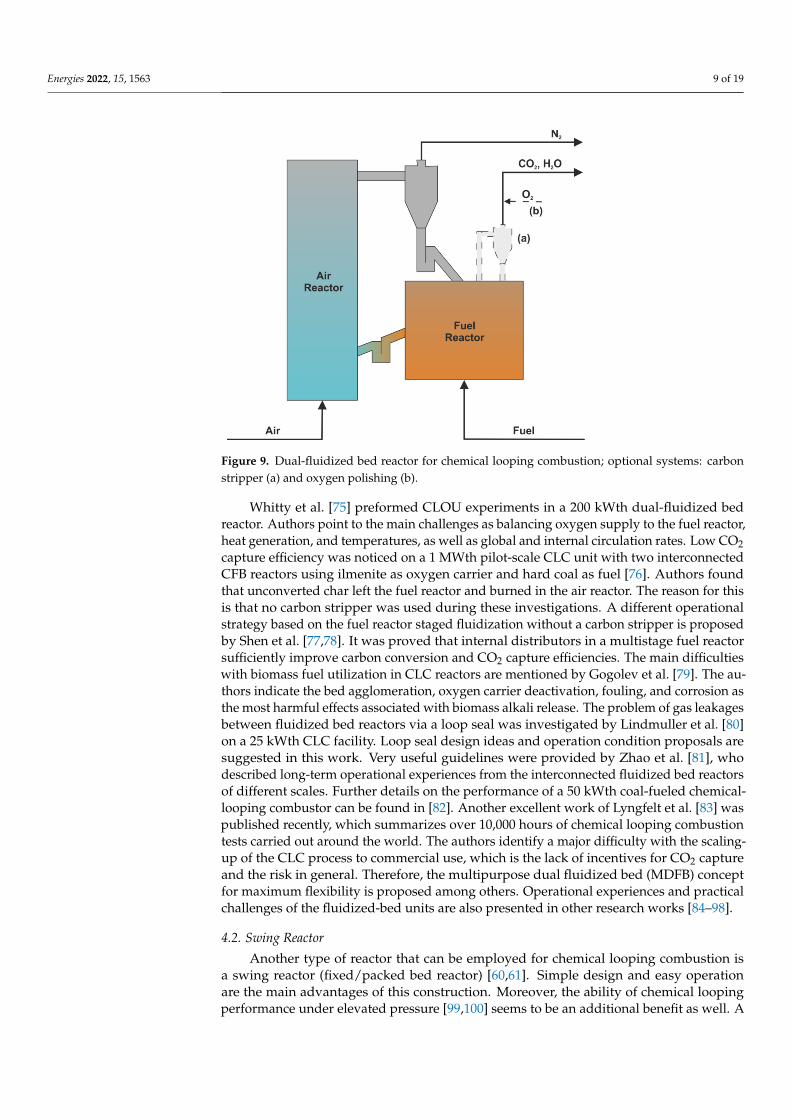
A dual fluidized-bed reactor consists of two combined reactors, which are the fuelreactor and the air reactor (Figure 9). The fuel reactor is fed with fuel being burnt with thehelp of oxygen carriers, which are further regenerated in the air reactor. Solids circulationbecomes possible due to the cyclone separator and two loop-seals installed between thereactors. Usually, the air reactor is operated under fast-fluidized bed (FFB) conditions,whereas the fuel reactor works in a regime of bubbling fluidized bed (BFB), however, thereare known constructions with FFB [67,68] or BFB [69] in both reactors. Moreover, CLCreactors are often equipped with a so-called carbon stripper (CS) system and/or oxygenpolishing (OP) system, both shown in Figure 9. The carbon stripper [70–72] is used toreturn unburned char back to the fuel reactor, whereas oxygen polishing [73,74] enables toburn out all combustibles remaining in the exhaust gases.
Energies 2022, 15, 1563 9 of 19
Energies 2022, 15, 1563 9 of 20
becomes possible due to the cyclone separator and two loop-seals installed between the reactors. Usually, the air reactor is operated under fast-fluidized bed (FFB) conditions, whereas the fuel reactor works in a regime of bubbling fluidized bed (BFB), however, there are known constructions with FFB [67,68] or BFB [69] in both reactors. Moreover, CLC reactors are often equipped with a so-called carbon stripper (CS) system and/or oxygen polishing (OP) system, both shown in Figure 9. The carbon stripper [70–72] is used to return unburned char back to the fuel reactor, whereas oxygen polishing [73,74] enables to burn out all combustibles remaining in the exhaust gases.
Figure 9. Dual-fluidized bed reactor for chemical looping combustion; optional systems: carbon stripper (a) and oxygen polishing (b).
Whitty et al. [75] preformed CLOU experiments in a 200 kWth dual-fluidized bed reactor. Authors point to the main challenges as balancing oxygen supply to the fuel re-actor, heat generation, and temperatures, as well as global and internal circulation rates. Low CO2 capture efficiency was noticed on a 1 MWth pilot-scale CLC unit with two in-terconnected CFB reactors using ilmenite as oxygen carrier and hard coal as fuel [76]. Authors found that unconverted char left the fuel reactor and burned in the air reactor. The reason for this is that no carbon stripper was used during these investigations. A different operational strategy based on the fuel reactor staged fluidization without a carbon stripper is proposed by Shen et al. [77,78]. It was proved that internal distributors in a multistage fuel reactor sufficiently improve carbon conversion and CO2 capture effi-ciencies. The main difficulties with biomass fuel utilization in CLC reactors are men-tioned by Gogolev et al. [79]. The authors indicate the bed agglomeration, oxygen carrier deactivation, fouling, and corrosion as the most harmful effects associated with biomass alkali release. The problem of gas leakages between fluidized bed reactors via a loop seal was investigated by Lindmuller et al. [80] on a 25 kWth CLC facility. Loop seal design ideas and operation condition proposals are suggested in this work. Very useful guide-lines were provided by Zhao et al. [81], who described long-term operational experiences from the interconnected fluidized bed reactors of different scales. Further details on the performance of a 50 kWth coal-fueled chemical-looping combustor can be found in [82]. Another excellent work of Lyngfelt et al. [83] was published recently, which summarizes over 10,000 hours of chemical looping combustion tests carried out around the world. The authors identify a major difficulty with the scaling-up of the CLC process to com-mercial use, which is the lack of incentives for CO2 capture and the risk in general.
Figure 9. Dual-fluidized bed reactor for chemical looping combustion; optional systems: carbonstripper (a) and oxygen polishing (b).
Whitty et al. [75] preformed CLOU experiments in a 200 kWth dual-fluidized bedreactor. Authors point to the main challenges as balancing oxygen supply to the fuel reactor,heat generation, and temperatures, as well as global and internal circulation rates. Low CO2capture efficiency was noticed on a 1 MWth pilot-scale CLC unit with two interconnectedCFB reactors using ilmenite as oxygen carrier and hard coal as fuel [76]. Authors foundthat unconverted char left the fuel reactor and burned in the air reactor. The reason for thisis that no carbon stripper was used during these investigations. A different operationalstrategy based on the fuel reactor staged fluidization without a carbon stripper is proposedby Shen et al. [77,78]. It was proved that internal distributors in a multistage fuel reactorsufficiently improve carbon conversion and CO2 capture efficiencies. The main difficultieswith biomass fuel utilization in CLC reactors are mentioned by Gogolev et al. [79]. The au-thors indicate the bed agglomeration, oxygen carrier deactivation, fouling, and corrosion asthe most harmful effects associated with biomass alkali release. The problem of gas leakagesbetween fluidized bed reactors via a loop seal was investigated by Lindmuller et al. [80]on a 25 kWth CLC facility. Loop seal design ideas and operation condition proposals aresuggested in this work. Very useful guidelines were provided by Zhao et al. [81], whodescribed long-term operational experiences from the interconnected fluidized bed reactorsof different scales. Further details on the performance of a 50 kWth coal-fueled chemical-looping combustor can be found in [82]. Another excellent work of Lyngfelt et al. [83] waspublished recently, which summarizes over 10,000 hours of chemical looping combustiontests carried out around the world. The authors identify a major difficulty with the scaling-up of the CLC process to commercial use, which is the lack of incentives for CO2 captureand the risk in general. Therefore, the multipurpose dual fluidized bed (MDFB) conceptfor maximum flexibility is proposed among others. Operational experiences and practicalchallenges of the fluidized-bed units are also presented in other research works [84–98].
4.2. Swing Reactor
Another type of reactor that can be employed for chemical looping combustion isa swing reactor (fixed/packed bed reactor) [60,61]. Simple design and easy operationare the main advantages of this construction. Moreover, the ability of chemical loopingperformance under elevated pressure [99,100] seems to be an additional benefit as well. A
Energies 2022, 15, 1563 10 of 19
weak point of swing reactors is, however, the readiness for gaseous fuel combustion only,therefore, in the case of solid fuels they need to be gasified in advance (see: SG-CLC system).
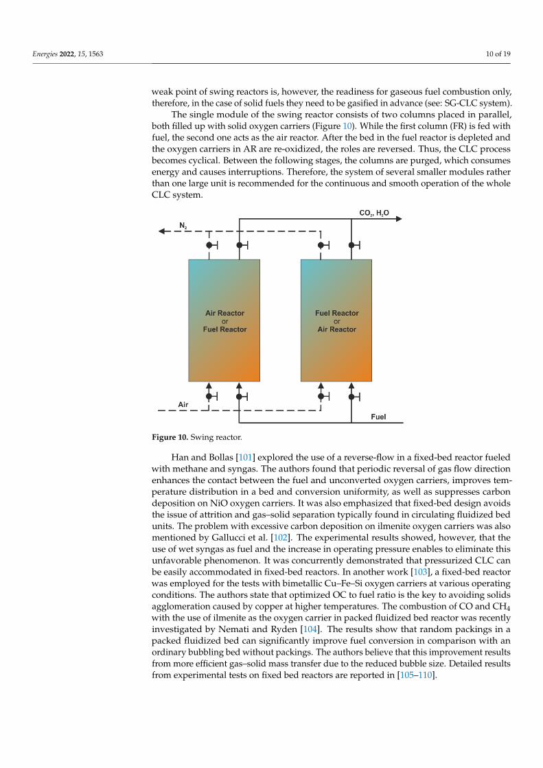
The single module of the swing reactor consists of two columns placed in parallel,both filled up with solid oxygen carriers (Figure 10). While the first column (FR) is fed withfuel, the second one acts as the air reactor. After the bed in the fuel reactor is depleted andthe oxygen carriers in AR are re-oxidized, the roles are reversed. Thus, the CLC processbecomes cyclical. Between the following stages, the columns are purged, which consumesenergy and causes interruptions. Therefore, the system of several smaller modules ratherthan one large unit is recommended for the continuous and smooth operation of the wholeCLC system.
Energies 2022, 15, 1563 10 of 20
Therefore, the multipurpose dual fluidized bed (MDFB) concept for maximum flexibility is proposed among others. Operational experiences and practical challenges of the flu-idized-bed units are also presented in other research works [84–98].
4.2. Swing Reactor Another type of reactor that can be employed for chemical looping combustion is a
swing reactor (fixed/packed bed reactor) [60,61]. Simple design and easy operation are the main advantages of this construction. Moreover, the ability of chemical looping per-formance under elevated pressure [99,100] seems to be an additional benefit as well. A weak point of swing reactors is, however, the readiness for gaseous fuel combustion only, therefore, in the case of solid fuels they need to be gasified in advance (see: SG-CLC sys-tem).
The single module of the swing reactor consists of two columns placed in parallel, both filled up with solid oxygen carriers (Figure 10). While the first column (FR) is fed with fuel, the second one acts as the air reactor. After the bed in the fuel reactor is de-pleted and the oxygen carriers in AR are re-oxidized, the roles are reversed. Thus, the CLC process becomes cyclical. Between the following stages, the columns are purged, which consumes energy and causes interruptions. Therefore, the system of several smaller modules rather than one large unit is recommended for the continuous and smooth operation of the whole CLC system.
Figure 10. Swing reactor.
Han and Bollas [101] explored the use of a reverse-flow in a fixed-bed reactor fueled with methane and syngas. The authors found that periodic reversal of gas flow direction enhances the contact between the fuel and unconverted oxygen carriers, improves tem-perature distribution in a bed and conversion uniformity, as well as suppresses carbon deposition on NiO oxygen carriers. It was also emphasized that fixed-bed design avoids the issue of attrition and gas–solid separation typically found in circulating fluidized bed units. The problem with excessive carbon deposition on ilmenite oxygen carriers was also mentioned by Gallucci et al. [102]. The experimental results showed, however, that the use of wet syngas as fuel and the increase in operating pressure enables to eliminate this unfavorable phenomenon. It was concurrently demonstrated that pressurized CLC can be easily accommodated in fixed-bed reactors. In another work [103], a fixed-bed reactor was employed for the tests with bimetallic Cu–Fe–Si oxygen carriers at various operating
Figure 10. Swing reactor.
Han and Bollas [101] explored the use of a reverse-flow in a fixed-bed reactor fueledwith methane and syngas. The authors found that periodic reversal of gas flow directionenhances the contact between the fuel and unconverted oxygen carriers, improves tem-perature distribution in a bed and conversion uniformity, as well as suppresses carbondeposition on NiO oxygen carriers. It was also emphasized that fixed-bed design avoidsthe issue of attrition and gas–solid separation typically found in circulating fluidized bedunits. The problem with excessive carbon deposition on ilmenite oxygen carriers was alsomentioned by Gallucci et al. [102]. The experimental results showed, however, that theuse of wet syngas as fuel and the increase in operating pressure enables to eliminate thisunfavorable phenomenon. It was concurrently demonstrated that pressurized CLC canbe easily accommodated in fixed-bed reactors. In another work [103], a fixed-bed reactorwas employed for the tests with bimetallic Cu–Fe–Si oxygen carriers at various operatingconditions. The authors state that optimized OC to fuel ratio is the key to avoiding solidsagglomeration caused by copper at higher temperatures. The combustion of CO and CH4with the use of ilmenite as the oxygen carrier in packed fluidized bed reactor was recentlyinvestigated by Nemati and Ryden [104]. The results show that random packings in apacked fluidized bed can significantly improve fuel conversion in comparison with anordinary bubbling bed without packings. The authors believe that this improvement resultsfrom more efficient gas–solid mass transfer due to the reduced bubble size. Detailed resultsfrom experimental tests on fixed bed reactors are reported in [105–110].
Energies 2022, 15, 1563 11 of 19
4.3. Rotary Reactor
Rotary reactors [62,63] are not investigated often compared with dual fluidized-bedreactors and swing reactors, despite a relatively high efficiency of fuel conversion. Thebiggest challenge in construction and operation of rotary reactors appears to be, however,the sealing of the following sections and parts being in continuous motion. These difficultieslead primarily to lower efficiency of CO2 capture as well as lower purity of exhaust gases.Moreover, this type of CLC unit is destined for gaseous fuel only.
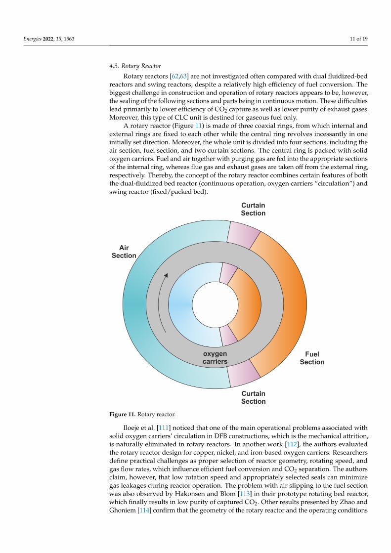
A rotary reactor (Figure 11) is made of three coaxial rings, from which internal andexternal rings are fixed to each other while the central ring revolves incessantly in oneinitially set direction. Moreover, the whole unit is divided into four sections, including theair section, fuel section, and two curtain sections. The central ring is packed with solidoxygen carriers. Fuel and air together with purging gas are fed into the appropriate sectionsof the internal ring, whereas flue gas and exhaust gases are taken off from the external ring,respectively. Thereby, the concept of the rotary reactor combines certain features of boththe dual-fluidized bed reactor (continuous operation, oxygen carriers “circulation”) andswing reactor (fixed/packed bed).
Energies 2022, 15, 1563 11 of 20
conditions. The authors state that optimized OC to fuel ratio is the key to avoiding solids agglomeration caused by copper at higher temperatures. The combustion of CO and CH4 with the use of ilmenite as the oxygen carrier in packed fluidized bed reactor was re-cently investigated by Nemati and Ryden [104]. The results show that random packings in a packed fluidized bed can significantly improve fuel conversion in comparison with an ordinary bubbling bed without packings. The authors believe that this improvement results from more efficient gas–solid mass transfer due to the reduced bubble size. De-tailed results from experimental tests on fixed bed reactors are reported in [105–110].
4.3. Rotary Reactor Rotary reactors [62,63] are not investigated often compared with dual fluidized-bed
reactors and swing reactors, despite a relatively high efficiency of fuel conversion. The biggest challenge in construction and operation of rotary reactors appears to be, howev-er, the sealing of the following sections and parts being in continuous motion. These dif-ficulties lead primarily to lower efficiency of CO2 capture as well as lower purity of ex-haust gases. Moreover, this type of CLC unit is destined for gaseous fuel only.
A rotary reactor (Figure 11) is made of three coaxial rings, from which internal and external rings are fixed to each other while the central ring revolves incessantly in one initially set direction. Moreover, the whole unit is divided into four sections, including the air section, fuel section, and two curtain sections. The central ring is packed with solid oxygen carriers. Fuel and air together with purging gas are fed into the appropriate sec-tions of the internal ring, whereas flue gas and exhaust gases are taken off from the ex-ternal ring, respectively. Thereby, the concept of the rotary reactor combines certain features of both the dual-fluidized bed reactor (continuous operation, oxygen carriers “circulation”) and swing reactor (fixed/packed bed).
Figure 11. Rotary reactor.
Iloeje et al. [111] noticed that one of the main operational problems associated with solid oxygen carriers’ circulation in DFB constructions, which is the mechanical attrition, is naturally eliminated in rotary reactors. In another work [112], the authors evaluated the rotary reactor design for copper, nickel, and iron-based oxygen carriers. Researchers define practical challenges as proper selection of reactor geometry, rotating speed, and gas flow rates, which influence efficient fuel conversion and CO2 separation. The authors
Figure 11. Rotary reactor.
Iloeje et al. [111] noticed that one of the main operational problems associated withsolid oxygen carriers’ circulation in DFB constructions, which is the mechanical attrition,is naturally eliminated in rotary reactors. In another work [112], the authors evaluatedthe rotary reactor design for copper, nickel, and iron-based oxygen carriers. Researchersdefine practical challenges as proper selection of reactor geometry, rotating speed, andgas flow rates, which influence efficient fuel conversion and CO2 separation. The authorsclaim, however, that low rotation speed and appropriately selected seals can minimizegas leakages during reactor operation. The problem with air slipping to the fuel sectionwas also observed by Hakonsen and Blom [113] in their prototype rotating bed reactor,which finally results in low purity of captured CO2. Other results presented by Zhao andGhoniem [114] confirm that the geometry of the rotary reactor and the operating conditions
Energies 2022, 15, 1563 12 of 19
will depend preliminary on the oxygen carrier properties. The OC kinetics together withthe inlet gas temperature and the operating pressure are identified as the most importantfactors in this work.
5. Competitiveness of CLC Technology
Chemical looping combustion technology offers almost pure carbon dioxide at theoutlet of the reactor, without any additional installations for gas separation. Therefore,dramatic reduction in CO2 emission into the atmosphere becomes possible with lower oper-ating and capital expenditures (OPEX and CAPEX, respectively) related to the whole powersystem [115,116]. Near-zero emission takes place when captured CO2 is subsequentlystored or utilized, which is described at the begging of this paper, however, even negativeCO2 emission is possible if only biomass is used as fuel [117,118]. Thus, the CLC techniquewith its inherent separation appears to be competitive for other pro-CCS technologies,which need advanced air separation units (oxy-fuel combustion and pre-combustion cap-ture) or post-processing CO2 capture unit (post-combustion capture). The comparison ofselected factors determined for both the CLC reactor and conventional circulating fluidizedbed (CFB) boiler integrated with post-combustion CO2 scrubber using monoethanolamine(MEA) is presented in Table 2 [119,120]. Moreover, the authors claim that the results ofanalyses carried out for the CFB-MEA case and the OXY-CFB case are very similar. The keydifference between a reference case (conventional CFB unit) and other examined pro-CCStechnologies is the CO2 capture facility, which significantly affects the net efficiency andother indices of the so-called near-zero emission power plants. A considerable discrepancy(more than 5 percentage points) between the net efficiencies of the CLC reactor and theCFB-MEA unit can be seen, which results mainly from the operation of the CO2 scrubbingsystem. Consequently, the energy penalty affects the cost of electricity production, whichis also shown in this chart. Another issue is the CO2 avoidance cost, which is higher by16 EUR/tCO2 for the CFB-MEA unit which means a significant increase of about 43%.
Table 2. Comparison of chemical looping combustion technology (CLC) with the amine absorptionmethod (MEA30%) with reference to a 630 MWe power unit with a fluidized bed boiler (CFB) (basedon [119,120]).
CFB Unit (Reference) MEA 30% CLC
Net power, MWe 630 630 630Net efficiency, % 44.9 34.9 40Coal consumption, t/h 198 255 222CAPEX, M EUR 1215 2064 1785OPEX, M EUR 156 220 206Cost of electricity, EUR/MWh 63 98 88CO2 avoidance cost, EUR/tCO2 - 53 37CO2 capture rate, % - >90 >90
The comparison of the SG-CLC concept with the pre-combustion CO2 capture tech-nology can be found in [116]. The net efficiency of 39.7% was determined for the CLCunit, which is about 2.6 percentage points more compared with the plant with the pre-combustion CO2 capture. Furthermore, the CO2 capture efficiency significantly exceeds thelevel of 90% in both evaluated cases. As a reference, a conventional integrated gasificationcombined cycle (IGCC) of the same fuel input energy (1127 MWth) was established, forwhich the net efficiency reaches 44.3% as it is not burdened by any CO2 capture systems.Very promising results can be also found in [121], where the achieved net efficiency penaltyis less than one percentage point for the integrated system of the CLOU reactor and CHPplant in comparison with the conventional reference plant with the same fuel input. Fur-thermore, the use of biomass as fuel allows the combined production of heat and powerwith the so-called negative emission of CO2. The potential of biomass combustion in theCLC plant with CCS is also noticed by Keller et al. [122]. In this study, chemical looping
Energies 2022, 15, 1563 13 of 19
combustion is benchmarked against a CFB process with post-combustion CO2 capture byamine scrubbing. The authors estimate, among other things, that for the plant of 50 MWthHHV fuel input, a cost reduction in the entire CLC-CCS chain can reach 17% over theCFB reference plant with an amine-scrubbing post-combustion capture process. Anotherinteresting evaluation of a poly-generation solar-assisted natural gas-fired CLC plant withwaste heat utilization using absorption chilling for cooling purposes was carried out byOgidiama et al. [123]. The authors claim that exhaust heat utilization significantly improvesthe overall efficiency of the combined power and cooling plant, which can exceed 63%. Fur-thermore, the integration with the solar system results in higher flexibility of the entire CLCplant. Other comprehensive techno-economic analyses of chemical looping combustiontechnologies can be found elsewhere [124–133]. The most recent study on a 550 MWe browncoal-fired CLC power plant is provided by Sayeed et al. [134]. The net efficiency penalty ofslightly more than five percentage points was obtained for a deeply integrated CLC systemin comparison with a conventional supercritical pulverized coal-fired power station of thesame net output. In conclusion, the authors state that for a considered commercial-scaleCLC power plant with 90% CO2 capture, an increase in the cost of electricity can be lowerthan 35%, which enables to meet the USDOE’s (United States Department of Energy) target.
6. Conclusions
A rising technology of chemical looping combustion (CLC) has untapped potentialto be used in zero CO2 emission power generation systems. The inherent separation thattakes place in the CLC reactors results in a highly reduced internal load of the plant, andhence the CLC technology can compete with other pro-CCS technologies such as oxy-fuelcombustion, pre-combustion capture, and post-combustion capture. However, it is still notmature enough for commercial implementation.
Key properties of currently considered oxygen carriers are provided, from which theCLOU feature seems to be crucial regarding direct solid fuel combustion. Innovative OCs asgeopolymer composites are also mentioned. Various kinds of chemical looping systems arepresented including those with external and internal gasification as well as one with directcombustion of solid fuels. Moreover, different designs of CLC reactors are shown includingdual fluidized-bed construction, which gives the best prospects for further development ofchemical looping combustion technology.
It is also noticed that ultimate utilization of the generated CO2 is essential for thisconcept, however, geological sequestration seems to be also necessary due to the globalvolume of greenhouse gas emissions. The greatest capabilities have EOR and EGR tech-nologies, but the production of carbon-based fuels and other chemicals appears to be ofgreat importance at present.
Author Contributions: Conceptualization, T.C.; resources, T.C., J.K., A.Z. and W.N.; writing—originaldraft preparation, T.C.; writing—review and editing, T.C., J.K. and A.Z.; visualization, T.C.; supervi-sion, W.N.; project administration, T.C.; funding acquisition, T.C. and W.N. All authors have read andagreed to the published version of the manuscript.
Funding: This study was funded from Norway Grants in the Polish-Norwegian Research Programmeoperated by the National Centre for Research and Development, project: Innovative Idea for Combustionof Solid Fuels via Chemical Looping Technology, agreement number POL-NOR/235083/104/2014. Thesupport is gratefully acknowledged. The work was also funded by the statute subvention of CzestochowaUniversity of Technology, Faculty of Infrastructure and Environment.
Institutional Review Board Statement: Not applicable.
Informed Consent Statement: Not applicable.
Data Availability Statement: Not applicable.
Conflicts of Interest: The authors declare no conflict of interest. The funders had no role in the designof the study; in the collection, analyses, or interpretation of data; in the writing of the manuscript, orin the decision to publish the results.
Energies 2022, 15, 1563 14 of 19
Nomenclature
AR Air reactorASU Air separation unitBFB Bubbling fluidized bedCAPEX Capital expendituresCCS Carbon capture and storageCCSU Carbon capture, storage, and utilizationCCU Carbon capture and utilizationCFB Circulating fluidized bedCLC Chemical looping combustionCLOU Chemical looping with oxygen uncouplingCLR Chemical looping reformingCS Carbon stripperDFB Dual fluidized bedEGR Enhanced gas recoveryEOR Enhanced oil recoveryFFB Fast fluidized bedFR Fuel reactorIGCC Integrated gasification combined cycleiG-CLC Incsitu gasification chemical looping combustionMDFB Multipurpose dual fluidized bedMEA MonoethanolamineOC Oxygen carrierOP Oxygen polishingOPEX Operating expendituresOTC Oxygen transport capacityOXY Oxy-fuel combustionSG-CLC Syngas chemical looping combustionSR Shift reactorUSDOE United States Department of Energy
References1. Sifat, N.S.; Haseli, Y. A critical review of CO2 capture technologies and prospects for clean power generation. Energies 2019,
12, 4143. [CrossRef]2. Cannone, S.F.; Lanzini, A.; Santarelli, M. A review on CO2 capture technologies with focus on CO2-enhanced methane recovery
from hydrates. Energies 2021, 14, 387. [CrossRef]3. Alalwan, H.A.; Alminshid, A.H. CO2 capturing methods: Chemical looping combustion (CLC) as a promising technique. Sci.
Total Environ. 2021, 788, 147850. [CrossRef]4. Madejski, P.; Chmiel, K.; Naveneethan, S.; Kus, T. Methods and techniques for CO2 capture: Review of potential solutions and
applications in modern energy technologies. Energies 2022, 15, 887. [CrossRef]5. Czakiert, T.; Zuwala, J.; Lasek, J. Oxy-fuel combustion: The state of the art. In Proceedings of the 12th International Conference
on Fluidized Bed Technology, Cracow, Poland, 23–27 May 2017; Nowak, W., Sciazko, M., Mirek, P., Eds.; Printing House of theRedemptorists: Tuchow, Poland, 2017.
6. Hossain, M.M.; de Lasa, H.I. Chemical-looping combustion (CLC) for inherent CO2 separations—A review. Chem. Eng. Sci. 2008,63, 4433–4451. [CrossRef]
7. Adanez, J.; Abad, A.; Garcia-Labiano, F.; Gayan, P.; de Diego, L.F. Progress in chemical-looping combustion and reformingtechnologies. Prog. Energy Combust. Sci. 2012, 38, 215–282. [CrossRef]
8. Anthony, E.J. Chemical-looping combustion systems and technology for carbon dioxide (CO2) capture in power plants. InDevelopments and Innovation in Carbon Dioxide (CO2) Capture and Storage Technology; Maroto-Valer, M.M., Ed.; Woodhead Publishing:Cambridge, UK, 2010; Volume 1, pp. 358–379.
9. Cao, C.; Liu, H.; Hou, Z.; Mehmood, F.; Liao, J.; Feng, W. A review of CO2 storage in view of safety and cost-effectiveness. Energies2020, 13, 600. [CrossRef]
10. Zheng, F.; Jahandideh, A.; Jha, B.; Jafarpour, B. Geologic CO2 storage optimization under geomechanical risk using coupled-physics models. Int. J. Greenh. Gas Control 2021, 110, 103385. [CrossRef]
11. Valluri, S.; Claremboux, V.; Kawatra, S. Opportunities and challenges in CO2 utilization. J. Environ. Sci. 2022, 113, 322–344.[CrossRef]
Energies 2022, 15, 1563 15 of 19
12. Zhang, Z.; Pan, S.-Y.; Li, H.; Cai, J.; Olabi, A.G.; Anthony, E.J.; Manovic, V. Recent advances in carbon dioxide utilization. Renew.Sustain. Energy Rev. 2020, 125, 109799. [CrossRef]
13. Liu, Z.-X.; Liang, Y.; Wang, Q.; Guo, Y.-J.; Gao, M.; Wang, Z.-B.; Liu, W.-L. Status and progress of worldwide EOR field applications.J. Pet. Sci. Eng. 2020, 193, 107449. [CrossRef]
14. Alvarado, V.; Manrique, E. Enhanced oil recovery: An update review. Energies 2010, 3, 1529–1575. [CrossRef]15. Lui, S.-Y.; Ren, B.; Li, H.-Y.; Yang, Y.-Z.; Wang, Z.-Q.; Wang, B.; Xu, J.-C.; Agarwal, R. CO2 storage with enhanced gas recovery
(CSEGR): A review of experimental and numerical studies. Pet. Sci. 2022, in press. [CrossRef]16. Hamza, A.; Hussein, I.A.; Al-Marri, M.J.; Mahmoud, M.; Shawabkeh, R.; Aparicio, S. CO2 enhanced gas recovery and sequestration
in depleted gas reservoirs: A review. J. Pet. Sci. Eng. 2021, 196, 107685. [CrossRef]17. Gur, T.M. Carbon dioxide emissions, capture, storage and utilization: Review of materials, processes and technologies. Prog.
Energy Combust. Sci. 2022, 89, 100965. [CrossRef]18. Eide, L.I.; Batum, M.; Dixon, T.; Elamin, Z.; Graue, A.; Hagen, S.; Havorka, S.; Nazarian, B.; Nokleby, P.H.; Olsen, G.I.;
et al. Enabling large-scale carbon capture, utilization, and storage (CCUS) using offshore carbon dioxide (CO2) infrastructuredevelopments—A review. Energies 2019, 12, 1945. [CrossRef]
19. Kamkeng, A.D.N.; Wang, M.; Hu, J.; Du, W.; Qian, F. Transformation technologies for CO2 utilisation: Current status, challengesand future prospects. Chem. Eng. J. 2021, 409, 128138. [CrossRef]
20. Alok, A.; Shrestha, R.; Ban, S.; Devkota, S.; Uprety, B.; Joshi, R. Technological advances in the transformative utilization of CO2 tovalue-added products. J. Environ. Chem. Eng. 2022, 10, 106922. [CrossRef]
21. Atsbha, T.A.; Yoon, T.; Seongho, P.; Lee, C.-J. A review on the catalytic conversion of CO2 using H2 for synthesis of CO, methanol,and hydrocarbons. J. CO2 Util. 2021, 44, 101413. [CrossRef]
22. Park, J.H.; Yang, J.; Kim, D.; Gim, H.; Choi, W.Y.; Lee, J.W. Review of recent technologies for transforming carbon dioxide tocarbon materials. Chem. Eng. J. 2022, 427, 130980. [CrossRef]
23. Lee, M.; Kim, Y.; Suk Lim, H.; Jo, A.; Kang, D.; Lee, J.W. Reverse water-gas shift chemical looping using a core-shell structuredperovskite oxygen carrier. Energies 2020, 13, 5324. [CrossRef]
24. Gorke, R.H.; Marek, E.J.; Donat, F.; Scott, S.A. Reduction and oxidation behavior of strontium perovskites for chemical looping airseparation. Int. J. Greenh. Gas Control 2020, 94, 102891. [CrossRef]
25. Miccio, F.; Bendoni, R.; Piancastelli, A.; Medri, V.; Landi, E. Geopolymer composites for chemical looping combustion. Fuel 2018,225, 436–442. [CrossRef]
26. Bendoni, R.; Miccio, F.; Medri, V.; Landi, E. Chemical looping combustion using geopolymer-based oxygen carriers. Chem. Eng. J.2018, 341, 187–197. [CrossRef]
27. Murri, A.N.; Miccio, F.; Medri, V.; Landi, E. Geopolymer-composites with thermomechanical stability as oxygen carriers forfluidized bed chemical looping combustion with oxygen uncoupling. Chem. Eng. J. 2020, 393, 124756. [CrossRef]
28. Hildor, F.; Mattisson, T.; Leion, H.; Linderholm, C.; Ryden, M. Steel converter slag as an oxygen carrier in a 12 MWth CFBboiler—Ash interaction and material evolution. Int. J. Greenh. Gas Control 2019, 88, 321–331. [CrossRef]
29. Liu, L.; Li, Z.; Li, W.; Cai, N. The melting characteristics of Vietnamese ilmenite and manganese ores used in chemical loopingcombustion. Int. J. Greenh. Gas Control 2019, 90, 102792. [CrossRef]
30. Rumble, J.R. Handbook of Chemistry and Physics, 99th ed.; CRC Press Taylor & Francis Group: Boca Raton, FL, USA, 2018.31. Idziak, K.; Czakiert, T.; Krzywanski, J.; Zylka, A.; Kozlowska, M.; Nowak, W. Safety and environmental reasons for the use of Ni-,
Co-, Cu-, Mn- and Fe-based oxygen carriers in CLC/CLOU applications: An overview. Fuel 2020, 268, 117245. [CrossRef]32. Thorne, R.J.; Bouman, E.A.; Sundseth, K.; Aranda, A.; Czakiert, T.; Pacyna, J.M.; Pacyna, E.G.; Krauz, M.; Celinska, A. Environ-
mental impacts of a chemical looping combustion power plant. Int. J. Greenh. Gas Control 2019, 86, 101–111. [CrossRef]33. Mattisson, T.; Keller, M.; Linderholm, C.; Moldenhauer, P.; Ryden, M.; Leion, H.; Lyngfelt, A. Chemical-looping technologies
using circulating fluidized bed systems: Status of development. Fuel Process. Technol. 2018, 172, 1–12. [CrossRef]34. Cho, P.; Mattisson, T.; Lyngfelt, A. Comparison of iron-, nickel-, copper- and manganese-based oxygen carriers for chemical-
looping combustion. Fuel 2004, 83, 1215–1225. [CrossRef]35. Lyngfelt, A. Oxygen carriers for chemical-looping combustion. In Calcium and Chemical Looping Technology for Power Generation
and Carbon Dioxide (CO2) Capture; Fennell, P., Anthony, B., Eds.; Woodhead Publishing: Cambridge, UK, 2015; pp. 221–254.36. Adanez, J.; de Diego, L.F.; Garcia-Labiano, F.; Gayan, P.; Abad, A.; Palacios, J.M. Selection of oxygen carriers for chemical
combustion. Energy Fuels 2004, 18, 371–377. [CrossRef]37. U.S. Department of the Interior and U.S. Geological Survey. Mineral Commodity Summaries 2018. U.S. Geological Survey; U.S.
Department of the Interior and U.S. Geological Survey: Reston, VA, USA, 2018.38. Dueso, C.; Garcia-Labiano, F.; Adanez, J.; de Diego, L.F.; Gayan, P.; Abad, A. Syngas combustion in a chemical-looping combustion
system using an impregnated Ni-based oxygen carrier. Fuel 2009, 88, 2357–2364. [CrossRef]39. Tian, H.; Chaudhari, K.; Simonyi, T.; Poston, J.; Liu, T.; Sanders, T.; Veser, G.; Siriwardane, R. Chemical-looping combustion of
coal-derived synthesis gas over copper oxide oxygen carriers. Energy Fuels 2008, 22, 3744–3755. [CrossRef]40. Cuadrat, A.; Abad, A.; Garcia-Labiano, F.; Gayan, P.; de Diego, L.F.; Adanez, J. Relevance of the coal rank on the performance of
the in situ gasification chemical-looping combustion. Chem. Eng. J. 2012, 195–196, 91–102. [CrossRef]41. Shen, Z.; Huang, Z. High-efficiency and pollution-controlling in-situ gasification chemical looping combustion system by using
CO2 instead of steam as gasification agent. Chin. J. Chem. Eng. 2018, 26, 2368–2376. [CrossRef]
Energies 2022, 15, 1563 16 of 19
42. Adanez-Rubio, I.; Abad, A.; Gayan, P.; de Diego, L.F.; Garcia-Labiano, F.; Adanez, J. Performance of CLOU process in thecombustion of different types of coal with CO2 capture. Int. J. Greenh. Gas Control 2013, 12, 430–440. [CrossRef]
43. Mattisson, T.; Lyngfelt, A.; Leion, H. Chemical-looping with oxygen uncoupling for combustion of solid fuels. Int. J. Greenh. GasControl 2009, 3, 11–19. [CrossRef]
44. Strohle, J.; Galloy, A.; Epple, B. Feasibility study on the carbonate looping process for post-combustion CO2 capture fromcoal-fired power plants. Energy Procedia 2009, 1, 1313–1320. [CrossRef]
45. Martinez, A.; Lisbona, P.; Lara, Y.; Romeo, L.M. Carbonate looping cycle for CO2 capture: Hydrodynamic of complex CFBsystems. Energy Procedia 2011, 4, 410–416. [CrossRef]
46. Luo, M.; Yi, Y.; Wang, S.; Wang, Z.; Du, M.; Pan, J.; Wang, Q. Review of hydrogen production using chemical-looping technology.Renew. Sustain. Energy Rev. 2018, 81, 3186–3214. [CrossRef]
47. Ryden, M.; Lyngfelt, A. Using steam reforming to produce hydrogen with carbon dioxide capture by chemical-looping combustion.Int. J. Hydrogen Energy 2006, 31, 1271–1283. [CrossRef]
48. Mattisson, T.; Lyngfelt, A.; Cho, P. The use of iron oxide as an oxygen carrier in chemical-looping combustion of methane withinherent separation of CO2. Fuel 2001, 80, 1953–1962. [CrossRef]
49. de Diego, L.F.; Garcia-Labiano, F.; Adanez, J.; Gayan, P.; Abad, A.; Corbella, B.M.; Palacios, J.M. Development of Cu-based oxygencarriers for chemical-looping combustion. Fuel 2004, 83, 1749–1757. [CrossRef]
50. Siriwardane, R.; Monazam, E.; Miller, D.; Poston, J.; Richards, G. Production of CO and hydrogen via chemical looping gasificationof coal with calcium ferrite and oxidation with steam. In Proceedings of the 5th International Conference on Chemical Looping,Park City, UT, USA, 24–27 September 2018.
51. Abad, A. Chemical looping for hydrogen production. In Calcium and Chemical Looping Technology for Power Generation and CarbonDioxide (CO2) Capture; Fennell, P., Anthony, B., Eds.; Woodhead Publishing: Cambridge, UK, 2015; pp. 327–374.
52. Hu, J.; Galvita, V.V.; Poelman, H.; Marin, G.B. Catalyst-assisted chemical looping auto-thermal dry reforming: The effectof operating pressure. In Proceedings of the 5th International Conference on Chemical Looping, Park City, UT, USA, 24–27September 2018.
53. Tang, M.; Liu, K.; Roddick, D.M.; Fan, M. Enhanced lattice oxygen reactivity over Fe2O3/Al2O3 redox catalyst for chemical-looping dry (CO2) reforming of CH4: Synergistic La-Ce effect. J. Catal. 2018, 368, 38–52. [CrossRef]
54. De Vos, Y.; Vamvakeros, A.; Matras, D.; Jacobs, M.; Van Der Voort, P.; Van Driessche, I.; Jacques, S.; Middelkoop, V.; Verberckmoes,A. Sustainable iron-based oxygen carriers for hydrogen production—Real-time operando investigation. Int. J. Greenh. Gas Control2019, 88, 393–402. [CrossRef]
55. Ugwu, A.; Zaabout, A.; Amini, S. An advancement in CO2 utilization through novel gas switching dry reforming. Int. J. Greenh.Gas Control 2019, 90, 102791. [CrossRef]
56. Shen, T.; Ge, H.; Shen, L. Characterization of combined Fe-Cu oxides as oxygen carrier in chemical looping gasification of biomass.Int. J. Greenh. Gas Control 2018, 75, 63–73. [CrossRef]
57. Wu, J.; Bai, L.; Tian, H.; Riley, J.; Siriwardane, R.; Wang, Z.; He, T.; Li, J.; Zhang, J.; Wu, J. Chemical looping gasification of ligninwith bimetallic oxygen carriers. Int. J. Greenh. Gas Control 2020, 93, 102897. [CrossRef]
58. Song, T.; Shen, L. Review of reactor for chemical looping combustion of solid fuels. Int. J. Greenh. Gas Control 2018, 76, 92–110.[CrossRef]
59. Zhou, Y.; Yang, L.; Lu, Y.; Hu, X.; Luo, X.; Chen, H.; Wang, J.; Yang, Y. Control of pressure balance and solids circulationcharacteristics in DCFB reactors. Powder Technol. 2018, 328, 114–121. [CrossRef]
60. Noorman, S.; van Sint Annaland, M.; Kuipers, H. Packed bed reactor technology for chemical-looping combustion. Ind. Eng.Chem. Res. 2007, 46, 4212–4220. [CrossRef]
61. Fernandez, J.R.; Alarcon, J.M. Chemical looping combustion process in fixed-bed reactors using ilmenite as oxygen carrier:Conceptual design and operation strategy. Chem. Eng. J. 2015, 264, 797–806. [CrossRef]
62. Zhao, Z.; Iloeje, C.O.; Chen, T.; Ghoniem, A.F. Design of a rotary reactor for chemical-looping combustion. Part 1: Fundamentalsand design methodology. Fuel 2014, 121, 327–343. [CrossRef]
63. Hakonsen, S.F.; Grande, C.A.; Blom, R. Rotating bed reactor for CLC: Bed characteristics dependences on internal gas mixing.Appl. Energy 2014, 113, 1952–1957. [CrossRef]
64. Kolbitsch, P.; Bolhar-Nordenkampf, J.; Proll, T.; Hofbauer, H. Operating experience with chemical looping combustion in a 120 kWdual circulating fluidized bed (DCFB) unit. Int. J. Greenh. Gas Control 2010, 4, 180–185. [CrossRef]
65. Lyngfelt, A.; Leckner, B. A 1000 MWth boiler for chemical-looping combustion of solid fuels—Discussion of design and costs.Appl. Energy 2015, 157, 475–487. [CrossRef]
66. Bayham, S.; Straub, D.; Weber, J. Operation of a 50-kWth chemical looping combustion test facility under autothermal conditions.Int. J. Greenh. Gas Control 2019, 87, 211–220. [CrossRef]
67. Kolbitsch, P.; Bolhar-Nordenkampf, J.; Proll, T.; Hofbauer, H. Design of a chemical looping combustor using a dual circulatingfluidized bed (DCFB) reactor system. In Proceedings of the 9th International Conference on Circulating Fluidized Beds, Hamburg,Germany, 13–16 May 2008; Werther, J., Nowak, W., Wirth, K.-E., Hartge, E.-U., Eds.; TuTech Innovation GmbH: Hamburg,Germany, 2008.
68. Chen, X.; Ma, J.; Tian, X.; Wan, J.; Zhao, H. CPFD simulation and optimization of a 50 kWth dual circulating fluidized bed reactorfor chemical looping combustion of coal. Int. J. Greenh. Gas Control 2019, 90, 102800. [CrossRef]
Energies 2022, 15, 1563 17 of 19
69. Adanez, J.; Gayan, P.; Celaya, J.; de Diego, L.F.; Garcia-Labiano, F.; Abad, A. Chemical looping combustion in a 10 kWth prototypeusing a CuO/Al2O3 oxygen carrier: Effect of operating conditions on methane combustion. Ind. Eng. Chem. Res. 2006, 45,6075–6080. [CrossRef]
70. Chen, H.; Cheng, M.; Liu, L.; Li, Y.; Li, Z.; Cai, N. Coal-fired chemical looping combustion coupled with a high-efficiency annualcarbon stripper. Int. J. Greenh. Gas Control 2020, 93, 102889. [CrossRef]
71. Nasah, J.; Jensen, B.; Dyrstad-Cincotta, N.; Gerber, J.; Laudal, D.; Mann, M.; Srinivasachar, S. Method for separation of coalconversion products from oxygen carriers. Int. J. Greenh. Gas Control 2019, 88, 361–370. [CrossRef]
72. Gong, Y.; Wang, X.; Chen, D.; Al-Qadri, B.M.H. Retrospect and prospect of carbon stripper technology in solid-fuel chemicallooping combustion. Fuel Process. Technol. 2021, 221, 106920. [CrossRef]
73. Mei, D.; Linderholm, C.; Lyngfelt, A. Performance on an oxy-polishing step in the 100 kWth chemical looping combustionprototype. Chem. Eng. J. 2021, 409, 128202. [CrossRef]
74. Perez-Vega, R.; Abad, A.; Garcia-Labiano, F.; Gayan, P.; de Diego, L.F.; Adanez, J. Coal combustion in a 50 kWth chemical loopingcombustion unit: Seeking operating conditions to maximize CO2 capture and combustion efficiency. Int. J. Greenh. Gas Control2016, 50, 80–92. [CrossRef]
75. Whitty, K.J.; Hamilton, M.A.; Merrett, K.M.; Lighty, J.S. Performance of a dual fluidized bed reactor for chemical loopingcombustion with oxygen uncoupling. In Proceedings of the 12th International Conference on Fluidized Bed Technology, Cracow,Poland, 23–27 May 2017; Nowak, W., Sciazko, M., Mirek, P., Eds.; Printing House of the Redemptorists: Tuchow, Poland, 2017.
76. Ohlemuller, P.; Busch, J.P.; Reitz, M.; Strohle, J.; Epple, B. Chemical-looping combustion of hard coal: Autothermal operation of a1 MWth pilot plant. J. Energy Resour. Technol. 2016, 137, 042203. [CrossRef]
77. Shen, T.; Wang, S.; Yan, J.; Shen, L.; Tian, H. Performance improvement of chemical looping combustion with coal by optimizingoperational strategies in a 3 kWth interconnected fluidized bed. Int. J. Greenh. Gas Control 2020, 98, 103060. [CrossRef]
78. Zhu, X.; Shen, T.; Bollas, G.; Shen, L. Design and operation of a multi-stage reactor system for chemical looping combustionprocess. Fuel Process. Technol. 2021, 215, 106748. [CrossRef]
79. Gogolev, I.; Linderholm, C.; Gall, D.; Schmitz, M.; Mattisson, T.; Pettersson, J.B.C.; Lyngfelt, A. Chemical-looping combustion in a100 kW unit using a mixture of synthetic and natural oxygen carriers—Operational results and fate of biomass fuel alkali. Int. J.Greenh. Gas Control 2019, 88, 371–382. [CrossRef]
80. Lindmuller, L.; Haus, J.; Nair, A.R.K.; Heinrich, S. Minimizing gas leakages in a system of coupled fluidized bed reactors forchemical looping combustion. Chem. Eng. Sci. 2022, 250, 117366. [CrossRef]
81. Zhao, H.; Tian, X.; Ma, J.; Su, M.; Wang, B.; Mei, D. Development of tailor-made oxygen carriers and reactors for chemical loopingprocesses at Huazhong University of Science & Technology. Int. J. Greenh. Gas Control 2020, 93, 102898. [CrossRef]
82. Ma, J.; Tian, X.; Wang, C.; Chen, X.; Zhao, H. Performance of a 50 kWth coal-fuelled chemical looping combustor. Int. J. Greenh.Gas Control 2018, 75, 98–106. [CrossRef]
83. Lyngfelt, A.; Brink, A.; Langorgen, O.; Mattisson, T.; Ryden, M.; Linderholm, C. 11,000 h of chemical-looping combustionoperation—Where are we and where do we want to go? Int. J. Greenh. Gas Control 2019, 88, 38–56. [CrossRef]
84. Hallberg, P.; Hanning, M.; Ryden, M.; Mattisson, T.; Lyngfelt, A. Investigation of a calcium manganite as oxygen carrier during99 h of operation of chemical-looping combustion in a 10 kWth reactor unit. Int. J. Greenh. Gas Control 2016, 53, 222–229. [CrossRef]
85. Moldenhauer, P.; Ryden, M.; Mattisson, T.; Lyngfelt, A. Chemical-looping combustion and chemical-looping reforming of kerosenein a circulating fluidized-bed 300 W laboratory reactor. Int. J. Greenh. Gas Control 2012, 9, 1–9. [CrossRef]
86. Vilches, T.B.; Lind, F.; Ryden, M.; Thunman, H. Experience of more than 1000 h of operation with oxygen carriers and solidbiomass at large scale. Appl. Energy 2017, 190, 1174–1183. [CrossRef]
87. Siriwardane, R.; Benincosa, W.; Riley, J.; Tian, H.; Richards, G. Investigation of reactions in a fluidized bed reactor during chemicallooping combustion of coal/steam with copper oxide-iron oxide-alumina oxygen carrier. Appl. Energy 2016, 183, 1550–1564.[CrossRef]
88. Xu, L.; Sun, H.; Li, Z.; Cai, N. Experimental study of copper modified manganese ores as oxygen carriers in a dual fluidized bedreactor. Appl. Energy 2016, 162, 940–947. [CrossRef]
89. Ma, J.; Zhao, H.; Tian, X.; Wei, Y.; Rajendran, S.; Zhang, Y.; Bhattacharya, S.; Zheng, C. Chemical looping combustion of coal in a5 kWth interconnected fluidized bed reactor using hematite as oxygen carrier. Appl. Energy 2015, 157, 304–313. [CrossRef]
90. Cuadrat, A.; Abad, A.; Garcia-Labiano, F.; Gayan, P.; de Diego, L.F.; Adanez, J. Effect of operating conditions in chemical-loopingcombustion of coal in a 500 Wth unit. Int. J. Greenh. Gas Control 2012, 6, 153–163. [CrossRef]
91. Schmitz, M.; Linderholm, C.J.; Lyngfelt, A. Chemical looping combustion of four different solid fuels using a manganese-silicon-titanium oxygen carrier. Int. J. Greenh. Gas Control 2018, 70, 88–96. [CrossRef]
92. Abad, A.; Adanez-Rubio, I.; Gayan, P.; Garcia-Labiano, F.; de Diego, L.F.; Adanez, J. Demonstration of chemical-looping withoxygen uncoupling (CLOU) process in a 1.5 kWth continuously operating unit using a Cu-based oxygen-carrier. Int. J. Greenh.Gas Control 2012, 6, 189–200. [CrossRef]
93. Strohle, J.; Orth, M.; Epple, B. Chemical looping combustion of hard coal in a 1 MWth pilot plant using ilmenite as oxygen carrier.Appl. Energy 2015, 157, 288–294. [CrossRef]
94. Mei, D.; Soleimanisalim, A.H.; Linderholm, C.; Lyngfelt, A.; Mattisson, T. Reactivity and lifetime assessment of an oxygenreleasable manganese ore with biomass fuels in a 10 kWth pilot rig for chemical looping combustion. Fuel Process. Technol. 2021,215, 106743. [CrossRef]
Energies 2022, 15, 1563 18 of 19
95. Moldenhauer, P.; Ryden, M.; Mattisson, T.; Younes, M.; Lyngfelt, A. The use of ilmenite as oxygen carrier with kerosene in a 300 WCLC laboratory reactor with continuous circulation. Appl. Energy 2014, 113, 1846–1854. [CrossRef]
96. Pishahang, M.; Larring, Y.; Stensrod, R.E.; Andreassen, K.A.; Spjelkavik, A.I. 3 kW circulating fluidized bed chemical loopingreactor—A thermochemical and chemomechanical investigation on the performance of Cu- impregnated Al2O3 as an oxygencarrier material. Int. J. Greenh. Gas Control 2021, 109, 103384. [CrossRef]
97. Idziak, K.; Czakiert, T.; Krzywanski, J.; Zylka, A.; Nowak, W. Studies on solids flow in a cold model of a dual fluidized bedreactor for chemical looping combustion of solid fuels. J. Energy Resour. Technol. 2020, 142, 022102. [CrossRef]
98. Abad, A.; Gayan, P.; Garcia-Labiano, F.; de Diego, L.F.; Adanez, J. Relevance of plant design on CLC process performance using aCu-based oxygen carrier. Fuel Process. Technol. 2018, 171, 78–88. [CrossRef]
99. Xiao, R.; Song, Q.; Song, M.; Lu, Z.; Zhang, S.; Shen, L. Pressurized chemical-looping combustion of coal with an iron ore-basedoxygen carrier. Combust. Flame 2010, 157, 1140–1153. [CrossRef]
100. Zaabout, A.; Cloete, S.; Tolchard, J.R.; Amini, S. A pressurized gas switching combustion reactor: Autothermal operation with aCaMnO3-δ-based oxygen carrier. Chem. Eng. Res. Des. 2018, 137, 20–32. [CrossRef]
101. Han, L.; Bollas, G.M. Chemical-looping combustion in a reverse-flow fixed bed reactor. Energy 2016, 102, 669–681. [CrossRef]102. Gallucci, F.; Hamers, H.P.; van Zanten, M.; van Sint Annaland, M. Experimental demonstration of chemical-looping combustion
of syngas in packed bed reactors with ilmenite. Chem. Eng. J. 2015, 274, 156–168. [CrossRef]103. Wang, P.; Howard, B.; Means, N. Investigation of reactivities of bimetallic Cu-Fe oxygen carriers with coal in high temperature
in-situ gasification chemical-looping combustion (iG-CLC) and chemical-looping with oxygen uncoupling (CLOU) using a fixedbed reactor. Fuel 2021, 285, 119012. [CrossRef]
104. Nemati, N.; Ryden, M. Chemical-looping combustion in packed-fluidized beds: Experiments with random packings in bubblingbed. Fuel Process. Technol. 2021, 222, 106978. [CrossRef]
105. Tian, Q.; Che, L.; Ding, B.; Wang, Q.; Su, Q. Performance of Cu-based oxygen carrier in a CLC process based on fixed bed reactors.Greenh. Gases Sci. Technol. 2017, 7, 731–744. [CrossRef]
106. Tian, Q.; Che, L.; Ding, B.; Wang, Q.; Su, Q. Performance of a Cu–Fe-based oxygen carrier combined with a Ni-based oxygencarrier in a chemical-looping combustion process based on fixed-bed reactors. Greenh. Gases Sci. Technol. 2018, 8, 542–556.[CrossRef]
107. Kooiman, R.F.; Hamers, H.P.; Gallucci, F.; van Sint Annaland, M. Experimental demonstration of two-stage packed bed chemical-looping combustion using syngas with CuO/Al2O3 and NiO/CaAl2O4 as oxygen carriers. Ind. Eng. Chem. Res. 2015, 54,2001–2011. [CrossRef]
108. Wang, K.; Yu, Q.; Qin, Q.; Zuo, Z.; Wu, T. Evaluation of Cu-based oxygen carrier for chemical looping air separation in a fixed-bedreactor. Chem. Eng. J. 2016, 287, 292–301. [CrossRef]
109. Tilland, A.; Prieto, J.; Petitjean, D.; Schaer, E. Study and analyses of a CLC oxygen carrier degradation mechanism in a fixed bedreactor. Chem. Eng. J. 2016, 302, 619–632. [CrossRef]
110. Hamers, H.P.; Gallucci, F.; Williams, G.; van Sint Annaland, M. Experimental demonstration of CLC and the pressure effect inpacked bed reactors using NiO/CaAl2O4 as oxygen carrier. Fuel 2015, 159, 828–836. [CrossRef]
111. Iloeje, C.O.; Zhao, Z.; Ghoniem, A.F. Design and techno-economic optimization of a rotary chemical looping combustion powerplant with CO2 capture. Appl. Energy 2018, 231, 1179–1190. [CrossRef]
112. Iloeje, C.O.; Zhao, Z.; Ghoniem, A.F. A reduced fidelity model for the rotary chemical looping combustion. Appl. Energy 2017, 190,725–739. [CrossRef]
113. Hakonsen, S.F.; Blom, R. Chemical looping combustion in a rotating bed reactor—Finding optimal process conditions forprototype reactor. Environ. Sci. Technol. 2011, 45, 9611–9626. [CrossRef] [PubMed]
114. Zhao, Z.; Ghoniem, A.F. Design of a rotary reactor for chemical-looping combustion. Part 2: Comparison of copper-, nickel-, andiron-based oxygen carriers. Fuel 2014, 121, 344–360. [CrossRef]
115. Ekstrom, C.; Schwendig, F.; Biede, O.; Franco, F.; Haupt, G.; de Koeijer, G.; Papapavlou, C.; Rokke, P.E. Techno-economicevaluations and benchmarking of pre-combustion CO2 capture and oxy-fuel processes developed in the European ENCAPproject. Energy Procedia 2009, 1, 4233–4240. [CrossRef]
116. Mukherjee, S.; Kumar, P.; Yang, A.; Fennell, P. Energy and exergy analysis of chemical looping combustion technology andcomparison with pre-combustion and oxy-fuel combustion technologies for CO2 capture. J. Environ. Chem. Eng. 2015, 3,2104–2114. [CrossRef]
117. Mendiara, T.; Garcia-Labiano, F.; Abad, A.; Gayan, P.; de Diego, L.F.; Izquierdo, M.T.; Adanez, J. Negative CO2 emissions throughthe use of biofuels in chemical looping technology: A review. Appl. Energy 2018, 232, 657–684. [CrossRef]
118. Coppola, A.; Scala, F. Chemical looping for combustion of solid biomass: A review. Energy Fuels 2021, 35, 19248–19265. [CrossRef]119. Gauthier, T.; Yazdanpanah, M.; Forret, A.; Amblard, B.; Lambert, A.; Bertholin, S. CLC, a promising concept with challenging
development issues. In Proceedings of the 15th International Conference on Fluidization, Fluidization XV, Montebello, QC,Canada, 22–27 May 2016; Chaouki, J., Berruti, F., Bi, X., Cocco, R., Eds.; ECI Symposium Series: New York, NY, USA, 2016.
120. Bourgeon, S.; Gauthier, T.; Guillou, F.; Stainton, H. Chemical looping combustion: Development status and perspectives. InProceedings of the 2th International Conference on Chemical Looping, Darmstadt, Germany, 26–28 September 2012.
121. Saari, J.; Peltola, P.; Tynjala, T.; Hyppanen, T.; Kaikko, J.; Vakkilainen, E. High-efficiency bioenergy carbon capture integratingchemical looping combustion with oxygen uncoupling and a large cogeneration plant. Energies 2020, 13, 3075. [CrossRef]
Energies 2022, 15, 1563 19 of 19
122. Keller, M.; Kaibe, K.; Hatano, H.; Otomo, J. Techno-economic evaluation of BECCS via chemical looping combustion of Japanesewoody biomass. Int. J. Greenh. Gas Control 2019, 83, 69–82. [CrossRef]
123. Ogidiama, O.V.; Abu-Zahra, M.R.M.; Shamim, T. Techno-economic analysis of a poly-generation solar-assisted chemical loopingcombustion power plant. Appl. Energy 2018, 228, 724–735. [CrossRef]
124. Ogidiama, O.V.; Zahra, M.A.; Shamim, T. Techno-economic analysis of a carbon capture chemical looping combustion powerplant. J. Energy Resour. Technol. 2018, 140, 112004. [CrossRef]
125. Sethi, S.S.; Dutta, S.K.; Singh, J.; Kumar, M. Techno economic analysis of chemical looping system for Indian power plants.Environ. Technol. Innov. 2018, 9, 16–29. [CrossRef]
126. Diego, M.E.; Abanades, J.C. Techno-economic analysis of a low carbon back-up power system using chemical looping. Renew.Sustain. Energy Rev. 2020, 132, 110099. [CrossRef]
127. Spinelli, M.; Peltola, P.; Bischi, A.; Ritvanen, J.; Hyppanen, T.; Romano, M.C. Process integration of chemical combustion withoxygen uncoupling in a coal-fired power plant. Energy 2016, 103, 646–659. [CrossRef]
128. Mantripragada, H.C.; Rubin, E.S. Chemical looping for pre-combustion and post-combustion CO2 capture. Energy Procedia 2017,114, 6403–6410. [CrossRef]
129. Erlach, B.; Schmidt, M.; Tsatsaronis, G. Comparison of carbon capture IGCC with pre-combustion decarbonisation and withchemical-looping combustion. Energy 2011, 36, 3804–3815. [CrossRef]
130. Bartocci, P.; Abad, A.; Cabello, A.; Zampilli, M.; Buia, G.; Serra, A.; Calantoni, S.; Taiana, A.; Bidini, G.; Fantozzi, F. Technicaleconomic and environmental analysis of chemical looping versus oxyfuel combustion for NGCC power plant. E3S Web Conf.2021, 312, 08019. [CrossRef]
131. Stenberg, V.; Spallina, V.; Mattisson, T.; Ryden, M. Techno-economic analysis of H2 production processes using fluidized bedheat exchangers with steam reforming—Part 1: Oxygen carrier aided combustion. Int. J. Hydrogen Energy 2020, 45, 6059–6081.[CrossRef]
132. Stenberg, V.; Spallina, V.; Mattisson, T.; Ryden, M. Techno-economic analysis of processes with integration of fluidized bed heatexchangers for H2 production—Part 2: Chemical-looping combustion. Int. J. Hydrogen Energy 2021, 46, 25355–25375. [CrossRef]
133. Sun, Z.; Aziz, M. Comparative thermodynamic and techno-economic assessment of green methanol production from biomassthrough direct chemical looping processes. J. Clean. Prod. 2021, 321, 129023. [CrossRef]
134. Sayeed, I.; Kibria, M.A.; Bhattacharya, S. Process modelling and techno-economic analysis of a 550 MWe chemical looping powerplant with victorian brown coal. Int. J. Greenh. Gas Control 2022, 113, 103547. [CrossRef]
Related Documents