• • •

Welcome message from author
This document is posted to help you gain knowledge. Please leave a comment to let me know what you think about it! Share it to your friends and learn new things together.
Transcript

Durham E-Theses
Chemical Functionalization of thiol-acrylate polyHIPEs
LANGFORD, CAITLIN,ROSE
How to cite:
LANGFORD, CAITLIN,ROSE (2014) Chemical Functionalization of thiol-acrylate polyHIPEs, Durhamtheses, Durham University. Available at Durham E-Theses Online: http://etheses.dur.ac.uk/10762/
Use policy
The full-text may be used and/or reproduced, and given to third parties in any format or medium, without prior permission orcharge, for personal research or study, educational, or not-for-pro�t purposes provided that:
• a full bibliographic reference is made to the original source
• a link is made to the metadata record in Durham E-Theses
• the full-text is not changed in any way
The full-text must not be sold in any format or medium without the formal permission of the copyright holders.
Please consult the full Durham E-Theses policy for further details.
Academic Support O�ce, Durham University, University O�ce, Old Elvet, Durham DH1 3HPe-mail: [email protected] Tel: +44 0191 334 6107
http://etheses.dur.ac.uk
1 | P a g e
Chemical Functionalization of Thiol-
Acrylate polyHIPEs
A thesis submitted in fulfilment of the requirements for the degree of Master
of Science.
Caitlin Rose Langford
2014

2 | P a g e
Abstract
The work described herein describes the synthesis and subsequent
functionalization of thiol-acrylate emulsion templated porous polymers
(polyHIPEs). Thiol-ene “click” chemistry has been employed in order to
produce polyHIPEs from multifunctional thiol and acrylate monomers, and
the level of residual thiol within the material determined. These residual
thiols have then been used as “reactive handles” which allow for the
functionalization of the thiol-acrylate polyHIPE post-polymerization. Both
radical mediated thiol-ene “click” and amine catalysed Michael additions
have been used in order to graft acrylates to the polymer surface, and the
formation of disulphide bonds between the polymer surface and thiols has
been explored.
The non-crosslinking monomer pentafluorophenyl acrylate (PFPA) has also
been incorporated into thiol-acrylate polyHIPEs in order to provide a route
to post-polymerization functionalization. The reaction between the PFPA
within the polymer network and amines occurs under mild conditions and
so this has been explored as a route to the incorporation of biomolecules in
the polymer network.

3 | P a g e
Table of Contents
Abstract ......................................................................................................................... 2
Table of Contents ........................................................................................................ 3
List of Figures .............................................................................................................. 6
List of Reaction Schemes ...................................................................................... 10
List of Tables ............................................................................................................. 12
List of Abbreviations .............................................................................................. 13
Declaration ................................................................................................................ 17
Statement of Copyright ......................................................................................... 17
Acknowledgements ................................................................................................ 18
1. Thiol-Ene “Click” Chemistry and the Production of Porous Polymer
Materials ............................................................................................................ 19
1.1 Thiol-Ene “Click” Chemistry and its Applications in Polymer and
Materials Chemistry ................................................................................... 19
1.1.1. “Click” Chemistry ............................................................................................. 19
1.1.2. Thiol-Ene “Click” Chemistry ....................................................................... 21
1.1.3. Applications of Thiol-Ene “Click” Chemistry ........................................ 26
1.1.3.1. Polymer and Macromer Synthesis ..................................................................... 26
1.1.3.2. Polymeric Materials ................................................................................................. 32
1.2. Porous Polymers ......................................................................................... 37
1.2.1. Synthesis of Emulsion Templated Porous Polymers ......................... 38
1.2.1.1 High Internal Phase Emulsions ............................................................................ 39
1.2.1.2 High Internal Phase Emulsion Templated Porous Polymers ................... 40
1.2.2. Functional Porous Polymer by High Internal Phase Emulsion
Templating ......................................................................................................... 45
1.2.2.1. Emulsion Templating of Hydrophilic Monomers ......................................... 48
1.2.2.2. Photopolymerization ............................................................................................... 50
1.2.3. Applications of Emulsion Templated Porous Polymers ......................... 53
1.2.3.1. Enzyme Immobilization ......................................................................................... 53
1.2.3.2. Hydrogen Storage ..................................................................................................... 54
1.2.3.3. Tissue Engineering and 3D Cell Culture .......................................................... 57
1.3. Aims and Objectives ....................................................................................... 60
2. Experimental .................................................................................................... 62
2.1. PolyHIPE Synthesis ..................................................................................... 62

4 | P a g e
2.1.1. Materials ............................................................................................................. 62
2.1.2. PolyHIPE Preparation .................................................................................... 62
2.1.3. PFPA-PolyHIPE Preparation ........................................................................ 63
2.1.4. UV Curing ............................................................................................................ 63
2.2. PolyHIPE Functionalization – Residual Thiol .................................... 63
2.2.1. Materials ............................................................................................................. 63
2.2.2. UV Initiated Post-Polymerization Functionalization of PolyHIPEs
by Clicking to Residual Thiols ..................................................................... 63
2.2.3. Thermally Initiated Post-Polymerization Functionalization of
PolyHIPEs by Clicking to Residual Thiols ............................................... 64
2.2.4. Post-Polymerization Functionalization of PolyHIPEs by Amine
Catalysed Michael Addition .......................................................................................... 64
2.2.5. Post-Polymerization Formation of Disulphide Bonds by Disulphide
Exchange ............................................................................................................. 65
2.2.6. Post-Polymerization Formation of Disulphide Bonds via a
Sulfenylthiosulphate Intermediate ........................................................... 65
2.3. PolyHIPE Functionalization – PFPA ...................................................... 66
2.3.1. Materials ............................................................................................................. 66
2.3.2. PFPA Synthesis ................................................................................................. 66
2.3.3. Post-Polymerization Functionalization of PFPA-PolyHIPEs –
Tris(2-Aminoethyl) Amine ........................................................................... 66
2.3.4. Post-Polymerization Functionalization of PFPA-PolyHIPEs – L-
Alanine ................................................................................................................ 66
2.3.5. Post-Polymerization Functionalization of PFPA-PolyHIPEs – RGD ....
................................................................................................................................ 67
2.4. Peptide Synthesis ........................................................................................ 68
2.4.1. Materials ............................................................................................................. 68
2.4.2. Peptide (GGRGD) Synthesis ......................................................................... 68
2.5. PolyHIPE Characterization ...................................................................... 69
2.5.1. Raman .................................................................................................................. 69
2.5.2. Solid State NMR Spectroscopy .................................................................... 69
2.5.3. XPS ........................................................................................................................ 70
2.5.4. FT-IR ..................................................................................................................... 70
2.5.5. Elemental Analysis .......................................................................................... 70
2.5.6. Scanning Electron Microscopy .................................................................... 70
2.5.7. Determination of Thiol Loading Using Ellman’s Reagent ................. 70
3. Results and Discussion ................................................................................. 71
3.1. Trithiol-Triacrylate PolyHIPEs............................................................... 71
3.1.1. Trithiol-Triacrylate PolyHIPE Synthesis ................................................ 71
3.1.2. Radical-Mediated Thiol-Ene “Click” and Michael Addition
Reactions to Residual Thiols in Triacrylate-Trithiol PolyHIPEs .... 75
3.1.3. Disulphide Bonds in Trithiol-Triacrylate PolyHIPEs ......................... 85
3.2. Trithiol-Penta/HexaAcrylate PolyHIPEs ............................................ 95

5 | P a g e
3.2.1. Trithiol-Penta/Hexa Acrylate polyHIPE Synthesis ............................. 95
3.2.2. Incorporation of Other Monomers into Trithiol-Penta/Hexa
Acrylate polyHIPE ........................................................................................... 97
3.2.3. Functionalization of PFPA-polyHIPE With Tris(2-Aminoethyl)
Amine ................................................................................................................ 107
3.2.4. Functionalization of PFPA With L-Alanine and RGD........................ 112
4. Conclusions ..................................................................................................... 119
6. References ....................................................................................................... 122

6 | P a g e
List of Figures
Figure 1.1 Examples of photoinitators
Figure 1.2 Formation of a crosslinked network via the ideal thiol-ene
reaction.
Figure 1.3 Formation of a high internal phase emulsion (HIPE)
Figure 1.4 Formation of a polyHIPE.
Figure 1.5 SEM of a typical polyHIPE polymer where V indicates a void
and W indicates a window.
Figure 1.6 SEM images of polyHIPE materials produced by µL.
Figure 2.1 Chemical structure of acrylates used to functionalize thiol-
acrylate polyHIPEs via thiol-ene “click” chemistry and Michael
addition. a) hexafluoroisopropyl acrylate (HFIPA), b)
poly(ethylene glycol) methacrylate methyl ether (PEGMA), c)
fluorescein O-acrylate.
Figure 2.2 Chemical structure of L-alanine.
Figure 2.3 Chemical structure of RGD.
Figure 2.4 Chemical structure of GGRGD.
Figure 3.1 Morphology of 50:50 TMPTMP/TMPTA polyHIPE as obtained
by SEM polyHIPE at two different magnifications.
Figure 3.2 Void diameter range observed for (front to back) 40%, 50%
and 60% TMPTMP polyHIPEs.
Figure 3.3 Raman spectrum of 60 % thiol trithiol-triacrylate polyHIPE.
Figure 3.4 Number of moles of unreacted thiol groups in trithiol-
triacrylate polyHIPEs.

7 | P a g e
Figure 3.5 Solid state 19F NMR spectrum of 50% TMPTMP thiol-acrylate
polyHIPE functionalized post-polymerization with HFIPA via
thermal and photo-initiated “click” reactions and by a Michael
addition.
Figure 3.6 XPS of 40% TMPTMP polyHIPEs surface functionalized with
HFIPA. a) Survey scan, b) high-resolution F 1s spectrum.
Figure 3.7 Morphology of TMPTMP/TMPTA polyHIPEs functionalized
with HFIPA post-polymerization as obtained by SEM
Figure 3.8 Void diameter range observed for (front to back) 40%
TMTMP polyHIPE before functionalization, 40% TMPTMP
polyHIPE after functionalization via a thermally initiated
“click” reaction, 40% TMPTMP polyHIPE after
functionalization via a photoinitiated “click” reaction, 40%
TMPTMP polyHIPE after functionalization by a Michael
addition.
Figure 3.9 Thiol-acrylate polyHIPE functionalized with fluorescein O-
acrylate under UV light.
Figure 3.10 Solid state 13C NMR spectrum of 50% TMPTMP thiol-acrylate
polyHIPE functionalized post-polymerization with PEGMA.
Figure 3.11 Water droplets added to the surface of 60% TMPTMP thiol-
acrylate polyHIPEs. a) polyHIPE before addition of PEGMA to
the surface, b) polyHIPE after the addition of PEGMA by a UV
initiated “click” reaction, c) polyHIPE after the addition of
PEGMA by a thermally initiated “click” reaction, d) polyHIPE
after the addition of PEGMA by a Michael addition.
Figure 3.12 XPS of TMPTMP polyHIPEs surface functionalized with
Ellman’s reagent. a) Survey scan, b) high-resolution N 1s
spectrum.

8 | P a g e
Figure 3.13 Morphology of TMPTMP/TMPTA polyHIPE after addition of
Ellman’s reagent to the polymer surface as obtained by SEM.
Figure 3.14 Void diameter range observed for 40% TMPTMP polyHIPE
functionalized post-polymerization with Ellman’s reagent.
Figure 3.15 FT-IR spectrum of 60% TMPTMP polyHIPE functionalized
post-polymerization with ATDT.
Figure 3.16 XPS of 50% TMPTMP polyHIPEs surface functionalized with
ATDT. a) Survey scan, b) high-resolution N spectrum.
Figure 3.17 Morphology of TMPTMP/TMPTA polyHIPE as obtained by
SEM.
Figure 3.18 Void diameter range observed for 50% TMPTMP polyHIPE
functionalized post-polymerization with ADTD.
Figure 3.19 Morphology of TMPTMP/DPEHA polyHIPEs with 25% PFPA.
a), b) SEM images at two different magnifications.
Figure 3.20 Void diameter range observed for DEPHA/TMPTMP polyHIPE.
Figure 3.21 Solid state 19F NMR spectrum of thiol-acrylate with and
without PFPA.
Figure 3.22 Solid state 13C NMR spectrum of PFPA-polyHIPE.
Figure 3.23 FT-IR spectrum of PFPA-polyHIPE
Figure 3.24 Morphology of TMPTMP/DPEHA/PFPA polyHIPEs. a), b) SEM
of 25% PFPA-polyHIPE images at two different
magnifications. c), d) SEM of 50% PFPA-polyHIPE at two
different magnifications.
Figure 3.25 Void diameter range observed for (front to back)
DPEHA/TMPTMP polyHIPE before functionalization, 25%
PFPA-polyHIPE, 50% PFPA-polyHIPE.
Figure 3.26 Solid State 13C NMR spectrum of 25% PEGMA-polyHIPE.

9 | P a g e
Figure 3.27 Morphology of PEGMA-polyHIPE. a), b) SEM images of PEG-
polyHIPE at two different magnifications.
Figure 3.28 Void diameters observed for (front to back) DPEHA/TMPTMP
polyHIPE and PEGMA-polyHIPE.
Figure 3.29 Water droplet added to the surface of trithiol-penta/hexa
acrylate polyHIPEs. a) Before inclusion of PEGMA into the
emulsion. b) PEGMA-polyHIPE.
Figure 3.30 Solid state 19F NMR spectrum of PFPA-PEGMA-polyHIPE.
Figure 3.31 FT-IR spectrum of PFPA-PEGMA-polyHIPE.
Figure 3.32 Solid State 13C NMR spectrum of PFPA-PEGMA-polyHIPE.
Figure 3.33 Morphology of PFPA-PEGMA-polyHIPE. a), b) SEM images of
PFPA-PEGMA-polyHIPE at two different magnifications.
Figure 3.34 Void diameters observed for (front to back) DPEHA/TMPTMP
polyHIPE and PFPA-PEGMA-polyHIPE.
Figure 3.35 Solid state 19F NMR spectra of PFPA-polyHIPE and PFPA-
PEGMA-polyHIPE functionalized post-polymerization with
TAEA.
Figure 3.36 FT-IR spectra of TAEA functionalized PFPA-polyHIPE.
Figure 3.37 Solid state 13C NMR spectrum of PFPA-PEGMA-polyHIPE
functionalized post-polymerization with TAEA.
Figure 3.38 Morphology of PFPA-polyHIPE and PFPA-PEGMA-polyHIPE
functionalized with TAEA post-polymerization. a), b) SEM
images of TAEA functionalized PFPA-polyHIPE at two
different magnifications. c), d) SEM images of TAEA
functionalized PFPA-PEGMA-polyHIPE at two different
magnifications.
10 | P a g e
Figure 3.39 Void diameters observed for (front to back) TAEA
functionalized PFPA-polyHIPE and TAEA functionalized PFPA-
PEGMA-polyHIPE.
Figure 3.40 Solid state 19F NMR spectra of PFPA-polyHIPE functionalized
with alanine and RGD.
Figure 3.41 FT-IR spectra of PFPA-polyHIPE functionalized with alanine
and RGD.
Figure 3.42 Solid state 13C NMR spectra of PFPA-polyHIPE functionalized
with L-alanine and RGD.
Figure 3.43 Morphology of PFPA-polyHIPE functionalized with alanine
and RGD post-polymerization. a), b) SEM images of alanine
functionalized PFPA-polyHIPE at two different magnifications.
c), d) SEM images of RGD functionalized PFPA-polyHIPE at
two different magnifications.
Figure 3.44 Void diameters observed for (front to back) PFPA-polyHIPE,
alanine functionalized PFPA-polyHIPE and RGD functionalized
PFPA-polyHIPE.
Figure 5.1 MALDI mass spectrum of GGRGD peptide.
List of Reaction Schemes Scheme 1.1 Copper catalysed Huisgen 1,3-dipolar cycloaddition (CuAAC).
Scheme 1.2 Thiol-ene “click” initiation step.
Scheme 1.3 Thiol-ene “click” propagation step.
Scheme 1.4 Thiol-ene “click” termination step.
Scheme 1.5 Non-ideal thiol-ene “click” reaction.

11 | P a g e
Scheme 1.6 Formation of the thiolate anion in the base catalysed thiol-ene
Michael addition.
Scheme 1.7 Formation of the thiolate anion in the nucleophile catalysed
thiol-ene Michael addition.
Scheme 1.8 Thiol-ene Michael addition.
Scheme 1.9 Thiol functionalization of 1,2-polybutadiene, highlighting the
competing intramolecular cyclisations.
Scheme 1.10 Synthesis and thiol functionalization of polyoxazolines via
thiol-ene “click” chemistry.
Scheme 1.11 RAFT polymerization of N, N-diethylacrylamide and
subsequent conjugation a trimethylolpropane core by thiol-
ene “click” chemistry, yielding the three-arm star polymer.
Scheme 1.12 Synthesis of 48-functional polyol dendrimer by sequential
radical thiol-ene and esterification reactions.
Scheme 1.13 Electrophilic aromatic substitution of phenyl rings of ST/DVB
polyHIPE.
Scheme 1.14 Amine functionalization of ST/VBC polyHIPEs.
Scheme 1.15 Thiol functionalization of (vinyl)polystyrene polyHIPEs.
Scheme 1.16 ATRP from the surface of a bromoester functionalized
polyHIPE.
Scheme 1.17 Amine functionalization of GMA polyHIPE.
Scheme 3.1 Preparation of thiol-acrylate polyHIPEs from TMPTMP and
TMPTA. Scale bar = 50 µm.
Scheme 3.2 Formation of the chromophore during colorimetric assay
using Ellman’s reagent.

12 | P a g e
Scheme 3.3 Functionalization of thiol-acrylate polyHIPEs by radical
mediated “click” and Michael addition reactions.
Scheme 3.4 Functionalization of thiol-acrylate polyHIPEs via a thiol-
disulphide exchange with Ellman’s reagent.
Scheme 3.5 Functionalization of thiol-acrylate polyHIPEs with ADTD via
the formation of a reactive sulfenylthiosulphate intermediate.
Scheme 3.6 Preparation of thiol-acrylate polyHIPEs from TMPTMP and
DPEHA. Scale bar = 50 µm.
Scheme 3.7 Functionalization of PFPA-polyHIPE with TAEA.
List of Tables
Table 2.1. Quantities of acrylates used to functionalize thiol-acrylate
polyHIPEs
Table 3.1 Percentage Functionalization of thiol-acrylate polyHIPEs
surface functionalized with HFIPA as determined using
Ellman’s reagent.
Table 3.2 Percentage functionalization of thiol-acrylate polyHIPEs
functionalized with Ellman’s reagent as determined by
elemental analysis.
Table 3.3 Percentage functionalization of thiol-acrylate polyHIPEs
functionalized with ATDT as determined by elemental
analysis.
Table 3.5 Percentage functionalization of PFPA-polyHIPE and PFPA-
PEGMA-polyHIPE after post-polymerization functionalization
with TAEA as determined by elemental analysis.

13 | P a g e
Table 3.6 Percentage functionalization of PFPA-polyHIPE and PFPA-
PEGMA-polyHIPE after post-polymerization functionalization
with L-alanine and RGD as determined by elemental analysis.
List of Abbreviations
AIBN Azobisisobutyronitrile
AM Acrylamide
ASGPR Asiaglycoprotein Receptor
ATDT 5-Amino-1,3,4-Thiadiazole-2-Thiol
ATRP Atom-Transfer Radical-Polymerization
BET Brunauer-Emmett-Teller
CuAAc Copper (I)-Catalysed Azide-Alkyne Cycloaddition
CuBr Copper Bromide
DCM Dichloromethane
DMF Dimethylformamide
DMSO Dimethyl Sulfoxide
DPEHA Dipentaerythritol Penta-/Hexa-Acrylate
DVB Divinylbenzene
ECM Extracellular Matrix
EGDMA Ethyleneglycol Dimethacrylate
EHA 2-Ethylhexylacrylate
EHMA 2-Ethylhexylmethacrylate
EO Ethylene Oxide
EVB Ethylvinyl Benzene
FTIR Fourier Transform Infrared

14 | P a g e
GGRGD Glycylglycylarginylglycylaspartic Acid
GMA Glycidyl Methacrylate
HA Hydroxyapatite
HEMA 2-Hydroxyethyl Methacrylate
HFIPA Hexafluoroisopropyl Acrylate
HIPE High Internal Phase Emulsion
HLB Hydrophile-Lipophile Balance
HPLC High-Perfomance Liquid Chromatography
IBOA Isobornyl Acrylate
LED Light Emitting Diode
MALDI Matrix-Assisted Laser Desorption/Ionization
MBAA Methylene Bisacrylamide
MMA Methyl Methacrylate
Mn Number Averaged Molecular Weight
NaCl Sodium Chloride
NASI N-Acryloxysuccinimide
NMM N-Methylmorpholine
NMR Nuclear Magnetic Resonance
PB 1,2-polybutadiene
PCL Poly(ε-Caprolactone)
PEG Poly(Ethylene Glycol)
PEGMA Poly(Ethylene Glycol) Methacrylate

15 | P a g e
PEO Poly(Ethylene Oxide)
PFPA Pentafluorophenyl Acrylate
PFPE Perfluoropolyether Ammonium Carboxylate
PGA Poly(Gluteraldehyde)
PLA Poly(Lactic Acid)
PO Propyleneoxide
PolyHIPE Polymerized High Internal Phase Emulsion
PTFE Poly(Tetrafluoroethylene)
PVAc Poly(Vinyl Acetate)
PVC Poly(Vinyl Chloride)
PyBOP Benzotriazol-1-yl-oxytripyrrolidinophosphonium
Hexafluorophosphate
RAFT Reversible Addition-Fragmentation Chain Transfer
RGD Arginylglycylaspartic Acid
ROMP Ring Opening Metathesis Polymerization
ScCO2 Super-Critical Carbon Dioxide
SEM Scanning Electron Microscopy
ST Styrene
TAEA Tris(2-aminoethyl)amine
TFA Trifluoroacetic Acid
THF Tetrahydrofuran
TIPS Triisopropyl Silane
TMEDA Tetramethylethylenediamine

16 | P a g e
TMPTA Trimethylolpropane Triacrylate
TMPTMP Trimethylolpropane Tris(3-Mercaptopropionate)
TNB 5-Sulphido-2-Nitrobenzoate
TT Pentaerythritoltetrakis 3-Mercaptopropionate
UV Ultra Violet
VBC 4-Vinylbenzyl Chloride
VPBMP 4-Vinylphenyl 2-Bromo-2-Methyl-Propanoate
XPS X-Ray Photoelectron Spectroscopy
µL Micro-Stereolithography
2D Two-Dimensional
3D Three-Dimensional
17 | P a g e
Declaration
The work presented herein was carried out in the Department of Chemistry
at Durham University between October 2012 and September 2013. Unless
otherwise stated all work is my own and had not been submitted for a
qualification at this or any other university
Statement of Copyright
The copyright of this thesis lies with the author. No quotation from it should
be published without prior written consent and information derived from it
should be acknowledged.

18 | P a g e
Acknowledgements
Firstly, I would like to take the opportunity to thank my supervisor Neil
Cameron for giving me the opportunity to undertake this Masters project.
His guidance and support during this time has been greatly appreciated.
A big thank you to the past and present members of the NRC group, as well
as those in office 235 for making this time so enjoyable, I couldn't have
asked for a better group of people to work with. A special thank you to David
Johnson for his help, support and endless patience, I will be forever grateful.
Thanks to Didsy for teaching me how to make a polyHIPE, I never would
have made it this far without you!
To the members of KA1 and KE2 (and Binky) thank you for all the good
times, for providing a source of distraction, and for reminding me I can't
make polymer without monomer...
To James for his unwavering support, encouragement and patience.
Finally, I would like to thank my parents for their advice and support during
my studies.

19 | P a g e
1. Thiol-Ene “Click” Chemistry and the
Production of Porous Polymer
Materials
1.1 Thiol-Ene “Click” Chemistry and its Applications
in Polymer and Materials Chemistry
1.1.1. “Click” Chemistry
Since its definition in 2001, “click” chemistry has received much attention in
the fields of polymer and materials science1, 2. The need to synthesize
polymers with defined molecular weights, narrow molecular weight
distribution, and well controlled functional group distribution on the
polymer backbone have been the main drivers of this interest in “click”
chemistry. Advances in conventional polymer synthesis methods, as well as
living polymerization and controlled radical polymerization techniques,
have allowed for excellent control over both molecular weight and chemical
composition of such macromolecules3-9. However, the limitations of these
methods are exposed when the desired architectures have complex
structures and chemical compositions. In order to overcome these
limitations “click” chemistry has been used as a means of synthesizing and
functionalizing complex macromolecules in a modular fashion.
In order for a reaction to be classed as a “click” reaction there are several
criteria it must fulfil. These include: the reaction must proceed with a near
quantitative yield; give stereospecific and regiospecific products; the
starting materials must be readily available; any by-products produced must
be inoffensive and easily removed; the reaction products must be simple to
isolate; the reactions must be insensitive to oxygen and water; reactions
should be carried out in the absence of solvent or using mild solvents10.

20 | P a g e
There are several types of reactions which can be described as a “click”
reaction. These reactions can be sorted into four categories:
1. Cycloaddition reactions11-13
2. Nucleophilic ring opening of strained heterocyclic electrophiles14
3. Non-aldol carbonyl chemistry
4. Additions across carbon-carbon multiple bonds1, 15
Of these reactions the most widely used in polymer chemistry is the copper
catalysed Huisgen 1,3-dipolar cycloaddition (CuAAC)16-22, the mechanism of
which is shown in Scheme 1.1. Its use within polymer chemistry has mainly
been in conjunction with controlled radical polymerization methods. In
particular, CuAAC and ATRP are easily combined as the end groups of
polymers synthesized by ATRP contain halogens, which are easily converted
to azide groups via a variety of organic reactions23, 24. ATRP and CuAAC
“click” reactions can also be carried out in a one-pot manner25, 26.
Scheme 1.1 Copper catalysed Huisgen 1,3-dipolar cycloaddition (CuAAC).
Despite the advantages of CuAAC in terms of its easy combination with other
polymerization techniques the reaction has limited applications in the
synthesis of biopolymers and biomaterials due to impurities from the
copper catalyst. CuAAC is also not viable for internal alkynes. Other
disadvantages of common click reactions include the low reactivity of
reagents used in Diels-Alder chemistry, and homo-coupling of double bond
containing molecules.
As a result, the thiol-ene and thiol-yne reactions were put forward as a
“click” reaction suitable for the synthesis and functionalization polymers
and materials for biological applications.

21 | P a g e
1.1.2. Thiol-Ene “Click” Chemistry
The reaction between molecules containing carbon-carbon double bonds
(enes) and thiols was first described in 190527. The reaction is known to
proceed by two mechanisms: free-radical addition to both electron-deficient
and electron-rich carbon-carbon double bonds; and amine or base catalysed
Michael additions across electron-deficient carbon-carbon double bonds.
The free-radical addition proceeds via a combination of step-growth and
chain growth mechanisms. While the presence of both step-growth and
chain growth mechanisms would suggest that the thiol-ene reaction is not a
“click” reaction, the ideal thiol-ene reaction occurs via a purely step-growth
mechanism28, leading many to describe the thiol-ene reaction as “click”
chemistry1. This mechanism has three steps: initiation, propagation and
termination. The initiation step (Scheme 1.2) involves the formation of a
thiyl radical, this can occur either upon exposure to UV light29 or via a
thermal process using initiators such as azobisisobutyronitrile (AIBN)30.
Scheme 1.2 Thiol-ene “click” initiation step.
The propagation step is the addition of the thiyl radical across the carbon-
carbon double bond to give the anti-Markovnikov product, leaving a carbon
centred radical. This carbon centred radical then under goes a chain transfer
reaction in which a hydrogen radical is abstracted from a thiol group,
generating a new thiyl radical1, as shown in Scheme 1.3.
Scheme 1.3 Thiol-ene “click” propagation step.
Termination occurs via radical coupling mechanisms, including coupling
and disproportionation reactions1 as shown in Scheme 1.4.
22 | P a g e
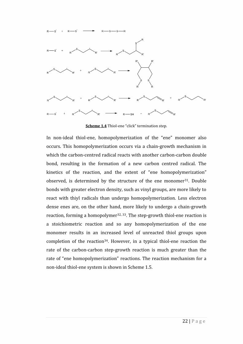
Scheme 1.4 Thiol-ene “click” termination step.
In non-ideal thiol-ene, homopolymerization of the “ene” monomer also
occurs. This homopolymerization occurs via a chain-growth mechanism in
which the carbon-centred radical reacts with another carbon-carbon double
bond, resulting in the formation of a new carbon centred radical. The
kinetics of the reaction, and the extent of “ene homopolymerization”
observed, is determined by the structure of the ene monomer31. Double
bonds with greater electron density, such as vinyl groups, are more likely to
react with thiyl radicals than undergo homopolymerization. Less electron
dense enes are, on the other hand, more likely to undergo a chain-growth
reaction, forming a homopolymer32, 33. The step-growth thiol-ene reaction is
a stoichiometric reaction and so any homopolymerization of the ene
monomer results in an increased level of unreacted thiol groups upon
completion of the reaction34. However, in a typical thiol-ene reaction the
rate of the carbon-carbon step-growth reaction is much greater than the
rate of “ene homopolymerization” reactions. The reaction mechanism for a
non-ideal thiol-ene system is shown in Scheme 1.5.

23 | P a g e
Scheme 1.5 Non-ideal thiol-ene “click” reaction.
Intramolecular reactions can also occur within thiol-ene polymerizations.
These reactions include intramolecular chain transfer, converting carbon-
centred radicals into thiyl radicals, and cyclization reactions. Cyclization
reactions are a form of intramolecular propagation in which a thiyl or a
carbon-centred radical attacks a double bond within the same molecule,
leading to the formation of a ring structure35.
While UV initiated thiol-ene reactions can occur without the use of a
photoinitiator, provided an appropriate wavelength of light is selected and
the monomers are sufficiently reactive36-38, the addition of a photoinitiator
can greatly reduce reaction times and increase the efficiency of such
reactions. Type I photoinitiators have been found to be more effective at
initiating thiol-ene reactions than Type II photoinitiators39-41. This is due to
the mechanisms by which the photoinitiators form radicals. Type I
photoinitiators undergo a unimolecular cleavage reaction upon exposure to
UV light, yielding two radicals. Both of these radicals can initiate the thiol-
ene reaction by abstracting hydrogen from a thiol group. The excited states
of these radicals are also short-lived singlets; this short lifetime prevents
quenching of the excited state by thiols. Type II photoinitiators, on the other
hand, produce radicals by a bimolecular reaction in which interactions
between the photoinitiator and a second co-initiator molecule leads to the
formation of radicals. This reaction occurs at a much lower quantum yield
24 | P a g e
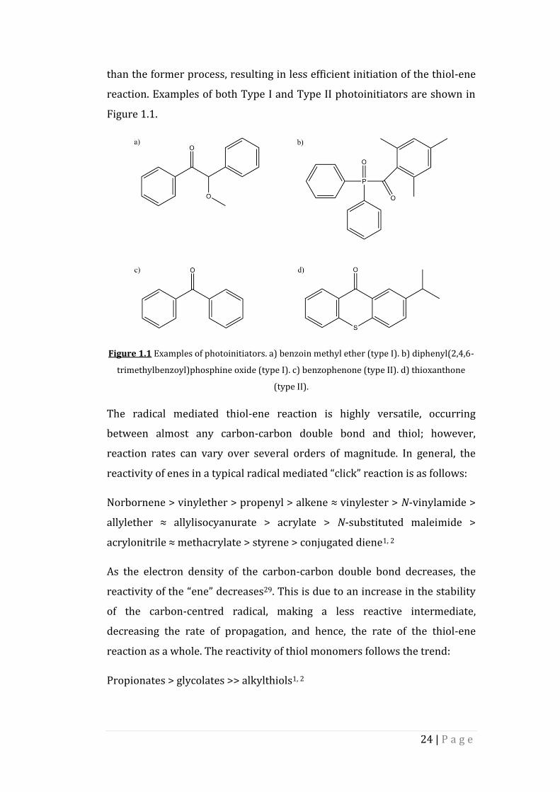
than the former process, resulting in less efficient initiation of the thiol-ene
reaction. Examples of both Type I and Type II photoinitiators are shown in
Figure 1.1.
Figure 1.1 Examples of photoinitiators. a) benzoin methyl ether (type I). b) diphenyl(2,4,6-
trimethylbenzoyl)phosphine oxide (type I). c) benzophenone (type II). d) thioxanthone
(type II).
The radical mediated thiol-ene reaction is highly versatile, occurring
between almost any carbon-carbon double bond and thiol; however,
reaction rates can vary over several orders of magnitude. In general, the
reactivity of enes in a typical radical mediated “click” reaction is as follows:
Norbornene > vinylether > propenyl > alkene ≈ vinylester > N-vinylamide >
allylether ≈ allylisocyanurate > acrylate > N-substituted maleimide >
acrylonitrile ≈ methacrylate > styrene > conjugated diene1, 2
As the electron density of the carbon-carbon double bond decreases, the
reactivity of the “ene” decreases29. This is due to an increase in the stability
of the carbon-centred radical, making a less reactive intermediate,
decreasing the rate of propagation, and hence, the rate of the thiol-ene
reaction as a whole. The reactivity of thiol monomers follows the trend:
Propionates > glycolates >> alkylthiols1, 2

25 | P a g e
The addition of a thiol group across a carbon-carbon double bond via a
Michael addition can also be referred to as a thiol-ene “click” reaction. The
reactions are generally catalysed by weak bases or strong nucleophiles and
proceed via an anionic chain mechanism. The Michael addition reaction is
open to fewer enes than the radical-mediated “click” reaction as the carbon-
carbon double bond must be electron deficient for the reaction to occur. The
first step of the weak base catalysed reaction (shown in Scheme 1.6) is the
formation of a thiolate anion as the base removes the hydrogen from the
thiol group42.
Scheme 1.6 Formation of the thiolate anion in the base catalysed thiol-ene Michael
addition.
When catalysed by a strong nucleophile an intermediate enolate base is
formed by nucleophilic attack on the carbon-carbon double bond of the ene,
this base then attacks a thiol group, forming the thiolate anion43 (Scheme
1.7).
Scheme 1.7 Formation of the thiolate anion in the nucleophile catalysed thiol-ene Michael
addition.
The thiolate ion then attacks the carbon-carbon double bond at the
electrophilic β-carbon, yielding an enolate intermediate. This intermediate

26 | P a g e
then forms the thiol-ene product by abstracting hydrogen either from
another thiol group or from the catalyst42, 43 as shown in Scheme 1.8.
Scheme 1.8 Thiol-ene Michael addition.
Both the radical-mediated and Michael thiol-ene reactions are regiospecific,
selectively yielding the anti-Markovnikov product and exhibiting the
favourable features attributed to “click” chemistry. Both reactions are
insensitive to oxygen and water and can occur in environmentally benign
solvents such as alcohols. The reactions also proceed at a fast rate, and in
near quantitative yields.
1.1.3. Applications of Thiol-Ene “Click” Chemistry
Although “click” chemistry was originally developed as a means of
simplifying the synthesis of biomolecules, it is often used in the field of
polymer chemistry. The regioselective nature and near quantitative
conversions observed in “click” chemistry, particularly thiol-ene “click”
chemistry, have been exploited in order to create many polymeric materials
including cross-linked polymer networks44, such as hydrogels45;
dendrimers46 and star polymers47; microfluidic devices34; and to
functionalize polymers post-polymerization48.
1.1.3.1. Polymer and Macromer Synthesis
A wide variety of different polymers have been synthesized and
functionalized using the thiol-ene “click” reaction. One of the simplest
examples of this is the functionalization of well-defined homopolymers of
1,2-polybutadiene (PB) and AB diblock copolymers of PB and poly(ethylene

27 | P a g e
oxide) (PEO) with a range of thiols49. The resulting polymer was found to be
free form carbon-carbon double bonds but the reaction proceeds with less
than quantitative conversions (generally between 70% and 80%)50. The
lower conversion can be attributed to intramolecular cyclization reactions50,
as shown in Scheme 1.9. The occurrence of these undesirable side reactions
and the large excess of thiol required (10 equivalents) means that this
reaction cannot be described as a “click” reaction. However, the results show
that polymers can be effectively functionalized post-polymerization by a
thiol-ene reaction.
Scheme 1.9 Thiol functionalization of 1,2-polybutadiene, highlighting the competing
intramolecular cyclisations.
The amount of thiol can be reduced to between 1.2-1.5 equivalents (to the
number of ene groups), and the ene replaced with a macromer that cannot
undergo homopolymerization or internal cyclization reactions, such as an
oxazoline51, as shown in Scheme 1.10. The method of initiation can include
thermal radical (AIBN) and UV irradiation at room temperature51, 52. This
enhanced reaction was found to proceed quantitatively, with no observed
cyclization53. These observations led Diehl and Schlaad to describe this
functionalization reaction as a “click” reaction51. A major advantage of this
reaction is that the starting materials can include a range of materials, such
as commodity polymers which can be purchased in bulk at low cost and
then functionalized in order to synthesize materials that previously required
complex, multistep, expensive chemistry54. Starting materials can also
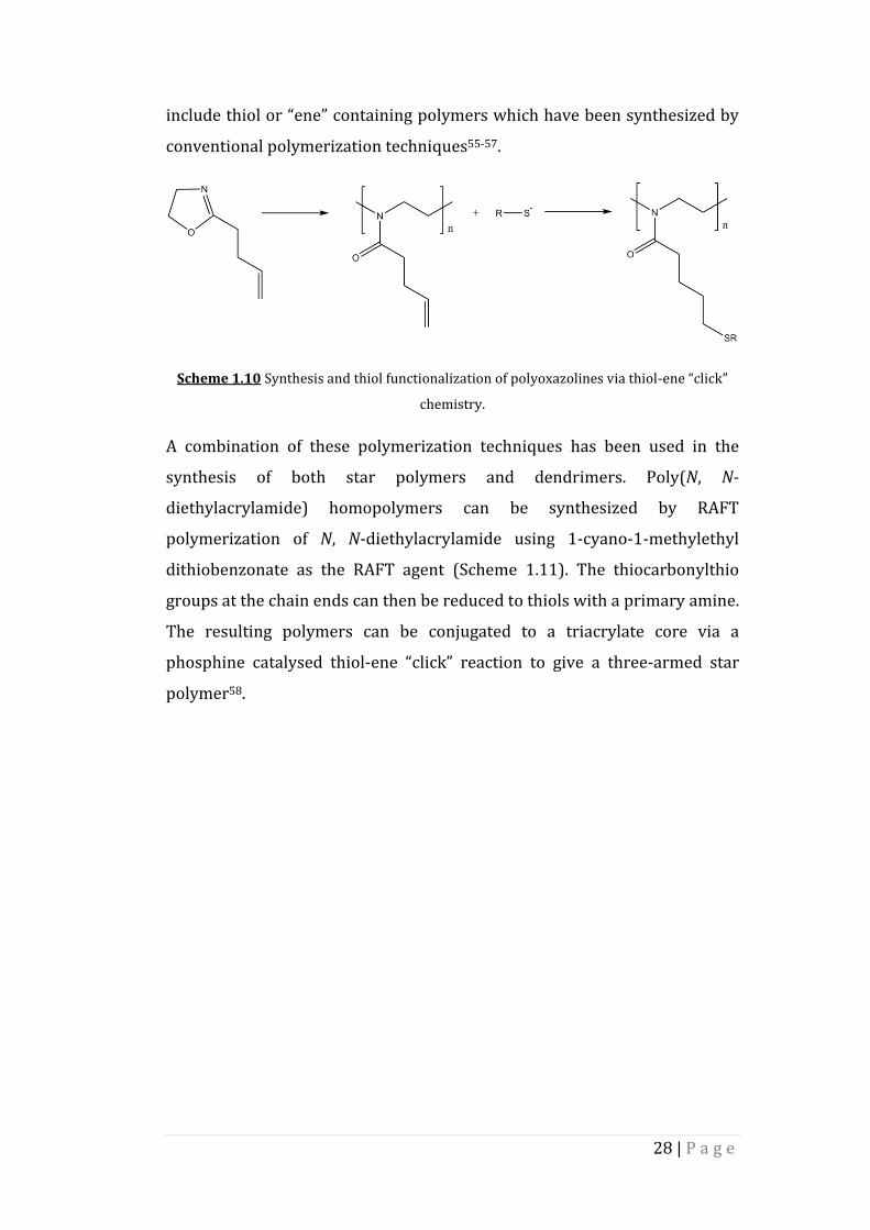
28 | P a g e
include thiol or “ene” containing polymers which have been synthesized by
conventional polymerization techniques55-57.
Scheme 1.10 Synthesis and thiol functionalization of polyoxazolines via thiol-ene “click”
chemistry.
A combination of these polymerization techniques has been used in the
synthesis of both star polymers and dendrimers. Poly(N, N-
diethylacrylamide) homopolymers can be synthesized by RAFT
polymerization of N, N-diethylacrylamide using 1-cyano-1-methylethyl
dithiobenzonate as the RAFT agent (Scheme 1.11). The thiocarbonylthio
groups at the chain ends can then be reduced to thiols with a primary amine.
The resulting polymers can be conjugated to a triacrylate core via a
phosphine catalysed thiol-ene “click” reaction to give a three-armed star
polymer58.

29 | P a g e
Scheme 1.11 RAFT polymerization of N, N-diethylacrylamide and subsequent conjugation a
trimethylolpropane core by thiol-ene “click” chemistry, yielding the three-arm star
polymer.
Killops et al. demonstrated that thiol-ene “click” chemistry can be used to
create a dendrimer backbone, with the tris-alkene 2,4,6-triallyloxy-1,3,5-
triazine as the core of the dendrimer, and then to functionalize the resulting
chain ends46. The first generation dendrimer was formed via the reaction of
1.5 equivalents (to the number of ene bonds) of 1-thioglycerol with the
dendrimer core under solventless conditions via a UV initiated reaction. The
formation of the first-generation hexa-hydroxy dendrimer was then

30 | P a g e
confirmed by 1H NMR spectroscopy. The first-generation dendrimer was
then prepared for further thiol-ene reactions by esterification. The thiol-ene
and the esterification reactions were then repeated in order to obtain the
fourth-generation dendrimer. In keeping with the facile nature of “click”
chemistry, the obtained dendrimers were purified by precipitation into
diethyl ether at greater than 90% purity. Once obtained the hydroxyl chain
ends on the fourth-generation dendrimer can then be converted to alkenes
by the previously described methods and functionalized with
monofunctional thiols, including biologically relevant molecules, such as
cysteine, via another thiol-ene “click” reaction46. A simplified mechanism for
the synthesis of the fourth-generation dendrimer is shown in Scheme 1.12.

31 | P a g e
Scheme 1.12 Synthesis of 48-functional polyol dendrimer by sequential radical thiol-ene
and esterification reactions.
32 | P a g e
Further exploration of the potential of “click” chemistry within dendrimer
synthesis has led to the development of a synthetic strategy for sixth-
generation dendrimers that can be synthesised in a single day59. While this
synthetic strategy combines both CuAAC and thiol-ene “click” reactions,
making it unsuitable for biological applications, the dendrimers can be
synthesized on a multi-gram scale and are purified by simple purification
techniques.
1.1.3.2. Polymeric Materials
The thiol-ene “click” reaction has found applications in the field of material
chemistry where it has been used to synthesize a variety of crosslinked
polymeric materials44, 60, 61. The reaction of multifunctional enes and
multifunctional thiols leads to the formation of highly cross-linked
networks. Of the “enes” available for this kind of reaction, acrylates and
methacrylates are among the most commonly used. The thiol-ene reaction
reduces the level of oxygen inhibition observed in acrylate and methacrylate
polymerizations62. This allows for “ene” systems that would normally
require nitrogen atmospheres and very high intensity UV radiation to be
cured under much milder conditions. The introduction of thiols into the
monomer system also helps to minimise the shrinkage and shrinkage stress
experienced by the network by delaying the gel point63. This delayed gel
point is a result of the step-growth nature of thiol-ene polymerizations64.
While undergoing a step-growth reaction one thiol monomer is added
across the carbon-carbon double bond, as opposed to the two monomer
additions which would occur in chain growth reactions. Delaying the gel
point also leads to the formation of more uniform networks31. These
combined benefits make thiol-ene “click” chemistry ideal for the fabrication
of polymeric materials such as microfluidic devices, hydrogels and porous
polymer networks65.

33 | P a g e
Figure 1.2 Formation of a crosslinked network via the ideal thiol-ene reaction.
In recent years, hydrogels have found several applications in the
biomaterials field. These applications include scaffolds for tissue
engineering66, 67 and wound healing68, and they have been explored as
potential drug delivery vehicles. The hydrogels used for such biological
applications are often synthesized from PEG macromers with double bond
chain ends, including acrylates45, 69, 70and other enes such as norbornenes71.
One of the main advantages of using hydrogels formed by thiol-ene “click”
chemistry for biological applications is the degradability of these materials.
In the case of PEG-norbornene-thiol hydrogels, the ester linkage formed
between the ene chain end and the PEG backbone can undergo hydrolytic
degradation72. The thioether-ester linkage in thiol-acrylate hydrogels can
also degrade hydrolytically69, 73. Therefore, the rate of hydrolysis can be
tuned by altering the number of functional groups each monomer possesses.
This changes the crosslink density of the overall network, increasing or
decreasing the number of bonds that need to be cleaved during
degradation74. Photodegradable hydrogels can also be formed by careful
selection of the monomers and photoinitiator used75.
The step-growth nature of the photoinitiated thiol-ene reaction gives thiol-
ene hydrogels an advantage over their chain-growth counterparts as the
level of ene homopolymerization is reduced71. This reduction in

34 | P a g e
homopolymerization often results in a reduction in the chain length of the
degradation products. Lower molecular weight degradation products are an
advantage when developing materials for implant as they are more easily
excreted by the body. Chain growth acrylate homopolymerization reactions
require long gelation times as a result of oxygen inhibition, whereas thiol-
ene reactions are not affected by the presence of oxygen1, leading to faster
gelation times76. While step-growth gels can be formed by both
photoinitiated “click” thiol-ene reactions and Michael addition thiol-ene
reactions, the photoinitiated reaction offers crosslinked networks with
lower levels of network defects, and hence improved mechanical
properties71. These improved mechanical properties are the result of several
features of the radical-mediated thiol-ene reaction. The first of these
features is the high reactivity of the radical species. The increased level of
reactivity can be observed as a reduction in gelation time. The gelation of
PEG-norbornene-thiol gels formed by a photoinitated thiol-ene “click”
reaction was found to be approximately 230 times faster than the equivalent
hydrogel formed by a Michael addition reaction72. The photoinitiated
reaction also leads to a decrease in the number of disulphide bonds formed
between thiol monomers as these bonds are weak and so are easily cleaved
by the radical species present in the reaction mix71, 77. Both of these features
of the radical-mediated thiol-ene “click” reaction lead to an increase in the
network crosslink density without the need to change the functionality of
the monomers used. Hydrogels formed by a photo-reaction are found to
have higher shear moduli and lower mass swelling ratios than their Michael
addition counterparts76.
There are three important variables which need to be considered when
synthesizing thiol-ene hydrogels with defined mechanical properties. These
variables are: the functional groups used to form the crosslinked network;
the molar mass of the monomers/macromers used, for example, the length
of PEG chain used in PEG-norbornene-thiol hydrogels; and the choice of
solvent and the concentrations used72. The choice of functional group is
important when trying to define the mechanical and degradation properties

35 | P a g e
of a hydrogel. The reactivities of the functional groups will determine the
rate of gelation and the number of network defects observed. “Ene”
monomers/macromers can be susceptible to homopolymerization and
internal cyclization reactions, which reduce the crosslink density of the
network, decreasing the tensile strength of the hydrogel78. The molar mass
of the monomers and macromers used also affects the degree of crosslinking
observed. Gels containing longer polymer chains require longer gelation
times due to the high mobility of the polymer chains, and the lower number
of functional groups per unit mass of polymer, reducing the likelihood of the
thiol groups reacting with the “ene” groups, leading to less densely
crosslinked hydrogels78. Finally, the choice and concentration of solvent also
impacts the likelihood of the reaction between thiol and “ene” chains ends.
Using a solvent that will disperse the monomer solution well will yield a
hydrogel with a higher tensile strength than a gel formed using a poor
solvent78. This increase in tensile strength is due to a better dispersion of
the functional groups required for network crosslinking. The concentration
of functional groups in the reaction mixture can also be controlled by
changing the concentration of solvent within the mixture. Reducing the
volume of solvent decreases the distance between functional groups, this
reduced distance increases the probability of a reaction, leading to a more
densely crosslinked gel.
The ease with which the mechanical and degradation properties of thiol-ene
hydrogels can be tuned has made them an attractive option for the synthesis
of scaffolds for tissue engineering. Hydrogels with consistent mechanical
properties can be produced from nontoxic, hydrophilic polymers, and
biomolecules which help support cell proliferation, migration and
differentiation can be easily incorporated into the gels. Control of the
swelling of hydrogels can be achieved by controlling the crosslink density of
the network. This allows for better control of mass transfer through the gel,
which is important in ensuring nutrients can be transported to and waste
products away from the cells79-81.
36 | P a g e
The thiol-ene reaction has been exploited in the formation and post-
polymerization functionalization of porous polymer networks44. The
emulsion templating method is a facile way of producing porous polymers
with well-defined morphologies and porosities. Emulsion templating
involves the formation of an emulsion with the monomers as the continuous
phase and a porogen as the non-continuous droplet phase. The continuous
phase is then polymerized and the porogen removed, leaving behind a
polymer foam82. The photo-initiated thiol-ene reaction allows for the
polymerization of emulsions that would otherwise collapse before the
polymerization reaction goes to completion. These biodegradable porous
polymers have also been used in tissue engineering and 3D cell culture
applications83. Porous polymer monoliths have also been used as the
stationary phase for detection, separation and chromatography purposes84,
85. The surface chemistry of these polymer networks is of great importance
when designing material for chromatography. The surface of the polymer
must be either resistant to or have a specific interaction with the targeted
chemical. Functionalizing the polymer network post-polymerization allows
for specific chemistries to be found at the polymer surface without the need
to reoptimize the polymerization conditions. The thiol or ene groups on the
polymer surface can be included either during polymerization of the
polymer network or via a post-polymerization functionalization step. Once
on the polymer surface they can then be used to impart a particular
chemical functionality onto the polymer surface. For example, the usually
hydrophobic poly(glycidyl methacrylate-co-ethylene dimethacrylate)
porous monoliths can be made hydrophilic and have been used to separate
both alkyl benzenes and peptides depending on the nature of the polymer
surface84. Thiol functionality is added to the polymer surface in a post-
polymerization grafting reaction using cystamine, followed by cleavage of
the disulphide bond using tris(2-carboxyethyl)phosphine. Hydrophilicity is
then imparted on the polymer surface by clicking [2-(methacroyloxy)ethyl]-
diemthyl-(3-sulfopropyl)ammonium betaine to the surface. While the
efficiency of this porous monolith as a separation column was not as high as

37 | P a g e
its silica based counterparts, these monoliths can be hypercrosslinked in
order to improve the efficiency84.
1.2. Porous Polymers
Porous polymers have found applications in a wide range of areas. These
applications include: as membranes for separation86, filtration87 and
chromatography88; scaffolds for tissue engineering89; supports for
catalysts90 and reagents used in synthesis; to encapsulate and facilitate the
controlled release of drugs87; as a support for sensors91; as gas storage
devices92-94; and as masks for lithography95, as well as many other uses. The
type of application suitable for a porous polymer is determined by a number
of factors, including the size and morphology of the pores, as well as the
chemical properties of the polymers used. Porous polymers have a number
of advantages over other commonly used porous materials, such as zeolites,
activated carbons and porous silicas. The wide range of polymerization
reactions that can be used to form porous polymers, and hence the wide
range of monomers available, allow for the production of polymers with
different chemical functionalities96-98. As a result of the different monomers
that can be utilized, a wide range of chemical functionalities can be imparted
onto the pore surface using various grafting techniques99-101. Solvent-based
processing techniques can also be employed for processing porous
polymers102. Due to the lightweight elements used in their production,
porous polymers are generally more lightweight than other porous
materials103, 104.
Polymer structures with either single or multiple pores can be described as
porous polymers. Pore sizes can be over a large range from nanometres to
hundreds of microns. According to IUPAC recommendations105, porous
polymers can be placed in three categories based on pore size:
1. Microporous polymers – pore diameter less than 2 nm
2. Mesoporous polymers – pore diameter in the range 2 – 50 nm
3. Macroporous polymers – pore diameter larger than 50 nm

38 | P a g e
The pore size is related to the Brunauer-Emmett-Teller surface area of the
polymer. Generally, polymers with smaller pore sizes, such as microporous
polymers, have larger surface areas than mesoporous or macroporous
polymers. The surface area, and hence the pore size, of a polymer often
impacts the applications for which a particular porous polymer can be used.
Other characteristics that dictate the suitable applications for a porous
polymer include: the pore geometry, which can range from individual
spherical pores, to a hierarchical network of fully interconnected pores; the
chemical functionality of the pore surface; and the nature of the polymer’s
topology with pores being found in ordered or disordered arrays.
As a result of the impact that the overall network properties of a porous
polymer has on its usefulness in certain applications, several synthetic
procedures have been developed aiming at designing polymers with well-
defined pore sizes and structures. These synthetic routes often allow the
polymers to be imparted with the desired chemical functionality either
during polymer synthesis or via post-polymerization modification
techniques. These synthetic methodologies include:
1. Direct templating
2. Self-assembly of block copolymers
3. Direct Synthesis
4. Breath Figure
5. Emulsion templating
For the purpose of this work the emulsion templating method will be
discussed in detail. Detailed discussions of other synthetic routes to porous
polymers mentioned above can be found in the literature98.
1.2.1. Synthesis of Emulsion Templated Porous Polymers
Emulsions are formed when at least two immiscible liquids are blended to
give a heterogeneous suspension of droplets of one liquid inside a
continuous phase of the other. If this continuous phase is polymerized, a
porous polymer is formed. Emulsions can be described as either oil-in-water

39 | P a g e
(o/w) or water-in-oil (w/o), where the droplet phase is oil or water
respectively.
1.2.1.1 High Internal Phase Emulsions
In order to produce highly porous materials a certain class of emulsion,
known as a high internal phase emulsion, or HIPE, is used. HIPEs are defined
as having an internal, or droplet, volume phase ratio, ϕ, of 0.74 or greater82.
A volume fraction of 0.74 represents the maximum volume ratio at which
the droplet phase will pack as uniform non-deformable spheres. Values of ϕ
up to 0.99 can be observed, indicating that the droplet phase in a HIPE is
either non-uniform or that the droplets are deformed into polyhedra82.
The most commonly used method of forming HIPEs is by the slow addition
of a porogen (non-continuous phase) to the continuous phase with mixing83,
106, 107, as demonstrated in Figure 1.3, although other methods can be
used108. The continuous phase generally consists of a mixture of monomer,
comonomer and a suitable surfactant; a solvent may also be included in
order to reduce the viscosity of the continuous phase. Mixing is generally at
a high shear rate and is an important stage in HIPE formation as it breaks up
any larger droplets into smaller ones. Other methods of HIPE formation
include the multiple emulsification method and the spontaneous formation
method. HIPEs can be both oil-in-water (o/w) and water-in-oil emulsions
(w/o). In w/o emulsions the continuous phase is the oil phase and the
porogen is water, in o/w emulsions it is the reverse. The type of emulsion
formed is dependent on the ratio of each phase and the type of surfactant
used.

40 | P a g e
Figure 1.3 Formation of a high internal phase emulsion (HIPE)
HIPEs are thermodynamically unstable, but exhibit varying degrees of
kinetic stability. The stability of the HIPE is strongly dependent on the
internal phase volume ratio, as well as the hydrophilic properties of the
monomers, and the type and volume of surfactant used. Increasing the
internal phase volume ratio increases the likelihood of droplet coalescence,
where droplets merge in order to form larger droplets, and Ostwald
ripening109, a phenomenon which causes larger droplets to grow at the
expense of smaller ones as a result of the high surface energy associated
with smaller droplets. The combination of droplet coalescence and Ostwald
ripening results in collapse of the HIPE as the size of the droplets become
too large for the continuous phase to support them.
One of the main applications of HIPEs is as a template in the formation of
highly porous polymers, known as polyHIPEs.
1.2.1.2 High Internal Phase Emulsion Templated Porous Polymers
Polymerization, or curing, the continuous phase of a HIPE gives a porous
polymeric material known as a polyHIPE110, 111, as shown in Figure 1.4. The
continuous phase of the emulsion must contain a cross-linker in addition to
the monomer and surfactant. The cross-linker is needed in order to form the
polymer network that makes up the polyHIPE structure. Once cured, the
porogen is removed and the porous material is washed by Soxhlet
extraction and dried.

41 | P a g e
Figure 1.4 Formation of a polyHIPE.
The obtained polymer is a highly porous and permeable material, with a
complex pore morphology. An SEM image of typical a polyHIPE is shown in
Figure 1.5. The spherical cavities shown are referred to as voids, while the
smaller interconnecting spheres between voids are known as windows. The
much smaller structures within the walls of the polyHIPE are referred to as
pores82.
Figure 1.5 SEM of a typical polyHIPE polymer where V indicates a void and W indicates a
window. Scale bar = 100 µm.
The polyHIPE void diameter can be varied from 1 µm to diameters greater
than 100 µm by controlling the diameter of the droplets in the HIPE112. The
3D structure of a polyHIPE is of great importance when the material is
intended for a particular application, and the ability to tune the structure by
varying the properties of the HIPE precursor is particularly attractive. The
ability to tune the void diameters in a polyHIPE material is generally

42 | P a g e
allowed for by control over the stability or instability of the HIPE112-114,
although, the rate of shear upon HIPE formation can also have an impact.
There are two major factors that affect HIPE stability: Ostwald ripening and
droplet coalescence. Ostwald ripening occurs as a direct result of the
differences in surface tension and chemical potential between large and
small droplets. Smaller droplets experience a higher solubility in the
continuous phase as a result of the Kelvin effect115. The Kelvin effect
describes the relationship between the curvature of a liquid’s surface and
the vapour pressure associated with the liquid. Curved surfaces exhibit a
higher vapour pressure than flat surfaces and so smaller droplets have much
higher vapour pressures than their larger counterparts. As a result, smaller
droplets have a much higher tendency to dissolve and diffuse through the
interfacial layer, finally being re-deposited into larger droplets. Droplet
coalescence occurs as a result of the thinning and subsequent rupture of the
interfacial layer116.
By far the most studied polyHIPE system is that of styrene (ST) with a
divinylbenzene (DVB) crosslinker107, 117-119. The factors that affect the 3D
structure of this polyHIPE system have been studied in great detail. It has
been shown that the nature and concentration of the surfactant used has an
impact on the appearance and size of the interconnecting windows113. The
interconnecting windows are believed to form by contraction of the
continuous phase upon curing. The addition of surfactant causes the
monomer film separating each individual droplet to thin. Since the film is at
its thinnest at the point of nearest contact between each droplet, any
contraction in the continuous phase would lead to the formation of holes at
this point. In order to study this more closely ST/DVB polyHIPEs were
prepared using varying concentrations of the surfactant Span 80. Closed-cell
materials with no interconnecting windows were obtained at surfactant
concentrations between 3% and 5% (w/w). As the surfactant concentration
was increased to between 7% and 10% an open-cell morphology was
observed. Increasing the surfactant concentration further resulted in an
increase in the interconnecting window diameter, up to 80% (w/w)

43 | P a g e
surfactant. A visual representation of the formation of interconnecting
windows can also be obtained using cryo-SEM117. Images of frozen HIPE
samples at different curing times indicate that the windows are produced by
shrinkage during polymerization. The formation of the interconnecting
windows appears to coincide with the gel point of the polymer, further
supporting the hypothesis that the windows are produced by shrinkage of
the continuous phase upon polymerization.
Increasing the temperature of the aqueous phase has an impact on both the
void diameter and the diameter of the interconnecting windows. This
increase in temperature leads to a decrease in the stability of the HIPE
precursor. This decrease in stability is due to two main factors: increased
mobility of the droplets and increase solubility of the surfactant in the
aqueous phase. Both factors increase the likelihood of droplet coalescence,
leading to an increase in void diameter107.
A further factor that impacts the 3D structure of a polyHIPE polymer is the
inclusion of additives into the emulsion. Small organic molecules, such as
acetone, methanol, and THF, can have a destabilising effect on a HIPE when
added as a co-solvent. The emulsion destabilization is as a result of the
solubility of the co-solvent in both the organic and aqueous phases. This
solubility increases the likelihood of both droplet coalescence and Ostwald
ripening by diluting the interfacial layer and increasing the solubility of the
surfactant in the aqueous phase. The relative solubility of the co-solvent in
each phase determines the extent of the effect on the polyHIPE morphology
and the mechanism by which emulsion destabilization occurs. PolyHIPEs
prepared with THF as the co-solvent show a much wider range of void
diameters than those with methanol as the co-solvent as well as a higher
average void diameter. This is believed to be due to the increased solubility
of THF in the organic phase compared to methanol. As the concentration of
the co-solvent is increased, materials with a narrow distribution of void
diameters and a higher degree of interconnection are obtained. Other
additives, including salts, have also been shown to have an effect on the
morphology of polyHIPE polymers107.

44 | P a g e
Due to their high porosity and relatively large void sizes, polyHIPE materials
are found to have low surface areas, typically between 3 m2 g-1 and 20 m2 g-1
by BET analysis118. This can be increased to up to 350 m2 g-1 by increasing
the crosslinker concentration and by the addition of a non-polymerizing
organic solvent118. The addition of a non-polymerizable organic solvent
increases the surface area of polyHIPE polymers by introducing a secondary
pore structure into the material. This secondary pore structure is as a result
of phase separation occurring in the continuous phase of the HIPE during
polymerization. The increase in surface area can be controlled by selecting a
solvent with a solubility parameter close to that of the growing polymer
chain, delaying the onset of phase separation, producing smaller pores, and
hence, a higher surface area.
The morphology of a polyHIPE material can also be controlled by the
moulding process82. Before curing the HIPE is poured into a mould, where it
remains during the curing process and the final polyHIPE polymer retains
the shape of the mould. A wide variety of different moulds with different
sizes and shapes are available, however, typically plastic bottles are used.
The mould substrate used during curing has been found to influence the
morphology of the polyHIPE surface. This has, again, been investigated for
the ST/DVB polyHIPE system. Glass moulds were found to be unsuitable for
ST/DVB polyHIPEs due to bonding between the surface and the polymer.
This bonding leads to the surface of the polyHIPE having a different
morphology to that of the polyHIPE interior, whereas, plastic substrates
such as PVC were found to leach plasticizer, destabilizing the emulsion.
Other plastic substrates investigated included polypropylene and PTFE.
PolyHIPEs cured in polypropylene moulds were found to have a closed cell
morphology in areas that were in contact with the mould. This is believed to
be caused by preferential wetting of the monomer phase, resulting in a thin
film that then forms a polymer skin upon curing. PTFE, on the other hand,
was found to have no impact on the polyHIPE morphology, giving open cell
surfaces. The dimensions of the mould can also be controlled in order to
produce large polyHIPE monoliths or porous membranes82.

45 | P a g e
1.2.2. Functional Porous Polymer by High Internal Phase
Emulsion Templating
As mentioned previously, the ST/DVB polyHIPE system is the most widely
studied, however, a much wider range of monomers can be used in order to
produce polyHIPE materials a wide range of mechanical, chemical and
degradation properties.
The mechanical properties of ST/DVB polyHIPEs can be tuned by the simple
addition of other hydrophobic monomers into the continuous phase of the
emulsion. Monomers including 2-ethylhexylacrylate (EHA) and
methacrylate (EHMA) have been shown to cause a decrease in the glass
transition temperature of ST/DVB polyHIPEs, leading to a more elastomeric
polymer network120. Isobornyl acrylate (IBOA) has been shown to have the
opposite effect, and its inclusion in a HIPE leads to the formation of a
network with increased rigidity121.
Chemical functionality can be imparted on ST/DVB polyHIPEs in one of two
ways. The first of these is by the post-polymerization modification of the ST
phenyl rings by electrophilic aromatic substitution (Scheme 1.13) to yield
bromo-, nitro- and sulfonic acid substituted polyHIPE polymers122. The
relatively low hydrophobicity of the electrophilic reagents compared with
the ST/DVB polymer resulted in materials with a higher degree of
substitution at the surface than in the centre. In order to overcome this,
reagents with a higher level of hydrophobicity, such as lauroyl sulphate in
cyclohexane were used. The use of reagents with higher hydrophobicity
produced materials with more even levels of functionalization throughout
their entirety122, 123.
Scheme 1.13 Electrophilic aromatic substitution of phenyl rings of ST/DVB polyHIPE.
The second method of chemical functionalization is to replace the ST
monomer with 4-vinylbenzyl chloride (VBC)124. The inclusion of VBC in the

46 | P a g e
emulsion does not have any effect on the morphology of the resulting
polyHIPE and the benzyl chloride groups function as “reactive handles”,
allowing for the polyHIPE material to be modified post-polymerization with
nucleophilic amines, such as morpholine and tris(2-aminoethyl)amine
(TAEA)125, 126, as shown in Scheme 1.14. In a similar manner VBC/DVB
polyHIPEs have been used to immobilize Wang linkers, commonly used in
solid phase peptide synthesis with loadings up to 3.1 mmol g-1 observed127.
Scheme 1.14 Amine functionalization of ST/VBC polyHIPEs.
Materials with reactive pendant vinyl groups can be produced in a similar
manner to the production of VBC/DVB polyHIPEs. The thermal free radical
polymerization of a HIPE with continuous phase consisting DVB and
ethylvinyl benzene (EVB) results in a material which the authors describe as
a (vinyl)polystyrene polyHIPE128. The pendant vinyl groups can undergo
both bromination and thiol addition via so-called batch and flow methods,
resulting in a dimethylene spacer between the polymer network and newly
introduced functionality128, 129, as shown in Scheme 1.15.
Scheme 1.15 Thiol functionalization of (vinyl)polystyrene polyHIPEs.
The copolymerization of the DVB crosslinker with the brominated styrenic
monomer 4-vinylphenyl 2-bromo-2-methyl-propanoate (VPBMP) has been
shown to result in a bromoester functionalized polystyrene polyHIPE. This
bromoester functionality was then used to initiate the polymerization of
monomers including methyl methacrylate (MMA) and glycidyl methacrylate
(GMA) via a CuBr catalysed ATRP reaction, as shown in Scheme 1.16. The
surface bound poly(MMA) and poly(GMA) were not found to have any
adverse effects on the morphology of the polyHIPE, and hence the
permeability of the materials was retained. As a result, a proposed

47 | P a g e
application for these polyHIPE materials is as monolithic scavengers for use
in organic synthesis130.
Scheme 1.16 ATRP from the surface of a bromoester functionalized polyHIPE.
As the relative hydrophilicity of the monomers is increased, the stability of
the result HIPE decreases. The use of surfactant with low hydrophile-
lipophile balance (HLB) numbers, allows for the stabilization of these HIPEs.
HLB numbers for non-ionic surfactants are determined from Equation 1.1,
based on Davies’ method131,
∑ ( ) (1.1)
where Hi represents the group number of hydrophilic group i, and n is the
number of methylene groups, each of which is assigned a value of 0.475.
Generally, HLB values range between 0 (very lipophilic) and 20 (very
hydrophilic). Using a low HLB number polyglycerol ester surfactant, HIPEs
with a continuous phase of up to 80% GMA were polymerized with a DVB
crosslinker via a thermally initiated free-radical reaction132. GMA based
polyHIPEs have also been prepared with ethyleneglycol dimethacrylate
(EGDMA) crosslinker with the use of other low HLB number surfactants133,
including triblock copolymers of ethylene oxide (EO) and propyleneoxide
(PO)134. The GMA is an attractive monomer for use in polyHIPEs due its
reactive epoxy groups which react readily with nucleophiles90, 135 by the
mechanism shown in Scheme 1.17. While hydrolysis of the epoxy groups is
observed, GMA polyHIPEs have been successfully used to immobilise
proteins and enzymes90.
Scheme 1.17 Amine functionalization of GMA polyHIPE.

48 | P a g e
Biodegradable polyHIPEs can be synthesized by the thermal free radical
polymerization of acrylated poly(ε-caprolactone)106 or poly(lactic acid)136.
The polymer networks, which have been investigated as scaffolds for tissue
engineering, have been shown to degrade completely in a sodium hydroxide
solution over a period of 10 weeks.
PolyHIPE polymers have also been produced by the ring opening metathesis
polymerization (ROMP) of norbornene derivatives96, 137. A water tolerant
ruthenium Grubb’s catalyst was used in this case, and the resulting HIPE
was stable enough to undergo thermal curing. Delueze et al., described the
polymerization as having a living character, such that the metal carbene
chain end is expected to remain active96, allowing for further modification of
the polyHIPE post-polymerization.
1.2.2.1. Emulsion Templating of Hydrophilic Monomers
Polymerizing the continuous phase of an o/w HIPE yields a hydrophilic
porous polymer. Hydrophilic polyHIPEs may have great potential in the field
of biotechnology, and several examples of hydrophilic polyHIPE polymers
designed for use as biomaterials have already been described138-140.
Biocompatible polyHIPE materials have been produced from the
polymerization of emulsions containing the monomer 2-hydroxyethyl
methacrylate (HEMA). Both w/o and o/w HIPEs can be produced for the
HEMA monomer with EGDMA141 and methylene bisacrylamide (MBAA)138
crosslinkers. Upon thermal polymerization of the emulsion, hydrophilic
porous polymers are produced. The wettability of these polyHIPEs has been
shown to increase as the concentration of MBAA crosslinker is increased.
Another route to biocompatible, hydrophilic polyHIPE materials is through
the use of methacrylated gelatin and dextran139, 142-144. Thermally initiated
radical polymerization of the vinyl terminated gelatin resulted in materials
with porosities of up to 95%, which, upon the addition of additives including
NaCl and DMSO, had void diameters within range suitable for tissue
engineering.

49 | P a g e
Despite their advantage in the formation of porous polymers for use a
biomaterials, there are relatively few examples of o/w HIPEs. Perhaps the
main reason for this is the large volumes of organic solvents required to
produce the HIPEs145. These organic solvents are often difficult to
completely remove from the polymer network, causing issues with
biocompatibility. One route to the formation of HIPEs from hydrophilic
monomers is to replace the continuous organic phase with super-critical
CO2 (scCO2)146. ScCO2 has many advantages when compared to organic
solvents due to it being non-flammable, clean and inexpensive147. ScCO2 is
easy to completely remove from the polyHIPE material as the CO2 returns to
the gaseous state once depressurized148. One of the first examples of the use
of scCO2 in polyHIPE synthesis is the preparation and subsequent
polymerization of a CO2 in water (c/w) HIPE with a continuous phase
consisting of and aqueous solution of acrylamide (AM) and MBAA, resulting
in a highly porous polyacrylamide material146. The hydrocarbon surfactants
required in the formation of o/w HIPEs display limited effectiveness in c/w
systems and so have been replaced with fluorinated surfactants, including
perfluoropolyether ammonium carboxylate (PFPE), which exhibit a higher
solubility in the CO2 phase146.
Dextran polyHIPEs have been synthesized from c/w HIPEs using the
fluorinated surfactant PFPE. The polyHIPEs obtained upon the thermal
curing of the aqueous continuous phase were found to have a fully
interconnected open-cell morphology and the degree of interconnectivity
increased with increasing ϕ. As a result of the highly interconnected
morphology, it is believed that these materials may be suitable for
biomedical applications140.
A major drawback of the use of c/w HIPEs in the synthesis of hydrophilic
porous polymers is the use of fluorinated surfactants. These surfactants are
expensive and are not biodegradable. In order to remove these surfactants
there has been some investigation into the use of more inexpensive
hydrocarbon surfactants135, 136. Polyacrylamide polyHIPEs, similar to those
described previously, were prepared from c/w HIPEs using a variety of low

50 | P a g e
cost, commercially available, biodegradable hydrocarbon surfactants. The
inclusion of the redox co-initiator tetremethylethylenediamine (TMEDA)
allowed for a reduction in the temperature required to polymerize these
materials from 60 oC to 20 oC149. The AM monomer has been found to be
toxic and so hydrophilic polyHIPEs have been prepared from monomers
such as HEA and HEMA with the intention of using these polymers as
biomaterials149. Other surfactants that have been explored for use in c/w
emulsions include di- and tri-block copolymers of poly(vinyl acetate) (PVAc)
and poly(ethylene glycol) (PEG), which have allowed for the formation of
AM/MBAA polyHIPEs under the same milder conditions as described
previously150, as well as fluorinated sugar based surfactants151, 152.
While the use of scCO2 offers several advantages for the synthesis of
hydrophilic emulsion templated porous polymers, the requirement for
specialized equipment and the need to at work at high pressures remain the
limiting factors of this technique.
1.2.2.2. Photopolymerization
Photoinitiated polymerizations offer an attractive route to the synthesis of
porous polymers due to the rapid rates of polymerizations. Photoinitiation
can reduce the length of time required to cure the polyHIPEs from several
hours to a matter of seconds. This rapid rate of curing offers an advantage
when curing highly unstable emulsions. There have been several examples
of the use of photo-, usually UV, initiation in polyHIPE synthesis. The earliest
example of this in the literature is the photopolymerization of the acrylate
monomers EHA and IBOA with a trimethylolpropane triacrylate (TMPTA)
crosslinker and an organic soluble photoinitiator153. Prior to this the use of
photopolymerizations had been described in two patents154, 155. Once
conditions were optimized, N-acryloxysuccinimide (NASI) was incorporated
into the HIPE in order to produce a polyHIPE with “reactive handles”. ATRP
initiators can also be incorporated into the EHA/IBOA HIPE prior to curing,
resulting in porous polymers which can undergo surface functionalization
via polymer grafting156. Other acrylates, including GMA and EGDMA, have

51 | P a g e
been cured in this way, forming polyHIPEs that can be further
functionalized90, 157, 158.
Until recently most photoinitiated HIPE polymerizations involved the use of
a UV bulb and the resulting materials were in the monolithic form. However,
the rapid cure times associated with UV initiation make acrylate based
HIPEs suitable candidates for UV laser curing, resulting in macrostructured
polyHIPE materials. Emulsions with continuous phase consisting EHA, IBOA,
TMPTA, photoinitiator and a surfactant were produced. The nominal
porosities of the material was varied between 75%, 80% and 90% porous
and the emulsions were cured using both scanning and projection micro-
stereolithography (µL) techniques. The resulting polyHIPE materials were
found to have the 3D macroscopic structure defined by the laser writing as
well as the porosity exhibited by bulk cured polyHIPEs159, as shown in
Figure 1.6. The ability for fine control over both the macroscopic structure
and porosity material may find an important role in the design of scaffolds
for tissue engineering. µL techniques have already found applications in the
synthesis of microstructured 3D PCL160, PLA161 and PEG-diacrylate162
scaffolds and biomaterials.

52 | P a g e
Figure 1.6 SEM images of polyHIPE materials produced by µL159. A) Printed lines at write
speeds of 1-5 mm s-1 from left to right, scale bar 500 µm. B) Two overlapping printed
squares, scale bar 2 mm. C) Printed grid structure, scale bar 500 µm. D) Tube produced by
photopolymerization of HIPE while translating in the z-direction, scale bar 1 mm. All insets
have scale bar 100 µm. Figure reproduced with permission of John Wiley and Sons.
As previously discussed, there are many reasons why thiol-ene chemistry is
attractive to the fields of materials and polymer science. The combination of
thiol-ene and thiol-yne chemistries with the rapid cure times associated
with photopolymerizations have led to a new class of thiol-ene polyHIPEs
which have been shown to have morphologies suitable for tissue
engineering and the added benefit of biodegradability83. Thiol-ene
polyHIPEs were first prepared from an emulsion with continuous phase
consisting TMPTA, trimethylolpropane tris(3-mercaptopropionate)
(TMPTMP), a surfactant and photoinitiator, with nominal porosities of up to
80%. The HIPEs were cured in a simple mould consisting a 50 x 50 x 5 mm
PTFE square frame secured between two glass slides44. The thiol-yne HIPE
was prepared in a similar manner, replacing the acrylate monomer with the
alkyne octadiyne44. While photoinitiated polymerizations are the most
commonly used in the preparation of thiol-ene polyHIPEs, examples of
thermally initiated curing have been described163.
µL techniques have also been applied to the curing of thiol-ene HIPEs.
TMPTA and pentaerythritoltetrakis 3-mercaptopropionate (TT) w/o HIPEs

53 | P a g e
have been successfully cured in a layer-by-layer manner using a high power
LED as the light source. The resulting polyHIPEs were found to exhibit
porosity on two scales: the micron scale, as formed during the emulsion-
templating process; and the millimetre scale as dictated by the curing
pattern164.
1.2.3. Applications of Emulsion Templated Porous Polymers
As a result of their morphologies and the ease with which chemical
functionality can be imparted, emulsion templated porous polymers have
found applications in a wide range of areas. These areas include: the
immobilization of enzymes90, 153, catalysts123 and other reagents used in
organic synthesis126; as scaffolds for tissue engineering136 and 3D cell
culture89; as materials for gas storage165; and as materials for water
purification166 and other separation processes167.
1.2.3.1. Enzyme Immobilization
Enzymes immobilized on solid supports have found a wide variety of
applications ranging from catalysts for chemical synthesis168 to
biosensors169. The high permeability and ease with which the polymer
surface can be chemically functionalized has led to the use of polyHIPE
polymers as solid supports for enzyme immobilization153, 170, 171.
Lipase enzymes are widely used as a cheap and versatile catalyst in the food,
pharmaceutical172 and energy industries for the hydrolysis of lipids173. One
major application of these enzymes is the synthesis of biodiesel from
vegetable oils as an alternative fuel source by the transesterification of
triglycerides with short chain alcohols174. Immobilizing these enzymes on a
solid support ensures their reusability, and it has been shown that the
hydrophobicity of the support has a large impact on the activity of the
enzyme175. ST/DVB HIPEs copolymerized with polyglutaraldehyde (PGA)
result in highly hydrophobic polymer networks suitable for the
immobilization of the lipase enzyme from Thermomyces lanuginosus via
covalent binding of the enzyme to the polymer surface176-178. In addition to
its high hydrophobicity, the polyHIPE support was found to offer a number
54 | P a g e
of other advantages over other support materials. These advantages include
the ease with which the polymer can be produced in large quantities, the
presence of glutaraldehyde groups on the polymer surface allows for both
covalent binding of the enzyme to the polymer surface as well as adsorption
of the enzyme, resulting in loadings of up to 11.4 mg enzyme per 1 g
polyHIPE. At these loadings biodiesel production from canola oil was found
to proceed with a conversion of 97%177. The immobilized lipase was found
to retain its high levels activity across 10 repeat reactions176. Lipase
enzymes, obtained from Candida antartica, have been successfully
immobilized on photopolymerized acrylate-based polyHIPEs bearing the N-
succinimide ester moiety at high loadings, and with stable levels of enzyme
activity153.
Proteases are another group of enzymes being used as catalysts in chemical
synthesis179. Protease-catalysed peptide synthesis allows for reactions to
occur with greater selectivity and under milder reaction conditions than
solid phase peptide synthesis180. Protease K, obtained from Tritirachium
album, has been successfully immobilized onto photopolymerized GMA-
polyHIPEs via amine functionalization of surface bound epoxy groups90. The
activity of the surface bound enzyme, assessed by monitoring the hydrolysis
of N-acetyl-L-tyrosine ethyl ester monohydrate, was found to be low, but
increased upon inclusion of a PEG spacer between the enzyme and polymer
surface90.
1.2.3.2. Hydrogen Storage
Fossil fuels are currently the most relied on source of energy, however, due
to depleting reserves and the effects of greenhouse gases, such as CO2, on
the environment there is a need to investigate other, cleaner and more
sustainable sources of energy. Hydrogen gas is an attractive energy source
due to its high energy density by mass (143.0 MJ kg-1)181, however, its use
has been limited so far due to two main factors:
1. Its low energy density by volume (0.0108 MJ l-1)181
2. Hydrogen gas is highly explosive in air

55 | P a g e
As a result, hydrogen storage tanks must be highly reinforced in order to
prevent explosions, and able to store large volumes. Motorized vehicles are
a major source of greenhouse gas pollution, and the need for large, heavily
reinforced fuel storage tanks makes the use of hydrogen as a clean energy
source less viable. In order to overcome this alternative hydrogen storage
methods must be considered.
While the most common methods of storing hydrogen still remain the
storage of the compressed gas in high-pressure tanks, storage of
cryogenically cooled liquid hydrogen, or a combination of the two181-183,
there has been research into alternative hydrogen storage methods.
Physisorption of hydrogen onto porous scaffolds and the storage of chemical
hydrides are two such methods currently being considered184.
A high surface area is required if a material is to be considered suitable for
the storage of H2 by physisorption185. While most polyHIPE materials are
found to have very low surface areas, typically ranging from 3 m2 g-1 and 20
m2 g-1, the use of inert porogenic solvents and hypercrosslinking reactions
can lead to dramatic increases in this value82. In the 1970s a class of
hypercrosslinked polymers with surface areas up to 2000 m2 g-1 186 were
developed by Davankov et al187. Hypercrosslinking is achieved by the
Friedel-Crafts condensation of polystyrene with bishalide monomers after
swelling of the polymer in a good solvent. ST/VBC/DVB polyHIPEs can be
hypercrosslinked using the Davankov method to yield monolithic porous
polymers that retain the open pore network typical of a polyHIPE polymer
but with surface areas up to 1200 m2 g-1. The high surface area is as a result
of the formation of a network of micropores on the surface of the polymer
network188. This microporosity imparts the material with a gravimetric
hydrogen storage capacity of 2.02 wt%189, a value which is much lower than
the target set by the United States Department of Energy (DOE). The iron
catalysts used in Friedel-Crafts alkylations creates difficulty in purifying the
polyHIPE polymers after hypercrosslinking, therefore, the ability to
introduce microporosity at the polymer surface without the need for a
Friedel-Crafts catalyst would ease the purification process. ST/DVB

56 | P a g e
polyHIPEs reswollen in a suitable solvent have been hypercrosslinked via
radical polymerization, initiated by the peroxy initiator di-tert-butyl
peroxide. Surface areas of up to 355 m2 g-1 were obtained using this
method119, with the lower values being attributed to the hypercrosslinking
reaction being a continuation of the polymerization reaction which formed
the initial polyHIPEs. As a result, any vinyl groups that remained unreacted
due to lack of a reaction partner would experience the same issue during the
hypercrosslinking reaction.
A second approach to the storage of hydrogen in polyHIPE polymers takes
advantage of the hydrogen storage potential of clathrate hydrates190. The
use of clathrate hydrates offers an environmental advantage as a high
proportion of their mass is water. One of the major drawbacks of using
clathrates lies in the kinetics of clathrate formation in the bulk191. The rate
of formation can be increased by increasing the surface-to-volume ratio of
the clathrate. This can be achieved in several ways, but perhaps the most
appropriate for applications such as the onboard storage of H2 is to disperse
the clathrate on a solid support192, 193. The large pore volumes and high
interconnectivity found in polyHIPE materials allow for the support of large
volumes of clathrate on small masses of polymer. PolyHIPEs comprised of
DVB and ethylstyrene (ES) have been trialled as clathrate supports165. The
addition of a THF stabiliser prior to clathrate formation reduced the
pressure required during clathrate formation194 and helped to overcome the
hydrophobicity of the ES/DVB polyHIPEs. An H2 storage capacity of 0.18
wt% was obtained, once again much lower than DOE targets165.
Despite both the hypercrosslinked polyHIPEs and polyHIPE supported
clathrate hydrate storage methods investigated giving lower than required
storage capacities, the low density, and ease with which the materials can be
produced in bulk make polyHIPEs attractive materials for the storage of
hydrogen as an alternative fuel source.

57 | P a g e
1.2.3.3. Tissue Engineering and 3D Cell Culture
At present there is significant interest in the fields of tissue engineering and
3D cell culture195-197. In the event of severe injury, or failure, of a tissue an
effective treatment method must be employed in order to repair or replace
the tissue. Tissue grafting and organ transplantation are, at present, the
most commonly used treatment methods197, 198, however, there are several
drawbacks198, 199. The number of donors restricts allografting (the
transplantation tissue from a donor to a recipient of the same species) with
demand often greatly outstripping the supply of donated organs and tissues,
and the risk of rejection results in patients requiring immunosuppressant
drugs for life199, 200. Autografting (the transplantation of tissue from one part
of the body to another) is limited by the size and location of injury, as well as
the tissue type affected200. The procedure is also painful and can also result
in severe scarring. Xenografting (the cross-species transplantation of
tissues) was considered as an alternative treatment method, however, the
other species used generally have shorter lifespans than humans, and hence
their tissues age quicker. Xenografted tissues can also be a source of disease
transmission201, rejection202, and introduced a wide range of ethical issues
surrounding the permanent alteration of an animal’s genetic code203. As a
result of these drawbacks, the ability to regrow tissues or organs from a
patient’s own cells in order to transplant them back into the body is
becoming increasingly attractive.
In order to culture cells in a 3D environment a scaffold is required to
support the cells and provide the biological cues found in the cells’ native
environment. There are several features a material must possess before it
can be considered for use as a biomaterial. These features include:
biocompatibility; a surface that allows sufficient cell attachment; a
morphology that allows for cell infiltration and the transport of nutrients to
and waste products away from the cells; mechanical properties that
resemble the mechanical properties of the native tissue; and, if the scaffold
is to be implanted, biodegradability198. There is a wide range of biomaterials
that feature the attributes required for tissue engineering and 3D cell

58 | P a g e
culture, including hydrogels204, 205 and electrospun fibres206, and the
scaffolds have been fabricated from a wide range of materials, including
natural207 and synthetic polymers208.
The highly interconnected, porous morphology of a polyHIPE and the ease
with which the void sizes, elasticity, and chemical functionality of the
surface can be tuned makes polyHIPE polymers suitable materials for 3D
cell culture and tissue engineering applications. Early work focussed on the
development of materials for 3D cell culture, fabricated from the non-
biodegradable STV/DVB polyHIPEs209, 210. A wide variety of cells lines have
been successfully cultured on ST/DVB polyHIPEs, including hepatocytes211,
osteoblasts210 and neural cells212. Cells grown in 2D behave differently to
cells grown in the body, and it is believed that cells cultured in 3D will
exhibit behaviour closer to those in vivo. The morphology of hepatocytes
cultured on a thin membrane of ST/DVB polyHIPE were found to more
closely resemble that of typical liver cells and had significantly more
microvilli than the same cells cultured in 2D213, 214. The cells grown in 3D
were also found to synthesize higher concentrations of albumin, a protein
found in the liver which plays a critical role in several liver functions
including scavenging free radicals and the binding and transport of drugs.
Albumin concentration is commonly used as a marker of hepatocyte
metabolic activity215, and so the higher concentration of albumin observed
in 3D culture of hepatocytes indicates that growing cells in 3D leads to
enhanced cell function214. Hepatic cell function can be further explored by
monitoring cell sensitivity to drugs metabolised in the liver. Methotrexate is
one such drug which is commonly used in the treatment of solid cancer
tumours, such as breast cancer, and leukaemia216. Hepatocytes cultured in
2D were found to be sensitive to methotrexate, and the cells’ metabolic
function was impaired in a dose-dependent manner. As the concentration of
methotrexate was increased, a reduction in the number of microvilli was
observed and the cells were seen to become flat and eventually disintegrate.
When cultured in the 3D environment provided by the ST/DVB scaffold, the

59 | P a g e
cells showed greater viability when exposed to higher concentrations of the
drug and responded to the drug in a manner more similar to the liver214.
The surface of an ST/DVB polyHIPE is relatively inert and the polymer is
highly hydrophobic. The ability to introduce biofunctionality at the polymer
surface, either via chemical functionalization or by adsorption of
biomolecules onto the surface, can be used to provide the biological cues
cells would normally receive from the extracellular matrix in vivo. There are
several routes to the preparation of chemically functionalized polyHIPEs,
the most commonly used during the preparation of polyHIPEs for 3D cell
culture applications is the copolymerization of a monomer that can be
further functionalized post-polymerization. Two recent examples are the
incorporation of acrylic acid into the aqueous phase of a ST/DVB/EHA
HIPE217, and the incorporation and subsequent modification of PFPA into
the continuous phase of the same HIPE211. The hydrophilic nature of the
acrylic acid monomer resulted in an increase in the wettability of the
scaffold without having a negative impact on hepatocyte adhesion. As a
result of these observations, it has been suggested that the acrylic acid can
be used as a route to further functionalization of ST/DVB polyHIPEs217. The
use of active esters, such as PFPA, as a route to the post-polymerization
modification of polyHIPE polymers was first explored in a thiol-ene
polyHIPE system99. Subsequently, its inclusion in a ST/DVB/EHA polyHIPE
was investigated as a route to galactose functionalized polyHIPEs211.
Hepatocyte cells are known to possess a cell-surface asiaglycoprotein
receptor218 (ASGPR) which binds specifically to galactose219. This
interaction can be targeted in order to improve cell-scaffold binding and cell
function. As with previous studies, albumin production was monitored as an
indication of the metabolic function of the hepatocyte cells, and was found to
be increased in cells cultured on galactose functionalized polyHIPEs. This
enhanced albumin production diminished with longer culture times. This
decrease is believed to be due to non-specific binding of serum proteins to
the polyHIPE surface, and needs to be addressed if galactose-functionalized
polyHIPEs are to find widespread application in hepatocyte culture211.

60 | P a g e
ST/DVB scaffolds can be enhanced for 3D cell culture applications by the
adsorption of biologically relevant molecules onto the polymer surface210.
The mineral hydroxyapatite (HA) is found in bone and teeth220, and many
implants, such as hip replacements, are coated in HA to promote integration
between living bone and the implant221. Osteoblast cells cultured on ST/DVB
scaffolds exhibited mineralization upon culture for 28 and 35 days and the
genes associated with osteoblast differentiation were observed. When
cultured upon HA modified polyHIPEs, there was an increase in the number
of cells penetrating into the polyHIPE polymer, and an increase in
mineralization was observed, indicating that coating the polyHIPE with HA
improves the osteoconductivity of the polyHIPE210.
There is a desire to prepare scaffolds for tissue engineering that are
biodegradable. These scaffolds can be implanted into the body in order to
support the growing tissue, degrading over time, until the tissue has been
fully repaired, and the scaffold replaced with ECM. Degradable scaffolds are
particularly attractive as it removes the need for a second surgery to remove
the scaffold. As previously discussed, biodegradable polyHIPE have been
prepared from vinyl-terminated PLA and PCL, as well as by thiol-ene
chemistry136, 222. Human fibroblasts cultured on PCL-polyHIPEs for 2.5 days
were shown to exhibit the spindle morphology typical of fibroblasts,
indicating cell proliferation and tissue growth. Human keratinocytes were
also successfully cultured on scaffolds prepared using thiol-ene chemistry,
indicating that these scaffolds are biocompatible83, however further
investigation into biodegradable scaffolds prepared by both thiol-ene
chemistry and from biopolymers is needed.
1.3. Aims and Objectives
The aim of this project is to explore the use of thiol-ene “click” chemistry in
the synthesis and subsequent functionalization of emulsion templated
porous polymers.
PolyHIPEs materials have been prepared using multi-functional thiol and
acrylate monomers, and the presence of residual, unreacted thiols within

61 | P a g e
these materials has been investigated. Two routes to the chemical
functionalization of the polymers using these unreacted thiol groups are
explored, using a range of acrylate and thiol monomers.
Thiol-acrylate polyHIPEs incorporating an active ester monomer were also
prepared and investigated as a route to the preparation of polyHIPEs
featuring biologically relevant molecules at the polymer surface.

62 | P a g e
2. Experimental
2.1. PolyHIPE Synthesis
2.1.1. Materials
The monomers trimethylolpropane tris(3-mercaptopropionate) and
trimethylolpropane triacrylate were obtained from Sigma Aldrich and used
without any further purification. The photoinitiator, diphenyl (2, 4, 6-
trimethyl benzoyl) – phosphine oxide/ 2-hydroxy-2-methylpropiophenone,
and solvent, 1,2-dichloroethane, were also obtained from Sigma Aldrich and
used as supplied. The surfactant, a polyhydroxystearic acid and
polyethylene glycol copolymer (Hypermer B246), was obtained from Croda
and used as supplied.
2.1.2. PolyHIPE Preparation
The oil phase, consisting of trimethylolpropane tris(3-mercaptopropionate),
trimethylolpropane triacrylate, 1,2-dichloroethane, surfactant and
photoinitiator, was added to a 250 ml two-necked round bottom flask with
continuous stirring at 350 rpm from an overhead stirrer. The water phase
was added dropwise, until an emulsion formed. This was then stirred for a
further minute in order to ensure the emulsion was homogenous.
The emulsion was then poured into a mould, consisting of a 80 mm x 80 mm
x 3 mm PTFE square between two glass slides, and photocured. The
photocuring was conducted using a Fusion Systems Inc. Light Hammer 6
variable power system fitted with an H-bulb. UV radiation is emitted over a
broad spectrum, with most emission between 200-450 nm. The cured
polyHIPE was then then washed in acetone, and then washed further by
Soxhlet extraction with dichloromethane at 50 °C overnight. The polyHIPE
was then left to dry under high vacuum for several hours.

63 | P a g e
2.1.3. PFPA-PolyHIPE Preparation
The oil phase, consisting of trimethylolpropane tris(3-mercaptopropionate),
dipentaerythritol penta-/hexa-acrylate, pentafluorophenyl acrylate, 1,2-
dichloroethane, surfactant and photoinitiator, was added to a 250 ml two-
necked round bottom flask with continuous stirring at 350 rpm from an
overhead stirrer. The water phase was added dropwise, until an emulsion
was formed. This is then stirred for a further minute in order to ensure the
emulsion is homogenous. The emulsion is then moulded and photocured as
described previously.
2.1.4. UV Curing
All UV curing was carried out using a Fusion UV Systems, Inc. Light Hammer
6 variable power UV curing system with bench-top conveyer. The operating
wavelength of the H-bulb is 200-450 nm.
2.2. PolyHIPE Functionalization – Residual Thiol
2.2.1. Materials
All chemicals were obtained from Sigma Aldrich and used without further
purification with the exception of the initiator azobisisobutyronitrile, AIBN,
which was obtained from BDH Chemicals and was used without further
purification.
2.2.2. UV Initiated Post-Polymerization Functionalization of
PolyHIPEs by Clicking to Residual Thiols
100 mg polyHIPE was frozen in liquid nitrogen and then ground to a powder
with a mortar and pestle. This powder was then transferred to a glass vial
and 10 ml chloroform added. The polyHIPE was left to swell in the
chloroform for 10 minutes. Two molar equivalents of the desired acrylate
(mass given in Table 2.1, structure in Figure 2.1) and 0.5 equivalents AIBN
were added to the polyHIPE and the resulting solution was exposed to UV
radiation. The polyHIPE was then washed with chloroform and dried under
reduced pressure. The quantities of acrylates used are shown in Table 2.1.

64 | P a g e
2.2.3. Thermally Initiated Post-Polymerization
Functionalization of PolyHIPEs by Clicking to Residual
Thiols
100 mg polyHIPE was frozen in liquid nitrogen and then ground to a powder
with a mortar and pestle. This powder was then transferred to a glass vial
and 10 ml toluene added. The polyHIPE was left to swell in the toluene for
10 minutes. Two molar equivalents of the desired acrylate (mass given in
Table 2.1, structure in Figure 2.1) and 0.5 equivalents AIBN were added to
the polyHIPE and the resulting solution was left in an oven at 60 oC
overnight. The polyHIPE was then washed with toluene and dried under
reduced pressure. The quantities of acrylates used are shown in Table 2.1.
2.2.4. Post-Polymerization Functionalization of PolyHIPEs by
Amine Catalysed Michael Addition
100 mg polyHIPE was swollen in 10 ml methanol for 10 minutes. Two molar
equivalents of the desired acrylate (mass given Table 2.1, structure in Figure
2.1) and 5 µl triethylamine were added to the polyHIPE and the resulting
solution was left at room temperature for 48 hours. The polyHIPE was then
washed with methanol and dried under reduced pressure.
Table 2.1. Quantities of acrylates used to functionalize thiol-acrylate polyHIPEs
Acrylate Mass of Acrylate (g) No. Moles Acrylate
(mmol)
Hexafluoroisopropyl
Acrylate
0.070 0.3
Fluorescein O-Acrylate 0.120 0.3
Poly(ethylene glycol)
methacrylate methyl
ether
0.154 0.3
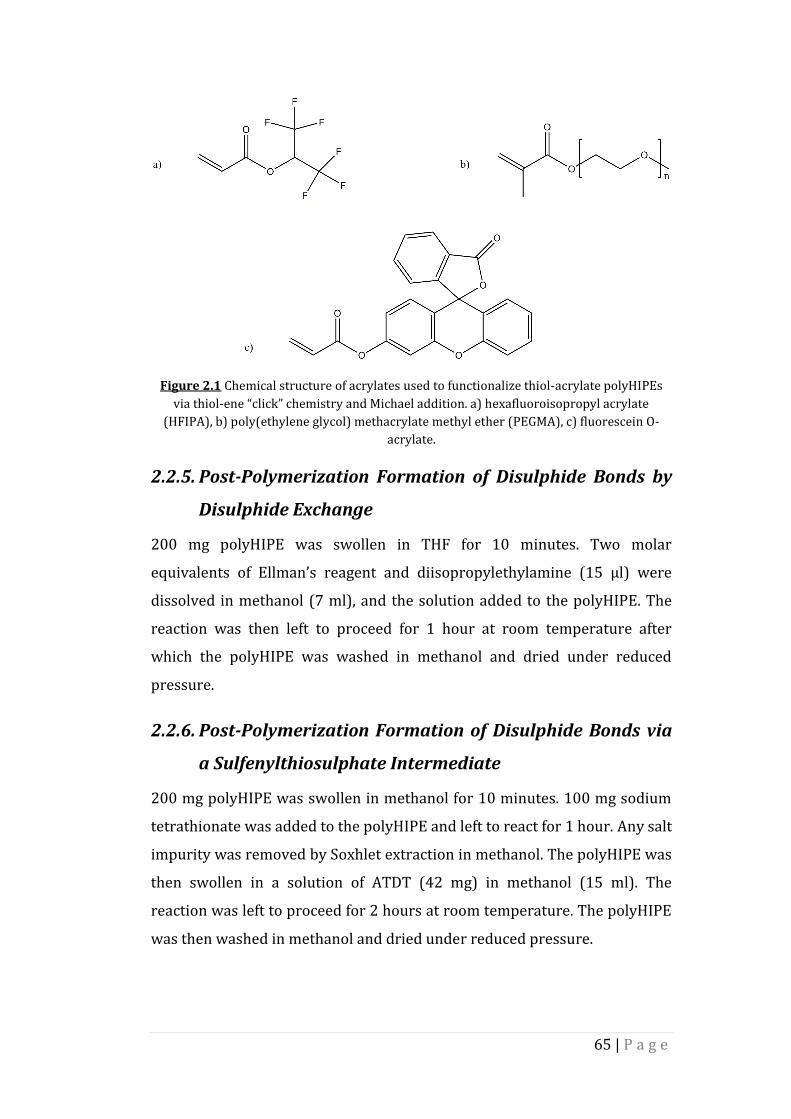
65 | P a g e
Figure 2.1 Chemical structure of acrylates used to functionalize thiol-acrylate polyHIPEs
via thiol-ene “click” chemistry and Michael addition. a) hexafluoroisopropyl acrylate
(HFIPA), b) poly(ethylene glycol) methacrylate methyl ether (PEGMA), c) fluorescein O-
acrylate.
2.2.5. Post-Polymerization Formation of Disulphide Bonds by
Disulphide Exchange
200 mg polyHIPE was swollen in THF for 10 minutes. Two molar
equivalents of Ellman’s reagent and diisopropylethylamine (15 µl) were
dissolved in methanol (7 ml), and the solution added to the polyHIPE. The
reaction was then left to proceed for 1 hour at room temperature after
which the polyHIPE was washed in methanol and dried under reduced
pressure.
2.2.6. Post-Polymerization Formation of Disulphide Bonds via
a Sulfenylthiosulphate Intermediate
200 mg polyHIPE was swollen in methanol for 10 minutes. 100 mg sodium
tetrathionate was added to the polyHIPE and left to react for 1 hour. Any salt
impurity was removed by Soxhlet extraction in methanol. The polyHIPE was
then swollen in a solution of ATDT (42 mg) in methanol (15 ml). The
reaction was left to proceed for 2 hours at room temperature. The polyHIPE
was then washed in methanol and dried under reduced pressure.

66 | P a g e
2.3. PolyHIPE Functionalization – PFPA
2.3.1. Materials
All chemicals were obtained from Sigma Aldrich and used without further
purification.
2.3.2. PFPA Synthesis
4.00 g pentafluorophenol and 2.64 g triethylamine were dissolved in dry
diethyl ether in a two-neck round bottom flask. 2.36 g acryloyl chloride was
added dropwise under cooling with an ice bath. The ice bath was then
removed and the mixture was stirred for two hours at room temperature.
The precipitate salt was removed by filtration. After evaporation of the
solvent the residue was filtered again and purified by column
chromatography (silica gel, petroleum ether).
The mass of PFPA obtained was 3.20 g, giving a yield of 80%.
1H NMR (CDCl3): δ/ppm: 6.70 (d, 1H), 6.35 (dd, 1H), 6.16 (d, 1H).
2.3.3. Post-Polymerization Functionalization of PFPA-
PolyHIPEs – Tris(2-Aminoethyl) Amine
0.5 g polyHIPE was left to swell in methanol for 10 minutes. A solution of
tris(2-aminoethyl) amine (0.027 g) and triethylamine (0.025 g) in 2 ml
methanol was prepared and added to the polyHIPE. The polyHIPE solution
was then left for 48 hours at room temperature. The polyHIPE was then
removed from the methanol solution and washed by Soxhlet extraction in
methanol for 12 hours. The polyHIPE was then dried under reduced
pressure.
2.3.4. Post-Polymerization Functionalization of PFPA-
PolyHIPEs – L-Alanine
0.25 g polyHIPE was swelled in methanol for 10 minutes. A solution of L-
alanine (0.01 g, chemical structure shown in Figure 2.2) and triethylamine
(0.013 g) in 20 ml methanol was prepared and then brought to pH 10 using

67 | P a g e
sodium hydroxide. The swollen polyHIPE was then transferred to the amino
acid solution and left at room temperature for 48 hours. The polyHIPE was
then washed by Soxhlet extraction for 12 hours and then dried under
reduced pressure.
Figure 2.2 Chemical Structure of L-alanine.
2.3.5. Post-Polymerization Functionalization of PFPA-
PolyHIPEs – RGD
0.25 g polyHIPE was swelled in methanol for 10 minutes. A solution of
arginylglycylaspartic acid (RGD) (23 mg) and triethylamine (0.013 g) in 20
ml methanol was prepared and then brought to pH 10 using sodium
hydroxide. The swollen polyHIPE was then transferred to the amino acid
solution and left at room temperature for 48 hours. The polyHIPE was then
washed by Soxhlet extraction for 12 hours and then dried under reduced
pressure.
Figure 2.3 Chemical structure of RGD.

68 | P a g e
2.4. Peptide Synthesis
2.4.1. Materials
Rink amide resin and amino acids were obtained from Novabiochem and
used as received.
PyBOP was obtained from Apollo Scientific and used without further
purification.
All other chemicals were obtained from Sigma Aldrich and used as received.
2.4.2. Peptide (GGRGD) Synthesis
1 g rink amide resin (loading 1.1 mmol g-1) was swollen in a mix of 2.5 ml
dimethylformamide (DMF) and 2.5 ml DCM for 1 hour. The DCM was then
washed off with DMF. The resin was then deprotected for 5 minutes in 5 ml
of a solution of 20% piperidine in DMF. The piperidine was then washed off
and the deprotection repeated for 10 minutes. The resin was then washed
thoroughly with DMF.
A solution of 0.796 g of PyBOP, 0.19 ml N-methylmorpholine (NMM) and
0.641 g aspartic acid in 5 ml DMF was prepared and left for 10 minutes in
order to activate the c-terminus of the amino acid. This solution was then
added to the deprotected resin, which was then shaken for 2 hours at 320
rpm. The resin was then washed with DMF and the procedure was repeated.
The amino acid was then deprotected using the same procedure used for
resin deprotection and the next amino acid then coupled by the same
method as described above.
Once all amino acids were coupled, the peptide was then cleaved from the
resin and any acid sensitive protecting groups removed from the amino acid
side chains. This was done by adding a 38:1:1 mixture of trifluoroacetic acid
(TFA), water and triisopropyl silane (TIPS, 3 ml in total) to the resin. The
resin was then left for 3 hours with occasional stirring. The resin was then
removed from the peptide solution by filtration and the peptide was then

69 | P a g e
precipitated into cold diethyl ether. The ether was then removed with a
pipette and the peptide was then freeze dried in a minimum of water.
The chemical structure of the GGRGD peptide is shown in Figure 2.4.
Figure 2.4 Chemical Structure of GGRGD.
2.5. PolyHIPE Characterization
2.5.1. Raman
All Raman spectroscopy data was recorded using a HORIBA Jobin Yvon
LabRAM HR 800 with a built in 633 nm He:Ne laser. All spectra are
referenced to Si band (ν = 520.07 cm-1).
2.5.2. Solid State NMR Spectroscopy
Solid-state 19F NMR spectra were obtained using a Varian VNMRS 400
spectrometer using a direct polarisation experiment at a frequency of
282.087 MHz.
Solid-state 13C NMR spectra were obtained using a VNMRS 400
spectrometer using a direct polarisation excitation experiment at a
frequency of 100.56 MHz.
All solid state NMR spectra were obtained using the on board Varian NMR
software and spectral referencing is the respect to external, neat
tetramethylsilane. All polyHIPE samples were ground to a powder prior to
obtained solid state NMR spectra.

70 | P a g e
2.5.3. XPS
X-ray photoelectron spectra were carried out by Dr. Naoko Sano at the
National EPSRC User’s Service (NEXUS) at Newcastle University, an EPSRC
Mid-Range Facility.
2.5.4. FT-IR
All IR spectra were obtained using a Perkin Elmer 1600 series FTIR
spectrometer equipped with a Golden Gate ATR element.
2.5.5. Elemental Analysis
Elemental microanalyses were carried out by Mr. Stephen Boyer at the
Microanalysis Service, London Metropolitan University.
2.5.6. Scanning Electron Microscopy
PolyHIPE morphology was investigated using a Philips/FEI XL30 ESEM
operating at 20 kV. Fractured polyHIPE pieces were sputter-coated with
gold to enhance conductivity and mounted on carbon fibre pads adhered to
aluminium stubs. The void diameters were obtained using Image J Version
1.44p. One hundred voids were measured in a random walk of voids across
the obtained micrograph. During fracturing, voids are unlikely to be exactly
bisected, and so the voids obtained by this method are an underestimation.
In order to account for this a statistical correction factor is applied107.
2.5.7. Determination of Thiol Loading Using Ellman’s Reagent
5-10 mg polyHIPE was frozen in liquid nitrogen and then ground to a
powder with a mortar and pestle. This powder was then transferred to a 5
ml volumetric flask and 1 ml THF was added. The polyHIPE was left to swell
for 10 minutes. During this time a 1 ml solution of Ellman’s reagent (5 μmol)
in ethanol was prepared. This solution was then added to the polyHIPE
along with 5 μl diisopropylethylamine. The flask was then shaken for 30
minutes and then diluted to 5 ml with ethanol. This solution was then
filtered and diluted to a concentration between 5 μmol and 5mmol in a 96
well plate and the absorbance measured at 412 nm.

71 | P a g e
3. Results and Discussion
3.1. Trithiol-Triacrylate PolyHIPEs
3.1.1. Trithiol-Triacrylate PolyHIPE Synthesis
The preparation of thiol-ene polyHIPEs from trimethylolpropane tris-
mercaptopropionate (TMPTMP) and trimethylolpropane triacrylate
(TMPTA) has been described previously44 (Scheme 3.1). Briefly: water was
added dropwise to an oil phase consisting of TMPTMP, TMPTA, 1,2-
dichloroethane, surfactant and a photoinitiator. Once the emulsion was
formed it was then poured into a mould and cured by passing under UV
radiation. The solid polyHIPE was then washed in acetone to remove the
aqueous droplet phase and dried under reduced pressure to yield the final
polyHIPE polymer.
Scheme 3.1 Preparation of thiol-acrylate polyHIPEs from TMPTMP and TMPTA. Scale bar =
50 µm.
The morphology of the obtained polyHIPEs was investigated using scanning
electron microscopy (SEM). The polyHIPE samples were found to be highly
porous and a fully interconnected, open cell morphology was observed
(Figure 3.1).

72 | P a g e
Figure 3.1 Morphology of 50:50 TMPTMP/TMPTA polyHIPE as obtained by SEM polyHIPE
at two different magnifications.
The measured void diameters are found to range from 10 – 100 µm, as
shown in Figure 3.2.
Figure 3.2 Void diameter range observed for (front to back) 40%, 50% and 60% TMPTMP
polyHIPEs.
A major advantage of using thiol-ene “click” chemistry is the resilience of
any unreacted carbon-carbon double bonds and thiols within the polymer
network to reaction upon storage compared to reactive monomers, such as
pentafluorophenyl acrylate (PFPA), which may undergo hydrolysis. The
presence of residual vinyl groups in (vinyl)polystyrene polyHIPEs has
previously been used as a route to the functionalization of these polymers
post-polymerization. Thiol-bearing molecules were added across these
double bonds via both batch and cross-flow methods, and the reactions
were monitored using analytical techniques such as fourier transform
a) b)

73 | P a g e
infrared (FT-IR spectrscopy) and elemental microanalysis. This project aims
to show that residual thiols found within thiol-acrylate polyHIPEs can be
used to functionalize the polymer surface with acrylate-containing
molecules and can also be used in the formation of disulphide bonds.
Raman spectroscopy (Figure 3.3) was used in order to show the presence of
unreacted thiol groups within the thiol-acrylate polyHIPEs.
Figure 3.3 Raman spectrum of 60 % thiol trithiol-triacrylate polyHIPE.
The small peak at ~2500 cm-1 indicates the presence of thiol groups within
the polyHIPE, while the larger peak at ~2900 cm-1 represents the aliphatic
C-H bonds.
The theoretical level of unreacted thiol within the 60% thiol polyHIPE can
be calculated using Equation 3.1223
(3.1)
where ninitial thiol groups is the number of thiol groups in the HIPE prior to
curing and ninitial π bonds is the number of carbon-carbon double bonds in the
HIPE prior to curing. The theoretical level of thiol loading was found to be
1.7 mmol g-1; however, possible acrylate homopolymerization during the
( )initial thiol groups initial bondsn nThiolLoading
Total massof reagents
S-H C-H

74 | P a g e
formation of the polyHIPE leads to unreacted thiol groups in polyHIPEs
containing 50% of the trithiol monomer and 40% of the trithiol monomer,
which the above equation cannot account for. In order to quantify the
amount of unreacted thiol within these polyHIPEs a colorimetric assay using
Ellman’s reagent was used224. The mechanism for the formation of the
chromophore is shown in Scheme 3.2 and the number of moles of thiol
detected using the assay is shown in Figure 3.4.
Scheme 3.2 Formation of the chromophore during colorimetric assay using Ellman’s
reagent.
Figure 3.4 Number of moles of unreacted thiol groups in trithiol-triacrylate
polyHIPEs.
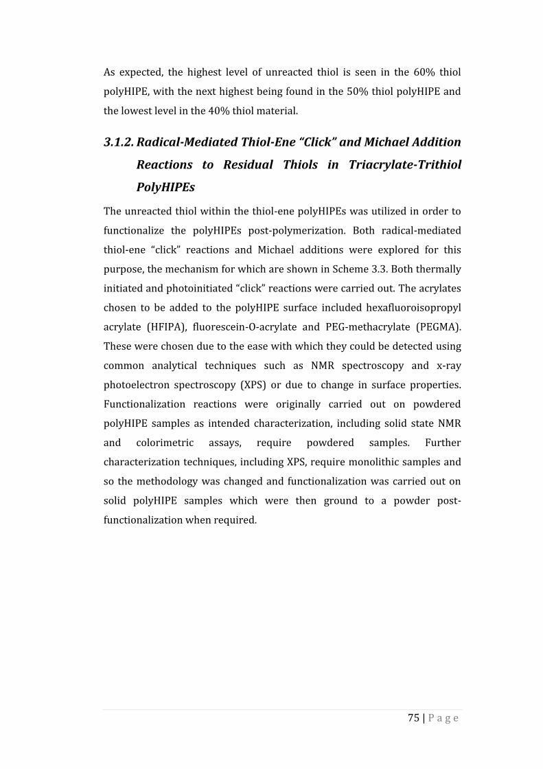
75 | P a g e
As expected, the highest level of unreacted thiol is seen in the 60% thiol
polyHIPE, with the next highest being found in the 50% thiol polyHIPE and
the lowest level in the 40% thiol material.
3.1.2. Radical-Mediated Thiol-Ene “Click” and Michael Addition
Reactions to Residual Thiols in Triacrylate-Trithiol
PolyHIPEs
The unreacted thiol within the thiol-ene polyHIPEs was utilized in order to
functionalize the polyHIPEs post-polymerization. Both radical-mediated
thiol-ene “click” reactions and Michael additions were explored for this
purpose, the mechanism for which are shown in Scheme 3.3. Both thermally
initiated and photoinitiated “click” reactions were carried out. The acrylates
chosen to be added to the polyHIPE surface included hexafluoroisopropyl
acrylate (HFIPA), fluorescein-O-acrylate and PEG-methacrylate (PEGMA).
These were chosen due to the ease with which they could be detected using
common analytical techniques such as NMR spectroscopy and x-ray
photoelectron spectroscopy (XPS) or due to change in surface properties.
Functionalization reactions were originally carried out on powdered
polyHIPE samples as intended characterization, including solid state NMR
and colorimetric assays, require powdered samples. Further
characterization techniques, including XPS, require monolithic samples and
so the methodology was changed and functionalization was carried out on
solid polyHIPE samples which were then ground to a powder post-
functionalization when required.

76 | P a g e
Scheme 3.3 Functionalization of thiol-acrylate polyHIPEs by radical mediated “click” and
Michael addition reactions.
The addition of HFIPA to the polyHIPE surface was monitored by solid state
19F NMR spectroscopy (Figure 3.5). In all three cases (photoinitiated “click”,
thermally initiated “click”, and Michael addition), a peak at ~73 ppm was
observed, indicating the presence of HFIPA in the polyHIPEs. The 19F NMR
spectrum of an unfunctionalized polyHIPE sample did not show any peaks.
Figure 3.5 Solid state 19F NMR spectrum of 50% TMPTMP thiol-acrylate polyHIPE
functionalized post-polymerization with HFIPA via thermal and photo-initiated “click”
reactions and by a Michael addition.
X-ray photoelectron spectroscopy (XPS) can also be used to monitor the
surface functionalization of the thiol-acrylate polyHIPEs. Both survey and

77 | P a g e
high-resolution spectra were obtained for each sample, and are shown in
Figure 3.6.
Figure 3.6 XPS of 40% TMPTMP polyHIPEs surface functionalized with HFIPA. a) Survey
scan, b) high-resolution F 1s spectrum.
The fluorine 1s electron can be observed at 686 eV in both the survey and
high-resolution spectra, with the peaks at 534 eV and 284 eV representing
the 1s electrons in the carbon atoms of carbonyl groups and oxygen 1s
a)
b)
F 1s
C 1s O 1s

78 | P a g e
electrons respectively. The difference in peak heights indicates a higher
level of functionalization has been achieved for the thermally initiated
“click” and Michael addition methods than for the photoinitiated “click”
functionalization. In order to investigate this further, the Ellman’s reagent
colorimetric assay was repeated on the functionalized polyHIPEs, and the
results are summarized in Table 3.1.

79 | P a g e
The Ellman’s assay confirms that a higher level of functionalization is
achieved for both the thermally initiated “click” and Michael addition
reactions across all three thiol concentrations. This could be attributed to
the longer reaction times associated with these two methods compared with
Ta
ble
3.1
Percen
tage F
un
ction
alization
of th
iol-acry
late po
lyH
IPE
s surface fu
nctio
na
lized w
ith H
FIP
A as d
etermin
ed u
sing
Ellm
an’s reag
ent.
Po
lyH
IPE
U
nfu
nctio
nalized
T
herm
al Click
U
V C
lick
Mich
ael Ad
ditio
n
Th
iol
Co
ncen
tration
(mm
ol)
Th
iol
Co
ncen
tration
(mm
ol)
%
Fu
nctio
nalizatio
n
Th
iol
Co
ncen
tration
(mm
ol)
%
Fu
nctio
nalizatio
n
Th
iol
Co
ncen
tration
(mm
ol)
%
Fu
nctio
nalizatio
n
40
%
Th
iol
0.0
9
0.0
1
87
0
.10
0
0
.02
8
2
50
%
Th
iol
0.2
5
0.0
3
88
0
.11
5
5
0.0
2
93
60
%
Th
iol
0.3
5
0.0
4
89
0
.15
5
9
0.0
2
94

80 | P a g e
the photoinitiated functionalization reaction or due to a lack of penetration
of UV into the opaque polyHIPE.
The level of functionalization achieved using the photoinitiated “click”
method on the 40% TMPTMP polyHIPE was much lower than expected
(~0%). The concentration of residual, unreacted thiol on the surface of all
three polyHIPE samples post-functionalization via the photoinitiated “click”
reaction are comparable, suggesting that a percentage of the thiols of the
surface of a thiol-acrylate polyHIPE are inaccessible on the timescale of the
photoinitiated “click” reaction. The initial concentration of thiol is much
lower in the 40% TMPTMP sample than the other polyHIPE samples
prepared (0.09 mmol g-1, compared with 0.25 mmol g-1 and 0.35 mmol g-1
for the 50% TMPTMP and 60% TMPTMP polyHIPE respectively), and is
roughly the same as the concentration obtained post-functionalization.
Therefore, it can be concluded that all of the thiol on the surface of the 40%
TMPTMP polyHIPE cannot be accessed by further acrylate containing
molecules during the short reaction time associated with the photoinitiated
“click” reaction.
The morphology of the functionalized polyHIPEs was investigated using
SEM. As with the unfunctionalized polyHIPEs described previously, the
polymers display an open cell morphology with fully interconnected voids
(Figure 3.7).

81 | P a g e
Figure 3.7 Morphology of TMPTMP/TMPTA polyHIPEs functionalized with HFIPA post-
polymerization as obtained by SEM. a), b) SEM images of 60% TMPTMP polyHIPE after
functionalization via a thermally initiated “click” reaction at two different magnifications. c),
d) SEM images of 60% TMPTMP polyHIPE after functionalization via a UV initiated “click”
reaction at two different magnifications. e), f) SEM images of 60% TMPTMP polyHIPE after
functionalization via a Michael addition at two different magnifications.
The range of void diameters observed was measured and the results are
summarized in Figure 3.8.
a)
d)
b)
c)
e) f)

82 | P a g e
Figure 3.8 Void diameter range observed for (front to back) 40% TMTMP polyHIPE before
functionalization, 40% TMPTMP polyHIPE after functionalization via a thermally initiated
“click” reaction, 40% TMPTMP polyHIPE after functionalization via a photoinitiated “click”
reaction, 40% TMPTMP polyHIPE after functionalization by a Michael addition.
The diameter of the observed voids falls within the same range as those in
the unfunctionalized polyHIPEs and the surface of the polymer appears the
same. Therefore, it can be deduced that surface functionalization of these
thiol-acrylate polyHIPEs via “click” and Michael addition reactions does not
alter the morphology of the polyHIPEs.
The fluorescent acrylate, fluorescein O-acrylate, was grafted to the surface in
order to give a visual demonstration of the functionalization reaction
(Figure 3.9). Prior to functionalization the polymer fluoresces blue under UV
radiation. Upon grafting of fluorescein O-acrylate to the surface the
polyHIPE then exhibits the yellow/green colour characteristic of the
fluorescent acrylate. Extensive washing via Soxhlet extraction suggests that
this colour change is due to fluorescein O-acrylate that is chemically bonded
to the polyHIPE surface rather than trapped in the crosslinked polymer
network.

83 | P a g e
Figure 3.9 Thiol-acrylate polyHIPE functionalized with fluorescein O-acrylate under UV
light. Functionalization carried out via a thermally initiated “click” reaction: a)
unfunctionalized polyHIPE, b) 40% TMPTMP polyHIPE, c) 50% TMPTMP polyHIPE, d) 60%
TMPTMP polyHIPE. Functionalization carried out via a photoinitiated “click” reaction: e)
unfunctionalized polyHIPE, f) 40% TMPTMP polyHIPE, g) 50% TMPTMP polyHIPE, h) 60%
TMPTMP polyHIPE. Functionalization carried out via a Michael addition: i) unfunctionalized
polyHIPE, j) 40% TMPTMP polyHIPE, k) 50% TMPTMP polyHIPE, l) 60% TMPTMP
polyHIPE.
It was hypothesized that surface functionalization via the thermally initiated
“click” and Michael addition reactions should give sufficient levels of
functionalization in order to change the surface properties of the polymer.
In order to investigate this, a short chain PEG-methacrylate (PEGMA, Mn =
300 Da) was chosen and grafted to the surface. The presence of PEGMA
within the polyHIPE network was then determined by solid state 13C NMR
spectroscopy (Figure 3.10). The peak at 71 ppm represents the carbon in the
PEG chain and is not observed in the spectrum of an unfunctionalized
sample.

84 | P a g e
Figure 3.10 Solid state 13C NMR spectrum of 50% TMPTMP thiol-acrylate polyHIPE
functionalized post-polymerization with PEGMA.
The change in the hydrophobicity of the surface after the polyHIPEs were
functionalized with PEGMA was tested as follows: water droplets coloured
with blue food dye (a mixture of brilliant blue and carmoisine which should
not affect the surface tension of water) were added to the surface of the
polyHIPE and monitored in order to see if the droplets were absorbed into
the polymer network (Figure 3.11). PolyHIPEs containing 60% TMPTMP
functionalized by both the thermal “click” and Michael addition methods
exhibited a changed in surface hydrophobicity and the water droplets were
seen to soak into the polymer. The surface concentration of PEGMA was
found to be too low to induce a change in the properties of the polymer
surface in all samples containing lower TMPTMP concentrations as well as
the 60% TMPTMP polyHIPE functionalized via the UV initiated “click”
reaction.

85 | P a g e
Figure 3.11 Water droplets added to the surface of 60% TMPTMP thiol-acrylate polyHIPEs.
a) polyHIPE before addition of PEGMA to the surface, b) polyHIPE after the addition of
PEGMA by a UV initiated “click” reaction, c) polyHIPE after the addition of PEGMA by a
thermally initiated “click” reaction, d) polyHIPE after the addition of PEGMA by a Michael
addition. Pink colouration observed in (d) is an artefact of the camera used to obtain the
image.
3.1.3. Disulphide Bonds in Trithiol-Triacrylate PolyHIPEs
As well as thiol-ene “click” and Michael addition chemistries, thiol-
containing molecules are also known to form disulphide bonds, and so it
was hypothesized that the unreacted thiol in the thiol-acrylate polyHIPE
network may form disulphide bonds with other thiol-containing molecules.
Disulphide bonds between the polymer surface and two different thiol
containing molecules were formed via two reaction methods. The first of
these methods is the base catalysed reaction of 5,5’-dithiobis-(2-
nitrobenzoic acid) (Ellman’s reagent) with the surface bound thiol groups,
as shown in scheme 3.4. The disulphide bond in Ellman’s reagent undergoes
a disulphide exchange, releasing a chromogenic molecule, 5-sulphido-2-
nitrobenzoate (TNB). TNB absorbs strongly at 412 nm, and a single
molecule is released from each molecule of Ellman’s reagent that reacts with
a surface bound thiol group224. It is this quantitative release of a
chromogenic molecule which is the basis of the colorimetric assay used to
a)
d)
b)
c)

86 | P a g e
determine the percentage of functionalization achieved using “click” and
Michael addition chemistries.
Scheme 3.4 Functionalization of thiol-acrylate polyHIPEs via a thiol-disulphide exchange
with Ellman’s reagent.
Due to its nitrogen content, the presence of Ellman’s reagent on the surface
of the polyHIPEs can be determined by both XPS, as shown in Figure 3.12,
and elemental analysis.

87 | P a g e
Figure 3.12 XPS of TMPTMP polyHIPEs surface functionalized with Ellman’s reagent. a)
Survey scan, b) high-resolution N 1s spectrum.
Both the survey scan and high resolution XPS spectra show a low intensity
nitrogen peak at 399 eV, representing the nitrogen 1s electron, with peaks
at 534 eV and 284 eV representing the 1s electrons in the carbon atoms of
carbonyl groups and oxygen 1s electrons respectively . The low intensity of
the nitrogen 1s peak indicates that the concentration of nitrogen at the
polymer surface is low. The overall percentage functionalization achieved
can be obtained by elemental analysis, the results of which are summarized
in Table 3.2.
a)
b)
N 1s
C 1s
O 1s

88 | P a g e
Table 3.2 Percentage functionalization of thiol-acrylate polyHIPEs functionalized with
Ellman’s reagent as determined by elemental analysis.
PolyHIPE % Nitrogen
(Theoretical)
% Nitrogen
(Obtained)
% Functionalization
40% Thiol 0.64 0.64 100
50% Thiol 1.79 1.41 79
60% Thiol 2.50 <0.1 0
A high percentage functionalization was obtained for both the 40%
TMPTMP and 50% TMPTMP samples, however, the percentage of nitrogen
in the 60% TMPTMP sample was too low to be detected. The high-resolution
N 1s XPS spectrum of the same sample indicates that there is a low
concentration of nitrogen on the surface of the polymer. This nitrogen
concentration may be too low to be detected by elemental analysis. In order
to ascertain the reason for the conflicting elemental analysis and XPS results
in the case of the 60% TMPTMP polyHIPE other analytical techniques must
be explored. Using a wider range of thiol molecules would allow for a more
thorough evaluation of this method using simple analytical techniques such
as NMR and FT-IR spectroscopy. Longer reaction times may also result in a
higher degree of functionalization, allowing for the detection of nitrogen
using the elemental analysis technique. The high percentage of N observed
by elemental analysis in the 40% TMPTMP sample may also be falsely high.
This could be due to incorrect washing of the sample, resulting in Ellman’s
reagent being trapped in the polyHIPE network as opposed to bound to the
polymer surface.

89 | P a g e
The morphology of the functionalized polyHIPEs was investigated using
SEM (Figure 3.13).
Figure 3.13 Morphology of TMPTMP/TMPTA polyHIPE after addition of Ellman’s reagent
to the polymer surface as obtained by SEM. a), b) SEM images of 40% TMPTMP polyHIPE at
two different magnifications.
The polyHIPEs display open cell morphology with fully interconnected
voids, suggesting the formation of disulphide bonds between the thiol
groups in the polyHIPE network and the thiol group in Ellman’s reagent has
not resulted in any visible changes to the polymer surface. The void
diameters were also measured, the results of which are shown in Figure
3.14
Figure 3.14 Void diameter range observed for 40% TMPTMP polyHIPE functionalized post-
polymerization with Ellman’s reagent.
The diameter of the obtained voids falls within the same range as those in
the unfunctionalized polyHIPEs
a) b)
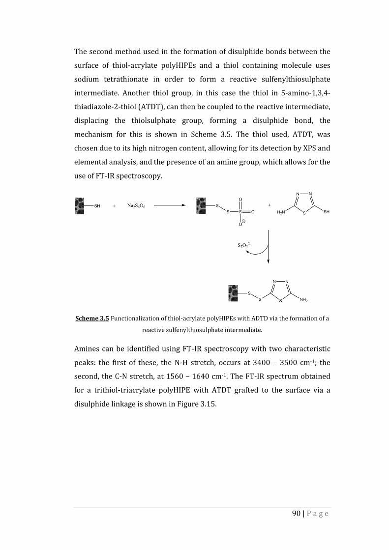
90 | P a g e
The second method used in the formation of disulphide bonds between the
surface of thiol-acrylate polyHIPEs and a thiol containing molecule uses
sodium tetrathionate in order to form a reactive sulfenylthiosulphate
intermediate. Another thiol group, in this case the thiol in 5-amino-1,3,4-
thiadiazole-2-thiol (ATDT), can then be coupled to the reactive intermediate,
displacing the thiolsulphate group, forming a disulphide bond, the
mechanism for this is shown in Scheme 3.5. The thiol used, ATDT, was
chosen due to its high nitrogen content, allowing for its detection by XPS and
elemental analysis, and the presence of an amine group, which allows for the
use of FT-IR spectroscopy.
Scheme 3.5 Functionalization of thiol-acrylate polyHIPEs with ADTD via the formation of a
reactive sulfenylthiosulphate intermediate.
Amines can be identified using FT-IR spectroscopy with two characteristic
peaks: the first of these, the N-H stretch, occurs at 3400 – 3500 cm-1; the
second, the C-N stretch, at 1560 – 1640 cm-1. The FT-IR spectrum obtained
for a trithiol-triacrylate polyHIPE with ATDT grafted to the surface via a
disulphide linkage is shown in Figure 3.15.

91 | P a g e
Figure 3.15 FT-IR spectrum of 60% TMPTMP polyHIPE functionalized post-polymerization
with ATDT.
The broad peak at 3400 cm-1 and the smaller peak at 1640 cm-1 in the FT-IR
spectrum of a 60% TMPTMP polyHIPE after undergoing surface
functionalization with ATDT indicate the presence of an amine on the
polymer surface. The nitrogen content of the functionalized polymer was
also investigated by XPS, the results of which are shown in Figure 3.16.

92 | P a g e
Figure 3.16 XPS of 50% TMPTMP polyHIPEs surface functionalized with ATDT. a) Survey
scan, b) high-resolution N spectrum.
Both the survey scan and high resolution XPS spectra show a low intensity
nitrogen peak at 399 eV, representing the nitrogen 1s electron, with peaks
at 534 eV and 284 eV representing the 1s electrons in the carbon atoms of
carbonyl groups and oxygen 1s electrons respectively . The low intensity of
the nitrogen 1s peak indicates that the concentration of nitrogen at the
polymer surface is low. The overall percentage functionalization achieved
can be obtained by elemental analysis, the results of which are summarized
in Table 3.3.
a)
b)
N 1s
C 1s
O 1s

93 | P a g e
Table 3.3 Percentage functionalization of thiol-acrylate polyHIPEs functionalized with
ATDT as determined by elemental analysis.
PolyHIPE % Nitrogen
(Theoretical)
% Nitrogen
(Obtained)
% Functionalization
40% Thiol 1.90 0.52 27
50% Thiol 5.35 0.32 6
60% Thiol 7.49 <0.1 0
The level of functionalization obtained using sodium tetrathionate to initiate
the formation of disulphide bonds between the polymer surface and ATDT is
significantly lower than that obtained in the previous method. As with the
previous method, a higher level of functionalization was achieved in the
40% TMPTMP sample, and the concentration of nitrogen in the 60%
TMPTMP sample was too low to be detected. XPS and FT-IR analysis on the
60% TMPTMP polyHIPE sample indicate that there is nitrogen on the
surface of the polymer. The concentration of nitrogen within the 60%
TMPTMP polyHIPE may be too low to be detected by elemental analysis. The
low level of functionalization obtained in all samples could be due to a
number of factors, including inefficient displacement of the thiosulphate ion
from the sulfenylthiosulphate intermediate. Repeating the reaction with an
increased reaction time or with a larger excess of ATDT may lead to an
increase in the level of functionalization observed. Using a wider range of
thiol molecules would allow also for a more thorough evaluation of this
method using simple analytical techniques such as NMR and FT-IR
spectroscopy.

94 | P a g e
The morphology of the functionalized polyHIPEs was investigated using
SEM (Figure 3.17).
Figure 3.17 Morphology of TMPTMP/TMPTA polyHIPE as obtained by SEM. A), b) SEM
images of 50% TMPTMP polyHIPE two different magnifications.
The polyHIPEs display the same open cell morphology as seen in the
unfunctionalized samples. The diameter of the obtained voids was measured
and the results are summarized in Figure 3.18.
a) b)

95 | P a g e
Figure 3.18 Void diameter range observed for 50% TMPTMP polyHIPE functionalized post-
polymerization with ADTD.
The diameter of the voids fall within the same range as those in the
unfunctionalized polyHIPEs, suggesting that surface functionalization of the
polymer with the thiol ATDT has not resulted in any changes to the
polyHIPE morphology.
3.2. Trithiol-Penta/HexaAcrylate PolyHIPEs
3.2.1. Trithiol-Penta/Hexa Acrylate polyHIPE Synthesis
The formation of polyHIPEs from dipentaerythritol penta-/hexa-acrylate
(DPEHA) and TMPTMP has been described previously99 (Scheme 3.6).
Briefly: water was added dropwise to an oil phase consisting of TMPTMP,
DPEHA, dichloroethane, surfactant and a photoinitiator. Once the emulsion
was formed it was then poured into a mould and cured by passing under UV
radiation. The solid polyHIPE was then washed in acetone to remove the
aqueous droplet phase and dried under reduced pressure to yield the final
polyHIPE polymer.

96 | P a g e
Scheme 3.6 Preparation of thiol-acrylate polyHIPEs from TMPTMP and DPEHA. Scale bar =
50 µm.
The morphology of these polyHIPEs was investigated via SEM (Figure 3.19).
Figure 3.19 Morphology of TMPTMP/DPEHA polyHIPEs with 25% PFPA. a), b) SEM images
at two different magnifications.
The morphology of the polyHIPEs was found to be the typical open cell
structure seen in previous polyHIPEs, with a fully interconnected porous
network. The observed void diameters were also measured, the results of
which are summarized in Figure 3.20
a) b)

97 | P a g e
Figure 3.20 Void diameter range observed for DEPHA/TMPTMP polyHIPE.
The void diameters were calculated to be in the range of 0 to 60 µm. The use
of a penta-/hexa-acrylate, such as DPEHA, results in a material with a higher
crosslink density than those formed using TMPTA. This higher crosslink
density results in a slight decrease in the void diameter, when compared to
thiol-acrylate polyHIPEs formed using TMPTA, and an increase in the
mechanical strength of the material44. This increase in crosslink density
allows for non-crosslinking acrylates to be incorporated into a thiol-acrylate
polyHIPE, resulting in a further route to the chemical functionalization of
these materials.
3.2.2. Incorporation of Other Monomers into Trithiol-
Penta/Hexa Acrylate polyHIPE
It has been shown previously that the addition of active esters, such as
pentafluorophenyl acrylate (PFPA), into the continuous phase of an
emulsion yields polyHIPEs that retain the functionality of the ester upon
curing99. These groups can then be used to further functionalize the
polyHIPE post-polymerization using simple organic reactions. Up to 50% of
the acrylate monomer concentration can be replaced by a functional
acrylate, such as PFPA, before the effect on the mechanical properties
becomes too great. The incorporation and subsequent reactions of PFPA can
be monitored via solid state NMR spectroscopy (figure 3.21).

98 | P a g e
Figure 3.21 Solid state 19F NMR spectrum of thiol-acrylate with and without PFPA.
The multiplet signal in the 19F NMR spectra of the polyHIPEs indicates that
PFPA has been successfully incorporated into the polymer matrix. Solid
state 13C NMR spectroscopy can also be used to determine the presence of
PFPA within the polyHIPE (Figure 3.22)
Figure 3.22 Solid state 13C NMR spectrum of PFPA-polyHIPE.

99 | P a g e
The solid state 13C NMR spectrum of the PFPA-polyHIPE shows two peaks
representative of the PFPA molecule: the first of these, at 129 ppm, indicates
the presence of the aromatic carbons; the second, at 166 ppm, indicates the
presence of carbonyl carbon in an ester group. The two PFPA peaks are not
present in the 13C NMR spectrum of a PFPA free thiol-acrylate polyHIPE.
PFPA can be identified using FT-IR spectroscopy via three peaks: the C-O-C
stretch of the ester group can be occurs at 1145 cm-1; the carbonyl at 1727
cm-1; and the aromatic carbon stretch at 1519 cm-1. The FT-IR spectrum of
the 25% PFPA-polyHIPE is shown in Figure 3.23
Figure 3.23 FT-IR spectrum of PFPA-polyHIPE
In the FT-IR spectrum of the PFPA-polyHIPE the PFPA can clearly be
identified by the peak at 1519 cm-1, which does not appear in the spectrum
of a thiol-acrylate polyHIPE without PFPA. The carbonyl and C-O-C ester
stretches indicative of PFPA are not clearly distinguishable as they appear in
the same position as the carbonyl and C-O-C ester stretches of the DPEHA.
The morphology of the PFPA-polyHIPEs was investigated using SEM (Figure
3.24).

100 | P a g e
Figure 3.24 Morphology of TMPTMP/DPEHA/PFPA polyHIPEs. a), b) SEM of 25% PFPA-
polyHIPE images at two different magnifications. c), d) SEM of 50% PFPA-polyHIPE at two
different magnifications.
The morphology of the polyHIPEs was found to be the typical open cell
structure seen in previous polyHIPEs, with a fully interconnected porous
network. The void diameters obtained upon inclusion of PFPA into the
emulsion were measured, as shown in Figure 3.25.
Figure 3.25 Void diameter range observed for (front to back) DPEHA/TMPTMP polyHIPE
before functionalization, 25% PFPA-polyHIPE, 50% PFPA-polyHIPE.
a)
d)
b)
c)
101 | P a g e
The void diameters are calculated to be in the range of 0 to 80 µm. The
increase in the obtained void diameter upon inclusion of PFPA is probably
as a result of the slightly higher solubility of PFPA in the aqueous phase
compared to DPEHA. The solubility of each monomer in the aqueous phase
can be quantified by their partition coefficient (log P), which is obtained
using Equation 3.2
octanol
un ionized water
logSolute
PSolute
(3.2)
where [Solute]octanol and [Solute}un-ionized water represent the solubility of a
given solute in octanol and un-ionized water, respectively. The partition
coefficient (log P) values for PFPA, DPEHA and TMPTMP are shown in Table
3.4. The values of log P indiciate that the addition of PFPA to the continuous
phase of a HIPE results in a slight increase in the hydrophilicity, and hence
to a slight destabilization of the emulsion, allowing water droplets to
aggregate. The aggregation of water droplets leads to the larger void
diameters observed. This increase in void diameter will need to be
accounted for when synthesizing polyHIPEs for specific applications where
the void diameter is important.
Table 3.4 Partition coefficient (log P) values of monomers used in DPEHA/TMPTMP
polyHIPE synthesis225-227.
Monomer log P
TMPTMP 3.01
DPEHA 2.65
PFPA 2.55
Incorporating non-crosslinking acrylates into the continuous phase of the
HIPE can also be used to directly alter the chemical properties of the
polyHIPE without the need for further reaction after curing. Monomers, such
as PEGMA, can be included in the emulsion in order to change the

102 | P a g e
hydrophobicity of the surface. The incorporation of PEGMA into the polymer
network, by replacing 25% DPEHA with PEGMA, can be monitored by solid
state 13C NMR spectroscopy, as shown in Figure 3.26.
Figure 3.26 Solid State 13C NMR spectrum of 25% PEGMA-polyHIPE.
The peak observed at 71 ppm represents the PEG chain and is not observed
in the spectrum of the thiol-acrylate polyHIPE without PEGMA.
The morphology of the PEG-polyHIPE was investigated using SEM, the
results of which are shown in Figure 3.27.
Figure 3.27 Morphology of PEGMA-polyHIPE. a), b) SEM images of PEG-polyHIPE at two
different magnifications.
The PEGMA-polyHIPE displays the same open cell morphology and the voids
are fully interconnected. The void diameters of the PEGMA-polyHIPE were
measured, the results of which are summarized in Figure 3.28
a) b)

103 | P a g e
Figure 3.28 Void diameters observed for (front to back) DPEHA/TMPTMP polyHIPE and
PEGMA-polyHIPE.
As seen with the PFPA-polyHIPEs, there is an increase in the observed void
diameters. This increase also arises from the hydrophilic nature of the PEG
chain in the PEGMA monomer.
The influence the addition of the PEGMA monomer has on the surface
properties of the polymer was investigated in the same way as described
previously. A water droplet is placed on the surface of the polyHIPE and is
monitored to see if it soaks into the polyHIPE (Figure 3.29).
Figure 3.29 Water droplet added to the surface of trithiol-penta/hexa acrylate polyHIPEs.
a) Before inclusion of PEGMA into the emulsion. b) PEGMA-polyHIPE.
Replacing 25% of the acrylate concentration of a trithiol-penta/hexa-
acrylate polyHIPE with PEGMA does not result in a change in the surface
properties of the final polymer. This method of functionalization leads to a
a) b)

104 | P a g e
lower concentration of PEG at the polymer surface than the “click” and
Michael addition functionalizations described previously. In this case the
active monomer is included in the polymerization mixture and can be found
throughout the bulk of the polymer in the porous network, as opposed to
just on the polymer surface as occurs using the previous grafting techniques.
This lower concentration of PEG at the surface means that the same change
in surface properties is not observed. Including PEGMA in the monomer
system may offer another advantage when developing polyHIPEs to be used
as scaffolds for 3D cell culture and tissue engineering. PEG has been shown
to inhibit non-specific protein adsorption to the surface of polymer
scaffolds228. This may be an advantage when bioactive molecules such as
sugars or small peptides are added to the polymer surface, as it may prevent
the proteins found in serum and media used in cell culture from interfering
with the way in which cultured cells interact with the surface bound
molecules. Extensive cell culture work would be required in order to prove
this hypothesis.
Since up to 50% of the acrylate monomer can be replaced by a functional
acrylate, polyHIPEs containing both PFPA and PEG were synthesized. Both
19F (Figure 3.30) and 13C solid state can be used to confirm the presence of
PEGMA and PFPA within the polymer network.
Figure 3.30 Solid state 19F NMR spectrum of PFPA-PEGMA-polyHIPE.

105 | P a g e
The multiplet signal in the 19F spectrum of the PFPA-PEGMA-polyHIPE
occurs in the same region as the PFPA-polyHIPE and as the 19F NMR
spectrum of the PFPA monomer. The presence of PFPA within the PFPA-
PEGMA-polyHIPE can also be determined by FT-IR spectroscopy (Figure
3.31).
Figure 3.31 FT-IR spectrum of PFPA-PEGMA-polyHIPE.
The PFPA aromatic carbons can be seen in the PFPA-PEGMA-polyHIPE
sample at 1519 cm-1. The PFPA ester stretches are, once again, masked by
the same ester stretches from the DPEHA monomer.
Solid state 13C NMR spectroscopy was also carried out on the same PFPA-
PEGMA-polyHIPE sample, the results of which are shown in Figure 3.32.

106 | P a g e
Figure 3.32 Solid State 13C NMR spectrum of PFPA-PEGMA-polyHIPE.
The PEG chain can be observed at 71 ppm as seen with the previous PEGMA
functionalized polyHIPE.
The morphology of the PFPA-PEGMA-polyHIPE was investigated using SEM,
the results of which are shown in Figure 3.33.
Figure 3.33 Morphology of PFPA-PEGMA-polyHIPE. a), b) SEM images of PFPA-PEGMA-
polyHIPE at two different magnifications.
The morphology observed for the PFPA-PEGMA-polyHIPE is much the same
as the morphology observed for both the PEGMA- and PFPA-polyHIPEs. The
void diameters obtained for the PFPA-PEGMA-polyHIPE were measured, the
results of which are summarized in Figure 3.34.
a) b)

107 | P a g e
Figure 3.34 Void diameters observed for (front to back) DPEHA/TMPTMP polyHIPE and
PFPA-PEGMA-polyHIPE.
As seen with both the PFPA-polyHIPE and the PEGMA-polyHIPE there is an
increase in the average void diameter upon the inclusion of functional
monomers in the HIPE.
3.2.3. Functionalization of PFPA-polyHIPE With Tris(2-
Aminoethyl) Amine
Once incorporated into the polyHIPE polymer network, PFPA can undergo
further reactions with nucleophiles, leading to functionalized polyHIPEs.
The mechanism for this functionalization reaction is shown in Scheme 3.7.
The first nucleophile chosen is tris(2-aminoethyl) amine (TAEA). This amine
was chosen due to its high nitrogen content, allowing for its detection by
elemental analysis. Solid state NMR and IR can also be used to monitor the
reaction as the peaks relating to the PFPA molecule will disappear.
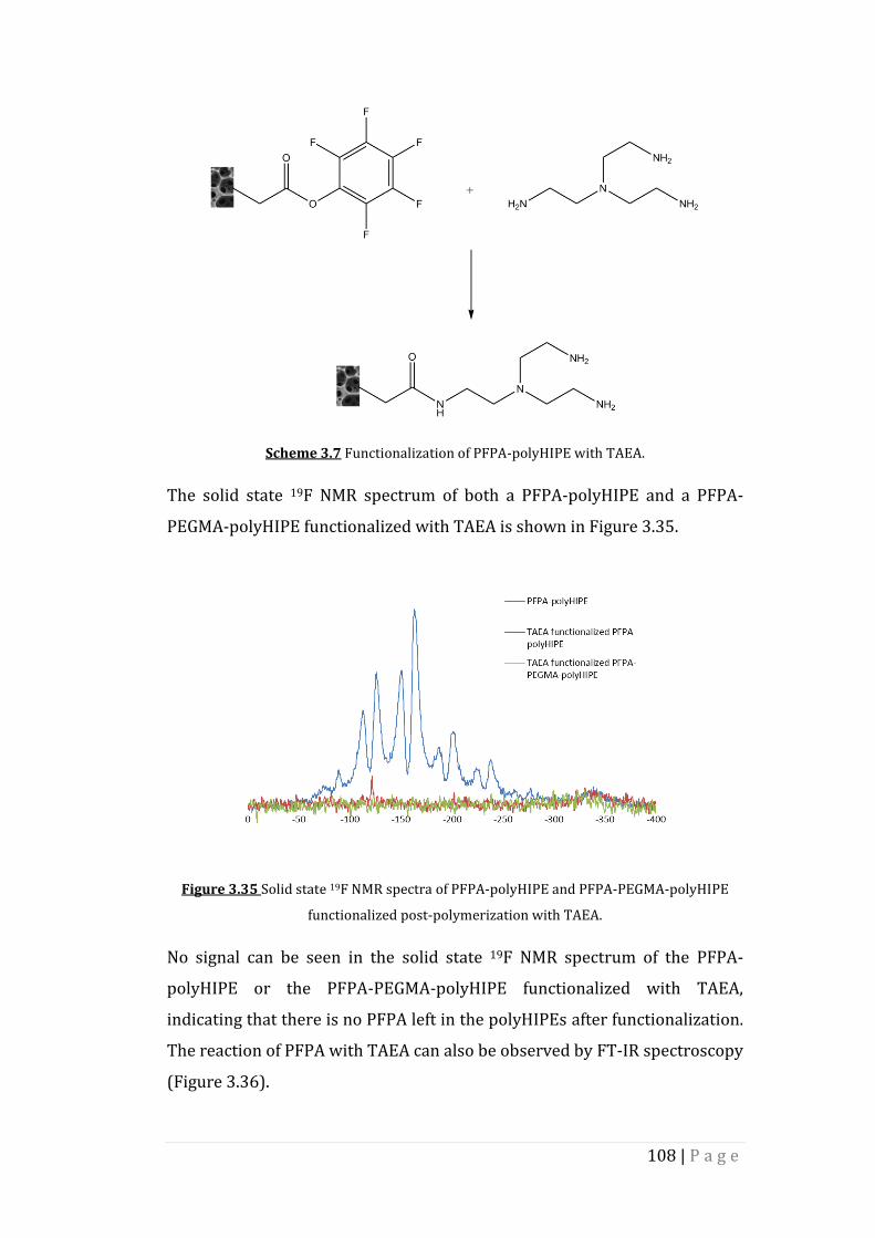
108 | P a g e
Scheme 3.7 Functionalization of PFPA-polyHIPE with TAEA.
The solid state 19F NMR spectrum of both a PFPA-polyHIPE and a PFPA-
PEGMA-polyHIPE functionalized with TAEA is shown in Figure 3.35.
Figure 3.35 Solid state 19F NMR spectra of PFPA-polyHIPE and PFPA-PEGMA-polyHIPE
functionalized post-polymerization with TAEA.
No signal can be seen in the solid state 19F NMR spectrum of the PFPA-
polyHIPE or the PFPA-PEGMA-polyHIPE functionalized with TAEA,
indicating that there is no PFPA left in the polyHIPEs after functionalization.
The reaction of PFPA with TAEA can also be observed by FT-IR spectroscopy
(Figure 3.36).
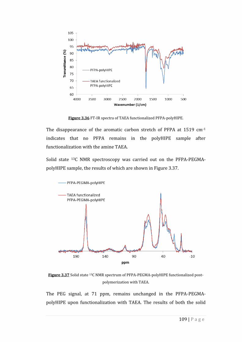
109 | P a g e
Figure 3.36 FT-IR spectra of TAEA functionalized PFPA-polyHIPE.
The disappearance of the aromatic carbon stretch of PFPA at 1519 cm-1
indicates that no PFPA remains in the polyHIPE sample after
functionalization with the amine TAEA.
Solid state 13C NMR spectroscopy was carried out on the PFPA-PEGMA-
polyHIPE sample, the results of which are shown in Figure 3.37.
Figure 3.37 Solid state 13C NMR spectrum of PFPA-PEGMA-polyHIPE functionalized post-
polymerization with TAEA.
The PEG signal, at 71 ppm, remains unchanged in the PFPA-PEGMA-
polyHIPE upon functionalization with TAEA. The results of both the solid

110 | P a g e
state 19F NMR spectroscopy and solid state 13C NMR spectroscopy indicate
that the inclusion of PEGMA in to the polyHIPE network does not have a
negative effect on the subsequent reactions of the PFPA monomer, and that
the reactions of the PFPA within the polymer network does not affect the
PEG chains in the polyHIPE polymer.
The percentage functionalization of PFPA can be obtained via elemental
analysis (Table 3.5).
Table 3.5 Percentage functionalization of PFPA-polyHIPE and PFPA-PEGMA-polyHIPE after
post-polymerization functionalization with TAEA as determined by elemental analysis.
PolyHIPE % Nitrogen
(Theoretical)
% Nitrogen
(Obtained)
% Functionalization
PFPA-
polyHIPE
0 <0.1 0
PFPA-PEG-
polyHIPE
0 <0.1 0
TAEA
functionalized
PFPA-
polyHIPE
0.86 0.61 71
TAEA
functionalized
PFPA-PEG-
polyHIPE
0.86 0.86 100
A high level of functionalization is achieved for both the PFPA-polyHIPE and
PFPA-PEGMA-polyHIPE samples. This high level of functionalization and the
mild conditions at which they were achieved suggests that this post-
polymerization functionalization method may be a suitable route to the
incorporation of biomolecules into the polyHIPE polymer network.
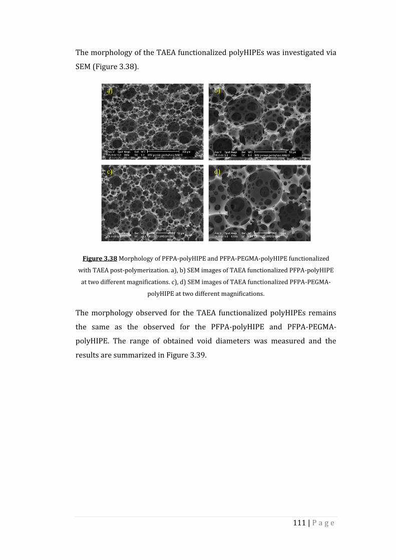
111 | P a g e
The morphology of the TAEA functionalized polyHIPEs was investigated via
SEM (Figure 3.38).
Figure 3.38 Morphology of PFPA-polyHIPE and PFPA-PEGMA-polyHIPE functionalized
with TAEA post-polymerization. a), b) SEM images of TAEA functionalized PFPA-polyHIPE
at two different magnifications. c), d) SEM images of TAEA functionalized PFPA-PEGMA-
polyHIPE at two different magnifications.
The morphology observed for the TAEA functionalized polyHIPEs remains
the same as the observed for the PFPA-polyHIPE and PFPA-PEGMA-
polyHIPE. The range of obtained void diameters was measured and the
results are summarized in Figure 3.39.
a)
d)
b)
c)

112 | P a g e
Figure 3.39 Void diameters observed for (front to back) TAEA functionalized PFPA-
polyHIPE and TAEA functionalized PFPA-PEGMA-polyHIPE.
As would be expected from the previous post-polymerization
functionalization methods, there is no change in the morphology or void
diameter range observed upon functionalization.
3.2.4. Functionalization of PFPA With L-Alanine and RGD
PFPA within the polymer network will undergo reactions with a wide range
of nucleophilic amines. Many molecules of biological importance, including
amino acids and peptides, contain nucleophilic amines, and so can be
incorporated into the polyHIPE network via the post-polymerization
functionalization reaction described previously. The short chain peptide
arginylglycylaspartic acid (RGD) was chosen due to its extensive use in
biomaterials for cell culture79, 229, 230. The RGD sequence is associated with
many extracellular matrix (ECM) proteins, including fibronectin and
collagen I, and interacts with integrin receptors on the cell surface to
facilitate focal point adhesion to the surface of the ECM231. RGD has been
incorporated into biomaterials via conjugation to a wide range of polymers,
and has been shown to promote cell proliferation and differentiation229, 232,
233. The advantage of incorporating the RGD peptide into a biomaterial, as
opposed to a whole ECM protein, lies in the small size of the peptide. This
small size allows for a higher packing density of the molecule within the
biomaterial, giving a higher density of cell adhesion points.

113 | P a g e
In order to investigate the potential of incorporating peptides into a PFPA-
polyHIPE, an amino acid, L-alanine, was first added to the polymer, followed
by the RGD peptide (obtained from Sigma Aldrich). The progress of the
reaction was monitored by solid state 19F and 13C spectroscopy, FT-IR
spectroscopy and elemental analysis. SEM was also used in order to
investigate the impact the functionalization process has on the polyHIPE
polymer surface.
The solid state 19F NMR spectrum of both the L-alanine and RGD
functionalized PFPA-polyHIPEs are shown in Figure 3.40.
Figure 3.40 Solid state 19F NMR spectra of PFPA-polyHIPE functionalized with alanine and
RGD.
The signal is seen to be at a reduced intensity in the 19F NMR spectrum of
the L-alanine and RGD functionalized PFPA-polyHIPE, indicating that there
is little PFPA left in the polyHIPE after functionalization.
The reaction of the polymer bound PFPA can also be observed by FT-IR
spectroscopy (Figure 3.41).

114 | P a g e
Figure 3.41 FT-IR spectra of PFPA-polyHIPE functionalized with alanine and RGD.
The aromatic carbons of the PFPA molecule can be clearly seen in the FT-IR
spectrum of the PFPA-polyHIPE at 1519 cm-1. Upon reaction with both L-
alanine and RGD this peak can be seen to disappear, indicating that no PFPA
remains in the sample upon completion of the functionalization reaction.
The presence of the biomolecules in the polyHIPE network can be shown by
solid state 13C NMR spectroscopy (Figure 3.42).

115 | P a g e
Figure 3.42 Solid state 13C NMR spectra of PFPA-polyHIPE functionalized with L-alanine
and RGD.
Upon incorporating the amino acid and peptide into the polymer network a
signal at 52 ppm can be observed in the solid state 13C NMR spectra. This
signal is indicative of an amine and cannot be seen in the 13C NMR spectrum
of PFPA-polyHIPE, suggesting that the biomolecules have been successfully
bonded to the polymer.
Elemental analysis can be used to determine the percentage conversion of
PFPA to biomolecule, the results of which are summarized in Table 3.6.

116 | P a g e
Table 3.6 Percentage functionalization of PFPA-polyHIPE and PFPA-PEGMA-polyHIPE after
post-polymerization functionalization with L-alanine and RGD as determined by elemental
analysis.
PolyHIPE % Nitrogen
(Theoretical)
% Nitrogen
(Obtained)
% Functionalization
L-Alanine
functionalized
PFPA-
polyHIPE
0.22 0.54 245
L-Alanine
functionalized
PFPA-PEG-
polyHIPE
0.22 0.56 254
RGD
functionalized
PFPA-
polyHIPE
1.28 0.57 44
The high levels of functionalization observed for the functionalization of
PFPA-polyHIPE could be explained in a number of ways. The first of these is
that the L-alanine has adsorbed onto the polymer surface rather than
undergoing a reaction with PFPA. In order to investigate this, the reaction
was repeated on a PFPA-PEGMA-polyHIPE as PEG has been shown at have
anti-biofouling properties. The similarly high concentration observed in the
L-alanine functionalized PFPA-PEGMA-polyHIPE sample would suggest
either the high percentage nitrogen is not as a result of adsorption onto the
polymer surface, or that the anti-biofouling properties of PEG are not
effective when biomolecules with a very low molecular weight are used.
Other possible reasons for the high level of nitrogen observed compared
with the theoretical level include: the previously measured percentage of

117 | P a g e
PFPA within PFPA-polyHIPE network is lower than the level in the sample
used or; elemental analysis is not a reliable method for calculating the
concentration of nitrogen within a polyHIPE.
The low level of functionalization achieved for the RGD functionalized PFPA-
polyHIPE is due to the lower ratio of RGD to PFPA (1:1, where a ratio of 2:1
was used during the L-alanine functionalization) used for this reaction.
The morphology of the alanine and RGD functionalized polyHIPEs was
investigated using SEM, the results of which are shown in Figure 3.43.
Figure 3.43 Morphology of PFPA-polyHIPE functionalized with alanine and RGD post-
polymerization. a), b) SEM images of alanine functionalized PFPA-polyHIPE at two different
magnifications. c), d) SEM images of RGD functionalized PFPA-polyHIPE at two different
magnifications.
As can be seen from the SEM images in Figure 10.4, functionalization of
PFPA-polyHIPE with alanine and RGD post-polymerization does not have
any impact on the morphology of the polyHIPE. The diameters of the voids
observed were measured and the results are summarized in Figure 3.44.
a)
d)
b)
c)
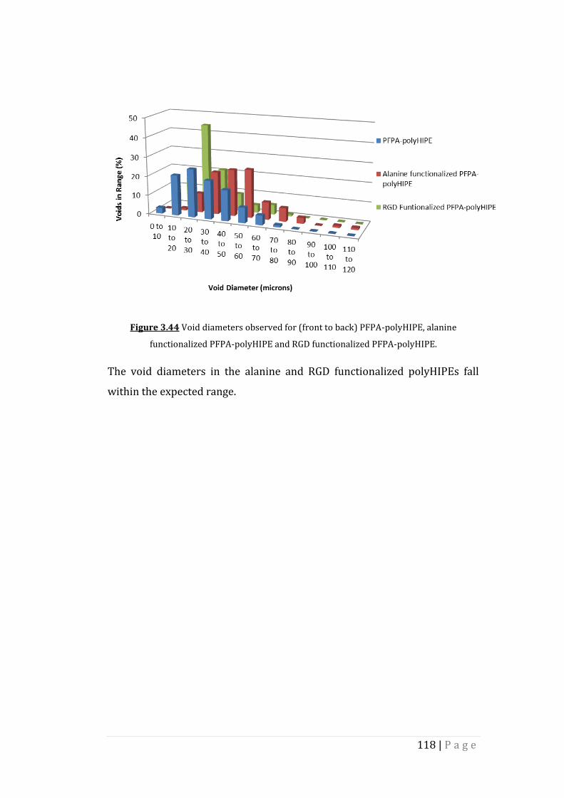
118 | P a g e
Figure 3.44 Void diameters observed for (front to back) PFPA-polyHIPE, alanine
functionalized PFPA-polyHIPE and RGD functionalized PFPA-polyHIPE.
The void diameters in the alanine and RGD functionalized polyHIPEs fall
within the expected range.

119 | P a g e
4. Conclusions
Thiol-ene chemistry has been used to produce four thiol-acrylate polyHIPEs
via photopolymerization. These polyHIPEs have then been successfully
functionalized post-polymerization via several methods, including “click”
reactions and Michael additions, the formation of disulphide bonds, and the
incorporation and subsequent reaction of reactive monomers in to the HIPE
prior to curing. The effect the post-polymerization functionalizations have
on the morphology of the polyHIPEs was monitored by scanning electron
microscopy, and was found to remain constant.
Surface functionalization of trithiol-TMPTA polyHIPE polymers was
achieved by both radical mediated “click” reactions and by Michael addition.
Molecules including fluorinated and fluorescent acrylates, as well as PEGMA,
were successfully grafted to the polymer surface under mild conditions,
with high levels of functionalization observed. The addition of PEGMA to the
polymer surface allowed for the preparation of hydrophilic polyHIPEs. The
formation of disulphide bonds between the residual thiols at the polymer
surface and thiol containing molecules has also been used to prepare surface
functionalized polyHIPEs.
Non-crosslinking monomers, including the active ester PFPA, were added to
trithiol-DPEHA polyHIPE, allowing for their functionalization post-
polymerization. The reactivity of PFPA was tested using an amine with high
nitrogen content before repeating the functionalization with bioactive
molecules, including the amino acid alanine, and a short integrin binding
peptide RGD. Conversions of up to 100% were achieved, with any unreacted
PFPA being removed from the polyHIPE by hydrolysis.
Overall it has been shown that these thiol-acrylate polyHIPEs can undergo
chemical functionalization via a wide variety of methods, retaining their
highly porous and interconnected morphology.

120 | P a g e
5. Further Work – GGRGD Synthesis
This project has demonstrated the ease with which thiol-acrylate polyHIPEs
can be chemically functionalized post-polymerization. Further work into
how the addition of chemical functionality into the polymer network will
enhance the range of applications available to these materials is required.
As previously discussed, polyHIPE polymers have found application in the
field of tissue engineering and 3D cell culture, with the chemical
functionalization of the polymers enhancing the viability of cells cultured in
this environment. Thiol-acrylate polyHIPEs also have the added benefit of
biodegradability, a feature which may make these materials suitable for
implant. This project has demonstrated the ease with which a short chain
integrin binding peptide (RGD) can be grafted to the surface of the polymer,
under mild conditions. In order to ascertain if the inclusion of biomolecules
such as RGD into the polymer network does create an environment more
suited to cells, a detailed in vitro cell culture study must be carried out. In
order for this study to be carried out one limiting factor must be addressed.
This limiting factor is the cost of the RGD peptide. With tissue culture plastic
being cheap to manufacture on large scales, any chemical or process which
increases the cost of scaffold production will hinder any possibility of 3D cell
culture becoming the norm.
PolyHIPE functionalization worked carried out in this project utilized RGD
purchased from Sigma Aldrich. One way of reducing this cost is to synthesize
the peptide in house using the solid phase peptide synthesis methodology.
Preparing the peptide in house also allows for the inclusion of a short spacer
(two extra glycine units), which should lift the integrin binding section of
the peptide off the polymer surface, allowing cells better access232. Solid
phase peptide synthesis should also allow for production of the peptide on
the large scales often needed when working with polyHIPE polymers.
GGRGD was synthesized on rink amide resin, with a yield of 0.3 g being
targeted. Once synthesized, the peptide was then analysed by MALDI mass
spectroscopy, the results of which are shown in Figure 5.1

121 | P a g e
Figure 5.1 MALDI mass spectrum of GGRGD peptide.
The peak at 460.5 m/z represents the targeted GGRGD peptide. The other
peaks at 517.5, 682.4 and 739.4 m/z represent the insertion of extra glycine
and arginine residues into the chain. In order to obtained 0.3 g peptide, 1 g
rink amide resin was used. It is possible that this mass of resin was too large
for the peptide synthesis tube used, making it difficult to remove the
reagents at the end of each synthesis step. Purification of the peptide was
via HPLC; however, the peptide appeared to stick to the column.
The GGRGD integrin binding peptide can be synthesized, however the work
must be carried out on a smaller scale and other methods to purify the
peptide must be explored. Unfortunately, due to time constraints, it was not
possible to further this work or carry out the cell culture experiments
required in order to assess the impact surface bound peptides have on cells
cultured on thiol-acrylate polyHIPE scaffolds.

122 | P a g e
6. References 1. C. E. Hoyle and C. N. Bowman, Angewandte Chemie-International
Edition, 2010, 49, 1540-1573. 2. A. B. Lowe, Polymer Chemistry, 2010, 1, 17-36. 3. N. Hadjichristidis, H. Iatrou, M. Pitsikalis and J. Mays, Progress in
Polymer Science, 2006, 31, 1068-1132. 4. A. Hirao, M. Hayashi, S. Loykulnant and K. Sugiyama, Progress in
Polymer Science, 2005, 30, 111-182. 5. J. Chiefari, Y. K. Chong, F. Ercole, J. Krstina, J. Jeffery, T. P. T. Le, R. T. A.
Mayadunne, G. F. Meijs, C. L. Moad, G. Moad, E. Rizzardo and S. H. Thang, Macromolecules, 1998, 31, 5559-5562.
6. C. Barner-Kowollik and S. Perrier, Journal of Polymer Science Part a-Polymer Chemistry, 2008, 46, 5715-5723.
7. C. J. Hawker, A. W. Bosman and E. Harth, Chemical Reviews, 2001, 101, 3661-3688.
8. M. Ouchi, T. Terashima and M. Sawamoto, Chemical Reviews, 2009, 109, 4963-5050.
9. F. di Lena and K. Matyjaszewski, Progress in Polymer Science, 2010, 35, 959-1021.
10. H. C. Kolb, M. G. Finn and K. B. Sharpless, Angewandte Chemie-International Edition, 2001, 40, 2004-2021.
11. L. Y. Liang and D. Astruc, Coordination Chemistry Reviews, 2011, 255, 2933-2945.
12. M. A. Tasdelen and Y. Yagci, Angewandte Chemie-International Edition, 2013, 52, 5930-5938.
13. H. Stockmann, A. A. Neves, S. Stairs, K. M. Brindle and F. J. Leeper, Organic & Biomolecular Chemistry, 2011, 9, 7303-7305.
14. B. S. Sumerlin and A. P. Vogt, Macromolecules, 2010, 43, 1-13. 15. A. B. Lowe, C. E. Hoyle and C. N. Bowman, Journal of Materials
Chemistry, 2010, 20, 4745-4750. 16. W. H. Binder and C. Kluger, Current Organic Chemistry, 2006, 10,
1791-1815. 17. J. A. Johnson, M. G. Finn, J. T. Koberstein and N. J. Turro,
Macromolecular Rapid Communications, 2008, 29, 1052-1072. 18. P. Lundberg, C. J. Hawker, A. Hult and M. Malkoch, Macromolecular
Rapid Communications, 2008, 29, 998-1015. 19. W. H. Binder and R. Sachsenhofer, Macromolecular Rapid
Communications, 2007, 28, 15-54. 20. W. H. Binder and R. Sachsenhofer, Macromolecular Rapid
Communications, 2008, 29, 952-981. 21. R. A. Evans, Australian Journal of Chemistry, 2007, 60, 384-395. 22. J. E. Moses and A. D. Moorhouse, Chemical Society Reviews, 2007, 36,
1249-1262. 23. P. D. Topham, N. Sandon, E. S. Read, J. Madsen, A. J. Ryan and S. P.
Armes, Macromolecules, 2008, 41, 9542-9547. 24. J. A. Opsteen and J. C. M. van Hest, Chem Commun (Camb), 2005, 57-
59.

123 | P a g e
25. J. Yin, Z. Ge, H. Liu and S. Liu, Journal of Polymer Science Part a-Polymer Chemistry, 2009, 47, 2608-2619.
26. A. J. de Graaf, E. Mastrobattista, C. F. van Nostrum, D. T. S. Rijkers, W. E. Hennink and T. Vermonden, Chem Commun (Camb), 2011, 47, 6972-6974.
27. T. Posner, Berichte Der Deutschen Chemischen Gesellschaft, 1905, 38, 646-657.
28. N. B. Cramer, S. K. Reddy, A. K. O'Brien and C. N. Bowman, Macromolecules, 2003, 36, 7964-7969.
29. C. E. Hoyle, T. Y. Lee and T. Roper, Journal of Polymer Science Part a-Polymer Chemistry, 2004, 42, 5301-5338.
30. M. Uygun, M. A. Tasdelen and Y. Yagci, Macromolecular Chemistry and Physics, 2010, 211, 103-110.
31. A. F. Senyurt, H. Wei, C. E. Hoyle, S. G. Piland and T. E. Gould, Macromolecules, 2007, 40, 4901-4909.
32. T. Y. Lee, Z. Smith, S. K. Reddy, N. B. Cramer and C. N. Bowman, Macromolecules, 2007, 40, 1466-1472.
33. H. Wei, A. F. Senyurt, S. Jonsson and C. E. Hoyle, Journal of Polymer Science Part a-Polymer Chemistry, 2007, 45, 822-829.
34. C. O. Bounds, J. Upadhyay, N. Totaro, S. Thakuri, L. Garber, M. Vincent, Z. Y. Huang, M. Hupert and J. A. Pojman, Acs Applied Materials & Interfaces, 2013, 5, 1643-1655.
35. O. Okay, S. K. Reddy and C. N. Bowman, Macromolecules, 2005, 38, 4501-4511.
36. N. B. Cramer, J. P. Scott and C. N. Bowman, Macromolecules, 2002, 35, 5361-5365.
37. T. Y. Lee, T. M. Roper, E. S. Jonsson, I. Kudyakov, K. Viswanathan, C. Nason, C. A. Guymon and C. E. Hoyle, Polymer, 2003, 44, 2859-2865.
38. N. B. Cramer, S. K. Reddy, M. Cole, C. Hoyle and C. N. Bowman, Journal of Polymer Science Part a-Polymer Chemistry, 2004, 42, 5817-5826.
39. L. V. Natarajan, D. P. Brown, J. M. Wofford, V. P. Tondiglia, R. L. Sutherland, P. F. Lloyd and T. J. Bunning, Polymer, 2006, 47, 4411-4420.
40. A. F. Senyurt and C. E. Hoyle, European Polymer Journal, 2006, 42, 3133-3139.
41. T. F. Scott, C. J. Kloxin, R. B. Draughon and C. N. Bowman, Macromolecules, 2008, 41, 2987-2989.
42. B. D. Mather, K. Viswanathan, K. M. Miller and T. E. Long, Progress in Polymer Science, 2006, 31, 487-531.
43. J. W. Chan, C. E. Hoyle and A. B. Lowe, Journal of the American Chemical Society, 2009, 131, 5751-5753.
44. E. Lovelady, S. D. Kimmins, J. J. Wu and N. R. Cameron, Polymer Chemistry, 2011, 2, 559-562.
45. C. N. Salinas and K. S. Anseth, Macromolecules, 2008, 41, 6019-6026. 46. K. L. Killops, L. M. Campos and C. J. Hawker, Journal of the American
Chemical Society, 2008, 130, 5062-5064. 47. J. W. Chan, B. Yu, C. E. Hoyle and A. B. Lowe, Chem Commun (Camb),
2008, 4959-4961.
124 | P a g e
48. J. Justynska and H. Schlaad, Macromolecular Rapid Communications, 2004, 25, 1478-1481.
49. J. Justynska and H. Schlaad, Macromolecular Rapid Communications, 2004, 25, 1478-1481.
50. J. Justynska, Z. Hordyjewicz and H. Schlaad, Polymer, 2005, 46, 12057-12064.
51. A. Gress, A. Volkel and H. Schlaad, Macromolecules, 2007, 40, 7928-7933.
52. N. ten Brummelhuis, C. Diehl and H. Schlaad, Macromolecules, 2008, 41, 9946-9947.
53. C. Diehl and H. Schlaad, Macromolecular Bioscience, 2009, 9, 157-161. 54. L. Lotti, S. Coiai, F. Ciardelli, M. Galimberti and E. Passaglia,
Macromolecular Chemistry and Physics, 2009, 210, 1471-1483. 55. C. Boyer, A. Granville, T. P. Davis and V. Bulmus, Journal of Polymer
Science Part a-Polymer Chemistry, 2009, 47, 3773-3794. 56. L. M. Campos, K. L. Killops, R. Sakai, J. M. J. Paulusse, D. Damiron, E.
Drockenmuller, B. W. Messmore and C. J. Hawker, Macromolecules, 2008, 41, 7063-7070.
57. M. Li, P. De, S. R. Gondi and B. S. Sumerlin, Journal of Polymer Science Part a-Polymer Chemistry, 2008, 46, 5093-5100.
58. J. W. Chan, B. Yu, C. E. Hoyle and A. B. Lowe, Chemical Communications, 2008, 4959-4961.
59. P. Antoni, M. J. Robb, L. Campos, M. Montanez, A. Hult, E. Malmstrom, M. Malkoch and C. J. Hawker, Macromolecules, 2010, 43, 6625-6631.
60. A. Dondoni, Angewandte Chemie-International Edition, 2008, 47, 8995-8997.
61. L. M. Campos, I. Meinel, R. G. Guino, M. Schierhorn, N. Gupta, G. D. Stucky and C. J. Hawker, Advanced Materials, 2008, 20, 3728-3733.
62. A. K. O'Brien, N. B. Cramer and C. N. Bowman, Journal of Polymer Science Part a-Polymer Chemistry, 2006, 44, 2007-2014.
63. S. K. Reddy, O. Okay and C. N. Bowman, Macromolecules, 2006, 39, 8832-8843.
64. O. Okay and C. N. Bowman, Macromolecular Theory and Simulations, 2005, 14, 267-277.
65. C. E. Hoyle, T. Y. Lee and T. Roper, Journal of Polymer Science Part a-Polymer Chemistry, 2004, 42, 5301-5338.
66. J. L. Drury and D. J. Mooney, Biomaterials, 2003, 24, 4337-4351. 67. K. Y. Lee and D. J. Mooney, Chemical Reviews, 2001, 101, 1869-1879. 68. J. Cabral and S. C. Moratti, Future Medicinal Chemistry, 2011, 3, 1877-
1888. 69. P. van de Wetering, A. T. Metters, R. G. Schoenmakers and J. A.
Hubbell, Journal of Controlled Release, 2005, 102, 619-627. 70. A. E. Rydholm, C. N. Bowman and K. S. Anseth, Biomaterials, 2005, 26,
4495-4506. 71. B. D. Fairbanks, M. P. Schwartz, A. E. Halevi, C. R. Nuttelman, C. N.
Bowman and K. S. Anseth, Advanced Materials, 2009, 21, 5005-5010. 72. H. Shih and C. C. Lin, Biomacromolecules, 2012, 13, 2003-2012. 73. D. L. Elbert, A. B. Pratt, M. P. Lutolf, S. Halstenberg and J. A. Hubbell,
Journal of Controlled Release, 2001, 76, 11-25.
125 | P a g e
74. A. E. Rydholm, S. K. Reddy, K. S. Anseth and C. N. Bowman, Biomacromolecules, 2006, 7, 2827-2836.
75. C. S. Ki, H. Shih and C. C. Lin, Polymer, 2013, 54, 2115-2122. 76. C.-C. Lin, A. Raza and H. Shih, Biomaterials, 2011, 32, 9685-9695. 77. B. D. Fairbanks, S. P. Singh, C. N. Bowman and K. S. Anseth,
Macromolecules, 2011, 44, 2444-2450. 78. T. Yang, H. Long, M. Malkoch, E. Kristofer Gamstedt, L. Berglund and
A. Hult, Journal of Polymer Science Part A: Polymer Chemistry, 2011, 49, 4044-4054.
79. C. N. Salinas, B. B. Cole, A. M. Kasko and K. S. Anseth, Tissue Engineering, 2007, 13, 1025-1034.
80. Y. T. Hao, H. Shih, Z. Munoz, A. Kemp and C. C. Lin, Acta Biomaterialia, 2014, 10, 104-114.
81. K. D. Xu, Y. Fu, W. J. Chung, X. X. Zheng, Y. J. Cui, I. C. Hsu and W. J. Kao, Acta Biomaterialia, 2012, 8, 2504-2516.
82. N. R. Cameron, Polymer, 2005, 46, 1439-1449. 83. S. Caldwell, D. W. Johnson, M. P. Didsbury, B. A. Murray, J. J. Wu, S. A.
Przyborski and N. R. Cameron, Soft Matter, 2012, 8, 10344-10351. 84. Y. Q. Lv, Z. X. Lin and F. Svec, Analyst, 2012, 137, 4114-4118. 85. B. Preinerstorfer, W. Bicker, W. Lindner and M. Lammerhofer, Journal
of Chromatography A, 2004, 1044, 187-199. 86. C. Triantafillidis, M. S. Elsaesser and N. Husing, Chemical Society
Reviews, 2013, 42, 3833-3846. 87. E. A. Jackson and M. A. Hillmyer, Acs Nano, 2010, 4, 3548-3553. 88. Y. Liang, L. H. Zhang and Y. K. Zhang, Analytical and Bioanalytical
Chemistry, 2013, 405, 2095-2106. 89. E. Knight, B. Murray, R. Carnachan and S. Przyborski, in 3d Cell
Culture: Methods and Protocols, ed. J. W. Haycock, 2011, vol. 695, pp. 323-340.
90. S. D. Kimmins, P. Wyman and N. R. Cameron, Polymer, 2014, 55, 416-425.
91. M. S. Silverstein, H. W. Tai, A. Sergienko, Y. L. Lumelsky and S. Pavlovsky, Polymer, 2005, 46, 6682-6694.
92. C. D. Wood, B. Tan, A. Trewin, H. Niu, D. Bradshaw, M. J. Rosseinsky, Y. Z. Khimyak, N. L. Campbell, R. Kirk, E. Stöckel and A. I. Cooper, Chemistry of Materials, 2007, 19, 2034-2048.
93. C. D. Wood, B. Tan, A. Trewin, F. Su, M. J. Rosseinsky, D. Bradshaw, Y. Sun, L. Zhou and A. I. Cooper, Advanced Materials, 2008, 20, 1916-1921.
94. C. F. Martin, E. Stoeckel, R. Clowes, D. J. Adams, A. I. Cooper, J. J. Pis, F. Rubiera and C. Pevida, Journal of Materials Chemistry, 2011, 21, 5475-5483.
95. C.-C. Chao, T.-C. Wang, R.-M. Ho, P. Georgopanos, A. Avgeropoulos and E. L. Thomas, Acs Nano, 2010, 4, 2088-2094.
96. H. Deleuze, R. Faivre and V. Herroguez, Chem Commun (Camb), 2002, 2822-2823.
97. M. A. Hillmyer, in Block Copolymers Ii, ed. V. Abetz, 2005, vol. 190, pp. 137-181.
126 | P a g e
98. D. Wu, F. Xu, B. Sun, R. Fu, H. He and K. Matyjaszewski, Chemical Reviews, 2012, 112, 3959-4015.
99. L. Kircher, P. Theato and N. R. Cameron, Polymer, 2013, 54, 1755-1761.
100. M. Guerrouache, S. Mahouche-Chergui, M. M. Chehimi and B. Carbonnier, Chem Commun (Camb), 2012, 48, 7486-7488.
101. M. Guerrouache, M. C. Millot and B. Carbonnier, Macromolecular Rapid Communications, 2009, 30, 109-113.
102. P. M. Budd, E. S. Elabas, B. S. Ghanem, S. Makhseed, N. B. McKeown, K. J. Msayib, C. E. Tattershall and D. Wang, Advanced Materials, 2004, 16, 456-459.
103. B. Li, X. Huang, L. Liang and B. Tan, Journal of Materials Chemistry, 2010, 20, 7444-7450.
104. A. P. Cote, A. I. Benin, N. W. Ockwig, M. O'Keeffe, A. J. Matzger and O. M. Yaghi, Science, 2005, 310, 1166-1170.
105. K. S. W. Sing, D. H. Everett, R. A. W. Haul, L. Moscou, R. A. Pierotti, J. Rouquerol and T. Siemieniewska, Pure and Applied Chemistry, 1985, 57, 603-619.
106. W. Busby, N. R. Cameron and C. A. B. Jahoda, Biomacromolecules, 2001, 2, 154-164.
107. R. J. Carnachan, M. Bokhari, S. A. Przyborski and N. R. Cameron, Soft Matter, 2006, 2, 608-616.
108. R. Pons, I. Carrera, P. Erra, H. Kunieda and C. Solans, Colloids and Surfaces a-Physicochemical and Engineering Aspects, 1994, 91, 259-266.
109. K. J. Lissant, Journal of Colloid and Interface Science, 1966, 22, 462-468.
110. H. Bartl and W. Vonbonin, Makromolekulare Chemie, 1962, 57, 74-95. 111. Euorpean Patent, EP0060138, 1986. 112. J. M. Williams, A. J. Gray and M. H. Wilkerson, Langmuir, 1990, 6, 437-
444. 113. J. M. Williams, Langmuir, 1991, 7, 1370-1377. 114. J. M. Williams and D. A. Wrobleski, Langmuir, 1988, 4, 656-662. 115. J. Jiao and D. J. Burgess, Journal of Colloid and Interface Science, 2003,
264, 509-516. 116. M. G. Freire, A. M. A. Dias, M. A. Z. Coelho, J. A. P. Coutinho and I. M.
Marrucho, Journal of Colloid and Interface Science, 2005, 286, 224-232.
117. N. R. Cameron, D. C. Sherrington, L. Albiston and D. P. Gregory, Colloid and Polymer Science, 1996, 274, 592-595.
118. P. Hainey, I. M. Huxham, B. Rowatt, D. C. Sherrington and L. Tetley, Macromolecules, 1991, 24, 117-121.
119. U. Sevšek, J. Brus, K. Jeřabek and P. Krajnc, Polymer, 2014, 55, 410-415.
120. N. R. Cameron and D. C. Sherrington, Journal of Materials Chemistry, 1997, 7, 2209-2212.
121. Y. Tunc, N. Hasirci and K. Ulubayram, Soft Materials, 2012, 10, 449-461.

127 | P a g e
122. N. R. Cameron, D. C. Sherrington, I. Ando and H. Kurosu, Journal of Materials Chemistry, 1996, 6, 719-726.
123. M. Ottens, G. Leene, A. Beenackers, N. Cameron and D. C. Sherrington, Industrial & Engineering Chemistry Research, 2000, 39, 259-266.
124. A. Barbetta, N. R. Cameron and S. J. Cooper, Chem Commun (Camb), 2000, 221-222.
125. P. Krajnc, J. F. Brown and N. R. Cameron, Organic Letters, 2002, 4, 2497-2500.
126. S. Kovacic and P. Krajnc, Journal of Polymer Science Part a-Polymer Chemistry, 2009, 47, 6726-6734.
127. P. Krajnc, N. Leber, J. F. Brown and N. R. Cameron, Reactive & Functional Polymers, 2006, 66, 81-91.
128. A. Mercier, H. Deleuze and O. Mondain-Monval, Reactive & Functional Polymers, 2000, 46, 67-79.
129. A. Mercier, H. Deleuze and O. Mondain-Monval, Macromolecular Chemistry and Physics, 2001, 202, 2672-2680.
130. L. Moine, H. Deleuze and B. Maillard, Tetrahedron Letters, 2003, 44, 7813-7816.
131. D. Myers, Surfactant Science and Technology, 3rd edn., John Wiley and Sons, 2005.
132. A. Barbetta, M. Dentini, L. Leandri, G. Ferraris, A. Coletta and M. Bernabei, Reactive & Functional Polymers, 2009, 69, 724-736.
133. P. Krajnc, N. Leber, D. Stefanec, S. Kontrec and A. Podgornik, Journal of Chromatography A, 2005, 1065, 69-73.
134. C. Yao, L. Qi, H. Jia, P. Xin, G. Yang and Y. Chen, Journal of Materials Chemistry, 2009, 19, 767-772.
135. M. A. Gauthier, M. I. Gibson and H.-A. Klok, Angewandte Chemie-International Edition, 2009, 48, 48-58.
136. W. Busby, N. R. Cameron and A. B. C. Jahoda, Polymer International, 2002, 51, 871-881.
137. S. Kovacic, P. Krajnc and C. Slugovc, Chem Commun (Camb), 2010, 46, 7504-7506.
138. O. Kulygin and M. S. Silverstein, Soft Matter, 2007, 3, 1525-1529. 139. A. Barbetta, M. Dentini, E. M. Zannoni and M. E. De Stefano, Langmuir,
2005, 21, 12333-12341. 140. C. Palocci, A. Barbetta, A. La Grotta and M. Dentini, Langmuir, 2007,
23, 8243-8251. 141. S. Kovacic, D. Stefanec and P. Krajnc, Macromolecules, 2007, 40, 8056-
8060. 142. A. Barbetta, M. Dentini, M. S. De Vecchis, P. Filippini, G. Formisano
and S. Caiazza, Advanced Functional Materials, 2005, 15, 118-124. 143. A. Barbetta, M. Massimi, L. C. Devirgiliis and M. Dentini,
Biomacromolecules, 2006, 7, 3059-3068. 144. A. Barbetta, M. Massimi, B. Di Rosario, S. Nardecchia, M. De Colli, L. C.
Devirgiliis and M. Dentini, Biomacromolecules, 2008, 9, 2844-2856. 145. H. F. Zhang and A. I. Cooper, Soft Matter, 2005, 1, 107-113. 146. R. Butler, C. M. Davies and A. I. Cooper, Advanced Materials, 2001, 13,
1459-1463. 147. J. M. DeSimone, Science, 2002, 297, 799-803.

128 | P a g e
148. R. Butler, I. Hopkinson and A. I. Cooper, Journal of the American Chemical Society, 2003, 125, 14473-14481.
149. R. Butler, I. Hopkinson and A. I. Cooper, Journal of the American Chemical Society, 2003, 125, 14473-14481.
150. B. Tan, J.-Y. Lee and A. I. Cooper, Macromolecules, 2007, 40, 1945-1954.
151. C. Boyere, A. F. Leonard, B. Grignard, A. Favrelle, J.-P. Pirard, M. Paquot, C. Jerome and A. Debuigne, Chem Commun (Camb), 2012, 48, 8356-8358.
152. C. Boyere, A. Favrelle, A. F. Leonard, F. Boury, C. Jerome and A. Debuigne, Journal of Materials Chemistry A, 2013, 1, 8479-8487.
153. S. J. Pierre, J. C. Thies, A. Dureault, N. R. Cameron, J. C. M. van Hest, N. Carette, T. Michon and R. Weberskirch, Advanced Materials, 2006, 18, 1822-1826.
154. European Patent, EP0216622 1988. 155. European Patent, EP1218440A1, 2001. 156. D. Cummins, P. Wyman, C. J. Duxbury, J. Thies, C. E. Koning and A.
Heise, Chemistry of Materials, 2007, 19, 5285-5292. 157. M. T. Gokmen, W. Van Camp, P. J. Colver, S. A. F. Bon and F. E. Du Prez,
Macromolecules, 2009, 42, 9289-9294. 158. S. D. Kimmins, P. Wyman and N. R. Cameron, Reactive & Functional
Polymers, 2012, 72, 947-954. 159. D. W. Johnson, C. Sherborne, M. P. Didsbury, C. Pateman, N. R.
Cameron and F. Claeyssens, Advanced Materials, 2013, 25, 3178-3181.
160. F. Claeyssens, E. A. Hasan, A. Gaidukeviciute, D. S. Achilleos, A. Ranella, C. Reinhardt, A. Ovsianikov, S. Xiao, C. Fotakis, M. Vamvakaki, B. N. Chichkov and M. Farsari, Langmuir, 2009, 25, 3219-3223.
161. V. Melissinaki, A. A. Gill, I. Ortega, M. Vamvakaki, A. Ranella, J. W. Haycock, C. Fotakis, M. Farsari and F. Claeyssens, Biofabrication, 2011, 3, 12.
162. I. Ortega, P. Deshpande, A. A. Gill, S. MacNeil and F. Claeyssens, Biofabrication, 2013, 5, 11.
163. B. Sergent, M. Birot and H. Deleuze, Reactive & Functional Polymers, 2012, 72, 962-966.
164. M. Susec, S. C. Ligon, J. Stampfl, R. Liska and P. Krajnc, Macromolecular Rapid Communications, 2013, 34, 938-943.
165. F. Su, C. L. Bray, B. Tan and A. I. Cooper, Advanced Materials, 2008, 20, 2663-2666.
166. J. J. Parlow, R. V. Devraj and M. S. South, Current Opinion in Chemical Biology, 1999, 3, 320-336.
167. Z. Bhumgara, Filtration & Separation, 1995, 32, 245-251. 168. R. A. Sheldon, Advanced Synthesis & Catalysis, 2007, 349, 1289-1307. 169. D. Ma and L.-M. Zhang, Materials Science and Engineering: C, 2013, 33,
2632-2638. 170. N. Dizge, C. Aydiner, D. Y. Imer, M. Bayramoglu, A. Tanriseven and B.
Keskinlera, Bioresource Technology, 2009, 100, 1983-1991. 171. C. Zhao, E. Danish, N. R. Cameron and R. Kataky, Journal of Materials
Chemistry, 2007, 17, 2446-2453.

129 | P a g e
172. A. Ghanem, Tetrahedron, 2007, 63, 1721-1754. 173. R. DiCosimo, J. McAuliffe, A. J. Poulose and G. Bohlmann, Chemical
Society Reviews, 2013, 42, 6437-6474. 174. B. H. Zhang, Y. Q. Weng, H. Xu and Z. P. Mao, Applied Microbiology and
Biotechnology, 2012, 93, 61-70. 175. R. Fernandez-Lafuente, P. Armisén, P. Sabuquillo, G. Fernández-
Lorente and J. M. Guisán, Chemistry and Physics of Lipids, 1998, 93, 185-197.
176. N. Dizge, C. Aydiner, D. Y. Imer, M. Bayramoglu, A. Tanriseven and B. Keskinler, Bioresource Technology, 2009, 100, 1983-1991.
177. N. Dizge, B. Keskinler and A. Tanriseven, Biochemical Engineering Journal, 2009, 44, 220-225.
178. N. Dizge, B. Keskinler and A. Tanriseven, Colloids and Surfaces B-Biointerfaces, 2008, 66, 34-38.
179. F. Bordusa, Chemical Reviews, 2002, 102, 4817-4867. 180. M. Capellas, G. Caminal, G. Gonzalez, J. LopezSantin and P. Clapes,
Biotechnology and Bioengineering, 1997, 56, 456-463. 181. D. J. Durbin and C. Malardier-Jugroot, International Journal of
Hydrogen Energy, 2013, 38, 14595-14617. 182. L. Schlapbach and A. Zuttel, Nature, 2001, 414, 353-358. 183. U. Eberle, M. Felderhoff and F. Schüth, Angewandte Chemie
International Edition, 2009, 48, 6608-6630. 184. U. Sevsek, J. Brus, K. Jerabek and P. Krajnc, Polymer, 2014, 55, 410-
415. 185. N. L. Rosi, J. Eckert, M. Eddaoudi, D. T. Vodak, J. Kim, M. O'Keeffe and
O. M. Yaghi, Science, 2003, 300, 1127-1129. 186. J. H. Ahn, J. E. Jang, C. G. Oh, S. K. Ihm, J. Cortez and D. C. Sherrington,
Macromolecules, 2006, 39, 627-632. 187. US Patent, US3729457 A, 1973. 188. I. Pulko, J. Wall, P. Krajnc and N. R. Cameron, Chemistry-a European
Journal, 2010, 16, 2350-2354. 189. M. G. Schwab, I. Senkovska, M. Rose, N. Klein, M. Koch, J. Pahnke, G.
Jonschker, B. Schmitz, M. Hirscher and S. Kaskel, Soft Matter, 2009, 5, 1055-1059.
190. K. L. Lim, H. Kazemian, Z. Yaakob and W. R. W. Daud, Chemical Engineering & Technology, 2010, 33, 213-226.
191. T. A. Strobel, C. A. Koh and E. D. Sloan, Fluid Phase Equilibria, 2007, 261, 382-389.
192. H. Lee, J. W. Lee, D. Y. Kim, J. Park, Y. T. Seo, H. Zeng, I. L. Moudrakovski, C. I. Ratcliffe and J. A. Ripmeester, Nature, 2005, 434, 743-746.
193. Y. P. Zhou, Y. X. Wang, H. H. Chen and L. Zhou, Carbon, 2005, 43, 2007-2012.
194. L. J. Florusse, C. J. Peters, J. Schoonman, K. C. Hester, C. A. Koh, S. F. Dec, K. N. Marsh and E. D. Sloan, Science, 2004, 306, 469-471.
195. R. H. Harrison, J.-P. St-Pierre and M. M. Stevens, Tissue Engineering Part B-Reviews, 2014, 20, 1-16.
130 | P a g e
196. A. Schober, U. Fernekorn, S. Singh, G. Schlingloff, M. Gebinoga, J. Hampl and A. Williamson, Engineering in Life Sciences, 2013, 13, 352-367.
197. S. J. Hollister, Nature Materials, 2005, 4, 518-524. 198. R. Langer and J. P. Vacanti, Science, 1993, 260, 920-926. 199. M. D. Duncan and D. S. Wilkes, Proceedings of the American Thoracic
Society, 2005, 2, 449-455. 200. R. R. Betz, Orthopedics, 2002, 25, S561-S570. 201. Y. Takeuchi and R. A. Weiss, Current Opinion in Immunology, 2000,
12, 504-507. 202. G. Chen, Q. Y. Sun, X. M. Wang, S. Q. Shen, H. Guo, H. Wang, Y. Wu, W. Y.
Wang, Y. L. Xiong and S. Chen, Xenotransplantation, 2004, 11, 123-132.
203. E. van Rongen, in Xenotransplantation: Scientific Frontiers and Public Policy, eds. J. Fishman, D. Sachs and R. Shaikh, New York Acad Sciences, New York, 1998, vol. 862, pp. 177-183.
204. K. Chatterjee, S. Lin-Gibson, W. E. Wallace, S. H. Parekh, Y. J. Lee, M. T. Cicerone, M. F. Young and C. G. Simon, Jr., Biomaterials, 2010, 31, 5051-5062.
205. J. Zhu, Biomaterials, 2010, 31, 4639-4656. 206. Y. F. Goh, I. Shakir and R. Hussain, Journal of Materials Science, 2013,
48, 3027-3054. 207. B. Kundu, N. E. Kurland, S. Bano, C. Patra, F. B. Engel, V. K. Yadavalli
and S. C. Kundu, Progress in Polymer Science, 2014, 39, 251-267. 208. M. Okamoto and B. John, Progress in Polymer Science, 2013, 38, 1487-
1503. 209. M. W. Hayman, K. H. Smith, N. R. Cameron and S. A. Przyborski,
Biochemical and Biophysical Research Communications, 2004, 314, 483-488.
210. G. Akay, M. A. Birch and M. A. Bokhari, Biomaterials, 2004, 25, 3991-4000.
211. A. S. Hayward, A. M. Eissa, D. J. Maltman, N. Sano, S. A. Przyborski and N. R. Cameron, Biomacromolecules, 2013, 14, 4271-4277.
212. M. W. Hayman, K. H. Smith, N. R. Cameron and S. A. Przyborski, Journal of Biochemical and Biophysical Methods, 2005, 62, 231-240.
213. M. Bokhari, R. J. Carnachan, N. R. Cameron and S. A. Przyborski, Biochemical and Biophysical Research Communications, 2007, 354, 1095-1100.
214. M. Bokhari, R. J. Carnachan, N. R. Cameron and S. A. Przyborski, Journal of Anatomy, 2007, 211, 567-576.
215. B. J. Kane, M. J. Zinner, M. L. Yarmush and M. Toner, Analytical Chemistry, 2006, 78, 4291-4298.
216. Cancer Research UK, Methotrexate (Maxtrex), http://www.cancerresearchuk.org/cancer-help/about-cancer/treatment/cancer-drugs/methotrexate, Accessed 27/3, 2014.
217. A. S. Hayward, N. Sano, S. A. Przyborski and N. R. Cameron, Macromolecular Rapid Communications, 2013, 34, 1844-1849.
218. G. Ashwell and A. G. Morell, Advances in Enzymology and Related Areas of Molecular Biology, 1974, 41, 99-128.

131 | P a g e
219. C. S. Cho, S. J. Seo, I. K. Park, S. H. Kim, T. H. Kim, T. Hoshiba, I. Harada and T. Akaike, Biomaterials, 2006, 27, 576-585.
220. C. Rey, C. Combes, C. Drouet and M. J. Glimcher, Osteoporosis International, 2009, 20, 2155-2155.
221. K. Kuroda and M. Okido, Bioinorganic Chemistry and Applications, 2012, 7.
222. W. Busby, N. R. Cameron and C. A. B. Jahoda, Biomacromolecules, 2001, 2, 154-164.
223. M. T. Gokmen, J. Brassinne, R. A. Prasath and F. E. Du Prez, Chem Commun (Camb), 2011, 47, 4652-4654.
224. J. P. Badyal, A. M. Cameron, N. R. Cameron, D. M. Coe, R. Cox, B. G. Davis, L. J. Oates, G. Oye and P. G. Steel, Tetrahedron Letters, 2001, 42, 8531-8533.
225. Royal Society of Chemistry, Pentafluorophenyl Acrylate, http://www.chemspider.com/Chemical-Structure.2056299.html, Accessed 27/3, 2014.
226. Royal Society of Chemistry, 3-(Acryloyloxy)-2-{[3-(acryloyloxy)-2-[(acryloyloxy)methyl]-2-(hydroxymethyl)propoxy]methyl}-2-[(acryloyloxy)methyl]propyl acrylate http://www.chemspider.com/Chemical-Structure.97982.html, Accessed 27/3, 2014.
227. Royal Society of Chemistry, Trimethylolpropane Tris(3-mercaptopropionate), http://www.chemspider.com/Chemical-Structure.105802.html, Accessed 27/3, 2014.
228. S. I. Jeon, J. H. Lee, J. D. Andrade and P. G. Degennes, Journal of Colloid and Interface Science, 1991, 142, 149-158.
229. A. Hansson, N. Hashom, F. Falson, P. Rousselle, O. Jordan and G. Borchard, Carbohydrate Polymers, 2012, 90, 1494-1500.
230. A. Meyer, J. Auemheimer, A. Modlinger and H. Kessler, Current Pharmaceutical Design, 2006, 12, 2723-2747.
231. A. Huttenlocher and A. R. Horwitz, Cold Spring Harbor Perspectives in Biology, 2011, 3, 16.
232. N. Ardjomandi, C. Klein, K. Kohler, A. Maurer, H. Kalbacher, J. Niederlander, S. Reinert and D. Alexander, Journal of Biomedical Materials Research Part A, 2012, 100A, 2034-2044.
233. H. Lee, B. G. Choi, H. J. Moon, J. Choi, K. Park, B. Jeong and D. K. Han, Macromolecular Research, 2012, 20, 106-111.
Related Documents