CHEMICAL ENGINEERING TRANSACTIONS VOL. 48, 2016 A publication of The Italian Association of Chemical Engineering Online at www.aidic.it/cet Guest Editors: Eddy de Rademaeker, Peter Schmelzer Copyright © 2016, AIDIC Servizi S.r.l., ISBN 978-88-95608-39-6; ISSN 2283-9216 Developments in Modelling of Thermal Radiation from Pool and Jet Fires Hans Boot TNO, Dep. Urban Environment and Safety,PO Box 80015 , 3508 TA, UTRECHT, The Netherlands [email protected] In the past decades, the standard approach in the modelling of consequences of pool and jet fires would be to describe these fires as tilted cylindrical shaped radiating flame surfaces, having a specific SEP (Surface Emissive Power). Some fine tuning on pool fires has been done by Rew and Hulbert in the late nineties to divide the flame in a clear and sooty part, and provide some typical -substance dependent- values for SEP clear and SEP soot . However, this approach still describes the pool-fire as a tilted and cylindrical shaped radiator. Unfortunately, in the real world, the typical pool fire dimensions, and consequently the flame shape, are being determined by local circumstances, such as the presence of a semi-rectangular bund around storage tanks. Other pool shape determining examples are ditches, drains or even elevated platforms that restrict the free spreading of a pool and lead to a specific pool shape. Of course the resulting pool surface will not only determine pool burning rate, but also the radiation behaviour. In order to predict the consequences of these “real world” situation, TNO extended the fire modelling in its consequence calculation software EFFECTS® with a more elaborated radiation calculation, additionally providing the possibility to determine heat load distribution on a receiving object. In case of a pool fire, the expected pool dimensions can be drawn (on top of a topographic map or aerial photo) and potential receiving objects can be defined, such as nearby installations, including typical vulnerability thresholds. This enables the possibility to evaluate potential domino effects of a fire. The same approach is also used for jet fires, now describing the jet as a truly cone shaped radiator, which can be pointed in any direction. The paper will provide a full description of the applied method, including some typical application examples 1. Fire modelling Fire modelling should be seen as an important part of consequence modelling, allowing to predict potential damage due to heat radiation of fires. Fire models themselves can be separated in models describing either jet fire, pool fire or fireball (BLEVE) phenomena. A jet fire model describes the fire phenomenon of a gaseous or two phase (e.g. Propane) continuous release. Such a jet fire model (sometimes referred to as “torch fire”) generally describes the size and shape of a cone or cylindrical shaped fire surface, and provides information about heat radiation versus distance or location. A high outflow velocity will also introduce a lift-off effect, causing the flame shape to start at certain distance from the actual release point. The flame tilt angle of the jet is highly influenced by the wind speed and will thus determine the resulting flame geometry and radiation pattern. A pool fire describes a flame surface on top of a burning liquid pool. The pool fire is usually described as a cylindrical shaped flame geometry, which will be tilted by the wind. Typical results of a pool fire model contain flame diameter, flame height and tilt, and heat radiation levels at various distances from the pool. Although a BLEVE (Boiling Liquid Expanding Vapour Explosion) is technically a description of an explosion (e.g. overpressure) phenomenon, the potential BLEVE of an LPG vessel is feared the most because of its fireball result. Dedicated BLEVE fireball models have been developed, describing the diameter and lift-off a the spherical flame and resulting heat load. These models all have in common that they use “Solid flame modelling”, describing the surface of the flame as a specific geometry, with a typical Surface Emissive Power (SEP) leading to a corresponding heat radiation footprint. DOI: 10.3303/CET1648012 Please cite this article as: Boot H., 2016, Developments in modelling of thermal radiation from pool and jet fires, Chemical Engineering Transactions, 48, 67-72 DOI:10.3303/CET1648012 67

Welcome message from author
This document is posted to help you gain knowledge. Please leave a comment to let me know what you think about it! Share it to your friends and learn new things together.
Transcript
CHEMICAL ENGINEERING TRANSACTIONS
VOL. 48, 2016
A publication of
The Italian Association
of Chemical Engineering Online at www.aidic.it/cet
Guest Editors: Eddy de Rademaeker, Peter SchmelzerCopyright © 2016, AIDIC Servizi S.r.l., ISBN 978-88-95608-39-6; ISSN 2283-9216
Developments in Modelling of Thermal Radiation from Pool and Jet Fires
Hans Boot
TNO, Dep. Urban Environment and Safety,PO Box 80015 , 3508 TA, UTRECHT, The Netherlands [email protected]
In the past decades, the standard approach in the modelling of consequences of pool and jet fires would be to describe these fires as tilted cylindrical shaped radiating flame surfaces, having a specific SEP (Surface Emissive Power). Some fine tuning on pool fires has been done by Rew and Hulbert in the late nineties to divide the flame in a clear and sooty part, and provide some typical -substance dependent- values for SEPclear and SEPsoot. However, this approach still describes the pool-fire as a tilted and cylindrical shaped radiator. Unfortunately, in the real world, the typical pool fire dimensions, and consequently the flame shape, are being determined by local circumstances, such as the presence of a semi-rectangular bund around storage tanks. Other pool shape determining examples are ditches, drains or even elevated platforms that restrict the free spreading of a pool and lead to a specific pool shape. Of course the resulting pool surface will not only determine pool burning rate, but also the radiation behaviour. In order to predict the consequences of these “real world” situation, TNO extended the fire modelling in its consequence calculation software EFFECTS® with a more elaborated radiation calculation, additionally providing the possibility to determine heat load distribution on a receiving object. In case of a pool fire, the expected pool dimensions can be drawn (on top of a topographic map or aerial photo) and potential receiving objects can be defined, such as nearby installations, including typical vulnerability thresholds. This enables the possibility to evaluate potential domino effects of a fire. The same approach is also used for jet fires, now describing the jet as a truly cone shaped radiator, which can be pointed in any direction. The paper will provide a full description of the applied method, including some typical application examples
1. Fire modelling
Fire modelling should be seen as an important part of consequence modelling, allowing to predict potential damage due to heat radiation of fires. Fire models themselves can be separated in models describing either jet fire, pool fire or fireball (BLEVE) phenomena. A jet fire model describes the fire phenomenon of a gaseous or two phase (e.g. Propane) continuous release. Such a jet fire model (sometimes referred to as “torch fire”) generally describes the size and shape of a cone or cylindrical shaped fire surface, and provides information about heat radiation versus distance or location. A high outflow velocity will also introduce a lift-off effect, causing the flame shape to start at certain distance from the actual release point. The flame tilt angle of the jet is highly influenced by the wind speed and will thus determine the resulting flame geometry and radiation pattern. A pool fire describes a flame surface on top of a burning liquid pool. The pool fire is usually described as a cylindrical shaped flame geometry, which will be tilted by the wind. Typical results of a pool fire model contain flame diameter, flame height and tilt, and heat radiation levels at various distances from the pool. Although a BLEVE (Boiling Liquid Expanding Vapour Explosion) is technically a description of an explosion (e.g. overpressure) phenomenon, the potential BLEVE of an LPG vessel is feared the most because of its fireball result. Dedicated BLEVE fireball models have been developed, describing the diameter and lift-off a the spherical flame and resulting heat load. These models all have in common that they use “Solid flame modelling”, describing the surface of the flame as a specific geometry, with a typical Surface Emissive Power (SEP) leading to a corresponding heat radiation footprint.
DOI: 10.3303/CET1648012
Please cite this article as: Boot H., 2016, Developments in modelling of thermal radiation from pool and jet fires, Chemical Engineering Transactions, 48, 67-72 DOI:10.3303/CET1648012
67

The most important steps in this modelling approach are: 1. Determine mass released and resulting burning rate (and corresponding released combustion
energy) 2. Derive the dimensions (diameter, height, tilt) of the flame surface. 3. Determine surface emissive power (usually based on chemical and/or flame temperature) 4. Determine the heat radiation at a point (x,y,z coordinate) by using a geometric view-factor and
atmospheric transmissivity (based on distances and viewing angles towards flame shape).
1.1 The need for more sophisticated flame geometry description Although the generalised “solid flame modelling” approach sketched above can give satisfying results, some weaknesses of the method should be pointed out:
- The dimensions of the flame are based on empirical relations. For jet fires [Chamberlain, 1987] or [Cook, 1990] , these model describe idealised conical shapes, but for the view factor, jet flames are usually being modelled as tilted cylinders. Although this perfectly valid for heat radiation at longer distances, the heat radiation in close proximity of the fire is highly affected by this flame geometry.
- Pool fires are generally modelled as tilted cylinders (which may include a flame elongation effect on the top plane) but in reality, the shape of the pool is highly determined by local circumstances. The presence of bunds, dykes, ditches or other obstacles around the liquid storage will eventually describe the shape of the pool. An idealised circular pool shape may dramatically underestimate the heat load on the surroundings.
- The surface emissive power of a pool fire is highly influenced by a “soot fraction” and a “fraction of heat radiated”, which are a typical substance dependent parameter and need to be provided as model input. In (Rew & Hulbert, 1996), a more sophisticated approach was chosen, dividing the flame in two zones: a clear part with a high SEP, and a sooty part with a lower radiation intensity. Experimental data for both values, as well as for flame heights of clear a sooty part were provided in a substance table. Because TNO regarded this approach as an obvious improvement compared to the original (Yellow book, 2005) model, this “two zone pool fire” model is now also available within the EFFECTS software.
- A similar improvement was already available for the BLEVE Fireball modelling, where the “Dynamic BLEVE” (Martinsen & Marx,1999) describing a fireball which is rising and growing in time gives a better description of the reality compared to the original Yellow book model.
Because both the more realistic “cone shaped” jet fire, non-circular pool fires, and height dependent surface emissive power all required a non-standard way of describing a radiating surface, a different approach had to be used to calculate resulting heat radiation of a flame surface. For decades, people have been using the analytical formulas as published in (Mudan, 1987) providing the view factor of standardised geometries. These goniometric formulas describe the view factor as a function of dimensions, angles and distances for straightforward shapes like cylinders and spheres. Obviously, the view factor relation for a sphere can also be applied for a “growing and rising” dynamic fireball, but for a (pool or jet) fire geometry which is no longer cylindrical or has a location dependent SEP, these relations can no longer be applied straightforward.
2. Dealing with arbitrary shaped flame surfaces
One clear requirement for improved pool fire modelling is the ability to define arbitrary shaped fire surfaces. Because the shape of the pool is determined by local circumstances, the pool boundaries should be drawn on top of a site map, aerial photo or topographic map of the actual location. This enables the user to simply define the expected pool shape as a result of bunds, dykes or other obstacles present. The pool shape drawn immediately defines the maximum pool area, resulting in total burning rate to be based on chemical properties. For a conventional circular pool shape, the resulting height of the pool fire (or flame length from bottom to top) is a function of the diameter. Because arbitrary shaped pools don’t have one diameter, a pragmatic choice was made to use the “hydraulic diameter” as an equivalent diameter to calculate the flame height. = 4 ∗
With Deq= Equivalent hydraulic diameter, Apool= Area pool shape [m2] , Ppool = Perimeter of pool shape.
68

This equivalent diameter, together with wind speed and wind direction will also be used to calculate the flame tilt, eventually leading to a well-defined skewed polygon describing the flame surface.
Figure1: Examples of tilted polygonal shaped pool fire
When using the two-zone approach, bottom parts of the flame surface will have a higher heat radiation intensity than the upper (sooty) parts of the flame geometry. These high SEP values at the bottom flame parts specifically influence the short distance heat load. The next step in predicting the radiative heat transfer from this flame surface, is the calculation of the resulting view factor for this potentially irregularly shaped flame geometry. To be able to deal with “any” 3 dimensional shape, a discretised surface method has been developed, described in the next paragraph.
3. Discretization of flame surfaces
For irregular shaped fire geometries, a solution was chosen to divide the radiating shape into multiple plane elements. This way, the problem can be reduced to series of plane-to-plane calculations. For such a discretized surface, the total energy radiated form a flame to a receiver surface can be expressed by the relation: = ∗ ∗ Where : S = path length between flame and receiver dAf = (discretized) Area flame dAr = (discretized) Area receiver SEP = Surface Emissive Power flame Βf = Angle vector along S and normal to flame area Af βr = Angle vector along S and normal to receiver area Ar τa(s) = Transmissivity of atmosphere, Figure 2: Radiation formula parameters
a function of path length
Instead of using the original analytical formulas, the “sheared elliptical cylinder shaped” or arbitrary shaped pool fires and “cone” shaped jet fires can be modelled using this discretization method as arrays of surface elements, as depicted in the illustration below
sdA
dAβ
β
69
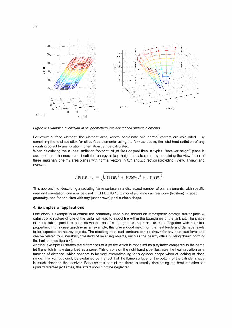
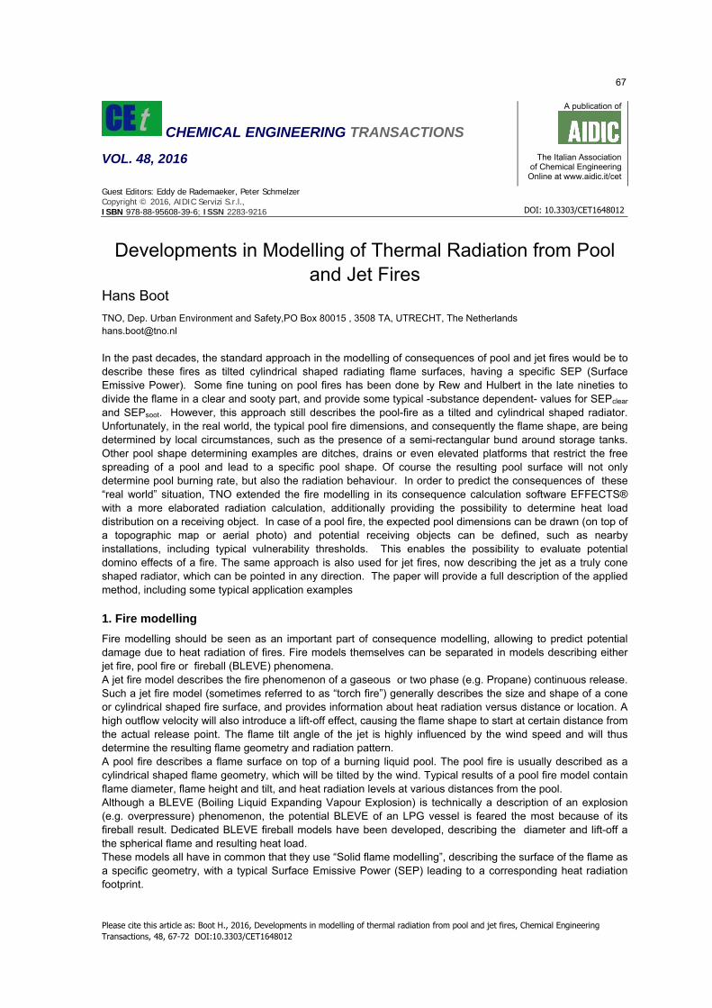
Figure 3: Examples of division of 3D geometries into discretised surface elements
For every surface element, the element area, centre coordinate and normal vectors are calculated. By combining the total radiation for all surface elements, using the formula above, the total heat radiation of any radiating object to any location / orientation can be calculated. When calculating the a “heat radiation footprint” of jet fires or pool fires, a typical “receiver height” plane is assumed, and the maximum irradiated energy at [x,y, height] is calculated, by combining the view factor of three imaginary one m2 area planes with normal vectors in X,Y and Z direction (providing Fviewx Fviewy and Fviewz )
= + +
This approach, of describing a radiating flame surface as a discretized number of plane elements, with specific area and orientation, can now be used in EFFECTS 10 to model jet flames as real cone (frustum) shaped geometry, and for pool fires with any (user drawn) pool surface shape.
4. Examples of applications
One obvious example is of course the commonly used bund around an atmospheric storage tanker park. A catastrophic rupture of one of the tanks will lead to a pool fire within the boundaries of the tank pit. The shape of the resulting pool has been drawn on top of a topographic maps or site map. Together with chemical properties, in this case gasoline as an example, this give a good insight on the heat loads and damage levels to be expected on nearby objects. The resulting heat load contours can be drawn for any heat load level and can be related to vulnerability threshold of receiving objects, such as the nearby office building drawn north of the tank pit (see figure 4). Another example illustrates the differences of a jet fire which is modelled as a cylinder compared to the same jet fire which is now described as a cone. This graphs on the right hand side illustrates the heat radiation as a function of distance, which appears to be very overestimating for a cylinder shape when at looking at close range. This can obviously be explained by the fact that the flame surface for the bottom of the cylinder shape is much closer to the receiver. Because this part of the flame is usually dominating the heat radiation for upward directed jet flames, this effect should not be neglected.
70
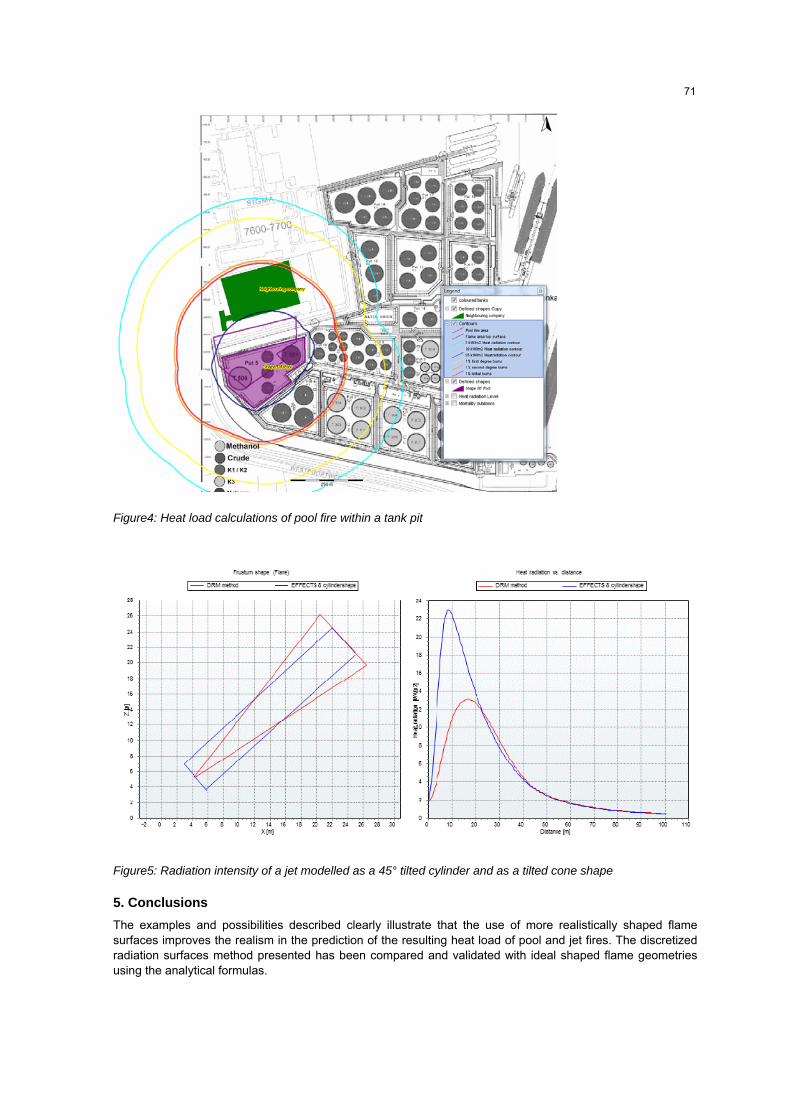
Figure4: Heat load calculations of pool fire within a tank pit
Figure5: Radiation intensity of a jet modelled as a 45° tilted cylinder and as a tilted cone shape
5. Conclusions
The examples and possibilities described clearly illustrate that the use of more realistically shaped flame surfaces improves the realism in the prediction of the resulting heat load of pool and jet fires. The discretized radiation surfaces method presented has been compared and validated with ideal shaped flame geometries using the analytical formulas.
71
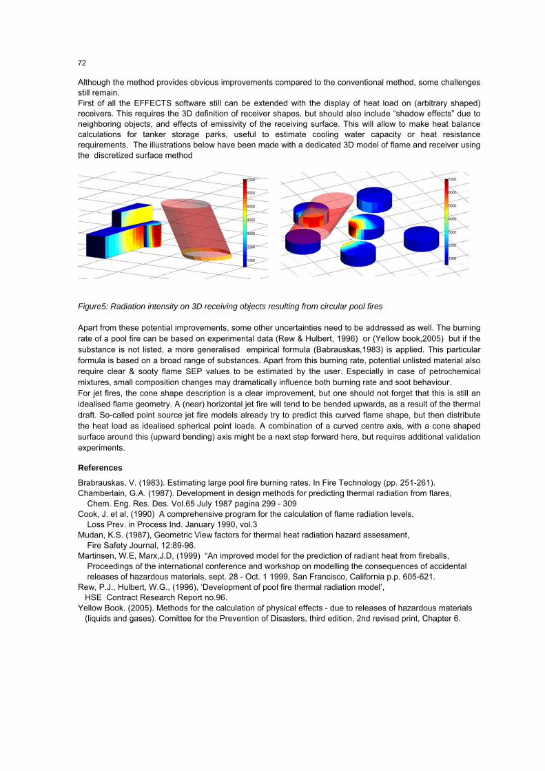
Although the method provides obvious improvements compared to the conventional method, some challenges still remain. First of all the EFFECTS software still can be extended with the display of heat load on (arbitrary shaped) receivers. This requires the 3D definition of receiver shapes, but should also include “shadow effects” due to neighboring objects, and effects of emissivity of the receiving surface. This will allow to make heat balance calculations for tanker storage parks, useful to estimate cooling water capacity or heat resistance requirements. The illustrations below have been made with a dedicated 3D model of flame and receiver using the discretized surface method
Figure5: Radiation intensity on 3D receiving objects resulting from circular pool fires
Apart from these potential improvements, some other uncertainties need to be addressed as well. The burning rate of a pool fire can be based on experimental data (Rew & Hulbert, 1996) or (Yellow book,2005) but if the substance is not listed, a more generalised empirical formula (Babrauskas,1983) is applied. This particular formula is based on a broad range of substances. Apart from this burning rate, potential unlisted material also require clear & sooty flame SEP values to be estimated by the user. Especially in case of petrochemical mixtures, small composition changes may dramatically influence both burning rate and soot behaviour. For jet fires, the cone shape description is a clear improvement, but one should not forget that this is still an idealised flame geometry. A (near) horizontal jet fire will tend to be bended upwards, as a result of the thermal draft. So-called point source jet fire models already try to predict this curved flame shape, but then distribute the heat load as idealised spherical point loads. A combination of a curved centre axis, with a cone shaped surface around this (upward bending) axis might be a next step forward here, but requires additional validation experiments.
References
Brabrauskas, V. (1983). Estimating large pool fire burning rates. In Fire Technology (pp. 251-261). Chamberlain, G.A. (1987). Development in design methods for predicting thermal radiation from flares, Chem. Eng. Res. Des. Vol.65 July 1987 pagina 299 - 309 Cook, J. et al, (1990) A comprehensive program for the calculation of flame radiation levels, Loss Prev. in Process Ind. January 1990, vol.3 Mudan, K.S. (1987), Geometric View factors for thermal heat radiation hazard assessment, Fire Safety Journal, 12:89-96. Martinsen, W.E, Marx,J.D, (1999) “An improved model for the prediction of radiant heat from fireballs, Proceedings of the international conference and workshop on modelling the consequences of accidental releases of hazardous materials, sept. 28 - Oct. 1 1999, San Francisco, California p.p. 605-621. Rew, P.J., Hulbert, W.G., (1996), ‘Development of pool fire thermal radiation model’, HSE Contract Research Report no.96. Yellow Book. (2005). Methods for the calculation of physical effects - due to releases of hazardous materials (liquids and gases). Comittee for the Prevention of Disasters, third edition, 2nd revised print, Chapter 6.
72
Related Documents