Chemical Characterization and Thermal Stressing Studies of Perfluorohexane Fluids for Space-Based Applications William A. Arnold, Ph.D. 1 ZIN Technologies, Inc., Brook Park, Ohio, 44142, USA Thomas G. Hartman, Ph.D. 2 CAFT, Cook College, Rutgers the Sate University of New Jersey, New Brunswick, NJ, 08901 USA John McQuillen, 3 NASA Glenn Research Center, Cleveland, Ohio, 44135, USA Perfluorohexane (PFH), C 6 F 14 , is a perfluorocarbon fluid. Several PFH fluids with different isomer concentrations were evaluated for use in an upcoming NASA space experiment. Samples tested included two commercially obtained high-purity n-perfluorohexane (n-PFH) fluids and a technical grade mixture of C 6 F 14 branched and linear isomers (FC-72 ). These fluids were evaluated for exact chemical composition, impurity purity and high temperature degradation behavior (pyrolysis). Our investigation involved simulated thermal stressing studies of PFH fluids under conditions likely to occur in the event of an atmospheric breach within the International Space Station (ISS) and subsequent exposure of the vapors to the high temperature and catalyst present in its Trace Contaminant Control Subsystem (TCCS). Exposure to temperatures in the temperature range of 200-450° C in an inert or oxidizing atmosphere, with and without the presence of catalyst was investigated. The most aggressive conditions studied were exposure of PFH vapors to 450° C in air and in the presence of TCCS (palladium) catalyst. Gas chromatography-mass spectrometry (GC-MS) and gas chromatography (GC) analyses were conducted on the perfluorohexane samples before and after pyrolysis. The FC-72 and n-PFH samples showed no significant degradation following pyrolysis even under the most aggressive study conditions. Some trace level impurities associated with the PFH samples such as linear perfluorocarbon monohydrides or monoiodides were destroyed by pyrolysis at the upper limit. Other trace level impurities such as olefinic or cycloolefinic perfluorocarbons were converted into oxidation products by pyrolysis. The purity of PFH following pyrolysis actually increased slightly as a consequence since these trace contaminants were effectively scrubbed from the samples. However, since the initial concentrations of the thermally-impacted impurities were so low, the net effect was trivial. A potential by- product of exposure of perfluorohexane fluids to high temperatures is the production of perfluoroisobutene (PFiB), which is extremely toxic. An ultra-high sensitivity PFiB-specific analysis based on GC-MS with negative ion chemical ionization (NICI) detection was used to evaluate the samples following thermal stressing. The perfluorohexanes examined here under conditions reflective of the ISS TCCS environment showed no signs of PFiB production with an analytical detection limit of 10 part per billion (ppb v/v). Nomenclature BXF = Boiling eXperiment Facility ECLSS = Environmental Control and Life Support System EI = Electron Ionization FDA = Food and Drug Administration GC = Gas Chromatography HVAC = Heating, Ventilation and Air Conditioning ISRU = In-situ resource utilization 1 Interdisciplinary Engineer / Scientist, 2001 Aerospace Parkway, Brook Park, Ohio 44142. 2 Mass Spectrometry Lab Manager & Research Professor, CAFT, Rutgers the State University of New Jersey, 63 Dudley Road, New Brunswick, NJ 08901. 3 Aerospace Engineer, 21000 Brookpark Rd., Cleveland, Ohio 44135. https://ntrs.nasa.gov/search.jsp?R=20060020119 2018-05-26T01:06:00+00:00Z

Welcome message from author
This document is posted to help you gain knowledge. Please leave a comment to let me know what you think about it! Share it to your friends and learn new things together.
Transcript
Chemical Characterization and Thermal Stressing Studies of
Perfluorohexane Fluids for Space-Based Applications
William A. Arnold, Ph.D.1
ZIN Technologies, Inc., Brook Park, Ohio, 44142, USA
Thomas G. Hartman, Ph.D.2
CAFT, Cook College, Rutgers the Sate University of New Jersey, New Brunswick, NJ, 08901 USA
John McQuillen,3
NASA Glenn Research Center, Cleveland, Ohio, 44135, USA
Perfluorohexane (PFH), C6F14, is a perfluorocarbon fluid. Several PFH fluids with different isomer
concentrations were evaluated for use in an upcoming NASA space experiment. Samples tested included two
commercially obtained high-purity n-perfluorohexane (n-PFH) fluids and a technical grade mixture of C6F14
branched and linear isomers (FC-72 ). These fluids were evaluated for exact chemical composition, impurity
purity and high temperature degradation behavior (pyrolysis). Our investigation involved simulated thermal
stressing studies of PFH fluids under conditions likely to occur in the event of an atmospheric breach within
the International Space Station (ISS) and subsequent exposure of the vapors to the high temperature and
catalyst present in its Trace Contaminant Control Subsystem (TCCS). Exposure to temperatures in the
temperature range of 200-450°C in an inert or oxidizing atmosphere, with and without the presence of
catalyst was investigated. The most aggressive conditions studied were exposure of PFH vapors to 450°C in
air and in the presence of TCCS (palladium) catalyst. Gas chromatography-mass spectrometry (GC-MS)
and gas chromatography (GC) analyses were conducted on the perfluorohexane samples before and after
pyrolysis. The FC-72 and n-PFH samples showed no significant degradation following pyrolysis even under
the most aggressive study conditions. Some trace level impurities associated with the PFH samples such as
linear perfluorocarbon monohydrides or monoiodides were destroyed by pyrolysis at the upper limit. Other
trace level impurities such as olefinic or cycloolefinic perfluorocarbons were converted into oxidation
products by pyrolysis. The purity of PFH following pyrolysis actually increased slightly as a consequence
since these trace contaminants were effectively scrubbed from the samples. However, since the initial
concentrations of the thermally-impacted impurities were so low, the net effect was trivial. A potential by-
product of exposure of perfluorohexane fluids to high temperatures is the production of perfluoroisobutene
(PFiB), which is extremely toxic. An ultra-high sensitivity PFiB-specific analysis based on GC-MS with
negative ion chemical ionization (NICI) detection was used to evaluate the samples following thermal
stressing. The perfluorohexanes examined here under conditions reflective of the ISS TCCS environment
showed no signs of PFiB production with an analytical detection limit of 10 part per billion (ppb v/v).
Nomenclature
BXF = Boiling eXperiment Facility
ECLSS = Environmental Control and Life Support System
EI = Electron Ionization
FDA = Food and Drug Administration
GC = Gas Chromatography
HVAC = Heating, Ventilation and Air Conditioning
ISRU = In-situ resource utilization
1 Interdisciplinary Engineer / Scientist, 2001 Aerospace Parkway, Brook Park, Ohio 44142.
2 Mass Spectrometry Lab Manager & Research Professor, CAFT, Rutgers the State University of New Jersey, 63
Dudley Road, New Brunswick, NJ 08901. 3 Aerospace Engineer, 21000 Brookpark Rd., Cleveland, Ohio 44135.
https://ntrs.nasa.gov/search.jsp?R=20060020119 2018-05-26T01:06:00+00:00Z
ISS = International Space Station
M.W. = Molecular Weight
MS = Mass Spectrometry
MSG = Microgravity Science Glovebox
MSDS = Materials Safety Data Sheet
NASA = National Aeronautics and Space Administration
NICI = Negative Ion Chemical Ionization
PFiB = Perfluoroisobutene
PFH = Perfluorohexane
n-PFH = n-Perfluorohexane
PPB = parts per billion
PPM = parts per million
TCCS = Trace Contaminant Control Subassembly
I. Introduction
he National Aeronautics and Space Administration (NASA) is currently developing several space
experiments which use fluorocarbon fluids. These experiments are scheduled to be flown in the next few years. One
such experiment is the Boiling eXperiment Facility (BXF) which uses a perfluorocarbon fluid called
perfluorohexane (PFH). BXF provides a research platform to carry out critical research necessary for NASA’s long
term space objectives. This experiment will be carried out in the Microgravity Science Glovebox (MSG) aboard the
International Space Station (ISS).
Boiling is known to be an efficient mode of heat transfer, and as such, it is employed in component cooling and
in various energy conversion systems. Boiling is a complex phenomenon where the hydrodynamics, heat transfer,
mass transfer, and interfacial phenomena are tightly interwoven. For space-based applications, boiling is the heat
transfer mode of choice, since for a given power rating, the size of the components can be significantly reduced. For
any space mission, the size and, in turn, the weight of the components plays an important role in the economics of
the mission. Applications of boiling heat transfer in space can be found in the areas of thermal management, fluid
handling and control, and power systems. It is of importance to space-based hardware and processes due to the large
amounts of heat that can be removed with relatively little change in temperature. Design and development of safe
operating procedures for on-orbit storage and supply systems for cryogenic propellants and life support fluids
requires quantitative data for boiling heat transfer under long duration of microgravity conditions. An understanding
of boiling and critical heat flux in microgravity environments is important to the design of future heat removal
equipment for these space-based applications.
T
A key element of the future space vehicles supporting the President’s Vision for Space Exploration is the use of
cryogenic liquids for the propulsion, power, and life support systems. Liquid hydrogen and liquid oxygen are the
baseline propellants for the reusable launch vehicle main propulsion system. The proposed non-toxic upgrade of the
space shuttle on-board propulsion systems uses liquid oxygen as a propellant. In-situ resource utilization (ISRU)
has been shown to reduce, significantly, the earth launch mass of lunar and Mars missions. Central to the ISRU
theme is the production, liquefaction and storage of oxygen and methane as propellants, oxygen as a reactant for
localized power generation, and for crew life support. These systems can be expected to operate under gravity
levels varying from 1g to 10-6
g, thus necessitating an understanding of boiling heat transfer including maximum and
minimum heat fluxes at these gravity levels.
At present, there is little understanding of this important mode of heat transfer at low gravity levels, and
consequently, there are no verified correlations or models that a designer can use to design efficient heat exchange
equipment with any level of confidence. Although much research in this area has been performed since the Space
Station was proposed, the mechanisms by which heat is removed from surfaces under these environments are still
unclear. The BXF will go a long way in providing a sound physical basis for the development of design guidelines.
Of special importance with relevance to the fluid analyses presented in this paper is the potential use of
fluorocarbon fluids in heat transfer loops in space-based operations. The use of these fluorocarbon fluids as heat
transfer fluids could potentially reduce current two-loop systems, which use two different fluids and heat
exchangers, to one loop system using one fluid. In addition, a single fluid system would not require heat exchangers
to thermally couple two different fluids.
Waste heat needs to be transported from its source to a sink in order to ensure continued operation of machinery
and electronics. For spacecraft, this heat is rejected to ambient environment either through radiation heat transfer or
through the evaporation or sublimation of a volatile fluid. Transporting the heat internal to the spacecraft relies on
conduction and often fluid convection through ducted channels. The acquisition, transport and rejection of heat is
classified as “thermal management.”
Fluid selection for thermal management systems requiring convective heat transport is based on multiple criteria:
• The heat source or acquisition temperature affects whether the thermal fluid is vapor or liquid based on the
fluid’s boiling point
• The heat sink or rejection temperature compared to the fluid’s freezing point.
• The fluid’s thermal properties, such as heat capacity and latent heat of vaporization, set the fluid’s heat
carrying capabilities.
• The fluid’s hydrodynamic properties, such as viscosity and density, which determines the amount of power
required to pump the fluid at the necessary flow rates.
• The fluid’s corrosive properties, especially with regards to materials such as metals that are used in heat
transfer applications.
• The fluid’s toxicity and flammability especially in the event of a leak, but also with regards to filling and
draining operations.
Early manned spacecraft, such as Apollo, accepted the risk associated with fluid toxicity by utilizing an ethylene
glycol mixture as the thermal management fluid. This system was a “single-phase” system. To account for periods
of low heat rejection, some fluid in the parallel radiator legs was allowed to freeze1.
Recent spacecraft, namely the ISS and the space shuttle2, utilize a dual-loop configuration. An internal flow
loop circulates a “non-toxic” single-phase fluid, water, through the crewed portions of the vehicle and then transfers
heat to an external loop that circulates another, usually toxic, fluid to the radiator. The external flow loop for the
ISS uses liquid ammonia and for the space shuttle uses liquid R-21 (fluorodichloromethane).
For closed loop life support systems, those that filter and scrub the air for particulate matter, harmful
contaminants and carbon dioxide, the toxicity of both the fluid and its high temperature decomposition products
need to be accounted for. The Environmental Control and Life Support System (ECLSS) for the ISS has a Trace
Contaminant Control Subassembly (TCCS) that is used to absorb or decompose trace amounts of contaminants in
the cabin atmosphere that could otherwise gradually build up over time to toxic levels. The TCCS consists of an
activated carbon bed that absorbs the longer chain carbon molecules, a catalytic converter to thermally decompose
contaminants, and a lithium hydroxide bed to neutralize the acidic byproducts of the decomposition reaction3. The
thermal decomposition reaction occurs at temperatures of 450ºC.
Fluorocarbon compounds have been identified as an acceptable alternative working fluid for Heating,
Ventilation and Air Conditioning (HVAC) systems and also for electronic cooling. These fluids are relatively inert
within these systems, i.e., they do not corrode the metals used in these systems, and they are “friendly” to the
atmospheric ozone layer. NASA has identified that some of these fluorocarbon fluids may be suitable thermal
management heat transfer fluids in terms of utilization within the space environment, primarily because of their low
freezing point.
Perfluorohexane, C6F14, is a highly inert fluorocarbon that actually describes several different isomers. These
isomers are shown in Figure 1. The Materials Safety Data Sheet (MSDS)4 for FC-72 , a trademarked 3M heat
transfer fluid consisting of several PFH isomers, indicates that the chemical compound is fairly inert and even
benign in most cases. It is one of a group of candidate fluids for replacement blood because of its affinity for
oxygen (absorbs roughly 50 volume percent of its liquid volume), its use has no risk of transmission of pathogenic
microorganisms, and it is not metabolized within the body5. PFH is also currently registered for use by the US
Food and Drug Administration (FDA) in an intravenously-administered formulation (Imagent ) used as contrast
agent in cardiac ultrasound imaging. The injected dose in humans is non-metabolized and is completely excreted
from the breath within 24 hours. Despite the inertness and extreme low toxicity of PFH, there are concerns of
toxicity associated with potential thermal decomposition or pyrolysis products. For instance, the MSDS for PFH
states that exposure to temperatures in excess of 200ºC could result in the decomposition of FC-72 into hydrogen
fluoride and perfluoroisobutene (PFiB).
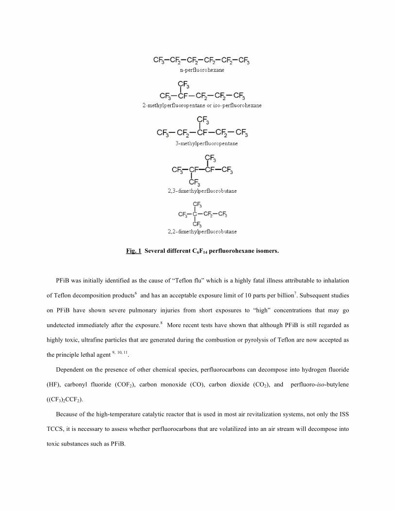
Fig. 1 Several different C6F14 perfluorohexane isomers.
PFiB was initially identified as the cause of “Teflon flu” which is a highly fatal illness attributable to inhalation
of Teflon decomposition products6 and has an acceptable exposure limit of 10 parts per billion
7. Subsequent studies
on PFiB have shown severe pulmonary injuries from short exposures to “high” concentrations that may go
undetected immediately after the exposure.8 More recent tests have shown that although PFiB is still regarded as
highly toxic, ultrafine particles that are generated during the combustion or pyrolysis of Teflon are now accepted as
the principle lethal agent 9,
10, 11
.
Dependent on the presence of other chemical species, perfluorocarbons can decompose into hydrogen fluoride
(HF), carbonyl fluoride (COF2), carbon monoxide (CO), carbon dioxide (CO2), and perfluoro-iso-butylene
((CF3)2CCF2).
Because of the high-temperature catalytic reactor that is used in most air revitalization systems, not only the ISS
TCCS, it is necessary to assess whether perfluorocarbons that are volatilized into an air stream will decompose into
toxic substances such as PFiB.
The PFiB formation mechanism is commonly postulated as a series of additive reactions involving the highly
reactive fluorocarbene free radical, CF2, with short chain perfluoroalkanes and perfluoropropene. Hauptschein, et
al.12
, attempted thermal dimerization of perfluoropropene under both short duration “flow” conditions and long
duration “stagnant” conditions. Perfluoropropene (CF2)3 is a cycloalkane. In the first case, they found that for
contact times of about 10 seconds in a hot tube of 510ºC at atmospheric pressure, there was no reaction. However,
after seven hours of exposure to the same conditions in a sealed, a six percent conversion was noted. PFIB was not
detected in reactions below 700 oC. Salmon, et al.
13 conducted experiments of chlorodifluoromethane, 1,1,1,2-
tetrafluoro-2-chloroethane, trifluoromethane, and perfluoropropene in nitrogen at temperatures of 550 to 1000 ºC
with exposure times of two seconds at atmospheric pressure. While they were able to obtain significant conversion
of PFiB based upon the carbon content of the feed material, they did not detect any PFiB below reactor temperatures
of 700 ºC. They suggest a mechanism of perfluoropropane isomerization to 1:C(CF3)2, a collisional stabilization,
and the eventual addition of the fluorocarbene radical.
Tortelli, et al14
, attributed the thermal stability upon the extent of branching and bulkiness (chemical-bond steric
constraint) of the molecules. One disturbing reaction was the pyrolysis of 2,3,3-trifluoromethylperfluoropentane
that generates PFiB. The branching similarity in the structure of 2,3,3-trifluoromethylperfluoropentane to 2,2-
dimethylperfluorobutane suggests that PFiB could be a potential decomposition product for some perfluorohexane
isomers. Later, Tonelli and Tortelli15
identified conditions favorable for the formation of PFiB included the
presence of a hot surface in a perfluorocarbon-rich environment which can be accelerated by the presence of halogen
gasses such as chlorine or bromine gas. However, it should be noted, that in both of these studies, the
perfluorocarbon was sealed within a tube, either by itself or with the other reactant (the chlorine or bromine gas) and
allowed to react for a period of at least an hour at the high temperature.
Ainogas16
specifically examined the pyrolysis of normal perfluorohexane at temperatures exceeding 700ºC in a
helium at atmospheric pressure. While the isomer did decompose, there was no indication that PFiB was formed.
In order to assess the thermal decomposition of perfluorohexane vapor that is applicable to removing trace
contaminants in a closed loop life support system, two other factors need to be considered: the presence of air,
specifically oxygen, and the residence time or the time that the perfluorocarbon is in contact with the hot surface of
the catalytic bed.
While data is lacking for perfluorohexane isomers under these conditions, there are data available on behaviors
for perfluoroalkanes with five carbons or less and for polymer chains that have many carbon chains present. Arito
and Soda17
investigated the high temperature decomposition products of polytetrafluoroethylene (PFTE) in both dry
and wet air streams, and found that the formation of PFiB occurred in a nitrogen stream and that the formation in
PFTE was suppressed by the presence of oxygen. No mechanism was proposed.
Trowbridge18
conducted a literature survey of the decomposition of perfluorocyclobutane, perfluoroethylene and
other polymeric perfluorocarbons such as PTFE. The presence of oxygen suppressed the formation of PFiB, but
also led to the formation of other toxic compounds such as HF (hydrogen fluoride), CO (carbon monoxide), COF2
(carbonyl fluoride), CF4 (methane) and CO2 (carbon dioxide). He did cite some sources that did indicate PFIB
formation under conditions that at least initially contained oxygen. These involved the pyrolysis of solid
fluorocarbon polymers, such as PTFE, which are high density sources of reactant (versus gas-phase oxygen) that
possibly depleted the available oxygen before the PFiB was generated.
Trowbridge19
later conducted an analysis of the reaction kinetics for additional 4-carbon compounds, namely c-
C4F8O, n-C4F10 (normal- perfluorobutane)and c-C4F8 (cycloperfluorobutane) and confirmed the previous literature
survey and analysis.
With regards to the residence time, there have been several studies also on this topic. Hauptschein, et al., in their
study found that for short duration, “flow-like” exposure conditions, perfluoropropene exposure to high temperature
resulted in no decomposition, but batch reactions did. Decorpo, et. al20
conducted tests on Teflon packing around a
rotating shaft. They found no PFiB was generated when the packing reached about 480 oC for 30 seconds. They
asserted that both the failure of air circulation and long duration exposure of the Teflon to the high temperatures
were required before PFiB could be generated. The argument that the air circulation needed to be stopped before the
PFiB was generated also involves the oxygen depletion argument associated with the solid perfluorocarbon
compounds.
Our investigation involved simulated thermal stressing studies of PFH fluids under conditions likely to occur
in the event of a breach in the BXF triple containment system within the ISS and subsequently expose the vapors to
high temperature and catalyst present in the TCCS. The PFH fluids were analyzed before and after thermal
stressing. The conditions of the thermal stressing studies such as transit time, atmospheric gas composition,
pressure, temperature and catalyst exposure were modeled based on TCCS operational specifications. Please note,
the terms “pyrolysis” and “thermal stressing” are used interchangeably in this report. However, the authors
acknowledge the term thermal stressing more scientifically defines the experiments conducted. The term pyrolysis
refers to rapid heating to high temperatures (~600-800°C) in the absence of oxygen so thermal dissociation of
chemical bonds results rather than combustion. Our studies were conducted at sub-pyrolytic temperatures in the
range of 200 - 450°C and some experiments were in the presence of oxygen (air) so the strict definition of the term
pyrolysis was not met. Nonetheless, the term pyrolysis in this paper is used generically to describe the thermal
stressing experiments.
II. Fluid Purity and Composition Analyses
Fluid Samples
Perfluorohexane fluids were the focus of this investigation and were obtained from commercial sources. High
purity reference standards consisting primarily of the linear isomer, n-perfluorohexane (PFH) were obtained from
Aldrich Chemical Company (Lot #18025DB) and F2 Chemicals LTD (Batch No. 0219C). A sample of mixed
perfluorohexane isomers with the tradename FC-72 was obtained from 3M Corporation. Detailed chemical
composition analyses of these samples were performed using analysis conditions detailed in the next section.
Analytical Methodology
The PFH and FC-72 samples were analyzed for exact chemical composition and impurity profile by capillary
gas chromatography - mass spectrometry (GC-MS) using both electron ionization (EI) and negative ion chemical
ionization (NICI) modes of operation. The samples were also analyzed by gas chromatography with flame
ionization detection (GC-FID). The GC-FID analyses were conducted to provide quantitative data on sample purity
(GC Area %) due to the increased dynamic range of the GC-FID technique. Chemical composition and identity of
impurities were obtained from the GC-MS data. The GC-MS analyses were also designed to detect potential
impurities such as HF that do not yield a signal in an FID detector. Cryogenic GC temperature programming was
employed to provide optimum chromatographic resolution of test substances. Details of the GC-MS and GC-FID
analyses are provided next.
GC-MS analyses were performed on a Varian 3400 GC directly interfaced to a Finnigan MAT 8230, high
resolution, double focussing, magnetic sector type mass spectrometer. Neat 0.1 – 1.0 μl injections of fluorocarbon
fluids were made on a 60 meter x 0.25 mm I.D. SPB-1 (non-polar polydimethylsiloxane bonded phase) capillary
column containing a 1.0 μm film thickness. The injector temperature was 220°C and an injector split ratio of 200:1
was employed. The GC column was temperature programmed from -30° (hold 1.0 min.) to 40°C at a rate of 4°C per
minute (zero hold) then up to 260°C at a rate of 20°C per minute with a 10 minute hold at the upper limit. The GC
column flow rate was 1.0 ml per minute (26 psi head pressure) using helium carrier gas and the GC-MS transfer line
temperature was 260°C. MS data was recorded using both EI (70 eV) and NICI modes of operation. In EI mode the
mass spectrometer was scanned from 20-750 amu at a rate of 0.6 seconds per decade with a 0.8 second interscan
time for magnet reset. The NICI analyses were conducted using isobutane reagent gas at a source pressure of 0.7
Torr scanning masses 20-750 amu at a rate of 0.6 seconds per decade with a 0.8 second interscan time. The filament
emission current and ionization source temperature for both the EI and NICI analyses were 0.5 milliamperes and
250°C, respectively. In both EI and NICI analyses, the mass spectrometer resolution was 1000 and mass calibration
was performed using perfluorokerosene (PFK). Data were recorded and processed using a Finnigan MAT SS300
data system and/or a Micromass MassLynx data system.
GC-FID analyses were performed on a Varian 3400 GC using chromatographic run conditions identical to those
described for GC-MS except the FID detector temperature was 280°C with a detector make up gas at 30 ml/min.
The GC-FID chromatograms were recorded and processed using an SRI PeakSimple data system.
The EI and NICI MS data were interpreted to provide absolute structure identification and/or structural
characterization of perfluorocarbon fluid components. Structural assignments were based on comparison of EI
spectra to the US National Institute of Standards & Technology (NIST) database, by reference to an extensive
perfluorocarbon mass spectral data base compiled by one of the authors, literature references, molecular weight
confirmation afforded by the NICI data, manual interpretation of EI and NICI mass spectral fragmentation patterns
and correlation with GC retention time index compiled from reference standards. One of the authors has been
working with perfluorocarbons used in pharmaceuticals, medical diagnostics, anesthetics, industrial coatings, gases
for semiconductor manufacture, textiles and other industrial applications for over 20 years and maintains an
extensive unpublished mass spectral perfluorocarbon database, a GC retention time index and is skilled in

interpretation of mass spectra of perfluorinated compounds and decomposition products. Quantitative data based on
GC peak area percent was obtained from the GC-FID analyses assuming an FID response factor of 1.0 for all
detected components.
Results & Discussion for PFH and FC-72 Chemical Composition
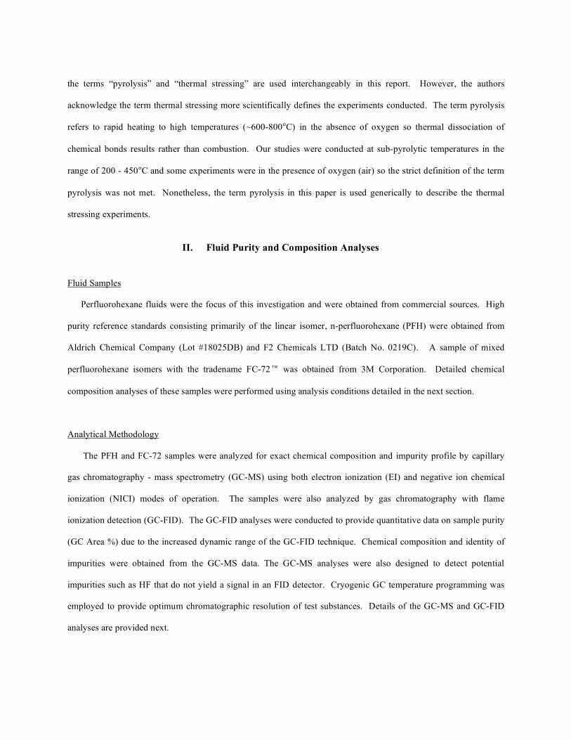
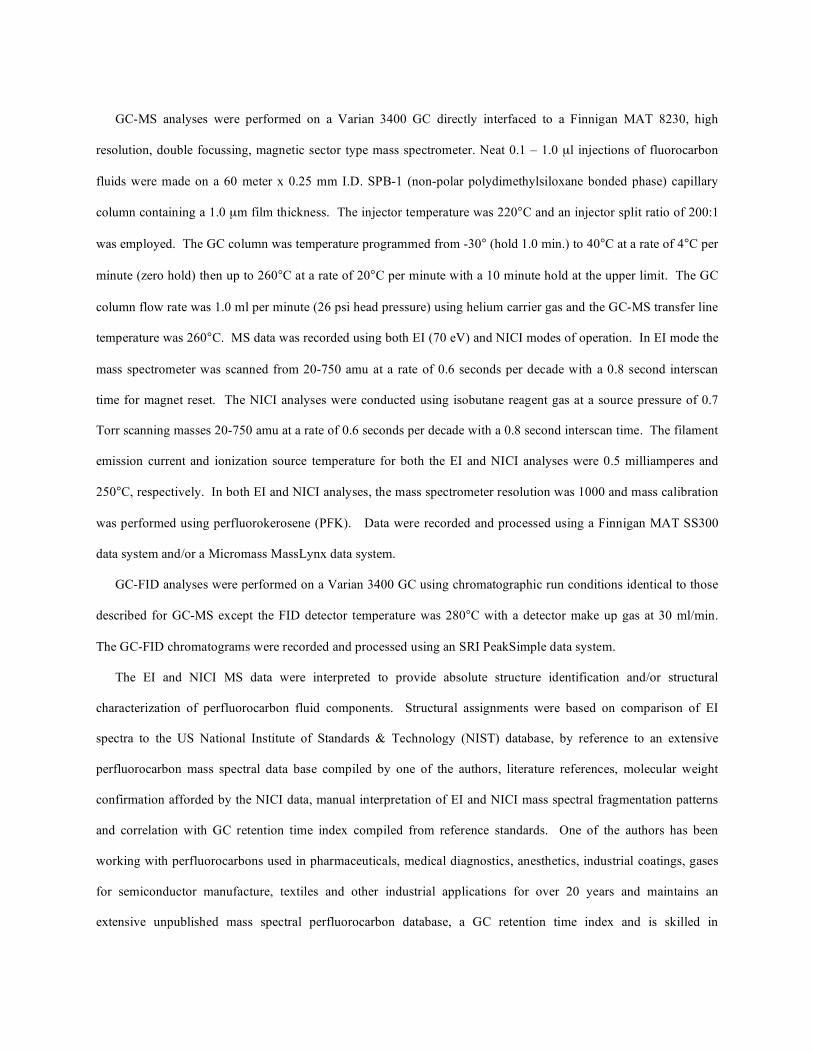
The chemical composition data from the GC-MS and GC-FID analyses of the FC-72, Aldrich PFH, and F2
Chemicals PFH samples are summarized in Tables 1, 2 & 3 respectively. From left to right, the columns in each
Table list the structural assignment, molecular weight (M.W.) and the percent composition based on GC peak area
%. The compounds are listed in order of elution from the GC (in order of increasing boiling point). Compounds
listed as trace (<0.001%) were detected in the GC-MS analyses but were below the threshold for reliable peak area
integration in the GC-FID data. Compounds listed as ultra-trace (<0.0001%) were impurities present at exceedingly
trace concentration and were typically detected only in the NICI-GC-MS data.
The Aldrich and F2 Chemicals LTD PFH samples consist primarily of n-perfluorohexane (99% +) along with
trace impurities. The FC-72 fluid contains n-perfluorohexane as the major component (73.2%), significant
quantities of branched C6F14 isomers and cyclic C6F12 species along with other trace level impurities. The combined
percentage of C6F14 isomers in the FC-72 fluid are approximately 98.8%.
Table 1 GC-MS/GC-FID Profile of FC-72
Structural Assignment
M.W.
GC Area %
n-perfluorobutane
238
trace (<0.001%)
n-perfluoropentane
288
trace (<0.001%)
perfluoro-2-methylbutane (perfluoroisopentane)
288
trace (<0.001%)
C6F14O isomer
354
trace (<0.001%)
n-perfluorohexane
338
73.200
perfluoro-2-methylpentane (perfluoroisohexane)
338
17.892
perfluoro-3-methylpentane
338
5.954
Perfluorocyclohexane
300
1.105
perfluoro-2,3-dimethylbutane + perfluoro-2,2-dimethylbutane
338
1.723
perfluoromethylcyclopentane
300
0.126
n-perfluoroheptane
388
trace (<0.001%)
perfluoro-2-methylhexane (perfluoroisoheptane)
388
trace (<0.001%)
C7F14 isomer
350
ultra-trace (<0.0001%)
C7F14 isomer
350
ultra-trace (<0.0001%)
C7F14 isomer
350
ultra-trace (<0.0001%)
C7F14 isomer
350
ultra-trace (<0.0001%)
C8F16O isomer
416
trace (<0.001%)
n-perfluorooctane
438
trace (<0.001%)
perfluoro-2-methylheptane
438
trace (<0.001%)
perfluoro-3-methylheptane
438
trace (<0.001%)
C8F16O isomer
416
ultra-trace (<0.0001%)
C8F16O isomer
416
trace (<0.001%)
C8F16O isomer
416
trace (<0.001%)
C8F16O isomer
416
ultra-trace (<0.0001%)
C8F16 isomer
400
ultra-trace (<0.0001%)
C8F16O isomer
416
ultra-trace (<0.0001%)
C8F16 isomer
400
ultra-trace (<0.0001%)
Table 2 GC-MS/GC-FID Profile of Aldrich Lot #18025DB PFH
Peak Assignment
M.W.
GC Area %
C6F14O isomer
354
trace (<0.001%)
n-perfluorohexane (PFH)
338
99.399
perfluorocyclohexane
300
trace (<0.001%)
C6F12O isomer
316
ultra-trace (<0.0001%)
C6F12O isomer
316
ultra-trace (<0.0001%)
perfluoromethylcyclopentane
300
0.019
C7F14 isomer, (C7 perfluorocarbon w/ one ring or double bond)
350
ultra-trace (<0.0001%)
C7F14 isomer, (C7 perfluorocarbon w/ one ring or double bond)
350
ultra-trace (<0.0001%)
C6F10 isomer, (C6 perfluorocarbon w/ two rings or double bonds)
262
ultra-trace (<0.0001%)
C6F10 isomer, (C6 perfluorocarbon w/ two rings or double bonds)
262
0.114
C7F10 isomer, (C7 perfluorocarbon w/ three rings or double bonds)
274
ultra-trace (<0.0001%)
C7F10 isomer, (C7 perfluorocarbon w/ three rings or double bonds)
274
ultra-trace (<0.0001%)
n-perfluorooctane
438
0.021
n-perfluorohexyl-1-hydride
320
0.047
C6F10 isomer, (C6 perfluorocarbon w/ two rings or double bonds)
262
ultra-trace (<0.0001%)
C6F8 isomer, (C6 perfluorocarbon w/ three rings or double bonds)
224
ultra-trace (<0.0001%)
C6F8 isomer, (C6 perfluorocarbon w/ two rings or double bonds)
224
ultra-trace (<0.0001%)
C6F8 isomer, (C6 perfluorocarbon w/ two rings or double bonds)
224
ultra-trace (<0.0001%)
C10F20 isomer, (C10 perfluorocarbon w/ one ring or double bond)
500
0.045
C10F18 isomer, (C10 perfluorocarbon w/ two rings or double bonds)
462
0.067
C10F18 isomer, (C10 perfluorocarbon w/ two rings or double bonds)
462
0.185
perfluorocarbon monohydride possibly perfluorodecyl-1-hydride
520
0.104
Table 3 GC-MS/GC-FID Profile of F2 Chemicals Ltd. PFH, Batch No. 0219C
Peak Assignment
M.W.
GC Area %
perfluorocyclopentane
250
0.108
n-perfluorohexane
338
99.679
perfluoro-2-methylpentane (perfluoroisohexane)
338
0.190
n-perfluorohexyl-1-hydride
320
0.012
n-perfluorobutyl-1-iodide
346
0.010
III. Fluid Decomposition Behavior at High Temperatures: Thermal Stressing Studies
Test Matrix
The FC-72 and PFH perfluorocarbons listed in Section II above were exposed to thermal stress conditions
designed to simulate a potential breach of the volatile fluids into the atmosphere aboard the International Space
Station (ISS) and subsequent exposure of the vapors to high temperature and catalyst associated with the Trace
Contaminant Control Subsassembly (TCCS) used for air purification. The TCCS operates at 450°C in the presence
of a palladium-coated alumina catalyst. This temperature is higher than the 200°C listed on the MSDS for potential
thermal breakdown. One potential by-product listed is perfluoroisobutene (PFiB). PFiB’s are extremely toxic with a
low threshold.
Thermal stressing tests were performed in the 200 – 450 oC range in the vapor phase diluted in air or inert
atmosphere (nitrogen) with and without catalyst exposure. The transit time through the thermal reaction zone was
modeled on the residence time of atmospheric gases passing through the heated catalyst in the TCCS and the
experiments were conducted at or near atmospheric pressure. It was desired to study the pyrolysis effect and
interaction of the TCCS catalyst material and air on these fluids. The test matrix is summarized in Table 4.
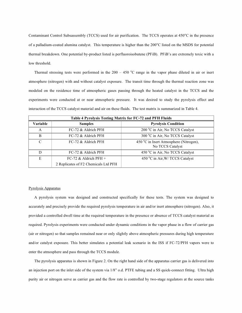
Table 4 Pyrolysis Testing Matrix for FC-72 and PFH Fluids
Variable Samples Pyrolysis Condition
A FC-72 & Aldrich PFH 200 oC in Air, No TCCS Catalyst
B FC-72 & Aldrich PFH 300 oC in Air, No TCCS Catalyst
C FC-72 & Aldrich PFH 450 oC in Inert Atmosphere (Nitrogen),
No TCCS Catalyst
D FC-72 & Aldrich PFH 450 oC in Air, No TCCS Catalyst
E FC-72 & Aldrich PFH +
2 Replicates of F2 Chemicals Ltd PFH
450 oC in Air,W/ TCCS Catalyst
Pyrolysis Apparatus
A pyrolysis system was designed and constructed specifically for these tests. The system was designed to
accurately and precisely provide the required pyrolysis temperature in air and/or inert atmosphere (nitrogen). Also, it
provided a controlled dwell time at the required temperature in the presence or absence of TCCS catalyst material as
required. Pyrolysis experiments were conducted under dynamic conditions in the vapor phase in a flow of carrier gas
(air or nitrogen) so that samples remained near or only slightly above atmospheric pressures during high temperature
and/or catalyst exposure. This better simulates a potential leak scenario in the ISS if FC-72/PFH vapors were to
enter the atmosphere and pass through the TCCS module.
The pyrolysis apparatus is shown in Figure 2. On the right hand side of the apparatus carrier gas is delivered into
an injection port on the inlet side of the system via 1/8” o.d. PTFE tubing and a SS quick-connect fitting. Ultra high
purity air or nitrogen serve as carrier gas and the flow rate is controlled by two-stage regulators at the source tanks
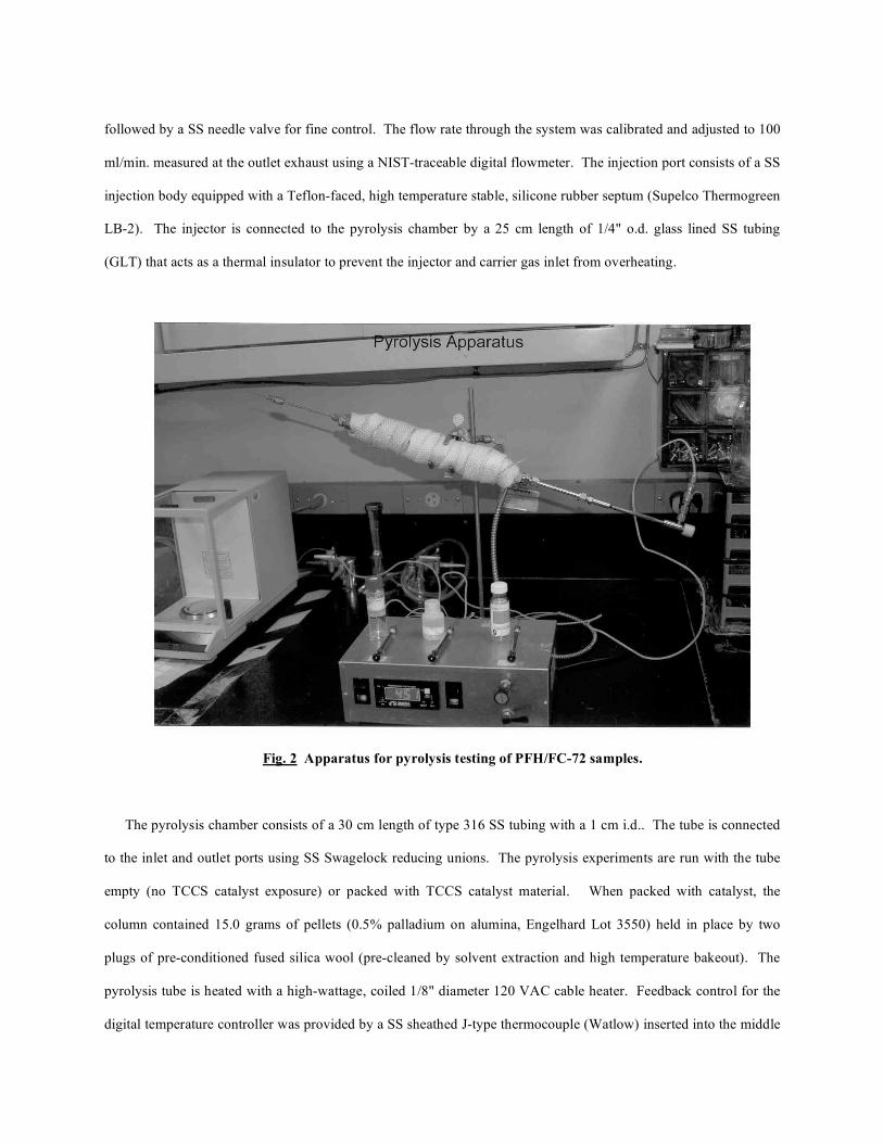
followed by a SS needle valve for fine control. The flow rate through the system was calibrated and adjusted to 100
ml/min. measured at the outlet exhaust using a NIST-traceable digital flowmeter. The injection port consists of a SS
injection body equipped with a Teflon-faced, high temperature stable, silicone rubber septum (Supelco Thermogreen
LB-2). The injector is connected to the pyrolysis chamber by a 25 cm length of 1/4" o.d. glass lined SS tubing
(GLT) that acts as a thermal insulator to prevent the injector and carrier gas inlet from overheating.
Fig. 2 Apparatus for pyrolysis testing of PFH/FC-72 samples.
The pyrolysis chamber consists of a 30 cm length of type 316 SS tubing with a 1 cm i.d.. The tube is connected
to the inlet and outlet ports using SS Swagelock reducing unions. The pyrolysis experiments are run with the tube
empty (no TCCS catalyst exposure) or packed with TCCS catalyst material. When packed with catalyst, the
column contained 15.0 grams of pellets (0.5% palladium on alumina, Engelhard Lot 3550) held in place by two
plugs of pre-conditioned fused silica wool (pre-cleaned by solvent extraction and high temperature bakeout). The
pyrolysis tube is heated with a high-wattage, coiled 1/8" diameter 120 VAC cable heater. Feedback control for the
digital temperature controller was provided by a SS sheathed J-type thermocouple (Watlow) inserted into the middle
of the thermal reaction tube and held in place by a welded 1/16” Swagelock tube fitting. The heating tube is
wrapped with several layers of glass fiber tape for thermal insulation.
Heating control was maintained with a precision of ±1.0 oC using a digital temperature controller (Omega) with
thermocouple feedback control. Temperature control was calibrated to internal tube temperature with normal flow
of carrier gas. The controller can be viewed at the bottom-center of Figure 2. The outlet of the pyrolysis apparatus
consists of a 15 cm long 1/8" o.d. GLT transfer line terminating in a side-port SS needle adapter. SS Swagelock
unions are used for connections to the pyrolysis tube and needle.
Please note that the entire pyrolysis apparatus is constructed entirely of inert materials such as type 316 SS, GLT
tubing and Teflon. All ferrules and fittings in the high temperature zones were SS. No elastomeric o-rings or rubber
seals were used as these can out-gas contaminants when heated.
Pyrolysis of FC-72/PFH Samples
Prior to conducting pyrolysis experiments on the fluorocarbons, the carrier gas flow was initiated and calibrated
and the desired temperature was set on the pyrolysis tube. The system was then allowed to equilibrate and bake-out
for approximately 60 minutes to vent off any trace contaminants potentially out-gassing from the construction
materials or catalyst. A 1.0 liter Tedlar gas sampling bag was then connected to the needle adapter outlet and a
method blank was collected and analyzed to verify a clean system. Finally, pyrolysis experiments were then
conducted on the perfluorocarbon samples.
In a pyrolysis experiment, a 1.0 liter Tedlar gas sampling bag was connected to the needle adapter of the pre-
conditioned system by piercing through a septum on the bag. As carrier gas is flowing through the system at a rate
of 100 ml/min., the bag inflates. For the actual pyrolysis experiment, 1.0 ml of the fluorocarbon liquid was then
injected into the apparatus with the use of a gas-tight syringe at the rate of approximately 1.0 ml per minute. The
fluorocarbon liquids vaporize in the injector and the vapors are swiftly moved through the pyrolysis tube by the
carrier gas and the pyrolysis products are collected into the Tedlar bag. Sample collection was allowed to proceed
for approximately 10 minutes until the Tedlar bags were filled to capacity. Bags were then removed and stored for a
short period prior to chemical analysis by GC-MS and GC-FID.
Dwell time of fluorocarbon vapor in the pyrolysis zone was estimated based on linear carrier velocity of the
purge gas and dead-volume inside the apparatus. Dead-volume of the system was measured after the pyrolysis
experiments by filling up the apparatus with water and measuring its volume. The empty system without the TCCS
catalyst packing had a dead volume of 27.5 ml, while the system with the TCCS catalyst had a dead-volume of 18.5
ml. Assuming a constant carrier gas flow rate of 100 ml/min. and no back-diffusion of vapor into the system from
the Tedlar bag, the minimum dwell time for samples in the thermal zone were calculated to be approximately 17
seconds for the empty system and 11 seconds for the TCCS catalyst -ontaining system. If back diffusion of sample
from the Tedlar bag occurred during the pyrolysis experiments the maximum possible dwell time for any
fluorocarbon contact with the thermal zone would be 10 minutes which was the duration of the entire experiment.
However, this latter scenario is unlikely since the needle gauge on the outlet of the apparatus is narrow and the
sample and carrier gas exit the system under slight positive pressure which would be expected to prevent any
significant level of back-streaming. The dwell time of atmospheric gases passing through the TCCS on the ISS is
reportedly less than 2 seconds.21
Analysis of FC-72/PFH Samples
Following collection of perfluorocarbon samples after pyrolysis under the specified conditions, the samples were
subjected to complete chemical analysis by GC-MS and by GC-FID and a mass balance was performed. The
samples were carefully checked for changes in chemical composition by comparing the pyrolysis data to the analysis
results performed previously on the neat liquids before exposure. For the mass balance, 1.0 ml of each
perfluorocarbon fluid was injected into a 1.0 L Tedlar bag, evaporated into the gas phase and diluted to volume with
nitrogen. Tedlar bags prepared in this manner, and samples collected after pyrolysis were analyzed by GC-FID.
The total area under the curve (AUC) of the GC-FID chromatograms before and after pyrolysis were used to
calculate mass balance for the experiments.
The PFH and FC-72 pyrolysis samples were analyzed in the gas phase directly sampled from the Tedlar bags by
capillary GC-MS using both EI and NICI modes of operation. The samples were also analyzed by GC-FID. The
GC-FID analyses were conducted to provide quantitative data on sample purity (GC Area %) and for mass balance
following the pyrolysis exposure. The GC-MS and GC-FID analysis conditions were identical to those already
described in Section II for the structure and impurity profiling of the neat liquids with only slight modification for
sample injection technique. The pyrolysis gases were analyzed by injecting 0.1-0.25 ml aliquots of vapor from the
Tedlar gas sampling bags using a pre-heated, 1.0 ml volume gastight syringe equipped with an on/off valve
(Dynatech Pressure-Lok ).
Perfluoroisobutylene (PFiB) Specific Analysis
Due to the known high toxicity of PFiB, specific ultra-high sensitivity analyses were performed for this
compound to check if it is produced as a pyrolysis product of any of the perfluorocarbon liquids. A certified
analytical reference sample of PFiB was purchased at a concentration of 33.17 parts per million (PPM) v/v in
nitrogen from Scott Specialty Gases (Plumsteadville, Pa). A gas-phase serial dilution of this sample was prepared in
nitrogen to prepare a working standard at a final concentration of 33.17 parts per billion (PPB) v/v. The 33.17 PPB
reference standard of PFiB was used to validate the detection limit of this compound using GC-MS in NICI mode
using the exact same conditions as for pyrolysis study samples.
Results & Discussion for PFH/FC-72 Thermal Stressing Studies
The results of the pyrolysis study are summarized in Table 5. None of the perfluorocarbon study samples were
significantly degraded by any of the pyrolysis conditions. Mass balance before and after pyrolysis confirmed this
result quantitative. Table 5 lists the percentage of PFH in the initial liquid samples and following pyrolysis under
the various study conditions. Please note that for FC-72, the percentages listed are the sum of branched plus linear
C6F14 isomers. As far as the major components of all samples are concerned, essentially no decomposition was
noted under any of the pyrolysis conditions. Some decomposition of trace level impurities associated with the
Aldrich and F2 Chemicals PFH samples was noted. These samples contain trace impurities of compounds such as
linear perfluorocarbon monohydrides and monoiodides and some unsaturated or cyclic-unsaturated
perfluorocarbons. The more aggressive pyrolysis conditions were found to degrade these impurities so they were no
longer present in the samples following pyrolysis at the upper limit. As a consequence, the purity of PFH in these
instances actually increased slightly as the pyrolysis procedure effectively scrubbed the samples of these impurities.
This effect can be observed as slight increases in PFH percentages in Table 5 with increasing pyrolysis temperature.
Since the impacted impurities were trace level to begin with the overall effect is trivial. Presumably, these hydrogen
and iodine-containing trace-level impurities were decomposed into non-volatile radical species. Also, at the highest
temperature condition of pyrolysis, some trace level (<0.001 %) of oxygenated-perfluorocarbon decomposition
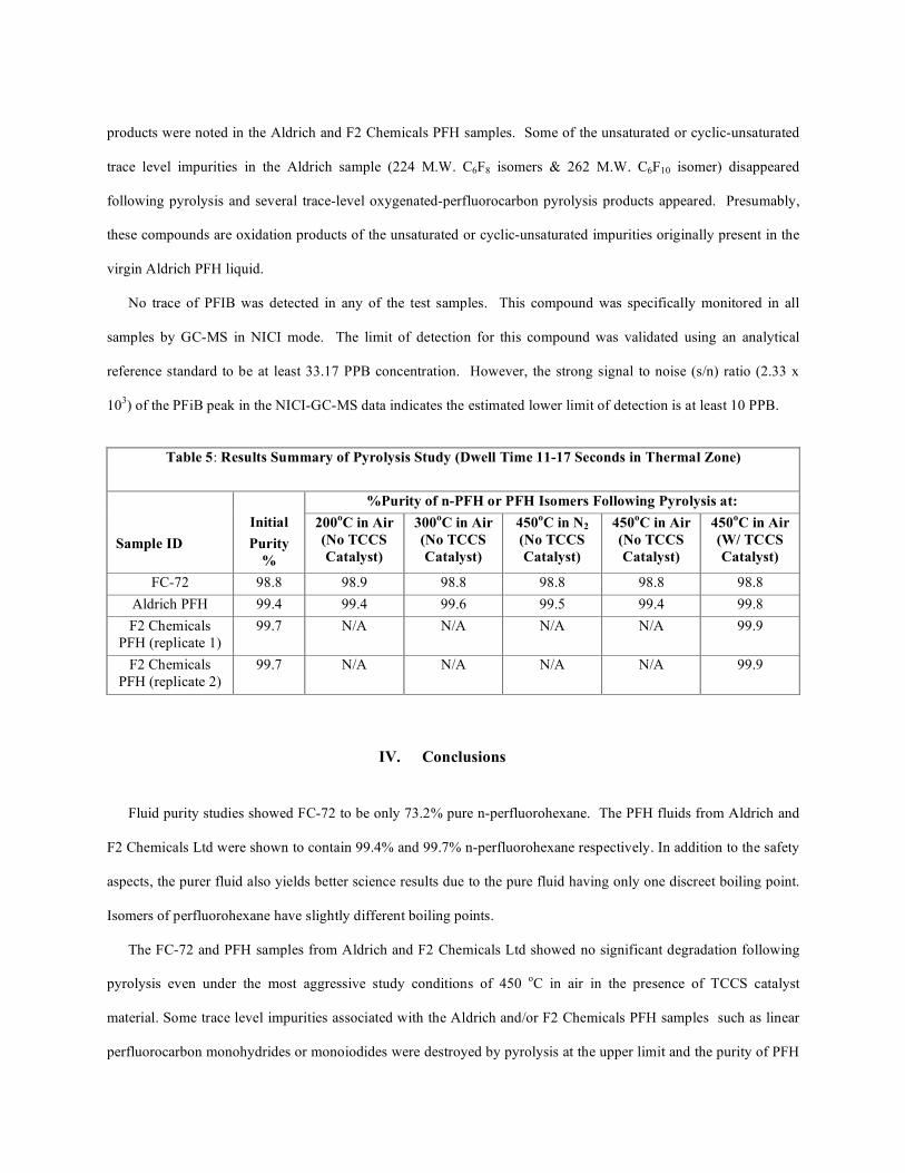
products were noted in the Aldrich and F2 Chemicals PFH samples. Some of the unsaturated or cyclic-unsaturated
trace level impurities in the Aldrich sample (224 M.W. C6F8 isomers & 262 M.W. C6F10 isomer) disappeared
following pyrolysis and several trace-level oxygenated-perfluorocarbon pyrolysis products appeared. Presumably,
these compounds are oxidation products of the unsaturated or cyclic-unsaturated impurities originally present in the
virgin Aldrich PFH liquid.
No trace of PFIB was detected in any of the test samples. This compound was specifically monitored in all
samples by GC-MS in NICI mode. The limit of detection for this compound was validated using an analytical
reference standard to be at least 33.17 PPB concentration. However, the strong signal to noise (s/n) ratio (2.33 x
103) of the PFiB peak in the NICI-GC-MS data indicates the estimated lower limit of detection is at least 10 PPB.
Table 5: Results Summary of Pyrolysis Study (Dwell Time 11-17 Seconds in Thermal Zone)
%Purity of n-PFH or PFH Isomers Following Pyrolysis at:
Sample ID
Initial
Purity
%
200oC in Air
(No TCCS
Catalyst)
300oC in Air
(No TCCS
Catalyst)
450oC in N2
(No TCCS
Catalyst)
450oC in Air
(No TCCS
Catalyst)
450oC in Air
(W/ TCCS
Catalyst)
FC-72 98.8 98.9 98.8 98.8 98.8 98.8
Aldrich PFH 99.4 99.4 99.6 99.5 99.4 99.8
F2 Chemicals
PFH (replicate 1)
99.7 N/A N/A N/A N/A 99.9
F2 Chemicals
PFH (replicate 2)
99.7 N/A N/A N/A N/A 99.9
IV. Conclusions
Fluid purity studies showed FC-72 to be only 73.2% pure n-perfluorohexane. The PFH fluids from Aldrich and
F2 Chemicals Ltd were shown to contain 99.4% and 99.7% n-perfluorohexane respectively. In addition to the safety
aspects, the purer fluid also yields better science results due to the pure fluid having only one discreet boiling point.
Isomers of perfluorohexane have slightly different boiling points.
The FC-72 and PFH samples from Aldrich and F2 Chemicals Ltd showed no significant degradation following
pyrolysis even under the most aggressive study conditions of 450 oC in air in the presence of TCCS catalyst
material. Some trace level impurities associated with the Aldrich and/or F2 Chemicals PFH samples such as linear
perfluorocarbon monohydrides or monoiodides were destroyed by pyrolysis at the upper limit and the purity of PFH
following pyrolysis actually increased slightly as a consequence. The virgin Aldrich PFH sample contains some
trace level unsaturated or cyclic-unsaturated perfluorocarbon impurities that presumably oxidized during pyrolysis at
the upper limit forming some trace level (<0.001%) oxygenated-perfluorocarbon decomposition products. For
example, it is postulated that compounds such as perfluorocyclohexene are oxidized into compounds such as
perfluorocyclohexanone.
No trace of PFiB was observed in any of the perfluorocarbon samples before or after pyrolysis. The detection
limit of the analytical method for PFiB was validated at 33.17 PPB v/v but was estimated to be at least 10 PPB v/v
based on the strong observed s/n ratio (2.33e3) in the NICI-GC-MS data.
Testing and analyses are also underway regarding two other 3M fluorocarbon engineering fluids, HFE-7000
(methyl perfluoropropyl ether) and HFE-7500 (2-trifluoromethyl-3-ethoxydodecafluorohexane).
Fluorocarbon fluids hold great promise in future space-based heat transfer applications. These fluids could
potentially reduce size and weight of heat transfer apparatuses while vastly improving performance. The work
presented here and the work being performed on other fluorocarbon fluids is not only applicable for the specific
space experiments for which they were originally intended, but rather also represents a stepping stone in getting
these and other fluorocarbon fluids approved for general heat transfer applications in future space missions.
V. Acknowledgements
This research was supported by the Human System Research and Technology Development (HSR&T) Program
at NASA Headquarters.
VI. References
1 Samonski, F. H. Jr., and Tucker, E. M., “Apollo Experience Report – Command and Service Module
Environmental Control System,” NASA TN D6718, 1972.
2 Nason, J. R.; Wierum, F. A.; Yanosy, J. L., “Challenges In The Development Of The Orbiter Active Thermal
Control Subsystem,” NASA. Johnson Space Center Space Shuttle Tech. Conf., Pt. 1/ p 450-464, 1985.
3 Tatara, J. D., Perry J. L and Franks G. D., “Overview of the International Space Station System Level Trace
Contaminant Injection Test,” NASA/TM-1997-208137; International Conference on Environmental Systems
(ICES), Danvers, MA, 13-16 Jul. 1998 , 19970101; 1997
4 3M, Material Safety Data Sheet on FC-72 3M Performance Fluid. 3M, St. Paul, MN, 1995
5 Riess JG, “Blood substitutes and other potential biomedical applications of fluorinated colloids, ” Journal Of
Fluorine Chemistry Vol 114, pp 119-126, 2002
6 Waritz, R. S. and Kwon, B. K., “The Inhalation Toxicity of Pyrolysis Products of Polytetrafluoroethylene
Heated Below 500 Degrees Centrigrade,” American Industrial Hygiene Association Journal, p 19- 26, 1968,
7 Kennedy, G. L. Jr., and Geisen, R. J., “Setting Occupational Exposure Limits for Perfluoroisobutylene, A
Highly Toxic Chemical Following Acute Exposure,” Journal of Occupational Medicine, Vol. 27, No. 9, p 675,
1985.
8 Lehnert, B. E., Archuleta, D., Behr, M. J., and Stavert, D. M., “Lung Injury after Acute Inhalation of
Perfluoroisobutylene: Exposure Concentration – Response Relationships, “Inhalation Toxicology, Vol. 5, 1-32,
1993.
9 Warheit, D. B., Seidel, W. C., Carakostas, M. C., and Hartsky, M. A, “Attenuation of Perfluoropolymer Fume
Pulmonary Toxicity: Effect of Filters, Combustion Method, and Aerosol Age,” Experimental and Molecular
Pathology, Vol 52, 309-329, 1990.
10 Lee, K. P., and Seidel. W. C., “Pulmonary Response of Rats Exposed to Polytetrafluoroethylene and
Tetrafluoroethylene Hexafluoropropylene Copolymer Fume and Isolated Particles,” Inhalation Toxicology, Vol.
3, 237-264, 1991.
11
Oberdorster, G., Gelein, R. M., Ferin, J., and Weiss, B., “Association of Particulate Air Pollution and Acute
Mortality: Involvement of Ultrafine Particles?” Inhalation Toxicology, Vol. 7, 111-124, 1995.
12 Hauptschein, M. Fainberg, A. H., and Braid, M. “The Thermal Dimerization of Perfluoropropene,” Journal of
the American Chemical Society, Vol. 80, 842-845, 1958.
13 Salmon, R. P. DiFelice, J. J., and Ritter, E. R., “An Experimental Study of the Formation of
Perfluoroisobutene,” Combustion Science and Technology, Vol. 134, 65-85, 1998.
14 Tortelli V., Tonelli, C., and Corvaja, C., “Thermal Decomposition Of Branched-Chain Perfluroalkanes,” J.
Fluorine Chemistry 60: 165-174, 1993.
15 Tonelli, C. and Tortelli V., “Pyrolysis Of Branched-Chain Perfluoroalkanes In The Presence Of Halogens”. J.
Fluorine Chemistry 67: 125-128, 1994.
16 Ainagos, A.F. “Mechanism And Kinetics Of Pyrolysis Of Perfluorohexane,” Kinetics And Catalysis, Vol. 32
pp. 720-725, 1991.
17 Arito H. and Soda, R, “Pyrolysis Products of Polytetrafluoroethylene and Polyfluoroethylenepropylene with
Reference to Inhalation Toxicity,” Annals of Occupational Hygiene, Vol. 20, pp. 247-255, 1977.
18 Trowbridge, L. D, “Potential Hazards Relating to the Pyrolysis of c-C4F8 in selected Gaseous Diffusion Plant
Operations, ORNL/TM-13758, 1999.
19 Trowbridge, L. D, “Potential Hazards Relating to the Pyrolysis of c-C4F8O, n-C4F10 and c-C4F8 in selected
Gaseous Diffusion Plant Operations, ORNL/TM-2000/68, 2000.
20 DeCorpo , J. J, Holtzclaw, J. R., and Clark, R. C., “Testing and Evaluation of Potential Hazards from a Teflon
Impregnated Packing,” NRL Memorandum Report 4026, 1979.
21 Perry, J. L, “Space Station Freedom Environmental Control and Life Support System (ECLSS) Phase III
Simplified Integrated Test Trace Contaminant Control Subsystem Performance, “ NASA TM 4202, 1990.
Related Documents