N. Chutichairattanaphum et al., Effects of Raschig Ring Packing Patterns…, Chem. Biochem. Eng. Q., 33 (2) 191–211 (2019) 191 Effects of Raschig Ring Packing Patterns on Pressure Drop, Heat Transfer, Methane Conversion, and Coke Deposition on a Semi-pilot-scale Packed Bed Reformer N. Chutichairattanaphum, a,b,* P. Narataruksa, a,b,c K. Pana-suppamassadu, a,b,c S. Tungkamani, b,c C. Prapainainar, a,b S. Chotiwan, d and W. Wattanathana e a Department of Chemical Engineering, Faculty of Engineering, King Mongkut’s University of Technology North Bangkok, Bangkok, 10800, Thailand b Research and Development Center for Chemical Engineering Unit Operation and Catalyst Design (RCC), King Mongkut’s University of Technology North Bangkok, Bangkok, 10800, Thailand c Department of Industrial Chemistry, Faculty of Applied Science, King Mongkut’s University of Technology North Bangkok, Bangkok, 10800, Thailand d Department of Chemistry, Faculty of Science, Kasetsart University, Ladyao, Chatuchak, Bangkok 10900, Thailand e Department of Materials Engineering, Faculty of Engineering, Kasetsart University, Ladyao, Chatuchak, Bangkok 10900, Thailand The effects of Raschig ring packing patterns on the efficiency of dry methane re- forming reactions were investigated using computational fluid dynamics (CFD). The present study aims to understand the behavior of fluid flow in packed bed reactors, espe- cially under low reactor-to-ring ratios between 4 and 8. Three packing patterns were studied: vertical staggered (VS), chessboard staggered (CS), and reciprocal staggered (RS). It was determined that packing pattern notably affected pressure drop across the reactor length. The VS pattern produced the lowest pressure drop of 223 mPa, while the CS and RS patterns produced pressure drops of 228 mPa and 308 mPa, respectively. The values of methane conversion can be increased by ca. 2 % by selecting a more suitable packing pattern (i.e., 76 % for the VS pattern and 74 % for the CS and RS patterns). Keywords: packed bed reactor, Raschig ring, dry methane reforming, reactions kinetics Introduction Due to the global issue of elevated greenhouse gas emissions, the search for alternative low pollu- tion energy sources remains necessary. Notably, the use of synthesis gas represents an option for de- creasing greenhouse gas from industries, since methane (CH 4 ) and carbon dioxide (CO 2 ) are com- monly employed as reactant gases for synthesis gas production. Moreover, synthesis gas can be used as raw material for the synthesis of Fischer-Tropsch synthesis, methanol, ammonia, and dimethyl ether (DME) 1–4 . Typically, the reaction equilibrium to produce syngas is: Catalyst 4 2 2 CH +CO 2CO+2H → (1) Nevertheless, the thermodynamic barrier rep- resents a major challenge and is unfavorable to pro- cesses that rely merely on heat to convert the two-carbon molecules of methane and carbon diox- ide at high conversion levels 5 . The key to the suc- cess of the dry reforming process depends on the management of heat distribution for this highly en- dothermic reaction process. The use of catalyst sys- tems may lead to a reduction in energy invested in the process, which would allow dry reforming to become closer to an economical process down- stream. Metal catalysts are suitable for reforming processes. Using nickel-based catalysts–either di- rectly or supported–is one of the most commonly reported methods 5–12 . Furthermore, it has been re- ported that many nickel-based catalysts are efficient in inducing dry methane reforming (DMR) at lower temperatures than predicted based on equilibrium calculations. https://doi.org/10.15255/CABEQ.2019.1623 Original scientific paper Received: February 20, 2019 Accepted: July 1, 2019 * Corresponding author: E-mail: [email protected] This work is licensed under a Creative Commons Attribution 4.0 International License N. Chutichairattanaphum et al., Effects of Raschig Ring Packing Patterns… 191–211

Welcome message from author
This document is posted to help you gain knowledge. Please leave a comment to let me know what you think about it! Share it to your friends and learn new things together.
Transcript

N. Chutichairattanaphum et al., Effects of Raschig Ring Packing Patterns…, Chem. Biochem. Eng. Q., 33 (2) 191–211 (2019) 191
Effects of Raschig Ring Packing Patterns on Pressure Drop, Heat Transfer, Methane Conversion, and Coke Deposition on a Semi-pilot-scale Packed Bed Reformer
N. Chutichairattanaphum,a,b,* P. Narataruksa,a,b,c K. Pana-suppamassadu,a,b,c S. Tungkamani,b,c C. Prapainainar,a,b S. Chotiwan,d and W. Wattanathanae
aDepartment of Chemical Engineering, Faculty of Engineering, King Mongkut’s University of Technology North Bangkok, Bangkok, 10800, ThailandbResearch and Development Center for Chemical Engineering Unit Operation and Catalyst Design (RCC), King Mongkut’s University of Technology North Bangkok, Bangkok, 10800, ThailandcDepartment of Industrial Chemistry, Faculty of Applied Science, King Mongkut’s University of Technology North Bangkok, Bangkok, 10800, ThailanddDepartment of Chemistry, Faculty of Science, Kasetsart University, Ladyao, Chatuchak, Bangkok 10900, ThailandeDepartment of Materials Engineering, Faculty of Engineering, Kasetsart University, Ladyao, Chatuchak, Bangkok 10900, Thailand
The effects of Raschig ring packing patterns on the efficiency of dry methane re-forming reactions were investigated using computational fluid dynamics (CFD). The present study aims to understand the behavior of fluid flow in packed bed reactors, espe-cially under low reactor-to-ring ratios between 4 and 8. Three packing patterns were studied: vertical staggered (VS), chessboard staggered (CS), and reciprocal staggered (RS). It was determined that packing pattern notably affected pressure drop across the reactor length. The VS pattern produced the lowest pressure drop of 223 mPa, while the CS and RS patterns produced pressure drops of 228 mPa and 308 mPa, respectively. The values of methane conversion can be increased by ca. 2 % by selecting a more suitable packing pattern (i.e., 76 % for the VS pattern and 74 % for the CS and RS patterns).
Keywords:packed bed reactor, Raschig ring, dry methane reforming, reactions kinetics
Introduction
Due to the global issue of elevated greenhouse gas emissions, the search for alternative low pollu-tion energy sources remains necessary. Notably, the use of synthesis gas represents an option for de-creasing greenhouse gas from industries, since methane (CH4) and carbon dioxide (CO2) are com-monly employed as reactant gases for synthesis gas production. Moreover, synthesis gas can be used as raw material for the synthesis of Fischer-Tropsch synthesis, methanol, ammonia, and dimethyl ether (DME)1–4. Typically, the reaction equilibrium to produce syngas is:
Catalyst4 2 2CH +CO 2CO+2H→ (1)
Nevertheless, the thermodynamic barrier rep-resents a major challenge and is unfavorable to pro-cesses that rely merely on heat to convert the two-carbon molecules of methane and carbon diox-ide at high conversion levels5. The key to the suc-cess of the dry reforming process depends on the management of heat distribution for this highly en-dothermic reaction process. The use of catalyst sys-tems may lead to a reduction in energy invested in the process, which would allow dry reforming to become closer to an economical process down-stream. Metal catalysts are suitable for reforming processes. Using nickel-based catalysts–either di-rectly or supported–is one of the most commonly reported methods5–12. Furthermore, it has been re-ported that many nickel-based catalysts are efficient in inducing dry methane reforming (DMR) at lower temperatures than predicted based on equilibrium calculations.
https://doi.org/10.15255/CABEQ.2019.1623
Original scientific paper Received: February 20, 2019
Accepted: July 1, 2019
*Corresponding author: E-mail: [email protected]
This work is licensed under a Creative Commons Attribution 4.0
International License
N. Chutichairattanaphum et al., Effects of Raschig Ring Packing Patterns…191–211

192 N. Chutichairattanaphum et al., Effects of Raschig Ring Packing Patterns…, Chem. Biochem. Eng. Q., 33 (2) 191–211 (2019)
Due to DMR being confined from two moles of methane and carbon dioxide to four moles of products, this reaction favors low pressure. Ad-vanced catalyst shapes have been presented for higher catalyst activity at a lower pressure drop across the bed. The reformer throughput at a fixed operating temperature, pressure, and inlet gas com-position largely relies on the activity of the unit of volume of the catalyst bed. Fukuhara et al. also worked with a nickel-based catalyst impregnated on honeycomb-like structure. They reported that this catalyst was more efficient at high temperature (700 °C) and exhibited less deactivation13. Moreover, uti-lizing a wall-coated catalyst is an alternative tech-nique that possibly prevents the coke formation that can occur inside the packed column due to hotspot problems; however, metal oxide catalysts have proven to be less sensitive to carbon deposition on the catalyst surface14. Notably, the application of a wall-coated catalyst is known to improve heat and mass transfer. A typical DMR process is performed in packed bed reactor that must supply heat to this highly endothermic reaction.
The modified packed bed reactor is a promis-ing technology that is a fundamental ideal for chem-ical reactions with low energy consumption, mini-mum contamination, and the ability to control the non-ideal behavior of gas mixtures inside a packed bed reactor. At the industrial level, a packed bed re-actor is widely used in chemical and petrochemical processes, such as methanol synthesis, ammonium synthesis, and Fischer-Tropsch synthesis1–4. Typi-cally, reactors consist of the reaction zone (or effec-tive volume), where reactant(s) flow and contact with catalytic packing to transform into product(s). The design of a packed bed is based on the mecha-nisms of fluid flow, heat transfer, and internal mass transfer limitations15. Moreover, particle shape will impact pressure drop, while the complex structural system in a randomly packed bed typically results in flow and temperature maldistributions. At high tube-to-particle diameter ratios (N), generally be-tween 50 and 500, which represents the average amount of catalyst particles on a cross-section of the diameter, the wall effects can be negligible since the affected area is very small compared to the reac-tor bulk. Optimization of the tube-to-particle ratio strategy has attracted many reseachers16–19. In ex-tremely exo- and endothermic processes, the heat flowing axially through the bed is one of the most important factors. The challenge is to increase the heat transfer rate from the reactor wall to the packed bed. For example, a low tube-to-particle ratio (N = 4–8) was investigated on large void fractions exist-ing in the near-wall region5,20,21. Furthermore, stag-nation or backflow can be observed in the wake of the particles, with high velocities being detected in
regions with high void fractions21. Uncontrolled heat transfer may lead to undesired products, selec-tivity, and yields, sometimes resulting in reactor damage.
Recently, computational fluid dynamics (CFD) has been used to simulate the flow and heat transfer characteristics of packed beds at low aspect ratios. For example, Nijemeisland and Dixon20 studied a packed bed of spheres with a low tube-to-particle diameter ratio of 2. The pressure profile within the bed was investigated using CFD. The authors deter-mined that, using a sphere diameter of 99 % of the actual sphere diameter, had led to a turbulent solu-tion while maintaining the original velocity distri-bution around the contact points. Further studies have been conducted on fluid flow, heat transfer, and dispersion in either low-N packed tubes or small periodic groups of spherical particles without reaction.
In cases using randomly filled tubular fixed bed reactors with small tube-to-particle diameter ra-tios, the lattice Boltzmann approach can provide detailed insight into flow and transport processes in complex geometries21. However, the inclusion of chemical reactions been limited to lattice Boltz-mann simulations of isothermal flows with surface reactions to date, have shown strong agreement among computational and experimental results22–24.
Although a randomly packed bed is more com-monly used due to the ease of packing and accept-able pressure drop values, Nijemeisland and Dixon studied a random catalyst packed bed using numer-ical techniques and experiments to reflect the local effects20. Moreover, Dixon et al. determined DMR endothermic reactions by coupling fluid flow in the packed bed to transport and react inside catalyst particles using CFD25. The authors observed that temperature, concentration, and reaction rate at cat-alyst particles are heterogeneous near the wall. Ad-ditionally, Nijemeisland et al.26 also used CFD to compare catalyst geometries and hole sizes for non-reactive heat transfers. The modelling of low tube-to-particle ratio beds that are used in extremely exo- and endothermic processes in shell-and-tube type reactors is complicated due to the presence of radial temperature profiles across the tube27. There-fore, the physical mechanisms involved, especially in the wall vicinity, must be understood in order to develop a non-intrusive tool to collect numerical data for comparison against experimental results. Packing technology ideas are used to design fluid flow in a packed bed by determining patterns that minimize maldistribution and pressure drops in a low tube-to-particle ratio. The present study com-pares simulation results with experimental results to determine the validity of the kinetic model.

N. Chutichairattanaphum et al., Effects of Raschig Ring Packing Patterns…, Chem. Biochem. Eng. Q., 33 (2) 191–211 (2019) 193
The goal of the present study was to present three practicable Raschig ring packing patterns—VS, CS, and RS. The present study used a semi-pi-lot scale reformer reactor 10.16 cm in diameter and 5.16 cm in length. A low tube-to-particle ratio (N) (4–8) was used to provide information concerning the limitations of heat and mass transfer, catalyst deactivation, and system controllability. Several ex-periments were performed to determine the overall reaction conversion. Due to being a semi-pilot-scale project, the CFD models were constructed to illus-trate the velocity, temperature, pressure, and con-centration profiles inside a reactor. In this work, kinetic parameters were validated using a lab-scale packed bed filled with 10 % Ni/Al2O3-MgO coated on Raschig ring structures. The effect of various in-fluencing parameters, such as feed velocity and feed concentration parameters, were used in the CFD models in order to reflect the catalytic perfor-mance via computational analysis. Finally, the ex-perimental results and the CFD approach were used to clarify the holistic effects of the three packing patterns on a studied reformer.
Materials and methods
In the present study, the experimental rig was fabricated to conduct the DMR reaction in a labora-tory-scale packed bed reactor (5 catalyst pellets) and a semi-pilot-scale packed bed reactor (20–24 catalyst pellets). The experimental program was di-vided into two parts, i.e., study of the kinetic pa-rameters in a laboratory-scale packed bed reactor, and effects of packing patterns in a semi-pilot-scale packed bed reactor.
Catalyst preparation
Sol-gel procedure
Raschig rings coated with 10 % Ni/Al2O3-MgO catalyst were prepared using the sol-gel method. In brief, the sol-gel synthesis of the catalyst required aluminum isopropoxide (Al(OC3H7)3), nickel(II) nitrate (Ni(NO3)2) · 6H2O, and magnesium ethoxide 98 % (Sigma-Aldrich®, Thailand) (Mg(OC2H5)2) as precursors. The aluminum isopropoxide was dis-solved in water to undergo hydrolysis. It was then changed into a gel by addition of nitric acid. The magnesium ethoxide precursor was dissolved sepa-rately in water, and then added into the gel. The precursors were refluxed for ca. 12 h. The Ni solu-tion was added to the sol-gel solution under vigor-ous stirring. The obtained solution was maintained under stirring for ca. 1 h until a green gel was formed. The technique has been described previous-ly by Piyapaka28.
Coating procedure
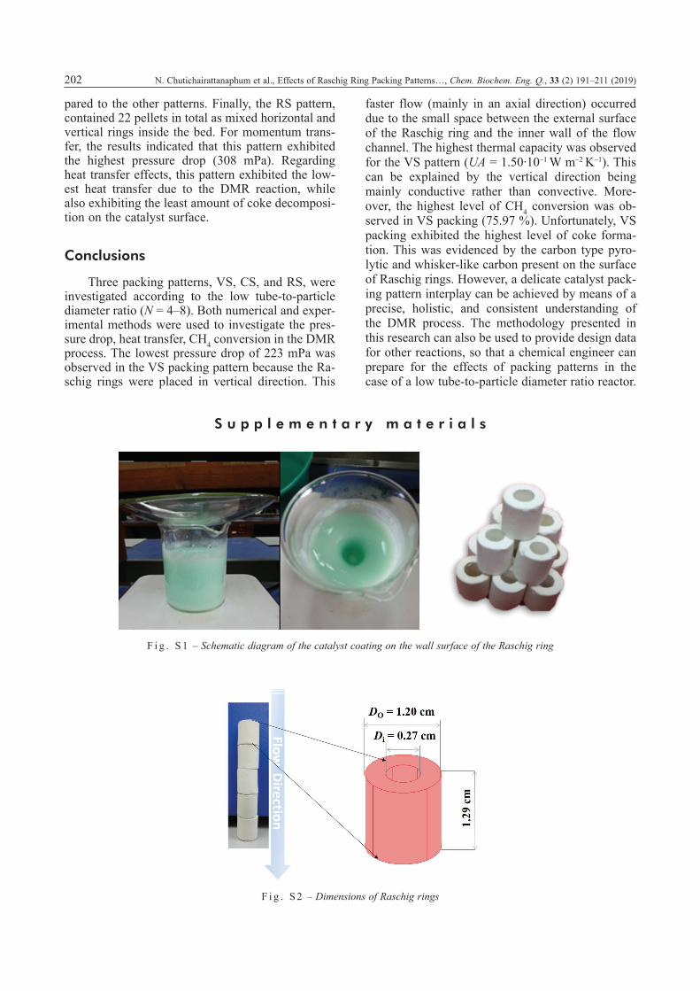
Raschig rings were used as the substrate for sol-gel dip coating. Firstly, the surfaces of Raschig rings were washed with deionized water (DI water) in an ultrasonic bath for cleaning and removal of impurities and organic compounds. For the Raschig ring dip coating process, the rings were arranged in a vertical direction during coating to cover the en-tire ring surface. They were then immersed in an ultrasonic bath of sol-gel solution for 25 min. Final-ly, the Raschig rings were dried and calcined in air at 450 °C by controlling the heating rate (1 °C min–1), as shown in Fig. S1.
The specific surface areas of Raschig ring wall-coated catalysts were measured using a BEL-SORP-mini instrument. The samples were degassed at 350 °C for 4 h prior to N2 physisorption. The spe-cific surface area of 10 % Ni/Al2O3-MgO was 177.68 m2 g–1, while its pore volume was 8.92 cm3 g–1 with a pore diameter of 0.201 nm.
Experimental system and procedure
Laboratory-scale setup for the study of kinetics: Optimizing the rate constants
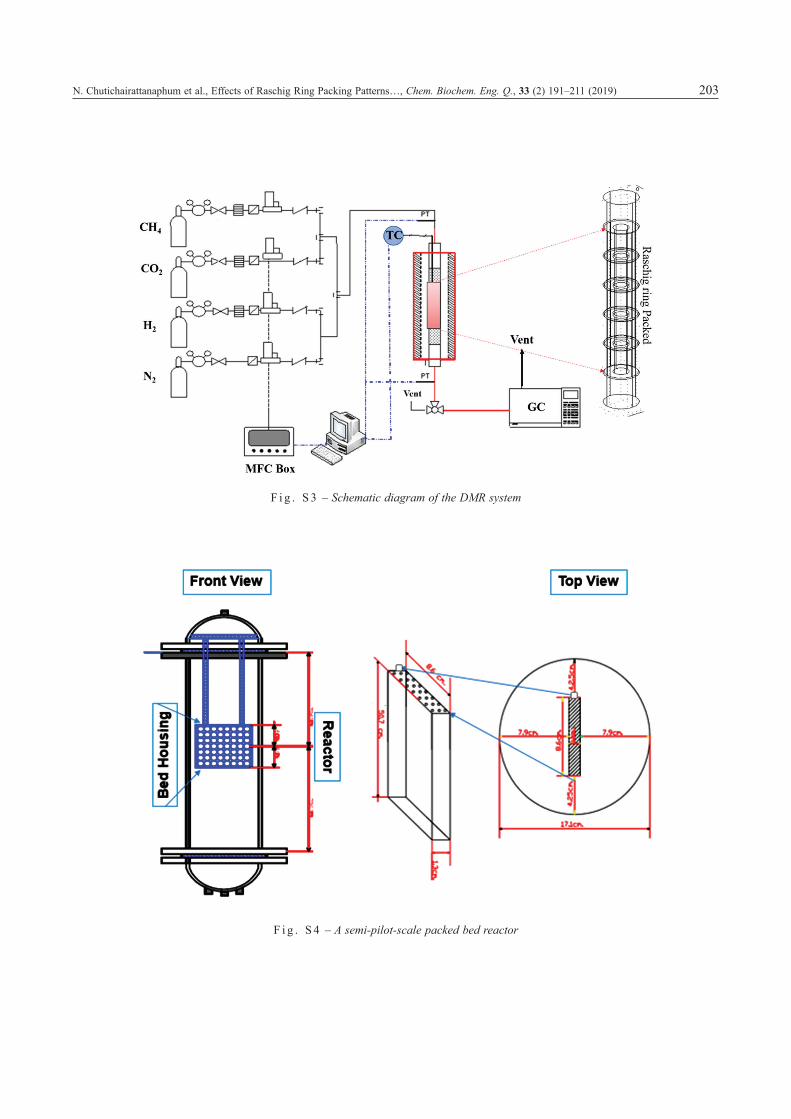
The kinetic study of the DMR reaction was performed in a packed bed reactor (1.587 cm diam-eter). Five pellets of Raschig ring catalyst were used for the kinetic study, as presented in Fig. S2. The reactor was placed in an electrically heated fur-nace, and its temperature was controlled by an intel-ligent temperature control meter (Carbolite Model.VST12/600/3216P1). The inlet flow rate of reactant gases, CH4 and CO2, was controlled by a mass flow controller (Kofloc model 8500). A schematic of the DMR system is presented in Fig. S3. Before the reaction occurred, the Raschig ring coated with 10 % Ni/Al2O3-MgO catalyst was reduced by flow-ing H2/N2 (40 % H2 by volume) into the reactor with the temperature increasing from room tem-perature to 600 °C over 12 h. The samples were tested in a 600 – 800 °C temperature range.
A mathematical model of kinetic reaction was developed using COMSOL Multiphysics V3.5a software, which facilitated the design of geometries and boundary conditions. The simulation environ-ment of this software facilitates all steps in the modelling process. In the present study, COMSOL Multiphysics V3.5a was used to build the numerical model describing the effect of packing pattern on the DMR reaction, and its extensive interface, ex-cel, was used to determine the reaction rate con-stants of this process. The algorithm proceeds as follows. Since the reactions were assigned to occur at the catalyst surfaces, the catalyst thickness, po-rosity of catalyst layer, and tortuosity of fluid in the

194 N. Chutichairattanaphum et al., Effects of Raschig Ring Packing Patterns…, Chem. Biochem. Eng. Q., 33 (2) 191–211 (2019)
catalyst layer were not included in the model. The concentration of species i or Ci, and the rate equa-tion of species i or ri were introduced in the numer-ical models presented in Eqs. 2 and 3.
( ) 0i i iD c u C r∇ ⋅ − ∇ + ⋅∇ − = (2)
i ir k C′− = ⋅ (3)
In order to obtain the reaction rate constants k', the numerical program was performed as shown in Fig. 1. In the first step, the initial predictions of rate constants (k') and the concentration of component Ci at the Raschig ring surface must be offered for numerical model; then, the simulation can start, end, and determine the interval times. The concen-trations from simulation were obtained for compar-ison against experimental results at each measured point. All deviations between experimental and cal-culated values were squared and summed to form an objective function (J) (Eq. 4). The constant k' using the least square method during the cycle were determined as the lowest sum of squared differenc-es J of experimental and modelling components’
final concentrations. The results of alternatives of k' constant are presented in Table 1.
( )2
_model _expi 1
n
i iJ C C=
= −∑ (4)
After discovering the reaction rate constants, (illustrated in Fig. 2), the model was compared with experimental data. Reaction rate constants were ob-tained by fitting the mathematical model to experi-mental data generated from the Raschig ring pack-ing pattern for the DMR reaction. It was observed that the lowest objective function J was at k'11 = 0.2016. Then, the rate constant k'11 was called k', which presented the rate constant that combined the catalyst characteristic parameter “a” (Eq. 8).
For the DMR reaction, the rate constant is de-fined as the rate of concentration of a substance in-volved in the reaction with a minus or plus sign at-tached, depending on whether the substance is a reactant or a product, respectively25. The rate con-stant is the constant of proportionality “k'” in the rate equation, as expressed by Eqs. 5 – 7:
Ta b l e 1 – Experimental data and the optimization of k’ constants
Experimental data: Ci_exp [mol m–3]Optimization
of k’ [s–1]Run 1 Run 2 Run 3 Run 4 Run 5
[CH4]in [CH4]out [CH4]in [CH4]out [CH4]in [CH4]out [CH4]in [CH4]out [CH4]in [CH4]out
2.848 4.257 4.658 5.798 5.877 6.408 6.670 6.886 7.240 7.155 k1= 0.1601
2.848 4.211 4.658 5.734 5.877 6.338 6.670 6.810 7.240 7.077 k2 = 0.1638
2.848 4.164 4.658 5.671 5.877 6.267 6.670 6.734 7.240 6.998 k3 = 0.1677
2.848 4.117 4.658 5.606 5.877 6.196 6.670 6.658 7.240 6.918 k4 = 0.1716
2.848 4.069 4.658 5.542 5.877 6.125 6.670 6.581 7.240 6.839 k5 = 0.1756
2.848 4.022 4.658 5.477 5.877 6.053 6.670 6.581 7.240 6.759 k6 = 0.1797
2.848 3.974 4.658 5.412 5.877 5.981 6.670 6.427 7.240 6.678 k7 = 0.1838
2.848 3.926 4.658 5.346 5.877 5.909 6.670 6.349 7.240 6.597 k8 = 0.1881
2.848 3.878 4.658 5.281 5.877 5.837 6.670 6.271 7.240 6.516 k9 = 0.1925
2.848 3.829 4.658 5.215 5.877 5.764 6.670 6.193 7.240 6.435 k10 = 0.1970
2.848 3.781 4.658 5.149 5.877 5.691 6.670 6.114 7.240 6.353 k11 = 0.2016
2.848 3.732 4.658 5.082 5.877 5.617 6.670 6.035 7.240 6.271 k12 = 0.2063
2.848 3.683 4.658 5.016 5.877 5.544 6.670 5.956 7.240 6.189 k13 = 0.2111
2.848 3.634 4.658 4.949 5.877 5.470 6.670 5.877 7.240 6.107 k14 = 0.2160
2.848 3.585 4.658 4.883 5.877 5.396 6.670 5.798 7.240 6.024 k15 = 0.2210
2.848 3.536 4.658 4.816 5.877 5.322 6.670 5.718 7.240 5.942 k16 = 0.2262
2.848 3.487 4.658 4.749 5.877 5.248 6.670 5.639 7.240 5.859 k17 = 0.2314
2.848 3.438 4.658 4.681 5.877 5.174 6.670 5.559 7.240 5.776 k18 = 0.2368
2.848 3.388 4.658 4.614 5.877 5.100 6.670 5.479 7.240 5.693 k19 = 0.2423
2.848 3.339 4.658 4.547 5.877 5.025 6.670 5.399 7.240 5.610 k20 = 0.2480

N. Chutichairattanaphum et al., Effects of Raschig Ring Packing Patterns…, Chem. Biochem. Eng. Q., 33 (2) 191–211 (2019) 195
4 4CH CHr k C′− = ⋅ (5)
4 4CH 0 CHe
aERTR a k C−
− = ⋅ ⋅ (6)
0eE
RTa
k a k−
′ = ⋅ (7)
The rate constant is combined with catalytic parameter “a” as fol-lows:
[ ][ ][ ]1 2 3ringcat cat
ring cat R
AW Aa a a aA W V
= =
(8)
Substituting the previous values into the model (Eq. 6), the values of the rate constants k' and pre-exponential factor k0 were determined, as sum-marized in Table 2.
Semi-pilot-scale packed bed reactor to study the effects of packing patterns
The ceramic Raschig ring catalyst had a single channel with an internal diameter of 0.55 cm, an external diameter of 1.2 cm, and a pellet length of 1.29 cm. The Raschig rings were packed in the re-actor that was 10.16 cm in diameter and 5.16 cm long (see Fig. S4). The schematic diagram of the DMR for testing the Raschig ring catalyst on a semi-pilot-scale packed bed reactor is presented in Fig. S5. Two stainless steel plates were installed on both sides to create a set of realization of close-ly-packed packing. The reactor was placed in an electrically heated furnace with its temperature con-trolled by an intelligent temperature control meter (Carbolite modelVST12/600/3216P1). In order to explore the impact of structured Raschig ring cata-lyst packing in the reactor, three practical structured packing patterns, VS, CS, and RS, were modelled, as shown in Fig. 3.
F i g . 1 – Schematic of numerical model optimization
F i g . 2 – Optimization data plot of the k' constant and objec-tive function J
Ta b l e 2 – Simulation conditions
Parameters Value Unit
Ea 1.02 · 106 J mol–1
k0 0.2016 s–1
Acat 150 m2
Wcat 0.025 gAring 4.41 · 10–3 m2
VR 1.1179 m3
F i g . 3 – Three well-defined packing patterns

196 N. Chutichairattanaphum et al., Effects of Raschig Ring Packing Patterns…, Chem. Biochem. Eng. Q., 33 (2) 191–211 (2019)
For a semi-pilot-scale system, H2 with a flow rate of 150 mL min–1 at 600 °C was used to reduce the catalyst for 12 h. The reactant gases (CH4 and CO2), controlled by a mass flow controller (Kofloc model 8500), were introduced through the Raschig ring packing bed balanced with N2 with a feed reac-tant molar ratio (CO2:CH4:N2) of 2:1:0.5. The con-version was measured by taking gas chromatogra-phy (GC) samples of the reactor effluents for 200 h. The carbon formation were investigated using the temperature programmed hydrogenation technique (TPH).
Results and discussion
Simulation results
Momentum transfer effects – velocity distribution
Changes in flow direction are forced by pack-ing but remain under the governing laws of momen-tum, flow energy, and mass. Using COMSOL Mul-tiphysics Version 3.5a, governing equations, and mathematical models, the hydrodynamics of the gas mixture were explained by the Navier-Stokes’ equa-tions:
( ) ( )( )Tu u u u pIρ η − ⋅∇ = ∇ ⋅ − ∇ + ∇ = (9)
0u∇ ⋅ = (10)
The boundary conditions were set as follows:At inlet of reactor channel; u·n = v0,At wall of reactor channel; u = 0,
At outlet of reactor channel; p = pref, in which the reference pressure at outlet was set to 101.325 kPa atmosphere.
Vertical staggered packing (VS)
For the VS packing pattern, twenty-four pellets were used to create four-row packing pattern, with the centers of each pellet being offset with the cen-ters of the pellets in the following row, as shown in Fig. 4. The modelled volumetric flow rate of 576 mL min–1 was within the laminar flow regime ad-opted in the present work. Regarding velocity pro-file, flow velocity was highest at the centerline of the Raschig ring hole. This faster flow region oc-curred due to the small space between the external surface of the Raschig ring and the inner wall of the flow channel. Flow direction was mainly in axial direction. The flow was slow near the stagnation point at the bottom surface of the next Raschig ring row. There, the fluid stream divided and reemerged with the other half of the flow stream from the neighboring Raschig ring to ensure mass balance. A similar pattern to that of the first-row packing reap-peared in the second and third rows of packing, as shown in Fig. 4. Nevertheless, average flow velo-city was identical for each row.
Chessboard staggered packing (CS)
The CS packing pattern exhibited high flow on the vertical rings and very low flow velocity within the horizontal rings, as shown in Fig. 5. This higher flow velocity resulted from the reduction in the flow area due to packing, while the maximum velocity was higher than that of the VS packing pat-tern.
F i g . 4 – Total velocity distribution of VS packing

N. Chutichairattanaphum et al., Effects of Raschig Ring Packing Patterns…, Chem. Biochem. Eng. Q., 33 (2) 191–211 (2019) 197
Reciprocal staggered packing (RS)
The flow structure observed within the first row of the RS pattern was qualitatively the same as that of the VS packing pattern. The changing of Ra-schig ring direction influenced the flow in the sec-ond row. The gas moved from axial direction to ra-dial direction. In the third row, the gas changed direction again to axial. Therefore, there was more variation in flow distribution in the RS packing pat-tern than in the other patterns. This packing pattern offers both radial mixing and axial mixing, as shown in Fig. 6.
The influence of different packing patterns is illustrated in Fig. S6. The reactors demonstrated an entry length zone and a reaction zone. In the entry length zone, reactants were mixed before flowing through the catalyst pack, shown at a distance from the inlet of 0 to 0.028 m.
For the reaction zone, the reactants contacted the catalyst to transform into product molecules, shown at a bed distance from 0.028 to 0.083 m. The VS packing pattern produced the lowest velocity distribution, where the flow was mainly in axial di-rection. The CS and RS patterns, where the packing
Fig. 5 – Total velocity distribution of CS packing
Fig. 6 – Total velocity distribution of RS packing

198 N. Chutichairattanaphum et al., Effects of Raschig Ring Packing Patterns…, Chem. Biochem. Eng. Q., 33 (2) 191–211 (2019)
was a mixed horizontal and vertical ring inside the bed, exhibited similar velocity distributions. How-ever, the RS packing pattern obtained the highest velocity distribution due to the horizontal direction of the rings, with more horizontal rings decreasing the bulk area in the second and fourth rows.
Momentum transfer effects – pressure drop
The results indicate that pressure drop was in-fluenced by particle arrangement, which can be evaluated using the CFD models, as shown in Fig. S7. Pressure drop was especially significant in the horizontal Raschig ring direction. The VS pattern produced the lowest pressure drop among the stud-ied patterns. The RS pattern exhibited the highest pressure drop with respect to the other two patterns, and tended to increase much faster along the bed. In general, pressure distribution was quite uniform in each row of catalyst across the studied patterns, with the exception of RS, for which the entrance effect and flow impingement may have somehow affected pressure near the center of the reactor, causing it to be lower than that near the side. In addition, the pressure field revealed two-value dis-tribution for each row of packing using the RS pat-tern, i.e., the higher the pressure within horizontal catalyst pellets, the lower the pressure within verti-cal catalyst pellets. This is in accordance with the inverse velocity distribution and in compliance with the energy principle.
It is evident that variations in local velocity and fluid pressure were significantly affected by pack-ing pattern (see Table 3). The pressure drop across a Raschig ring bed is typically attributed to several factors, including bounding wall viscosity, catalytic domain, and inertia force.
The VS pattern is a well-known industrial pat-tern that has been validated with an average velo-city of 0.0207 m s–1 and pressure drop of 223 mPa. Adjusting the average fluid velocity or resident time inside the low tube-to-particle packed bed can be done not only by changing the bed volume, but also by using different packing patterns. The CS pattern creates more local turbulence by placing horizontal rings within every row in the bed. The same number of horizontal rings has been modelled in two rows between the vertical rows in a RS pattern.
The results indicate that the local turbulence promoted in a CS pattern can reduce average fluid velocity when compared to the VS pattern.
Heat transfer effect
Since the DMR is highly endothermic, the combination of momentum, heat, and mass transfer is important in terms of packing geometry. The en-ergy balance equation applied to the packed bed reactor domain in consideration of heat transfer through convection and conduction, was as follows:
[ ]p D pTC k T C u T Qt
ρ ρ∂+∇ ⋅ − ∇ + ⋅∇ =
∂ (11)
The temperature gradient profile due to the DMR reaction can be seen in Fig. S8. In compari-son, the VS pattern exhibited the lowest average temperature at 548 °C, while the CS pattern exhib-ited the highest average temperature at 558 °C, and RS pattern exhibited an average temperature of 555 °C during the DMR process. Notably, the furnace must reach 600 °C to support the reaction tempera-ture. Notably, Raschig ring direction can control fluid flow direction and heat distribution (discussed in more detail in the next section).
Figs. S9a, S9b and S9c show insignificant overall temperature variation along the reactor height within the Raschig ring packing during DMR. The inlet temperature and wall temperature were set to 600 °C. There was a sharp temperature decrease within a limited region between the first row of packing and above the catalyst entrance lev-el. This was mainly due to heat being consumed by the DMR process, which is slightly endothermic. Due to the endothermic reactions, the temperature inside the bed decreased. Moreover, there were strong axial and radial heat differences of up to ap-proximately 40–50 °C. A nearly uniform tempera-ture distribution was obtained within the medium zone of the packing bed. As previously mentioned, Raschig ring direction is one of the primary deter-minants of flow distribution. During the reaction, the temperature was high at the entrance and dra-matically dropped in the medium zone, depending on the packing pattern used. Upon comparing the three packing patterns, the VS pattern facilitated the highest flow velocity at the centerline of the hole, with temperature distribution being in a largely axi-al direction. Therefore, the overall temperature for the VS pattern was lower than that of the other pat-terns.
Mass transfer effect
As previously stated, the goal of the present re-search was to study the effects of packing pattern on DMR reactions. The results of CFD modelling
Ta b l e 3 – Comparison of average velocity via pressure drop in three packing patterns
Packing pattern Average velocity uav [m s–1]
Pressure drop Dp[mPa]
Vertical staggered: VS 0.0207 223
Chessboard staggered: CS 0.0237 228
Reciprocal staggered: RS 0.0243 308

N. Chutichairattanaphum et al., Effects of Raschig Ring Packing Patterns…, Chem. Biochem. Eng. Q., 33 (2) 191–211 (2019) 199
can provide microscopic data that may be difficult to measure experimentally, especially when consid-ering a semi-pilot-scale processing unit. As expect-ed, both reactants (CH4 and CO2, appeared in high concentrations at the entrance of the bed and then became consumed as they decreased towards the bottom (see Figs. S10 and S11). Hydrogen and car-bon monoxide (H2 and CO) both appeared in high quantities at the bottom (see Figs. S12 and S13).
Figs. S10 and S11 clearly present the distribu-tion of CH4 and CO2 concentration along the pack-ing bed for the different packing patterns. Notably, CH4 and CO2 concentrations decreased due to the DMR reaction. The VS pattern showed lower con-centrations of CH4 and CO2 over the reactor length, implying the highest rates of CH4 and CO2 conver-sion. However, the results suggested differences be-tween the simulation and the experiment. In this case, this effect may be explained in terms of car-bon deposition. Regarding the rate equation mecha-nism and kinetic model, this model did not cover overall surface species effects in which catalyst de-activation was mainly caused by carbon deposition. It is discussed in more detail in the next section.
Analysis of DMR reaction over Raschig ring packing catalyst
CH4 conversion values for VS, CS, and RS pat-terns were 75.97 %, 73.80 %, and 74.25 %, respec-tively, while the average percent errors were in the 6–10 % range for the three packing patterns. The
product ratio of H2/CO was >1 for all packing pat-terns. The results indicate that the effects of packing pattern can be investigated further regarding CH4 decomposition, which is directly affected by DMR.
Fig. 7 shows the % CH4 conversion, % CO2 conversion values, and % H2 and % CO selectivity as a function of time for 200 h. It was determined that packing pattern influenced the time required for the system to reach a relationally steady value of % CH4 conversion. Namely, it took 21 h, 3 h, and 2.17 h for reaction systems with VS, CS and RS packing patterns to reach a steady value of % CH4 conver-sion at 75.97 %, 73.80 %, and 74.25 %, respective-ly. Similarly, it was determined that packing pattern influenced the time required for the system to reach a steady value of % CO2 conversion. Namely, it took 42.6 h, 53.17 h, and 9.17 h for reaction sys-tems with VS, CS and RS packing patterns to reach a steady value of % CO2 conversion at 20.05 %, 13.09 %, and 11.65 %, respectively. In contrast to % CH4 and % CO2 conversion, H2 and CO selectiv-ity continuously changed over the 200-h operation. It was found that the packing patterns remarkably influenced the selectivity. Significantly, H2 selectiv-ity continued to increase from 55.37 % to 70.30 % in the first 28.3 h, and from 70.30 % to 81.09 % from 28.3 h to 200 h. A possible explanation for the continuous increase in H2 selectivity was the occurrence of coke formation on the catalyst, which caused the decomposition of CH4 into coke and H2.
F i g . 7 – DMR performance of VS, CS, and RS packing patterns for DMR reactions at 600 °C, feed composition CH4:CO2 = 1:2

200 N. Chutichairattanaphum et al., Effects of Raschig Ring Packing Patterns…, Chem. Biochem. Eng. Q., 33 (2) 191–211 (2019)
Effects of packing pattern on coke formation
Due to the hotspot issues inherent in packed columns, coke can easily form on a catalyst surface under the decomposition reaction. As seen in Fig. S14, the TPH was used to investigate the types of coke formed.
H2 gas was introduced into the reactor with a flow rate of 40 mL min–1 from 27 °C to 900 °C. The gas effluent (CH4) was then collected to investigate coke formation on the surface of Raschig rings fol-lowing Eq. 12:
2 4C+2H CH→ (12)
Morris and Calvin29 reviewed information on the type of coke that formed when using a Ni cata-lyst. The VS pattern exhibited two types of coke deposition on the Raschig ring surface, namely whisker-like and pyrolytic carbon (at temperatures between 400 – 600 °C or greater).
The TPH profiles of the CS and RS patterns retained two types of coke on their surface at tem-peratures between 350 – 400 °C and 400 – 450 °C, presented as encapsulating film and whisker-like carbon. These carbon types express slow polymer-ization of CH4 radicals on the Raschig ring catalyst surface, forming encapsulating film and some whis-ker-like growth, as shown in Figs. 8 and 9. The CS and RS patterns introduced more local turbulence due to the placement of horizontal rings. Table 3 presents the average velocity results, which were lower in the CS and RS than in the VS pattern. Therefore, the pyrolytic carbon type disappeared in the CS.
Notably, the types of coke formation present on a catalyst surface depended significantly on the packing patterns due to variations in their contact time and temperature in the beds. A suitable pack-
ing pattern could be useful in helping to reduce the polymerization of carbon deposition onto a catalytic surface since the lifespan of the catalyst depends on coke formation. Steady-state operation and the en-ergy balance around control volume are explained in Fig. 10. The energy conservation of the bed con-
sists of the enthalpy in and out with inlet and outlet streams (F
.inH
.in,·F
.outH
.out) the en-
ergy transfer from furnace via the reactor wall (Q
.), and the energy consumed by the
endothermic reaction (Fx.iΔHrxn).
0
in in out out
lm i rxn
F H F H
UA T Fx H
− +
+ D − D =
(13)
The bed may be considered isother-mal at any given time with the overall temperature level increasing with time of operation, in which the number of moles in more or less equals that of the moles out, the inlet stream (F
.in) is not much dif-
ferent from outlet stream (F.out) and the
inlet temperature (Tin) is equal to the out-let temperature (Tout) due to isothermal; therefore:
F i g . 8 – TPH results for Raschig ring packing after the semi-pilot-scale packed bed DMR process
F i g . 9 – TEM images of (a) and (b) VS; (c) and (b) CS; (e) and (f) RS

N. Chutichairattanaphum et al., Effects of Raschig Ring Packing Patterns…, Chem. Biochem. Eng. Q., 33 (2) 191–211 (2019) 201
lm i rxn rxnUA T Fx H QD = D = (14)
In the case that the three packing patterns re-turn more or less the same value of conversion (see Table 4), this (Fx.iΔHrxn) can be taken as the same constant. The UA value can be calculated from the experimental data. The overall heat transfer coeffi-cient can be calculated as shown in Eq. 14.
1 1 1
condfluid r
RU h h
= + + (15)
The VS pattern resulted in the highest tempera-ture coke type. This was due to the most efficient heat transfer of this pattern, as seen by the highest coefficient of UA = 1.50·10–1 W m–2 K–1 in Table 4. The TPH shows carbon films at a high temperature starting polymerization into the whisker-like and pyrolytic carbon phases.
A summary of the effects of the three packing patterns on pressure drop, heat transfer efficiency,
reaction conversion, and amounts of coke deposit is presented in a radar chart (Fig. 11). For the VS packing pattern, which contained a total of 24 pel-lets in a vertical direction, the results of momentum transfer showed the lowest pressure drop (223 mPa) compared to the other patterns. For heat transfer during the DMR reaction using the required thermal capacity (UA value), the vertical direction largely observed with the VS pattern was applied in a main-ly conductive manner rather than convective. The fluid flowed mostly in an axial direction and the VS pattern exhibited the highest UA value of 1.50·10–1
W m–2 K–1. Additionally, the VS pattern exhibited the highest rate of CH4 conversion (75.97 %). For the CS pattern,which contained 22 pellets in total, more local turbulence was produced by placing hor-izontal rings within every row in the bed. The re-sults of momentum transfer showed a pressure drop of 228 mPa. Regarding heat transfer during the DMR reaction, the results for this pattern were low-er than those of the RS pattern, but higher than the VS pattern in terms of UA value. Additionally, the effects of mass transfer in the form of coke deposi-tion were lower than for the VS pattern, but higher than for the RS pattern. Moreover, the CS pattern exhibited reduced CH4 conversion (73.80 %) com-
Ta b l e 4 – Summary of the overall heat transfer coefficient results
Packing patterns Equations
UA –2 –1 W m K
Vertical staggered: VS ( )Verticalrxn lmQ UA T= D (16)
11.50 10−⋅
Chessboard staggered: CS ( )Chessboardrxn lmQ UA T= D (17)
11.46 10−⋅
Reciprocal staggered: RS ( )Reciprocalrxn lmQ UA T= D (18)
11.44 10−⋅
F i g . 1 0 – Control volume for the energy balance
F i g . 11 – Radar chart for the effects of packing pattern on pressure drop, heat transfer, CH4 conversion, and coke deposition
202 N. Chutichairattanaphum et al., Effects of Raschig Ring Packing Patterns…, Chem. Biochem. Eng. Q., 33 (2) 191–211 (2019)
pared to the other patterns. Finally, the RS pattern, contained 22 pellets in total as mixed horizontal and vertical rings inside the bed. For momentum trans-fer, the results indicated that this pattern exhibited the highest pressure drop (308 mPa). Regarding heat transfer effects, this pattern exhibited the low-est heat transfer due to the DMR reaction, while also exhibiting the least amount of coke decomposi-tion on the catalyst surface.
Conclusions
Three packing patterns, VS, CS, and RS, were investigated according to the low tube-to-particle diameter ratio (N = 4–8). Both numerical and exper-imental methods were used to investigate the pres-sure drop, heat transfer, CH4 conversion in the DMR process. The lowest pressure drop of 223 mPa was observed in the VS packing pattern because the Ra-schig rings were placed in vertical direction. This
faster flow (mainly in an axial direction) occurred due to the small space between the external surface of the Raschig ring and the inner wall of the flow channel. The highest thermal capacity was observed for the VS pattern (UA = 1.50·10–1 W m–2 K–1). This can be explained by the vertical direction being mainly conductive rather than convective. More-over, the highest level of CH4 conversion was ob-served in VS packing (75.97 %). Unfortunately, VS packing exhibited the highest level of coke forma-tion. This was evidenced by the carbon type pyro-lytic and whisker-like carbon present on the surface of Raschig rings. However, a delicate catalyst pack-ing pattern interplay can be achieved by means of a precise, holistic, and consistent understanding of the DMR process. The methodology presented in this research can also be used to provide design data for other reactions, so that a chemical engineer can prepare for the effects of packing patterns in the case of a low tube-to-particle diameter ratio reactor.
S u p p l e m e n t a r y m a t e r i a l s
F i g . S 1 – Schematic diagram of the catalyst coating on the wall surface of the Raschig ring
F i g . S 2 – Dimensions of Raschig rings
N. Chutichairattanaphum et al., Effects of Raschig Ring Packing Patterns…, Chem. Biochem. Eng. Q., 33 (2) 191–211 (2019) 203
F i g . S 3 – Schematic diagram of the DMR system
F i g . S 4 – A semi-pilot-scale packed bed reactor

204 N. Chutichairattanaphum et al., Effects of Raschig Ring Packing Patterns…, Chem. Biochem. Eng. Q., 33 (2) 191–211 (2019)
Fig
. S
5 –
Sche
mat
ic d
iagr
am o
f the
DM
R ex
peri
men
tal s
et-u
p fo
r te
stin
g th
e Ra
schi
g ri
ng c
atal
yst o
n se
mi-s
cale
pac
ked
bed
reac
tor

N. Chutichairattanaphum et al., Effects of Raschig Ring Packing Patterns…, Chem. Biochem. Eng. Q., 33 (2) 191–211 (2019) 205
F i g . S 6 – Velocity distribution profile for each packing pattern
F i g . S 7 – Pressure distribution profile
F i g . S 8 – Temperature gradient in different Raschig ring positions during DMR process

206 N. Chutichairattanaphum et al., Effects of Raschig Ring Packing Patterns…, Chem. Biochem. Eng. Q., 33 (2) 191–211 (2019)
F i g . S 9 – Temperature gradient of Raschig ring packing during the DMR
(a)
(b)
(c)

N. Chutichairattanaphum et al., Effects of Raschig Ring Packing Patterns…, Chem. Biochem. Eng. Q., 33 (2) 191–211 (2019) 207
F i g . S 1 0 – Distribution of CH4
F i g . S 11 – Distribution of CO2

208 N. Chutichairattanaphum et al., Effects of Raschig Ring Packing Patterns…, Chem. Biochem. Eng. Q., 33 (2) 191–211 (2019)
F i g . S 1 2 – Distribution of CO
F i g . S 1 3 – Distribution of H2

N. Chutichairattanaphum et al., Effects of Raschig Ring Packing Patterns…, Chem. Biochem. Eng. Q., 33 (2) 191–211 (2019) 209
F i g . S 1 4 – Experimental set-up for determination of coke formation on catalytic surface
ACKNOWLEDGMENTS
This work has been partly funded by PTT Pub-lic Company Limited (PTT) and financially sup-ported by the Thailand Research Fund through the Royal Golden Jubilee Ph.D. Program, which identi-fied Grant No. PHD/0310/2551.
L i s t o f s y m b o l s
k0 – pre-exponential factors, m s–1
k' – rate constantEa – activation energy, J mol–1
m – reaction order of CH4
n – reaction order of CO2
Δp – pressure drop, mPa
UA – heat transfer coefficient, W m–2 K–1
J – objective functionri – rate equation of species iCi – concentration of species i, mol dm–3
Ci_model – molar concentration of species “i” from COMSOL model, mol dm–3
Ci_exp – molar concentration of species “i” from ex-periment, mol dm–3
ε – tolerancea – catalyst characteristic parameterWcat – weight of catalyst on Raschig ring surface, gVR – reactor volume, m3
Acat – surface area of a catalyst, m2
Aring – surface area of Raschig ring, m2
a1 – catalyst weight per unit area of Raschig ring surface, m3 g–1

210 N. Chutichairattanaphum et al., Effects of Raschig Ring Packing Patterns…, Chem. Biochem. Eng. Q., 33 (2) 191–211 (2019)
a2 – catalyst loading on Raschig ring surface, m2 g–1
a3 – surface area of Raschig ring per unit volume, m2 m–3
ρ – density, kg m–3
u – velocity, m s–1
η – viscosity, kg m–1 s–1
p – pressure, Papref – reference pressure, PakD – thermal conductivity, W m–1 K–1
F.in – inlet stream
F.out – outlet stream
Tin – inlet temperature, °CTout – outlet temperature, °Chfluid – heat transfer coefficient, W m–2 K–1
N – low tube-to-particle ratio (dt/dp)dt – reactor diameter (m)dp – catalyst diameter (m)
A b b r e v i a t i o n s
VS – vertical staggeredCS – chessboard staggeredRS – reciprocal staggeredCFD – computational fluid dynamics
R e f e r e n c e s
1. Ghouri, M. M., Afzal, S., Hussain, R., Blank, J., Bukur, D. B., Elbashir, N. O., Multi-scale modeling of fixed-bed Fischer-Tropsch reactor, Comput. Chem. En. 91 (2016) 38.
2. Arab, S., Commenge, J. M., Portha, J. F., Falk, L., Metha-nol synthesis from CO2 and H2 in multi-tubular fixed-bed reactor and multi-tubular reactor filled with monoliths, Chem. Eng. Res. Des. 92(11) (2014) 2598.doi: https://doi.org/10.1016/j.cherd.2014.03.009
3. Selim, A. M., Elsayed, M. M., Performance of a packed bed absorber for aqua ammonia absorption refrigeration system, Int. J. Refrig. 22(4) (1999) 283.doi: https://doi.org/10.1016/s0140-7007(98)00066-8
4. Miniere, M., Boutin, O., Soric, A., Experimental coupling and modelling of wet air oxidation and packed-bed biofilm reactor as an enhanced phenol removal technology, Envi-ron. Sci. Pollut. R. 24(8) (2017) 7693.doi: https://doi.org/10.1007/s11356-017-8435-5
5. Lavoie, J. M., Review on dry reforming of methane, a po-tentially more environmentally friendly approach to the in-creasing natural gas exploitation, Front. Chem. 2(81) (2014).doi: https://doi.org/10.3389/fchem.2014.00081
6. Abdullah, B., Abd Ghani, N. A., Vo, D. V. N., Recent ad-vances in dry reforming of methane over Ni-based cata-lysts, J. Clean Prod. 162 (2017) 170.doi: https://doi.org/10.1016/j.jclepro.2017.05.176
7. Luyben, W. L., Design and control of the dry methane re-forming process, Ind. Eng. Chem. Res. 53 (2014) 14423.doi: https://doi.org/10.1021/ie5023942
8. Wang, Y., Yang, L., Wang, T., Zhang, Z., Ruan, G., Han, S., Effect of metal oxides on the reforming of methane with carbon dioxide, React. Kinet. Catal. Lett. 68(2) (1999) 183.doi: https://doi.org/10.1007/bf02475500
9. Takano, A., Tagawa, T., Goto, S., Carbon dioxide reforming of methane on supported nickel catalysts, J. Chem. Eng. Jpn. 27(6) (1994) 727.doi: https://doi.org/10.1252/jcej.27.727
10. Li, W., Xianquan, A., Shihan, W., Catalysts for carbon diox-ide catalytic reforming of methane to synthesis gas, Prog. Chem. 9 (2012) 1696.
11. Seo, H. O., Recent scientific progress on developing sup-ported Ni catalysts for dry (CO2) reforming of methane, Catalysts 8 (2018) 110.doi: https://doi.org/10.3390/catal8030110
12. Védrine J. C., Heterogeneous catalysis on metal oxides, Catalysts 7 (2017) 341.
13. Fukuhara, C., Hyodo, R., Yamamoto, K., Masuda K., Wata-nabe, R., A novel nickel-based catalyst for methane dry re-forming: A metal honeycomb-type catalyst prepared by sol–gel method and electroless plating, Appl. Catal. A. 468 (2013) 18.doi: https://doi.org/10.1016/j.apcata.2013.08.024
14. Ji, C., Gong, L., Zhang, J., Shi, K., A study on the kinetics of the catalytic reforming reaction of CH4 with CO2: Deter-mination of the reaction order, J. Nat. Gas Chem. 12(3) (2003) 201.
15. Bai, P. T., Manokaran, V., Saiprasad, P. S., Srinath, S., Studies on heat and mass transfer limitations in oxidative dehydrogenation of ethane over Cr2O3 /Al2O3 catalyst, Pro-cedia Eng. 127 (2015) 1338.doi: https://doi.org/10.1016/j.proeng.2015.11.492
16. Leising, G., Radial heat transfer studies in low tube to par-ticle diameter ratio fixed bed reactors. Master’s thesis, Worcester Polytechnic Institute, USA (2005).
17. Dixon, A. G., Taskin, M. E., Nijemeisland, M., Stitt, E. H., Wall-to-particle heat transfer in steam reformer tubes: CFD comparison of catalyst particles, Chem. Eng. Sci. 63(8) (2008) 2219.doi: https://doi.org/10.1016/j.ces.2008.01.017
18. Mueller, G. E., Radial void fraction distributions in ran-domly packed fixed beds of uniformly sized spheres in cy-lindrical containers, Adv. Powder Technol. 72(3) (1992) 269.doi: https://doi.org/10.1016/0032-5910(92)80045-x
19. Klerk, A. D., Voidage variation in packed beds at small col-umn to particle diameter ratio, AlChE J. 49(8) (2003) 2022.doi: https://doi.org/10.1002/aic.690490812
20. Nijemeisland, M., Dixon, A. G., Comparison of CFD simu-lations to experiment for convective heat transfer in a gas–solid fixed bed, Chem. Eng. J. 82 (2001) 231.doi: https://doi.org/10.1016/s1385-8947(00)00360-0
21. Zhang, M., Dong, H., Geng, Z., Computational study of flow and heat transfer in fixed beds with cylindrical parti-cles for low tube to particle diameter ratios, Chem. Eng. Res. Des. 132 (2018) 149.doi: https://doi.org/10.1016/j.cherd.2018.01.006
22. Zeiser, T., Lammers, P., Klemm, E., Li, Y. W., Bernsdorf, J., Brenner, G., CFD-calculation of flow, dispersion and re-action in a catalyst filled tube by the lattice Boltzmann method, Chem. Eng. Sci. 56(4) (2001) 1697.doi: https://doi.org/10.1016/s0009-2509(00)00398-5
23. Freund, H., Zeiser, T., Huber, F., Klemm, E., Brenner, G., Durst, F., Emig, G., Numerical simulations of single phase reacting flows in randomly packed fixed-bed reactors and experimental validation, Chem. Eng. Sci. 58 (2003) 903.doi: https://doi.org/10.1016/s0009-2509(02)00622-x

N. Chutichairattanaphum et al., Effects of Raschig Ring Packing Patterns…, Chem. Biochem. Eng. Q., 33 (2) 191–211 (2019) 211
24. Yuen, E. H. L., Sederman, A. J., Sani, F., Alexander, P., Gladden, L. F., Correlations between local conversion and hydrodynamics in a 3-D fixed-bed esterification process: An MRI and lattice-Boltzmann study, Chem. Eng. Sci. 58 (2003) 613.doi: https://doi.org/10.1016/s0009-2509(02)00586-9
25. Taskin, M. E., Dixon, A. G., Stitt, E. H., Nijemeisland, M., Approximation of reaction heat effects in cylindrical cata-lyst particles with internal voids using CFD, Int. J. Chem. React. Eng. 5(1) (2007) 1.doi: https://doi.org/10.2202/1542-6580.1387
26. Nijemeisland, M., Dixon, A. G., Stitt, E. H., Catalyst design by CFD for heat transfer and reaction in steam reforming, Chem. Eng. Sci. 59 (2004) 5185.doi: https://doi.org/10.1016/j.ces.2004.07.088
27. Dixon, A. G., Nijemeisland, M., Stitt, H., CFD simulation of reaction and heat transfer near the wall of a fixed bed, Int. J. Chem. React. Eng. 1(A22) (2003) 1542.doi: https://doi.org/10.2202/1542-6580.1069
28. Piyapaka, K., Tungkamani, S., Phongaksorn, M., Effect of strong metal support interactions of supported Ni and Ni-Co catalyst on metal dispersion and catalytic activity toward dry methane reforming reaction, IJAST 9(4) (2016) 255.doi: https://doi.org/10.14416/j.ijast.2016.10.001
29. Morris, D. A., Calvin, H. B., Heterogeneous catalyst deacti-vation and regeneration: A review, Catalysts 5 (2015) 145.
Related Documents


![Biochem [Gluconeogenesis]](https://static.cupdf.com/doc/110x72/577c82b31a28abe054b1e4af/biochem-gluconeogenesis.jpg)