Place your chosen image here. The four corners must just cover the arrow tips. For covers, the three pictures should be the same size and in a straight line. CMP242: Charging arrangements for interlinked offshore transmission solutions connecting to a single onshore substation CMP242 Workgroup Meeting – 22nd May 2015 Paul Wakeley These slides represent material presented to the workgroup and not necessarily the views of the workgroup. The views and conclusions of the workgroup are captured in the workgroup consultation report.

Welcome message from author
This document is posted to help you gain knowledge. Please leave a comment to let me know what you think about it! Share it to your friends and learn new things together.
Transcript

Place your chosenimage here. The fourcorners must justcover the arrow tips.For covers, the threepictures should be thesame size and in astraight line.
CMP242: Charging arrangements forinterlinked offshore transmission solutionsconnecting to a single onshore substation
CMP242 Workgroup Meeting – 22nd May 2015
Paul Wakeley These slides represent material presented to theworkgroup and not necessarily the views of theworkgroup.The views and conclusions of the workgroup arecaptured in the workgroup consultation report.

Place your chosenimage here. The fourcorners must justcover the arrow tips.For covers, the threepictures should be thesame size and in astraight line.
Safety Moment

3
Safety in different scenarios

Agenda
Item Detail Lead
1 Introduction and meeting objectives Patrick Hynes
2 Review of previous actions Patrick Hynes
3Discussion arising from actions – Scenariosfor consideration
Paul Wakeley
4 Discuss Workshop Terms of Reference All
5 Next Steps Richard Loukes
4

Place your chosenimage here. The fourcorners must justcover the arrow tips.For covers, the threepictures should be thesame size and in astraight line.
1. Introduction and Meeting Objectives
Patrick Hynes

Place your chosenimage here. The fourcorners must justcover the arrow tips.For covers, the threepictures should be thesame size and in astraight line.
2. Review of Previous Actions
Patrick Hynes

No Action Description Owner DateRaised
Deadline Status Latest Update
1All Workgroup members to consider scenarios for anysolution should be tested against and provide these toRichard Loukes before the next meeting.
All Workgroupmembers
01/05 15/05ProposeClosure
Received from GG.
Further discussions today
2
All Workgroup members to consider any furtherprinciples that could be applied in the solution , tobe presented for discussion at the next Workgroupmeeting.
All Workgroupmembers
01/05 22/05ProposeClosure
Further discussion today.
3Edda Dirks to update the Workgroup with Ofgem’srequirements for the provision of consumer benefitevidence within the final Workgroup report.
Edda Dirks(Ofgem)
01/05 22/05 Open
4Provide a view on the potential for Interlink Cabling to bemono-directional – Alternating Current vs. Direct Current.
Wayne Mullins(National Grid)
01/05 22/05ProposeClosure
Will be discussed today.
5Provide a view as to the crossover point for distance forAlternating Current vs. Direct Current.
Joe Dunn(SP EnergyNetworks)
01/05 22/05 Open
6Provide editable National Grid slides that supported the01/05 Workgroup
Wayne Mullins(National Grid)
01/05 11/05 Closed Richard to circulate alongside action list.
7Update the Terms of Reference - IndustryRepresentatives - Correct spelling of names andIndicative Workgroup Timetable
Richard Loukes(National Grid)
01/05 22/05ProposedClosure
8Request Workgroup members availability for the secondWorkgroup meeting
Richard Loukes(National Grid)
01/05 05/05 ClosedNote requesting availability sent out05/05/2015
9
10
Closed Actions have been shaded grey
CMP242: Charging arrangements for interlinked offshore transmission solutions connectingto a single onshore substation – Action Log

Place your chosenimage here. The fourcorners must justcover the arrow tips.For covers, the threepictures should be thesame size and in astraight line.
3. Discussion and Scenarios
Facilitator: Paul Wakeley

Background
Multiple generatorsaccess the MITSvia a single onshoresubstation.
9
Onshore Offshore
Generator ACircuit A
Generator B
Circuit B
Interlink
Additional transmissioncircuit installed betweenplatforms.
Provides a level of security with the interlink being held inopen standby until a circuit to shore becomes unavailable.
May result in no additional transmission capacity, but someadded security.

Summary of Defect
Under the current charging methodology, the cost ofproviding the additional security would not be reflectedin the local circuit charge.
Some offshore developers are considering developinginterlinks for some of their forthcoming projects.
Therefore there is a need to develop an appropriatecost reflective charge for the resulting links.
10

Proposed CUSC Modification
This proposal seeks to modify the TNUoS chargingmethodology within Section 14 of the CUSC to ensurethat:
Circuits that interlink platforms connecting to the sameonshore substation are charged cost reflectively; and
Charges take account of any additional capacity that canbe utilised on export cables to shore through use of suchan interlink.
11

Justification against ApplicableCUSC Objectives
Ensures that the TNUoS charging methodology takesaccount of interlinked offshore transmission solutions.
Better facilitating applicable objective (c) - Taking account oftransmission business developments.
Will result in generation charges that reflect the cost oftransmission assets provided as part of an interlinkedsolution.
Better facilitating applicable objective (b) – Cost reflectivity.
As a result the OFTO revenue associated will be targeted tothe generator using the interlink rather than beingincorporated within the residual charge to all generation
Better facilitating applicable objective (a) - Competition.
12
Examples from Garth Graham
13

14
Example 1
Both generator cables are the same capacity (100MW each)
Total Cost £200 (£100 paid by each generator for ‘their’ cablecost)
Onshore Offshore
Platform 2
100MW Generation
(TEC)
£100
Platform 1
100MW
Generation (TEC)
£100
Cable 1
100MW
£100
Cable 2
100MW
£100

15
Example 2 (a)
Both generator cables are the same capacity (100MW each) butinterlink means less cost for G2 cable
Total Cost £195 (more efficient than Example 1 at £200)
Onshore Offshore
Platform 2
100MW Generation
(TEC)
Platform 1
100MW
Generation (TEC)
Interlink
100MW
£10
Cable 1
100MW
£100
Cable 2
100MW
£85

16
Example 2 (b)
How do we allocate the £195 between the two generators?
100% of ‘their’ cable cost plus 50:50 of the interlink cost (£10)Or the saving to generator requesting the interlink (G2) and theother (G1) held ‘neutral’ (saving to option without interlink)
Onshore Offshore
Platform 2
100MW Generation
(TEC)
£90 (£10)
£95 (£5)
Platform 1
100MW
Generation (TEC)
£105 (£-5)
£100 (£0)Interlink
100MW
£10
Cable 1
100MW
£100
Cable 2
100MW
£85

17
Example 3
Capacity / cable cost to shore different for each generator
How do we allocate the £210 between the two generators?
100% of ‘their’ cable cost plus 50:50 of interlink cost (£10) orpro-rata by capacity?
Onshore Offshore
Platform 2
50MW Generation
(TEC)
£55 £52.50
Platform 1
150MW
Generation (TEC)
£155 £157.50Interlink
(50MW)
£10
Cable 1
150MW
£150
Cable 2
50MW
£50

Summary of Scenarios
18

Possible Test Scenarios
19
Gen A100MW
Circuit A100MW
Gen B100MWCircuit B
100MW
Interlink100MW
Gen A200MW
Circuit A200MW
Gen B100MWCircuit B
100MW
Interlink100MW
i. Non redundant.Equal Generator
ii. Non redundant.unequal Generator

Possible Test Scenarios
20
Gen A100MW
Circuit A150MW
Gen B100MWCircuit B
150MW
Interlink100MW
Gen A100MW
Circuit A200MW
Gen B100MWCircuit B
200MW
Interlink100MW
iii. Partially Redundant iv. Fully Redundant

Possible Test Scenarios
21
Gen ACircuit A
Gen BCircuit B
Interlink
Gen A100MW
Circuit A2 x 50MWOr 2 x 100MW
Gen B
Circuit B
Interlink
v. Different lengths(various configurations)
vi. One or more Double Circuitswith and without spare capacity

Possible Test Scenarios
22
vii. The Triple Case
Gen ACircuit A
Gen C
Circuit B
Circuit C
Gen B
Interlink AB
Interlink BC
Any there any further scenarioswe should consider?
Options and example to facilitate discussion
23

Assumptions
Agreement between parties
Due to needing a substation to be appropriately sized toallow for an interlink, an interlink would be included atdesign stage, and so both generators would agree to it.
Technology and Operation
An Interlink will be AC (due to the short distance)
Will operate bi-directionally as needed. (In theory candesign a mono-directional switching arrangement, butunlikely to be used in practice)
24

For discussion:What should comprise the Charge for Generator A
No Interlink: Charge based on Circuit A Tariff, andLocal Substation A Tariff.
With Interlink:What should be reflected in A’s Charge:
Substation A?
Substation B?
Local Circuit A?
Local Circuit B?
Interlink?
25
Generator ACircuit A
Generator B
Circuit B
Interlink

Generator A Tariff Elements (Substations)
Local Substation (A)
Additional equipment in the substation can be included inthe local substation charge, as per the currentmethodology.
Other Offshore Substation (B)
The current charging principle is that only pay for the firstsubstation. Therefore no charge for substation B forgenerator A.
26
No methodologychange required?

Generator A Tariff Elements (Circuits)
Circuit A (local circuit)
Currently pay for firm access on Circuit A
Circuit B (other circuit)
Circuit B (via the Interlink) may provide additional firmaccess and additional security, so some cost should bereflected in the overall charge.
Interlink (new)
Needs to be apportioned between the generators.
27
Interlink element
Circuit element
Circuit element
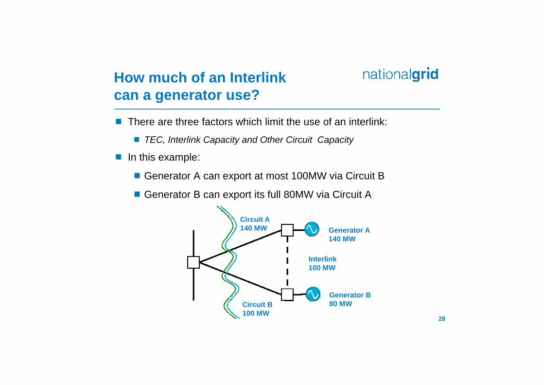
How much of an Interlinkcan a generator use?
There are three factors which limit the use of an interlink:
TEC, Interlink Capacity and Other Circuit Capacity
In this example:
Generator A can export at most 100MW via Circuit B
Generator B can export its full 80MW via Circuit A
28
Generator A140 MW
Circuit A140 MW
Generator B80 MWCircuit B
100 MW
Interlink100 MW

How much firm accessdoes a generator have via an interlink?
The local generator has firm access to the local circuit.
The other generator can have firm access to anyremaining capacity via the interlink.
For example:
Generator B is firm for80MW on Circuit B, soGenerator A may have20MW of firm access
Generator A is firm for140MW on Circuit A,so Generator B mayno firm access.
29
Generator A140 MW
Circuit A140 MW
Generator B80 MWCircuit B
100 MW
Interlink100 MW

This leads to two concepts:
A measure of how much a generator can use aninterlink:
Interlink Utilisation for Generator A=min( TECA, CAPI, CAPB )
A measure of additional firm access a generator has toonshore via alternative route
Additional Firm Capacity for Generator A =min( TECA, CAPI, (CAPB – TECB) )
30
Interlink element
Examples provided in the two circuit /generator scenario. Three or more willneed to be considered separately.
Circuit element

Option 1: Sharing / Non-Sharing
Apportionment of interlink revenue is based on sharedpart and non-shared part of the interlink capacity
The shared part is divided equally
The unshared part is paid by one party only
31
A change in TEC affects the other offshore parties; but noresidual to consumers
? Could fix tariff against TEC decreases below Day 1 level.
Interlink element

Option 1: Sharing / Non-Sharing
Total Interlink Capacity = 100MW
Utilisation for A: min(140,100,100) = 100 MW
Utilisation for B: min(80, 100, 140) = 80 MW
32
Generator A140 MW
Circuit A140 MW
Generator B80 MWCircuit B
100 MW
Interlink100 MW
Interlink element
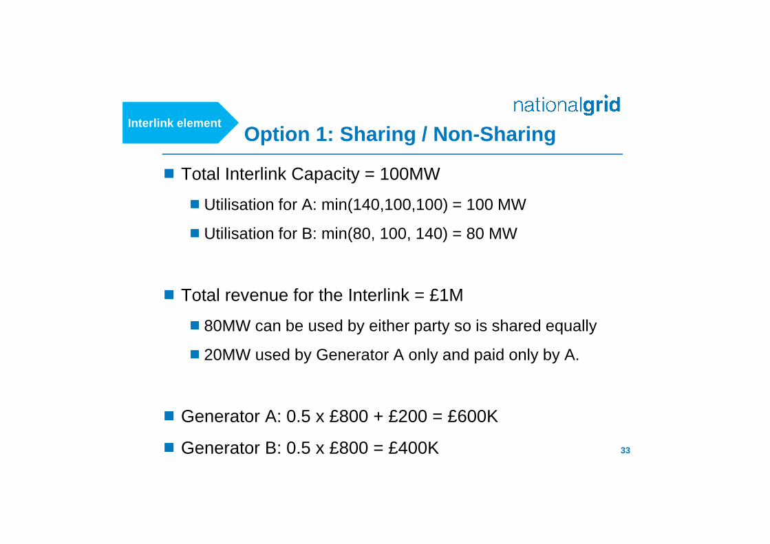
Option 1: Sharing / Non-Sharing
Total Interlink Capacity = 100MW
Utilisation for A: min(140,100,100) = 100 MW
Utilisation for B: min(80, 100, 140) = 80 MW
Total revenue for the Interlink = £1M
80MW can be used by either party so is shared equally
20MW used by Generator A only and paid only by A.
Generator A: 0.5 x £800 + £200 = £600K
Generator B: 0.5 x £800 = £400K 33
Interlink element

Option 2: Interlink Tariffcharged based on Utilisation
Interlink Tariff (£/kW) calculated as other cables with asecurity factor of 1.
Generator Interlink element (£m)=0.5 × Interlink Utilisation (MW) ×Interlink Tariff (£/kW)
The half accounts that there are generators at either endand to avoid over recovery
34
TEC changes do not affect the other party, but there is spill in tothe residual affecting the wider tariff.
Interlink element

Option 2: Interlink Tariffcharged based on Utilisation
Example: Assumed Interlink Revenue of £1m.
Utilisation for A: min(140,100,100) = 100 MW
Utilisation for B: min(80, 100, 140) = 80 MW
Interlink Tariff = 1 × £1m / 100 MW = £10 / kW
Charges:
A = £0.5M
B = £0.4M
Added to residual £0.1M
35
Generator A140 MW
Circuit A140 MW
Generator B80 MWCircuit B
100 MW
Interlink100 MW
Interlink element
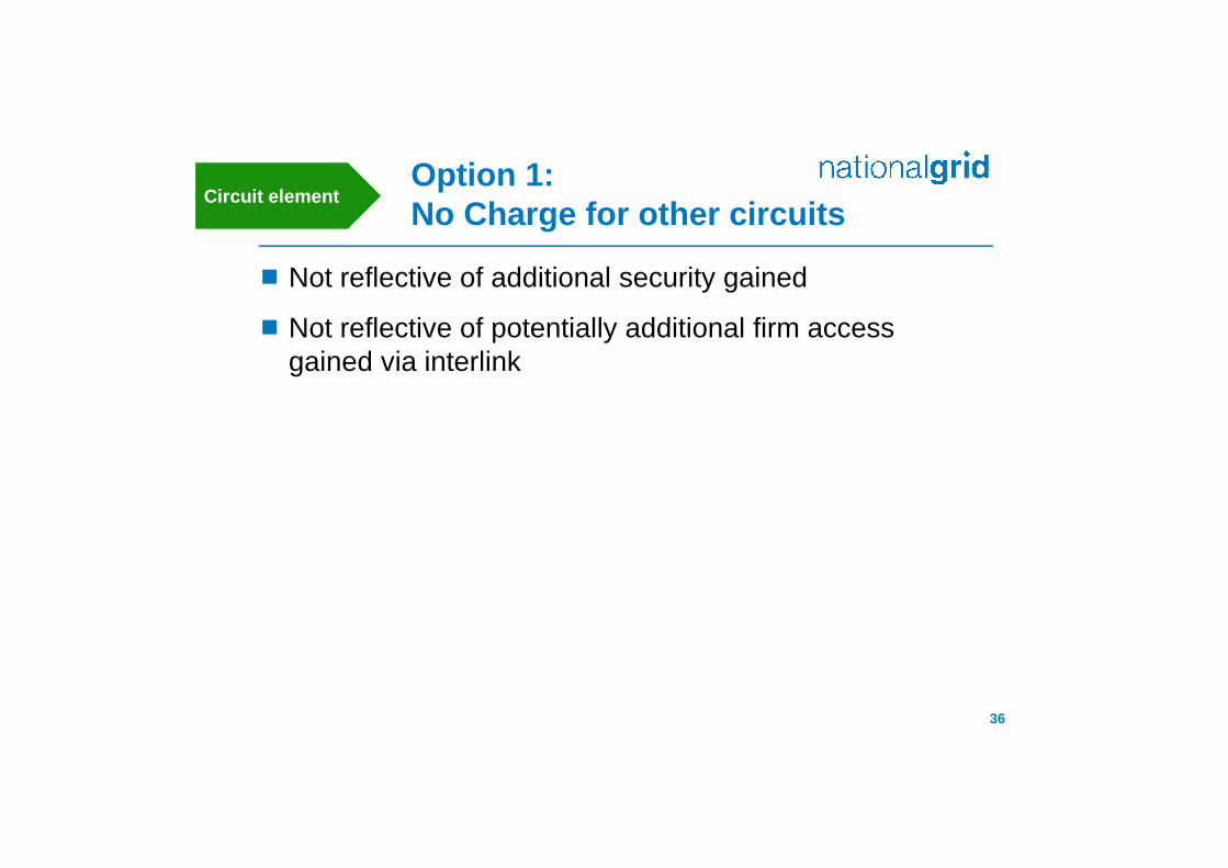
Option 1:No Charge for other circuits
Not reflective of additional security gained
Not reflective of potentially additional firm accessgained via interlink
36
Circuit element

Generators should pay towards the other local circuit ifthey have firm access; this access is measured throughthe Additional Firm Capacity (AFC)
Generator A, has an additional circuit charge= Circuit B tariff x AFC.
This approach reflect the additional capacity, but not theadditional security the firm access.
37
Option 2a:Charge for firm access on other Cables
Circuit element

Example: Additional Firm Capacity
For Gen A, there is 20MW charge on Circuit B
For Gen B, there is 0MW on Circuit A, so zero charge
38
Generator A140 MW
Circuit A140 MW
Generator B80 MWCircuit B
100 MW
Interlink100 MW
Option 2a:Charge for firm access on other Cables
Circuit element

Generator Local Circuit Charge is modelled as anequivalent double circuit, with the firm capacity on thelocal circuit, and any firm capacity on the other circuit
Generator A140 MW
Circuit A140 MW // £3MTariff £21.43
Generator B80 MW
Circuit B100 MW // £2MTariff £20 /kW
Interlink100 MW
Generator A
140MW
Circuit 1 // £3MRating 140MWFirm 140MW
Circuit 2Rating 100MWFirm 20MW
Model as
Option 2b:Mimicking a double circuit
Generator B
80 MW
Circuit 1 // £3MRating 100MWFirm 80MW
NO Circuit 2
Circuit element

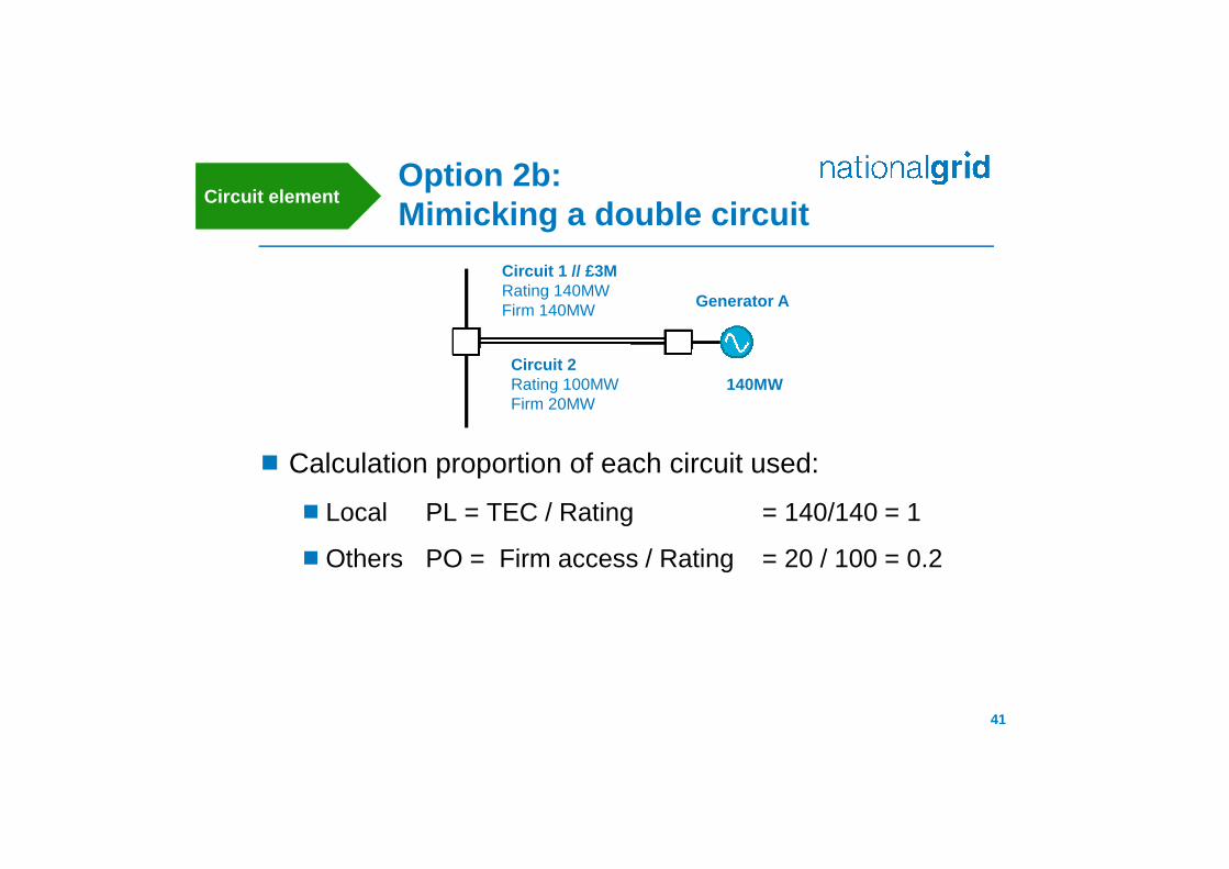
Option 2b:Mimicking a double circuit
Calculate an Equivalent Security Factor=(Local circuit rating + firm access on other ccts) / TEC
ESF capped at 1.8; if no firm access on other circuit = 1
In this example, ESF = (140+20)/140 = 1.14285
40
Generator A
140MW
Circuit 1 // £3MRating 140MWFirm 140MW
Circuit 2Rating 100MWFirm 20MW
Circuit element
Option 2b:Mimicking a double circuit
Calculation proportion of each circuit used:
Local PL = TEC / Rating = 140/140 = 1
Others PO = Firm access / Rating = 20 / 100 = 0.2
41
Generator A
140MW
Circuit 1 // £3MRating 140MWFirm 140MW
Circuit 2Rating 100MWFirm 20MW
Circuit element

Option 2b:Mimicking a double circuit
Calculate Local Circuit tariff (£/kW) =Effective Security Factor × Revenue weighted by
Proportion / Rating weighted by Proportion
E.g. Local Circuit Tariff =
= 1.14285 × ( 1 × 3 + 0.2 × 2 ) / (1 × 140 + 0.2 × 100)= £24.29 / kW [previously £21.42 for single cct]
Would then set expansion factor based on this calculation.42
Generator A
140MW
Circuit 1 // £3MRating 140MWFirm 140MW
Circuit 2 // £2MRating 100MWFirm 20MW
Circuit element
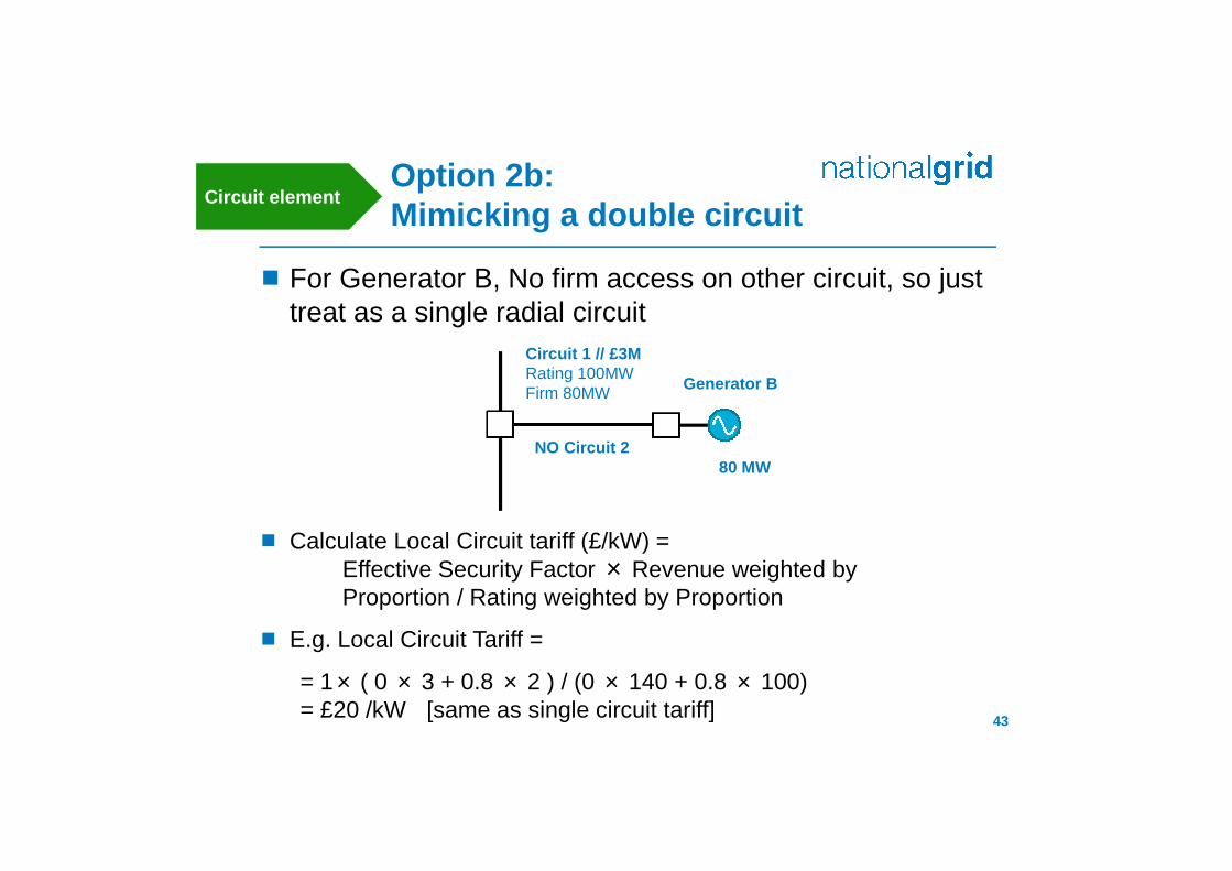
Option 2b:Mimicking a double circuit
For Generator B, No firm access on other circuit, so justtreat as a single radial circuit
43
Circuit element
Calculate Local Circuit tariff (£/kW) =Effective Security Factor × Revenue weighted byProportion / Rating weighted by Proportion
E.g. Local Circuit Tariff =
= 1× ( 0 × 3 + 0.8 × 2 ) / (0 × 140 + 0.8 × 100)= £20 /kW [same as single circuit tariff]
Generator B
80 MW
Circuit 1 // £3MRating 100MWFirm 80MW
NO Circuit 2
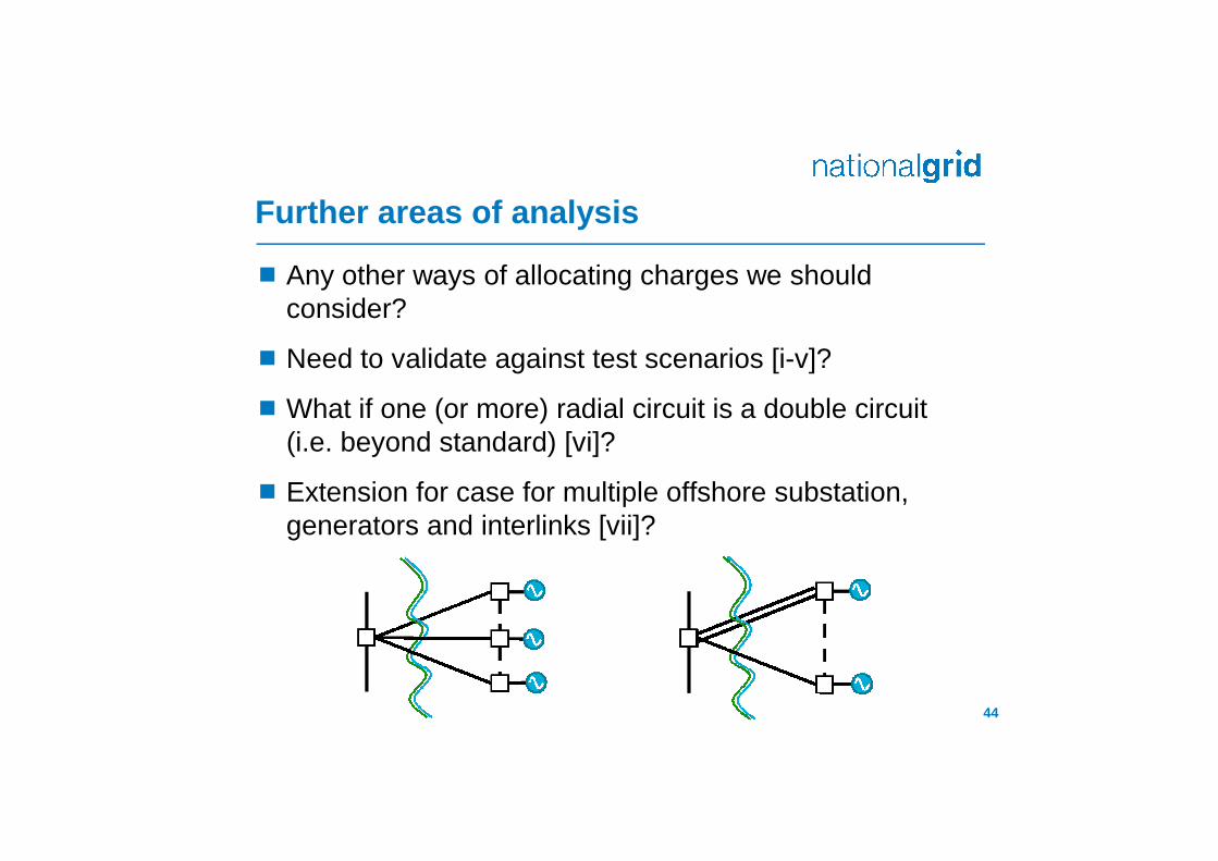
Further areas of analysis
Any other ways of allocating charges we shouldconsider?
Need to validate against test scenarios [i-v]?
What if one (or more) radial circuit is a double circuit(i.e. beyond standard) [vi]?
Extension for case for multiple offshore substation,generators and interlinks [vii]?
44

Place your chosenimage here. The fourcorners must justcover the arrow tips.For covers, the threepictures should be thesame size and in astraight line.
4. Term of Reference

Place your chosenimage here. The fourcorners must justcover the arrow tips.For covers, the threepictures should be thesame size and in astraight line.
5. Next Steps
Richard Loukes
Related Documents