1516 IEEE TRANSACTIONS ON VEHICULAR TECHNOLOGY, VOL. 60, NO. 4, MAY 2011 Charge-Depleting Control Strategies and Fuel Optimization of Blended-Mode Plug-In Hybrid Electric Vehicles Bingzhan Zhang, Chris Chunting Mi, Senior Member, IEEE, and Mengyang Zhang, Member, IEEE Abstract—This paper investigates the fuel consumption mini- mization problem of a blended-mode plug-in hybrid electric ve- hicle (PHEV). A simplified mathematical model of the PHEV was constructed to obtain optimal solutions for depleting the battery to a given final state of charge (SOC) under constant vehicle speed. An optimal power strategy was constructed from theoret- ical analysis and simulation for constant speed cases and then applied to typical drive-cycle simulations for a middle-size plug-in sport utility vehicle in the Urban Dynamometer Driving Schedule, the U.S. Environmental Protection Agency US06 (Supplemental Federal Test Procedure), and the CR-City drive cycles. Simulation results indicate that the proposed control strategy is more efficient than other strategies of interest. Only the electric system loss char- acteristics, vehicle power demand, total battery energy, and trip distance are needed to implement the proposed control strategy in a PHEV. It does not rely on the detailed trip information other than the total trip distance. Therefore, it is possible to implement the control strategy in real time if the total trip distance is known before the trip. Index Terms—Control strategy, fuel consumption, plug-in hy- brid electric vehicles (PHEVs), theoretical analysis. I. I NTRODUCTION P LUG-IN hybrid electric vehicles (PHEVs) use grid elec- tricity to power the vehicle for an initial driving range, which is referred to as the charge depletion (CD) mode. Using electric energy from the utility grid to displace a part of the fuel is the major feature of PHEVs [1], [2]. There are two basic types of PHEVs: 1) extended-range electric vehicles (EREVs) and 2) blended-mode PHEVs. EREVs offer pure electric driving capability in the initial driving range, which is called the all-electric range (AER). To realize pure electric driving in all driving conditions, EREVs are equipped with a full-sized traction motor powered by the Manuscript received October 24, 2010; revised January 11, 2011 and February 24, 2011; accepted February 25, 2011. Date of publication March 3, 2011; date of current version May 16, 2011. The review of this paper was coordinated by Prof. M. E. Benbouzid. B. Zhang was with the DTE Power Electronics Laboratory, Department of Electrical and Computer Engineering, University of Michigan–Dearborn, Dearborn, MI 48128 USA. He is now with the School of Mechanical and Automotive Engineering, Hefei University of Technology, Hefei 230009, China (e-mail: [email protected]). C. C. Mi is with the DTE Power Electronics Laboratory, Department of Electrical and Computer Engineering, University of Michigan–Dearborn, Dearborn, MI 48128 USA (e-mail: [email protected]). M. Zhang is with the Chrysler Group LLC, Auburn Hills, MI 48326 USA (e-mail: [email protected]). Color versions of one or more of the figures in this paper are available online at http://ieeexplore.ieee.org. Digital Object Identifier 10.1109/TVT.2011.2122313 PHEV battery pack. One of the disadvantages of the EREV is the increased system cost due to the full-sized traction motor and power requirement for the battery. The other disadvantage is the high losses in the electric system (battery and electric motor) at high power operations. These constraints have led to the concept of blended-mode PHEVs. A blended-mode PHEV usually has less powerful electric drive capability. Therefore, it can typically achieve cruise and moderate acceleration in the electric mode at low to moderate vehicle speeds. For operations that require either higher power or higher torque, the engine must be used, either with or without electric assist, depending on the vehicle control strategy. Control strategies for a blended-mode PHEV can be com- plex and multidimensional and will have significant impacts on vehicle performance, driveability, and fuel consumption [3]–[5]. One of the PHEV’s primary capabilities is fuel dis- placement by depleting the onboard electric energy storage system (ESS) to a preset low-threshold state of charge (SOC). It is generally desirable that the onboard ESS has reached this depleted state (charge-sustaining SOC) by the end of the “designed” vehicle travel distance. On one hand, aggressive CD may result in higher electric loss incurred in the vehicle systems and adversely affect engine efficiency. On the other hand, a vehicle with less than sufficient CD operations may not achieve the fuel displacement function as designed, and the capacity of the onboard ESS is underutilized. Therefore, how we can achieve optimized CD operations in PHEV applications is one of the fundamental problems of PHEV control. It becomes more challenging in real-world applications, because the trip distance and drive scenarios are not precisely known. Therefore, the objective of the PHEV optimization problem is to minimize the vehicle fuel consumption subject to specific constraints, e.g., component capabilities and available ESS energy. The problem can be formulated as follows: Objective : minimize J = T f 0 f (P eng ) dt (1) Subjected to : ⎧ ⎪ ⎨ ⎪ ⎩ P b,min (t) ≤ P b (t) ≤ P b,max (t) P em,min (t) ≤ P em (t) ≤ P em,max (t) 0 ≤ P eng (t) ≤ P eng,max (t) SOC min ≤ SOC(t) ≤ SOC max (2) where P b is the power of the battery, P em is the power of the electric motor, P eng is the engine power, SOC is the battery state of charge, and f is the fuel mass flow rate. 0018-9545/$26.00 © 2011 IEEE

Welcome message from author
This document is posted to help you gain knowledge. Please leave a comment to let me know what you think about it! Share it to your friends and learn new things together.
Transcript
1516 IEEE TRANSACTIONS ON VEHICULAR TECHNOLOGY, VOL. 60, NO. 4, MAY 2011
Charge-Depleting Control Strategies and FuelOptimization of Blended-Mode Plug-In
Hybrid Electric VehiclesBingzhan Zhang, Chris Chunting Mi, Senior Member, IEEE, and Mengyang Zhang, Member, IEEE
Abstract—This paper investigates the fuel consumption mini-mization problem of a blended-mode plug-in hybrid electric ve-hicle (PHEV). A simplified mathematical model of the PHEV wasconstructed to obtain optimal solutions for depleting the batteryto a given final state of charge (SOC) under constant vehiclespeed. An optimal power strategy was constructed from theoret-ical analysis and simulation for constant speed cases and thenapplied to typical drive-cycle simulations for a middle-size plug-insport utility vehicle in the Urban Dynamometer Driving Schedule,the U.S. Environmental Protection Agency US06 (SupplementalFederal Test Procedure), and the CR-City drive cycles. Simulationresults indicate that the proposed control strategy is more efficientthan other strategies of interest. Only the electric system loss char-acteristics, vehicle power demand, total battery energy, and tripdistance are needed to implement the proposed control strategyin a PHEV. It does not rely on the detailed trip information otherthan the total trip distance. Therefore, it is possible to implementthe control strategy in real time if the total trip distance is knownbefore the trip.
Index Terms—Control strategy, fuel consumption, plug-in hy-brid electric vehicles (PHEVs), theoretical analysis.
I. INTRODUCTION
P LUG-IN hybrid electric vehicles (PHEVs) use grid elec-tricity to power the vehicle for an initial driving range,
which is referred to as the charge depletion (CD) mode. Usingelectric energy from the utility grid to displace a part of thefuel is the major feature of PHEVs [1], [2]. There are two basictypes of PHEVs: 1) extended-range electric vehicles (EREVs)and 2) blended-mode PHEVs.
EREVs offer pure electric driving capability in the initialdriving range, which is called the all-electric range (AER). Torealize pure electric driving in all driving conditions, EREVsare equipped with a full-sized traction motor powered by the
Manuscript received October 24, 2010; revised January 11, 2011 andFebruary 24, 2011; accepted February 25, 2011. Date of publicationMarch 3, 2011; date of current version May 16, 2011. The review of this paperwas coordinated by Prof. M. E. Benbouzid.
B. Zhang was with the DTE Power Electronics Laboratory, Departmentof Electrical and Computer Engineering, University of Michigan–Dearborn,Dearborn, MI 48128 USA. He is now with the School of Mechanical andAutomotive Engineering, Hefei University of Technology, Hefei 230009, China(e-mail: [email protected]).
C. C. Mi is with the DTE Power Electronics Laboratory, Departmentof Electrical and Computer Engineering, University of Michigan–Dearborn,Dearborn, MI 48128 USA (e-mail: [email protected]).
M. Zhang is with the Chrysler Group LLC, Auburn Hills, MI 48326 USA(e-mail: [email protected]).
Color versions of one or more of the figures in this paper are available onlineat http://ieeexplore.ieee.org.
Digital Object Identifier 10.1109/TVT.2011.2122313
PHEV battery pack. One of the disadvantages of the EREV isthe increased system cost due to the full-sized traction motorand power requirement for the battery. The other disadvantageis the high losses in the electric system (battery and electricmotor) at high power operations. These constraints have led tothe concept of blended-mode PHEVs.
A blended-mode PHEV usually has less powerful electricdrive capability. Therefore, it can typically achieve cruise andmoderate acceleration in the electric mode at low to moderatevehicle speeds. For operations that require either higher poweror higher torque, the engine must be used, either with or withoutelectric assist, depending on the vehicle control strategy.
Control strategies for a blended-mode PHEV can be com-plex and multidimensional and will have significant impactson vehicle performance, driveability, and fuel consumption[3]–[5]. One of the PHEV’s primary capabilities is fuel dis-placement by depleting the onboard electric energy storagesystem (ESS) to a preset low-threshold state of charge (SOC).It is generally desirable that the onboard ESS has reachedthis depleted state (charge-sustaining SOC) by the end of the“designed” vehicle travel distance. On one hand, aggressive CDmay result in higher electric loss incurred in the vehicle systemsand adversely affect engine efficiency. On the other hand, avehicle with less than sufficient CD operations may not achievethe fuel displacement function as designed, and the capacityof the onboard ESS is underutilized. Therefore, how we canachieve optimized CD operations in PHEV applications is oneof the fundamental problems of PHEV control. It becomes morechallenging in real-world applications, because the trip distanceand drive scenarios are not precisely known.
Therefore, the objective of the PHEV optimization problemis to minimize the vehicle fuel consumption subject to specificconstraints, e.g., component capabilities and available ESSenergy. The problem can be formulated as follows:
Objective : minimize J =
Tf∫0
f(Peng) dt (1)
Subjected to :
⎧⎪⎨⎪⎩
Pb,min(t) ≤ Pb(t) ≤ Pb,max(t)Pem,min(t) ≤ Pem(t) ≤ Pem,max(t)0 ≤ Peng(t) ≤ Peng,max(t)SOCmin ≤ SOC(t) ≤ SOCmax
(2)
where Pb is the power of the battery, Pem is the power of theelectric motor, Peng is the engine power, SOC is the batterystate of charge, and f is the fuel mass flow rate.
0018-9545/$26.00 © 2011 IEEE
Karthi
Highlight
ZHANG et al.: CHARGE-DEPLETING CONTROL STRATEGIES AND FUEL OPTIMIZATION OF BLENDED-MODE PHEVs 1517
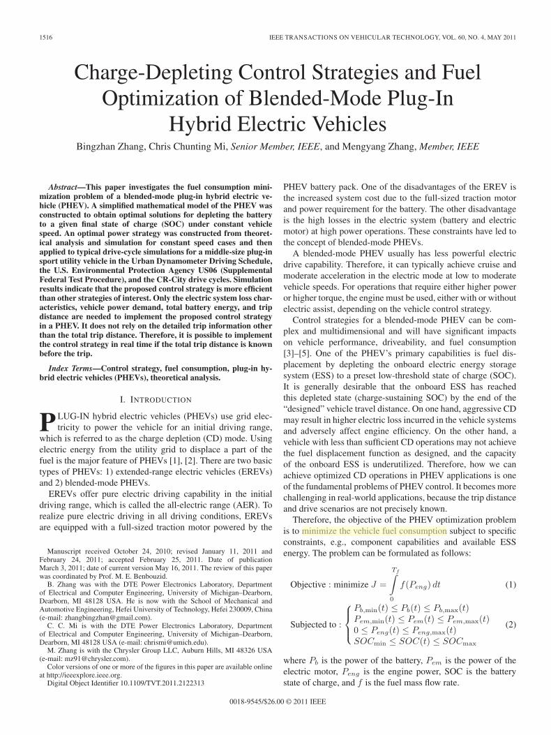
Fig. 1. Power flow of a PHEV.
TABLE IVEHICLE PARAMETERS
TABLE IIHEV MAIN COMPONENTS
Assume that the vehicle distance traveled is greater than theAER. A fixed distance and different constant speed were usedfor the theoretical analysis to obtain the control parameters.The control parameters table are constructed and evaluated inthe Powertrain Systems Analysis Toolkit (PSAT) with theseconstant-speed drive scenarios and then implemented in typicaldrive cycle tests.
II. VEHICLE MODEL
In this paper, a blended-mode PHEV was built in PSAT for amid-sized plug-in sport utility vehicle (SUV). A typical parallelconfiguration is adopted, as shown in Fig. 1. The parallel PHEVallows both the engine and the electric motor to deliver powerin parallel to drive the wheels. The propulsion power may besupplied by the engine, or the motor, or both [6]. If the motorpower is sufficient, it can also realize pure electric drivingmode. The electric motor can be used as a generator to chargebatteries during regenerative braking or absorbing power fromthe engine when the engine has excessive power.
Although a generic parallel PHEV model is used for thispaper, the methodology is also applicable to other types ofPHEVs, including planetary-gear-based configurations, e.g.,Prius and GM/Chrysler Two-Mode Hybrid, whose main oper-ation can be considered parallel [7]–[9]. The parameters andmain components of the vehicle are listed in Tables I and II.
III. ANALYSIS OF POWER FLOW IN A PLUG-IN
HYBRID ELECTRIC VEHICLE
References [10] and [11] analyzed the efficiency of con-ventional hybrid electric vehicles (HEVs), including seriesand parallel HEVs. The analysis of the fuel consumption isgenerally operated on a specific drive cycle based on energybalance and component efficiencies. In this section, the focusis on a PHEV for specific drive cycles based on energy balanceand component efficiencies.
As shown in Fig. 1, based on power balance, the powerconsumed to propel the vehicle Po is equal to the powerprovided by the engine Peng and from the electric motorPem, i.e.,
Po =Peng + Pem (3)
Pb =Pem + Pem_loss (4)
Pb_in =Pb + Pb_loss (5)
where Pem_loss is the loss of the electric motor, Pb_loss is theloss of the battery during discharging/charging, Pb is the batteryoutput power to the electric motor, and Pb_in is the batteryoutput power, considering battery power loss. Pem, Pb, andPb_in have signs that are positive, indicating discharging, andnegative, indicating charging. Pem_loss and Pb_loss are alwayspositive. Po can be calculated by the following equation basedon vehicle parameters and speed:
1ηT
(magfr
3600v+
CDA
76140v3+
δ · ma · v3600
dv
dt+
ma · g · sinα · v3600
)
(6)
where Po is the demand power (in kilowatts), ηT is the trans-mission efficiency, ma is the vehicle mass (in kilograms), g isthe acceleration of gravity (in square meters per second), fr isthe rolling coefficient, v is the vehicle speed in (in kilometersper hour), CD is the aerodynamic coefficient, A is the frontalarea (in square meters), δ is the rotating mass coefficient, and αis the slope angle (in rads).
In a specific drive cycle, the total energy demand Ea andavailable battery energy Eb are constant, i.e.,
Eb =
T∫0
Pb_in dt = const. (7)
Karthi
Highlight
1518 IEEE TRANSACTIONS ON VEHICULAR TECHNOLOGY, VOL. 60, NO. 4, MAY 2011
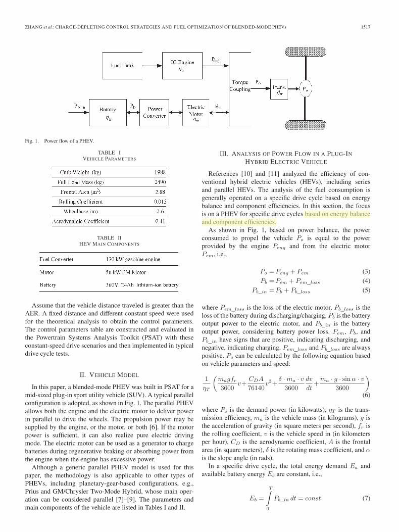
Fig. 2. Fuel rate for various engine speed.
Eb = 0 is for charge-sustaining operations, and Eb > 0 is forCD operations. We have
Ea =
T∫0
Po dt = const. (8)
A. Fuel Consumption of an Idealized InternalCombustion Engine
The engine efficiency is represented by a nonlinear static mapthat describes fuel rate as a function of engine speed and enginetorque, as shown in Fig. 2. It is shown that the fuel rate canapproximately be represented by a linear function as enginepower for each engine speed. We have
f_rate = f(Pe, ω). (9)
For further simplicity, a linear relationship is assumed toobtain an optimized solution as
f = fo + kPeng (10)
where fo is caused by mechanical friction and pumping lossesin the engine, and k approximately reflects the combustionefficiency. fo obviously varies with different engine powerratings and increases with engine size, whereas k is almost thesame for different size engines. For the specific engine usedin this paper, the value of fo and k are 1.59 × 10⁻¹ g/s and7.13 × 10−2 g/(kW · s), respectively.
B. Electric Power Loss
The electric losses in the PHEV include battery loss, electricmotor loss, and inverter loss. These losses can be divided intothe following three types: 1) the frictional and windage loss inthe electric motor, which is a function of motor speed and loadtorque; 2) the magnetic loss in the motor, which is related tomagnitude and frequency of supply voltage; and 3) copper lossin the motor and internal loss in the battery due to battery inter-nal resistance. The last type of loss is proportional to the currentsquared, i.e., out power squared if the voltage is assumed tobe constant. Hence, the total electric system losses includea portion that is constant (windage loss and some magneticloss), a second portion that is proportional to the output power
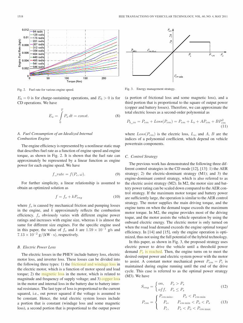
Fig. 3. Energy management strategy.
(a portion of frictional loss and some magnetic loss), and athird portion that is proportional to the square of output power(copper and battery losses). Therefore, we can approximate thetotal electric losses as a second-order polynomial as
Pb_in = Pem + Loss(Pem) = Pem + Lo + APem + BP 2em
(11)
where Loss(Pem) is the electric loss, Lo, and A, B are theindices of a polynomial coefficient, which depend on vehiclepowertrain components.
C. Control Strategy
The previous work has demonstrated the following three dif-ferent control strategies in the CD mode [12], [13]: 1) the AERstrategy; 2) the electric-dominant strategy (M1); and 3) theengine-dominant control strategy, which is also referred to asthe electric assist strategy (M2). In M2, the motor size and bat-tery power rating can be scaled down compared to the AER con-trol strategy. If the maximum motor torque and battery powerare sufficiently large, the operation is similar to the AER controlstrategy. The motor supplies the main driving torque, and theengine turns on when the demand toque exceeds the maximummotor torque. In M2, the engine provides most of the drivingtoque, and the motor assists the vehicle operation by using theonboard electric energy. The electric motor is only turned onwhen the road load demand exceeds the engine optimal torque/efficiency. In [14] and [15], only the engine operation is opti-mized, thus not using the full potential of the hybrid technology.
In this paper, as shown in Fig. 3, the proposed strategy useselectric power to drive the vehicle until a threshold powerdemand Ps is reached. Then, the engine turns on to meet thedesired output power and electric system power with the motorto assist. A constant motor mechanical power Pem = Pc ismaintained during engine running until the end of the drivecycle. This case is referred to as the optimal power strategy(M3). We have
Seng ={
on, Po > Ps
off, Po ≤ Ps
(12)
Pem =
⎧⎨⎩
Pemmin, Po < Pemmin
Po, Pemmin < Po < Ps
Pc, Ps < Po < Pemmax
(13)
Karthi
Highlight
Karthi
Highlight
Karthi
Highlight
Karthi
Highlight
ZHANG et al.: CHARGE-DEPLETING CONTROL STRATEGIES AND FUEL OPTIMIZATION OF BLENDED-MODE PHEVs 1519
Fig. 4. Two segments in the whole trip.
where Pemmin is the maximum regenerative power, and Ps isthe power threshold, below which, the engine is off. Pc is theconstant motor mechanical power used to assist the engine.
As shown in Fig. 4, it is assumed that, if Pem = Pc, thebattery energy is used up at time T1. If Pem = Pc_min, thebattery energy is used up at time T . A fixed distance andconstant speed are first used for the analysis. We have
T =S
Vo(14)
where S is the distance, Vo is the constant speed, and T isthe time of the whole trip, which depends on S and Vo. Po isdependent on Vo.
If Po > Ps, the engine will turn on, assuming that, afterT1, the battery energy will be used up. T1 depends on Pc.During the time interval between T1 and T , only the engine pro-vides the energy to the vehicle. The total fuel consumption inthis drive cycle is
mf =
T1∫0
mf (Peng) dt +
T∫T1
mf (Peng) dt
=
T1∫0
(fo + k(Po − Pc)) dt +
T∫T1
(fo + kPo) dt
= (fo + k(Po − Pc)) T1 + (fo + kPo)(T − T1)
= (fo + kPo)T − kPcT1. (15)
According to (7) and (11), T1 can be obtained as
Eb =
T1∫0
Pb dt =
T1∫0
(Psc + Loss(Pc)) dt
=(Lo + (1 + A)Pc + BP 2
c
)T1. (16)
Replacing T1, (15) can be expressed as
mf = (fo + kPo)T − kEbPc
Lo + (1 + A)Pc + BP 2c
. (17)
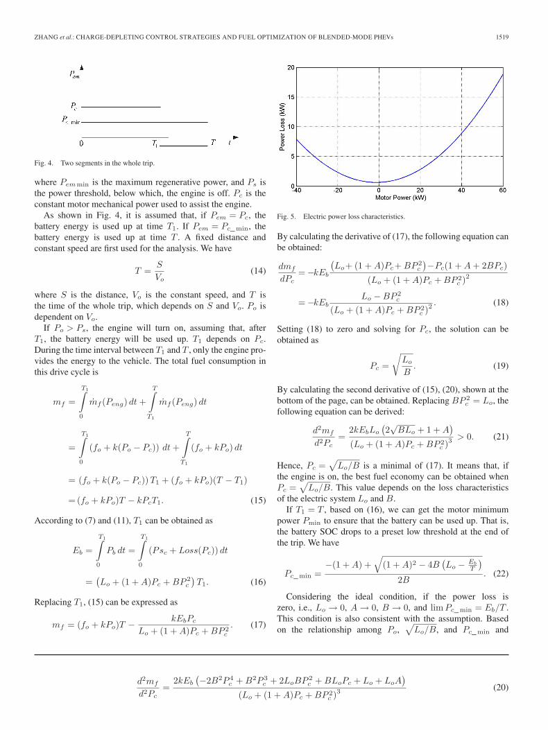
Fig. 5. Electric power loss characteristics.
By calculating the derivative of (17), the following equation canbe obtained:
dmf
dPc= −kEb
(Lo+ (1 + A)Pc+ BP 2
c
)−Pc(1 + A + 2BPc)
(Lo + (1 + A)Pc + BP 2c )2
= −kEbLo − BP 2
c
(Lo + (1 + A)Pc + BP 2c )2
. (18)
Setting (18) to zero and solving for Pc, the solution can beobtained as
Pc =
√Lo
B. (19)
By calculating the second derivative of (15), (20), shown at thebottom of the page, can be obtained. Replacing BP 2
c = Lo, thefollowing equation can be derived:
d2mf
d2Pc=
2kEbLo
(2√
BLo + 1 + A)
(Lo + (1 + A)Pc + BP 2c )3
> 0. (21)
Hence, Pc =√
Lo/B is a minimal of (17). It means that, ifthe engine is on, the best fuel economy can be obtained whenPc =
√Lo/B. This value depends on the loss characteristics
of the electric system Lo and B.If T1 = T , based on (16), we can get the motor minimum
power Pmin to ensure that the battery can be used up. That is,the battery SOC drops to a preset low threshold at the end ofthe trip. We have
Pc_min =−(1 + A) +
√(1 + A)2 − 4B
(Lo − Eb
T
)2B
. (22)
Considering the ideal condition, if the power loss iszero, i.e., Lo → 0, A → 0, B → 0, and lim Pc_min = Eb/T .This condition is also consistent with the assumption. Basedon the relationship among Po,
√Lo/B, and Pc_min and
d2mf
d2Pc=
2kEb
(−2B2P 4
c + B2P 3c + 2LoBP 2
c + BLoPc + Lo + LoA)
(Lo + (1 + A)Pc + BP 2c )3
(20)
1520 IEEE TRANSACTIONS ON VEHICULAR TECHNOLOGY, VOL. 60, NO. 4, MAY 2011
TABLE IIICALCULATION RESULTS (FOR A TOTAL DRIVING RANGE OF 40 mi)
considering (18) and (21), the results can be discussed asfollows.
1) If Po <√
Lo/B, then dmf/dPc < 0, and the fuel con-sumption decreases with the increase of Pc.
2) If Pc_min ≤√
Lo/B ≤ Po, the fuel consumption has aminimum value at Pc =
√Lo/B.
3) If Pc_min >√
Lo/B, then dmf/dPc > 0, and the fuelconsumption increases with Pc.
If Pc = Po, from 0 to T1, the engine will be turned off,which means that the vehicle is in the AER mode. The totalfuel consumption becomes
mf =
T∫T1
mf (Peng) dt=
T∫T1
fo + kPo dt=(fo+ kPo)(T− T1).
(23)
The aforementioned set points for Pc can be used for thecontrol of PHEV to optimize fuel economy (minimize fuelconsumption). Based on the aforementioned analysis, it seemsthat, because the optimal values of Pc depend on Po, Pc_min,and
√Lo/B, we will need to calculate their values based on
the drive cycle and then decide on the engine turn-on threshold,as well as the battery/motor power once the engine has beenturned on. Hence, the control can be described in the followingsteps.
• Obtain Lo, B, and A for the electric systems. This ap-proach can be done based on the simulations of the elec-tric system or through experiments of the actual electricsystem, including the battery, inverter, and electric motor.
• Calculate√
Lo/B and Pc_min.• In drive cycle simulations or real-world driving, calculate
the power demand of the vehicle Po. The power demandis determined by looking at the pedal positions and theauxiliary electric power demand.
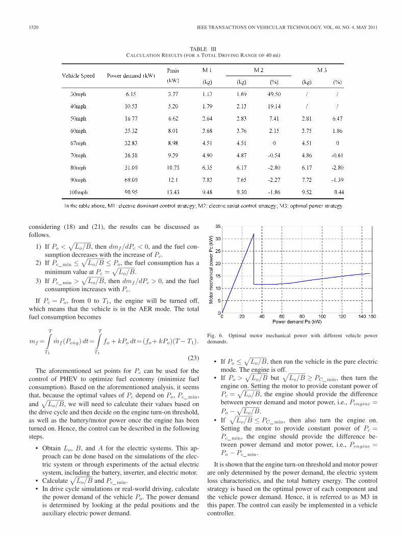
Fig. 6. Optimal motor mechanical power with different vehicle powerdemands.
• If Po ≤√
Lo/B, then run the vehicle in the pure electricmode. The engine is off.
• If Po >√
Lo/B but√
Lo/B ≥ PC_min, then turn theengine on. Setting the motor to provide constant power ofPc =
√Lo/B, the engine should provide the difference
between power demand and motor power, i.e., Pengine =Po −
√Lo/B.
• If√
Lo/B ≤ PC_min, then also turn the engine on.Setting the motor to provide constant power of Pc =Pc_min, the engine should provide the difference be-tween power demand and motor power, i.e., Pengine =Po − Pc_min.
It is shown that the engine turn-on threshold and motor powerare only determined by the power demand, the electric systemloss characteristics, and the total battery energy. The controlstrategy is based on the optimal power of each component andthe vehicle power demand. Hence, it is referred to as M3 inthis paper. The control can easily be implemented in a vehiclecontroller.
ZHANG et al.: CHARGE-DEPLETING CONTROL STRATEGIES AND FUEL OPTIMIZATION OF BLENDED-MODE PHEVs 1521
TABLE IVCONSTANT-SPEED-CYCLE SIMULATION RESULTS
IV. CONSTRUCTION OF THE PARAMETER TABLE
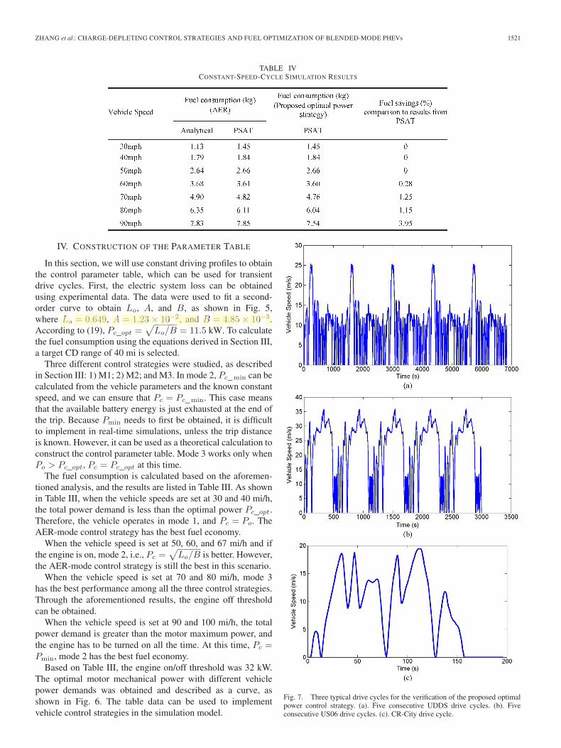
In this section, we will use constant driving profiles to obtainthe control parameter table, which can be used for transientdrive cycles. First, the electric system loss can be obtainedusing experimental data. The data were used to fit a second-order curve to obtain Lo, A, and B, as shown in Fig. 5,where Lo = 0.649, A = 1.23 × 10⁻², and B = 4.85 × 10⁻³.According to (19), Pc_opt =
√Lo/B = 11.5 kW. To calculate
the fuel consumption using the equations derived in Section III,a target CD range of 40 mi is selected.
Three different control strategies were studied, as describedin Section III: 1) M1; 2) M2; and M3. In mode 2, Pc_min can becalculated from the vehicle parameters and the known constantspeed, and we can ensure that Pc = Pc_min. This case meansthat the available battery energy is just exhausted at the end ofthe trip. Because Pmin needs to first be obtained, it is difficultto implement in real-time simulations, unless the trip distanceis known. However, it can be used as a theoretical calculation toconstruct the control parameter table. Mode 3 works only whenPo > Pc_opt, Pc = Pc_opt at this time.
The fuel consumption is calculated based on the aforemen-tioned analysis, and the results are listed in Table III. As shownin Table III, when the vehicle speeds are set at 30 and 40 mi/h,the total power demand is less than the optimal power Pc_opt.Therefore, the vehicle operates in mode 1, and Pc = Po. TheAER-mode control strategy has the best fuel economy.
When the vehicle speed is set at 50, 60, and 67 mi/h and ifthe engine is on, mode 2, i.e., Pc =
√Lo/B is better. However,
the AER-mode control strategy is still the best in this scenario.When the vehicle speed is set at 70 and 80 mi/h, mode 3
has the best performance among all the three control strategies.Through the aforementioned results, the engine off thresholdcan be obtained.
When the vehicle speed is set at 90 and 100 mi/h, the totalpower demand is greater than the motor maximum power, andthe engine has to be turned on all the time. At this time, Pc =Pmin, mode 2 has the best fuel economy.
Based on Table III, the engine on/off threshold was 32 kW.The optimal motor mechanical power with different vehiclepower demands was obtained and described as a curve, asshown in Fig. 6. The table data can be used to implementvehicle control strategies in the simulation model.
Fig. 7. Three typical drive cycles for the verification of the proposed optimalpower control strategy. (a). Five consecutive UDDS drive cycles. (b). Fiveconsecutive US06 drive cycles. (c). CR-City drive cycle.
Karthi
Highlight
1522 IEEE TRANSACTIONS ON VEHICULAR TECHNOLOGY, VOL. 60, NO. 4, MAY 2011
TABLE VCOMPARISON OF THE THREE DRIVE CYCLES
V. SIMULATION RESULTS
First, we use PSAT to simulate the vehicle fuel economy inconstant drive cycles to gain the confidence of the proposedstrategy. Table IV shows the simulated results from PSAT forthe different constant speed driving profiles for the proposedM3 and the default AED strategies. For ease of comparison, inthe same table, we have also listed the fuel economy of the AEDstrategy calculated using the analytical method from the previ-ous section. Table IV shows the following two observations:1) The simulated fuel economy is very close to the calculatedfuel economy shown in Table III, and hence, it validates theequations and parameters derived in the previous section; and2) there is no improvement in 30, 40, 50, and 60 mi/h byusing the proposed M3, because the power demand is less thanthe threshold for the engine to turn on. As the power demandincreases, the proposed M3 shows fuel savings in 70, 80, and90 mi/h.
This simple simulation shows that the proposed controlstrategy can help save fuel consumption as the power demandincreases. Because power demand in transient drive cycles ismuch higher, the estimated fuel savings can be more significant.Hence, it is important to see how well the proposed strategyperforms in various transient drive cycles. For this purpose,the proposed strategy is applied to the Urban DynamometerDriving Schedule (UDDS), the U.S. Environmental ProtectionAgency US06 (Supplemental Federal Test Procedure), and theCR-City drive cycles, as shown in Fig. 7.
Compared to UDDS, the US06 and CR-City drive cy-cles are more aggressive in terms of acceleration and decel-eration, which better approximate aggressive driving in thereal world. A comparison among the three cycles is shownin Table V.
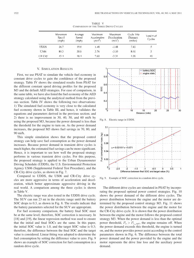
The electric range was also tested in the UDDS drive cycle.The SUV can run 23 mi in the electric range until the batterySOC drops to 0.3, as shown in Fig. 8. The results indicate thatthe battery parameters selected for the SUV are appropriate.
For fuel economy comparison, the battery final SOC mustbe at the same level; therefore, SOC correction is necessary. In[18] and [19], the linear regression method was used to ensurethat the initial and final SOCs are the same. In this paper,the initial SOC value is 1.0, and the target SOC value is 0.3;therefore, the difference between the final SOC and the targetvalue is considered. Linear fitting was adopted to determine thefuel consumption by setting the difference value to zero. Fig. 9shows an example of SOC correction for fuel consumption in arandom drive cycle.
Fig. 8. Electric range in UDDS.
Fig. 9. Example of SOC correction in a random drive cycle.
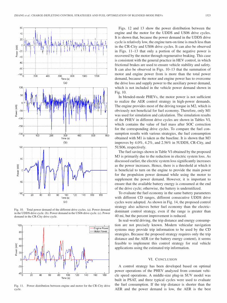
The different drive cycles are simulated in PSAT by incorpo-rating the proposed optimal power control strategies. Fig. 10shows the power demand of the different drive cycles. Thepower distribution between the engine and the motor are de-termined by the proposed control strategy M3. Fig. 11 showsthe power distribution between the engine and the motor forthe CR-City drive cycle. It is shown that the power distributionbetween the engine and the motor follows the proposed controlstrategy M3. When the power demand is less than the optimalpower threshold, Po > Pc_opt, the engine remains off. Whenthe power demand exceeds this threshold, the engine is turnedon, and the motor provides power assist according to the controlparameters shown in Fig. 6. The difference between the totalpower demand and the power provided by the engine and themotor represents the drive line loss and the auxiliary powerdemand.
ZHANG et al.: CHARGE-DEPLETING CONTROL STRATEGIES AND FUEL OPTIMIZATION OF BLENDED-MODE PHEVs 1523
Fig. 10. Total power demand of the different drive cycles. (a). Power demandin the UDDS drive cycle. (b). Power demand in the US06 drive cycle. (c). Powerdemand in the CR-City drive cycle.
Fig. 11. Power distribution between engine and motor for the CR-City drivecycle.
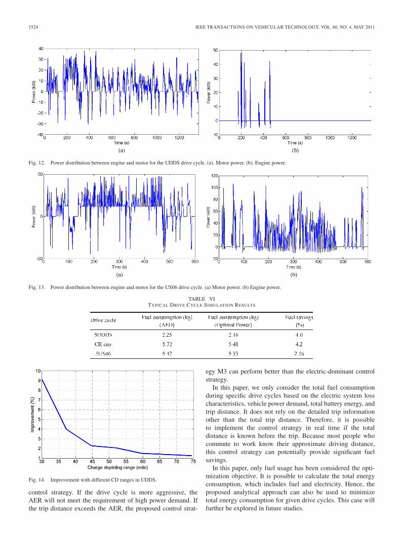
Figs. 12 and 13 show the power distribution between theengine and the motor for the UDDS and US06 drive cycles.It is shown that, because the power demand in the UDDS drivecycle is relatively low, the engine turn-on time is much less thanin the CR-City and US06 drive cycles. It can also be observedin Figs. 11–13 that only a portion of the negative power isrecovered by the motor through regenerative braking. This caseis consistent with the general practice in HEV control, in whichfrictional brakes are used to ensure vehicle stability and safety.It can also be observed in Figs. 10–13 that the summation ofmotor and engine power from is more than the total powerdemand, because the motor and engine power has to overcomethe drive loss and supply power to the auxiliary power demand,which is not included in the vehicle power demand shown inFig. 10.
In blended-mode PHEVs, the motor power is not sufficientto realize the AER control strategy in high-power demands.The engine provides most of the driving torque in M2, which isobviously not beneficial for fuel economy. Therefore, only M1was used for simulation and calculation. The simulation resultsof the PHEV in different drive cycles are shown in Tables VI,which contains the value of fuel mass after SOC correctionfor the corresponding drive cycles. To compare the fuel con-sumption results with various strategies, the fuel consumptionobtained with M1 is taken as the baseline. It is shown that M3improves by 4.0%, 4.2%, and 2.56% in 5UDDS, CR-City, and5US06, respectively.
The fuel savings shown in Table VI obtained by the proposedM3 is primarily due to the reduction in electric system loss. Asdiscussed earlier, the electric system loss significantly increasesas the power increases. Hence, there is a threshold at which itis beneficial to turn on the engine to provide the main powerfor the propulsion power demand while using the motor tosupplement the power demand. However, it is important toensure that the available battery energy is consumed at the endof the drive cycle; otherwise, the battery is underutilized.
To evaluate the fuel economy in the same battery parameterswith different CD ranges, different consecutive UDDS drivecycles were adopted. As shown in Fig. 14, the proposed controlstrategy also achieves better fuel economy than the electric-dominant control strategy, even if the range is greater than40 mi, but the percent improvement is reduced.
In real-world driving, the trip distance and energy consump-tion are not precisely known. Modern vehicular navigationsystems may provide trip information to be used by the CDstrategies. Because the proposed strategy requires only the tripdistance and the AER (or the battery energy content), it seemsfeasible to implement this control strategy for real vehicleapplications using the estimated trip information.
VI. CONCLUSION
A control strategy has been developed based on optimalpower operations of the PHEV analyzed from constant vehi-cle speed operations. A middle-size plug-in SUV model wasbuilt in PSAT, and three typical cycles were used to evaluatethe fuel consumption. If the trip distance is shorter than theAER and the power demand is low, the AER is the best
1524 IEEE TRANSACTIONS ON VEHICULAR TECHNOLOGY, VOL. 60, NO. 4, MAY 2011
Fig. 12. Power distribution between engine and motor for the UDDS drive cycle. (a). Motor power. (b). Engine power.
Fig. 13. Power distribution between engine and motor for the US06 drive cycle. (a) Motor power. (b) Engine power.
TABLE VITYPICAL DRIVE CYCLE SIMULATION RESULTS
Fig. 14. Improvement with different CD ranges in UDDS.
control strategy. If the drive cycle is more aggressive, theAER will not meet the requirement of high power demand. Ifthe trip distance exceeds the AER, the proposed control strat-
egy M3 can perform better than the electric-dominant controlstrategy.
In this paper, we only consider the total fuel consumptionduring specific drive cycles based on the electric system losscharacteristics, vehicle power demand, total battery energy, andtrip distance. It does not rely on the detailed trip informationother than the total trip distance. Therefore, it is possibleto implement the control strategy in real time if the totaldistance is known before the trip. Because most people whocommute to work know their approximate driving distance,this control strategy can potentially provide significant fuelsavings.
In this paper, only fuel usage has been considered the opti-mization objective. It is possible to calculate the total energyconsumption, which includes fuel and electricity. Hence, theproposed analytical approach can also be used to minimizetotal energy consumption for given drive cycles. This case willfurther be explored in future studies.

ZHANG et al.: CHARGE-DEPLETING CONTROL STRATEGIES AND FUEL OPTIMIZATION OF BLENDED-MODE PHEVs 1525
REFERENCES
[1] A. Simpson, “Cost-benefit analysis of plug-in hybrid electric vehicletechnology,” presented at the 22nd Int. Battery, Hybrid Fuel Cell ElectricVehicle Symp. Exh., Yokohama, Japan, Oct. 23–28, 2006.
[2] S. S. Williamson, “Electric drive train efficiency analysis based onvaried energy storage system usage for plug-in hybrid electric vehicleapplication,” in Proc. IEEE Power Electron. Spec. Conf., Jun. 17–21,2007, pp. 1515–1520.
[3] V. Freyermuth, E. Fallas, and A. Rousseau, “Comparison of powertrainconfiguration for plug-in HEVs from a fuel economy perspective,” pre-sented at the SAE World Congr. Exh., Detroit, MI, 2008, Paper SAE2008-01-0461.
[4] Q. Gong, Y. Li, and Z.-R. Peng, “Trip-based optimal power managementof plug-in hybrid electric vehicles,” IEEE Trans. Veh. Technol., vol. 57,no. 6, pp. 3393–3401, Nov. 2008.
[5] Q. Gong, Y. Li, and Z.-R. Peng, “Trip-based optimal power managementof plug-in hybrid electric vehicle with advanced traffic modeling,” pre-sented at the SAE World Congr. Exh., Detroit, MI, 2008, Paper SAE2008-01-1316.
[6] H. Zhao and B. Zhang, “Research on parameters matching of parallelhybrid electric vehicle powertrain,” in Proc. IEEE VPPC, Sep. 3–5, 2008,pp. 1–4.
[7] F. U. Syed, M. L. Kuang, J. Czubay, and H. Ying, “Derivation and exper-imental validation of a power-split hybrid electric vehicle model,” IEEETrans. Veh. Technol., vol. 55, no. 6, pp. 1731–1747, Nov. 2006.
[8] J. Liu and H. Peng, “Modeling and control of a power-split hybrid vehi-cle,” IEEE Trans. Control Syst. Technol., vol. 16, no. 6, pp. 1242–1251,Nov. 2008.
[9] J. Meisel, “An analytic foundation for the two-mode hybrid-electric pow-ertrain with a comparison to the single-mode Toyota Prius THS-II,” pre-sented at the SAE World Congr. Exh., Detroit, MI, 2009, Paper SAE2009-01-1321.
[10] T. Katrašnik, “Hybridization of powertrain and downsizing of IC engine:A way to reduce fuel consumption and pollutant emissions—Part 1,”Energy Convers. Manage., vol. 48, no. 5, pp. 1411–1423, May 2007.
[11] T. Katrašnik, F. Trenc, and S. R. Opresnik, “Analysis of energy conversionefficiency in parallel and series hybrid powertrains,” IEEE Trans. Veh.Technol., vol. 56, no. 6, pp. 3649–3659, Nov. 2007.
[12] J. Gonder and T. Markel, “Energy management strategies for plug-in hy-brid electric vehicles,” presented at the SAE World Congr. Exh., Detroit,MI, 2007, Paper SAE 2007-01-0290.
[13] P. B. Sharer and A. Rousseau, “Plug-in hybrid electric vehicle controlstrategy: Comparison between EV and charge-depleting options,” pre-sented at the SAE World Congr. Exh., Detroit, MI, 2008, Paper SAE2008-01-0460.
[14] B. K. Powell, K. E. Bailey, and S. R. Cikanek, “Dynamic modeling andcontrol of hybrid electric vehicle powertrain systems,” IEEE Control Syst.Mag., vol. 18, no. 5, pp. 17–33, Oct. 1998.
[15] M. Ehsani, Y. Gao, and K. L. Butler, “Application of electrically peak-ing hybrid (ELPH) propulsion system to a full-size passenger car withsimulated design verification,” IEEE Trans. Veh. Technol., vol. 48, no. 6,pp. 1779–1787, Nov. 1999.
[16] C. C. Lin, H. Peng, and J. W. Grizzle, “A stochastic control strategyfor hybrid electric vehicles,” in Proc. Amer. Control Conf., Boston, MA,Jun. 30–Jul. 2, 2004, pp. 4710–4715.
[17] E. D. Tate, Jr., J. W. Grizzle, and H. Peng, “Shortest path stochastic controlfor hybrid electric vehicles,” Int. J. Robust Nonlinear Control, vol. 18,no. 14, pp. 1409–1429, Sep. 2008.
[18] N. N. Clark, W. Xie, M. Gautam, and D. W. Lyons, “Hybrid diesel-electricheavy duty bus emissions: Benefits of regeneration and need for state ofcharge correction,” presented at the Int. Fuels Lubricants Meeting Expo.,Baltimore, MD, 2000, Paper SAE-01-2955.
[19] D. L. McKain, N. N. Clark, T. H. Balon, and P. J. Moynihan, “Character-ization of emissions from hybrid electric and conventional transit buses,”presented at the CEC/SAE Spring Fuels Lubricants Meeting Expo., Paris,France, 2000, Paper SAE 2000-01-2011.
Bingzhan Zhang received the B.S. degree in auto-motive engineering in 2004 from Hefei Universityof Technology, Hefei, China, where he is currentlyworking toward the Ph.D. degree with the School ofMechanical and Automotive Engineering.
From September 2008 to August 2010, he wasa Visiting Scholar with the DTE Power ElectronicsLaboratory, Department of Electrical and ComputerEngineering, University of Michigan, Dearborn. Hisresearch interests include hybrid electric vehiclemodeling and supervisory control.
Chris Chunting Mi (SM’00–A’01–M’01–SM’03)received the B.S.E.E. and M.S.E.E. degrees inelectrical engineering from the Northwestern Poly-technical University, Xi’an, China, and the Ph.D.degree from the University of Toronto, Toronto, ON,Canada.
He was an Electrical Engineer with General Elec-tric Canada, Inc. He is currently an Associate Profes-sor of electrical and computer engineering and theDirector of the DTE Power Electronics Laboratory,Department of Electrical and Computer Engineering,
University of Michigan, Dearborn. He has been a Guest Editor of the Interna-tional Journal of Power Electronics, a Member of the Editorial Board of theInternational Journal of Electric and Hybrid Vehicles and the IET ElectricalSystems in Transportation, and the Associate Editor for the Journal of Circuits,Systems, and Computers (2007–2009). He has conducted extensive researchand published more than 100 articles. His research interests include electricdrives, power electronics, electric machines, renewable energy systems, andelectrical and hybrid vehicles.
Dr. Mi received the National Innovation Award, the Government SpecialAllowance Award, the Distinguished Teaching Award, and the DistinguishedResearch Award from the University of Michigan, Dearborn. He also receivedthe 2007 IEEE Region 4 Outstanding Engineer Award, the IEEE SoutheasternMichigan Section Outstanding Professional Award, and the SAE Environmen-tal Excellence in Transportation Award. From 2008 to 2009, he was the Chairof the IEEE Southeastern Michigan Section. He was the Vice Chair of theIEEE Southeastern Michigan Section from 2006 to 2007 and the Chair in 2008.He was the General Chair of the Fifth IEEE Vehicle Power and PropulsionConference held in Dearborn on September 6–11, 2009. He is an AssociateEditor of the IEEE TRANSACTIONS ON VEHICULAR TECHNOLOGY, anAssociate Editor of the IEEE POWER ELECTRONICS LETTERS, and a SeniorEditor of IEEE Vehicular Technology Magazine.
Mengyang Zhang (M’08) received the M.S.degree in physics from West Virginia University,Morgantown, in 1993.
He is currently a Senior Technical Specialist withthe Chrysler Group LLC, Auburn Hills, MI. Hisresearch interests include powertrain controls andcalibrations for Chrysler hybrid electric vehicle pro-grams and advanced vehicle electrification technolo-gies. He has more than 16 years in the researchand development of automotive products, includ-ing advanced powertrain, electric drive systems, and
chassis systems. He taught a short course on the fundamentals of hybrid electricvehicle powertrains for the IEEE Vehicular Technology Society in 2010.
Karthi
Highlight
Karthi
Highlight
Related Documents