Journal of Science and Technique - N.209 (7-2020) - Le Quy Don Technical University 73 CHARACTERIZING AIRFLOW IN THE ANNULAR COMBUSTOR DIFFUSER OF AN AVIATION GAS TURBINE ENGINE Pham Vu Thanh Nam, Pham Dung Ha, Nguyen Trung Kien, Nguyen Quoc Quan, Pham Van Thin, Nguyen Manh Hung, Pham Xuan Phuong * Le Quy Don Technical University Abstract In the combustor of aviation gas turbine engines, the diffuser’s role is to reduce the airflow velocity (generated from the compressor) to restrain the pressure loss. Characterizing the airflow in the diffuser is essential for further studies on the processes occurring in the combustor such as fuel atomization, mixing, and combustion. This paper has successfully developed a 3D simulation model using Star CCM+ to characterize airflow in an annular combustor diffuser equipped in a gas turbine engine. The results obtained from this study show that this diffuser reduces airflow velocity by 65%, increases static pressure by 2%, whereas the total pressure slightly reduces (the maximal reduction is 0.8% in the emergency regime) in comparison with the conditions at the compressor outlet. The amount of air directly supplying into the burner attains about 20%, in which the amount of air passing through the swirler makes up 9% of the total amount under the nominal regime. Keywords: Diffuser; simulation; aerodynamics; gas turbine engine; Star CCM+. 1. Introduction In many gas turbine engines, the velocity of airflow formed in the compressor outlet may reach 170 m/s even higher, and burning air-fuel mixture in such flowing conditions is impractical [1]. Besides, the fundamental pressure loss in the combustor would be significant. Thus, to get the mixture ignited, the air velocity must be significantly reduced and this is accomplished by fitting a diffuser located at the downstream of the compressor. Structurally, the diffuser comprises a pre-diffuser and passages and therefore it divides the airflow into two streams [2]. One stream supplies the liner cooling air around the burner. The cooling air also provides a portion of primary and intermediate air for combusting. The other stream flows directly into the burner through the injector housing for fuel atomizing, dome cooling, and combusting and as such characterizing the air streams is critically important in order to deeply examine the atomization, cooling and combustion processes. This study aims to investigate the airflow characteristics to provide boundary conditions for future studies on the multi-phase interactions occurring in the fuel nozzle exit as well as in the combuster. * Email: [email protected]

Welcome message from author
This document is posted to help you gain knowledge. Please leave a comment to let me know what you think about it! Share it to your friends and learn new things together.
Transcript
Journal of Science and Technique - N.209 (7-2020) - Le Quy Don Technical University
73
CHARACTERIZING AIRFLOW IN THE ANNULAR COMBUSTOR DIFFUSER OF AN AVIATION GAS TURBINE ENGINE
Pham Vu Thanh Nam, Pham Dung Ha, Nguyen Trung Kien, Nguyen Quoc Quan, Pham Van Thin, Nguyen Manh Hung, Pham Xuan Phuong*
Le Quy Don Technical University Abstract In the combustor of aviation gas turbine engines, the diffuser’s role is to reduce the airflow velocity (generated from the compressor) to restrain the pressure loss. Characterizing the airflow in the diffuser is essential for further studies on the processes occurring in the combustor such as fuel atomization, mixing, and combustion. This paper has successfully developed a 3D simulation model using Star CCM+ to characterize airflow in an annular combustor diffuser equipped in a gas turbine engine. The results obtained from this study show that this diffuser reduces airflow velocity by 65%, increases static pressure by 2%, whereas the total pressure slightly reduces (the maximal reduction is 0.8% in the emergency regime) in comparison with the conditions at the compressor outlet. The amount of air directly supplying into the burner attains about 20%, in which the amount of air passing through the swirler makes up 9% of the total amount under the nominal regime.
Keywords: Diffuser; simulation; aerodynamics; gas turbine engine; Star CCM+.
1. Introduction In many gas turbine engines, the velocity of airflow formed in the compressor outlet
may reach 170 m/s even higher, and burning air-fuel mixture in such flowing conditions is impractical [1]. Besides, the fundamental pressure loss in the combustor would be significant. Thus, to get the mixture ignited, the air velocity must be significantly reduced and this is accomplished by fitting a diffuser located at the downstream of the compressor. Structurally, the diffuser comprises a pre-diffuser and passages and therefore it divides the airflow into two streams [2]. One stream supplies the liner cooling air around the burner. The cooling air also provides a portion of primary and intermediate air for combusting. The other stream flows directly into the burner through the injector housing for fuel atomizing, dome cooling, and combusting and as such characterizing the air streams is critically important in order to deeply examine the atomization, cooling and combustion processes. This study aims to investigate the airflow characteristics to provide boundary conditions for future studies on the multi-phase interactions occurring in the fuel nozzle exit as well as in the combuster. * Email: [email protected]
Journal of Science and Technique - N.209 (7-2020) - Military Technical Academy
74
During the last few decades, a number of experimental as well as numerical studies have been done to investigate the airflows in the diffuser of gas turbine engines. Those studies have covered a wide range of issues such as the influence of geometry characteristics on airflow [3-5], the impact of intake conditions [6, 7] or pre-diffuser performance [8] on the flows, and other related topics [9, 10]. For those studies, utilizing Computational Fluid Dynamics (CFD) simulation to calculate and observe flows like the work done in [11] is one of the most currently appropriate and efficient methods. Such studies usually focus on diffuser optimization in order to increase pressure recovery and stable airflows.
This paper aims to characterize the airflow in a diffuser of a particular gas turbine engine. This paper adopted the CFD approach to calculate dynamic parameters of flows at the diffuser sections, especially at the section just before the injector, where the flow is divided into two streams, as briefly mentioned above. In order to develop the 3D model, this work also represents an approach to construct a 3D shape of the diffuser. The influence of operating conditions on the air-flowing characteristics is also investigated. This is our initial effort to provide the boundary conditions for future studies on atomization, evaporation, mixing and combustion process of the gas turbine engine. In atomization process, for example, the flow conditions will be required to quantify the dimensionless parameters including Weber, Reynolds and Ohnesorge numbers that are used to investigate the behaviour of two-phase flow (fuel and air) in the atomizing zone at the nozzle exit where the primary and secondary atomization occurred. 2. Model development 2.1. Boundary conditions and assumptions at the compressor outlet
In order to develop the simulation model, firstly, boundary conditions and asumptions have to be determined. The air in the compressor outlet is usually described as an axial flow, for all engine operating conditions. Operating conditions of a gas turbine engine include emergency, take off, nominal, I-cruise, II-cruise and idle power. At emergency conditions, the engine reaches the greatest rotary speed (rpm%) while that of the idle power regime is the smallest. For this calculation, the following assumptions are made:
- The flow of the gas phase in the engine components is in steady condition. - The heat transferring between airflow in the engine components and external
environment is ignored (except in the main combustor). - The air flowing in the compressor is assumedly an ideal gas. - The unevenness of airflow parameters in the cross-section of the flow is ignored.
Journal of Science and Technique - N.209 (7-2020) - Le Quy Don Technical University
75
- The temperature and pressure of the ambient air correspond to standard atmospheric conditions.
The two most important initial parameters are static pressure and mass flow rate. The axial compressor’s parameters are listed in Table 1.
Table 1. Airflow parameters at the diffuser inlet for all engine regimes at ground H = 0 m and velocity V = 0 m/s, at standard atmospheric conditions [12].
Operations Idle power II-cruise I-cruise Nominal Take off Emergency RPM, % 76 91.7 93.6 94 96.3 97.4 Pressure, kPa 327.14 702.05 762.23 797.43 853.40 893.86 Mass flow rate, kg/s 3.02 6.95 7.45 7.73 8.17 8.48 Velocity, m/s 70.08 93.39 94.36 94.82 95.46 95.85 Temperature, K 458.71 570.55 584.12 591.70 603.28 626.30
2.2. Developing 3D shape of the diffuser In this study, a three-dimensional shape of the practical diffuser investigated here
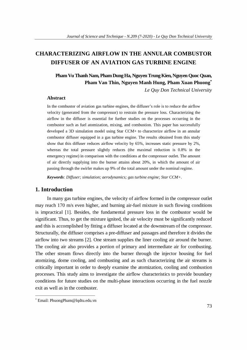
has been constructed. Firstly, we need a real cutaway combustor so that the diffuser profiles can be computed as shown in Fig. 1a. The combustor shown in Fig. 1 is an annular combustor consisting of 12 uniform parts equipped with 12 injectors, respectively. Thus, when characterizing airflow properties in the diffuser, we just limit in this study to consider one of those parts. Basically, the diffuser shape of gas turbine engines is quite simple. However, in order to calculate the distribution of the airflow behind the diffuser, it is necessary to accurately determine the dimensions of components located in the first part of the combustor chamber including the air swirler, the fuel injector, and the dome. Practically, measuring geometry shapes of these components is quite challenging, even when using 3D scanners, because of the narrow lines and hidden corners of those parts. Therefore, in this work, a three-dimensional digitizer was utilized (Fig. 1b). That is a spatial measuring tool used to determine the XYZ coordinates of points in three- dimensional space, or on the surface of an object. Basically, this device will record the coordinates of the point where the stylus is touching. Its accuracy depends on the stylus magnitude, and its workspace depends on its arm length.
The considered combustor (Fig. 1a) consists of different curved sheets welding togerther. To reconstruct such curves using the digitizer, firstly, it is necessary to determine exactly the starting point and the endpoint of each curve. Then, the remaining points of that curve are automatically sketched using a devision of 0.3 mm between two consecutive points from the starting point.
Journal of Science and Technique - N.209 (7-2020) - Military Technical Academy
76
Because of the extended arm, it is possible to derive the coordinates of the points, which are located at the hidden corners, when moving the stylus along the edge of any sheet.
(a) (b)
Fig. 1. (a) Practical cutaway combustor investigated in this study; (b) 3D digitizer.
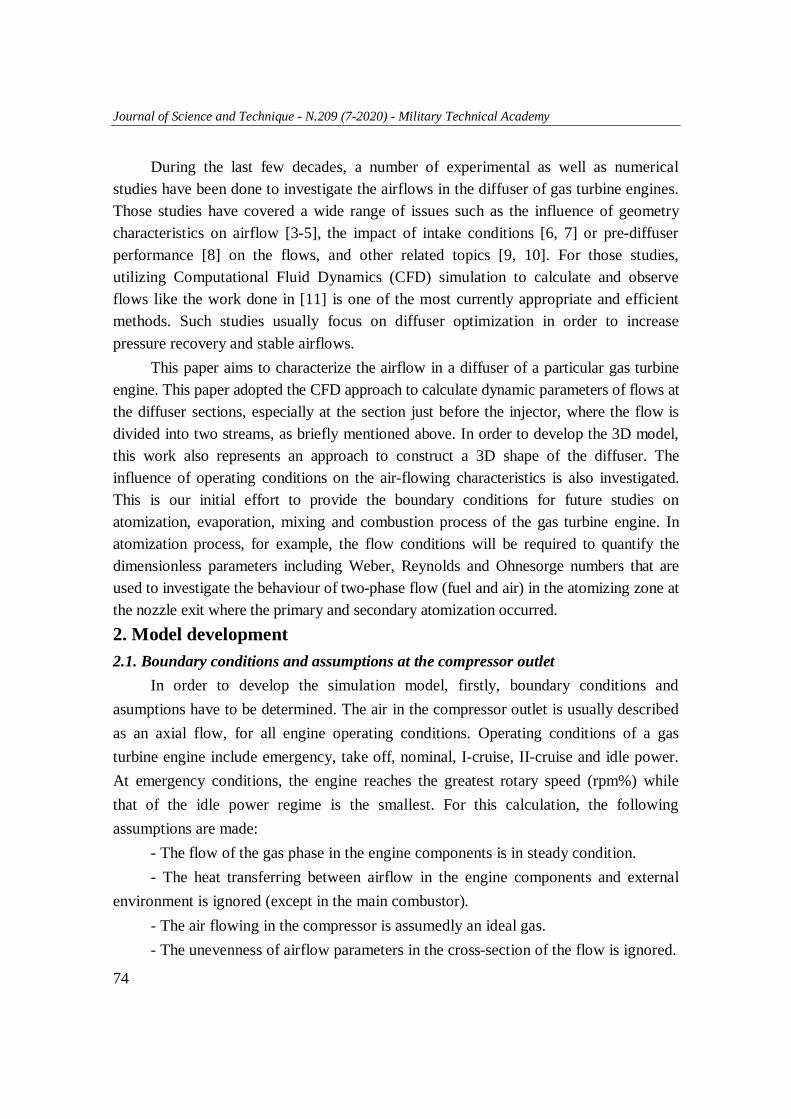
For this study, we used the MicroScribe GX2 digitizer which has an accuracy of 0.23 mm and a wide workspace of 1.27 m. The digitized coordinates are directly, automatically inserted into a computer file in type of the set of 3D points (Fig. 2).
Fig. 2. Set of 3D points of the combustor investigated in this study
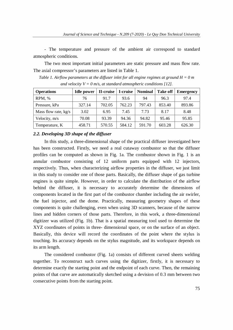
From the coordinate information, a 3D model was developed using SolidWorks software and the model is illustrated in Fig. 3. Fig. 3a schematically shows one twelfth of the combustor while a cross-section before the fuel injector is shown in Fig. 3b.
(a) (b)
Fig. 3. 3D structure of the combustor. (a) One twelfth of the combustor; (b) Cross section before the injector.
Journal of Science and Technique - N.209 (7-2020) - Le Quy Don Technical University
77
3. Simulation model development 3.1. Simulation software
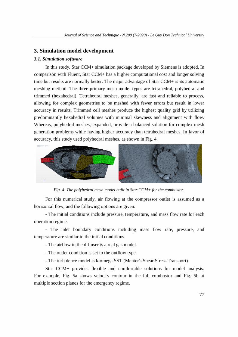
In this study, Star CCM+ simulation package developed by Siemens is adopted. In comparison with Fluent, Star CCM+ has a higher computational cost and longer solving time but results are normally better. The major advantage of Star CCM+ is its automatic meshing method. The three primary mesh model types are tetrahedral, polyhedral and trimmed (hexahedral). Tetrahedral meshes, generally, are fast and reliable to process, allowing for complex geometries to be meshed with fewer errors but result in lower accuracy in results. Trimmed cell meshes produce the highest quality grid by utilizing predominantly hexahedral volumes with minimal skewness and alignment with flow. Whereas, polyhedral meshes, expanded, provide a balanced solution for complex mesh generation problems while having higher accuracy than tetrahedral meshes. In favor of accuracy, this study used polyhedral meshes, as shown in Fig. 4.
Fig. 4. The polyhedral mesh model built in Star CCM+ for the combustor.
For this numerical study, air flowing at the compressor outlet is assumed as a horizontal flow, and the following options are given:
- The initial conditions include pressure, temperature, and mass flow rate for each operation regime.
- The inlet boundary conditions including mass flow rate, pressure, and temperature are similar to the initial conditions.
- The airflow in the diffuser is a real gas model.
- The outlet condition is set to the outflow type.
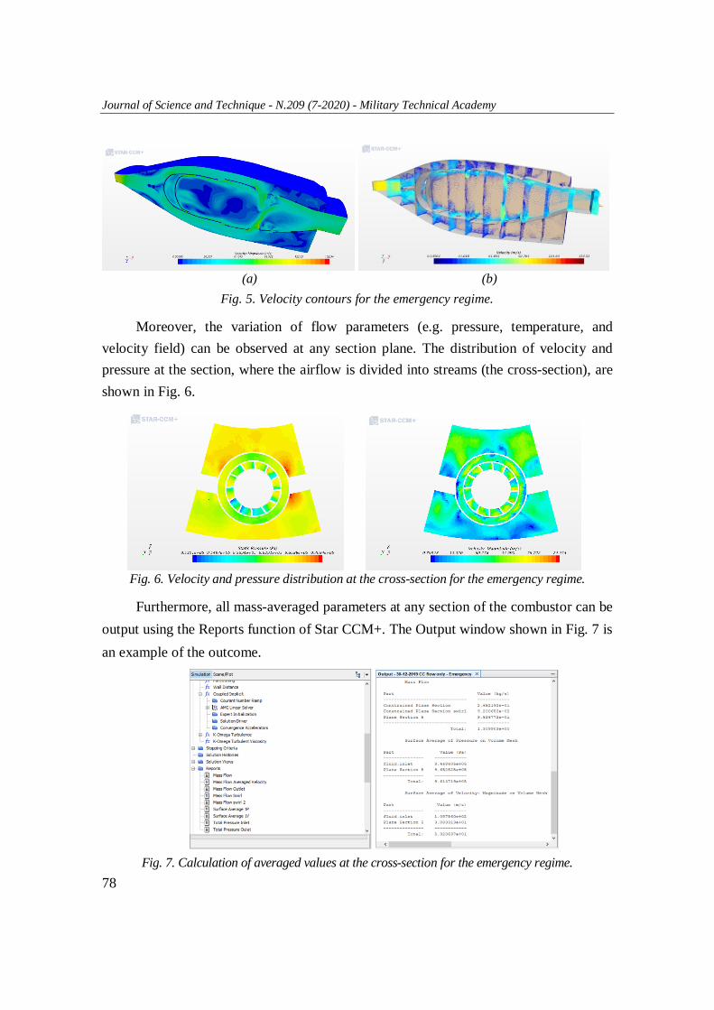
- The turbulence model is k-omega SST (Menter's Shear Stress Transport). Star CCM+ provides flexible and comfortable solutions for model analysis.
For example, Fig. 5a shows velocity contour in the full combustor and Fig. 5b at multiple section planes for the emergency regime.
Journal of Science and Technique - N.209 (7-2020) - Military Technical Academy
78
(a) (b)
Fig. 5. Velocity contours for the emergency regime.
Moreover, the variation of flow parameters (e.g. pressure, temperature, and velocity field) can be observed at any section plane. The distribution of velocity and pressure at the section, where the airflow is divided into streams (the cross-section), are shown in Fig. 6.
Fig. 6. Velocity and pressure distribution at the cross-section for the emergency regime.
Furthermore, all mass-averaged parameters at any section of the combustor can be output using the Reports function of Star CCM+. The Output window shown in Fig. 7 is an example of the outcome.
Fig. 7. Calculation of averaged values at the cross-section for the emergency regime.
Journal of Science and Technique - N.209 (7-2020) - Le Quy Don Technical University
79
3.2. Convergence and grid independence study It is important to pay attention to the convergence problems when building the
numerical experiments of the combustor models because of their complex geometries. We should not perform the simulations of the diffuser model without the full combustor, but all small cooling details of the liner and injector region could be simplified. It does not affect the numerical aerodynamic results, but also help to get the inlet/outlet mass imbalance of less than 10-5 and the residuals of nearly 10-3.
Besides, mesh independence was also investigated to get accurate parameters. Using the polyhedral mesh with base size changes within 0.5÷5.0 mm, the base size of 1mm (nearly 4 million elements with the cell quality of mesh 99.7% above the recommended value - 0.2) finally was chosen for all cases in this paper. It is noted that the mesh models using the minimum surface size of 5% of base and 5 boundary layers (surface growth rate equals 1.3) are suitable to use the k-ω SST turbulence model that was recommended in many articles. All numerical results were compared with the experimental compressor map [12] that figured out the acceptable mesh models in this study. 4. Results and discussion
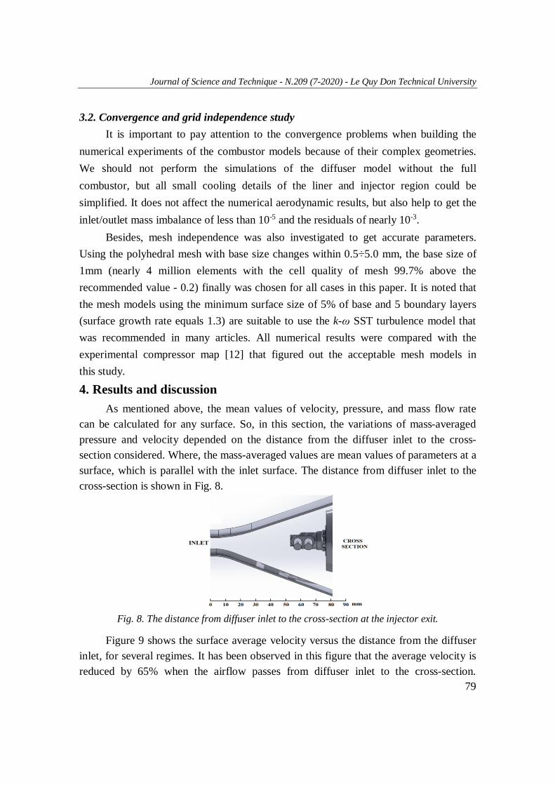
As mentioned above, the mean values of velocity, pressure, and mass flow rate can be calculated for any surface. So, in this section, the variations of mass-averaged pressure and velocity depended on the distance from the diffuser inlet to the cross-section considered. Where, the mass-averaged values are mean values of parameters at a surface, which is parallel with the inlet surface. The distance from diffuser inlet to the cross-section is shown in Fig. 8.
Fig. 8. The distance from diffuser inlet to the cross-section at the injector exit.
Figure 9 shows the surface average velocity versus the distance from the diffuser inlet, for several regimes. It has been observed in this figure that the average velocity is reduced by 65% when the airflow passes from diffuser inlet to the cross-section.
Journal of Science and Technique - N.209 (7-2020) - Military Technical Academy
80
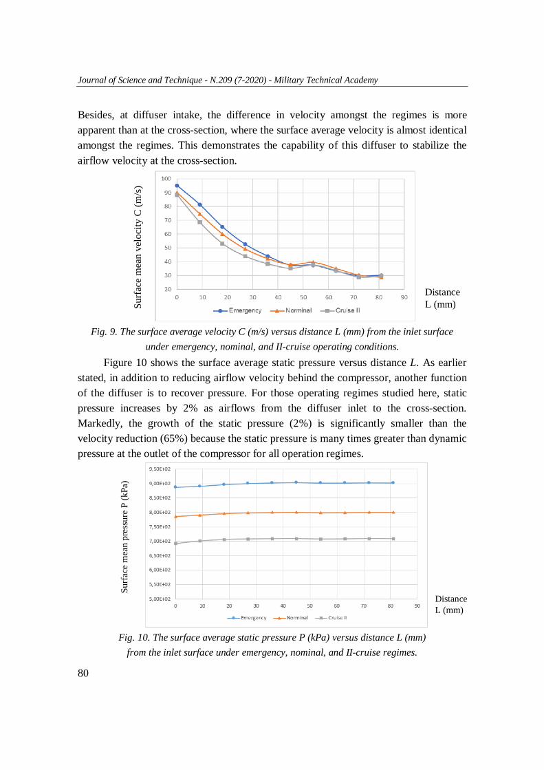
Besides, at diffuser intake, the difference in velocity amongst the regimes is more apparent than at the cross-section, where the surface average velocity is almost identical amongst the regimes. This demonstrates the capability of this diffuser to stabilize the airflow velocity at the cross-section.
Fig. 9. The surface average velocity C (m/s) versus distance L (mm) from the inlet surface
under emergency, nominal, and II-cruise operating conditions. Figure 10 shows the surface average static pressure versus distance L. As earlier
stated, in addition to reducing airflow velocity behind the compressor, another function of the diffuser is to recover pressure. For those operating regimes studied here, static pressure increases by 2% as airflows from the diffuser inlet to the cross-section. Markedly, the growth of the static pressure (2%) is significantly smaller than the velocity reduction (65%) because the static pressure is many times greater than dynamic pressure at the outlet of the compressor for all operation regimes.
Fig. 10. The surface average static pressure P (kPa) versus distance L (mm)
from the inlet surface under emergency, nominal, and II-cruise regimes.
Surfa
ce m
ean
velo
city
C (m
/s)
Distance L (mm)
Distance L (mm)
Surf
ace
mea
n pr
essu
re P
(kPa
)
Journal of Science and Technique - N.209 (7-2020) - Le Quy Don Technical University
81
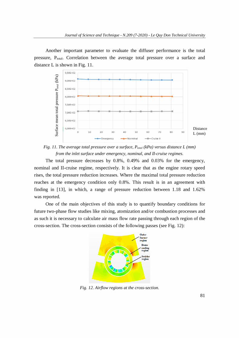
Another important parameter to evaluate the diffuser performance is the total pressure, Ptotal. Correlation between the average total pressure over a surface and distance L is shown in Fig. 11.
Fig. 11. The average total pressure over a surface, Ptotal (kPa) versus distance L (mm)
from the inlet surface under emergency, nominal, and II-cruise regimes. The total pressure decreases by 0.8%, 0.49% and 0.03% for the emergency,
nominal and II-cruise regime, respectively. It is clear that as the engine rotary speed rises, the total pressure reduction increases. Where the maximal total pressure reduction reaches at the emergency condition only 0.8%. This result is in an agreement with finding in [13], in which, a range of pressure reduction between 1.18 and 1.62% was reported.
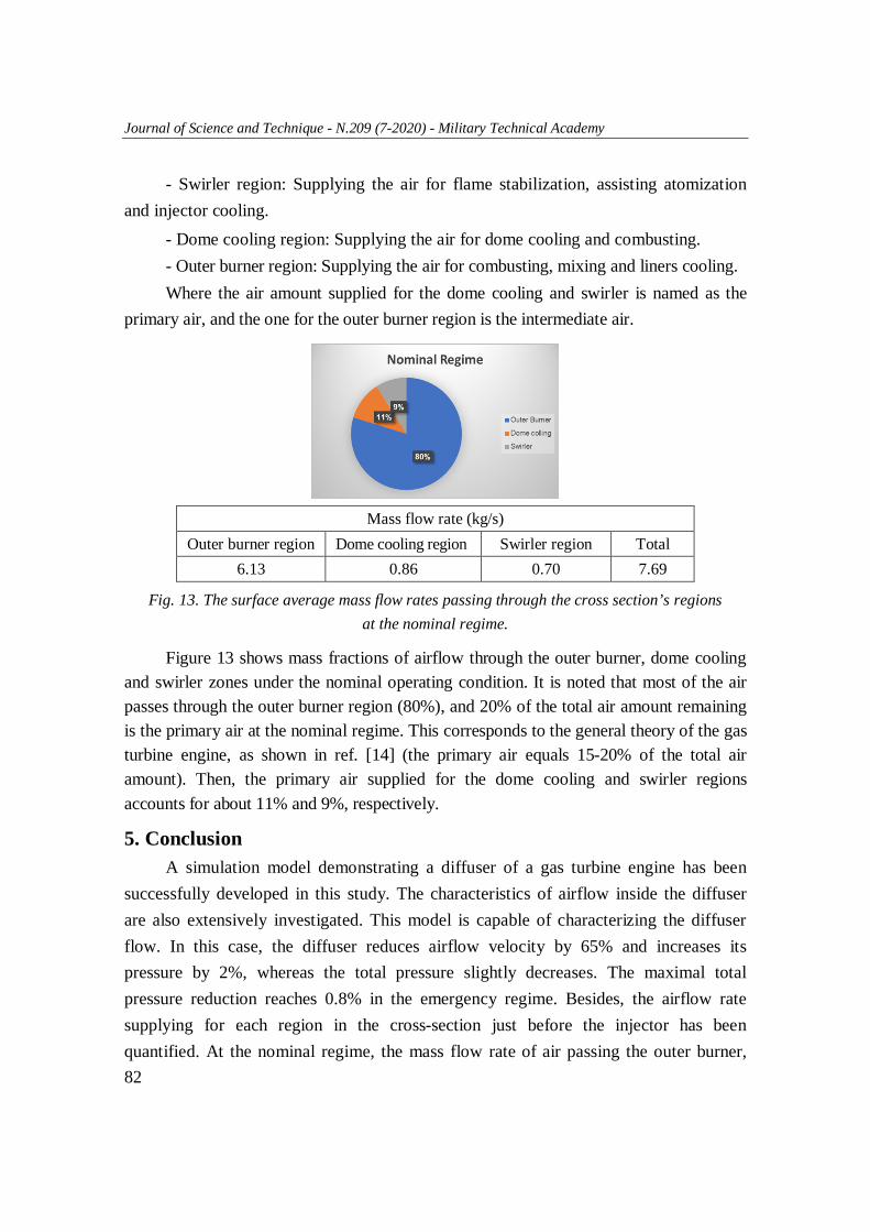
One of the main objectives of this study is to quantify boundary conditions for future two-phase flow studies like mixing, atomization and/or combustion processes and as such it is necessary to calculate air mass flow rate passing through each region of the cross-section. The cross-section consists of the following passes (see Fig. 12):
Fig. 12. Airflow regions at the cross-section.
Surf
ace
mea
n to
tal p
ress
ure
P tot
al (k
Pa)
Distance L (mm)
Journal of Science and Technique - N.209 (7-2020) - Military Technical Academy
82
- Swirler region: Supplying the air for flame stabilization, assisting atomization and injector cooling.
- Dome cooling region: Supplying the air for dome cooling and combusting. - Outer burner region: Supplying the air for combusting, mixing and liners cooling. Where the air amount supplied for the dome cooling and swirler is named as the
primary air, and the one for the outer burner region is the intermediate air.
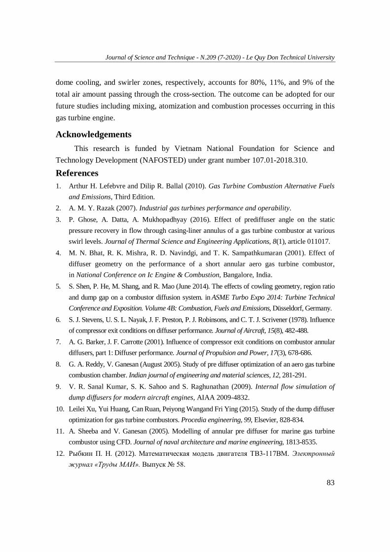
Mass flow rate (kg/s)
Outer burner region Dome cooling region Swirler region Total 6.13 0.86 0.70 7.69
Fig. 13. The surface average mass flow rates passing through the cross section’s regions at the nominal regime.
Figure 13 shows mass fractions of airflow through the outer burner, dome cooling and swirler zones under the nominal operating condition. It is noted that most of the air passes through the outer burner region (80%), and 20% of the total air amount remaining is the primary air at the nominal regime. This corresponds to the general theory of the gas turbine engine, as shown in ref. [14] (the primary air equals 15-20% of the total air amount). Then, the primary air supplied for the dome cooling and swirler regions accounts for about 11% and 9%, respectively.
5. Conclusion A simulation model demonstrating a diffuser of a gas turbine engine has been
successfully developed in this study. The characteristics of airflow inside the diffuser are also extensively investigated. This model is capable of characterizing the diffuser flow. In this case, the diffuser reduces airflow velocity by 65% and increases its pressure by 2%, whereas the total pressure slightly decreases. The maximal total pressure reduction reaches 0.8% in the emergency regime. Besides, the airflow rate supplying for each region in the cross-section just before the injector has been quantified. At the nominal regime, the mass flow rate of air passing the outer burner,
Journal of Science and Technique - N.209 (7-2020) - Le Quy Don Technical University
83
dome cooling, and swirler zones, respectively, accounts for 80%, 11%, and 9% of the total air amount passing through the cross-section. The outcome can be adopted for our future studies including mixing, atomization and combustion processes occurring in this gas turbine engine.
Acknowledgements This research is funded by Vietnam National Foundation for Science and
Technology Development (NAFOSTED) under grant number 107.01-2018.310.
References 1. Arthur H. Lefebvre and Dilip R. Ballal (2010). Gas Turbine Combustion Alternative Fuels
and Emissions, Third Edition. 2. A. M. Y. Razak (2007). Industrial gas turbines performance and operability. 3. P. Ghose, A. Datta, A. Mukhopadhyay (2016). Effect of prediffuser angle on the static
pressure recovery in flow through casing-liner annulus of a gas turbine combustor at various swirl levels. Journal of Thermal Science and Engineering Applications, 8(1), article 011017.
4. M. N. Bhat, R. K. Mishra, R. D. Navindgi, and T. K. Sampathkumaran (2001). Effect of diffuser geometry on the performance of a short annular aero gas turbine combustor, in National Conference on Ic Engine & Combustion, Bangalore, India.
5. S. Shen, P. He, M. Shang, and R. Mao (June 2014). The effects of cowling geometry, region ratio and dump gap on a combustor diffusion system. in ASME Turbo Expo 2014: Turbine Technical Conference and Exposition. Volume 4B: Combustion, Fuels and Emissions, Düsseldorf, Germany.
6. S. J. Stevens, U. S. L. Nayak, J. F. Preston, P. J. Robinsons, and C. T. J. Scrivener (1978). Influence of compressor exit conditions on diffuser performance. Journal of Aircraft, 15(8), 482-488.
7. A. G. Barker, J. F. Carrotte (2001). Influence of compressor exit conditions on combustor annular diffusers, part 1: Diffuser performance. Journal of Propulsion and Power, 17(3), 678-686.
8. G. A. Reddy, V. Ganesan (August 2005). Study of pre diffuser optimization of an aero gas turbine combustion chamber. Indian journal of engineering and material sciences, 12, 281-291.
9. V. R. Sanal Kumar, S. K. Sahoo and S. Raghunathan (2009). Internal flow simulation of dump diffusers for modern aircraft engines, AIAA 2009-4832.
10. Leilei Xu, Yui Huang, Can Ruan, Peiyong Wangand Fri Ying (2015). Study of the dump diffuser optimization for gas turbine combustors. Procedia engineering, 99, Elsevier, 828-834.
11. A. Sheeba and V. Ganesan (2005). Modelling of annular pre diffuser for marine gas turbine combustor using CFD. Journal of naval architecture and marine engineering, 1813-8535.
12. Рыбкин П. Н. (2012). Математическая модель двигателя ТВ3-117ВМ. Электронный журнал «Труды МАИ». Выпуск № 58.
Journal of Science and Technique - N.209 (7-2020) - Military Technical Academy
84
13. М. Ю. Орлов, В. С. Зинковский, С. С. Матвеев. (2012). Oптимизация конструкции диффузора камеры сгорания газотурбинного двигателя с использованием расчётов в cae системах, Самарский государственный аэрокосмический университет.
14. H. I. H. Saravanamuttoo, G. F. C. Rogers, H. Cohen (2001). Gas Turbine Theory, 5th edition.
ĐẶC TRƯNG DÒNG KHÍ TRONG VÀNH KHUẾCH TÁN CỦA ĐỘNG CƠ TUA BIN KHÍ HÀNG KHÔNG
Tóm tắt: Trong buồng đốt của động cơ tua bin khí hàng không, vành khuếch tán có nhiệm vụ giảm tốc độ và hạn chế tổn thất áp suất dòng khí sau máy nén. Hiểu rõ các đặc tính dòng chảy trong vành khuếch tán là cần thiết cho các công trình nghiên cứu tiếp theo về các quá trình xảy ra trong buồng đốt, như: quá trình phun nhiên liệu, hòa trộn, hay quá trình cháy. Bài báo đã xây dựng thành công mô hình mô phỏng 3D dòng khí trong một vành khuếch tán thực trang bị trên động cơ tua bin khí hàng không, dựa trên phần mềm Star CCM+. Kết quả tính toán cho thấy vành khuếch tán giúp giảm tốc độ dòng khí từ 65%, tăng áp suất tĩnh khoảng 2%, trong khi đó áp suất toàn phần giảm nhẹ (giảm nhiều nhất ở chế độ khẩn cấp là 0,8%) so với dòng khí sau máy nén. Lượng khí cung cấp cho ống đốt chiếm khoảng 20%, trong đó lượng cung cấp cho bộ tạo xoáy chiếm 9% tổng lượng khí, ở chế độ định mức.
Từ khóa: Vành khuếch tán; mô phỏng; khí động học; động cơ tua bin khí; Star CCM+.
Received: 12/3/2020; Revised: 21/7/2020; Accepted for publication: 28/7/2020
Related Documents