CHARACTERIZATION OF X-RAY IRRADIATED GRAPHENE OXIDE COATINGS USING X-RAY DIFFRACTION, X-RAY PHOTOELECTRON SPECTROSCOPY, AND ATOMIC FORCE MICROSCOPY Thomas N. Blanton and Debasis Majumdar Eastman Kodak Company, Kodak Technology Center, Rochester, NY 14650-2106 USA ABSTRACT In an effort to study an alternative approach to make graphene from graphene oxide (GO), exposure of GO to high-energy X-ray radiation has been performed. X-ray Diffraction (XRD), X-ray Photoelectron Spectroscopy (XPS), and Atomic Force Microscopy (AFM) have been used to characterize GO before and after irradiation. Results indicate that GO exposed to high-energy radiation is converted to an amorphous carbon phase that is conductive. INTRODUCTION Graphene is a single-layer planar sheet of sp 2 bonded carbon atoms that are packed in a two- dimensional honeycomb lattice. Intrinsic graphene behaves like a semi-metal or zero-gap semiconductor. One problem with graphene is that it cannot be dispersed in water, preventing any practical applications that utilize aqueous coating or deposition technology. Graphene oxide (GO), sometimes referred to as graphite oxide, is generated by treating graphite with strong oxidizers (Dreyer et al., 2010). GO retains the layer structure of graphite but with a larger and irregular basal plane spacing (Blanton and Majumdar, 2012). The name graphene oxide does not completely describe this material chemically. Besides oxygen epoxide groups, other functional groups observed to be present are carbonyl, phenol, and hydroxyl groups. It is the presence of the hydroxyl groups that allows GO to be dispersed in water. Unfortunately, as a material GO does not have some of the attractive properties of graphene, such as high electrical conductivity. Aqueous dispersions of GO, however, allow one to formulate these materials into waterborne compositions which can be coated onto various substrates by conventional coating methods, such as dip, slot die, gravure, rod or knife coating, often at relatively high speed. Therefore, a post-coating method to convert GO into a graphitic structure has been deemed to be a practical alternative to creating graphene layers at an industrial scale. Though a complete conversion of GO to graphene has proven to be difficult, a partially reduced form of graphene oxide (r-GO) with improved electrical conductivity has been obtained in some cases (Gilje et al., 2007; Yang et al., 2009). Most methods of converting GO to r-GO are chemical or thermal processes. For example, Gilje (2010) discloses the use of hydrazine as a reducing agent for GO. The choice of such a chemical has some health and safety related issues that need to be addressed especially in a manufacturing environment. The use of thermal energy for reduction of GO (Wang et al., 2008) Copyright ©JCPDS-International Centre for Diffraction Data 2013 ISSN 1097-0002 116 Advances in X-ray Analysis, Volume 56

Welcome message from author
This document is posted to help you gain knowledge. Please leave a comment to let me know what you think about it! Share it to your friends and learn new things together.
Transcript

CHARACTERIZATION OF X-RAY IRRADIATED GRAPHENE OXIDE COATINGS USING X-RAY DIFFRACTION, X-RAY PHOTOELECTRON
SPECTROSCOPY, AND ATOMIC FORCE MICROSCOPY
Thomas N. Blanton and Debasis Majumdar Eastman Kodak Company, Kodak Technology Center, Rochester, NY 14650-2106 USA
ABSTRACT In an effort to study an alternative approach to make graphene from graphene oxide (GO), exposure of GO to high-energy X-ray radiation has been performed. X-ray Diffraction (XRD), X-ray Photoelectron Spectroscopy (XPS), and Atomic Force Microscopy (AFM) have been used to characterize GO before and after irradiation. Results indicate that GO exposed to high-energy radiation is converted to an amorphous carbon phase that is conductive. INTRODUCTION Graphene is a single-layer planar sheet of sp2 � bonded carbon atoms that are packed in a two-dimensional honeycomb lattice. Intrinsic graphene behaves like a semi-metal or zero-gap semiconductor. One problem with graphene is that it cannot be dispersed in water, preventing any practical applications that utilize aqueous coating or deposition technology. Graphene oxide (GO), sometimes referred to as graphite oxide, is generated by treating graphite with strong oxidizers (Dreyer et al., 2010). GO retains the layer structure of graphite but with a larger and irregular basal plane spacing (Blanton and Majumdar, 2012). The name graphene oxide does not completely describe this material chemically. Besides oxygen epoxide groups, other functional groups observed to be present are carbonyl, phenol, and hydroxyl groups. It is the presence of the hydroxyl groups that allows GO to be dispersed in water. Unfortunately, as a material GO does not have some of the attractive properties of graphene, such as high electrical conductivity. Aqueous dispersions of GO, however, allow one to formulate these materials into waterborne compositions which can be coated onto various substrates by conventional coating methods, such as dip, slot die, gravure, rod or knife coating, often at relatively high speed. Therefore, a post-coating method to convert GO into a graphitic structure has been deemed to be a practical alternative to creating graphene layers at an industrial scale. Though a complete conversion of GO to graphene has proven to be difficult, a partially reduced form of graphene oxide (r-GO) with improved electrical conductivity has been obtained in some cases (Gilje et al., 2007; Yang et al., 2009). Most methods of converting GO to r-GO are chemical or thermal processes. For example, Gilje (2010) discloses the use of hydrazine as a reducing agent for GO. The choice of such a chemical has some health and safety related issues that need to be addressed especially in a manufacturing environment. The use of thermal energy for reduction of GO (Wang et al., 2008)
Copyright ©JCPDS-International Centre for Diffraction Data 2013 ISSN 1097-0002 116Advances in X-ray Analysis, Volume 56

This document was presented at the Denver X-ray Conference (DXC) on Applications of X-ray Analysis. Sponsored by the International Centre for Diffraction Data (ICDD). This document is provided by ICDD in cooperation with the authors and presenters of the DXC for the express purpose of educating the scientific community. All copyrights for the document are retained by ICDD. Usage is restricted for the purposes of education and scientific research. DXC Website – www.dxcicdd.com
ICDD Website - www.icdd.com
Advances in X-ray Analysis, Volume 56
also suffers from some limitations in terms of choice of substrate and addenda in the GO layer, which can be polymeric materials with limited thermal stability. Cote et al. (2009) has reported the use of a xenon light source, to reduce GO to a conductive form, using a common digital camera flash. While this process may have advantage over chemical and thermal reduction methods, it may have some inefficiency in terms of penetration depth, especially if the GO is distributed in a binder or buried under a layer in a composite structure. In this work, we describe the use of X-rays as the radiation source for converting GO to r-GO with improved electrical conductivity. Characterization of the resulting material using XRD, XPS and AFM is also provided in detail. EXPERIMENTAL A. Sample preparation A dispersion of 0.5wt% GO in water (N002PS) and graphene powder (N008-100-N) were obtained from Angstron Materials. Neat GO coatings were formed by depositing a few drops of GO dispersion solution onto gold foil or glass disk followed by drying in ambient air. A small amount of graphite (G) was observed to be present in this GO dispersion. The (002) G peak was used as an internal peak position standard for X-ray diffraction analysis. Dried GO films were analyzed as made, or after one of two methods of processing: (1) in vacuum or helium (He) exposed to X-rays (4.02 kW) using a Bruker S8 X-ray fluorescence spectrometer or (2) in vacuum exposed to X-rays (0.3 kW) and in situ thermally annealed (400 C) using a Thermo Electron Vacuum Generators ESCA-LAB 250 X-ray photoelectron spectroscopy spectrometer. B. X-ray diffraction X-ray diffraction, XRD, data were collected using a Rigaku D2000 Bragg-Brentano diffractometer, equipped with a copper rotating anode, diffracted beam monochromator tuned to
Cu K radiation, and a scintillation detector. All data were collected using reflection mode geometry. C. X-ray photoelectron spectroscopy X-ray photoelectron spectroscopy, XPS, analyses were performed using a Thermo Electron
Vacuum Generators ESCA-LAB 250 equipped with a monochromatic Al K source. D. Atomic force microscopy Atomic force microscopy, AFM, data were collected in conductive mode (cAFM) using a Veeco Metrology Nanoscope Dimension 3100 scanning probe microscope. Conductive AFM was performed using an applied DC bias of 500 mV. The bias voltage was swept from -5 to +5 volts, and the resulting current vs. voltage spectrum was an average of 64 spectra.
Copyright ©JCPDS-International Centre for Diffraction Data 2013 ISSN 1097-0002 117Advances in X-ray Analysis, Volume 56

RESULTS AND DISCUSSION The reflection mode geometry X-ray diffraction pattern for a neat GO film has a strong (001) diffraction peak indicating preferred orientation of graphene oxide basal planes parallel to the sample plane. The two-theta position of the (001) GO diffraction peak can show a range of ~7-12 two theta (Cu K radiation) depending on the amount of residual water intercalated between basal planes in a GO film (Blanton and Majumdar, 2012). In addition there is a broad peak at ~19 two theta due to a disordered component(s) generated during the chemical processing of graphite to make GO. To study the effect of high energy radiation on GO, a GO film coated on glass was irradiated in a wavelength dispersive XRF spectrometer, using a rhodium X-ray tube operating at 60 kV, 67 mA (4.02 kW). Exposures were additive starting with 5 min. and ending with a total exposure of 120 min. An X-ray diffraction pattern was collected after each XRF exposure, and all are shown in Figure 1.
Figure 1. X-ray diffraction patterns of GO coated on glass, after 4.02kW X-ray irradiation in He ambient. (GO � graphene oxide, r-GO � reduced graphene oxide, G � graphite).
After the 5 min. exposure, the (001) GO peak shows a decrease in peak height intensity, and two peaks are now observed. The XRF X-ray irradiation started to remove residual water from the surface of the GO film resulting in the additional higher two-theta (smaller d-spacing) diffraction peak, whereas below the surface the GO film still has residual water. After 45 min. exposure a single (001) peak is observed suggesting all water has been removed. The extended time required for water removal is an indication of the torturous pathway the water molecules must travel, both horizontal and vertical, before reaching the GO film surface. Also observed in Figure 1 is the
growth of a broad diffraction peak in the range of 23-24 two theta with increasing X-ray irradiation of the GO film. This peak, at a lower two theta than bulk graphite, is identified as reduced graphene oxide (r-GO) (Cote et al., 2009).
Copyright ©JCPDS-International Centre for Diffraction Data 2013 ISSN 1097-0002 118Advances in X-ray Analysis, Volume 56
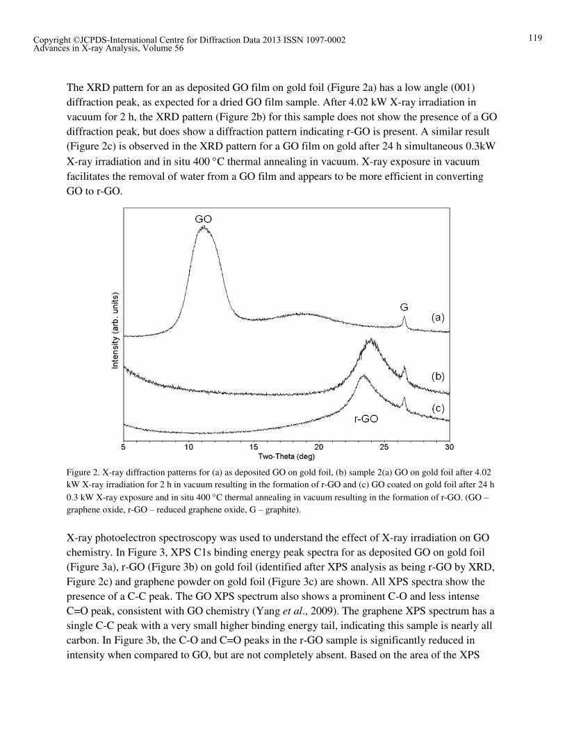
The XRD pattern for an as deposited GO film on gold foil (Figure 2a) has a low angle (001) diffraction peak, as expected for a dried GO film sample. After 4.02 kW X-ray irradiation in vacuum for 2 h, the XRD pattern (Figure 2b) for this sample does not show the presence of a GO diffraction peak, but does show a diffraction pattern indicating r-GO is present. A similar result (Figure 2c) is observed in the XRD pattern for a GO film on gold after 24 h simultaneous 0.3kW X-ray irradiation and in situ 400 C thermal annealing in vacuum. X-ray exposure in vacuum facilitates the removal of water from a GO film and appears to be more efficient in converting GO to r-GO.
Figure 2. X-ray diffraction patterns for (a) as deposited GO on gold foil, (b) sample 2(a) GO on gold foil after 4.02 kW X-ray irradiation for 2 h in vacuum resulting in the formation of r-GO and (c) GO coated on gold foil after 24 h
0.3 kW X-ray exposure and in situ 400 C thermal annealing in vacuum resulting in the formation of r-GO. (GO � graphene oxide, r-GO � reduced graphene oxide, G � graphite).
X-ray photoelectron spectroscopy was used to understand the effect of X-ray irradiation on GO chemistry. In Figure 3, XPS C1s binding energy peak spectra for as deposited GO on gold foil (Figure 3a), r-GO (Figure 3b) on gold foil (identified after XPS analysis as being r-GO by XRD, Figure 2c) and graphene powder on gold foil (Figure 3c) are shown. All XPS spectra show the presence of a C-C peak. The GO XPS spectrum also shows a prominent C-O and less intense C=O peak, consistent with GO chemistry (Yang et al., 2009). The graphene XPS spectrum has a single C-C peak with a very small higher binding energy tail, indicating this sample is nearly all carbon. In Figure 3b, the C-O and C=O peaks in the r-GO sample is significantly reduced in intensity when compared to GO, but are not completely absent. Based on the area of the XPS
Copyright ©JCPDS-International Centre for Diffraction Data 2013 ISSN 1097-0002 119Advances in X-ray Analysis, Volume 56

peaks in Figure 3, the percent carbon in GO, r-GO, and graphene is 64, 92, and 97percent respectively. These data indicate that the conversion of GO to r-GO is the result of the loss of oxygen.
Figure 3. X-ray photoelectron spectroscopy spectra, C1s binding energy peaks, for (a) as deposited GO on gold foil,
(b) GO on gold foil after 24 h 0.3 kW X-ray exposure and in situ 400 C thermal annealing in vacuum resulting in the formation of r-GO and (c) neat graphene powder on gold foil.
Using cAFM, the conductivity of r-GO was investigated to determine if r-GO has the potential to be used as a conductive film. The cAFM conductivity curves for GO, r-GO, and graphene are
Copyright ©JCPDS-International Centre for Diffraction Data 2013 ISSN 1097-0002 120Advances in X-ray Analysis, Volume 56

presented in Figure 4. On opposite ends of conductivity, GO is found to be essentially nonconductive and graphene, as expected, is highly conductive. The conductivity of r-GO is observed to be close to graphene. The resistance of GO, r-GO, and graphene can be calculated from cAFM current-voltage curves and was found to be 1.54 x 10⁶, 7.66 x 10³, and 2.09 x 10³ nano-Ohms respectively (for highly ordered pyrolytic graphite, resistance was measured to be 2.00 x 10³ nano-Ohms).
Figure 4. Conductive atomic force microscopy conductivity curves for () GO deposited on gold foil, () GO on
gold foil after 24 h 0.3 kW X-ray exposure and in situ 400 C thermal annealing in vacuum resulting in the formation of r-GO and () neat graphene powder on gold foil.
Structure changes observed by XRD, chemical changes detected by XPS, and conductivity data measured by cAFM demonstrate that X-ray irradiation of GO results in the generation of an r-GO phase that has good conductivity. It may be possible to drive the GO to r-GO conversion further by exposure of GO to even higher energy or higher flux radiation. SUMMARY � A novel method for converting aqueous coatable GO to r-GO has been presented � XRD results demonstrate that upon high energy X-ray exposure or high energy X-ray
exposure plus moderate thermal annealing, GO has a change in structure to r-GO � XPS results show GO loses oxygen during X-ray exposure, and that r-GO has a similar
chemistry as graphene
Copyright ©JCPDS-International Centre for Diffraction Data 2013 ISSN 1097-0002 121Advances in X-ray Analysis, Volume 56

� Conductive AFM results indicate r-GO is significantly more conductive than GO, and approaches the conductivity of graphene
� Due to its coatability and the conversion methods described in this study, GO could be used in functional printing applications to ultimately produce conductive films
ACKNOWLEDGEMENTS The authors would like to thank Steve Brandt for collection of XPS data and Jill Fornalik for collection of AFM data. REFERENCES Blanton, T.N. and Majumdar, D., (2012). �X-ray diffraction characterization of polymer intercalated graphite oxide,� Powd. Diff., 27(2), 104-107. Cote, L.J., Cruz-Silva, R. and Huang, J., (2009). �Flash reduction and patterning of graphite oxide and its polymer composite,� J. Am. Chem. Soc., 131, 11027-11032. Dreyer, D.R., Park, S., Bielawski, C.W. and Ruoff, R.S., (2010). �The chemistry of graphene oxide,� Chem. Soc. Rev., 39, 228-240. Gilje, S., Han, S. Wang, M., Wang, K.L. and Kaner, R.B., (2007). �A chemical route to graphene for device applications,� Nano. Lett., 7(11), 3394-3398. Gilje, S. S., (2010). �Reduction of graphene oxide to graphene in high boiling point solvents,� U.S. Patent Application 20100237296A1. Wang. X., Zhi, L. and Mullen, K., (2008). �Transparent, conductive graphene electrodes for dye-sensitized solar cells,� Nano. Lett., 8(1), 323-327. Yang, D., Velamakanni, A., Bozoklu, G., Park, S., Stoller, M., Piner, R.D., Stankovich, S., Jung, I., Field, D.A., Ventrice, C.A. and Ruoff, R.S., (2009). �Chemical analysis of graphene oxide films after heat and chemical treatments by X-ray photoelectron spectroscopy and micro-Raman spectroscopy,� Carbon, 47, 145-152.
Copyright ©JCPDS-International Centre for Diffraction Data 2013 ISSN 1097-0002 122Advances in X-ray Analysis, Volume 56
Related Documents