IJRET: International Journal of Research in Engineering and Technology eISSN: 2319-1163 | pISSN: 2321-7308 _______________________________________________________________________________________ Volume: 03 Issue: 04 | Apr-2014, Available @ http://www.ijret.org 846 CHARACTERIZATION OF REFLECTORS AND ABSORBER COATINGS FOR SOLAR CONCENTRATORS Rahul B.Waghe Department of Mechanical Engineering, Smt.Kashibai Navale College of Engineering, Pune University, Pune Abstract Solar energy has great significance specifically for a country like India which is struggling to meet its energy demand. The project includes development of a test chamber for simulating different conditions of weathering and testing of ordinary glass mirrors and solar mirrors to identify the effect of weathering. This project will help in identifying the appropriate reflector and absorber coating for different locations and also in defining the maintenance schedule. This project is an attempt for testing of reflector and absorber coating which will help in material selection by identifying the merit and demerits of each material helpful in defining the replacement or maintenance cycle. New types of selective coatings and effect of different conditions on performance of reflectors and coatings have been discussed in this paper. Key Words-Solar Energy, Test chamber, Reflector, Absorber coating ------------------------------------------------------------------------***---------------------------------------------------------------------- 1. INTRODUCTION Solar energy is a very large, inexhaustible bit dilute source of energy. The power from the sun intercepted by the earth is approximately 1.8 x 10 11 MW which is many thousands of times larger than the present consumption rate on the earth of all commercial energy sources. Thus, in principle, solar energy could supply all the present and future energy needs of the world on a counting basis. This makes it one of the most promising of the unconventional energy sources. Solar concentrator is a device that allows the collection of sunlight from a large area and focusing it on a smaller receiver or exit. A conceptual representation of a solar concentrator used in harnessing the power from the sun to generate electricity is shown in Figure 1. The material used to fabricate the concentrator varies depending on the usage. For solar thermal, most of the concentrators are made from mirrors while for the BIPV system, the concentrator is either made of glass or transparent plastic. These materials are far cheaper than the PV material. The cost per unit area of a solar concentrator is therefore much cheaper than the cost per unit area of a PV material. By introducing this concentrator, not only the same amount of energy could be collected from the sun, the total cost of the solar cell could also be reduced. Fig -1: Generating electricity from the sun, with and without a solar concentrator. Fig -2: Solar Concentrator

Welcome message from author
This document is posted to help you gain knowledge. Please leave a comment to let me know what you think about it! Share it to your friends and learn new things together.
Transcript
IJRET: International Journal of Research in Engineering and Technology eISSN: 2319-1163 | pISSN: 2321-7308
_______________________________________________________________________________________
Volume: 03 Issue: 04 | Apr-2014, Available @ http://www.ijret.org 846
CHARACTERIZATION OF REFLECTORS AND ABSORBER COATINGS
FOR SOLAR CONCENTRATORS
Rahul B.Waghe
Department of Mechanical Engineering, Smt.Kashibai Navale College of Engineering, Pune University, Pune
Abstract Solar energy has great significance specifically for a country like India which is struggling to meet its energy demand. The project
includes development of a test chamber for simulating different conditions of weathering and testing of ordinary glass mirrors and
solar mirrors to identify the effect of weathering. This project will help in identifying the appropriate reflector and absorber coating
for different locations and also in defining the maintenance schedule. This project is an attempt for testing of reflector and absorber
coating which will help in material selection by identifying the merit and demerits of each material helpful in defining the replacement
or maintenance cycle. New types of selective coatings and effect of different conditions on performance of reflectors and coatings have
been discussed in this paper.
Key Words-Solar Energy, Test chamber, Reflector, Absorber coating
------------------------------------------------------------------------***----------------------------------------------------------------------
1. INTRODUCTION
Solar energy is a very large, inexhaustible bit dilute source of
energy. The power from the sun intercepted by the earth is
approximately 1.8 x 10¹¹
MW which is many thousands of times
larger than the present consumption rate on the earth of all
commercial energy sources. Thus, in principle, solar energy
could supply all the present and future energy needs of the world
on a counting basis. This makes it one of the most promising of
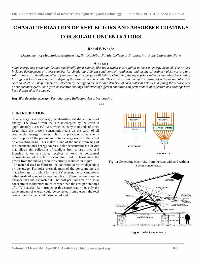
the unconventional energy sources. Solar concentrator is a device
that allows the collection of sunlight from a large area and
focusing it on a smaller receiver or exit. A conceptual
representation of a solar concentrator used in harnessing the
power from the sun to generate electricity is shown in Figure 1.
The material used to fabricate the concentrator varies depending
on the usage. For solar thermal, most of the concentrators are
made from mirrors while for the BIPV system, the concentrator is
either made of glass or transparent plastic. These materials are far
cheaper than the PV material. The cost per unit area of a solar
concentrator is therefore much cheaper than the cost per unit area
of a PV material. By introducing this concentrator, not only the
same amount of energy could be collected from the sun, the total
cost of the solar cell could also be reduced.
Fig -1: Generating electricity from the sun, with and without
a solar concentrator.
Fig -2: Solar Concentrator
IJRET: International Journal of Research in Engineering and Technology eISSN: 2319-1163 | pISSN: 2321-7308
_______________________________________________________________________________________
Volume: 03 Issue: 04 | Apr-2014, Available @ http://www.ijret.org 847
1.1 Types of Solar Concentrator
1. Parabolic Concentrator
2. Hyperboloid Concentrator
3. Fresnel Lens Concentrator
4. Compound Parabolic Concentrator (CPC)
5. Dielectric Totally Internally Reflecting Concentrator (DTIRC)
6. Flat High Concentration Devices
7. Quantum Dot Concentrator (QDC)
2. DESIGN OF ACCELERATED WEATHERING
CHAMBER.
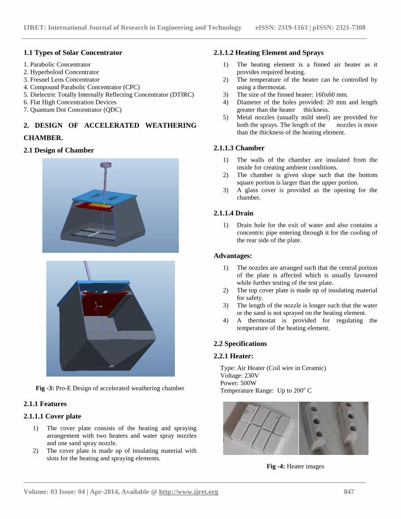
2.1 Design of Chamber
Fig -3: Pro-E Design of accelerated weathering chamber
2.1.1 Features
2.1.1.1 Cover plate
1) The cover plate consists of the heating and spraying
arrangement with two heaters and water spray nozzles
and one sand spray nozzle.
2) The cover plate is made up of insulating material with
slots for the heating and spraying elements.
2.1.1.2 Heating Element and Sprays
1) The heating element is a finned air heater as it
provides required heating.
2) The temperature of the heater can be controlled by
using a thermostat.
3) The size of the finned heater: 160x60 mm.
4) Diameter of the holes provided: 20 mm and length
greater than the heater thickness.
5) Metal nozzles (usually mild steel) are provided for
both the sprays. The length of the nozzles is more
than the thickness of the heating element.
2.1.1.3 Chamber
1) The walls of the chamber are insulated from the
inside for creating ambient conditions.
2) The chamber is given slope such that the bottom
square portion is larger than the upper portion.
3) A glass cover is provided as the opening for the
chamber.
2.1.1.4 Drain
1) Drain hole for the exit of water and also contains a
concentric pipe entering through it for the cooling of
the rear side of the plate.
Advantages:
1) The nozzles are arranged such that the central portion
of the plate is affected which is usually favoured
while further testing of the test plate.
2) The top cover plate is made up of insulating material
for safety.
3) The length of the nozzle is longer such that the water
or the sand is not sprayed on the heating element.
4) A thermostat is provided for regulating the
temperature of the heating element.
2.2 Specifications
2.2.1 Heater:
Type: Air Heater (Coil wire in Ceramic)
Voltage: 230V
Power: 500W
Temperature Range: Up to 200o C
Fig -4: Heater images
IJRET: International Journal of Research in Engineering and Technology eISSN: 2319-1163 | pISSN: 2321-7308
_______________________________________________________________________________________
Volume: 03 Issue: 04 | Apr-2014, Available @ http://www.ijret.org 848
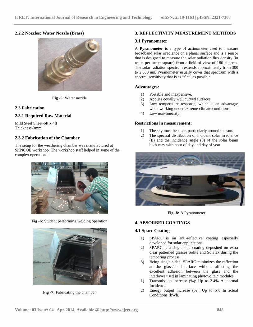
2.2.2 Nozzles: Water Nozzle (Brass)
Fig -5: Water nozzle
2.3 Fabrication
2.3.1 Required Raw Material
Mild Steel Sheet-6ft x 4ft
Thickness-3mm
2.3.2 Fabrication of the Chamber
The setup for the weathering chamber was manufactured at
SKNCOE workshop. The workshop staff helped in some of the
complex operations.
Fig -6: Student performing welding operation
Fig -7: Fabricating the chamber
3. REFLECTIVITY MEASUREMENT METHODS
3.1 Pyranometer
A Pyranometer is a type of actinometer used to measure
broadband solar irradiance on a planar surface and is a sensor
that is designed to measure the solar radiation flux density (in
watts per meter square) from a field of view of 180 degrees.
The solar radiation spectrum extends approximately from 300
to 2,800 nm. Pyranometer usually cover that spectrum with a
spectral sensitivity that is as “flat” as possible.
Advantages:
1) Portable and inexpensive.
2) Applies equally well curved surfaces.
3) Low temperature response, which is an advantage
when working under extreme climate conditions.
4) Low non-linearity.
Restrictions in measurement:
1) The sky must be clear, particularly around the sun.
2) The spectral distribution of incident solar irradiance
(Ii) and the incidence angle (θ) of the solar beam
both vary with hour of day and day of year.
Fig -8: A Pyranometer
4. ABSORBER COATINGS
4.1 Sparc Coating
1) SPARC is an anti-reflective coating especially
developed for solar applications.
2) SPARC is a single-side coating deposited on extra
clear patterned glasses Solite and Solatex during the
tempering process.
3) Being single-sided, SPARC minimizes the reflection
at the glass/air interface without affecting the
excellent adhesion between the glass and the
interlayer used in laminating photovoltaic modules.
1) Transmission increase (%): Up to 2.4% At normal
Incidence
2) Energy output increase (%): Up to 5% In actual
Conditions (kWh)
IJRET: International Journal of Research in Engineering and Technology eISSN: 2319-1163 | pISSN: 2321-7308
_______________________________________________________________________________________
Volume: 03 Issue: 04 | Apr-2014, Available @ http://www.ijret.org 849
4) Tests Cleared: i) Damped Heat ii) Thermal Cycle iii)
Climatic SO2 iv) Salt Spray
4.2 Sun Mirox T
1) SUN MIROXTM THIN is an extra clear extra thin high
reflectivity mirror perfectly suited for lamination
purposes and use in parabolic dish, parabolic trough
collectors, CSP or CPV.
2) Once laminated with an appropriate adhesive onto a
support material the mirror is perfectly well protected
and shows a very high chemical and mechanical
durability.
3) In order to minimize its environmental impact before,
during and after service, SUN MIROXTM THIN is
copper-free and lead-free.
4.2.1 Thermal Characteristics
1) Hemispherical emissivity: 0.84(Between -18°C and
66°C)
2) Expansion coefficient: 9 (EN572between 20°C and
300°C)
3) Specific heat (J/kg/K): 720
4) Thermal conductivity (W/m/K):1
5) Softening point (°C): 722
6) Annealing point (°C): 552
7) Strain point (°C) : 500
4.3 Organic Coatings
1) Pencil hardness: 3H to 5H
2) Solvent resistance: 100+ acetone rubs w/o effect
3) Tape adhesion: no loss after 30 minutes boiling water
4.3.1 Advantages:
1) New Technology
2) Low Temperature
3) Heavy Metal Free
4.4 Almeco Tinox Solar Coatings
1) TiNOX is an energy trap.
2) Highly selective blue TiNOX energy absorber coatings
take up a lot of energy -- some 95% of incident solar
radiation -- and convert it into heat energy.
3) Conventional absorbers lose a large part of that energy
as heat radiation. In contrast, TiNOX energy coatings
have an extremely low thermal emissivity of less than
4% in the infrared range to prevent such heat losses.
4) Once the energy has been converted into heat, it stays
trapped within the TiNOX absorber.
5) The high performance of the absorber layer therefore
requires the greatest possible degree of absorption within
the solar radiation range and the lowest possible degree
of emissivity in the heat radiation range.
6) TiNOX energy fulfils this requirement ideally:
Solar absorption α= 95%
Thermal emissivity ε < 4%
5. ACCELERATED CHAMBER TESTING
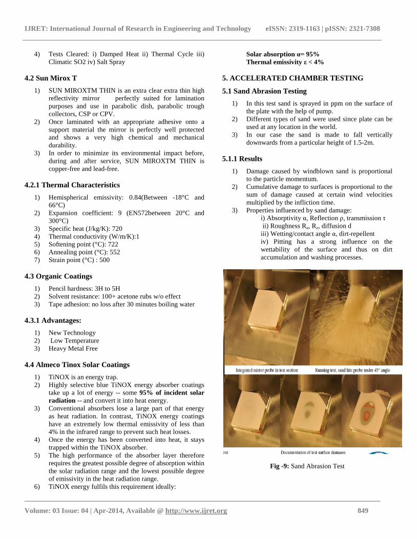
5.1 Sand Abrasion Testing
1) In this test sand is sprayed in ppm on the surface of
the plate with the help of pump.
2) Different types of sand were used since plate can be
used at any location in the world.
3) In our case the sand is made to fall vertically
downwards from a particular height of 1.5-2m.
5.1.1 Results
1) Damage caused by windblown sand is proportional
to the particle momentum.
2) Cumulative damage to surfaces is proportional to the
sum of damage caused at certain wind velocities
multiplied by the infliction time.
3) Properties influenced by sand damage:
i) Absorptivity α, Reflection ρ, transmission τ
ii) Roughness Ra, Rz, diffusion d
iii) Wetting/contact angle α, dirt-repellent
iv) Pitting has a strong influence on the
wettability of the surface and thus on dirt
accumulation and washing processes.
Fig -9: Sand Abrasion Test
IJRET: International Journal of Research in Engineering and Technology eISSN: 2319-1163 | pISSN: 2321-7308
_______________________________________________________________________________________
Volume: 03 Issue: 04 | Apr-2014, Available @ http://www.ijret.org 850
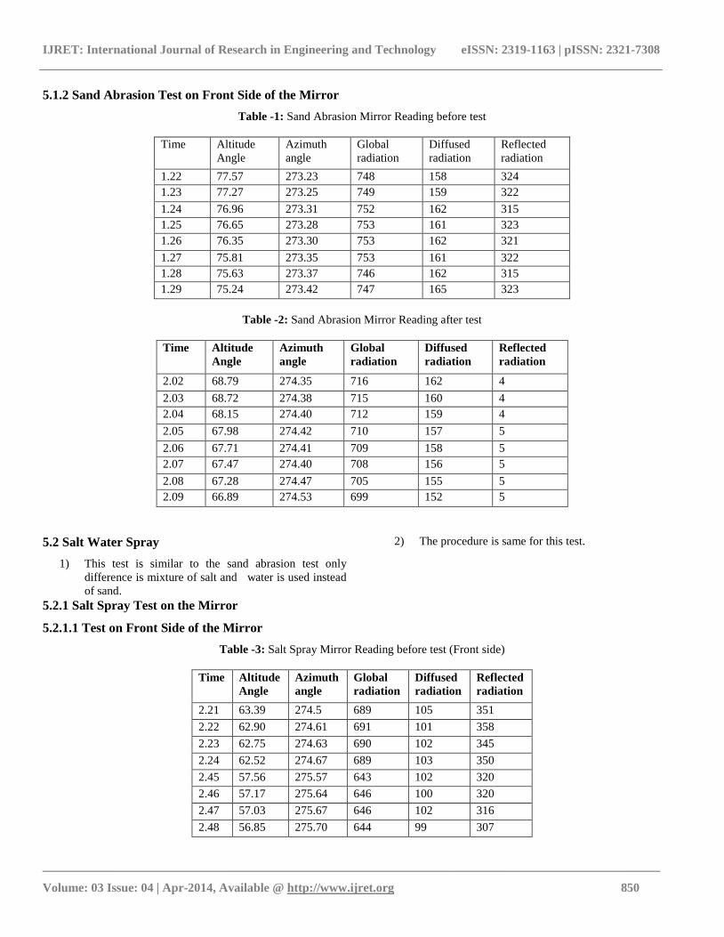
5.1.2 Sand Abrasion Test on Front Side of the Mirror
Table -1: Sand Abrasion Mirror Reading before test
Time Altitude
Angle
Azimuth
angle
Global
radiation
Diffused
radiation
Reflected
radiation
1.22 77.57 273.23 748 158 324
1.23 77.27 273.25 749 159 322
1.24 76.96 273.31 752 162 315
1.25 76.65 273.28 753 161 323
1.26 76.35 273.30 753 162 321
1.27 75.81 273.35 753 161 322
1.28 75.63 273.37 746 162 315
1.29 75.24 273.42 747 165 323
Table -2: Sand Abrasion Mirror Reading after test
Time Altitude
Angle
Azimuth
angle
Global
radiation
Diffused
radiation
Reflected
radiation
2.02 68.79 274.35 716 162 4
2.03 68.72 274.38 715 160 4
2.04 68.15 274.40 712 159 4
2.05 67.98 274.42 710 157 5
2.06 67.71 274.41 709 158 5
2.07 67.47 274.40 708 156 5
2.08 67.28 274.47 705 155 5
2.09 66.89 274.53 699 152 5
5.2 Salt Water Spray
1) This test is similar to the sand abrasion test only
difference is mixture of salt and water is used instead
of sand.
2) The procedure is same for this test.
5.2.1 Salt Spray Test on the Mirror
5.2.1.1 Test on Front Side of the Mirror
Table -3: Salt Spray Mirror Reading before test (Front side)
Time Altitude
Angle
Azimuth
angle
Global
radiation
Diffused
radiation
Reflected
radiation
2.21 63.39 274.5 689 105 351
2.22 62.90 274.61 691 101 358
2.23 62.75 274.63 690 102 345
2.24 62.52 274.67 689 103 350
2.45 57.56 275.57 643 102 320
2.46 57.17 275.64 646 100 320
2.47 57.03 275.67 646 102 316
2.48 56.85 275.70 644 99 307
IJRET: International Journal of Research in Engineering and Technology eISSN: 2319-1163 | pISSN: 2321-7308
_______________________________________________________________________________________
Volume: 03 Issue: 04 | Apr-2014, Available @ http://www.ijret.org 851
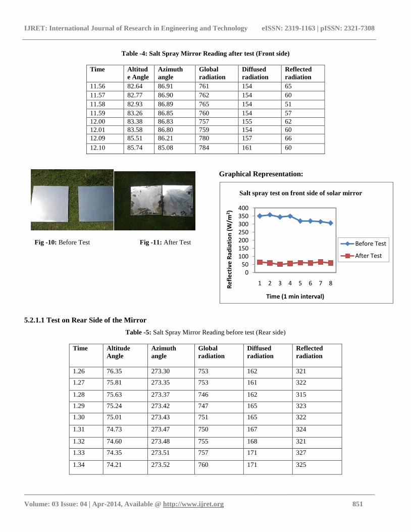
Table -4: Salt Spray Mirror Reading after test (Front side)
Time Altitud
e Angle
Azimuth
angle
Global
radiation
Diffused
radiation
Reflected
radiation
11.56 82.64 86.91 761 154 65
11.57 82.77 86.90 762 154 60
11.58 82.93 86.89 765 154 51
11.59 83.26 86.85 760 154 57
12.00 83.38 86.83 757 155 62
12.01 83.58 86.80 759 154 60
12.09 85.51 86.21 780 157 66
12.10 85.74 85.08 784 161 60
Fig -10: Before Test Fig -11: After Test
Graphical Representation:
5.2.1.1 Test on Rear Side of the Mirror
Table -5: Salt Spray Mirror Reading before test (Rear side)
Time Altitude
Angle
Azimuth
angle
Global
radiation
Diffused
radiation
Reflected
radiation
1.26 76.35 273.30 753 162 321
1.27 75.81 273.35 753 161 322
1.28 75.63 273.37 746 162 315
1.29 75.24 273.42 747 165 323
1.30 75.01 273.43 751 165 322
1.31 74.73 273.47 750 167 324
1.32 74.60 273.48 755 168 321
1.33 74.35 273.51 757 171 327
1.34 74.21 273.52 760 171 325
050
100150200250300350400
1 2 3 4 5 6 7 8
Re
fle
ctiv
e R
adia
tio
n (
W/m
2 )
Time (1 min interval)
Salt spray test on front side of solar mirror
Before Test
After Test
IJRET: International Journal of Research in Engineering and Technology eISSN: 2319-1163 | pISSN: 2321-7308
_______________________________________________________________________________________
Volume: 03 Issue: 04 | Apr-2014, Available @ http://www.ijret.org 852
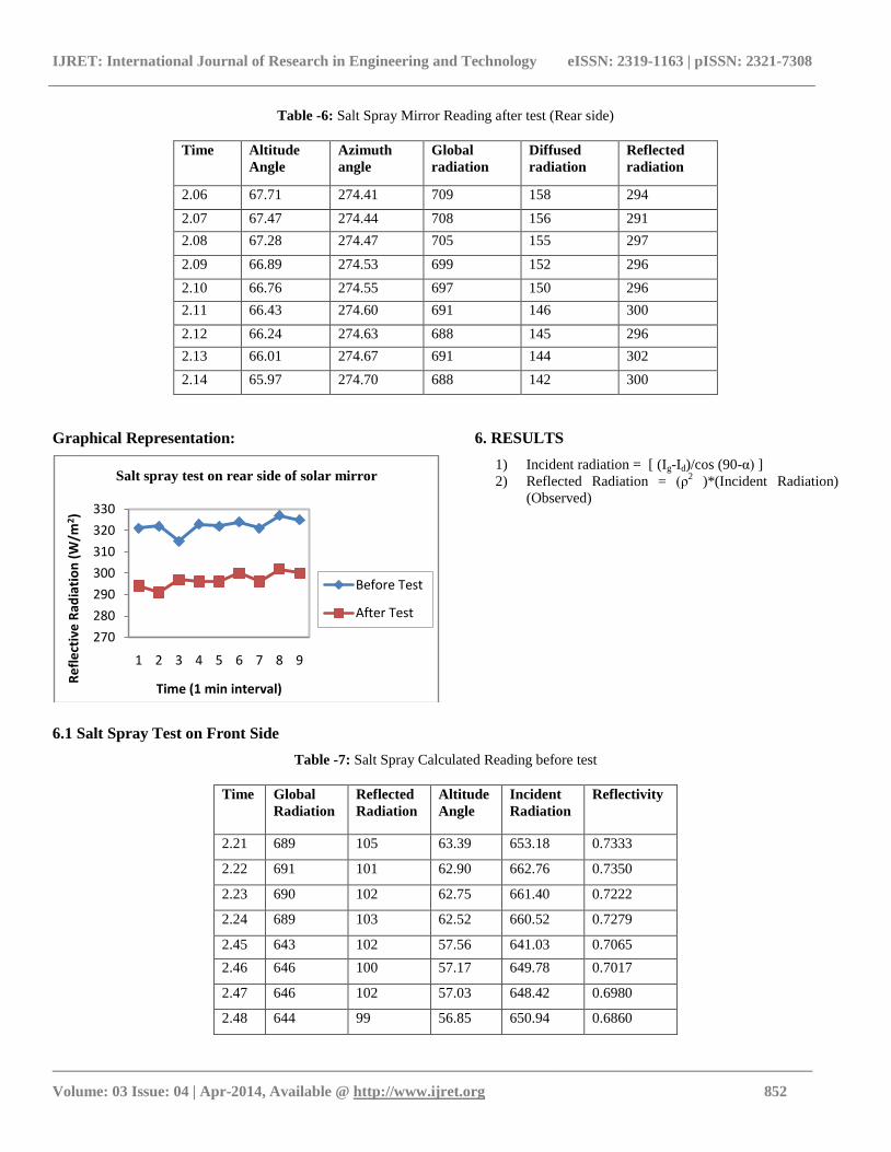
Table -6: Salt Spray Mirror Reading after test (Rear side)
Time Altitude
Angle
Azimuth
angle
Global
radiation
Diffused
radiation
Reflected
radiation
2.06 67.71 274.41 709 158 294
2.07 67.47 274.44 708 156 291
2.08 67.28 274.47 705 155 297
2.09 66.89 274.53 699 152 296
2.10 66.76 274.55 697 150 296
2.11 66.43 274.60 691 146 300
2.12 66.24 274.63 688 145 296
2.13 66.01 274.67 691 144 302
2.14 65.97 274.70 688 142 300
Graphical Representation:
6. RESULTS
1) Incident radiation = [ (Ig-Id)/cos (90-α) ]
2) Reflected Radiation = (ρ2 )*(Incident Radiation)
(Observed)
6.1 Salt Spray Test on Front Side
Table -7: Salt Spray Calculated Reading before test
Time Global
Radiation
Reflected
Radiation
Altitude
Angle
Incident
Radiation
Reflectivity
2.21 689 105 63.39 653.18 0.7333
2.22 691 101 62.90 662.76 0.7350
2.23 690 102 62.75 661.40 0.7222
2.24 689 103 62.52 660.52 0.7279
2.45 643 102 57.56 641.03 0.7065
2.46 646 100 57.17 649.78 0.7017
2.47 646 102 57.03 648.42 0.6980
2.48 644 99 56.85 650.94 0.6860
270
280
290
300
310
320
330
1 2 3 4 5 6 7 8 9
Re
fle
ctiv
e R
adia
tio
n (
W/m
2)
Time (1 min interval)
Salt spray test on rear side of solar mirror
Before Test
After Test
IJRET: International Journal of Research in Engineering and Technology eISSN: 2319-1163 | pISSN: 2321-7308
_______________________________________________________________________________________
Volume: 03 Issue: 04 | Apr-2014, Available @ http://www.ijret.org 853
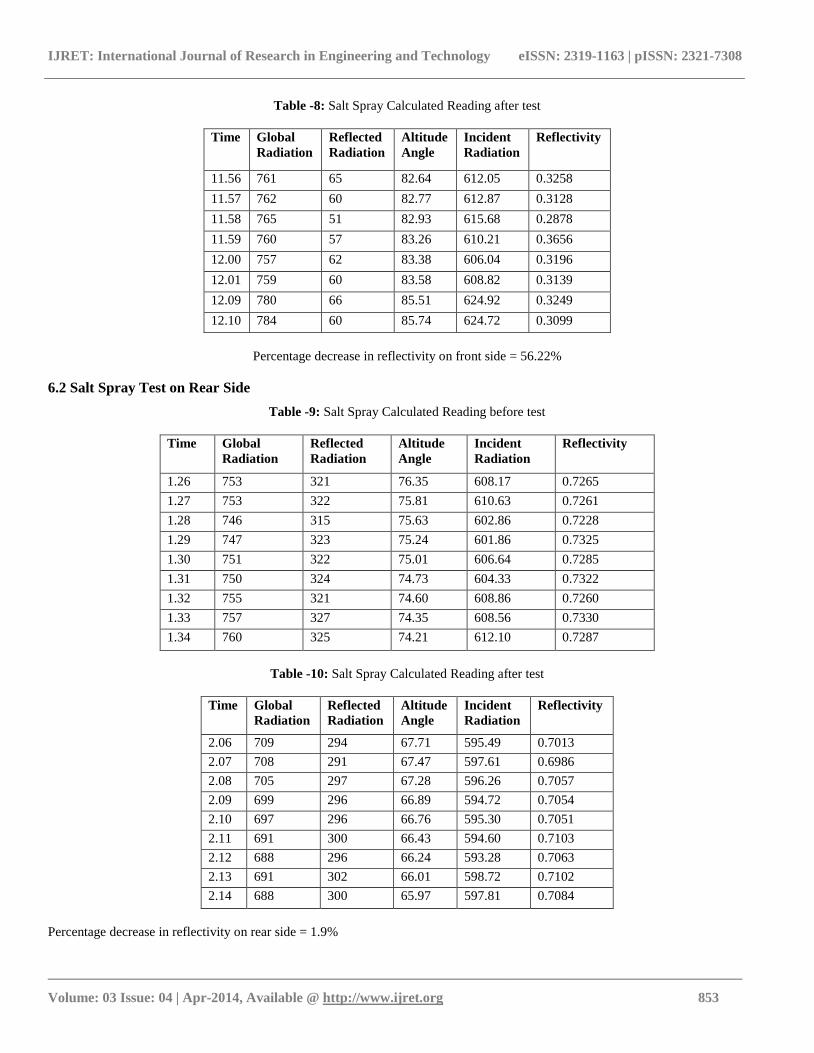
Table -8: Salt Spray Calculated Reading after test
Time Global
Radiation
Reflected
Radiation
Altitude
Angle
Incident
Radiation
Reflectivity
11.56 761 65 82.64 612.05 0.3258
11.57 762 60 82.77 612.87 0.3128
11.58 765 51 82.93 615.68 0.2878
11.59 760 57 83.26 610.21 0.3656
12.00 757 62 83.38 606.04 0.3196
12.01 759 60 83.58 608.82 0.3139
12.09 780 66 85.51 624.92 0.3249
12.10 784 60 85.74 624.72 0.3099
Percentage decrease in reflectivity on front side = 56.22%
6.2 Salt Spray Test on Rear Side
Table -9: Salt Spray Calculated Reading before test
Time Global
Radiation
Reflected
Radiation
Altitude
Angle
Incident
Radiation
Reflectivity
1.26 753 321 76.35 608.17 0.7265
1.27 753 322 75.81 610.63 0.7261
1.28 746 315 75.63 602.86 0.7228
1.29 747 323 75.24 601.86 0.7325
1.30 751 322 75.01 606.64 0.7285
1.31 750 324 74.73 604.33 0.7322
1.32 755 321 74.60 608.86 0.7260
1.33 757 327 74.35 608.56 0.7330
1.34 760 325 74.21 612.10 0.7287
Table -10: Salt Spray Calculated Reading after test
Time Global
Radiation
Reflected
Radiation
Altitude
Angle
Incident
Radiation
Reflectivity
2.06 709 294 67.71 595.49 0.7013
2.07 708 291 67.47 597.61 0.6986
2.08 705 297 67.28 596.26 0.7057
2.09 699 296 66.89 594.72 0.7054
2.10 697 296 66.76 595.30 0.7051
2.11 691 300 66.43 594.60 0.7103
2.12 688 296 66.24 593.28 0.7063
2.13 691 302 66.01 598.72 0.7102
2.14 688 300 65.97 597.81 0.7084
Percentage decrease in reflectivity on rear side = 1.9%
IJRET: International Journal of Research in Engineering and Technology eISSN: 2319-1163 | pISSN: 2321-7308
_______________________________________________________________________________________
Volume: 03 Issue: 04 | Apr-2014, Available @ http://www.ijret.org 854
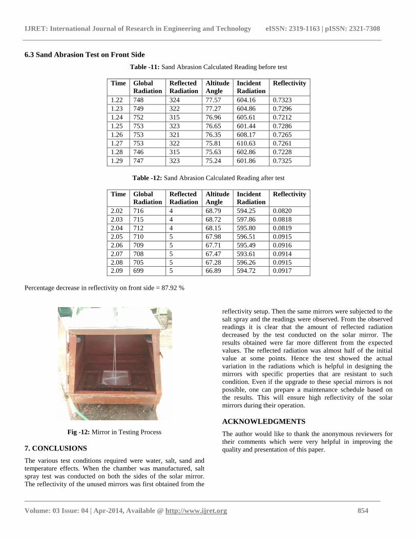
6.3 Sand Abrasion Test on Front Side
Table -11: Sand Abrasion Calculated Reading before test
Time Global
Radiation
Reflected
Radiation
Altitude
Angle
Incident
Radiation
Reflectivity
1.22 748 324 77.57 604.16 0.7323
1.23 749 322 77.27 604.86 0.7296
1.24 752 315 76.96 605.61 0.7212
1.25 753 323 76.65 601.44 0.7286
1.26 753 321 76.35 608.17 0.7265
1.27 753 322 75.81 610.63 0.7261
1.28 746 315 75.63 602.86 0.7228
1.29 747 323 75.24 601.86 0.7325
Table -12: Sand Abrasion Calculated Reading after test
Time Global
Radiation
Reflected
Radiation
Altitude
Angle
Incident
Radiation
Reflectivity
2.02 716 4 68.79 594.25 0.0820
2.03 715 4 68.72 597.86 0.0818
2.04 712 4 68.15 595.80 0.0819
2.05 710 5 67.98 596.51 0.0915
2.06 709 5 67.71 595.49 0.0916
2.07 708 5 67.47 593.61 0.0914
2.08 705 5 67.28 596.26 0.0915
2.09 699 5 66.89 594.72 0.0917
Percentage decrease in reflectivity on front side = 87.92 %
Fig -12: Mirror in Testing Process
7. CONCLUSIONS
The various test conditions required were water, salt, sand and
temperature effects. When the chamber was manufactured, salt
spray test was conducted on both the sides of the solar mirror.
The reflectivity of the unused mirrors was first obtained from the
reflectivity setup. Then the same mirrors were subjected to the
salt spray and the readings were observed. From the observed
readings it is clear that the amount of reflected radiation
decreased by the test conducted on the solar mirror. The
results obtained were far more different from the expected
values. The reflected radiation was almost half of the initial
value at some points. Hence the test showed the actual
variation in the radiations which is helpful in designing the
mirrors with specific properties that are resistant to such
condition. Even if the upgrade to these special mirrors is not
possible, one can prepare a maintenance schedule based on
the results. This will ensure high reflectivity of the solar
mirrors during their operation.
ACKNOWLEDGMENTS
The author would like to thank the anonymous reviewers for
their comments which were very helpful in improving the
quality and presentation of this paper.
IJRET: International Journal of Research in Engineering and Technology eISSN: 2319-1163 | pISSN: 2321-7308
_______________________________________________________________________________________
Volume: 03 Issue: 04 | Apr-2014, Available @ http://www.ijret.org 855
REFERENCES
[1] Daly, J.C., 1979. Solar concentrator flux distributions
using backward ray tracing. Applied Optics 18 (15),
2696–2699.
[2] Hutchinson, T.P., Lai, C.D., 1991. The Engineering
Statistician’s Guide to continuous Bivariate Distributions.
Rumsby Scientific Publishing, pp. 280.
[3] Jeter, S.M., 1986. The distribution of concentrated solar
radiation in paraboloidal collectors. Journal of Solar
Energy Engineering 108, 219–225.
[4] Johnston, G., 1995. On the analysis of surface error
distributions on concentrated solar collectors. Journal of
Solar Energy Engineering 117 (4), 294–296.
[5] Ronnen Levinson, Hashem Akbari, and Paul Berdahl.
Measuring solar reflectance Part I: defining a metric that
accurately predicts solar heat gain.
[6] Charlie Moore. The solar spectrum reectometer (SSR).
Technical Note 79-16, Devices & Services, Dallas, TX,
1979.
[7] http://www.sciencedirect.com/science/article/pii/0038092
X59900039
[8] C.F. Chen, C.H. Lin, H.T.Jan & Y.L. Yang, “ Design of a
Solar Concentrator Combining Paraboloidal and
Hyperbolic Mirrors Using Ray Tracing Method”, Optics
Communication, 282: 360-366, 2009.
[9] V.B. Omubo-Pepple, C. Israel-Cookey and G.I.
Alaminokuma, “ Effects of Temperature, Solar Flux and
Relative Humidity on the Efficient Conversion of Solar
Energy to Electricity”, European Journal of Scientific
Research, 35(2): 173-180, 2009.
Related Documents


![PARABOLIC TROUGH PROJECT IN CERRO PRIETO, …...2014/07/13 · absorber pipe of the solar concentrators using direct steam generation DGS [9] to generate steam. The first alternative](https://static.cupdf.com/doc/110x72/5f542433f92aa850936c3dda/parabolic-trough-project-in-cerro-prieto-20140713-absorber-pipe-of-the.jpg)


