Characterization of Perpendicular Write Heads using Inductance Measurements Alexander Taratorin 3000 Olcott St. Santa Clara, CA 95054 Tel: 408 653-0300 E-Mail: [email protected] Web: www.us-isi.com

Characterization of Perpendicular Write Heads using Inductance Measurements Alexander Taratorin 3000 Olcott St. Santa Clara, CA 95054 Tel: 408 653-0300.
Dec 15, 2015
Welcome message from author
This document is posted to help you gain knowledge. Please leave a comment to let me know what you think about it! Share it to your friends and learn new things together.
Transcript
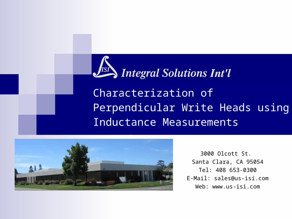
Characterization of Perpendicular Write Heads using Inductance Measurements
Alexander Taratorin
3000 Olcott St.
Santa Clara, CA 95054
Tel: 408 653-0300
E-Mail: [email protected]
Web: www.us-isi.com

Need for Production Testing of Write Heads
Significant variations of write head performance during dynamic testing
Early production screening for wafer, bar or slider levels is currently not available
New diagnostic tool: High resolution, fast relative inductance measurement
Changes of relative inductance in external magnetic field and with DC write current
Arbitrary Magnetic Field Orientation

Blazer-X6B Advanced Test Platform
QST-2002Low & High Freq QST Measurement
QPS-1050QST & Transverse Magnet Power Supply
QMS-1050Longitudinal Magnet Power Supply
RIA-2008Relative Inductance Analyzer
Computer

HGA Level System Arrangement
QST-2002Low & High Freq QST Measurement
QPS-1050QST & Transverse Magnet Power Supply
QMS-1050Longitudinal Magnet Power Supply
RIA-2008Relative Inductance Analyzer
Computer

Perpendicular Write Head Geometry, Cross-section side view
Return pole
Trailing pole
Upper yoke
Main pole
Trailing shield
Recording pole
Coil
Main pole Recession
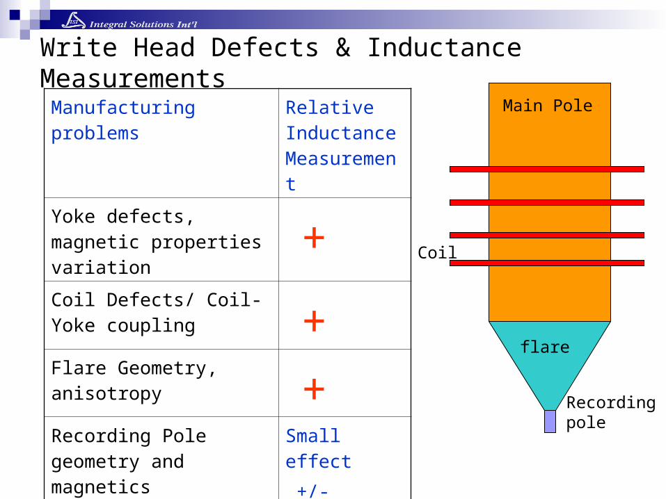
Write Head Defects & Inductance Measurements
Manufacturing problems Relative Inductance Measurement
Yoke defects, magnetic properties variation +Coil Defects/ Coil-Yoke coupling +Flare Geometry, anisotropy +Recording Pole geometry and magnetics
Small effect
+/-
flare
Recordingpole
Main Pole
Coil

LSATI – Inductance Saturation using DC write current
-60 -40 -20 0 20 40 600.5
1
1.5
2
Current, mA
Rel
ativ
e In
duct
ance
Flux closure in Air:Mainly through the trailing shield
ISAT - Inductance saturation vs. write current L(I) – combined influence of yoke properties, domains, head efficiency and trailing shield spacing
-60 -40 -20 0 20 40 600.6
0.8
1
1.2
1.4
1.6
1.8
2
Current, mA
Rela
tive I
nducta
nce
More efficient head
Less efficient head
Domainproblem

Inductance saturation in perpendicular field depends on:
- Yoke properties (anisotropy, defects and domains)- Recording pole/main pole throat height and recession- Changes of L(H) slope dependence used for diagnostics - Critical Field (main pole saturation) varies for different yoke length and materialVariation of critical field for the same head type correlates with head efficiency (saturation, OW, magnetic track width)
H
LSATF - Inductance Saturation in Magnetic Field
Patents Pending
0 500 1000 1500 2000 25000
0.2
0.4
0.6
0.8
1
1.2
1.4
1.6
1.8
2
Field, OeR
elat
ive
Indu
ctan
ce
Flare Saturation
Main poleSaturation(head to headpermeabilityvariation)
Yoke defect

LSATF - Inductance Saturation in Magnetic Field
0 500 1000 1500 2000 25000
0.2
0.4
0.6
0.8
1
1.2
1.4
1.6
1.8
2
Field, Oe
Rel
ativ
e In
duct
ance
Yoke Defects and asymmetry can be detected using LSATF test
Different head designs
Longer yokeHigher inductance
Shorter yoke,Lower inductance
-2500 -2000 -1500 -1000 -500 0 500 1000 1500 2000 25000
0.2
0.4
0.6
0.8
1
1.2
1.4
1.6
1.8
Field, Oe
Rela
tive I
nducta
nce
Head Defect (Asymmetry)
StrongSaturationAsymmetry
Normalhead
Patents Pending

LSATF - Inductance Saturation in Magnetic Field
0 500 1000 1500 2000 25000
0.2
0.4
0.6
0.8
1
1.2
1.4
1.6
1.8
Field, Oe
Rel
ativ
e In
duct
ance
Combine Magnetic Field & Write CurrentShift of saturation kinks correlates with head efficiency and recording performance
Current opposite to field
Current & Field Same direction
Current = 0
Patents Pending

0 5 10 15 20 25 30 35 40 450.2
0.3
0.4
0.5
0.6
0.7
0.8
0.9
1
Write Current, mA
Rela
tive I
nducta
nce
Hext
coil
Flux generated by write current is opposite to Hext in the main pole – decreasing main pole saturation Slope dL(I)/dI determines coil to yoke coupling – amount of flux, generated in the main pole per 1 ma of write current - CYCET correlates with head efficiency/overwrite (if pole definition is nominal)
Efficient head
Less efficient heads
CYCET –Coil-Yoke Coupling Efficiency Test
Patents Pending

Compare inductance saturation in perpendicular/cross-track magnetic field
Differences in saturation – signature of defects
Hext
YDT – Yoke Defect Test
flare
Recordingpole
Main Pole
Hext
0 500 1000 1500 2000 25000
0.2
0.4
0.6
0.8
1
1.2
1.4
1.6
1.8
2
Field, Oe
Rel
ativ
e In
duct
ance
0 200 400 600 800 1000 1200 1400 1600 1800 20000
0.2
0.4
0.6
0.8
1
1.2
1.4
1.6
1.8
Field, Oe
Rel
ativ
e In
duct
ance
Normal head
Yoke defect signature
Cross-track
Cross-track
perpendicular
perpendicular
Hext0.8 1 1.2 1.4 1.6 1.8 2
x 108
-1
-0.5
0
0.5
1
1.5
x 10-10
Frequency, MHz
Indu
ctan
ce,
nH
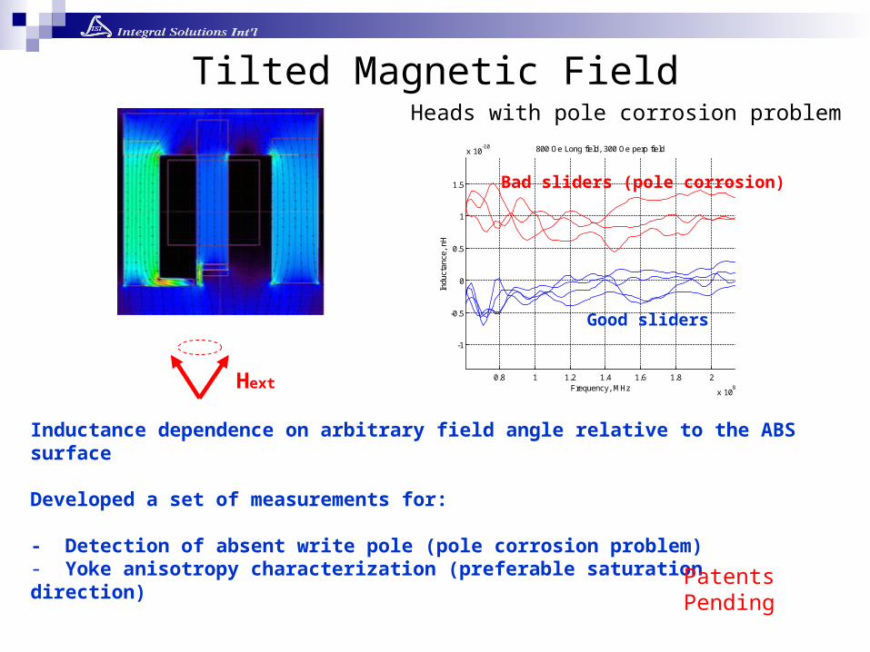
800 Oe Long field, 300 Oe perp field
Good sliders
Bad sliders (pole corrosion)
Inductance dependence on arbitrary field angle relative to the ABS surface
Developed a set of measurements for:
- Detection of absent write pole (pole corrosion problem)- Yoke anisotropy characterization (preferable saturation direction)
Tilted Magnetic Field
Patents Pending
Heads with pole corrosion problem
-80 -60 -40 -20 0 20 40 60 800.65
0.7
0.75
0.8
0.85
0.9
0.95
1
Field Angle, degreesN
orm
aliz
ed R
ela
tive I
nducta
nce
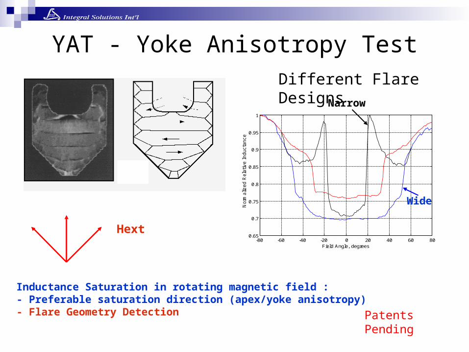
YAT - Yoke Anisotropy Test
Hext
Inductance Saturation in rotating magnetic field :- Preferable saturation direction (apex/yoke anisotropy) - Flare Geometry Detection
Different Flare DesignsNarrow
Wide
Patents Pending

-80 -60 -40 -20 0 20 40 60 800.65
0.7
0.75
0.8
0.85
0.9
0.95
1
Field Angle, degrees
Norm
aliz
ed R
ela
tive I
nducta
nce
YAT - Yoke Anisotropy Test
-40 -30 -20 -10 0 10 20 30 400.65
0.7
0.75
0.8
0.85
0.9
0.95
1
1.05
1.1
Field Angle, degrees
Norm
aliz
ed R
ela
tive I
nducta
nce
Changes of yoke anisotropy Flare shape variations
Detection of yoke/apex anisotropy (results in asymmetrical writing)Flare shape variation for production control
isotropic
anisotropic
Angle 1
Angle 2
Patents Pending

0 10 20 30 40 50 60 70 80 90 1001.595
1.6
1.605
Trial #
Rela
tive I
nducta
nce
0 10 20 30 40 50 60 70 80 90 100-5
0
5x 10
-3
Trial #
Delta I
nducta
nce
Hext1
Hext2Head with hystersis
•Yoke domains cause variability of head switching and distort recorded transitions• Domains result in changes of inductance after external Field and current excitation• Detectable using developed inductance measurement in cycles of external field and write current
Domain-free yoke
Yoke Hysteresis & Domains: YHDFT & YHDIT
Patents Pending

Inductance saturation vs write current and external field
Coil to yoke coupling
Yoke anisotropy
Determination of yoke defects
Selecting hysteretic/domain write heads
Flare Geometry
Pole absence due to corrosion
Write Head Measurements Summary
Related Documents