15. LS-DYNA Forum 2018, Bamberg © 2018 Copyright by DYNAmore GmbH Characterization of metal sheet forming by free bending with LS-DYNA M.Sc. Pascal Froitzheim 1 , Dr.-Ing. Normen Fuchs 1 , Prof. Dr.-Ing. Wilko Flügge 1,2 , Prof. Dr.-Ing. habil. Christoph Woernle 3 1 Fraunhofer Research Institution for Large Structures in Production Engineering IGP 2 University of Rostock, Faculty of Mechanical Engineering and Marine Technology, Chair of Production Technology 3 University of Rostock, Faculty of Mechanical Engineering and Marine Technology, Chair of Technical Mechanics / Dynamics 1 Application of metal sheet forming by free bending The production of multidimensional curved metal sheets with large thicknesses and dimensions is based on a non-thermal plastic forming process by free bending. This process is used for application cases in ship building, the structural-facing sector, the aviation industry as well as the wind turbine industry. At present, this forming process is manually controlled by a system operator due to small production batches and a high product variety [1]. Within the forming process the metal sheet is handled above the forming tool by a crane system con- sisting of four separately controllable chain hoists, which are mounted on crane trolleys. The forming is conducted by a stepwise sword insertion (see Fig.1). Beside the manual control of the crane system, the forming strategy especially the service point selection as well as the choice of sword engagement depth is exclusively based on system operator experience. Fig.1 Forming press for non-thermal plastic metal sheet forming To monitor the deformation behavior of the curved metal sheets only the so called “light gap method” with cork templates is at hand for a rough quality assessment within the production cycle and after- wards. Hereby the cork templates are representing the panel cross sections. The continuous control of the metal sheet shape between the process steps is basis for the subjective definition of the forming strategy for the subsequent steps. Because of human-induced fluctuations of production accuracy and the dependency on the operator’s experience an efficient and reproducible process is difficult to achieve. Therefore today’s efforts are to automate the press and crane system in respect of the forming process. This approach consists of the following aspects: 1. Replacement of the manually defined forming strategy by a theoretical process control approach. 2. Replacement of the subjective light gap method by an optical measurement system. 3. Anti-sway handling of the metal sheet above the forming tool by means of an intelligent crane con- trol (presented in [2, 3]). For forming press and crane system automation a profound understanding of non-thermal plastic sheet metal forming is fundamental. To derivate a process scheduling approach with real-time capabil- ity it is necessary to characterize the deformation behavior by means of a sensitivity analysis. A char- acterization purely based on experimental tests is a considerable effort due to plate dimensions and sample size. Therefore a numerical simulation model of the forming process is developed and validat- ed. During the model setup, the technical issues of sheet metal and tool modeling as well as the im- plementation of a suitable routine for a parameterized model setup of multi-step forming has to be

Welcome message from author
This document is posted to help you gain knowledge. Please leave a comment to let me know what you think about it! Share it to your friends and learn new things together.
Transcript
15. LS-DYNA Forum 2018, Bamberg
© 2018 Copyright by DYNAmore GmbH
Characterization of metal sheet forming by free bending with LS-DYNA
M.Sc. Pascal Froitzheim1, Dr.-Ing. Normen Fuchs1, Prof. Dr.-Ing. Wilko Flügge1,2, Prof. Dr.-Ing. habil. Christoph Woernle3
1 Fraunhofer Research Institution for Large Structures in Production Engineering IGP 2 University of Rostock, Faculty of Mechanical Engineering and Marine Technology, Chair of Production Technology
3 University of Rostock, Faculty of Mechanical Engineering and Marine Technology, Chair of Technical Mechanics / Dynamics
1 Application of metal sheet forming by free bending
The production of multidimensional curved metal sheets with large thicknesses and dimensions is based on a non-thermal plastic forming process by free bending. This process is used for application cases in ship building, the structural-facing sector, the aviation industry as well as the wind turbine industry. At present, this forming process is manually controlled by a system operator due to small production batches and a high product variety [1].
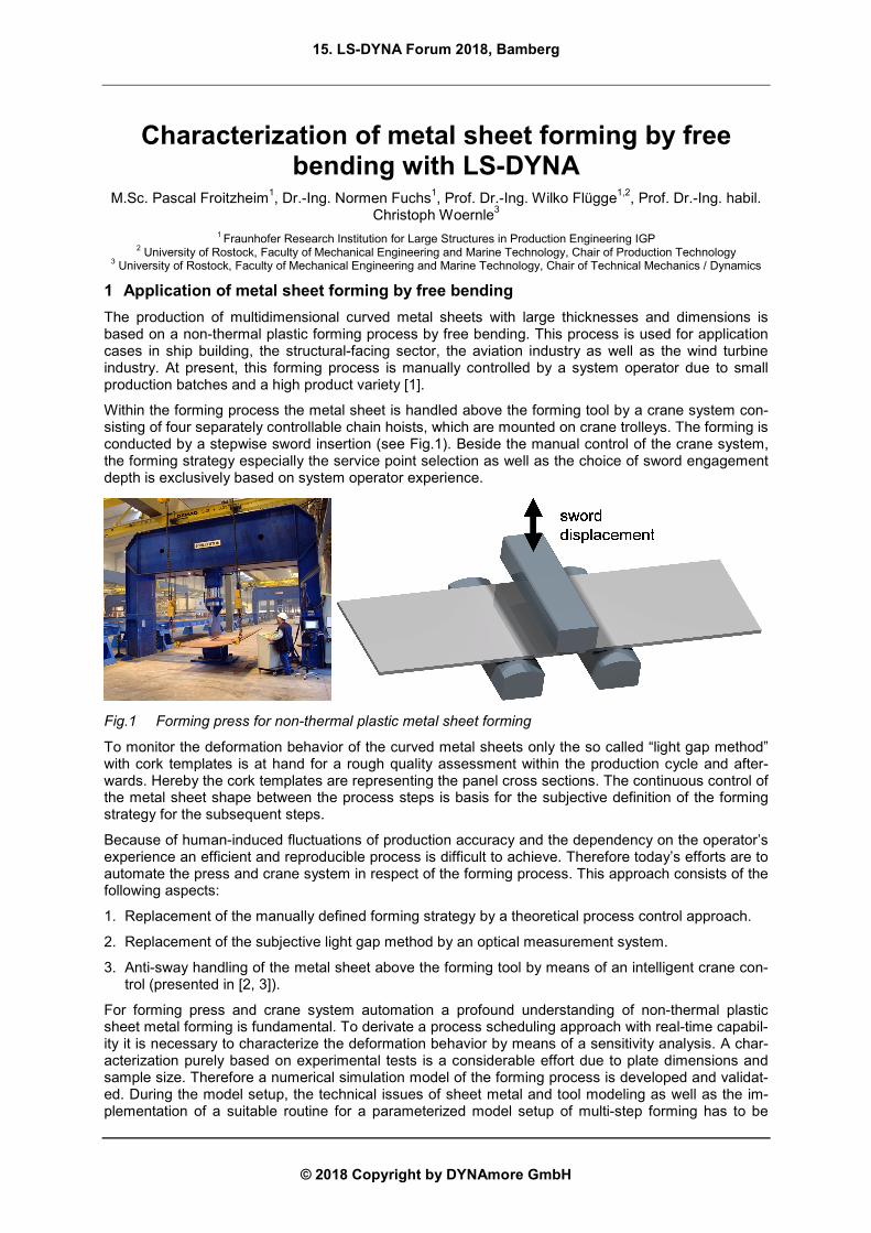
Within the forming process the metal sheet is handled above the forming tool by a crane system con-sisting of four separately controllable chain hoists, which are mounted on crane trolleys. The forming is conducted by a stepwise sword insertion (see Fig.1). Beside the manual control of the crane system, the forming strategy especially the service point selection as well as the choice of sword engagement depth is exclusively based on system operator experience.
Fig.1 Forming press for non-thermal plastic metal sheet forming
To monitor the deformation behavior of the curved metal sheets only the so called “light gap method” with cork templates is at hand for a rough quality assessment within the production cycle and after-wards. Hereby the cork templates are representing the panel cross sections. The continuous control of the metal sheet shape between the process steps is basis for the subjective definition of the forming strategy for the subsequent steps.
Because of human-induced fluctuations of production accuracy and the dependency on the operator’s experience an efficient and reproducible process is difficult to achieve. Therefore today’s efforts are to automate the press and crane system in respect of the forming process. This approach consists of the following aspects:
1. Replacement of the manually defined forming strategy by a theoretical process control approach.
2. Replacement of the subjective light gap method by an optical measurement system.
3. Anti-sway handling of the metal sheet above the forming tool by means of an intelligent crane con-trol (presented in [2, 3]).
For forming press and crane system automation a profound understanding of non-thermal plastic sheet metal forming is fundamental. To derivate a process scheduling approach with real-time capabil-ity it is necessary to characterize the deformation behavior by means of a sensitivity analysis. A char-acterization purely based on experimental tests is a considerable effort due to plate dimensions and sample size. Therefore a numerical simulation model of the forming process is developed and validat-ed. During the model setup, the technical issues of sheet metal and tool modeling as well as the im-plementation of a suitable routine for a parameterized model setup of multi-step forming has to be
15. LS-DYNA Forum 2018, Bamberg
© 2018 Copyright by DYNAmore GmbH
considered. Therefore this article presents the essential aspects of the numerical model setup, the model validation by experimental test results of a scaled setup as well as the results of a numerical sensitivity analysis study.
2 State of the art in numerical metal sheet forming simulation
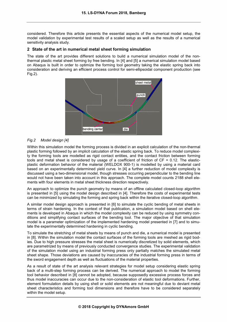
The state of the art provides different solutions to build a numerical simulation model of the non-thermal plastic metal sheet forming by free bending. In [4] and [5] a numerical simulation model based on Abaqus is built in order to optimize the forming tool geometry taking the elastic spring back into consideration and deriving an efficient process control for semi-ellipsoidal component production (see Fig.2).
Fig.2 Model design [4]
Within this simulation model the forming process is divided in an explicit calculation of the non-thermal plastic forming followed by an implicit calculation of the elastic spring back. To reduce model complexi-ty the forming tools are modelled as rigid contact entities, and the contact friction between forming tools and metal sheet is considered by usage of a coefficient of friction of CF = 0.12. The elastic-plastic deformation behavior of the material (WELDOX 900-1) is modelled by using a material card based on an experimentally determined yield curve. In [4] a further reduction of model complexity is discussed using a two-dimensional model, though stresses occurring perpendicular to the bending line would not have been taken into account in this approach. The complete model counts 2188 shell ele-ments with four elements in metal sheet thickness direction respectively.
An approach to optimize the punch geometry by means of an offline calculated closed-loop algorithm is presented in [5] using the model design described in [4]. Therefore the costs of experimental tests can be minimized by simulating the forming and spring back within the iterative closed-loop algorithm.
A similar model design approach is presented in [6] to simulate the cyclic bending of metal sheets in terms of strain hardening. In the context of that publication, a simulation model based on shell ele-ments is developed in Abaqus in which the model complexity can be reduced by using symmetry con-ditions and simplifying contact surfaces of the bending tool. The major objective of that simulation model is a parameter optimization of the implemented hardening model presented in [7] and to simu-late the experimentally determined hardening in cyclic bending.
To simulate the stretching of metal sheets by means of punch and die, a numerical model is presented in [8]. Within the simulation model the contact surfaces of the forming tools are meshed as rigid bod-ies. Due to high pressure stresses the metal sheet is numerically discretized by solid elements, which are parametrized by means of previously conducted convergence studies. The experimental validation of the simulation model using an industrial forming press only partially matches the simulated metal sheet shape. Those deviations are caused by inaccuracies of the industrial forming press in terms of the sword engagement depth as well as fluctuations of the material properties.
As a result of state of the art analysis relevant strategies for model setup considering elastic spring back of a multi-step forming process can be derived. The numerical approach to model the forming tool behavior described in [8] cannot be adopted, because supposedly excessive process forces and thus model inaccuracies can occur due to the non-consideration of elastic tool deformations. Further, element formulation details by using shell or solid elements are not meaningful due to deviant metal sheet characteristics and forming tool dimensions and therefore have to be considered separately within the model setup.
15. LS-DYNA Forum 2018, Bamberg
© 2018 Copyright by DYNAmore GmbH
3 Model setup in LS-DYNA
In the following section, the relevant model properties of the numerical simulation model in LS-DYNA are explained.
3.1 Tool modelling
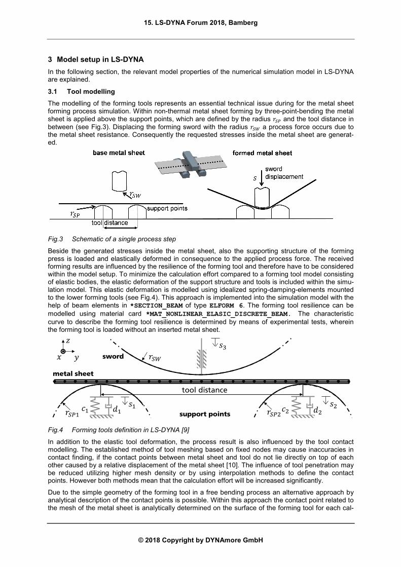
The modelling of the forming tools represents an essential technical issue during for the metal sheet forming process simulation. Within non-thermal metal sheet forming by three-point-bending the metal sheet is applied above the support points, which are defined by the radius ��� and the tool distance in between (see Fig.3). Displacing the forming sword with the radius ��� a process force occurs due to the metal sheet resistance. Consequently the requested stresses inside the metal sheet are generat-ed.
Fig.3 Schematic of a single process step
Beside the generated stresses inside the metal sheet, also the supporting structure of the forming press is loaded and elastically deformed in consequence to the applied process force. The received forming results are influenced by the resilience of the forming tool and therefore have to be considered within the model setup. To minimize the calculation effort compared to a forming tool model consisting of elastic bodies, the elastic deformation of the support structure and tools is included within the simu-lation model. This elastic deformation is modelled using idealized spring-damping-elements mounted to the lower forming tools (see Fig.4). This approach is implemented into the simulation model with the help of beam elements in *SECTION_BEAM of type ELFORM 6. The forming tool resilience can be modelled using material card *MAT_NONLINEAR_ELASIC_DISCRETE_BEAM. The characteristic curve to describe the forming tool resilience is determined by means of experimental tests, wherein the forming tool is loaded without an inserted metal sheet.
Fig.4 Forming tools definition in LS-DYNA [9]
In addition to the elastic tool deformation, the process result is also influenced by the tool contact modelling. The established method of tool meshing based on fixed nodes may cause inaccuracies in contact finding, if the contact points between metal sheet and tool do not lie directly on top of each other caused by a relative displacement of the metal sheet [10]. The influence of tool penetration may be reduced utilizing higher mesh density or by using interpolation methods to define the contact points. However both methods mean that the calculation effort will be increased significantly.
Due to the simple geometry of the forming tool in a free bending process an alternative approach by analytical description of the contact points is possible. Within this approach the contact point related to the mesh of the metal sheet is analytically determined on the surface of the forming tool for each cal-
metal sheet
support points
sword
tool distance
15. LS-DYNA Forum 2018, Bamberg
© 2018 Copyright by DYNAmore GmbH
culation step. As a result the effort of calculation is minimized, and the penetration between forming tool and metal sheet is avoided.
This approach is implemented within the LS-DYNA model using type *PART_INERTIA rigid bodies
within the material card *MAT_RIGID(020) to model the dynamic properties of the forming tools. The previously included beam elements for elastic tool deformation description are mounted to each rigid body using additionally defined contact points (*CONSTRAINED_EXTRA_NODES_NODE). To ana-lytically describe the forming tools the contact surface is defined as *CONTACT_ENTITY represented by a cylinder (GEOTYP 3) with the specific tool radius. Additionally the position of each rigid body with-in the global coordinate system defines the tool distance. The friction conditions of the contact surfac-es are modeled using the friction model of Coulomb (CF).
To model the destined engagement depth the forming sword displacement is implemented within LS-DYNA using a rigid-body motion (*BOUNDARY_PRESCRIBED_MOTION_RIGID) restricting movement to a single degree of freedom.
3.2 Metal sheet modelling
Based on the model approach for the forming tool, the material and deformation behaviour of the met-al sheet has to be suitable modelled within the simulation. Therefore material cards of three steel types with high relevance in industrial application are parameterized based an experimental material characterization. The required load curves are determined by standardized tensile tests assuming that an idealized bending stress causes only one-directional stresses inside the metal sheet [11]. To ex-trapolate the load curves for higher plastic strains an exponential approach by HOCKETT-SHERBY is used [12]. The determined material properties and load curves are used to parameterize the linear plastic material card *MAT_PIECEWISE_LINEAR_PLASTICITY(024).
To define a suitable element formulation for the metal sheet a preliminary study is carried out based on the above mentioned material cards comparing solid and shell element types. This study is based on the well-known effect that solid element usage provides high model accuracy, but does result in a significantly higher calculation effort and also in longer calculation times. On the contrary for small metal sheet thicknesses in combination with low plastic strains, fully integrated shell elements provide sufficiently high model accuracy with comparatively short calculation times and have therefore estab-lished themselves [13].
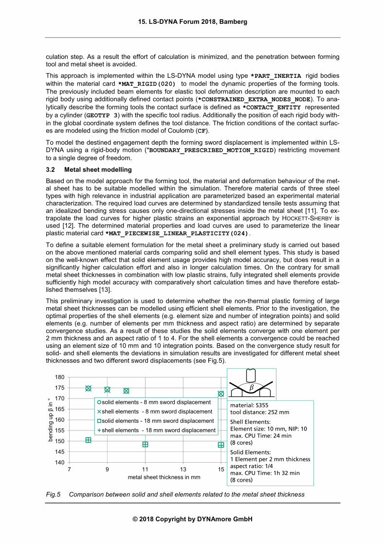
This preliminary investigation is used to determine whether the non-thermal plastic forming of large metal sheet thicknesses can be modelled using efficient shell elements. Prior to the investigation, the optimal properties of the shell elements (e.g. element size and number of integration points) and solid elements (e.g. number of elements per mm thickness and aspect ratio) are determined by separate convergence studies. As a result of these studies the solid elements converge with one element per 2 mm thickness and an aspect ratio of 1 to 4. For the shell elements a convergence could be reached using an element size of 10 mm and 10 integration points. Based on the convergence study result for solid- and shell elements the deviations in simulation results are investigated for different metal sheet thicknesses and two different sword displacements (see Fig.5).
Fig.5 Comparison between solid and shell elements related to the metal sheet thickness
140
145
150
155
160
165
170
175
180
7 9 11 13 15 17
bendin
gup
βin
°
metal sheet thickness in mm
solid elements - 8 mm sword displacement
shell elements - 8 mm sword displacement
solid elements - 18 mm sword displacement
shell elements - 18 mm sword displacement
material: S355tool distance: 252 mm
Shell Elements:Element size: 10 mm, NIP: 10max. CPU Time: 24 min(8 cores)
Solid Elements:1 Element per 2 mm thicknessaspect ratio: 1/4max. CPU Time: 1h 32 min(8 cores)
15. LS-DYNA Forum 2018, Bamberg
© 2018 Copyright by DYNAmore GmbH
In conclusion shell elements (*section shell) of the type ELFORM 16 are suitable to discretize the metal sheet forming by free bending. Within the simulation model additional bearing or boundary con-ditions of the metal sheet are not necessary due to neglected gravitation effects. The metal sheet bearing will be conducted by the support points and the clamping of the forming sword.
3.3 Elastic spring back
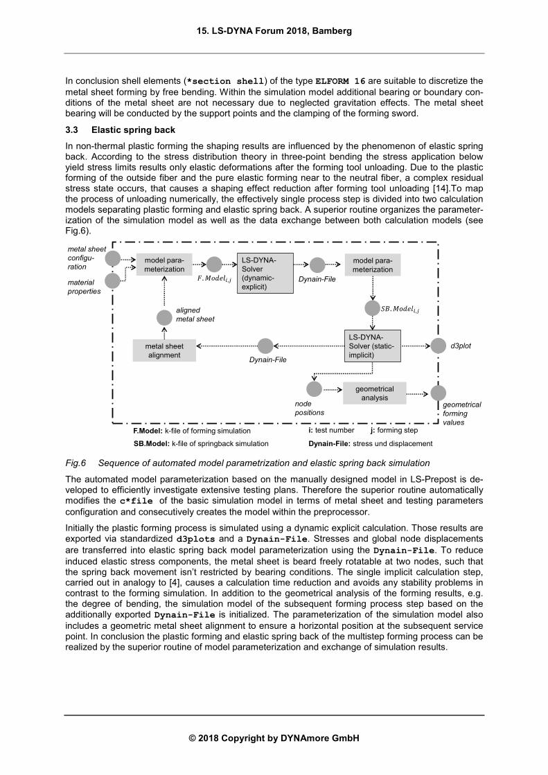
In non-thermal plastic forming the shaping results are influenced by the phenomenon of elastic spring back. According to the stress distribution theory in three-point bending the stress application below yield stress limits results only elastic deformations after the forming tool unloading. Due to the plastic forming of the outside fiber and the pure elastic forming near to the neutral fiber, a complex residual stress state occurs, that causes a shaping effect reduction after forming tool unloading [14].To map the process of unloading numerically, the effectively single process step is divided into two calculation models separating plastic forming and elastic spring back. A superior routine organizes the parameter-ization of the simulation model as well as the data exchange between both calculation models (see Fig.6).
Fig.6 Sequence of automated model parametrization and elastic spring back simulation
The automated model parameterization based on the manually designed model in LS-Prepost is de-veloped to efficiently investigate extensive testing plans. Therefore the superior routine automatically modifies the c*file of the basic simulation model in terms of metal sheet and testing parameters configuration and consecutively creates the model within the preprocessor.
Initially the plastic forming process is simulated using a dynamic explicit calculation. Those results are exported via standardized d3plots and a Dynain-File. Stresses and global node displacements are transferred into elastic spring back model parameterization using the Dynain-File. To reduce induced elastic stress components, the metal sheet is beard freely rotatable at two nodes, such that the spring back movement isn’t restricted by bearing conditions. The single implicit calculation step, carried out in analogy to [4], causes a calculation time reduction and avoids any stability problems in contrast to the forming simulation. In addition to the geometrical analysis of the forming results, e.g. the degree of bending, the simulation model of the subsequent forming process step based on the additionally exported Dynain-File is initialized. The parameterization of the simulation model also includes a geometric metal sheet alignment to ensure a horizontal position at the subsequent service point. In conclusion the plastic forming and elastic spring back of the multistep forming process can be realized by the superior routine of model parameterization and exchange of simulation results.
metal sheet
configu-
ration
material
properties
model para-meterization
LS-DYNA-Solver (dynamic-explicit)
Dynain-File
metal sheet alignment
LS-DYNA-Solver (static-implicit)
model para-meterization
i: test number j: forming step
Dynain-File
aligned
metal sheet
d3plot
geometrical analysis
node
positionsgeometrical
forming
values
Dynain-File: stress und displacement
F.Model: k-file of forming simulation
SB.Model: k-file of springback simulation
15. LS-DYNA Forum 2018, Bamberg
© 2018 Copyright by DYNAmore GmbH
4 Experimental model validation
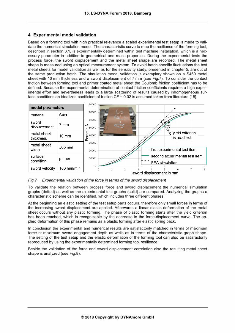
Based on a forming tool with high practical relevance a scaled experimental test setup is made to vali-date the numerical simulation model. The characteristic curve to map the resilience of the forming tool, described in section 3.1, is experimentally determined within test machine installation, which is a nec-essary parameter in addition to geometrical and mass properties. During the experimental tests the process force, the sword displacement and the metal sheet shape are recorded. The metal sheet shape is measured using an optical measurement system. To avoid batch specific fluctuations the test metal sheets for model validation as well as for the sensitivity study, presented in chapter 5, are out of the same production batch. The simulation model validation is exemplary shown on a S460 metal sheet with 10 mm thickness and a sword displacement of 7 mm (see Fig.7). To consider the contact friction between forming tool and primer coated metal sheet the Coulomb friction coefficient has to be defined. Because the experimental determination of contact friction coefficients requires a high exper-imental effort and nevertheless leads to a large scattering of results caused by inhomogeneous sur-face conditions an idealized coefficient of friction CF = 0.02 is assumed taken from literature [15].
Fig.7 Experimental validation of the force in terms of the sword displacement
To validate the relation between process force and sword displacement the numerical simulation graphs (dotted) as well as the experimental test graphs (solid) are compared. Analyzing the graphs a characteristic scheme can be identified, which includes three different phases.
At the beginning an elastic setting of the test setup parts occurs, therefore only small forces in terms of the increasing sword displacement are applied. Afterwards a linear elastic deformation of the metal sheet occurs without any plastic forming. The phase of plastic forming starts after the yield criterion has been reached, which is recognizable by the decrease in the force-displacement curve. The ap-plied deformation of this phase remains as a plastic forming after elastic spring back.
In conclusion the experimental and numerical results are satisfactorily matched in terms of maximum force at maximum sword engagement depth as wells as in terms of the characteristic graph shape. The setting of the test setup and the elastic deformation of the forming tool can also be satisfactorily reproduced by using the experimentally determined forming tool resilience.
Beside the validation of the force and sword displacement correlation also the resulting metal sheet shape is analyzed (see Fig.8).
15. LS-DYNA Forum 2018, Bamberg
© 2018 Copyright by DYNAmore GmbH
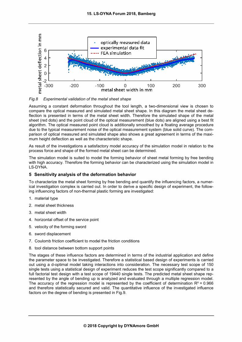
Fig.8 Experimental validation of the metal sheet shape
Assuming a constant deformation throughout the tool length, a two-dimensional view is chosen to compare the optical measured and simulated metal sheet shape. In this diagram the metal sheet de-flection is presented in terms of the metal sheet width. Therefore the simulated shape of the metal sheet (red dots) and the point cloud of the optical measurement (blue dots) are aligned using a best fit algorithm. The optical measured point cloud is additionally smoothed by a floating average procedure due to the typical measurement noise of the optical measurement system (blue solid curve). The com-parison of optical measured and simulated shape also shows a great agreement in terms of the maxi-mum height deflection as well as the characteristic shape.
As result of the investigations a satisfactory model accuracy of the simulation model in relation to the process force and shape of the formed metal sheet can be determined.
The simulation model is suited to model the forming behavior of sheet metal forming by free bending with high accuracy. Therefore the forming behavior can be characterized using the simulation model in LS-DYNA.
5 Sensitivity analysis of the deformation behavior
To characterize the metal sheet forming by free bending and quantify the influencing factors, a numer-ical investigation complex is carried out. In order to derive a specific design of experiment, the follow-ing influencing factors of non-thermal plastic forming are investigated:
1. material type
2. metal sheet thickness
3. metal sheet width
4. horizontal offset of the service point
5. velocity of the forming sword
6. sword displacement
7. Coulomb friction coefficient to model the friction conditions
8. tool distance between bottom support points
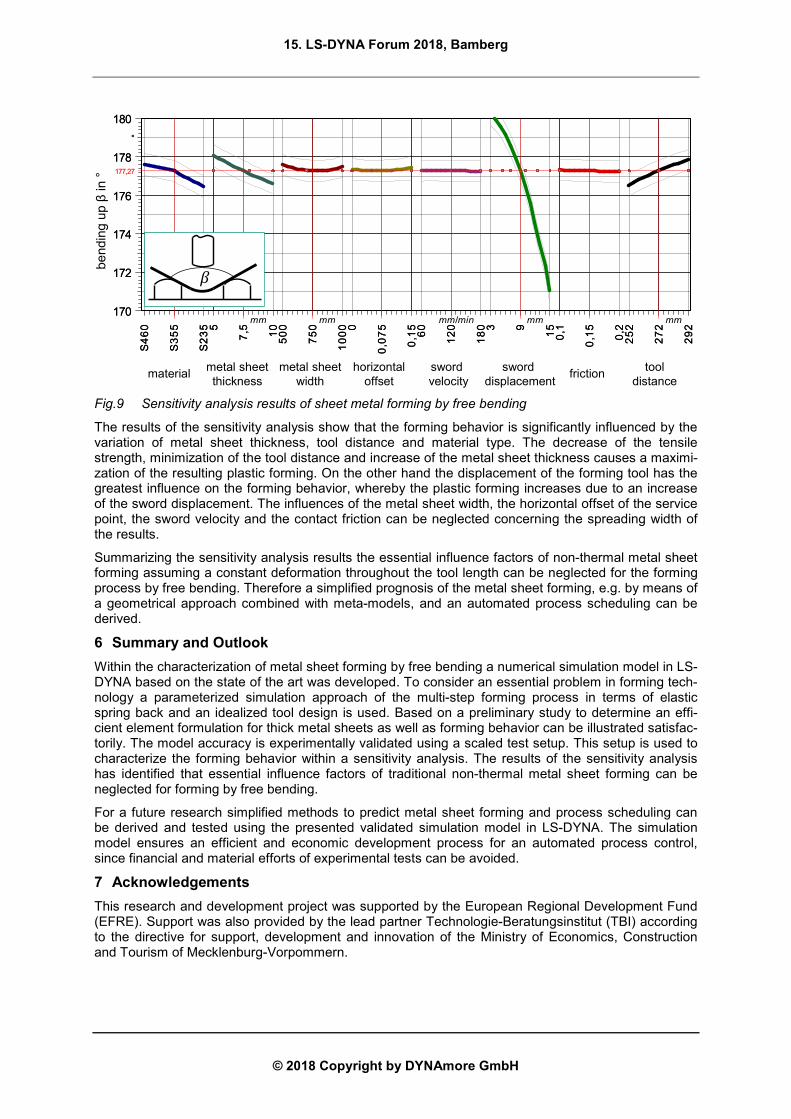
The stages of these influence factors are determined in terms of the industrial application and define the parameter space to be investigated. Therefore a statistical based design of experiments is carried out using a d-optimal model taking interactions into consideration. The necessary test scope of 150 single tests using a statistical design of experiment reduces the test scope significantly compared to a full factorial test design with a test scope of 19440 single tests. The predicted metal sheet shape rep-resented by the angle of bending up is analyzed and evaluated through a multiple regression model. The accuracy of the regression model is represented by the coefficient of determination R² = 0.966 and therefore statistically secured and valid. The quantitative influence of the investigated influence factors on the degree of bending is presented in Fig.9.
15. LS-DYNA Forum 2018, Bamberg
© 2018 Copyright by DYNAmore GmbH
Fig.9 Sensitivity analysis results of sheet metal forming by free bending
The results of the sensitivity analysis show that the forming behavior is significantly influenced by the variation of metal sheet thickness, tool distance and material type. The decrease of the tensile strength, minimization of the tool distance and increase of the metal sheet thickness causes a maximi-zation of the resulting plastic forming. On the other hand the displacement of the forming tool has the greatest influence on the forming behavior, whereby the plastic forming increases due to an increase of the sword displacement. The influences of the metal sheet width, the horizontal offset of the service point, the sword velocity and the contact friction can be neglected concerning the spreading width of the results.
Summarizing the sensitivity analysis results the essential influence factors of non-thermal metal sheet forming assuming a constant deformation throughout the tool length can be neglected for the forming process by free bending. Therefore a simplified prognosis of the metal sheet forming, e.g. by means of a geometrical approach combined with meta-models, and an automated process scheduling can be derived.
6 Summary and Outlook
Within the characterization of metal sheet forming by free bending a numerical simulation model in LS-DYNA based on the state of the art was developed. To consider an essential problem in forming tech-nology a parameterized simulation approach of the multi-step forming process in terms of elastic spring back and an idealized tool design is used. Based on a preliminary study to determine an effi-cient element formulation for thick metal sheets as well as forming behavior can be illustrated satisfac-torily. The model accuracy is experimentally validated using a scaled test setup. This setup is used to characterize the forming behavior within a sensitivity analysis. The results of the sensitivity analysis has identified that essential influence factors of traditional non-thermal metal sheet forming can be neglected for forming by free bending.
For a future research simplified methods to predict metal sheet forming and process scheduling can be derived and tested using the presented validated simulation model in LS-DYNA. The simulation model ensures an efficient and economic development process for an automated process control, since financial and material efforts of experimental tests can be avoided.
7 Acknowledgements
This research and development project was supported by the European Regional Development Fund (EFRE). Support was also provided by the lead partner Technologie-Beratungsinstitut (TBI) according to the directive for support, development and innovation of the Ministry of Economics, Construction and Tourism of Mecklenburg-Vorpommern.
06
4S
55
3S
53
2S
5 5,7
01
00
5
05
7
00
01
0 57
0,0
51,
00
6
02
1
08
13 9 5
11,
0
51,
0
2,0
25
2
27
2
29
2
°
170
172
174
176
178
180S355S355 7,57,5 750750 0,0750,075 120120 99 0,150,15 272272
177,27177,27177,27177,27177,27177,27177,27177,27177,27177,27177,27177,27
06
4S
55
3S
53
2S
5 5,7
01
00
5
05
7
00
01
0 57
0,0
51,
00
6
02
1
08
13 9 5
11,
0
51,
0
2,0
25
2
27
2
29
2
°
170
172
174
176
178
180S355S355 7,57,5 750750 0,0750,075 120120 99 0,150,15 272272
177,27177,27177,27177,27177,27177,27177,27177,27177,27177,27177,27177,27
materialmetal sheetthickness
metal sheetwidth
horizontaloffset
swordvelocity
sworddisplacement
frictiontool
distance
be
ndin
gup
βin
°
mm mm mm/min mm mm
15. LS-DYNA Forum 2018, Bamberg
© 2018 Copyright by DYNAmore GmbH
8 Literature
[1] LANGE, K.: Umformtechnik - Handbuch für Industrie und Wissenschaft; Zweite, völlig neubear-beitete und erweiterte Auflage; Berlin, Heidelberg; Springer Berlin Heidelberg; Imprint; Springer; 1990.
[2] STOLTMANN, M., FROITZHEIM, P., FUCHS, N. und WOERNLE, C.: Flatness-Based Feedfor-ward Control of a Crane Manipulator with Four Load Chains; In: B. CORVES, P. WENGER und M. HÜSING, Hg.; EuCoMeS 2018 - Proceedings of the 7th European Conference on Mechanism Science; Cham, Switzerland: Springer; 2019; S. 61-68; ISBN 3319980203.
[3] STOLTMANN, M., FROITZHEIM, P., FUCHS, N. und WOERNLE, C.: Feedforward control of a crane manipulator; In: T.L. IMSD, Hg.; The 5th Joint International Conference on Multibody Sys-tem Dynamics.; Lisboa, Portugal; 2018.
[4] FU, Z., MO, J., GONG, P., ZHANG, W., LI, Z. und HUANG, K.: Mould correction for sheet-metal multi-step incremental air-bending forming based on close-loop control and FEM simulation [online]; International Journal of Mechanical Sciences; 2009, 51(9-10), S. 732-740; ISSN 00207403; Verfügbar unter: doi:10.1016/j.ijmecsci.2009.08.006
[5] FU, Z., MO, J. und ZHANG, W.: Study on multiple-step incremental air-bending forming of sheet metal with springback model and FEM simulation [online]; The International Journal of Advanced Manufacturing Technology; 2009, 45(5-6), S. 448-458; ISSN 0268-3768; Verfügbar unter: doi:10.1007/s00170-009-1982-2
[6] ZHAO, K.M. und LEE, J.K.: Finite element analysis of the three-point bending of sheet metals [online]; Journal of Materials Processing Technology; 2002, 122(1), S. 6-11; Journal of Materials Processing Technology; Verfügbar unter: doi:10.1016/S0924-0136(01)01064-0
[7] LEMAITRE, J. und CHABOCHE, J.-L.: Plasticity; In: J. LEMAITRE und J.-L. CHABOCHE, Hg.; Mechanics of Solid Materials; Cambridge: Cambridge University Press; 1990; S. 161-252; ISBN 9781139167970.
[8] HOEPKE, J.: Entwicklung eines Finite-Elemente-Modells zur Vorhersage von Grobblechumfor-mungen; Masterarbeit; Rostock; 2. Nov. 2015.
[9] FLOREK, L.: Aufbau und Validierung eines Simulationsmodells zur Nachbildung der kaltplasti-schen Blechumformung; Masterarbeit; Rostock; 8. Jan. 2018.
[10] KUGLER, H.: Umformtechnik - Umformen metallischer Konstruktionswerkstoffe; München; Fachbuchverl. Leipzig im Carl-Hanser-Verl.; 2009.
[11] RICHARD, H.A. und SANDER, M.: Technische Mechanik. Festigkeitslehre - Lehrbuch mit Pra-xisbeispielen, Klausuraufgaben und Lösungen; Studium; 2., erweiterte Auflage; Wiesbaden; Vie-weg+Teubner / GWV Fachverlage GmbH, Wiesbaden; 2008.
[12] HOCKETT, J.E. und SHERBY, O.D.: Large strain deformation of polycrystalline metals at low homologous temperatures; Journal of the Mechanics and Physics of Solids, 1975.
[13] BEN AYED, L., ROBERT, C., DELAMÉZIÈRE, A., NOUARI, M. und BATOZ, J.L.: Simplified numerical aprroach for incremental sheet metal forming process; 2014.
[14] BIRKERT, A.R., HAAGE, S. und STRAUB, M.: Umformtechnische Herstellung komplexer Ka-rosserieteile - Auslegung von Ziehanlagen; SpringerLink; Berlin, Heidelberg; Springer Berlin Hei-delberg; 2013.
[15] VDI-RICHTLINIE 2230 Blatt 1: Systematische Berechnung hochbeanspruchter Schraubenver-bindungen-Zylindrische Einschraubenverbindungen; Berlin; Beuth; November 2015.
Related Documents