(This is a sample cover image for this issue. The actual cover is not yet available at this time.) This article appeared in a journal published by Elsevier. The attached copy is furnished to the author for internal non-commercial research and education use, including for instruction at the authors institution and sharing with colleagues. Other uses, including reproduction and distribution, or selling or licensing copies, or posting to personal, institutional or third party websites are prohibited. In most cases authors are permitted to post their version of the article (e.g. in Word or Tex form) to their personal website or institutional repository. Authors requiring further information regarding Elsevier’s archiving and manuscript policies are encouraged to visit: http://www.elsevier.com/copyright

Welcome message from author
This document is posted to help you gain knowledge. Please leave a comment to let me know what you think about it! Share it to your friends and learn new things together.
Transcript

(This is a sample cover image for this issue. The actual cover is not yet available at this time.)
This article appeared in a journal published by Elsevier. The attachedcopy is furnished to the author for internal non-commercial researchand education use, including for instruction at the authors institution
and sharing with colleagues.
Other uses, including reproduction and distribution, or selling orlicensing copies, or posting to personal, institutional or third party
websites are prohibited.
In most cases authors are permitted to post their version of thearticle (e.g. in Word or Tex form) to their personal website orinstitutional repository. Authors requiring further information
regarding Elsevier’s archiving and manuscript policies areencouraged to visit:
http://www.elsevier.com/copyright

Author's personal copy
Characterization and mechanical testing of alumina-basednanocomposites reinforced with niobium and/or carbon
nanotubes fabricated by spark plasma sintering
K.E. Thomson a,1, D. Jiang a, W. Yao a, R.O. Ritchie b, A.K. Mukherjee a,⇑
a Department of Chemical Engineering and Materials Science, University of California, Davis, CA 95616, USAb Department of Materials Science and Engineering, University of California, Berkeley, CA 94720, USA
Received 12 April 2011; received in revised form 29 September 2011; accepted 2 October 2011
Abstract
Alumina-based nanocomposites reinforced with niobium and/or carbon nanotubes (CNT) were fabricated by advanced powder pro-cessing techniques and consolidated by spark plasma sintering. Raman spectroscopy revealed that single-walled carbon nanotubes(SWCNT) begin to break down at sintering temperatures >1150 �C. Nuclear magnetic resonance showed that, although thermodynam-ically unlikely, no Al4C3 formed in the CNT–alumina nanocomposites, such that the nanocomposite can be considered as purely a phys-ical mixture with no chemical bond formed between the nanotubes and ceramic matrix. In addition, in situ single-edge notched bend testswere conducted on niobium and/or CNT-reinforced alumina nanocomposites to assess their toughness. Despite the absence of subcriticalcrack growth, average fracture toughness values of 6.1 and 3.3 MPa m1/2 were measured for 10 vol.% Nb and 10 vol.% Nb–5 vol.%SWCNT–alumina, respectively. Corresponding tests for the alumina nanocomposites containing 5 vol.% SWCNT, 10 vol.% SWCNT,5 vol.% double-walled-CNT and 10 vol.% Nb yielded average fracture toughnesses of 3.0, 2.8, 3.3 and 4.0 MPa m1/2, respectively. Itappears that the reason for not observing improvement in fracture toughness of CNT-reinforced samples is because of either damageto CNTs or possibly non-optimal interfacial bonding between CNT-alumina.� 2011 Acta Materialia Inc. Published by Elsevier Ltd. All rights reserved.
Keywords: Nanocomposite; Carbon nanotubes; Alumina; Toughness; Raman spectroscopy
1. Introduction
The low density, chemical inertness and high hardness/strength of nanocrystalline alumina make it an attractivecandidate for compressive structural applications. Unfortu-nately, its low fracture toughness (�2.5 MPa m1/2) impedesits use in such applications. The most successful approachto improving alumina’s fracture toughness has been theaddition of second phases. The creation of ceramic–matrixcomposites (CMC) has combined the high strength/hard-ness of alumina and toughening from the second phases
by means of mechanisms such as ductile phase toughening,fiber toughening, transformation toughening and micro-crack toughening. Over the past decade, many researchershave studied the strengthening and toughening effects ofadding various metal and ceramic phases to alumina [1–15]. Many researchers have explored the potentially benefi-cial effects of adding carbon nanotubes (CNT) to nanocrys-talline alumina [16–31]. Unfortunately, the comparison offracture toughness data is complicated by the fact thatmany different techniques have been used to assess themechanical properties of these CMC. Specifically, manyinvestigators employed the indentation fracture (IF) tech-nique, which has been proved to be somewhat questionablefor assessing the toughness of these materials [32].
The present work investigates the effect of adding CNT(single-walled (SWCNT) and double-walled (DWCNT))
1359-6454/$36.00 � 2011 Acta Materialia Inc. Published by Elsevier Ltd. All rights reserved.
doi:10.1016/j.actamat.2011.10.002
⇑ Corresponding author. Tel.: +1 530 752 1776; fax: +1 530 752 9554.E-mail address: [email protected] (A.K. Mukherjee).
1 Present address: Stryker Endoscopy, 5900 Optical Court, San Jose, CA95138, USA.
www.elsevier.com/locate/actamat
Available online at www.sciencedirect.com
Acta Materialia 60 (2012) 622–632
Author's personal copy
and elemental niobium on the mechanical properties ofnanocrystalline alumina with the intent of creating a toughalumina-based nanocomposite. The intention was to exam-ine whether the incorporation of CNT would provide asource of extrinsic toughening in alumina. CNT were cho-sen because, owing to their structural perfection, they areultra-strong (�0.15 TPa [33]), yet at the same time flexible.In addition, their conductivity and relatively high-tempera-ture resistance provide, in many respects, the ideal “nano-crystalline” fiber for reinforcement. Unfortunately,adequate dispersion of CNT is very difficult, owing to theirtendency to group into “bundles” or “ropes” of 10–100nanotubes (held together by weak Van der Waals forces)in order to minimize the surface area.
Second, it was proposed that niobium additions to nano-crystalline alumina would provide both intrinsic and extrin-sic toughening via a ductile-phase toughening mechanism.Nb has been used as a model reinforcement, as it has beenshown for many ceramic–matrix and intermetallic–matrixcomposites, where Nb has been incorporated in particulateform, that extrinsic toughening is particularly active. Nio-bium was also chosen because its high melting temperaturewould be compatible with the high-temperature sinteringcondition of alumina. Furthermore, the possible synergisticeffect of combined toughening mechanisms, such as the duc-tile phase and fiber toughening, represents an exciting pos-sibility in these materials.
To fabricate these materials, spark plasma sintering(SPS) was used for consolidation because it avoids theexcessive grain growth that would prevent a truly nanocrys-talline material from being obtained. SPS is an advanced,moderate pressure-assisted consolidation technique whichcan produce fully dense samples at lower temperaturesand shorter times than conventional sintering techniqueswould allow. Although the mechanisms behind SPS areunclear, it is believed that a combination of rapid heatingrate, pressure application and electrical pulsing enhancesthe surface diffusion and thus promotes sintering of ceramicpowders [34,35].
2. Experimental methods
The details of processing conditions and parameterschosen for SPS of 5 vol.% SWCNT–alumina, 5 vol.%DWCNT–alumina, 10 vol.% Nb–alumina and 10 vol.%Nb–5 vol.% SWCNT–alumina are presented as a self-con-tained section in Appendix.
2.1. Raman spectroscopy
Pulsed laser Raman spectroscopy was conducted at Law-rence Berkeley National Laboratory. Spectra were detectedwith an imaging photomultiplier (1024 � 1024) with 5 cm�1
resolution. First, an investigation into the preservation of10 vol.% SWCNT–alumina consolidated at 1150 �C for3 min was conducted using lasers of 522–488 nm wave-length with a 60 s scan. Four scans were taken and overlaid
for comparison of D- and G-bands: pure SWCNT, graphitestandard, pure alumina and the 10 vol.% SWCNT–aluminacomposite. Using the same equipment, a more in-depthRaman study was performed to identify the highest SPScondition that can be used without destroying the CNT.This experiment was conducted using a 488 nm Ar+ laserline at a power of 35 mW and collection times of 4 min.
2.2. Nuclear magnetic resonance
Nuclear magnetic resonance (NMR) was also used toinvestigate the CNT–alumina nanocomposites. Consoli-dated samples were crushed and sieved to yield powders fitfor NMR study. 27Al magic angle spinning (MAS) NMRexperiments were carried out on a Bruker Avance 500 wide-bore system, with Larmor frequency 130.32 MHz, MAS rate15 kHz, digitization rate 166.7 kHz, pulse length 0.5 ls (15�tip angle) and 1 s of recycle delay, and transients of 1024. Thesystem was calibrated with aluminum chloride solution, and�100 mg of powder was loaded into a 2.5 mm vial and ana-lyzed under an 11.74 T magnetic field.
A series of spectra were taken to investigate the localchemical environment of alumina powder, as-receivedand subjected to high-energy ball-milling (HEBM), consol-idated monolithic alumina and CNT–alumina compositesin order to gain information about the interface betweenthe CNT and the alumina matrix. All samples were sinteredusing 32 nm Nanotek alumina powder.
2.3. Mechanical testing
Vickers indentation methods were employed to deter-mine the hardness and to estimate the approximate fracturetoughness of the CMC in this study. A standard Tukonmicrohardness tester was used with a diamond Vickerstip, a 2.278 kg load and a dwell time of 12 s. In most cases,the hardness and toughness crack lengths were measuredon a Buehler optical microscope with the Analysis programfor maximum crack resolution. The indentation toughnesswas calculated using the Antis equation [36] by measuringboth diagonal lengths and crack lengths. The average ofthe hardness and indentation toughness was taken from10 or more indents.
Because the IF technique has been claimed to be ques-tionable for assessing the toughness of these materials[32], single-edge notched four-point bend (SENB) testswere conducted using a standard servo-hydraulic MTSload frame with a 12.7 mm displacement cartridge and a890 N load cartridge to provide a more appropriate charac-terization of the fracture toughness of the composites. Two3 mm � 4 mm � 19 mm beams were cut from each SPSspecimen and polished to a 1 lm finish. Samples were firstnotched using a 0.5 mm diamond saw blade to a depth of�600 lm; final notches were created using a micro-notch-ing procedure involving polishing the root of the machinednotch using a razor blade with 1 lm diamond paste; thistechnique reliably produced sharpened notches with a root
K.E. Thomson et al. / Acta Materialia 60 (2012) 622–632 623
Author's personal copy
radius between 11 and 20 lm. An optical microscope wasused to measure the notch depth (a) and notch radius ofthe beams. The final crack length to width (a/W) ratiostypically ranged from 0.2 to 0.3. LabView was used to con-duct the four-point bending tests (load span 15 mm) underdisplacement control, and the breaking load was recorded.The beam fracture surfaces were analyzed by scanning elec-tron microscopy (SEM) in a FEI XL-30 SFEG instrument.
In situ three-point bend testing was also conducted bySEM to measure the toughness while simultaneously imag-ing how the crack interacts with the material’s microstruc-ture; in this manner, extrinsic toughening effects, if any, ofniobium and SWCNT additions to nanocrystalline aluminacould be examined. SPS samples were polished to a 0.5 lmsurface finish and cut into beams with dimensions3 � 4 � 19 mm. SENB samples were pre-notched using adiamond saw, followed by an automated razor blade with1 lm diamond paste to an a/W ratio of 0.25–0.5. Other sam-ple preparation procedures were made in accordance withASTM STP 1409. The pre-notched beams were three-pointbend tested by SEM at a loading rate of 0.55 lm s�1 withina Hitachi S-4300SE/N instrument, using a Gatan Microtest2000 test assembly, and the process of crack propagationobserved under back-scattering mode in an attempt to mea-sure the crack-resistance curve (R curve). The fracturetoughness of the nanocomposites was computed from thefracture load’s breaking load using the stress intensity K-solutions given in ASTM E399. Fracture surfaces were ana-lyzed in a FEI XL-30 SFEG SEM.
3. Results and discussion
3.1. Raman spectroscopy
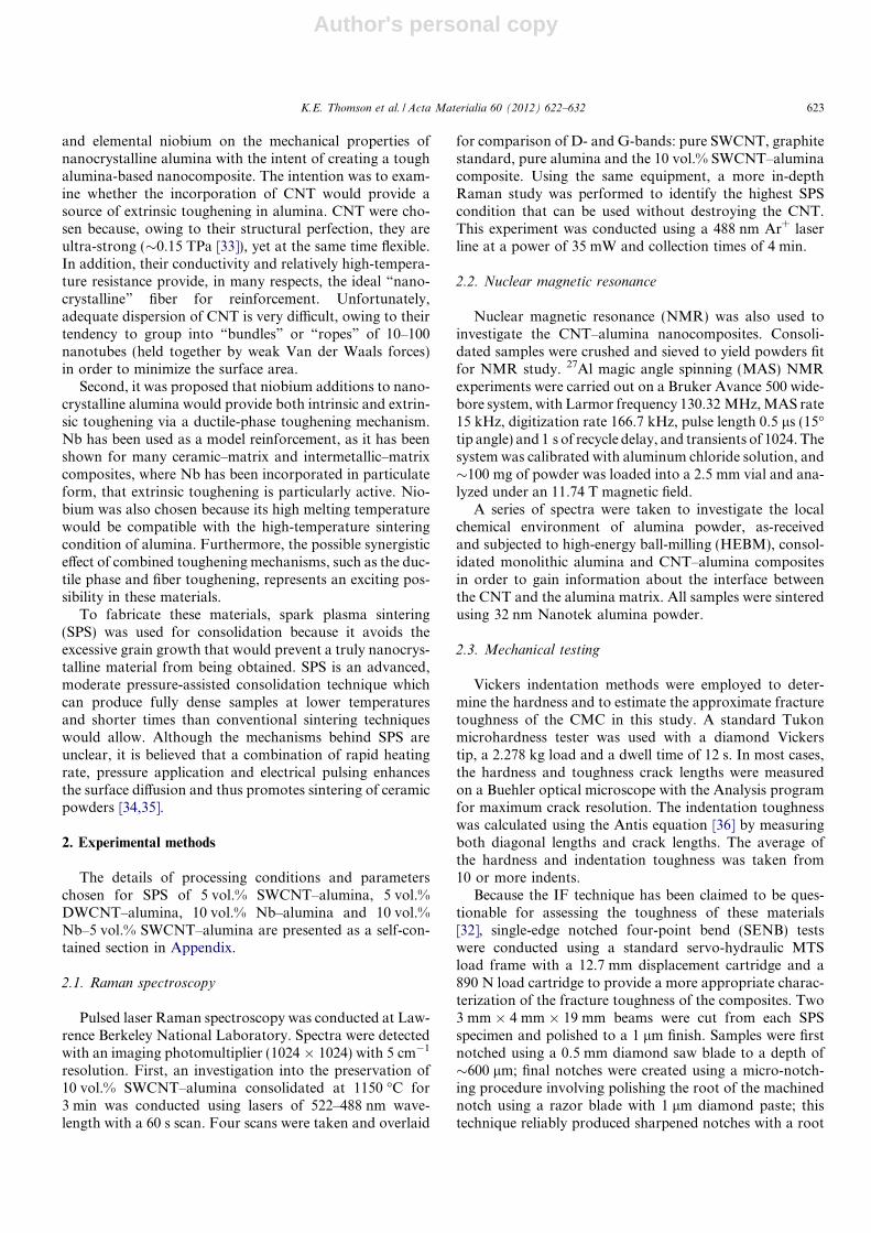
The results from the pulsed laser Raman spectroscopy areshown in Figs. 1 and 2. Comparison of the spectra in Fig. 1for pure SWCNT with that of the nanocomposite consoli-dated at 1150 �C reveals a major peak at �1595 cm�1 anda shoulder in the 1550–1575 cm�1 region in both spectra.
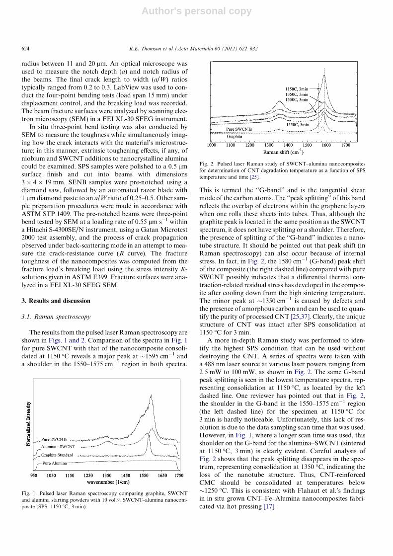
This is termed the “G-band” and is the tangential shearmode of the carbon atoms. The “peak splitting” of this bandreflects the overlap of electrons within the graphene layerswhen one rolls these sheets into tubes. Thus, although thegraphite peak is located in the same position as the SWCNTspectrum, it does not have splitting or a shoulder. Therefore,the presence of splitting of the “G-band” indicates a nano-tube structure. It should be pointed out that peak shift (inRaman spectroscopy) can also occur because of internalstress. In fact, in Fig. 2, the 1580 cm�1 (G-band) peak shiftof the composite (the right dashed line) compared with pureSWCNT possibly indicates that a differential thermal con-traction-related residual stress has developed in the compos-ite after cooling down from the high sintering temperature.The minor peak at �1350 cm�1 is caused by defects andthe presence of amorphous carbon and can be used to quan-tify the purity of processed CNT [25,37]. Clearly, the uniquestructure of CNT was intact after SPS consolidation at1150 �C for 3 min.
A more in-depth Raman study was performed to iden-tify the highest SPS condition that can be used withoutdestroying the CNT. A series of spectra were taken witha 488 nm laser source at various laser powers ranging from2 5 mW to 100 mW, as shown in Fig. 2. The same G-bandpeak splitting is seen in the lowest temperature spectra, rep-resenting consolidation at 1150 �C, as located by the leftdashed line. One reviewer has pointed out that in Fig. 2,the shoulder in the G-band in the 1550–1575 cm�1 region(the left dashed line) for the specimen at 1150 �C for3 min is hardly noticeable. Unfortunately, this lack of res-olution is due to the data sampling scan time that was used.However, in Fig. 1, where a longer scan time was used, thisshoulder on the G-band for the alumina–SWCNT (sinteredat 1150 �C, 3 min) is clearly evident. Careful analysis ofFig. 2 shows that the peak splitting disappears in the spec-trum, representing consolidation at 1350 �C, indicating theloss of the nanotube structure. Thus, CNT-reinforcedCMC should be consolidated at temperatures below�1250 �C. This is consistent with Flahaut et al.’s findingsin in situ grown CNT–Fe–Alumina nanocomposites fabri-cated via hot pressing [17].
Fig. 1. Pulsed laser Raman spectroscopy comparing graphite, SWCNTand alumina starting powders with 10 vol.% SWCNT–alumina nanocom-posite (SPS: 1150 �C, 3 min).
Fig. 2. Pulsed laser Raman study of SWCNT–alumina nanocompositesfor determination of CNT degradation temperature as a function of SPStemperature and time [25].
624 K.E. Thomson et al. / Acta Materialia 60 (2012) 622–632

Author's personal copy
3.2. NMR
Analysis of the NMR spectra in Fig. 3 revealed that thealuminum atom coordination of the as-received powder wasa mixture of four (at �65 ppm) and six (at �10 ppm). Closeinspection of the sixfold peak indicates that there was somedistortion in the aluminum–oxygen octahedral structuredue to the small amount of splitting at the top of this peak.HEBM seems to provide sufficient energy to correct this dis-tortion, because the HEBM spectra showed a clean sixfoldpeak (Fig. 3b). Consequently, consolidation in the SPS at1200 �C results in complete phase transformation of thecubic 4-coordinated, metastable alumina gamma phase tothe rhombohedral 6-coordinated, stable alpha phase asshown in Fig. 3c and d. Hence, after SPS consolidation,the sample had only alpha alumina, and all the mechanicaltests were conducted on this alpha alumina matrix. The twosatellite peaks in Fig. 3d are termed “spinning side bands“
and are a result of spinning and are not indicative of thechemical environment of aluminum atoms.
In addition, analysis [42] of the CNT/alumina compositespectra for both 1200 �C and 1550 �C (not shown) indicatedthat the alumina remains 6-coordinated and that no alumi-num carbide (Al4C3) was formed. Although thermodynam-ically improbable because the reaction is very slow, a peakbetween 20 and 100 ppm would have appeared if aluminumcarbide had been formed. The solid-state NMR equipmenthas sufficient sensitivity and, if this peak had been present, itwould have been recorded. In other words, the compositesample was purely a physical mixture, and no chemicalbonding occurred at the alumina grain/CNT interface. Thisis an important observation, because formation of Al4C3
would mean breakdown of the nanotube, because the nano-tubes used in these studies were single-walled. Thus, it isclear that the nanotubes remained as ultra-strong reinforc-ing fibers within the brittle alumina matrix.
3.3. Mechanical testing
Although only approximate in the quantification of thefracture toughness, IF testing revealed anisotropy in cracklengths and, hence, some degree of extrinsic toughening inthe CMC fabricated by SPS. For example, indents wereintroduced to both the cross-sectional and surface faces ofthe 10 vol.% Nb–alumina sample intermixed by cryomil-ling. The average IF toughness and hardness calculatedon the cross-sectional surface (parallel to the pressing direc-tion in SPS) was 3.5 MPa m1/2 and 21.0 GPa, respectively.However, lower fracture toughness and slightly lower hard-ness were measured for the surface (perpendicular to thepressing direction in SPS), specifically 2.6 MPa m1/2 and20.8 GPa, respectively. This corresponds to a 32% differ-ence in indentation toughness between the surface andcross-section orientations. The samples containing 5 vol.%DWCNT showed as much as 103% difference in indentationtoughness when surface and cross-sectional indents werecompared.
In addition, there was anisotropy found within thecross-sectional indents themselves. The cracks propagatingin the pressing direction tended to be shorter than thoseperpendicular to the pressing direction, indicating maxi-mum toughness in the pressing direction. Since the aluminagrains were equiaxed, the anisotropic mechanical proper-ties are attributed to residual stresses and, in the case ofCMC, elongated niobium/CNT regions.
Table 1 shows all the data collected from four-point bendtesting and Vickers indentation. Both surface (s) and cross-section surface (c.s.) were measured using Vickers indenta-tion method. The data reveal that the samples made fromthe cryomilled Nb–alumina powders had slightly higherfracture toughness (by �0.40 MPa m1/2) than those madefrom the HEBM powder. The IF toughness values indicatethat the same anisotropy seen in DWCNT CMC was alsopresent in the cryomilled 10 vol.% Nb–alumina samples.Regardless of milling technique, the addition of 10 vol.%Nb to nanocrystalline alumina was more effective in improv-ing the fracture toughness than CNT were. The Nb–aluminasystem contained less porosity (100% TD) and cleaner inter-faces than the CNT system. The residual porosity (�1.5%)and the weakened alumina grain boundaries in the CNT sys-tem may explain the lack of toughening. Analysis of theindents made on the 10 vol.% Nb–alumina samples indi-cated that crack blunting was active and responsible forthe improvement in fracture toughness.
Despite the increase in CNT loading, the 10 vol.%SWCNT samples displayed lower toughness than the5 vol.% samples. Among the 10 vol.% SWCNT samples,the fracture toughness values increased from 2.45 to2.76 MPa m1/2 as the density increased from 96.4% to
Fig. 3. 27Al MAS NMR spectra showing: (a) as-received alumina; (b)HEBM alumina; (c) pure alumina subjected to SPS at 1200 �C for 4 min;and (d) 5 vol.% SWCNT–alumina subjected to SPS at 1200 �C for 6 min(10–14 ppm = 6 coordinated and �66 ppm = 4 coordinated).
K.E. Thomson et al. / Acta Materialia 60 (2012) 622–632 625
Author's personal copy
97.4% TD. It is believed that the density of the samples out-weighed the benefits of more reinforcing phase. Thus,obtaining full density in this material system is essential toobtain maximum strength and toughness.
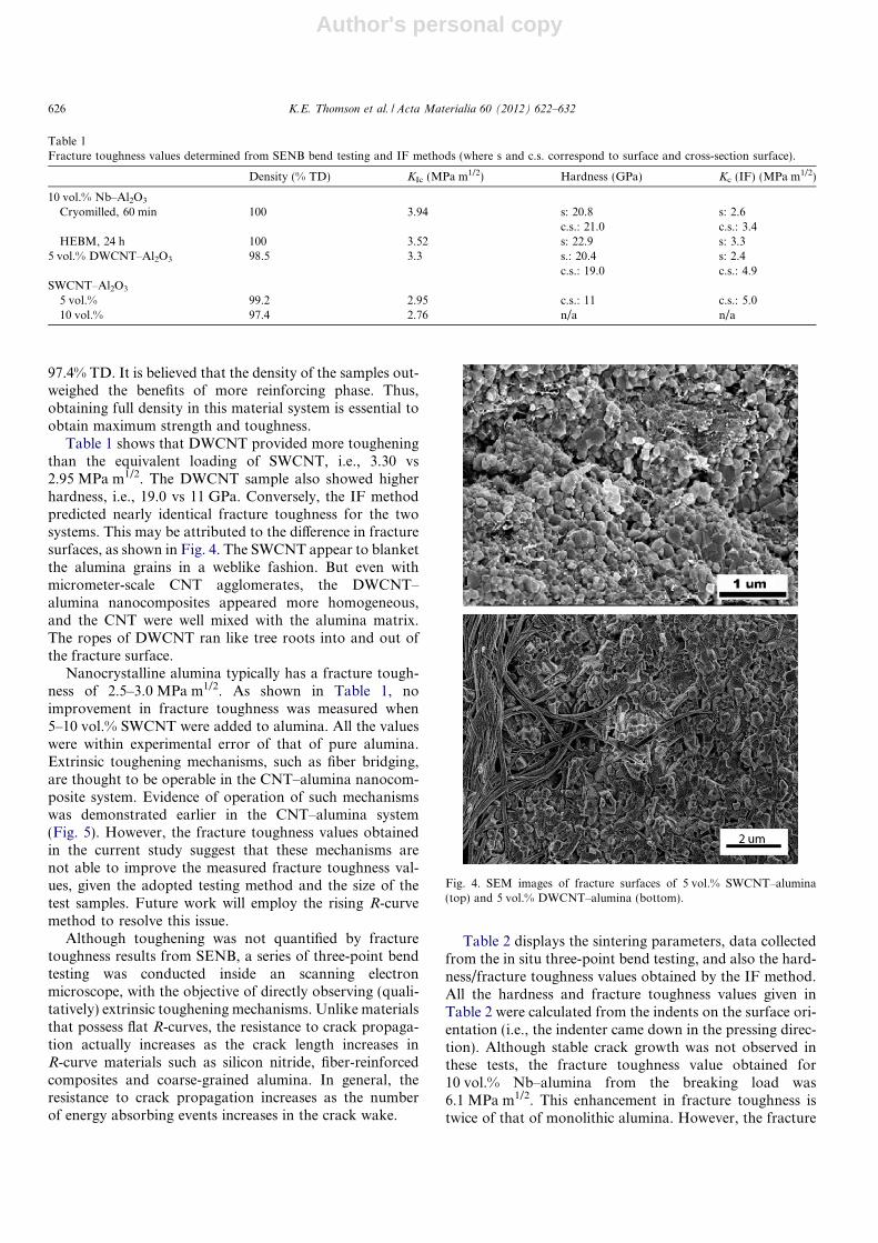
Table 1 shows that DWCNT provided more tougheningthan the equivalent loading of SWCNT, i.e., 3.30 vs2.95 MPa m1/2. The DWCNT sample also showed higherhardness, i.e., 19.0 vs 11 GPa. Conversely, the IF methodpredicted nearly identical fracture toughness for the twosystems. This may be attributed to the difference in fracturesurfaces, as shown in Fig. 4. The SWCNT appear to blanketthe alumina grains in a weblike fashion. But even withmicrometer-scale CNT agglomerates, the DWCNT–alumina nanocomposites appeared more homogeneous,and the CNT were well mixed with the alumina matrix.The ropes of DWCNT ran like tree roots into and out ofthe fracture surface.
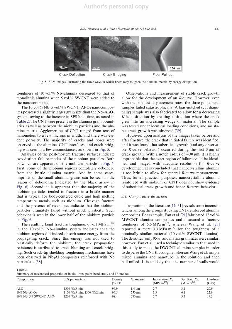
Nanocrystalline alumina typically has a fracture tough-ness of 2.5–3.0 MPa m1/2. As shown in Table 1, noimprovement in fracture toughness was measured when5–10 vol.% SWCNT were added to alumina. All the valueswere within experimental error of that of pure alumina.Extrinsic toughening mechanisms, such as fiber bridging,are thought to be operable in the CNT–alumina nanocom-posite system. Evidence of operation of such mechanismswas demonstrated earlier in the CNT–alumina system(Fig. 5). However, the fracture toughness values obtainedin the current study suggest that these mechanisms arenot able to improve the measured fracture toughness val-ues, given the adopted testing method and the size of thetest samples. Future work will employ the rising R-curvemethod to resolve this issue.
Although toughening was not quantified by fracturetoughness results from SENB, a series of three-point bendtesting was conducted inside an scanning electronmicroscope, with the objective of directly observing (quali-tatively) extrinsic toughening mechanisms. Unlike materialsthat possess flat R-curves, the resistance to crack propaga-tion actually increases as the crack length increases inR-curve materials such as silicon nitride, fiber-reinforcedcomposites and coarse-grained alumina. In general, theresistance to crack propagation increases as the numberof energy absorbing events increases in the crack wake.
Table 2 displays the sintering parameters, data collectedfrom the in situ three-point bend testing, and also the hard-ness/fracture toughness values obtained by the IF method.All the hardness and fracture toughness values given inTable 2 were calculated from the indents on the surface ori-entation (i.e., the indenter came down in the pressing direc-tion). Although stable crack growth was not observed inthese tests, the fracture toughness value obtained for10 vol.% Nb–alumina from the breaking load was6.1 MPa m1/2. This enhancement in fracture toughness istwice of that of monolithic alumina. However, the fracture
Table 1Fracture toughness values determined from SENB bend testing and IF methods (where s and c.s. correspond to surface and cross-section surface).
Density (% TD) KIc (MPa m1/2) Hardness (GPa) Kc (IF) (MPa m1/2)
10 vol.% Nb–Al2O3
Cryomilled, 60 min 100 3.94 s: 20.8 s: 2.6c.s.: 21.0 c.s.: 3.4
HEBM, 24 h 100 3.52 s: 22.9 s: 3.35 vol.% DWCNT–Al2O3 98.5 3.3 s.: 20.4 s: 2.4
c.s.: 19.0 c.s.: 4.9SWCNT–Al2O3
5 vol.% 99.2 2.95 c.s.: 11 c.s.: 5.010 vol.% 97.4 2.76 n/a n/a
Fig. 4. SEM images of fracture surfaces of 5 vol.% SWCNT–alumina(top) and 5 vol.% DWCNT–alumina (bottom).
626 K.E. Thomson et al. / Acta Materialia 60 (2012) 622–632
Author's personal copy
toughness of 10 vol.% Nb–alumina decreased to that ofmonolithic alumina when 5 vol.% SWCNT were added tothe nanocomposite.
The 10 vol.% Nb–5 vol.% SWCNT–Al2O3 nanocompos-ites possessed a slightly larger grain size than the Nb–Al2O3
system, owing to the increase in SPS hold time, as noted inTable 2. The CNT were present in the alumina grain bound-aries as well as between the niobium particles and the alu-mina matrix. Agglomerates of CNT ranged from tens ofnanometers to a few microns in width, and there was evi-dent porosity. The majority of cracks and pores wereobserved at the alumina–CNT interfaces, and crack bridg-ing was seen in a few circumstances, as shown in Fig. 5.
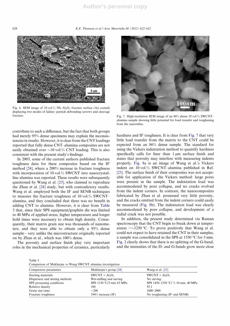
Analyses of the post-mortem fracture surfaces indicatetwo distinct failure modes of the niobium particles. Bothof which are apparent on the niobium particle in Fig. 6.First, some of the niobium regions completely debondedfrom the brittle alumina matrix. And in some cases,imprints of the small alumina grains can be seen in theregion of debonding (indicated by the black arrow inFig. 6). Second, it is apparent that the majority of theniobium particles tended to fracture in a brittle mannerthat is typical for body-centered cubic and high meltingtemperature metals such as niobium. Cleavage fractureand the presence of river lines indicate that the niobiumparticles ultimately failed without much plasticity. Suchbehavior is seen in the lower half of the niobium particlein Fig. 6.
The resulting bend fracture toughness of 6.1 MPa m1/2
in the 10 vol.% Nb–alumina system indicates that theniobium regions did indeed absorb some energy from thepropagating crack. Since this energy was not used toplastically deform the niobium, the crack propagationresistance is attributed to crack blunting and crack bridg-ing. Such crack-tip shielding toughening mechanisms havebeen observed in Nb3Al composites reinforced with Nbparticulate [38].
Observations and measurement of stable crack growthallow for the development of an R-curve. However, evenwith the smallest displacement rates, the three-point bendsamples failed catastrophically. A bias-notched (cut diago-nally) sample was also fabricated to allow for a decreasingK-field situation by creating a situation where the crackgrew into an increasing wedge of material. The samplewas tested under identical loading conditions, and no sta-ble crack growth was observed [39].
However, upon analysis of the images taken before andafter fracture, the crack that initiated failure was identified,and it was found that subcritical growth (and any observa-ble R-curve behavior) occurred during the first 3 lm ofcrack growth. With a notch radius of �30 lm, it is highlyimprobable that the exact region of failure could be identi-fied and imaged with adequate resolution for R-curvedevelopment. It is concluded that nanocrystalline aluminais too brittle to allow for general R-curve measurement.Thus, for all practical purposes, nanocrystalline aluminareinforced with niobium or CNT does not show evidenceof subcritical crack growth and hence R-curve behavior.
3.4. Comparative discussion
Inspection of the literature [16–31] reveals some inconsis-tencies among the groups studying CNT-reinforced aluminacomposites. For example, Fan et al. [21] fabricated 12 vol.%MWCNT–alumina composites and measured a fracturetoughness of 5.5 MPa m1/2, whereas Wang et al. [23]reported a mere 3.3 MPa m1/2 for the toughness of anominally similar material (10 vol.% SWCNT–alumina).The densities (only 95%) and matrix grain sizes were similar;however, Fan et al. used a technique similar to that used inthis study to make the DWCNT–alumina samples in orderto disperse the CNT thoroughly, whereas Wang et al. simplymixed alumina and nanotube in the solution and thenball-milled. It is unlikely that the number of walls would
Fiber Pull-outCrack Deflection Crack Bridging
Fig. 5. SEM images illustrating the three ways in which fibers may toughen the alumina matrix by energy dissipation.
Table 2Summary of mechanical properties of in situ three-point bend study and IF method.
Composition SPS parameters Density(% TD)
Grain size Indentation Kc
(MPa m1/2)3pt Bend KIc
(MPa m1/2)Hardness(GPa)
Al2O3 1300 �C/3 min 99.9 1.4 lm 2.7 3.1 20.910% Nb–Al2O3 1150 �C/3 min, 1300 �C/2 min 99.5 250 nm 3.3 6.1 22.910% Nb–5% SWCNT–Al2O3 1200 �C/5 min 98.4 580 nm 2.7 3.3 19.3
K.E. Thomson et al. / Acta Materialia 60 (2012) 622–632 627
Author's personal copy
contribute to such a difference, but the fact that both groupshad merely 95% dense specimens may explain the inconsis-tencies in results. However, it is clear from the CNT loadingsreported that fully dense CNT–alumina composites are noteasily obtained over �10 vol.% CNT loading. This is alsoconsistent with the present study’s findings.
In 2003, some of the current authors published fracturetoughness data for these composites based on the IFmethod [24], where a 200% increase in fracture toughnesswith incorporation of 10 vol.% SWCNT into nanocrystal-line alumina was reported. These results were subsequentlyquestioned by Wang et al. [23], who claimed to reproducethe Zhan et al. [24] study, but with contradictory results.Wang et al. employed both the IF and SENB techniquesto measure the fracture toughness of 10 vol.% SWCNT–alumina, and they concluded that there was no benefit inadding CNT to alumina. However, it is clear from Table3 that, since their SPS equipment/graphite die was limitedto 40 MPa of applied stress, higher temperature and longerhold times were necessary to obtain high density. Conse-quently, their matrix grain size was thousands of nanome-ters, and they were able to obtain only a 95% densesample—very unlike the microstructure originally reportedon by Zhan et al., which was 100% dense.
The porosity and surface finish play very importantroles in the mechanical properties of ceramics, particularly
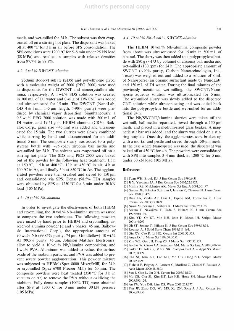
hardness and IF toughness. It is clear from Fig. 7 that verylittle load transfer from the matrix to the CNT could beexpected from an 86% dense sample. The standard forusing the Vickers indentation method to quantify hardnessspecifically calls for finer than 1 lm surface finish andstates that porosity may interfere with measuring indentsproperly. Fig. 8a is an image of Wang et al.’s Vickersindent on 10 vol.% SWCNT–alumina published in Ref.[23]. The surface finish of their composites was not accept-able for application of the Vickers method: large poreswere present in the sample. The indentation load wasaccommodated by pore collapse, and no cracks evolvedfrom the indent corners. In contrast, the nanocompositesfabricated by Zhan et al. possessed very little porosity,and the cracks emitted from the indent corners could easilybe measured (Fig. 8b). The indentation load was clearlyaccommodated by pore collapse, and development of aradial crack was not possible.
In addition, the present study determined via Ramanspectroscopy that the CNT begin to break down at temper-atures >�1250 �C. To prove positively that Wang et al.could not expect to have retained the CNT in their samples,a sample was consolidated in the SPS at 1550 �C for 5 min.Fig. 2 clearly shows that there is no splitting of the G-band,and the intensities of the D- and G-bands grow more close
Fig. 6. SEM image of 10 vol.% Nb–Al2O3 fracture surface (Au coated)displaying two modes of failure: particle debonding (arrow) and cleavagefracture.
Table 3Comparison of Mukherjee vs Wang SWCNT–alumina investigation.
Comparison parameters Mukherjee’s group [24] Wang et al. [23]
Starting materials SWCNT + Al2O3 SWCNT + Al2O3
Dispersion and mixing methods Wet-milling and sieving No sievingSPS processing conditions SPS 1150 �C/3 min 63 MPa SPS 1450–1550 �C/ 3–10 min, 40 MPaRelative density 100 95.1Grain size (nm) �200 1000–2000Fracture toughness 194% increase (IF) No toughening (IF and SENB)
Fig. 7. High-resolution SEM image of an 86% dense 10 vol.% SWCNT–alumina sample showing little potential for load transfer and tougheningfrom the nanotubes.
628 K.E. Thomson et al. / Acta Materialia 60 (2012) 622–632

Author's personal copy
in amplitude, both signaling loss of CNT structure and cre-ation of disordered graphite.
Furthermore, the present authors have tried to deliber-ately induce damage to CNT due to Joule heating by pass-ing large pulsed current to the CNT/alumina powdercompact [43] in the SPS process. The results revealed thatthe RBM peaks indexed by (11, 0), (9, 1) and (8, 0) chiralitycompletely disappeared when a large current passedthrough the CNT. When BN spacers were used to isolatethe top and bottom push-rods in the SPS equipment(thereby preventing any Joule heating in the CNT), no suchloss of tubular chirality was noticed. These observationssuggest that prior HEBM of the alumina powder and sub-sequent wet-milling of alumina powder and CNT with adispersant did not affect the overall tubularity of CNT ordamage the CNT. This wet-milling was conducted in a mildmanner at a very low speed which would not result in anydamage to CNT. However, subjecting the CNT to highertemperature in the sintering chamber (using high SPS tem-perature or passing a large current producing Joule heat-ing) did produce damage.
As in the present study, Wang et al. also applied theSENB technique to measure fracture toughness. Unlikethe discrepancies in the IF data, both groups obtained sim-ilar SENB results for 10 vol.% SWCNT–alumina; Wanget al. reported 3.3 MPa m1/2, and the present study reports2.76 MPa m1/2. Interestingly, the 5 vol.% DWCNT–alumina samples tested with the SENB in the present studywere exactly what Wang et al. measured (3.33 MPa m1/2)for their 10 vol.% SWCNT–alumina samples. Conse-quently, most groups (including the present study) thathave reported SENB fracture data have found thatCNT–alumina composite materials have moderate or noincrease in fracture toughness compared with the intrinsictoughness of monolithic alumina.
Fibers are added to matrices for strengthening andtoughening via fiber bridging—a crack wake or extrinsictoughening phenomenon. Commonly, the amount of tough-ening increases with the volume content of fibers, because
the number of fibers bridging the crack wake increases asfiber loading increases. CNT were selected because theyhave a remarkable combination of tensile strength and flex-iblility. However, as depicted by the SENB testing, the inclu-sion of the CNT provided only a negligible contribution tothe toughening. This may be attributed to the nanoscale nat-ure of the CNT and/or a very weak interaction (i.e., negligi-ble traction forces) between the nanotubes and aluminamatrix. One reviewer suggested that, in general, a weak rein-forcement/matrix interface is preferred for CMC. This fol-lows because delamination along the interface permits thereinforcement (typically in the form of a fiber or whisker)to remain intact behind the crack tip to promote crackbridging. (Incidentally, this is not always the case wherethe reinforcement can itself deform—here an intermediatestrength interface is preferable to promote maximum workdone in deforming the reinforcement.) However, in the pres-ent work, the lack of a pronounced effect of the interfacestrength in the extent of toughening in CNT–alumina mate-rials does indicate that either the effect of the CNT in gener-ating crack bridging is minimal or that the CNT weredamaged during processing. As there is little evidence ofprocessing damage to the CNT, it is the present authors’strong belief that this effect results from a minimal role ofcrack bridging by the CNT. Strengthening the interfacebetween the CNT and alumina by means of surface func-tionalization may result in some measurable extrinsic tough-ening. This phenomenon could theoretically be measured bymethods that can achieve stable crack growth and obtainingan R-curve (stress intensity vs crack extension). R-curvescan be obtained using standard bend testing or compact ten-sion (C(T)) techniques, in which the load is incrementallyincreased during stable crack growth and the crack lengthrecorded. From the recorded loads and crack measure-ments, the stress intensity K vs Da (crack extension) curvecan be generated.
Unfortunately, such stable crack growth is very difficultto obtain in nanocrystalline ceramics. In the present study,disk-shaped samples of pure alumina and 5 vol.%
Fig. 8. Vickers indents from (a) Wang et al.’s paper [23] showing no crack generation on 10 vol.% SWCNT–alumina (95% dense) and (b) Zhan et al.’spaper [24].
K.E. Thomson et al. / Acta Materialia 60 (2012) 622–632 629

Author's personal copy
SWCNT–alumina were tested using the C(T) technique(ASTM 399). Stable crack growth, and, hence, develop-ment of an R-curve, could not be obtained in either system.It is clear that the nanocrystalline alumina matrix was sim-ply too brittle to measure the extrinsic toughening expectedfrom grain and fiber bridging.
It is clear that, with respect to the fracture toughness ofCNT reinforced ceramic composites, comparison of resultsfrom various investigators in the literature [1–31] should beperformed with some caution, as the different methodsused to evaluate the fracture toughness, specifically theindentation toughness and standard precracked bend orC(T) methods, can yield conflicting results. In particular,the indentation method (IF) of estimating the fracturetoughness can be misleading and inaccurate in these partic-ular materials.
4. Conclusions
Alumina-based nanocomposites were successfully fabri-cated using advanced powder processing techniques (i.e.,HEBM and cryomilling) and consolidated using SPS. Injust a few minutes, fully dense (>98.5% TD) niobiumand/or CNT-reinforced alumina nanocomposites were pro-duced. Raman spectroscopy was used to verify that thenanotubes were preserved after sintering within the SPSat 1150 �C. However, it was also found that SWCNT aredestroyed if sintered at 1350 �C. Thus, it is advised thatconsolidation temperatures be limited to �1250 �C whenSWCNT are present within the sample. NMR showed thatno Al4C3 was formed in SWCNT–alumina nanocompos-ites, even after consolidation at 1500 �C for 10 min. Thus,the SWCNT–alumina is purely a physical mixture, andno chemical bonding occurs between the CNT and alu-mina. The structural perfection of SWCNT have not beencompromised, and they remain as ultra-strong fibers.
SPS results in anisotropic mechanical properties in alu-mina nanocomposites due to residual stresses and preferen-tial alignment of CNT or Nb agglomerates perpendicularto the pressing direction. A 103% difference in fracturetoughness between sample orientations (surface vs crosssection) was measured using the Vickers indentationmethod in the 5 vol.% DWCNT–alumina samples. Usingsingle-edge V-notched bend testing to measure the tough-ness of alumina-based nanocomposites, the fracture tough-ness of 5 and 10 vol.% SWCNT–alumina composites wasfound, within experimental error, to be comparable withthat of pure alumina (�3 MPa m1/2). Similarly, samplesconsolidated from cryomilled and HEBM powders hadan average fracture toughness of 3.9 and 3.5 MPa m1/2,respectively. Note though that CNT can be added to nano-crystalline alumina to induce beneficial of anisotropic elec-trical and thermal properties [40,41] without degrading thetoughness. Additions of 10 vol.% Nb, however, was suc-cessful in toughening nanocrystalline alumina, yielding atoughness of �6 MPa m1/2 measured in three-point bendtests. For both CNT- and Nb-reinforced nanocrystalline
alumina, no subcritical crack growth could be detected,owing to the extreme brittleness of the matrix alumina;consequently, neither class of composites was found to dis-play resistance-curve behavior, which is a characteristic ofactive extrinsic toughening mechanisms.
Controversy remains about the effectiveness of CNTadditions to the toughening of alumina. In this work, it isfound that indentation toughness and SENB tests ofCNT-reinforced nanocrystalline alumina composites bothshow that reinforcement by the nanotubes provides onlyminimal increases in the fracture toughness. However, asprevious experiments using indentation toughness mea-surements have shown widely conflicting results, it is con-cluded that this latter technique is highly questionable forestimating the toughness of these materials, and it is sug-gested that future toughness evaluations should be per-formed using standard precracked or sharply notchedsamples.
Acknowledgements
This investigation was supported by a Grant from theUS Army Research Office (#W911NF-04-1-0348) and aGrant from the US National Science Foundation (#NSF-CMMI-0700272) to the Department of Chemical Engineer-ing and Materials Science of the University of California,Davis (through AKM). The involvement of ROR wassupported by the Office of Science, Office of Basic EnergySciences, Division of Materials Sciences and Engineering,of the US Department of Energy under Contract No.DE-AC02-05CH11231. The authors would like to thankan anonymous reviewer for constructive comments.
Appendix A. Processing details
A.1. 5 vol.% SWCNT–Alumina
The as-received nanocrystalline alumina powder wasfirst subjected to HEBM. Total powder charges of �10 gof powder were loaded into a tungsten carbide (WC) vialwith a single 14.3 mm WC ball and subjected to HEBMfor 24 h in a Spex 8000 Mixer/Mill. To prevent severe pow-der agglomeration during milling, 1 wt.% polyvinyl alcohol(PVA) was added, but was baked out at 350 �C for 3 h inair before further processing was performed. To preventthe natural tendency of CNT to agglomerate, due to Vander Waals forces, 10 mL of Nanosperse (made by Nano-Lab) was added to �200 mL of deionized (DI) water andmixed by hand until dissolved. The appropriate amountof SWCNT produced via the HiPcO method (CarbonNanotechnologies, Inc., Texas, �1–4 nm diameter, 90%purity) was added to the dispersant solution and in ultra-sonication for �15 min. Simultaneously, the appropriateamount of HEBM alumina powder (NanoTek, 32 nm)was added to �200 mL of ethanol, hand stirred and inultrasonication for �5 min. The composite slurry wasadded to a polystyrene bottle with �25 vol.% zirconia ball
630 K.E. Thomson et al. / Acta Materialia 60 (2012) 622–632
Author's personal copy
media and wet-milled for 24 h. The solvent was then evap-orated off on a stirring hot plate. The dispersant was bakedoff at 400 �C for 3 h in air before SPS consolidation. TheSPS conditions were 1200 �C for 5–8 min under 25 kN load(88 MPa) and resulted in samples with relative densitiesfrom 97.7% to 98.3%.
A.2. 5 vol.% DWCNT–alumina
Sodium dodecyl sulfate (SDS) and polyethylene glycolwith a molecular weight of 2000 (PEG 2000) were usedas dispersants for the DWCNT and nanocrystalline alu-mina, respectively. A 1 wt.% SDS solution was createdin 300 mL of DI water and 0.49 g of DWCNT was addedand ultrasonicated for 15 min. The DWCNT (NanoLab,OD 4 ± 1 nm, 1–5 lm length, >90% purity) were pro-duced by chemical vapor deposition. Simultaneously, a0.5 wt.% PEG 2000 solution was made with 300 mL ofDI water, and 19.51 g of HEBM alumina (CR30, Baik-alox Corp., grain size �45 nm) was added and ultrasoni-cated for 15 min. The two slurries were slowly combinedwhile stirring by hand and ultrasonicated for an addi-tional 5 min. The composite slurry was added to a poly-styrene bottle with �25 vol.% zirconia ball media andwet-milled for 24 h. The solvent was evaporated off on astirring hot plate. The SDS and PEG 2000 were bakedout of the powder by the following heat treatment: 1.5 hat 150 �C, 1.5 h at 400 �C, 12 h at 450 �C in air, 4 h at600 �C in Ar, and finally 3 h at 850 �C in Ar. The agglom-erated powders were then crushed and sieved to 150 lmand consolidated via SPS. Dense (98.5% TD) sampleswere obtained by SPS at 1250 �C for 3 min under 30 kNload (105 MPa).
A.3. 10 vol.% Nb–alumina
In order to investigate the effectiveness of both HEBMand cryomilling, the 10 vol.% Nb–alumina system was usedto compare the two techniques. The following powderswere mixed by hand prior to HEBM and cryomilling: as-received alumina powder (a and c phases, 45 nm, Baikow-ski International Corp.), the appropriate amount of90 wt.% Nb (99.85% purity, 74 lm, Goodfellow)–10 wt.%Al (99.5% purity, 45 lm, Johnson Matthey Electronics)alloy to yield a 10 vol.% Nb/alumina composition, and1 wt.% PVA. Aluminum was added to reduce the surfaceoxide of the niobium particles, and PVA was added to pre-vent severe powder agglomeration. This powder mixturewas subjected to HEBM (Spex 8000 Mixer/Mill) for 24 hor cryomilled (Spex 6700 Freezer Mill) for 60 min. Thecomposite powders were heat treated (350 �C for 3 h invacuum or Ar) to remove the PVA without oxidizing theniobium. Fully dense samples (100% TD) were obtainedafter SPS at 1300 �C for 3 min under 30 kN pressure(105 MPa).
A.4. 10 vol.% Nb–5 vol.% SWCNT–alumina
The HEBM 10 vol.% Nb–alumina composite powderfrom above was ultrasonicated for 15 min in 500 mL ofethanol. The slurry was then added to a polypropylene bot-tle with 280 g (�1/3 by volume) of zirconia ball media andwet-milled (130 rpm) for 24 h. The appropriate amount ofSWCNT (�90% purity, Carbon Nanotechnologies, Inc.,Texas) was weighed out and added to a solution of 8 mLof Nanosperse (an organic surfactant made by NanoLab)and 150 mL of DI water. During the final minutes of thepreviously mentioned wet-milling, the SWCNT/Nano-sperse aqueous solution was ultrasonicated for 5 min.The wet-milled slurry was slowly added to the dispersedCNT solution while ultrasonicating and was added backinto the polypropylene bottle and wet-milled for an addi-tional 24 h.
The Nb/SWCNT/alumina slurries were taken off thewet-mill, ball-media separated, sieved through a 150-lmmesh, and placed in a medium-sized glass beaker. A mag-netic stir bar was added, and the slurry was dried on a stir-ring hotplate. Once dry, the agglomerates were broken upwith a mortar and pestle and sieved through 150-lm mesh.In the case where Nanosperse was used, the dispersant wasbaked off at 450 �C for 4 h. The powders were consolidatedwith SPS into samples 3–4 mm thick at 1200 �C for 5 minunder 30 kN load (105 MPa).
References
[1] Tuan WH, Brook RJ. J Eur Ceram Soc 1990;6:31.[2] Ji Y, Yeomans JA. J Eur Ceram Soc 2002;22:1927.[3] Mishra RS, Mukherjee AK. Mater Sci Eng A 2001;301:97.[4] Garcia DE, Schicker S, Bruhn J, Janssen R, Claussen N. J Am Ceram
Soc 1998;81:429.[5] Diaz LA, Valdes AF, Diaz C, Espino AM, Torrecillas R. J Eur
Ceram Soc 2003;23:2829.[6] Nawa M, Sekino T, Niihara K. J Mater Sci 1994;29:3185.[7] Sekino T, Nakajima T, Ueda S, Niihara K. J Am Ceram Soc
1997;80:1139.[8] Kim YD, Oh ST, Min KH, Jeon H, Moon IH. Scripta Mater
2001;44:293.[9] Oh ST, Sekino T, Niihara K. J Eur Ceram Soc 1998;18:31.
[10] Rousset A. J Solid State Chem 1994;111:164.[11] Qin XY, Cao R, Li HQ. Ceram Int 2006;32:575.[12] Anya CC. J Mater Sci 1999;34:5557.[13] Zhu WZ, Gao JH, Ding ZS. J Mater Sci 1997;32:537.[14] Acchar W, Cairos CA, Segadaes AM. Mater Sci Eng A 2005;406:74.[15] Sarkar D, Adak S, Mitra NK. Compos Part A – Appl Sci Manuf
2007;38:124.[16] Cha SI, Kim KT, Lee KH, Mo CB, Hong SH. Scripta Mater
2005;53:793.[17] Flahaut E, Peigney A, Laurent C, Marliere C, Chastel F, Rousset A.
Acta Mater 2000;48:3803.[18] Sun J, Gao L, Jin XH. Ceram Int 2005;31:893.[19] Mo CB, Cha SI, Kim KT, Lee KH, Hong SH. Mater Sci Eng A
2005;395:124.[20] An JW, You DH, Lim DS. Wear 2003;255:677.[21] Fan JP, Zhao DQ, Wu MS, Xu ZN, Song J. J Am Ceram Soc
2006;89:750.
K.E. Thomson et al. / Acta Materialia 60 (2012) 622–632 631

Author's personal copy
[22] Siegel RW, Chang SK, Ash BJ, Stone J, Ajayan PM, Doremus RW,et al. Scripta Mater 2001;44:2061.
[23] Wang XT, Padture NP, Tanaka H. Nat Mater 2004;3:539.[24] Zhan GD, Kuntz JD, Wan JL, Mukherjee AK. Nat Mater 2003;2:38.[25] Jiang DT, Thomson K, Kuntz JD, Ager JW, Mukherjee AK. Scripta
Mater 2007;56:959.[26] Yamamoto G, Omori M, Hashida T, Kimura H. Nanotechnology
2008;19.[27] Wei T, Fan ZJ, Luo GH, Wei F. Mater Lett 2008;62:641.[28] Ahmad K, Pan W. Compos Sci Technol 2008;68:1321.[29] Zhang T, Kumari L, Du GH, Li WZ, Wang QW, Balani K, et al.
Compos Part A – Appl Sci Manuf 2009;40:86.[30] Ahmad I, Cao HZ, Chen HH, Zhao H, Kennedy A, Zhu YQ. J Eur
Ceram Soc 2010;30:865.[31] Bi S, Hou G, Su X, Zhang Y, Guo F. Mater Sci Eng A 2011;528:1596.[32] Quinn GD, Bradt RC. J Am Ceram Soc 2007;90:673.[33] Demczyk BG, Wang YM, Cumings J, Hetman M, Han W, Zettl A,
et al. Mater Sci Eng A 2002;334:173.[34] Chen W, Anselmi-Tamburini U, Garay JE, Groza JR, Munir ZA.
Mater Sci Eng A 2005;394:132.
[35] Shen ZJ, Johnsson M, Zhao Z, Nygren M. J Am Ceram Soc2002;85:1921.
[36] Anstis GR, Chantikul P, Lawn BR, Marshall DB. J Am Ceram Soc1981;64:533.
[37] Saito R, Dresselhaus G, Dresselhaus MS. In: Saito R, Dresselhaus G,Dresselhaus MS, editors. Physical properties of carbon nano-tubes. London: Imperial College Press; 1998.
[38] Bencher CD, Sakaida A, Rao KTV, Ritchie RO. Metall Mater TransA 1995;26:2027.
[39] Thomson KE, Jiang D, Lemberg JA, Koester KJ, Ritchie RO,Mukherjee AK. Mater Sci Eng A 2008;493:256.
[40] Zhan GD, Mukherjee AK. Rev Adv Mater Sci 2005;10:185.[41] Zhan GD, Kuntz JD, Mukherjee AK, Zhu PX, Koumoto K. Scripta
Mater 2006;54:77.[42] Thomson KE. Processing, characterization and mechanical properties
of alumina-based nanocomposites. PhD dissertation, University ofCalifornia, Davis; 2007.
[43] Huang Q, Jiang D, Ovid’ko IA, Mukherjee AK. Scripta Mater2010;63:1181.
632 K.E. Thomson et al. / Acta Materialia 60 (2012) 622–632
Related Documents