Australian Government CHARACTERISATION OF NEUTRON CHARACTERISATION OF NEUTRON FIELD IN RIG ROOM AT ANSTO FIELD IN RIG ROOM AT ANSTO INSTRUMENT CALIBRATION FACILITY INSTRUMENT CALIBRATION FACILITY Haider Meriaty Haider Meriaty Safety, Environmental & Radiological Assurance Safety, Environmental & Radiological Assurance ANSTO, Locked Bag 2001, ANSTO, Locked Bag 2001, Kirrawee Kirrawee DC, NSW 2232, Australia DC, NSW 2232, Australia [email protected] [email protected]

Characterisation of neutron meriaty
Jul 13, 2015
Welcome message from author
This document is posted to help you gain knowledge. Please leave a comment to let me know what you think about it! Share it to your friends and learn new things together.
Transcript
Australian Government
CHARACTERISATION OF NEUTRON CHARACTERISATION OF NEUTRON FIELD IN RIG ROOM AT ANSTO FIELD IN RIG ROOM AT ANSTO
INSTRUMENT CALIBRATION FACILITYINSTRUMENT CALIBRATION FACILITY
Haider MeriatyHaider Meriaty
Safety, Environmental & Radiological AssuranceSafety, Environmental & Radiological AssuranceANSTO, Locked Bag 2001, ANSTO, Locked Bag 2001, KirraweeKirrawee DC, NSW 2232, AustraliaDC, NSW 2232, Australia
[email protected]@ansto.gov.au
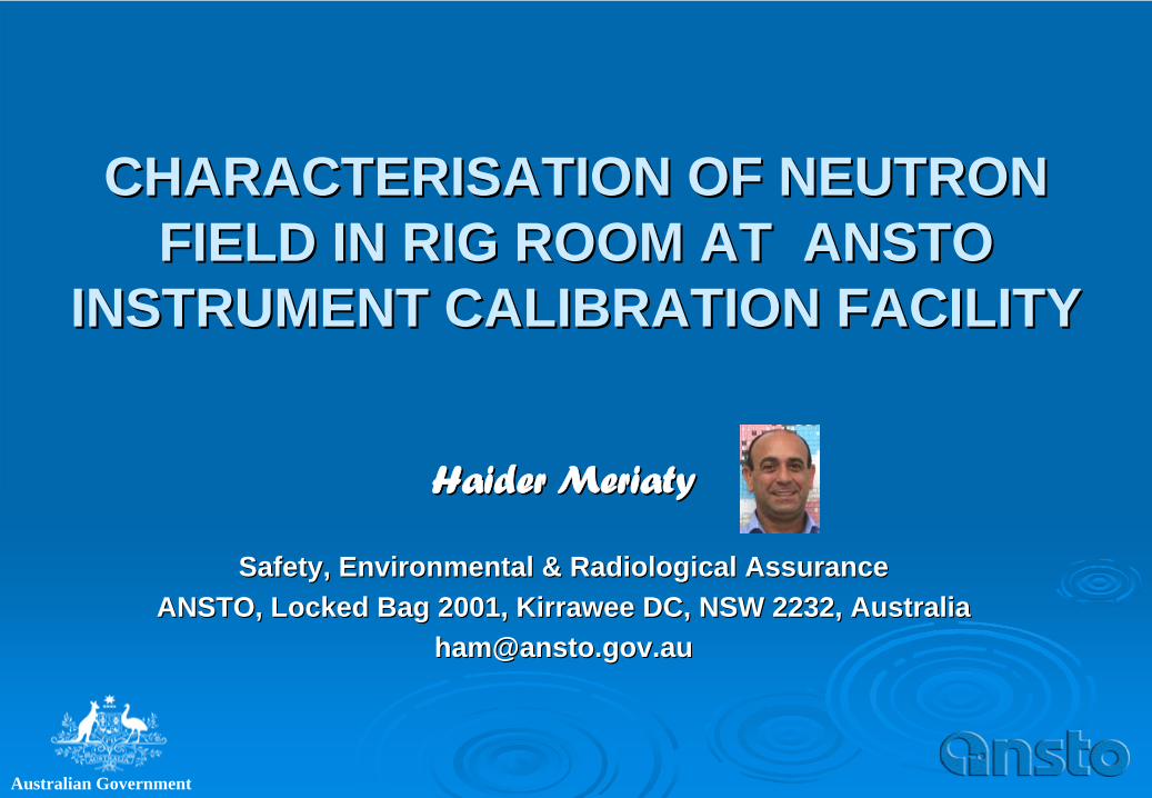
INTRODUCTIONThe Instrument Calibration Facility at Australian Nuclear Science & Technology Organisation (ANSTO) provides calibration to radiation monitors for radiation protection applications. The Services cover neutron, gamma, beta and alpha monitors.
The neutron calibration room was characterised with 241Am/Be source, dose equivalent neutron monitor (digipig2222). The room’s size category is large1.
OBJECTIVES
To determine the Fractional Room Return Scatter at the ICF rig calibration room.
To determine the ambient dose equivalent response of ICF reference neutron monitor.
To evaluate the appropriate calibration standards for implementation at ICF.
METHODOLOGY
Measurement results were assessed by four different standard methods, which commonly applied at neutron calibration facilities. The methods1 included, the Shadow Shield, the Semi-Empirical, the Polynomial and NCRP-112 shadow shield.
The shadow shield was a truncated cone of two stacked sections: a solid iron and an aluminum shell filled with 24%w/w LiBr aqueous solution. The properties5 of neutron absorption and scattering were compared with Li2 CO3 wax shield of NCRP-112 and the former showed superior properties.
Forsythe and Power Least squared methods3 were used to fit the polynomial functions.

CHARACTERISATION TECHNIQUES1) Shadow Shield (ISO 10647):
M . FA (l) = k / l 2 (Equation 1)Monitor readings were taken with and without the shield. The reading difference, corrected for air attenuation ‘FA (l )’ (Table 1), plotted against the inversed distance squared (Plot 1). The Characteristic Constance ‘k’ obtained as the slope of the linear function, fitted to data.2) Semi-Empirical (ISO 10647:
MT / [
. Fl (l) . (1 + A . l )] = R
(1 + S . l 2) (Equation 2)The ratio of Monitor readings to neutron fluence, corrected for air scatter ‘A’ and geometry ‘F1 (l)’’, were taken and plotted versus distance squared (plot 3). Data fitted into linear function. The intercept and slope of the function provided the monitor response and the fractional room return scatter ‘s’ (Table 5).3) Polynomial Fitting (ISO 10647):
MT / [
. Fl (l)] = R
(1 + B . l + C . l 2) (Equation 3)The ratio of Monitor readings to neutron fluence, corrected for geometry ‘F1(l)’’ (Table 3), were taken and plotted versus distance (Plot 4). Data fitted into quadratic function3. The intercept of the function provided the monitor response, R
. Also, linear function fitted to data and compared with the quadratic one.4) Shadow Shield (NCRP 112):
D. l 2 = Do (1 + S. l 2) (Equation 4)The product of monitor readings by distance squared (Table 4) were plotted versus distance squared as well as fitted into linear function. The function’s intercept and slope provided the monitor response and the fractional room return scatter ‘S’ (Plots 5, 6).
TOOLS & INSTRUMENT
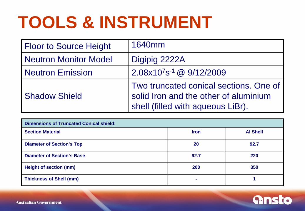
Dimensions of Truncated Conical shield:
Section Material Iron Al Shell
Diameter of Section’s Top 20 92.7
Diameter of Section’s Base 92.7 220
Height of section (mm) 200 350
Thickness of Shell (mm) - 1
Floor to Source Height 1640mm
Neutron Monitor Model Digipig 2222ANeutron Emission 2.08x10⁷s-1 @ 9/12/2009
Shadow ShieldTwo truncated conical sections. One of solid Iron and the other of aluminium shell (filled with aqueous LiBr).

SETUP1: SOURCE, SHADOW SHIELD & MONITOR
The conical shadow shield was placed at half way between the source rig (red circle) and monitor stand (exception was the measurement at 1m). Steps ladder was removed during measurements.

At 1m reference distance, the shadow shield was placed closer to source guide (vertical tube to left). This arrangement allowed sufficient scattered neutrons to impinge on monitor.
SETUP2: SOURCE, SHADOW SHIELD & MONITOR

FLOOR PLAN OF RIG CALIBRATION ROOM
Neutron Source
Rail & monitor stand system
concrete walls
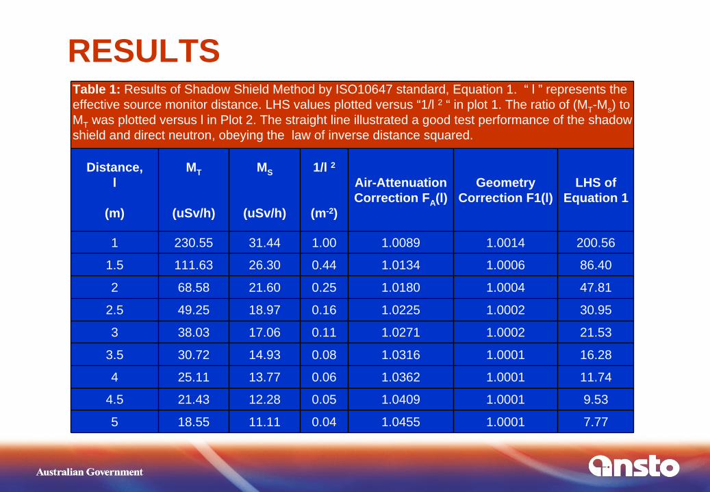
Table 1: Results of Shadow Shield Method by ISO10647 standard, Equation 1. “ l ” represents the effective source monitor distance. LHS values plotted versus “1/l 2 “ in plot 1. The ratio of (MT -Ms ) to MT was plotted versus l in Plot 2. The straight line illustrated a good test performance of the shadow shield and direct neutron, obeying the law of inverse distance squared.
Distance, l
(m)
MT
(uSv/h)
MS
(uSv/h)
1/l 2
(m-2)
Air-Attenuation Correction FA (l)
Geometry Correction F1(l)
LHS of Equation 1
1 230.55 31.44 1.00 1.0089 1.0014 200.56
1.5 111.63 26.30 0.44 1.0134 1.0006 86.40
2 68.58 21.60 0.25 1.0180 1.0004 47.81
2.5 49.25 18.97 0.16 1.0225 1.0002 30.95
3 38.03 17.06 0.11 1.0271 1.0002 21.53
3.5 30.72 14.93 0.08 1.0316 1.0001 16.28
4 25.11 13.77 0.06 1.0362 1.0001 11.74
4.5 21.43 12.28 0.05 1.0409 1.0001 9.53
5 18.55 11.11 0.04 1.0455 1.0001 7.77
RESULTS

Plot 1: Direct neutron dose rate versus source-monitor inverse distance squared at ICF. The “y” function represents the linear fitting of data. The straight line and correlation value (R2) illustrated a good outcome of the performance test of the shield integrity.
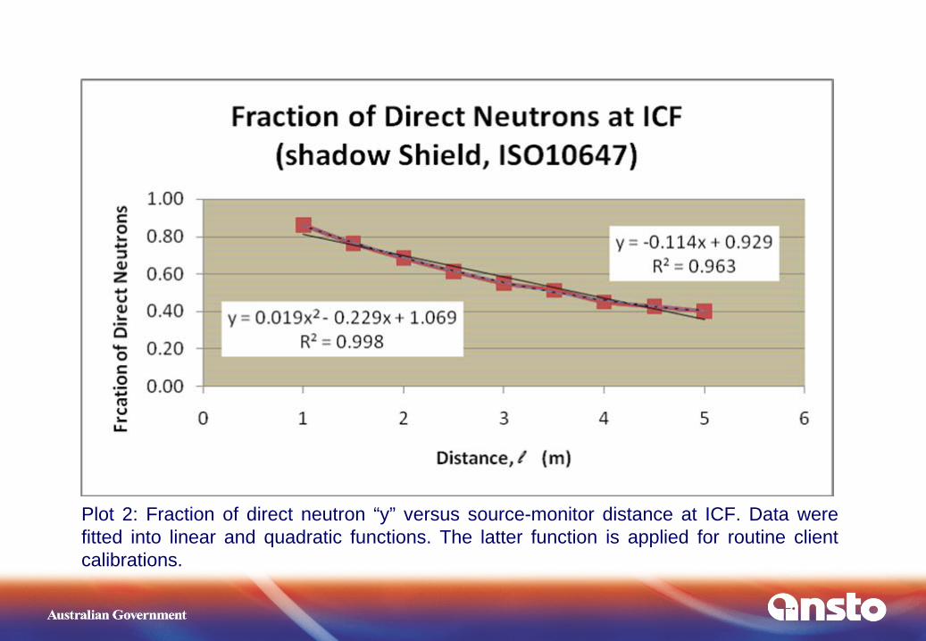
Plot 2: Fraction of direct neutron “y” versus source-monitor distance at ICF. Data were fitted into linear and quadratic functions. The latter function is applied for routine client calibrations.
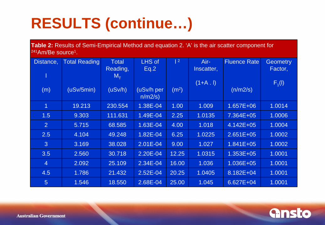
Table 2: Results of Semi-Empirical Method and equation 2. ‘A’ is the air scatter component for 241Am/Be source1.Distance,
l
(m)
Total Reading
(uSv/5min)
Total Reading,
MT
(uSv/h)
LHS of Eq.2
(uSv/h per n/m2/s)
l 2
(m2)
Air- Inscatter,
(1+A . l)
Fluence Rate
(n/m2/s)
Geometry Factor,
F1 (l)
1 19.213 230.554 1.38E-04 1.00 1.009 1.657E+06 1.00141.5 9.303 111.631 1.49E-04 2.25 1.0135 7.364E+05 1.00062 5.715 68.585 1.63E-04 4.00 1.018 4.142E+05 1.0004
2.5 4.104 49.248 1.82E-04 6.25 1.0225 2.651E+05 1.00023 3.169 38.028 2.01E-04 9.00 1.027 1.841E+05 1.0002
3.5 2.560 30.718 2.20E-04 12.25 1.0315 1.353E+05 1.00014 2.092 25.109 2.34E-04 16.00 1.036 1.036E+05 1.0001
4.5 1.786 21.432 2.52E-04 20.25 1.0405 8.182E+04 1.00015 1.546 18.550 2.68E-04 25.00 1.045 6.627E+04 1.0001
RESULTS (continue…)
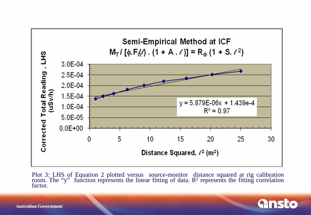
Plot 3: LHS of Equation 2 plotted versus source-monitor distance squared at rig calibration room. The “y” function represents the linear fitting of data. R2 represents the fitting correlation factor.

Table 3: Results of Polynomial Fitting Method and Equation 3. LHS values plotted versus distance (l ) and fitted to quadratic function (RHS) of a, b, c parameters. The data fitted also linearly for comparison (Plot 4). The percentage difference (%) of RHS to LHS results is listed in column 8.
Distance,
l
(m)
l 2
(m2)
Total Reading
MT
(uSv/h)
Geometry Factor,
F1 (l)
Fluence Rate
(n/m2/s)
LHS
(uSv/h per n/m2/s)
RHS=R(1+b..l +c..l 2)
1.042e- 4(1+0.2966 l +0.8671 l 2)
%
of RHS to
LHS
1 1 2.306E+02 1.0014 1.657E+06 1.389E-04 1.360E-04 2.091.5 2.25 1.116E+02 1.0006 7.364E+05 1.515E-04 1.526E-04 -0.752 4 6.858E+01 1.0004 4.142E+05 1.655E-04 1.697E-04 -2.51
2.5 6.25 4.925E+01 1.0002 2.651E+05 1.857E-04 1.872E-04 -0.773 9 3.803E+01 1.0002 1.841E+05 2.065E-04 2.051E-04 0.69
3.5 12.25 3.072E+01 1.0001 1.353E+05 2.271E-04 2.235E-04 1.584 16 2.511E+01 1.0001 1.036E+05 2.424E-04 2.424E-04 0.04
4.5 20.25 2.143E+01 1.0001 8.182E+04 2.619E-04 2.617E-04 0.105 25 1.855E+01 1.0001 6.627E+04 2.799E-04 2.814E-04 -0.55
RESULTS (continue…)

Polynomial Fitting Method at ICFDose Rate = a + b.l + c.l 2
y = 3.63E‐05x + 9.76E‐05
R2 = 9.97E‐01
y = 3.59E‐05x + 9.86E‐05
R2 = 9.99E‐01
0.0E+00
5.0E‐05
1.0E‐04
1.5E‐04
2.0E‐04
2.5E‐04
3.0E‐04
0 1 2 3 4 5 6
Distance, l (m)
Dose Rate Responses, (uSv/hr)
LHS‐Eq.3
RHS‐Eq.3
Linear (LHS‐Eq.3)
Linear (RHS‐Eq.3)
Parameters of Fitting:R=a=1.073e‐4b=2.876e‐5c=1.186e‐6
Dose Rate=1.073e‐4(1+0.268 l +0.011 l 2)
Plot 4: Data was fitted to Equation 3 (i.e. quadratic function, RHS), so its parameters “a”, “b” and “c” were determined. The fitted function as well as data (i.e. LHS) were then plotted versus source-monitor distance. The dose rate response (R
) is given by parameter “a” of the fitted function. Data were also fitted to a linear function and plotted for comparison.
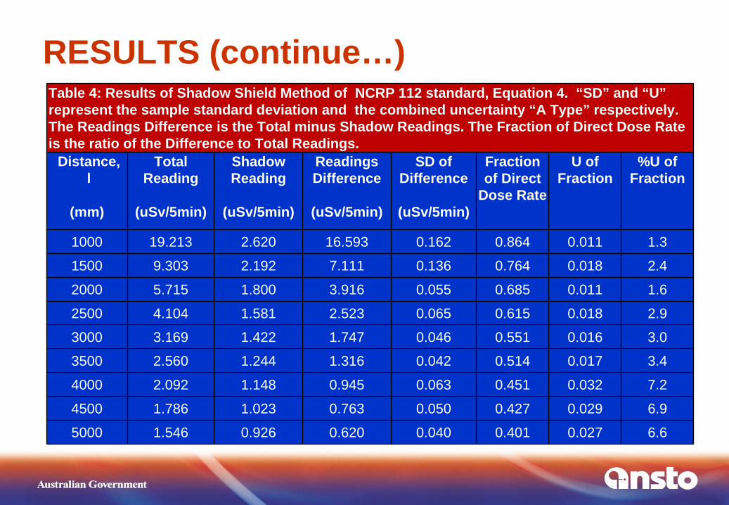
Table 4: Results of Shadow Shield Method of NCRP 112 standard, Equation 4. “SD” and “U” represent the sample standard deviation and the combined uncertainty “A Type” respectively. The Readings Difference is the Total minus Shadow Readings. The Fraction of Direct Dose Rate is the ratio of the Difference to Total Readings.
Distance,l
(mm)
Total Reading
(uSv/5min)
Shadow Reading
(uSv/5min)
Readings Difference
(uSv/5min)
SD of Difference
(uSv/5min)
Fraction of Direct
Dose Rate
U of Fraction
%U of Fraction
1000 19.213 2.620 16.593 0.162 0.864 0.011 1.3
1500 9.303 2.192 7.111 0.136 0.764 0.018 2.4
2000 5.715 1.800 3.916 0.055 0.685 0.011 1.6
2500 4.104 1.581 2.523 0.065 0.615 0.018 2.9
3000 3.169 1.422 1.747 0.046 0.551 0.016 3.0
3500 2.560 1.244 1.316 0.042 0.514 0.017 3.4
4000 2.092 1.148 0.945 0.063 0.451 0.032 7.2
4500 1.786 1.023 0.763 0.050 0.427 0.029 6.9
5000 1.546 0.926 0.620 0.040 0.401 0.027 6.6
RESULTS (continue…)

Plot 5 : Fraction of direct neutron “y” versus source-monitor distance at ICF. Data were fitted into linear and quadratic functions and plotted for comparison.

Plot 6: Fraction of direct neutron versus source-monitor distance at ICF. Data were fitted into linear and quadratic functions and plotted for comparison.
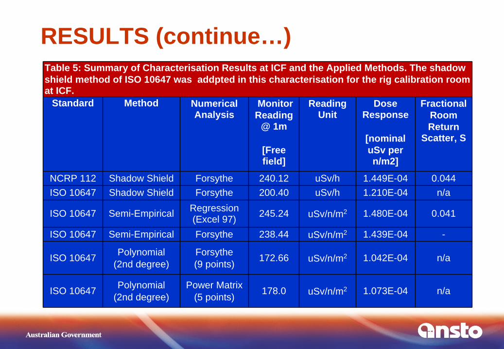
Table 5: Summary of Characterisation Results at ICF and the Applied Methods. The shadow shield method of ISO 10647 was addpted in this characterisation for the rig calibration room at ICF.
Standard Method Numerical Analysis
Monitor Reading
@ 1m
[Free field]
Reading Unit
Dose Response
[nominal uSv per n/m2]
Fractional Room Return
Scatter, S
NCRP 112 Shadow Shield Forsythe 240.12 uSv/h 1.449E-04 0.044ISO 10647 Shadow Shield Forsythe 200.40 uSv/h 1.210E-04 n/a
ISO 10647 Semi-Empirical Regression (Excel 97) 245.24 uSv/n/m2 1.480E-04 0.041
ISO 10647 Semi-Empirical Forsythe 238.44 uSv/n/m2 1.439E-04 -
ISO 10647 Polynomial(2nd degree)
Forsythe(9 points) 172.66 uSv/n/m2 1.042E-04 n/a
ISO 10647 Polynomial(2nd degree)
Power Matrix(5 points) 178.0 uSv/n/m2 1.073E-04 n/a
RESULTS (continue…)
DISCUSSION
The evaluation of LiBr and Li2 CO3 properties for neutron demonstrated the advantage of LiBr solution as shadow shield materials against Li2 CO3 waxed cone i.e. 7% higher absorption and 31% less scattering of neutrons. In addition, the solution did provide a uniformity of absorber distribution at ionic level as well as simpler and straightforward preparation. The shadow shield assembly passed the performance test well, in which the direct neutron fluence followed the law of inverse distance squared (plot 1).
The arithmetical mean and sample standard deviation of repeated 5 measurements were used to represent the average reading and associated statistical dispersion. The uncertainty propagation technique was applied, to obtain the combine uncertainty (A type) of a given measurement technique’s function4.
The fitted & plotted agreement with the hypothesis of the measurement technique was considered as an illustration of good accuracy with measurement4. The uncertainty scope given in ISO 10647 is still applicable to this work and considered as Type B uncertainty.
The values of Characteristic Constant ‘k’, the fraction of free field neutrons and ‘S’ obtained, by the shadow shield methods, were implemented at ICF rig calibration room i.e. medium to large size of calibration room1.
The ‘in situ’ calibration of ICF reference monitor was compared and agreed with the monitor calibration that completed recently by PTB standard laboratory, within 5.6% accuracy.
At 1m reference distance, the shadow shield was placed closer to source i.e. 5cm (photo in setup2). This arrangement was necessary to allow sufficient air gap between the cone face and monitor, so optimising the linear relationship1, 9 between air inscatter and net scatters (i.e. inscatter minus outscatter). The ratio of monitor-air gap to cone length was 73% of the recommended value (for uncertainty < 3%). However, the shield was placed half way between source and monitor (photo in setup1) in other reference distances,
CONCLUSIONS
The Fractional Room Return Scatter (S) at ICF rig calibration room was determined. Its small value illustrated a good quality feature of the room e.g. minimal scatter (Table 5).
The measured S Values by NCRP112 or ISO10647 techniques (equations 2 & 4) were in good agreement (93%).
Routine calibrations should be carried out within 3m distance from neutron source in order to comply with 40% room scatter limit, recommended by ISO10647 standard.
The new type of aqueous LiBr truncated cone was successfully implemented in measurements of the shadow shield technique.
The fluence and dose rate equivalent responses were determined (Table 5) for ICF reference monitor (digipig2222A type) and 241Am/Be neutron source. The reference neutron fluence was taken from the source certificate6 and is now linked to the PTB standard authority for traceability.
The ‘in situ’ calibration of ICF reference monitor compared and agreed with the monitor calibration that completed recently by PTB standard laboratory, within 5.6% accuracy
Two extra positions of higher dose rate were determined (extrapolation). They expand the capability of dose rate range at ICF calibration service that desired by some clients.
The characterisation parameters measured by the different techniques were evaluated and the Shadow Method1 of ISO10647 was identified as the appropriate one for implementation at ICF rig calibration room.
Two neutron sources of appropriate activities are recommended, So the full dose rates range given in ISO10647 can be achieved within the distance limitation for air scatter .
REFERENCES1) ISO 10647, 1996E; ISO 8522:1989E; ISO 8529-3:1998E.2) NCRP 112 Report, 1991.3) Southworth, R.W, et al; Digital Computation & Numerical Methods;
1965.4) Caria, M; Measurement Analysis, 2000.5) Curtiss, L. F.; Introduction to Neutron Physics, 19596) 241Am/Be Certificate of Measurement; NPL Reference N113, 1982. 7) Hunt, J B; The Calibration of Neutron Sensitive Spherical devices,
Radiation Protection & Dosimetry, 1984.8) Eisenhauer, C M; Review of Scattering Corrections for Calibration of
Neutron Instruments; Radiation Protection & Dosimetry, , 1989.9) Burger, G, et al.; Guidelines on Calibration of Neutron Measuring
Devices; IAEA; 1988
Related Documents