All rights reserved. 2003 A. Jaafar Chapter 3: Fluid kinematics The Bernoulli Equation • Newton’s Second Law •F=ma along a streamline •F=ma normal to a streamline •Physical interpretations •Static, Stagnation, Dynamic and Total Pressure •Examples of use of the Bernoulli Equation •The energy line and the hydraulic grade line •Restrictions of use of the Bernoulli Equation Open

Welcome message from author
This document is posted to help you gain knowledge. Please leave a comment to let me know what you think about it! Share it to your friends and learn new things together.
Transcript

All rights reserved. 2003 A. Jaafar
Chapter 3: Fluid kinematics
The Bernoulli Equation• Newton’s Second Law•F=ma along a streamline•F=ma normal to a streamline•Physical interpretations•Static, Stagnation, Dynamic and Total Pressure•Examples of use of the Bernoulli Equation•The energy line and the hydraulic grade line•Restrictions of use of the Bernoulli Equation
Open

All rights reserved. 2003 A. Jaafar
Newton’s 2nd Law
The net force acting on the fluid particle must equal its mass times its acceleration
F=maFor inviscid fluid, we are assuming that the fluid motion is governed by pressure and gravity forces only
Open
All rights reserved. 2003 A. Jaafar
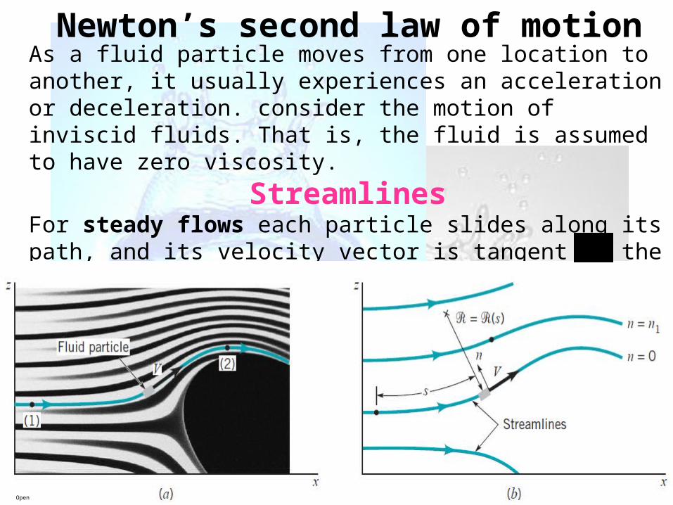
Newton’s second law of motionAs a fluid particle moves from one location to another, it usually experiences an acceleration or deceleration. consider the motion of inviscid fluids. That is, the fluid is assumed to have zero viscosity.
StreamlinesFor steady flows each particle slides along its path, and its velocity vector is tangent to the path. The lines that are tangent to the velocity vectors throughout the flow field are called streamlines.
Open

All rights reserved. 2003 A. JaafarOpen

All rights reserved. 2003 A. Jaafar
Bernoulli equation states that the sum of pressure head,Velocity head, andElevation head is constant along a streamline
Open

All rights reserved. 2003 A. Jaafar
Physical InterpretationAn equivalent form of the Bernoulli Equation
Hzg
Vp
2
2
Constant along a streamline
Elevation head-related to potential energy of the particle
Velocity head-vertical distance needed for the fluid to fall freely (neglecting friction) if it is to reach V from restPressure head
-height of the column of fluid that is needed to produce the pressure p
Total head
Open

All rights reserved. 2003 A. Jaafar
Example 1 Some animals have learned to take advantage of the Bernoulli
effect. For example, a typical prairie dog burrow contains two entrances – a flat front door and a mounded back door. When the wind blows with velocity Vo across the front door, the average velocity across the back door is greater than Vo because of the mound. Assume the air velocity across the back door is 1.07Vo. For a wind velocity of 6 m/s, what pressure difference, p1-p2, is generated to provide a fresh air flow within the burrow.
Open

All rights reserved. 2003 A. JaafarOpen

All rights reserved. 2003 A. Jaafar
Static, stagnation, Dynamic and Total
Pressure TpzVp 2
2
1Constant along a streamline
Dynamic pressure
Hydrostatic pressure
Total pressure
Static pressureActual thermodynamic pressure
Open

All rights reserved. 2003 A. JaafarOpen
Static, stagnation, Dynamic pressure

All rights reserved. 2003 A. Jaafar
Static, stagnation, DynamicThe way to measure the static pressure would be to drill a hole in a flat surface and fasten a piezometer tube as indicated by the location of point 3 in Figure. P3=ρgh4-3
Open
Point 2 is a stagnation point.
ρ V2/2 is called dynamic pressure

All rights reserved. 2003 A. Jaafar
Static, stagnation, Dynamic and Total
Pressure (cont.)Then, p2 is called the stagnation pressure
The pressure at stagnation point, p2, is greater than the static pressure, p1
There is a stagnation point on any stationary body that is placed into a flowing fluid
Open

All rights reserved. 2003 A. Jaafar
Example 2Natural gas (methane) flow from a 7.6cm diameter gas main, through a 2.5cm diameter pipe and in to a burner of a furnace at a rate of 2.8m3/h. determine the pressure in the gas main if the pressure in the 2.5cm pipe is to be 15.2cm of water (take density of methane =0.667kg/m3)
Open

All rights reserved. 2003 A. JaafarOpen

All rights reserved. 2003 A. JaafarOpen

All rights reserved. 2003 A. Jaafar
Examples of use of the Bernoulli Equation
Free Jets
Assumptionsz1=h, z2=0
Reservoir is large, V1=0
Reservoir is open to atmosphere, p1=0 gage
Fluid leaves as a free jet, p2=0 gageOnce outside nozzle, the stream continues as a free jet, p5=0 gage
Figure 3 : Vertical flow
from a tank
Open

All rights reserved. 2003 A. Jaafar
Example 3Determine the flow rate from the tank
as shown in figure
Open
(Ans.=3.7liters/s)

All rights reserved. 2003 A. JaafarOpen
Q = A2V2=0.0037m3/s

All rights reserved. 2003 A. Jaafar
Example 4 If viscous effects are neglected and the tank is large, determine the flow rate
from the tank shown in Fig.
Open

All rights reserved. 2003 A. Jaafar
Z1 = 0.7, V1 = 0,
Z2 = 0 and P2 = 0
Open
Datum line

All rights reserved. 2003 A. Jaafar
Example 4Water flows through the pipe contraction shown in Figure for the given 0.2-m difference in the manometer level, determine the flow rate as a function of the diameter of the small pipe, D. (Answer=0.0156m3/s)
Open

All rights reserved. 2003 A. Jaafar
Solution in the class
Q=0.1555 m3/sOpen

All rights reserved. 2003 A. Jaafar
Water flows through the pipe contraction shown in Figure For the given 0.2-m difference in the manometer level, determine the flow rate as a function of the diameter of the small pipe, D.
Example 5
Open

All rights reserved. 2003 A. Jaafar
Solution in the class
Open

All rights reserved. 2003 A. Jaafar
Examples of use of the Bernoulli Equation
Confined FlowsIn many cases, fluid is confined and its pressure cannot be prescribed a priori – need to use the concept of conservation of mass
Figure 5 : Steady flow into and out of a tank
Open

All rights reserved. 2003 A. Jaafar
Examples of use of the Bernoulli Equation
Confined Flows (cont.)
In such case, mass is conserved, i.e. inflow rate must equal to the outflow rate
In general, following Bernoulli, an increase in velocity (could be due to reduction of flow area) is accompanied by a decrease in pressureFor flows of liquids, this may result in cavitation, a potentially dangerous situation that results when liquid pressure is reduced to vapor pressure and the liquid “boils”.
ible)incompress(ifor 211222111 VAVAVAVA
AVmAVQ ,
Open

All rights reserved. 2003 A. Jaafar
Example 5Water is siphoned from a large tank and discharges into the atmosphere through a 5.08 cm diameter tube as shown in Figure. The end of the tube is 0.9 m below the tank bottom, and viscous effects are negligible. (a) Determine the volume flow rate from the tank. (b) Determine the maximum height, H, over which the water can be siphoned without cavitation occurring. Atmospheric pressure is 101.3 Kpa and the water vapor pressure Is 1.8 Kpa
Open

All rights reserved. 2003 A. JaafarOpen

All rights reserved. 2003 A. Jaafar
Solution in the class
Open

All rights reserved. 2003 A. JaafarOpen

All rights reserved. 2003 A. Jaafar
Examples of use of the Bernoulli Equation
Free Jets (cont.) – If exit of tank is not smooth, well contoured nozzle, the diameter of the jet will be less than the diameter of the hole – vena contracta effect– Contraction coef., Cc=Aj/Ah
holejet
Figure 3 : Typical flow patterns and contraction coef. for various round exit configurations
Open

All rights reserved. 2003 A. Jaafar
Examples of use of the Bernoulli Equation
Flowrate measurement Assumptions – steady, inviscid and incompressible
Figure 6 : Typical devices for measuring flowrate in pipes
Open

All rights reserved. 2003 A. Jaafar
Examples of use of the Bernoulli Equation
Flowrate measurement (cont.)Between points (1) and (2)
212
212
2211
222
12
212
11
1
)(2
hence
and
AA
ppAQ
VAVAQ
VpVp
Open

All rights reserved. 2003 A. Jaafar
Examples of use of the Bernoulli Equation
Flowrate measurement (cont.)The actual measured flowrate, Qactual will be smaller than this theoretical results because of the assumptions made in deriving the Bernoulli Equation
Other flowmeters based on Bernoulli equation are used to measure flowrates in open channels such as flumes and irrigation ditches.
Open

All rights reserved. 2003 A. Jaafar
Determine the flow rate through the Venturi meter shown in figure if ideal conditions exist. (6 liters/s)
Open

All rights reserved. 2003 A. Jaafar= 6.1 Liters/s
Open

All rights reserved. 2003 A. JaafarOpen
Water flows steadily from large tank and exits through a vertical, constant diameter pipe as shown in the following figure. The air in the tank is pressurized to 50 kN/m2. Assume inviscid and incompressible flow for the water. The specific weight of water is 9.8 kN/m3. Determine 1.Determine the height, h to which the water rises. 2.Calculate the water velocity in the pipe. 3.Find the pressure in the horizontal part of the pipe. 4.Propose TWO(2) changes we can make in order to decrease the height of the fountain to half of the initial height. Justify your answers

All rights reserved. 2003 A. JaafarOpen
ρg = 1000x9.81=9810
SinceP1= 50,000 Pa, P2=0V1=0, V2=0Z1=2, Z2=h=???

All rights reserved. 2003 A. JaafarOpen
SinceP1= 50,000 Pa, P2=0V1=0, V2=?Z1=2, Z2=4
ρg = 1000x9.81=9810

All rights reserved. 2003 A. Jaafar
SinceP1= 50,000 Pa, P2=????V1=0, V2=7.79Z1=2, Z2=0
Open

All rights reserved. 2003 A. Jaafar
Videos
Open
Related Documents