Section 4.6

Welcome message from author
This document is posted to help you gain knowledge. Please leave a comment to let me know what you think about it! Share it to your friends and learn new things together.
Transcript

Section 4.6

THIS PAGE IS INTENTIONALLY BLANK

Proponent’s Environmental Assessment Devers-Mirage 115 kV Subtransmission System Split Project January 2008
4.6-1
4.6 GEOLOGY AND SOILS This section describes existing conditions and the potential impacts on geology and soils from construction and operation of the Proposed Project and alternatives. 4.6.1 Applicable Laws, Regulations, and Standards 4.6.1.1 Alquist-Priolo Earthquake Fault Zoning Act The intent of the Alquist-Priolo Earthquake Fault Zoning Act of 1972 (AP Act) is to minimize the chance for structures used for human occupancy to be built over active faults, by requiring a geological investigation for new development within designated active earthquake fault zones. The AP Act includes definitions for “active faults” and “potentially active faults,” as well as for other specific terms applied to fault evaluations. For purposes of implementing the AP Act, it is assumed that the area within 50 feet of an active fault is underlain by active branches of the fault, until proven otherwise by an appropriate geologic investigation. 4.6.1.2 Seismic Hazards Mapping Act The State Department of Conservation, California Geological Survey (CGS), provides guidance with regard to seismic hazards. Under the CGS Seismic Hazards Mapping Act, seismic hazard zones are to be identified and mapped to assist local governments for planning and development purposes. The intent of this publication is to protect the public from the effects of strong ground shaking, liquefaction, landslides, or other types of ground failure, and other hazards caused by earthquakes. CGS Special Publications 117, Guidelines for Evaluating and Mitigating Seismic Hazards in California, provides guidance for evaluation and mitigation of earthquake-related hazards for projects within designated zones of required investigations. 4.6.1.3 Design Standards Building codes provide specific standards for design of buildings and structures. The Uniform Building Code (UBC) defines "expansive soil" in Table 18-1-B. The UBC does not apply to electrical structures or other equipment. SCE complies with Institute of Electrical and Electronics Engineers (IEEE) standards. The IEEE provides recommended seismic design practices for electrical equipment within substations in IEEE 693-2005. SCE designs overhead electric lines to meet or exceed GO 95 wind-loading criteria. SCE's design standards incorporate lateral wind loading requirements that exceed seismic loading forces. 4.6.1.4 Riverside County General Plan The Riverside County General Plan Safety Element includes faults designated under both the AP Act, as well as their own County Fault Zones. 4.6.2 Significance Criteria Impacts to geology and soils are considered potentially significant if the project:

Proponent’s Environmental Assessment Devers-Mirage 115 kV Subtransmission System Split Project January 2008
4.6-2
• Exposes people or structures to potential substantial adverse effects, including the risk of loss, injury, or death involving: - Rupture of a known earthquake fault, as delineated on the most recent Alquist-Priolo
Earthquake Fault Zoning Map issued by the State Geologist for the area or based on other substantial evidence of a known fault
- Strong seismic ground shaking - Seismic-related ground failure, including liquefaction - Landslides
• Results in substantial soil erosion or the loss of topsoil • Is located on a geologic unit or soil that is unstable, or that would become unstable as a
result of the project, and potentially result in on- or off-site landslide, lateral spreading, subsidence, liquefaction or collapse
• Is located on expansive soil, as defined in Table 18-1-B of the Uniform Building Code (1994), creating substantial risks to life or property
• Has soils incapable of adequately supporting the use of septic tanks or alternative waste water disposal systems where sewers are not available for the disposal of wastewater
4.6.3 Applicant Proposed Measures The following APMs would be implemented for geological and soil resources.
GEO-1. Seismic Design for Ground Shaking. A geotechnical investigation of site soils and geologic conditions, coupled with engineering design, would identify the hazards and develop recommendations to support appropriate seismic designs to mitigate the effects of ground shaking. Specific requirements for seismic design would be based on the IEEE 693 “Recommended Practices for Seismic Design of Substations.” GEO-2. Subsurface Trenching. Where appropriate, subsurface trenching along active fault traces would be required to ensure tower foundations are not placed on, or immediately adjacent to, these features. In addition, tower locations would be selected to accommodate anticipated fault offset, and minimize excessive tension in lines, should a fault movement occur.
4.6.4 Environmental Setting The geological study area includes the City of Palm Springs and the community of Thousand Palms, in Riverside County, California. This area is defined as the Coachella Valley, which is characterized by extreme variation in topographic features and is the northern extension of a broad structural depression known as the Salton Trough. The northern, western, and southern edges of the Coachella Valley are bordered by major mountain ranges, including the San Bernardino, Little San Bernardino, San Jacinto, and Santa Rosa mountains. Coachella Valley elevations are near mean sea level and summit elevations range from 9,600 feet to 11,502 feet above mean sea level (City of Palm Desert Comprehensive General Plan V-2 2004). 4.6.4.1 Geologic Setting The Coachella Valley is a broad alluvial plain, extending for approximately 45 miles in Riverside County, southeast from the San Bernardino Mountains to the Salton Sea (Proctor 1968). The Coachella Valley is approximately 15 miles wide for most of its length, bounded on the west by

Proponent’s Environmental Assessment Devers-Mirage 115 kV Subtransmission System Split Project January 2008
4.6-3
the San Jacinto Mountains, on the south by the Santa Rosa Mountains, and on the north and east by the Little San Bernardino Mountains. Two branches of the San Andreas Fault trend through Coachella Valley. The north branch, also known as the Mission Creek Fault, runs along the north side of the Indio Hills, in the center of the Coachella Valley. The south branch, also known as the Banning Fault, runs along the south side of the Indio Hills. The geological study area consists largely of Holocene alluvium (sand and gravel), which overlies thick Pleistocene fan deposits (Procter 1968; Rasmussen 1981). The Proposed Project lies within the San Andreas Fault zone, and fault branches within the San Andreas fault zone that cross, or lie adjacent to, the geological study area include the Banning and the Garnet Hill faults. Faults in the region are delineated on Figure 4.6-1: Regional Fault Map. The only two recent fault activities recorded in Palm Springs include the 1986 North Palm Springs earthquake and the 1992 Landers earthquake. The 1986 quake registered a magnitude of 5.6 and caused minor ground rupturing along the Banning, Mission Creek, and Garnet Hill faults, but these cracks were due to shaking, not surface rupture (Southern California Earthquake Data Center). The 1992 quake mainly produced landslides triggered by long ground-shaking but it also did cause fractures along the Garnet Hill Fault (Palm Springs General Plan 2006). The Proposed Project is located within the northwestern portion of the Salton Trough, a narrow, tectonic depression that began forming about 5 million years ago. The geologic and hydrologic characteristics of this formation are responsible for a number of geologic hazards and engineering challenges, which are described below. The most recently deposited sediments in the geological study area are of alluvial (stream-deposited) or aeolian (wind-deposited) origin. Among these hazards are windblown sand, wind erosion, and subsidence (gradual settling or sinking of the ground surface) (City of Palm Desert Comprehensive General Plan V-2 2004). 4.6.4.2 Geologic Hazards Collapsible Soils Soil collapse, or hydroconsolidation, occurs when soils undergo a rearrangement of their grains and a loss of cementation, resulting in substantial and rapid settlement under relatively low loads. This phenomenon typically occurs in recently deposited Holocene soils in a dry or semi-arid environment, including aeolian sands and alluvial fan and mudflow sediments deposited during flash floods. Alluvial and aeolian sediments in the geological study area have the potential for collapse (City of Palm Desert Comprehensive General Plan V-3 2004). Expansive Soils Expansive soils contain significant amounts of clay particles that have the ability to give up water (shrink) or take on water (swell). When these soils swell, the change in volume can exert significant pressures on loads that are placed on them, such as buildings, and can result in structural distress and/or damage. Given the relatively minor amount of clay present in soils in and around the study area, expansive soils are not considered a hazard in the geological study area (City of Palm Desert Comprehensive General Plan V-6 2004). Regional Tectonic Setting The City of Palm Springs is located at the northwestern extreme of the Salton Trough, a broad structural depression, which is the landward extension of the San Andreas rift zone. As the ridge

Proponent’s Environmental Assessment Devers-Mirage 115 kV Subtransmission System Split Project January 2008
4.6-4
spreads, it forces the Pacific tectonic plate to move northwestwardly into the North American Plate. These plates are sliding past one another at a rate of about 50 millimeters per year, and their movement is responsible for generating the earthquakes that occur in southern California (City of Palm Desert Comprehensive General Plan V-9 2004). Seismic Activity The Proposed Project is located within the San Andreas Fault zone, which crosses the northern boundary of the Palm Springs planning area. Several faults are capable of generating strong ground-shaking in the geological study area, and strong ground-shaking is the geologic hazard that has the greatest potential to impact the Proposed Project (City of Palm Desert Comprehensive General Plan V-10 2004). The numerous faults mentioned earlier are likely to experience some activity in the future, which is why there is a possibility of structural damage to the Proposed Project components in the future. The Garnet Hill Fault extends from the vicinity of Whitewater Canyon possibly as far as Edom Hill and crosses close to the geological study area, just north of I-10. Given the orientation and proximity of the Garnet Hill Fault to the San Andreas Fault, the Garnet Hill Fault may be an ancestral branch of the San Andreas Fault. Although the California Division of Mines and Geology has not designated the Garnet Hill Fault as an active fault, it can act as a plane of weakness and move in response to an earthquake on another nearby fault. Ground fractures associated with the 1986 North Palm Springs earthquake were reported along the trace of the Garnet Hill Fault and indicate a near-surface response of weak surfaces (Cathedral City General Plan V-12, 13 2002). 4.6.4.3 Seismically Induced Geotechnical Hazards Liquefaction Liquefaction is the total or substantial loss of the shear strength of loose, sandy, saturated sediments in the presence of ground accelerations greater than 0.2 g (acceleration due to gravity). Liquefaction generally occurs within 50 feet of the ground surface because below that depth it is prevented by high, confining pressures. When liquefaction occurs, the sediments involved behave much like a liquid. This phenomenon can result in structural distress and/or failure due to settlement. The potential for liquefaction to occur is low to none throughout most of the geological study area, principally because groundwater in Palm Springs and Thousand Palms typically occurs deeper than 100 feet below the ground surface, too deep to saturate the loose sediments of the valley floor (Palm Springs General Plan 2006, Palm Desert General Plan 2004, and Section 4.8.4.2, Hydrology and Water Quality - Groundwater). Seismically Induced Settlement Strong ground-shaking can cause the densification or compaction of soils, resulting in local or regional settlement of the ground surface. Settlement can damage structures, as well as pipelines, transmission lines, canals, and other grade-sensitive structures. The potential for seismically induced settlement to occur is controlled by the intensity and duration of ground-shaking and the density of subsurface soils (City of Palm Desert Comprehensive General Plan V-15 2004).

!?
!?
!?
#*
#*
#*
#*
#*
#*
#*
San Andreas Fault - North Branch (Mission Creek Fault)San Andreas Fault - South Branch (Banning Fault)
Garnet Hill Fault
S a n A n d r e a s F a u l t Z o n eUnion Pacific Railroad
Palm SpringsInternational
Airport
§̈¦10
THOUSANDPALMS
PALM DESERT
RANCHOMIRAGE
CATHEDRALCITY
PALM SPRINGS
·|}111
·|}111
UP RR
VARNER RD
MONT
EREY
AV
VARNER RD
20TH AV
MESQUITEAV
BOB HOPE DR
GERALD FORD DR
RAMON RD
FRANK SINATRA DR
VISTA CHINO
CATH
EDRA
LCAN
YON
DR
DINAH SHORE DR
MOUNT
AINVIE
WRD
DATE
PALM
DR
PALM
DR
INDI
ANCA
NYON
DR
DAV A
LLDR
FA RREL
LDR
ELCI
ELO
RD
GOLF C LU
B DR
PALM CANYON DR
AVEN
IDAC
ABAL
LERO
S
DILLON RD
TOLE
DOAV
30TH AV
SUNR
ISEW
Y
MURRAY CANYON DR
LA VER NE WY
CAPWIND
MIRAGE
THORNHILL
TAMARISK
GARNET
FARRELL
EISENHOWER
Features depicted herein are planning level accuracy, and intended forinformational purposes only. Distances and locations may be distorted atthis scale. Always consult with the proper legal documents or agenciesregarding such features. © Corporate Real Estate Department,REO-Mapping and GIS.
Mapping Prepared by:Corporate Real Estate Department
Real Estate Sales OperationsSurvey and Mapping
Thomas Bros. Maps (TBM) is a registered trademark of Rand McNally & Company. Reproduced with permission granted by Rand McNally & Company. © Rand McNally & Company. All rights reserved.
SAN DIEGO
SAN BERNARDINO
RIVERSIDEORANGE
LOSANGELES
IMPERIALPacific
Ocean
O
Figure 4.6-1Regional Fault Map
0 1 20.5
Miles
Project ID: 2006LE7177Custodian: John LeFilename: Fig 4.6-1 Regional Fault Map_epg.mxdDate: July 25, 2007
LEGENDQuaternary Faults (CDG, 2005)Recency of Movement
Project Features
Alternate Subtransmission Line Routes
Transportation (TBM, 2006)
Holocene (<11,000 Years)Late Quaternary (<750,000 Years)
Farrell-Garnet 115kV Route #1Mirage-Santa Rosa 115kV Route #4
Farrell-Garnet 115 kV Route #2Farrell-Garnet 115 kV Route #3Mirage-Santa Rosa 115 kV Route #5
Interstate FreewayState HighwayMajor RoadRailroads
Farrell-Garnet 115 kV Route #1 Option A
Devers-Coachella 220 kV Loop-In
Subtransmission Line Reconfiguration!?
SCE Substations - Proposed Modification#*
Farrell - Garnet Project AreaMirage - Santa Rosa Project Area
Proposed Project
kjames
Text Box
4.6-5

Proponent’s Environmental Assessment Devers-Mirage 115 kV Subtransmission System Split Project January 2008 4.6-6
THIS PAGE IS INTENTIONALLY BLANK
Proponent’s Environmental Assessment Devers-Mirage 115 kV Subtransmission System Split Project January 2008
4.6-7
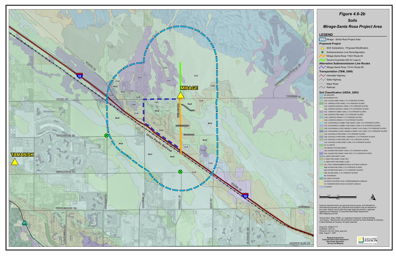
4.6.4.4 Soils Soils result from chemical, physical, and biological weathering of sediments and rocks exposed at or near the earth’s surface. Soil can contain both mineral and organic materials. Figures 4.6-2a: Soils (Farrell-Garnet Project Area) and 4.6-2b: Soils (Mirage-Santa Rosa Project Area) show the soil units for the geological study area as developed by the USDA, NRCS. The majority of the Proposed Project, including the transmission and subtransmission line upgrades and reconfigurations, would be located on sandy alluvial soils. The majority of the existing substation locations are within areas already developed. The landforms on which these soils are present include alluvial fans and plains, which are composed of gravelly alluvium derived from granite rock (NRCS 2006). The Proposed Devers-Coachella Valley 220 kV Loop-In crosses Carsitas gravelly sand and Carsitas cobbly sand. Carsitas soils are excessively drained, with no frequency of flooding or ponding. These soils can be found around 800 feet in elevation, at a 0 to 9 percent slope. The soil profiles are usually found within the first 10 inches, with gravelly sand from 10 to 60 inches. The Carsitas cobbly sand is an alluvium derived from granite that is excessively drained, with a very low water capacity (about 3.0 inches). Carsitas fine sand has nearly the same composition as the cobbly sand, except it is excessively drained, with low water capacity (about 3.1 inches). Carsitas gravelly sand has a moderate potential for erosion, but mostly on steeper slopes. The landforms on which these soils are present include alluvial fans and plains, which are composed of gravelly alluvium derived from granite rock (NRCS 2006). The Proposed Farrell-Garnet 115 kV Subtransmission Line (Route 1) crosses Carsitas cobbly sand, Carsitas fine sand, Carsitas gravelly sand, and riverwash, as well as alluvium borrow pits associated with mineral excavation. The Mirage Substation sits on Carsitas gravelly sand, and the Proposed Mirage-Santa Rosa 115 kV Subtransmission Line (Route 4) would cross a small portion of Carsitas gravelly sand, then would cross Myoma and Coachella fine sands. Myoma fine sand is a wind-blown deposit derived from sandy alluvium. It is excessively drained, with no flooding and with a low water capacity (about 4.8 inches) (NRCS 2006). Coachella fine sand, also found in alluvial fans derived from igneous rock, is well drained, with no frequency of flooding or ponding (NRCS 2006). The proposed substransmission line pole reconfiguration on the corner of Date Palm Drive and Varner Road would cross Carsitas gravelly sand and Myoma fine sand. The pole reconfiguration on the corner of Bob Hope Drive and Dinah Shore Drive would be located on Myoma fine sand. The pole replacement at the corner of Gerald Ford Drive and Portola Avenue would be located on Myoma fine sand. The Garnet, Farrell, and Mirage substations are located on Carsitas gravelly sandy soil.

Proponent’s Environmental Assessment Devers-Mirage 115 kV Subtransmission System Split Project January 2008
4.6-8
4.6.5 Impact Analysis 4.6.5.1 Construction Impacts No known geologic resources of recreational or scientific value (not including mineral resources) are present within the geological study area. The alluvial and wash deposits such as those found near the geological study area are not quarried and are unlikely to be quarried, with the exception of the Massey Rock and Sand Company rock quarry. The Proposed Project would be constructed along existing routes, and existing roads within the SCE ROWs and franchise locations would be graded to improve access for construction vehicles and equipment. However, pole sites located on land without existing access would require temporary access from the nearest existing roadway. No new roads would need to be constructed for the Proposed Project. A new driveway at the northwest corner of the Farrell Substation would be constructed for the Proposed Project. Due to its close proximity to major active faults, the Proposed Project could experience moderate levels of earthquake-induced ground shaking generated by large earthquakes occurring at one of these faults. A final engineering design geotechnical study would identify potential ground shaking hazards and appropriate seismic designs of support structures to reduce the effects of ground shaking (APM GEO-1). Since the Proposed Project does not include the construction of any human-occupied structures, the AP Act does not apply. A final engineering design geotechnical study would identify potential ground rupture hazards, and towers and poles would be located to avoid any identified active faults (APM GEO-2). SCE designs overhead electric lines to meet or exceed GO 95 wind loading criteria. SCE's design standards incorporate lateral wind loading requirements that exceed seismic loading forces. Consequently, impacts from potential seismic ground shaking would be less than significant. Liquefaction is not likely to occur within the geological study area because the depth to groundwater (see Section 4.8: Hydrology and Water Quality) exceeds the depth where liquefaction would typically occur (approximately 50 feet below the ground surface). Implementation of foundation design recommendations would further reduce any potential impact during construction (APMs GEO-1 and GEO-2). The geological study area is located on a relatively flat area and project construction would not involve extensive excavation, grade, or elevation changes. The Proposed Project would not result in substantial soil erosion or loss of topsoil. The Proposed Project is located on a geologic unit or soil that could be unstable, although on- or off-site landslide, lateral spreading, subsidence, liquefaction or collapse would not likely be caused by construction of the Proposed Project. Given the site topography, there is negligible potential for landslides or other slope stability concerns from project construction. The geological study area is not situated in an area prone to subsidence, and construction of the Proposed Project would not include activities that could induce subsidence. Implementation of foundation design recommendations would further reduce any potential impact during construction (APM GEO-2).

!?
#*
#*
#*IN
DIAN
CAN
YON
DR
PALM
CAN
YON
DR
AVEN
IDA
CABA
LLER
OS
SUNR
ISE
WY
FARR
ELL
DR
LAND
AU B
LVD
DATE
PALM
DR
VISTA CHINO
SAN RAFAEL RD
RACQUET CLUB RD
INDI
AN A
V
20TH AV
PALM
DR
MOUN
TAIN
VIE
W D
R
GENE
AUT
RY T
R
VARNER RD
TAMARISK RD
PalmSprings
InternationalAirport
CcC
ChC
CdC
MaBCkB
CkB
CkB
CkB
MaB
CdC
CdC
RA
MaB
CdC
MaB
CkB
ChCChC
ChC
ChC
CdC
ChC
MaDBP
CdC
CdE
CkB
CmB
LR
ChC GP
CkBCkB
CkB
CkBCdC
CdC
CdC
CdC
CdC
CdC
CdC ChC
ChC
CkB
MaB
MaBMaD
CkB
MaB
CkB
CdCCkB
MaDCdC
MaB
MaB
CdC
CkB
MaD
MaB
CkB
CdC
CdC
CkB
MaB
CkB
§̈¦10
§̈¦10
Union Pacific Railroad
·|}111
·|}111
CAPWIND
GARNET
FARRELLFeatures depicted herein are planning level accuracy, and intended forinformational purposes only. Distances and locations may be distorted atthis scale. Always consult with the proper legal documents or agenciesregarding such features. © Corporate Real Estate Department,REO-Mapping and GIS.
Mapping Prepared by:Corporate Real Estate Department
Real Estate OperationsSurvey and Mapping
Thomas Bros. Maps (TBM) is a registered trademark of Rand McNally & Company. Reproduced with permission granted by Rand McNally & Company. © Rand McNally & Company. All rights reserved.
O
Figure 4.6-2a
Project ID: 2006LE7177Custodian: John LeFilename: Fig 4.6-2 Soils_epg.mxdDate: August 1, 2007
SoilsFarrell-Garnet Project Area
LEGEND
Soil Classification (USDA, 2005)BA, BADLANDBP, BORROW PITSCaD, CAJON LOAMY SAND, 5 TO 15 PERCENT SLOPESCcC, CARRIZO STONY SAND, 2 TO 9 PERCENT SLOPESCdC, CARSITAS GRAVELLY SAND, 0 TO 9 PERCENT SLOPESCdE, CARSITAS GRAVELLY SAND, 9 TO 30 PERCENT SLOPESChC, CARSITAS COBBLY SAND, 2 TO 9 PERCENT SLOPESCkB, CARSITAS FINE SAND, 0 TO 5 PERCENT SLOPESCmB, CARSITAS VARIANT, 2 TO 5 PERCENT SLOPESCmE, CARSITAS VARIANT, 5 TO 30 PERCENT SLOPESCnC, CHUCKAWALLA COBBLY FINE SANDY LOAM, 2 TO 9 PERCENT SLOPESCnE, CHUCKAWALLA COBBLY FINE SANDY LOAM, 9 TO 30 PERCENT SLOPESCoB, CHUCKAWALLA VERY GRAVELLY SANDY CLAY LOAM, 2 TO 5 PERCENT SLOPESCoD, CHUCKAWALLA VERY GRAVELLY SANDY CLAY LOAM, 5 TO 15 PERCENT SLOPESCpA, COACHELLA FINE SAND, 0 TO 2 PERCENT SLOPESCpB, COACHELLA FINE SAND, HUMMOCKY, 2 TO 5 PERCENT SLOPESCrA, COACHELLA FINE SAND, WET, 0 TO 2 PERCENT SLOPESCsA, COACHELLA FINE SANDY LOAM, 0 TO 2 PERCENT SLOPESFe, FLUVENTSGP, GRAVEL PITS AND DUMPSGbA, GILMAN FINE SANDY LOAM, 0 TO 2 PERCENT SLOPESGcA, GILMAN FINE SANDY LOAM, WET, 0 TO 2 PERCENT SLOPESIp, INDIO FINE SANDY LOAMIr, INDIO FINE SANDY LOAM, WETIs, INDIO VERY FINE SANDY LOAMLR, LITHIC TORRIPSAMMENTS-ROCK OUTCROP COMPLEXMaB, MYOMA FINE SAND, 0 TO 5 PERCENT SLOPESMaD, MYOMA FINE SAND, 5 TO 15 PERCENT SLOPESNaB, NILAND SAND, 2 TO 5 PERCENT SLOPESRA, RIVERWASHRO, ROCK OUTCROPRT, ROCK OUTCROP-LITHIC TORRIPSAMMENTS COMPLEXTO, TORRIORTHENTS-ROCK OUTCROP COMPLEXW, WATER
0 0.5 10.25
Miles
Alternative Subtransmission Line Routes
Transportation (TBM, 2006)
Major RoadRailroad
Farrell - Garnet Project Area
Farrell-Garnet 115kV Route #1
Farrell-Garnet 115 kV Route #3
Interstate HighwayState Highway
Farrell-Garnet 115 kV Route # Option AFarrell-Garnet 115 kV Route #2
Proposed ProjectSCE Substations - Proposed Modification#*Subtransmission Line Reconfiguration!?
kjames
Text Box
4.6-9

Proponent’s Environmental Assessment Devers-Mirage 115 kV Subtransmission System Split Project January 2008 4.6-10
THIS PAGE IS INTENTIONALLY BLANK
!?
!?
#*
#*
#*
CALLE DESIERTO
CALLE FRAN C ISCO
CALLE TOSCA
VISTA
DE
ORO
THOUSAND PALMS CANYON RD
WASHINGTON STRAMON RD
DINAH SHORE DR
GERALD FORD DR
FRANK SINATRA DR BOB
HOPE
DR
MONT
EREY
AV
PORT
OLA
AV
COOK
ST
EL D
ORAD
O D
R
AVENUE 38
COUNTRY CLUB DR
VARNER RD
VARNER RDMO
RNIN
GSID
E D
R
MaB
MaB
MaBMaD
CpA
CpA
CpA
CpB
CpB
ChCChC
MaB
MaB
MaB
CdC
CdC
CdC
CkB
CkB
MaD
CsA
GcACsA
CsA
MaB
CdC
MaD CdC
Union Pacific Railroad
§̈¦10
§̈¦10
·|}111
MIRAGE
TAMARISK
Features depicted herein are planning level accuracy, and intended forinformational purposes only. Distances and locations may be distorted atthis scale. Always consult with the proper legal documents or agenciesregarding such features. © Corporate Real Estate Department,REO-Mapping and GIS.
Mapping Prepared by:Corporate Real Estate Department
Real Estate OperationsSurvey and Mapping
Thomas Bros. Maps (TBM) is a registered trademark of Rand McNally & Company. Reproduced with permission granted by Rand McNally & Company. © Rand McNally & Company. All rights reserved.
O
Figure 4.6-2b
Project ID: 2006LE7177Custodian: John LeFilename: Fig 4.6-2 Soils_epg.mxdDate: August 1, 2007
Soil Classification (USDA, 2005)BA, BADLANDBP, BORROW PITSCaD, CAJON LOAMY SAND, 5 TO 15 PERCENT SLOPESCcC, CARRIZO STONY SAND, 2 TO 9 PERCENT SLOPESCdC, CARSITAS GRAVELLY SAND, 0 TO 9 PERCENT SLOPESCdE, CARSITAS GRAVELLY SAND, 9 TO 30 PERCENT SLOPESChC, CARSITAS COBBLY SAND, 2 TO 9 PERCENT SLOPESCkB, CARSITAS FINE SAND, 0 TO 5 PERCENT SLOPESCmB, CARSITAS VARIANT, 2 TO 5 PERCENT SLOPESCmE, CARSITAS VARIANT, 5 TO 30 PERCENT SLOPESCnC, CHUCKAWALLA COBBLY FINE SANDY LOAM, 2 TO 9 PERCENT SLOPESCnE, CHUCKAWALLA COBBLY FINE SANDY LOAM, 9 TO 30 PERCENT SLOPESCoB, CHUCKAWALLA VERY GRAVELLY SANDY CLAY LOAM, 2 TO 5 PERCENT SLOPESCoD, CHUCKAWALLA VERY GRAVELLY SANDY CLAY LOAM, 5 TO 15 PERCENT SLOPESCpA, COACHELLA FINE SAND, 0 TO 2 PERCENT SLOPESCpB, COACHELLA FINE SAND, HUMMOCKY, 2 TO 5 PERCENT SLOPESCrA, COACHELLA FINE SAND, WET, 0 TO 2 PERCENT SLOPESCsA, COACHELLA FINE SANDY LOAM, 0 TO 2 PERCENT SLOPESFe, FLUVENTSGP, GRAVEL PITS AND DUMPSGbA, GILMAN FINE SANDY LOAM, 0 TO 2 PERCENT SLOPESGcA, GILMAN FINE SANDY LOAM, WET, 0 TO 2 PERCENT SLOPESIp, INDIO FINE SANDY LOAMIr, INDIO FINE SANDY LOAM, WETIs, INDIO VERY FINE SANDY LOAMLR, LITHIC TORRIPSAMMENTS-ROCK OUTCROP COMPLEXMaB, MYOMA FINE SAND, 0 TO 5 PERCENT SLOPESMaD, MYOMA FINE SAND, 5 TO 15 PERCENT SLOPESNaB, NILAND SAND, 2 TO 5 PERCENT SLOPESRA, RIVERWASHRO, ROCK OUTCROPRT, ROCK OUTCROP-LITHIC TORRIPSAMMENTS COMPLEXTO, TORRIORTHENTS-ROCK OUTCROP COMPLEXW, WATER
0 0.5 10.25
Miles
SoilsMirage-Santa Rosa Project Area
LEGEND
Alternative Subtransmission Line Routes
Transportation (TBM, 2006)
Major RoadRailroad
Mirage-Santa Rosa 115kV Route #4
Mirage-Santa Rosa 115 kV Route #5
Interstate HighwayState Highway
Devers-Coachella 220 kV Loop-In
Subtransmission Line Reconfiguration!?
SCE Substations - Proposed Modification#*
Mirage - Santa Rosa Project AreaProposed Project
kjames
Text Box
4.6-11
Proponent’s Environmental Assessment Devers-Mirage 115 kV Subtransmission System Split Project January 2008 4.6-12
THIS PAGE IS INTENTIONALLY BLANK
Proponent’s Environmental Assessment Devers-Mirage 115 kV Subtransmission System Split Project January 2008
4.6-13
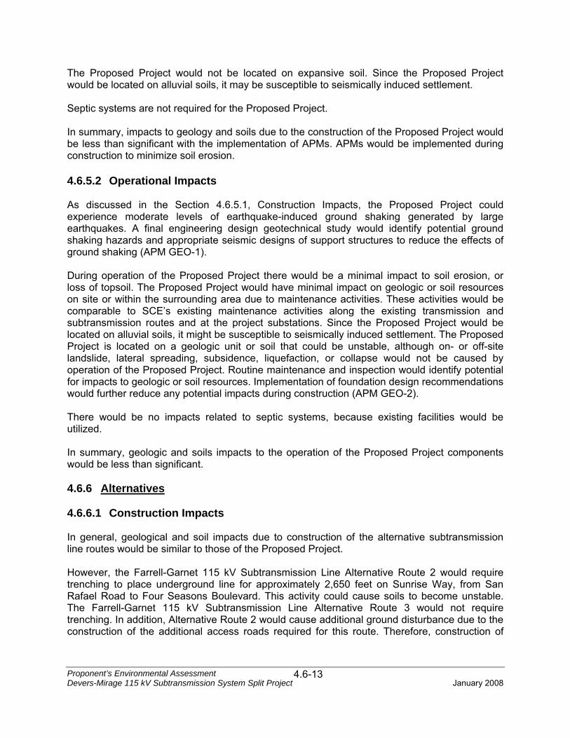
The Proposed Project would not be located on expansive soil. Since the Proposed Project would be located on alluvial soils, it may be susceptible to seismically induced settlement. Septic systems are not required for the Proposed Project. In summary, impacts to geology and soils due to the construction of the Proposed Project would be less than significant with the implementation of APMs. APMs would be implemented during construction to minimize soil erosion. 4.6.5.2 Operational Impacts As discussed in the Section 4.6.5.1, Construction Impacts, the Proposed Project could experience moderate levels of earthquake-induced ground shaking generated by large earthquakes. A final engineering design geotechnical study would identify potential ground shaking hazards and appropriate seismic designs of support structures to reduce the effects of ground shaking (APM GEO-1). During operation of the Proposed Project there would be a minimal impact to soil erosion, or loss of topsoil. The Proposed Project would have minimal impact on geologic or soil resources on site or within the surrounding area due to maintenance activities. These activities would be comparable to SCE’s existing maintenance activities along the existing transmission and subtransmission routes and at the project substations. Since the Proposed Project would be located on alluvial soils, it might be susceptible to seismically induced settlement. The Proposed Project is located on a geologic unit or soil that could be unstable, although on- or off-site landslide, lateral spreading, subsidence, liquefaction, or collapse would not be caused by operation of the Proposed Project. Routine maintenance and inspection would identify potential for impacts to geologic or soil resources. Implementation of foundation design recommendations would further reduce any potential impacts during construction (APM GEO-2). There would be no impacts related to septic systems, because existing facilities would be utilized. In summary, geologic and soils impacts to the operation of the Proposed Project components would be less than significant. 4.6.6 Alternatives 4.6.6.1 Construction Impacts In general, geological and soil impacts due to construction of the alternative subtransmission line routes would be similar to those of the Proposed Project. However, the Farrell-Garnet 115 kV Subtransmission Line Alternative Route 2 would require trenching to place underground line for approximately 2,650 feet on Sunrise Way, from San Rafael Road to Four Seasons Boulevard. This activity could cause soils to become unstable. The Farrell-Garnet 115 kV Subtransmission Line Alternative Route 3 would not require trenching. In addition, Alternative Route 2 would cause additional ground disturbance due to the construction of the additional access roads required for this route. Therefore, construction of
Proponent’s Environmental Assessment Devers-Mirage 115 kV Subtransmission System Split Project January 2008
4.6-14
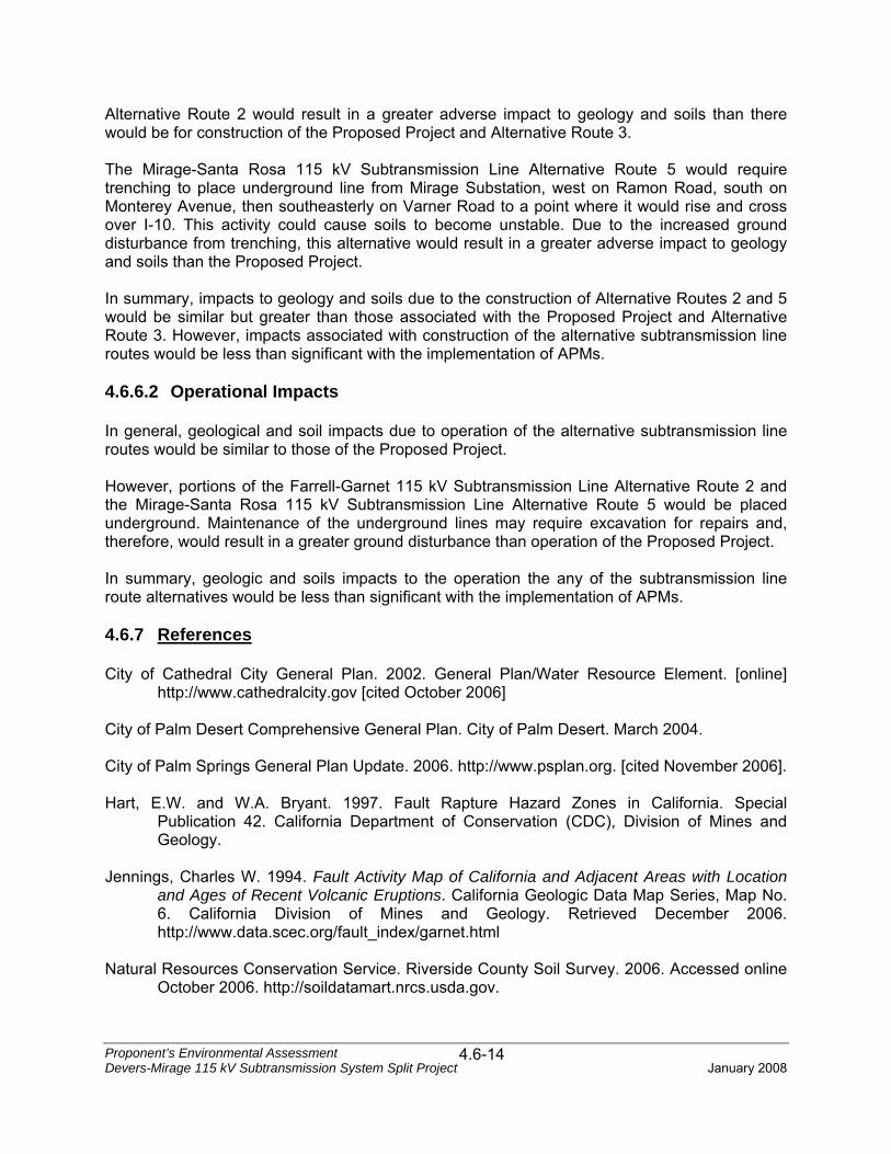
Alternative Route 2 would result in a greater adverse impact to geology and soils than there would be for construction of the Proposed Project and Alternative Route 3. The Mirage-Santa Rosa 115 kV Subtransmission Line Alternative Route 5 would require trenching to place underground line from Mirage Substation, west on Ramon Road, south on Monterey Avenue, then southeasterly on Varner Road to a point where it would rise and cross over I-10. This activity could cause soils to become unstable. Due to the increased ground disturbance from trenching, this alternative would result in a greater adverse impact to geology and soils than the Proposed Project. In summary, impacts to geology and soils due to the construction of Alternative Routes 2 and 5 would be similar but greater than those associated with the Proposed Project and Alternative Route 3. However, impacts associated with construction of the alternative subtransmission line routes would be less than significant with the implementation of APMs. 4.6.6.2 Operational Impacts In general, geological and soil impacts due to operation of the alternative subtransmission line routes would be similar to those of the Proposed Project. However, portions of the Farrell-Garnet 115 kV Subtransmission Line Alternative Route 2 and the Mirage-Santa Rosa 115 kV Subtransmission Line Alternative Route 5 would be placed underground. Maintenance of the underground lines may require excavation for repairs and, therefore, would result in a greater ground disturbance than operation of the Proposed Project. In summary, geologic and soils impacts to the operation the any of the subtransmission line route alternatives would be less than significant with the implementation of APMs. 4.6.7 References City of Cathedral City General Plan. 2002. General Plan/Water Resource Element. [online]
http://www.cathedralcity.gov [cited October 2006] City of Palm Desert Comprehensive General Plan. City of Palm Desert. March 2004. City of Palm Springs General Plan Update. 2006. http://www.psplan.org. [cited November 2006]. Hart, E.W. and W.A. Bryant. 1997. Fault Rapture Hazard Zones in California. Special
Publication 42. California Department of Conservation (CDC), Division of Mines and Geology.
Jennings, Charles W. 1994. Fault Activity Map of California and Adjacent Areas with Location
and Ages of Recent Volcanic Eruptions. California Geologic Data Map Series, Map No. 6. California Division of Mines and Geology. Retrieved December 2006. http://www.data.scec.org/fault_index/garnet.html
Natural Resources Conservation Service. Riverside County Soil Survey. 2006. Accessed online
October 2006. http://soildatamart.nrcs.usda.gov.

Proponent’s Environmental Assessment Devers-Mirage 115 kV Subtransmission System Split Project January 2008
4.6-15
Proctor, R. J. 1968. Geology of the Desert Hot Springs-Upper Coachella Valley area, California: California Division of Mines and Geology Special Report 94, 50 p.
Rasmussen, G. S. 1981. Engineering geology investigation [of a] 1,171 foot (east-west) by
2,700 (north-south) rectangular parcel, tentative Tract No. 16847, Lots 1-67, North Palm Springs, California: Gary S. Rasmussen and Associates, San Bernardino, California, unpublished consulting report prepared for Robert A. Hammack Development Company, GSR Project No. 1697, 14 p. plus appendices.
The Alquist-Priolo Earthquake Fault Zoning Act. 1976. (Cal) Section 2621.6 United States Geological Survey. 2005. Earthquake Hazards Program. http://www.usgs.gov
[cited October 2006]. Western Coachella Valley Area Plan. http://www.rctlma.org/generalplan/ap2/wcvap.html [cited
October 2006].

Proponent’s Environmental Assessment Devers-Mirage 115 kV Subtransmission System Split Project January 2008
4.6-16
THIS PAGE IS INTENTIONALLY BLANK
Related Documents