KM1914 Engineering Graphics Chapter 8 Dimensioning and Tolerances Lecturers Azli Arifin Assoc Prof Dr Mariyam Jameelah

Chapter8 dimensioning and-tolerances
Jul 13, 2015
Welcome message from author
This document is posted to help you gain knowledge. Please leave a comment to let me know what you think about it! Share it to your friends and learn new things together.
Transcript
KM1914Engineering Graphics
Chapter 8Dimensioning and Tolerances
Lecturers
Azli Arifin
Assoc Prof Dr Mariyam Jameelah

8-2
Section 8.1Dimensioning
Before an object can be built, complete information about the size and shape of the object must be available.
The exact shape of an object is communicated through orthographic drawings, which are developed following standard
drawing practices.
The process of adding size information to a drawing is known as dimensioning the drawing.
In order that size information is communicated as clearly as possible, standard dimension practices have been established.
8-3
• Communications is the fundamental purpose of dimensions.
• Geometrics is the science of specifying and tolerancing the shapes and locations of features on objects.
• Once the shape of a part is defined with an orthographic drawings, the size information is added also in the form of dimensions.
• Dimensioning a drawing also identifies the tolerance (or accuracy) required for each dimension.
• Dimensions and tolerance – a medium in the design process.
8-4
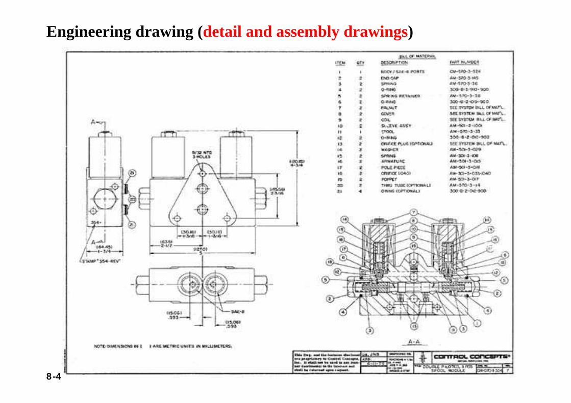
Engineering drawing (detail and assembly drawings)

8-5
Section 8.2Size and Location Dimensions
Parts are dimensioned based on two criteria:• Basic size and locations of the features.• Details of a part's construction, for manufacturing.
8-6
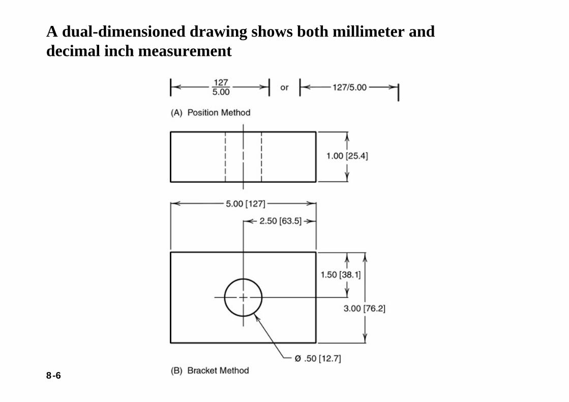
A dual-dimensioned drawing shows both millimeter and decimal inch measurement
8-7
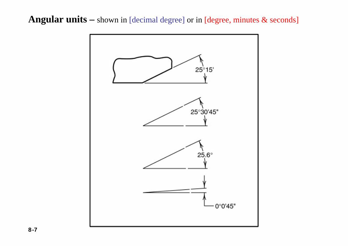
Angular units – shown in [decimal degree] or in [degree, minutes & seconds]
8-8
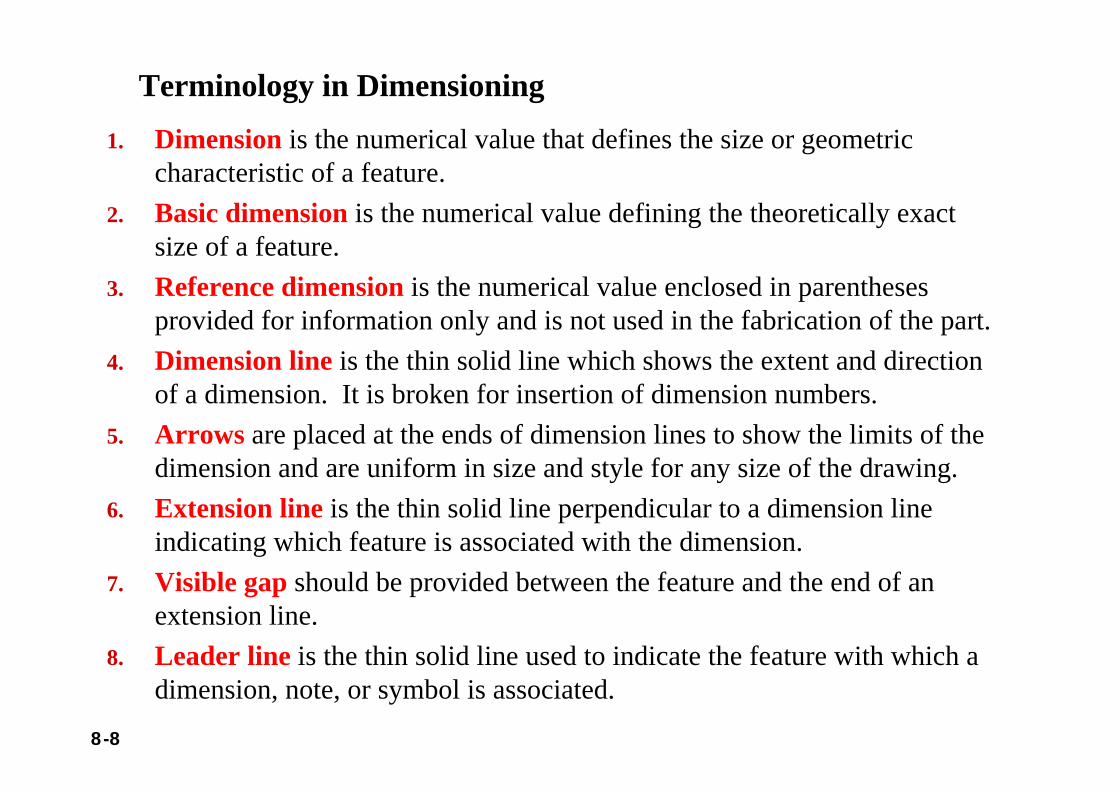
Terminology in Dimensioning1. Dimension is the numerical value that defines the size or geometric
characteristic of a feature.2. Basic dimension is the numerical value defining the theoretically exact
size of a feature.3. Reference dimension is the numerical value enclosed in parentheses
provided for information only and is not used in the fabrication of the part.4. Dimension line is the thin solid line which shows the extent and direction
of a dimension. It is broken for insertion of dimension numbers.5. Arrows are placed at the ends of dimension lines to show the limits of the
dimension and are uniform in size and style for any size of the drawing.6. Extension line is the thin solid line perpendicular to a dimension line
indicating which feature is associated with the dimension.7. Visible gap should be provided between the feature and the end of an
extension line.8. Leader line is the thin solid line used to indicate the feature with which a
dimension, note, or symbol is associated.
8-9
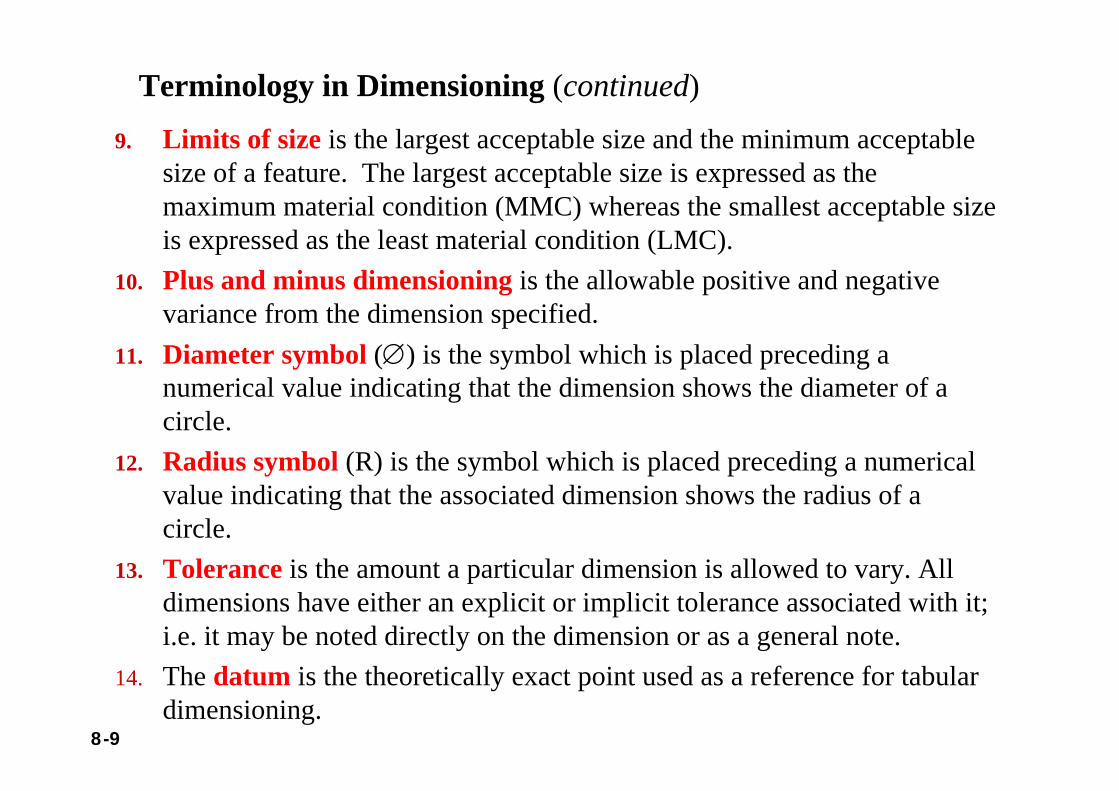
Terminology in Dimensioning (continued)9. Limits of size is the largest acceptable size and the minimum acceptable
size of a feature. The largest acceptable size is expressed as the maximum material condition (MMC) whereas the smallest acceptable size is expressed as the least material condition (LMC).
10. Plus and minus dimensioning is the allowable positive and negative variance from the dimension specified.
11. Diameter symbol (∅) is the symbol which is placed preceding a numerical value indicating that the dimension shows the diameter of a circle.
12. Radius symbol (R) is the symbol which is placed preceding a numerical value indicating that the associated dimension shows the radius of a circle.
13. Tolerance is the amount a particular dimension is allowed to vary. All dimensions have either an explicit or implicit tolerance associated with it; i.e. it may be noted directly on the dimension or as a general note.
14. The datum is the theoretically exact point used as a reference for tabular dimensioning.
8-10
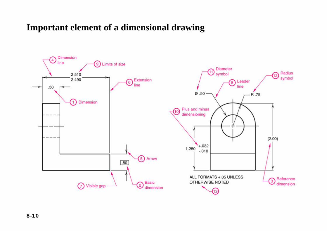
Important element of a dimensional drawing
8-11
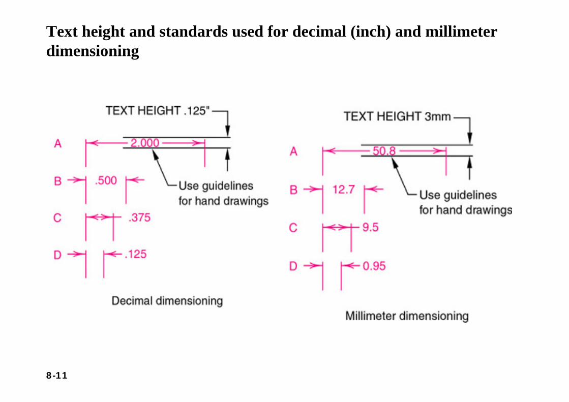
Text height and standards used for decimal (inch) and millimeterdimensioning
8-12
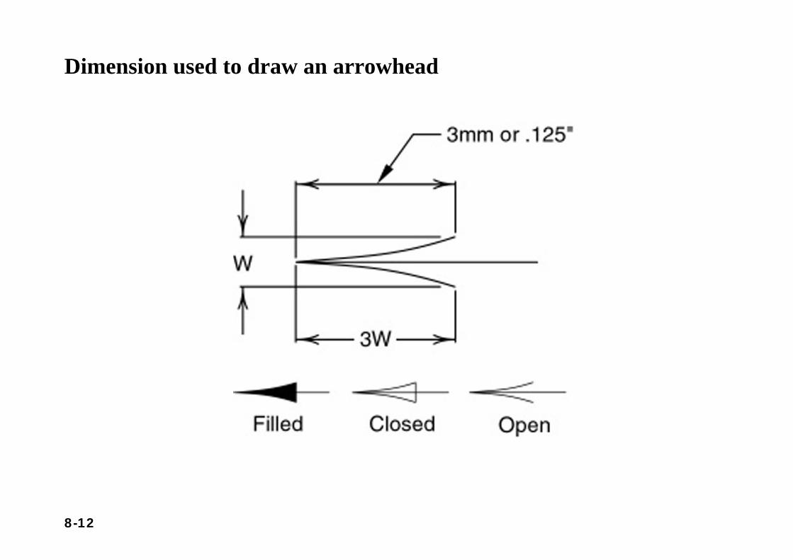
Dimension used to draw an arrowhead
8-13
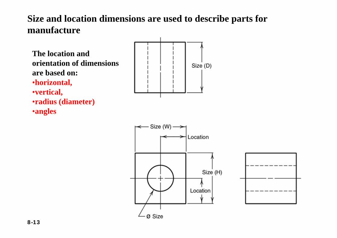
Size and location dimensions are used to describe parts for manufacture
The location and orientation of dimensions are based on: •horizontal,•vertical, •radius (diameter)•angles
8-14
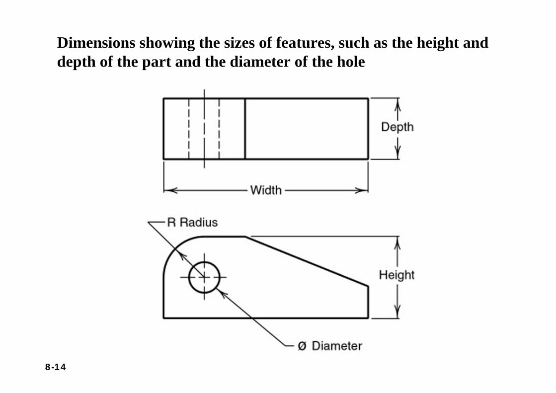
Dimensions showing the sizes of features, such as the height anddepth of the part and the diameter of the hole
8-15
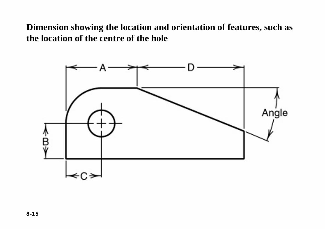
Dimension showing the location and orientation of features, such as the location of the centre of the hole
8-16
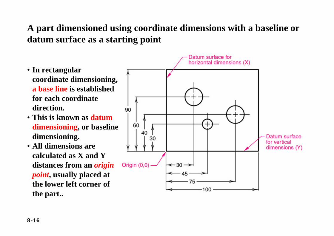
A part dimensioned using coordinate dimensions with a baseline or datum surface as a starting point
• In rectangular coordinate dimensioning, a base line is established for each coordinate direction.
• This is known as datum dimensioning, or baseline dimensioning.
• All dimensions are calculated as X and Y distances from an origin point, usually placed at the lower left corner of the part..
8-17
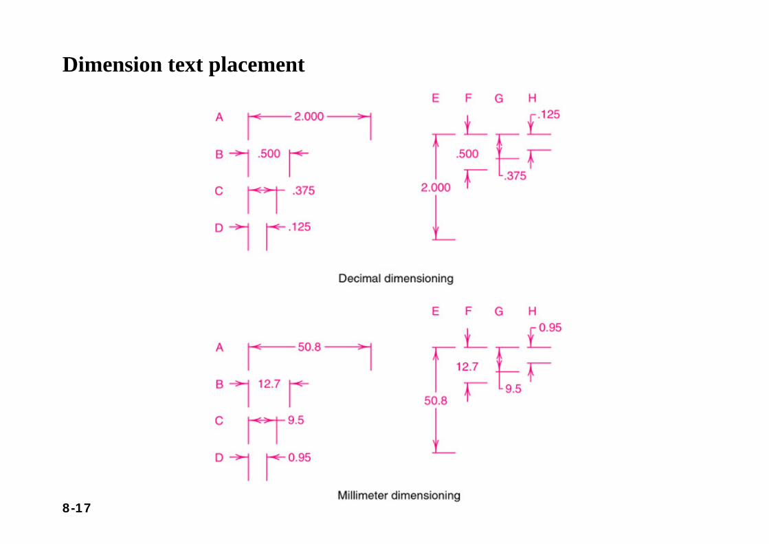
Dimension text placement
8-18
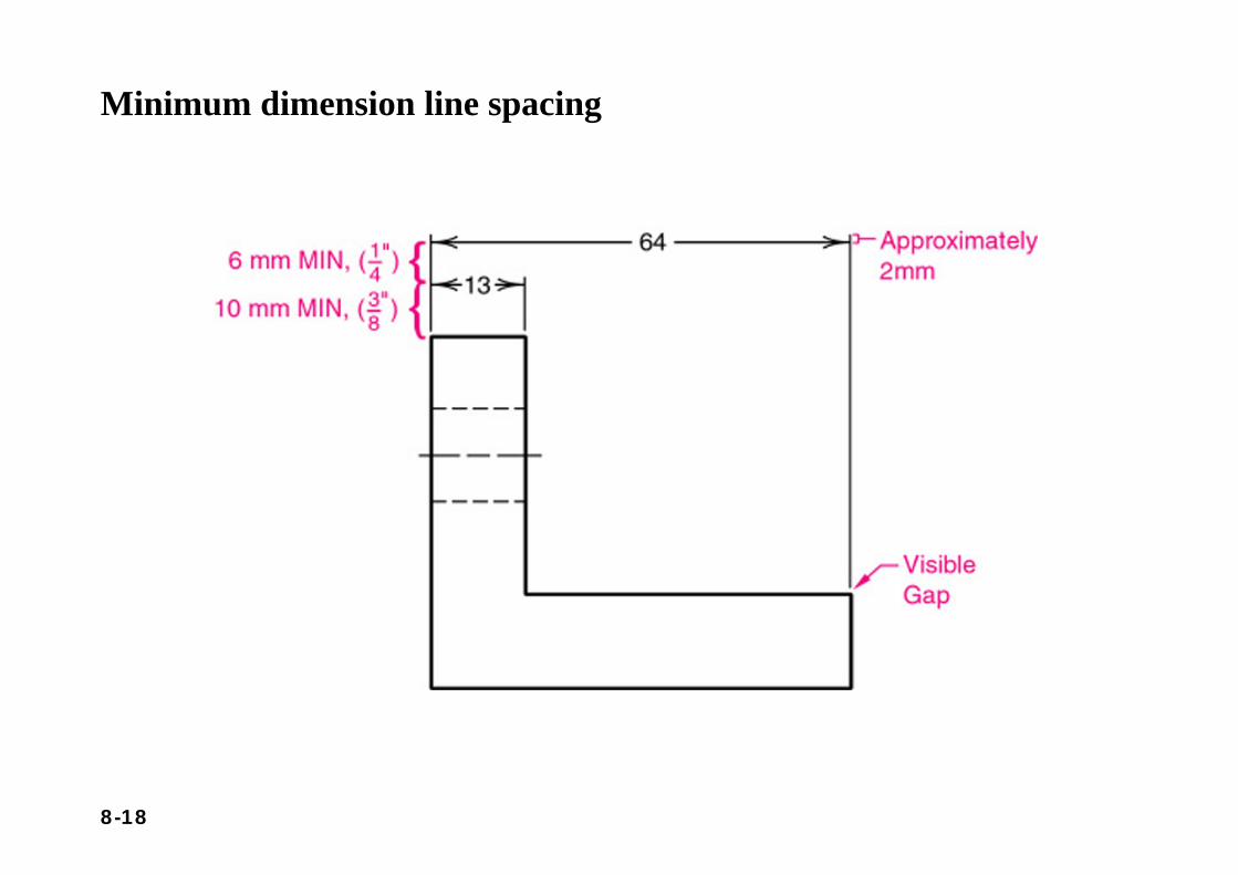
Minimum dimension line spacing
8-19
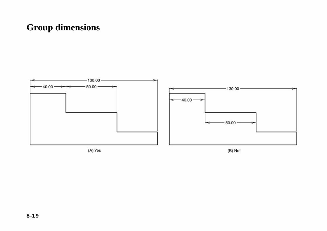
Group dimensions
8-20
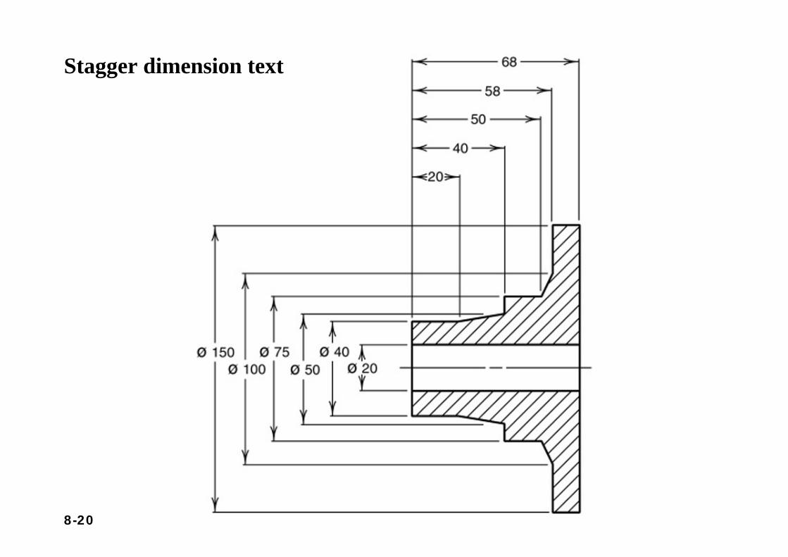
Stagger dimension text
8-21
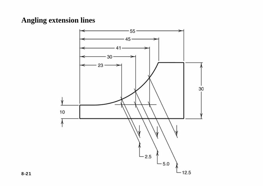
Angling extension lines
8-22
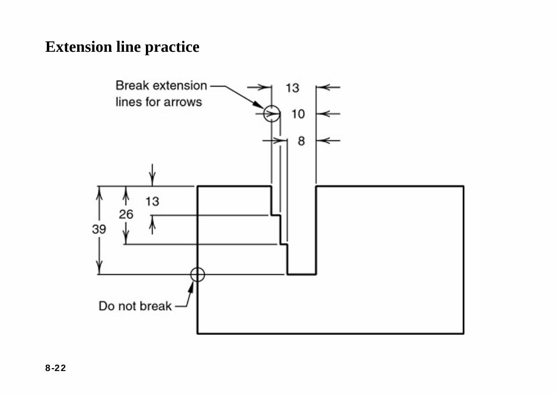
Extension line practice
8-23
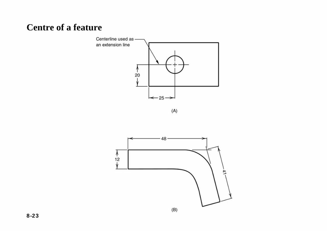
Centre of a feature
8-24
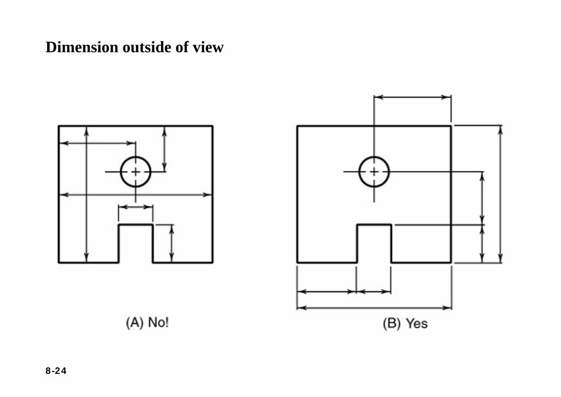
Dimension outside of view
8-25
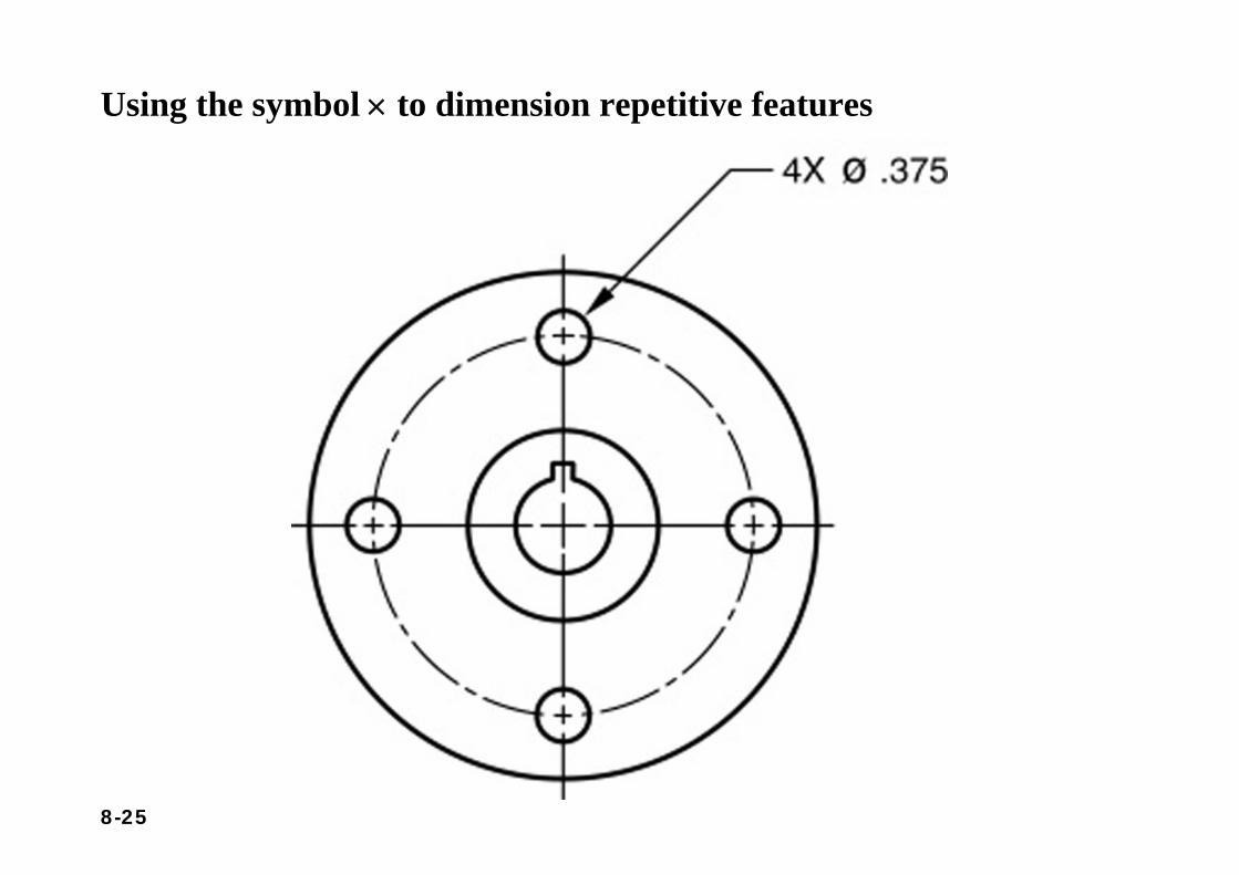
Using the symbol × to dimension repetitive features
8-26
Section 8.3Detail Dimensioning
8-27
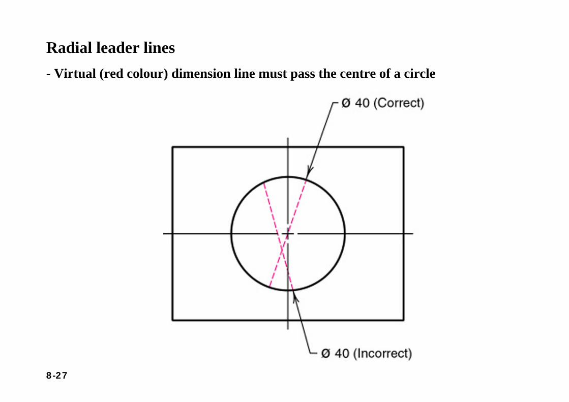
Radial leader lines- Virtual (red colour) dimension line must pass the centre of a circle
8-28
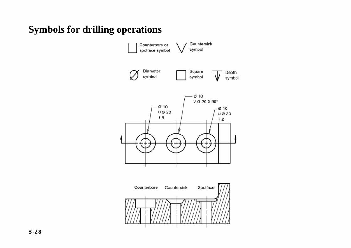
Symbols for drilling operations
8-29
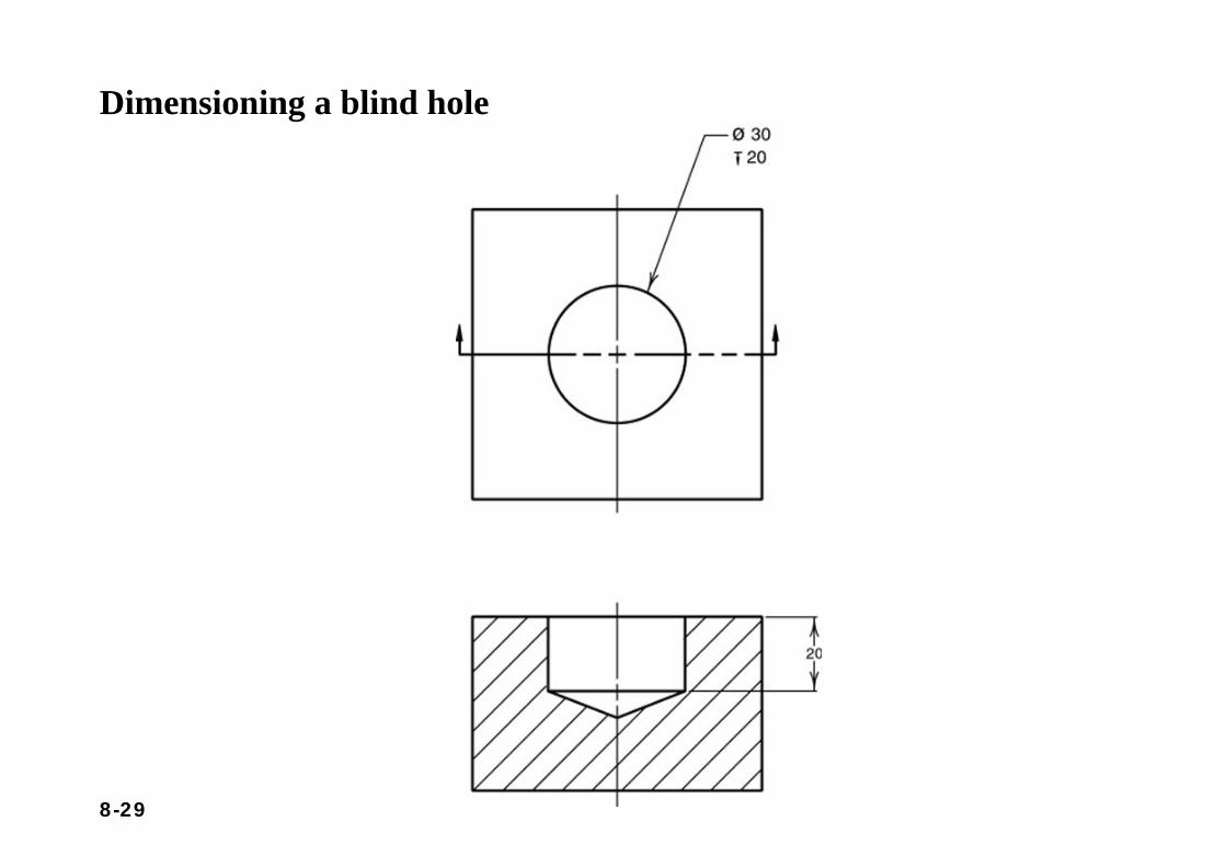
Dimensioning a blind hole
8-30
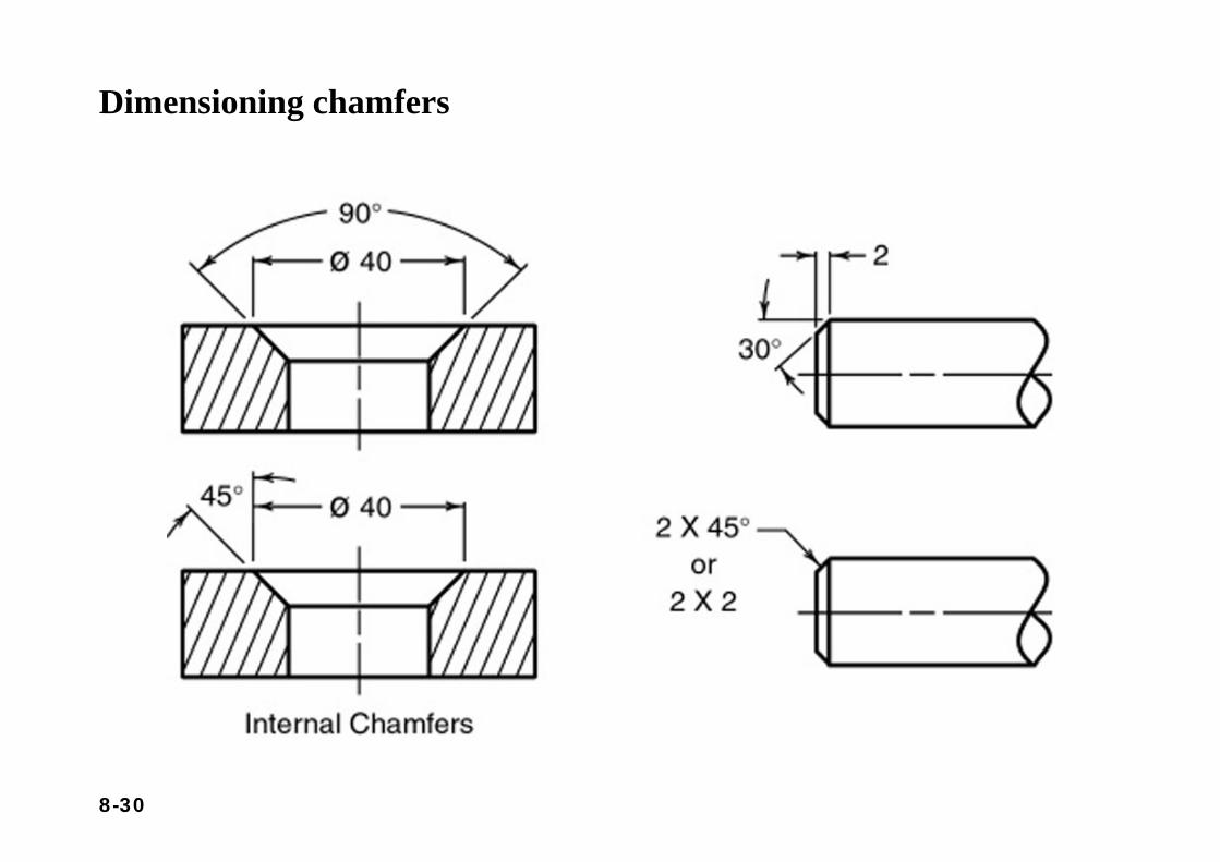
Dimensioning chamfers
8-31
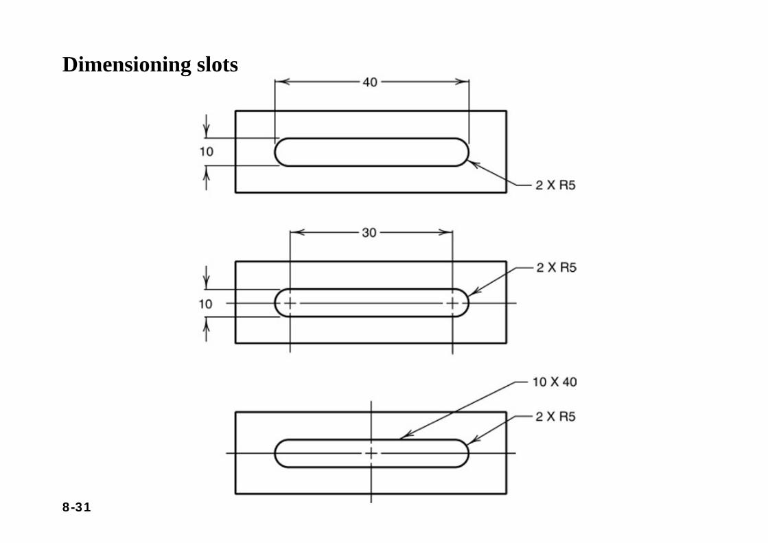
Dimensioning slots
8-32
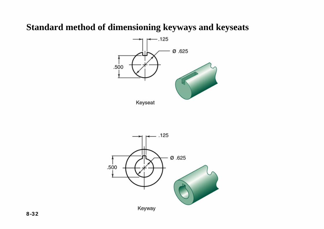
Standard method of dimensioning keyways and keyseats
8-33
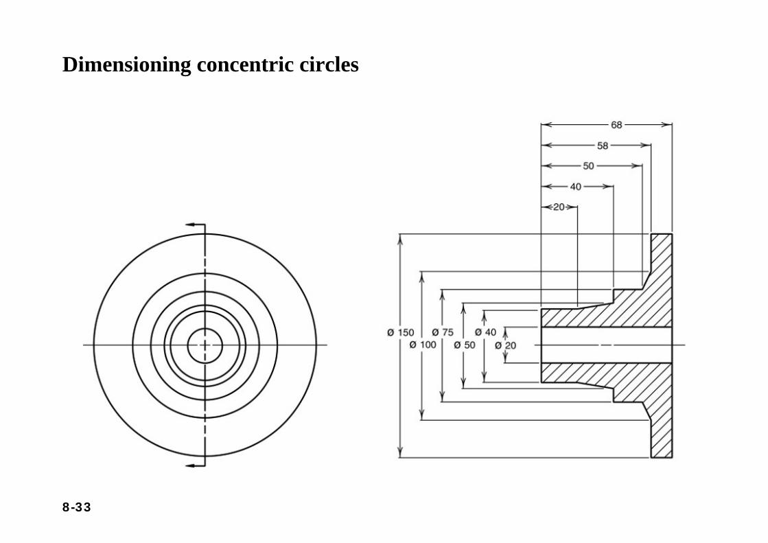
Dimensioning concentric circles
8-34
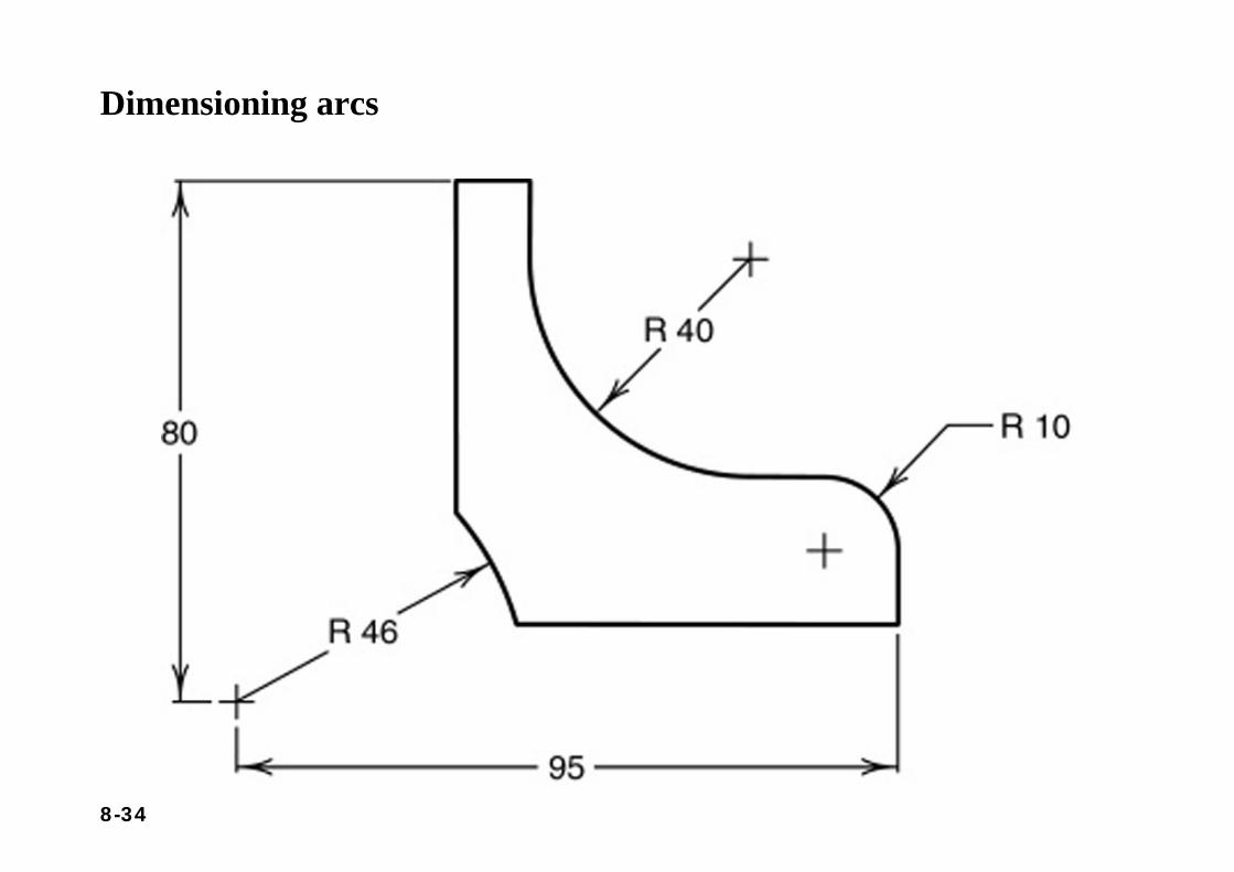
Dimensioning arcs
8-35
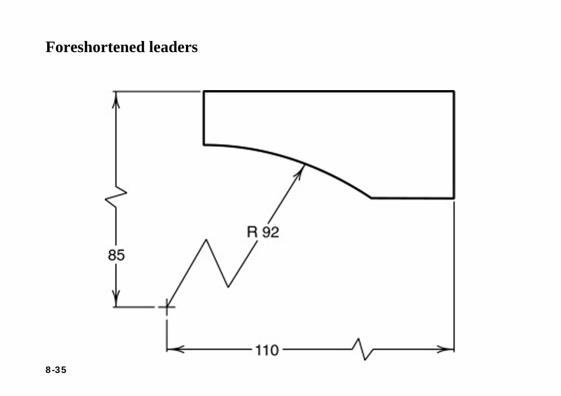
Foreshortened leaders
8-36
Section 8.4Dimensioning Techniques
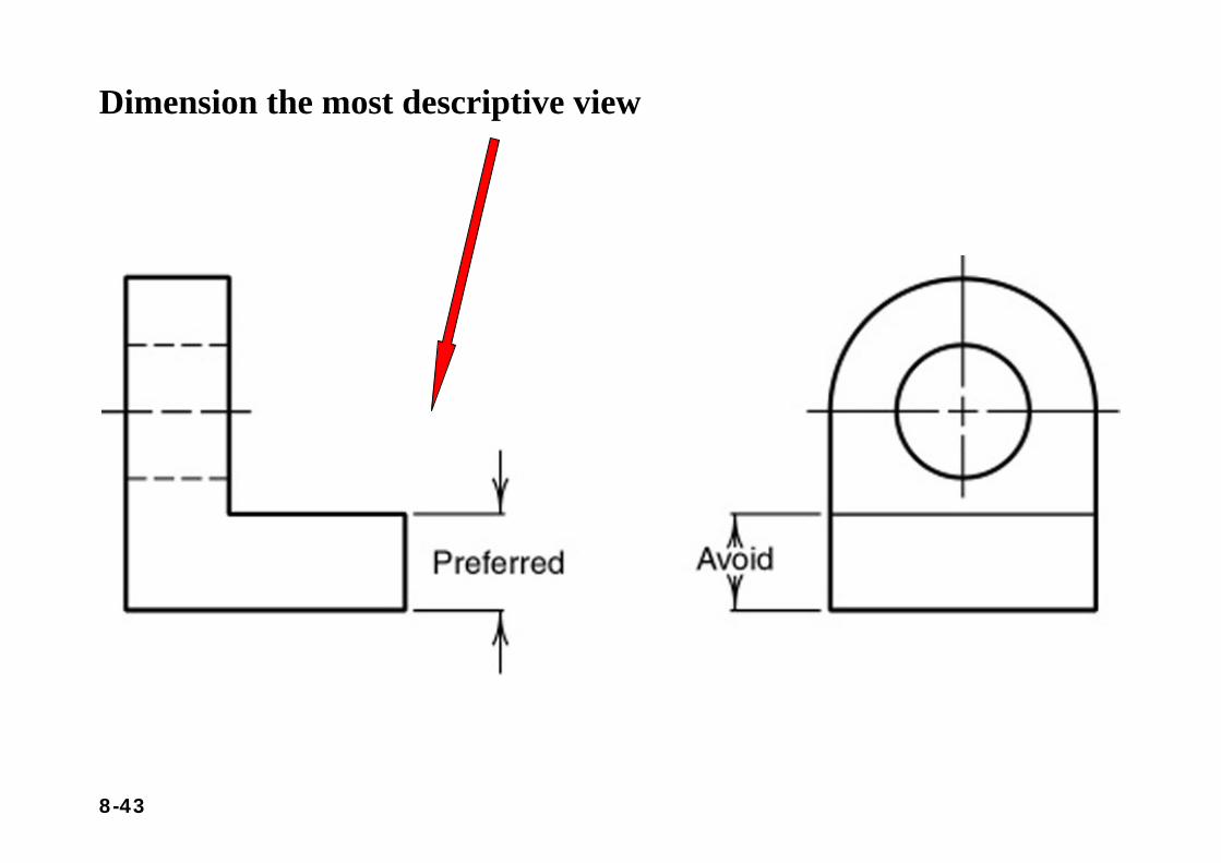
Contour dimensioning - the contours or shapes of the object are dimensioned in their most descriptive view. For example, the radius of a arc would be dimensioned where it appears as an arc and not as a hidden
feature.
Geometric breakdown - dimensioning a part is to break the part into its geometric configurations; is used on objects made of geometric primitives,
such as prisms, cylinders, and spheres, or their derivatives such as half spheres or negative cylinders (holes).
8-37
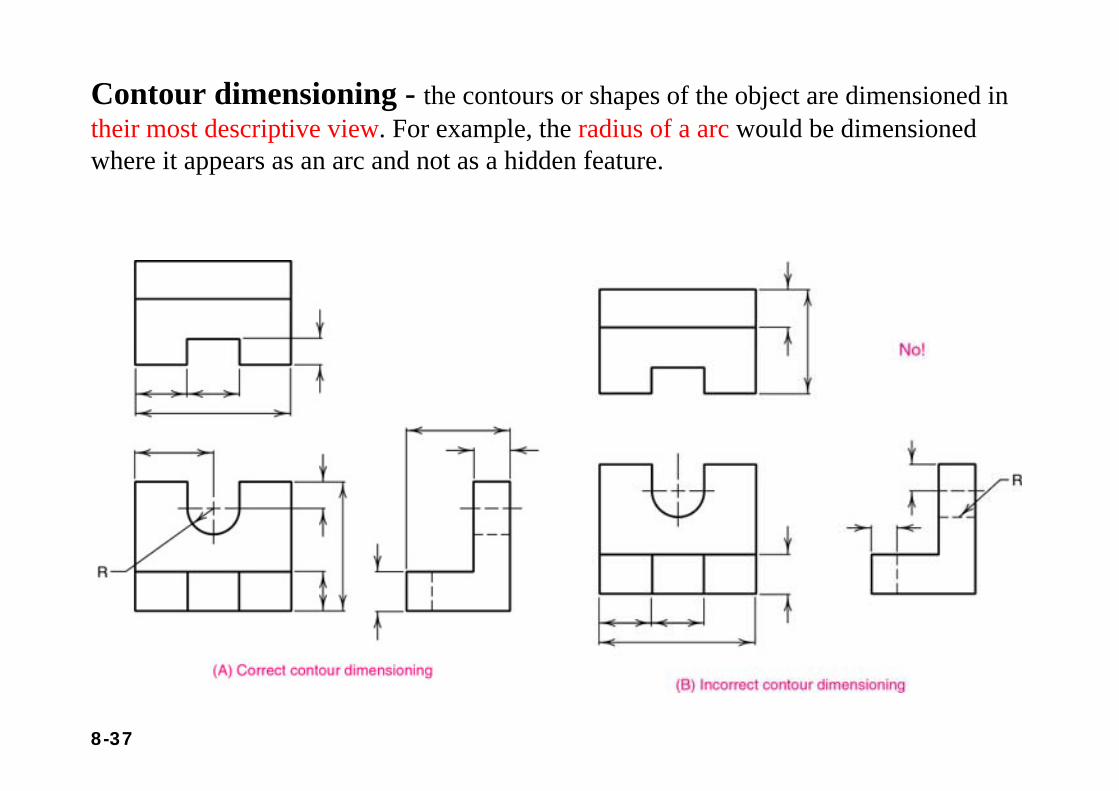
Contour dimensioning - the contours or shapes of the object are dimensioned in their most descriptive view. For example, the radius of a arc would be dimensioned where it appears as an arc and not as a hidden feature.
8-38
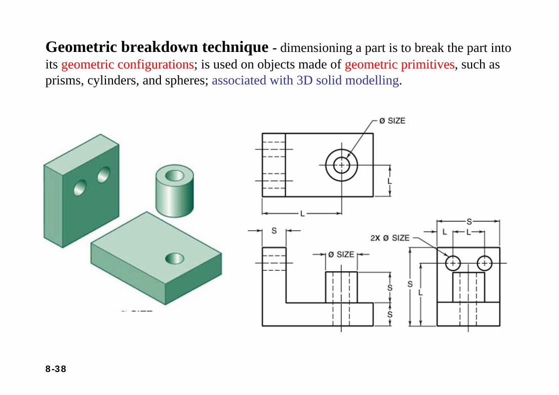
Geometric breakdown technique - dimensioning a part is to break the part into its geometric configurations; is used on objects made of geometric primitives, such as prisms, cylinders, and spheres; associated with 3D solid modelling.
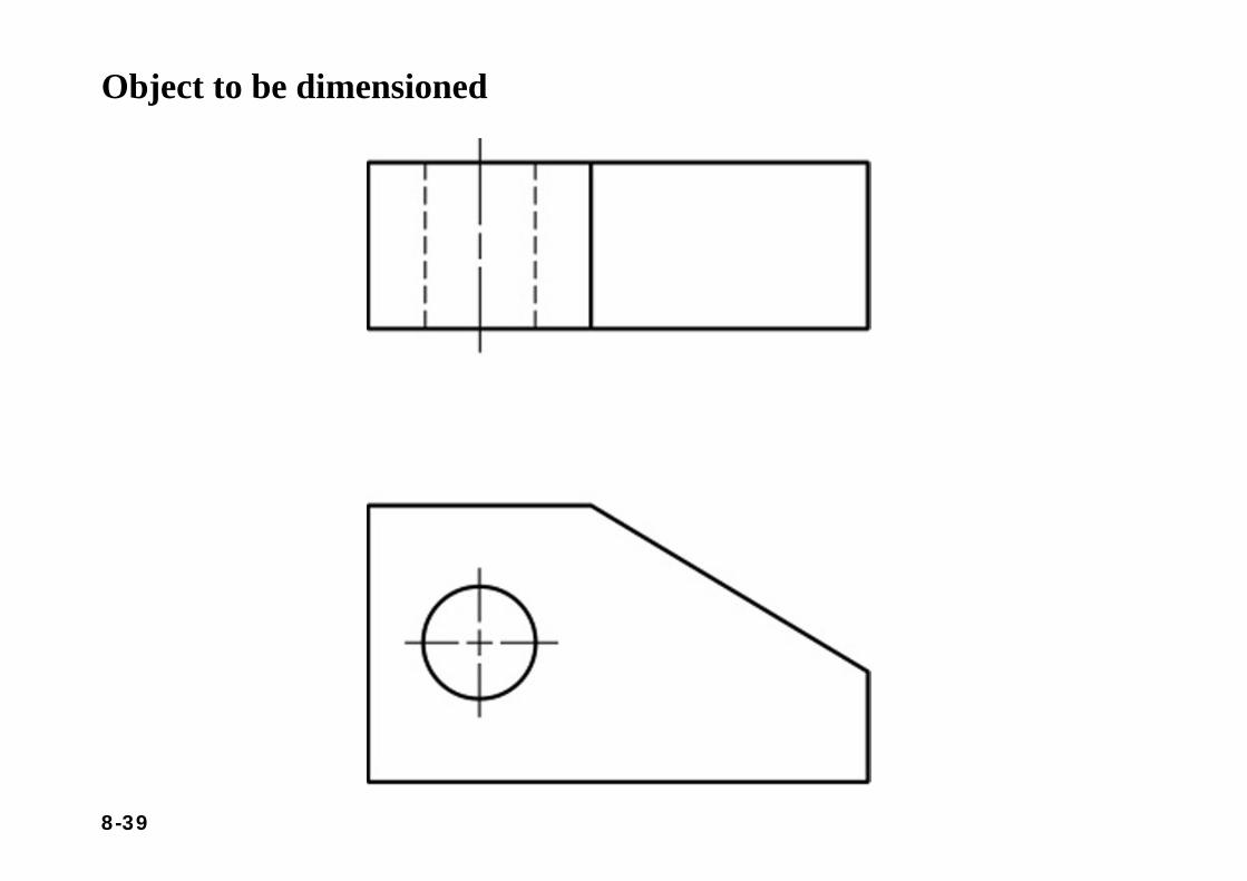
8-39
Object to be dimensioned
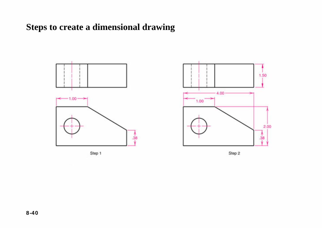
8-40
Steps to create a dimensional drawing
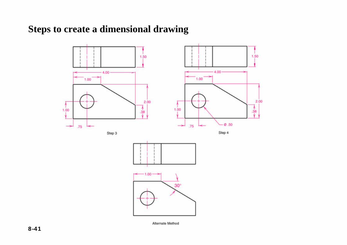
8-41
Steps to create a dimensional drawing
8-42
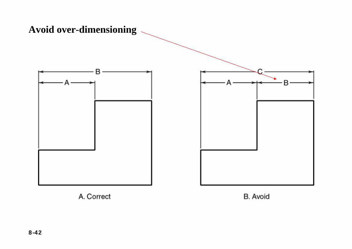
Avoid over-dimensioning
8-43
Dimension the most descriptive view
8-44
Section 8.5Tolerancing
• Tolerances are used to control the amount of variation inherent in all manufactured parts.
• In particular, tolerances are assigned to mating parts in an assembly. For example, the slot in the part must accommodate another part.
• One of the great advantages of using tolerances is that it allows for interchangeable parts, thus permitting the replacement of individual parts.
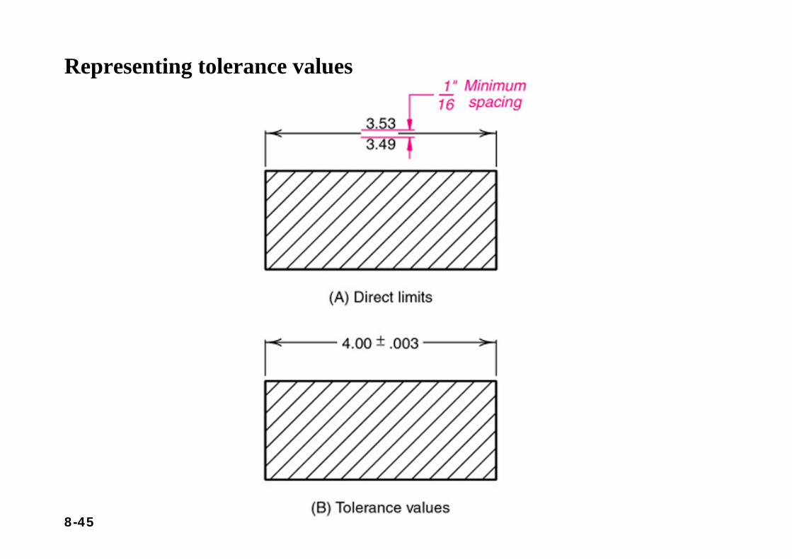
• Tolerance is the total amount a dimension may vary and is the difference between the upper (maximum) and lower (minimum)limits.
8-45
Representing tolerance values
8-46
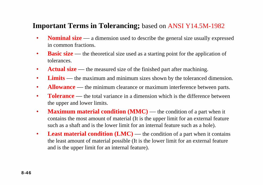
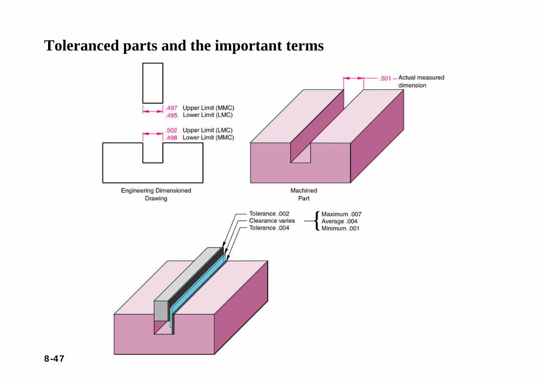
Important Terms in Tolerancing; based on ANSI Y14.5M-1982
• Nominal size — a dimension used to describe the general size usually expressed in common fractions.
• Basic size — the theoretical size used as a starting point for the application of tolerances.
• Actual size — the measured size of the finished part after machining.• Limits — the maximum and minimum sizes shown by the toleranced dimension.• Allowance — the minimum clearance or maximum interference between parts.• Tolerance — the total variance in a dimension which is the difference between
the upper and lower limits.• Maximum material condition (MMC) — the condition of a part when it
contains the most amount of material (It is the upper limit for an external feature such as a shaft and is the lower limit for an internal feature such as a hole).
• Least material condition (LMC) — the condition of a part when it contains the least amount of material possible (It is the lower limit for an external feature and is the upper limit for an internal feature).
8-47
Toleranced parts and the important terms
8-48
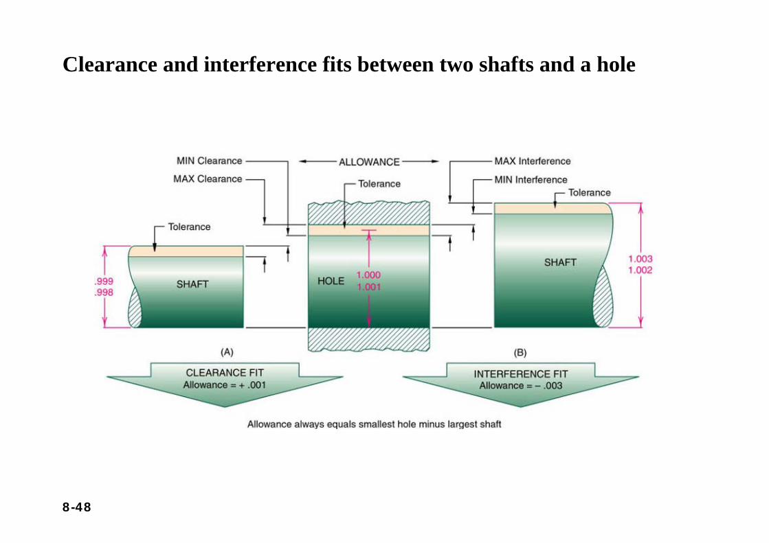
Clearance and interference fits between two shafts and a hole
8-49
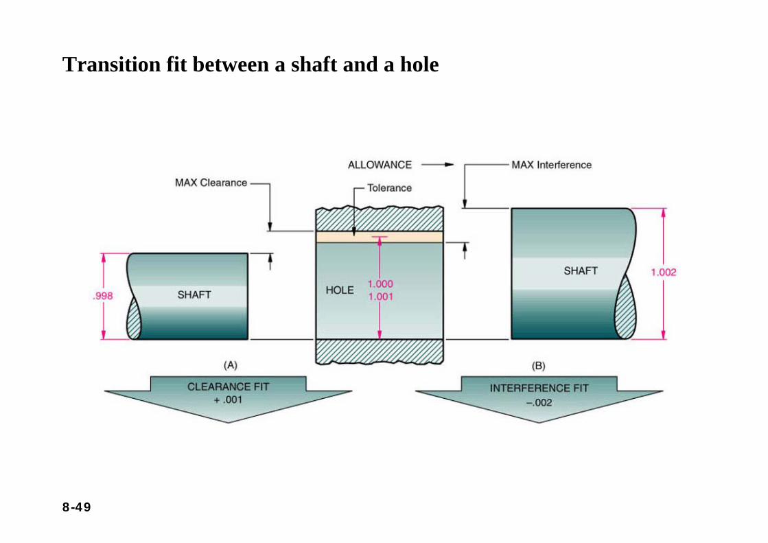
Transition fit between a shaft and a hole
8-50
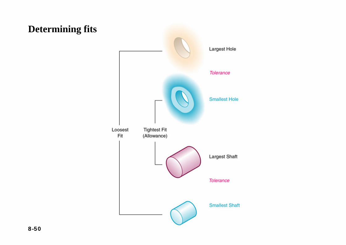
Determining fits
8-51
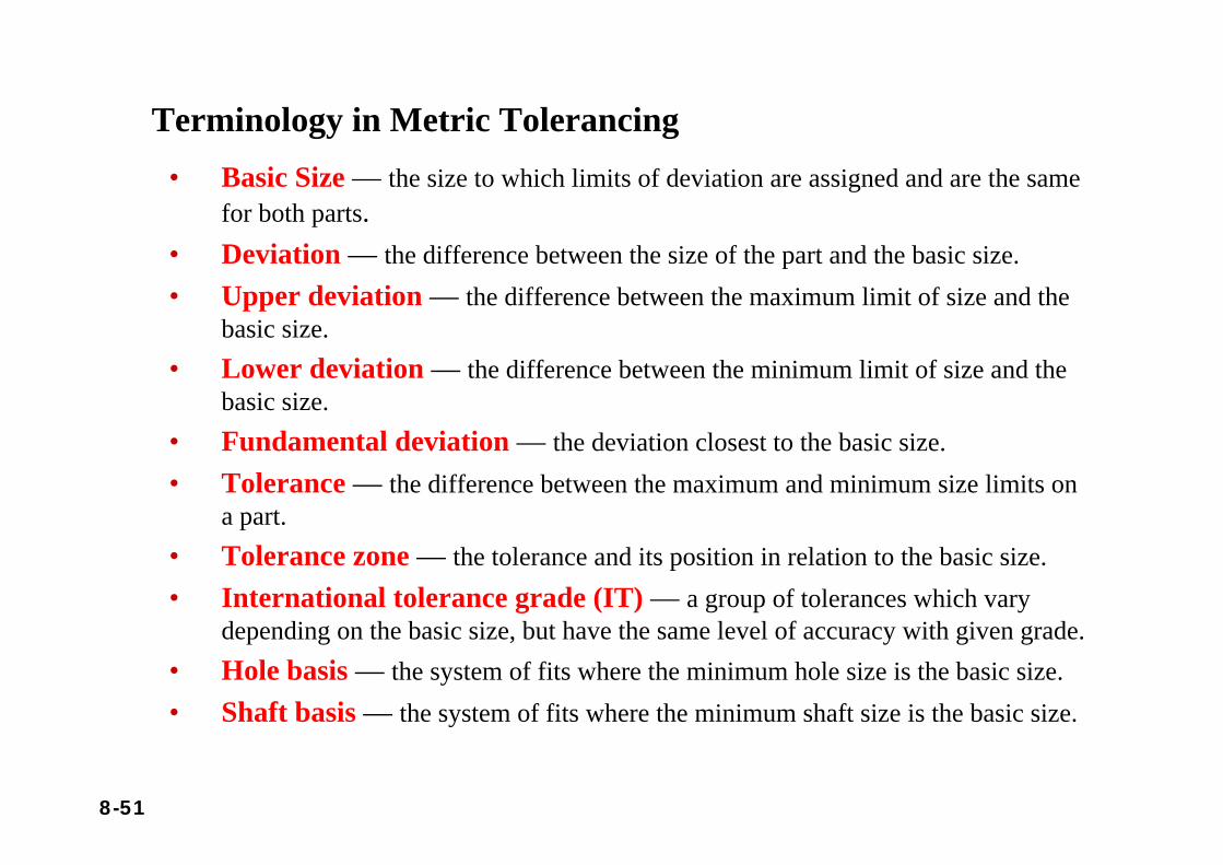
Terminology in Metric Tolerancing• Basic Size — the size to which limits of deviation are assigned and are the same
for both parts.• Deviation — the difference between the size of the part and the basic size.• Upper deviation — the difference between the maximum limit of size and the
basic size.• Lower deviation — the difference between the minimum limit of size and the
basic size.• Fundamental deviation — the deviation closest to the basic size.• Tolerance — the difference between the maximum and minimum size limits on
a part.• Tolerance zone — the tolerance and its position in relation to the basic size.• International tolerance grade (IT) — a group of tolerances which vary
depending on the basic size, but have the same level of accuracy with given grade.• Hole basis — the system of fits where the minimum hole size is the basic size.• Shaft basis — the system of fits where the minimum shaft size is the basic size.
8-52
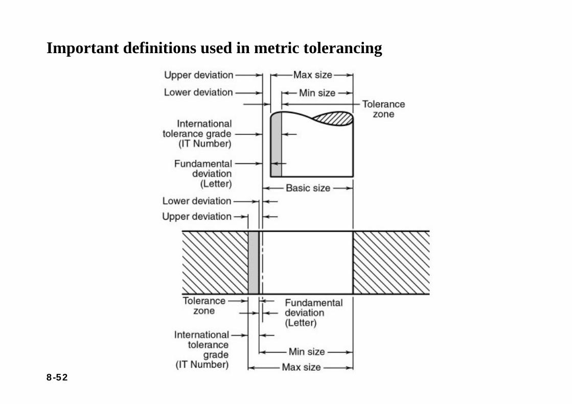
Important definitions used in metric tolerancing
8-53
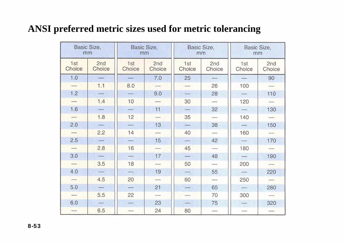
ANSI preferred metric sizes used for metric tolerancing
8-54
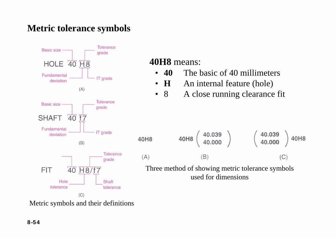
Metric tolerance symbols
Metric symbols and their definitions
Three method of showing metric tolerance symbols used for dimensions
40H8 means:• 40 The basic of 40 millimeters• H An internal feature (hole)• 8 A close running clearance fit
8-55
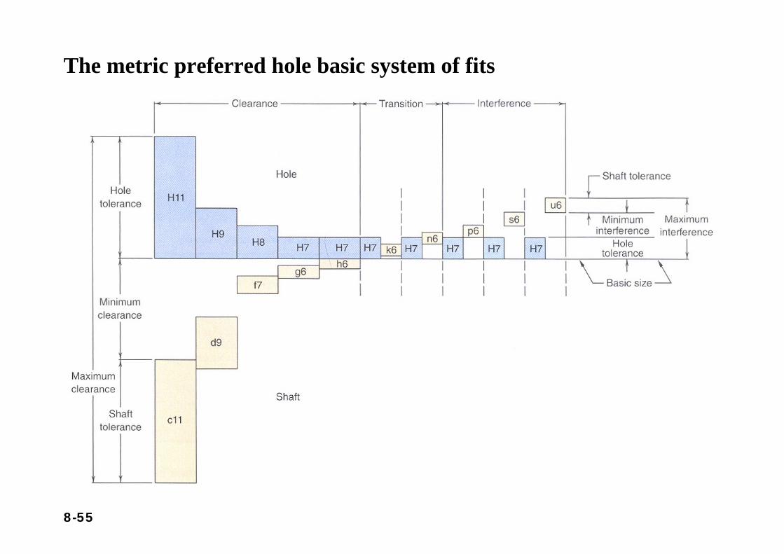
The metric preferred hole basic system of fits
8-56
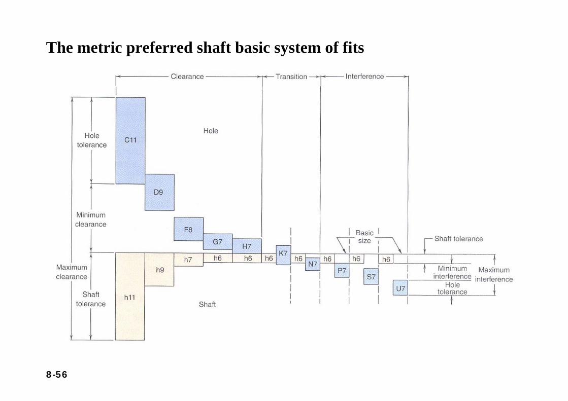
The metric preferred shaft basic system of fits
8-57
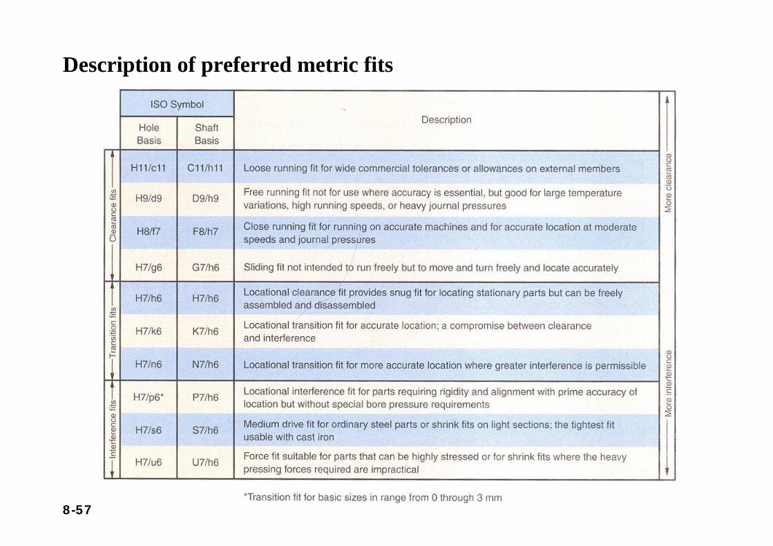
Description of preferred metric fits
8-58
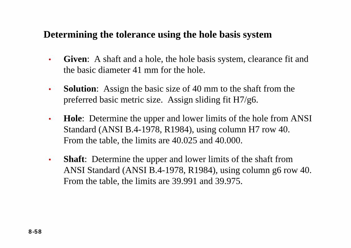
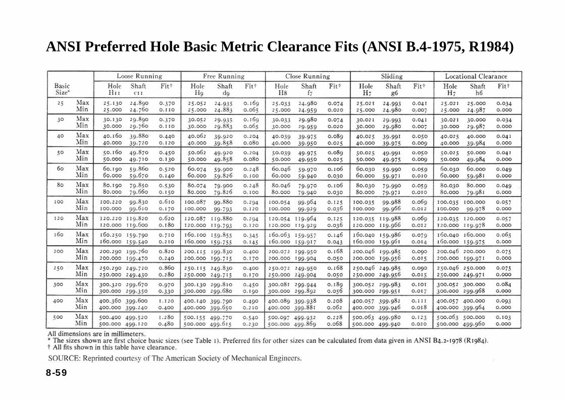
Determining the tolerance using the hole basis system
• Given: A shaft and a hole, the hole basis system, clearance fit and the basic diameter 41 mm for the hole.
• Solution: Assign the basic size of 40 mm to the shaft from the preferred basic metric size. Assign sliding fit H7/g6.
• Hole: Determine the upper and lower limits of the hole from ANSI Standard (ANSI B.4-1978, R1984), using column H7 row 40. From the table, the limits are 40.025 and 40.000.
• Shaft: Determine the upper and lower limits of the shaft from ANSI Standard (ANSI B.4-1978, R1984), using column g6 row 40. From the table, the limits are 39.991 and 39.975.
8-59
ANSI Preferred Hole Basic Metric Clearance Fits (ANSI B.4-1975, R1984)
8-60
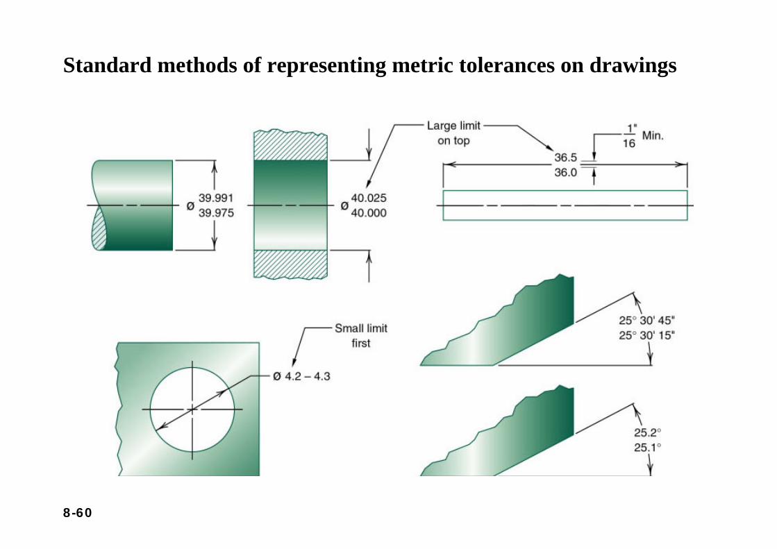
Standard methods of representing metric tolerances on drawings
8-61
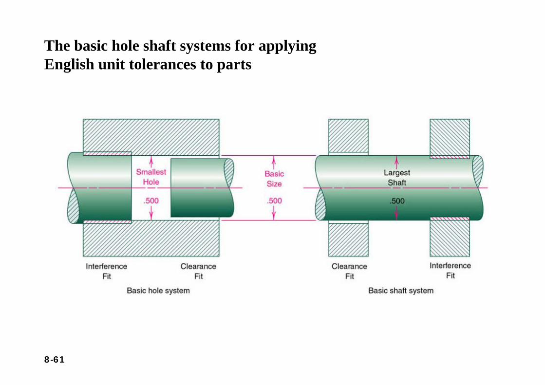
The basic hole shaft systems for applying English unit tolerances to parts
8-62
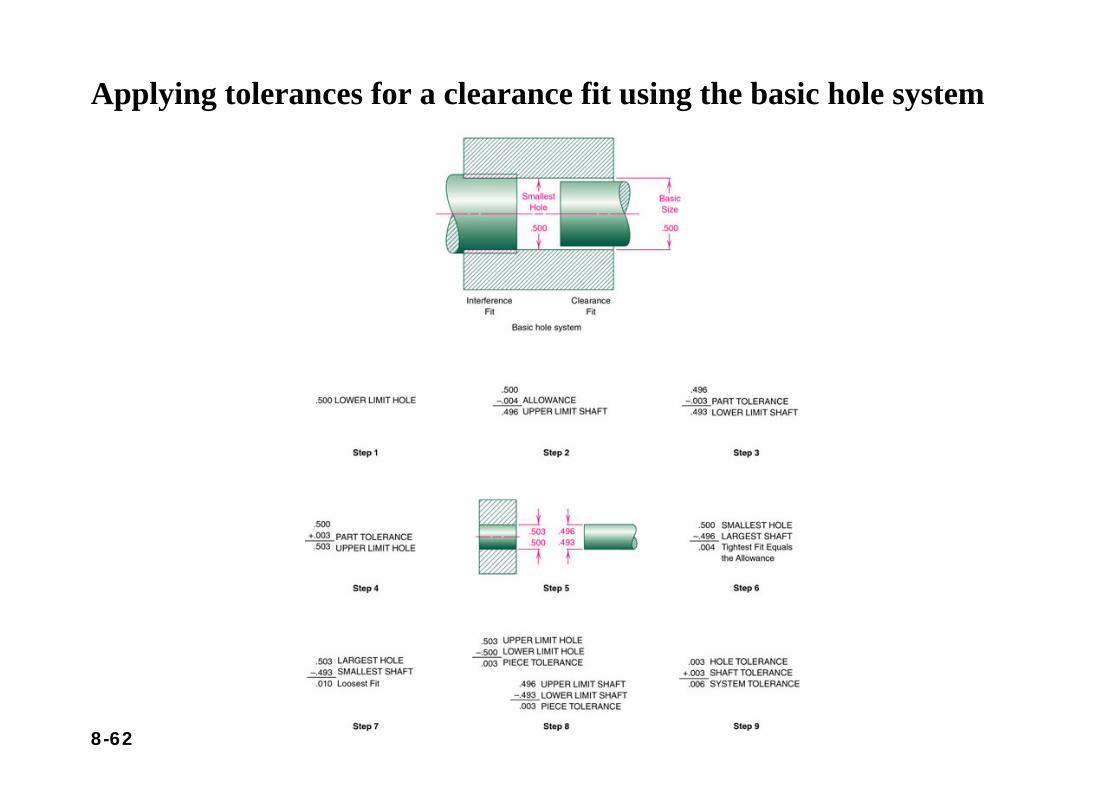
Applying tolerances for a clearance fit using the basic hole system
8-63
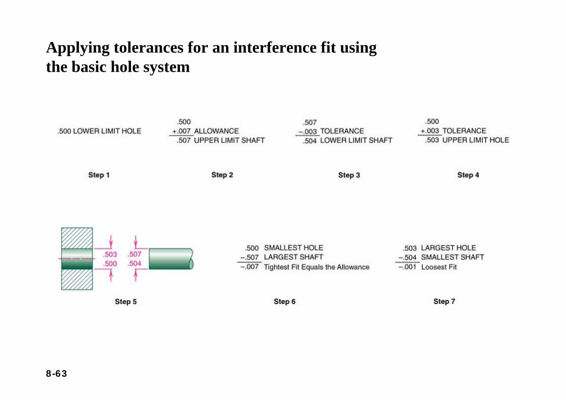
Applying tolerances for an interference fit using the basic hole system
8-64
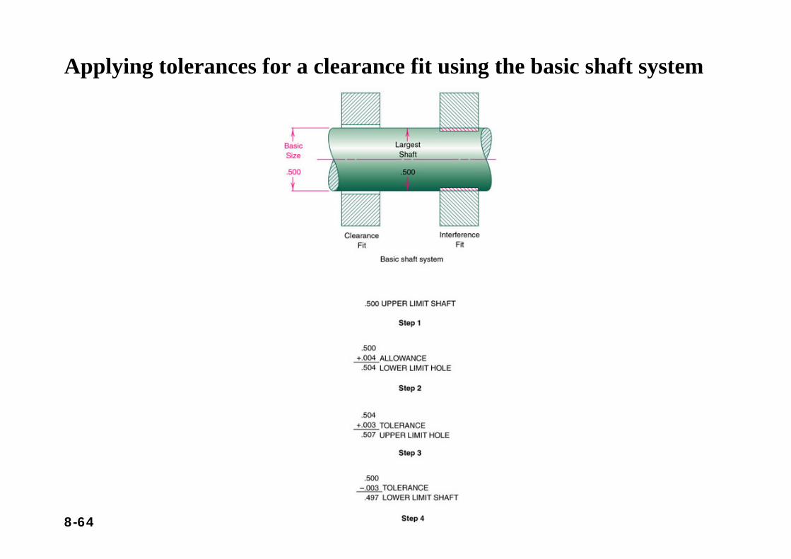
Applying tolerances for a clearance fit using the basic shaft system
8-65
Section 8.6Surface Texture
8-66
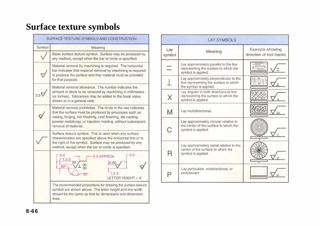
Surface texture symbols
8-67
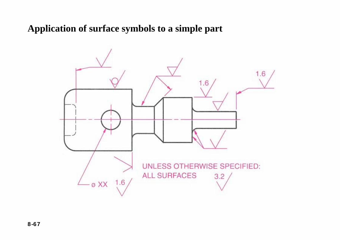
Application of surface symbols to a simple part
8-68
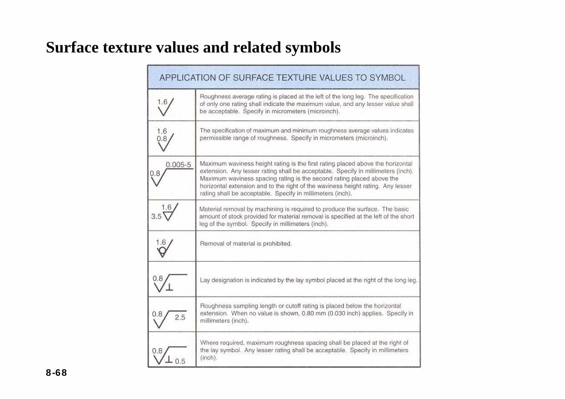
Surface texture values and related symbols
8-69
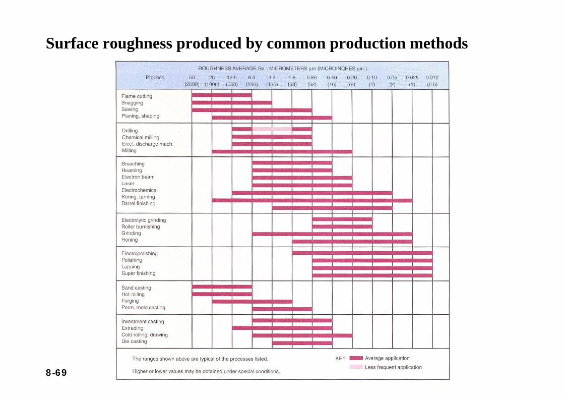
Surface roughness produced by common production methods
8-70
Section 8.7Geometric Dimensioning and Tolerances (GDT)
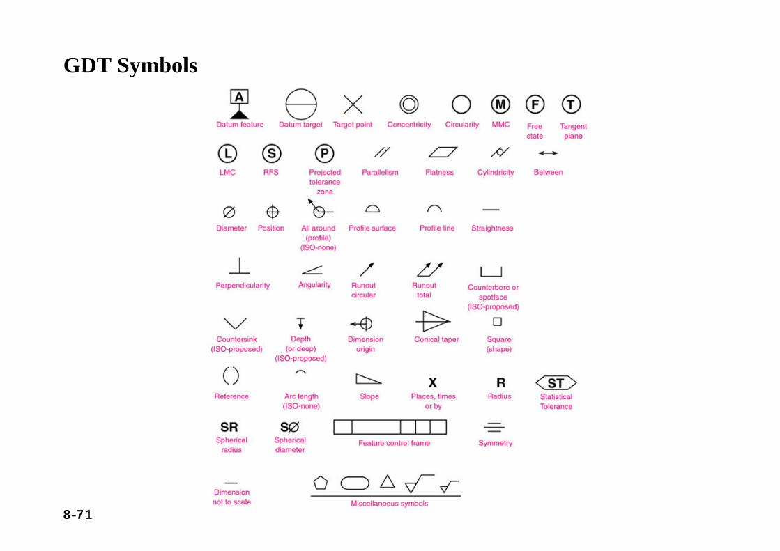
8-71
GDT Symbols
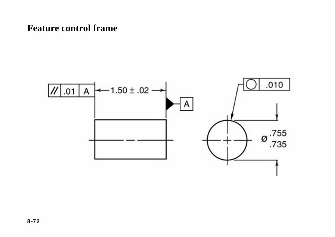
8-72
Feature control frame
8-73
Section 8.8Applying GDT in Design
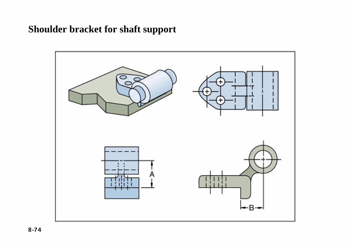
8-74
Shoulder bracket for shaft support
8-75
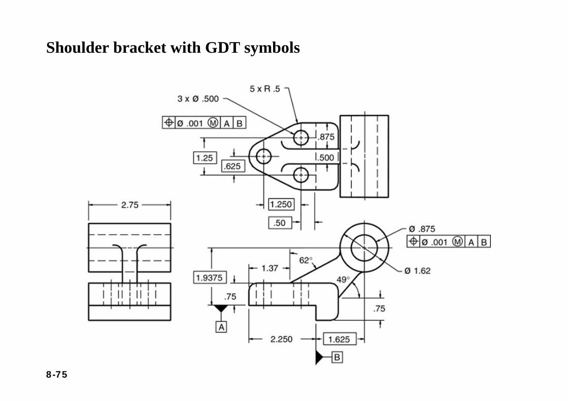
Shoulder bracket with GDT symbols
8-76
SUMMARY
• Dimensioning is a method of accurately communicating size information for objects and structures so that they can be produced.
• Dimensioning of mechanical devices follows standards establishedby ANSI.
• Many parts need to be dimensioned using toleranced values. • Tolerances allow a dimension to vary within limits. Toleranced
dimensions are especially useful in the accurate manufacture of assembled parts.
• Just as the clear communication about the shape of an object is accomplished by following the standard principles and onventionsof orthographic projection, the clear communication about the size of an object is accomplished through adherence to standard dimensioning practices.
8-77
QUESTIONS FOR REVIEW
1. How are concentric circles best dimensioned?2. Sketch the symbols for diameter, radius, depth, counterbore,
countersink, and square.3. Where are these symbols placed with respect to their numerical
values?4. What is the primary difference between counterbore and
spotface?5. When is a small cross required at the center of a radius?6. Define the depth of a blind hole.7. When are angled extension lines used? Sketch an example.8. When should extension lines be broken?9. How is a reference dimension identified?10. How can you tell if a dimension is out of scale (without
measuring the drawing)?
8-78
QUESTIONS FOR REVIEW
11. Write a note showing that a .25-inch deep .875-inch diameter hole is to be repeated six times.
12. When is an arc dimensioned with a diameter, and when is one dimensioned with a radius?
13. When should the word “drill” replace the word “diameter” when dimensioning a hole?
14. What is the proper proportion of width to length of arrowheads?15. What is the difference between limit dimensioning and plus and minus
dimensioning?16. What is the term for the theoretical size of a feature?17. Compare the thickness of dimension lines to object lines.18. Compare the thickness of dimension lines to extension lines.19. If two dimensioning guidelines appear to conflict, which guideline should
be followed?20. Write a definition of what Rule 1 means for a drawing of a flat washer with
a 0.500 diameter ID, 1.000 diameter OD, and a thickness of 0.062. Use a tolerance of plus or minus 0.005.
Related Documents