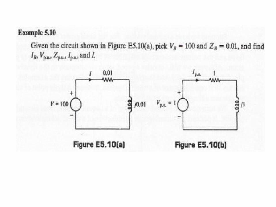
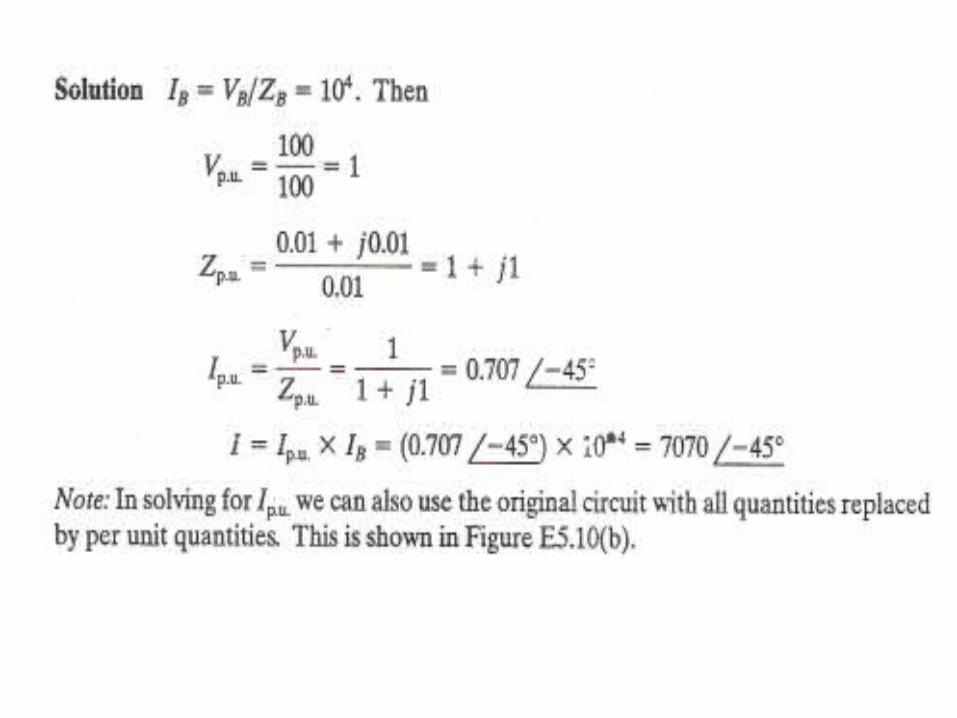
PER UNIT Analysis In power system calculations a normalization of variables called per unit normalization is almost always used. It is especially convenient if many transformers and voltage levels are involved. The idea is to Dick base values for quantities such as voltages, currents, impedances, power, and so on, and to define the quantity in per unit as follows.

Chapter7 PER UNIT Analysis
Oct 26, 2014
Welcome message from author
This document is posted to help you gain knowledge. Please leave a comment to let me know what you think about it! Share it to your friends and learn new things together.
Transcript
PER UNIT Analysis
In power system calculations a normalization of variables called per unit normalization is almost always used. It is especially convenient if many transformers and voltage levels are involved.The idea is to Dick base values for quantities such as voltages, currents, impedances,
power, and so on, and to define the quantity in per unit as follows.
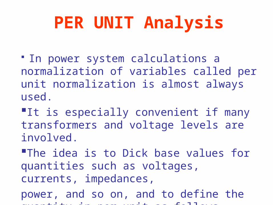
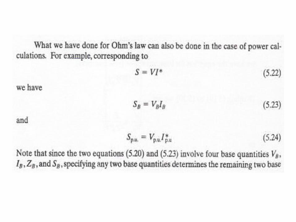
• A very important point is that the base variables are chosen to satisfy the same kind of relationship as the actual variables.
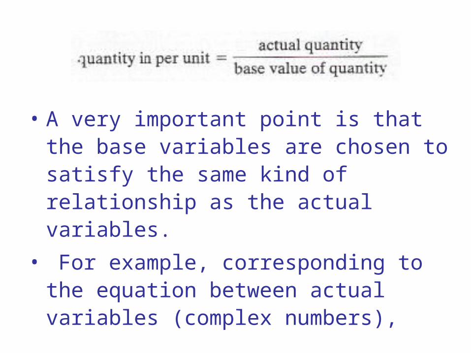
• For example, corresponding to the equation between actual variables (complex numbers),
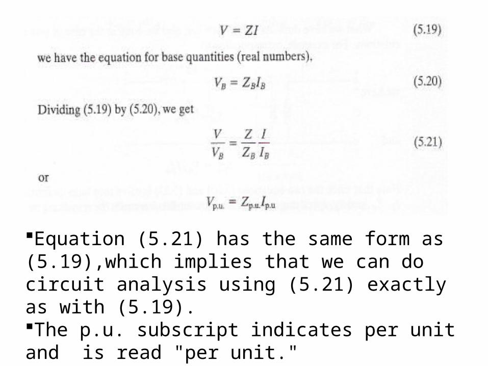
Equation (5.21) has the same form as (5.19),which implies that we can do circuit analysis using (5.21) exactly as with (5.19).The p.u. subscript indicates per unit and is read "per unit."
• If the network includes transformers, there is an advantage to picking different bases for the two sides of the transformer.
• Suppose that we make the ratio of voltage bases equal to the connection-induced voltage ratio in the per phase equivalent circuit, or what we will take to be equivalent,
• The ratio of secondary and primary (open-circuit) voltage ratings of the three-phase banks.
• Let SB be the same on both sides.
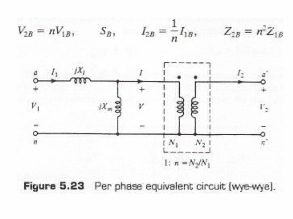
• For example, consider a transformer bank connected Wye -wye.
• Figure 5.23 Pick convenient bases V1B, SB,I1B and ZIB for side 1.
• Then, we get for the corresponding quantities on side 2,
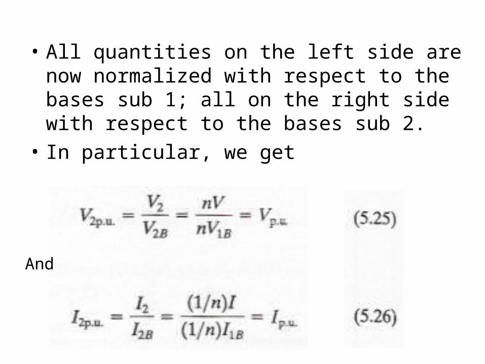
• All quantities on the left side are now normalized with respect to the bases sub 1; all on the right side with respect to the bases sub 2.
• In particular, we get
And
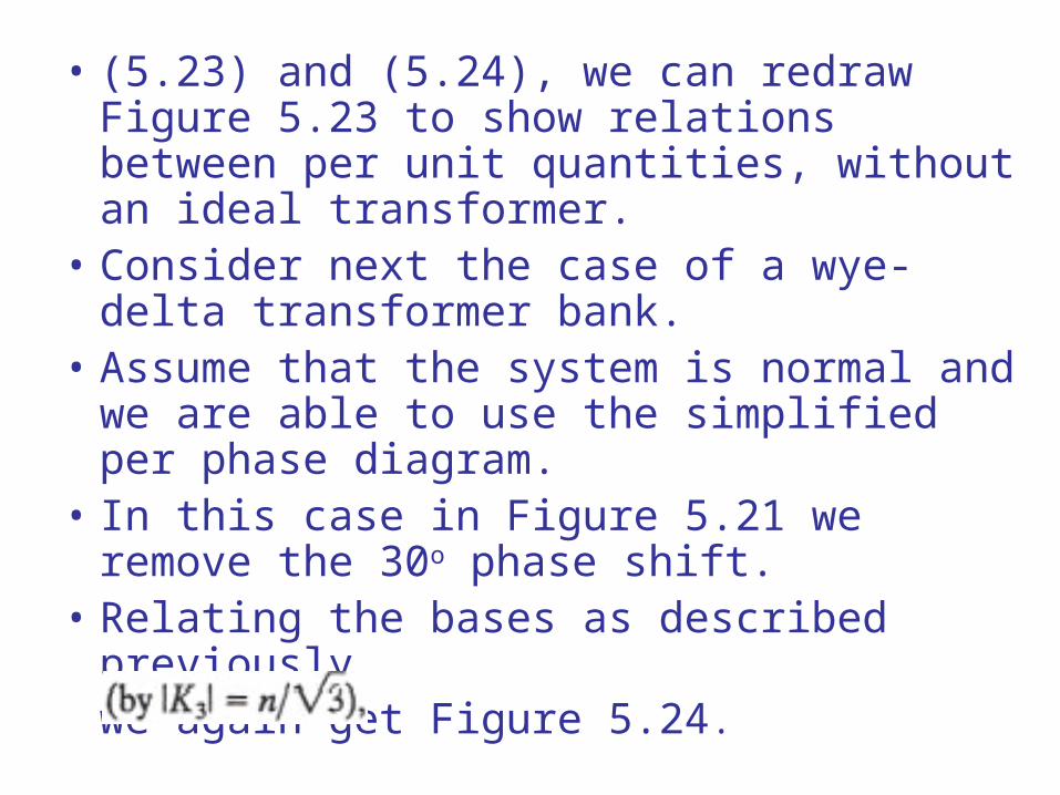
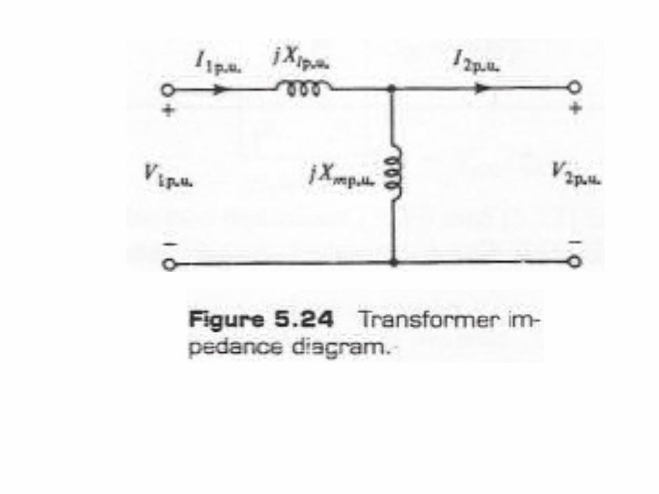
• (5.23) and (5.24), we can redraw Figure 5.23 to show relations between per unit quantities, without an ideal transformer.
• Consider next the case of a wye-delta transformer bank.
• Assume that the system is normal and we are able to use the simplified per phase diagram.
• In this case in Figure 5.21 we remove the 30o phase shift.
• Relating the bases as described previouslywe again get Figure 5.24.
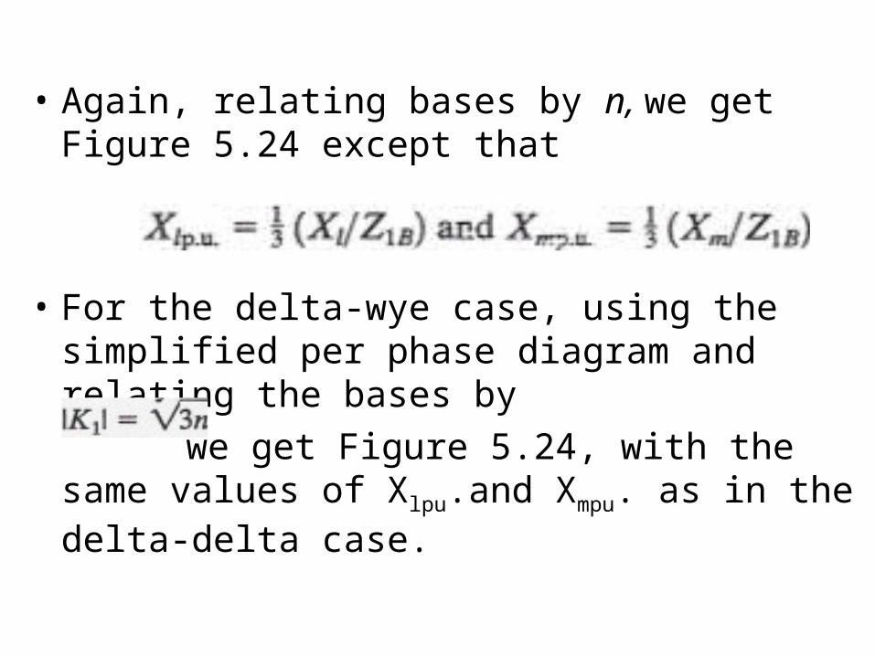
• Again, relating bases by n, we get Figure 5.24 except that
• For the delta-wye case, using the simplified per phase diagram and relating the bases by
we get Figure 5.24, with the same values of Xlpu.and Xmpu. as in the delta-delta case.
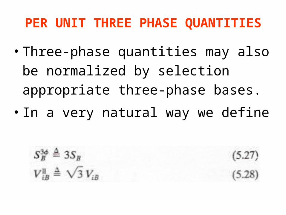
PER UNIT THREE PHASE QUANTITIES
• Three-phase quantities may also be
normalized by selection appropriate
three-phase bases.
• In a very natural way we define
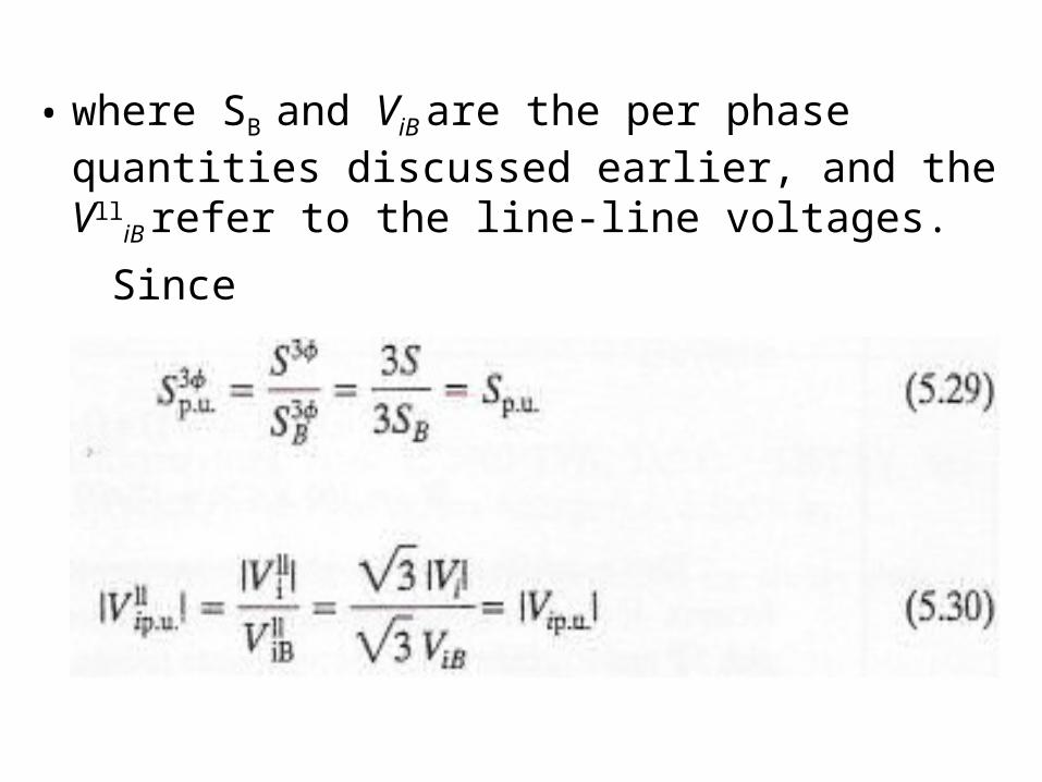
• where SB and ViB are the per phase quantities discussed earlier, and the Vll
iB refer to the line-line voltages.
Since
• we see that numerically, the difference between per phase and three-phase quantities expressed in per unit may be unimportant.
• Power engineers sometimes need not specify whether a per unit voltage is line-line or line-neutral.
• For example, if we say that the voltage (magnitude) is 1 p.u., this means that the line-line voltage (magnitude) is 1 p.u.
• (i.e., equal to its base value) and that the line-neutral voltage (magnitude) is also 1 p.u i.e. equal to its base value).
• A similar is permissible relative to three-phase and single-phase power.
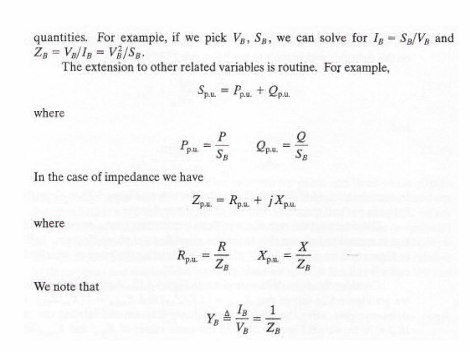
• Consider also the formula for ZB' We can
• calculate ZB using either single-phase or three-phase quantities.
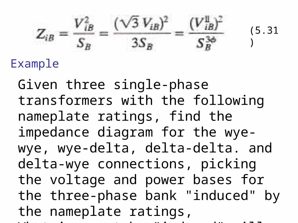
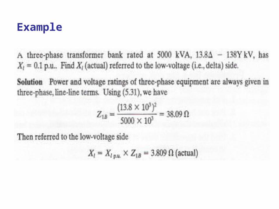
Example
Given three single-phase transformers with the following nameplate ratings, find the impedance diagram for the wye-wye, wye-delta, delta-delta. and delta-wye connections, picking the voltage and power bases for the three-phase bank "induced" by the nameplate ratings, What is meant by "induced" will be clearer from the example.
(5.31)
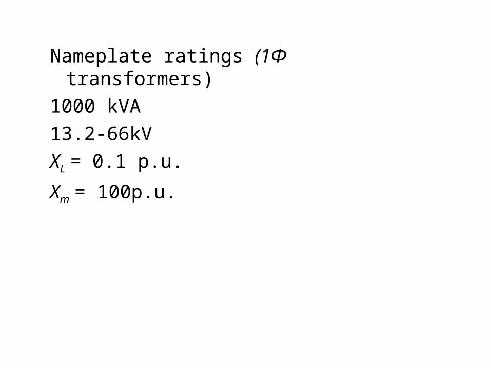
Nameplate ratings (1Φ transformers)
1000 kVA
13.2-66kV
XL = 0.1 p.u.
Xm = 100p.u.
Solution
• The significance of the per unit reactance specified in the nameplate ratings is the following.
• The manufacturer has picked impedance bases in accordance with the nameplate volt-ampere and voltage ratings.
• Thus for the 1<Ф> transformers, we have
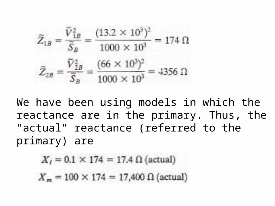
We have been using models in which the reactance are in the primary. Thus, the "actual" reactance (referred to the primary) are
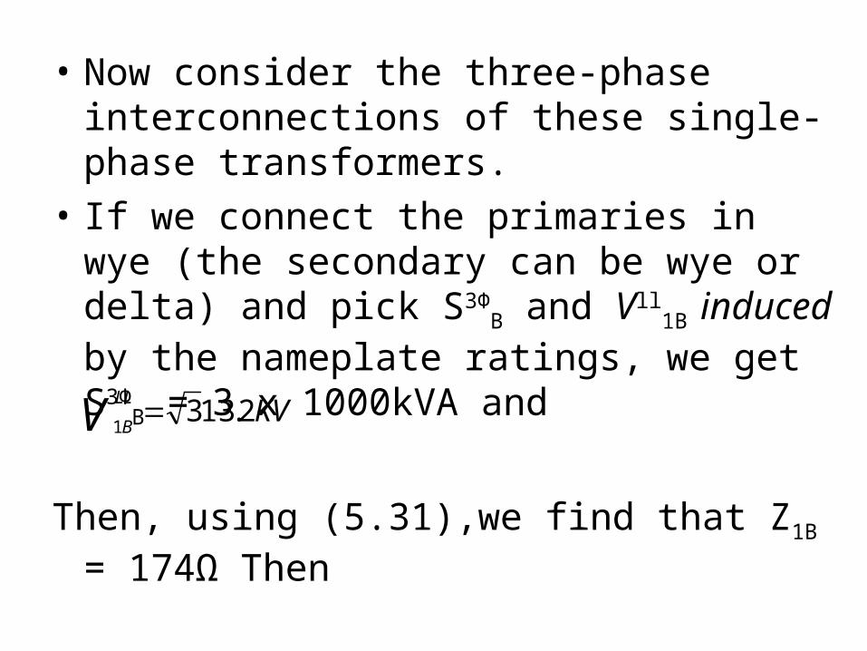
• Now consider the three-phase interconnections of these single-phase transformers.
• If we connect the primaries in wye (the secondary can be wye or delta) and pick S3Φ
B and Vll1B induced by the nameplate
ratings, we get S3ΦB = 3 x 1000kVA and
Then, using (5.31),we find that Z1B = 174Ω Then
KVVLL
B2.133
1
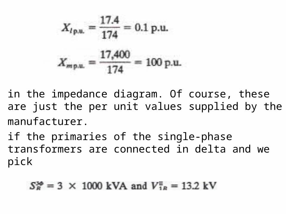
in the impedance diagram. Of course, these are just the per unit values supplied by the
manufacturer.
if the primaries of the single-phase transformers are connected in delta and we pick
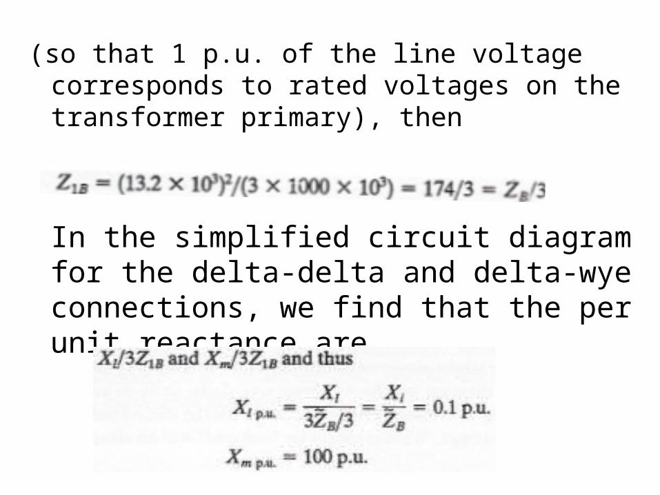
(so that 1 p.u. of the line voltage corresponds to rated voltages on the transformer primary), then
In the simplified circuit diagram for the delta-delta and delta-wye connections, we find that the per unit reactance are
• Thus we get, in every case, the same per unit values for X, and Xm as in the case of the single-phase transformer.
• In all four cases we have the impedance diagram shown in Figure E5.11.
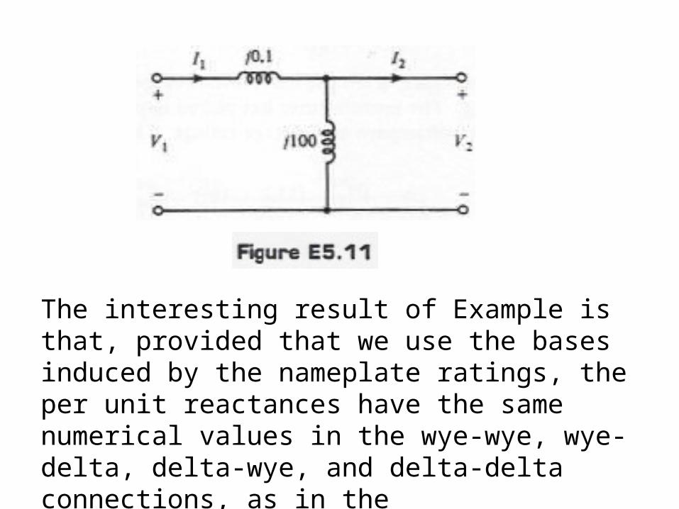
The interesting result of Example is that, provided that we use the bases induced by the nameplate ratings, the per unit reactances have the same numerical values in the wye-wye, wye-delta, delta-wye, and delta-delta connections, as in thesingle phase case.
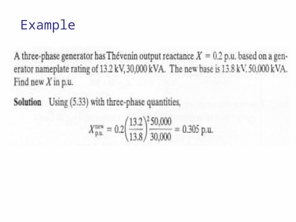
Example
CHANGE OF BASE
• With several items of equipment, with different ratings, it is not usually possible to pick base values so that they are always the same as the nameplate ratings.
• It is then necessary to recalculate the per unit values on the new basis.
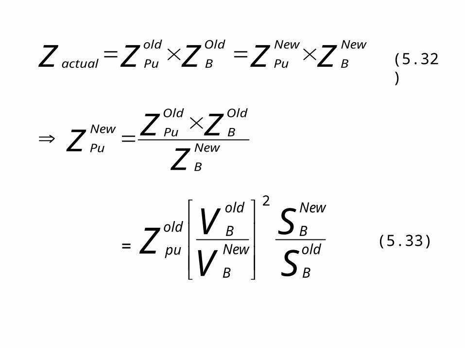
• The key idea is that Zpu depends on ZB but, of course, Z actual does not.
• We note the relationship between old and new values:
ZZZZ
ZZZZZ
New
B
Old
B
Old
PuNew
Pu
New
B
New
Pu
Old
B
old
Puactual
SS
VVZ old
B
New
BNew
B
old
Bold
pu
2
=
(5.32)
(5.33)
Example
PER UNIT ANALYSIS OF NORMAL SYSTEM
• If we have a normal system, we can greatly simplify the solution of the usual power system problem by using an impedance diagram.
• The rationale was described in Section
5.5 and the procedure is summarized as follows.
Procedure for a per unit analysis
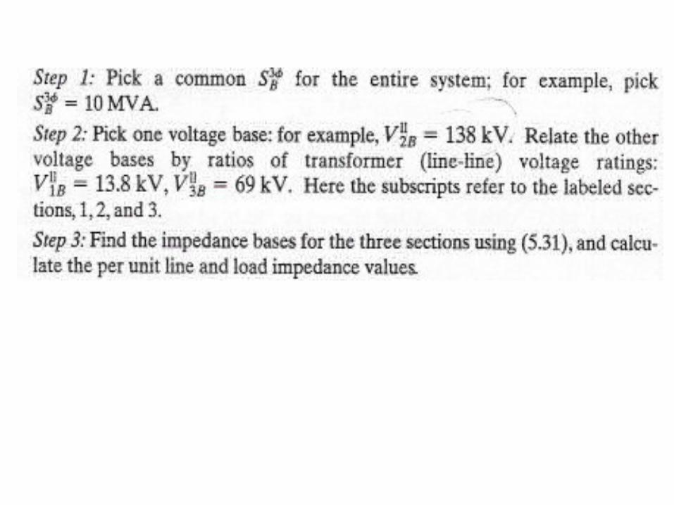
1. Pick a volt-ampere base for the whole system.
2. Pick one base voltage arbitrarily. Relate all the others by the ratio of the magnitudes of the open-circuit line voltages of each transformer bank.
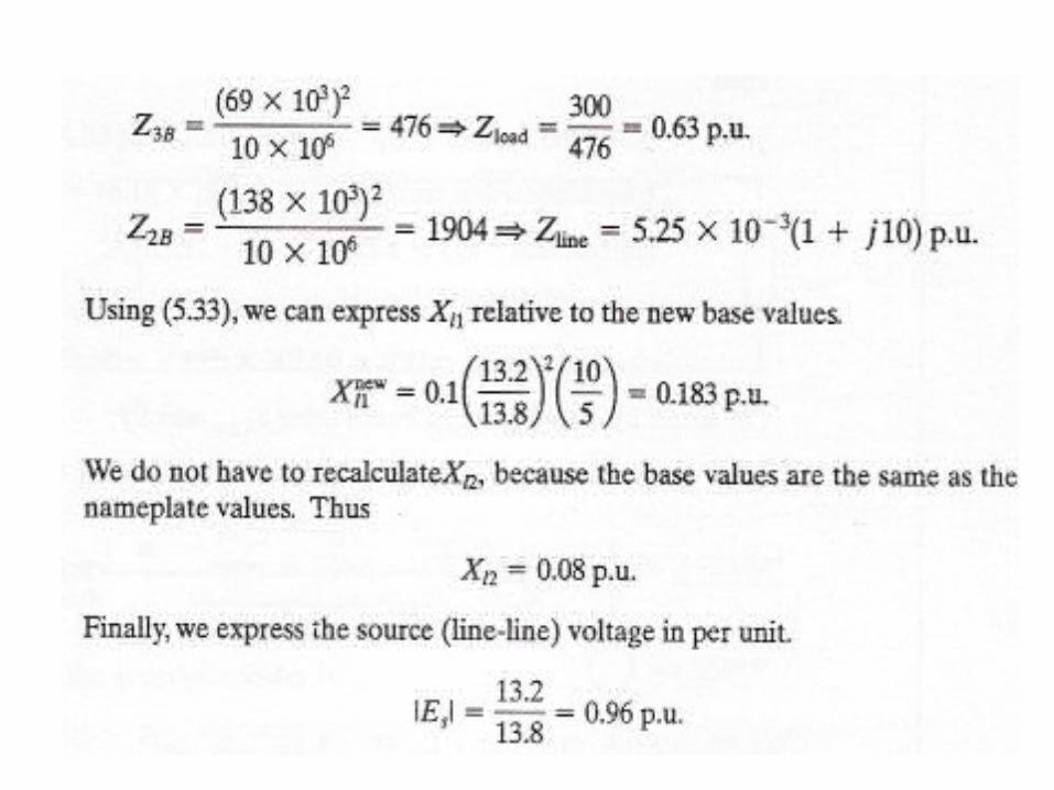
3. Find the impedance bases in the different sections and express all impedances in consistent per unit terms.
desired.
4. Draw the impedance diagram for the entire system, and solve for desired per unit quantities.
5. Convert back to actual quantities if desired.
• In step 1 it is convenient to pick the three-phase volt-ampere rating of one of the generators or transformer banks.
• In step 2 it is convenient to pick as a base voltage the rated voltage of the unit picked in step 1.
• In this case in step 3, the manufacturer's specification of impedance in per unit be used directly.
• If not, in step 3 use (5.33). In step 4 we note that the impedance diagram will not have phase shifters or ideal transformers.
• Finally, we note that for a normal system the procedure described in step 2 is feasible; we get a consistent set of base voltages.
• The procedure is illustrated in the next two examples.
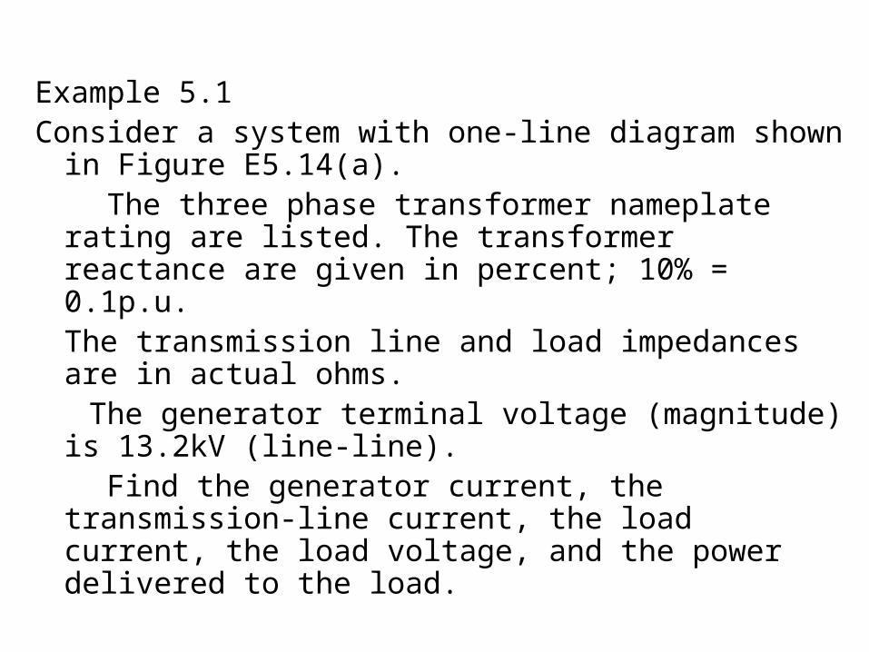
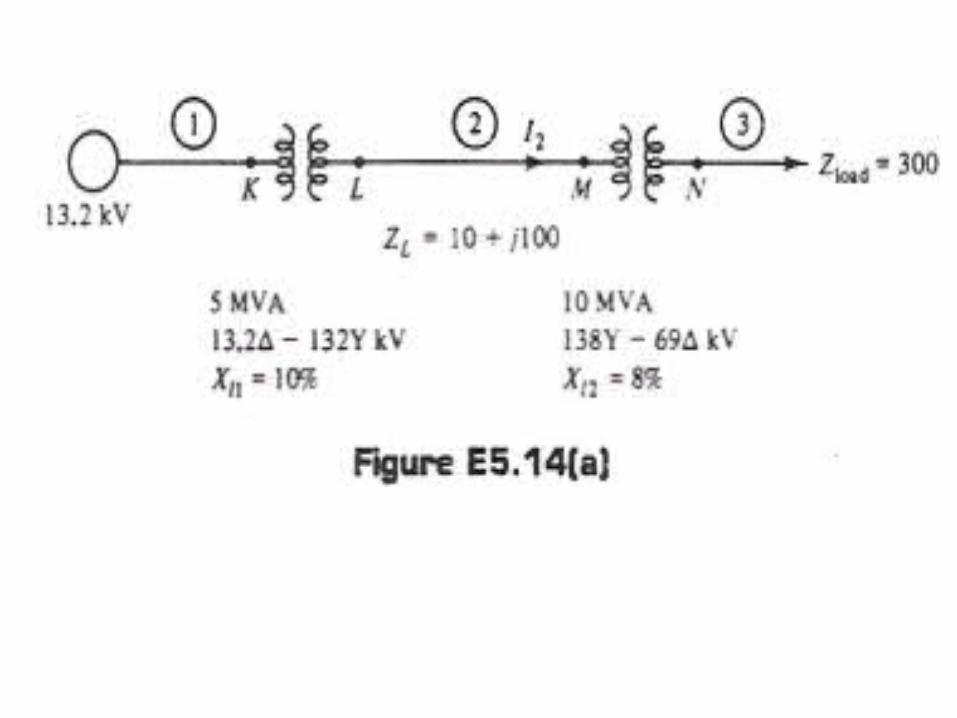
Example 5.1Consider a system with one-line diagram shown in
Figure E5.14(a). The three phase transformer nameplate rating are
listed. The transformer reactance are given in percent; 10% = 0.1p.u. The transmission line and load impedances are in actual ohms.
The generator terminal voltage (magnitude) is 13.2kV (line-line).
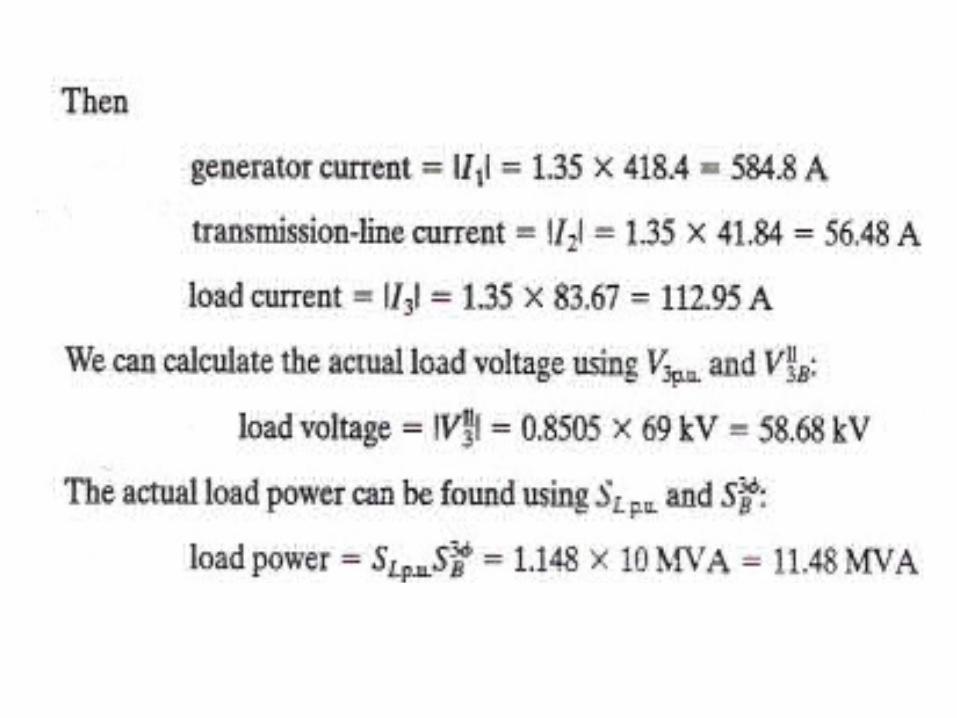
Find the generator current, the transmission-line current, the load current, the load voltage, and the power delivered to the load.
Solution
• The system is normal, and we can ignore transformation-induced phase shifts.
• We wish to derive an impedance diagram.
• In Figure E5.14(a), three sections (1, 2, and 3) are identified.
• We will need to pick appropriate bases for these three sections.
• To do the circuit analysis it is convenient to pick Es =0.96L0o p.u. but since this choice is arbitrary, there is no significance to the absolute phases of the quantities resulting from the analysis.
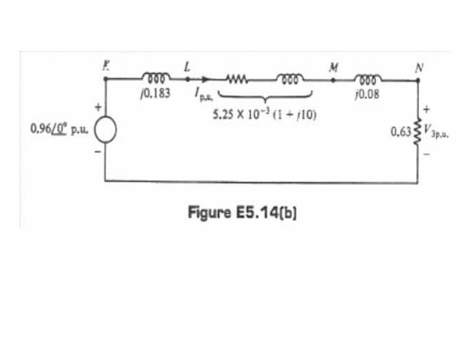
• Step 4: We are now able to draw the impedance diagram [Figure E5.14(b)].
• The points labeled KLMN correspond to the points similarly labeled on the one line diagram.
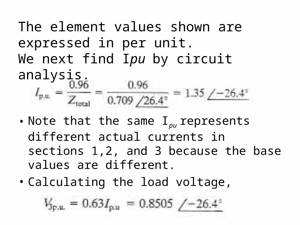
• Note that the same Ipu represents different actual currents in sections 1,2, and 3 because the base values are different.
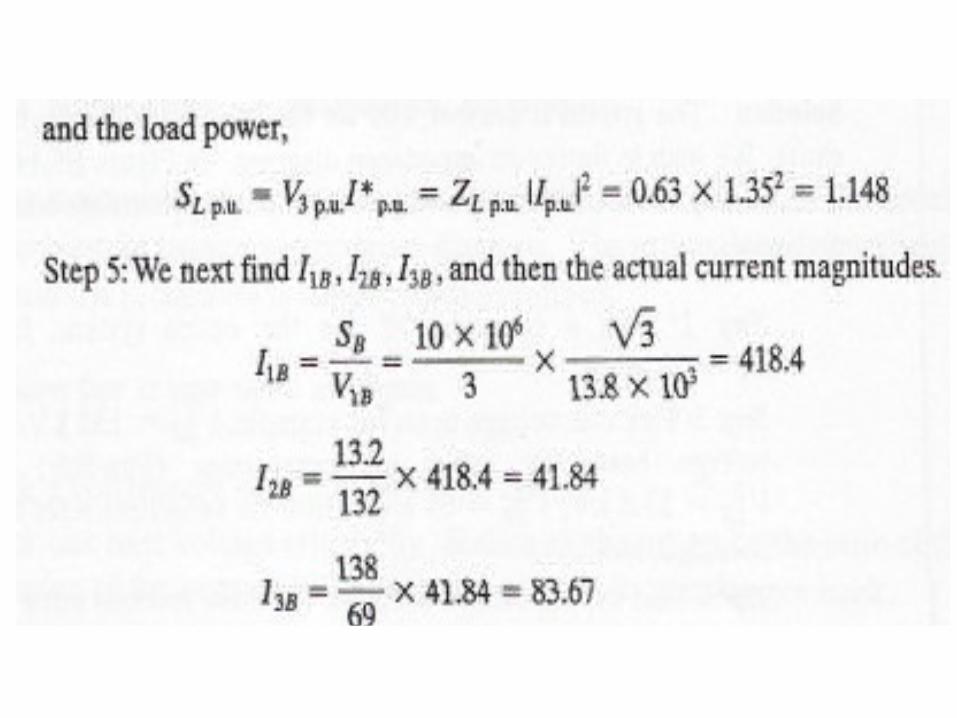
• Calculating the load voltage,
The element values shown are expressed in per unit. We next find Ipu by circuit analysis.
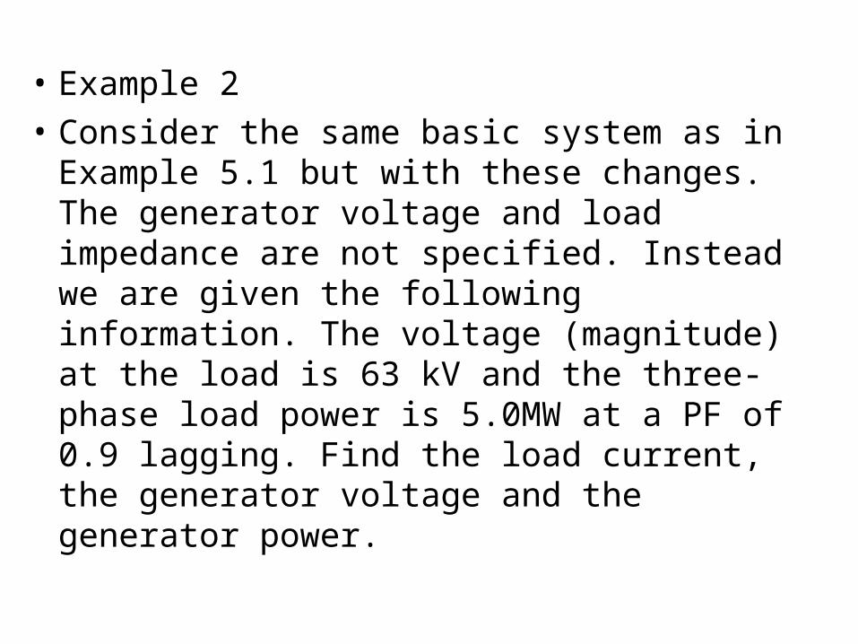
• Example 2
• Consider the same basic system as in Example 5.1 but with these changes. The generator voltage and load impedance are not specified. Instead we are given the following information. The voltage (magnitude) at the load is 63 kV and the three-phase load power is 5.0MW at a PF of 0.9 lagging. Find the load current, the generator voltage and the generator power.
Solution
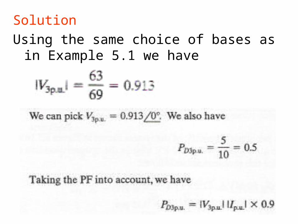
Using the same choice of bases as in Example 5.1 we have
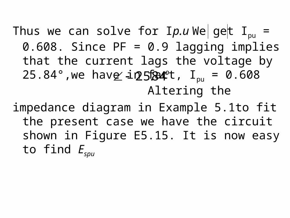
Thus we can solve for Ip.u We get Ipu = 0.608. Since PF = 0.9 lagging implies that the current lags the voltage by 25.84°,we have in fact, Ipu = 0.608 Altering the
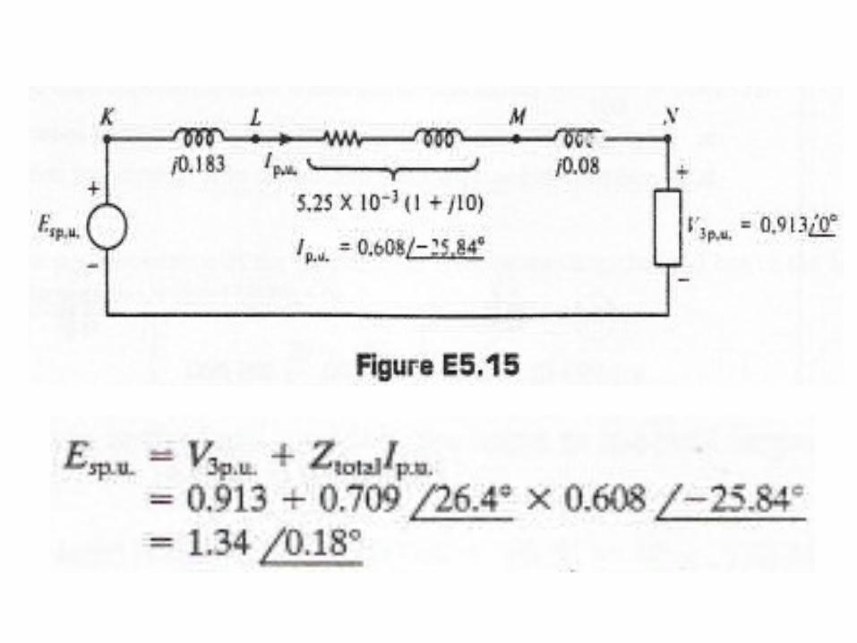
impedance diagram in Example 5.1to fit the present case we have the circuit shown in Figure E5.15. It is now easy to find Espu
o84.25
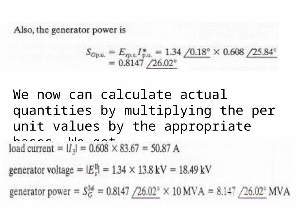
We now can calculate actual quantities by multiplying the per unit values by the appropriate bases. We get
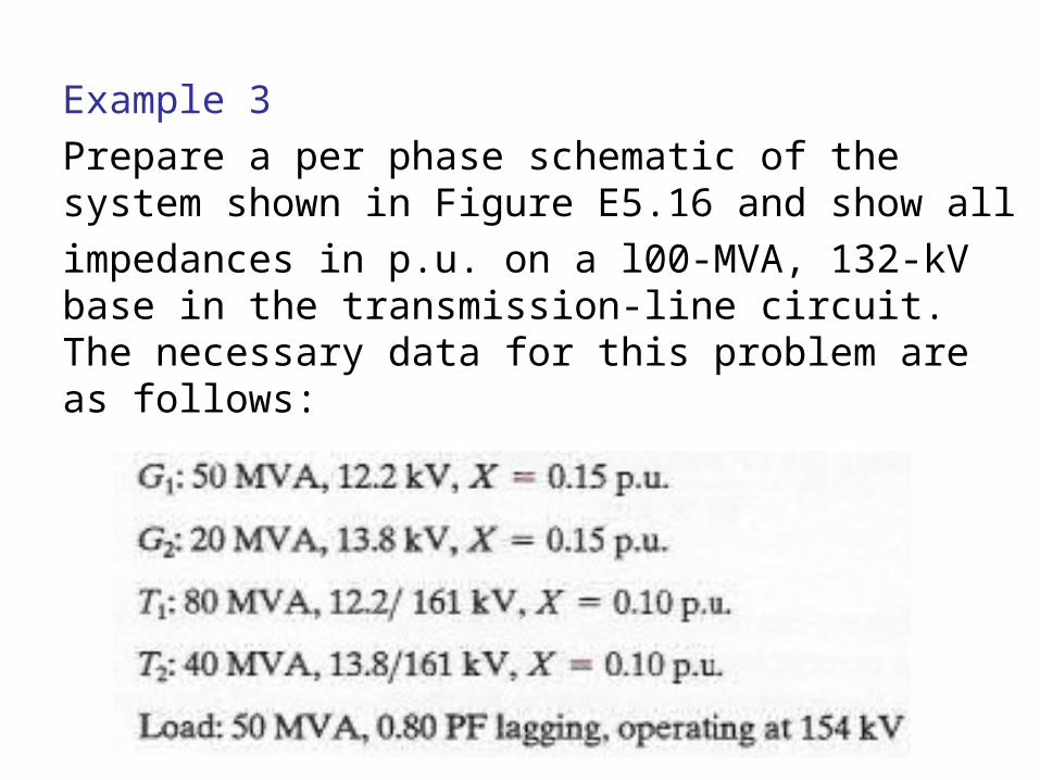
Example 3
Prepare a per phase schematic of the system shown in Figure E5.16 and show all
impedances in p.u. on a l00-MVA, 132-kV base in the transmission-line circuit. The necessary data for this problem are as follows:
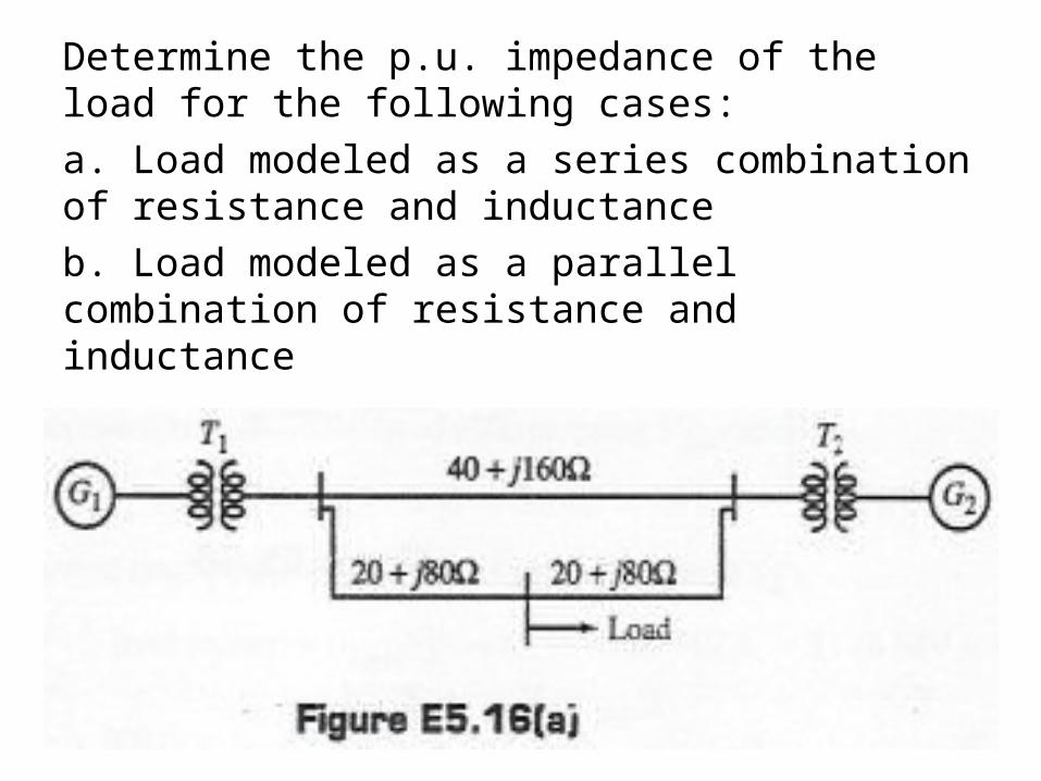
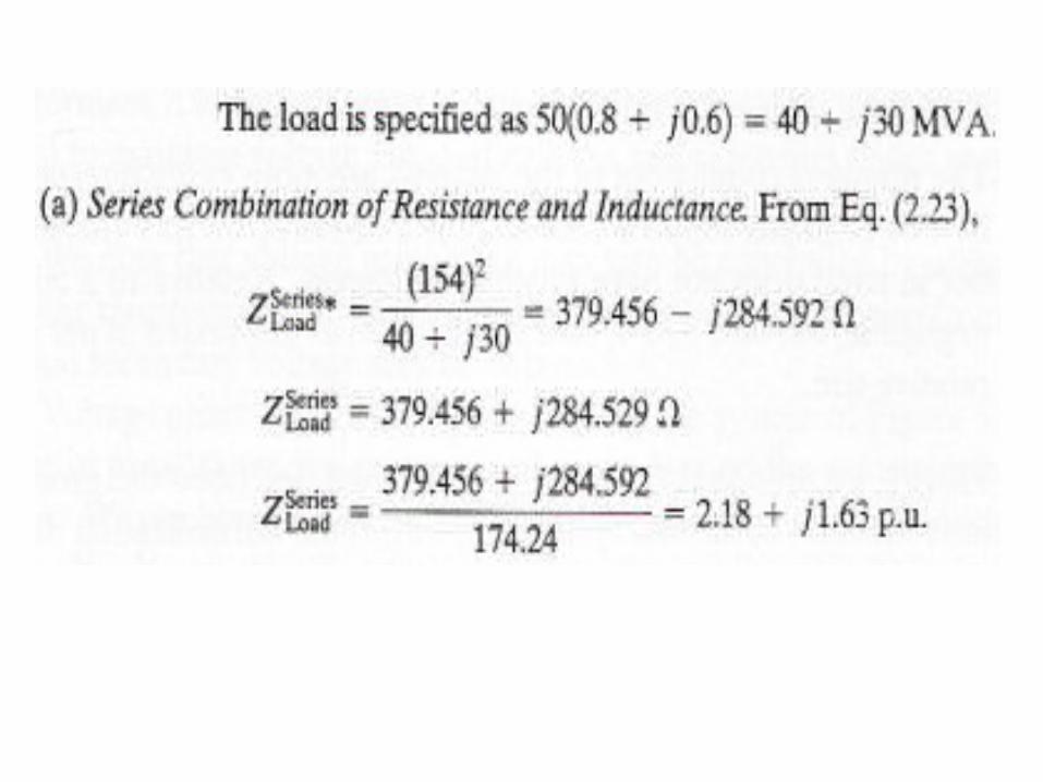
Determine the p.u. impedance of the load for the following cases:
a. Load modeled as a series combination of resistance and inductance
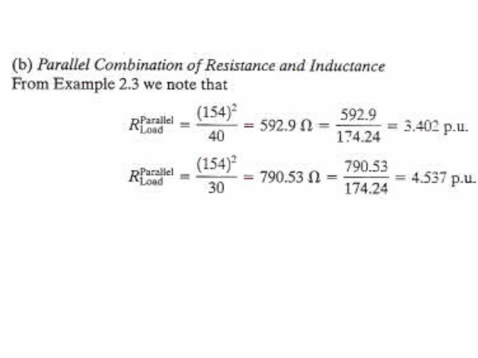
b. Load modeled as a parallel combination of resistance and inductance
SolutionThis example illustrates the various steps in deriving the p.u. representation of the system. Note that the data presented are in p.u on a base specified for each component.
This would be typically provided by the manufacturer. In the following analysis, we will convert all these quantities to a common system base that has been specified in the transmission circuit.
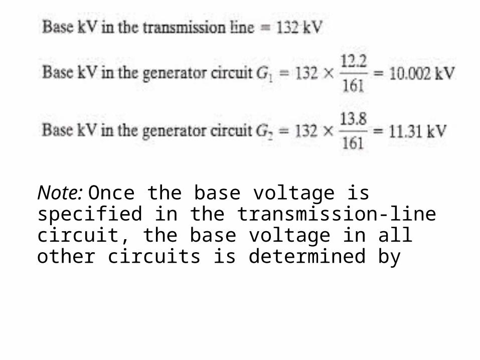
Note: Once the base voltage is specified in the transmission-line circuit, the base voltage in all other circuits is determined by
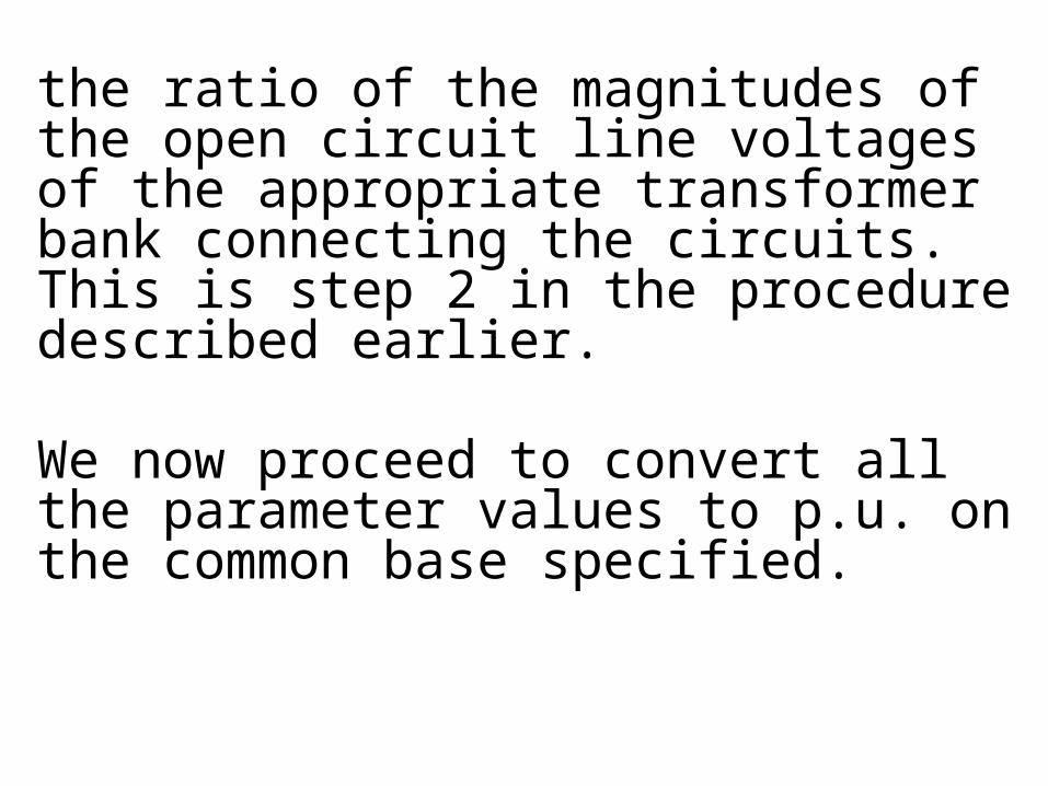
the ratio of the magnitudes of the open circuit line voltages of the appropriate transformer bank connecting the circuits. This is step 2 in the procedure described earlier.
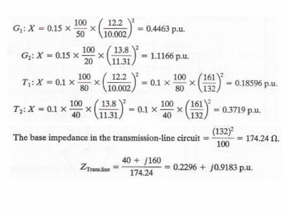
We now proceed to convert all the parameter values to p.u. on the common base specified.
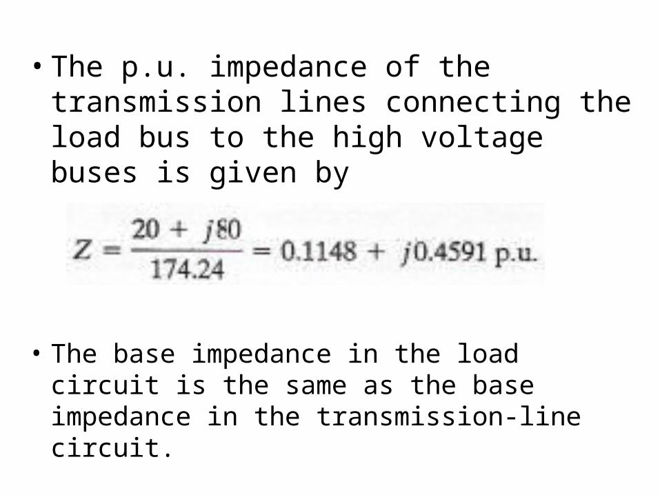
• The p.u. impedance of the transmission lines connecting the load bus to the high voltage buses is given by
• The base impedance in the load circuit is the same as the base impedance in the transmission-line circuit.
Related Documents