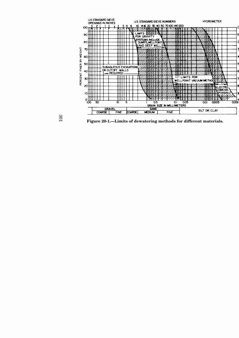
Chapter 20 WATER CONTROL Introduction This chapter discusses site conditions that need dewatering and the extent and basic requirements for construction dewatering. A more comprehensive discus- sion of technical requirements and methods for con- structing dewatering facilities is available in the Reclamation Ground Water Manual. The subjects that are discussed include: C Site review C Site investigations C Data collection C Data interpretation, evaluation, and presentation C Specifications paragraphs C Construction considerations C Supervision and oversight C Documentation of results (final construction report) Water control is lumped into two categories—dewatering and unwatering. Water control is the removal or cont rol of groundwater or seepage from below the surface (dewatering) or the removal or control of ponded or flowing surface water by ditches, surface drains, or sumps (unwatering). Excavation of materials or construction near or below the water table or near surface water bodies usually requires control of the groundwater or seepage. Control may involve isolati on with cutoffs, stabilization by freezing, grouting, or other methods, or by a combination of methods. Control of groundwater and seepage usually involves installation and operation of wells or drains. A key operation in most water control in unstable materials is the removal of water from below the ground surface in advance of excavation and maintaining the water level at

Welcome message from author
This document is posted to help you gain knowledge. Please leave a comment to let me know what you think about it! Share it to your friends and learn new things together.
Transcript
7/31/2019 Chapter20- Water Control
http://slidepdf.com/reader/full/chapter20-water-control 1/22
Chapter 20
WATER CONTROL
Introduction
This chapter discusses site conditions that need
dewatering and the extent and basic requirements for
construction dewatering. A more comprehensive discus-
sion of technical requirements and methods for con-
structing dewatering facilities is available in the
Reclamation Ground Water Manual. The subjects thatare discussed include:
C Site review
C Site investigations
C Data collection
C Data interpretation, evaluation, and presentation
C Specifications paragraphs
C Construction considerations
C Supervision and oversight
C Documentation of results (final construction report)
Water control is lumped into two categories—dewateringand unwatering. Water control is the removal or control
of groundwater or seepage from below the surface
(dewatering) or the removal or control of ponded or
flowing surface water by ditches, surface drains, or sumps
(unwatering). Excavation of materials or construction
near or below the water table or near surface water bodies
usually requires control of the groundwater or seepage.
Control may involve isolation with cutoffs, stabilization by
freezing, grouting, or other methods, or by a combination
of methods. Control of groundwater and seepage usually
involves installation and operation of wells or drains. A
key operation in most water control in unstable materials
is the removal of water from below the ground surface in
advance of excavation and maintaining the water level at
7/31/2019 Chapter20- Water Control
http://slidepdf.com/reader/full/chapter20-water-control 2/22
7/31/2019 Chapter20- Water Control
http://slidepdf.com/reader/full/chapter20-water-control 3/22
3 0 1
Figure 20-1.—Limits of dewatering methods for diff
7/31/2019 Chapter20- Water Control
http://slidepdf.com/reader/full/chapter20-water-control 4/22
FIELD MANUAL
302
temporary excavation, especially in clayey or silty soils
that have low permeability and are difficult to drain.
Unwatering methods are commonly used in soils thathave high porosity but low permeabilities (clayey or silty
soils), bedrock that has solution cavities, and lava tubes
that carry large volumes of water in isolated areas.
Unwatering methods are commonly used to control
surface water.
Unwatering usually is performed in conjunction withdewatering to ensure control of surface water and to
permit dewatering to proceed unaffected by recharge or
flooding from nearby surface water. Failure to properly
remove or control water during unwatering or dewatering
may result in:
• Unstable natural or excavated slopes
• Unstable, unworkable, or unsuitable subgrade
• Boils, springs, blowouts, or seeps on slopes or in the
subgrade
• Flooding of excavations or structures
• Uplift of constructed features such as concrete slabs
• Dilution, corrosion, or other adverse effects on con-
crete, metals, or other construction materials
• Instability of nearby structures
• Draining surrounding surface water and ground-
water
7/31/2019 Chapter20- Water Control
http://slidepdf.com/reader/full/chapter20-water-control 5/22
WATER CONTROL
303
• Instability of cutoff facilities such as cofferdams
• Loss of fines from the foundation
• Safety problems
• Delays in construction
• Increased construction costs
Water control may vary widely in scope, magnitude, anddifficulty. Some controlling factors related to the
constructed feature include footprint, foundation depth,
and construction time. Factors related to site conditions
are:
• Subsurface geology including general material types;
bedding, attitudes and lateral extent of bedding; andattitudes, continuity, and apertures of fractures
• Subsurface hydraulic conditions including permea-
bilities and thicknesses of different materials,
groundwater occurrence, and levels
• Recharge conditions including proximity to surface
water bodies and precipitation
• Other facilities including cofferdams and site access
Conditions that may indicate the need for dewatering and
the possibility for difficult dewatering include:
• Site location adjacent to a large body of surfacewater, a stream, a marshy area, or an area subject to
flooding
• An excavation significantly below the water table
7/31/2019 Chapter20- Water Control
http://slidepdf.com/reader/full/chapter20-water-control 6/22
FIELD MANUAL
304
• Complex foundation geology
• An artesian zone immediately below grade
• Existing structures or facilities
• Existing use of groundwater
• Poor quality groundwater
• Presence of hazardous materials
• Thick zones of saturated, low-strength materials such
as silt or soft clay, especially under artesian
conditions
• Presence of cofferdams or other similar features for
which dewatering is needed for stability
• Conditions where failure of dewatering facilities
could result in catastrophic failure of protective or
other features and a hazard to life or property
Sites requiring groundwater or seepage control for
construction or proper operation of a facility should be
identified as early in the planning or design process aspossible.
Exploration Program
Investigations for water control should be part of the
general exploration and design data collection program. Advantages of conducting investigations together include:
7/31/2019 Chapter20- Water Control
http://slidepdf.com/reader/full/chapter20-water-control 7/22
WATER CONTROL
305
• Maximizing the use of design data collection and
lowering exploration costs
• Providing dewatering data early in the program
• Using field personnel efficiently
Water control investigations generally cannot be
established in detail until some reconnaissance level
drilling has been done and general subsurface geologic
and hydrologic conditions are determined. Generalsurface conditions including topography and surface
hydrology should be known. A specialist should be
consulted as early in the program as possible to maximize
the benefits of the obtained data.
Design Data Requirements, Responsibilities,and Methods of Collection and Presentation
Adequate surface and subsurface data are essential to the
proper design, installation, and operation of water control
facilities. The amount of data required for water control
facilities design may equal or exceed the foundation data
required for design of the structure. Water control
facilities may be designed in-house or by the contractor;but investigations may be extensive, complex, time
consuming, and beyond the capability of a contractor to
accomplish in the bidding period. An in-house design is
generally better because the time is usually available to
do the job right, the designer has control over the design
data, responsibility for the water control design is clear to
the owner and the contractor, and the contractor can bidthe water control installation more accurately.
Design data for water control facilities should be obtained
regardless of who is ultimately responsible for the design.
7/31/2019 Chapter20- Water Control
http://slidepdf.com/reader/full/chapter20-water-control 8/22
FIELD MANUAL
306
The extent and level of data should be appropriate for the
anticipated water control requirements and facilities. All
subsurface investigations should be sufficiently detailed
to determine the groundwater conditions, including thedepth of the vadose zone and the various potentiometric
water surfaces; and the investigations should provide at
least enough data to estimate the permeability of the soil
or rock. Crude soil permeabilities can be estimated from
blow counts and the visual or laboratory soil
classification. Permeability tests should be considered in
any exploration program. If aquifer tests are required,the test wells should approximate the size and capacity of
anticipated dewatering wells. Facilities should be
preserved and made available to prospective contractors
for their testing or use, if appropriate.
If the contractor is responsible for the dewatering design,
all field design data should be included in theconstruction specifications. Data include details of
drilling and completion of exploratory drill holes, wells,
piezometers, and other installations as well as test data.
Data should be as concise as possible and clearly show the
history, sequence, and location of all exploration. Design
data for water control facilities should be obtained con-
currently with feature design data if possible. Specialists
should be consulted when preparing design dataprograms, especially programs for foundation drilling and
aquifer testing. Water control data are an essential part
of the design data package and must be given the
required priority in funds, time, and personnel to
minimize problems such as construction delays and
claims. Where dewatering may have impacts on existing
adjacent structures, wells, facilities, or water resources,a study of the area surrounding the site may be necessary
to determine and document impacts. In addition to data
involving the constructed feature such as a structure
7/31/2019 Chapter20- Water Control
http://slidepdf.com/reader/full/chapter20-water-control 9/22
WATER CONTROL
307
layout, excavation depth, and time to construct, other
information is required on site conditions such as:
Surface Data
• Site and surrounding topography at an appropriate
scale and contour interval
• Cultural features on and off site
• Site and surrounding surface geology with descrip-tions of materials
• Site and adjacent surface water features such as
lakes, streams, swamps, bogs, and marshes
• Plan map of all data points, including locations of
drill holes, test holes, piezometers, observation wells,test wells, and overlays on the plan of the proposed
feature
Surface information should include data on soil erosion or
resistance or how erosion relates to runoff or the potential
recharge of the groundwater system. Soil infiltration data
from Natural Resource Conservation Service mapping
should be included if available.
Subsurface Data
Subsurface data should include representative
permeabilities, a real distribution of permeabilities, lo-
cation and potential recharge sources or barriers, and
anticipated seasonal changes in the groundwater system.When a project has a relatively high soil or rock
permeability and the permeable formation extends
laterally over a large area, storage (storativity, effective
7/31/2019 Chapter20- Water Control
http://slidepdf.com/reader/full/chapter20-water-control 10/22
FIELD MANUAL
308
porosity) of the aquifer requires evaluation. Specific data
that may be necessary include:
• General geology of the site and surrounding areaincluding geologic cross sections that show vertical
and lateral variations in materials
• Logs of drill holes, test holes, and piezometers
showing depths and thicknesses of materials,
descriptions of materials, and results of testing
• Results of material sampling including depths,
descriptions, mechanical analyses, and hydrometer
analyses
• Geophysical logs
• Aquifer or permeability test results including yields
and drawdown with time and static water levels
• Layout of test holes and depths and designs of wells
and piezometers
• Water quality analyses
Other Data
• Climatic data for the nearest station including daily
temperature and precipitation and details on the
occurrence of severe storms
• Streamflow and elevation, lake or reservoir depth,
elevation, and other similar data
• Groundwater levels for monitored observation wells,
piezometers, test wells, drill holes, and pits
7/31/2019 Chapter20- Water Control
http://slidepdf.com/reader/full/chapter20-water-control 11/22
WATER CONTROL
309
• If a nearby surface water body and the groundwater
are connected, continuous monitoring of both features
for a typical hydrologic cycle
Presentation of Data
The presentation of dewatering data may differ from the
presentation of conventional geologic data because water
control data are subject to a variety of quantitative
interpretations and because water levels, flow, and water
quality vary with time.
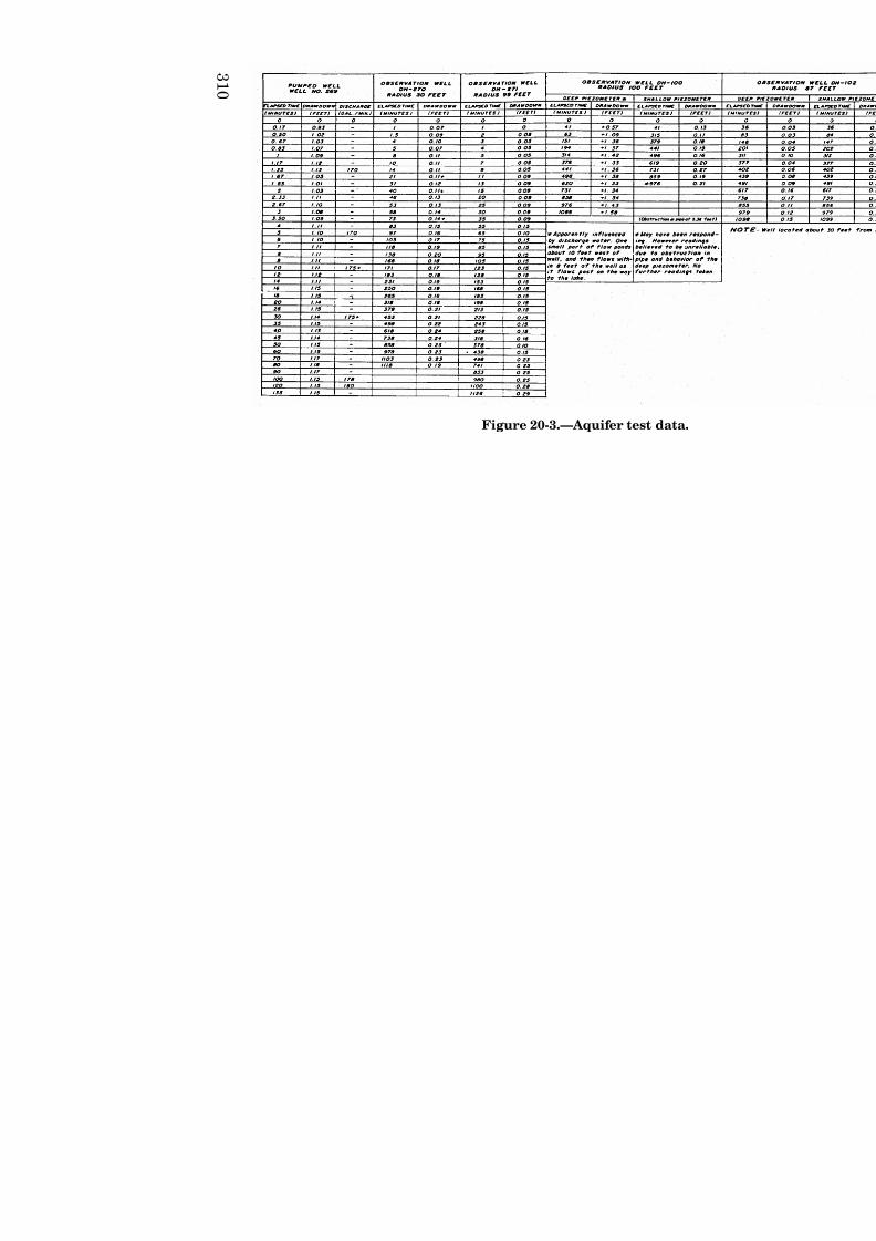
Because of the potential for different interpretations, most
dewatering data such as those from aquifer tests and
packer tests are presented as observed field data and as
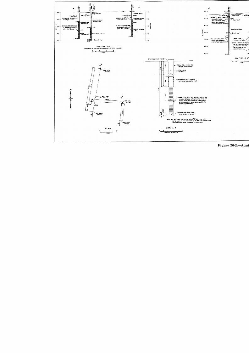
interpretations. A complete description of the site,
subsurface conditions, and test facilities should be given
along with the data (figures 20-2 and 20-3).
Where time related data are presented, the information
should be in a form that will ensure maximum recognition
and proper interpretation. Hydrographs that plot time
versus water levels mean a lot more than a table of
readings.
Monitoring
Water control activities must be monitored during
construction and, in some cases, up to a year or more
before and following completion of the facility. Details of
the monitoring program including design and layout of
the system, the responsibilities for installing the system,and monitoring and maintaining records must be included
in the specifications and construction considerations to
ensure adequate reliable data and inform construction
personnel of monitoring requirements.
7/31/2019 Chapter20- Water Control
http://slidepdf.com/reader/full/chapter20-water-control 12/22
3 1 0
Figure 20-3.—Aquifer test data.
7/31/2019 Chapter20- Water Control
http://slidepdf.com/reader/full/chapter20-water-control 13/22
7/31/2019 Chapter20- Water Control
http://slidepdf.com/reader/full/chapter20-water-control 14/22
WATER CONTROL
311
Monitoring is intended to:
• Provide data on base level conditions
• Confirm that the specifications requirements are
being met
• Maintain a general data base on conditions and
impacts resulting from the dewatering
• Alert personnel to unsuitable, hazardous, or poten-
tially hazardous conditions
• Document conditions in the event of claims or
litigation
• Provide background data for a followup analysis in
the event of a slope, foundation, or structural failure
Monitoring of water control parameters, activities, and
features should include:
• Groundwater levels
• Discharges
• Sediment content of discharges
• Chemical and biologic quality of water discharged
• Horizontal and vertical control on constructed
features and natural and excavated slopes
• Levels and sizes of nearby surface water bodies
• Stability of nearby structures
The monitoring facilities may range from a fewobservation wells to a complex system involving sophisti-
cated equipment and continuous and possibly remote
monitoring. The extent, complexity, and capability of
water control facilities depend on the size and complexity
7/31/2019 Chapter20- Water Control
http://slidepdf.com/reader/full/chapter20-water-control 15/22
7/31/2019 Chapter20- Water Control
http://slidepdf.com/reader/full/chapter20-water-control 16/22
WATER CONTROL
313
dewatering. Off-site monitoring is especially important in
areas where groundwater is widely used, where
groundwater levels are crucial to existing activities, or
where there might be subsidence or groundwater leveldecline.
Locations of individual water level monitoring instru-
ments must be based on conditions encountered at the
site, construction activities, and the dewatering facilities.
Monitoring instrumentation locations generally will have
to be selected after other features such as dewatering sys-tems and roads have been located to avoid conflicts and to
ensure representative and reliable monitoring. Instru-
mentation should be installed and functioning long before
construction to obtain trends and base level conditions.
Existing instrumentation may be used for monitoring; but
unless the instrumentation construction and other details
are known, instrumentation designed specifically for theconditions of the site should be installed as a part of
construction.
Groundwater Monitoring Instrumentation
Instrumentation for monitoring groundwater levels usu-
ally consists of several observation wells or piezometers.
The type of instrumentation, depth, and riser and holediameter depends primarily on subsurface conditions,
desired operating life, and type of monitoring. The design
of the instrumentation should be tailored to the
subsurface and data requirements so that measurements
are a true indication of in place conditions.
Observation wells intended to monitor general ground-water levels can be used in areas where the foundation
material is relatively uniform in depth, there is little or no
layering, and groundwater levels do not vary appreciably
7/31/2019 Chapter20- Water Control
http://slidepdf.com/reader/full/chapter20-water-control 17/22
FIELD MANUAL
314
with depth. Piezometers should be used where layering
exists or perching, artesian, or complex conditions are
expected.
Observation wells and piezometers usually consist of a
section of well screen, perforated pipe, or porous tube
isolated in the zone to be monitored and connected to a
length of standpipe, riser, or casing extending to the
surface. The section of well screen, perforations, or porous
tube must be isolated with a watertight grout or bentonite
seal, and a watertight riser must be used. The diameterof the screen and standpipe should conform to ASTM
D-5092. Water levels are measured directly in the well or
piezometer by use of tape or electric sounder (M-scope).
Float-type recorders can be used to continuously record
water level fluctuations but may require a minimum 4- to
6-inch (10- to 15-cm) diameter casing or standpipe. A
wide range of electronic and pneumatic instruments isavailable for monitoring and recording groundwater
levels.
Special types of monitoring wells or piezometers may be
necessary if hazardous materials are present.
Monitoring Discharges From Dewatering Systems
The discharge from dewatering facilities such as wells,
well point systems, drains, and sump pumps should be
monitored to provide a record of the dewatering quan-
tities. Data should include starting and stopping times,
instantaneous rates of discharge, changes in rates,
combined daily volumes, and, in some cases, waterchemistry, turbidity, and biologic content.
Discharge rates can be monitored by flow meters
(propeller, pitot tube, and acoustic), free discharge
7/31/2019 Chapter20- Water Control
http://slidepdf.com/reader/full/chapter20-water-control 18/22
WATER CONTROL
315
orifices, weirs, flumes, and volumetric (tank-stopwatch)
methods. Meters must be calibrated using a volumetric
test before flow testing. Measuring devices generally
must be accurate within 10 percent.
Sediment content of dewatering facilities including wells,
well point systems, and drains should be monitored.
Sediment can damage pumping equipment, cause deteri-
oration of water quality in a receiving water body, and
create voids in the foundation that result in well collapse
and foundation settlement.
Sediment content usually is measured in parts per million
by volume of water or in nephelometric turbidity units
(NTU) in water taken directly from the discharge.
Measurement requires special equipment. If the limits
are 50 parts per million or less, a special centrifugal
measuring device is required. If the limits are more than50 parts per million, an Imhoff cone can be used. A tur-
bidity meter typically measures values less than
2,000 NTUs. Values less than 200 NTUs are generally
acceptable for discharge. If sediment yield increases
rapidly, the facility may need to be shut down to avoid
serious damage or contamination.
The chemical and biologic content of water dischargedfrom dewatering systems should be monitored by periodic
collection and analysis of samples taken directly from the
system discharge. A single representative sample is ade-
quate if there are a number of discharges from the same
source. If there is pumping from different sources,
multiple samples may be needed. The initial samples
should be taken shortly after startup of the dewateringsystem (or during any test pumping done during
exploration) and periodically during operation. Each
sample may need biologic and chemical analyses for
heavy metals, organics, and pesticides. More frequent
7/31/2019 Chapter20- Water Control
http://slidepdf.com/reader/full/chapter20-water-control 19/22
7/31/2019 Chapter20- Water Control
http://slidepdf.com/reader/full/chapter20-water-control 20/22
7/31/2019 Chapter20- Water Control
http://slidepdf.com/reader/full/chapter20-water-control 21/22
FIELD MANUAL
318
Performance Evaluation During Construction
The performance of the water control facilities should be
evaluated and documented periodically during construc-tion. This will ensure that the specifications are being
met and that unusual or unexpected conditions are
properly accommodated. Charts and diagrams such as
hydrographs or plots of well or system discharge rates
should be prepared at the start of dewatering operations
and updated throughout the construction period. An
evaluation, along with tables and graphs, should beincluded in monthly reports to provide essential data for
final reports. The evaluation should be coordinated with
the design staff to ensure complete understanding of
conditions.
Final Reporting
The final construction report should include a section on
water control. This section should include a chronology of
dewatering and an evaluation of the performance of the
facilities as well as contractor compliance with the
specifications. Problem areas and unusual events such as
pump or slope failures should be documented. Mon-
itoring results, including groundwater levels anddischarge rates, should be presented in the form of
hydrographs and other similar plots or tabulated data.
Bibliography
Bureau of Reclamation, U.S. Department of the Interior,Ground Water Manual, 2nd Edition, 1995.
Cedergren, Harry R., Seepage, Drainage and Flow Nets,
John Wiley and Sons, Inc., New York, New York, 1967.

7/31/2019 Chapter20- Water Control
http://slidepdf.com/reader/full/chapter20-water-control 22/22
WATER CONTROL
Driscoll, Fletcher, G., Ground Water and Wells, Johnson
Division, St. Paul, Minnesota, 1986.
Joint AEG-ASCE Symposium, Practical Construction Dewatering, Baltimore, Maryland, May 16, 1975.
Leonards, G.A., Editor, Foundation Engineering,
McGraw-Hill Book Co., Inc., New York, New York, 1962.
Powers, J. Patrick, Construction Dewatering, John Wiley
and Sons, New York, New York, 1981.
U.S. Departments of the Army, the Navy, and the Air
Force, Dewatering and Groundwater Control for Deep
Excavations, TM5-818-5, NAVFAC P-418, AFM 88-5,
Chapter 6, April 1971.
Related Documents