Introduction to Forensic Science Page III.16.1 Draft 3/3/12 J. T. Spencer 2 DRAFT An Introduction to Forensic Science: The Science of Criminalistics James T. Spencer, Ph.D. Professor of Chemistry and Forensic Science Syracuse University CHAPTER 16 Firearms, Ballistics and Impression Evidence Confidential Correspondence Copyright © 2007-2011, James T. Spencer

Welcome message from author
This document is posted to help you gain knowledge. Please leave a comment to let me know what you think about it! Share it to your friends and learn new things together.
Transcript
Introduction to Forensic Science Page III.16.1 Draft 3/3/12 J. T. Spencer
2
DRAFT
An Introduction to Forensic Science: The
Science of Criminalistics
James T. Spencer, Ph.D. Professor of Chemistry and Forensic Science
Syracuse University
CHAPTER 16 Firearms, Ballistics and Impression Evidence
Confidential Correspondence
Copyright © 2007-2011, James T. Spencer

Introduction to Forensic Science Page III.16.2 Draft 3/3/12 J. T. Spencer
An Introduction to Forensic Science Prof. James T. Spencer, Syracuse University
IV. Physical Properties in Evidence
Chapter 16: Firearms, Ballistics and Impression Evidence 16.1. Forensic Firearms and Ballistics Introduction Historical Perspective Firearm Basics Handguns Long guns Shotguns Ammunition Ballistics 16.2. Forensic Identification of Firearms Introduction Bullet Comparisons Other Stria Comparisons Gunshot Residues (GSR) Ballistics IBIS and NIBIN 16.3. Forensic Impression Evidence Introduction Impression Evidence Basics Footprints Tire Tracks Tool Marks Bite Marks References and Bibliography Glossary of Terms Questions for Further Practice and Mastery
Copyright © 2007-‐2012, James T. Spencer
Introduction to Forensic Science Page III.16.3 Draft 3/3/12 J. T. Spencer
Chapter 16.1: Forensic Firearms and Ballistics
Learning Goals and Objectives Firearms are frequently used in the commission of criminal acts. In this chapter, you will need to understand the following concepts:
Ø How have firearms developed and what are their basic principles of operation; Ø What are the differences and features of handguns, long guns and shotguns; Ø What is meant by ballistics and what factors affect the trajectory of a projectile; Ø How do gun and ammunition design affect aspects of ballistics.
Introduction Firearms have played a key role in human
history and they clearly remain a ubiquitous part of society worldwide today. Everyone who has ever been to the movies or watched television is well acquainted with our fascination with firearms. “Westerns” have made famous the 19th-century revolver-carrying outlaw confronting the rifle-wielding law officers. War movies and urban crime shows frequently depict handgun and automatic weapon use in all types of settings. We see handguns carried by our law officers, long guns by hunters, and even larger weapons by members of the armed services. There is no denying that firearms are a part of our everyday lives.
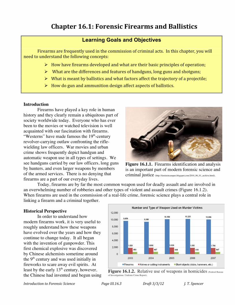
Today, firearms are by far the most common weapon used for deadly assault and are involved in an overwhelming number of robberies and other types of violent and assault crimes (Figure 16.1.2). When firearms are used in the commission of a real-life crime, forensic science plays a central role in linking a firearm and a criminal together.
Historical Perspective
In order to understand how modern firearms work, it is very useful to roughly understand how these weapons have evolved over the years and how they continue to change today. It all began with the invention of gunpowder. This first chemical explosive was discovered by Chinese alchemists sometime around the 9th century and was used initially in fireworks to scare away evil spirits. At least by the early 13th century, however, the Chinese had invented and begun using
Figure 16.1.1. Firearms identification and analysis is an important part of modern forensic science and criminal justice (http://feministcampus.blogspot.com/2010_06_01_archive.html).
Figure 16.1.2. Relative use of weapons in homicides (Federal Bureau of Investigations, Uniform Crime Report).
Introduction to Forensic Science Page III.16.4 Draft 3/3/12 J. T. Spencer
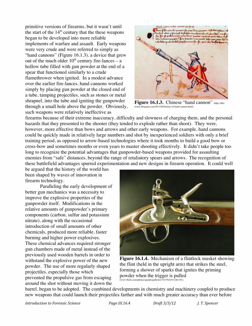
primitive versions of firearms, but it wasn’t until the start of the 14th century that the these weapons began to be developed into more reliable implements of warfare and assault. Early weapons were very crude and were referred to simply as “hand cannons” (Figure 16.1.3), a device that grew out of the much older 10th century fire-lances – a hollow tube filled with gun powder at the end of a spear that functioned similarly to a crude flamethrower when ignited. In a modest advance over the earlier fire-lances, hand cannons worked simply by placing gun powder at the closed end of a tube, tamping projectiles, such as stones or metal shrapnel, into the tube and igniting the gunpowder through a small hole above the powder. Obviously, such weapons were relatively ineffective as firearms because of their extreme inaccuracy, difficulty and slowness of charging them, and the personal hazards that they presented to the shooter (they tended to explode rather than shoot). They were, however, more effective than bows and arrows and other early weapons. For example, hand cannons could be quickly made in relatively large numbers and shot by inexperienced soldiers with only a brief training period, as opposed to arrow-based technologies where it took months to build a good bow or cross-bow and sometimes months or even years to master shooting effectively. It didn’t take people too long to recognize the potential advantages that gunpowder-based weapons provided for assaulting enemies from “safe” distances, beyond the range of retaliatory spears and arrows. The recognition of these battlefield advantages spurred experimentation and new designs in firearm operation. It could well be argued that the history of the world has been shaped by waves of innovation in firearm technology.
Paralleling the early development of better gun mechanics was a necessity to improve the explosive properties of the gunpowder itself. Modifications in the relative amounts of gunpowder’s primary components (carbon, sulfur and potassium nitrate), along with the occasional introduction of small amounts of other chemicals, produced more reliable, faster burning and higher power explosives. These chemical advances required stronger gun chambers made of metal instead of the previously used wooden barrels in order to withstand the explosive power of the new powder. The use of more regularly shaped projectiles, especially those which prevented the propulsive gas from escaping around the shot without moving it down the barrel, began to be adopted. The combined developments in chemistry and machinery coupled to produce new weapons that could launch their projectiles farther and with much greater accuracy than ever before
Figure 16.1.3. Chinese “hand cannon” (http://dba-oracle.blogspot.com/2011/06/history-of-hand-cannon.html).
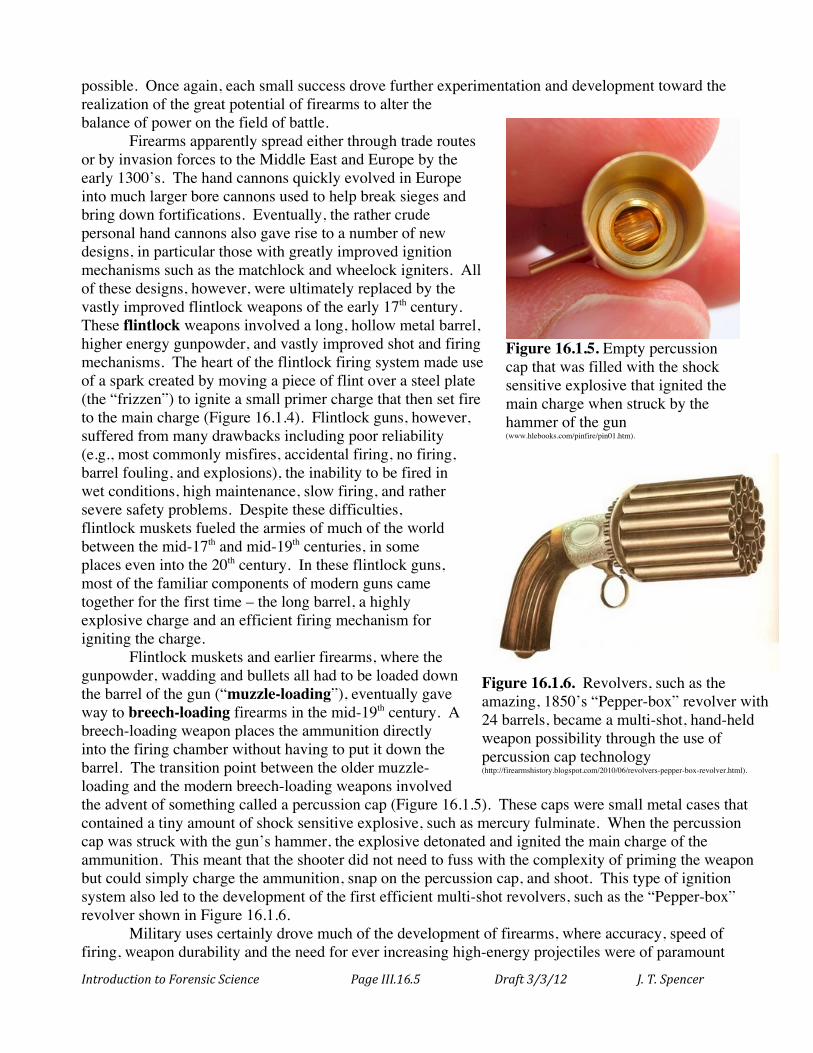
Figure 16.1.4. Mechanism of a flintlock musket showing the flint (held in the upright arm) that strikes the steel, forming a shower of sparks that ignites the priming powder when the trigger is pulled (www.flickr.com/photos/spaudo/galleries/72157622511261341).
Introduction to Forensic Science Page III.16.5 Draft 3/3/12 J. T. Spencer
possible. Once again, each small success drove further experimentation and development toward the realization of the great potential of firearms to alter the balance of power on the field of battle.
Firearms apparently spread either through trade routes or by invasion forces to the Middle East and Europe by the early 1300’s. The hand cannons quickly evolved in Europe into much larger bore cannons used to help break sieges and bring down fortifications. Eventually, the rather crude personal hand cannons also gave rise to a number of new designs, in particular those with greatly improved ignition mechanisms such as the matchlock and wheelock igniters. All of these designs, however, were ultimately replaced by the vastly improved flintlock weapons of the early 17th century. These flintlock weapons involved a long, hollow metal barrel, higher energy gunpowder, and vastly improved shot and firing mechanisms. The heart of the flintlock firing system made use of a spark created by moving a piece of flint over a steel plate (the “frizzen”) to ignite a small primer charge that then set fire to the main charge (Figure 16.1.4). Flintlock guns, however, suffered from many drawbacks including poor reliability (e.g., most commonly misfires, accidental firing, no firing, barrel fouling, and explosions), the inability to be fired in wet conditions, high maintenance, slow firing, and rather severe safety problems. Despite these difficulties, flintlock muskets fueled the armies of much of the world between the mid-17th and mid-19th centuries, in some places even into the 20th century. In these flintlock guns, most of the familiar components of modern guns came together for the first time – the long barrel, a highly explosive charge and an efficient firing mechanism for igniting the charge.
Flintlock muskets and earlier firearms, where the gunpowder, wadding and bullets all had to be loaded down the barrel of the gun (“muzzle-loading”), eventually gave way to breech-loading firearms in the mid-19th century. A breech-loading weapon places the ammunition directly into the firing chamber without having to put it down the barrel. The transition point between the older muzzle-loading and the modern breech-loading weapons involved the advent of something called a percussion cap (Figure 16.1.5). These caps were small metal cases that contained a tiny amount of shock sensitive explosive, such as mercury fulminate. When the percussion cap was struck with the gun’s hammer, the explosive detonated and ignited the main charge of the ammunition. This meant that the shooter did not need to fuss with the complexity of priming the weapon but could simply charge the ammunition, snap on the percussion cap, and shoot. This type of ignition system also led to the development of the first efficient multi-shot revolvers, such as the “Pepper-box” revolver shown in Figure 16.1.6.
Military uses certainly drove much of the development of firearms, where accuracy, speed of firing, weapon durability and the need for ever increasing high-energy projectiles were of paramount
Figure 16.1.5. Empty percussion cap that was filled with the shock sensitive explosive that ignited the main charge when struck by the hammer of the gun (www.hlebooks.com/pinfire/pin01.htm).
Figure 16.1.6. Revolvers, such as the amazing, 1850’s “Pepper-box” revolver with 24 barrels, became a multi-shot, hand-held weapon possibility through the use of percussion cap technology (http://firearmshistory.blogspot.com/2010/06/revolvers-pepper-box-revolver.html).
Introduction to Forensic Science Page III.16.6 Draft 3/3/12 J. T. Spencer
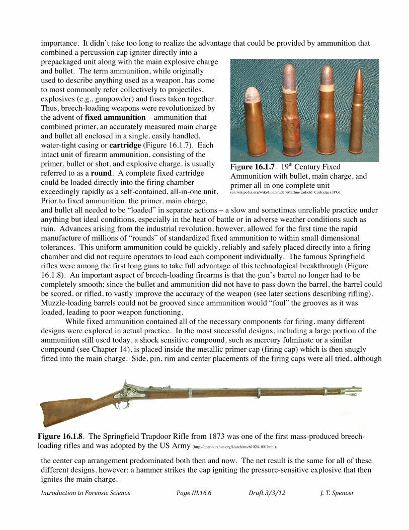
importance. It didn’t take too long to realize the advantage that could be provided by ammunition that combined a percussion cap igniter directly into a prepackaged unit along with the main explosive charge and bullet. The term ammunition, while originally used to describe anything used as a weapon, has come to most commonly refer collectively to projectiles, explosives (e.g., gunpowder) and fuses taken together. Thus, breech-loading weapons were revolutionized by the advent of fixed ammunition – ammunition that combined primer, an accurately measured main charge and bullet all enclosed in a single, easily handled, water-tight casing or cartridge (Figure 16.1.7). Each intact unit of firearm ammunition, consisting of the primer, bullet or shot, and explosive charge, is usually referred to as a round. A complete fixed cartridge could be loaded directly into the firing chamber exceedingly rapidly as a self-contained, all-in-one unit. Prior to fixed ammunition, the primer, main charge, and bullet all needed to be “loaded” in separate actions – a slow and sometimes unreliable practice under anything but ideal conditions, especially in the heat of battle or in adverse weather conditions such as rain. Advances arising from the industrial revolution, however, allowed for the first time the rapid manufacture of millions of “rounds” of standardized fixed ammunition to within small dimensional tolerances. This uniform ammunition could be quickly, reliably and safely placed directly into a firing chamber and did not require operators to load each component individually. The famous Springfield rifles were among the first long guns to take full advantage of this technological breakthrough (Figure 16.1.8). An important aspect of breech-loading firearms is that the gun’s barrel no longer had to be completely smooth; since the bullet and ammunition did not have to pass down the barrel, the barrel could be scored, or rifled, to vastly improve the accuracy of the weapon (see later sections describing rifling). Muzzle-loading barrels could not be grooved since ammunition would “foul” the grooves as it was loaded, leading to poor weapon functioning.
While fixed ammunition contained all of the necessary components for firing, many different designs were explored in actual practice. In the most successful designs, including a large portion of the ammunition still used today, a shock sensitive compound, such as mercury fulminate or a similar compound (see Chapter 14), is placed inside the metallic primer cap (firing cap) which is then snugly fitted into the main charge. Side, pin, rim and center placements of the firing caps were all tried, although
the center cap arrangement predominated both then and now. The net result is the same for all of these different designs, however: a hammer strikes the cap igniting the pressure-sensitive explosive that then ignites the main charge.
Figure 16.1.8. The Springfield Trapdoor Rifle from 1873 was one of the first mass-produced breech-loading rifles and was adopted by the US Army (http://operatorchan.org/k/arch/res/61024-100.html).
Figure 16.1.7. 19th Century Fixed Ammunition with bullet, main charge, and primer all in one complete unit (en.wikipedia.org/wiki/File:Snider-Martini-Enfield_Cartridges.JPG).
Introduction to Forensic Science Page III.16.7 Draft 3/3/12 J. T. Spencer
Advances in the rapid delivery of fresh ammunition and the extraction of spent cases allowed the development of efficient “repeater”, semi-automatic and automatic (“machine gun”) weapons, including those that hold many cartridges of ammunition without the need for manual reloading. Today, there is an enormous variation in commercial and military weapons, from small-bore handguns to massive artillery weaponry. The fastest military automatic machine guns today can shoot up to a staggering one million rounds per minute (“Metal storm” weapon) while high-precision sniper rifles can hit moving targets several miles away with startling accuracy. Guns for civilian use are readily available in all shapes and sizes, from tiny derringers to very large hunting rifles, shotguns and some semi-automatic weapons.
To better understand the weapons encountered in forensic work, the next section describes the major types of modern firearms and their modes of operation. Firearm Basics
A firearm is usually defined as an assembly consisting of a barrel and a mechanical action that allows a projectile(s) to be propelled forward through the action of an extremely fast combustion reaction. As expected, given such a general definition, there is an enormous range and variety of firearms, spanning from miniature pistols to massive military weapon systems. But all of these weapons have several basic features in common: an explosive material is detonated within an enclosed chamber which provides only one direction for the escape of the enormous pressure built up from the reaction. The release of this high-pressure gas is channeled to push an object, the projectile, down a tube toward a target with great energy. The combustion chamber where the explosion occurs is designed with an intentional “weakness” – one open side with all of the remaining sides sealed – like a box without a top. The projectile tightly fits within the walls of the chamber such that when the explosion occurs, the energy of the escaping gas acts upon the end of the projectile to force it down the barrel. All firearm designs must accommodate this basic mode of action in some fashion.
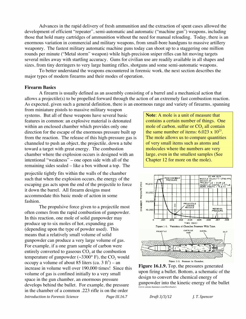
The propulsive force given to a projectile most often comes from the rapid combustion of gunpowder. In this reaction, one mole of solid gunpowder may produce up to six moles of hot, expanding gas (depending upon the type of powder used). This means that a relatively small volume of solid gunpowder can produce a very large volume of gas. For example, if a one gram sample of carbon were entirely converted to gaseous CO2 at the combustion temperature of gunpowder (~3300° F), the CO2 would occupy a volume of about 85 liters (ca. 3 ft3) – an increase in volume well over 190,000 times! Since this volume of gas is confined initially to a very small space in the gun chamber, an enormous pressure develops behind the bullet. For example, the pressure in the chamber of a common .223 rifle is on the order
Note: A mole is a unit of measure that contains a certain number of things. One mole of carbon, sulfur or CO2 all contain the same number of items: 6.023 x 10²³. The mole allows us to compare quantities of very small items such as atoms and molecules where the numbers are very large, even in the smallest samples (See Chapter 12 for more on the mole).
Figure 16.1.9. Top, the pressures generated upon firing a bullet. Bottom, a schematic of the design to convert the chemical energy of gunpowder into the kinetic energy of the bullet (www.orions-hammer.com/blowback/).
Introduction to Forensic Science Page III.16.8 Draft 3/3/12 J. T. Spencer
of 4,300 atmospheres (that’s a pressure 4,300 times the pressure that is found on the surface of the Earth, or about 62,000 psi). The typical buildup of high-pressure gas upon firing a firearm is illustrated in Figure 16.1.9. This huge pressure is quickly relieved as the bullet is forced down the barrel with great energy and velocity.
Over time, gun designers have discovered a variety of innovative ways to modify all of the required features of firearms in order to maximize particular desired end results, such as accuracy, projectile mass, weapon size, bullet velocity, terminal ballistics, and other features. In forensic science, however, three basic firearm designs are most commonly encountered in criminal actions: the handgun, rifle (long guns), and shotgun.
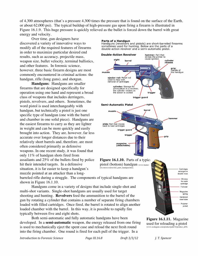
Handguns: Handguns are smaller firearms that are designed specifically for operation using one hand and represent a broad class of weapons that includes derringers, pistols, revolvers, and others. Sometimes, the word pistol is used interchangeably with handgun, but technically a pistol is just one specific type of handgun (one with the barrel and chamber in one solid piece). Handguns are the easiest firearms to carry as they are lighter in weight and can be more quickly and easily brought into action. They are, however, far less accurate over longer distances due to their relatively short barrels and, therefore, are most often considered primarily as defensive weapons. In one recent study, it was found that only 11% of handgun shots fired from assailants and 25% of the bullets fired by police hit their intended targets. In a defensive situation, it is far easier to keep a handgun’s muzzle pointed at an attacker than a long-barreled rifle during a struggle. The components of typical handguns are shown in Figure 16.1.10.
Handguns come in a variety of designs that include single-shot and multi-shot variants. Single-shot handguns are usually used for target shooting and hunting. Revolvers feed the ammunition to the barrel of the gun by rotating a cylinder that contains a number of separate firing chambers loaded with filled cartridges. Once fired, the barrel is rotated to align another loaded chamber with the barrel. In this way, it is possible to rapidly fire typically between five and eight shots.
Both semi-automatic and fully automatic handguns have been developed. In a semi-automatic weapon, the energy released from one firing is used to mechanically eject the spent case and reload the next fresh round into the firing chamber. One round is fired for each pull of the trigger. In a
Figure 16.1.10. Parts of a typical revolver (top) and pistol (bottom) handgun (www.hunter-ed.com/sc/course/ch2_parts_handgun.htm).
Figure 16.1.11. Magazine used for reloading a pistol (www.ocalaguns.com/product/path/32/product_id/8).
Introduction to Forensic Science Page III.16.9 Draft 3/3/12 J. T. Spencer
fully automatic weapon, the filled rounds are reloaded as in the semi-automatic weapon but the weapon continues to fire when the trigger is held down – multiple shots are fired from one trigger pull. Pistols are reloaded through the use of a magazine – a device that is spring loaded with ammunition that forces a new cartridge into the firing chamber immediately after one round has been fired, as shown in Figures 16.1.10 and 16.1.11.
Revolvers tend to be simpler than the automatic weapons, easier to maintain, and are usually capable of firing larger bullets while automatic weapons typically can shoot more rounds at a time and be reloaded faster.
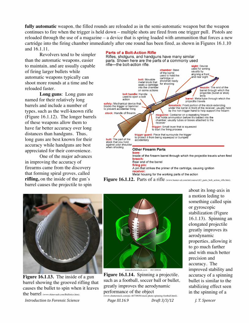
Long guns: Long guns are named for their relatively long barrels and include a number of types, such as the well-known rifle (Figure 16.1.12). The longer barrels of these weapons allow them to have far better accuracy over long distances than handguns. Thus, long guns are best known for their accuracy while handguns are best appreciated for their convenience.
One of the major advances in improving the accuracy of firearms came from the discovery that forming spiral groves, called rifling, on the inside of the gun’s barrel causes the projectile to spin
about its long-axis in a motion leding to something called spin or gyroscopic stabilization (Figure 16.1.13). Spinning an elongated projectile greatly improves its aerodynamic properties, allowing it to go much farther and with much better precision and accuracy. The improved stability and accuracy of a spinning bullet is similar to the stabilizing effect seen in the spinning of a
Figure 16.1.12. Parts of a rifle (www.hunter-ed.com/mt/course/ch3_parts_bolt_action_rifle.htm).
Figure 16.1.13. The inside of a gun barrel showing the grooved rifling that causes the bullet to spin when it leaves the barrel (www.rhinovault.com/Ballistics.htm).
Figure 16.1.14. Spinning a projectile, such as a football, soccer ball or bullet, greatly improves the aerodynamic performance of the object (www.shutterstock.com/pic-46730656/stock-photo-spinning-football.html).
Introduction to Forensic Science Page III.16.10 Draft 3/3/12 J. T. Spencer
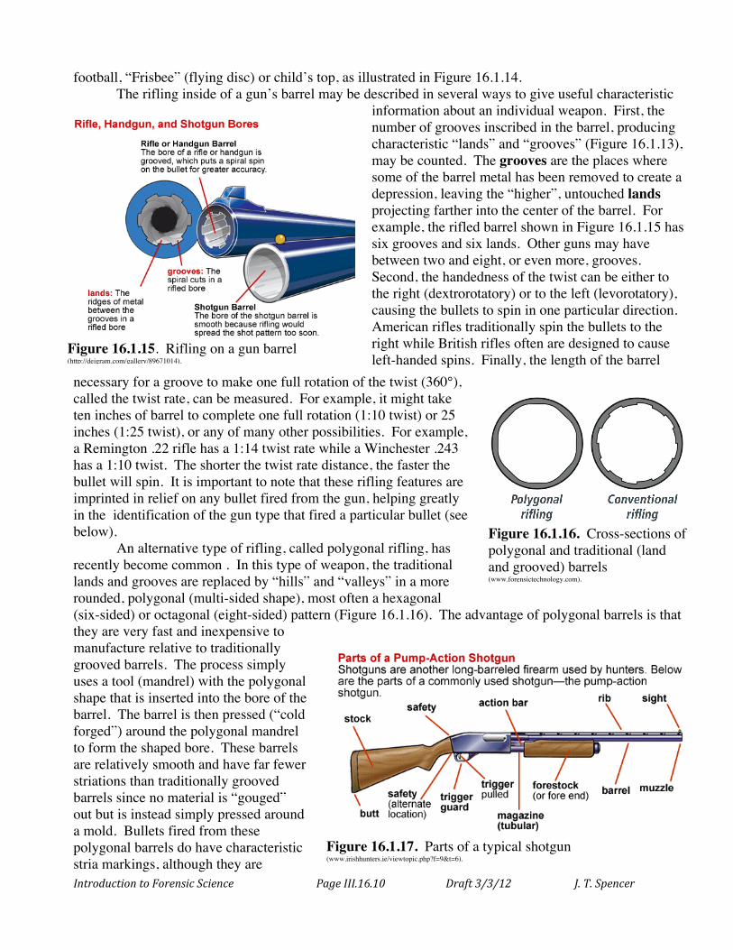
football, “Frisbee” (flying disc) or child’s top, as illustrated in Figure 16.1.14. The rifling inside of a gun’s barrel may be described in several ways to give useful characteristic
information about an individual weapon. First, the number of grooves inscribed in the barrel, producing characteristic “lands” and “grooves” (Figure 16.1.13), may be counted. The grooves are the places where some of the barrel metal has been removed to create a depression, leaving the “higher”, untouched lands projecting farther into the center of the barrel. For example, the rifled barrel shown in Figure 16.1.15 has six grooves and six lands. Other guns may have between two and eight, or even more, grooves. Second, the handedness of the twist can be either to the right (dextrorotatory) or to the left (levorotatory), causing the bullets to spin in one particular direction. American rifles traditionally spin the bullets to the right while British rifles often are designed to cause left-handed spins. Finally, the length of the barrel
necessary for a groove to make one full rotation of the twist (360°), called the twist rate, can be measured. For example, it might take ten inches of barrel to complete one full rotation (1:10 twist) or 25 inches (1:25 twist), or any of many other possibilities. For example, a Remington .22 rifle has a 1:14 twist rate while a Winchester .243 has a 1:10 twist. The shorter the twist rate distance, the faster the bullet will spin. It is important to note that these rifling features are imprinted in relief on any bullet fired from the gun, helping greatly in the identification of the gun type that fired a particular bullet (see below).
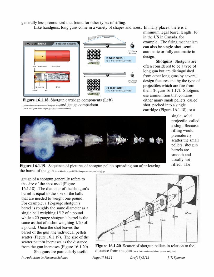
An alternative type of rifling, called polygonal rifling, has recently become common . In this type of weapon, the traditional lands and grooves are replaced by “hills” and “valleys” in a more rounded, polygonal (multi-sided shape), most often a hexagonal (six-sided) or octagonal (eight-sided) pattern (Figure 16.1.16). The advantage of polygonal barrels is that they are very fast and inexpensive to manufacture relative to traditionally grooved barrels. The process simply uses a tool (mandrel) with the polygonal shape that is inserted into the bore of the barrel. The barrel is then pressed (“cold forged”) around the polygonal mandrel to form the shaped bore. These barrels are relatively smooth and have far fewer striations than traditionally grooved barrels since no material is “gouged” out but is instead simply pressed around a mold. Bullets fired from these polygonal barrels do have characteristic stria markings, although they are
Figure 16.1.16. Cross-sections of polygonal and traditional (land and grooved) barrels (www.forensictechnology.com).
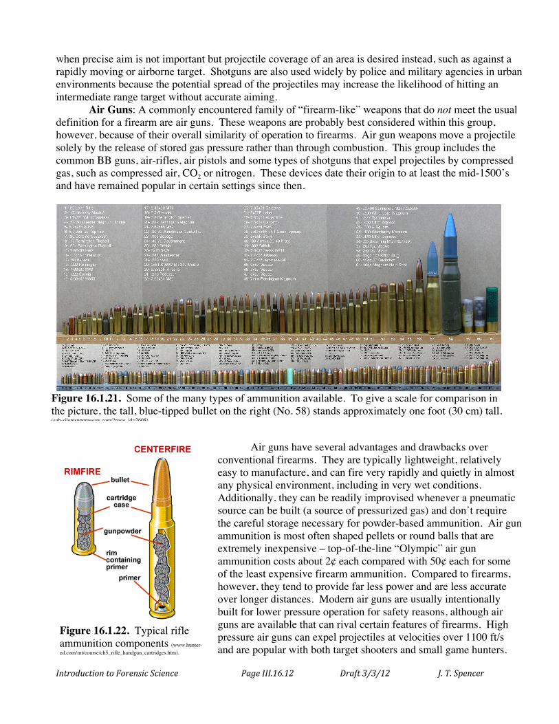
Figure 16.1.17. Parts of a typical shotgun (www.irishhunters.ie/viewtopic.php?f=9&t=6).
Figure 16.1.15. Rifling on a gun barrel (http://deigram.com/gallery/89671014).
Introduction to Forensic Science Page III.16.11 Draft 3/3/12 J. T. Spencer
generally less pronounced that found for other types of rifling. Like handguns, long guns come in a variety of shapes and sizes. In many places, there is a
minimum legal barrel length, 16” in the US in Canada, for example. The firing mechanism can also be single-shot, semi-automatic or fully automatic in design.
Shotguns: Shotguns are often considered to be a type of long gun but are distinguished from other long guns by several design features and by the type of projectiles which are fire from them (Figure 16.1.17). Shotguns use ammunition that contains either many small pellets, called shot, packed into a single cartridge (Figure 16.1.18), or a
single, solid projectile, called a slug. Because rifling would prematurely scatter the small pellets, shotgun barrels are smooth and usually not rifled. The
gauge of a shotgun generally refers to the size of the shot used (Figure 16.1.18). The diameter of the shotgun’s barrel is equal to the size of the balls that are needed to weight one pound. For example, a 12-gauge shotgun’s barrel is roughly the same diameter as a single ball weighing 1/12 of a pound while a 20 gauge shotgun’s barrel is the same as that of a shot weighing 1/20 of a pound. Once the shot leaves the barrel of the gun, the individual pellets scatter (Figure 16.1.19). The size of the scatter pattern increases as the distance from the gun increases (Figure 16.1.20).
Shotguns are particularly useful
Figure 16.1.19. Sequence of pictures of shotgun pellets spreading out after leaving the barrel of the gun (en.wikipedia.org/wiki/File:Shotgun-shot-sequence-1g.jpg).
Figure 16.1.18. Shotgun cartridge components (Left) (science.howstuffworks.com/shotgun9.htm).and gauge comparison (www.info4guns.com/shotgun_gauge_ammunition.html).
Figure 16.1.20. Scatter of shotgun pellets in relation to the distance from the gun (www.chuckhawks.com/where_pattern_today.htm).
Introduction to Forensic Science Page III.16.12 Draft 3/3/12 J. T. Spencer
when precise aim is not important but projectile coverage of an area is desired instead, such as against a rapidly moving or airborne target. Shotguns are also used widely by police and military agencies in urban environments because the potential spread of the projectiles may increase the likelihood of hitting an intermediate range target without accurate aiming.
Air Guns: A commonly encountered family of “firearm-like” weapons that do not meet the usual definition for a firearm are air guns. These weapons are probably best considered within this group, however, because of their overall similarity of operation to firearms. Air gun weapons move a projectile solely by the release of stored gas pressure rather than through combustion. This group includes the common BB guns, air-rifles, air pistols and some types of shotguns that expel projectiles by compressed gas, such as compressed air, CO2 or nitrogen. These devices date their origin to at least the mid-1500’s and have remained popular in certain settings since then.
Air guns have several advantages and drawbacks over conventional firearms. They are typically lightweight, relatively easy to manufacture, and can fire very rapidly and quietly in almost any physical environment, including in very wet conditions. Additionally, they can be readily improvised whenever a pneumatic source can be built (a source of pressurized gas) and don’t require the careful storage necessary for powder-based ammunition. Air gun ammunition is most often shaped pellets or round balls that are extremely inexpensive – top-of-the-line “Olympic” air gun ammunition costs about 2¢ each compared with 50¢ each for some of the least expensive firearm ammunition. Compared to firearms, however, they tend to provide far less power and are less accurate over longer distances. Modern air guns are usually intentionally built for lower pressure operation for safety reasons, although air guns are available that can rival certain features of firearms. High pressure air guns can expel projectiles at velocities over 1100 ft/s and are popular with both target shooters and small game hunters.
Figure 16.1.21. Some of the many types of ammunition available. To give a scale for comparison in the picture, the tall, blue-tipped bullet on the right (No. 58) stands approximately one foot (30 cm) tall. (sub-silentsuppressors.com/?page_id=2608).
Figure 16.1.22. Typical rifle ammunition components (www.hunter-ed.com/mt/course/ch5_rifle_handgun_cartridges.htm).
Introduction to Forensic Science Page III.16.13 Draft 3/3/12 J. T. Spencer
Ammunition
The ammunition for firearms comes in as many variations as the weapons themselves. They vary depending upon which outcome the designers are attempting to optimize – speed, accuracy, distance, or other characteristics (Figure 16.1.21). Ammunition is most often defined by the size of the gun barrel that it is designed for, usually given as a caliber or mm measurement. Caliber is the size of a gun barrel, measured between opposite grooves, and expressed as a fraction of an inch. For example, a barrel with a diameter of 0.22 inches is referred to as .22 caliber. The diameter can also be expressed in mm (1/1000 of a meter) such as 9 mm. Even though caliber actually refers to the size of the gun’s bore, cartridges are referred to by the caliber weapon in which they are intended to be used. As described previously, shotguns are usually defined by gauge rather than caliber or mm used for other firearms.
Ammunition is also defined by the amount and type of powder used, the dimensions and shape of the projectile, composition of the bullet (what metals make up the alloy used in the bullet), and other features. An example of typical rifle ammunition is shown in Figure 16.1.22. Ballistics
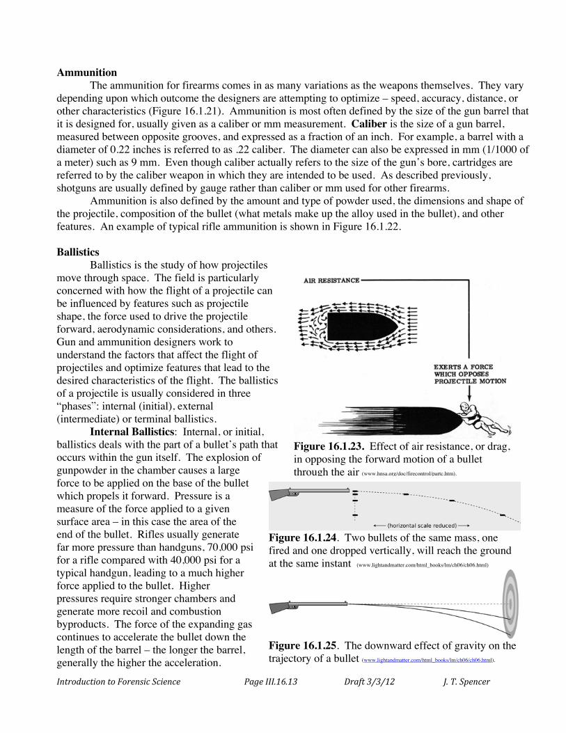
Ballistics is the study of how projectiles move through space. The field is particularly concerned with how the flight of a projectile can be influenced by features such as projectile shape, the force used to drive the projectile forward, aerodynamic considerations, and others. Gun and ammunition designers work to understand the factors that affect the flight of projectiles and optimize features that lead to the desired characteristics of the flight. The ballistics of a projectile is usually considered in three “phases”: internal (initial), external (intermediate) or terminal ballistics.
Internal Ballistics: Internal, or initial, ballistics deals with the part of a bullet’s path that occurs within the gun itself. The explosion of gunpowder in the chamber causes a large force to be applied on the base of the bullet which propels it forward. Pressure is a measure of the force applied to a given surface area – in this case the area of the end of the bullet. Rifles usually generate far more pressure than handguns, 70,000 psi for a rifle compared with 40,000 psi for a typical handgun, leading to a much higher force applied to the bullet. Higher pressures require stronger chambers and generate more recoil and combustion byproducts. The force of the expanding gas continues to accelerate the bullet down the length of the barrel – the longer the barrel, generally the higher the acceleration.
Figure 16.1.23. Effect of air resistance, or drag, in opposing the forward motion of a bullet through the air (www.hnsa.org/doc/firecontrol/partc.htm).
Figure 16.1.24. Two bullets of the same mass, one fired and one dropped vertically, will reach the ground at the same instant (www.lightandmatter.com/html_books/lm/ch06/ch06.html)
Figure 16.1.25. The downward effect of gravity on the trajectory of a bullet (www.lightandmatter.com/html_books/lm/ch06/ch06.html).
Introduction to Forensic Science Page III.16.14 Draft 3/3/12 J. T. Spencer
External Ballistics: External, or intermediate, ballistics focuses upon the flight of the bullet from the time it leaves the barrel of the gun until it reaches the target. A number of features define the specific flight properties of a bullet and include the energy propelling it forward, the bullet’s shape, its mass, and environmental conditions (e.g., wind, rain, etc.).
The ideal situation in gun design would be to have as much of the energy as possible from the contained explosion reaction converted into moving the projectile down the barrel. This process actually represents a conversion of the chemical energy of the gunpowder into the kinetic
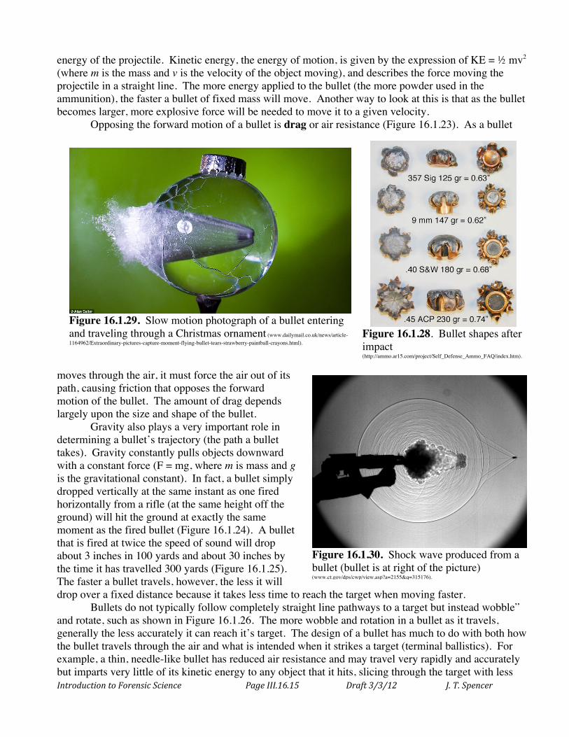
Figure 16.1.26. The “wobble” and “rotation” of a typical bullet as it moves along its trajectory (http://library.med.utah.edu/WebPath/TUTORIAL/GUNS/GUNBLST.html).
Some Helpful Firearms Definitions
Action: Mechanical apparatus of a firearm that loads, fires, and ejects the cartridge.
Barrel: Metal pipe that guides initial flight of the bullet. Breech: End of the gun barrel nearest to the action. Breech block (or face): Back of the firing chamber. Bullet: Projectile fired from a weapon. Caliber: Diameter of the gun barrel in 1/100th of a inch. Cartridge: Ammunition made up of casing, primer,
powder, wadding and bullet. Chamber: Enclosure that contains the cartridge when
ready to fire. Gauge: Measure of the diameter of the barrel of a shotgun. Hammer: The part of the action that drives the firing pin
into the primer upon firing. Lands and grooves: The spiral groves and raised positions
inside a gun barrel resulting from rifling. Magazine: Device for holding and delivering cartridges. Magnum: Type of cartridge containing more than the
standard amount of powder resulting in more power to the bullet.
Muzzle: The very end of the gun barrel where the bullet exits the weapon.
Powder: Solid explosive used to propel the bullet. Primer: Shock sensitive compound that ignites the main
charge of a cartridge upon being struck. Rifling: The spiral grooves or polygonal interior shape
inside a gun barrel. Sight: Device on top of a gun that improves aim and
accuracy. Silencer: Device, placed over the muzzle, that reduces the
noise emitted when the weapon is fired. Stock: Frame holding the barrel and action together which
allows aiming and firing.
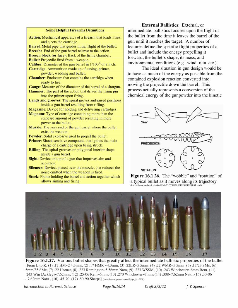
Figure 16.1.27. Various bullet shapes that greatly affect the intermediate ballistic properties of the bullet [From L to R: (1) .17 HM~2 4.3mm, (2) .17 HMR ~4.3mm, (3) .22LR~5.5mm, (4) .22 WMR~5.5mm, (5) .17/23 SMc, (6) 5mm/35 SMc, (7) .22 Hornet, (8) .223 Remington~5.56mm Nato, (9) .223 WSSM, (10) .243 Winchester~6mm Rem, (11) .243 Win (Ackley)~7.62mm, (12) .25-06 Rem~6mm, (13) .270 Winchester~7mm, (14) .308~7.62mm Nato, (15) .30-06 ~7.62mm Nato , (16) .45-70, (17) .50-90 Sharps] (sub-silentsuppressors.com/?page_id=2608).
Introduction to Forensic Science Page III.16.15 Draft 3/3/12 J. T. Spencer
energy of the projectile. Kinetic energy, the energy of motion, is given by the expression of KE = ½ mv2 (where m is the mass and v is the velocity of the object moving), and describes the force moving the projectile in a straight line. The more energy applied to the bullet (the more powder used in the ammunition), the faster a bullet of fixed mass will move. Another way to look at this is that as the bullet becomes larger, more explosive force will be needed to move it to a given velocity.
Opposing the forward motion of a bullet is drag or air resistance (Figure 16.1.23). As a bullet
moves through the air, it must force the air out of its path, causing friction that opposes the forward motion of the bullet. The amount of drag depends largely upon the size and shape of the bullet.
Gravity also plays a very important role in determining a bullet’s trajectory (the path a bullet takes). Gravity constantly pulls objects downward with a constant force (F = mg, where m is mass and g is the gravitational constant). In fact, a bullet simply dropped vertically at the same instant as one fired horizontally from a rifle (at the same height off the ground) will hit the ground at exactly the same moment as the fired bullet (Figure 16.1.24). A bullet that is fired at twice the speed of sound will drop about 3 inches in 100 yards and about 30 inches by the time it has travelled 300 yards (Figure 16.1.25). The faster a bullet travels, however, the less it will drop over a fixed distance because it takes less time to reach the target when moving faster.
Bullets do not typically follow completely straight line pathways to a target but instead wobble” and rotate, such as shown in Figure 16.1.26. The more wobble and rotation in a bullet as it travels, generally the less accurately it can reach it’s target. The design of a bullet has much to do with both how the bullet travels through the air and what is intended when it strikes a target (terminal ballistics). For example, a thin, needle-like bullet has reduced air resistance and may travel very rapidly and accurately but imparts very little of its kinetic energy to any object that it hits, slicing through the target with less
Figure 16.1.30. Shock wave produced from a bullet (bullet is at right of the picture) (www.ct.gov/dps/cwp/view.asp?a=2155&q=315176).
Figure 16.1.29. Slow motion photograph of a bullet entering and traveling through a Christmas ornament (www.dailymail.co.uk/news/article-1164962/Extraordinary-pictures-capture-moment-flying-bullet-tears-strawberry-paintball-crayons.html).
Figure 16.1.28. Bullet shapes after impact (http://ammo.ar15.com/project/Self_Defense_Ammo_FAQ/index.htm).
Introduction to Forensic Science Page III.16.16 Draft 3/3/12 J. T. Spencer
damage. A round bullet, in contrast, has far a greater air resistance, causing it travel more slowly and less accurately, but it would deliver most or all of its energy into the target, causing far more damage (assuming it actually makes it to the target). Many bullet designs are, therefore, available that deal with these conflicting features to optimize a desired outcome (Figure 16.1.27).
Terminal Ballistics: Terminal ballistics describes what happens when a bullet hits its target. Biological aspects of a bullet hitting a living object, including tissue damage, have already been presented in detail in Chapter 8. Bullets may tumble, flatten (Figure 16.1.28), fragment and melt when they encounter a target (Figure 16.1.29). The pattern of injury or damage depends upon the shape, speed and motion of the bullet when it strikes. Significant damage may also result from the impact of shock waves arising from the compression and rarefaction of air along the path of the bullet (Figure 16.1.30). The more energy that the projectile can impart to its target, the more damage that will be done.
Right to Bear Arms In the US, the 2nd Amendment to the US Constitution deals with the right of people to own
firearms. The Amendment says that “A well regulated militia being necessary to the security of a free State, the right of the People to keep and bear arms shall not be infringed.”
A vigorous debate continues today, however, about what the “right to bear arms” phrase in this amendment really means. Some argue that it refers to private individuals while others contend that it includes only the military use of arms. The Supreme Court has historically interpreted this phrase as referring to an individual’s right to own and carry weapons, within reasonable limits. In both 2008 and 2010, the Supreme Court ruled in two 2nd Amendment cases that the wording protects an individual's right to “possess a firearm, unconnected to service in a militia and to use that arm for traditionally lawful purposes, such as self-defense within the home.” They did, however, also support limitations on what type of weapons fall into this category of “lawful use.”
Introduction to Forensic Science Page III.16.17 Draft 3/3/12 J. T. Spencer
Chapter 16.2: Forensic Identification of Firearms Introduction Firearm identification often plays a particularly valuable role in forensic laboratory investigations. Important questions as to how and by whom gun-related crimes were committed may be answered through a detailed examination of the bullets and firearms recovered either from a crime scene or taken from suspects. The Association of Firearm and Toolmark Examiners (AFTE) has defined the field of forensic firearms identification as determining “if a bullet, cartridge case, or other ammunition component was fired by a particular firearm.” In this section, we will focus upon several of the most important types of firearms investigations that are routinely employed in forensic investigations. Bullet Comparisons Firearm evidence, especially bullets and ammunition casings, are often recovered from crime scenes. Investigators usually want to know key information such as the type of gun that fired the recovered bullets and the likelihood that they were fired from one specific weapon. If they can link a suspect to the specific weapon that fired the shots, much of an investigation can quickly fall into place. Fortunately, there are several well-established ways that this type of information can be provided.
Bullets recovered from a crime scene can sometimes be measured to provide information about the caliber and the type of ammunition. Additionally, the chemical composition of a bullet, along with the composition of any gunpowder residue and material from the gunbarrel, can be analyzed to provide comparative information. This information significantly limits the possible range of weapons that the bullet could have been fired from, along with the possible manufacturers of the ammunition, narrowing the search for the weapon down significantly. One of the best ways, however, of
connecting a bullet with a type of weapon or even with one particular weapon comes from a close examination of the rifling marks that were inscribed upon the bullet as it passes down the gun’s barrel.
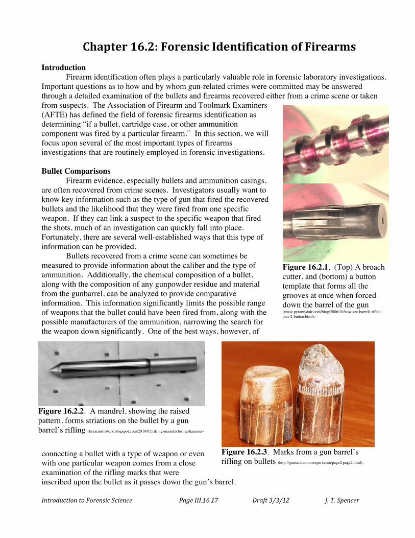
Figure 16.2.1. (Top) A broach cutter, and (bottom) a button template that forms all the grooves at once when forced down the barrel of the gun (www.pyramydair.com/blog/2006/10/how-are-barrels-rifled-part-2-button.html).
Figure 16.2.2. A mandrel, showing the raised pattern, forms striations on the bullet by a gun barrel’s rifling (firearmshistory.blogspot.com/2010/05/rifling-manufacturing-hammer-forged.html).
Figure 16.2.3. Marks from a gun barrel’s rifling on bullets (http://gunsandammoexpert.com/page2/page2.html).
Introduction to Forensic Science Page III.16.18 Draft 3/3/12 J. T. Spencer
The rifling, the lands and grooves inside the barrel of a gun that cause the bullet to spin upon firing, are made in a variety of ways – all of which are employed in the manufacture of weapons today. Several methods are employed to form the grooves in the metal on the inside of the barrel, either all at once or one groove at a time. A broach cutter (Figure 16.2.1) is used to cut all of the grooves simultaneously by forcing a cutter head down the smooth, drilled-out barrel of the gun while rotating the cutter with a characteristic twist rate. A second method, probably the most commonly employed technique today, employs a hot “button” (Figure 16.2.1) that is forced down the smooth barrel at very high pressures, compressing the metal into the grooved shapes rather than cutting the grooves into the metal. Alternatively, a mandrel (a sort of rod-shaped, grooved template) that has raised ribs corresponding to the desired rifling grooves (Figure 16.2.2) is first inserted into a slightly oversized, smooth barrel and then the barrel is compressed or hammered into shape around the mandrel, leaving the grooves and lands formed inside the barrel when the mandrel is removed.
When a bullet passes along the barrel of a gun, the softer metal of the bullet is distorted and shaped to match the lands and groves of the barrel. Examination of the fired bullet can then provide information about the gun it was fired from, such as the number of grooves, the direction of twist (left-handed or right-handed), and the twist rate (Figure 16.2.3). Investigative agencies, such as the FBI, maintain databases of this type of information for an enormous number of manufactured weapons. This information, coupled with the caliber and overall shape and chemical composition of the bullet, can identify unambiguously the make and model of the gun that shot the bullet - very useful class
characteristics. Similarly, if the number, size, handedness and twist of a bullet do not all match a suspect gun, then that gun can be eliminated as a possible weapon employed in
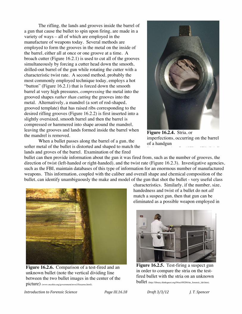
Figure 16.2.4. Stria, or imperfections, occurring on the barrel of a handgun (http://accessscience.com/content/Forensic%20firearms%20identification/YB110188).
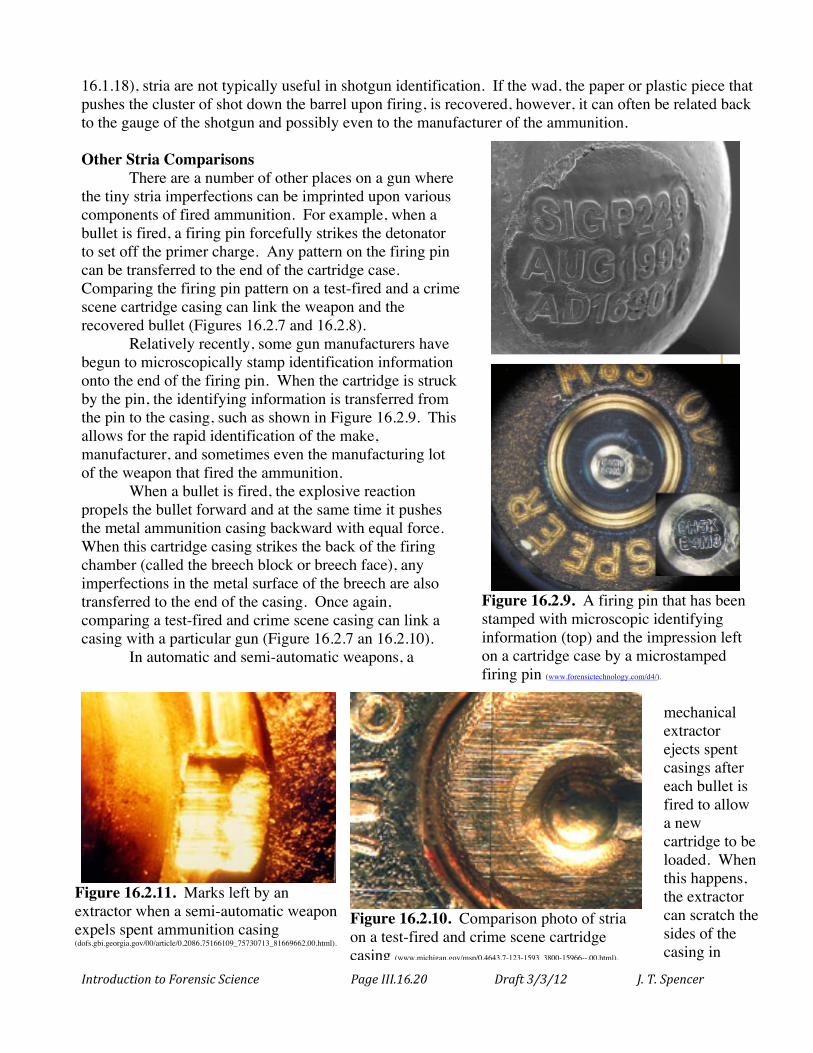
Figure 16.2.5. Test-firing a suspect gun in order to compare the stria on the test-fired bullet with the stria on an unknown bullet (http://library.thinkquest.org/04oct/00206/tte_forensic_lab.htm).
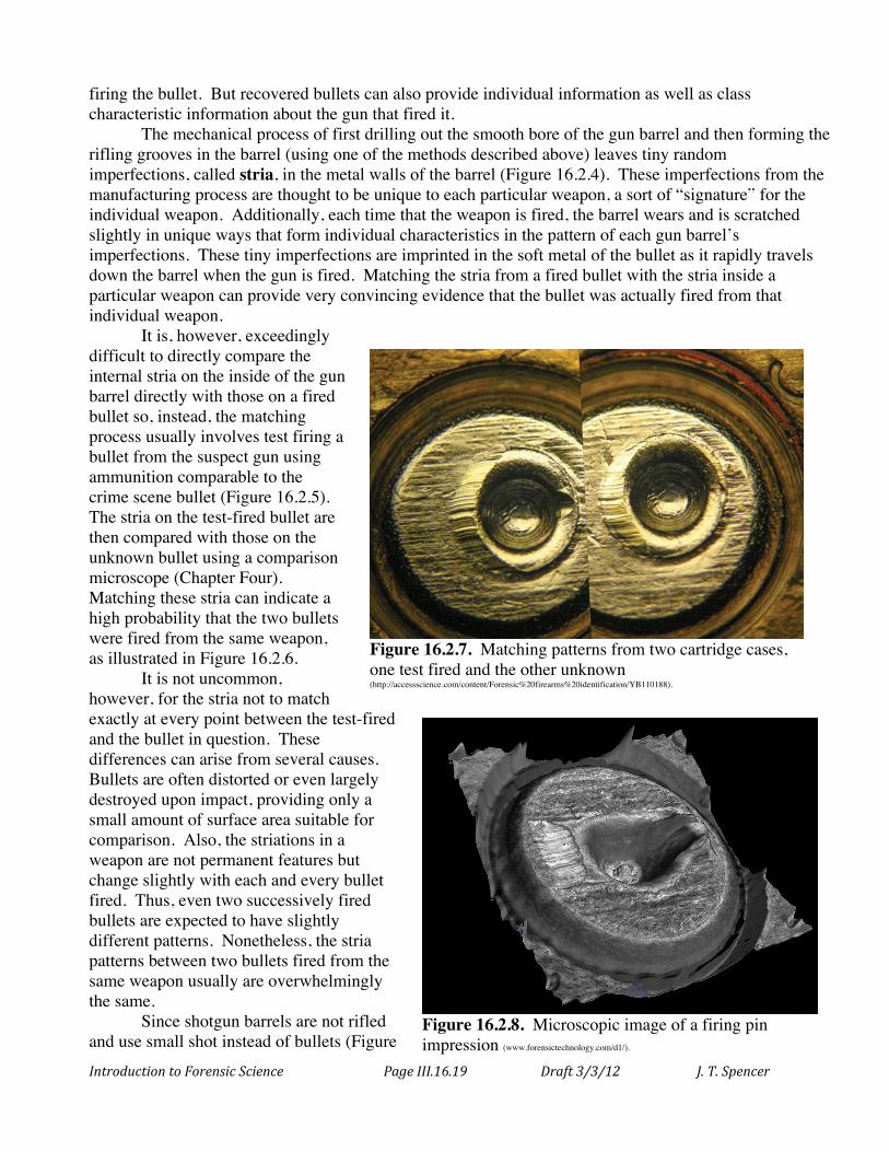
Figure 16.2.6. Comparison of a test-fired and an unknown bullet (note the vertical dividing line between the two bullet images in the center of the picture) (www.mcohio.org/government/mvrcl/firearms.html).
Introduction to Forensic Science Page III.16.19 Draft 3/3/12 J. T. Spencer
firing the bullet. But recovered bullets can also provide individual information as well as class characteristic information about the gun that fired it.
The mechanical process of first drilling out the smooth bore of the gun barrel and then forming the rifling grooves in the barrel (using one of the methods described above) leaves tiny random imperfections, called stria, in the metal walls of the barrel (Figure 16.2.4). These imperfections from the manufacturing process are thought to be unique to each particular weapon, a sort of “signature” for the individual weapon. Additionally, each time that the weapon is fired, the barrel wears and is scratched slightly in unique ways that form individual characteristics in the pattern of each gun barrel’s imperfections. These tiny imperfections are imprinted in the soft metal of the bullet as it rapidly travels down the barrel when the gun is fired. Matching the stria from a fired bullet with the stria inside a particular weapon can provide very convincing evidence that the bullet was actually fired from that individual weapon.
It is, however, exceedingly difficult to directly compare the internal stria on the inside of the gun barrel directly with those on a fired bullet so, instead, the matching process usually involves test firing a bullet from the suspect gun using ammunition comparable to the crime scene bullet (Figure 16.2.5). The stria on the test-fired bullet are then compared with those on the unknown bullet using a comparison microscope (Chapter Four). Matching these stria can indicate a high probability that the two bullets were fired from the same weapon, as illustrated in Figure 16.2.6.
It is not uncommon, however, for the stria not to match exactly at every point between the test-fired and the bullet in question. These differences can arise from several causes. Bullets are often distorted or even largely destroyed upon impact, providing only a small amount of surface area suitable for comparison. Also, the striations in a weapon are not permanent features but change slightly with each and every bullet fired. Thus, even two successively fired bullets are expected to have slightly different patterns. Nonetheless, the stria patterns between two bullets fired from the same weapon usually are overwhelmingly the same.
Since shotgun barrels are not rifled and use small shot instead of bullets (Figure
Figure 16.2.7. Matching patterns from two cartridge cases, one test fired and the other unknown (http://accessscience.com/content/Forensic%20firearms%20identification/YB110188).
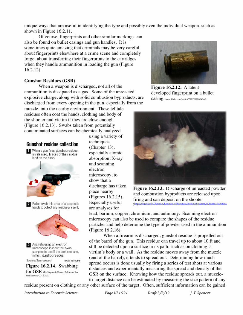
Figure 16.2.8. Microscopic image of a firing pin impression (www.forensictechnology.com/d1/).
Introduction to Forensic Science Page III.16.20 Draft 3/3/12 J. T. Spencer
16.1.18), stria are not typically useful in shotgun identification. If the wad, the paper or plastic piece that pushes the cluster of shot down the barrel upon firing, is recovered, however, it can often be related back to the gauge of the shotgun and possibly even to the manufacturer of the ammunition. Other Stria Comparisons
There are a number of other places on a gun where the tiny stria imperfections can be imprinted upon various components of fired ammunition. For example, when a bullet is fired, a firing pin forcefully strikes the detonator to set off the primer charge. Any pattern on the firing pin can be transferred to the end of the cartridge case. Comparing the firing pin pattern on a test-fired and a crime scene cartridge casing can link the weapon and the recovered bullet (Figures 16.2.7 and 16.2.8).
Relatively recently, some gun manufacturers have begun to microscopically stamp identification information onto the end of the firing pin. When the cartridge is struck by the pin, the identifying information is transferred from the pin to the casing, such as shown in Figure 16.2.9. This allows for the rapid identification of the make, manufacturer, and sometimes even the manufacturing lot of the weapon that fired the ammunition.
When a bullet is fired, the explosive reaction propels the bullet forward and at the same time it pushes the metal ammunition casing backward with equal force. When this cartridge casing strikes the back of the firing chamber (called the breech block or breech face), any imperfections in the metal surface of the breech are also transferred to the end of the casing. Once again, comparing a test-fired and crime scene casing can link a casing with a particular gun (Figure 16.2.7 an 16.2.10).
In automatic and semi-automatic weapons, a
mechanical extractor ejects spent casings after each bullet is fired to allow a new cartridge to be loaded. When this happens, the extractor can scratch the sides of the casing in
Figure 16.2.9. A firing pin that has been stamped with microscopic identifying information (top) and the impression left on a cartridge case by a microstamped firing pin (www.forensictechnology.com/d4/).
Figure 16.2.10. Comparison photo of stria on a test-fired and crime scene cartridge casing (www.michigan.gov/msp/0,4643,7-123-1593_3800-15966--,00.html).
Figure 16.2.11. Marks left by an extractor when a semi-automatic weapon expels spent ammunition casing (dofs.gbi.georgia.gov/00/article/0,2086,75166109_75730713_81669662,00.html).
Introduction to Forensic Science Page III.16.21 Draft 3/3/12 J. T. Spencer
unique ways that are useful in identifying the type and possibly even the individual weapon, such as shown in Figure 16.2.11.
Of course, fingerprints and other similar markings can also be found on bullet casings and gun handles. It is sometimes quite amazing that criminals may be very careful about fingerprints elsewhere at a crime scene and completely forget about transferring their fingerprints to the cartridges when they handle ammunition in loading the gun (Figure 16.2.12). Gunshot Residues (GSR)
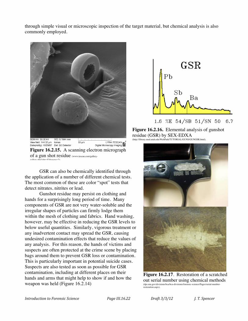
When a weapon is discharged, not all of the ammunition is dissipated as a gas. Some of the unreacted explosive charge, along with solid combustion byproducts, are discharged from every opening in the gun, especially from the muzzle, into the nearby environment. These telltale residues often coat the hands, clothing and body of the shooter and victim if they are close enough (Figure 16.2.13). Swabs taken from potentially contaminated surfaces can be chemically analyzed
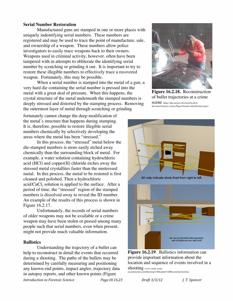
using a variety of techniques (Chapter 13), especially atomic absorption, X-ray and scanning electron microscopy, to show that a discharge has taken place nearby (Figures 16.2.15). Especially useful are analyses for lead, barium, copper, chromium, and antimony. Scanning electron microscopy can also be used to compare the shapes of the residue particles and help determine the type of powder used in the ammunition (Figure 16.2.16).
When a firearm is discharged, gunshot residue is propelled out of the barrel of the gun. This residue can travel up to about 10 ft and still be detected upon a surface in its path, such as on clothing, a victim’s body or a wall. As the residue moves away from the muzzle (end of the barrel), it tends to spread out. Determining how much spread occurs is done usually by firing a series of test shots at various distances and experimentally measuring the spread and density of the GSR on the surface. Knowing how the residue spreads out, a muzzle-to-target distance can be estimated by measuring the size pattern of any
residue present on clothing or any other surface of the target. Often, sufficient information can be gained
Figure 16.2.12. A latent developed fingerprint on a bullet casing (www.flickr.com/photos/27119371@N04/).
Figure 16.2.13. Discharge of unreacted powder and combustion byproducts are released upon firing and can deposit on the shooter (http://ok.gov/osbi/Forensic_Laboratory/Forensic_Services/Firearms_&_Toolmarks/index.html).
Figure 16.2.14. Swabbing for GSR (By Stephanie Hanes; Baltimore Sun Staff January 23, 2005).
Introduction to Forensic Science Page III.16.22 Draft 3/3/12 J. T. Spencer
through simple visual or microscopic inspection of the target material, but chemical analysis is also commonly employed.
GSR can also be chemically identified through the application of a number of different chemical tests. The most common of these are color “spot” tests that detect nitrates, nitrites or lead. Gunshot residue may persist on clothing and hands for a surprisingly long period of time. Many components of GSR are not very water-soluble and the irregular shapes of particles can firmly lodge them within the mesh of clothing and fabrics. Hand washing, however, may be effective in reducing the GSR levels to below useful quantities. Similarly, vigorous treatment or any inadvertent contact may spread the GSR, causing undesired contamination effects that reduce the values of any analysis. For this reason, the hands of victims and suspects are often protected at the crime scene by placing bags around them to prevent GSR loss or contamination. This is particularly important in potential suicide cases. Suspects are also tested as soon as possible for GSR contamination, including at different places on their hands and arms that might help to show if and how the weapon was held (Figure 16.2.14)
Figure 16.2.15. A scanning electron micrograph of a gun shot residue (www.tescan.com/gallery-gallery.php?obr=52&menu=2).
Figure 16.2.16. Elemental analysis of gunshot residue (GSR) by SEX-EDXA (http://library.med.utah.edu/WebPath/TUTORIAL/GUNS/GUNGSR.html).
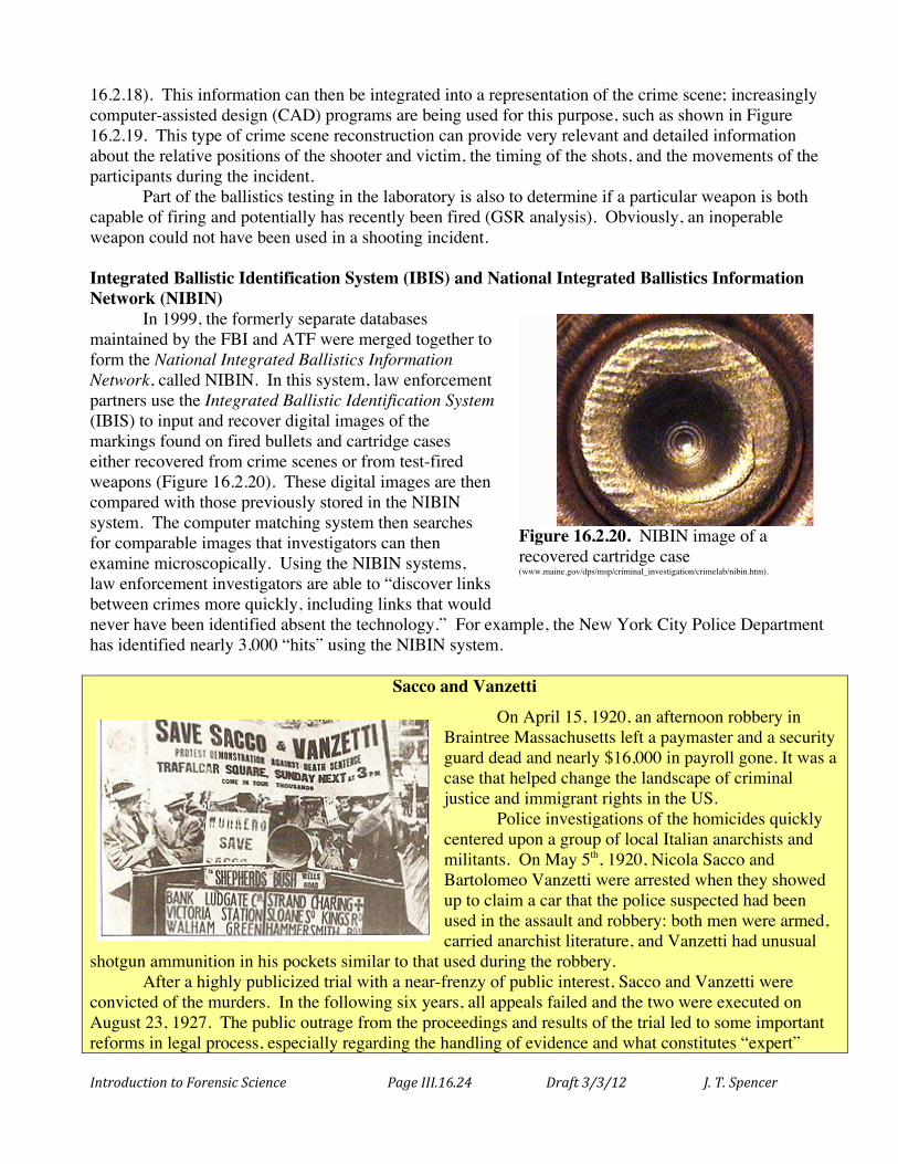
Figure 16.2.17. Restoration of a scratched out serial number using chemical methods (dps.mn.gov/divisions/bca/bca-divisions/forensic-science/Pages/serial-number-restoration.aspx).
Introduction to Forensic Science Page III.16.23 Draft 3/3/12 J. T. Spencer
Serial Number Restoration Manufactured guns are stamped in one or more places with
uniquely indentifying serial numbers. These numbers are registered and may be used to trace the point of manufacture, sale, and ownership of a weapon. These numbers allow police investigators to easily trace weapons back to their owners. Weapons used in criminal activity, however, often have been tampered with in attempts to obliterate the identifying serial number by scratching or grinding it out. It is important to try to restore these illegible numbers to effectively trace a recovered weapon. Fortunately, this may be possible.
When a serial number is stamped into the metal of a gun, a very hard die containing the serial number is pressed into the metal with a great deal of pressure. When this happens, the crystal structure of the metal underneath the stamped numbers is deeply stressed and distorted by the stamping process. Removing the outermost layer of metal through scratching or grinding fortunately cannot change the deep modification of the metal’s structure that happens during stamping. It is, therefore, possible to restore illegible serial numbers chemically by selectively developing the areas where the metal has been “stressed.”
In this process, the “stressed” metal below the die-stamped numbers is more easily etched away chemically than the surrounding block of metal. For example, a water solution containing hydrochloric acid (HCl) and copper(II) chloride etches away the stressed metal crystallites faster than the unstressed metal. In this process, the metal to be restored is first cleaned and polished. Then a hydrochloric acid/CuCl2 solution is applied to the surface. After a period of time, the “stressed” region of the stamped numbers is dissolved away to reveal the ID number. An example of the results of this process is shown in Figure 16.2.17.
Unfortunately, the records of serial numbers of older weapons may not be available or a crime weapon may have been stolen or passed among many people such that serial numbers, even when present, might not provide much valuable information. Ballistics
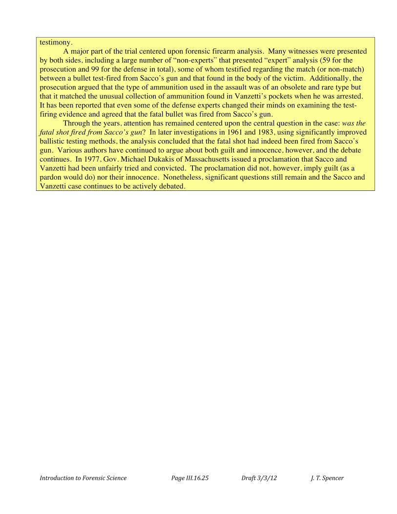
Understanding the trajectory of a bullet can help to reconstruct in detail the events that occurred during a shooting. The paths of the bullets may be determined by carefully measuring and positioning any known end points, impact angles, trajectory data in autopsy reports, and other known points (Figure
Figure 16.2.19. Ballistics information can provide important information about the location and sequence of events involved in a shooting (www.crime-scene-reconstruction.com/Shooting%20Incident%20Reconstruction.htm).
Figure 16.2.18. Reconstruction of bullet trajectories at a crime scene (https://dps.mn.gov/divisions/bca/bca-divisions/forensic-science/Pages/firearms-identification.aspx).
Introduction to Forensic Science Page III.16.24 Draft 3/3/12 J. T. Spencer
16.2.18). This information can then be integrated into a representation of the crime scene; increasingly computer-assisted design (CAD) programs are being used for this purpose, such as shown in Figure 16.2.19. This type of crime scene reconstruction can provide very relevant and detailed information about the relative positions of the shooter and victim, the timing of the shots, and the movements of the participants during the incident.
Part of the ballistics testing in the laboratory is also to determine if a particular weapon is both capable of firing and potentially has recently been fired (GSR analysis). Obviously, an inoperable weapon could not have been used in a shooting incident. Integrated Ballistic Identification System (IBIS) and National Integrated Ballistics Information Network (NIBIN)
In 1999, the formerly separate databases maintained by the FBI and ATF were merged together to form the National Integrated Ballistics Information Network, called NIBIN. In this system, law enforcement partners use the Integrated Ballistic Identification System (IBIS) to input and recover digital images of the markings found on fired bullets and cartridge cases either recovered from crime scenes or from test-fired weapons (Figure 16.2.20). These digital images are then compared with those previously stored in the NIBIN system. The computer matching system then searches for comparable images that investigators can then examine microscopically. Using the NIBIN systems, law enforcement investigators are able to “discover links between crimes more quickly, including links that would never have been identified absent the technology.” For example, the New York City Police Department has identified nearly 3,000 “hits” using the NIBIN system.
Sacco and Vanzetti
On April 15, 1920, an afternoon robbery in Braintree Massachusetts left a paymaster and a security guard dead and nearly $16,000 in payroll gone. It was a case that helped change the landscape of criminal justice and immigrant rights in the US. Police investigations of the homicides quickly centered upon a group of local Italian anarchists and militants. On May 5th, 1920, Nicola Sacco and Bartolomeo Vanzetti were arrested when they showed up to claim a car that the police suspected had been used in the assault and robbery: both men were armed, carried anarchist literature, and Vanzetti had unusual
shotgun ammunition in his pockets similar to that used during the robbery. After a highly publicized trial with a near-frenzy of public interest, Sacco and Vanzetti were convicted of the murders. In the following six years, all appeals failed and the two were executed on August 23, 1927. The public outrage from the proceedings and results of the trial led to some important reforms in legal process, especially regarding the handling of evidence and what constitutes “expert”
Figure 16.2.20. NIBIN image of a recovered cartridge case (www.maine.gov/dps/msp/criminal_investigation/crimelab/nibin.htm).
Introduction to Forensic Science Page III.16.25 Draft 3/3/12 J. T. Spencer
testimony. A major part of the trial centered upon forensic firearm analysis. Many witnesses were presented by both sides, including a large number of “non-experts” that presented “expert” analysis (59 for the prosecution and 99 for the defense in total), some of whom testified regarding the match (or non-match) between a bullet test-fired from Sacco’s gun and that found in the body of the victim. Additionally, the prosecution argued that the type of ammunition used in the assault was of an obsolete and rare type but that it matched the unusual collection of ammunition found in Vanzetti’s pockets when he was arrested. It has been reported that even some of the defense experts changed their minds on examining the test-firing evidence and agreed that the fatal bullet was fired from Sacco’s gun. Through the years, attention has remained centered upon the central question in the case: was the fatal shot fired from Sacco’s gun? In later investigations in 1961 and 1983, using significantly improved ballistic testing methods, the analysis concluded that the fatal shot had indeed been fired from Sacco’s gun. Various authors have continued to argue about both guilt and innocence, however, and the debate continues. In 1977, Gov. Michael Dukakis of Massachusetts issued a proclamation that Sacco and Vanzetti had been unfairly tried and convicted. The proclamation did not, however, imply guilt (as a pardon would do) nor their innocence. Nonetheless, significant questions still remain and the Sacco and Vanzetti case continues to be actively debated.
Introduction to Forensic Science Page III.16.26 Draft 3/3/12 J. T. Spencer
Chapter 16.3: Forensic Impression Evidence
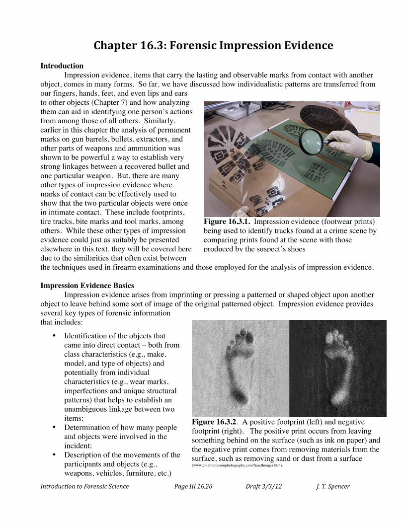
Introduction Impression evidence, items that carry the lasting and observable marks from contact with another
object, comes in many forms. So far, we have discussed how individualistic patterns are transferred from our fingers, hands, feet, and even lips and ears to other objects (Chapter 7) and how analyzing them can aid in identifying one person’s actions from among those of all others. Similarly, earlier in this chapter the analysis of permanent marks on gun barrels, bullets, extractors, and other parts of weapons and ammunition was shown to be powerful a way to establish very strong linkages between a recovered bullet and one particular weapon. But, there are many other types of impression evidence where marks of contact can be effectively used to show that the two particular objects were once in intimate contact. These include footprints, tire tracks, bite marks and tool marks, among others. While these other types of impression evidence could just as suitably be presented elsewhere in this text, they will be covered here due to the similarities that often exist between the techniques used in firearm examinations and those employed for the analysis of impression evidence.
Impression Evidence Basics
Impression evidence arises from imprinting or pressing a patterned or shaped object upon another object to leave behind some sort of image of the original patterned object. Impression evidence provides several key types of forensic information that includes:
• Identification of the objects that came into direct contact – both from class characteristics (e.g., make, model, and type of objects) and potentially from individual characteristics (e.g., wear marks, imperfections and unique structural patterns) that helps to establish an unambiguous linkage between two items;
• Determination of how many people and objects were involved in the incident;
• Description of the movements of the participants and objects (e.g., weapons, vehicles, furniture, etc.)
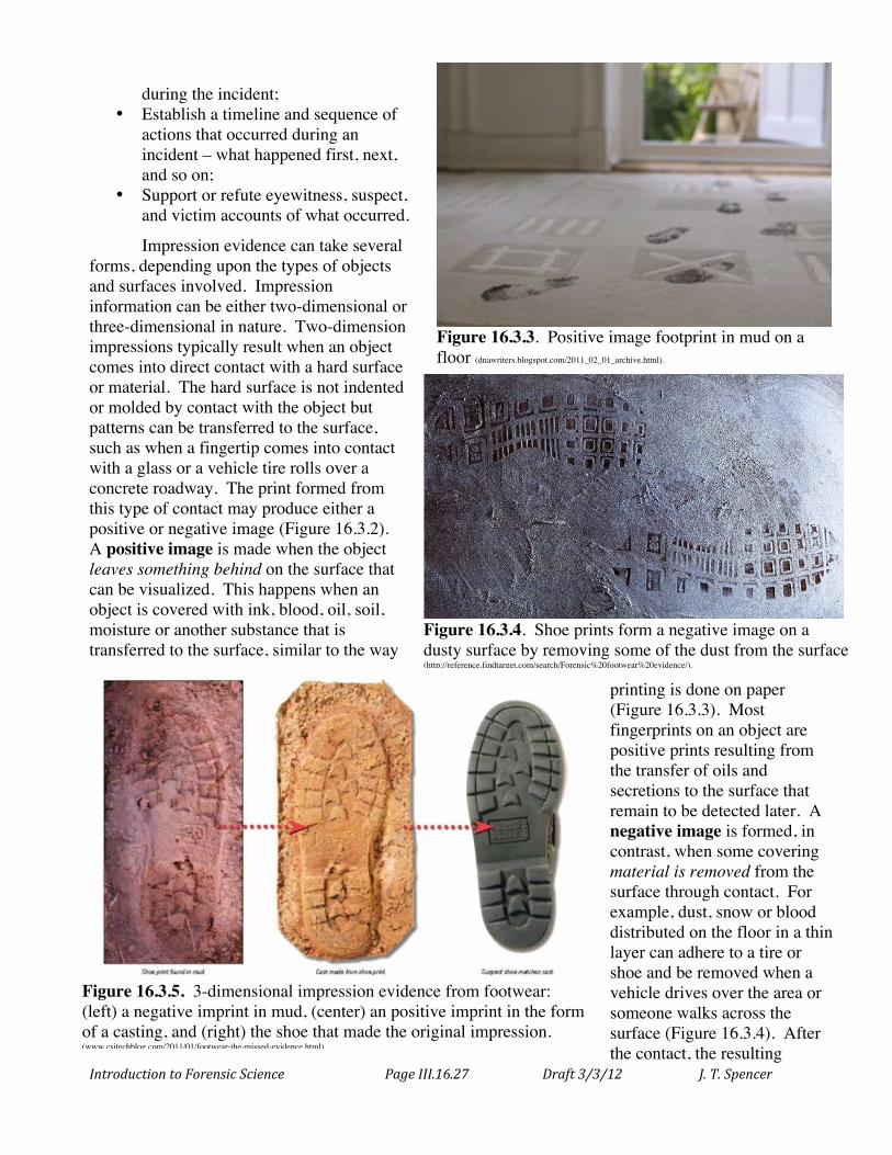
Figure 16.3.2. A positive footprint (left) and negative footprint (right). The positive print occurs from leaving something behind on the surface (such as ink on paper) and the negative print comes from removing materials from the surface, such as removing sand or dust from a surface (www.colethompsonphotography.com/SandImages.htm).
Figure 16.3.1. Impression evidence (footwear prints) being used to identify tracks found at a crime scene by comparing prints found at the scene with those produced by the suspect’s shoes (http://crimespace.ning.com/profiles/blogs/how-important-is-impression).
Introduction to Forensic Science Page III.16.27 Draft 3/3/12 J. T. Spencer
during the incident; • Establish a timeline and sequence of
actions that occurred during an incident – what happened first, next, and so on;
• Support or refute eyewitness, suspect, and victim accounts of what occurred.
Impression evidence can take several forms, depending upon the types of objects and surfaces involved. Impression information can be either two-dimensional or three-dimensional in nature. Two-dimension impressions typically result when an object comes into direct contact with a hard surface or material. The hard surface is not indented or molded by contact with the object but patterns can be transferred to the surface, such as when a fingertip comes into contact with a glass or a vehicle tire rolls over a concrete roadway. The print formed from this type of contact may produce either a positive or negative image (Figure 16.3.2). A positive image is made when the object leaves something behind on the surface that can be visualized. This happens when an object is covered with ink, blood, oil, soil, moisture or another substance that is transferred to the surface, similar to the way
printing is done on paper (Figure 16.3.3). Most fingerprints on an object are positive prints resulting from the transfer of oils and secretions to the surface that remain to be detected later. A negative image is formed, in contrast, when some covering material is removed from the surface through contact. For example, dust, snow or blood distributed on the floor in a thin layer can adhere to a tire or shoe and be removed when a vehicle drives over the area or someone walks across the surface (Figure 16.3.4). After the contact, the resulting
Figure 16.3.4. Shoe prints form a negative image on a dusty surface by removing some of the dust from the surface (http://reference.findtarget.com/search/Forensic%20footwear%20evidence/).
Figure 16.3.3. Positive image footprint in mud on a floor (dnawriters.blogspot.com/2011_02_01_archive.html).
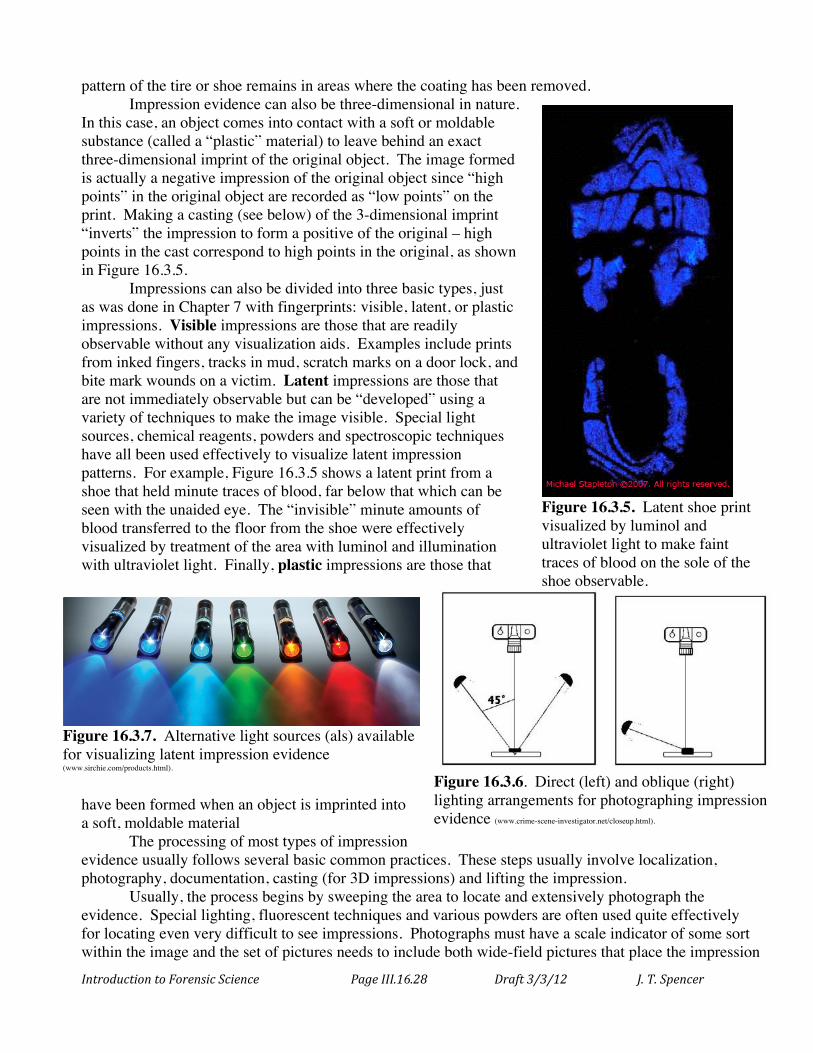
Figure 16.3.5. 3-dimensional impression evidence from footwear: (left) a negative imprint in mud, (center) an positive imprint in the form of a casting, and (right) the shoe that made the original impression. (www.csitechblog.com/2011/01/footwear-the-missed-evidence.html).
Introduction to Forensic Science Page III.16.28 Draft 3/3/12 J. T. Spencer
pattern of the tire or shoe remains in areas where the coating has been removed. Impression evidence can also be three-dimensional in nature.
In this case, an object comes into contact with a soft or moldable substance (called a “plastic” material) to leave behind an exact three-dimensional imprint of the original object. The image formed is actually a negative impression of the original object since “high points” in the original object are recorded as “low points” on the print. Making a casting (see below) of the 3-dimensional imprint “inverts” the impression to form a positive of the original – high points in the cast correspond to high points in the original, as shown in Figure 16.3.5.
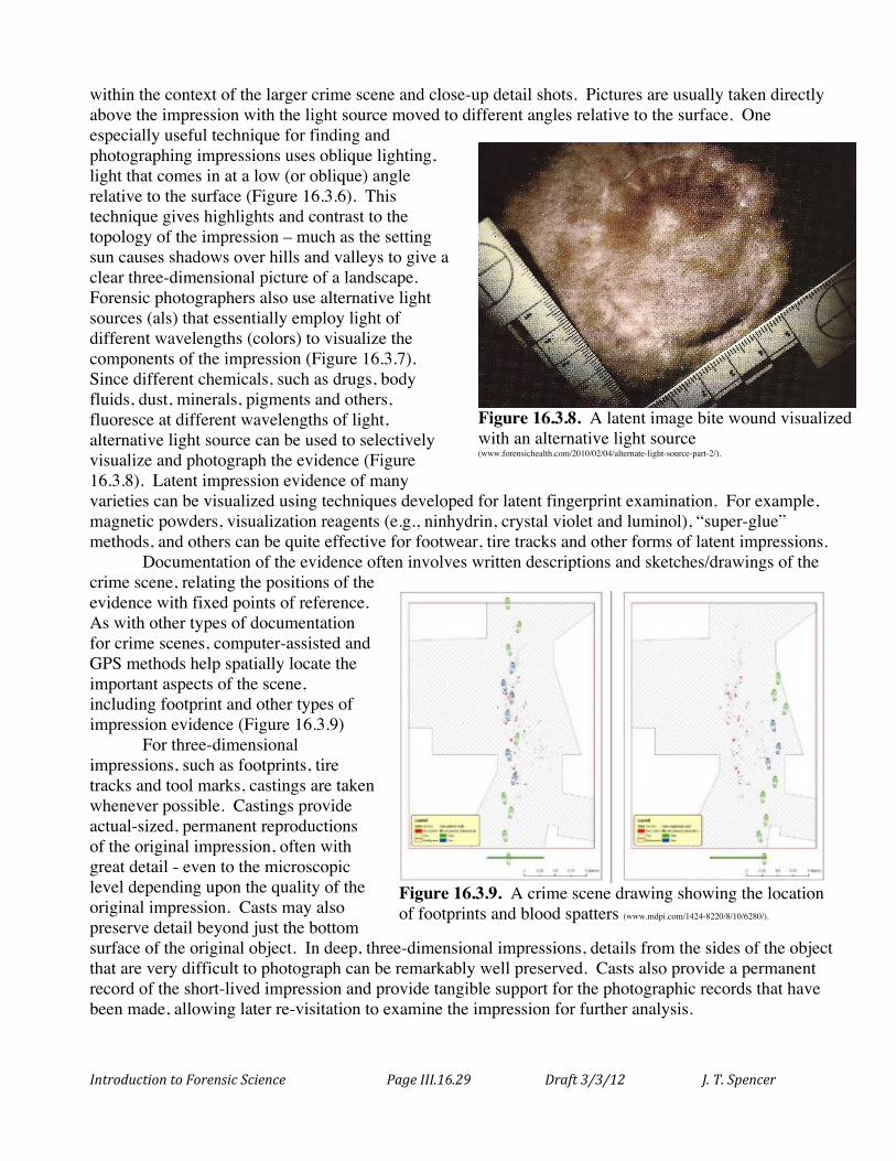
Impressions can also be divided into three basic types, just as was done in Chapter 7 with fingerprints: visible, latent, or plastic impressions. Visible impressions are those that are readily observable without any visualization aids. Examples include prints from inked fingers, tracks in mud, scratch marks on a door lock, and bite mark wounds on a victim. Latent impressions are those that are not immediately observable but can be “developed” using a variety of techniques to make the image visible. Special light sources, chemical reagents, powders and spectroscopic techniques have all been used effectively to visualize latent impression patterns. For example, Figure 16.3.5 shows a latent print from a shoe that held minute traces of blood, far below that which can be seen with the unaided eye. The “invisible” minute amounts of blood transferred to the floor from the shoe were effectively visualized by treatment of the area with luminol and illumination with ultraviolet light. Finally, plastic impressions are those that
have been formed when an object is imprinted into a soft, moldable material
The processing of most types of impression evidence usually follows several basic common practices. These steps usually involve localization, photography, documentation, casting (for 3D impressions) and lifting the impression.
Usually, the process begins by sweeping the area to locate and extensively photograph the evidence. Special lighting, fluorescent techniques and various powders are often used quite effectively for locating even very difficult to see impressions. Photographs must have a scale indicator of some sort within the image and the set of pictures needs to include both wide-field pictures that place the impression
Figure 16.3.6. Direct (left) and oblique (right) lighting arrangements for photographing impression evidence (www.crime-scene-investigator.net/closeup.html).
Figure 16.3.7. Alternative light sources (als) available for visualizing latent impression evidence (www.sirchie.com/products.html).
Figure 16.3.5. Latent shoe print visualized by luminol and ultraviolet light to make faint traces of blood on the sole of the shoe observable. (www.forensicsrus.com/images/LuminolShoePrint.jpg).
Introduction to Forensic Science Page III.16.29 Draft 3/3/12 J. T. Spencer
within the context of the larger crime scene and close-up detail shots. Pictures are usually taken directly above the impression with the light source moved to different angles relative to the surface. One especially useful technique for finding and photographing impressions uses oblique lighting, light that comes in at a low (or oblique) angle relative to the surface (Figure 16.3.6). This technique gives highlights and contrast to the topology of the impression – much as the setting sun causes shadows over hills and valleys to give a clear three-dimensional picture of a landscape. Forensic photographers also use alternative light sources (als) that essentially employ light of different wavelengths (colors) to visualize the components of the impression (Figure 16.3.7). Since different chemicals, such as drugs, body fluids, dust, minerals, pigments and others, fluoresce at different wavelengths of light, alternative light source can be used to selectively visualize and photograph the evidence (Figure 16.3.8). Latent impression evidence of many varieties can be visualized using techniques developed for latent fingerprint examination. For example, magnetic powders, visualization reagents (e.g., ninhydrin, crystal violet and luminol), “super-glue” methods, and others can be quite effective for footwear, tire tracks and other forms of latent impressions.
Documentation of the evidence often involves written descriptions and sketches/drawings of the crime scene, relating the positions of the evidence with fixed points of reference. As with other types of documentation for crime scenes, computer-assisted and GPS methods help spatially locate the important aspects of the scene, including footprint and other types of impression evidence (Figure 16.3.9)
For three-dimensional impressions, such as footprints, tire tracks and tool marks, castings are taken whenever possible. Castings provide actual-sized, permanent reproductions of the original impression, often with great detail - even to the microscopic level depending upon the quality of the original impression. Casts may also preserve detail beyond just the bottom surface of the original object. In deep, three-dimensional impressions, details from the sides of the object that are very difficult to photograph can be remarkably well preserved. Casts also provide a permanent record of the short-lived impression and provide tangible support for the photographic records that have been made, allowing later re-visitation to examine the impression for further analysis.
Figure 16.3.8. A latent image bite wound visualized with an alternative light source (www.forensichealth.com/2010/02/04/alternate-light-source-part-2/).
Figure 16.3.9. A crime scene drawing showing the location of footprints and blood spatters (www.mdpi.com/1424-8220/8/10/6280/).
Introduction to Forensic Science Page III.16.30 Draft 3/3/12 J. T. Spencer
1
2
3
4
5
6
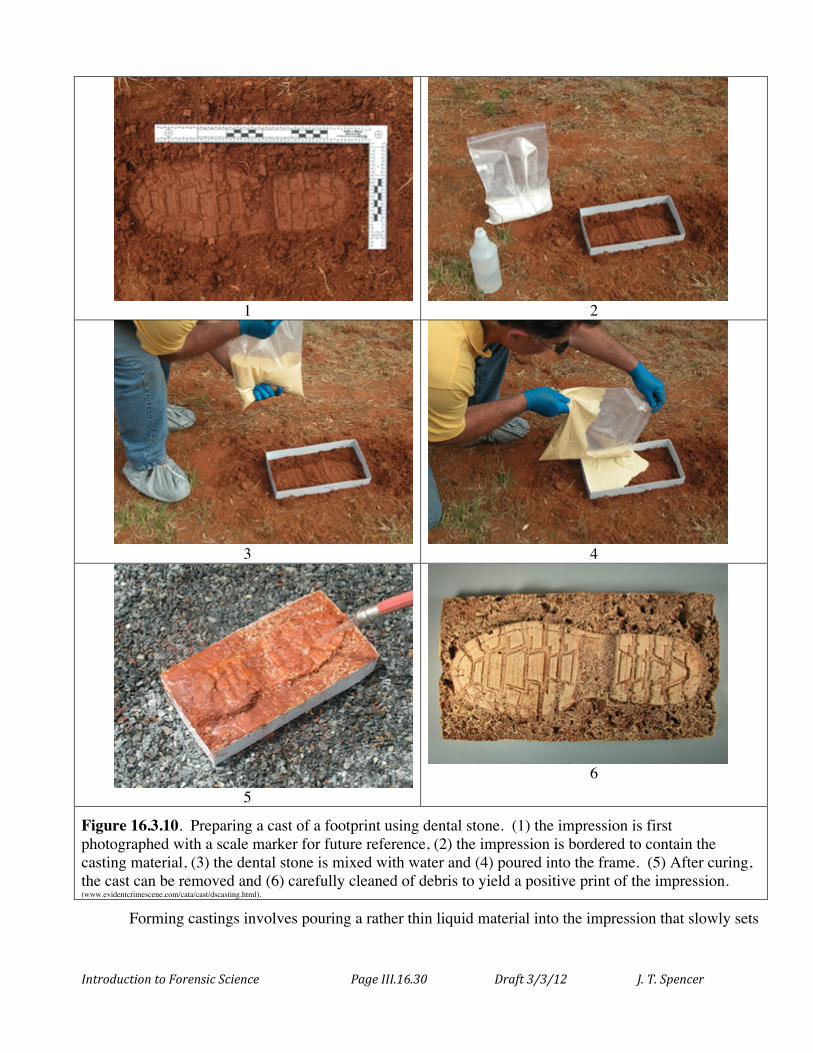
Figure 16.3.10. Preparing a cast of a footprint using dental stone. (1) the impression is first photographed with a scale marker for future reference, (2) the impression is bordered to contain the casting material, (3) the dental stone is mixed with water and (4) poured into the frame. (5) After curing, the cast can be removed and (6) carefully cleaned of debris to yield a positive print of the impression. (www.evidentcrimescene.com/cata/cast/dscasting.html).
Forming castings involves pouring a rather thin liquid material into the impression that slowly sets
Introduction to Forensic Science Page III.16.31 Draft 3/3/12 J. T. Spencer
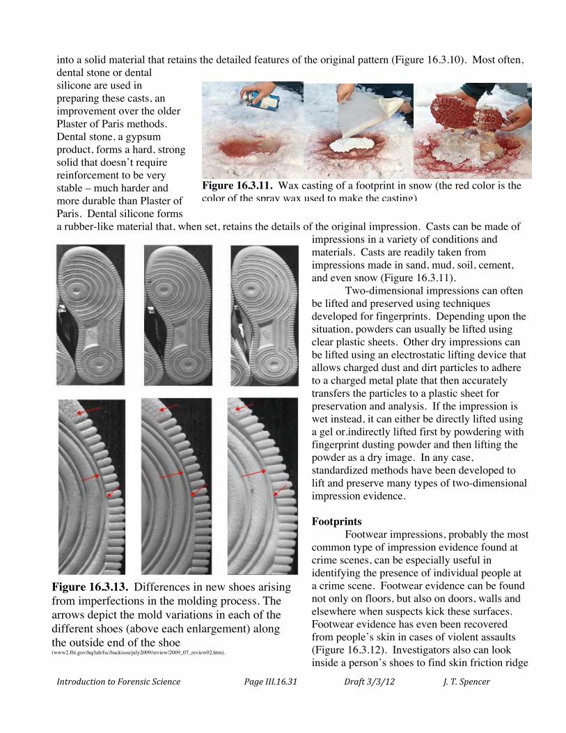
into a solid material that retains the detailed features of the original pattern (Figure 16.3.10). Most often, dental stone or dental silicone are used in preparing these casts, an improvement over the older Plaster of Paris methods. Dental stone, a gypsum product, forms a hard, strong solid that doesn’t require reinforcement to be very stable – much harder and more durable than Plaster of Paris. Dental silicone forms a rubber-like material that, when set, retains the details of the original impression. Casts can be made of
impressions in a variety of conditions and materials. Casts are readily taken from impressions made in sand, mud, soil, cement, and even snow (Figure 16.3.11).
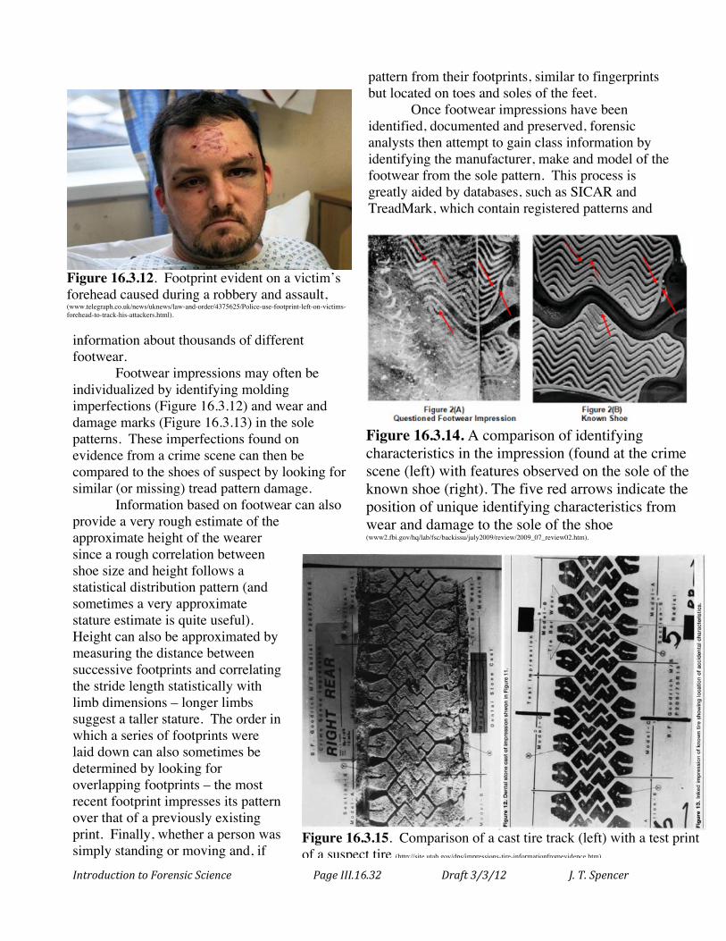
Two-dimensional impressions can often be lifted and preserved using techniques developed for fingerprints. Depending upon the situation, powders can usually be lifted using clear plastic sheets. Other dry impressions can be lifted using an electrostatic lifting device that allows charged dust and dirt particles to adhere to a charged metal plate that then accurately transfers the particles to a plastic sheet for preservation and analysis. If the impression is wet instead, it can either be directly lifted using a gel or.indirectly lifted first by powdering with fingerprint dusting powder and then lifting the powder as a dry image. In any case, standardized methods have been developed to lift and preserve many types of two-dimensional impression evidence. Footprints Footwear impressions, probably the most common type of impression evidence found at crime scenes, can be especially useful in identifying the presence of individual people at a crime scene. Footwear evidence can be found not only on floors, but also on doors, walls and elsewhere when suspects kick these surfaces. Footwear evidence has even been recovered from people’s skin in cases of violent assaults (Figure 16.3.12). Investigators also can look inside a person’s shoes to find skin friction ridge
Figure 16.3.13. Differences in new shoes arising from imperfections in the molding process. The arrows depict the mold variations in each of the different shoes (above each enlargement) along the outside end of the shoe (www2.fbi.gov/hq/lab/fsc/backissu/july2009/review/2009_07_review02.htm).
Figure 16.3.11. Wax casting of a footprint in snow (the red color is the color of the spray wax used to make the casting) (www.redwop.com/minutiae.asp?action=showArticle&ID=264).
Introduction to Forensic Science Page III.16.32 Draft 3/3/12 J. T. Spencer
pattern from their footprints, similar to fingerprints but located on toes and soles of the feet.
Once footwear impressions have been identified, documented and preserved, forensic analysts then attempt to gain class information by identifying the manufacturer, make and model of the footwear from the sole pattern. This process is greatly aided by databases, such as SICAR and TreadMark, which contain registered patterns and
information about thousands of different footwear. Footwear impressions may often be individualized by identifying molding imperfections (Figure 16.3.12) and wear and damage marks (Figure 16.3.13) in the sole patterns. These imperfections found on evidence from a crime scene can then be compared to the shoes of suspect by looking for similar (or missing) tread pattern damage. Information based on footwear can also provide a very rough estimate of the approximate height of the wearer since a rough correlation between shoe size and height follows a statistical distribution pattern (and sometimes a very approximate stature estimate is quite useful). Height can also be approximated by measuring the distance between successive footprints and correlating the stride length statistically with limb dimensions – longer limbs suggest a taller stature. The order in which a series of footprints were laid down can also sometimes be determined by looking for overlapping footprints – the most recent footprint impresses its pattern over that of a previously existing print. Finally, whether a person was simply standing or moving and, if
Figure 16.3.14. A comparison of identifying characteristics in the impression (found at the crime scene (left) with features observed on the sole of the known shoe (right). The five red arrows indicate the position of unique identifying characteristics from wear and damage to the sole of the shoe (www2.fbi.gov/hq/lab/fsc/backissu/july2009/review/2009_07_review02.htm).
Figure 16.3.12. Footprint evident on a victim’s forehead caused during a robbery and assault, (www.telegraph.co.uk/news/uknews/law-and-order/4375625/Police-use-footprint-left-on-victims-forehead-to-track-his-attackers.html).
Figure 16.3.15. Comparison of a cast tire track (left) with a test print of a suspect tire (http://site.utah.gov/dps/impressions-tire-informationfromevidence.htm).
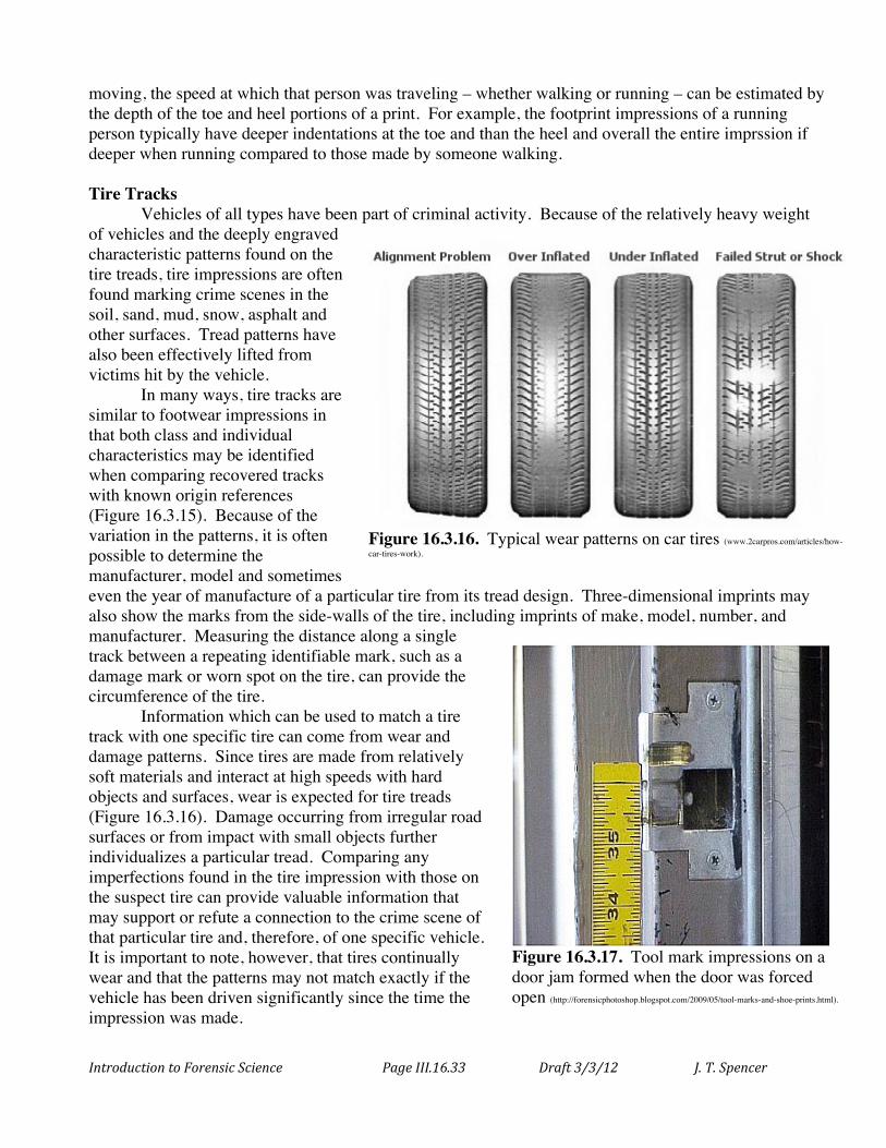
Introduction to Forensic Science Page III.16.33 Draft 3/3/12 J. T. Spencer
moving, the speed at which that person was traveling – whether walking or running – can be estimated by the depth of the toe and heel portions of a print. For example, the footprint impressions of a running person typically have deeper indentations at the toe and than the heel and overall the entire imprssion if deeper when running compared to those made by someone walking. Tire Tracks Vehicles of all types have been part of criminal activity. Because of the relatively heavy weight of vehicles and the deeply engraved characteristic patterns found on the tire treads, tire impressions are often found marking crime scenes in the soil, sand, mud, snow, asphalt and other surfaces. Tread patterns have also been effectively lifted from victims hit by the vehicle.
In many ways, tire tracks are similar to footwear impressions in that both class and individual characteristics may be identified when comparing recovered tracks with known origin references (Figure 16.3.15). Because of the variation in the patterns, it is often possible to determine the manufacturer, model and sometimes even the year of manufacture of a particular tire from its tread design. Three-dimensional imprints may also show the marks from the side-walls of the tire, including imprints of make, model, number, and manufacturer. Measuring the distance along a single track between a repeating identifiable mark, such as a damage mark or worn spot on the tire, can provide the circumference of the tire.
Information which can be used to match a tire track with one specific tire can come from wear and damage patterns. Since tires are made from relatively soft materials and interact at high speeds with hard objects and surfaces, wear is expected for tire treads (Figure 16.3.16). Damage occurring from irregular road surfaces or from impact with small objects further individualizes a particular tread. Comparing any imperfections found in the tire impression with those on the suspect tire can provide valuable information that may support or refute a connection to the crime scene of that particular tire and, therefore, of one specific vehicle. It is important to note, however, that tires continually wear and that the patterns may not match exactly if the vehicle has been driven significantly since the time the impression was made.
Figure 16.3.16. Typical wear patterns on car tires (www.2carpros.com/articles/how-car-tires-work).
Figure 16.3.17. Tool mark impressions on a door jam formed when the door was forced open (http://forensicphotoshop.blogspot.com/2009/05/tool-marks-and-shoe-prints.html).
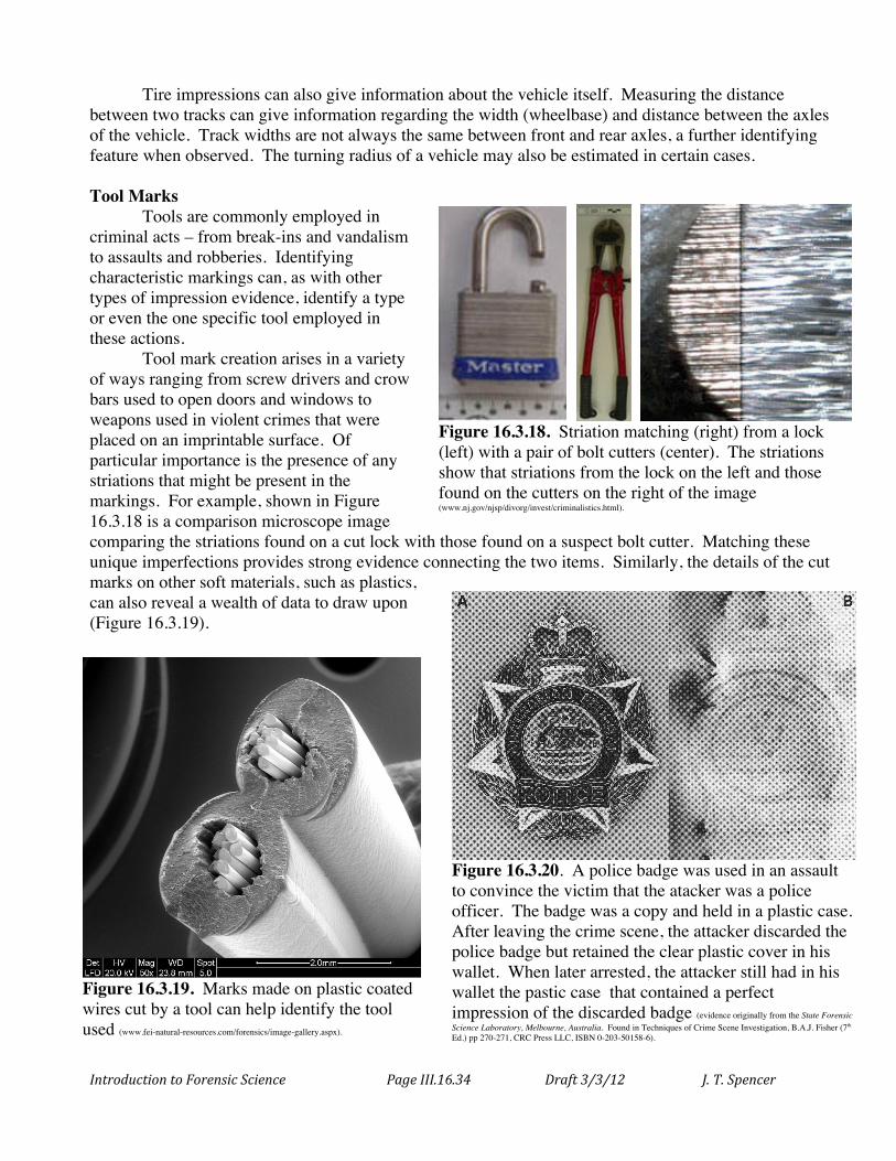
Introduction to Forensic Science Page III.16.34 Draft 3/3/12 J. T. Spencer
Tire impressions can also give information about the vehicle itself. Measuring the distance between two tracks can give information regarding the width (wheelbase) and distance between the axles of the vehicle. Track widths are not always the same between front and rear axles, a further identifying feature when observed. The turning radius of a vehicle may also be estimated in certain cases. Tool Marks Tools are commonly employed in criminal acts – from break-ins and vandalism to assaults and robberies. Identifying characteristic markings can, as with other types of impression evidence, identify a type or even the one specific tool employed in these actions.
Tool mark creation arises in a variety of ways ranging from screw drivers and crow bars used to open doors and windows to weapons used in violent crimes that were placed on an imprintable surface. Of particular importance is the presence of any striations that might be present in the markings. For example, shown in Figure 16.3.18 is a comparison microscope image comparing the striations found on a cut lock with those found on a suspect bolt cutter. Matching these unique imperfections provides strong evidence connecting the two items. Similarly, the details of the cut marks on other soft materials, such as plastics, can also reveal a wealth of data to draw upon (Figure 16.3.19).
Figure 16.3.18. Striation matching (right) from a lock (left) with a pair of bolt cutters (center). The striations show that striations from the lock on the left and those found on the cutters on the right of the image (www.nj.gov/njsp/divorg/invest/criminalistics.html).
Figure 16.3.19. Marks made on plastic coated wires cut by a tool can help identify the tool used (www.fei-natural-resources.com/forensics/image-gallery.aspx).
Figure 16.3.20. A police badge was used in an assault to convince the victim that the atacker was a police officer. The badge was a copy and held in a plastic case. After leaving the crime scene, the attacker discarded the police badge but retained the clear plastic cover in his wallet. When later arrested, the attacker still had in his wallet the pastic case that contained a perfect impression of the discarded badge (evidence originally from the State Forensic Science Laboratory, Melbourne, Australia. Found in Techniques of Crime Scene Investigation, B.A.J. Fisher (7th Ed.) pp 270-271, CRC Press LLC, ISBN 0-203-50158-6).
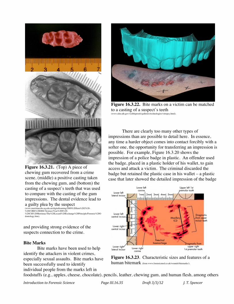
Introduction to Forensic Science Page III.16.35 Draft 3/3/12 J. T. Spencer
There are clearly too many other types of impressions than are possible to detail here. In essence, any time a harder object comes into contact forcibly with a softer one, the opportunity for transferring an impression is possible. For example, Figure 16.3.20 shows the impression of a police badge in plastic. An offender used the badge, placed in a plastic holder of his wallet, to gain access and attack a victim. The criminal discarded the badge but retained the plastic case in his wallet – a plastic case that later showed the detailed impression of the badge
and providing strong evidence of the suspects connection to the crime. Bite Marks Bite marks have been used to help identify the attackers in violent crimes, especially sexual assaults. Bite marks have been successfully used to identify individual people from the marks left in foodstuffs (e.g., apples, cheese, chocolate), pencils, leather, chewing gum, and human flesh, among others
Figure 16.3.22. Bite marks on a victim can be matched to a casting of a suspect’s teeth (www.nlm.nih.gov/visibleproofs/galleries/technologies/virtopsy.html).
Figure 16.3.21. (Top) A piece of chewing gum recovered from a crime scene, (middle) a positive casting taken from the chewing gum, and (bottom) the casting of a suspect’s teeth that was used to compare with the casting of the gum impressions. The dental evidence lead to a guilty plea by the suspect (www.merrimacshs.eq.edu.au/digitallearning/2009%20Sem%202%20-%20CORE%20DISC/Science/Year%208%20-%20CSI%20Merrimac/The%20Locard%20Exchange%20Principle/Forensic%20Odontology.htm).
Figure 16.3.23. Characteristic sizes and features of a human bitemark (from www.forensicmed.co.uk/wounds/bitemarks/).
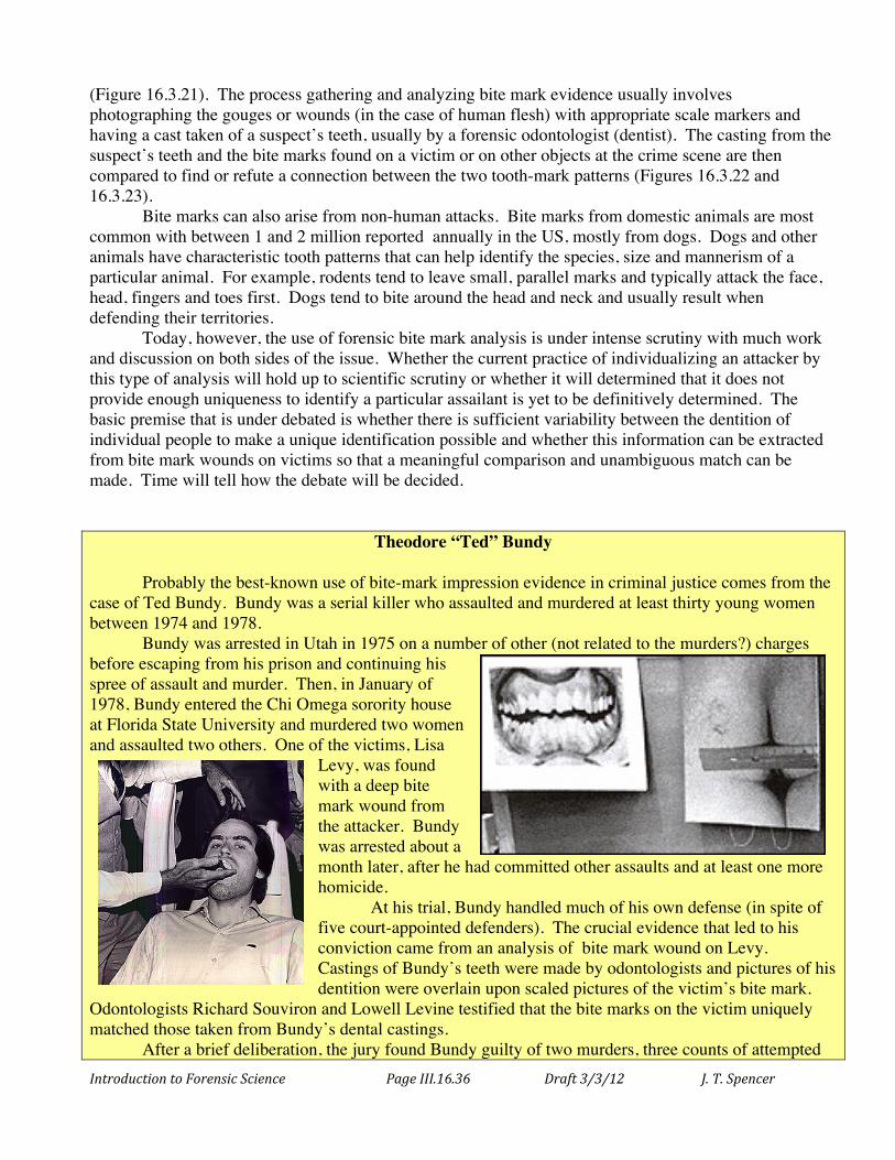
Introduction to Forensic Science Page III.16.36 Draft 3/3/12 J. T. Spencer
(Figure 16.3.21). The process gathering and analyzing bite mark evidence usually involves photographing the gouges or wounds (in the case of human flesh) with appropriate scale markers and having a cast taken of a suspect’s teeth, usually by a forensic odontologist (dentist). The casting from the suspect’s teeth and the bite marks found on a victim or on other objects at the crime scene are then compared to find or refute a connection between the two tooth-mark patterns (Figures 16.3.22 and 16.3.23). Bite marks can also arise from non-human attacks. Bite marks from domestic animals are most common with between 1 and 2 million reported annually in the US, mostly from dogs. Dogs and other animals have characteristic tooth patterns that can help identify the species, size and mannerism of a particular animal. For example, rodents tend to leave small, parallel marks and typically attack the face, head, fingers and toes first. Dogs tend to bite around the head and neck and usually result when defending their territories. Today, however, the use of forensic bite mark analysis is under intense scrutiny with much work and discussion on both sides of the issue. Whether the current practice of individualizing an attacker by this type of analysis will hold up to scientific scrutiny or whether it will determined that it does not provide enough uniqueness to identify a particular assailant is yet to be definitively determined. The basic premise that is under debated is whether there is sufficient variability between the dentition of individual people to make a unique identification possible and whether this information can be extracted from bite mark wounds on victims so that a meaningful comparison and unambiguous match can be made. Time will tell how the debate will be decided.
Theodore “Ted” Bundy Probably the best-known use of bite-mark impression evidence in criminal justice comes from the case of Ted Bundy. Bundy was a serial killer who assaulted and murdered at least thirty young women between 1974 and 1978. Bundy was arrested in Utah in 1975 on a number of other (not related to the murders?) charges before escaping from his prison and continuing his spree of assault and murder. Then, in January of 1978, Bundy entered the Chi Omega sorority house at Florida State University and murdered two women and assaulted two others. One of the victims, Lisa
Levy, was found with a deep bite mark wound from the attacker. Bundy was arrested about a month later, after he had committed other assaults and at least one more homicide. At his trial, Bundy handled much of his own defense (in spite of five court-appointed defenders). The crucial evidence that led to his conviction came from an analysis of bite mark wound on Levy. Castings of Bundy’s teeth were made by odontologists and pictures of his dentition were overlain upon scaled pictures of the victim’s bite mark.
Odontologists Richard Souviron and Lowell Levine testified that the bite marks on the victim uniquely matched those taken from Bundy’s dental castings. After a brief deliberation, the jury found Bundy guilty of two murders, three counts of attempted

Introduction to Forensic Science Page III.16.37 Draft 3/3/12 J. T. Spencer
first-degree murder, and two counts of burglary. Six months later, Bundy was also tried and convicted of the murder of 12-year old Kimberly Leach in Orlando, Florida. The judge ordered Bundy executed on the murder convictions. After exhausting all possible appeals, Bundy finally agreed to talk with investigators where he confessed to (but without ever taking the responsibility for) over thirty murders, including some that investigators were not even aware of. Bundy was ultimately executed for his crimes on Jan. 24, 1989.

Introduction to Forensic Science Page III.16.38 Draft 3/3/12 J. T. Spencer
Chapter 16 References and Bibliography Association of Firearm and Tool Mark Examiners, AFTE Glossary, 1994. Brian J. Heard, Handbook of Firearms and Ballistics, John Wiley and Sons, 1997. Tom Warlow, Firearms, the Law, and Forensic Ballistics (2nd Ed.), CRC Press, 2005. Robert A. Rinker, Understanding Firearm Ballistics (6th Ed.), Mulberry House Publ. Com., 2005. Edward E. Hueske, Practical Analysis and Reconstruction of Shooting Incidents, CRC Press, 2005. Lucien C. Haag, Shooting Incident Reconstruction, Academic Press, 2006. William J. Bodziak, Footwear Impression Evidence: Detection, Recovery and Examination (2nd Ed.),
CRC Press, 1999. David S. Pierce, Mechanics of Impression Evidence, Auerbach Publications, 2011. Raymond J. Johansen, Raymond Johansen and C. Michael Bowers, Digital Analysis of Bite Mark
Evidence, Forensic Imaging Inst., 2000. C. Michale Bowers, Forensic Dental Evidence (2nd Ed.), Academic Press, 2010.
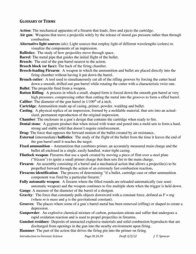
Introduction to Forensic Science Page III.16.39 Draft 3/3/12 J. T. Spencer
GLOSSARY OF TERMS Action: The mechanical apparatus of a firearm that loads, fires and ejects the cartridge. Air gun: Weapons that move a projectile solely by the release of stored gas pressure rather than through
combustion. Alternative light sources (als): Light sources that employ light of different wavelengths (colors) to
visualize the components of an impression. Ballistics: The study of how projectiles move through space. Barrel: The metal pipe that guides the initial flight of the bullet. Breech: The end of the gun barrel nearest to the action. Breech block (or face): The back of the firing chamber. Breech-loading Firearm: A weapon in which the ammunition and bullet are placed directly into the
firing chamber without having it put down the barrel. Broach cutter: A tool used to simultaneously cut all of the rifling grooves by forcing the cutter head
down a smooth, drilled-out gun barrel while rotating the cutter with a characteristic twist rate. Bullet: The projectile fired from a weapon. Button Rifling: A process in which a small, shaped form is forced down the smooth gun barrel at very
high pressures, compressing rather than cutting the metal into the grooves to form a rifled barrel. Caliber: The diameter of the gun barrel in 1/100th of a inch. Cartridge: Ammunition made up of casing, primer, powder, wadding and bullet. Casting: A physical replica of an impression, formed by a moldable material, that sets into an actual-
sized, permanent reproduction of the original impression. Chamber: The enclosure in a gun’s design that contains the cartridge when ready to fire. Dental stone: A gypsum product that when mixed with water and pored into a mold sets to form a hard,
strong and stable solid that doesn’t require reinforcement. Drag: The force that opposes the forward motion of the bullet created by air resistance. External (intermediate) ballistics: The study of the flight of the bullet from the time it leaves the end of
the gun barrel until it reaches the target. Fixed ammunition – Ammunition that combines primer, an accurately measured main charge and the
bullet all enclosed in a single, easily handled, water-tight casing. Flintlock weapon: Firearms that use a spark created by moving a piece of flint over a steel plate
(“frizzen”) to ignite a small primer charge that then sets fire to the main charge. Firearm: An assembly consisting of a barrel and a mechanical action that allows a projectile(s) to be
propelled forward through the action of an extremely fast combustion reaction. Firearms identification: The process of determining “if a bullet, cartridge case or other ammunition
component was fired by a particular firearm.” Fully automatic weapon: A firearm where the filled rounds are reloaded automatically (see semi-
automatic weapon) and the weapon continues to fire multiple shots when the trigger is held down. Gauge: A measure of the diameter of the barrel of a shotgun. Gravity: The force that constantly pulls objects downward with a constant force, defined as F = mg
(where m is mass and g is the gravitational constant). Grooves: The places where some of a gun’s barrel metal has been removed (rifling) or shaped to create a
depression. Gunpowder: An explosive chemical mixture of carbon, potassium nitrate and sulfur that undergoes a
rapid oxidation reaction and is used to propel projectiles in firearms. Gunshot residues: Deposits of unreacted explosive materials and solid combustion byproducts that are
discharged from openings in the gun into the nearby environment upon firing. Hammer: The part of the action that drives the firing pin into the primer on firing.
Introduction to Forensic Science Page III.16.40 Draft 3/3/12 J. T. Spencer
Handgun: Smaller firearms that are designed for operation using one hand. Impression evidence: Items of evidence that carry the lasting and observable marks from contact with
another object. Internal (initial) ballistics: The consideration of the part of a bullet’s path that occurs within the gun
itself. Kinetic energy: The energy of motion that is given by the expression of KE = ½ mv2 (where m is the
mass and v is the velocity of the moving object). Lands: The portions of the inside surface of a rifled gun barrel that project farthest into the center of the
barrel adjacent to grooves. Latent impression: Impression evidence that is not immediately observable but which can be made
visible using a variety of techniques. Long gun: A category of firearms with relatively long barrels that includes rifles. Magazine: A device for holding and delivering cartridges. Magnum: A cartridge containing more than the standard amount of powder which delivers more power
to the bullet. Mandrel: A rod-shaped, grooved template with raised ribs corresponding to the desired rifling
grooves; a slightly oversized, smooth gun barrel is compressed or hammered into shape around the mandrel leaving the formation of grooves and lands inside the barrel when the mandrel is removed.
Muzzle: The very end of the gun barrel where the bullet exits the weapon. Muzzle-loading firearm: A weapon in which the bullets and ammunition are loaded directly down the
barrel of the gun. National Integrated Ballistics Information Network (NIBIN): A database used to compare stored
firearm pattern information with unknown (crime scene recovered) patterns. Negative image: An image formed when some material covering a surface is material is removed by
contact. Oblique lighting: Light that comes in at a low (or oblique) angle relative to the surface. Percussion cap: A small metal case containing a tiny amount of shock sensitive explosive, such as
mercury fulminate that when struck sets off the main charge of the ammunition. Plastic: A moldable material. Plastic impressions: Impression evidence that have been formed when an object is imprinted into a soft,
moldable material. Polygonal rifling: An alternative to the traditional lands and grooves rifling where “hills” and “valleys”
form a more rounded, polygonal pattern. Positive image: An image created when an object leaves something behind on the surface which can be
visualized. Powder: The solid explosive used to propel the bullet. Primer: The shock sensitive compound that ignites the main charge of a cartridge upon being struck. Revolver: A firearm in which ammunition is moved into place for firing by means of rotating a cylinder
that contains a number of separate firing chambers loaded with filled cartridges. Rifling: Spiral grooves inside of the gun’s barrel which cause the projectile to spin about its long-axis. Round: An intact unit ammunition (primer, bullet or “slug” and main charge). Semi-automatic weapon: A firearm in which the energy released from one firing mechanically ejects
the spent case and reloads the next fresh round into the firing chamber; one round is fired for each pull of the trigger.
Serial number restoration: The process of making visible serial numbers stamped into a gun that have been filed or ground away.
Introduction to Forensic Science Page III.16.41 Draft 3/3/12 J. T. Spencer
Shotgun: A type of long gun without rifling that uses ammunition containing either many small pellets (shot) packed into a single cartridge or a single, solid projectile (slug).
Shrapnel: Fragments of metal from a bomb, shell or mine. Sight: The device on top of a gun that improves aim and accuracy. Silencer: A device, placed over the muzzle, that reduces the noise emitted by firing a weapon. Spin (or gyroscopic) stabilization: The rotational movement of an elongated projectile around its long
axis which greatly improves its aerodynamic properties allowing it to go much farther and with increased precision and accuracy.
Stock: Frame that hold the barrel and action together to allow aiming and firing. Stria (striations): Tiny, random imperfection marks transferred between two objects that pass with direct
contact. Terminal Ballistics: The study of what happens when a projectile hits its target. Three-dimensional impression: Impressions that occur when an object comes into contact with a soft or
moldable substance to leave behind an exact three-dimensional imprint of the original object. Twist rate: The length of a gun barrel in which the rifling makes one full rotation (360°). Two-dimensional impression: Impressions that occur when an object comes into direct contact with a
hard surface or material that is not indented or molded by contact with the object but onto which patterns can be transferred by the deposition or removal of materials.
Visible impressions; Impression evidence that is readily observable without any visualization aids.
Introduction to Forensic Science Page III.16.42 Draft 3/3/12 J. T. Spencer
QUESTIONS FOR FURTHER PRACTICE AND MASTERY 16.1. Land and groove marks on a recovered bullet arise from
(a) the rifling in the gun’s barrel. (b) the striations in the gun barrel’s walls. (c) the impression from the firing pin. (d) the impression of the breechblock of the gun. (e) all of the above.
16.2. What is meant by terminal ballistics. 16.3. Explain the difference between muzzle loading firearms and breech loading firearms. 16.4. What is the function of a percussion cap? 16.5. What is fixed ammunition and what are its advantages? 16.6. What is rifling and what effect does it have on a bullet? 16.7. What is the difference between a pistol and a revolver? 16.8. What is the difference between a semi-automatic and a fully automatic weapon? 16.9. What are the lands and grooves in a rifle barrel? 16.10. What is polygonal rifling? 16.11. What is meant by twist rate? What effect does increasing the twist rate have on a projectile? 16.12. What are some of the features of a shotgun that distinguish it from a rifle? 16.13. How is the caliber of a gun determined? Why are bullets referred to by caliber? 16.14. What is meant by the term ballistics? 16.15. What are the three “phases” of ballistics for a projectile? Explain each phase. 16.16. What are the typical methods for rifling a gun barrel? 16.17. What information can a forensic scientist determine from examining a fired bullet? 16.18. What are stria and how do they occur? 16.19. What identifying information can be obtained from a bullet casing that may connect it to a
particular weapon? 16.20. What is gunshot residue (GSR)? 16.21. A forensic technician studies the GSR pattern at a crime scene. The technician measures the
pattern of the GSR on objects leading up to the victim. After conducting a comparison test with the murder weapon, what conclusions can be drawn about the position of the killer relative to the victim?
16.22. What two chemicals are typically used when trying to restore an illegible gun serial number? 16.23. What is the fundamental principle being used with regard to metal crystal structure in serial
number restoration through chemical treatment? 16.24. What is the difference between a positive impression and negative impression? 16.25. What are the three basic types of impressions? Explain the differences and give examples. 16.26. What methods are used to process impressions? 16.27. How do alternative light sources aid in photographing impressions? 16.28. What is the preferred medium used for making a forensic casting? What are its advantages over
the old plaster of Paris medium? 16.29. What information about a suspect might be determined from (a) the size of a shoe print (b) the
distance between shoe prints (c) the depth of the heel and toe imprints? 16.30. What identifying markers are looked for when analyzing tire impressions at a crime scene? 16.31. What are tool marks? 16.32. What is the debate in the legal community about bite mark impressions as admissible evidence?
Related Documents