Copyright © 2017 Cengage Learning®. All Rights Reserved. May not be scanned, copied, or duplicated, or posted to a publicly accessible website, in whole or in part. Chapter Tests and Problems CHAPTER 6 LINES AND LETTERING TEST INSTRUCTIONS Answer the questions with short, complete statements or draw- ings as needed. QUESTIONS Part 1: Lines 1. Identify the ASME document that governs line standards. 2. What are construction lines used for, and how should they be drawn? 3. Discuss line uniformity and line contrast. 4. Should there be any difference in line darkness? 5. What is the recommended thickness of object lines? 6. What do hidden lines represent on a drawing? 7. Describe two functions that centerlines serve on a drawing. 8. Extension lines are thin lines that are used for what purpose? 9. Where should the extension lines begin in relationship to the object and end in relation to the last dimension line? 10. Describe leaders. 11. What is the correct length-to-width ratio of a properly drawn arrowhead? 12. Should arrowheads on a drawing all be the same size? Why? 13. Describe the difference between a cutting-plane and a viewing-plane line. 14. Should cutting-plane lines be drawn thick or thin? 15. Discuss the recommended spacing and angle of section lines. 16. List two uses for phantom lines. 17. What type of line is used to indicate that a portion of a sur- face or feature will receive a specific treatment? 18. Describe the line thicknesses recommended by the ASME standard. 19. How can you draw parallel lines that are very close together, so the space between the lines does not fill in when the drawing is reproduced? 20. Give another name for visible lines, describe their purpose on a drawing, and give their recommended thickness. Part 2: Line Identification Given the print on page 217, identify the lines labeled A through M. Part 3: Lettering 1. What type of lettering characters are recommended by ASME for engineering drafting? 2. According to ASME standards, what are the minimum rec- ommended lettering heights? 3. Define font. 4. Identify two terms that are used for lettering in CADD terminology. 5. Identify the ASME recommended inch and metric units. 6. Provide the general note placed on drawings to identify the predominant units used on the drawing. 7. Identify the ASME document that provides the recom- mended lettering standards. 8. Describe how decimal points should be treated when placed in numerals. 9. Identify the drafting disciplines that commonly use frac- tions on drawings, and describe the options used for dis- playing fractions on drawings. 10. Give the recommended slant for inclined lettering, and identify at least one drafting discipline where inclined let- tering is used. 11. Briefly describe lettering legibility requirements on a drawing. 12. Explain what the ASME standard recommends for the spac- ing of letters in words, between words, and between lines of lettering. 13. Define the term default and give an example related to lettering. 59728_ch06_EOC_ptg01.indd 1 03/02/16 10:23 am

Welcome message from author
This document is posted to help you gain knowledge. Please leave a comment to let me know what you think about it! Share it to your friends and learn new things together.
Transcript

Copyright © 2017 Cengage Learning®. All Rights Reserved. May not be scanned, copied, or duplicated, or posted to a publicly accessible website, in whole or in part.
Chapter Tests and Problems
ChaPTer 6 Lines and LeTTering TesT
INSTRUCTIONS
Answer the questions with short, complete statements or draw-ings as needed.
QUESTIONS
Part 1: Lines
1. Identify the ASME document that governs line standards.
2. What are construction lines used for, and how should they be drawn?
3. Discuss line uniformity and line contrast.
4. Should there be any difference in line darkness?
5. What is the recommended thickness of object lines?
6. What do hidden lines represent on a drawing?
7. Describe two functions that centerlines serve on a drawing.
8. Extension lines are thin lines that are used for what purpose?
9. Where should the extension lines begin in relationship to the object and end in relation to the last dimension line?
10. Describe leaders.
11. What is the correct length-to-width ratio of a properly drawn arrowhead?
12. Should arrowheads on a drawing all be the same size? Why?
13. Describe the difference between a cutting-plane and a viewing-plane line.
14. Should cutting-plane lines be drawn thick or thin?
15. Discuss the recommended spacing and angle of section lines.
16. List two uses for phantom lines.
17. What type of line is used to indicate that a portion of a sur-face or feature will receive a specific treatment?
18. Describe the line thicknesses recommended by the ASME standard.
19. How can you draw parallel lines that are very close together, so the space between the lines does not fill in when the drawing is reproduced?
20. Give another name for visible lines, describe their purpose on a drawing, and give their recommended thickness.
Part 2: Line Identification
Given the print on page 217, identify the lines labeled A through M.
Part 3: Lettering
1. What type of lettering characters are recommended by ASME for engineering drafting?
2. According to ASME standards, what are the minimum rec-ommended lettering heights?
3. Define font.
4. Identify two terms that are used for lettering in CADD terminology.
5. Identify the ASME recommended inch and metric units.
6. Provide the general note placed on drawings to identify the predominant units used on the drawing.
7. Identify the ASME document that provides the recom-mended lettering standards.
8. Describe how decimal points should be treated when placed in numerals.
9. Identify the drafting disciplines that commonly use frac-tions on drawings, and describe the options used for dis-playing fractions on drawings.
10. Give the recommended slant for inclined lettering, and identify at least one drafting discipline where inclined let-tering is used.
11. Briefly describe lettering legibility requirements on a drawing.
12. Explain what the ASME standard recommends for the spac-ing of letters in words, between words, and between lines of lettering.
13. Define the term default and give an example related to lettering.
59728_ch06_EOC_ptg01.indd 1 03/02/16 10:23 am
Copyright © 2017 Cengage Learning®. All Rights Reserved. May not be scanned, copied, or duplicated, or posted to a publicly accessible website, in whole or in part.
2X
.30
0
1.7
40
2.3
00
4X
.7
5
2X
.2
50
-20
UN
C-2
BS
HO
WN
4X
30
6.2
0
R2
.10
03
5
2X
11
3
1.7
00
.12
0
.40
0
2X
R1
.95
0
R1
.85
2±.
00
1
VIE
WA
-A
3.1
0
2X
1.2
3
(3.5
8)
R1
.80
5
15
30
2
X 6
7
1.7
0
.50
0
6X
.1
38
-32
UN
C-2
B.2
5 M
IN
A
2X
.2
50
-20
UN
C-2
B.3
0 M
IN
.10
R.2
5
2.1
00
.95.5
0
2.1
00
30
2X
67
2X
.4
0
2.3
50
.03
0
.06
05
.40
0.4
4 M
IN
2X
11
3
2.7
00
R2
.35
0
2X
.1
25
2.3
50
4X
ÿ.2
70
± .0
10
TH
RU
ÿ.4
4.4
3
5
.42
0
2.0
00
2X
60
4X
R3
.00
0
.60
1.7
0
1.2
5
A.12
X 4
5
5
5X
.2
80
SH
OW
NS
HO
WN
ÿ.2
8ÿ
.44
5X
ÿ.1
80
TH
RU
ÿ.3
12
.25
PR
OJE
CT
:
DR
AW
N
CH
EC
K
DE
SIG
N
EN
GR
AP
PR
DA
TE
TIT
LE
SIZ
EC
AG
ED
WG
. N
O.
SC
AL
EP
RIN
TE
D:
RE
VIS
ION
S
DE
SC
RIP
TIO
NZ
ON
ELT
RD
AT
EA
PP
RO
VE
D
RE
VD
WG
NO
.
Po
rtla
nd
Or
97
22
41
65
05
SW
72
nd
Ave
FL
IR S
yste
ms
Inc.
CA
LC. W
T.
FIN
ISH
MA
TE
RIA
L
DIM
EN
SIO
NS
AR
E I
N I
NC
HE
SU
NL
ES
S O
TH
ER
WIS
E S
PE
CIF
IED
DE
CIM
ALS
.XX
.XX
XH
OLE
ˇ .X
X.X
XX
AN
GLE
S
0 3
0'B
EN
DS
±2
PE
RP
EN
D.
.00
3/IN
CO
NC
EN
.003
/IN
FR
AC
TIO
NS
±1/
32S
TR
AIG
HT
NE
SS
&/O
R F
LA
TN
ES
S:
.00
5/I
NT
HR
EA
DS
:E
XT
ER
NA
L-C
LA
SS
2A
INT
ER
NA
L-C
LA
SS
2B
AN
GL
ES
,BE
ND
S,
& I
NT
ER
SE
CT
ION
S:
90
M
AC
HIN
ED
SU
RF
AC
ES
:
SA
MP
LE
S M
US
T B
E A
PP
RO
VE
D B
Y E
NG
.P
RIO
R T
O S
TA
RT
ING
PR
OD
UC
TIO
N
DO
NO
T S
CA
LE
DR
AW
ING
63O
R B
ET
TE
R
DW
G2
RE
V2
AL
L D
IME
NS
ION
S I
N [
] A
RE
MM
± .00
5.0
03.0
01
±.01
5±.
005
7
A
56
84
12
3
BCD
ABCD
56
78
41
3
RE
V
11
SH
EE
T
OF
1:1
DAT
ED
RA
WN
PR
OJE
CT
D6
48
69
NO
TE
S:
+ -L
EN
S M
TG
SA
DD
LE
- T
EL
ES
CO
PE
.05
TH
ICK
AL
50
52
-H3
2
MIL
-C-5
541,
CL3
CH
EM
FIL
M P
ER
CO
NT
RA
ST
ING
CO
LOR
, .1
2 in
. H
IGH
GO
TH
IC S
TY
LE C
HA
RA
CT
ER
S,
INC
LUD
EID
EN
TIF
Y I
AW
MIL
-ST
D-1
30,
BY
RU
BB
ER
ST
AM
P O
R H
AN
D M
AR
K,
PA
RT
TO
BE
FR
EE
OF
BU
RR
S A
ND
SH
AR
P E
DG
ES
.
DIM
EN
SIO
NS
AN
D T
OLE
RA
NC
ES
PE
R A
SM
E Y
14.5
-200
9.
LAT
ES
T R
EV
LE
VE
L: 6
4869
-XX
XX
XX
XX
RE
V_.
LO
CA
TE
AP
PR
OX
AS
SH
OW
N.
INT
ER
PR
ET
DR
AW
ING
IA
W M
IL-S
TD
-100
.
3. 42.1.
G
L
I
J
H
F
C
E
D
B
A
K
M
59728_ch06_EOC_ptg01.indd 2 03/02/16 10:23 am
Copyright © 2017 Cengage Learning®. All Rights Reserved. May not be scanned, copied, or duplicated, or posted to a publicly accessible website, in whole or in part.
14. Define justification.
15. What does the term single stroke mean with regard to free-hand lettering?
ChaPTer 6 Lines and LeTTering ProbLems
LINE PRObLEmS
Part 1: Problems 6.1 Through 6.11
1. Using the selected engineer’s layout as a guide only, create an original drawing following your course objectives. Make a preliminary sketch if required by your instructor. Draw only the object lines, centerlines, hidden lines, and phantom lines as appropriate for each problem. Do not draw dimen-sions. Keep in mind that the engineer’s sketches are rough and not meant for tracing.
2. Complete the drawing using the correct line standards de-scribed in this chapter.
3. Use an appropriately sized ASME sheet and use ASME sheet blocks. Complete the title block.
a. The title of the drawing is given.b. The material the part is made of is given.c. The drawing or part number is the same as the problem
number.d. Specify the scale and other unspecified information.
4. Reproduce your drawing for checking unless otherwise specified by your instructor.
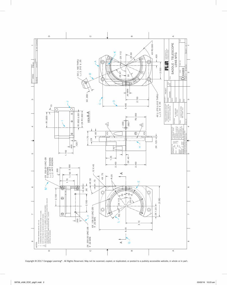
Problem 6.1 Object lines (in.)Part Name: PlateMaterial: .25-in.-thick mild steel (MS)
3.5
9.0
4.05.5
8.0
3.5
6.0
6.5
7.0
2.0
3.5
5.5
1.01.5
5.0
2.5
2.0
Problem 6.2 Straight object lines only (in.)Part Name: Milk StencilMaterial: .015-in.-thick wax-coated cardboard. Used as a stencil to spray paint identification on crates of milk.
(CUT
OUT)
(CU
T O
UT)
(CU
T O
UT)
(CUT O
UT)
1/2
1/4
1/2
1/2 1/2
1 1/2 3/4
1/2
9 3/4
1
3 3/4
3/4
62º
3/4 1 3/41/2 1/2
30º
40º
1/2
1 3/4
1/2
30º
1 1/23/455º
CENTERLINE
5 3/4
59728_ch06_EOC_ptg01.indd 3 03/02/16 10:23 am
Copyright © 2017 Cengage Learning®. All Rights Reserved. May not be scanned, copied, or duplicated, or posted to a publicly accessible website, in whole or in part.
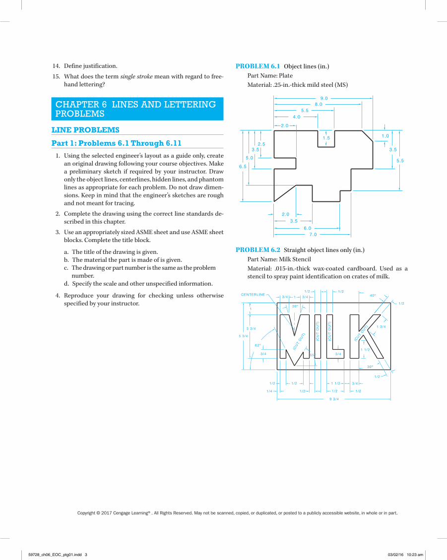
Problem 6.3 Arcs, object lines, and centerlines (in.)
Part Name: Latch
Material: .25-in.-thick mild steel
8 5/8
R12
67 3/8
2848
23 5/8
Problem 6.4 Circle, object lines, and centerlines (in.)
Part Name: Stove Back
Material: .25-in.-thick mild steel
3.0
6.0
4.0
23.0
18.0
24.0
12.0
708
Ø6.0
Problem 6.5 Circle and arc object lines and centerlines (in.)
Part Name: Bogie Lock
Material: .25-in.-thick mild steel
10 3/1613
17 3/16
8
Ø5 1/2
R7
R1 1/2
2
29 1/2
59
Problem 6.6 Circle and arc object lines and centerlines (metric)
Part Name: T-Slot Cleaner
Material: 6-mm-thick cold rolled steel (CRS)
12
6R13
R3
Ø10
R14
10
125
44
28
Problem 6.7 Circle and arc object lines and centerlines (in.)
Part Name: T-Slot Cleaner
Material: .25-in.-thick cold rolled steel
.500
.250R.500
R.125
Ø.375
R.562
4.938
1.750
.375
1.125
Problem 6.8 Arcs, circles, and centerlines (in.)
Part Name: Bracket
Material: Stainless steel
5.000
3.875
R1.125
.500
.500.625
2X Ø.250
.375
.750
.500
3.250
1.625
.625
2.00
.250
1.3751
59728_ch06_EOC_ptg01.indd 4 03/02/16 10:23 am

Copyright © 2017 Cengage Learning®. All Rights Reserved. May not be scanned, copied, or duplicated, or posted to a publicly accessible website, in whole or in part.
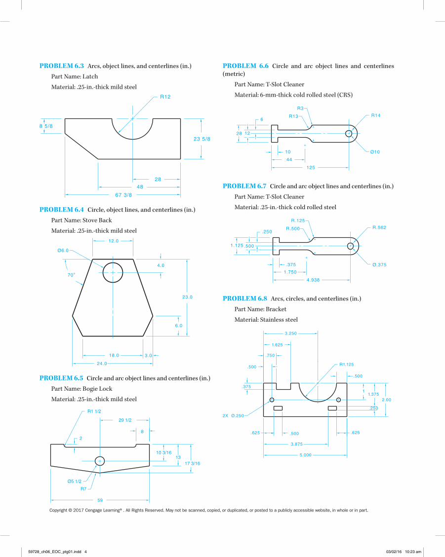
Problem 6.9 Arcs, circles, and centerlines (in.)
Part Name: Bracket
Material: Mild steel
1.375 1.375 1.375
1.50.531
1.00
.281
3.125
4.687
2X R.781
6X Ø.218
2X Ø.531
Problem 6.10 Arcs, centerlines, and hidden lines (in.)
Part Name: Pin
Material: Phosphor bronze
LETTERINg PRObLEmS
Part 2: Problems 6.12 Through 6.14
Use a Gothic lettering style such as Arial, Century Gothic, RomanS, or SansSerif unless otherwise specified by your instruc-tor. Use text .12-in. (3-mm) high. Space lines of lettering .12 in. apart unless otherwise specified by your instructor. Reproduce your drawing for checking unless otherwise specified by your instructor.
Problem 6.12The standard for lettering was established in 1935 by the Ameri-can National Standards Institute. This standard is now conveyed by the American Society of Mechanical Engineers Document ASME Y14.2, Line Conventions and Lettering. Letters and num-bers should be opaque and clearly spaced. Lettering can be verti-cal or inclined, but only one style should be used throughout the
Ø.380
4X .090
3X Ø.420Ø.540
Ø.550 Ø.320Ø.385
R .020
2.120
1.900
.350
.400
3X Ø.400
R .020
Problem 6.11 Multiviews (2 views), object lines, and hidden lines (in.)
Part Name: V-block
Material: 4.00-in.-thick mild steel
2.000
.100.375
.500
1.000
.250
45º
4.000
.250
.250
.125
.250.250
2.000
59728_ch06_EOC_ptg01.indd 5 03/02/16 10:23 am

Copyright © 2017 Cengage Learning®. All Rights Reserved. May not be scanned, copied, or duplicated, or posted to a publicly accessible website, in whole or in part.
drawing. Uppercase letters are used on drawings unless lower-case letters are required for a specific application. The lettering style used when revising a drawing should match the original drawing lettering style.
Problem 6.13According to ASME Y14.2, the minimum recommended lettering height depends on the drawing-sheet size and the application on the drawing. Typically, lettering height on engineering drawings is .12 in. (3 mm). All dimension numerals, notes, and other let-tered information should be the same height except for titles, drawing numbers, section and view letters, and other captions, which are .24 in. (6 mm) high.
Problem 6.14
NoTeS:
1. Unless otherwise specified, all dimensions are in millimeters.
2. Dimensions and tolerances per ASME Y14.5-2009.
3. Remove all burrs and sharp edges.
4. All fillets and rounds r6.
5. Caseharden 62 rockwell c scale.
6. Areas where material has been removed shall have smooth transitions and be free of scratches, grind marks, and burrs.
7. Finish black oxide.8. Part to be clean and free of foreign debris.
maTh PRObLEmS
Part 3: Problems 6.15 Through 6.19
Problem 6.15 For the illustration of the block shown:
2 14
2 18
1
y1y21
2
14
14
a. Determine dimension y1.b. Determine dimension y2.c. Determine the overall width of 12 of the blocks laid side
to side.d. Convert each of the four given dimensions of the block to
decimal fractions.Problem 6.16 Twenty-five pieces of metal are needed for a job. Each piece is to be 3 3/320 in length. Disregarding the cutting loss, what length of stock is needed?
Problem 6.17 A piece of stock 25 7/80 long is to be cut into five equal lengths. Allowing 1/160 lost per cut, what will be the length of each of the five pieces?
Problem 6.18 A drawing shows a dimension of 4.18750. Convert this decimal fraction to a common fraction.
Problem 6.19 Convert each decimal fraction to a common fraction:
a. 2.50b. .1250c. 14.43750d. 5.750
59728_ch06_EOC_ptg01.indd 6 03/02/16 10:23 am
Related Documents