CHAPTER IX WATER MAINS AND RELATED FACILITIES

Welcome message from author
This document is posted to help you gain knowledge. Please leave a comment to let me know what you think about it! Share it to your friends and learn new things together.
Transcript
CHAPTER IX
WATER MAINS AND RELATED FACILITIES

TOC-IX-3 of 3
CHAPTER IX
WATER MAINS AND RELATED FACILITIES
CHAPTER CONTENTS
Page No.
I. GENERAL........................................................................................................................1
A. Introduction............................................................................................................1 B. Ownership and Responsibility ...............................................................................1
1. County-Maintained Facilities ....................................................................1 2. On-Site Facilities .......................................................................................1
C. Definitions .............................................................................................................1
II. DESIGN CRITERIA .......................................................................................................2
A. General...................................................................................................................2 B. Pre-Design Meeting ...............................................................................................3 C. Demands ................................................................................................................4
1. Residential Demands .................................................................................4 2. Commercial and Industrial Demands.........................................................4 3. Fire Flow Rates ..........................................................................................4
D. Hydraulic Computations ........................................................................................5 1. General.......................................................................................................5 2. Design Flows and Residual Pressures .......................................................5 3. Flow Velocities ..........................................................................................6 4. Hazen-Williams “C” and Minor Losses ....................................................6
E. Distribution System Layout and Sizing .................................................................7 1. General.......................................................................................................7 2. Residential Subdivision (New and Existing) .............................................7 3. Commercial and Industrial Areas ..............................................................7
F. Service Connections ..............................................................................................8 1. Location .....................................................................................................8 2. Sizing .........................................................................................................9 3. Cover..........................................................................................................9 4. Clearances ..................................................................................................9 5. Appurtenances ...........................................................................................9
G. Distribution Mains ...............................................................................................10 1. Location ...................................................................................................10 2. Sizing .......................................................................................................11 3. Cover........................................................................................................11 4. Clearances ................................................................................................11 5. Appurtenances .........................................................................................12 6. Materials ..................................................................................................14
H. Transmission Mains .............................................................................................14 1. Location ...................................................................................................14

WATER MAINS AND RELATED FACILITIES IX-3 of 39
2. Sizing .......................................................................................................14 3. Cover........................................................................................................14 4. Clearances ................................................................................................15 5. Hydraulics ................................................................................................15 6. Appurtenances .........................................................................................15 7. Materials ..................................................................................................15
I. Structural Considerations.....................................................................................16 1. Pipe Bedding............................................................................................16 2. Buttresses and Anchors............................................................................16 3. Restrained Joints ......................................................................................16 4. Jacking and Tunneling .............................................................................17 5. Directional Drilling/Microtunneling........................................................17 6. Design Loads and Pipe Design ................................................................17 7. Curves and Deflections ............................................................................18
J. Testing and Disinfection......................................................................................18 K. Abandonment Procedures ....................................................................................18 L. Potable Water Related Facilities..........................................................................18
1. General.....................................................................................................18 2. References................................................................................................18 3. Production Wells......................................................................................19 4. Potable Water Storage Facilities..............................................................20 5. Water Pumping Stations ..........................................................................29 6. Booster Pumps .........................................................................................33 7. Extended Shaft Turbine (Column) and Submersible Pumps ...................34
M. Programmable Logic Controllers.........................................................................35 1. General.....................................................................................................35 2. RF. Path Study .........................................................................................35 3. Telemetry .................................................................................................35 4. Screen Displays........................................................................................36 5. Communications Protocols ......................................................................36 6. PLC Equipment........................................................................................36
N. Corrosion Protection ............................................................................................36 1. Design professionals shall obtain soil samples and review the analyses of
the samples with the DPW. If proposed pipes will be below or near the water table, the test borings shall be observed for a fluctuating water table. Soil samples shall be tested for pH, resistivity and chlorides, and organic soils shall be tested additionally for sulfides and sulfates. ......................36
2. If soil tests or inspection of existing utilities in the project area reveals evidence of, or potential for corrosion, the DPW shall be notified of the condition. Should the DPW deem it necessary, the design professional shall design suitable trench backfill, coating and/or cathodic corrosion protection measures using AWWA standards and practices for the pipe material selected. .....................................................................................36
3. In all cases proper bedding shall be provided for pipes. Pipes shall not be placed on undisturbed earth. ....................................................................36
4. Backfill which will not damage pipe coatings shall be specified. ...........36
Published: 01/01 Revised:

WATER MAINS AND RELATED FACILITIES IX-4 of 39
5. If a new water main crosses or parallels another utility line which is protected by a cathodic protection system, the design professional is responsible for contacting the other utility and working with its corrosion engineer to design the water main so as to protect the water main from the influence of the other utility’s cathodic protection system and to mitigate any adverse impact which the water main may cause to the existing utility’s cathodic protection system. ........................................................36
O. Repaving of Roads...............................................................................................37 A. Reports .................................................................................................................37 B. Design Computations...........................................................................................37 C. Specifications.......................................................................................................37 D. Contract Drawings ...............................................................................................37
1. General.....................................................................................................37 2. Horizontal Location .................................................................................38 3. Profiles .....................................................................................................38 4. Ground Over/Under Water Main .............................................................38
E. Cost Estimates......................................................................................................38
III. APPENDIX.....................................................................................................................39
A. References............................................................................................................44 B. Check List - Water Drawings ..............................................................................45 C. Basis for Residential Water Demand Projections for Undeveloped or Partially
Developed Areas..................................................................................................49 D. Flow Estimates for Capital Facility Connection Charges....................................50 E. Commercial, Industrial and Institutional Water Use by Zoning..........................51 F. Fire Flow Rates ....................................................................................................52 G. Guidelines for Sizing Building Services and Meters...........................................53 H. Nomograph for Pipes Flowing Full, Hazen-Williams .........................................54 I. Minor Losses of Head in Equivalent Pipe Diameters..........................................55 J. Maximum First Floor Elevations for Each Water Pressure Zone........................56
Published: 01/01 Revised:
IX-1 of 39
ANNE ARUNDEL COUNTY DESIGN MANUAL
CHAPTER IX
WATER MAINS AND RELATED FACILITIES
I. GENERAL
A. Introduction
This Chapter of the Manual outlines the policies, minimum criteria and design procedures for the preparation of feasibility reports and construction plans and specifications for County maintained and on-site potable water system improvements.
B. Ownership and Responsibility
1. County-Maintained Facilities
The parts of the water supply system, which are considered the property, and responsibility of Anne Arundel County are the water mains, appurtenances and that portion of the building water services, which lie in the public rights-of-way. The water supply and distribution system for Anne Arundel County is designed and maintained by the Department of Public Works (DPW).
2. On-Site Facilities
The parts of the building water services, which lie within private property, are the responsibility of the owner and are constructed and maintained by the owner.
C. Definitions
Service Connections: Water mains connecting the distribution mains to individual homes, buildings or facilities for both consumptive use and fire protection.
Long Connections: Special service connections which are 75 ft. or less in length within the public right-of-way or easement.
Distribution Mains: Water mains connecting the transmission mains to the service connections. The distribution mains provide area wide fire protection. Generally the distribution mains will be in a grid or branched configuration.
Transmission Mains: Large diameter mains connecting the treatment plant(s) with the storage facilities and the distribution mains.
Average Day Demand: Average day demand is the volume of water used in the year divided by 365.

WATER MAINS AND RELATED FACILITIES IX-2 of 39
Average Day Rate (Average Day): Average day rate is the average day demand volume divided by a one day time period, expressed in gallons per minute (gpm) or million gallons per day (mgd).
Maximum Day Demand: Maximum day demand is the largest volume of water used in one day during the year.
Maximum Day Rate (Max. Day): Maximum day rate is the water used during the maximum day divided by a one-day time period expressed in gpm or mgd.
Peak Hour Demand: Peak hour demand is the largest volume of water used in one hour. The peak hour demand usually occurs during the day of maximum daily demand.
Peak Hour Rate (Peak Hour): Peak hour rate is the peak hour demand volume divided by 60 minutes, expressed in gpm; or multiplied by 24 hours, expressed as mgd.
II. DESIGN CRITERIA
A. General
The sizing of major components of the County water supply system such as transmission mains, major distribution mains (generally 12 inches diameter and larger), production wells, storage facilities, and booster pumping facilities are the responsibility of the DPW and beyond the scope of this Manual.
The County water system master plan shows the existing and planned supply system components. The design professional should be familiar with and design in accordance with this document.
Construction of production wells is beyond the scope of this Manual, but is outlined in the County’s “Standard Specifications For Production Wells” which may be obtained from the DPW. Size, capacity and aquifer to be accessed shall be determined by the using agency.
The design professional that is responsible for the extensions of distribution mains shall follow the guidelines in this Manual for the derivation of design flows. The calculation of water demands will usually require extension of the average daily rate for the facility, application of a peaking factor to derive the maximum daily rate, then addition of the fire flow requirement. System loses have been accounted for in the peaking factors.
Generally, the design professional will be selecting distribution mains of 12-inch diameter and smaller, and often will be required to provide the minimum size mains listed later in this Chapter.
Published: 01/01 Revised:
WATER MAINS AND RELATED FACILITIES IX-3 of 39
The water design criteria presented herein shall also apply to subdivisions and other developments. The developer should be familiar with the Anne Arundel County Code Article 26, Subdivision, paragraph 2-419, Water, in addition to these design criteria.
B. Pre-Design Meeting
Prior to commencing any design work on a Capital Project, a pre-design meeting will be held as provided in Chapter I, General Instructions. For Developer Projects, a pre-sketch meeting may be held at the request of the developer. These meetings will discuss, at a minimum, the following design parameters pertinent to this Chapter as well as items, which pertain to any other chapters, which will govern the design of the project:
• Sizing of major water supply components. • Applicable plumbing codes. • Route selection and location of the pipe in the public right-of-way. • Interaction with, and crossings of, other known utilities, particularly if those
utilities employ cathodic protection systems. • Methods of crossing roads, railroads, and streams. • Pipe material • Pipe access • DPW requirements for water pumping, treatment and storage facilities, if
applicable. • Identification by DPW of any storage facilities in the network to be affected
by the project whose refill rate is more critical than the design flow rates. • PACE shall advise developers of existing and proposed site conditions in
accordance with County Code Article 26, Subtitle 2, Paragraph 2-202. • Developers shall deliver to PACE a schematic pencil sketch of the proposed
development on a copy of the County’s topographic survey. • DPW will provide information on how existing central master system screen
displays are to be updated for additional Program Logic Controllers (PLC’s). • DPW will advise what reports, if any, need to be updated by additional
PLC’s. • DPW will provide manufacturers and model numbers of existing PLC and
SCADA equipment and software. • DPW will furnish information from preliminary RF path studies for PLC’s. • DPW will direct which communication protocol is to be used for additional
PLC’s. • Design professional shall submit for County approval any non-County
approved PLC equipment and/or software.
Published: 01/01 Revised:

WATER MAINS AND RELATED FACILITIES IX-4 of 39
C. Demands
1. Residential Demands
Studies have shown that the quantity of average daily water use and peaking factor for residential areas are related to lot size. This is due to increases in persons per dwelling unit, per capita consumption, and greater lawn sprinkling as the lot sizes increase. Appendix C shall be used to derive residential demands and peaking rates.
2. Commercial and Industrial Demands
The estimation of average daily water consumption and peaking factors for commercial and industrial demands are greatly dependent on the type of facility. With the exception of industries using process water, the fire demand generally is the major component of the design demand used to size distribution main extensions and service connections to buildings having sprinkler systems. The design professional shall refer to the County Plumbing Code for derivation of building design flows if the number of fixture units is known or may be estimated. When no interior plumbing information is available use Appendix D. For undeveloped land use Appendix E to derive commercial and industrial water demands according to zoning.
3. Fire Flow Rates
The required fire flow rates shall be calculated using the Insurance Service Offices (ISO) method as outlined in their publication Fire Suppression Rating Schedule. The term used for fire flow in that publication is “Needed Fire Flow (NFF).” The ISO method is also presented in the National Fire Protection Association (NFPA) Fire Protection Handbook, latest edition, and the American Water Works Association (AWWA) Manual M31 Distribution System Requirements for Fire Protection, latest edition. Where specific building information is not available for use in the ISO method, use Appendix F.
Recommended fire flow durations shall be as follows in Table IX-1 as presented in AWWA Manual M31:
TABLE IX-1 FIRE FLOW DURATIONS
Required Fire Flow (GPM)
Duration (HR)
2500 or less
2
3000 to 3500
3
4000 to 12,000
4
Published: 01/01 Revised:
WATER MAINS AND RELATED FACILITIES IX-5 of 39
Duration is generally limited to 4 hours for economic reasons. However, special cases may arise which require longer durations for fire flows greater than 4000 gpm as listed in Table 5-3E of the NFPA Fire Protection Handbook. Such special cases shall be brought to the attention of the Deputy Director, Bureau of Utility Operations, DPW, for his review and recommendations.
NFPA Standard 1231 “Water Supplies for Rural and Suburban Areas” may also be used by the design professional as a source of design information for less densely settled areas which according to planning and zoning records may remain less densely settled for the foreseeable future.
D. Hydraulic Computations
1. General
The hydraulic design of water mains shall be in accordance with Pipeline Design for Water and Wastewater, ASCE, 1975, or latest edition thereof, and the additional guidelines and criteria in this Chapter. Refer to Section III, Contract Drawings and Documents, to determine if hydraulic calculations are required. If hydraulic computations are required, the design professional shall first submit the design flows for the site to the DPW. The DPW will then supply the design professional with the residual pressure(s) or elevation(s) at a point(s) on the County’s distribution system nearest the proposed site. The design professional will use this elevation to begin the hydraulic design of any distribution main extensions and onsite service connections.
2. Design Flows and Residual Pressures
Service connections, distribution mains and transmission mains shall be sized in accordance with the County’s Water and Sewer Master Plan as referenced by the County Code. The following three pressure requirements must be met within the distribution system:
• Maximum Day Demand - 40 psi minimum at the curb • Peak Hourly Demand - 30 psi minimum at the curb • Maximum + Fire Flow Demand - 20 psi minimum residual maintained at the
curb
As a guideline, a list of maximum first floor elevations for each water pressure zone, which should ensure adequate water pressure within a normal single-family (2-story) dwelling, is shown in Appendix J.
In some locations the main size will be determined by the flow rate required to refill a storage facility, which may be more critical than the above requirements. The DPW will identify this design condition if applicable.
Published: 01/01 Revised:
WATER MAINS AND RELATED FACILITIES IX-6 of 39
First floor elevations of served facilities shall not exceed the tank overflow elevation minus 120 feet (i.e., maximum first floor elevation in Glen Burnie High Zone = 295' - 120' = 175' above sea level). If this situation is unavoidable, the subdivision shall either be connected to a higher pressure zone, have a new booster pump station constructed, or in an extreme case, have an individual facility booster pump system installed which will be maintained by the building owner.
3. Flow Velocities
Although the flow velocities and direction may vary considerably in distribution mains, there are upper and lower velocity boundaries that indicate to the design professional that design weaknesses may exist. The following are useful guidelines:
a. Velocities greater than 7-fps at design flow - This condition may produce large friction losses and high potential for valve and joint damage due to water hammer.
b. Velocities less than 0.5 fps at design flow - This condition indicates that the main may be oversized. Future maintenance problems may result from siltation at valves and there may be water quality degradation.
4. Hazen-Williams “C” and Minor Losses
The total head loss at the point of discharge for design flows shall be the sum of both friction and minor losses. The elevation difference between the source and discharge point shall be algebraically added to the total head losses.
Head losses for new pipes shall be computed using the nomograph in Appendix H and the following coefficients:
Published: 01/01 Revised:

WATER MAINS AND RELATED FACILITIES IX-7 of 39
TABLE IX-2 HAZEN-WILLIAMS “C” FACTORS
Type Pipe Diameter Hazen-Williams “C”
Service Connections
Copper 3/4"-3" 130
PVC 3/4"-4" 130
DIP 3" 100
Distribution Mains
PVC 6"-16" 120
DIP 4"-8" 100
DIP 10"-12" 110
Transmission Mains
All Material 16"-20" 120
All Material 24" - and larger 130 Minor losses due to fittings and valves shall be included as equivalent lengths of pipe, equivalent pipe diameters as presented in Appendix I, or as fractional losses in velocity head as described in “Pipeline Design for Water and Wastewater”, ASCE, 1975, or other hydraulics texts.
E. Distribution System Layout and Sizing
1. General
Extensions of distribution mains will normally be on a grid basis with interconnecting nodes at street intersections.
2. Residential Subdivision (New and Existing)
The water distribution system for residential areas where fire protection is to be provided shall met the following criteria:
• Maximum length of dead end 6-inch main shall be 600 ft. • Maximum length of dead end 8-inch main shall be 1500 ft.
3. Commercial and Industrial Areas
The water distribution mains for Commercial and Industrial areas where fire protection is to be provided shall meet the following criteria:
• Minimum size shall be 8-inch, except for fire hydrant leads of less than 200 ft. and service connections.
Published: 01/01 Revised:
WATER MAINS AND RELATED FACILITIES IX-8 of 39
• Maximum lengths of dead end 8-inch main shall be 800 ft. • Maximum length of dead end 10-inch mains shall be 2000 ft.
Where design flow rates exceed 1500 gpm, hydraulic computations shall be provided for dead end mains.
F. Service Connections
1. Location
Water house connections shall be built to the meter boxes near the property line for all lots within a proposed development. All adjacent improved lots which are not a part of the proposed development but are to be served by the water line shall be provided with a valved connection to the property line and shown on the contract drawings. Service connections for these lots shall be designed where and as directed by the Deputy Director, Bureau of Utility Operations, Department of Public Works.
Single facility service connections shall be indicated schematically on the drawing(s) 15ft. from the side property line on the high end of the lot. The exact location will be fixed in the field after a conference with the property owner. Twin services shall be placed on the property line separating two houses in single family, attached or detached house subdivisions. Service connections to townhouses shall be dimensioned from the property lines on the drawings.
In the event extenuating circumstances lead to a request for water service connections that are proposed to traverse County rights-of-way, a request for a long connection, or a request for a long connection in lieu of an extension, a formal written request with details must be submitted to the Deputy Director, Bureau of Utility Operations for approval/disapproval.
Long connections will only be considered for approval when no additional connections are anticipated upstream of the requesting or petitioning lot, and it is anticipated the water line will not be extended in the future. Normally, this situation will only exist in cul-de-sacs or dead end streets where, due to topography, the street cannot be extended. The decision to provide a long connection or extend the main line will be handled on an individual basis. The length of connection within the public rights-of-way or easements shall not be more than 75 feet in order to conform to the County Plumbing Code. Connections within private rights-of-way or easements are subject to the County Plumbing Code.
Where water utilities are extended to accommodate development, they shall be extended across the full frontage of the property being serviced. Water main extensions less than 4 inches in diameter will not be permitted and will not be considered as long connections.
Published: 01/01 Revised:
WATER MAINS AND RELATED FACILITIES IX-9 of 39
2. Sizing
The minimum size for any service connection shall be 3/4 inch. For large homes and other buildings, larger connections are required. These connections shall be sized based on the County Plumbing Code. Appendix G is a table for selection of the meter size.
3. Cover
Cover over service lines shall be as indicated in the Standard Details measured from finished grade.
4. Clearances
Water house services shall ordinarily be placed 7 ft. horizontally from sewer house connections and a minimum of 1 ft. clear above the sewer house connection. If ductile iron or PVC rubber gasketed joint pipe is used for the sewer connections, the water connections may be placed not less than 1.5 ft. clear horizontally and 1 ft. clear above sewer services.
5. Appurtenances
a. Meters and Vaults: In new and existing subdivisions with curbed streets, meter boxes shall be located 2.5 ft. behind face of curb for standard straight-faced curbs and 3.0 ft. behind the flow line of the gutterpan for standard mountable curbs and gutters. In existing developed areas, without curbed streets, meter boxes shall be located 3 ft. from the property line in the public right-of-way. In roads with a drainage ditch, meter shall be located 3 ft. from the edge of the ditch between the ditch and property line. (See Standard Details). Meter box installation shall be as indicated in the Standard Details. Meters shall be sized in conjunction with the sizing of service connections as provided in Appendix G.
Meter types for Commercial, Industrial and Institutional applications shall be determined by the DPW. The sizing and vault piping arrangement for Commercial, Industrial and Institutional meters shall be based on AWWA Manual M6, “Water Meters-Selection, Installation, Testing and Maintenance”, Manual M22, “Sizing Water Service Lines and Meters”, manufacturers design charts and the standard details.
b. Valves: A valve or corporation cock shall be provided on the water main side of each meter installation as indicated in the Standard Details.
c. Backflow Prevention Device: Reduced pressure backflow prevention devices where required by the Plumbing Code, shall be located on the service connection ahead of any outlet. A dual cartridge check valve is required in the meter vault immediately after the meter for all domestic
Published: 01/01 Revised:
WATER MAINS AND RELATED FACILITIES IX-10 of 39
service connections. Refer to AWWA, “Cross Connection and Backflow Prevention”, 1975, for additional design criteria.
1) The backflow preventers shall be located above ground in the facility or structure it is to serve. The backflow preventer shall be installed in accordance with the County Plumbing Code.
2) If the backflow preventer cannot be located in the facility it is to serve, it shall be located in an underground vault which can be completely drained by gravity through a pipeline. The vault drainage pipe shall not be subject to backups and the discharge point shall preferably be visible such that personnel in the area will be able to detect a discharge from the relief valve.
3) If the backflow preventer cannot be located as described in 1) and 2) above, the design professional, as a last resort, shall use the location described in 1) or 2) with relief valve discharge piping extended above ground.
A basket strainer with blow-off shall be provided upstream of reduced pressure backflow preventers. Where fire fighting capability (sprinkler systems, fire hydrants) is required or potentially required downstream, an Underwriter’s Laboratory strainer listed for fire lines shall be used in accordance with the Standard Specifications. For non-fire service, the design professional may, with DPW approval, amend the Standard Specification for strainers to accommodate differing downstream requirements. The design professional shall consider head losses through the strainer and backflow preventers in his/her design.
With respect to fire lines, the design professional is reminded that the National Fire Protection Association recommends the first valve on a fire line on private property be an indicating valve. The design professional must, therefore, consider incorporating indicating valves in lieu of, or in addition to, the valve required for backflow preventers.
G. Distribution Mains
1. Location
In new subdivisions and in existing developments with curbs, water mains shall be constructed a minimum of 7 ft. from the centerline of the street right-of-way generally on the side of the street toward high ground (on opposite side of street from the sanitary sewer). Mains shall be located within the pavement area, wherever possible, but no less than 5 ft. from face of curb or proposed curb. See
Published: 01/01 Revised:
WATER MAINS AND RELATED FACILITIES IX-11 of 39
Standard Reference Drawing Nos. G-8 and G-9 in Appendix B of Chapter I, General Instructions, for normal utility locations.
In existing developments without curbs, the water main location shall generally be located 2 ft. outside of the edge of pavement on the opposite side of the street from the sewer, except that the main shall not be constructed under a future curb. The location of other existing and proposed utilities shall be fully considered.
In parks and public rights-of-way where location of the water main would require removal of trees the design professional shall obtain approval of the State Department of Forestry for tree removal.
Distribution mains may be designed on a curved alignment to reduce the number of bends. Along curves, the water main may be deflected at each joint within the limits given in the Standard Details.
2. Sizing
Distribution mains shall be sized to provide the required design flow rate and residual pressures as detailed in Section II of this Chapter.
3. Cover
Normal cover over distribution mains shall be 4'-0", except at crossings over other utilities where a minimum cover of 3'-0", or a maximum cover of 9'-0", will be allowed.
In new subdivisions cover shall be measured from final grade of the street.
In existing roads or ungraded streets a future profile grade shall be obtained from the DPW. If such profile grade is not available, the design professional shall submit a proposed profile grade for approval by the DPW. If future profile grade is at or below existing surface, cover shall be measured from the future profile grade; if the future profile grade is above the existing surface, cover shall be measured from the existing surface.
In areas outside of existing or planned streets, cover shall be measured from existing grade. The design professional shall thoroughly investigate, and make suitable allowances for likely changes to existing topography. Such changes include future erosion of streambeds or grading of lots.
4. Clearances
a. General: Clearances between water mains and other utilities shall be measured between the outside of pipes.
Water mains shall have a minimum clearance of 1 ft. above a sanitary sewer if the two are crossing at nearly right angles.
Published: 01/01 Revised:
WATER MAINS AND RELATED FACILITIES IX-12 of 39
Where sanitary sewers and water mains are generally parallel and less than 10 ft. apart horizontally, water mains shall be 6 ft. clear above sewers. Where more than 10 ft. apart, water mains shall be above sewers. The design professional shall investigate the possibility of stray current transfer at or near the point where the two pipelines will cross based on the results of the soil tests and whether or not the existing utility is cathodically protected. If the likelihood exists for stray current transfer, the design professional shall provide a resistive bond connection between the proposed distribution main and the existing utility and a cathodic protection system to protect both pipes.
b. Interactive Considerations: In general, existing utilities have prior right to maintain their location. The existence and location of such utilities must be considered when designing new distribution mains. Design professionals shall investigate clearance between distribution mains and other utilities, both existing and future, and whether or not the existing utilities are protected from corrosion by cathodic protection systems. The clearance to other utilities shall be considered when designing a cathodic protection system (if required) for a new distribution main or if the new distribution main might cause interference with an existing cathodic protection system. Water mains shall have a minimum clearance of 1 ft. where crossing other utilities. Water mains shall also have a minimum horizontal separation of 10 ft. to a sanitary sewer, whenever possible, where the two lines are parallel.
Where specified clearance cannot be obtained between sewer and water lines in a new subdivision, or in locations where the sewer is built along streets having existing water mains, the sewers shall be designed with concrete encasement as provided for in Chapter VII, Sanitary Sewers, of this Manual.
c. Underwater Water Main Crossings (15' and wider): Minimum of 2 ft. cover. The main shall be of special construction with flexible watertight joints. A valve shall be placed at each end of the crossing and permanent taps provided at each end for testing purposes. In addition, the valves shall be easily accessible and not subject to flooding. The valves shall be in watertight manholes.
The water main should be installed as nearly horizontal as possible.
5. Appurtenances
a. Valves and Vaults: Mains 4-inch to 16-inch shall have valves of the same size as the main. All valves 16-inch and larger shall have bevel gears and enclosed gear case.
Published: 01/01 Revised:

WATER MAINS AND RELATED FACILITIES IX-13 of 39
Valves shall be installed on the loop or network at such places as to isolate the branch sections as may be necessary. All valves smaller in size than 16-inch shall be resilient seated gate valves. Valves greater than 16-inch may be either gate valves (resilient seated) or butterfly valves. Maximum spacing of valves shall be 1500 ft. Valves shall be installed on all fire hydrant leads as close to the water main as practical. When a small main branches from a larger main, the difference in diameters between the two mains being 4 inches or more, a valve shall be placed on the smaller main, as close as practical to the larger main, except valves at intersections shall be placed on projection of street right-of-way lines.
Refer to the Standard Details for valve vault and road box dimensions.
b. Fire Hydrants: All hydrants shall be a minimum of 6-inch diameter. Hydrants on large mains shall be 8-inch if directed by the DPW. Where 8-inch fire hydrants are specified, the design professional shall submit to the DPW a 1 in. = 200 ft. scale map showing location of 8-inch fire hydrants for transmittal to the Anne Arundel County Fire Administrator. The connection from the main to the hydrant shall be the same diameter as the nominal inside diameter of the hydrant.
Spacing of hydrants shall be in accordance with the Insurance Services Office (ISO) “Fire Suppression Rating Schedule”, latest edition. Hydrants shall be located at street intersections wherever possible.
Hydrants not at intersections shall be located in relation to property lines in order to avoid interference with driveways. Hydrants shall be located to provide vehicular clearance from the street and pedestrian safety in accordance with the Standard Details. Elevations shall be such as to protect the breakaway characteristics of the hydrant.
Hydrants shall be placed at the end of dead-end lines 6-inches in diameter and larger.
c. Tapping Sleeves and Valves: Tapping sleeves and valves on water mains to serve as line valves shall be used for all connections 8 inch and larger in diameter to any existing main where more than 10 domestic services would be shut off during installation of a standard tee. The main being tapped may be the same size as the proposed main or tapping valve but the tapping cutter shall be ¼ inch or more undersized. Tapping sleeves shall be furnished, installed, and tested by the contractor. Use of mechanical joint sleeves will be permitted only upon written authorization of the DPW and will be considered only where pipe being tapped is new ductile iron pipe. Valve boxes or vaults for tapping sleeves shall be sized in accordance with the Standard Details.
Published: 01/01 Revised:

WATER MAINS AND RELATED FACILITIES IX-14 of 39
d. Blow-offs and Air Release Valves: A blow-off shall be installed at the end of each dead end main less than 6-inches in diameter. A temporary hydrant may be installed where a main will be extended in reasonably short time. Air release valves shall be installed at prominent peaks on long distribution mains where there are no service connections. Air release valves will generally not be required for distribution mains. Where required, air release valves shall be installed in accordance with the Standard Details.
6. Materials
All distribution mains shall be ductile iron or PVC with standard mechanical joints or push-on joints. Ductile iron pipe, fittings and linings shall meet the requirements of AWWA Standards, Section C100. PVC pipe and fittings shall meet the requirements of AWWA Standards, Section C900. Other materials may be used if approved by the DPW. At bridge crossings steel pipe shall be used and shall have a fusion bonded epoxy lining in accordance with AWWA Standard C213. Steel pipes 16 inches in diameter and smaller shall also have a frost proof covering. Steel pipe, fittings, coatings and linings shall meet the requirements of AWWA Standards, Section C200. Expansion joints, insulated couplings and rollers shall be provided as required on bridges.
H. Transmission Mains
1. Location
The approximate location of transmission mains shall be based on a computerized network analysis by the DPW. This analysis shall indicate the beginning and ending points of the main and the major distribution system intersecting nodes. The design professional shall select an alignment which satisfies the approximate location as determined in the DPW analysis while taking into consideration length of pipe, number and type of fittings, public or private property, construction and maintenance access, future road widening, horizontal and vertical alignment changes, flood prone areas, subsurface conditions, and existing and future utility interferences.
2. Sizing
The size of transmission mains shall be based on the computerized network analysis by the DPW.
3. Cover
Normal cover for transmission mains shall be 4 ft., except where existing utilities are crossed, where the minimum will be 3 ft. Maximum cover will be 9 ft., except where authorized by the DPW.
Published: 01/01 Revised:

WATER MAINS AND RELATED FACILITIES IX-15 of 39
4. Clearances
See Section II.F.4. of this Chapter.
5. Hydraulics
System hydraulic gradient, static and residual pressures, velocities, and flow direction will be provided by the DPW. The design professional, if requested by the DPW, will examine the potential for water hammer in transmission mains. In most cases the water hammer analysis will be limited to pipelines of finite length for line rupture and sudden valve closure. The computation methodology is detailed in “Pipeline Design for Water and Wastewater”, ASCE, 1975.
6. Appurtenances
a. Valves and Vaults: All gate valves 20 inches in diameter and larger shall be placed in a standard concrete vault in accordance with the Standard Details and Specifications. Direct-bury butterfly valves may be used if approved by the DPW.
b. Air and Vacuum Release Valves: The proper ventilation of transmission mains is often overlooked by design professionals. Trapped air pockets can significantly reduce the capacity of the mains as well as cause increased pumping heads and corresponding higher pumping costs. The following guidelines shall be used to locate air and vacuum release valves:
• Peaks in profiles • Abrupt increase in downward slope. • Abrupt decrease in upward slope. • Long ascents - 1500 ft. to 3000 ft. intervals. • Long descents - 1500 ft. to 3000 ft. intervals. • Long horizontal - 1500 ft. to 3000 ft. intervals. • Pumps - on the discharge side of pump having suction lift as close to
the check valve as possible. • Valves - high point of large valves or bypass piping and downstream
of large pressure reducing valves. • Provide for the proper venting of air and vacuum release valve vaults.
c. Pipe Access: Where greater than 2000 ft. of 30 inches or larger diameter pipe is proposed, the DPW will determine the necessity of pipe access. The DPW will advise the design professional of its requirements for pipe access at the pre-design meeting.
7. Materials
The pipe material for transmission mains shall be selected based on its corrosion resistance, strength against internal and external pressures, hydraulic
Published: 01/01 Revised:
WATER MAINS AND RELATED FACILITIES IX-16 of 39
characteristics, installation conditions, and economics. Transmission mains may be constructed of ductile iron, PVC or steel.
For more detailed information refer to the following AWWA Manuals:
• M11 - Steel Water Pipe • M23 - PVC Pipe
I. Structural Considerations
1. Pipe Bedding
In all cases proper bedding shall be provided for pipes where pipes are to be placed in fill. Pipe in fill material may be required to be placed on timber pile bents unless special measures satisfactory to the DPW are taken to consolidate the fill.
2. Buttresses and Anchors
At all fittings, which achieve a change in pipeline direction, such as tees, fire hydrants, bends and dead ends, thrust restraint is necessary. Restrained joints or anchorage blocks are the two means of achieving thrust restraint. The design professional shall decide which system is appropriate for each particular situation based on an analysis of such factors as soil conditions, clearance requirements, constructability, existing and future utility excavations, future expansion and cost.
Under normal soil conditions fittings up to 36 inches in diameter shall be buttressed or anchored as provided for in the Standard Details. In the event that fittings larger than 36 inches in diameter are being designed, or the soils will not bear 3000 psf, the design professional shall design buttresses or anchorages appropriate to the situation.
3. Restrained Joints
If the soils at the project site are unusually poor, or other factors such as cost, space limitations, or future construction so indicate, restrained pipe joints shall be utilized in place of buttresses. The joint restraint may be either harnesses, mechanical joints with restraint glands, or a proprietary restraining type joint furnished by the pipe manufacturer for mains up to 16-inch diameter. Proprietary type joint restraint systems and restrained joint types for larger mains shall be approved by the DPW prior to proceeding with design. Retainer rings, joints, bolts, nuts and gaskets shall be rated for the size of pipe and pressure specified and shall meet all applicable requirements of ANSI/AWWA C110/A21.10 and ANSI/AWWA C111/A21.11. The design shall account for test pressures, soil frictional resistance and effect of groundwater. The design methods for
Published: 01/01 Revised:

WATER MAINS AND RELATED FACILITIES IX-17 of 39
restrained joint systems are detailed in “Thrust Restraint Design for Ductile Iron Pipe”, 1989, by the Ductile Iron Pipe Research Association.
4. Jacking and Tunneling
Where mains are being designed to cross railroads, state highways, or other roads, on which service cannot be interrupted, the water mains shall be installed in a sleeve, tunneled, or jacked under the road or railroad. The sleeve size and material and the method of tunneling or jacking shall be approved by the owner of the road or railroad being crossed.
The sleeve diameter shall be sufficient to permit the proper positioning of the water main within the sleeve. Water mains installed in sleeves shall have restrained joints throughout the length of the sleeve. The annular void between the main and the sleeve shall be completely filled with grout or other approved material, or the pipe shall be supported through the sleeve by casing pipe insulators.
Water mains installed in sleeves shall be equipped with sufficient valves to shut-off all flow through the sleeved section. In the case of a dead end main, one valve upstream will be sufficient; in other cases a valve at each end is required.
5. Directional Drilling/Microtunneling
Where mains are being designed to cross environmentally sensitive areas, waterways, cultural or historical preservation areas, etc., the design professional shall consider the use of directional drilling or microtunneling. The pipe material shall be acceptable for potable water service and shall meet all pertinent AWWA Standards. The DPW shall approve the use of the selected pipe material.
Directionally drilled or microtunneled sections of water mains shall be equipped with valves at both ends of the section capable of shutting off all flow through the section.
The design professional shall support his/her selection of directional drilling or microtunneling with a report addressing the criteria presented in Chapter I, General Instructions, Section II.
6. Design Loads and Pipe Design
In cases where deemed necessary by the DPW, the design professional shall submit all calculations necessary to support the selection of the type and class of pipe indicated on the contract drawings.
The calculations may account for the following:
• Vehicle or railroad loads (H-20, E-80, etc.).
Published: 01/01 Revised:

WATER MAINS AND RELATED FACILITIES IX-18 of 39
• Pipe loading factors (Dead, live, impact). • Internal pressure (Static, dynamic, surge). • Trench configuration.
7. Curves and Deflections
Gradual changes in pipeline direction may be achieved by joint deflection. The Standard Details provide tables of allowable joint deflection and minimum achievable radii for different sizes and joint types of ductile iron pipe.
J. Testing and Disinfection
The contract documents shall provide for the disinfection and hydrostatic testing of newly constructed mains as described in the County’s Standard Specifications. Hydrostatic tests shall be performed for pressure rating conformance and leakage.
K. Abandonment Procedures
Abandoned service connections shall be cut and capped at the service main, and the meters removed and salvaged if their condition permits reuse. Distribution mains that are to be abandoned shall be capped at the point of abandonment. It is not necessary to plug the pipe on each side of any existing valves. Instead, the valves, valve vaults and hydrants shall be removed and salvaged if their reuse appears practicable. Any necessary buttresses or anchorages required shall be designed by the design professional or constructed in accordance with the Standard Details.
L. Potable Water Related Facilities
1. General
A detailed presentation of design criteria for pumping, treatment and storage facilities is beyond the scope of this Manual. The DPW will specify the exact requirements to be met by the design of these facilities at the pre-design meeting.
2. References
The design professional may find the following references useful:
a. “Water Quality and Treatment”, 1990, AWWA. This publication presents design criteria for use in design of treatment plants.
b. “Handbook of Public Water Systems”, Culp, Wesner, and Culp, Van Nostrand Reinhold Company, New York, 1986. This book presents suitable criteria for use in the design of distribution, pumping and storage facilities.
Published: 01/01 Revised:

WATER MAINS AND RELATED FACILITIES IX-19 of 39
3. Production Wells
The design professional is directed to Section 02555 “Production Wells” of the County’s Standard Specifications for Construction, and the following:
a. General well appurtenances - The following well appurtenances are required:
1) A sanitary seal shall be provided on the top of the well casing.
2) A properly screened vent with the end elbowed downward shall be provided for the well casing.
3) A sampling tap shall be provided for raw water sampling which discharges in a downward direction and away from the well casing.
4) Adequate control switches, etc., for the pumping equipment shall be provided.
5) A water meter is required to determine water production for each well and the meter shall be located upstream of the well blow-off.
6) The well casing shall extend at least 12 inches above the concrete floor or apron surrounding the well.
7) Adequate support for the well pump and drop pipe shall be provided.
8) Each well casing shall be equipped with a drawdown gauge, airline, and appurtenances for measuring the change in the elevation of the water level in the well.
b. Drilled wells with extended shaft turbine (column) pumps shall:
1) Have the casing extend 12 inches above the floor, and be equipped with a flange or suitable sanitary seal,
2) Have the casing firmly connected to the pump structure or have the casing inserted into a recess extending at least one inch into the base of the pump if a watertight connection is not provided,
3) Have the base of the pump not less than 12 inches above the pump room floor or apron,
4) Have the pump foundation and base designed to prevent water from coming into contact with the joint between the casing and the prime mover.
Published: 01/01 Revised:

WATER MAINS AND RELATED FACILITIES IX-20 of 39
c. Submersible pumps: Where a submersible pump is used, the top of the casing shall be effectively sealed against entrance of water under all conditions of vibration or movement of conductors or cables and shall have a gooseneck vent with a screen covered opening.
d. Discharge piping: The discharge piping shall be provided with separate means to pump (blowoff) water of unsatisfactory quality to a point away from the groundwater source, but shall not be directly connected to a sewer. The discharge line shall:
1) Have control valves located above the pump floor,
2) Be protected against freezing,
3) Be valved to permit testing and control of each well,
4) Have watertight joints.
5) Have all exposed valves protected,
6) Have erosion protection at the point of waste discharge.
e. General well pump house construction requirements:
1) The well pump house floor or apron surrounding the well shall:
a ) Be of good quality concrete with adequate reinforcement,
b ) Be a minimum of six inches in thickness,
c ) Extend a minimum of three feet in all directions from the well,
d ) Slope at least 1/4 inch per foot towards a screened four-inch floor drain to atmosphere.
2) Well houses or well pump stations in pits are prohibited.
4. Potable Water Storage Facilities
a. General: The materials and designs used for finished water storage structures shall provide stability and durability as well as protect the quality of the stored water. Steel and concrete structures shall follow the most current available American Water Works Association standards concerning steel and concrete tanks, standpipes, reservoirs, and elevated tanks except as may be modified herein.
1) Location of finished water storage facilities
Published: 01/01 Revised:
WATER MAINS AND RELATED FACILITIES IX-21 of 39
a ) The bottom of ground level reservoirs, storage tanks and standpipes should be placed at the normal ground surface.
b ) Where the bottom must be below normal ground surface, it shall be placed above the groundwater table. Sewers, drains, standing water, and similar sources of contamination shall be kept at least 50 feet from the reservoir. AWWA approved water pipe, pressure tested in place without leakage, shall be used for gravity sewers at lesser separations.
c ) The top of all storage facilities shall not be less than two feet above the normal ground surface and shall be above the 100-year flood level.
d ) The site should be large enough to permit construction of the facility and have a right-of-way to the nearest public road.
2) Obstructions to air navigation
a ) For structures within a 4 nautical mile radius of BWI Airport, the filing of a building permit application with PACE will automatically trigger a review by the Maryland Aviation Administration (MAA). To discuss a proposed structure prior to design or submittal, the design professional should contact the MAA, Third Floor, Terminal Building, Box 8766, Baltimore/Washington International Airport, Maryland 21240, telephone 410-859-7692.
b ) For structures within a 4 nautical mile radius of any other public-use airport, the design professional shall be governed by the latest revision of COMAR Paragraph 11.03.05.05; shall contact the MAA Office of Regional Aviation Assistance, telephone 410-859-7064; and shall complete Federal Aviation Administration (FAA) Form 7460-1 as required by Part 77 of the Federal Air Regulations and deliver the completed form to the MAA as specified in paragraph a), above.
3) Information to be furnished by the DPW to the design professional at the pre-design meeting shall include the information outlined in the AWWA Standards for each respective type of structure, process or material as follows:
Published: 01/01 Revised:
WATER MAINS AND RELATED FACILITIES IX-22 of 39
a ) Welded steel tanks - AWWA D100, Forward, Paragraph III.A.1 or III.A.2., as appropriate.
b ) Bolted steel tanks - AWWA D103, Forward, Paragraphs III and V.
c ) Circular prestressed concrete tanks - AWWA D110, Forward, Paragraphs III.A. and III.B.; and AWWA D115, Forward, Paragraphs III.A. and III.A.1.
d ) Coating steel tanks - AWWA D102, Forward, Paragraph III.A.
e ) Flexible-membrane-lining and floating-cover materials - AWWA D130, Forward, Paragraph III.A.
4) Safety - The safety of employees shall be considered in the design of the storage structure. As a minimum, such matters shall conform to pertinent building codes, laws, and regulations of the area where the reservoir is constructed.
a ) Ladders, ladder guards, balcony railings, and safe location of entrance hatches shall be provided.
b ) Elevated tanks with riser pipes over eight inches in diameter shall have protective bars over the riser opening inside the tank.
c ) Ladders must meet the minimum requirements of OSHA 29 CFR Part 1910. The DPW shall advise the design professional if cages, rest platforms, roof ladders or other safety appliances must meet any local or state requirements which exceed OSHA 29 CFR Part 1910.
d ) Lighting, pumps and cathodic protection system equipment shall meet the requirements of the National Electric Code.
5) Grading - The area surrounding a ground level structure should be graded in a manner that will prevent surface water from standing within 50 feet of the structure.
6) Drainage for roof or cover - The roof or cover of the storage structure should be well drained, but downspout pipes shall not enter or pass through the reservoir.
7) Drains
Published: 01/01 Revised:
WATER MAINS AND RELATED FACILITIES IX-23 of 39
a ) No drain on a water storage structure shall have a direct connection to a sewer or storm drain.
b ) All finished water storage structures shall be equipped with separate drains discharging to the atmosphere. Drainage of finished water storage structures to the distribution system through inlet/outlet piping shall not be allowed.
8) Freezing - All finished water storage structures and their appurtenances, especially the riser pipes, overflows, and vents, shall be designed to prevent freezing which will interfere with proper functioning.
9) Internal catwalk - Every catwalk over finished water in a storage structure shall have a solid floor with raised edges so designed that shoe scrapings and dirt will not fall into the water.
b. Storage Tanks:
1) Definition - In this Design Manual, the word “Tank” shall be taken to mean a standpipe, reservoir or elevated tank.
2) Guidelines for evaluation of steel vs. composite tanks, fluted column type only;
a ) Economic Considerations:
(1) Establish preliminary design parameters:
(a) Capacity within operating range (b) Maximum operating range (c) Overflow elevation (d) Existing ground elevation (e) Final ground elevation
(2) Obtain from manufacturers
(a) Construction cost for tank complete in place erected on furnished foundation.
(b) Approximate tank bowl dimensions, material type and thickness, and approximate weight.
(c) Approximate pedestal dimensions, material type, thickness, and weight.
(3) Determine subsurface conditions at proposed site.
Published: 01/01 Revised:

WATER MAINS AND RELATED FACILITIES IX-24 of 39
(4) Estimate foundation requirements for each tank and prepare construction cost estimates.
(5) Determine recoat interval for steel surfaces, interior and exterior, and estimate the cost.
(6) Determine cleaning/sealing interval for concrete pedestal.
(7) Perform Present Worth analysis using initial total construction cost, tank plus foundation, and estimated recoat/cleaning costs. Minimum time period for analysis should be 20 years. Time period selection is based on maintenance intervals that result in the same time frame (i.e. - repaint every 15 years, clean/seal every 20 years, time period = 60 years).
b ) Non-Economic Considerations:
(1) National Standards available to govern design, fabrication, and erection.
(2) Number of tanks designed, fabricated, and erected by at least two manufacturer’s for each tank type over the past 10 years.
(3) Number and type of failures (bowl, pedestal, or foundation) experienced over the past 10 years for tanks and manufacturer’s in 2 above.
3) Welded steel tanks - Design shall follow the provisions of AWWA Standard D100, “Welded Steel Tanks for Water Storage” modified as follows:
a ) Tanks should be designed for Seismic Zone 0.
b ) All permanent attachments to the tank shall be made prior to the hydrotest.
c ) The alternative design basis presented in AWWA D100 will not be used unless approved by the DPW.
d ) Aluminum dome roofs shall be used only by approval of the DPW.
e ) Tanks shall be provided with remote level sensing and recording equipment with telemetry to the Water Supply
Published: 01/01 Revised:
WATER MAINS AND RELATED FACILITIES IX-25 of 39
Command Center in accordance with Section II.M., Programmable Logic Controllers, of this Chapter.
f ) The design professional will specify that the Contractor will furnish at a minimum, the information listed in AWWA D100, Forward, Paragraph III.B.1. or III.B.2. as appropriate.
g ) Silt stops are not required for welded steel tanks.
h ) Disinfection will be performed by the contractor in accordance with Section II.L.4.e. of this Chapter.
4) Factory-coated bolted steel tanks - Design shall follow the provisions of AWWA Standard D103, “Factory-Coated Bolted Steel Tanks” modified as follows:
a ) Tanks should be designed for Seismic Zone 0.
b ) Coatings for bolted tanks are usually proprietary, and each tank manufacturer is different. The coating shall, therefore, be a consideration in the selection of a manufacturer.
c ) Foundations shall be installed by the Contractor.
d ) Foundation selection in AWWA D103, Section 11.4, shall be based on site soil conditions.
e ) Aluminum dome roofs shall be used only by approval of the DPW.
f ) Silt stops are not required for factory-coated bolted steel tanks.
g ) Tanks shall be provided with remote level sensing and recording equipment with telemetry to the Water Supply Command Center in accordance with Section II.M., Programmable Logic Controllers, of this Chapter.
h ) Disinfection will be performed by the contractor in accordance with Section II.L.4.e. of this chapter.
i ) The design professional will specify that the Contractor will furnish, at a minimum, the information listed in AWWA D103, Forward, Paragraph IV.
5) Circular prestressed concrete tanks - Design shall follow the provisions of AWWA Standard D110, “Wire - and Strand-Wound,
Published: 01/01 Revised:
WATER MAINS AND RELATED FACILITIES IX-26 of 39
Circular, Prestressed Concrete Water Tanks”, or AWWA Standard D115, “Circular Prestressed Concrete Water Tanks with Circumferential Tendons”, modified as follows:
a ) Tanks should be designed for Seismic Zone 0.
b ) Bearing pads used in wall-to-floor and wall-to-roof joints shall be neoprene.
c ) Sealant for steel diaphragm joints shall be epoxy.
d ) The floor design will be determined by prevailing site foundation conditions.
e ) Silt stops are not required on circular prestressed concrete tanks.
f ) Provide wash down piping from the supply system with a valved hose connection inside the tank.
g ) Provide a tank drain line valved outside the tank.
h ) Provide underdrains if necessary to prevent hydrostatic uplift of an empty tank.
i ) Tanks shall be provided with remote level sensing and recording equipment with telemetry to the Water Supply Command Center in accordance with Section II.M, Programmable Logic Controllers, of this Chapter.
j ) Shotcrete shall have a broomed finish.
k ) The DPW will advise the design professional at the pre-design meeting if architectural treatments are desired on the exterior of the tank.
l ) The design professional will specify that the Contractor will furnish, at a minimum, the information listed in AWWA D110, Forward, Paragraph III.B., or in AWWA D115, Forward, Paragraphs III.A. and III.A.1. as appropriate.
m ) Disinfection will be performed by the contractor in accordance with Section II.L.4.e. of this Chapter.
c. Coatings and linings for steel tanks - Selection of coating and lining systems for steel tanks shall follow the provisions of AWWA Standard D102, “Coating Steel Water Storage Tanks”, modified as follows:
Published: 01/01 Revised:

WATER MAINS AND RELATED FACILITIES IX-27 of 39
1) Use outside coating system No. 6 except the dry film thickness (DFT) of the system selected should be a minimum of 9 mils.
2) Use inside coating system No. 2, Paint 2, except the dry film thickness (DFT) of the system selected should be a minimum of 13 mils.
3) Roller application is the preferred method of application.
4) Dry film thickness (DFT) is the preferred method to determine acceptability.
5) The design professional shall specify that the contractor submit an affidavit of compliance that all materials and work comply with the applicable requirements of AWWA Standard D102.
6) The design professional shall list in the project specifications all federal, state and local regulations regarding environmental issues.
7) The design professional shall specify that the contractor will furnish for approval submittals for the coatings manufacturer, application method, materials, and material safety data sheets.
d. Cleaning: All finished water storage facilities shall be cleaned to remove all dirt and loose materials prior to disinfection of the structure. Only potable water shall be used to clean and rinse the water storage facilities. All equipment including brooms, brushes, spray equipment, and workmen’s boots shall be disinfected before they are used to clean the storage facilities.
e. Disinfecting and Testing:
1) Disinfection - All potable water storage facilities shall be satisfactorily disinfected in accordance with AWWA Standard C652, Chlorination Method 1, using calcium hypochlorite, prior to being placed in operation. The disinfection of the storage facilities shall be repeated until it is determined, by bacteriological testing, that the water is free of coliform bacteria.
2) Testing - Testing of the water following disinfection shall be performed in accordance with AWWA Standard C652.
f. Cathodic Protection - Design shall follow the provisions of AWWA Standard D104, “Automatically Controlled, Impressed Current Cathodic Protection for the Interior of Steel Water Tanks”, modified as follows:
1) The design professional shall retain the services of a NACE International (National Association of Corrosion Engineers) certified corrosion engineer to design the cathodic protection system.
Published: 01/01 Revised:

WATER MAINS AND RELATED FACILITIES IX-28 of 39
2) The design professional shall specify that the contractor shall furnish an affidavit of compliance for all applicable provisions of AWWA D104.
3) The design professional shall use the Type A - IR drop-free potential measurement system.
4) Long life anodes with a minimum life of 20 years shall be specified.
5) The anode suspension system shall be a buoyant spider-type rope system with a design life of 20 years, minimum.
g. Flexible membrane lining and floating cover materials - Design shall follow the provisions of AWWA Standard D130, “Flexible-Membrane-Lining and Floating-Cover Materials for Potable Water Storage”, modified as follows:
1) The design professional shall specify that the contractor furnish an affidavit of compliance for all installed materials.
h. Distribution Storage - The applicable design standards of Section II.L.4., of this Chapter shall be followed for distribution storage.
1) Pressure variation - The maximum variation between high and low water levels in finished water storage structures which float on a distribution system should not exceed 30 feet. Large diameter, shallow depth reservoirs are preferable over small diameter, deep depth reservoirs.
2) Level controls - Adequate controls shall be provided to maintain levels in distribution system storage structures at all times.
a ) A telemetering system and recording equipment should be provided, to the Water Supply Command Center, for the transmission and recording of storage levels in the distribution system, in accordance with Section II.M. of this Chapter.
b ) Altitude valves or equivalent controls may be required for subsequent structures on the system.
c ) Overflow, low level and pump malfunction warnings or alarms should be transmitted to the Water Supply Command Center.
3) Pressure tanks - Pressure tanks shall not be used for distribution storage systems. Pressure tanks may be used for small community systems if approved by the DPW.
Published: 01/01 Revised:

WATER MAINS AND RELATED FACILITIES IX-29 of 39
5. Water Pumping Stations
a. Location - The water pumping station shall be located so that the proposed site will meet the requirements of the sanitary protection of the water quality and the hydraulics of the system, and be protected against interruption of service by fire, flood, or any other hazard. The water pumping station shall be:
1) Elevated to a minimum of one foot above the 100 year flood elevation or protected to such elevation,
2) Accessible at all times unless permitted to be out of service for a period of inaccessibility,
3) Graded around the station so as to lead surface drainage away from the station,
4) Protected to prevent vandalism and entrance by animals or unauthorized persons,
5) Located with respect to availability of a power or a fuel supply. The design professional shall consider the availability of electrical power from more than one source. The County DPW will, at the pre-design meeting, direct whether or not a standby power source is required.
b. Capacity:
1) Pumping capacity shall exceed the maximum daily water demand of the system as determined in Section II.C. of this Chapter.
2) Pressure requirements shall be determined in accordance with Section II.D.2. of this Chapter.
c. Building: For design of the structure the design professional is directed to Chapter XI, “Buildings - General”, of this Manual. All paints, coatings, sealers and liners to be specified for the water pumping station shall be approved for use in potable water.
d. Water pumping stations associated with surface water sources, treatment facilities and finished water shall generally conform to the guidelines presented in Chapter XI, Buildings - General, of this Manual, and the following:
1) Have adequate space for the installation of additional units if needed, and for the safe servicing of all equipment,
2) Be of durable construction, fire and weather resistant, and with outward opening doors,
Published: 01/01 Revised:
WATER MAINS AND RELATED FACILITIES IX-30 of 39
3) Have the floor elevation at least six inches above the finished grade if possible,
4) Have the underground structure waterproofed,
5) Have all floors drained without impairing the quality of water being handled, and, if equipment is contained on the floor, the floor shall slope at least 1/8 inch in every foot to the point of discharge,
6) Provide suitable outlet for drainage from pump glands without discharging onto the floor.
e. Suction well - Suction wells shall:
1) Be watertight,
2) Have floors sloped to permit removal of water and entrained solids,
3) Be covered or otherwise protected against contamination, including contamination by pump lubricants, and
4) Provide two pumping chambers or other means to allow the suction well to be taken out of service for inspection, maintenance or repair.
5) Be designed in accordance with Hydraulic Institute standards regarding suction well and pump intake design recommendations.
f. Equipment servicing in pump stations:
1) Provide craneways, hoist beams, eyebolts, or other adequate facilities for servicing or removal of pumps, motors, or other heavy equipment.
2) Provide walkways to lubrication points of equipment if these are located at intermediate points between floors.
3) Provide openings in floors, roofs or wherever else needed for removal of heavy or bulky equipment.
4) Provide convenient tool board or other facilities as needed for proper maintenance of the equipment.
g. Stairways and ladders - Stairs are preferred in areas where there is frequent traffic or where supplies are transported by hand. They shall have risers not exceeding 9 inches and treads wide enough for safety. Where ladders are used, intermediate landings should be provided if the vertical distance exceeds 10 feet. Stairways and ladders shall:
Published: 01/01 Revised:

WATER MAINS AND RELATED FACILITIES IX-31 of 39
1) Be provided between all floors, in pits or compartments which must be entered, and
2) Have handrails on both sides, and treads of nonslip material.
h. Heating: In water pumping stations not occupied by personnel, only enough heat need be provided to prevent freezing of equipment or treatment process. Provision shall be made for adequate heating for the comfort of the operator and the safe and efficient operation of the equipment.
i. Ventilation - Ventilation shall comply with existing state and local codes. Adequate ventilation shall be provided for all pumping stations. Forced draft ventilation of at least six changes of air per hour (continuous operation) shall be provided for:
1) All rooms, compartments, pits and other enclosures below the grade floor, and
2) Any area where an unsafe atmosphere may develop or where excessive heat may build up.
j. Dehumidification: In areas where excess moisture could cause hazards to safety or damage to equipment, means for dehumidification shall be provided.
k. Lighting: Water pumping stations shall be adequately lighted throughout. All electrical work shall conform to the requirements of the National Electric Code and any County modifications thereto, and the BOCA National Energy Conservation Code - 1993, or latest revision thereof.
l. Pumps - At least two pumping units shall be provided. If only two units are provided, each shall be capable of delivering the peak demand. If more than two units are installed, they shall have sufficient capacity so that if any one pump is out of service, the remaining pumps are capable of carrying the peak demand. The pumping units shall:
1) Have ample capacity to supply the peak demand without overloading,
2) Be driven by a prime mover able to operate against the maximum head and air temperature which may be encountered,
3) Have maintenance parts and tools readily available.
4) Be served by control equipment that has proper heater and overload protection for the air temperature encountered.
5) Be selected and sized for energy efficient operation.
Published: 01/01 Revised:
WATER MAINS AND RELATED FACILITIES IX-32 of 39
m. Suction lift: If suction lift is necessary, provision shall be made for priming the pumps. Suction lift should be less than 15 feet.
n. Priming: Priming water must not be of lesser sanitary quality than that of the water being pumped. Means shall be provided to prevent back siphonage. When an air-operated ejector is used, the screened intake shall draw clean air from a point at least 10 feet above the ground or other source of contamination, unless the air is filtered by an apparatus approved by the County DPW. Vacuum priming may be used.
o. Automatic Remote Controlled Stations: All automatic stations should be provided with a programmable logic controller (PLC), in accordance with Section II.M. of this Chapter, which will report to a facility manned 24 hours per day when the station is out of service. All remote controlled stations shall be electrically operated and controlled and shall have a signaling apparatus of proven performance. Installation of electrical equipment shall conform with the National Electric Code and any County modifications thereto.
p. Valves: Pumps shall be adequately valved to permit satisfactory operation, maintenance, and repair of the equipment. If foot valves are necessary, they shall have a net valve area of at least 2 1/2 times the area of the suction pipe and they shall be screened. Each pump shall have a positive acting check valve on the discharge side between the pump and shutoff valve.
q. Piping - In general, piping shall:
1) Be designed so that the friction losses will be minimized,
2) Not be subject to contamination,
3) Be sloped in one direction to drains.
4) Have adequate cleanouts,
5) Have watertight joints,
6) Be protected against surge or water hammer,
7) Be such that each pump has an individual suction line or the lines shall be so manifolded that they will insure similar hydraulic and operational conditions, and
8) Have proper legends to identify the contents of the pipes.
r. Gauges and meters - The station should have indicating, totalizing, and recording metering of the total water pumped. Each pump shall:
Published: 01/01 Revised:
WATER MAINS AND RELATED FACILITIES IX-33 of 39
1) Have a standard pressure gauge on its discharge line,
2) Have a compound gauge on its suction line,
3) Have recording gauges in the larger stations as required by the County DPW.
s. Pump shaft water seals - Pump shaft water seals shall not be supplied with water of a lesser sanitary quality than that of the water being pumped. Where pumps are sealed with potable water and are pumping water of lesser sanitary quality, the seal shall:
1) Be provided with a break tank open to atmospheric pressure, and
2) Have an air gap between feeder line and spill line of the tank, at least two inches or two pipe diameters, whichever is greater.
t. Controls: Pumps, their prime movers, and all accessories, shall be controlled in such a manner that they will operate at their rated capacity without overloading. Where two or more pumps are installed, provision shall be made for proper alternation. Alternation may be automatic or manual. Provision shall be made to prevent operation of the pump during the backspin cycle. Electrical controls should be located above grade. Equipment shall be provided, or other arrangements made, to prevent surge pressures from activating controls, which switch on pumps or activate other equipment outside the normal design cycle of operation.
u. Power: When power failure would result in cessation of the minimum essential service, the power supply shall be provided from at least two independent sources or an auxiliary source shall be provided.
v. Water prelubrication: When automatic prelubrication of pump bearings is necessary, and an auxiliary power supply is provided, the prelubrication line shall be provided with a valved by-pass around the automatic control.
6. Booster Pumps
a. Booster pumps, except those connected to supply mains not containing service connections and except those taking suction directly from storage facilities, shall be located or controlled so that:
1) They will not produce negative pressure in their suction line,
2) The intake pressure shall be at least 20 psi when the pump is in normal operation,
Published: 01/01 Revised:
WATER MAINS AND RELATED FACILITIES IX-34 of 39
3) An automatic pressure cutoff or a pressure-regulating valve shall be provided to prevent suction line pressure from dropping to below 10 psi.
4) Automatic or remote control devices shall have a range between the start and cutoff pressure which will prevent excessive cycling, and
5) A bypass is provided.
b. Inline booster pumps: In addition to the other requirements of this section, inline booster pumps shall be accessible for servicing and repairs.
7. Extended Shaft Turbine (Column) and Submersible Pumps
The design professional shall determine column-friction loss, discharge head loss, pump horsepower required to overcome mechanical friction, line-shaft selection and pump testing and specifications in accordance with the criteria presented in AWWA E100 - Pumps. Pump materials should be selected based on water source alkalinity and abrasiveness. When comparing extended shaft turbine and submersible pumps for selection of a pump type for a well, the design professional should consider the following:
a. Extended Shaft Turbine Pump:
1) Generally more cost effective in wells less than 500 feet deep.
2) Higher first cost.
3) Motors (prime mover) more accessible for repair.
4) Line shafts must be machined to close tolerance to eliminate vibration.
5) Line shafts must be supported by bearings every 10 feet.
6) Consider use of open line-shaft to reduce initial and maintenance costs. When worn, line shaft sections can be reversed to extend shaft life.
7) Line-shaft bearing retainers cause turbulence in the column, which promotes corrosion.
8) Line-shaft bearing retainers are held in place by the column couplings. If the bearing retainers and column couplings are dissimilar metals, corrosion and water leakage, aided by turbulence at the bearing retainers, occur at the column couplings which can ultimately lead to failure of the well column and line shaft.
Published: 01/01 Revised:

WATER MAINS AND RELATED FACILITIES IX-35 of 39
9) Refer to Section II.L.3.b. of this Chapter for additional design criteria.
b. Submersible Pumps:
1) Generally more cost effective in wells over 500 feet deep.
2) Replacement and repair costs and power cable are more costly.
3) Submersible pumps may be more suitable for use in or near residential areas because they are quieter.
4) There must be sufficient flow-by of water past the pump motor to cool it sufficiently. This is especially important if the motor is located at the bottom of a well where most of the inflow to the well is above the motor.
5) Refer to Section II.L.3.c. of this Chapter for additional design criteria.
M. Programmable Logic Controllers
1. General
Programmable logic controllers (PLC’s) shall be specified for water mains and/or pumping stations when directed by the County. The County will provide the design professional with information on how the existing central master system screen displays are to be updated, what reports, if any, need to be updated by information received from the additional PLC’s, current manufacturers and model numbers of equipment and existing software in use by the County. All equipment and software must be compatible with the County’s existing SCADA system.
2. RF. Path Study
The design professional shall perform an RF. path study as part of the project design effort. The RF. path study is used to verify communications reliability between the proposed PLC location and the existing control master unit or the nearest radio communications hub. The County will furnish the design professional with any information, which it has acquired from its preliminary County-wide RF. path studies, which may be applicable to the project.
3. Telemetry
Where the RF. path study indicates it is feasible, spread spectrum radio will be used to transmit signals between the PLC’s and the Water Supply Command Center. Where spread spectrum radio cannot be used, communications shall be via the use of leased telephone lines.
Published: 01/01 Revised:

WATER MAINS AND RELATED FACILITIES IX-36 of 39
4. Screen Displays
The design professional shall specify that it is the contractor’s responsibility to provide screen displays to the existing man-machine interface (MMI) computers, which meet the County’s requirements. The County will provide direction to the contractor regarding the graphics required for the screen displays.
5. Communications Protocols
The PLC shall utilize either the Modbus or the DF-1 protocols as directed by the County. Communication baud rates shall be matched with the existing SCADA system communication rates.
6. PLC Equipment
PLC equipment currently approved by, and in use in the County includes Modicon and Allen Bradley. The design professional should specify either of these manufacturers or an approved equal. Other manufacturer’s equipment must be compatible with the existing Modicon and Allen Bradley SCADA system communication protocols used by the County and must be approved by the County.
N. Corrosion Protection
1. Design professionals shall obtain soil samples and review the analyses of the samples with the DPW. If proposed pipes will be below or near the water table, the test borings shall be observed for a fluctuating water table. Soil samples shall be tested for pH, resistivity and chlorides, and organic soils shall be tested additionally for sulfides and sulfates.
2. If soil tests or inspection of existing utilities in the project area reveals evidence of, or potential for corrosion, the DPW shall be notified of the condition. Should the DPW deem it necessary, the design professional shall design suitable trench backfill, coating and/or cathodic corrosion protection measures using AWWA standards and practices for the pipe material selected.
3. In all cases proper bedding shall be provided for pipes. Pipes shall not be placed on undisturbed earth.
4. Backfill which will not damage pipe coatings shall be specified.
5. If a new water main crosses or parallels another utility line which is protected by a cathodic protection system, the design professional is responsible for contacting the other utility and working with its corrosion engineer to design the water main so as to protect the water main from the influence of the other utility’s cathodic protection system and to mitigate any adverse impact which the water main may cause to the existing utility’s cathodic protection system.
Published: 01/01 Revised:

WATER MAINS AND RELATED FACILITIES IX-37 of 39
O. Repaving of Roads
Repaving of roads shall be in accordance with Anne Arundel County Standard Detail W/1 and Subsection J of Chapter III, Section II, Design Criteria. CONTRACT DRAWINGS AND DOCUMENTS
A. Reports
For mains larger than 12 inches in diameter, a design report shall be submitted in accordance with Chapter I, General Instructions. The report shall include a sketch of the preliminary layout and a summary of the design data.
B. Design Computations
The design professional shall submit design data and calculations for all water projects. The computations shall be in the format presented in Chapter I, General Instructions, of this Manual.
The design data and computations shall include: average and peak demands, fire demand, and future requirements.
Design computations for all special structures shall be submitted. Where information pertinent to design, such as borings, has been collected, this information shall be submitted to the DPW. The locations of borings shall be shown on the plan drawings and the boring logs shall be included in the Contract Special Provisions.
C. Specifications
Contract specifications shall be prepared per Chapter I, General Instructions.
D. Contract Drawings
1. General
Format, size, drafting standards, etc., for contract drawings shall be in accordance with Chapter I, General Instructions. The scale of water plans shall be 1" = 40' or larger. Water main contract drawings may also include sanitary sewers in part of the contract. Block-type plans showing more than one street shall be used where appropriate. The drawing numbers of plans and of other utilities being prepared at the same time shall be listed on the drawings. Job order and contract numbers of prior adjacent water projects shall be obtained from the DPW and shown on the plan drawings. If a route-type plan is appropriate, the plan shall be at the top of the drawing. All applicable items shown on the drawing check list shall be clearly shown on the contract drawings using appropriate symbols and line weights shown in Chapter I. One copy of the checklist shall be submitted along with the final contract drawings.
Published: 01/01 Revised:
WATER MAINS AND RELATED FACILITIES IX-38 of 39
2. Horizontal Location
Generally, water mains and structures within streets and adjacent developed areas shall be located in plan by dimensions from property markers or other well-defined physical features and by coordinates as stated in Chapter I. However, in areas where physical features are not available, and to facilitate GIS data base development, all significant system features should be coordinated including all transmission mains, valves, hydrants, vaults and fittings based on the Anne Arundel County coordinate system.
3. Profiles
Profiles shall be shown for all water mains in any location.
The profile shall be shown under the plan except where a block-type plan is used. Where a block-type plan is used, profile shall be shown on separate sheets.
The scale of profiles for water mains shall match the scale of the plan view horizontally and one-tenth the horizontal scale vertically. Profiles shall show all crossings of other utilities and clearance dimensions. Water main profiles on straight streets shall be shown to correct scale. On curved streets horizontal distances between structures shall be plotted using length of street centerline between radial projections to structures.
4. Ground Over/Under Water Main
Actual proposed or existing grade over the centerline of the water main shall be shown. Where mains are located in proposed paving or graded areas, existing ground over the centerline of the main shall also be shown.
Where water main is to be constructed in fill, a profile of the undisturbed earth (at main location) shall also be shown.
Other existing and proposed utilities shall be accurately and clearly shown in plan and profile according to the standard symbols in Chapter I, General Instructions. Structures or details not included in the Standard Details shall be clearly detailed on the contract drawings, preferably where the detail is used in plan.
E. Cost Estimates
The design professional shall submit an estimate of project construction costs for each contract, including contingent items if requested by the DPW. The cost estimate shall be prepared as described in Chapter I, General Instructions.
Published: 01/01 Revised:

WATER MAINS AND RELATED FACILITIES IX-39 of 39
Published: 01/01 Revised:
III. APPENDIX
A. References
B. Check List - Water Drawings
C. Basis for Residential Water Demand Projections for Undeveloped or Partially Developed Areas
D. Flow Estimates for Capital Facility Connection Charges
E. Commercial, Industrial and Institutional Water Use by Zoning
F. Fire Flow Rates
G. Guidelines for Sizing Building Services and Meters
H. Nomograph for Pipes Flowing Full, Hazen-Williams
I. Minor Losses of Head in Equivalent Pipe Diameters
J. Maximum First Floor Elevations for Each Water Pressure Zone
IX-A -1 of 1
APPENDIX A
References
American Society of Civil Engineers, “Pipeline Design for Water and Wastewater,” ASCE, 345 East 47th Street, New York, NY, 1975.
American Water Works Association (AWWA), 6666 W. Quincy Avenue, Denver, CO 80235:
Water Meters-Selection, Installation, Testing, and Maintenance, No. M6, 1986.
Concrete Pressure Pipe, No. M9, 1995.
Steel Water Pipe, No. M11, 1979.
Recommended Practice for Backflow Prevention and Cross Connection Control, No. M14, 1990.
Cross Connection and Backflow Prevention, 1974.
PVC Pipe, Design and Installation No. M23, 1980.
Distribution System Requirements for Fire Protection, M31, 1989.
Economics of Internal Corrosion Control, 1989.
Chemistry of Corrosion Inhibitors in Potable Water, 1989.
External Corrosion - Introduction to Chemistry and Control, M27, 1986.
Ductile Iron Pipe and Fittings, M41, 1996.
Water Quality and Treatment, 1990.
Anne Arundel County “Standard Details for Construction,” 1988.
Anne Arundel County “Standard Specifications for Construction,” 1988.
Culp, Wesner, and Culp, Handbook of Public Water Systems, Van Nostrand Reinhold Co., Inc., 115 Fifth Avenue, New York, NY 10003, 1986.
Ductile Iron Pipe Research Association, Thrust Restraint Design for Ductile Iron Pipe, 245 Riverchase Parkway East, Suite 0, Birmingham, AL 35244, 1989.
Insurance Services Office, Guide for Determination of Required Fire Flow, 160 Water Street, New York, NY 10038, 1974.
Published: 01/01 Revised:
IX-B-1 of 1
APPENDIX B
UTILITIES DESIGN
WATER CHECKLIST
The following checklist is provided to assist the design professional in developing complete plans to expedite review by the Department. All final water and/or sewer plans; County capital projects submitted for review are to include a copy of the checklist(s) signed by a registered professional engineer in responsible charge with the firm. Submittals not including the checklist will be returned without review, comments, or approval.
Compliance with the checklist, however, in no way is meant to relieve the design professional of responsibility for project design.
LOCATION:
DATE:
CHECKED BY:
I. Cover Sheet
1. Name of Capital Project or Subdivision. 2. Anne Arundel County Project and Account Numbers. 3. Grant Number.
II. Vicinity Map, Location Plan, Index of Drawings Sheet and General
1. Vicinity Map - located in upper right hand corner. 2. Vicinity Map - oriented with North to the top. 3. Vicinity Map - scale shown. 4. Vicinity Map - state roads shown. 5. Location Plan - scale 1-inch to 200 feet. 6. Location Plan - north arrow. 7. Location Plan - existing and proposed water mains. 8. Location Plan - existing and proposed valves to be closed to make necessary tie-ins. 9. Location Plan - fire hydrants, including radius coverage. 10. Location Plan - coverage of individual plan sheets shown. 11. Location Plan - Street Names - Capital Project Areas - Proposed Subdivision. 12. Index of Drawings - all drawings included. 13. General Notes - appropriate general noes added. 14. General Notes - phone number and agency titles checked. 15. General Notes - pipe material and material class checked.
Published: 01/01 Revised:

APPENDIX B IX-B-2 of 2
III. Plan Sheets
1. Recorded plat reference. 2. Street names and alignment. 3. Lot dimensions, lot numbers, and street address numbers. 4. Owners and tax account numbers in all areas up to 60 feet beyond end of main. 5. Road surface: symbol and label. 6. State Road labeled on plan, where such roads are shown. 7. Dimensions between street lines and curb lines. 8. Arc Radii of curvatures along property lines if proposed main is crimped. 9. “Full Trench Compaction” - Special bedding requirements indicated where
required. 10. Existing utilities in ink-using proper symbols. 11. Show drawing numbers of all existing sewer plans. 12. Existing water, sewer and storm drains checked against Record Drawings. 13. Distance of existing dead ends from street center line, property line or macadam
edge. 14. Check with BG&E, C&P, and Cable Television for existing utilities in all traveled
roads. 15. Engineer to contact BG&E, C&P, and Cable Television for necessary relocations of
existing utilities. 16. Proposed utilities in pencil, water accentuated by bold, heavy marking. 17. Drawing numbers of all proposed adjoining water plans. 18. Other proposed utilities checked against construction plans of same. 19. Proposed water services to be at least 10 feet minimum distance from existing or
proposed sanitary connections. 20. Right-of-way reference. 21. North Arrow - Scale - Coordinate Ticks (3). 22. Call out all valves that must be closed to make necessary tie-ins. 23. Proper location and distribution of valves and hydrants. 24. Mark limits of proposed or existing paving under this contract. 25. Blow-off or fire hydrant located at the end of each line. 26. Minimum water main size - 4 inches. 27. Minimum water main size with fire hydrant - 8 inches. 28. Mains extended to limit of property. 29. Fire hydrants located at road intersection, and not end of cul-de-sac. 30. Fire hydrants not more than 500 feet from center of any lot, 300 feet from
townhouses. 31. Three (3) valve shut-off provided to eliminate flow to a hydrant. 32. Extend main (at intersecting streets to rear line of lots). 33. Distance of proposed main from macadam edge, road center line or property line. 34. Distance of proposed water from proposed sewer: minimum 10 feet horizontal.
Published: 01/01 Revised:

APPENDIX B IX-B-3 of 3
35. Size of proposed main indicated. 36. Proposed and/or existing curb gutter - show symbol and label. 37. Traffic type meter frame and cover for setting located in existing or future driveway
or roadway. 38. Special notes -- Such as meter note, jacking note, etc. 39. Benchmark - B. M. No. (if any) description and elevation. 40. Contractor’s work clearly state as to limits in “Abandon existing water and
transfer....” cases. 41. Restrictions, if any, as to number of connections in this particular Service Zone. 42. House service connections to be located at high end of lot frontage. 43. Twin service connections used where feasible. 44. Service connections larger than ¾ of an inch identified. 45. Service connections 4-inches and larger identified by type of service, i.e.,
combined, fire, domestics, separate fire and domestic, with appropriate std. detail called out where appropriate.
46. Service connection - 15 feet from property line unless twin connections to be used. 47. Service connection shown for unimproved lots. 48. Easement provided where water meter is not located within road R/W. 49. Fitting on plan -- symbol, size and label. 50. Bill of materials -- quality and size. (construction cost estimate). 51. Crossing detail -- crossovers numbered and computed. 52. Future crossing detail -- profile and elevation values. 53. Key sheet and position sheet identification on all plans. 54. Minimum right-of-way easement – 15 feet. 55. Right-of-way to be indicated on plan and clearly labeled as to existing or future. 56. Erosion Control Plan provided. 57. Engineer’s seal and signature.
IV. Specifications
1. Special provisions – All County capital projects and subdivision projects involving construction mechanical equipment such as weather booster station.
2. Project Name, County Contract Number, and engineers seal shown on cover sheet. 3. Index – all appropriate sections have been included. 4. Proposal form – submitted in duplicate. 5. Proposal form – quantities for contingent items based on engineered estimate. 6. County sign – all County projects. 7. Special provisions – minimize repetition of Standard Specifications and Standard
Details. 8. Special provisions – summary of shop drawings, certification, catalog cuts and
other submittal required.
Published: 01/01 Revised:

APPENDIX B IX-B-4 of 4
Published: 01/01 Revised:
9. Special provisions – materials testing by independent agent through County inspection contract.
10. Inspection trailer, utilities and telephone service provided. 11. Testing and turnover procedures – separate section where appropriate. 12. Training requirements – separate section where appropriate. 13. Traffic Control Plan – all projects involving existing County roads. 14. List of changes to County Standard Specifications 15. Engineered Dewatering Plan – well points or trench dewatering.

IX-C -1 of 1 IX-C -1 of 1
Published: 01/01 Revised:
Published: 01/01 Revised:
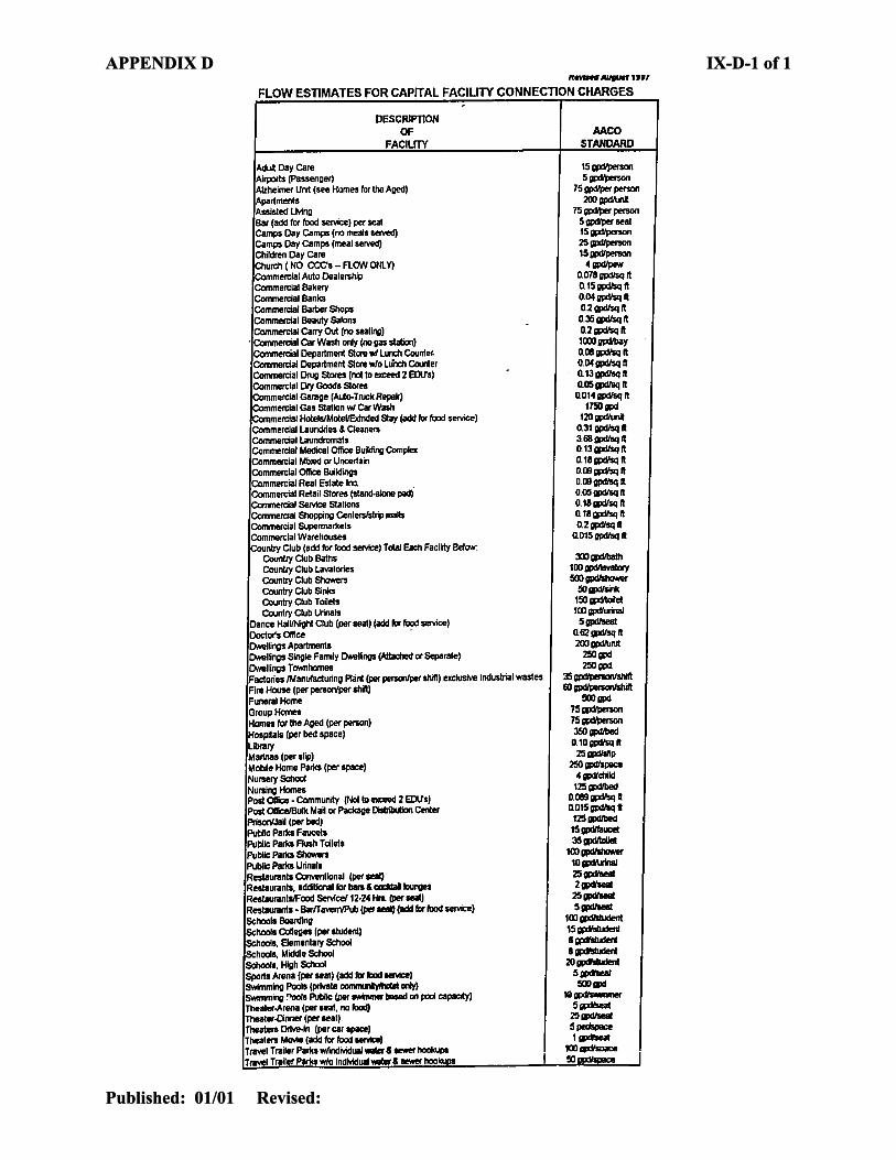
APPENDIX D IX-D-1 of 1 APPENDIX D IX-D-1 of 1
Published: 01/01 Revised:
Published: 01/01 Revised:
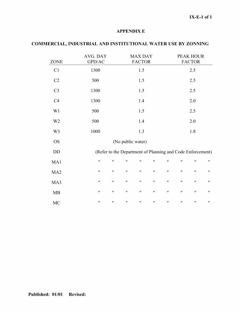
IX-E-1 of 1
APPENDIX E
COMMERCIAL, INDUSTRIAL AND INSTITUTIONAL WATER USE BY ZONNING
AVG. DAY MAX DAY PEAK HOUR ZONE GPD/AC FACTOR FACTOR
C1 1300 1.5 2.5
C2 500 1.5 2.5
C3 1300 1.5 2.5
C4 1300 1.4 2.0
W1 500 1.5 2.5
W2 500 1.4 2.0
W3 1000 1.3 1.8
OS (No public water)
DD (Refer to the Department of Planning and Code Enforcement)
MA1 ″ ″ ″ ″ ″ ″ ″ ″ ″
MA2 ″ ″ ″ ″ ″ ″ ″ ″ ″
MA3 ″ ″ ″ ″ ″ ″ ″ ″ ″
MB ″ ″ ″ ″ ″ ″ ″ ″ ″
MC ″ ″ ″ ″ ″ ″ ″ ″ ″
Published: 01/01 Revised:

IX-F-1 of 1
APPENDIX F
FIRE FLOW RATES
RESIDENTIAL: (1)
SINGLE FAMILY (2) 1,000 GPM AT 20 PSI RESIDUAL TOWNHOUSES (R-5) 1,500 GPM AT 20 PSI RESIDUAL GARDEN TYPE APARTMENTS (R-15) 2,000 GPM AT 20 PSI RESIDUAL HIGH RISE APARTMENTS (R-22) 2,500 GPM AT 20 PSI RESIDUAL
COMMERCIAL: (1)
REGIONAL SHOPPING CENTERS (C-3) 3,000 GPM AT 20 PSI RESIDUAL
INDUSTRIAL: (1) 3,000 GPM AT 20 PSI RESIDUAL
INSTITUTIONS: (1)
HOSPITALS 2,500 GPM AT 20 PSI RESIDUAL SCHOOLS 2,500 GPM AT 20 PSI RESIDUAL
OFFICE BUILDING COMPLEX: (1) 3,000 GPM AT 20 PSI RESIDUAL
________________________________________________
(1) ABOVE FIRE FLOWS TO BE USED IN THE ABSENCE OF SITE SPECIFIC DATA FROM FIRE UNDERWRITERS OR CONSTRUCTION PLANS WHICH WOULD PERMIT A DETERMINATION OF FIRE FLOW REQUIREMENTS USING INSURANCE INDUSTRY STANDARDS (INSURANCE SERVICE OFFICE – ISO). CONSIDERATION WILL BE GIVEN TO REDUCING THE REQUIREMENT WHERE PROPOSED CONSTRUCTION INCLUDES SPRINGLER SYSTEMS; REFER TO CURRENT ISO RECOMMENDATIONS.
(2) CONSIDERATION WILL BE GIVEN TO REDUCING THE REQUIREMENT TO 750 GPM WHERE IT CAN BE DEMONSTRATED THAT 1,000GPM IS TECHNICALLY UNFEASIBLE.
Published: 01/01 Revised:

IX-G -1 of 1
Published: 01/01 Revised:
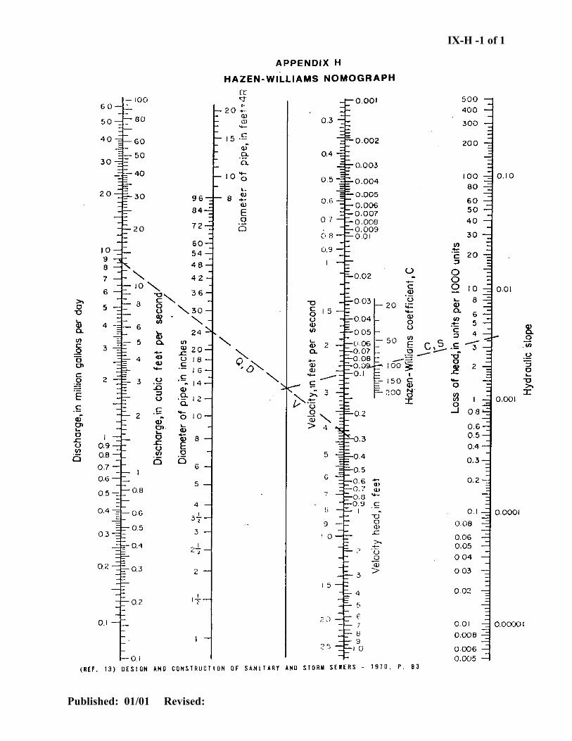
IX-H -1 of 1
Published: 01/01 Revised:
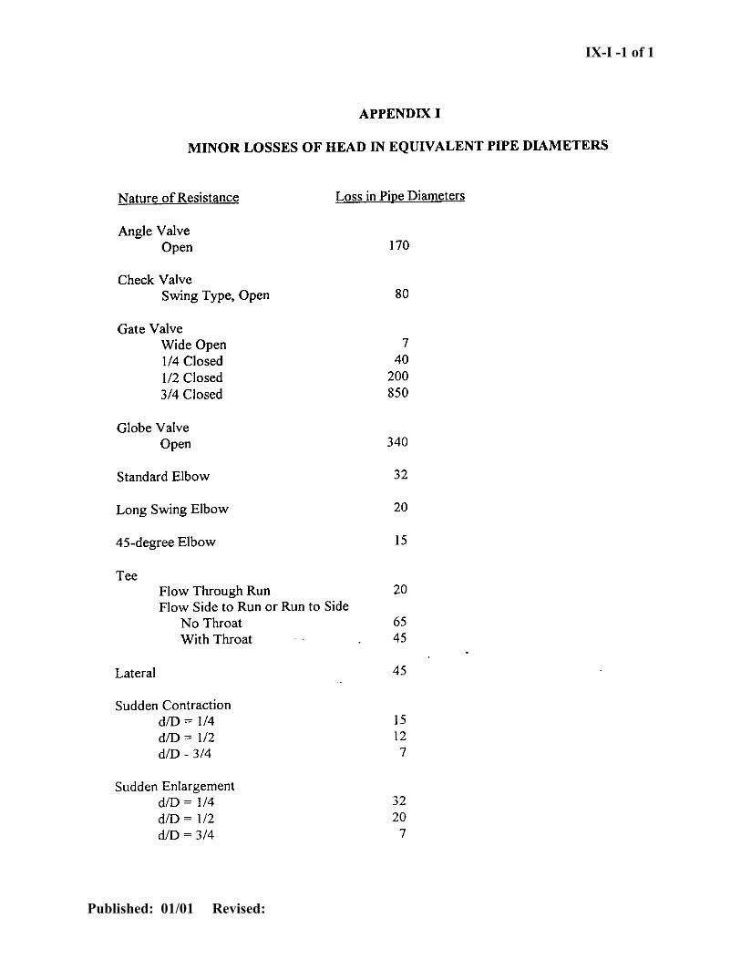
IX-I -1 of 1
Published: 01/01 Revised:
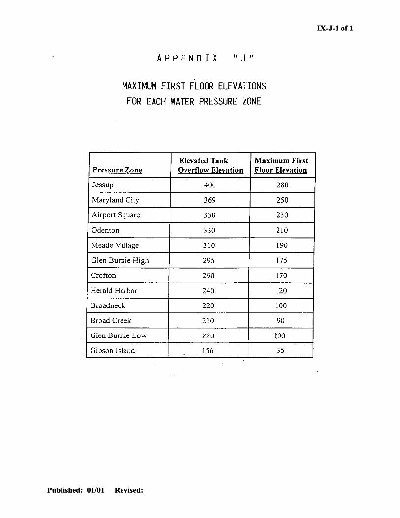
IX-J-1 of 1 IX-J-1 of 1
Published: 01/01 Revised:
Published: 01/01 Revised:
Related Documents