CHAPTER IV PROCESS TREATMENT AND CHEMICAL APPLICATION IV.A GENERAL IV.A.1 Facility Location 1.) New facilities are to be located: PHC 19-13-B102 (d) A. Above the level of the one hundred year flood. B. Where chlorine gas will not be stored or used within three hundred feet of any residence. C. Where the facility is not likely to be subject to fires or other natural or manmade disasters. 2.) The state health department must be notified before entering into a financial commitment for a new public water system or increasing the capacity of an existing public water system, and the approval of the state health department must be obtained before any construction is begun. This includes construction of supply and treatment works, transmission lines, storage tanks, pumping stations and other works of sanitary significance. It does not include the routine extension of laterals or tapping of new service connections. IV.A.2 Bench and Pilot Scale Studies Refer to Water Supplies Section, Recommended Procedure, “ Pilot Studies Required For Proposed Water Treatment Plants” in Appendix B. WSS RP IV.A.3 Chemical Application • Effective immediately no chemical substance other than those presently used with the approval of the commissioner of health shall be added to public water supplies designed for human consumption whether in the course of filtration, for control of plant or animal life, or for any other purpose without prior approval by the commissioner of health. Before installation of equipment for such addition, plans and specifications shall be submitted to and approved by the commissioner of health. These plans shall provide procedures necessary for the satisfactory operation of the installation, including the proper testing of the water for chemical content, which procedures shall be followed by any person, firm, corporation or municipality having jurisdiction over the supply. PHC 19-13-B80 • Chemicals shall be applied to the water at such points and by such means as to RSWW 5.0.2 a. assure maximum efficiency of treatment, b. assure maximum safety to consumer, Page IV - 1

Welcome message from author
This document is posted to help you gain knowledge. Please leave a comment to let me know what you think about it! Share it to your friends and learn new things together.
Transcript

CHAPTER IV
PROCESS TREATMENT AND CHEMICAL APPLICATION
IV.A GENERAL
IV.A.1 Facility Location
1.) New facilities are to be located: PHC 19-13-B102 (d)
A. Above the level of the one hundred year flood. B. Where chlorine gas will not be stored or used within three hundred feet
of any residence.
C. Where the facility is not likely to be subject to fires or other natural or manmade disasters.
2.) The state health department must be notified before entering into a financial
commitment for a new public water system or increasing the capacity of an existing public water system, and the approval of the state health department must be obtained before any construction is begun. This includes construction of supply and treatment works, transmission lines, storage tanks, pumping stations and other works of sanitary significance. It does not include the routine extension of laterals or tapping of new service connections.
IV.A.2 Bench and Pilot Scale Studies
Refer to Water Supplies Section, Recommended Procedure, “ Pilot Studies Required For Proposed Water Treatment Plants” in Appendix B.
WSS RP
IV.A.3 Chemical Application
• Effective immediately no chemical substance other than those presently used with the approval of the commissioner of health shall be added to public water supplies designed for human consumption whether in the course of filtration, for control of plant or animal life, or for any other purpose without prior approval by the commissioner of health. Before installation of equipment for such addition, plans and specifications shall be submitted to and approved by the commissioner of health. These plans shall provide procedures necessary for the satisfactory operation of the installation, including the proper testing of the water for chemical content, which procedures shall be followed by any person, firm, corporation or municipality having jurisdiction over the supply.
PHC 19-13-B80
• Chemicals shall be applied to the water at such points and by such means as to
RSWW 5.0.2
a. assure maximum efficiency of treatment, b. assure maximum safety to consumer,
Page IV - 1
c. provide maximum safety to operators, d. assure satisfactory mixing of the chemicals with the water, e. provide maximum flexibility of operation through various points of
application, when appropriate, and RSWW 5.0.2 (continued)
f. prevent backflow or back-siphonage between multiple points of feed through common manifolds.
• Refer to Water Supplies Section, Guidance Document, “Drinking Water Additives and System Components” in Appendix A.
WSS GD
IV.A.4 General Equipment Design
General equipment design shall be such that RSWW 5.0.3
a. feeders will be able to supply, at all times, the necessary amounts of
chemicals at an accurate rate, throughout the range of feed,
b. chemical-contact materials and surfaces are resistant to the aggressiveness of the chemical solution,
c. corrosive chemicals are introduced in such a manner as to minimize potential for corrosion,
d. chemicals that are incompatible are not stored or handled together, e. all chemicals are conducted from the feeder to the point of application in
separate conduits,
f. chemical feeders are as near as practical to the feed point, g. chemical feeders and pumps shall operate at no lower than 20 percent of the
feed range unless two fully independent adjustment mechanisms such as pump pulse rate and stroke length are fitted when the pump shall operate at no lower than 10 percent of the rated maximum, and
h. chemicals are fed by gravity where practical. IV.B FACILITY DESIGN
IV.B.1 Chemical Storage, Feed, and Control
IV.B.1.a Number of Feeders
a. Where chemical feed is necessary for the protection of the supply, such
as chlorination, coagulation or other essential processes, RSWW 5.1.1
1. a minimum of two feeders shall be provided, and 2. the standby unit or a combination of units of sufficient capacity
should be available to replace the largest unit during shut-downs;
3. where a booster pump is required, duplicate equipment should be provided and, when necessary, standby power.
b. A separate feeder shall be used for each chemical applied. c. Spare parts shall be available for all feeders to replace parts which are
subject to wear and damage.
Page IV - 2

IV.B.1.b Control
a. Feeders may be manually or automatically controlled, with automatic controls being designed so as to allow override by manual controls.
RSWW 5.1.2
b. At automatically operated facilities, chemical feeders shall be electrically interconnected with the well or service pump and should be provided a nonstandard electrical receptacle.
c. Chemical feed rates shall be proportional to flow. d. A means to measure water flow must be provided in order to determine
chemical feed rates.
e. Provisions shall be made for measuring the quantities of chemicals used.
f. Weighing scales
1. shall be provided for weighing cylinders at all plants utilizing chlorine gas,
2. may be required for fluoride solution feed, 3. should be provided for volumetric dry chemical feeders, and 4. shall be capable of providing reasonable precision in relation to
average daily dose.
g. Where conditions warrant, for example with rapidly fluctuating intake
turbidity, coagulant and coagulant aid addition may be made according to turbidity, streaming current or other sensed parameter.
• Refer to Water Supplies Section in Guidance Document “Chemical Treatment Monitoring/Safety” in Appendix A.
WSS GD
IV.B.1.c Dry Chemical Feeders
Dry chemical feeders shall RSWW 5.1.3
a. measure chemicals volumetrically or gravimetrically, b. provide adequate solution water and agitation of the chemical in the
solution pot,
c. provide gravity feed from solution pots, and d. completely enclose chemicals to prevent emission of dust to the
operating room.
IV.B.1.d Positive Displacement Solution Pumps
Positive displacement type solution feed pumps should be used to feed liquid chemicals, but shall not be used to feed chemical slurries. Pumps must be capable of operating at the required maximum rate against the maximum head conditions found at the point of injection.
RSWW 5.1.4
IV.B.2 Operation Considerations
Disinfection of Water Treatment Plants shall conform to AWWA Standard C653-95 Disinfection of Water Treatment Plant.
Page IV - 3
IV.C OPERATOR REQUIREMENTS AND SAFETY
IV.C.1 General
IV.C.1.a Qualifications for Certified Water Treatment Operators
(a) Except as provided in subsection (f) of this section, every community water supply treatment plant shall have at least one operator who is certified at the plant’s class or higher and who shall be designated by the utility as the chief operator. The chief operator shall have direct responsible charge, of the plant. In the event that the chief operator is not available, the utility shall place an operator, which is certified at the plant’s class or higher, in direct responsible charge to serve in the interim. All operators in direct responsible charge shall be certified at the plant’s call or higher.
PHC 25-35-9
(b) To become certified as a water treatment plant operator a person must demonstrate the ability to responsibly operate a plant of the given classification applied for (I, II, III, IV) by completing a written application to the Department of Health Services attesting to the education, experience and written test requirements required by subsection (c) of this section.
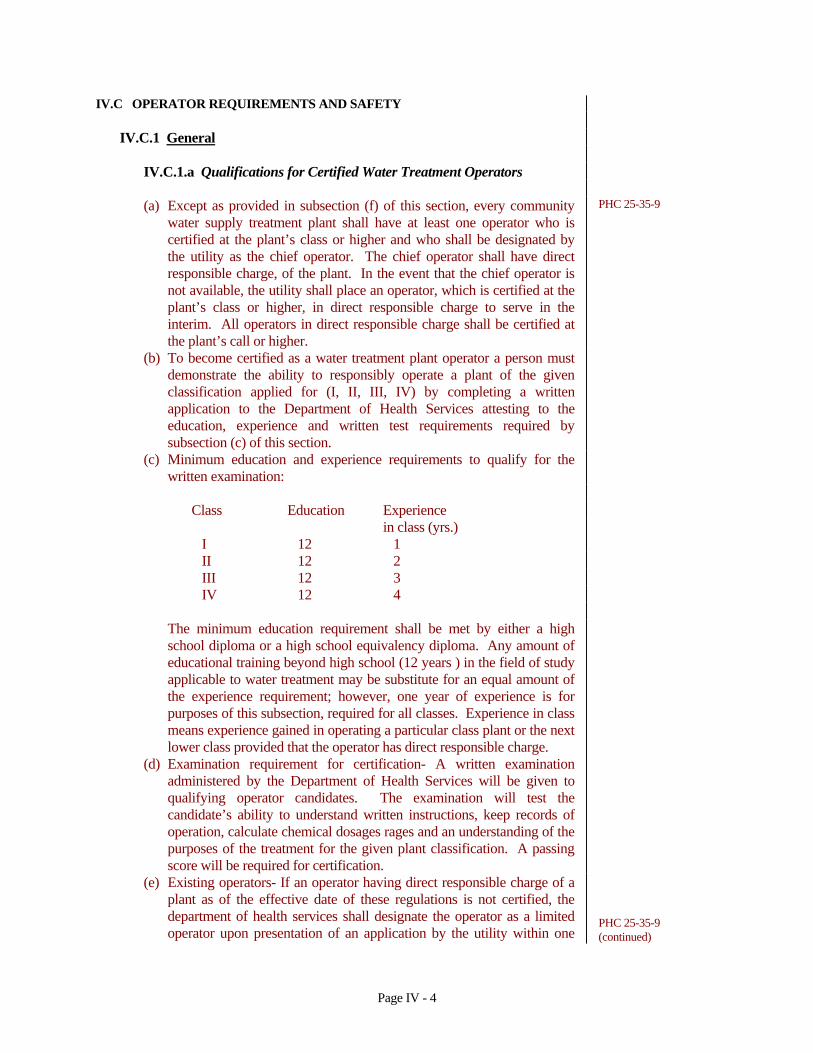
(c) Minimum education and experience requirements to qualify for the written examination:
Class Education Experience in class (yrs.) I 12 1 II 12 2 III 12 3 IV 12 4
The minimum education requirement shall be met by either a high school diploma or a high school equivalency diploma. Any amount of educational training beyond high school (12 years ) in the field of study applicable to water treatment may be substitute for an equal amount of the experience requirement; however, one year of experience is for purposes of this subsection, required for all classes. Experience in class means experience gained in operating a particular class plant or the next lower class provided that the operator has direct responsible charge.
(d) Examination requirement for certification- A written examination administered by the Department of Health Services will be given to qualifying operator candidates. The examination will test the candidate’s ability to understand written instructions, keep records of operation, calculate chemical dosages rages and an understanding of the purposes of the treatment for the given plant classification. A passing score will be required for certification.
(e) Existing operators- If an operator having direct responsible charge of a plant as of the effective date of these regulations is not certified, the department of health services shall designate the operator as a limited operator upon presentation of an application by the utility within one
PHC 25-35-9 (continued)
Page IV - 4

year of the effective date of these regulations. This designation is only granted for a specific plant and cannot be transferred to another plant. A limited operator cannot be designated as a chief operator but can serve in direct responsible charge.
(f) Provisional operators - If a utility does not have a qualified operator as outlined in Section 25-32-9(a) and if the department of health services determines that this is due to reasons beyond the utility’s control, the Department of Health Services may grant a provisional operator status to an operator. The utility must submit a request in writing which indicates the reasons for not having a qualified operator and include an application. The provisional operator status would only be granted for a given plant and only be given to an operator who could qualify to take the appropriate class exam within 2 years.
(g) Operator-in-training- A person who has received a certificate of achievement in water management from a Connecticut Technical College, or its equivalent as determined by the Department of Health Services, may apply to take any class examination. After successful completion of the examination, the person will be an operator-in-training. After the operator-in -training has completed the education and experience requirements of the appropriate class, he may apply to become a certified operator.
IV.C.2 Sensors and Alarms
Chlorine Leak Detection
A bottle of concentrated ammonium hydroxide (56 percent ammonia solution) shall be available for chlorine leak detection; where ton containers are used, a leak repair kit approved by the Chlorine Institute shall be provided. Continuous chlorine leak detection equipment is recommended. Where a leak detector is provided it shall be equipped with both an audible alarm and a warning light.
RSWW 5.3.3
• Refer to Water Supplies Section Guidance Document “Chemical Treatment Monitoring/Safety” in Appendix A
IV.C.3 Ventilation
Special provisions shall be made for ventilation of chlorine feed and storage rooms.
RSWW 5.3.1
IV.C.4 Personal Protective Equipment
• Respiratory Protection Equipment RSWW 5.3.2
Respiratory protection equipment, meeting the requirements of the National Institute for Occupational Safety and Health (NIOSH) shall be available where chlorine gas is handled, and shall be stored at a convenient heated location, but not inside any room where chlorine is used or stored. The units shall use compressed air, have at least a 30 minute capacity, and be compatible with or exactly the same as units used by the fire department responsible for the plant
RSWW 5.3.2 (continued)
Page IV - 5

responsible for the plant.
• Protective Equipment RSWW 5.3.4
a. At least one pair of rubber gloves, a dust respirator of a type certified by
NIOSH for toxic dusts, an apron or other protective clothing and goggles or face mask shall be provided for each operator as required by the Department. A deluge shower and/or eyewashing device should be installed where strong acids and alkalis are used or stored.
b. A water holding tank that will allow water to come to room temperature must be installed in the water line feeding the deluge shower and eyewashing device. Other methods of water tempering will be considered on an individual basis.
IV.D CHEMICALS
• Refer to Water Supplies Section, Guidance Document, “Drinking Water Additives and System Components” in Appendix A.
WSS, GD
IV.D.1 Delivery
Chemical shipping containers shall be fully labeled to include RSWW 5.2.1 a. chemical name, purity and concentration, and b. supplier name and address
IV.D.2 Storage
a. Space should be provided for RSWW 5.1.9
1. at least 30 days of chemical supply, 2. convenient and efficient handling of chemicals, 3. dry storage conditions, and 4. a minimum storage volume of 1.5 truck loads where purchase is by
truck load lots.
b. Storage tanks and pipelines for liquid chemicals shall be specified for use
with individual chemicals and not used for different chemicals.
c. Chemicals shall be stored in covered or unopened shipping containers, unless the chemical is transferred into an approved storage unit.
d. Liquid chemical storage tanks must
1. have a liquid level indicator, and 2. have an overflow and a receiving basin capable of receiving accidental
spills or overflows without uncontrolled discharge.
IV.D.3 Solution Tanks
IV.D.3.a Solution Tanks
Page IV - 6

a. A means which is consistent with the nature of the chemical solution
shall be provided in a solution tank to maintain a uniform strength of solution. Continuous agitation shall be provided to maintain slurries in suspension.
RSWW 5.1.10
b. Two solution tanks of adequate volume may be required for a chemical to assure continuity of supply while servicing a solution tank.
c. Means shall be provided to measure the liquid level in the tank. d. Chemical solution shall be kept covered. Large tanks with access
openings shall have such openings curbed and fitted with overhanging cover.
e. Subsurface locations for solution tanks shall
1. be free from sources of possible contamination, and 2. assure positive drainage for groundwaters, accumulated water,
chemical spills and overflows.
f. Overflow pipes, when provided, should
1. be turned downward, with the end screened, 2. have a free fall discharge, and 3. be located where noticeable
g. Acid storage tanks must be vented to the outside atmosphere, but not
through vents in common with day tanks.
h. Each tank shall be provided with valved drain, protected against backflow in accordance with Section IV.D.3.b and IV.D.3.c of this document.
i. Solution tanks shall be located and protective curbings provided so that chemical from equipment failure, spillage or accidental drainage shall not enter the water in conduits, treatment or storage basins.
IV.D.3.b Liquid Chemical Feeders-Siphon Control
Liquid chemical feeders shall be such that chemical solutions cannot be siphoned into the water supply, by
RSWW 5.1.5
a. assuring discharge at a point of positive pressure, or b. providing vacuum relief, or c. providing a suitable air gap, or d. providing other suitable means or combinations as necessary.
IV.D.3.c Cross-connection Control
Cross-connection control must be provided to assure that RSWW 5.1.6
a. the service water lines discharging to solution tanks shall be properly protected from backflow as required by the Department;
RSWW 5.1.6 (continued)
b. liquid chemical solutions cannot be siphoned through solution feeders
Page IV - 7
into the water supply as stated in Section IV.D.3.b of this document; and
c. no direct connection exists between any sewer and a drain or overflow from the feeder, solution chamber or tank by providing that all drains terminate at least six inches or two pipe diameters, whichever is greater, above the overflow rim of a receiving sump, conduit or waste receptacle.
IV.D.4 Day Tanks
a. Day tanks shall be provided where bulk storage of liquid chemical is
provided. RSWW 5.1.11
b. Day tanks shall meet all the requirements of Section IV.D.3 of this document.
c. Day tanks should hold no more than a 30 hour supply. d. Day tanks shall be scale-mounted, or have a calibrated gauge painted or
mounted on the side if liquid level can be observed in a gauge tube or through translucent sidewalls of the tank. In opaque tanks, a gauge rod extending above a reference point at the top of the tank, attached to a float may be used. The ratio of the area of the tank to its height must be such that unit readings are meaningful in relation to the total amount of chemical fed during a day.
e. Hand pumps may be provided for transfer from a carboy or drum. A tip rack may be used to permit withdrawal into a bucket from a spigot. Where motor-driven transfer pumps are provided, a liquid level limit switch and an over-flow from the day tank, must be provided.
f. A means which is consistent with the nature of the chemical solution shall be provided to maintain uniform strength of solution in a day tank. Continuous agitation shall be provided to maintain chemical slurries in suspension.
g. Tanks and tank refilling line entry points shall be clearly labeled with the name of the chemical contained.
h. Well sealed containment with no open drain, sized to hold the entire tank’s content, shall be provided.
IV.D.5 Specifications
Chemicals and water contact materials shall meet ANSI/AWWA quality standards and ANSI/NSF standard 60 or 61 safety specifications.
RSWW 5.2.2
IV.D.6 Specific Chemicals
IV.D.6.a Chlorine Gas
New facilities are to be located where chlorine gas will not be stored or used within three hundred feet of any residence.
PHC 19-13-B102(d)(1)(B)
a. Chlorine gas feed and storage shall be enclosed and separated from other operating areas. The chlorine room shall be
RSWW 5.4.1
Page IV - 8

1. provided with a shatter resistant inspection window installed in an interior wall,
RSWW 5.4.1 (continued)
2. constructed in such a manner that all openings between the chlorine room and the remainder of the plant are sealed, and
3. provided with doors equipped with panic hardware, assuring ready means of exit and opening outward only to the building exterior.
b. Full and empty cylinders of chlorine gas should be
1. isolated from operating areas, 2. restrained in position to prevent upset, stored in rooms separate
from ammonia storage,
3. stored in areas not in direct sunlight or exposed to excessive heat, and
4. clearly labeled as to its status (full or empty).
c. Where chlorine gas is used, the room shall be constructed to provide the following:
1. each room shall have a ventilation fan with a capacity which
provides one complete air change per minute when the room is occupied,
2. the ventilating fan shall take suction near the floor as far as practical from the door and air inlet, with the point of discharge so located as not to contaminant air inlets to any rooms or structures,
3. air inlets should be through louvers near the ceiling, 4. louvers for chlorine room air intake and exhaust shall facilitate
airtight closure,
5. separate switches for the fan and lights shall be located outside of the chlorine room and at the inspection window. Outside switches shall be protected from vandalism. A signal light indicating fan operation shall be provided at each entrance when the fan can be controlled from more than one point,
6. vents from feeders and storage shall discharge to the outside atmosphere, above grade,
7. the room location should be on the prevailing downwind side of the building away from entrances, windows, louvers, walkways, etc.,
8. floor drains are discouraged. Where provided, the floor drains shall discharge to the outside of the building and shall not be connected to other internal or external drainage systems.
9. where deemed necessary, provision shall be made to chemically neutralize chlorine gas before discharge from the water treatment plant building into the environment. Such equipment shall be designed as part of the chlorine gas storage and feed areas to automatically engage in the event of any measured chlorine release. The equipment shall be sized to treat the entire contents of the largest storage container on site.
Page IV - 9

d. Chlorinator rooms should be heated to 60oF, and be protected from excess heat. Cylinders and gas lines should be protected from temperature above that of the feed equipment.
e. Pressurized chlorine feed lines shall not carry chlorine gas beyond the chlorinator room.
RSWW 5.4.1 (continued)
IV.D.6.b Acids and Caustics
a. Acids and caustics shall be kept in closed corrosion-resistant shipping
containers or storage units. RSWW 5.4.2
b. Acids and caustics shall not be handled in open vessels, but should be pumped in undiluted form from original containers through suitable hose, to the point of treatment or to a covered day tank.
IV.D.6.c Sodium Chlorite for Chlorine Dioxide Generation
Proposals for the storage and use of sodium chlorite must be approved by the Department prior to the preparation of final plans and specifications. Provisions shall be made for proper storage and handling of sodium chlorite to eliminate any danger of fire or explosion associated with its powerful oxidizing nature.
RSWW 5.4.3
a. Storage
1. Chlorite (sodium chlorite) shall be stored by itself in a separate
room and preferably shall be stored in an outside building detached from the water treatment facility. It must be stored away from organic materials because many materials will catch fire and burn violently when in contact with chlorite.
2. The storage structures shall be constructed of noncombustible materials.
3. If the storage structure must be located in an area where a fire may occur, water must be available to keep the sodium chlorite area cool enough to prevent heat induced explosive decomposition of the chlorite.
b. Handling
1. Care should be taken to prevent spillage. 2. An emergency plan of operation should be available for the clean
up of any spillage.
3. Storage drums must be thoroughly flushed prior to recycling or disposal.
c. Feeders
1. Positive displacement feeders shall be provided. 2. Tubing for conveying sodium chlorite or chlorine dioxide solutions
shall be Type 1 PVC, polyethylene or materials recommended by
Page IV - 10

the manufacturer.
3. Chemical feeders may be installed in chlorine rooms if sufficient space is provided or facilities meeting the requirements of RSWW subsection 5.4.1 (section IV.D.6.a of this document) shall be provided.
RSWW 5.4.3 (continued)
4. Feed lines shall be installed in a manner to prevent formation of gas pockets and shall terminate at a point of positive pressure.
5. Check valves shall be provided to prevent the backflow of chlorine into the sodium chlorite line.
IV.E CLARIFICATION
IV.E.1 Rapid Mix
Rapid mix shall mean the rapid dispersion of chemicals throughout the water to be treated, usually by violent agitation. The engineer shall submit the design basis for the velocity gradient (G value) selected, considering the chemicals to be added and water temperature, color and other related water quality parameters.
RSWW 4.1.2
a. Equipment - Basins should be equipped with mechanical mixing devices.
Static mixing maybe considered if treatment flow is not variable and can be justified by the design engineer.
b. Mixing - The detention period should be not more than thirty seconds. c. Location - The rapid mix and flocculation basin shall be as close together as
possible.
IV.E.2 Coagulants
• Each public water system shall certify annually in writing to the department that when acrylamide and epichlorohydrin are used in drinking water systems, the combination of dose and monomer level does not exceed the levels specified in 40 CFR 141.111.
PHC 19-13-B102j(5)
• Coagulants should conform to the most current applicable AWWA standards:
AWWA
B402-95 Ferrous Sulfate B403-93 Aluminum Sulfate-Liquid, Ground, or Lump B404-92 Liquid Sodium Silicate B405-94 Sodium Aluminate B406-92 Ferric Sulfate B407-93 Liquid FerricChloride B408-93 Liquid Polyaluminum Chloride B451-92 Poly (Diallyldimethylammonium Chloride) B452-90 EPI-DMA Polyamines B453-96 Polyacrylamide
• Maximum allowed dosage shall be in accordance with the most current NSF
Page IV - 11

applicable ANSI/NSF standards.
IV.E.3 Flocculation
Flocculation shall mean the agitation of water at low velocities for long periods of time.
RSWW 4.1.3
a. Basin Design - Inlet and outlet design shall prevent short-circuiting and
destruction of floc. A drain and/or pumps shall be provided to handle dewatering and sludge removal.
b. Detention - The flow-through velocity shall be not less than 0.5 nor greater than 1.5 feet per minute with a detention time for floc formation of at least 30 minutes.
c. Equipment - Agitators shall be driven by variable speed drives with the peripheral speed of paddles ranging from 0.5 to 3.0 feet per second.
d. Piping - Flocculation and sedimentation basins shall be as close together as possible. The velocity of flocculated water through pipes or conduits to settling basins shall be not less 0.5 nor greater than 1.5 feet per second. Allowances must be made to minimize turbulence at bends and changes in direction.
e. Other designs - Baffling may be used to provide for flocculation in small plants only after consultation with the Department. The design should be such that the velocities and flows noted above will be maintained.
f. Superstructure - A superstructure over the flocculation basins may be required.
IV.E.4 Sedimentation
Sedimentation shall follow flocculation. The detention time for effective clarification is dependent upon a number of factors related to basin design and the nature of the raw water The following criteria apply to conventional sedimentation units:
RSWW 4.1.4
a. Detention time - shall provide a minimum of four hours of settling time.
This may be reduced to two hours for lime-soda softening facilities treating only groundwater. Reduced sedimentation time may also be approved when equivalent effective settling is demonstrated or when overflow rate is not more than 0.5 gpm per square foot (1.2 m/hr).
b. Inlet devices - Inlets shall be designed to distribute the water equally and at uniform velocities. Open ports, submerged ports, and similar entrance arrangements are required. A baffle should be constructed across the basin close to the inlet end and should project several feet below the water surface to dissipate inlet velocities and provide uniform flows across the basin.
c. Outlet devices - Outlet weirs or submerged orifices shall maintain velocities suitable for settling in the basin and minimize short-circuiting. The use of submerged orifices is recommended in order to provide a volume above the orifices for storage when there are fluctuations in flow. Outlet weirs and submerged orifices shall be designed as follows:
1. The rate of flow over the outlet weirs or through the submerged orifices
shall not exceed 20,000 gallons per day per foot (250 m3/day/m) of the
Page IV - 12

outlet launder. 2. Submerged orifices should not be located lower than three feet below
the flow line. RSWW 4.1.4 (continued)
3. The entrance velocity through the submerged orifices shall not exceed 0.5 feet per second.
d. Velocity - The velocity through settling basins should not exceed 0.5 feet
per minute. The basins must be designed to minimize short-circuiting. Fixed or adjustable baffles must be provided as necessary to achieve the maximum potential for clarification.
e. Overflow - An overflow weir or pipe designed to establish the maximum water level desired on top of the filters should be provided. The overflow shall discharge by gravity with a free fall at a location where the discharge will be noted.
f. Superstructure - A superstructure over the sedimentation basins may be required. If there is no mechanical equipment in the basins and if provisions are included for adequate monitoring under all expected weather conditions, a cover may be provided in lieu of a superstructure.
g. Sludge collection - Mechanical sludge collection equipment should be provided.
h. Drainage - Basins must be provided with a means for dewatering. Basin bottoms should slope toward the drain not less than one foot in twelve feet where mechanical sludge collection equipment is not required.
i. Flushing lines - Flushing lines or hydrants shall be provided and must be equipped with backflow prevention devices acceptable to the Department.
j. Safety - Permanent ladders or handholds should be provided on the inside walls of basins above the water level. Guard rails should be included. Compliance with other applicable safety requirements, such as OSHA, shall be required.
k. Sludge removal - Sludge removal design shall provide that
1. sludge pipes shall be not less than three inches in diameter and so arranged as to facilitate cleaning,
2. entrance to sludge withdrawal piping shall prevent clogging, 3. valves shall be located outside the tank for accessibility, 4. the operator may observe and sample sludge being withdrawn from the
unit.
l. Sludge disposal - Facilities are required by the Department for disposal of sludge. See RSWW Section 4.11 (section IV.M of this document).
IV.E.5 Flotation
• Refer to the latest edition of AWWA “Water Quality and Treatment” Handbook.
AWWA
IV.E.6 Tube or Plate Settlers RSWW 4.1.6
Proposals for settler unit clarification must include pilot plant and/or full scale demonstration data on water with similar quality prior to the preparation of final plans and specifications for approval. Settler units consisting of variously
Page IV - 13

shaped tubes or plates which are installed in multiple layers and at an angle to the flow may be used for sedimentation, following flocculation.
IV.E.6.a General Criteria RSWW 4.1.6.1
a. Inlet and outlet considerations - Design to maintain velocities suitable for settling in the basin and to minimize short-circuiting. Plate units shall be designed to minimize maldistribution across the units.
b. Drainage - Drain piping from the settler units must be sized to facilitate a quick flush of the settler units and to prevent flooding other portions of the plant.
c. Protection from freezing - Although most units will be located within a plant, outdoor installations must provide sufficient freeboard above the top of the settlers to prevent freezing in the units. A cover or enclosure is strongly recommended.
d. Application rate for tubes - A maximum rate of 2 gpm per square foot of cross-sectional area (4.8 m/hr) for tube settlers, unless higher rates are successfully shown through pilot plant or in-plant demonstration studies.
e. Application rate for plates - A maximum plate loading rate of 0.5 gpm per square foot (1.2 m/hr), based on 80 percent of the projected horizontal plate area.
f. Flushing lines - Flushing lines shall be provided to facilitate maintenance and must be properly protected against backflow or back siphonage.
IV.E.7 Solids Upflow Contact Units
IV.E.7.a General
Units are generally acceptable for combined softening and clarification where water characteristics, especially temperature, do not fluctuate rapidly, flow rates are uniform and operation is continuous. Before such units are considered as clarifiers without softening, specific approval of the Department shall be obtained. Clarifiers should be designed for the maximum uniform rate and should be adjustable to changes in flow which are less than the design rate and for changes in water characteristics. A minimum of two units are required for surface water treatment.
RSWW 4.1.5
IV.E.7.b Installation of Equipment
Supervision by a representative of the manufacturer shall be provided with regard to all mechanical equipment at the time of
RSWW 4.1.5.1
a. installation, and b. initial operation
IV.E.7.c Operating Equipment
The following shall be provided for plant operation: RSWW 4.1.5.2
Page IV - 14

a. a complete outfit of tools and accessories, RSWW 4.1.5.2 b. necessary laboratory equipment, (continued) c. adequate piping with suitable sampling taps so located as to permit the
collection of samples of water from critical portions of the units.
IV.E.7.d Chemical Feed
Chemicals shall be applied at such points and by such means as to insure satisfactory mixing of the chemicals with the water.
RSWW 4.1.5.3
IV.E.7.e Mixing
A rapid mix device or chamber ahead of solids contact units may be required by the Department to assure a proper mixing of the chemicals applied. Mixing devices employed shall be so constructed as to
RSWW 4.1.5.4
a. provide good mixing of the raw water with previously formed sludge
particles, and
b. prevent deposition of solids in the mixing zone.
IV.E.7.f Flocculation
Flocculation equipment RSWW 4.1.5.5
a. shall be adjustable (speed and/or pitch) b. must provide for coagulation in a separate chamber or baffled zone
within the unit,
c. should provide for flocculation and mixing period to be not less than 30 minutes.
IV.E.7.g Sludge Concentrators
a. The equipment should provide either internal or external concentrators
in order to obtain a concentrated sludge with a minimum of waste water.
RSWW 4.1.5.6
b. Large basins should have at least two sumps for collecting sludge located in the central flocculation zone.
IV.E.7.h Sludge Removal
Sludge removal design shall provide that RSWW 4.1.5.7
a. sludge pipes shall be not less than three inches in diameter and so arranged as to facilitate cleaning,
b. entrance to sludge withdrawal piping shall prevent clogging, c. valves shall be located outside the tank for accessibility, and d. the operator may observe and sample sludge being withdrawn from the
unit.
Page IV - 15

IV.E.7.i Cross-connections
a. Blow-off outlets and drains must terminate and discharge at places satisfactory to the Department.
RSWW 4.1.5.8
b. Cross-connection control must be included for the portable water lines
used to backflush sludge lines.
IV.E.7.j Detention Period
The detention time shall be established on the basis of the raw water characteristics and other local conditions that affect the operation of the unit. Based on design flow rates, the detention time should be
RSWW 4.1.5.9
a. two to four hours for suspended solids contact clarifiers and softeners
treating surface water, and
b. one to two hours for the suspended solids contact softeners treating only groundwater.
The Department may alter detention time requirements.
IV.E.7.k Suspended Slurry Concentrate
Softening units should be designed so that continuous slurry concentrates of one percent or more, by weight, can be satisfactorily maintained.
RSWW 4.1.5.10
IV.E.7.l Water Losses
a. Units shall be provided with suitable controls for sludge withdrawal. RSWW 4.1.5.11 b. Total water losses should not exceed
1. five percent for clarifiers, 2. three percent for softening units.
c. Solids concentrations of sludge bled to waste should be
1. three percent by weight for clarifiers, 2. five percent by weight for softeners.
IV.E.7.m Weirs or Orifices
The units should be equipped with either overflow weirs or orifices constructed so that water at the surface of the unit does not travel over 10 feet horizontally to the collection trough.
RSWW 4.1.5.12
a. Weirs shall be adjustable, and at least equivalent in length to the
perimeter of the tank.
b. Weir loading shall not exceed
Page IV - 16
1. 10 gpm per foot of weir length (120 L/min/m) for units used for
clarifiers
2. 20 gpm per foot of weir length (240 L/min/m) for units used for softeners.
c. Where orifices are used the loading rates per foot of launder rates
should be equivalent to weir loadings. Either shall produce uniform rising rates over the entire area of the tank.
RSWW 4.1.5.12 (continued)
IV.E.7.n Upflow Rates
Unless supporting data is submitted to the Department to justify rates exceeding the following, rates shall not exceed
RSWW 4.1.5.13
a. 1.0 gpm per square foot of area (2.4 m/hr) at the sludge separation line
for units used for clarifiers,
b. 1.75 gpm per square foot of area (4.2 m/hr) at the slurry separation line for units used for softeners.
IV.E.8 Microscreening
IV.E.8.a General
A microscreen is a mechanical supplement of treatment capable of removing suspended matter from the water by straining. It may be used to reduce nuisance organisms and organic loadings. It shall not be used in place of
RSWW 4.10
a. filtration, when filtration is necessary to provide a satisfactory water, or b. coagulation, in the preparation of water for filtration.
IV.E.8.b Design
a. shall give due consideration to RSWW 4.10.1
1. nature of the suspended matter to be removed, 2. corrosiveness of the water, 3. effect of chlorination, when required as pre-treatment, 4. duplication of units for continuous operation during equipment
maintenance;
b. shall provide
1. a durable, corrosion-resistant screen, 2. by-pass arrangements, 3. protection against back-siphonage when potable water is used for
washing,
4. proper disposal of wash waters. See RSWW Section 4.11 (section IV.M of this document).
Page IV - 17

IV.F FILTRATION
IV.F.1 General
IV.F.1.a Monitoring Requirements
Systems that use a surface water source or a groundwater source under the direct influence of surface water and provide filtration treatment shall monitor in accordance with this subparagraph beginning in June 29, 1993, or when filtration is installed, which ever is later.
PHC 19-13-B102(e)(7)(S)
(i) Turbidity measurements as required by subsection (j)(4) of this section
shall be performed on representative samples of the system’s filtered water using a continuous turbidity analyzer for the time that the system serves water to the public. If there is a failure in the continuous monitoring equipment, grab sampling every four hours shall be conducted in lieu of continuous monitoring, but for no more than five days following the failure of the equipment unless an extension is granted in writing by the department. A system shall validate the continuous measurement on a daily basis using the appropriate procedure in the latest edition of standard methods for examination of water and wastewater.
(ii) The residual disinfectant concentration of the water entering the distribution system shall be monitored continuously, and the lowest value shall be recorded each day, except that if there is a failure in the continuous monitoring equipment, grab sampling every four hours shall be conducted in lieu of continuous monitoring, but for no more than five days following the failure of the equipment.
(iii) The residual disinfectant concentration shall be measured at least at the same points in the distribution system and at the same time as total coliforms are sampled, as specified in 40 CFR 141.21. Heterotrophic bacteria, measured as heterotrophic plate count as specific in 907A in 40 CFR 141.74 (a) (3), may be measured in lieu of residual disinfectant concentration.
IV.F.1.b Filtration
A system that uses a surface water source or a ground water source under the direct influence of surface water shall provide treatment consisting of both disinfection, as specified in subdivision (3) (B) of this subsection and filtration treatment which complies with the requirements of subparagraphs (A), (B), (C), or (D) of this subdivision by June 29, 1993, or eighteen (18) months after the department’s determination that the groundwater sources is under direct surface water influence and that filtration is required. Failure to meet any requirement of this section after the date specified in the paragraph is a treatment technique violation, and as such is a tier I violation.
PHC 19-13-B102 (j) (4)
Page IV - 18

A. Conventional filtration treatment or direct filtration
(i) For systems using conventional filtration or direct filtration, the
turbidity level of representative samples of a system’s filtered water shall be less than or equal to 0.5 NTU in at least ninety five percent (95%) of the measurement taken each month, measured as specified in 40 CFR 141.74 (a) (4) and subsection (e) (7) (S) (i) of this section. If the department determines in accordance with the EPA “Guidance Manual For Compliance With The Filtration And Disinfection Requirements For Public Water Systems Using Surface Water Sources” that the system is capable of achieving at least ninety nine and nine tenths percent (99.9%) removal and/or inactivation of Giardia lamblia cysts at some turbidity level higher than 0.5 NTU in at least ninety five percent (95%) of the measurements taken each month, the department may substitute this higher turbidity limit for that system.
PHC 19-13-B102 (j) (4) (continued)
(ii) The turbidity level of representative samples of system’s filtered water (treatment effluent) shall at no time exceed one (1) NTU, measured as specified in 40 CFR 141.74 (a) (4) and subsection (e) (7) (S) (i) of this section.
B. Slow sand filtration
For systems using slow sand filtration, the turbidity level of representative samples of a system’s filtered water shall be less than or equal to one (1) NTU in all of the measurements taken each month, measured as specified in 40 CFR 141.74 (a) (4) and subsection (e) (7) (S) (i) of this section.
C. Diatomaceous earth filtration
For systems using diatomaceous earth filtration, the turbidity level of representative samples of a system’s filtered water shall be less than or equal to one (1) NTU in all of the measurements taken each month, measured as specified in 40 CFR 141.74 (a) (4) and subsection (e) (7) (S) (i) of this section.
D. Other filtration technologies.
A system may use a filtration technology not listed in subparagraph (A) through (C) of this subdivision if it demonstrates to the department, using pilot plant studies or other means, that the alternative filtration technology, in combination with disinfection treatment that meets the requirements of subdivision (3) (B) of this subsection, consistently achieves ninety nine and nine tenths percent (99.9%) removal and/or inactivation of Giardia lamblia cysts and ninety nine and ninety nine hundredths percent (99.99%) removal and/or inactivation of viruses. For a system that makes this demonstration, the requirements of subparagraph (3) (B) of this subsection apply.
Page IV - 19
IV.F.1.c General Requirements - Surface Water Treatment Rule
A.) Each system with a surface water resource or a ground water source under the direct influence of surface water shall install and properly operate water treatment processes that reliable achieve
PHC 19-13-B102(j)(2)
(i) At least 99.9 percent (3-log) removal and/or inactivation of Giardia
lamblia cysts between a point where the raw water is not subject to recontamination by surface water runoff and a point downstream before or at the first customer; and
(ii) At least 99.99 percent (4-log) removal and/or inactivation of viruses cysts between a point where the raw water is not subject to recontamination by surface water runoff and a point downstream before or at the first customer.
B.) A system using a surface water source or a ground water source under
the direct influence of surface water is considered to be in compliance with the requirements of subparagraph (A) of this subdivision if it meets the filtration requirements in subsection (j)(4) and the disinfection requirements in subsection (j)(3)(B) of this section.
C.) Each system using a surface water source or a ground water source under the direct influence of surface water shall be operated by qualified personnel pursuant to sections 25-32-7a through 25-32-14 of the Regulations of Connecticut State Agencies.
D.) A system shall install filtration by June 29, 1993 for surface water systems; or within eighteen (18) months following the department’s determination that filtration is required for a groundwater source. Such determination shall be made if that groundwater source is at risk of contamination from Giardia lamblia. In making this determination, the department shall be guided by its document entitled “Determination of Groundwater Under The Direct Influence Of Surface Water.” As an interim requirement until such filtration is operational, the system shall not exceed five (5) NTUs of turbidity level measured as specified in 40 CFR 141,74 (a)(4) in a representative sample of the source water immediately prior to the first or only point of disinfection application; and such system shall be free of any waterborne disease outbreak.;
IV.F.1.d Filtration Materials and Media
Filtration materials and media shall conform to the applicable AWWA standards:
AWWA
B100-96 (Revised) Filtering Material B101-94 Precoat Filter Media
IV.F.2 Rapid Rate Gravity Filters
Page IV - 20

IV.F.2.a Pretreatment
The use of rapid rate gravity filters shall require pretreatment. RSWW 4.2.1.1
IV.F.2.b Rate of Infiltration
The rate of infiltration shall be determined through consideration of such factors as raw water quality, degree of pretreatment provided, filter media, water quality control parameters, competency of operating personnel, and other factors as required by the Department. In any case, the filter rate must be proposed and justified by the design engineer to the satisfaction of the Department prior to the preparation of final plans and specifications.
RSWW 4.2.1.2
IV.F.2.c Number
At least two units shall be provided. Where only two units are provided, each shall be capable of meeting the plants design capacity (normally the projected maximum daily demand) at the approved filtration rate. Where more than two filter units are provided, the filters shall be capable of meeting the plant design capacity at the approved filtration rate with one filter removed from service. Where declining rate filtration is provided, the variable aspect of filtration rates, and the number of filters must be considered when determining the design capacity of the filters.
RSWW 4.2.1.3
IV.F.2.d Structural Details and Hydraulics
The filter structure shall be designed to provide for RSWW 4.2.1.4
a. vertical walls within the filter, b. no protrusion of the filter walls into the filter media, c. cover by superstructure, d. head room to permit normal inspection and operation, e. minimum depth of filter box of 8.5 feet, f. minimum water depth over the surface of the filter media of three feet, g. trapped effluent to prevent backflow of air to the bottom of the filters, h. prevention of floor drainage to the filter with a minimum 4-inch curb
around the filters,
i. prevention of flooding by providing overflow, j. maximum velocity of treated water in pipe and conduits to filters of two
feet per second,
k. cleanouts and straight alignment for influent pipes or conduits where solids loading is heavy, or following lime-soda softening,
l. washwater drain capacity to carry maximum flow, m. walkways around filters, to be not less than 24 inches wide, n. safety handrails or walls around all filter walkways, o. construction to prevent cross connections and common walls between
potable and non-potable water.
IV.F.2.e Washwater Troughs
Page IV - 21
Wash water troughs should be constructed to have RSWW 4.2.1.5 a. the bottom elevation above the minimum level of expanded media
during washing,
b. a two-inch freeboard at the maximum rate of wash, c. the top edge level and all at the same elevation, d. spacing so that each trough serves the same number of square feet of
filter area,
e. maximum horizontal travel of suspended particles to reach the trough not to exceed three feet.
• F101-96 Contact-Molded, Fiberglass-Reinforced Plastic Wash Water Troughs and Launders
AWWA
IV.F.2.f Filter Material
The media shall be clean silica sand or other natural or synthetic media approved by the Department, having the following characteristics:
RSWW 4.2.1.6
a. a total depth of not less than 24 inches and generally not more than 30
inches,
b. an effective size range of the smallest material no greater than 0.45 mm to 0.55 mm,
c. a uniformity coefficient of the smallest material not greater than 1.65, d. a minimum of 12 inches of media with an effective size range no
greater than 0.45 mm to 0.55 mm, and a specific gravity greater than other filtering materials within the filter.
e. Types of filter media:
1. Anthracite - Clean crushed anthracite, or a combination of anthracite and other media may be considered on the basis of experimental data specific to the project, and shall have
a. effective size of 0.45 mm -0.55 mm with uniformity coefficient
not greater than 1.65 when used alone
b. effective size of 0.8 mm - 1.2 mm with a uniformity coefficient not greater than 1.85 when used as a cap,
c. effective size for anthracite used as a single media on potable groundwater for iron and manganese removal only shall be a maximum of 0.8 mm (effective sizes greater than 0.8 mm may be approved based upon onsite pilot plant studies or other demonstration acceptable to the Department).
2. Sand - sand shall have RSWW 4.2.1.6 (continued)
a. effective size of 0.45 mm to 0.55 mm, b. uniformity coefficient of not greater than 1.65.
Page IV - 22

3. Granular activated carbon (GAC) - Granular activated carbon as a
single media may be considered for filtration only after pilot or full scale testing and with prior approval of the Department. The design shall include the following:
a. The media must meet the basic specifications for filter media as
given in this subsection (a-d) except that larger size media may be allowed by the Department where full scale tests have demonstrated that treatment goals can be met under all conditions.
b. There must be provisions for a free chlorine residual and adequate contact time in the water following the filters and prior to distribution. See RSWW Sections 4.3.2.d and 4.3.3 (sections IV.G.3 and IV.G.4 of this document).
c. There must be means for periodic treatment of filter material for control of bacterial and other growth.
d. Provisions must be made for frequent replacement or regeneration.
4. Other media - Other media will be considered based on
experimental data and operating experience.
5. Torpedo sand- A three inch layer of torpedo sand shall be used as a
supporting media for filter sand where supporting gravel is used, and shall have
a. effective size of 0.8 mm to 2.0 mm, and b. uniformity coefficient not greater than 1.7.
6. Gravel - Gravel, when used as the supporting media shall consist of
cleaned and washed, hard, durable, rounded silica particles and shall not include flat or elongated particles. The coarsest gravel shall be 2.5 inches in size when the gravel rests directly on a lateral system, and must extend above the top of the perforated laterals. Not less than four layers of gravel shall be provided in accordance with the following size and depth distribution:
Size Depth 2.5 to 1.5 inches 5 to 8 inches 1.5 to 0.75 inches 3 to 5 inches 0.75 to 0.5 inches 3 to 5 inches 0.76 to 3/16 inches 2 to 3 inches 3/16 to 3/32 inches 2 to 3 inches
Reduction of gravel depths and other size gradations may be considered upon justification to the Department for slow sand filtration or when proprietary filter bottoms are specified.
RSWW 4.2.1.6 (continued)
IV.F.2.g Filter Bottoms and Strainer Systems
Page IV - 23
Departures from these standards may be acceptable for high rate filters and for proprietary bottoms. Porous plate bottoms shall not be used where iron and manganese may clog them or with waters softened by lime. The design of manifold-type collection systems shall:
RSWW 4.2.1.7
a. minimize loss of head in the manifold and laterals, b. ensure even distribution of washwaters and even rate of filtration over
the entire area of the filter,
c. provide the ratio of the area of the final openings of the strainer systems to the area of the filter at about 0.003,
d. provide the total cross-sectional area of the laterals at about twice the total area of the final openings,
e. provide the cross-sectional area of the manifold at 1.5 to 2 times the total area of the laterals,
f. lateral perforations without strainers shall be directed downward.
IV.F.2.h Surface Wash or Subsurface Wash
Surface or subsurface wash facilities are required except for filters used exclusively for iron or manganese removal, and may be accomplished by a system of fixed nozzles or revolving-type apparatus. All devices shall be designed with
RSWW 4.2.1.8
a. provision for water pressures of at least 45 psi (310 kPa), b. a properly installed vacuum breaker or other approved device to prevent
back siphonage if connected to the treated water system,
c. rate of flow of 2.0 gallons per minute per square foot of filter area (4.9 m/hr) with fixed nozzles or 0.5 gallons per minute per square foot (1.2 m/hr) with revolving arms,
d. air wash can be considered based on experimental data and operating experiences.
IV.F.2.i Air Scouring
Air scouring can be considered in place of surface wash RSWW 4.2.1.9
a. air flow for air scouring the filter must be 3-5 standard cubic feet per
minute square foot of filter area (0.9 - 1.5 m3/min/m2) when the air is introduced in the underdrain; a lower air rate must be used when the air scour distribution system is placed above the underdrains,
b. a method of avoiding excessive loss of the filter media during backwashing must be provided,
c. air scouring must be followed by a fluidization wash sufficient to restratify the media,
d. air must be free from contamination, RSWW 4.2.1.9 e. air scour distribution systems should be place above the media and
supporting bed interface; if placed at the interface the air scour nozzles shall be designed to prevent media from clogging the nozzles or entering the air distribution system.
(continued)
f. piping for the air distribution system shall not be flexible hose which
Page IV - 24
will collapse when not under air pressure and shall not be a relatively soft material which may erode at the orifice opening with the passage of air at high velocity.
g. air delivery piping shall not pass down through the filter media nor shall there be any arrangement in the filter design which would allow short circuiting between the applied unfiltered water and the filtered water,
h. consideration should be given to maintenance and replacement of air delivery piping,
i. the backwash water delivery system must be capable of 15 gallons per minute per square foot of filter surface area (37 m/hr); however, when air scour is provided the backwash water rate must be variable and should not exceed 8 gallons per minute per square foot (20 m/hr) unless operating experience shows that a higher rate is necessary to remove scoured particles from filter media surfaces.
j. the filter underdrains shall be designed to accommodate air scour piping when the piping is installed in the underdrain, and
k. the provisions of Section IV.F.2.k of this document shall be followed.
IV.F.2.j Appurtenances
a. The following shall be provided for every filter; RSWW 4.2.1.10
1. influent and effluent sampling taps, 2. an indicating loss of head gauge, 3. and indicating rate-of flow meter. A modified rate controller which
limits the rate of filtration to a maximum rate may be used. However, equipment that simply maintains a constant water level on the filters is not acceptable, unless the rate of flow onto the filter is properly controlled. A pump or flow meter in each filter effluent line may be used as the limiting device for the rate of filtration only after consultation with the Department.
4. where used for surface water, provisions for filtering to waste with appropriate measures for backflow prevention.
b. It is recommended the following be provided for every filter:
1. a continuous or rotating cycle turbidity recording device for surface
water treatment plants,
2. wall sleeves providing access to the filter interior at several locations for sampling or pressure sensing,
3. a 1 to 1.5 inch pressure hose and storage rack at the operating floor for washing filter walls,
4. particle monitoring equipment as a means to enhance overall treatment operations where used for surface water.
RSWW 4.2.1.10 (continued)
IV.F.2.k Backwash
Provisions shall be made for washing filters as follows: RSWW 4.2.1.11
Page IV - 25

a. a minimum rate of 15 gallons per minute per square foot (37 m/hr), consistent with water temperatures and specific gravity of the filter media. A rate of 20 gallons per minute per square foot (50 m/hr) or a rate necessary to provide for a 50 percent expansion of the filter bed is recommended. A reduced rate of 10 gallons per minute per square foot (24 m/hr) may be acceptable for full depth anthracite or granular activated carbon filters,
b. filtered water provided at the required rate by washwater tanks, a washwater pump, from the high service main, or a combination of these,
c. washwater pumps in duplicate unless an alternate means of obtaining washwater is available,
d. not less than 15 minutes wash of one filter at the design rate of wash, e. a washwater regulator or valve on the main washwater line to obtain the
desired rate of filter wash with the washwater valves on the individual filters open wide,
f. a rate-of-flow indicator, preferably with a totalizer, on the main washwater line, located so that it can be easily read by the operator during the washing process,
g. design to prevent rapid changes in backwash water flow. h. backwash shall be operator initiated. Automated systems shall be
operator adjustable.
IV.F.2.l Miscellaneous
Roof drains shall not discharge into the filters or basins and conduits preceding the filters.
RSWW 4.2.1.12
IV.F.3 Rapid Rate Pressure Filters
IV.F.3.a General
Minimum criteria relative to rate of filtration, structural details and hydraulics, filter media, etc., provided for rapid rate gravity filters also apply to pressure filters where appropriate.
RSWW 4.2.2.1
IV.F.3.b Rate of Infiltration
The rate shall not exceed three gallons per minute per square foot of filter area (7.2 m/hr) except where in-plant testing as approved by the Department has demonstrated satisfactory results at higher rates.
RSWW 4.2.2.2
IV.F.3.c Details of Design
The filters shall be designed to provide for RSWW 4.2.2.3 a. loss of head gauges on the inlet and outlet pipes of each filter, b. an easily readable meter or flow indicator on each battery of filters. A
Page IV - 26

flow indicator is recommended for each filtering unit, c. filtration and backwashing of each filter individually with an
arrangement of piping as simple as possible to accomplish these purposes,
d. minimum side wall shell height of five feet. A corresponding reduction in side wall height is acceptable where proprietary bottoms permit reduction of the gravel depth,
e. the top of the washwater collectors to be at least 18 inches above the surface of the media,
f. the underdrain system to efficiently collect the filtered water and to uniformly distribute the backwash water at a rate not less than 15 gallons per minute per square foot of filter area (37 m/hr),
g. backwash flow indicators and controls that are easily readable while operating the control valves,
h. an air release valve on the highest point of each filter, i. an accessible manhole to facilitate inspection and repairs for filters 36
inches or more in diameter. Sufficient handholes shall be provided for filters less than 36 inches in diameter. Manholes should be at least 24 inches in diameter where feasible,
j. means to observe the wastewater during backwashing, k. construction to prevent cross-connection.
IV.F.4 Diatomaceous Earth Filtration
The use of these filters may be considered for application to surface waters with low turbidity and low bacterial contamination, and may be used for iron removal for ground waters providing the removal is effective and the water is of satisfactory sanitary quality before treatment.
RSWW 4.2.3
IV.F.4.a Conditions of Use
Diatomaceous earth filters are expressly excluded from consideration for the following conditions:
RSWW 4.2.3.1
a. bacteria removal, b. color removal, c. turbidity removal where either the gross quantity of turbidity is high or
the turbidity exhibits poor filterability characteristics,
d. filtration of waters with high algae counts.
IV.F.4.b Pilot Plant Study
Installation of a diatomaceous earth filtration system shall be preceded by a pilot plant study on the water to be treated.
RSWW 4.2.3.2
a. Conditions of the study such as duration, filter rates, head loss
accumulation, slurry feed rates, turbidity removal, bacteria removal, etc., must be approved by the Department prior to the study.
RSWW 4.2.3.2 (continued)
b. Satisfactory pilot plant results must be obtained prior to preparation of final construction plans and specifications.
c. The pilot plant study must demonstrate the ability of the system to meet
Page IV - 27
applicable drinking water standards at all times.
IV.F.4.c Types of Filters
Pressure or vacuum diatomaceous earth filtration units will be considered for approval. However, the vacuum type is preferred for its ability to accommodate a design which permits observation of the filter surfaces to determine proper cleaning, damage to a filter element, and adequate coating over the entire filter area.
RSWW 4.2.3.3
IV.F.4.d Treated Water Storage
Treated water storage capacity in excess of normal requirements shall be provided to:
RSWW 4.2.3.4
a. allow operation of the filters at a uniform rate during all conditions of
system demand at or below the approved filtration rate, and,
b. guarantee continuity of service during adverse raw water conditions without by-passing the system.
IV.F.4.e Number of Units
See Section IV.F.2.c of this document.
IV.F.4.f Precoat
a. Application - A uniform precoat shall be applied hydraulically to each
septum by introducing a slurry to the tank influent line and employing a filter-to-waste or recirculation system.
RSWW 4.2.3.6
b. Quantity - Diatomaceous earth in the amount of 0.1 pounds per square foot of filter area (0.49- 0.98 kg/m2) or an amount sufficient to apply a 1/16 inch coat should be used with recirculation. When precoating is accomplished with a filter-to-waste system, 0.15 - 0.2 pounds per square foot of filter area is recommended.
IV.F.4.g Body Feed
A body feed system to apply additional amounts of diatomaceous earth slurry during the filter run is required to avoid short filter runs or excessive head losses.
RSWW 4.2.3.7
a. Quantity - Rate of body feed is dependent on raw water quality and characteristics and must be determined in the pilot plant study.
RSWW 4.2.3.7 (continued)
b. Operation and maintenance can be simplified by providing accessibility to the feed system and slurry lines.
c. Continuous mixing of the body feed slurry is required.
IV.F.4.h Filtration
a. Rate of filtration - The recommended nominal rate is 1.0 gallon per RSWW 4.2.3.8
Page IV - 28

minute per square foot of filter area (2.4 m/hr) with a recommended maximum of 1.5 gallons per minute per square foot (3.7 m/hr). The filtration rate shall be controlled by a positive means.
b. Head loss - The head loss shall not exceed 30 psi (210 kPa) for pressure diatomaceous earth filters, or a vacuum of 15 inches of mercury (-51 kPa) for a vacuum system.
c. Recirculation - A recirculation or holding pump shall be employed to maintain differential pressure across the filter when the unit is not in operation in order to prevent the filter cake from dropping off the filter elements. A minimum recirculation rate of 0.1 gallons per minute per square foot of filter area (0.24 m/hr) shall be provided.
d. Septum or filter element - The filter elements shall be structurally capable of withstanding maximum pressure and velocity variations during filtration and backwash cycles, and shall be spaced such that no less than one inch is provided between elements or between any element and a wall.
e. Inlet design - The filter influent shall be designed to prevent scour of the diatomaceous earth from the filter element.
IV.F.4.i Backwash
RSWW 4.2.3.9
A satisfactory method to thoroughly remove and dispose of spent filter cake shall be provided.
IV.F.4.j Appurtenances
The following shall be provided for every filter: RSWW 4.2.3.10
a. sampling taps for raw and filtered water, b. loss of head or differential pressure gauge, c. rate-of-flow indicator, preferable with totalizer, d. a throttling used to reduce rates below normal during adverse raw water
conditions,
e. evaluation of the need for body feed, recirculation, and any other pumps, in accordance with RSWW Section 6.3 (section V.B.1 of this document).
f. provisions for filtering to waste with appropriate measures for backflow prevention. See Section 4.11 (section IV.M of this document).
IV.F.4.k Monitoring
a. A continuous monitoring turbidimeter with recorder is required on the
filter effluent for plants treating surface water.
b. Particle monitoring equipment should be provided as a means to enhance overall treatment operations for plants treating surface water.
RSWW 4.2.3.11
IV.F.5 Slow Sand Filters
The use of these filters shall require prior engineering studies to demonstrate the adequacy and suitability of this method of filtration for the specific raw water
RSWW 4.2.4
Page IV - 29

supply.
IV.F.5.a Quality of Raw Water
Slow rate gravity filtration shall be limited to waters having maximum turbidities of 10 units and maximum color of 15 units; such turbidity must not be attributable to colloidal clay. Raw water quality data must included examinations for algae.
RSWW 4.2.4.1
IV.F.5.b Number
At least two units shall be provided. Where only two units are provided, each shall be capable of meeting the plant design capacity (normally the projected maximum daily demand) at the approved filtration rate. Where more than two filter units are provided, the filters shall be capable of meeting the plant design capacity at the approved filtration rate with one filter removed from service.
RSWW 4.2.4.2
IV.F.5.c Structural Details and Hydraulics
Slow rate gravity filters shall be so designed as to provide: RSWW 4.2.4.3
a. cover b. headroom to permit normal movement by operating personnel for
scraping and sand removal operations,
c. adequate access hatches and access ports for handling of sand and for ventilation,
d. filtration of waste, e. an overflow at the maximum filter water level, and f. protection from freezing.
IV.F.5.d Rates of Filtration
The permissible rates of filtration shall be determined by the quality of the raw water and shall be on the basis of experimental data derived from the water to be treated. The nominal rate may be 45 to 150 gallons per day per square foot of sand area (100 to 360 m/hr), with somewhat higher rates acceptable when demonstrated to the satisfaction of the approving authority.
RSWW 4.2.4.4
IV.F.5.e Underdrains
Each filter unit shall be equipped with a main drain and an adequate number of lateral underdrains to collect the filtered water. The underdrains shall be so spaced that the maximum velocity of the water flow in the underdrain will not exceed 0.75 feet per second. The maximum spacing of laterals shall not exceed 3 feet if pipe laterals are used.
RSWW 4.2.4.5 RSWW 4.2.4.5 (continued)
IV.F.5.f Filtering Material
a. Filter sand shall be placed on graded gravel layers for a minimum depth of 30 inches.
RSWW 4.2.4.6
Page IV - 30

b. The effective size shall be between 0.15 mm and 0.30 mm. Larger sizes may be considered by the Department; a pilot plant study may be required.
c. The uniformity coefficient shall not exceed 2.5. d. The sand shall be cleaned and washed free from foreign matter. e. The sand shall be rebedded when scraping has reduced the bed depth to
no less than 19 inches. Where sand is to be reused in order to provide biological seeding and shortening of the ripening process, rebedding shall utilize a “throw over” technique whereby new sand is placed on the support gravel and existing sand is replaced on top of the new sand.
IV.F.5.g Filter Gravel
The supporting gravel should be similar to the size and depth distribution provided for rapid rate gravity filters. See RSWW Section 4.2.1.6.e.5,6 (section IV.F.2.f of this document).
RSWW 4.2.4.7
IV.F.5.h Depth of Water on Filter Beds
Design shall provide a depth of at least three to six feet of water over the sand. Influent water shall not scour the sand surface.
RSWW 4.2.4.8
IV.F.5.i Control Appurtenances
Each filter shall be equipped with: RSWW 4.2.4.9 a. loss of head gauge, b. an orifice, Venturi meter, or other suitable means of discharge
measurement installed on each filter to control the rate of filtration,
c. an effluent pipe designed to maintain the water level above the top of the filter sand.
IV.F.5.j Ripening
Slow sand filters shall be operated to waste after scraping or rebedding during a ripening period until the filter effluent turbidity falls to consistently below 1 NTU.
RSWW 4.2.4.10
IV.F.6 Direct Filtration Direct filtration, as used herein refers to the filtration of a surface water following chemical coagulation and possibly flocculation but without prior settling. The nature of the treatment process will depend upon the raw water quality. A full scale direct filtration plant shall not be constructed without prior pilot studies which are acceptable to the Department. In plant demonstration studies may be appropriate where conventional treatment plants are converted to direct filtration. Where direct filtration is proposed, an engineering report shall
RSWW 4.2.5
Page IV - 31
be submitted prior to conducting pilot plant or in plant demonstration studies.
IV.F.6.a Engineering Report
• In addition to the terms considered in this Section, “Engineering Report”, the report should include a historical summary of meteorological conditions and of raw water quality with special reference to fluctuations in quality, and possible sources of contamination. The following raw water parameters should be evaluated in the report:
RSWW 4.2.5.1
a. color, b. turbidity, c. bacterial concentration, d. microscopic biological organisms, e. temperature, f. total solids, g. general inorganic chemical characteristics, h. additional parameters as required by the Department.
The report should also include a description of methods and work to be done during a pilot plant study or, where appropriate, an in-plant demonstration study.
• The engineer’s report for water works improvements shall, where pertinent, present the following information:
RSWW 1.1
IV.F.6.a.i General Information
Including RSWW 1.1.1 a. description of the existing water works and sewerage facilities, b. identification of the municipality or area served, c. name and mailing address of the owner or official custodian.
IV.F.6.a.ii Alternate Plans Where two or more solutions exist for providing public water supply facilities, each of which is feasible and practicable, discuss the alternate plans. Give reasons for selecting the one recommended, including financial considerations, and a comparison of the minimum classification of water works operator required for operation of each alternative facility.
RSWW 1.1.3 RSWW 1.1.3
(continued)
IV.F.6.a.iii Sewerage System Available Describe the existing sewerage system and sewage treatment works, with special reference to their relationship to existing or proposed water works structures which may affect the operation of the water supply system, or which may affect the quality of the supply.
RSWW 1.1.7
Page IV - 32
IV.F.6.a.iv Proposed Treatment Processes Summarize and establish the adequacy of proposed processes and unit parameters for the treatment of the specific water under consideration. Alternative methods of water treatment and chemical use should be considered as a means of reducing waste handling and disposal problems. Pilot studies may be required.
RSWW 1.1.9
IV.F.6.a.v Waste Disposal Discuss the various wastes from the water treatment plant, their volume, proposed treatment and points of discharge.
RSWW 1.1.10
IV.F.6.a.vi Project Sites Including RSWW 1.1.12 a. discussion of the various sites considered and advantages of the
recommended ones,
b. the proximity of residences, industries, and other establishments, c. any potential sources of pollution that may influence the quality of
the supply or interfere with effective operation of the water works system, such as sewage absorption systems, septic tanks, privies, cesspools, sink holes, sanitary landfills, refuse and garbage dumps, etc.
IV.F.6.b Pilot Plant Studies
After approval of the engineering report, a pilot plant study or in-plant demonstration study shall be conducted. The study must be conducted over a sufficient time to treat all expected raw water conditions throughout the year. The study shall emphasize but not be limited to, the following items:
RSWW 4.2.5.2
a. chemical mixing conditions including shear gradients and detention
periods,
b. chemical feed rates, c. use of various coagulants and coagulant aids, d. flocculation conditions, e. filtration rates, f. filter gradation, types of media and depth of media, g. filter breakthrough conditions, and RSWW 4.2.5.2 h. adverse impact of recycling backwash water due to solids, algae,
trihalomethane formation and similar problems. (continued)
Prior to the initiation of design plans and specifications, a final report including the engineer’s design recommendations shall be submitted to the Department.
The pilot plant filter must be of a similar type and operated in the same
Page IV - 33

manner as proposed for full scale operation. The pilot study must demonstrate the minimum contact time necessary for optimum filtration for each coagulant proposed.
IV.F.6.c Pretreatment - Rapid Mix and Flocculation The final rapid mix and flocculation basin design should be based on the pilot plant or in-plant demonstration studies augmented with applicable portions of Sections IV.E.1 and IV.E.3 of this document.
RSWW 4.2.5.3
IV.F.6.d Filtration a. Filters shall be rapid rate gravity filters with dual or mixed media. The
final filter design shall be based on the pilot plant or in-plant demonstration studies and all portions of RSWW Section 4.2.1 (section IV.F.2 of this document), “Rapid Rate Gravity Filters”. Pressure filters or single media sand filters shall not be used.
RSWW 4.2.5.4
b. A continuous recording turbidimeter shall be installed on each filter effluent line and on the composite filter effluent line.
c. Additional continuous monitoring equipment to assist in control of coagulant dose may be required by the Department.
IV.F.6.e Siting Requirements
The plant design and land ownership surrounding the plant shall allow for the installation of conventional sedimentation basins should it be found that such are necessary.
RSWW 4.2.5.6
IV.F.7 GAC Filtration
IV.F.7.a General
Activated carbon works on the principle of adsorption. Dissolved contaminants (adsorbate) are transferred from the water solution to the microporous surface of the carbon particles (adsorbent). Activated carbon’s large internal surface area and porosity are the primary reasons for its excellent adsorption capabilities.
EPA/625/4-89/023
The adsorption process is primarily a physical process that can be reversed relatively easily. The ease of reversing adsorption is another key factor in activated carbon’s usefulness because it facilitates the recycling or reuse of the carbon.
EPA/625/4-89/023 (continued)
Contaminant characteristics greatly affect GAC’s adsorption ability. GAC has an affinity for contaminants that are:
• Branch-chained, rather that straight-chained
• High in molecular weight
Page IV - 34
• Low solubility
• Non-Polar
• Present in higher concentrations
GAC’s affinity for larger molecular weight compounds is illustrated by its reduced effectiveness when preceded by ozonation. Ozonation breaks down contaminants and thus can reduce GAC’s ability to adsorb them. The table below lists readily and poorly adsorbed contaminants.
Readily Adsorbed Organics
• Aromatic solvents (benzene, toluene, nitrobenzenes)
• Chlorinated aromatics (PCBs, chlorobenzenes, chloronaphthalene)
• Phenol and chlorophenols
• Polynuclear aromatics (acenapthene, benzopyrenes)
• Pesticides and herbicides (DDT, aldrin, chlordane, heptachlor)
• Chlorinated nonaromatics (carbon tetrachloride, chloroalkyl ethers)
• High molecular weight hydrocarbons (dyes, gasoline, amines, humics)
Poorly Adsorbed Organics
• Alcohols
• Low molecular weight ketones, acids, and aldehydes
• Sugars and starches
• Very high molecular weight or colloidal organics
• Low molecular weight aliphatics
The outer surfaces of macropores on GAC particles are large enough to house colonies of bacteria that feed on biodegradable organics as they pass in and out of the macropores. Consequently, considerable mineralization of organic material occurs after a few weeks of operating unused GAC. Ozonation and other advanced oxidation (ozone/hydrogen peroxide or ozone/ultraviolet radiation) convert organic contaminants into more readily biodegradable materials.
Raw water characteristics also affect GAC’s adsorption ability. The most important characteristic is the presence of competing contaminants or dissolved solids which can adversely affect adsorption.
IV.F.7.b Process Design Considerations
Key process design considerations include: EPA/625/4-89/023
(continued)
• GAC type
• Surface loading rate of the GAC filter
• Empty bed contact time (EBCT)
• Contaminant type and concentration
• Contaminant competition
• Carbon depth and usage
Page IV - 35

IV.F.7.b.i GAC Type
Various types of GAC are available for removing organics from drinking water. The most frequently used carbon is coal-based carbon because of its hardness, adsorption capacity, and availability. Some peat and lignite carbons have been used. Several sizes of carbon are available, and the size selected for a particular application is based on backwash and headloss characteristics, rate of adsorption, and cost. Headloss is lessened with the larger carbons, while the rate of adsorption is increased with the smaller carbons.
A carbon with the following specifications is recommended for a contaminated ground water source:
Iodine # (Min) 850 Abrasion # (Min) 75 Effective Size 0.55-0.75 Uniformity Coef. (Max) 1.9 Particle Size 12 x 40
IV.F.7.b.ii Surface Loading Rate
The surface loading rate of the GAC filter is related to an individual plant’s design capacity. Surface loading rate is the amount of water passing through a one square foot area of the activated carbon filter bed per unit of time, and it typically ranges from 2 to 10 GPM/sq. ft.
IV.F.7.b.iii Empty Bed Contact Time Contact between the influent and GAC is the primary factor in determining the size and capital cost of a GAC treatment system. The empty bed contact time (EBCT), the time required for water to pass through the empty column or bed (absent of GAC), is determined by the following equation:
EBCT (min) = GAC (ft3)/flow rate (ft3/min) While most EBCTs range from 5 to 30 minutes, EBCTs of less than 7.5 minutes have been ineffective. Typical effective EBCTs are around 10 to 15 minutes and 10-minute EBCTs are typical for removal of most organic compounds. GAC is effective in removing radon with 180- to 200-minute EBCTs (Lowry and Brandown). However, these long EBCTs are only practical for point-of-use applications, not for many community systems.
EPA/625/4-89/023 (continued)
IV.F.7.b.iv Contaminant Type and Concentration
GAC’s removal efficiency varies for different organic compounds.
Page IV - 36

Contaminants in the water can occupy GAC adsorption sites, whether they are targeted for removal or not. Therefore, the presence of other contaminants may interfere with the removal of the contaminants of concern. A profile of all contaminants in the water will help predict the design specifications required to achieve mandatory effluent levels for regulated contaminants.
Radon requires an extremely long EBCT, ranging from 100 to 200 minutes; therefore, only small amounts of radon are adsorbed during typical GAC operations for organic contaminants. In addition, radon decays continuously during the removal process (Lowry and Brandown). Consequently, the small amount of radon adsorbed during a typical organic contaminant EBCT also decays during its residency in the GAC, thus the carbon is renewed on a continual basis.
IV.F.7.b.v Carbon Depth and Usage
Carbon depth is related to the amount of carbon necessary to achieve a desired EBCT and filter life with a specific level of contamination. Typical carbon depth reaches 10 to 30 feet.
Carbon usage, expressed in pounds of carbon per 1,000 gallons of treated water, largely determines the system’s operating expenses. The carbon is considered to be exhausted when the effluent organic concentration approaches the influent organic concentration, at which time regeneration becomes necessary. Determining when regeneration is necessary, however, is a site-specific decision. It may be necessary either when contamination is detected in the finished water or when the level of contamination exceeds the regulated level.
Typical carbon usage ranges from 0.05 to 1.0 lb/1,000 gal. of treated water, although SOCs are removed with carbon usage rates as low as 0.01 lb/1,000 gal. of treated water (O’Brien et al., 1981).
Carbon usage varies with the type of contamination. VOCs utilize the most carbon, and quickly shorten the carbon’s useful life as an adsorption medium. Pesticides generally use less carbon than VOCs, however, their demands on carbon usage vary. VOC carbon usage rates typically translate into carbon replacement intervals of 3 to 6 months, while other organic compounds require carbon replacement rates of from 1 to 2 years depending on contaminant concentrations. Pretreatment can significantly extend carbon’s longevity. For example, PTA preceding GAC removes a large portion of VOCs. In addition, oxidation can lower the amount of adsorbable organics by converting some organics into materials that are biochemically mineralized during passage through the GAC.
EPA/625/4-89/023 (continued)
Page IV - 37
In addition to the specific type of organic contamination present, an influent’s dissolved organic carbon (DOC) level can increase GAC usage. DOC is especially a problem for surface water supplies. Pretreatment of surface water with coagulation and filtration reduces the burden of turbidity and DOC and thus extends GAC’s longevity.
• Refer to Water Supplies Section, “Granular Activated Carbon Filters - Private Wells” in Appendix A.
WSS, GD
IV.G DISINFECTION
IV.G.1 General
IV.G.1.a Minimum Contact & Residual
Where the water is chlorinated, at least daily tests shall be made for residual chlorine. In the case of surface water systems, water entering the distribution system shall have been exposed to a free chlorine residual of at least 0.3 mg/l for at least thirty (30) minutes, or the equivalent thereof as determined by the Department. When well systems are chlorinated, a free chlorine residual of at least 0.2 mg/l after ten (10) minutes contact, or the equivalent thereof, shall be used.
PHC 9-13-B102(e)(7)(M)
(a) Minimum free chlorine residual in a water distribution system should be 0.2 to 0.5 milligrams per liter. Minimum combined chlorine residuals, if appropriate, should be 1.0 to 2.0 milligrams per liter at distant points in the distribution system.
RSWW 4.3.3
(b) Higher residuals may be required depending on pH, temperature and other characteristics of the water.
IV.G.1.b Disinfection Requirements
Disinfection. For surface water systems and groundwater systems that are required to install filtration, as determined by the department, interim disinfection shall be required prior to installation of filtration. Specific requirements shall be determined pursuant to subparagraph (2) (D) of this section.
PHC 19-13-B102(j)(3)
(A) A system that uses a surface water source that provides filtration treatment shall provide the disinfection treatment specified in subparagraph (B) of this subdivision beginning June 29, 1993, or beginning when filtration is installed, whichever is later. A system that uses a groundwater source under the direct influence of surface water and provides filtration treatment shall provide disinfection treatment as specified in subparagraph (B) of this subdivision by June 29, 1993, or beginning when filtration is installed, whichever is later. Failure to meet any requirement of this section after the applicable date specified in this paragraph is a treatment technique violation , and as such is a tier I violation.
PHC 19-13-B102(j)(3) (continued)
(B) Each system that provides filtration treatment shall provide disinfection treatment as follows:
Page IV - 38
(i) The disinfection treatment shall be sufficient to ensure that the total treatment processes of that system achieve at lest 99.9 percent (3-log) inactivation and/or removal of Giardia lamblia cysts and at least 99.99 percent (4-log) inactivation and/or removal of viruses. Disinfection effectiveness shall be determined by the calculation of “CT” values as specified in the most recent edition of the EPA “Guidance Manual For Compliance With The Filtration And Disinfection Requirements For Public Water Systems Using Surface Water Sources.”
(ii) The residual disinfectant concentration in water entering the distribution system, measured as specified in 40 CFR 141. 74 (a)(5) and subsection (e)(7)(s)(ii) of this section shall not be less than 0.2 mg/l for more than four (4) hours.
(iii) The residual disinfectant concentration in the distribution system, measured as free chlorine, combined chlorine, or chlorine dioxide, as specified in 40 CFR 141.74 (a)(5) and subsection (e)(7)(S)(ii) of this section, shall not be undetectable in more than five percent (5%) of the samples each month, for any two (2) consecutive months that the system serves water to the public. Water in the distribution system with a heterotrophic bacteria concentration less than or equal to five hundred (500)/ml, measured as heterotrophic plate count (HPC) as specified in 40 CFR 141.74 (a) (3) is deemed to have a detectable disinfectant residual for purposes of determining compliance with this requirement. The value “V” in the following formula shall not exceed five percent (5%) in one (1) month, for any two (2) consecutive months.
V=(C+D+E/A+B)*100
Where: A = Number of instances where the residual disinfectant
concentration is measured;
B = Number of instances where the residual disinfectant concentration is not measured but heterotrophic bacteria plate count (HPC) is measured;
C = Number of instances where the residual disinfectant concentration is measured but not detected and no HPC is measured;
PHC 19-13-B102(j)(3) (continued)
D = Number of instances where no residual disinfectant concentration is detected and where the HPC is greater than five hundred (500)/ml; and
E = Number of instances where the residual disinfectant concentration is not measured and HPC is greater than five hundred (500)/ml.
IV.G.1.c Notifications
(iii) Each system, upon discovering that a waterborne disease outbreak PHC 19-13-B102(h)(6) (iii)
Page IV - 39

potentially attributable to that water system has occurred, shall report that occurrence to the department as soon as possible, but no later than by the end of the next business day. If at any time the turbidity exceeds five (5) NTU, the system must inform the department as soon as possible, but no later than the end of the next business day. If at any time the residual falls below 0.2 mg/l in the water entering the distribution system, the system shall notify the department as soon as possible, but not later than by the end of the next business day. The system also shall notify the department by the end of the next business day whether the residual was restored to at least 0.2 mg/l within four (4) hours from the time of discovery of insufficient chlorine residual.
IV.G.1.d Disinfectants
Disinfectants shall conform to the applicable AWWA standard’s most current revision:
AWWA
B300-92 Hypochlorites B301-92 Liquid Chlorine B302-95 (Revised) Ammonium Sulfate B303-95 (Revised) Sodium Chlorite
IV.G.2 Chlorination Equipment
IV.G.2.a Type Solution-feed gas chlorinators or hypochlorite feeders of the positive displacement type must be provided as in Section IV.B.1.d of this document.
RSWW 4.3.1.1
IV.G.2.b Capacity The chlorinator capacity shall be such that a free chlorine residual of at least 2 milligrams per liter can be maintained in the water after contact time of at least 30 minutes when maximum flow rate coincides with anticipated maximum chlorine demand. The equipment shall be of such design that it will operate accurately over the desired feeding range.
RSWW 4.3.1.2
IV.G.2.c Standby Equipment Where chlorination is required for protection of the supply, standby equipment of sufficient capacity shall be available to replace the largest unit. Spare parts shall be made available to replace parts subject to wear and breakage. If there is large difference in feed rates between routine and emergency dosages, a gas metering tube should be provided for each dose range to ensure accurate control of the chlorine feed.
RSWW 4.3.1.3
IV.G.2.d Automatic Switch-over Automatic switch-over of chlorine cylinders should be provided, where RSWW 4.3.1.4
Page IV - 40

necessary, to assure continuous disinfection.
IV.G.2.e Automatic Proportioning Automatic proportioning chlorinators will be required where the rate of flow or chlorine demand is not reasonably constant.
RSWW 4.3.1.5
IV.G.2.f Eductor
Each eductor must be selected for the point of application with particular attention given to the quantity of chlorine to be added, the maximum injector waterflow, the total discharge back pressure, the injector operating pressure, and the size of the chlorine solution line. Gauges for measuring water pressure and vacuum at the inlet and outlet of each eductor should be provided.
RSWW 4.3.1.6
IV.G.2.g Injector/Diffuser The chlorine solution injector/diffuser must be compatible with the point of application to provide a rapid and thorough mix with all the water being tested. The center of a pipeline is the preferred application point.
RSWW 4.3.1.7
IV.G.3 Contact Time and Point of Application
• (M) Where the water is chlorinated, at least daily tests shall be made for residual chlorine. In the case of surface water systems, water entering the distribution system shall have been exposed to a free chlorine residual of at least 0.3 mg/L for at least thirty (30) minutes, or the equivalent thereof as determined by the department. When well systems are chlorinated, a free chlorine residual of at least 0.2 mg/L after ten (10) minutes contact, or the equivalent thereof, shall be used.
PHC 19-13-B102(e)(7) (M) PHC 19-13-B102(e)(7) (M) (continued)
• (a) Due consideration shall be given to the contact time of the disinfectant in water with relation to pH, ammonia, taste-producing substances, temperature, bacterial quality, trihalomethane formation potential and other pertinent factors. The disinfectant should be applied at a point which will provide adequate contact time. All basins used for disinfection must be designed to minimize short circuiting. Additional baffling can be added to new or existing basins to minimize short circuiting and increase contact time.
RSWW 4.3.2 RSWW 4.3.2 (continued)
(b) At plants treating surface water, provisions shall be made for applying the disinfectant to the raw water, settled water, filtered water, and water entering the distribution system.
(c) As a minimum, at plants treating groundwater, provisions shall be made for applying the disinfectant to the detention basin inlet and water entering the distribution system.
(d) The amount of contact time provided will depend on the type of disinfectant used along with the parameters mentioned in Section IV.G.3(a) of this document above. As a minimum, the system must be designed to meet the Contact Time (CT) standards set by the Department in accordance
Page IV - 41

with the Surface Water Treatment Rule (SWTR). If primary disinfection is accomplished using ozone, chlorine dioxide, or some other chemical that does not provide a residual disinfectant, then chlorine must be added to provide a residual disinfectant as mentioned in Section IV.G.4 of this document.
IV.G.4 Testing Equipment
• Testing Equipment RSWW 4.3.4
a. Chlorine residual test equipment recognized in the latest edition of Standard
Methods for the Examination of Water and Wastewater shall be provided and should be capable of measuring residuals to the nearest 0.1 milligrams per liter. It is recommended that larger systems, as a minimum, use the DPD method that utilizes the digital readout with a self contained light source.
b. Automatic chlorine residual recorders should be provided where the chlorine demand varies appreciably over a short period of time.
c. All treatment plants having a capacity of 0.5 million gallons per day or greater should be equipped with recording chlorine analyzers monitoring water entering the distribution system. (See Section RSWW 2.9, Section IV.G.5 of this report).
d. All surface water treatment plants that serve a population greater than 3,300 must have equipment to measure chlorine residuals continuously entering the distribution system.
• Monitoring Equipment RSWW 2.9
Water treatment plants with a capacity of 0.5 mgd or more should be provided with continuous monitoring equipment (including recorders to monitor water being discharged to the distribution system as follows:
a. Plants treating surface water and plants using lime for softening should have
the capability to monitor and record turbidity, free chlorine residual and pH. In addition, continuous monitoring of entry point disinfection residuals shall be provided for systems with a service population greater than 3,300 people. Monitoring of the parameters to evaluate adequate CT disinfection, such as residuals, pH and water temperature, should be provided.
b. Plants treating ground water using iron removal and/or ion exchange softening should have the capability to monitor and record free chlorine residual.
RSWW 2.9 (continued)
• Refer to WSS, Guidance Document “Chemical Treatment – Monitoring/ Safety” in Appendix A.
WSS GD
IV.G.5 Chlorinator Piping
IV.G.5.a Cross-connection Protection The chlorinator water supply piping shall be designed to prevent RSWW 4.3.5.1
Page IV - 42

contamination of the treated water supply by sources of questionable quality. At all facilities treating surface water, pre- and post-chlorination systems must be independent to prevent possible siphoning of partially treated water into the clear well. The water supply to each eductor shall have a separate shut-off valve. No master shut-off valve will be allowed.
IV.G.5.b Pipe Material The pipes carrying elemental liquid or dry gaseous chlorine under pressure must be Schedule 80 seamless steel tubing or other materials recommended by the Chlorine Institute (never use PVC). Rubber, PVC, polyethylene, or other materials recommended by the Chlorine Institute must be used for chlorine solution piping and fittings. Nylon products are not acceptable for any part of the chlorine solution piping system.
RSWW 4.3.5.2
IV.G.6 Housing
Adequate housing must be provided for the chlorination equipment and for storing the chlorine.
RSWW 4.3.7
IV.G.7 Other Disinfecting Agents
Although disinfecting agents other than chlorine are available, each has usually demonstrated shortcomings when applied to a public water supply. Proposals for use of disinfecting agents other than chlorine must be approved by the Department prior to preparation of final plans and specifications.
RSWW 4.3.7
IV.H PRECIPITATION
IV.H.1 Iron/Manganese Removal by Oxidation
IV.H.1.a Oxidation
Oxidation may be by aeration, as indicated in Section IV.I.3 of this document or by chemical oxidation with chlorine, potassium permanganate, ozone or chlorine dioxide.
RSWW 4.6.1.1
IV.H.1.b Detention
a. Reaction - A minimum detention time of 30 minutes shall be provided
following aeration to insure that the oxidation reactions are as complete as possible. This minimum detention may be omitted only where a pilot plant study indicates no need for detention. The detention basin may be designed as a holding tank without provisions for sludge collection but with sufficient baffling to prevent short circuiting.
RSWW 4.6.1.2
b. Sedimentation - Sedimentation basins shall be provided when treating
water with high iron and/or manganese content, or where chemical coagulation is used to reduce the load on the filters. Provisions for
Page IV - 43

sludge removal shall be made.
IV.H.1.c Filtration Filters shall be provided and shall conform to Section IV.F.2 of this document.
RSWW 4.6.1.3
IV.H.2 Hardness Removal by Lime-Soda Ash Precipitation
Design standards for rapid mix, flocculation and sedimentation are in Section IV.E of this report. Additional considerations must be given to the following process elements.
RSWW 4.4.1
IV.H.2.a Hydraulics
When split treatment is used, the bypass line should be sized to carry total plant flow, and an accurate means of measuring and splitting the flow must be provided.
RSWW 4.4.1.1
IV.H.2.b Aeration Determinations should be made for the carbon dioxide content of the raw water. When concentrations exceed 10 mg/l, the economics of removal by aeration as opposed to removal with lime should be considered if it has been determined that dissolved oxygen in the finished water will not cause corrosion problems in the distribution system. See Section IV.I of this document.
RSWW 4.4.1.2
IV.H.2.c Chemical Feed Point Lime and recycled sludge should be fed directly into the rapid mix basin. RSWW 4.4.1.3
IV.H.2.d Rapid Mix Rapid mix basins must provide not more than 30 seconds detention time with adequate velocity gradients to keep the lime particles dispersed.
RSWW 4.4.1.4
IV.H.2.e Stabilization Equipment for stabilization of water softened by the lime or lime-soda process is required. See Section IV.K.2 of this document.
RSWW 4.4.1.5
IV.H.2.f Sludge Collection a. Mechanical sludge removal equipment shall be provided in the
sedimentation basin. RSWW 4.4.1.6
b. Sludge recycling to the rapid mix should be provided.
IV.H.2.g Sludge Disposal
Page IV - 44
Provisions must be included for proper disposal of softening sludges. See Section IV.M of this document.
RSWW 4.4.1.7
IV.H.2.h Disinfection The use of excess lime shall not be considered an acceptable substitute for disinfection. See Section IV.G.2 of this document.
RSWW 4.4.1.8
IV.H.2.i Plant Start-up
• The plant processes must be manually started following shut-down. RSWW 4.4.1.9
• Treatment chemicals should conform to the most current applicable AWWA standard:
B201-92 Soda Ash AWWA B202-93 Quicklime and Hydrated Lime
IV.H.3 Iron/Manganese and Hardness Removal by Ion Exchange
Cation exchange process RSWW 4.4.2
Alternative methods of hardness reduction should be investigated when the sodium content and dissolved solids concentration is of concern.
IV.H.3.a Pre-treatment Requirements Iron, manganese, or a combination of the two, should not exceed 0.3 mg/l in the water as applied to the ion exchange resin. Pre-treatment is required when the content of iron, manganese, or a combination of the two, is 1.0 mg/l or more. See Section IV.H.1 of this document. Waters having 5 units or more turbidity should not be applied directly to the cation exchange softener.
RSWW 4.4.2.1 RSWW 4.4.2.1 (continued)
IV.H.3.b Design
The units may be of pressure or gravity type, of either an upflow or downflow design. Automatic regeneration based on volume of water softened should be used unless manual regeneration is justified and is approved by the Department. A manual override shall be provided on all automatic controls.
RSWW 4.4.2.2 RSWW 4.4.2.2 (continued)
IV.H.3.c Exchange Capacity The design capacity for hardness removal should not exceed 20,000 grains per cubic foot (46 kg.m3) when resin is regenerated with 0.3 pounds (0.14 kg) of salt per kg of hardness removed.
RSWW 4.4.2.3
IV.H.3.d Depth of Resin The depth of the exchange resin should not be less than three feet. RSWW 4.4.2.4
Page IV - 45

IV.H.3.e Flow rates The rate of softening should not exceed seven gallons per minute per square foot of bed area (17 m/hr) and the backwash rate should be six to eight gallons per minute per square foot (14-20 m/hr) of bed area. Rate-of-flow controllers or the equivalent must be installed for the above purposes.
RSWW 4.4.2.5
IV.H.3.f Freeboard RSWW 4.4.2.6 The freeboard will depend upon the specific gravity of the resin and the direction of water flow. Generally, the washwater collector should be 24 inches above the top of the resin on downflow units.
IV.H.3.g Underdrains and Supporting Gravel The bottoms, strainer systems and support for the exchange resin shall conform to criteria provided for rapid rate gravity filters. See Sections IV.F.2.f and IV.F.2.g of this document.
RSWW 4.4.2.7
IV.H.3.h Brine Distribution Facilities should be included for even distribution of the brine over the entire surface of both upflow and downflow units.
RSWW 4.4.2.8
IV.H.3.i Cross-connection Control
Backwash, rinse and air relief discharge pipes should be installed in such a manner as to prevent any possibility of back-siphonage.
RSWW 4.4.2.9
IV.H.3.j Bypass Piping and Equipment
A bypass must be provided around softening units to produce a blended water of desirable hardness. Totalizing meters must be installed on the bypass line and on each softener unit. The bypass line must have a shutoff valve and should have an automatic proportioning or regulating device. In some installations, it may be necessary to treat the bypassed water to obtain acceptable levels of iron and/or manganese in the finished water.
RSWW 4.4.2.10
IV.H.3.k Additional Limitations Silica gel resins should not be used for waters having a pH above 8.4 or containing less than 6 mg/l silica and should not be used when iron is present. When the applied water contains a chlorine residual, the cation exchange resin shall be a type that is not damaged by residual chlorine. Phenolic resin should not be used.
RSWW 4.4.2.11
IV.H.3.l Sampling taps Smooth-nose sampling taps must be provided for the collection of representative samples. The taps shall be located to provide for sampling of
RSWW 4.4.2.12
Page IV - 46

the softener influent, effluent and blended water. The sampling taps for the blended water shall be at least 20 feet downstream from the point of blending. Petcocks are not acceptable as sampling taps. Sampling taps should be provided on the brine tank discharge piping.
IV.H.3.m Brine and Salt Storage Tanks a. Salt dissolving or brine tanks and wet salt storage tanks must be covered
and must be corrosion-resistant. RSWW 4.4.2.13
b. The make-up water inlet must be protected from back-siphonage. Water for filling the tank should be distributed over the entire surface by pipes above the maximum brine level in the tank. The tanks should be provided with an automatic declining level control system on the make-up water line.
c. Wet salt storage basins must be equipped with manholes or hatchways for access and for direct dumping of salt from truck or railcar. Openings must be provided with raised curbs and watertight covers having overlapping edges similar to those required for finished water reservoirs.
d. Overflows, where provided, must be protected with corrosion resistant screens and must terminate with either a turned downed bend having a proper free fall discharge or a self-closing flap valve.
e. Two wet salt storage tanks or compartments designed to operate independently should be provided.
f. The salt shall be supported on graduated layers of gravel placed over a brine collection system.
g. Alternative designs which are conducive to frequent cleaning of the wet salt storage tank may be considered.
IV.H.3.n Salt and Brine Storage Capacity Total salt storage should have sufficient capacity to store in excess of 1.5 carloads or truckloads of salt, and provide for at least 30 days of operation.
RSWW 4.4.2.14
IV.H.3.o Brine Pump or Eductor An eductor may be used to transfer brine from the brine tank to the softeners. If a pump is used, a brine measuring tank or means of metering should be provided to obtain proper dilution.
RSWW 4.4.2.15
IV.H.3.p Waste Disposal Suitable disposal must be provided for brine waste. See Section IV.M of this document. Where the volume of spent brine must be reduced, consideration may be given to using a part of the spent brine for a subsequent regeneration.
RSWW 4.4.2.17
IV.H.3.q Construction Materials Pipes and contact materials must be resistant to the aggressiveness of salt. RSWW 4.4.2.18
Page IV - 47

Plastic and red brass are acceptable piping materials. Steel and concrete must be coated with an non-leaching protective coating which is compatible with salt and brine.
IV.H.3.r Housing RSWW 4.4.3.19
Bagged salt and dry bulk salt storage shall be enclosed and separated from other operating areas in order to prevent damage to equipment.
IV.H.4 Removal by Manganese Coated Media Filtration
This process, consists of a continuous feed of potassium permanganate to the influent of a manganese coated media filter.
RSWW 4.6.3
a. Provisions should be made to apply the permanganate as far ahead of the
filter as practical and to a point immediately before the filter.
b. Other oxidizing agents or processes such as chlorination or aeration may be used prior to the permanganate feed to reduce the cost of the chemical.
c. An anthracite media cap of at least six inches shall be provided over manganese coated media.
d. Normal filtration rate is three gallons per minute per square foot (7.2 m/hr).
e. Normal wash rate is 8 to 10 gallons per minute per square foot (20-40-m/hr) with manganese greensand and 15 to 20 gallons per minute (37-49 m/hr) with manganese coated media.
f. Air washing should be provided. g. Sample taps shall be provided.
1. Prior to application of permanganate, 2. immediately ahead of filtration, 3. at the filter effluent, and 4. should be provided at points between the anthracite media and the
manganese coated media.
IV.H.5 Removal by Ion Exchange RSWW 4.6.4
This process of iron and manganese removal should not be used for water containing more than 0.3 milligrams per liter of iron, manganese or combination thereof. This process is not applicable where either the raw water or wash water contains dissolved oxygen or other oxidants.
IV.H.6 Sequestration by Polyphosphates RSWW 4.6.5
This process shall not be used when iron, manganese or combination thereof exceeds 1.0 milligrams per liter. The total phosphate applied shall not exceed 10 milligrams per liter as PO4. Where phosphate treatment is used, satisfactory chlorine residuals shall be maintained in the distribution system. Possible adverse affects on corrosion must be addressed when phosphate addition is proposed for iron sequestering.
a. Feeding equipment shall conform to the requirements of (RSWW Part 5).
Page IV - 48
b. Stock phosphate solution must be kept covered and disinfected by carrying approximately 10 milligrams per liter free chlorine residual. Phosphate solutions having a pH of 2.0 or less may be exempted from this requirement by the Department.
c. Polyphosphates shall not be applied ahead of iron and manganese removal treatment. The point of application shall be prior to any aeration, oxidation or disinfection if no iron or manganese removal treatment is provided.
IV.H.7 Sequestration by Sodium Silicates RSWW 4.6.6
Sodium silicate sequestration of iron and manganese is appropriate only for groundwater supplies prior to air contact. On-site pilot tests are required to determine the suitability of sodium silicate for the particular water and the minimum feed needed. Rapid oxidation of the metal ions such as by chlorine or chlorine dioxide must accompany or closely precede the sodium silicate addition. Injection of the sodium silicate more than 15 seconds after oxidation may cause detectable loss of chemical efficiency. Dilution of feed solutions much below five per cent silica as SiO2 should also be avoided for the same reason.
a. Sodium silicate addition is applicable to waters containing up to 2 mg/l of
iron, manganese or combination thereof.
b. Chlorine residuals shall be maintained throughout the distribution system to prevent biological breakdown of the sequestered iron.
c. The amount of silicate added shall be limited to 20 mg/l as SiO2, but the amount of added and naturally occurring silicate shall not exceed 60 mg/l as SiO2.
d. Feeding equipment shall conform to the requirements of (RSWW Part 5). e. Sodium silicate shall not be applied ahead of iron or manganese removal
treatment.
IV.I AERATION
IV.I.1 Spray Aeration
Design shall provide RSWW 4.5.3 a. a hydraulic head of between 5-25 feet, b. nozzles, with the size, number, and spacing of the nozzles being dependent
on the flowrate, space, and the amount of head available,
c. nozzle diameters in the range of 1 to 1.5 inches to minimize clogging, d. an enclosed basin to contain the spray. Any openings for ventilation, etc.
must be protected with a 24-mesh screen.
Page IV - 49

IV.I.2 Packed Tower Aeration
Packed tower aeration (PTA) which is also known as air stripping involves passing water down through a column of packing material while pumping air counter-currently up through the packing. PTA is used for the removal of volatile organic compounds with a Henry’s Constant greater than 100 (expressed in atm mol/mol) - at 120C), but not normally feasible for removing compounds with a Henry’s Constant less than 10. For values between 10 and 100, PTA may be feasible but should be extensively evaluated using pilot studies. Values for Henry’s Constant should be discussed with the Department prior to final design.
RSWW 4.5.5
IV.I.2.a Process Design a. Process design methods for PTA involve the determination of Henry’s
Constant for the contaminant, the mass transfer coefficient, air pressure drop and stripping factor. The applicant shall provide justification for the design parameters selected (i.e. height of and diameter of the unit, air to water ratio, packing depth, surface loading rate, etc.). Pilot plant testing shall be provided.
RSWW 4.5.5.1
The pilot test shall evaluate a variety of loading rates and air to water ratios at the peak contaminant concentration. Special consideration should be given to removal efficiencies when multiple contaminations occur. Where there is considerable past performance data on the contaminant to be treated and there is a concentration level similar to previous projects, the Department may approve the process design based on use of appropriate calculations without pilot testing. Proposals of this type must be discussed with the Department prior to submission of any permit applications.
b. The tower shall be designed to reduce contaminants to below the maximum contaminant level (MCL) and to the lowest practical level.
c. The ratio of the column diameter to packing diameter should be at least 7:1 for the pilot unit and at least 10:1 for the full scale tower. The type and size of the packing used in the full scale unit shall be the same as that used in the pilot work.
d. The minimum volumetric air to water ratio at peak water flow should be 25:1. The maximum air to water ratio for which credit will be given is 80:1.
RSWW 4.5.5.1 (continued)
e. The design should consider potential fouling problems from calcium carbonate and iron precipitation and from bacterial growth. It may be necessary to provide pretreatment. Disinfection capability shall be provided prior to and after PTA.
f. The effects of temperature should be considered since a drop in water temperature can result in a drop in contaminant removal efficiency.
IV.I.2.b Materials of Construction a. The tower can be constructed of stainless steel, concrete, aluminum, RSWW 4.5.5.2
Page IV - 50
fiberglass or plastic. Uncoated carbon steel is not recommended because of corrosion. Towers constructed of light-weight materials should be provided with adequate support to prevent damage from wind.
b. Packing materials shall be resistant to the aggressiveness of the water, dissolved gases and cleaning materials and shall be suitable for contact with potable water.
IV.I.2.c Water Flow System a. Water should be distributed uniformly at the top of the tower using
spray nozzles or orifice-type distributor trays that prevent short circuiting. For multi-point injection, one injection point for every 30 in2 (190 cm2) of tower cross-sectional area is recommended.
RSWW 4.5.5.3
b. A mist eliminator shall be provided above the water distributor system. c. A side wiper redistribution ring should be provided at least every 10
feet in order to prevent water channeling along the tower wall and short circuiting.
d. Sample taps shall be provided in the influent and effluent piping. e. The effluent sump, if provided, shall have easy access for cleaning
purposes and be equipped with a drain valve. The drain shall not be connected directly to any storm or sanitary sewer.
f. A blow-off line should be provided in the effluent piping to allow for discharge of water/chemicals used to clean the tower.
g. The design shall prevent freezing of the influent riser and effluent piping when the unit is not operating. If piping is buried, it shall be maintained under positive pressure.
h. The water flow to each tower shall be metered. i. An overflow line shall be provided which discharges 12 to 14 inches
above a splash pad or drainage inlet. Proper drainage shall be provided to prevent flooding of the area.
j. Butterfly valves may be used in the water effluent line for better flow control, as well as to minimize air entrainment.
k. Means shall be provided to prevent flooding of the air blower. l. The water influent pipe should be supported separately from the tower’s
main structural support.
IV.I.2.d Air Flow System a. The air inlet to the blower and the tower discharge vent shall be
downturned and protected with a noncorrodible 24-mesh screen to prevent contamination from extraneous matter. It is recommended that a 4-mesh screen also be installed prior to the 24-mesh screen on the air inlet system.
RSWW 4.5.5.4
b. The air inlet shall be in a protected location. c. An air flow meter shall be provided on the influent air line or an
alternative method to determine the air flow shall be provided.
d. A positive air flow sensing device and a pressure gauge must be installed on the air influent line. The positive air flow sensing device must be a part of an automatic control system which will turn off the
Page IV - 51
influent water if positive air flow is not detected. The pressure gauge will serve as an indicator of fouling buildup.
e. A backup motor for the air blower must be readily available.
IV.I.2.e Other features that shall be provided a. A sufficient number of access ports with a minimum diameter of 24
inches to facilitate inspection, media replacement, media cleaning and maintenance of the interior.
RSWW 4.5.5.5
b. A method of cleaning the packing material when iron, manganese, or calcium carbonated fouling may occur.
c. Tower effluent collection and pumping wells constructed to clear well standards.
d. Provisions for extending the tower height without major reconstruction. e. An acceptable alternative supply must be available during periods of
maintenance and operation interruptions. No bypass shall be provided unless specifically approved by the reviewing agency.
f. Disinfection application points both ahead of and after the tower to control biological growth.
g. Disinfection and adequate contact time after the water has passed through the tower and prior to the distribution system.
h. Adequate packing support to allow free flow of water and to prevent deformation with deep packing heights.
i. Operation of the blower and disinfectant feeder equipment during power failures.
j. Adequate foundation to support the tower and lateral support to prevent overturning due to wind loading.
k. Fencing and locking gate to prevent vandalism. l. An access ladder with safety cage for inspection of the aerator including
the exhaust port and de-mister.
m. Electrical interconnection between blower, disinfectant feeder and well pump.
IV.I.2.f Environmental Factors a. The applicant must contact the appropriate air quality office to
determine if permits are required under the Clean Air Act. RSWW 4.5.5.6
b. Noise control facilities should be provided on PTA systems located in residential areas.
IV.I.3 Natural Draft Aeration
Design shall provide RSWW 4.5.1 a. perforations in the distribution pan 3/16 to ½ inches in diameter, spaced 1 to
3 inches on centers to maintain a six inch water depth,
Page IV - 52
b. for distribution of water uniformly over the top tray, c. discharge through a series of three or more trays with separation of trays not
less than 12 inches,
d. loading at a rate of 1 to 5 gallons per minute for each square foot of total tray area (2.5 - 12.5 m/hr)
e. trays with slotted, heavy wire (1/2 inch openings) mesh or perforated bottoms,
f. construction of durable material resistant to aggressiveness of the water and dissolved gases,
g. protection from loss of spray water by wind carriage by enclosure with louvers sloped to the inside at a angle of approximately 45 degrees,
h. protection from insects by 24-mesh screen.
IV.I.4 Forced or Induced Draft Aeration
Devices shall be designed to RSWW 4.5.2 a. include a blower with a weatherproof motor in a tight housing and screened
enclosure,
b. insure adequate counter current of air through the enclosed aerator column, c. exhaust air directly to the outside atmosphere, d. include a down-turned and 24-mesh screened air outlet and inlet, e. be such that air introduced in the column shall be as free from obnoxious
fumes, dust, and dirt as possible,
f. be such that sections of the aerator can be easily reached or removed for maintenance of the interior or installed in a separate aerator room,
g. provide loading at a rate of 1 to 5 gallons per minute for each square foot of total tray area (2.5-12.5 m/hr),
h. insure that the water outlet is adequately sealed to prevent unwarranted loss of air,
i. discharge through a series of five or more trays with separation of trays not less than six inches,
j. provide distribution of water uniformly over the top tray,
k. be of durable material resistant to the aggressiveness of the water and dissolved gases.
IV.I.5 Pressure Aeration
Pressure aeration may be used for oxidation purposes only if pilot plant study indicates the method is applicable; it is not acceptable for removal of dissolved gases. Filters following pressure aeration must have adequate exhaust devices for release of air. Pressure aeration devices shall be designed to
RSWW 4.5.4
a. give thorough mixing of compressed air with water being treated, b. provide screened and filtered air, free of obnoxious fumes, dust, dirt and
other contaminants.
IV.I.6 Other Methods of Aeration
Page IV - 53
Other methods of aeration may be used if applicable to the treatment needs. Such methods include but are not restricted to spraying, diffused air, cascades and mechanical aeration. The treatment processes must be designed to meet the particular needs of the water to be treated and are subject to the approval of the Department.
RSWW 4.5.6
IV.I.7 Protection of Aerators
All aerators except those discharging to lime softening or clarification plants shall be protected from contamination by birds, insects, wind borne debris, rainfall and water draining off the exterior of the aerator.
RSWW 4.5.7
IV.I.8 Disinfection
Groundwater supplies exposed to the atmosphere by aeration must receive chlorination as the minimum additional treatment.
RSWW 4.5.8
IV.J FLUORIDATION
IV.J.1 General
• Fluoridation of Public Water Supplies CGS 19a-38
Wherever the fluoride content of public water supplies serving twenty thousand or more persons supplies less than eight tenths of a milligram per liter of fluoride, the person, firm, corporation, or municipality having jurisdiction over the supply shall add a measured amount of fluoride to the water so as to maintain a fluoride content of between eight tenths of a milligram per liter and one and two tenths milligram per liter.
Where the fluoride content is artificially adjusted , tests for fluoride shall be made on each source so adjusted at least daily. The fluoride content of such supplies shall be maintained between 0.8 mg/L and 1.2 mg/L. If the monthly average of the daily tests does not fall within these limits it shall be reported as a failure to comply with these regulations. If warranted by conditions that may be detrimental to the health of consumers, samples from each fluoridated source shall be submitted to the Department of testing.
CGS 19a-38 (continued)
Fluoudation chemicals should comply with the applicable AWWA standard, most current revision:
AWWA
B701-94 Sodium Fluoride B702-94 Sodium Fluorosilicate B703-94 Fluorosilicic Acid
IV.J.2 Fluoride Compound Storage
Fluoride chemicals should be isolated from other chemicals to prevent contamination. Compounds shall be stored in covered or unopened shipping containers and should be stored inside a building. Unsealed storage units for fluosilicic acid should be vented to the atmosphere at a point outside any
RSWW 4.7.1
Page IV - 54
building. Bags, fiber drums and steel drums should be stored on pallets.
IV.J.3 Chemical Feed Equipment and Methods In addition to the applicable requirements in Section IV.A through D of this document, fluoride feed equipment shall meet the following requirements:
RSWW 4.7.2
a. scales, loss-of-weight recorded or liquid level indicators, as appropriate,
accurate to within five percent of the average daily change in reading shall be provided for chemical feeds,
b. feeders shall be accurate to within five percent of any desired feed rate, c. fluoride compound shall not be added before lime-soda softening or ion
exchange softening,
d. the point of application of fluorosilicic acid, if into a horizontal pipe, shall be in the lower half of the pipe,
e. a fluoride solution shall be applied by a positive displacement pump having a stroke rate not less than 20 strokes per minute,
f. a spring device opposed diaphragm type anti-siphon device shall be provided for all fluoride feed lines and dilution water lines,
g. a device to measure the flow of water to be treated is required, h. the dilution water pipe shall terminate at least two pipe diameters above the
solution tank,
i. water used for sodium fluoride dissolution shall be softened if hardness exceeds 75 mg/l as calcium carbonate,
j. fluoride solutions shall be injected at a point of continuous positive pressure or a suitable air gap provided,
k. the electrical outlet used for the fluoride feed pump should have a nonstandard receptacle and shall be interconnected with the well or service pump,
l. saturators should be of the upflow type and be provided with a meter and backflow protection on the makeup water line.
IV.J.4 Secondary Controls Secondary control systems for fluoride chemical feed devices shall be provided as a means of reducing the possibility for overfeed; these may include flow or pressure switches or other devices.
RSWW 4.7.3
IV.J.5 Protective Equipment Personal protective equipment as outlined in Section IV.C.4 of this document shall be provided for operators handling fluoride compounds. Deluge showers and eye wash devices shall be provided at all fluosilicic acid installations.
RSWW 4.7.4
IV.J.6 Dust Control
a. Provision must be made for the transfer of dry fluoride compounds from RSWW 4.7.5
Page IV - 55

shipping containers to storage bins or hoppers in such a way as to minimize the quantity of fluoride dust which may enter the room in which the equipment is installed. The enclosure shall be provided with an exhaust fan and dust filter which place the hopper under a negative pressure. Air exhausted from fluoride handling equipment shall discharge through a dust filter to the outside atmosphere of the building.
b. Provision shall be made for disposing of empty bags, drums or barrels in a manner which will minimize exposure to fluoride dusts. A floor drain should be provided to facilitate the hosing of floors.
IV.J.7 Testing of Equipment
Equipment shall be provided for measuring the quantity of fluoride in the water. Such equipment shall be subject to the approval of the Department.
RSWW 4.7.6
IV.K CORROSION CONTROL
IV.K.1 Corrosion Control Study
(i) Any public water system performing corrosion control studies shall evaluate
the effectiveness of each of the following treatments, and, if appropriate, combination of the following treatments to identify the optimal corrosion control treatment for that system, alkalinity and pH adjustment, calcium hardness adjustment, and the addition of a phosphate or silicate-based corrosion inhibitor at a concentration sufficient to maintain an effective residual concentration in all test tap samples.
PHC 19-13-B102(j)(8)(c)
(ii) The water system shall evaluate each of the corrosion control treatments using either pipe rig/loop tests, metal coupon tests, partial-system test, or analyses based on documented analogous treatments with other systems of similar size, water chemistry and distribution system configuration.
(iii) The water system shall measure the following water quality parameters in any tests conducted under this subparagraph before and after evaluation of the corrosion control treatments listed above: lead, copper, pH, alkalinity, calcium, conductivity, orthophosphate (when an inhibitor containing a phosphate compound is used), silicate (when an inhibitor containing a silicate compound is used), water temperature.
PHC 19-13-B102(j)(8)(c) (continued)
(iv) The water system shall identify all chemical or physical constraints that limit or prohibit the use of a particular corrosion control treatment and document such constrains with at least one (1) of the following: date and documentation showing that a particular corrosion control treatment has adversely affected other water treatment processes when used by another water system with comparable water quality characteristics; and/or data and documentation demonstration that the water system has previously attempted to evaluate a particular corrosion control treatment and has found that the treatment is ineffective or adversely affects other water quality treatment processes.
(v) The water system shall evaluate the effect of the chemicals used for corrosion control treatment on other water quality treatment processes.
(vi) On the basis of an analysis of the data generated during each evaluation, the water system shall propose to the department in writing the treatment option
Page IV - 56

that the corrosion control studies indicate constitutes optimal corrosion control treatment for that system. The water system shall provide a rationale for its proposal along with all supporting documentation specified in this subparagraph.
IV.K.2 pH Adjustment
IV.K.2.a Carbon Dioxide Addition
• a. Recarbonation basin design should provide RSWW 4.8.1
1. a total detention time of 20 minutes, 2. two compartments, with a depth that will provide a diffuser
submergence of not less than 7.5 feet nor greater submergence than recommended by the manufacturer as follows:
a. a mixing compartment having a detention time of at least 3
minutes,
b. a reaction compartment.
b. Plants generating carbon dioxide from combustion shall have open top recarbonation tanks in order to dissipate carbon monoxide gas.
c. Where liquid carbon dioxide is used, adequate precautions must be taken to prevent carbon dioxide from entering the plant from the recarbonation process.
d. Provisions shall be made for draining the recarbonation basin and removing sludge.
• Carbon dioxide should conform to AWWA Standard B510-95, most current revision.
AWWA
IV.K.2.b Acid Addition a. Feed equipment shall conform to Section IV.B.1 of this document. RSWW 4.8.2 b. Adequate precautions shall be taken for operator safety, such as not
adding water to the concentrated acid. See Sections IV.C.2-4 of this report and Sections IV.D.6.a-c of this report.
IV.K.2.c Alkali Feed
Water with low alkalinity or pH should be treated with an alkali chemical. RSWW 4.8.5
IV.K.2.d Carbon Dioxide Reduction by Aeration
The carbon dioxide content of an aggressive water may be reduced by aeration. Aeration devices shall conform to Section IV.I of this document.
RSWW 4.8.6
IV.K.3 Polyphosphate Addition
Page IV - 57

• Phosphates RSWW 4.8.3
The feeding of phosphates may be applicable for sequestering calcium in lime-softened water, for corrosion control, and in conjunction with alkali feed following ion exchange softening.
a. Feed equipment shall conform to Section IV.B.1 of this document. b. Stock phosphate solution must be kept covered and disinfected by
carrying approximately 10 milligrams per liter free chlorine residual. Phosphate solutions having a pH of 2.0 or less may be exempt from this requirement by the Department.
c. Satisfactory chlorine residuals shall be maintained in the distribution system when phosphates are used.
• Phosphates should conform to the following AWWA standards, most current revision:
AWWA
B502-94 Sodium Polyphosphate, Glassy (Sodium
Hexametaphosphate) AWWA
B503-94 Sodium Tripolyphosphate B504-94 Monosodium Phosphate, Anhydrous B505-95 Disodium Phosphate, Anhydrous
IV.K.4 “Split Treatment” Under some conditions, a lime-softening water treatment plant can be designed using “split treatment” in which raw water is blended with lime-softened water to partially stabilize the water prior to secondary clarification and filtration. Treatment plants designed to utilize “split treatment” should also contain facilities for further stabilization by other methods.
RSWW 4.8.4
IV.K.5 Other Treatment Other treatment for controlling corrosive waters by the use of calcium hydroxide, sodium silicate and sodium bicarbonate may be used where necessary. Any proprietary compound must receive the specific approval of the Department before use. Chemical feeders shall be as required in Section IV.B.1 of this document.
RSWW 4.8.7
IV.K.6 Water Unstable Due to Biochemical Action in Distribution System
Unstable water resulting from the bacterial decomposition of organic matter in water (especially in dead end mains), the biochemical action within tubercles, and the reduction of sulfates to sulfides should be prevented by the maintenance of a free and/or combined chlorine residual throughout the distribution system.
RSWW 4.8.8
IV.K.7 Monitoring Requirements
• Monitoring after installation of corrosion control. Any large system that PHC 19-13-B102(e)(9)(c)
Page IV - 58
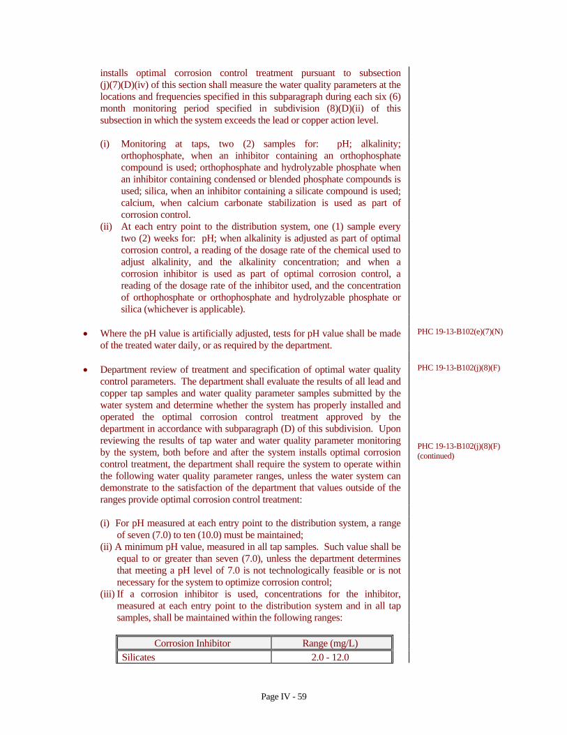
installs optimal corrosion control treatment pursuant to subsection (j)(7)(D)(iv) of this section shall measure the water quality parameters at the locations and frequencies specified in this subparagraph during each six (6) month monitoring period specified in subdivision (8)(D)(ii) of this subsection in which the system exceeds the lead or copper action level.
(i) Monitoring at taps, two (2) samples for: pH; alkalinity;
orthophosphate, when an inhibitor containing an orthophosphate compound is used; orthophosphate and hydrolyzable phosphate when an inhibitor containing condensed or blended phosphate compounds is used; silica, when an inhibitor containing a silicate compound is used; calcium, when calcium carbonate stabilization is used as part of corrosion control.
(ii) At each entry point to the distribution system, one (1) sample every two (2) weeks for: pH; when alkalinity is adjusted as part of optimal corrosion control, a reading of the dosage rate of the chemical used to adjust alkalinity, and the alkalinity concentration; and when a corrosion inhibitor is used as part of optimal corrosion control, a reading of the dosage rate of the inhibitor used, and the concentration of orthophosphate or orthophosphate and hydrolyzable phosphate or silica (whichever is applicable).
• Where the pH value is artificially adjusted, tests for pH value shall be made of the treated water daily, or as required by the department.
PHC 19-13-B102(e)(7)(N)
• Department review of treatment and specification of optimal water quality control parameters. The department shall evaluate the results of all lead and copper tap samples and water quality parameter samples submitted by the water system and determine whether the system has properly installed and operated the optimal corrosion control treatment approved by the department in accordance with subparagraph (D) of this subdivision. Upon reviewing the results of tap water and water quality parameter monitoring by the system, both before and after the system installs optimal corrosion control treatment, the department shall require the system to operate within the following water quality parameter ranges, unless the water system can demonstrate to the satisfaction of the department that values outside of the ranges provide optimal corrosion control treatment:
PHC 19-13-B102(j)(8)(F) PHC 19-13-B102(j)(8)(F) (continued)
(i) For pH measured at each entry point to the distribution system, a range
of seven (7.0) to ten (10.0) must be maintained;
(ii) A minimum pH value, measured in all tap samples. Such value shall be equal to or greater than seven (7.0), unless the department determines that meeting a pH level of 7.0 is not technologically feasible or is not necessary for the system to optimize corrosion control;
(iii) If a corrosion inhibitor is used, concentrations for the inhibitor, measured at each entry point to the distribution system and in all tap samples, shall be maintained within the following ranges:
Corrosion Inhibitor Range (mg/L)
Silicates 2.0 - 12.0
Page IV - 59
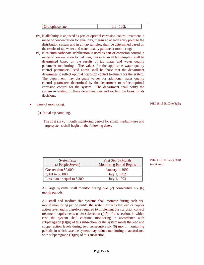
Orthophosphate 0.1 - 10.2;
(iv) If alkalinity is adjusted as part of optimal corrosion control treatment, a
range of concentration for alkalinity, measured at each entry point to the distribution system and in all tap samples, shall be determined based on the results of tap water and water quality parameter monitoring;
(v) If calcium carbonate stabilization is used as part of corrosion control, a range of concentration for calcium, measured in all tap samples, shall be determined based on the results of tap water and water quality parameter monitoring. The values for the applicable water quality control parameters listed above shall be those that the department determines to reflect optimal corrosion control treatment for the system, The department may designate values for additional water quality control parameters determined by the department to reflect optimal corrosion control for the system. The department shall notify the system in writing of these determinations and explain the basis for its decisions.
• Time of monitoring. PHC 19-13-B102(e)(8)(D)
(i) Initial tap sampling.
The first six (6) month monitoring period for small, medium-size and large systems shall begin on the following dates:
System Size First Six (6) Month PHC 19-13-B102(e)(8)(D) (# People Served) Monitoring Period Begins (continued)
Greater than 50,000 January 1, 1992
3,301 to 50,000 July 1, 1992
Less than or equal to 3,300 July 1, 1993
All large systems shall monitor during two (2) consecutive six (6) month periods.
All small and medium-size systems shall monitor during each six-month monitoring period until: the system exceeds the lead or copper action level and is therefore required to implement the corrosion control treatment requirements under subsection (j)(7) of this section, in which case the system shall continue monitoring in accordance with subparagraph (D)(ii) of this subsection, or the system meets the lead and copper action levels during two consecutive six (6) month monitoring periods, in which case the system may reduce monitoring in accordance with subparagraph (D)(iv) of this subsection.
Page IV - 60
(ii) Monitoring after installation of corrosion control and source water
treatment. Any large system that installs optimal corrosion control treatment pursuant to subsection (j)(7)(D)(iv) of this section shall monitor during two (2) consecutive six (6) month monitoring periods by the date specified in subsection (j)(7)(S)(v) of this section. Any small or medium-size system that installs optimal corrosion control treatment pursuant to subsection (j)(7)(E)(v) of this section shall monitor during two (2) consecutive six (6) month monitoring periods by the date specified in subsection (j)(7)(E)(vi) of this subsection. Any system that installs source water treatment pursuant to subsection (j)(9)(A)(iii) of this section shall monitor during two (2) consecutive six (6) month monitoring periods by the date specified in subsection (j)(9)(A)(iv) of this section.
(iii) Monitoring after the department specifies water quality parameter
values for optimal corrosion control.
After the department specifies the values for water quality control parameters under subsection (j)(8)(F) of this section, the system shall monitor during each subsequent six (6) month monitoring period, with the first monitoring period to begin on the date the department specifies the optimal values under subsection (j)(8)(F) of this section.
(iv) Reduced monitoring
A small or medium-size water system that meets the lead and copper action levels during each of two (2) consecutive six (6) month monitoring periods may reduce the number of samples in accordance with subparagraph (C) of this subdivision, and reduce the frequency of sampling to once per year, Any water system that maintains the range of values for the water quality control parameters reflection optimal corrosion control treatment specified by the department under subsection (j)(8)(F) of this section during each of two (2) consecutive six (6) month monitoring periods may request that the department allow the system to reduce the frequency of monitoring to once per year and to reduce the number of lead and copper samples in accordance with subparagraph (c) of this subdivision. The department shall review the information submitted by the water system and shall make its decision in writing, setting forth the basis for its determination. The department shall review, and where appropriate, revise its determination when the system submits new monitoring or treatment data, or when other data relevant to the number and frequency of tap sampling becomes available. A small or medium-size water system that meets the lead and copper action levels during three (3) consecutive years of monitoring may reduce the frequency of monitoring for lead and copper from annually to once every three (3) years. Any water system that maintains the range of values for the water quality control parameters reflection optimal corrosion control treatment specified by the department under subsection (j)(8)(F) of this section during three (3) consecutive years of
PHC 19-13-B102(e)(8)(D) (continued)
Page IV - 61
monitoring may request that the department allow the system to reduce the frequency of monitoring from annually to once every three (3) years . The department shall review the information submitted by the water system and shall make its decision in writing, setting forth the basis for its determination. The department shall review, and where appropriate, revise its determination when the system submits new monitoring or treatment data, or when other data relevant to the number and frequency of tap sampling becomes available. A water system that reduces the number and frequency of sampling shall collect these samples from sites included in the pool of targeted sampling sites identified in subparagraph (A) of this subdivision. Systems sampling annually or less frequently shall conduct the lead and copper tap sampling during the months of June, July, August, or September. A small or medium-size water system subject to reduced monitoring that exceeds the lead or copper action level shall resume sampling in accordance with subparagraph (D)(iii) of this subdivision and collect the number of samples specified for standard monitoring under subparagraph (C) of this subdivision. Such system shall also conduct water quality parameter monitoring in accordance with subdivision (9)(B), (C), or (D) of this subsection (as appropriate) during the monitoring period in which it exceeded the action level. Any water system subject to reduced monitoring frequency that fails to operate within the range of values for the water quality control parameters specified by the department under subsection (j)(8)(F) of this section shall resume tap water sampling in accordance with subparagraph (D)(iii) of this subdivision and collect the number of samples specified for standard monitoring under subparagraph (C) of this subdivision.
IV.L TASTE AND ODOR CONTROL
IV.L.1 Flexibility
Plants treating water that is known to have taste and odor problems should be provided with equipment that makes several of the control processes available so that the operator will have flexibility in operation.
RSWW 4.9.1
IV.L.2 Chlorination
Chlorination can be used for the removal of some objectionable odors. Adequate contact time must be provided to complete the chemical reactions involved. Excessive potential trihalomethane production through this process should be avoided by adequate bench-scale testing prior to design.
RSWW 4.9.2
IV.L.3 Chlorine Dioxide
Chlorine dioxide has been generally recognized as a treatment for tastes caused by industrial wastes, such as phenols. However, chlorine dioxide can be used in
RSWW 4.9.3
Page IV - 62
the treatment of any taste and odor that is treatable by an oxidizing compound. Provisions shall be made for proper storing and handling of the sodium chlorite, so as to eliminate any danger of explosion. See RSWW Section 5.4.3 (section IV.D.6.c of this document).
IV.L.4 Powdered Activated Carbon
• (a) Powdered activated carbon should be added as early as possible in the treatment process to provide maximum contact time. Flexibility to allow the addition of carbon at several points is preferred. Activated carbon should not be applied near the point of chlorine or other oxidant application
RSWW 4.9.4
(b) The carbon can be added as a pre-mixed slurry or by means of a dry-feed machine as long as the carbon is properly wetted.
(c) Continuous agitation or resuspension equipment is necessary to keep the carbon from depositing in the slurry storage tank.
(d) Provisions shall be made for adequate dust control. (e) The required rate of feed of carbon in a water treatment plant depends upon the tastes and/or odors involved, but provisions should be made for adding from 0.1 mg/l to at least 40 mg/l.
(f) Powdered activated carbon shall be handled as a potentially combustible material. It should be stored in a building or compartment as nearly fireproof as possible. Other chemicals should not be stored in the same compartment. A separate room should be provided for carbon feed installations. Carbon feeder rooms should be equipped with explosion-proof electrical outlets, lights and motors.
• Powdered activated carbon should conform to AWWA Standard B600-96, most current revision.
AWWA
IV.L.5 Granular Activated Carbon
• See Section IV.F.2.f of this document for application within filters.
• Granular activated carbon should conform to AWWA Standard B604-96,
most current revision. AWWA
IV.L.6 Copper Sulfate and Other Copper Compounds
• Continuous or periodic treatment of water with copper compounds to kill
algae or other growths shall be controlled to prevent copper in excess of 1.0 mg/l as copper in the plant effluent or distribution system. Care shall be taken to assure an even distribution.
RSWW 4.9.6
• Copper sulfate should coform to AWWA Standard B602-91, most current revision.
AWWA
IV.L.7 Aeration See Section IV.I of this document.
IV.L.8 Potassium Permanganate
Page IV - 63
• Application of potassium permanganate may be considered, providing the treatment shall be designed so that the products of the reaction are not visible in the finished water.
RSWW 4.9.8
• Potassium permanganate should conform to AWWA standard B603-93, most current revision.
AWWA
IV.L.9 Ozone
Ozonation can be used as a means of taste and odor control. Adequate contact time must be provided to complete the chemical reactions involved. Ozone is generally more desirable for treating water with high threshold odors. (see RSWW ozone policy statement)
RSWW 4.9.9
IV.L.10 Other Methods RSWW 4.9.10
The decision to use any other methods of taste and odor control should be made only after careful laboratory and/or pilot plant tests and on consultation with the Department.
IV.M WASTE HANDLING AND DISPOSAL
IV.M.1 Sanitary Waste
The sanitary waste from water treatment plants, pumping stations, and other waterworks installations must receive treatment. Waste from these facilities must be discharged directly to a sanitary sewer system, when available and feasible, or to an adequate on-site waste treatment facility approved by the Department and Connecticut Department of Environmental Protection.
RSWW 4.11.1 RSWW 4.11.1 (continued)
IV.M.2 Lime Softening Sludge
Sludge from the plants using lime to soften water varies in quantity and in chemical characteristics depending on the softening process and the chemical characteristics of the water being softened. Recent studies show that the quantity of sludge produced is much larger than indicated by stoichiometric calculations. Methods of treatment and disposal are as follows:
RSWW 4.11.3
a. Lagoon
1. Temporary lagoons which must be cleaned periodically should be
designed on the basis of 0.7 acres per million gallons per day per 100 mg/l of hardness removed based on a usable lagoon depth of five feet. This should provide about 2.5 years storage. At least two but preferable more lagoons must be provided in order to give flexibility in operation. An acceptable means of final sludge disposal must be provided. Provisions must be made for convenient cleaning.
2. Permanent lagoons should have a volume of at least four times that for temporary lagoons.
Page IV - 64

3. The design of both temporary lagoons and permanent lagoons should provide for
a. location free from flooding, b. when necessary, dikes, deflecting gutters or other means of
diverting surface water so that it does not flow into lagoons,
c. a minimum usable depth of five feet, d. adequate freeboard of at least two feet, e. adjustable decanting device, f. effluent sampling point, g. adequate safety provisions, and h. parallel operation.
b. The application of liquid lime sludge to farm land should be considered as a
method of ultimate disposal. Prior to land application, a chemical analysis of the sludge including calcium and heavy metals shall be conducted. Approval from the appropriate Department must be obtained. When this method is selected, the following provisions shall be made:
1. Transport of sludge by vehicle or pipeline shall incorporate a plan or
design which prevents spillage or leakage during transport.
2. Interim storage areas at the application site shall be kept to a minimum and facilities shall be provided to prevent washoff of sludge or flooding.
3. Sludge shall not be applied at times when washoff of sludge from the land could be expected.
4. Sludge shall not be applied to sloping land where washoff could be expected unless provisions are made, for suitable land, to immediately incorporate the sludge into the soil.
RSWW 4.11.3 (continued)
5. Trace metals loading shall be limited to prevent significant increases in trace metals in the food chain, phytotoxicity or water pollution.
6. Each area of land to receive lime sludge shall be considered individually and a determination made as to the amount of sludge needed to raise soil pH to the optimum for the crop to be grown.
c. Discharge of lime sludge to sanitary sewers should be avoided since it may
cause both liquid volume and sludge volume problems at the sewage treatment plant. This method should be used only when the sewerage system has the capability to adequately handle the lime sludge.
d. Mixing of lime sludge with activated sludge waste may be considered as a means of co-disposal .
e. Disposal at a landfill can be done as either a solid or liquid if the landfill can accept such waste, depending on individual state requirements.
f. Mechanical dewatering of sludge may be considered. Pilot studies on particular plant waste are required.
g. Lime sludge drying beds are not recommended.
IV.M.3 Water Treatment Backwash/Regeneration Wastewater
Waste filter wash water from iron and manganese removal plants can be RSWW 4.11.5
Page IV - 65
disposed of as follows
IV.M.3.a Sand Filters
• Sand filters should have the following features: RSWW 4.11.5.1
a. Total filter area shall be sufficient to adequately dewater applied
solids. Unless the filter is small enough to be cleaned and returned to service in one day, two or more cells are required.
b. The “red water” filter shall have sufficient capacity to contain, above the level of the sand, the entire volume of wash water produced by washing all of the production filters in the plant, unless the production filters are washed on a rotating schedule and the flow through the production filters is regulated by true rate of flow controllers. Then sufficient volume must be provided to properly dispose of the wash water involved.
c. Sufficient filter surface area should be provided so that, during any one filtration cycle, no more that two feet of backwash water will accumulate over the sand surface.
d. The filter shall not be subject to flooding by surface runoff or flood waters. Finished grade elevation shall be established to facilitate maintenance, cleaning and removal of surface sand as required. Flash boards or other non-watertight devices shall not be used in the construction of filter side walls.
e. The filter media should consist of a minimum of twelve inches of sand, three to four inches of supporting small gravel or torpedo sand, and nine inches of gravel in graded layers. All sand and gravel should be washed to remove fines.
RSWW 4.11.5.1 (continued)
f. Filter sand should have an effective size of 0.3 to 0.5 mm and a uniformity coefficient not to exceed 3.5. The use of larger sized sands shall be justified by the designing engineer to the satisfaction of the review authority.
g. The filter should be provided with an adequate under-drainage collection system to permit satisfactory discharge of filtrate.
h. Provision shall be made for the sampling of the filter effluent. i. Overflow devices from “red water” filters shall not be permitted. j. Where freezing is a problem, provisions should be made for
covering the filters during the winter months.
k. “Red water” filters shall comply with the common wall provisions contained in Section IV.M.3.a of this report and Section VII.E.1 of this report which pertain to the possibility of containing treated water with an unsafe water.
The Department must be contacted for approval of any arrangement where a separate structure is not provided.
• Adjacent Compartments RSWW 7.1.3
Finished water must not be stored or conveyed in a compartment
Page IV - 66

adjacent to unsafe water when the two compartments are separated by a single wall.
IV.M.3.b Lagoons
Lagoons shall have the following features: RSWW 4.11.5.2
a. be designed with volume 10 times the total quantity of wash water discharged during any 24-hour period,
b. a minimum usable depth of three feet, c. length four times width, and the width at least three times the depth, as
measured at the operating water level,
d. outlet to be at the end opposite the inlet, e. a weir overflow device at the outlet end with weir length equal to or
greater than depth,
f. velocity to be dissipated at the inlet end.
IV.M.3.c Discharge to Community Sanitary Sewer
Wastewater can be discharged to a community sewer. However, approval of this method will depend on obtaining approval from the owner of the sewage system as well as from the regulatory agency before final designs are made. A holding tank is recommended to prevent overloading the sewers.
RSWW 4.11.5.3
IV.M.3.d Recycling Wastes Recycling of supernatant of filtrate from water treatment facilities to the head end of a water treatment plant shall not be allowed except as approved by the Department.
RSWW 4.11.5.4
IV.M.3.e Waste Filter Wash Water Waste filter wash water from surface water treatment or lime softening plants should have suspended solids reduced to a level acceptable to the regulatory agency before being discharged. Many plants have constructed holding tanks and returned this water to the inlet end of the plant. The holding tank should be of such a size that it will contain the anticipated volume of waste wash water produced by the plant when operating at design capacity. A plant that has two filters should have a holding tank that will contain the total waste wash water from both filters calculated by using a 15 minute wash at 20 gallons per minute per square foot. In plant with more filters, the size of the holding tank will depend on the anticipated hours of operation. It is recommended that waste filter wash water be returned at a rate of less than 10 percent of the raw water flow rate entering the plant. Filter backwash water should not be recycled when the raw water contains excessive algae, when finished water taste and odor problems are encountered, or when trihalomethane levels in the distribution system may exceed allowable levels. Particular attention must be given to the presence of protozoans such as Giardia and Cryptosporidium concentration in the
RSWW 4.11.6
Page IV - 67
waste water stream. Water utilities may need to treat filter waste water prior to recycling or avoid reclaiming filter wash water given the increased risk to treated water quality.
IV.M.4 Ion Exchange Regeneration/Backwash Wastewater
Brine Waste RSWW 4.11.2
Waste from ion exchange plants, demineralization plants, or other plants which produce a brine, may be disposed of by controlled discharge to a stream if adequate dilution is available. Surface water quality requirements of the regulatory agency will control the rate of discharge. Except when discharging to large waterways, a holding tank of sufficient size should be provided to allow the brine to be discharged over a twenty-four hour period. Where discharging to a sanitary sewer, a holding tank may be required to prevent the overloading of the sewer and/or interference with the waste treatment processes. The effect of brine discharge to sewage lagoons may depend on the rate of evaporation from the lagoons Whenever applicable, reference should be made to the US EPA Suggested Guidelines for Disposal of Drinking Water Treatment Wastes Containing Radioactivity.
IV.M.5 Alum Sludge
Lagooning may be used as a method of handling alum sludge. Lagoon size can be calculated using total chemicals used plus a factor for turbidity. Mechanical concentrations may be considered. A pilot plant study is required before the design of a mechanical dewatering installation. Freezing changes the nature of alum sludge so that it can be used for fill. Acid treatment of sludge for alum recovery may be a possible alternative. Alum sludge can be discharged to a sanitary sewer. However, initiation of this practice will depend on obtaining approval from the owner of the sewage system as well as from the regulatory agency before final designs are made.
RSWW 4.11.4 RSWW 4.11.4 (continued)
Lagoons should be designed to produce an effluent satisfactory to the regulatory agency and should provide for
a. location free from flooding, b. where necessary, dikes, deflecting gutters or other means of diverting
surface water so that it does not flow into the lagoon,
c. a minimum usable depth of five feet, d. adequate freeboard of at least two feet, e. adjustable decanting device, f. effluent sampling point, g. adequate safety provisions, and h. a minimum of two cells, each with appropriate inlet/outlet structures to
facilitate independent filling/dewatering operations.
Page IV - 68
Related Documents