Chapter 30 Introduction to Visual Basic for Applications (VBA) AutoCAD and Its Applications—Advanced 688 Copyright by Goodheart-Willcox Co., Inc. Learning Objectives After completing this chapter, you will be able to: ✓ Explain object-oriented programming. ✓ Describe the AutoCAD object model. ✓ Change an object’s properties. ✓ Use an object’s methods. ✓ Use the VBA Manager . ✓ Develop a VBA project using the Visual Basic Editor . ✓ Explain the data types used in VBA. ✓ Store data in variables. ✓ Run a VBA macro. ✓ Create a form (dialog box) in a VBA project. Visual Basic for Applications (VBA) is a version of Microsoft’s Visual Basic (VB) programming language that is built into AutoCAD. All of the features of the full version of VB are included, in addition to functions and procedures that are specific to programming the AutoCAD application. This chapter is intended to give you an overview of the basics of VBA. You will learn how easy to use, and yet powerful, the language is. This chapter is by no means an in-depth look at VBA. For more complete discussions and study of VBA within AutoCAD, refer to VBA for AutoCAD published by The Goodheart-Willcox Company, Inc. In order to use VBA in AutoCAD 2010, the VBA module must be downloaded from the Autodesk website. If the module is not installed, selecting any of the VBA tools (Visual Basic Editor , Run VBA Macro, or VBA Manager) from the Applications panel on the Manage tab of the ribbon opens a dialog box that will guide you through the process. Object-Oriented Programming VBA is an object-oriented programming language. Although lines, arcs, and circles are objects, AutoCAD entities are not the only objects. The many “parts” that make up the AutoCAD application itself are considered objects. The whole program and all that it is composed of are considered the object model. The AutoCAD object model Introduction to Visual Basic for Applications (VBA) CHAPTER

Welcome message from author
This document is posted to help you gain knowledge. Please leave a comment to let me know what you think about it! Share it to your friends and learn new things together.
Transcript

Chapter 30 Introduction to Visual Basic for Applications (VBA) AutoCAD and Its Applications—Advanced 688Copyright by Goodheart-Willcox Co., Inc.
Learning ObjectivesAfter completing this chapter, you will be able to:✓ Explain object-oriented programming.✓ Describe the AutoCAD object model.✓ Change an object’s properties.✓ Use an object’s methods.✓ Use the VBA Manager.✓ Develop a VBA project using the Visual Basic Editor.✓ Explain the data types used in VBA.✓ Store data in variables.✓ Run a VBA macro.✓ Create a form (dialog box) in a VBA project.
Visual Basic for Applications (VBA) is a version of Microsoft’s Visual Basic (VB) programming language that is built into AutoCAD. All of the features of the full version of VB are included, in addition to functions and procedures that are specific to programming the AutoCAD application. This chapter is intended to give you an overview of the basics of VBA. You will learn how easy to use, and yet powerful, the language is. This chapter is by no means an in-depth look at VBA. For more complete discussions and study of VBA within AutoCAD, refer to VBA for AutoCAD published by The Goodheart-Willcox Company, Inc.
In order to use VBA in AutoCAD 2010, the VBA module must be downloaded from the Autodesk website. If the module is not installed, selecting any of the VBA tools (Visual Basic Editor, Run VBA Macro, or VBA Manager) from the Applicationspanel on the Manage tab of the ribbon opens a dialog box that will guide you through the process.
Object-Oriented Programming
VBA is an object-oriented programming language. Although lines, arcs, and circles are objects, AutoCAD entities are not the only objects. The many “parts” that make up the AutoCAD application itself are considered objects. The whole program and all that it is composed of are considered the object model. The AutoCAD object model
Introduction to Visual Basic for
Applications (VBA)
C H A P T E R
Chapter 30 Introduction to Visual Basic for Applications (VBA) AutoCAD and Its Applications—Advanced 689Copyright by Goodheart-Willcox Co., Inc.
contains all of the objects and provides access to their methods, properties, and events in a tree-like hierarchy. See Figure 30-1. To display this object model, pick the Help button in the InfoCenter on the AutoCAD title bar. Once the help file is displayed, pick the Contents tab. Then, double-click on ActiveX Automation and VBA. Finally, in the right-hand pane, select Object Model.
Figure 30-1.The object model for AutoCAD.
DatabasePreferences
Plot
Utility
MenuGroup
PopupMenuItem
Toolbar
ToolbarItem
Document
Documents
Preferences
Database
Hyperlinks
3DFace
3DPoly
3DSolid
Arc
Attribute
AttributeRef
BlockRef
Circle
Dim3PointAngular
DimAligned
DimAngular
DimDiametric
Hyperlink
DimOrdinate
DimRadial
DimRotated
Ellipse
ExternalReference
Hatch
Leader
LightweightPolyline
Line
MinsertBlock
MLine
MText
Point
PolyfaceMesh
Polyline
PolygonMesh
Raster
Ray
Region
Shape
Solid
PViewport
Dictionary
PaperSpace
ModelSpace
Block
XRecord
DimStyle
FileDependency
Group
Layer
Layout
Linetype
PlotConfiguration
RegisteredApplication
TextStyle
UCS
View
Viewport
Dictionaries
Blocks
DimStyles
FileDependencies
Groups
Layers
Layouts
Linetypes
PlotConfigurations
RegisteredApps
TextStyles
UCSs
Views
Viewports
MenuBar
MenuGroups
SummaryInfo
PopupMenu
PopupMenuAcCmColor
Application
LayerStateManager
SecurityParams
PopupMenus
Toolbars
Spline
Table
Text
Tolerance
Trace
XLine
DimArcLength
MLeader
SelectionSetSelectionSets
SortentsTable
TableStyle
DynamicBlockReferenceProperty
DimRadialLarge
Wipeout

Chapter 30 Introduction to Visual Basic for Applications (VBA) AutoCAD and Its Applications—Advanced 690Copyright by Goodheart-Willcox Co., Inc.
Notice that the AutoCAD Application object itself is the upper-most object in the hierarchy. The application is considered the root of the tree. Under the application are branches for Preferences, Documents, Document, MenuBar, and MenuGroups. Each of these is considered an object. Through the Application object and then through these five objects (branches of the tree), all of the methods, properties, and events can be accessed for all of the objects in the AutoCAD program.
For example, to change the size of the pick box to four, you must go through the hierarchy to get to that object’s properties using the following code. Each level, or branch, of the object model is separated by a period.
Application.Preferences.Selection.PickBoxSize = 4
The above code introduces another level in the hierarchy: Selection. The Selection object is a subobject of the Preferences object. The Preferences object holds those options in AutoCAD’s Options dialog box that are stored in the registry. The Preferences object is made up of subobjects that represent each of the tabs in the Options dialog box. Working from AutoCAD’s point of view, rather than VBA’s point of view, the pick box size is set on the Selection tab of the Options dialog box in the AutoCAD application.
Methods, Properties, and Events
Each object within the object model has various methods, properties, and events associated with it. The set of available methods, properties, and events is unique for each object. However, some methods, properties, and events are available to multiple objects. Some objects do not have any methods, properties, or events available to them.
Methods are functions built into the objects that allow the object’s properties to be modified. Some examples of methods that are available to a few objects include:
• The Circle object has a Move method and 18 other methods.• The Layer object has a Delete method and three other methods.• The ModelSpace object has an AddLine method and 51 other methods.• The Document object has a Close method and 19 other methods.Properties are the “settings” associated with an object, similar to the properties of
AutoCAD entities that are found in the Properties dialog box. Other, non-AutoCAD-entity objects have properties, too. Some examples of properties that are associated with a few objects include:
• The Circle object has a Layer property and 20 other properties.• The Layer object has a Freeze property and 19 other properties.• The ModelSpace object has a Count property and six other properties.• The Document object has an ActiveSpace property and 48 other properties.Events are actions that occur while a VBA program or macro is running. An event
can be monitored (continuously checked) and, if it occurs, another action can be trig-gered. An event can be as simple as the user picking the OK button to close a dialog box. For example, you can create a VBA program that changes the linetype scale setting when the user switches from model space to paper (layout) space. Some examples of events that are associated with a few objects include:
• The Circle object has a Modified event.• The Layer object has a Modified event.• The ModelSpace object has a Modified event.• The Document object has a LayoutSwitched event and 27 other events.
Events are beyond the scope of this text. For more information on using events in VBA macros, refer to VBA for AutoCAD published by The Goodheart-Willcox Company, Inc.
Chapter 30 Introduction to Visual Basic for Applications (VBA) AutoCAD and Its Applications—Advanced 691Copyright by Goodheart-Willcox Co., Inc.
Exercise 30-1Complete the exercise on the student website.www.g-wlearning.com/CAD
Understanding How a VBA Program Works
VBA programs are actually called projects. A project consists of the forms and modules necessary to obtain the desired outcome. VBA refers to dialog boxes asforms. Modules are the Sub procedures that actually contain the program code. Sub procedures are subroutines, or small programs, that can be called from within other procedures. A macro is a Sub that is declared as Public, meaning it will show up in AutoCAD’s Macros dialog box. The terms projects, modules, macros, subs, and forms are used throughout this chapter.
Projects can be stored in two locations: in a file or in a drawing. A project stored in a drawing is considered embedded. That project is automatically loaded and its macros are available each time the drawing in which the project is embedded is opened. A project stored in a file has a .dvb file extension and must be loaded in order for its macros to be available in the drawing. A project stored as a DVB file is considered global as it can be loaded into any drawing from any computer that has access to the DVB file. If the project is saved as a file named acad.dvb and the file is in the AutoCAD search path, it is loaded each time a drawing is opened. Interestingly, once a project has been loaded into one drawing, its macros are available to all open drawings, as long as the drawing into which the project was loaded remains open.
Using the VBA Manager
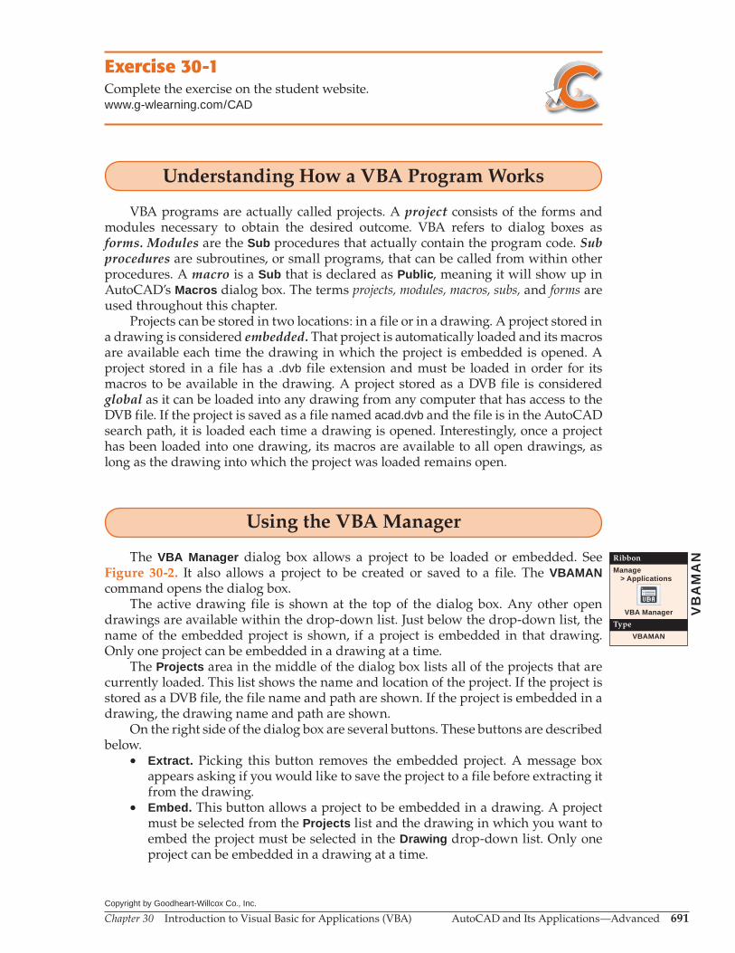
The VBA Manager dialog box allows a project to be loaded or embedded. SeeFigure 30-2. It also allows a project to be created or saved to a file. The VBAMANcommand opens the dialog box.
The active drawing file is shown at the top of the dialog box. Any other open drawings are available within the drop-down list. Just below the drop-down list, the name of the embedded project is shown, if a project is embedded in that drawing. Only one project can be embedded in a drawing at a time.
The Projects area in the middle of the dialog box lists all of the projects that are currently loaded. This list shows the name and location of the project. If the project is stored as a DVB file, the file name and path are shown. If the project is embedded in a drawing, the drawing name and path are shown.
On the right side of the dialog box are several buttons. These buttons are described below.
• Extract. Picking this button removes the embedded project. A message box appears asking if you would like to save the project to a file before extracting it from the drawing.
• Embed. This button allows a project to be embedded in a drawing. A project must be selected from the Projects list and the drawing in which you want to embed the project must be selected in the Drawing drop-down list. Only one project can be embedded in a drawing at a time.
VB
AM
ANRibbon
Manage > Applications
VBA Manager
Type
VBAMAN

Chapter 30 Introduction to Visual Basic for Applications (VBA) AutoCAD and Its Applications—Advanced 692Copyright by Goodheart-Willcox Co., Inc.
• New. Picking this button creates a new project and adds it to the Projects list. The new project has the default name ACADProject name and is generically listed as Globaln, where n is a sequential integer. The project name can only be changed in the Visual Basic Editor, which is covered in the next section. The Globaln location is updated when the project is saved as a file or embedded in a drawing.
• Save as. Use this button to save to a file the project highlighted in the Projects list. A standard Windows “save as” dialog box appears when the button is picked.
• Load. Picking this button displays a standard Windows “open” dialog box in which you can select a project file (DVB) to be loaded. The project is loaded into the drawing selected in the Drawing drop-down list.
• Unload. This button allows a project to be unloaded, making its macros unavail-able. Highlight the project to unload in the Projects list and then pick this button.
• Macros. Picking this button closes the VBA Manager dialog box and opens the Macros dialog box. The available macros are listed in the Macros dialog box. The Macros dialog box has a VBA Manager… button that displays the VBA Manager dialog box.
There is also the Visual Basic Editor button in the lower-left corner of the VBA Manager dialog box. Picking this button opens the Visual Basic Editor, which is covered in the next section.
Using the Visual Basic Editor
The Visual Basic Editor is a full featured, built-in editor for VBA programming in AutoCAD. The VBAIDE command displays the Visual Basic Editor. It can also be opened by picking the Visual Basic Editor button from within the VBA Manager dialog box.
Now that you have been introduced to VBA terminology and have a basic under-standing of how to manipulate projects, you will create a project to allow you to examine the Visual Basic Editor. To avoid confusion, first unload all loaded projects:
1. Open the VBA Manager. 2. Select a project in the Projects list. 3. Pick the Unload button. 4. Do the same for all other projects until the Projects list is empty.
Figure 30-2.The VBA Manager in AutoCAD.
Newproject
Activedrawing
Loadedproject
Pick tocreate a new
project
Pick toload aproject
file
VB
AID
ERibbon
Manage > Applications
Visual Basic Editor
Type
VBAIDE [Alt]+[F11]
Chapter 30 Introduction to Visual Basic for Applications (VBA) AutoCAD and Its Applications—Advanced 693Copyright by Goodheart-Willcox Co., Inc.
5. Pick the New button. A project named ACADProject is added to the Projects list and its location is shown as Globaln.
6. Pick the Visual Basic Editor button in the lower-left corner of the VBA Manager dialog box.
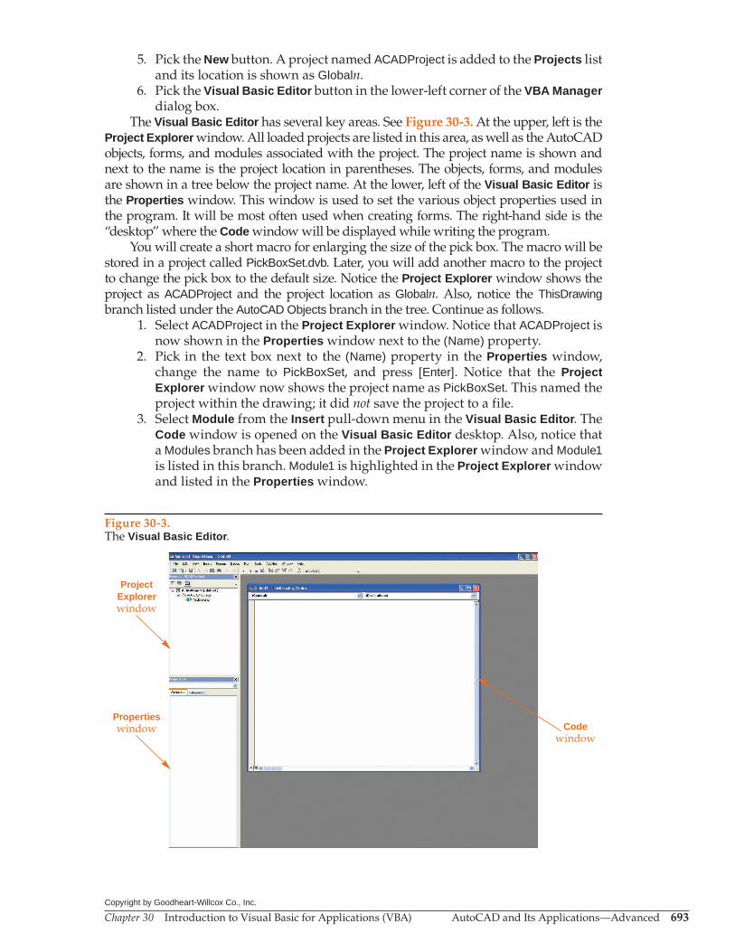
The Visual Basic Editor has several key areas. See Figure 30-3. At the upper, left is the Project Explorer window. All loaded projects are listed in this area, as well as the AutoCAD objects, forms, and modules associated with the project. The project name is shown and next to the name is the project location in parentheses. The objects, forms, and modules are shown in a tree below the project name. At the lower, left of the Visual Basic Editor is the Properties window. This window is used to set the various object properties used in the program. It will be most often used when creating forms. The right-hand side is the “desktop” where the Code window will be displayed while writing the program.
You will create a short macro for enlarging the size of the pick box. The macro will be stored in a project called PickBoxSet.dvb. Later, you will add another macro to the project to change the pick box to the default size. Notice the Project Explorer window shows the project as ACADProject and the project location as Globaln. Also, notice the ThisDrawing branch listed under the AutoCAD Objects branch in the tree. Continue as follows.
1. Select ACADProject in the Project Explorer window. Notice that ACADProject is now shown in the Properties window next to the (Name) property.
2. Pick in the text box next to the (Name) property in the Properties window, change the name to PickBoxSet, and press [Enter]. Notice that the Project Explorer window now shows the project name as PickBoxSet. This named the project within the drawing; it did not save the project to a file.
3. Select Module from the Insert pull-down menu in the Visual Basic Editor. The Code window is opened on the Visual Basic Editor desktop. Also, notice that a Modules branch has been added in the Project Explorer window and Module1 is listed in this branch. Module1 is highlighted in the Project Explorer window and listed in the Properties window.
Figure 30-3.The Visual Basic Editor.
ProjectExplorerwindow
Propertieswindow Code
window
Chapter 30 Introduction to Visual Basic for Applications (VBA) AutoCAD and Its Applications—Advanced 694Copyright by Goodheart-Willcox Co., Inc.
4. In the Properties window, change the name of Module1 to PickBoxBig. Notice that the module name is updated in the Project Explorer window and in the title bar of the Code window.
5. Pick inside of the Code window. Notice the blinking, vertical cursor in the window, similar to how it would appear in a text editor.
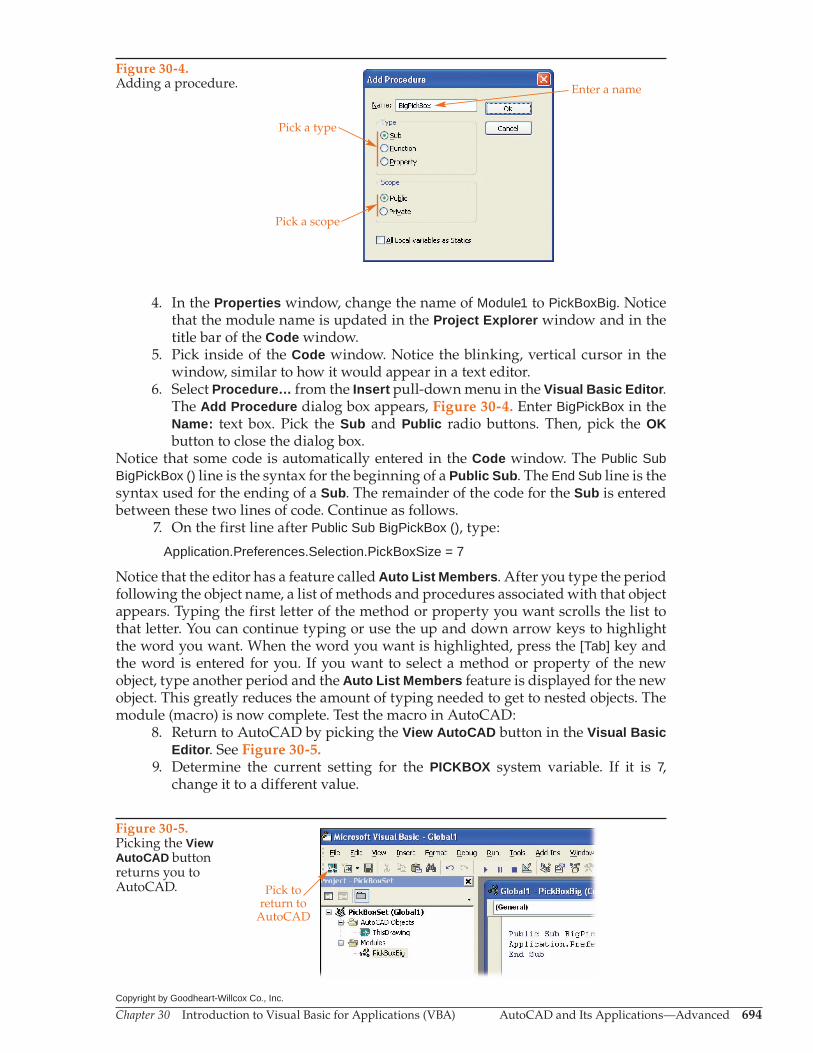
6. Select Procedure… from the Insert pull-down menu in the Visual Basic Editor. The Add Procedure dialog box appears, Figure 30-4. Enter BigPickBox in the Name: text box. Pick the Sub and Public radio buttons. Then, pick the OK button to close the dialog box.
Notice that some code is automatically entered in the Code window. The Public Sub BigPickBox () line is the syntax for the beginning of a Public Sub. The End Sub line is the syntax used for the ending of a Sub. The remainder of the code for the Sub is entered between these two lines of code. Continue as follows.
7. On the first line after Public Sub BigPickBox (), type:
Application.Preferences.Selection.PickBoxSize = 7
Notice that the editor has a feature called Auto List Members. After you type the period following the object name, a list of methods and procedures associated with that object appears. Typing the first letter of the method or property you want scrolls the list to that letter. You can continue typing or use the up and down arrow keys to highlight the word you want. When the word you want is highlighted, press the [Tab] key and the word is entered for you. If you want to select a method or property of the new object, type another period and the Auto List Members feature is displayed for the new object. This greatly reduces the amount of typing needed to get to nested objects. The module (macro) is now complete. Test the macro in AutoCAD:
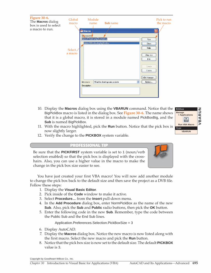
8. Return to AutoCAD by picking the View AutoCAD button in the Visual Basic Editor. See Figure 30-5.
9. Determine the current setting for the PICKBOX system variable. If it is 7, change it to a different value.
Figure 30-4.Adding a procedure.
Pick a type
Enter a name
Pick a scope
Figure 30-5.Picking the View AutoCAD button returns you to AutoCAD. Pick to
return toAutoCAD
Chapter 30 Introduction to Visual Basic for Applications (VBA) AutoCAD and Its Applications—Advanced 695Copyright by Goodheart-Willcox Co., Inc.
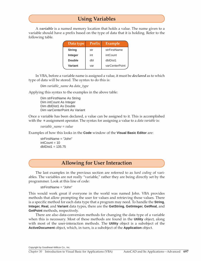
10. Display the Macros dialog box using the VBARUN command. Notice that the BigPickBox macro is listed in the dialog box. See Figure 30-6. The name shows that it is a global macro, it is stored in a module named PickBoxBig, and the Sub is named BigPickBox.
11. With the macro highlighted, pick the Run button. Notice that the pick box is now slightly larger.
12. Verify the change to the PICKBOX system variable.
PROFESSIONAL TIP
Be sure that the PICKFIRST system variable is set to 1 (noun/verb selection enabled) so that the pick box is displayed with the cross-hairs. Also, you can use a higher value in the macro to make the change in the pick box size easier to see.
You have just created your first VBA macro! You will now add another module to change the pick box back to the default size and then save the project as a DVB file. Follow these steps:
1. Display the Visual Basic Editor. 2. Pick inside of the Code window to make it active. 3. Select Procedure… from the Insert pull-down menu. 4. In the Add Procedure dialog box, enter NormPickBox as the name of the new
Sub. Also, pick the Sub and Public radio buttons, then pick the OK button. 5. Enter the following code in the new Sub. Remember, type the code between
the Public Sub and the End Sub lines.
Application.Preferences.Selection.PickBoxSize = 3
6. Display AutoCAD. 7. Display the Macros dialog box. Notice the new macro is now listed along with
the first macro. Select the new macro and pick the Run button. 8. Notice that the pick box size is now set to the default size. The default PICKBOX
value is 3.
VB
AR
UNRibbon
Manage > Applications
Run VBA Macro
Type
VBARUN
Figure 30-6.The Macros dialog box is used to select a macro to run.
Selecta macro
Globalmacro
Modulename Sub name
Pick to runthe macro

Chapter 30 Introduction to Visual Basic for Applications (VBA) AutoCAD and Its Applications—Advanced 696Copyright by Goodheart-Willcox Co., Inc.
9. Display the Visual Basic Editor. 10. Pick the Save button on the toolbar in the Visual Basic Editor. A standard
Windows “save as” dialog box appears. Save the file under the name PickBoxSetin the folder of your choice. The .dvb extension is automatically added.
As you work through the rest of the chapter, enter each example in the Code window in the Visual Basic Editor. Then, test each example using Macros dialog box in AutoCAD.
Exercise 30-2Complete the exercise on the student website.www.g-wlearning.com/CAD
Dealing with Data Types
The concept of programming revolves around gathering, storing, and reusing data. The data used by programs come in various data types. In the previous project, the macro set the pick box size by providing an integer. An integer is considered a data type. As you learn to use VBA to manipulate the AutoCAD environment in other ways and to create and modify AutoCAD entities, you will need to use other data types.
Although there are many data types available and needed while programming in VBA, only a few are often used while working in AutoCAD. The more common data types used in AutoCAD are strings, integers, real numbers, and variants. Integers and real numbers are each further broken down into two types covering different ranges of numbers.
Data type Range Description
String Text characters.
Integer –32,768 to 32,767 Small integer values.
Long –2,147,483,648 to 2,147,483,647 Large integer values.
Single 1.4E–45 to 3.4E+48 Single precision floating point numbers.
Double 4.94E–324 to 1.8E+308 Double precision floating point numbers.
Variant Typically used to denote coordinates.
For the examples in the rest of this chapter, you will use the String, Integer, Double, and Variant data types. The practical applications for these data types are:
• String. Used for command names, prompts, AutoCAD system variables, and so on. When using strings within a program, the characters making up the string are enclosed in quotation marks “like this”.
• Integer. Used for counting. Often, the program has to progress through a list in increments. Integers are used to do so.
• Double. Used for lengths; distances; and X, Y, or Z coordinate values (when dealing with X, Y, and Z separately).
• Variant. Used for point coordinates (when working with X, Y, and Z values together).
Chapter 30 Introduction to Visual Basic for Applications (VBA) AutoCAD and Its Applications—Advanced 697Copyright by Goodheart-Willcox Co., Inc.
Using Variables
A variable is a named memory location that holds a value. The name given to a variable should have a prefix based on the type of data that it is holding. Refer to the following table.
Data type Prefix Example
String str strFirstName
Integer int intCount
Double dbl dblDist1
Variant var varCenterPoint
In VBA, before a variable name is assigned a value, it must be declared as to which type of data will be stored. The syntax to do this is:
Dim variable_name As data_type
Applying this syntax to the examples in the above table:
Dim strFirstName As StringDim intCount As IntegerDim dblDist1 As DoubleDim varCenterPoint As Variant
Once a variable has been declared, a value can be assigned to it. This is accomplished with the = assignment operator. The syntax for assigning a value to a data variable is:
variable_name = value
Examples of how this looks in the Code window of the Visual Basic Editor are:
strFirstName = "John"intCount = 10dblDist1 = 135.75
Allowing for User Interaction
The last examples in the previous section are referred to as hard coding of vari-ables. The variables are not really “variable,” rather they are being directly set by the programmer. Look at this line of code:
strFirstName = "John"
This would work great if everyone in the world was named John. VBA provides methods that allow prompting the user for values and retrieving those values. There is a specific method for each data type that a program may need. To handle the String, Integer, Real, and Variant data types, there are the GetString, GetInteger, GetReal, and GetPoint methods, respectively.
There are also data-conversion methods for changing the data type of a variable when this is necessary. Most of these methods are found in the Utility object, along with most of the user-interaction methods. The Utility object is a subobject of the ActiveDocument object, which, in turn, is a subobject of the Application object.

Chapter 30 Introduction to Visual Basic for Applications (VBA) AutoCAD and Its Applications—Advanced 698Copyright by Goodheart-Willcox Co., Inc.
PROFESSIONAL TIP
To make coding a little easier, the ThisDrawing object can be used as an alias for the Application.ActiveDocument object.
To store a string supplied by the user, the Utility object’s GetString method is used. The GetString method has one required argument, which must come first, and one optional argument, which must come second. An argument is additional information that can be passed to the method. The arguments are listed within parentheses imme-diately after the method. Each argument is separated by a comma. This additional information is required in some instances and optional in other instances.
In the case of the GetString method, the first argument is a TRUE or FALSE test and determines whether or not the string that the user enters can contain spaces. Actu-ally, it determines whether the space bar is interpreted as a space or as the [Enter] key. If the argument is FALSE, spaces are not allowed. If the user presses the space bar, the text input is ended. If the argument is TRUE, spaces are allowed in the input string.
The second argument for the GetString method is an optional prompt. If included, it must be a string. The provided string is displayed on the command line when the method is called. This can be used to let the user know what is expected of them. Even though this argument is optional, it is almost always included.
The following code gets a string input by the user and stores it in a variable. Notice that spaces are not allowed in the string.
Dim strName as StringstrName = ThisDrawing.Utility.GetString(FALSE,"First name only: ")
Now that the value is stored, it can be used in some way. For the test macro, it will just be sent to the command line using the Prompt method. The Prompt method requires one argument, which must be a string. The data stored in the strName variable represent a string, so pass this variable to the Prompt method:
ThisDrawing.Utility.Prompt (strName)
Another feature of the Visual Basic Editor becomes apparent as you enter func-tions that can have arguments passed to them. The Auto Quick Info feature displays information about the arguments as soon as you type the opening parenthesis. The argument that you are “working on” is in bold. Arguments that are optional are shown enclosed in brackets. Required arguments are shown without brackets.
The following shows additional example code for the GetInteger, GetReal, and GetPoint methods. For each method, the variable is passed to the Prompt variable.
Sub GetSamples ()
Dim strName as String strName = ThisDrawing.Utility.GetString(FALSE,"First name only: ") ThisDrawing.Utility.Prompt (strName)
Dim intNumber as Integer intNumber = ThisDrawing.Utility.GetInteger("Enter an integer: ") ThisDrawing.Utility.Prompt (intNumber)
Dim dblNumber as Double dblNumber = ThisDrawing.Utility.GetReal("Enter a real number: ") ThisDrawing.Utility.Prompt (dblNumber)
Dim varPoint as Variant varPoint = ThisDrawing.Utility.GetPoint(, "Pick a point: ") ThisDrawing.Utility.Prompt (varPoint(0) & ", " & varPoint(1))
End Sub
Chapter 30 Introduction to Visual Basic for Applications (VBA) AutoCAD and Its Applications—Advanced 699Copyright by Goodheart-Willcox Co., Inc.
Some items of note regarding the GetPoint code:• The GetPoint method can have two arguments, but in this case only a prompt
string argument needs to be supplied. However, this must be the second argu-ment. The first argument is left blank, but still separated from the second argu-ment with a comma.
• The GetPoint method returns (produces) a set of X, Y, and Z coordinates. These three values are stored in what is called an array in VBA, which is similar to an AutoLISP list. The items in an array are indexed beginning with 0, rather than 1. So, the X value is in the array at an index of 0, the Y value at index 1, and the Z value at index 2. Each item can be passed as an argument by using its index in the array. In the above example, the X and Y values (at index positions 0 and 1) are passed to the Prompt method.
• The Prompt method can only have one argument, a string, passed to it. Multiple strings can be concatenated (added together) using the ampersand (&). In the above example, only the X value varPoint(0) and Y value varPoint(1) are supplied and they are separated by a comma and a space (", ").
Exercise 30-3Complete the exercise on the student website.www.g-wlearning.com/CAD
Creating AutoCAD Entities
AutoCAD entities can be created using VBA. The following sample code creates a circle. Later in this section, sample code is provided that creates a line.
Sub CreateCircle()
Dim objCircle As AcadCircleDim varCP As VariantDim dblRadius As Double
varCP = ThisDrawing.Utility.GetPoint(, "Center point for circle: ")dblRadius = ThisDrawing.Utility.GetReal("Enter circle radius: ")
Set objCircle = ThisDrawing.ModelSpace.AddCircle(varCP, dblRadius)
End Sub
The Set statement and = assignment operator are used to assign a reference to a particular object type. This is how you store a value in an object variable. The AddCirclemethod is used to create a circle, in this case as a member of the ModelSpace collection (created in model space). This example also introduces a new data type. AcadCircleis an object data type exclusive to AutoCAD. Variables for use with object data types have their names prefixed with obj. A list of all AutoCAD-specific object data types is located in the developer’s help:
Finally, in the right-hand pane, select Object Model. 1. Pick the Help button in the InfoCenter on the AutoCAD title bar. 2. Once the help file is displayed, pick the Contents tab. Then, double-click on
ActiveX Automation and VBA. 3. In the right-hand pane, select Objects.

Chapter 30 Introduction to Visual Basic for Applications (VBA) AutoCAD and Its Applications—Advanced 700Copyright by Goodheart-Willcox Co., Inc.
4. The right-hand pane now displays a list of all AutoCAD-specific data types. Picking on an object name displays information specific to that data type.
The next example creates a line between two points that the user selects. This example is similar to the previous example.
Sub CreateLine()
Dim objLine As AcadLineDim varFP As VariantDim varNP As Variant
varFP = ThisDrawing.Utility.GetPoint(, "Select first point for line: ")varNP = ThisDrawing.Utility.GetPoint(varFP, "Select last point for line: ")
Set objLine = ThisDrawing.ModelSpace.AddLine(varFP, varNP)
End Sub
The only new concept introduced in this macro is that the first selected point, which is stored in a variable as a Variant data type, is being passed as the first argument for the second use of the GetPoint method. By including this, a “drag line” is shown from the first point to the cursor location until the second point is picked or entered.
Exercise 30-4Complete the exercise on the student website.www.g-wlearning.com/CAD
Editing AutoCAD Entities
Editing an AutoCAD entity typically involves changing one of its properties. In order to do that, the user must be allowed to select the entity. Then, the properties of the entity can be accessed. The GetEntity method allows the user to pick an entity, returns the object and the point used to select it, and provides for a prompt that can be used to let the user know what to do. The following code allows the user to specify a radius and then to select a circle to change.
Sub ChngCirRad()
Dim objCir As AcadCircleDim varPt As VariantDim dblCirRad As Double
dblCirRad = ThisDrawing.Utility.GetReal("Enter new circle radius: ")ThisDrawing.Utility.GetEntity objCir, varPt, "Pick a circle: "
objCir.Radius = dblCirRad
End Sub
The GetEntity method assigns both the selected object and the selection point to the variable. This is similar to the argument-passing concept. A third argument is the prompting string. Notice how the Radius property of the variable objCir, which is an AcadCircle data type, is set equal to the value of the dblCirRad variable.

Chapter 30 Introduction to Visual Basic for Applications (VBA) AutoCAD and Its Applications—Advanced 701Copyright by Goodheart-Willcox Co., Inc.
Exercise 30-5Complete the exercise on the student website.www.g-wlearning.com/CAD
Creating a Dialog Box Using VBA
When programming using VBA, dialog boxes are called forms. The command buttons, option buttons, labels, text boxes, and other items that are found on forms are called controls. Adding forms to your programs and controls to your forms is rather easy. If you are familiar with AutoLISP and Dialog Control Language (DCL) program-ming, you will find VBA’s approach to dialog box creation much simpler.
This section shows you how to add a form to a VBA project, use some of the available controls, add code to those controls, and create a macro that will call the dialog box. It is not meant to be an in-depth discussion on forms and their many possible uses. When you have completed this section, you will have a good overview of the concepts of forms and controls, as well as created a very handy program. For more detailed information on VBA forms, refer to VBA for AutoCAD published by The Goodheart-Willcox Company, Inc.
The example in this section creates a program that adds and subtracts the areas of circles and polylines selected by the user. The program has a dialog box (form) interface, which has buttons to be used for adding and subtracting objects. The area of the last object selected is shown in the dialog box along with the running total area. See Figure 30-7.
Step 1: Begin a New Project 1. In AutoCAD, open the VBA Manager dialog box. Pick the New button. Make
note of the location. 2. Pick the Visual Basic Editor button to open the Visual Basic Editor. 3. In the Project Explorer window, highlight the ACADProject that was just
created. The location appears at the end of the name. 4. In the Properties window, pick in the (Name) property text box. 5. Change the name of the project to AreaCalc. 6. Pick the Save button on the toolbar in the Visual Basic Editor to save the
project. 7. Name the project AreaCalc.dvb and put it in a folder of your choice. Notice that
the location is changed in the Project Explorer window.
Figure 30-7.This is the dialog box you will create using VBA.

Chapter 30 Introduction to Visual Basic for Applications (VBA) AutoCAD and Its Applications—Advanced 702Copyright by Goodheart-Willcox Co., Inc.
Step 2: Add a User Form 1. In the Visual Basic Editor, select Insert>UserForm from the pull-down menu.
The UserForm window, containing a blank user form, is opened on the Visual Basic Editor desktop. A Toolbox window also appears, which contains controls that can be placed on the form.
2. The Properties window shows all of the various properties of the form. Change the (Name) property to frmAreaCalc. Also, change the Caption property to Area Calculator.
The Caption property is the name that appears in the title bar of the form (dialog box). The form is an object and, for the sake of clarity, is usually given a name with the standard form prefix frm. Other standard prefixes will be used later when you provide names for the controls that are placed on the form. The project should now look similar to Figure 30-8.
Step 3: Add Controls to the Form 1. From the Toolbox window, drag a CommandButton object onto the form
and drop it anywhere. If you pause the cursor over an object in the Toolbox window, the name of the object is displayed as help text.
The default size of the command button may be quite large or small in comparison to the default size of the form. The form and controls can be resized. The controls can also be repositioned on the form.
2. In the UserForm window, pick on the form to make it the active object. Resizing grips appear along the edges and at the corners.
3. Move the cursor to the lower-right corner. When the standard Windows resizing cursor appears, drag the corner down and to the right to increase the size of the form.
4. From the Toolbox window, drag three more CommandButton objects, two Label objects, and two TextBox objects onto the form.
Figure 30-8.A new form has been added to the project. Its name and caption have been changed.
Toolbox window
Changethe
name
Changethe
caption
UserFormwindow
Blankform

Chapter 30 Introduction to Visual Basic for Applications (VBA) AutoCAD and Its Applications—Advanced 703Copyright by Goodheart-Willcox Co., Inc.
5. The controls can be moved around on the form by picking on the object and dragging it to a new location. Multiple controls can be selected by pressing the [Ctrl] key before picking the objects. Arrange the controls as shown in Figure 30-9.
Step 4: Set the Properties of the Controls 1. Select the upper-left command button to make it active. Notice that its
properties are now shown in the Properties window and the resizing grips are displayed on the object.
2. Change the Caption property to Add Object… and the (Name) property to btnAddObject. The btn prefix is used for the names of button objects.
3. Select the upper-right command button. Change its Caption property to Subtract Object… and its (Name) property to btnSubtractObject.
4. Change the (Name) property of the top label to lblLastArea and its Caption property to Area of last object selected:. The lbl prefix is used for the names of label objects.
5. Change the (Name) property of the bottom label to lblTotalArea and its Caption property to Total area of objects selected:.
6. Change the (Name) property of the top text box to txtLastArea. Leave its Text property blank. The txt prefix is used for the names of text box objects.
7. Change the (Name) property of the bottom text box to txtTotalArea. Leave its Text property blank.
8. Change the (Name) property of the bottom-left command button to btnExit. Change its Caption property to OK.
9. Change the (Name) property of the bottom-right command button to btnCancel. Change its Caption property to Cancel.
Next, you will change the font used to display text on the objects. This can be done “globally” by selecting all of the objects. Press the [Ctrl] key and pick each of the eight objects on the form. The properties that are common to the selected controls are displayed in the Properties window. Continue as follows.
10. Pick in the Font property text box and select the … button at the far right. The Font dialog box is displayed.
11. Select Arial in the Font: list, Bold in the Font style: list, and 10 in the Size: list. Then, pick the OK button to close the Font dialog box.
Figure 30-9.Controls have been added to the form and arranged.
Chapter 30 Introduction to Visual Basic for Applications (VBA) AutoCAD and Its Applications—Advanced 704Copyright by Goodheart-Willcox Co., Inc.
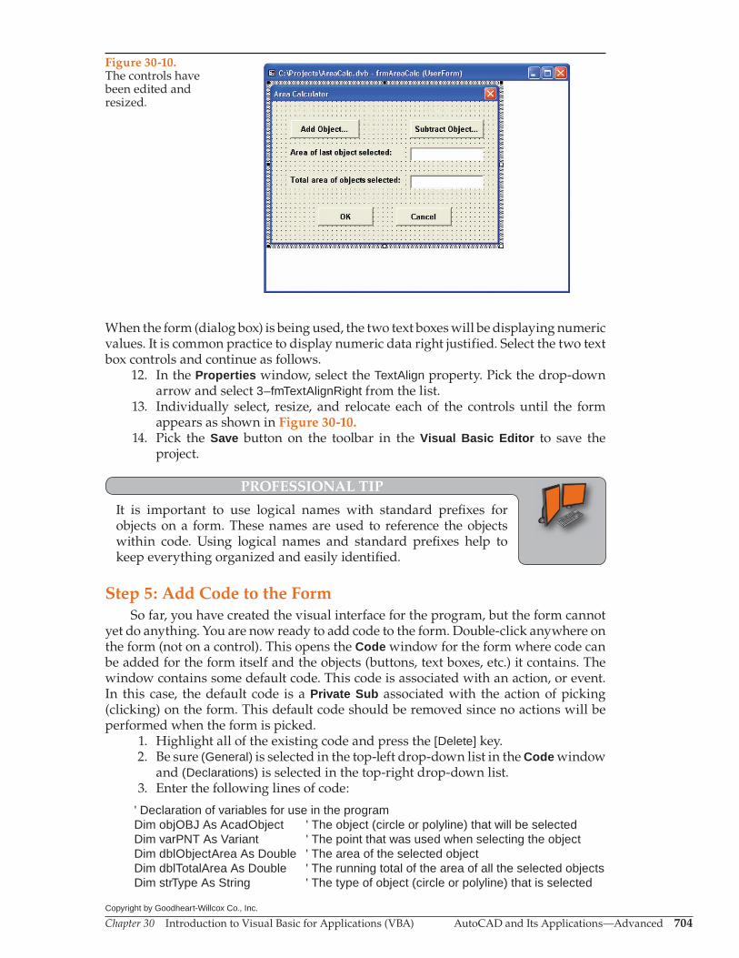
When the form (dialog box) is being used, the two text boxes will be displaying numeric values. It is common practice to display numeric data right justified. Select the two text box controls and continue as follows.
12. In the Properties window, select the TextAlign property. Pick the drop-down arrow and select 3–fmTextAlignRight from the list.
13. Individually select, resize, and relocate each of the controls until the form appears as shown in Figure 30-10.
14. Pick the Save button on the toolbar in the Visual Basic Editor to save the project.
PROFESSIONAL TIP
It is important to use logical names with standard prefi xes for objects on a form. These names are used to reference the objects within code. Using logical names and standard prefi xes help to keep everything organized and easily identifi ed.
Step 5: Add Code to the FormSo far, you have created the visual interface for the program, but the form cannot
yet do anything. You are now ready to add code to the form. Double-click anywhere on the form (not on a control). This opens the Code window for the form where code can be added for the form itself and the objects (buttons, text boxes, etc.) it contains. The window contains some default code. This code is associated with an action, or event. In this case, the default code is a Private Sub associated with the action of picking (clicking) on the form. This default code should be removed since no actions will be performed when the form is picked.
1. Highlight all of the existing code and press the [Delete] key. 2. Be sure (General) is selected in the top-left drop-down list in the Code window
and (Declarations) is selected in the top-right drop-down list. 3. Enter the following lines of code:
' Declaration of variables for use in the programDim objOBJ As AcadObject ' The object (circle or polyline) that will be selectedDim varPNT As Variant ' The point that was used when selecting the objectDim dblObjectArea As Double ' The area of the selected objectDim dblTotalArea As Double ' The running total of the area of all the selected objectsDim strType As String ' The type of object (circle or polyline) that is selected
Figure 30-10.The controls have been edited and resized.
Chapter 30 Introduction to Visual Basic for Applications (VBA) AutoCAD and Its Applications—Advanced 705Copyright by Goodheart-Willcox Co., Inc.
4. Pick the Save button on the toolbar in the Visual Basic Editor to save the project.
The code you just entered declares the variables needed to do the area calcula-tions. Also, note the comments added to the code. Adding comments is very important because it informs you or anyone else reading the code as to the purpose of the code. Anything after an apostrophe (') is ignored by VBA. Comments are usually added to a line above code or at the end of a line of code, as shown above.
Step 6: Add Code to the Exit Button 1. With the Code window active, select btnExit in the upper-left drop-down list.The upper-right drop-down list changes to the Click action. A Private Sub is added
that will be executed when the Exit button on the form is picked. Also, notice the hori-zontal line between the declarations and the beginning of the Private Sub. This auto-matically appears before each Sub to help visually separate the program into blocks. It is also common practice to use tabs and blank lines to visually separate logical blocks of code. Continue as follows.
2. On the blank line between the Private Sub line and the End Sub line, type:
Unload Me
This line of code closes the dialog box and removes from memory all of the code associated with the form.
3. Save the project.
Step 7: Add Code to the Cancel Button 1. Activate the UserForm window. This can be done by picking on the window
(if it is visible) or selecting the window in the Window pull-down menu of the Visual Basic Editor.
2. Double-click on the btnCancel control. Make sure you do not double-click on the label displayed on the object.
This displays the Code window and adds a Private Sub that will be executed when the Cancel button on the form is picked. In the last section, you used the left-hand drop-down list in the Code window to accomplish the same thing. Use whichever method you prefer. Continue as follows.
3. Add the Unload Me line of code to the Private Sub. The Code window should appear as shown in Figure 30-11.
4. Save the project.In the Area Calculator dialog box (form) you are creating, there will be no differ-
ence between the actions of the OK button and the Cancel button. Both are included for consistency, since most AutoCAD dialog boxes have an OK and a Cancel button. Users quickly become accustom to the consistent locations of features in the software. Try to mimic this with your programs by always including OK and Cancel buttons located near the bottom of the dialog box.
Step 8: Add Code to the Add Object… Button 1. Make the UserForm window active. 2. Double-click on the btnAddObject object. The Code window is displayed and
a Private Sub is added that will be executed when the Add Object… button on the form is picked.

Chapter 30 Introduction to Visual Basic for Applications (VBA) AutoCAD and Its Applications—Advanced 706Copyright by Goodheart-Willcox Co., Inc.
3. Between the Private Sub line and the End Sub line, type the following lines of code. Notice how blank lines and tabs are used to visually organize the code.
frmAreaCalc.Hide
ThisDrawing.Utility.GetEntity objOBJ, varPNT, "Pick a circle or a polyline: " strType = objOBJ.ObjectName
If strType = "AcDbCircle" Or strType = "AcDbPolyline" Then dblObjectArea = objOBJ.Area dblTotalArea = dblObjectArea + dblTotalArea txtLastArea.Text = Str(dblObjectArea) txtTotalArea.Text = Str(dblTotalArea) frmAreaCalc.Show
Else
MsgBox ("Object must be a circle or a polyline") frmAreaCalc.Show
Exit Sub
End If
4. Save the project.
Figure 30-11.Variables have been declared and code has been added for the Cancel and Exit buttons.
Chapter 30 Introduction to Visual Basic for Applications (VBA) AutoCAD and Its Applications—Advanced 707Copyright by Goodheart-Willcox Co., Inc.
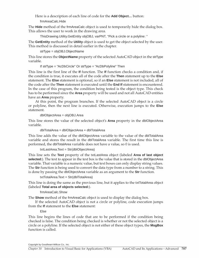
Here is a description of each line of code for the Add Object… button:frmAreaCalc.Hide
The Hide method of the frmAreaCalc object is used to temporarily hide the dialog box. This allows the user to work in the drawing area.
ThisDrawing.Utility.GetEntity objOBJ, varPNT, "Pick a circle or a polyline: "
The GetEntity method of the Utility object is used to get the object selected by the user. This method is discussed in detail earlier in the chapter.
strType = objOBJ.ObjectName
This line stores the ObjectName property of the selected AutoCAD object in the strType variable.
If strType = "AcDbCircle" Or strType = "AcDbPolyline" Then
This line is the first line of the If function. The If function checks a condition and, if the condition is true, it executes all of the code after the Then statement up to the Else statement. The Else statement is optional, so if an Else statement is not included, all of the code after the Then statement is executed until the End If statement is encountered. In the case of this program, the condition being tested is the object type. This check has to be performed since the Area property will be used and not all AutoCAD entities have an Area property.
At this point, the program branches. If the selected AutoCAD object is a circle or polyline, then the next line is executed. Otherwise, execution jumps to the Else statement.
dblObjectArea = objOBJ.Area
This line stores the value of the selected object’s Area property in the dblObjectArea variable.
dblTotalArea = dblObjectArea + dblTotalArea
This line adds the value of the dblObjectArea variable to the value of the dblTotalArea variable and stores the result in the dblTotalArea variable. The first time this line is performed, the dblTotalArea variable does not have a value, so 0 is used.
txtLastArea.Text = Str(dblObjectArea)
This line sets the Text property of the txtLastArea object (labeled Area of last object selected:). The text to appear in the text box is the value that is stored in the dblObjectArea variable. That variable is a numeric value, but text boxes can only display string values. The Str function is being used to convert the data type from a number to a string. This is done by passing the dblObjectArea variable as an argument to the Str function.
txtTotalArea.Text = Str(dblTotalArea)
This line is doing the same as the previous line, but it applies to the txtTotalArea object (labeled Total area of objects selected:).
frmAreaCalc.Show
The Show method of the frmAreaCalc object is used to display the dialog box.If the selected AutoCAD object is not a circle or polyline, code execution jumps
from the If statement to the Else statement:Else
This line begins the lines of code that are to be performed if the condition being checked is false. The condition being checked is whether or not the selected object is a circle or a polyline. If the selected object is not either of these object types, the MsgBox function is called.

Chapter 30 Introduction to Visual Basic for Applications (VBA) AutoCAD and Its Applications—Advanced 708Copyright by Goodheart-Willcox Co., Inc.
MsgBox ("Object must be a circle or a polyline")
The MsgBox function takes a string as an argument and shows that string as a message to the user in a small dialog box with an OK button at the bottom. The message informs the user that a circle or a polyline was not selected. When the user picks the OK button, the next line of code is executed.
frmAreaCalc.Show
This line uses the Show method of the frmAreaCalc object to display the dialog box, allowing the user to pick the Add Objects… button to select another object or Subtract Object… button to remove an object.
Exit Sub
This line exits the Sub routine that was called when the user picked the Add Object… button the first time.
End If
This line signals the end of the code within the If function.
Step 9: Add Code to the Subtract Object… Button 1. Activate the UserForm window. 2. Double-click on the btnSubtractObject object. The Code window is displayed
and a Private Sub is added that will be executed when the Subtract Object… button on the form is picked.
3. Between the Private Sub line and the End Sub line, type the following lines of code. Notice how blank lines and tabs are used to visually organize the code.
frmAreaCalc.Hide
ThisDrawing.Utility.GetEntity objOBJ, varPNT, "Pick a circle or a polyline: " strType = objOBJ.ObjectName
If strType = "AcDbCircle" Or strType = "AcDbPolyline" Then dblObjectArea = objOBJ.Area dblTotalArea = dblTotalArea – dblObjectArea txtLastArea.Text = Str(dblObjectArea) txtTotalArea.Text = Str(dblTotalArea) frmAreaCalc.Show
Else
MsgBox (“Object must be a circle or a polyline”) frmAreaCalc.Show
Exit Sub
End If
The only difference between these lines of code and those for the Add Object… button is this line:
dblTotalArea = dblTotalArea – dblObjectArea
This line subtracts the area of the selected AutoCAD object from the total area.
4. Save the project.
Ands jspois a thspo cnb angoxu igcuostues tre poiust piod agousgas on few ousi zougosa eossougsgo.
Chapter 30 Introduction to Visual Basic for Applications (VBA) AutoCAD and Its Applications—Advanced 709Copyright by Goodheart-Willcox Co., Inc.
NOTE
As you double-click to add code for the various objects on the form, the Private Subs are added to the Code window in alphabetical order. The Private Subs can be rearranged using cut-and-paste editing to more closely follow the fl ow of the program, if desired. For example, you may wish to rearrange the Private Subs for the controls on the frmAreaCalc form as:
Private Sub btnAddObject_Click() lines of codeEnd Sub
Private Sub btnSubtractObject_Click() lines of codeEnd Sub
Private Sub btnExit_Click() lines of codeEnd Sub
Private Sub btnCancel_Click() lines of codeEnd Sub
Step 10: Create a Macro to Call the FormThe form is complete, as is the code attached to the command button controls on
the form. The last task is to create a macro to call the form so the dialog box will be displayed on the screen.
1. In the Visual Basic Editor, make sure the AreaCalc project is selected in the Project Explorer window.
2. Select Insert>Module from the pull-down menu.The Code window for the module is opened on the Visual Basic Editor desktop. This is not the same Code window for the form, which is why it currently is blank. Also, notice that a Modules folder is added to the tree in the Project Explorer window with Module1 listed below it. Continue as follows.
3. Select Module1 in the tree in the Project Explorer window. 4. In the Properties window, change the (Name) property to RunAreaCalc. 5. In the module Code window, type:
Public Sub RunAreaCalc()
frmAreaCalc.Show
End Sub
6. Save the project.
Chapter 30 Introduction to Visual Basic for Applications (VBA) AutoCAD and Its Applications—Advanced 710Copyright by Goodheart-Willcox Co., Inc.
Step 11: Load the Project and Run the MacroIf you have been following along with the text, the macro is available at this point
and you can skip to step 3. Otherwise, the project needs to be loaded. In this case, begin with step 1.
1. Open the VBA Manager dialog box. 2. In the VBA Manager dialog box, pick the Load… button. Navigate to the
AreaCalc.dvb file and open it. The project name and location are shown in the dialog box. If the file is already loaded, you do not need to reload it.
3. Switch to AutoCAD. 4. Draw a couple of circles, polylines, lines, and arcs. 5. Open the Macros dialog box. The macro that was created in the AreaCalc
project is listed. 6. Highlight the RunAreaCalc macro and pick the Run button.The form (Area Calculator dialog box) created in the project appears. Pick the Add
Object… button; the dialog box is hidden. Select one of the circles you drew. The dialog box is displayed and the area of the circle appears in both text boxes in the dialog box. Pick the Add Object… button again and select a different circle. The area of that circle appears in the top text box and the combined area of the two circles appears in the bottom text box. Experiment with using the Subtract Object… button, selecting a line or arc, and using the OK and Cancel buttons.
CAUTION
This routine is not error proof. It will break down if you do not select an object when prompted to do so. Error checking is an important feature of programming. For information on adding error checking to your VBA programs, refer to VBA for AutoCAD published by The Goodheart-Willcox Company, Inc.
Running a VBA Macro from the Keyboard
One drawback of the VBA language is that there is no way to create a command out of a VBA macro or project. Additionally, there is no way to create a keyboard shortcut for a VBA macro or a project. There is, however, a way to create a command from a VBA project through the use of AutoLISP.
Create the following AutoLISP program using the Visual LISP Editor. A couple of AutoLISP functions are used that are not covered in this text. You can research these functions in the online documentation if you want to explore them deeper.
; For use with AreaCalc VBA project(defun c:AreaCalc () (vl-vbaload "c:/vba projects/AreaCalc.dvb") (vl-vbarun "RunAreaCalc") (princ))
The first line of code after the comment defines a function called AreaCalc that can be used on the command line. The second line of code after the comment loads a VBA project file. The path needs to match the location of your file, so adjust this line as needed. The next line runs the macro that calls the dialog box from the loaded project. The next line creates a clean exit from the AutoLISP program. The last line just closes the (defun) function. Now, this LISP program can be saved, loaded into AutoCAD, and run. Refer to Chapters 27 and 28 for more information.
Chapter 30 Introduction to Visual Basic for Applications (VBA) AutoCAD and Its Applications—Advanced 711Copyright by Goodheart-Willcox Co., Inc.
Chapter TestAnswer the following questions. Write your answers on a separate sheet of paper or complete the electronic chapter test on the student website.www.g-wlearning.com/CAD
1. What does VBA stand for? 2. Briefly describe the AutoCAD object model. 3. What is the root object of the AutoCAD object model? 4. What are the five objects that branch from the root object in the AutoCAD object
model? 5. Which branch off of the root allows access to most of the objects stored in
AutoCAD’s Options dialog box? 6. Which branch off of the root allows access to the objects stored in model space and
paper space? 7. What is a VBA method? 8. What is a property, in terms of VBA? 9. What are events, in terms of VBA? 10. What is a VBA project? 11. What is a form? 12. Describe the difference between an embedded project and a global project. 13. How do you access to the Macros dialog box, VBA Manager, and Visual Basic Editor
using the ribbon? 14. Describe the Auto List Members feature of the Visual Basic Editor. 15. Name six common data types used in VBA programming. 16. Define variable. 17. What is declaring a variable? 18. What does the term hard coding mean? 19. The ThisDrawing object is an alias for _____. 20. In which object are most of the user-interaction methods stored? 21. Name the methods that will obtain each of the following data types: String, Integer,
Real, Point. 22. Given ThisDrawing.Utility.Prompt (strName), which term describes the (strName)
portion of the code? 23. Describe the Auto Quick Info feature of the Visual Basic Editor. 24. Describe the difference between storing a value in an object variable versus storing
a value in a data variable. 25. Command buttons, option buttons, labels, text boxes, and other items that are
found on forms are called ____.
Dra
win
g P
rob
lem
s -
Chap
ter
30
Chapter 30 Introduction to Visual Basic for Applications (VBA) AutoCAD and Its Applications—Advanced 712Copyright by Goodheart-Willcox Co., Inc.
Drawing Problems
1. Create a VBA macro that will ask the user to select an object. Then, display a messagebox indicating the type of object selected Name the macro P30_01_ObjectType.
2. Create a VBA macro that will ask the user to select a line. Then, display the length of the selected object in a message box. If the selected object is not a line, display a message informing the user of this. Name the macro P30_02_LineLength.
3. Create a VBA macro that will draw three circles.A. Draw the first circle using a center point and radius provided by the user.B. Draw the second circle using the same center point and a radius 25% larger
than the first circle.C. Draw the third circle using the same center point and a radius 25% smaller
than the first circle.D. Provide prompts for the user for the center point and radius.E. Name the macro P30_03_DrawCircles.
4. Create a VBA macro that will reduce the radius of a selected arc or circle to half of its original radius. If the selected object is not an arc or circle, display a message informing the user of this. Name the macro P30_04_ChangeRadius.
Related Documents